
Evaluation of distribution transformer banks in electric ...users.ntua.gr/pgeorgil/Files/J63.pdf ·...
16
Evaluation of distribution transformer banks in electric power systems Juan Carlos Olivares-Galvan 1 * , Rafael Escarela-Perez 1 , Pavlos S. Georgilakis 2 and Issouf Fofana 3 1 Departamento de Energia, Universidad Autonoma Metropolitana de Azcapotzalco, Ciudad de Mexico, D.F., 02200, Mexico 2 School of Electrical and Computer Engineering, National Technical University of Athens, GR-15780, Athens, Greece 3 Canada Research Chair on Insulating Liquids and Mixed Dielectrics for Electrotechnology (ISOLIME), Université du Québec à Chicoutimi, Québec, Canada SUMMARY This article compares the total mass and the total owning cost (TOC) of three-phase distribution transformer banks with standard three-phase distribution transformers. The comparison is based on the minimum TOC. This is achieved through a field-validated distribution transformer design program that automatically minimises the objective function (TOC). In particular, 12 oil-immersed distribution transformers are designed: 6 three-phase transformer banks and 6 three-phase transformers; these designs meet all the requirements of a given transformer standard. As a result, curves of minimum TOC versus transformer rating are obtained for three- phase transformer banks and three-phase transformers. Moreover, similar curves from seven transformer manufacturers are collected; the advantage of this collection is that these different manufacturers have different types of transformers: oil immersed or dry type, core or shell type, various voltage classes and power ratings, and so on, and consequently more general conclusions can be drawn regarding the comparison of three-phase transformer banks and three-phase transformers. From these investigations, it was found that from the view- point of minimum total mass and minimum TOC, three-phase transformer banks should be recommended in case of small-size transformers (rating lower than 45 kVA). This is an important finding that is not emphasised in recommended practices reported in transformer textbooks. Copyright © 2011 John Wiley & Sons, Ltd. key words: cost of transformer materials; total owning cost; transformer total mass; distribution transformers; single-phase distribution transformers; three-phase distribution transformers 1. INTRODUCTION Transformers are essential components in the electrical power system. A typical transformer consists of coils of copper or aluminium conductors (that may be insulated with paper insulation for large units), which are wound around a magnetic core. Transformers are filled with dielectric fluid, which has two important functions [1]: a) to strengthen the dielectric properties of solid insulation by impregnation and to electrically insulate active parts from grounded ones, and b) to remove heat generated by the windings during service. There are three main reasons why three phases are used in electrical power systems: a) a three-phase machine can generate up to 95.5% of an ideal machine with infinite number of phases [2], b) the use of three conductors in a three-phase system can provide 173% more power than two conduc- tors in a single-phase system [2], and *Correspondence to: Juan Carlos. Olivares-Galvan, Departamento de Energia, Universidad Autonoma Metropolitana de Azcapotzalco, Ciudad de Mexico, D.F., 02200, Mexico. E-mail: [email protected] Copyright © 2011 John Wiley & Sons, Ltd. INTERNATIONAL TRANSACTIONS ON ELECTRICAL ENERGY SYSTEMS Int. Trans. Electr. Energ. Syst. 2013; 23:364–379 Published online 30 December 2011 in Wiley Online Library (wileyonlinelibrary.com). DOI: 10.1002/etep.665
Transcript of Evaluation of distribution transformer banks in electric ...users.ntua.gr/pgeorgil/Files/J63.pdf ·...
Evaluation of distribution transformer banks in electric powersystems
Juan Carlos Olivares-Galvan1*, Rafael Escarela-Perez1,Pavlos S. Georgilakis2 and Issouf Fofana3
1Departamento de Energia, Universidad Autonoma Metropolitana de Azcapotzalco, Ciudad de Mexico, D.F., 02200, Mexico2School of Electrical and Computer Engineering, National Technical University of Athens, GR-15780, Athens, Greece3Canada Research Chair on Insulating Liquids and Mixed Dielectrics for Electrotechnology (ISOLIME), Université du
Québec à Chicoutimi, Québec, Canada
SUMMARY
This article compares the total mass and the total owning cost (TOC) of three-phase distribution transformerbanks with standard three-phase distribution transformers. The comparison is based on the minimumTOC. Thisis achieved through a field-validated distribution transformer design program that automatically minimises theobjective function (TOC). In particular, 12 oil-immersed distribution transformers are designed: 6 three-phasetransformer banks and 6 three-phase transformers; these designs meet all the requirements of a giventransformer standard. As a result, curves of minimum TOC versus transformer rating are obtained for three-phase transformer banks and three-phase transformers. Moreover, similar curves from seven transformermanufacturers are collected; the advantage of this collection is that these different manufacturers have differenttypes of transformers: oil immersed or dry type, core or shell type, various voltage classes and power ratings,and so on, and consequently more general conclusions can be drawn regarding the comparison of three-phasetransformer banks and three-phase transformers. From these investigations, it was found that from the view-point of minimum total mass and minimum TOC, three-phase transformer banks should be recommended incase of small-size transformers (rating lower than 45 kVA). This is an important finding that is not emphasisedin recommended practices reported in transformer textbooks. Copyright © 2011 John Wiley & Sons, Ltd.
key words: cost of transformer materials; total owning cost; transformer total mass; distributiontransformers; single-phase distribution transformers; three-phase distribution transformers
1. INTRODUCTION
Transformers are essential components in the electrical power system. A typical transformer consists ofcoils of copper or aluminium conductors (that may be insulated with paper insulation for large units),which are wound around a magnetic core. Transformers are filled with dielectric fluid, which has twoimportant functions [1]:
a) to strengthen the dielectric properties of solid insulation by impregnation and to electrically insulateactive parts from grounded ones, and
b) to remove heat generated by the windings during service.
There are three main reasons why three phases are used in electrical power systems:
a) a three-phase machine can generate up to 95.5% of an ideal machine with infinite number of phases [2],b) the use of three conductors in a three-phase system can provide 173% more power than two conduc-
tors in a single-phase system [2], and
*Correspondence to: Juan Carlos. Olivares-Galvan, Departamento de Energia, Universidad Autonoma Metropolitana deAzcapotzalco, Ciudad de Mexico, D.F., 02200, Mexico.E-mail: [email protected]
Copyright © 2011 John Wiley & Sons, Ltd.
INTERNATIONAL TRANSACTIONS ON ELECTRICAL ENERGY SYSTEMSInt. Trans. Electr. Energ. Syst. 2013; 23:364–379Published online 30 December 2011 in Wiley Online Library (wileyonlinelibrary.com). DOI: 10.1002/etep.665
c) three-phase power can be transmitted with transmission lines over long distances with small wiregauges.
Three single-phase transformers can be connected to form a three-phase transformer bank. There arethree advantages of using a three-phase transformer instead of a three-phase transformer bank [3–8]:
a) cost reduction,b) total mass reduction, andc) space saving.
When a transformer is used for distribution service (the secondary is connected directly to the customerload), it is called a distribution transformer. Distribution transformers are distinguished from large powertransformers, which are used in high-voltage transmission systems for the transmission of large amount ofpower. Both large power and distribution transformers are used for transmission and distribution applica-tions. The difference between large power and distribution transformers refers to size and input voltage.Distribution transformers vary typically between 5 kVA and 10 MVA, with input voltage between 1 and36kV. Power transformers are typically units from 5 to 500 MVA, with input voltage higher than 36 kV.Distribution transformers may be oil filled or dry filled. Because small distribution transformers do notgenerate much heat, a higher proportion of them tend to be dry type.
2. THREE-PHASE TRANSFORMER BANK VERSUS STANDARD THREE-PHASETRANSFORMER
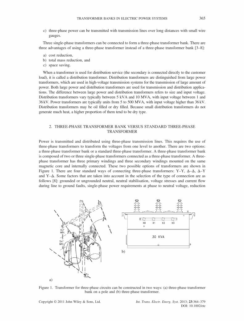
Power is transmitted and distributed using three-phase transmission lines. This requires the use ofthree-phase transformers to transform the voltages from one level to another. There are two options:a three-phase transformer bank or a standard three-phase transformer. A three-phase transformer bankis composed of two or three single-phase transformers connected as a three-phase transformer. A three-phase transformer has three primary windings and three secondary windings mounted on the samemagnetic core and internally connected. These two possible options of transformers are shown inFigure 1. There are four standard ways of connecting three-phase transformers: Y–Y, Δ–Δ, Δ–Yand Y–Δ. Some factors that are taken into account in the selection of the type of connection are asfollows [8]: grounded or ungrounded neutral, neutral stabilisation, voltage stresses and current flowduring line to ground faults, single-phase power requirements at phase to neutral voltage, reduction
a)
b)
Figure 1. Transformer for three-phase circuits can be constructed in two ways: (a) three-phase transformerbank on a pole and (b) three-phase transformer.
TRANSFORMER BANKS IN ELECTRIC POWER SYSTEMS 365
Copyright © 2011 John Wiley & Sons, Ltd. Int. Trans. Electr. Energ. Syst. 2013; 23:364–379DOI: 10.1002/ete
of harmonic voltages and currents and angular phase displacement between the different voltage levelsin the distribution system.An important advantage of a three-phase transformer bank over a standard three-phase trans-
former is that each unit in the bank may be replaced/repaired individually in case of failure. Forexample, the open delta (V–V) and the open–Y–open-delta connections are generally used in caseof emergency to guarantee continued service. These are two ways to perform three-phase transfor-mation with only two transformers. Each of these types of connections has certain advantages anddisadvantages that influence their selection. Furthermore, one spare single-phase transformer isusually all that is required to assure sufficient reliability for the entire bank. With a three-phasetransformer, an additional spare three-phase transformer would be required, so the total cost ofthe installation plus a spare transformer is twice the cost of the installation itself. On the otherhand, the total cost of a three-phase transformer bank plus a spare single-phase transformer is only133% the cost of the bank alone. Therefore, the total cost of a bank of single-phase transformersplus a spare is probably less than the cost of a three-phase transformer plus a spare. For instance,it may be impossible or impractical to fabricate and/or deliver a three-phase power transformer withan extremely large kilovolt-ampere capacity, although a bank of three single-phase transformersmay then be the solution.Loads on a distribution system consist of a combination of three-phase and single-phase loads. To
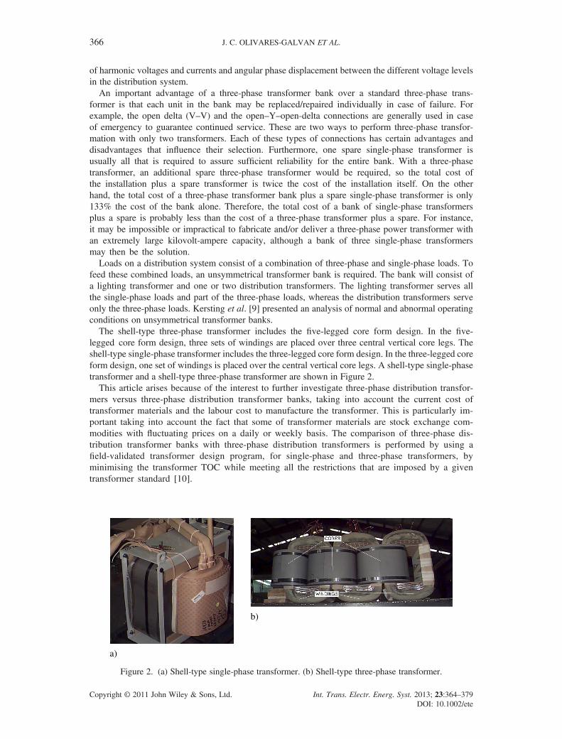
feed these combined loads, an unsymmetrical transformer bank is required. The bank will consist ofa lighting transformer and one or two distribution transformers. The lighting transformer serves allthe single-phase loads and part of the three-phase loads, whereas the distribution transformers serveonly the three-phase loads. Kersting et al. [9] presented an analysis of normal and abnormal operatingconditions on unsymmetrical transformer banks.The shell-type three-phase transformer includes the five-legged core form design. In the five-
legged core form design, three sets of windings are placed over three central vertical core legs. Theshell-type single-phase transformer includes the three-legged core form design. In the three-legged coreform design, one set of windings is placed over the central vertical core legs. A shell-type single-phasetransformer and a shell-type three-phase transformer are shown in Figure 2.This article arises because of the interest to further investigate three-phase distribution transfor-
mers versus three-phase distribution transformer banks, taking into account the current cost oftransformer materials and the labour cost to manufacture the transformer. This is particularly im-portant taking into account the fact that some of transformer materials are stock exchange com-modities with fluctuating prices on a daily or weekly basis. The comparison of three-phase dis-tribution transformer banks with three-phase distribution transformers is performed by using afield-validated transformer design program, for single-phase and three-phase transformers, byminimising the transformer TOC while meeting all the restrictions that are imposed by a giventransformer standard [10].
a)
b)
Figure 2. (a) Shell-type single-phase transformer. (b) Shell-type three-phase transformer.
J. C. OLIVARES-GALVAN ET AL.366
Copyright © 2011 John Wiley & Sons, Ltd. Int. Trans. Electr. Energ. Syst. 2013; 23:364–379DOI: 10.1002/ete
3. OVERVIEW OF TRANSFORMER DESIGN METHODOLOGY
This section provides an overview of the methodology and the computer program developed for theoptimal design of single-phase and three-phase distribution transformers [11]. This computer programis used in this article for the study and comparison of three-phase transformer banks with three-phasetransformers.
3.1. Input data
The input data required by the transformer design program are the following:
a) Transformer capacity (kVA)b) Number of phasesc) Connection typed) High voltage (V)e) Low voltage (V)f) Frequency (Hz)
3.2. Variables
The optimisation routine (see Section 3.5), considers five design variables. These variables and theirvariation ranges are as follows:
a) High-voltage conductors’ size varying from 6 to 27 AWG.b) Magnetic flux density varying from 1.4 to 1.7 T.c) Number of turns of the low-voltage winding, NLV. This parameter varies from 5 to 50, in the case
of single-phase transformers. From the transformer kilovolt-ampere rating, the number of turnsof the low-voltage winding can be computed from the expression NLV = 89.6828�kVA�0.5 [12].
d) Width of core steel sheet. There are six widths between 152.4 and 304.8mm.e) Cross-sectional area of aluminium foil for low voltage. There are seven values available. The width
of aluminium foil varies from 114.3 to 254.0mm, and its thickness varies from 0.30 to 1.78mm.
3.3. Output parameters
The transformer design program computes the following four fundamental parameters:
a) Transformer impedance (%)b) Transformer massc) Transformer material costd) Transformer total owning cost (TOC)
3.3.1. Transformer impedance. In rectangular windings of distribution transformers, the low-voltagewinding is placed close to the core producing the L–H–L configuration. The transformer impedance(%Z) for shell-type and wound core transformers is calculated by the following formulas [13]:
%Z ¼ffiffiffiffiffiffiffiffiffiffiffiffiffiffiffiffiffiffiffiffiffiffiffiffiffiffiffiffiffiffiffiffi%Rð Þ2 þ %Xð Þ2
q(1a)
%R ¼ Wc
10 kVA(1b)
%X ¼ 8� p2 � f � IN� K �MLTwind � g� 10�8
gVt(1c)
where %R=winding resistance (%) at 85�C, Wc = conductor losses at 85�C (W), kVA= transformerrating, %X=winding reactance (%), f = frequency (Hz), IN = ampere turn of transformer, K= 1.00for three-phase transformers, K= 0.85 for single-phase transformers, MLTwind =mean turn length of
TRANSFORMER BANKS IN ELECTRIC POWER SYSTEMS 367
Copyright © 2011 John Wiley & Sons, Ltd. Int. Trans. Electr. Energ. Syst. 2013; 23:364–379DOI: 10.1002/ete
windings (mm), g = length of magnetic linkage (mm), g = average winding height plus average windingthickness (mm) and Vt =Volt per turn.
3.3.2. Transformer total mass. The transformer mass includes the mass of the core, the high- and low-voltage conductors, the tank and the mineral oil. The core mass for shell-type three-phase transformers isgiven by [14]:
Mc�3f ¼ 2 Pl1 þ Pl2ð Þ (2)
where Pl1 is the lateral coremass (kg) and Pl2 is the central coremass (kg). To be less repetitive, the equationsfor the three-phase case are presented here. The single-phase case can be easily deduced. Details concerningthe calculation of Pl1 and Pl2 can be found in the studies of Olivares-Galvan et al. [11], Harlow [15],Georgilakis [16] and Cogent Power Inc. [14].The mean turn length is required to calculate the winding resistance and the mass for any given
winding (for the calculation of the winding mean turn length, see Rubaai [17] and McLyman[17,18]). The high-voltage conductor mass for three-phase transformers, MCu, is given by [19]:
MCu ¼ 3MLTHV�NHV�csHV�rHV (3)
where MLTHV is the mean turn length of high voltage (m), NHV is the number of turns of high-voltageconductor, csHV is the cross-sectional area of high-voltage conductor (m2) and rHV is the density ofhigh-voltage conductor (kg/m3).The low-voltage conductor mass for three-phase transformers MAl is given by [19]
MAl ¼ 3MLTLV�NLV�csLV�rLV (4)
where MLTLV is the mean turn length of low voltage (m), NLV is the number of turns of low-voltageconductor, csLV is the cross-sectional area of low-voltage conductor (m2) and rLV is the density oflow-voltage conductor (kg/m3).The tank mass, Mta, is derived from [20]
Mta ¼ Vct þ Vft þ Vttð Þrac (5)
where Vct is the volume of carbon steel plate content of the tank body (m3), Vft is the volume of carbonsteel plate content of the bottom of the tank, Vtt is the volume of carbon steel plate content of tankcover and rac is the density of steel (kg/m3).The three-phase transformer total mass Mt� 3f is given by [20]
Mt�3f ¼ MHV�3f þMLV�3f þMc�3f þMta�3f þMoil�3f (6)
whereMta� 3f andMoil� 3f are the tank mass and the mineral oil mass, respectively, of the three-phasetransformer.
3.3.3. Transformer material cost. The material cost of the three-phase transformer is given by [21]
Cmat�3f ¼ ucHVMHV�3f þ ucLVMLV�3f þ uccMc�3f þ uctaMta�3f þ ucoilMoil�3f (7)
where ucHV is the per unit cost of high-voltage conductor ($/kg), ucLV is the per unit cost of low-voltageconductor ($/kg), ucc is the per unit cost of core magnetic material ($/kg), ucta is the per unit cost of tanksteel ($/kg) and ucoil is the per unit cost of mineral oil ($/kg).
3.3.4. Transformer TOC. The TOC takes into account not only the initial transformer cost but also thecost to operate the transformer over its life. The TOC is given by [22]
TOC ¼ BPþ A� NLLþ B� LL (8)
where
BP ¼ Cmat þ Clab
1� SM(9)
where BP is the transformer bid price ($), A is the transformer no-load loss cost rate ($/W), NLL is thetransformer no-load loss (W), B is the transformer load loss cost rate ($/W), LL is the transformer load loss
J. C. OLIVARES-GALVAN ET AL.368
Copyright © 2011 John Wiley & Sons, Ltd. Int. Trans. Electr. Energ. Syst. 2013; 23:364–379DOI: 10.1002/ete
(W), Cmat is the transformer material cost ($) computed from Equation (7), Clab is the transformer labor cost($) and SM is the transformer salesmargin. Details concerning the computation ofA andB loss cost rates canbe found in the work of Kennedy [23].Strictly speaking, the TOC should also consider themaintenance and the failure repair costs, according to [24]
TOC ¼ BPþ A� NLLþ B� LLþ Cm þ Cr (10)
where Cm and Cr denote the maintenance and the failure repair costs, respectively.Cm is negligible because maintenance is typically not performed on distribution transformers in service by
electric utilities, and Cr is also negligible, given the very low rate of transformers annual failures. Majorrefurbishments such as rewinding the transformer represent a small percentage (0.02%) of the transformersremoved from service (3.0%). Maintenance is usually not performed on distribution transformers in serviceby electric utilities. Typically, maintenance is only performed when distribution transformers are removedfrom service. The maintenance program used by most utilities consists of the following basic elements:inspection and testing, minor in-house refurbishments, major refurbishments in the form of rewindingtransformers and retirements. Distribution transformers are not normally removed from service because ofage alone [25].
3.4. Standard specifications (constraints)
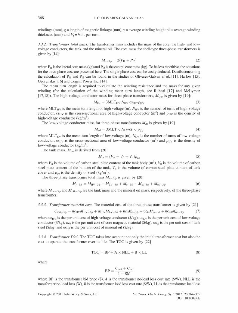
The optimisation process considers a group of constraints related to the excitation current, no-load losses, totallosses, impedance and efficiency [16]. Table 1 shows the values of the no-load and total loss constraints fordistribution transformers according to a given transformer standard [10]. The values of the minimumefficiencies versus the transformer rating and the basic impulse insulation level for single-phase transformersand three-phase transformers can be found in Table 2 [10]. Alternatively, other efficiency standards [26] couldbe also used. According to Norma Mexicana ANCE [10], the excitation current should not exceed 1.5% ofnominal current in all single-phase transformers as well as for three-phase transformers with capacity higherthan 45 kVA. In case of three-phase transformers up to 45 kVA, the excitation current should not be higherthan 2.0% of nominal current. Table 3 shows the impedance specifications for single-phase and three-phasedistribution transformers. The impedance depends on both the insulation class and the transformer rating.
Table I. Maximum no-load losses (W) and maximum total losses (W) required by the standard [10] forsingle-phase and three-phase transformers.
Size (kVA)
BIL (kV)
BIL ≤ 95 95<BIL ≤ 150 150<BIL ≤ 200
No load Total No load Total No load Total
Single-phase transformers 5 30 107 38 112 63 11810 47 178 57 188 83 19915 62 244 75 259 115 27525 86 368 100 394 145 41937.5 114 513 130 552 185 59050 138 633 160 684 210 73675 186 834 215 911 270 988
100 235 1061 265 1163 320 1266167 365 1687 415 1857 425 2028
Three-phase transformers 15 88 314 110 330 135 34530 137 534 165 565 210 59745 180 755 215 802 265 84875 255 1142 305 1220 365 1297
112.5 350 1597 405 1713 450 1829150 450 1976 500 2130 525 2284225 750 2844 820 3080 900 3310300 910 3644 1000 3951 1100 4260500 1330 5561 1475 6073 1540 6588
BIL, basic impulse insulation level.
TRANSFORMER BANKS IN ELECTRIC POWER SYSTEMS 369
Copyright © 2011 John Wiley & Sons, Ltd. Int. Trans. Electr. Energ. Syst. 2013; 23:364–379DOI: 10.1002/ete

3.5. Multiple design optimisation algorithm
The transformer design optimisation problem is achieved using a multiple design method that assignsmany alternative values to the design variables so as to generate a large number of alternative designsand finally to select the design that satisfies all the problem constraints with the optimum value of theobjective function [16,27]. Consequently, this method guarantees the finding of the optimum amongthe alternative designs considered [11,16,27].The five design variables and their ranges of variation have been presented in Section 3.2.
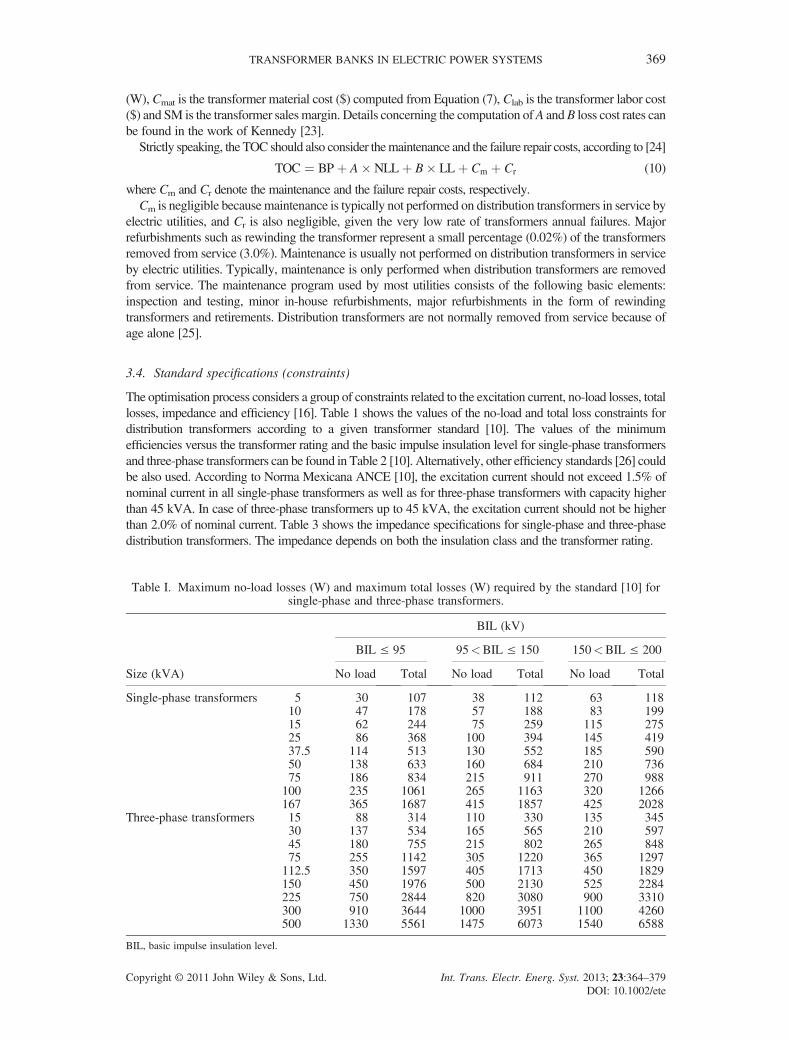
From these ranges (see Section 3.2), the computer program investigates various potential solu-tions. For each solution, the specifications (constraints) are evaluated. If all these constraintsare satisfied, the value of the objective function is calculated and the solution is characterisedas ‘acceptable’. On the other hand, the potential solutions that do not meet the specificationsare characterised as ‘nonacceptable’ solutions. Finally, among the acceptable solutions, the trans-former with the optimum value of the objective function is selected, which is the optimumtransformer.Figure 3 shows the flowchart for optimising TOC,where kVbt is the low voltage, kVat is the high voltage,
AVmfd is the number of alternative values for the magnetic flux density, AVcccsa is the number of alternativevalues of copper conductor cross-sectional areas, AVaccsa is the number of alternative values of aluminiumconductor cross-sectional area, AVlw is the number of alternative values of lamination width and AVlvt is the
Table II. Minimum efficiencies (%) required by the standard [10] for single-phase and three-phasetransformers.
Size(kVA)
BIL (kV)
BIL ≤ 95 95<BIL ≤ 150 150<BIL ≤ 200
Single-phase transformers 5 97.9 97.8 97.710 98.25 98.15 98.0515 98.4 98.3 98.225 98.55 98.45 98.3537.5 98.65 98.55 98.4550 98.75 98.65 98.5575 98.9 98.8 98.7
100 98.95 98.85 98.75167 to 500 99 98.9 98.8
Three-phase transformers 15 97.95 97.85 97.7530 98.25 98.15 98.0545 98.35 98.25 98.1575 98.5 98.4 98.3
112.5 98.6 98.5 98.4150 98.7 98.6 98.5225 98.75 98.65 98.55300 98.8 98.7 98.6500 98.9 98.8 98.7
BIL, basic impulse insulation level.
Table III. Impedance constraints required by the standard [10] for single-phase and three-phasetransformers.
Insulationclass (kV)
Impedance (%)
Single-phase transformers Three-phase transformers
5–167 kVA Pole type 15–150 kVA Substation type 225–500 kVA
1.2–25 1.5–3.00 2.00–3.00 2.50–5.0025 1.50–3.25 2.00–3.25 2.75–5.5034.5 1.50–3.50 2.00–3.50 3.00–5.75
J. C. OLIVARES-GALVAN ET AL.370
Copyright © 2011 John Wiley & Sons, Ltd. Int. Trans. Electr. Energ. Syst. 2013; 23:364–379DOI: 10.1002/ete
number of alternative values of turns of low voltage. Other objective functions (e.g. total material cost ortotal mass) can substitute TOC objective function in Figure 3.In addition to Equations (1a), (1b) and 1c–9(1c)–, the most important formulas can be found in the
study of Olivares-Galvan et al. [11], which are involved in the transformer design program (shown inthe flowchart of Figure 3) to compute quantities such as core mass, no load loss, excitation current,winding mass, load losses and efficiency.
BEGIN
Input data # Phases
kVAkVbtkVat
FrequencyConnection
Does the design meets the given constraints?
NO
YES
Design accepted
Obtain the Transformer design with the lowest TOC
Optimal design
End
Calculate volts per turn Calculate dimension of the core Calculate current densities for low voltage and high voltage Calculate coil dimensions and its insulation Calculate winding weightCalculate transformer impedanceCalculate core weight and no-load losses Calculate load lossesCalculate total losses Calculate efficiency Calculate tank dimensions and oil volume Calculate oil-copper gradientCalcule TOC
Transformer designs that do not meet the given constraints are
removed.
AV = 6 to 15, STEP=1
AV = 15 to 17, STEP=0.1
AV = 81.1988 -5 to 81.1988 +5,
STEP=1
AV =1 to 4, STEP=1
AV = 1 to 7, STEP=1
Figure 3. Simplified flow diagram for transformer optimisation using TOC as an objective function
DF
G
E
a)
Insulation against the core
Interior low-voltage windingHigh-voltage winding
Ww
Hw
Exterior low voltage winding
Interior insulation
Exterior insulation
Tt w Low-voltage terminals
High-voltage terminals
Tl v
Th v
b)
Figure 4. Active element. (a) Core dimensions and (b) low–high–low winding dimensions.
TRANSFORMER BANKS IN ELECTRIC POWER SYSTEMS 371
Copyright © 2011 John Wiley & Sons, Ltd. Int. Trans. Electr. Energ. Syst. 2013; 23:364–379DOI: 10.1002/ete

4. RESULTS AND DISCUSSIONS
4.1. Simulation results
In the context of this research, 12 oil-immersed distribution transformers are designed: 6 three-phasetransformer banks and 6 three-phase transformers. These designs meet all the requirements of a giventransformer standard [10]. The transformer designs are optimised using the multiple design method ofSection 3.5. M3 lamination was used for the magnetic material of all transformers (Figure 4).Figures 5 to 8 were generated using a field-validated transformer design program [11]. Figure 5 shows
the tendency of three-phase transformers to have less weight than three-phase transformer banks, but forlower power ratings, the opposite is observed, which is depicted with details in Figure 6.The total mass for a three-phase transformer is always lower than total mass of three-phase transformer
bank, although at lower ratings, these mass differences are smaller. More specifically:
• For the 30-kVA rating, the total mass of the three-phase transformer is 7.21% higher than that ofthe three-phase transformer bank, as Figure 6 shows.
• For the 112.5-kVA rating, the total mass of the three-phase transformer is 21.7% lower than thatof the three-phase transformer bank, as can be seen in Figure 5.
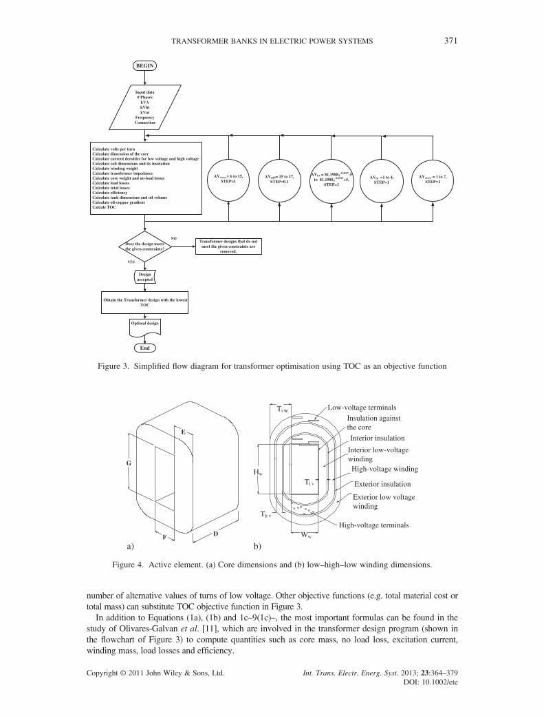
Figure 7 shows the comparison of TOC between three-phase transformer banks and three-phasetransformers. There is a trend of higher cost for three-phase transformer banks. However, the differencein cost of low-rating transformers is significantly reduced. More specifically:
• For the 30-kVA rating, the TOC of the three-phase transformer is 8.69% lower than that of thethree-phase transformer bank.
Figure 5. Total weight comparison for three-phase transformers and three-phase transformer banks.
Figure 6. Zoom of Figure 5 for low-size transformers.
J. C. OLIVARES-GALVAN ET AL.372
Copyright © 2011 John Wiley & Sons, Ltd. Int. Trans. Electr. Energ. Syst. 2013; 23:364–379DOI: 10.1002/ete
• For the 112.5-kVA rating, the TOC of the three-phase transformer is 18.17% lower than that ofthe three-phase transformer bank.
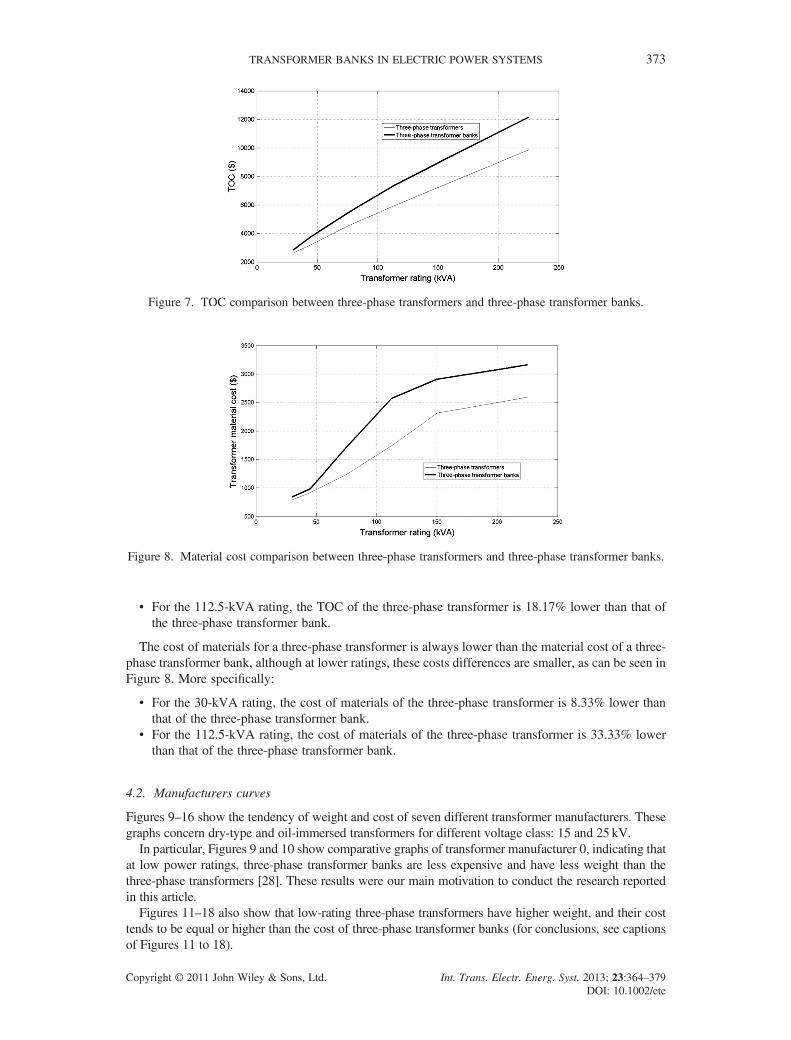
The cost of materials for a three-phase transformer is always lower than the material cost of a three-phase transformer bank, although at lower ratings, these costs differences are smaller, as can be seen inFigure 8. More specifically:
• For the 30-kVA rating, the cost of materials of the three-phase transformer is 8.33% lower thanthat of the three-phase transformer bank.
• For the 112.5-kVA rating, the cost of materials of the three-phase transformer is 33.33% lowerthan that of the three-phase transformer bank.
4.2. Manufacturers curves
Figures 9–16 show the tendency of weight and cost of seven different transformer manufacturers. Thesegraphs concern dry-type and oil-immersed transformers for different voltage class: 15 and 25 kV.In particular, Figures 9 and 10 show comparative graphs of transformer manufacturer 0, indicating that
at low power ratings, three-phase transformer banks are less expensive and have less weight than thethree-phase transformers [28]. These results were our main motivation to conduct the research reportedin this article.Figures 11–18 also show that low-rating three-phase transformers have higher weight, and their cost
tends to be equal or higher than the cost of three-phase transformer banks (for conclusions, see captionsof Figures 11 to 18).
Figure 7. TOC comparison between three-phase transformers and three-phase transformer banks.
Figure 8. Material cost comparison between three-phase transformers and three-phase transformer banks.
TRANSFORMER BANKS IN ELECTRIC POWER SYSTEMS 373
Copyright © 2011 John Wiley & Sons, Ltd. Int. Trans. Electr. Energ. Syst. 2013; 23:364–379DOI: 10.1002/ete
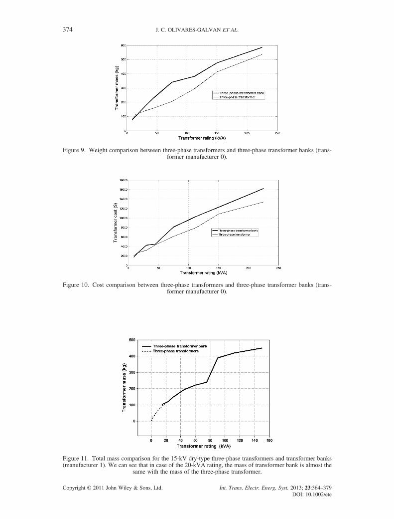
Figure 9. Weight comparison between three-phase transformers and three-phase transformer banks (trans-former manufacturer 0).
Figure 10. Cost comparison between three-phase transformers and three-phase transformer banks (trans-former manufacturer 0).
Figure 11. Total mass comparison for the 15-kV dry-type three-phase transformers and transformer banks(manufacturer 1). We can see that in case of the 20-kVA rating, the mass of transformer bank is almost the
same with the mass of the three-phase transformer.
J. C. OLIVARES-GALVAN ET AL.374
Copyright © 2011 John Wiley & Sons, Ltd. Int. Trans. Electr. Energ. Syst. 2013; 23:364–379DOI: 10.1002/ete
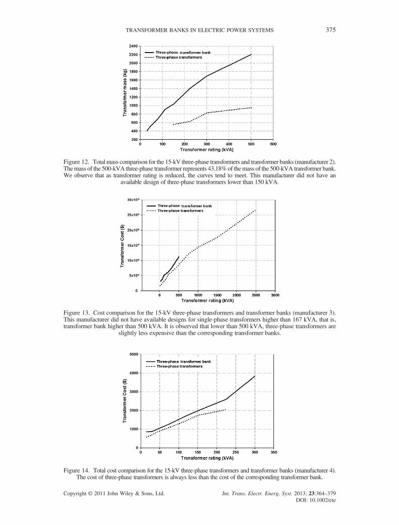
Figure 12. Total mass comparison for the 15-kV three-phase transformers and transformer banks (manufacturer 2).Themass of the 500-kVA three-phase transformer represents 43.18%of themass of the 500-kVA transformer bank.We observe that as transformer rating is reduced, the curves tend to meet. This manufacturer did not have an
available design of three-phase transformers lower than 150 kVA.
Figure 13. Cost comparison for the 15-kV three-phase transformers and transformer banks (manufacturer 3).This manufacturer did not have available designs for single-phase transformers higher than 167 kVA, that is,transformer bank higher than 500 kVA. It is observed that lower than 500 kVA, three-phase transformers are
slightly less expensive than the corresponding transformer banks.
Figure 14. Total cost comparison for the 15-kV three-phase transformers and transformer banks (manufacturer 4).The cost of three-phase transformers is always less than the cost of the corresponding transformer bank.
TRANSFORMER BANKS IN ELECTRIC POWER SYSTEMS 375
Copyright © 2011 John Wiley & Sons, Ltd. Int. Trans. Electr. Energ. Syst. 2013; 23:364–379DOI: 10.1002/ete
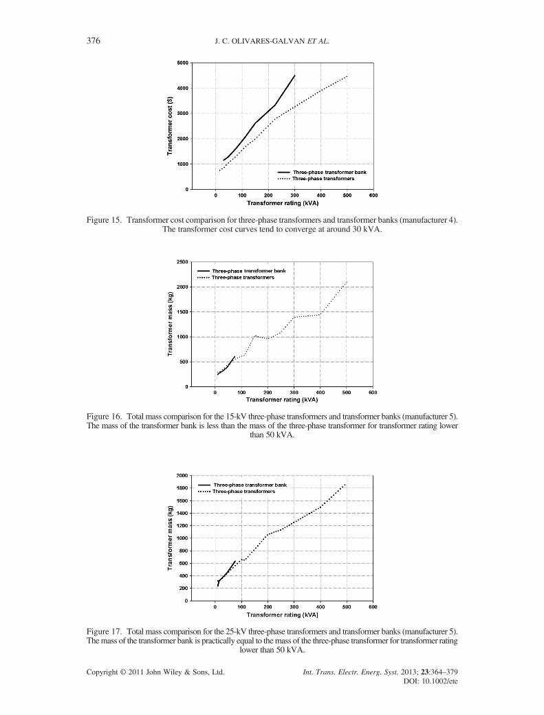
Figure 15. Transformer cost comparison for three-phase transformers and transformer banks (manufacturer 4).The transformer cost curves tend to converge at around 30 kVA.
Figure 16. Total mass comparison for the 15-kV three-phase transformers and transformer banks (manufacturer 5).The mass of the transformer bank is less than the mass of the three-phase transformer for transformer rating lower
than 50 kVA.
Figure 17. Total mass comparison for the 25-kV three-phase transformers and transformer banks (manufacturer 5).Themass of the transformer bank is practically equal to themass of the three-phase transformer for transformer rating
lower than 50 kVA.
J. C. OLIVARES-GALVAN ET AL.376
Copyright © 2011 John Wiley & Sons, Ltd. Int. Trans. Electr. Energ. Syst. 2013; 23:364–379DOI: 10.1002/ete

4.3. Future research
In the near future, an extension of this studywill bemade;we are planning to compare three-phase transformersagainst transformer banks in many aspects, such as temperature distribution in transformer windings [29–31],tank rupture [32] and inrush current [33,34].
5. CONCLUSIONS
In this article, three-phase transformer banks and three-phase transformers are studied and compared. Thecomparison is based on a transformer design optimisation methodology that minimises the transformerTOC while meeting all the requirements imposed by transformer design standards and specifications.Optimum single-phase and three-phase transformers are designed using a field-validated transformerdesign optimisation computer program that has been used for many years in a mid-size transformerfactory. Specifically, 12 optimum transformer designs are computed for the comparison of three-phasetransformer banks versus the three-phase transformers. As a result, curves of minimum TOC versustransformer rating are obtained for three-phase transformer banks and three-phase transformers.Moreover, similar curves from seven transformer manufacturers are collected. The advantage of thiscollection is that these different manufacturers have different types of transformers: oil immersed or drytype, core or shell type, various voltage classes and power ratings, and so on, and consequently moregeneral conclusions can be drawn regarding the comparison of three-phase transformer banks andthree-phase transformers. Specifically, a wide range of transformers with different power ratings, from30 to 2500 kVA, is compared. On the basis of this study, it is concluded that the advantage of usingthree-phase transformers with power rating higher than 45 kVA is strong in terms of cost and weight.However, low-size three-phase transformers have more weight, and their cost tends to be equal or higherthan the cost of three-phase transformer banks. We are presenting many evidence of this behaviour in theform of figures of seven different transformer manufacturers. The main reason behind this finding isrelated to the higher weight of transformer tank, oil and high-voltage conductor of three-phase transformerover three-phase transformer banks.
6. LIST OF ABBREVIATIONS AND SYMBOLS
NLV number of turns of the low voltage windingTOC transformer total owning cost%Z transformer impedance%R winding resistance (in %) at 85o CWc conductor losses at 85o C (Watts)
Figure 18. Total mass comparison for the 15-kV three-phase transformers and transformer banks (manufac-turer 6). For transformer rating higher than 75 kVA, we observe that mass curves tend to diverge.
TRANSFORMER BANKS IN ELECTRIC POWER SYSTEMS 377
Copyright © 2011 John Wiley & Sons, Ltd. Int. Trans. Electr. Energ. Syst. 2013; 23:364–379DOI: 10.1002/ete
kVA transformer rating%X winding reactance (in %)f frequency (Hz)IN ampere turn of transformerK 1.00 for three-phase transformersK 0.85 for single-phase transformersMLTwind mean turn length of windings (mm)g length of magnetic linkage (mm)g average winding height plus average winding thickness (mm)Vt volt per turnMc� 3θ core mass (kg)P11 lateral core mass (kg)P12 central core mass (kg)MCu high-voltage conductor mass for three-phase transformersMLTHV mean turn length of high-voltage (m)NHV number of turns of high-voltage windingcsHV cross-section area of high-voltage conductor (m2)rHV density of high-voltage conductor (kg/m3)MAl low-voltage conductor mass for three-phase transformersMLTLV mean turn length of low-voltage winding (m)NLV number of turns of low-voltage windingcsLV cross-section area of low-voltage conductor (m2)rLV density of low-voltage conductor (kg/m3)Mta tank massVct volume of carbon steel plate content of the tank body (m3)Vft volume of carbon steel plate content of the bottom of the tankVtt volume of carbon steel plate content of tank coverrac density of steel (kg/m3)Mt� 3θ three-phase transformer total massMta� 3θ tank mass of the three-phase transformerMoil� 3θ mineral oil mass of the three-phase transformerCmat� 3θ material cost of the three-phase transformerucHV per unit cost of high-voltage conductor ($/kg)ucLV per unit cost of low-voltage conductor ($/kg)ucc per unit cost of core magnetic material ($/kg)ucta per unit cost of tank steel ($/kg)ucoil per unit cost of mineral oil ($/kg)BP transformer bid price ($)A transformer no-load loss cost rate ($/W)NLL the transformer no-load loss (W)B transformer load loss cost rate ($/W)LL transformer load loss (W)Cmat transformer material cost ($) computed from Equation (7)Clab transformer labor cost ($)SM transformer sales marginCm maintenance costsCr failure repair costskVbt low voltagekVat high voltageAVmfd number of alternative values for the magnetic flux densityAVcccsa number of alternative values of copper conductor cross-sectional areasAVaccsa number of alternative values of aluminum conductor cross-sectional areaAVlw number of alternative values of lamination width andAVlvt number of alternative values of turns of low voltage
J. C. OLIVARES-GALVAN ET AL.378
Copyright © 2011 John Wiley & Sons, Ltd. Int. Trans. Electr. Energ. Syst. 2013; 23:364–379DOI: 10.1002/ete
REFERENCES
1. Fofana I, Sabau J. Application of petroleum-based oil in power transformer. In Natural Gas Research Progress, David N,Michel T (eds). Nova Science Publishers: USA, 2008.
2. Chiasson J. Modeling and High-Performance Control of Electric Machines. IEEE Press Series on Power Engineering:USA, 2005.
3. Siskind CS. Electrical machines, 2nd edn. International Student Edition: USA, 1959.4. Fitzgerald AE, Kingsley C, Jr., Umans SD. Electrical Machines. McGraw-Hill: USA, 1992; 87–89.5. Laithwaite ER, Freris LL. Electric Energy: its generation, transmission and use. McGraw-Hill: Great Britain, 1980;
35–41.6. Chapman SJ. Electrical Machines. McGraw-Hill: USA, 2005.7. Gibbs JB. Transformer principles and practice. McGraw-Hill: USA, 1950; 6–11.8. Blume LF, Boyajian A. Transformer Connections, Including Auto-Transformer Connections. General Electric Company,
Publication GET-2B: Hickory, N.C., 1940.9. Kersting WH, Phillips WH. Modeling and Analysis of Unsymmetrical Transformer Banks Serving Unbalanced
Loads. IEEE Transactions on Industry Applications May/Jun 1996; 32(3):720–725.10. Norma NMX-J116-ANCE-2006, Norma Mexicana ANCE, Pole mounted and substation transformers, (In Spanish),
pp. 7, 29–31.11. Olivares-Galvan JC, Georgilakis PS, Escarela-Perez R, Campero Littlewood E. Optimal Design of Single-Phase
Shell-Type Distribution Transformers based on a Multiple Design Method Validated by Measurements. ElectricalEngineering, 6 June 2011, 1–10, DOI:10.1007/s00202-011-0211-9.
12. Say MG. The performance and design of alternating current machines, 3rd edn. Pitman Paperbacks: Great Britain,1958.
13. Olivares JC, Antonio Trujillo J, Jara F. Methodology for optimization of distribution transformer cost, (in Spanish),Reunión de Verano de Potencia. Tomo 1, IEEE Sección México Julio 1998. Acapulco, Guerrero, México.
14. Cogent Power Inc. Catalog of design and manufacture of transformer cores. Cogent Power Inc.: Canada, 2001.15. Harlow JH (ed). Electric Power Transformer Engineering. CRC Press LLC: USA, 2004.16. Georgilakis PS. Spotlight on Modern Transformer Design. Springer: London, 2009.17. Rubaai A. Computer aided instruction of power transformer design in the undergraduate power engineering class.
IEEE Transactions on Power Systems 1994; 9:1174–1181.18. McLyman CWT. Transformer and Inductor Design Handbook, 3rd edn (revised and expanded). Marcel Dekker:
NY, 2006; 183–184.19. Kuhmann JJ. Design of electrical apparatus. J. Wiley and Sons: New York, 1940.20. Elleuch M, Poloujadoff M. Technical and Economical Analysis of 3-LIMB and 4-LIMB Three Phase Transformers
in YN/yn Network. European Transactions on Electrical Power November/December 2002; 12(6):397–402.21. Corrales Martín J. Optimal calculation of transformers (in Spanish). Marcombo: Barcelona, 1977.22. Olivares-Galvan JC, de León F, Georgilakis PS, Escarela-Perez R. Selection of Copper versus Aluminum Windings
for Distribution Transformers. IET Electric Power Applications 2010; 4(6):474–485.23. Kennedy BW. Energy Efficient Transformers. McGraw-Hill: New York, 1998.24. Frau J, Arcos Á, Ruíz E, Ramis A. Energy Efficiency and Profitability Analysis of Reduced Loss Transformers:
Experiences in Spain. 17th International Conference on Electricity Distribution, Barcelona, 12–15 May 2003.25. Barnes PR, Van Dyke JW, McConnell BW, Cohn SM, Purucker SL. The feasibility of replacing or upgrading utility
distribution transformers during routine maintenance, Power Systems Technology Program, Oak Ridge NationalLaboratory, RNL-6804/Rl, April 1995.
26. Georgilakis PS, Amoiralis EI. Distribution transformer cost evaluation methodology incorporating environmentalcost. IET Generation, Transmission and Distribution July 2010; 4(7):861–872.
27. Georgilakis PS, Tsili MA, Souflaris AT. A heuristic solution to the transformer manufacturing cost optimizationproblem. Journal of Materials Processing Technology 2007; 181:260–266.
28. http://www.phaseconverter.com/sptransformer.html29. Faiz J, Sharifian MBB, Fakhri A. Two-dimensional finite element thermal modeling of an oil-immersed transformer.
European Transactions on Electrical Power 2008; 18(6):577–594.30. Weigen C, Chong P, Yuxin Y. Power transformer top-oil temperature model based on thermal–electric analogy theory.
European Transactions on Electrical Power 2009; 19(3):341–354.31. Taghikhani MA, Gholami A. Temperature distribution in ONAN power transformer windings with finite element
method. European Transactions on Electrical Power 2009; 19(5):718–730.32. Culver B, Fröhlich K, Widenhorn L. Prevention of tank rupture of faulted power transformers by generator circuit
breakers. European Transactions on Electrical Power 1996; 6(1):39–45.33. Theocharis AD, Milias-Argitis J, Zacharias T. Three-Phase Transformer Model Including Magnetic Hysteresis and
Eddy Currents Effects. IEEE Transactions on Power Delivery July 2009; 24(3):1284–1294.34. Theocharis AD, Milias-Argitis J, Zacharias T. A systematic method for the development of a three-phase transformer
non-linear model. International Journal of Circuit Theory and Applications, Published online in Wiley InterScience,DOI: 10.1002/cta.599, 2009.
TRANSFORMER BANKS IN ELECTRIC POWER SYSTEMS 379
Copyright © 2011 John Wiley & Sons, Ltd. Int. Trans. Electr. Energ. Syst. 2013; 23:364–379DOI: 10.1002/ete