Evaluation of Cracking in Pre-Service and In-Service Snow ...
55
Research, Development and Technology MoDOT RDT 03-015 Evaluation of Cracking in Pre-service and In-service Snow Plow Carbide Wear Surfaces December, 2003 RI 01-023
Transcript of Evaluation of Cracking in Pre-Service and In-Service Snow ...
Research, Development and Technology
MoDOT
RDT 03-015
Evaluation of Cracking in Pre-service and
In-service Snow Plow Carbide Wear Surfaces
December, 2003
RI 01-023
Evaluation of Cracking in Pre-service and In-service
Snow Plow Carbide Wear Surfaces
Research Investigation RI 01-023
Research Number RDT 03-015
Prepared By
Missouri Department of Transportation
Research, Development and Technology Division
Jefferson City, Missouri
Principal Investigator:
John MacIver
Date Submitted: December 2003
The opinions, findings and conclusions expressed in this publication are those of the
principal investigator and the Research, Development and Technology Division of the
Missouri Department of Transportation. They are not necessarily those of the U.S.
Department of Transportation or Federal Highway Administration. This report does not
constitute a standard, specification or regulation.

TECHNICAL REPORT DOCUMENTATION PAGE
1. Report No. 2. Government Accession No. 3. Recipient's Catalog No. RDT 03-015 4. Title and Subtitle 5. Report Date
December, 2003 6. Performing Organization Code
Evaluation of Cracking in Pre-service and In-service Snow-plow Carbide Wear Surfaces
MoDOT
7. Author(s) John MacIver
8. Performing Organization Report No. RI 01-023
9. Performing Organization Name and Address 10. Work Unit No.
11. Contract or Grant No.
Missouri Department of Transportation Research, Development and Technology P. O. Box 270-Jefferson City, MO 65102 12. Sponsoring Agency Name and Address 13. Type of Report and Period
Covered Final Report 14. Sponsoring Agency Code
Missouri Department of Transportation Research, Development and Technology P. O. Box 270-Jefferson City, MO 65102 MoDOT 15. Supplementary Notes 16. Abstract Purpose of the study was to determine the source of defect propagation in carbide/steel snowplow blade inserts and qualify a non destructive testing technique that will: a) locate and determine whether or not defects originating in the manufacturing process have an impact on blade service life, b) be able to monitor in-service blades to determine the rate of carbide insert and bond breakdown in the field, c) evaluate various carbide insert configurations in the field. Research, Development and Technology recommends the following and that blade life be monitored to determine if satisfactory results from these changes occur: 1) Use the nondestructive technique for receipt inspection to detect indications oriented transverse and other than transverse to the sound beam, as well as lack of bond, 2) Use front or rear mounted blades next to the carbide blade to increase the service life of the individual carbide blade, 3) With a 0° +/- roadway angle, MoDOT should change the shape of the carbide insert such that the inserts have a flat face, 4) try dual carbide blades on front mounted plows. 17. Key Words 18. Distribution Statement Snowplow blade, carbide, nondestructive testing, ultrasound, ultrasonic inspection, moldboard, snowplow wear surface, snowplow blade damage.
No restrictions. This document is available to the public through National Technical Information Center, Springfield, Virginia 22161
19. Security Classification (of this report)
20. Security Classification (of this page)
21. No. of Pages 22. Price
Unclassified Unclassified 42 ---- Form DOT F 1700.7 (06/98)


ACNOWLEDGEMENTS
The principal investigator wishes to thank William H. Stalcup, Missouri Department of
Transportation, Physical Laboratory Director and the Materials Division, for their support
on this project. The Materials Division was instrumental in approving the project concept
and providing continued support throughout the evaluation.
The principal investigator wishes to thank Bob Lannert, Missouri Department of
Transportation, General Services Division Enterprise Administrator for his continued
support in field evaluations throughout this investigation. His cooperation and assistance
was instrumental in this projects’ success.
The principal investigator wishes to thank the Missouri Department of Transportation
personnel at the Ashland, Auxvasse, Columbia, Harrisburg and Jefferson City
Maintenance Facilities for their consistent assistance during field evaluations during the
2002/2003 snow removal season.

Executive Summary:
Purpose of the study was to determine the source of defect propagation in
carbide/steel snowplow blade inserts and qualify a Non Destructive Testing (NDT)
technique and procedure that which will; (a) locate, quantify and size defects as well as
determine whether or not defects originating in the manufacturing process have an impact
on blade service life, (b) be able to monitor in-service blades to determine the rate of
carbide insert and bond breakdown in the field in order to assess acceptability of various
blade insert materials and defect acceptability parameters, and (c) evaluate various
carbide insert configurations in the field that could possibly best meet MoDOT snow
removal requirements.
We have shown that ultrasound examination can divulge pre-service and in-service
defects in single layered carbide insert blades. The inspection of these blades in the lab is
easy, and the techniques work well in the field as long as the blade surface of the
inspection area is not damaged. I believe that the ultrasonic inspection technique
developed here shows the most promise as a receipt inspection tool. Indications show that
blade life appears to be influenced by operational and environmental situations and not
by manufacturing defects. Missouri uses carbide blades that are manufactured and shaped
to be used on plows utilizing a 20°to 30°incident angle. Because the 0° angle of attack
used by Missouri subjects the point of the carbide blade to excessive impact pressures
due to the configuration of the carbide, impact damage prior to the “wearing in” of the
blades is maximized during break in periods. If Missouri intends to continue with its use
of a 0° +/- roadway incident angle then we may want to consider changing the shape of
the inserts. The state could either have an insert manufactured with a flat face, or inserts
could be placed in the blade slot upside down, so the flat side is out. This will have a
greater area of roadway contact to the carbide and thus minimize chipping. Other options
that seem to give the carbide more time to “wear in” and protect the carbide from impact
are also available, such as using front or back wear plates mounted adjacent to the carbide
blade.
The following items should be implemented in the 2003/2004 snow removal season
and that blade life be monitored to determine satisfactory results from these changes
occur.
1) Nondestructive testing should be added as a receipt inspection process. It was
found that the technique can detect indications oriented transverse to the sound
beam, indications oriented on a plane other than transverse, as well as lack of
bond. If a small percentage of blades were examined for lack of bond and carbide
cracking and a penetrant test performed on the base metal steel, a better indication
of blade quality would exist.
2) A wear plate should be implemented in all front plow configurations. It appears
that a front mounted wear plate has the most promise but blades used at the
Ashland maintenance facility have had excellent results utilizing a rear mounted
wear blade. In all cases, a front or rear mounted wear blade greatly increased the
service life of the individual carbide over un-protected blades.
3) With a 0° +/- roadway incident angle, MoDOT should change the shape of the
carbide insert such that the inserts have a flat face which will have a greater area
of roadway contact and thus minimize chipping. If MoDOT starts out with a flat

insert, we should be able to skip the “wearing in” process where most of the
carbide damage seems to originate.
4) Dual carbide blades should be tried on front mounted snow plows.

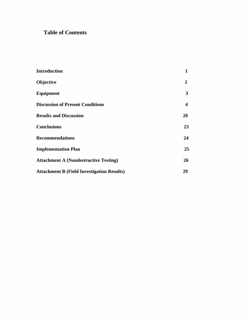
Table of Contents
Introduction 1
Objective 2
Equipment 3
Discussion of Present Conditions 4
Results and Discussion 20
Conclusions 23
Recommendations 24
Implementation Plan 25
Attachment A (Nondestructive Testing) 26
Attachment B (Field Investigation Results) 29

1

Introduction:
The higher speeds used when snow plowing coupled with the newer raised pavement
markers and rumble strips that increase blade impact, have decreased the service life of
the plow blade wear surfaces due to cracking and breakdown of the carbide insert. In
addition, blades may be being purchased with defects caused during manufacture. State
purchasing officials have a need to know the condition of the insert and silver braze bond
at the plow blade carbide/steel interface during procurement inspections prior to purchase
by the state. Missouri needs an inspection technique that will find manufacturing defects
and that will also work in a program set up for in-service blade monitoring.
It is believed that manufacturing defects in the wear surface are present prior to state
purchase, and that they are either caused by improper heat application during the brazing
process, or excessive cold forming while straightening the finished blade at the
manufacturer. Ultrasonic inspection (Attachment A), is a proven technique for detecting
lack of bond as well as locating crack and defect parameters in steel. These ultrasonic
techniques would supply the data necessary for the state to reject defective blades,
purchase higher quality blade wear surfaces and monitor existing blade surfaces.
The increase in plowing speed causes increased heat introduction at the blade/road
interface immediately adjacent to the cold snow covered upper blade. It is speculated that
this causes heat induced grinding crack like indications in the carbide face. The impact as
this wear surface rides over rumble strips and raised road marking and falls back to the
pavement coupled with the expansion/contraction stress at the heated carbide face next to
the colder carbide exterior causes rapid procreation of any existing cracks, and may cause
0

the initiation of additional cracks at any stress riser within the carbide insert. A cutting
edge at the front or rear of the blade seems to protect the carbide inserts from localized
impact and expand the metal distance between the warmer wear surface and the cold
snow faced blade.
Ultrasound examination can divulge the cause of in-service defects so that
engineering can; (a) require that the manufacturing process be changed if needed, (b)
determine if the Rockwell hardness of the carbide inserts needs to be lowered, (c)
recommend adding a protective cutting edge to the front of the carbide wear surface
plate, and/or (d) recommend a change in snowplow operation practices. Such data would
allow Missouri to improve the design, specifications and/or operational requirements for
these products.
Objective:
The objective of this project was to determine the source of defect propagation in
carbide/steel snowplow blade inserts and qualify a technique and procedure that would;
(a) locate, quantify and determine whether or not the cause of defects is originating in the
manufacturing process, (b) be able to monitor in-service blades to determine the rate of
carbide insert and bond breakdown in order to assess acceptability of various blade insert
materials, and (c) evaluate various carbide hardness parameters, brazing techniques and
insert configurations that would best meet MoDOT requirements. This report will
investigate attributes and limitations of the surface contact and delay line ultrasonic
nondestructive testing technique that was used to determine the quality of various carbide
insert configurations used by the Missouri Department of Transportation. Visual
1
evaluation of blade configurations in the field during the 2002/2003 snow removal season
and the results of these configurations on blade service life is also documented.
Equipment:
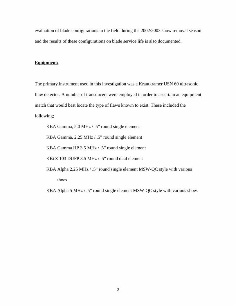
The primary instrument used in this investigation was a Krautkramer USN 60 ultrasonic
flaw detector. A number of transducers were employed in order to ascertain an equipment
match that would best locate the type of flaws known to exist. These included the
following;
KBA Gamma, 5.0 MHz / .5” round single element
KBA Gamma, 2.25 MHz / .5” round single element
KBA Gamma HP 3.5 MHz / .5” round single element
KBi Z 103 DUFP 3.5 MHz / .5” round dual element
KBA Alpha 2.25 MHz / .5” round single element MSW-QC style with various
shoes
KBA Alpha 5 MHz / .5” round single element MSW-QC style with various shoes
2
Blade inspection with a contact delay line shoe
Discussion of Present Conditions
The blades under consideration are designed as wear plate attachments that are
bolted to the bottom of the snowplow blades used on the International heavy duty dump
trucks used by the Missouri Department of Transportation (MoDOT) during the states’
annual snow removal program. Missouri employs a clean surface snow removal policy,
so the use of raised plow skid plates is not an option. The wear plate attachments are
made of mild steel plate about .75” thick by 5” tall and between three and five feet long
with bolt hole attachment points at intervals along the upper blade length. (see photo of
blade configuration on page 6.) A slot machined into the lower working face contains
molded carbide inserts that are brazed in place with mid range industrial bronze (see
3
additional configurations of blade wear plate slots and carbide inserts on page 13).
Kennametal Inc. of Bedford, PA, 15522 and Valk Mfg. Co. in New Kingston PA are
presently supplying most of Missouri’s blades.
There are a number of design parameters inherent with this product that add a
dimension of difficulty to ultrasonic examination, but since the only other inexpensive
full volumetric examination technique is radiography and the carbide density and
expected defect orientation preclude its use, an ultrasound procedure is desirable if
adequate results can be achieved. Due to the complexities of through transmission
alignment and the narrow back face area, a pitch/catch mode was used. The sound beam
must travel through, not counting the Lucite shoe, three materials and four interfaces to
reach the initial back face, and then go back through all of these material interfaces to
reach the transducer in the “catch” mode. The carbide is a sintered powder product which
is isotropic in nature but can have anisotropic properties due to variations in binder
location, and cooling after sintering.
4
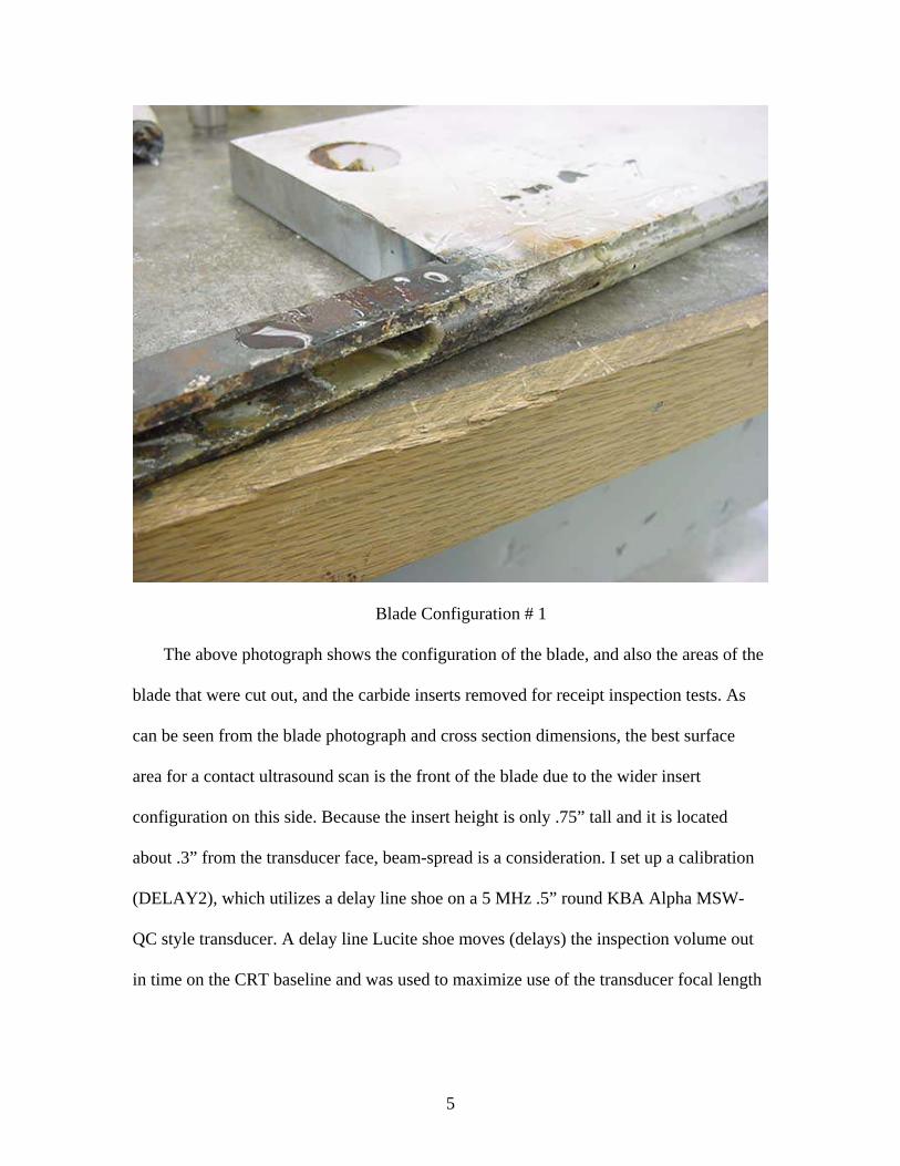
Blade Configuration # 1
The above photograph shows the configuration of the blade, and also the areas of the
blade that were cut out, and the carbide inserts removed for receipt inspection tests. As
can be seen from the blade photograph and cross section dimensions, the best surface
area for a contact ultrasound scan is the front of the blade due to the wider insert
configuration on this side. Because the insert height is only .75” tall and it is located
about .3” from the transducer face, beam-spread is a consideration. I set up a calibration
(DELAY2), which utilizes a delay line shoe on a 5 MHz .5” round KBA Alpha MSW-
QC style transducer. A delay line Lucite shoe moves (delays) the inspection volume out
in time on the CRT baseline and was used to maximize use of the transducer focal length
5

which allows us to get better resolution of the various interfaces. The screen is
incremented in .25” of product with each major screen division representing .25”.
Carbide Front Carbide back Blade Back Delay line shoe multiple
The first multiple of the shoe comes up at 1”, but since the part thickness is .75”, that is
not a problem. The first in-product interface (steel/carbide) comes up at about .2”, the
second interface (carbide/steel), comes up at about .45”, with the part back at .7”. There
is a delay line shoe multiple on the CRT outside the area of interest within the carbide
that could confuse inexperienced inspectors, but which is otherwise not a problem on the
single insert blades but could mask indications on the newer double insert blades, unless
a longer delay line shoe is used. Cracking in the carbide seems to be gross in nature so
reflected signals from such a defect should be easily discernable to a trained individual.
Many cracks within the insert are not oriented for adequate detection through reflection,
6
but such indications cause a loss of back, which will cause the inspector to further
evaluate those areas. It was also noted that on the outside steel face of the blade, and
within the heat affected brazing zone, many longitudinal cracks varying in length from
.25” and 2” were found. These surface indications were verified by penetrant exam, and
subsequent analysis shows that they are surface in nature, and extend less than .01” into
the product. Since these indications could easily represent a stress riser in an area of the
blade that could speed denigration of the wear surface, an inquiry was placed with
Kennametal Inc. as to whether heat caused by the milling process could have caused the
OD indications, or whether the brazing process was the cause. I also contacted
Kennametal Inc. to better understand the dendritics of the carbide and the manufacturing
process of the blade.
I ultimately spoke with Kennametal Inc. Research and Development, and received
the following information. The notch that houses the carbide insert is machine milled.
The process is cooled as in the normal milling process, so heat “should not” be an issue.
However, from experience, I know that a dull machining head could cause the type of
surface indication found on the blade face. Kennametal Inc. also gave me a lot of
information about their carbide manufacturing process. Powdered carbide is sintered with
roughly 15% cobalt to form the insert. The carbide is, from an ultrasonic inspectors
perspective, microscopically isotropic, but macroscopically anisotropic. The crystals are
microscopic, (between 2 and 10 microns in length) and they are randomly oriented. They
are many faceted and prismatic in nature, so although reflection and refraction occurs
with its resulting attenuation, the end result microscopically is an ultrasonically isotropic
material. Because carbide is a mixed powder with cobalt added as a binder, and because a
7
mixed powder cannot be totally mixed nor can it be added to a mold uniformly, the
material is macroscopically anisotropic. As soon as the powder has finished its’
crystallization process in the sintering mold and has cooled into a dendritic mass, there is
no further movement of material within the insert. Although carbide is somewhat
anisotropic, velocity tests indicate uniform wave propagation so it appears that a dendritic
structure should not cause problems other than attenuation within the test pieces. I noted
that probe frequency changes do not significantly increase signal response at the material
interfaces.
Three blades were initially supplied to the Materials Department for analysis, but
because blade # 11C1B277 was found to be rejectable due to insert alignment problems,
two more blades were sent by Kennametal Inc. The other two initial blades were
numbered 19TJG111 and 14TLR735. Initial examination of blade # 11C1B277 disclosed
a number of lack of bond and possible crack indications, so after data documentation, the
surface on both sides were ground smooth, paint and braze overflow was removed and
the blade was inspected again. This eliminated the majority of the crack-like indications
while retaining lack of bond area indications. It was at this time that the longitudinal
linear surface indications were disclosed. It appears that while generally an adequate
inspection can be made on the blade in the as-manufactured condition after removing
only the slag with a file, in some instances where numerous indications are present, the
paint needs to be removed in order for signals to be evaluated. Four-foot long blade #
14TLR735 exhibited many lack of bond areas, primarily on side two, and two inserts that
required further analysis to verify that no cracks were present.
8

Screen showing lack of bond area;
Multiples of the carbide front interface Loss of back
It appears that insufficient heat during brazing may have been the cause of these bond
problems. Inserts were numbered from left to right when looking at the front (broad face)
of the blade in order to establish uniformity in insert identification during the monitoring
program. The two replacement blades, numbered 11C1B290 and 1011859 exhibited no
ultrasonic defects, however small insufficient braze voids were noted visually in a few
locations. The blades, #11C1B290 and 1011859 were found acceptable to present
acceptance criteria, but one small area of lack of bond was found on insert # 32 of blade
11C1B290, and blade # 1011859 had a small area of lack of bond on insert # 11 and a
9

cross insert lack of bond on inserts # 32/33 and # 35/36. None of the lack of bond areas
were a reason to reject the parts, but since monitoring of the blades would assist in our
knowledge of blade use, as well as inform us as to whether blade denigration was due to
lack of bond areas inherent in presently acceptable blades, it was decided that the blades
should be monitored. The inspected blades were spray painted to differentiate them from
other blades, stamped with a unique identification number and placed in service in the
regular MoDOT snow removal program. The blades were kept in the Jefferson City area
so that they could be analyzed during and after use. Unfortunately, or fortunately,
depending on perspective, the blades were used only once and minimally the first
monitoring season due to the lack of snow in the Jefferson City area during the
2001/2002 winter season. The blades were however, used for at least three snowfall
events in 2003.
Test Blade # 11C1B290 looking at the front of the blade
Lack of bond area on one half of insert # 32
Lack of bond on one half of insert # 32 on the back side of the insert was verified by
ultrasound exam from both sides of the blade. There were no cracks or additional lack of
bonded areas found on this blade.
10
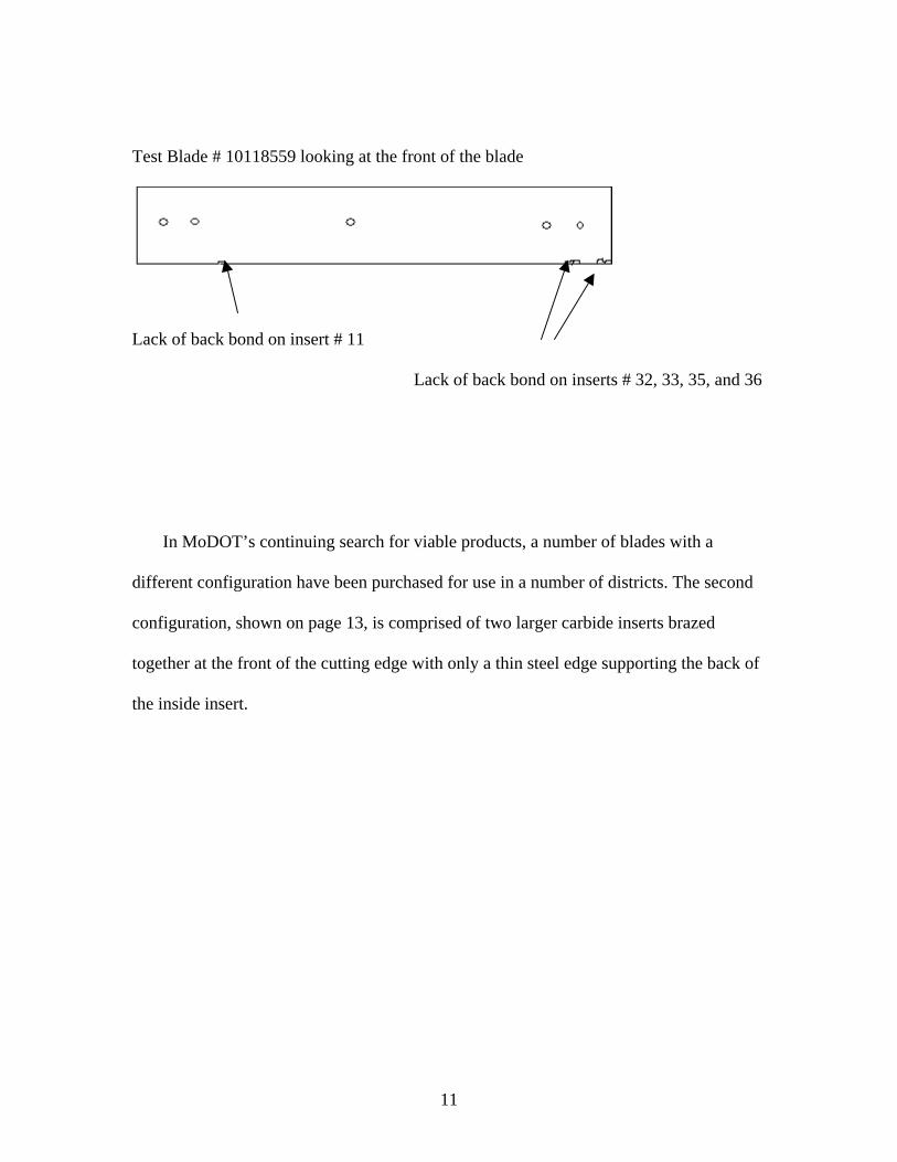
Test Blade # 10118559 looking at the front of the blade
Lack of back bond on insert # 11
Lack of back bond on inserts # 32, 33, 35, and 36
In MoDOT’s continuing search for viable products, a number of blades with a
different configuration have been purchased for use in a number of districts. The second
configuration, shown on page 13, is comprised of two larger carbide inserts brazed
together at the front of the cutting edge with only a thin steel edge supporting the back of
the inside insert.
11
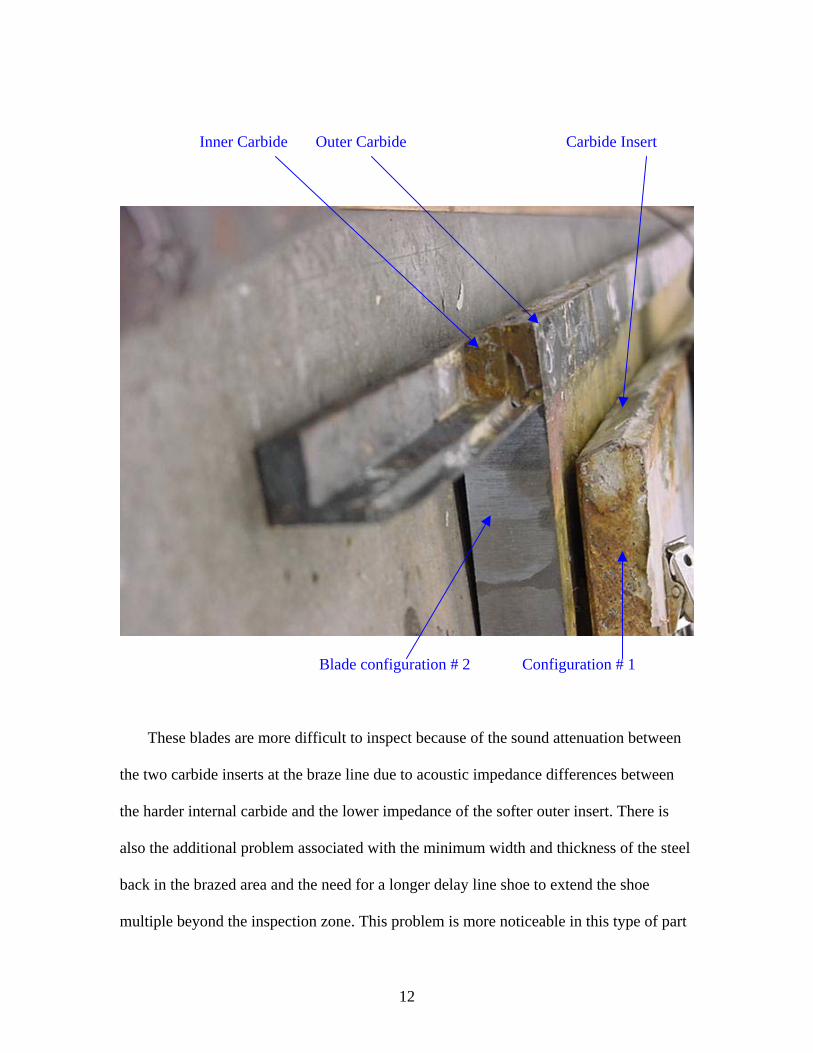
Inner Carbide Outer Carbide Carbide Insert
Blade configuration # 2 Configuration # 1
These blades are more difficult to inspect because of the sound attenuation between
the two carbide inserts at the braze line due to acoustic impedance differences between
the harder internal carbide and the lower impedance of the softer outer insert. There is
also the additional problem associated with the minimum width and thickness of the steel
back in the brazed area and the need for a longer delay line shoe to extend the shoe
multiple beyond the inspection zone. This problem is more noticeable in this type of part
12

where a shorter delay line shoe length would be optimal for transducer focal length
parameters. The use of a longer focal length in a transducer for this type of multi-layered
product minimizes beam-spread reflection problems, but introduces sensitivity
restrictions. A lower frequency yields better penetration, yet poorer discernment of the
braze interfaces. For these reasons, the double insert blades are resisting adequate
inspection results using the present inspection technique. This may be significant because
it is believed that due to the configuration of the blade, there could be increased internal
stresses in the exposed carbide over those found in the enclosed and therefore protected
carbide blade inserts found in configuration # 1. On the Type #2 blades, even though
there is more carbide on the wear surface, there is no mild steel protection to take the
shock, and the cold snow interface is in contact with the carbide. This cold face is
adjacent to the friction-generated heat at the roadway surface in the brittle carbide, which
could induce excessive internal thermal disparity stresses within the carbide insert. We
have not yet tested any of these blades on front plows in the field here in Missouri, but
we are experiencing excellent service from double inserted blades on belly plows where
we have not seen any extraordinary thermal or impact damage.
In a third configuration, a pencil sized cylindrical carbide insert will be inserted and
brazed into a drilled hole in the bottom of the blade wear surface. Due to the orientation
and shape of the insert, coupled with the expected orientation of defects within the insert,
this type of configuration does not lend itself to ultrasonic inspection. However, it would
be much more receptive to radiographic examination. At present, Missouri has not used
this new configuration.
13
After inspection, the blades were placed in service for use during the 2003 snow
removal program. They were checked periodically in the field to determine whether areas
of lack of bond noted during the ultrasound exams had any impact on the blade life
parameters. The following section catalogues the techniques used in the field portion of
this study.
Snow plow status for the ultrasound inspected blades on Jan 14, 2003 is as follows.
The blades were placed on Truck # 6635, which is a single dual axle International dump.
Looking toward the truck from the front, I have numbered the blades #1 thru #4 with # 1
being at the roadway edge (right side of the truck), and blade #4 on the roadway center
(left (drivers) side of the truck). The plow uses a four blade system with the two blades of
interest being numbered 1, and 3. The carbide blades were protected with a full-length
steel wear plate installed on the front of the carbide blades. Because the stamping is not
visible due to the mounting configuration, which blade is 11C1B290 and 10118559 is
unknown at this time, however the orange paint we used to additionally identify the
blades is visible at the top and in the mounting holes of the two blades of interest. The
blades while mounted to the truck and resting on the concrete floor are at a 0° angle. By
this date the blades have been used in at least two snow storms on the roads in and around
Jefferson City. They were used on various roadway surfaces including Rt. 50, which is
concrete and rough in places.
I will break down the observations on January 14, 2003 for all four blades on this
plow individually starting with blade #1.
14
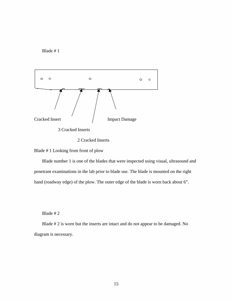
Blade # 1
Cracked Insert Impact Damage
3 Cracked Inserts
2 Cracked Inserts
Blade # 1 Looking from front of plow
Blade number 1 is one of the blades that were inspected using visual, ultrasound and
penetrant examinations in the lab prior to blade use. The blade is mounted on the right
hand (roadway edge) of the plow. The outer edge of the blade is worn back about 6”.
Blade # 2
Blade # 2 is worn but the inserts are intact and do not appear to be damaged. No
diagram is necessary.
15
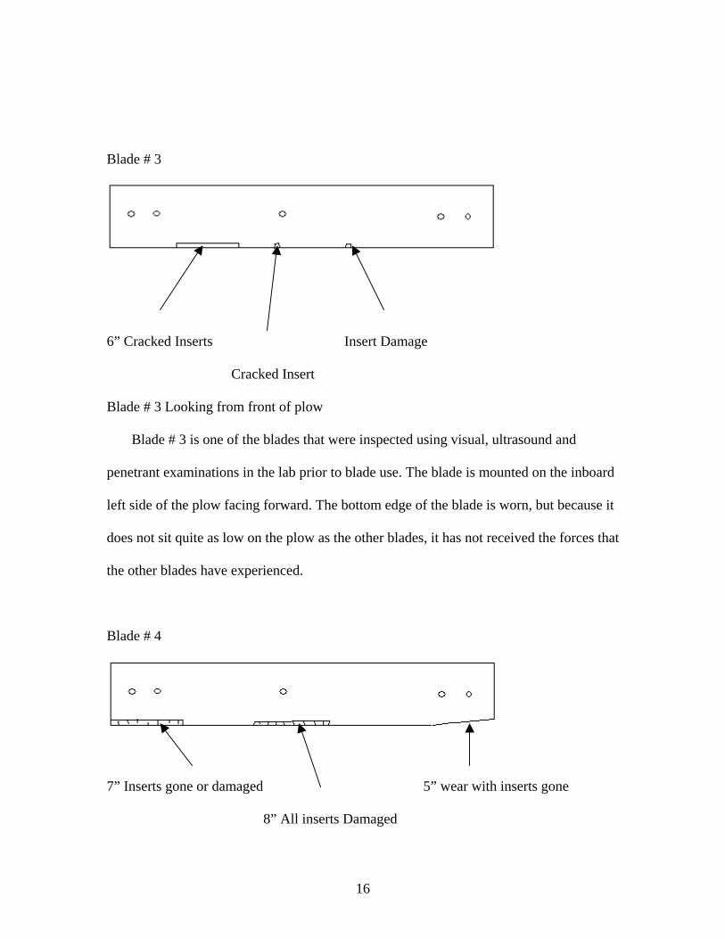
Blade # 3
6” Cracked Inserts Insert Damage
Cracked Insert
Blade # 3 Looking from front of plow
Blade # 3 is one of the blades that were inspected using visual, ultrasound and
penetrant examinations in the lab prior to blade use. The blade is mounted on the inboard
left side of the plow facing forward. The bottom edge of the blade is worn, but because it
does not sit quite as low on the plow as the other blades, it has not received the forces that
the other blades have experienced.
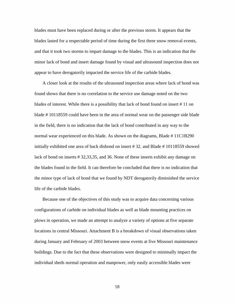
Blade # 4
7” Inserts gone or damaged 5” wear with inserts gone
8” All inserts Damaged
16

Blade # 4 is mounted on the outboard left side of the plow facing forward. The
bottom edge of the blade is worn, and there is significant carbide insert damage on the
inboard end of the blade, significant insert damage in the center of the blade and about
five inches of wear including loss of inserts in the outboard end.
It was noted during field evaluation that the above damage to the blades was either
due to impact damage and migrating damage emanating from the initial point of damage,
or wear and contact damage located at the outer edges of the plow. It appears that blades
with backing blades installed have less splintering of carbide than blades that have no
front or back protective plate. However, with the exception of blades used at the Ashland
maintenance facility, blades with a backing plate have significantly more shattering than
blades with plates mounted on the front of the carbide blade. There may be many reasons
for this, but we have found that the front mounted plate seems to better support the
carbide insert blade, which allows the blade to “wear in” to a stable, better-protected
configuration. Once the blade insert is worn flat, the blade seems to wear evenly and
without significant shattering until the inserts thin to less than 1/8th inch, at which point
rapidly changing heat parameters within the thin carbide coupled with minimal remaining
braze and other influences causes the inserts to shatter and/or leave the machined blade
slot altogether.
After the above date observations, the plow on truck # 6635 was used during the
snow storm of January 18/19. On January 21, 2003 the blades were observed on the
truck, and it was noted that there were three relatively new blades on this plow, and that
none of them were the ones that we tested with ultrasound in the lab. Our inspected
17
blades must have been replaced during or after the previous storm. It appears that the
blades lasted for a respectable period of time during the first three snow removal events,
and that it took two storms to impart damage to the blades. This is an indication that the
minor lack of bond and insert damage found by visual and ultrasound inspection does not
appear to have derogatorily impacted the service life of the carbide blades.
A closer look at the results of the ultrasound inspection areas where lack of bond was
found shows that there is no correlation to the service use damage noted on the two
blades of interest. While there is a possibility that lack of bond found on insert # 11 on
blade # 10118559 could have been in the area of normal wear on the passenger side blade
in the field, there is no indication that the lack of bond contributed in any way to the
normal wear experienced on this blade. As shown on the diagrams, Blade # 11C1B290
initially exhibited one area of back disbond on insert # 32. and Blade # 10118559 showed
lack of bond on inserts # 32,33,35, and 36. None of these inserts exhibit any damage on
the blades found in the field. It can therefore be concluded that there is no indication that
the minor type of lack of bond that we found by NDT derogatorily diminished the service
life of the carbide blades.
Because one of the objectives of this study was to acquire data concerning various
configurations of carbide on individual blades as well as blade mounting practices on
plows in operation, we made an attempt to analyze a variety of options at five separate
locations in central Missouri. Attachment B is a breakdown of visual observations taken
during January and February of 2003 between snow events at five Missouri maintenance
buildings. Due to the fact that these observations were designed to minimally impact the
individual sheds normal operation and manpower, only easily accessible blades were
18
observed. Information was taken on all the blades under the premise that some of the
blades would match up as being accessible by chance, without impacting the snow
removal program. This proved to be the case, and some of the information that we were
able to acquire led to the following conclusions.
The dual carbide blades used on the belly plow seem to have a significantly better
performance curve than previously envisioned. The blades utilizing this configuration
were all in excellent shape even considering the 400 to 600 psi hydraulic blade pressure
exerted on the blade. It should be noted that weight in the truck has an influence on the
roadway incident angle and the interface pressure at the roadway surface. The blades that
we monitored at the Harrisburg maintenance building were set up using the dual insert
blade configuration, and experienced excellent service throughout the season. In fact, the
blades were in use the previous year prior to monitoring, lasted through the 2002/2003
snow event season, and are still in excellent shape with only minimal, even wear full
length and no impact damage.
Results and Discussion:
At this time it has been learned that the ultrasonic technique can help insure that
MoDOT receives the quality of blades that are ordered from a manufacturer. The fact that
Missouri has the capability to perform a full volumetric exam on purchased blades can
influence a manufacturer to work harder to ensure that the type of defects disclosed by
this type of exams do not derogatorily affect his sale of blades to the state. Spot
19
inspections during receipt exams will establish a pre determined acceptance base line that
can be used to judge future incoming products.
We have shown that ultrasound examination can divulge pre-service and in-service
defects in single layered carbide insert blades. The inspection of these blades in the lab is
easy, and the techniques work well in the field as long as the blade surface of the
inspection area is not damaged. Bent metal at the front of the blade caused by in-service
use may need to be smoothed out to insure adequate transducer contact. I believe that the
ultrasonic inspection technique developed here shows the most promise as a receipt
inspection tool. It was found that the technique can detect indications oriented transverse
to the sound beam, indications oriented on a plane other than transverse, and inserts
exhibiting lack of bond. An additional sound direction angle is required to verify some
types of defect. While this ultrasound technique performs adequately on the single insert
configured blades, it does not lend itself well to the other new configurations. The
examination is relatively inexpensive and can supply information on blade quality to
Missouri DOT purchasing agents. Ultrasound inspection of these blades does require
removal of paint and surface roughness in the inspection area. The technique also
requires the services of a skilled technician familiar with ultrasound inspection.
The blade life appears to be influenced by operational and environmental situations
and not by manufacturing defects. It appears that blades with backing blades installed
have less splintering of carbide than blades with no front or back plate, but significantly
more shattering than blades with plates mounted on the front of the carbide blade. There
may be many reasons for this but the front mounted plate seems to better support the
carbide insert blade which allows the blade to “wear in” to a stable, better protected
20

configuration. Once the blade insert is worn flat, the blade seems to wear evenly and
without significant shattering until the inserts thin to less than 1/8th inch, at which point
rapidly changing heat parameters within the thin carbide coupled with minimal
remaining braze and other influences causes the inserts to shatter and/or leave the
machined blade slot altogether.
Missouri uses carbide blades that are manufactured and shaped to be used on plows
utilizing a 20°to 30°incident angle. Because the 0° angle used by the state subjects the
point of the carbide blade to excessive impact pressures due to the configuration of the
carbide, impact damage prior to the “wearing in” of the blades is maximized during break
in periods. If Missouri intends to continue with its use of a 0° +/- roadway incident angle
then we may want to consider the following changes; 1) support the carbide insert with a
front mounted full length plate such that they can “break in” without shattering, 2)
change the shape of the carbide insert such that the inserts have a flat face, which will
have a greater area of roadway contact and thus minimize chipping, 3) we could perhaps
meet both of the above criterion by mounting carbide blades front to back such that the
front blade is mounted backward and the rear blade is mounted normally. This would
protect the two carbide sharp edges during the wearing in process, place the thicker mild
steel blade slot thickness on the front of the leading blade thus better protecting both
carbide sets from impact as well as increase the insulation distance between the cold
snow contacted front face and the outer carbide. We would double the carbide road
contact surface at only twice the cost as opposed to the three times cost expenditure that
we would realize if we used the dual insert blades on the front plows (dual inserts still
appears to be the best choice for the belly plows however). It appears that after the
21
expected rapid wear of the thin mild steel edge, there will be a ¼”, 27° bevel on the front
of the blade which could cause some skiing until the carbide wears flat. Experiments
could determine whether the benefits compensate for this tendency to ski. It may be of
use to further evaluate the surface cracking found through penetrant exams on some of
the test blades. It may be desirable to determine whether this phenomenon is prevalent
and also whether it is significant as an impact on blade life. A fourth possibility could be
to have the inserts brazed into the slot upside down, with the angled edge in the slot and
the flat surface out. This would remove the “wearing in” process entirely, as the flat
contact surface would then already be parallel to the road.
Conclusions:
1) The ultrasonic delay line contact technique can be used to help insure that
MoDOT receives the quality of blade that is ordered from a manufacture. This
process can target defective blades and notify the manufacturer that MoDOT is
capable of detecting inferior blades.
2) Blade life seems to be mainly influenced by operational and environmental
situations and not by manufacturing defects. Field examinations have disclosed a
wide parameter of blade life duration on similar roadway surfaces. Blade set up
configuration appears to be the most influential.
3) Blades installed with back or front mounted wear plates seem to have less
splintering than do blades with no wear plate installed. Generally, but not always,
front mounted wear plate protected blades exhibit a longer service life.
22
4) Because Missouri uses a 0° incident angle on their plows during operation, the
present blade configuration specifications, which require a 20° to 30° angle on
the carbide insert face, allows the unsupported sharp point of the insert to take the
full impact caused by roadway anomalies. A square faced carbide surface may
yield better service life when using a 0° incident angle.
5) Although data is limited, dual carbide blades worked very good on belly-
mounted plows.
Recommendations:
Research Development and Technology recommends that the following items be
implemented in the 2003/2004 snow removal season, and that blade life be monitored to
determine satisfactory results from these changes, as well as whether continued use of
these changes is warranted.
1) Nondestructive testing should be added as a receipt inspection process. It was
found that the technique can detect indications oriented transverse to the sound
beam, indications oriented on a plane other that transverse, as well as lack of
bond. If a small percentage of blades were examined for lack of bond and carbide
cracking and a penetrant test performed on the base metal steel, a better indication
of blade quality would exist.
2) A wear plate should be implemented into all front plow configurations. It appears
that a front mounted wear plate has the most promise but blades used at the
Ashland maintenance facility have had excellent results utilizing a rear mounted
23
wear blade. In all cases, a front or rear mounted wear blade greatly increased the
service life of the individual carbide over un-protected blades.
3) With a 0° +/- roadway incident angle, MoDOT should change the shape of the
carbide insert such that the inserts have a flat face which will have a greater area
of roadway contact and thus minimize chipping. If MoDOT starts out with a flat
insert, we should be able to skip the “wearing in” process where most of the
carbide damage seems to originate.
4) With the success of dual carbide blades on belly-mounted plows, they should also
be tried on front mounted plows.
Implementation Plan
Implementation has been discussed with Materials and Maintenance. Two of the
recommendations have already been implemented. The configuration of the carbide
insert has been changed to a rectangular shape by eliminating the beveled edge. And,
most districts are already using backup or front plates with the carbide blades.
As for receipt inspection, Materials does not have the personnel or the training to
do NDT testing at this time. With two of the recommendations already implemented,
hopefully, breakdown of the carbide blades will be less of a problem. If the problem is
no better or becomes worse, Materials will consider training someone for NDT testing for
this program.
24
Attachment A
Non Destructive Testing (NDT)
Of the many non destructive testing techniques, only a few can realistically be
utilized for the types of discontinuity found in carbide snow plow blades. The following
is an abbreviated breakdown of what these techniques are, how they work, what they will
do, and a rough idea of their cost of implementation.
A) Ultrasonic inspection (UT): An ultrasound testing set up consists of a system
incorporating a sweep, rate, and pulse generator with an RF amplifier and a CRT
presentation connected to a transducer. An electrical pulse is transmitted to the
transducer where it is converted to mechanical energy that is then carried though a
couplant medium and into the part to be inspected. Indications such as flaws or
the back surface, then reflect the pulse wave back to the transducer where it is
changed back to an electrical signal to be displayed on the CRT screen. A
simplified analogy would be the systems comparison to a fish/depth detector. This
simplified straight beam technique can be easily used to detect flaws in the
carbide, as long as the entry surface is flat, and carbide defects are oriented
transverse to the sound beam. Defects oriented in other directions would not show
as an indication on the screen, but would show up as a lost back signal on the
25

CRT. The transducer can also be attached to a lucite wedge so that the sound can
be directed into the part at an angle, which will give the signal additional
properties that can be used to detect cracks oriented transverse to the inspection
beam. Of the NDT types, UT is the only practical full penetration inspection
technique that will detect sub surface defects. The ultrasound system is
completely self contained, uses its own battery electrical source, is easily utilized
in the field and at about $5000 to $7000 is relatively inexpensive. Its primary
liability is that it requires a thoroughly trained technician skilled in UT equipment
operation and signal interpretation, and who should also have a current ASNT TC
1 A level II ultrasonic inspectors certification. Ultrasound examination requires a
flat area for the transducer and room to direct the signal in the desired location.
B) Magnetic Particle Inspection (MT): Of the magnetic particle examination types,
a yoke is the only one that is practical for use on carbide snow plow blades. A
magnetic field is generated around anything through which electricity is
conducted. If you conduct the current through a coil around a number of U shaped
plates (a yoke), the magnetic field generated around the plates can be induced into
the part to be inspected by placing the yoke in contact with the part. If fine metal
filings are spread within this field, the filings will be attracted to any flux leakage
field caused by a discontinuity in the part, such as a crack. A yoke can be bought
for around $800 dollars, and does not require much training for use, but an
inspector should possess a current ASNT TC 1 A level II certification. A yokes
liability is that it requires 110 AC current for operation, and it is primarily a
surface exam, although it will pick up large cracks below a thin braze layer.
26

C) Penetrant inspection (PT): Penetrant inspection can best be used on the surface
of the carbide blades, as well as on the carbide and braze areas. The exam
technique will only detect surface connected discontinuities and will not detect
discontinuities below the braze layer. Penetrant exams can be used as a backup
verification of indications found by visual or other NDT surface techniques.
Penetrant inspections are performed by first cleaning the inspection zone and then
placing a red dye penetrant material on the required area. During a dwell time, the
penetrant is drawn into cracks by capillary action. After removal of the surface
dye, and an application of a developer that draws penetrant out of the crack, the
area of concern is easily identifiable. Penetrant inspection is inexpensive, (under
$200 for a kit), is applicable for field use, and does not require a great deal of
expertise to perform, although an inspector should possess a current ASNT TC 1
A level II certification. Penetrant inspections require a clean, smooth and dry
surface and sharp corners such as can be found at the carbide steel interface can
mask fine indications.
27
Attachment B
Snow Plow Field Data; January 14 through February 26, 2003
Ashland, Columbia, Harrisburg, Auxvasse, Jefferson City Maintenance locations
On Jan 28, I made the loop of the above sheds with the following results. I’ll color
code the January 28th additions in green this time. I suspect that this document may get
fairly colorful by completion. Please see the note at the bottom of the Ashland blade
report. They are getting excellent results with their backing plate protected blades.
Blade inspection color code;
Initial January 14 Blade information;………………...Black
January 21 blade condition……………………………Blue
January 28 blade condition……………………………Green
February 26 blade condition…………………………..Maroon
On January 21, 2003, I went to the following sheds and made the following observations
of the previously observed snowplows. Observations were made due to the potential
threat of snow tomorrow (Jan 22). Observations for Jan 21 are noted in blue.
Due to the expected snow event of Feb 26, 2003, a final check on the primary blades
of interest was made, with the following maroon noted results.
28
Ashland Shed;
Blade 3655 +2° Three blades, two Kennametal with a Valk in the middle, Three Blades
Carbide with backing plate in good condition.
Blade 3655 was off the truck and on blocks. Blade is “worn in” but with no damage
Blade (Truck 6907) blade # 4986 Two Valk (drivers side) and one Kennametal +2° with
backing plate
Blade 6907 is off of the truck and on blocks. The blade is “worn in” .It is in good
condition with only two inserts damaged at the blade end on the passenger side.
Blade 6019 all Kennametal with backing plate +5° Three Kennametal with backing plate
Jan 21, 03. Blades at Ashland were not available.
Blade 6019 is off of the truck and on blocks. It is “worn in” with no damage full length.
Special Note; I talked with the shed foreman to find out how long his shed goes
between carbide blade changes. He says he put new blades on at the beginning of the
season and has not had to change any yet. His blades, like everyone else’s, have been
used for three snow storms. About 75% of his work is on concrete on Rt. 63 with the rest
on blacktop. This is interesting because he is getting these excellent blade statistics with a
backing plate, and carbide blades in the front. They have “no break” in technique, they
just put them on and “run them”. They run these blades on Rt. 63 at highway speeds, on
concrete with expansion joints and other discontinuities, and their blades are wearing
uniformly with no significant damage. Could there be an operator technique variable
29
here? There is also now a question about whether the front plate or backing plate is the
better option.
I spoke again with the Ashland shed supervisor. All of his blades are still going
strong, with no damage to the blades. I was informed informs that they also now
have a new 14 foot plow that they acquired in early February, and that they have used it
once so far. The blade is in excellent shape after the first snow removal event, and is just
starting to be “worn in”. The foreman mentioned that at one time during snow removal,
he hit an expansion joint at just the wrong angle, and he thought that the carbide blades
would be damaged, however after use there was no damage found. This could lead us to
the conclusion that some aspect of the blade set up is different than other shed set-ups.
Spring tension? Down pressure? Speed? We know the angle of attack is the same as other
sheds, so we can probably rule that out, but how about rake angle? I believe at this point
that the blades are of similar quality and that who manufactures a blade probably has
little to do with blade service life. We have no absolute proof that this is the case, though,
because we were unable to consistently identify the manufacturer of blades in use on the
plows.
Columbia Shed;
“Extra plow” +4° Three Kennametal with front plate, plate is full length except for
about 10” on drivers side
Blade on a truck but not observed. (blade was on the road)
Blade labeled “Extra Plow” has been in use. Blade is off of the truck and on one block
which elevates the right half of the blade but leaves the left half on the ground and
30

unavailable for inspection. The right half appears to be correctly “worn in” with no
discernable damage.
Blade # 6193 has three new Kennametal blades with a front plate at +3°
The Blade is off the truck and on blocks. There is slight carbide damage between the
outboard bolts on the drivers’ side, with one insert damaged and one insert shattered. The
rest of the blade exhibits no damage with the carbide “worn in”.
No apparent change to this blade.
Blade 6636 Three Kennametal with front plate +2°
This blade was in the process of being changed, and all of the three carbide blades were
worn out. The blade on the passenger side has been retained, there is about ¼ inch of
carbide left in some locations but most of the carbide is shattered or missing. The steel
around the carbide is torn and worn backward with obvious impact damage. The middle
blade has lost about 1 ½ feet of carbide with heavy wear, and the remaining carbide is
worn and shattered to a thickness of about 1/8 inch. The driver’s side blade was missing
all of its carbide and about one inch of the remaining steel was worn away. The steel was
folded back through heat, pressure and friction and wear at this point appears to have
been rapid. New blades have been installed on this plow, so it is starting out fresh for the
next snowfall. Of note; we would not have known about the change of blades if we had
just inspected the plows for wear as they were found in the field. We would have
inspected the blades, found them acceptable, and gone to the next blade. A record of
blade changes may be required to insure blade life determinations are accurate.
31
Blade 6636 appears to have been unused since the blade change on Jan 21st . Blade is off
the truck and on blocks.
Blade 5661 3 Kennametal +4° with full-length front plate.
This blade is still predominantly OK, but two sections of insert outs were noted on the
driver’s side blade due to impact. One of these was a two insert section between the
fourth and fifth bolt holes (from the drivers side), and the other insert out between bolts
five and six was made up of four damaged inserts. Three inserts were destroyed at the
outside edge of this blade. The rest of the blade showed normal wear and no visible
damage.
Blade 5661 is off of the truck and on blocks. There is slight damage on two inserts
between the second and third bolts from the driver’s side, and two inserts damaged
between bolts four and five from the passenger side (7 & 8 from the drivers side). The
rest of the plow is in good condition with the carbide evenly “worn in”.
Blade 5193 +3° Three Kennametal with front plate carbide blades are all good.
This blade could not be fully checked because it was sitting on the ground, but there was
no obvious visible damage.
Blade 5193 is off the truck and on blocks. Blades are “worn in” with no damage full
length of the plow.
32

Columbia; Many of the blades were off the trucks and on blocks but covered with thick
ice from use during the last storm, and the carbide on these blades was not observable.
The remaining ones were on the trucks but on the ground during the lunch hour. However
the following information was obtained.
Blade # 6193 was in ice and not observable.
Blade # 4497 was unused in the last storm.
Blade # 6919 has a brand new set of blades and has not yet been used.
Blade # 5625 was in ice and not observable.
Blade # 5661 was used in the last storm, and no damage was found on the blades. They
appear to be evenly “worn in”.
Blade # 5667 was used during the last storm but was on the ground and not observable.
Blade # 5609 was on the ground and not observable.
Blade # 3548 is on the ground so the carbide is not observable, but a great deal of the
blade is worn down on the drivers’ side. It appears that there is as much as 2” of blade
loss
on the drivers side, with an even line of wear from this loss to the right side of the plow
blade, where carbide is still evident.
Blade # 5193 is on the ground and the carbide is not observable but it has identical wear
to blade # 3548 with the exception that the loss is on the passenger side of the plow. On
this blade the 2” loss was on the passenger side of the blade, with even wear to the
drivers side where carbide is still evident.
Blade # 6636 was used during the last storm, and the blades are fairly new. The blade is
on the ground and the carbide is not observable.
33
Harrisburg Shed;
Truck 6257 is a tandem axle and has a front plow with three carbide and a front plate at
0° Truck mileage as of today (Jan 14 03) is 31936. Truck also sports a belly plow with
dual carbide insert blades worn slightly to about a -5° angle. Plow with no weight in the
truck has a down position of -10° which gives the total negative angle of 15° with no salt
load in the truck. The blades were in use last year, and have been used this year for at
least one snow storm. The blades are in excellent shape, wearing evenly, with no damage
at the ends. Wear on the carbide inserts is at the -5° angle and intercepts the rear mild
steel blade at the rear inserts rear braze line leaving the rear mild steel intact. There is no
apparent mild steel, insert or braze damage. NOTE: Weight on the truck increases the
negative angle of incidence on the belly plow. It also changes the perpendicular force
exerted on the plows roadway interface for a given hydraulic pressure.
The belly plow was used during the last snow removal process. There seems to be little
wear in the belly plow and no damage full length. The front plow is off the truck and not
on 4 x 4s, so the carbide is not visible, but there appears to be no obvious visible damage.
The truck has a new mileage of 32341.6 (405.6 miles driven) since observed on Jan 14.
Truck and blade 6257. The belly plow on this truck is still in good shape. The carbide is
not even worn much into the inner carbide set of inserts for the edges and to the rear mild
steel in the center of the blade. The carbide is worn evenly with no damage full length of
the plow. The front plow is on the truck.. Three inserts are damaged between bolts 4 and
5 from the passenger side with some of the surrounding soft steel damaged and missing.
The rest of the blade is evenly “worn in”.
34
Blade 6915 +6° has 3? Kennametal blades with full length front plate There is no
damage full length of the plow.
Blade 6915 still has normal wear and no obvious visible damage at this time.
Blade 6915 is still evenly “worn in” with no damage for full length of the blade.
Blade 6908 +5° four Kennametal blades with full length front plate. There is no damage
full length of the plow.
This plow was not available.
Blade 6908 is “worn in” with no significant damage. One insert is missing between the
4th and 5th bolt from the passenger side (counting the two end bolts as one). There is no
other damage.
Harrisburg; Blade # 6257. I spoke with the driver of the truck supporting this blade, and
he stated that he drove the plow hard during the last snow event and that the carbide
blades were holding up nicely. I found even wear across the full length of the blade with
no observable damage to the carbide. The driver stated that the belly plow with the dual
carbide inserts is holding up nicely as well, and they use this blade on about every storm.
I was unable to observe the carbide due to ice and snow buildup on the blade, however I
could see no obvious damage. This blade is in use on an International 4900, 530 dual axle
truck, with salt spreader equipment in the bed.
Auxvasse Shed;
Talked with the Shed Foreman about front plate versus rear plate. The Auxvasse shed
uses the rear plate technique, but is interested in trying the front plate method.
I saw no plows mounted with a front plate at this time.
35

14” Blade # P0590 has 4 carbide blades all Kennametal and +10° angle (flat mount.
There is indication that the mount in operation aims down). The carbide on this steel
plow is all shattered pretty much for the full length of the blade.
This blade has all new carbide blades at this time, and appears to be unused. The
shattered carbide blades ether did not last the storm, or were replaced prior to use and
have not yet been placed in service.
Blade P0590 is still un-used, off the truck and on blocks.
Test plow # 1 has all new carbide blades. This plow has a plastic moldboard apron and a
spring activated lower cutting edge. The protective plate is mounted behind the carbide
blades.
This plows carbide still appear to have little wear and no damage, but the plow is on the
ground and not attached to a truck so full analysis is not possible.
Test blade # 1 is off the truck and on the ground, so it is not possible to check the carbide
condition.
Plow # 5815 is off the truck and on blocks. The plow has new blades but has been used.
All plows at Auxvasse use the backing plate system. Two inserts are damaged under bolt
3 from the driver’s side. Remaining inserts are OK. This plow was not previously
observed.
36
Plow # 6021 is off the truck and on blocks. About one foot is worn down past the carbide
on the passenger side, with about 50% of the carbide shattered intermittently for the full
length of the blade. This plow was not previously observed.
Plow # 5330 is off the truck and on blocks. About one foot of carbide is damaged to the
drivers’ side blade at outboard side. The rest of the blade is evenly “worn in”. This plow
was not previously observed.
Plow # 5A-1606 Spare? Is off the truck and on blocks. The drivers side blade has 50%
carbide shattering, the passenger side blade has 50% carbide damage on the outside edge,
and the middle blade is “worn in” evenly. This blade was not previously observed.
Jefferson City Shed;
Truck # 6635
This is the truck carrying the plow with the two previously non-destructive test
inspected blades. Looking toward the truck from the front, I have numbered the blades #1
thru #4 with # 1 being at the roadway edge (right side of the truck), and blade #4 on the
roadway center (left side of the truck). The plow uses a four-blade system with the two
blades of interest being numbered 1, and 3. Because the stamping is not visible due to the
mounting configuration, which blade is 11C1B290 and 10118559 is unknown at this
time, however the orange paint we used to additionally identify the blades is visible at the
top and in the mounting holes of the two blades of interest. The blades while mounted to
the truck and resting on the concrete floor are at a 0° angle.
37

I will break down the observations of all four blades on this plow individually
starting with blade #1.
Blade # 1
Blade number 1 is one of the blades that were inspected using visual, ultrasound and
penetrant examinations in the lab prior to blade use. The blade is mounted on the right
hand (roadway edge) of the plow. The outer edge of the blade is worn back about 6”.
Blade # 2
Blade # 2 is worn but the inserts are intact and do not appear to be damaged. No
diagram is necessary.
Blade # 3
Blade # 3 is one of the blades that were inspected using visual, ultrasound and
penetrant examinations in the lab prior to blade use. The blade is mounted on the inboard
left side of the plow facing forward. The bottom edge of the blade is worn but because it
does not sit quite as low on the plow as the other blades, it has not received the forces that
the other blades have experienced.
Blade # 4
Blade # 4 is mounted on the outboard left side of the plow facing forward. The
bottom edge of the blade is worn, and there is significant carbide insert damage on the
inboard end of the blade, significant insert damage in the center of the blade and about
five inches of wear including loss of inserts in the outboard end.
38

Blade 6635 is on the truck. There are three relatively new blades on this plow, but none
of them are the ones that we tested with ultrasound in the lab. Our inspected blades must
have been replaced during or after the last storm. It appears that the blades lasted for full
use during the first three snow removal events. This indicates that the minor lack of bond
and insert damage found by visual and ultrasound inspection does not appear to have
derogatorily impacted service life of the carbide blades. The blade life appears to be
influenced by operational and environmental situations and not by manufacturing defects.
There is a 14’ Blade # P0592 which has 4 carbide blades backed by 4 carbide blades.
There are four Valk 3’ blades and four 4’ Kennametal blades configured as follows;
Drivers side has two inner Valk blades with two outer Kennametal blades, and on the
roadway edge side (right side of truck) the inside blades are Kennametal with two Valk
blades on the outside. The blades are all mounted with the sharp edges to the front.
This blade is off the truck and on the ground. The carbide looks ok but full analysis is not
possible.
This plow is on truck # 5821. Five inches of the carbide is damaged on outboard blade on
passenger side between bolt 3 and 4 (impact damage).
Note, another plow, number PO 596 is also a 14’ plow with double carbide blade
mounting. It is also on the ground and not fully visible but the blades look relatively new.
Plow # PO 596 is off the truck and on the ground. The carbide cannot be inspected.
39

Jefferson City; One of the initiatives that we initially wanted was to observe the plows
with two carbide blades mounted back to back. So far we have been unable to perform
this function because of the availability of the trucks, or the fact that the blades were off
the trucks and on the ground. Further data still needs to be obtained for these blades.
Our observations and conclusions on the above data are as follows;
1) It appears that blades with backing blades installed have less splintering of carbide
than blades with no front or back plate, but significantly more shattering than
blades with plates mounted on the front of the carbide blade. The front versus rear
mounted plate benefits may be contested with further analysis of the Ashland shed
blades, which employ the backing plate technique. These blades are providing
excellent service on concrete at high speed. There may be many reasons for this
but the front mounted plate seems to better support the carbide insert blade which
allows the blade to “wear in” to a stable better protected configuration. Once the
blade insert is worn flat, the blade seems to wear evenly and without significant
shattering until the inserts thin to less than 1/8th inch, at which point rapidly
changing heat parameters within the thin carbide coupled with minimal remaining
braze and other influences causes the inserts to shatter and/or leave the machined
blade slot altogether.
2) The dual carbide blades used on the belly plow seem to have a significantly better
performance curve than previously envisioned. The blades utilizing this
configuration were all in excellent shape even considering the 400 to 600 psi
40
hydraulic blade pressure exerted on the blade. It should be noted that weight in the
truck has an influence on the roadway incident angle and the interface pressure at
the roadway surface.
3) If Missouri intends to continue with its use of a 0° +/- roadway incident angle than
we may want to consider the following changes; A) Support the carbide insert with
a front mounted full-length plate such that they can “break in” without shattering.
B) Change the shape of the carbide insert such that the inserts have a greater area
of roadway contact and additional support within the carbide blade itself. C) we
could meet both of the above criterion by mounting carbide blades front to back
such that the front blade is mounted backward and the rear blade is mounted
normally. This would protect the two carbide sharp edges during the wearing in
process, place the thicker mild steel blade slot thickness on the front of the leading
blade thus better protecting both carbide sets from impact as well as increase the
insulation distance between the cold snow contacted front face and the outer
carbide. We would double the carbide road contact surface at only twice the cost as
opposed to the three times cost expenditure that we would realize if we used the
dual insert blades on the front plows (dual inserts still appears to be the best choice
for the belly plows however). It appears that after the expected rapid wear of the
sharp edged mild steel edge, there will be a ¼’, 27° bevel on the front of the blade
which could cause some skiing until the carbide wears flat. Experiments could
determine whether the benefits compensate for this tendency to ski.
41