Evaluation of Advanced Gas Metal Arc Welding and ... · Tandem Gas Metal Arc Welding (T-GMAW): ......
524
Kent Leclair Reference: 6131C.FR July 31, 2008 Evaluation of Advanced Gas Metal Arc Welding and Distortion Mitigation Techniques
Transcript of Evaluation of Advanced Gas Metal Arc Welding and ... · Tandem Gas Metal Arc Welding (T-GMAW): ......

Kent Leclair Reference: 6131C.FR July 31, 2008
Evaluation of Advanced Gas Metal Arc Welding and Distortion Mitigation Techniques
BMT Fleet Technology Limited accepts no liability for any errors or omissions or for any loss, damage, claim or other demand in connection with the usage of this report, insofar as those errors and omissions, claims or other demands are due to any incomplete or inaccurate information supplied to BMT Fleet Technology Limited for the purpose of preparing this report.
6131C.FR
EVALUATION OF ADVANCED GAS METAL ARC WELDING AND DISTORTION MITIGATION TECHNIQUES
FINAL REPORT
July 31, 2008
Submitted to:
ATI 5300 International Blvd North Charleston, S.C.
29418
Submitted by:
BMT FLEET TECHNOLOGY LIMITED 311 Legget Drive
Kanata, ON K2K 1Z8
BMT Contact: Darren Begg Tel: 613-592-2830, ext 229
Fax: 613-592-4950 Email: [email protected]
Category B Government Purpose Rights
Approved for Public Release, Distribution is Unlimited
BMT Fleet Technology Limited 6131C.FR
Evaluation of Advanced Gas Metal Arc Welding and Distortion Mitigation Techniques for Thin Panel Steel and Aluminum Structures
i
BMT DOCUMENT QUALITY CONTROL DATA SHEET
REPORT: Evaluation of Advanced Gas Metal Arc Welding and
Distortion Mitigation Techniques for Thin Panel Steel and Aluminum Structures
DATE: July 31, 2008
PREPARED BY: Kent Leclair,
Senior Technologist, Welding Engineering REVIEWED AND APPROVED BY:
Darren Begg, Program Manager, Welding and Inspection
REPORT PRODUCTION BY:
Document Editor PROJECT TEAM MEMBERS: Marinette Marine Corp ESAB Hobart Brothers

BMT Fleet Technology Limited 6131C.FR
Evaluation of Advanced Gas Metal Arc Welding and Distortion Mitigation Techniques for Thin Panel Steel and Aluminum Structures
ii
ACKNOWLEDGMENTS
The Author would like to acknowledge the following people for their support in this project.
• Bruce Halverson and Mark Spicknall (Marinette Marine Corp.) for donating the steel and aluminum stiffeners and plate used in this project, providing benchmark welding procedure data, and for providing technical support to this project.
• Jamie Scripnick and Victor Taylor (ESAB) for donating T-GMAW and Pulse on Pulse welding systems, software, seam tracking, aluminum electrodes, and for providing technical support to this project.
• Russ McClellan (Hobart Brothers) for donating metal cored electrodes and providing technical support to this project.
BMT Fleet Technology Limited 6131C.FR
Evaluation of Advanced Gas Metal Arc Welding and Distortion Mitigation Techniques for Thin Panel Steel and Aluminum Structures
iii
EXECUTIVE SUMMARY
The US Navy is in the process of transforming their surface combatant fleet with highly capable, multi-mission Destroyers, advanced Cruisers and a new breed of focused mission ships, such as the Littoral Combat Ship (LCS). The Lockheed Martin LCS design is a survivable, semi-planing steel monohull that provides outstanding maneuverability with proven sea-keeping characteristics to support launch and recovery operations, mission execution and optimum crew comfort. The LCS1 will be the first surface combatant to be classed under the new Naval Vessel Rules by the American Bureau of Shipping. The LCS1 is currently being built by Marinette Marine Corporation (MMC). Bollinger Shipyards constructed one of the LCS1’s stern modules. The General Dynamics (GD) LCS design features an innovative, high-speed trimaran aluminum hull that is based on a proven Austal (Henderson, Australia) design. The LCS2 is being built by GD Bath Iron Works (GDBIW) at Austal USA in Mobile, Alabama. Each LCS features thin light weight steel and aluminum alloy materials that are highly sensitive to welding induced distortion that when not controlled can lead to costly fit-up and rework efforts throughout the build process. To address this issue, researchers have been examining welding processes such as Friction Stir Welding (FSW) and laser or laser hybrid processes for consideration in full production. Although very effective at reducing distortion, the current technology for FSW does not allow for weld joints to be completed at a high rate of productivity. The laser and/or laser hybrid welding processes provide a good combination of distortion control and enhanced productivity and has been proven in Europe to be effective in shipbuilding applications, however the equipment and required maintenance is very costly. Furthermore, for each of these processes weld joint fit-up needs to be precisely controlled to be effective in production and therefore extensive tooling is required. In addition to the distortion issues, there are requirements in LCS construction that most primed steel structures not have their primers removed prior to welding. In order to produce sound welds when welding over primers welding processes such as flux cored arc welding (FCAW) with special electrode formulations have been traditionally used. Slow welding speeds are employed to allow the gases generated from the decomposed primers to sufficiently escape the weld prior to solidification. The slow welding speeds result in higher heat inputs that generate increased levels of distortion in thin panel structures as well as low production rates. In commercial shipbuilding it is common practice to remove the primers prior to welding by grit blasting and then reapply after the welding operations are complete. This method of construction adds time and money to the build process and shipyards are always looking for productive methods to effectively weld over primers to reduce their costs. To increase the productivity of welding, processes with high deposition rates need to be employed; however, to reduce distortion high travel speeds and low heat inputs are required. Welding processes that provide a suitable balance between productivity and distortion control need to be considered as well as provide a significant return on the equipment investment. In addition, methods that increase the level of restraint in the structure need to be investigated that have the potential to reduce distortion in thin panel structures. The methods that are discussed following have been investigated in this project to resolve the aforementioned issues without sacrificing quality, and these are:
BMT Fleet Technology Limited 6131C.FR
Evaluation of Advanced Gas Metal Arc Welding and Distortion Mitigation Techniques for Thin Panel Steel and Aluminum Structures
iv
Controlled Dip Transfer Welding: The controlled dip transfer welding processes (such as Lincoln Electric’s Surface Tension Transfer (STT) and Miller Electric’s Regulated Metal Deposition (RMD)) have been tested on the first LCS at MMC and have proven appropriate for a limited set of welds on distortion sensitive areas. This process provides low heat input welds with little to no spatter and excellent weld geometries; however, the process is not suited for a large range of applications. This report provides detailed guidelines and procedures for the application of the STT process. Although the process is successful in producing welds with low distortion, it is not highly productive and therefore does not provide a suitable balance between productivity and distortion for many applications such as welding of stiffeners to base plates in panel line production. Superpulse Technology: ESAB has recently released a series of new GMAW technologies including pulse/pulse, pulse/short, and pulse/spray. The pulse/pulse technology has similar attributes to the STT and RMD processes; however, unlike the STT and RMD processes it can be applied to the welding of aluminum structures. Optimal procedures were developed for aluminum welding of stiffener assemblies with the pulse/pulse, pulse/short, and the pulse spray transfers. The pulse/pulse mode of transfer produced improved bead appearance and profile, as well as significantly lower distortion (greater than 30% reduction) compared to the conventional CV process. The trade-off was productivity as the pulse/pulse technology resulted in a 40% decrease in travel speed compared to the conventional CV process. Tandem Gas Metal Arc Welding (T-GMAW): T-GMAW uses two wires which are fed through a single torch, into the weld pool simultaneously. The T-GMAW process results in a significant increase in deposition rate, requiring higher rates of travel speeds to complete welds of various types and sizes. The higher travel speeds generate lower heat inputs and resulting distortion. The use of metal cored electrodes with the T-GMAW process (referred to as T-MCAW) resulted in a 221% increase in travel speed compared to the benchmark FCAW procedure. With no clean-up operations to remove slag after welding, the actual productivity improvements are estimated at 250%. Procedures for T-MCAW were developed for welding over primers to utilize the elongated puddle of the tandem arc to extend the degasification period allowing higher travel speeds to be employed without generating weld defects. These procedures resulted in an increase of 140% in travel speed compared to the benchmark FCAW procedure. Porosity counts on fractured weld samples revealed that the T-MCAW process was capable of achieving porosity requirements; however, variations in the primer coating thickness resulted in sections of weld where resulting porosity was not acceptable. It appears that the T-MCAW process is less tolerant to the amount of primer on the material compared to the benchmark FCAW process. It is believed that a mechanical process to mill the edge of the stiffener square, removing primer from only the bottom surface of the stiffener and eliminating ridges where primer settles would make the T-MCAW more feasible. Joint fit-up would be improved with the machine edge reducing the amount of rework and productivity would be improved due to the increased travel speeds achieved with the T-MCAW process.

BMT Fleet Technology Limited 6131C.FR
Evaluation of Advanced Gas Metal Arc Welding and Distortion Mitigation Techniques for Thin Panel Steel and Aluminum Structures
v
Mechanical Tensioning: The very nature of the arc welding process, viz., local and non-uniform heating and cooling, is such that it is usually accompanied by distortion of the structure being fabricated. The magnitude of the distortion is controlled in practice within specified tolerances, not only for aesthetic purposes but also to maintain the structural integrity in service. It is preferable to implement techniques and procedures that minimize distortion in the first place since its correction at a later stage entails substantial hidden costs, including an adverse effect on the quality of the subsequent welds and of the overall fabrication (e.g., poor fit-up, greater amount of weld volume, possibly higher residual stresses, etc). Mechanically applied tension loading parallel to the weld axis during welding has been used by fabricators to minimize the buckling of thin plate during butt welding. Kawasaki Heavy Industries developed several methods to reduce out-of-plane distortion involving mechanical tensioning, and the methods were so successful that they were called the “Kawasaki Perfect Panel Production” method. The tension load forces the weld and thermally upset zone alongside to stretch longitudinally and transverse to the weld to conform to the geometry of the balance of the sheet. BMT developed a mechanical tensioning set-up for a mock panel line to investigate the effects of pre-tensioned panels on distortion. Results were inconclusive for groove weld operations joining panels together; however, success was achieved in the use of mechanical tensioning to align the fit-up of the panels to be welded. The mechanical tensioning process was successful in reducing distortion (greater than 30% reduction) in stiffener welding applications of both steel and aluminum applications. Further work is required to develop a mechanical tensioning arrangement that can provide equal tension along the entire width of the plates to be joined as well as restrain the plates longitudinally during welding. It is believed that a set-up like this would have the potential to produce improved distortion results for seam welding operation of large plates as well as overall improvement in distortion for plates greater than 10” wide. Further work is also required to develop a process where the bottom edge of stiffeners is machined prior to welding, and welding over primer procedures with T-MCAW utilized to achieve highly productive welds meeting porosity requirements with repeatability. The improved mechanical tensioning arrangement would be employed for welding of stiffeners on large base plates with reduced distortion throughout the assembly.

BMT Fleet Technology Limited 6131C.FR
Evaluation of Advanced Gas Metal Arc Welding and Distortion Mitigation Techniques for Thin Panel Steel and Aluminum Structures
vi
TABLE OF CONTENTS
1. INTRODUCTION ................................................................................................................... 1 1.1 Problem to be Addressed ............................................................................................... 1 1.2 Scope.............................................................................................................................. 1
2. PROJECT OBJECTIVES........................................................................................................ 3
3. TASK 1: DEFINITION OF BENCHMARK WELDING PROCEDURES........................... 4
4. TASK 2: DEVELOP OPTIMUM TENSION PROFILES 2 ................................................ 13 4.1 Design of Tension System ........................................................................................... 13 4.2 Plate Assembly Results ................................................................................................ 17 4.3 Volume due to Plate Deformation................................................................................ 25 4.4 FCAW Stiffened Panel Assembly (10” Wide Base Plate) Results .............................. 28
4.4.1 Net Improvement ............................................................................................. 37
5. TASK 3: DEVELOP OPTIMIZED WELDING PROCEDURE AND GUIDELINES FOR CONTROLLED DIP TRANSFER WELDING OF STEEL STRUCTURES ...................... 40 5.1 Surface Tension Transfer ............................................................................................. 40
6. TASK 4: DEVELOP OPTIMIZED WELDING PROCEDURES AND GUIDELINES FOR ADVANCED PULSE TRANSFERS FOR ALUMINUM WELDING ................................ 50 6.1 Aluminum Welding with Advanced Processes............................................................ 50 6.2 Pulse Arc/Short Arc ..................................................................................................... 51 6.3 Spray Arc/Pulse Arc..................................................................................................... 51 6.4 Stiffened Aluminum Panel Assembly.......................................................................... 52 6.5 Comparing Benchmark Aluminum Welding Processes............................................... 72 6.6 Summary of Results for Advanced Aluminum Welding Process................................ 83
7. TASK 5: TANDEM MCAW (T-MCAW) OF STIFFENER ASSEMBLIES RESULTS.... 85 7.1 Stiffened Panel Assembly (10” wide base plate) ......................................................... 85
7.1.1 Net Improvement ............................................................................................. 93 7.2 Stiffened Panel Assembly (4’ x 10’ HSLA 80 Base Plate)........................................ 101
7.2.1 Net Improvement ........................................................................................... 129 7.3 Difference between Average and Displacement Values............................................ 134 7.4 Porosity Results.......................................................................................................... 136 7.5 Productivity Results ................................................................................................... 141

BMT Fleet Technology Limited 6131C.FR
Evaluation of Advanced Gas Metal Arc Welding and Distortion Mitigation Techniques for Thin Panel Steel and Aluminum Structures
vii
APPENDICES APPENDIX A: DISTORTION PLOTS FOR GROOVE WELDS APPENDIX B: DISTORTION PLOTS FOR FILLET WELDS (STT and FCAW Processes) APPENDIX C: STT PROCESS RECOMMENDATIONS APPENDIX D: WELDING PROCEDURE DATA SHEETS APPENDIX E: DISTORTION COMPARISON BETWEEN FCAW and T-MCAW
(10” WIDE BASE PLATES APPENDIX F: DISTORTION PLOTS FOR FILLET WELDS T-MCAW PROCESS
(10” WIDE BASE PLATES) APPENDIX G: NET DISPLACEMENTS FOR FCAW and T-MCAW
(4’ x 10’ HSLA 80 BASE PLATES) APPENDIX H: NET IMPROVEMENT VERSUS BENCHMARK PLATE 7
(4’ x 10’ HSLA 80 BASE PLATES) APPENDIX I: CHANGE IN DISPLACEMENTS AFTER WELDING
(4’ x 10’ HSLA 80 BASE PLATES) APPENDIX J: NET DISPLACEMENTS FOR FCAW and T-MCAW (4’ x 10’ HSLA 80 BASE
PLATES) WITH CALCULATED AVERAGE DISPLACEMENT APPENDIX K: DEVIATION FROM AVERAGE RELATIVE DISPLACEMENT FOR FCAW
and T-MCAW (4’ x 10’ HSLA 80 BASE PLATES) APPENDIX L: POROSITY ASSESSMENT FOR PLATE 3 APPENDIX M: POROSITY ASSESSMENT FOR PLATE 7 APPENDIX N: POROSITY ASSESSMENT FOR PLATE 8 APPENDIX O: POROSITY ASSESSMENT FOR PLATE 9
BMT Fleet Technology Limited 6131C.FR
Evaluation of Advanced Gas Metal Arc Welding and Distortion Mitigation Techniques for Thin Panel Steel and Aluminum Structures
viii
LIST OF FIGURES Figure 3.1: Welding Gantry and Frame Set-up.............................................................................. 4 Figure 3.2: Self Leveling Laser Level ........................................................................................... 5 Figure 3.3: Beam Projected on Steel Rule ..................................................................................... 6 Figure 3.4: Plate Layout................................................................................................................. 6 Figure 3.5: Stiffener Assembly Layout (Steel) .............................................................................. 7 Figure 3.6: Stiffener Assembly Layout (Aluminum)..................................................................... 8 Figure 3.7: Stiffener Assembly Layout (Steel 10’ Base Plate)...................................................... 8 Figure 3.8: Welding Procedure Data Sheet for Benchmark SAW................................................. 9 Figure 3.9: Welding Procedure Data Sheet for Benchmark FCAW............................................ 10 Figure 3.10: Welding Procedure Data Sheet for Benchmark STT .............................................. 11 Figure 3.11: Welding Procedure Data Sheet for Benchmark GMAW of Aluminum.................. 12 Figure 4.1: Hole Locations in Plate for Mechanical Tensioning ................................................. 13 Figure 4.2: Distance from Plate Edge vs. Lateral Displacement for Hole Locations.................. 14 Figure 4.3: Side View of Clevice with Plate under Tension........................................................ 15 Figure 4.4: Top View of Clevice with Plate under Tension ........................................................ 15 Figure 4.5: View of Entire Plate Assembly under Tension ......................................................... 16 Figure 4.6: Plate Distortion Measurement Grid........................................................................... 17 Figure 4.7: Fit-Up of Plates before Pre-Tensioning .................................................................... 18 Figure 4.8: High Low in Plates before Pre-Tensioning ............................................................... 19 Figure 4.9: Fit-Up of Plates after Pre-Tensioning ....................................................................... 19 Figure 4.10: Plate Distortion Measurement Grid......................................................................... 20 Figure 4.11: Plate Distortion Measurement Grid......................................................................... 20 Figure 4.12: Net Displacement along Transverse Section A11 for Plate 1-Side1....................... 21 Figure 4.13: Net Displacement along Longitudinal Section F for Plate 1-Side1 ........................ 22 Figure 4.14: Net Plate Deformation after Welding Plate 1-Side1 ............................................... 22 Figure 4.15: Net Displacement along Transverse Section A11 for Plate 4-Side1....................... 23 Figure 4.16: Net Displacement along Longitudinal Section F for Plate 4-Side1 ........................ 24 Figure 4.17: Net Plate Deformation (No Weld No Tension -Weld under Tension).................... 24 Figure 4.18: Net Plate Deformation after Welding (Tension Case) (No Weld with Tension-Weld
under Tension) ......................................................................................................... 25 Figure 4.19: Net Displacement along Transverse Section A1 for Plate 6-Side1......................... 26 Figure 4.20: Offset Net Displacement along Transverse Section A1 for Plate 6-Side1.............. 26 Figure 4.21: Net Plate Volume .................................................................................................... 27 Figure 4.22: Stiffened Panel Distortion Measurement Grid ........................................................ 29 Figure 4.23: Net Displacement along Longitudinal Section A for STT Stiffener Benchmark
Assembly.................................................................................................................. 32 Figure 4.24: Net Displacement along Longitudinal Section B for STT Stiffener Benchmark
Assembly.................................................................................................................. 33 Figure 4.25: Net Displacement along Longitudinal Section A for FCAW Stiffener Benchmark
Assembly.................................................................................................................. 33 Figure 4.26: Net Displacement along Longitudinal Section B for FCAW Stiffener Benchmark
Assembly.................................................................................................................. 34 Figure 4.27: Net Displacement along Longitudinal Section A for FCAW Stiffener
Assembly 2............................................................................................................... 35

BMT Fleet Technology Limited 6131C.FR
Evaluation of Advanced Gas Metal Arc Welding and Distortion Mitigation Techniques for Thin Panel Steel and Aluminum Structures
ix
Figure 4.28: Net Displacement along Longitudinal Section B for FCAW Stiffener Assembly 2............................................................................................................... 36
Figure 4.29: FCAW_Stiff_2 -Net Improvement at Location A................................................... 38 Figure 4.30: FCAW_Stiff_2 -Net Improvement at Location B................................................... 38 Figure 4.31: FCAW_Stiff_2 -Net Improvement at Location T ................................................... 39 Figure 5.1: Lincoln STT Process ................................................................................................. 41 Figure 5.2: Sample ID #1 – 0.035” Dia. Wire, C02 Gas, Program 127....................................... 43 Figure 5.3: Sample ID #2 – 0.035” Dia. Wire, C02 Gas, Program 131....................................... 43 Figure 5.4: Sample ID #3 – 0.035” Dia. Wire, C25 Gas, Program 127....................................... 44 Figure 5.5: Sample ID #4 – 0.035” Dia. Wire, C25 Gas, Program 131....................................... 44 Figure 5.6: Sample ID #5 – 0.045” Dia. Wire, C02 Gas, Program 133....................................... 45 Figure 5.7: Sample ID #6 – 0.045” Dia. Wire, C02 Gas, Program 133....................................... 45 Figure 5.8: Sample ID #7 – 0.045” Dia. Wire, C02 Gas, Program 129....................................... 46 Figure 5.9: Sample ID #8 – 0.045” Dia. Wire, C02 Gas, Program 117....................................... 46 Figure 5.10: Sample ID #9 – 0.045” Dia. Wire, C25 Gas, Program 118..................................... 47 Figure 5.11: Sample ID #10 – 0.045” Dia. Wire, C25 Gas, Program 133................................... 47 Figure 5.12: Sample ID #11 – 0.045” Dia. Wire, C25 Gas, Program 129................................... 48 Figure 5.13: Benchmark STT – 0.035” Dia. Wire, C02 Gas, Program 131 ................................ 49 Figure 5.14: Benchmark FCAW.................................................................................................. 49 Figure 6.1: Pulse/Pulse Waveform .............................................................................................. 50 Figure 6.2: Pulse Arc/Short Arc Waveform ................................................................................ 51 Figure 6.3: Spray Arc/Pulse Arc.................................................................................................. 51 Figure 6.4: Stiffened Panel Distortion Measurement Grid .......................................................... 52 Figure 6.5: Tacked Stiffener Test Assembly on Test Frame ....................................................... 53 Figure 6.6: Plate Marked for Distortion Readings....................................................................... 53 Figure 6.7: Net Displacement along Longitudinal Section A for Benchmark Assembly1.......... 58 Figure 6.8: Net Displacement along Longitudinal Section T for Benchmark Assembly1 .......... 58 Figure 6.9: Net Displacement along Longitudinal Section C for Benchmark Assembly1.......... 59 Figure 6.10: Net Displacement along Longitudinal Section B for Benchmark Assembly1........ 59 Figure 6.11: Net Displacement along Longitudinal Section A for Benchmark Assembly2........ 60 Figure 6.12: Net Displacement along Longitudinal Section T for Benchmark Assembly2 ........ 60 Figure 6.13: Net Displacement along Longitudinal Section C for Benchmark Assembly2........ 61 Figure 6.14: Net Displacement along Longitudinal Section B for Benchmark Assembly2........ 61 Figure 6.15: Net Displacement along Longitudinal Section A for Benchmark Assembly3........ 62 Figure 6.16: Net Displacement along Longitudinal Section T for Benchmark Assembly3 ........ 62 Figure 6.17: Net Displacement along Longitudinal Section C for Benchmark Assembly3........ 63 Figure 6.18: Net Displacement along Longitudinal Section B for Benchmark Assembly3........ 63 Figure 6.19: Net Displacement along Longitudinal Section A for Benchmark Assembly4........ 64 Figure 6.20: Net Displacement along Longitudinal Section T for Benchmark Assembly4 ........ 64 Figure 6.21: Net Displacement along Longitudinal Section C for Benchmark Assembly4........ 65 Figure 6.22: Net Displacement along Longitudinal Section B for Benchmark Assembly4........ 65 Figure 6.23: Net Displacement along Longitudinal Section A for Benchmark Assembly4
(Repeat).................................................................................................................... 66 Figure 6.24: Net Displacement along Longitudinal Section T for Benchmark Assembly4
(Repeat).................................................................................................................... 66
BMT Fleet Technology Limited 6131C.FR
Evaluation of Advanced Gas Metal Arc Welding and Distortion Mitigation Techniques for Thin Panel Steel and Aluminum Structures
x
Figure 6.25: Net Displacement along Longitudinal Section C for Benchmark Assembly4 (Repeat).................................................................................................................... 67
Figure 6.26: Net Displacement along Longitudinal Section B for Benchmark Assembly4 (Repeat).................................................................................................................... 67
Figure 6.27: Net Displacement along Longitudinal Section A for Benchmark Assembly5........ 68 Figure 6.28: Net Displacement along Longitudinal Section T for Benchmark Assembly5 ........ 68 Figure 6.29: Net Displacement along Longitudinal Section C for Benchmark Assembly5........ 69 Figure 6.30: Net Displacement along Longitudinal Section B for Benchmark Assembly5......... 69 Figure 6.31: Net Displacement along Longitudinal Section A for Assembly6 ........................... 70 Figure 6.32: Net Displacement along Longitudinal Section T for Assembly6............................ 70 Figure 6.33: Net Displacement along Longitudinal Section C for Assembly6 ........................... 71 Figure 6.34: Net Displacement along Longitudinal Section B for Assembly6 ........................... 71 Figure 6.36: Net Displacement along Longitudinal Section B.................................................... 73 Figure 6.37: Net Displacement along Longitudinal Section T .................................................... 73 Figure 6.38: Net Improvement along Longitudinal Section A .................................................... 74 Figure 6.39: Net Improvement along Longitudinal Section B .................................................... 75 Figure 6.40: Net Improvement along Longitudinal Section T..................................................... 75 Figure 6.41: Weld Profile, Benchmark Assembly 1 (Conventional CV) .................................... 76 Figure 6.42: Weld Profile, Benchmark Assembly 2 (Pulse on Pulse) ......................................... 77 Figure 6.43: Weld Profile, Benchmark Assembly 3 (Pulse on Short) ......................................... 77 Figure 6.44: Weld Profile, Benchmark Assembly 4 (Pulse on Spray) ........................................ 78 Figure 6.45: Weld Profile, Benchmark Assembly 5 (Pulse)........................................................ 78 Figure 6.46: Cross-section Showing Penetration Profile of Benchmark Assembly1 .................. 79 Figure 6.47: Cross-section Showing Penetration Profile of Benchmark Assembly2 .................. 79 Figure 6.48: Cross-section Showing Penetration Profile of Benchmark Assembly3 .................. 80 Figure 6.49: Cross-section Showing Penetration Profile of Benchmark Assembly4 .................. 80 Figure 6.50: Cross-section Showing Penetration Profile of Assembly5...................................... 81 Figure 7.1: Stiffened Panel Distortion Measurement Grid .......................................................... 86 Figure 7.2: Net Displacement along Longitudinal Section A for T-MCAW Stiffener
Benchmark Assembly .............................................................................................. 89 Figure 7.3: Net Displacement along Longitudinal Section B for T-MCAW Stiffener
Benchmark Assembly .............................................................................................. 90 Figure 7.4: Net Displacement along Longitudinal Section T for T-MCAW Stiffener
Benchmark Assembly .............................................................................................. 90 Figure 7.5: Net Displacement along Longitudinal Section A for T-MCAW Stiffener
Assembly 2............................................................................................................... 91 Figure 7.6: Net Displacement along Longitudinal Section B for T-MCAW Stiffener
Assembly 2............................................................................................................... 92 Figure 7.7: T-MCAW_Stiff_2 -Net Improvement at Location A................................................ 94 Figure 7.8: T-MCAW_Stiff_2 -Net Improvement at Location B................................................ 94 Figure 7.9: T-MCAW_Stiff_2 -Net Improvement at Location T ................................................ 95 Figure 7.10: Net Displacement along Longitudinal Section A for Benchmark T-MCAW
Stiffener Assembly vs. Benchmark FCAW Stiffener Assembly ............................. 96 Figure 7.11: Net Displacement along Longitudinal Section B for Benchmark T-MCAW
Stiffener Assembly vs. Benchmark FCAW Stiffener Assembly ............................. 96
BMT Fleet Technology Limited 6131C.FR
Evaluation of Advanced Gas Metal Arc Welding and Distortion Mitigation Techniques for Thin Panel Steel and Aluminum Structures
xi
Figure 7.12: Net Displacement along Longitudinal Section T for Benchmark T-MCAW Stiffener Assembly vs. Benchmark FCAW Stiffener Assembly ............................. 97
Figure 7.13: Net Improvement along Longitudinal Section A for T-MCAW Stiffener Assembly vs. FCAW Stiffener Assembly with 10 000lbs Tension......................... 97
Figure 7.14: Net Improvement along Longitudinal Section B for T-MCAW Stiffener Assembly vs. FCAW Stiffener Assembly with 10 000lbs Tension......................... 98
Figure 7.15: Net Improvement along Longitudinal Section T for T-MCAW Stiffener Assembly vs. FCAW Stiffener Assembly with 10 000lbs Tension......................... 98
Figure 7.16: T-MCAW Weld Profile........................................................................................... 99 Figure 7.17: T-MCAW Weld Profile with 92Ar/8C02.............................................................. 100 Figure 7.18: T-MCAW Weld Profile with 85Ar/15C02............................................................ 100 Figure 7.19: Stiffened Panel Distortion Measurement Grid ...................................................... 102 Figure 7.20: Vertical Displacement of Ten Base Plates for Location A ................................... 111 Figure 7.21: Vertical Displacement of Ten Base Plates for Location B.................................... 112 Figure 7.22: Vertical Displacement of Ten Base Plates for Location C.................................... 112 Figure 7.23: Vertical Displacement Comparison of Plate 3 and Plate 7 for Location A........... 113 Figure 7.24: Vertical Displacement Comparison of Plate 3 and Plate 7 for Location B........... 113 Figure 7.25: Vertical Displacement Comparison of Plate 3 and Plate 7 for Location C........... 114 Figure 7.26: Vertical Displacement Comparison of Plate 8 and Plate 9 for Location A........... 114 Figure 7.27: Vertical Displacement Comparison of Plate 8 and Plate 9 for Location B........... 115 Figure 7.28: Vertical displacement Comparison of Plate 8 and Plate 9 for Location C............ 115 Figure 7.29: Net Displacement along Longitudinal Section E for FCAW Benchmark
Assembly Plate 7.................................................................................................... 121 Figure 7.30: Net Displacement along Longitudinal Section F (Stiffener) for FCAW
Benchmark Assembly Plate 7 ................................................................................ 122 Figure 7.31: Net Displacement along Longitudinal Section G for FCAW Benchmark
Assembly Plate 7.................................................................................................... 122 Figure 7.32: Net Displacement along Longitudinal Section E for T-MCAW Benchmark
Assembly Plate 8.................................................................................................... 123 Figure 7.33: Net Displacement along Longitudinal Section F (Stiffener) for T-MCAW
Benchmark Assembly Plate 8 ................................................................................ 124 Figure 7.34: Net Displacement along Longitudinal Section G for T-MCAW Benchmark
Assembly Plate 8.................................................................................................... 124 Figure 7.35: Net Displacement along Longitudinal Section E for FCAW 10 000lbs Tension
Assembly Plate 3.................................................................................................... 125 Figure 7.36: Net Displacement along Longitudinal Section F (Stiffener) for FCAW 10 000lbs
Tension Assembly Plate 3...................................................................................... 126 Figure 7.37: Net Displacement along Longitudinal Section G for FCAW 10 000lbs Tension
Assembly Plate 3.................................................................................................... 126 Figure 7.38: Net Displacement along Longitudinal Section E for T-MCAW 10 000lbs Tension
Assembly Plate 9.................................................................................................... 127 Figure 7.39: Net Displacement along Longitudinal Section F (Stiffener) for T-MCAW
10 000lbs Tension Assembly Plate 9 ..................................................................... 128 Figure 7.40: Net Displacement along Longitudinal Section G for T-MCAW 10 000lbs
Tension Assembly Plate 9...................................................................................... 128

BMT Fleet Technology Limited 6131C.FR
Evaluation of Advanced Gas Metal Arc Welding and Distortion Mitigation Techniques for Thin Panel Steel and Aluminum Structures
xii
Figure 7.41: Net Improvement along Longitudinal Section E for T-MCAW Plate 8 vs. FCAW Plate 7 (No Tension)........................................................................................... 130
Figure 7.42: Net Improvement along Longitudinal Section F (Stiffener) for T-MCAW Plate 8 vs. FCAW Plate 7 (No Tension) ......................................................................... 130
Figure 7.43: Net Improvement along Longitudinal Section G for T-MCAW Plate 8 vs. FCAW Plate 7 (No Tension)........................................................................................... 131
Figure 7.44: Net Improvement along Longitudinal Section E for T-MCAW Plate 9 (10 000lbs tension) vs. FCAW Plate 7 (No Tension) ..................................................... 132
Figure 7.45: Net Improvement along Longitudinal Section F (Stiffener) for T-MCAW Plate 9 (10 000lbs tension) vs. FCAW Plate 7 (No Tension) ......................................... 133
Figure 7.46: Net Improvement along Longitudinal Section G for T-MCAW Plate 9 (10 000lbs tension) vs. FCAW Plate 7 (No Tension) ..................................................... 133
Figure 7.47: Vertical Displacement with Respect to Average along Longitudinal Section E for FCAW Plate 7 (No Tension) .................................................................... 134
Figure 7.48: Vertical Displacement with Respect to Average along Longitudinal Section E for T-MCAW Plate 9 (10 000lbs Tension...................................................... 135
Figure 7.49: Welding Procedure Data Sheet for FCAW ........................................................... 142 Figure 7.50: Welding Procedure Data Sheet for T-MCAW ...................................................... 143
BMT Fleet Technology Limited 6131C.FR
Evaluation of Advanced Gas Metal Arc Welding and Distortion Mitigation Techniques for Thin Panel Steel and Aluminum Structures
xiii
LIST OF TABLES Table 2.1: Project Metrics.............................................................................................................. 3 Table 4.1: Test Summary............................................................................................................. 18 Table 4.2: Test Summary............................................................................................................. 30 Table 4.3: STT_Stiff_1_Benchmark Distortion Data.................................................................. 30 Table 4.4: FCAW_Stiff_1_Benchmark Distortion Data ............................................................. 31 Table 4.5: FCAW_Stiff_2 Distortion Data.................................................................................. 31 Table 4.6: FCAW_Stiff_2 Net Displacement.............................................................................. 37 Table 5.1: STT Procedure Development Parameters................................................................... 42 Table 6.1: Test Summary............................................................................................................. 54 Table 6.2: Benchmark Assembly 1-Distortion Data.................................................................... 54 Table 6.3: Benchmark Assembly 2-Distortion Data.................................................................... 55 Table 6.4: Benchmark Assembly 3-Distortion Data.................................................................... 55 Table 6.5: Benchmark Assembly 4-Distortion Data.................................................................... 56 Table 6.6: Benchmark Assembly 4 (Repeat)-Distortion Data ..................................................... 56 Table 6.7: Benchmark Assembly 5-Distortion Data.................................................................... 57 Table 6.8: Assembly 6-Distortion Data ....................................................................................... 57 Table 6.9: Resulting Weld Sizes.................................................................................................. 82 Table 6.10: Travel Speeds............................................................................................................ 82 Table 6.11: Heat Input ................................................................................................................. 82 Table 6.12: Displacement Values ................................................................................................ 82 Table 7.1: Test Summary............................................................................................................. 87 Table 7.2: T-MCAW_Stiff_1_Benchmark Distortion Data ........................................................ 87 Table 7.3: T-MCAW_Stiff_2_92Ar/8C02 Distortion Data......................................................... 88 Table 7.4: T-MCAW_Stiff_3_85Ar/15C02 Distortion Data....................................................... 88 Table 7.5: T-MCAW_Stiff_4_75Ar/25C02 Distortion Data....................................................... 89 Table 7.6: T-MCAW_Stiff_2 Net Displacement......................................................................... 93 Table 7.7: Coating Thickness Readings for Stiffener 7............................................................. 103 Table 7.8: Coating Thickness Readings for Plate 7................................................................... 104 Table 7.9: Coating Thickness Readings for Stiffener 3............................................................. 105 Table 7.10: Coating Thickness Readings for Plate 3................................................................. 106 Table 7.11: Coating Thickness Readings for Stiffener 8........................................................... 107 Table 7.12: Coating Thickness Readings for Plate 8................................................................. 108 Table 7.13: Coating Thickness Readings for Stiffener 9........................................................... 109 Table 7.14: Coating Thickness Readings for Plate 9................................................................. 110 Table 7.15: Test Summary......................................................................................................... 116 Table 7.16: FCAW Benchmark Plate 7 Distortion Data before Welding.................................. 116 Table 7.17: FCAW Benchmark Plate 7 Distortion Data after Welding .................................... 117 Table 7.18: T-MCAW Benchmark Plate 8 Distortion Data before Welding ............................ 117 Table 7.19: T-MCAW Benchmark Plate 8 Distortion Data after Welding ............................... 118 Table 7.20: FCAW Plate 3 Distortion Data, No-Tension before Welding................................ 118 Table 7.21: FCAW Plate 3 Distortion Data, Tension before Welding ...................................... 119 Table 7.22: FCAW Plate 3 Distortion Data, Tension after Welding ......................................... 119 Table 7.23: T-MCAW Plate 9 Distortion Data, No-Tension before Welding........................... 120 Table 7.24: T-MCAW Plate 9 Distortion Data, Tension before Welding ................................. 120

BMT Fleet Technology Limited 6131C.FR
Evaluation of Advanced Gas Metal Arc Welding and Distortion Mitigation Techniques for Thin Panel Steel and Aluminum Structures
xiv
Table 7.25: T-MCAW Plate 9 Distortion Data, Tension after Welding.................................... 121 Table 7.26: Net Improvement, T-MCAW Plate 8 vs. FCAW Plate 7 (No Tension)................. 129 Table 7.27: Net Improvement, T-MCAW Plate 9 vs. FCAW Plate 7 (No Tension)................ 132 Table 7.28: Vertical Displacement with Respect to Average for FCAW Plate 7
(No Tension) .......................................................................................................... 135 Table 7.29: Vertical Displacement with Respect to Average for T-MCAW Plate 9
(10 000lbs Tension) ............................................................................................... 136 Table 7.30: Porosity Counts for Plate 7 ..................................................................................... 137 Table 7.31: Porosity Counts for Plate 3 ..................................................................................... 138 Table 7.32: Porosity Counts for Plate 8 ..................................................................................... 139 Table 7.33: Porosity Counts for Plate 9 ..................................................................................... 140

BMT Fleet Technology Limited 6131C.FR
Evaluation of Advanced Gas Metal Arc Welding and Distortion Mitigation Techniques for Thin Panel Steel and Aluminum Structures
xv
ACRONYMS
AWS American Welding Society CTTD Contact Tip To Work CV Constant Voltage DCEN Direct Current Electrode Negative DCEP Direct Current Electrode Positive FCAW Flux Cored Arc Welding FSW Friction Stir Welding GMAW Gas Metal Arc Welding HSLA High Strength Low Alloy IPM Inches Per Minute MCAW Metal Core Arc Welding MMC Marinette Marine Corp. NSRP National Shipbuilding Research Program RMD Regulated Metal Deposition SAW Submerged Arc Welding STT Surface Tension Transfer T-GMAW Tandem Gas Metal Arc Welding WFS Wire Feed Speed WPDS Welding Procedure Data Sheet

BMT Fleet Technology Limited 6131C.FR
Evaluation of Advanced Gas Metal Arc Welding and Distortion Mitigation Techniques for Thin Panel Steel and Aluminum Structures
1
1. INTRODUCTION
1.1 Problem to be Addressed Ships such as the LCS feature thin light weight steel and aluminum alloy materials that are highly sensitive to welding induced distortion that when not controlled can lead to costly fit-up and rework efforts throughout the build process. Shipyards such as MMC are looking for cost effective solutions and/or technologies that can be incorporated into their existing panel line operations to achieve distortion within tolerances and avoid costly fit-up and rework. In addition to the distortion issues, there are requirements in LCS construction that welding be performed over the primed plates and stiffeners. The FCAW process using special electrode formulations have been traditionally used to produce sound welds over primed surfaces. The FCAW procedures utilize slow welding speeds for degasification of the decomposing primer. The slow welding speeds result in higher heat inputs that generate increased levels of distortion in thin panel structures as well as low production rates. In commercial shipbuilding it is common practice to remove the primers prior to welding by grit blasting and then reapply after the welding operations are complete. This method of construction adds time and money to the build process and shipyards are always looking for productive methods to effectively weld over primers to reduce their cost. To increase the productivity of welding, processes with high deposition rates need to be employed; however, to reduce distortion high travel speeds and low heat inputs are required. Welding processes that provide a suitable balance between productivity and distortion control need to be considered as well as provide a significant return on the equipment investment. In addition, methods that increase the level of restraint in the structure need to be investigated that have the potential to reduce distortion in thin panel structures. The following methods that are proposed have the potential to resolve the above issues without sacrificing quality, and these are: Controlled Dip Transfer Welding (including ESAB Superpulse Technology), Tandem Gas Metal Arc Welding (T-GMAW), and Mechanical Tensioning.
1.2 Scope Many shipyards use the GMAW and FCAW processes for various applications in their panel lines. In some cases, shipyards have investigated laser or laser-hybrid joining technologies to further improve productivity and improve subsequent block fit-up efforts through distortion reduction. However, these processes are quite costly (initial cost of equipment and extensive fit-up efforts) and it is for this reason most shipyards are reluctant to use these in production, although many European shipyards have had great success to-date. The T-GMAW technology proposed in this study is a low cost solution with a greater margin of return on the investment, compared to other advanced joining methods. The weld metal deposition rates achieved with this process are typically twice that compared to single electrode welding. Greater deposition rates require higher travel speeds to complete a weld of a given size, and therefore higher productivity rates are achieved. Higher travel speeds result in lower heat inputs and less welding induced distortion. T-GMAW has the potential to enhance welding speeds while welding over primers without introducing weld defects.

BMT Fleet Technology Limited 6131C.FR
Evaluation of Advanced Gas Metal Arc Welding and Distortion Mitigation Techniques for Thin Panel Steel and Aluminum Structures
2
Metal cored electrodes for GMAW are manufactured using a mild steel jacket with a core of specifically selected iron and other metal powders and alloys. The current is carried only by the thin sheath surrounding the electrode, thereby increasing resistive heating of the electrode, resulting in increased deposition rates and thus higher productivity. Stabilizers and arc enhancers are added to its core, typically providing a wider operating window compared to welding with solid wires. Formulations have been developed specifically for welding over primers. Aluminum’s coefficient of thermal expansion is approximately six times greater that that of steel, and therefore makes it much more susceptible to welding induced distortion in comparison. Processes such as Pulse/Pulse and other SuperPulse GMAW modes need to be investigated to reduce heat input and distortion as well as improve productivity rates.

BMT Fleet Technology Limited 6131C.FR
Evaluation of Advanced Gas Metal Arc Welding and Distortion Mitigation Techniques for Thin Panel Steel and Aluminum Structures
3
2. PROJECT OBJECTIVES The main objective of the proposed investigation is to utilize recent technological advancements in GMAW processes and consumable design to improve productivity rates and reduce the construction costs of both commercial and naval vessels in US shipyards. Secondly, mechanical tensioning may reduce distortion in thin panel structures and therefore reduce the cost of fit-up and rework efforts. The benefits of this project to the sponsor group vary based upon the interests of the sponsoring organization. The NSRP will expect to increase the quality and economy of ship construction completed in US shipyards. This will both make naval platforms and commercial vessels more affordable and improve the structural integrity of ships built in US shipyards. The sponsoring shipyards would expect to be able to reduce their fabrication costs through higher productivity and lower rework and scrap rates. The shipyard sponsors will appreciate that the proposed welding equipment can be easily implemented into any of their existing panel lines that use the SAW, FCAW, or GMAW process, with minimal modifications. The project metrics are shown in Table 2.1
Table 2.1: Project Metrics Metric “As-is” Baseline Project Goal Tracking and Reporting Plan
Weld Completion Rates for Aluminum
and Non-primed steel structures
Current Weld Metal Deposition Rates and
Travel Speeds per Unit Length of Weld
Increase Weld Completion
Rates by 200%
Select and evaluate current welding procedures for panel line welding of same materials and thickness; Compare results with those using the proposed technologies.
Reduce Distortion Through Heat Inputs and Tension Loads
Current Levels Reduce by 30% Collect data from shipyards on current levels of distortion. Produce welds in lab with new welding processes and mechanical tensioning and measure resulting distortion
Extend Travel Speeds for Welding Over
Primers
Current Levels Increase by up to 50%
Collect data from shipyards on current practice for welding over primers. Produce welding procedures with T-GMAW process and compare productivity rates.
BMT Fleet Technology Limited 6131C.FR
Evaluation of Advanced Gas Metal Arc Welding and Distortion Mitigation Techniques for Thin Panel Steel and Aluminum Structures
4
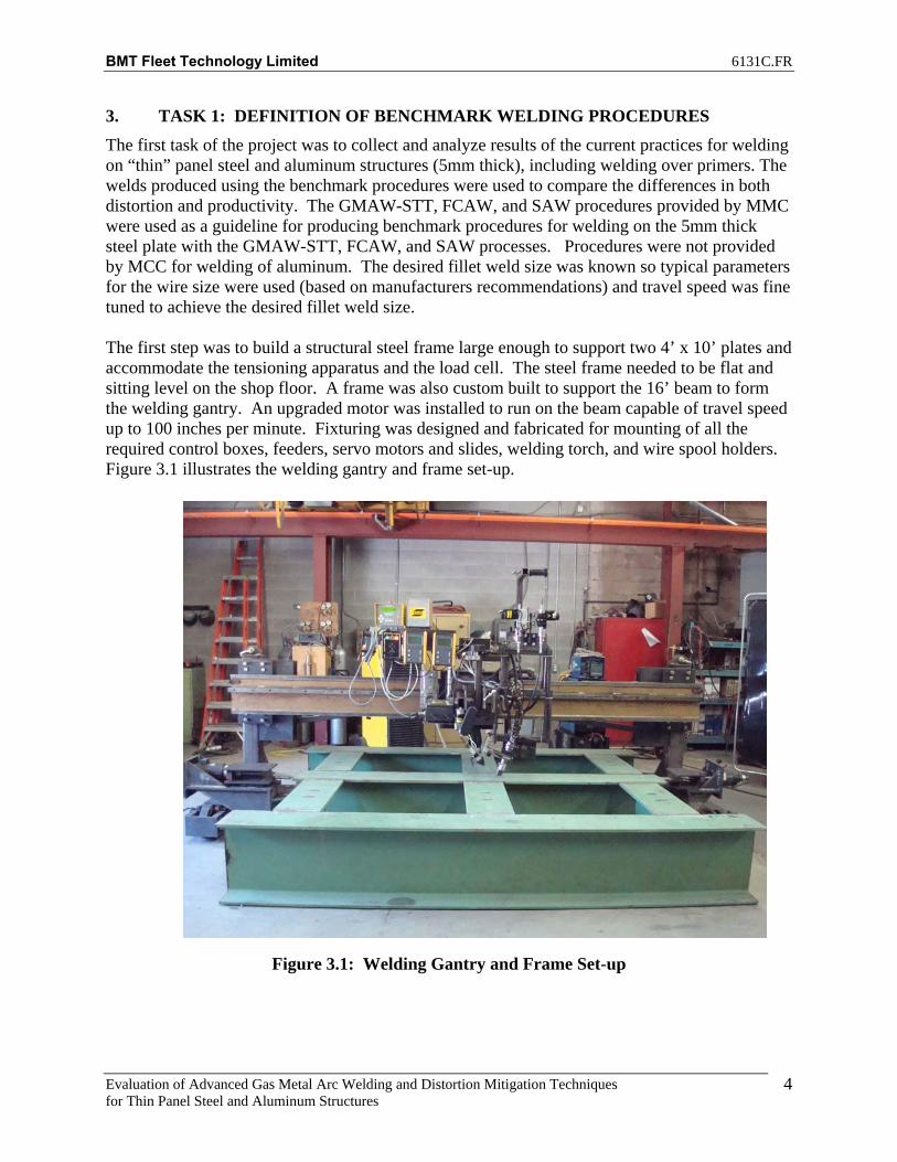
3. TASK 1: DEFINITION OF BENCHMARK WELDING PROCEDURES The first task of the project was to collect and analyze results of the current practices for welding on “thin” panel steel and aluminum structures (5mm thick), including welding over primers. The welds produced using the benchmark procedures were used to compare the differences in both distortion and productivity. The GMAW-STT, FCAW, and SAW procedures provided by MMC were used as a guideline for producing benchmark procedures for welding on the 5mm thick steel plate with the GMAW-STT, FCAW, and SAW processes. Procedures were not provided by MCC for welding of aluminum. The desired fillet weld size was known so typical parameters for the wire size were used (based on manufacturers recommendations) and travel speed was fine tuned to achieve the desired fillet weld size. The first step was to build a structural steel frame large enough to support two 4’ x 10’ plates and accommodate the tensioning apparatus and the load cell. The steel frame needed to be flat and sitting level on the shop floor. A frame was also custom built to support the 16’ beam to form the welding gantry. An upgraded motor was installed to run on the beam capable of travel speed up to 100 inches per minute. Fixturing was designed and fabricated for mounting of all the required control boxes, feeders, servo motors and slides, welding torch, and wire spool holders. Figure 3.1 illustrates the welding gantry and frame set-up.
Figure 3.1: Welding Gantry and Frame Set-up

BMT Fleet Technology Limited 6131C.FR
Evaluation of Advanced Gas Metal Arc Welding and Distortion Mitigation Techniques for Thin Panel Steel and Aluminum Structures
5
Distortion readings are taken using a self leveling laser to project a beam across the plate, level with the working surface. Reading are taken for every point on the plate (plate distortion measurement grid) and recorded on a spreadsheet for use in creating tables, charts, and ANSYS models of the plate and the displacements. Measurements are also taken of the frame for reference to corresponding location on the plate for accurate displacement results. Distortion readings were taken of all benchmark plates before and after welding for later comparison with tension cases. Figure 3.2 shows the self-leveling laser level and Figure 3.3 shows the beam projected on the steel rule.
Figure 3.2: Self Leveling Laser Level

BMT Fleet Technology Limited 6131C.FR
Evaluation of Advanced Gas Metal Arc Welding and Distortion Mitigation Techniques for Thin Panel Steel and Aluminum Structures
6
Figure 3.3: Beam Projected on Steel Rule
Plates for the benchmark procedures were first fitted and tacked to form a butt joint with no preparation and no gap. Chalklines were made at predetermined spacing along the width and length of the plate. Figure 3.4 shows the plate distortion measurement grid used for the benchmark plate as well as the tension cases. The benchmark plates were free to rest on the test frame during welding.
Figure 3.4: Plate Layout

BMT Fleet Technology Limited 6131C.FR
Evaluation of Advanced Gas Metal Arc Welding and Distortion Mitigation Techniques for Thin Panel Steel and Aluminum Structures
7
Stiffener Assemblies for the benchmark procedures were fitted and tacked so that the stiffener was at 90 degrees with the base plate. Tack welds were performed at predetermined points for all assemblies so there was no variance in displacement readings due to the tack welding operations. Stiffeners were fit tight to the base plate so there were no gaps. Points were marked on the base plate and stiffener following the distortion matrix grid for taking distortion readings. Figure 4.22 (FCAW 10” Base Plate), Figure 6.4 (Aluminum) and Figure 7.19 (FCAW 4’ Base Plate) show the plate distortion measurement grid used for the benchmark plate as well as the tension cases. The benchmark plates were free to rest on the test frame during welding. Figures 3.5 to 3.7 show the various assembly layouts.
Figure 3.5: Stiffener Assembly Layout (Steel)

BMT Fleet Technology Limited 6131C.FR
Evaluation of Advanced Gas Metal Arc Welding and Distortion Mitigation Techniques for Thin Panel Steel and Aluminum Structures
8
Figure 3.6: Stiffener Assembly Layout (Aluminum)
Figure 3.7: Stiffener Assembly Layout (Steel 10’ Base Plate)
Welding parameters used for the benchmark procedures have been summarized in the form of welding procedure data sheets as shown in Figures 3.8 through 3.11. Distortion results are discussed later in the report as the benchmark distortion data is used to compare with the distortion results of the tension cases.

BMT Fleet Technology Limited 6131C.FR
Evaluation of Advanced Gas Metal Arc Welding and Distortion Mitigation Techniques for Thin Panel Steel and Aluminum Structures
9
Figure 3.8: Welding Procedure Data Sheet for Benchmark SAW

BMT Fleet Technology Limited 6131C.FR
Evaluation of Advanced Gas Metal Arc Welding and Distortion Mitigation Techniques for Thin Panel Steel and Aluminum Structures
10
Figure 3.9: Welding Procedure Data Sheet for Benchmark FCAW

BMT Fleet Technology Limited 6131C.FR
Evaluation of Advanced Gas Metal Arc Welding and Distortion Mitigation Techniques for Thin Panel Steel and Aluminum Structures
11
Figure 3.10: Welding Procedure Data Sheet for Benchmark STT

BMT Fleet Technology Limited 6131C.FR
Evaluation of Advanced Gas Metal Arc Welding and Distortion Mitigation Techniques for Thin Panel Steel and Aluminum Structures
12
Figure 3.11: Welding Procedure Data Sheet for Benchmark GMAW of Aluminum

BMT Fleet Technology Limited 6131C.FR
Evaluation of Advanced Gas Metal Arc Welding and Distortion Mitigation Techniques for Thin Panel Steel and Aluminum Structures
13
4. TASK 2: DEVELOP OPTIMUM TENSION PROFILES 2
4.1 Design of Tension System The first step in this task was to determine the hole locations required for tensioning the plates. The concern was tear out and plastic deformation of the plate material so modeling was done with different dimensions for (a) and (b) shown on Figure 4.1. The air cylinder has a maximum capacity of 30 tonne; however, it was expected that actual loads would be closer to 10 tonnes. Figure 4.2 shows modeling results for the lateral displacement for different values of (a) and (b) using a 10 tonne tension load. The lateral displacement using a 3” value for a and a 3” value for b was approximately 0.2mm, very low, so it was decided to use a value of 2.5” for both a and b dimensions. Once this was established the clevices were fabricated along with the 1” diameter pins.
Figure 4.1: Hole Locations in Plate for Mechanical Tensioning
P/2
a
b
Y
X
10'
4'
Measurements Start Here, Taken On Top Edge of Plate at X=0

BMT Fleet Technology Limited 6131C.FR
Evaluation of Advanced Gas Metal Arc Welding and Distortion Mitigation Techniques for Thin Panel Steel and Aluminum Structures
14
Figure 4.2: Distance from Plate Edge vs. Lateral Displacement for Hole Locations Figures 4.3 through 4.5 show the operation of the clevice system in how they attach to the plates through hardened 1” diameter pins and locate the plates in proper orientation for welding while providing desired tension load. A load cell is connected to the clevice at the bottom of Figure 4.5 and is connected to a laptop computer to provide tension load information. The tension load is monitored during welding and the load adjusted as required to maintain a constant load throughout the welding of the plate.

BMT Fleet Technology Limited 6131C.FR
Evaluation of Advanced Gas Metal Arc Welding and Distortion Mitigation Techniques for Thin Panel Steel and Aluminum Structures
15
Figure 4.3: Side View of Clevice with Plate under Tension
Figure 4.4: Top View of Clevice with Plate under Tension

BMT Fleet Technology Limited 6131C.FR
Evaluation of Advanced Gas Metal Arc Welding and Distortion Mitigation Techniques for Thin Panel Steel and Aluminum Structures
16
Figure 4.5: View of Entire Plate Assembly under Tension
BMT Fleet Technology Limited 6131C.FR
Evaluation of Advanced Gas Metal Arc Welding and Distortion Mitigation Techniques for Thin Panel Steel and Aluminum Structures
17
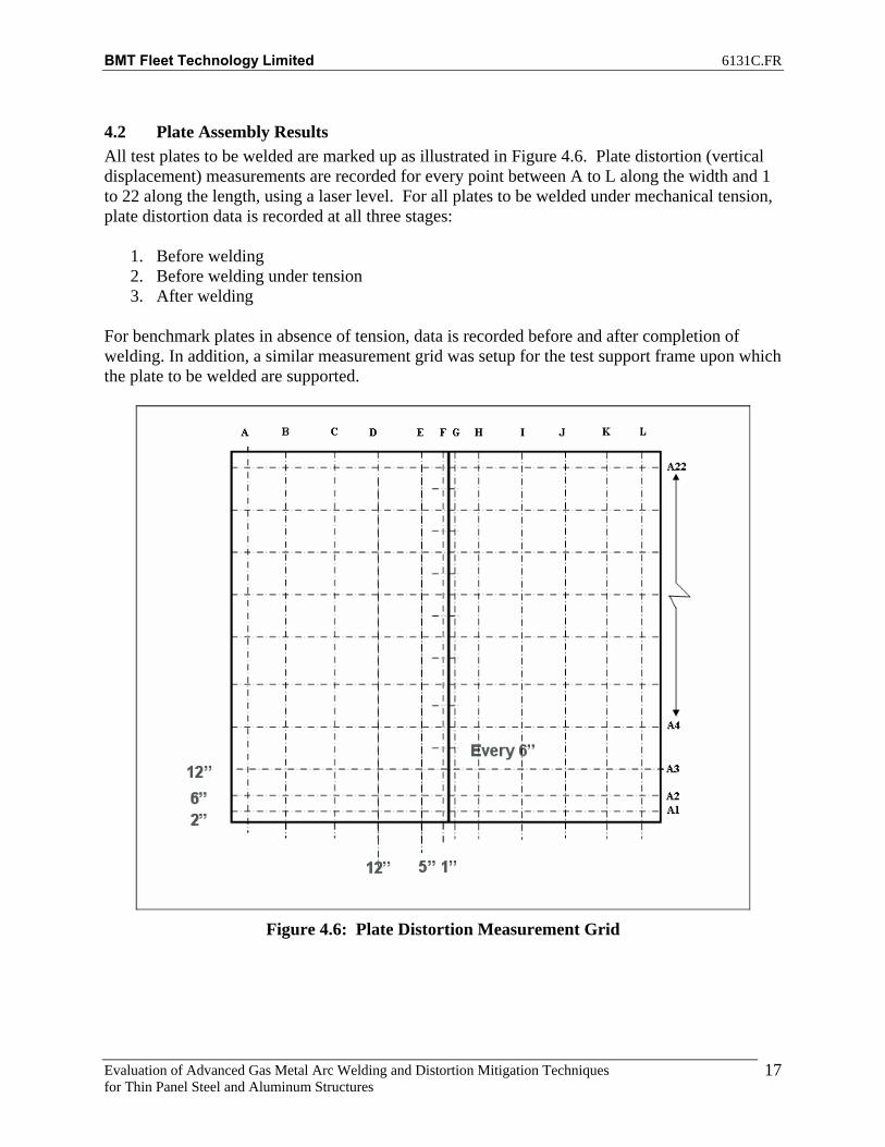
4.2 Plate Assembly Results All test plates to be welded are marked up as illustrated in Figure 4.6. Plate distortion (vertical displacement) measurements are recorded for every point between A to L along the width and 1 to 22 along the length, using a laser level. For all plates to be welded under mechanical tension, plate distortion data is recorded at all three stages:
1. Before welding 2. Before welding under tension 3. After welding
For benchmark plates in absence of tension, data is recorded before and after completion of welding. In addition, a similar measurement grid was setup for the test support frame upon which the plate to be welded are supported.
Figure 4.6: Plate Distortion Measurement Grid

BMT Fleet Technology Limited 6131C.FR
Evaluation of Advanced Gas Metal Arc Welding and Distortion Mitigation Techniques for Thin Panel Steel and Aluminum Structures
18
Table 4.1 summarizes the test cases that were analyzed as part of the on-going research. Applied tension loads under 10, 000 lbs achieved a straightening effect on plates that were distorted. Tension loading was increased at increments of 5,000 lbs to determine the optimal tension load profile.
Table 4.1: Test Summary
Specimen No.
Side Applied Tension(lbs)
Test Type
1 1, 2 - 6 1, 2 - Benchmark
2 1 10,000 3 1, 2 15,000 5 1, 2 15,000 4 1,2 30,000
MechanicalTensioning
Figure 4.7, 4.8 and 4.9 illustrate the benefits of mechanical tensioning on straightening and alignment of plates to be welded. In Figures 4.7 and 4.8, a high low situation up to approximately 1” exists between the plates to be welded. With the use of less than 10,000lbs of tension, the plate are brought within tolerance and ready for welding as shown in Figure 4.9. Figure 4.10 shows the vertical displacement of the plates with no tension and Figure 4.11 shows the vertical displacement of the plates under 10,000lbs of tension.
Figure 4.7: Fit-Up of Plates before Pre-Tensioning

BMT Fleet Technology Limited 6131C.FR
Evaluation of Advanced Gas Metal Arc Welding and Distortion Mitigation Techniques for Thin Panel Steel and Aluminum Structures
19
Figure 4.8: High Low in Plates before Pre-Tensioning
Figure 4.9: Fit-Up of Plates after Pre-Tensioning

BMT Fleet Technology Limited 6131C.FR
Evaluation of Advanced Gas Metal Arc Welding and Distortion Mitigation Techniques for Thin Panel Steel and Aluminum Structures
20
Figure 4.10: Plate Distortion Measurement Grid
Figure 4.11: Plate Distortion Measurement Grid

BMT Fleet Technology Limited 6131C.FR
Evaluation of Advanced Gas Metal Arc Welding and Distortion Mitigation Techniques for Thin Panel Steel and Aluminum Structures
21
In order to measure the effectiveness of mechanical tensioning approach, the net displacement of each marked point on the plate with respect to the corresponding point on the test frame is compared at each of the above stages. Figures 4.12 and 4.13 compare the net displacement along transverse and longitudinal sections for benchmark Plate 1-Side 1. Figure 4.14 is a 3-dimensional ANSYS model that shows the net displacement after welding for Plate 1-Side 1. Additional plots are provided in Appendix A.
-70
-50
-30
-10
10
30
50
70
-1500 -1000 -500 0 500 1000 1500
Distance from centre, mm
Ver
tical
Dis
plac
emen
t,mm
Before WeldAfter Weld
Figure 4.12: Net Displacement along Transverse Section A11 for Plate 1-Side1

BMT Fleet Technology Limited 6131C.FR
Evaluation of Advanced Gas Metal Arc Welding and Distortion Mitigation Techniques for Thin Panel Steel and Aluminum Structures
22
-70
-50
-30
-10
10
30
50
70
0 500 1000 1500 2000 2500 3000 3500
Distance from edge, mm
Ver
tical
Dis
plac
emen
t,mm
Before WeldAfter Weld
Figure 4.13: Net Displacement along Longitudinal Section F for Plate 1-Side1
Figure 4.14: Net Plate Deformation after Welding Plate 1-Side1

BMT Fleet Technology Limited 6131C.FR
Evaluation of Advanced Gas Metal Arc Welding and Distortion Mitigation Techniques for Thin Panel Steel and Aluminum Structures
23
Figures 4.15 and 4.16 compare the net displacement along transverse and longitudinal sections for Plate 4-Side 1. Figures 4.17 and 4.18 are 3-dimensional ANSYS models that show the net displacement before and after welding for Plate 4-Side 1. Additional plots are provided in Appendix A.
-70
-50
-30
-10
10
30
50
70
-1500 -1000 -500 0 500 1000 1500
Distance from centre, mm
Ver
tical
Dis
plac
emen
t,mm
No Weld No TensionNo Weld With TensionWeld With Tension
Figure 4.15: Net Displacement along Transverse Section A11 for Plate 4-Side1

BMT Fleet Technology Limited 6131C.FR
Evaluation of Advanced Gas Metal Arc Welding and Distortion Mitigation Techniques for Thin Panel Steel and Aluminum Structures
24
-70
-50
-30
-10
10
30
50
70
0 500 1000 1500 2000 2500 3000 3500
Distance from edge, mm
Ver
tical
Dis
plac
emen
t,mm
No Weld No TensionNo Weld With TensionWeld With Tension
Figure 4.16: Net Displacement along Longitudinal Section F for Plate 4-Side1
Figure 4.17: Net Plate Deformation (No Weld No Tension -Weld under Tension)

BMT Fleet Technology Limited 6131C.FR
Evaluation of Advanced Gas Metal Arc Welding and Distortion Mitigation Techniques for Thin Panel Steel and Aluminum Structures
25
Figure 4.18: Net Plate Deformation after Welding (Tension Case)
(No Weld with Tension-Weld under Tension)
4.3 Volume due to Plate Deformation The original measured displacement values were offset by value of 10 to account for negative values. Figures 4.19 and 4.20 compare the displacement data before and after offset correction. These offset corrected values are used to calculate the area under the curve.

BMT Fleet Technology Limited 6131C.FR
Evaluation of Advanced Gas Metal Arc Welding and Distortion Mitigation Techniques for Thin Panel Steel and Aluminum Structures
26
-70
-50
-30
-10
10
30
50
70
-1500 -1000 -500 0 500 1000 1500
Distance from centre, mm
Ver
tical
Dis
plac
emen
t,mm
Before Weld
Figure 4.19: Net Displacement along Transverse Section A1 for Plate 6-Side1
Figure 4.20: Offset Net Displacement along Transverse Section A1 for Plate 6-Side1

BMT Fleet Technology Limited 6131C.FR
Evaluation of Advanced Gas Metal Arc Welding and Distortion Mitigation Techniques for Thin Panel Steel and Aluminum Structures
27
The approach used to calculate plate volume due to plate geometry is as follows:
1. Calculate area under each of the segment of the curve (before and after welding) Ex: Area segment AB = Area AXZY + Area AXB
2. Total area under the curve AL is summation of areas under segment AB, BC, CD, DE, EF,FG, GH, HI, IJ, JK and KL respectively.
3. Total volume between transverse sections Total area AL times the spacing between transverse sections A1 and A2 gives.
4. Volumes for sections A2 to A22 are calculated using similar approach. 5. Total volume generated due to plate geometry is summation of all transverse sectional
volumes. 6. Plate volumes are calculated before and after welding operation. 7. The net change in plate volume is difference in plate volume before and after welding
The results of above approach are illustrated in Figure 4.21.
0.00E+00
5.00E+07
1.00E+08
1.50E+08
2.00E+08
2.50E+08
3.00E+08
P1S1-0 P1S2-0 P6S1-0 P6S2a-0 P6S2b-0 P2S1-10,000
P3S1-15,000
P3S2-15,000
P5S1-15,000
P5S2-15,000
P4S1-30,000
P4S2-30,000
Specimen-Applied Tension (lbs)
Plat
e V
olum
e, m
m3
Before Weld After Weld Net Volume
Baseline Weld Specimen Tensioned Weld Specimen
Figure 4.21: Net Plate Volume
It can be seen that the mechanical tensioning approach as applied to groove welding of high strength steel during panel line operation doesn’t seem to provide significant advantage to counter deformation, at least within the methods it’s applied in this study. The results are not consistent for the benchmark assemblies or for the tension assemblies. Benchmark plate 1 resulted in a similar ‘net volume change’ (volume after welding subtracted by volume before welding) of distortion for side one and side two. Plate 6 was a repeated benchmark attempt to determine consistency of results and it resulted in a similar first side result with significantly more ‘net volume change’ of distortion on the second side. Two separate reading were taken

BMT Fleet Technology Limited 6131C.FR
Evaluation of Advanced Gas Metal Arc Welding and Distortion Mitigation Techniques for Thin Panel Steel and Aluminum Structures
28
from side two as shown in Figure 4.21 to determine whether the ‘net volume change’ distortion results would differ depending on how the plate was buckled; the end results were similar. Plates three and five were performed at 15, 000lbs of tension which was determined to be the best tension profile for this application. Plate three and five show a similar trend in reduction of net displacement after welding compared to net displacement before welding; However, the ‘net volume change’ of displacement on average is greater than with the benchmark procedures. The best comparison for distortion is probably to compare between the net displacement before welding for side one and the net displacement after welding side two. Using this method the plates would rank in this order from least distortion to greatest distortion:
1. Plate 3 (Tension Case) 2. Plate 1 (Non Tension) 3. Plate 4 (Tension Case) 4. Plate 5 (Tension Case) 5. Plate 6 (Non Tension))
Further work with a modified tension set-up where the entire width of the plates is tensioned and length of the plates restrained is proposed for future work. The mechanical tension was effective at straightening the seam to be welding, helping with the fit-up operations.
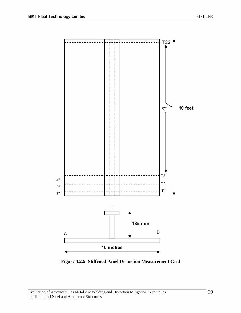
4.4 FCAW Stiffened Panel Assembly (10” Wide Base Plate) Results Welding of stiffener assemblies was performed using the STT process and FCAW process and the 10” wide base plates for comparison of tension profiles to the benchmark assembly. CSA 300W base plate was used for this comparison to conserve the 4’ wide primed HSLA 80 base plate for the final testing. All the stiffened panels (5mm thick) to be welded were marked up as illustrated in Figure 4.22. Panel distortion (vertical displacement) measurements are recorded for points A, B and T along the width and T1 to T23 along the length, using a laser level. For all plates to be welded under mechanical tension, the distortion data is recorded at all three stages:
1. Before welding 2. Before welding under tension 3. After welding
For benchmark stiffener assembly in absence of tension, data is recorded before and after completion of welding. In addition, a similar measurement grid was setup for the test support frame upon which the stiffener assembly to be welded are supported.
BMT Fleet Technology Limited 6131C.FR
Evaluation of Advanced Gas Metal Arc Welding and Distortion Mitigation Techniques for Thin Panel Steel and Aluminum Structures
29
A B
T
10 inches
10 feet
T23
T11"
T23"
4"T3
135 mm
Figure 4.22: Stiffened Panel Distortion Measurement Grid

BMT Fleet Technology Limited 6131C.FR
Evaluation of Advanced Gas Metal Arc Welding and Distortion Mitigation Techniques for Thin Panel Steel and Aluminum Structures
30
STT and FCAW techniques were used to set up two benchmark stiffener assemblies. Table 4.2 summarizes the test cases that were analyzed. Tables 4.3 through 4.5 summarize the measured distortion data for stiffener assemblies at locations A and B. The data is color-coded red and yellow to help better visualize the assembly distortion (torsion). The color red indicates a higher distortion compared to color yellow, whereas light green indicates no change in displacement. Additional test data is provided in Appendix B.
Table 4.2: Test Summary
Stiffener Assembly Applied Tension (lbs) STT_Stiff_1_Benchmark 0 FCAW_Stiff_1_Benchmark 0 FCAW_Stiff_2 10,000 FCAW_Stiff_3-worst case 10,000 FCAW_Stiff_4 10,000
Table 4.3: STT_Stiff_1_Benchmark Distortion Data
A T B Abs Diff A T B Abs Diff1 9 67 6.5 2.5 1 6.5 65.5 5 1.52 8.5 66.5 6 2.5 2 6.5 65 5 1.53 6.5 65 4.5 2 3 5.5 64 3.5 24 6 63.5 4 2 4 5.5 63 4 1.55 5 62 3 2 5 5 61.25 3.5 1.56 3.5 60.5 1.5 2 6 3.5 59.5 2.5 17 2.5 59.25 0.5 2 7 3 58.5 2 18 2 58 0.5 1.5 8 2.5 57.5 1.5 19 1.5 56.75 0.5 1 9 2 56.5 2 0
10 0 55.5 0 0 10 1.5 55.5 1.5 011 1 55.25 0 1 11 2 55.5 1.5 0.512 1 55 0.5 0.5 12 2.5 55.5 2 0.513 1.5 54.5 0.5 1 13 2.5 55 2 0.514 1 54 0.5 0.5 14 2 54.5 2 015 1.5 54.25 0.5 1 15 2.5 54.75 2.5 016 2.5 54.5 1.5 1 16 3.5 55 3 0.517 3 55 1.5 1.5 17 4 55.25 3 118 3.5 55.5 2.5 1 18 4.5 55.5 4 0.519 5.5 56.5 3.5 2 19 5.5 56.25 5 0.520 6.5 57.5 5 1.5 20 6.5 57 6 0.521 8 58.5 6 2 21 6.5 57.5 6 0.522 9 59 7 2 22 6.5 58 6.5 023 10 59.5 8 2 23 7.5 58.5 7.5 0
Displacement w.r.t to Frame, mmAfter WeldBefore Weld
Displacement w.r.t to Frame, mm

BMT Fleet Technology Limited 6131C.FR
Evaluation of Advanced Gas Metal Arc Welding and Distortion Mitigation Techniques for Thin Panel Steel and Aluminum Structures
31
Table 4.4: FCAW_Stiff_1_Benchmark Distortion Data
A T B Abs Diff A T B Abs Diff1 7 55 9.5 2.5 1 3.5 53 9 5.52 6.5 55 9 2.5 2 3 53 8.5 5.53 5 54 7.5 2.5 3 2.5 52.25 7 4.54 4.5 53 6.5 2 4 2 51.5 6.5 4.55 3.5 51.75 5.5 2 5 2 50.5 5.5 3.56 2.5 50.5 3.5 1 6 2 49.5 4 27 2 50 3 1 7 2 49.25 3.5 1.58 1.5 49.5 2 0.5 8 2 49 3 19 1.5 49 1.5 0 9 2 48.75 2.5 0.5
10 0.5 48.5 0.5 0 10 2 48.5 2 011 1 49 1 0 11 2.5 49 2 0.512 1.5 49.5 1.5 0 12 3 49.5 2.5 0.513 1.5 49.5 1.5 0 13 3 49.5 2.5 0.514 1 49.5 1.5 0.5 14 2.5 49.5 2 0.515 2 50.5 2 0 15 3 50.25 2.5 0.516 2.5 51.5 3 0.5 16 3 51 3 017 3 52.5 3.5 0.5 17 3 51.5 3.5 0.518 3.5 53.5 5 1.5 18 3.5 52 4.5 119 5 55 6 1 19 4.5 53 5 0.520 6.5 56.5 7.5 1 20 4.5 54 6 1.521 7.5 58 8.5 1 21 3.5 54.5 5 1.522 8 58.75 9 1 22 4.5 55 5 0.523 8.5 59.5 9.5 1 23 5 55.5 5.5 0.5
After WeldDisplacement w.r.t to Frame, mm
Before WeldDisplacement w.r.t to Frame, mm
Table 4.5: FCAW_Stiff_2 Distortion Data
A T B Abs Diff A T B Abs Diff A T B Abs Diff1 10 57.5 10 0 1 5 54.5 4 1 1 3 52.5 2.5 0.52 9 57 8 1 2 5 54.5 4 1 2 3 52.5 2.5 0.53 7 56.25 6.5 0.5 3 4 53.5 3 1 3 2 51.5 1.5 0.54 6.5 55.5 5.5 1 4 4.5 52.5 3 1.5 4 3 50.5 2.5 0.55 5 54 4.5 0.5 5 3.5 51.25 2 1.5 5 2.5 49.75 2 0.56 4 52.5 3 1 6 2 50 0.5 1.5 6 1.5 49 1 0.57 3 51.5 2 1 7 1 49.5 0 1 7 1.5 48.75 1 0.58 2 50.5 1.5 0.5 8 0.5 49 0 0.5 8 1.5 48.5 1 0.59 1.5 50 1 0.5 9 0 48.5 0 0 9 1.5 48.5 1 0.5
10 1 49.5 0.5 0.5 10 0 48 0 0 10 1.5 48.5 1 0.511 1.5 50 0.5 1 11 0.5 48.75 0 0.5 11 1.5 49 1 0.512 1.5 50.5 0.5 1 12 0.5 49.5 0 0.5 12 2 49.5 1.5 0.513 2 50.5 1 1 13 1 49.25 0 1 13 2 49.75 1.5 0.514 1.5 50.5 1 0.5 14 0.5 49 0 0.5 14 2 50 1 115 2 51.25 1 1 15 1 50.25 0 1 15 2.5 50.5 2 0.516 2 52 1.5 0.5 16 1 51.5 0 1 16 2.5 51 2 0.517 2.5 52.75 1.5 1 17 1 51.75 0.5 0.5 17 2.5 51.5 2 0.518 4 53.5 2.5 1.5 18 2.5 52 1.5 1 18 3.5 52 2.5 119 5.5 54.75 3 2.5 19 3.5 53.75 2.5 1 19 5 53 3.5 1.520 7 56 4.5 2.5 20 4.5 55.5 3.5 1 20 5 54 3.5 1.521 8 58 4.5 3.5 21 2.5 56 2 0.5 21 3 56 1.5 1.522 8.5 58.5 6 2.5 22 2.5 57 2 0.5 22 3 56.25 1.5 1.523 9.5 59 7 2.5 23 2.5 58 2 0.5 23 3 56.5 1.5 1.5
Before WeldDisplacement w.r.t to Frame, mm
After WeldDisplacement w.r.t to Frame, mmDisplacement w.r.t to Frame, mm
Tension No Weld
BMT Fleet Technology Limited 6131C.FR
Evaluation of Advanced Gas Metal Arc Welding and Distortion Mitigation Techniques for Thin Panel Steel and Aluminum Structures
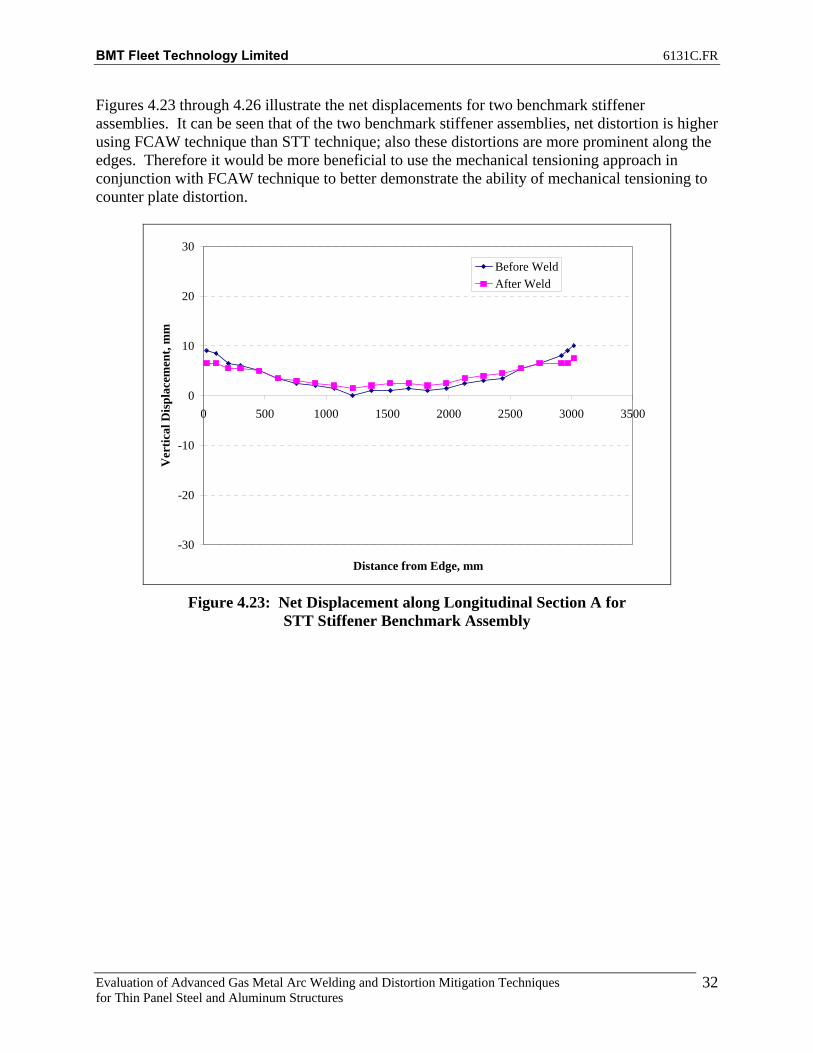
32
Figures 4.23 through 4.26 illustrate the net displacements for two benchmark stiffener assemblies. It can be seen that of the two benchmark stiffener assemblies, net distortion is higher using FCAW technique than STT technique; also these distortions are more prominent along the edges. Therefore it would be more beneficial to use the mechanical tensioning approach in conjunction with FCAW technique to better demonstrate the ability of mechanical tensioning to counter plate distortion.
-30
-20
-10
0
10
20
30
0 500 1000 1500 2000 2500 3000 3500
Distance from Edge, mm
Ver
tical
Dis
plac
emen
t, m
m
Before WeldAfter Weld
Figure 4.23: Net Displacement along Longitudinal Section A for
STT Stiffener Benchmark Assembly

BMT Fleet Technology Limited 6131C.FR
Evaluation of Advanced Gas Metal Arc Welding and Distortion Mitigation Techniques for Thin Panel Steel and Aluminum Structures
33
-30
-20
-10
0
10
20
30
0 500 1000 1500 2000 2500 3000 3500
Distance from Edge, mm
Ver
tical
Dis
plac
emen
t, m
mBefore WeldAfter Weld
Figure 4.24: Net Displacement along Longitudinal Section B for
STT Stiffener Benchmark Assembly
-30
-20
-10
0
10
20
30
0 500 1000 1500 2000 2500 3000 3500
Distance from Edge, mm
Ver
tical
Dis
plac
emen
t, m
m
Before WeldAfter Weld
Figure 4.25: Net Displacement along Longitudinal Section A for
FCAW Stiffener Benchmark Assembly

BMT Fleet Technology Limited 6131C.FR
Evaluation of Advanced Gas Metal Arc Welding and Distortion Mitigation Techniques for Thin Panel Steel and Aluminum Structures
34
-30
-20
-10
0
10
20
30
0 500 1000 1500 2000 2500 3000 3500
Distance from Edge, mm
Ver
tical
Dis
plac
emen
t, m
mBefore WeldAfter Weld
Figure 4.26: Net Displacement along Longitudinal Section B for FCAW Stiffener Benchmark Assembly
In order to measure the effectiveness of mechanical tensioning approach, the net displacement of each marked point on the assembly (Figure 4.22) with respect to the corresponding point on the test frame is compared at each of the above stages. Figures 4.27 and 4.28 compare the net displacement along the longitudinal sections for FCAW Stiffener Assembly subjected to a tension load of 10,000 lbs. additional plots are provided in Appendix B.
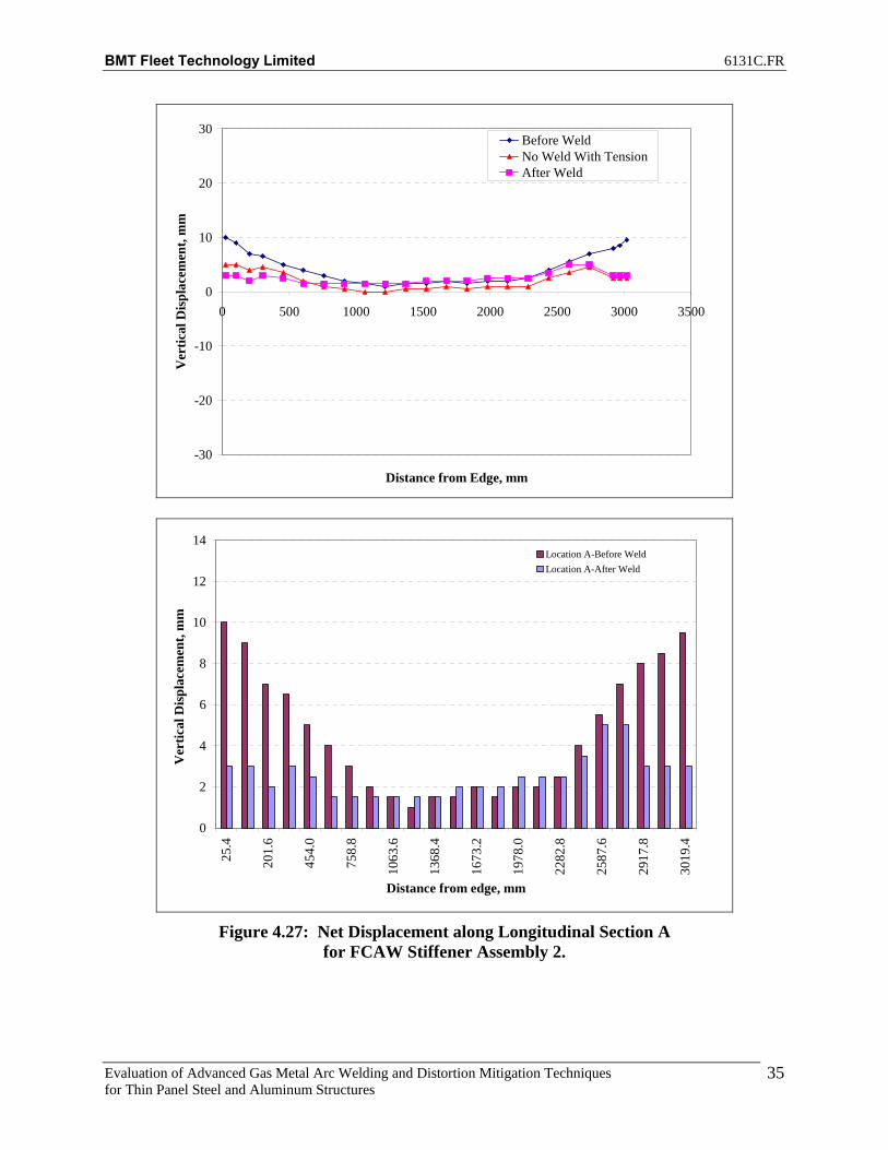
BMT Fleet Technology Limited 6131C.FR
Evaluation of Advanced Gas Metal Arc Welding and Distortion Mitigation Techniques for Thin Panel Steel and Aluminum Structures
35
-30
-20
-10
0
10
20
30
0 500 1000 1500 2000 2500 3000 3500
Distance from Edge, mm
Ver
tical
Dis
plac
emen
t, m
m
Before WeldNo Weld With TensionAfter Weld
0
2
4
6
8
10
12
14
25.4
201.
6
454.
0
758.
8
1063
.6
1368
.4
1673
.2
1978
.0
2282
.8
2587
.6
2917
.8
3019
.4
Distance from edge, mm
Ver
tical
Dis
plac
emen
t, m
m
Location A-Before WeldLocation A-After Weld
Figure 4.27: Net Displacement along Longitudinal Section A
for FCAW Stiffener Assembly 2.

BMT Fleet Technology Limited 6131C.FR
Evaluation of Advanced Gas Metal Arc Welding and Distortion Mitigation Techniques for Thin Panel Steel and Aluminum Structures
36
-30
-20
-10
0
10
20
30
0 500 1000 1500 2000 2500 3000 3500
Distance from Edge, mm
Ver
tical
Dis
plac
emen
t, m
m
Before WeldNo Weld With TensionAfter Weld
0
2
4
6
8
10
12
14
25.4
201.
6
454.
0
758.
8
1063
.6
1368
.4
1673
.2
1978
.0
2282
.8
2587
.6
2917
.8
3019
.4
Distance from edge, mm
Ver
tical
Dis
plac
emen
t, m
m
Location B-Before WeldLocation B-After Weld
Figure 4.28: Net Displacement along Longitudinal Section B
for FCAW Stiffener Assembly 2

BMT Fleet Technology Limited 6131C.FR
Evaluation of Advanced Gas Metal Arc Welding and Distortion Mitigation Techniques for Thin Panel Steel and Aluminum Structures
37
4.4.1 Net Improvement The distortion data in Table 4.6 and Figures 4.29 through 4.31 compare the overall net improvement achieved in controlling distortion under applied tension with respect to the benchmark assembly. The negative values, color coded blue indicates location where tensioning has been effective to counter distortion due to welding. Also cells color coded light green indicate no change in distortion and yellow indicates a marginal increases in distortion. Additional plots and tables are provided in Appendix B.
Table 4.6: FCAW_Stiff_2 Net Displacement
A T B Abs Diff A T B Abs Diff1 -7 -5 -7.5 0.5 1 -3.5 -2 -0.5 3 -3.5 -3 -72 -6 -4.5 -5.5 0.5 2 -3.5 -2 -0.5 3 -2.5 -2.5 -53 -5 -4.75 -5 0 3 -2.5 -1.75 -0.5 2 -2.5 -3 -4.54 -3.5 -5 -3 0.5 4 -2.5 -1.5 0 2.5 -1 -3.5 -35 -2.5 -4.25 -2.5 0 5 -1.5 -1.25 0 1.5 -1 -3 -2.56 -2.5 -3.5 -2 0.5 6 -0.5 -1 0.5 1 -2 -2.5 -2.57 -1.5 -2.75 -1 0.5 7 0 -0.75 0.5 0.5 -1.5 -2 -1.58 -0.5 -2 -0.5 0 8 0.5 -0.5 1 0.5 -1 -1.5 -1.59 0 -1.5 0 0 9 0.5 -0.25 1 0.5 -0.5 -1.25 -1
10 0.5 -1 0.5 0 10 1.5 0 1.5 0 -1 -1 -111 0 -1 0.5 0.5 11 1.5 0 1 0.5 -1.5 -1 -0.512 0.5 -1 1 0.5 12 1.5 0 1 0.5 -1 -1 013 0 -0.75 0.5 0.5 13 1.5 0 1 0.5 -1.5 -0.75 -0.514 0.5 -0.5 0 0.5 14 1.5 0 0.5 1 -1 -0.5 -0.515 0.5 -0.75 1 0.5 15 1 -0.25 0.5 0.5 -0.5 -0.5 0.516 0.5 -1 0.5 0 16 0.5 -0.5 0 0.5 0 -0.5 0.517 0 -1.25 0.5 0.5 17 0 -1 0 0 0 -0.25 0.518 -0.5 -1.5 0 0.5 18 0 -1.5 -0.5 0.5 -0.5 0 0.519 -0.5 -1.75 0.5 1 19 -0.5 -2 -1 0.5 0 0.25 1.520 -2 -2 -1 1 20 -2 -2.5 -1.5 0.5 0 0.5 0.521 -5 -2 -3 2 21 -4 -3.5 -3.5 0.5 -1 1.5 0.522 -5.5 -2.25 -4.5 1 22 -3.5 -3.75 -4 0.5 -2 1.5 -0.523 -6.5 -2.5 -5.5 1 23 -3.5 -4 -4 0.5 -3 1.5 -1.5
Net Displacement, mmDisplacement w.r.t to Frame, mm
Net Displacement, mmBenchmark
Net Improvement, mmBenchmark
.

BMT Fleet Technology Limited 6131C.FR
Evaluation of Advanced Gas Metal Arc Welding and Distortion Mitigation Techniques for Thin Panel Steel and Aluminum Structures
38
-10
-8
-6
-4
-2
0
2
4
25.4
201.
6
454.
0
758.
8
1063
.6
1368
.4
1673
.2
1978
.0
2282
.8
2587
.6
2917
.8
3019
.4
Distance from edge, mm
Ver
tical
Dis
plac
emen
t, m
mNet Improvement
Figure 4.29: FCAW_Stiff_2 -Net Improvement at Location A.
-10
-8
-6
-4
-2
0
2
4
25.4
201.
6
454.
0
758.
8
1063
.6
1368
.4
1673
.2
1978
.0
2282
.8
2587
.6
2917
.8
3019
.4
Distance from edge, mm
Ver
tical
Dis
plac
emen
t, m
m
Net Improvement
Figure 4.30: FCAW_Stiff_2 -Net Improvement at Location B.

BMT Fleet Technology Limited 6131C.FR
Evaluation of Advanced Gas Metal Arc Welding and Distortion Mitigation Techniques for Thin Panel Steel and Aluminum Structures
39
-10
-8
-6
-4
-2
0
2
4
25.4
201.
6
454.
0
758.
8
1063
.6
1368
.4
1673
.2
1978
.0
2282
.8
2587
.6
2917
.8
3019
.4
Distance from edge, mm
Ver
tical
Dis
plac
emen
t, m
mNet Improvement
Figure 4.31: FCAW_Stiff_2 -Net Improvement at Location T
From the data presented it can be concluded that the mechanical tensioning approach as applied to fillet welding of high strength steel stiffener assemblies does provide significant advantage to counter deformation. Figures 4.29 through 4.31 demonstrate this with the majority of values showing as negative vertical displacement, negative is a positive effect on reducing distortion. Table 4.6 also shows the effect of mechanical tensioning on distortion with the blue indicating locations where tensioning has been effective to counter distortion due to welding. Comparing the net displacements for FCAW_Stiff_2 (10,000lbs tension) vs. FCAW Stiff_1 (Benchhmark), a reduction in distortion of 144% results from the use of mechanical tensioning. In summary, mechanical tensioning of plate assemblies did not result in a significant reduction in distortion, with results inconsistent to one another. The mechanical tensioning of stiffener assemblies resulted in a significant reduction in distortion on the stiffened panel assemblies, with clear and repeatable results. The results of mechanical tensioning of aluminum stiffener assemblies are discussed in Task 4.

BMT Fleet Technology Limited 6131C.FR
Evaluation of Advanced Gas Metal Arc Welding and Distortion Mitigation Techniques for Thin Panel Steel and Aluminum Structures
40
5. TASK 3: DEVELOP OPTIMIZED WELDING PROCEDURE AND GUIDELINES FOR CONTROLLED DIP TRANSFER WELDING OF STEEL STRUCTURES
5.1 Surface Tension Transfer This report provides the results on the independent evaluation of the surface tension transfer (STT) process conducted at BMT Fleet Technology for the application of distortion control on thin panel high strength fillet welds used in light weight combatants. The objective in this task was to determine the operating limitations of the process as well as provide guidance on its potential use in regular production. STT is a modified short circuit transfer (also known as controlled dip transfer) using inverter power source technology with waveform control to provide a better welding solution than traditional short circuiting GMAW. Unlike conventional GMAW power sources, the STT power source does not use a voltage control knob. Current controls are used to adjust the heat independent of the wire feed speed, so changes in electrode extension do not affect heat. Low heat input welds can therefore be produced without overheating or even burning through thin plate. Distortion is also limited due to the low heat input. Figure 5.1 shows what is happening to the consumable wire at the welding arc at different stages of the waveform. Marinette Marine Corp. (MMC) is currently using this process for some applications and provided data sheets for use as benchmark and reference data. A series of welds were performed using 0.035” diameter wire and 0.045” diameter wire with 100% C02 shielding gas and 75Ar / 25 C02 shielding gas. Welding procedure data sheets and user guidelines have been established for procedures that successfully achieved acceptable penetration profile, acceptable weld profile, acceptable arc stability, and operating characteristics. The power source used was a Lincoln Powerwave 455 with pre-loaded software. Wavedesigner 2000 software can be used to modify waveforms in an effort to optimize them for specific applications. There is limited support available for wavedesigner software through Lincoln Electric, and efforts to modify the waveform did not result in improved arc characteristics. For this reason, the preloaded software was used with no modification of the waveform other than adjustment to the synergic controls such as trim and arc control. It is possible that other Lincoln STT power sources such as the Lincoln Invertec STT II (used by MMC) will allow for further fine tuning of the waveform or even broader parameter range, however this is an assumption and such procedures shall be evaluated and qualified prior to use with alternative power sources. The welding procedure data sheets may need to be adjusted as well for synergic controls if used on other types of controlled dip transfer power supplies, such as with Miller Electric’s Regulated Metal Deposition (RMD) technology.

BMT Fleet Technology Limited 6131C.FR
Evaluation of Advanced Gas Metal Arc Welding and Distortion Mitigation Techniques for Thin Panel Steel and Aluminum Structures
41
Figure 5.1: Lincoln STT Process
Table 5.1 shows the various wire/gas and program combinations evaluated with the STT process. The ranking system takes into account operating characteristics of the arc and resulting bead profile. A five star ranking is the best and a one star ranking is the worst. The current MMC procedure uses 0.035” diameter wire with CO2 shielding gas to produce a 1/8” fillet weld size on 3/8” thick plate. This is an unlikely weld size to achieve with STT transfer and maintain adequate penetration and fusion. The STT transfer is recommended for fillet welds on material thickness up to 3/16.” All procedure development welding was performed on 5mm plate thickness (slightly greater than 3/16”). The wire feed speeds shown are optimal for the wire size and achieving acceptable arc characteristics and weld profile for producing a 1/8” fillet weld. Of all the combinations experimented with, Sample ID #9 with 0.045” diameter wire, C25 (75Ar / 25C02) shielding gas, and program 118 resulted in the greatest flexibility with wire feed speeds ranging from 125 to 175 inches per minute. Acceptable operating characteristics and weld profiles were achieved with both wire diameters; however, the penetration profile of the welds performed with the 0.045” diameter wire exhibited better penetration and fusion. Both five star ranking welds (C02 and C25 shielding gas) for the 0.045” diameter wires resulted in good penetration and fusion, with good bead profile. The only five star ranking weld with the 0.035” diameter wire resulted in a penetration profile that was not acceptable.
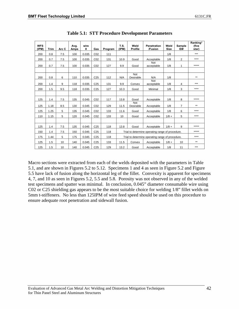
BMT Fleet Technology Limited 6131C.FR
Evaluation of Advanced Gas Metal Arc Welding and Distortion Mitigation Techniques for Thin Panel Steel and Aluminum Structures
42
Table 5.1: STT Procedure Development Parameters
Macro sections were extracted from each of the welds deposited with the parameters in Table 5.1, and are shown in Figures 5.2 to 5.12. Specimens 1 and 4 as seen in Figure 5.2 and Figure 5.5 have lack of fusion along the horizontal leg of the fillet. Convexity is apparent for specimens 4, 7, and 10 as seen in Figures 5.2, 5.5 and 5.8. Porosity was not observed in any of the welded test specimens and spatter was minimal. In conclusion, 0.045” diameter consumable wire using C02 or C25 shielding gas appears to be the most suitable choice for welding 1/8” fillet welds on 5mm t-stiffeners. No less than 125IPM of wire feed speed should be used on this procedure to ensure adequate root penetration and sidewall fusion.
WFS (IPM) Trim Arc C
Avg. Amps
wire θ Gas Program
T.S. (IPM)
Weld Profile
Penetration /Fusion
Weld Size
Sample ID#
Ranking* (five star)
200 0.8 7.5 100 0.035 C02 111 1/8 ***
200 0.7 7.5 100 0.035 C02 131 10.9 Good Acceptable 1/8 2 ****
200 0.7 7.5 100 0.035 C02 127 9.9 Good Not
acceptable 1/8 1 *****
200 0.8 6 110 0.035 C25 112 N/A Not
Desirable N/A 1/8 **
200 1.4 9 118 0.035 C25 131 9.9 Convex Not
acceptable 1/8 4 ***
200 1.5 9.5 118 0.035 C25 127 10.3 Good Minimal 1/8 3 ****
125 1.4 7.5 135 0.045 C02 117 13.8 Good Acceptable 1/8 8 *****
125 1.18 8.5 130 0.045 C02 129 11.5 Not
Desirable Acceptable 1/8 7 **
125 1.25 5 135 0.045 C02 133 11.6 Good Acceptable 1/8 6 ****
110 1.15 5 120 0.045 C02 133 10 Good Acceptable 1/8 + 5 ****
125 1.4 7.5 135 0.045 C25 118 13.8 Good Acceptable 1/8 + 9 *****
150 1.4 7.5 150 0.045 C25 118 Trial to determine operating range of procedure. *****
175 1.44 5 175 0.045 C25 118 Trial to determine operating range of procedure. ****
125 1.5 10 140 0.045 C25 133 11.5 Convex Acceptable 1/8 + 10 **
125 1.5 10 140 0.045 C25 129 13.2 Good Acceptable 1/8 11 ***
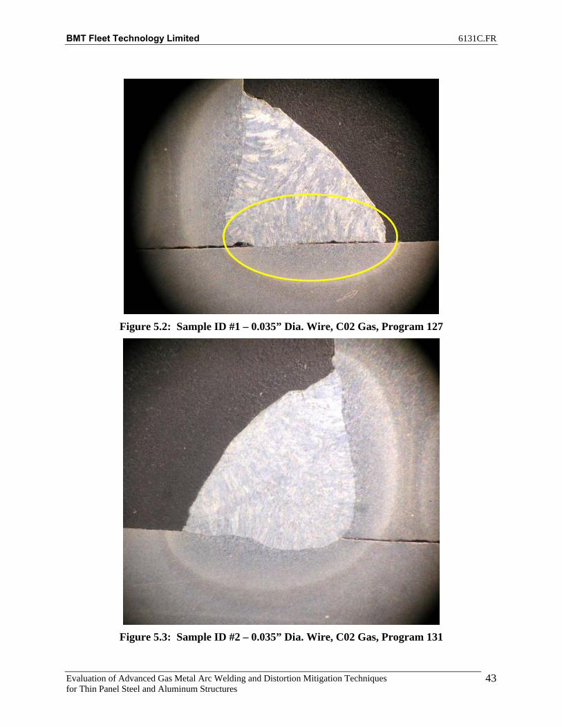
BMT Fleet Technology Limited 6131C.FR
Evaluation of Advanced Gas Metal Arc Welding and Distortion Mitigation Techniques for Thin Panel Steel and Aluminum Structures
43
Figure 5.2: Sample ID #1 – 0.035” Dia. Wire, C02 Gas, Program 127
Figure 5.3: Sample ID #2 – 0.035” Dia. Wire, C02 Gas, Program 131
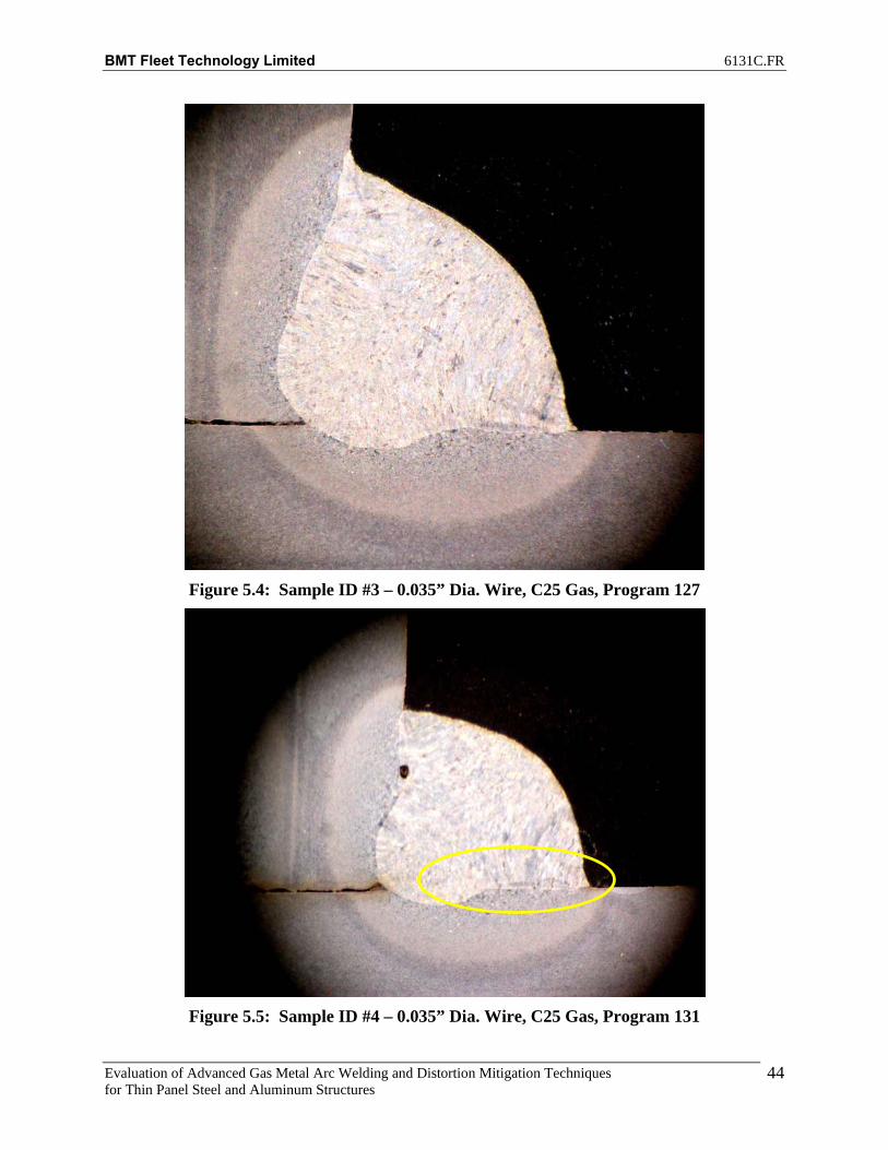
BMT Fleet Technology Limited 6131C.FR
Evaluation of Advanced Gas Metal Arc Welding and Distortion Mitigation Techniques for Thin Panel Steel and Aluminum Structures
44
Figure 5.4: Sample ID #3 – 0.035” Dia. Wire, C25 Gas, Program 127
Figure 5.5: Sample ID #4 – 0.035” Dia. Wire, C25 Gas, Program 131

BMT Fleet Technology Limited 6131C.FR
Evaluation of Advanced Gas Metal Arc Welding and Distortion Mitigation Techniques for Thin Panel Steel and Aluminum Structures
45
Figure 5.6: Sample ID #5 – 0.045” Dia. Wire, C02 Gas, Program 133
Figure 5.7: Sample ID #6 – 0.045” Dia. Wire, C02 Gas, Program 133
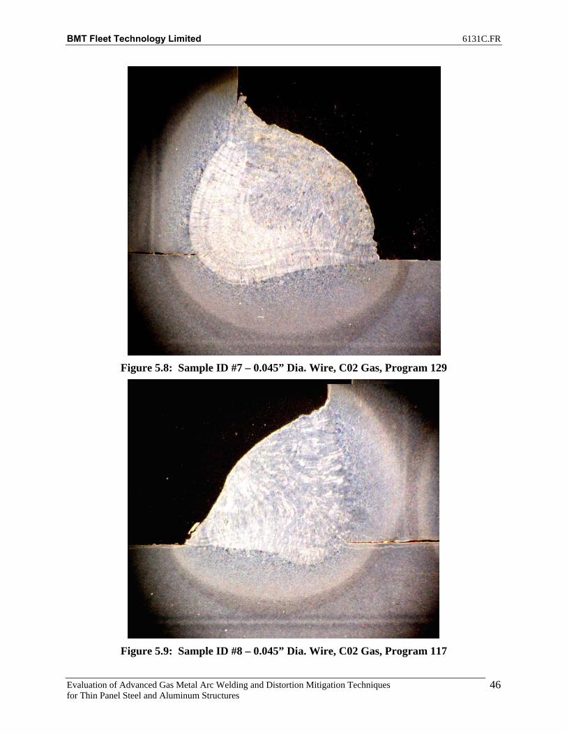
BMT Fleet Technology Limited 6131C.FR
Evaluation of Advanced Gas Metal Arc Welding and Distortion Mitigation Techniques for Thin Panel Steel and Aluminum Structures
46
Figure 5.8: Sample ID #7 – 0.045” Dia. Wire, C02 Gas, Program 129
Figure 5.9: Sample ID #8 – 0.045” Dia. Wire, C02 Gas, Program 117

BMT Fleet Technology Limited 6131C.FR
Evaluation of Advanced Gas Metal Arc Welding and Distortion Mitigation Techniques for Thin Panel Steel and Aluminum Structures
47
Figure 5.10: Sample ID #9 – 0.045” Dia. Wire, C25 Gas, Program 118
Figure 5.11: Sample ID #10 – 0.045” Dia. Wire, C25 Gas, Program 133

BMT Fleet Technology Limited 6131C.FR
Evaluation of Advanced Gas Metal Arc Welding and Distortion Mitigation Techniques for Thin Panel Steel and Aluminum Structures
48
Figure 5.12: Sample ID #11 – 0.045” Dia. Wire, C25 Gas, Program 129
Recommendations for STT welding are provided in Appendix C along with preferred welding procedure data sheets (WPDS’s) for welding with both .035” and .045” diameter ER100S-1 electrodes and C02 and C25 gases. Distortion measurements were taken of welded t-stiffeners using benchmark parameters, before and after welding in the as-welded condition (see Table 4.3, Figures 4.23 and 4.24). The distortion results of the STT welded t-stiffener was compared to distortion results of the FCAW welded t-stiffener (see Table 4.3, Figures 4.25 and 4.26). Mechanical tensioning was not performed using the STT process, because after reviewing the distortion results of the assembly in the as welded condition it was felt that little advantage would be gained by use of mechanical tensioning. Penetration profiles of the two benchmark processes, STT and FCAW, are seen in Figures 5.13 and 5.14, respectively. Notice the increased sidewall fusion of the weld performed with the FCAW process vs. the STT process. Typical heat input values for the STT process are less than 9 kj/in compared to 12 kj/in for the FCAW process when depositing a 1/8” fillet weld size.
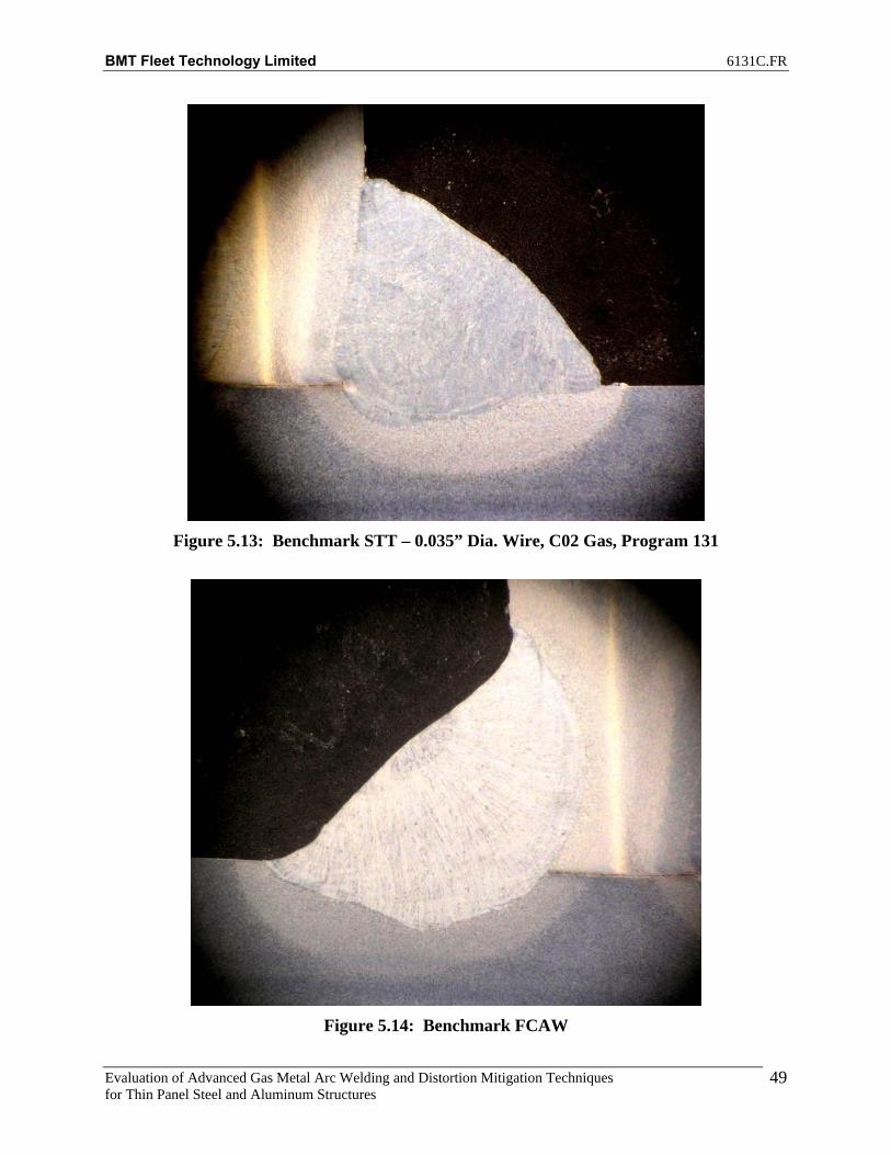
BMT Fleet Technology Limited 6131C.FR
Evaluation of Advanced Gas Metal Arc Welding and Distortion Mitigation Techniques for Thin Panel Steel and Aluminum Structures
49
Figure 5.13: Benchmark STT – 0.035” Dia. Wire, C02 Gas, Program 131
Figure 5.14: Benchmark FCAW

BMT Fleet Technology Limited 6131C.FR
Evaluation of Advanced Gas Metal Arc Welding and Distortion Mitigation Techniques for Thin Panel Steel and Aluminum Structures
50
6. TASK 4: DEVELOP OPTIMIZED WELDING PROCEDURES AND GUIDELINES FOR ADVANCED PULSE TRANSFERS FOR ALUMINUM WELDING
6.1 Aluminum Welding with Advanced Processes This report provides the results on the evaluation and comparison of the ESAB superpulse technology (pulse on pulse, pulse on spray, and pulse on short circuit) with conventional CV and pulse modes of metal transfer for the application of distortion control on aluminum thin panel fillet welds used in light weight combatants. The objective in this task was to develop optimized welding procedures and guidelines for superpulse welding of aluminum structures and compare the distortion results of superpulse with conventional CV and standard pulse processes. The secondary objective was to determine if baseline distortions can be further reduced with the use of mechanical tensioning. Pulse/pulse technology was created to provide a GMAW solution for aluminum welding that made the process less difficult than standard pulse and therefore required less operator skill. Unlike standard pulse welding, pulse/pulse uses a sequence of varying pulse wave shapes to crate a bead shape and appearance similar to the Gas Tungsten Arc Welding (GTAW) process. Pulse/pulse was primarily designed for welding on aluminum and stainless steels. It utilizes low amperage in one phase for heat reduction and higher amperage in the other phase for enhanced penetration. The phases are named primary and secondary. A typical pulse/pulse waveform is shown in Figure 6.1.
Figure 6.1: Pulse/Pulse Waveform
The Aristo SuperPulse is ESAB’s latest development for GMAW that gives access to enhanced welding productivity in an easy to operate system. It is an extension to the pulse/pulse concept with full control over the heat input and arc behavior. The two additional arc modes include pulse arc/short arc, and, spray arc/pulse arc.
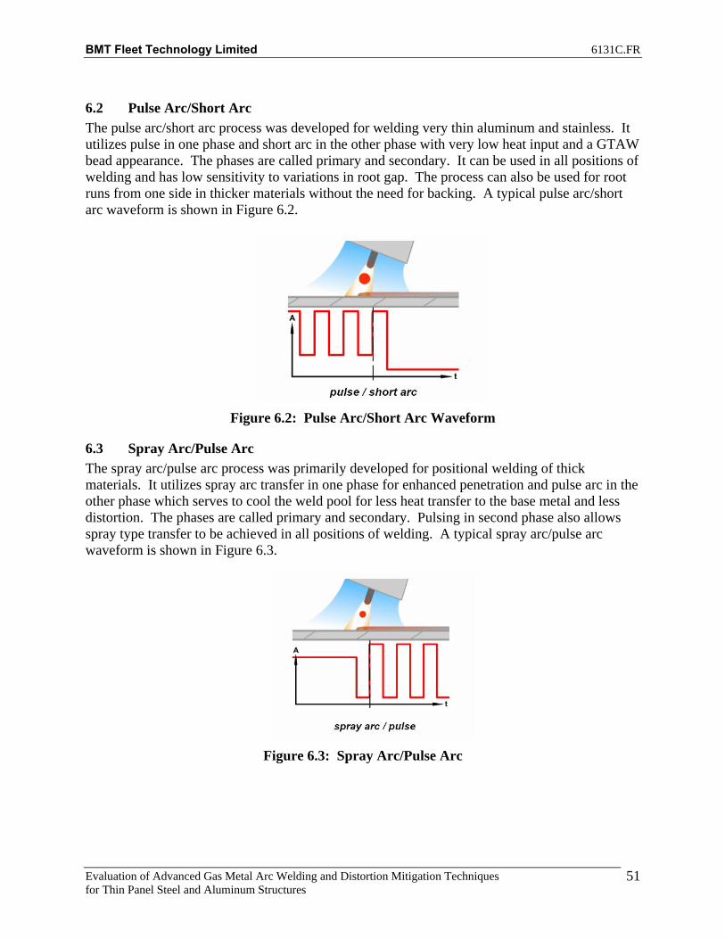
BMT Fleet Technology Limited 6131C.FR
Evaluation of Advanced Gas Metal Arc Welding and Distortion Mitigation Techniques for Thin Panel Steel and Aluminum Structures
51
6.2 Pulse Arc/Short Arc The pulse arc/short arc process was developed for welding very thin aluminum and stainless. It utilizes pulse in one phase and short arc in the other phase with very low heat input and a GTAW bead appearance. The phases are called primary and secondary. It can be used in all positions of welding and has low sensitivity to variations in root gap. The process can also be used for root runs from one side in thicker materials without the need for backing. A typical pulse arc/short arc waveform is shown in Figure 6.2.
Figure 6.2: Pulse Arc/Short Arc Waveform
6.3 Spray Arc/Pulse Arc The spray arc/pulse arc process was primarily developed for positional welding of thick materials. It utilizes spray arc transfer in one phase for enhanced penetration and pulse arc in the other phase which serves to cool the weld pool for less heat transfer to the base metal and less distortion. The phases are called primary and secondary. Pulsing in second phase also allows spray type transfer to be achieved in all positions of welding. A typical spray arc/pulse arc waveform is shown in Figure 6.3.
Figure 6.3: Spray Arc/Pulse Arc

BMT Fleet Technology Limited 6131C.FR
Evaluation of Advanced Gas Metal Arc Welding and Distortion Mitigation Techniques for Thin Panel Steel and Aluminum Structures
52
6.4 Stiffened Aluminum Panel Assembly All the stiffened panels (5mm thick) to be welded were marked up as illustrated in Figure 6.4. Panel distortion (vertical) measurements are recorded for points A, B, C and T along the width and T1 to T23 along the length, using a laser level. For benchmark stiffener assembly in absence of tension, data is recorded before and after completion of welding. In addition, a similar measurement grid was setup for the test support frame upon which the stiffener assembly to be welded are supported.
A B
T
12 inches
10 feet
T23
T11"
T23"
4"T3
50.8 mm
C
Figure 6.4: Stiffened Panel Distortion Measurement Grid

BMT Fleet Technology Limited 6131C.FR
Evaluation of Advanced Gas Metal Arc Welding and Distortion Mitigation Techniques for Thin Panel Steel and Aluminum Structures
53
Figure 6.5 illustrates a typical test assembly is shown with tacks every 12 inches on the back side. Welding is performed on the other side of the assembly. Care is taken when fitting up assemblies so that all tacked assemblies are identical.
Figure 6.5: Tacked Stiffener Test Assembly on Test Frame
The matrix for distortion readings is shown marked on the plate (Figure 6.6).
Figure 6.6: Plate Marked for Distortion Readings
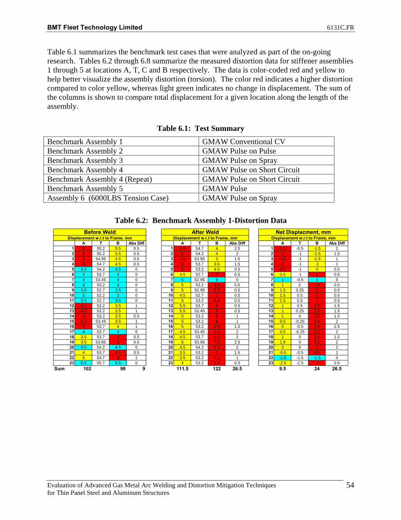
BMT Fleet Technology Limited 6131C.FR
Evaluation of Advanced Gas Metal Arc Welding and Distortion Mitigation Techniques for Thin Panel Steel and Aluminum Structures
54
Table 6.1 summarizes the benchmark test cases that were analyzed as part of the on-going research. Tables 6.2 through 6.8 summarize the measured distortion data for stiffener assemblies 1 through 5 at locations A, T, C and B respectively. The data is color-coded red and yellow to help better visualize the assembly distortion (torsion). The color red indicates a higher distortion compared to color yellow, whereas light green indicates no change in displacement. The sum of the columns is shown to compare total displacement for a given location along the length of the assembly.
Table 6.1: Test Summary
Benchmark Assembly 1 GMAW Conventional CV Benchmark Assembly 2 GMAW Pulse on Pulse Benchmark Assembly 3 GMAW Pulse on Spray Benchmark Assembly 4 GMAW Pulse on Short Circuit Benchmark Assembly 4 (Repeat) GMAW Pulse on Short Circuit Benchmark Assembly 5 GMAW Pulse Assembly 6 (6000LBS Tension Case) GMAW Pulse on Spray
Table 6.2: Benchmark Assembly 1-Distortion Data
A T B Abs Diff A T B Abs Diff A T B Abs Diff1 6 55.2 5.5 0.5 1 6.5 54.7 4 2.5 1 0.5 -0.5 -1.5 22 6 55.2 5.5 0.5 2 6 54.2 4 2 2 0 -1 -1.5 1.53 5 54.95 4.5 0.5 3 4.5 53.95 3 1.5 3 -0.5 -1 -1.5 14 5 54.7 4.5 0.5 4 5 53.7 3.5 1.5 4 0 -1 -1 15 4.5 54.2 4.5 0 5 5 53.2 4.5 0.5 5 0.5 -1 0 0.56 4 53.7 4 0 6 4.5 52.7 5 0.5 6 0.5 -1 1 0.57 4 53.45 4 0 7 5 52.95 5 0 7 1 -0.5 1 08 4 53.2 4 0 8 5 53.2 5.5 0.5 8 1 0 1.5 0.59 3.5 52.7 3.5 0 9 5 52.95 5.5 0.5 9 1.5 0.25 2 0.5
10 3 52.2 3 0 10 4.5 52.7 5 0.5 10 1.5 0.5 2 0.511 3.5 52.7 3.5 0 11 5 53.2 5.5 0.5 11 1.5 0.5 2 0.512 4.5 53.2 3.5 1 12 5.5 53.7 6 0.5 12 1 0.5 2.5 1.513 4.5 53.2 3.5 1 13 5.5 53.45 6 0.5 13 1 0.25 2.5 1.514 4 53.2 3.5 0.5 14 5 53.2 6 1 14 1 0 2.5 1.515 4.5 53.45 3.5 1 15 5 53.2 6 1 15 0.5 -0.25 2.5 216 5 53.7 4 1 16 5 53.2 6.5 1.5 16 0 -0.5 2.5 2.517 4 53.7 4 0 17 4.5 53.45 6.5 2 17 0.5 -0.25 2.5 218 3.5 53.7 4 0.5 18 4.5 53.7 6.5 2 18 1 0 2.5 1.519 3.5 53.95 4 0.5 19 5 53.95 7.5 2.5 19 1.5 0 3.5 220 4.5 54.2 4.5 0 20 4.5 54.2 6.5 2 20 0 0 2 221 4 53.7 4.5 0.5 21 3.5 53.2 5 1.5 21 -0.5 -0.5 0.5 122 5 54.7 6 1 22 3.5 53.2 4.5 1 22 -1.5 -1.5 -1.5 023 6.5 55.7 6.5 0 23 4 53.2 4.5 0.5 23 -2.5 -2.5 -2 0.5
Sum 102 98 9 111.5 122 26.5 9.5 24 26.5
Displacement w.r.t to Frame, mmNet Displacment, mmBefore Weld
Displacement w.r.t to Frame, mm Displacement w.r.t to Frame, mmAfter Weld

BMT Fleet Technology Limited 6131C.FR
Evaluation of Advanced Gas Metal Arc Welding and Distortion Mitigation Techniques for Thin Panel Steel and Aluminum Structures
55
Table 6.3: Benchmark Assembly 2-Distortion Data
A T B Abs Diff A T B Abs Diff A T B Abs Diff1 8.5 57.2 7.5 1 1 7.5 55.2 4 3.5 1 -1 -2 -3.5 2.52 7.5 57.2 7.5 0 2 7.5 55.2 4 3.5 2 0 -2 -3.5 3.53 6.5 56.45 6.5 0 3 5.5 54.45 2.5 3 3 -1 -2 -4 34 6 55.7 6 0 4 5.5 53.7 3 2.5 4 -0.5 -2 -3 2.55 5 54.95 5.5 0.5 5 5.5 53.45 4.5 1 5 0.5 -1.5 -1 1.56 4.5 54.2 5 0.5 6 5 53.2 4.5 0.5 6 0.5 -1 -0.5 17 4.5 53.7 4.5 0 7 5.5 53.2 5 0.5 7 1 -0.5 0.5 0.58 4 53.2 4 0 8 5 53.2 5 0 8 1 0 1 09 3.5 52.45 3.5 0 9 5 52.7 4.5 0.5 9 1.5 0.25 1 0.5
10 2.5 51.7 2.5 0 10 4 52.2 3.5 0.5 10 1.5 0.5 1 0.511 3.5 52.45 3 0.5 11 5 52.95 4 1 11 1.5 0.5 1 0.512 4 53.2 3.5 0.5 12 5.5 53.7 5 0.5 12 1.5 0.5 1.5 013 4 52.95 3.5 0.5 13 5 53.2 5 0 13 1 0.25 1.5 0.514 3.5 52.7 3 0.5 14 4.5 52.7 4.5 0 14 1 0 1.5 0.515 4 53.2 3.5 0.5 15 4.5 52.7 5.5 1 15 0.5 -0.5 2 1.516 5 53.7 4.5 0.5 16 4.5 52.7 5 0.5 16 -0.5 -1 0.5 117 4.5 54.2 4.5 0 17 4 52.7 5 1 17 -0.5 -1.5 0.5 118 4.5 54.7 5 0.5 18 3.5 52.7 5.5 2 18 -1 -2 0.5 1.519 5 55.7 6 1 19 4 53.2 6 2 19 -1 -2.5 0 120 6.5 56.7 7 0.5 20 4.5 53.7 6 1.5 20 -2 -3 -1 121 6.5 57.2 7 0.5 21 3.5 53.7 4.5 1 21 -3 -3.5 -2.5 0.522 7.5 58.2 9 1.5 22 4 53.95 4.5 0.5 22 -3.5 -4.25 -4.5 123 8.5 59.2 10.5 2 23 4.5 54.2 5 0.5 23 -4 -5 -5.5 1.5
Sum 119.5 122.5 11 113 106 27 -6.5 -16.5 27
Displacement w.r.t to Frame, mmNet Displacment, mmBefore Weld
Displacement w.r.t to Frame, mm Displacement w.r.t to Frame, mmAfter Weld
Table 6.4: Benchmark Assembly 3-Distortion Data
A T B Abs Diff A T B Abs Diff A T B Abs Diff1 3.5 54.2 5 1.5 1 3.5 53.2 3.5 0 1 0 -1 -1.5 1.52 3.5 54.2 5 1.5 2 3.5 53.7 3.5 0 2 0 -0.5 -1.5 1.53 3 54.2 4.5 1.5 3 3 53.45 3 0 3 0 -0.75 -1.5 1.54 3.5 54.2 5 1.5 4 3.5 53.2 3.5 0 4 0 -1 -1.5 1.55 4 54.45 5 1 5 4 52.95 5 1 5 0 -1.5 0 06 3.5 54.7 4.5 1 6 3.5 52.7 5 1.5 6 0 -2 0.5 0.57 3.5 54.2 4.5 1 7 4 53.7 6 2 7 0.5 -0.5 1.5 18 3.5 53.7 4 0.5 8 5 54.7 6.5 1.5 8 1.5 1 2.5 19 3.5 53.45 4 0.5 9 6 54.95 7.5 1.5 9 2.5 1.5 3.5 1
10 2.5 53.2 3.5 1 10 6 55.2 7 1 10 3.5 2 3.5 011 3 53.45 4 1 11 6 55.2 7.5 1.5 11 3 1.75 3.5 0.512 3.5 53.7 4 0.5 12 6.5 55.2 7.5 1 12 3 1.5 3.5 0.513 3.5 53.45 3.5 0 13 6 55.2 7 1 13 2.5 1.75 3.5 114 3.5 53.2 3.5 0 14 5.5 55.2 7 1.5 14 2 2 3.5 1.515 3.5 53.45 4 0.5 15 5.5 54.95 7.5 2 15 2 1.5 3.5 1.516 3.5 53.7 4 0.5 16 5 54.7 7 2 16 1.5 1 3 1.517 3 53.45 3.5 0.5 17 4.5 54.2 6.5 2 17 1.5 0.75 3 1.518 3.5 53.2 3.5 0 18 4.5 53.7 6.5 2 18 1 0.5 3 219 3.5 53.45 3.5 0 19 4.5 54.2 6.5 2 19 1 0.75 3 220 4 53.7 4 0 20 4.5 54.7 6.5 2 20 0.5 1 2.5 221 3.5 53.2 3.5 0 21 3.5 53.7 4.5 1 21 0 0.5 1 122 4 53.7 4 0 22 3.5 53.45 4 0.5 22 -0.5 -0.25 0 0.523 5 54.2 4.5 0.5 23 3.5 53.2 4 0.5 23 -1.5 -1 -0.5 1
Sum 81 94.5 14.5 105 132.5 27.5 24 38 26
Displacement w.r.t to Frame, mmNet Displacment, mmBefore Weld
Displacement w.r.t to Frame, mm Displacement w.r.t to Frame, mmAfter Weld

BMT Fleet Technology Limited 6131C.FR
Evaluation of Advanced Gas Metal Arc Welding and Distortion Mitigation Techniques for Thin Panel Steel and Aluminum Structures
56
Table 6.5: Benchmark Assembly 4-Distortion Data
A T B Abs Diff A T B Abs Diff A T B Abs Diff1 4.5 54.2 4 0.5 1 5 55.2 4 1 1 1 1 0 0.52 4 54.2 4 0 2 4.5 55.2 3.5 1 2 1 1 -0.5 13 3 53.95 3 0 3 3 54.7 3.5 0.5 3 0 0.75 0.5 0.54 3.5 53.7 3.5 0 4 3.5 54.2 3.5 0 4 0 0.5 0 05 4 53.7 4 0 5 4 53.7 5 1 5 0 0 1 16 3 53.7 3.5 0.5 6 4 53.2 5.5 1.5 6 1 -0.5 2 17 3 53.7 3.5 0.5 7 4 53.2 5.5 1.5 7 1 -0.5 2 18 3.5 53.7 3.5 0 8 4.5 53.2 6.5 2 8 1 -0.5 3 29 3.5 53.2 3.5 0 9 5 53.2 6.5 1.5 9 1.5 0 3 1.5
10 3 52.7 2.5 0.5 10 4 53.2 5.5 1.5 10 1 0.5 3 211 3.5 53.2 3 0.5 11 4.5 53.45 5.5 1 11 1 0.25 2.5 1.512 3.5 53.7 3.5 0 12 5 53.7 5.5 0.5 12 1.5 0 2 0.513 4 53.2 3.5 0.5 13 4.5 53.45 5.5 1 13 0.5 0.25 2 1.514 4 52.7 3 1 14 3.5 53.2 5 1.5 14 -0.5 0.5 2 2.515 4 53.2 3.5 0.5 15 4 54.45 5.5 1.5 15 0 1.25 2 216 4 53.7 3.5 0.5 16 5 55.7 8.5 3.5 16 1 2 5 417 4 53.7 3.5 0.5 17 7 57.95 10.5 3.5 17 3 4.25 7 418 3.5 53.7 3.5 0 18 9.5 60.2 14 4.5 18 6 6.5 10.5 4.519 3.5 54.2 4 0.5 19 12 62.2 16.5 4.5 19 8.5 8 12.5 420 4 54.7 4.5 0.5 20 12.5 64.2 16.5 4 20 8.5 9.5 12 3.521 4 54.7 4 0 21 11.5 64.2 15.5 4 21 7.5 9.5 11.5 422 5 55.45 5.5 0.5 22 11.5 63.95 15 3.5 22 6.5 8.5 9.5 323 6.5 56.2 6.5 0 23 12.5 63.7 15 2.5 23 6 7.5 8.5 2.5
Sum 88.5 86.5 7 144.5 187.5 47 56 101 48
Displacement w.r.t to Frame, mmNet Displacment, mmBefore Weld
Displacement w.r.t to Frame, mm Displacement w.r.t to Frame, mmAfter Weld
Table 6.6: Benchmark Assembly 4 (Repeat)-Distortion Data
A T B Abs Diff A T B Abs Diff A T B Abs Diff1 5.5 55.2 4.5 1 1 5.5 54.7 3.5 2 1 0 -0.5 -1 12 5 55.2 4 1 2 4.5 55.2 3.5 1 2 -1 0 -0.5 03 4 54.95 3.5 0.5 3 3.5 54.7 2.5 1 3 -1 -0.25 -1 0.54 4.5 54.7 4 0.5 4 4 54.2 4 0 4 -1 -0.5 0 0.55 5.5 53.95 4.5 1 5 4 53.45 5.5 1.5 5 -1.5 -0.5 1 2.56 4 53.2 4 0 6 4 52.7 5.5 1.5 6 0 -0.5 1.5 1.57 3.5 52.95 3.5 0 7 3.5 52.7 6 2.5 7 0 -0.25 2.5 2.58 3.5 52.7 3.5 0 8 1.5 52.7 6 4.5 8 -2 0 2.5 4.59 3.5 52.45 3.5 0 9 3.5 52.45 6 2.5 9 0 0 2.5 2.5
10 3 52.2 3 0 10 3.5 52.2 5.5 2 10 0.5 0 2.5 211 3.5 52.95 4 0.5 11 4 52.95 6 2 11 0.5 0 2 1.512 4 53.7 4.5 0.5 12 4.5 53.7 6.5 2 12 0.5 0 2 1.513 4.5 53.7 5 0.5 13 5 53.2 7 2 13 0.5 -0.5 2 1.514 4.5 53.7 5 0.5 14 4.5 52.7 6.5 2 14 0 -1 1.5 1.515 4.5 53.95 5 0.5 15 4 53.2 6.5 2.5 15 -0.5 -0.75 1.5 216 5 54.2 5 0 16 4 53.7 7.5 3.5 16 -1 -0.5 2.5 3.517 4.5 54.7 5 0.5 17 4 53.7 7 3 17 -0.5 -1 2 2.518 5.5 55.2 6 0.5 18 4.5 53.7 7.5 3 18 -1 -1.5 1.5 2.519 6 55.45 7 1 19 5 53.7 8.5 3.5 19 -1 -1.75 1.5 2.520 6.5 55.7 8 1.5 20 4.5 53.7 7.5 3 20 -2 -2 -0.5 1.521 6.5 56.2 8 1.5 21 3.5 52.7 5.5 2 21 -3 -3.5 -2.5 0.522 7.5 57.2 9 1.5 22 3.5 52.95 5 1.5 22 -4 -4.25 -4 023 9 58.2 10.5 1.5 23 4 53.2 5 1 23 -5 -5 -5.5 0.5
Sum 113.5 120 14.5 92.5 134 49.5 -21 14 39
Displacement w.r.t to Frame, mmNet Displacment, mmBefore Weld
Displacement w.r.t to Frame, mm Displacement w.r.t to Frame, mmAfter Weld

BMT Fleet Technology Limited 6131C.FR
Evaluation of Advanced Gas Metal Arc Welding and Distortion Mitigation Techniques for Thin Panel Steel and Aluminum Structures
57
Table 6.7: Benchmark Assembly 5-Distortion Data
A T B Abs Diff A T B Abs Diff A T B Abs Diff1 4 54.2 3.5 0.5 1 4 53.2 2.5 1.5 1 0 -1 -1 12 3.5 53.7 4 0.5 2 3.5 53.2 3 0.5 2 0 -0.5 -1 13 2.5 53.45 3 0.5 3 2.5 52.7 2.5 0 3 0 -0.75 -0.5 0.54 3 53.2 3.5 0.5 4 3 52.2 3.5 0.5 4 0 -1 0 05 3 52.7 3.5 0.5 5 3.5 51.95 4.5 1 5 0.5 -0.75 1 0.56 3 52.2 3 0 6 2.5 51.7 4.5 2 6 -0.5 -0.5 1.5 27 2.5 52.45 3 0.5 7 3 52.45 5.5 2.5 7 0.5 0 2.5 28 3 52.7 3 0 8 4 53.2 6.5 2.5 8 1 0.5 3.5 2.59 3.5 52.95 3.5 0 9 5 53.7 7.5 2.5 9 1.5 0.75 4 2.5
10 3 53.2 3.5 0.5 10 5 54.2 7 2 10 2 1 3.5 1.511 3 53.45 3.5 0.5 11 5.5 54.45 7 1.5 11 2.5 1 3.5 112 3.5 53.7 4 0.5 12 5.5 54.7 7 1.5 12 2 1 3 113 3.5 53.45 4.5 1 13 5 54.2 7 2 13 1.5 0.75 2.5 114 3.5 53.2 4 0.5 14 4.5 53.7 6 1.5 14 1 0.5 2 115 3.5 53.7 4.5 1 15 4.5 53.95 6 1.5 15 1 0.25 1.5 0.516 4 54.2 4.5 0.5 16 4 54.2 6 2 16 0 0 1.5 1.517 3.5 54.45 4.5 1 17 4 54.7 7 3 17 0.5 0.25 2.5 218 4 54.7 5 1 18 5.5 55.2 8.5 3 18 1.5 0.5 3.5 219 4.5 54.95 5.5 1 19 6 55.45 9 3 19 1.5 0.5 3.5 220 5 55.2 5.5 0.5 20 5.5 55.7 7.5 2 20 0.5 0.5 2 1.521 4.5 55.2 5 0.5 21 4.5 54.7 4.5 0 21 0 -0.5 -0.5 0.522 5.5 55.7 5.5 0 22 4 54.45 3.5 0.5 22 -1.5 -1.25 -2 0.523 6.5 56.2 6 0.5 23 4 54.2 3.5 0.5 23 -2.5 -2 -2.5 0
Sum 85.5 95.5 12 98.5 129.5 37 13 34 28
Displacement w.r.t to Frame, mmNet Displacment, mmBefore Weld
Displacement w.r.t to Frame, mm Displacement w.r.t to Frame, mmAfter Weld
Table 6.8: Assembly 6-Distortion Data
A T B Abs Diff A T B Abs Diff A T B Abs Diff1 6.5 54.7 7 0.5 1 5.5 54.2 4.5 1 1 -1 -0.5 -2.5 1.52 5.5 54.7 6.5 1 2 5 54.2 4.5 0.5 2 -0.5 -0.5 -2 1.53 4 54.45 5 1 3 3.5 53.7 3 0.5 3 -0.5 -0.75 -2 1.54 4 54.2 5 1 4 4 53.2 3.5 0.5 4 0 -1 -1.5 1.55 4 53.95 4.5 0.5 5 4 52.95 4.5 0.5 5 0 -1 0 06 4 53.7 4 0 6 3.5 52.7 5 1.5 6 -0.5 -1 1 1.57 4 53.7 4 0 7 4 52.95 5 1 7 0 -0.75 1 18 4 53.7 4 0 8 4 53.2 5.5 1.5 8 0 -0.5 1.5 1.59 4 53.45 3.5 0.5 9 4.5 53.2 6 1.5 9 0.5 -0.25 2.5 2
10 4 53.2 3 1 10 4 53.2 5.5 1.5 10 0 0 2.5 2.511 4 53.7 3.5 0.5 11 4.5 53.7 6 1.5 11 0.5 0 2.5 212 4.5 54.2 4 0.5 12 5 54.2 6 1 12 0.5 0 2 1.513 4.5 53.95 4 0.5 13 5 53.95 6 1 13 0.5 0 2 1.514 4 53.7 3.5 0.5 14 5 53.7 6 1 14 1 0 2.5 1.515 4.5 53.95 4 0.5 15 4.5 53.7 6 1.5 15 0 -0.25 2 216 5 54.2 4 1 16 5 53.7 5.5 0.5 16 0 -0.5 1.5 1.517 4.5 54.2 4 0.5 17 4.5 53.45 5.5 1 17 0 -0.75 1.5 1.518 4.5 54.2 4 0.5 18 4.5 53.2 5.5 1 18 0 -1 1.5 1.519 5 54.7 4.5 0.5 19 5 54.2 6.5 1.5 19 0 -0.5 2 220 5 55.2 5 0 20 4.5 55.2 6 1.5 20 -0.5 0 1 1.521 4.5 54.7 4 0.5 21 3 54.2 4.5 1.5 21 -1.5 -0.5 0.5 222 5.5 54.7 5.5 0 22 3.5 54.2 4.5 1 22 -2 -0.5 -1 123 7 54.7 6.5 0.5 23 4 54.2 5 1 23 -3 -0.5 -1.5 1.5
Sum 106.5 103 11.5 100 120 25 -6.5 17 35.5
Displacement w.r.t to Frame, mm Displacement w.r.t to Frame, mm Displacement w.r.t to Frame, mmBefore Weld After Weld Net Displacment, mm

BMT Fleet Technology Limited 6131C.FR
Evaluation of Advanced Gas Metal Arc Welding and Distortion Mitigation Techniques for Thin Panel Steel and Aluminum Structures
58
Figures 6.7 through 6.10 illustrate the net displacements for benchmark stiffener assembly 1 at edge locations A, T, C and B respectively.
-30
-20
-10
0
10
20
30
0 500 1000 1500 2000 2500 3000 3500
Distance from Edge, mm
Ver
tical
Dis
plac
emen
t, m
mBefore WeldAfter Weld
Figure 6.7: Net Displacement along Longitudinal Section A for Benchmark Assembly1
30
40
50
60
70
80
90
0 500 1000 1500 2000 2500 3000 3500
Distance from Edge, mm
Ver
tical
Dis
plac
emen
t, m
m
Before WeldAfter Weld
Figure 6.8: Net Displacement along Longitudinal Section T for Benchmark Assembly1

BMT Fleet Technology Limited 6131C.FR
Evaluation of Advanced Gas Metal Arc Welding and Distortion Mitigation Techniques for Thin Panel Steel and Aluminum Structures
59
-30
-20
-10
0
10
20
30
0 500 1000 1500 2000 2500 3000 3500
Distance from Edge, mm
Ver
tical
Dis
plac
emen
t, m
m
Before WeldAfter Weld
Figure 6.9: Net Displacement along Longitudinal Section C for Benchmark Assembly1
-30
-20
-10
0
10
20
30
0 500 1000 1500 2000 2500 3000 3500
Distance from Edge, mm
Ver
tical
Dis
plac
emen
t, m
m
Before WeldAfter Weld
Figure 6.10: Net Displacement along Longitudinal Section B for Benchmark Assembly1
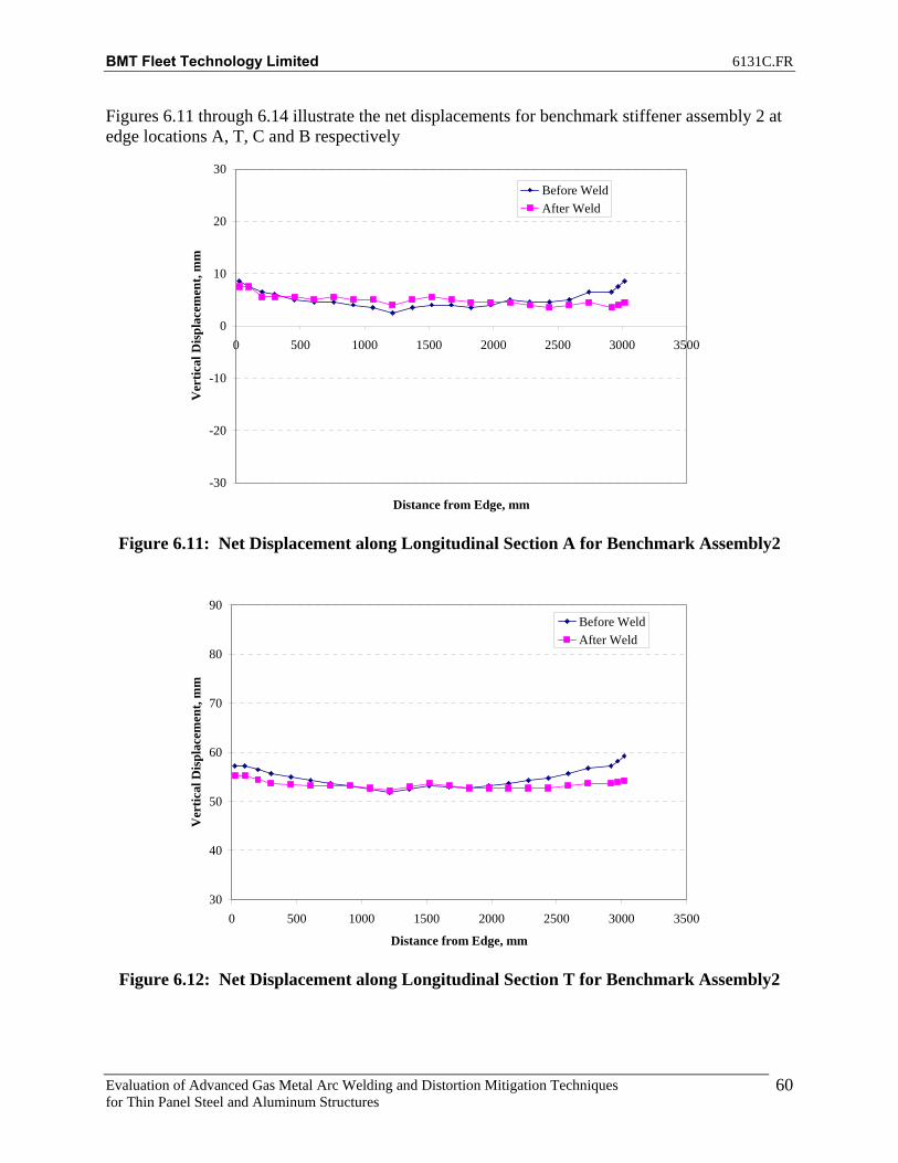
BMT Fleet Technology Limited 6131C.FR
Evaluation of Advanced Gas Metal Arc Welding and Distortion Mitigation Techniques for Thin Panel Steel and Aluminum Structures
60
Figures 6.11 through 6.14 illustrate the net displacements for benchmark stiffener assembly 2 at edge locations A, T, C and B respectively
-30
-20
-10
0
10
20
30
0 500 1000 1500 2000 2500 3000 3500
Distance from Edge, mm
Ver
tical
Dis
plac
emen
t, m
mBefore WeldAfter Weld
Figure 6.11: Net Displacement along Longitudinal Section A for Benchmark Assembly2
30
40
50
60
70
80
90
0 500 1000 1500 2000 2500 3000 3500
Distance from Edge, mm
Ver
tical
Dis
plac
emen
t, m
m
Before WeldAfter Weld
Figure 6.12: Net Displacement along Longitudinal Section T for Benchmark Assembly2

BMT Fleet Technology Limited 6131C.FR
Evaluation of Advanced Gas Metal Arc Welding and Distortion Mitigation Techniques for Thin Panel Steel and Aluminum Structures
61
-30
-20
-10
0
10
20
30
0 500 1000 1500 2000 2500 3000 3500
Distance from Edge, mm
Ver
tical
Dis
plac
emen
t, m
m
Before WeldAfter Weld
Figure 6.13: Net Displacement along Longitudinal Section C for Benchmark Assembly2
-30
-20
-10
0
10
20
30
0 500 1000 1500 2000 2500 3000 3500
Distance from Edge, mm
Ver
tical
Dis
plac
emen
t, m
m
Before WeldAfter Weld
Figure 6.14: Net Displacement along Longitudinal Section B for Benchmark Assembly2

BMT Fleet Technology Limited 6131C.FR
Evaluation of Advanced Gas Metal Arc Welding and Distortion Mitigation Techniques for Thin Panel Steel and Aluminum Structures
62
Figures 6.15 through 6.18 illustrate the net displacements for benchmark stiffener assembly 3 at edge locations A, T, C and B respectively
-30
-20
-10
0
10
20
30
0 500 1000 1500 2000 2500 3000 3500
Distance from Edge, mm
Ver
tical
Dis
plac
emen
t, m
mBefore WeldAfter Weld
Figure 6.15: Net Displacement along Longitudinal Section A for Benchmark Assembly3
30
40
50
60
70
80
90
0 500 1000 1500 2000 2500 3000 3500
Distance from Edge, mm
Ver
tical
Dis
plac
emen
t, m
m
Before WeldAfter Weld
Figure 6.16: Net Displacement along Longitudinal Section T for Benchmark Assembly3

BMT Fleet Technology Limited 6131C.FR
Evaluation of Advanced Gas Metal Arc Welding and Distortion Mitigation Techniques for Thin Panel Steel and Aluminum Structures
63
-30
-20
-10
0
10
20
30
0 500 1000 1500 2000 2500 3000 3500
Distance from Edge, mm
Ver
tical
Dis
plac
emen
t, m
m
Before WeldAfter Weld
Figure 6.17: Net Displacement along Longitudinal Section C for Benchmark Assembly3
-30
-20
-10
0
10
20
30
0 500 1000 1500 2000 2500 3000 3500
Distance from Edge, mm
Ver
tical
Dis
plac
emen
t, m
m
Before WeldAfter Weld
Figure 6.18: Net Displacement along Longitudinal Section B for Benchmark Assembly3

BMT Fleet Technology Limited 6131C.FR
Evaluation of Advanced Gas Metal Arc Welding and Distortion Mitigation Techniques for Thin Panel Steel and Aluminum Structures
64
Figures 6.19 through 6.22 illustrate the net displacements for benchmark stiffener assembly 4 at edge locations A, T, C and B respectively.
-30
-20
-10
0
10
20
30
0 500 1000 1500 2000 2500 3000 3500
Distance from Edge, mm
Ver
tical
Dis
plac
emen
t, m
mBefore WeldAfter Weld
Figure 6.19: Net Displacement along Longitudinal Section A for Benchmark Assembly4
30
40
50
60
70
80
90
0 500 1000 1500 2000 2500 3000 3500
Distance from Edge, mm
Ver
tical
Dis
plac
emen
t, m
m
Before WeldAfter Weld
Figure 6.20: Net Displacement along Longitudinal Section T for Benchmark Assembly4
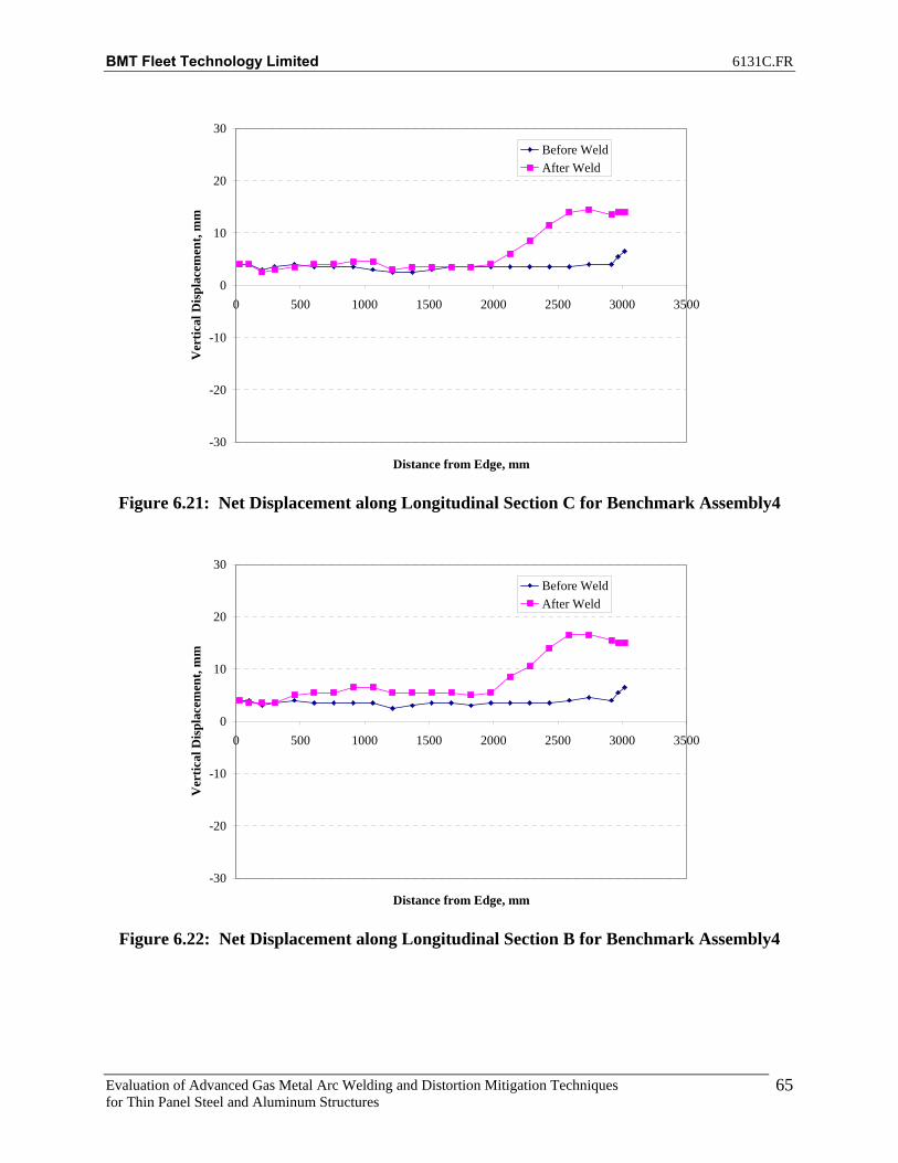
BMT Fleet Technology Limited 6131C.FR
Evaluation of Advanced Gas Metal Arc Welding and Distortion Mitigation Techniques for Thin Panel Steel and Aluminum Structures
65
-30
-20
-10
0
10
20
30
0 500 1000 1500 2000 2500 3000 3500
Distance from Edge, mm
Ver
tical
Dis
plac
emen
t, m
m
Before WeldAfter Weld
Figure 6.21: Net Displacement along Longitudinal Section C for Benchmark Assembly4
-30
-20
-10
0
10
20
30
0 500 1000 1500 2000 2500 3000 3500
Distance from Edge, mm
Ver
tical
Dis
plac
emen
t, m
m
Before WeldAfter Weld
Figure 6.22: Net Displacement along Longitudinal Section B for Benchmark Assembly4

BMT Fleet Technology Limited 6131C.FR
Evaluation of Advanced Gas Metal Arc Welding and Distortion Mitigation Techniques for Thin Panel Steel and Aluminum Structures
66
Figures 6.23 through 2.26 illustrate the net displacements for benchmark stiffener assembly 4 (Repeat) at edge locations A, T, C and B respectively. Benchmark Assembly 4 was repeated due to tacks breaking during welding of benchmark assembly 4 starting at approximately the 2200mm region of the assembly.
-30
-20
-10
0
10
20
30
0 500 1000 1500 2000 2500 3000 3500
Distance from Edge, mm
Ver
tical
Dis
plac
emen
t, m
m
Before WeldAfter Weld
Figure 6.23: Net Displacement along Longitudinal Section A for Benchmark Assembly4
(Repeat)
30
40
50
60
70
80
90
0 500 1000 1500 2000 2500 3000 3500
Distance from Edge, mm
Ver
tical
Dis
plac
emen
t, m
m
Before WeldAfter Weld
Figure 6.24: Net Displacement along Longitudinal Section T for Benchmark Assembly4
(Repeat)
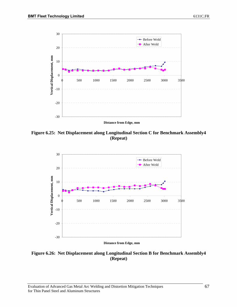
BMT Fleet Technology Limited 6131C.FR
Evaluation of Advanced Gas Metal Arc Welding and Distortion Mitigation Techniques for Thin Panel Steel and Aluminum Structures
67
-30
-20
-10
0
10
20
30
0 500 1000 1500 2000 2500 3000 3500
Distance from Edge, mm
Ver
tical
Dis
plac
emen
t, m
m
Before WeldAfter Weld
Figure 6.25: Net Displacement along Longitudinal Section C for Benchmark Assembly4
(Repeat)
-30
-20
-10
0
10
20
30
0 500 1000 1500 2000 2500 3000 3500
Distance from Edge, mm
Ver
tical
Dis
plac
emen
t, m
m
Before WeldAfter Weld
Figure 6.26: Net Displacement along Longitudinal Section B for Benchmark Assembly4
(Repeat)

BMT Fleet Technology Limited 6131C.FR
Evaluation of Advanced Gas Metal Arc Welding and Distortion Mitigation Techniques for Thin Panel Steel and Aluminum Structures
68
Figures 6.27 through 6.30 illustrate the net displacements for benchmark stiffener assembly 5 at edge locations A, T, C and B respectively.
-30
-20
-10
0
10
20
30
0 500 1000 1500 2000 2500 3000 3500
Distance from Edge, mm
Ver
tical
Dis
plac
emen
t, m
mBefore WeldAfter Weld
Figure 6.27: Net Displacement along Longitudinal Section A for Benchmark Assembly5
30
40
50
60
70
80
90
0 500 1000 1500 2000 2500 3000 3500
Distance from Edge, mm
Ver
tical
Dis
plac
emen
t, m
m
Before WeldAfter Weld
Figure 6.28: Net Displacement along Longitudinal Section T for Benchmark Assembly5
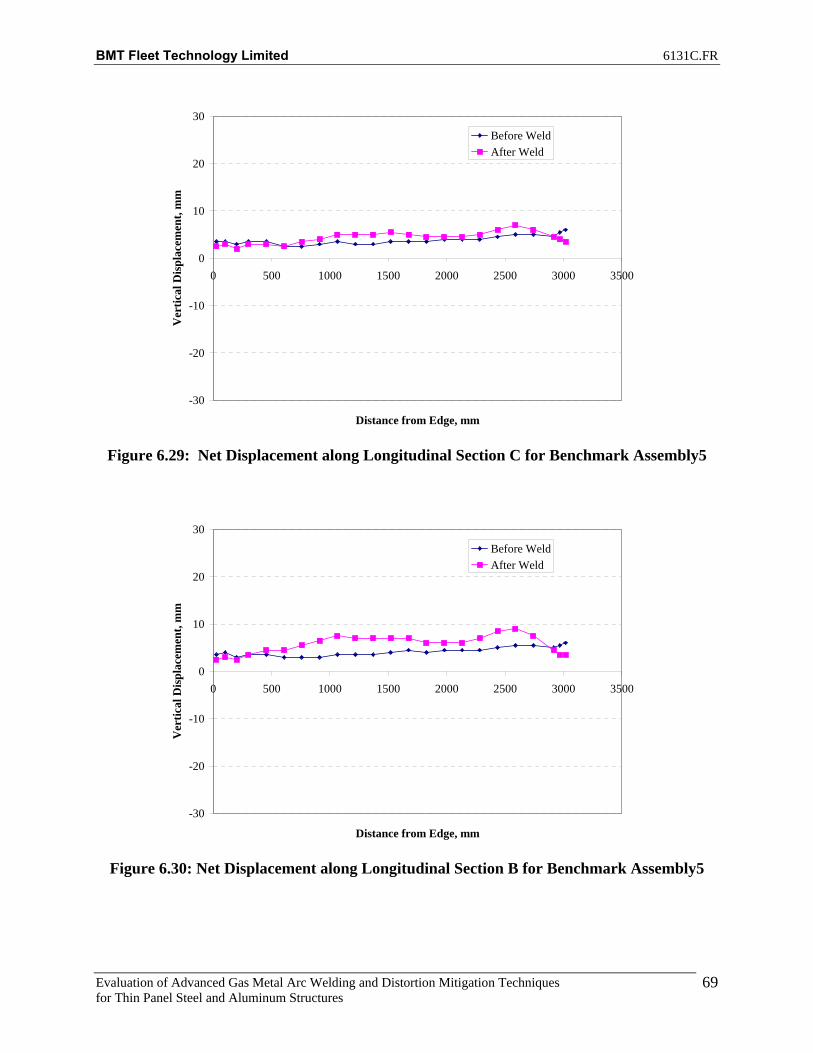
BMT Fleet Technology Limited 6131C.FR
Evaluation of Advanced Gas Metal Arc Welding and Distortion Mitigation Techniques for Thin Panel Steel and Aluminum Structures
69
-30
-20
-10
0
10
20
30
0 500 1000 1500 2000 2500 3000 3500
Distance from Edge, mm
Ver
tical
Dis
plac
emen
t, m
m
Before WeldAfter Weld
Figure 6.29: Net Displacement along Longitudinal Section C for Benchmark Assembly5
-30
-20
-10
0
10
20
30
0 500 1000 1500 2000 2500 3000 3500
Distance from Edge, mm
Ver
tical
Dis
plac
emen
t, m
m
Before WeldAfter Weld
Figure 6.30: Net Displacement along Longitudinal Section B for Benchmark Assembly5

BMT Fleet Technology Limited 6131C.FR
Evaluation of Advanced Gas Metal Arc Welding and Distortion Mitigation Techniques for Thin Panel Steel and Aluminum Structures
70
Figures 6.31 through 6.34 illustrate the net displacements for stiffener assembly 6 at edge locations A, T, C and B respectively.
-30
-20
-10
0
10
20
30
0 500 1000 1500 2000 2500 3000 3500
Distance from Edge, mm
Ver
tical
Dis
plac
emen
t, m
mBefore WeldAfter WeldNo Weld-Tension
Figure 6.31: Net Displacement along Longitudinal Section A for Assembly6
30
40
50
60
70
80
90
0 500 1000 1500 2000 2500 3000 3500
Distance from Edge, mm
Ver
tical
Dis
plac
emen
t, m
m
Before WeldAfter WeldNo Weld-Tension
Figure 6.32: Net Displacement along Longitudinal Section T for Assembly6

BMT Fleet Technology Limited 6131C.FR
Evaluation of Advanced Gas Metal Arc Welding and Distortion Mitigation Techniques for Thin Panel Steel and Aluminum Structures
71
-30
-20
-10
0
10
20
30
0 500 1000 1500 2000 2500 3000 3500
Distance from Edge, mm
Ver
tical
Dis
plac
emen
t, m
m
Before WeldAfter WeldNo Weld-Tension
Figure 6.33: Net Displacement along Longitudinal Section C for Assembly6
-30
-20
-10
0
10
20
30
0 500 1000 1500 2000 2500 3000 3500
Distance from Edge, mm
Ver
tical
Dis
plac
emen
t, m
m
Before WeldAfter WeldNo Weld-Tension
Figure 6.34: Net Displacement along Longitudinal Section B for Assembly6

BMT Fleet Technology Limited 6131C.FR
Evaluation of Advanced Gas Metal Arc Welding and Distortion Mitigation Techniques for Thin Panel Steel and Aluminum Structures
72
6.5 Comparing Benchmark Aluminum Welding Processes Figures 6.35 through 6.37 compare the net effectiveness of each of the welding processes in terms of the net displacement along the longitudinal section of each marked point on the assembly (Figure 6.4) with respect to corresponding point on the test frame before and after welding.
-8.0
-4.0
0.0
4.0
8.0
12.0
16.0
25.4
202
454
759
1064
1368
1673
1978
2283
2588
2918
3019
Distance from Edge, mm
Net
Ver
tical
Dis
plac
emen
t, m
m
Assembly 1 Assembly 2 Assembly 3 Assembly 4R Assembly 5
Figure 6.35: Net Displacement along Longitudinal Section A
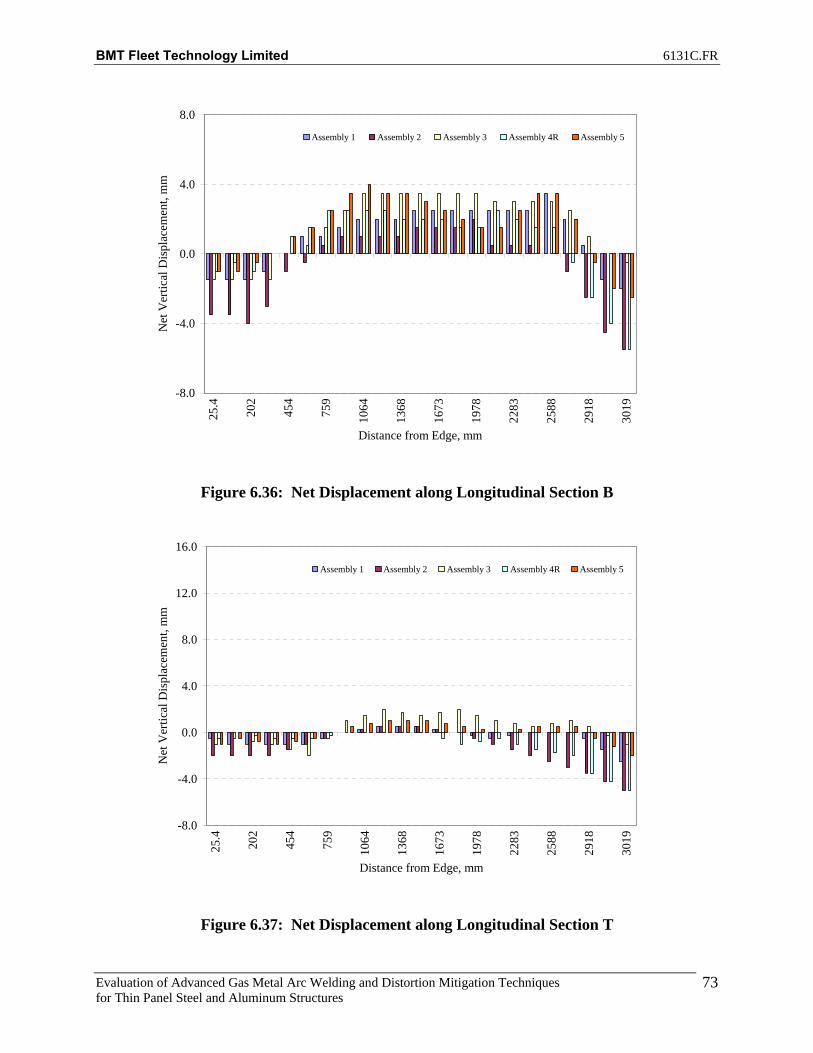
BMT Fleet Technology Limited 6131C.FR
Evaluation of Advanced Gas Metal Arc Welding and Distortion Mitigation Techniques for Thin Panel Steel and Aluminum Structures
73
-8.0
-4.0
0.0
4.0
8.0
25.4
202
454
759
1064
1368
1673
1978
2283
2588
2918
3019
Distance from Edge, mm
Net
Ver
tical
Dis
plac
emen
t, m
m
Assembly 1 Assembly 2 Assembly 3 Assembly 4R Assembly 5
Figure 6.36: Net Displacement along Longitudinal Section B
-8.0
-4.0
0.0
4.0
8.0
12.0
16.0
25.4
202
454
759
1064
1368
1673
1978
2283
2588
2918
3019
Distance from Edge, mm
Net
Ver
tical
Dis
plac
emen
t, m
m
Assembly 1 Assembly 2 Assembly 3 Assembly 4R Assembly 5
Figure 6.37: Net Displacement along Longitudinal Section T

BMT Fleet Technology Limited 6131C.FR
Evaluation of Advanced Gas Metal Arc Welding and Distortion Mitigation Techniques for Thin Panel Steel and Aluminum Structures
74
Figures 6.38 through 6.40 compare the net improvement of test assembly 6 welded with 6000lb tension load with respect to benchmark assembly 3 after welding. The welding process for benchmark assembly 3 and test assembly 6 were the same (GMAW Superpulse Pulse on Spray). Benchmark assembly 3 was chosen to be reproduced under tension because this was determined to be the worst case scenario for vertical displacement (distortion).
-10
-8
-6
-4
-2
0
2
4
25.4
201.
6
454.
0
758.
8
1063
.6
1368
.4
1673
.2
1978
.0
2282
.8
2587
.6
2917
.8
3019
.4
Distance from edge, mm
Ver
tical
Dis
plac
emen
t, m
m
Net Improvement
Figure 6.38: Net Improvement along Longitudinal Section A

BMT Fleet Technology Limited 6131C.FR
Evaluation of Advanced Gas Metal Arc Welding and Distortion Mitigation Techniques for Thin Panel Steel and Aluminum Structures
75
-10
-8
-6
-4
-2
0
2
4
25.4
201.
6
454.
0
758.
8
1063
.6
1368
.4
1673
.2
1978
.0
2282
.8
2587
.6
2917
.8
3019
.4
Distance from edge, mm
Ver
tical
Dis
plac
emen
t, m
mNet Improvement
Figure 6.39: Net Improvement along Longitudinal Section B
-10
-8
-6
-4
-2
0
2
4
25.4
201.
6
454.
0
758.
8
1063
.6
1368
.4
1673
.2
1978
.0
2282
.8
2587
.6
2917
.8
3019
.4
Distance from edge, mm
Ver
tical
Dis
plac
emen
t, m
m
Net Improvement
Figure 6.40: Net Improvement along Longitudinal Section T

BMT Fleet Technology Limited 6131C.FR
Evaluation of Advanced Gas Metal Arc Welding and Distortion Mitigation Techniques for Thin Panel Steel and Aluminum Structures
76
Figures 6.41 through 6.45 show the appearance of the weld beads with the five different processes. As seen in the photos, the superpulse technology produces a very consistent bead profile.
Figure 6.41: Weld Profile, Benchmark Assembly 1 (Conventional CV)

BMT Fleet Technology Limited 6131C.FR
Evaluation of Advanced Gas Metal Arc Welding and Distortion Mitigation Techniques for Thin Panel Steel and Aluminum Structures
77
Figure 6.42: Weld Profile, Benchmark Assembly 2 (Pulse on Pulse)
Figure 6.43: Weld Profile, Benchmark Assembly 3 (Pulse on Short)

BMT Fleet Technology Limited 6131C.FR
Evaluation of Advanced Gas Metal Arc Welding and Distortion Mitigation Techniques for Thin Panel Steel and Aluminum Structures
78
Figure 6.44: Weld Profile, Benchmark Assembly 4 (Pulse on Spray)
Figure 6.45: Weld Profile, Benchmark Assembly 5 (Pulse)

BMT Fleet Technology Limited 6131C.FR
Evaluation of Advanced Gas Metal Arc Welding and Distortion Mitigation Techniques for Thin Panel Steel and Aluminum Structures
79
Figures 6.46 through 6.50 show the cross-section of the assembly with an etched surface demonstrating the penetration profiles of the four benchmark welds. These etched samples were taken from procedure development trials before the actual benchmark test assemblies were welded. The actual benchmark assemblies will remain intact for future reference. The penetration is acceptable for all five welds.
Figure 6.46: Cross-section Showing Penetration Profile of Benchmark Assembly1
Figure 6.47: Cross-section Showing Penetration Profile of Benchmark Assembly2

BMT Fleet Technology Limited 6131C.FR
Evaluation of Advanced Gas Metal Arc Welding and Distortion Mitigation Techniques for Thin Panel Steel and Aluminum Structures
80
Figure 6.48: Cross-section Showing Penetration Profile of Benchmark Assembly3
Figure 6.49: Cross-section Showing Penetration Profile of Benchmark Assembly4

BMT Fleet Technology Limited 6131C.FR
Evaluation of Advanced Gas Metal Arc Welding and Distortion Mitigation Techniques for Thin Panel Steel and Aluminum Structures
81
Figure 6.50: Cross-section Showing Penetration Profile of Assembly5
Tables 6.9 through 6.12 show comparisons of weld sizes obtained, travel speeds, resulting heat inputs, and displacement values. Weld size values followed by a + symbol indicate that the weld size is larger than the size indicated, and smaller than the next weld size to a 1/16”. Heat input values are calculated using average amperage and voltage values. Displacement values are obtained from Tables 6.4 through 6.8. The “Sum Torsion” column refers to the displacement relationship between points A and B after welding compared to points A and B before welding. The value shown in the table is the sum of the absolute difference between locations A and B for points 1 to 23 after welding subtracted by before welding values. A high positive value indicates increased torsion, twisting or uneven lifting of the plate edges. The “Sum Net Displacement” column refers to the sum of the net displacement values from locations A and B for all 23 points. A high positive value indicates increased vertical displacement over the length of the test assembly. A negative value represents less vertical displacement than the original test assembly which is an improvement over the original plate.

BMT Fleet Technology Limited 6131C.FR
Evaluation of Advanced Gas Metal Arc Welding and Distortion Mitigation Techniques for Thin Panel Steel and Aluminum Structures
82
Table 6.9: Resulting Weld Sizes
Test Assembly Weld Size (in.) Benchmark Assembly 1 (CV) 3/16+
Benchmark Assembly 2 (Pulse/Pulse) ¼ Benchmark Assembly 3 (Pulse/Spray) 3/16+ Benchmark Assembly 4 (Pulse/Short) ¼
Benchmark Assembly 5 (Pulse) 3/16+
Table 6.10: Travel Speeds
Test Assembly Travel Speed (IPM) Benchmark Assembly 1 (CV) 50
Benchmark Assembly 2 (Pulse/Pulse) 30 Benchmark Assembly 3 (Pulse/Spray) 35 Benchmark Assembly 4 (Pulse/Short) 25
Benchmark Assembly 5 (Pulse) 46
Table 6.11: Heat Input
Test Assembly Heat Input (KJ/IN) Benchmark Assembly 1 (CV) 6.2
Benchmark Assembly 2 (Pulse/Pulse) 9.1 Benchmark Assembly 3 (Pulse/Spray) 7.9 Benchmark Assembly 4 (Pulse/Short) 7.3
Benchmark Assembly 5 (Pulse) 7.2
Table 6.12: Displacement Values
Test Assembly Torsion (mm) Sum Net Displacement (mm)
Benchmark Assembly 1 (CV) +17.5 +33.5 Benchmark Assembly 2 (Pulse/Pulse) +16.0 -23.0 Benchmark Assembly 3 (Pulse/Spray) +13.0 +62.0 Benchmark Assembly 4 (Pulse/Short) +40.0 +157.0
Benchmark Assembly 4 Repeat (Pulse/Short)
+35.0 -7.0
Benchmark Assembly 5 (Pulse) +25.0 +47 Assembly 6 (6000lbs Tension,
Pulse/Spray) +13.5 +10.5

BMT Fleet Technology Limited 6131C.FR
Evaluation of Advanced Gas Metal Arc Welding and Distortion Mitigation Techniques for Thin Panel Steel and Aluminum Structures
83
6.6 Summary of Results for Advanced Aluminum Welding Process From the data presented, it can be concluded that the superpulse-pulse on pulse process results in less distortion than the other four benchmark processes. Based on the process comparison and data presented above, the following ranking lists the processes in order from best to worst with respect to resulting distortion (vertical displacement):
1. Superpulse, Pulse on Pulse 2. Conventional CV 3. Superpulse. Pulse on Short 4. Pulse 5. Superpulse, Pulse on Spray
This ranking is subjective because some assemblies such as benchmark assembly 4 repeat (pulse/short) demonstrated an improvement over the length of the plate; however it demonstrated more torsion (differences in displacement values between points A and B for a given location). For better visualization of torsion, refer to Tables 6.2 through 6.8 where color red indicates higher distortion compared to color yellow and light green indicates no change. In all cases, the trend for the longitudinal plots was for increased distortion at section B compared to section A, C, and T. Section B is along the edge on the same side as the weld deposit. When comparing Net Displacement Longitudinal Plots of section B for benchmark assembly 1 and benchmark assembly 2 (Figure 5.64 and Figure 5.68), it is clear that benchmark assembly 2 resulted in less distortion than benchmark assembly 1. Benchmark assembly 3 (pulse/spray) was repeated under tension as assembly 6 because the vertical displacement values were the highest of the five processes with a “Sum Net Displacement” at +62. The objective of using mechanical tensioning during the welding of the assembly was to reduce vertical displacement without significant increases in torsion. Assembly 6 was welded using a tension load of 6000lbs and a significant reduction in distortion was observed compared to benchmark assembly 3. Assembly 6 was similar to benchmark assembly 3 for torsion. The “sum net displacement” improves from +62mm to +10.5mm, an improvement of 51.5mm or 490% using mechanical tensioning vs. an unrestrained condition. It is also useful to compare Net Displacement Longitudinal Plots from Figure 6.11 to Figure 6.14 for benchmark 3 and Figure 6.31 to 6.34 for assembly 6. Net Improvement Longitudinal Plots from Figure 6.38 to 6.40 highlight the improvement in distortion from benchmark assembly 3 to assembly 6 performed under tension. The results for benchmark assembly 4 (pulse/short) were compromised due to tacks breaking during welding at the 2200mm location on the assembly. Benchmark assembly 4 was repeated to rule out the possibility of additional distortion occurring in this location due to the broken tacks. Benchmark assembly 4 (repeat) confirmed that there was indeed an increase in distortion due to the broken tacks. The “Sum Net Displacement” was improved from +157mm to -7.0mm, an improvement of 164mm. During welding of assembly 6 under tension, a tack broke as well. With the aid of the mechanical tensioning, there were no adverse effects with respect to distortion from the broken tack on this assembly.

BMT Fleet Technology Limited 6131C.FR
Evaluation of Advanced Gas Metal Arc Welding and Distortion Mitigation Techniques for Thin Panel Steel and Aluminum Structures
84
There appears to be no correlation between heat input and resulting distortion as superpulse-pulse on pulse has the highest heat input, and lowest distortion of the four processes. The conventional CV process was able to achieve the greatest travel speed at 50IPM which is a benefit for productivity. The pulse process was very close in travel speed at 46IPM; however, distortion was greater with pulse than with conventional CV. The superpulse technology is limited in travel speed due to the switching between primary and secondary phases. Reducing the second phase time can assist in traveling faster; however, this is counteractive to the benefits of the superpulse technology as the process becomes more similar to standard pulse transfer. Traveling too fast with the superpulse processes results in less desirable weld profile and erratic arc characteristics. The weld size of ¼” for Benchmark Assembly 2 and Benchmark Assembly 4 was larger than initially desired; however, the parameters were necessary to maintain acceptable penetration and fusion profiles. Benchmark Assembly 2 (Pulse on Pulse) achieves the greatest amount of straightening at the two ends of the plate as seen in Figures 6.35, 6.36 and 6.37. Negative values indicate that the plate has reduced in vertical displacement after welding compared to the plate position before welding. Benchmark Assembly 4 (repeat) resulted in a similar effect as well as benchmark assembly 1. There appears to be no correlation between penetration profile and resulting distortion. The most desirable weld profiles resulted from the superpulse and pulse processes with flat bead shapes. The conventional CV process resulted in a slightly convex bead shape. Depth of penetration is acceptable for all five processes with the least penetration being achieved with superpulse, pulse on short as seen in Figure 2.103. Welding procedure data sheets for the five process variations (Standard CV, Standard Pulse, Superpulse Pulse on Pulse, Superpulse Pulse on Spray, and Superpulse Pulse on Short) are shown in Appendix D. Follow on work to this project could include investigating the tolerance of superpulse technology when dealing with inconsistent fit-up (root gaps) compared to conventional CV. This work could be performed in both non-restrained and tensioned state. It is believed that the cooling effect of the secondary phase with superpulse technology would allow for larger deviations in fit-up. It is also believed, based on the effectiveness of the mechanical tensioning with breaking tacks, that there would be a more significant advantage of using mechanical tensioning in cases where fit up is less than optimal.

BMT Fleet Technology Limited 6131C.FR
Evaluation of Advanced Gas Metal Arc Welding and Distortion Mitigation Techniques for Thin Panel Steel and Aluminum Structures
85
7. TASK 5: TANDEM MCAW (T-MCAW) OF STIFFENER ASSEMBLIES RESULTS
Welding of stiffener assemblies with the FCAW process, tension and no-tension cases, was discussed earlier. The same stiffener panel assembly configuration was repeated using the T-MCAW process, tension and no-tension cases, to compare with the FCAW results. Different shielding gases were also experimented with to determine the optimal gas for achieving high speed fillet welds with desired surface and penetration profile characteristics. The base plates used for this work were 10” wide, 5mm thick CSA G40.21 300W uncoated steel. Once the results were complete and the optimal parameters, shielding gas and tension load was determined, final weldments were produced on larger scale 4’ x 10’ primed HSLA 80 panels. Parameters were fine tuned to achieve desirable fillet welds welding over primer. The FCAW benchmark procedure was repeated for tension and no-tension cases for comparison to the T-MCAW when welding over primer on HSLA 80 Steel.
7.1 Stiffened Panel Assembly (10” wide base plate) All the stiffened panels (5mm thick) to be welded were marked up as illustrated in Figure 7.1. Panel distortion (vertical) measurements are recorded for points A, B and T along the width and T1 to T23 along the length, using a laser level. For all plates to be welded under mechanical tension, the distortion data is recorded at all three stages:
1. Before welding 2. Before welding under tension 3. After welding
For benchmark stiffener assembly in absence of tension, data is recorded before and after completion of welding. In addition, a similar measurement grid was setup for the test support frame upon which the stiffener assembly to be welded was supported.

BMT Fleet Technology Limited 6131C.FR
Evaluation of Advanced Gas Metal Arc Welding and Distortion Mitigation Techniques for Thin Panel Steel and Aluminum Structures
86
A B
T
10 inches
10 feet
T23
T11"
T23"
4"T3
135 mm
Figure 7.1: Stiffened Panel Distortion Measurement Grid

BMT Fleet Technology Limited 6131C.FR
Evaluation of Advanced Gas Metal Arc Welding and Distortion Mitigation Techniques for Thin Panel Steel and Aluminum Structures
87
T-MCAW process was used for all welded stiffener assemblies. Table 7.1 summarizes the test cases that were analyzed. Tables 7.2 through 7.5 summarize the measured distortion data for stiffener assemblies at locations A and B. The data is color-coded red and yellow to help better visualize the assembly distortion (torsion). The color red indicates a higher distortion compared to color yellow, whereas light green indicates no change in displacement.
Table 7.1: Test Summary
Stiffener Assembly Applied Tension (lbs) T-MCAW_Stiff_1_Benchmark 92Ar/8C02 0 T-MCAW_Stiff_2 92Ar/8C02 10,000 T-MCAW_Stiff_3 85Ar/15C02 10,000 T-MCAW_Stiff_4 75Ar/25C02 10,000
Table 7.2: T-MCAW_Stiff_1_Benchmark Distortion Data
A T B Abs Diff A T B Abs Diff1 9 58.5 10 1 1 5.5 55.5 5.5 02 8 58 9 1 2 5.5 55 5.5 03 6.5 56.75 7.5 1 3 4.5 54 4.5 04 6 55.5 6.5 0.5 4 4 53 4.5 0.55 4.5 54 5 0.5 5 3.5 52 3.5 06 3.5 52.5 3 0.5 6 2 51 2.5 0.57 2.5 51.75 2.5 0 7 1.5 50.5 2 0.58 1.5 51 1.5 0 8 1 50 1 09 1 50.5 1 0 9 1 49.5 0.5 0.5
10 0.5 50 0.5 0 10 0.5 49 0.5 011 1 50.5 0.5 0.5 11 1 49.5 0.5 0.512 1 51 1 0 12 1.5 50 1.5 013 1.5 51 1 0.5 13 1.5 50.25 1.5 014 1 51 1 0 14 1 50.5 1 015 2 51.75 1 1 15 2 51 1.5 0.516 3 52.5 1.5 1.5 16 3 51.5 2 117 4 53.25 2 2 17 3.5 52.5 2 1.518 5.5 54 3 2.5 18 4.5 53.5 3.5 119 7 55.5 4.5 2.5 19 4 54.5 4.5 0.520 8.5 57 6 2.5 20 7.5 55.5 5 2.521 10.5 59 7.5 3 21 8.5 57 5.5 322 11 59.5 7.5 3.5 22 9.5 57.5 6 3.523 11.5 60 9.5 2 23 10 58 6.5 3.5
After WeldDisplacement w.r.t to Frame, mm
Before WeldDisplacement w.r.t to Frame, mm

BMT Fleet Technology Limited 6131C.FR
Evaluation of Advanced Gas Metal Arc Welding and Distortion Mitigation Techniques for Thin Panel Steel and Aluminum Structures
88
Table 7.3: T-MCAW_Stiff_2_92Ar/8C02 Distortion Data
A T B Abs Diff A T B Abs Diff A T B Abs Diff1 11.5 60 11.5 0 1 6.5 55 6.5 0 1 6.5 55 7 0.52 11.5 59.5 11.5 0 2 6.5 54.5 6.5 0 2 6.5 54.5 7 0.53 10.5 58 11 0.5 3 5 53.5 5 0 3 5.5 53.5 6 0.54 10 56.5 10 0 4 5.5 52.5 5.5 0 4 6 52.5 7 15 8 55 8.5 0.5 5 4.5 51.5 4.5 0 5 5 51 6.5 1.56 6.5 53.5 6.5 0 6 3 50.5 3 0 6 3.5 49.5 5 1.57 5.5 52.5 4.5 1 7 2 49.5 2 0 7 2.5 49 4 1.58 4.5 51.5 4 0.5 8 1.5 48.5 1.5 0 8 2 48.5 3.5 1.59 3.5 50.25 3 0.5 9 1 47.75 1 0 9 2 48 3 1
10 3 49 2 1 10 0.5 47 0 0.5 10 1.5 47.5 2.5 111 3 49.5 2 1 11 1 47.25 0.5 0.5 11 2 48 2.5 0.512 3 50 2.5 0.5 12 1.5 47.5 1 0.5 12 2 48.5 2.5 0.513 3.5 49.75 2.5 1 13 1.5 47.5 1 0.5 13 2 48.5 3 114 3 49.5 2 1 14 1 47.5 0.5 0.5 14 2 48.5 2.5 0.515 3 50 2.5 0.5 15 1 47.75 0.5 0.5 15 2 49 2.5 0.516 4 50.5 3.5 0.5 16 1.5 48 1 0.5 16 2.5 49.5 3 0.517 4 51.25 4 0 17 1 48.25 0.5 0.5 17 2.5 49.5 2.5 018 4.5 52 4.5 0 18 1.5 48.5 1.5 0 18 3 49.5 3.5 0.519 5.5 52.75 5 0.5 19 2 49.25 1.5 0.5 19 3 50.25 3.5 0.520 6.5 53.5 6.5 0 20 3.5 50 2.5 1 20 4 51 4 021 7.5 55 8 0.5 21 3.5 51 2 1.5 21 4 52 4 022 7.5 55.25 8 0.5 22 3.5 51.75 2 1.5 22 4 52.75 4 023 7.5 55.5 8 0.5 23 3.5 52.5 2 1.5 23 4 53.5 4 0
Before WeldDisplacement w.r.t to Frame, mm
After WeldDisplacement w.r.t to Frame, mmDisplacement w.r.t to Frame, mm
Tension No Weld
Table 7.4: T-MCAW_Stiff_3_85Ar/15C02 Distortion Data
A T B Abs Diff A T B Abs Diff A T B Abs Diff1 9.5 52.5 10.5 1 1 5.5 49 6.5 1 1 6 48.5 7.5 1.52 9.5 52 10.5 1 2 5.5 48.5 6.5 1 2 6 48 7.5 1.53 8.5 50.75 9.5 1 3 4.5 47.5 5.5 1 3 5 47 6.5 1.54 8 49.5 8.5 0.5 4 5 46.5 5.5 0.5 4 5.5 46 7.5 25 6.5 47.75 7 0.5 5 4 45.25 5 1 5 4 45.25 7.5 3.56 5 46 5 0 6 2.5 44 3.5 1 6 3 44.5 6.5 3.57 4 45.25 4.5 0.5 7 1.5 43.5 2.5 1 7 2.5 44 6.5 48 2.5 44.5 3 0.5 8 1 43 1.5 0.5 8 1.5 43.5 5.5 49 2 43.75 2 0 9 1 42.5 1 0 9 2 43 5 3
10 1.5 43 1 0.5 10 0.5 42 0.5 0 10 1 42.5 4 311 1.5 43.5 1 0.5 11 1 42.5 1 0 11 1.5 43.25 4.5 312 2 44 1.5 0.5 12 1.5 43 1 0.5 12 2 44 5 313 2 44 2 0 13 1.5 43 1.5 0 13 2.5 43.75 5.5 314 2 44 2 0 14 1 43 1 0 14 2 43.5 5 315 2.5 44.75 2 0.5 15 1 43.25 1 0 15 2.5 44.25 5.5 316 3 45.5 3 0 16 1.5 43.5 1.5 0 16 2.5 45 5.5 317 3.5 46.5 3.5 0 17 1.5 44.25 2 0.5 17 3 45.5 6 318 5 47.5 5 0 18 2 45 3 1 18 4 46 7 319 6 49 6 0 19 3 46 4 1 19 4.5 47.25 7.5 320 7.5 50.5 7.5 0 20 4 47 5.5 1.5 20 5 48.5 7.5 2.521 9 52 9 0 21 3 48.5 5 2 21 4.5 49 6.5 222 9 52.75 9 0 22 3 49.25 5 2 22 4.5 49.75 5.5 123 9 53.5 9 0 23 3 50 5 2 23 4 50.5 5.5 1.5
After WeldDisplacement w.r.t to Frame, mm
Before WeldDisplacement w.r.t to Frame, mm
Tension No WeldDisplacement w.r.t to Frame, mm

BMT Fleet Technology Limited 6131C.FR
Evaluation of Advanced Gas Metal Arc Welding and Distortion Mitigation Techniques for Thin Panel Steel and Aluminum Structures
89
Table 7.5: T-MCAW_Stiff_4_75Ar/25C02 Distortion Data
A T B Abs Diff A T B Abs Diff A T B Abs Diff1 9.5 68 10 0.5 1 6 65 4 2 1 5 63.5 4.5 0.52 9.5 67.5 10 0.5 2 6 64.5 4 2 2 5 63.5 4.5 0.53 8.5 66 9 0.5 3 5 63.25 3 2 3 4 62.25 3.5 0.54 7.5 64.5 8 0.5 4 6 62 4 2 4 5 61 5 05 6 62.75 6.5 0.5 5 5 60.5 3.5 1.5 5 4 59.5 5 16 4.5 61 4.5 0 6 3 59 2 1 6 2.5 58 4 1.57 3 60 3 0 7 2 58.25 1.5 0.5 7 2 57.5 3.5 1.58 2.5 59 2.5 0 8 1.5 57.5 1 0.5 8 1.5 57 3 1.59 2 58.25 2 0 9 1 57 1 0 9 1.5 56.75 2.5 1
10 1.5 57.5 1 0.5 10 0.5 56.5 0.5 0 10 1 56.5 1.5 0.511 2 58 1 1 11 1 57 0.5 0.5 11 1.5 57.25 2.5 112 2 58.5 1.5 0.5 12 1 57.5 1 0 12 2 58 2.5 0.513 2 58.5 1.5 0.5 13 1.5 57.5 1 0.5 13 2 57.75 2.5 0.514 2 58.5 1 1 14 1 57.5 1 0 14 2 57.5 2 015 2.5 59.25 1.5 1 15 1.5 58 1 0.5 15 2.5 57.5 2.5 016 4 60 3 1 16 2 58.5 1 1 16 3 57.5 3 017 4.5 61 3 1.5 17 2 58.75 1.5 0.5 17 3 58.5 3 018 6 62 4 2 18 2.5 59 2.5 0 18 3.5 59.5 3.5 019 7.5 63.75 6 1.5 19 3 60.25 3.5 0.5 19 5 60.5 3.5 1.520 9.5 65.5 7.5 2 20 4.5 61.5 5 0.5 20 6 61.5 4 221 11.5 68 9.5 2 21 4 63 5 1 21 6.5 63 3.5 322 11.5 68.5 9.5 2 22 4 63.75 5 1 22 6.5 63.5 3.5 323 11.5 69 9.5 2 23 4 64.5 5 1 23 6.5 64 3.5 3
Before WeldDisplacement w.r.t to Frame, mm
Tension No WeldDisplacement w.r.t to Frame, mm
After WeldDisplacement w.r.t to Frame, mm
Figures 7.2 through 7.4 illustrate the net displacements for the T-MCAW benchmark stiffener assembly.
-30
-20
-10
0
10
20
30
0 500 1000 1500 2000 2500 3000 3500
Distance from Edge, mm
Ver
tical
Dis
plac
emen
t, m
m
Before Weld-TMCAW After Weld-TMCAW
Figure 7.2: Net Displacement along Longitudinal Section A for
T-MCAW Stiffener Benchmark Assembly

BMT Fleet Technology Limited 6131C.FR
Evaluation of Advanced Gas Metal Arc Welding and Distortion Mitigation Techniques for Thin Panel Steel and Aluminum Structures
90
-30
-20
-10
0
10
20
30
0 500 1000 1500 2000 2500 3000 3500
Distance from Edge, mm
Ver
tical
Dis
plac
emen
t, m
mBefore Weld-TMCAW After Weld-TMCAW
Figure 7.3: Net Displacement along Longitudinal Section B for
T-MCAW Stiffener Benchmark Assembly
30
40
50
60
70
80
90
0 500 1000 1500 2000 2500 3000 3500
Distance from Edge, mm
Ver
tical
Dis
plac
emen
t, m
m
Before Weld-TMCAW After Weld-TMCAW
Figure 7.4: Net Displacement along Longitudinal Section T for
T-MCAW Stiffener Benchmark Assembly
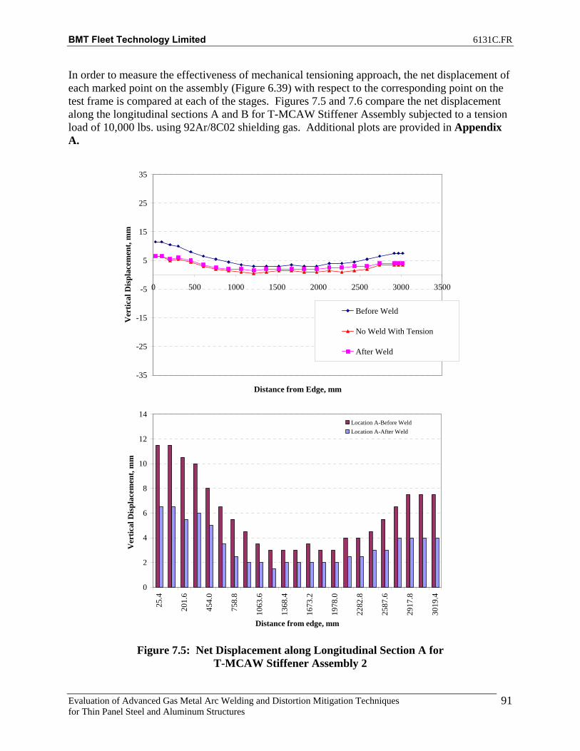
BMT Fleet Technology Limited 6131C.FR
Evaluation of Advanced Gas Metal Arc Welding and Distortion Mitigation Techniques for Thin Panel Steel and Aluminum Structures
91
In order to measure the effectiveness of mechanical tensioning approach, the net displacement of each marked point on the assembly (Figure 6.39) with respect to the corresponding point on the test frame is compared at each of the stages. Figures 7.5 and 7.6 compare the net displacement along the longitudinal sections A and B for T-MCAW Stiffener Assembly subjected to a tension load of 10,000 lbs. using 92Ar/8C02 shielding gas. Additional plots are provided in Appendix A.
-35
-25
-15
-5
5
15
25
35
0 500 1000 1500 2000 2500 3000 3500
Distance from Edge, mm
Ver
tical
Dis
plac
emen
t, m
m
Before Weld
No Weld With Tension
After Weld
0
2
4
6
8
10
12
14
25.4
201.
6
454.
0
758.
8
1063
.6
1368
.4
1673
.2
1978
.0
2282
.8
2587
.6
2917
.8
3019
.4
Distance from edge, mm
Ver
tical
Dis
plac
emen
t, m
m
Location A-Before WeldLocation A-After Weld
Figure 7.5: Net Displacement along Longitudinal Section A for
T-MCAW Stiffener Assembly 2

BMT Fleet Technology Limited 6131C.FR
Evaluation of Advanced Gas Metal Arc Welding and Distortion Mitigation Techniques for Thin Panel Steel and Aluminum Structures
92
-35
-25
-15
-5
5
15
25
35
0 500 1000 1500 2000 2500 3000 3500
Distance from Edge, mm
Ver
tical
Dis
plac
emen
t, m
m
Before Weld
No Weld With Tension
After Weld
0
2
4
6
8
10
12
14
25.4
201.
6
454.
0
758.
8
1063
.6
1368
.4
1673
.2
1978
.0
2282
.8
2587
.6
2917
.8
3019
.4
Distance from edge, mm
Ver
tical
Dis
plac
emen
t, m
m
Location B-Before WeldLocation B-After Weld
Figure 7.6: Net Displacement along Longitudinal Section B for
T-MCAW Stiffener Assembly 2

BMT Fleet Technology Limited 6131C.FR
Evaluation of Advanced Gas Metal Arc Welding and Distortion Mitigation Techniques for Thin Panel Steel and Aluminum Structures
93
7.1.1 Net Improvement The distortion data in Table 7.6 and Figures 7.7 through 7.9 compare the overall net improvement achieved in controlling distortion under applied tension with respect to benchmark assembly. The negative values, color coded light blue indicates location where tensioning has been effective to counter distortion due to welding. Also cells color coded green indicate no change in distortion and yellow indicates an increase in distortion. Additional plots are provided in Appendix F.
Table 7.6: T-MCAW_Stiff_2 Net Displacement
A T B Abs Diff A T B Abs Diff1 -5 -5 -4.5 0.5 1 -3.5 -3 -4.5 1 -1.5 -2 02 -5 -5 -4.5 0.5 2 -2.5 -3 -3.5 1 -2.5 -2 -13 -5 -4.5 -5 0 3 -2 -2.75 -3 1 -3 -1.75 -24 -4 -4 -3 1 4 -2 -2.5 -2 0 -2 -1.5 -15 -3 -4 -2 1 5 -1 -2 -1.5 0.5 -2 -2 -0.56 -3 -4 -1.5 1.5 6 -1.5 -1.5 -0.5 1 -1.5 -2.5 -17 -3 -3.5 -0.5 2.5 7 -1 -1.25 -0.5 0.5 -2 -2.25 08 -2.5 -3 -0.5 2 8 -0.5 -1 -0.5 0 -2 -2 09 -1.5 -2.25 0 1.5 9 0 -1 -0.5 0.5 -1.5 -1.25 0.5
10 -1.5 -1.5 0.5 2 10 0 -1 0 0 -1.5 -0.5 0.511 -1 -1.5 0.5 1.5 11 0 -1 0 0 -1 -0.5 0.512 -1 -1.5 0 1 12 0.5 -1 0.5 0 -1.5 -0.5 -0.513 -1.5 -1.25 0.5 2 13 0 -0.75 0.5 0.5 -1.5 -0.5 014 -1 -1 0.5 1.5 14 0 -0.5 0 0 -1 -0.5 0.515 -1 -1 0 1 15 0 -0.75 0.5 0.5 -1 -0.25 -0.516 -1.5 -1 -0.5 1 16 0 -1 0.5 0.5 -1.5 0 -117 -1.5 -1.75 -1.5 0 17 -0.5 -0.75 0 0.5 -1 -1 -1.518 -1.5 -2.5 -1 0.5 18 -1 -0.5 0.5 1.5 -0.5 -2 -1.519 -2.5 -2.5 -1.5 1 19 -3 -1 0 3 0.5 -1.5 -1.520 -2.5 -2.5 -2.5 0 20 -1 -1.5 -1 0 -1.5 -1 -1.521 -3.5 -3 -4 0.5 21 -2 -2 -2 0 -1.5 -1 -222 -3.5 -2.5 -4 0.5 22 -1.5 -2 -1.5 0 -2 -0.5 -2.523 -3.5 -2 -4 0.5 23 -1.5 -2 -3 1.5 -2 0 -1
Net Displacement, mmDisplacement w.r.t to Frame, mm
Net Displacement, mmBenchmark
Net Improvement, mmBenchmark
.

BMT Fleet Technology Limited 6131C.FR
Evaluation of Advanced Gas Metal Arc Welding and Distortion Mitigation Techniques for Thin Panel Steel and Aluminum Structures
94
-10
-8
-6
-4
-2
0
2
4
25.4
201.
6
454.
0
758.
8
1063
.6
1368
.4
1673
.2
1978
.0
2282
.8
2587
.6
2917
.8
3019
.4
Distance from edge, mm
Ver
tical
Dis
plac
emen
t, m
mNet Improvement
Figure 7.7: T-MCAW_Stiff_2 -Net Improvement at Location A.
-10
-8
-6
-4
-2
0
2
4
25.4
201.
6
454.
0
758.
8
1063
.6
1368
.4
1673
.2
1978
.0
2282
.8
2587
.6
2917
.8
3019
.4
Distance from edge, mm
Ver
tical
Dis
plac
emen
t, m
m
Net Improvement
Figure 7.8: T-MCAW_Stiff_2 -Net Improvement at Location B

BMT Fleet Technology Limited 6131C.FR
Evaluation of Advanced Gas Metal Arc Welding and Distortion Mitigation Techniques for Thin Panel Steel and Aluminum Structures
95
-10
-8
-6
-4
-2
0
2
4
25.4
201.
6
454.
0
758.
8
1063
.6
1368
.4
1673
.2
1978
.0
2282
.8
2587
.6
2917
.8
3019
.4
Distance from edge, mm
Ver
tical
Dis
plac
emen
t, m
mNet Improvement
Figure 7.9: T-MCAW_Stiff_2 -Net Improvement at Location T As mentioned previously, the FCAW process, with and without tension, was presented in earlier in this report. Displacements are plotted on Figures 7.10 through 7.12 for locations A, B, and T to compare the non-tension cases. Net-Improvement comparisons are shown on Figures 7.13 through 7.15 for 10 000lbs tension cases. Additional distortion plots are shown in Appendix E.

BMT Fleet Technology Limited 6131C.FR
Evaluation of Advanced Gas Metal Arc Welding and Distortion Mitigation Techniques for Thin Panel Steel and Aluminum Structures
96
-30
-20
-10
0
10
20
30
0 500 1000 1500 2000 2500 3000 3500
Distance from Edge, mm
Ver
tical
Dis
plac
emen
t, m
m
Before Weld-FCAW After Weld-FCAWBefore Weld-TMCAW After Weld-TMCAW
Figure 7.10: Net Displacement along Longitudinal Section A for Benchmark
T-MCAW Stiffener Assembly vs. Benchmark FCAW Stiffener Assembly
-30
-20
-10
0
10
20
30
0 500 1000 1500 2000 2500 3000 3500
Distance from Edge, mm
Ver
tical
Dis
plac
emen
t, m
m
Before Weld-FCAW After Weld-FCAW
Before Weld-TMCAW After Weld-TMCAW
Figure 7.11: Net Displacement along Longitudinal Section B for Benchmark T-MCAW Stiffener Assembly vs. Benchmark FCAW Stiffener Assembly

BMT Fleet Technology Limited 6131C.FR
Evaluation of Advanced Gas Metal Arc Welding and Distortion Mitigation Techniques for Thin Panel Steel and Aluminum Structures
97
30
40
50
60
70
80
90
0 500 1000 1500 2000 2500 3000 3500
Distance from Edge, mm
Ver
tical
Dis
plac
emen
t, m
m
Before Weld-FCAW After Weld-FCAWBefore Weld-TMCAW After Weld-TMCAW
Figure 7.12: Net Displacement along Longitudinal Section T for Benchmark
T-MCAW Stiffener Assembly vs. Benchmark FCAW Stiffener Assembly
-8
-6
-4
-2
0
2
4
6
25.4
201.
6
454.
0
758.
8
1063
.6
1368
.4
1673
.2
1978
.0
2282
.8
2587
.6
2917
.8
3019
.4
Distance from edge, mm
Ver
tical
Dis
plac
emen
t, m
m
FCAW-Net ImprovementTMCAW-Net Improvement
Figure 7.13: Net Improvement along Longitudinal Section A for T-MCAW Stiffener
Assembly vs. FCAW Stiffener Assembly with 10 000lbs Tension

BMT Fleet Technology Limited 6131C.FR
Evaluation of Advanced Gas Metal Arc Welding and Distortion Mitigation Techniques for Thin Panel Steel and Aluminum Structures
98
-8
-6
-4
-2
0
2
4
6
25.4
201.
6
454.
0
758.
8
1063
.6
1368
.4
1673
.2
1978
.0
2282
.8
2587
.6
2917
.8
3019
.4
Distance from edge, mm
Ver
tical
Dis
plac
emen
t, m
m
FCAW-Net ImprovementTMCAW-Net Improvement
Figure 7.14: Net Improvement along Longitudinal Section B for T-MCAW Stiffener
Assembly vs. FCAW Stiffener Assembly with 10 000lbs Tension
-8
-6
-4
-2
0
2
4
6
25.4
201.
6
454.
0
758.
8
1063
.6
1368
.4
1673
.2
1978
.0
2282
.8
2587
.6
2917
.8
3019
.4
Distance from edge, mm
Ver
tical
Dis
plac
emen
t, m
m
FCAW-Net ImprovementTMCAW-Net Improvement
Figure 7.15: Net Improvement along Longitudinal Section T for T-MCAW Stiffener
Assembly vs. FCAW Stiffener Assembly with 10 000lbs Tension

BMT Fleet Technology Limited 6131C.FR
Evaluation of Advanced Gas Metal Arc Welding and Distortion Mitigation Techniques for Thin Panel Steel and Aluminum Structures
99
From the data presented it can be concluded that the mechanical tensioning approach as applied to fillet welding of stiffener assemblies does provide an advantage to counter distortion. The best weldability, profile, and distortion results were with the use of 92Ar/8C02 shielding gas. Penetration profile and weld profile are shown in Figure 7.16 and 7.17. Second best results were achieved with the use of 85Ar/15C02, see Figure 7.18 for weld profile. The data presented also shows that use of the T-MCAW process results in a similar reduction in distortion compared with the FCAW process. The advantage is that with the T-MCAW process, welding speeds are 90IPM compared to 28IPM with the FCAW Process representing a 221% improvement in travel speed. The productivity of the stiffener welding operations would be greatly increased by using the T-MCAW process.
Figure 7.16: T-MCAW Weld Profile

BMT Fleet Technology Limited 6131C.FR
Evaluation of Advanced Gas Metal Arc Welding and Distortion Mitigation Techniques for Thin Panel Steel and Aluminum Structures
100
Figure 7.17: T-MCAW Weld Profile with 92Ar/8C02
Figure 7.18: T-MCAW Weld Profile with 85Ar/15C02

BMT Fleet Technology Limited 6131C.FR
Evaluation of Advanced Gas Metal Arc Welding and Distortion Mitigation Techniques for Thin Panel Steel and Aluminum Structures
101
The above results are with material that has primer and mill scale removed. Common practice in the shipyards is to weld the stiffeners to the plate material over the primer. Parameters were tweaked for both FCAW and T-MCAW process for welding over primer. The test assemblies welded over primer used larger HSLA 80 sheets, approximately 4’ x 10’ in size. A new distortion matrix was created to adequately capture change in vertical displacement of the larger assemblies. Preliminary welds were produced and it was determined that the use of 85Ar/15C02 shielding gas was better suited to welding over primer compared to 92Ar/8C02 shielding gas.
7.2 Stiffened Panel Assembly (4’ x 10’ HSLA 80 Base Plate) All the stiffened panels (5mm thick) to be welded were marked up as illustrated in Figure 7.19. Panel distortion (vertical) measurements are recorded for points A through K along the width and T1 to T23 along the length, using a laser level. For all plates to be welded under mechanical tension, the distortion data is recorded at all three stages:
1. Before welding 2. Before welding under tension 3. After welding
For benchmark stiffener assembly in absence of tension, data is recorded before and after completion of welding. In addition, a similar measurement grid was setup for the test support frame upon which the stiffener assembly to be welded are supported. Additional readings included coating thickness measurements which were taken every 4” along the length of the plate (weld zone) and stiffener edge to determine if there is any correlation between porosity and primer thickness. Tables 7.7 and 7.8 show the coating thickness readings for stiffener and plate 7.

BMT Fleet Technology Limited 6131C.FR
Evaluation of Advanced Gas Metal Arc Welding and Distortion Mitigation Techniques for Thin Panel Steel and Aluminum Structures
102
Figure 7.19: Stiffened Panel Distortion Measurement Grid

BMT Fleet Technology Limited 6131C.FR
Evaluation of Advanced Gas Metal Arc Welding and Distortion Mitigation Techniques for Thin Panel Steel and Aluminum Structures
103
Table 7.7: Coating Thickness Readings for Stiffener 7
Distance (mm) From Stiffener End Thickness Reading (mil)
25 1.74 125 1.99 225 1.27 325 1.21 425 1.83 525 1.56 625 1.38 725 1.67 825 1.90 925 1.71
1025 1.64 1125 1.95 1225 1.94 1325 1.72 1425 2.07 1525 1.83 1625 1.32 1725 1.71 1825 1.98 1925 1.73 2025 1.80 2125 1.85 2225 1.29 2325 1.61 2425 1.69 2525 1.62 2625 1.58 2725 1.77 2825 1.34 2925 1.83 3125 1.66
Average 1.68

BMT Fleet Technology Limited 6131C.FR
Evaluation of Advanced Gas Metal Arc Welding and Distortion Mitigation Techniques for Thin Panel Steel and Aluminum Structures
104
Table 7.8: Coating Thickness Readings for Plate 7
Distance (mm) From Plate End Thickness Reading (mil)
25 0.94 125 1.10 225 1.16 325 1.15 425 1.33 525 1.51 625 1.47 725 1.16 825 1.14 925 1.44 1025 1.89 1125 0.84 1225 0.84 1325 1.22 1425 1.02 1525 0.82 1625 1.22 1725 0.90 1825 0.73 1925 0.89 2025 1.37 2125 0.80 2225 1.01 2325 1.38 2425 1.00 2525 1.36 2625 1.24 2725 1.01 2825 0.78 2925 1.39 3125 1.39
Average 1.15
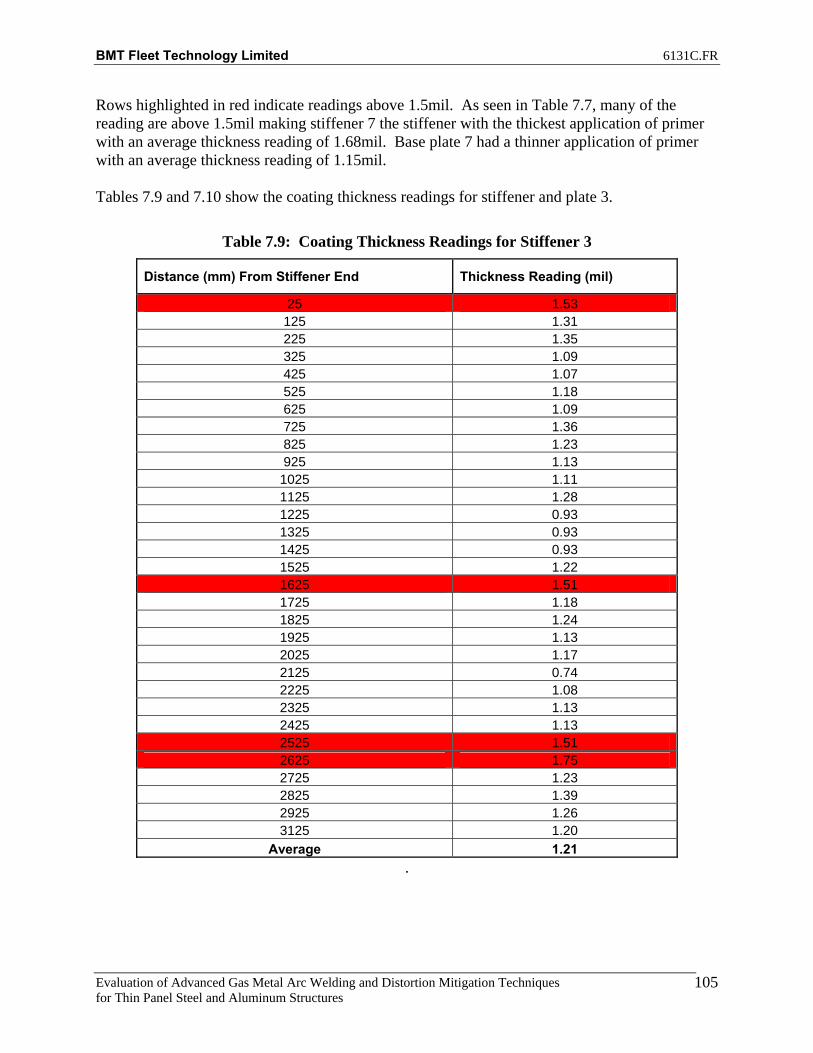
BMT Fleet Technology Limited 6131C.FR
Evaluation of Advanced Gas Metal Arc Welding and Distortion Mitigation Techniques for Thin Panel Steel and Aluminum Structures
105
Rows highlighted in red indicate readings above 1.5mil. As seen in Table 7.7, many of the reading are above 1.5mil making stiffener 7 the stiffener with the thickest application of primer with an average thickness reading of 1.68mil. Base plate 7 had a thinner application of primer with an average thickness reading of 1.15mil. Tables 7.9 and 7.10 show the coating thickness readings for stiffener and plate 3.
Table 7.9: Coating Thickness Readings for Stiffener 3
Distance (mm) From Stiffener End Thickness Reading (mil)
25 1.53 125 1.31 225 1.35 325 1.09 425 1.07 525 1.18 625 1.09 725 1.36 825 1.23 925 1.13 1025 1.11 1125 1.28 1225 0.93 1325 0.93 1425 0.93 1525 1.22 1625 1.51 1725 1.18 1825 1.24 1925 1.13 2025 1.17 2125 0.74 2225 1.08 2325 1.13 2425 1.13 2525 1.51 2625 1.75 2725 1.23 2825 1.39 2925 1.26 3125 1.20
Average 1.21 .

BMT Fleet Technology Limited 6131C.FR
Evaluation of Advanced Gas Metal Arc Welding and Distortion Mitigation Techniques for Thin Panel Steel and Aluminum Structures
106
Table 7.10: Coating Thickness Readings for Plate 3
Distance (mm) From Plate End Thickness Reading (mil)
25 0.98 125 1.15 225 0.61 325 0.96 425 1.06 525 1.32 625 0.62 725 0.90 825 1.32 925 0.78
1025 1.21 1125 0.98 1225 1.02 1325 1.08 1425 1.05 1525 0.79 1625 1.12 1725 0.88 1825 0.98 1925 1.49 2025 0.83 2125 1.22 2225 0.80 2325 0.63 2425 0.85 2525 1.11 2625 0.63 2725 0.86 2825 0.90 2925 0.92 3125 1.15
Average 0.97

BMT Fleet Technology Limited 6131C.FR
Evaluation of Advanced Gas Metal Arc Welding and Distortion Mitigation Techniques for Thin Panel Steel and Aluminum Structures
107
Stiffener and base plate 3 had an application of primer significantly less than 1.5mil with an average thickness reading of 1.21mil and 0.97mil. Because of the significant differences in average coating thickness between stiffener 7 and 3, test assembly 7 and test assembly 3 will be compared for porosity counts to determine if primer thickness plays a role in the amount of porosity generated for the FCAW process. Tables 7.11 and 7.12 show the coating thickness readings for stiffener and plate 8.
Table 7.11: Coating Thickness Readings for Stiffener 8
Distance (mm) From Stiffener End Thickness Reading (mil)
25 2.04 125 1.57 225 1.16 325 1.17 425 0.99 525 1.10 625 0.87 725 1.33 825 1.03 925 0.85 1025 1.03 1125 2.11 1225 1.01 1325 0.93 1425 1.28 1525 2.31 1625 1.69 1725 2.31 1825 1.08 1925 1.29 2025 1.52 2125 1.39 2225 1.78 2325 1.58 2425 1.41 2525 4.73 2625 0.77 2725 3.16 2825 0.71 2925 2.15 3125 1.09
Average 1.53
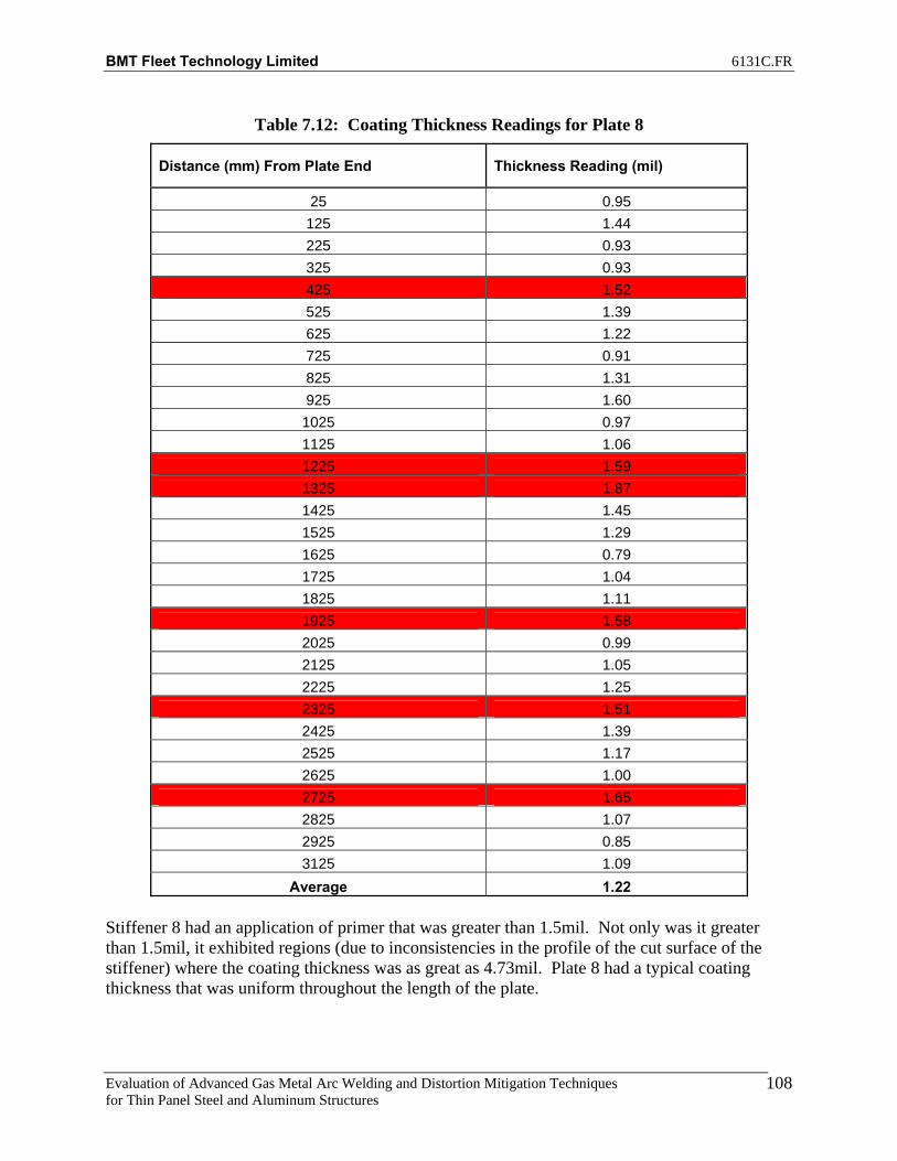
BMT Fleet Technology Limited 6131C.FR
Evaluation of Advanced Gas Metal Arc Welding and Distortion Mitigation Techniques for Thin Panel Steel and Aluminum Structures
108
Table 7.12: Coating Thickness Readings for Plate 8
Distance (mm) From Plate End Thickness Reading (mil)
25 0.95 125 1.44 225 0.93 325 0.93 425 1.52 525 1.39 625 1.22 725 0.91 825 1.31 925 1.60 1025 0.97 1125 1.06 1225 1.59 1325 1.87 1425 1.45 1525 1.29 1625 0.79 1725 1.04 1825 1.11 1925 1.58 2025 0.99 2125 1.05 2225 1.25 2325 1.51 2425 1.39 2525 1.17 2625 1.00 2725 1.65 2825 1.07 2925 0.85 3125 1.09
Average 1.22
Stiffener 8 had an application of primer that was greater than 1.5mil. Not only was it greater than 1.5mil, it exhibited regions (due to inconsistencies in the profile of the cut surface of the stiffener) where the coating thickness was as great as 4.73mil. Plate 8 had a typical coating thickness that was uniform throughout the length of the plate.

BMT Fleet Technology Limited 6131C.FR
Evaluation of Advanced Gas Metal Arc Welding and Distortion Mitigation Techniques for Thin Panel Steel and Aluminum Structures
109
Tables 7.13 and 7.14 show the coating thickness readings for stiffener and plate 9.
Table 7.13: Coating Thickness Readings for Stiffener 9
Distance (mm) From Stiffener End Thickness Reading (mil)
25 1.23 125 1.08 225 1.54 325 1.36 425 1.22 525 1.42 625 0.98 725 0.81 825 1.35 925 1.35
1025 1.29 1125 1.74 1225 1.28 1325 1.86 1425 0.96 1525 1.36 1625 1.37 1725 1.45 1825 1.16 1925 0.86 2025 1.31 2125 1.09 2225 1.12 2325 1.04 2425 0.92 2525 1.02 2625 1.15 2725 0.94 2825 1.02 2925 0.93 3125 1.22
Average 1.21
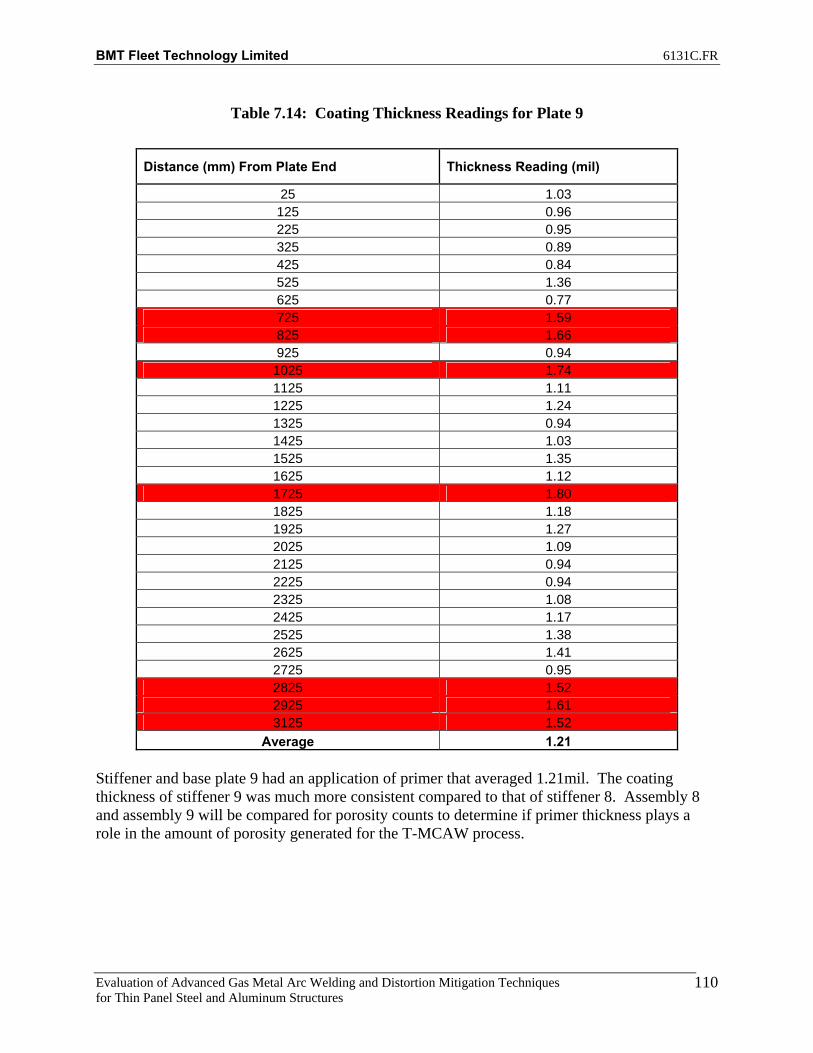
BMT Fleet Technology Limited 6131C.FR
Evaluation of Advanced Gas Metal Arc Welding and Distortion Mitigation Techniques for Thin Panel Steel and Aluminum Structures
110
Table 7.14: Coating Thickness Readings for Plate 9
Distance (mm) From Plate End Thickness Reading (mil)
25 1.03 125 0.96 225 0.95 325 0.89 425 0.84 525 1.36 625 0.77 725 1.59 825 1.66 925 0.94 1025 1.74 1125 1.11 1225 1.24 1325 0.94 1425 1.03 1525 1.35 1625 1.12 1725 1.80 1825 1.18 1925 1.27 2025 1.09 2125 0.94 2225 0.94 2325 1.08 2425 1.17 2525 1.38 2625 1.41 2725 0.95 2825 1.52 2925 1.61 3125 1.52
Average 1.21 Stiffener and base plate 9 had an application of primer that averaged 1.21mil. The coating thickness of stiffener 9 was much more consistent compared to that of stiffener 8. Assembly 8 and assembly 9 will be compared for porosity counts to determine if primer thickness plays a role in the amount of porosity generated for the T-MCAW process.

BMT Fleet Technology Limited 6131C.FR
Evaluation of Advanced Gas Metal Arc Welding and Distortion Mitigation Techniques for Thin Panel Steel and Aluminum Structures
111
It was decided that since the large 4’ x 10’ plates are distorted to begin with, a distortion matrix consisting of 11 points down the length of the plates and three point (center and the two extremities) across the width of the plates was used to measure distortion of the base plates for the purpose of matching up base plates with similar distortion profiles. This was done for better accuracy in comparison of the benchmark and tension cases. A total of ten plates were selected with each of these ten plates marked with a distortion matrix and measured for distortion. Distortion plots were produced and used to compare between the ten plates. Figures 7.20 through 7.22 show the displacement plots of the base plates. Figures 7.23 through 7.25 show the similarity between plates 7 and 3 used for the FCAW benchmark and tension case. Figures 7.26 through 7.28 show the similarity between plates 8 and 9.
Section A
-50
-45
-40
-35
-30
-25
-200 500 1000 1500 2000 2500 3000 3500
Distance from edge, mm
Rel
ativ
e D
ispl
acem
ent,m
m
Plate 1 Plate 2 Plate 3 Plate 4 Plate 5Plate 6 Plate 7 Plate 8 Plate 9 Plate 10
Figure 7.20: Vertical Displacement of Ten Base Plates for Location A

BMT Fleet Technology Limited 6131C.FR
Evaluation of Advanced Gas Metal Arc Welding and Distortion Mitigation Techniques for Thin Panel Steel and Aluminum Structures
112
Section B
-50
-45
-40
-35
-30
-25
-200 500 1000 1500 2000 2500 3000 3500
Distance from edge, mm
Rel
ativ
e D
ispl
acem
ent,m
m
Plate 1 Plate 2 Plate 3 Plate 4 Plate 5Plate 6 Plate 7 Plate 8 Plate 9 Plate 10
Figure 7.21: Vertical Displacement of Ten Base Plates for Location B
Section C
-50
-45
-40
-35
-30
-25
-200 500 1000 1500 2000 2500 3000 3500
Distance from edge, mm
Rel
ativ
e D
ispl
acem
ent,m
m
Plate 1 Plate 2 Plate 3 Plate 4 Plate 5Plate 6 Plate 7 Plate 8 Plate 9 Plate 10
Figure 7.22: Vertical Displacement of Ten Base Plates for Location C

BMT Fleet Technology Limited 6131C.FR
Evaluation of Advanced Gas Metal Arc Welding and Distortion Mitigation Techniques for Thin Panel Steel and Aluminum Structures
113
Section A
-50
-45
-40
-35
-30
-25
-200 500 1000 1500 2000 2500 3000 3500
Distance from edge, mm
Rel
ativ
e D
ispl
acem
ent,m
m
Plate 3 Plate 7
Figure 7.23: Vertical Displacement Comparison of Plate 3 and Plate 7 for Location A
Section B
-50
-45
-40
-35
-30
-25
-200 500 1000 1500 2000 2500 3000 3500
Distance from edge, mm
Rel
ativ
e D
ispl
acem
ent,m
m
Plate 3 Plate 7
Figure 7.24: Vertical Displacement Comparison of Plate 3 and Plate 7 for Location B

BMT Fleet Technology Limited 6131C.FR
Evaluation of Advanced Gas Metal Arc Welding and Distortion Mitigation Techniques for Thin Panel Steel and Aluminum Structures
114
Section C
-50
-45
-40
-35
-30
-25
-200 500 1000 1500 2000 2500 3000 3500
Distance from edge, mm
Rel
ativ
e D
ispl
acem
ent,m
m
Plate 3 Plate 7
Figure 7.25: Vertical Displacement Comparison of Plate 3 and Plate 7 for Location C
Section A
-50
-45
-40
-35
-30
-25
-200 500 1000 1500 2000 2500 3000 3500
Distance from edge, mm
Rel
ativ
e D
ispl
acem
ent,m
m
Plate 8 Plate 9
Figure 7.26: Vertical Displacement Comparison of Plate 8 and Plate 9 for Location A
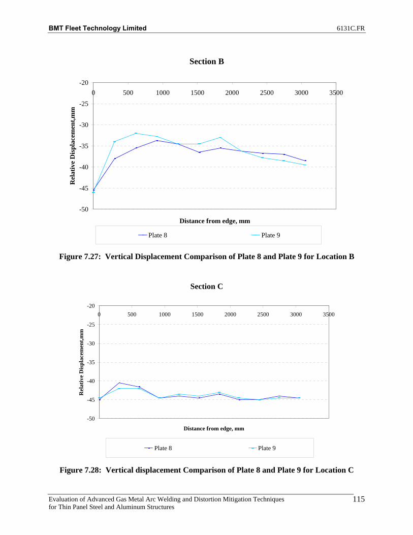
BMT Fleet Technology Limited 6131C.FR
Evaluation of Advanced Gas Metal Arc Welding and Distortion Mitigation Techniques for Thin Panel Steel and Aluminum Structures
115
Section B
-50
-45
-40
-35
-30
-25
-200 500 1000 1500 2000 2500 3000 3500
Distance from edge, mm
Rel
ativ
e D
ispl
acem
ent,m
m
Plate 8 Plate 9
Figure 7.27: Vertical Displacement Comparison of Plate 8 and Plate 9 for Location B
Section C
-50
-45
-40
-35
-30
-25
-200 500 1000 1500 2000 2500 3000 3500
Distance from edge, mm
Rel
ativ
e D
ispl
acem
ent,m
m
Plate 8 Plate 9
Figure 7.28: Vertical displacement Comparison of Plate 8 and Plate 9 for Location C

BMT Fleet Technology Limited 6131C.FR
Evaluation of Advanced Gas Metal Arc Welding and Distortion Mitigation Techniques for Thin Panel Steel and Aluminum Structures
116
The FCAW and T-MCAW processes were used for the welded stiffener assemblies. Table 7.15 summarizes the test cases that were analyzed. Tables 7.16 through 7.25 summarize the measured distortion data for stiffener assemblies at locations A through K. The data is color-coded red and yellow to help better visualize the assembly distortion (torsion). The color red indicates a higher distortion compared to color yellow, whereas light green indicates no change in displacement. Additional net-displacement plots are shown in Appendix G and Appendix J.
Table 7.15: Test Summary
Stiffener Assembly Applied Tension (lbs) FCAW, Benchmark Plate 7 0 T-MCAW, Benchmark Plate 8 0 FCAW, Plate 3 10,000 T-MCAW, Plate 9 10,000
Table 7.16: FCAW Benchmark Plate 7 Distortion Data before Welding
A B C D E F G H I J K1 22 26 27.5 27.5 28.5 160 28 26.5 25 24 212 23.5 28 29 28.5 29.5 160 28 27 26.5 24 203 24 28 29 28.5 28.5 159.5 28 26 25 23.5 194 23.5 27 28.5 29.5 29.5 159 27.5 26 25 23.5 19.55 21 24.5 26 26 27 159 27 26 25 23.5 20.56 18.5 22.5 24 25.5 25.5 158.5 26.5 25.5 25 23 217 16.5 21 24 25 25.5 158 25.5 25 24 23 20.58 16 21 24 24 25.5 159 26 25.5 24 23.5 20.59 16.5 21 23 25 25 159 25.5 25 24 23 21
10 17.5 22.5 23.5 25 26.5 159 25 24.5 23.5 23 2111 20 24 24.5 26 25.5 159.5 24.5 24 23 23 20.512 21.5 25 26 27 26.5 160 25 24.5 23 23 20.513 21.5 26 26.5 28 28 161 26 25 23.5 22 20.514 17.5 22 23.5 25 24.5 160 24 23.5 22.5 20.5 2015 16 21 23 24.5 25 161 25 24.5 24 22 2016 15 25 23 24.5 25 162.5 26.5 26 24.5 23 2017 14.5 19.5 22 24.5 25 161.5 25.5 25.5 24.5 22.5 20.518 15 19.5 23 24.5 26 162 24.5 24.5 23.5 22 2119 19 23 25.5 26.5 27.5 163 25 24.5 23.5 22 2120 21.5 25 26.5 28.5 29 164.5 24.5 24.5 23.5 22 19.521 23 27.5 29 29.5 30.5 165.5 25.5 25 23.5 21.5 1922 23.5 27.5 29 29.5 31.5 166.5 26 25 22.5 20.5 1723 22.5 26.5 28.5 29.5 31 167 26 25 22.5 20 17
Displacement w.r.t to Frame, mmBefore Weld - Plate 7

BMT Fleet Technology Limited 6131C.FR
Evaluation of Advanced Gas Metal Arc Welding and Distortion Mitigation Techniques for Thin Panel Steel and Aluminum Structures
117
Table 7.17: FCAW Benchmark Plate 7 Distortion Data after Welding
A B C D E F G H I J K1 24.5 27 26.5 27 25 155 20 19 19 19 16.52 26 28 27.5 28 26 155 20.5 20 20 20 17.53 25.5 28 27.5 28 25 154.5 21 20 20.5 20.5 18.54 24 26.5 26.5 28.5 26.5 154 21.5 21 22 22 19.55 20 23 23 24.5 23 154 22 22.5 23.5 23.5 22.56 16.5 19 20.5 23 21.5 153.5 22.5 23.5 25.5 26 257 13.5 17 19 22 21.5 153 22.5 24.5 26 26.5 268 12.5 16.5 18.5 20.5 21.5 153.5 23 24.5 26.5 27 269 13.5 17.5 18 21.5 21 154 22.5 24.5 25 26.5 25
10 16.5 20 20 22.5 23 154.5 22 23 23.5 23.5 2311 21 24.5 23 24.5 22.5 154 20.5 21.5 21.5 22 20.512 25.5 27.5 26 26.5 24.5 155 21 21.5 21.5 21.5 19.513 27.5 29 27.5 27.5 25.5 156 22 22 22.5 21.5 2014 23 25 24 24 21.5 154.5 20.5 21.5 22 22.5 2215 19.5 22.5 22.5 23 21.5 156 22 23.5 25 25 24.516 17 20 21 22 21.5 157 23.5 25 26.5 27 27.517 15.5 18.5 19.5 22 21 156.5 21.5 25 26 26.5 2818 15.5 18.5 20 21.5 22 157 20.5 23 24 25.5 2619 18.5 21.5 22.5 23 22.5 158 21 22 22.5 23.5 24.520 21 24 24.5 24.5 24 159 19.5 20.5 21 21.5 20.521 22 25 25.5 25.5 25 159.5 20.5 20 20 19.5 18.522 22 24.5 25 25.5 25.5 160.5 20 19 18.5 17 1523 21 24 24.5 24.5 25.5 161 20 19 17.5 16.5 14
After Weld - Plate 7Displacement w.r.t to Frame, mm
Table 7.18: T-MCAW Benchmark Plate 8 Distortion Data before Welding
A B C D E F G H I J K1 13.5 17 19 20.5 23 151 22.5 21 19.5 17.5 132 15 18.5 20.5 22 24 151 23 21.5 20 18.5 143 16 19.5 21.5 22.5 23 150 23 21.5 19.5 19 154 17 20 22.5 24 24.5 149.5 22.5 21 20.5 19.5 155 17 20.5 22.5 22.5 23 149.5 21.5 20.5 19.5 19 166 18.5 22 23.5 23.5 22.5 149 20.5 19.5 18 17.5 14.57 21 24 25 24.5 23 148.5 19 18 16.5 15 128 22.5 25.5 26 25 24 149 20 18 16.5 14.5 11.59 22 25 24.5 25 23.5 149 20 18.5 16.5 15.5 12.5
10 19.5 22.5 22.5 23.5 23.5 149 20.5 19 18 16.5 1411 17 20.5 20.5 21.5 22.5 149 20.5 20 19 18.5 16.512 17 19.5 19 21 22.5 150 21 20.5 19.5 19 16.513 18 20.5 20 21.5 23 150.5 22 21 20 19 1714 17 19.5 19.5 20 21 150 20 19 18 16.5 14.515 19 22.5 22 22.5 22.5 150 21 19.5 18.5 16.5 15.516 21.5 24.5 24.5 24 23.5 151 21 20.5 18.5 17 14.517 20.5 23.5 24 24.5 23.5 150.5 20.5 20 18.5 17 1518 18.5 21.5 23 24 24.5 150.5 21 21 19 17.5 1719 17 20.5 22 23.5 25 152 21.5 22 20.5 20 19.520 16.5 20 22 24.5 26.5 153 23 22.5 21.5 21 1821 17 21 23 25 26.5 154 24 23.5 22.5 21.5 18.522 19.5 22.5 24.5 27 28.5 155 25 24 22.5 20.5 1723 20 23 25.5 27.5 29 155.5 25.5 24.5 24 20.5 17
Before Weld - Plate 8Displacement w.r.t to Frame, mm

BMT Fleet Technology Limited 6131C.FR
Evaluation of Advanced Gas Metal Arc Welding and Distortion Mitigation Techniques for Thin Panel Steel and Aluminum Structures
118
Table 7.19: T-MCAW Benchmark Plate 8 Distortion Data after Welding
A B C D E F G H I J K1 11 13 14.5 16 15.5 145 16.5 17 17 17 132 13.5 15.5 17 17.5 16.5 145 17 17.5 17.5 17.5 143 16.5 18 19 19 16.5 144.5 16.5 17.5 17 17.5 14.54 18.5 20.5 21.5 21.5 18.5 144 16.5 17.5 18 18 14.55 21.5 23.5 23.5 21.5 18 143.5 16 16.5 16.5 16.5 146 26 27 26.5 24 18 143 15 15 14.5 14 117 31 31 29.5 26.5 20 143 13.5 12.5 11.5 11 78 33 33 31.5 27 20.5 143 13.5 12.5 11 10 6.59 31.5 32 29.5 27.5 20 143 14 13.5 11.5 11.5 7.5
10 26 27 25.5 24 20.5 143 15 14.5 13.5 13.5 9.511 20.5 22 20.5 20 18.5 143 15 16.5 16.5 16.5 1512 17.5 19 17.5 18 17 144 16 17.5 18.5 18 1713 18.5 19.5 18 18.5 18 144.5 16.5 18.5 18.5 19.5 1814 19 19.5 18.5 18 16.5 142.5 15 16 17 17 15.515 24 24.5 23 21.5 18.5 143.5 15.5 16.5 17 16 1516 28.5 28.5 26.5 24 19.5 144.5 16 16.5 17 16.5 1517 27.5 28 25.5 24 20 144 15 16 16.5 16 1518 23.5 24 23.5 22 20 144 15 16 16.5 16.5 1719 20 20.5 20.5 20 19.5 145 15.5 17 17 17.5 18.520 16.5 18.5 18.5 19.5 19.5 145.5 16 17 17 17.5 1721 16.5 18.5 18.5 19.5 20.5 146.5 17 17.5 17.5 17.5 16.522 16.5 18.5 19.5 21 21.5 147 17 17 17 16.5 1523 17 19 20.5 21.5 21.5 147.5 17.5 17.5 17 16 14.5
After Weld No Tension - Plate 8Displacement w.r.t to Frame, mm
Table 7.20: FCAW Plate 3 Distortion Data, No-Tension before Welding
A B C D E F G H I J K1 24 27 27 28.5 30 164 30.5 29.5 25 22 172 24.5 27.5 28 28.5 30.5 163.5 31 30 26.5 24 193 24.5 27 27 27.5 28.5 162 31 30 27 23.5 19.54 23.5 26 27 28.5 30 161 30 30 27.5 24.5 205 20.5 23.5 24.5 25 27.5 159.5 29.5 29.5 27.5 25 216 17 21 23 24 25 158.5 28 29 26.5 25 217 15 19.5 22 24 25 157 27 28 26 23.5 20.58 15 19.5 22 23 25 156.5 26.5 27.5 25.5 23.5 209 16 19 20.5 23 23.5 156 26 26.5 25 24 19.5
10 16.5 19 19.5 21.5 24 155.5 25 26 25 23.5 20.511 18 19.5 19 20.5 21.5 154 23.5 25.5 25.5 24 20.512 19.5 20.5 19.5 20.5 21.5 154 23.5 26 25.5 24 2113 20 21 19.5 21 22 154 24.5 26 25.5 23.5 2114 17 17.5 17 18 19 151.5 22 23.5 23.5 22 2015 15.5 17 16.5 17.5 19 151.5 22 23.5 23.5 22 1916 15.5 17.5 17 18 19 151.5 22 23 22.5 21.5 1917 15 16.5 16.5 18.5 19 150 21 21.5 21.5 20 19.518 15.5 17 17.5 18.5 19.5 149.5 19.5 21 20 20.5 2019 17 18 18.5 19 20 149.5 20 21 21.5 21.5 2120 18.5 18.5 19 19.5 20.5 149.5 19.5 21.5 21.5 22 20.521 17 17.5 18.5 19.5 21 150 19.5 20.5 21 20 2022 13.5 14.5 16 18.5 20 150.5 18 18 17.5 17 1723 10.5 12 14 17 19.5 150.5 17 16.5 15.5 15 15
Displacement w.r.t to Frame, mmBefore Weld - Plate 3

BMT Fleet Technology Limited 6131C.FR
Evaluation of Advanced Gas Metal Arc Welding and Distortion Mitigation Techniques for Thin Panel Steel and Aluminum Structures
119
Table 7.21: FCAW Plate 3 Distortion Data, Tension before Welding
A B C D E F G H I J K1 18 19.5 19 18.5 20 154.5 19 19 17.5 15.5 13.52 20 21 20 20 21 154 21 21.5 19.5 18 153 20 22.5 20 20 20.5 153 21.5 21.5 21 19 17.54 20.5 22 22 21.5 22.5 152.5 21.5 22.5 21.5 21.5 185 20 21.5 20.5 19 21 151.5 22 22.5 22.5 22 196 18 19.5 20 19.5 19.5 151 21.5 22 21.5 21.5 197 16 18.5 19.5 19.5 19.5 150 20 20.5 20.5 20 17.58 16 18.5 19.5 19 20 150 20 21 21 20 17.59 16.5 19 18.5 19.5 19.5 150 19 20.5 20.5 19.5 17
10 17 19 18.5 19.5 20 149.5 19 20.5 20.5 20 1811 18 19 17.5 18.5 18.5 149 18.5 20.5 20.5 20.5 19.512 19.5 20.5 18.5 19 19.5 149.5 19 21 21.5 20.5 1913 20 21 19 19.5 20 149.5 20 22 22 21 1914 17 18 16.5 16.5 17 147.5 17.5 19.5 21 19.5 1815 17 18 17 17.5 17.5 148 18.5 20 20 19.5 17.516 17.5 18.5 17.5 17.5 17.5 148.5 18.5 20 20 19 1717 16.5 17.5 17 18.5 17.5 147.5 17.5 19.5 19.5 18 17.518 16.5 18 17.5 17.5 18 147.5 17 19 19 18 18.519 17.5 18 18 18.5 19 147.5 18 19.5 19 19 2020 18 18 18 18.5 19 148 18 19 19.5 19 18.521 17.5 17 17.5 18.5 19 149.5 18.5 19 18.5 18 1822 13.5 14 15.5 17.5 18.5 149.5 16 16.5 15.5 14.5 1423 10 12 13.5 16.5 18 149.5 14.5 14 13 13 12
Displacement w.r.t to Frame, mmTension No Weld - Plate 3
Table 7.22: FCAW Plate 3 Distortion Data, Tension after Welding
A B C D E F G H I J K1 25 25.5 23.5 21.5 21 154 18.5 18.5 17 16.5 13.52 26 26.5 24 22.5 22 153.5 20.5 21 20 19 163 26 26.5 24 22.5 21 152.5 21.5 22 21.5 21 18.54 25.5 26 24.5 24.5 23 152 22 24 22.5 23.5 205 21.5 23 22.5 21.5 21 151 23 25 24 25 226 16.5 19.5 20 20 19.5 150.5 23 25 24 25.5 227 13 17 19.5 20.5 20 149.5 22 24 23.5 24 218 13 17 19.5 20 20.5 150 22.5 24.5 23.5 23 20.59 14.5 17.5 18.5 20.5 20 150 22 24 23.5 23 19
10 16 18 18.5 19.5 21 150 22 24 24 23 2011 18.5 19.5 18.5 19 19 149.5 21.5 25 25.5 24.5 2212 20 20.5 19 21 20 150 23 25.5 27.5 27 2513 20.5 21 19.5 20 21 150.5 24 27.5 29.5 29.5 2814 17 18 17 17 17.5 148.5 22.5 25.5 28.5 29 3015 16.5 18 17 17.5 18 149 22.5 26 28.5 29.5 3016 17.5 19.5 18.5 19 19 150 22.5 25 27 27.5 27.517 19 20 19.5 20.5 20 149.5 21 23.5 25 24.5 2418 21 21.5 21.5 21.5 21 149.5 20 22 22.5 22.5 2219 23.5 23.5 23 22.5 21.5 150.5 20.5 21.5 22 22 2220 24 23.5 23 23 22.5 151 20.5 20.5 21.5 21.5 2021 22.5 22 22 23 23 151.5 20.5 20.5 20.5 20.5 19.522 18.5 19 19.5 21 22 152.5 18 18 18 17 1623 16.5 16.5 17.5 19.5 21 153 16 16 15 14.5 14
Displacement w.r.t to Frame, mmAfter Weld - Plate 3

BMT Fleet Technology Limited 6131C.FR
Evaluation of Advanced Gas Metal Arc Welding and Distortion Mitigation Techniques for Thin Panel Steel and Aluminum Structures
120
Table 7.23: T-MCAW Plate 9 Distortion Data, No-Tension before Welding
A B C D E F G H I J K1 6 12.5 17 19.5 23 157.5 25 24 19.5 18 132 10.5 17.5 20.5 22.5 25.5 157.5 25.5 25 20.5 19 143 15.5 26.5 23.5 25.5 26.5 157 26 24.5 20.5 19 144 19 25 26.5 28.5 29 156.5 26 23 21.5 19.5 155 20.5 26 26.5 26.5 27 156 25 22.5 21 19.5 15.56 19.5 25 26 26.5 26 155.5 25.5 22 20.5 19 15.57 17.5 22.5 25 26 25.5 154.5 24.5 21 18.5 17 13.58 16 21 24 24.5 25.5 154.5 24.5 21 19 17 149 14.5 19.5 22 24 24 153.5 24.5 21 19.5 17 14
10 14.5 19.5 21 23.5 25 153 24.5 21.5 19.5 17.5 15.511 16.5 20.5 21.5 22.5 24.5 152 24 26 19.5 18.5 1712 18.5 23 24 25 25.5 152.5 23.5 21 20 19 1713 21 25 25.5 26.5 26 153.5 23 21 19.5 18.5 1714 20 23 24.5 24.5 23.5 151.5 21 18.5 17.5 16.5 1515 20 23.5 24.5 25 24 152.5 21.5 19 18 16.5 14.516 19.5 23 24.5 24.5 24.5 153 22.5 19.5 18.5 17 15.517 16.5 20.5 22 23.5 23.5 152.5 21.5 19.5 18.5 17.5 1618 15.5 19 21.5 22.5 24 152.5 21.5 20 19 17.5 1819 16.5 19.5 22 23.5 24.5 154 22.5 21 19.5 19 1920 17.5 21.5 24 25 25.5 154.5 22.5 21 20.5 19 1821 18.5 22.5 25 26.5 26.5 155 22.5 21.5 20.5 19.5 1722 19 23 25.5 26.5 27 156 22.5 21.5 20 18.5 16.523 18 22.5 25.5 26.5 27 156.5 22.5 21.5 20 18.5 16.5
Displacement w.r.t to Frame, mmBefore Weld - Plate 9
Table 7.24: T-MCAW Plate 9 Distortion Data, Tension before Welding
A B C D E F G H I J K1 4.5 9 11 13 16 150 13.5 14 13.5 14.5 92 9.5 13 15 16 18 150 15 15.5 15 16 103 14 17.5 18.5 18.5 19 149.5 16.5 16 16.5 16.5 12.54 17 20.5 21 21.5 21.5 149 17 17 17 17 135 18 21 20.5 19.5 20 148.5 16 17 17.5 17 146 17 19.5 20 19.5 18 148 16 16.5 16.5 16.5 147 14.5 18.5 19 19 18 146.5 15.5 15.5 15.5 15 11.58 13.5 16.5 18.5 18 18 146.5 15.5 15.5 15.5 14.5 11.59 12.5 15.5 16.5 17.5 16.5 146 15.5 15.5 15.5 15 12.5
10 13 15.5 16 17 17.5 145.5 16 15.5 16 15.5 1411 15 17 16 17 17 145 15 15.5 16 16 1512 17 18.5 18 18 18 145 15.5 16 16.5 16.5 15.513 18 20 19.5 19.5 18.5 145.5 15.5 16 16 16.5 15.514 16 18 18 17.5 16 143.5 13.5 13.5 14 14.5 13.515 16 18.5 18.5 18 16.5 143.5 13.5 14 14 14.5 1316 16 18.5 18.5 18 17 145.5 14.5 15 15 14.5 13.517 14.5 16.5 16.5 17 16.5 145 14 14.5 15 15 1518 14 15 16.5 16.5 17 145 14 15 15.5 16 1719 15 16 17 17 17.5 146 15 16 16.5 16.5 1820 15.5 17.5 18.5 19 18.5 147 15.5 16 16.5 17 16.521 16.5 18.5 19.5 19.5 19.5 148.5 16 16.5 16.5 17 1622 16 18 19.5 19.5 20 149 15.5 16 16 16 1523 15 17.5 19 19 19.5 149.5 15.5 15.5 16 16 15
Displacement w.r.t to Frame, mmTension No Weld - Plate 9

BMT Fleet Technology Limited 6131C.FR
Evaluation of Advanced Gas Metal Arc Welding and Distortion Mitigation Techniques for Thin Panel Steel and Aluminum Structures
121
Table 7.25: T-MCAW Plate 9 Distortion Data, Tension after Welding
A B C D E F G H I J K1 8 12 13.5 14.5 17 150 15 15 14 10.5 82 13.5 17 18 18 19.5 150 17 17 16 13.5 10.53 19 22.5 22.5 21 20.5 149.5 18 17.5 17 15.5 12.54 23 26 25.5 25 23.5 149 19 19.5 19.5 17 145 25.5 27.5 26 24 22 148.5 20 21 21.5 19.5 176 23.5 25.5 25 24 21 148 20.5 21.5 23 21.5 20.57 19.5 22 22.5 22 20 147 20.5 22.5 24 23.5 238 16 18.5 19.5 19 19.5 146.5 21.5 24 26 26 26.59 13 16 16.5 18 18 146 21.5 24.5 27 27 26.5
10 13 15.5 15.5 17.5 18 145.5 21.5 24 26 26 26.511 16 18 17 18 18 145 20 22.5 24 23.5 2412 20.5 22.5 21.5 21.5 20 145.5 19 21 21.5 20.5 2013 25.5 27 25.5 24 21.5 146 18.5 19 18.5 17 1614 26.5 27.5 26 23 19 144.5 15.5 15.5 15 13 12.515 27 27.5 26 23.5 19.5 145 16 15.5 14.5 12.5 10.516 25 26 25 23 19.5 146 16.5 16.5 15.5 13.5 1217 20 21.5 21 21 19 146 16.5 17 16 14.5 14.518 16.5 18 19 18.5 18.5 146 16 17 16.5 16 1719 15.5 17.5 18.5 18.5 18.5 147 16.5 17.5 17.5 17.5 18.520 16 17.5 19 19.5 19 148 16.5 16.5 17 17.5 17.521 16.5 18.5 20 20 20 148.5 16.5 17 16.5 17 1722 15.5 18 19.5 19.5 19.5 149.5 15.5 16 16 16 1523 15 17.5 19 19 19 150 15 15.5 16 16 14.5
Displacement w.r.t to Frame, mmAfter Weld No Tension - Plate 9
Figures 7.29 through 7.31 illustrate the net displacements for the FCAW benchmark stiffener assembly welding over primer. Lines are plotted representing the average for each set of readings for comparison purposes. Plots were prepared for points A through K as shown in Appendix G. Points E, F (stiffener), and G are shown below.
-35
-25
-15
-5
5
15
25
35
0 500 1000 1500 2000 2500 3000 3500
Distance from Edge, mm
Ver
tical
Dis
plac
emen
t, m
m
Before Weld
After Weld
Before Weld - Average
After Weld - Average
Figure 7.29: Net Displacement along Longitudinal Section E for
FCAW Benchmark Assembly Plate 7
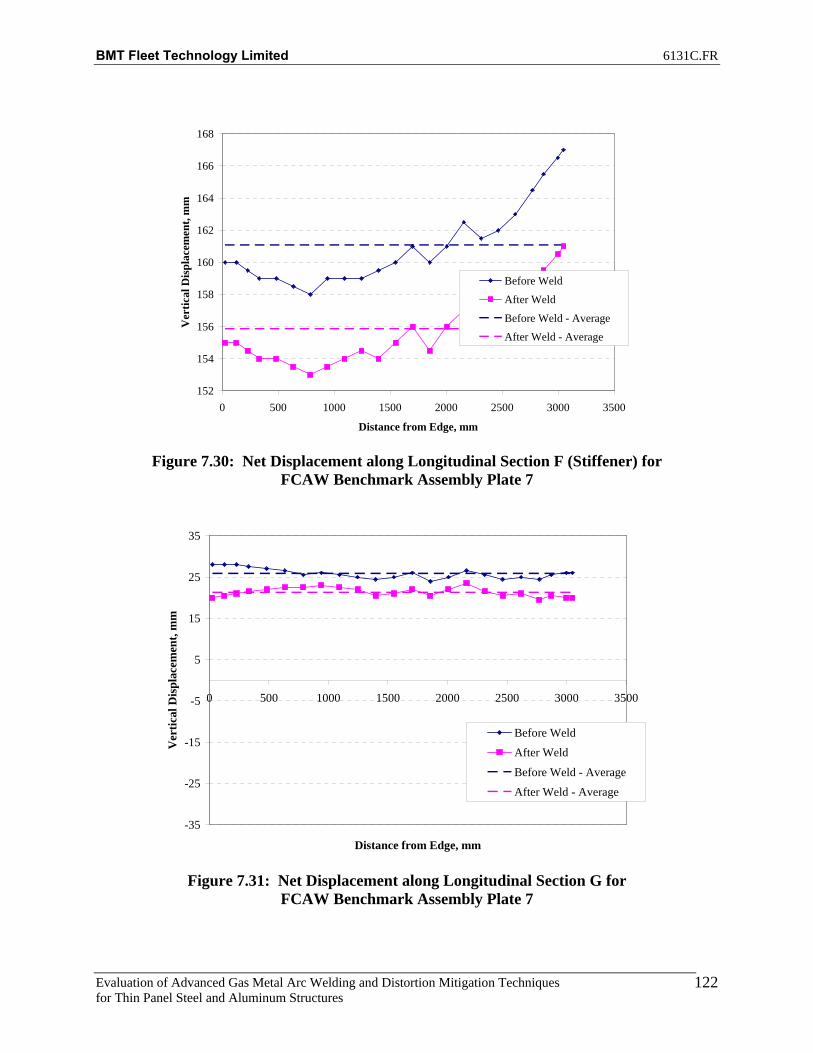
BMT Fleet Technology Limited 6131C.FR
Evaluation of Advanced Gas Metal Arc Welding and Distortion Mitigation Techniques for Thin Panel Steel and Aluminum Structures
122
152
154
156
158
160
162
164
166
168
0 500 1000 1500 2000 2500 3000 3500
Distance from Edge, mm
Ver
tical
Dis
plac
emen
t, m
m
Before Weld
After Weld
Before Weld - Average
After Weld - Average
Figure 7.30: Net Displacement along Longitudinal Section F (Stiffener) for
FCAW Benchmark Assembly Plate 7
-35
-25
-15
-5
5
15
25
35
0 500 1000 1500 2000 2500 3000 3500
Distance from Edge, mm
Ver
tical
Dis
plac
emen
t, m
m
Before Weld
After Weld
Before Weld - Average
After Weld - Average
Figure 7.31: Net Displacement along Longitudinal Section G for
FCAW Benchmark Assembly Plate 7
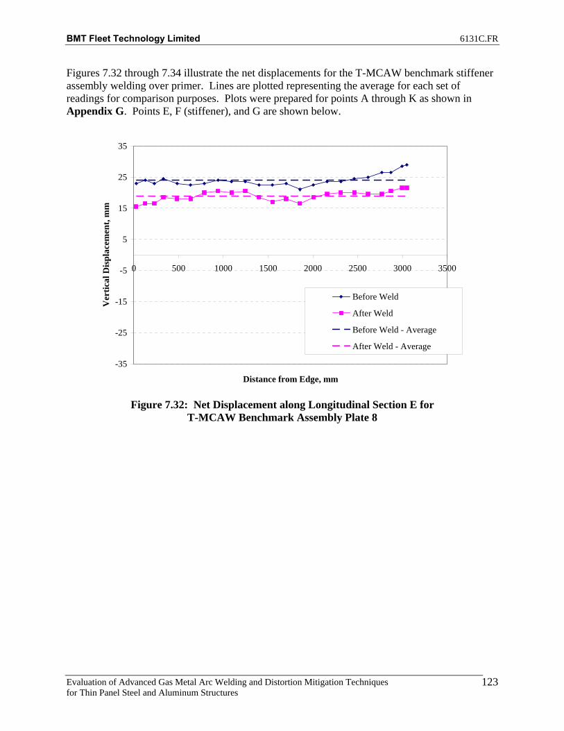
BMT Fleet Technology Limited 6131C.FR
Evaluation of Advanced Gas Metal Arc Welding and Distortion Mitigation Techniques for Thin Panel Steel and Aluminum Structures
123
Figures 7.32 through 7.34 illustrate the net displacements for the T-MCAW benchmark stiffener assembly welding over primer. Lines are plotted representing the average for each set of readings for comparison purposes. Plots were prepared for points A through K as shown in Appendix G. Points E, F (stiffener), and G are shown below.
-35
-25
-15
-5
5
15
25
35
0 500 1000 1500 2000 2500 3000 3500
Distance from Edge, mm
Ver
tical
Dis
plac
emen
t, m
m
Before Weld
After Weld
Before Weld - Average
After Weld - Average
Figure 7.32: Net Displacement along Longitudinal Section E for
T-MCAW Benchmark Assembly Plate 8

BMT Fleet Technology Limited 6131C.FR
Evaluation of Advanced Gas Metal Arc Welding and Distortion Mitigation Techniques for Thin Panel Steel and Aluminum Structures
124
140
145
150
155
160
165
0 500 1000 1500 2000 2500 3000 3500
Distance from Edge, mm
Ver
tical
Dis
plac
emen
t, m
m
Before Weld
After Weld
Before Weld - Average
After Weld - Average
Figure 7.33: Net Displacement along Longitudinal Section F (Stiffener) for
T-MCAW Benchmark Assembly Plate 8
-35
-25
-15
-5
5
15
25
35
0 500 1000 1500 2000 2500 3000 3500
Distance from Edge, mm
Ver
tical
Dis
plac
emen
t, m
m
Before Weld
After Weld
Before Weld - Average
After Weld - Average
Figure 7.34: Net Displacement along Longitudinal Section G for
T-MCAW Benchmark Assembly Plate 8

BMT Fleet Technology Limited 6131C.FR
Evaluation of Advanced Gas Metal Arc Welding and Distortion Mitigation Techniques for Thin Panel Steel and Aluminum Structures
125
Figures 7.35 through 7.37 illustrate the net displacements for the FCAW stiffener assembly welded using 10 000lbs tension (welding over primer). Lines are plotted representing the average for each set of readings for comparison purposes. Plots were prepared for points A through K as shown in Appendix G. Points E, F (stiffener), and G are shown below.
-35
-25
-15
-5
5
15
25
35
0 500 1000 1500 2000 2500 3000 3500
Distance from Edge, mm
Ver
tical
Dis
plac
emen
t, m
m
Before WeldNo Weld With TensionAfter WeldBefore Weld - AverageNo Weld With Tension - AverageAfter Weld - Average
Figure 7.35: Net Displacement along Longitudinal Section E for
FCAW 10 000lbs Tension Assembly Plate 3

BMT Fleet Technology Limited 6131C.FR
Evaluation of Advanced Gas Metal Arc Welding and Distortion Mitigation Techniques for Thin Panel Steel and Aluminum Structures
126
145
147
149
151
153
155
157
159
161
163
165
0 500 1000 1500 2000 2500 3000 3500
Distance from Edge, mm
Ver
tical
Dis
plac
emen
t, m
m
Before WeldNo Weld With TensionAfter WeldBefore Weld - AverageNo Weld With Tension - AverageAfter Weld - Average
Figure 7.36: Net Displacement along Longitudinal Section F (Stiffener) for
FCAW 10 000lbs Tension Assembly Plate 3
-35
-25
-15
-5
5
15
25
35
0 500 1000 1500 2000 2500 3000 3500
Distance from Edge, mm
Ver
tical
Dis
plac
emen
t, m
m
Before WeldNo Weld With TensionAfter WeldBefore Weld - AverageNo Weld With Tension - AverageAfter Weld - Average
Figure 7.37: Net Displacement along Longitudinal Section G for
FCAW 10 000lbs Tension Assembly Plate 3
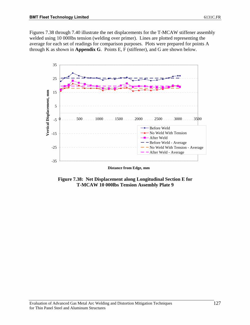
BMT Fleet Technology Limited 6131C.FR
Evaluation of Advanced Gas Metal Arc Welding and Distortion Mitigation Techniques for Thin Panel Steel and Aluminum Structures
127
Figures 7.38 through 7.40 illustrate the net displacements for the T-MCAW stiffener assembly welded using 10 000lbs tension (welding over primer). Lines are plotted representing the average for each set of readings for comparison purposes. Plots were prepared for points A through K as shown in Appendix G. Points E, F (stiffener), and G are shown below.
-35
-25
-15
-5
5
15
25
35
0 500 1000 1500 2000 2500 3000 3500
Distance from Edge, mm
Ver
tical
Dis
plac
emen
t, m
m
Before WeldNo Weld With TensionAfter WeldBefore Weld - AverageNo Weld With Tension - AverageAfter Weld - Average
Figure 7.38: Net Displacement along Longitudinal Section E for
T-MCAW 10 000lbs Tension Assembly Plate 9

BMT Fleet Technology Limited 6131C.FR
Evaluation of Advanced Gas Metal Arc Welding and Distortion Mitigation Techniques for Thin Panel Steel and Aluminum Structures
128
140
145
150
155
160
165
0 500 1000 1500 2000 2500 3000 3500
Distance from Edge, mm
Ver
tical
Dis
plac
emen
t, m
m
Before WeldNo Weld With TensionAfter WeldBefore Weld - AverageNo Weld With Tension - AverageAfter Weld - Average
Figure 7.39: Net Displacement along Longitudinal Section F (Stiffener) for
T-MCAW 10 000lbs Tension Assembly Plate 9
-35
-25
-15
-5
5
15
25
35
0 500 1000 1500 2000 2500 3000 3500
Distance from Edge, mm
Ver
tical
Dis
plac
emen
t, m
m
Before WeldNo Weld With TensionAfter WeldBefore Weld - AverageNo Weld With Tension - AverageAfter Weld - Average
Figure 7.40: Net Displacement along Longitudinal Section G for
T-MCAW 10 000lbs Tension Assembly Plate 9
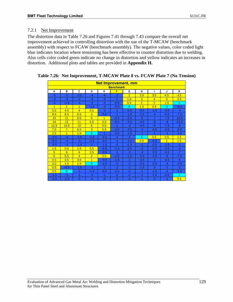
BMT Fleet Technology Limited 6131C.FR
Evaluation of Advanced Gas Metal Arc Welding and Distortion Mitigation Techniques for Thin Panel Steel and Aluminum Structures
129
7.2.1 Net Improvement The distortion data in Table 7.26 and Figures 7.41 through 7.43 compare the overall net improvement achieved in controlling distortion with the use of the T-MCAW (benchmark assembly) with respect to FCAW (benchmark assembly). The negative values, color coded light blue indicates location where tensioning has been effective to counter distortion due to welding. Also cells color coded green indicate no change in distortion and yellow indicates an increases in distortion. Additional plots and tables are provided in Appendix H.
Table 7.26: Net Improvement, T-MCAW Plate 8 vs. FCAW Plate 7 (No Tension)
A B C D E F G H I J K-5 -5 -3.5 -4 -4 -1 2 3.5 3.5 4.5 4.5-4 -3 -2 -4 -4 -1 1.5 3 4 3 2.5-1 -1.5 -1 -3 -3 -0.5 0.5 2 2 1.5 01 1 1 -1.5 -3 -0.5 0 1.5 0.5 0 -0.5
5.5 4.5 4 0.5 -1 -1 -0.5 -0.5 -1.5 -2.5 -49.5 8.5 6.5 3 -0.5 -1 -1.5 -2.5 -4 -6.5 -7.513 11 9.5 5 1 -0.5 -2.5 -5 -7 -7.5 -10.514 12 11 5.5 0.5 -0.5 -3.5 -4.5 -8 -8 -10.5
12.5 10.5 10 6 0.5 -1 -3 -4.5 -6 -7.5 -97.5 7 6.5 3 0.5 -1.5 -2.5 -3 -4.5 -3.5 -6.52.5 1 1.5 0 -1 -0.5 -1.5 -1 -1 -1 -1.5-3.5 -3 -1.5 -2.5 -3.5 -1 -1 0 0.5 0.5 1.5-5.5 -4 -3 -2.5 -2.5 -1 -1.5 0.5 -0.5 1 1.5-3.5 -3 -1.5 -1 -1.5 -2 -1.5 -1 -0.5 -1.5 -11.5 0.5 1.5 0.5 -0.5 -1.5 -2.5 -2 -2.5 -3.5 -55 9 4 2.5 -0.5 -1 -2 -3 -3.5 -4.5 -76 5.5 4 2 0.5 -1.5 -1.5 -3.5 -3.5 -5 -7.5
4.5 3.5 3.5 1 -0.5 -1.5 -2 -3.5 -3 -4.5 -53.5 1.5 1.5 0 -0.5 -2 -2 -2.5 -2.5 -4 -4.50.5 -0.5 -1.5 -1 -2 -2 -2 -1.5 -2 -3 -20.5 0 -1 -1.5 -0.5 -1.5 -2 -1 -1.5 -2 -1.5-1.5 -1 -1 -2 -1 -2 -2 -1 -1.5 -0.5 0-1.5 -1.5 -1 -1 -2 -2 -2 -1 -2 -1 0.5
Net Improvement, mmBenchmark

BMT Fleet Technology Limited 6131C.FR
Evaluation of Advanced Gas Metal Arc Welding and Distortion Mitigation Techniques for Thin Panel Steel and Aluminum Structures
130
-20
-15
-10
-5
0
5
10
15
20
25.4
228.
6
482.
6
787.
4
1092
.2
1397
.0
1701
.8
2006
.6
2311
.4
2616
.2
2870
.2
3048
.0
Distance from edge, mm
Ver
tical
Dis
plac
emen
t, m
mNet Improvement
Figure 7.41: Net Improvement along Longitudinal Section E for
T-MCAW Plate 8 vs. FCAW Plate 7 (No Tension)
-20
-15
-10
-5
0
5
10
15
20
25.4
228.
6
482.
6
787.
4
1092
.2
1397
.0
1701
.8
2006
.6
2311
.4
2616
.2
2870
.2
3048
.0
Distance from edge, mm
Ver
tical
Dis
plac
emen
t, m
m
Net Improvement
Figure 7.42: Net Improvement along Longitudinal Section F (Stiffener) for
T-MCAW Plate 8 vs. FCAW Plate 7 (No Tension)

BMT Fleet Technology Limited 6131C.FR
Evaluation of Advanced Gas Metal Arc Welding and Distortion Mitigation Techniques for Thin Panel Steel and Aluminum Structures
131
-20
-15
-10
-5
0
5
10
15
20
25.4
228.
6
482.
6
787.
4
1092
.2
1397
.0
1701
.8
2006
.6
2311
.4
2616
.2
2870
.2
3048
.0
Distance from edge, mm
Ver
tical
Dis
plac
emen
t, m
m
Net Improvement
Figure 7.43: Net Improvement along Longitudinal Section G for
T-MCAW Plate 8 vs. FCAW Plate 7 (No Tension) The T-MCAW process results in a reduction in vertical displacement (distortion) compared to the FCAW process for the benchmark assemblies with no applied mechanical tension. The distortion data in Table 7.27 and Figures 7.44 through 7.46 compare the overall net improvement achieved in controlling distortion with the use of the T-MCAW (10 000lbs tension) with respect to FCAW (benchmark assembly). The negative values, color coded light blue indicates location where tensioning has been effective to counter distortion due to welding. Also cells color coded green indicate no change in distortion and yellow indicates an increases in distortion. Additional plots and tables are provided in Appendix H.

BMT Fleet Technology Limited 6131C.FR
Evaluation of Advanced Gas Metal Arc Welding and Distortion Mitigation Techniques for Thin Panel Steel and Aluminum Structures
132
Table 7.27: Net Improvement, T-MCAW Plate 9 vs. FCAW Plate 7 (No Tension)
A B C D E F G H I J K-0.5 -1.5 -2.5 -4.5 -2.5 -2.5 -2 -1.5 0.5 -2.5 -0.50.5 -0.5 -1 -4 -2.5 -2.5 -1 -1 2 -1.5 -12 -4 0.5 -4 -2.5 -2.5 -1 -1 1 -0.5 -1
3.5 1.5 1 -2.5 -2.5 -2.5 -1 1.5 1 -1 -16 3 2.5 -1 -1 -2.5 0 2 2 0 -0.56 4 2.5 0 -1 -2.5 -1 1.5 2 -0.5 15 3.5 2.5 -1 -1.5 -2.5 -1 2 3.5 3 4
3.5 2 1 -2 -2 -2.5 0 4 4.5 5.5 71.5 0 -0.5 -2.5 -2 -2.5 0 4 6.5 6.5 8.5-0.5 -1.5 -2 -3.5 -3.5 -3 0 4 6.5 8 9-1.5 -3 -3 -3 -3.5 -1.5 0 -1 6 6 7-2 -3 -2.5 -3 -3.5 -2 -0.5 3 3 3 4
-1.5 -1 -1 -2 -2 -2.5 -0.5 1 0 -1 -0.51 1.5 1 -0.5 -1.5 -1.5 -2 -1 -2 -5.5 -4.5
3.5 2.5 2 0 -1 -2.5 -2.5 -2.5 -4.5 -7 -8.53.5 8 2.5 1 -1.5 -1.5 -3 -2 -5 -7.5 -112.5 2 1.5 0 -0.5 -1.5 -1 -2 -4 -7 -90.5 0 0.5 -1 -1.5 -1.5 -1.5 -1.5 -3 -5 -6-0.5 -0.5 -0.5 -1.5 -1 -2 -2 -1 -1 -3 -4-1 -3 -3 -1.5 -1.5 -1 -1 -0.5 -1 -1 -1.5-1 -1.5 -1.5 -2.5 -1 -0.5 -1 0.5 -0.5 -0.5 0.5-2 -2 -2 -3 -1.5 -0.5 -1 0.5 0 1 0.5
-1.5 -2.5 -2.5 -2.5 -2.5 -0.5 -1.5 0 1 1 1
Net Improvement, mmBenchmark
-20
-15
-10
-5
0
5
10
15
20
25.4
228.
6
482.
6
787.
4
1092
.2
1397
.0
1701
.8
2006
.6
2311
.4
2616
.2
2870
.2
3048
.0
Distance from edge, mm
Ver
tical
Dis
plac
emen
t, m
m
Net Improvement
Figure 7.44: Net Improvement along Longitudinal Section E for
T-MCAW Plate 9 (10 000lbs tension) vs. FCAW Plate 7 (No Tension)
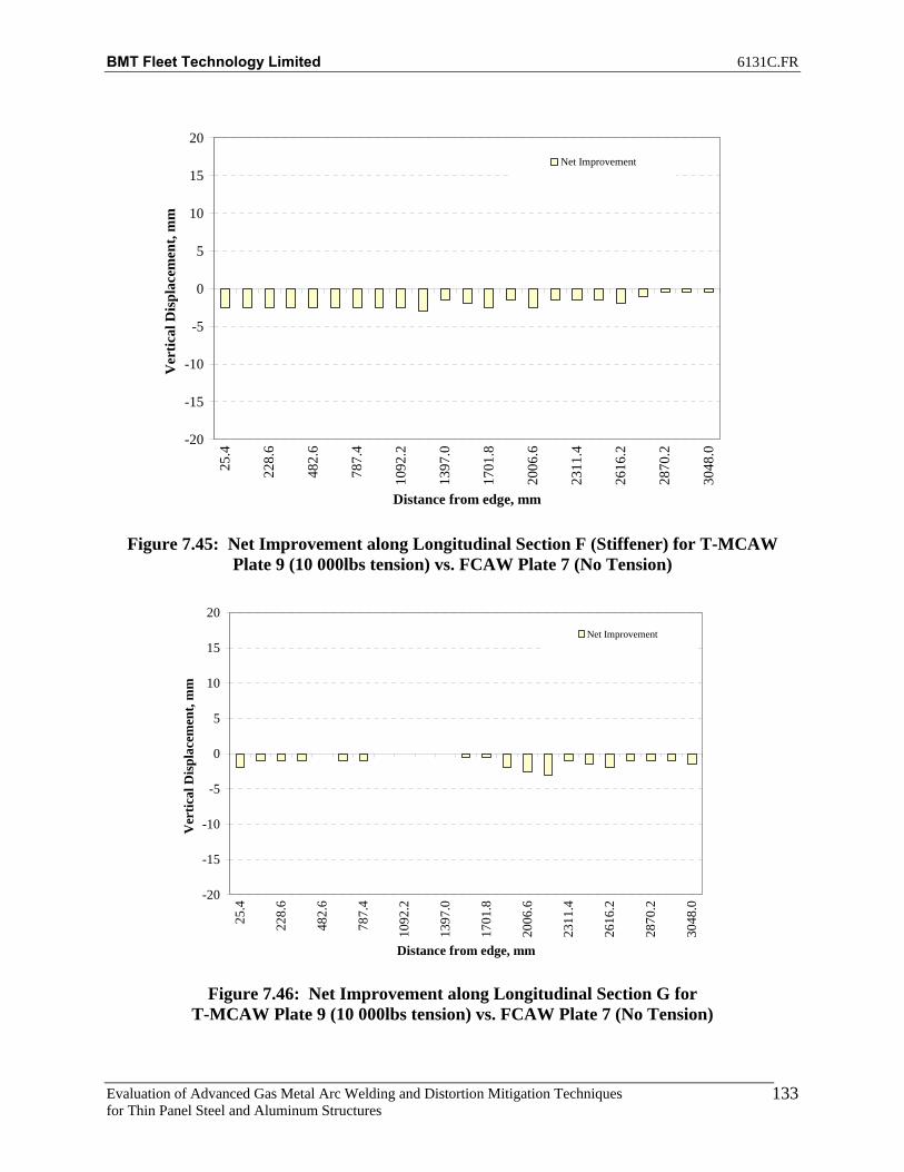
BMT Fleet Technology Limited 6131C.FR
Evaluation of Advanced Gas Metal Arc Welding and Distortion Mitigation Techniques for Thin Panel Steel and Aluminum Structures
133
-20
-15
-10
-5
0
5
10
15
20
25.4
228.
6
482.
6
787.
4
1092
.2
1397
.0
1701
.8
2006
.6
2311
.4
2616
.2
2870
.2
3048
.0
Distance from edge, mm
Ver
tical
Dis
plac
emen
t, m
mNet Improvement
Figure 7.45: Net Improvement along Longitudinal Section F (Stiffener) for T-MCAW
Plate 9 (10 000lbs tension) vs. FCAW Plate 7 (No Tension)
-20
-15
-10
-5
0
5
10
15
20
25.4
228.
6
482.
6
787.
4
1092
.2
1397
.0
1701
.8
2006
.6
2311
.4
2616
.2
2870
.2
3048
.0
Distance from edge, mm
Ver
tical
Dis
plac
emen
t, m
m
Net Improvement
Figure 7.46: Net Improvement along Longitudinal Section G for
T-MCAW Plate 9 (10 000lbs tension) vs. FCAW Plate 7 (No Tension)
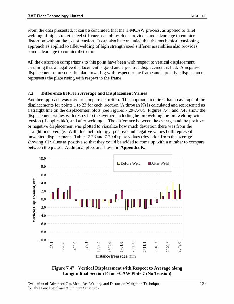
BMT Fleet Technology Limited 6131C.FR
Evaluation of Advanced Gas Metal Arc Welding and Distortion Mitigation Techniques for Thin Panel Steel and Aluminum Structures
134
From the data presented, it can be concluded that the T-MCAW process, as applied to fillet welding of high strength steel stiffener assemblies does provide some advantage to counter distortion without the use of tension. It can also be concluded that the mechanical tensioning approach as applied to fillet welding of high strength steel stiffener assemblies also provides some advantage to counter distortion. All the distortion comparisons to this point have been with respect to vertical displacement, assuming that a negative displacement is good and a positive displacement is bad. A negative displacement represents the plate lowering with respect to the frame and a positive displacement represents the plate rising with respect to the frame.
7.3 Difference between Average and Displacement Values Another approach was used to compare distortion. This approach requires that an average of the displacements for points 1 to 23 for each location (A through K) is calculated and represented as a straight line on the displacement plots (see Figures 7.29-7.40). Figures 7.47 and 7.48 show the displacement values with respect to the average including before welding, before welding with tension (if applicable), and after welding. The difference between the average and the positive or negative displacement was plotted to visualize how much deviation there was from the straight line average. With this methodology, positive and negative values both represent unwanted displacement. Tables 7.28 and 7.29 display values (deviation from the average) showing all values as positive so that they could be added to come up with a number to compare between the plates. Additional plots are shown in Appendix K.
-10.0
-8.0
-6.0
-4.0
-2.0
0.0
2.0
4.0
6.0
8.0
10.0
25.4
228.
6
482.
6
787.
4
1092
.2
1397
.0
1701
.8
2006
.6
2311
.4
2616
.2
2870
.2
3048
.0
Distance from edge, mm
Ver
tical
Dis
plac
emen
t, m
m
Before Weld After Weld
Figure 7.47: Vertical Displacement with Respect to Average along
Longitudinal Section E for FCAW Plate 7 (No Tension)

BMT Fleet Technology Limited 6131C.FR
Evaluation of Advanced Gas Metal Arc Welding and Distortion Mitigation Techniques for Thin Panel Steel and Aluminum Structures
135
-10.0
-8.0
-6.0
-4.0
-2.0
0.0
2.0
4.0
6.0
8.0
10.0
25.4
228.
6
482.
6
787.
4
1092
.2
1397
.0
1701
.8
2006
.6
2311
.4
2616
.2
2870
.2
3048
.0
Distance from edge, mm
Ver
tical
Dis
plac
emen
t, m
m
Before WeldNo Weld With TensionAfter Weld
Figure 7.48: Vertical Displacement with Respect to Average
along Longitudinal Section E for T-MCAW Plate 9 (10 000lbs Tension
Table 7.28: Vertical Displacement with Respect to Average for FCAW Plate 7 (No Tension)
A B C D E F G H I J K1 4.4 4.1 3.3 2.7 1.7 0.9 1.3 3.0 3.6 3.8 5.2 28.82 5.9 5.1 4.3 3.7 2.7 0.9 0.8 2.0 2.6 2.8 4.2 30.83 5.4 5.1 4.3 3.7 1.7 1.4 0.3 2.0 2.1 2.3 3.2 28.34 3.9 3.6 3.3 4.2 3.2 1.9 0.2 1.0 0.6 0.8 2.2 22.75 0.1 0.1 0.2 0.2 0.3 1.9 0.7 0.5 0.9 0.7 0.8 5.56 3.6 3.9 2.7 1.3 1.8 2.4 1.2 1.5 2.9 3.2 3.3 24.57 6.6 5.9 4.2 2.3 1.8 2.9 1.2 2.5 3.4 3.7 4.3 34.58 7.6 6.4 4.7 3.8 1.8 2.4 1.7 2.5 3.9 4.2 4.3 39.09 6.6 5.4 5.2 2.8 2.3 1.9 1.2 2.5 2.4 3.7 3.3 34.0
10 3.6 2.9 3.2 1.8 0.3 1.4 0.7 1.0 0.9 0.7 1.3 16.511 0.9 1.6 0.2 0.2 0.8 1.9 0.8 0.5 1.1 0.8 1.2 8.712 5.4 4.6 2.8 2.2 1.2 0.9 0.3 0.5 1.1 1.3 2.2 20.313 7.4 6.1 4.3 3.2 2.2 0.1 0.7 0.0 0.1 1.3 1.7 25.414 2.9 2.1 0.8 0.3 1.8 1.4 0.8 0.5 0.6 0.3 0.3 11.615 0.6 0.4 0.7 1.3 1.8 0.1 0.7 1.5 2.4 2.2 2.8 11.716 3.1 2.9 2.2 2.3 1.8 1.1 2.2 3.0 3.9 4.2 5.8 26.717 4.6 4.4 3.7 2.3 2.3 0.6 0.2 3.0 3.4 3.7 6.3 28.218 4.6 4.4 3.2 2.8 1.3 1.1 0.8 1.0 1.4 2.7 4.3 23.319 1.6 1.4 0.7 1.3 0.8 2.1 0.3 0.0 0.1 0.7 2.8 9.020 0.9 1.1 1.3 0.2 0.7 3.1 1.8 1.5 1.6 1.3 1.2 13.521 1.9 2.1 2.3 1.2 1.7 3.6 0.8 2.0 2.6 3.3 3.2 21.522 1.9 1.6 1.8 1.2 2.2 4.6 1.3 3.0 4.1 5.8 6.7 27.523 0.9 1.1 1.3 0.2 2.2 5.1 1.3 3.0 5.1 6.3 7.7 26.5
84.4 76.3 60.7 45.2 38.5 43.6 21.3 38.0 50.8 59.8 78.3 518.5
Difference Btw. Avg and Disp - After Weld - Plate 7Displacement w.r.t to Frame, mm

BMT Fleet Technology Limited 6131C.FR
Evaluation of Advanced Gas Metal Arc Welding and Distortion Mitigation Techniques for Thin Panel Steel and Aluminum Structures
136
Table 7.29: Vertical Displacement with Respect to Average for T-MCAW Plate 9 (10 000lbs Tension)
A B C D E F G H I J K1 11.0 9.3 6.6 5.2 2.3 3.1 1.4 2.4 0.1 0.2 2.7 41.62 6.5 4.3 3.1 2.2 0.2 3.1 1.9 3.4 0.9 0.8 1.7 26.43 1.5 4.7 0.1 0.8 1.2 2.6 2.4 2.9 0.9 0.8 1.7 17.94 2.0 3.2 2.9 3.8 3.7 2.1 2.4 1.4 1.9 1.3 0.7 24.75 3.5 4.2 2.4 1.8 1.7 1.6 1.4 0.9 1.4 1.3 0.2 20.26 2.5 3.2 2.4 1.8 0.7 1.1 1.9 0.4 0.9 0.8 0.2 15.77 0.5 0.7 1.4 1.3 0.2 0.1 0.9 0.6 1.1 1.2 2.2 8.08 1.0 0.8 0.4 0.2 0.2 0.1 0.9 0.6 0.6 1.2 1.7 6.09 2.5 2.3 1.6 0.7 1.3 0.9 0.9 0.6 0.1 1.2 1.7 12.1
10 2.5 2.3 2.6 1.2 0.3 1.4 0.9 0.1 0.1 0.7 0.2 12.111 0.5 1.3 2.1 2.2 0.8 2.4 0.4 4.4 0.1 0.3 1.3 14.512 1.5 1.2 0.4 0.3 0.2 1.9 0.1 0.6 0.4 0.8 1.3 7.413 4.0 3.2 1.9 1.8 0.7 0.9 0.6 0.6 0.1 0.3 1.3 14.114 3.0 1.2 0.9 0.2 1.8 2.9 2.6 3.1 2.1 1.7 0.7 19.515 3.0 1.7 0.9 0.3 1.3 1.9 2.1 2.6 1.6 1.7 1.2 17.116 2.5 1.2 0.9 0.2 0.8 1.4 1.1 2.1 1.1 1.2 0.2 12.517 0.5 1.3 1.6 1.2 1.8 1.9 2.1 2.1 1.1 0.7 0.3 14.318 1.5 2.8 2.1 2.2 1.3 1.9 2.1 1.6 0.6 0.7 2.3 16.819 0.5 2.3 1.6 1.2 0.8 0.4 1.1 0.6 0.1 0.8 3.3 9.420 0.5 0.3 0.4 0.3 0.2 0.1 1.1 0.6 0.9 0.8 2.3 5.221 1.5 0.7 1.4 1.8 1.2 0.6 1.1 0.1 0.9 1.3 1.3 10.622 2.0 1.2 1.9 1.8 1.7 1.6 1.1 0.1 0.4 0.3 0.8 12.123 1.0 0.7 1.9 1.8 1.7 2.1 1.1 0.1 0.4 0.3 0.8 11.1
55.5 54.1 41.5 34.3 26.1 36.1 31.6 31.9 17.8 20.4 30.1 349.3
Displacement w.r.t to Frame, mm Difference Btw. Avg and Disp - After Weld - Plate 9
The sum of all vertical displacement with respect to the average for the benchmark FCAW plate 7 was 518.5 compared to 349.3 for the T-MCAW plate welded with 10 000lbs tension. This indicates that the stiffener plate assembly welded with T-MCAW using 10 000lbs of tension exhibited 48% less distortion overall compared to the benchmark FCAW stiffener test assembly.
7.4 Porosity Results FCAW plates 7, 3 and MCAW plates 8, 9 (primed plates) were evaluated for porosity indications by method of visual examination of fractured weld surface as per the requirements of MIL-ST-248C. A total length of 36” was required for testing from each test assembly. A 12” section was taken from the start, center, and end locations of the large test assemblies to investigate possible patterns related to amount of porosity and location of porosity on the plate. The 12” sections were then cut into 6” sections to facilitate fracturing for examination. The first side weld was removed by grinding and tabs were welded to the top and bottom of the specimen for loading in the load cell where tension was applied until fracture occurred. Measurements of porosity indications were taken from the fractured weld surface and evaluation was performed to MIL-STD-248C. See Tables 7.30 through 7.33 for porosity results.

BMT Fleet Technology Limited 6131C.FR
Evaluation of Advanced Gas Metal Arc Welding and Distortion Mitigation Techniques for Thin Panel Steel and Aluminum Structures
137
Table 7.30: Porosity Counts for Plate 7
Weld Location Location (Ruler) # Defects at 3/32" min. Special NotesStart 1 0-1" 1
1-2" 02-3" 03-4" 04-5" 05-6" 0
Start 2 0-1" 01-2" 02-3" 03-4" 04-5" 05-6" 0
Center 1 0-1" 01-2" 02-3" 03-4" 04-5" 0 Fail: More than 5 indications larger than 1/16" were found within 5-6" 0 1 inch of weld exceeding maximum as stated in MIL-STD-248C
Center 2 0-1" 01-2" 02-3" 03-4" 04-5" 05-6" 0
End 1 0-1" 01-2" 02-3" 03-4" 04-5" 05-6" 0
End 2 0-1" 01-2" 02-3" 03-4" 04-5" 05-6" 0
Porosity Counts for Plate 7
Plate 7 was relatively free of porosity in the fractured weld with only one region in the center of the plate exhibiting an accumulation of more than 5 porosity indications greater than 1/16” within 1 inch of weld. For this reason plate 7 fails to meet the requirements of MIL-STD-248C. Photographs of all fracture specimens for plate 7 are shown in Appendix M.

BMT Fleet Technology Limited 6131C.FR
Evaluation of Advanced Gas Metal Arc Welding and Distortion Mitigation Techniques for Thin Panel Steel and Aluminum Structures
138
Table 7.31: Porosity Counts for Plate 3
Weld Location Location (Ruler) # Defects at 3/32" min. Special notesStart 1 0-1" 0
1-2" 02-3" 03-4" 04-5" 05-6" 0
Start 2 0-1" 01-2" 02-3" 03-4" 04-5" 05-6" 0
Center 1 0-1" 01-2" 02-3" 03-4" 04-5" 05-6" 0
Center 2 0-1" 11-2" 02-3" 03-4" 04-5" 05-6" 0
End 1 0-1" 6 3/32" defect to surface at 7/8" mark.1-2" 32-3" 03-4" 04-5" 05-6" 0 Fail: Indication exceeding 3/32" as stated in MIL-STD-248C
End 2 0-1" 01-2" 02-3" 03-4" 04-5" 05-6" 0
Porosity Counts for Plate 3
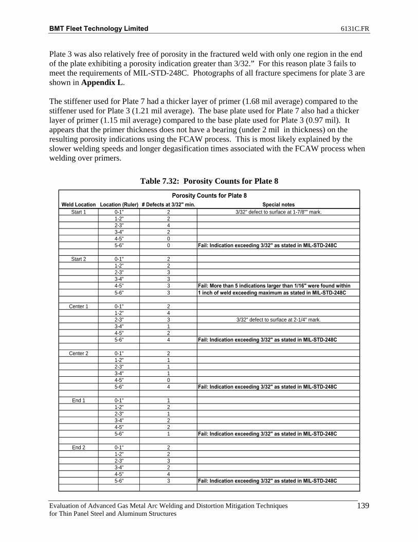
BMT Fleet Technology Limited 6131C.FR
Evaluation of Advanced Gas Metal Arc Welding and Distortion Mitigation Techniques for Thin Panel Steel and Aluminum Structures
139
Plate 3 was also relatively free of porosity in the fractured weld with only one region in the end of the plate exhibiting a porosity indication greater than 3/32.” For this reason plate 3 fails to meet the requirements of MIL-STD-248C. Photographs of all fracture specimens for plate 3 are shown in Appendix L. The stiffener used for Plate 7 had a thicker layer of primer (1.68 mil average) compared to the stiffener used for Plate 3 (1.21 mil average). The base plate used for Plate 7 also had a thicker layer of primer (1.15 mil average) compared to the base plate used for Plate 3 (0.97 mil). It appears that the primer thickness does not have a bearing (under 2 mil in thickness) on the resulting porosity indications using the FCAW process. This is most likely explained by the slower welding speeds and longer degasification times associated with the FCAW process when welding over primers.
Table 7.32: Porosity Counts for Plate 8
Weld Location Location (Ruler) # Defects at 3/32" min. Special notesStart 1 0-1" 2 3/32" defect to surface at 1-7/8"" mark.
1-2" 22-3" 43-4" 24-5" 05-6" 0 Fail: Indication exceeding 3/32" as stated in MIL-STD-248C
Start 2 0-1" 21-2" 22-3" 33-4" 34-5" 3 Fail: More than 5 indications larger than 1/16" were found within 5-6" 3 1 inch of weld exceeding maximum as stated in MIL-STD-248C
Center 1 0-1" 21-2" 42-3" 3 3/32" defect to surface at 2-1/4" mark.3-4" 14-5" 25-6" 4 Fail: Indication exceeding 3/32" as stated in MIL-STD-248C
Center 2 0-1" 21-2" 12-3" 13-4" 14-5" 05-6" 4 Fail: Indication exceeding 3/32" as stated in MIL-STD-248C
End 1 0-1" 11-2" 22-3" 13-4" 24-5" 25-6" 1 Fail: Indication exceeding 3/32" as stated in MIL-STD-248C
End 2 0-1" 21-2" 22-3" 33-4" 24-5" 45-6" 3 Fail: Indication exceeding 3/32" as stated in MIL-STD-248C
Porosity Counts for Plate 8

BMT Fleet Technology Limited 6131C.FR
Evaluation of Advanced Gas Metal Arc Welding and Distortion Mitigation Techniques for Thin Panel Steel and Aluminum Structures
140
Plate 8 exhibited the greatest amount of porosity with many indications exceeding 3/32” throughout the start, center, and end locations. For this reason plate 8 fails to meet the requirements of MIL-STD-248C. Photographs of all fracture specimens for plate 8 are shown in Appendix N.
Table 7.33: Porosity Counts for Plate 9
Weld Location Location (Ruler) # Defects at 3/32" min. Special NotesStart 1 0-1" 0
1-2" 02-3" 03-4" 04-5" 25-6" 0 Fail: Indication exceeding 3/32" as stated in MIL-STD-248C
Start 2 0-1" 01-2" 02-3" 03-4" 04-5" 05-6" 0
Center 1 0-1" 21-2" 12-3" 23-4" 24-5" 05-6" 0
Center 2 0-1" 11-2" 22-3" 03-4" 04-5" 05-6" 0 Fail: Indication exceeding 3/32" as stated in MIL-STD-248C
End 1 0-1" 01-2" 02-3" 03-4" 04-5" 05-6" 0
End 2 0-1" 11-2" 12-3" 33-4" 14-5" 05-6" 0 Fail: Indication exceeding 3/32" as stated in MIL-STD-248C
Porosity Counts for Plate 9

BMT Fleet Technology Limited 6131C.FR
Evaluation of Advanced Gas Metal Arc Welding and Distortion Mitigation Techniques for Thin Panel Steel and Aluminum Structures
141
Plate 9 exhibited significantly less porosity compared to plate 8. A total of three indications exceeding 3/32” in the start, center, and end locations were observed. For this reason plate 9 fails to meet the requirements of MIL-STD-248C. Photographs of all fracture specimens for plate 9 are shown in Appendix O. The stiffener used for Plate 8 had a thicker layer of primer (1.53 mil average) compared to the stiffener used for Plate 9 (1.21 mil average). The stiffener used for plate 8 also exhibited dramatic fluctuations in primer thickness from 0.71 mil to 4.73 mil due to the rough surface condition of the cut edge of the stiffener. The base plate used for Plate 8 and Plate 9 were similar in thickness at 1.22 mil and 1.21 mil. It appears that fluctuations in primer thickness have a bearing on the resulting porosity indications using the T-MCAW process.
7.5 Productivity Results Travel speeds obtained with the T-MCAW process were much faster than with the benchmark FCAW process. The T-MCAW non-primed stiffener assemblies were welded at 90IPM travel speeds compared to 28IPM travel speeds achieved with the FCAW benchmark procedure for a 221% increase in travel speed. The T-MCAW primed stiffener assemblies were welded at 60IPM travel speeds compared to 25IPM travel speeds achieved with the FCAW benchmark procedure for a 140% increase in travel speed. The resulting weld size was slightly larger for the T-MCAW process (between ¼” and 3/16” leg size) compared to the resulting weld size for the FCAW process (between 1/8” and 3/16”). Figures 7.49 and 7.50 show data sheets for the FCAW and T-MCAW processes for both welding over primer and welding on clean steel.

BMT Fleet Technology Limited 6131C.FR
Evaluation of Advanced Gas Metal Arc Welding and Distortion Mitigation Techniques for Thin Panel Steel and Aluminum Structures
142
Figure 7.49: Welding Procedure Data Sheet for FCAW

BMT Fleet Technology Limited 6131C.FR
Evaluation of Advanced Gas Metal Arc Welding and Distortion Mitigation Techniques for Thin Panel Steel and Aluminum Structures
143
Figure 7.50: Welding Procedure Data Sheet for T-MCAW

BMT Fleet Technology Limited 6131C.FR
Evaluation of Advanced Gas Metal Arc Welding and Distortion Mitigation Techniques for Thin Panel Steel and Aluminum Structures
A-1
APPENDIX A
DISTORTION PLOTS FOR GROOVE WELDS

BMT Fleet Technology Limited 6131C.FR
Evaluation of Advanced Gas Metal Arc Welding and Distortion Mitigation Techniques for Thin Panel Steel and Aluminum Structures
A-2
PLATE 1 – SIDE 1
-70
-50
-30
-10
10
30
50
70
-1500 -1000 -500 0 500 1000 1500
Distance from centre, mm
Ver
tical
Dis
plac
emen
t,mm
Before WeldAfter Weld
Figure 1: Transverse Section A1
-70
-50
-30
-10
10
30
50
70
-1500 -1000 -500 0 500 1000 1500
Distance from centre, mm
Ver
tical
Dis
plac
emen
t,mm
Before WeldAfter Weld
Figure 2: Transverse Section A2

BMT Fleet Technology Limited 6131C.FR
Evaluation of Advanced Gas Metal Arc Welding and Distortion Mitigation Techniques for Thin Panel Steel and Aluminum Structures
A-3
-70
-50
-30
-10
10
30
50
70
-1500 -1000 -500 0 500 1000 1500
Distance from centre, mm
Ver
tical
Dis
plac
emen
t,mm
Before WeldAfter Weld
Figure 3: Transverse Section A3
-70
-50
-30
-10
10
30
50
70
-1500 -1000 -500 0 500 1000 1500
Distance from centre, mm
Ver
tical
Dis
plac
emen
t,mm
Before WeldAfter Weld
Figure 4: Transverse Section A5
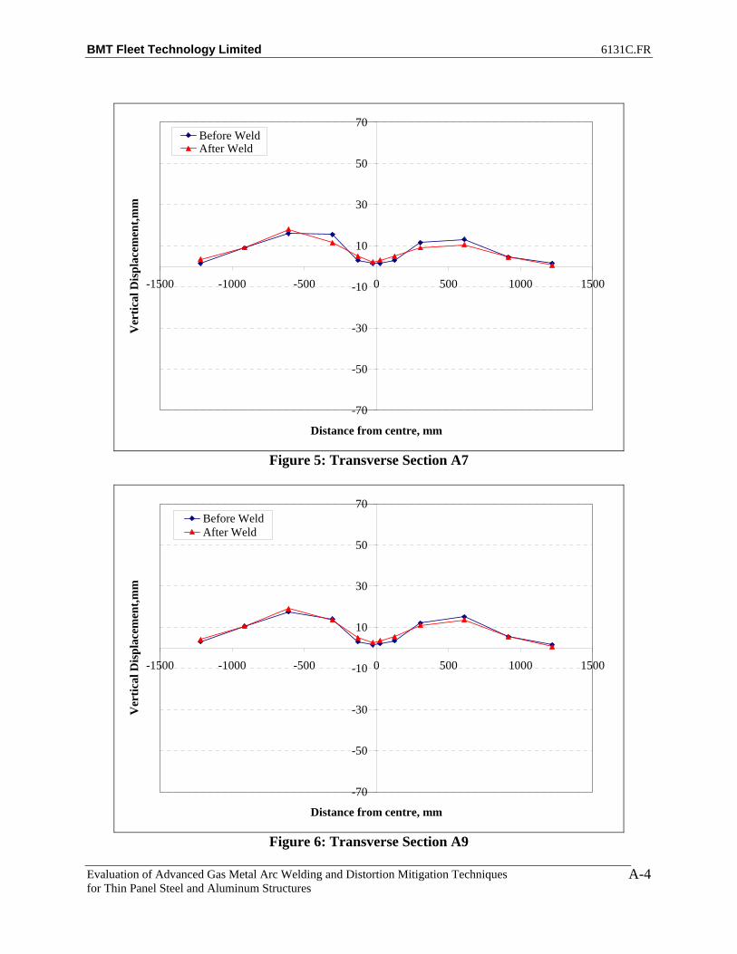
BMT Fleet Technology Limited 6131C.FR
Evaluation of Advanced Gas Metal Arc Welding and Distortion Mitigation Techniques for Thin Panel Steel and Aluminum Structures
A-4
-70
-50
-30
-10
10
30
50
70
-1500 -1000 -500 0 500 1000 1500
Distance from centre, mm
Ver
tical
Dis
plac
emen
t,mm
Before WeldAfter Weld
Figure 5: Transverse Section A7
-70
-50
-30
-10
10
30
50
70
-1500 -1000 -500 0 500 1000 1500
Distance from centre, mm
Ver
tical
Dis
plac
emen
t,mm
Before WeldAfter Weld
Figure 6: Transverse Section A9

BMT Fleet Technology Limited 6131C.FR
Evaluation of Advanced Gas Metal Arc Welding and Distortion Mitigation Techniques for Thin Panel Steel and Aluminum Structures
A-5
-70
-50
-30
-10
10
30
50
70
-1500 -1000 -500 0 500 1000 1500
Distance from centre, mm
Ver
tical
Dis
plac
emen
t,mm
Before WeldAfter Weld
Figure 7: Transverse Section A11
-70
-50
-30
-10
10
30
50
70
-1500 -1000 -500 0 500 1000 1500
Distance from centre, mm
Ver
tical
Dis
plac
emen
t,mm
Before WeldAfter Weld
Figure 8: Transverse Section A13

BMT Fleet Technology Limited 6131C.FR
Evaluation of Advanced Gas Metal Arc Welding and Distortion Mitigation Techniques for Thin Panel Steel and Aluminum Structures
A-6
-70
-50
-30
-10
10
30
50
70
-1500 -1000 -500 0 500 1000 1500
Distance from centre, mm
Ver
tical
Dis
plac
emen
t,mm
Before WeldAfter Weld
Figure 9: Transverse Section A15
-70
-50
-30
-10
10
30
50
70
-1500 -1000 -500 0 500 1000 1500
Distance from centre, mm
Ver
tical
Dis
plac
emen
t,mm
Before WeldAfter Weld
Figure 10: Transverse Section A17
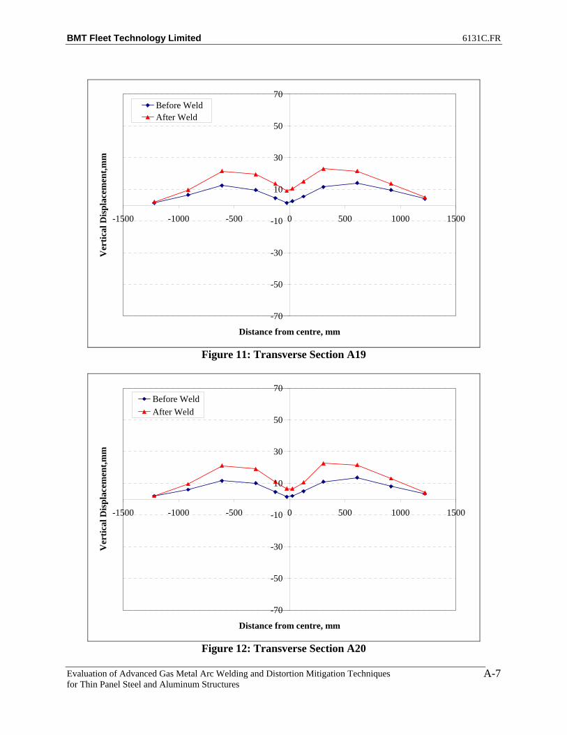
BMT Fleet Technology Limited 6131C.FR
Evaluation of Advanced Gas Metal Arc Welding and Distortion Mitigation Techniques for Thin Panel Steel and Aluminum Structures
A-7
-70
-50
-30
-10
10
30
50
70
-1500 -1000 -500 0 500 1000 1500
Distance from centre, mm
Ver
tical
Dis
plac
emen
t,mm
Before WeldAfter Weld
Figure 11: Transverse Section A19
-70
-50
-30
-10
10
30
50
70
-1500 -1000 -500 0 500 1000 1500
Distance from centre, mm
Ver
tical
Dis
plac
emen
t,mm
Before WeldAfter Weld
Figure 12: Transverse Section A20

BMT Fleet Technology Limited 6131C.FR
Evaluation of Advanced Gas Metal Arc Welding and Distortion Mitigation Techniques for Thin Panel Steel and Aluminum Structures
A-8
-70
-50
-30
-10
10
30
50
70
-1500 -1000 -500 0 500 1000 1500
Distance from centre, mm
Ver
tical
Dis
plac
emen
t,mm
Before WeldAfter Weld
Figure 13: Transverse Section A21
-70
-50
-30
-10
10
30
50
70
-1500 -1000 -500 0 500 1000 1500
Distance from centre, mm
Ver
tical
Dis
plac
emen
t,mm
Before WeldAfter Weld
Figure 14: Transverse Section A22
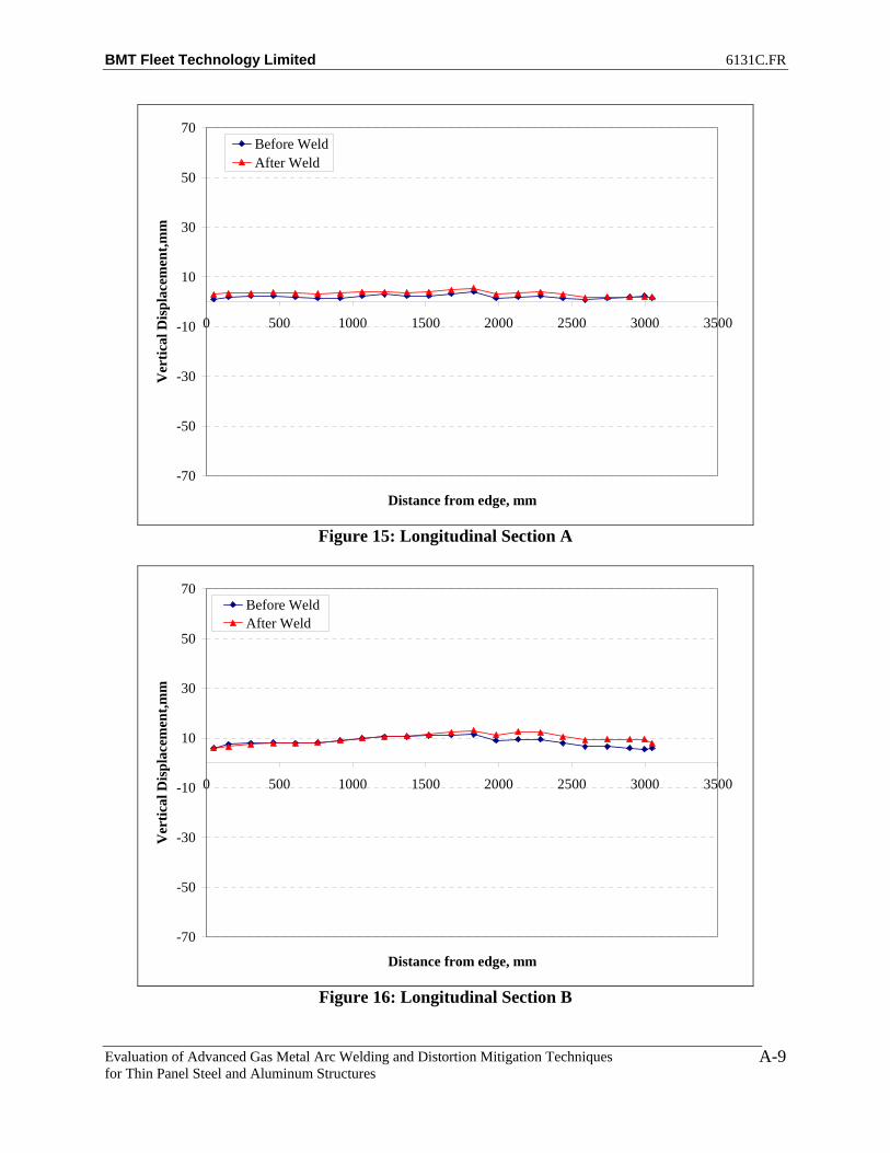
BMT Fleet Technology Limited 6131C.FR
Evaluation of Advanced Gas Metal Arc Welding and Distortion Mitigation Techniques for Thin Panel Steel and Aluminum Structures
A-9
-70
-50
-30
-10
10
30
50
70
0 500 1000 1500 2000 2500 3000 3500
Distance from edge, mm
Ver
tical
Dis
plac
emen
t,mm
Before WeldAfter Weld
Figure 15: Longitudinal Section A
-70
-50
-30
-10
10
30
50
70
0 500 1000 1500 2000 2500 3000 3500
Distance from edge, mm
Ver
tical
Dis
plac
emen
t,mm
Before WeldAfter Weld
Figure 16: Longitudinal Section B
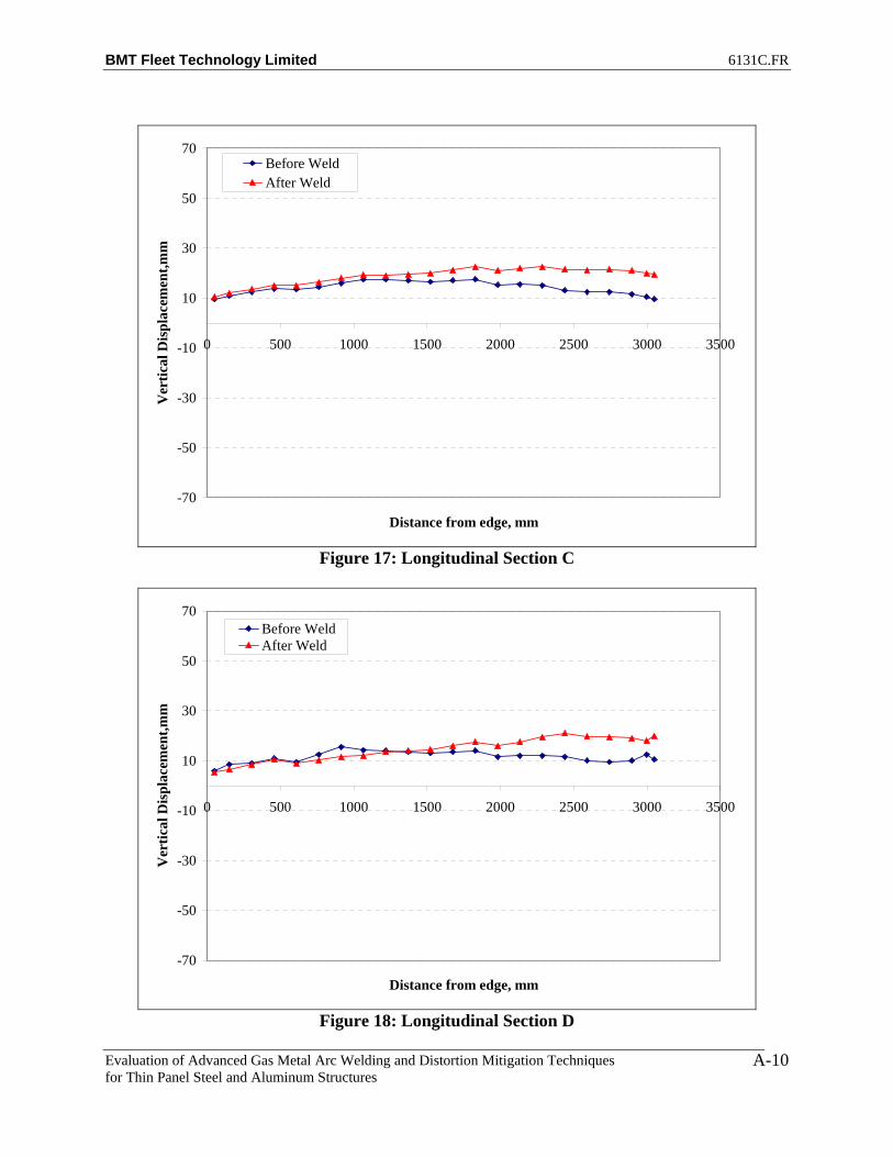
BMT Fleet Technology Limited 6131C.FR
Evaluation of Advanced Gas Metal Arc Welding and Distortion Mitigation Techniques for Thin Panel Steel and Aluminum Structures
A-10
-70
-50
-30
-10
10
30
50
70
0 500 1000 1500 2000 2500 3000 3500
Distance from edge, mm
Ver
tical
Dis
plac
emen
t,mm
Before WeldAfter Weld
Figure 17: Longitudinal Section C
-70
-50
-30
-10
10
30
50
70
0 500 1000 1500 2000 2500 3000 3500
Distance from edge, mm
Ver
tical
Dis
plac
emen
t,mm
Before WeldAfter Weld
Figure 18: Longitudinal Section D

BMT Fleet Technology Limited 6131C.FR
Evaluation of Advanced Gas Metal Arc Welding and Distortion Mitigation Techniques for Thin Panel Steel and Aluminum Structures
A-11
-70
-50
-30
-10
10
30
50
70
0 500 1000 1500 2000 2500 3000 3500
Distance from edge, mm
Ver
tical
Dis
plac
emen
t,mm
Before WeldAfter Weld
Figure 19: Longitudinal Section E
-70
-50
-30
-10
10
30
50
70
0 500 1000 1500 2000 2500 3000 3500
Distance from edge, mm
Ver
tical
Dis
plac
emen
t,mm
Before WeldAfter Weld
Figure 20: Longitudinal Section F

BMT Fleet Technology Limited 6131C.FR
Evaluation of Advanced Gas Metal Arc Welding and Distortion Mitigation Techniques for Thin Panel Steel and Aluminum Structures
A-12
-70
-50
-30
-10
10
30
50
70
0 500 1000 1500 2000 2500 3000 3500
Distance from edge, mm
Ver
tical
Dis
plac
emen
t,mm
Before WeldAfter Weld
Figure 21: Longitudinal Section G
-70
-50
-30
-10
10
30
50
70
0 500 1000 1500 2000 2500 3000 3500
Distance from edge, mm
Ver
tical
Dis
plac
emen
t,mm
Before WeldAfter Weld
Figure 22: Longitudinal Section H

BMT Fleet Technology Limited 6131C.FR
Evaluation of Advanced Gas Metal Arc Welding and Distortion Mitigation Techniques for Thin Panel Steel and Aluminum Structures
A-13
-70
-50
-30
-10
10
30
50
70
0 500 1000 1500 2000 2500 3000 3500
Distance from edge, mm
Ver
tical
Dis
plac
emen
t,mm
Before WeldAfter Weld
Figure 23: Longitudinal Section I
-70
-50
-30
-10
10
30
50
70
0 500 1000 1500 2000 2500 3000 3500
Distance from edge, mm
Ver
tical
Dis
plac
emen
t,mm
Before WeldAfter Weld
Figure 24: Longitudinal Section J

BMT Fleet Technology Limited 6131C.FR
Evaluation of Advanced Gas Metal Arc Welding and Distortion Mitigation Techniques for Thin Panel Steel and Aluminum Structures
A-14
-70
-50
-30
-10
10
30
50
70
0 500 1000 1500 2000 2500 3000 3500
Distance from edge, mm
Ver
tical
Dis
plac
emen
t,mm
Before WeldAfter Weld
Figure 25: Longitudinal Section K
-70
-50
-30
-10
10
30
50
70
0 500 1000 1500 2000 2500 3000 3500
Distance from edge, mm
Ver
tical
Dis
plac
emen
t,mm
Before WeldAfter Weld
Figure 26: Longitudinal Section L

BMT Fleet Technology Limited 6131C.FR
Evaluation of Advanced Gas Metal Arc Welding and Distortion Mitigation Techniques for Thin Panel Steel and Aluminum Structures
A-15
Figure 27: Net Plate Deformation after Welding

BMT Fleet Technology Limited 6131C.FR
Evaluation of Advanced Gas Metal Arc Welding and Distortion Mitigation Techniques for Thin Panel Steel and Aluminum Structures
A-16
PLATE 1 – SIDE 2
-70
-50
-30
-10
10
30
50
70
-1500 -1000 -500 0 500 1000 1500
Distance from centre, mm
Ver
tical
Dis
plac
emen
t,mm
Before WeldAfter Weld
Figure 1: Transverse Section A1
-70
-50
-30
-10
10
30
50
70
-1500 -1000 -500 0 500 1000 1500
Distance from centre, mm
Ver
tical
Dis
plac
emen
t,mm
Before WeldAfter Weld
Figure 2: Transverse Section A2

BMT Fleet Technology Limited 6131C.FR
Evaluation of Advanced Gas Metal Arc Welding and Distortion Mitigation Techniques for Thin Panel Steel and Aluminum Structures
A-17
-70
-50
-30
-10
10
30
50
70
-1500 -1000 -500 0 500 1000 1500
Distance from centre, mm
Ver
tical
Dis
plac
emen
t,mm
Before WeldAfter Weld
Figure 3: Transverse Section A3
-70
-50
-30
-10
10
30
50
70
-1500 -1000 -500 0 500 1000 1500
Distance from centre, mm
Ver
tical
Dis
plac
emen
t,mm
Before WeldAfter Weld
Figure 4: Transverse Section A5

BMT Fleet Technology Limited 6131C.FR
Evaluation of Advanced Gas Metal Arc Welding and Distortion Mitigation Techniques for Thin Panel Steel and Aluminum Structures
A-18
-70
-50
-30
-10
10
30
50
70
-1500 -1000 -500 0 500 1000 1500
Distance from centre, mm
Ver
tical
Dis
plac
emen
t,mm
Before WeldAfter Weld
Figure 5: Transverse Section A7
-70
-50
-30
-10
10
30
50
70
-1500 -1000 -500 0 500 1000 1500
Distance from centre, mm
Ver
tical
Dis
plac
emen
t,mm
Before WeldAfter Weld
Figure 6: Transverse Section A9

BMT Fleet Technology Limited 6131C.FR
Evaluation of Advanced Gas Metal Arc Welding and Distortion Mitigation Techniques for Thin Panel Steel and Aluminum Structures
A-19
-70
-50
-30
-10
10
30
50
70
-1500 -1000 -500 0 500 1000 1500
Distance from centre, mm
Ver
tical
Dis
plac
emen
t,mm
Before WeldAfter Weld
Figure 7: Transverse Section A11
-70
-50
-30
-10
10
30
50
70
-1500 -1000 -500 0 500 1000 1500
Distance from centre, mm
Ver
tical
Dis
plac
emen
t,mm
Before WeldAfter Weld
Figure 8: Transverse Section A13

BMT Fleet Technology Limited 6131C.FR
Evaluation of Advanced Gas Metal Arc Welding and Distortion Mitigation Techniques for Thin Panel Steel and Aluminum Structures
A-20
-70
-50
-30
-10
10
30
50
70
-1500 -1000 -500 0 500 1000 1500
Distance from centre, mm
Ver
tical
Dis
plac
emen
t,mm
Before WeldAfter Weld
Figure 9: Transverse Section A15
-70
-50
-30
-10
10
30
50
70
-1500 -1000 -500 0 500 1000 1500
Distance from centre, mm
Ver
tical
Dis
plac
emen
t,mm
Before WeldAfter Weld
Figure 10: Transverse Section A17

BMT Fleet Technology Limited 6131C.FR
Evaluation of Advanced Gas Metal Arc Welding and Distortion Mitigation Techniques for Thin Panel Steel and Aluminum Structures
A-21
-70
-50
-30
-10
10
30
50
70
-1500 -1000 -500 0 500 1000 1500
Distance from centre, mm
Ver
tical
Dis
plac
emen
t,mm
Before WeldAfter Weld
Figure 11: Transverse Section A19
-70
-50
-30
-10
10
30
50
70
-1500 -1000 -500 0 500 1000 1500
Distance from centre, mm
Ver
tical
Dis
plac
emen
t,mm
Before WeldAfter Weld
Figure 12: Transverse Section A20

BMT Fleet Technology Limited 6131C.FR
Evaluation of Advanced Gas Metal Arc Welding and Distortion Mitigation Techniques for Thin Panel Steel and Aluminum Structures
A-22
-70
-50
-30
-10
10
30
50
70
-1500 -1000 -500 0 500 1000 1500
Distance from centre, mm
Ver
tical
Dis
plac
emen
t,mm
Before WeldAfter Weld
Figure 13: Transverse Section A21
-70
-50
-30
-10
10
30
50
70
-1500 -1000 -500 0 500 1000 1500
Distance from centre, mm
Ver
tical
Dis
plac
emen
t,mm
Before WeldAfter Weld
Figure 14: Transverse Section A22

BMT Fleet Technology Limited 6131C.FR
Evaluation of Advanced Gas Metal Arc Welding and Distortion Mitigation Techniques for Thin Panel Steel and Aluminum Structures
A-23
-70
-50
-30
-10
10
30
50
70
0 500 1000 1500 2000 2500 3000 3500
Distance from edge, mm
Ver
tical
Dis
plac
emen
t,mm
Before WeldAfter Weld
Figure 15: Longitudinal Section A
-70
-50
-30
-10
10
30
50
70
0 500 1000 1500 2000 2500 3000 3500
Distance from edge, mm
Ver
tical
Dis
plac
emen
t,mm
Before WeldAfter Weld
Figure 16: Longitudinal Section B
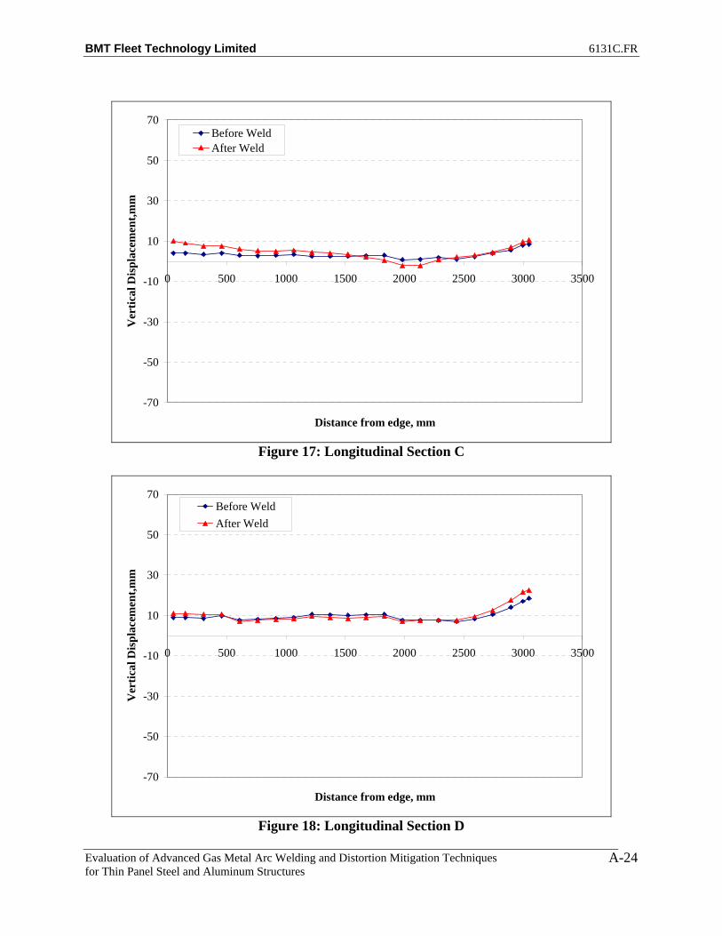
BMT Fleet Technology Limited 6131C.FR
Evaluation of Advanced Gas Metal Arc Welding and Distortion Mitigation Techniques for Thin Panel Steel and Aluminum Structures
A-24
-70
-50
-30
-10
10
30
50
70
0 500 1000 1500 2000 2500 3000 3500
Distance from edge, mm
Ver
tical
Dis
plac
emen
t,mm
Before WeldAfter Weld
Figure 17: Longitudinal Section C
-70
-50
-30
-10
10
30
50
70
0 500 1000 1500 2000 2500 3000 3500
Distance from edge, mm
Ver
tical
Dis
plac
emen
t,mm
Before WeldAfter Weld
Figure 18: Longitudinal Section D

BMT Fleet Technology Limited 6131C.FR
Evaluation of Advanced Gas Metal Arc Welding and Distortion Mitigation Techniques for Thin Panel Steel and Aluminum Structures
A-25
-70
-50
-30
-10
10
30
50
70
0 500 1000 1500 2000 2500 3000 3500
Distance from edge, mm
Ver
tical
Dis
plac
emen
t,mm
Before WeldAfter Weld
Figure 19: Longitudinal Section E
-70
-50
-30
-10
10
30
50
70
0 500 1000 1500 2000 2500 3000 3500
Distance from edge, mm
Ver
tical
Dis
plac
emen
t,mm
Before WeldAfter Weld
Figure 20: Longitudinal Section F

BMT Fleet Technology Limited 6131C.FR
Evaluation of Advanced Gas Metal Arc Welding and Distortion Mitigation Techniques for Thin Panel Steel and Aluminum Structures
A-26
-70
-50
-30
-10
10
30
50
70
0 500 1000 1500 2000 2500 3000 3500
Distance from edge, mm
Ver
tical
Dis
plac
emen
t,mm
Before WeldAfter Weld
Figure 21: Longitudinal Section G
-70
-50
-30
-10
10
30
50
70
0 500 1000 1500 2000 2500 3000 3500
Distance from edge, mm
Ver
tical
Dis
plac
emen
t,mm
Before WeldAfter Weld
Figure 22: Longitudinal Section H

BMT Fleet Technology Limited 6131C.FR
Evaluation of Advanced Gas Metal Arc Welding and Distortion Mitigation Techniques for Thin Panel Steel and Aluminum Structures
A-27
-70
-50
-30
-10
10
30
50
70
0 500 1000 1500 2000 2500 3000 3500
Distance from edge, mm
Ver
tical
Dis
plac
emen
t,mm
Before WeldAfter Weld
Figure 23: Longitudinal Section I
-70
-50
-30
-10
10
30
50
70
0 500 1000 1500 2000 2500 3000 3500
Distance from edge, mm
Ver
tical
Dis
plac
emen
t,mm
Before WeldAfter Weld
Figure 24: Longitudinal Section J

BMT Fleet Technology Limited 6131C.FR
Evaluation of Advanced Gas Metal Arc Welding and Distortion Mitigation Techniques for Thin Panel Steel and Aluminum Structures
A-28
-70
-50
-30
-10
10
30
50
70
0 500 1000 1500 2000 2500 3000 3500
Distance from edge, mm
Ver
tical
Dis
plac
emen
t,mm
Before WeldAfter Weld
Figure 25: Longitudinal Section K
-70
-50
-30
-10
10
30
50
70
0 500 1000 1500 2000 2500 3000 3500
Distance from edge, mm
Ver
tical
Dis
plac
emen
t,mm
Before WeldAfter Weld
Figure 26: Longitudinal Section L
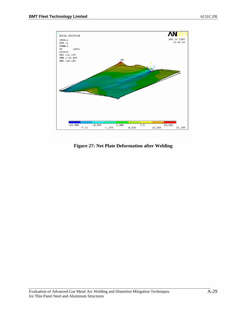
BMT Fleet Technology Limited 6131C.FR
Evaluation of Advanced Gas Metal Arc Welding and Distortion Mitigation Techniques for Thin Panel Steel and Aluminum Structures
A-29
Figure 27: Net Plate Deformation after Welding

BMT Fleet Technology Limited 6131C.FR
Evaluation of Advanced Gas Metal Arc Welding and Distortion Mitigation Techniques for Thin Panel Steel and Aluminum Structures
A-30
PLATE 2 – SIDE 1
-70
-50
-30
-10
10
30
50
70
-1500 -1000 -500 0 500 1000 1500
Distance from centre, mm
Ver
tical
Dis
plac
emen
t,mm
No Weld No TensionNo Weld With TensionWeld With Tension
Figure 1: Transverse Section A1
-70
-50
-30
-10
10
30
50
70
-1500 -1000 -500 0 500 1000 1500
Distance from centre, mm
Ver
tical
Dis
plac
emen
t,mm
No Weld No TensionNo Weld With TensionWeld With Tension
Figure 2: Transverse Section A2

BMT Fleet Technology Limited 6131C.FR
Evaluation of Advanced Gas Metal Arc Welding and Distortion Mitigation Techniques for Thin Panel Steel and Aluminum Structures
A-31
-70
-50
-30
-10
10
30
50
70
-1500 -1000 -500 0 500 1000 1500
Distance from centre, mm
Ver
tical
Dis
plac
emen
t,mm
No Weld No TensionNo Weld With TensionWeld With Tension
Figure 3: Transverse Section A3
-70
-50
-30
-10
10
30
50
70
-1500 -1000 -500 0 500 1000 1500
Distance from centre, mm
Ver
tical
Dis
plac
emen
t,mm
No Weld No TensionNo Weld With TensionWeld With Tension

BMT Fleet Technology Limited 6131C.FR
Evaluation of Advanced Gas Metal Arc Welding and Distortion Mitigation Techniques for Thin Panel Steel and Aluminum Structures
A-32
Figure 4: Transverse Section A5
-70
-50
-30
-10
10
30
50
70
-1500 -1000 -500 0 500 1000 1500
Distance from centre, mm
Ver
tical
Dis
plac
emen
t,mm
No Weld No TensionNo Weld With TensionWeld With Tension
Figure 5: Transverse Section A7
-70
-50
-30
-10
10
30
50
70
-1500 -1000 -500 0 500 1000 1500
Distance from centre, mm
Ver
tical
Dis
plac
emen
t,mm
No Weld No TensionNo Weld With TensionWeld With Tension

BMT Fleet Technology Limited 6131C.FR
Evaluation of Advanced Gas Metal Arc Welding and Distortion Mitigation Techniques for Thin Panel Steel and Aluminum Structures
A-33
Figure 6: Transverse Section A9
-70
-50
-30
-10
10
30
50
70
-1500 -1000 -500 0 500 1000 1500
Distance from centre, mm
Ver
tical
Dis
plac
emen
t,mm
No Weld No TensionNo Weld With TensionWeld With Tension
Figure 7: Transverse Section A11
-70
-50
-30
-10
10
30
50
70
-1500 -1000 -500 0 500 1000 1500
Distance from centre, mm
Ver
tical
Dis
plac
emen
t,mm
No Weld No TensionNo Weld With TensionWeld With Tension

BMT Fleet Technology Limited 6131C.FR
Evaluation of Advanced Gas Metal Arc Welding and Distortion Mitigation Techniques for Thin Panel Steel and Aluminum Structures
A-34
Figure 8: Transverse Section A13
-70
-50
-30
-10
10
30
50
70
-1500 -1000 -500 0 500 1000 1500
Distance from centre, mm
Ver
tical
Dis
plac
emen
t,mm
No Weld No TensionNo Weld With TensionWeld With Tension
Figure 9: Transverse Section A15
-70
-50
-30
-10
10
30
50
70
-1500 -1000 -500 0 500 1000 1500
Distance from centre, mm
Ver
tical
Dis
plac
emen
t,mm
No Weld No TensionNo Weld With TensionWeld With Tension
Figure 10: Transverse Section A17

BMT Fleet Technology Limited 6131C.FR
Evaluation of Advanced Gas Metal Arc Welding and Distortion Mitigation Techniques for Thin Panel Steel and Aluminum Structures
A-35
-70
-50
-30
-10
10
30
50
70
-1500 -1000 -500 0 500 1000 1500
Distance from centre, mm
Ver
tical
Dis
plac
emen
t,mm
No Weld No TensionNo Weld With TensionWeld With Tension
Figure 11: Transverse Section A19
-70
-50
-30
-10
10
30
50
70
-1500 -1000 -500 0 500 1000 1500
Distance from centre, mm
Ver
tical
Dis
plac
emen
t,mm
No Weld No TensionNo Weld With TensionWeld With Tension
Figure 12: Transverse Section A20

BMT Fleet Technology Limited 6131C.FR
Evaluation of Advanced Gas Metal Arc Welding and Distortion Mitigation Techniques for Thin Panel Steel and Aluminum Structures
A-36
-70
-50
-30
-10
10
30
50
70
-1500 -1000 -500 0 500 1000 1500
Distance from centre, mm
Ver
tical
Dis
plac
emen
t,mm
No Weld No TensionNo Weld With TensionWeld With Tension
Figure 13: Transverse Section A21
-70
-50
-30
-10
10
30
50
70
-1500 -1000 -500 0 500 1000 1500
Distance from centre, mm
Ver
tical
Dis
plac
emen
t,mm
No Weld No TensionNo Weld With TensionWeld With Tension
Figure 14: Transverse Section A22

BMT Fleet Technology Limited 6131C.FR
Evaluation of Advanced Gas Metal Arc Welding and Distortion Mitigation Techniques for Thin Panel Steel and Aluminum Structures
A-37
-70
-50
-30
-10
10
30
50
70
0 500 1000 1500 2000 2500 3000 3500
Distance from edge, mm
Ver
tical
Dis
plac
emen
t,mm
No Weld No TensionNo Weld With TensionWeld With Tension
Figure 15: Longitudinal Section A
-70
-50
-30
-10
10
30
50
70
0 500 1000 1500 2000 2500 3000 3500
Distance from edge, mm
Ver
tical
Dis
plac
emen
t,mm
No Weld No TensionNo Weld With TensionWeld With Tension
Figure 16: Longitudinal Section B

BMT Fleet Technology Limited 6131C.FR
Evaluation of Advanced Gas Metal Arc Welding and Distortion Mitigation Techniques for Thin Panel Steel and Aluminum Structures
A-38
-70
-50
-30
-10
10
30
50
70
0 500 1000 1500 2000 2500 3000 3500
Distance from edge, mm
Ver
tical
Dis
plac
emen
t,mm
No Weld No TensionNo Weld With TensionWeld With Tension
Figure 17: Longitudinal Section C
-70
-50
-30
-10
10
30
50
70
0 500 1000 1500 2000 2500 3000 3500
Distance from edge, mm
Ver
tical
Dis
plac
emen
t,mm
No Weld No TensionNo Weld With TensionWeld With Tension
Figure 18: Longitudinal Section D
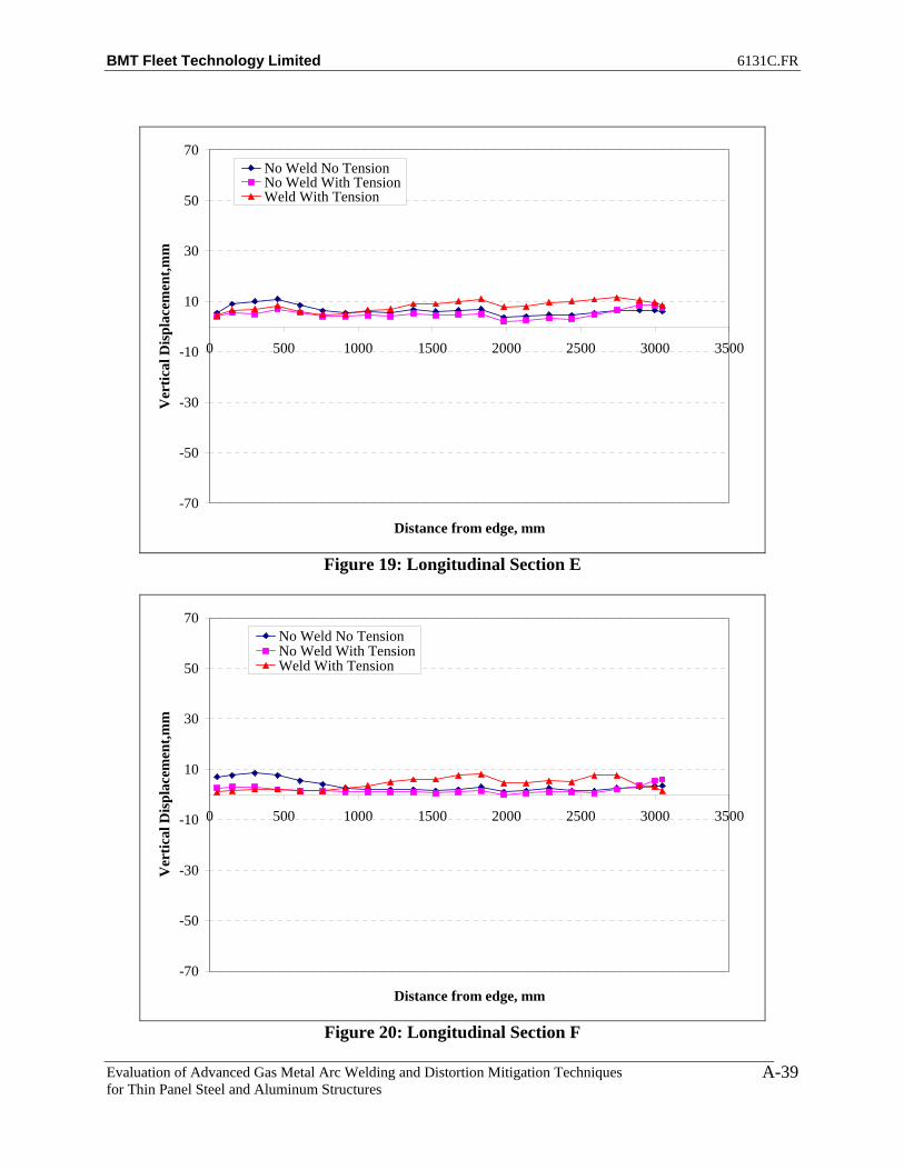
BMT Fleet Technology Limited 6131C.FR
Evaluation of Advanced Gas Metal Arc Welding and Distortion Mitigation Techniques for Thin Panel Steel and Aluminum Structures
A-39
-70
-50
-30
-10
10
30
50
70
0 500 1000 1500 2000 2500 3000 3500
Distance from edge, mm
Ver
tical
Dis
plac
emen
t,mm
No Weld No TensionNo Weld With TensionWeld With Tension
Figure 19: Longitudinal Section E
-70
-50
-30
-10
10
30
50
70
0 500 1000 1500 2000 2500 3000 3500
Distance from edge, mm
Ver
tical
Dis
plac
emen
t,mm
No Weld No TensionNo Weld With TensionWeld With Tension
Figure 20: Longitudinal Section F

BMT Fleet Technology Limited 6131C.FR
Evaluation of Advanced Gas Metal Arc Welding and Distortion Mitigation Techniques for Thin Panel Steel and Aluminum Structures
A-40
-70
-50
-30
-10
10
30
50
70
0 500 1000 1500 2000 2500 3000 3500
Distance from edge, mm
Ver
tical
Dis
plac
emen
t,mm
No Weld No TensionNo Weld With TensionWeld With Tension
Figure 21: Longitudinal Section G
-70
-50
-30
-10
10
30
50
70
0 500 1000 1500 2000 2500 3000 3500
Distance from edge, mm
Ver
tical
Dis
plac
emen
t,mm
No Weld No TensionNo Weld With TensionWeld With Tension
Figure 22: Longitudinal Section H

BMT Fleet Technology Limited 6131C.FR
Evaluation of Advanced Gas Metal Arc Welding and Distortion Mitigation Techniques for Thin Panel Steel and Aluminum Structures
A-41
-70
-50
-30
-10
10
30
50
70
0 500 1000 1500 2000 2500 3000 3500
Distance from edge, mm
Ver
tical
Dis
plac
emen
t,mm
No Weld No TensionNo Weld With TensionWeld With Tension
Figure 23: Longitudinal Section I
-70
-50
-30
-10
10
30
50
70
0 500 1000 1500 2000 2500 3000 3500
Distance from edge, mm
Ver
tical
Dis
plac
emen
t,mm
No Weld No TensionNo Weld With TensionWeld With Tension
Figure 24: Longitudinal Section J

BMT Fleet Technology Limited 6131C.FR
Evaluation of Advanced Gas Metal Arc Welding and Distortion Mitigation Techniques for Thin Panel Steel and Aluminum Structures
A-42
-70
-50
-30
-10
10
30
50
70
0 500 1000 1500 2000 2500 3000 3500
Distance from edge, mm
Ver
tical
Dis
plac
emen
t,mm
No Weld No TensionNo Weld With TensionWeld With Tension
Figure 25: Longitudinal Section K
-70
-50
-30
-10
10
30
50
70
0 500 1000 1500 2000 2500 3000 3500
Distance from edge, mm
Ver
tical
Dis
plac
emen
t,mm
No Weld No TensionNo Weld With TensionWeld With Tension
Figure 26: Longitudinal Section L
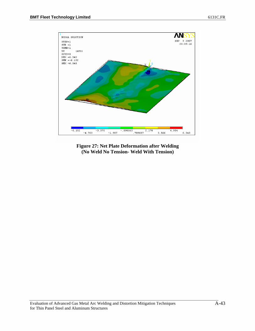
BMT Fleet Technology Limited 6131C.FR
Evaluation of Advanced Gas Metal Arc Welding and Distortion Mitigation Techniques for Thin Panel Steel and Aluminum Structures
A-43
Figure 27: Net Plate Deformation after Welding
(No Weld No Tension- Weld With Tension)

BMT Fleet Technology Limited 6131C.FR
Evaluation of Advanced Gas Metal Arc Welding and Distortion Mitigation Techniques for Thin Panel Steel and Aluminum Structures
A-44
PLATE 3 – SIDE 1
-70
-50
-30
-10
10
30
50
70
-1500 -1000 -500 0 500 1000 1500
Distance from centre, mm
Ver
tical
Dis
plac
emen
t,mm
No Weld No TensionNo Weld With TensionWeld With Tension
Figure 1: Transverse Section A1
-70
-50
-30
-10
10
30
50
70
-1500 -1000 -500 0 500 1000 1500
Distance from centre, mm
Ver
tical
Dis
plac
emen
t,mm
No Weld No TensionNo Weld With TensionWeld With Tension
Figure 2: Transverse Section A2
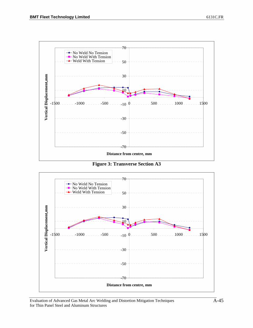
BMT Fleet Technology Limited 6131C.FR
Evaluation of Advanced Gas Metal Arc Welding and Distortion Mitigation Techniques for Thin Panel Steel and Aluminum Structures
A-45
-70
-50
-30
-10
10
30
50
70
-1500 -1000 -500 0 500 1000 1500
Distance from centre, mm
Ver
tical
Dis
plac
emen
t,mm
No Weld No TensionNo Weld With TensionWeld With Tension
Figure 3: Transverse Section A3
-70
-50
-30
-10
10
30
50
70
-1500 -1000 -500 0 500 1000 1500
Distance from centre, mm
Ver
tical
Dis
plac
emen
t,mm
No Weld No TensionNo Weld With TensionWeld With Tension
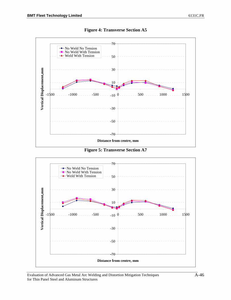
BMT Fleet Technology Limited 6131C.FR
Evaluation of Advanced Gas Metal Arc Welding and Distortion Mitigation Techniques for Thin Panel Steel and Aluminum Structures
A-46
Figure 4: Transverse Section A5
-70
-50
-30
-10
10
30
50
70
-1500 -1000 -500 0 500 1000 1500
Distance from centre, mm
Ver
tical
Dis
plac
emen
t,mm
No Weld No TensionNo Weld With TensionWeld With Tension
Figure 5: Transverse Section A7
-70
-50
-30
-10
10
30
50
70
-1500 -1000 -500 0 500 1000 1500
Distance from centre, mm
Ver
tical
Dis
plac
emen
t,mm
No Weld No TensionNo Weld With TensionWeld With Tension

BMT Fleet Technology Limited 6131C.FR
Evaluation of Advanced Gas Metal Arc Welding and Distortion Mitigation Techniques for Thin Panel Steel and Aluminum Structures
A-47
Figure 6: Transverse Section A9
-70
-50
-30
-10
10
30
50
70
-1500 -1000 -500 0 500 1000 1500
Distance from centre, mm
Ver
tical
Dis
plac
emen
t,mm
No Weld No TensionNo Weld With TensionWeld With Tension
Figure 7: Transverse Section A11
-70
-50
-30
-10
10
30
50
70
-1500 -1000 -500 0 500 1000 1500
Distance from centre, mm
Ver
tical
Dis
plac
emen
t,mm
No Weld No TensionNo Weld With TensionWeld With Tension

BMT Fleet Technology Limited 6131C.FR
Evaluation of Advanced Gas Metal Arc Welding and Distortion Mitigation Techniques for Thin Panel Steel and Aluminum Structures
A-48
Figure 8: Transverse Section A13
-70
-50
-30
-10
10
30
50
70
-1500 -1000 -500 0 500 1000 1500
Distance from centre, mm
Ver
tical
Dis
plac
emen
t,mm
No Weld No TensionNo Weld With TensionWeld With Tension
Figure 9: Transverse Section A15
-70
-50
-30
-10
10
30
50
70
-1500 -1000 -500 0 500 1000 1500
Distance from centre, mm
Ver
tical
Dis
plac
emen
t,mm
No Weld No TensionNo Weld With TensionWeld With Tension
Figure 10: Transverse Section A17

BMT Fleet Technology Limited 6131C.FR
Evaluation of Advanced Gas Metal Arc Welding and Distortion Mitigation Techniques for Thin Panel Steel and Aluminum Structures
A-49
-70
-50
-30
-10
10
30
50
70
-1500 -1000 -500 0 500 1000 1500
Distance from centre, mm
Ver
tical
Dis
plac
emen
t,mm
No Weld No TensionNo Weld With TensionWeld With Tension
Figure 11: Transverse Section A19
-70
-50
-30
-10
10
30
50
70
-1500 -1000 -500 0 500 1000 1500
Distance from centre, mm
Ver
tical
Dis
plac
emen
t,mm
No Weld No TensionNo Weld With TensionWeld With Tension
Figure 12: Transverse Section A20

BMT Fleet Technology Limited 6131C.FR
Evaluation of Advanced Gas Metal Arc Welding and Distortion Mitigation Techniques for Thin Panel Steel and Aluminum Structures
A-50
-70
-50
-30
-10
10
30
50
70
-1500 -1000 -500 0 500 1000 1500
Distance from centre, mm
Ver
tical
Dis
plac
emen
t,mm
No Weld No TensionNo Weld With TensionWeld With Tension
Figure 13: Transverse Section A21
-70
-50
-30
-10
10
30
50
70
-1500 -1000 -500 0 500 1000 1500
Distance from centre, mm
Ver
tical
Dis
plac
emen
t,mm
No Weld No TensionNo Weld With TensionWeld With Tension
Figure 14: Transverse Section A22

BMT Fleet Technology Limited 6131C.FR
Evaluation of Advanced Gas Metal Arc Welding and Distortion Mitigation Techniques for Thin Panel Steel and Aluminum Structures
A-51
-70
-50
-30
-10
10
30
50
70
0 500 1000 1500 2000 2500 3000 3500
Distance from edge, mm
Ver
tical
Dis
plac
emen
t,mm
No Weld No TensionNo Weld With TensionWeld With Tension
Figure 15: Longitudinal Section A
-70
-50
-30
-10
10
30
50
70
0 500 1000 1500 2000 2500 3000 3500
Distance from edge, mm
Ver
tical
Dis
plac
emen
t,mm
No Weld No TensionNo Weld With TensionWeld With Tension
Figure 16: Longitudinal Section B

BMT Fleet Technology Limited 6131C.FR
Evaluation of Advanced Gas Metal Arc Welding and Distortion Mitigation Techniques for Thin Panel Steel and Aluminum Structures
A-52
-70
-50
-30
-10
10
30
50
70
0 500 1000 1500 2000 2500 3000 3500
Distance from edge, mm
Ver
tical
Dis
plac
emen
t,mm
No Weld No TensionNo Weld With TensionWeld With Tension
Figure 17: Longitudinal Section C
-70
-50
-30
-10
10
30
50
70
0 500 1000 1500 2000 2500 3000 3500
Distance from edge, mm
Ver
tical
Dis
plac
emen
t,mm
No Weld No TensionNo Weld With TensionWeld With Tension
Figure 18: Longitudinal Section D
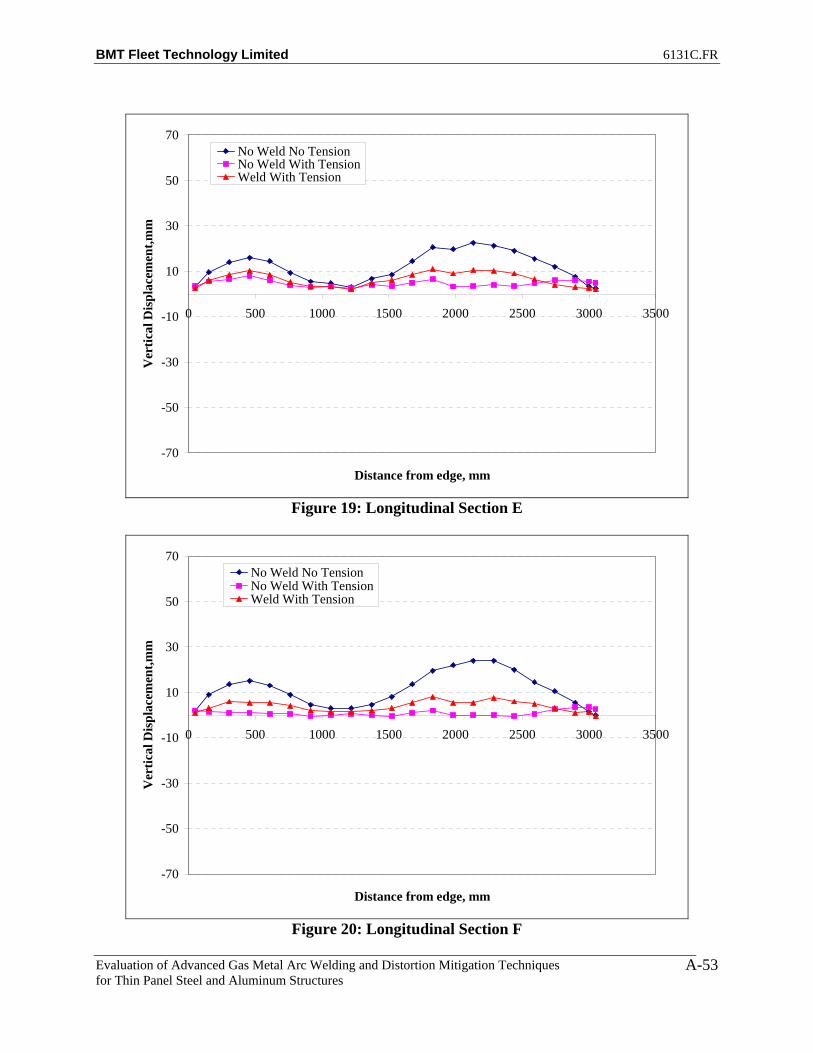
BMT Fleet Technology Limited 6131C.FR
Evaluation of Advanced Gas Metal Arc Welding and Distortion Mitigation Techniques for Thin Panel Steel and Aluminum Structures
A-53
-70
-50
-30
-10
10
30
50
70
0 500 1000 1500 2000 2500 3000 3500
Distance from edge, mm
Ver
tical
Dis
plac
emen
t,mm
No Weld No TensionNo Weld With TensionWeld With Tension
Figure 19: Longitudinal Section E
-70
-50
-30
-10
10
30
50
70
0 500 1000 1500 2000 2500 3000 3500
Distance from edge, mm
Ver
tical
Dis
plac
emen
t,mm
No Weld No TensionNo Weld With TensionWeld With Tension
Figure 20: Longitudinal Section F

BMT Fleet Technology Limited 6131C.FR
Evaluation of Advanced Gas Metal Arc Welding and Distortion Mitigation Techniques for Thin Panel Steel and Aluminum Structures
A-54
-70
-50
-30
-10
10
30
50
70
0 500 1000 1500 2000 2500 3000 3500
Distance from edge, mm
Ver
tical
Dis
plac
emen
t,mm
No Weld No TensionNo Weld With TensionWeld With Tension
Figure 21: Longitudinal Section G
-70
-50
-30
-10
10
30
50
70
0 500 1000 1500 2000 2500 3000 3500
Distance from edge, mm
Ver
tical
Dis
plac
emen
t,mm
No Weld No TensionNo Weld With TensionWeld With Tension
Figure 22: Longitudinal Section H

BMT Fleet Technology Limited 6131C.FR
Evaluation of Advanced Gas Metal Arc Welding and Distortion Mitigation Techniques for Thin Panel Steel and Aluminum Structures
A-55
-70
-50
-30
-10
10
30
50
70
0 500 1000 1500 2000 2500 3000 3500
Distance from edge, mm
Ver
tical
Dis
plac
emen
t,mm
No Weld No TensionNo Weld With TensionWeld With Tension
Figure 23: Longitudinal Section I
-70
-50
-30
-10
10
30
50
70
0 500 1000 1500 2000 2500 3000 3500
Distance from edge, mm
Ver
tical
Dis
plac
emen
t,mm
No Weld No TensionNo Weld With TensionWeld With Tension
Figure 24: Longitudinal Section J

BMT Fleet Technology Limited 6131C.FR
Evaluation of Advanced Gas Metal Arc Welding and Distortion Mitigation Techniques for Thin Panel Steel and Aluminum Structures
A-56
-70
-50
-30
-10
10
30
50
70
0 500 1000 1500 2000 2500 3000 3500
Distance from edge, mm
Ver
tical
Dis
plac
emen
t,mm
No Weld No TensionNo Weld With TensionWeld With Tension
Figure 25: Longitudinal Section K
-70
-50
-30
-10
10
30
50
70
0 500 1000 1500 2000 2500 3000 3500
Distance from edge, mm
Ver
tical
Dis
plac
emen
t,mm
No Weld No TensionNo Weld With TensionWeld With Tension
Figure 26: Longitudinal Section L

BMT Fleet Technology Limited 6131C.FR
Evaluation of Advanced Gas Metal Arc Welding and Distortion Mitigation Techniques for Thin Panel Steel and Aluminum Structures
A-57
Figure 27: Net Plate Deformation (No Weld -Weld under Tension)
Figure 28: Net Plate Deformation after Welding
(No Weld Tension-Weld under Tension)
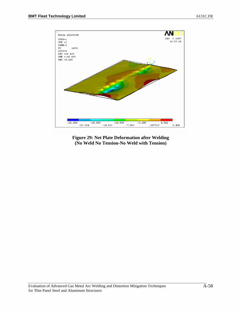
BMT Fleet Technology Limited 6131C.FR
Evaluation of Advanced Gas Metal Arc Welding and Distortion Mitigation Techniques for Thin Panel Steel and Aluminum Structures
A-58
Figure 29: Net Plate Deformation after Welding
(No Weld No Tension-No Weld with Tension)

BMT Fleet Technology Limited 6131C.FR
Evaluation of Advanced Gas Metal Arc Welding and Distortion Mitigation Techniques for Thin Panel Steel and Aluminum Structures
A-59
PLATE 3 – SIDE 2
-70
-50
-30
-10
10
30
50
70
-1500 -1000 -500 0 500 1000 1500
Distance from centre, mm
Ver
tical
Dis
plac
emen
t,mm
No Weld No TensionNo Weld With TensionWeld With Tension
Figure 1: Transverse Section A1
-70
-50
-30
-10
10
30
50
70
-1500 -1000 -500 0 500 1000 1500
Distance from centre, mm
Ver
tical
Dis
plac
emen
t,mm
No Weld No TensionNo Weld With TensionWeld With Tension
Figure 2: Transverse Section A2
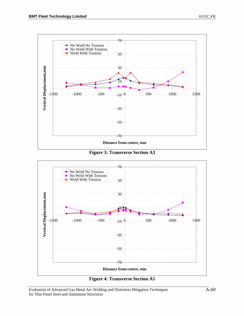
BMT Fleet Technology Limited 6131C.FR
Evaluation of Advanced Gas Metal Arc Welding and Distortion Mitigation Techniques for Thin Panel Steel and Aluminum Structures
A-60
-70
-50
-30
-10
10
30
50
70
-1500 -1000 -500 0 500 1000 1500
Distance from centre, mm
Ver
tical
Dis
plac
emen
t,mm
No Weld No TensionNo Weld With TensionWeld With Tension
Figure 3: Transverse Section A3
-70
-50
-30
-10
10
30
50
70
-1500 -1000 -500 0 500 1000 1500
Distance from centre, mm
Ver
tical
Dis
plac
emen
t,mm
No Weld No TensionNo Weld With TensionWeld With Tension
Figure 4: Transverse Section A5

BMT Fleet Technology Limited 6131C.FR
Evaluation of Advanced Gas Metal Arc Welding and Distortion Mitigation Techniques for Thin Panel Steel and Aluminum Structures
A-61
-70
-50
-30
-10
10
30
50
70
-1500 -1000 -500 0 500 1000 1500
Distance from centre, mm
Ver
tical
Dis
plac
emen
t,mm
No Weld No TensionNo Weld With TensionWeld With Tension
Figure 5: Transverse Section A7
-70
-50
-30
-10
10
30
50
70
-1500 -1000 -500 0 500 1000 1500
Distance from centre, mm
Ver
tical
Dis
plac
emen
t,mm
No Weld No TensionNo Weld With TensionWeld With Tension
Figure 6: Transverse Section A9
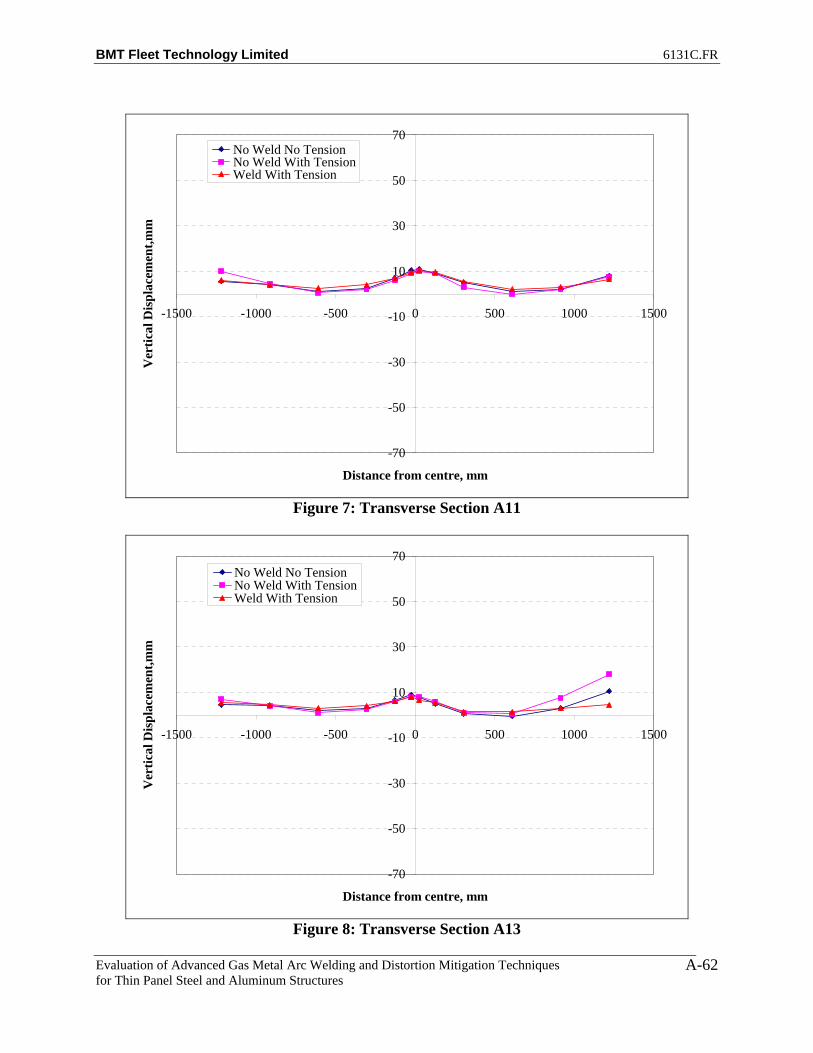
BMT Fleet Technology Limited 6131C.FR
Evaluation of Advanced Gas Metal Arc Welding and Distortion Mitigation Techniques for Thin Panel Steel and Aluminum Structures
A-62
-70
-50
-30
-10
10
30
50
70
-1500 -1000 -500 0 500 1000 1500
Distance from centre, mm
Ver
tical
Dis
plac
emen
t,mm
No Weld No TensionNo Weld With TensionWeld With Tension
Figure 7: Transverse Section A11
-70
-50
-30
-10
10
30
50
70
-1500 -1000 -500 0 500 1000 1500
Distance from centre, mm
Ver
tical
Dis
plac
emen
t,mm
No Weld No TensionNo Weld With TensionWeld With Tension
Figure 8: Transverse Section A13
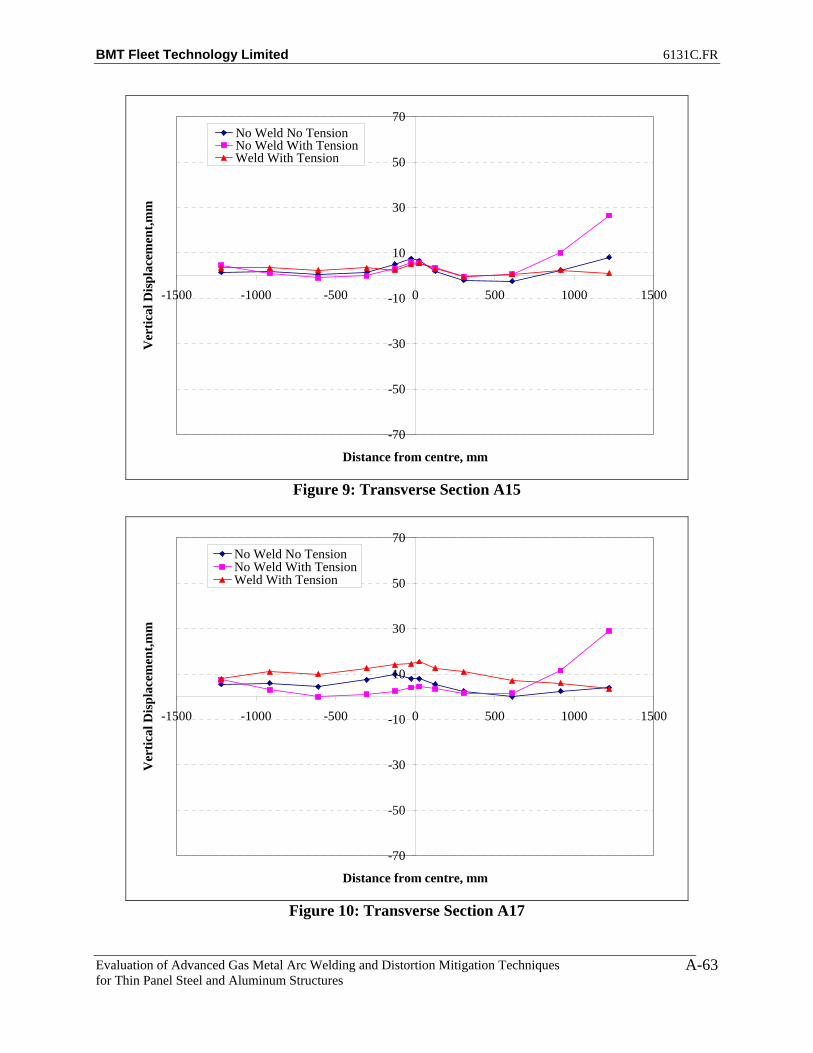
BMT Fleet Technology Limited 6131C.FR
Evaluation of Advanced Gas Metal Arc Welding and Distortion Mitigation Techniques for Thin Panel Steel and Aluminum Structures
A-63
-70
-50
-30
-10
10
30
50
70
-1500 -1000 -500 0 500 1000 1500
Distance from centre, mm
Ver
tical
Dis
plac
emen
t,mm
No Weld No TensionNo Weld With TensionWeld With Tension
Figure 9: Transverse Section A15
-70
-50
-30
-10
10
30
50
70
-1500 -1000 -500 0 500 1000 1500
Distance from centre, mm
Ver
tical
Dis
plac
emen
t,mm
No Weld No TensionNo Weld With TensionWeld With Tension
Figure 10: Transverse Section A17

BMT Fleet Technology Limited 6131C.FR
Evaluation of Advanced Gas Metal Arc Welding and Distortion Mitigation Techniques for Thin Panel Steel and Aluminum Structures
A-64
-70
-50
-30
-10
10
30
50
70
-1500 -1000 -500 0 500 1000 1500
Distance from centre, mm
Ver
tical
Dis
plac
emen
t,mm
No Weld No TensionNo Weld With TensionWeld With Tension
Figure 11: Transverse Section A19
-70
-50
-30
-10
10
30
50
70
-1500 -1000 -500 0 500 1000 1500
Distance from centre, mm
Ver
tical
Dis
plac
emen
t,mm
No Weld No TensionNo Weld With TensionWeld With Tension
Figure 12: Transverse Section A20

BMT Fleet Technology Limited 6131C.FR
Evaluation of Advanced Gas Metal Arc Welding and Distortion Mitigation Techniques for Thin Panel Steel and Aluminum Structures
A-65
-70
-50
-30
-10
10
30
50
70
-1500 -1000 -500 0 500 1000 1500
Distance from centre, mm
Ver
tical
Dis
plac
emen
t,mm
No Weld No TensionNo Weld With TensionWeld With Tension
Figure 13: Transverse Section A21
-70
-50
-30
-10
10
30
50
70
-1500 -1000 -500 0 500 1000 1500
Distance from centre, mm
Ver
tical
Dis
plac
emen
t,mm
No Weld No TensionNo Weld With TensionWeld With Tension
Figure 14: Transverse Section A22

BMT Fleet Technology Limited 6131C.FR
Evaluation of Advanced Gas Metal Arc Welding and Distortion Mitigation Techniques for Thin Panel Steel and Aluminum Structures
A-66
-70
-50
-30
-10
10
30
50
70
0 500 1000 1500 2000 2500 3000 3500
Distance from edge, mm
Ver
tical
Dis
plac
emen
t,mm
No Weld No TensionNo Weld With TensionWeld With Tension
Figure 15: Longitudinal Section A
-70
-50
-30
-10
10
30
50
70
0 500 1000 1500 2000 2500 3000 3500
Distance from edge, mm
Ver
tical
Dis
plac
emen
t,mm
No Weld No TensionNo Weld With TensionWeld With Tension
Figure 16: Longitudinal Section B
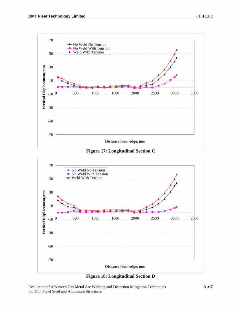
BMT Fleet Technology Limited 6131C.FR
Evaluation of Advanced Gas Metal Arc Welding and Distortion Mitigation Techniques for Thin Panel Steel and Aluminum Structures
A-67
-70
-50
-30
-10
10
30
50
70
0 500 1000 1500 2000 2500 3000 3500
Distance from edge, mm
Ver
tical
Dis
plac
emen
t,mm
No Weld No TensionNo Weld With TensionWeld With Tension
Figure 17: Longitudinal Section C
-70
-50
-30
-10
10
30
50
70
0 500 1000 1500 2000 2500 3000 3500
Distance from edge, mm
Ver
tical
Dis
plac
emen
t,mm
No Weld No TensionNo Weld With TensionWeld With Tension
Figure 18: Longitudinal Section D

BMT Fleet Technology Limited 6131C.FR
Evaluation of Advanced Gas Metal Arc Welding and Distortion Mitigation Techniques for Thin Panel Steel and Aluminum Structures
A-68
-70
-50
-30
-10
10
30
50
70
0 500 1000 1500 2000 2500 3000 3500
Distance from edge, mm
Ver
tical
Dis
plac
emen
t,mm
No Weld No TensionNo Weld With TensionWeld With Tension
Figure 19: Longitudinal Section E
-70
-50
-30
-10
10
30
50
70
0 500 1000 1500 2000 2500 3000 3500
Distance from edge, mm
Ver
tical
Dis
plac
emen
t,mm
No Weld No TensionNo Weld With TensionWeld With Tension
Figure 20: Longitudinal Section F
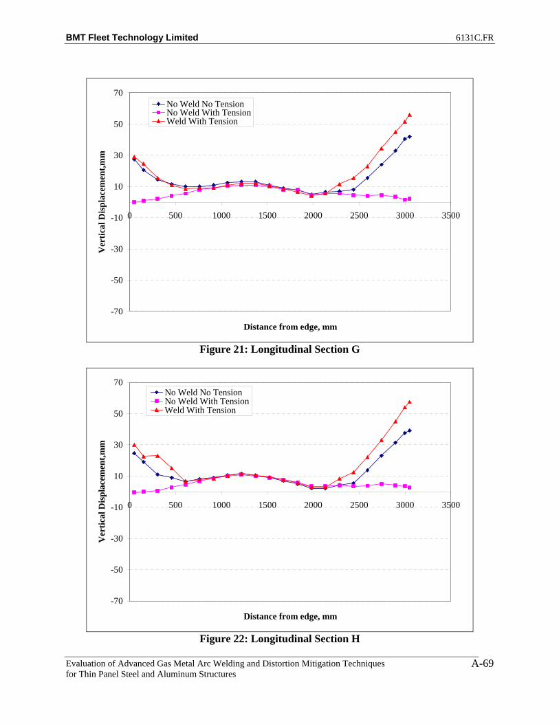
BMT Fleet Technology Limited 6131C.FR
Evaluation of Advanced Gas Metal Arc Welding and Distortion Mitigation Techniques for Thin Panel Steel and Aluminum Structures
A-69
-70
-50
-30
-10
10
30
50
70
0 500 1000 1500 2000 2500 3000 3500
Distance from edge, mm
Ver
tical
Dis
plac
emen
t,mm
No Weld No TensionNo Weld With TensionWeld With Tension
Figure 21: Longitudinal Section G
-70
-50
-30
-10
10
30
50
70
0 500 1000 1500 2000 2500 3000 3500
Distance from edge, mm
Ver
tical
Dis
plac
emen
t,mm
No Weld No TensionNo Weld With TensionWeld With Tension
Figure 22: Longitudinal Section H

BMT Fleet Technology Limited 6131C.FR
Evaluation of Advanced Gas Metal Arc Welding and Distortion Mitigation Techniques for Thin Panel Steel and Aluminum Structures
A-70
-70
-50
-30
-10
10
30
50
70
0 500 1000 1500 2000 2500 3000 3500
Distance from edge, mm
Ver
tical
Dis
plac
emen
t,mm
No Weld No TensionNo Weld With TensionWeld With Tension
Figure 23: Longitudinal Section I
-70
-50
-30
-10
10
30
50
70
0 500 1000 1500 2000 2500 3000 3500
Distance from edge, mm
Ver
tical
Dis
plac
emen
t,mm
No Weld No TensionNo Weld With TensionWeld With Tension
Figure 24: Longitudinal Section J

BMT Fleet Technology Limited 6131C.FR
Evaluation of Advanced Gas Metal Arc Welding and Distortion Mitigation Techniques for Thin Panel Steel and Aluminum Structures
A-71
-70
-50
-30
-10
10
30
50
70
0 500 1000 1500 2000 2500 3000 3500
Distance from edge, mm
Ver
tical
Dis
plac
emen
t,mm
No Weld No TensionNo Weld With TensionWeld With Tension
Figure 25: Longitudinal Section K
-70
-50
-30
-10
10
30
50
70
0 500 1000 1500 2000 2500 3000 3500
Distance from edge, mm
Ver
tical
Dis
plac
emen
t,mm
No Weld No TensionNo Weld With TensionWeld With Tension
Figure 26: Longitudinal Section L

BMT Fleet Technology Limited 6131C.FR
Evaluation of Advanced Gas Metal Arc Welding and Distortion Mitigation Techniques for Thin Panel Steel and Aluminum Structures
A-72
Figure 27: Net Plate Deformation after Welding (No Weld -Weld under Tension)
Figure 28: Net Plate Deformation before Welding
(No Weld No Tension-No Weld with Tension)

BMT Fleet Technology Limited 6131C.FR
Evaluation of Advanced Gas Metal Arc Welding and Distortion Mitigation Techniques for Thin Panel Steel and Aluminum Structures
A-73
Figure 29: Net Plate Deformation under Tension
(No Weld with Tension-Weld under Tension)

BMT Fleet Technology Limited 6131C.FR
Evaluation of Advanced Gas Metal Arc Welding and Distortion Mitigation Techniques for Thin Panel Steel and Aluminum Structures
A-74
PLATE 4 – SIDE 1
-70
-50
-30
-10
10
30
50
70
-1500 -1000 -500 0 500 1000 1500
Distance from centre, mm
Ver
tical
Dis
plac
emen
t,mm
No Weld No TensionNo Weld With TensionWeld With Tension
Figure 1: Transverse Section A1
-70
-50
-30
-10
10
30
50
70
-1500 -1000 -500 0 500 1000 1500
Distance from centre, mm
Ver
tical
Dis
plac
emen
t,mm
No Weld No TensionNo Weld With TensionWeld With Tension
Figure 2: Transverse Section A2

BMT Fleet Technology Limited 6131C.FR
Evaluation of Advanced Gas Metal Arc Welding and Distortion Mitigation Techniques for Thin Panel Steel and Aluminum Structures
A-75
-70
-50
-30
-10
10
30
50
70
-1500 -1000 -500 0 500 1000 1500
Distance from centre, mm
Ver
tical
Dis
plac
emen
t,mm
No Weld No TensionNo Weld With TensionWeld With Tension
Figure 3: Transverse Section A3
-70
-50
-30
-10
10
30
50
70
-1500 -1000 -500 0 500 1000 1500
Distance from centre, mm
Ver
tical
Dis
plac
emen
t,mm
No Weld No TensionNo Weld With TensionWeld With Tension
Figure 4: Transverse Section A5
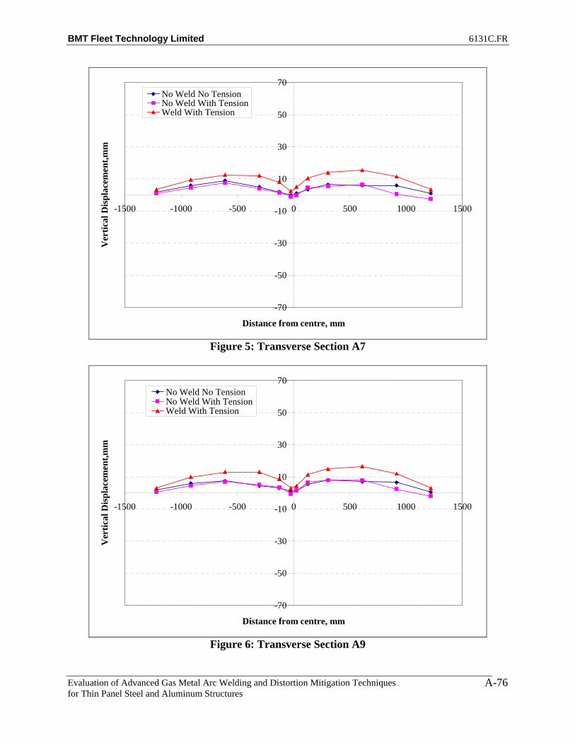
BMT Fleet Technology Limited 6131C.FR
Evaluation of Advanced Gas Metal Arc Welding and Distortion Mitigation Techniques for Thin Panel Steel and Aluminum Structures
A-76
-70
-50
-30
-10
10
30
50
70
-1500 -1000 -500 0 500 1000 1500
Distance from centre, mm
Ver
tical
Dis
plac
emen
t,mm
No Weld No TensionNo Weld With TensionWeld With Tension
Figure 5: Transverse Section A7
-70
-50
-30
-10
10
30
50
70
-1500 -1000 -500 0 500 1000 1500
Distance from centre, mm
Ver
tical
Dis
plac
emen
t,mm
No Weld No TensionNo Weld With TensionWeld With Tension
Figure 6: Transverse Section A9
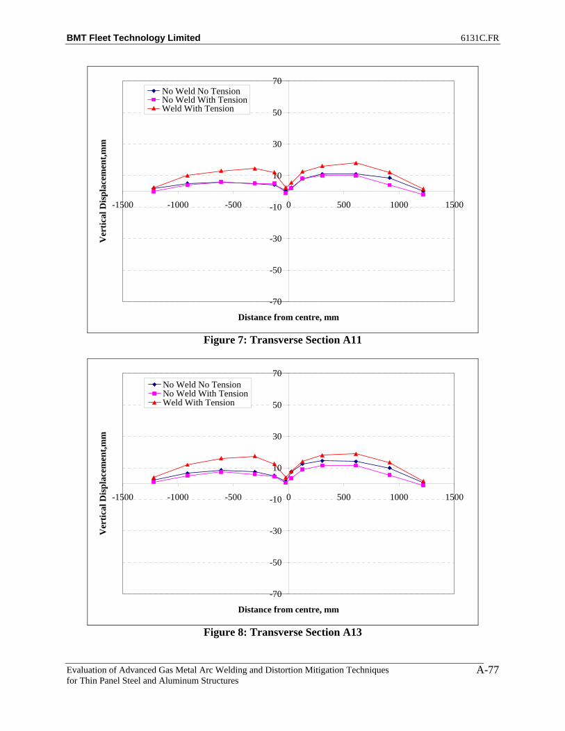
BMT Fleet Technology Limited 6131C.FR
Evaluation of Advanced Gas Metal Arc Welding and Distortion Mitigation Techniques for Thin Panel Steel and Aluminum Structures
A-77
-70
-50
-30
-10
10
30
50
70
-1500 -1000 -500 0 500 1000 1500
Distance from centre, mm
Ver
tical
Dis
plac
emen
t,mm
No Weld No TensionNo Weld With TensionWeld With Tension
Figure 7: Transverse Section A11
-70
-50
-30
-10
10
30
50
70
-1500 -1000 -500 0 500 1000 1500
Distance from centre, mm
Ver
tical
Dis
plac
emen
t,mm
No Weld No TensionNo Weld With TensionWeld With Tension
Figure 8: Transverse Section A13

BMT Fleet Technology Limited 6131C.FR
Evaluation of Advanced Gas Metal Arc Welding and Distortion Mitigation Techniques for Thin Panel Steel and Aluminum Structures
A-78
-70
-50
-30
-10
10
30
50
70
-1500 -1000 -500 0 500 1000 1500
Distance from centre, mm
Ver
tical
Dis
plac
emen
t,mm
No Weld No TensionNo Weld With TensionWeld With Tension
Figure 9: Transverse Section A15
-70
-50
-30
-10
10
30
50
70
-1500 -1000 -500 0 500 1000 1500
Distance from centre, mm
Ver
tical
Dis
plac
emen
t,mm
No Weld No TensionNo Weld With TensionWeld With Tension
Figure 10: Transverse Section A17

BMT Fleet Technology Limited 6131C.FR
Evaluation of Advanced Gas Metal Arc Welding and Distortion Mitigation Techniques for Thin Panel Steel and Aluminum Structures
A-79
-70
-50
-30
-10
10
30
50
70
-1500 -1000 -500 0 500 1000 1500
Distance from centre, mm
Ver
tical
Dis
plac
emen
t,mm
No Weld No TensionNo Weld With TensionWeld With Tension
Figure 11: Transverse Section A19
-70
-50
-30
-10
10
30
50
70
-1500 -1000 -500 0 500 1000 1500
Distance from centre, mm
Ver
tical
Dis
plac
emen
t,mm
No Weld No TensionNo Weld With TensionWeld With Tension
Figure 12: Transverse Section A20
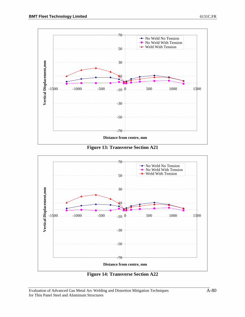
BMT Fleet Technology Limited 6131C.FR
Evaluation of Advanced Gas Metal Arc Welding and Distortion Mitigation Techniques for Thin Panel Steel and Aluminum Structures
A-80
-70
-50
-30
-10
10
30
50
70
-1500 -1000 -500 0 500 1000 1500
Distance from centre, mm
Ver
tical
Dis
plac
emen
t,mm
No Weld No TensionNo Weld With TensionWeld With Tension
Figure 13: Transverse Section A21
-70
-50
-30
-10
10
30
50
70
-1500 -1000 -500 0 500 1000 1500
Distance from centre, mm
Ver
tical
Dis
plac
emen
t,mm
No Weld No TensionNo Weld With TensionWeld With Tension
Figure 14: Transverse Section A22

BMT Fleet Technology Limited 6131C.FR
Evaluation of Advanced Gas Metal Arc Welding and Distortion Mitigation Techniques for Thin Panel Steel and Aluminum Structures
A-81
-70
-50
-30
-10
10
30
50
70
0 500 1000 1500 2000 2500 3000 3500
Distance from edge, mm
Ver
tical
Dis
plac
emen
t,mm
No Weld No TensionNo Weld With TensionWeld With Tension
Figure 15: Longitudinal Section A
-70
-50
-30
-10
10
30
50
70
0 500 1000 1500 2000 2500 3000 3500
Distance from edge, mm
Ver
tical
Dis
plac
emen
t,mm
No Weld No TensionNo Weld With TensionWeld With Tension
Figure 16: Longitudinal Section B

BMT Fleet Technology Limited 6131C.FR
Evaluation of Advanced Gas Metal Arc Welding and Distortion Mitigation Techniques for Thin Panel Steel and Aluminum Structures
A-82
-70
-50
-30
-10
10
30
50
70
0 500 1000 1500 2000 2500 3000 3500
Distance from edge, mm
Ver
tical
Dis
plac
emen
t,mm
No Weld No TensionNo Weld With TensionWeld With Tension
Figure 17: Longitudinal Section C
-70
-50
-30
-10
10
30
50
70
0 500 1000 1500 2000 2500 3000 3500
Distance from edge, mm
Ver
tical
Dis
plac
emen
t,mm
No Weld No TensionNo Weld With TensionWeld With Tension
Figure 18: Longitudinal Section D

BMT Fleet Technology Limited 6131C.FR
Evaluation of Advanced Gas Metal Arc Welding and Distortion Mitigation Techniques for Thin Panel Steel and Aluminum Structures
A-83
-70
-50
-30
-10
10
30
50
70
0 500 1000 1500 2000 2500 3000 3500
Distance from edge, mm
Ver
tical
Dis
plac
emen
t,mm
No Weld No TensionNo Weld With TensionWeld With Tension
Figure 19: Longitudinal Section E
-70
-50
-30
-10
10
30
50
70
0 500 1000 1500 2000 2500 3000 3500
Distance from edge, mm
Ver
tical
Dis
plac
emen
t,mm
No Weld No TensionNo Weld With TensionWeld With Tension
Figure 20: Longitudinal Section F
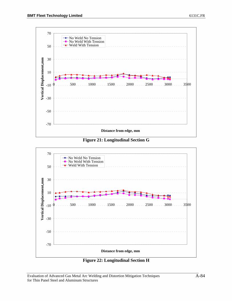
BMT Fleet Technology Limited 6131C.FR
Evaluation of Advanced Gas Metal Arc Welding and Distortion Mitigation Techniques for Thin Panel Steel and Aluminum Structures
A-84
-70
-50
-30
-10
10
30
50
70
0 500 1000 1500 2000 2500 3000 3500
Distance from edge, mm
Ver
tical
Dis
plac
emen
t,mm
No Weld No TensionNo Weld With TensionWeld With Tension
Figure 21: Longitudinal Section G
-70
-50
-30
-10
10
30
50
70
0 500 1000 1500 2000 2500 3000 3500
Distance from edge, mm
Ver
tical
Dis
plac
emen
t,mm
No Weld No TensionNo Weld With TensionWeld With Tension
Figure 22: Longitudinal Section H
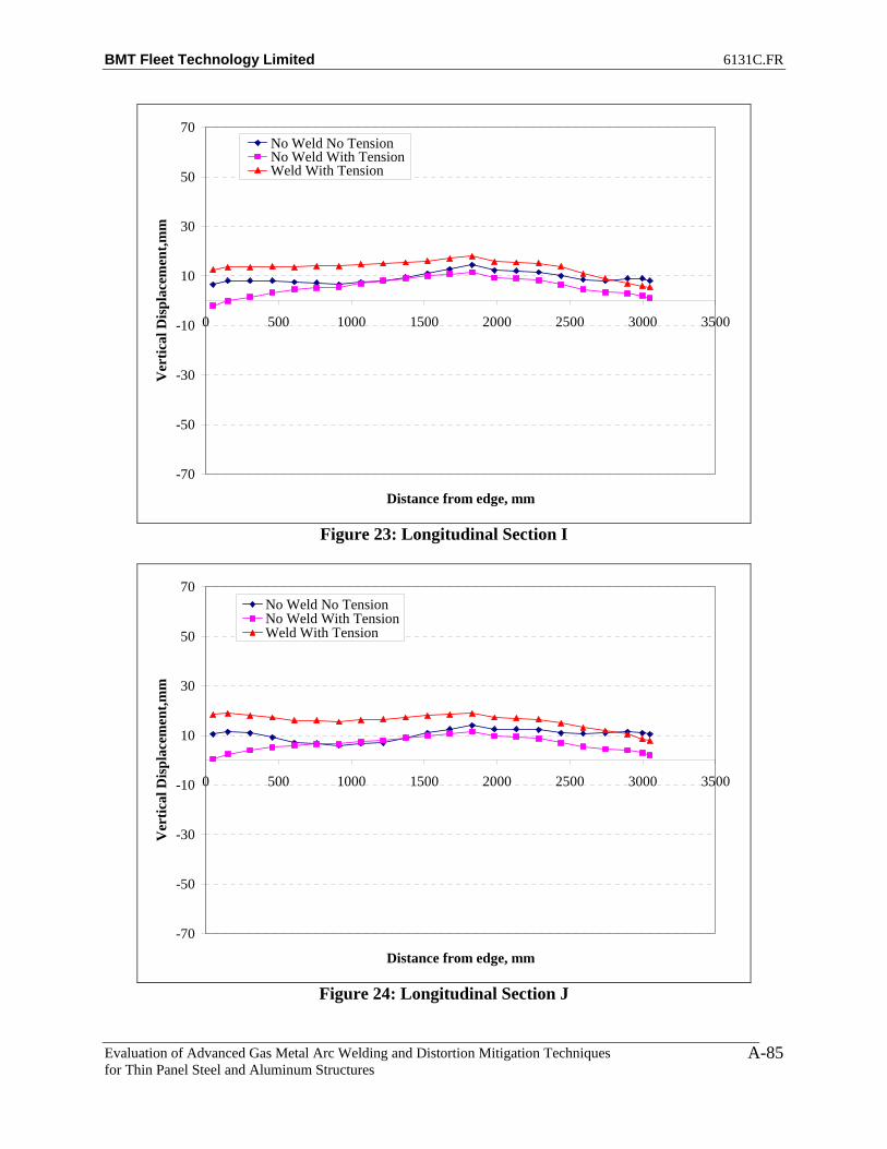
BMT Fleet Technology Limited 6131C.FR
Evaluation of Advanced Gas Metal Arc Welding and Distortion Mitigation Techniques for Thin Panel Steel and Aluminum Structures
A-85
-70
-50
-30
-10
10
30
50
70
0 500 1000 1500 2000 2500 3000 3500
Distance from edge, mm
Ver
tical
Dis
plac
emen
t,mm
No Weld No TensionNo Weld With TensionWeld With Tension
Figure 23: Longitudinal Section I
-70
-50
-30
-10
10
30
50
70
0 500 1000 1500 2000 2500 3000 3500
Distance from edge, mm
Ver
tical
Dis
plac
emen
t,mm
No Weld No TensionNo Weld With TensionWeld With Tension
Figure 24: Longitudinal Section J

BMT Fleet Technology Limited 6131C.FR
Evaluation of Advanced Gas Metal Arc Welding and Distortion Mitigation Techniques for Thin Panel Steel and Aluminum Structures
A-86
-70
-50
-30
-10
10
30
50
70
0 500 1000 1500 2000 2500 3000 3500
Distance from edge, mm
Ver
tical
Dis
plac
emen
t,mm
No Weld No TensionNo Weld With TensionWeld With Tension
Figure 25: Longitudinal Section K
-70
-50
-30
-10
10
30
50
70
0 500 1000 1500 2000 2500 3000 3500
Distance from edge, mm
Ver
tical
Dis
plac
emen
t,mm
No Weld No TensionNo Weld With TensionWeld With Tension
Figure 26: Longitudinal Section L

BMT Fleet Technology Limited 6131C.FR
Evaluation of Advanced Gas Metal Arc Welding and Distortion Mitigation Techniques for Thin Panel Steel and Aluminum Structures
A-87
Figure 27: Net Plate Deformation (No Weld No Tension -Weld under Tension)
Figure 28: Net Plate Deformation after Welding (Tension Case)
(No Weld with Tension-Weld under Tension)
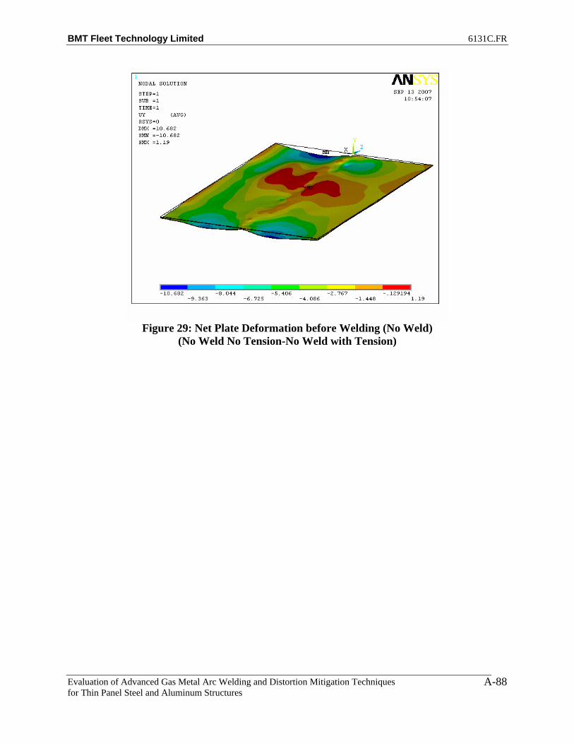
BMT Fleet Technology Limited 6131C.FR
Evaluation of Advanced Gas Metal Arc Welding and Distortion Mitigation Techniques for Thin Panel Steel and Aluminum Structures
A-88
Figure 29: Net Plate Deformation before Welding (No Weld)
(No Weld No Tension-No Weld with Tension)

BMT Fleet Technology Limited 6131C.FR
Evaluation of Advanced Gas Metal Arc Welding and Distortion Mitigation Techniques for Thin Panel Steel and Aluminum Structures
A-89
PLATE 4 – SIDE 2
-70
-50
-30
-10
10
30
50
70
-1500 -1000 -500 0 500 1000 1500
Distance from centre, mm
Ver
tical
Dis
plac
emen
t,mm
No Weld No TensionNo Weld With TensionWeld With Tension
Figure 1: Transverse Section A1
-70
-50
-30
-10
10
30
50
70
-1500 -1000 -500 0 500 1000 1500
Distance from centre, mm
Ver
tical
Dis
plac
emen
t,mm
No Weld No TensionNo Weld With TensionWeld With Tension
Figure 2: Transverse Section A2

BMT Fleet Technology Limited 6131C.FR
Evaluation of Advanced Gas Metal Arc Welding and Distortion Mitigation Techniques for Thin Panel Steel and Aluminum Structures
A-90
-70
-50
-30
-10
10
30
50
70
-1500 -1000 -500 0 500 1000 1500
Distance from centre, mm
Ver
tical
Dis
plac
emen
t,mm
No Weld No TensionNo Weld With TensionWeld With Tension
Figure 3: Transverse Section A3
-70
-50
-30
-10
10
30
50
70
-1500 -1000 -500 0 500 1000 1500
Distance from centre, mm
Ver
tical
Dis
plac
emen
t,mm
No Weld No TensionNo Weld With TensionWeld With Tension
Figure 4: Transverse Section A5

BMT Fleet Technology Limited 6131C.FR
Evaluation of Advanced Gas Metal Arc Welding and Distortion Mitigation Techniques for Thin Panel Steel and Aluminum Structures
A-91
-70
-50
-30
-10
10
30
50
70
-1500 -1000 -500 0 500 1000 1500
Distance from centre, mm
Ver
tical
Dis
plac
emen
t,mm
No Weld No TensionNo Weld With TensionWeld With Tension
Figure 5: Transverse Section A7
-70
-50
-30
-10
10
30
50
70
-1500 -1000 -500 0 500 1000 1500
Distance from centre, mm
Ver
tical
Dis
plac
emen
t,mm
No Weld No TensionNo Weld With TensionWeld With Tension
Figure 6: Transverse Section A9

BMT Fleet Technology Limited 6131C.FR
Evaluation of Advanced Gas Metal Arc Welding and Distortion Mitigation Techniques for Thin Panel Steel and Aluminum Structures
A-92
-70
-50
-30
-10
10
30
50
70
-1500 -1000 -500 0 500 1000 1500
Distance from centre, mm
Ver
tical
Dis
plac
emen
t,mm
No Weld No TensionNo Weld With TensionWeld With Tension
Figure 7: Transverse Section A11
-70
-50
-30
-10
10
30
50
70
-1500 -1000 -500 0 500 1000 1500
Distance from centre, mm
Ver
tical
Dis
plac
emen
t,mm
No Weld No TensionNo Weld With TensionWeld With Tension
Figure 8: Transverse Section A13

BMT Fleet Technology Limited 6131C.FR
Evaluation of Advanced Gas Metal Arc Welding and Distortion Mitigation Techniques for Thin Panel Steel and Aluminum Structures
A-93
-70
-50
-30
-10
10
30
50
70
-1500 -1000 -500 0 500 1000 1500
Distance from centre, mm
Ver
tical
Dis
plac
emen
t,mm
No Weld No TensionNo Weld With TensionWeld With Tension
Figure 9: Transverse Section A15
-70
-50
-30
-10
10
30
50
70
-1500 -1000 -500 0 500 1000 1500
Distance from centre, mm
Ver
tical
Dis
plac
emen
t,mm
No Weld No TensionNo Weld With TensionWeld With Tension
Figure 10: Transverse Section A17

BMT Fleet Technology Limited 6131C.FR
Evaluation of Advanced Gas Metal Arc Welding and Distortion Mitigation Techniques for Thin Panel Steel and Aluminum Structures
A-94
-70
-50
-30
-10
10
30
50
70
-1500 -1000 -500 0 500 1000 1500
Distance from centre, mm
Ver
tical
Dis
plac
emen
t,mm
No Weld No TensionNo Weld With TensionWeld With Tension
Figure 11: Transverse Section A19
-70
-50
-30
-10
10
30
50
70
-1500 -1000 -500 0 500 1000 1500
Distance from centre, mm
Ver
tical
Dis
plac
emen
t,mm
No Weld No TensionNo Weld With TensionWeld With Tension
Figure 12: Transverse Section A20

BMT Fleet Technology Limited 6131C.FR
Evaluation of Advanced Gas Metal Arc Welding and Distortion Mitigation Techniques for Thin Panel Steel and Aluminum Structures
A-95
-70
-50
-30
-10
10
30
50
70
-1500 -1000 -500 0 500 1000 1500
Distance from centre, mm
Ver
tical
Dis
plac
emen
t,mm
No Weld No TensionNo Weld With TensionWeld With Tension
Figure 13: Transverse Section A21
-70
-50
-30
-10
10
30
50
70
-1500 -1000 -500 0 500 1000 1500
Distance from centre, mm
Ver
tical
Dis
plac
emen
t,mm
No Weld No TensionNo Weld With TensionWeld With Tension
Figure 14: Transverse Section A22
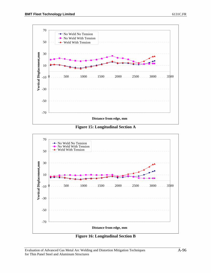
BMT Fleet Technology Limited 6131C.FR
Evaluation of Advanced Gas Metal Arc Welding and Distortion Mitigation Techniques for Thin Panel Steel and Aluminum Structures
A-96
-70
-50
-30
-10
10
30
50
70
0 500 1000 1500 2000 2500 3000 3500
Distance from edge, mm
Ver
tical
Dis
plac
emen
t,mm
No Weld No TensionNo Weld With TensionWeld With Tension
Figure 15: Longitudinal Section A
-70
-50
-30
-10
10
30
50
70
0 500 1000 1500 2000 2500 3000 3500
Distance from edge, mm
Ver
tical
Dis
plac
emen
t,mm
No Weld No TensionNo Weld With TensionWeld With Tension
Figure 16: Longitudinal Section B

BMT Fleet Technology Limited 6131C.FR
Evaluation of Advanced Gas Metal Arc Welding and Distortion Mitigation Techniques for Thin Panel Steel and Aluminum Structures
A-97
-70
-50
-30
-10
10
30
50
70
0 500 1000 1500 2000 2500 3000 3500
Distance from edge, mm
Ver
tical
Dis
plac
emen
t,mm
No Weld No TensionNo Weld With TensionWeld With Tension
Figure 17: Longitudinal Section C
-70
-50
-30
-10
10
30
50
70
0 500 1000 1500 2000 2500 3000 3500
Distance from edge, mm
Ver
tical
Dis
plac
emen
t,mm
No Weld No TensionNo Weld With TensionWeld With Tension
Figure 18: Longitudinal Section D

BMT Fleet Technology Limited 6131C.FR
Evaluation of Advanced Gas Metal Arc Welding and Distortion Mitigation Techniques for Thin Panel Steel and Aluminum Structures
A-98
-70
-50
-30
-10
10
30
50
70
0 500 1000 1500 2000 2500 3000 3500
Distance from edge, mm
Ver
tical
Dis
plac
emen
t,mm
No Weld No TensionNo Weld With TensionWeld With Tension
Figure 19: Longitudinal Section E
-70
-50
-30
-10
10
30
50
70
0 500 1000 1500 2000 2500 3000 3500
Distance from edge, mm
Ver
tical
Dis
plac
emen
t,mm
No Weld No TensionNo Weld With TensionWeld With Tension
Figure 20: Longitudinal Section F

BMT Fleet Technology Limited 6131C.FR
Evaluation of Advanced Gas Metal Arc Welding and Distortion Mitigation Techniques for Thin Panel Steel and Aluminum Structures
A-99
-70
-50
-30
-10
10
30
50
70
0 500 1000 1500 2000 2500 3000 3500
Distance from edge, mm
Ver
tical
Dis
plac
emen
t,mm
No Weld No TensionNo Weld With TensionWeld With Tension
Figure 21: Longitudinal Section G
-70
-50
-30
-10
10
30
50
70
0 500 1000 1500 2000 2500 3000 3500
Distance from edge, mm
Ver
tical
Dis
plac
emen
t,mm
No Weld No TensionNo Weld With TensionWeld With Tension
Figure 22: Longitudinal Section H
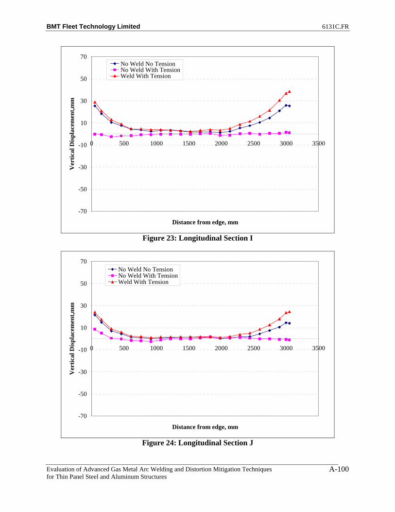
BMT Fleet Technology Limited 6131C.FR
Evaluation of Advanced Gas Metal Arc Welding and Distortion Mitigation Techniques for Thin Panel Steel and Aluminum Structures
A-100
-70
-50
-30
-10
10
30
50
70
0 500 1000 1500 2000 2500 3000 3500
Distance from edge, mm
Ver
tical
Dis
plac
emen
t,mm
No Weld No TensionNo Weld With TensionWeld With Tension
Figure 23: Longitudinal Section I
-70
-50
-30
-10
10
30
50
70
0 500 1000 1500 2000 2500 3000 3500
Distance from edge, mm
Ver
tical
Dis
plac
emen
t,mm
No Weld No TensionNo Weld With TensionWeld With Tension
Figure 24: Longitudinal Section J
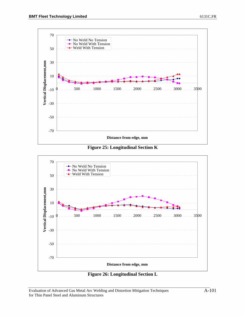
BMT Fleet Technology Limited 6131C.FR
Evaluation of Advanced Gas Metal Arc Welding and Distortion Mitigation Techniques for Thin Panel Steel and Aluminum Structures
A-101
-70
-50
-30
-10
10
30
50
70
0 500 1000 1500 2000 2500 3000 3500
Distance from edge, mm
Ver
tical
Dis
plac
emen
t,mm
No Weld No TensionNo Weld With TensionWeld With Tension
Figure 25: Longitudinal Section K
-70
-50
-30
-10
10
30
50
70
0 500 1000 1500 2000 2500 3000 3500
Distance from edge, mm
Ver
tical
Dis
plac
emen
t,mm
No Weld No TensionNo Weld With TensionWeld With Tension
Figure 26: Longitudinal Section L
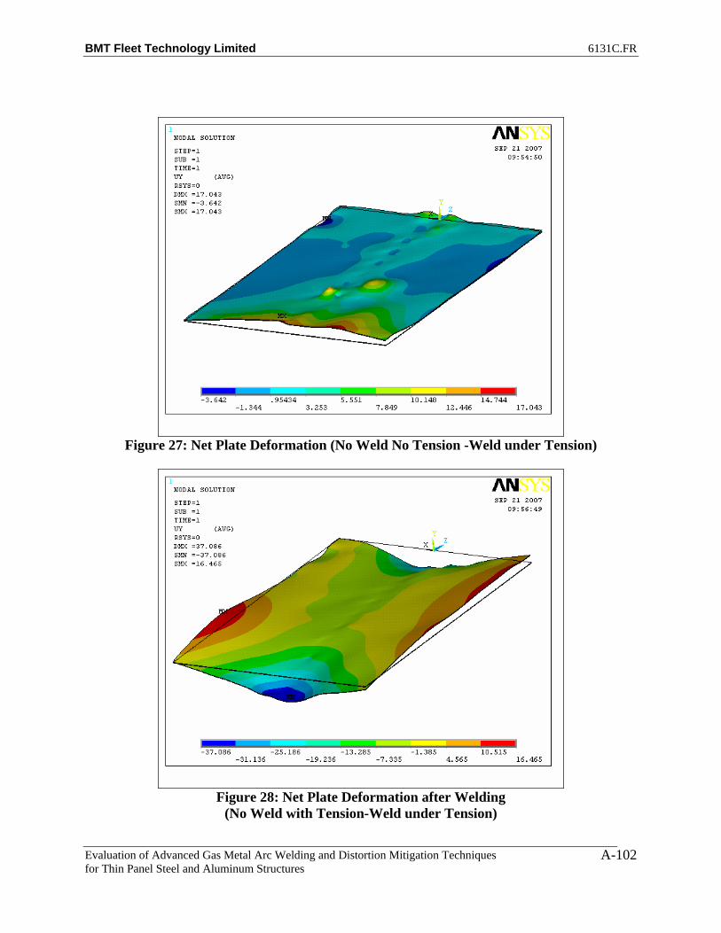
BMT Fleet Technology Limited 6131C.FR
Evaluation of Advanced Gas Metal Arc Welding and Distortion Mitigation Techniques for Thin Panel Steel and Aluminum Structures
A-102
Figure 27: Net Plate Deformation (No Weld No Tension -Weld under Tension)
Figure 28: Net Plate Deformation after Welding
(No Weld with Tension-Weld under Tension)

BMT Fleet Technology Limited 6131C.FR
Evaluation of Advanced Gas Metal Arc Welding and Distortion Mitigation Techniques for Thin Panel Steel and Aluminum Structures
A-103
Figure 29: Net Plate Deformation before Welding
(No Weld No Tension-No Weld with Tension)

BMT Fleet Technology Limited 6131C.FR
Evaluation of Advanced Gas Metal Arc Welding and Distortion Mitigation Techniques for Thin Panel Steel and Aluminum Structures
A-104
PLATE 5 – SIDE 1
-70
-50
-30
-10
10
30
50
70
-1500 -1000 -500 0 500 1000 1500
Distance from centre, mm
Ver
tical
Dis
plac
emen
t,mm
No Weld No TensionNo Weld With TensionWeld With Tension
Figure 1: Transverse Section A1
-70
-50
-30
-10
10
30
50
70
-1500 -1000 -500 0 500 1000 1500
Distance from centre, mm
Ver
tical
Dis
plac
emen
t,mm
No Weld No TensionNo Weld With TensionWeld With Tension
Figure 2: Transverse Section A2

BMT Fleet Technology Limited 6131C.FR
Evaluation of Advanced Gas Metal Arc Welding and Distortion Mitigation Techniques for Thin Panel Steel and Aluminum Structures
A-105
-70
-50
-30
-10
10
30
50
70
-1500 -1000 -500 0 500 1000 1500
Distance from centre, mm
Ver
tical
Dis
plac
emen
t,mm
No Weld No TensionNo Weld With TensionWeld With Tension
Figure 3: Transverse Section A3
-70
-50
-30
-10
10
30
50
70
-1500 -1000 -500 0 500 1000 1500
Distance from centre, mm
Ver
tical
Dis
plac
emen
t,mm
No Weld No TensionNo Weld With TensionWeld With Tension
Figure 4: Transverse Section A5

BMT Fleet Technology Limited 6131C.FR
Evaluation of Advanced Gas Metal Arc Welding and Distortion Mitigation Techniques for Thin Panel Steel and Aluminum Structures
A-106
-70
-50
-30
-10
10
30
50
70
-1500 -1000 -500 0 500 1000 1500
Distance from centre, mm
Ver
tical
Dis
plac
emen
t,mm
No Weld No TensionNo Weld With TensionWeld With Tension
Figure 5: Transverse Section A7
-70
-50
-30
-10
10
30
50
70
-1500 -1000 -500 0 500 1000 1500
Distance from centre, mm
Ver
tical
Dis
plac
emen
t,mm
No Weld No TensionNo Weld With TensionWeld With Tension
Figure 6: Transverse Section A9

BMT Fleet Technology Limited 6131C.FR
Evaluation of Advanced Gas Metal Arc Welding and Distortion Mitigation Techniques for Thin Panel Steel and Aluminum Structures
A-107
-70
-50
-30
-10
10
30
50
70
-1500 -1000 -500 0 500 1000 1500
Distance from centre, mm
Ver
tical
Dis
plac
emen
t,mm
No Weld No TensionNo Weld With TensionWeld With Tension
Figure 7: Transverse Section A11
-70
-50
-30
-10
10
30
50
70
-1500 -1000 -500 0 500 1000 1500
Distance from centre, mm
Ver
tical
Dis
plac
emen
t,mm
No Weld No TensionNo Weld With TensionWeld With Tension
Figure 8: Transverse Section A13

BMT Fleet Technology Limited 6131C.FR
Evaluation of Advanced Gas Metal Arc Welding and Distortion Mitigation Techniques for Thin Panel Steel and Aluminum Structures
A-108
-70
-50
-30
-10
10
30
50
70
-1500 -1000 -500 0 500 1000 1500
Distance from centre, mm
Ver
tical
Dis
plac
emen
t,mm
No Weld No TensionNo Weld With TensionWeld With Tension
Figure 9: Transverse Section A15
-70
-50
-30
-10
10
30
50
70
-1500 -1000 -500 0 500 1000 1500
Distance from centre, mm
Ver
tical
Dis
plac
emen
t,mm
No Weld No TensionNo Weld With TensionWeld With Tension
Figure 10: Transverse Section A17

BMT Fleet Technology Limited 6131C.FR
Evaluation of Advanced Gas Metal Arc Welding and Distortion Mitigation Techniques for Thin Panel Steel and Aluminum Structures
A-109
-70
-50
-30
-10
10
30
50
70
-1500 -1000 -500 0 500 1000 1500
Distance from centre, mm
Ver
tical
Dis
plac
emen
t,mm
No Weld No TensionNo Weld With TensionWeld With Tension
Figure 11: Transverse Section A19
-70
-50
-30
-10
10
30
50
70
-1500 -1000 -500 0 500 1000 1500
Distance from centre, mm
Ver
tical
Dis
plac
emen
t,mm
No Weld No TensionNo Weld With TensionWeld With Tension
Figure 12: Transverse Section A20

BMT Fleet Technology Limited 6131C.FR
Evaluation of Advanced Gas Metal Arc Welding and Distortion Mitigation Techniques for Thin Panel Steel and Aluminum Structures
A-110
-70
-50
-30
-10
10
30
50
70
-1500 -1000 -500 0 500 1000 1500
Distance from centre, mm
Ver
tical
Dis
plac
emen
t,mm
No Weld No TensionNo Weld With TensionWeld With Tension
Figure 13: Transverse Section A21
-70
-50
-30
-10
10
30
50
70
-1500 -1000 -500 0 500 1000 1500
Distance from centre, mm
Ver
tical
Dis
plac
emen
t,mm
No Weld No TensionNo Weld With TensionWeld With Tension
Figure 14: Transverse Section A22
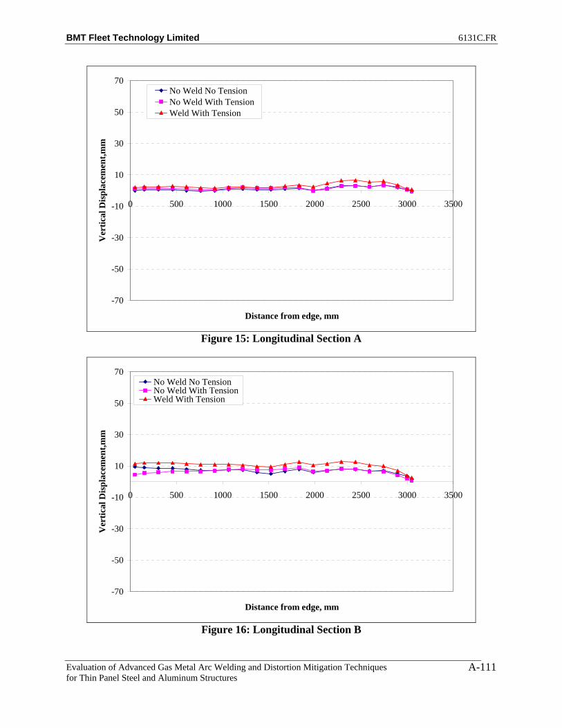
BMT Fleet Technology Limited 6131C.FR
Evaluation of Advanced Gas Metal Arc Welding and Distortion Mitigation Techniques for Thin Panel Steel and Aluminum Structures
A-111
-70
-50
-30
-10
10
30
50
70
0 500 1000 1500 2000 2500 3000 3500
Distance from edge, mm
Ver
tical
Dis
plac
emen
t,mm
No Weld No TensionNo Weld With TensionWeld With Tension
Figure 15: Longitudinal Section A
-70
-50
-30
-10
10
30
50
70
0 500 1000 1500 2000 2500 3000 3500
Distance from edge, mm
Ver
tical
Dis
plac
emen
t,mm
No Weld No TensionNo Weld With TensionWeld With Tension
Figure 16: Longitudinal Section B

BMT Fleet Technology Limited 6131C.FR
Evaluation of Advanced Gas Metal Arc Welding and Distortion Mitigation Techniques for Thin Panel Steel and Aluminum Structures
A-112
-70
-50
-30
-10
10
30
50
70
0 500 1000 1500 2000 2500 3000 3500
Distance from edge, mm
Ver
tical
Dis
plac
emen
t,mm
No Weld No TensionNo Weld With TensionWeld With Tension
Figure 17: Longitudinal Section C
-70
-50
-30
-10
10
30
50
70
0 500 1000 1500 2000 2500 3000 3500
Distance from edge, mm
Ver
tical
Dis
plac
emen
t,mm
No Weld No TensionNo Weld With TensionWeld With Tension
Figure 18: Longitudinal Section D

BMT Fleet Technology Limited 6131C.FR
Evaluation of Advanced Gas Metal Arc Welding and Distortion Mitigation Techniques for Thin Panel Steel and Aluminum Structures
A-113
-70
-50
-30
-10
10
30
50
70
0 500 1000 1500 2000 2500 3000 3500
Distance from edge, mm
Ver
tical
Dis
plac
emen
t,mm
No Weld No TensionNo Weld With TensionWeld With Tension
Figure 19: Longitudinal Section E
-70
-50
-30
-10
10
30
50
70
0 500 1000 1500 2000 2500 3000 3500
Distance from edge, mm
Ver
tical
Dis
plac
emen
t,mm
No Weld No TensionNo Weld With TensionWeld With Tension
Figure 20: Longitudinal Section F

BMT Fleet Technology Limited 6131C.FR
Evaluation of Advanced Gas Metal Arc Welding and Distortion Mitigation Techniques for Thin Panel Steel and Aluminum Structures
A-114
-70
-50
-30
-10
10
30
50
70
0 500 1000 1500 2000 2500 3000 3500
Distance from edge, mm
Ver
tical
Dis
plac
emen
t,mm
No Weld No TensionNo Weld With TensionWeld With Tension
Figure 21: Longitudinal Section G
-70
-50
-30
-10
10
30
50
70
0 500 1000 1500 2000 2500 3000 3500
Distance from edge, mm
Ver
tical
Dis
plac
emen
t,mm
No Weld No TensionNo Weld With TensionWeld With Tension
Figure 22: Longitudinal Section H

BMT Fleet Technology Limited 6131C.FR
Evaluation of Advanced Gas Metal Arc Welding and Distortion Mitigation Techniques for Thin Panel Steel and Aluminum Structures
A-115
-70
-50
-30
-10
10
30
50
70
0 500 1000 1500 2000 2500 3000 3500
Distance from edge, mm
Ver
tical
Dis
plac
emen
t,mm
No Weld No TensionNo Weld With TensionWeld With Tension
Figure 23: Longitudinal Section I
-70
-50
-30
-10
10
30
50
70
0 500 1000 1500 2000 2500 3000 3500
Distance from edge, mm
Ver
tical
Dis
plac
emen
t,mm
No Weld No TensionNo Weld With TensionWeld With Tension
Figure 24: Longitudinal Section J

BMT Fleet Technology Limited 6131C.FR
Evaluation of Advanced Gas Metal Arc Welding and Distortion Mitigation Techniques for Thin Panel Steel and Aluminum Structures
A-116
-70
-50
-30
-10
10
30
50
70
0 500 1000 1500 2000 2500 3000 3500
Distance from edge, mm
Ver
tical
Dis
plac
emen
t,mm
No Weld No TensionNo Weld With TensionWeld With Tension
Figure 25: Longitudinal Section K
-70
-50
-30
-10
10
30
50
70
0 500 1000 1500 2000 2500 3000 3500
Distance from edge, mm
Ver
tical
Dis
plac
emen
t,mm
No Weld No TensionNo Weld With TensionWeld With Tension
Figure 26: Longitudinal Section L

BMT Fleet Technology Limited 6131C.FR
Evaluation of Advanced Gas Metal Arc Welding and Distortion Mitigation Techniques for Thin Panel Steel and Aluminum Structures
A-117
Figure 27: Net Plate Deformation (No Weld No Tension -Weld under Tension)
Figure 28: Plate Deformation after Welding
(No Weld with Tension-Weld under Tension)
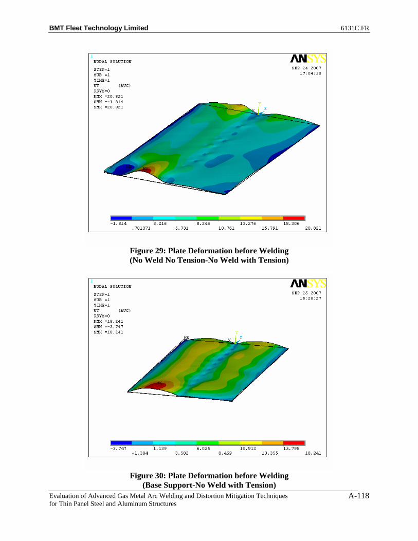
BMT Fleet Technology Limited 6131C.FR
Evaluation of Advanced Gas Metal Arc Welding and Distortion Mitigation Techniques for Thin Panel Steel and Aluminum Structures
A-118
Figure 29: Plate Deformation before Welding (No Weld No Tension-No Weld with Tension)
Figure 30: Plate Deformation before Welding
(Base Support-No Weld with Tension)
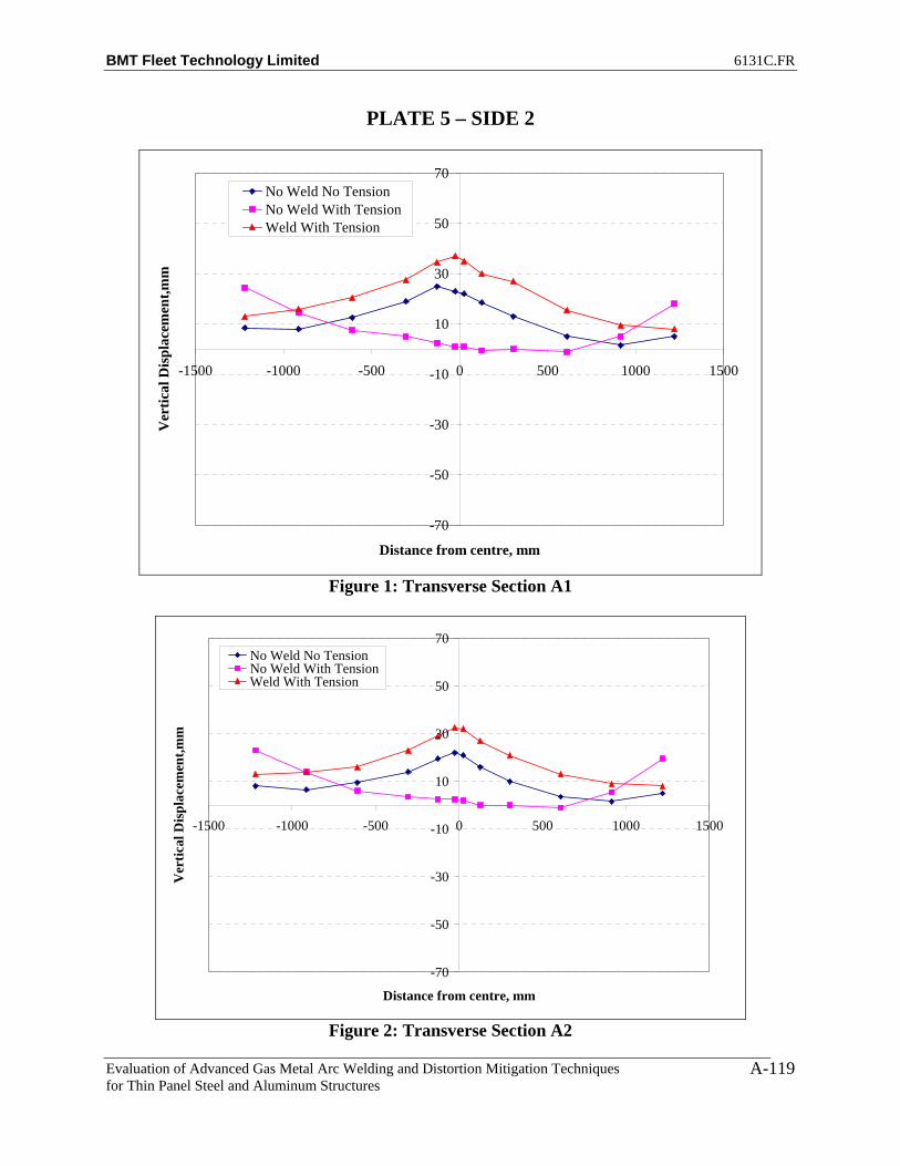
BMT Fleet Technology Limited 6131C.FR
Evaluation of Advanced Gas Metal Arc Welding and Distortion Mitigation Techniques for Thin Panel Steel and Aluminum Structures
A-119
PLATE 5 – SIDE 2
-70
-50
-30
-10
10
30
50
70
-1500 -1000 -500 0 500 1000 1500
Distance from centre, mm
Ver
tical
Dis
plac
emen
t,mm
No Weld No TensionNo Weld With TensionWeld With Tension
Figure 1: Transverse Section A1
-70
-50
-30
-10
10
30
50
70
-1500 -1000 -500 0 500 1000 1500
Distance from centre, mm
Ver
tical
Dis
plac
emen
t,mm
No Weld No TensionNo Weld With TensionWeld With Tension
Figure 2: Transverse Section A2
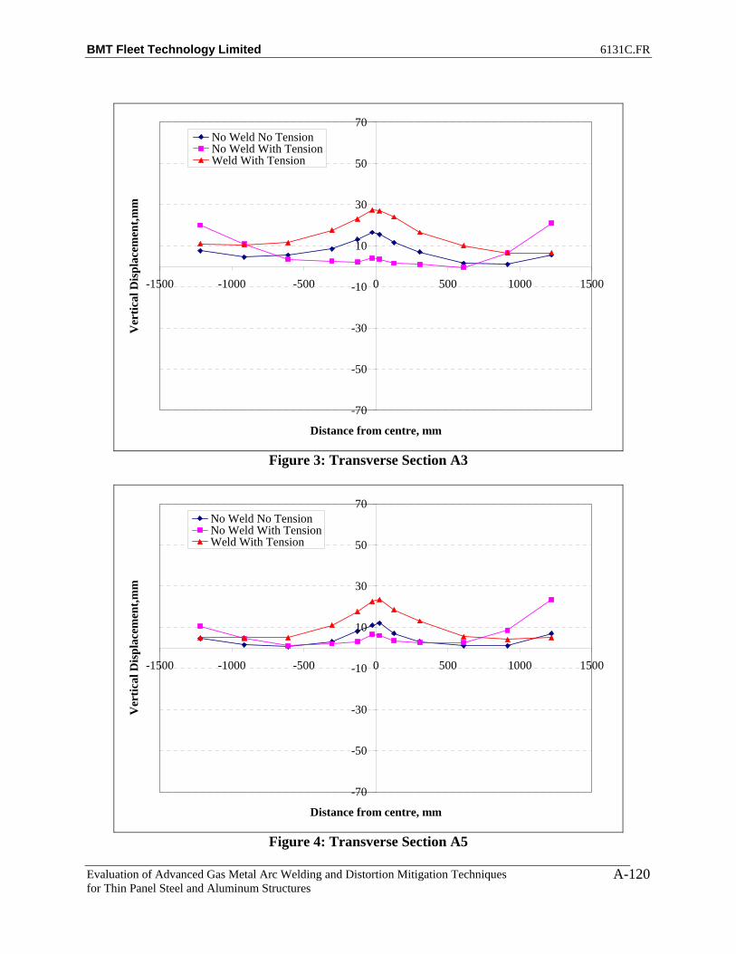
BMT Fleet Technology Limited 6131C.FR
Evaluation of Advanced Gas Metal Arc Welding and Distortion Mitigation Techniques for Thin Panel Steel and Aluminum Structures
A-120
-70
-50
-30
-10
10
30
50
70
-1500 -1000 -500 0 500 1000 1500
Distance from centre, mm
Ver
tical
Dis
plac
emen
t,mm
No Weld No TensionNo Weld With TensionWeld With Tension
Figure 3: Transverse Section A3
-70
-50
-30
-10
10
30
50
70
-1500 -1000 -500 0 500 1000 1500
Distance from centre, mm
Ver
tical
Dis
plac
emen
t,mm
No Weld No TensionNo Weld With TensionWeld With Tension
Figure 4: Transverse Section A5

BMT Fleet Technology Limited 6131C.FR
Evaluation of Advanced Gas Metal Arc Welding and Distortion Mitigation Techniques for Thin Panel Steel and Aluminum Structures
A-121
-70
-50
-30
-10
10
30
50
70
-1500 -1000 -500 0 500 1000 1500
Distance from centre, mm
Ver
tical
Dis
plac
emen
t,mm
No Weld No TensionNo Weld With TensionWeld With Tension
Figure 5: Transverse Section A7
-70
-50
-30
-10
10
30
50
70
-1500 -1000 -500 0 500 1000 1500
Distance from centre, mm
Ver
tical
Dis
plac
emen
t,mm
No Weld No TensionNo Weld With TensionWeld With Tension
Figure 6: Transverse Section A9
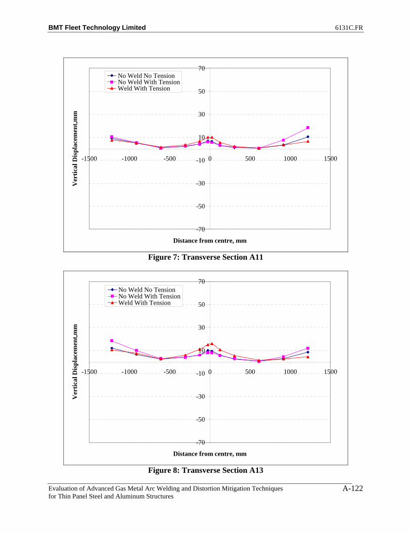
BMT Fleet Technology Limited 6131C.FR
Evaluation of Advanced Gas Metal Arc Welding and Distortion Mitigation Techniques for Thin Panel Steel and Aluminum Structures
A-122
-70
-50
-30
-10
10
30
50
70
-1500 -1000 -500 0 500 1000 1500
Distance from centre, mm
Ver
tical
Dis
plac
emen
t,mm
No Weld No TensionNo Weld With TensionWeld With Tension
Figure 7: Transverse Section A11
-70
-50
-30
-10
10
30
50
70
-1500 -1000 -500 0 500 1000 1500
Distance from centre, mm
Ver
tical
Dis
plac
emen
t,mm
No Weld No TensionNo Weld With TensionWeld With Tension
Figure 8: Transverse Section A13

BMT Fleet Technology Limited 6131C.FR
Evaluation of Advanced Gas Metal Arc Welding and Distortion Mitigation Techniques for Thin Panel Steel and Aluminum Structures
A-123
-70
-50
-30
-10
10
30
50
70
-1500 -1000 -500 0 500 1000 1500
Distance from centre, mm
Ver
tical
Dis
plac
emen
t,mm
No Weld No TensionNo Weld With TensionWeld With Tension
Figure 9: Transverse Section A15
-70
-50
-30
-10
10
30
50
70
-1500 -1000 -500 0 500 1000 1500
Distance from centre, mm
Ver
tical
Dis
plac
emen
t,mm
No Weld No TensionNo Weld With TensionWeld With Tension
Figure 10: Transverse Section A17

BMT Fleet Technology Limited 6131C.FR
Evaluation of Advanced Gas Metal Arc Welding and Distortion Mitigation Techniques for Thin Panel Steel and Aluminum Structures
A-124
-70
-50
-30
-10
10
30
50
70
-1500 -1000 -500 0 500 1000 1500
Distance from centre, mm
Ver
tical
Dis
plac
emen
t,mm
No Weld No TensionNo Weld With TensionWeld With Tension
Figure 11: Transverse Section A19
-70
-50
-30
-10
10
30
50
70
-1500 -1000 -500 0 500 1000 1500
Distance from centre, mm
Ver
tical
Dis
plac
emen
t,mm
No Weld No TensionNo Weld With TensionWeld With Tension
Figure 12: Transverse Section A20

BMT Fleet Technology Limited 6131C.FR
Evaluation of Advanced Gas Metal Arc Welding and Distortion Mitigation Techniques for Thin Panel Steel and Aluminum Structures
A-125
-70
-50
-30
-10
10
30
50
70
-1500 -1000 -500 0 500 1000 1500
Distance from centre, mm
Ver
tical
Dis
plac
emen
t,mm
No Weld No TensionNo Weld With TensionWeld With Tension
Figure 13: Transverse Section A21
-70
-50
-30
-10
10
30
50
70
-1500 -1000 -500 0 500 1000 1500
Distance from centre, mm
Ver
tical
Dis
plac
emen
t,mm
No Weld No TensionNo Weld With TensionWeld With Tension
Figure 14: Transverse Section A22

BMT Fleet Technology Limited 6131C.FR
Evaluation of Advanced Gas Metal Arc Welding and Distortion Mitigation Techniques for Thin Panel Steel and Aluminum Structures
A-126
-70
-50
-30
-10
10
30
50
70
0 500 1000 1500 2000 2500 3000 3500
Distance from edge, mm
Ver
tical
Dis
plac
emen
t,mm
No Weld No TensionNo Weld With TensionWeld With Tension
Figure 15: Longitudinal Section A
-70
-50
-30
-10
10
30
50
70
0 500 1000 1500 2000 2500 3000 3500
Distance from edge, mm
Ver
tical
Dis
plac
emen
t,mm
No Weld No TensionNo Weld With TensionWeld With Tension
Figure 16: Longitudinal Section B

BMT Fleet Technology Limited 6131C.FR
Evaluation of Advanced Gas Metal Arc Welding and Distortion Mitigation Techniques for Thin Panel Steel and Aluminum Structures
A-127
-70
-50
-30
-10
10
30
50
70
0 500 1000 1500 2000 2500 3000 3500
Distance from edge, mm
Ver
tical
Dis
plac
emen
t,mm
No Weld No TensionNo Weld With TensionWeld With Tension
Figure 17: Longitudinal Section C
-70
-50
-30
-10
10
30
50
70
0 500 1000 1500 2000 2500 3000 3500
Distance from edge, mm
Ver
tical
Dis
plac
emen
t,mm
No Weld No TensionNo Weld With TensionWeld With Tension
Figure 18: Longitudinal Section D

BMT Fleet Technology Limited 6131C.FR
Evaluation of Advanced Gas Metal Arc Welding and Distortion Mitigation Techniques for Thin Panel Steel and Aluminum Structures
A-128
-70
-50
-30
-10
10
30
50
70
0 500 1000 1500 2000 2500 3000 3500
Distance from edge, mm
Ver
tical
Dis
plac
emen
t,mm
No Weld No TensionNo Weld With TensionWeld With Tension
Figure 19: Longitudinal Section E
-70
-50
-30
-10
10
30
50
70
0 500 1000 1500 2000 2500 3000 3500
Distance from edge, mm
Ver
tical
Dis
plac
emen
t,mm
No Weld No TensionNo Weld With TensionWeld With Tension
Figure 20: Longitudinal Section F
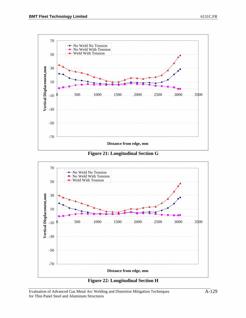
BMT Fleet Technology Limited 6131C.FR
Evaluation of Advanced Gas Metal Arc Welding and Distortion Mitigation Techniques for Thin Panel Steel and Aluminum Structures
A-129
-70
-50
-30
-10
10
30
50
70
0 500 1000 1500 2000 2500 3000 3500
Distance from edge, mm
Ver
tical
Dis
plac
emen
t,mm
No Weld No TensionNo Weld With TensionWeld With Tension
Figure 21: Longitudinal Section G
-70
-50
-30
-10
10
30
50
70
0 500 1000 1500 2000 2500 3000 3500
Distance from edge, mm
Ver
tical
Dis
plac
emen
t,mm
No Weld No TensionNo Weld With TensionWeld With Tension
Figure 22: Longitudinal Section H

BMT Fleet Technology Limited 6131C.FR
Evaluation of Advanced Gas Metal Arc Welding and Distortion Mitigation Techniques for Thin Panel Steel and Aluminum Structures
A-130
-70
-50
-30
-10
10
30
50
70
0 500 1000 1500 2000 2500 3000 3500
Distance from edge, mm
Ver
tical
Dis
plac
emen
t,mm
No Weld No TensionNo Weld With TensionWeld With Tension
Figure 23: Longitudinal Section I
-70
-50
-30
-10
10
30
50
70
0 500 1000 1500 2000 2500 3000 3500
Distance from edge, mm
Ver
tical
Dis
plac
emen
t,mm
No Weld No TensionNo Weld With TensionWeld With Tension
Figure 24: Longitudinal Section J
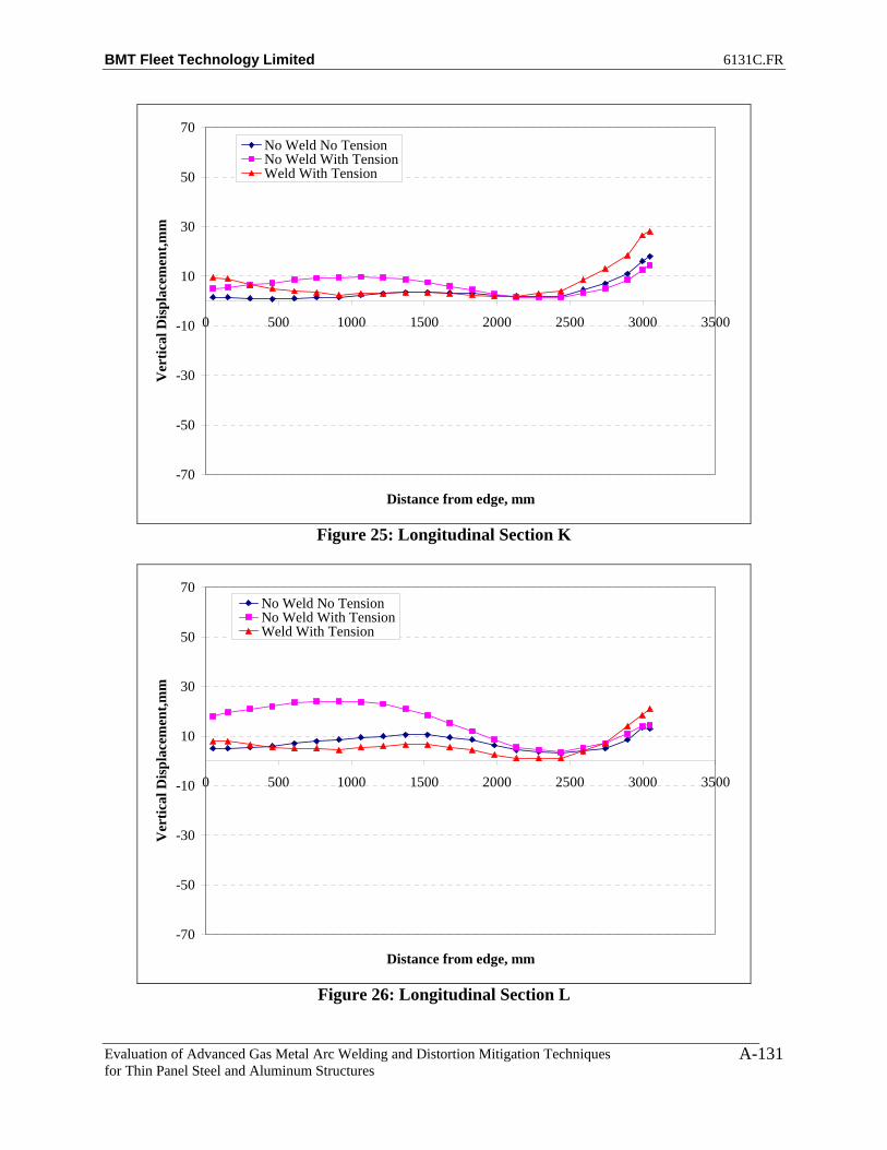
BMT Fleet Technology Limited 6131C.FR
Evaluation of Advanced Gas Metal Arc Welding and Distortion Mitigation Techniques for Thin Panel Steel and Aluminum Structures
A-131
-70
-50
-30
-10
10
30
50
70
0 500 1000 1500 2000 2500 3000 3500
Distance from edge, mm
Ver
tical
Dis
plac
emen
t,mm
No Weld No TensionNo Weld With TensionWeld With Tension
Figure 25: Longitudinal Section K
-70
-50
-30
-10
10
30
50
70
0 500 1000 1500 2000 2500 3000 3500
Distance from edge, mm
Ver
tical
Dis
plac
emen
t,mm
No Weld No TensionNo Weld With TensionWeld With Tension
Figure 26: Longitudinal Section L
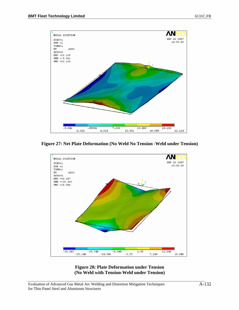
BMT Fleet Technology Limited 6131C.FR
Evaluation of Advanced Gas Metal Arc Welding and Distortion Mitigation Techniques for Thin Panel Steel and Aluminum Structures
A-132
Figure 27: Net Plate Deformation (No Weld No Tension -Weld under Tension)
Figure 28: Plate Deformation under Tension (No Weld with Tension-Weld under Tension)

BMT Fleet Technology Limited 6131C.FR
Evaluation of Advanced Gas Metal Arc Welding and Distortion Mitigation Techniques for Thin Panel Steel and Aluminum Structures
A-133
Figure 29: Plate Deformation before Welding (No Weld No Tension-No Weld with Tension)
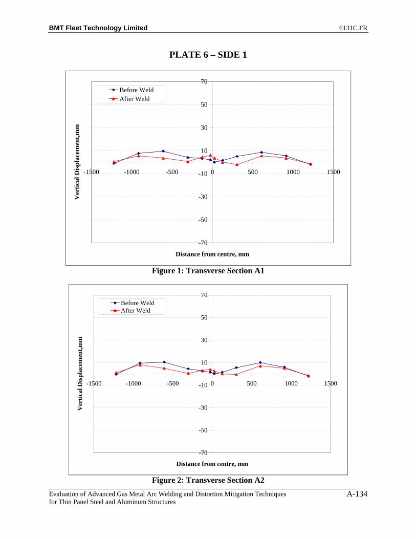
BMT Fleet Technology Limited 6131C.FR
Evaluation of Advanced Gas Metal Arc Welding and Distortion Mitigation Techniques for Thin Panel Steel and Aluminum Structures
A-134
PLATE 6 – SIDE 1
-70
-50
-30
-10
10
30
50
70
-1500 -1000 -500 0 500 1000 1500
Distance from centre, mm
Ver
tical
Dis
plac
emen
t,mm
Before WeldAfter Weld
Figure 1: Transverse Section A1
-70
-50
-30
-10
10
30
50
70
-1500 -1000 -500 0 500 1000 1500
Distance from centre, mm
Ver
tical
Dis
plac
emen
t,mm
Before WeldAfter Weld
Figure 2: Transverse Section A2
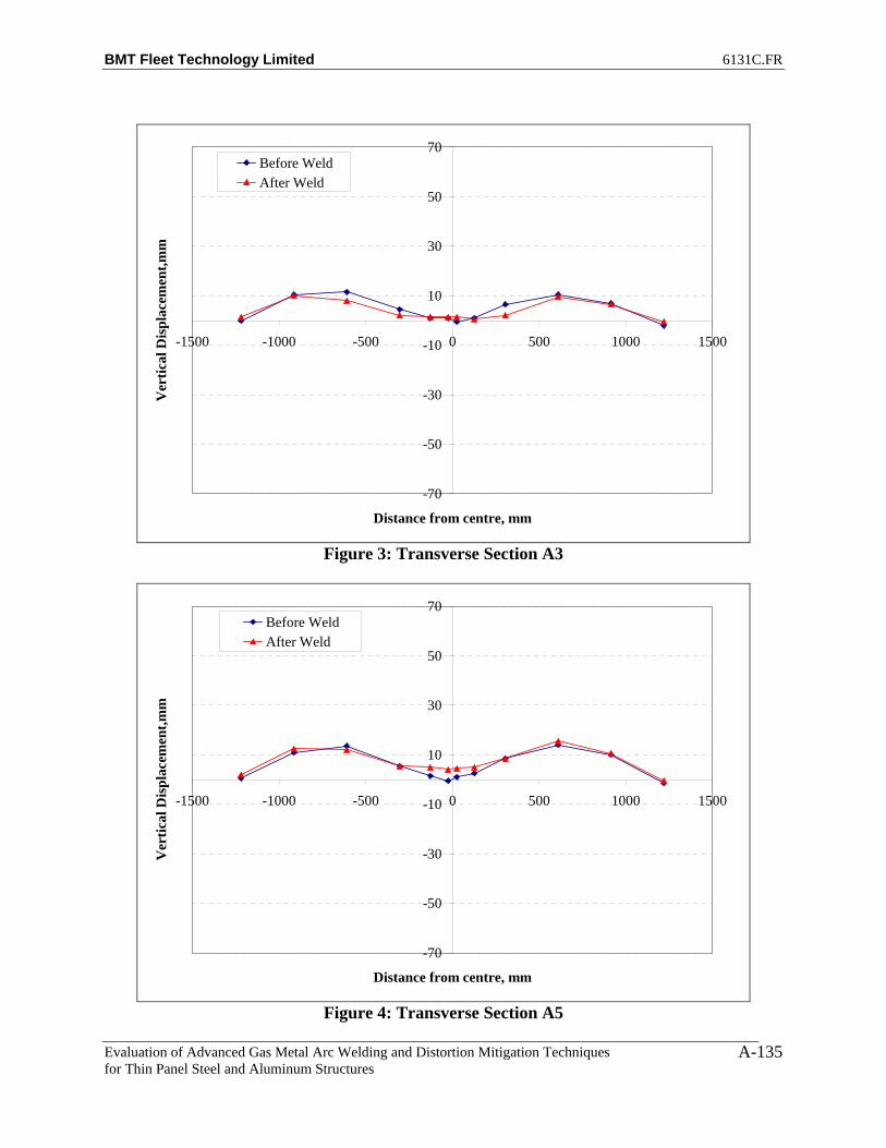
BMT Fleet Technology Limited 6131C.FR
Evaluation of Advanced Gas Metal Arc Welding and Distortion Mitigation Techniques for Thin Panel Steel and Aluminum Structures
A-135
-70
-50
-30
-10
10
30
50
70
-1500 -1000 -500 0 500 1000 1500
Distance from centre, mm
Ver
tical
Dis
plac
emen
t,mm
Before WeldAfter Weld
Figure 3: Transverse Section A3
-70
-50
-30
-10
10
30
50
70
-1500 -1000 -500 0 500 1000 1500
Distance from centre, mm
Ver
tical
Dis
plac
emen
t,mm
Before WeldAfter Weld
Figure 4: Transverse Section A5
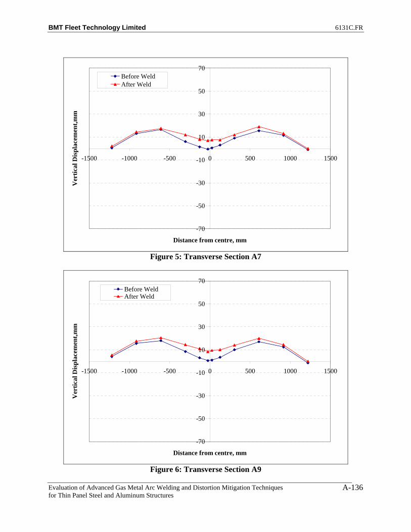
BMT Fleet Technology Limited 6131C.FR
Evaluation of Advanced Gas Metal Arc Welding and Distortion Mitigation Techniques for Thin Panel Steel and Aluminum Structures
A-136
-70
-50
-30
-10
10
30
50
70
-1500 -1000 -500 0 500 1000 1500
Distance from centre, mm
Ver
tical
Dis
plac
emen
t,mm
Before WeldAfter Weld
Figure 5: Transverse Section A7
-70
-50
-30
-10
10
30
50
70
-1500 -1000 -500 0 500 1000 1500
Distance from centre, mm
Ver
tical
Dis
plac
emen
t,mm
Before WeldAfter Weld
Figure 6: Transverse Section A9
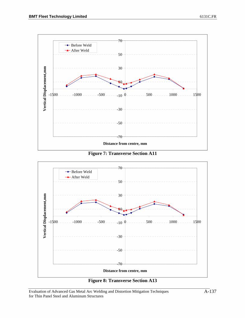
BMT Fleet Technology Limited 6131C.FR
Evaluation of Advanced Gas Metal Arc Welding and Distortion Mitigation Techniques for Thin Panel Steel and Aluminum Structures
A-137
-70
-50
-30
-10
10
30
50
70
-1500 -1000 -500 0 500 1000 1500
Distance from centre, mm
Ver
tical
Dis
plac
emen
t,mm
Before WeldAfter Weld
Figure 7: Transverse Section A11
-70
-50
-30
-10
10
30
50
70
-1500 -1000 -500 0 500 1000 1500
Distance from centre, mm
Ver
tical
Dis
plac
emen
t,mm
Before WeldAfter Weld
Figure 8: Transverse Section A13

BMT Fleet Technology Limited 6131C.FR
Evaluation of Advanced Gas Metal Arc Welding and Distortion Mitigation Techniques for Thin Panel Steel and Aluminum Structures
A-138
-70
-50
-30
-10
10
30
50
70
-1500 -1000 -500 0 500 1000 1500
Distance from centre, mm
Ver
tical
Dis
plac
emen
t,mm
Before WeldAfter Weld
Figure 9: Transverse Section A15
-70
-50
-30
-10
10
30
50
70
-1500 -1000 -500 0 500 1000 1500
Distance from centre, mm
Ver
tical
Dis
plac
emen
t,mm
Before WeldAfter Weld
Figure 10: Transverse Section A17

BMT Fleet Technology Limited 6131C.FR
Evaluation of Advanced Gas Metal Arc Welding and Distortion Mitigation Techniques for Thin Panel Steel and Aluminum Structures
A-139
-70
-50
-30
-10
10
30
50
70
-1500 -1000 -500 0 500 1000 1500
Distance from centre, mm
Ver
tical
Dis
plac
emen
t,mm
Before WeldAfter Weld
Figure 11: Transverse Section A19
-70
-50
-30
-10
10
30
50
70
-1500 -1000 -500 0 500 1000 1500
Distance from centre, mm
Ver
tical
Dis
plac
emen
t,mm
Before WeldAfter Weld
Figure 12: Transverse Section A20

BMT Fleet Technology Limited 6131C.FR
Evaluation of Advanced Gas Metal Arc Welding and Distortion Mitigation Techniques for Thin Panel Steel and Aluminum Structures
A-140
-70
-50
-30
-10
10
30
50
70
-1500 -1000 -500 0 500 1000 1500
Distance from centre, mm
Ver
tical
Dis
plac
emen
t,mm
Before WeldAfter Weld
Figure 13: Transverse Section A21
-70
-50
-30
-10
10
30
50
70
-1500 -1000 -500 0 500 1000 1500
Distance from centre, mm
Ver
tical
Dis
plac
emen
t,mm
Before WeldAfter Weld
Figure 14: Transverse Section A22

BMT Fleet Technology Limited 6131C.FR
Evaluation of Advanced Gas Metal Arc Welding and Distortion Mitigation Techniques for Thin Panel Steel and Aluminum Structures
A-141
-70
-50
-30
-10
10
30
50
70
0 500 1000 1500 2000 2500 3000 3500
Distance from edge, mm
Ver
tical
Dis
plac
emen
t,mm
Before WeldAfter Weld
Figure 15: Longitudinal Section A
-70
-50
-30
-10
10
30
50
70
0 500 1000 1500 2000 2500 3000 3500
Distance from edge, mm
Ver
tical
Dis
plac
emen
t,mm
Before WeldAfter Weld
Figure 16: Longitudinal Section B

BMT Fleet Technology Limited 6131C.FR
Evaluation of Advanced Gas Metal Arc Welding and Distortion Mitigation Techniques for Thin Panel Steel and Aluminum Structures
A-142
-70
-50
-30
-10
10
30
50
70
0 500 1000 1500 2000 2500 3000 3500
Distance from edge, mm
Ver
tical
Dis
plac
emen
t,mm
Before WeldAfter Weld
Figure 17: Longitudinal Section C
-70
-50
-30
-10
10
30
50
70
0 500 1000 1500 2000 2500 3000 3500
Distance from edge, mm
Ver
tical
Dis
plac
emen
t,mm
Before WeldAfter Weld
Figure 18: Longitudinal Section D

BMT Fleet Technology Limited 6131C.FR
Evaluation of Advanced Gas Metal Arc Welding and Distortion Mitigation Techniques for Thin Panel Steel and Aluminum Structures
A-143
-70
-50
-30
-10
10
30
50
70
0 500 1000 1500 2000 2500 3000 3500
Distance from edge, mm
Ver
tical
Dis
plac
emen
t,mm
Before WeldAfter Weld
Figure 19: Longitudinal Section E
-70
-50
-30
-10
10
30
50
70
0 500 1000 1500 2000 2500 3000 3500
Distance from edge, mm
Ver
tical
Dis
plac
emen
t,mm
Before WeldAfter Weld
Figure 20: Longitudinal Section F
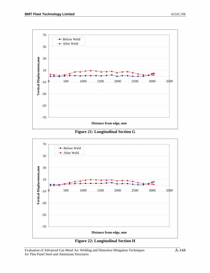
BMT Fleet Technology Limited 6131C.FR
Evaluation of Advanced Gas Metal Arc Welding and Distortion Mitigation Techniques for Thin Panel Steel and Aluminum Structures
A-144
-70
-50
-30
-10
10
30
50
70
0 500 1000 1500 2000 2500 3000 3500
Distance from edge, mm
Ver
tical
Dis
plac
emen
t,mm
Before WeldAfter Weld
Figure 21: Longitudinal Section G
-70
-50
-30
-10
10
30
50
70
0 500 1000 1500 2000 2500 3000 3500
Distance from edge, mm
Ver
tical
Dis
plac
emen
t,mm
Before WeldAfter Weld
Figure 22: Longitudinal Section H

BMT Fleet Technology Limited 6131C.FR
Evaluation of Advanced Gas Metal Arc Welding and Distortion Mitigation Techniques for Thin Panel Steel and Aluminum Structures
A-145
-70
-50
-30
-10
10
30
50
70
0 500 1000 1500 2000 2500 3000 3500
Distance from edge, mm
Ver
tical
Dis
plac
emen
t,mm
Before WeldAfter Weld
Figure 23: Longitudinal Section I
-70
-50
-30
-10
10
30
50
70
0 500 1000 1500 2000 2500 3000 3500
Distance from edge, mm
Ver
tical
Dis
plac
emen
t,mm
Before WeldAfter Weld
Figure 24: Longitudinal Section J

BMT Fleet Technology Limited 6131C.FR
Evaluation of Advanced Gas Metal Arc Welding and Distortion Mitigation Techniques for Thin Panel Steel and Aluminum Structures
A-146
-70
-50
-30
-10
10
30
50
70
0 500 1000 1500 2000 2500 3000 3500
Distance from edge, mm
Ver
tical
Dis
plac
emen
t,mm
Before WeldAfter Weld
Figure 25: Longitudinal Section K
-70
-50
-30
-10
10
30
50
70
0 500 1000 1500 2000 2500 3000 3500
Distance from edge, mm
Ver
tical
Dis
plac
emen
t,mm
Before WeldAfter Weld
Figure 26: Longitudinal Section L

BMT Fleet Technology Limited 6131C.FR
Evaluation of Advanced Gas Metal Arc Welding and Distortion Mitigation Techniques for Thin Panel Steel and Aluminum Structures
A-147
Figure 27: Net Plate Deformation after Welding
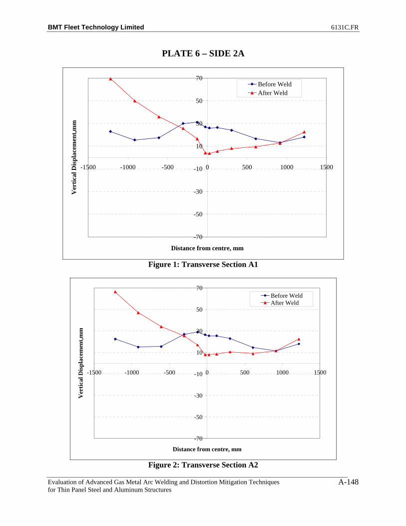
BMT Fleet Technology Limited 6131C.FR
Evaluation of Advanced Gas Metal Arc Welding and Distortion Mitigation Techniques for Thin Panel Steel and Aluminum Structures
A-148
PLATE 6 – SIDE 2A
-70
-50
-30
-10
10
30
50
70
-1500 -1000 -500 0 500 1000 1500
Distance from centre, mm
Ver
tical
Dis
plac
emen
t,mm
Before WeldAfter Weld
Figure 1: Transverse Section A1
-70
-50
-30
-10
10
30
50
70
-1500 -1000 -500 0 500 1000 1500
Distance from centre, mm
Ver
tical
Dis
plac
emen
t,mm
Before WeldAfter Weld
Figure 2: Transverse Section A2

BMT Fleet Technology Limited 6131C.FR
Evaluation of Advanced Gas Metal Arc Welding and Distortion Mitigation Techniques for Thin Panel Steel and Aluminum Structures
A-149
-70
-50
-30
-10
10
30
50
70
-1500 -1000 -500 0 500 1000 1500
Distance from centre, mm
Ver
tical
Dis
plac
emen
t,mm
Before WeldAfter Weld
Figure 3: Transverse Section A3
-70
-50
-30
-10
10
30
50
70
-1500 -1000 -500 0 500 1000 1500
Distance from centre, mm
Ver
tical
Dis
plac
emen
t,mm
Before WeldAfter Weld
Figure 4: Transverse Section A5

BMT Fleet Technology Limited 6131C.FR
Evaluation of Advanced Gas Metal Arc Welding and Distortion Mitigation Techniques for Thin Panel Steel and Aluminum Structures
A-150
-70
-50
-30
-10
10
30
50
70
-1500 -1000 -500 0 500 1000 1500
Distance from centre, mm
Ver
tical
Dis
plac
emen
t,mm
Before WeldAfter Weld
Figure 5: Transverse Section A7
-70
-50
-30
-10
10
30
50
70
-1500 -1000 -500 0 500 1000 1500
Distance from centre, mm
Ver
tical
Dis
plac
emen
t,mm
Before WeldAfter Weld
Figure 6: Transverse Section A9

BMT Fleet Technology Limited 6131C.FR
Evaluation of Advanced Gas Metal Arc Welding and Distortion Mitigation Techniques for Thin Panel Steel and Aluminum Structures
A-151
-70
-50
-30
-10
10
30
50
70
-1500 -1000 -500 0 500 1000 1500
Distance from centre, mm
Ver
tical
Dis
plac
emen
t,mm
Before WeldAfter Weld
Figure 7: Transverse Section A11
-70
-50
-30
-10
10
30
50
70
-1500 -1000 -500 0 500 1000 1500
Distance from centre, mm
Ver
tical
Dis
plac
emen
t,mm
Before WeldAfter Weld
Figure 8: Transverse Section A13

BMT Fleet Technology Limited 6131C.FR
Evaluation of Advanced Gas Metal Arc Welding and Distortion Mitigation Techniques for Thin Panel Steel and Aluminum Structures
A-152
-70
-50
-30
-10
10
30
50
70
-1500 -1000 -500 0 500 1000 1500
Distance from centre, mm
Ver
tical
Dis
plac
emen
t,mm
Before WeldAfter Weld
Figure 9: Transverse Section A15
-70
-50
-30
-10
10
30
50
70
-1500 -1000 -500 0 500 1000 1500
Distance from centre, mm
Ver
tical
Dis
plac
emen
t,mm
Before WeldAfter Weld
Figure 10: Transverse Section A17

BMT Fleet Technology Limited 6131C.FR
Evaluation of Advanced Gas Metal Arc Welding and Distortion Mitigation Techniques for Thin Panel Steel and Aluminum Structures
A-153
-70
-50
-30
-10
10
30
50
70
-1500 -1000 -500 0 500 1000 1500
Distance from centre, mm
Ver
tical
Dis
plac
emen
t,mm
Before WeldAfter Weld
Figure 11: Transverse Section A19
-70
-50
-30
-10
10
30
50
70
-1500 -1000 -500 0 500 1000 1500
Distance from centre, mm
Ver
tical
Dis
plac
emen
t,mm
Before WeldAfter Weld
Figure 12: Transverse Section A20
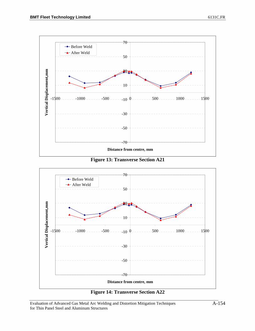
BMT Fleet Technology Limited 6131C.FR
Evaluation of Advanced Gas Metal Arc Welding and Distortion Mitigation Techniques for Thin Panel Steel and Aluminum Structures
A-154
-70
-50
-30
-10
10
30
50
70
-1500 -1000 -500 0 500 1000 1500
Distance from centre, mm
Ver
tical
Dis
plac
emen
t,mm
Before WeldAfter Weld
Figure 13: Transverse Section A21
-70
-50
-30
-10
10
30
50
70
-1500 -1000 -500 0 500 1000 1500
Distance from centre, mm
Ver
tical
Dis
plac
emen
t,mm
Before WeldAfter Weld
Figure 14: Transverse Section A22

BMT Fleet Technology Limited 6131C.FR
Evaluation of Advanced Gas Metal Arc Welding and Distortion Mitigation Techniques for Thin Panel Steel and Aluminum Structures
A-155
-70
-50
-30
-10
10
30
50
70
0 500 1000 1500 2000 2500 3000 3500
Distance from edge, mm
Ver
tical
Dis
plac
emen
t,mm
Before WeldAfter Weld
Figure 15: Longitudinal Section A
-70
-50
-30
-10
10
30
50
70
0 500 1000 1500 2000 2500 3000 3500
Distance from edge, mm
Ver
tical
Dis
plac
emen
t,mm
Before WeldAfter Weld
Figure 16: Longitudinal Section B

BMT Fleet Technology Limited 6131C.FR
Evaluation of Advanced Gas Metal Arc Welding and Distortion Mitigation Techniques for Thin Panel Steel and Aluminum Structures
A-156
-70
-50
-30
-10
10
30
50
70
0 500 1000 1500 2000 2500 3000 3500
Distance from edge, mm
Ver
tical
Dis
plac
emen
t,mm
Before WeldAfter Weld
Figure 17: Longitudinal Section C
-70
-50
-30
-10
10
30
50
70
0 500 1000 1500 2000 2500 3000 3500
Distance from edge, mm
Ver
tical
Dis
plac
emen
t,mm
Before WeldAfter Weld
Figure 18: Longitudinal Section D

BMT Fleet Technology Limited 6131C.FR
Evaluation of Advanced Gas Metal Arc Welding and Distortion Mitigation Techniques for Thin Panel Steel and Aluminum Structures
A-157
-70
-50
-30
-10
10
30
50
70
0 500 1000 1500 2000 2500 3000 3500
Distance from edge, mm
Ver
tical
Dis
plac
emen
t,mm
Before WeldAfter Weld
Figure 19: Longitudinal Section E
-70
-50
-30
-10
10
30
50
70
0 500 1000 1500 2000 2500 3000 3500
Distance from edge, mm
Ver
tical
Dis
plac
emen
t,mm
Before WeldAfter Weld
Figure 20: Longitudinal Section F

BMT Fleet Technology Limited 6131C.FR
Evaluation of Advanced Gas Metal Arc Welding and Distortion Mitigation Techniques for Thin Panel Steel and Aluminum Structures
A-158
-70
-50
-30
-10
10
30
50
70
0 500 1000 1500 2000 2500 3000 3500
Distance from edge, mm
Ver
tical
Dis
plac
emen
t,mm
Before WeldAfter Weld
Figure 21: Longitudinal Section G
-70
-50
-30
-10
10
30
50
70
0 500 1000 1500 2000 2500 3000 3500
Distance from edge, mm
Ver
tical
Dis
plac
emen
t,mm
Before WeldAfter Weld
Figure 22: Longitudinal Section H

BMT Fleet Technology Limited 6131C.FR
Evaluation of Advanced Gas Metal Arc Welding and Distortion Mitigation Techniques for Thin Panel Steel and Aluminum Structures
A-159
-70
-50
-30
-10
10
30
50
70
0 500 1000 1500 2000 2500 3000 3500
Distance from edge, mm
Ver
tical
Dis
plac
emen
t,mm
Before WeldAfter Weld
Figure 23: Longitudinal Section I
-70
-50
-30
-10
10
30
50
70
0 500 1000 1500 2000 2500 3000 3500
Distance from edge, mm
Ver
tical
Dis
plac
emen
t,mm
Before WeldAfter Weld
Figure 24: Longitudinal Section J

BMT Fleet Technology Limited 6131C.FR
Evaluation of Advanced Gas Metal Arc Welding and Distortion Mitigation Techniques for Thin Panel Steel and Aluminum Structures
A-160
-70
-50
-30
-10
10
30
50
70
0 500 1000 1500 2000 2500 3000 3500
Distance from edge, mm
Ver
tical
Dis
plac
emen
t,mm
Before WeldAfter Weld
Figure 25: Longitudinal Section K
-70
-50
-30
-10
10
30
50
70
0 500 1000 1500 2000 2500 3000 3500
Distance from edge, mm
Ver
tical
Dis
plac
emen
t,mm
Before WeldAfter Weld
Figure 26: Longitudinal Section L

BMT Fleet Technology Limited 6131C.FR
Evaluation of Advanced Gas Metal Arc Welding and Distortion Mitigation Techniques for Thin Panel Steel and Aluminum Structures
A-161
Figure 27: Net Plate Deformation after Welding
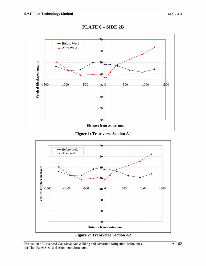
BMT Fleet Technology Limited 6131C.FR
Evaluation of Advanced Gas Metal Arc Welding and Distortion Mitigation Techniques for Thin Panel Steel and Aluminum Structures
A-162
PLATE 6 – SIDE 2B
-70
-50
-30
-10
10
30
50
70
-1500 -1000 -500 0 500 1000 1500
Distance from centre, mm
Ver
tical
Dis
plac
emen
t,mm
Before WeldAfter Weld
Figure 1: Transverse Section A1
-70
-50
-30
-10
10
30
50
70
-1500 -1000 -500 0 500 1000 1500
Distance from centre, mm
Ver
tical
Dis
plac
emen
t,mm
Before WeldAfter Weld
Figure 2: Transverse Section A2

BMT Fleet Technology Limited 6131C.FR
Evaluation of Advanced Gas Metal Arc Welding and Distortion Mitigation Techniques for Thin Panel Steel and Aluminum Structures
A-163
-70
-50
-30
-10
10
30
50
70
-1500 -1000 -500 0 500 1000 1500
Distance from centre, mm
Ver
tical
Dis
plac
emen
t,mm
Before WeldAfter Weld
Figure 3: Transverse Section A3
-70
-50
-30
-10
10
30
50
70
-1500 -1000 -500 0 500 1000 1500
Distance from centre, mm
Ver
tical
Dis
plac
emen
t,mm
Before WeldAfter Weld
Figure 4: Transverse Section A5

BMT Fleet Technology Limited 6131C.FR
Evaluation of Advanced Gas Metal Arc Welding and Distortion Mitigation Techniques for Thin Panel Steel and Aluminum Structures
A-164
-70
-50
-30
-10
10
30
50
70
-1500 -1000 -500 0 500 1000 1500
Distance from centre, mm
Ver
tical
Dis
plac
emen
t,mm
Before WeldAfter Weld
Figure 5: Transverse Section A7
-70
-50
-30
-10
10
30
50
70
-1500 -1000 -500 0 500 1000 1500
Distance from centre, mm
Ver
tical
Dis
plac
emen
t,mm
Before WeldAfter Weld
Figure 6: Transverse Section A9

BMT Fleet Technology Limited 6131C.FR
Evaluation of Advanced Gas Metal Arc Welding and Distortion Mitigation Techniques for Thin Panel Steel and Aluminum Structures
A-165
-70
-50
-30
-10
10
30
50
70
-1500 -1000 -500 0 500 1000 1500
Distance from centre, mm
Ver
tical
Dis
plac
emen
t,mm
Before WeldAfter Weld
Figure 7: Transverse Section A11
-70
-50
-30
-10
10
30
50
70
-1500 -1000 -500 0 500 1000 1500
Distance from centre, mm
Ver
tical
Dis
plac
emen
t,mm
Before WeldAfter Weld
Figure 8: Transverse Section A13

BMT Fleet Technology Limited 6131C.FR
Evaluation of Advanced Gas Metal Arc Welding and Distortion Mitigation Techniques for Thin Panel Steel and Aluminum Structures
A-166
-70
-50
-30
-10
10
30
50
70
-1500 -1000 -500 0 500 1000 1500
Distance from centre, mm
Ver
tical
Dis
plac
emen
t,mm
Before WeldAfter Weld
Figure 9: Transverse Section A15
-70
-50
-30
-10
10
30
50
70
-1500 -1000 -500 0 500 1000 1500
Distance from centre, mm
Ver
tical
Dis
plac
emen
t,mm
Before WeldAfter Weld
Figure 10: Transverse Section A17
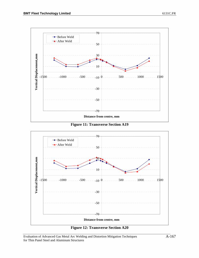
BMT Fleet Technology Limited 6131C.FR
Evaluation of Advanced Gas Metal Arc Welding and Distortion Mitigation Techniques for Thin Panel Steel and Aluminum Structures
A-167
-70
-50
-30
-10
10
30
50
70
-1500 -1000 -500 0 500 1000 1500
Distance from centre, mm
Ver
tical
Dis
plac
emen
t,mm
Before WeldAfter Weld
Figure 11: Transverse Section A19
-70
-50
-30
-10
10
30
50
70
-1500 -1000 -500 0 500 1000 1500
Distance from centre, mm
Ver
tical
Dis
plac
emen
t,mm
Before WeldAfter Weld
Figure 12: Transverse Section A20

BMT Fleet Technology Limited 6131C.FR
Evaluation of Advanced Gas Metal Arc Welding and Distortion Mitigation Techniques for Thin Panel Steel and Aluminum Structures
A-168
-70
-50
-30
-10
10
30
50
70
-1500 -1000 -500 0 500 1000 1500
Distance from centre, mm
Ver
tical
Dis
plac
emen
t,mm
Before WeldAfter Weld
Figure 13: Transverse Section A21
-70
-50
-30
-10
10
30
50
70
-1500 -1000 -500 0 500 1000 1500
Distance from centre, mm
Ver
tical
Dis
plac
emen
t,mm
Before WeldAfter Weld
Figure 14: Transverse Section A22

BMT Fleet Technology Limited 6131C.FR
Evaluation of Advanced Gas Metal Arc Welding and Distortion Mitigation Techniques for Thin Panel Steel and Aluminum Structures
A-169
-70
-50
-30
-10
10
30
50
70
0 500 1000 1500 2000 2500 3000 3500
Distance from edge, mm
Ver
tical
Dis
plac
emen
t,mm
Before WeldAfter Weld
Figure 15: Longitudinal Section A
-70
-50
-30
-10
10
30
50
70
0 500 1000 1500 2000 2500 3000 3500
Distance from edge, mm
Ver
tical
Dis
plac
emen
t,mm
Before WeldAfter Weld
Figure 16: Longitudinal Section B

BMT Fleet Technology Limited 6131C.FR
Evaluation of Advanced Gas Metal Arc Welding and Distortion Mitigation Techniques for Thin Panel Steel and Aluminum Structures
A-170
-70
-50
-30
-10
10
30
50
70
0 500 1000 1500 2000 2500 3000 3500
Distance from edge, mm
Ver
tical
Dis
plac
emen
t,mm
Before WeldAfter Weld
Figure 17: Longitudinal Section C
-70
-50
-30
-10
10
30
50
70
0 500 1000 1500 2000 2500 3000 3500
Distance from edge, mm
Ver
tical
Dis
plac
emen
t,mm
Before WeldAfter Weld
Figure 18: Longitudinal Section D

BMT Fleet Technology Limited 6131C.FR
Evaluation of Advanced Gas Metal Arc Welding and Distortion Mitigation Techniques for Thin Panel Steel and Aluminum Structures
A-171
-70
-50
-30
-10
10
30
50
70
0 500 1000 1500 2000 2500 3000 3500
Distance from edge, mm
Ver
tical
Dis
plac
emen
t,mm
Before WeldAfter Weld
Figure 19: Longitudinal Section E
-70
-50
-30
-10
10
30
50
70
0 500 1000 1500 2000 2500 3000 3500
Distance from edge, mm
Ver
tical
Dis
plac
emen
t,mm
Before WeldAfter Weld
Figure 20: Longitudinal Section F
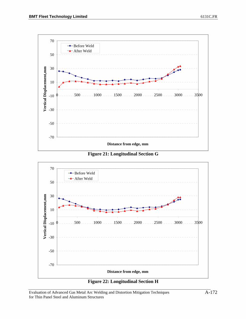
BMT Fleet Technology Limited 6131C.FR
Evaluation of Advanced Gas Metal Arc Welding and Distortion Mitigation Techniques for Thin Panel Steel and Aluminum Structures
A-172
-70
-50
-30
-10
10
30
50
70
0 500 1000 1500 2000 2500 3000 3500
Distance from edge, mm
Ver
tical
Dis
plac
emen
t,mm
Before WeldAfter Weld
Figure 21: Longitudinal Section G
-70
-50
-30
-10
10
30
50
70
0 500 1000 1500 2000 2500 3000 3500
Distance from edge, mm
Ver
tical
Dis
plac
emen
t,mm
Before WeldAfter Weld
Figure 22: Longitudinal Section H

BMT Fleet Technology Limited 6131C.FR
Evaluation of Advanced Gas Metal Arc Welding and Distortion Mitigation Techniques for Thin Panel Steel and Aluminum Structures
A-173
-70
-50
-30
-10
10
30
50
70
0 500 1000 1500 2000 2500 3000 3500
Distance from edge, mm
Ver
tical
Dis
plac
emen
t,mm
Before WeldAfter Weld
Figure 23: Longitudinal Section I
-70
-50
-30
-10
10
30
50
70
0 500 1000 1500 2000 2500 3000 3500
Distance from edge, mm
Ver
tical
Dis
plac
emen
t,mm
Before WeldAfter Weld
Figure 24: Longitudinal Section J
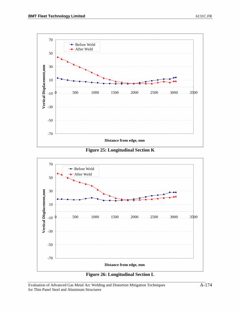
BMT Fleet Technology Limited 6131C.FR
Evaluation of Advanced Gas Metal Arc Welding and Distortion Mitigation Techniques for Thin Panel Steel and Aluminum Structures
A-174
-70
-50
-30
-10
10
30
50
70
0 500 1000 1500 2000 2500 3000 3500
Distance from edge, mm
Ver
tical
Dis
plac
emen
t,mm
Before WeldAfter Weld
Figure 25: Longitudinal Section K
-70
-50
-30
-10
10
30
50
70
0 500 1000 1500 2000 2500 3000 3500
Distance from edge, mm
Ver
tical
Dis
plac
emen
t,mm
Before WeldAfter Weld
Figure 26: Longitudinal Section L
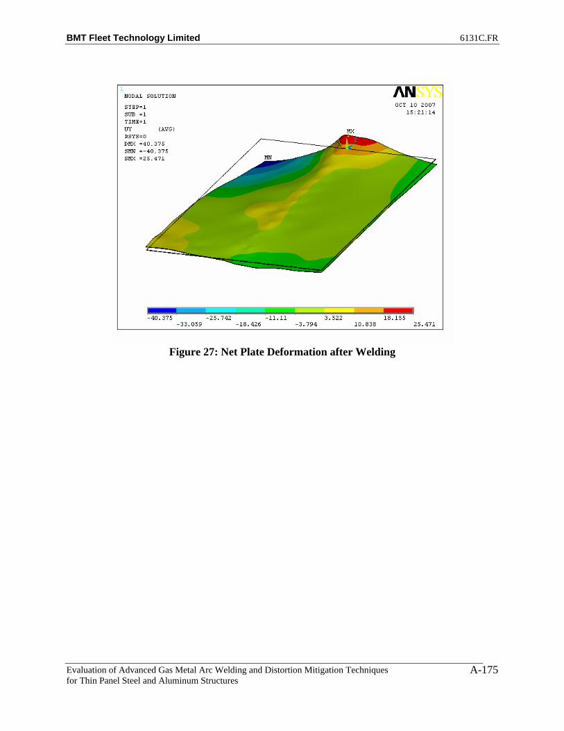
BMT Fleet Technology Limited 6131C.FR
Evaluation of Advanced Gas Metal Arc Welding and Distortion Mitigation Techniques for Thin Panel Steel and Aluminum Structures
A-175
Figure 27: Net Plate Deformation after Welding

BMT Fleet Technology Limited 6131C.FR
Evaluation of Advanced Gas Metal Arc Welding and Distortion Mitigation Techniques for Thin Panel Steel and Aluminum Structures
B-1
APPENDIX B
DISTORTION PLOTS FOR FILLET WELDS (STT and FCAW Processes)

BMT Fleet Technology Limited 6131C.FR
Evaluation of Advanced Gas Metal Arc Welding and Distortion Mitigation Techniques for Thin Panel Steel and Aluminum Structures
B-2
Table B1: STT_Stiff_1_Benchmark Distortion Data
A T B Abs Diff A T B Abs Diff1 9 67 6.5 2.5 1 6.5 65.5 5 1.52 8.5 66.5 6 2.5 2 6.5 65 5 1.53 6.5 65 4.5 2 3 5.5 64 3.5 24 6 63.5 4 2 4 5.5 63 4 1.55 5 62 3 2 5 5 61.25 3.5 1.56 3.5 60.5 1.5 2 6 3.5 59.5 2.5 17 2.5 59.25 0.5 2 7 3 58.5 2 18 2 58 0.5 1.5 8 2.5 57.5 1.5 19 1.5 56.75 0.5 1 9 2 56.5 2 0
10 0 55.5 0 0 10 1.5 55.5 1.5 011 1 55.25 0 1 11 2 55.5 1.5 0.512 1 55 0.5 0.5 12 2.5 55.5 2 0.513 1.5 54.5 0.5 1 13 2.5 55 2 0.514 1 54 0.5 0.5 14 2 54.5 2 015 1.5 54.25 0.5 1 15 2.5 54.75 2.5 016 2.5 54.5 1.5 1 16 3.5 55 3 0.517 3 55 1.5 1.5 17 4 55.25 3 118 3.5 55.5 2.5 1 18 4.5 55.5 4 0.519 5.5 56.5 3.5 2 19 5.5 56.25 5 0.520 6.5 57.5 5 1.5 20 6.5 57 6 0.521 8 58.5 6 2 21 6.5 57.5 6 0.522 9 59 7 2 22 6.5 58 6.5 023 10 59.5 8 2 23 7.5 58.5 7.5 0
Displacement w.r.t to Frame, mmAfter WeldBefore Weld
Displacement w.r.t to Frame, mm
Table B2: FCAW_Stiff_1_Benchmark Distortion Data
A T B Abs Diff A T B Abs Diff1 7 55 9.5 2.5 1 3.5 53 9 5.52 6.5 55 9 2.5 2 3 53 8.5 5.53 5 54 7.5 2.5 3 2.5 52.25 7 4.54 4.5 53 6.5 2 4 2 51.5 6.5 4.55 3.5 51.75 5.5 2 5 2 50.5 5.5 3.56 2.5 50.5 3.5 1 6 2 49.5 4 27 2 50 3 1 7 2 49.25 3.5 1.58 1.5 49.5 2 0.5 8 2 49 3 19 1.5 49 1.5 0 9 2 48.75 2.5 0.5
10 0.5 48.5 0.5 0 10 2 48.5 2 011 1 49 1 0 11 2.5 49 2 0.512 1.5 49.5 1.5 0 12 3 49.5 2.5 0.513 1.5 49.5 1.5 0 13 3 49.5 2.5 0.514 1 49.5 1.5 0.5 14 2.5 49.5 2 0.515 2 50.5 2 0 15 3 50.25 2.5 0.516 2.5 51.5 3 0.5 16 3 51 3 017 3 52.5 3.5 0.5 17 3 51.5 3.5 0.518 3.5 53.5 5 1.5 18 3.5 52 4.5 119 5 55 6 1 19 4.5 53 5 0.520 6.5 56.5 7.5 1 20 4.5 54 6 1.521 7.5 58 8.5 1 21 3.5 54.5 5 1.522 8 58.75 9 1 22 4.5 55 5 0.523 8.5 59.5 9.5 1 23 5 55.5 5.5 0.5
After WeldDisplacement w.r.t to Frame, mm
Before WeldDisplacement w.r.t to Frame, mm

BMT Fleet Technology Limited 6131C.FR
Evaluation of Advanced Gas Metal Arc Welding and Distortion Mitigation Techniques for Thin Panel Steel and Aluminum Structures
B-3
Table B3: FCAW_Stiff_2 Distortion Data
A T B Abs Diff A T B Abs Diff A T B Abs Diff1 10 57.5 10 0 1 5 54.5 4 1 1 3 52.5 2.5 0.52 9 57 8 1 2 5 54.5 4 1 2 3 52.5 2.5 0.53 7 56.25 6.5 0.5 3 4 53.5 3 1 3 2 51.5 1.5 0.54 6.5 55.5 5.5 1 4 4.5 52.5 3 1.5 4 3 50.5 2.5 0.55 5 54 4.5 0.5 5 3.5 51.25 2 1.5 5 2.5 49.75 2 0.56 4 52.5 3 1 6 2 50 0.5 1.5 6 1.5 49 1 0.57 3 51.5 2 1 7 1 49.5 0 1 7 1.5 48.75 1 0.58 2 50.5 1.5 0.5 8 0.5 49 0 0.5 8 1.5 48.5 1 0.59 1.5 50 1 0.5 9 0 48.5 0 0 9 1.5 48.5 1 0.5
10 1 49.5 0.5 0.5 10 0 48 0 0 10 1.5 48.5 1 0.511 1.5 50 0.5 1 11 0.5 48.75 0 0.5 11 1.5 49 1 0.512 1.5 50.5 0.5 1 12 0.5 49.5 0 0.5 12 2 49.5 1.5 0.513 2 50.5 1 1 13 1 49.25 0 1 13 2 49.75 1.5 0.514 1.5 50.5 1 0.5 14 0.5 49 0 0.5 14 2 50 1 115 2 51.25 1 1 15 1 50.25 0 1 15 2.5 50.5 2 0.516 2 52 1.5 0.5 16 1 51.5 0 1 16 2.5 51 2 0.517 2.5 52.75 1.5 1 17 1 51.75 0.5 0.5 17 2.5 51.5 2 0.518 4 53.5 2.5 1.5 18 2.5 52 1.5 1 18 3.5 52 2.5 119 5.5 54.75 3 2.5 19 3.5 53.75 2.5 1 19 5 53 3.5 1.520 7 56 4.5 2.5 20 4.5 55.5 3.5 1 20 5 54 3.5 1.521 8 58 4.5 3.5 21 2.5 56 2 0.5 21 3 56 1.5 1.522 8.5 58.5 6 2.5 22 2.5 57 2 0.5 22 3 56.25 1.5 1.523 9.5 59 7 2.5 23 2.5 58 2 0.5 23 3 56.5 1.5 1.5
Before WeldDisplacement w.r.t to Frame, mm
After WeldDisplacement w.r.t to Frame, mmDisplacement w.r.t to Frame, mm
Tension No Weld
Table B4: FCAW_Stiff_3 Distortion Data
A T B Abs Diff A T B Abs Diff A T B Abs Diff1 10 57 9.5 0.5 1 3 54 4 1 1 0.5 53.5 2.5 22 9 56.5 8 1 2 3 53.5 4 1 2 1 53.5 3.5 2.53 6.5 55.25 6 0.5 3 2 52.75 3 1 3 1 52.5 3 24 6 54 5 1 4 3 52 3.5 0.5 4 1.5 51.5 3 1.55 5 52.5 3.5 1.5 5 2 51 2.5 0.5 5 1 50.5 2.5 1.56 3.5 51 2 1.5 6 1 50 1 0 6 0.5 49.5 1.5 17 2 50.25 1 1 7 0.5 49.25 0 0.5 7 1 49 1 08 1.5 49.5 0.5 1 8 0.5 48.5 0 0.5 8 1 48.5 0.5 0.59 1 48.75 0 1 9 0 47.75 0 0 9 1 48.25 0 1
10 0 48 0 0 10 0 47 0.5 0.5 10 0.5 48 0.5 011 0.5 48.25 0 0.5 11 0.5 47.5 0 0.5 11 1 48.5 1.5 0.512 1 48.5 0 1 12 0.5 48 0 0.5 12 1 49 1.5 0.513 1 48.5 0.5 0.5 13 0.5 47.75 0 0.5 13 1 49 2 114 0.5 48.5 0 0.5 14 0 47.5 0 0 14 0.5 49 1.5 115 1 49.25 0.5 0.5 15 0 48.25 0 0 15 0.5 49.5 2 1.516 2 50 1.5 0.5 16 0.5 49 0 0.5 16 1 50 2.5 1.517 2.5 51 2.5 0 17 0.5 49.5 1 0.5 17 0.5 50.5 3 2.518 4 52 4 0 18 1.5 50 1.5 0 18 1.5 51 3.5 219 5.5 53.75 5.5 0 19 2 51 3 1 19 3 52 4.5 1.520 7 55.5 7.5 0.5 20 3.5 52 4.5 1 20 4 53 5 121 8.5 57 9 0.5 21 3.5 53.5 4 0.5 21 3 54 5.5 2.522 9.5 58 10.5 1 22 3.5 54.25 4 0.5 22 3.5 54.5 5.5 223 11 59 11 0 23 3.5 55 4 0.5 23 4 55 5.5 1.5
After WeldDisplacement w.r.t to Frame, mm
Before WeldDisplacement w.r.t to Frame, mm
Tension No WeldDisplacement w.r.t to Frame, mm

BMT Fleet Technology Limited 6131C.FR
Evaluation of Advanced Gas Metal Arc Welding and Distortion Mitigation Techniques for Thin Panel Steel and Aluminum Structures
B-4
Table B5: FCAW_Stiff_4 Distortion Data
Table 6: FCAW_Stiff_2 Net Displacement
A T B Abs Diff A T B Abs Diff1 -7 -5 -7.5 0.5 1 -3.5 -2 -0.5 3 -3.5 -3 -72 -6 -4.5 -5.5 0.5 2 -3.5 -2 -0.5 3 -2.5 -2.5 -53 -5 -4.75 -5 0 3 -2.5 -1.75 -0.5 2 -2.5 -3 -4.54 -3.5 -5 -3 0.5 4 -2.5 -1.5 0 2.5 -1 -3.5 -35 -2.5 -4.25 -2.5 0 5 -1.5 -1.25 0 1.5 -1 -3 -2.56 -2.5 -3.5 -2 0.5 6 -0.5 -1 0.5 1 -2 -2.5 -2.57 -1.5 -2.75 -1 0.5 7 0 -0.75 0.5 0.5 -1.5 -2 -1.58 -0.5 -2 -0.5 0 8 0.5 -0.5 1 0.5 -1 -1.5 -1.59 0 -1.5 0 0 9 0.5 -0.25 1 0.5 -0.5 -1.25 -1
10 0.5 -1 0.5 0 10 1.5 0 1.5 0 -1 -1 -111 0 -1 0.5 0.5 11 1.5 0 1 0.5 -1.5 -1 -0.512 0.5 -1 1 0.5 12 1.5 0 1 0.5 -1 -1 013 0 -0.75 0.5 0.5 13 1.5 0 1 0.5 -1.5 -0.75 -0.514 0.5 -0.5 0 0.5 14 1.5 0 0.5 1 -1 -0.5 -0.515 0.5 -0.75 1 0.5 15 1 -0.25 0.5 0.5 -0.5 -0.5 0.516 0.5 -1 0.5 0 16 0.5 -0.5 0 0.5 0 -0.5 0.517 0 -1.25 0.5 0.5 17 0 -1 0 0 0 -0.25 0.518 -0.5 -1.5 0 0.5 18 0 -1.5 -0.5 0.5 -0.5 0 0.519 -0.5 -1.75 0.5 1 19 -0.5 -2 -1 0.5 0 0.25 1.520 -2 -2 -1 1 20 -2 -2.5 -1.5 0.5 0 0.5 0.521 -5 -2 -3 2 21 -4 -3.5 -3.5 0.5 -1 1.5 0.522 -5.5 -2.25 -4.5 1 22 -3.5 -3.75 -4 0.5 -2 1.5 -0.523 -6.5 -2.5 -5.5 1 23 -3.5 -4 -4 0.5 -3 1.5 -1.5
Net Displacement, mmDisplacement w.r.t to Frame, mm
Net Displacement, mmBenchmark
Net Improvement, mmBenchmark
A T B Abs Diff A T B Abs Diff A T B Abs Diff1 2.5 54.5 4.5 2 1 3 54.5 2 1 1 0.5 52 0.5 02 2.5 54.5 3.5 1 2 3 54.5 2 1 2 0.5 52 0.5 03 1 54 2 1 3 2 54 1 1 3 0 52.25 0 04 1.5 53.5 2 0.5 4 2 53.5 1.5 0.5 4 0.5 52.5 0.5 05 1 53 2 1 5 1.5 53.25 1 0.5 5 0.5 52.5 0.5 06 0 52.5 1 1 6 0.5 53 0 0.5 6 0 52.5 0 07 0 52.5 0.5 0.5 7 0.5 53 0 0.5 7 0.5 52.75 0.5 08 0 52.5 0.5 0.5 8 0.5 53 0 0.5 8 0.5 53 1 0.59 0 52.5 0 0 9 0 52.75 0 0 9 0.5 53 1.5 1
10 0 52.5 0 0 10 0 52.5 0 0 10 0 53 1.5 1.511 0 53 0 0 11 0 53 0 0 11 0.5 53.75 2 1.512 0 53.5 0 0 12 0.5 53.5 0.5 0 12 1 54.5 3 213 0.5 53.5 0.5 0 13 0.5 53.25 0.5 0 13 1 54.5 3 214 0 53.5 0 0 14 0 53 0 0 14 0.5 54.5 2 1.515 0.5 54 0 0.5 15 0.5 53.5 0 0.5 15 1 54.75 2 116 1 54.5 0 1 16 0.5 54 0 0.5 16 1 55 2.5 1.517 0.5 54.75 0.5 0 17 0.5 54.5 0 0.5 17 1 55 2 118 1.5 55 1.5 0 18 1 55 0 1 18 1 55 2 119 2 56 1 1 19 1.5 55.5 0.5 1 19 1.5 55.25 1.5 020 2.5 57 1.5 1 20 2 56 0.5 1.5 20 1.5 55.5 1.5 021 2.5 57 1.5 1 21 2 56 0 2 21 0.5 55.5 0.5 022 3.5 57.25 2.5 1 22 2 56.5 0 2 22 0.5 55.75 1 0.523 4 57.5 3 1 23 2 57 0 2 23 1 56 1 0
Before WeldDisplacement w.r.t to Frame, mm
Tension No WeldDisplacement w.r.t to Frame, mm
After WeldDisplacement w.r.t to Frame, mm

BMT Fleet Technology Limited 6131C.FR
Evaluation of Advanced Gas Metal Arc Welding and Distortion Mitigation Techniques for Thin Panel Steel and Aluminum Structures
B-5
Table B3: FCAW_Stiff_3 Net Improvement
A T B Abs Diff A T B Abs Diff1 -9.5 -3.5 -7 2.5 1 -3.5 -2 -0.5 3 -6 -1.5 -6.52 -8 -3 -4.5 3.5 2 -3.5 -2 -0.5 3 -4.5 -1 -43 -5.5 -2.75 -3 2.5 3 -2.5 -1.75 -0.5 2 -3 -1 -2.54 -4.5 -2.5 -2 2.5 4 -2.5 -1.5 0 2.5 -2 -1 -25 -4 -2 -1 3 5 -1.5 -1.25 0 1.5 -2.5 -0.75 -16 -3 -1.5 -0.5 2.5 6 -0.5 -1 0.5 1 -2.5 -0.5 -17 -1 -1.25 0 1 7 0 -0.75 0.5 0.5 -1 -0.5 -0.58 -0.5 -1 0 0.5 8 0.5 -0.5 1 0.5 -1 -0.5 -19 0 -0.5 0 0 9 0.5 -0.25 1 0.5 -0.5 -0.25 -1
10 0.5 0 0.5 0 10 1.5 0 1.5 0 -1 0 -111 0.5 0.25 1.5 1 11 1.5 0 1 0.5 -1 0.25 0.512 0 0.5 1.5 1.5 12 1.5 0 1 0.5 -1.5 0.5 0.513 0 0.5 1.5 1.5 13 1.5 0 1 0.5 -1.5 0.5 0.514 0 0.5 1.5 1.5 14 1.5 0 0.5 1 -1.5 0.5 115 -0.5 0.25 1.5 2 15 1 -0.25 0.5 0.5 -1.5 0.5 116 -1 0 1 2 16 0.5 -0.5 0 0.5 -1.5 0.5 117 -2 -0.5 0.5 2.5 17 0 -1 0 0 -2 0.5 0.518 -2.5 -1 -0.5 2 18 0 -1.5 -0.5 0.5 -2.5 0.5 019 -2.5 -1.75 -1 1.5 19 -0.5 -2 -1 0.5 -2 0.25 020 -3 -2.5 -2.5 0.5 20 -2 -2.5 -1.5 0.5 -1 0 -121 -5.5 -3 -3.5 2 21 -4 -3.5 -3.5 0.5 -1.5 0.5 022 -6 -3.5 -5 1 22 -3.5 -3.75 -4 0.5 -2.5 0.25 -123 -7 -4 -5.5 1.5 23 -3.5 -4 -4 0.5 -3.5 0 -1.5
Net Displacement, mmBenchmark
Net Improvement, mmBenchmark
Net Displacement, mmDisplacement w.r.t to Frame, mm
Table B4: FCAW_Stiff_4 Net Improvement
A T B Abs Diff A T B Abs Diff1 -2 -2.5 -4 2 1 -3.5 -2 -0.5 3 1.5 -0.5 -3.52 -2 -2.5 -3 1 2 -3.5 -2 -0.5 3 1.5 -0.5 -2.53 -1 -1.75 -2 1 3 -2.5 -1.75 -0.5 2 1.5 0 -1.54 -1 -1 -1.5 0.5 4 -2.5 -1.5 0 2.5 1.5 0.5 -1.55 -0.5 -0.5 -1.5 1 5 -1.5 -1.25 0 1.5 1 0.75 -1.56 0 0 -1 1 6 -0.5 -1 0.5 1 0.5 1 -1.57 0.5 0.25 0 0.5 7 0 -0.75 0.5 0.5 0.5 1 -0.58 0.5 0.5 0.5 0 8 0.5 -0.5 1 0.5 0 1 -0.59 0.5 0.5 1.5 1 9 0.5 -0.25 1 0.5 0 0.75 0.5
10 0 0.5 1.5 1.5 10 1.5 0 1.5 0 -1.5 0.5 011 0.5 0.75 2 1.5 11 1.5 0 1 0.5 -1 0.75 112 1 1 3 2 12 1.5 0 1 0.5 -0.5 1 213 0.5 1 2.5 2 13 1.5 0 1 0.5 -1 1 1.514 0.5 1 2 1.5 14 1.5 0 0.5 1 -1 1 1.515 0.5 0.75 2 1.5 15 1 -0.25 0.5 0.5 -0.5 1 1.516 0 0.5 2.5 2.5 16 0.5 -0.5 0 0.5 -0.5 1 2.517 0.5 0.25 1.5 1 17 0 -1 0 0 0.5 1.25 1.518 -0.5 0 0.5 1 18 0 -1.5 -0.5 0.5 -0.5 1.5 119 -0.5 -0.75 0.5 1 19 -0.5 -2 -1 0.5 0 1.25 1.520 -1 -1.5 0 1 20 -2 -2.5 -1.5 0.5 1 1 1.521 -2 -1.5 -1 1 21 -4 -3.5 -3.5 0.5 2 2 2.522 -3 -1.5 -1.5 1.5 22 -3.5 -3.75 -4 0.5 0.5 2.25 2.523 -3 -1.5 -2 1 23 -3.5 -4 -4 0.5 0.5 2.5 2
Net Displacement, mmDisplacement w.r.t to Frame, mm
Net Displacement, mmBenchmark
Net Improvement, mmBenchmark

BMT Fleet Technology Limited 6131C.FR
Evaluation of Advanced Gas Metal Arc Welding and Distortion Mitigation Techniques for Thin Panel Steel and Aluminum Structures
B-6
-30
-20
-10
0
10
20
30
0 500 1000 1500 2000 2500 3000 3500
Distance from Edge, mm
Ver
tical
Dis
plac
emen
t, m
m
Before WeldAfter Weld
Figure B1: Net Displacement along Longitudinal Section A for STT Stiffener Benchmark
Assembly
-30
-20
-10
0
10
20
30
0 500 1000 1500 2000 2500 3000 3500
Distance from Edge, mm
Ver
tical
Dis
plac
emen
t, m
m
Before WeldAfter Weld
Figure B2: Net Displacement along Longitudinal Section B for STT Stiffener Benchmark
Assembly

BMT Fleet Technology Limited 6131C.FR
Evaluation of Advanced Gas Metal Arc Welding and Distortion Mitigation Techniques for Thin Panel Steel and Aluminum Structures
B-7
-30
-20
-10
0
10
20
30
0 500 1000 1500 2000 2500 3000 3500
Distance from Edge, mm
Ver
tical
Dis
plac
emen
t, m
m
Before WeldAfter Weld
Figure B3: Net Displacement along Longitudinal Section A for FCAW Stiffener
Benchmark Assembly
-30
-20
-10
0
10
20
30
0 500 1000 1500 2000 2500 3000 3500
Distance from Edge, mm
Ver
tical
Dis
plac
emen
t, m
m
Before WeldAfter Weld
Figure B4: Net Displacement along Longitudinal Section B for FCAW Stiffener
Benchmark Assembly

BMT Fleet Technology Limited 6131C.FR
Evaluation of Advanced Gas Metal Arc Welding and Distortion Mitigation Techniques for Thin Panel Steel and Aluminum Structures
B-8
-30
-20
-10
0
10
20
30
0 500 1000 1500 2000 2500 3000 3500
Distance from Edge, mm
Ver
tical
Dis
plac
emen
t, m
mBefore WeldNo Weld With TensionAfter Weld
0
2
4
6
8
10
12
14
25.4
201.
6
454.
0
758.
8
1063
.6
1368
.4
1673
.2
1978
.0
2282
.8
2587
.6
2917
.8
3019
.4
Distance from edge, mm
Ver
tical
Dis
plac
emen
t, m
m
Location A-Before WeldLocation A-After Weld
Figure B5: Net Displacement along Longitudinal Section A for FCAW Stiffener Assembly 2

BMT Fleet Technology Limited 6131C.FR
Evaluation of Advanced Gas Metal Arc Welding and Distortion Mitigation Techniques for Thin Panel Steel and Aluminum Structures
B-9
-30
-20
-10
0
10
20
30
0 500 1000 1500 2000 2500 3000 3500
Distance from Edge, mm
Ver
tical
Dis
plac
emen
t, m
m
Before WeldNo Weld With TensionAfter Weld
0
2
4
6
8
10
12
14
25.4
201.
6
454.
0
758.
8
1063
.6
1368
.4
1673
.2
1978
.0
2282
.8
2587
.6
2917
.8
3019
.4
Distance from edge, mm
Ver
tical
Dis
plac
emen
t, m
m
Location B-Before WeldLocation B-After Weld
Figure B6: Net Displacement along Longitudinal Section B for FCAW Stiffener Assembly 2

BMT Fleet Technology Limited 6131C.FR
Evaluation of Advanced Gas Metal Arc Welding and Distortion Mitigation Techniques for Thin Panel Steel and Aluminum Structures
B-10
-30
-20
-10
0
10
20
30
0 500 1000 1500 2000 2500 3000 3500
Distance from Edge, mm
Ver
tical
Dis
plac
emen
t, m
m
Before WeldNo Weld With TensionAfter Weld
0
2
4
6
8
10
12
14
25.4
201.
6
454.
0
758.
8
1063
.6
1368
.4
1673
.2
1978
.0
2282
.8
2587
.6
2917
.8
3019
.4
Distance from edge, mm
Ver
tical
Dis
plac
emen
t, m
m
Location A-Before WeldLocation A-After Weld
Figure B7: Net Displacement along Longitudinal Section A for FCAW Stiffener Assembly 3

BMT Fleet Technology Limited 6131C.FR
Evaluation of Advanced Gas Metal Arc Welding and Distortion Mitigation Techniques for Thin Panel Steel and Aluminum Structures
B-11
-30
-20
-10
0
10
20
30
0 500 1000 1500 2000 2500 3000 3500
Distance from Edge, mm
Ver
tical
Dis
plac
emen
t, m
m
Before WeldNo Weld With TensionAfter Weld
0
2
4
6
8
10
12
14
25.4
201.
6
454.
0
758.
8
1063
.6
1368
.4
1673
.2
1978
.0
2282
.8
2587
.6
2917
.8
3019
.4
Distance from edge, mm
Ver
tical
Dis
plac
emen
t, m
m
Location B-Before WeldLocation B-After Weld
Figure B8: Net Displacement along Longitudinal Section B for FCAW Stiffener
Benchmark Assembly 3
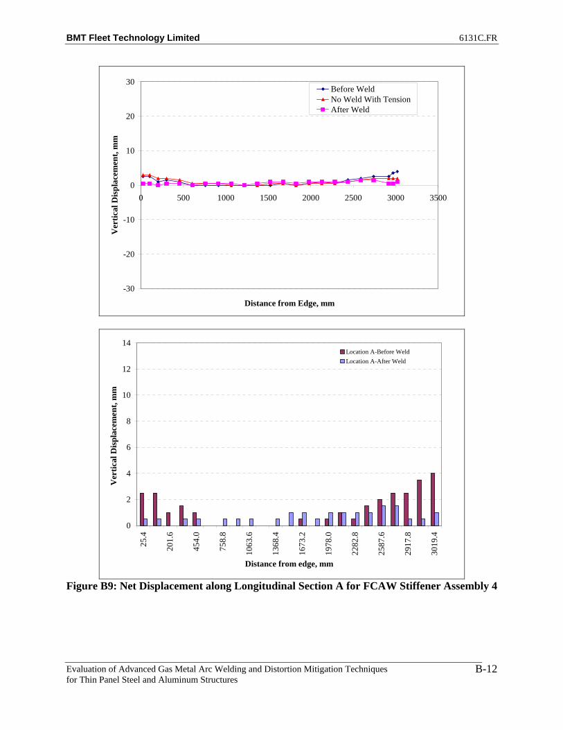
BMT Fleet Technology Limited 6131C.FR
Evaluation of Advanced Gas Metal Arc Welding and Distortion Mitigation Techniques for Thin Panel Steel and Aluminum Structures
B-12
-30
-20
-10
0
10
20
30
0 500 1000 1500 2000 2500 3000 3500
Distance from Edge, mm
Ver
tical
Dis
plac
emen
t, m
m
Before WeldNo Weld With TensionAfter Weld
0
2
4
6
8
10
12
14
25.4
201.
6
454.
0
758.
8
1063
.6
1368
.4
1673
.2
1978
.0
2282
.8
2587
.6
2917
.8
3019
.4
Distance from edge, mm
Ver
tical
Dis
plac
emen
t, m
m
Location A-Before WeldLocation A-After Weld
Figure B9: Net Displacement along Longitudinal Section A for FCAW Stiffener Assembly 4

BMT Fleet Technology Limited 6131C.FR
Evaluation of Advanced Gas Metal Arc Welding and Distortion Mitigation Techniques for Thin Panel Steel and Aluminum Structures
B-13
-30
-20
-10
0
10
20
30
0 500 1000 1500 2000 2500 3000 3500
Distance from Edge, mm
Ver
tical
Dis
plac
emen
t, m
m
Before WeldNo Weld With TensionAfter Weld
0
2
4
6
8
10
12
14
25.4
201.
6
454.
0
758.
8
1063
.6
1368
.4
1673
.2
1978
.0
2282
.8
2587
.6
2917
.8
3019
.4
Distance from edge, mm
Ver
tical
Dis
plac
emen
t, m
m
Location B-Before WeldLocation B-After Weld
Figure B10: Net Displacement along Longitudinal Section B for FCAW Stiffener
Benchmark Assembly 4

BMT Fleet Technology Limited 6131C.FR
Evaluation of Advanced Gas Metal Arc Welding and Distortion Mitigation Techniques for Thin Panel Steel and Aluminum Structures
B-14
-10
-8
-6
-4
-2
0
2
4
25.4
201.
6
454.
0
758.
8
1063
.6
1368
.4
1673
.2
1978
.0
2282
.8
2587
.6
2917
.8
3019
.4
Distance from edge, mm
Ver
tical
Dis
plac
emen
t, m
m
Net Improvement
Figure B11: FCAW_Stiff_2 -Net Improvement at Location A.
-10
-8
-6
-4
-2
0
2
4
25.4
201.
6
454.
0
758.
8
1063
.6
1368
.4
1673
.2
1978
.0
2282
.8
2587
.6
2917
.8
3019
.4
Distance from edge, mm
Ver
tical
Dis
plac
emen
t, m
m
Net Improvement
Figure B12: FCAW_Stiff_2 -Net Improvement at Location B.

BMT Fleet Technology Limited 6131C.FR
Evaluation of Advanced Gas Metal Arc Welding and Distortion Mitigation Techniques for Thin Panel Steel and Aluminum Structures
B-15
-10
-8
-6
-4
-2
0
2
4
25.4
201.
6
454.
0
758.
8
1063
.6
1368
.4
1673
.2
1978
.0
2282
.8
2587
.6
2917
.8
3019
.4
Distance from edge, mm
Ver
tical
Dis
plac
emen
t, m
m
Net Improvement
Figure B13: FCAW_Stiff_2 -Net Improvement at Location T.
-10
-8
-6
-4
-2
0
2
4
25.4
201.
6
454.
0
758.
8
1063
.6
1368
.4
1673
.2
1978
.0
2282
.8
2587
.6
2917
.8
3019
.4
Distance from edge, mm
Ver
tical
Dis
plac
emen
t, m
m
Net Improvement
Figure B14: FCAW_Stiff_3 -Net Improvement at Location A.
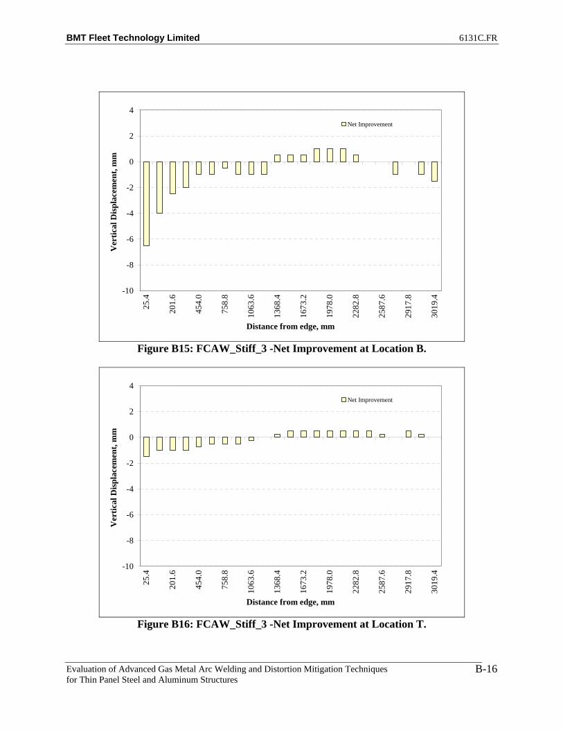
BMT Fleet Technology Limited 6131C.FR
Evaluation of Advanced Gas Metal Arc Welding and Distortion Mitigation Techniques for Thin Panel Steel and Aluminum Structures
B-16
-10
-8
-6
-4
-2
0
2
4
25.4
201.
6
454.
0
758.
8
1063
.6
1368
.4
1673
.2
1978
.0
2282
.8
2587
.6
2917
.8
3019
.4
Distance from edge, mm
Ver
tical
Dis
plac
emen
t, m
mNet Improvement
Figure B15: FCAW_Stiff_3 -Net Improvement at Location B.
-10
-8
-6
-4
-2
0
2
4
25.4
201.
6
454.
0
758.
8
1063
.6
1368
.4
1673
.2
1978
.0
2282
.8
2587
.6
2917
.8
3019
.4
Distance from edge, mm
Ver
tical
Dis
plac
emen
t, m
m
Net Improvement
Figure B16: FCAW_Stiff_3 -Net Improvement at Location T.

BMT Fleet Technology Limited 6131C.FR
Evaluation of Advanced Gas Metal Arc Welding and Distortion Mitigation Techniques for Thin Panel Steel and Aluminum Structures
B-17
-10
-8
-6
-4
-2
0
2
4
25.4
201.
6
454.
0
758.
8
1063
.6
1368
.4
1673
.2
1978
.0
2282
.8
2587
.6
2917
.8
3019
.4
Distance from edge, mm
Ver
tical
Dis
plac
emen
t, m
m
Net Improvement
Figure B17: FCAW_Stiff_4 -Net Improvement at Location A.
-10
-8
-6
-4
-2
0
2
4
25.4
201.
6
454.
0
758.
8
1063
.6
1368
.4
1673
.2
1978
.0
2282
.8
2587
.6
2917
.8
3019
.4
Distance from edge, mm
Ver
tical
Dis
plac
emen
t, m
m
Net Improvement
Figure B18: FCAW_Stiff_4 -Net Improvement at Location B.

BMT Fleet Technology Limited 6131C.FR
Evaluation of Advanced Gas Metal Arc Welding and Distortion Mitigation Techniques for Thin Panel Steel and Aluminum Structures
B-18
-10
-8
-6
-4
-2
0
2
4
25.4
201.
6
454.
0
758.
8
1063
.6
1368
.4
1673
.2
1978
.0
2282
.8
2587
.6
2917
.8
3019
.4
Distance from edge, mm
Ver
tical
Dis
plac
emen
t, m
m
Net Improvement
Figure B19: FCAW_Stiff_4 -Net Improvement at Location T.

BMT Fleet Technology Limited 6131C.FR
Evaluation of Advanced Gas Metal Arc Welding and Distortion Mitigation Techniques for Thin Panel Steel and Aluminum Structures
C-1
APPENDIX C
STT PROCESS RECOMMENDATIONS
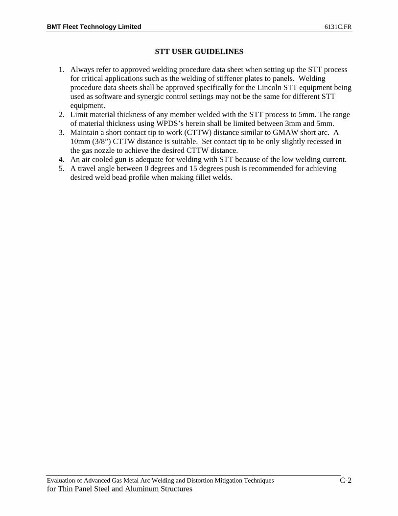
BMT Fleet Technology Limited 6131C.FR
Evaluation of Advanced Gas Metal Arc Welding and Distortion Mitigation Techniques for Thin Panel Steel and Aluminum Structures
C-2
STT USER GUIDELINES
1. Always refer to approved welding procedure data sheet when setting up the STT process for critical applications such as the welding of stiffener plates to panels. Welding procedure data sheets shall be approved specifically for the Lincoln STT equipment being used as software and synergic control settings may not be the same for different STT equipment.
2. Limit material thickness of any member welded with the STT process to 5mm. The range of material thickness using WPDS’s herein shall be limited between 3mm and 5mm.
3. Maintain a short contact tip to work (CTTW) distance similar to GMAW short arc. A 10mm (3/8”) CTTW distance is suitable. Set contact tip to be only slightly recessed in the gas nozzle to achieve the desired CTTW distance.
4. An air cooled gun is adequate for welding with STT because of the low welding current. 5. A travel angle between 0 degrees and 15 degrees push is recommended for achieving
desired weld bead profile when making fillet welds.
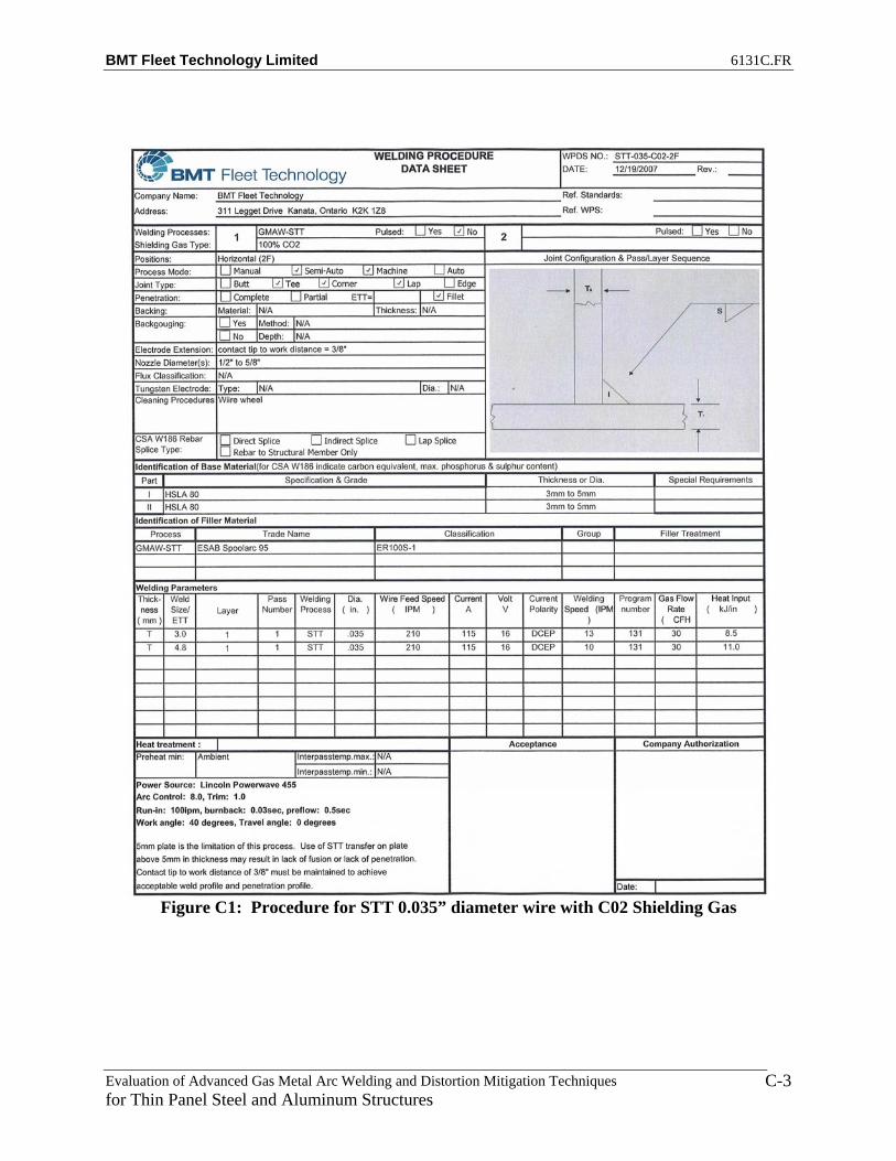
BMT Fleet Technology Limited 6131C.FR
Evaluation of Advanced Gas Metal Arc Welding and Distortion Mitigation Techniques for Thin Panel Steel and Aluminum Structures
C-3
Figure C1: Procedure for STT 0.035” diameter wire with C02 Shielding Gas

BMT Fleet Technology Limited 6131C.FR
Evaluation of Advanced Gas Metal Arc Welding and Distortion Mitigation Techniques for Thin Panel Steel and Aluminum Structures
C-4
Figure C2: Procedure for STT 0.035” diameter wire with C25 Shielding Gas

BMT Fleet Technology Limited 6131C.FR
Evaluation of Advanced Gas Metal Arc Welding and Distortion Mitigation Techniques for Thin Panel Steel and Aluminum Structures
C-5
Figure C3: Procedure for STT 0.045” diameter wire with C02 Shielding Gas

BMT Fleet Technology Limited 6131C.FR
Evaluation of Advanced Gas Metal Arc Welding and Distortion Mitigation Techniques for Thin Panel Steel and Aluminum Structures
C-6
Figure C4: Procedure for STT 0.045” diameter wire with C25 Shielding Gas

BMT Fleet Technology Limited 6131C.FR
Evaluation of Advanced Gas Metal Arc Welding and Distortion Mitigation Techniques for Thin Panel Steel and Aluminum Structures
D-1
APPENDIX D
WELDING PROCEDURE DATA SHEETS

BMT Fleet Technology Limited 6131C.FR
Evaluation of Advanced Gas Metal Arc Welding and Distortion Mitigation Techniques for Thin Panel Steel and Aluminum Structures
D-2
Figure C1: Procedure for Conventional CV Process

BMT Fleet Technology Limited 6131C.FR
Evaluation of Advanced Gas Metal Arc Welding and Distortion Mitigation Techniques for Thin Panel Steel and Aluminum Structures
D-3
Figure C2: Procedure for Standard Pulse

BMT Fleet Technology Limited 6131C.FR
Evaluation of Advanced Gas Metal Arc Welding and Distortion Mitigation Techniques for Thin Panel Steel and Aluminum Structures
D-4
Figure C3: Procedure for Superpulse, Pulse on Pulse

BMT Fleet Technology Limited 6131C.FR
Evaluation of Advanced Gas Metal Arc Welding and Distortion Mitigation Techniques for Thin Panel Steel and Aluminum Structures
D-5
Figure C4: Procedure for Superpulse, Pulse on Spray

BMT Fleet Technology Limited 6131C.FR
Evaluation of Advanced Gas Metal Arc Welding and Distortion Mitigation Techniques for Thin Panel Steel and Aluminum Structures
D-6
Figure C5: Procedure for Superpulse, Pulse on Short

BMT Fleet Technology Limited 6131C.FR
Evaluation of Advanced Gas Metal Arc Welding and Distortion Mitigation Techniques for Thin Panel Steel and Aluminum Structures
E-1
APPENDIX E
DISTORTION COMPARISON BETWEEN FCAW and T-MCAW (10” WIDE BASE PLATES)

BMT Fleet Technology Limited 6131C.FR
Evaluation of Advanced Gas Metal Arc Welding and Distortion Mitigation Techniques for Thin Panel Steel and Aluminum Structures
E-2
-30
-20
-10
0
10
20
30
0 500 1000 1500 2000 2500 3000 3500
Distance from Edge, mm
Ver
tical
Dis
plac
emen
t, m
mBefore Weld-FCAW After Weld-FCAWBefore Weld-TMCAW After Weld-TMCAW
Figure E.1: Baseline Location A – Relative Displacement
-30
-20
-10
0
10
20
30
0 500 1000 1500 2000 2500 3000 3500
Distance from Edge, mm
Ver
tical
Dis
plac
emen
t, m
m
Before Weld-FCAW After Weld-FCAW
Before Weld-TMCAW After Weld-TMCAW
Figure E.2: Baseline Location B – Relative Displacement
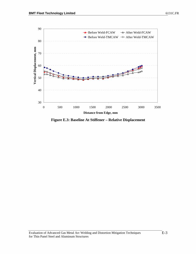
BMT Fleet Technology Limited 6131C.FR
Evaluation of Advanced Gas Metal Arc Welding and Distortion Mitigation Techniques for Thin Panel Steel and Aluminum Structures
E-3
30
40
50
60
70
80
90
0 500 1000 1500 2000 2500 3000 3500
Distance from Edge, mm
Ver
tical
Dis
plac
emen
t, m
mBefore Weld-FCAW After Weld-FCAWBefore Weld-TMCAW After Weld-TMCAW
Figure E.3: Baseline At Stiffener – Relative Displacement

BMT Fleet Technology Limited 6131C.FR
Evaluation of Advanced Gas Metal Arc Welding and Distortion Mitigation Techniques for Thin Panel Steel and Aluminum Structures
E-4
-8
-6
-4
-2
0
2
4
6
25.4
201.
6
454.
0
758.
8
1063
.6
1368
.4
1673
.2
1978
.0
2282
.8
2587
.6
2917
.8
3019
.4
Distance from edge, mm
Ver
tical
Dis
plac
emen
t, m
mFCAW-Net ImprovementTMCAW-Net Improvement
Figure FF.1: Plate 2 Location A – Net Improvement
-8
-6
-4
-2
0
2
4
6
25.4
201.
6
454.
0
758.
8
1063
.6
1368
.4
1673
.2
1978
.0
2282
.8
2587
.6
2917
.8
3019
.4
Distance from edge, mm
Ver
tical
Dis
plac
emen
t, m
m
FCAW-Net ImprovementTMCAW-Net Improvement
Figure F.2: Plate 2 Location B – Net Improvement

BMT Fleet Technology Limited 6131C.FR
Evaluation of Advanced Gas Metal Arc Welding and Distortion Mitigation Techniques for Thin Panel Steel and Aluminum Structures
E-5
-8
-6
-4
-2
0
2
4
6
25.4
201.
6
454.
0
758.
8
1063
.6
1368
.4
1673
.2
1978
.0
2282
.8
2587
.6
2917
.8
3019
.4
Distance from edge, mm
Ver
tical
Dis
plac
emen
t, m
mFCAW-Net ImprovementTMCAW-Net Improvement
Figure F.3: Plate 2 At Stiffener – Net Improvement
-8
-6
-4
-2
0
2
4
6
25.4
201.
6
454.
0
758.
8
1063
.6
1368
.4
1673
.2
1978
.0
2282
.8
2587
.6
2917
.8
3019
.4
Distance from edge, mm
Ver
tical
Dis
plac
emen
t, m
m
FCAW-Net ImprovementTMCAW-Net Improvement
Figure F.4: Plate 3 Location A – Net Improvement
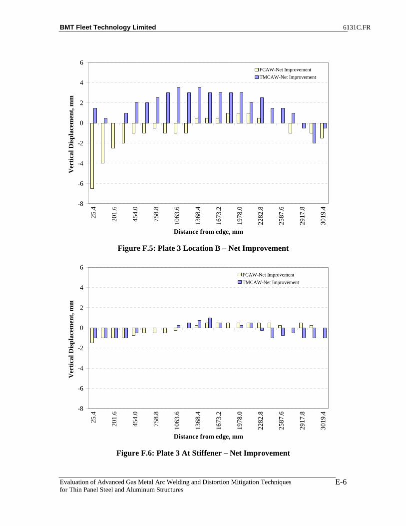
BMT Fleet Technology Limited 6131C.FR
Evaluation of Advanced Gas Metal Arc Welding and Distortion Mitigation Techniques for Thin Panel Steel and Aluminum Structures
E-6
-8
-6
-4
-2
0
2
4
6
25.4
201.
6
454.
0
758.
8
1063
.6
1368
.4
1673
.2
1978
.0
2282
.8
2587
.6
2917
.8
3019
.4
Distance from edge, mm
Ver
tical
Dis
plac
emen
t, m
mFCAW-Net ImprovementTMCAW-Net Improvement
Figure F.5: Plate 3 Location B – Net Improvement
-8
-6
-4
-2
0
2
4
6
25.4
201.
6
454.
0
758.
8
1063
.6
1368
.4
1673
.2
1978
.0
2282
.8
2587
.6
2917
.8
3019
.4
Distance from edge, mm
Ver
tical
Dis
plac
emen
t, m
m
FCAW-Net ImprovementTMCAW-Net Improvement
Figure F.6: Plate 3 At Stiffener – Net Improvement

BMT Fleet Technology Limited 6131C.FR
Evaluation of Advanced Gas Metal Arc Welding and Distortion Mitigation Techniques for Thin Panel Steel and Aluminum Structures
E-7
-8
-6
-4
-2
0
2
4
6
25.4
201.
6
454.
0
758.
8
1063
.6
1368
.4
1673
.2
1978
.0
2282
.8
2587
.6
2917
.8
3019
.4
Distance from edge, mm
Ver
tical
Dis
plac
emen
t, m
mFCAW-Net ImprovementTMCAW-Net Improvement
Figure F.7: Plate 4 Location A – Net Improvement
-8
-6
-4
-2
0
2
4
6
25.4
201.
6
454.
0
758.
8
1063
.6
1368
.4
1673
.2
1978
.0
2282
.8
2587
.6
2917
.8
3019
.4
Distance from edge, mm
Ver
tical
Dis
plac
emen
t, m
m
FCAW-Net ImprovementTMCAW-Net Improvement
Figure F.8: Plate 4 Location B – Net Improvement
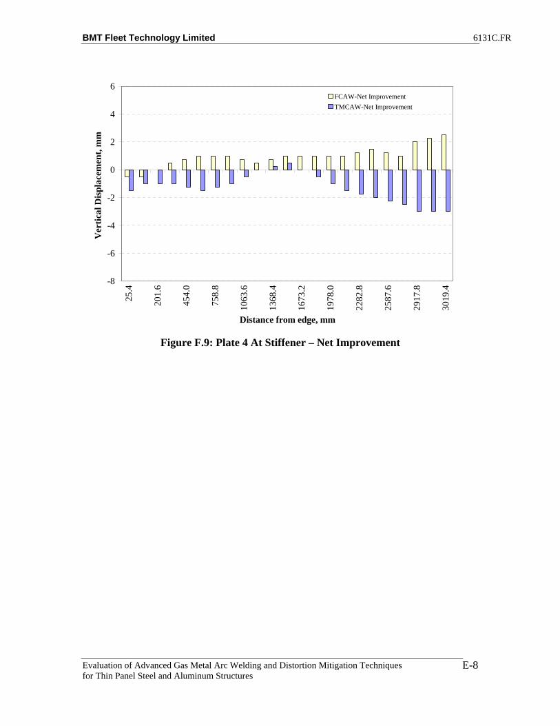
BMT Fleet Technology Limited 6131C.FR
Evaluation of Advanced Gas Metal Arc Welding and Distortion Mitigation Techniques for Thin Panel Steel and Aluminum Structures
E-8
-8
-6
-4
-2
0
2
4
6
25.4
201.
6
454.
0
758.
8
1063
.6
1368
.4
1673
.2
1978
.0
2282
.8
2587
.6
2917
.8
3019
.4
Distance from edge, mm
Ver
tical
Dis
plac
emen
t, m
mFCAW-Net ImprovementTMCAW-Net Improvement
Figure F.9: Plate 4 At Stiffener – Net Improvement

BMT Fleet Technology Limited 6131C.FR
Evaluation of Advanced Gas Metal Arc Welding and Distortion Mitigation Techniques for Thin Panel Steel and Aluminum Structures
F-1
APPENDIX F
DISTORTION PLOTS FOR FILLET WELDS T-MCAW PROCESS (10” WIDE BASE PLATES)

BMT Fleet Technology Limited 6131C.FR
Evaluation of Advanced Gas Metal Arc Welding and Distortion Mitigation Techniques for Thin Panel Steel and Aluminum Structures
F-2
Table F.1: T-MCAW_Stiff_1_Benchmark Distortion Data
A T B Abs Diff A T B Abs Diff1 9 58.5 10 1 1 5.5 55.5 5.5 02 8 58 9 1 2 5.5 55 5.5 03 6.5 56.75 7.5 1 3 4.5 54 4.5 04 6 55.5 6.5 0.5 4 4 53 4.5 0.55 4.5 54 5 0.5 5 3.5 52 3.5 06 3.5 52.5 3 0.5 6 2 51 2.5 0.57 2.5 51.75 2.5 0 7 1.5 50.5 2 0.58 1.5 51 1.5 0 8 1 50 1 09 1 50.5 1 0 9 1 49.5 0.5 0.5
10 0.5 50 0.5 0 10 0.5 49 0.5 011 1 50.5 0.5 0.5 11 1 49.5 0.5 0.512 1 51 1 0 12 1.5 50 1.5 013 1.5 51 1 0.5 13 1.5 50.25 1.5 014 1 51 1 0 14 1 50.5 1 015 2 51.75 1 1 15 2 51 1.5 0.516 3 52.5 1.5 1.5 16 3 51.5 2 117 4 53.25 2 2 17 3.5 52.5 2 1.518 5.5 54 3 2.5 18 4.5 53.5 3.5 119 7 55.5 4.5 2.5 19 4 54.5 4.5 0.520 8.5 57 6 2.5 20 7.5 55.5 5 2.521 10.5 59 7.5 3 21 8.5 57 5.5 322 11 59.5 7.5 3.5 22 9.5 57.5 6 3.523 11.5 60 9.5 2 23 10 58 6.5 3.5
After WeldDisplacement w.r.t to Frame, mm
Before WeldDisplacement w.r.t to Frame, mm
Table F.2: T-MCAW_Stiff_2_92Ar/8C02 Distortion Data
A T B Abs Diff A T B Abs Diff A T B Abs Diff1 11.5 60 11.5 0 1 6.5 55 6.5 0 1 6.5 55 7 0.52 11.5 59.5 11.5 0 2 6.5 54.5 6.5 0 2 6.5 54.5 7 0.53 10.5 58 11 0.5 3 5 53.5 5 0 3 5.5 53.5 6 0.54 10 56.5 10 0 4 5.5 52.5 5.5 0 4 6 52.5 7 15 8 55 8.5 0.5 5 4.5 51.5 4.5 0 5 5 51 6.5 1.56 6.5 53.5 6.5 0 6 3 50.5 3 0 6 3.5 49.5 5 1.57 5.5 52.5 4.5 1 7 2 49.5 2 0 7 2.5 49 4 1.58 4.5 51.5 4 0.5 8 1.5 48.5 1.5 0 8 2 48.5 3.5 1.59 3.5 50.25 3 0.5 9 1 47.75 1 0 9 2 48 3 1
10 3 49 2 1 10 0.5 47 0 0.5 10 1.5 47.5 2.5 111 3 49.5 2 1 11 1 47.25 0.5 0.5 11 2 48 2.5 0.512 3 50 2.5 0.5 12 1.5 47.5 1 0.5 12 2 48.5 2.5 0.513 3.5 49.75 2.5 1 13 1.5 47.5 1 0.5 13 2 48.5 3 114 3 49.5 2 1 14 1 47.5 0.5 0.5 14 2 48.5 2.5 0.515 3 50 2.5 0.5 15 1 47.75 0.5 0.5 15 2 49 2.5 0.516 4 50.5 3.5 0.5 16 1.5 48 1 0.5 16 2.5 49.5 3 0.517 4 51.25 4 0 17 1 48.25 0.5 0.5 17 2.5 49.5 2.5 018 4.5 52 4.5 0 18 1.5 48.5 1.5 0 18 3 49.5 3.5 0.519 5.5 52.75 5 0.5 19 2 49.25 1.5 0.5 19 3 50.25 3.5 0.520 6.5 53.5 6.5 0 20 3.5 50 2.5 1 20 4 51 4 021 7.5 55 8 0.5 21 3.5 51 2 1.5 21 4 52 4 022 7.5 55.25 8 0.5 22 3.5 51.75 2 1.5 22 4 52.75 4 023 7.5 55.5 8 0.5 23 3.5 52.5 2 1.5 23 4 53.5 4 0
Before WeldDisplacement w.r.t to Frame, mm
After WeldDisplacement w.r.t to Frame, mmDisplacement w.r.t to Frame, mm
Tension No Weld

BMT Fleet Technology Limited 6131C.FR
Evaluation of Advanced Gas Metal Arc Welding and Distortion Mitigation Techniques for Thin Panel Steel and Aluminum Structures
F-3
Table F.3: T-MCAW_Stiff_3_85Ar/15C02 Distortion Data
A T B Abs Diff A T B Abs Diff A T B Abs Diff1 9.5 52.5 10.5 1 1 5.5 49 6.5 1 1 6 48.5 7.5 1.52 9.5 52 10.5 1 2 5.5 48.5 6.5 1 2 6 48 7.5 1.53 8.5 50.75 9.5 1 3 4.5 47.5 5.5 1 3 5 47 6.5 1.54 8 49.5 8.5 0.5 4 5 46.5 5.5 0.5 4 5.5 46 7.5 25 6.5 47.75 7 0.5 5 4 45.25 5 1 5 4 45.25 7.5 3.56 5 46 5 0 6 2.5 44 3.5 1 6 3 44.5 6.5 3.57 4 45.25 4.5 0.5 7 1.5 43.5 2.5 1 7 2.5 44 6.5 48 2.5 44.5 3 0.5 8 1 43 1.5 0.5 8 1.5 43.5 5.5 49 2 43.75 2 0 9 1 42.5 1 0 9 2 43 5 3
10 1.5 43 1 0.5 10 0.5 42 0.5 0 10 1 42.5 4 311 1.5 43.5 1 0.5 11 1 42.5 1 0 11 1.5 43.25 4.5 312 2 44 1.5 0.5 12 1.5 43 1 0.5 12 2 44 5 313 2 44 2 0 13 1.5 43 1.5 0 13 2.5 43.75 5.5 314 2 44 2 0 14 1 43 1 0 14 2 43.5 5 315 2.5 44.75 2 0.5 15 1 43.25 1 0 15 2.5 44.25 5.5 316 3 45.5 3 0 16 1.5 43.5 1.5 0 16 2.5 45 5.5 317 3.5 46.5 3.5 0 17 1.5 44.25 2 0.5 17 3 45.5 6 318 5 47.5 5 0 18 2 45 3 1 18 4 46 7 319 6 49 6 0 19 3 46 4 1 19 4.5 47.25 7.5 320 7.5 50.5 7.5 0 20 4 47 5.5 1.5 20 5 48.5 7.5 2.521 9 52 9 0 21 3 48.5 5 2 21 4.5 49 6.5 222 9 52.75 9 0 22 3 49.25 5 2 22 4.5 49.75 5.5 123 9 53.5 9 0 23 3 50 5 2 23 4 50.5 5.5 1.5
After WeldDisplacement w.r.t to Frame, mm
Before WeldDisplacement w.r.t to Frame, mm
Tension No WeldDisplacement w.r.t to Frame, mm
Table F.4: T-MCAW_Stiff_4_75Ar/25C02 Distortion Data
A T B Abs Diff A T B Abs Diff A T B Abs Diff1 9.5 68 10 0.5 1 6 65 4 2 1 5 63.5 4.5 0.52 9.5 67.5 10 0.5 2 6 64.5 4 2 2 5 63.5 4.5 0.53 8.5 66 9 0.5 3 5 63.25 3 2 3 4 62.25 3.5 0.54 7.5 64.5 8 0.5 4 6 62 4 2 4 5 61 5 05 6 62.75 6.5 0.5 5 5 60.5 3.5 1.5 5 4 59.5 5 16 4.5 61 4.5 0 6 3 59 2 1 6 2.5 58 4 1.57 3 60 3 0 7 2 58.25 1.5 0.5 7 2 57.5 3.5 1.58 2.5 59 2.5 0 8 1.5 57.5 1 0.5 8 1.5 57 3 1.59 2 58.25 2 0 9 1 57 1 0 9 1.5 56.75 2.5 1
10 1.5 57.5 1 0.5 10 0.5 56.5 0.5 0 10 1 56.5 1.5 0.511 2 58 1 1 11 1 57 0.5 0.5 11 1.5 57.25 2.5 112 2 58.5 1.5 0.5 12 1 57.5 1 0 12 2 58 2.5 0.513 2 58.5 1.5 0.5 13 1.5 57.5 1 0.5 13 2 57.75 2.5 0.514 2 58.5 1 1 14 1 57.5 1 0 14 2 57.5 2 015 2.5 59.25 1.5 1 15 1.5 58 1 0.5 15 2.5 57.5 2.5 016 4 60 3 1 16 2 58.5 1 1 16 3 57.5 3 017 4.5 61 3 1.5 17 2 58.75 1.5 0.5 17 3 58.5 3 018 6 62 4 2 18 2.5 59 2.5 0 18 3.5 59.5 3.5 019 7.5 63.75 6 1.5 19 3 60.25 3.5 0.5 19 5 60.5 3.5 1.520 9.5 65.5 7.5 2 20 4.5 61.5 5 0.5 20 6 61.5 4 221 11.5 68 9.5 2 21 4 63 5 1 21 6.5 63 3.5 322 11.5 68.5 9.5 2 22 4 63.75 5 1 22 6.5 63.5 3.5 323 11.5 69 9.5 2 23 4 64.5 5 1 23 6.5 64 3.5 3
Before WeldDisplacement w.r.t to Frame, mm
Tension No WeldDisplacement w.r.t to Frame, mm
After WeldDisplacement w.r.t to Frame, mm

BMT Fleet Technology Limited 6131C.FR
Evaluation of Advanced Gas Metal Arc Welding and Distortion Mitigation Techniques for Thin Panel Steel and Aluminum Structures
F-4
-30
-20
-10
0
10
20
30
0 500 1000 1500 2000 2500 3000 3500
Distance from Edge, mm
Ver
tical
Dis
plac
emen
t, m
mBefore Weld-TMCAW After Weld-TMCAW
Figure F.1: Net Displacement along Longitudinal Section A for T-MCAW Stiffener
Benchmark Assembly
-30
-20
-10
0
10
20
30
0 500 1000 1500 2000 2500 3000 3500
Distance from Edge, mm
Ver
tical
Dis
plac
emen
t, m
m
Before Weld-TMCAW After Weld-TMCAW
Figure F.2: Net Displacement along Longitudinal Section B for T-MCAW Stiffener
Benchmark Assembly

BMT Fleet Technology Limited 6131C.FR
Evaluation of Advanced Gas Metal Arc Welding and Distortion Mitigation Techniques for Thin Panel Steel and Aluminum Structures
F-5
30
40
50
60
70
80
90
0 500 1000 1500 2000 2500 3000 3500
Distance from Edge, mm
Ver
tical
Dis
plac
emen
t, m
mBefore Weld-TMCAW After Weld-TMCAW
Figure F.3: Net Displacement along Longitudinal Section T for T-MCAW Stiffener
Benchmark Assembly

BMT Fleet Technology Limited 6131C.FR
Evaluation of Advanced Gas Metal Arc Welding and Distortion Mitigation Techniques for Thin Panel Steel and Aluminum Structures
F-6
-35
-25
-15
-5
5
15
25
35
0 500 1000 1500 2000 2500 3000 3500
Distance from Edge, mm
Ver
tical
Dis
plac
emen
t, m
m
Before Weld
No Weld With Tension
After Weld
0
2
4
6
8
10
12
14
25.4
201.
6
454.
0
758.
8
1063
.6
1368
.4
1673
.2
1978
.0
2282
.8
2587
.6
2917
.8
3019
.4
Distance from edge, mm
Ver
tical
Dis
plac
emen
t, m
m
Location A-Before WeldLocation A-After Weld
Figure F.4: Net Displacement along Longitudinal Section A for T-MCAW Stiffener
Assembly 2

BMT Fleet Technology Limited 6131C.FR
Evaluation of Advanced Gas Metal Arc Welding and Distortion Mitigation Techniques for Thin Panel Steel and Aluminum Structures
F-7
-35
-25
-15
-5
5
15
25
35
0 500 1000 1500 2000 2500 3000 3500
Distance from Edge, mm
Ver
tical
Dis
plac
emen
t, m
m
Before Weld
No Weld With Tension
After Weld
0
2
4
6
8
10
12
14
25.4
201.
6
454.
0
758.
8
1063
.6
1368
.4
1673
.2
1978
.0
2282
.8
2587
.6
2917
.8
3019
.4
Distance from edge, mm
Ver
tical
Dis
plac
emen
t, m
m
Location B-Before WeldLocation B-After Weld
Figure F.5: Net Displacement along Longitudinal Section B for T-MCAW Stiffener
Assembly 2

BMT Fleet Technology Limited 6131C.FR
Evaluation of Advanced Gas Metal Arc Welding and Distortion Mitigation Techniques for Thin Panel Steel and Aluminum Structures
F-8
40
45
50
55
60
65
0 500 1000 1500 2000 2500 3000 3500
Distance from Edge, mm
Ver
tical
Dis
plac
emen
t, m
mBefore Weld
No Weld With Tension
After Weld
Figure F.6: Net Displacement along Longitudinal Section T for T-MCAW Stiffener
Assembly 2

BMT Fleet Technology Limited 6131C.FR
Evaluation of Advanced Gas Metal Arc Welding and Distortion Mitigation Techniques for Thin Panel Steel and Aluminum Structures
F-9
-30
-20
-10
0
10
20
30
0 500 1000 1500 2000 2500 3000 3500
Distance from Edge, mm
Ver
tical
Dis
plac
emen
t, m
m
Before WeldNo Weld With TensionAfter Weld
0
2
4
6
8
10
12
14
25.4
201.
6
454.
0
758.
8
1063
.6
1368
.4
1673
.2
1978
.0
2282
.8
2587
.6
2917
.8
3019
.4
Distance from edge, mm
Ver
tical
Dis
plac
emen
t, m
m
Location A-Before WeldLocation A-After Weld
Figure F.7: Net Displacement along Longitudinal Section A for TMCAW Stiffener
Assembly 3
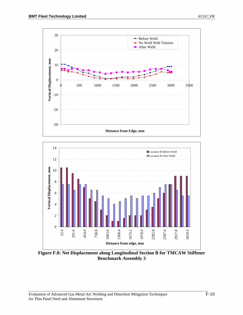
BMT Fleet Technology Limited 6131C.FR
Evaluation of Advanced Gas Metal Arc Welding and Distortion Mitigation Techniques for Thin Panel Steel and Aluminum Structures
F-10
-30
-20
-10
0
10
20
30
0 500 1000 1500 2000 2500 3000 3500
Distance from Edge, mm
Ver
tical
Dis
plac
emen
t, m
m
Before WeldNo Weld With TensionAfter Weld
0
2
4
6
8
10
12
14
25.4
201.
6
454.
0
758.
8
1063
.6
1368
.4
1673
.2
1978
.0
2282
.8
2587
.6
2917
.8
3019
.4
Distance from edge, mm
Ver
tical
Dis
plac
emen
t, m
m
Location B-Before WeldLocation B-After Weld
Figure F.8: Net Displacement along Longitudinal Section B for TMCAW Stiffener
Benchmark Assembly 3

BMT Fleet Technology Limited 6131C.FR
Evaluation of Advanced Gas Metal Arc Welding and Distortion Mitigation Techniques for Thin Panel Steel and Aluminum Structures
F-11
40
42
44
46
48
50
52
54
56
0 500 1000 1500 2000 2500 3000 3500
Distance from Edge, mm
Ver
tical
Dis
plac
emen
t, m
m
Before Weld
No Weld With Tension
After Weld
Figure F.9: Net Displacement along Longitudinal Section T for TMCAW Stiffener
Benchmark Assembly 3

BMT Fleet Technology Limited 6131C.FR
Evaluation of Advanced Gas Metal Arc Welding and Distortion Mitigation Techniques for Thin Panel Steel and Aluminum Structures
F-12
-35
-25
-15
-5
5
15
25
35
0 500 1000 1500 2000 2500 3000 3500
Distance from Edge, mm
Ver
tical
Dis
plac
emen
t, m
m
Before Weld
No Weld With Tension
After Weld
0
2
4
6
8
10
12
14
25.4
201.
6
454.
0
758.
8
1063
.6
1368
.4
1673
.2
1978
.0
2282
.8
2587
.6
2917
.8
3019
.4
Distance from edge, mm
Ver
tical
Dis
plac
emen
t, m
m
Location A-Before WeldLocation A-After Weld
Figure F.10: Net Displacement along Longitudinal Section A for TMCAW Stiffener
Assembly 4

BMT Fleet Technology Limited 6131C.FR
Evaluation of Advanced Gas Metal Arc Welding and Distortion Mitigation Techniques for Thin Panel Steel and Aluminum Structures
F-13
-35
-25
-15
-5
5
15
25
35
0 500 1000 1500 2000 2500 3000 3500
Distance from Edge, mm
Ver
tical
Dis
plac
emen
t, m
m
Before Weld
No Weld With Tension
After Weld
0
2
4
6
8
10
12
14
25.4
201.
6
454.
0
758.
8
1063
.6
1368
.4
1673
.2
1978
.0
2282
.8
2587
.6
2917
.8
3019
.4
Distance from edge, mm
Ver
tical
Dis
plac
emen
t, m
m
Location B-Before WeldLocation B-After Weld
Figure F.11: Net Displacement along Longitudinal Section B for TMCAW Stiffener
Benchmark Assembly 4

BMT Fleet Technology Limited 6131C.FR
Evaluation of Advanced Gas Metal Arc Welding and Distortion Mitigation Techniques for Thin Panel Steel and Aluminum Structures
F-14
40
45
50
55
60
65
70
75
0 500 1000 1500 2000 2500 3000 3500
Distance from Edge, mm
Ver
tical
Dis
plac
emen
t, m
m
Before Weld
No Weld With Tension
After Weld
Figure F.12: Net Displacement along Longitudinal Section T for TMCAW Stiffener
Benchmark Assembly 4
-10
-8
-6
-4
-2
0
2
4
25.4
201.
6
454.
0
758.
8
1063
.6
1368
.4
1673
.2
1978
.0
2282
.8
2587
.6
2917
.8
3019
.4
Distance from edge, mm
Ver
tical
Dis
plac
emen
t, m
m
Net Improvement
Figure F.13: Plate 2 Location A – Net Improvement

BMT Fleet Technology Limited 6131C.FR
Evaluation of Advanced Gas Metal Arc Welding and Distortion Mitigation Techniques for Thin Panel Steel and Aluminum Structures
F-15
-10
-8
-6
-4
-2
0
2
4
25.4
201.
6
454.
0
758.
8
1063
.6
1368
.4
1673
.2
1978
.0
2282
.8
2587
.6
2917
.8
3019
.4
Distance from edge, mm
Ver
tical
Dis
plac
emen
t, m
m
Net Improvement
Figure F.14: Plate 2 Location B – Net Improvement
-10
-8
-6
-4
-2
0
2
4
25.4
201.
6
454.
0
758.
8
1063
.6
1368
.4
1673
.2
1978
.0
2282
.8
2587
.6
2917
.8
3019
.4
Distance from edge, mm
Ver
tical
Dis
plac
emen
t, m
m
Net Improvement
Figure F.15: Plate 2 At Stiffener – Net Improvement

BMT Fleet Technology Limited 6131C.FR
Evaluation of Advanced Gas Metal Arc Welding and Distortion Mitigation Techniques for Thin Panel Steel and Aluminum Structures
F-16
-10
-8
-6
-4
-2
0
2
4
25.4
201.
6
454.
0
758.
8
1063
.6
1368
.4
1673
.2
1978
.0
2282
.8
2587
.6
2917
.8
3019
.4
Distance from edge, mm
Ver
tical
Dis
plac
emen
t, m
m
Net Improvement
Figure F.16: TMCAW_Stiff_3 -Net Improvement at Location A.
-10
-8
-6
-4
-2
0
2
4
25.4
201.
6
454.
0
758.
8
1063
.6
1368
.4
1673
.2
1978
.0
2282
.8
2587
.6
2917
.8
3019
.4
Distance from edge, mm
Ver
tical
Dis
plac
emen
t, m
m
Net Improvement
Figure F.17: TMCAW_Stiff_3 -Net Improvement at Location B.
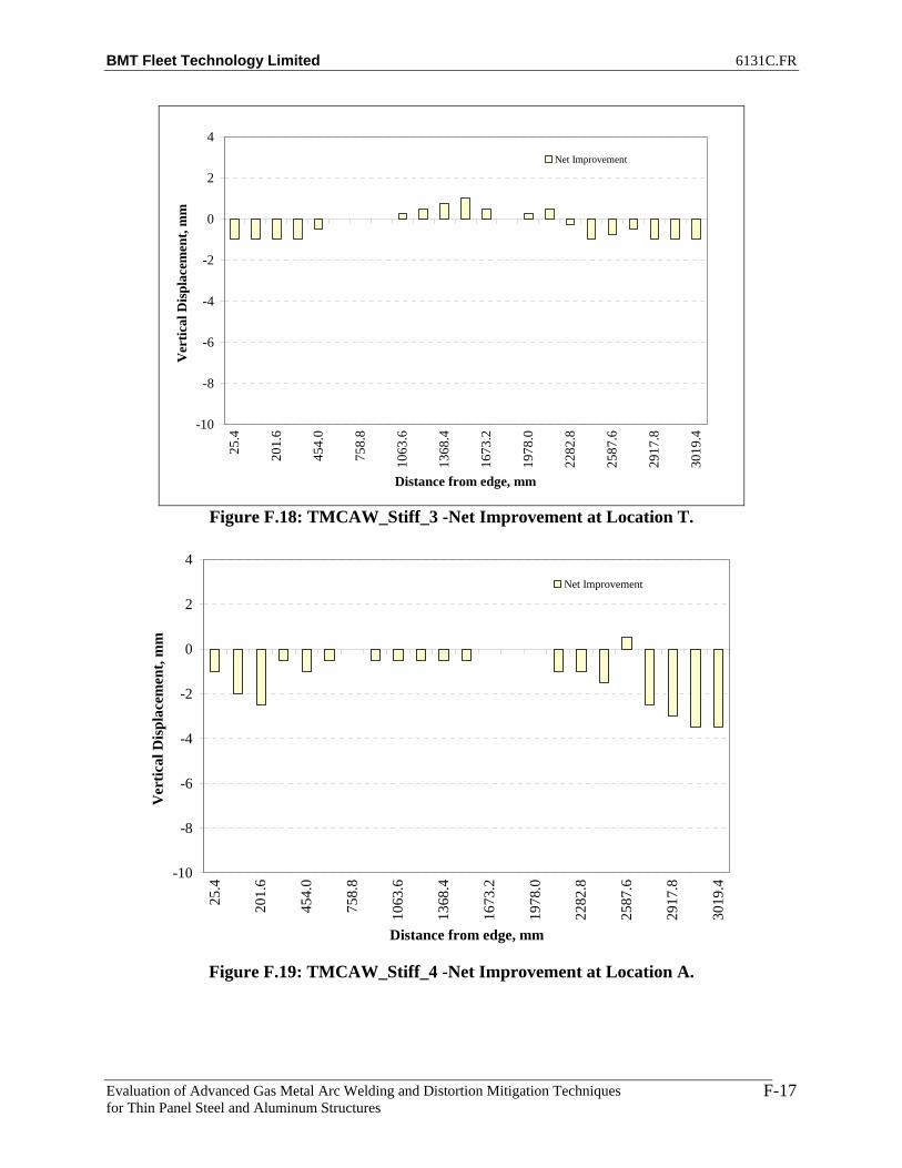
BMT Fleet Technology Limited 6131C.FR
Evaluation of Advanced Gas Metal Arc Welding and Distortion Mitigation Techniques for Thin Panel Steel and Aluminum Structures
F-17
-10
-8
-6
-4
-2
0
2
4
25.4
201.
6
454.
0
758.
8
1063
.6
1368
.4
1673
.2
1978
.0
2282
.8
2587
.6
2917
.8
3019
.4
Distance from edge, mm
Ver
tical
Dis
plac
emen
t, m
m
Net Improvement
Figure F.18: TMCAW_Stiff_3 -Net Improvement at Location T.
-10
-8
-6
-4
-2
0
2
4
25.4
201.
6
454.
0
758.
8
1063
.6
1368
.4
1673
.2
1978
.0
2282
.8
2587
.6
2917
.8
3019
.4
Distance from edge, mm
Ver
tical
Dis
plac
emen
t, m
m
Net Improvement
Figure F.19: TMCAW_Stiff_4 -Net Improvement at Location A.

BMT Fleet Technology Limited 6131C.FR
Evaluation of Advanced Gas Metal Arc Welding and Distortion Mitigation Techniques for Thin Panel Steel and Aluminum Structures
F-18
-10
-8
-6
-4
-2
0
2
4
25.4
201.
6
454.
0
758.
8
1063
.6
1368
.4
1673
.2
1978
.0
2282
.8
2587
.6
2917
.8
3019
.4
Distance from edge, mm
Ver
tical
Dis
plac
emen
t, m
mNet Improvement
Figure F.20: TMCAW_Stiff_4 -Net Improvement at Location B.
-10
-8
-6
-4
-2
0
2
4
25.4
201.
6
454.
0
758.
8
1063
.6
1368
.4
1673
.2
1978
.0
2282
.8
2587
.6
2917
.8
3019
.4
Distance from edge, mm
Ver
tical
Dis
plac
emen
t, m
m
Net Improvement
Figure F.21: TMCAW_Stiff_4 -Net Improvement at Location T.

BMT Fleet Technology Limited 6131C.FR
Evaluation of Advanced Gas Metal Arc Welding and Distortion Mitigation Techniques for Thin Panel Steel and Aluminum Structures
G-1
APPENDIX G
NET DISPLACEMENTS FOR FCAW and T-MCAW (4’ x 10’ HSLA 80 BASE PLATES)

BMT Fleet Technology Limited 6131C.FR
Evaluation of Advanced Gas Metal Arc Welding and Distortion Mitigation Techniques for Thin Panel Steel and Aluminum Structures
G-2
Table G.1: FCAW Benchmark Plate 7 Distortion Data Before Welding
A B C D E F G H I J K1 22 26 27.5 27.5 28.5 160 28 26.5 25 24 212 23.5 28 29 28.5 29.5 160 28 27 26.5 24 203 24 28 29 28.5 28.5 159.5 28 26 25 23.5 194 23.5 27 28.5 29.5 29.5 159 27.5 26 25 23.5 19.55 21 24.5 26 26 27 159 27 26 25 23.5 20.56 18.5 22.5 24 25.5 25.5 158.5 26.5 25.5 25 23 217 16.5 21 24 25 25.5 158 25.5 25 24 23 20.58 16 21 24 24 25.5 159 26 25.5 24 23.5 20.59 16.5 21 23 25 25 159 25.5 25 24 23 21
10 17.5 22.5 23.5 25 26.5 159 25 24.5 23.5 23 2111 20 24 24.5 26 25.5 159.5 24.5 24 23 23 20.512 21.5 25 26 27 26.5 160 25 24.5 23 23 20.513 21.5 26 26.5 28 28 161 26 25 23.5 22 20.514 17.5 22 23.5 25 24.5 160 24 23.5 22.5 20.5 2015 16 21 23 24.5 25 161 25 24.5 24 22 2016 15 25 23 24.5 25 162.5 26.5 26 24.5 23 2017 14.5 19.5 22 24.5 25 161.5 25.5 25.5 24.5 22.5 20.518 15 19.5 23 24.5 26 162 24.5 24.5 23.5 22 2119 19 23 25.5 26.5 27.5 163 25 24.5 23.5 22 2120 21.5 25 26.5 28.5 29 164.5 24.5 24.5 23.5 22 19.521 23 27.5 29 29.5 30.5 165.5 25.5 25 23.5 21.5 1922 23.5 27.5 29 29.5 31.5 166.5 26 25 22.5 20.5 1723 22.5 26.5 28.5 29.5 31 167 26 25 22.5 20 17
Displacement w.r.t to Frame, mmBefore Weld - Plate 7
Table G-2: FCAW Benchmark Plate 7 Distortion Data After Welding
A B C D E F G H I J K1 24.5 27 26.5 27 25 155 20 19 19 19 16.52 26 28 27.5 28 26 155 20.5 20 20 20 17.53 25.5 28 27.5 28 25 154.5 21 20 20.5 20.5 18.54 24 26.5 26.5 28.5 26.5 154 21.5 21 22 22 19.55 20 23 23 24.5 23 154 22 22.5 23.5 23.5 22.56 16.5 19 20.5 23 21.5 153.5 22.5 23.5 25.5 26 257 13.5 17 19 22 21.5 153 22.5 24.5 26 26.5 268 12.5 16.5 18.5 20.5 21.5 153.5 23 24.5 26.5 27 269 13.5 17.5 18 21.5 21 154 22.5 24.5 25 26.5 25
10 16.5 20 20 22.5 23 154.5 22 23 23.5 23.5 2311 21 24.5 23 24.5 22.5 154 20.5 21.5 21.5 22 20.512 25.5 27.5 26 26.5 24.5 155 21 21.5 21.5 21.5 19.513 27.5 29 27.5 27.5 25.5 156 22 22 22.5 21.5 2014 23 25 24 24 21.5 154.5 20.5 21.5 22 22.5 2215 19.5 22.5 22.5 23 21.5 156 22 23.5 25 25 24.516 17 20 21 22 21.5 157 23.5 25 26.5 27 27.517 15.5 18.5 19.5 22 21 156.5 21.5 25 26 26.5 2818 15.5 18.5 20 21.5 22 157 20.5 23 24 25.5 2619 18.5 21.5 22.5 23 22.5 158 21 22 22.5 23.5 24.520 21 24 24.5 24.5 24 159 19.5 20.5 21 21.5 20.521 22 25 25.5 25.5 25 159.5 20.5 20 20 19.5 18.522 22 24.5 25 25.5 25.5 160.5 20 19 18.5 17 1523 21 24 24.5 24.5 25.5 161 20 19 17.5 16.5 14
After Weld - Plate 7Displacement w.r.t to Frame, mm

BMT Fleet Technology Limited 6131C.FR
Evaluation of Advanced Gas Metal Arc Welding and Distortion Mitigation Techniques for Thin Panel Steel and Aluminum Structures
G-3
Table G-3: T-MCAW Benchmark Plate 8 Distortion Data Before Welding
A B C D E F G H I J K1 13.5 17 19 20.5 23 151 22.5 21 19.5 17.5 132 15 18.5 20.5 22 24 151 23 21.5 20 18.5 143 16 19.5 21.5 22.5 23 150 23 21.5 19.5 19 154 17 20 22.5 24 24.5 149.5 22.5 21 20.5 19.5 155 17 20.5 22.5 22.5 23 149.5 21.5 20.5 19.5 19 166 18.5 22 23.5 23.5 22.5 149 20.5 19.5 18 17.5 14.57 21 24 25 24.5 23 148.5 19 18 16.5 15 128 22.5 25.5 26 25 24 149 20 18 16.5 14.5 11.59 22 25 24.5 25 23.5 149 20 18.5 16.5 15.5 12.5
10 19.5 22.5 22.5 23.5 23.5 149 20.5 19 18 16.5 1411 17 20.5 20.5 21.5 22.5 149 20.5 20 19 18.5 16.512 17 19.5 19 21 22.5 150 21 20.5 19.5 19 16.513 18 20.5 20 21.5 23 150.5 22 21 20 19 1714 17 19.5 19.5 20 21 150 20 19 18 16.5 14.515 19 22.5 22 22.5 22.5 150 21 19.5 18.5 16.5 15.516 21.5 24.5 24.5 24 23.5 151 21 20.5 18.5 17 14.517 20.5 23.5 24 24.5 23.5 150.5 20.5 20 18.5 17 1518 18.5 21.5 23 24 24.5 150.5 21 21 19 17.5 1719 17 20.5 22 23.5 25 152 21.5 22 20.5 20 19.520 16.5 20 22 24.5 26.5 153 23 22.5 21.5 21 1821 17 21 23 25 26.5 154 24 23.5 22.5 21.5 18.522 19.5 22.5 24.5 27 28.5 155 25 24 22.5 20.5 1723 20 23 25.5 27.5 29 155.5 25.5 24.5 24 20.5 17
Before Weld - Plate 8Displacement w.r.t to Frame, mm
Table G-4: T-MCAW Benchmark Plate 8 Distortion Data After Welding
A B C D E F G H I J K1 11 13 14.5 16 15.5 145 16.5 17 17 17 132 13.5 15.5 17 17.5 16.5 145 17 17.5 17.5 17.5 143 16.5 18 19 19 16.5 144.5 16.5 17.5 17 17.5 14.54 18.5 20.5 21.5 21.5 18.5 144 16.5 17.5 18 18 14.55 21.5 23.5 23.5 21.5 18 143.5 16 16.5 16.5 16.5 146 26 27 26.5 24 18 143 15 15 14.5 14 117 31 31 29.5 26.5 20 143 13.5 12.5 11.5 11 78 33 33 31.5 27 20.5 143 13.5 12.5 11 10 6.59 31.5 32 29.5 27.5 20 143 14 13.5 11.5 11.5 7.5
10 26 27 25.5 24 20.5 143 15 14.5 13.5 13.5 9.511 20.5 22 20.5 20 18.5 143 15 16.5 16.5 16.5 1512 17.5 19 17.5 18 17 144 16 17.5 18.5 18 1713 18.5 19.5 18 18.5 18 144.5 16.5 18.5 18.5 19.5 1814 19 19.5 18.5 18 16.5 142.5 15 16 17 17 15.515 24 24.5 23 21.5 18.5 143.5 15.5 16.5 17 16 1516 28.5 28.5 26.5 24 19.5 144.5 16 16.5 17 16.5 1517 27.5 28 25.5 24 20 144 15 16 16.5 16 1518 23.5 24 23.5 22 20 144 15 16 16.5 16.5 1719 20 20.5 20.5 20 19.5 145 15.5 17 17 17.5 18.520 16.5 18.5 18.5 19.5 19.5 145.5 16 17 17 17.5 1721 16.5 18.5 18.5 19.5 20.5 146.5 17 17.5 17.5 17.5 16.522 16.5 18.5 19.5 21 21.5 147 17 17 17 16.5 1523 17 19 20.5 21.5 21.5 147.5 17.5 17.5 17 16 14.5
After Weld No Tension - Plate 8Displacement w.r.t to Frame, mm
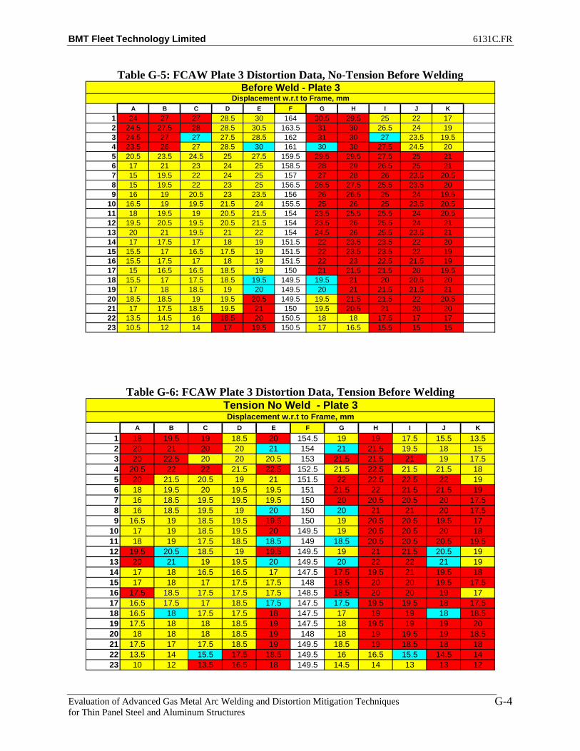
BMT Fleet Technology Limited 6131C.FR
Evaluation of Advanced Gas Metal Arc Welding and Distortion Mitigation Techniques for Thin Panel Steel and Aluminum Structures
G-4
Table G-5: FCAW Plate 3 Distortion Data, No-Tension Before Welding
A B C D E F G H I J K1 24 27 27 28.5 30 164 30.5 29.5 25 22 172 24.5 27.5 28 28.5 30.5 163.5 31 30 26.5 24 193 24.5 27 27 27.5 28.5 162 31 30 27 23.5 19.54 23.5 26 27 28.5 30 161 30 30 27.5 24.5 205 20.5 23.5 24.5 25 27.5 159.5 29.5 29.5 27.5 25 216 17 21 23 24 25 158.5 28 29 26.5 25 217 15 19.5 22 24 25 157 27 28 26 23.5 20.58 15 19.5 22 23 25 156.5 26.5 27.5 25.5 23.5 209 16 19 20.5 23 23.5 156 26 26.5 25 24 19.5
10 16.5 19 19.5 21.5 24 155.5 25 26 25 23.5 20.511 18 19.5 19 20.5 21.5 154 23.5 25.5 25.5 24 20.512 19.5 20.5 19.5 20.5 21.5 154 23.5 26 25.5 24 2113 20 21 19.5 21 22 154 24.5 26 25.5 23.5 2114 17 17.5 17 18 19 151.5 22 23.5 23.5 22 2015 15.5 17 16.5 17.5 19 151.5 22 23.5 23.5 22 1916 15.5 17.5 17 18 19 151.5 22 23 22.5 21.5 1917 15 16.5 16.5 18.5 19 150 21 21.5 21.5 20 19.518 15.5 17 17.5 18.5 19.5 149.5 19.5 21 20 20.5 2019 17 18 18.5 19 20 149.5 20 21 21.5 21.5 2120 18.5 18.5 19 19.5 20.5 149.5 19.5 21.5 21.5 22 20.521 17 17.5 18.5 19.5 21 150 19.5 20.5 21 20 2022 13.5 14.5 16 18.5 20 150.5 18 18 17.5 17 1723 10.5 12 14 17 19.5 150.5 17 16.5 15.5 15 15
Displacement w.r.t to Frame, mmBefore Weld - Plate 3
Table G-6: FCAW Plate 3 Distortion Data, Tension Before Welding
A B C D E F G H I J K1 18 19.5 19 18.5 20 154.5 19 19 17.5 15.5 13.52 20 21 20 20 21 154 21 21.5 19.5 18 153 20 22.5 20 20 20.5 153 21.5 21.5 21 19 17.54 20.5 22 22 21.5 22.5 152.5 21.5 22.5 21.5 21.5 185 20 21.5 20.5 19 21 151.5 22 22.5 22.5 22 196 18 19.5 20 19.5 19.5 151 21.5 22 21.5 21.5 197 16 18.5 19.5 19.5 19.5 150 20 20.5 20.5 20 17.58 16 18.5 19.5 19 20 150 20 21 21 20 17.59 16.5 19 18.5 19.5 19.5 150 19 20.5 20.5 19.5 17
10 17 19 18.5 19.5 20 149.5 19 20.5 20.5 20 1811 18 19 17.5 18.5 18.5 149 18.5 20.5 20.5 20.5 19.512 19.5 20.5 18.5 19 19.5 149.5 19 21 21.5 20.5 1913 20 21 19 19.5 20 149.5 20 22 22 21 1914 17 18 16.5 16.5 17 147.5 17.5 19.5 21 19.5 1815 17 18 17 17.5 17.5 148 18.5 20 20 19.5 17.516 17.5 18.5 17.5 17.5 17.5 148.5 18.5 20 20 19 1717 16.5 17.5 17 18.5 17.5 147.5 17.5 19.5 19.5 18 17.518 16.5 18 17.5 17.5 18 147.5 17 19 19 18 18.519 17.5 18 18 18.5 19 147.5 18 19.5 19 19 2020 18 18 18 18.5 19 148 18 19 19.5 19 18.521 17.5 17 17.5 18.5 19 149.5 18.5 19 18.5 18 1822 13.5 14 15.5 17.5 18.5 149.5 16 16.5 15.5 14.5 1423 10 12 13.5 16.5 18 149.5 14.5 14 13 13 12
Displacement w.r.t to Frame, mmTension No Weld - Plate 3

BMT Fleet Technology Limited 6131C.FR
Evaluation of Advanced Gas Metal Arc Welding and Distortion Mitigation Techniques for Thin Panel Steel and Aluminum Structures
G-5
Table G-7: FCAW Plate 3 Distortion Data, Tension After Welding
A B C D E F G H I J K1 25 25.5 23.5 21.5 21 154 18.5 18.5 17 16.5 13.52 26 26.5 24 22.5 22 153.5 20.5 21 20 19 163 26 26.5 24 22.5 21 152.5 21.5 22 21.5 21 18.54 25.5 26 24.5 24.5 23 152 22 24 22.5 23.5 205 21.5 23 22.5 21.5 21 151 23 25 24 25 226 16.5 19.5 20 20 19.5 150.5 23 25 24 25.5 227 13 17 19.5 20.5 20 149.5 22 24 23.5 24 218 13 17 19.5 20 20.5 150 22.5 24.5 23.5 23 20.59 14.5 17.5 18.5 20.5 20 150 22 24 23.5 23 19
10 16 18 18.5 19.5 21 150 22 24 24 23 2011 18.5 19.5 18.5 19 19 149.5 21.5 25 25.5 24.5 2212 20 20.5 19 21 20 150 23 25.5 27.5 27 2513 20.5 21 19.5 20 21 150.5 24 27.5 29.5 29.5 2814 17 18 17 17 17.5 148.5 22.5 25.5 28.5 29 3015 16.5 18 17 17.5 18 149 22.5 26 28.5 29.5 3016 17.5 19.5 18.5 19 19 150 22.5 25 27 27.5 27.517 19 20 19.5 20.5 20 149.5 21 23.5 25 24.5 2418 21 21.5 21.5 21.5 21 149.5 20 22 22.5 22.5 2219 23.5 23.5 23 22.5 21.5 150.5 20.5 21.5 22 22 2220 24 23.5 23 23 22.5 151 20.5 20.5 21.5 21.5 2021 22.5 22 22 23 23 151.5 20.5 20.5 20.5 20.5 19.522 18.5 19 19.5 21 22 152.5 18 18 18 17 1623 16.5 16.5 17.5 19.5 21 153 16 16 15 14.5 14
Displacement w.r.t to Frame, mmAfter Weld - Plate 3
Table G-8: T-MCAW Plate 9 Distortion Data, No-Tension Before Welding
A B C D E F G H I J K1 6 12.5 17 19.5 23 157.5 25 24 19.5 18 132 10.5 17.5 20.5 22.5 25.5 157.5 25.5 25 20.5 19 143 15.5 26.5 23.5 25.5 26.5 157 26 24.5 20.5 19 144 19 25 26.5 28.5 29 156.5 26 23 21.5 19.5 155 20.5 26 26.5 26.5 27 156 25 22.5 21 19.5 15.56 19.5 25 26 26.5 26 155.5 25.5 22 20.5 19 15.57 17.5 22.5 25 26 25.5 154.5 24.5 21 18.5 17 13.58 16 21 24 24.5 25.5 154.5 24.5 21 19 17 149 14.5 19.5 22 24 24 153.5 24.5 21 19.5 17 14
10 14.5 19.5 21 23.5 25 153 24.5 21.5 19.5 17.5 15.511 16.5 20.5 21.5 22.5 24.5 152 24 26 19.5 18.5 1712 18.5 23 24 25 25.5 152.5 23.5 21 20 19 1713 21 25 25.5 26.5 26 153.5 23 21 19.5 18.5 1714 20 23 24.5 24.5 23.5 151.5 21 18.5 17.5 16.5 1515 20 23.5 24.5 25 24 152.5 21.5 19 18 16.5 14.516 19.5 23 24.5 24.5 24.5 153 22.5 19.5 18.5 17 15.517 16.5 20.5 22 23.5 23.5 152.5 21.5 19.5 18.5 17.5 1618 15.5 19 21.5 22.5 24 152.5 21.5 20 19 17.5 1819 16.5 19.5 22 23.5 24.5 154 22.5 21 19.5 19 1920 17.5 21.5 24 25 25.5 154.5 22.5 21 20.5 19 1821 18.5 22.5 25 26.5 26.5 155 22.5 21.5 20.5 19.5 1722 19 23 25.5 26.5 27 156 22.5 21.5 20 18.5 16.523 18 22.5 25.5 26.5 27 156.5 22.5 21.5 20 18.5 16.5
Displacement w.r.t to Frame, mmBefore Weld - Plate 9
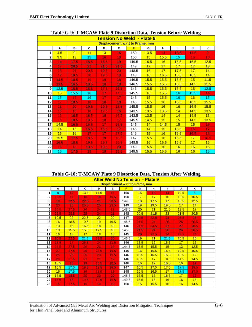
BMT Fleet Technology Limited 6131C.FR
Evaluation of Advanced Gas Metal Arc Welding and Distortion Mitigation Techniques for Thin Panel Steel and Aluminum Structures
G-6
Table G-9: T-MCAW Plate 9 Distortion Data, Tension Before Welding
A B C D E F G H I J K1 4.5 9 11 13 16 150 13.5 14 13.5 14.5 92 9.5 13 15 16 18 150 15 15.5 15 16 103 14 17.5 18.5 18.5 19 149.5 16.5 16 16.5 16.5 12.54 17 20.5 21 21.5 21.5 149 17 17 17 17 135 18 21 20.5 19.5 20 148.5 16 17 17.5 17 146 17 19.5 20 19.5 18 148 16 16.5 16.5 16.5 147 14.5 18.5 19 19 18 146.5 15.5 15.5 15.5 15 11.58 13.5 16.5 18.5 18 18 146.5 15.5 15.5 15.5 14.5 11.59 12.5 15.5 16.5 17.5 16.5 146 15.5 15.5 15.5 15 12.5
10 13 15.5 16 17 17.5 145.5 16 15.5 16 15.5 1411 15 17 16 17 17 145 15 15.5 16 16 1512 17 18.5 18 18 18 145 15.5 16 16.5 16.5 15.513 18 20 19.5 19.5 18.5 145.5 15.5 16 16 16.5 15.514 16 18 18 17.5 16 143.5 13.5 13.5 14 14.5 13.515 16 18.5 18.5 18 16.5 143.5 13.5 14 14 14.5 1316 16 18.5 18.5 18 17 145.5 14.5 15 15 14.5 13.517 14.5 16.5 16.5 17 16.5 145 14 14.5 15 15 1518 14 15 16.5 16.5 17 145 14 15 15.5 16 1719 15 16 17 17 17.5 146 15 16 16.5 16.5 1820 15.5 17.5 18.5 19 18.5 147 15.5 16 16.5 17 16.521 16.5 18.5 19.5 19.5 19.5 148.5 16 16.5 16.5 17 1622 16 18 19.5 19.5 20 149 15.5 16 16 16 1523 15 17.5 19 19 19.5 149.5 15.5 15.5 16 16 15
Displacement w.r.t to Frame, mmTension No Weld - Plate 9
Table G-10: T-MCAW Plate 9 Distortion Data, Tension After Welding
A B C D E F G H I J K1 8 12 13.5 14.5 17 150 15 15 14 10.5 82 13.5 17 18 18 19.5 150 17 17 16 13.5 10.53 19 22.5 22.5 21 20.5 149.5 18 17.5 17 15.5 12.54 23 26 25.5 25 23.5 149 19 19.5 19.5 17 145 25.5 27.5 26 24 22 148.5 20 21 21.5 19.5 176 23.5 25.5 25 24 21 148 20.5 21.5 23 21.5 20.57 19.5 22 22.5 22 20 147 20.5 22.5 24 23.5 238 16 18.5 19.5 19 19.5 146.5 21.5 24 26 26 26.59 13 16 16.5 18 18 146 21.5 24.5 27 27 26.5
10 13 15.5 15.5 17.5 18 145.5 21.5 24 26 26 26.511 16 18 17 18 18 145 20 22.5 24 23.5 2412 20.5 22.5 21.5 21.5 20 145.5 19 21 21.5 20.5 2013 25.5 27 25.5 24 21.5 146 18.5 19 18.5 17 1614 26.5 27.5 26 23 19 144.5 15.5 15.5 15 13 12.515 27 27.5 26 23.5 19.5 145 16 15.5 14.5 12.5 10.516 25 26 25 23 19.5 146 16.5 16.5 15.5 13.5 1217 20 21.5 21 21 19 146 16.5 17 16 14.5 14.518 16.5 18 19 18.5 18.5 146 16 17 16.5 16 1719 15.5 17.5 18.5 18.5 18.5 147 16.5 17.5 17.5 17.5 18.520 16 17.5 19 19.5 19 148 16.5 16.5 17 17.5 17.521 16.5 18.5 20 20 20 148.5 16.5 17 16.5 17 1722 15.5 18 19.5 19.5 19.5 149.5 15.5 16 16 16 1523 15 17.5 19 19 19 150 15 15.5 16 16 14.5
Displacement w.r.t to Frame, mmAfter Weld No Tension - Plate 9
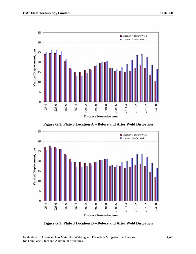
BMT Fleet Technology Limited 6131C.FR
Evaluation of Advanced Gas Metal Arc Welding and Distortion Mitigation Techniques for Thin Panel Steel and Aluminum Structures
G-7
0
5
10
15
20
25
30
35
25.4
228.
6
482.
6
787.
4
1092
.2
1397
.0
1701
.8
2006
.6
2311
.4
2616
.2
2870
.2
3048
.0
Distance from edge, mm
Ver
tical
Dis
plac
emen
t, m
mLocation A-Before WeldLocation A-After Weld
Figure G.1: Plate 3 Location A – Before and After Weld Distortion
0
5
10
15
20
25
30
35
25.4
228.
6
482.
6
787.
4
1092
.2
1397
.0
1701
.8
2006
.6
2311
.4
2616
.2
2870
.2
3048
.0
Distance from edge, mm
Ver
tical
Dis
plac
emen
t, m
m
Location B-Before WeldLocation B-After Weld
Figure G.2: Plate 3 Location B – Before and After Weld Distortion

BMT Fleet Technology Limited 6131C.FR
Evaluation of Advanced Gas Metal Arc Welding and Distortion Mitigation Techniques for Thin Panel Steel and Aluminum Structures
G-8
0
5
10
15
20
25
30
35
25.4
228.
6
482.
6
787.
4
1092
.2
1397
.0
1701
.8
2006
.6
2311
.4
2616
.2
2870
.2
3048
.0
Distance from edge, mm
Ver
tical
Dis
plac
emen
t, m
mLocation C-Before WeldLocation C-After Weld
Figure G.3: Plate 3 Location C – Before and After Weld Distortion
0
5
10
15
20
25
30
35
25.4
228.
6
482.
6
787.
4
1092
.2
1397
.0
1701
.8
2006
.6
2311
.4
2616
.2
2870
.2
3048
.0
Distance from edge, mm
Ver
tical
Dis
plac
emen
t, m
m
Location D-Before WeldLocation D-After Weld
Figure G.4: Plate 3 Location D – Before and After Weld Distortion

BMT Fleet Technology Limited 6131C.FR
Evaluation of Advanced Gas Metal Arc Welding and Distortion Mitigation Techniques for Thin Panel Steel and Aluminum Structures
G-9
0
5
10
15
20
25
30
35
25.4
228.
6
482.
6
787.
4
1092
.2
1397
.0
1701
.8
2006
.6
2311
.4
2616
.2
2870
.2
3048
.0
Distance from edge, mm
Ver
tical
Dis
plac
emen
t, m
mLocation E-Before WeldLocation E-After Weld
Figure G.5: Plate 3 Location E – Before and After Weld Distortion
140
145
150
155
160
165
170
25.4
228.
6
482.
6
787.
4
1092
.2
1397
.0
1701
.8
2006
.6
2311
.4
2616
.2
2870
.2
3048
.0
Distance from edge, mm
Ver
tical
Dis
plac
emen
t, m
m
Stiffener-Before WeldStiffener-After Weld
Figure G.6: Plate 3 At Stiffener – Before and After Weld Distortion
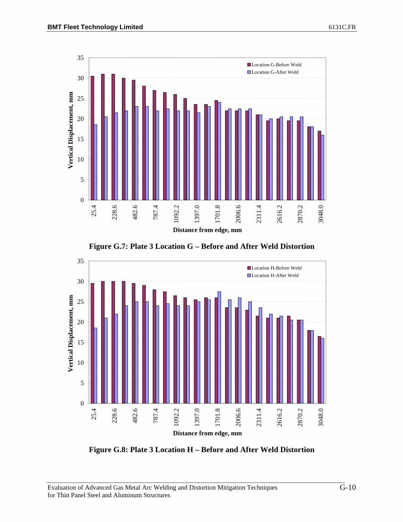
BMT Fleet Technology Limited 6131C.FR
Evaluation of Advanced Gas Metal Arc Welding and Distortion Mitigation Techniques for Thin Panel Steel and Aluminum Structures
G-10
0
5
10
15
20
25
30
35
25.4
228.
6
482.
6
787.
4
1092
.2
1397
.0
1701
.8
2006
.6
2311
.4
2616
.2
2870
.2
3048
.0
Distance from edge, mm
Ver
tical
Dis
plac
emen
t, m
mLocation G-Before WeldLocation G-After Weld
Figure G.7: Plate 3 Location G – Before and After Weld Distortion
0
5
10
15
20
25
30
35
25.4
228.
6
482.
6
787.
4
1092
.2
1397
.0
1701
.8
2006
.6
2311
.4
2616
.2
2870
.2
3048
.0
Distance from edge, mm
Ver
tical
Dis
plac
emen
t, m
m
Location H-Before WeldLocation H-After Weld
Figure G.8: Plate 3 Location H – Before and After Weld Distortion

BMT Fleet Technology Limited 6131C.FR
Evaluation of Advanced Gas Metal Arc Welding and Distortion Mitigation Techniques for Thin Panel Steel and Aluminum Structures
G-11
0
5
10
15
20
25
30
35
25.4
228.
6
482.
6
787.
4
1092
.2
1397
.0
1701
.8
2006
.6
2311
.4
2616
.2
2870
.2
3048
.0
Distance from edge, mm
Ver
tical
Dis
plac
emen
t, m
mLocation I-Before WeldLocation I-After Weld
Figure G.9: Plate 3 Location I – Before and After Weld Distortion
0
5
10
15
20
25
30
35
25.4
228.
6
482.
6
787.
4
1092
.2
1397
.0
1701
.8
2006
.6
2311
.4
2616
.2
2870
.2
3048
.0
Distance from edge, mm
Ver
tical
Dis
plac
emen
t, m
m
Location J-Before WeldLocation J-After Weld
Figure G.10: Plate 3 Location J – Before and After Weld Distortion

BMT Fleet Technology Limited 6131C.FR
Evaluation of Advanced Gas Metal Arc Welding and Distortion Mitigation Techniques for Thin Panel Steel and Aluminum Structures
G-12
0
5
10
15
20
25
30
35
25.4
228.
6
482.
6
787.
4
1092
.2
1397
.0
1701
.8
2006
.6
2311
.4
2616
.2
2870
.2
3048
.0
Distance from edge, mm
Ver
tical
Dis
plac
emen
t, m
mLocation K-Before WeldLocation K-After Weld
Figure G.11: Plate 3 Location K – Before and After Weld Distortion
0
5
10
15
20
25
30
35
25.4
228.
6
482.
6
787.
4
1092
.2
1397
.0
1701
.8
2006
.6
2311
.4
2616
.2
2870
.2
3048
.0
Distance from edge, mm
Ver
tical
Dis
plac
emen
t, m
m
Location A-Before WeldLocation A-After Weld
Figure G.12: Plate 7 Location A – Before and After Weld Distortion

BMT Fleet Technology Limited 6131C.FR
Evaluation of Advanced Gas Metal Arc Welding and Distortion Mitigation Techniques for Thin Panel Steel and Aluminum Structures
G-13
0
5
10
15
20
25
30
35
25.4
228.
6
482.
6
787.
4
1092
.2
1397
.0
1701
.8
2006
.6
2311
.4
2616
.2
2870
.2
3048
.0
Distance from edge, mm
Ver
tical
Dis
plac
emen
t, m
mLocation B-Before WeldLocation B-After Weld
Figure G.13: Plate 7 Location B – Before and After Weld Distortion
0
5
10
15
20
25
30
35
25.4
228.
6
482.
6
787.
4
1092
.2
1397
.0
1701
.8
2006
.6
2311
.4
2616
.2
2870
.2
3048
.0
Distance from edge, mm
Ver
tical
Dis
plac
emen
t, m
m
Location C-Before WeldLocation C-After Weld
Figure G.14: Plate 7 Location C – Before and After Weld Distortion
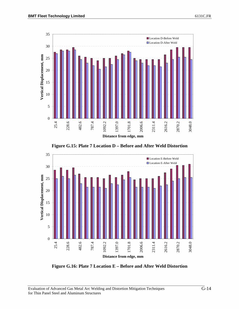
BMT Fleet Technology Limited 6131C.FR
Evaluation of Advanced Gas Metal Arc Welding and Distortion Mitigation Techniques for Thin Panel Steel and Aluminum Structures
G-14
0
5
10
15
20
25
30
35
25.4
228.
6
482.
6
787.
4
1092
.2
1397
.0
1701
.8
2006
.6
2311
.4
2616
.2
2870
.2
3048
.0
Distance from edge, mm
Ver
tical
Dis
plac
emen
t, m
mLocation D-Before WeldLocation D-After Weld
Figure G.15: Plate 7 Location D – Before and After Weld Distortion
0
5
10
15
20
25
30
35
25.4
228.
6
482.
6
787.
4
1092
.2
1397
.0
1701
.8
2006
.6
2311
.4
2616
.2
2870
.2
3048
.0
Distance from edge, mm
Ver
tical
Dis
plac
emen
t, m
m
Location E-Before WeldLocation E-After Weld
Figure G.16: Plate 7 Location E – Before and After Weld Distortion

BMT Fleet Technology Limited 6131C.FR
Evaluation of Advanced Gas Metal Arc Welding and Distortion Mitigation Techniques for Thin Panel Steel and Aluminum Structures
G-15
140
145
150
155
160
165
170
25.4
228.
6
482.
6
787.
4
1092
.2
1397
.0
1701
.8
2006
.6
2311
.4
2616
.2
2870
.2
3048
.0
Distance from edge, mm
Ver
tical
Dis
plac
emen
t, m
mStiffener-Before WeldStiffener-After Weld
Figure G.17: Plate 7 At Stiffener – Before and After Weld Distortion
0
5
10
15
20
25
30
35
25.4
228.
6
482.
6
787.
4
1092
.2
1397
.0
1701
.8
2006
.6
2311
.4
2616
.2
2870
.2
3048
.0
Distance from edge, mm
Ver
tical
Dis
plac
emen
t, m
m
Location G-Before WeldLocation G-After Weld
Figure G.18: Plate 7 Location G – Before and After Weld Distortion

BMT Fleet Technology Limited 6131C.FR
Evaluation of Advanced Gas Metal Arc Welding and Distortion Mitigation Techniques for Thin Panel Steel and Aluminum Structures
G-16
0
5
10
15
20
25
30
35
25.4
228.
6
482.
6
787.
4
1092
.2
1397
.0
1701
.8
2006
.6
2311
.4
2616
.2
2870
.2
3048
.0
Distance from edge, mm
Ver
tical
Dis
plac
emen
t, m
mLocation H-Before WeldLocation H-After Weld
Figure G.19: Plate 7 Location H – Before and After Weld Distortion
0
5
10
15
20
25
30
35
25.4
228.
6
482.
6
787.
4
1092
.2
1397
.0
1701
.8
2006
.6
2311
.4
2616
.2
2870
.2
3048
.0
Distance from edge, mm
Ver
tical
Dis
plac
emen
t, m
m
Location I-Before WeldLocation I-After Weld
Figure G.20: Plate 7 Location I – Before and After Weld Distortion

BMT Fleet Technology Limited 6131C.FR
Evaluation of Advanced Gas Metal Arc Welding and Distortion Mitigation Techniques for Thin Panel Steel and Aluminum Structures
G-17
0
5
10
15
20
25
30
35
25.4
228.
6
482.
6
787.
4
1092
.2
1397
.0
1701
.8
2006
.6
2311
.4
2616
.2
2870
.2
3048
.0
Distance from edge, mm
Ver
tical
Dis
plac
emen
t, m
mLocation J-Before WeldLocation J-After Weld
Figure G.21: Plate 7 Location J – Before and After Weld Distortion
0
5
10
15
20
25
30
35
25.4
228.
6
482.
6
787.
4
1092
.2
1397
.0
1701
.8
2006
.6
2311
.4
2616
.2
2870
.2
3048
.0
Distance from edge, mm
Ver
tical
Dis
plac
emen
t, m
m
Location K-Before WeldLocation K-After Weld
Figure G.22: Plate 7 Location K – Before and After Weld Distortion

BMT Fleet Technology Limited 6131C.FR
Evaluation of Advanced Gas Metal Arc Welding and Distortion Mitigation Techniques for Thin Panel Steel and Aluminum Structures
G-18
0
5
10
15
20
25
30
35
25.4
228.
6
482.
6
787.
4
1092
.2
1397
.0
1701
.8
2006
.6
2311
.4
2616
.2
2870
.2
3048
.0
Distance from edge, mm
Ver
tical
Dis
plac
emen
t, m
mLocation A-Before WeldLocation A-After Weld
Figure G.23: Plate 8 Location A – Before and After Weld Distortion
0
5
10
15
20
25
30
35
25.4
228.
6
482.
6
787.
4
1092
.2
1397
.0
1701
.8
2006
.6
2311
.4
2616
.2
2870
.2
3048
.0
Distance from edge, mm
Ver
tical
Dis
plac
emen
t, m
m
Location B-Before WeldLocation B-After Weld
Figure G.24: Plate 8 Location B – Before and After Weld Distortion

BMT Fleet Technology Limited 6131C.FR
Evaluation of Advanced Gas Metal Arc Welding and Distortion Mitigation Techniques for Thin Panel Steel and Aluminum Structures
G-19
0
5
10
15
20
25
30
35
25.4
228.
6
482.
6
787.
4
1092
.2
1397
.0
1701
.8
2006
.6
2311
.4
2616
.2
2870
.2
3048
.0
Distance from edge, mm
Ver
tical
Dis
plac
emen
t, m
mLocation C-Before WeldLocation C-After Weld
Figure G.25: Plate 8 Location C – Before and After Weld Distortion
0
5
10
15
20
25
30
35
25.4
228.
6
482.
6
787.
4
1092
.2
1397
.0
1701
.8
2006
.6
2311
.4
2616
.2
2870
.2
3048
.0
Distance from edge, mm
Ver
tical
Dis
plac
emen
t, m
m
Location D-Before WeldLocation D-After Weld
Figure G.26: Plate 8 Location D – Before and After Weld Distortion
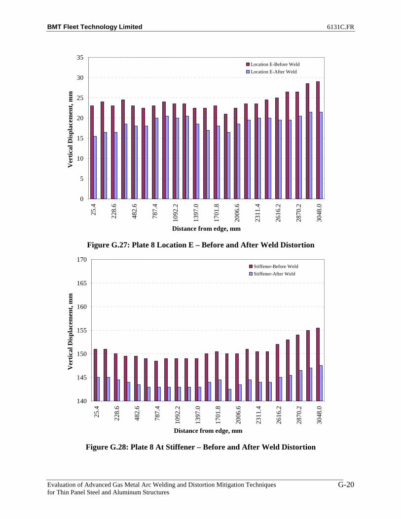
BMT Fleet Technology Limited 6131C.FR
Evaluation of Advanced Gas Metal Arc Welding and Distortion Mitigation Techniques for Thin Panel Steel and Aluminum Structures
G-20
0
5
10
15
20
25
30
35
25.4
228.
6
482.
6
787.
4
1092
.2
1397
.0
1701
.8
2006
.6
2311
.4
2616
.2
2870
.2
3048
.0
Distance from edge, mm
Ver
tical
Dis
plac
emen
t, m
mLocation E-Before WeldLocation E-After Weld
Figure G.27: Plate 8 Location E – Before and After Weld Distortion
140
145
150
155
160
165
170
25.4
228.
6
482.
6
787.
4
1092
.2
1397
.0
1701
.8
2006
.6
2311
.4
2616
.2
2870
.2
3048
.0
Distance from edge, mm
Ver
tical
Dis
plac
emen
t, m
m
Stiffener-Before WeldStiffener-After Weld
Figure G.28: Plate 8 At Stiffener – Before and After Weld Distortion

BMT Fleet Technology Limited 6131C.FR
Evaluation of Advanced Gas Metal Arc Welding and Distortion Mitigation Techniques for Thin Panel Steel and Aluminum Structures
G-21
0
5
10
15
20
25
30
35
25.4
228.
6
482.
6
787.
4
1092
.2
1397
.0
1701
.8
2006
.6
2311
.4
2616
.2
2870
.2
3048
.0
Distance from edge, mm
Ver
tical
Dis
plac
emen
t, m
mLocation G-Before WeldLocation G-After Weld
Figure G.29: Plate 8 Location G – Before and After Weld Distortion
0
5
10
15
20
25
30
35
25.4
228.
6
482.
6
787.
4
1092
.2
1397
.0
1701
.8
2006
.6
2311
.4
2616
.2
2870
.2
3048
.0
Distance from edge, mm
Ver
tical
Dis
plac
emen
t, m
m
Location H-Before WeldLocation H-After Weld
Figure G.30: Plate 8 Location H – Before and After Weld Distortion

BMT Fleet Technology Limited 6131C.FR
Evaluation of Advanced Gas Metal Arc Welding and Distortion Mitigation Techniques for Thin Panel Steel and Aluminum Structures
G-22
0
5
10
15
20
25
30
35
25.4
228.
6
482.
6
787.
4
1092
.2
1397
.0
1701
.8
2006
.6
2311
.4
2616
.2
2870
.2
3048
.0
Distance from edge, mm
Ver
tical
Dis
plac
emen
t, m
mLocation I-Before WeldLocation I-After Weld
Figure G.31: Plate 8 Location I – Before and After Weld Distortion
0
5
10
15
20
25
30
35
25.4
228.
6
482.
6
787.
4
1092
.2
1397
.0
1701
.8
2006
.6
2311
.4
2616
.2
2870
.2
3048
.0
Distance from edge, mm
Ver
tical
Dis
plac
emen
t, m
m
Location J-Before WeldLocation J-After Weld
Figure G.32: Plate 8 Location J – Before and After Weld Distortion

BMT Fleet Technology Limited 6131C.FR
Evaluation of Advanced Gas Metal Arc Welding and Distortion Mitigation Techniques for Thin Panel Steel and Aluminum Structures
G-23
0
5
10
15
20
25
30
35
25.4
228.
6
482.
6
787.
4
1092
.2
1397
.0
1701
.8
2006
.6
2311
.4
2616
.2
2870
.2
3048
.0
Distance from edge, mm
Ver
tical
Dis
plac
emen
t, m
mLocation K-Before WeldLocation K-After Weld
Figure G.33: Plate 8 Location K – Before and After Weld Distortion
0
5
10
15
20
25
30
35
25.4
228.
6
482.
6
787.
4
1092
.2
1397
.0
1701
.8
2006
.6
2311
.4
2616
.2
2870
.2
3048
.0
Distance from edge, mm
Ver
tical
Dis
plac
emen
t, m
m
Location A-Before WeldLocation A-After Weld
Figure G.34: Plate 9 Location A – Before and After Weld Distortion

BMT Fleet Technology Limited 6131C.FR
Evaluation of Advanced Gas Metal Arc Welding and Distortion Mitigation Techniques for Thin Panel Steel and Aluminum Structures
G-24
0
5
10
15
20
25
30
35
25.4
228.
6
482.
6
787.
4
1092
.2
1397
.0
1701
.8
2006
.6
2311
.4
2616
.2
2870
.2
3048
.0
Distance from edge, mm
Ver
tical
Dis
plac
emen
t, m
mLocation B-Before WeldLocation B-After Weld
Figure G.35: Plate 9 Location B – Before and After Weld Distortion
0
5
10
15
20
25
30
35
25.4
228.
6
482.
6
787.
4
1092
.2
1397
.0
1701
.8
2006
.6
2311
.4
2616
.2
2870
.2
3048
.0
Distance from edge, mm
Ver
tical
Dis
plac
emen
t, m
m
Location C-Before WeldLocation C-After Weld
Figure G.36: Plate 9 Location C – Before and After Weld Distortion
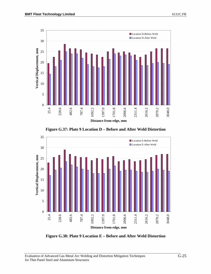
BMT Fleet Technology Limited 6131C.FR
Evaluation of Advanced Gas Metal Arc Welding and Distortion Mitigation Techniques for Thin Panel Steel and Aluminum Structures
G-25
0
5
10
15
20
25
30
35
25.4
228.
6
482.
6
787.
4
1092
.2
1397
.0
1701
.8
2006
.6
2311
.4
2616
.2
2870
.2
3048
.0
Distance from edge, mm
Ver
tical
Dis
plac
emen
t, m
mLocation D-Before WeldLocation D-After Weld
Figure G.37: Plate 9 Location D – Before and After Weld Distortion
0
5
10
15
20
25
30
35
25.4
228.
6
482.
6
787.
4
1092
.2
1397
.0
1701
.8
2006
.6
2311
.4
2616
.2
2870
.2
3048
.0
Distance from edge, mm
Ver
tical
Dis
plac
emen
t, m
m
Location E-Before WeldLocation E-After Weld
Figure G.38: Plate 9 Location E – Before and After Weld Distortion

BMT Fleet Technology Limited 6131C.FR
Evaluation of Advanced Gas Metal Arc Welding and Distortion Mitigation Techniques for Thin Panel Steel and Aluminum Structures
G-26
140
145
150
155
160
165
170
25.4
228.
6
482.
6
787.
4
1092
.2
1397
.0
1701
.8
2006
.6
2311
.4
2616
.2
2870
.2
3048
.0
Distance from edge, mm
Ver
tical
Dis
plac
emen
t, m
mStiffener-Before WeldStiffener-After Weld
Figure G.39: Plate 9 At Stiffener – Before and After Weld Distortion
0
5
10
15
20
25
30
35
25.4
228.
6
482.
6
787.
4
1092
.2
1397
.0
1701
.8
2006
.6
2311
.4
2616
.2
2870
.2
3048
.0
Distance from edge, mm
Ver
tical
Dis
plac
emen
t, m
m
Location G-Before WeldLocation G-After Weld
Figure G.40: Plate 9 Location G – Before and After Weld Distortion

BMT Fleet Technology Limited 6131C.FR
Evaluation of Advanced Gas Metal Arc Welding and Distortion Mitigation Techniques for Thin Panel Steel and Aluminum Structures
G-27
0
5
10
15
20
25
30
35
25.4
228.
6
482.
6
787.
4
1092
.2
1397
.0
1701
.8
2006
.6
2311
.4
2616
.2
2870
.2
3048
.0
Distance from edge, mm
Ver
tical
Dis
plac
emen
t, m
mLocation H-Before WeldLocation H-After Weld
Figure G.41: Plate 9 Location H – Before and After Weld Distortion
0
5
10
15
20
25
30
35
25.4
228.
6
482.
6
787.
4
1092
.2
1397
.0
1701
.8
2006
.6
2311
.4
2616
.2
2870
.2
3048
.0
Distance from edge, mm
Ver
tical
Dis
plac
emen
t, m
m
Location I-Before WeldLocation I-After Weld
Figure G.42: Plate 9 Location I – Before and After Weld Distortion

BMT Fleet Technology Limited 6131C.FR
Evaluation of Advanced Gas Metal Arc Welding and Distortion Mitigation Techniques for Thin Panel Steel and Aluminum Structures
G-28
0
5
10
15
20
25
30
35
25.4
228.
6
482.
6
787.
4
1092
.2
1397
.0
1701
.8
2006
.6
2311
.4
2616
.2
2870
.2
3048
.0
Distance from edge, mm
Ver
tical
Dis
plac
emen
t, m
mLocation J-Before WeldLocation J-After Weld
Figure G.43: Plate 9 Location J – Before and After Weld Distortion
0
5
10
15
20
25
30
35
25.4
228.
6
482.
6
787.
4
1092
.2
1397
.0
1701
.8
2006
.6
2311
.4
2616
.2
2870
.2
3048
.0
Distance from edge, mm
Ver
tical
Dis
plac
emen
t, m
m
Location K-Before WeldLocation K-After Weld
Figure G.44: Plate 9 Location K – Before and After Weld Distortion

BMT Fleet Technology Limited 6131C.FR
Evaluation of Advanced Gas Metal Arc Welding and Distortion Mitigation Techniques for Thin Panel Steel and Aluminum Structures
H-1
APPENDIX H
NET IMPROVEMENT VERSUS BENCHMARK PLATE 7 (4’ x 10’ HSLA 80 BASE PLATES)

BMT Fleet Technology Limited 6131C.FR
Evaluation of Advanced Gas Metal Arc Welding and Distortion Mitigation Techniques for Thin Panel Steel and Aluminum Structures
H-2
Table H.1: Net Improvement, T-MCAW Plate 8 vs. FCAW Plate 7 (No Tension)
A B C D E F G H I J K-5 -5 -3.5 -4 -4 -1 2 3.5 3.5 4.5 4.5-4 -3 -2 -4 -4 -1 1.5 3 4 3 2.5-1 -1.5 -1 -3 -3 -0.5 0.5 2 2 1.5 01 1 1 -1.5 -3 -0.5 0 1.5 0.5 0 -0.5
5.5 4.5 4 0.5 -1 -1 -0.5 -0.5 -1.5 -2.5 -49.5 8.5 6.5 3 -0.5 -1 -1.5 -2.5 -4 -6.5 -7.513 11 9.5 5 1 -0.5 -2.5 -5 -7 -7.5 -10.514 12 11 5.5 0.5 -0.5 -3.5 -4.5 -8 -8 -10.5
12.5 10.5 10 6 0.5 -1 -3 -4.5 -6 -7.5 -97.5 7 6.5 3 0.5 -1.5 -2.5 -3 -4.5 -3.5 -6.52.5 1 1.5 0 -1 -0.5 -1.5 -1 -1 -1 -1.5-3.5 -3 -1.5 -2.5 -3.5 -1 -1 0 0.5 0.5 1.5-5.5 -4 -3 -2.5 -2.5 -1 -1.5 0.5 -0.5 1 1.5-3.5 -3 -1.5 -1 -1.5 -2 -1.5 -1 -0.5 -1.5 -11.5 0.5 1.5 0.5 -0.5 -1.5 -2.5 -2 -2.5 -3.5 -55 9 4 2.5 -0.5 -1 -2 -3 -3.5 -4.5 -76 5.5 4 2 0.5 -1.5 -1.5 -3.5 -3.5 -5 -7.5
4.5 3.5 3.5 1 -0.5 -1.5 -2 -3.5 -3 -4.5 -53.5 1.5 1.5 0 -0.5 -2 -2 -2.5 -2.5 -4 -4.50.5 -0.5 -1.5 -1 -2 -2 -2 -1.5 -2 -3 -20.5 0 -1 -1.5 -0.5 -1.5 -2 -1 -1.5 -2 -1.5-1.5 -1 -1 -2 -1 -2 -2 -1 -1.5 -0.5 0-1.5 -1.5 -1 -1 -2 -2 -2 -1 -2 -1 0.5
Net Improvement, mmBenchmark
Table H.2: Net Improvement, T-MCAW Plate 9 vs. FCAW Plate 7 (No Tension)
A B C D E F G H I J K-0.5 -1.5 -2.5 -4.5 -2.5 -2.5 -2 -1.5 0.5 -2.5 -0.50.5 -0.5 -1 -4 -2.5 -2.5 -1 -1 2 -1.5 -12 -4 0.5 -4 -2.5 -2.5 -1 -1 1 -0.5 -1
3.5 1.5 1 -2.5 -2.5 -2.5 -1 1.5 1 -1 -16 3 2.5 -1 -1 -2.5 0 2 2 0 -0.56 4 2.5 0 -1 -2.5 -1 1.5 2 -0.5 15 3.5 2.5 -1 -1.5 -2.5 -1 2 3.5 3 4
3.5 2 1 -2 -2 -2.5 0 4 4.5 5.5 71.5 0 -0.5 -2.5 -2 -2.5 0 4 6.5 6.5 8.5-0.5 -1.5 -2 -3.5 -3.5 -3 0 4 6.5 8 9-1.5 -3 -3 -3 -3.5 -1.5 0 -1 6 6 7-2 -3 -2.5 -3 -3.5 -2 -0.5 3 3 3 4
-1.5 -1 -1 -2 -2 -2.5 -0.5 1 0 -1 -0.51 1.5 1 -0.5 -1.5 -1.5 -2 -1 -2 -5.5 -4.5
3.5 2.5 2 0 -1 -2.5 -2.5 -2.5 -4.5 -7 -8.53.5 8 2.5 1 -1.5 -1.5 -3 -2 -5 -7.5 -112.5 2 1.5 0 -0.5 -1.5 -1 -2 -4 -7 -90.5 0 0.5 -1 -1.5 -1.5 -1.5 -1.5 -3 -5 -6-0.5 -0.5 -0.5 -1.5 -1 -2 -2 -1 -1 -3 -4-1 -3 -3 -1.5 -1.5 -1 -1 -0.5 -1 -1 -1.5-1 -1.5 -1.5 -2.5 -1 -0.5 -1 0.5 -0.5 -0.5 0.5-2 -2 -2 -3 -1.5 -0.5 -1 0.5 0 1 0.5
-1.5 -2.5 -2.5 -2.5 -2.5 -0.5 -1.5 0 1 1 1
Net Improvement, mmBenchmark

BMT Fleet Technology Limited 6131C.FR
Evaluation of Advanced Gas Metal Arc Welding and Distortion Mitigation Techniques for Thin Panel Steel and Aluminum Structures
H-3
-20
-15
-10
-5
0
5
10
15
20
25.4
228.
6
482.
6
787.
4
1092
.2
1397
.0
1701
.8
2006
.6
2311
.4
2616
.2
2870
.2
3048
.0
Distance from edge, mm
Ver
tical
Dis
plac
emen
t, m
m
Net Improvement
Figure H.1: Plate 3 vs. Plate 7 Location A – Net Improvement
-20
-15
-10
-5
0
5
10
15
20
25.4
228.
6
482.
6
787.
4
1092
.2
1397
.0
1701
.8
2006
.6
2311
.4
2616
.2
2870
.2
3048
.0
Distance from edge, mm
Ver
tical
Dis
plac
emen
t, m
m
Net Improvement
Figure H.2: Plate 3 vs. Plate 7 Location B – Net Improvement
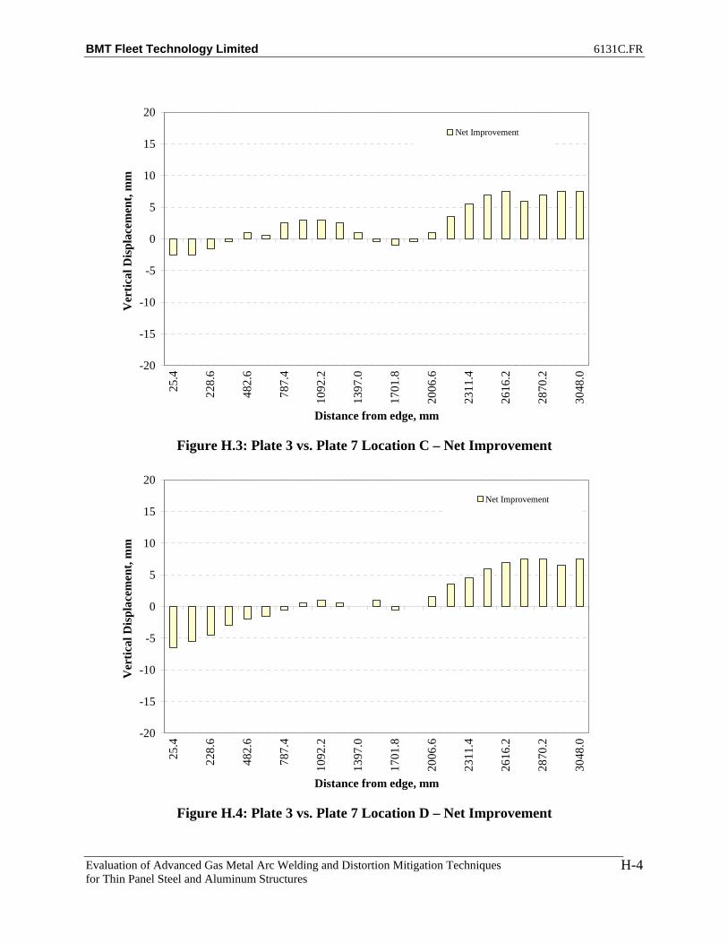
BMT Fleet Technology Limited 6131C.FR
Evaluation of Advanced Gas Metal Arc Welding and Distortion Mitigation Techniques for Thin Panel Steel and Aluminum Structures
H-4
-20
-15
-10
-5
0
5
10
15
20
25.4
228.
6
482.
6
787.
4
1092
.2
1397
.0
1701
.8
2006
.6
2311
.4
2616
.2
2870
.2
3048
.0
Distance from edge, mm
Ver
tical
Dis
plac
emen
t, m
mNet Improvement
Figure H.3: Plate 3 vs. Plate 7 Location C – Net Improvement
-20
-15
-10
-5
0
5
10
15
20
25.4
228.
6
482.
6
787.
4
1092
.2
1397
.0
1701
.8
2006
.6
2311
.4
2616
.2
2870
.2
3048
.0
Distance from edge, mm
Ver
tical
Dis
plac
emen
t, m
m
Net Improvement
Figure H.4: Plate 3 vs. Plate 7 Location D – Net Improvement
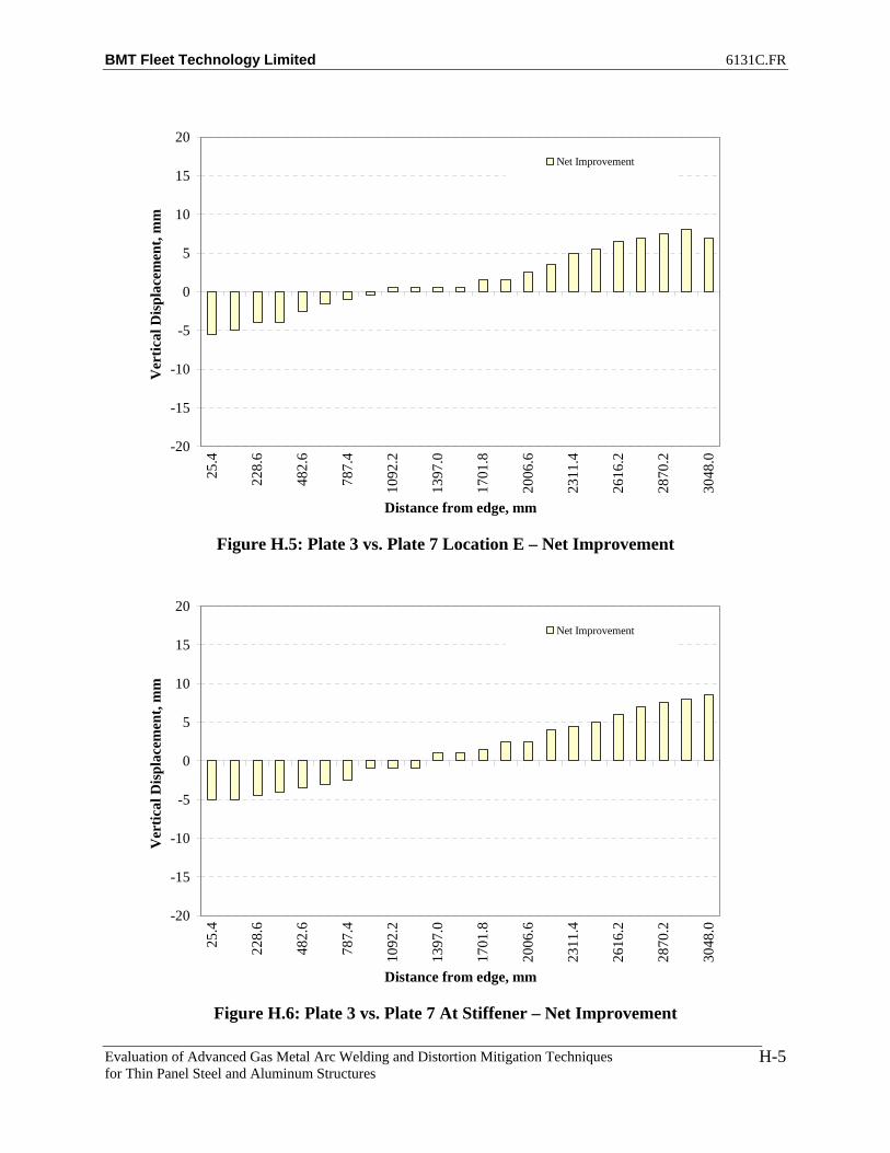
BMT Fleet Technology Limited 6131C.FR
Evaluation of Advanced Gas Metal Arc Welding and Distortion Mitigation Techniques for Thin Panel Steel and Aluminum Structures
H-5
-20
-15
-10
-5
0
5
10
15
20
25.4
228.
6
482.
6
787.
4
1092
.2
1397
.0
1701
.8
2006
.6
2311
.4
2616
.2
2870
.2
3048
.0
Distance from edge, mm
Ver
tical
Dis
plac
emen
t, m
mNet Improvement
Figure H.5: Plate 3 vs. Plate 7 Location E – Net Improvement
-20
-15
-10
-5
0
5
10
15
20
25.4
228.
6
482.
6
787.
4
1092
.2
1397
.0
1701
.8
2006
.6
2311
.4
2616
.2
2870
.2
3048
.0
Distance from edge, mm
Ver
tical
Dis
plac
emen
t, m
m
Net Improvement
Figure H.6: Plate 3 vs. Plate 7 At Stiffener – Net Improvement

BMT Fleet Technology Limited 6131C.FR
Evaluation of Advanced Gas Metal Arc Welding and Distortion Mitigation Techniques for Thin Panel Steel and Aluminum Structures
H-6
-20
-15
-10
-5
0
5
10
15
20
25.4
228.
6
482.
6
787.
4
1092
.2
1397
.0
1701
.8
2006
.6
2311
.4
2616
.2
2870
.2
3048
.0
Distance from edge, mm
Ver
tical
Dis
plac
emen
t, m
mNet Improvement
Figure H.7: Plate 3 vs. Plate 7 Location G – Net Improvement
-20
-15
-10
-5
0
5
10
15
20
25.4
228.
6
482.
6
787.
4
1092
.2
1397
.0
1701
.8
2006
.6
2311
.4
2616
.2
2870
.2
3048
.0
Distance from edge, mm
Ver
tical
Dis
plac
emen
t, m
m
Net Improvement
Figure H.8: Plate 3 vs. Plate 7 Location H – Net Improvement
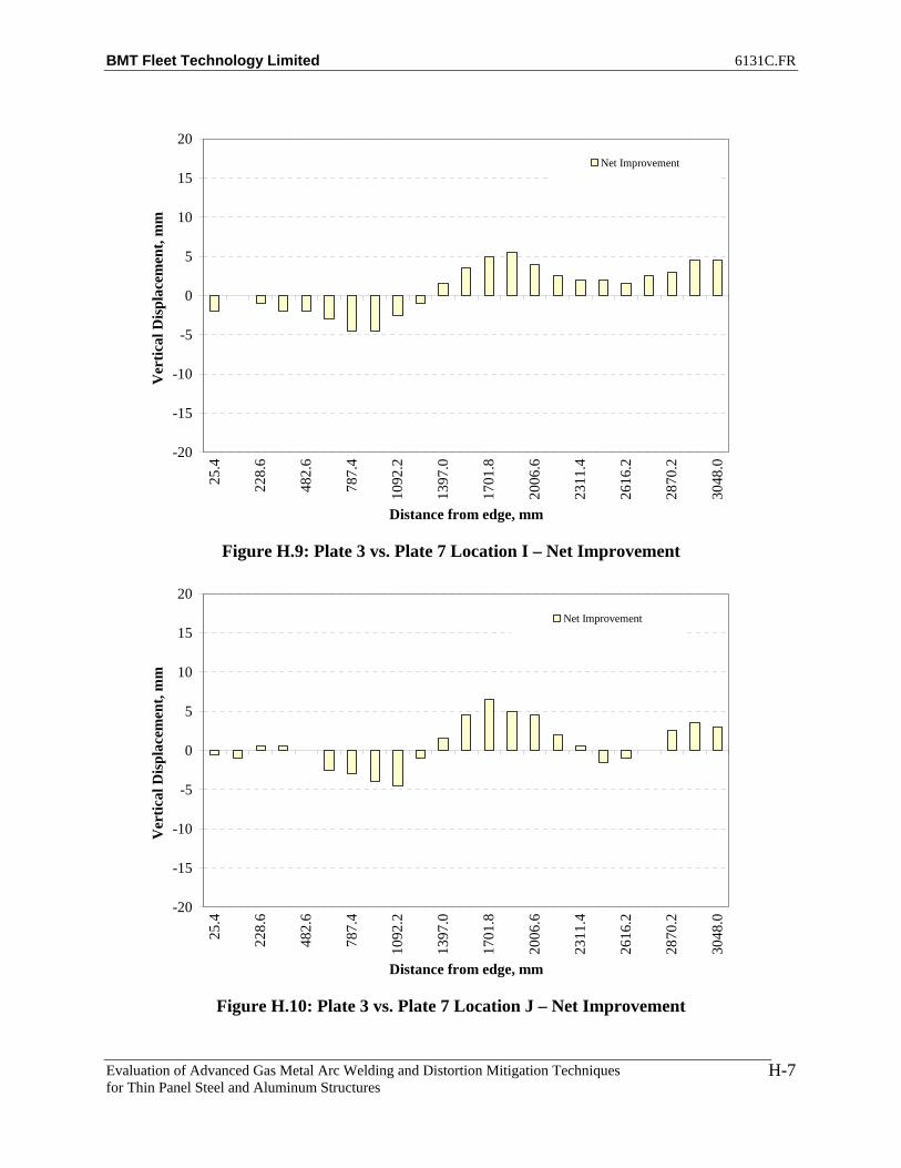
BMT Fleet Technology Limited 6131C.FR
Evaluation of Advanced Gas Metal Arc Welding and Distortion Mitigation Techniques for Thin Panel Steel and Aluminum Structures
H-7
-20
-15
-10
-5
0
5
10
15
20
25.4
228.
6
482.
6
787.
4
1092
.2
1397
.0
1701
.8
2006
.6
2311
.4
2616
.2
2870
.2
3048
.0
Distance from edge, mm
Ver
tical
Dis
plac
emen
t, m
mNet Improvement
Figure H.9: Plate 3 vs. Plate 7 Location I – Net Improvement
-20
-15
-10
-5
0
5
10
15
20
25.4
228.
6
482.
6
787.
4
1092
.2
1397
.0
1701
.8
2006
.6
2311
.4
2616
.2
2870
.2
3048
.0
Distance from edge, mm
Ver
tical
Dis
plac
emen
t, m
m
Net Improvement
Figure H.10: Plate 3 vs. Plate 7 Location J – Net Improvement

BMT Fleet Technology Limited 6131C.FR
Evaluation of Advanced Gas Metal Arc Welding and Distortion Mitigation Techniques for Thin Panel Steel and Aluminum Structures
H-8
-20
-15
-10
-5
0
5
10
15
20
25.4
228.
6
482.
6
787.
4
1092
.2
1397
.0
1701
.8
2006
.6
2311
.4
2616
.2
2870
.2
3048
.0
Distance from edge, mm
Ver
tical
Dis
plac
emen
t, m
mNet Improvement
Figure H.11: Plate 3 vs. Plate 7 Location K – Net Improvement
-20
-15
-10
-5
0
5
10
15
20
25.4
228.
6
482.
6
787.
4
1092
.2
1397
.0
1701
.8
2006
.6
2311
.4
2616
.2
2870
.2
3048
.0
Distance from edge, mm
Ver
tical
Dis
plac
emen
t, m
m
Net Improvement
Figure H.12: Plate 8 vs. Plate 7 Location A – Net Improvement

BMT Fleet Technology Limited 6131C.FR
Evaluation of Advanced Gas Metal Arc Welding and Distortion Mitigation Techniques for Thin Panel Steel and Aluminum Structures
H-9
-20
-15
-10
-5
0
5
10
15
20
25.4
228.
6
482.
6
787.
4
1092
.2
1397
.0
1701
.8
2006
.6
2311
.4
2616
.2
2870
.2
3048
.0
Distance from edge, mm
Ver
tical
Dis
plac
emen
t, m
mNet Improvement
Figure H.13: Plate 8 vs. Plate 7 Location B – Net Improvement
-20
-15
-10
-5
0
5
10
15
20
25.4
228.
6
482.
6
787.
4
1092
.2
1397
.0
1701
.8
2006
.6
2311
.4
2616
.2
2870
.2
3048
.0
Distance from edge, mm
Ver
tical
Dis
plac
emen
t, m
m
Net Improvement
Figure H.14: Plate 8 vs. Plate 7 Location C – Net Improvement

BMT Fleet Technology Limited 6131C.FR
Evaluation of Advanced Gas Metal Arc Welding and Distortion Mitigation Techniques for Thin Panel Steel and Aluminum Structures
H-10
-20
-15
-10
-5
0
5
10
15
20
25.4
228.
6
482.
6
787.
4
1092
.2
1397
.0
1701
.8
2006
.6
2311
.4
2616
.2
2870
.2
3048
.0
Distance from edge, mm
Ver
tical
Dis
plac
emen
t, m
mNet Improvement
Figure H.15: Plate 8 vs. Plate 7 Location D – Net Improvement
-20
-15
-10
-5
0
5
10
15
20
25.4
228.
6
482.
6
787.
4
1092
.2
1397
.0
1701
.8
2006
.6
2311
.4
2616
.2
2870
.2
3048
.0
Distance from edge, mm
Ver
tical
Dis
plac
emen
t, m
m
Net Improvement
Figure H.16: Plate 8 vs. Plate 7 Location E – Net Improvement
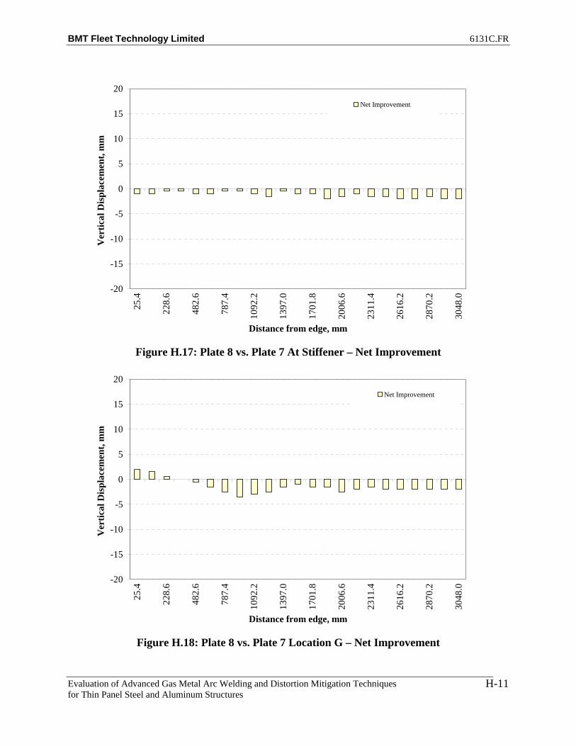
BMT Fleet Technology Limited 6131C.FR
Evaluation of Advanced Gas Metal Arc Welding and Distortion Mitigation Techniques for Thin Panel Steel and Aluminum Structures
H-11
-20
-15
-10
-5
0
5
10
15
20
25.4
228.
6
482.
6
787.
4
1092
.2
1397
.0
1701
.8
2006
.6
2311
.4
2616
.2
2870
.2
3048
.0
Distance from edge, mm
Ver
tical
Dis
plac
emen
t, m
mNet Improvement
Figure H.17: Plate 8 vs. Plate 7 At Stiffener – Net Improvement
-20
-15
-10
-5
0
5
10
15
20
25.4
228.
6
482.
6
787.
4
1092
.2
1397
.0
1701
.8
2006
.6
2311
.4
2616
.2
2870
.2
3048
.0
Distance from edge, mm
Ver
tical
Dis
plac
emen
t, m
m
Net Improvement
Figure H.18: Plate 8 vs. Plate 7 Location G – Net Improvement

BMT Fleet Technology Limited 6131C.FR
Evaluation of Advanced Gas Metal Arc Welding and Distortion Mitigation Techniques for Thin Panel Steel and Aluminum Structures
H-12
-20
-15
-10
-5
0
5
10
15
20
25.4
228.
6
482.
6
787.
4
1092
.2
1397
.0
1701
.8
2006
.6
2311
.4
2616
.2
2870
.2
3048
.0
Distance from edge, mm
Ver
tical
Dis
plac
emen
t, m
mNet Improvement
Figure H.19: Plate 8 vs. Plate 7 Location H – Net Improvement
-20
-15
-10
-5
0
5
10
15
20
25.4
228.
6
482.
6
787.
4
1092
.2
1397
.0
1701
.8
2006
.6
2311
.4
2616
.2
2870
.2
3048
.0
Distance from edge, mm
Ver
tical
Dis
plac
emen
t, m
m
Net Improvement
Figure H.20: Plate 8 vs. Plate 7 Location I – Net Improvement
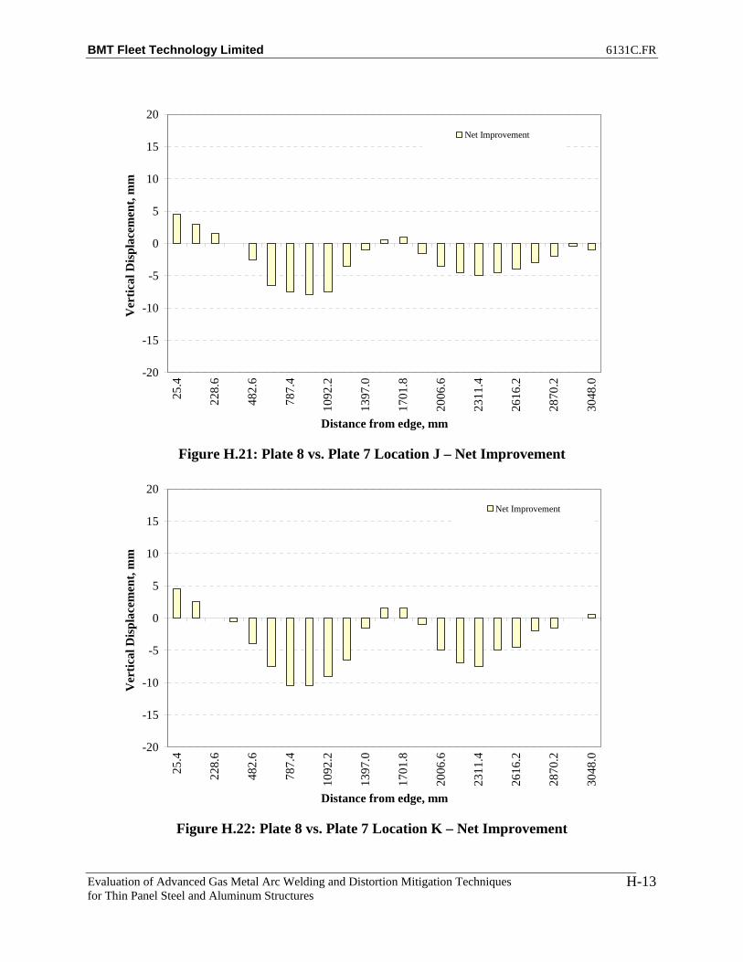
BMT Fleet Technology Limited 6131C.FR
Evaluation of Advanced Gas Metal Arc Welding and Distortion Mitigation Techniques for Thin Panel Steel and Aluminum Structures
H-13
-20
-15
-10
-5
0
5
10
15
20
25.4
228.
6
482.
6
787.
4
1092
.2
1397
.0
1701
.8
2006
.6
2311
.4
2616
.2
2870
.2
3048
.0
Distance from edge, mm
Ver
tical
Dis
plac
emen
t, m
mNet Improvement
Figure H.21: Plate 8 vs. Plate 7 Location J – Net Improvement
-20
-15
-10
-5
0
5
10
15
20
25.4
228.
6
482.
6
787.
4
1092
.2
1397
.0
1701
.8
2006
.6
2311
.4
2616
.2
2870
.2
3048
.0
Distance from edge, mm
Ver
tical
Dis
plac
emen
t, m
m
Net Improvement
Figure H.22: Plate 8 vs. Plate 7 Location K – Net Improvement

BMT Fleet Technology Limited 6131C.FR
Evaluation of Advanced Gas Metal Arc Welding and Distortion Mitigation Techniques for Thin Panel Steel and Aluminum Structures
H-14
-20
-15
-10
-5
0
5
10
15
20
25.4
228.
6
482.
6
787.
4
1092
.2
1397
.0
1701
.8
2006
.6
2311
.4
2616
.2
2870
.2
3048
.0
Distance from edge, mm
Ver
tical
Dis
plac
emen
t, m
m
Net Improvement
Figure H.23: Plate 9 vs. Plate 7 Location A – Net Improvement
-20
-15
-10
-5
0
5
10
15
20
25.4
228.
6
482.
6
787.
4
1092
.2
1397
.0
1701
.8
2006
.6
2311
.4
2616
.2
2870
.2
3048
.0
Distance from edge, mm
Ver
tical
Dis
plac
emen
t, m
m
Net Improvement
Figure H.24: Plate 9 vs. Plate 7 Location B – Net Improvement

BMT Fleet Technology Limited 6131C.FR
Evaluation of Advanced Gas Metal Arc Welding and Distortion Mitigation Techniques for Thin Panel Steel and Aluminum Structures
H-15
-20
-15
-10
-5
0
5
10
15
20
25.4
228.
6
482.
6
787.
4
1092
.2
1397
.0
1701
.8
2006
.6
2311
.4
2616
.2
2870
.2
3048
.0
Distance from edge, mm
Ver
tical
Dis
plac
emen
t, m
mNet Improvement
Figure H.25: Plate 9 vs. Plate 7 Location C – Net Improvement
-20
-15
-10
-5
0
5
10
15
20
25.4
228.
6
482.
6
787.
4
1092
.2
1397
.0
1701
.8
2006
.6
2311
.4
2616
.2
2870
.2
3048
.0
Distance from edge, mm
Ver
tical
Dis
plac
emen
t, m
m
Net Improvement
Figure H.26: Plate 9 vs. Plate 7 Location D – Net Improvement

BMT Fleet Technology Limited 6131C.FR
Evaluation of Advanced Gas Metal Arc Welding and Distortion Mitigation Techniques for Thin Panel Steel and Aluminum Structures
H-16
-20
-15
-10
-5
0
5
10
15
20
25.4
228.
6
482.
6
787.
4
1092
.2
1397
.0
1701
.8
2006
.6
2311
.4
2616
.2
2870
.2
3048
.0
Distance from edge, mm
Ver
tical
Dis
plac
emen
t, m
mNet Improvement
Figure H.27: Plate 9 vs. Plate 7 Location E – Net Improvement
-20
-15
-10
-5
0
5
10
15
20
25.4
228.
6
482.
6
787.
4
1092
.2
1397
.0
1701
.8
2006
.6
2311
.4
2616
.2
2870
.2
3048
.0
Distance from edge, mm
Ver
tical
Dis
plac
emen
t, m
m
Net Improvement
Figure H.28: Plate 9 vs. Plate 7 At Stiffener – Net Improvement

BMT Fleet Technology Limited 6131C.FR
Evaluation of Advanced Gas Metal Arc Welding and Distortion Mitigation Techniques for Thin Panel Steel and Aluminum Structures
H-17
-20
-15
-10
-5
0
5
10
15
20
25.4
228.
6
482.
6
787.
4
1092
.2
1397
.0
1701
.8
2006
.6
2311
.4
2616
.2
2870
.2
3048
.0
Distance from edge, mm
Ver
tical
Dis
plac
emen
t, m
mNet Improvement
Figure H.29: Plate 9 vs. Plate 7 Location G – Net Improvement
-20
-15
-10
-5
0
5
10
15
20
25.4
228.
6
482.
6
787.
4
1092
.2
1397
.0
1701
.8
2006
.6
2311
.4
2616
.2
2870
.2
3048
.0
Distance from edge, mm
Ver
tical
Dis
plac
emen
t, m
m
Net Improvement
Figure H.30: Plate 9 vs. Plate 7 Location H – Net Improvement

BMT Fleet Technology Limited 6131C.FR
Evaluation of Advanced Gas Metal Arc Welding and Distortion Mitigation Techniques for Thin Panel Steel and Aluminum Structures
H-18
-20
-15
-10
-5
0
5
10
15
20
25.4
228.
6
482.
6
787.
4
1092
.2
1397
.0
1701
.8
2006
.6
2311
.4
2616
.2
2870
.2
3048
.0
Distance from edge, mm
Ver
tical
Dis
plac
emen
t, m
mNet Improvement
Figure H.31: Plate 9 vs. Plate 7 Location I – Net Improvement
-20
-15
-10
-5
0
5
10
15
20
25.4
228.
6
482.
6
787.
4
1092
.2
1397
.0
1701
.8
2006
.6
2311
.4
2616
.2
2870
.2
3048
.0
Distance from edge, mm
Ver
tical
Dis
plac
emen
t, m
m
Net Improvement
Figure H.32: Plate 9 vs. Plate 7 Location J – Net Improvement
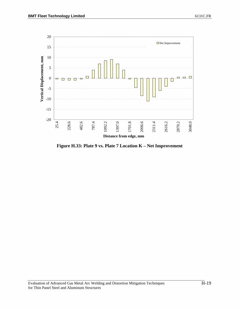
BMT Fleet Technology Limited 6131C.FR
Evaluation of Advanced Gas Metal Arc Welding and Distortion Mitigation Techniques for Thin Panel Steel and Aluminum Structures
H-19
-20
-15
-10
-5
0
5
10
15
20
25.4
228.
6
482.
6
787.
4
1092
.2
1397
.0
1701
.8
2006
.6
2311
.4
2616
.2
2870
.2
3048
.0
Distance from edge, mm
Ver
tical
Dis
plac
emen
t, m
mNet Improvement
Figure H.33: Plate 9 vs. Plate 7 Location K – Net Improvement
BMT Fleet Technology Limited 6131C.FR
Evaluation of Advanced Gas Metal Arc Welding and Distortion Mitigation Techniques for Thin Panel Steel and Aluminum Structures
I-1
APPENDIX I
CHANGE IN DISPLACEMENTS AFTER WELDING (4’ x 10’ HSLA 80 BASE PLATES)

BMT Fleet Technology Limited 6131C.FR
Evaluation of Advanced Gas Metal Arc Welding and Distortion Mitigation Techniques for Thin Panel Steel and Aluminum Structures
I-2
-20
-15
-10
-5
0
5
10
15
20
25.4
228.
6
482.
6
787.
4
1092
.2
1397
.0
1701
.8
2006
.6
2311
.4
2616
.2
2870
.2
3048
.0
Distance from edge, mm
Ver
tical
Dis
plac
emen
t, m
m
Displacement Change After Welding - Location A
Figure I.1: Plate 3 Location A – Change in Displacement After Welding
-20
-15
-10
-5
0
5
10
15
20
25.4
228.
6
482.
6
787.
4
1092
.2
1397
.0
1701
.8
2006
.6
2311
.4
2616
.2
2870
.2
3048
.0
Distance from edge, mm
Ver
tical
Dis
plac
emen
t, m
m
Displacement Change After Welding - Location B
Figure I.2: Plate 3 Location B – Change in Displacement After Welding
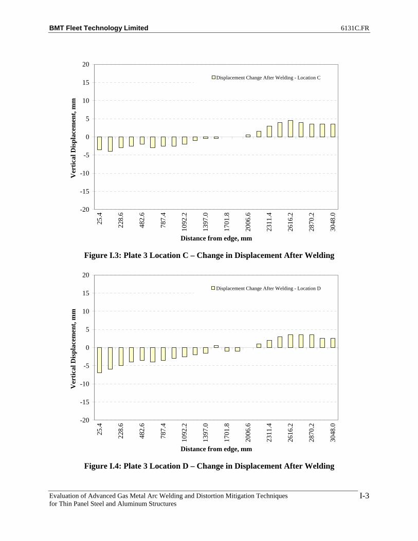
BMT Fleet Technology Limited 6131C.FR
Evaluation of Advanced Gas Metal Arc Welding and Distortion Mitigation Techniques for Thin Panel Steel and Aluminum Structures
I-3
-20
-15
-10
-5
0
5
10
15
20
25.4
228.
6
482.
6
787.
4
1092
.2
1397
.0
1701
.8
2006
.6
2311
.4
2616
.2
2870
.2
3048
.0
Distance from edge, mm
Ver
tical
Dis
plac
emen
t, m
mDisplacement Change After Welding - Location C
Figure I.3: Plate 3 Location C – Change in Displacement After Welding
-20
-15
-10
-5
0
5
10
15
20
25.4
228.
6
482.
6
787.
4
1092
.2
1397
.0
1701
.8
2006
.6
2311
.4
2616
.2
2870
.2
3048
.0
Distance from edge, mm
Ver
tical
Dis
plac
emen
t, m
m
Displacement Change After Welding - Location D
Figure I.4: Plate 3 Location D – Change in Displacement After Welding
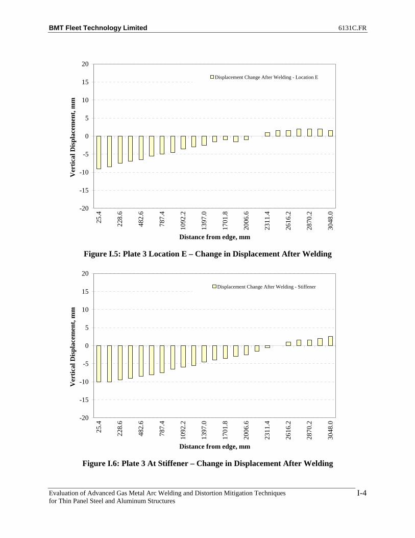
BMT Fleet Technology Limited 6131C.FR
Evaluation of Advanced Gas Metal Arc Welding and Distortion Mitigation Techniques for Thin Panel Steel and Aluminum Structures
I-4
-20
-15
-10
-5
0
5
10
15
20
25.4
228.
6
482.
6
787.
4
1092
.2
1397
.0
1701
.8
2006
.6
2311
.4
2616
.2
2870
.2
3048
.0
Distance from edge, mm
Ver
tical
Dis
plac
emen
t, m
mDisplacement Change After Welding - Location E
Figure I.5: Plate 3 Location E – Change in Displacement After Welding
-20
-15
-10
-5
0
5
10
15
20
25.4
228.
6
482.
6
787.
4
1092
.2
1397
.0
1701
.8
2006
.6
2311
.4
2616
.2
2870
.2
3048
.0
Distance from edge, mm
Ver
tical
Dis
plac
emen
t, m
m
Displacement Change After Welding - Stiffener
Figure I.6: Plate 3 At Stiffener – Change in Displacement After Welding

BMT Fleet Technology Limited 6131C.FR
Evaluation of Advanced Gas Metal Arc Welding and Distortion Mitigation Techniques for Thin Panel Steel and Aluminum Structures
I-5
-20
-15
-10
-5
0
5
10
15
20
25.4
228.
6
482.
6
787.
4
1092
.2
1397
.0
1701
.8
2006
.6
2311
.4
2616
.2
2870
.2
3048
.0
Distance from edge, mm
Ver
tical
Dis
plac
emen
t, m
mDisplacement Change After Welding - Location G
Figure I.7: Plate 3 Location G – Change in Displacement After Welding
-20
-15
-10
-5
0
5
10
15
20
25.4
228.
6
482.
6
787.
4
1092
.2
1397
.0
1701
.8
2006
.6
2311
.4
2616
.2
2870
.2
3048
.0
Distance from edge, mm
Ver
tical
Dis
plac
emen
t, m
m
Displacement Change After Welding - Location H
Figure I.8: Plate 3 Location H – Change in Displacement After Welding

BMT Fleet Technology Limited 6131C.FR
Evaluation of Advanced Gas Metal Arc Welding and Distortion Mitigation Techniques for Thin Panel Steel and Aluminum Structures
I-6
-20
-15
-10
-5
0
5
10
15
20
25.4
228.
6
482.
6
787.
4
1092
.2
1397
.0
1701
.8
2006
.6
2311
.4
2616
.2
2870
.2
3048
.0
Distance from edge, mm
Ver
tical
Dis
plac
emen
t, m
mDisplacement Change After Welding - Location I
Figure I.9: Plate 3 Location I – Change in Displacement After Welding
-20
-15
-10
-5
0
5
10
15
20
25.4
228.
6
482.
6
787.
4
1092
.2
1397
.0
1701
.8
2006
.6
2311
.4
2616
.2
2870
.2
3048
.0
Distance from edge, mm
Ver
tical
Dis
plac
emen
t, m
m
Displacement Change After Welding - Location J
Figure I.10: Plate 3 Location J – Change in Displacement After Welding
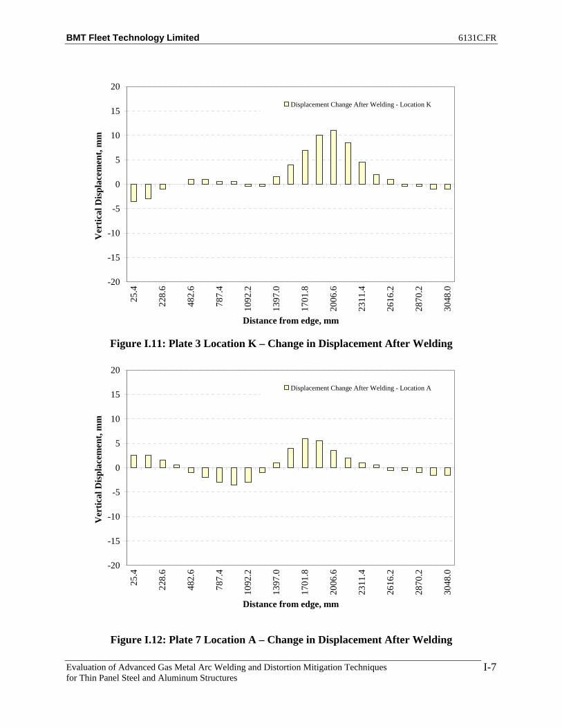
BMT Fleet Technology Limited 6131C.FR
Evaluation of Advanced Gas Metal Arc Welding and Distortion Mitigation Techniques for Thin Panel Steel and Aluminum Structures
I-7
-20
-15
-10
-5
0
5
10
15
20
25.4
228.
6
482.
6
787.
4
1092
.2
1397
.0
1701
.8
2006
.6
2311
.4
2616
.2
2870
.2
3048
.0
Distance from edge, mm
Ver
tical
Dis
plac
emen
t, m
mDisplacement Change After Welding - Location K
Figure I.11: Plate 3 Location K – Change in Displacement After Welding
-20
-15
-10
-5
0
5
10
15
20
25.4
228.
6
482.
6
787.
4
1092
.2
1397
.0
1701
.8
2006
.6
2311
.4
2616
.2
2870
.2
3048
.0
Distance from edge, mm
Ver
tical
Dis
plac
emen
t, m
m
Displacement Change After Welding - Location A
Figure I.12: Plate 7 Location A – Change in Displacement After Welding
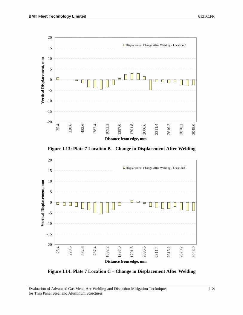
BMT Fleet Technology Limited 6131C.FR
Evaluation of Advanced Gas Metal Arc Welding and Distortion Mitigation Techniques for Thin Panel Steel and Aluminum Structures
I-8
-20
-15
-10
-5
0
5
10
15
20
25.4
228.
6
482.
6
787.
4
1092
.2
1397
.0
1701
.8
2006
.6
2311
.4
2616
.2
2870
.2
3048
.0
Distance from edge, mm
Ver
tical
Dis
plac
emen
t, m
mDisplacement Change After Welding - Location B
Figure I.13: Plate 7 Location B – Change in Displacement After Welding
-20
-15
-10
-5
0
5
10
15
20
25.4
228.
6
482.
6
787.
4
1092
.2
1397
.0
1701
.8
2006
.6
2311
.4
2616
.2
2870
.2
3048
.0
Distance from edge, mm
Ver
tical
Dis
plac
emen
t, m
m
Displacement Change After Welding - Location C
Figure I.14: Plate 7 Location C – Change in Displacement After Welding
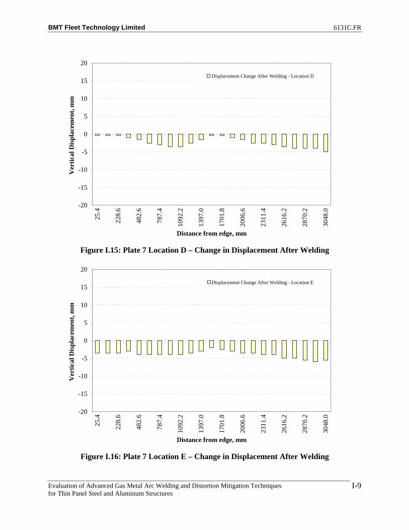
BMT Fleet Technology Limited 6131C.FR
Evaluation of Advanced Gas Metal Arc Welding and Distortion Mitigation Techniques for Thin Panel Steel and Aluminum Structures
I-9
-20
-15
-10
-5
0
5
10
15
20
25.4
228.
6
482.
6
787.
4
1092
.2
1397
.0
1701
.8
2006
.6
2311
.4
2616
.2
2870
.2
3048
.0
Distance from edge, mm
Ver
tical
Dis
plac
emen
t, m
mDisplacement Change After Welding - Location D
Figure I.15: Plate 7 Location D – Change in Displacement After Welding
-20
-15
-10
-5
0
5
10
15
20
25.4
228.
6
482.
6
787.
4
1092
.2
1397
.0
1701
.8
2006
.6
2311
.4
2616
.2
2870
.2
3048
.0
Distance from edge, mm
Ver
tical
Dis
plac
emen
t, m
m
Displacement Change After Welding - Location E
Figure I.16: Plate 7 Location E – Change in Displacement After Welding

BMT Fleet Technology Limited 6131C.FR
Evaluation of Advanced Gas Metal Arc Welding and Distortion Mitigation Techniques for Thin Panel Steel and Aluminum Structures
I-10
-20
-15
-10
-5
0
5
10
15
20
25.4
228.
6
482.
6
787.
4
1092
.2
1397
.0
1701
.8
2006
.6
2311
.4
2616
.2
2870
.2
3048
.0
Distance from edge, mm
Ver
tical
Dis
plac
emen
t, m
mDisplacement Change After Welding - Stiffener
Figure I.17: Plate 7 At Stiffener – Change in Displacement After Welding
-20
-15
-10
-5
0
5
10
15
20
25.4
228.
6
482.
6
787.
4
1092
.2
1397
.0
1701
.8
2006
.6
2311
.4
2616
.2
2870
.2
3048
.0
Distance from edge, mm
Ver
tical
Dis
plac
emen
t, m
m
Displacement Change After Welding - Location G
Figure I.18: Plate 7 Location G – Change in Displacement After Welding

BMT Fleet Technology Limited 6131C.FR
Evaluation of Advanced Gas Metal Arc Welding and Distortion Mitigation Techniques for Thin Panel Steel and Aluminum Structures
I-11
-20
-15
-10
-5
0
5
10
15
20
25.4
228.
6
482.
6
787.
4
1092
.2
1397
.0
1701
.8
2006
.6
2311
.4
2616
.2
2870
.2
3048
.0
Distance from edge, mm
Ver
tical
Dis
plac
emen
t, m
mDisplacement Change After Welding - Location H
Figure I.19: Plate 7 Location H – Change in Displacement After Welding
-20
-15
-10
-5
0
5
10
15
20
25.4
228.
6
482.
6
787.
4
1092
.2
1397
.0
1701
.8
2006
.6
2311
.4
2616
.2
2870
.2
3048
.0
Distance from edge, mm
Ver
tical
Dis
plac
emen
t, m
m
Displacement Change After Welding - Location I
Figure I.20: Plate 7 Location I – Change in Displacement After Welding

BMT Fleet Technology Limited 6131C.FR
Evaluation of Advanced Gas Metal Arc Welding and Distortion Mitigation Techniques for Thin Panel Steel and Aluminum Structures
I-12
-20
-15
-10
-5
0
5
10
15
20
25.4
228.
6
482.
6
787.
4
1092
.2
1397
.0
1701
.8
2006
.6
2311
.4
2616
.2
2870
.2
3048
.0
Distance from edge, mm
Ver
tical
Dis
plac
emen
t, m
mDisplacement Change After Welding - Location J
Figure I.21: Plate 7 Location J – Change in Displacement After Welding
-20
-15
-10
-5
0
5
10
15
20
25.4
228.
6
482.
6
787.
4
1092
.2
1397
.0
1701
.8
2006
.6
2311
.4
2616
.2
2870
.2
3048
.0
Distance from edge, mm
Ver
tical
Dis
plac
emen
t, m
m
Displacement Change After Welding - Location K
Figure I.22: Plate 7 Location K – Change in Displacement After Welding

BMT Fleet Technology Limited 6131C.FR
Evaluation of Advanced Gas Metal Arc Welding and Distortion Mitigation Techniques for Thin Panel Steel and Aluminum Structures
I-13
-20
-15
-10
-5
0
5
10
15
20
25.4
228.
6
482.
6
787.
4
1092
.2
1397
.0
1701
.8
2006
.6
2311
.4
2616
.2
2870
.2
3048
.0
Distance from edge, mm
Ver
tical
Dis
plac
emen
t, m
m
Displacement Change After Welding - Location A
Figure I.23: Plate 8 Location A – Change in Displacement After Welding
-20
-15
-10
-5
0
5
10
15
20
25.4
228.
6
482.
6
787.
4
1092
.2
1397
.0
1701
.8
2006
.6
2311
.4
2616
.2
2870
.2
3048
.0
Distance from edge, mm
Ver
tical
Dis
plac
emen
t, m
m
Displacement Change After Welding - Location B
Figure I.24: Plate 8 Location B – Change in Displacement After Welding

BMT Fleet Technology Limited 6131C.FR
Evaluation of Advanced Gas Metal Arc Welding and Distortion Mitigation Techniques for Thin Panel Steel and Aluminum Structures
I-14
-20
-15
-10
-5
0
5
10
15
20
25.4
228.
6
482.
6
787.
4
1092
.2
1397
.0
1701
.8
2006
.6
2311
.4
2616
.2
2870
.2
3048
.0
Distance from edge, mm
Ver
tical
Dis
plac
emen
t, m
mDisplacement Change After Welding - Location C
Figure I.25: Plate 8 Location C – Change in Displacement After Welding
-20
-15
-10
-5
0
5
10
15
20
25.4
228.
6
482.
6
787.
4
1092
.2
1397
.0
1701
.8
2006
.6
2311
.4
2616
.2
2870
.2
3048
.0
Distance from edge, mm
Ver
tical
Dis
plac
emen
t, m
m
Displacement Change After Welding - Location D
Figure I.26: Plate 8 Location D – Change in Displacement After Welding

BMT Fleet Technology Limited 6131C.FR
Evaluation of Advanced Gas Metal Arc Welding and Distortion Mitigation Techniques for Thin Panel Steel and Aluminum Structures
I-15
-20
-15
-10
-5
0
5
10
15
20
25.4
228.
6
482.
6
787.
4
1092
.2
1397
.0
1701
.8
2006
.6
2311
.4
2616
.2
2870
.2
3048
.0
Distance from edge, mm
Ver
tical
Dis
plac
emen
t, m
mDisplacement Change After Welding - Location E
Figure I.27: Plate 8 Location E – Change in Displacement After Welding
-20
-15
-10
-5
0
5
10
15
20
25.4
228.
6
482.
6
787.
4
1092
.2
1397
.0
1701
.8
2006
.6
2311
.4
2616
.2
2870
.2
3048
.0
Distance from edge, mm
Ver
tical
Dis
plac
emen
t, m
m
Displacement Change After Welding - Stiffener
Figure I.28: Plate 8 At Stiffener – Change in Displacement After Welding

BMT Fleet Technology Limited 6131C.FR
Evaluation of Advanced Gas Metal Arc Welding and Distortion Mitigation Techniques for Thin Panel Steel and Aluminum Structures
I-16
-20
-15
-10
-5
0
5
10
15
20
25.4
228.
6
482.
6
787.
4
1092
.2
1397
.0
1701
.8
2006
.6
2311
.4
2616
.2
2870
.2
3048
.0
Distance from edge, mm
Ver
tical
Dis
plac
emen
t, m
mDisplacement Change After Welding - Location G
Figure I.29: Plate 8 Location G – Change in Displacement After Welding
-20
-15
-10
-5
0
5
10
15
20
25.4
228.
6
482.
6
787.
4
1092
.2
1397
.0
1701
.8
2006
.6
2311
.4
2616
.2
2870
.2
3048
.0
Distance from edge, mm
Ver
tical
Dis
plac
emen
t, m
m
Displacement Change After Welding - Location H
Figure I.30: Plate 8 Location H – Change in Displacement After Welding

BMT Fleet Technology Limited 6131C.FR
Evaluation of Advanced Gas Metal Arc Welding and Distortion Mitigation Techniques for Thin Panel Steel and Aluminum Structures
I-17
-20
-15
-10
-5
0
5
10
15
20
25.4
228.
6
482.
6
787.
4
1092
.2
1397
.0
1701
.8
2006
.6
2311
.4
2616
.2
2870
.2
3048
.0
Distance from edge, mm
Ver
tical
Dis
plac
emen
t, m
mDisplacement Change After Welding - Location I
Figure I.31: Plate 8 Location I – Change in Displacement After Welding
-20
-15
-10
-5
0
5
10
15
20
25.4
228.
6
482.
6
787.
4
1092
.2
1397
.0
1701
.8
2006
.6
2311
.4
2616
.2
2870
.2
3048
.0
Distance from edge, mm
Ver
tical
Dis
plac
emen
t, m
m
Displacement Change After Welding - Location J
Figure I.32: Plate 8 Location J – Change in Displacement After Welding

BMT Fleet Technology Limited 6131C.FR
Evaluation of Advanced Gas Metal Arc Welding and Distortion Mitigation Techniques for Thin Panel Steel and Aluminum Structures
I-18
-20
-15
-10
-5
0
5
10
15
20
25.4
228.
6
482.
6
787.
4
1092
.2
1397
.0
1701
.8
2006
.6
2311
.4
2616
.2
2870
.2
3048
.0
Distance from edge, mm
Ver
tical
Dis
plac
emen
t, m
mDisplacement Change After Welding - Location K
Figure I.33: Plate 8 Location K – Change in Displacement After Welding
-20
-15
-10
-5
0
5
10
15
20
25.4
228.
6
482.
6
787.
4
1092
.2
1397
.0
1701
.8
2006
.6
2311
.4
2616
.2
2870
.2
3048
.0
Distance from edge, mm
Ver
tical
Dis
plac
emen
t, m
m
Displacement Change After Welding - Location A
Figure I.34: Plate 9 Location A – Change in Displacement After Welding
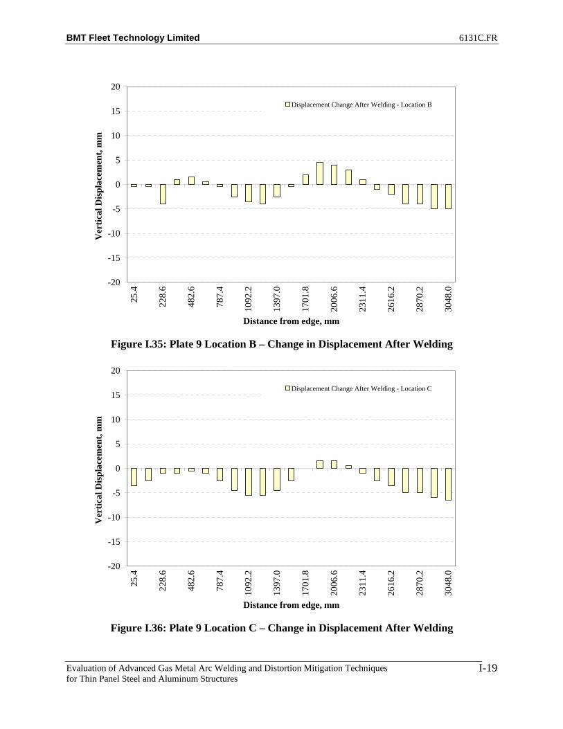
BMT Fleet Technology Limited 6131C.FR
Evaluation of Advanced Gas Metal Arc Welding and Distortion Mitigation Techniques for Thin Panel Steel and Aluminum Structures
I-19
-20
-15
-10
-5
0
5
10
15
20
25.4
228.
6
482.
6
787.
4
1092
.2
1397
.0
1701
.8
2006
.6
2311
.4
2616
.2
2870
.2
3048
.0
Distance from edge, mm
Ver
tical
Dis
plac
emen
t, m
mDisplacement Change After Welding - Location B
Figure I.35: Plate 9 Location B – Change in Displacement After Welding
-20
-15
-10
-5
0
5
10
15
20
25.4
228.
6
482.
6
787.
4
1092
.2
1397
.0
1701
.8
2006
.6
2311
.4
2616
.2
2870
.2
3048
.0
Distance from edge, mm
Ver
tical
Dis
plac
emen
t, m
m
Displacement Change After Welding - Location C
Figure I.36: Plate 9 Location C – Change in Displacement After Welding

BMT Fleet Technology Limited 6131C.FR
Evaluation of Advanced Gas Metal Arc Welding and Distortion Mitigation Techniques for Thin Panel Steel and Aluminum Structures
I-20
-20
-15
-10
-5
0
5
10
15
20
25.4
228.
6
482.
6
787.
4
1092
.2
1397
.0
1701
.8
2006
.6
2311
.4
2616
.2
2870
.2
3048
.0
Distance from edge, mm
Ver
tical
Dis
plac
emen
t, m
mDisplacement Change After Welding - Location D
Figure I.37: Plate 9 Location D – Change in Displacement After Welding
-20
-15
-10
-5
0
5
10
15
20
25.4
228.
6
482.
6
787.
4
1092
.2
1397
.0
1701
.8
2006
.6
2311
.4
2616
.2
2870
.2
3048
.0
Distance from edge, mm
Ver
tical
Dis
plac
emen
t, m
m
Displacement Change After Welding - Location E
Figure I.38: Plate 9 Location E – Change in Displacement After Welding
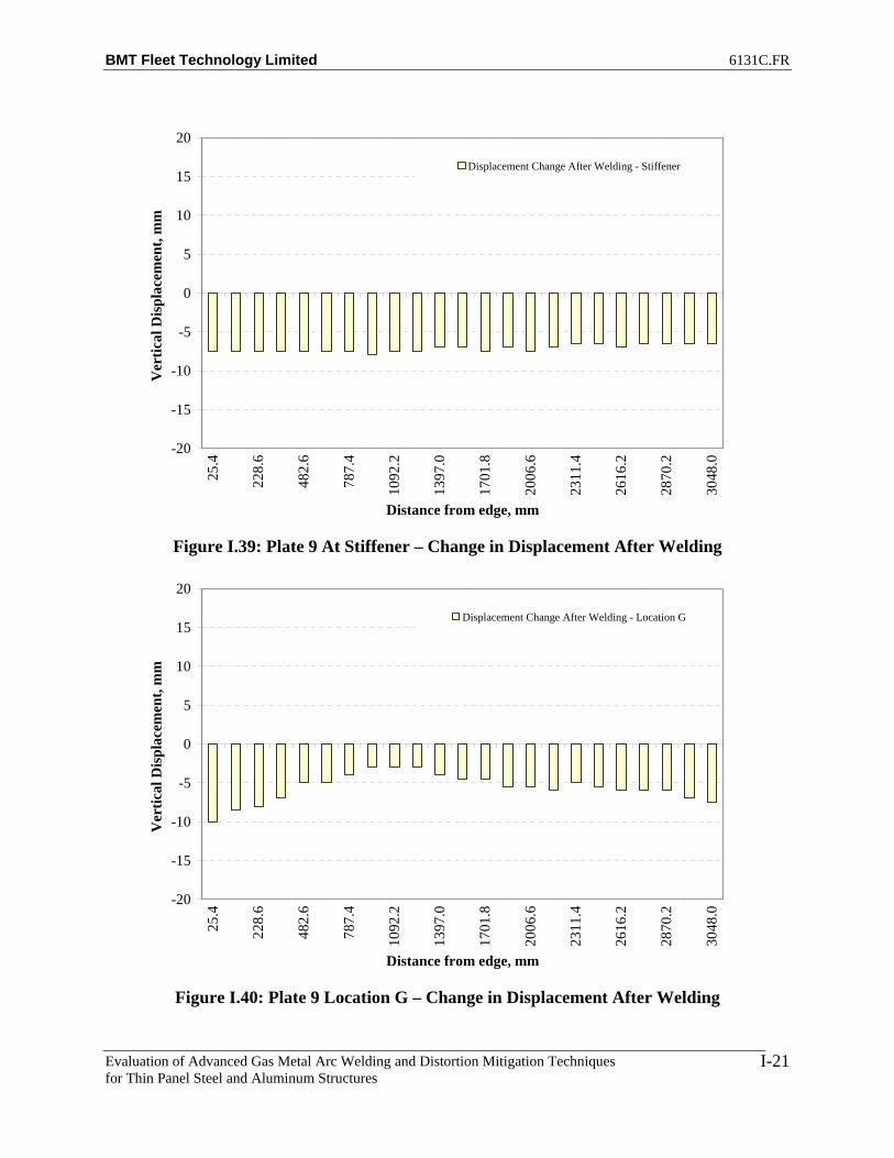
BMT Fleet Technology Limited 6131C.FR
Evaluation of Advanced Gas Metal Arc Welding and Distortion Mitigation Techniques for Thin Panel Steel and Aluminum Structures
I-21
-20
-15
-10
-5
0
5
10
15
20
25.4
228.
6
482.
6
787.
4
1092
.2
1397
.0
1701
.8
2006
.6
2311
.4
2616
.2
2870
.2
3048
.0
Distance from edge, mm
Ver
tical
Dis
plac
emen
t, m
mDisplacement Change After Welding - Stiffener
Figure I.39: Plate 9 At Stiffener – Change in Displacement After Welding
-20
-15
-10
-5
0
5
10
15
20
25.4
228.
6
482.
6
787.
4
1092
.2
1397
.0
1701
.8
2006
.6
2311
.4
2616
.2
2870
.2
3048
.0
Distance from edge, mm
Ver
tical
Dis
plac
emen
t, m
m
Displacement Change After Welding - Location G
Figure I.40: Plate 9 Location G – Change in Displacement After Welding

BMT Fleet Technology Limited 6131C.FR
Evaluation of Advanced Gas Metal Arc Welding and Distortion Mitigation Techniques for Thin Panel Steel and Aluminum Structures
I-22
-20
-15
-10
-5
0
5
10
15
20
25.4
228.
6
482.
6
787.
4
1092
.2
1397
.0
1701
.8
2006
.6
2311
.4
2616
.2
2870
.2
3048
.0
Distance from edge, mm
Ver
tical
Dis
plac
emen
t, m
mDisplacement Change After Welding - Location H
Figure I.41: Plate 9 Location H – Change in Displacement After Welding
-20
-15
-10
-5
0
5
10
15
20
25.4
228.
6
482.
6
787.
4
1092
.2
1397
.0
1701
.8
2006
.6
2311
.4
2616
.2
2870
.2
3048
.0
Distance from edge, mm
Ver
tical
Dis
plac
emen
t, m
m
Displacement Change After Welding - Location I
Figure I.42: Plate 9 Location I – Change in Displacement After Welding

BMT Fleet Technology Limited 6131C.FR
Evaluation of Advanced Gas Metal Arc Welding and Distortion Mitigation Techniques for Thin Panel Steel and Aluminum Structures
I-23
-20
-15
-10
-5
0
5
10
15
20
25.4
228.
6
482.
6
787.
4
1092
.2
1397
.0
1701
.8
2006
.6
2311
.4
2616
.2
2870
.2
3048
.0
Distance from edge, mm
Ver
tical
Dis
plac
emen
t, m
mDisplacement Change After Welding - Location J
Figure I.43: Plate 9 Location J – Change in Displacement After Welding
-20
-15
-10
-5
0
5
10
15
20
25.4
228.
6
482.
6
787.
4
1092
.2
1397
.0
1701
.8
2006
.6
2311
.4
2616
.2
2870
.2
3048
.0
Distance from edge, mm
Ver
tical
Dis
plac
emen
t, m
m
Displacement Change After Welding - Location K
Figure I.44: Plate 9 Location K – Change in Displacement After Welding

BMT Fleet Technology Limited 6131C.FR
Evaluation of Advanced Gas Metal Arc Welding and Distortion Mitigation Techniques for Thin Panel Steel and Aluminum Structures
J-1
APPENDIX J
NET DISPLACEMENTS FOR FCAW and T-MCAW (4’ x 10’ HSLA 80 BASE PLATES)
WITH CALCULATED AVERAGE DISPLACEMENT

BMT Fleet Technology Limited 6131C.FR
Evaluation of Advanced Gas Metal Arc Welding and Distortion Mitigation Techniques for Thin Panel Steel and Aluminum Structures
J-2
-35
-25
-15
-5
5
15
25
35
0 500 1000 1500 2000 2500 3000 3500
Distance from Edge, mm
Ver
tical
Dis
plac
emen
t, m
m
Before WeldNo Weld With TensionAfter WeldBefore Weld - AverageNo Weld With Tension - AverageAfter Weld - Average
Figure J.1: Plate 3 Location A – Relative Displacement
-35
-25
-15
-5
5
15
25
35
0 500 1000 1500 2000 2500 3000 3500
Distance from Edge, mm
Ver
tical
Dis
plac
emen
t, m
m
Before WeldNo Weld With TensionAfter WeldBefore Weld - AverageNo Weld With Tension - AverageAfter Weld - Average
Figure J.2: Plate 3 Location B – Relative Displacement

BMT Fleet Technology Limited 6131C.FR
Evaluation of Advanced Gas Metal Arc Welding and Distortion Mitigation Techniques for Thin Panel Steel and Aluminum Structures
J-3
-35
-25
-15
-5
5
15
25
35
0 500 1000 1500 2000 2500 3000 3500
Distance from Edge, mm
Ver
tical
Dis
plac
emen
t, m
m
Before WeldNo Weld With TensionAfter WeldBefore Weld - AverageNo Weld With Tension - AverageAfter Weld - Average
Figure J.3: Plate 3 Location C – Relative Displacement
-35
-25
-15
-5
5
15
25
35
0 500 1000 1500 2000 2500 3000 3500
Distance from Edge, mm
Ver
tical
Dis
plac
emen
t, m
m
Before WeldNo Weld With TensionAfter WeldBefore Weld - AverageNo Weld With Tension - AverageAfter Weld - Average
Figure J.4: Plate 3 Location D – Relative Displacement

BMT Fleet Technology Limited 6131C.FR
Evaluation of Advanced Gas Metal Arc Welding and Distortion Mitigation Techniques for Thin Panel Steel and Aluminum Structures
J-4
-35
-25
-15
-5
5
15
25
35
0 500 1000 1500 2000 2500 3000 3500
Distance from Edge, mm
Ver
tical
Dis
plac
emen
t, m
m
Before WeldNo Weld With TensionAfter WeldBefore Weld - AverageNo Weld With Tension - AverageAfter Weld - Average
Figure J.5: Plate 3 Location E – Relative Displacement
145
147
149
151
153
155
157
159
161
163
165
0 500 1000 1500 2000 2500 3000 3500
Distance from Edge, mm
Ver
tical
Dis
plac
emen
t, m
m
Before WeldNo Weld With TensionAfter WeldBefore Weld - AverageNo Weld With Tension - AverageAfter Weld - Average
Figure J.6: Plate 3 At Stiffener – Relative Displacement

BMT Fleet Technology Limited 6131C.FR
Evaluation of Advanced Gas Metal Arc Welding and Distortion Mitigation Techniques for Thin Panel Steel and Aluminum Structures
J-5
-35
-25
-15
-5
5
15
25
35
0 500 1000 1500 2000 2500 3000 3500
Distance from Edge, mm
Ver
tical
Dis
plac
emen
t, m
m
Before WeldNo Weld With TensionAfter WeldBefore Weld - AverageNo Weld With Tension - AverageAfter Weld - Average
Figure J.7: Plate 3 Location G – Relative Displacement
-35
-25
-15
-5
5
15
25
35
0 500 1000 1500 2000 2500 3000 3500
Distance from Edge, mm
Ver
tical
Dis
plac
emen
t, m
m
Before WeldNo Weld With TensionAfter WeldBefore Weld - AverageNo Weld With Tension - AverageAfter Weld - Average
Figure J.8: Plate 3 Location H – Relative Displacement
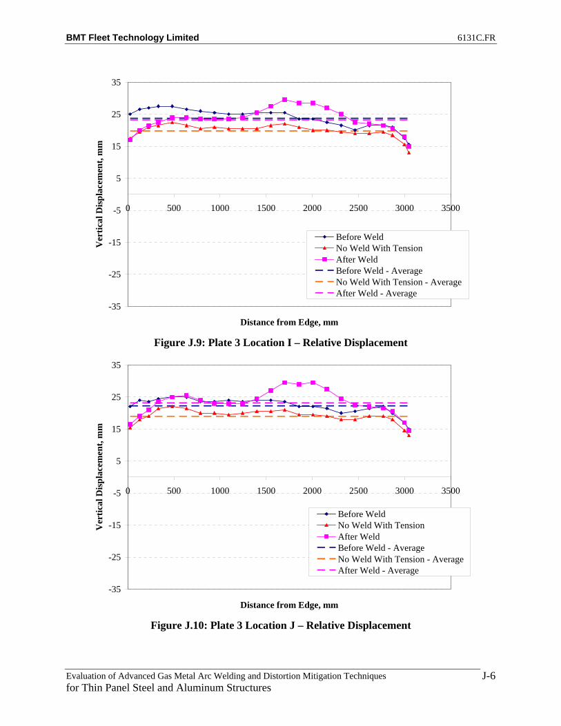
BMT Fleet Technology Limited 6131C.FR
Evaluation of Advanced Gas Metal Arc Welding and Distortion Mitigation Techniques for Thin Panel Steel and Aluminum Structures
J-6
-35
-25
-15
-5
5
15
25
35
0 500 1000 1500 2000 2500 3000 3500
Distance from Edge, mm
Ver
tical
Dis
plac
emen
t, m
m
Before WeldNo Weld With TensionAfter WeldBefore Weld - AverageNo Weld With Tension - AverageAfter Weld - Average
Figure J.9: Plate 3 Location I – Relative Displacement
-35
-25
-15
-5
5
15
25
35
0 500 1000 1500 2000 2500 3000 3500
Distance from Edge, mm
Ver
tical
Dis
plac
emen
t, m
m
Before WeldNo Weld With TensionAfter WeldBefore Weld - AverageNo Weld With Tension - AverageAfter Weld - Average
Figure J.10: Plate 3 Location J – Relative Displacement

BMT Fleet Technology Limited 6131C.FR
Evaluation of Advanced Gas Metal Arc Welding and Distortion Mitigation Techniques for Thin Panel Steel and Aluminum Structures
J-7
-35
-25
-15
-5
5
15
25
35
0 500 1000 1500 2000 2500 3000 3500
Distance from Edge, mm
Ver
tical
Dis
plac
emen
t, m
m
Before WeldNo Weld With TensionAfter WeldBefore Weld - AverageNo Weld With Tension - AverageAfter Weld - Average
Figure J.11: Plate 3 Location K – Relative Displacement
-35
-25
-15
-5
5
15
25
35
0 500 1000 1500 2000 2500 3000 3500
Distance from Edge, mm
Ver
tical
Dis
plac
emen
t, m
m
Before Weld
After Weld
Before Weld - Average
After Weld - Average
Figure J.12: Plate 7 Location A – Relative Displacement

BMT Fleet Technology Limited 6131C.FR
Evaluation of Advanced Gas Metal Arc Welding and Distortion Mitigation Techniques for Thin Panel Steel and Aluminum Structures
J-8
-35
-25
-15
-5
5
15
25
35
0 500 1000 1500 2000 2500 3000 3500
Distance from Edge, mm
Ver
tical
Dis
plac
emen
t, m
m
Before Weld
After Weld
Before Weld - Average
After Weld - Average
Figure J.13: Plate 7 Location B – Relative Displacement
-35
-25
-15
-5
5
15
25
35
0 500 1000 1500 2000 2500 3000 3500
Distance from Edge, mm
Ver
tical
Dis
plac
emen
t, m
m
Before Weld
After Weld
Before Weld - Average
After Weld - Average
Figure J.14: Plate 7 Location C – Relative Displacement

BMT Fleet Technology Limited 6131C.FR
Evaluation of Advanced Gas Metal Arc Welding and Distortion Mitigation Techniques for Thin Panel Steel and Aluminum Structures
J-9
-35
-25
-15
-5
5
15
25
35
0 500 1000 1500 2000 2500 3000 3500
Distance from Edge, mm
Ver
tical
Dis
plac
emen
t, m
m
Before Weld
After Weld
Before Weld - Average
After Weld - Average
Figure J.15: Plate 7 Location D – Relative Displacement
-35
-25
-15
-5
5
15
25
35
0 500 1000 1500 2000 2500 3000 3500
Distance from Edge, mm
Ver
tical
Dis
plac
emen
t, m
m
Before Weld
After Weld
Before Weld - Average
After Weld - Average
Figure J.16: Plate 7 Location E – Relative Displacement

BMT Fleet Technology Limited 6131C.FR
Evaluation of Advanced Gas Metal Arc Welding and Distortion Mitigation Techniques for Thin Panel Steel and Aluminum Structures
J-10
152
154
156
158
160
162
164
166
168
0 500 1000 1500 2000 2500 3000 3500
Distance from Edge, mm
Ver
tical
Dis
plac
emen
t, m
m
Before Weld
After Weld
Before Weld - Average
After Weld - Average
Figure J.17: Plate 7 At Stiffener – Relative Displacement
-35
-25
-15
-5
5
15
25
35
0 500 1000 1500 2000 2500 3000 3500
Distance from Edge, mm
Ver
tical
Dis
plac
emen
t, m
m
Before Weld
After Weld
Before Weld - Average
After Weld - Average
Figure J.18: Plate 7 Location G – Relative Displacement

BMT Fleet Technology Limited 6131C.FR
Evaluation of Advanced Gas Metal Arc Welding and Distortion Mitigation Techniques for Thin Panel Steel and Aluminum Structures
J-11
-35
-25
-15
-5
5
15
25
35
0 500 1000 1500 2000 2500 3000 3500
Distance from Edge, mm
Ver
tical
Dis
plac
emen
t, m
m
Before Weld
After Weld
Before Weld - Average
After Weld - Average
Figure J.19: Plate 7 Location H – Relative Displacement
-35
-25
-15
-5
5
15
25
35
0 500 1000 1500 2000 2500 3000 3500
Distance from Edge, mm
Ver
tical
Dis
plac
emen
t, m
m
Before Weld
After Weld
Before Weld - Average
After Weld - Average
Figure J.20: Plate 7 Location I – Relative Displacement

BMT Fleet Technology Limited 6131C.FR
Evaluation of Advanced Gas Metal Arc Welding and Distortion Mitigation Techniques for Thin Panel Steel and Aluminum Structures
J-12
-35
-25
-15
-5
5
15
25
35
0 500 1000 1500 2000 2500 3000 3500
Distance from Edge, mm
Ver
tical
Dis
plac
emen
t, m
m
Before Weld
After Weld
Before Weld - Average
After Weld - Average
Figure J.21: Plate 7 Location J – Relative Displacement
-35
-25
-15
-5
5
15
25
35
0 500 1000 1500 2000 2500 3000 3500
Distance from Edge, mm
Ver
tical
Dis
plac
emen
t, m
m
Before Weld
After Weld
Before Weld - Average
After Weld - Average
Figure J.22: Plate 7 Location K – Relative Displacement

BMT Fleet Technology Limited 6131C.FR
Evaluation of Advanced Gas Metal Arc Welding and Distortion Mitigation Techniques for Thin Panel Steel and Aluminum Structures
J-13
-35
-25
-15
-5
5
15
25
35
0 500 1000 1500 2000 2500 3000 3500
Distance from Edge, mm
Ver
tical
Dis
plac
emen
t, m
m
Before Weld
After Weld
Before Weld - Average
After Weld - Average
Figure J.23: Plate 8 Location A – Relative Displacement
-35
-25
-15
-5
5
15
25
35
0 500 1000 1500 2000 2500 3000 3500
Distance from Edge, mm
Ver
tical
Dis
plac
emen
t, m
m
Before Weld
After Weld
Before Weld - Average
After Weld - Average
Figure J.24: Plate 8 Location B – Relative Displacement

BMT Fleet Technology Limited 6131C.FR
Evaluation of Advanced Gas Metal Arc Welding and Distortion Mitigation Techniques for Thin Panel Steel and Aluminum Structures
J-14
-35
-25
-15
-5
5
15
25
35
0 500 1000 1500 2000 2500 3000 3500
Distance from Edge, mm
Ver
tical
Dis
plac
emen
t, m
m
Before Weld
After Weld
Before Weld - Average
After Weld - Average
Figure J.25: Plate 8 Location C – Relative Displacement
-35
-25
-15
-5
5
15
25
35
0 500 1000 1500 2000 2500 3000 3500
Distance from Edge, mm
Ver
tical
Dis
plac
emen
t, m
m
Before Weld
After Weld
Before Weld - Average
After Weld - Average
Figure J.26: Plate 8 Location D – Relative Displacement
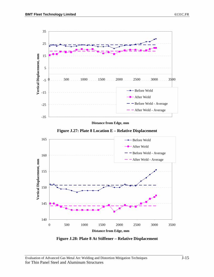
BMT Fleet Technology Limited 6131C.FR
Evaluation of Advanced Gas Metal Arc Welding and Distortion Mitigation Techniques for Thin Panel Steel and Aluminum Structures
J-15
-35
-25
-15
-5
5
15
25
35
0 500 1000 1500 2000 2500 3000 3500
Distance from Edge, mm
Ver
tical
Dis
plac
emen
t, m
m
Before Weld
After Weld
Before Weld - Average
After Weld - Average
Figure J.27: Plate 8 Location E – Relative Displacement
140
145
150
155
160
165
0 500 1000 1500 2000 2500 3000 3500
Distance from Edge, mm
Ver
tical
Dis
plac
emen
t, m
m
Before Weld
After Weld
Before Weld - Average
After Weld - Average
Figure J.28: Plate 8 At Stiffener – Relative Displacement

BMT Fleet Technology Limited 6131C.FR
Evaluation of Advanced Gas Metal Arc Welding and Distortion Mitigation Techniques for Thin Panel Steel and Aluminum Structures
J-16
-35
-25
-15
-5
5
15
25
35
0 500 1000 1500 2000 2500 3000 3500
Distance from Edge, mm
Ver
tical
Dis
plac
emen
t, m
m
Before Weld
After Weld
Before Weld - Average
After Weld - Average
Figure J.29: Plate 8 Location G – Relative Displacement
-35
-25
-15
-5
5
15
25
35
0 500 1000 1500 2000 2500 3000 3500
Distance from Edge, mm
Ver
tical
Dis
plac
emen
t, m
m
Before Weld
After Weld
Before Weld - Average
After Weld - Average
Figure J.30: Plate 8 Location H – Relative Displacement

BMT Fleet Technology Limited 6131C.FR
Evaluation of Advanced Gas Metal Arc Welding and Distortion Mitigation Techniques for Thin Panel Steel and Aluminum Structures
J-17
-35
-25
-15
-5
5
15
25
35
0 500 1000 1500 2000 2500 3000 3500
Distance from Edge, mm
Ver
tical
Dis
plac
emen
t, m
m
Before Weld
After Weld
Before Weld - Average
After Weld - Average
Figure J.31: Plate 8 Location I – Relative Displacement
-35
-25
-15
-5
5
15
25
35
0 500 1000 1500 2000 2500 3000 3500
Distance from Edge, mm
Ver
tical
Dis
plac
emen
t, m
m
Before Weld
After Weld
Before Weld - Average
After Weld - Average
Figure J.32: Plate 8 Location J – Relative Displacement

BMT Fleet Technology Limited 6131C.FR
Evaluation of Advanced Gas Metal Arc Welding and Distortion Mitigation Techniques for Thin Panel Steel and Aluminum Structures
J-18
-35
-25
-15
-5
5
15
25
35
0 500 1000 1500 2000 2500 3000 3500
Distance from Edge, mm
Ver
tical
Dis
plac
emen
t, m
m
Before Weld
After Weld
Before Weld - Average
After Weld - Average
Figure J.33: Plate 8 Location K – Relative Displacement
-35
-25
-15
-5
5
15
25
35
0 500 1000 1500 2000 2500 3000 3500
Distance from Edge, mm
Ver
tical
Dis
plac
emen
t, m
m
Before WeldNo Weld With TensionAfter WeldBefore Weld - AverageNo Weld With Tension - AverageAfter Weld - Average
Figure J.34: Plate 9 Location A – Relative Displacement

BMT Fleet Technology Limited 6131C.FR
Evaluation of Advanced Gas Metal Arc Welding and Distortion Mitigation Techniques for Thin Panel Steel and Aluminum Structures
J-19
-35
-25
-15
-5
5
15
25
35
0 500 1000 1500 2000 2500 3000 3500
Distance from Edge, mm
Ver
tical
Dis
plac
emen
t, m
m
Before WeldNo Weld With TensionAfter WeldBefore Weld - AverageNo Weld With Tension - AverageAfter Weld - Average
Figure J.35: Plate 9 Location B – Relative Displacement
-35
-25
-15
-5
5
15
25
35
0 500 1000 1500 2000 2500 3000 3500
Distance from Edge, mm
Ver
tical
Dis
plac
emen
t, m
m
Before WeldNo Weld With TensionAfter WeldBefore Weld - AverageNo Weld With Tension - AverageAfter Weld - Average
Figure J.36: Plate 9 Location C – Relative Displacement

BMT Fleet Technology Limited 6131C.FR
Evaluation of Advanced Gas Metal Arc Welding and Distortion Mitigation Techniques for Thin Panel Steel and Aluminum Structures
J-20
-35
-25
-15
-5
5
15
25
35
0 500 1000 1500 2000 2500 3000 3500
Distance from Edge, mm
Ver
tical
Dis
plac
emen
t, m
m
Before WeldNo Weld With TensionAfter WeldBefore Weld - AverageNo Weld With Tension - AverageAfter Weld - Average
Figure J.37: Plate 9 Location D – Relative Displacement
-35
-25
-15
-5
5
15
25
35
0 500 1000 1500 2000 2500 3000 3500
Distance from Edge, mm
Ver
tical
Dis
plac
emen
t, m
m
Before WeldNo Weld With TensionAfter WeldBefore Weld - AverageNo Weld With Tension - AverageAfter Weld - Average
Figure J.38: Plate 9 Location E – Relative Displacement

BMT Fleet Technology Limited 6131C.FR
Evaluation of Advanced Gas Metal Arc Welding and Distortion Mitigation Techniques for Thin Panel Steel and Aluminum Structures
J-21
140
145
150
155
160
165
0 500 1000 1500 2000 2500 3000 3500
Distance from Edge, mm
Ver
tical
Dis
plac
emen
t, m
mBefore WeldNo Weld With TensionAfter WeldBefore Weld - AverageNo Weld With Tension - AverageAfter Weld - Average
Figure J.39: Plate 9 At Stiffener – Relative Displacement
-35
-25
-15
-5
5
15
25
35
0 500 1000 1500 2000 2500 3000 3500
Distance from Edge, mm
Ver
tical
Dis
plac
emen
t, m
m
Before WeldNo Weld With TensionAfter WeldBefore Weld - AverageNo Weld With Tension - AverageAfter Weld - Average
Figure J.40: Plate 9 Location G – Relative Displacement

BMT Fleet Technology Limited 6131C.FR
Evaluation of Advanced Gas Metal Arc Welding and Distortion Mitigation Techniques for Thin Panel Steel and Aluminum Structures
J-22
-35
-25
-15
-5
5
15
25
35
0 500 1000 1500 2000 2500 3000 3500
Distance from Edge, mm
Ver
tical
Dis
plac
emen
t, m
m
Before WeldNo Weld With TensionAfter WeldBefore Weld - AverageNo Weld With Tension - AverageAfter Weld - Average
Figure J.41: Plate 9 Location H – Relative Displacement
-35
-25
-15
-5
5
15
25
35
0 500 1000 1500 2000 2500 3000 3500
Distance from Edge, mm
Ver
tical
Dis
plac
emen
t, m
m
Before WeldNo Weld With TensionAfter WeldBefore Weld - AverageNo Weld With Tension - AverageAfter Weld - Average
Figure J.42: Plate 9 Location I – Relative Displacement
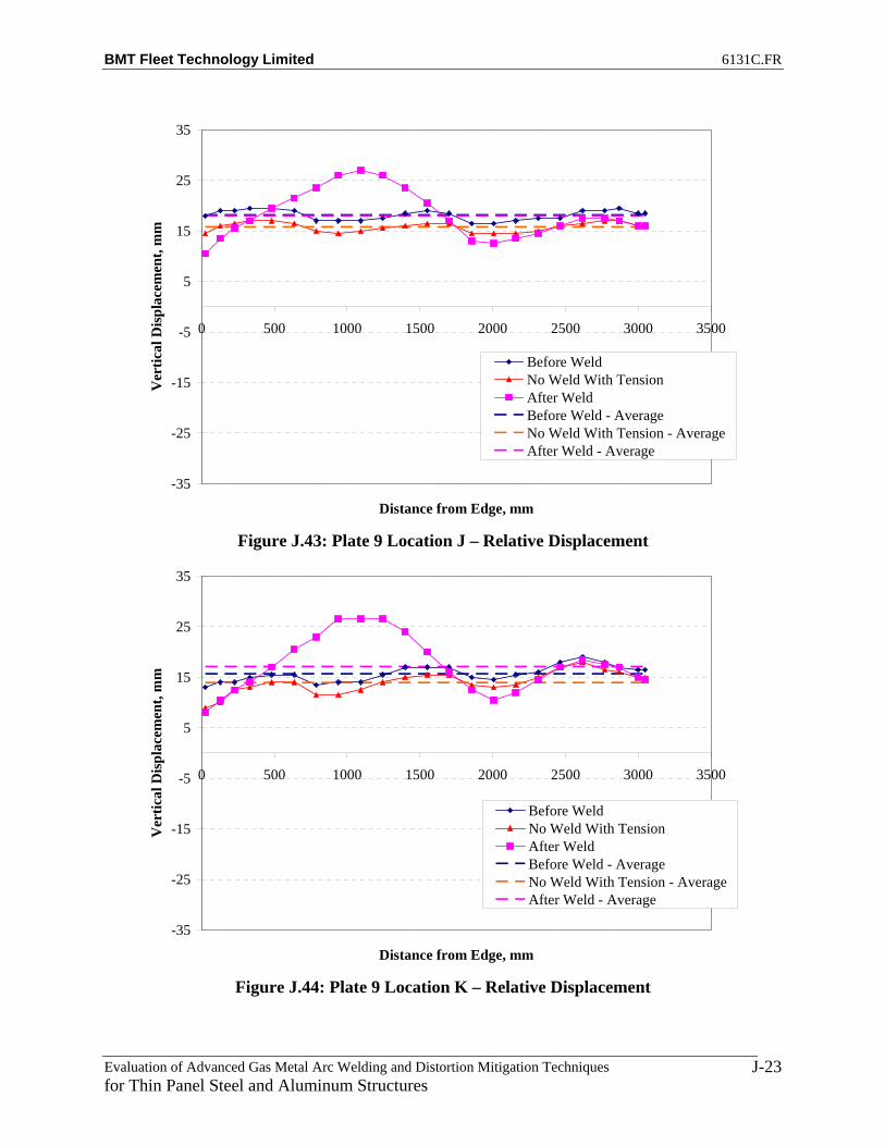
BMT Fleet Technology Limited 6131C.FR
Evaluation of Advanced Gas Metal Arc Welding and Distortion Mitigation Techniques for Thin Panel Steel and Aluminum Structures
J-23
-35
-25
-15
-5
5
15
25
35
0 500 1000 1500 2000 2500 3000 3500
Distance from Edge, mm
Ver
tical
Dis
plac
emen
t, m
m
Before WeldNo Weld With TensionAfter WeldBefore Weld - AverageNo Weld With Tension - AverageAfter Weld - Average
Figure J.43: Plate 9 Location J – Relative Displacement
-35
-25
-15
-5
5
15
25
35
0 500 1000 1500 2000 2500 3000 3500
Distance from Edge, mm
Ver
tical
Dis
plac
emen
t, m
m
Before WeldNo Weld With TensionAfter WeldBefore Weld - AverageNo Weld With Tension - AverageAfter Weld - Average
Figure J.44: Plate 9 Location K – Relative Displacement

BMT Fleet Technology Limited 6131C.FR
Evaluation of Advanced Gas Metal Arc Welding and Distortion Mitigation Techniques for Thin Panel Steel and Aluminum Structures
K-1
APPENDIX K
DEVIATION FROM AVERAGE RELATIVE DISPLACEMENT FOR FCAW and T-MCAW (4’ x 10’ HSLA 80 BASE PLATES)
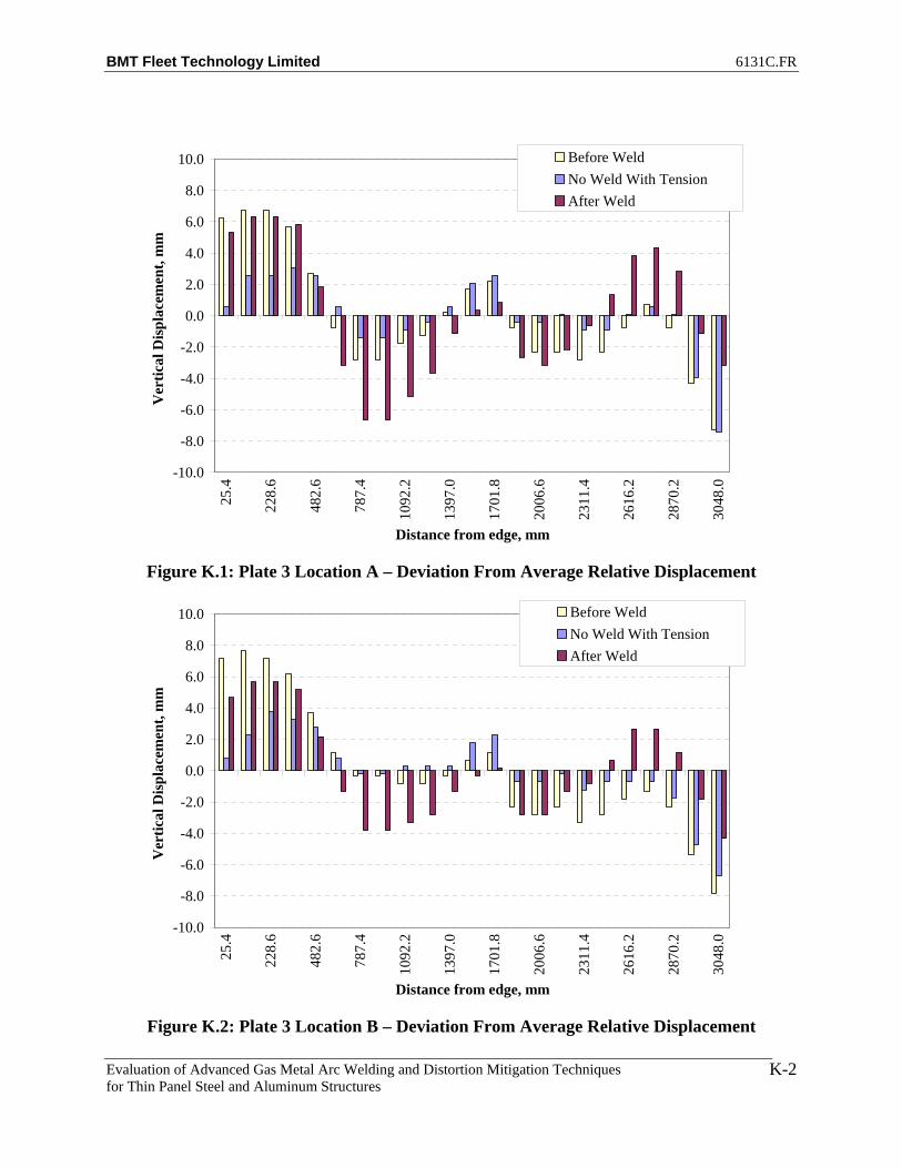
BMT Fleet Technology Limited 6131C.FR
Evaluation of Advanced Gas Metal Arc Welding and Distortion Mitigation Techniques for Thin Panel Steel and Aluminum Structures
K-2
-10.0
-8.0
-6.0
-4.0
-2.0
0.0
2.0
4.0
6.0
8.0
10.0
25.4
228.
6
482.
6
787.
4
1092
.2
1397
.0
1701
.8
2006
.6
2311
.4
2616
.2
2870
.2
3048
.0
Distance from edge, mm
Ver
tical
Dis
plac
emen
t, m
mBefore WeldNo Weld With TensionAfter Weld
Figure K.1: Plate 3 Location A – Deviation From Average Relative Displacement
-10.0
-8.0
-6.0
-4.0
-2.0
0.0
2.0
4.0
6.0
8.0
10.0
25.4
228.
6
482.
6
787.
4
1092
.2
1397
.0
1701
.8
2006
.6
2311
.4
2616
.2
2870
.2
3048
.0
Distance from edge, mm
Ver
tical
Dis
plac
emen
t, m
m
Before WeldNo Weld With TensionAfter Weld
Figure K.2: Plate 3 Location B – Deviation From Average Relative Displacement

BMT Fleet Technology Limited 6131C.FR
Evaluation of Advanced Gas Metal Arc Welding and Distortion Mitigation Techniques for Thin Panel Steel and Aluminum Structures
K-3
-10.0
-8.0
-6.0
-4.0
-2.0
0.0
2.0
4.0
6.0
8.0
10.0
25.4
228.
6
482.
6
787.
4
1092
.2
1397
.0
1701
.8
2006
.6
2311
.4
2616
.2
2870
.2
3048
.0
Distance from edge, mm
Ver
tical
Dis
plac
emen
t, m
mBefore WeldNo Weld With TensionAfter Weld
Figure K.3: Plate 3 Location C – Deviation From Average Relative Displacement
-10.0
-8.0
-6.0
-4.0
-2.0
0.0
2.0
4.0
6.0
8.0
10.0
25.4
228.
6
482.
6
787.
4
1092
.2
1397
.0
1701
.8
2006
.6
2311
.4
2616
.2
2870
.2
3048
.0
Distance from edge, mm
Ver
tical
Dis
plac
emen
t, m
m
Before WeldNo Weld With TensionAfter Weld
Figure K.4: Plate 3 Location D – Deviation From Average Relative Displacement

BMT Fleet Technology Limited 6131C.FR
Evaluation of Advanced Gas Metal Arc Welding and Distortion Mitigation Techniques for Thin Panel Steel and Aluminum Structures
K-4
-10.0
-8.0
-6.0
-4.0
-2.0
0.0
2.0
4.0
6.0
8.0
10.0
25.4
228.
6
482.
6
787.
4
1092
.2
1397
.0
1701
.8
2006
.6
2311
.4
2616
.2
2870
.2
3048
.0
Distance from edge, mm
Ver
tical
Dis
plac
emen
t, m
mBefore WeldNo Weld With TensionAfter Weld
Figure K.5: Plate 3 Location E – Deviation From Average Relative Displacement
Figure K.6: Plate 3 At Stiffener – Deviation From Average Relative Displacement
-10.0
-8.0
-6.0
-4.0
-2.0
0.0
2.0
4.0
6.0
8.0
10.0
25.4
228.
6
482.
6
787.
4
1092
.2
1397
.0
1701
.8
2006
.6
2311
.4
2616
.2
2870
.2
3048
.0
Distance from edge, mm
Ver
tical
Dis
plac
emen
t, m
m
Before WeldNo Weld With TensionAfter Weld

BMT Fleet Technology Limited 6131C.FR
Evaluation of Advanced Gas Metal Arc Welding and Distortion Mitigation Techniques for Thin Panel Steel and Aluminum Structures
K-5
-10.0
-8.0
-6.0
-4.0
-2.0
0.0
2.0
4.0
6.0
8.0
10.0
25.4
228.
6
482.
6
787.
4
1092
.2
1397
.0
1701
.8
2006
.6
2311
.4
2616
.2
2870
.2
3048
.0
Distance from edge, mm
Ver
tical
Dis
plac
emen
t, m
mBefore WeldNo Weld With TensionAfter Weld
Figure K.7: Plate 3 Location G – Deviation From Average Relative Displacement
-10.0
-8.0
-6.0
-4.0
-2.0
0.0
2.0
4.0
6.0
8.0
10.0
25.4
228.
6
482.
6
787.
4
1092
.2
1397
.0
1701
.8
2006
.6
2311
.4
2616
.2
2870
.2
3048
.0
Distance from edge, mm
Ver
tical
Dis
plac
emen
t, m
m
Before WeldNo Weld With TensionAfter Weld
Figure K.8: Plate 3 Location H – Deviation From Average Relative Displacement
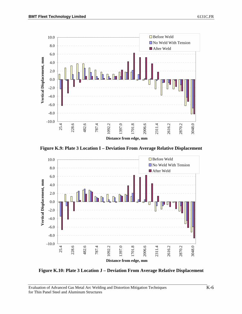
BMT Fleet Technology Limited 6131C.FR
Evaluation of Advanced Gas Metal Arc Welding and Distortion Mitigation Techniques for Thin Panel Steel and Aluminum Structures
K-6
-10.0
-8.0
-6.0
-4.0
-2.0
0.0
2.0
4.0
6.0
8.0
10.0
25.4
228.
6
482.
6
787.
4
1092
.2
1397
.0
1701
.8
2006
.6
2311
.4
2616
.2
2870
.2
3048
.0
Distance from edge, mm
Ver
tical
Dis
plac
emen
t, m
mBefore WeldNo Weld With TensionAfter Weld
Figure K.9: Plate 3 Location I – Deviation From Average Relative Displacement
-10.0
-8.0
-6.0
-4.0
-2.0
0.0
2.0
4.0
6.0
8.0
10.0
25.4
228.
6
482.
6
787.
4
1092
.2
1397
.0
1701
.8
2006
.6
2311
.4
2616
.2
2870
.2
3048
.0
Distance from edge, mm
Ver
tical
Dis
plac
emen
t, m
m
Before WeldNo Weld With TensionAfter Weld
Figure K.10: Plate 3 Location J – Deviation From Average Relative Displacement

BMT Fleet Technology Limited 6131C.FR
Evaluation of Advanced Gas Metal Arc Welding and Distortion Mitigation Techniques for Thin Panel Steel and Aluminum Structures
K-7
-10.0
-8.0
-6.0
-4.0
-2.0
0.0
2.0
4.0
6.0
8.0
10.0
25.4
228.
6
482.
6
787.
4
1092
.2
1397
.0
1701
.8
2006
.6
2311
.4
2616
.2
2870
.2
3048
.0
Distance from edge, mm
Ver
tical
Dis
plac
emen
t, m
mBefore WeldNo Weld With TensionAfter Weld
Figure K.11: Plate 3 Location K – Deviation From Average Relative Displacement
-10.0
-8.0
-6.0
-4.0
-2.0
0.0
2.0
4.0
6.0
8.0
10.0
25.4
228.
6
482.
6
787.
4
1092
.2
1397
.0
1701
.8
2006
.6
2311
.4
2616
.2
2870
.2
3048
.0
Distance from edge, mm
Ver
tical
Dis
plac
emen
t, m
m
Before Weld After Weld
Figure K.12: Plate 7 Location A – Deviation From Average Relative Displacement

BMT Fleet Technology Limited 6131C.FR
Evaluation of Advanced Gas Metal Arc Welding and Distortion Mitigation Techniques for Thin Panel Steel and Aluminum Structures
K-8
-10.0
-8.0
-6.0
-4.0
-2.0
0.0
2.0
4.0
6.0
8.0
10.0
25.4
228.
6
482.
6
787.
4
1092
.2
1397
.0
1701
.8
2006
.6
2311
.4
2616
.2
2870
.2
3048
.0
Distance from edge, mm
Ver
tical
Dis
plac
emen
t, m
mBefore Weld After Weld
Figure K.13: Plate 7 Location B – Deviation From Average Relative Displacement B
-10.0
-8.0
-6.0
-4.0
-2.0
0.0
2.0
4.0
6.0
8.0
10.0
25.4
228.
6
482.
6
787.
4
1092
.2
1397
.0
1701
.8
2006
.6
2311
.4
2616
.2
2870
.2
3048
.0
Distance from edge, mm
Ver
tical
Dis
plac
emen
t, m
m
Before Weld After Weld
Figure K.14: Plate 7 Location C – Deviation From Average Relative Displacement
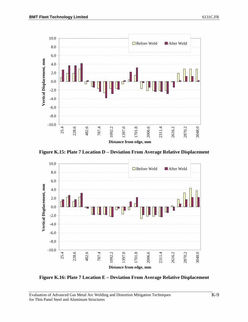
BMT Fleet Technology Limited 6131C.FR
Evaluation of Advanced Gas Metal Arc Welding and Distortion Mitigation Techniques for Thin Panel Steel and Aluminum Structures
K-9
-10.0
-8.0
-6.0
-4.0
-2.0
0.0
2.0
4.0
6.0
8.0
10.0
25.4
228.
6
482.
6
787.
4
1092
.2
1397
.0
1701
.8
2006
.6
2311
.4
2616
.2
2870
.2
3048
.0
Distance from edge, mm
Ver
tical
Dis
plac
emen
t, m
mBefore Weld After Weld
Figure K.15: Plate 7 Location D – Deviation From Average Relative Displacement
-10.0
-8.0
-6.0
-4.0
-2.0
0.0
2.0
4.0
6.0
8.0
10.0
25.4
228.
6
482.
6
787.
4
1092
.2
1397
.0
1701
.8
2006
.6
2311
.4
2616
.2
2870
.2
3048
.0
Distance from edge, mm
Ver
tical
Dis
plac
emen
t, m
m
Before Weld After Weld
Figure K.16: Plate 7 Location E – Deviation From Average Relative Displacement

BMT Fleet Technology Limited 6131C.FR
Evaluation of Advanced Gas Metal Arc Welding and Distortion Mitigation Techniques for Thin Panel Steel and Aluminum Structures
K-10
-10.0
-8.0
-6.0
-4.0
-2.0
0.0
2.0
4.0
6.0
8.0
10.0
25.4
228.
6
482.
6
787.
4
1092
.2
1397
.0
1701
.8
2006
.6
2311
.4
2616
.2
2870
.2
3048
.0
Distance from edge, mm
Ver
tical
Dis
plac
emen
t, m
mBefore Weld After Weld
Figure K.17: Plate 7 At Stiffener – Deviation From Average Relative Displacement
-10.0
-8.0
-6.0
-4.0
-2.0
0.0
2.0
4.0
6.0
8.0
10.0
25.4
228.
6
482.
6
787.
4
1092
.2
1397
.0
1701
.8
2006
.6
2311
.4
2616
.2
2870
.2
3048
.0
Distance from edge, mm
Ver
tical
Dis
plac
emen
t, m
m
Before Weld After Weld
Figure K.18: Plate 7 Location G – Deviation From Average Relative Displacement

BMT Fleet Technology Limited 6131C.FR
Evaluation of Advanced Gas Metal Arc Welding and Distortion Mitigation Techniques for Thin Panel Steel and Aluminum Structures
K-11
-10.0
-8.0
-6.0
-4.0
-2.0
0.0
2.0
4.0
6.0
8.0
10.0
25.4
228.
6
482.
6
787.
4
1092
.2
1397
.0
1701
.8
2006
.6
2311
.4
2616
.2
2870
.2
3048
.0
Distance from edge, mm
Ver
tical
Dis
plac
emen
t, m
mBefore Weld After Weld
Figure K.19: Plate 7 Location H – Deviation From Average Relative Displacement
-10.0
-8.0
-6.0
-4.0
-2.0
0.0
2.0
4.0
6.0
8.0
10.0
25.4
228.
6
482.
6
787.
4
1092
.2
1397
.0
1701
.8
2006
.6
2311
.4
2616
.2
2870
.2
3048
.0
Distance from edge, mm
Ver
tical
Dis
plac
emen
t, m
m
Before Weld After Weld
Figure K.20: Plate 7 Location I – Deviation From Average Relative Displacement

BMT Fleet Technology Limited 6131C.FR
Evaluation of Advanced Gas Metal Arc Welding and Distortion Mitigation Techniques for Thin Panel Steel and Aluminum Structures
K-12
-10.0
-8.0
-6.0
-4.0
-2.0
0.0
2.0
4.0
6.0
8.0
10.0
25.4
228.
6
482.
6
787.
4
1092
.2
1397
.0
1701
.8
2006
.6
2311
.4
2616
.2
2870
.2
3048
.0
Distance from edge, mm
Ver
tical
Dis
plac
emen
t, m
mBefore Weld After Weld
Figure K.21: Plate 7 Location J – Deviation From Average Relative Displacement
-10.0
-8.0
-6.0
-4.0
-2.0
0.0
2.0
4.0
6.0
8.0
10.0
25.4
228.
6
482.
6
787.
4
1092
.2
1397
.0
1701
.8
2006
.6
2311
.4
2616
.2
2870
.2
3048
.0
Distance from edge, mm
Ver
tical
Dis
plac
emen
t, m
m
Before Weld After Weld
Figure K.22: Plate 7 Location K – Deviation From Average Relative Displacement

BMT Fleet Technology Limited 6131C.FR
Evaluation of Advanced Gas Metal Arc Welding and Distortion Mitigation Techniques for Thin Panel Steel and Aluminum Structures
K-13
-12.0
-10.0
-8.0
-6.0
-4.0
-2.0
0.0
2.0
4.0
6.0
8.0
10.0
12.0
25.4
228.
6
482.
6
787.
4
1092
.2
1397
.0
1701
.8
2006
.6
2311
.4
2616
.2
2870
.2
3048
.0
Distance from edge, mm
Ver
tical
Dis
plac
emen
t, m
m
Before Weld After Weld
Figure K.23: Plate 8 Location A – Deviation From Average Relative Displacement
-12.0
-10.0
-8.0
-6.0
-4.0
-2.0
0.0
2.0
4.0
6.0
8.0
10.0
12.0
25.4
228.
6
482.
6
787.
4
1092
.2
1397
.0
1701
.8
2006
.6
2311
.4
2616
.2
2870
.2
3048
.0
Distance from edge, mm
Ver
tical
Dis
plac
emen
t, m
m
Before Weld After Weld
Figure K.24: Plate 8 Location B – Deviation From Average Relative Displacement

BMT Fleet Technology Limited 6131C.FR
Evaluation of Advanced Gas Metal Arc Welding and Distortion Mitigation Techniques for Thin Panel Steel and Aluminum Structures
K-14
-10.0
-8.0
-6.0
-4.0
-2.0
0.0
2.0
4.0
6.0
8.0
10.0
25.4
228.
6
482.
6
787.
4
1092
.2
1397
.0
1701
.8
2006
.6
2311
.4
2616
.2
2870
.2
3048
.0
Distance from edge, mm
Ver
tical
Dis
plac
emen
t, m
mBefore Weld After Weld
Figure K.25: Plate 8 Location C – Deviation From Average Relative Displacement
-10.0
-8.0
-6.0
-4.0
-2.0
0.0
2.0
4.0
6.0
8.0
10.0
25.4
228.
6
482.
6
787.
4
1092
.2
1397
.0
1701
.8
2006
.6
2311
.4
2616
.2
2870
.2
3048
.0
Distance from edge, mm
Ver
tical
Dis
plac
emen
t, m
m
Before Weld After Weld
Figure K.26: Plate 8 Location D – Deviation From Average Relative Displacement
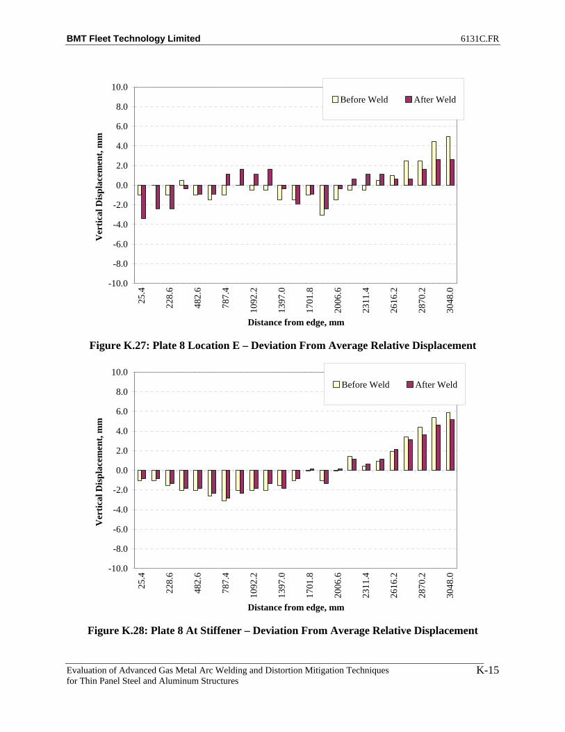
BMT Fleet Technology Limited 6131C.FR
Evaluation of Advanced Gas Metal Arc Welding and Distortion Mitigation Techniques for Thin Panel Steel and Aluminum Structures
K-15
-10.0
-8.0
-6.0
-4.0
-2.0
0.0
2.0
4.0
6.0
8.0
10.0
25.4
228.
6
482.
6
787.
4
1092
.2
1397
.0
1701
.8
2006
.6
2311
.4
2616
.2
2870
.2
3048
.0
Distance from edge, mm
Ver
tical
Dis
plac
emen
t, m
mBefore Weld After Weld
Figure K.27: Plate 8 Location E – Deviation From Average Relative Displacement
-10.0
-8.0
-6.0
-4.0
-2.0
0.0
2.0
4.0
6.0
8.0
10.0
25.4
228.
6
482.
6
787.
4
1092
.2
1397
.0
1701
.8
2006
.6
2311
.4
2616
.2
2870
.2
3048
.0
Distance from edge, mm
Ver
tical
Dis
plac
emen
t, m
m
Before Weld After Weld
Figure K.28: Plate 8 At Stiffener – Deviation From Average Relative Displacement

BMT Fleet Technology Limited 6131C.FR
Evaluation of Advanced Gas Metal Arc Welding and Distortion Mitigation Techniques for Thin Panel Steel and Aluminum Structures
K-16
-10.0
-8.0
-6.0
-4.0
-2.0
0.0
2.0
4.0
6.0
8.0
10.0
25.4
228.
6
482.
6
787.
4
1092
.2
1397
.0
1701
.8
2006
.6
2311
.4
2616
.2
2870
.2
3048
.0
Distance from edge, mm
Ver
tical
Dis
plac
emen
t, m
mBefore Weld After Weld
Figure K.29: Plate 8 Location G – Deviation From Average Relative Displacement
-10.0
-8.0
-6.0
-4.0
-2.0
0.0
2.0
4.0
6.0
8.0
10.0
25.4
228.
6
482.
6
787.
4
1092
.2
1397
.0
1701
.8
2006
.6
2311
.4
2616
.2
2870
.2
3048
.0
Distance from edge, mm
Ver
tical
Dis
plac
emen
t, m
m
Before Weld After Weld
Figure K.30: Plate 8 Location H – Deviation From Average Relative Displacement

BMT Fleet Technology Limited 6131C.FR
Evaluation of Advanced Gas Metal Arc Welding and Distortion Mitigation Techniques for Thin Panel Steel and Aluminum Structures
K-17
-10.0
-8.0
-6.0
-4.0
-2.0
0.0
2.0
4.0
6.0
8.0
10.0
25.4
228.
6
482.
6
787.
4
1092
.2
1397
.0
1701
.8
2006
.6
2311
.4
2616
.2
2870
.2
3048
.0
Distance from edge, mm
Ver
tical
Dis
plac
emen
t, m
mBefore Weld After Weld
Figure K.31: Plate 8 Location I – Deviation From Average Relative Displacement
-10.0
-8.0
-6.0
-4.0
-2.0
0.0
2.0
4.0
6.0
8.0
10.0
25.4
228.
6
482.
6
787.
4
1092
.2
1397
.0
1701
.8
2006
.6
2311
.4
2616
.2
2870
.2
3048
.0
Distance from edge, mm
Ver
tical
Dis
plac
emen
t, m
m
Before Weld After Weld
Figure K.32: Plate 8 Location J – Deviation From Average Relative Displacement

BMT Fleet Technology Limited 6131C.FR
Evaluation of Advanced Gas Metal Arc Welding and Distortion Mitigation Techniques for Thin Panel Steel and Aluminum Structures
K-18
-10.0
-8.0
-6.0
-4.0
-2.0
0.0
2.0
4.0
6.0
8.0
10.0
25.4
228.
6
482.
6
787.
4
1092
.2
1397
.0
1701
.8
2006
.6
2311
.4
2616
.2
2870
.2
3048
.0
Distance from edge, mm
Ver
tical
Dis
plac
emen
t, m
mBefore Weld After Weld
Figure K.33: Plate 8 Location K – Deviation From Average Relative Displacement
-12.0
-10.0
-8.0
-6.0
-4.0
-2.0
0.0
2.0
4.0
6.0
8.0
10.0
12.0
25.4
228.
6
482.
6
787.
4
1092
.2
1397
.0
1701
.8
2006
.6
2311
.4
2616
.2
2870
.2
3048
.0
Distance from edge, mm
Ver
tical
Dis
plac
emen
t, m
m
Before WeldNo Weld With TensionAfter Weld
Figure K.34: Plate 9 Location A – Deviation From Average Relative Displacement

BMT Fleet Technology Limited 6131C.FR
Evaluation of Advanced Gas Metal Arc Welding and Distortion Mitigation Techniques for Thin Panel Steel and Aluminum Structures
K-19
-10.0
-8.0
-6.0
-4.0
-2.0
0.0
2.0
4.0
6.0
8.0
10.0
25.4
228.
6
482.
6
787.
4
1092
.2
1397
.0
1701
.8
2006
.6
2311
.4
2616
.2
2870
.2
3048
.0
Distance from edge, mm
Ver
tical
Dis
plac
emen
t, m
m
Before WeldNo Weld With TensionAfter Weld
Figure K.35: Plate 9 Location B – Deviation From Average Relative Displacement
-10.0
-8.0
-6.0
-4.0
-2.0
0.0
2.0
4.0
6.0
8.0
10.0
25.4
228.
6
482.
6
787.
4
1092
.2
1397
.0
1701
.8
2006
.6
2311
.4
2616
.2
2870
.2
3048
.0
Distance from edge, mm
Ver
tical
Dis
plac
emen
t, m
m
Before WeldNo Weld With TensionAfter Weld
Figure K.36: Plate 9 Location C – Deviation From Average Relative Displacement

BMT Fleet Technology Limited 6131C.FR
Evaluation of Advanced Gas Metal Arc Welding and Distortion Mitigation Techniques for Thin Panel Steel and Aluminum Structures
K-20
-10.0
-8.0
-6.0
-4.0
-2.0
0.0
2.0
4.0
6.0
8.0
10.0
25.4
228.
6
482.
6
787.
4
1092
.2
1397
.0
1701
.8
2006
.6
2311
.4
2616
.2
2870
.2
3048
.0
Distance from edge, mm
Ver
tical
Dis
plac
emen
t, m
mBefore WeldNo Weld With TensionAfter Weld
Figure K.37: Plate 9 Location D – Deviation From Average Relative Displacement
-10.0
-8.0
-6.0
-4.0
-2.0
0.0
2.0
4.0
6.0
8.0
10.0
25.4
228.
6
482.
6
787.
4
1092
.2
1397
.0
1701
.8
2006
.6
2311
.4
2616
.2
2870
.2
3048
.0
Distance from edge, mm
Ver
tical
Dis
plac
emen
t, m
m
Before WeldNo Weld With TensionAfter Weld
Figure K.38: Plate 9 Location E – Deviation From Average Relative Displacement

BMT Fleet Technology Limited 6131C.FR
Evaluation of Advanced Gas Metal Arc Welding and Distortion Mitigation Techniques for Thin Panel Steel and Aluminum Structures
K-21
-10.0
-8.0
-6.0
-4.0
-2.0
0.0
2.0
4.0
6.0
8.0
10.0
25.4
228.
6
482.
6
787.
4
1092
.2
1397
.0
1701
.8
2006
.6
2311
.4
2616
.2
2870
.2
3048
.0
Distance from edge, mm
Ver
tical
Dis
plac
emen
t, m
mBefore WeldNo Weld With TensionAfter Weld
Figure K.39: Plate 9 At Stiffener – Deviation From Average Relative Displacement
-10.0
-8.0
-6.0
-4.0
-2.0
0.0
2.0
4.0
6.0
8.0
10.0
25.4
228.
6
482.
6
787.
4
1092
.2
1397
.0
1701
.8
2006
.6
2311
.4
2616
.2
2870
.2
3048
.0
Distance from edge, mm
Ver
tical
Dis
plac
emen
t, m
m
Before WeldNo Weld With TensionAfter Weld
Figure K.40: Plate 9 Location G – Deviation From Average Relative Displacement

BMT Fleet Technology Limited 6131C.FR
Evaluation of Advanced Gas Metal Arc Welding and Distortion Mitigation Techniques for Thin Panel Steel and Aluminum Structures
K-22
-10.0
-8.0
-6.0
-4.0
-2.0
0.0
2.0
4.0
6.0
8.0
10.0
25.4
228.
6
482.
6
787.
4
1092
.2
1397
.0
1701
.8
2006
.6
2311
.4
2616
.2
2870
.2
3048
.0
Distance from edge, mm
Ver
tical
Dis
plac
emen
t, m
mBefore WeldNo Weld With TensionAfter Weld
Figure K.41: Plate 9 Location H – Deviation From Average Relative Displacement
-10.0
-8.0
-6.0
-4.0
-2.0
0.0
2.0
4.0
6.0
8.0
10.0
25.4
228.
6
482.
6
787.
4
1092
.2
1397
.0
1701
.8
2006
.6
2311
.4
2616
.2
2870
.2
3048
.0
Distance from edge, mm
Ver
tical
Dis
plac
emen
t, m
m
Before WeldNo Weld With TensionAfter Weld
Figure K.42: Plate 9 Location I – Deviation From Average Relative Displacement

BMT Fleet Technology Limited 6131C.FR
Evaluation of Advanced Gas Metal Arc Welding and Distortion Mitigation Techniques for Thin Panel Steel and Aluminum Structures
K-23
-10.0
-8.0
-6.0
-4.0
-2.0
0.0
2.0
4.0
6.0
8.0
10.0
25.4
228.
6
482.
6
787.
4
1092
.2
1397
.0
1701
.8
2006
.6
2311
.4
2616
.2
2870
.2
3048
.0
Distance from edge, mm
Ver
tical
Dis
plac
emen
t, m
mBefore WeldNo Weld With TensionAfter Weld
Figure K.43: Plate 9 Location J – Deviation From Average Relative Displacement
-10.0
-8.0
-6.0
-4.0
-2.0
0.0
2.0
4.0
6.0
8.0
10.0
25.4
228.
6
482.
6
787.
4
1092
.2
1397
.0
1701
.8
2006
.6
2311
.4
2616
.2
2870
.2
3048
.0
Distance from edge, mm
Ver
tical
Dis
plac
emen
t, m
m
Before WeldNo Weld With TensionAfter Weld
Figure K.44: Plate 9 Location K – Deviation From Average Relative Displacement

BMT Fleet Technology Limited 6131C.FR
Evaluation of Advanced Gas Metal Arc Welding and Distortion Mitigation Techniques for Thin Panel Steel and Aluminum Structures
L-1
APPENDIX L
POROSITY ASSESSMENT FOR PLATE 3

BMT Fleet Technology Limited 6131C.FR
Evaluation of Advanced Gas Metal Arc Welding and Distortion Mitigation Techniques for Thin Panel Steel and Aluminum Structures
L-2
Figure L.1: Plate 3 Start 1
Figure L.2: Plate 3 Start 2

BMT Fleet Technology Limited 6131C.FR
Evaluation of Advanced Gas Metal Arc Welding and Distortion Mitigation Techniques for Thin Panel Steel and Aluminum Structures
L-3
Figure l.3: Plate 3 Center 1
Figure L.4: Plate 3 Center 2

BMT Fleet Technology Limited 6131C.FR
Evaluation of Advanced Gas Metal Arc Welding and Distortion Mitigation Techniques for Thin Panel Steel and Aluminum Structures
L-4
Figure L.5: Plate 3 End 1
Figure L.6: Plate 3 End 2
BMT Fleet Technology Limited 6131C.FR
Evaluation of Advanced Gas Metal Arc Welding and Distortion Mitigation Techniques for Thin Panel Steel and Aluminum Structures
M-1
APPENDIX M
POROSITY ASSESSMENT FOR PLATE 7

BMT Fleet Technology Limited 6131C.FR
Evaluation of Advanced Gas Metal Arc Welding and Distortion Mitigation Techniques for Thin Panel Steel and Aluminum Structures
M-2
Figure M.1: Plate 7 Start 1
Figure M.2: Plate 7 Start 2
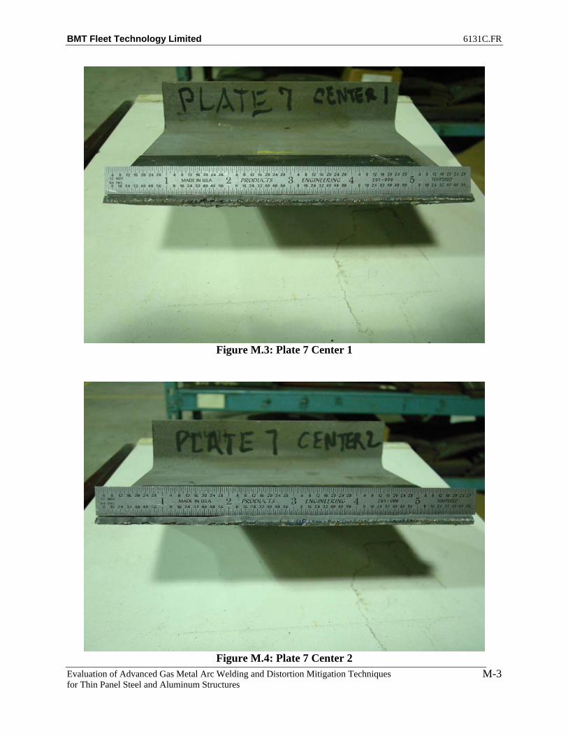
BMT Fleet Technology Limited 6131C.FR
Evaluation of Advanced Gas Metal Arc Welding and Distortion Mitigation Techniques for Thin Panel Steel and Aluminum Structures
M-3
Figure M.3: Plate 7 Center 1
Figure M.4: Plate 7 Center 2

BMT Fleet Technology Limited 6131C.FR
Evaluation of Advanced Gas Metal Arc Welding and Distortion Mitigation Techniques for Thin Panel Steel and Aluminum Structures
M-4
Figure M.5: Plate 7 End 1
Figure M.6: Plate 7 End 2
BMT Fleet Technology Limited 6131C.FR
Evaluation of Advanced Gas Metal Arc Welding and Distortion Mitigation Techniques for Thin Panel Steel and Aluminum Structures
N-1
APPENDIX N
POROSITY ASSESSMENT FOR PLATE 8

BMT Fleet Technology Limited 6131C.FR
Evaluation of Advanced Gas Metal Arc Welding and Distortion Mitigation Techniques for Thin Panel Steel and Aluminum Structures
N-2
Figure N.1: Plate 8 Start 1
Figure N.2: Plate 8 Start 2
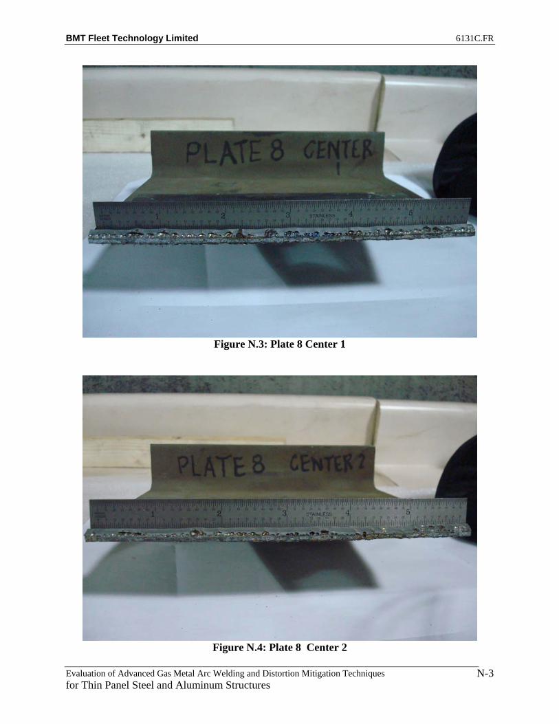
BMT Fleet Technology Limited 6131C.FR
Evaluation of Advanced Gas Metal Arc Welding and Distortion Mitigation Techniques for Thin Panel Steel and Aluminum Structures
N-3
Figure N.3: Plate 8 Center 1
Figure N.4: Plate 8 Center 2
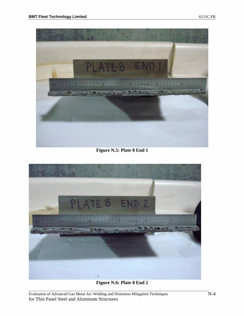
BMT Fleet Technology Limited 6131C.FR
Evaluation of Advanced Gas Metal Arc Welding and Distortion Mitigation Techniques for Thin Panel Steel and Aluminum Structures
N-4
Figure N.5: Plate 8 End 1
Figure N.6: Plate 8 End 2

BMT Fleet Technology Limited 6131C.FR
Evaluation of Advanced Gas Metal Arc Welding and Distortion Mitigation Techniques for Thin Panel Steel and Aluminum Structures
O-1
APPENDIX O
POROSITY ASSESSMENT FOR PLATE 9

BMT Fleet Technology Limited 6131C.FR
Evaluation of Advanced Gas Metal Arc Welding and Distortion Mitigation Techniques for Thin Panel Steel and Aluminum Structures
O-2
Figure O.1: Plate 9 Start 1
Figure O.2: Plate 9 Start 2
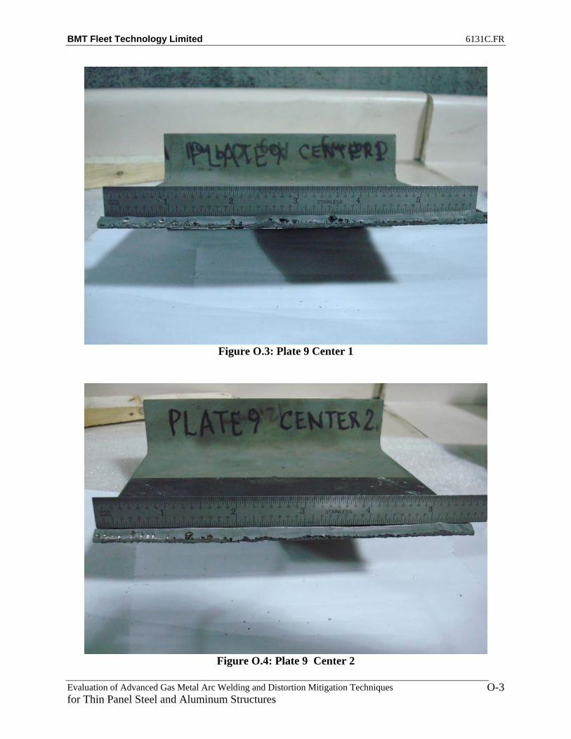
BMT Fleet Technology Limited 6131C.FR
Evaluation of Advanced Gas Metal Arc Welding and Distortion Mitigation Techniques for Thin Panel Steel and Aluminum Structures
O-3
Figure O.3: Plate 9 Center 1
Figure O.4: Plate 9 Center 2

BMT Fleet Technology Limited 6131C.FR
Evaluation of Advanced Gas Metal Arc Welding and Distortion Mitigation Techniques for Thin Panel Steel and Aluminum Structures
O-4
Figure O.5: Plate 9 End 1
Figure O.6: Plate 9 End 2

A1B 1W1