
Evaluation of a Gas-Assisted Cupolastacks.cdc.gov/view/cdc/10463/cdc_10463_DS1.pdf · Evaluation of...
21
iRl i SS 91 PLEASE DO NOT REMOVE FRCM LIBRARY Bureau of Mines Report of Investigations/1984 Evaluation of a Gas-Assisted Cupola By Victor R. Spironello UNITED STATES DEPARTMENT OF THE INTERIOR
Transcript of Evaluation of a Gas-Assisted Cupolastacks.cdc.gov/view/cdc/10463/cdc_10463_DS1.pdf · Evaluation of...

iRliSS91 PLEASE DO NOT REMOVE FRCM LIBRARY
Bureau of Mines Report of Investigations/1984
Evaluation of a Gas-Assisted Cupola
By Victor R. Spironello
UNITED STATES DEPARTMENT OF THE INTERIOR

Report of Investigations 8891
Evaluation of a Gas-Assisted Cupola
By Victor R. Spironello
UNITED STATES DEPARTMENT OF THE INTERIOR
William P. Clark, Secretary
BUREAU OF MINES Robert C. Horton, Director

Library of Congress Cataloging in Publication Data:
Spironello, Victor R Evaluation of a gas-assisted cupola.
(Bureau of Mines report of inve s tigations; 8891)
Bibliography : p. 15.
Supt. of Docs. no.: I 28.23:8891.
1. Cupola-furna ces . 2. Gas as fuel. I. Title. II. Series: Report of investigations (United States. Buteau of Mines) ; 8891.
TN23.U43 [TS23l] 6228 [672,2'4]

Abstract ••••••••• Introduction ••••• Ma terials ......................... . Equipment ••••••••••••••••••• Procedure ••.•••.••••••.•••.• Results and discussion •••••••
Iron chemistries •••• Oxidation •••••••••••• Coke rate and coke bed height •• Energy input and melting rate. Scrubber waters and solids ••
Conclusions •••••• References ••••••• Appendix •••••••••
CONTENTS
...
. ...................... .
ILLUSTRATIONS
Conventional Schematic of
cupola in operation ••••••••••••••••••••• preheating and melting chamber used in of modification •••••••••••••••••
ion ....................... .
modification .• 1. 2. 3. 4. 5. 6. 7. B.
cupola iron as a function of coke rate •••••••••••••••• cupola iron melting as a function of coke rate ••.•..••..
Closeup view Modified cupola in Silicon content of Energy input for Cupola melting Cupola melting
1. 2. 3.
4. 5.
6. A-I.
rate as rate as
influenced by total energy input of coke plus gas. a function of coke rate ............ II ••••••••••••••
TABLES
Analyses of nonfuel charge materials used in cupola .................... . Weights of Scrap bulk
charge materials used with 55 lb of scrap •.............•...... density and use of fluorspar in individual cupola evaluation
trials .................... 111 •• ,. .................. ., ................... If
Fuel and air combinations used in evaluation of modified cupola •••••••••• Gray iron compositions and operating information from evaluation of modified cupola ......................................... .
Slags resulting from evaluation of modified cupola ••••••• Analyses of waters and solids from scrubber discharge •••
1 2 3 5 6 9 9
11 11 13 14 14 15 16
4 5 6 7
11 13 13 14
3 8
8 9
10 12 16
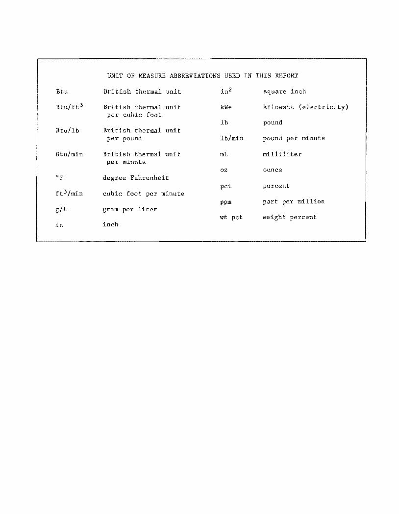
UNIT OF MEASURE ABBREVIATIONS USED IN THIS REPORT
Btu British thermal unit in2 square inch
Btu/ft 3 British thermal unit kWe kilowatt (electricity) per cubic foot
Ib pound Btu/lb British thermal unit
per pound Ib/min pound per minute
Btu/min British thermal unit mL milliliter per minute
oz ounce of degree Fahrenheit
percent ft 3/min cubic foot per minute
ppm per million giL gram per liter
wt pet weight percent in inch

EVALUATION OF A GAS.ASSI ED CUPOLA
By Victor R. Spironello 1
ABSTRACT
The Bureau of Mines is studying cupola ironmel technology with the objectives of conserving high-quality raw materials through substi-tution and productivity. In the research re-ported here, a ize was modified by a gas-fired melting and/or ing chamber into the stack above the level of the coke bed, for study as a prototype for a coal-fired melting chamber. The modified cupola, in which natural gas was used to partially replace foundry coke, was evaluated in several trial runs.
Data were obtained on furnace performance, metal and slag chemistry, and scrubber waters as particulates. Results of the modified ion were compared to those of conventional cupola operation. Although this research was preliminary--since the ultimate goal is to use pulverized coal instead of yielded ample evidence that the melting rate of a cupola can be icantly increased with less than a increase in energy input. Other evidence suggests that melting of lowdensity scrap can be enhanced and that scrap containing undesirable and/or oxidizable elements can be appreciably upgraded. This work is continuing and will include the use of pulverized coal of low rank to assist in melting.
1'1etallurgist, Twin Cities Research Center, Bureau of Mines, Minneapolis, MN.

?
INTRODUCTION
Approximately two-thirds of the iron melted in U.S. iron foundries is melted in cupolas (~).2 Cupola operation requires the use of foundry coke, a premium high-cost fuel. Although predictions of coke shortages have not come true, the high price of foundry coke provides substantial incentive for finding other methods and fuels. The iron industry has recently shown considerable interest in lowering energy requirements for melting and finding suitable alternatives for foundry coke (5, 9). If a fraction of the coke could-be- replaced by fuel of lower rank without sacrificing metal quality, the economics of cupola iron melting could be improved, coking coals could be conserved, and potential coke shortages could be alleviated. The Bureau of Mines is conducting research on partial coke replacement so that these goals can be realized. This work is consistent with the Bureau's goals of conserving important raw materials and finding ways to make use of waste materials.
Foundry coke is produced to close specifications by the carbonization of selected metallurgical coals, anthracite fines, and petroleum coke. It is used in cupolas to melt ferrous materials to provide hot metal suitable for various types of iron for castings.
A cupola (l) may be simply described as a vertical shaft furnace into which iron, alloys, and fluxes are charged at the top and molten iron and slag are drawn off at the bottom. The shaft is partially filled with foundry coke to a specified height (coke bed). Combustion air is introduced at several points in one or two horizontal planes while the coke burns. As melting proceeds, the coke in the bed is consumed, and additional coke is charged into the shaft to maintain the bed's height. Coke provides all the heat required for melting, superheating the
ZUnderlined numbers in parentheses refer to items in the list of references preceding the appendix.
iron, and forming slag. It also provides sufficient carbon monoxide in the furnace atmosphere to prevent the oxidation of iron and/or alloying elements. The coke must also support itself and the charge materials physically. Finally, coke provides carbon for carburization of the molten iron so that carbon specifications for the various types of cast iron can be met. The coke preferred by the foundry industry must be high in carbon, low in impurities, and strong.
The use of fuels other than foundry coke in cupolas is not new. According to the "Cupola Handbook" (1), charcoal and anthracite coal were replaced by coke in about 1841. In about 1893, beehive coke was replaced by coke produced in byproduct ovens. Many efforts have been made over the years to find fuels to partially replace foundry coke, and various approaches have been tried. Agglomerates of fine materials derived from parent fuels, such as coke breeze and fine coals, have frequently been tried. Efforts to inject fuels including coke breeze, fine coal, various oils, and natural gas have also been numerous. Early efforts to burn pulverized coal at various levels of the cupola stack included replacement of the tuyeres by burners (2) and use of a cyclonic burner to pass the heat just above the tap holes into the coke bed or into a bed of refractory fragments (.§).
More recent research has been directed to coke-gas cupolas, coke-oil cupolas, and completely gas-fired cupolas. The work of Stone (12) and Davis (~-l) is noteworthy. The -equipment required for natural gas injection was reported by Venendaal and Davis (14). A totally gasfired cupola was reported by Taft (13). A most notable bibliography prepared by Warda and Darke (15) of the Canada Centre for Mineral and Energy Technology lists cupola literature over 60 yr in commendable fashion. It includes references to the efforts made using the various fuels and fuel combinations.

Recent efforts by the Bureau to partially replace charge coke in cupola operation have been reported (~). Experimental fuels included anthracite, bituminous coal, scrap rubber tires, and briquet ted waste materials of high calorific value. The work reported
3
here--experimental efforts using natural gas-- was an extension of the earlier research. A cupola was modified in a relatively simple manner so that natural gas could be used. Gas was chosen for convenience, although the ultimate goal is to use pulverized coal.
MATERIALS
Analyses of the charge materials used, other than fuels, are given in table 1. The shredded (fragmented) automobile scrap was obtained from a local dealer and contained small amounts of wire, fabric, and other foreign material. Refuse scrap is the magnetic fraction from municipal waste; it is essentially food and beverage containers. This material was used as received and was relatively clean and free from the debris normally associated with municipal waste. The primary reason for using this scrap was its low bulk density (lQ), although the distribution of tramp elements during melting also was of interest. The iron content of each scrap was estimated from previous cupola studies conducted by the Bureau (11). The alloying elements silicon and manganese were charged as ferrosilicon and silicomanganese, both commercial products. The limestone and fluorspar used were also commercial materials.
The fuels for this research were foundry coke and natural gas, with calorific values of 13,000 Btu/lb, and 1,000 Btu/
ft 3 , respectively. The foundry coke contained 87.7 wt pct fixed carbon, 8.3 wt pct ash, 0.8 wt pct S, and 0.2 wt pct moisture.
All of the charge materials were sized for a pilot-size cupola, as follows:
Materials
Auto scrap ••••• Refuse scrap ••• Silicomanganese Ferrosilicon ••• Limestone •••••• Fluorspar •••••• Foundry coke •••
Size
1- to 4-in fragments. 1- to 8-in assortment. Minus 1 plus 1/4 in. Minus 1 plus 1/4 in. Minus 1-1/2 plus 1/2 in. Minus 1 plus 1/2 in. Minus 1-1/2 plus 1 in.
Cupola trials were conducted using either basic slag practice, with commercial magnesite linings, or acid slag practice, with commercial fireclay brick linings. Patching was done with compatible materials. (Details of the experimental procedures follow the "Equipment" section. )
TABLE 1. - Analyses of nonfuel charge materials used in cupola, percent
Material Constituents 1
Auto scrap2 ••••••••• 95-97 Fe, 0.3 C, 0.2 Si, 0.3 Mn. Refuse scrap3 ••••••. 89-90 Fe, 0.5 C, 0.2 Si, 0.4 Mn, 41-1.5 Al. Silicomanganese ••••• 14 Fe, 1.5 C, 18.5 Si, 65 Mn. Ferrosilicon •••••••• 50 Fe, 48 Si. Limestone ••••••••••• 54.9 CaO, 0.2 Si02 , 0.7 MgO, 0.7 A1 20 3 • Fluorspar ••••••••••• 2.0 CaO, 92.5 CaF2' 2.0 Si02 , 0.2 MgO, 0.5 A1 20 3 • 1Constituents not listed were not determined. 2Estimated from previous work (11); bulk density, 54 lb/ft 3• 3Estimated from previous work (11), except Al; bulk density, 19 Ib/ft 3• 4 Est imated.

4
FIGURE 1. ,- Conventional cupola in operation ,.

5
EQUIPMENT
All trials were conducted in an 18-indiam cupola. Its conventional design is pictured in figure 1, and a cupola of the same type is described in the literature (1). The well of the cupola had extra insulation and could accumulate about 300 lb of iron. Combustion air for the coke was supplied by a 10-oz turbo blower and was metered by an air-weight controller. This air was preheated in a 130-kWe stove and distributed through four 3-in-diam tuyeres whose total area was 28 in2 • The tuyeres were located 90 0 apart and were 22 in above the iron taphole.
The modification made to the cupola (fig. 2) was to insert a preheating and melting chamber into the shaft at a level just above the coke bed (D in figure 2). The 5-in-thick rings (C) were incorporated into the design to allow the elevation of the chamber (A) to be changed.
1. 1
B
Lining-- -t-
Coke bed ca rbu r ilot ion
KEY A Chamber
B ' Natura I gas burners
C Elevat ion -ad jus tment ri ng s
o Cake bed
E Upper tuyeres
FLower tuyeres
B
c 5"
Well
FIGURE 2.· Schematic of preheating and melting
chamber used in cupola modification.
The four burners (B) used in the unit were mounted 90° apart, offset 45° from the lower tuyeres (F), and inclined downward 30° from horizontal. The upper tuyeres (E) were in the design of the conventional cupola but were not in service in the modified cupola. (The upper tuyeres can be seen in figure 1.) Natural gas was burned in the chamber, with combustion air supplied by a separate blower.
Figure 3 is a closeup view of the entire modification assembly. The natural gas and air for combustion were premixed and introduced to the burners through the 6-in-diam manifolds (shown, where the flexible lines are connected). The smaller diameter manifolds and flexible lines were for pilot lights. Electric igniters (spark plugs) were also part of the design. Figure 4, which presents a more distant view of the operation, shows the scale.
Exhaust gases of about 1,600° F were cooled in the spark arrester hood by a water-cooled heat exchanger. Water sprays in the exhaust duct further cooled the gases before they entered the scrubber and fan.
The high suIted from
exhaust gas combustion
temperatures reof the effluent
gases containing carbon monoxide in the stack above the charge. The melting and superheating of iron produced in a cupola utilizes about 60 pct of the thermal energy in the coke. The balance is mostly in the carbon monoxide. The exhaust gas temperatures will vary somewhat depending on a variety of factors, such as charging practice, stack height, and fuel quality. However, all cupolas produce excess energy in the melting process, and exhaust gas temperatures similar to the temperature reported here (about 16,000° F) may be expected in the upper stack. Furnaces with recuperative systems recover this energy by collecting and cleaning the offgases. The energy contained is then utilized for preheating combustion (cupola) air and for plant heating.

6
FIGURE 3. - Closeup view of cupola modification.
PROCEDURE
Twenty-one melting trials were conducted using the modified cupola. For comparison, four trials were conducted following conventional cupola practice, in the same cupola prior to its modification. The melting procedures used are described below. The procedures were the same for both types of operation except as otherwise stated.
The cupola was preheated with a natural gas-oxygen torch. Coke was added for further preheating and to establish a coke bed. The height of the coke bed in most cases was 30 in above the tuyeres, a level previously determined (~) to be critical for acceptable performance of the unit in conventional operation. To evaluate the modified furnace, two coke bed heights were used: 30 or 34 in above the tuyeres.
The preheating procedure for both conventional and modified operation was identical. For modified operation, the burners were ignited about 5 min before charging began. This earlier ignition permitted some preheating above the coke bed and fine adjustments of the air and gas proportions.
Once the actual charging and melting started, the cupola was operated continuously with two charges above the coke bed (at about one-fourth to one-third of the height to the charging door in conventional operation). During operation of the modified unit, with the burners on, charging was done to the charging door sill, about 90 in above the tuyeres. When the stack was fully charged to the door sill, it was necessary to readjust

7
FIGURE 4 .• Modified cupola in operation.

8
the air and gas proportions because of increased back pressure.
Six charges containing a total of 330 lb of steel scrap comprised one tap, and seven taps were made for each trial. Each charge contained either all-auto scrap with an average bulk density of 54 Ib/ft. 3 or a mixture of 33 lb of refuse scrap and 22 lb of auto scrap with a density of about 26 Ib/ft 3 • Appropriate quantities of fluxes and alloying elements were added with each charge to provide the desired iron and slag chemistry. The weights of the constituents in each charge with 55 lb of scrap (mixed charges) are shown in table 2. The charging sequence was scrap, additives with or without fluorspar, and then coke. For each trial, table 33 shows the bulk density of the scrap used and indicates whether or not fluorspar was used.
Iron was tapped either into a ladle for pigging in sand or into a sand mold
3The trial numbers listed in table 3 correspond to those shown in tables 4-6 and A-1 and those mentioned in the text.
TABLE 2. - Weights of charge materials used with 55 lb of scrap, 1 pounds
Material Basic practice
Coke •••••••••••••• 5.0-12.2 Silicomanganese... .5 Ferrosilicon...... 3.0 Limestone......... 2.5 Fluorspar ••••••••• 0 or .5
Acid practice
5.5 or 8.0 .5
3.0 1.65 None
'Refuse scrap-auto scrap mixture.
to form a large button. In each trial, analytical and chill (control) samples were taken from the metal stream for taps 1, 2, and 7 and from the casting ladle or sand mold for others. Slag samples were taken from the stream (rear slagging) before ~he iron was tapped. Temperatures were taken by an optical pyrometer on the stream. Taps 3, 4, 5, and 6 were considered representative of steady-state conditions. Water samples containing particulates were taken during steadystate operation from the scrubber discharge. Following each trial, the cupola bottom was dropped, and the hot coke was quen-ched- a di-s-c-a-rded •
TABLE 3. - Scrap bulk density and use of fluorspar in individual cupola evaluation trials
Trial
Conventional operation--basic slag:
1 •••••••••••••••••••••••••••• 2 •••••••••••••••••••••••••••• 3 •••••••••••••••••••••••••••• 4 ••••••••••••••••••••••••••••
Modified operation--basic slag: 5 •••••••••••••••••••••••••••• 6 •••••••••••••••••••••••••••• 7 •••••••••••••••••••••••••••• 8 •••••••••••••••••••••••••••• 9 ••••••••••••••••••••••••••••
10 •••••••••••••••••••••••••••• 11 •••.•.••••.••.•..••••••.••.. 12 ....•....•.............•.... 13 ....•....................••.
Scrap, lb/ft 3
154 54 26
126
154 154 154 154 154 154 126 '26 26
Trial
Modified operation--basic slag-Con.
14 •••....•.....••••....•.•.•... 15 .•.•......•.......•......•••. 16 .••..••..••••...•..•......••.
Modified operation--acid slag: 17 .••.......••••..•••...•..•••• 18 ...•.•.....•.......•.......•. 19 ............................ . 20 ............................ . 21 .....•....••.....•........... 22 ............................ . 23 ............................ . 24 ..................•.......... 25 •••••••••••••••••••••••••••••
Scrap, Ib/ft 3
26 26 26
26 26 54 26 26 26 54 54 54
NOTE.--54 lb/ft 3 indicates average density (of all-auto scrap); 26-lb/ft 3 densities (auto scrap-refuse scrap mixture) are approximate.

The various combinations of conditions used in this research sented in table 4. Air to the was preheated to 600 0 F in all
fuels and are pre
tuyeres trials,
9
then supplied at the rates given in table 4. In conventional cupola operation, 700 ft 3/min of preheated air is standard.
P~SULTS AND DISCUSSION
IRON CHEMISTRIES
Chemistcies of the irons produced ~re presented in table 5 along with pertinent operating information. Trials 1 through 4 (conventional operation, basic practice) were baseline operations, and the results of these trials were consistent with other Bureau research OP cupola ironmelting (9-10). For example, in trials 3 and 4, in which refuse scrap was
used in the charge, the silicon, alumin'Jm, and tin cont:ents of th~ gray iron were higher than in trials 1 and 2 (allauto-scrap charge). Charging with refus e scrap also resulted in higher irontapping temperatures. Similar results were obtained in a previous cupola study (10) in wp..ich refuse scrap and auto scrap ,,!er e melted. Refuse scrap contains metallic aluminum (from 1 to 1.5 pct) in bimetallic cans.
TABLE 4. - Fuel and air combine.tions used in evaluation of modified cupola
Coke Air, ft 3/min Natural Air:gas Energy input, Trial Charge, I Rate 1 Tuyeres\ Burners gas , ratio 10 3 Btu
Ib ft3/ min Coke 2 I Gas 3
CONVENTIONAL OPERATION--BASIC SLAG 1 •••• 10.0 5.50 700 NAp NAp NAp 56.33.1 NAp 2 •••• 10.0 5.50 700 NAp NAp NAp 57.994 NAp 3 •••• 11 . 2 4.91 700 NAp NAp NAp 51.815 NAp 4 • • • • 11.2 4.91 700 NAp NAp NAp 60.996 NAp
MODIFIED OPERATION--BASIC SLAG 5 • ••• 7. 0 7.86 500 300 30 10 74.045 30.0 6 • • •• 7.0 7.86 500 300 30 10 85.534 30.0 7 •••• 7.0 7.86 500 270 30 9 51.900 30.0 8 •••• 7.0 7.86 500 285 30 9,5 74.295 30.0 9 •••• 9.0 6.11 500 300 30 10 67.989 30.0 10 ••• 11.0 5.00 500 300 30 10 60.502 30.0 11 • •• 12.2 4.51 500 300 30 10 70.633 30.0 12 •• • 12.2 4.51 500 300 27 11.1 82.621 27.0 13 ••• 12.2 4.51 500 300 27 11.1 69.936 27.0 14 ••• 12.2 4.51 500 300 27 11.1 77 . 006 27.0 15 ••• 6.1 9.02 500 300 27 11.1 70 .348 27 .0 16 ••• 5 . 0 11 . 00 500 300 27 11.1 41 . 101 ?7.0
MODIFIED OPERATION---ACID SLAG 17 • • • 8.0 6.88 500 360 33 10.9 68.548 33.0 18 •• • 8.0 6.88 500 360 33 10 . 9 63 . 317 33 .0 19 ••• 8.0 6.88 600 270 27 10 63.577 27.0 20 ••• 8.0 6 . 88 600 330 33 10 74.429 33 .0 21 ••• 5 . 5 10.00 500 270 27 10 49.286 27.0 22 • •• 5.5 10.00 600 300 27 11.1 59.526 27.0 23 ••• 5 . 5 10.00 600 360 33 10.9 55 0599 33.0 24 ••• 5.5 10.00 500 330 33 10 73.940 33. 0 25 ••• 8.0 6 . 88 500 300 27 11.1 70.556 27.0 NAp Not applicable. lPounds scrap + pounds charge coke .
213,000 Btu/lb, steady-s tate . 31 , 000 Btu/ft 3 , steady- state .

TABLE 5. - Gray iron compositions and operating information from evaluation of modified cupola
(Refuse scrap was used in charge in trials 3-4, 11-18, and 20-22. All-auto scrap was used in all other trials.)
Total Chemical analyses, wt pct l Tap Melt Av energy
Trial C I Si I S
I P
Mnl Al
I Cu I Sn
I Cr temp, rate, Index3 chill, input, Remarks
of lb/min2 1132 in 10 3 Btul net ton 2
CONVENTIONAL OPERATION -BASIC SLAG 1 •••• 3.6 2.3 0.048 0.021 0.8 1 <0.020 0.21 0.010 0.117 2,750 23.0 0.965 4.5 4,898.7 2 •••• 3.4 2.5 .050 .021 .84 .020 .29 .014 .14 2,750 23.8 .970 7.5 4,873.5 3 •••• 3.4 2.9 .028 .026 .84 .14 .56 .049 .089 2,870 16.5 .843 1.8 6,280.6 4 •••• 3.5 2.9 .022 .029 .83 .18 .23 .058 .103 2,890 19.7 .855 1.8 6,192.4
MODIFIED OPERATION--BASIC SLAG 5 •••• 3.4 2.2 0.10 0.014 0.33 <0 .020 0.30 0.009 0.13 2,590 45.2 1.010 AW 4,603.8 Shakedown test. Various charging
heights used. Gas was shut off during part of trial (cause unknown).
6 •••• 3.2 .8 .098 .014 .38 <.020 .18 .008 .094 2,570 57.9 1.120 AW 3,990.8 No castings made; scrap melted too quickly.
7 .... 4.3 1.0 .088 .017 .44 < . 020 .16 .011 .12 2,610 29.8 .950 AW 5,496.7 Less skulling, but skull over burners.
8 .... 3.5 .8 .092 .013 .49 <.020 .16 .009 .11 2,600 46.7 1.040 AW 4,466.6 Little skull over 2 burners.
9 .... 3.4 1.2 .09 .012 .60 <.020 .17 < .010 .11 2,570 32.6 1.020 AW 6,011.6 Some chill showing but mostly melted. Some skull over burners •
10 ••• 4.0 1.3 .073 .029 .67 <.020 • 24 .010 .13 2,660 23.2 .997 12.0 7,801.8 Charge coke was increased. Chill present, but scrap melted slowly •
11 ... 4.3 2.4 .055 .025 .87 <.020 .27 • 047 .1 0 2,660 21.8 .890 1.5 9,232.4 Coke was increased. 12 ... 3.4 2.0 .079 .023 .88 <.020 .29 .053 .072 2,660 25.5 .890 2.7 8,597.7 Do • 13 ... 3.4 2.4 .086 .025 .60 <.020 .21 • 051 .10 2,590 21.1 .870 2.7 9,188.3 Do • 14 ... 3.5 2.1 .078 .020 .76 .027 .25 • 051 .13 2,630 23 .5 .880 5.0 8,851.6 Do. 15 ... 3.2 1.7 .069 .069 .65 .022 .41 • 063 .095 2,610 44.4 .910 11.0 4,385.0 Coke was decreased • 16 ••• 3.1 1.4 .062 < .010 .69 .027 .19 .080 .083 2,740 31.3 .900 11.0 4,351.5 Do.
MODIFIED OPERATION ACID SLAG 17 ... 3.1 1.5 0.12 0.016 0.33 <0.020 0.42 0.067 0.093 2,610 32.3 0.891 19.5 6,287.8 Wash run to condition new acid
lining • 18 ... 2.8 1.7 .11 .019 .31 <.020 • 41 .066 .072 2,560 29.4 .878 AW 6,552.2 19 ... 3. 0 2.0 .11 .016 .56 <.020 .23 <.010 .094 2,660 39.3 1.010 16.5 5,118.4 20 ••• 3.0 1.5 .13 .014 .33 <.020 .45 .066 .076 2,770 37.0 .940 24.0 5,807.0 21. .. 3.0 1.3 .11 .017 .29 <.020 .23 .067 .057 2,560 34.5 .910 AW 4,422.4 22 ••• 2.9 1.2 .084 .016 .29 <.020 .38 .070 .069 2,590 43.5 .950 AW 3,978.2 23 ••• 2.9 1.2 .100 < .010 .36 <.020 .25 < .010 .091 2,550 41.4 .968 AW 4,280.2 24 ••• 2.7 1.4 .100 .012 .38 <.020 .27 < .010 .100 2,540 55.0 .967 AW 3,888.7 25 ••• 2.9 1.6 .12 .016 .46 < .020 .38 .011 .12 2,570 37.5 1.005 AW 5,203.0 AW All-white fracture read from chill. IAverage of steady-state taps, not weighted. 2S teady-state conditions. 3Pounds gray iron T pounds scrap, overall basis. 4All trials except trial 17 were part of a fractional factorial design.

The lower depth of chill which resulted from the use of refuse scrap (table 5) was consistent with the higher silicon levels in the iron. Silicon decreases the solubility of carbon in solidified iron and promotes the precipitation of graphite at the expense of combined carbon.
Total energy input (table 5) was calculated based on melting rate and iron index (pounds gray iron 7 pounds scrap, overall basis). Energy input is described more fully in the "Energy Input and Melting Rate" section.
OXIDATION
The slags produced in this work are described in table 6. The basicities4 of the slags listed varied for two main reasons, although there were other minor ones. One reason was that the alumina in the slags was higher when refuse scrap was used and/or during acid-practice operations--due to the alumina in the refractory lining . The alumina in the former case resulted from the oxidation of aluminum in the refuse scrap. The other main reason was the partial oxidation of silicon to silica, which entered the slag when the modified furnace was operated. As shown in table 6, the lower basicity slags also had lower sulfide capacities. Apparently, burning natural gas onto the scrap column above the coke bed develops a higher-than-desirable partial pressure of oxygen above the bed. Additional evi" dence of this oxidizing condition may be seen in the manganese behavior and in the level of iron (as oxide) in the slag. A likely cause of the increased oxygen potential is the water vapor formed as the natural gas is burned. The carbon dioxide which is also formed is a relatively strong oxidizer that contributes to the condition. Dilution of the carbon monoxide formed from the coke bed by water and carbon dioxide would also be a factor. Adding silicon and manganese to
4Basieity = pet (CaO + MgO) 7 pet (Si02 + A1203)·
11
the ladle after tapping for final adjustment is done routinely in many operations and is acceptable.
The oxidizing condition does provide at least one beneficial side effect, however, as seen in the low aluminum contents in the irons when refuse scrap was used (table 5). The aluminum was oxidized and lowered by a factor of about 8, from an average of about 0.16 wt pct to about 0.02 wt pcL The same effect would be e)~pected of any oxidizable element, as discussed for silicon and manganese.
COKE RATE AND COKE BED HEIGHT
Figure 5 shows a general relationship between coke rate and silicon in the

TABLE 6. - Slags resulting from evaluation of modified cupola
(Refuse scrap was used in charge in trials 3-4, 11-18, and 20-22. All-auto scrap was used in all other trials.)
Chemical analyses, wt pct l Slag Trial Fe I CaO I MgO I Si02 1 Al 203 1 Mn I S
I F Basic-I Vol- Remarks ity2 ume3
CONVENTIONAL OPERATION--BASIC SLAG 1 •••• 0.31 41.2 10.1 27.8 10.7 1.00 1.2 0.97 1.34 0.069 2 •••• .46 40.2 12.7 29.3 11. 3 1.02 1.4 .10 1.26 .046 3 •••• .40 35.2 7.1 13.8 39.2 .60 1.6 .10 .81 .063 4 •••• .75 35.2 12.2 14.8 32.0 .70 1.0 .68 1.02 .052
MODIFIED OPERATION--BASIC SLAG 5 •••• 4.1 26.6 12.0 36.6 7.4 4.8 0.14 0.11 0.87 0.100 Black slag; no
slag one tap. 6 •... 3.9 30.0 9.1 35.5 6.4 5.6 .11 .12 .92 .110 Black slag. 7 •••• 3.3 29.8 12.5 36.2 7.5 5.0 .21 .10 .97 .03 Do. 8 •••• 2.0 32.5 13.8 33.8 7.4 3.2 .33 .19 1.12 .08 Do. g •••• 1.8 29.8 17.5 34.6 8.6 2.8 .36 .11 1.09 .07 Mos tly dark gray
slags • 10 ••. • 94 29.7 24.3 32.2 8.9 2.2 .65 .18 1. 31 .05 Gray to brown
slag. 11. •• 1.14 26.5 23.9 26.4 20.1 1.4 .52 .12 1.08 .09 Most taps gray
slag. 12 ••. 2.0 26.3 20.3 22.9 25.3 1.5 .45 .22 .97 .06 Do. 13 ••• NS NS NS NS NS NS NS NS .NS NS Slag was stiff. 14 ••• 2.5 23.7 16.8 24.9 25.8 1.9 .37 .10 .80 .11 Slag brown to
black. 15 ••• 2.9 23.8 16.5 22.6 27.0 2.2 .27 .10 .82 .09 Mostly black,
some brown. 16 •.• 2.3 24.1 14.7 23.5 24.1 2.5 .27 .10 .82 .10 Slag gray, to
brown, to black. MODIFIED OPERATION--ACID SLAG
17 ••• 9.1 11.2 1.5 34.2 33.6 3.1 0.07 ND 0.19 0.13 18 ••• 9.7 12.7 1.1 34.5 28.8 3.9 19 ••• 3.2 16.3 2.0 38.3 32.6 3.2 20 ••. 7.1 13 .1 1.5 33.8 33.3 3.4 21. .. 8.4 13.7 1.7 34.1 31.0 4.1 22 ••• 6.6 15.0 1.1 36.1 31.4 4.1 23 •.• 5.9 16.4 1.1 36 .3 30.3 4.0 24 ••• 7.0 13.2 1.8 36.6 29.7 3.8 25 .•• 5.0 16.2 2.1 38.1 30.1 3.5 ND Not determLned. NS No samples. lAverage of steady-state taps, not weighted.
.08 ND .22 .16
.17 ND .26 .09
.01 ND .22 .15
.093 ND .24 .14
.078 ND .24 .12
.17 ND .27 .07
.099 ND .23 .12
.12 ND .27 .11
2Basicity = percent (CaO + MgO) ~ percent (Si0 2 + Al203). 3Pounds slag ~ pounds iron, overall basis.
iron. The graph in figure 5 includes data from all the trials, including the conventional operations, and is not intended to represent any degree of specificity. Coke rate is by definition the pounds of scrap divided by the pounds of coke, so smaller numerical values mean
more coke. The relationship of silicon loss in the iron as a function of coke rate seems to be a valid one. A similar relationship can be expected in a conventional cupola as a function of the height of the coke bed. A decreasing coke bed height in a conventionally operated

cupola will cause silicon (and manganese) oxidation with marked decreases in tapping temperatures and melting rates. A coke bed that is too high in a given cupola will show high silicon (and manganese) recovery, and the tapping temperatures again decrease as does the melting rate.
The effect shown in figure 5 is believed to be different from that of a low coke bed. Trials conducted using similar coke rates may be compared in tables 4 and 5. See, for example, trials 1 and 2 as compared to trials 9 and 10. The results of modified operation in trials 9 and 10 show evidence of additional oxidation. Further evidence may also be seen in the data for manganese content in the iron (table 5) and manganese and iron (oxide) contents in the slag (table 6).
ENERGY INPUT AND MELTING RATE
Table 5 shows the total energy input (coke plus gas) per net ton of iron during steady-state melting. The steadystate melting rate is the straight-line portion of the curve defined by plotting cumulative iron-tap weights versus cumulative time. The steady-state approach eliminates startup and tail·-end effects of charging and draining the furnace. A general relationship between energy input versus coke rate is shown in figure 6. This graph includes results from all the trials, and the dis proportionality is well defined. This means that with gas burners it is possible to melt iron in a cupola for less total energy while using less coke. Although all of the energy input was charged to melting iron, the melting efficiency must be factored in for an accurate assessment. The melting efficiency of cupolas varies somewhat, but approximately 40 pct is typical. The relationship shown in figure 6 would therefore shift by this factor. The combustion efficiency of coke is generally about 60 pct.
The melting rate for all trials as it was influenced by the total energy input of either coke or coke plus gas is shown in figure 7. The results plotted in the
10
• 9
• • c 8 !? 0
'Qj co .... ~
CD 7
"'0
>-" I => 6 a. ~ >-<.!J
'" w 5 z 8 w
-' <! f-a
4 f-
3
2 4 5
0
6
• • •
7
KEY Operal ion type; slog type; scrap density, Ib/tt':
a Conve nt ional, ba sic, 54
o Modified, basic, 54 l!. Modified, acid, 54
• Conventional, basic, 26
• Modified. basic, 26
• Modified, acid, 26
o
o o
o
8
•
9
... l!.
... l!.
10
COKE RATE, Ib scrapllb coke
13
" FIGURE 6. - Energy input for cupola iron melt
ing as a function of coke rate.
co E ....
:9.
w" >-<t
'" <.!J
~ >--' w ::.
60,-----,----,-----,-----,-----,-----,----, o
KEY 55 Opera tion type; slog type;
sc rap density, Ib /ft';
o Conven t ional, basic, 54
50 o Modif ied, bas ic, 54 l!. Mod if ied, acid, 54 • Conventi onal, basic, 26 • Modi fied, basic, 26 0
45 ... Modi fied, acid, 26 • 0
... l!.
40 l!.
l!. • 35 ...
0 ... •
30 0 ...
25 • (J
0 • (J
• • 20 •
• 15
50 60 70 80 90 100 110 120 TOTAL ENERGY INPUT, 10
3 Btu /mi n
FIGURE 7. - Cupola melting rate as Influenced
by tot a I energy input of coke plus gas.

14
lower right quadrant were obtained from trials using high levels of coke in the charge, along with gas, which gives an effect similar to having a coke bed too high in a conventional furnace. Increasing the total energy into the system increases the melting rate by a disproportionate amount. The relationship between the cupola melting rate and coke rate for all trials is represented by figure 8. Increasing the melting rate of a given cupola by a factor of at least 2 for a less-than-proportionate increase in energy input is significant. Since this research was preliminary and all findings were strictly experimental, no effort was made to select certain trials and comment on them separately. It is clear, however, that the melting rate of the pilot cupola was increased with less coke and lower unit energy than are usually required in conventional cupola operation. The furnace modification also improved the melting rate of low-density scrap.
It is believed that the benefits reported f rom a change in the mode of preheating and/or melting of scrap. In a conventional cupola, melting is done at the interface of coke and scrap (charge), or on a single plane. In the modified furnace with the burners on, preheating and/or melting took place at this same interface and at the walls of the cylindrical pile of scrap (charge).
SCRUBBER WATERS AND SOLIDS
Analyses of the scrubber waters and particulates are given in appendix table A-I. The use of the gas burners apparently promoted the loss of fluorine, which was added as fluorspar in some
60
55
50
45
.!: 40 E "-~
w-I-- 35 <t a:
'" ~ I-- 30 ..J W ::;;
25
20
15
10 "4
• • • •
KEY Opera tion type; sl a~ t ype ; scrap dens i ty, Ibl ft :
o Conventi onal, ba sic, 54 o Modi f ied, ba sic, 54
0. Modified, ac id, 54
• Convent iona l, basi c, 26 • Modi f ied, basi c, 26
• Modified, ac id, 26
o
•
•
o o
0
6
0.
0.
• • •
7
0
0
o
0
0
8 9
COKE RATE, Ib sc rapllb coke
•
10 I I
FIGURE 8. - Cupola melt ing rate as a function of coke rate.
trials (table 3) to fluidize the slag. High losses of fluorine are evident in table A-I, and its use was discontinued after trial 12. The levels of cadmium, lead, zinc, and tin in the particulates resulted from the scrap and were higher with the use of refuse scrap. The results given in table A-I are generally consistent with previous Bureau work (10) •
CONCLUSIONS
In this investigation, a cupola modified to allow for the partial replacement of foundry coke with natural gas was evaluated. Due to the preliminary nature of this research, only limited conclusions can be drawn; however, it provided ample evidence that the melting rate of a
cupola can be significantly increased with less than a proportionate increase in energy input. Other evidence suggests that the melting of lOW-density scrap can be enhanced and that scrap containing undesirable and oxidizable elements can be appreciably upgraded. Work is cont-inuing

on the concept of partial coke replacement, and efforts are underway to design, construct, and evaluate a system that
15
will use pulverized coal instead of natural gas.
REFERENCES
1. American Foundrymen's Society. Cupola Handbook. AFS, 1975, pp. 1-15.
2. Davis, J. Gibeaut. Gas Melting Costs, Foundry, v. 97,
A., R. Clark, and W. A. Injection Lowers Cupola Increases Melting Rates. June 1969, pp. 66-73.
3. Davis, J. A., G. P. Dahm, and D. E. Price. Low-Pollution Gas-Fired Cupola Completes Pilot Run Tests. Mod. Cast., v. 62, Sept. 1972, pp. 48-50.
4. Heine, H. J. AFS Conference Analyzes Status of Cupola. Foundry Manage. & Technol., v. 109, Nov. 1980, pp. 112, 115-116.
5. Iron Casters Stage Survival Seminar. Foundry Manage. & Technol., v. Ill, Jan. 1983, pp. 52, 54.
6. pola. 1961.
Hudson, H. P. Canadian Pat.
Cyclone Fired Cu-618,814, Apr. 25,
7. Meyer, F. Cupola Fired With Powdered Coal. Iron Age, v. 121. No. 23, 1928, pp. 1503-1504.
8. Spironello, V. R. An Evaluation of Variables in Cupola Operation Using Prepared Automobile Scrap. BuMines OFR 8-79, 1979, 28 pp.
9. Spironello. V. R., and W. M. Mahan. Partial Replacement of Coke in Cupola Operation. BuMines RI 8488, 1980, 19 pp.
10. Utilizing the Magnetic Fraction of Raw Refuse With Shredded Automobile Scrap in Cupola Gray Iron. BuMines RI 8454, 1980, 19 pp.
11. Spironello, V. R., I. D. Shah, and R. H. Nafziger. Steels From a Variety of Ferrous Scrap Including Materials of Low Quality. BuMines RI 8622, 1982, 15 pp.
12. Stone, A. J. Natural Supplementary Cupola Fuel. 93, Oct. 1965, pp. 87-91.
Gas as a Foundry, v.
13. Taft, R. T. The First Twelve Months Operation of a Totally Gas-Fired Cupola. Brit. Foundryman, Sept. 1972, pp. 321-328, 355-358.
14. Venendaal, R., and J. A. Davis. Equipping for Natural Gas Cupola Injection. Foundry, v. 97, July 1969, pp.128-132.
15. Warda, R. D., and E. F. Darke. Sixty Years of Cupola Literature. CANMET, 1980, 74 pp.

Z -i ., ro c o " s: z m
_OJ>
1)
Cl :r 1)
l>
'" .... '" '" o
APPENDIX
TABLE A-I. - Analyses 1 of waters and solids from scrubber discharge
(Refuse scrap was used in charge in trials 3-4, 11-18, and 20-22. All-auto scrap was used in all other trials.)
Trial pH Waters 2 Solids, Chemical analyses of solids, wt pct F, ppm I NaOH, 3 mL giL Fe I C I Cu I Cr 1 Cd I Pb I Zn I Sn I F I s
CONVENTIONAL CUPOLA OPERATION--BASIC SLAG 1 ••••••• 4.5 185 37 5.8 17.3 13.0 0.091 ND ND 1.0 2.7 <0.20 9.0 0.28 2 ••••••• 6.5 23 1 5.6 15.4 25.4 .18 ND ND 1.1 6.6 .20 .3 .27 3 ••••••• 6.0 21 3 4.7 11.6 20.8 .15 ND ND 5.1 7.9 2.7 .2 .33 4 ••••••• 4.8 103 4 6.9 11.7 18.0 .14 ND ND 4.1 4.4 2.6 6.0 .30
MODIFIED CUPOLA OPERATION--BASIC SLAG 5 ••••••• 4.2 250 42 6.5 14.8 19.7 0.17 ND ND 1.1 1.5 <0.20 12.0 0.46 6 ••••••• 3.5 250 48 6.6 13.0 18.7 .61 ND ND .6 1.5 .20 20.8 .41 7 ••••••• 3.6 348 64 6.1 16.3 ND .13 ND ND 1.3 2.2 1.2 15.6 .34 8 ••••••• 3.3 356 65 3.4 14.2 23.9 .09 ND ND .6 1.5 <.20 19.3 .44 9 ••••••• 3.4 337 68 3.6 14.2 24.5 .08 ND ND .5 1.5 .20 17.5 .46 10 •••••• 4.0 259 30 1.1 11.6 31.1 .13 0.098 0.014 1.1 2.6 .20 21.6 .45 11 ...•.• 4.7 92 0 1.6 ND 22.7 .08 <.05 .039 2.2 2.1 1.0 4.0 .42 12 ..•... 5.0 107 2 3.6 21.3 14.1 .08 .05 .023 2.9 1.8 1.6 5.9 .49 13 ...... 5.4 15 0 1.7 17.8 19.0 .13 .05 .023 2.1 3.5 1.0 .3 .28 14 ...... 5.6 6 ND 1.0 17.6 25.1 .23 .048 .017 1.3 1.9 .8 .2 .40 15 ...... 6.5 5 ND 2.7 ND 21.3 .12 .05 .044 2.2 2.9 .8 .1 .37 16 ...... 6.3 8 ND 7.0 18.6 18.5 .09 <.05 .030 5.5 4.9 .9 .1 .64
MODIFIED CUPOLA OP RATION--ACID SLAG 17 ••••.• 6.2 ND 2 7.5 7.6 20.4 0.12 <0.05 0.03 5.2 3.5 1.3 ND 0.50 18 ...... 6.2 ND 0 3.4 14.5 16.5 .14 .055 .028 2.5 ~.2 1.0 ND .37 19 .....• 6.3 ND 0 3.0 13.4 35.9 .12 <.05 .02 1.3 3.8 .3 ND .50 20 ...... 6.4 ND 0 7.0 6.9 14.7 .14 .06 .047 8.1 7.1 3.0 ND .44 21 ..••.. 6.2 ND <1 11.9 12.9 25.6 .06 <.05 .030 4.7 3.4 1.8 ND .40 22 ....•. 6.5 ND 3 8.0 9.6 27.9 .07 .05 . 028 6.6 4.6 1.6 ND .70 23 ...... 6.8 ND 2 9.2 32.0 16.3 .09 .023 .033 1.1 4.2 .2 ND .25 24 .... ~ . 6.3 ND <1 7.5 27.4 14.1 .18 <.05 .028 2.1 5.4 <.2 ND .31 25 .•...• 7.0 ND 1 5.7 21.7 19.3 .13 .04 .040 1.7 12.3 .21 ND .:2 ND Not determined. 2Water flow through scrubber: 5 gpm; pH = 7. lRepresentative of steady-state conditions. 3Titration to pH 7 with 0.204 N NaOH per liter of scrubber water.


