Evaluation of a Boron-Lined Neutron Detectorcradpdf.drdc-rddc.gc.ca/PDFS/unc196/p539104_A1b.pdf ·...
40
Evaluation of a Boron-Lined Neutron Detector Prepared by: B. M. van der Ende Atoemic Energy of Canada Limited Chalk River, ON K0J 1J0 Scientific Authority: Guy Jonkmans DRDC Centre for Security Science The scientific or technical validity of this Contract Report is entirely the responsibility of the Contractor and the contents do not necessarily have the approval or endorsement of the Department of National Defence of Canada. Defence Research and Development Canada Contract Report DRDC-RDDC 2014-C82 April 2014
Transcript of Evaluation of a Boron-Lined Neutron Detectorcradpdf.drdc-rddc.gc.ca/PDFS/unc196/p539104_A1b.pdf ·...
Evaluation of a Boron-Lined Neutron Detector
Prepared by: B. M. van der Ende Atoemic Energy of Canada Limited Chalk River, ON K0J 1J0 Scientific Authority: Guy Jonkmans DRDC Centre for Security Science
The scientific or technical validity of this Contract Report is entirely the responsibility of the Contractor and the contents do not necessarily have the approval or endorsement of the Department of National Defence of Canada.
Defence Research and Development Canada Contract Report DRDC-RDDC 2014-C April 2014

IMPORTANT INFORMATIVE STATEMENTS This project Boron lined neutron detector evaluation CSSP-2013-CD-1028, was supported by the Canadian Safety and Security Program (CSSP) which is led by Defence Research and Development Canada’s Centre for Security Science, in partnership with Public Safety Canada. Partners in the project include Atomic Energyof Canada Limited, Natural Resources Canada, and Canada Border Services Agency The CSSP is a federally-funded program to strengthen Canada’s ability to anticipate, prevent/mitigate, prepare for, respond to, and recover from natural disasters, serious accidents, crime and terrorism through the convergence of science and technology with policy, operations and intelligence
© Her Majesty the Queen in Right of Canada, as represented by the Minister of National Defence, 2014
© Sa Majesté la Reine (en droit du Canada), telle que représentée par le ministre de la Défense nationale, 2014

Technical Evaluation
Atomic Energy ofCanada Limited
Chalk River, OntarioCanada K0J 1J0
Énergie Atomique duCanada Limitée
Chalk River (Ontario)Canada K0J 1J0
van der Ende Bryan - ReactorPhysicist
Prepared byRédigé par
Atanackovic Jovica - R & DScientist
Reviewed byVérifié par
Bentoumi Ghaouti - G.BENTOUMI
O'Kane Mike MA - BranchManager Applied Physics
Approved byApprouvé par
EVALUATION OF ABORON-LINED NEUTRONDETECTOR
153-100000-TE-001
Revision 0
2014/03/19AECL - OFFICIALUSE ONLY
2014/03/19À L'USAGE EXCLUSIFD'EACL

153-100000-TE-001 2014/03/19
Technical Evaluation
Evaluation of a Boron-Lined Neutron Detector
Research and Development
153-100000-TE-001Revision 0
2014 March
AECL - OFFICIAL USE ONLY
mars 2014
À USAGE EXCLUSIF - EACL
© Atomic Energy of Canada Limited
© Énergie atomique du Canada limitée
Rev
isio
n H
isto
ryLi
ste
de ré
visi
ons
AEC
L -O
FFIC
IAL
USE
ON
LYÀ
USA
GE
EXC
LUSI
F -E
AC
L
153
1000
00TE
001
Doc
umen
t Det
ails
/ D
étai
ls s
ur le
doc
umen
t
Eval
uatio
n of
a B
oron
-Lin
ed N
eutro
n D
etec
tor
37
For R
elea
se In
form
atio
n, re
fer t
o th
e D
ocum
ent T
rans
mitt
al S
heet
acc
ompa
nyin
g th
is d
ocum
ent.
Pour
des
rens
eign
emen
ts p
orta
nt s
ur la
diff
usio
n,
cons
ulte
z la
feui
lle d
e tr
ansm
issi
on d
e do
cum
ents
ci-j
oint
e.R
evis
ion
Hist
ory
/ Lis
te d
e ré
visi
ons
153-
1000
00-T
E-00
1 20
14/0
3/19
D1
2014
/03/
03Is
sued
for“
Revi
ew a
nd C
omm
ent”
.B.
M. v
an d
er E
nde
G. B
ento
umi
J. A
tana
ckov
icM
. O’K
ane
020
14/0
3/19
Issu
ed a
s “A
ppro
ved
for U
se”
B. M
. van
der
End
eG
. Ben
toum
iJ.
Ata
nack
ovic
M. O
’Kan
e
01

TABLE OF CONTENTS
SECTION PAGE
153-100000-TE-001 2014/03/19
1. INTRODUCTION ........................................................................................... 1-1
1.1 Purpose and Scope ........................................................................................... 1-1 1.2 Abbreviations ................................................................................................... 1-1
2. DETECTOR PRINCIPLES, DESCRIPTION, AND PERFORMANCE PARAMETERS ............................................................................................... 2-1
2.1 Neutron Detection Principle ............................................................................. 2-1 2.2 BCS Detector Configuration ............................................................................ 2-1 2.3 Detector Performance Parameters .................................................................... 2-2 2.3.1 The absolute neutron efficiency .................................................................. 2-2 2.3.2 The gamma intrinsic efficiency .................................................................. 2-2 2.3.3 The gamma absolute rejection ratio for neutrons......................................... 2-3 2.4 Evaluation Goals .............................................................................................. 2-3
3. DESCRIPTION OF MEASUREMENT SETUPS ............................................ 3-1
3.1 Neutron Tests ................................................................................................... 3-1 3.2 Gamma Tests ................................................................................................... 3-2 3.3 Gamma-plus-neutron Tests .............................................................................. 3-3 3.4 Data Acquisition Electronics ............................................................................ 3-4
4. MEASUREMENT RESULTS ......................................................................... 4-1
4.1 Neutron Efficiency Measurements ................................................................... 4-1 4.1.1 Pulse height spectra and choice of discriminator level ................................ 4-1 4.1.2 Effect of moderator thickness ..................................................................... 4-2 4.1.2.1 GEANT4 simulation: determine optimal moderator thickness............... 4-2 4.1.2.2 Experiment: replacing the front incident moderator panel with
smaller thickness .................................................................................. 4-4 4.1.3 Influence of BCS detector orientation ......................................................... 4-5 4.1.4 Shadow cone measurements ....................................................................... 4-6 4.1.5 Discussion .................................................................................................. 4-8 4.2 Gamma Insensitivity Measurements ................................................................4-10 4.3 Gamma Absolute Rejection Ratio for neutrons (GARRn) ................................4-16
5. SOME NOTES ON INTERFACING WITH PROPORTIONAL TECHNOLOGIES INC. AS A CUSTOMER ................................................... 5-1
6. SUMMARY AND CONCLUSIONS ............................................................... 6-1
7. REFERENCES ................................................................................................ 7-1

TABLE OF CONTENTS
SECTION PAGE
153-100000-TE-001 2014/03/19
8. ACKNOWLEDGEMENTS ............................................................................. 8-1
TABLES
Table 4-1: Summary of shadow cone measurements performed with the BCS detector. Counts are for 30 s real time, and corrected for dead time. The detector orientation was vertical. ............................................................... 4-7
Table 4-2: Summary of estimated detection efficiency for configurations employing 1” aluminum tubes, each consisting of seven 7 mm diameter boron-coated straws. ..................................................................................................4-10
FIGURES
Figure 2-1: Schematic of a cylindrical boron-coated straw, depicting the detection of alpha particle resulting from neutron capture by 10B. The 7Li ion produced (not shown) recoils in the direction opposite to the alpha particle’s trajectory at the point of neutron capture. .......................................... 2-1
Figure 2-2: The BCS detector from Proportional Technologies, Inc. It is shown together with a DC ±5 V power supply for the preamplifiers and summing amplifier of the detector, a biasing high voltage power supply, and an oscilloscope for observing the detector output. .......................... 2-2
Figure 2-3: The 3He detector from Natural Resources Canada ................................................ 2-3 Figure 3-1: The setup employed for shadow cone measurements. This shadow cone
is placed 14 cm in front of the holder where the 252Cf source appears when it is exposed. The BCS detector, encased in HDPE moderator, appears in the background in photo (b.) ............................................................ 3-1
Figure 3-2: The setup employed for gamma insensitivity measurements in GC60. The 3He detector appears in photo (a), while the BCS detector, encased in HDPE moderator, appears in photo (b). ........................................................ 3-2
Figure 3-3: The setup employed for gamma insensitivity measurements in B469. The holder where the 192Ir appears after it is exposed appears in the foreground. ...................................................................................................... 3-3
Figure 3-4: The setup employed for GARRn measurements in HPNG. In photo (a), the 252Cf source holder appears in the foreground, and the 192Ir source holder appears behind the BCS detector, attached to a pylon. The glow of the pylon in photo (b) is due to camera flash........................................ 3-3
Figure 3-5: Photo of NIM modules, displaying settings and connections employed for neutron counting ......................................................................................... 3-5

TABLE OF CONTENTS
SECTION PAGE
153-100000-TE-001 2014/03/19
Figure 4-1: A typical pulse height spectrum for the boron-lined neutron detector. In this case, the 252Cf source-detector distance is 2 m, and the counts are collected over 30 s. .......................................................................................... 4-1
Figure 4-2: Percentage change in the MCA counts when varying the lower bound of the ROI from channel 34, between channels 0 and 60. ...................................... 4-2
Figure 4-3: Snapshot of a GEANT4 simulation investigating the ideal moderator thickness to thermalize neutrons emitted by a 252Cf source ............................... 4-3
Figure 4-4: GEANT4 detector simulation counts vs. moderator thickness............................... 4-3 Figure 4-5: Energy distribution of neutrons detected in the GEANT4 simulation. In
this case, the source-detector distance was set to 2 m, and the moderator thickness was 5 cm .......................................................................... 4-4
Figure 4-6: Count rate of the BCS detector versus source-detector distance, when exposed to a 252Cf source for differing moderator thickness configurations: encasing entirely in 2” thick HPDE moderator (red squares), and replacing a 2” panel with a 1” thick panel at the front incident side (black circles) .............................................................................. 4-5
Figure 4-7: Count rate of the BCS detector versus source-detector distance, when exposed to a 252Cf source for differing detector orientation: horizontal orientation (red squares), and vertical orientation (black circles) ...................... 4-6
Figure 4-8: Count rate of the BCS detector (without shadow cone) versus inverse source-detector distance squared, for distances in the range of 2 to 4 m. The BCS detector was in the vertical orientation, with 2” thick moderator on all sides. ..................................................................................... 4-8
Figure 4-9: Efficiency in detection of neutrons from moderated 252Cf versus the number of 4 mm diameter BCS straws mounted in a hexagonal array surrounded by HDPE moderator, from Proportional Technologies, Inc. Data is taken from Refs. [7,12,13]. ................................................................... 4-9
Figure 4-10: Pulse height spectrum for the BCS detector when irradiated with a 20 mR/hr 137Cs gamma field, in GC60 facility......................................................4-11
Figure 4-11: BCS detector response to 192Ir gamma irradiation, in the vertical orientation, versus LLD...................................................................................4-12
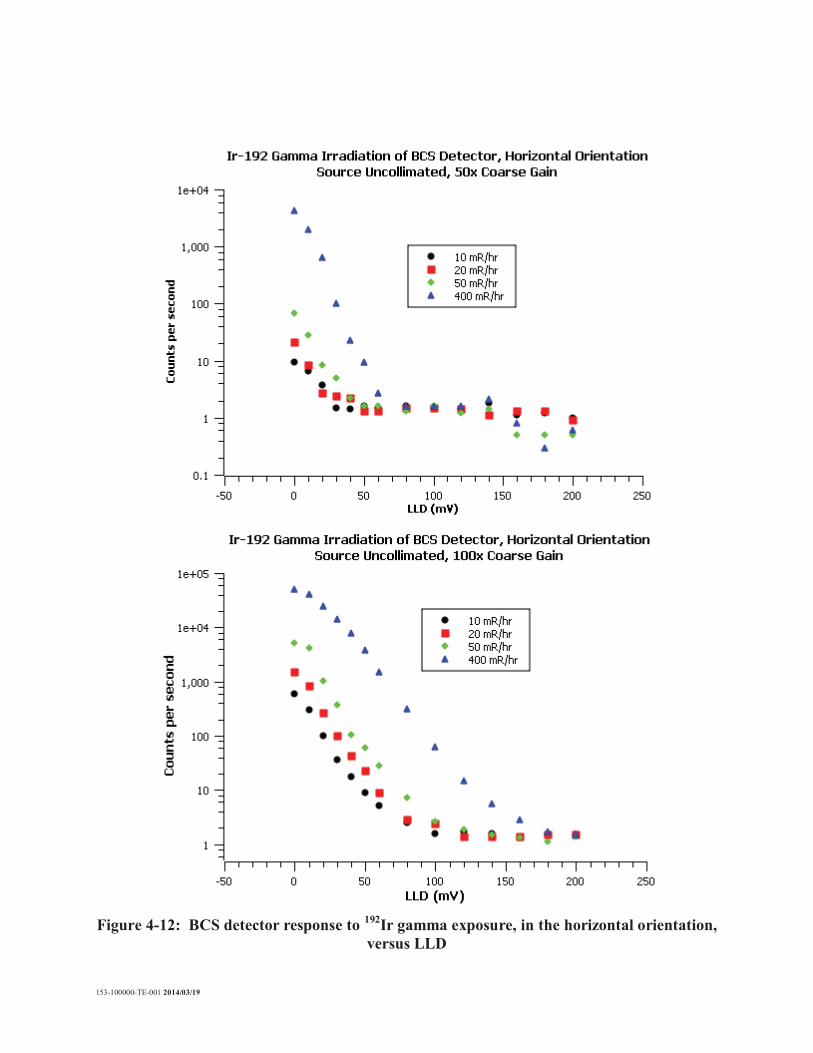
Figure 4-12: BCS detector response to 192Ir gamma exposure, in the horizontal orientation, versus LLD...................................................................................4-13
Figure 4-13: 3He detector response to 192Ir gamma irradiation versus LLD ............................4-14 Figure 4-14: BCS detector background without 192Ir gamma irradiation ................................4-14 Figure 4-15: Average gamma insensitivity versus LLD, for the BCS detector in
vertical (black squares) and horizontal (red circles) orientations, and for the 3He detector .........................................................................................4-16
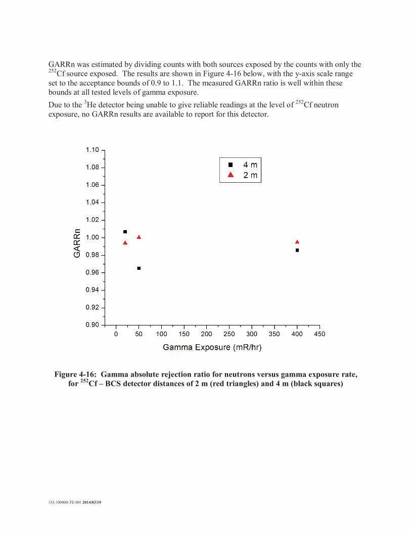
Figure 4-16: Gamma absolute rejection ratio for neutrons versus gamma exposure rate, for 252Cf – BCS detector distances of 2 m (red triangles) and 4 m (black squares) ................................................................................................4-17

153-100000-TE-001 2014/03/19
1. INTRODUCTION
Proportional gas detectors filled with 3He are the “gold standard” for detection of thermal neutrons. 3He has a large cross-section for the capture of thermal neutrons (5330 barns) [1],while remaining insensitive to the detection of gamma rays. 3He detectors are typically simple and robust in design, and they are useful for a wide range of applications, including border security technology for monitoring of special nuclear materials [2]. Due to an increased demand for 3He for security applications, and a very limited supply of 3He [2[3], it has become imperative to develop alternative technology for the detection of neutrons. A commercially available technology that can serve as a viable replacement for 3He detectors are boron-lined proportional counters. 10B also has a high cross section for capturing thermal neutrons (3840 barns) [1]. Boron-lined neutron counters from Proportional Technologies Inc. (Houston, TX, USA) consist of a thin layer (~1 m thick) of solid 10B4C deposited on a metal substrate. When the boron layer captures a neutron, it undergoes a nuclear reaction yielding a 6Li ion and an alpha particle. These charged particles ionize the gas inside a proportional counter, which leads to the creation of a detector signal from charge collection driven by high voltage applied in the proportional counter [4].
1.1 Purpose and Scope
This report evaluates the performance of a particular boron-lined proportional counter manufactured by Proportional Technologies, Inc. (Houston, TX, USA). The report will describe the detector principles and design, as well as performance parameters that were used to assess the efficacy of the detector for detection of special nuclear materials, for border security purposes. The results of measurements performed with the detector at facilities at AECL Chalk River Laboratories are evaluated in terms of these parameters.
1.2 Abbreviations
B469 Building 469 B513 Building 513 BCS 10B-Coated Straw GARRn Gamma Absolute Rejection Ratio for neutrons GC60 Gamma Co-60GEANT4 GEometry ANd Tracking, version 4 (Monte Carlo package) HDPE High-Density PolyEthylene HPNG Health Physics Neutron Generator NIM Nuclear Instrument Module PNNL Pacific Northwest National Laboratory PTI Proportional Technologies, Inc. ROI Region Of Interest SCA Single Channel Analyzer
153-100000-TE-001 2014/03/19
2. DETECTOR PRINCIPLES, DESCRIPTION, AND PERFORMANCE PARAMETERS
2.1 Neutron Detection Principle
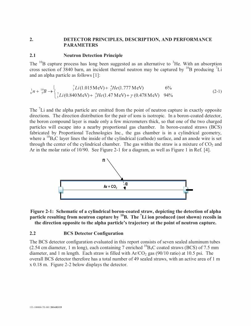
The 10B capture process has long been suggested as an alternative to 3He. With an absorption cross section of 3840 barn, an incident thermal neutron may be captured by 10B producing 7Li and an alpha particle as follows [1]:
94%MeV) (0.478 MeV) 1.47( MeV)840.0(6%MeV) 1.777( MeV)015.1(
42
73
42
7310
510 HeLi
HeLiBn (2-1)
The 7Li and the alpha particle are emitted from the point of neutron capture in exactly opposite directions. The direction distribution for the pair of ions is isotropic. In a boron-coated detector, the boron compound layer is made only a few micrometers thick, so that one of the two charged particles will escape into a nearby proportional gas chamber. In boron-coated straws (BCS) fabricated by Proportional Technologies Inc., the gas chamber is in a cylindrical geometry, where a 10B4C layer lines the inside of the cylindrical (cathode) surface, and an anode wire is set through the center of the cylindrical chamber. The gas within the straw is a mixture of CO2 and Ar in the molar ratio of 10/90. See Figure 2-1 for a diagram, as well as Figure 1 in Ref. [4].
Figure 2-1: Schematic of a cylindrical boron-coated straw, depicting the detection of alpha particle resulting from neutron capture by 10B. The 7Li ion produced (not shown) recoils in
the direction opposite to the alpha particle’s trajectory at the point of neutron capture.
2.2 BCS Detector Configuration
The BCS detector configuration evaluated in this report consists of seven sealed aluminum tubes (2.54 cm diameter, 1 m long), each containing 7 enriched 10B4C coated straws (BCS) of 7.5 mm diameter, and 1 m length. Each straw is filled with Ar/CO2 gas (90/10 ratio) at 10.5 psi. The overall BCS detector therefore has a total number of 49 sealed straws, with an active area of 1 m x 0.18 m. Figure 2-2 below displays the detector.

153-100000-TE-001 2014/03/19
Figure 2-2: The BCS detector from Proportional Technologies, Inc. It is shown together with a DC ±5 V power supply for the preamplifiers and summing amplifier of the detector, a biasing high voltage power supply, and an oscilloscope for observing the detector output.
2.3 Detector Performance Parameters
The performance evaluation centres on three key parameters [5,6]:1) absolute neutron detection efficiency ( abs n),2) intrinsic efficiency of gamma rays detected as neutrons (gamma insensitivity) ( int ), and 3) Gamma Absolute Rejection Ratio in the presence of neutrons (GARRn).
2.3.1 The absolute neutron efficiency
The absolute neutron efficiency ( abs n) represents the number of pulses recorded per number ofradiation quanta emitted by the source in a given geometry. PNNL guidelines [5] state that an acceptable neutron detector should read a count rate of 2.5 cps when a 252Cf source of 1 nano-gram (ng) surrounded by 0.5 cm thick lead (for blocking gamma rays) and 2.5 cm thick polyethylene (for moderating the neutron spectrum), is placed at a distance of 2 m from the detector [5,6]. This efficiency is often reported in cps/ng, and it connects the rate of signal detection to the activity of the nuclear material being detected. Note: 10 ng of 252Cf emits 2.314 x 10⁴ n/s [7,8].
2.3.2 The gamma intrinsic efficiency
The gamma intrinsic efficiency int measures the response of a neutron detector to the presence of a gamma ray field. It is the net number of registered counts divided by the number of gamma photons striking the detector. At an exposure rate of 10 mR/hr (0.1 mSv/hr), a well-designed 3He

153-100000-TE-001 2014/03/19
detector has a ratio int, ~ 10-7. It is reasonable to require int 10-6 for good gamma ray insensitivity at an exposure level of 10 mR/hr [5,6].
2.3.3 The gamma absolute rejection ratio for neutrons
The gamma absolute rejection ratio for neutrons (GARRn) measures the detector response in the presence of both a large gamma ray source and a neutron source. GARRn is defined as the absolute neutron detection efficiency in the presence of both sources ( abs n), divided by the absolute neutron detection efficiency ( abs n):
GARRn = abs n/ abs n
Where the gamma ray source has no impact on neutron detection, the GARRn = 1. The proposed specification for acceptable neutron detection is 0.9 < GARRn < 1.1 at 10 mR/hr exposure [5,6].
2.4 Evaluation Goals
The overall objective of this test evaluation is to determine the real performance of the boron-lined detector from Proportional Technologies, Inc., for each of the three above parameters. This evaluation will be performed in comparison with a 3He detector on loan from Natural Resources Canada. The 3He detector is a RSN-4 model from Radiation Solutions, Inc. (Mississauga, ON, Canada), employing a RS-705 mobile data acquisition unit. The detector consists of four 253142 model cylindrical 3He tubes from LND, Inc. (Oceanside, NY, USA). The 3He pressure in each tube is 2052 torr (39.68 psi). Each tube has an effective length of 32.00” (81.27 cm), and an effective diameter of 1.96” (4.98 cm). Figure 2-3 displays the 3He detector.
Figure 2-3: The 3He detector from Natural Resources Canada

153-100000-TE-001 2014/03/19
3. DESCRIPTION OF MEASUREMENT SETUPS
3.1 Neutron Tests
Measurements of the absolute neutron efficiency were performed at the Health Physics Neutron Generator (HPNG) facility in B513 at AECL. The HPNG facility is equipped with a calibrated 252Cf source (half-life of 2.645 yr). The current source was purchased from Frontier Technology Corporation (Xenia, OH, USA), which on Feb. 18, 2010 had a neutron output of 2.3 x 10⁸ n/s.The facility is also equipped with calibrated Bonner sphere and rotating proton recoil spectrometers that have carefully characterized the neutron dose and fluence at various distances from the 252Cf source in the facility room. These characterizations were carried out using solid, boron-loaded shadow cones, as prescribed in the ISO 8529 standard [9]. In particular, the shadow cone method provides a means of determining the component of detected neutron flux that is incident directly from the source, in isolation from the component of detected neutron flux that is incident from scattering in the facility room. By performing shadow cone measurements with a neutron detector at various source-detector distances, the direct component of the neutron count rate can be determined in each case. Figure 3-1 displays the setup employed for shadow cone measurements. Table 3-1 provides the decay-corrected source neutron emission rate, and the corresponding 252Cf mass on the dates that shadow cone measurements were performed.
(a) (b) Figure 3-1: The setup employed for shadow cone measurements. This shadow cone is
placed 14 cm in front of the holder where the 252Cf source appears when it is exposed. The BCS detector, encased in HDPE moderator, appears in the background in photo (b.)

153-100000-TE-001 2014/03/19
Table 3-1: 252Cf mass and neutron emission rate on days when shadow cone measurements were performed in HPNG.
Date 252Cf Neutron Emission Rate (n/s) 252Cf mass ( g)
Dec. 19, 2013 8.421 × 10⁷ 36.39
Jan. 15, 2014 8.259 × 10⁷ 35.69
Jan. 16, 2014 8.253 × 10⁷ 35.67
Jan. 21, 2014 8.223 × 10⁷ 35.54
Jan. 22, 2014 8.218 × 10⁷ 35.51
3.2 Gamma Tests
Measurements of the gamma intrinsic efficiency (or, gamma insensitivity) were performed at the Gamma Co-60 (GC60) facility in B513 at AECL (Figure 3-2), as well as in a gamma radiography facility in B469 at AECL (Figure 3-3). Initial measurements were performed at GC60, using 60Co and 137Cs sources. Subsequent, and the most reliable measurements, were performed in B469, using a 192Ir source (half-life of 73.83 days). The source-detector distance was varied to produce various gamma exposure fields at the detector face, and the registered counts of the detector were recorded.
(a) (b) Figure 3-2: The setup employed for gamma insensitivity measurements in GC60. The 3He
detector appears in photo (a), while the BCS detector, encased in HDPE moderator, appears in photo (b).
153-100000-TE-001 2014/03/19
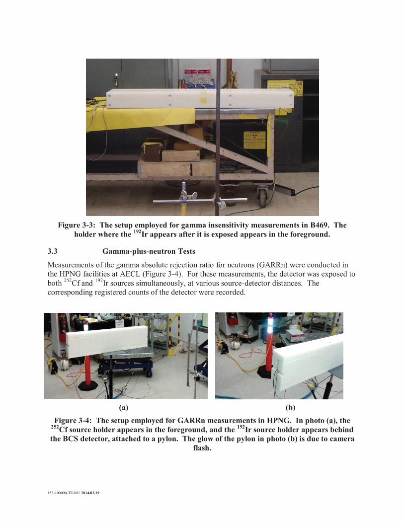
Figure 3-3: The setup employed for gamma insensitivity measurements in B469. The holder where the 192Ir appears after it is exposed appears in the foreground.
3.3 Gamma-plus-neutron Tests
Measurements of the gamma absolute rejection ratio for neutrons (GARRn) were conducted in the HPNG facilities at AECL (Figure 3-4). For these measurements, the detector was exposed to both 252Cf and 192Ir sources simultaneously, at various source-detector distances. The corresponding registered counts of the detector were recorded.
(a) (b) Figure 3-4: The setup employed for GARRn measurements in HPNG. In photo (a), the
252Cf source holder appears in the foreground, and the 192Ir source holder appears behind the BCS detector, attached to a pylon. The glow of the pylon in photo (b) is due to camera
flash.

153-100000-TE-001 2014/03/19
3.4 Data Acquisition Electronics
BCS neutron detector measurements were collected using an AmpTek PocketMCA 8000A, as well as with a Nuclear Instruments Module (NIM) counter. The PocketMCA records signal output from a neutron detector that is shaped through a NIM shaping amplifier, using either an Ortec 570 or Ortec 671 amplifier. Dead time in the recorded count rate was corrected by multiplying it by the ratio of the MCA’s real time to live time. The NIM counter (either an Ortec 996 or Ortec 776 model) received detector signal that wasrelayed though a shaping amplifier (Ortec 570 or Ortec 671), followed by a single channel analyzer (Ortec 550A or Ortec 406A), and finally a gate and delay generator (Ortec 416A) – see Figure 3-5. The role of the single channel analyzer was to set the lower level discriminator (LLD), and the role of the gate and delay generator was to set a fixed delay time longer the delay time of the acquisition electronics, which then became the new effective dead time of the acquisition system. Then a non-paralyzable model was used to correct for dead time in the recorded count rate [1]. For these measurements, the delay time was set to 12 s. The 3He detector was designed to collect data through its own self-contained RS-705 data acquisition unit, so the above methods did not apply to this detector. The RS-705 unit recorded and stored counts binned in 1 second intervals, up to a 24 hour period of data acquisition time.

153-100000-TE-001 2014/03/19
Figure 3-5: Photo of NIM modules, displaying settings and connections employed for neutron counting

153-100000-TE-001 2014/03/19
4. MEASUREMENT RESULTS
4.1 Neutron Efficiency Measurements
4.1.1 Pulse height spectra and choice of discriminator level
A representative pulse height spectrum from the BCS neutron detector while registering neutrons from an exposed, bare 252Cf source in AECL’s HPNG facility, is shown in Figure 4-1. The spectrum shows some energy pile-up near the zeroth channel, which is due to the presence of gamma emission from the 252Cf source. Recent literature [10] has demonstrated that the contribution of gamma dose is about 5% of the total 252Cf neutron dose. This confirms that the gamma energy pile-up should form only a small portion of the overall pulse height spectrum.
Figure 4-1: A typical pulse height spectrum for the boron-lined neutron detector. In this case, the 252Cf source-detector distance is 2 m, and the counts are collected over 30 s.
Figure 4-1 also shows a relatively low plateau region for channels 20 to 60, preceding the majority of neutron counts that appear at higher channels. The region of interest (ROI) of the pulse height spectrum was defined to be channels 34 to 511 (end of the spectrum), where channel 34 appears near the center of the plateau region. Integration of the spectrum over the ROI provides the number of neutron counts. This choice of ROI serves to effectively discriminate against counts due to gamma events, while minimally sacrificing counts due to neutron events. Based on the typical spectrum shown in Figure 4-1, Figure 4-2 below demonstrates how the counts change by at most 15% when setting the lower bound of the ROI to other channels in range of 0 to 60. Counts from the MCA defined with the ROI of channels 34 to 511 agree with NIM counter counts with the LLD of the single channel analyzer set to 320 mV, typically within 5%. The LLD of the NIM counter was therefore set to 320 mV for neutron counting. Neutron counting data for the BCS detector presented hereafter in this report will display NIM counter data.

153-100000-TE-001 2014/03/19
Figure 4-2: Percentage change in the MCA counts when varying the lower bound of the ROI from channel 34, between channels 0 and 60.
4.1.2 Effect of moderator thickness
4.1.2.1 GEANT4 simulation: determine optimal moderator thickness
The optimal thickness of high density polyethylene (HDPE) moderator material with which to encase the BCS detector, was determined with preliminary calculations carried out with GEANT4 (GEometry ANd Tracking) Monte Carlo package [11]. The simulations consisted of a bare 252Cf source positioned at a specified distance from a 1 m x 0.18 m detector encased with HDPE of varying thickness. The source emitted 10 × 106 neutrons uniformly over a 4 solid angle in the simulation, and the number of neutrons incident in the detector plane was tallied. This was done for source-detector distances of 2 m and 4 m. A snapshot of the simulation is shown in Figure 4-3. The counts are plotted versus moderator thickness in Figure 4-4, which indicates that 5 cm ( 2”) moderator thickness appears to admit the most neutrons to the detector.The energy distribution of the neutrons arriving at the detector for this moderator thickness is shown in Figure 4-5; the distribution resembles a typical Maxwellian representation of a thermal neutron spectrum, with a peak position value close to 0.025 eV. Based on these simulation results, 2” thick moderator material was designed and fabricated with which to surround and moderate the BCS detector.

153-100000-TE-001 2014/03/19
Figure 4-3: Snapshot of a GEANT4 simulation investigating the ideal moderator thickness to thermalize neutrons emitted by a 252Cf source
Figure 4-4: GEANT4 detector simulation counts vs. moderator thickness

153-100000-TE-001 2014/03/19
Figure 4-5: Energy distribution of neutrons detected in the GEANT4 simulation. In this case, the source-detector distance was set to 2 m, and the moderator thickness was 5 cm
4.1.2.2 Experiment: replacing the front incident moderator panel with smaller thickness
Further discussion also suggested that neutrons might be better thermalized and detected if the front moderator thickness was made thinner than the other sides of the detector. Measurements in HPNG were therefore conducted with boron-lined detector surrounded by 2 inch thick moderator on all sides, as well as with the front panel replaced with 1 inch thick moderator. Figure 4-6 below shows the BCS detector counts versus distance for the two moderator thickness configurations. The graph shows that the two configurations give comparable detector count rates in when exposed to an unmoderated 252Cf neutron energy spectrum.
neutron energy/eV 0 0.05 0.1 0.15 0.2 0.25
coun
ts
0
50
100
150
200
250
300

153-100000-TE-001 2014/03/19
Figure 4-6: Count rate of the BCS detector versus source-detector distance, when exposed to a 252Cf source for differing moderator thickness configurations: encasing entirely in 2”
thick HPDE moderator (red squares), and replacing a 2” panel with a 1” thick panel at the front incident side (black circles)
4.1.3 Influence of BCS detector orientation
The influence of BCS detector orientation was also investigated. For a moderator thickness of 2” on all sides, the count rate of the detector was measured when placing its broader side parallel to the floor (horizontal configuration), as opposed to perpendicular to the floor (vertical configuration). Figure 4-7 displays the measurements versus source-detector distance for these two orientations. The horizontal orientation presents a front incident area that is a factor of 7 lower than for the vertical orientation, yet the count rate is reduced by a factor of less than 2. This suggests that the horizontal orientation detects more neutrons per unit incident area, than does the vertical orientation. This is due to each incident neutron having greater likelihood of being detected in the horizontal configuration, than in the vertical configuration, since there are more BCS straws behind the incident area in the horizontal configuration, than in the vertical configuration.

153-100000-TE-001 2014/03/19
Figure 4-7: Count rate of the BCS detector versus source-detector distance, when exposed to a 252Cf source for differing detector orientation: horizontal orientation (red squares),
and vertical orientation (black circles)
4.1.4 Shadow cone measurements
The measurements in Figures 4-6 and 4-7 include both direct and scattering components in the neutron count measurements. To measure only the direct component of the neutron counts, the shadow cone method described in the previous section was employed. Shadow cone measurements were performed at a source-detector distance of 2 m, as this is the distance that applies in the 2.5 cps/ng neutron detection efficiency standard mentioned in the Introduction section. However, due to the large active area of the BCS detector, and the size limitations of the shadow cones, the largest shadow cone could not provide full shadow coverage of the BCS active area at 2 m distance. As such, shadow cone measurements were also performed at 4 m, where the largest shadow cone could provide adequate shadowing, and therefore enable an accurate estimate of the direct neutron counts. Table 4-1 summarizes the results of these shadow cone measurements.

153-100000-TE-001 2014/03/19
Table 4-1: Summary of shadow cone measurements performed with the BCS detector.Counts are for 30 s real time, and corrected for dead time. The detector orientation was
vertical.
Source-Detector Distance
(m)
Moderator Configuration
252Cf mass (ng)
Counts without Shadow (Total)
Counts with
Shadow (Scattered)
Difference (Direct)
Detection Efficiency (cps/ng)
2 1” front + 2” other sides
35,512 1283105 883465 399640 0.38
4 1” front + 2” other sides
35,512 596397 419307 177090 0.17
4 2” all sides 36,389 551972 343357 208615 0.19
The detection efficiency of the BCS detector at 2 m distance from the source was found to be 0.38 cps/ng. This is quite a bit lower than the 2.5 cps/ng standard. However, the number is suspect since the cone did not properly shadow the detector at 2 m. Since the detector was not properly shadowed, some of the direct component of neutron flux incident on the detector was included in the scattering component measurement (counts with shadow). The size of the direct component (the difference between counts without shadow and counts with shadow) is thenunderestimated, and therefore so is the detection efficiency. The efficiency of 0.17-0.19 cps/ng estimated at 4 m distance is more reliable, since the detector was properly shadowed at this distance. Figure 4-8 demonstrates that the BCS detector count rate (without shadow cone) varies as 1/r2 for distances in the range of 2 – 4 m. Figure 4-4 also indicates a factor of 3.9 between the counts tallied at 2 m, and the counts tallied at 4 m, in the GEANT4 simulation; this is close to what is expected from 1/r2 intensity scaling. Using the 0.17-0.19 cps/ng efficiency estimates at 4 m, simple 1/r2 intensity scaling, where r is the source-detector distance, yields an estimate of efficiency at 2 m of about 0.7 cps/ng.

153-100000-TE-001 2014/03/19
Figure 4-8: Count rate of the BCS detector (without shadow cone) versus inverse source-detector distance squared, for distances in the range of 2 to 4 m. The BCS detector was in
the vertical orientation, with 2” thick moderator on all sides.
There is an additional caveat to the results shown in Table 3-1. The 2.5 cps/ng standard stipulates that the 252Cf source should be surrounded by 0.5 cm thick lead to reduce its gamma emission, as well as 2.5 cm thick polyethylene to moderate the emitted neutrons [2]. It was not possible to comply with these conditions in the measurements performed at HPNG. The measurements shown in this work are for an unmoderated 252Cf source; only the detector was moderated. Based on measurements reported in literature, moderating the 252Cf source can increase the efficiency estimate by a factor of 1.2 [7]. Even with this additional factor, the final estimated efficiency of the BCS detector (0.84 cps/ng) is well below the 2.5 cps/ng standard. Unfortunately, shadow cone measurements could not be carried out with the 3He detector. The data acquisition unit that interfaces with the 3He detector is designed for optimal operation in low neutron fluence fields (less than ~1000 cps). The neutron fluence from the HPNG 252Cf source was too high for the 3He detector, such that the detector acquisition electronics could not yield meaningful counts.
4.1.5 Discussion
Some comparison of the efficiency measurements in this report with published efficiency measurements of other BCS detectors should be made. Kouzes et al. [7] have tested a BCSneutron detector from Proportional Technologies, but in a different straw configuration. The detector consists of 171 straws, each of which are 4 mm in diameter. The straws are individually surrounded by moderator, in an array consisting of 9 rows of 19 tubes each. The array fit in a

153-100000-TE-001 2014/03/19
space of 0.114 m deep x 0.304 m wide x 2.18 m tall, with an active surface area of 0.663 m2. For this configuration, they measured the neutron detection efficiency to be between 4.2 and 4.7 cps/ng. Lacy et al. [12] have conducted neutron efficiency measurements on BCS detectors from Proportional Technologies in a similar configuration. Using 85 straws, the measured sensitivity is between 3.34 and 3.45 cps/ng, and for 63 straws it is 2.86 cps/ng. The Proportional Technologies website [13] claims to have an efficiency of 3.55 cps/ng for 96 straws. These measurements are summarized in Figure 4-9, which demonstrates an approximately linear trend in the scaling. This trend is confirmed by Fig. 4 of Ref [12].
Figure 4-9: Efficiency in detection of neutrons from moderated 252Cf versus the number of 4 mm diameter BCS straws mounted in a hexagonal array surrounded by HDPE
moderator, from Proportional Technologies, Inc. Data is taken from Refs. [7,12,13].
The scaling of Figure 4-9 does not include our 0.84 cps/ng estimated for the 49 straws in the BCS detector evaluated in this report. This is because the straw configuration of the detector evaluated in this report is fundamentally different. Detectors employed for Figure 4-9 consist of 4 mm diameter straws individually surrounded by HDPE moderator in a hexagonal array. This appears to be more optimal than the configuration of the BCS detector evaluated in this work,which consists of 7 mm diameter straws bundled together in groups of 7, and surrounded by air in their 1” diameter aluminum tubes. Figure 4-7 suggests that to meet the 2.5 cps/ng standard with the configuration evaluated in this work, more 1” diameter tubes could be set behind each other. Figure 4-7 shows that the ratio in counts between vertical and horizontal configurations at 2 m is 1.53, even though the front incident area of the detector is reduced by a factor of 7 in the horizontal configuration. The vertical configuration has a single 1” diameter tube deep for a direct neutron incident on the front
153-100000-TE-001 2014/03/19
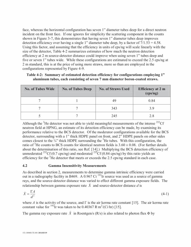
face, whereas the horizontal configuration has seven 1” diameter tubes deep for a direct neutron incident on the front face. If one ignores for simplicity the scattering component in the counts shown in Figure 3-7, this demonstrates that having seven 1” diameter tubes deep improves detection efficiency over having a single 1” diameter tube deep, by a factor of 7/1.53 = 4.58. Using this factor, and assuming that the efficiency in units of cps/ng will scale linearly with the size of the detector, Table 4-2 summarizes estimates of how much the neutron detection efficiency at 2 m source-detector distance could improve when using seven 1” tubes deep and five or seven 1” tubes wide. While these configurations are estimated to exceed the 2.5 cps/ng at 2 m standard, this is at the price of using more straws, more so than are employed in the configurations represented by Figure 4-9.
Table 4-2: Summary of estimated detection efficiency for configurations employing 1” aluminum tubes, each consisting of seven 7 mm diameter boron-coated straws.
No. of Tubes Wide No. of Tubes Deep No. of Straws Used Efficiency at 2 m (cps/ng)
7 1 49 0.84
7 7 343 3.9
5 7 245 2.8
Although the 3He detector was not able to yield meaningful measurements of the intense 252Cf neutron field at HPNG, an estimate of its detection efficiency can be made, by examining its performance relative to the BCS detector. Of the moderator configurations available for the BCS detector, surrounding with a 1” thick HDPE panel on front, and 2” HDPE panels on other sides comes closest to the ¾” thick HDPE surrounding the 3He tubes. With this configuration, the ratio of 3He counts to BCS counts for identical neutron fields is 3.60 ± 0.08. (For further details about the determination of this ratio, see Ref. [14].) Multiplying the BCS detection efficiency of unmoderated 252Cf (0.7 cps/ng) and moderated 252Cf (0.84 cps/ng) by this ratio yields an efficiency for the 3He detector that meets or exceeds the 2.5 cps/ng standard in each case.
4.2 Gamma Insensitivity Measurements
As described in section 2, measurements to determine gamma intrinsic efficiency were carried out in a radiography facility in B469. A 0.967 Ci 192Ir source was used as a source of gamma rays, and the source-detector distance was varied to effect different gamma exposure fields. The relationship between gamma exposure rate X and source-detector distance d is
2dAX (4-1)
where A is the activity of the source, and is the air kerma rate constant [15]. The air kerma rate constant value for 192Ir was taken to be 0.40367 R·m2/(Ci·hr) [15].
The gamma ray exposure rate X in Roentgen/s (R/s) is also related to photon flux by

153-100000-TE-001 2014/03/19
air
en EEX )(1083.1 8 (4-2)
where E is the average photon energy in MeV, ( en/ )air is the mass interaction coefficient of air in cm2/g, and is in s-1·cm-2 [16]. The average photon energy from the gamma emission spectrum of 192Ir is 0.38 MeV. The mass interaction coefficient of air is interpolated to be 0.02934 cm2/g at 0.38 MeV [17]. One can solve for from Equation (4-2) to determine the photon flux for a given gamma exposure rate. (Note that estimating the exposure rate and photon flux in this way ignores any room scattering contribution.) From the photon flux and detector area, the incident photon rate can be determined and subsequently divided into the measured detector count rate response to the gamma field. This ratio estimates the gamma intrinsic efficiency. The response of the neutron detectors to gamma irradiation occurs primarily for low values of the Lower Level Discriminator (LLD) setting. This is demonstrated in the pulse height spectrum shown below in Figure 4-10.
Figure 4-10: Pulse height spectrum for the BCS detector when irradiated with a 20 mR/hr 137Cs gamma field, in GC60 facility.
Figures 4-11 and 4-12 show plots of the response of the BCS detector for varying values of LLD,. For the BCS detector, the LLD was varied through an Ortec 406A single channel analyzer. Figure 4-13 shows an analogous graph for the 3He detector, wherein the LLD was varied through its RS-705 data acquisition unit. Figure 4-14 shows the background recorded by the BCS detector as a function of LLD, in the absence of gamma ray exposure.

153-100000-TE-001 2014/03/19
Figure 4-11: BCS detector response to 192Ir gamma irradiation, in the vertical orientation, versus LLD
153-100000-TE-001 2014/03/19
Figure 4-12: BCS detector response to 192Ir gamma exposure, in the horizontal orientation, versus LLD

153-100000-TE-001 2014/03/19
Figure 4-13: 3He detector response to 192Ir gamma irradiation versus LLD
Figure 4-14: BCS detector background without 192Ir gamma irradiation

153-100000-TE-001 2014/03/19
Figure 4-14 demonstrates that the background count rate of the BCS detector is 1 cps or lower, independent of the LLD setting. It should be noted that the background measurements include all sources of noise that would be present during a 192Ir gamma irradiation, including the ticking klaxon alarm that sounds when gamma fields are present. In the case of the 3He detector (Figure 4-13), the detector response to 10 mR/hr gamma exposure is essentially on the level of background count rates (1-2 cps). The low background count rate of the detectors for all LLD values in such an environment is testament to the quiet environment of room 130 in building 469. Figures 4-11 to 4-14 demonstrate that the heightened detector count rate at lower LLD values during gamma exposure represent a response of the detector solely to the incident gamma field. The GC60 facility does not offer the same degree of decoupling between noise and gamma-induced detector response, since the facility introduces additional equipment noise and vibrations during its irradiation operation. These additional sources of noise and vibration can be picked up by the detectors through a micro-phonics effect. The determination of the gamma intrinsic efficiency, or gamma insensitivity, is dependent upon the choice of LLD. In the case of the BCS detector, the gain setting of the Ortec 671 shaping amplifier also had some influence. These factors should be set such that the count rate is just above background levels when exposing the detector to 10 or 20 mR/hr gamma exposure fields [18]. In the case of the BCS detector, the appropriate LLD value to use was 80 mV when the coarse gain was set to 100x, and 20 or 30 mV when the coarse gain was set to 50x (the fine gain in each case was set to 1x). In the case of the 3He detector, acquisition software and hardware limited the LLD settings between 50 mV and 400 mV. Steady count rates could only be obtained for LLD values between 100 mV and 400 mV for 10 mR/hr, 20 mR/hr, and 50 mR/hr gamma exposure. For 400 mR/hr, the LLD was further limited to 250 mV – 400 mV for steady data-taking. It is noteworthy how the data in Figure 4-13 for 50 mR/hr and 400 mR/hr cases appears to plateau well above background for higher LLD values. This may be due to signal pile-up effect, occurring at voltages above the LLD values shown in Figure 4-13. Figure 4-15 displays the average gamma insensitivity for the BCS detector in horizontal and vertical orientations, and for the 3He detector. The gamma insensitivity values were determined from the ratio of the observed count rate to the expected incident photon rate. The expected incident photon rate was determined from the photon flux in Equation (4-2) and the incident detector area. In the case of the BCS detector, the values shown are averaged between the 50x and 100x coarse gain setting cases, and the error bars shown represent the spread in the values from these cases. In the case of the 3He detector, the data shown is with taking 100 mV as the LLD in the case of gamma exposure fields 50 mR/hr and lower. For 400 mR/hr, 250 mV was taken as the LLD. The error bars for 3He data points is the standard deviation of the mean of the count rates measured each second over a specific time period. Note that since Equations (4-1) and (4-2) neglect any scattering component, the actual photon exposure rate, and corresponding photon flux, is likely to be greater. Since the intrinsic gamma efficiency is the detector count rate divided by the incident photon rate (= incident photon flux × detector area), the true intrinsic gamma efficiency is likely to be lower than what is shown in Figure 4-15.

153-100000-TE-001 2014/03/19
Figure 4-15: Average gamma insensitivity versus LLD, for the BCS detector in vertical (black squares) and horizontal (red circles) orientations, and for the 3He detector
Figure 4-15 demonstrates that gamma insensitivity worsens with gamma exposure. The BCS detector displays the most superior gamma insensitivity in the vertical orientation. BCS gamma insensitivity worsens in the horizontal orientation, since each incident gamma ray has a higher probability of registering an event (in one of up to seven 1” diameter tubes, each behind each other) than in the vertical orientation. 3He gamma insensitivity is systematically worse than the BCS detector in the vertical orientation, and in some cases worse than the BCS in the horizontal orientation. These gamma insensitivity values are comparable to those reported in literature [5,7]. Both detectors meet the acceptance criteria of < 10-6 at 10 mR/hr exposure.
4.3 Gamma Absolute Rejection Ratio for neutrons (GARRn)
Measurements of the gamma absolute rejection ratio for neutrons (GARRn) were conducted in the HPNG facility. In these measurements, the BCS detector was exposed simultaneously to a 252Cf neutron field, and a 192Ir gamma field. The activity of the 192Ir source at the time of testing was 1.3455 Ci. With the 252Cf source – BCS detector distance set at 2 m or 4 m, the 192Ir field was varied between 20 and 400 mR/hr by varying the 192Ir source – BCS detector distance. The
153-100000-TE-001 2014/03/19
GARRn was estimated by dividing counts with both sources exposed by the counts with only the 252Cf source exposed. The results are shown in Figure 4-16 below, with the y-axis scale range set to the acceptance bounds of 0.9 to 1.1. The measured GARRn ratio is well within these bounds at all tested levels of gamma exposure. Due to the 3He detector being unable to give reliable readings at the level of 252Cf neutron exposure, no GARRn results are available to report for this detector.
Figure 4-16: Gamma absolute rejection ratio for neutrons versus gamma exposure rate,for 252Cf – BCS detector distances of 2 m (red triangles) and 4 m (black squares)

153-100000-TE-001 2014/03/19
5. SOME NOTES ON INTERFACING WITH PROPORTIONAL TECHNOLOGIES INC. AS A CUSTOMER
As part of this technical evaluation, it is perhaps relevant to make some remarks about past experiences in interactions with Proportional Technologies Inc. (PTI) that could affect future decisions about further procurement from this company. At the time of procuring a boron-lined detector from PTI, detectors with straws that have optimal surface-area to volume ratios in configurations that optimize detection sensitivity for safeguard applications were sought from the company, but were not available. The detector evaluated here was the only configuration available. It took some months after purchasing to receive the detector from the company. When the detector arrived, it was found to be with an electronics configuration different what was advertised on their website [13]. The detector was also without the aluminum frame around the active area tubes that is presented on their website. None of these changes were communicated by Proportional Technologies before the detector arrived. In the fall of 2013, specifications for the detector were promised. As of yet, those specifications have not arrived. Overall, customer service from PTI has left much to be desired.

153-100000-TE-001 2014/03/19
6. SUMMARY AND CONCLUSIONS
This report presents a technical evaluation of a boron-lined neutron detector from Proportional Technologies Inc. This detector was evaluated as a potential replacement for 3He neutron detection technology. Measurements of the detector’s neutron detection efficiency, gamma insensitivity, and its gamma absolute rejection ratio for neutrons were conducted, in controlled indoor environments. All of these measurements were made in close comparison with a 3He detector, wherever possible. Neutron detection efficiency measurements were conducted in the HPNG facility at AECL using an unmoderated, calibrated 252Cf source. The direct component of the incident neutron flux was measured using a shadow cone method [9]. Reliable shadow cone measurements for the BCS detector were conducted at 4 m source – detector distance, yielding 0.18 cps/ng sensitivity response. Simple 1/r2 scaling to 2 m estimates the detector sensitivity to be 0.7 cps/ng at 2 m.Based on measurements in published literature, moderating the 252Cf source would increase the sensitivity at 2 m by about a factor of 1.2 to 0.84 cps/ng. This is well below the minimum acceptance criteria of 2.5 cps/ng at 2 m 252Cf source-detector distance [2,6]. In order for this configuration of boron-coated straws to meet this acceptance criteria, more straws (to a total of 245 straws or more) would need to be added in behind to capture a larger percentage of the incident neutron flux.Direct shadow cone measurements with the 3He detector were not possible since its acquisition electronics could not keep up with the intense neutron field of the 252Cf source. The relevant ratio of 3He/BCS detector response, based on lower neutron fields, is 3.60 ± 0.08. Based on this ratio, the 3He detector response meets or exceeds the minimum acceptance of 2.5 cps/ng at 2 m for safeguard applications. The intrinsic gamma efficiency, defined as the neutron detector count rate divided by the rate of gamma photons incident upon the detector, measures the insensitivity of the detector to gamma radiation, in the absence of neutron radiation. This efficiency should be < 10-6 at 10 mR/hr exposure for accepted safeguard use. The measured gamma insensitivity at 10 mR/hr of the boron – lined detector in the vertical orientation, at 6.8 × 10⁻⁸, surpasses that of the 3He detector, at 1.4 × 10⁻⁷. It should be noted that these estimates are overestimates, since the scattered component of the incident gamma flux has been neglected in the computations. The gamma absolute rejection ratio for neutrons (GARRn) provides a measure of the influence of a gamma field. It quantifies the ratio of efficiency of neutron counting when the detector is simultaneously exposed to neutron and gamma radiation, to the efficiency of neutron counting when the detector is exposed to the same neutron field in the absence of gamma radiation. If the gamma radiation has no influence, this ratio is unity. The acceptance criteria for safeguards is 0.9 < GARRn < 1.1. The BCS detector response was tested in the presence of neutron radiation from 252Cf, with and without gamma radiation of varying strength (10 to 400 mR/hr) from a 192Ir source. The resulting GARRn ratio is well within the bounds of acceptance. These tests could not be carried out for the 3He detector, again due to the inability of its data acquisition system to count steadily in the presence of the intense neutron radiation from the 252Cf source.

153-100000-TE-001 2014/03/19
7. REFERENCES
[1] G. F. Knoll, Radiation Detection and Measurement, Third Edition. Toronto: John Wiley and Sons, Inc. 2000.
[2] R. T. Kouzes, J. H. Ely, L. E. Erikson, W. J. Kernan, Z. T. Lintereur, E. R. Siciliano, D. L. Stephens, D. C. Stromswold, R. M. van Ginhoven, M. L. Woodring, “Neutron detection alternatives to 3He for national security applications”, Nuclear Instruments and Methods in Physics Research A, vol. 623, pp. 1035-1045, 2010.
[3] R. T. Kouzes, “The 3He Supply Problem”, Pacific Northwest National Laboratory Report PNNL-18388, April 2009.
[4] J. L. Lacy, A. Athanasiades, N. N. Shehad, R. A. Austin, C. S. Martin, “Novel Neutron Detection for High Rate Imaging Applications”, IEEE Nuclear Science Symposium Conference Record, vol. 1, pp. 392-396, 2002.
[5] R. T. Kouzes, J. R. Ely, A. T. Lintereur, D. L. Stephens, “Neutron Detector Gamma Insensitivity Criteria”, Pacific Northwest National Laboratory Report PNNL-18903, October 2009.
[6] P. Peerani, A. Tomanin, S. Pozzi, J. Dolan, E. Miller, M. Flaska, M. Battaglieri, R. De Vita, L. Ficini, G. Ottonello, G. Ricco, G. Dermody, C. Giles, “Testing on novel neutron detectors as alternative to 3He for security applications”, Nuclear Instruments and Methods in Physics Research A, vol. 696, pp.110-120, 2012.
[7] R. T. Kouzes, J. R. Ely, D. C. Stromswold, “Boron-Lined Straw-Tube Neutron Detector Test”, Pacific Northwest National Laboratory Report PNNL-19600, August 7, 2010.
[8] P. Narayan, L. R. Meghwal, K. C. Songara, S. G. Baijapurkar, P. K. Bhatnagar, “Radiological safety aspects in Californium-252 source transfer operation”, Indian Journal of Pure and Applied Physics, vol. 48, pp. 798-801, 2010.
[9] International Organization for Standardization. Reference neutron radiations – Part 2: Calibration fundamentals of radiation protection devices related to the basic quantities characterizing the radiation field. Geneva: ISO; ISO-8529, 2000.
[10] N. J. Roberts, N. A. Horwood, and C. J. McKay, “Photon Doses in NPL Standard Neutron Fields”, Radiation Protection Dosimetry, doi: 10.1093/rpd/nct249, 2013.
[11] S. Agostinelli , et al., Nuclear Instruments and Methods in Physics Research A, vol. 506, pp.250-303, 2003.
[12] J. L. Lacy, A. Athanasiades, L. Sun, C. S. Martin, T. D. Lyons, M. A. Foss, H. B Haygood, “Boron-coated straws as a replacement for 3He-based neutron detectors”, Nuclear Instruments and Methods in Physics Research A, vol. 652, pp.359-363, 2011.
[13] http://www.proportionaltech.com/new_site/, accessed 21 February 2014. [14] B. M. van der Ende, “Detection of Neutrons Emanating from ZED-2”, AECL document
153-123110-TD-001, March 2014.

153-100000-TE-001 2014/03/19
[15] M. M. Ninkovic, F. Adrovic, “Air Kerma Rate Constants for Nuclides Important to Gamma Ray Dosimetry and Practical Application”, in Gamma Radiation, Prof. Feriz Adrovic (Ed.), ISBN:978-953-51-0316-5, InTech, 2012. Available from http://www.intechopen.com/books/gamma-radiation/.
[16] J. K. Shultis, R. E. Faw, Fundamentals of Nuclear Science and Engineering, Second Edition. New York: CRC Press, 2008.
[17] http://physics.nist.gov/PhysRefData/XrayMassCoef/ComTab/air.html, accessed 13 December 2013, and 21 February 2014.
[18] L. Sun, Proportional Technologies Inc. Personal Communication on January 15, 2014.

153-100000-TE-001 2014/03/19
8. ACKNOWLEDGEMENTS
This work has been conducted in a number of different facilities at AECL, and as such, the help of a collection of individuals should be acknowledged. First and foremost, the supervision of Liqian Li, and Ghaouti Bentoumi must be recognized, for providing their technical direction, as well as facilitating the funding and execution of this project. Regarding measurements conducted in B513 at AECL, Jovica Atanackovic was instrumental in the execution of measurements conducted at HPNG, and for their analysis afterwards. Jovica’s enthusiasm for this project, and his critical approach to achieving quality measurements are hallmarks of this aspect of the project. Ela Rochon was responsible for the execution of gamma-only measurements performed at GC60. The assistance of Neil Leroux must also be acknowledged, who provided very able help in the setup of measurements in both HPNG and GC60, as well as in conducting some of the measurements at GC60. Gordon Tapp oversaw much of the measurements conducted in HPNG, and he is also to be thanked for lending his laptop for the 3He detector data acquisition. Brian Corbett also provided critical support in a number of ways. He and his 192Ir source were employed in gamma-plus-neutron tests conducted at HPNG. Further, gamma-only measurements were performed in his room 130 facility in B469, again using his 192Ir source. On days when Brian when was not available to help with the measurement setup in B469, his colleague Douglas Cram filled in his place. Finally, Henry Seyweerd and John Buckle at Natural Resources Canada are to be thanked for the use of their 3He detector for these tests.

DOCUMENT CONTROL DATA (Security classification of title, body of abstract and indexing annotation must be entered when the overall document is classified)
1. ORIGINATOR (The name and address of the organization preparing the document. Organizations for whom the document was prepared, e.g. Centre sponsoring a contractor's report, or tasking agency, are entered in section 8.)
Atomic Energy of Canada Limited Chalk River ON K0J 1J0
2. 2a. SECURITY MARKING (Overall security marking of the document including
special supplemental markings if applicable.) UNCLASSIFIED 2b. (NON-CONTROLLED GOODS) DMC A REVIEW: GCEC APRIL 2011
3. TITLE (The complete document title as indicated on the title page. Its classification should be indicated by the appropriate abbreviation (S, C or U)
in parentheses after E B -L N
4. AUTHORS (last name, followed by initials – ranks, titles, etc. not to be used) van der Ende, B.M.
5. DATE OF PUBLICATION (Month and year of publication of document.)
April 2014
6a. NO. OF PAGES
39
6b. NO. OF REFS
18
7. DESCRIPTIVE NOTES (The category of the document, e.g. technical report, technical note or memorandum. If appropriate, enter the type of report, e.g. interim, progress, summary, annual or final. Give the inclusive dates when a specific reporting period is covered.) Final Report
8. SPONSORING ACTIVITY (The name of the department project office or laboratory sponsoring the research and development – include address.) DRDC CSS
9a. PROJECT OR GRANT NO. (If appropriate, the applicable research and development project or grant number under which the document was written. Please specify whether project or grant.)
CSSP-2013-CD-1128
9b. CONTRACT NO. (If appropriate, the applicable number under which the document was written.)
NA
10a. ORIGINATOR'S DOCUMENT NUMBER (The official document number by which the document is identified by the originating activity. This number must be unique to this document.) 153-100000-TE-001
10b. OTHER DOCUMENT NO(s). (Any other numbers which may be assigned this document either by the originator or by the sponsor.)
11. DOCUMENT AVAILABILITY (Any limitations on further dissemination of the document, other than those imposed by security classification.)
Unclassified/Unlimited
12. DOCUMENT ANNOUNCEMENT (Any limitation to the bibliographic announcement of this document. This will normally correspond to the Document Availability (11). However, where further distribution (beyond the audience specified in (11) is possible, a wider announcement audience may be selected.)) Unlimited
13. AECL, through its partnership with Defense Research and Development Canada, under the Government of Canada’s Chemical Biological Radiological Nuclear Explosive (CBRNE) Research Technology Initiative (CRTI 08-0241RD), Advanced Applied Physics Solutions (AAPS), Canada Border Services Agency, Carleton University, Health Canada and International Safety Research Inc. has committed to conduct trials at Chalk River of the Canadian muon tomography cargo inspection system. This report outlines the requirements for the installation of this system at Chalk River Laboratory. 14. KEYWORDS, DESCRIPTORS or IDENTIFIERS Neutron Det ctor; Nuclear Detection; Border Security