EVALUATION KIT Wide 4.5V to 28V Input, Dual-Output ...T-Dallas-Semiconduc…General Description The...
28
General Description The MAX15023 dual, synchronous step-down controller operates from a 5.5V to 28V or 5V ±10% input voltage range and generates two independent output voltages. Each output is adjustable from 85% of the input voltage down to 0.6V and supports loads of 12A or higher. Input voltage ripple and total RMS input ripple current are reduced by interleaved 180° out-of-phase operation. The MAX15023 offers the ability to adjust the switching frequency from 200kHz to 1MHz with an external resistor. The MAX15023’s adaptive synchronous rectification elimi- nates the need for external freewheeling Schottky diodes. The device also utilizes the external low-side MOSFET’s on-resistance as a current-sense element, eliminating the need for a current-sense resistor. This protects the DC- DC components from damage during output overloaded conditions or output short-circuit faults without requiring a current-sense resistor. Hiccup-mode current limit reduces power dissipation during short-circuit conditions. The MAX15023 includes two independent power-good out- puts and two independent enable inputs with precise turn-on/turn-off thresholds, which can be used for supply monitoring and for power sequencing. Additional protection features include cycle-by-cycle, low-side, sink peak current limit, and thermal shutdown. Cycle-by-cycle, low-side, sink peak current limit prevents reverse inductor current from reaching dangerous levels when the device is sinking current from the output. The MAX15023 also allows prebiased startup without dis- charging the output and features adaptive internal digital soft-start. This new proprietary feature enables monoton- ic charging of externally large output capacitors at start- up, and achieves good control of the peak inductor current during hiccup-mode short-circuit protection. The MAX15023 is available in a space-saving and ther- mally enhanced 4mm x 4mm, 24-pin TQFN-EP pack- age. The device operates over the -40°C to +85°C extended temperature range. Applications Point-of-Load Regulators Set-Top Boxes LCD TV Secondary Supplies Switches/Routers Power Modules DSP Power Supplies Features ♦ 5.5V to 28V or 5V ±10% Input Supply Range ♦ 0.6V to (0.85 x V IN ) Adjustable Outputs ♦ Adjustable 200kHz to 1MHz Switching Frequency ♦ Guaranteed Monotonic Startup into a Prebiased Load ♦ Lossless, Cycle-by-Cycle, Low-Side, Source Peak Current Limit with Adjustable, Temperature- Compensated Threshold ♦ Cycle-by-Cycle, Low-Side, Sink Peak Current- Limit Protection ♦ Proprietary Adaptive Internal Digital Soft-Start ♦ ±1% Accurate Voltage Reference ♦ Internal Boost Diodes ♦ Adaptive Synchronous Rectification Eliminates External Freewheeling Schottky Diodes ♦ Hiccup-Mode Short-Circuit Protection and Thermal Shutdown ♦ Power-Good Outputs and Analog Enable Inputs for Power Sequencing MAX15023 Wide 4.5V to 28V Input, Dual-Output Synchronous Buck Controller ________________________________________________________________ Maxim Integrated Products 1 23 24 22 21 *EP *EXPOSED PAD (CONNECT TO GROUND). 8 7 9 EN1 PGOOD1 DL1 PGND1 10 FB1 FB2 PGOOD2 DL2 COMP2 PGND2 1 2 LIM2 4 5 6 17 18 16 14 13 LIM1 COMP1 DH2 DH1 BST1 LX1 MAX15023 EN2 V CC 3 15 IN 20 + 11 BST2 SGND 19 12 LX2 RT TQFN TOP VIEW Pin Configuration Ordering Information 19-4219; Rev 2; 3/11 For pricing, delivery, and ordering information, please contact Maxim Direct at 1-888-629-4642, or visit Maxim’s website at www.maxim-ic.com. EVALUATION KIT AVAILABLE PART TEMP RANGE PIN-PACKAGE MAX15023ETG+ -40°C to +85°C 24 TQFN-EP* MAX15023ETG/V+ -40°C to +85°C 24 TQFN-EP* +Denotes a lead(Pb)-free/RoHS-compliant package. *EP = Exposed pad.
Transcript of EVALUATION KIT Wide 4.5V to 28V Input, Dual-Output ...T-Dallas-Semiconduc…General Description The...

General DescriptionThe MAX15023 dual, synchronous step-down controlleroperates from a 5.5V to 28V or 5V ±10% input voltagerange and generates two independent output voltages.Each output is adjustable from 85% of the input voltagedown to 0.6V and supports loads of 12A or higher. Inputvoltage ripple and total RMS input ripple current arereduced by interleaved 180° out-of-phase operation.
The MAX15023 offers the ability to adjust the switchingfrequency from 200kHz to 1MHz with an external resistor.The MAX15023’s adaptive synchronous rectification elimi-nates the need for external freewheeling Schottky diodes.The device also utilizes the external low-side MOSFET’son-resistance as a current-sense element, eliminating theneed for a current-sense resistor. This protects the DC-DC components from damage during output overloadedconditions or output short-circuit faults without requiring acurrent-sense resistor. Hiccup-mode current limit reducespower dissipation during short-circuit conditions. TheMAX15023 includes two independent power-good out-puts and two independent enable inputs with preciseturn-on/turn-off thresholds, which can be used for supplymonitoring and for power sequencing.
Additional protection features include cycle-by-cycle,low-side, sink peak current limit, and thermal shutdown.Cycle-by-cycle, low-side, sink peak current limit preventsreverse inductor current from reaching dangerous levelswhen the device is sinking current from the output. TheMAX15023 also allows prebiased startup without dis-charging the output and features adaptive internal digitalsoft-start. This new proprietary feature enables monoton-ic charging of externally large output capacitors at start-up, and achieves good control of the peak inductorcurrent during hiccup-mode short-circuit protection.
The MAX15023 is available in a space-saving and ther-mally enhanced 4mm x 4mm, 24-pin TQFN-EP pack-age. The device operates over the -40°C to +85°Cextended temperature range.
ApplicationsPoint-of-Load Regulators
Set-Top Boxes
LCD TV Secondary Supplies
Switches/Routers
Power Modules
DSP Power Supplies
Features 5.5V to 28V or 5V ±10% Input Supply Range 0.6V to (0.85 x VIN) Adjustable Outputs Adjustable 200kHz to 1MHz Switching Frequency Guaranteed Monotonic Startup into a Prebiased
Load Lossless, Cycle-by-Cycle, Low-Side, Source Peak
Current Limit with Adjustable, Temperature-Compensated Threshold
Cycle-by-Cycle, Low-Side, Sink Peak Current-Limit Protection
Proprietary Adaptive Internal Digital Soft-Start ±1% Accurate Voltage Reference Internal Boost Diodes Adaptive Synchronous Rectification Eliminates
External Freewheeling Schottky Diodes Hiccup-Mode Short-Circuit Protection and
Thermal Shutdown Power-Good Outputs and Analog Enable Inputs
for Power Sequencing
MA
X1
50
23
Wide 4.5V to 28V Input, Dual-OutputSynchronous Buck Controller
________________________________________________________________ Maxim Integrated Products 1
23
24
22
21
*EP
*EXPOSED PAD (CONNECT TO GROUND).
8
7
9
EN1
PGOO
D1 DL1
PGND
1
10
FB1
FB2
PGOO
D2
DL2
COM
P2
PGND
2
1 2
LIM2
4 5 6
1718 16 14 13
LIM1
COMP1
DH2
DH1
BST1
LX1
MAX15023
EN2
V CC
3
15
IN
20
+
11 BST2SGND
19 12 LX2RT
TQFN
TOP VIEW
Pin Configuration
Ordering Information
19-4219; Rev 2; 3/11
For pricing, delivery, and ordering information, please contact Maxim Direct at 1-888-629-4642,or visit Maxim’s website at www.maxim-ic.com.
EVALUATION KIT
AVAILABLE
PART TEMP RANGE PIN-PACKAGE
MAX15023ETG+ -40°C to +85°C 24 TQFN-EP*
MAX15023ETG/V+ -40°C to +85°C 24 TQFN-EP*+Denotes a lead(Pb)-free/RoHS-compliant package.*EP = Exposed pad.

MA
X1
50
23
Wide 4.5V to 28V Input, Dual-OutputSynchronous Buck Controller
2 _______________________________________________________________________________________
ABSOLUTE MAXIMUM RATINGS
ELECTRICAL CHARACTERISTICS(VIN = 12V, RT = 33kΩ, CVCC = 4.7µF, CIN = 1µF, TA = -40°C to +85°C, unless otherwise noted. Typical values are at TA = +25°C.)(Note 3)
Stresses beyond those listed under “Absolute Maximum Ratings” may cause permanent damage to the device. These are stress ratings only, and functionaloperation of the device at these or any other conditions beyond those indicated in the operational sections of the specifications is not implied. Exposure toabsolute maximum rating conditions for extended periods may affect device reliability.
Note 1: These power limits are due to the thermal characteristics of the package, absolute maximum junction temperature (150°C),and the JEDEC 51-7 defined setup. Maximum power dissipation could be lower, limited by the thermal shutdown protectionincluded in this IC.
Note 2: Package thermal resistances were obtained using the method described in JEDEC specification JESD51-7, using a four-layerboard. For detailed information on package thermal considerations, refer to http://www.maxim-ic.com/thermal-tutorial.
IN to SGND.............................................................-0.3V to +30VBST_ to VCC............................................................-0.3V to +30VLX_ to SGND .............................................................-1V to +30VEN_ to SGND............................................................-0.3V to +6VPGOOD_ to SGND .................................................-0.3V to +30VBST_ to LX_ ..............................................................-0.3V to +6VDH_ to LX_ ..........................................….-0.3V to (VBST_ + 0.3V)DL_ to PGND_ ............................................-0.3V to (VCC + 0.3V)SGND to PGND_ .................................................. -0.3V to +0.3VVCC to SGND................-0.3V to the lower of +6V or (VIN + 0.3V)All Other Pins to SGND...............................-0.3V to (VCC + 0.3V)
VCC Short Circuit to SGND.........................................ContinuousVCC Input Current (IN = VCC, internal LDO not used) ......600mAPGOOD_ Sink Current ........................................................20mAContinuous Power Dissipation (TA = +70°C)(Note 1)
24-Pin TQFN-EP (derate 27.8mW/°C above +70°C)......2222.2mWOperating Temperature Range ...........................-40°C to +85°CJunction Temperature ......................................................+150°CStorage Temperature Range .............................-60°C to +150°CLead Temperature (soldering, 10s) .................................+300°CSoldering Temperature (reflow) .......................................+260°C
PARAMETER SYMBOL CONDITIONS MIN TYP MAX UNITS
GENERAL
5.5 28Input Voltage Range VIN
VIN = VCC 4.5 5.5V
Quiescent Supply Current IIN VFB1 = VFB2 = 0.9V, no switching 4.5 6 mA
Standby Supply Current IIN_SBY VEN1 = VEN2 = VSGND 0.21 0.35 mA
VCC REGULATOR
6V < VIN < 28V, ILOAD = 5mAOutput Voltage VCC
VIN = 6V, 1mA < ILOAD < 100mA5.00 5.2 5.50 V
VCC Regulator Dropout ILOAD = 100mA 0.07 V
VCC Short-Circuit Output Current VIN = 5V 150 250 mA
VCC Undervoltage Lockout VCC_UVLO VCC falling 3.6 3.8 4 V
VCC Undervoltage LockoutHysteresis
430 mV
ERROR AMPLIFIER (FB_, COMP_)
FB_ Input Voltage Set-Point VFB_ 594 600 606 mV
FB_ Input Bias Current IFB_ VFB_ = 0.6V -250 +250 nA
PACKAGE THERMAL CHARACTERISTICS (Note 2)24 TQFN-EPJunction-to-Ambient Thermal Resistance (θJA)...............+36°C/WJunction-to-Case Thermal Resistance (θJC)......................+8°C/W

MA
X1
50
23
Wide 4.5V to 28V Input, Dual-OutputSynchronous Buck Controller
_______________________________________________________________________________________ 3
PARAMETER SYMBOL CONDITIONS MIN TYP MAX UNITS
FB_ to COMP_Transconductance
gm ICOMP = ±40µA 650 1200 1900 µS
Amplifier Open-Loop Gain No load 80 dB
Amplifier Unity-Gain Bandwidth 10 MHz
COMP_ Swing (High) 2.4 V
COMP_ Swing (Low) No load at COMP_ 0.6 V
COMP_ Source/Sink Current ICOMP_ | ICOMP_ |, VCOMP_ = 1.5V 45 80 120 µA
ENABLE (EN_)
EN_ Input High VEN_H EN_ rising 1.15 1.20 1.25 V
EN_ Input Hysteresis VEN_HYS 150 mV
EN_ Input Leakage Current ILEAK_EN_ -250 +250 nA
OSCILLATOR
Switching Frequency fSW Each converter 460 500 540 kHz
Switching FrequencyAdjustment Range
(Note 4) 200 1000 kHz
PWM Ramp Peak-to-PeakAmplitude
VRAMP 1.42 V
PWM Ramp Valley VVALLEY 0.72 V
Phase Shift BetweenChannels
From DH1 to DH2 rising edges 180 Degrees
Minimum Controllable On-Time 60 100 ns
Maximum Duty Cycle 86 87.5 %
OUTPUT DRIVERS
Low, sinking 100mA, VBST_ - VLX_ = 5V 1DH_ On-Resistance
H i g h, sour ci ng 100m A, V B S T _ - V L X _ = 5V 1.2Ω
Low, sinking 100mA, VCC = 5.2V 0.75DL_ On-Resistance
High, sourcing 100mA, VCC = 5.2V 1.4Ω
Sinking 3DH_ Peak Current CLOAD = 10nF
Sourcing 2A
Sinking 3DL_ Peak Current CLOAD = 10nF
Sourcing 2A
DH_, DL_ Break-Before-MakeTime (Dead Time)
15 ns
SOFT-START
Soft-Start Duration 2048Switching
cycles
Reference Voltage Steps 64 Steps
ELECTRICAL CHARACTERISTICS (continued)(VIN = 12V, RT = 33kΩ, CVCC = 4.7µF, CIN = 1µF, TA = -40°C to +85°C, unless otherwise noted. Typical values are at TA = +25°C.)(Note 3)

MA
X1
50
23
Wide 4.5V to 28V Input, Dual-OutputSynchronous Buck Controller
4 _______________________________________________________________________________________
ELECTRICAL CHARACTERISTICS (continued)(VIN = 12V, RT = 33kΩ, CVCC = 4.7µF, CIN = 1µF, TA = -40°C to +85°C, unless otherwise noted. Typical values are at TA = +25°C.)(Note 3)
PARAMETER SYMBOL CONDITIONS MIN TYP MAX UNITS
CURRENT LIMIT/HICCUP
Cycle-by-Cycle, Low-Side,Source Peak Current-LimitThreshold Adjustment Range
Source peak limit = VLIM_/10 30 300 mV
LIM_ Reference Current ILIM_ VLIM_ = 0.3V to 3V, TA = +25°C 45 50 55 µA
LIM_ Reference Current TC VLIM_ = 0.3V 2400 ppm/°C
Number of Consecutive Current-Limit Events to Hiccup
7 Events
Hiccup Timeout Out of soft-start 7936Switching
cycles
Cycle-by-Cycle, Low-Side,Sink Peak Current-Limit SenseVoltage
V L IM _/20
V
BOOST
Boost Switch Resistance VIN = VCC = 5.2V, IBST_ = 10mA 4.5 8 ΩPOWER-GOOD OUTPUTS
VFB_ rising 88.5 92.5 96.5PGOOD_ Threshold
VFB_ falling 85.5 89.5 93.5%
V FB( N OM IN A L)
PGOOD_ Output Leakage ILEAK_PGD VPGOOD_ = 28V, VEN_ = 5V, VFB_ = 0.8V 1 µA
PGOOD_ Output Low Voltage VPGOOD_L IPGOOD_ = 2mA, EN_ = SGND 0.4 V
THERMAL SHUTDOWN
Thermal Shutdown Threshold +150 °C
Thermal Shutdown Hysteresis Temperature falling 20 °C
Note 3: All Electrical Characteristics limits over temperature are 100% tested at room temperature and guaranteed by design overthe specified temperature range.
Note 4: Select RT as R kf kHz
has aTSW
( )( ( ))
(.
Ω = 2480624806
1 066311
faradunit).

MA
X1
50
23
Wide 4.5V to 28V Input, Dual-OutputSynchronous Buck Controller
_______________________________________________________________________________________ 5
EFFICIENCYvs. LOAD CURRENT
MAX
1502
3 to
c01
LOAD CURRENT (A)
EFFI
CIEN
CY (%
)
101
35404550556065707580859095
300.1 100
VIN = 12V
VOUT1 = 1.2V
VOUT1 = 3.3V
EFFICIENCYvs. LOAD CURRENT
MAX
1502
3 to
c02
LOAD CURRENT (A)
EFFI
CIEN
CY (%
)
101
35404550556065707580859095
100
300.1 100
VOUT1 = 1.2V
VOUT1 = 3.3V
VIN = VCC = 5V
OUTPUT VOLTAGE CHANGEvs. LOAD CURRENT
MAX
1502
3 to
c03
LOAD CURRENT (A)
OUTP
UT V
OLTA
GE C
HANG
E (%
)
108642
99.2
99.4
99.6
99.8
100.0
100.2
100.4
100.6
100.8
101.0
99.00 12
OUT1
VCC VOLTAGEvs. LOAD CURRENT
MAX
1502
3 to
c04
LOAD CURRENT (mA)
SUPP
LY V
OLTA
GE (V
)
13512015 30 45 75 9060 105
5.05
5.10
5.15
5.20
5.25
5.30
5.35
5.40
5.000 150
VCC VOLTAGEvs. IN VOLTAGE
MAX
1502
3 to
c05
IN VOLTAGE (V)
V CC
VOLT
AGE
(V)
242016128
4.15
4.30
4.45
4.60
4.75
4.90
5.05
5.20
5.35
5.50
4.004 28
ILOAD = 5mA
ILOAD = 50mA
VCC VOLTAGEvs. TEMPERATURE
MAX
1502
3 to
c06
TEMPERATURE (°C)
SUPP
LY V
OLTA
GE (V
)
303510-15
5.05
5.10
5.15
5.20
5.25
5.30
5.35
5.40
5.45
5.50
5.00-40 85
ILOAD = 5mA
SWITCHING FREQUENCYvs. RT
MAX
1502
3 to
c07
RT (kΩ)
SWIT
CHIN
G FR
EQUE
NCY
(kHz
)
807050 6030 4020
200300400500600700800900
1000110012001300
10010 90
SWITCHING FREQUENCYvs. TEMPERATURE
MAX
1502
3 to
c08
TEMPERATURE (°C)
SWIT
CHIN
G FR
EQUE
NCY
(kHz
)
603510-15
250300350400450500550600650700750800
200-40 85
RT = 22.1kΩ
RT = 33.2kΩ
RT = 66.5kΩ
IIN CURRENTvs. SWITCHING FREQUENCY
MAX
1502
3 to
c09
SWITCHING FREQUENCY (kHz)
I IN C
URRE
NT (m
A)
900800700600500400300
30
60
90
120
150
180
210
0200 1000
VIN = 12V
CDL = CDH = 10nF
CDL = CDH = 4.7nF
CDL = CDH = 1nF
CDL = CDH = 0nF
Typical Operating Characteristics(Supply = IN = 12V, unless otherwise noted. See Typical Application Circuit of Figure 6.)

MA
X1
50
23
Wide 4.5V to 28V Input, Dual-OutputSynchronous Buck Controller
6 _______________________________________________________________________________________
Typical Operating Characteristics (continued)(Supply = IN = 12V, unless otherwise noted. See Typical Application Circuit of Figure 6.)
IIN + IVCC CURRENTvs. SWITCHING FREQUENCY
MAX
1502
3 to
c10
SWITCHING FREQUENCY (kHz)
I IN +
I VCC
CUR
RENT
(mA)
900800700600500400300
30
60
90
120
150
180
210
0200 1000
VIN = VCC = 5V
CDL_ = CDH_ = 10nF
CDL_ = CDH_ = 4.7nF
CDL_ = CDH_ = 1nF
CDL = CDH = 0nF
EN_ TURN-ON AND TURN-OFF THRESHOLDvs. TEMPERATURE
MAX
1502
3 to
c11
TEMPERATURE (°C)
EN_
TURN
-ON
AND
TURN
-OFF
THR
ESHO
LDS
603510-15
1.025
1.050
1.075
1.100
1.125
1.150
1.175
1.200
1.225
1.250
1.000-40 85
EN_ RISING
EN_ FALLING
LIM_ CURRENTvs. TEMPERATURE
MAX
1502
3 to
c12
TEMPERATURE (°C)
LIM
_ CU
RREN
T (µ
A)
603510-15
40
42
44
46
48
50
52
54
56
58
60
38-40 85
ILIM2
ILIM1
SHUTDOWN CURRENTvs. TEMPERATURE
MAX
1502
3 to
c13
TEMPERATURE (°C)
SHUT
DOW
N CU
RREN
T (µ
A)
603510-15
205
210
215
220
225
230
200-40 85
CURRENT-LIMIT THRESHOLDvs. RLIM
MAX
1502
3 to
c14
RLIM (kΩ)
CURR
ENT-
LIM
IT T
HRES
HOLD
(mV)
555040 4515 20 25 30 3510
30
60
90
120
150
180
210
240
270
300
05 60
SOURCE CURRENT LIMIT
SINK CURRENT LIMIT
LOAD TRANSIENT ON OUT1MAX15023 toc15
10µs/div
VOUT1 (AC-COUPLED)100mV/div
VOUT2 (AC-COUPLED)50mV/div
IOUT15A/div
LOAD TRANSIENT ON OUT2MAX15023 toc16
10µs/div
VOUT2 (AC-COUPLED)200mV/div
VOUT1 (AC-COUPLED)100mV/div
IOUT22A/div
MA
X1
50
23
Wide 4.5V to 28V Input, Dual-OutputSynchronous Buck Controller
_______________________________________________________________________________________ 7
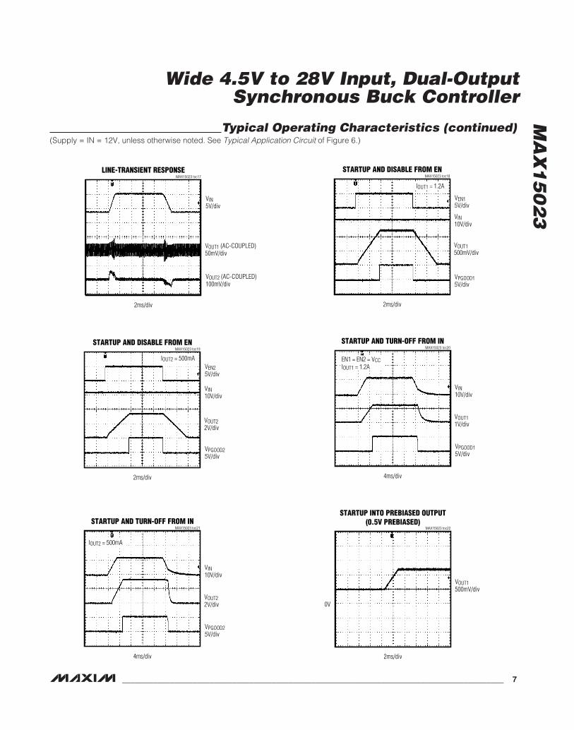
Typical Operating Characteristics (continued)(Supply = IN = 12V, unless otherwise noted. See Typical Application Circuit of Figure 6.)
STARTUP AND DISABLE FROM ENMAX15023 toc19
2ms/div
VEN25V/div
VIN10V/div
VOUT22V/div
VPGOOD25V/div
IOUT2 = 500mA
STARTUP AND TURN-OFF FROM INMAX15023 toc20
4ms/div
VIN10V/div
VOUT11V/div
VPGOOD15V/div
EN1 = EN2 = VCCIOUT1 = 1.2A
STARTUP AND TURN-OFF FROM INMAX15023 toc21
4ms/div
VIN10V/div
VOUT22V/div
VPGOOD25V/div
IOUT2 = 500mA
STARTUP INTO PREBIASED OUTPUT(0.5V PREBIASED)
MAX15023 toc22
2ms/div
VOUT1500mV/div
0V
LINE-TRANSIENT RESPONSEMAX15023 toc17
2ms/div
VIN5V/div
VOUT1 (AC-COUPLED)50mV/div
VOUT2 (AC-COUPLED)100mV/div
STARTUP AND DISABLE FROM ENMAX15023 toc18
2ms/div
VEN15V/div
VIN10V/div
VOUT1500mV/div
VPGOOD15V/div
IOUT1 = 1.2A
MA
X1
50
23
Wide 4.5V to 28V Input, Dual-OutputSynchronous Buck Controller
8 _______________________________________________________________________________________
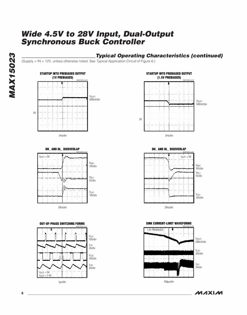
Typical Operating Characteristics (continued)(Supply = IN = 12V, unless otherwise noted. See Typical Application Circuit of Figure 6.)
STARTUP INTO PREBIASED OUTPUT(1V PREBIASED)
MAX15023 toc23
2ms/div
VOUT1500mV/div
0V
STARTUP INTO PREBIASED OUTPUT(1.5V PREBIASED)
MAX15023 toc24
2ms/div
VOUT1500mV/div
0V
DH_ AND DL_ DISOVERLAPMAX15023 toc25
20ns/div
VDH110V/div
VDL15V/div
VLX110V/div
IOUT1 = 5A
DH_ AND DL_ DISOVERLAPMAX15023 toc26
20ns/div
VDH110V/divVDL15V/div
VLX110V/div
IOUT1 = 5A
OUT-OF-PHASE SWITCHING FORMSMAX15023 toc27
1µs/div
VLX110V/div
VLX210V/div
ILX15A/div
ILX22A/div
IOUT1 = 5AIOUT2 = 2.5A
SINK CURRENT-LIMIT WAVEFORMSMAX15023 toc28
100µs/div
VOUT1200mV/div
VLX120V/div
ILX12A/div
1.5V PREBIASED

MA
X1
50
23
Wide 4.5V to 28V Input, Dual-OutputSynchronous Buck Controller
_______________________________________________________________________________________ 9
Pin Description
PIN NAME FUNCTION
1 FB1Feedback Input for Regulator 1. Connect FB1 to a resistive divider between Output 1 and SGND to adjustthe output voltage between 0.6V and (0.85 x input voltage (V)). See the Setting the Output Voltage section.
2 EN1Active-High Enable Input for Regulator 1. When the voltage at EN1 exceeds 1.2V (typ), the controller beginsregulating OUT1. When the voltage falls below 1.05V (typ), the regulator is turned off. The EN1 input can beused for power sequencing and as a secondary UVLO. Connect EN1 to VCC for always-on applications.
3 EN2Active-High Enable Input for Regulator 2. When the voltage at EN2 exceeds 1.2V (typ), the controller beginsregulating OUT2. When the voltage falls below 1.05V (typ), the regulator is turned off. The EN2 input can beused for power sequencing and as a secondary UVLO. Connect EN2 to VCC for always-on applications.
4 PGOOD1Power-Good Output (Open Drain) for Channel 1. To obtain a logic signal, pull up PGOOD1 with an externalresistor connected to a positive voltage below 28V.
5 DL1Low-Side Gate-Driver Output for Regulator 1. DL1 swings from VCC to PGND1. DL1 is low before VCCreaches the UVLO rising threshold voltage.
6 PGND1Low-Side Gate-Driver Supply Return (Regulator 1). Connect to the source of the low-side MOSFET ofRegulator 1.
7 LX1External Inductor Connection for Regulator 1. Connect LX1 to the switched side of the inductor. LX1 servesas the lower supply rail for the DH1 high-side gate driver and as sensing input of the synchronousMOSFET’s VDS drop (drain terminal).
8 BST1Boost Flying-Capacitor Connection for Regulator 1. Connect a ceramic capacitor with a minimum value of100nF between BST1 and LX1.
9 DH1High-Side Gate-Driver Output for Regulator 1. DH1 swings from LX1 to BST1. DH1 is low before VCCreaches the UVLO rising threshold voltage.
10 DH2High-Side Gate-Driver Output for Regulator 2. DH2 swings from LX2 to BST2. DH2 is low before VCCreaches the UVLO rising threshold voltage.
11 BST2Boost Flying-Capacitor Connection for Regulator 2. Connect a ceramic capacitor with a minimum value of100nF between BST2 and LX2.
12 LX2External Inductor Connection for Regulator 2. Connect LX2 to the switched side of the inductor. LX2 servesas the lower supply rail for the DH2 high-side gate driver and as sensing input of the synchronousMOSFET’s VDS drop (drain terminal).

MA
X1
50
23
Wide 4.5V to 28V Input, Dual-OutputSynchronous Buck Controller
10 ______________________________________________________________________________________
Pin Description (continued)
PIN NAME FUNCTION
13 PGND2Low-Side Gate-Driver Supply Return (Regulator 2). Connect to the source of the low-side MOSFET ofRegulator 2.
14 DL2Low-Side Gate-Driver Output for Regulator 2. DL2 swings from VCC to PGND2. DL2 is low before VCCreaches the UVLO rising threshold voltage.
15 PGOOD2Power-Good Output (Open Drain) for Channel 2. To obtain a logic signal, pull up PGOOD2 with an externalresistor connected to a positive voltage below 28V.
16 VCC
Internal 5.2V Linear Regulator Output and the Device’s Core Supply. When using the internal regulator,bypass VCC to SGND with a 4.7µF minimum low-ESR ceramic capacitor. If VCC is connected to IN for 5Voperation, then a 2.2µF ceramic capacitor is adequate for decoupling (see the Typical Application Circuits).
17 FB2Feedback Input for Regulator 2. Connect FB2 to a resistive divider between output 2 and SGND to adjustthe output voltage between 0.6V and (0.85 x input voltage (V)). See the Setting the Output Voltage section.
18 COMP2 Compensation Pin for Regulator 2. See the Compensation section.
19 RTOscillator-Timing Resistor Input. Connect a resistor from RT to SGND to set the oscillator frequency from200kHz to 1MHz (see the Setting the Switching Frequency section).
20 SGNDSignal Ground. Connect SGND to the SGND plane. SGND also serves as sensing input of the synchronousMOSFET’s VDS drop (source terminals) for both channels.
21 INInternal VCC Regulator Input. Bypass IN to SGND with a 1µF minimum ceramic capacitor when the internallinear regulator (VCC) is used. When operating in the 5V ±10% range, connect IN to VCC.
22 LIM2Current-Limit Adjustment for Regulator 2. Connect a resistor (RLIM2) from LIM2 to SGND to adjust thecurrent-limit threshold (VITH2) from 30mV (RLIM2 = 6kΩ) to 300mV (RLIM2 = 60kΩ). See the Setting theCycle-by-Cycle Low-Side Source Peak Current Limit section.
23 LIM1Current-Limit Adjustment for Regulator 1. Connect a resistor (RLIM1) from LIM1 to SGND to adjust thecurrent-limit threshold (VITH1) from 30mV (RLIM1 = 6kΩ) to 300mV (RLIM1 = 60kΩ). See the Setting theCycle-by-Cycle Low-Side Source Peak Current Limit section.
24 COMP1 Compensation Pin for Regulator 1. See the Compensation section.
— EPExposed Paddle. Connect EP to a large copper plane at SGND potential to improve thermal dissipation. Donot use as the main IC’s SGND ground connection.

MA
X1
50
23
Wide 4.5V to 28V Input, Dual-OutputSynchronous Buck Controller
______________________________________________________________________________________ 11
Functional Diagram
OSCI
LLAT
OR ENAB
LELO
GIC
VREF
RT EN1
ENAB
LE1
COM
PARA
TOR
THER
MAL
SHUT
DOW
N
BAND
GAP
REFE
RENC
E
STAR
TUP
BIAS
VREF
VREF
= 0
.6V
VREF
EN2
SGND IN
LIM
2
LIM
1
V CC
ENAB
LE2
COM
PARA
TOR
INUV
LO
V CC
UVLOINTE
RNAL
VOLT
AGE
REGU
LATO
R
LIM
CURR
ENT
GENE
RATO
R
MAX
1502
3 GE
N
VREF
CK2
CK1
ENAB
LE1
ENAB
LE2
VREF
CK2
LIM
2
SGND
LIM
1
CK1
ENAB
LE1
ENAB
LE1
g M
V REF
ENAB
LE2
DC-D
C CO
NVER
TER
2
DC-D
C CO
NVER
TER
1
SOFT
-STA
RT/
STOP
LOG
ICAN
DHI
CCUP
LOG
IC
COM
P2BS
T2DH
2PG
ND2
PGOO
D2FB
2DL
2LX
2
MAX
1502
3
VREF
0.92
5 x V
REF
CK1
FB1
DAC_
VREF
PWM
COM
PARA
TOR
RAM
P G
ENER
ATOR
BOOS
TDR
IVER
LOW
-SID
E DR
IVER
SINK
CURR
ENT-
LIM
ITCO
MPA
RATO
R
PGOO
DCO
MPA
RATO
R
SOUR
CECU
RREN
T-LI
MIT
COM
PARA
TOR
HIGH
-SI
DEDR
IVERPW
M
PWM
CONT
ROL
LOGI
C
RAM
P
GATE
P
HICC
UP T
IMEO
UTHI
CCUP
HICC
UP
V CC
LIM
1/20
LIM
1/10
HICC
UPTI
MEO
UT
COM
P1
BST1
DH1
LX1
DL1
PGND
1
FB1
PGOO
D1

MA
X1
50
23
Wide 4.5V to 28V Input, Dual-OutputSynchronous Buck Controller
12 ______________________________________________________________________________________
Detailed DescriptionThe MAX15023 dual, synchronous, step-down con-troller operates from a 5.5V to 28V or 5V ±10% inputvoltage range and generates two independent outputvoltages. As long as the controller’s input bias voltageis within the specified range, the input power bus canalso be lower than 4.5V and step-down conversionfrom a 3.3V rail is also possible. Both output voltagescan be set from 0.6V to 85% of regulator’s input volt-age. Each output can support loads of 12A or higher.The switching sequence of the regulators is interleavedwith 180° out-of-phase operation, so that input voltageripple and total RMS input ripple current are reduced.
Enable inputs with precise turn-on/off threshold(±4.2%) allow accurate external UVLO settings. Power-good (PGOOD) open-drain outputs can be used forsupply sequencing.
The MAX15023’s capability to provide low output volt-ages (down to 0.6V) and high output current (in excessof 12A) makes it ideal for applications where a 5V or12V bus is postregulated to deliver low voltages andhigh currents, such as in set-top boxes.
The switching frequency is adjustable from 200kHz to1MHz using an external resistor. The MAX15023’sadaptive synchronous rectification eliminates the needfor external freewheeling Schottky diodes.
The MAX15023 utilizes voltage-mode control and exter-nal compensation. The device also utilizes cycle-by-cycle low-side source peak current limit for overcurrentprotection, where the external low-side MOSFET’s on-resistance is used as a current-sense element duringthe inductor freewheeling time, eliminating the need fora current-sense resistor. The current-limit thresholdvoltage is resistor adjustable independently on eachregulator from 30mV to 300mV and is temperaturecompensated, so that the effects of the MOSFET’sRDS(ON) variation over temperature are reduced.Hiccup-mode current limit reduces average currentand power dissipation during a prolonged short-circuitcondition.
The MAX15023 also features a proprietary adaptiveinternal digital soft-start and allows prebias startupwithout discharging the output. Adaptive digital soft-start, by acting on the loop voltage reference, automati-cally prolongs the soft-start time, if the current-limitthreshold is reached during the soft-start sequence.This increases the ability to smoothly bring up a large,unknown amount of output capacitance. Also, since
soft-start is invoked during hiccup-mode short-circuitprotection, the same voltage reference rollback algo-rithm achieves good control of the peak inductor cur-rent during steady short-circuit or overload conditions.
An additional protection feature (cycle-by-cycle low-side sink peak current limit) prevents the regulators fromsinking excessive amount of current if the prebias volt-age exceeds the programmed steady-state regulationlevel, or if another voltage source is trying to force theoutput above that. This way, the synchronous rectifierMOSFET and the body diode of the high-side MOSFETdo not experience dangerous levels of current stresswhile the regulator is sinking current from the output.
Thermal shutdown protects the MAX15023 from exces-sive power dissipation.
DC-DC PWM ControllerThe MAX15023 step-down controller uses a PWM volt-age-mode control scheme (see the FunctionalDiagram) for each channel. Control loop compensationis external for providing maximum flexibility in choosingthe operating frequency and output LC filter compo-nents. An internal transconductance error amplifier pro-duces an integrated error voltage at COMP_ that helpsprovide higher DC accuracy. The voltage at COMP_sets the duty cycle using a PWM comparator and aramp generator. On the rising edge of its internal clock,the high-side n-channel MOSFET of each regulatorturns on and remains on until either the appropriateduty cycle or the maximum duty cycle is reached.During the high-side MOSFET’s on-time, the inductorcurrent ramps up. During the second-half of the switch-ing cycle, the high-side MOSFET turns off and the low-side n-channel MOSFET turns on. Now the inductorreleases the stored energy as its current ramps down,providing current to the output. Under overload condi-tions, when the inductor current exceeds the selectedcycle-by-cycle low-side source peak current-limitthreshold (see the Current-Limit Circuit (LIM_) section),the high-side MOSFET does not turn on at the subse-quent clock rising edge and the low-side MOSFETremains on to let the inductor current ramp down.
Interleaved Out-of-Phase OperationThe two independent regulators in the MAX15023 oper-ate 180° out-of-phase to reduce input filtering require-ments, reduce electromagnetic interference (EMI), andimprove efficiency. This effectively lowers componentcost and saves board space, making the MAX15023ideal for cost-sensitive applications.
MA
X1
50
23
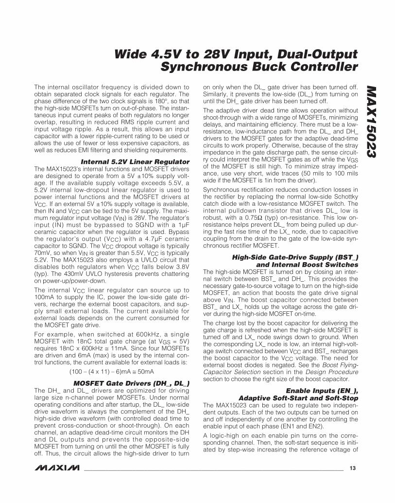
The internal oscillator frequency is divided down toobtain separated clock signals for each regulator. Thephase difference of the two clock signals is 180°, so thatthe high-side MOSFETs turn on out-of-phase. The instan-taneous input current peaks of both regulators no longeroverlap, resulting in reduced RMS ripple current andinput voltage ripple. As a result, this allows an inputcapacitor with a lower ripple-current rating to be used orallows the use of fewer or less expensive capacitors, aswell as reduces EMI filtering and shielding requirements.
Internal 5.2V Linear RegulatorThe MAX15023’s internal functions and MOSFET driversare designed to operate from a 5V ±10% supply volt-age. If the available supply voltage exceeds 5.5V, a5.2V internal low-dropout linear regulator is used topower internal functions and the MOSFET drivers atVCC. If an external 5V ±10% supply voltage is available,then IN and VCC can be tied to the 5V supply. The maxi-mum regulator input voltage (VIN) is 28V. The regulator’sinput (IN) must be bypassed to SGND with a 1µFceramic capacitor when the regulator is used. Bypassthe regulator’s output (VCC) with a 4.7µF ceramiccapacitor to SGND. The VCC dropout voltage is typically70mV, so when VIN is greater than 5.5V, VCC is typically5.2V. The MAX15023 also employs a UVLO circuit thatdisables both regulators when VCC falls below 3.8V(typ). The 430mV UVLO hysteresis prevents chatteringon power-up/power-down.
The internal VCC linear regulator can source up to100mA to supply the IC, power the low-side gate dri-vers, recharge the external boost capacitors, and sup-ply small external loads. The current available forexternal loads depends on the current consumed forthe MOSFET gate drive.
For example, when switched at 600kHz, a single MOSFET with 18nC total gate charge (at VGS = 5V)requires 18nC x 600kHz ≅ 11mA. Since four MOSFETsare driven and 6mA (max) is used by the internal con-trol functions, the current available for external loads is:
(100 – (4 x 11) – 6)mA ≅ 50mA
MOSFET Gate Drivers (DH_, DL_)The DH_ and DL_ drivers are optimized for drivinglarge size n-channel power MOSFETs. Under normaloperating conditions and after startup, the DL_ low-sidedrive waveform is always the complement of the DH_high-side drive waveform (with controlled dead time toprevent cross-conduction or shoot-through). On eachchannel, an adaptive dead-time circuit monitors the DHand DL outputs and prevents the opposite-side MOSFET from turning on until the other MOSFET is fullyoff. Thus, the circuit allows the high-side driver to turn
on only when the DL_ gate driver has been turned off.Similarly, it prevents the low-side (DL_) from turning onuntil the DH_ gate driver has been turned off.
The adaptive driver dead time allows operation withoutshoot-through with a wide range of MOSFETs, minimizingdelays, and maintaining efficiency. There must be a low-resistance, low-inductance path from the DL_ and DH_drivers to the MOSFET gates for the adaptive dead-timecircuits to work properly. Otherwise, because of the strayimpedance in the gate discharge path, the sense circuit-ry could interpret the MOSFET gates as off while the VGSof the MOSFET is still high. To minimize stray imped-ance, use very short, wide traces (50 mils to 100 milswide if the MOSFET is 1in from the driver).
Synchronous rectification reduces conduction losses inthe rectifier by replacing the normal low-side Schottkycatch diode with a low-resistance MOSFET switch. Theinternal pulldown transistor that drives DL_ low isrobust, with a 0.75Ω (typ) on-resistance. This low on-resistance helps prevent DL_ from being pulled up dur-ing the fast rise time of the LX_ node, due to capacitivecoupling from the drain to the gate of the low-side syn-chronous rectifier MOSFET.
High-Side Gate-Drive Supply (BST_) and Internal Boost Switches
The high-side MOSFET is turned on by closing an inter-nal switch between BST_ and DH_. This provides thenecessary gate-to-source voltage to turn on the high-sideMOSFET, an action that boosts the gate drive signalabove VIN. The boost capacitor connected betweenBST_ and LX_ holds up the voltage across the gate dri-ver during the high-side MOSFET on-time.
The charge lost by the boost capacitor for delivering thegate charge is refreshed when the high-side MOSFET isturned off and LX_ node swings down to ground. Whenthe corresponding LX_ node is low, an internal high-volt-age switch connected between VCC and BST_ rechargesthe boost capacitor to the VCC voltage. The need forexternal boost diodes is negated. See the Boost Flying-Capacitor Selection section in the Design Proceduresection to choose the right size of the boost capacitor.
Enable Inputs (EN_), Adaptive Soft-Start and Soft-Stop
The MAX15023 can be used to regulate two indepen-dent outputs. Each of the two outputs can be turned onand off independently of one another by controlling theenable input of each phase (EN1 and EN2).
A logic-high on each enable pin turns on the corre-sponding channel. Then, the soft-start sequence is initi-ated by step-wise increasing the reference voltage of
Wide 4.5V to 28V Input, Dual-OutputSynchronous Buck Controller
______________________________________________________________________________________ 13

MA
X1
50
23
Wide 4.5V to 28V Input, Dual-OutputSynchronous Buck Controller
14 ______________________________________________________________________________________
the error amplifier. The duration of the soft-start ramp is2048 switching cycles and the resolution is 1/64 of thesteady-state regulation voltage. This allows a smoothincrease of the output voltage. A logic-low on each EN_initiates a soft-stop sequence by stepping down the ref-erence voltage of the error amplifier. After the soft-stopsequence is completed, the MOSFET drivers are bothturned off. See Figure 1 for more detail.
Connect EN1 and EN2 to VCC for always-on operation.Owing to their accurate turn-on and turn–off thresholds,EN1 and EN2 can be used as a UVLO adjustment inputand for power sequencing together with the PGOOD_outputs. (See the Setting the Enable Input (EN_) section).
The adaptive action in the soft-start becomes visible ifthe cycle-by-cycle, low-side, source peak current limitis reached during the soft-start ramping sequence. Inthis case, the rate-of-rise of the internal reference isdecreased, so that the PWM controller tries to regulateto the inductor current around its limit value, rather than
the output voltage. The soft-start time can be prolongedup to 4096 clock cycles (twice the normal soft-startduration). This implementation allows the soft-start timeto be automatically adapted to the time necessary tokeep the LX current below the limit while charging theoutput capacitor.
Since soft-start is invoked by the hiccup-mode short-circuit protection, also see the Hiccup ModeOvercurrent Protection section for additional details.
Power-Good Outputs (PGOOD_)The MAX15023 includes two power-good comparatorsto monitor the regulators’ output voltages and detectthe power-good threshold, fixed at 92.5% of the nomi-nal FB voltage. The PGOOD_ outputs are open-drainand should be pulled up with an external resistor to thesupply voltage of the logic input they drive. This voltageshould not exceed 28V. They can sink up to 2mA ofcurrent while low.
VCC
B C D E
2048 CLKCYCLES
2048 CLKCYCLES
F G H IAUVLO
EN_
VOUT_
DAC_VREF_
DH_
DL_
UVLO Undervoltage threshold value is provided inthe Electrical Characteristics table.Internal 5.2V linear regulator output.Active-high enable input. Regulator output voltage.Regulator internal soft-start and soft-stop signal.Regulator high-side gate-driver output.Regulator low-side gate-driver output.
VCC rising while below the UVLO threshold.EN_ is low.
VCC
EN_VOUT_
DAC_VREF_DH_DL_
A
SYMBOL DEFINITION
B VCC is higher than the UVLO threshold. EN_ is low.
EN is pulled high. DH_ and DL_ start switching.Normal operation.VCC drops below UVLO.VCC goes above UVLO threshold. DH_ and DL_ start switching. Normal operation.
EN_ is pulled low. VOUT_ enters soft-stop.
EN_ is pulled high. DH_ and DL_ start switching. Normal operation.VCC drops below UVLO.
CDE
F
G
H
I
SYMBOL DEFINITION
Figure 1. MAX15023 Detailed Power-On/-Off Sequencing

MA
X1
50
23
Each PGOOD_ goes high (high impedance) when thecorresponding regulator output increases above 92.5%of its nominal regulated voltage. Each PGOOD_ goeslow when the corresponding regulator output voltagedrops typically below 89.5% of its nominal regulatedvoltage. PGOOD_ can be used as power-on-reset orpower sequencing for the two regulators.
PGOOD_ asserts low during the hiccup timeout period.
Startup into a Prebiased OutputWhen the controller starts into a prebiased output, theDH_/DL_ complementary switching sequence is inhibit-ed until the PWM comparator commands its first PWMpulse. Until then, DH_ and DL_ are kept off so that theconverter does not sink current from the output. Thefirst PWM pulse occurs when the ramping referencevoltage increases above the FB_ voltage or the internalsoft-start time is over.
Current-Limit Circuit (LIM_)The current-limit circuit employs a cycle-by-cycle low-side source peak and sink current-sensing algorithmthat uses the on-resistance of the low-side MOSFET asa current-sensing element, so that costly sense resis-tors are not required. The current-limit circuit is alsotemperature compensated to track the MOSFET’s on-resistance variation over temperature. The current limitis adjustable on each channel with an external resistorat LIM_ (see the Typical Application Circuits), andaccommodates MOSFETs with a wide range of on-resistance characteristics (see the Design Proceduresection). The adjustment range is from 30mV to 300mVfor the cycle-by-cycle, low-side, source peak currentlimit, corresponding to resistor values of 6kΩ to 60kΩ.The cycle-by-cycle, low-side, source peak current-limitthreshold across the low-side MOSFET is precisely 1/10the voltage seen at LIM_, while the cycle-by-cycle, low-side, sink peak current-limit threshold is 1/20 the volt-age seen at LIM_.
The MAX15023 uses SGND to sense the voltage of thesource terminals of the low-side MOSFETs for bothchannels, and LX_ to sense the drain voltage of eachlow-side MOSFET. Carefully observe the PCB LayoutGuidelines section to ensure that noise and systematicerrors do not corrupt the current-sense signals seen byLX_ and SGND on each channel.
Cycle-by-cycle, low-side, source peak current limit actswhen the inductor current flows in the normal direction,and the drain (LX_) is more negative than source(sensed by SGND) during the low-side MOSFET on-time. If the magnitude of current-sense signal exceedsthe cycle-by-cycle, low-side, source peak current-limit
threshold during the low-side MOSFET on-time, thecontroller does not initiate a new PWM cycle and letsthe inductor current decay in the next cycle. Sincecycle-by-cycle, low-side, source peak current sensingis employed, the actual peak current is greater than thecurrent-limit threshold by an amount equal to the induc-tor ripple current. Therefore, the exact current-limitcharacteristic and maximum load capability are func-tions of the low-side MOSFET’s on-resistance, current-limit threshold, inductor value, and input voltage.
Cycle-by-cycle, low-side, sink peak current limit is alsoimplemented by monitoring the voltage drop across thelow-side MOSFET, but with opposite polarity (drainmore positive than source). If this drop exceeds 1/20the voltage at the corresponding LIM_ pin at any timeduring the low-side MOSFET on-time, the low-sideMOSFET is turned off and the inductor current flowsfrom the output through the high-side MOSFET back. Ifthe cycle-by-cycle, low-side, sink peak current limit isactivated, the DH_ and DL_ switching sequence is nolonger complementary.
Hiccup Mode Overcurrent ProtectionHiccup mode overcurrent protection reduces powerdissipation during prolonged short-circuit or deep over-load conditions.
After the soft-start sequence has been completed, oneach switching cycle where the cycle-by-cycle, low-side,source peak current-limit threshold is reached, a 3-bitcounter is incremented. The counter is decremented oneach switching cycle where the threshold is not reached,and stopped at zero (000).
If the cycle-by-cycle, low-side, source peak current-limit condition persists, the counter fills up reaching 111(= 7 events). Then, the controller stops both DL_ andDH_ drivers and waits for 7936 switching cycles (hic-cup timeout delay). After this delay, the controller initi-ates a new soft-start sequence.
If cycle-by-cycle, low-side, source peak current-limitevents occur during the soft-start time, turn-on cycles arestill skipped to control the inductor current, but the fill-upof the 3-bit counter does not terminate the soft-startsequence. Rather, the soft-start ramp is slowed down orrolled back based on the cycle-by-cycle, low-side, sourcepeak current-limit events occurrences, so that the PWMcontroller tries to regulate the inductor current around itslimit value, rather than the output voltage.
This proprietary technique prevents the duty cycle fromsaturating, and limits the on-time and thus, the peakinductor current is reached every time the high-sideMOSFET is turned on.
Wide 4.5V to 28V Input, Dual-OutputSynchronous Buck Controller
______________________________________________________________________________________ 15

MA
X1
50
23
Wide 4.5V to 28V Input, Dual-OutputSynchronous Buck Controller
16 ______________________________________________________________________________________
In case of a nonideal short circuit applied at the output,the output voltage equals the output impedance times thelimited inductor current during this phase. After reachingthe maximum allowable limit of the soft-start duration(twice the normal soft-start time), the controller remains offfor 7936 clock cycles before trying to soft-start again.
Undervoltage LockoutThe MAX15023 has an internal undervoltage lockout(UVLO) circuit to monitor the voltage on VCC. TheUVLO circuit prevents the MAX15023 from operating ifthe voltages for the MOSFET drivers or for the internalcontrol functions are too low. The VCC falling thresholdis 3.8V (typ), with 430mV hysteresis to prevent chatter-ing on the rising/falling edge of the supply voltage.Before VCC reaches UVLO rising threshold voltage,DL_ and DH_ stay low to inhibit switching.
Thermal-Overload ProtectionThermal-overload protection limits total power dissipationin the MAX15023. When the device’s die-junction tem-perature exceeds TJ = +150°C, an on-chip thermal sen-sor shuts down the device, forcing DL_ and DH_ low,allowing the IC to cool. The thermal sensor turns thedevice on again after the junction temperature cools by20°C. During thermal shutdown, the regulators shutdown, and soft-start is reset. Thermal-overload protectioncan be triggered by power dissipation in the LDO regula-tor, by excessive driving losses, or by both. Therefore,carefully evaluate the total power dissipation (see thePower Dissipation section) to avoid unwanted triggeringof the thermal-overload protection in normal operation.
Design ProcedureEffective Input Voltage Range
Although the MAX15023 controllers can operate frominput supplies up to 28V and regulate down to 0.6V, theminimum voltage conversion ratio (VOUT/VIN) might belimited by the minimum controllable on-time. For properfixed-frequency PWM operation, the voltage conversionratio should obey the following condition:
where tON(MIN) is 100ns (max) and fSW is the switchingfrequency in Hertz. If the desired voltage conversiondoes not meet the above condition, then pulse skippingoccurs to decrease the effective duty cycle. To avoidthis, decrease the switching frequency or lower theinput voltage VIN.
The maximum voltage conversion ratio is limited by themaximum duty cycle (Dmax):
where VDROP1 is the sum of the parasitic voltage dropsin the inductor discharge path, including synchronousrectifier, inductor, and PCB resistances. VDROP2 is thesum of the resistances in the charging path, includinghigh-side switch, inductor, and PCB resistances. Inpractice, the above condition should be met with ade-quate margin for good load-transient response.
Setting the Enable Input (EN_)Each controller has an enable input referenced to ananalog voltage (1.2V). When the voltage exceeds 1.2V,the regulator is enabled. To set a specific turn-onthreshold that can act as a secondary UVLO, a resistivedivider circuit can be used (see Figure 2)
Select R2 (EN_ to SGND resistor) to a value lower than200kΩ. Calculate R1 (VMON to EN_ resistor) with the fol-lowing equation:
where VEN_H_ = 1.2V (typical).
R RV
VMON
EN H1 2 1=
⎛
⎝⎜
⎞
⎠⎟
⎡
⎣⎢⎢
⎤
⎦⎥⎥
−_ _
VV
DD V (1 D ) V
VOUT
INmax
max DROP2 max DROP1
IN< × + ×
−−
VV
t fOUT
NON(MIN) SW
I> ×
EN_
R1
VMON
R2
MA15023
Figure 2. Adjustable Enable Voltage

MA
X1
50
23
Setting the Output VoltageSet the MAX15023 output voltage on each channel byconnecting a resistive divider from the output to FB_ toSGND (Figure 3). Select R2 (FB_ to SGND resistor) lessthan or equal to 16kΩ. Calculate R1 (OUT_ to FB_ resis-tor) with the following equation:
where VFB_ = 0.6V (typ) (see the Electrical Characteristicstable) and VOUT_ can range from 0.6V to (0.85 x VIN).
Resistor R1 also plays a role in the design of the TypeIII compensation network. If a Type III compensationnetwork is used, make sure to review the values of R1and R2 according to the Type III CompensationNetwork (See Figure 5) section.
Setting the Switching FrequencyThe switching frequency, fSW, for each channel is setby a resistor (RT) connected from RT to SGND. Therelationship between fSW and RT is:
where fSW is in kHz, RT is in kΩ, and 24806 is in1/farad. For example, a 600kHz switching frequency isset with RT = 27.05kΩ. Higher frequencies allowdesigns with lower inductor values and less outputcapacitance. Consequently, peak currents and I2Rlosses are lower at higher switching frequencies, butcore losses, gate-charge currents, and switching loss-es increase.
Inductor SelectionThree key inductor parameters must be specified foroperation with the MAX15023: inductance value (L),inductor saturation current (ISAT), and DC resistance(RDC). To select inductance value, the ratio of inductorpeak-to-peak AC current to DC average current (LIR)must be selected first. A good compromise betweensize and loss is a 30% peak-to-peak ripple current toaverage-current ratio (LIR = 0.3). The switching fre-quency, input voltage, output voltage, and selected LIRthen determine the inductor value as follows:
where VIN, VOUT, and IOUT are typical values (so thatefficiency is optimum for typical conditions). Theswitching frequency is set by RT (see the Setting theSwitching Frequency section). The exact inductor valueis not critical and can be adjusted in order to maketrade-offs among size, cost, efficiency, and transientresponse requirements. Lower inductor values minimizesize and cost, but also improve transient response andreduce efficiency due to higher peak currents. On theother hand, higher inductance increases efficiency byreducing the RMS current, but requires more outputcapacitance to meet load-transient specifications.
Find a low-loss inductor having the lowest possible DCresistance that fits in the allotted dimensions. Theinductor’s saturation rating (ISAT) must be high enoughto ensure that saturation can occur only above the max-imum current-limit value, given the tolerance of the low-side MOSFET’s on-resistance and of the LIM_ referencecurrent (ILIM). On the other hand, these tolerancesshould not prevent the converter from delivering therated load current (ILOAD(MAX)). Combining these con-ditions, the inductor saturation current (ISAT) should besuch that:
where RDS(ON,MAX) and RDS(ON,TYP) are the maximumand typical on-resistance of the low-side MOSFET. Fora given inductor type and value, choose the LIR corre-sponding to the worst-case inductor tolerance.
For LIR = 0.4, and a +25% on the low-side MOSFET’sRDS(ON,MAX), the inductor saturation current should beabout 50% greater than the converter’s maximum loadcurrent. A variety of inductors from different manufac-turers can be chosen to meet this requirement (forexample, Coilcraft MSS1278 series).
I 1 ISATRDS(ON,MAX)RDS(ON,TYP) LOAD(MAX)> × +⎛
⎝⎜⎞⎠⎟
×LIR2
LV V V
V f I LIROUT IN OUT
IN SW OUT= −( )
Rf
TSW
= 248061 0663( ) .
R RV
VOUT
FB1 2 1=
⎛
⎝⎜
⎞
⎠⎟
⎡
⎣⎢⎢
⎤
⎦⎥⎥
−_
_
FB_
R1
OUT_
R2MA15023
Figure 3. Adjustable Output Voltage
Wide 4.5V to 28V Input, Dual-OutputSynchronous Buck Controller
______________________________________________________________________________________ 17

MA
X1
50
23
Wide 4.5V to 28V Input, Dual-OutputSynchronous Buck Controller
18 ______________________________________________________________________________________
Setting the Cycle-by-Cycle, Low-Side,Source Peak Current Limit
The minimum current-limit threshold must be highenough to support the maximum expected load currentwith the worst-case low-side MOSFET on-resistancevalue since the low-side MOSFET’s on-resistance isused as the current-sense element. The inductor’scycle-by-cycle, low-side, source peak current occurs atILOAD(MAX) minus half the ripple current. The ripple cur-rent is maximum when the inductor value is at the lowerlimit of its specified tolerance. The minimum value ofthe current-limit threshold voltage (VITH) should begreater than the voltage on the low-side MOSFET dur-ing the ripple-current valley:
where RDS(ON) is the on-resistance of the low-sideMOSFET in ohms. Use the maximum value for RDS(ON)from the low-side MOSFET’s data sheet.
To adjust the current-limit threshold, connect a resistor(RLIM_) from LIM_ to SGND. The relationship betweenthe current-limit threshold (VITH_) and RLIM_ is:
where RLIM_ is in kΩ and VITH_ is in mV.
An RLIM_ resistance range of 6kΩ to 60kΩ correspondsto a current-limit threshold of 30mV to 300mV. Whenadjusting the current limit, use 1% tolerance resistors tominimize errors in the current-limit threshold setting.
Input CapacitorThe input filter capacitor reduces peak currents drawnfrom the power source and reduces noise and voltageripple on the input caused by the circuit’s switching.The two converters of the MAX15023 run 180° out-of-phase, thereby, effectively doubling the switching fre-quency at the input and lowering the input RMS current.
The input ripple waveform would be unsymmetrical dueto the difference in load current and duty cycle betweenconverter 1 and converter 2. In fact, the worst-case inputRMS current occurs when only one controller is operat-ing. The converter delivering the highest output power(VOUT x IOUT) must be used in the formulas below:
The input capacitor RMS current requirement (IRMS) isdefined by the following equation:
IRMS has a maximum value when the input voltageequals twice the output voltage (VIN = 2VOUT), soIRMS(MAX) = ILOAD(MAX)/2.
Choose an input capacitor that exhibits less than +10°Ctemperature rise at the RMS input current for optimallong-term reliability.
The input voltage ripple is composed of ∆VQ (causedby the capacitor discharge) and ∆VESR (caused by theESR of the capacitor). Use low-ESR ceramic capacitorswith high ripple current capability at the input. Assumethe contribution from the ESR and capacitor dischargeare equal to 50%. Calculate the input capacitance andESR required for a specified input voltage ripple usingthe following equations:
where:
and:
where:
All equations listed above are valid under the assump-tion that the input ports of both converters can bemerged in the physical layout, so that only one inputcapacitor truly serves both converters. If this is not thecase, additional low-ESR, low-ESL ceramic capacitorsshould be locally placed on each converter’s input port,connected between the drain of the high-side MOSFETand the source of the low-side MOSFET.
Output CapacitorThe key selection parameters for the output capacitorare capacitance value, ESR, and voltage rating. Theseparameters affect the overall stability, output ripple volt-age, and transient response. The output ripple has twocomponents: variations in the charge stored in the out-put capacitor, and the voltage drop across the capaci-tor’s ESR caused by the current flowing into and out ofthe capacitor:
∆ ∆ ∆V V VRIPPLE ESR Q≅ +
DVVOUT
IN=
CI D D
V fINOUT
Q SW= ×
×−( )1
∆
∆IV V V
V f LLIN OUT OUT
IN SW= ×
× ×−( )
ESRV
IIIN
ESR
OUTL
=+
∆∆2
I IV V V
VRMS LOAD MAXOUT IN OUT
IN=
−( )
( )
RV
ALIMITH
__=
×10
50µ
V R ILIR
ITH DS ONMAX LOAD MAX> × × ⎛⎝⎜
⎞⎠⎟
−( , ) ( ) 12

MA
X1
50
23
Wide 4.5V to 28V Input, Dual-OutputSynchronous Buck Controller
______________________________________________________________________________________ 19
The output voltage ripple as a consequence of the ESRand the output capacitance is:
where ∆IL is the peak-to-peak inductor current ripple(see the Inductor Selection section). These equationsare suitable for initial capacitor selection, but final val-ues should be verified by testing in a prototype or eval-uation circuit.
As a general rule, a smaller inductor ripple currentresults in less output ripple voltage. The output capaci-tor must be also checked against load-transientresponse requirements. The allowable deviation of theoutput voltage during fast load transients also deter-mines the output capacitance, its ESR, and its equiva-lent series inductance (ESL). The output capacitorsupplies the load current during a load step until thecontroller responds with a greater duty cycle. Theresponse time (tRESPONSE) depends on the closed-loop bandwidth of the converter (see the Compensationsection). The resistive drop across the output capaci-tor’s ESR, the drop across the capacitor’s ESL (∆VESL),and the capacitor discharge causes a voltage droopduring the load step.
Use a combination of low-ESR tantalum/aluminum elec-trolytic or polymer and ceramic capacitors for bettertransient load and voltage ripple performance. Non-leaded capacitors and capacitors in parallel helpreduce the ESL. Keep the maximum output voltagedeviation below the tolerable limits of the load. Use thefollowing equations to calculate the required ESR, ESL,and capacitance value during a load step:
where ISTEP is the load step, tSTEP is the rise time of theload step, tRESPONSE is the response time of the con-troller, and fO is the closed-loop crossover frequency.
CompensationEach channel of the MAX15023 provides an internaltransconductance amplifier with its inverting input andits output available to the user for external frequencycompensation. The flexibility of external compensationfor each converter offers wide selection of output filter-ing components, especially the output capacitor. Forcost-sensitive applications, use low-ESR aluminumelectrolytic capacitors; for component-size sensitiveapplications, use low-ESR tantalum, polymer, or ceram-ic capacitors at the output. The high switching frequen-cy of the MAX15023 allows use of ceramic capacitorsat the output. Choose the small-signal components forthe error amplifier to achieve the desired closed-loopbandwidth and phase margin.
To choose the appropriate compensation network type,the power-supply poles and zeros, the zero crossoverfrequency, and the type of the output capacitor must bedetermined.
In a buck converter, the LC filter in the output stageintroduces a pair of complex poles at the following fre-quency:
The output capacitor and its ESR also introduce a zeroat:
The loop-gain crossover frequency (fO, where the loopgain equals 1 (0dB)) should be set below 1/10 theswitching frequency:
Choosing a lower crossover frequency might also helpin reducing the effects of noise pickup into the feed-back loop, such as jittery duty cycle.
In order to maintain a stable system, two stability crite-ria must be met:
1) The phase shift at the crossover frequency fO, mustbe less than 180°. In other words, the phase marginof the loop must be greater than zero.
2) The gain at the frequency where the phase shift is -180° (gain margin) must be less than 1.
ff
OSW≤10
fESR CZO
OUT=
× ×1
2π
fL C
POOUT OUT
=× ×
1
2π
ESRV
I
CI t
V
ESLV t
I
tf
ESR
STEP
OUTSTEP RESPONSE
Q
ESL STEP
STEP
RESPONSEO
=
= ×
= ×
≅×
∆
∆∆
13
∆ ∆
∆ ∆
∆
V I ESR
VI
C f
IV V V
V f L
ESR L
QL
OUT SW
LIN OUT OUT
IN SW
= ×
=× ×
= ×× ×
−
8( )

MA
X1
50
23
Wide 4.5V to 28V Input, Dual-OutputSynchronous Buck Controller
20 ______________________________________________________________________________________
It is recommended to have a phase margin around+50° to +60° to maintain a robust loop stability andwell-behaved transient response.
If an electrolytic or large-ESR tantalum output capacitoris used, the capacitor ESR zero fZO typically occursbetween the LC poles and the crossover frequency fO(fPO < fZO < fO). In this case, use a Type II (PI or pro-portional-integral) compensation network.
If a ceramic or low-ESR tantalum output capacitor isused, the capacitor ESR zero typically occurs abovethe desired crossover frequency fO, that is fPO < fO <fZO. In this situation, choose a Type III (PID or propor-tional-integral-derivative) compensation network.
Type II Compensation Network (See Figure 4)
If fZO is lower than fO and close to fPO, the phase leadof the capacitor ESR zero almost cancels the phaseloss of one of the complex poles of the LC filter aroundthe crossover frequency. Therefore, a Type II compen-sation network with a midband zero and a high-fre-quency pole can be used to stabilize the loop. In Figure4, RF and CF introduce a midband zero (fZ1). RF andCCF in the Type II compensation network also provide ahigh-frequency pole (fP1), which mitigates the effects ofthe output high-frequency ripple.
To calculate the component values for Type II compen-sation network in Figure 4, follow the instruction below:
1) Calculate the gain of the modulator (GainMOD)—composed of the regulator’s pulse-width modulator,LC filter, feedback divider, and associated circuitryat crossover frequency:
where VIN is the regulator’s input voltage, VOSC is theamplitude of the ramp in the pulse-width modulator,VFB is the FB_ input voltage set-point (0.6V typically,see Electrical Characteristics table), and VOUT is thedesired output voltage.
The gain of the error amplifier (GainEA) in midband fre-quencies is:
where gm is the transconductance of the error amplifier.
The total loop gain as the product of the modulator gainand the error amplifier gain at fO should equal 1. So:
Therefore:
Solving for RF:
2) Set a midband zero (fZ1) at 0.75 x fPO (to cancelone of the LC poles):
Solving for CF:
3) Place a high-frequency pole at fP1 = 0.5 x fSW (toattenuate the ripple at the switching frequency, fSW)and calculate CCF using the following equation:
CR f
C
CFF SW
F
=× × −
11π
CR fF
F PO=
× × ×1
2 0 75π .
fR C
fZF F
PO11
20 75=
× ×= ×
π.
RV f L V
V V g ESRFOSC O OUT OUT
FB IN m=
× × ×( ) ×× × ×
2π
VV
ESRf L
VV
g RIN
OSC O OUT
FB
OUTm F×
× ×× × × =
( )21
π
Gain GainMOD EA× = 1
Gain g REA m F= ×
GainV
VESRf L
VVMOD
IN
OSC O OUT
FB
OUT= ×
× ×( ) ×2π
VREF
R1
VOUT
R2gm
RF
COMP
CF CCF
Figure 4. Type II Compensation Network

MA
X1
50
23
Type III Compensation Network (See Figure 5)
If the output capacitor used is a low-ESR tantalum orceramic type, the ESR-induced zero frequency is usual-ly above the targeted zero crossover frequency (fO). Inthis case, Type III compensation is recommended.Type III compensation provides three poles and twozeros at the following frequencies:
Two midband zeros (fZ1 and fZ2) cancel the pair ofcomplex poles introduced by the LC filter:
fP1 = 0
fP1 introduces a pole at zero frequency (integrator) fornulling DC output voltage errors:
Depending on the location of the ESR zero (fZO), fP2can be used to cancel it, or to provide additional atten-uation of the high-frequency output ripple:
fP3 attenuates the high-frequency output ripple.
The locations of the zeros and poles should be suchthat the phase margin peaks around fO.
Ensure that RF>>2/gm (1/gm(MIN) = 1/600µS = 1.67kΩ)and the parallel resistance of R1, R2, and RI is greaterthan 1/gm. Otherwise, a 180° phase shift is introducedto the response and will make it unstable.
The following procedure is recommended:
1) With RF ≥ 10kΩ, place the first zero (fZ1) at 0.5 xfPO:
so:
2) The gain of the modulator (GainMOD)—composed ofthe regulator’s pulse-width modulator, LC filter,feedback divider, and associated circuitry atcrossover frequency is:
The gain of the error amplifier (GainEA) in midband fre-quencies is:
The total loop gain as the product of the modulator gainand the error amplifier gain at fO should be equal to 1.So:
Therefore:
Solving for CI:
3) If fPO < fO < fZO < fSW/2, the second pole (fP2)should be used to cancel fZO. This way, the Bodeplot of the loop gain plot does not flatten out soonafter the 0dB crossover, and maintains its -20dB/decade slope up to 1/2 the switching frequen-cy. This is likely to occur if the output capacitor is alow-ESR tantalum or polymer. Then set:
fP2 = fZO
If a ceramic capacitor is used, then the capacitor ESRzero, fZO, is likely to be located even above 1/2 theswitching frequency, that is, fPO < fO< fSW/2 < fZO. Inthis case, the frequency of the second pole (fP2) shouldbe placed high enough in order not to significantlyerode the phase margin at the crossover frequency. Forexample, it can be set at 5 x fO, so that its contributionto phase loss at the crossover frequency, fO, is onlyabout 11°:
fP2 = 5 x fOOnce fP2 is known, calculate RI:
Rf CIP I
=× ×
12 2π
CV f L C
V RIOSC O OUT OUT
IN F=
× × × ×( )×
2π
VV f C L
f C RIN
OSC O OUT OUTO I F×
× × ×× × × × =1
22 1
2( )
ππ
Gain GainMOD EA× = 1
Gain f C REA O I F= × × ×2π
GainV
V f L CMOD
IN
OSC O OUT OUT= ×
× × ×
1
2 2( )π
CR fF
F PO=
× × ×1
2 0 5π .
fR C
fZF F
PO11
20 5=
× ×= ×
π.
fR
C CC C
PF
F CF
F CF
31
2=
× × ×+
π
fR CP
I I2
12
=× ×π
fR C
fC R R
ZF F
ZI I
1
21
12
12
=× ×
=× × +
π
π ( )
Wide 4.5V to 28V Input, Dual-OutputSynchronous Buck Controller
______________________________________________________________________________________ 21

MA
X1
50
23
Wide 4.5V to 28V Input, Dual-OutputSynchronous Buck Controller
22 ______________________________________________________________________________________
4) Place the second zero (fZ2) at 0.2 x fO or at fPO,whichever is lower and calculate R1 using the fol-lowing equation:
5) Place the third pole (fP3) at half the switching fre-quency and calculate CCF:
6) Calculate R2 as:
MOSFET SelectionThe MAX15023’s step-down controller drives two exter-nal logic-level n-channel MOSFETs as the circuit switchelements. The key selection parameters to choosethese MOSFETs include:
• On-resistance (RDS(ON) )
• Maximum drain-to-source voltage (VDS(MAX) )
• Minimum threshold voltage (VTH(MIN) )
• Total gate charge (Qg)
• Reverse transfer capacitance (CRSS)
• Power dissipation
All four n-channel MOSFETs must be a logic-level typewith guaranteed on-resistance specifications at VGS =4.5V. For maximum efficiency, choose a high-sideMOSFET (NH_) that has conduction losses equal to theswitching losses at the typical input voltage. Ensurethat the conduction losses at minimum input voltage donot exceed MOSFET package thermal limits, or violatethe overall thermal budget. Also, ensure that the con-duction losses plus switching losses at the maximuminput voltage do not exceed package ratings or violatethe overall thermal budget. Ensure that the MAX15023DL_ gate drivers can drive a low-side MOSFET (NL_).In particular, check that the dV/dt caused by NH_ turn-ing on does not pull up the NL_ gate through NL_’sdrain-to-gate capacitance. This is the most frequentcause of cross-conduction problems.
Gate-charge losses are dissipated by the driver and donot heat the MOSFET. Therefore, if the drive current istaken from the internal LDO regulator, the power dissi-pation due to drive losses must be checked. AllMOSFETs must be selected so that their total gatecharge is low enough; therefore, VCC can power all fourdrivers without overheating the IC:
where QG_TOTAL is the sum of the gate charges of allfour MOSFETs.
Power DissipationDevice’s maximum power dissipation depends on thethermal resistance from the die to the ambient environ-ment and the ambient temperature. The thermal resis-tance depends on the device package, PCB copperarea, other thermal mass, and airflow.
The power dissipated into the package (PT) depends onthe supply configuration (see the Typical ApplicationCircuits). It can be calculated using the following equation:
PT = VIN x IINFor the circuits of Figures 7 and 8:
PT = VCC x (IIN + IVCC)
where VIN and VCC are the voltages at the respectivepins, IIN is the current at the input of the internal LDO(IIN is practically zero for the circuits of Figures 7 and8), IVCC is the current consumed by the internal coreand drivers when the internal regulator is unused for 5Vsupply operation (IN = VCC). See the correspondingTypical Operating Characteristics for the typical curvesof IIN and IVCC current consumption vs. operating fre-quency at various load capacitance values.
P V Q fDRIVE IN G TOTAL SW= × ×_
RV
V VRFB
OUT FB2 1= ×
−
CC
f R CCFF
SW F F=
× × × ×( ) −2 0 5 1π .
Rf C
RZ I
I12
12
=× ×
−π
VREF
gm
R1
R2
VOUT
RI
COMP
CI
CCF
RF CF
Figure 5. Type III Compensation Network

MA
X1
50
23
To estimate the temperature rise of the die, use the fol-lowing equation:
TJ = TA + (PT x θJA)
where θJA is the junction-to-ambient thermal resistanceof the package, PT is power dissipated in the device,and TA is the ambient temperature. The θJA is 36°C/Wfor the 24-pin TQFN package on multilayer boards, withthe conditions specified by the respective JEDEC stan-dards (JESD51-5, JESD51-7). If actual operating condi-tions significantly deviate from those described in theJEDEC standards, then an accurate estimation of thejunction temperature requires a direct measurement ofthe case temperature (TC). Then, the junction tempera-ture can be calculated using the following equation:
TJ = TC + (PT x θJC)
Use 3°C/W as θJC thermal resistance for the 24-pinTQFN package. The case-to-ambient thermal resis-tance (θCA) is dependent on how well the heat is trans-ferred from the PCB to the ambient. Therefore, solderthe exposed pad of the TQFN package to a large cop-per area to spread heat through the board surface,minimizing the case-to-ambient thermal resistance. Uselarge copper areas to keep the PCB temperature low.
Boost Flying-Capacitor SelectionThe MAX15023 uses a bootstrap circuit to generate thenecessary gate-to-source voltage to turn on the high-side MOSFET. The selected n-channel high-side MOS-FET determines the appropriate boost capacitancevalues (CBST_in Typical Application Circuits) accordingto the following equation:
where Qg is the total gate charge of the high-sideMOSFET and ∆VBST_ is the voltage variation allowed onthe high-side MOSFET driver after turn-on. Choose∆VBST_ such that the available gate drive voltage is notsignificantly degraded (e.g., ∆VBST_ = 100mV to300mV) when determining CBST_. The boost flying-capacitor should be a low-ESR ceramic capacitor. Aminimum value of 100nF is recommended.
Applications InformationPCB Layout Guidelines
Make the controller ground connections as follows: cre-ate a small analog ground plane near the IC or use adedicated internal plane. Connect this plane to SGNDand use this plane for the ground connection for the INbypass capacitor, compensation components, feed-back dividers, RT resistor, and LIM_ resistors.
If possible, place all power components on the top sideof the board, and run the power stage currents (espe-cially the one having large high-frequency components)using traces or copper fills on the top side only, withoutadding vias.
On the top side, lay out a large PGND copper area forthe output of channels 1 and 2, and connect the bottomterminals of the high-frequency input capacitors, outputcapacitors, and the source terminals of the low-sideMOSFETs to that area.
Then, make a star connection of the SGND plane to thetop copper PGND area with few vias in the vicinity ofthe source terminal sensing. Do not connect PGND andSGND anywhere else. Refer to the MAX15023Evaluation Kit data sheet for guidance.
Keep the power traces and load connections short,especially at the ground terminals. This practice isessential for high efficiency and jitter-free operation. Usethick copper PCBs (2oz vs. 1oz) to enhance efficiency.
Place the controller IC adjacent to the synchronous rec-tifier MOSFETs (NL_) and keep the connections for LX_,PGND_, DH_, and DL_ short and wide. Use multiplesmall vias to route these signals from the top to the bot-tom side. The gate current traces must be short andwide, measuring 50 mils to 100 mils wide if the low-sideMOSFET is 1in from the controller IC. Connect eachPGND trace from the IC close to the source terminal ofthe respective low-side MOSFET.
Route high-speed switching nodes (BST_, LX_, DH_,and DL_) away from the sensitive analog areas (RT,COMP_, LIM_, and FB_). Group all SGND-referred andfeedback components close to the IC. Keep the FB_and compensation network nets as small as possible toprevent noise pickup.
CQg
VBSTBST
__
=∆
Wide 4.5V to 28V Input, Dual-OutputSynchronous Buck Controller
______________________________________________________________________________________ 23

MA
X1
50
23
Wide 4.5V to 28V Input, Dual-OutputSynchronous Buck Controller
24 ______________________________________________________________________________________
Typical Application Circuits
3300pF
390pF
33pFMAX15023
Q3FDS8880
Q2FDS8880
Q5FDS6982AS-Q2
Q4FDS6982AS-Q1
Q1FDS8880
2EN1
8BST1
9DH1
15PGOOD2
19RT
18COMP2
16VCC
11BST2
10DH2
17FB2
7
LX1
12
LX2
5
DL1
6
PGND
1
14
DL2
13
PGND
2
24
COM
P1
23LI
M1
21IN
1
FB1
1µF
16.2kΩ
47kΩ
200kΩ
30.1kΩ
20kΩ
2200pF
1.5Ω
RT33kΩ
10µF25V
2200pF
3300pF
22pF
CBST10.22µF
CBST20.22µF
4.7µF
10µF25V
20
SGND
22
LIM
2
12.1kΩ
12.1kΩ
EN1
VOUT1
VOUT2
VCC
PGOOD2
VCC
VIN
VIN 9V TO 16V
3EN2
4PGOOD1
47kΩ
200kΩ
22.1kΩ
10kΩ
45.3kΩ1.62kΩ
EN2
DL1
PGOOD1
VOUT1
VCC
0.8µH 3.3µH
VIN
22µF6.3V
1500µF2.5V
22µF6.3V
22µF6.3V
22µF6.3V
10µF25V
1.5Ω
VOUT2
Figure 6. Application Diagram (Operation from a Single-Supply Rail, VIN = 9V to 16V)

MA
X1
50
23
Typical Application Circuits (continued)
MAX15023
22
DH1
LIM
2
9
BST2
SGND
11
20
DH2
IN
10
21
LX2
RT
12
19
BST1
LIM
1
8
23
LX1
COM
P1
7
24
5 14DL1 DL2
4 15PGOOD1 PGOOD2
6 13PGND1 PGND2
3 16VCCEN2
2 17FB2EN1
1 18COMP2
VIN 4.5V TO 5.5V
PGOOD2
VOUT2
L2
VIN
FB1
C8
R6C6
Q1
Q2
C2
CIN2
C3
C5
C5
R2
R4
RPU1
R8
R7
R1
R10 R9 RTR5
EN1
PGOOD1
VOUT1
L1
EN2
CIN1
CBST1 CBST2
COUT1
C4 R3
RPU2
Q3
VIN
Q4 COUT2
Figure 7. Application Diagram (Operation with VIN = VCC = 5V ±10%)
Wide 4.5V to 28V Input, Dual-OutputSynchronous Buck Controller
______________________________________________________________________________________ 25

MA
X1
50
23
Wide 4.5V to 28V Input, Dual-OutputSynchronous Buck Controller
26 ______________________________________________________________________________________
Typical Application Circuits (continued)
MAX15023
22
DH1
LIM
2
9
BST2
SGND
11
20
DH2
IN
10
21
LX2
RT
12
19
BST1
LIM
1
8
23
LX1
COM
P1
7
24
5 14DL1 DL2
4 15PGOOD1 PGOOD2
6 13PGND1 PGND2
3 16VCCEN2
2 17FB2EN1
1 18COMP2
VAUX 4.5V TO 5.5V
PGOOD2
VOUT2
L2
VIN3.3V
FB1
C8
R6C6
Q1
Q2
C2
CIN2
C3
C5
C5
R2
R4
RPU1
R8
VIN 3.3V
R7
R1
R10 R9 RTR5
EN1
PGOOD1
VOUT1
L1
EN2
CIN1
CBST1 CBST2
COUT1
C4 R3
RPU2
Q3
Q4 COUT2
Figure 8. Application Diagram (Operation with Auxiliary 5V Supply and 3.3V Bus)

MA
X1
50
23
Wide 4.5V to 28V Input, Dual-OutputSynchronous Buck Controller
______________________________________________________________________________________ 27
Chip InformationPROCESS: BiCMOS
Package InformationFor the latest package outline information and land patterns(footprints), go to www.maxim-ic.com/packages. Note that a“+”, “#”, or “-” in the package code indicates RoHS status only.Package drawings may show a different suffix character, butthe drawing pertains to the package regardless of RoHS status.
PACKAGETYPE
PACKAGECODE
OUTLINE NO.LAND
PATTERN NO.
24 TQFN-EP T2444+4 21-0139 90-0022

MA
X1
50
23
Wide 4.5V to 28V Input, Dual-OutputSynchronous Buck Controller
Maxim cannot assume responsibility for use of any circuitry other than circuitry entirely embodied in a Maxim product. No circuit patent licenses areimplied. Maxim reserves the right to change the circuitry and specifications without notice at any time.
28 ____________________Maxim Integrated Products, 120 San Gabriel Drive, Sunnyvale, CA 94086 408-737-7600
© 2011 Maxim Integrated Products Maxim is a registered trademark of Maxim Integrated Products, Inc.
Revision History
REVISIONNUMBER
REVISIONDATE DESCRIPTION PAGES
CHANGED
0 7/08 Initial release —
1 2/09 Updated Electrical Characteristics, Current-Limit Circuit (LIM_), andSetting the Enable Input (EN_) sections. 4, 15, 16
2 3/11 Added automatic part MAX5023ETG/V+ 1, 2, 13, 27