Evaluating the Environmental Implications of … the Environmental Implications of Hydraulic ......
21
Evaluating the Environmental Implications of Hydraulic Fracturing in Shale Gas Reservoirs Authors: J. Daniel Arthur, P.E., ALL Consulting; Brian Bohm, P.G., ALL Consulting; Bobbi Jo Coughlin, EIT, ALL Consulting; Mark Layne, Ph.D., P.E., ALL Consulting Lead Author Biographical Sketch Dan Arthur is a founding member and the Managing Partner of ALL Consulting (www.all‐llc.com). Mr. Arthur earned his bachelors degree in Petroleum Engineering from the University of Missouri‐ Rolla. He is a recognized authority on environmental issues pertaining to unconventional resource development and production. Mr. Arthur has served or is currently serving as the lead researcher on several significant projects involving unconventional resources; environmental considerations pertaining to shale gas development; produced water management and recycling; access to federal lands; and low impact natural gas and oil development. Has previously managed U.S. Department of Energy (DOE) funded research projects involving the development of best management practices utilizing GIS technologies for efficient environmental protection during unconventional resource Development and Production; research to develop a national primer on coal bed methane; research to develop a Handbook on the preparation and review of environmental documents for CBM development; and research with the Ground Water Protection Research Foundation (GWPRF) and funded by DOE and BLM involving analysis of produced water management alternatives and beneficial uses of coal bed methane produced water. Mr. Arthur has published many articles and reports and has made numerous presentations on environmental, energy, and technology issues. Abstract Exploration, drilling and production of shale gas plays such as the Barnett, Fayetteville, and Haynesville have transformed the unconventional gas industry. These and other existing and developing plays have had unimaginable economic impacts to many regions, created tens of thousands of jobs, and have generated royalty payments to a variety of state and local governments as well as many individuals. At the core of shale gas development are two key technologies: horizontal drilling and hydraulic fracturing. Techniques used to hydraulically fracture horizontal wells completed in shale reservoirs often require larger volumes of fracturing fluid than might be common for conventional, vertical well stimulations. The rapid development of shale gas across the country has created concerns on issues such as the use of infrastructure and environmental impacts. Specifically, the common practice of hydraulic fracturing of these shales has attracted critical interest regarding risks potentially posed to groundwater and surface water. This paper will present a summary and evaluation of the environmental implications of hydraulic fracturing in shale gas reservoirs, with examples from multiple basins. Copyright ©, ALL Consulting, 2008 1
Transcript of Evaluating the Environmental Implications of … the Environmental Implications of Hydraulic ......

Evaluating the Environmental Implications of Hydraulic Fracturing in Shale Gas Reservoirs
Authors: J. Daniel Arthur, P.E., ALL Consulting; Brian Bohm, P.G., ALL Consulting; Bobbi Jo Coughlin, EIT, ALL Consulting; Mark Layne, Ph.D., P.E., ALL Consulting
Lead Author Biographical Sketch Dan Arthur is a founding member and the Managing Partner of ALL Consulting (www.all‐llc.com). Mr. Arthur earned his bachelors degree in Petroleum Engineering from the University of Missouri‐Rolla. He is a recognized authority on environmental issues pertaining to unconventional resource development and production. Mr. Arthur has served or is currently serving as the lead researcher on several significant projects involving unconventional resources; environmental considerations pertaining to shale gas development; produced water management and recycling; access to federal lands; and low impact natural gas and oil development. Has previously managed U.S. Department of Energy (DOE) funded research projects involving the development of best management practices utilizing GIS technologies for efficient environmental protection during unconventional resource Development and Production; research to develop a national primer on coal bed methane; research to develop a Handbook on the preparation and review of environmental documents for CBM development; and research with the Ground Water Protection Research Foundation (GWPRF) and funded by DOE and BLM involving analysis of produced water management alternatives and beneficial uses of coal bed methane produced water. Mr. Arthur has published many articles and reports and has made numerous presentations on environmental, energy, and technology issues.
Abstract Exploration, drilling and production of shale gas plays such as the Barnett, Fayetteville, and Haynesville have transformed the unconventional gas industry. These and other existing and developing plays have had unimaginable economic impacts to many regions, created tens of thousands of jobs, and have generated royalty payments to a variety of state and local governments as well as many individuals. At the core of shale gas development are two key technologies: horizontal drilling and hydraulic fracturing. Techniques used to hydraulically fracture horizontal wells completed in shale reservoirs often require larger volumes of fracturing fluid than might be common for conventional, vertical well stimulations. The rapid development of shale gas across the country has created concerns on issues such as the use of infrastructure and environmental impacts. Specifically, the common practice of hydraulic fracturing of these shales has attracted critical interest regarding risks potentially posed to groundwater and surface water. This paper will present a summary and evaluation of the environmental implications of hydraulic fracturing in shale gas reservoirs, with examples from multiple basins.
Copyright ©, ALL Consulting, 2008 1

Introduction Natural gas production from tight shale formations, known as “shale gas”, is one of the most rapidly expanding trends in onshore, domestic natural gas exploration and production. In some areas, development of shale gas resources is bringing drilling and production to regions of the country that has previously seen little to no oil and gas development activity. In plays like the Barnett Shale of Texas, development is occurring in urban and suburban areas where both operators and regulators are adapting to this new environment. Shales are the most abundant sedimentary rock in the Earth’s crust and are present across the U.S. (Exhibit 1).
Shales have been sources of natural gas in small but continuous volumes since the earliest years of gas development. The first producing gas well in the U.S. was completed in 1821 in Devonian‐aged shale near the town of Fredonia, New York1. Early sources of natural gas were shallow gas wells that were from dug wells and natural gas seeps2. Shallow wells and seeps were capable of producing small amounts of natural gas which were used for illuminating city streets and households3. These early gas wells played a key part in bringing illumination to the cities and towns of the eastern U.S.1. In contrast, modern shale gas development has become a technological play, in which development is facilitated by the technological advances the oil and gas industry has made in hydraulic fracturing and horizontal drilling over the last two decades.
In the 1980’s develop of the Barnett Shale play kicked‐off in the area around Fort Worth, Texas1. The Barnett Shale play has quickly become the most active natural gas play in the U.S., the success of which has grabbed the gas industry’s attention. Through
Exhibit 1: Gas Shale Basins of the United States with Estimated Gas Reserves
Modified from Schlumberger, 2005
1 Harper, J. 2008. The Marcellus Shale – An Old “New” Gas Reservoir in Pennsylvania. Published by the Bureau of Topographic and Geologic Survey, Pennsylvania Department of Conservation and Natural Resources. Pennsylvania Geology. v 28. no 1. Spring 2008. 2 NY DEC. 1992. Final Generic Environmental Impact Statement on the Oil, Gas and Solution Mining Regulatory Program. Division of Mineral Resources. 3 Frantz, J.K. and Jochen, V. 2005. Shale Gas White Paper. 05-OF299. Schlumberger Marketing Communications. October 2005.
Copyright ©, ALL Consulting, 2008 2

continued improvements in hydraulic fracturing techniques and technology, development of the Barnett Shale has continued at an accelerating pace4. In the two decades since initial development of the Barnett, the science of shale gas extraction has matured into a sophisticated process which utilizes horizontal drilling and sequenced multi‐stage hydraulic fracturing technologies. As the Barnett Shale play has matured, natural gas producers have been extrapolating the lessons learned in the Barnett to the other shale gas formations present across the U.S. (Exhibit 1) and Canada4
In addition to the Barnett, a second play has also been the source of technological advances in hydraulic fracturing and horizontal drilling. The Bakken Shale of the Williston Basin of Montana and North Dakota has greater oil than gas production
.
5, but has seen a similar accelerated rate of development as the Barnett. The Bakken is another technical play in which the development of this unconventional resource has benefitted from the technological advances in horizontal wells and hydraulic fracturing6.
Each gas shale basin is different with a unique set of exploration criteria and operational challenges. Yet, the combination of sequenced hydraulic fracture treatments and horizontal well completions has been crucial in facilitating the expansion of modern shale gas development to other shale plays. Prior to the successful application of these two technologies in the Barnett Shale; gas shale resources in many basins were bypassed in favor of other reservoirs which were more economically favorable1. The low natural permeability of shale has historically been the limiting factor to the production of gas shale resources. Low natural permeability means only minor volumes of gas are capable of flowing to a wellbore7 and without today’s hydraulic fracturing technology to increase the permeability, this would still be true today.
Shale Gas – Geology Shale gas is natural gas produced from shale formations and these shales function as both reservoir and source rock for the natural gas. In terms of its chemical composition, shale gas is typically dry gas composed primarily of methane (90% or more methane). While there are some shale gas formations that do produce gas and water, the Antrim and New Albany Shales being the largest examples (Exhibit 1), they are the exception based on data from those plays with active development8.
Shale is a sedimentary rock predominantly comprised of consolidated clay sized particles that were deposited as muds in low‐energy depositional environments. Low energy depositional environments include tidal flats and deep water basins where the fine‐grained particles fall out of
eposited with these very fine‐grained sediments is organic matter in suspension in quiet waters4. D
4 Arthur, J.D., Bohm, B., and Layne, M. 2008. Hydraulic Fracturing Considerations for Natural Gas Wells of the Marcellus Shale. ALL Consulting. Presented at the GWPC Annual Forum in Cincinnati, OH. September 2008. 5 ALL Consulting and Ground Water Protection Council, in development, Shale Gas Development in the United States: A Primer. Prepared for the U.S. Department of Energy National Energy Technology Laboratory. 6 Cohen, D. 2008. An Unconventional Play in the Bakken. Energy Bulletin. April 2008. 7 Ameri, S., Aminian, K., Miller, J.A., Doricich, D., and Yost, A.B. A Systematic Approach for Economic Development of the Devonian Shale Gas Resources. SPE 14504. 8 Boyer, C., Kieschnick, J., Suarez-rivera, R., Lewis, R., and Walter, G. 2006. Producing Gas from Its Source. Schlumberger. Oilfield Review. Autumn 2006.
Copyright ©, ALL Consulting, 2008 3

the form of algae, plant, and animal derived organic debris9. The naturally tabular clay grains tend to lay flat as the sediments accumulate and subsequently become compacted as additional sediments are deposited. These muds lithify into thin laminar bedding that forms thinly layered shale rock (Exhibit 2). The natural layering and fracturing of shales is typically seen in outcrop. Exhibit 2 shows a shale outcrop which reveals the natural bedding planes, or layers of the shale, and near vertical joints that cross‐cut the natural horizontal bedding planes.
While the various shales were deposited in similar environments, post deposition changes have resulted in considerable differences in the current condition of these shales. Differences inherit to
the gas shales can be seen by comparing the data presented in Exhibit 3.
Exhibit 3 summarizes the key characteristics of select shale gas plays across the U.S. The table provides data related to the character of the select gas shales, providing a means to compare characteristics of the different gas shale plays. For example, the Antrim Shale in the northern portions of the lower peninsula of Michigan and New Albany Shale are much shallower shales than the five other gas shales characterized in the table. These two shales are also the only shales presented in the table to produce formation water in considerable volumes. Spatial
distribution is another characteristic which varies considerably, the Barnett Shale is estimated to occur within a 5,000 square mile area of urban to sub‐urban areas near Forth Worth, Texas. In contrast, the Marcellus Shale is expected to be developed over 95,000 square miles of mixed rural and urban areas covering parts of New York, Pennsylvania, Ohio, Kentucky, and West Virginia
Exhibit 2: Marcellus Shale Outcrop
Source: ALL Consulting, 2008
(Exhibit 1).
Other characteristic differences include the thickness of shales, the thickness of the intervening formations or natural barriers provided by geologic materials present between producing gas shales and groundwater sources. In the areas of the Haynesville and Woodford Shales, the natural
Copyright ©, ALL Consulting, 2008 4
9 Davis Jr, R. 1992. Depositional Systems: An Introduction to Sedimentology and Stratigraphy. Prentice Hall. 2nd Edition. 1992.

Copyrigh 5 t ©, ALL Consulting, 2008
EXHIB MP DA G S IN ED S IT 3. CO ARISON OF TA FOR THE AS SHALE THE UNIT TATES
Gas Shale Basin Barnett Fay lle ettevi Haynesville M arcellus W oodford Antrim New Albany Estimated Basin
are miles Area, squ 5,000 9,000 9,000 95,000 11,000 1 2,000 4 3,500
Depth, ft 6, 500 ‐ 8,50010
1,000 ‐ 07,0001
10,500 ‐13,50011
4,000 ‐ 8,5001
6,000 – 011,0001
600 – 2,20010
500 – 02,0001
Net Thickness, ft 100‐60010
20‐200 01 20 0 010‐ 30 50 2‐2001 12 130‐220 70‐1210 50 0‐1001
Depth to BaseTreatable Water, f
of t
~1200 ~50014 ~400 ~850 ~400 ~300 ~400
Rock Column between Pay and
ble Base of TreataWater
5,300– 7,300 500 – 6,500 10,100 –
13,100 2,125 – 7,650
5,600 – 10,600
300 – 1,900 100 – 1,600
Total Organic Carbon, % 4.510
4. 00‐9.81 0.5 – 4.011 3‐1215 1‐1416 1 0‐201 1‐2510
Total Porosity, % 4‐510 2‐810 8‐911 1017 3‐918 910 10‐1410Gas Content, scf/ton
300‐3 0501
60‐2 02 10 100‐ 033 19 60‐1 00 17 200‐30020 40‐100 01 40‐8010
Water Production, ay Barrels water/d 010 0 0 0 5‐50010 5‐ 05001
Well spacing, Acres 60‐16010 80 0 ‐16 40‐56021 40‐16021 64021 40‐16010 8010Original Gas‐In‐Place, Tcf22 327 52 717 1,500 52 76 160
Reserves, Tcf22 44 41. 6 251 36323, 50024 11.4 20 19.2
Est. Production, mcf/day/well 33824
53024 625‐
1,80025 3,10026 41524 125‐20024
mcf = thousands of cubic feet of gas. NOTE: Data derived from various sources and research analysis. Information from some basins was unable to be identified and confirmed at the time of this paper and has been left blank. # ‐ for the Depth to base of treatable water data, the data was based on depth data from state oil and gas agencies and state geological survey data.
10 he Barnett Shale. Visitor’s Guide to the Hot Hayden, J., and Pursell, D. T Oct. 2005. 11 ol. 229
c Fracturing Across U.S. pp 42‐43. January/February 2000.
test Gas Play in the US. the Barnett Cools. World Oil Magazine. V Berman, A. 2008. The Haynesville Shale Sizzles with No.9. Sept.2008.
12
Builds in the Woodford Shale. p 17. January 2006. Drilling Contractor. 2000. Alabama Lawsuit Poses Threat to Hydrauli
13 Activity5.
Haines, L. 2006. Supplement to Oil & Gas Investor. Shale gas: 14 Arkansas Oil and Gas Commission. 2008. Field Rules and Rule B‐115 007. Update on Regional Assessment of Gas Potent n
. October 1, 2007. Nyahay, R., Leone, J., Smith, L., Martin, J., and Jarvie, D. 2 ial in the Devonia
M ician Utica Shales of New Yorkklahoma Geological Survey. Overview of Unconventiona
arcellus and Ordov16 Cardott, B. 2004. O l Energy Resources of Oklahoma. March 9, 2004. 17 v 3. Issue 1. January 1, Soeder, D.J. 1986. Porosity and Permeability of Eastern Devonian Gas Shale. SPE Formation Evaluation.1986. 18 ., Wolhart, S., Mayerhofer, M., Machovoe, S., and Waltman, 007. Applying Hydraulic Fracture
in the Woodford Shale. SPE 110029. 2007. Vulgamore, T., Clawson, T., Pope, C C. 2
D ns Haynesville Success. Augus
iagnostics to Optimize Stimulatio19 t 15, 2008.
oduce Unconven Petroleum Listing Services. 2008. Other Players Reporting
20 06. New Techology Needs to Prccountability Project (OGAP). Shale Gas: Focus
Jochen, V. Schlumberger. 20 tional Gas. November 29, 2006. 21 Sumi, L. 2008. Oil and Gas A on the Marcellus Shale. May 2008. 22 Navigant Consulting. 2008. North American Natural Gas Supply Assessment. Prepared for American Clean Skies Foundation. July 4, 2008. 23 he Philadelphia Inquire
ast Ocean of Natural Gas. p 44‐50. Summer 200 Mary Esch, 2008. Estimated Gas Yield from M r. November 4
24 n Skies. A V 8. ergy CEO: Haynesville Shale is Fourth Largest in the World. July 6, 2008.
arcellus Shale Goes Up. T , 2008. Williams, P. 2008. American Clea
25 Gas Leases. 2008. Chesapeake En26 Engelder, T and Lash, G.G. 2008. Marcellus Shale Play’s Vast Resource Potential Creating Stir in Appalachia. The American Oil & Gas Reporter. May 2008.

barriers are thousands of feet to 10,000 feet thick. In contrast shales like the New Albany and Antrim are only hundreds of feet to approximately 2,200 feet thick (Exhibit 3). Gas shales also show a wide range in the estimated quantities of gas in place, from low estimates of 52 Tcf for the Fayetteville and Woodford to high estimates of 1,500 Tcf for the Marcellus (Exhibit 3).
Gas shales were deposited from the Cambrian to the Tertiary. Exhibit 4 presents a summary table depicting the age of the known shale gas plays in the United States. The Cambrian Conasauga Shale of Alabama is geologically oldest known gas shale play and the Miocene McClure Shale of California the youngest gas shale (Exhibit 4). The deposition of gas rich black shales in North America thrived from the Middle Devonian to Mississippian. As seen in Exhibit 4, there are 13 gas shale plays which were deposited from the Middle Devonian to Mississippian. Included in these 13 shales are the four shale plays with the largest aerial extent: the Huron, Ohio, Marcellus,
Chattanooga, and their equivalents.
While deposited in different geologic times, these shales share similar depositional environments. Black shales accumulate in deposition settings in which there is little to no oxygen present in the water (anaerobic environments)9. Shales of the Devonian and Mississippian were deposited at a time when an interior seaway was present across much of the continental U.S. from the
EXHIBIT 4: STRATIGRAPHY OF THE U.S. GAS SHALES
Period Shale Formation Location
Miocene McClure/Monterey California Tertiary Eocene G rreen Rive Colorado, Utah
Gammon Montana Mowry Wyoming
Lewis Mancos New Mexico, Utah Cretaceaous Late
Niobrara ColoradoJurassic Late Haynes le vil Louisiana
Excello K a ansa homs, OklaPennsylvanian Hovenweep Colorado, Utah Barnett Texas
Fayetteville Arkansas
Floyd/Neal Alaba sippi ma, MissisLate
Mo ld orefie Arkansas
Mississippian
Early Caney Oklahoma New Albany Illinois, Indiana M ississippian
/Devonian Woodford Oklahoma, Texas
Chattanooga Alabama, Arkansas, Kentu essee cky, Tenn
Antrim Shale Michigan
Ellsworth Michigan
Huron Ohio, Virginia, West Virginia, Kentucky
Ohio Kentucky, Ohio, West Virginia
Devonian Late
Marcellus New York,
Penn est sylvania, WVirginia
O rdovician Utica N ew YorkCambrian Conasauga Alabama
Source: Cardott, 2008.27
27 Brian J. Cardott, 2008, Understanding gains on ‘new’reservoir: Shales Closing ‘Conventional’ Gap. In AAPG Explorer , November 2008.
Copyright ©, ALL Consulting, 2008 6

Appalachian Mountains westward to the present day Rocky Mountains26. These shales were deposited in deep trough basins below the pycnocline, a layer in water bodies below which a density difference prevents water from overturning and bringing oxygen to the lower portions of the water, shallow silled basins in which freshwater recharge was limited or on shallow marine shelves in which oxygen was depleted28. All three depositional environments are characterized by minimal clastic sediment deposition (from rivers and streams), and high organic matter preservation from the lack of oxygen at depth. Similar deposition is observed in the modern Black Sea and fjords of northern Europe, where a layer of low salinity fresh water traps normal salinity water out of contact with supplies of oxygenated water and the atmosphere29. The deposition of large quantities of organic matter below the pycnocline and tectonic activity resulted in the rapid burial and accumulation of the organic matter in these black shales26. These depositional environments also support the accumulation of Uranium which along with its daughter product Radium is usually found in Black Shales at what can sometimes be at concentrations higher than other subsurface geologic formations30.
Gas shales are organic‐rich shale formations that have traditionally been viewed as source rocks and seals for gas accumulating in the stratigraphically proximal sandstone and carbonate reservoirs of traditional onshore gas development31. Gas that was accumulated in the shales was not historically considered a resource that could be economically recovered utilizing conventional gas development methods1. Shale is a sedimentary rock that is predominantly comprised of consolidated clay and silt sized particles. The compaction of clay particles that occurs during post‐deposition as additional materials accumulate above these particles results in the formation thin laminae layers. Thin laminae form in part because the clay grains rotate to lie flat as a result of pressure from compaction. The thin layers that make up shale result in a rock with limited horizontal permeability and minimal vertical permeability. Unfractured shales typically have permeabilities on the order of 0.01 to 0.00001 millidarcies32. The low natural permeability of shale has been a limiting factor to the production of shale gas resources33.
The natural matrix permeability of shales is sometimes overcome by the formation of natural fracture networks which development when overburden pressure is reduced as a result of erosion of overlying rock formations. Other tectonic activity can also cause a change in the pressure creating additional fractures. These natural fractures are usually very apparent in outcrop as seen in Exhibit 2. Fractures are often key sources of permeability facilitating the migration of fluids hrough fine grained rocks such as shales. t
28 R. Wicander, and J.S. Monroe. 1989. Historical Geology: Evolution of the Earth and Life through Time. West Publishing Company. 578 pgs. 29 James I. Drever, 1988, Geochemistry of Natural Waters, Prentice Hall. 437 pgs. 30 Barbara J. Graves; 1987 Radon in Ground Water. Lewis Publishers. 546 pgs. 31 Schlumberger 2005. Shale Gas White Paper. 05-OF299. October 2005, Schlumberger Marketing Communications. 32 R.A. Freeze and J.A. Cherry. 1979. Groundwater. Prentice Hall. 604pgs. 33 S. Ameri, K. Aminian, J.A. Miller, D. Doricich, and A.B. Yost II. 1985. A Systematic Approach for Economic Development of the Devonian Shale Gas Resources. SPE 14504.
Copyright ©, ALL Consulting, 2008 7

Hydraulic Fracturing Basics Hydraulic fracturing is a formation stimulation practice used to create additional permeability in a producing formation. By creating additional permeability, hydraulic fracturing facilitates the migration of fluids to the wellbore for purposes of production34. Hydraulic fracturing can be used to overcome barriers to the flow of fluids, one of the primary reasons development of gas shales has traditionally been limited. Barriers may include naturally low permeability common in shale formations or reduced permeability resulting from near wellbore permeability impairment caused during drilling activities34. While aspects of hydraulic fracturing have been changing and maturing, this technology has been utilized by industry to increase production to support the increasing demand for energy for over 60 years4.
The process of hydraulic fracturing as typically used for shale gas development involves the pumping of tens of thousands of barrels of sand laden water into the target shale zone. Fluids pumped into the shale creates fractures or openings through which the sand flows, at the same time the sand acts to prop open the fractures that have been created. Once the pumping of fluids has stopped the sand remains in‐place allowing fluids (both gas and water) to flow back to the wellbore. The following sections discuss the process of hydraulic fracturing beginning with the designing of stimulations and ending with a discussion of how produced and flowback water is handled.
Fracture Stimulation Design Modern formation stimulation practices are complex sophisticated processes which can cost millions of dollars. Hydraulic fracture simulations are engineered models which production companies use to design a hydraulic fracturing treatment to emplace fracture networks in specific areas35. Hydraulic fracture treatments are designed formation stimulations in which specific characteristics of the target formation (thickness of shale,
istics, to s
rock fracturing characterstress regimes, etc.) are used develop a network of fracture
The design process for a hydraulic fracture treatment starts with pre‐stimulation reservoir evaluation which typically involves the process of collecting field data. Understanding the character of
Exhibit 5: Example Output of a Hydraulic Fracture Simulation
4.
the reservoir and the dynamics
34 Veatch, Ralph W. Jr.; Zissis A. Moschovidis; and C. Robert Fast, An Overview of Hydraulic Fracturing. in Recent Advances in Hydraulic Fracturing, Edited by John L Gidley, Stephen A. Holditch, Dale E. Nierode, and Ralph W, Veatch Jr. Society of Petroleum Engineers, Henry L Doherty Series Monograph Volume 12. 35 C. Boyer, J. Kieshchnick, and R Lewis. 2006. Producing Gas from Its Source. In Oilfield Review Autumn 2006. pgs 36-49.
Copyright ©, ALL Consulting, 2008 8

of existing stress relationship are two of the critical components engineers use in designing fracturstimulation. Data related to the reservoir may be collected from surface geophysical logging prior to drilling, core analysis, open or cased hole logging, and offset production performance analysis
e
36. Data collected includes porosity, permeability, and lithology of the producing formation, fluid saturation data, natural fracture character and present day stress regimes which identify the maximum and least principal horizontal stresses. Natural fracture data including orientation, height, half length, fracture width and permeability is used to determine where new fractures are needed and to assess how new fractures may develop in the formation37, 38. Hydraulic fracturing designs are constantly being refined to optimize fracture networking and to maximize gas production, while ensuring that fracture development is confined to the target formation35.
One method used to optimize fracture stimulation design is the use of computer simulators. Computer simulators are programs designed to use collected data (as described above) for the producing formation and create a model, using mathematical formulas of fracture propagation, to predict possible fracture propagations. Simulators allow engineers to alter the stimulation programs (volumes and types of proppants, fluids, and additives) to evaluate how fractures could develop within the reservoir. Simulators allow engineers to evaluate hydraulic fracture treatment design in a controlled setting and assess the resultant fractures that are predicted to develop39. There are a variety of models that can be used, with each respective model having different options. A simulator may be used to predicted three‐dimensional fracture geometry (Exhibit 5), integrated acid fracturing solutions, or to reverse engineer design stages for specific characteristics35.
Modeling programs also allow designers to modify plans as additional data are collected relative to the specific target formation39. The use of models allows designers to make advances in the design of hydraulic fracturing operations to develop more efficient ways to create additional flow‐paths to the wellbores, without risking actual wells.
When designing fracture stimulation treatments, operators take into consideration formation stresses to predict probable fracture propagation. Use of a single fracture event and microsiesmic monitoring on a vertical well in the formation of interest prior to drilling horizontal laterals on that well can be used to design lateral orientation to the preferred direction. There are three principal categories of stresses that exist in a formation: vertical stress, maximum horizontal stress,
Stress Fields on a Formation at DSource: ALL Consulting, 2008
epth
36 Proptester/Styfan Engineering Alliance, Hydraulic Fracturing and Stimulation Services for the Global Oil and Gas Industry. November 7, 2008. www.proptester.com 37 Chesapeake Energy Corporation, Components of Hydraulic Fracturing, Presented to the NY DEC, October 2008. 38 Pekarek, Gary and F. Pichard, Fracture Solutions Unlock US Gas Shale Plays, March 2008. E&P. 39 Meyer & Associates, Inc. User’s Guide for the Meyer Fracturing Simulators. Sixth Edition.
Copyright ©, ALL Consulting, 2008 9
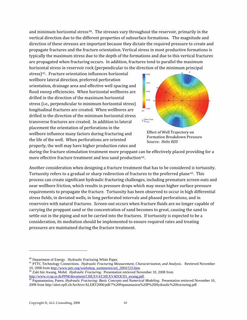
and minimum horizontal stress40. The stresses vary throughout the reservoir, primarily in the vertical direction due to the different properties of subsurface formations. The magnitude and direction of these stresses are important because they dictate the required pressure to create and propagate fractures and the fracture orientation. Vertical stress in most productive formations is typically the maximum stress due to the depth of the formations and due to this vertical fractures are propagated when fracturing occurs. In addition, fractures tend to parallel the maximum horizontal stress in reservoir rock (perpendicular to the direction of the minimum principal stress)41. Fracture orientation influences horizontal wellbore lateral direction, preferred perforation orientation, drainage area and effective well spacing anflood sweep efficiencies. When horizontal wellbores ardrilled in the direction of the maximum horizontal stress (i.e., perpendicular to minimum horizontal stress)longitudinal fractures are created. When wellbores are drilled in the direction of the minimum horizontal stress transverse fractures are created. In addition to lateral placement the orientation of perforations in the wellbore influence many factors during fracturing and the life of the well. When perforations are oriented properly, the well may have higher production rates and during the fracture stimulation treatment more proppant can be effectively placed providing for a more effective fracture treatment and less sand production
d e
42.
Effect of FormatioSource: Helix RDS
Well Trajectory on n Breakdown Pressure
Another consideration when designing a fracture treatment that has to be considered is tortuosity. Tortuosity refers to a gradual or sharp redirection of fractures to the preferred plane43. This process can create significant hydraulic fracturing challenges, including premature screen‐outs and near wellbore friction, which results in pressure drops which may mean higher surface pressure requirements to propagate the fracture. Tortuosity has been observed to occur in high differential stress fields, in deviated wells, in long perforated intervals and phased perforations, and in reservoirs with natural fractures. Screen‐out occurs when fracture fluids are no longer capable of carrying the proppant sand or the concentration of sand becomes to great, causing the sand to settle out in the piping and not be carried into the fractures. If tortuosity is expected to be a consideration, its mediation should be implemented to ensure required rates and treating pressures are maintained during the fracture treatment.
40 Department of Energy. Hydraulic Fracturing White Paper. 41 PTTC Technology Connections. Hydraulic Fracturing Measurement, Characterization, and Analysis. Retrieved November 10, 2008 from http://www.pttc.org/workshop_summaries/sol_2004/533.htm. 42 Zaki bin Awang, Mohd. Hydraulic Fracturing. Presentation retrieved November 10, 2008 from http://www.ccop.or.th/PPM/document/CHEXV4/CHEXV4DOC03_awang.pdf. 43 Papanastasiou, Panos. Hydraulic Fracturing: Basic Concepts and Numerical Modeling. Presentation retrieved November 10, 2008 from http://alert.epfl.ch/Archive/ALERT2006/pdf/7%20Papanastasiou%20P%20Hydraulic%20fracturing.pdf
Copyright ©, ALL Consulting, 2008 10

Fracture Monitoring Additional advances in hydraulic fracturing design target analysis of hydraulic fracture treatments through monitoring technologies. Monitoring technologies are used to map where fracturing occurs during a stimulation treatment and includes such techniques as microseismic fracture mapping, and tilt meter measurements4. These technologies can be used to define the success and orientation of the fractures created during a stimulation process.
Microseismic monitoring is the process by which the seismic waves generated during the fracturing of a rock formation are monitored and used to map the locations of the fractures generated (Exhibit 6)44. Monitoring is done using a similar technology to that used to monitor larger naturally occurring seismic events associated with earthquakes and other natural processes. Microseismic monitoring is an active monitoring process performed during a hydraulic fracture treatment44. As an active monitoring process microseismic monitoring can
be used to develop real time changes to a fracture program. Microseismic monitoring provides engineers the ability to manage the resource through intelligent placement of additional wells to take advantage of the natural conditions of the reservoir and expected fracture results in new
Exhibit 6: Mapping of Microseismic Events
Source: Oilfield Service Company
wells44.
Tiltmeters are passive monitoring technologies which record the deformation of rocks that are induced by the hydraulic fracture process45. Tiltmeters can be placed at the ground surface away from a well or downhole in a nearby wellbore tightly into the rock. Tiltmeters measure changes in inclination in two orthogonal directions, which can then be translated into the strain rotation that results from hydraulic fracturing45. Engineers can then determine based on the strain rotation the location of the hydraulic fracturing event that caused the strain rotation.
Hydraulic Fracturing Process and Equipment Used Hydraulic fracturing of the horizontal shale gas wells is performed in stages. Lateral lengths in typical shale gas development wells are from 1,000 feet to more than 5,000 feet in length. Because of the length of exposed wellbore, it is usually not possible to maintain a downhole pressure sufficient to stimulate the entire length of a lateral in a single stimulation event46. As such,
44 C. Kessler, Fracture Monitoring Technology allows Operators to Optimize Treatments in the Field in Real Time, Halliburton Energy Services, May 2007. 45 Hydraulic Fracturing Club, Tiltmeter Fracture Mapping, 2008. www.hydraulicfracturing.org 46 W.K. Overbey, A.B. Yost, and D.A. Wilkins, 1988, Inducing Multiple Hydraulic Fractures from a Horizontal Wellbore. SPE Paper 18249.
Copyright ©, ALL Consulting, 2008 11

hydraulic fracture treatments of shale gas wells are performed by isolating portions of the lateral and performing multiple treatments to stimulate the entire length of
Copyright ©, ALL Consulting, 2008 12
the lateral portion of the well37.
Exhibit 7 presents a process flow diagram showing the order of events that occur for one stage of a hydraulic fracture treatment. A hydraulic fracture treatment starts with bringing equipment onsite. Once onsite, the equipment is “rigged up”. Rig‐up involves making all of the iron connections necessary between the frac head on the well, frac pumps, manifold trailers, and additive equipment which feed fluids and additives into the frac pumps. Iron connections are typically secured with restraints to ensure safety in case of iron failure.
Each fracture stage is performed within an isolated interval (for example, a 500 ft interval) within which a cluster of perforations is created using a perforating tool. Perforations allow fluids to flow through the casing to the formation during the fracture treatment and also allow gas to flow into the wellbore during the production phase of operations37. In order to isolate each fracture stage of a fracture treatment, a packer is used to isolate each fracturing interval. One type of packer used for creating zonal isolation is a ball packer which works by having a steel ball pumped into a seat point typically located where the last fracture stage was completed. The ball acts as a sealing agent
A Ball and Ball Packe (Pennsylvania Marcellus Shale)r Source: ALL Consulting 2008
to the previously treated zone isolating the next treatment interval.
For gas shales individual fracture treatment stages typically include multiple sub‐stages, during which different fluids and concentrations of proppants are pumped into the well. Initial sub‐stages are typically performed as a flush and often may simply include pumping fresh water into the wellbore. Following the fresh water flush is an acid flush to clean cement from the perforations and near the wellbore area to facilitate the flow of fluids during the fracturing process.
Following the acid flush is typically a spacer which pushes the acid into the formation and begins the propagation of fracturing. After the spacer is pumped, the next sub‐stage is typically a well shut‐in during which the fracture gradient for the formation is calculated. When the well is opened again, a clean fracture fluid pad is injected to lubricate well tubing and formation fractures aiding in the delivery of the proppant sub‐stages. The next sub‐stages are a series in which proppant is used to create and maintain fractures.

Exhibit 7: Process Flow Diagram for a Hydraulic Fracture Treatment
Model Simulations:
Drilling & Data Collection:
Bring Hydraulic Fracturing Equipment On-site:
Perforate Production Tubing
Bring Fluids On-site:
Rig-Up Piping:
Flush and Initiate Formation Breakdown:
Acid Treatment:
Pump Slickwater Pad
Pump Proppant Stages:
More Proppant Stages: Well Flush:
Copyright ©, ALL Consulting, 2008 13

In some fracture treatments, two or more proppants are used to optimize the propping of fractures at various distances from the wellbore34. Fracture treatments of the Barnett Shale typically include the use of multiple proppants which may include up to four different proppants starting with a 100 mesh sand, then a 40/70 mesh sand, then a 30/50 mesh sand and finally a resin coated 30/50 mesh sand proppant. Initial proppant placement sub‐stages start with low concentrations typically around 0.1 pounds of sand per gallon (ppg) of fluid47. At each subsequent sub‐stage, an increase in proppant concentration is performed at a regular rate, increments of 0.2 ppg per sub‐stage are typical.
The number of sub‐stages is determined by volumes of proppant and fracture fluid that are designed for the fracture treatment. For a multiple proppant treatment schedule, proppant concentration is typically maintained when a transition from one proppant to another occurs such that the final slurry density would be the same as the initial slurry density of the next stage. Once the prescribed volume of fluids and proppant has been pumped, a final flush is performed to clean the wellbore and tubing of proppant.
For a hydraulic fracturing treatment, specialized equipment is necessary to perform the steps required to stimulate the formation. This equipment includes storage tanks, pumps, chemical trucks and a variety of pipes and fittings to connect everything together. The following is a brief description of some items that are typically utilized during a horizontal shale gas well fracture treatment. Fracture or “frac” tanks are large trailer tanks which are designed to hold several hundred barrels of fresh water which is used as the base fluid for slickwater fracture treatments. Chemical trucks are flat bed trucks used to transport chemicals from site to site.
Chemical additive trucks may also be used to transport some of the additives to the site, but these trucks also contain pumps which are used to pump additives to the blenders. Acid is typically transported to the job site by an acid transport truck, which can hold up to 5,000 gallons of acid. Acid transport trucks may have multiple compartments to allow transport of several different acids or additives. Acid can also be transported with an acid fracturing or backside pump, which is a unit that pumps and holds pressure on the casing or to pump acid jobs. Sand storage units are large tanks which are used to hold the proppant (typically sand), these units feed sand to the blender via
Water Storage – “Frac” Tanks (Fayetteville Shale)Source: ALL Consulting 2008
47 Data collected by ALL Consulting from Weatherford Fracturing Technologies on a treatment schedule of a Fayetteville Shale gas well, September 2008.
Copyright ©, ALL Consulting, 2008 14

a large conveyer belt. A sand storage unit may contain as much as 350, 000 to 450,000 pounds of proppant48.
A blender takes fresh fluids from the frac tanks using suction pumps and combines the water with the proppant in a hopper. Fluids and proppant are blended with other additives at the programmed concentrations; the slurry is then pressurized and transferred to frac pumps. Frac pumps are high pressure pumps that pull fracturing fluids from a blender and pressurize the fluid via a positive displacement pump prior to discharging the fluid into the manifold trailer48. The manifold trailer is a large manifold system which acts as a transfer station for all fluids, mixed fluids from the blender pumps move through the manifold on the way to the pump trucks. Similarly, pressurized fluids from the frac pumps are pumped through the manifold into the ground lines
ac head. which transfer the fluids to the fr
A technical monitoring vehicle (TMV) data van is the work area for the fracturing service supervisor, engineers, pump operators and company representative. This van is where activities associated with the fracture treatment are monitored and coordinated this includes monitoring all treatment pressures, chemicals, proppant density, fluid velocity, pressures, and where all data is recorded and reviewed. Within the TMV the entire fracture stimulation is tracked for each stage that is preformed.
Hydraulic fracturing stimulations are monitored continuously by operators and service companies to evaluate and document the events of the hydraulic fracturing treatments. Monitoring of fracture treatments includes tracking the process with wellhead and downhole pressures, pumping rates, fracturing fluid slurry density measurements, tracking volumes for additives, tracking volumes of water, and ensuring that equipment is functioning properly. During a typical hydraulic fracturing event for a horizontal well, there may be more than 30 service company representatives on site performing and monitoring the stimulation as well as additional staff from the operator and perhaps the state oil & gas agency. This level of manpower also serves as an emergency response team should an unforeseen incident occur.
Technical Monitoring Van (Marcellus Shale) Source: ALL Consulting 2008
48 Weatherford, Hydraulic Fracturing 101, Presentation provided to new employees to familiarize employees with Fracturing equipment. Revised 1-18-07.
Copyright ©, ALL Consulting, 2008 15

Refinement of the hydraulic fracturing process occurs as operators collect more resource specific data. This process generally helps to create a more optimized fracture patterns within the target formation for purposes of increasing gas production as well as further ensuring that fractures do not grow out of the target formation49. The refinement of the hydraulic fracturing process was a necessary step in the success of the Barnett Shale as development moved away from the core area of the Barnett50. Hydraulic fracturing in some areas of the Barnett resulted in fractures extending into the underlying Ellenberger Formation. Wells in which fractures extended into the Ellenberger Formation had increased water production as water from the more water laden Ellenberger flowed into these wellbores50. This resulted in higher costs and undesired water handling issues. As a
result, fracturing processes have been refined and unintentional fracturing of adjacent zones has become a lesser issues as the technology has evolved.
Source: Compiled from Data collected at a Fayetteville Shale Fracture Stimulation by ALL Consulting 2008.
Exhibit 8: Composition of a Proppant Laden Fracture Fluid
Fracturing Fluids and Additives Water is the primary component for the slickwater fracturing treatments used in most shale gas plays (Exhibit 8). Availability of water is a distinguishing factor between various shale gas plays across the country. With fracture treatments requiring tens of thousands of barrels of water per stage4 to stimulate fractures operators within shale gas plays are compelled to identify a number of unique ways of acquiring fresh water. For example, at the Dallas Fort Worth (DFW) Airport project of the Barnett shale gas play, Chesapeake Energy has constructed taps into the DFW airport’s fresh water system. Water is pumped into lined storage impoundments and stored until it is transported by temporary above ground piping to the well pad locations for a fracture treatment. Chesapeake has strategically located impoundments throughout the project area. Locations were chosen based
49 Schlumberger Fracturing Services PowerSTIM webpage. www.slb.com September 2, 2008. 50 Joel Parshall. Barnett Shale Showcases Tight-gas Development. Journal of Petroleum Technology
Copyright ©, ALL Consulting, 2008 16

on considerations relative to the location of the newly constructed water vaults and well clusters to provide optimal access and reuse.
The urban nature of the Barnett Play has allowed operators developing other areas around the Dallas‐Fort Worth area to tap into city fire hydrants and utilized local surface reservoirs on golf courses to store and supply water. In the rural area of the Fayetteville Shale development, Chesapeake is in the process of constructing the Little Red River Reservoir. The 500 acre‐ft reservoir will be supplied by water diverted from the Little Red River during periods of high flow51. The current permit allows up to 1,550 acre‐ft of
water to be collectedly annually and stored for future use in fracturing and drilling51. Water is transported from the Little Red River Reservoir via above ground temporary pipelines and water hauling trucks to the well pad locations when necessary.
Fresh WSource: ALL Consulting, 2008
ater Vault Tap at DFW Project
After water, the largest compound of a fracture fluid utilized to treat a shale gas wells is proppant. Proppant is a granular material, usually sand, which is mixed with the fracture fluids to hold or prop open the created fractures that allow gas to flow to the well52. Other commonly used proppants include resin coated sand, intermediate strength proppant (ISP) ceramics, and high strength proppants such as sintered bauxite and zirconium oxide53. Resin coated sands are utilized regularly in the shale gas plays during the final stages of a fracture. Resin coating may be applied to improve proppant strength or may be design to react and act as a glue to hold some of the coated grains together. Resins are generally used in the end stages of the job to hold back the other proppants and maintain near wellbore permeability53.
The viscosity of fresh water tends to be low, which limits waters ability to transport the proppant necessary for a successful fracture stimulation treatment. As a result, some hydraulic fracturing fluids have a gel additive to increase the viscosity of fracture fluids. Typically, either a linear or a cross‐linked gel is utilized54. Gellant selection is based on reservoir formation characteristics, such as thickness, porosity, permeability, temperature, and pressure55. Guar gum, a powder, is added to the water, and the guar particles swell, creating a gel. As temperatures increase, these solutions tend to thin dramatically. In order to prevent the loss of viscosity, polymer concentration can be increased (polymer loading) or instead, cross‐linking agents can be added to increase the molecularweight, thus increasing the viscosity of the solution.
51 Chesapeake Energy Corporation, Little Red River Project. Presentation to Trout Unlimited, May 6, 2008. 52 Daulton, Dan & Steve Szymczak. 2008 Treat production problems before they occur. E & P Magazine. July 2, 2008. 53 . 1989 Reservoir Stimulation. Second Edition. 1989. Economides, Michael J, & Kenneth G. Nolte54 AKZO NOBEL. 2008“Acid Corrosion Inhib ” Retrieve55 Environmental Protection Agency. 2004. Evaluation of Impacts to Underground Sources of DrinkingWater by Hydraulic Fracturing of Coalbed Methane Reservoirs; National Study Final Report. June 2004.
itors for Oilfield Stimulation d November 7, 2008
Copyright ©, ALL Consulting, 2008 17

In addition to water and proppant, many other additives are essential to successful shale gas n up reservoir fracture stimulation. Acid is utilized in the beginning of the fracture process to clea
cement that is lodged in the perforations and provide an accessible path to the formation once fracturing fluid is pumped. A common type of acid utilized in fracture operations is hydrochloric acid, which is utilized in everyday household cleaners and swimming pool treatments. HCl is mostcommonly used in concentration of 15% HCl (15% HCl and 85% water), although it can effectively be utilized in concentrations ranging from 3% to 28%. Acids are typically diluted to desired concentrations prior to transporting to the job location. Once it is added to the frac fluids, it is further diluted by a factor of 1,000 or more prior to subsurface injection.
In stimulations that utilize an acid breakdown, a corrosion inhibitor is used to hinder the corrosion
of steel tubing, well casing, tools and tanks. The addition of 0.1% to 2% of a corrosion inhibitor can decrease corrosion by up to 95%54. Concentrations of corrosion inhibitor depend on downhole temperatures and casing and tubing types. At temperatures exceeding 250 degrees Fahrenheit, higher concentrations of corrosion inhibitor, a booster, or an intensifier may also be necessary. A typical corrosion inhibitor utilized in shale gas plays is N,n,dimethyl formamide37. This additive is also utilized regularly as a crystallization medium in the pharmaceutical industry. It is transportedto the job site via a chemical additives truck. Prior to initiation of the acidizing stage of the fracture treatment, the corrosion inhibitor is transferred from the chemical truck to the blender or CAS unit and mixed before pressurized and transferred to the frac pumps.
Biocides are additives that are used to minimize the danger of bacterial corrosion in the wellbore52. Fracture fluids typically contain gels that are organic, which provides an ideal medium for bacterial growth, reducing viscosity and the ability of the fluid to effectively carry proppant. Biocides, such as Gluteraldehyde (same chemical that is utilized as a sterilant in the health care industry), are liquid additives that are diluted in the frac fluid in a mannerism similar to the addition of the corrosion inhibitor. Transported to the location in the chemical additives truck, it is added to the blender or CAS unit prior to transferring to the frac pumps. In addition to gluteraldehyde, biocidescan also contain bleach, DAZOMET, or 2,2‐dibromo3‐nitrilopropionamide.
When a formation contains clay, permeability can be significantly reduced when exposed to water that is less saline than the formation water. As a result, treatment with solutions containing 1% to 3% salt is generally utilized as a base liquid when clay swelling is probable. Potassium Chloride (KCl) is the most common chemical utilized as a clay stabilizer due to its ability to stabilize clay against the invasion of water to prevent swelling. Potassium Chloride is usually transported to a frac location in a dry powder form and mixed with the frac water in the blender or CAS unit.
Thermal breaking of the polymer gel occurs when temperatures exceed 225 degrees Fahrenheit5. However, in wells that have lower temperatures, such as the shale gas wells in the Barnett and Fayetteville plays, a breaker is added to the frac fluid in later stages of the process to break down the viscosity of the gelling agent to aid in releasing the proppant and enhance the volume of flowback water received after the completion3. The most common type of breaker is peroxydisulfates. Breakers are typically added as the gel is being pumped because if given enoughtime, it could reduce the viscosity prior to pumping.
Copyright ©, ALL Consulting, 2008 18

Water Transport and Disposal
Water production associated with shale gas varies between the shale gas plays and also varies significantly within regions of each of the plays. For example, in the Barnett play in Texas, wateproduction is greater on the western edge of the play and decreases to nearly zero on the eastern edge of the play. The Fayetteville play has very little associated water production. Most of the concerns of water transport and disposal arise from flowback water, or the partial recovery of the fluids that are utilized to fracture stimulation a well.
Water disposal creates additional challenges for operators in the shale gas play areas. Land hod
r
application facilities, both commercial and single use applications, are the main disposal metutilized in the Fayetteville play4. These activities are regulated by the Arkansas Department of Environmental Quality. Twelve commercial land farm facilities are in operation in Arkansas and 3 additional applications are being drafted. Over 100 single time use permits have been issued for land farming operations4. In the Barnett area, disposal in Class II injection wells is the primary disposal method. Methods for Class II injection and municipal and industrial water treatment facilities in the Marcellus shale play are being explored. Chesapeake Energy currently has over 60 UIC permit application that are being drafted in New York4. However, in order to make injection anacceptable disposal method for the long term in all of the shale gas plays, additional research on the receiving formations will be necessary to accommodate the number of wells that will be necessary. As more wells are brought onto production, operators will be tasked with finding new and leading edge technologies for managing the water.
Another option for management of the large volumes of flowback water from fracture stimulation options is recycling. While still in the very early phases, many operators have applied to the Railroad Commission of Texas for pilot projects in the Barnett shale with varying results56.
Fountain Quail Water Management uses a recycling process that allows reuse of approximately 80% of the fractured fluid used in theBarnett shale play. Distilling units are utilized on the location that heat and separate the brine from the water. The treated water is then utilized in future fracturing treatments, reducing the stress on water availability and the burden of water disposal. As of April 26, 2008, Fountain Quail has processed over 5.7 million barrels of flowback water to recover over 4.5 million barrels of water that wasreused in additional fracture stimulations56. DTE Gas Resources, Inc. performed a pilot study for two wells utilizing on site separation and filtration, but found the process to be uneconomic. Devon Energy Production Company, LP also performed a pilot project on five to ten Barnett shale gas wells similar to the process approved by DTE Gas Resources56. As additional operators conduct successful pilot projects and prove the technologies available,
Mobile Evaporator treating Barnett fracture flowback water for recycling Source: Onsite Water Treatment, 2006.
56 Railroad Commission of Texas. Water Use in the Barnett Shale. Recovered from http://www.rrc.state.tx.us/barnettshale/wateruse_barnettshale.php. October 30, 2008.
Copyright ©, ALL Consulting, 2008 19

recycling may become a more prominent disposal method and more operators will be encouragedto utilize the new techniques.
Naturally Occurring Radioactive Materials
to human health and the enviro
Naturally occurring radioactive material (NORM) refers to the low level of radioactive material from natural sources that are found in soils, water, air, and food. While everyone is exposed to levels of radiation in everyday life from activities such as sun exposure, x‐rays, porcelain dental work, or even books and wristwatches57. In terms of shale gas development NORM may be found in drill cuttings, natural gas and produced water associated with the production of natural gas from shale formations. The NORM from these items typically originates in the subsurface formations which are drilled and developed to produce natural gas. The depositional settings which result in the accumulation of the organic matter which has been converted into the hydrocarbons (anaerobic basins) also supports the natural accumulation of Uranium30. Uranium is mobile in an oxygen rich (aerobic) environment and will remain in solution or suspension until it reaches an environment in which is lacking oxygen (anaerobic). An anaerobic environment causes Uranium to be deposited in precipitates of Uranium oxides, and carbonates29. While Uranium is more commonly deposit in black shales, the concentrations are still low with most shales averaging between 0.0003% or 0.0004%, black shales average closer to 0.0008% to 0.0020%58.
In natural gas development NORM concentrations are noticeable in areas where sediments tend to accumulate or where precipitates accumulate as scale on pipes, storage tanks, and other surface equipment or in sediment accumulations inside tanks and process vessels59. Because of where NORM accumulates in natural gas operations, exposure typically only occurs when repair work is performed. The dense steel used in natural gas production equipment acts to block alpha and beta radiation and reduces the amount of gamma radiation that is transmitted. Typically exposure only occurs when equipment is opened and exposed to the atmosphere, as such it is unlikely that an oil field worker would be exposed to a dosage exceeding one rem per year, and an average citizen would be exposed to even less57. The risk to average citizen is reduced in comparison because distance plays a key roll in reducing exposure to radioactivity as such the level of radioactivity is reduced by a compounding factor such that exposure is 4 times lower 2 feet from the source and 16 times lower 4 feet away, compared to one foot away57.
Although methods for managing NORM in oilfield operations varies, a number of states have enacted regulations specific to NORM while others handle this issue through standard oilfield waste rules as well as permit stipulations in some cases. Standards for cleanup typically require average concentrations of less than 5 pCi/g in the upper 15cm of soil and an average of less than 15 pCi/g in deeper soils. However, management and cleanup practices vary based on very low perceived risks
nment.
57 Chesapeake Energy, 2008 Norm Fact Sheet, 2 pgs. 58 Vernon E. Swanson and E.R. Landis. 1962. Geology of a Uranium-Bearing Black Shale of Late Devonian Age in North-Central Arkansas. USGS Information Circular No. 22. 59 United States Geological Survey. “Naturally Occurring Radioactive Materials (NORM) in Produced Water and Oil-Field Equipment – An Issue for the Energy Industry.” Fact Sheet FS-142-99. September 1999.
Copyright ©, ALL Consulting, 2008 20

Copyright ©, ALL Consulting, 2008 21
Summary Horizontal drilling in conjunction with hydraulic fracturing has made development of the shale gas resource an economic viable venture. Estimates of shale gas reserves have indicated that there is over 1,000 Tcf of gas reserves in U.S. shale formations. As additional wells are drilled and more information is gathered on reservoir characteristics, additional advances may be realized in the fields of horizontal drilling and hydraulic fracturing which could further enhance development of other shale gas resources. Development of the Barnett Shale has proven to be the prototype to development of other gas shales in the U.S. Continued development of the Barnett and other unconventional shale gas resources should help to decrease the U.S. dependence of foreign imports of fossil fuels.
Development of the shale gas includes many unique challenges, including water availability and water disposal. For developers to be successful, they must create innovate solutions to developmental challenges associated with supplying the necessary volumes of water for hydraulic fracturing. For example, Chesapeake Energy is constructing a 500 acre‐foot reservoir to hold water from the Little Red River for Fayetteville development. Currently, hydraulic fracturing flow‐back water is being transported to a permitted land disposal facility, a disposal well or recycled for other hydraulic fracturing treatments. As more wells are drilled and development increases, it is anticipated that companies will continue designing leading edge technological solutions to water availability and disposal including expanding the volume of water that is re‐used.