
EUROPEAN STANDARD N346 - ULisboaweb.ist.utl.pt/guilherme.f.silva/EC/EC1 - Actions on... ·...
120
EUROPEAN STANDARD NORME EUROPÉENNE EUROPÄISCHE NORM Draft prEN 1991-2 Will supersede ENV 1991-3:1995 English Version prEN 1991-2 EUROCODE 1 - Actions on structures Part 2 : Traffic loads on bridges Eurocode 1 – Actions sur les structures – Partie 2 : Actions générales - Actions sur les ponts, dues au trafic Eurocode 1 – Einwirkungen auf Tragwerke – Teil 2 : Allgemeine Einwirkungen - Verkehrslasten auf Brücken FINAL DRAFT (Stage 49) 10 JANUARY 2002 CEN European Committee for Standardization Comité Européen de Normalisation Europäisches Komitee für Normung Management Centre : rue de Stassart 36, B-1050 Brussels © 2001 CEN Ref. No. pEN1991-2:… CEN/TC250/SC1/N346 This document was endorsed by the Chairman of TC250/SC1, Prof. H. Gulvanessian on 10 January 2002
Transcript of EUROPEAN STANDARD N346 - ULisboaweb.ist.utl.pt/guilherme.f.silva/EC/EC1 - Actions on... ·...
EUROPEAN STANDARD NORME EUROPÉENNE
CEN/TC250/SC1/N346
EUROPÄISCHE NORM Draft prEN 1991-2
Will supersede ENV 1991-3:1995
English Version
prEN 1991-2
EUROCODE 1 - Actions on structures
Part 2 : Traffic loads on bridges
Eurocode 1 – Actions sur les structures – Partie 2 : Actions générales - Actions sur les
ponts, dues au trafic
Eurocode 1 – Einwirkungen auf Tragwerke – Teil 2 : Allgemeine Einwirkungen -
Verkehrslasten auf Brücken
FINAL DRAFT (Stage 49) 10 JANUARY 2002
CEN
European Committee for Standardization Comité Européen de Normalisation Europäisches Komitee für Normung
Management Centre : rue de Stassart 36, B-1050 Brussels © 2001 CEN Ref. No. pEN1991-2:…
This document was endorsed by the Chairman of TC250/SC1, Prof. H. Gulvanessian on 10 January 2002
Page prEN 1991-2
2
Contents FOREWORD..............................................................................................................................................5
BACKGROUND OF THE EUROCODE PROGRAMME......................................................................................5 STATUS AND FIELD OF APPLICATION OF EUROCODES ...............................................................................6 NATIONAL STANDARDS IMPLEMENTING EUROCODES ..............................................................................7 LINKS BETWEEN EUROCODES AND HARMONISED TECHNICAL SPECIFICATIONS (ENS AND ETAS) FOR PRODUCTS ................................................................................................................................................7 ADDITIONAL INFORMATION SPECIFIC TO EN 1991 PART 2 .......................................................................7 NATIONAL ANNEX FOR EN 1991 PART 2 .................................................................................................9
SECTION 1 GENERAL ..........................................................................................................................14 1.1 SCOPE...............................................................................................................................................14 1.2 NORMATIVE REFERENCES.................................................................................................................15 1.3 DISTINCTION BETWEEN PRINCIPLES AND APPLICATION RULES ........................................................15 1.4 TERMS AND DEFINITIONS..................................................................................................................16
1.4.1 Harmonised terms and common definitions.............................................................................16 1.4.2 Terms and definitions specifically for road bridges.................................................................18 1.4.3 Terms and definitions specifically for railway bridges ............................................................19
1.5 SYMBOLS..........................................................................................................................................20 1.5.1 Common symbols .....................................................................................................................20 1.5.2 Symbols specifically for sections 4 and 5.................................................................................20 1.5.3 Symbols specifically for section 6 ............................................................................................21
SECTION 2 CLASSIFICATION OF ACTIONS ..................................................................................26 2.1 GENERAL..........................................................................................................................................26 2.2 VARIABLE ACTIONS..........................................................................................................................26 2.3 ACTIONS FOR ACCIDENTAL DESIGN SITUATIONS...............................................................................27
SECTION 3 DESIGN SITUATIONS .....................................................................................................29
SECTION 4 ROAD TRAFFIC ACTIONS AND OTHER ACTIONS SPECIFICALLY FOR ROAD BRIDGES..................................................................................................................................................30
4.1 FIELD OF APPLICATION .....................................................................................................................30 4.2 REPRESENTATION OF ACTIONS .........................................................................................................30
4.2.1 Models of road traffic loads.....................................................................................................30 4.2.2 Loading classes........................................................................................................................31 4.2.3 Divisions of the carriageway into notional lanes.....................................................................31 4.2.4 Location and numbering of the lanes for design......................................................................32 4.2.5 Application of the load models on the individual lanes ...........................................................33
4.3 VERTICAL LOADS - CHARACTERISTIC VALUES..................................................................................34 4.3.1 General and associated design situations................................................................................34 4.3.2 Load Model 1 ...........................................................................................................................34 4.3.3 Load Model 2 ...........................................................................................................................37 4.3.4 Load Model 3 (special vehicles) ..............................................................................................38 4.3.5 Load Model 4 (crowd loading) ................................................................................................38 4.3.6 Dispersal of concentrated loads ..............................................................................................39
4.4 HORIZONTAL FORCES - CHARACTERISTIC VALUES............................................................................40 4.4.1 Braking and acceleration forces ..............................................................................................40 4.4.2 Centrifugal and other transverse forces ..................................................................................41
4.5 GROUPS OF TRAFFIC LOADS ON ROAD BRIDGES ................................................................................41 4.5.1 Characteristic values of the multi-component action...............................................................41 4.5.2 Other representative values of the multi-component action.....................................................44 4.5.3 Groups of loads in transient design situations.........................................................................44
4.6 FATIGUE LOAD MODELS....................................................................................................................45 4.6.1 General ....................................................................................................................................45 4.6.2 Fatigue Load Model 1 (similar to LM1) ..................................................................................48 4.6.3 Fatigue Load Model 2 (set of "frequent" lorries) ....................................................................48

Page prEN 1991-2
3
4.6.4 Fatigue Load Model 3 (single vehicle model)..........................................................................49 4.6.5 Fatigue Load Model 4 (set of "standard" lorries)....................................................................50 4.6.6 Fatigue Load Model 5 (based on recorded road traffic) .........................................................52
4.7 ACTIONS FOR ACCIDENTAL DESIGN SITUATIONS...............................................................................52 4.7.1 General ....................................................................................................................................52 4.7.2 Collision forces from vehicles under the bridge ......................................................................52
4.7.2.1 Collision forces on piers and other supporting members.................................................................. 52 4.7.2.2 Collision forces on decks.................................................................................................................. 53
4.7.3 Actions from vehicles on the bridge .........................................................................................53 4.7.3.1 Vehicle on footways and cycle tracks on road bridges ..................................................................... 53 4.7.3.2 Collision forces on kerbs .................................................................................................................. 54 4.7.3.3 Collision forces on vehicle restraint systems.................................................................................... 55 4.7.3.4 Collision forces on structural members ............................................................................................ 56
4.8 ACTIONS ON PEDESTRIAN PARAPETS ................................................................................................56 4.9 LOAD MODELS FOR ABUTMENTS AND WALLS ADJACENT TO BRIDGES...............................................57
4.9.1 Vertical loads...........................................................................................................................57 4.9.2 Horizontal force .......................................................................................................................57
SECTION 5 ACTIONS ON FOOTWAYS, CYCLE TRACKS AND FOOTBRIDGES....................58 5.1 FIELD OF APPLICATION .....................................................................................................................58 5.2 REPRESENTATION OF ACTIONS .........................................................................................................58
5.2.1 Models of the loads ..................................................................................................................58 5.2.2 Loading classes........................................................................................................................59 5.2.3 Application of the load models.................................................................................................59
5.3 STATIC MODELS FOR VERTICAL LOADS - CHARACTERISTIC VALUES .................................................59 5.3.1 General ....................................................................................................................................59 5.3.2 Load Models ............................................................................................................................60
5.3.2.1 Uniformly distributed load ............................................................................................................... 60 5.3.2.2 Concentrated load............................................................................................................................. 60 5.3.2.3 Service vehicle ................................................................................................................................. 61
5.4 STATIC MODEL FOR HORIZONTAL FORCES - CHARACTERISTIC VALUES.............................................61 5.5 GROUPS OF TRAFFIC LOADS ON FOOTBRIDGES..................................................................................61 5.6 ACTIONS FOR ACCIDENTAL DESIGN SITUATIONS FOR FOOTBRIDGES .................................................62
5.6.1 General ....................................................................................................................................62 5.6.2 Collision forces from road vehicles under the bridge..............................................................62
5.6.2.1 Collision forces on piers................................................................................................................... 62 5.6.2.2 Collision forces on decks.................................................................................................................. 63
5.6.3 Accidental presence of vehicles on the bridge .........................................................................63 5.7 DYNAMIC MODELS OF PEDESTRIAN LOADS .......................................................................................64 5.8 ACTIONS ON PARAPETS.....................................................................................................................64 5.9 LOAD MODEL FOR ABUTMENTS AND WALLS ADJACENT TO BRIDGES ................................................64
SECTION 6 RAIL TRAFFIC ACTIONS AND OTHER ACTIONS SPECIFICALLY FOR RAILWAY BRIDGES .............................................................................................................................65
6.1 FIELD OF APPLICATION .....................................................................................................................65 6.2 REPRESENTATION OF ACTIONS � NATURE OF RAIL TRAFFIC LOADS...................................................66 6.3 VERTICAL LOADS - CHARACTERISTIC VALUES (STATIC EFFECTS) AND ECCENTRICITY AND DISTRIBUTION OF LOADING.....................................................................................................................66
6.3.1 General ....................................................................................................................................66 6.3.2 Load Model 71 .........................................................................................................................66 6.3.3 Load Models SW/0 and SW/2...................................................................................................67 6.3.4 Load Model �unloaded train� .................................................................................................68 6.3.5 Eccentricity of vertical loads (Load Models 71 and SW/0)......................................................68 6.3.6 Distribution of axle loads by the rails, sleepers and ballast ....................................................69
6.3.6.1 Longitudinal distribution of a point force or wheel load by the rail.................................................. 69 6.3.6.2 Longitudinal distribution of load by sleepers and ballast ................................................................. 69 6.3.6.3 Transverse distribution of actions by the sleepers and ballast .......................................................... 70 6.3.6.4 Equivalent vertical loading for earthworks and earth pressure effects ............................................. 72
6.3.7 General maintenance loading for non-public footpaths ..........................................................72 6.4 DYNAMIC EFFECTS (INCLUDING RESONANCE) ..................................................................................72
6.4.1 Introduction .............................................................................................................................72 6.4.2 Factors influencing dynamic behaviour...................................................................................73

Page prEN 1991-2
4
6.4.3 General design rules ................................................................................................................73 6.4.4 Requirement for a static or dynamic analysis ..........................................................................74 6.4.5 Dynamic factor Φ (Φ2, Φ3) ......................................................................................................77
6.4.5.1 Field of application........................................................................................................................... 77 6.4.5.2 Definition of the dynamic factor Φ .................................................................................................. 77 6.4.5.3 Determinant length LΦ...................................................................................................................... 78 6.4.5.4 Reduced dynamic effects.................................................................................................................. 81
6.4.6 Requirements for a dynamic analysis ......................................................................................82 6.4.6.1 Loading and load combinations........................................................................................................ 82 6.4.6.2 Speeds to be considered.................................................................................................................... 86 6.4.6.3 Bridge parameters............................................................................................................................. 87 6.4.6.4 Modelling the excitation and dynamic behaviour of the structure.................................................... 88 6.4.6.5 Verifications of the limit states......................................................................................................... 90 6.4.6.6 Additional verification for fatigue where dynamic analysis is required ........................................... 91
6.5 HORIZONTAL FORCES - CHARACTERISTIC VALUES............................................................................92 6.5.1 Centrifugal forces ....................................................................................................................92 6.5.2 Nosing force.............................................................................................................................96 6.5.3 Actions due to traction and braking.........................................................................................96 6.5.4 Combined response of structure and track to variable actions................................................97
6.5.4.1 General principles............................................................................................................................. 97 6.5.4.2 Parameters affecting the combined response of the structure and track ........................................... 98 6.5.4.3 Actions to be considered ................................................................................................................ 100 6.5.4.4 Modelling and calculation of the combined track/structure system................................................ 100 6.5.4.5 Design criteria ................................................................................................................................ 102 6.5.4.6 Calculation methods ....................................................................................................................... 104
6.5.5 Other horizontal forces ..........................................................................................................106 6.6 AERODYNAMIC EFFECTS AS A RESULT OF PASSING TRAINS.............................................................107
6.6.1 General ..................................................................................................................................107 6.6.2 Simple vertical surfaces parallel to the track (e.g. noise barriers)........................................107 6.6.3 Simple horizontal surfaces above the track (e.g. overhead protective structures).................108 6.6.4 Simple horizontal surfaces adjacent to the track (e.g. platform canopies with no vertical wall)........................................................................................................................................................109 6.6.5 Multiple-surface structures alongside the track with vertical and horizontal or inclined surfaces (e.g. bent noise barriers, platform canopies with vertical walls etc.)...............................110 6.6.6 Surfaces enclosing the structure gauge of the tracks over a limited length (up to 20 m) (horizontal surface above the tracks and at least one vertical wall, e.g. scaffolding, temporary constructions)..................................................................................................................................111
6.7 DERAILMENT AND OTHER ACTIONS FOR RAILWAY BRIDGES ...........................................................112 6.7.1 Derailment actions from rail traffic on a railway bridge ......................................................112 6.7.2 Derailment under or adjacent to a structure and other actions for Accidental Design Situations ........................................................................................................................................113 6.7.3 Other actions..........................................................................................................................114
6.8 APPLICATION OF TRAFFIC LOADS ON RAILWAY BRIDGES ................................................................114 6.8.1 General ..................................................................................................................................114 6.8.2 Groups of Loads - characteristic values of the multicomponent action.................................116 6.8.3 Groups of Loads - other representative values of the multicomponent actions .....................118
6.8.3.1 Frequent values of the multicomponent actions ............................................................................. 118 6.8.3.2 Quasi-permanent values of the multicomponent actions ................................................................ 119
6.8.4 Traffic loads in Transient Design Situations..........................................................................119 6.9 TRAFFIC LOADS FOR FATIGUE.........................................................................................................119

Page prEN 1991-2
5
Foreword This European Standard has been prepared by Technical Committee CEN/TC250 « Structural Eurocodes », the secretariat of which is held by BSI. CEN/TC 250 is responsible for all Structural Eurocodes. This document is currently submitted to the Formal Vote. This European Standard supersedes ENV 1991-3:1995 The Annexes A, B, E, F, G and H are informative. Background of the Eurocode Programme In 1975, the Commission of the European Community decided on an action programme in the field of construction, based on article 95 of the Treaty. The objective of the programme was the elimination of technical obstacles to trade and the harmonisation of technical specifications. Within this action programme, the Commission took the initiative to establish a set of harmonised technical rules for the design of construction works which, in a first stage, would serve as an alternative to the national rules in force in the Member States and, ultimately, would replace them. For fifteen years, the Commission, with the help of a Steering Committee with Representatives of Member States, conducted the development of the Eurocodes programme, which led to the first generation of European codes in the 1980s. In 1989, the Commission and the Member States of the EU and EFTA decided, on the basis of an agreement1 between the Commission and CEN, to transfer the preparation and the publication of the Eurocodes to CEN through a series of Mandates, in order to provide them with a future status of European Standard (EN). This links de facto the Eurocodes with the provisions of all the Council�s Directives and/or Commission�s Decisions dealing with European standards (e.g. the Council Directive 89/106/EEC on construction products - CPD - and Council Directives 93/37/EEC, 92/50/EEC and 89/440/EEC on public works and services and equivalent EFTA Directives initiated in pursuit of setting up the internal market). The Structural Eurocode programme comprises the following standards generally consisting of a number of Parts: EN 1990 Eurocode : Basis of Structural Design EN 1991 Eurocode 1: Actions on structures EN 1992 Eurocode 2: Design of concrete structures EN 1993 Eurocode 3: Design of steel structures EN 1994 Eurocode 4: Design of composite steel and concrete structures 1 Agreement between the Commission of the European Communities and the European Committee for Standardisation (CEN)
concerning the work on EUROCODES for the design of building and civil engineering works (BC/CEN/03/89).

Page prEN 1991-2
6
EN 1995 Eurocode 5: Design of timber structures EN 1996 Eurocode 6: Design of masonry structures EN 1997 Eurocode 7: Geotechnical design EN 1998 Eurocode 8: Design of structures for earthquake resistance EN 1999 Eurocode 9: Design of aluminium structures Eurocode standards recognise the responsibility of regulatory authorities in each Member State and have safeguarded their right to determine values related to regulatory safety matters at national level where these continue to vary from State to State. Status and field of application of Eurocodes The Member States of the EU and EFTA recognise that Eurocodes serve as reference documents for the following purposes : � as a means to prove compliance of building and civil engineering works with the
essential requirements of Council Directive 89/106/EEC, particularly Essential Requirement N°1 � Mechanical resistance and stability � and Essential Requirement N°2 � Safety in case of fire ;
� as a basis for specifying contracts for construction works and related engineering
services ; � as a framework for drawing up harmonised technical specifications for construction
products (ENs and ETAs) The Eurocodes, as far as they concern the construction works themselves, have a direct relationship with the Interpretative Documents2 referred to in Article 12 of the CPD, although they are of a different nature from harmonised product standards3. Therefore, technical aspects arising from the Eurocodes work need to be adequately considered by CEN Technical Committees and/or EOTA Working Groups working on product standards with a view to achieving a full compatibility of these technical specifications with the Eurocodes. The Eurocode standards provide common structural design rules for everyday use for the design of whole structures and component products of both a traditional and an innovative nature. Unusual forms of construction or design conditions are not specifically covered and additional expert consideration will be required by the designer in such cases.
2 According to Art. 3.3 of the CPD, the essential requirements (ERs) shall be given concrete form in interpretative documents for
the creation of the necessary links between the essential requirements and the mandates for harmonised ENs and ETAGs/ETAs. 3 According to Art. 12 of the CPD the interpretative documents shall : a) give concrete form to the essential requirements by harmonising the terminology and the technical bases and indicating classes
or levels for each requirement where necessary ; b) indicate methods of correlating these classes or levels of requirement with the technical specifications, e.g. methods of
calculation and of proof, technical rules for project design, etc. ; c) serve as a reference for the establishment of harmonised standards and guidelines for European technical approvals. The Eurocodes, de facto, play a similar role in the field of the ER 1 and a part of ER 2.

Page prEN 1991-2
7
National Standards implementing Eurocodes The National Standards implementing Eurocodes will comprise the full text of the Eurocode (including any annexes), as published by CEN, which may be preceded by a National title page and National foreword, and may be followed by a National Annex. The National Annex may only contain information on those parameters which are left open in the Eurocode for national choice, known as Nationally Determined Parameters, to be used for the design of buildings and civil engineering works to be constructed in the country concerned, i.e. : � values and/or classes where alternatives are given in the Eurocode, � values to be used where a symbol only is given in the Eurocode, � country specific data (geographical, climatic, etc.), e.g. snow map, � procedure to be used where alternative procedures are given in the Eurocode. It may also contain � decisions on the application of informative annexes, � references to non-contradictory complementary information to assist the user to
apply the Eurocode. Links between Eurocodes and harmonised technical specifications (ENs and ETAs) for products There is a need for consistency between the harmonised technical specifications for construction products and the technical rules for works4. Furthermore, all the information accompanying the CE Marking of the construction products which refer to Eurocodes should clearly mention which Nationally Determined Parameters have been taken into account. Additional information specific to EN 1991 Part 2 Part 2 of EN 1991 defines models of traffic loads for the design of road bridges, footbridges and railway bridges. For the design of new bridges, EN 1991 Part 2 is intended to be used, for direct application, together with Eurocodes EN 1990 to 1999. The bases for combinations of traffic loads with non-traffic loads are given in Annex A2 to EN 1990 � Eurocode : Basis of Structural Design. Complementary rules may be specified for particular projects : � when traffic loads need to be considered which are not defined in this Part of
Eurocode 1 (e.g. site loads, military loads, tramway loads) ; � for bridges intended for both road and rail traffic ; � for actions to be considered in accidental design situations. For road bridges, Load Models 1 and 2, defined in 4.3.2 and 4.3.3, and taken into account with adjustment factors α and β equal to 1, are deemed to represent the most severe traffic met or expected in practice, other than that of special vehicles requiring permits to travel, on the main routes of European countries. The traffic on other routes
4 see Art.3.3 and Art.12 of the CPD, as well as clauses 4.2, 4.3.1, 4.3.2 and 5.2 of ID 1 (Interpretative Document Nr. 1).

Page prEN 1991-2
8
in these countries and in some other countries may be substantially lighter, or better controlled. However it should be noted that a great number of existing bridges do not meet the requirements of this Part 2 of EN 1991 and the associated Structural Eurocodes EN 1992 to EN 1999. It is therefore recommended to the national authorities that values of the adjustment factors α and β be chosen for road bridge design corresponding possibly to several classes of routes on which the bridges are located, but remain as few and simple as possible, based on consideration of the national traffic regulations and the efficiency of the associated control. For railway bridges, Load Model 71 (together with Load Model SW/0 for continuous bridges), defined in 6.3.2, represent the static effect of standard rail traffic operating over the standard-gauge or wide-gauge European mainline-network. Load Model SW/2, defined in 6.3.3, represents the static effect of heavy rail traffic. The lines, or sections of lines, over which such loads shall be taken into account are defined in the National Annex (see below) or for the particular project. Provision is made for varying the specified loading to cater for variations in the type, volume and maximum weight of rail traffic on different railways, as well as for different qualities of track. The characteristic values given for Load Models 71 and SW/0 may be multiplied by a factor α , to be specified in the National Annex, for lines carrying rail traffic which is heavier or lighter than the standard. In addition two other load models are given for railway bridges : − load model "unloaded train" for checking the lateral stability of single track bridges
and − load model HSLM to represent the loading from passenger trains at speeds exceeding
200 km/h. Guidance is also given on aerodynamic effects on structures adjacent to railway tracks as a result of passing trains and on other actions from railway infrastructure. Bridges are essentially public works, for which : � the European Directive 89/440/CEC on contracts for public works is particularly
relevant, and � public authorities have responsibilities as owners. Public authorities also have responsibilities for the issue of regulations on authorised traffic (especially on vehicle loads) and for delivery and control dispensations when relevant, e.g. for special vehicles. This Part 2 of EN 1991 is therefore intended for use by : � committees drafting standards for structural design and related product, testing and
execution standards ; � clients (e.g. for the formulation of their specific requirements on traffic and
associated loading requirements) ; � designers and constructors ; � relevant authorities.

Page prEN 1991-2
9
National Annex for EN 1991 Part 2 This Standard gives alternative procedures, values and recommendations for classes with notes indicating where national choices have to be made. Therefore the National Standard implementing EN 1991-2 should have a National Annex containing all Nationally Determined Parameters to be used for the design of bridges to be constructed in the relevant country. This Standard also gives values and recommendations for classes with notes indicating where choices may have to be made for a particular project. In such a case, particular rules or values may be defined in the project specification. National choice and choice for the particular project are allowed in EN 1991-2 through clauses : Foreword Permitted
choice1) Additional information specific to EN1991 Part 2
Complementary rules for traffic loads not defined in this part of the Eurocode, bridges intended for both road and rail traffic and actions to be considered in accidental design situations.
PP
Section 1 : General Permitted
choice1) 1.1(3) Complementary rules for retaining walls, buried
structures and tunnels. NA/PP
Section 2 : Classification of actions Permitted
choice1) 2.2(2) NOTE 2 Use of infrequent values of loading for road bridges NA 2.3(1) Definition of appropriate protection against collisions NA/PP 2.3(4) Rules concerning collisions forces from various origins NA/PP Section 3 : Design situations Permitted
choice1) (5) Rules for bridges carrying both road and rail traffic NA/PP Section 4 : Road traffic actions and other actions specifically for road bridges
Permitted choice1)
4.1(1) NOTE 2 Road traffic actions for loaded lengths greater than 200m NA/PP 4.1(2) NOTE 1 Specific load models for bridges with limitation of
vehicle weight NA/PP
4.2.1(1) NOTE 2
Definition of complementary load models NA
4.2.1(1) NOTE 3
Definition of an additional dynamic amplification PP
4.2.1(2) Definition of models of special vehicles NA 4.2.3(1) Conventional height of kerbs NA 4.2.3(4) Division of a carriageway into notional lanes PP

Page prEN 1991-2
10
4.3.1(2) NOTE 2
Use of LM2 NA
4.3.2(3) NOTES 1 & 2
Values of α factors NA
4.3.2(6) Use of simplified alternative load models NA 4.3.3(2) Values of β factor NA 4.3.3(4) NOTE 2
Selection of wheel contact surface for LM2 NA
4.3.4(1) Definition of Load Model 3 (special vehicles) NA 4.3.5(1) Use of Load Model 4 (crowd loading) PP 4.4.1(2) NOTE 2
Upper limit of the braking force on road bridges NA
4.4.1(2) NOTE 3
Horizontal forces associated with LM3 NA
4.4.1(5) Braking force transmitted by expansion joints NA 4.4.2(4) Lateral forces on road bridge decks NA 4.5.1 � Table 4.4a
Consideration of horizontal forces in gr1a NA
4.5.2 NOTE 3 Use of infrequent values of variable actions NA 4.6.1(2) NOTE 1
Definition of horizontal forces for Fatigue Load Models PP
4.6.1(2) NOTE 2
Use of Fatigue Load Models NA
4.6.1(3) Definition of traffic categories NA 4.6.1(6) Definition of additional amplification factor (fatigue) NA 4.6.2(1) Adjustment of Fatigue Load Model 1 PP 4.6.4(3) Adjustment of Fatigue Load Model 3 NA/PP 4.6.5(1) NOTE 2
Road traffic characteristics for the use of Fatigue Load Model 4
NA/PP
4.6.6(1) Use of Fatigue Load Model 5 NA 4.7.2.1(1) Definition of impact force and height of impact NA 4.7.2.2(1) Definition of collision forces on decks NA 4.7.3.3(1) NOTE 1
Definition of collision forces on vehicle restraint systems NA
4.7.3.3(1) NOTE 3
Definition of vertical force acting simultaneously with the horizontal collision force
4.7.3.3(2) Design load for the structure supporting a vehicle parapet NA 4.7.3.4(1) Definition of collision forces on unprotected vertical
structural members NA/PP
4.7.3.4(2) Design force for intermediate members PP 4.8(1) NOTE 2 Definition of actions on pedestrian parapets NA/PP 4.8(2) Protection of pedestrian parapets PP 4.8(3) Definition of design loads due to pedestrian parapets for
the supporting structure NA
4.9.1(1) Definition of load models on embankments NA Section 5 : Actions on footways, cycle tracks and footbridges Permitted
choice1) 5.1(2) NOTE 2 Definition of load model and combination rules for large PP

Page prEN 1991-2
11
footbridges 5.2.1(1) NOTE 1
Definition of loads due to horses or cattle PP
5.2.3(2) Definition of load models for inspection gangways NA/PP 5.3.2.1(1) Definition of the characteristic value of the uniformly
distributed load NA/PP
5.3.2.2(1) Definition of the concentrated load on footbridges NA 5.3.2.3(1)P Definition of service vehicles for footbridges NA/PP 5.4(2) Characteristic value of the horizontal force on
footbridges NA/PP
5.6.1(1) Definition of specific collision forces NA/PP 5.6.2(1) Definition of protective measures PP 5.6.2.1(1) Collision forces on piers NA 5.6.2.2(1) Collision forces on decks NA/PP 5.6.3(2) NOTE 2
Definition of a load model for accidental presence of a vehicle on a footbridge
NA/PP
5.7(3) Definition of dynamic models of pedestrian loads NA/PP 5.9(1) NOTE 2 Uniformly distributed load for abutments and walls
adjacent to bridges PP
Section 6 : Rail traffic actions and other actions specifically for railway bridges
Permitted choice1)
6.1(2) Traffic outside the scope of EN1991-2, alternative load models
NA/PP
6.1(3)P Other types of railways NA/PP 6.1(7) Temporary bridges NA/PP 6.3.2(3) Values of α factor NA 6.3.3(4) Choice of lines for heavy rail traffic NA/PP 6.3.6.3(5) Transverse distribution of actions by sleepers PP 6.3.7 Alternative loading for non-public footpaths PP 6.4.4 Alternative requirements for a dynamic analysis NA 6.4.5.2(3)P Choice of dynamic factor NA 6.4.5.3(1) Alternative values of determinant lengths NA 6.4.5.3(2) Alternative values of determinant lengths PP 6.4.5.3 Table 6.2
Determinant length of cantilevers NA
6.4.6.1.1(1)P Characteristic values of loading for Real Trains PP 6.4.6.1.1(2)P Lines where European high speed interoperability
criteria applies PP
6.4.6.1.1(6) Additional requirements for the application of HSLM NA 6.4.6.1.1(7) Loading and methodology for dynamic analysis NA 6.4.6.1.2(3) Table 6.5
Additional load cases depending upon number of tracks NA
6.4.6.2(1)P Speeds to be considered PP 6.4.6.3.1(3) Table 6.6
Values of damping NA
6.4.6.3.2(2) Minimum density of ballast PP 6.4.6.3.2(3) Density of other materials, enhanced Young�s modulus
and other material properties NA

Page prEN 1991-2
12
6.4.6.4(4) Reduction of peak response at resonance and alternative additional damping values
NA
6.4.6.4(5) Allowance for track defects and vehicle imperfections NA 6.4.6.6(2)P Additional verification for fatigue PP 6.4.6.6(3) Speeds to be considered PP 6.4.6.6(5) Increased maximum Nominal Speed PP 6.5.1(2) Increased height of centre of gravity for centrifugal
forces NA/PP
6.5.1(5)P Increased Maximum Line Speed for centrifugal forces PP 6.5.1(10) Additional criteria for heavy freight traffic PP 6.5.3(5)P Actions due to braking for loaded lengths greater than
300 m NA
6.5.3(6) Alternative traction and braking criteria for high speed traffic
PP
6.5.4.1(5) Combined response of structure and track, requirements for non-ballasted track
NA/PP
6.5.4.2(1)P Permitted location of rail expansion devices PP 6.5.4.3.(1)P Alternative requirements for the application of traction
and braking forces, temperature range NA
6.5.4.4(2) Longitudinal shear resistance between track and bridge deck
NA
6.5.4.4(3) Characteristics of the track PP 6.5.4.5 Alternative design criteria NA 6.5.4.5.1(2) Minimum value of track radius NA 6.5.4.5.1(2) Limiting values for rail stresses NA/PP 6.5.4.6 Alternative calculation methods NA 6.5.4.6.1(1) Alternative criteria for simplified calculation methods NA 6.5.4.6.1(4) Longitudinal shear resistance between track and bridge
deck NA
6.5.5(1)P Other horizontal forces from stressing or destressing rails or accidental breakage of rails
NA/PP
6.6.1(3) Aerodynamic actions, alternative values NA/PP 6.7.1(2)P Derailment of rail traffic, additional requirements NA/PP 6.7.1(7)P Derailment of rail traffic, measures for structural
elements situated above the level of the rails and requirements to retain a derailed train on the structure
NA/PP
6.7.3(1)P Load effects from catenaries and other overhead line equipment
NA/PP
6.7.3(2) Loading from other railway infrastructure PP 6.8.1(1)P Track positions and tolerances and structural gauging
clearance requirements PP
6.8.1(2) Minimum spacing between centre-lines of the tracks and structural gauge clearance requirements
PP
6.8.1(11)P Table 6.10
Number of tracks loaded when checking drainage and structural clearances
NA/PP
6.8.2 Table 6.11
Assessment of groups of loads NA
6.8.3.1(1) Frequent values of multi-component actions NA 6.8.3.2(1) Quasi-permanent values of multi-component actions NA

Page prEN 1991-2
13
6.8.4(1)P Traffic loads for Tansient Design Situations PP 6.9(2) Fatigue load models, traffic mix PP 6.9(3) Fatigue load models, special traffic PP 6.9(6) Fatigue load models, structural life NA 6.9(7) Fatigue load models, special traffic NA/PP Annex C(3) Dynamic factor NA Annex C(3) Method of dynamic analysis NA Annex D2(2) Partial safety factor for fatigue loading NA 1) NA indicates choice permitted in the National Annex and PP indicates choice permitted for the particular project.

Page prEN 1991-2
14
Section 1 General 1.1 Scope (1) EN 1991-2 defines imposed loads (models and representative values) associated with road traffic, pedestrian actions and rail traffic which include, when relevant, dynamic effects and centrifugal, braking and acceleration actions and actions for accidental design situations. (2) Imposed loads defined in EN 1991-2 are intended to be used for the design of new bridges, including piers, abutments and wing walls, and their foundations. (3) The load models and values given in EN 1991-2 should be used for the design of retaining walls adjacent to roads and railway lines. NOTE For some models only, applicability conditions are defined in EN 1991-2. For the design of buried structures, retaining walls and tunnels, other provisions than those in EN 1990 to EN 1999 may be necessary. Possible complementary conditions may be defined in the National Annex or for the particular project. (4) EN 1991-2 is intended to be used in conjunction with EN 1990 (especially Annex A2) and EN 1991 to EN 1999. (5) Section 1 gives definitions and symbols. (6) Section 2 defines loading principles for road bridges, footbridges (or cycle-track bridges) and railway bridges. (7) Section 3 is concerned with design situations and gives guidance on simultaneity of traffic load models and on combinations with non-traffic actions. (8) Section 4 defines : � imposed loads (models and representative values) due to traffic actions on road
bridges and their conditions of mutual combination and of combination with pedestrian and cycle traffic (see section 5) ;
� other actions specifically for the design of road bridges. (9) Section 5 defines : � imposed loads (models and representative values) on footways, cycle tracks and
footbridges ; � other actions specifically for the design of footbridges. (10) Sections 4 and 5 also define loads transmitted to the structure by vehicle restraint systems and/or pedestrian parapets.

Page prEN 1991-2
15
(11) Section 6 defines : � imposed actions due to rail traffic on bridges ; � other actions specifically for the design of railway bridges and structures adjacent to
the railway. 1.2 Normative references This European Standard incorporates by dated or undated reference provisions from other publications. These normative references are cited at the appropriate places in the text and the publications are listed hereafter. For dated references, subsequent amendments to, or revisions of, any of these publications apply to this European Standard only when incorporated in it by amendment or revision. For undated references the latest edition of the publication referred to applies (including amendments). EN 1317 Road restraint systems Part 1 : Terminology and general criteria for test methods Part 2 : Performance classes, impact test acceptance criteria and test
methods for safety barriers Part 6 : Pedestrian parapets
NOTE The Eurocodes were published as European Prestandards. The following European Standards which are published or in preparation are cited in normative clauses or in NOTES to normative clauses : EN 1990 Eurocode : Basis of Structural Design EN 1991-1-1 Eurocode 1 : Actions on structures : Part 1-1 : General actions -
Densities, self-weight and imposed loads for buildings EN 1991-1-3 Eurocode 1 : Actions on structures : Part 1-3 : General actions -
Snow loads EN 1991-1-4 Eurocode 1 : Actions on structures : Part 1-4 : General actions -
Wind actions EN 1991-1-5 Eurocode 1 : Actions on structures : Part 1-5 : General actions -
Thermal actions EN 1991-1-6 Eurocode 1 : Actions on structures : Part 1-6 : General actions -
Actions during execution EN 1991-1-7 Eurocode 1 : Actions on structures : Part 1-7 : General actions -
Accidental actions from impact and explosions EN 1992 Eurocode 2 : Design of concrete structures EN 1993 Eurocode 3 : Design of steel structures EN 1994 Eurocode 4 : Design of composite steel and concrete structures EN 1995 Eurocode 5 : Design of timber structures EN 1997 Eurocode 7 : Geotechnical design EN 1998 Eurocode 8 : Design of structures for earthquake resistance EN 1999 Eurocode 9 : Design of aluminium structures
1.3 Distinction between Principles and Application Rules (1) Depending on the character of the individual clauses, distinction is made in EN 1991-2 between Principles and Application Rules.

Page prEN 1991-2
16
(2) The Principles comprise : � general statements and definitions for which there is no alternative, as well as ; � requirements and analytical models for which no alternative is permitted unless
specifically stated. (3) The Principles are identified by the letter P following the paragraph number. (4) The Application Rules are generally recognised rules which comply with the Principles and satisfy their requirements. (5) It is permissible to use alternative design rules different from the Application Rules given in EN 1991-2 for works, provided that it is shown that the alternative rules accord with the relevant Principles and are at least equivalent with regard to the structural safety, serviceability and durability which would be expected when using the Eurocodes. NOTE If an alternative design rule is substituted for an Application Rule, the resulting design cannot be claimed to be wholly in accordance with EN 1991-2 although the design will remain in accordance with the Principles of EN 1991-2. When EN 1991-2 is used in respect of a property listed in an Annex Z of a product standard or an ETAG5, the use of an alternative design rule may not be acceptable for CE marking. (6) In EN 1991-2, the Application Rules are identified by a number in brackets e.g. as this clause. 1.4 Terms and definitions NOTE 1 For the purposes of this European Standard, general definitions are provided in EN 1990 � Eurocode : Basis of Structural Design and additional definitions specific to this Part are given below. NOTE 2 Terminology for road restraint systems is derived from EN1317-1 �Road restraint systems � Part 1 : Terminology and general criteria for test methods�. 1.4.1 Harmonised terms and common definitions 1.4.1.1 deck the parts of a bridge which carry the traffic loading over piers, abutments and other walls, pylons being excluded. 1.4.1.2 road restraint systems general name for vehicle restraint system and pedestrian restraint system used on the road. NOTE Road restraint systems may be, according to use : � permanent (fixed) or temporary (demountable, i.e. they are removable and used during temporary road works, emergencies or similar situations), � deformable or rigid, � single-sided (they can be hit on one side only) or double-sided (they can be hit on either side). 5 ETAG : European Technical Approval Guideline

Page prEN 1991-2
17
1.4.1.3 safety barrier a road vehicle restraint system installed alongside, or on the central reserve, of a road. 1.4.1.4 vehicle parapet a safety barrier installed on the edge, or near the edge, of a bridge or on a retaining wall or similar structure where there is a vertical drop and which may include additional protection and restraint for pedestrians and other road users. 1.4.1.5 pedestrian restraint system a system installed and to provide guidance for pedestrians. 1.4.1.6 pedestrian parapet a pedestrian or �other user� restraint system along a bridge or on top of a retaining wall or similar structure and which is not intended to act as a road vehicle restraint system. 1.4.1.7 pedestrian guardrail a pedestrian or �other user� restraint system along the edge of a footway or footpath intended to restrain pedestrians and other users from stepping onto or crossing a road or other area likely to be hazardous. NOTE �Other user� may include provision for equestrians, cyclists and cattle. 1.4.1.8 noise barrier screen to reduce transmission of noise. 1.4.1.9 inspection gangway permanent access for inspection, not open for public traffic. 1.4.1.10 movable inspection platform part of a vehicle, distinct from the bridge, used for inspection. 1.4.1.11 footbridge bridge intended mainly to carry pedestrian and/or cycle-track loads, and on which neither normal road traffic loads nor any railway load are permitted.

Page prEN 1991-2
18
1.4.2 Terms and definitions specifically for road bridges 1.4.2.1 carriageway for application of sections 4 and 5, the part of the road surface, supported by a single structure (deck, pier, etc.), which includes all physical traffic lanes (i.e. as may be marked on the road surface), hard shoulders, hard strips and marker strips (see 4.2.3(1)). 1.4.2.2 hard shoulder surfaced strip, usually of one traffic lane width, adjacent to the outermost physical traffic lane, intended for use by vehicles in the event of difficulty or during obstruction of the physical traffic lanes. 1.4.2.3 hard strip surfaced strip, usually less than or equal to 2 m wide, located alongside a physical traffic lane, and between this traffic lane and a safety barrier or vehicle parapet. 1.4.2.4 central reservation area separating the physical traffic lanes of a dual-carriageway road. It generally includes a median strip and lateral hard strips separated from the median strip by safety barriers. 1.4.2.5 notional lanes strip of the carriageway, parallel to an edge of the carriageway, which in section 4 is deemed to carry a line of cars and/or lorries. 1.4.2.6 remaining area difference, where relevant, between the total area of the carriageway and the sum of the areas of the notional lanes (see Figure 4.1). 1.4.2.7 tandem system assembly of two consecutive axles considered to be simultaneously loaded. 1.4.2.8 abnormal loads vehicle loads which may not be carried on a route without permission from the relevant authority.

Page prEN 1991-2
19
1.4.3 Terms and definitions specifically for railway bridges 1.4.3.1 tracks the tracks include rails and sleepers. They are laid on a ballast bed or are directly fastened to the decks of bridges. The tracks may be equipped with expansion joints at one end or both ends of a deck. The position of tracks and the depth of ballast may be modified during the lifetime of bridges, for the maintenance of tracks. 1.4.3.2 footpath strip located alongside the tracks, between the tracks and the parapets. 1.4.3.3 resonant speed traffic speed at which a frequency of loading (or a multiple of) matches a natural frequency of the structure (or a multiple of). 1.4.3.4 frequent operating speed most probable speed at the site for a particular type of Real Train (used for fatigue considerations). 1.4.3.5 maximum line speed at the site maximum permitted speed of traffic at the site specified for the particular project (generally limited by characteristics of the infrastructure or railway operating safety requirements). 1.4.3.6 maximum permitted vehicle speed maximum permitted speed of Real Trains due to vehicle considerations and generally independent of the infrastructure. 1.4.3.7 maximum nominal speed generally the Maximum Line Speed at the Site. Where specified for the particular project, a reduced speed may be used for checking individual Real Trains for their associated maximum permitted vehicle speed. 1.4.3.8 maximum design speed generally 1,2 × Maximum Nominal Speed. 1.4.3.9 maximum train commissioning speed maximum speed used for testing a new train before the new train is brought into operational service and for special tests etc. The speed generally exceeds the Maximum

Page prEN 1991-2
20
Permitted Vehicle Speed and the appropriate requirements are to be specified for the particular project. 1.5 Symbols For the purpose of this European Standard, the following symbols apply. 1.5.1 Common symbols NOTE Symbols used in one place only are not systematically repeated below. Latin upper case letters L In general, loaded length Latin lower case letters gri Group of loads, i is a number (i = 1 to n) r Horizontal radius of a carriageway or track centre-line, distance between
wheel loads (Figure 6.3) 1.5.2 Symbols specifically for sections 4 and 5 Latin upper case letters
akQ Characteristic value of a single axle load (Load Model 2) for a road bridge (see 4.3.3)
flkQ Characteristic horizontal force on a footbridge
fwkQ Characteristic value of the concentrated load (wheel load) on a footbridge (see 5.3.2.2)
ikQ Magnitude of characteristic axle load (Load Model 1) on notional lane number i (i = 1, 2...) of a road bridge
lkQ Magnitude of the characteristic longitudinal forces (braking and acceleration forces) on a road bridge
servQ Load model corresponding to a service vehicle for footbridges
tkQ Magnitude of the characteristic transverse or centrifugal forces on road bridges
trkQ Transverse braking force on road bridges TS Tandem system for Load Model 1 UDL Uniformly distributed load for Load Model 1 Latin lower case letters
hf In general, natural horizontal frequency of a bridge
vf In general, natural vertical frequency of a bridge
ln Number of notional lanes for a road bridge
eqq Equivalent uniformly distributed load for axle loads on embankments (see 4.9.1)
fkq Characteristic vertical uniformly distributed load on footways or f b id

Page prEN 1991-2
21
footbridges ikq Magnitude of the characteristic vertical distributed load (Load Model 1) on
notional lane number i (i = 1, 2...) of a road bridge rkq Magnitude of the characteristic vertical distributed load on the remaining
area of the carriageway (Load Model 1) w Carriageway width for a road bridge, including hard shoulders, hard strips
and marker strips (see 4.2.3(1)) lw Width of a notional lane for a road bridge
Greek upper case letters
fatϕ∆ Additional dynamic amplification factor for fatigue near expansion joints (see 4.6.1(6))
Greek lower case letters
qiQi , αα adjustment factors of some load models on lanes i (i = 1, 2...), defined in 4.3.2
qrα Adjustment factor of load models on the remaining area, defined in 4.3.2
Qβ Adjustment factor of Load Model 2 defined in 4.3.3
fatϕ Dynamic amplification factor for fatigue (see Annex B) 1.5.3 Symbols specifically for section 6
(1) Running surface (2) Longitudinal forces acting along the centreline of the track
Figure 1.1 - Notation and dimensions specifically for railways Latin upper case letters A Area of rail cross-section A(L/λ)G(λ) Aggressivity (see Equations E.4 and E.5) D Coach or vehicle length DIC Intermediate coach length for a Regular Train with one axle per coach

Page prEN 1991-2
22
cmE Secant modulus of elasticity of normal weight concrete
TF Force due to combined response of track and structure to temperature FTk Longitudinal force on fixed bearing due to combined response of track and
structure to temperature **
WF Wind force compatible with rail traffic
lF Total longitudinal support reaction
laF Longitudinal force on fixed bearing due to combined response of track and structure to traction (acceleration)
lbF Longitudinal force on fixed bearing due to combined response of track and structure to braking
liF Individual longitudinal support reaction corresponding to the action i
δF Longitudinal force on fixed bearing due to combined response of track and structure to deformation of the deck
G Self-weight (general) H Height between (horizontal) axis of rotation of the (fixed) bearing and the
upper surface of the deck (underside of ballast beneath tracks) K Total longitudinal support stiffness L Length (general) Lf Influence length of the loaded part of curved track
TL Expansion length LTP Maximum permissible expansion length
iL Influence length
ΦL "determinant" length (length associated with Φ) M Number of point forces in train N Number of regularly repeating coaches or vehicles, or
number of axles, or number of equal point forces
P Point force Individual axle load
QA1d Point load for derailment loading hQ Horizontal force (general)
Qk Concentrated load laQ Traction (acceleration) force
lbQ Braking force
rQ Rail traffic action (general, e.g. resultant of wind and centrifugal force)
sQ Nosing force
tQ Centrifugal force
vQ Vertical axle load
viQ Wheel load V Speed in km/h
Maximum Line Speed at the Site in km/h Xi Length of sub-train consisting of i axles

Page prEN 1991-2
23
Latin lower case letters a Distance between rail supports, length of distributed loads (Load Models
SW/0 and SW/2) ga Horizontal distance to the track centre
a´g Equivalent horizontal distance to the track centre b Length of the longitudinal distribution of a load by sleeper and ballast c Space between distributed loads (Load Models SW/0 and SW/2)
pc Aerodynamic coefficient d Regular spacing of groups of axles
Spacing of axles within a bogie Spacing of point forces in HSLM-B
dBA Spacing of axles within a bogie dBS Spacing between centres of adjacent bogies e Eccentricity of vertical loads, eccentricity of resulting action (on reference
plane) ec Distance between adjacent axles across the coupling of two individual
regular trainsets f Reduction factor for centrifugal force
fck, fck, cube Concrete compressive cylinder/ cube strength g Acceleration due to gravity h Height (general)
Height of cover including ballast from top of deck to top of sleeper gh Vertical distance from running surface to the underside of the structure
above the track th Height of centrifugal force over running surface
wh Height of wind force over running surface k Longitudinal resistance of the track to displacement 1k Train shape coefficient
2k Specific factor for slipstream effects on vertical surfaces parallel to the tracks
3k Reduction factor for slipstream effects on simple horizontal surfaces adjacent to the track
4k Multiplication factor for slipstream effects on surfaces enclosing the tracks (horizontal actions)
5k Multiplication factor for slipstream effects on surfaces enclosing the tracks (vertical actions)
m Mass of structure per unit length 0n First natural bending frequency of the unloaded structure
nT First natural torsional frequency of structure Aiq Accidental line load
qA1d, qA2d Distributed loading for derailment loading fq Loading on non public footpath
iq Equivalent distributed loads from aerodynamic effects qt Centrifugal force
vq Vertical distributed load

Page prEN 1991-2
24
r Radius of track curvature Transverse distance between wheel loads
s Gauge u Cant, relative vertical distance between the uppermost surface of the two
rails at a particular location along the track v Maximum Nominal Speed
Maximum Permitted Vehicle Speed in m/s Speed in m/s
vDS Maximum Design Speed vi Resonant speed in m/s ydyn , ystat Maximum dynamic response and maximum corresponding static response
at any particular point Greek upper case letters ∆TD Temperature variation of the deck ∆TN Temperature variation ∆TR Temperature variation of the rail ∆σ71 Stress range due to the Load Model 71 (and where required SW/0) ∆σC Reference value of fatigue strength Θ End rotation of structure (general)
),( 32 ΦΦΦ Dynamic factor for railway Load Models 71, SW/0 and SW/2 Greek lower case letters α Load classification factor
Coefficient for speed Linear temperature coefficient for thermal expansion
β Ratio of distance between neutral axis and surface of deck relative to height H
δ Deformation (general) Vertical deflection
δ0 Deflection at midspan due to permanent actions δB Longitudinal relative displacement at end of deck due to traction and
braking δH Longitudinal relative displacement at end of deck due to deformation of
the deck hδ Horizontal displacement
Horizontal displacement due to longitudinal displacement of foundations of substructure
δp Horizontal displacement due to longitudinal deformation of substructure δV Vertical relative displacement at end of deck δθ Horizontal displacement due to longitudinal rotation of foundation γFf Partial safety factor for fatigue loading γMf Partial safety factor for fatigue strength λ Damage equivalent factor for fatigue
Excitation wavelength λC Critical wavelength of excitation λi Principal wavelength of excitation

Page prEN 1991-2
25
λV Wavelength of excitation at the Maximum Design Speed ρ Density σ Stress
",', ϕϕϕ Dynamic increment of static loading for Real Trains
dyn'ϕ Dynamic increment of static loading for a Real Train determined from a dynamic analysis
ξ Reduction factor for the determination of the longitudinal forces in the fixed bearings of one-piece decks due to traction and braking
ζ Lower limit of percentage of critical damping (%), or damping ratio
ζ∆ Additional damping (%)

Page prEN 1991-2
26
Section 2 Classification of actions 2.1 General (1) The relevant traffic actions and other specific actions on bridges should be classified in accordance with EN 1990 Eurocode : Basis of Structural Design, section 4 (4.1.1). (2) Traffic actions on road bridges, footbridges and railway bridges consist of variable actions and actions for accidental design situations, which are represented by various models. (3) All traffic actions should be classified as free actions within the limits specified in sections 4 to 6. (4) Traffic actions are multi-component actions. 2.2 Variable actions (1) For normal conditions of use (i.e. excluding any accidental situation), the traffic and pedestrian loads (dynamic amplification included where relevant) should be considered as variable actions. (2) The various representative values are : � characteristic values, which are either statistical, i.e. corresponding to a limited
probability of being exceeded on a bridge during its design working life, or nominal, see EN 1990 clause 4.1.2(7) ;
� frequent values ; � quasi-permanent values. NOTE 1 In Table 2.1, some information is given on the bases for the calibration of the main Load Models (fatigue excluded) for road bridges and footbridges. Rail loading and the associated γ and ψ factors have been developed using Method (a) in Figure C1 of EN 1990.

Page prEN 1991-2
27
Table 2.1 – Bases for the calibration of the main Load Models (fatigue excluded)
Traffic Load
Models Characteristic values Frequent values Quasi-permanent values
Road bridges LM1
(4.3.2) 1000 year return period (or probability of exceedance of 5% in 50 years) for traffic on the main roads in Europe (α factors equal to 1, see 4.3.2).
1 week return period for traffic on the main roads in Europe (α factors equal to 1, see 4.3.2).
Calibration in accordance with definition given in EN 1990.
LM2 (4.3.3)
1000 year return period (or probability of exceedance of 5% in 50 years) for traffic on the main roads in Europe (β factor equal to 1, see 4.3.3).
1 week return period for traffic on the main roads in Europe (β factor equal to 1, see 4.3.3).
Not relevant
LM3 (4.3.4)
Set of nominal values. Basic values defined in Annex A are derived from a synthesis based on various national regulations.
Not relevant Not relevant
LM4 (4.3.5)
Nominal value deemed to represent the effects of a crowd. Defined with reference to existing national standards.
Not relevant Not relevant
Footbridges Uniformly
distributed load (5.3.2.1)
Nominal value deemed to represent the effects of a crowd. Defined with reference to existing national standards.
Equivalent static force calibrated on the basis of 2 pedestrians/m2 (in the absence of particular dynamic behaviour). It can be considered, for footbridges in urban areas, as a load of 1 week return period.
Calibration in accordance with definition given in EN 1990.
Concentrated load (5.3.2.2)
Nominal value. Defined with reference to existing national standards.
Not relevant Not relevant
Service vehicle (5.3.2.3)
Nominal value. As specified or given in 5.6.3.
Not relevant Not relevant
NOTE 2 For road bridges, the National Annex may impose the use of infrequent values which are intended to correspond approximately to a mean return period of one year for traffic on the main roads in Europe. See also EN 1992-2, EN1994-2 and Annex A2 to EN 1990. (3) For calculation of fatigue lives, separate models, associated values and, where relevant, specific requirements are given in 4.6 for road bridges, in 6.9 for railway bridges, and in the relevant annexes. 2.3 Actions for accidental design situations (1) Road vehicles and trains may generate actions due to collision or accidental presence or location. These actions should be considered for the structural design where appropriate protection is not provided. NOTE Appropriate protection may be defined in the National Annex or for the particular project.

Page prEN 1991-2
28
(2) Actions for accidental design situations described in this Part of EN 1991 refer to common situations. They are represented by various load models defining design values in the form of static equivalent loads. (3) For actions due to road vehicles under road bridges, footbridges and railway bridges during accidental design situations, see 4.7.2 and 5.6.2. (4) Collision forces due to boats, ships or aeroplanes, for road bridges, footbridges and railway bridges (e.g. over canals and navigable water), are not covered by this Part of EN 1991. NOTE See EN 1991-1-7 and National Annex. Additional requirements may be specified for the particular project. (5) Actions for accidental design situations due to road vehicles on road bridges and footbridges are defined in 4.7.3 and 5.6.3 respectively. (6) Actions for accidental design situations due to trains or railway infrastructure are defined in 6.7. They are applicable where relevant to road bridges, footbridges and railway bridges.

Page prEN 1991-2
29
Section 3 Design situations (1)P Selected design situations shall be taken into account and critical load cases identified. For each critical load case, the design values of the effects of actions in combination shall be determined. NOTE For bridges for which signalling is used to limit the weight of vehicles, an accidental design situation may have to be taken into account, corresponding to the crossing of the bridge by one vehicle in breach of warnings. (2) The various traffic loads to be taken into account as simultaneous when using groups of loads (combinations of action components) are given in the following sections ; each of which should be considered in design calculations, where relevant. (3)P The combination rules, depending on the calculation to be undertaken, shall be in accordance with EN 1990 � Eurocode : Basis of Structural Design. NOTE For seismic combinations for bridges and associated rules, see EN1998-2. (4) Specific rules for the simultaneity with other actions for road bridges, footbridges, and railway bridges are given in Annex A2 to EN 1990. (5) For bridges intended for both road and rail traffic, the simultaneity of actions and the particular required verifications should be specified. NOTE The particular rules may be defined in the National Annex or for the particular project.

Page prEN 1991-2
30
Section 4 Road traffic actions and other actions specifically for road bridges 4.1 Field of application (1) Load models defined in this section should be used for the design of road bridges with loaded lengths less than 200 m. NOTE 1 200 m corresponds to the maximum length taken into account for the calibration of Load Model 1 (see 4.3.2). In general, the use of Load Model 1 is safe-sided for loaded lengths over 200 m. NOTE 2 Load models for loaded lengths greater than 200 m may be defined in the National Annex or for the particular project. (2) The models and associated rules are intended to cover all normally foreseeable traffic situations (i.e. traffic conditions in either direction on any lane due to the road traffic) to be taken into account for design (see however (3) and the notes in 4.2.1). NOTE 1 Specific models may be defined in the National Annex or for the particular project to be used for bridges equipped with appropriate means including road signs intended to strictly limit the weight of any vehicle (e.g. for local, agricultural or private roads). NOTE 2 Load models for abutments and walls adjacent to bridges are defined separately (see 4.9). They derive from the road traffic models without any correction for dynamic effects. For frame bridges, loads on road embankments may also give rise to action effects in the bridge structure. (3) The effects of loads on road construction sites (e.g. due to scrapers, lorries carrying earth, etc.) or of loads specifically for inspection and tests are not intended to be covered by the load models and should be separately specified, where relevant. 4.2 Representation of actions 4.2.1 Models of road traffic loads (1) Loads due to the road traffic, consisting of cars, lorries and special vehicles (e.g. for industrial transport), give rise to vertical and horizontal, static and dynamic forces. NOTE 1 The load models defined in this section do not describe actual loads. They have been selected and calibrated so that their effects (with dynamic amplification included where indicated) represent the effects of the actual traffic in the year 2000 in European countries. NOTE 2 The National Annex may define complementary load models, with associated combination rules where traffic outside the scope of the load models specified in this section needs to be considered. NOTE 3 The dynamic amplification included in the models (fatigue excepted), although established for a medium pavement quality (see Annex B) and pneumatic vehicle suspension, depends on various parameters and on the action effect under consideration. Therefore, it cannot be represented by a unique factor. In some unfavourable cases, it may reach 1,7 (local effects), but still more unfavourable values can be reached for poorer pavement quality, or if there is a risk of resonance. These cases can be avoided by appropriate quality and design measures. Therefore, an additional dynamic amplification may have to be taken into account for particular calculations (see 4.6.1.(7)) or for the particular project.

Page prEN 1991-2
31
(2) Where vehicles which do not comply with National regulations concerning limits of weights and, possibly, dimensions of vehicles not requiring special permits, or military loads, have to be taken into account for the design of a bridge, they should be defined. NOTE The National Annex may define these models. Guidance on standard models for special vehicles and their application is given in Annex A. See 4.3.4. 4.2.2 Loading classes (1) The actual loads on road bridges result from various categories of vehicles and from pedestrians. (2) Vehicle traffic may differ between bridges depending on its composition (e.g. percentages of lorries), its density (e.g. average number of vehicles per year), its conditions (e.g. jam frequency), the extreme likely weights of vehicles and their axle loads, and, if relevant, the influence of road signs restricting carrying capacity. These differences should be taken into account through the use of load models suited to the location of a bridge (e.g. choice of adjustment factors α and β defined in 4.3.2 for Load Model 1 and in 4.3.3 for Load Model 2). 4.2.3 Divisions of the carriageway into notional lanes (1) The carriageway width, w, should be measured between kerbs or between the inner limits of vehicle restraint systems, and should not include the distance between fixed vehicle restraint systems or kerbs of a central reservation nor the widths of these vehicle restraint systems. NOTE The National Annex may define the minimum value of the height of the kerbs to be taken into account. The recommended minimum value of this height is 100 mm. (2) The width lw of notional lanes on a carriageway and the greatest possible whole (integer) number ln of such lanes on this carriageway are defined in Table 4.1.

Page prEN 1991-2
32
Table 4.1 - Number and width of notional lanes
Carriageway
width w Number of
notional lanes Width of a
notional lane lw Width of the
remaining area
w < 5,4 m ln = 1 3 m w - 3 m 5,4 m ≤ w < 6 m ln = 2
2w
0
6 m ≤ w
=
3lwIntn
3 m
w - 3 × ln
NOTE For example, for a carriageway width equal to 11m, 33l =
= wIntn , and the width of the
remaining area is 11 - 3×3 = 2m.
(3) For variable carriageway widths, the number of notional lanes should be defined in accordance with the principles used for Table 4.1. NOTE For example, the number of notional lanes will be : � 1 where w < 5,4 m � 2 where 5,4 ≤ w < 9 m � 3 where 9 m ≤ w < 12 m, etc. (4) Where the carriageway on a bridge deck is physically divided into two parts separated by a central reservation, then : (a) each part, including all hard shoulders or strips, should be separately divided into
notional lanes if the parts are separated by a permanent road restraint system ; (b) the whole carriageway, central reservation included, should be divided into notional
lanes if the parts are separated by a temporary road restraint system. NOTE The rules given in 4.2.3(4) may be adjusted for the particular project, depending on envisaged future modifications of the traffic lanes on the deck, e.g. for repair. 4.2.4 Location and numbering of the lanes for design The location and numbering of the lanes should be determined in accordance with the following rules : (1) The locations of notional lanes should not be necessarily related to their numbering. (2) For each individual verification (e.g. for a verification of the ultimate limit state of resistance of a cross-section to bending), the number of lanes to be taken into account as loaded, their location on the carriageway and their numbering should be so chosen that the effects from the load models are the most adverse. (3) For frequent and fatigue representative values and models, the location and the numbering of the lanes should be selected depending on the traffic to be expected in normal conditions.

Page prEN 1991-2
33
(4) The lane giving the most unfavourable effect is numbered Lane Number 1, the lane giving the second most unfavourable effect is numbered Lane Number 2, etc. (see Figure 4.1).
w : carriageway width
lw : notional lane width 1 : Notional Lane Nr. 1 2 : Notional Lane Nr. 2 3 : Notional Lane Nr. 3 4 : Remaining area
Figure 4.1 - Example of the Lane Numbering in the most general case (5) Where the carriageway consists of two separate parts on the same deck, only one numbering should be used for the whole carriageway. NOTE Hence, even if the carriageway is divided into two separate parts, there is only one Lane Number 1, which can be alternatively on the two parts. (6) Where the carriageway consists of two separate parts on two independent decks, each part should be considered as a carriageway. Separate numbering should then be used for the design of each deck. If the two decks are supported by the same piers and/or abutments, there should be one numbering for the two parts together for the design of the piers and/or the abutments. 4.2.5 Application of the load models on the individual lanes (1) For each individual verification, the load models, on each notional lane, should be applied on such a length and so longitudinally located that the most adverse effect is obtained, as far as this is compatible with the conditions of application defined below for each particular model. (2) On the remaining area, the associated load model should be applied on such lengths and widths in order to obtain the most adverse effect, as far as this is compatible with particular conditions specified in 4.3. (3) When relevant, the various load models should be combined together (see 4.5) and with models for pedestrian or cycle loads.

Page prEN 1991-2
34
4.3 Vertical loads - characteristic values 4.3.1 General and associated design situations (1) Characteristic loads are intended for the determination of road traffic effects associated with ultimate limit state verifications and with particular serviceability verifications (see EN 1990 to EN 1999). (2) The load models for vertical loads represent the following traffic effects : a) Load Model 1 (LM1) : Concentrated and uniformly distributed loads, which cover
most of the effects of the traffic of lorries and cars. This model should be used for general and local verifications.
b) Load Model 2 (LM2) : A single axle load applied on specific tyre contact areas
which covers the dynamic effects of the normal traffic on short structural members. NOTE 1 As an order of magnitude, LM2 can be predominant in the range of loaded lengths up to 3m to 7m. NOTE 2 The use of LM2 may be further defined in the National Annex. c) Load Model 3 (LM3) : A set of assemblies of axle loads representing special
vehicles (e.g. for industrial transport) which can travel on routes permitted for abnormal loads. It is intended for general and local verifications.
d) Load Model 4 (LM4) : A crowd loading, intended only for general verifications. NOTE This crowd loading is particularly relevant for bridges located in or near towns if its effects are not obviously covered by Load Model 1. (3) Load Models 1, 2 and 3, where relevant, should be taken into account for any type of design situation (e.g. for transient situations during repair works). (4) Load Model 4 should be used only for some transient design situations. 4.3.2 Load Model 1 (1) Load Model 1 consists of two partial systems : (a) Double-axle concentrated loads (tandem system : TS), each axle having the
following weight : kQQα (4.1)
where : Qα are adjustment factors.
− No more than one tandem system should be taken into account per notional lane. − Only complete tandem systems should be taken into account.

Page prEN 1991-2
35
− For the assessment of general effects, each tandem system should be assumed to travel centrally along the axes of notional lanes (see (5) below for local verifications and Figure 4.2b).
− Each axle of the tandem system should be taken into account with two identical wheels, the load per wheel being therefore equal to kQ5,0 Qα .
− The contact surface of each wheel should be taken as square and of side 0,40 m (see Figure 4.2b).
(b) Uniformly distributed loads (UDL system), having the following weight per square metre of notional lane :
kqqα (4.2) where :
qα are adjustment factors. These loads should be applied only in the unfavourable parts of the influence surface, longitudinally and transversally. NOTE LM1 is intended to cover flowing, congested or traffic jam situations with a high percentage of heavy lorries. In general, when used with the basic values, it covers the effects of a special vehicle of 600 kN as defined in Annex A. (2) Load Model 1 should be applied on each notional lane and on the remaining areas. On notional lane Number i, the load magnitudes are referred to as ikQiQα and ikqiqα (see Table 4.2). On the remaining areas, the load magnitude is referred to as rkqrqα . (3) The values of adjustment factors qiQi , αα and qrα should be selected depending on the expected traffic and possibly on different classes of routes. In the absence of specification these factors should be taken equal to unity. NOTE 1 The values of Qiα , qiα and qrα factors are given in the National Annex. In all cases, for bridges without road signs restricting vehicle weights, the following minimum values are recommended :
Q1α ≥ 0,8 and (4.3) for : i ≥ 2,
qiα ≥ 1 ; this restriction being not applicable to qrα . (4.4)
NOTE 2 Values of α factors may correspond, in the National Annex, to classes of traffic. When they are taken equal to 1, they correspond to a traffic for which a heavy industrial international traffic is expected, representing a large part of the total traffic of heavy vehicles. For more common traffic compositions (highways or motorways), a moderate reduction of α factors applied to tandems systems and the uniformly distributed loads on Lane 1 may be recommended (10 to 20%). (4) The characteristic values of ikQ and ikq , dynamic amplification included, should be taken from Table 4.2.

Page prEN 1991-2
36
Table 4.2 - Load model 1 : characteristic values
Location Tandem system TS UDL system
Axle loads ikQ (kN) ikq (or rkq ) (kN/m2)
Lane Number 1 300 9 Lane Number 2 200 2,5 Lane Number 3 100 2,5
Other lanes 0 2,5 Remaining area ( rkq ) 0 2,5
The details of Load Model 1 are illustrated in Figure 4.2a.
(1) Lane Nr. 1 : Q1k = 300 kN ; q1k = 9 kN/m2 (2) Lane Nr. 2 : Q2k = 200 kN ; q2k = 2,5 kN/m2 (3) Lane Nr. 3 : Q3k = 100 kN ; q3k = 2,5 kN/m2 (*) For lw = 3,00 m
Figure 4.2a - Application of load Model 1
NOTE The application of 4.2.4-(2) and 4.3.2-(1) to (4) practically consists, for this model, of choosing the locations of the numbered lanes and the locations of the tandem systems (in most cases in the same cross-section). The length and width to be loaded by UDL are those of the relevant adverse parts of the influence surfaces. (5) For local verifications, a tandem system should be applied at the most unfavourable location. Where two tandem systems on adjacent notional lanes are taken into account, they may be brought closer, with a distance between wheel axles not below 0,50 m (see Figure 4.2b).

Page prEN 1991-2
37
Figure 4.2b - Application of Tandem Systems for local verifications (6) Where general and local effects can be calculated separately, the general effects may be calculated by using the following simplified alternative rules : NOTE The National Annex may define the conditions of use of these alternative rules. a) the second and third tandem systems are replaced by a second tandem system with
axle weight equal to : (200 Q2α + 100 Q3α ) kN, or (4.5) b) for span lengths greater than 10 m, each tandem system are replaced in each lane by
a one-axle concentrated load of weight equal to the total weight of the two axles. NOTE In that case, the single axle weight is : � 600 Q1α kN on Lane Number 1
� 400 Q2α kN on Lane Number 2
� 200 Q3α kN on Lane Number 3
4.3.3 Load Model 2 (1) Load Model 2 consists of a single axle load akQQβ with akQ equal to 400 kN, dynamic amplification included, which should be applied at any location on the carriageway. However, when relevant, only one wheel of 200 Qβ (kN) may be taken into account. (2) The value of Qβ should be taken equal to the value of Q1α . NOTE The National Annex may adjust this rule.

Page prEN 1991-2
38
(3) In the vicinity of expansion joints, an additional dynamic amplification factor equal to the value defined in 4.6.1(6) should be applied. (4) The contact surface of each wheel should be taken into account as a rectangle of sides 0,35 m and 0,60 m (see Figure 4.3).
X : bridge longitudinal axis direction 1 : kerb
Figure 4.3 - Load Model 2
NOTE 1 The contact areas of Load Models 1 and 2 are different, and correspond to different tyre models, arrangements and pressure distributions. The contact areas of Load Model 2, corresponding to twin tyres, are normally relevant for orthotropic decks. NOTE 2 For the sake of simplicity, the National Annex may adopt the same square contact surface for the wheels of Load Models 1 and 2. 4.3.4 Load Model 3 (special vehicles) (1) Where relevant, models of special vehicles should be defined and taken into account. NOTE The National Annex may define Load Model 3 and its conditions of use. Annex A gives guidance on standard models and their conditions of application. 4.3.5 Load Model 4 (crowd loading) (1) Crowd loading, if relevant, should be represented by a Load Model consisting of a uniformly distributed load (which includes dynamic amplification) equal to 5 kN/m2. NOTE The application of LM4 may be defined for the particular project. (2) Load Model 4 should be applied on the relevant parts of the length and width of the road bridge deck, the central reservation being included where relevant. This loading
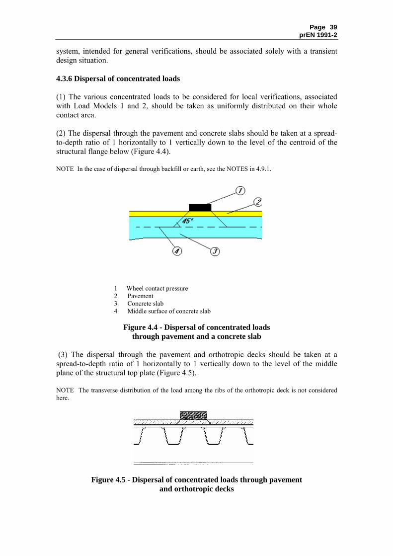
Page prEN 1991-2
39
system, intended for general verifications, should be associated solely with a transient design situation. 4.3.6 Dispersal of concentrated loads (1) The various concentrated loads to be considered for local verifications, associated with Load Models 1 and 2, should be taken as uniformly distributed on their whole contact area. (2) The dispersal through the pavement and concrete slabs should be taken at a spread-to-depth ratio of 1 horizontally to 1 vertically down to the level of the centroid of the structural flange below (Figure 4.4). NOTE In the case of dispersal through backfill or earth, see the NOTES in 4.9.1.
1 Wheel contact pressure 2 Pavement 3 Concrete slab 4 Middle surface of concrete slab
Figure 4.4 - Dispersal of concentrated loads
through pavement and a concrete slab (3) The dispersal through the pavement and orthotropic decks should be taken at a spread-to-depth ratio of 1 horizontally to 1 vertically down to the level of the middle plane of the structural top plate (Figure 4.5). NOTE The transverse distribution of the load among the ribs of the orthotropic deck is not considered here.
Figure 4.5 - Dispersal of concentrated loads through pavement and orthotropic decks

Page prEN 1991-2
40
4.4 Horizontal forces - characteristic values 4.4.1 Braking and acceleration forces (1)P A braking force, denoted by lkQ , shall be taken as a longitudinal force acting at the finished carriageway level. (2) The characteristic value of lkQ , limited to 900 kN for the total width of the bridge, should be calculated as a fraction of the total maximum vertical loads corresponding to the Load Model 1 likely to be applied on Lane Number 1, as follows :
)(900)(18010,0)2(6,0
lkQ1
l1kq11kQ1lk
kNQkNLwqQQ
≤≤
+=
ααα
(4.6)
where : L is the length of the deck or of the part of it under consideration. NOTE 1 For example, Qlk = 360 + 2,7L (≤ 900 kN) for a 3m wide lane and for a loaded length L>1,2 m, if α factors are equal to unity. NOTE 2 The upper limit (900 kN) may be adjusted in the National Annex. The value 900 kN is normally intended to cover the maximum braking force of military vehicles according to STANAG6. NOTE 3 Horizontal forces associated with Load Model 3 may be defined in the National Annex. (3) This force should be taken into account as located along the axis of any lane. However, if the eccentricity effects are not significant, the force may be considered to be applied only along the carriageway axis, and uniformly distributed over the loaded length. (4) Acceleration forces should be taken into account with the same magnitude as braking forces, but in the opposite direction. NOTE Practically this means that Q
1k may be negative as well as positive.
(5) The horizontal force transmitted by expansion joints or applied to structural members that can be loaded by only one axle should be taken as :
1kQ1lk 6,0 QQ α= (4.6a) NOTE The National Annex may define a different value of this force.
6 STANAG : Military STANdardization AGreements (STANAG 2021)

Page prEN 1991-2
41
4.4.2 Centrifugal and other transverse forces (1) The centrifugal force tkQ should be taken as a transverse force acting at the finished carriageway level and radially to the axis of the carriageway. (2) The characteristic value of tkQ , in which dynamic effects are included, should be taken from Table 4.3.
Table 4.3 - Characteristic values of centrifugal forces
vtk 2,0 QQ = (kN) if r < 200 m
rQQ /40 vtk = (kN) if 200 ≤ r ≤ 1500 m
tkQ = 0 if r > 1500 m
where : r is the horizontal radius of the carriageway centreline [m]
vQ is the total maximum weight of vertical concentrated loads of the tandem systems of LM1, i.e. )2( ikQi Q
i∑α (see Table 4.2).
(3) tkQ should be assumed to act as a point load at any deck cross-section. (4) Where relevant, lateral forces from skew braking or skidding should be taken into account. A transverse braking force, trkQ , equal to 25% of the longitudinal braking or acceleration force lkQ , should be considered to act simultaneously with lkQ at the finished carriageway level. NOTE The National Annex may define a minimum transverse loading. In most cases, forces resulting from wind effects and collisions on kerbs provide a sufficient transverse loading. 4.5 Groups of traffic loads on road bridges 4.5.1 Characteristic values of the multi-component action (1) The simultaneity of the loading systems defined in 4.3.2 (Load Model 1), 4.3.3 (Load Model 2), 4.3.4 (Load Model 3), 4.3.5 (Load Model 4), 4.4 (horizontal forces) and the loads defined in section 5 for footways should be taken into account by considering the groups of loads defined in Table 4.4a. Each of these groups of loads, which are mutually exclusive, should be considered as defining a characteristic action for combination with non-traffic loads.


Page 43 prEN 1991-2
Table 4.4a - Assessment of groups of traffic loads (characteristic values of the multi-component action)
CARRIAGEWAY FOOTWAYS AND
CYCLE TRACKS
Load type Vertical forces Horizontal forces Vertical forces only
Reference 4.3.2 4.3.3 4.3.4 4.3.5 4.4.1 4.4.2 5.3.2-(1) Load system LM1
(TS and UDL
systems)
LM2 (Single axle)
LM3 (Special vehicles)
LM4 (Crowd loading)
Braking and acceleration
forces
Centrifugal and
transverse forces
Uniformly Distributed
load
gr1a Characteristic values
a) a) Combination value b)
gr1b Characteristic value
gr2 Frequent valuesb)
Characteristic value
Characteristic value
Groups of Loads
gr3 d) Characteristic value c)
Gr4 Characteristic value
Characteristic value b)
Gr5 See Annex A Characteristic value
Dominant component action (designated as component associated with the group) a) If specified, may be defined in the National Annex. b) May be defined in the National Annex. c) See 5.3.2.1-(3). One footway only should be considered to be loaded if the effect is more unfavourable than the effect of two loaded footways. d) This group is irrelevant if gr4 is considered.

Page prEN 1991-2
44
4.5.2 Other representative values of the multi-component action (1) The frequent action should consist only of either the frequent values of LM1 or the frequent value of LM2, or the frequent values of loads on footways or cycle-tracks (taking the more unfavourable), without any accompanying component, as defined in Table 4.4b. NOTE 1 For the individual components of the traffic action, these representative values are defined in EN 1990 Eurocode : Basis of Structural Design, Annex A2. NOTE 2 For quasi-permanent values (generally equal to zero), see Annex A2 to EN 1990. NOTE 3 Where the National Annex refers to infrequent values of variable actions, the same rule as in 4.5.1 may be applied by replacing all characteristic values in Table 4.4 by infrequent values defined in EN 1990 Eurocode : Basis of Structural Design, Annex A2, without modifying the other values mentioned in the Table. But the infrequent group gr2 is practically irrelevant for road bridges.
Table 4.4b - Assessment of groups of traffic loads (frequent values of the multi-component action)
CARRIAGEWAY FOOTWAYS AND
CYCLE TRACKS Load type Vertical forces Reference 4.3.2 4.3.3 5.3.2(1)
Load system LM1 (TS and UDL systems)
LM2 (single axle) Uniformly distributed load
gr1a Frequent values Groups of
loads gr1b Frequent values
gr3 Frequent value a) a) See 5.3.2.1(3). One footway only should be considered to be loaded if the effect is more unfavourable than the effect of two loaded footways. 4.5.3 Groups of loads in transient design situations (1) The rules given in 4.5.1 and 4.5.2 are applicable with the following modifications. (2) For verifications in transient design situations, the characteristic values associated with the tandem system should be taken equal to ikQi8,0 Qα , and all other characteristic, frequent and quasi-permanent values and the horizontal forces are as specified for persistent design situations without any modification (i.e. they are not reduced proportionally to the weight of the tandems). NOTE In transient design situations due to road or bridge maintenance, the traffic is commonly concentrated on smaller areas without being significantly reduced, and long lasting traffic jams are frequent. However, more reductions may be applied in the cases where the heaviest lorries are diverted by appropriate measures.

Page prEN 1991-2
45
4.6 Fatigue load models 4.6.1 General (1) Traffic running on bridges produces a stress spectrum which may cause fatigue. The stress spectrum depends on the geometry of the vehicles, the axle loads, the vehicle spacing, the composition of the traffic and its dynamic effects. (2) In the following, five fatigue load models of vertical forces are defined.
NOTE 1 Horizontal forces may have to be taken into account simultaneously with vertical forces for the particular project : for example, centrifugal forces may occasionally need to be considered in conjunction with the vertical loads. NOTE 2 The use of the various Fatigue Load Models is defined in EN 1992 to EN 1999. a) Fatigue Load Models 1, 2 and 3 are intended to be used to determine the maximum and minimum stresses resulting from the possible load arrangements on the bridge of any of these models ; in many cases, only the algebraic difference between these stresses is used in design Eurocodes. b) Fatigue Load Models 4 and 5 are intended to be used to determine stress range spectra resulting from the passage of lorries on the bridge. c) Fatigue Load Models 1 and 2 are intended to be used to check whether the fatigue life may be considered as unlimited when a constant stress amplitude fatigue limit is given. Therefore, they are appropriate for steel constructions and may be inappropriate for other materials. Fatigue Load Model 1 is generally conservative and covers multi-lane effects automatically. Fatigue Load Model 2 is more accurate than Fatigue Load Model 1 when the simultaneous presence of several lorries on the bridge can be neglected for fatigue verifications. If that is not the case, it should be used only if it is supplemented by additional data. See National Annex. d) Fatigue Load Models 3, 4 and 5 are intended to be used for fatigue life assessment by reference to fatigue strength curves defined in design Eurocodes. They should not be used to check whether fatigue life can be considered as unlimited. For this reason, they are not numerically comparable to Fatigue Load Models 1 and 2. Fatigue Load Model 3 may also be used for the direct verification of designs by simplified methods in which the influence of the annual traffic volume and of some bridge dimensions is taken into account by a material-dependent adjustment factor eλ . e) Fatigue Load Model 4 is more accurate than Fatigue Load Model 3 for a variety of bridges and of the traffic when the simultaneous presence of several lorries on the bridge can be neglected. If that is not the case, it should be used only if it is supplemented by additional data, specified or as defined in the National Annex. f) Fatigue Load Model 5 is the most general model, using actual traffic data. NOTE 3 The load values given for Fatigue Load Models 1 to 3 are appropriate for typical heavy traffic on European main roads or motorways (traffic category Number 1 as defined in Table 4.5). NOTE 4 The values of Fatigue Load Models 1 and 2 may be modified for the particular project or by the National Annex when considering other categories of traffic. In this case, the modifications made to both models should be proportional. For Fatigue Load Model 3 a modification depends on the verification procedure. (3) A traffic category on a bridge should be defined, for fatigue verifications, at least, by: � the number of slow lanes,

Page prEN 1991-2
46
� the number obsN of heavy vehicles (maximum gross vehicle weight more than 100 kN), observed or estimated, per year and per slow lane.
NOTE 1 The traffic categories and values may be defined in the National Annex. Indicative values for
obsN are given in Table 4.5 for a slow lane when using Fatigue Load Models 3 and 4. On each fast lane, additionally, 10% of obsN may be taken into account.
Table 4.5 - Indicative number of heavy vehicles expected per year and per slow lane
Traffic categories Nobs per year and per slow lane
1 Roads and motorways with 2 or more lanes per direction with high flow rates of lorries
2,0 × 10⁶
2 Roads and motorways with medium flow rates of lorries
0,5 × 10⁶
3 Main roads with low flow rates of lorries
0,125 × 106
4 Local roads with low flow rates of lorries
0,05 × 10⁶
NOTE 2 Table 4.5 is not sufficient to characterise the traffic for fatigue verifications. Other parameters may have to be considered like : - percentages of vehicle types (see, e.g., Table 4.7), which depend on the "traffic type", - parameters defining the distribution of the weight of vehicles or axles of each type. NOTE 3 There is no general relation between traffic categories for fatigue verifications, and the loading classes and associated α factors mentioned in 4.2.2 and 4.3.2. NOTE 4 Intermediate values of Nobs are not excluded, but are unlikely to have very significant influence on the fatigue lifetime. (4) For the assessment of general action effects (e.g. in main girders) all fatigue load models should be placed centrally on the notional lanes defined in accordance with the principles and rules given in 4.2.4(2) and (3). The slow lanes should be identified in the design. (5) For the assessment of local action effects (e.g. in slabs) the models should be centered on notional lanes assumed to be located anywhere on the carriageway. However, when the transverse location of the vehicles for Fatigue Load Models 3, 4 and 5 is significant for the studied effects (e.g. for orthotropic decks), a statistical distribution of this transverse location should be taken into account in accordance with Figure 4.6.

Page prEN 1991-2
47
Figure 4.6 - Frequency distribution of transverse location
of centre line of vehicle (6) Fatigue Load Models 1 to 4 include dynamic load amplification appropriate for pavements of good quality (see Annex B). An additional amplification factor fatϕ∆ should be taken into account near expansion joints and applied to all loads :
1;6
130,1 fatfat ≥∆
−=∆ ϕϕ D (4.7)
where : D distance (m) of the cross-section under consideration from the expansion joint. See Figure 4.7.
∆ϕfat : Additional amplification factor D : Distance of the cross-section under consideration from the expansion joint
Figure 4.7 - Representation of the additional amplification factor
NOTE A conservative, often acceptable, simplification may consist of adopting 3,1fat =∆ϕ for any cross-section within 6m from the expansion joint. The dynamic amplification may be modified in the National Annex.

Page prEN 1991-2
48
4.6.2 Fatigue Load Model 1 (similar to LM1) (1) Fatigue Load Model 1 has the configuration of the characteristic Load Model 1 defined in 4.3.2, with the values of the axle loads equal to ik7,0 Q and the values of the uniformly distributed loads equal to ik3,0 q and (unless otherwise specified) rk3,0 q . NOTE The load values for Fatigue Load Model 1 are similar to those defined for the Frequent Load Model. However adopting the Frequent Load Model without adjustment would have been excessively conservative by comparison with the other models, especially for large loaded areas. For particular projects, rkq may be neglected. (2) The maximum and minimum stresses ( max,FLMσ and minFLM,σ ) should be determined from the possible load arrangements of the model on the bridge. 4.6.3 Fatigue Load Model 2 (set of "frequent" lorries) (1) Fatigue Load Model 2 consists of a set of idealised lorries, called "frequent" lorries, to be used as defined in (3) below. (2) Each �frequent lorry� is defined by : � the number of axles and the axle spacing (Table 4.6, columns1+2), � the frequent load of each axle (Table 4.6, column 3), � the wheel contact areas and the transverse distance between wheels (column 4 of
Table 4.6 and Table 4.8). (3) The maximum and minimum stresses should be determined from the most severe effects of different lorries, separately considered, travelling alone along the appropriate lane. NOTE When some of these lorries are obviously the most critical, the others may be disregarded.

Page prEN 1991-2
49
Table 4.6 - Set of “frequent” lorries
1 2 3 4
LORRY SILHOUETTE
Axle spacing
(m)
Frequent axle loads
(kN)
Wheel type (see Table 4.8)
4,5 90 190
A B
4,20 1,30
80 140 140
A B B
3,20 5,20 1,30 1,30
90 180 120 120 120
A B C C C
3,40 6,00 1,80
90 190 140 140
A B B B
4,80 3,60 4,40 1,30
90 180 120 110 110
A B C C C
4.6.4 Fatigue Load Model 3 (single vehicle model) (1) This model consists of four axles, each of them having two identical wheels. The geometry is shown in Figure 4.8. The weight of each axle is equal to 120 kN, and the contact surface of each wheel is a square of side 0,40 m.
wl : Lane width X : Bridge longitudinal axis
Figure 4.8 - Fatigue Load Model 3

Page prEN 1991-2
50
(2) The maximum and minimum stresses and the stress ranges for each cycle of stress fluctuation, i.e. their algebraic difference, resulting from the transit of the model along the bridge should be calculated. (3) Where relevant, two vehicles in the same lane should be taken into account. NOTE The conditions of application of this rule may be defined in the National Annex or for the particular project. Possible conditions are give hereafter : � one vehicle is as defined in (1) above ; � the geometry of the second vehicle is as defined in (1) above and the weight of each axle is equal to
36 kN (instead of 120 kN) ; � the distance between the two vehicles, measured from centre to centre of vehicles, is not less than 40
m. 4.6.5 Fatigue Load Model 4 (set of "standard" lorries) (1) Fatigue Load Model 4 consists of sets of standard lorries which together produce effects equivalent to those of typical traffic on European roads. A set of lorries appropriate to the traffic mixes predicted for the route as defined in Tables 4.7 and 4.8 should be taken into account.
Table 4.7 - Set of equivalent lorries
VEHICLE TYPE TRAFFIC TYPE
1 2 3 4 5 6 7
Long distance
Medium distance
Local traffic
LORRY
Axle spacing
(m)
Equivalent axle
loads (kN)
Lorry percentage
Lorry percentage
Lorry percentage
Wheel type
4,5 70 130
20,0 40,0 80,0 A B
4,20 1,30
70 120 120
5,0 10,0 5,0 A B B
3,20 5,20 1,30 1,30
70 150 90 90 90
50,0 30,0 5,0 A B C C C
3,40 6,00 1,80
70 140 90 90
15,0 15,0 5,0 A B B B
4,80 3,60 4,40 1,30
70 130 90 80 80
10,0 5,0 5,0 A B C C C

Page prEN 1991-2
51
NOTE 1 This model, based on five standard lorries, simulates traffic which is deemed to produce fatigue damage equivalent to that due to actual traffic of the corresponding category defined in Table 4.5. NOTE 2 Other standard lorries and lorry percentages may be defined for the particular project or in the National Annex. NOTE 3 For the selection of a traffic type, it may broadly be considered that : - "Long distance" means hundreds of kilometres, - "Medium distance" means 50 to 100 km, - "Local traffic" means distances less than 50 km. In reality, mixture of traffic types may occur.
Table 4.8 - Definition of wheels and axles
WHEEL/ AXLE TYPE
GEOMETRICAL DEFINITION
A
B
C
(2) Each standard lorry is defined by : � the number of axles and the axle spacing (Table 4.7, columns 1+2), � the equivalent load of each axle (Table 4.7, column 3) � the wheel contact areas and the transverse distances between wheels, in accordance
with column 7 of Table 4.7. and Table 4.8. (3) The calculations should be based on the following procedure : � the percentage of each standard lorry in the traffic flow should be selected from
Table 4.7. columns 4, 5 or 6 as relevant ;

Page prEN 1991-2
52
� the total number of vehicles per year to be considered for the whole carriageway ∑ obsN should be defined ;
NOTE Recommended values are given in Table 4.5. � each standard lorry is considered to cross the bridge in the absence of any other
vehicle. (4) The stress range spectrum and the corresponding number of cycles from each fluctuation in stress during the passage of individual lorries on the bridge should be the Rainflow or the Reservoir counting method. NOTE For verification rules, see EN1992 to EN 1999 4.6.6 Fatigue Load Model 5 (based on recorded road traffic) (1) Fatigue Load Model 5 consists of the direct application of recorded traffic data, supplemented, if relevant, by appropriate statistical and projected extrapolations. NOTE For the use of this model, see the National Annex. Guidance for a complete specification and the application of such a model is given in Annex B. 4.7 Actions for accidental design situations 4.7.1 General (1)P Loads due to road vehicles in accidental design situations shall be taken into account where relevant, resulting from : � vehicle collision with bridge piers or decks, � the presence of heavy wheels on footways (effects of heavy wheels on footways shall
be considered for all road bridges where footways are not protected by an effective rigid road restraint system),
� vehicle collision with kerbs, vehicle parapets and structural components (effects of vehicle collision with vehicle parapets and safety barriers shall be considered for all road bridges where such road restraint systems are provided on the bridge deck ; effects of vehicle collision with kerbs shall be considered in all cases).
4.7.2 Collision forces from vehicles under the bridge NOTE See 5.6.2 and 6.7.1.3(1)P, and Annex A2 to EN 1990 � Eurocode : Basis of Structural Design. 4.7.2.1 Collision forces on piers and other supporting members (1) Forces due to the collision of abnormal height or aberrant road vehicles with piers or with the supporting members of a bridge should be taken into account. NOTE The National Annex may define : � rules to protect the bridge from collision forces, � when collision forces are to be taken into account (e.g. with reference to a safety distance between
piers and the edge of the carriageway), � the magnitude and location of collision forces, � and also the limit states to be considered.

Page prEN 1991-2
53
For stiff piers the following minimum values are recommended : a) Impact force : 1000 kN in the direction of vehicle travel or 500 kN perpendicular to that direction ; b) Height above the level of adjacent ground surface : 1,25 m. See also EN 1991-1-7. 4.7.2.2 Collision forces on decks (1) If relevant the vehicle collision force should be specified. NOTE 1 The National Annex may define the collision force on decks, possibly in relation to vertical clearance and other forms of protection. See EN 1991-1-7. NOTE 2 Collision loads on bridge decks and other structural components over roads may vary widely depending on structural and non-structural parameters, and their conditions of applicability. The possibility of collision by vehicles having an abnormal or illegal height may have to be envisaged, as well as a crane swinging up while a vehicle is moving. Protective measures may be introduced as an alternative to designing for collision forces. 4.7.3 Actions from vehicles on the bridge 4.7.3.1 Vehicle on footways and cycle tracks on road bridges (1) If a safety barrier of an appropriate containment level is provided, wheel loading beyond this protection need not be taken into account. NOTE Containment levels for safety barriers are defined in EN 1317-2. (2) Where the protection mentioned in (1) is provided, one accidental axle load corresponding to 2kQ2Qα (see 4.3.2) should be so placed and oriented on the unprotected parts of the deck so as to give the most adverse effect adjacent to the safety barrier as shown, for example, in Figure 4.9. This axle load should not be taken into account simultaneously with any other variable load on the deck. A single wheel alone should be taken into account if geometrical constraints make a two-wheel arrangement impossible. Beyond the vehicle restraint system, the characteristic variable concentrated load defined in clause 5.3.2.2 should be applied, if relevant, separately from the accidental load.

Page prEN 1991-2
54
(1) Pedestrian parapet (or vehicle parapet if a safety barrier is not provided) (2) Safety barrier (3) Carriageway
Figure 4.9 - Examples showing locations of loads from vehicles on footways and cycle tracks of road bridges
(3) In the absence of the protection mentioned in (1), the rules given in (2) are applicable up to the edge of the deck where a vehicle parapet is provided. 4.7.3.2 Collision forces on kerbs (1) The action from vehicle collision with kerbs or pavement upstands should be taken as a lateral force equal to 100 kN acting at a depth of 0,05 m below the top of the kerb. This force should be considered as acting on a line 0,5 m long and is transmitted by the kerbs to the structural members supporting them. In rigid structural members, the load should be assumed to have an angle of dispersal of 45°. When unfavourable, a vertical traffic load acting simultaneously with the collision force equal to 1kQ175,0 Qα (see Figure 4.10) should be taken into account.

Page prEN 1991-2
55
1) Footway � 2) kerb
Figure 4.10 - Definition of vehicle collision forces on kerbs
4.7.3.3 Collision forces on vehicle restraint systems (1) For structural design, horizontal and vertical forces transferred to the bridge deck by vehicle restraint systems should be taken into account. NOTE 1 The National Annex may define and select classes of collision forces and associated conditions of application. In the following, 4 recommended classes of values for the transferred horizontal force are given : Table 4.9 – Recommended classes for the horizontal force transferred by vehicle restraint systems
Recommended class Horizontal force (kN) A 100 B 200 C 400 D 600
The horizontal force, acting transversely, may be applied 100 mm below the top of the selected vehicle restraint system or 1,0 m above the level of the carriageway or footway, whichever is the lower, and on a line 0,5 m long. NOTE 2 The values of the horizontal forces given for the classes A to D derive from measurements during collision tests on real vehicle restraint systems used for bridges. There is no direct correlation between these values and performance classes of vehicle restraint systems. The proposed values depend rather on the stiffness of the connection between the vehicle restraint system and the kerb or the part of the bridge to which it is connected. A very strong connection leads to the horizontal force given for class D. The lowest horizontal force derives from measurements for a vehicle restraint system with a weak connection. Such systems are frequently used for a steel vehicle restraint systems according to a performance class H2 according to EN 1317, Part 2. A very weak connection may lead to the horizontal force given for class A. NOTE 3 The vertical force acting simultaneously with the horizontal collision force may be defined in the National Annex. The recommended values may be taken equal to
1kQ175,0 Qα . The horizontal and vertical forces may be replaced, when possible, by detailing measures (for example, design of reinforcement).

Page prEN 1991-2
56
(2) The structure supporting the vehicle parapet should be designed to sustain locally an accidental load effect corresponding to 1,25 times the characteristic local resistance of vehicle parapet (e.g. resistance of the connection of the parapet to the structure) exclusive of any variable load. NOTE This design load effect may be defined in the National Annex. 4.7.3.4 Collision forces on structural members (1) The vehicle collision forces on unprotected structural members above or beside the carriageway levels should be taken into account. NOTE These forces may the defined in the National Annex. They may be the same as defined in 4.7.2.1(1), acting 1,25 m above the carriageway level. However, when additional protective measures between the carriageway and these members are provided, this force may be reduced for the particular project. (2) These forces should not be considered to act simultaneously with any variable load. NOTE For some intermediate members damage to one of which would not cause collapse (e.g. hangers or stays), smaller forces may be defined for the particular project. 4.8 Actions on pedestrian parapets (1) For structural design, forces that are transferred to the bridge deck by pedestrian parapets should be taken into account as variable loads and defined, depending on the selected loading class of the parapet. NOTE 1 For loading classes of pedestrian parapets, see EN 1317-6. For bridges, class C is the recommended minimum class. NOTE 2 The forces transferred to the bridge deck by pedestrian parapets may be defined with their classification for the particular project or in the National Annex in accordance with EN1317-6. A line force of 1,0 kN/m acting, as a variable load, horizontally or vertically on the top of the parapet is a recommended minimum value for footways or footbridges. For service side paths, the recommended minimum value is 0,8 kN/m. Exceptional and accidental cases are not covered by these recommended minimum values. (2) For the design of the supporting structure, if pedestrian parapets are adequately protected against vehicle collision, the horizontal actions should be considered as simultaneous with the uniformly vertical loads defined in 5.3.2.1. NOTE Pedestrian parapets can be considered as adequately protected only if the protection satisfies the requirements for the particular project. (3) Where pedestrian parapets cannot be considered as adequately protected against vehicle collisions, the supporting structure should be designed to sustain an accidental load effect corresponding to 1,25 times the characteristic resistance of the parapet, exclusive of any variable load. NOTE This design load effect may be defined in the National Annex

Page prEN 1991-2
57
4.9 Load models for abutments and walls adjacent to bridges 4.9.1 Vertical loads (1) The carriageway located behind abutments, wing walls, side walls and other parts of the bridge in contact with earth, should be loaded with appropriate models. NOTE 1 These appropriate load models may be defined in the National Annex. The use of Load Model 1, defined in 4.3.2, is recommended, but, for the sake of simplification, the tandem system loads may be replaced by an equivalent uniformly distributed load, noted qeq, spread over an appropriate relevant rectangular surface depending on the dispersal of the loads through the backfill or earth.
NOTE 2 For the dispersal of the loads through the backfill or earth, see EN 1997. In the absence of any other rule, if the backfill is properly consolidated, the recommended value of the dispersal angle from to the vertical is equal to 30°. With such a value, the surface on which qeq is applied may be taken as a rectangular surface 3 m wide and 2,20 m long . (2) Representative values of the load model other than the characteristic values should not be considered. 4.9.2 Horizontal force (1) No horizontal force should be taken into account at the surfacing level of the carriageway over the backfill. (2) For the design of abutment upstand walls (see Figure 4.11), a longitudinal braking force should be taken into account with a characteristic value equal to 1kQ16,0 Qα , acting simultaneously with the 1kQ1Qα axle loading of Load Model Number 1 and with the earth pressure from the backfill. The backfill should be assumed not to be loaded simultaneously.
(1) Upstand wall (2) Bridge deck (3) Abutment
Figure 4.11 : Definition of loads on upstand walls

Page prEN 1991-2
58
Section 5 Actions on footways, cycle tracks and footbridges 5.1 Field of application (1) Load models defined in this section are applicable to footways, cycle tracks and footbridges. (2) The uniformly distributed load fkq (defined in 5.3.2.1) and the concentrated load
fwkQ (defined in 5.3.2.2) should be used for road and railway bridges as well as for footbridges, where relevant (see 4.5, 4.7.3 and 6.3.6.2(1)). All other variable actions and actions for accidental design situations defined in this section are intended only for footbridges. NOTE 1 For loads on access steps, see 4.4 in EN 1991-1-1. NOTE 2 For large footbridges (for example more than 6 m width) load models defined in this section may not be appropriate and then complementary load models, with associated combination rules, may have to be defined for the particular project. Indeed, various human activities may take place on wide footbridges. (3) Models and representative values given in this section should be used for serviceability and ultimate limit state calculations excluding fatigue limit states. (4) For calculations relating to the vibration of pedestrian bridges and based on dynamic analysis, see 5.7. For all other calculations of load effects to be performed for any bridge type, the models and values given in this section include the dynamic amplification effects, and the variable actions should be treated as static. (5) The effects of loads on construction sites are not intended to be covered by the load models given in this section and should be separately specified, where relevant. 5.2 Representation of actions 5.2.1 Models of the loads (1) The imposed loads defined in this section result from pedestrian and cycle traffic, minor common construction and maintenance loads (e.g. service vehicles), and accidental situations. These loads give rise to vertical and horizontal, static and dynamic forces. NOTE 1 Loads due to cycle traffic are generally much lower than those due to pedestrian traffic, and the values given in this section are based on the frequent or occasional presence of pedestrians on cycle lanes. Special consideration may need to be given to loads due to horses or cattle for particular projects. NOTE 2 The load models defined in this section do not describe actual loads. They have been selected so that their effects (with dynamic amplification included where mentioned) represent the effects of actual traffic.

Page prEN 1991-2
59
(2) Actions for accidental design situations due to collision should be represented by static equivalent loads. 5.2.2 Loading classes (1) Loads on footbridges may differ depending on their location and on the possible traffic flow of some vehicles. These factors are mutually independent and are envisaged in various clauses given below. Therefore no general classification of these bridges needs to be defined. 5.2.3 Application of the load models (1) The same models, service vehicle excepted (see 5.3.2.3), should be used for pedestrian and cycle traffic on footbridges, on the areas of the deck of road bridges limited by pedestrian parapets and not included in the carriageway as defined in 1.4.2 (denominated footways in this Part of EN 1991) and on the footpaths of railway bridges. (2) Appropriate other models should be defined for inspection gangways within the structures of bridges and for platforms on railway bridges. NOTE Such models can be defined in the National Annex or for the particular project. The recommended models, to be used separately in order to get the most unfavourable effects, are an uniformly distributed load of 2 kN/m2 and a concentrated load of 3 kN applicable to a square surface of 0,20×0,20 m2. (3) For each individual application, the models of vertical loads should be applied anywhere within the relevant areas so that the most adverse effect is obtained. NOTE In other terms, these actions are free actions. 5.3 Static models for vertical loads - characteristic values 5.3.1 General (1) Characteristic loads are intended for the determination of pedestrian or cycle-track static load effects associated with ultimate limit-states verifications and particular serviceability verifications. (2) Three models, mutually exclusive, should be taken into account, as relevant. They consist of : � a uniformly distributed load, fkq � a concentrated load fwkQ , and � loads representing service vehicles, servQ . (3) The characteristic values of these load models should be used for both persistent and transient design situations.

Page prEN 1991-2
60
5.3.2 Load Models 5.3.2.1 Uniformly distributed load (1) For the design of footbridges, a uniformly distributed load fkq should be defined and applied only in the unfavourable parts of the influence surface, longitudinally and transversally. NOTE 1 The characteristic value fkq may be defined in the National Annex or for the particular project. Load Model 4 (crowd loading) defined in 4.3.5, corresponding to 2
fk kN/m5=q , may be specified to cover the static effects of a continuous dense crowd where such a risk exists.
NOTE 2 Where the application of Load Model 4 defined in 4.3.5 is not required, the recommended value for fkq is :
2fk kN/m
301200,2+
+=L
q
2fk kN/m5,2≥q ; 2
fk kN/m0,5≤q (5.1) where : L is the loaded length in [m]. (2) For road bridges supporting footways or cycle tracks, the characteristic value of the uniformly distributed load should be taken equal to fkq = 5 kN/m2 (Figure 5.1)
Figure 5.1 - Characteristic load on a footway (or cycle track) 5.3.2.2 Concentrated load (1) The characteristic value of the concentrated load fwkQ should be taken equal to 10 kN acting on a square surface of sides 0,10 m. NOTE The characteristic value of the load as well as the dimensions may be adjusted in the National Annex. (2) Where, in a verification, general and local effects can be distinguished, the concentrated load should be taken into account only for local effects.

Page prEN 1991-2
61
(3) If, for a footbridge, a service vehicle, as mentioned in 5.3.2.3 is specified, fwkQ should not be considered. 5.3.2.3 Service vehicle (1)P When service vehicles are to be carried on a footbridge or footway, one service vehicle servQ shall be taken into account. NOTE 1 This vehicle may be a vehicle for maintenance, emergencies (e.g. ambulance, fire) or other services. The characteristics of this vehicle (axle weight and spacing, contact area of wheels), the dynamic amplification and all other appropriate loading rules may be defined for the particular project or in the National Annex. If no information is available and if no permanent obstacle prevents a vehicle being driven onto the bridge deck, the use of the vehicle defined in 5.6.3 as the service vehicle (characteristic load) is recommended ; in this case, there will be no need to apply 5.6.3, i.e. to consider the same vehicle as accidental.
NOTE 2 The consideration of a service vehicle has no purpose if permanent provisions are made to prevent access of all vehicles to the footbridge.
NOTE 3 Several service vehicles, mutually exclusive, may have to be taken into account and may be defined for the particular project. 5.4 Static model for horizontal forces - characteristic values (1) For footbridges only, a horizontal force flkQ should be taken into account, acting along the bridge deck axis at the pavement level. (2) The characteristic value of the horizontal force should be taken equal to the greater of the following two values : � 10 per cent of the total load corresponding to the uniformly distributed load (5.3.2.1), � 60 per cent of the total weight of the service vehicle, if relevant (5.3.2.3-(1)P). NOTE The characteristic value of the horizontal force may be defined in the National Annex or for the particular project. (3) The horizontal force is considered as acting simultaneously with the corresponding vertical load, and in no case with the concentrated load fwkQ . NOTE This force is normally sufficient to ensure the horizontal longitudinal stability of footbridges. It does not ensure horizontal transverse stability, which should be ensured by considering other actions or by appropriate design measures. 5.5 Groups of traffic loads on footbridges (1)When relevant, the vertical loads and horizontal forces due to traffic should be taken into account by considering groups of loads defined in Table 5.1. Each of these groups of loads, which are mutually exclusive, should be considered as defining a characteristic action for combination with non�traffic loads.

Page prEN 1991-2
62
Table 5.1 - Definition of groups of loads (characteristic values)
Load type Vertical forces Horizontal
forces Load system Uniformly
distributed load Service vehicle
Groups gr1 fkq 0 flkQ
of loads gr2 0 servQ flkQ
(2) For any combination of traffic loads together with actions specified in other Parts of EN 1991, any such group should be considered as one action. NOTE For the individual components of the traffic loads on footbridges, the other representative values are defined in Annex A2 to EN 1990 Eurocode : Basis of Structural Design. 5.6 Actions for accidental design situations for footbridges 5.6.1 General (1) Such actions are due to : � road traffic under the bridge (i.e. collision) or
� the accidental presence of a heavy vehicle on the bridge. NOTE Other collision forces (see 2.3) may be defined for the particular project or in the National Annex. 5.6.2 Collision forces from road vehicles under the bridge (1) The measures to protect a footbridge should be defined. NOTE Footbridges (piers and decks) are generally much more sensitive to collision forces than road bridges. Designing them for the same collision load may be unrealistic. The most effective way to take collision into account generally consists of protecting the footbridges : � by establishing road restraint systems at appropriate distances before piers, � by giving the bridges a higher clearance than for neighbouring road or railway bridges over the same
road in the absence of intermediate access to the road. 5.6.2.1 Collision forces on piers (1) Forces due to the collision of abnormal height or aberrant road vehicles with piers or with the supporting members of a footbridge or ramps or stairs should be taken into account. NOTE The National Annex may define : � rules to protect the bridge from collision forces, � when collision forces are to be taken into account (e.g. with reference to a safety distance between
piers and the edge of the carriageway), � the magnitude and location of collision forces, � and also the limit states to be considered.

Page prEN 1991-2
63
For stiff piers the following minimum values are recommended : a) Impact force : 1000 kN in the direction of vehicle travel or 500 kN perpendicular to that direction ; b) Height above the level of adjacent ground surface : 1,25 m. See also EN 1991-1-7. 5.6.2.2 Collision forces on decks (1) An adequate vertical clearance between the ground surface and the soffit of the deck above should be ensured in the design, when relevant. NOTE 1 The National Annex or the particular project may define collision forces depending on the vertical clearance. See also EN 1991-1-7. NOTE 2 The possibility of collision by vehicles having an abnormal or illegal height may have to be envisaged. 5.6.3 Accidental presence of vehicles on the bridge (1)P If no permanent obstacle prevents a vehicle from being driven onto the bridge deck, the accidental presence of a vehicle on the bridge deck shall be taken into account. (2) For such a situation, the following load model should be used, consisting of a two-axle load group of 80 and 40 kN, separated by a wheel base of 3 m (Figure 5.2), with a track (wheel-centre to wheel-centre) of 1,3 m and square contact areas of side 0,2m at coating level. The braking force associated with the load model should be 60% of the vertical load.
x : Bridge axis direction Qsv1 = 80 kN Qsv2 = 40 kN
Figure 5.2 - Accidental loading NOTE 1 See the note in 5.3.2.3-(1)P. NOTE 2 If relevant, other characteristics of the load model may be defined in the National Annex or for the particular project.

Page prEN 1991-2
64
(3) No variable action should be taken into account simultaneously with the load model defined in 5.6.3(2). 5.7 Dynamic models of pedestrian loads (1) Depending on the dynamic characteristics of the structure, the relevant natural frequencies (corresponding to vertical, horizontal, torsional vibrations) of the main structure of the bridge deck should be assessed from an appropriate structural model. NOTE Vibrations of footbridges may have various origins : pedestrians, who can walk, run, jump or dance, wind forces, vandalism actions, etc. (2) Forces exerted by pedestrians with a frequency identical to one of the natural frequencies of the bridge can result into resonance and need be taken into account for limit state verifications in relation with vibrations. NOTE Effects of pedestrian traffic on a footbridge depend on various parameters as, for example, the number and location of people likely to be simultaneously on the bridge, and also on external circumstances, more or less linked to the location of the bridge. In the absence of significant response of the bridge, a pedestrian normally walking exerts on it simultaneous periodic forces which are : � vertical, with a frequency that can range between 1 and 3 Hz, and � horizontal, with a frequency that can range between 0,5 and 1,5 Hz. Groups of joggers may cross a footbridge with a frequency of 3 Hz. (3) Appropriate dynamic models of pedestrian loads and comfort criteria should be defined. NOTE The dynamic models of pedestrian loads and associated comfort criteria may be defined in the National Annex or for the particular project. See also Annex A2 to EN 1990 � Eurocode : Basis of Structural Design. 5.8 Actions on parapets (1) For footbridges, pedestrian parapets should be designed in accordance with rules given in 4.8. 5.9 Load model for abutments and walls adjacent to bridges (1) The area external to a carriageway and located behind abutments, wing walls, side walls and other parts of the bridge in contact with earth, should be loaded with a uniformly distributed vertical load whose magnitude is equal to 5 kN/m2. NOTE 1 This load does not cover the effects of heavy site vehicles and other lorries commonly used for the placing of the backfill. NOTE 2 The characteristic value may be adjusted for the particular project.

Page prEN 1991-2
65
Section 6 Rail traffic actions and other actions specifically for railway bridges 6.1 Field of application (1)P This section applies to rail traffic on the standard track gauge and wide track gauge European mainline network. (2) The load models defined in this section do not describe actual loads. They have been selected so that their effects, with dynamic increments taken into account separately, represent the effects of service traffic. Where traffic outside the scope of the load models specified in this Part needs to be considered, then alternative load models, with associated combination rules, should be specified for the particular project. NOTE The alternative load models with associated combination rules may be defined in the National Annex. (3)P This section is not applicable for actions due to: � narrow-gauge railways, � tramways and other light railways, � preservation railways, � rack and pinion railways, � funicular railways. The loading and characteristic values of actions for these types of railways should be specified for the particular project. NOTE The loading and characteristic values of actions for these types of railways may be defined in the National Annex. (4) Requirements are specified in EN 1990 � Eurocode: Basis of Structural Design, Annex A2 for the limits of deformation of structures carrying rail traffic to maintain the safety of operations and to ensure the comfort of passengers etc.. (5) Three standard mixes of rail traffic are given as a basis for calculating the fatigue life of structures (see Annex D). (6) The self-weight of non-structural elements includes the weight of elements such as, for example, noise and safety barriers, signals, ducts, cables and overhead line equipment (except the forces due to the tension of the contact wire etc.). (7) Designers should pay special attention to temporary bridges because of the flexibility of some types of temporary structures. The loading and requirements for the design of temporary bridges should be specified for the particular project. NOTE The National Annex may specify loading requirements for the design of temporary railway bridges which may generally be based on this document. The National Annex may give special requirements for temporary bridges depending upon the conditions in which they are used (e.g. special requirements for skew bridges).

Page prEN 1991-2
66
6.2 Representation of actions – nature of rail traffic loads (1) General rules are given for the calculation of the associated dynamic effects, centrifugal forces, nosing force, traction and braking forces and aerodynamic effects due to passing rail traffic. (2) Actions due to railway operations are given for: � vertical loads: Load Models 71, SW (SW/0 and SW/2), �unloaded train� and HSLM
(6.3 and 6.4.6.1.1), � vertical loading for earthworks (6.3.6.4), � dynamic effects (6.4), � centrifugal forces (6.5.1), � nosing force (6.5.2), � traction and braking forces (6.5.3), � combined response of a structure and track to variable actions (6.5.4), � aerodynamic effects from passing trains (6.6), � actions due to overhead line equipment and other railway infrastructure and equipment
(6.7.3). (3) Derailment actions for Accidental Design Situations are given for: � the effect of rail traffic derailment on a structure carrying rail traffic (6.7.1). 6.3 Vertical loads - characteristic values (static effects) and eccentricity and distribution of loading 6.3.1 General (1) Rail traffic actions are defined by means of load models. Five models of railway loading are given: � Load Model 71 (and Load Model SW/0 for continuous bridges) to represent normal
rail traffic on mainline railways, � Load Model SW/2 to represent heavy loads, � Load Model HSLM to represent the loading from passenger trains at speeds exceeding
200 km/h, � Load Model �unloaded train� to represent the effect of an unloaded train. NOTE Requirements for the application of load models are given in 6.8.1. (2) Provision is made for varying the specified loading to allow for differences in the nature, volume and maximum weight of rail traffic on different railways, as well as different qualities of track. 6.3.2 Load Model 71 (1) Load Model 71 represents the static effect of vertical loading due to normal rail traffic. (2)P The load arrangement and the characteristic values for vertical loads shall be taken as shown in Figure 6.1.
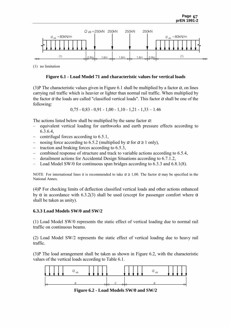
Page prEN 1991-2
67
(1) no limitation
Figure 6.1 - Load Model 71 and characteristic values for vertical loads (3)P The characteristic values given in Figure 6.1 shall be multiplied by a factor α, on lines carrying rail traffic which is heavier or lighter than normal rail traffic. When multiplied by the factor α the loads are called "classified vertical loads". This factor α shall be one of the following:
0,75 - 0,83 - 0,91 - 1,00 - 1,10 - 1,21 - 1,33 � 1.46 The actions listed below shall be multiplied by the same factor α: � equivalent vertical loading for earthworks and earth pressure effects according to
6.3.6.4, � centrifugal forces according to 6.5.1, � nosing force according to 6.5.2 (multiplied by α for α ≥ 1 only), � traction and braking forces according to 6.5.3, � combined response of structure and track to variable actions according to 6.5.4, � derailment actions for Accidental Design Situations according to 6.7.1.2, � Load Model SW/0 for continuous span bridges according to 6.3.3 and 6.8.1(8). NOTE For international lines it is recommended to take α ≥ 1,00. The factor α may be specified in the National Annex. (4)P For checking limits of deflection classified vertical loads and other actions enhanced by α in accordance with 6.3.2(3) shall be used (except for passenger comfort where α shall be taken as unity). 6.3.3 Load Models SW/0 and SW/2 (1) Load Model SW/0 represents the static effect of vertical loading due to normal rail traffic on continuous beams. (2) Load Model SW/2 represents the static effect of vertical loading due to heavy rail traffic. (3)P The load arrangement shall be taken as shown in Figure 6.2, with the characteristic values of the vertical loads according to Table 6.1.
Figure 6.2 - Load Models SW/0 and SW/2

Page prEN
1991-2
68
Table 6.1 - C
haracteristic values for vertical loads for Load M
odels SW/0 and
SW/2
Load
Model
qvk
[kN/m
] a
[m]
c [m
] SW
/0 SW
/2 133 150
15,0 25,0
5,3 7,0
(4)P The lines or section of line over which heavy rail traffic m
ay operate where Load
Model SW
/2 shall be taken into account shall be designated. N
OTE The designation m
ay be made in the N
ational Annex or for the particular project.
(5)P Load Model SW
/0 shall be multiplied by the factor α in accordance w
ith 6.3.2(3). 6.3.4 L
oad Model “unloaded train”
(1) For some specific verifications (see EN
1990 Annex 2, § 2.2.4(2)) a particular load
model is used, called "unloaded train". The Load M
odel �unloaded train� consists of a vertical uniform
ly distributed load with a characteristic value of 10,0 kN
/m.
6.3.5 Eccentricity of vertical loads (Load Models 71 and SW
/0) (1)P The effect of lateral displacem
ent of vertical loads shall be considered by taking the ratio of w
heel loads on all axles as up to 1,25:1,00 on any one track. The resulting eccentricity e is show
n in Figure 6.3. Eccentricity of vertical loads m
ay be neglected when considering fatigue.
NO
TE Requirements for taking into account the position and tolerance in position of tracks are given in
6.8.1.
(1) uniformly distributed load and point loads on each rail as appropriate
(2) LM 71 (and SW
/0 where required)
(3) transverse distance between w
heel loads
Figure 6.3 - Eccentricity of vertical loads

Page prEN
1991-2
69
6.3.6 Distribution of axle loads by the rails, sleepers and ballast
(1) Clauses 6.3.6.1 to 6.3.6.3 are applicable to Real Trains, Fatigue Trains, Load Models
71, SW/0, SW
/2, the �unloaded train� and HSLM
except where stated otherw
ise. 6.3.6.1 Longitudinal distribution of a point force or wheel load by the rail (1) A
point force in Load Model 71 (or classified vertical load in accordance w
ith 6.3.2(3) w
here required) and HSLM
(except for HSLM
-B) or wheel load m
ay be distributed over three rail support points as show
n in Figure 6.4 below:
Figure 6.4 - Longitudinal distribution of a point force or w
heel load by the rail
viQ
is the point force on each rail due to Load M
odel 71 or a wheel load of a R
eal Train in accordance w
ith 6.3.5, Fatigue Train or HSLM
(except for HSLM
-B) a
is the distance betw
een rail support points 6.3.6.2 Longitudinal distribution of load by sleepers and ballast (1) G
enerally the point loads of Load Model 71 only (or classified vertical load in
accordance with 6.3.2(3) w
here required) or an axle load may be distributed uniform
ly in the longitudinal direction (except w
here local load effects are significant, e.g. for the design of local floor elem
ents, etc.). (2) For the design of local floor elem
ents etc. (e.g. longitudinal and transverse ribs, rail bearers, cross girders, deck plates, thin concrete slabs, etc.), the longitudinal distribution beneath sleepers as show
n in Figure 6.5 should be taken into account, where the reference
plane is defined as the upper surface of the deck.

Page prEN
1991-2
70
(1) load on sleeper (2) reference plane
Figure 6.5 - Longitudinal distribution of load by a sleeper and ballast
6.3.6.3 Transverse distribution of actions by the sleepers and ballast (1) O
n bridges with ballasted track w
ithout cant, the actions should be distributed transversely as show
n in Figure 6.6.
(1) reference plane
Figure 6.6 - Transverse distribution of actions by the sleepers and ballast, track
without cant (effect of eccentricity of vertical loads not show
n) (2) O
n bridges with ballasted track (w
ithout cant) and full length sleepers, where the
ballast is only consolidated under the rails, or for duo-block sleepers, the actions should be distributed transversely as show
n in Figure 6.7.

Page prEN
1991-2
71
(1) running surface (2) reference plane
Figure 6.7 - Transverse distribution of actions by the sleepers and ballast, track
without cant (effect of eccentricity of vertical loads not show
n) (3) O
n bridges with ballasted track w
ith cant the actions should be distributed transversely as show
n in Figure 6.8.
(1) reference plane
Figure 6.8 - Transverse distribution of actions by the sleepers and ballast, track
with cant (effect of eccentricity of vertical loads not show
n)

Page prEN
1991-2
72
(4) On bridges w
ith ballasted track and cant and for full length sleepers, where the ballast
is only consolidated under the rails, or for duo-block sleepers, Figure 6.8 should be m
odified to take into account the transverse load distribution under each rail shown in
Figure 6.7. (5) The particular project should specify w
hich transverse distribution is applicable. 6.3.6.4 Equivalent vertical loading for earthworks and earth pressure effects (1) For global effects, the equivalent characteristic vertical loading due to rail traffic actions for earthw
orks under or adjacent to the track may be taken as the appropriate load
model (LM
71 (or classified vertical load in accordance with 6.3.2(3) w
here required) and SW
/2 where required) uniform
ly distributed over a width of 3,00 m
at a level 0,70 m
below the running surface of the track.
(2) No dynam
ic factor or increment needs to be applied to the above uniform
ly distributed load. (3) For the design of local elem
ents close to a track (e.g. ballast retention walls), a special
calculation should be carried out taking into account the maxim
um local vertical,
longitudinal and transverse loading on the element due to rail traffic actions.
6.3.7 General m
aintenance loading for non-public footpaths N
OTE The particular project m
ay specify alternative loading requirements for non-public footpaths,
maintenance w
alkways or platform
s etc. (1) N
on-public footpaths are those designated for use by only authorised persons. (2) Pedestrian, cycle and general m
aintenance loads should be represented by a uniformly
distributed load with a characteristic value
fkq
= 5 kN/m
². (3) For the design of local elem
ents a concentrated load Qk = 2,0 kN
acting alone should be taken into account and applied on a square surface w
ith a 200 mm
side. (4) H
orizontal forces on parapets, partition walls and barriers due to persons should be
taken as category B and C
1 of EN1991-1-1.
6.4 Dynam
ic effects (including resonance) 6.4.1 Introduction (1) The static stresses and deform
ations (and associated bridge deck acceleration) induced in a bridge are increased and decreased under the effects of m
oving traffic by the follow
ing: �
the rapid rate of loading due to the speed of traffic crossing the structure and the inertial response (im
pact) of the structure, �
the passage of successive loads with approxim
ately uniform spacing w
hich can excite the structure and under certain circum
stances create resonance (where the
frequency of excitation (or a multiple there of) m
atches a natural frequency of the

Page prEN
1991-2
73
structure (or a multiple there of), there is a possibility that the vibrations caused by
successive axles running onto the structure will be excessive),
� variations in w
heel loads resulting from track or vehicle im
perfections (including w
heel irregularities. (2)P For determ
ining the effects (stresses, deflections, bridge deck acceleration etc.) of rail traffic actions the above effects shall be taken into account. 6.4.2 Factors influencing dynam
ic behaviour (1) The principal factors w
hich influence dynamic behaviour are:
i) the speed of traffic across the bridge,
ii) the span L of the elem
ent and the influence line length for deflection of the elem
ent being considered, iii)
the mass of the structure,
iv) the natural frequencies of the w
hole structure and relevant elements of the
structure and the associated mode shapes (eigenform
s) along the line of the track, v)
the number of axles, axle loads and the spacing of axles,
vi) the dam
ping of the structure, vii)
vertical irregularities in the track, viii)
the unsprung/sprung mass and suspension characteristics of the vehicle,
ix) the presence of regularly spaced supports of the deck slab and/or track (cross girders, sleepers etc.),
x) vehicle im
perfections (wheel flats, out of round w
heels, suspension defects etc.), xi)
the dynamic characteristics of the track (ballast, sleepers, track com
ponents etc.). These factors are taken into account in 6.4.4 to 6.4.6. N
OTE There are no specific deflection lim
its specified for avoiding resonance and excessive vibration effects. See EN
1990 Annex A
2 for deflection criteria for traffic safety and passenger comfort etc.
6.4.3 General design rules
(1)P A static analysis shall be carried out w
ith the load models defined in 6.3 (LM
71 and w
here required Load Models SW
/0 and SW/2). The results shall be m
ultiplied by the dynam
ic factor Φ defined in 6.4.5 (and if required m
ultiplied by α in accordance w
ith 6.3.2). (2) The criteria for determ
ining whether a dynam
ic analysis is required are given in 6.4.4. (3)P W
here a dynamic analysis is required:
� the additional load cases for the dynam
ic analysis shall be in accordance with
6.4.6.1.2. �
maxim
um peak deck acceleration shall be checked in accordance w
ith 6.4.6.5. �
the results of the dynamic analysis shall be com
pared with the results of the static
analysis multiplied by the dynam
ic factor Φ in 6.4.5 (and if required m
ultiplied by α in accordance w
ith 6.3.2). The most unfavourable values of the load effects shall be
used for the bridge design in accordance with 6.4.6.5.

Page prEN
1991-2
74
� a check shall be carried out according to 6.4.6.6 to ensure that the additional fatigue loading at high speeds and at resonance is covered by consideration of the stresses derived from
the results of the static analysis multiplied by the dynam
ic factor Φ.
The most unfavourable values of stresses etc. shall be used for the fatigue
verification. (4) A
ll bridges where the M
aximum
Line Speed at the Site is greater than 200 km/h or
where a dynam
ic analysis is required should be designed for characteristic values of Load M
odel 71 (and where required Load M
odel SW/0) or classified vertical loads w
ith α ≥ 1 in accordance w
ith 6.3.2. (5) For passenger trains the allow
ances for dynamic effects in 6.4.4 to 6.4.6 are valid for
Maxim
um Perm
itted Vehicle Speeds up to 350 km
/h. 6.4.4 R
equirement for a static or dynam
ic analysis (1) The requirem
ents for determining w
hether a static or a dynamic analysis is required
are shown in Figure 6.9.
NO
TE The National A
nnex may specify alternative requirem
ents.
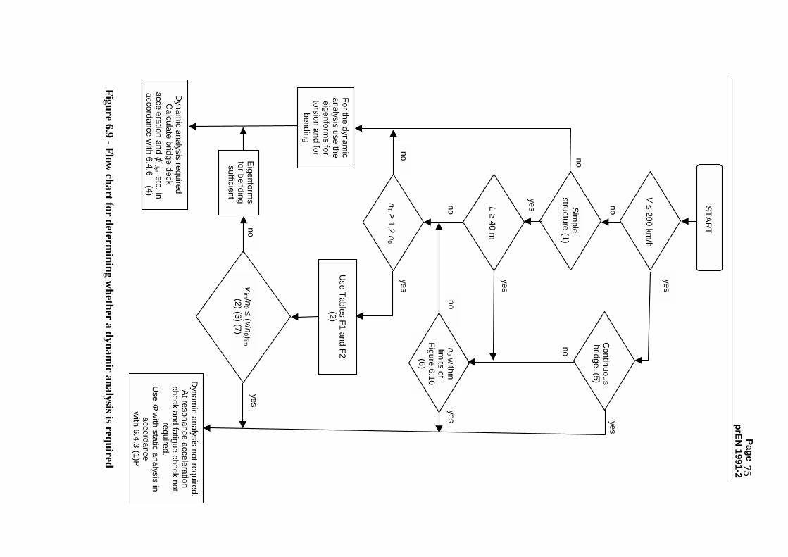
Page prEN
1991-2
75
For the dynamic
analysis use theeigenform
s fortorsion and for
bending
no
Dynam
ic analysis requiredC
alculate bridge deck acceleration and ϕ´dyn etc. inaccordance w
ith 6.4.6 (4)
vlim / n
0 ≤ ( v/ n0 )lim
(2) (3) (7)
START
V ≤ 200 km/h
L ≥ 40 m
nT > 1,2 n
0
Use Tables F1 and F2
(2)
n0 w
ithinlim
its ofFigure 6.10
(6)
no
nono
yes
yes
yes
yesno
Dynam
ic analysis not required.At resonance acceleration
check and fatigue check notrequired.
Use Φ
with static analysis inaccordance
with 6.4.3 (1)P
Eigenforms
for bendingsufficient
Simple
structure (1)
no
yes
yes
yes
Continuous
bridge (5)
no
Figure 6.9 - Flow
chart for determining w
hether a dynamic analysis is required

Page prEN
1991-2
76
where: V
is the Maxim
um Line Speed at the Site [km
/h] L
is the span length [m]
n0
is the first natural bending frequency of the bridge loaded by permanent
actions [Hz]
nT
is the first natural torsional frequency of the bridge loaded by permanent
actions [Hz]
(v/n0 )lim
is given as a function of vlim /n0 in A
nnex F N
OTE 1 V
alid for simply supported bridges w
ith only longitudinal line beam or sim
ple plate behaviour w
ith negligible skew effects on rigid supports.
NO
TE 2 For Tables F1 and F2 and associated limits of validity see A
nnex F. N
OTE 3 A
dynamic analysis is required w
here the Frequent Operating Speed of a R
eal Train equals a R
esonant Speed of the structure. See 6.4.6.6 and Annex F.
NO
TE 4 ϕ′dyn is the dynamic im
pact component for R
eal Trains for the structure given in 6.4.6.5(3). N
OTE 5 V
alid providing the bridge meets the requirem
ents for resistance, deformation lim
its given in EN
1990 Annex A
2.4.4 and the maxim
um coach body acceleration (or associated deflection lim
its) corresponding to a very good standard of passenger com
fort given in EN1990 A
nnex A2.
NO
TE 6 For bridges with a first natural frequency n
0 within the lim
its given by Figure 6.10 and a M
aximum
Line Speed at the Site not exceeding 200km/h, a dynam
ic analysis is not required. N
OTE 7 For bridges w
ith a first natural frequency n0 exceeding the upper lim
it (1) in Figure 6.10 a dynam
ic analysis is required. Also see 6.4.6.1.1(7).
The upper limit of n
0 is governed by dynamic
increments due to track irregularities and is
given by : n
0 = 94,76L-0,748
(6.1) The low
er limit of n
0 is governed by dynamic
impact criteria and is given by :
n0 = 80/L
for 4m ≤ L ≤ 20m
n
0 = 23,58L-0,592
for 20m < L ≤ 100m
(6.2)
where:
n0 is the first natural frequency of the bridge
taking account of mass due to perm
anent actions, L is the span length for sim
ply supported bridges or L
Φ for other bridge types.
(1)
upper limit of natural frequency
(2) low
er limit of natural frequency
Figure 6.10 - Lim
its of bridge natural frequency n0 [H
z] as a function of L [m]

Page prEN
1991-2
77
NO
TE 8 For a simply supported bridge subjected to bending only, the natural frequency m
ay be estim
ated using the formula :
00
17,75[H
z]δ
n=
(6.3)
where:
δ0
is the deflection at mid span due to perm
anent actions [mm
] and is calculated, using a short term
modulus for concrete bridges, in accordance w
ith a loading period appropriate to the natural frequency of the bridge.
6.4.5 Dynam
ic factor ΦΦΦ Φ (ΦΦΦ Φ
2 , ΦΦΦ Φ3 )
6.4.5.1 Field of application (1) The dynam
ic factor Φ takes account of the dynam
ic magnification of stresses and
vibration effects in the structure but does not take account of resonance effects. (2)P W
here the criteria specified in 6.4.4 are not satisfied there is a risk that resonance or excessive vibration of the bridge m
ay occur (with a possibility of excessive deck
accelerations leading to ballast instability etc. and excessive deflections and stresses etc.). For such cases a dynam
ic analysis shall be carried out to calculate impact and
resonance effects. N
OTE Q
uasi static methods w
hich use static load effects multiplied by the dynam
ic factor Φ defined in
6.4.5 are unable to predict resonance effects from high speed trains. D
ynamic analysis techniques, w
hich take into account the tim
e dependant nature of the loading from the H
igh Speed Load Model (H
SLM) and
Real Trains (e.g. by solving equations of m
otion) are required for predicting dynamic effects at
resonance. (3) Structures carrying m
ore than one track should be considered without any reduction
of dynamic factor Φ
. 6.4.5.2 D
efinition of the dynamic factor ΦΦΦ Φ
(1)P The dynam
ic factor Φ w
hich enhances the static load effects under Load Models 71,
SW/0 and SW
/2 shall be taken as either Φ2 or Φ
3 . (2) G
enerally the dynamic factor Φ
is taken as either Φ2 or Φ
3 according to the quality of track m
aintenance as follows:
(a) For carefully maintained track:
820
20
441Φ
2,
,L
,Φ
+−
=
(6.4)
with:
1,00 ≤ Φ2 ≤ 1,67
(b) For track with standard m
aintenance:
730
20
162Φ
3,
,L
,Φ
+−
=
(6.5)

Page prEN
1991-2
78
with:
1,00 ≤ Φ3 ≤ 2,0
where:
LΦ
�D
eterminant� length (length associated w
ith Φ) defined in Table 6.2 [m
]. N
OTE The dynam
ic factors were established for sim
ply supported girders. The length LΦ allow
s these factors to be used for other structural m
embers w
ith different support conditions. (3)P If no dynam
ic factor is specified Φ3 shall be used.
NO
TE The dynamic factor to be used m
ay be specified in the National A
nnex. (4)P The dynam
ic factor Φ shall not be used w
ith: �
the loading due to Real Trains,
� the loading due to Fatigue Trains (A
nnex D),
� Load M
odel HSLM
(6.4.6.1.1(2)), �
the load model �unloaded train� (6.3.4).
6.4.5.3 Determ
inant length LΦΦΦ Φ
(1) The determinant lengths L
Φ to be used are given in the Table 6.2 below.
NO
TE Alternative values of L
Φ may be specified in the N
ational Annex.
(2) Where no value of L
Φ is specified in Table 6.2 the determinant length should be
taken as the length of the influence line for deflection of the element being considered
or alternative values specified for the particular project. (3) If the resultant stress in a structural m
ember depends on several effects, each of w
hich relates to a separate structural behaviour, then each effect should be calculated using the appropriate determ
inant length.

Page prEN
1991-2
79
T
able 6.2 - Determ
inant lengths LΦΦΦ Φ
Case
Structural element
Determ
inant length LΦΦΦ Φ
Steel deck plate: closed deck with ballast bed (orthotropic deck plate) (for local and
transverse stresses)
Deck w
ith cross girders and continuous longitudinal ribs:
1.1 D
eck plate (for both directions)
3 times cross girder spacing
1.2
Continuous longitudinal ribs
(including small cantilevers up to
0,50 m) a)
3 times cross girder spacing
1.3 C
ross girders
Twice the length of the cross girder
1.4
End cross girders
3.6m b)
Deck plate w
ith cross girders only:
2.1 D
eck plate (for both directions)
Twice cross girder spacing + 3 m
2.2 C
ross girders Tw
ice cross girder spacing + 3 m
2.3
End cross girders 3.6m
b) Steel grillage: open deck w
ithout ballast bed b) (for local and transverse stresses) 3.1
Rail bearers:
- as an elem
ent of a continuous grillage
- sim
ply supported
3 times cross girder spacing
Cross girder spacing + 3 m
3.2 C
antilever of rail bearer a)
3.6m b)
3.3
Cross girders (as part of cross
girder/ continuous rail bearer grillage)
Twice the length of the cross girder
3.4 End cross girders
3.6m b)
a) In general all cantilevers greater than 0,50 m supporting rail traffic actions need a special study in
accordance with 6.4.6 and w
ith the loading agreed with the relevant authority specified in the N
ational Annex.
b) It is recomm
ended to apply Φ3

Page prEN
1991-2
80
Table 6.2 (cont.)
Case
Structural element
Determ
inant length LΦΦΦ Φ
Concrete deck slab w
ith ballast bed (for local and transverse stresses) 4.1
Deck slab as part of box girder or
upper flange of main beam
-
spanning transversely to the main
girders -
spanning in the longitudinal direction
3 times span of deck plate
3 times span of deck plate
-
cross girders
Twice the length of the cross girder
- transverse cantilevers supporting railw
ay loading
- e ≤ 0,5 m
: 3 times the distance betw
een the w
ebs - e > 0,5 m
: a) Figure 6.11 - Transverse cantilever
supporting railway loading
4.2 D
eck slab continuous (in main
girder direction) over cross girders
Twice the cross girder spacing
4.3 D
eck slab for half through and trough bridges: -
spanning perpendicular
to the
main girders
- spanning in the longitudinal direction
Twice span of deck slab + 3m
Tw
ice span of deck slab
4.4 D
eck slabs spanning transversely betw
een longitudinal steel beams in
filler beam decks
Twice the determ
inant length in the longitudinal direction
4.5 Longitudinal cantilevers of deck slab
- e ≤ 0,5 m: 3,6m
b) - e > 0,5 m
: a)
4.6 End cross girders or trim
mer beam
s/ trim
mer girders
3,6m b)
a) In general all cantilevers greater than 0,50 m supporting rail traffic actions need a special study in accordance
with 6.4.6 and w
ith the loading agreed with the relevant authority specified in the N
ational Annex.
b) It is recomm
ended to apply Φ3
NO
TE For Cases 1.1 to 4.6 inclusive L
Φ is subject to a maxim
um of the determ
inant length of the main girders.

Page prEN
1991-2
81
Table 6.2 (cont.)
Case
Structural element
Determ
inant length LΦΦΦ Φ
Main girders 5.1
Simply supported girders and slabs
(including steel beams em
bedded in concrete)
Span in main girder direction
5.2 G
irders and slabs continuous over n spans w
ith L
m = 1/n (L1 + L
2 + .. + Ln )
(6.6)
LΦ = k × L
m ,
(6.7) but not less than m
ax Li (i = 1,..., n)
n = 2 3 4 ≥ 5 �
��
��
��
��
��
�
k = 1,2 1,3 1,4 1,5
5.3 Portal fram
es and closed frames or boxes:
- single-span - m
ulti-span
Consider as three-span continuous beam
(use 5.2, w
ith vertical and horizontal lengths of m
embers of the fram
e or box) C
onsider as multi-span continuous beam
(use 5.2, w
ith lengths of end vertical m
embers and horizontal m
embers)
5.4
Single arch, archrib, stiffened girders of bow
strings
Half span
5.5 Series of arches w
ith solid spandrels retaining fill
Twice the clear opening
5.6 Suspension bars (in conjunction w
ith stiffening girders)
4 times the longitudinal spacing of the
suspension bars
Structural supports 6
Colum
ns, trestles,
bearings, uplift
bearings, tension
anchors and
for the
calculation of
contact pressures
under bearings.
Determ
inant length of the supported m
embers
6.4.5.4 Reduced dynamic effects
(1) In the case of arch bridges and concrete bridges of all types with a cover of m
ore than 1,00 m
, Φ2 and Φ
3 may be reduced as follow
s:
1,0
10 1,00 -
32
32
h -
Φ
= Φ
red,
,≥
(6.8)

Page prEN
1991-2
82
where:
h is the height of cover including the ballast from
the top of the deck to the top of the sleeper, (for arch bridges, from
the crown of the extrados) [m
]. (2) The effects of rail traffic actions on colum
ns with a slenderness (buckling length/radius
of gyration) < 30, abutments, foundations, retaining w
alls and ground pressures may be
calculated without taking into account dynam
ic effects. 6.4.6 R
equirements for a dynam
ic analysis 6.4.6.1 Loading and load com
binations 6.4.6.1.1 Loading (1)P The dynam
ic analysis shall be undertaken using characteristic values of the loading from
the Real Trains specified for the particular project. The specification for the
particular project shall take into account each permitted or envisaged train form
ation for every type of high speed train perm
itted or envisaged to use the structure at speeds over 200km
/h. The particular project should specify the characteristic axle loads and spacings for each configuration of each R
eal Train. N
OTE A
lso see 6.4.6.1.1(8) for loading where a dynam
ic analysis is required for a Maxim
um Line Speed
at the Site less than 200km/h.
(2)P The dynamic analysis shall also be undertaken using Load M
odel HSLM
on bridges designed for international lines w
here European high speed interoperability criteria are applicable in accordance w
ith the requirements for the particular project.
(3) Load Model H
SLM com
prises of two separate U
niversal Trains with variable coach
lengths, HSLM
-A and H
SLM-B
. N
OTE H
SLM-A
and HSLM
-B together represent the dynam
ic load effects of single axle, articulated and conventional high speed passenger trains in accordance w
ith the requirements for the European Technical
Specification for Interoperability given in Annex E in E1.
(4) HSLM
-A is defined in Figure 6.12 and Table 6.3:
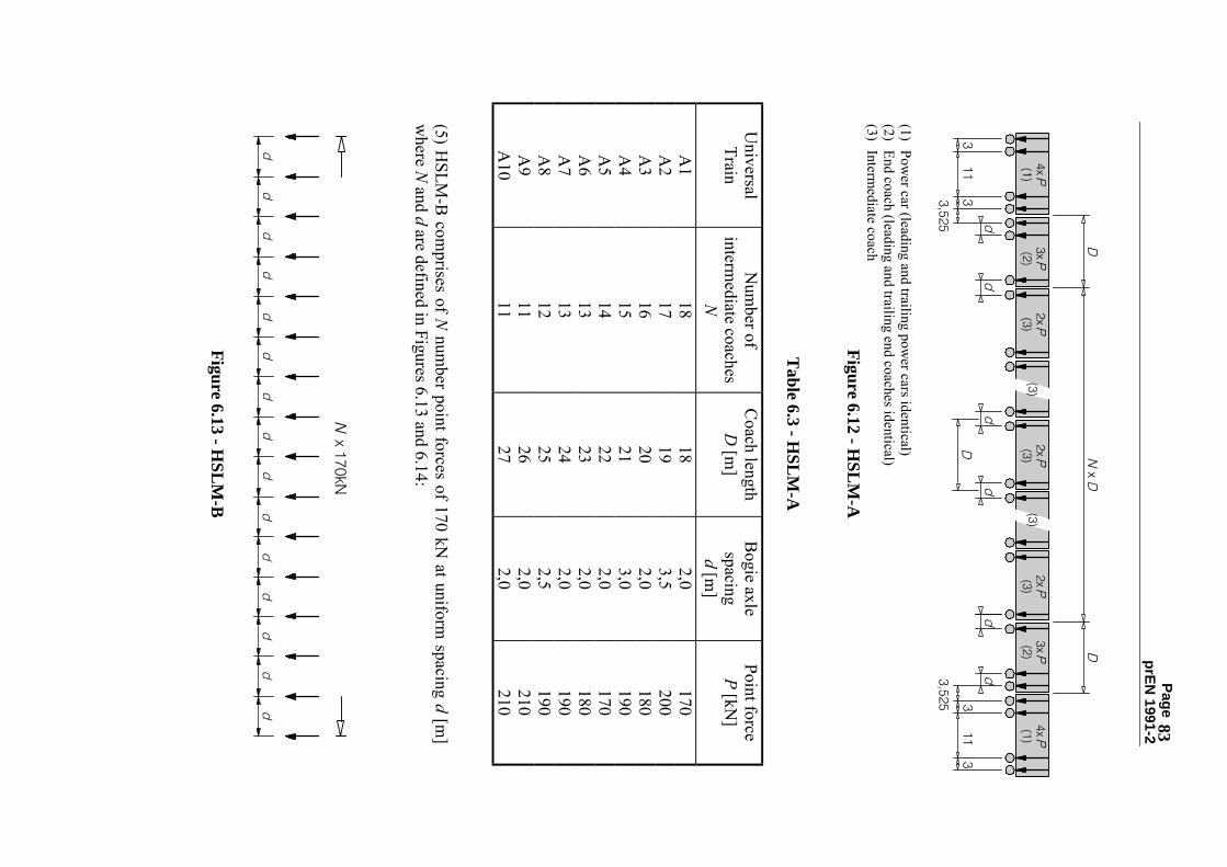
Page prEN
1991-2
83
(1) Power car (leading and trailing pow
er cars identical) (2) End coach (leading and trailing end coaches identical) (3) Interm
ediate coach Figure 6.12 - H
SLM-A
Table 6.3 - H
SLM
-A
Universal Train
Num
ber of interm
ediate coaches N
Coach length
D [m
] B
ogie axle spacing d [m
]
Point force P [kN
]
A1
18 18
2,0 170
A2
17 19
3,5 200
A3
16 20
2,0 180
A4
15 21
3,0 190
A5
14 22
2,0 170
A6
13 23
2,0 180
A7
13 24
2,0 190
A8
12 25
2,5 190
A9
11 26
2,0 210
A10
11 27
2,0 210
(5) HSLM
-B com
prises of N num
ber point forces of 170 kN at uniform
spacing d [m]
where N
and d are defined in Figures 6.13 and 6.14:
Figure 6.13 - HSLM
-B

Page prEN
1991-2
84 2
2.5 3
3.5 4
4.5 5
5.5 6
1
1.6
2.5
2.8
3.2
3.5
3.8
4.2
4.5
4.8
5.5
5.8
6.5
L [m
]
d [m]
0 5 10 15 20
N
Figure 6.14 - H
SLM-B
where L is the span length [m
]. (6) Either H
SLM-A
or HSLM
-B should be applied in accordance w
ith the requirements
of Table 6.4:
Table 6.4 - A
pplication of HSL
M-A
and HSL
M-B
Structural configuration
Span
L < 7m
L ≥ 7m
Simply supported span
(1)
H
SLM-B
(2) H
SLM-A
(3)
Continuous structure (1)
or C
omplex structure (5)
HSLM
-A
Trains A1 to A
10 inclusive (4)
HSLM
-A
Trains A1 to A
10 inclusive (4)
(1) Valid for bridges w
ith only longitudinal line beam or sim
ple plate behaviour with negligible skew
effects on rigid supports. (2) For sim
ply supported spans with a span of up to 7 m
a single critical Universal Train from
HSLM
-B
may be used for the analysis in accordance w
ith 6.4.6.1.1(5). (3) For sim
ply supported spans with a span of 7 m
or greater a single critical Universal Train from
H
SLM-A
may be used for the dynam
ic analysis in accordance with A
nnex E. (Alternatively U
niversal trains A
1 to A10 inclusive m
ay be used). (4) A
ll Trains A1 to A
10 inclusive should be used in the design. (5) A
ny structure that does not comply w
ith Note (1) above. For exam
ple a skew structure, bridge w
ith significant torsional behaviour, half through structure w
ith significant floor and main girder vibration
modes etc.
NO
TE The National A
nnex may specify additional requirem
ents relating to the application of HSLM
-A
and HSLM
-B to continuous and com
plex structures.

Page prEN
1991-2
85
(7) Where the frequency lim
its of Figure 6.10 are not satisfied and the Maxim
um Line
Speed at the Site is ≤ 200 km/h a dynam
ic analysis should be carried out. The analysis should take into account the behaviours identified in 6.4.2 and consider: �
Train Types 1 to 12 given in Annex D
, �
Real Trains specified for the particular project.
NO
TE The loading and methodology for the analysis should be agreed w
ith the relevant authority specified in the N
ational Annex.
6.4.6.1.2 Load combinations and load factors
(1) For the dynamic analysis the calculation of the value of m
ass associated with self
weight and rem
ovable loads (ballast etc.) should use nominal values of density.
(2)P For the dynamic analysis loads according to 6.4.6.1.1(1) and (2) and w
here required 6.4.6.1.1(7) shall be used. (3) For the dynam
ic analysis of the structure only, any one track on the structure should be loaded in accordance w
ith Table 6.5.
Table 6.5 - Sum
mary of additional load cases
depending upon number of tracks on bridge
N
umber of tracks on a
bridge Loaded track
Loading for dynamic analysis
1 one
Each Real Train and Load M
odel H
SLM (if required) travelling in the
permitted direction(s) of travel.
either track
Each Real Train and Load M
odel H
SLM (if required) travelling in the
permitted direction(s) of travel.
2 (Trains normally
travelling in opposite directions) (1)
other track
None.
(1) For bridges carrying 2 tracks with trains norm
ally travelling in the same directions or
carrying 3 or more tracks w
ith a Maxim
um Line Speed at the Site exceeding 200km
/h the loading should be agreed w
ith the relevant authority specified in the National A
nnex. (4) W
here the load effects from a dynam
ic analysis exceed the effects from Load M
odel 71 (and Load M
odel SW/0 for continuous structures) in accordance w
ith 6.4.6.5(3) on any one track the load effects from
a dynamic analysis should be com
bined with:
� horizontal forces on the track subject to the loading in the dynam
ic analysis, �
the load effects from vertical and horizontal loading on the other track(s), in
accordance with the requirem
ents of 6.8.1 and Table 6.11. (5)P W
here the load effects from a dynam
ic analysis exceed the effects from Load
Model 71 (and Load M
odel SW/0 for continuous structures) in accordance w
ith 6.4.6.5(3) the dynam
ic rail loading effects (bending mom
ents, shears, deformations etc.

Page prEN
1991-2
86
excluding acceleration) determined from
the dynamic analysis shall be enhanced by the
partial factors given in Annex A
2 of EN1990.
(6)P Partial factors shall not be applied to the loading given in 6.4.6.1.1 when
determining bridge deck accelerations. The calculated values of acceleration shall be
directly compared w
ith the design values in 6.4.6.5. (7) For fatigue, a bridge should be designed for the additional fatigue effects at resonance from
the loading in accordance with 6.4.6.1.1 on any one track. See 6.4.6.6.
6.4.6.2 Speeds to be considered (1)P For each R
eal Train and Load Model H
SLM a series of speeds up to the M
aximum
D
esign Speed shall be considered. The Maxim
um D
esign Speed shall be generally 1,2 × M
aximum
Line Speed at the site. The particular project should specify the M
aximum
Line Speed at the site. N
OTE 1 W
here specified for the particular project a reduced speed may be used for checking individual
Real Trains for 1,2 × their associated M
aximum
Permitted V
ehicle Speed. N
OTE 2 It is recom
mended that the particular project specify an increased M
aximum
Line Speed at the Site to take into account potential m
odifications to the infrastructure and future rolling stock. N
OTE 3 Structures can exhibit a highly peaked response due to resonance effects. W
here there is a likelihood of train overspeeding and exceeding either the M
aximum
Permitted V
ehicle Speed or the current or envisaged M
aximum
Line Speed at the Site it is recomm
ended that the particular project specify an additional factor for increasing the M
aximum
Design Speed to be used in the dynam
ic analysis. N
OTE 4 It is recom
mended that the particular project specify additional requirem
ents for checking structures w
here there is a requirement for a section of line to be suitable for com
missioning tests of a
Real Train. The M
aximum
Design Speed used for the R
eal Train should be at least 1,2 × Maxim
um Train
Com
missioning Speed. C
alculations are required to demonstrate that safety considerations (m
aximum
deck accelerations, m
aximum
load effects, etc. ) are satisfactory for structures at speeds in excess of 200 km
/h. Fatigue
and passenger
comfort
criteria need
not be
checked at
1,2 ×
Maxim
um
Train C
omm
issioning Speeds. (2) C
alculations should be made for a series of speeds from
40m/s up to the M
aximum
D
esign Speed defined by 6.4.6.2(1). Smaller speed steps should be m
ade in the vicinity of R
esonant Speeds. For sim
ply supported bridges that may be m
odelled as a line beam the R
esonant Speeds m
ay be estimated using Equation 6.9.
i
0i
λn
v=
(6.9)
and 40 m
/s ≤ vi ≤ Maxim
um D
esign Speed,
(6.10)
where:

Page prEN
1991-2
87
vi is the R
esonant Speed [m/sec]
n0
is the first natural frequency of the unloaded structure, λ
i is the principal w
avelength of frequency of excitation and may be estim
ated by:
i d=
λi
(6.11)
d is the regular spacing of groups of axles
i = 1, 2, 3 or 4.
6.4.6.3 Bridge parameters
6.4.6.3.1 Structural damping
(1) The peak response of a structure at traffic speeds corresponding to resonant loading is highly dependent upon dam
ping. (2)P O
nly lower bound estim
ates of damping shall be used.
(3) The following values of dam
ping should be used in the dynamic analysis:
T
able 6.6 - Values of dam
ping to be assumed for design purposes
ζ Low
er limit of percentage of critical dam
ping [%]
B
ridge Type Span L < 20m
Span L ≥ 20m
Steel and com
posite ζ = 0,5 + 0,125 (20 - L)
ζ = 0,5 Prestressed concrete
ζ = 1,0 + 0,07 (20 - L) ζ = 1,0
Filler beam and reinforced
concrete ζ = 1,5 + 0,07 (20 - L)
ζ = 1,5
NO
TE Alternative safe low
er bound values may be used subject to the agreem
ent of the relevant authority specified in the N
ational Annex.
6.4.6.3.2 Mass of the bridge
(1) Maxim
um dynam
ic load effects are likely to occur at resonant peaks when a
multiple of the frequency of loading and a natural frequency of the structure coincide
and any underestimation of m
ass will overestim
ate the natural frequency of the structure and overestim
ate the traffic speeds at which resonance occurs.
At resonance the m
aximum
acceleration of a structure is inversely proportional to the m
ass of the structure. (2)P Tw
o specific cases for the mass of the structure including ballast and track shall be
considered: �
a lower bound estim
ate of mass to predict m
aximum
deck accelerations using the m
inimum
likely dry clean density and minim
um thickness of ballast,
� an upper bound estim
ate of mass to predict the low
est speeds at which resonant
effects are likely to occur using the maxim
um saturated density of dirty ballast w
ith allow
ance for future track lifts.

Page prEN
1991-2
88
NO
TE The minim
um density of ballast m
ay be taken as 1700kg/ m3. A
lternative values may be specified
for the particular project. (3) In the absence of specific test data the values for the density of m
aterials should be taken from
EN1991-1-1.
NO
TE Ow
ing to the large number of param
eters which can affect the density of concrete it is not
possible to predict enhanced density values with sufficient accuracy for predicting the dynam
ic response of a bridge. A
lternative density values may be used w
hen the results are confirmed by trial m
ixes and the testing of sam
ples taken from site in accordance w
ith EN1990, EN
1992 and ISO6784 subject to the
agreement of the relevant authority specified in the N
ational Annex.
6.4.6.3.3 Stiffness of the bridge (1) M
aximum
dynamic load effects are likely to occur at resonant peaks w
hen a m
ultiple of the frequency of loading and a natural frequency of the structure coincide. A
ny overestimation of bridge stiffness w
ill overestimate the natural frequency of the
structure and speed at which resonance occurs.
(2)P A low
er bound estimate of the stiffness throughout the structure shall be used.
(3) The stiffness of the whole structure including the determ
ination of the stiffness of elem
ents of the structure may be determ
ined in accordance with EN
1992 to EN1994.
Values of Y
oung�s modulus m
ay be taken from EN
1992 to EN1994.
For concrete compressive cylinder strength fck ≥ 50 N
/mm
2 (compressive cube strength
fck, cube ≥ 60 N/m
m2) the value of static Y
oung�s modulus (E
cm ) should be limited to the
value corresponding to a concrete of strength of fck = 50 N/m
m2 (fck, cube = 60 N
/mm
2). N
OTE 1 O
wing to the large num
ber of parameters w
hich can affect Ecm it is not possible to predict
enhanced Young�s m
odulus values with sufficient accuracy for predicting the dynam
ic response of a bridge. Enhanced E
cm values may be used w
hen the results are confirmed by trial m
ixes and the testing of sam
ples taken from site in accordance w
ith EN1990, EN
1992 and ISO6784 subject to the agreem
ent of the relevant authority specified in the N
ational Annex.
NO
TE 2 Other m
aterial properties may be used subject to the agreem
ent of the relevant authority specified in the N
ational Annex.
6.4.6.4 Modelling the excitation and dynam
ic behaviour of the structure (1) The dynam
ic effects of a Real Train m
ay be represented by a series of travelling point forces. V
ehicle/structure mass interaction effects m
ay be neglected. The analysis should take into account variations throughout the length of the train in axle forces and the variations in spacing of individual axles or groups of axles. (2) W
here appropriate the analysis technique should allow for the follow
ing dynamic
behaviours of the structure: �
for complex structures the proxim
ity of adjacent frequencies and associated mode
shapes of oscillation, �
interaction between bending and torsional m
odes,

Page prEN
1991-2
89
� local deck elem
ent behaviour (shallow floors and cross girders of half-through type
bridges or trusses etc.), �
the skew behaviour of slabs etc.
(3) The representation of each axle by a single point force tends to overestimate
dynamic effects for loaded lengths of less than 10m
. In such cases, the load distribution effects of rails, sleepers and ballast m
ay be taken into account. N
otwithstanding 6.3.6.2 individual axle loads m
ay not be distributed uniformly in the
longitudinal direction. (4) For spans less than 30 m
dynamic vehicle/bridge m
ass interaction effects tend to reduce the peak response at resonance. A
ccount may be taken of these effects by:
� carrying out a dynam
ic vehicle/structure interactive analysis, N
OTE The m
ethod used should be agreed with the relevant authority specified in the N
ational Annex.
� increasing the value of dam
ping assumed for the structure according to Figure 6.15.
For continuous beams, the sm
allest value ∆ζ for all spans should be used. The total dam
ping to be used is given by : ζ
TOTA
L = ζ + ∆ζ (6.12)
0
0.1
0.2
0.3
0.4
0.5
0.6
0.7
05
1015
2025
30
L [m
]
∆∆∆∆ζζζζ [%]
Figure 6.15 - A
dditional damping ∆∆∆ ∆ζζζ ζ [%
] as a function of span length L [m]
where:
[%]
0002550
00440
04410
100064
00187
03
2
2
L,
L,
L,
L,
L,
+−
−−
=ζ∆
(6.13)
ζ is the low
er limit of percentage of critical dam
ping [%] defined in 6.4.6.3.1.
NO
TE: The National A
nnex may specify alternative values.

Page prEN
1991-2
90
(5) The increase in calculated dynamic load effects (stresses, deflections, bridge deck
accelerations, etc.) due to track defects and vehicle imperfections m
ay be estimated by
multiplying the calculated effects by a factor of:
(1 + ϕ′′/2 ) for carefully m
aintained track, (1 + ϕ′′ )
for track with standard track m
aintenance, w
here: ϕ′′
is in accordance with A
nnex C and should not be taken as less than zero.
NO
TE The National A
nnex may specify the factor to be used.
(6) Where the bridge satisfies the upper lim
it in Figure 6.10 the factors that influence dynam
ic behaviours (vii) to (xi) identified in 6.4.2 may be considered to be allow
ed for in Φ
, ϕ′′/2 and ϕ′′ given in 6.4 and Annex C
. 6.4.6.5 Verifications of the lim
it states (1)P To ensure traffic safety: �
The verification of maxim
um peak deck acceleration shall be regarded as a traffic
safety requirement checked at the serviceability lim
it state for the prevention of track instability.
� The dynam
ic increment of load effects shall be allow
ed for by multiplying the static
loading by the dynamic factor Φ
defined in 6.4.5. If a dynamic analysis is necessary,
the results of the dynamic analysis shall be com
pared with the results of the static
analysis enhanced by Φ (and if required m
ultiplied by α in accordance with 6.3.2)
and the most unfavourable load effects shall be used for the bridge design.
� If a dynam
ic analysis is necessary, a check shall be carried out according to 6.4.6.6 to establish w
hether the additional fatigue loading at high speeds and at resonance is covered by consideration of the stresses due to load effects from
Φ x LM
71 (and if required Φ
× Load Model SW
/0 for continuous structures and classified vertical load in accordance w
ith 6.3.2(3) where required). The m
ost adverse fatigue loading shall be used in the design.
(2)P The maxim
um perm
itted peak design values of bridge deck acceleration calculated along the line of a track shall not exceed the recom
mended values given in A
nnex A2 of
EN1990 (see A
.2.4.4.2.1). (3) A
dynamic analysis (if required) should be used to determ
ine the following dynam
ic increm
ent:
1
max
−=
statdyn
dyny/
y' ϕ
(6.14)
where:
ydyn is the m
aximum
dynamic response and ystat the corresponding m
aximum
static response at any particular point in the structural elem
ent due to a Real Train or
Load Model H
SLM.

Page prEN
1991-2
91
For the design of the bridge, taking into account all the effects of vertical traffic loads, the m
ost unfavourable value of: (
)
×
++
RT
HSLM
dynor
2
/"
'
1
ϕϕ
(6.15)
or Φ
× (LM71"+"SW
/0) (6.16)
should be used where:
HSLM
is the load m
odel for high speed lines defined in 6.4.6.1.1(2), LM
71"+"SW/0
is Load Model 71 and if relevant Load M
odel SW/0 for continuous
bridges (or classified vertical load in accordance with 6.3.2(3) w
here required).
RT
is the loading due to all Real Trains defined in 6.4.6.1.1.
''ϕ
/2 is the increase in calculated dynam
ic load effects (stresses, deflections, bridge deck accelerations, etc.) resulting from
track defects and vehicle im
perfections in accordance with A
nnex C for carefully
maintained track (
''ϕ
to be used for track with standard m
aintenance). Φ
is the dynam
ic factor in accordance with 6.4.4.
6.4.6.6 Additional verification for fatigue where dynamic analysis is required
(1)P The fatigue check of the structure shall allow for the stress range resulting from
elem
ents of the structure oscillating above and below the corresponding perm
anent load deflection due to: �
additional free vibrations set up by impact effects from
axle loads travelling at high speed,
� the m
agnitude of dynamic live loading effects at resonance,
� the additional cycles of stress caused by the dynam
ic loading at resonance. (2)P W
here the Frequent Operating Speed of a R
eal Train at a structure is near to a R
esonant Speed the design shall allow for the additional fatigue loading due to
resonance effects. The particular project should specify the details, associated annual tonnage and m
ix of Real Trains and associated Frequent O
perating Speeds at the site. (3) W
here the bridge is designed for Load Model H
SLM in accordance w
ith 6.4.6.1.1(2) the particular project m
ay specify the fatigue loading (details, associated annual tonnage and m
ix of Real Trains and associated Frequent O
perating Speeds at the site) taking into account the best estim
ate of current and future traffic. (4) For structures that satisfy A
nnex F the Resonant Speed m
ay be estimated using
Equations 6.9 and 6.10. (5) For the verification for fatigue a series of speeds up to a M
aximum
Nom
inal Speed should be considered.

Page prEN
1991-2
92
NO
TE It is recomm
ended that the particular project specify an increased Maxim
um N
ominal Speed at
the Site to take into account potential modifications to the infrastructure and future rolling stock.
6.5 Horizontal forces - characteristic values
6.5.1 Centrifugal forces
(1)P Where the track on a bridge is curved over the w
hole or part of the length of the bridge, the centrifugal force and the track cant shall be taken into account. (2) The centrifugal forces should be taken to act outw
ards in a horizontal direction at a height of 1,80 m
above the running surface (see Figure 1.1). For some traffic types, e.g.
double stacked containers, the particular project should specify an increased value of ht .
NO
TE The National A
nnex may specify an increased value of h
t . (3)P The centrifugal force shall alw
ays be combined w
ith the vertical traffic load. The centrifugal force shall not be m
ultiplied by the dynamic factor Φ
2 or Φ3 .
NO
TE When considering the vertical effects of centrifugal loading, the vertical load effect of centrifugal
loading less any reduction due to cant is enhanced by the relevant dynamic factor.
(4)P The characteristic value of the centrifugal force shall be determined according to the
following equations:
)Q
f(r
V)
Qf
(rg v
Qvk
vktk
×=
××
=127 2
2
(6.17)
)q
f(r
V)
qf
(rg v
qvk
vktk
×=
××
=127 2
2
(6.18)
where:
Qtk , q
tk C
haracteristic values of the centrifugal forces [kN, kN
/m]
Qvk , q
vk C
haracteristic values of the vertical loads specified in 6.3 (excluding any enhancem
ent for dynamic effects) for Load M
odels 71, SW/0, SW
/2 and �unloaded train�. For load m
odel HSLM
the characteristic value of centrifugal force should be determ
ined using Load Model 71.
f R
eduction factor (see below)
v M
aximum
speed in accordance with 6.5.1(5) [m
/s] V
Maxim
um speed in accordance w
ith 6.5.1(5) [km/h]
g A
cceleration due to gravity [9,81 m/s²]
r R
adius of curvature [m]
In the case of a curve of varying radii, suitable mean values m
ay be taken for the value r. (5)P The calculations shall be based on the M
aximum
Line Speed at the Site specified for the particular project. In the case of Load M
odel SW/2 a m
aximum
speed of 80 km/h m
ay be assum
ed. N
OTE It is recom
mended that the particular project specify an increased M
aximum
Line Speed at the Site to take into account potential m
odifications to the infrastructure and future rolling stock.

Page prEN
1991-2
93
(6)P In addition, for bridges located in a curve, the case of the loading specified in 6.3.2 and, if applicable, 6.3.3, shall also be considered w
ithout centrifugal force. (7) For Load M
odel 71 (and where required Load M
odel SW/0) and a M
aximum
Line Speed at the Site higher than 120 km
/h, the following cases should be considered:
a) Load M
odel 71 (and where required Load M
odel SW/0) w
ith its dynamic factor and
the centrifugal force for V=120 km/h according to equations 6.17 and 6.18 w
ith f = 1. b)
A reduced Load M
odel 71 (f × Qvk , f × q
vk ) (and where required f × Load M
odel SW/0)
with its dynam
ic factor and the centrifugal force according to equations 6.17 and 6.18 for the m
aximum
speed V specified, with a value for the reduction factor f given
by 6.5.1(8). (8) For Load M
odel 71 (and where required Load M
odel SW/0) the reduction factor f is
given by:
−
+−
−=
f 882
175
1814
1000 1201
L ,,
VV
f
(6.19)
subject to a minim
um value of 0,35 w
here: L
f is the influence length of the loaded part of curved track on the bridge, w
hich is most
unfavourable for the design of the structural element under consideration [m
]. V
is the maxim
um speed in accordance w
ith 6.5.1(5). f =1
for either V ≤ 120 km
/h
or L
f ≤ 2,88 m
f <1 for 120 km
/h <V ≤ 300 km/h
)
(see Table 6.7 or Figure 6.16 or equation 6.19) )
and Lf > 2,88m
f(V) = f(300) for V >300 km
/h.
)
For the load models SW
/2 and �unloaded train� the value of the reduction factor f should be taken as 1,0.

Page prEN
1991-2
94
Table 6.7 - Factor f for Load M
odel 71 and SW/0
L
f [m]
Maxim
um speed in accordance w
ith 6.5.1(5) [km/h]
≤≤≤ ≤ 120
160 200
250 ≥≥≥ ≥ 300
≤ 2,88 3 4 5 6 7 8 9
10 12 15 20 30 40 50 60 70 80 90
100 ≥150
1,00 1,00 1,00 1,00 1,00 1,00 1,00 1,00 1,00 1,00 1,00 1,00 1,00 1,00 1,00 1,00 1,00 1,00 1,00 1,00 1,00
1,00 0,99 0,96 0,93 0,92 0,90 0,89 0,88 0,87 0,86 0,85 0,83 0,81 0,80 0,79 0,79 0,78 0,78 0,78 0,77 0,76
1,00 0,99 0,93 0,89 0,86 0,83 0,81 0,80 0,78 0,76 0,74 0,71 0,68 0,66 0,65 0,64 0,63 0,62 0,62 0,61 0,60
1,00 0,99 0,90 0,84 0,80 0,77 0,74 0,72 0,70 0,67 0,63 0,60 0,55 0,52 0,50 0,49 0,48 0,47 0,47 0,46 0,44
1,00 0,98 0,88 0,81 0,75 0,71 0,68 0,65 0,63 0,59 0,55 0,50 0,45 0,41 0,39 0,37 0,36 0,35 0,35 0,35 0,35
Figure 6.16 - Factor f for L
oad Model 71 and SW
/0

Page prEN
1991-2
95
(9) For LM71 and SW
/0 centrifugal forces should be determined from
equations 6.17 and 6.18 using classified vertical loads (see 6.3.2(3)) in accordance w
ith the load cases given in Table 6.8:
Table 6.8 - Load Cases for centrifugal force corresponding to values of ααα α and
Maxim
um L
ine Speed at Site
Centrifugal force based on : (4)
Value
of ααα α M
aximum
Line
Speed at Site [km
/h] V
[km/h]
α f
Associated
vertical traffic action based on:
(1) V
1 (3) f
1(3) x f x
(LM71"+"SW
/0) for case 6.5.1(7)b
Φ x 1
(3) x f x (LM
71"+"SW/0)
120 α
1 α x 1 x
(LM71"+"SW
/0) for case 6.5.1(7)a
> 120
0 -
- -
V α
1 α x 1 x
(LM71"+"SW
/0)
α < 1
≤ 120
0 -
- -
Φ x α x 1 x
(LM71"+"SW
/0)
V 1
f 1 x f x
(LM71"+"SW
/0) for case 6.5.1(7)b
Φ x 1 x f x
(LM71"+"SW
/0)
120 1
1 1 x 1 x
(LM71"+"SW
/0) for case 6.5.1(7)a
> 120
0 -
- -
V 1
1 1 x 1 x
(LM71"+"SW
/0)
α = 1
≤ 120
0 -
- -
Φ x 1 x 1 x
(LM71"+"SW
/0)
V 1
f 1 x f x
(LM71"+"SW
/0) for case 6.5.1(7)b
Φ x 1 x f x
(LM71"+"SW
/0)
120 α
1 α x 1 x
(LM71"+"SW
/0) for case 6.5.1(7)a
> 120 (2)
0 -
- -
V α
1 α x 1 x
(LM71"+"SW
/0)
α > 1
≤ 120
0 -
- -
Φ x α x 1 x
(LM71"+"SW
/0)
(1) 0,5 x (LM71"+"SW
/0) instead of (LM71"+"SW
/0) where vertical traffic actions favourable.
(2) Valid for heavy freight traffic lim
ited to a maxim
um sped of 120 km
/h. (3) α = 1 to avoid double counting the reduction in m
ass of train with f.
(4) See 6.5.1(3) regarding vertical effects of centrifugal loading. Vertical load effect of centrifugal loading
less any reduction due to cant should be enhanced by the relevant dynamic factor.
where:

Page prEN
1991-2
96
V M
aximum
speed in accordance with 6.5.1(5) [km
/h] f
Reduction factor in accordance w
ith 6.5.1(8) α
Factor for classified vertical loads in accordance with 6.3.2(3).
LM71"+"SW
/0 Load M
odel 71 and if relevant Load Model SW
/0 for continuous bridges.
(10) The criteria in 6.5.1(5) and 6.5.1(7) to 6.5.1(9) are not valid for heavy freight traffic w
ith a Maxim
um Perm
itted Vehicle Speed exceeding 120 km
/h. For heavy freight traffic w
ith a speed exceeding 120 km/h the particular project should specify
additional requirements.
6.5.2 Nosing force
(1)P The nosing force shall be taken as a concentrated force acting horizontally, at the top of the rails, perpendicular to the centre-line of track. It shall be applied on both straight track and curved track. (2)P The characteristic value of the nosing force shall be taken as Q
sk = 100 kN. It shall not
be multiplied by the factor Φ
(see 6.4.5) or by the factor f in 6.5.1(4). (3) The characteristic value of the nosing force in 6.5.2(2) should be m
ultiplied by the factor α in accordance w
ith 6.3.2(3) for values of α ≥ 1. (4)P The nosing force shall alw
ays be combined w
ith a vertical traffic load. 6.5.3 A
ctions due to traction and braking (1)P Traction and braking forces act at the top of the rails in the longitudinal direction of the track. They shall be considered as uniform
ly distributed over the corresponding influence length L
a,b for traction and braking effects for the structural element considered.
The direction of the traction and braking forces shall take account of the permitted
direction(s) of travel on each track. (2)P The characteristic values of traction and braking forces shall be taken as follow
s: Traction force:
Qlak = 33 [kN
/m] L
a,b [m] ≤ 1000 [kN
] (6.20)
for Load Models 71,
SW
/0, SW/2 and H
SLM
Braking force:
Qlbk = 20 [kN
/m] L
a,b [m] ≤ 6000 [kN
] (6.21)
for Load Models 71,
SW/0 and Load M
odel HSLM
Q
lbk = 35 [kN/m
] La,b [m
] (6.22)
for Load Model SW
/2 The characteristic values of traction and braking forces shall not be m
ultiplied by the factor Φ
(see 6.4.4.2) or by the factor f in 6.5.1(6).

Page prEN
1991-2
97
NO
TE 1 For Load M
odels SW/0 and SW
/2 traction and braking forces need only to be applied to those parts of the structure w
hich are loaded according to Figure 6.2 and Table 6.1.
NO
TE 2 Traction and braking m
ay be neglected for the Load Model �unloaded train�.
(3) These characteristic values are applicable to all types of track construction, e.g. continuous w
elded rails or jointed rails, with or w
ithout expansion devices. (4) The above traction and braking forces for Load M
odels 71 and SW/0 should be
multiplied by the factor α in accordance w
ith the requirements of 6.3.2(3).
(5) For loaded lengths greater than 300m the N
ational Annex should specify additional
requirements for taking into account the effects of braking.
(6) For lines carrying special traffic (e.g. restricted to high speed passenger traffic) the traction and braking forces m
ay be taken as equal to 25% of the sum
of the axle-loads (R
eal Train) acting on the influence length of the action effect of the structural element
considered, with a m
aximum
value of 1000 kN for Q
lak and 6000 kN for Q
lbk . The lines carrying special traffic and associated loading details m
ay be specified for the particular project. N
OTE W
here the particular project specifies reduced traction and braking loading in accordance with the
above the specified loading should take into account other traffic permitted to use the line, e.g. trains for
track maintenance etc.
(7)P Traction and braking forces shall be combined w
ith the corresponding vertical loads. (8) W
hen the track is continuous at one or both ends of the bridge only a proportion of the traction or braking force is transferred through the deck to the bearings, the rem
ainder of the force being transm
itted through the track where it is resisted behind the abutm
ents. The proportion of the force transferred through the deck to the bearings should be determ
ined by taking into account the com
bined response of the structure and track in accordance with
6.5.4. 6.5.4 C
ombined response of structure and track to variable actions
6.5.4.1 General principles
(1) Where the rails are continuous over discontinuities in the support to the track (e.g.
between a bridge structure and an em
bankment) the structure of the bridge (bridge deck,
bearings and substructure) and the track (rails, ballast etc.) jointly resist the longitudinal actions due to traction or braking. Longitudinal actions are transm
itted partly by the rails to the em
bankment behind the abutm
ent and partly by the bridge bearings and the substructure to the foundations. N
OTE R
eferences to embankm
ent throughout 6.5.4 may also be taken as references to the track
formation or ground beneath the track on the approaches to the bridge w
hether the track is on an em
bankment, level ground or in a cutting.
(2) Where continuous rails restrain the free m
ovement of the bridge deck, deform
ations of the bridge deck (e.g. due to therm
al variations, vertical loading, creep and shrinkage) produce longitudinal forces in the rails and in the fixed bridge bearings.

Page prEN
1991-2
98
(3)P The effects resulting from the com
bined response of the structure and the track to variable actions shall be taken into account for the design of the bridge superstructure, fixed bearings, the substructure and for checking load effects in the rails. (4) The requirem
ents of 6.5.4 are valid for conventional ballasted track. (5) The requirem
ents for non-ballasted track should be specified for the particular project. N
OTE The requirem
ents for non-ballasted track may be specified in the N
ational Annex.
6.5.4.2 Parameters affecting the com
bined response of the structure and track (1)P The follow
ing parameters influence the com
bined behaviour of the structure and track and shall be taken into account in the analysis: a)
Configuration of the structure:
� sim
ply supported beam, continuous beam
s or a series of beams,
� num
ber of individual decks and length of each deck, �
number of spans and length of each span,
� position of fixed bearings,
� position of the therm
al fixed point, �
expansion length LT betw
een the thermal fixed point and the end of the deck.
Figure 6.17 - Exam
ples of expansion length LT
b) C
onfiguration of the track: �
ballasted track or non-ballasted track systems,
� vertical distance betw
een the upper surface of the deck and the neutral axis of the rails,
� location of rail expansion devices.

Page prEN
1991-2
99
NO
TE The particular project may specify requirem
ents regarding the location of rail expansion devices taking into account requirem
ents to ensure such devices are effective whilst ensuring that the rail
expansion devices are not adversely affected by bending effects in the rail due to the close proximity of
the end of a bridge deck etc. c)
Properties of the structure: �
vertical stiffness of the deck, �
vertical distance between the neutral axis of the deck and the upper surface of
the deck, �
vertical distance between the neutral axis of the deck and the axis of rotation of
the bearing, �
structural configuration at bearings generating longitudinal displacement of the
end of the deck from angular rotation of the deck,
� longitudinal stiffness of the structure defined as the total stiffness w
hich can be m
obilised by the substructure against actions in the longitudinal direction of the tracks taking into account the stiffness of the bearings, substructure and foundations.
For example the total longitudinal stiffness of a single pier is given by:
K =
)(
F
hp
l
δϕ δ
δ+
+
(6.23)
for the case represented below as an exam
ple.
(1)
bending of the pier (2)
rotation of the foundation (3)
displacement of the foundation
(4) total displacem
ent of the pier head
Figure 6.18 - Exam
ple of the determination of equivalent
longitudinal stiffness at bearings d)
Properties of the track: �
axial stiffness of the rail, �
resistance of the track or the rails against longitudinal displacement considering
either:

Page prEN
1991-2
100
� resistance against displacem
ent of the track (rails and sleepers) in the ballast relative to the underside of the ballast, or
� resistance against displacem
ent of the rails from rail fastenings and supports
e.g. with frozen ballast or w
ith directly fastened rails, w
here the resistance against displacement is the force per unit length of the track
that acts against the displacement as a function of the relative displacem
ent betw
een rail and the supporting deck or embankm
ent. 6.5.4.3 Actions to be considered (1)P The follow
ing actions shall be taken into account: �
traction and braking forces as defined in 6.5.3. In the case of a bridge carrying tw
o or more tracks the braking forces on one track
shall be considered with the traction forces on one other track.
Where tw
o or more tracks have the sam
e permitted direction of travel either traction
on two tracks or braking on tw
o tracks shall be taken into account. N
OTE For bridges carrying tw
o or more tracks w
ith the same perm
itted direction of travel the N
ational Annex m
ay specify alternative requirements for the application of traction and braking
forces.
� Therm
al effects in the combined structure and track system
. Tem
perature variations in the bridge shall be taken as ∆TN , in EN
1991-1-5, with γ
and ψ taken as 1,0.
NO
TE 1 The N
ational Annex m
ay specify alternative values of ∆TN
NO
TE 2 For sim
plified calculations a temperature variation of the superstructure of ∆T
N = ± 35 K
elvin may be taken into account. O
ther values may be specified in the N
ational Annex.
� C
lassified vertical
traffic loads
(including SW
/0 and
SW/2
where
required). A
ssociated dynamic effects m
ay be neglected. N
OTE The com
bined response of the structure and track to the �unloaded train� and load model H
SLM
may be neglected
� O
ther actions such as creep, shrinkage, temperature gradient etc. shall be taken into
account for the determination of rotation and associated longitudinal displacem
ent of the end of the decks w
here relevant. (2) W
hen determining the com
bined response of track and structure to traction and braking forces, the traction and braking forces should not be applied on the adjacent em
bankment unless a com
plete analysis is carried out considering the approach, passage over and departure from
the bridge of rail traffic on the adjacent embankm
ents to evaluate the m
ost adverse load effects. 6.5.4.4 M
odelling and calculation of the combined track/structure system
(1) For the determ
ination of load effects in the combined track/structure system
a model
based upon Figure 6.19 may be used.
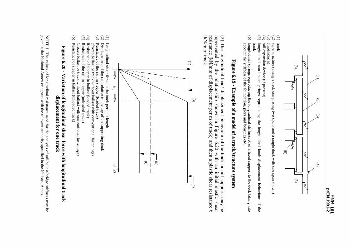
Page prEN
1991-2
101
(1) track (2) superstructure (a single deck com
prising two spans and a single deck w
ith one span shown)
(3) embankm
ent (4) rail expansion device (if present) (5) longitudinal non-linear springs reproducing the longitudinal load/ displacem
ent behaviour of the track
(6) longitudinal springs reproducing the longitudinal stiffness K of a fixed support to the deck taking into
account the stiffness of the foundation, piers and bearings etc.
Figure 6.19 - Example of a m
odel of a track/structure system
(2) The longitudinal load/ displacement behaviour of the track or rail supports m
ay be represented by the relationship show
n in Figure 6.20 with an initial elastic shear
resistance [kN/m
m of displacem
ent per m of track] and then a plastic shear resistance k
[kN/m
of track].
(1) Longitudinal shear force in the track per unit length (2) D
isplacement of the rail relative to the top of the supporting deck
(3) Resistance of the rail in sleeper (loaded track)
(frozen ballast or track w
ithout ballast with conventional fastenings)
(4) Resistance of sleeper in ballast (loaded track)
(5) Resistance of the rail in sleeper (unloaded track)
(frozen ballast or track w
ithout ballast with conventional fastenings)
(6) Resistance of sleeper in ballast (unloaded track)
Figure 6.20 - V
ariation of longitudinal shear force with longitudinal track
displacement for one track
NO
TE 1 The values of longitudinal resistance used for the analysis of rail/ballast/bridge stiffness may be
given in the National A
nnex or agreed with the relevant authority specified in the N
ational Annex.

Page prEN
1991-2
102
NO
TE 2 The behaviour described in Figure 6.20 is valid in most cases (but not for em
bedded rails w
ithout conventional rail fastenings etc.). (3)P W
here it can be reasonably foreseen that the track characteristics may change in
the future, this shall be taken into account in the calculations in accordance with the
requirements for the particular project.
(4)P For the calculation of the total horizontal support reaction FL and in order to
compare the global equivalent rail stress w
ith permissible values, the global effect is
calculated as follows:
∑ =
li0i
lF
Fψ
(6.24)
with:
Fli
the individual horizontal support reactions, ψ
0i for
the calculation
of load
effects in
the superstructure,
bearings and
substructures the combination factors defined in EN
1990 Annex A
2 shall be used,
ψ0i
for the calculation of rail stresses, ψ0i shall be taken as 1,0.
(5) When determ
ining the effect of each action the non-linear behaviour of the track stiffness show
n in Figure 6.20 should be taken into account. (6) The longitudinal forces in the rails and bearings resulting from
each action may be
combined using linear superim
position. 6.5.4.5 D
esign criteria N
OTE A
lternative requirements m
ay be specified in the National A
nnex. 6.5.4.5.1 Track (1) For rails on the bridge and on the adjacent abutm
ent the permissible additional rail
stresses due to the combined response of the structure and track to variable actions
should be limited to the follow
ing design values: �
Com
pression: 72 N
/mm
², �
Tension:
92 N/m
m².
(2) The limiting values for the rail stresses given in clause 6.5.4.5.1(1) are valid for
track complying w
ith: �
UIC
60 rail with a tensile strength of at least 900 N
/mm
², �
straight track or track radius r ≥ 1 500 m,
NO
TE For ballasted tracks with additional lateral restraints to the track and for directly fastened
tracks this minim
um value of track radius m
ay be reduced subject to the agreement of the relevant
authority specified in the National A
nnex.
� for ballasted tracks w
ith heavy concrete sleepers with a m
aximum
spacing of 65 cm
or equivalent track construction, �
for ballasted tracks with at least 30 cm
consolidated ballast under the sleepers.

Page prEN
1991-2
103
When the above criteria are not satisfied special studies should be carried out or
additional measures provided.
NO
TE For other track construction standards (in particular effect on lateral resistance) and other types of rail it is recom
mended that the m
aximum
additional rail stresses is specified in the National A
nnex or for the particular project. 6.5.4.5.2 Lim
iting values for the deformation of the structure
(1)P Due to traction and braking δ
B [m
m] shall not exceed the follow
ing values: �
5 mm
for continuous welded rails w
ithout rail expansion devices or with a rail
expansion device at one end of the deck, �
30 mm
for rail expansion devices at both ends of the deck where the ballast is
continuous at the ends of the deck, �
movem
ents exceeding 30 mm
shall only be permitted w
here the ballast is provided w
ith a movem
ent gap and rail expansion devices provided. w
here δB
[mm
] is: �
the relative longitudinal displacement betw
een the end of a deck and the adjacent abutm
ent or, �
the relative longitudinal displacement betw
een two consecutive decks
(2)P For vertical traffic actions (up to two tracks loaded w
ith load model LM
71 (and w
here required SW/0) δ
H [m
m] shall not exceed the follow
ing values: �
8 mm
when the com
bined behaviour of structure and track is taken into account (valid w
here there is only one or no expansion devices per deck), �
10 mm
when the com
bined behaviour of the structure and track is neglected. w
here δH
[mm
] is: �
the longitudinal displacement of the upper surface of the deck at the end of a deck
due to deformation of the deck.
NO
TE Where either the perm
issible additional stresses in the rail in 6.5.4.5.1(1) are exceeded or the longitudinal displacem
ent of the deck in 6.5.4.5.2(1) or 6.5.4.5.2(2) is exceeded either change the structure or provide rail expansion devices. (3)P The vertical displacem
ent of the upper surface of a deck relative to the adjacent construction (abutm
ent or another deck) δV
[mm
] due to variable actions shall not exceed the follow
ing values: �
3 mm
for a Maxim
um Line Speed at the Site of up to 160 km
/h, �
2 mm
for a Maxim
um Line Speed at the Site over 160 km
/h. (4)P For directly fastened rails the uplift forces (under vertical traffic loads) on rail supports and fastening system
s shall be checked against the relevant limit state
(including fatigue) performance characteristics of the rail supports and fastening
systems.

Page prEN
1991-2
104
6.5.4.6 Calculation methods
NO
TE Alternative calculation m
ethods may be specified in the N
ational Annex
(1) The following calculation m
ethods enable the combined response of the track and
structure to be checked against the design criteria given in 6.5.4.5. The design criteria for ballasted decks m
ay be summ
arised as: a)
Longitudinal relative displacement at the end of the deck split into tw
o components
to enable comparison w
ith the permitted values: δ
B due to braking and traction and δ
H due to vertical deformation of the deck,
b) M
aximum
additional stresses in the rails, c)
Maxim
um vertical relative displacem
ent at the end of the deck, δV .
For directly
fastened decks an additional check on uplift forces is required in accordance w
ith 6.5.4.5.2(4). (2) In section 6.5.4.6.1 a sim
plified method is given for estim
ating the combined
response of a simply supported or a continuous structure consisting of single bridge
deck and track to variable actions for structures with an expansion length L
T of up to 40m
. (3) For structures that do not satisfy the requirem
ents of 6.5.4.6.1 a method is given in
Annex G
for determining the com
bined response of a structure and track to variable actions for: �
simply supported or a continuous structure consisting of a single bridge deck,
� structures consisting of a succession of sim
ply supported decks, �
structures consisting of a succession of continuous single piece decks. (4) A
lternatively, or for other track or structural configurations, an analysis may be
carried out in accordance with the requirem
ents of 6.5.4.2 to 6.5.4.5 or Annex G
. 6.5.4.6.1 Sim
plified calculation method for a single deck
(1) For a superstructure comprising of a single deck (sim
ply supported, continuous spans w
ith a fixed bearing at one end or continuous spans with an interm
ediate fixed bearing) it is not necessary to check the rail stresses providing: �
the substructure has sufficient stiffness, K to lim
it δB , the displacem
ent of the deck in the longitudinal direction due to traction and braking, to a m
aximum
of 5 mm
under the longitudinal forces due to traction and braking defined in 6.5.4.6.1(2) (classified in accordance w
ith 6.3.2(3) where required). For the determ
ination of the displacem
ents the configuration and properties of the structure given in 6.5.4.2(1) should be taken into account.
� for vertical traffic actions δ
H , the longitudinal displacement of the upper surface of
the deck at the end of the deck due to deformation of the deck does not exceed 5m
m,
� expansion length L
T is less than 40m,
NO
TE Alternative criteria m
ay be specified in the National A
nnex.

Page prEN
1991-2
105
(2) The limits of validity of the calculation m
ethod in 6.5.4.6.1 are: �
track complies w
ith the construction requirements given in 6.5.4.5.1(2).
� longitudinal plastic shear resistance k of the track is:
unloaded track: k = 20 to 40 kN
per m of track,
loaded track: k = 60 kN
per m of track.
� vertical traffic loading:
Load Model 71 (and w
here required Load Model SW
/0) with α = 1 in accordance
with 6.3.2(3),
Load Model SW
/2, N
OTE The m
ethod is valid for values of α where the load effects from
α x LM71 are less than or
equal to the load effects from SW
/2.
� actions due to braking for:
Load Model 71 (and w
here required Load Model SW
/0) and Load Model
HSLM
: q
lbk = 20 kN/m
, Load M
odel SW/2:
qlbk = 35 kN
/m.
� actions due to traction:
qlak = 33 kN
/m, lim
ited to a maxim
um of Q
lak = 1000 kN.
� actions due to tem
perature: Tem
perature variation ∆TD of the deck: ∆T
D ≤ 35 Kelvin,
Temperature variation ∆T
R of the rail: ∆TR ≤ 50 K
elvin, M
aximum
difference in temperature betw
een rail and deck: ∆
TD - ∆T
R ≤ 20 Kelvin.
6.25 (3) The longitudinal forces due to traction and braking acting on the fixed bearings m
ay be obtained by m
ultiplying the traction and braking forces by the reduction factor ξ given in Table 6.9. Table 6.9 - R
eduction factor ξξξ ξ for the determination of the longitudinal forces in
the fixed bearings of one-piece decks due to traction and braking
Reduction factor ξ
Overall length of structure [m
] C
ontinuous track R
ail expansion devices at one end of deck
Rail expansion
devices at both ends of deck
≤ 40 0,60
0,70 1,00
NO
TE For portal frames and closed fram
es or boxes it is recomm
ended that the reduction factor ξ be taken as unity. A
lternatively the method given in A
nnex G or an analysis in accordance w
ith 6.5.4.2 to 6.5.4.5 m
ay be used. (4) The characteristic longitudinal forces F
Tk per track due to temperature variation
(according to 6.5.4.3) acting on the fixed bearings may be obtained as follow
s : �
for bridges with continuous w
elded rails at both deck ends and fixed bearings at one end of the deck : F
Tk [kN] = ± 0,6 k L
T (6.26)

Page prEN
1991-2
106
with k [kN
/m] the longitudinal plastic shear resistance of the track per unit length
according to 6.5.4.4(2) for unloaded track and LT [m
] the expansion length according to 6.5.4.2(1).
� for bridges w
ith continuous welded rails at both deck ends and fixed bearings
situated in a distance L1 from
one end of the deck and L2 from
the other end : F
Tk [kN] = ± 0,6 k (L
2 - L1 )
(6.27) w
ith k [kN/m
] the longitudinal plastic shear resistance of the track per unit length according to 6.5.4.4(2) for unloaded track and L
1 [m] and L
2 [m] according to Figure
6.21.
Figure 6.21 - Deck w
ith fixed bearings not located at one end (1) (1) D
eck corresponding to either L1 or L
2 may com
prise of one or more spans.
� for bridges w
ith continuous welded rails at the deck end w
ith fixed bearings and rail expansion devices at the free deck end: F
Tk [kN] = ± 20 L
T , but FTk ≤ 1100 kN
(6.28)
with L
T [m] expansion length according to 6.5.4.2.(1).
�
for bridge decks with rail expansion devices at both ends:
FTk = 0
(6.29) N
OTE For track com
plying with 6.5.4.5.1(2) values of k m
ay be taken from A
nnex G2(3). A
lternative values of k m
ay be specified in the National A
nnex. (5) The characteristic longitudinal forces F
Qk per track on the fixed bearings due to
deformation of the deck m
ay be obtained as follows:
� for bridges w
ith continuous welded rails at both deck ends and fixed bearings on one
end of the deck or with rail expansion devices at the free end of the deck:
FQ
k [kN] = ± 20 L
(6.30) w
ith L [m] the length of the first span near the fixed bearing
�
for bridges with rail expansion devices at both ends of the deck:
FQ
k [kN] = 0
(6.31) (6) The vertical displacem
ent of the upper surface of a deck relative to the adjacent construction (abutm
ent or another deck) due to variable actions may be calculated
ignoring the combined response of the structure and track and checked against the
criteria in 6.5.4.5.2(3). 6.5.5 O
ther horizontal forces (1)P The follow
ing actions shall also be considered in the design of the structure:

Page prEN
1991-2
107
� effects due to inclined decks or inclined bearing surfaces,
� longitudinal anchorage forces from
stressing or destressing rails in accordance with
any requirements specified for the particular project,
NO
TE The National A
nnex may specify the requirem
ents.
� longitudinal forces due to the accidental breakage of rails in accordance w
ith any requirem
ents specified for the particular project. N
OTE The N
ational Annex m
ay specify the requirements.
6.6 Aerodynam
ic effects as a result of passing trains 6.6.1 G
eneral (1)P A
erodynamic effects from
passing trains shall be taken into account when
designing structures adjacent to railway tracks.
(2) The passing of rail traffic subjects any structure situated near the track to a travelling w
ave of alternating pressure and suction (see Figures 6.22 to 6.25). The magnitude of the
action depends mainly on:
� the square of the speed of the train,
� the aerodynam
ic shape of the train, �
the shape of the structure, �
the position of the structure, particularly the clearance between the vehicle and the
structure. (3) The actions m
ay be approximated by equivalent loads at the head and rear ends of a
train, when checking ultim
ate and serviceability limit states and fatigue. Characteristic
values of the equivalent loads are given in 6.6.2 to 6.6.6. N
OTE The N
ational Annex or the particular project m
ay specify alternative values. (5) In 6.6.2 to 6.6.6 the M
aximum
Design Speed V [km
/h] should be taken as the M
aximum
Line Speed at the Site except for cases covered by EN1990 A
2.2.4(6). (6) A
t the start and end of structures adjacent to the tracks, for a length of 5 m from
the start and end of the structure m
easured parallel to the tracks the equivalent loads in 6.6.2 to 6.6.6 should be m
ultiplied by a dynamic am
plification factor of 2,0. N
OTE For dynam
ically sensitive structures the above dynamic am
plification factor may be insufficient
and may need to be determ
ined by a special study. The study should take into account dynamic
characteristics of the structure including support and end conditions, the speed of the adjacent rail traffic and associated aerodynam
ic effects and the dynamic response of the structure including the speed of a
deflection wave induced in the structure.
6.6.2 Simple vertical surfaces parallel to the track (e.g. noise barriers)
(1) The characteristic values of the actions, ± q1k , are given in Figure 6.22.

Page prEN
1991-2
108
(1) section (2) surface of structure (3) plan view
(4) surface of structure
Figure 6.22 - Characteristic values of actions q
1k for simple vertical surfaces
parallel to the track (2) The characteristic values apply to trains w
ith an unfavourable aerodynamic shape and
may be reduced by:
� a factor k1 = 0,85 for trains w
ith smooth sided rolling stock
� a factor k1 = 0,6
for streamlined rolling stock (e.g. ETR
, ICE, TG
V, Eurostar or
similar)
(3) If a small part of a w
all with a height ≤ 1,00 m
and a length ≤ 2,50 m is considered,
e.g. an element of a noise protection w
all, the actions q1k should be increased by a factor k2
= 1,3. 6.6.3
Simple
horizontal surfaces
above the
track (e.g.
overhead protective
structures) (1) The characteristic values of the actions, ± q
2k , are given in Figure 6.23. (2) The loaded w
idth for the structural mem
ber under investigation extends up to 10 m to
either side from the centre-line of the track.

Page prEN
1991-2
109
(1) section (2) elevation (3) underside of the structure
Figure 6.23 - Characteristic values of actions q
2k for simple horizontal surfaces
above the track (3) For trains passing each other in opposite directions the actions should be added. The loading from
trains on only two tracks needs to be considered.
(4) The actions q2k m
ay be reduced by the factor k1 as defined in 6.6.2. (5) The actions acting on the edge strips of a w
ide structure which cross the track m
ay be m
ultiplied by a factor of 0,75 over a width up to 1,50 m
. 6.6.4 Sim
ple horizontal surfaces adjacent to the track (e.g. platform canopies w
ith no vertical w
all) (1) The characteristic values of the actions, ± q
3k , are given in Figure 6.24 and apply irrespective of the aerodynam
ic shape of the train. (2) For every position along the structure to be designed, q
3k should be determined as a
function of the distance ag from
the nearest track. The actions should be added, if there are tracks on either side of the structural m
ember under consideration.
(3) If the distance hg exceeds 3,80 m
the action q3k m
ay be reduced by a factor k3 :

Page prEN
1991-2
110 735
7g
3,
)h
,(
k−
= for 3,8 m
< hg < 7,5 m
(6.32)
k3 = 0 for hg ≥ 7,5 m
(6.33)
where:
hg
distance from top of rail level to the underside of the structure.
(1) section (2) elevation (3) underside of the structure
Figure 6.24 - Characteristic values of actions q
3k for simple horizontal surfaces
adjacent to the track 6.6.5 M
ultiple-surface structures alongside the track with vertical and horizontal
or inclined surfaces (e.g. bent noise barriers, platform canopies w
ith vertical walls
etc.) (1) The characteristic values of the actions, ± q
4k , as given in Figure 6.25 should be applied norm
al to the surfaces considered. The actions should be taken from the graphs in Figure
6.22 adopting a track distance the lesser of: a'g = 0,6 m
in ag + 0,4 m
ax ag
or
6 m
(6.34)
where distances m
in ag and m
ax ag are show
n in Figure 6.25. (2) If m
ax ag > 6 m
the value max a
g = 6 m should be used.
(3) The factors k1 and k2 defined in 6.6.2 should be used.

Page prEN
1991-2
111
Figure 6.25 - D
efinition of the distances min a
g and max a
g from centre-line of the
track 6.6.6 Surfaces enclosing the structure gauge of the tracks over a lim
ited length (up to 20 m
) (horizontal surface above the tracks and at least one vertical wall, e.g.
scaffolding, temporary constructions)
(1) All actions should be applied irrespective of the aerodynam
ic shape of the train: �
to the full height of the vertical surfaces: ±k4 q
1k (6.35)
where:
q1k is determ
ined according to 6.6.2, k4 = 2 �
to the horizontal surfaces: ±k5 q
2k (6.36)
where:
q2k is determ
ined according to 6.6.3 for only one track, k5 = 2,5 if one track is enclosed, k5 = 3,5 if tw
o tracks are enclosed.

Page prEN
1991-2
112
6.7 Derailm
ent and other actions for railway bridges
(1)P Railw
ay structures shall be designed in such a way that, in the event of a derailm
ent, the resulting dam
age to the bridge (in particular overturning or the collapse of the structure as a w
hole) is limited to a m
inimum
. 6.7.1 D
erailment actions from
rail traffic on a railway bridge
(1)P Derailm
ent of rail traffic on a railway bridge shall be considered as an A
ccidental D
esign Situation. (2)P Tw
o design situations shall be considered: �
Design Situation I: D
erailment of railw
ay vehicles, with the derailed vehicles
remaining in the track area on the bridge deck w
ith vehicles retained by the adjacent rail or an upstand w
all. �
Design Situation II: D
erailment of railw
ay vehicles, with the derailed vehicles balanced
on the edge of the bridge and loading the edge of the superstructure (excluding non-structural elem
ents such as walkw
ays). N
OTE The N
ational Annex or particular project m
ay specify additional requirements and alternative
loading. (3)P For D
esign Situation I, collapse of a major part of the structure shall be avoided.
Local damage, how
ever, may be tolerated. The parts of the structure concerned shall be
designed for the following design loads in the A
ccidental Design Situation:
α × 1,4 × LM 71 (both point loads and uniform
ly distributed loading, QA
1d and qA
1d ) parallel to the track in the m
ost unfavourable position inside an area of width 1,5 tim
es the track gauge on either side of the centre-line of the track:
(1) m
ax. 1,5s or less if against wall
(2) track gauge s (3) for ballasted decks the point forces m
ay be assumed to be distributed on a square of side 450m
m at
the top of the deck.
Figure 6.26 - Design Situation I - equivalent load Q
A1d and q
A1d
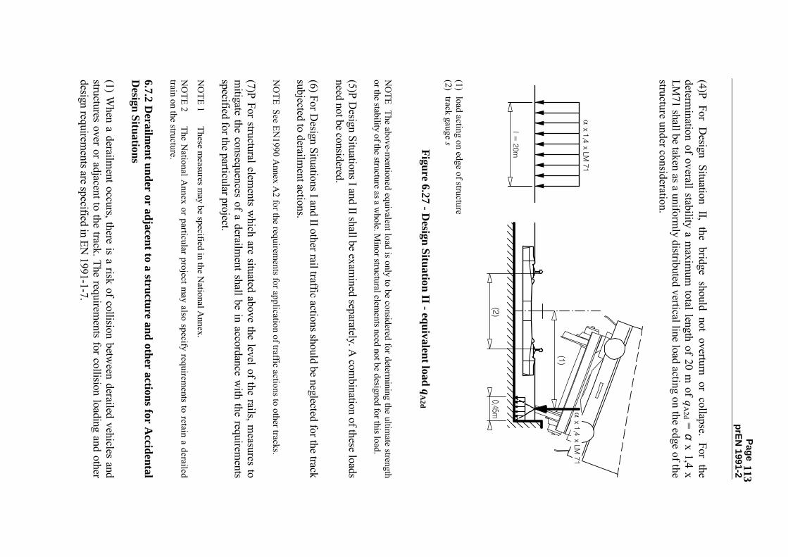
Page prEN
1991-2
113
(4)P For Design Situation II, the bridge should not overturn or collapse. For the
determination of overall stability a m
aximum
total length of 20 m of q
A2d = α x 1,4 x
LM71 shall be taken as a uniform
ly distributed vertical line load acting on the edge of the structure under consideration.
(1) load acting on edge of structure (2) track gauge s
Figure 6.27 - Design Situation II - equivalent load q
A2d
NO
TE The above-mentioned equivalent load is only to be considered for determ
ining the ultimate strength
or the stability of the structure as a whole. M
inor structural elements need not be designed for this load.
(5)P Design Situations I and II shall be exam
ined separately. A com
bination of these loads need not be considered. (6) For D
esign Situations I and II other rail traffic actions should be neglected for the track subjected to derailm
ent actions. N
OTE See EN
1990 Annex A
2 for the requirements for application of traffic actions to other tracks.
(7)P For structural elements w
hich are situated above the level of the rails, measures to
mitigate the consequences of a derailm
ent shall be in accordance with the requirem
ents specified for the particular project. N
OTE 1
These measures m
ay be specified in the National A
nnex.
NO
TE 2 The N
ational Annex or particular project m
ay also specify requirements to retain a derailed
train on the structure. 6.7.2 D
erailment under or adjacent to a structure and other actions for A
ccidental D
esign Situations (1) W
hen a derailment occurs, there is a risk of collision betw
een derailed vehicles and structures over or adjacent to the track. The requirem
ents for collision loading and other design requirem
ents are specified in EN 1991-1-7.

Page prEN
1991-2
114
(2) Other actions for A
ccidental Design Situations are given in EN
1991-1-7 and should be taken into account. 6.7.3 O
ther actions (1)P The load effects from
catenaries and other overhead line equipment attached to the
structure shall be taken into account. N
OTE A
ctions including actions for the Accidental D
esign Situation to be taken into account may be
specified in the National A
nnex or for the particular project. (2)P The load effects from
other railway infrastructure and equipm
ent shall be taken into account in accordance w
ith the requirements specified for the particular project.
6.8 Application of traffic loads on railw
ay bridges 6.8.1 G
eneral N
OTE See 6.3.2 for the application of the factor α and 6.4.5 for the application of the dynam
ic factor Φ.
(1)P The bridge shall be designed for the required number and position(s) of the tracks
in accordance with the track positions and tolerances specified for the particular project.
(2) Each structure should also be designed for the greatest number of tracks geom
etrically and structurally possible in the least favourable position, irrespective of the position of the intended tracks taking into account the m
inimum
spacing of tracks and structural gauge clearance requirem
ents specified for the particular project. (3)P The effects of all actions shall be determ
ined with the traffic loads and forces placed
in the most unfavourable positions. Traffic actions w
hich produce a relieving effect shall be neglected. (4)P For the determ
ination of the most adverse load effects from
the application of Load M
odel 71: �
any number of lengths of the uniform
ly distributed load qvk shall be applied to a
track and up to four of the individual concentrated loads Qvk shall be applied once
per track, �
for elements carrying tw
o tracks, Load Model 71 shall be applied to either track or
both tracks, �
for bridges carrying three or more tracks, Load M
odel 71 shall be applied to any one track, any tw
o tracks or 0,75 times Load M
odel 71 to three or more of the tracks.
(5)P For the determination of the m
ost adverse load effects from the application of Load
Model SW
/0: �
the loading defined in Figure 6.2 and Table 6.1 shall be applied once to a track, �
for elements carrying tw
o tracks, Load Model SW
/0 shall be applied to either track or both tracks,
� for bridges carrying three or m
ore tracks, Load Model SW
/0 shall be applied to any one track, any tw
o tracks or 0,75 times Load M
odel SW/0 to three or m
ore of the tracks.

Page prEN
1991-2
115
(6)P For the determination of the m
ost adverse load effects from the application of Load
Model SW
/2: �
the loading defined in Figure 6.2 and Table 6.1 shall be applied once to a track, �
for elements carrying m
ore than one track, Load Model SW
/2 shall be applied to any one track only w
ith Load Model 71 or Load M
odel SW/0 applied to the other
tracks in accordance with 6.8.1(4) and 6.8.1(5).
(7)P For the determination of the m
ost adverse load effects from the application of Load
Model �unloaded train�:
� any num
ber of lengths of the uniformly distributed load q
vk shall be applied to a track,
� generally Load M
odel �unloaded train� shall only be considered in the design of structures carrying one track.
(8)P All continuous beam
bridges designed for Load Model 71 shall be checked
additionally for Load Model SW
/0. (9)P W
here a dynamic analysis is required in accordance w
ith 6.4.4 all bridges shall also be designed for the loading from
Real trains and Load M
odel HSLM
where
required by 6.4.6.1.1. The determination of the m
ost adverse load effects from R
eal Trains and the application of Load M
odel HSLM
shall be in accordance with
6.4.6.1.1(6) and 6.4.6.5(3). (10)P For the verification of deform
ations and vibrations the vertical loading to be applied shall be: �
Load Model 71 and w
here required Load Models SW
/0 and SW/2,
� Load M
odel HSLM
where required by 6.4.6.1.1,
� Real Trains w
hen determining the dynam
ic behaviour in the case of resonance or excessive vibrations of the deck w
here required by 6.4.6.1.1. (11)P For bridge decks carrying one or m
ore tracks the checks for the limits of deflection
and vibration shall be made w
ith the number of tracks loaded w
ith all associated relevant traffic actions in accordance w
ith Table 6.10. Where required by 6.3.2(3) classified loads
shall be taken into account.

Page prEN
1991-2
116
Table 6.10 - N
umber of tracks to be loaded for checking lim
its of deflection and vibration
N
umber of tracks on the bridge
Limit State and
associated acceptance criteria 1
2 ≥≥≥ ≥ 3
Traffic Safety Checks:
� D
eck twist (EN
1990 Annex 2
A2.4.4.2.2)
1 1 or 2 a)
1 or 2 or 3 or m
ore b)
�
Vertical
deformation
of the
deck (EN
1990 Annex 2 A
2.4.4.2.3)
1 1 or 2 a)
1 or 2 or 3 or m
ore b)
�
Horizontal deform
ation of the deck (EN
1990 Annex 2 A
2.4.4.2.4)
1 1 or 2 a)
1 or 2 or 3 or m
ore b)
�
Combined response of structure and
track to variable actions including lim
its to vertical and longitudinal displacem
ent of the end of a deck (6.5.4)
1 1 or 2 a)
1 or 2 a)
� V
ertical acceleration of the deck (6.4.6 and EN
1990 Annex 2
A2.4.4.2.1)
1 1
1
SLS C
hecks:
� Passenger com
fort criteria (EN 1990
Annex 2 A
2.4.4.3)
1 1
1
UL
S Checks
� U
plift at bearings (EN1990 A
nnex 2 A
2.4.4.1(2)P) 1
1 or 2 a) 1 or 2 or 3 or
more b)
a) W
hichever is critical b) W
here groups of loads are used the number of tracks to be loaded should be in accordance w
ith Table 6.11. W
here groups of loads are not used the number of tracks to be loaded should be in accordance w
ith Table 6.11. N
OTE Requirem
ents for the number of tracks to be considered loaded w
hen checking drainage and structural clearance requirem
ents may be specified in the N
ational Annex or for the particular project.
6.8.2 Groups of L
oads - characteristic values of the multicom
ponent action (1) The sim
ultaneity of the loading defined in 6.3 to 6.5 and 6.7 may be taken into account
by considering the groups of loads defined in Table 6.11. Each of these groups of loads, w
hich are mutually exclusive, should be considered as defining a single variable
characteristic action for combination w
ith non-traffic loads. Each Group of Loads should
be applied as a single variable action.

Page prEN
1991-2
117
NO
TE In some cases it is necessary to consider other appropriate com
binations of unfavourable individual traffic actions. See A
2.2.6(4) of EN1990.
(2) The factors given in the Table 6.11 should be applied to the characteristic values of the different actions considered in each group. N
OTE A
ll the proposed values given for these factors may be varied in the N
ational Annex.
(3)P Where groups of loads are not taken into account rail traffic actions shall be
combined in accordance w
ith Table A2.3 of EN
1990.

Page prEN
1991-2
118
Table 6.11 - A
ssessment of G
roups of Loads for rail traffic (characteristic values of
the multicom
ponent actions) num
ber of G
roups of loads V
ertical forces H
orizontal forces
tracks on structure
Reference EN
1991-2 6.3.2/6.3.3
6.3.3 6.3.4
6.5.3 6.5.1
6.5.2 C
omm
ent
1 2
≥ 3 num
ber of tracks loaded
Load G
roup(8)
Loaded track
LM 71
(1) SW
/0 (1), (2)
HSLM
(6)(7)
SW/2
(1),(3) U
nloaded train
Traction, Braking (1)
Centrifugal
force (1)
Nosing
force (1)
1
gr11 T
1 1
1 (5) 0,5 (5)
0,5 (5) M
ax. vertical 1 with m
ax. longitudinal
1
gr 12 T
1 1
0,5 (5) 1 (5)
1 (5) M
ax. vertical 2 with m
ax. transverse
1
gr 13 T
1 1 (4)
1 0,5 (5)
0,5 (5) M
ax. longitudinal
1 gr 14
T1
1 (4)
0,5 (5)
1 1
Max. lateral
1
gr 15 T
1
1
1 (5)
1 (5 Lateral stability w
ith �unloaded train�
1
gr 16 T
1
1
1 (5) 0,5 (5)
0,5 (5) SW
/2 with m
ax. longitudinal
1
gr 17 T
1
1
0,5 (5) 1 (5)
1 (5) SW
/2 with m
ax. transverse
2 gr 21
T1
T2
1 1
1 (5)
1 (5) 0,5 (5)
0,5 (5) 0,5 (5)
0,5 (5) M
ax. vertical 1 with m
ax longitudinal
2
gr 22 T
1 T
2 1 1
0,5 (5)
0,5 (5) 1 (5) 1 (5)
1 (5) 1 (5)
Max. vertical 2 w
ith max.
transverse
2 gr 23
T1
T2
1 (4)
1 (4)
1 1
0,5 (5) 0,5 (5)
0,5 (5)
0,5 (5) M
ax. longitudinal
2
gr 24 T
1 T
2 1 (4)
1 (4)
0,5 (5)
0,5 (5) 1 1
1 1 M
ax. lateral
2
gr 26 T
1 T
2 1
1
1 (5)
1 (5) 0,5 (5)
0,5 (5) 0,5 (5)
0,5 (5) SW
/2 with m
ax. longitudinal
2
gr 27 T
1 T
2 1
1
0,5 (5)
0,5 (5) 1 (5) 1 (5)
1 (5) 1 (5)
SW/2 w
ith max. transverse
≥3
gr 31 T
i
0.75
0.75 (5)
0.75 (5) 0.75 (5)
Additional load case
(1) A
ll relevant factors (α , Φ, f, ...) shall be taken into account.
(2) SW
/0 shall only be taken into account for continuous span bridges. (3)
SW/2 needs to be taken into account only if it is stipulated for the line.
(4) Factor m
ay be reduced to 0,5 if favourable effect, it cannot be zero. (5)
In favourable cases these non-dominant values shall be taken equal to zero.
(6) H
SLM and R
eal Trains where required in accordance w
ith 6.4.4 and 6.4.6.1.1. (7)
If a dynamic analysis is required in accordance w
ith 6.4.4 see also 6.4.6.5(3) and 6.4.6.1.2. (8)
See also Table A2.3 of A
nnex A2 of EN
1990
Dom
inant component action as appropriate
to be considered in designing a structure supporting one track (Load G
roups 11-17)
to be considered in designing a structure supporting two tracks (Load G
roups 11-27 except 15). Each of the tw
o tracks shall be considered as either T
1 (Track one) or T2 (Track 2)
to be considered in designing a structure supporting three or m
ore tracks; (Load G
roups 11 to 31 except 15. Any one track shall be taken as T
1 , any other track as T
2 with all other tracks unloaded. In addition the Load G
roup 31 has to be considered as an additional load case w
here all unfavourable lengths of track Ti are loaded.
6.8.3 Groups of L
oads - other representative values of the multicom
ponent actions 6.8.3.1 Frequent values of the m
ulticomponent actions
(1) Where G
roups of Loads are taken into account the same rule as in 6.8.2(1) above is
applicable by applying the factors given in Table 6.11 for each Group of Loads, to the
frequent values of the relevant actions considered in each Group of Loads.
NO
TE The National A
nnex may specify otherw
ise.

Page prEN
1991-2
119
(2)P Where G
roups of Loads are not used rail traffic actions shall be combined in
accordance with Table A
2.3 of EN1990.
6.8.3.2 Quasi-perm
anent values of the multicom
ponent actions (1) Q
uasi-permanent traffic actions should be taken as zero.
NO
TE The National A
nnex may specify otherw
ise 6.8.4 T
raffic loads in Transient D
esign Situations (1)P Traffic loads for Transient D
esign Situations shall be defined for the particular project. N
OTE Som
e indications are given in Annex H
. 6.9 Traffic loads for fatigue (1)P A
fatigue damage assessm
ent shall be carried out for all structural elements, w
hich are subjected to fluctuations of stress. (2) For norm
al traffic based on characteristic values of Load Model 71, including the
dynamic factor Φ
, the fatigue assessment should be carried out on the basis of the traffic
mixes, "standard traffic", "traffic w
ith 250 kN-axles" or �light traffic m
ix� depending on w
hether the structure carries mixed traffic, predom
inantly heavy freight traffic or lightw
eight passenger traffic in accordance with the requirem
ents for the particular project. D
etails of the service trains and traffic mixes considered and the dynam
ic enhancement to
be applied are given in Annex D
. (3) W
here the traffic mix does not represent the real traffic (e.g. in special situations
where a lim
ited number of vehicle type(s) dom
inate the fatigue loading or for traffic requiring a value of α greater than unity in accordance w
ith 6.3.2(3)) an alternative traffic m
ix should be specified for the particular project. (4) Each of the m
ixes is based on an annual traffic tonnage of 25 × 106 tonnes passing over
the bridge on each track. (5)P For structures carrying m
ultiple tracks, the fatigue loading shall be applied to a m
aximum
of two tracks in the m
ost unfavourable positions. (6) The fatigue dam
age should be assessed over a structural life of 100 years. N
OTE A
n alternative structural life may be specified in the N
ational Annex.
(7) Alternatively, the fatigue assessm
ent may be carried out on the basis of a special traffic
mix.
NO
TE A special traffic m
ix may be specified in the N
ational Annex or for the particular project.

Page prEN
1991-2
120
(8) Additional requirem
ents for the fatigue assessment of bridges w
here a dynamic
analysis is required in accordance with 6.4.4 w
hen dynamic effects are likely to be
excessive are given in 6.4.6.6.


![Sulzer Structured Packings for destillation - ULisboaweb.ist.utl.pt/ist11061/de/Equipamento/StructuredPackings[1].pdf · Sulzer Chemtech Structured Packings for Distillation, ...](https://static.fdocuments.net/doc/165x107/5ad8e9657f8b9af9068e1f56/sulzer-structured-packings-for-destillation-1pdfsulzer-chemtech-structured-packings.jpg)


