
EUROPEAN ORGANISATION FOR THE SAFETY OF … s transponders test benches ... eec note n° 21/98 eec...
49
EUROPEAN ORGANISATION FOR THE SAFETY OF AIR NAVIGATION EUROCONTROL EUROCONTROL EXPERIMENTAL CENTRE Mode S TRANSPONDERS TEST BENCHES USER REQUIREMENTS ( version 1 ) EEC Note N° 21/98 EEC Task C07 EATCHIP Task SUR-3-E1 Issued : September 1998 The information contained in this document is the property of the EUROCONTROL Agency and no part should be reproduced in any form without the Agency’s permission. The views expressed herein do not necessarily reflect the official views or policy of the Agency.
Transcript of EUROPEAN ORGANISATION FOR THE SAFETY OF … s transponders test benches ... eec note n° 21/98 eec...

EUROPEAN ORGANISATIONFOR THE SAFETY OF AIR NAVIGATION
EUROCONTROL
EUROCONTROL EXPERIMENTAL CENTRE
Mode S TRANSPONDERS TEST BENCHESUSER REQUIREMENTS
( version 1 )
EEC Note N° 21/98
EEC Task C07EATCHIP Task SUR-3-E1
Issued : September 1998
The information contained in this document is the property of the EUROCONTROL Agency and no part should bereproduced in any form without the Agency’s permission.
The views expressed herein do not necessarily reflect the official views or policy of the Agency.


REPORT DOCUMENTATION PAGE
Reference :EEC Note N° 21/98
Security Classification :Unclassified
Originator :EEC - COM(Communications)
Originator (Corporate Author) Name / Location :EUROCONTROL Experimental CentreB.P. 15F - 91222 BRETIGNY-SUR-ORGE CedexFranceTelephone : +33 (0)1 69 88 75 00
Sponsor :EATCHIP Development DirectorateDED.3
Sponsor (Contract Authority ) Name/Location :EUROCONTROL AgencyRue de la Fusée, 96B -1130 BRUXELLESTelephone : +32 (0)2 729 9011
TITLE :
MODE-S TRANSPONDER TEST BENCHES USER REQUIREMENTS ( VERSION 1 )
AuthorMichel BIOT
Date
9 / 98
Pages
viii + 41
Figures
5
Tables
6
Annexes
-
References
7
EATCHIP TaskSpecification
SUR-3-E1
EEC Task No .
C07
Task No. Sponsor
DED.3
Period
-
Distribution Statement :(a) Controlled by : Head of COM(b) Special Limitations : None(c) Copy to NTIS : YES / NO
Descriptors ( keywords ) :
Mode S, Test benches, Avionics maintenance
Abstracts :
This note presents user requirements for test tools for Mode S ( and Mode A/C ) transponders.Past experiences in transponder verification, mandatory maintenance rules are shown; a first series oftests is developed for what should be a common Ramp Test bench.A next note will develop the tests for a Laboratory unit, conceived as an extension to this Ramp version.

This document has been collated by mechanical means. Should there be missing pages, please reportto:
EUROCONTROL Experimental CentrePublications Office
B.P.15F - 91222 BRETIGNY-SUR-ORGE Cedex
France

v
EEC Note N° 21/98 EEC Task N° C07
Issued : September 1998
Mode S TRANSPONDERS TEST BENCHESUSER REQUIREMENTS
( version 1 )
by
Michel BIOT
Summary
Ramp test equipment for Mode A/C transponders exist at present, but generally perform only the
mandatory tests to assure the safe behaviour of these avionics.
There is a need for standardised test tools, that would execute defined sets of measurements in defined
test conditions so as to give comparable results for Mode A/C and Mode S transponders.
A Ramp version would be necessary for maintenance, and a Laboratory version for repair and research
and development .
Based on multiple experiences of transponder performance measurements, as well as on actual test tools,
the present paper develops the test needs for both versions, followed by the user requirements for the
Ramp version that could be accepted as a base for technical specifications.
The user requirements for the Lab version will follow in the second version.

vi
LIST of ACRONYMS and ABBREVIATIONS
ADLP Aircraft Data Link Processor
BDS Binary Data Store : subfield in MB downlink field
BDS x,x now renamed GICB register x,x
CMC Central Maintenance Computer ( of the aircraft )
CMS Central Maintenance System ( of the aircraft )
GDLP Ground Data Link Processor
GICB Ground Initiated Comm B
GTVS Ground Transponder Verification System
MOPS Minimum Operating Performance Specifications
( of the Transponders, edited by EUROCAE)
STFTV Surveillance team Task Force for Transponder Verification
TCAS Traffic alert and Collision Avoidance System
XPDR Transponder ( Mode A/C and Mode S )

vii
TABLE of CONTENTS
1 Preamble : PRESENT SITUATION & NEEDS ..................................................1
1.1 The Tools.................................................................................1
1.2 The Reasons ...........................................................................1
1.3 The Laboratory Test bench......................................................2
1.4 The Ramp Test bench .............................................................3
1.5 Short Historic ...........................................................................3
1.6 Transponder Performance Analysers ......................................4
1.7 Present Situation .....................................................................4
2 CURRENT LISTS OF TESTS............................................................................5
2.1 Mode A&C : Possible and Necessary Tests ............................5
2.2 Mode S Characteristics............................................................6
3 PROPOSED TESTS LIST................................................................................11
3.1 Global Proposal .....................................................................11
3.2 Latest Requirements..............................................................11
3.3 List of Tests and Procedures .................................................11
3.4 Suggested List of Procedures for The Ramp Test set ...........12
3.5 List of Procedures for The Laboratory Test set .....................14
4 RAMP TEST SET.............................................................................................17
4.1 Procedures Analysis ..............................................................17
4.2 Ramp Test Program...............................................................33
4.3 Technical Data.......................................................................37
4.4 Testing Environment..............................................................37
5 LABORATORY TEST BENCH.........................................................................39
5.1 Procedures Analysis ................................................................. /
5.2 Bench Test Program................................................................. /
5.3 Technical Data.......................................................................... /
5.4 Testing Environment................................................................. /
6 REFERENCES.................................................................................................41

viii
( blank page )

Transponder Test Benches 1
1 P r e a m b l e : P R E S E N T S I T U AT I O N & N E E D S
1.1 THE TOOLS
Figure 1 : Laboratory bench for XPDR & ADLP F igure 2 : Ramp tester for Airborne chain
AirborneData
Simulator
GEN XMTR RF-outGEN XM TR RF-out
ADLPXPDR
1.2 THE REASONS
1.2.1 References
We refer mainly to an information paper called "Off-line tools for Airborne Equipment" (see reference 1)
developed by DED.3 dated Feb 96, philosophy in support of the IIMSES requesting a coherent bench
policy for these equipment, compatible with the future ATN.
Concerning the measurements to be executed in Mode A/C, the following documents are also used:
the GTVS (Ground Transponder Verification System) feasibility (see ref 2 & 3 )
the STFTV (Task Force on Transponder Verification) (see ref 4 )
an FAA report “ Field Study of Transponder Performance in General Aviation Aircraft “ (see ref 5 ).
1.2.2 Laboratory tests
Several test benches exist for Mode A/C but new bench tools are needed for Mode S XPDRs :
to analyse new errors,
to investigate new problems, new developments,
to examine protocols,
to help certify the airborne installation.
1.2.3 Ramp tests
Several ramp test sets exist for Mode A/C & Mode S but
they are outdated,
they are not yet adapted - to rapid testing of protocols,
- to the increased set of tests (data link functions).
1.2.4 Concerning tests in both situations
Data link function that add new domains of investigation that are only partially fulfilled
European Harmonisation is necessary for both tools and maintenance requirements
(for Mode A/C & S airborne equipment) based on the same EUROCAE MOPS.

2 Transponder Test Benches
1.3 THE LABORATORY TEST BENCH
1.3.1 A need for aeronautical administrations research and technical services
In support of the Initial Implementation Mode S Enhanced Surveillance Programme (IIMSES) which
requests a coherent policy be developed for bench testing of airborne equipment;
Data link, ADLP, TCAS, CMS developers in various European industries may take advantage of the
availability of such a common instrument.
Existing test benches either measure only Mode A/C & S electric characteristics or some protocol but
always off-line. The proposed bench go further in testing systematically all electric parameters and
protocols on-line, giving way to up-down sequences, each reply influencing the next interrogation;
these protocols include Comm A, B, C & D messages.
1.3.2 Test set-up for a complete test bench
Basically, the tests will be executed on the bench, but finally a ramp installation is necessary to
validate “ in situ “ the complete airborne chain (incl. antenna), that is, with TCAS, CMC,.. in a real
environment " on the ground " or, simulated, " in the air ".
For this purpose, some extension towards ramp use (power, antenna, physical support) has to be
envisaged. In addition to this operational validation, acceptance of the maintenance procedures will
also use this variant.
Finally, mixed installations, combining a specific laboratory with the bench, and a connected ground
station can be use to investigate special or new problems. A setup of this kind exist already between
the EEC and French and UK technical services.
1.3.3 Objectives of the bench
• validation of SARPS;
• validation in view of equipment certification (not the certification itself);
• validation for maintenance before delivering certificate of conformity and to prepare the
maintenance procedure to be adopted for each version of airborne set-up;
• new investigations & operational evaluations.
1.3.4 Test conditions
• Testing is based on ICAO Annex 10, the relevant RTCA & EUROCAE MOPS (signals in
space - reply capability - messages exchange protocols - test conditions).
• Altough some equipment will be connected to the XPDR & ADLP, they will not be tested by
the proposed tool, they are only in and output to XPDR & ADLP (e.g. they could be
replaced by a bench controled airborne data simulator), but the validity of the complete chain
will be tested.

Transponder Test Benches 3
1.4 THE RAMP TEST BENCH
1.4.1 A need for aircraft operators ( maintenance services)
Existing Ramp test sets are more or less outdated and cannot support all the requirements of
• complete set of Mode A/C tests
• all Mode S protocols
• squitter and long squitter validations
and the economy of fast and automatic testing.
1.4.2 A need for administrations ( technical services)
The administartions must control
• the validity of the proposed maintenance requirement
• the execution of this maintenance.
They need also a mixed form of testing, for validation of different equipment in a pseudo-real environment;
a set-up of this kind exist presently but this subset is not the purpose of the present document.
1.4.3 Objectives of the bench
The first objective being the testing in real conditions of Enhanced Surveillance transponders, the
RAMP test bench has to be developed first, the laboratory equipment being an extension of the ramp
unit.
1.4.4 Test conditions
• Testing is based on ICAO Annex 10, the relevant RTCA & EUROCAE MOPS
(signals in space - reply capability - messages exchange protocols - test conditions).
• The transponders will be tested in real situation, that is, aboard stationary aircraft, preferably out of
the hangar to avoid reflection.
1.5 SHORT HISTORIC
The ramp equipment for XPDR maintenance testing did evolve from the early tools, totally manual test
sets only capable of fixed, Mode A/C interrogations (only the spacing P1 - P3 was variable), fixed PRF
and SLS conditions, and few reply analyses (frequency, rough power, % of reply, pulse position of F2 only
and acceptance window for other ones), up to the present generation in use, capable of measuring under
variable interrogation parameters (pulses, SLS) most of the pulse characteristics (including frequency
variations) with a higher accuracy.
The tendency is now to produce test tools digitally controlled (e.g. touch screen or remote control by PC
through GICB links) but through long procedure, semi-automatic, and used mainly in lab. Most ramp tools
in use are variants with capabilities reduced on both interrogations and replies, characteristic and display;
part of the problem is linked to the time limits, to user technicity, to price.
Mode S is now included in these equipment, limited to electrical parameters and some protocols.

4 Transponder Test Benches
1.6 TRANSPONDER PERFORMANCE ANALYSERS
Starting in 1984, two successive mobile test installations have been built for measuring transponders
either on the bench or aboard moving aircraft on airports : the MTPA first, and then the DATAS were built
into a half-trailer with electrical power supply in order to have complete electrical autonomy; installed
beside the main runway of European airports where they could measure the operational transponders of
aircraft just before take-off or after landing and sometimes also on the main taxi-way.
Thousands of transponders have been measured and statistical data collected, served as support for ATC
surveillance plannings. Information on the defective tranponders was also transmitted to administrations
and companies, but the follow-up of this procedure was not really engaged.
During the same period, the equipment served as a very useful tool for transponder problem analysis and
for development, investigations and pre-certification of the first European Mode S transponders.
Altough the technology and the use of these equipment were obsolete in 1995, it is a good basis for the
present task.
1.7 PRESENT SITUATION
Table 1 : T O O L 'S AVAI L ABI L I T Y
User Object Certification& operational
validation
Maintenance Investigationssimulations
BENCHtest unit
Test centres& administrations
XPDR electric existing (1)to upgrade
existing (1)to upgrade
existing (1)to upgrade
( + JAA ) ADLP electric NOT existing NOT existing NOT existing
XPDR protocols NOT existing NOT existing specific bench
ADLP protocols NOT existing NOT existing
RAMPtest unit
Test centres& aircraft
XPDR electric existing (2)to upgrade
operators ADLP electric NOT existing NOT existing NOT existing
XPDR protocols,ADLP protocols
existing , to upgrade
existing (2) to upgrade
existing , to upgrade
NOTE 1 some equipment can test most of the parameters wanted (see next chapter) on the bench, but operation
is both long and semi-automatic.
NOTE 2 simple ramp test sets exist, but they test few parameters and their precision do not always follow the
improved accuracy that is wanted in the future ATC environment.
New ramp test sets are in preparation, that include automatic sequences; it is highly probable that their
increased capabilities will join our present request, at least partially. The present document is then a way
of standardising these tools, to reach the minimum commonality.

Transponder Test Benches 5
2 C U R R E N T L I S T S O F T E S T S
2.1 MODE A&C : POSSIBLE AND NECESSARY TESTS
2.1.1 GTVS Test lists (see ref 2 & 3 )
Some years ago, a feasilbility study was submitted for an equipment called GTVS (Ground Transponder
Verification System), to be installed on airports for measuring the transponders aboard the landing
aircraft.
The required list of tests took into account
1 the results of 5 years of measurements with the MTPA, reporting in particular fault percentage
2 the theoretical consequences of malfunctions
3 the real consequences observed during combined MTPA campaigns ( where MTPA result
was linked to simultaneous radar observations)
4 the administrations reports (" Central Transponder File" )
5 the possibility of automatic measuring and realistic field results.
Trials and theoretical works executed by the study contractors showed that a set of additional
measurements could probably be executed in their GTVS proposal. However, "variable" opinions existed
about the possibility to execute these tests on moving aircraft with valid and operational results.
These lists of tests are shown in Table 2.
For the BENCH or RAMP test sets we are dealing in this paper, the aircraft position is not a problem, and
time is not limited, at least it is not a question of seconds. RAMP means here that the transponder is in a
stationary aircraft (e.g. in, or better, out of its hangar ).
Therefore, we may consider that the best solution would be to execute ALL the tests developed in Table 2
and to take care of the 5 considerations above.
2.1.2 STFTV priorities (see ref 4 )
The Task Force for Transponder Verification issued in 1995-96 a report that developed considerations
and propositions concerning the verification of transponder behaviour in the ATC surveillance
environment.
Concerning parameter testing during lifetime, the following priorities were established:
• to test on RAMP every year the transponder, on the BENCH every 2 years;
• the RAMP tests should follow the FAR 43 regulations, in an " Europeanised" JAR version, that
is, completed by F1 - F2 spacingMode A and C accept vs. P1 & P3 spacing;
• the BENCH tests should follow all FAR 43 measurements with the addition of
sidelobe suppression vs. P1 ⇒ P2 spacing
reply delay time
reply % at PRF 500
Mode A and C acceptance vs. P1 & P3 width
width of ALL pulses.
Additionally, after each passage on the bench, whatever its reason and periodicity, the characteristics had
to be restored to the NOMINAL value. And transponders older than 12 years should pass every year a
visit on the bench.

6 Transponder Test Benches
2.1.3 Recent FAA field study (see ref 5 )
A recent field study of transponders aboard General Aviation aircraft in the USA was made using the
modified FAA DATAS equipment ; made on 548 flying aircraft, the test covered 31 parameters (those
executed by the EEC plus some additional ones).
The percentage of failures are significantly high if one considers the strict ICAO norms; but they refer to
General Aviation and in particular to aircraft rarely flying IFR, so the figures will not be analysed. If we
compare the relative importance of each parameter ( linked, as in our studies, to the effect of a
corresponding failure on ATC functionis) between this study and the other ones, one may point out:
altitude errors (or failure to report it ) and delay difference Mode A vs. C ( not measured)
sidelobe suppression vs. P1/P2 ratio and Mode A/C vs. P1 & P3 width, which were measured but
showed errors only in old transponder series now out of use.
2.1.4 A first list of tests in Mode A/C
Rebuilding the lists of parameters to test mentioned in the above paragraphs, with more coherence,
including all the tests executed during MTPA & DATAS campaigns and the recent FAA study, we get in
Table 2 a first list for a Bench Test System, concerning Mode A/C only. (1)
It incudes two columns revealing the importance of the measured parameter (theoretical consequences of
malfunctions), the occurence of faults during 1984 -1988 and 1991-1993 MTPA-DATAS campaigns and
the duration of the test.
2.2 MODE S CHARACTERISTICS
The emergence of Mode S engaged the equipment manufacturers to develop Mode S transponder test
sets some years ago; this generation of tools allows a series of electric characteristics to be tested.,
combined with a few essential protocol exchange verifications.
2.2.1 Ramp test set capabilities in all Modes
The possibilities of presently available ramp test sets are given in Table 3. Due to time limits and some
other considerations (economy, technical difficulties and unawareness of some misbehaviour), the full
amount of tests developed in Table 2 is not available or desirable on this sort of tool. (1)
2.2.2 RTCA & EUROCAE documents in Mode S / Intermode
RTCA MOPS DO-181A and EUROCAE MOPS ED-73 describe the Mode S transponder and the tests
procedures to ensure the transponder is complying with the ICAO specifications (defined in the “Annex-
10” ); chapter 3 contains the minimum performance specifications, chapter 5 tests procedures to be
executed in the laboratory, chapter 6 some additional ones executed on the ramp.
Altough not being a maintenance document, but a manufacturing verification / certification test
description, it is used as a main source document for establishing maintenance procedures and rules.
The document being a mandatory reference for the definition of the characteristics, it will serve as such in
the present paper; more, in order not to reinvent the wheel, we will use the protocol procedures directly as
they are listed (and e.g. use their number sequence, procedures 1 to 37); these protocol procedures are
shown in Table 4.
NOTE 1 For the sake of comparison, a numbering common to all tables ( including those in next chapter) has
been used - this explains the “holes” in the number sequences - :n° 1 ⇒ 19 : electrical characteristics of the transponder's transmission (1090 Mhz )
n° 21 ⇒ 39 : electrical characteristics, transponder's reception capability (1030 Mhz)
no numbers for the message / protocol tests, as they will be regrouped with the MOPS procedure tests
that follow.

Transponder Test Benches 7
T a b l e 2 : F I RST SERI ES o f M O DE A/ C T EST S
MTPA + DATAS GTVS FAA STFTV
Transponder's transmission
characteristics (1090 Mhz )
mean failure
occurence (%)
84-88 / 91-93
impor-tance
impor-tance
impor-tance
require-ments
1 - reply frequency 3.8 / 2.0 XXX XXX XX F
2 - mean output power 4.6 / 1.9 XX XX XX F
3 - pulse amplitude variation during a reply - XX -
4 - pulse positions : max offset. “ “ : mean offset
1.9 / 1.8 XX XXXXXX
XXX S
5 - pulse width (mean of all pulses) 4.7 / 1.8 XX XX XX SB
6 - Mode A code validity - / (a) XX -
7 - Mode C : altitude report. “ “ on the ground
-(a)
XX XXX F
8 - delay time, 3.0 / 0.8 X XX X SB delay time jitter - 9 - delay time difference Mode A vs. Mode C - XXX
10 - delay time vs. input level -
11 - squitter periodicity (no interrogations) - XXX -
12 - reply pulse rise & decay times - X -
13 - reply rate vs. PRF - -
13 reduced form - reply rate @ 235 hz. @ 500 hz
- / 0.8 X XX - FS
Receiver parameters (1030 Mhz )
21 - MTL Mode A, Mode C. MTL difference Mode A vs. Mode C
- / (a)
- / (a)
X-
XX-
X F
22 - dead time Å 0 / - X -
23 - suppression time 0.7 / 0.6 X X
24 - receiving frequency acceptance - XXX -
25 - sidelobe suppression vs. P1 / P2 level ratio 0.8 / Å 0 XX F ( 0 &9 dB)
26 - sidelobe suppression vs. P1 ⇒ P2 spacing 4.7 / 0.8(b)
XX XXX SB
27 - sidelobe suppression vs. P2 pulse width Å 0 / - -
28 - interference (additional P1* - P1 - P3 ) (a) / -29 - Mode A acceptance vs. P1 ⇒ P3 spacing. idem Mode C
0.6 / 2.31.4 / 2.1
XXXX
XX
XX
SS
30 - Mode A&C acceptance vs. P1 & P3 width 0.3 / 16.3 (c) X SB
LEGEND - not measured
a few measurements only; not statistically significative
b one old series of transponder showed some strange behaviour
c one or two old series of transponder reacted to very short P1&P3 pulses (< 200 ns )
X, XX, XXX by increasing importance
F FAR 43 mandatory biennal Ramp test ; included in STFTV
S STFTV addition to the FAR 43 rrequirements, for Ramp testingSB STFTV supplementary addition for Bench testing.

8 Transponder Test Benches
T a b l e 3 : PRESENT RAM P T EST ER CAPABI L I T I ES
Transmission parameters (1090 Mhz ) Mode A/C Intermodes Mode S
1 - reply frequency Y Y Y
2 - mean output power Y Y Y
4 - pulse positions : mean offset Y
5 - pulse width (mean of all pulses) Y
8 - delay time , delay time jitter Y Y Y
11 - squitter periodicity n a na Y
15 - diversity isolation n a Y
Receiver parameters (1030 Mhz)
21 - MTL all Mode s Y Y Y
25 - sidelobe suppression vs. P1 / P2 level ratio. ( in Mode S : " " vs. P5 / P6 level ratio
Yn a
Yn a /
31 reduced - Intermode A&C Only All-Call n a Y (Y) (1)
32 - Intermodes acceptance
. vs. P3 ⇒ P4 spacing
n a n a
33 - Mode S acceptance
. vs. P2 ⇒ SyncPh.Rev. spacing
n a n a (Y)On / Off only
Messages control Up / Down
- uplink address control Y
- long squitter Y
- UF 4 Y
- UF 5 Y
- UF 11 / Mode S Only All-Call n a n a Y
- UF 16 Y
- UF 20 Y
- UF 21 Y
- Comm - A limited (2)
- Comm - B limited (2)
- Comm - C
- Comm - D
LEGEND Y yes, available
n a not applicable to this Mode
(1) should not reply
(2) in octal; Comm-A only MA field programmable, limited and uneasy,
Comm-B difficult to extract the GICB registers (BDS) .

Transponder Test Benches 9
T a b l e 4 : M O PS ED- 73 , PRO T O CO L PRO CEDURES
Procedures MOPSnumber
XPDR level Laboratorytests
Ramptests
error protection 1 ALL Y Y
interrogation acceptance 2 ALL Y Y
CA verification (3 : in 2 ) ALL Y Y
non-selective lockout 4 ALL Y
selective lockout 5 ALL Y
squitter verification 6 ALL Y Y
FS & VS protocol / code 7 ALL Y
PI verification (in all tests > (8 : in 2) ALL Y Y
address verification 9 ALL Y Y
altitude report 10 ALL Y Y
4096 code 11 ALL Y Y
RI, acquisition & maximum airspeed 12 ALL Y Y
PR reply probability / stochastic acquisition 13 ALL Y Y
Comm-A interface & information contents 15 2 Y
broadcast All-Call formats (uplink) 16 2 Y
downlink interface DF 0, DF 16 (17 : in 18) 2 Y Y
Comm-B protocol 18 2 Y Y
AIS flight ident protocol & interface 19 2 Y
basic / extended capability report 20 2 Y
directed Comm-B 21 2 Y
Comm-B broadcast 21A 2 Y
downlink interface, storage design, buffer rate 22 2 Y
downlink interface, no-storage design 23 2 Y
Comm-C protocol 24 3 Y Y
uplink interface, ELM Comm-C 25 3 Y
Comm-D protocol 26 4 Y Y
directed Comm-D 27 4 Y
Comm-D interface 28 4 Y
Comm-U uplink interface 29 2 Y
sensitivity level operation 30 ACAS Y Y
RA report to Mode S ground interrogator 31 ACAS Y
transmission of ACAS capability information 32 ACAS Y
coordination 33 ACAS Y Y
ACAS broadcast message 34 ACAS Y
XPDR replies to incoming ACAS R messages 35 ACAS Y
XPDR / ACAS throughput 36 ACAS Y
XPDR communication timing 37 ACAS Y
Numbers in brackets means the parameter can be tested during another procedure;
this reduces the total measurement time .

10 Transponder Test Benches
( blank page )
Transponder Test Benches 11
3 P R O P O S E D T E S T S L I S T
3.1 GLOBAL PROPOSAL
To develop new ramp & lab test benches, one has to consider the following points:
• the tests tool will have two variants, one used in the laboratory, one operated on the ramp;
• the ramp tool shall be a "reduced" version of the lab tool, for both economical reason and
homogeneity of the measurements;
• the lab tool shall be able to test ALL the parameters defined in ICAO Annex 10 document as
well as in the various MOPS mentioned above (concerning transponders);
• the ramp tool shall be able to test all the IMPORTANT parameters, based on the earlier tools;
and studies, as shown in the above chapter; JAA43, STFTV and MOPS protocols list contains
obligations for ramp testing, but we feel this is far from being enough;
• in order to preserve the future, the tools will be able to enlarge their capabilities, at least in the
protocol domain;
• the ramp tool will be built first (see § 1.4.3 ).
3.2 LATEST REQUIREMENTS
In order to support the Enhanced Surveillance program (see POEMS), the ramp tool must,
analyse long squitters,
extract & display in clear all parameters contained in the GICB registers as defined in the Mode S
Specific Service Manual,
(extract & display in clear AICB messages);
the lab tool must, in addition
test all protocols for DATA LINK,
be able to vary the interrogator's frequency.
3.3 LIST OF TESTS AND PROCEDURES
3.3.1 List structure
The following Tables 5 & 6 are built by combining all tests in Tables 2, 3 & 4 above, plus the equivalent
tests in other Modes whenever it applies.
A subset of this “maximum” list is then proposed for the Laboratory test set; a further reduced list is then
eventually proposed for the Ramp test set.
Each procedure will describe a set of n [ interrogation --> reply ] sequences, that must be carried out to
verify each characteristic or action of the transponder. For the electric tests, it corresponds to n identical
sequences, where n is a function of the required accuracy. For the protocol tests, it is a series of
necessary transactions.
3.3.2 Procedures
Up to now, each test sequence was devoted to one characteristic or action; but it is possible to group
several parameter measurements in one reply (or on the mean of n replies, see above) to gain time. It is
especially useful for the Ramp test set. So, the “new” procedures proposed in this paper will combine
several measurements automatically. The way choosen for this grouping allows separation between the
tests compulsorily executed by the ramp test sets and those done in the laboratory or workshop. A
grouping that is not mandatory, just a proposed improvement.

12 Transponder Test Benches
3.3.3 Tests in different Modes
The way the characteristic is measured in Mode A&C or Intermode or Mode S may differ not only in the
interrogations patterns and reply data, but also in the importance for ATC or by the fact that the parameter
measured under one Mode is already verified in another.
This is to explain that
some tests are present in Mode A and/or in Mode S and not in Intermode,
the propositions for ramp testing differ,
the regrouping of tests in procedures differs between Mode A&C, Intemodes and Mode S,
electric tests generally use Mode or Intermode A, except in sets P 53, 58, 66, 67, 77, 85, 86 & 87,
where both Modes or Intermodes A and C interrogations are generated.
Mode A/C transponders only need to be verified by tests in the first tests / procedures dual column;
the Mode S types are to be checked versus all tests / procedures.
3.4 SUGGESTED LIST OF PROCEDURES FOR THE RAMP TEST SET
3.4.1 Preamble
The fact that a test or a procedure is proposed for the ramp test set does not automatically make it
mandatory for Maintenance rules; these last are defined by other regulation bodies (JAR or others ). The
test sets here defined must at least be able to execute the present ramp imposed tests plus those
recently proposed (see above chapters).
Besides, it must be recalled here that the ramp test set objective is not to replace the ramp part of the
certification of a transponder type. Neither to replace the -long- test procedure defined in the Eurocae
MOPS to verify the the transponders performance. But some of their measurement principle ( MOPS §5.4)
are reproduced or used as a basis.
3.4.2 Presentation
Some of the tests listed in the Tables 5 and 6 are already executed on the present generation of ramp test
sets. Naturally they include, at least, all what is mandatory in FAR43 for Mode A&C.
The objective is to enlarge the capacity of these equipment to
all tests proposed to be mandatory on ramp, in the STFTV report,
similar tests in Mode S / Intermodes A&C, whenever it applies,
some tests considered as important (see § 2.1) and generally already executable on lab test sets
and/or suggested for bench testing in the STFTV report (see § 2.1.2),
protocol tests necessary for long squitter and GICB register extraction, as recently required.
The following keys are used in the Tables 5 and 6 ( shown at end of this chapter 3) :
in italics test presently available on most ramp test sets
with dual border test mandatory on ramp by present rules, plus those in the STFTV recommendations plus those similar in Mode S & Intermode
with bold border to be executed in lab but which are also proposed for the ramp test sets,being considered as important for ATC (see 2.1.1)
in bold obl ique the procedures proposed for ramp test sets

Transponder Test Benches 13
The numbering scheme is the following:
electric tests are numbered
A1... for Modes A&C, T1... for Intermodes, S1... for Mode S (TS1... when combined)
(see also note on bottom of page 6)
protocol tests are listed 1... 3x, as in Table 4 & as in the MOPS.
The procedures are listed P1 ... P89 (starting with the protocol ones to keep the same numbers as
in the MOPS document).
3.4.3 The tests choosen for the Ramp tool
3.4.3.1 Modes A&C parameters
In addition to present equipment’s capability, one adds the tests
pulse amplitude variation,
delay time difference Mode A vs. Mode C,
Mode A code validity, Mode C height validity (on the ground value),
reply rate at various PRF instead of only 235 or 500 hz,
Mode A & C acceptance vs. P1 ⇒ P3 spacing;
all these tests that can be easily implemented, if not already executed in some ramp equipment.
Remark : test A4 is presently limited to the F2 position; the offset of ALL pulses should be verified and the
maximum value (in fact, the worst) displayed.
3.4.3.2 Intermodes A&C parameters
The Intermode A&C acceptance vs. P4 short or long pulse (test T31red) is enlarged to a complete test
T31, the acceptance vs. P4 width.
Important also is the test T32, Intermode A&C acceptance vs. P3 ⇒ P4 spacing.
3.4.3.3 Mode S - electric parameters
Are added to the present test sets possibilities:
pulse positions (mean offset is enough here),
pulse amplitude variation from the 1st to the 56th or 112th,
mean pulse width,
mixed reply rate capability (a complex series of various interrogations at various rates),
Mode S acceptance vs. P1 ⇒ Sync. Phase Reversal spacing.
All these tests are important for a correct decoding (a 112-bit long message is much more sensitive to a
deviating clock than a 12-bit in the Mode A reply); including the Sync Phase Reversal, where the
acceptance of the P2 - P6 spacing should be verified inside a large window and not just limited to YES or
NO at nominal time.
Besides, the squitter verification in Mode S is transfered to the protocol procedures list (see next
paragraph), because the squitter generation in recent transponders (e.g. Mark 4 types) is a complex
combination of short and long squitters whose contents vary in accordance to GICB / Mode S Specific
Service Manual.
Finally, altough desirable, it is not possible to test on the ramp (that is, without cable connections) the
diversity parameters, the two antennas receiving simultaneously the signals, albeit with very small time
delay and power difference.
14 Transponder Test Benches
3.4.3.4 Mode S protocols
The test procedure n° 1 ( “P1” ), Error Protection, is not possible with a XPDR installed in an aircraft, the
address being “cabled” in the rack. Only the correct address will be verified as part of any other tests.
Test procedure n° 3, the capability, and procedure n° 8, the PI verification, are checked in the replies
DF11 in procedure P 2 .
Squitter verification protocol n° 6 : the squitter protocols have changed since their increasing use in
ADS; simple and extended squitter are now part of the proposed and/or mandatory elements of the future
Mode S transponders. Therefore, in order to saveguard the future, the test bench shall be built such as to
accept and analyse the various squitter contents and periodicity ( P 6 ) .
Mode S addresses are tested in various combinations to discover e.g. incorrect cabling or bad contact in
the transponder rack mounting ( procedure P 9 .).
Procedure 10 verifies the altitude reports, but this depends on the installation possibilities.
Procedure 11 corresponds to the Mode A code validity executed on Mode A&C transponders, but
contained here in a Mode S downlink messages; the importance is therefore the same.
Maximum airspeed and identification( flight plan or a/c registration) of the aircraft are useful data to the air
traffic controller; stochastic behaviour of the transponder appears as important for a smooth radar
behaviour; those two characteristics are easily tested in procedures 12 , 19 & 13 .
Comm B messages are important in the data link exchanges between ground and aircraft, for various
reasons, including ADS; but they are not mandatory for all versions / levels of these transponders; more,
some characteristics are not yet adopted neither definitive. But many BDS ( see Mode S Specific
Services) are already defined. Therefore, following the latest requests (see § 3.2 ) both a new procedure
P 17 concerning the GICB registers and the easily applicable procedure P 20 will be kept for ramp
testing,
3.4.4 Proposed List of Procedures
Finally, the following list of procedures is proposed for the Ramp Test set :
Mode A&C : procedures P 51 , 52 , 53 , 57 , 58 , 62 & 66 .
Mode S and Intermode A&C : procedures P 71 , 72 , 75 , 77 , 78 , 86 , 87 & 88 .
Mode S Protocol : procedures P 2 , 6 , 9 , 10 , 11 , 12 , 13 , 17 , 19 & 20 .
3.5 LIST OF PROCEDURES FOR THE LABORATORY TEST SET
This version of the test set is of course much more complete as well as more flexible, because different
types of users are interested.
Research and developments : the operator may want to tests many problems encountered in various now
unkmown situations, etc...
Therefore, no limitations should be applied to the test lists and all the procedures developed in the
Tables 5 & 6 should be available to the technician.

Transponder Test Benches 15
T a b l e 5 : M AXI M UM T EST L I ST - ELECT RI C PARAM ET ERS
All XPDRs Mode A/C
interrogations
Mode S XPDRs only Intermode Mode S
interrogations interrogations
Transponder's transmissioncharacteristics ( 1090 Mhz )
test proce-dure
test proce-dure
test proce-dure
1 - reply frequency A1 P 51 TS1 P 71
2 - mean output power A2 P 52 TS2 P 72
3 - pulse amplitude variation during a reply A3 TS3
4 - pulse positions : max & mean offset A4 TS4
5 - pulse width (mean of all pulses) A5 TS5
6 - Mode A code validity A6 see P11
7 - Mode C : altitude A7 P 53 see P10
8 - delay time, delay time jitter A8 TS8 P 73
9 - delay time difference Mode A vs. Mode C A9
10 - delay time vs. input level A10 P 54
11 - squitter / unsolicited replies A11 P 55 see P 6
12 - reply pulse rise & decay times A12 P 56 S12 P 74
13 - reply rate vs. PRF A13 P 57
13 reduced : reply rate @ 500 hz A13 r
14 - mixed reply rate capability Mode A + S S14 P 75
15 - diversity isolation S15 P 76
Receiver capabilities ( 1030 Mhz )
21 - receiver dynamic range ( >MTLs) all modes A21 P 58 T21 P 77 S21 P 78
22 - dead time A22 P 59 T22 and S22 P 79
23 - suppression time A23 P 60 S23 P 80
24 - receiving frequency acceptance A24 P 61 S24 P 81
25 - sidelobe suppression vs. P1 / P2 level ratio. (in Mode S : vs. P5 / P6 level ratio)
A25 P 62S25 P 82
26 - sidelobe suppression vs. P1 ⇒ P2 spacing A26 P 63 T26 P 83
27 - sidelobe suppression vs. P2 pulse width A27 P 64
28 - interference A28 P 65 S28 P 84
29 - Mode A&C accep. vs. P1 ⇒ P3 spacing. (for Mode S XPDR : in Intermode A&C)
A29 P 66T29 P 85
30- Mode A&C acceptance vs. P1 & P3 width A30 P 67
31 - Intermode A&C acceptance vs. P4 width T31 P 86
. 31 reduced : Intermode A&C only All-Call T31 r
32 - Intermode A&C accep. vs. P3 ⇒ P4 spacing T32 P 87
33 - Mode S accept. vs. P2 ⇒ SyPh Rev spacing S33 P 88
see page 10 ( § 3 4.2 ) for presentation keys

16 Transponder Test Benches
T a b l e 6 : M AXI M UM T EST L I ST - PRO T O CO L S
Procedures MOPSnumber
UF DF proce-dures
error protection 1 04, 20 05, 21 P 1
interrogation acceptance 2 many (+IM) many P 2
CA verification (use instead : test P 2 > (3)
non-selective lockout 4 many (+IM) many P 4
selective lockout 5 04,05, 11, 20,21
.... P 5
squitter verification 6 mod / 11, 17 P 6
FS & VS protocol / code 7 04, 05, 0 04 P 7
PI verification (use tests P 4 & P 5 > (8) / /
address verification 9 04, 05, 11 04, 05, 11 P 9
altitude report 10 04 (+IM) 04, 20 P 10
4096 code (code set) 11 05 05, 21 P 11
RI, acquisition & maximum airspeed 12 00, 16 00, 16 P 12
PR reply probability / stochastic acquisition 13 11 11 P 13
Comm-A interface & information contents 15 20, 21 P 15
broadcast All-Call formats (uplink) 16 00, 04, 05, 11 P 16
downlink interface (use instead : test P 18> (17) 00, 16
GICB register extraction - 04, 20 P 17
Comm-B protocol 18 04, 05, 20, 21 04, 20, 21 P 18
AIS flight ident protocol & interface 19 04, 05 20, 21 P 19
basic / extended capability report 20 04 20 P 20
directed Comm-B 21
Comm-B broadcast 21A 04, 05, 20, 21 04, 05, 20, 21 P 21
downlink interface, storage design, buffer rate 22 P 22
downlink interface, no-storage design 23 P 23
Comm-C protocol 24 P 24
uplink interface, ELM Comm-C 25 04, 05, 20, 04, 05, 20, P 25
Comm-D protocol 26 21, 24 21, 24 P 26
directed Comm-D 27 P 27
Comm-D interface 28 P 28
Comm-U uplink interface 29 00, 16 P 29
sensitivity level operation 30 P 30
RA report to Mode S ground interrogator 31 P 31
transmission of ACAS capability information 32 see ACAS P 32
coordination 33 P 33
ACAS broadcast message 34 P 34
XPDR replies to incoming ACAS R messages 35 P 35
XPDR / ACAS throughput 36 P 36
XPDR communication timing 37 P 37
Note IM = Intermode interrogations in addition to the UF s
see page 10 ( § 3 4.2 ) for presentation keys

Transponder Test Benches 17
4 R AM P T E S T S E T
4.1 PROCEDURES ANALYSIS
4.1.1 Legend
1 - MS = Eurocae MOPS for SSR transponders : performance specifications (§ 3.2 ...)
2 - MT = “ “ “ “ “ : test procedures data (§ 5.4 )
3 - Mean: in the 3 paragraphs 4.1.1 to 4.1.3, all values are computed as the mean of
100 replies (100 identical [ interrogation--reply ] sequences)
4 - Time spacings are counted from the pulses front edge at half-amplitude
5 - Here, on ramp: . . when maximum load is requested, Mode A code is set to 7377
(+ the SPI if necessary) because the highest load code A 7777 could mislead safety on
radars in the vicinity;
. . when a variation between successive bits is desirable, A 1642 is used.
6 - Unless otherwise stated, PRF is 450 hz for Mode A&C and 50 hz for Intermodes and Mode S
7 - The sign ‡ means in a sequence : the interrogation followed by its reply.
8 - The sign ✈ shows settings on the transponder side (fixed and / or modified during the test )
entered / executed by the “ pilot “.
4.1.2 Mode A&C Procedures
Procedure P 51
a Verification
Reply Frequency.
b Performance specifications
MS 3.3.1 - MT 5.4.2.1.
c Fixed settings
Interrogator at nominal setting; level at XPDR input : -50 dBm; Mode A.
✈ XPDR code : A 7377 + SPI.
d Test progress
100 [ interrogation ‡ reply ] sequences.
e Measurement & display
frequency ( 1090 Mhz ): mean value of all pulses.
18 Transponder Test Benches
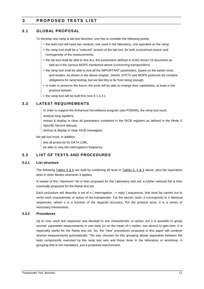
Procedure P 52
a Verification
Mean Output Power, Pulse Amplitude Variation, Mean Pulse Width, Pulse Positions,
Mode A pulse decoding.
b Performance specifications
MS 3.3.3, 3.5.1, 2, 4, 5 & 6 - MT 5.4.2.2 , 5.4.3.1 .
c Fixed settings
Interrogator at nominal setting; level at XPDR input : -50 dBm; Mode A.
d Test progress
100 [ interrogation ‡ reply ] sequences with ✈ XPDR set to code A 7377
repeated with successively ✈ codes A 4000 and A 0400.
e Measurement & display
Reply code displayed;
for each code:
power : . . . . . . mean value of all pulses / mean value of lowest pulse
maximum variation between all pulse in a reply (min-max).
position of ALL pulses (vs. F1 + n x 1.45 µs ) : mean value of each pulse
and the maximum offset (that is, the offset of the “worst” pulse)
pulse width : . . mean value of all pulses.
Procedure P 53
a Verification
Delay Time, Delay Time Jitter, Delay Time Difference Mode A vs. C, Code C .
b Performance specifications
MS 3.7.1 , Annex 10 (Gilham conversion ) - MT 5.4.3.3 .
c Fixed settings
Interrogator at nominal setting; level at XPDR input : -50 dBm .
d Test progress
100 [ interrogation ‡ reply ] sequences in Mode A; idem Mode C
✈ XPDR code A 1642, altimeter switched out if possible;
( if not : the altimeter will correspond to the “ground altitude”).
e Measurement & display
Delay time (P3 ⇒ F1) : mean value Mode A and Mode C are compared ;
jitter on delay time ( σ of 100 replies );
reply altitude decoded (either C 0000 or xxxx, corresponding to -1000 ft or to “ground altitude” ).
Transponder Test Benches 19
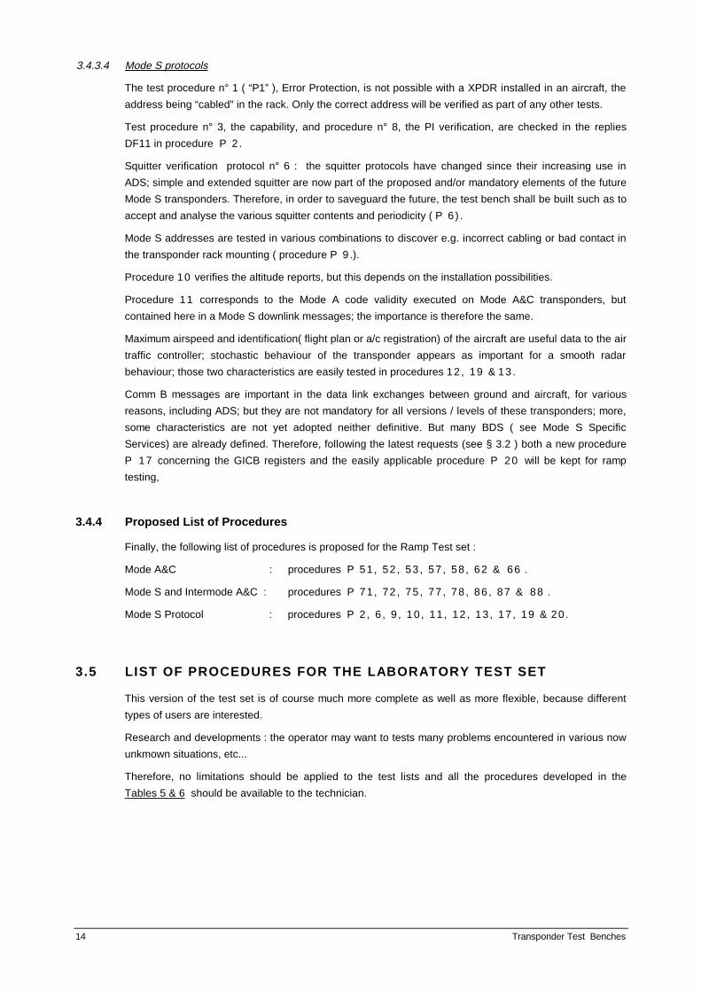
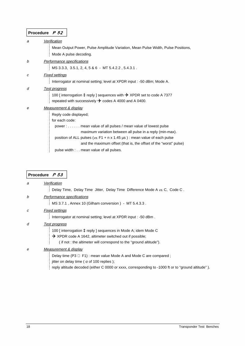
Procedure P 57
a Verification
Reply Rate vs. PRF.
b Performance specifications
MS 3.4.1 - MT 5.4.2.5 .
c Fixed settings
Interrogator at nominal setting; level at XPDR input : -50 dBm
✈ XPDR code : A 7377 + SPI .
d Test progress
PRF 500 interrogations per sec during one sec, followed by 5 or 10 sec rest,
then idem at 600, 700, . . . 1500 interrogations per sec.
e Measurement & display
Diagram : reply % vs. PRF.
Procedure P 58
a Verification
Mode A & C Sensitivity (MTL).
b Performance specifications
MS 3.2.4 - MT 5.4.1.2 .
c Fixed settings
Interrogator at nominal setting;
✈ XPDR code : A 1642, altimeter at zero if possible;
(if not : the altimeter will correspond to the “ground altitude”).
d Test progress
100 [ interrogation ‡ reply ] sequences, level at XPDR input : -60 ⇒ -80 dBm, per 1 dB steps
first with Mode A, then repeated using Mode C.
e Measurement & display
Diagram : reply % vs. input power; MTL = interrogator’s level when reply rate crosses 90 %
MTL difference Mode A ⇔ C displayed.

20 Transponder Test Benches
Procedure P 62
a Verification
Sidelobe Suppression vs. P1 / P2 Level Ratio.
b Performance specifications
MS 3.8.2 - MT 5.4.4.2 .
c Fixed settings
Interrogator at nominal setting;
✈ XPDR code : A 1642, altimeter at zero if possible;
(if not : the altimeter will correspond to the “ground altitude” ).
d Test progress
With a P2 at nominal position & width, P2/ P1 ratio varying from -12 ⇒ + 3 dB, per 1 dB steps
100 [ interrogation ‡ reply ] sequences for each step
repeated for the level at XPDR input : -50 dBm & MTL + 3 dB.
e Measurement & display
Diagrams : reply % vs. P2 / P1 ratio, tolerance areas shown (for the 2 input power levels).
Reduced version ( if available time is too short ) : replace the diagrams by the reply % at -9 dB and 0 dB only.
Procedure P 66
a Verification
Mode A & C Acceptance vs. P1 ⇒ P3 Spacing.
b Performance specifications
MS 3.9.3 - MT 5.4.5.2 .
c Fixed settings
Interrogator at nominal setting; no P2; level at XPDR input : MTL +10 dB
✈ XPDR code : A 1642.
d Test progress
P1 ⇒ P3 spacing varying from 6.5 ⇒ 9.5 µs and 19.5 ⇒ 22.5 µs, per 25 ns steps
100 [ interrogation ‡ reply ] sequences for each step.
e Measurement & display
Diagrams : reply % vs. P1 ⇒ P3 spacing, tolerance areas shown
for both Mode A ( 6 ⇒ 10 µs ) and Mode C ( 19 ⇒ 23 µs ).
Reduced version (if available time is too short) : replace the diagrams by a set of values;
reply % at -7.0, 7.8, 8.2, 9.0 µs and 20.0, 20.8, 21.2, 22.0 µs only.

Transponder Test Benches 21
4.1.3 Modes S electrical and Intermode A&C Procedures
Procedure P 71
a Verification
Reply Frequency.
b Performance specifications
MS 3.3.1 - MT 5.4.2.1 .
c Fixed settings
Interrogator at nominal setting; PRF 50 hz; level at XPDR input : -50 dBm
✈ XPDR code : A 1642.
d Test progress
100 [ interrogation UF 05 ‡ reply DF 05 ] sequences
or [ Intermode A ‡ reply DF11 ] sequences.
e Measurement & display
Frequency ( 1090 Mhz ) : mean value of all Mode S pulses.
Procedure P 72
a Verification
Mean Output Power, Pulse Amplitude Variation, Mean Pulse Positions, Mean Pulse Width.
b Performance specifications
MS 3.3.3, 3.6.1 ⇒ 3.6.6 - MT 5.4.2.2, 5.4.3.2 .
c Fixed settings
Interrogator at nominal setting; level at XPDR input : -50 dBm
✈ XPDR code : A 1642.
d Test progress
100 [ interrogation UF 05 or 21* ‡ reply DF 05 or 21* ] sequences
or [ Intermode A ‡ reply DF11] sequences.
e Measurement & display
Power : . . . . . . mean value of all Mode S pulses
+ diagram : amplitude of each reply data pulse (1st ⇒ 56th or 112 th * )
pulse position : mean offset (nominal vs. 1st pulse + (0.5 x n) µs )
pulse width: . . .mean value of, separately, the preamble pulses, the 0.5 µs pulses & the 1 µs pulses
note * : depending on the capability of the XPDR.

22 Transponder Test Benches
Procedure P 75
a Verification
Mixed Reply Rate Capability.
b Performance specifications
MS 3.4.2 - MT 5.4.2.5 .
c Fixed settings
Interrogator at nominal setting; level at XPDR input : -50 dBm
✈ XPDR code : A 7377 +SPI .
d Test progress
4 separated sequences lasting 1 sec each :
a - 500 interrogations Mode A uniformily mixed with 50 UF 05 interrogations * in 1 s
b - 120 interrogations Mode A uniformily mixed with 18 UF 05 interrogations * in 0.1 s,
followed by 0.9 s rest
c - 30 interrogations Mode A uniformily mixed with 8 UF 05 interrogations * in 0.025 s,
followed by 0.975 s rest
d - 2 interrogations Mode A uniformily mixed with 4 UF 05 interrogations * in 0.0016 s,
followed by 0.9984 s rest .
note * : if the XPDR is equiped for long replies, respectively 16 of the 50, 6 of the 18, 4 of the 8 and 2 of the 4 interrogations must require long replies.
e Measurement & display
The XPDR must reply to ALL these interrogations.
Procedure P 77
a Verification
Intermode A & C Sensitivity (MTL).
b Performance specifications
MS 3.2.4 - MT 5.4.1.2 .
c Fixed settings
Interrogator at nominal setting;
✈ XPDR code : A 1642, altimeter at zero if possible;
( if not : the altimeter will correspond to the “ground altitude”).
d Test progress
100 [ interrogation Intermode A ‡ reply DF11 ] sequences,
level at XPDR input : -60 ⇒ -80 dBm, 1 dB steps;
this repeated for Intermode C.
e Measurement & display
Diagrams : reply % vs. input power; MTL = interrogator’s level when reply rate crosses 90 %.
MTL difference Intermode A ⇔ C displayed.

Transponder Test Benches 23
Procedure P 78
a Verification
Mode S Sensitivity (MTL).
b Performance specifications
MS 3.2.4 - MT 5.4.11 .
c Fixed settings
Interrogator at nominal setting;
✈ XPDR code : A 1642.
d Test progress
100 [ interrogation UF 11 (with PR = 0) ‡ reply DF 11 ] sequences,
level at XPDR input : -60 ⇒ -80 dBm, per 1 dB steps.
e Measurement & display
Diagrams : reply % vs. input power; MTL = interrogator’s level when reply rate crosses 90 %
(for MTL + 3 dB and higher, the reply rate must be 99 % ).
Procedure P 86
a Verification
Intermode A & C Acceptance vs. P4 Width.
b Performance specifications
MS 3.9.4 - MT 5.4.5.2 .
c Fixed settings
Interrogator at nominal setting; no P2;
✈ XPDR code : A 1642, altimeter at zero if possible;
( if not : the altimeter will correspond to the “ground altitude”).
d Test progress
Level at XPDR input : -21, -40 & -60 dBm
P4 varying from 1.0 ⇒ 3.0 µs, per 25 ns steps
100 [ interrogation ‡ reply ] sequences for each step & each input level.
e Measurement & display
Diagrams : reply % vs. P4 width, tolerance areas shown
for both Intermode A & C and for each of the 3 input levels.

24 Transponder Test Benches
Procedure P 87
a Verification
Intermode A & C Acceptance vs. P3 ⇒ P4 Spacing.
b Performance specifications
MS 3.9.3 - MT 5.4.5.2 .
c Fixed settings
Interrogator at nominal setting; no P2;
✈ XPDR code : A 1642, altimeter at zero if possible;
( if not : the altimeter will correspond to the “ground altitude”).
d Test progress
Level at XPDR input : -21, -40 & -60 dBm
P3 ⇒ P4 spacing varying from 1.4 ⇒ 2.7 µs, per 25 ns steps
100 [ interrogation ‡ reply ] sequences for each step & each input level.
e Measurement & display
Diagrams : reply % vs. P3 ⇒ P4 spacing, tolerance areas shown
for both Intermode A & C and for each of the 3 input levels.
Procedure P 88
a Verification
Mode S Acceptance vs. P2 ⇒ P6 (Sync. Phase Reversal) Spacing.
b Performance specifications
MS 1.6.5, 3.9.5 - MT 5.4.5.2 .
c Fixed settings
Interrogator at nominal setting;
✈ XPDR code : A 1642.
d Test progress
P2 ⇒ Sy. Ph. Rev. spacing varying from 2.4 ⇒ 3.1 µs, per 25 ns steps;
level at XPDR input : MTL +3 dB and -50 dBm
100 [ interrogation ‡ reply ] sequences for each step for each power level.
e Measurement & display
Diagrams : reply % vs. P2 ⇒ Sync. Phase Reversal spacing, tolerance areas shown,
both level curves shown.

Transponder Test Benches 25
4.1.4 Mode S Protocol Procedures
For all these protocol tests, the interrogator is at nominal regarding “electric” values; no pulse P2 is
used; level at XPDR input is -50 dBm; uplink address is the XPDR address; XPDR code is A 7377.
Unless especially mentioned.
Some test are only applicable to some types of XPDRs, depending on their level or whether they are
“Mark 4 “ or not (see the double asterisks **).
Diversity operation must be inhibited to avoid unequal, unknown reception by the XPDR and
“jumping” problems : the power and delay differ, and, worse, the upper antenna may be totally
invisible to the test set located on the ground; or simplier, the test set ignores which antenna is
replying. Therefore, the top channel must be terminated by its characrteristic impedance.
Successive signs ‡ mean a sequence containing more than 1 interrogation followed by 1 reply.
ATTENTION : the Mode S Specific Services as well as the squitter protocol may still change in the
near future; so, in some of the protocol tests (see : “ ATTENTION : THE SPECIFICATIONS MAY
VARY”), the BDS definition, use, sequences, and repetition rate (if applicable) may be different from
what is developed; but the princip of the measurement remains. Always refer to the latest version of
th Mode S Specific Services (ref. 6) and Mode S Subnetwork SARPS.
The formats used in these tests are the following :
Uplink Formats :
UF 00 000 RL :1 0000 AQ :1
00 0000 0000 0000 0000 AP : 24
UF 04 PC : 3 RR : 5 DI : 3 SD : 16 AP : 24
UF 05 PC : 3 RR : 5 DI : 3 SD : 16 AP : 24
UF 11 PR : 4 II: 4 000 0000 0000 0000 0000 AP : 24
UF 16 000 RL :1 0000 AQ : 1 00 0000 0000 0000 0000 MU : 56 AP : 24
UF 20 PC : 3 RR : 5 DI : 3 SD : 16 MA : 56 AP : 24
UF 21 PC : 3 RR : 5 DI : 3 SD : 16 MA : 56 AP : 24
11 RC : 2 NC : 4 MC : 80 AP : 24
( YY : x means x bits are devoted to this field YY ; 0000 show a series of zeros between fields )

26 Transponder Test Benches
Downlink Formats :
DF 00 VS : 1 00 SL : 3 00 RI : 4 00 AC : 13 AP : 24
DF 04 FS : 3 DR : 5 UM : 6 AC : 13 AP : 24
DF 05 FS : 3 DR : 5 UM : 6 ID : 13 AP : 24
DF 11 PR : 4 AA : 24 PI : 24
DF 16 VS : 1 00 SL :3 00 RI: 4 00 AC : 13 MV 56 AP : 24
DF 17 FS : 3 DR : 5 DI : 3 SD : 16 MB : 56 AP : 24
DF 20 FS : 3 DR : 5 UM: 6 AC : 13 MB : 56 AP : 24
DF 21 FS : 3 DR : 5 UM: 6 ID : 13 MB : 56 AP : 24
11 0 KE : 1 ND : 4 MD : 80 AP : 24
( YY : x means x bits are devoted to this field YY ; 0000 show a series of zeros between fields )
Procedure P 2
a Verification
Interrogation Acceptance.
b Performance specifications
MS 3.20.2.2 & 3, 3.21.1.1 & 4 , 3.23 - MT 5.4.13.4 / protocol procedure n° 2 .
c Interrogation ‡ reply sequences
- Without P2 : Mode A, C; Intermodes A/S, C/S, A Only, C Only
- with P2 ( P2 level = P1) pulse included : the same ones
- Mode S: UF 0 { with RL = 0, =1 }
UF 11 { PR, II = 0 } { address = FF FFFF hex }
UF 4, 5, { with RR = 0, 15, 16, 17, 18, & 19 } { PC, DI, SD = 0 }
UF 20, 21 { with RR = 0, 15, 16, 17, 18, & 19 } { PC, DI, SD, MA = 0 } (**)
UF 16 { with RL = 0, =1 } (**)
UF 24 { with RC = 2 } (**)
d Control
The correct reply in each of the Modes.
Transponder Test Benches 27
Procedure P 6
a Verification
Squitter / Extended Squitter.
b Performance specifications
MS 3.20.2.6 modified - MT 5.4.13.4 / protocol procedure n° 6 (already modified).
ATTENTION : THE SPECIFICATIONS MAY VARY :
GICB sequences and repetition rate are not definitive and the AIRBORNE / GROUND status may
not be varied as desired.
c Interrogation ‡ reply sequences
Unsollicited replies in Mode S - There are no interrogations
To obtain valuable result in terms of periodicity, at least 400 different unsollicited replies must be
observed for each of the following cases:
1 - XPDRs with SHORT SQUITTER ONLY : the short squitters
DF 11 are transmitted at an average rate of 1/sec,
contents : { CA = ..., II = 0 , PI = address in clear}
2 - XPDRs with EXTENDED SQUITTER : a ( not controlled ) mixture of short & long squitters :
DF 11 like above
DF 17 : [FS = 1 ] [DR = 0 ] [DI = 7 ] [SD = 0x00 ] [ MB = z ] [ PI = XPDRs address ]
where x is the subfield BDS2 and equals 5, 6, 7, or 8
corresponding to GICB registers 0,5 ; 0,6 ; 0,7 or 0,8 )
where z = 56 bits of data defined in the Mode S Specific Service Manual
average rate of 2/sec down to 1/10 sec, depending on the register and the aircraft movement,
with a Surface Position Squitter that may vary if so determined by register 0,7 Squitter Status.
✈ For some registers, the transponder must be set to fictitious AIRBORNE status; it is not sure
whether this is possible on all aircraft; see the remark above.
d Control
The correct contents of DF 11 and DF 17;
the random transmission rate : a diagram Number of events vs. time (in ms) between
messages for the following registers ( the list is valid today and may vary ) :
DF 11 at a rate of 1 / sec ( limits : 0.8 to 1.2 s )
register 0,5 2 / sec ( limits : 0.4 to 0.6 s ) aircraft being set “AIRBORNE”
register 0,6 1 / 5 s ( limits : 4.8 to 5.2 s ) aircraft NOT set “AIRBORNE”
register 0,7 ?
register 0,8 1 / 5 s ( limits : 4.8 to 5.2 s ) if aircraft is set “AIRBORNE”
1 / 10 s ( limits : 9.6 to 10.4 s ) if aircraft is left stationnery.

28 Transponder Test Benches
Procedure P 9
a Verification
Mode S Address.
b Performance specifications
MS 3.17.1, 3.20.2.1, 2 &11 - MT 5.4.13.4 / extract of protocol procedure n° 9 .
c Interrogation ‡ reply sequences
UF 05 : [PC = 0 ] [RR = 0 ] [DI = 0 ] [SD = F000H ] [ AP = X ]
UF 11 : [PR = 0 ] [II = 1 & 14 ] [ . . . . zeros . . . . ] [ AP = X ]
where X = the 552 combinations of 2 ONEs & 22 ZEROs and of 2 ZEROs & 22 ONEs
plus the known - the sole - address of the transponder in test in the aircraft.
d Control
The non-reply to all 3 x 552 combinations ( to UF 05, to UF 11 with II = 1, to UF 11 with II = 14),
the correct contents in the replies to the 3 interrogations to be accepted:
DF 05 : [FS = 1 ] [DR = 0 ] [UM = 0 ] [ID = code 7377 ] [ AP = XPDRs address ]
DF 11 : [CA = 0, 4, 5 or 6 depending on the capability] [ AA = XPDRs address ] [ PI = II = 1]
DF 11 : [CA = 0, 4, 5 or 6 depending on the capability] [ AA = XPDRs address ] [ PI = II = 14 ].
Procedure P 10
a Verification
Altitude Report.
b Performance specifications
MS 2.5.1, 3.5.6, 3.17.1 b - MT 5.4.13.4 / extract of protocol procedure n°10.
c Interrogation ‡ reply sequences
Intermode C (Mode C / S All-call P1- P3 -P4) ❯ DF 11 reply with AA =XPDRs address ❯
UF 04 : [PC = 0 ] [RR = 0 ] [DI = 0 ] [SD = 0000H ] [ AP = the address ] ❯ DF 04 reply ❯
UF 04 : [PC = 0 ] [RR = 20 ] [DI = 0 ] [SD = 0000H ] [ AP = the address ] ❯ DF 20 reply .
Two options, depending on whether or not
a pressure / altitude variator is available
sufficient time for these repeated sequences is acceptable
if YES : test only the “ground altitude” and , if possible to switch off the altitude data, 0000 value
if NO : install the altitude-pressure variator at the relevant captor output and introduce succes-
sively a series of defined altitudes such arranged as to give a diversity of bit patterns :
-975 , -600, +600, 2800, 8700, 11800, 12400, 18800, 24300, 24600,
30800, 33400, 36800, 62800, 94800, 100800, 120800 & 1266700 ft .
d Control
The correct contents in the replies :
DF 11 : [CA = 0, 4, 5 or 6 depending on the capability] [AA = XPDRs address] [PI = 0 ].
if YES DF 04 : [FS = 1 ] [DR = 0 ] [UM = 0 ] [AC= x ] [ AP = XPDRs address ]
DF 20 : [FS = 1 ] [DR = 0 ] [UM = 0 ] [AC= x ] [MB = 0 ] [ AP = XPDRs address ]
x = Gilham conversion of the ground altitude and - 1000 ft if altitude is switched off;
if NO idem with x = each of Gilham conversion of the various altitudes set on the variator.

Transponder Test Benches 29
Procedure P 11
a Verification
Mode A Report.
b Performance specifications
MS 2.5.1, 3.5.6, 3.20.2.11 - MT 5.4.13.4 / protocol procedure n° 11.
c Interrogation ‡ reply sequences
UF 05 : [PC = 0 ] [RR = 20 ] [DI = 0 ] [SD = 0000H ] [ AP = the address ] ❯ DF 21 reply
The “ pilot “ manipulates the control box switches to follow a list of the 66 combinations containing
2 ONEs and 10 ZEROs plus 66 others with 2 ZEROs and 10 ONEs.
d Control
The correct replies for each of the successives codes ( X ) introduced by the pilot :
DF 05 : [FS = 1 ] [DR = 0 ] [UM = 0 ] [AC= X ] [ AP = XPDRs address ]
DF 21 : [FS = 1 ] [DR = 0 ] [UM = 0 ] [AC= X ] [MB = 0 ] [ AP = XPDRs address ].
Reduced version ( if available time is too short ) : only the A 1642 code is used.
Procedure P 12
a Verification
RI Acquisition and Maximum Airspeed.
b Performance specifications
MS 3.18.4.25 & 29 , 3.23.1.5 - MT 5.4.13.4 / protocol procedure n° 12.
c Interrogation ‡ reply sequences
Depends on whether the XPDR is ACAS-compatible or not
1 - NOT ACAS-compatible:
UF 00 : [000] [RL = 0 ] [000] [AQ = 0 & 1] [000....000] [ AP = the address ] ❯ DF 00 replies
2 - The XPDR is ACAS-compatible : the same UF 00 plus
UF 00 : [000] [RL = 1 ] [000] [AQ = 0 & 1] [000....000] [ AP = the address ] ❯ DF 16 replies ❯
UF 16 : [000] [RL = 0 ] [000] [AQ = 0 & 1] [000....000] [ MU = 0 ] [ AP = address ] ❯ DF 00 replies ❯
UF 16 : [000] [RL = 1 ] [000] [AQ = 0 & 1] [000....000] [ MU = 0 ] [ AP = address ] ❯ DF 16 replies .
d Control
The correct replies :
if 1 - :
DF 00 replies :
[ VS =1] [ SL = 0 ] [ RI = x ] [AC = altitude on the ground ] [ AP = XPDRs address ]
where x = 8 to 14 depending on the max airspeed,when bit AQ was 0
0 when bit AQ was 1.
if 2 - : ( see MS 3.23.1.5 )
DF 00 replies :
[VS =1] [SL = 0 to 7 depending on the ACAs level or the a/c] [ RI = x ] [AC = altitude
of the ground ] [AP = XPDRs address ]
where x = 0, 2, 3, 4 , depending on the ACAS capability of the a/c, when bit AQ was 0
8 to 14 , depending on the max airspeed, when bit AQ was 1 .
DF 16 replies : same contents, plus MV filled with zeros.
Remark : More complete tests of the ACAS exchange protocol are executed in Bench test set procedures 31, ....

30 Transponder Test Benches
Procedure P 13
a Verification
Stochastic Acquisition.
b Performance specifications
MS 3.18.4.23 , 3.20 2.2.i - MT 5.4.13.4 / protocol procedure n° 13.
c Interrogation ‡ reply sequences
UF 11 : [PR = X ] [II = 0 ] [ 000 0000 0000 0000 0000 ] [ AP = XPDRs address ]
where X is varying from 0 to 15, with 100 interrogations each
1 - with no lockout set
2 - with one lock-out set.
d Control
The correct % of replies in each case (with a tolerance of ± 30% for the values other than 99 or 0) :
if 1 - PR = 0 & 8 % >= 99 if 2 - PR = 8 % >= 99
1 & 9 = 50 (35 ⇒ 65) 9 = 50 (35 ⇒ 65)
2 & 10 = 25 (18 ⇒ 32) 10 = 25 (18 ⇒ 32)
3 & 11 = 12.5 ( 9 ⇒ 15) 11 = 12.5 ( 9 ⇒ 15)
4 & 12 = 6.2 ( 4 ⇒ 6) 12 = 6.2 ( 4 ⇒ 6)
other = 0 other = 0

Transponder Test Benches 31
Procedure P 17
a Verification
GICB Register Extraction.
b Performance specifications
MS 3.21.1.12 (a,b,c & f ) - Ref 6 : Mode S Specific Services Manual.
ATTENTION : THE SPECIFICATIONS MAY VARY :
In any case, refer to the latest version of both Mode S Specific Services Manual (see ref. 6 ) .
c Interrogation ‡ reply sequences
UF 04 (or 05) : [PC = 0 ] [RR = x] [DI = 7 ] [SD = 0y00 ] [ AP = XPDRs address]
❯ DF 20 (or 21)replies ;
where x and y ( hexadecimal numbers) vary to extract all desired GICB register,
x = sum of 16 + BDS1 subfield
y = RRS subfield = BDS2 subfield.
The present list of registers is
0,5 - 0,6 - 0,7 - 1,0 - 2,0 - 4,0 - 4,3 - 4,4 - 4,5 - 5,0 - 5,1 - 5,2 - 5,3 - 6,0
✈ The transponder must be linked to the corresponding interfaces (ADLP ...) that will input the
relevant information in the corresponding register ( 255 x 56 bit buffer).
d Control
The DF 20 (or 21) contains the following fields:
[DF = 20 ] [FS = 1 ] [DR = 0 ] [UM = X ] [AC = altitude =0 ] [MB = message ] [AP = XPDRs address ]
or
[DF = 21 ] [FS = 1 ] [DR = 0 ] [UM = X ] [ID = a/c code A ] [MB = message ] [AP = XPDRs address ] .
For each of the desired register, the MB message rmust be converted following the contents as
defined in the Mode S Specific Service Manual.
For example, for register = 4,0 “ Aircraft Intention” , the message content is:
bit 1 to 13 selected altiude , in steps of 16 ft ( bit 1 = staus, bit 2 = MSB )
bit 14 to 24 selected altiude rate, in steps of 32 ft /mn ( bit 14 = staus, bit 15 = MSB )
bit 25 to 35 selected magnetic course(0) / heading(1), in steps of 360/512 deg
( bit 25 = switch (0 or 1), bit 26 = status, bit 27 = sign, bit 28 = MSB)
bit 36 to 47 selected airspeed (0) / mach number (1), in steps of 0.5 kt or Mach 0.004
( bit 36 = switch (0 or 1), bit 37 = status, bit 38 = MSB)
bit 48 to 56 status and selection bits ...
Conversion software have already been developed by EUROCONTROL EEC and could be obtained
from this souce. Example of the display of these converted BDS are shown in the EEC note
“ Mode-S Specific Services and Data Link Test Bench “ (reference 7).

32 Transponder Test Benches
Procedure P 19
a Verification
AIS, Flight Identification Protocol.
b Performance specifications
MS 3.18.4.14 & 27, 3.21.1.13 & 17 - MT 5.4.13.4 / protocol procedure n° 19
+ Ref 6 : Mode S Specific Services Manual.
c Interrogation ‡ reply sequences
UF 04 or 05 : [PC = 0 ] [RR = 18 ] [DI = 7 ] [SD = 0000 ] [ AP = XPDRs address]
❯ DF 20 or 21replies,
where SD contains subfields IIS = 0 , RRS = 0 , the rest = 0 too.
d Control
The correct contents of the replies DF 20 or 21
[DF = 20 ] [FS = 1 ] [DR = 0 ] [UM = X ] [AC = altitude =0 ] [MB = message ] [AP = XPDRs address ]
or
[DF = 21 ] [FS = 1 ] [DR = 0 ] [UM = X ] [ID = a/c code A ] [MB = message ] [AP = XPDRs address ]
where the 56 bit message MB is :
[BDS = 2,0 ] [charac 1] [charac 2] [charac 3] [charac 4] [charac 5] [charac 6] [charac 7] [charac 8]
the characters giving, with ICAO international alphabet n°7, the aircraft’s registration (tail number).
Procedure P 20
a Verification
Capability Report.
b Performance specifications
MS 3.18.4.14 & 27, 3.21.1.12 & 17, 3.23.1.2b - MT 5.4.13.4 / protocol procedure n° 20.
ATTENTION : THE SPECIFICATIONS MAY VARY :
In any case, refer to the latest version of both Mode S Specific Services Manual (see ref. 6) and
the Mode S subnetwork SARPS.
c Interrogation ‡ reply sequences
UF 04 : [PC = 0 ] [RR = 17 ] [DI = 7 ] [SD = 0 ] [ AP = XPDRs address ]
where SD contains subfields IIS = 0 , RRS =
[DF = 20 ] [FS = 1 ] [DR = 0 ] [UM = X ] [AC = altitude =0 ] [MB = message ] [AP = XPDRs address].
d Control
Depending on the level of the transponder , its DataLink possibilities and the evolution of the
situation concerning BDS in the future standards.
[DF = 20 ] [FS = 1 ] [DR = 0 ] [UM = X ] [AC = altitude =0 ] [MB = message ] [AP = XPDRs address].

Transponder Test Benches 33
4.2 RAMP TEST PROGRAM
4.2.1 Operation
The installation of the test procedures in the Ramp test set is based on a set of successive software
modules, that control the sequences developed in paragraph 4.1.
The execution of the tests are dependant of aknowledgement (approval), continue, interrupt or re-start
buttons. These buttons may be physically installed in front of the equipment or touch-screen operation.
4.2.2 Modules
Each module controls a succession of displays and waiting periods for any order given by the buttons:
F i g u r e 3 : M o d u l e f o r o n e p r o c e d u r e
display procedure name, test contents
display settings to enter
yes
START
next
data in XPDR, fixed data, data in ADLP
start or continue procedure
modifie setting ?
modifie data settings
end display PASS / FAILED
SHOW RESULTS ?
display results ?
no
display
NEXT REPEAT STOP buttons
EXIT MODULE
YES NO buttons
YES NEXT buttons
DONE button
YES
1 module for 1 procedure
basic schematics

34 Transponder Test Benches
• display the procedure name and tests contents, waite for approval or stop or next procedure;
• display the settings: the data to enter in the transponder via its control box (e.g. the code) or, if
applicable, to the external equipment linked to it (ADLP, ...), waite for execution order;
• start of the procedure, stops whenever a new setting has to be applied during the procedure (e.g.
change of code), waite for continue order;
• stops at end of testing, display of the information “ PASSED “ or “ FAILED “, wait for order display
result or go to the next procedure;
• if result display button has been “pushed”, the successive results are presented in the form
corresponding to the measurement :
a data: e.g. Pulse Width = 455 ns (mean of 100 replies, 14 pulses) the tolerances is 350 ⇒ 550 ns
a X/Y diagram : e.g. reply % vs. P3 width with the tolerance areas in grey
a list of reply messages e.g. DF11, CA = 7, AA = 808080, II = 0 with the text : correct / wrong
after which the system switches over to another module.
4.2.3 Trial Modules
A trial is a planified sequence of procedures defined by the above modules; see this Figure 4 :
enter date, XPDR n° aircraft registration, ...
start first procedure
START
execution of the module ( see module
description)
next / repeat
keyboard entry
1 module for 1 trial (a series of planified procedures)
basic schematics
DONE
END TRIAL
PRINT EXIT DATA buttons
print , exit data
print ? exit data ?
NEXT REPEAT STOP buttons
?

Transponder Test Benches 35
A planned sequence is a list established depending on the user needs (planned maintenance, repair,
research, ...)
4.2.4 Fast trials
In order to fasten the trial, one can adopt a succession of test sequences, each sequence being arranged
in such a way that the same settings are used for all the tests contained, and no interrupt messages
appears during or between tests (like “ modify settings ? “ or “ display results ” or “ exit data ? “); all data
are stored in memory and printed at the end if wanted.
The only interruption in the trial is then the necessary change of settings between two sequences; see the
following
F i g u r e 5 : F a s t t r i a l ( Co m b i n a t i o n o f P r o c e d u r e s )
enter date, XPDR n° aircraft registration, ...
start group of procedures
START
keyboard entry
fast trial
(planified combination of test procedures )
basic schematics
DONE
PRINT EXIT DATA buttons
print , exit data
print ? exit data ?
NO last group ?
YES
execution of all the test modules of the group
display group settings to enter
data in XPDR, fixed data, data in ADLP
DONE button

36 Transponder Test Benches
Example of succession of sequences :
Set code to A 7377 + SPI > sequence P51 - P57 - P75 -P52 ;
change code to 4000 > P52 again ;
change code to 0400 > P52 again ;
change code to 1642 and switch off the altimeter > sequence P53 - P58 - P62 - P66 - P71 - P72 -
P77 - P78 - P86 - P87 - P88 ;
print result.
4.2.5 Other Possibilities
The system built for the ramp test set nead some flexibility; one must be able to modify the characteristics
of the tests. It is an obligation to allow
• the evolution of maintenance rules, these being adapted to the ATC SSR problems and to
manufacturing changes,
• the research and developments of administrations and airliner maintenance services,
• the easy building of the laboratory test set variant.
This implies the “availability” of the modules: one must be able to access the measurement parameters
(number of iterations, succession of Mode S formats, etc...), with the sole limitations that only authorised
technicians may control these elements and that in any case, the default values are set back for the usual
operator. Unauthorised values (too large, ..., unpossible message subfield, ...) for the test parameters are
announced to the operator and the system wait for new entry.
4.2.6 Results Management
4.2.6.1 Memory
All results are automatically written in memory; it contains the date, the transponder under test references
(serial number, aircraft regitration, Mode S address), each successive test protocol (n°, name), the
conditions of the test (settings), the resulting data (whatever the form) even if no display was asked by the
operator during the test.
To avoid to the risk of field failure, hard disk should be replaced by any other memory system.
4.2.6.2 Result transfer
The contents of the memory must be transferable by any actual means (floppy disk or equivalent, GPIB
bus, RS232, ...) to another computer base or local network. Printer output is required.
4.2.7 Autotest
The system must contain an autotest device, that is automatically launched before any operation starts.
This autotest verifies the input and output of the system and can control the exactness of the
measurements through a reference transponder.
It must be possible to introduce the distance ramp tool -- aircraft antenna before starting the tests, in order
to the apply the corresponding time delay correction.

Transponder Test Benches 37
4.3 TECHNICAL DATA
The equipment must be able to generate all the tests described in the test lists above and therefore must
have the following capacities:
4.3.1 Output (Uplink)
• Two channels (to allow in the bench variant, the diversity measurements)
• frequency : 1020 - 1040 Mhz, steps of 0.2 Mhz
• power : for measurements at 2 to 25 (or 15 ) meters: up to 37 or 44 dBm ( 5 or 25 W)
at output of antenna, in steps of 0.5 dB
difference between channels : up to . . . . .
• pulse : miminum width 250 ns, steps of 25 ns (or shorter),
with intervals of 200 ns between one pulse decay and the next pulse rise
pulse rise and decay times (respecting ICAO Annex 10)
DPSK modulator for uplink P6 pulses (idem)
• pulse sequences : all Mode A, C, Intermode A, C
that is, all combinations of two following P1, P2, P3, P4 trains;
Mode S UF / DF 00, 04, 05, 11, 16, 17, 20, 21, 24 with any field and subfield contents;
time delays up to 30 sec (use in lockout tests if these test are added)
• repetition rate : PRF 1 to 100 hz in Mode S, to 2000 hz in the other Modes
• physical output : both channels to connecting cable ( connector “N” )
one channel to antenna 10 W maximum.
• antenna : directional, on a tripod, to connecting cable ( connector “N” ).
4.3.2 Input (Downlink)
• Two channels (to allow in the bench variant, the diversity measurements)
• frequency : 1070 - 1110 Mhz, resolution 0.01Mhz
• power : up to 0.1W (17 dBm) at input to antenna, with a resolution of 0.5 dB
• pulse : miminum width 200 ns, resolution 25 ns (or shorter)
with intervals of 200 ns between one pulse decay and the next pulse rise
pulse rise and decay times measurable.
4.3.3 Display
• Active matrix for confortable external natural light
• 9 inch screen 800 x 600 pixels
• either 20 lines of text or diagram X/Y
• dialog windows with on-screen buttons, data result presentation
• powers : peak pulse value, mean values (as defined in the procedure paragraphs), in dB & in W
altitude available in feet.
4.4 TESTING ENVIRONMENT
• The equipment will be used essentially on external.
• Power input : 90 to 240 V , 45 - 440 hz
• Temperature : 0 to +55°C in operation
• -40 to +70°C storage
• Humidity : 95 %
• Standard shock proof.

38 Transponder Test Benches
( blank page )

Transponder Test Benches 39
5 L AB O R AT O R Y T E S T B E N C H
5.1 PROCEDURES ANALYSIS
see next version of this note
5.2 BENCH TEST PROGRAM
see next version of this note
5.3 TECHNICAL DATA
see next version of this note
5.4 TESTING ENVIRONMENT
see next version of this note

40 Transponder Test Benches
( blank page )

Transponder Test Benches 41
6 R E F E R E N C E S
Ref 1 . . . Off-line Tools for Airborne Equipment
EUROCONTROL DED3 information paper for the SSGT meeting October 1996
Ref 2 & 3 . GTVS : Ground Transponder Verification Verification
Two Feasibility Studies ordered by EUROCONTROL terminated in 1993 :
1) INTERSOFT ELECTRONICS Olen, Belgium
2) THOMSON-CSF/SDC Meudon-la-forêt, France
Ref 4 . . . STFTV Surveillance Team / Task Force on Transponder Verification
Report EEC note 20/95
Ref 5 . . . A Field Study of Transponder Performance in General Aviation Aircraft
Report FAA /Tech Center # DOT/FAA/CT-97/7 December 1997
Ref 6 . . . Mode S Specific Services Manual
ICAO Doc 9688-AN/952 June 1997
Ref 7 . . . Mode S Specific Services and Data link Test bench
EEC note 11/98 April 1998.