EUROPEAN ETS 300 253 TELECOMMUNICATION … · This ETS addresses earthing and bonding of...
22
New presentation - see History box EUROPEAN ETS 300 253 TELECOMMUNICATION January 1995 STANDARD Source: ETSI TC-EE Reference: DE/EE-02002 ICS: 33.080 Key words: Equipment, earthing, bonding Equipment Engineering (EE); Earthing and bonding of telecommunication equipment in telecommunication centres ETSI European Telecommunications Standards Institute ETSI Secretariat Postal address: F-06921 Sophia Antipolis CEDEX - FRANCE Office address: 650 Route des Lucioles - Sophia Antipolis - Valbonne - FRANCE X.400: c=fr, a=atlas, p=etsi, s=secretariat - Internet: [email protected] Tel.: +33 92 94 42 00 - Fax: +33 93 65 47 16 Copyright Notification: No part may be reproduced except as authorized by written permission. The copyright and the foregoing restriction extend to reproduction in all media. © European Telecommunications Standards Institute 1995. All rights reserved.
-
Upload
truongthuy -
Category
Documents
-
view
231 -
download
0
Transcript of EUROPEAN ETS 300 253 TELECOMMUNICATION … · This ETS addresses earthing and bonding of...
New
pre
sent
atio
n -
see
His
tory
box
EUROPEAN ETS 300 253
TELECOMMUNICATION January 1995
STANDARD
Source: ETSI TC-EE Reference: DE/EE-02002
ICS: 33.080
Key words: Equipment, earthing, bonding
Equipment Engineering (EE);Earthing and bonding of telecommunication equipment
in telecommunication centres
ETSIEuropean Telecommunications Standards Institute
ETSI Secretariat
Postal address: F-06921 Sophia Antipolis CEDEX - FRANCEOffice address: 650 Route des Lucioles - Sophia Antipolis - Valbonne - FRANCEX.400: c=fr, a=atlas, p=etsi, s=secretariat - Internet: [email protected]
Tel.: +33 92 94 42 00 - Fax: +33 93 65 47 16
Copyright Notification: No part may be reproduced except as authorized by written permission. The copyright and theforegoing restriction extend to reproduction in all media.
© European Telecommunications Standards Institute 1995. All rights reserved.

Page 2ETS 300 253: January 1995
Whilst every care has been taken in the preparation and publication of this document, errors in content,typographical or otherwise, may occur. If you have comments concerning its accuracy, please write to"ETSI Editing and Committee Support Dept." at the address shown on the title page.

Page 3ETS 300 253: January 1995
Contents
Foreword .......................................................................................................................................................5
Introduction....................................................................................................................................................5
1 Scope ..................................................................................................................................................7
2 Normative references..........................................................................................................................7
3 Abbreviations and definitions ..............................................................................................................83.1 Abbreviations .......................................................................................................................83.2 Definitions ............................................................................................................................8
3.2.1 IEC definitions (by IEC 50 numbers) ...............................................................83.2.2 Telecommunication definitions........................................................................9
4 General requirements .......................................................................................................................104.1 Safety from electrical hazards............................................................................................104.2 Signal reference.................................................................................................................104.3 EMC performance..............................................................................................................10
5 Requirements on bonding networks..................................................................................................105.1 Bonding configurations ......................................................................................................105.2 CBN within a telecommunication building..........................................................................115.3 BN within a telecommunication system .............................................................................115.4 Merging of CBN and MESH-BNs.......................................................................................145.5 Cabling within and between BNs .......................................................................................14
6 Requirements for power distribution .................................................................................................146.1 DC power distribution of secondary supply........................................................................146.2 DC power distribution of tertiary supplies ..........................................................................146.3 AC mains distribution and bonding of the protective conductor.........................................156.4 AC power distribution from tertiary power supply ..............................................................15
Annex A (normative): Rationale about CBN co-ordination ....................................................................18
Annex B (informative): Rationale about the integration of the DC return conductor into the mergedCBN/MESH-BN ..................................................................................................20
Annex C (informative): Bibliography........................................................................................................21
History..........................................................................................................................................................22

Page 4ETS 300 253: January 1995
Blank page
Page 5ETS 300 253: January 1995
Foreword
This European Telecommunication Standard (ETS) has been produced by the Equipment Engineering(EE) Technical Committee of the European Telecommunications Standards Institute (ETSI).
This ETS has been produced within the framework of the following considerations:
a) centralized telecommunication equipment is generally installed in telecommunication centres andheld in racks, cabinets or other mechanical structures;
b) the existing CCITT and CCIR Recommendations and CENELEC standards in such matters do notensure the required standardization at the equipment level;
c) network operators and equipment providers agreed to standardize on a bonding configuration thatfacilitates:
- compliance with functional requirements including Electromagnetic Compatibility (EMC)aspects of emission and immunity;
- compatible building and equipment provisions;
- installation of new telecommunication centres as well as expansion or replacement ofinstallations in existing telecommunication centres with equipment coming from differentsuppliers;
- a structured installation practice;
- simple maintenance rules;
- contracting on a common basis;
- cost effectiveness in development, manufacturing, installation and operation.
Transposition datesDate of latest announcement of this ETS (doa): 30 April 1995
Date of latest publication of new National Standardor endorsement of this ETS (dop/e):
31 October 1995
Date of withdrawal of any conflicting National Standard (dow): 31 October 1995
Introduction
This ETS addresses earthing and bonding of telecommunication equipment in telecommunication centresin relation to safety, functional performance and EMC.
Information regarding the general principles on earthing for telecommunication sites has been publishedby the CCITT in the handbook on "Earthing of telecommunication installations" (see annex C). CCITTRecommendation K.27 deals with bonding configurations and earthing inside a telecommunicationbuilding. One bonding configuration only is selected from CCITT Recommendation K.27 and tailored tothis ETS.

Page 6ETS 300 253: January 1995
Blank page
Page 7ETS 300 253: January 1995
1 Scope
This European Telecommunication Standard (ETS) applies in telecommunication centres and similarinstallations to the bonding network of the building, the bonding network of the equipment, and theinterconnection between these two networks. It contributes to the standardization of telecommunicationequipment and co-ordinates with the pre-requirements of installation conditions to achieve the followingtargets:
- safety from electrical hazards;
- reliable signal reference;
- satisfactory Electromagnetic Compatibility (EMC) performance.
A defined bonding configuration down to the equipment level shall facilitate the installation, operation andmaintenance of telecommunication centres in telecommunication buildings or similar installationsindependent of the equipment supplier.
The specification of telecommunication equipment and of the pre-requirements of installation are subjectto agreement of the parties (e.g. the supplier and the purchaser). Annex A can be used in the procedureto achieve agreement.
This ETS does not apply to telecommunication equipment not intended to be installed insidetelecommunication centres, e.g.:
- smaller telecommunication equipment inside a subscriber's building;
- subscriber line terminal equipment.
NOTE: A separate ETS about earthing and bonding of telecommunication equipment inside asubscriber's building is under consideration.
2 Normative references
This ETS incorporates by dated and undated reference, provisions from other publications. Thesenormative references are cited at the appropriate places in the text and the publications are listedhereafter. For dated references, subsequent amendments to or revisions of any of these publicationsapply to this ETS only when incorporated in it by amendment or revision. For undated references the latestedition of the publication referred to applies.
[1] CENELEC HD 384.4.41: "Electrical installation of buildings; Part 4: Protection forsafety; Chapter 41: Protection against electric shock".
[2] CENELEC HD 384.5.54: "Electrical installation of buildings; Part 5: Selectionand erection of electrical equipment; Chapter 54: Earthing arrangements andprotective conductors".
[3] CENELEC EN 60950: "Safety of information technology equipment includingelectrical business equipment" (as correspondent to IEC 950).
[4] CENELEC EN 41003: "Particular safety requirements for equipment to beconnected to telecommunication networks".
[5] IEC 50: "International Electrotechnical Vocabulary".
[6] IEC 50 (604): "International Electrotechnical Vocabulary; Chapter604: Generation, transmission and distribution of electricity - Operation".
[7] IEC 50 (826): "International Electrotechnical Vocabulary; Chapter 826: Electricalinstallations of buildings".
Page 8ETS 300 253: January 1995
3 Abbreviations and definitions
3.1 Abbreviations
For the purposes of this ETS, the following abbreviations apply:
AC Alternating CurrentBN Bonding NetworkCBN Common Bonding NetworkDC Direct CurrentEMC Electromagnetic CompatibilityLPS Lightning Protection SystemMESH-BN Meshed Bonding NetworkMESH-IBN Meshed Isolated Bonding NetworkN Neutral conductorPE Protective conductorPEN combined Protective conductor and Neutral conductorRF Radio FrequencySRPP System Reference Potential Plane
3.2 Definitions
The following definitions with respect to earthing and bonding are introduced by the IEC 50 [5] and areused within this ETS to maintain conformity.
3.2.1 IEC definitions (by IEC 50 numbers)
NOTE: IEC 50 [5] references are given in parentheses (see IEC 50 (604) [6] andIEC 50 (826) [7]).
earth (826-04-01): The conductive mass of earth, whose electric potential at any point is conventionallytaken as equal to zero.
earth electrode (826-04-02): A conductive part or a group of conductive parts in intimate contact with andproviding an electrical connection with earth.
earthing network (604-04-07): The part of an earthing installation that is restricted to the earth electrodesand their interconnections.
earthing conductor (826-04-07): A protective conductor connecting the main earthing terminal or bar tothe earth electrode.
main earthing terminal (826-04-08): A terminal or bar provided for the connection of protectiveconductors, including equipotential bonding conductors and conductors for functional earthing if any, tothe means of earthing.
equipotential bonding (826-04-09): Electrical connection putting various exposed conductive parts andextraneous conductive parts at a substantially equal potential.
equipotential bonding conductor (826-04-10): A protective conductor for ensuring equipotentialbonding.
Protective conductor (PE) (826-04-05): A conductor required by some measures for protection againstelectric shock by electrically connecting any of the following parts:
- exposed conductive parts;
- extraneous conductive parts;
- main earthing terminal;
- earth electrode;
Page 9ETS 300 253: January 1995
- earthed point of the source or artificial neutral.
Neutral conductor (N) (826-01-03): A conductor connected to the neutral point of a system and capableof contributing to the transmission of electrical energy.
PEN conductor (826-04-06): An earthed conductor combining the functions of both protective conductorand neutral conductor.
IT: See IEC Standard 364-3.
TN-C: See IEC Standard 364-3.
TN-S: See IEC Standard 364-3.
TT: See IEC Standard 364-3.
3.2.2 Telecommunication definitions
The following definitions, specific to telecommunication installations and not covered by the IEC 50 [5], areused within this ETS. Correspondence to CCITT Recommendation K.27 (see annex C) is indicated asappropriate.
Bonding Network (BN), (CCITT Recommendation K.27): A set of interconnected conductive structuresthat provides an "electromagnetic shield" for electronic systems and personnel at frequencies from DirectCurrent (DC) to low Radio Frequency (RF). The term "electromagnetic shield" denotes any structure usedto divert, block or impede the passage of electromagnetic energy. In general, a BN need not be connectedto earth but all BNs considered in this ETS will have an earth connection.
Common Bonding Network (CBN), (CCITT Recommendation K.27): The CBN is the principal meansfor effective bonding and earthing inside a telecommunication building. It is the set of metallic componentsthat are intentionally or incidentally interconnected to form the principal BN in a building. Thesecomponents include: structural steel or reinforcing rods, metallic plumbing, Alternating Current (AC) powerconduit, PE conductors, cable racks and bonding conductors. The CBN always has a mesh topology andis connected to the earthing network.
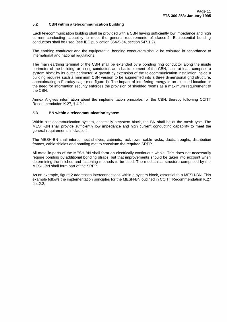
Meshed Bonding Network (MESH-BN), (CCITT Recommendation K.27): A bonding network in whichall associated equipment frames, racks and cabinets and usually the DC power return conductor, arebonded together as well as at multiple points to the CBN. Consequently, the MESH-BN augments theCBN (see figure 1).
Meshed Isolated Bonding Network (MESH-IBN), (CCITT Recommendation K.27): A type of IBN inwhich the components of the IBN (e.g. equipment frames) are interconnected to form a mesh-likestructure. This may, for example, be achieved by multiple interconnections between cabinet rows, or byconnecting all equipment frames to a metallic grid (a "bonding mat") extending beneath the equipment.The bonding mat is, of course, insulated from the adjacent CBN. If necessary the bonding mat couldinclude vertical extensions, resulting in an approximation to a Faraday cage. The spacing of the grid ischosen according to the frequency range of the electromagnetic environment.
system: A regularly interacting or interdependent group of items forming a unified whole.
system block: A functional group of equipment depending in its operation and performance on itsconnection to the same system reference potential plane, inherent to a MESH-BN.
System Reference Potential Plane (SRPP): A conductive solid plane, as an ideal goal in potentialequalising, is approached in practice by horizontal or vertical meshes. The mesh width thereof is adaptedto the frequency range to be considered. Horizontal and vertical meshes may be interconnected to form agrid structure approximating to a Faraday cage.
The SRPP facilitates signalling with reference to a common potential.
Page 10ETS 300 253: January 1995
bonding mat: Essential means to provide a SRPP by a discernible, nearly regular mesh structure. Thebonding mat may be located either below or above a collection of equipment constituting a system block.
power supply:
- primary supply: The public mains or, under emergency conditions, a locally generated AC supply;
- secondary supply: The supply to the telecommunication equipment, racks or system block,derived from the primary supply;
- tertiary supplies: The supplies to the telecommunication equipment, derived from the secondarysupply.
DC return conductor: The (+) conductor of the -48 V or -60 V secondary DC supply.
4 General requirements
4.1 Safety from electrical hazards
To achieve safety it is required to design equipment to the standards EN 60950 [3], EN 41003 [4] andCENELEC HD 384.4.41 [1] and to perform the installation of PEs and equipotential bonding conductors,according to CENELEC HD 384.5.54 [2].
The conductors involved shall provide sufficiently high current conducting capability and low impedanceaccording to the relevant safety standards to avoid electric shock, risk of fire, or damage to the equipmentunder normal or faulty operating conditions within an equipment or the distribution network, or due to theimpact of induced voltage and current, e.g. by lightning.
4.2 Signal reference
Reliable signal reference shall be provided by a SRPP dedicated at least to a functional unit or a systemblock. To avoid undue functional distortion or risk of component failure, the SRPP shall provide sufficientlylow impedance up to the highest frequency to be regarded by using a metal plane or a meshedconfiguration having adequate mesh dimensions, e.g. a bonding mat. The frequency band to be coveredshall include the spectral components of transients caused by switching, short circuits and atmosphericdischarges.
NOTE: Signal reference to the SRPP does not always imply signal return via the SRPP.
4.3 EMC performance
Measures to gain a satisfactory EMC performance shall be assisted by a SRPP. The SRPP shall providesufficiently low impedance for efficient connection of filters, cabinets and cable shields. The requirementto avoid undue emission of, or susceptibility to electromagnetic energy under normal operating conditionsmay govern the properties of the SRPP ahead of what is required in subclause 4.2. The EMCrequirements addressed include the discharge of electrostatic energy.
5 Requirements on bonding networks
5.1 Bonding configurations
Bonding configurations can be addressed at a building level (i.e. CBN), at an installation level (i.e. mergingof CBN and Meshed Bonding Network (MESH-BN)) and at an equipment level (i.e. MESH-BN).
CCITT Recommendation K.27 deals with bonding configurations of telecommunication equipment at abuilding and installation level. Regarding the bonding configuration at an equipment level a MESH-BN isexplicitly distinguished in this ETS.
Page 11ETS 300 253: January 1995
5.2 CBN within a telecommunication building
Each telecommunication building shall be provided with a CBN having sufficiently low impedance and highcurrent conducting capability to meet the general requirements of clause 4. Equipotential bondingconductors shall be used (see IEC publication 364-5-54, section 547.1.2).
The earthing conductor and the equipotential bonding conductors should be coloured in accordance tointernational and national regulations.
The main earthing terminal of the CBN shall be extended by a bonding ring conductor along the insideperimeter of the building, or a ring conductor, as a basic element of the CBN, shall at least comprise asystem block by its outer perimeter. A growth by extension of the telecommunication installation inside abuilding requires such a minimum CBN version to be augmented into a three dimensional grid structure,approximating a Faraday cage (see figure 1). The impact of interfering energy in an exposed location orthe need for information security enforces the provision of shielded rooms as a maximum requirement tothe CBN.
Annex A gives information about the implementation principles for the CBN, thereby following CCITTRecommendation K.27, § 4.2.1.
5.3 BN within a telecommunication system
Within a telecommunication system, especially a system block, the BN shall be of the mesh type. TheMESH-BN shall provide sufficiently low impedance and high current conducting capability to meet thegeneral requirements in clause 4.
The MESH-BN shall interconnect shelves, cabinets, rack rows, cable racks, ducts, troughs, distributionframes, cable shields and bonding mat to constitute the required SRPP.
All metallic parts of the MESH-BN shall form an electrically continuous whole. This does not necessarilyrequire bonding by additional bonding straps, but that improvements should be taken into account whendetermining the finishes and fastening methods to be used. The mechanical structure comprised by theMESH-BN shall form part of the SRPP.
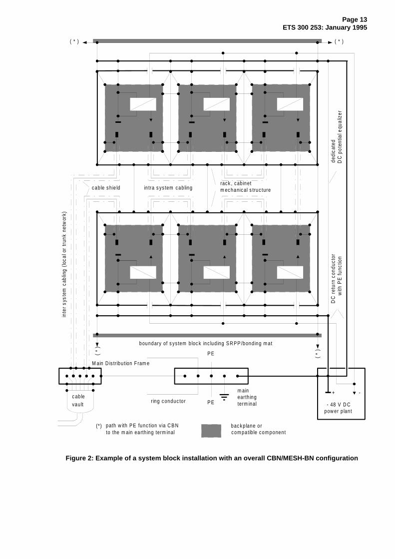
As an example, figure 2 addresses interconnections within a system block, essential to a MESH-BN. Thisexample follows the implementation principles for the MESH-BN outlined in CCITT Recommendation K.27§ 4.2.2.
Page 12ETS 300 253: January 1995
xx x x x x x x x x x x x x x
x x x x x x x x x x x x x x
x x x x x x x x x x x x x x
xx x x x x x
xxx x
xxx
x xxx
xxx
x xxx
xxx
xxx x
x xx
F loo r
In terc onnec tion
B ond ing m at
In terc onnec ted
rein fo rc em ent
F ram e o f DC pow erp lant
T e lec om c ab les x x x x
D C retu rn c onduc tor (+48V )
Inte rc onnec ted re in forc em ent
to the rac k is rec om m ended
M es h-B N equ ipm ent
M es h-B N equ ipm ent
B as em ent
Low er floo r
F loor n
F loor n+1
S ys tem bloc k 1
M es h-B N equ ipm ent
S ys tem b loc k 2
48V DC s erv ic e pane l
B ond ing c onduc tor
B ond ing r ing c onduc to r(reco m m en d ed )
S upport c olum n of the building
R ein forc em entB ond ing ring c onduc tor
T o foundation
xxx
xxx
xxx
xxx
L 1 L 2 L 3 N P E
A C d is tr ibu tion
M ain earth ing term inal
and bu ild ing s teel
PE
A irc o
P E
T o earth elec troderein forc em ent/r ing c onduc tor
S h ielded In ter-s ys tem c ab ling
Intra -s ys tem c ab ling
P lum bing
C onnec tion of c able s h ield
(D C retu rn c onduc tor term inal)
Figure 1: CBN/MESH-BN installation inside a telecommunication building
Page 13ETS 300 253: January 1995
+ -
- 48 V D Cpow er p lan t
P E
P E
ring c onduc to r
in tra s ys tem c ab ling
inte
r sy
stem
cab
ling
(loca
l or
trun
k ne
twor
k)
M ain D is tr ibu tion F ram e
( * ) ( * )
( *
)
( *
)
m ainearth ingterm inal
bac k p lane o rc om patib le c om ponent
dedi
cate
dD
C p
oten
tial e
qual
izer
( * ) path w ith P E func tion v ia C B Nto the m ain earth ing term inal
boundary of s ys tem b loc k inc lud ing S R P P /bond ing m at
DC
ret
urn
cond
ucto
rw
ith P
E fu
nctio
n
c ab le s h ie ldrac k , c ab inetm ec hanic al s truc ture
c ab levau lt
Figure 2: Example of a system block installation with an overall CBN/MESH-BN configuration
Page 14ETS 300 253: January 1995
5.4 Merging of CBN and MESH-BNs
All BNs of telecommunication systems and their associated DC return conductors shall be connected tothe CBN.
The MESH-BN shall augment the CBN including the main earthing terminal by multiple interconnections tothe CBN (see figures 1 and 2).
5.5 Cabling within and between BNs
Power distribution cables and signal cables within and between MESH-BNs shall be run tightly along themembers of the augmented CBN.
There shall be a separation distance of at least 100 mm between cable tracks of AC mains cables andsignal cables, unless adequate shielding is provided.
Cable shields shall be bonded directly to racks, cabinets or to the dedicated SRPP at least at each end.Circumferential connections are most effective and therefore are recommended.
NOTE: It is recognized that where a new system has to be cabled to existing equipment, it haspreviously been considered feasible to avoid the connection of cable shields at theexisting equipment end. However, the consequent solution of this ETS is to provide alower impedance path via improved bonding between the equipment locations, therebyenabling connection of cable shields at least at each end.
6 Requirements for power distribution
6.1 DC power distribution of secondary supply
The DC power distribution shall use (+) and (-) conductors routed close together. Each DC returnconductor serving a telecommunication system shall be bonded to the CBN at least at the main earthingterminal, at the service panel of the DC power plant and to the MESH-BN to at least one point of theSRPP.
The maximum DC voltage drop along each dedicated DC power return conductor shall be designed to beless than 1 V. The calculation shall take into account the maximum load current on the associated supplyconductor at maximum or minimum source voltage respectively under normal operating conditions.
NOTE: One concern of this requirement is to avoid electrochemical corrosion by straycurrents.
The DC return path in its entire length shall be capable of carrying over-currents in the case of a faultbetween a negative power conductor of the secondary supply and the MESH-BN.
The DC return terminal of a power plant powering the telecommunication system(s) shall be earthed at itsDC service panel by a solid connection to the main earthing terminal.
Annex B gives information about necessary agreements if, under exceptional conditions, DC returnconductors of a single equipment group cannot be integrated into the merged CBN/MESH-BN.
6.2 DC power distribution of tertiary supplies
The reference potential terminal of tertiary power supplies shall be connected to the MESH-BN.
Page 15ETS 300 253: January 1995
6.3 AC mains distribution and bonding of the protective conductor
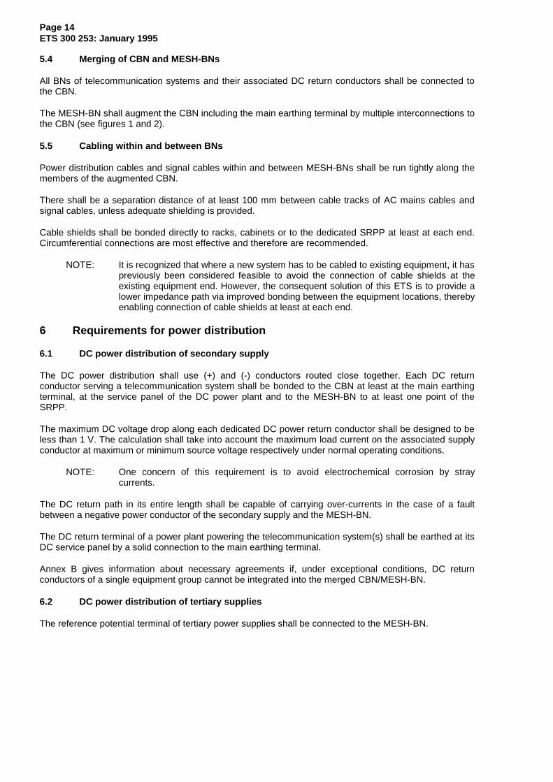
The definitions used in this subclause are based on IEC 364-3.
The AC power distribution inside a telecommunication building shall conform to the requirements of theTN-S system. This requires that there shall be no PEN conductor within the building, i.e. the option inIEC 364, section 546.2.1, shall not be used. This is a pre-condition to the requirements in clause 5 of thisETS.
Depending on the outdoor mains distribution network serving a telecommunication building, one of thefollowing requirements shall apply:
a) service by a TN-S section of the outdoor distribution network:
solely the protective conductor (PE) shall be connected to the main earthing terminal (see figure 3,structure 1 and figure 4, mode 1);
b) service by a TN-C section of the outdoor distribution network:
1) the PEN conductor shall be connected to the main earthing terminal only;
2) from the main earthing terminal to and within the consumer locations inside the building theNeutral conductor (N) shall be treated as a live conductor;
3) a dedicated PE shall be provided (see figure 3, structure 2 and figure 4, mode 2).
c) service by a TT section of the outdoor distribution network:
1) the PE shall be derived via the main earthing terminal from the earthing network (seefigure 3, structure 3 and figure 4, mode 3);
2) the dimensioning of the PE shall follow the rules of the TN-S system.
d) service by an IT section of the outdoor distribution network:
indoor installation related to earthing and bonding shall follow the instructions set up for the serviceby a TT section of the outdoor distribution network.
NOTE: Public service by an IT section of the outdoor distribution network is known as aspecial national condition. As the IT system is liable to deteriorate into a TT system,reference is given in this ETS to that related section. For information regardingunacceptable interference by an IT system, see annex A.
6.4 AC power distribution from tertiary power supply
The neutral point of a tertiary AC power supply shall be derived by bonding the terminal of the star point,or of an outer conductor respectively, to the MESH-BN at the source only. The distribution to the assignedloads shall follow the rules of the TN-S system.
If different configurations resembling an IT system have to be used (e.g. to provide remote feeding or theuninterruptible power supply of a subarrangement), the appropriate safety precautions shall beimplemented without degrading the effectiveness of the general requirements in clause 4.
Page 16ETS 300 253: January 1995
Exp osed conductive parts
L1
L2
L3
N
P E
D is trib ution (TN -S) Indoor Ins ta lla t ion (TN -S)
P E
- origin of PE at the main earthing terminal of the power source;- PE is intentionally earthed intermediately in the distribution and at each main earthing terminal;- N and PE are separated throughout the distribution, the indoor installation and within each
equipment.
E xposed co nduc tive pa rt s
L1
L2
L3
N
P EP EN
D istributio n (T N-C) Indo or Insta lla tio n (T N-S)
- origin of PEN at the main earthing terminal of the power source;- PEN is intentionally earthed intermediately in the distribution and at each main earthing terminal;- origin of N and PE at the main earthing terminal of the indoor installation;- N and PE are separated throughout the indoor installation and within each equipment.
E xposed co nduc tive pa rt s
L1
L2
L3
N
P E
N
D istrib ution (TT) Indoo r Insta lla tion (TT)
- origin of PE at the local main earthing terminal of the indoor installation;- N and PE are separated throughout the indoor installation and within each equipment.
Figure 3: Conventional mains supply systems (based on IEC Publication 364, section 312.2)

Page 17ETS 300 253: January 1995
Mode 1: TN-S/TN-S
N
N
P E
P E
M ain ea rth ing te rm in a l
ring c on d u c to rP E
P E
D C -re tu rn
E arth in g n e tw o rk
O u tp u t to in d o o rm a ins in sta lla tio n
In p u t fro m o u td o o rm a in s d is trib u tio n
Out
door
mai
ns d
istr
ibut
ion
NOTE: Mode 1 is obligatory if a separation transformer is dedicated to the building and theTN-S System consequently originates at the transformer load side.
Mode 2: TN-C/TN-S
Out
door
mai
ns d
istr
ibut
ion
NP E
P E NM ain ea rth ing te rm in a l
r in g c o n du c to rP E
P E
D C -re tu rn
E arth in g n e tw o rk
O u tp u t to in d o o rm a ins in sta lla tio n
In p u t fro m o u td o o rm a in s d is trib u tio n
Mode 3: TT/TT
N
N
P E
M ain ea rth ing te rm in a l
r in g c o n d u c to rP E
P E
D C -re tu rn
E arth in g n e tw o rk
O u tp u t to in d o o rm a ins in sta lla tio n
In p u t fro m o u td o o rm a in s d is trib u tio n
Out
door
mai
ns d
istr
ibut
ion
Figure 4: Arrangements for the transition from the outdoor mains distribution network to theindoor mains installation

Page 18ETS 300 253: January 1995
Annex A (normative): Rationale about CBN co-ordination
In the case of a telecommunication centre there are two main subjects needing co-ordination with respectto EMC:
- the building and its related ordinary installations;
- the telecommunication equipment and its interconnection.
New buildings shall provide adequate preconditions constituting a CBN by:
- a reliable foundation earth electrode system, i.e. a ring conductor immediately beneath the firstconcrete bed (see references [A.1] and [A.2]);
NOTE: This electrode system qualifies prior to a ring conductor along the outer perimeter of abuilding.
- welded joints of building steel or concrete reinforcement rods (see DIN 4099 [A.3] andIEC 1024-1 [A.4]) and a sufficient number of access terminals to these highly conductive elements;
- an enhanced outdoor Lightning Protection System (LPS) co-ordinated with the building structure(see IEC 1024-1 [A.4]);
- service pipes and air-conditioning ducts interconnected according to the CBN strategy, includingpotential equalization in excess of safety regulations;
- mains power supply installation as required for the TN-S principle, i.e. without any PEN sectiondownstream from the main earthing terminal and regardless of the principle applied to the mainsdistribution section upstream. The option in IEC 364 section 546.2.1 permitting for a PEN conductorwith a minimum cross sectional area shall not be used.
Telecommunication equipment which is designed to this ETS can be installed and interconnected to theCBN outlined above. The resulting MESH-BN (e.g. see figure 1) should easily conform to EMCrequirements.
Some existing buildings of telecommunication centres do not provide a CBN sufficient to meet theoperational requirements. When a decision is made to extend or replace existing telecommunicationinstallations in such buildings, the objective should be to move towards a CBN by enhancements.
Besides the fact that such enhancements require consultation on the spot, two subjects can be addressedin general:
- outdoor lightning protection may be installed at first according to IEC 1024 [A.4] including a ringconductor as an essential member of the earthing network. The LPS may be improved withconductive roof layers, closely spaced down conductors or application of metallic facades;
- unacceptable interference from the outdoor power distribution section can be mitigated by aseparation transformer dedicated to the building or by an equivalent measure. An indoor installationaccording to the rules of the IT system or TT system can be upgraded by additional PE conductorsand dedicated equipotential bonding conductors, thereby reducing the mesh width. A residualcurrent protection may also be adapted if necessary.
An existing CBN can be augmented by the telecommunication installation regarding dedicated ringconductors per room and floor, cable ducts/troughs/racks and any other supporting metal work. In contrastto the traditional practice to indulge into a restricted number of conductors with enlarged cross sectionalarea, it is recommended to aim at a large conductive surface, e.g. by providing bonding at both side bars,at joints within the run of a ladder type cable rack.
As outlined above, co-ordination resulting in an overall CBN/MESH-BN is recommended even in existingtelecommunication centres. Installation of new equipment with deviation into the Meshed Isolated BondingNetwork (MESH-IBN), as defined in CCITT Recommendation K.27 and depicted in figure B-2 of CCITTRecommendation K.27, is considered appropriate in exceptional situations only, such as a deficiency of an
Page 19ETS 300 253: January 1995
adequate lightning protection of the building, or a CBN with an interfering PEN section, or incompatibilitywith already installed telecommunication equipment.
Nevertheless, a MESH-IBN type installation according to CCITT Recommendation K.27 needsco-ordination concerning the routeing of cables and the bonding of their shields. In addition, maintenanceprocedures have to be extended to isolation inspection or monitoring.
References:
[A.1] Vereinigung Deutscher Elektrizitätswerke - VDEW - e.V. Richtlinien für dasEinbetten von Fundamenterdern in Gebäudefundamenten. Ausgabe1987 Verlags und Wirtschaftsgesellschaft der Elektrizitätswerke m.b.H - VDEWStresemannallee 23, D6000 Frankfurt/Main 70 ISBN 3-8022-0076-4.
[A.2] F. Wyss: Fundamenterder und Armierungen als Erder (SEV 3569-1,SEV 3569-2, SEV 3569-3) Referat 4 der ETG - Informationstagungen Erdungen,Januar 1987 in der Reihe ETG: Band 1d Schweizerischer ElektrotechnischerVerein, Vereinsverwaltung Postfach, CH 8034 Zürich.
[A.3] DIN 4099, November 1985 Schweißen von Betonstahl, Ausführung undPrüfung. Welding of reinforcing steel, procedure and test. Beuth Verlag GmbH,Burggrafenstraße 4-10, D1000 Berlin 30.
[A.4] IEC 1024-1, March 1990 Protection of structures against lightning. Part1: General principles.

Page 20ETS 300 253: January 1995
Annex B (informative): Rationale about the integration of the DC returnconductor into the merged CBN/MESH-BN
The integration of the DC return conductor is addressed in subclauses 5.4 and 6.1. When existingequipment requires replacement, it is essential that equipment design and installation conforms to a singlestandard without ambiguity. Agreement to this aim is stated in the Foreword of this ETS.
It is recognized that in existing installations groups of equipment may be operated with "isolated" DCreturn conductors, whereby "isolated" denotes the application of the DC-I version addressed in CCITTRecommendation K.27.
If the design of such equipment allows for operation with integrated DC return conductors, the existinginstallation should be adapted to this ETS.
If the operation of such equipment requires the existing installation to be unchanged, precautions have tobe taken to facilitate appropriate inter system signal exchange and compliance to other EMCrequirements.
Selection of such precautions shall take into account:
- inter system signal exchange by isolated and symmetrically operated circuitry;
- routeing of cables with shields via a common bonding point, located as near as possible to the mainearthing terminal, e.g. the main distribution frame, if transmission parameters allow for an additionallength of the transmission path;
- appropriate conductor arrangements in parallel to the inter system cabling route with minimizedlength dictated by transmission requirements, i.e. provision of shielding and potential equalizationsimultaneously;
- upgrading of the current conducting capability of the drain path for short circuit currents, i.e.provision of dedicated conductors without the steady state DC return function.
If the outlined adaptation of the existing installation is impossible due to an additional insufficiency of theCBN, installation of a new system block may follow the rules of the MESH-IBN (see annex A).
Page 21ETS 300 253: January 1995
Annex C (informative): Bibliography
The following references are used for information purposes within this ETS.
1) CCITT handbook: "Earthing of telecommunication installations" (Geneva 1976).
2) CCITT Recommendation K.27 (1991): "Bonding Configurations and Earthinginside a Telecommunication Building".
3) ETS 300 132-1: "Equipment Engineering (EE); Power supply interface at theinput to telecommunications equipment interface; Part 1: Interface operated byAlternating Current (AC)".
4) ETS 300 132-2: "Equipment Engineering (EE); Power supply interface at theinput to telecommunications equipment interface; Part 2: Interface operated byDirect Current (DC)".
5) IEC Standard 364: "Electrical installation of buildings".
6) IEC Standard 364-1 (1972): "Electrical installation of buildings; Part 1: Scope,object and definitions".
7) IEC Standard 364-3: "Electrical installation of buildings; Part 3: Assessment ofgeneral characteristics".
8) IEC Standard 364-4-41 (1982): "Electrical installation of buildings; Part4: Protection and safety. Chapter 41: Protection against electric shock".
9) IEC Standard 364-5-54 (1980): "Electrical installation of buildings; (Amendmentof 1982) Part 5: Selection and erection of electrical equipment. Chapter54: Earthing arrangements and protective conductors".
10) IEC Standard 950 (1986): "Safety of information technology equipment,(Amendment of 1988) including Electrical business equipment".

Page 22ETS 300 253: January 1995
History
Document history
January 1995 First Edition
January 1996 Converted into Adobe Acrobat Portable Document Format (PDF)


![EUROPEAN ETS 300 799 TELECOMMUNICATION STANDARD€¦ · ETS 300 799: September 1997 Introduction This ETS is one of a set associated with ETS 300 401 [1] describes the transmitted](https://static.fdocuments.net/doc/165x107/602b481e7085d253135ff9e5/european-ets-300-799-telecommunication-standard-ets-300-799-september-1997-introduction.jpg)