Eurofox Flight Manual - Northumbria Gliding
68
AEROPRO , Production of UL Planes Dlha 126, 949 07 NITRA Slovakia www.aeropro.sk Pilot Operating handbook And Flight training supplement AEROPRO + EuroFOX Aviation EuroFOX
Transcript of Eurofox Flight Manual - Northumbria Gliding
AEROPRO , Production of UL Planes
Dlha 126, 949 07 NITRA Slovakia www.aeropro.sk
Pilot Operating handbook
And
Flight training supplement
AEROPRO + EuroFOX Aviation
EuroFOX

EuroFOX LAA 560kg tail wheel- Pilot Operating Handbook + Flight Training
Supplement
Data www.aeropro.sk and www.eurofoxuk.co.uk 1-2
Aircraft Type:
EuroFOX Tail wheel Version
Serial Number:
Registration:
Date of Issue: October 14
Stamp, Signature
This aircraft kit was manufactured in accordance with CS VLA
airworthiness standards and approved by the UK LAA. It does not
conform to standard category airworthiness requirements.

EuroFOX LAA 560kg tail wheel- Pilot Operating Handbook + Flight Training
Supplement
Data www.aeropro.sk and www.eurofoxuk.co.uk 1-3
AIRCRAFT DATA
Type
Production
Serial
Number:
Year of production
Fuselage
EUROFOX Tail Wheel
AEROPRO
Engine
ROTAX 912 ULS
912iS
BOMBARDIER-ROTAX
GMBH
AUSTRIA
Propeller
SR200
DUC Swirl and
Windspoon
Woodcomp Czech Rep
France
…………………………… ……………………………… Signature Stamp

EuroFOX LAA 560kg tail wheel- Pilot Operating Handbook + Flight Training
Supplement
Data www.aeropro.sk and www.eurofoxuk.co.uk 1-4
0.1 RECORD OF REVISIONS
Any revisions or amendments to the present manual shall be issued in the form of bulletins with attached new pages. It is in the interests of every user to enter such revision into the table of revisions and to replace the existing page by the new one. The revised or corrected text shall be indicated by a vertical line on left page margin and the page shall bear revision number and date of its issue.
Rev.
No.
Pages Affected Date of Issue Bulletin
Number
New Page
Inserted
Signature
1 Initial issue Nov 11
2 Parachute added
Mar 13
3 912iS added April 14
4 Operating limits clarified.
Chap 3.5
October 14

EuroFOX LAA 560kg tail wheel- Pilot Operating Handbook + Flight Training
Supplement
Data www.aeropro.sk and www.eurofoxuk.co.uk 1-5
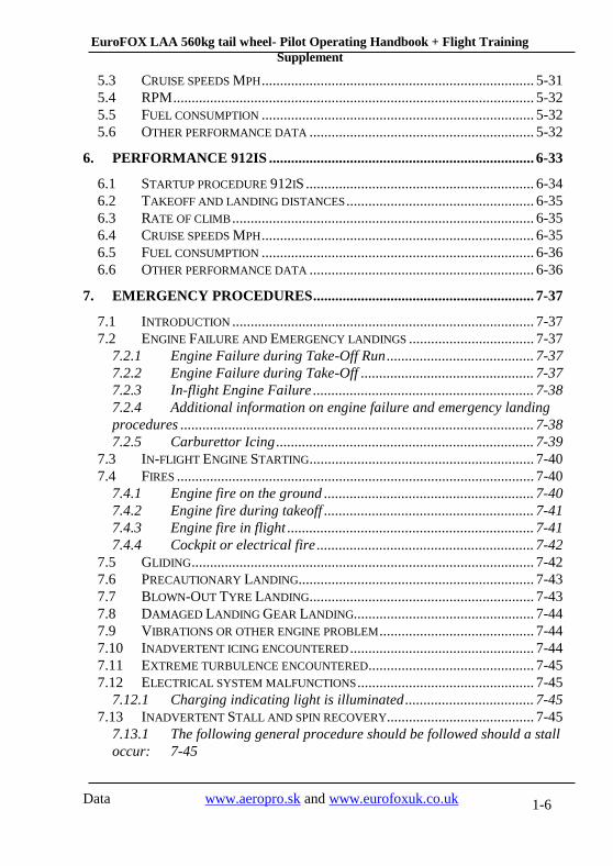
TABLE OF CONTENTS:
0.1 RECORD OF REVISIONS ................................................................. 1-4
1. GENERAL INFORMATION .................................................................. 1-9
1.1 INTRODUCTION .................................................................................... 1-9 1.2 CERTIFICATION BASIS .......................................................................... 1-9 1.3 MANUFACTURER ................................................................................. 1-9 1.4 WARNING, CAUTION AND NOTE .......................................................... 1-9
2. AIRCRAFT AND SYSTEMS DESCRIPTION .................................... 2-10
2.1 ENGINE .............................................................................................. 2-11 2.2 PROPELLER ........................................................................................ 2-12 2.3 FUEL AND FUEL CAPACITY ................................................................. 2-12 2.4 OIL .................................................................................................... 2-13 2.5 OPERATING WEIGHTS AND LOADING (OCCUPANTS, BAGGAGE, FUEL,
BALLAST) ....................................................................................................... 2-14 2.6 CABIN OVERVIEW (GUIDE ONLY) ........................................................ 2-14
3. OPERATING LIMITATIONS .............................................................. 3-21
3.1 STALL SPEED AT MAXIMUM TAKEOFF WEIGHT (VS AND VSO) ............. 3-21 3.2 FLAPS EXTENDED SPEED RANGE (VSO TO VFE) MPH ........................... 3-22 3.3 MAXIMUM MANEUVERING SPEED (VA) MPH ...................................... 3-22 3.4 NEVER EXCEED SPEED (VNE) MPH ..................................................... 3-22 3.5 CROSSWIND LIMITATION .................................................................... 3-22 3.6 SERVICE CEILING ............................................................................... 3-23 3.7 LOAD FACTORS .................................................................................. 3-23 3.8 PROHIBITED MANOEUVERS ................................................................ 3-23 3.9 OTHER LIMITATIONS .......................................................................... 3-23
4. WEIGHT AND BALANCE INFORMATION ..................................... 4-25
4.1 EQUIPMENT LIST POSSIBLE ................................................................. 4-25 4.2 CENTER OF GRAVITY (CG) RANGE AND DETERMINATION ................... 4-25
4.2.1 Aircraft weight and balance statement ..................................... 4-26 4.2.2 Weight and balance determination for flight ............................ 4-27 4.2.3 Detailed calculation of CG position ........................................ 4-28
5. PERFORMANCE ................................................................................... 5-30
5.1 TAKEOFF AND LANDING DISTANCES ................................................... 5-31 5.2 RATE OF CLIMB .................................................................................. 5-31
EuroFOX LAA 560kg tail wheel- Pilot Operating Handbook + Flight Training
Supplement
Data www.aeropro.sk and www.eurofoxuk.co.uk 1-6
5.3 CRUISE SPEEDS MPH .......................................................................... 5-31 5.4 RPM .................................................................................................. 5-32 5.5 FUEL CONSUMPTION .......................................................................... 5-32 5.6 OTHER PERFORMANCE DATA ............................................................. 5-32
6. PERFORMANCE 912IS ........................................................................ 6-33
6.1 STARTUP PROCEDURE 912IS .............................................................. 6-34 6.2 TAKEOFF AND LANDING DISTANCES ................................................... 6-35 6.3 RATE OF CLIMB .................................................................................. 6-35 6.4 CRUISE SPEEDS MPH .......................................................................... 6-35 6.5 FUEL CONSUMPTION .......................................................................... 6-36 6.6 OTHER PERFORMANCE DATA ............................................................. 6-36
7. EMERGENCY PROCEDURES ............................................................ 7-37
7.1 INTRODUCTION .................................................................................. 7-37 7.2 ENGINE FAILURE AND EMERGENCY LANDINGS .................................. 7-37
7.2.1 Engine Failure during Take-Off Run ........................................ 7-37 7.2.2 Engine Failure during Take-Off ............................................... 7-37 7.2.3 In-flight Engine Failure ............................................................ 7-38 7.2.4 Additional information on engine failure and emergency landing
procedures ................................................................................................ 7-38 7.2.5 Carburettor Icing ...................................................................... 7-39
7.3 IN-FLIGHT ENGINE STARTING ............................................................. 7-40 7.4 FIRES ................................................................................................. 7-40
7.4.1 Engine fire on the ground ......................................................... 7-40 7.4.2 Engine fire during takeoff ......................................................... 7-41 7.4.3 Engine fire in flight ................................................................... 7-41 7.4.4 Cockpit or electrical fire ........................................................... 7-42
7.5 GLIDING ............................................................................................. 7-42 7.6 PRECAUTIONARY LANDING ................................................................ 7-43 7.7 BLOWN-OUT TYRE LANDING ............................................................. 7-43 7.8 DAMAGED LANDING GEAR LANDING................................................. 7-44 7.9 VIBRATIONS OR OTHER ENGINE PROBLEM .......................................... 7-44 7.10 INADVERTENT ICING ENCOUNTERED .................................................. 7-44 7.11 EXTREME TURBULENCE ENCOUNTERED ............................................. 7-45 7.12 ELECTRICAL SYSTEM MALFUNCTIONS ................................................ 7-45
7.12.1 Charging indicating light is illuminated ................................... 7-45 7.13 INADVERTENT STALL AND SPIN RECOVERY........................................ 7-45
7.13.1 The following general procedure should be followed should a stall
occur: 7-45

EuroFOX LAA 560kg tail wheel- Pilot Operating Handbook + Flight Training
Supplement
Data www.aeropro.sk and www.eurofoxuk.co.uk 1-7
7.13.2 The following general procedure should be followed should a spin
occurs: 7-45
8. NORMAL PROCEDURES .................................................................... 8-46
8.1 PRE-FLIGHT INSPECTION .................................................................... 8-46 8.1.1 Daily Preparation ..................................................................... 8-47 8.1.2 Engine Warm-Up, Power Check ............................................... 8-49 8.1.3 Pre-Flight Inspection ................................................................ 8-50
8.2 ENGINE STARTING .............................................................................. 8-51 8.2.1 Use of External Power Supply .................................................. 8-51 8.2.2 Engine Starting ......................................................................... 8-51
8.3 TAXIING ............................................................................................. 8-52 8.3.1 Prior to Taxiing ........................................................................ 8-52 8.3.2 Taxiing ...................................................................................... 8-52
8.4 NORMAL TAKEOFF ............................................................................. 8-53 8.4.1 Prior to Take-Off ...................................................................... 8-53 8.4.2 Take-Off .................................................................................... 8-53
8.5 BEST ANGLE OF CLIMB SPEED (VX) .................................................... 8-54 8.5.1 Climbing ................................................................................... 8-54
8.6 BEST RATE OF CLIMB SPEED (VY) ....................................................... 8-55 8.6.1 Climbing ................................................................................... 8-55
8.7 CRUISE .............................................................................................. 8-55 8.7.1 Cruise Flight ............................................................................. 8-55
8.8 APPROACH ......................................................................................... 8-56 8.8.1 Descent ..................................................................................... 8-56 8.8.2 Downwind ................................................................................. 8-56
8.9 NORMAL LANDING ............................................................................. 8-57 8.9.1 On Base Leg .............................................................................. 8-57 8.9.2 On Final .................................................................................... 8-57 8.9.3 Landing ..................................................................................... 8-57 8.9.4 After landing ............................................................................. 8-58 8.9.5 Engine Stopping ........................................................................ 8-58 8.9.6 Post-Flight Check ..................................................................... 8-58
8.10 SHORT FIELD TAKE OFF AND LANDING PROCEDURES .......................... 8-59 8.11 BALKED LANDING PROCEDURES ........................................................ 8-59 8.12 INFORMATION ON STALLS, SPINS AND ANY OTHER USEFUL PILOT
INFORMATION ................................................................................................ 8-60 8.12.1 Rain ........................................................................................... 8-60
9. AIRCRAFT GROUND HANDLING AND SERVICING ................... 9-61

EuroFOX LAA 560kg tail wheel- Pilot Operating Handbook + Flight Training
Supplement
Data www.aeropro.sk and www.eurofoxuk.co.uk 1-8
9.1 SERVICING FUEL, OIL, COOLANT ......................................................... 9-61 9.1.1 Servicing fuel ............................................................................ 9-61 9.1.2 Servicing oil .............................................................................. 9-61 9.1.3 Servicing coolant ...................................................................... 9-62
9.2 LANDING GEAR TYRE DIMENSION AND PRESSURE .............................. 9-62 9.3 GROUND HANDLING AND TIE-DOWN INSTRUCTIONS ........................... 9-62
9.3.1 Aircraft moving instruction ....................................................... 9-62 9.3.2 Aircraft tie-down instruction ..................................................... 9-63
10. REQUIRED PLACARDS AND MARKINGS................................ 10-64
10.1 AIRSPEED INDICATOR RANGE MARKINGS AND OVERVIEW OF SPEED
LIMITS: 10-64 10.2 OPERATING LIMITATION PLACARD ON INSTRUMENT PANEL .............. 10-65 10.3 IF PARACHUTE FITTED ...................................................................... 10-65 10.4 PASSENGER WARNING ...................................................................... 10-65 10.5 “NO INTENTIONAL SPINS” ................................................................ 10-66 10.6 MISCELLANEOUS PLACARDS AND MARKINGS ................................... 10-66
11. SUPPLEMENTARY INFORMATION .......................................... 11-67
11.1 FAMILIARISATION FLIGHT PROCEDURES ........................................... 11-67 11.2 PILOT OPERATING ADVISORIES ......................................................... 11-67 11.3 FURTHER INFORMATION .................................................................. 11-67 11.4 STARTING AND PRE-FLIGHT CHECKS ................................................ 11-67

EuroFOX LAA 560kg tail wheel- Pilot Operating Handbook + Flight Training
Supplement
Data www.aeropro.sk and www.eurofoxuk.co.uk 1-9
1. General information
1.1 Introduction
This handbook is provided with your aircraft to allow you to attain as much knowledge about the aircraft and its operation as possible. Read this manual thoroughly before your first flight and make sure you understand all the information contained here. This aircraft is equipped with a non-certified engine. When flying the aircraft always ensure that a safe landing would be possible in the event of loss of engine power. Pay attention to the fact that you as the pilot are fully responsible for safety of your passengers and persons or property on the ground.
1.2 Certification Basis
This aircraft kit was manufactured in accordance with CS-VLA airworthiness standards approved by the UK LAA
1.3 Manufacturer
AEROPRO s.r.o
Dlhá 126
949 07 Nitra
Slovak Republic
www.aeropro.sk
UK and Ireland Distributor www.eurofoxuk.co.uk
1.4 Warning, Caution and Note
In this handbook the following is used to highlight especially important information:
WARNING Information which could prevent personnel injury or loss of
life
CAUTION Information which could prevent damage to equipment
NOTE Information of special importance to pilots

EuroFOX LAA 560kg tail wheel- Pilot Operating Handbook + Flight Training
Supplement
Data www.aeropro.sk and www.eurofoxuk.co.uk 2-10
2. Aircraft and Systems Description
The EuroFOX is designed as a high-wing monoplane. A two-spar wing is equipped with flaperons. The fuselage is an open truss structure welded with steel tubes. The tail unit is formed from a lattice-work tube frame. The Aircraft is equipped with tricycle landing gear and incorporates a steerable nose wheel.
Wing span .............................................................................. 9,125 m
Length ................................................................................... 5,605 m
Height ...................................................................................... 2,25 m
Wing area with flap ................................................................. 11,4 m2
Chord length without flap ........................................................ 1,12 m with flap ........................................................ 1,3 m
Wing loading ........................................................................ 39,47 kgm-2
Aspect-ratio ............................................................................... 7,3
Propeller clearance in flight condition (Woodcomp SR200) ........ 0,220 m

EuroFOX LAA 560kg tail wheel- Pilot Operating Handbook + Flight Training
Supplement
Data www.aeropro.sk and www.eurofoxuk.co.uk 2-11
2.1 Engine
The EuroFOX is powered by ROTAX 912 UL or 912ULS engine. It is a four-cylinder, four-stroke, horizontally opposed-cylinder, centre-camshaft engine with over-head valves. Engine cooling is of a combined type, cylinder heads are water-cooled, while cylinders are air-cooled. The engine has dry sump lubrication. The ignition system is of a dual, distributor less and capacitor flywheel magneto type. The engine is equipped with an electric starter, AC generator and a mechanical fuel delivery pump, with optional additional electric pump. The propeller is powered from an integrated reduction gear with mechanical damping.
Engine manufacturer .......... ROTAX GmbH., Austria
Engine model ........................ROTAX 912 ULS 100hp
Max. power - take-off ............................... 73.5 kW / 100 HP
- continuous ........................... 69.0 kW / 94 HP
Max. engine speed (MSL) - take-off ................... 5800 r.p.m. (max. 5 min)
- continuous ............................ 5500 r.p.m.
Max. cylinder head temperature ............................................ 150 C
Max. cooling liquid temperature ............................................. 110 C
Max. oil temperature .............................................................. 140 C
Oil pressure - minimum ............................................... 150 kPa
- maximum .............................................. 500 kPa
Oil consumption ............................................................... max. 0.1 l/h
Fuel pressure - minimum ..................................................... .0.15 bar
- maximum .................................................. 0.4 bar
Consumption at starting ........................................................... 16.2 l/h
Consumption at 75% of power rating ....................................... 12.1 l/h
Specific consumption ............................................................. 285 g/kWh
Fuel pressure - minimum ................................................... 0.15 bar
- maximum .................................................. 0.40 bar
Propeller gearbox reduction ration ............................................. 2.43 : 1
For more details see Operator’s Manual for all versions of Rotax 912 supplied with the engine.

EuroFOX LAA 560kg tail wheel- Pilot Operating Handbook + Flight Training
Supplement
Data www.aeropro.sk and www.eurofoxuk.co.uk 2-12
WARNING This aircraft is equipped with non-certified engine.
When flying the aircraft always ensure that a safe landing
would be possible in the event of loss of engine power. The
pilot is fully responsible for consequences of such failure.
2.2 Propeller
The Woodcomp SR200 propeller is a three-bladed, ground adjustable, clockwise rotation, tractor, made of wood/composite. Propeller diameter – 1680 mm. Cruise setting pitch is 24° at 100mm from each blade tip. This will give 4900-5000 rpm statically.
For additional propeller information see Operators Manual and Technical
description supplied with the propeller.
2.3 Fuel and fuel capacity
Fuel tank capacity - wing tanks .................................................. .2x 40 litres
- central connecting tank........................................................... .6 litres
Max. fuel quantity…. .................................................................... .86 litres
Usable fuel quantity ..................................................................... .85 litres
Unusable fuel quantity ................................................................. .1 litre
Fuel specification EN228 min RON 90 unleaded Mogas fuel (Standard Spec. for Automotive Spark-Ignition Engine) or AVGAS 100 LL.
Due to the higher lead content in AVGAS, the deposits in the combustion chamber and lead sediments in the lubrication system will cause an increase in the wear of the valve seats. Therefore, use AVGAS only if you encounter problems with vapour lock or if other fuel types are not available.
For additional information concerning fuel specification consult
Operator’s Manual for all versions of Rotax912 supplied with the engine and the most recent updates as issued by Rotax.
The fuel system includes two wing tanks of 40 litres each, a central tank of 6 litres, Fuel drain valve, fuel valves, a fuel filter, an engine fuel pump and connecting lines. Fuel tanks and fuel lines are suitable for fuel containing ethanol.
The fuel is gravity-fed from the right-hand or left-hand wing tank into the 6L central tank depending on which wing tank fuel valve is open. The fuel is then further directed from the central tank via the main fuel valve and fuel

EuroFOX LAA 560kg tail wheel- Pilot Operating Handbook + Flight Training
Supplement
Data www.aeropro.sk and www.eurofoxuk.co.uk 2-13
filter into the mechanical fuel pump on the engine which delivers the fuel to the carburettors. (additional electric fuel pump optional)
The amount of fuel in each tank is indicated by a wing root visual fuel gauge which is a part of each tank. Minimum fuel quantity in the central feeder tank is indicated by a warning light on the instrument panel. When remaining fuel is 4,1 litres, the light will illuminate and this means enough fuel for approximately 10 minutes of flight. The warning light condition can be verified at any time by pushing the control button. No red light indication when the control button is pushed and held means the bulb is blown out and the minimum fuel quantity is not indicated:- In this case, make a more conservative estimate for fuel on board, check fuel quantity in wing tanks and land as soon as you are not confident of the fuel quantity inside the wing tanks.
Do not forget to properly open and manage the main fuel tank valves to ensure continuous flow of fuel to the engine.
The fuel drain valve outlet is behind the left seat on the outside bottom side of the fuselage; to drain off water and dirt, the drain pipe is to be pressed into the fuselage and subsequently a fuel sample is to be taken.
For refuelling information see section 9.1
2.4 Oil
Oil tank capacity ........................................................................ 3.2 litres
Maximum oil quantity ................................................................. 2.6 litres
Minimum oil quantity .................................................................. 2.1 litres
Oil specification:
When selecting the most suitable lubricants refer to the latest recommendations issued by Rotax (UK distributor - Skydrive).
— Use only oil as recommended by Rotax (Skydrive)
— Oils primarily for Diesel engines are insufficient due to
high temperature properties and additives which favor
clutch slipping, are generally therefore are unsuitable.
CAUTION: If the engine is mainly run on AVGAS more frequent oil changes will be required. See the latest Rotax Service Information.
For additional information concerning oil system consult Operator’s
Manual for all versions of Rotax 912 supplied with the engine, with supplements as issued periodically by Rotax.

EuroFOX LAA 560kg tail wheel- Pilot Operating Handbook + Flight Training
Supplement
Data www.aeropro.sk and www.eurofoxuk.co.uk 2-14
The maximum and minimum oil level is indicated by two marks on the dip stick in the oil tank.
2.5 Operating weights and loading (occupants, baggage, fuel,
ballast)
Typical empty weight (standard version) ............................... 289 kg
Max. take-off weight .............................................................. 560 kg
Max. landing weight ............................................................... 560 kg
Max. fuel weight ....................................................................... 61 kg
Max. baggage weight in baggage compartment ...................... 20 kg
Maximum number of persons on board………………………. …2
Minimum crew weight .............................................................. 55 kg
Maximum loading per seat ..................................................... 120 kg
WARNING Make sure that above mentioned weight limits are strictly
followed.
Structural failures which result from overloading of the
aircraft may be dramatic and catastrophic.
The additional stress placed on the structural parts by overloading can accelerate the occurrence of metal fatigue failures. Also flight characteristics might change significantly when the aircraft is overloaded. Takeoff and landing distance are significantly longer for overloaded aircraft. Overloading and out of balance loading of the aircraft is one of the most common causes of accidents.
2.6 Cabin overview (guide only)

EuroFOX LAA 560kg tail wheel- Pilot Operating Handbook + Flight Training
Supplement
Data www.aeropro.sk and www.eurofoxuk.co.uk 2-15
Figure 1 - Airspeed Indicator marking
EuroFOX LAA 560kg tail wheel- Pilot Operating Handbook + Flight Training
Supplement
Data www.aeropro.sk and www.eurofoxuk.co.uk 2-16
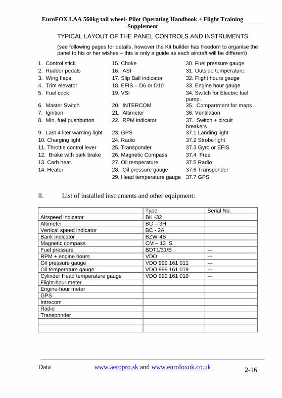
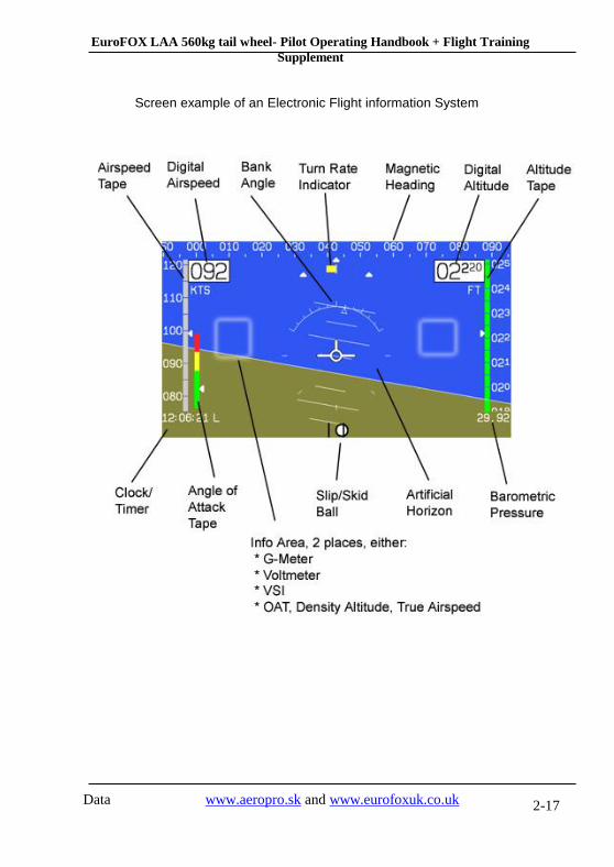
TYPICAL LAYOUT OF THE PANEL CONTROLS AND INSTRUMENTS
(see following pages for details, however the Kit builder has freedom to organise the panel to his or her wishes – this is only a guide as each aircraft will be different)
1. Control stick 15. Choke 30. Fuel pressure gauge
2. Rudder pedals 16. ASI 31. Outside temperature.
3. Wing flaps 17. Slip Ball indicator 32. Flight hours gauge
4. Trim elevator 18. EFIS – D6 or D10 33. Engine hour gauge
5. Fuel cock 19. VSI 34. Switch for Electric fuel pump.
6. Master Switch 20. INTERCOM 35. Compartment for maps
7. Ignition 21. Altimeter 36. Ventilation
8. Min. fuel pushbutton 22. RPM indicator 37. Switch + circuit breakers
9. Last 4 liter warning light 23. GPS 37.1 Landing light
10. Charging light 24. Radio 37.2 Strobe light
11. Throttle control lever 25. Transponder 37.3 Gyro or EFIS
12. Brake with park brake 26. Magnetic Compass 37.4 Free
13. Carb heat. 27. Oil temperature 37.5 Radio
14. Heater 28. Oil pressure gauge 37.6 Transponder
29. Head temperature gauge 37.7 GPS
II. List of installed instruments and other equipment:
Type Serial No.
Airspeed indicator BK -32
Altimeter BG – 3H
Vertical speed indicator BC - 2A
Bank indicator BZW-4B
Magnetic compass CM – 13 S
Fuel pressure BDT1/31/B ---
RPM + engine hours VDO ---
Oil pressure gauge VDO 999 161 011 ---
Oil temperature gauge VDO 999 161 019 ---
Cylinder Head temperature gauge VDO 999 161 019 ---
Flight-hour meter
Engine-hour meter
GPS
Intrecom
Radio
Transponder
EuroFOX LAA 560kg tail wheel- Pilot Operating Handbook + Flight Training
Supplement
Data www.aeropro.sk and www.eurofoxuk.co.uk 2-17
Screen example of an Electronic Flight information System

EuroFOX LAA 560kg tail wheel- Pilot Operating Handbook + Flight Training
Supplement
Data www.aeropro.sk and www.eurofoxuk.co.uk 2-18
Main Fuel Valve open and close position
Ignition and master switch
Central panel
Note if a vernier style
throttle body is fitted: Rotate
throttle knob for fine power
settings (clockwise to
increase power,
counterclockwise to reduce
power), for larger changes
push/pull throttle when the
central button is pressed and
held

EuroFOX LAA 560kg tail wheel- Pilot Operating Handbook + Flight Training
Supplement
Data www.aeropro.sk and www.eurofoxuk.co.uk 2-19
Intuative flap and trim levers located between P1 and P2 seat position
Example of switch and fuse layout
Aircraft
nose side
Pilot
seat side

EuroFOX LAA 560kg tail wheel- Pilot Operating Handbook + Flight Training
Supplement
Data www.aeropro.sk and www.eurofoxuk.co.uk 2-20
Warning lights and fuel reserve bulb check button
Door locking mechanism
The battery (Dryfit A500, 12 V, 16 Ah ) is located behind the right-hand pilot’s seat. Nominal voltage in aircraft system is 13.5 to 14.2 V. The engine is equipped with integrated AC generator with external rectifier-regulator (12 V, 20A DC)

EuroFOX LAA 560kg tail wheel- Pilot Operating Handbook + Flight Training
Supplement
Data www.aeropro.sk and www.eurofoxuk.co.uk 3-21
3. Operating limitations
MPH
IAS CAS 40 43
45 48
50 52
60 61
70 70
80 78
90 87
100 96
110 105
120 115
Airspeed indicator system calibration:
All flight speeds are presented as indicated airspeeds in miles per hour (MPH). As the calibrated airspeed cannot usually be determined by simple reading of the aircraft airspeed indicator, corresponding calibrated airspeed in miles per hours (MPH) are also presented in this document. All airspeed values in this handbook assume no instrument error. The pitot dynamic tube head is located on the port underside wing. The static tube reference is in the cabin.
3.1 Stall speed at maximum takeoff weight (VS and VSO)
Aircraft
configuration
Stall speed Mph – angle of bank 0°
IAS CAS
Flaps down (Vso) 41 45
Flaps up (Vs) 49 51

EuroFOX LAA 560kg tail wheel- Pilot Operating Handbook + Flight Training
Supplement
Data www.aeropro.sk and www.eurofoxuk.co.uk 3-22
WARNING The stall speed mentioned above are with wings level.
Once any angle of bank (e.g. turn) is encountered the stall
speed is significantly increased.
Example: angle of bank – 60° ……. VS= 73 MPH
The more bank – the higher stall speed. This simple rule is especially important when a turn at maximum permitted angle of bank (60°) is performed. Do not start the turn until you have sufficient airspeed reserve – recommended entry speed is 92 MPH. Full throttle is also essential to have sufficient thrust reserve as the drag is increased during a steep turn.
3.2 Flaps extended speed range (VSO to VFE) Mph
IAS CAS
Lower limit 41 45
Upper limit 93 90
3.3 Maximum maneuvering speed (VA) Mph
IAS CAS
Max. manoeuvring
speed (VA) 109 104
3.4 Never exceed speed (VNE) Mph
IAS CAS
Never exceed speed (VNE)
143 134
3.5 Crosswind limitation
Maximum permitted wind speed components for take-off and landing:
Crosswind……………………………………………….. 15 mph (12 knots)
The EuroFOX has demonstrated to be able to cope well with crosswinds exceeding this, especially with more experience pilots.
EuroFOX LAA 560kg tail wheel- Pilot Operating Handbook + Flight Training
Supplement
Data www.aeropro.sk and www.eurofoxuk.co.uk 3-23
Cross wind take offs and landings require training and experience, the higher the crosswind component, the better your skill must be. Do not fly without proper experience when the wind speed is approaching the limit.
Avoid take offs with tail wind when possible – the total take off distance is significantly longer and longer ground distance is required to gain altitude.
When landing with tail wind the aircraft ground speed is higher resulting in a longer landing distance.
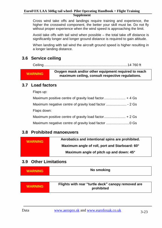
3.6 Service ceiling
Ceiling ...................................................................................... 14 760 ft
WARNING Oxygen mask and/or other equipment required to reach
maximum ceiling, consult respective regulations.
3.7 Load factors
Flaps up:
Maximum positive centre of gravity load factor ...................... + 4 Gs
Maximum negative centre of gravity load factor ..................... - 2 Gs
Flaps down:
Maximum positive centre of gravity load factor ...................... + 2 Gs
Maximum negative centre of gravity load factor ........................ 0 Gs
3.8 Prohibited manoeuvers
WARNING Aerobatics and intentional spins are prohibited.
Maximum angle of roll, port and Starboard: 60°
Maximum angle of pitch up and down: 45°
3.9 Other Limitations
WARNING No smoking
WARNING Flights with rear “turtle deck” canopy removed are
prohibited

EuroFOX LAA 560kg tail wheel- Pilot Operating Handbook + Flight Training
Supplement
Data www.aeropro.sk and www.eurofoxuk.co.uk 3-24
WARNING Only VFR day flights at ambient temperature above -10 C
are permitted.
Flights at ambient temperature between -10 C and 0 C are
permitted only under no icing conditions and when the
carburettor heating is activated (if fitted).
WARNING IFR flights and flying in cloud is prohibited.
Flight into know icing conditions is prohibited
This aircraft is not certified for operation in IMC (Instrument meteorological conditions). Always stay clear of clouds and have visual contact with the ground. Follow the airspace classification regarding distance from clouds. Always evaluate the weather during your flight and try to get weather information from your destination using the radio whenever possible. When weather is deteriorating make a diversion or turn back before low cloud base and/or low visibility are outside local licence requirements.
EuroFOX LAA 560kg tail wheel- Pilot Operating Handbook + Flight Training
Supplement
Data www.aeropro.sk and www.eurofoxuk.co.uk 4-25
4. Weight and Balance Information
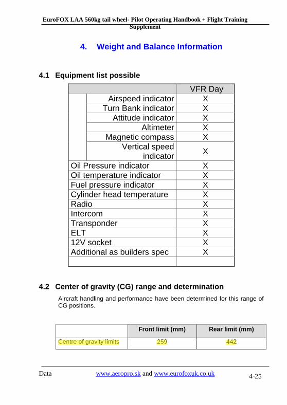
4.1 Equipment list possible
VFR Day
Airspeed indicator X Turn Bank indicator X
Attitude indicator X Altimeter X
Magnetic compass X Vertical speed
indicator X
Oil Pressure indicator X Oil temperature indicator X Fuel pressure indicator X Cylinder head temperature X Radio X Intercom X Transponder X ELT X 12V socket X Additional as builders spec X
4.2 Center of gravity (CG) range and determination
Aircraft handling and performance have been determined for this range of CG positions.
Front limit (mm) Rear limit (mm)
Centre of gravity limits 259 442
Rodger
Highlight

EuroFOX LAA 560kg tail wheel- Pilot Operating Handbook + Flight Training
Supplement
Data www.aeropro.sk and www.eurofoxuk.co.uk 4-26
4.2.1 Aircraft weight and balance statement
The CG position of the empty aircraft is determined by weighing. The procedure is described in the Maintenance manual and in LAA
publications. The whole procedure must be repeated and new Aircraft
weight and balance statement be prepared whenever a modification or repair having an impact on the weight of the aircraft occurs.
Serial Number Registration:
Aircraft Leveling: Bottom of door entrance level at zero degrees
Values Weighed: Main wheels right-hand MRH = kg L= mm
left-hand MLH = kg L1= mm
Tail wheel MTS = kg
Resulting weight Mres = kg
C.G. position B = (Mpr x L ) / Mvys = mm
X = L1 – B + 50 = mm
Date: Performed by:
Rodger
Highlight
EuroFOX LAA 560kg tail wheel- Pilot Operating Handbook + Flight Training
Supplement
Data www.aeropro.sk and www.eurofoxuk.co.uk 4-27
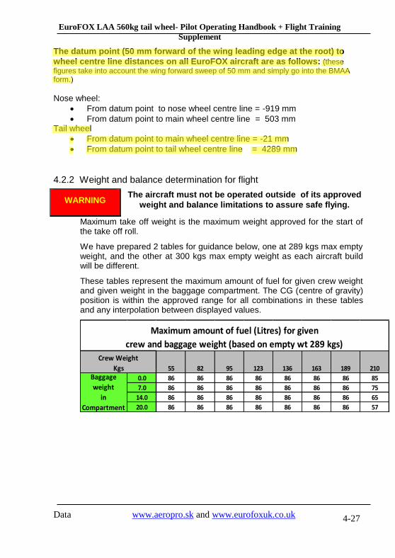
The datum point (50 mm forward of the wing leading edge at the root) to
wheel centre line distances on all EuroFOX aircraft are as follows: (these
figures take into account the wing forward sweep of 50 mm and simply go into the BMAA form.)
Nose wheel:
From datum point to nose wheel centre line = -919 mm
From datum point to main wheel centre line = 503 mm Tail wheel
From datum point to main wheel centre line = -21 mm
From datum point to tail wheel centre line = 4289 mm
4.2.2 Weight and balance determination for flight
WARNING The aircraft must not be operated outside of its approved
weight and balance limitations to assure safe flying.
Maximum take off weight is the maximum weight approved for the start of the take off roll.
We have prepared 2 tables for guidance below, one at 289 kgs max empty weight, and the other at 300 kgs max empty weight as each aircraft build will be different.
These tables represent the maximum amount of fuel for given crew weight and given weight in the baggage compartment. The CG (centre of gravity) position is within the approved range for all combinations in these tables and any interpolation between displayed values.
55 82 95 123 136 163 189 210
0.0 86 86 86 86 86 86 86 85
7.0 86 86 86 86 86 86 86 75
14.0 86 86 86 86 86 86 86 65
20.0 86 86 86 86 86 86 86 57
Maximum amount of fuel (Litres) for given
crew and baggage weight (based on empty wt 289 kgs)
Crew Weight
KgsBaggage
weight
in
Compartment
Rodger
Highlight
Rodger
Highlight

EuroFOX LAA 560kg tail wheel- Pilot Operating Handbook + Flight Training
Supplement
Data www.aeropro.sk and www.eurofoxuk.co.uk 4-28
55 82 95 123 136 163 189 210
0.0 86 86 86 86 86 86 86 69
7.0 86 86 86 86 86 86 86 60
14.0 86 86 86 86 86 86 79 50
20.0 86 86 86 86 86 86 70 42
Maximum amount of fuel (Litres) for given
crew and baggage weight (based on empty wt 300 kgs)
Crew Weight
KgsBaggage
weight
in
Compartment
All these loadings will keep the aircraft within MAUW and within the C of G range. It is imperative that the pilot knows exactly the real empty weight of his or her aircraft.
4.2.3 Detailed calculation of CG position
As all reference points are located behind the leading edge of the wing at the root, the leading edge was selected as the reference plane. The table below shows a typical calculation including an example.

EuroFOX LAA 560kg tail wheel- Pilot Operating Handbook + Flight Training
Supplement
Data www.aeropro.sk and www.eurofoxuk.co.uk 4-29
Example: Weight &
Balance for EuroFOX
Actual
Weight (kgs) Arm (mm's) Moment (kg/cm)
Empty aircraft wt
S/N…….. 289 277 801
Crew weight 189 440 832
Fuel weight (86 Ltrs) 62 440 273
Baggage compartment 20 1200 240
Totals 560 2145
Loaded aircraft CG
position in mm's X 100
Permitted C.G
from reference point 259 mm To 442 mm
Actual C.G result 383 mm
Total moment
Total weight
EuroFOX LAA 560kg tail wheel- Pilot Operating Handbook + Flight Training
Supplement
Data www.aeropro.sk and www.eurofoxuk.co.uk 5-30
5. Performance
The data is based on particular flight measurements undertaken with the aircraft of this type in good service conditions and with application of average piloting skills. The performance stated below are calculated at sea level of the international standard atmosphere (ISA). Variations in pilot technique can cause significant differences as well as the other conditions like runway slope, runway surface condition, humidity etc.
Use the following data for guidance but do not plan a take off or landing when only 50 ft extra runway length is available or do not plan a cross country with only 8 litres of fuel expected to remain when arriving at your destination. Always be conservative when planning a flight and be ready for the unexpected – unexpected wind, atmospheric turbulence or sudden weather change at the destination forcing you to divert to airfield 60 NM away. Always plan a reasonable fuel reserve – 60 minutes seems to be sufficient time for most of flights, but this time should be increased when complicated weather conditions (strong headwind or rain showers) are expected en route.
The propeller installed on your aircraft was set to achieve the best compromise between take off and cruising performance (the performance information below are based on this setting). You can change the setting (see propeller documentation) to achieve a better rate of climb or a better cruising speed. Always be carefully when making this change and make a record of the current settings. When the propeller is set to achieve a maximum cruise speed, the take off distance is significantly longer. On the other hand, when the propeller is set to achieve good rate of climb, the fuel consumption during level flight is higher. When a finer pitch is set (e.g. climb setting), a higher static RPM is achieved when aircraft is static and full power is applied. Be careful not to exceed the Rotax maximum limit RPM.

EuroFOX LAA 560kg tail wheel- Pilot Operating Handbook + Flight Training
Supplement
Data www.aeropro.sk and www.eurofoxuk.co.uk 5-31
5.1 Takeoff and landing distances
Surface Take off Distance (Metres)
Ground run Take off distance to 50 ft
Grass runway 149 319
Hard runway 139 309
Surface
Landing Distance (Metres)
Landing distance
from 50 ft Ground run
Grass runway 349 170
Hard runway 329 149
Both take off and landing distance are significantly increased by the following factors:
Tail wind
High airport altitude
High air temperature
Up-hill runway slope
Runway wet or covered with snow, dust or water
Propeller set to achieve better cruising performance
5.2 Rate of climb
MTOW 560 kg
Rate of climb (fpm) 816
5.3 Cruise speeds Mph
Maximum cruising speed at 75% ............................. 109 IAS (104 CAS)

EuroFOX LAA 560kg tail wheel- Pilot Operating Handbook + Flight Training
Supplement
Data www.aeropro.sk and www.eurofoxuk.co.uk 5-32
5.4 RPM
Max. take off power ............................................................ 5,800 (5 mins)
Max. continuous power ...................................................... 5,500
Cruise flight ...................................................................... .. 4,200 – 5,200
Idle speed ......................................................................... approx. 1,600
5.5 Fuel consumption
Engine settings Fuel consumption
(Litres per hour)
Take off power performance 26
Max. continuous performance 24
Cruise performance 12-19
Fuel consumption during cruise flight is dependent on various factors. The most important ones are engine settings and propeller settings. The higher the engine RPM is set during cruise, the higher the fuel consumption. When propeller is set to minimum angle to achieve good climbing performance, level flight will be slower together with higher fuel consumption. When planning a flight, always consider all these and other factors like wind direction and speed or expected weather en route. Always plan for sufficient fuel reserve when arriving at the destination. Always carefully evaluate fuel consumption during the flight.
5.6 Other performance data
Max. endurance ................................................................... 6 hours
Max. range…………………………………………... 620 Statute miles
Max. speed flying with doors open…………………………... 75 MPH

EuroFOX LAA 560kg tail wheel- Pilot Operating Handbook + Flight Training
Supplement
Data www.aeropro.sk and www.eurofoxuk.co.uk 6-33
6. Performance 912iS
The data is based on particular flight measurements undertaken with the aircraft of this type in good service conditions and with application of average piloting skills. The performance stated below are calculated at sea level of the international standard atmosphere (ISA). Variations in pilot technique can cause significant differences as well as the other conditions like runway slope, runway surface condition, humidity etc.
Use the following data for guidance but do not plan a take off or landing when only 50 ft extra runway length is available or do not plan a cross country with only 8 litres of fuel expected to remain when arriving at your destination. Always be conservative when planning a flight and be ready for the unexpected – unexpected wind, atmospheric turbulence or sudden weather change at the destination forcing you to divert to airfield 60 NM away. Always plan a reasonable fuel reserve – 60 minutes seems to be sufficient time for most of flights, but this time should be increased when complicated weather conditions (strong headwind or rain showers) are expected en route.
The propeller installed on your aircraft was set to achieve the best compromise between take off and cruising performance (the performance information below are based on this setting). You can change the setting (see propeller documentation) to achieve a better rate of climb or a better cruising speed. Always be carefully when making this change and make a record of the current settings. When the propeller is set to achieve a maximum cruise speed, the take off distance is significantly longer. On the other hand, when the propeller is set to achieve good rate of climb, the fuel consumption during level flight is higher. When a finer pitch is set (e.g. climb setting), a higher static RPM is achieved when aircraft is static and full power is applied. Be careful not to exceed the Rotax maximum limit RPM.

EuroFOX LAA 560kg tail wheel- Pilot Operating Handbook + Flight Training
Supplement
Data www.aeropro.sk and www.eurofoxuk.co.uk 6-34
6.1 Startup procedure 912iS
Start up 1. Throttle closed and friction lock on
2. Brakes ON
3. Fuel on – all 3 taps
4. Turn EMU on and wait for display to boot up
5. Turn key to “Avionic” tab
6. Turn lane “A” (primary computer) on, then turn lane “B” (secondary
computer) on
7. Turn fuel pump “A” (main fuel pump) on the fuel pump “B” (auxiliary fuel
pump) on
8. Hold on in the “up” position the momentary start switch – fuel pumps will
start running
9. Wait EMU display to show green for lane “A” and lane “B”
10. Wait for the red lights above lane “A” and lane “B” to extinguish
11. Set throttle to % position as indicated for best start position up by EMU,
lock throttle tight
12. Whilst continuing to hold the momentary start switch “UP” and on, turn
ignition key to “ON”
13. When engine starts release momentary switch and allow key to return to
“Avionics” and move hand to throttle control
14. Engine should be running, check all engine information on EMU
Shut down (normally wait 5 mins after landing) Note – never turn the fuel pumps off first
1. Turn off any comms, GPS, lights, strobes using their individual switches
and move key switch to “Engine”
2. Set engine to idle
3. Turn off lane “A” and lane “B”
4. Turn off fuel “A” and fuel “B”
5. Switch ignition key to off
6. Turn EMU off
7. Close all 3 fuel taps
8. Brakes on
The Rotax 912iS engine manual chapter 2 should be used in place of EuroFOX POH sections 3 and 7 for normal and abnormal operations

EuroFOX LAA 560kg tail wheel- Pilot Operating Handbook + Flight Training
Supplement
Data www.aeropro.sk and www.eurofoxuk.co.uk 6-35
6.2 Takeoff and landing distances
Surface Take off Distance (Metres)
Ground run Take off distance to 50 ft
Grass runway 149 319
Hard runway 139 309
Surface
Landing Distance (Metres)
Landing distance
from 50 ft Ground run
Grass runway 349 170
Hard runway 329 149
Both take off and landing distance are significantly increased by the following factors:
Tail wind
High airport altitude
High air temperature
Up-hill runway slope
Runway wet or covered with snow, dust or water
Propeller set to achieve better cruising performance
6.3 Rate of climb
MTOW 560 kg
Rate of climb (fpm) 816
6.4 Cruise speeds Mph
Maximum cruising speed at 75% ............................. 110 IAS (105 CAS)

EuroFOX LAA 560kg tail wheel- Pilot Operating Handbook + Flight Training
Supplement
Data www.aeropro.sk and www.eurofoxuk.co.uk 6-36
RPM
Max. take off power ............................................................ 5,800 (5 mins)
Max. continuous power ...................................................... 5,500
Cruise flight ...................................................................... .. 4,200 – 5,200
Idle speed ......................................................................... approx. 1,600
6.5 Fuel consumption
Engine settings Fuel consumption
(Litres per hour)
Take off power performance 26
Max. continuous performance 24.5
Cruise performance 12-19
Fuel consumption during cruise flight is dependent on various factors. The most important ones are engine settings and propeller settings. The higher the engine RPM is set during cruise, the higher the fuel consumption. When propeller is set to minimum angle to achieve good climbing performance, level flight will be slower together with higher fuel consumption. When planning a flight, always consider all these and other factors like wind direction and speed or expected weather en route. Always plan for sufficient fuel reserve when arriving at the destination. Always carefully evaluate fuel consumption during the flight.
6.6 Other performance data
Max. endurance ................................................................... 6 hours
Max. range…………………………………………... 620 Statute miles
Max. speed flying with doors open…………………………... 75 MPH
Best Glide speed ............................................................. .. 65 MPH
EuroFOX LAA 560kg tail wheel- Pilot Operating Handbook + Flight Training
Supplement
Data www.aeropro.sk and www.eurofoxuk.co.uk 7-37
7. Emergency procedures
7.1 Introduction
This section contains procedures for various emergencies which may occur. Emergencies caused by aircraft or engine malfunctions are rare if proper pre-flight inspections and maintenance are practised.
The chapter describes basic emergencies and recovery procedures. Not all emergencies that may occur can be listed here in full, therefore their solution depends on the experience of the crew controlling course of such events. All air speed values in this chapter are presented in MPH Indicated Airspeed, as this value represents instrument reading better than the Calibrated air speed. In respect to any engine failure, first priority is always FLY THE AIRCRAFT.
7.2 Engine Failure and Emergency landings
7.2.1 Engine Failure during Take-Off Run
- throttle REDUCE TO IDLE
- ignition OFF
- master switch OFF
- brakes AS REQUIRED
7.2.2 Engine Failure during Take-Off
- airspeed 75 mph IAS
- choice of landing site - after take-off and up to 150 ft - land in straight direction ahead, if possible
- over 150 ft choose suitable landing site
The landing site is to be preferably chosen in the runway direction or the nearest suitable site clear of obstacles
- master switch OFF
- ignition OFF
- main fuel valve SHUT
- tank fuel valves SHUT
- flaps EXTEND AS NEEDED

EuroFOX LAA 560kg tail wheel- Pilot Operating Handbook + Flight Training
Supplement
Data www.aeropro.sk and www.eurofoxuk.co.uk 7-38
- safety belts TIGHTEN
after touchdown:
- brakes AS REQUIRED
7.2.3 In-flight Engine Failure
- airspeed 75 Mph IAS
- landing site selection SELECT
- transmit MAYDAY on 121,5, ELT ON, XPDR 7700 - if time permits
check - master switch ON
- ignition ON
- main fuel valve OPEN
- wing tank fuel valves OPEN to tank with more fuel
- throttle SET TO 1/3 OF TRAVEL
- starter START THE ENGINE
If the engine cannot be restarted, proceed in accordance with the procedure 7.2.2 .
7.2.4 Additional information on engine failure and emergency landing procedures
If the engine failure occurs during the take off run, the pilots main concern should be to stop the aircraft on the remaining runway. Those extra items in the checklist are to add protection should the runway be too short to stop.
In flight, prompt reduction of pitch attitude to obtain and maintain a proper glide speed upon experiencing an engine failure is the first priority. If the failure has occurred shortly after take off, a landing should be planned straight ahead with only small changes in the flight direction to avoid obstacles. The best gliding ratio can be achieved with flaps up – flaps down will reduce the stall speed but at the same time deteriorating gliding performance. Try to stop rotation of propeller if restarting efforts are not successful – wind milling propeller has a higher drag than stopped propeller.

EuroFOX LAA 560kg tail wheel- Pilot Operating Handbook + Flight Training
Supplement
Data www.aeropro.sk and www.eurofoxuk.co.uk 7-39
While gliding towards a selected forced landing site, an effort should be made to determine and correct the cause of engine failure – time and altitude permitting. Do not concentrate on cause determination or restart effort unless you have selected a suitable landing site and you are confident of this manoeuvre. Flying the aircraft (especially maintaining the proper gliding speed) is always the first priority. If the cause cannot be determined and corrected the emergency landing must be accomplished.
Always announce your intent and position after engine failure using radio and other equipment when time permits. Turn radio to international emergency frequency – 121.5 and transmit MAYDAY message. Activate Emergency locator transmitter (ELBA) – set the switch to ON position. Set transponder (XPDR) to emergency code 7700. When the above mentioned procedure can not be performed due to time constraints try to complete as many steps as possible. Transmitting MAYDAY message on the frequency already tuned on your radio should be the minimum procedure.
WARNING During a landing it is vital for the pilot to continue to fly the
aircraft. Damages and/or injuries can be minimised if the
pilot is fully concentrating on controlling the aircraft until it
comes to complete stop
7.2.5 Carburettor Icing
Carburettor icing mostly occurs when getting into an area of ice formation. The carburettor icing shows itself through a decrease in engine power and an increase in engine temperatures. To recover the engine power, the following procedure is recommended:
- carburettors heating ACTIVATE
- airspeed 75 Mph IAS
- throttle 1/3 of power (3500 RPM)
- if possible, leave the icing area
- gradually increase the engine power to cruise conditions after 1-2 minutes
- if you fail to recover the engine power, land at the nearest airfield (if feasible), or, depending on circumstance, off-airfield, following the procedure given under 7.2.2

EuroFOX LAA 560kg tail wheel- Pilot Operating Handbook + Flight Training
Supplement
Data www.aeropro.sk and www.eurofoxuk.co.uk 7-40
7.3 In-flight Engine Starting
- airspeed 75 Mph IAS
- landing site selection SELECT
- master switch ON
- main fuel valve OPEN
- wing tank fuel valves OPEN to tank with more fuel
- choke SWITCH ON (cold engine only)
- throttle - ADJUST to 1/3 of travel
- IDLE (when choke is activated)
- ignition ON
- starter START UP
- if the engine cannot be restarted, increase the airspeed to 85 – 95 Mph IAS so that air flow can rotate the propeller, thus enabling engine starting.
WARNING Loss of height needed for in-flight engine starting is about 500 to 650 ft.
7.4 Fires
Follow these procedure when fire or smoke in the engine compartment or cockpit is detected. Fires are extremely rare in properly maintained aircraft.
7.4.1 Engine fire on the ground
- main fuel valve SHUT
- tank fuel valves SHUT
- throttle FULL
- ignition switch off when engine has stopped as all remaining fuel in carburettors was burned
- master switch OFF
- abandon the aircraft and extinguish fire (if possible)
- Fire damage INSPECT

EuroFOX LAA 560kg tail wheel- Pilot Operating Handbook + Flight Training
Supplement
Data www.aeropro.sk and www.eurofoxuk.co.uk 7-41
NOTE Time needed to burn fuel remaining in carburettors after fuel
valves are closed is around 30 sec.
WARNING DO NOT CONDUCT ANOTHER FLIGHT BEFORE THE FIRE
CAUSE HAS BEEN DETERMINED AND REPAIRED BY
AUTHORISED PERSONNEL
7.4.2 Engine fire during takeoff
- throttle IDLE
- main fuel valve SHUT
- tank fuel valves SHUT
- airspeed 75 Mph IAS
- brakes STOP
- throttle FULL
- ignition switch off when engine has stopped as all remaining fuel in carburettors has burned
- abandon the aircraft and extinguish fire (if possible) once the aircraft is stopped
7.4.3 Engine fire in flight
- main fuel valve SHUT
- tank fuel valves SHUT
- throttle FULL
- airspeed INCREASE as required to find an airspeed which will provide an incombustible mixture. Do not exceed VNE
- landing site selection guide the aircraft to the nearest airfield, or choose a suitable landing site for emergency landing
- ignition switch off when engine has stopped as all remaining fuel in carburettors was burned

EuroFOX LAA 560kg tail wheel- Pilot Operating Handbook + Flight Training
Supplement
Data www.aeropro.sk and www.eurofoxuk.co.uk 7-42
- master switch OFF
- airspeed 75 Mph IAS
- wings flaps EXTEND AS NEEDED
- safety belts TIGHTEN
- perform emergency landing
- abandon the aircraft and extinguish fire (if possible)
WARNING DO NOT ATTEMPT TO RESTART THE ENGINE
WARNING DO NOT CONDUCT ANOTHER FLIGHT BEFORE THE FIRE
CAUSE HAS BEEN DETERMINED AND REPAIRED BY
AUTHORISED PERSONNEL
7.4.4 Cockpit or electrical fire
Electrical fires are usually signalled by the odour of burning insulation.
- cockpit door OPEN to remove smoke from the cockpit
- avionics and other switches OFF
Land at the nearest suitable landing site. Consider shutting down the engine (and master switch) once the suitable landing site is reached. Extinguish fire as soon as possible.
7.5 Gliding
gliding ratio ................................................................................ 1 : 9
optimum gliding speed ............................................................. 70 Mph IAS
rate of descent ....................................................................... 551 fpm
Always consider flying though areas of descending air when calculating gliding range. Do not forget to have and maintain sufficient altitude to perform a landing procedure once suitable landing site has been reached.
EuroFOX LAA 560kg tail wheel- Pilot Operating Handbook + Flight Training
Supplement
Data www.aeropro.sk and www.eurofoxuk.co.uk 7-43
7.6 Precautionary Landing
- choose suitable landing site, evaluate wind direction and speed, surface, surrounding obstacles and total safety of the manoeuvre under consideration
- perform approach and fly-over at a speed of 75 Mph IAS along the selected landing site at a height of 150 ft to estimate the area condition, obstacles and to determine exact landing direction
- Follow normal landings checklist and land
after touchdown
- Ignition OFF
- master switch OFF
- fuel valves SHUT
- brakes AS REQUIRED
A precautionary landing is preferable to an emergency landing. When engine vibration or engine roughness is presented, do not wait until the engine stops, perform a precautionary landing as soon as possible.
A precautionary landing is also used when the fuel exhaustion is imminent. This should not happen when proper flight preparation is performed. Always perform a precautionary landing before all fuel is consumed, emergency landing following the loss of power is more complicated and more risky.
Also consider a precautionary landing when bad weather is encountered. Again, it should not happen when proper flight planning is made. When the cloud base is forcing you to fly in low altitude and/or visibility is limited, try to fly a 180 course to avoid bad weather area. If the conditions are not getting better or even are deteriorating, perform a precautionary landing before the conditions become even worse.
7.7 Blown-Out Tyre Landing
- carry out normal approach-to-land
- when flaring at landing, keep the damaged wheel above ground as long as possible using ailerons (or elevator for the nose wheel)
- maintain the direction at landing run, applying rudder

EuroFOX LAA 560kg tail wheel- Pilot Operating Handbook + Flight Training
Supplement
Data www.aeropro.sk and www.eurofoxuk.co.uk 7-44
7.8 Damaged Landing Gear Landing
- carry out a normal approach-to-land
- if the nose wheel is damaged, perform a touch-down on main wheels and hold the aircraft nose wheel up as long as possible till the speed is lost.
- if the main landing gear is damaged, perform touch-down at the lowest speed possible and maintain direction at landing run, if possible
7.9 Vibrations or other engine problem
If any forced vibrations appear in the aircraft, it is necessary:
- to set engine speed to such power rating where the vibrations are the lowest
- to land on the nearest airfield, or to perform a precautionary landing off-airfield
- if the vibrations are increasing, carry out an emergency landing off-airfield, following procedures given under 7.2.2
If the oil pressure reduces during a flight, an engine failure is probable. Reduce the engine power and execute a nearest airfield or precautionary landing before the engine failure occurs.
7.10 Inadvertent icing encountered
- carburettor heating ACTIVATE
- throttle INCREASE above normal cruise settings
- course REVERSE or ALTER as required to avoid icing
WARNING EVASIVE ACTION SHOULD BE INITIATED IMMEDIATELY
WHEN ICING CONDITIONS ARE ENCOUNTERED
A prompt action must be taken immediately once icing conditions are encountered. A 180° turn and a climb is usually appropriate. If the airframe ice builds extremely rapidly, consider off-airport forced landing. Approach speed should be increased slightly depending upon icing severity.

EuroFOX LAA 560kg tail wheel- Pilot Operating Handbook + Flight Training
Supplement
Data www.aeropro.sk and www.eurofoxuk.co.uk 7-45
7.11 Extreme turbulence encountered
- Airspeed REDUCE to 75 KIAS
- safety belts SECURED
- loose objects SECURED
When an area of extreme turbulence is entered reduce airspeed to approximately 85 Mph IAS. Do not reduce the airspeed too low in order to prevent the aircraft from stalling due to turbulence. Do not increase the speed into the yellow arc so as to prevent structural damage to the aircraft.
7.12 Electrical system malfunctions
7.12.1 Charging indicating light is illuminated
When the red charging light is illuminated no immediate action is required. All avionics and other equipment are powered from the battery, so the power source is limited. Try to switch off instruments which are not necessary for flight and land at the nearest airfield
7.13 Inadvertent Stall and spin recovery
Stall or spin should not occur during normal aircraft operation and they are prohibited.
7.13.1 The following general procedure should be followed should a stall occur:
- lower the nose by pushing the control stick
- gradually increase power
7.13.2 The following general procedure should be followed should a spin occurs:
- throttle IDLE
- rudder opposite to rotation
- control stick fully pushed
Once the rotation is stopped, centre rudder and establish a level flight.

EuroFOX LAA 560kg tail wheel- Pilot Operating Handbook + Flight Training
Supplement
Data www.aeropro.sk and www.eurofoxuk.co.uk 8-46
8. Normal procedures
All air speed values in this chapter are presented in MPH Indicated Airspeed, as this value represents instrument reading better than the Calibrated air speed.
8.1 Pre-flight inspection
Pre-flight inspection must be conducted before the first flight of the day. The pre-flight inspection is recommended prior to any flight or series of flights by one pilot on any given day. Prior to any flight fuel and oil quantity should be checked as a minimum.
If the aircraft has been stored outside the engine area and other points of entry should be checked for evidence of bird occupancy. All control surfaces and travel stops should be examined for wing damages. Wheel fairings are not recommended for muddy field operation due to possible mud accumulation inside the fairings. When operating from gravel fields pay special attention to propeller leading edges. Fuel caps should be monitored for any deterioration periodically to avoid fuel leakage in flight or water infiltration.
The aircraft general condition should be noted during a visual inspection of the aircraft. Inspect any signs of deterioration, distortion and any damages to fabric skin of the aircraft. In cold weather, all traces of ice, snow, and frost should be removed from the aircraft. Make sure that no ice, snow or debris is trapped between any movable control surfaces.
Make sure that all instruments are in good condition with no broken glass. Airspeed indicator should read zero, altimeter should be checked against ramp or field elevation.
Do not activate the electrical system when anyone is near the propeller to prevent injury that could possibility result from an electrical system malfunction.
Pay special attention to the propeller area – make sure the ignition and master switches are OFF before touching the propeller. Avoid touching propeller when possible to prevent possible injury resulting from electrical system malfunction.
WARNING DO NOT FLY THE AIRCRAFT IF YOU FIND ANY DAMAGE
OR PROBLEMS DURING A PRE-FLIGHT INSPECTION.
ALWAYS CONSULT AUTHORISED PERSONNEL FOR
REPAIRS

EuroFOX LAA 560kg tail wheel- Pilot Operating Handbook + Flight Training
Supplement
Data www.aeropro.sk and www.eurofoxuk.co.uk 8-47
8.1.1 Daily Preparation
10
11
1
322
4
55 6
7
9
3
12
8
13
1. Cockpit
POH and other documentation review and available to pilot
master switch OFF
ignition OFF
fuel valves OPEN, fuel quantity check
instruments INSPECT
safety belts INSPECT
check of flaperon tie rods INSPECT
control stick INSPECT , freedom of movement
rudder pedals INSPECT , freedom of movement
brakes INSPECT
trim freedom of movement, proper function

EuroFOX LAA 560kg tail wheel- Pilot Operating Handbook + Flight Training
Supplement
Data www.aeropro.sk and www.eurofoxuk.co.uk 8-48
engine controls INSPECT, freedom of movement
loose objects in cockpit remove
cockpit windows INSPECT
door INSPECT, shut and locked
2. Main landing gear
gear legs and attachment INSPECT
wheels INSPECT, tyre pressure 29 PSI
brakes INSPECT
3. Wings INSPECT – wing, struts, hinges, surface 4. Pitot tube INSPECT
5. Flaperons INSPECT –hinges, surface freedom of movement
counterweights attachment.
6. Rear cockpit cover INSPECT, secured
7. Fuselage INSPECT
8. Stabilizer, elevator, hinges INSPECT –surface, hinges, attachment of stabilizer struts
freedom of movement of elevator and trim tab.
9. Fin, rudder, hinges INSPECT surface, attachment, freedom of movement
condition and attachment of balance tab.
10. Nose wheel INSPECT, tyre pressure – 29 PSI
11. Propeller INSPECT / blades, propeller hub, check of locking propeller nuts (when visible)
12. Engine Remove the top engine cowling and
INSPECT - engine mount
INSPECT - air intake, carburettors and controls
INSPECT - exhaust system
EuroFOX LAA 560kg tail wheel- Pilot Operating Handbook + Flight Training
Supplement
Data www.aeropro.sk and www.eurofoxuk.co.uk 8-49
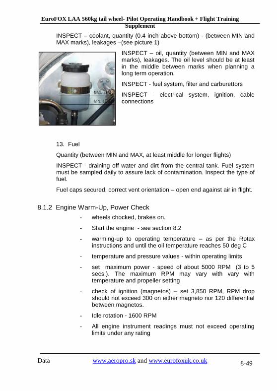
INSPECT – coolant, quantity (0.4 inch above bottom) - (between MIN and MAX marks), leakages –(see picture 1)
INSPECT – oil, quantity (between MIN and MAX marks), leakages. The oil level should be at least in the middle between marks when planning a long term operation.
INSPECT - fuel system, filter and carburettors
INSPECT - electrical system, ignition, cable connections
13. Fuel
Quantity (between MIN and MAX, at least middle for longer flights)
INSPECT - draining off water and dirt from the central tank. Fuel system must be sampled daily to assure lack of contamination. Inspect the type of fuel.
Fuel caps secured, correct vent orientation – open end against air in flight.
8.1.2 Engine Warm-Up, Power Check
- wheels chocked, brakes on.
- Start the engine - see section 8.2
- warming-up to operating temperature – as per the Rotax instructions and until the oil temperature reaches 50 deg C
- temperature and pressure values - within operating limits
- set maximum power - speed of about 5000 RPM (3 to 5 secs.). The maximum RPM may vary with vary with temperature and propeller setting
- check of ignition (magnetos) – set 3,850 RPM, RPM drop should not exceed 300 on either magneto nor 120 differential between magnetos.
- Idle rotation - 1600 RPM
- All engine instrument readings must not exceed operating limits under any rating

EuroFOX LAA 560kg tail wheel- Pilot Operating Handbook + Flight Training
Supplement
Data www.aeropro.sk and www.eurofoxuk.co.uk 8-50
- Remove wheel chocks for further operation, secure the aircraft
CAUTION Perform the engine check heading upwind. Do not carry it out on loose terrain. Nobody is allowed to stand within dangerous proximity and, in particular, within the propeller arc Select proper aircraft orientation – propeller blast can be surprisingly powerful.
CAUTION The engine is cowled for optimum cooling during flight. Use high power settings for limited time only during ground operation to avoid engine overheating
CAUTION After a check of engine power, cool down the engine for a short time to avoid evaporation of the cooling liquid in cylinder heads.
8.1.3 Pre-Flight Inspection
Make a brief walk around before you board the aircraft. This short inspection might discover damage or problems when occurred during the last flight. It is especially important to make this inspection when you are taking over the aircraft from other pilot.
Use chocks for main wheels when possible and practical to prevent the aircraft from moving. Always make sure that the person you asked to remove your chocks while the engine is running is aware of propeller danger. The best practise is to use chocks only for engine warm-up and engine checks and shut the engine down and remove chocks with the engine stopped. Before using chocks make sure they do not make contact with wheel spats to prevent any damage.
Cockpit - INSPECT COCKPIT INTERIOR EQUIPMENT
- INSPECT SAFETY BELTS
- CONTROL SYSTEM-FREEDOM OF MOVEMENT, CHECK FOR DAMAGE
wings - INSPECT WING SURFACES
- INSPECT WING AND STRUTS SUSPENSIONS
- INSPECT FLAPERONS.
Fuselage - INSPECT

EuroFOX LAA 560kg tail wheel- Pilot Operating Handbook + Flight Training
Supplement
Data www.aeropro.sk and www.eurofoxuk.co.uk 8-51
tail unit - INSPECT
landing gear - INSPECT
engine and propeller - INSPECT.
8.2 Engine starting
Lack of oil pressure within 10 seconds after engine starting can lead to serious engine damage.
Make sure people or objects are near the propeller when staring the engine. Shout CLEAR PROP.
8.2.1 Use of External Power Supply
If the aircraft is not provided with a connection for external power supply - the external power supply may be connected to battery contacts when necessary.
8.2.2 Engine Starting
- pre-flight inspection COMPLETED
- safety belts ADJUST AND SECURE
- rudder pedals FREEDOM OF MOVEMENT
- brakes CHECK FUNCTION
- control stick FREEDOM OF MOVEMENT
- trim FREEDOM OF MOVEMENT
- wing flaps FREEDOM OF MOVEMENT, RETRACTED
- engine control + choke FREEDOM OF MOVEMENT
- instruments CHECK OF VALUES, SETTINGS
- door CLOSED, LOCKED
- master switch SWITCH ON
- main fuel cock OPEN
- wing tank fuel cocks OPEN TO TANK WITH MORE FUEL
- choke SWITCH ON (COLD ENGINE ONLY)
- throttle 1/3 OF TRAVEL (IDLE for cold engine)
- control stick PULLED (clamped between legs)

EuroFOX LAA 560kg tail wheel- Pilot Operating Handbook + Flight Training
Supplement
Data www.aeropro.sk and www.eurofoxuk.co.uk 8-52
- brakes ON
- propeller area “CLEAR”
- ignition SWITCH ON
- starter SWITCH ON (10 sec as maximum without interruption, followed by a cooling period of 2 minutes)
- after starting the engine, adjust speed to smooth operation – IDLE
- instruments CHECK OF INDICATION (oil pressure must rise within 10 seconds. Increase of engine speed is permitted only at steady oil pressure readings above 30 PSI)
- choke SWITCH OFF (cold engine only)
- avionics and other switches SWITCH ON (transceiver, IC, turn-and- slip indicator .....)
The aircraft has a tendency to roll forward easily on paved surfaces like asphalt even when the engine is at idle. A tail wind is also a significant factor. Make sure that the aircraft is not moving once the engine is started. If the aircraft is rolling and cannot be stopped with brakes, turn the engine off immediately using the ignition switch.
8.3 Taxiing
8.3.1 Prior to Taxiing
Be aware of the entire area around the aircraft to ensure that the aircraft will clear all obstruction and other aircraft. When first beginning to taxi, the brakes should be tested for proper operation as soon as the aircraft is put in motion. If braking action is unsatisfactory, the engine should be shut down immediately.
- brakes FUNCTIONAL CHECK
- stop watch SWITCH ON, record time
8.3.2 Taxiing
- taxiing speed is 8 knots maximum. Steering is performed by rudder pedals controlling the nose wheel.
- in crosswind hold ailerons „upwind“, using the control stick.

EuroFOX LAA 560kg tail wheel- Pilot Operating Handbook + Flight Training
Supplement
Data www.aeropro.sk and www.eurofoxuk.co.uk 8-53
- In strong crosswind taxi the aircraft with an assisting person holding the wing by its windward side.
- When taxiing on gravel surfaces use as low engine power as possible to prevent damage to the propeller leading edges.
8.4 Normal takeoff
8.4.1 Prior to Take-Off
- brakes BRAKES ON
- speed 3,850 RPM
- magnetos CHECK (R, BOTH, L, BOTH)
- carburettor heating ACTIVATE WHEN NECESSARY
- choke OFF
- trim NEUTRAL
- wing flaps TAKE-OFF POSITION
- master switch ON
- ignition ON
- main fuel valve OPEN
- tank fuel valves FUEL QUANTITY CHECK, OPEN TO BOTH OR TANK WITH MORE FUEL QUANTITY
- instruments CHECK
- door CLOSED, LOCKED
- safety belts FASTENED, TIGHTENED
- controls FREEDOM OF MOVEMENT
- runway not occupied by another aircraft
8.4.2 Take-Off
Continuously increase engine power to maximum (max. 5800 RPM is not to be reached when aircraft is not moving and the propeller is not “in flight adjustable”), bringing the aircraft into motion. At a speed above 45 Mph IAS rotate the aircraft by slight pulling. Do not climb before the airspeed of 55 IAS is reached.

EuroFOX LAA 560kg tail wheel- Pilot Operating Handbook + Flight Training
Supplement
Data www.aeropro.sk and www.eurofoxuk.co.uk 8-54
Then make a transition to the climb out, get the aircraft to climb at a speed of 65 IAS. Accelerate during initial climb to 75 Mph IAS unless the best angle of climb is required. Maintain the airspeed for best climb angle carefully, do not let the speed drop below 70 Mph IAS.
- throttle FULL
- engine instruments CHECK
- elevator control ROTATE at 50 KIAS by slight pulling
- initial climb speed 70 Mph IAS
- engine instruments CHECK
- wing flaps slowly FLAPS UP ABOVE 150 FT
- trimming TRIM
WARNING Take-off is forbidden - if engine running is not smooth.
- if runway is occupied.
Perform a brief magneto check before take off after positioning the aircraft clear of other aircraft. When a magneto problem is present, do not take off. Monitor power and engine RPM early during take off run – if the engine RPM is lower than usual (exact RPM value depends on propeller settings) or engine is not running smoothly abort the take off immediately.
If taking off the from a gravel surface apply the power slowly to prevent propeller leading edge damage.
Always retract wing flaps slowly – sudden retraction of the flaps might cause a loss of attitude.
Always judge, based on your experience, whether the available runway is sufficient for normal take off. Always make a realistic estimate and be ready to abort the take off before critical speed is reached.
8.5 Best angle of climb speed (VX)
8.5.1 Climbing
- throttle 5,500 PRM MAX
- airspeed 70 Mph IAS
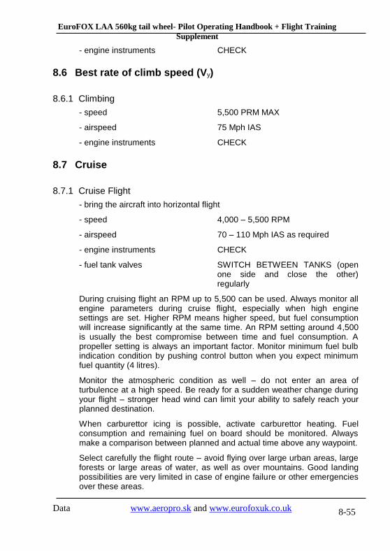
EuroFOX LAA 560kg tail wheel- Pilot Operating Handbook + Flight Training
Supplement
Data www.aeropro.sk and www.eurofoxuk.co.uk 8-55
- engine instruments CHECK
8.6 Best rate of climb speed (Vy)
8.6.1 Climbing
- speed 5,500 PRM MAX
- airspeed 75 Mph IAS
- engine instruments CHECK
8.7 Cruise
8.7.1 Cruise Flight
- bring the aircraft into horizontal flight
- speed 4,000 – 5,500 RPM
- airspeed 70 – 110 Mph IAS as required
- engine instruments CHECK
- fuel tank valves SWITCH BETWEEN TANKS (open one side and close the other) regularly
During cruising flight an RPM up to 5,500 can be used. Always monitor all engine parameters during cruise flight, especially when high engine settings are set. Higher RPM means higher speed, but fuel consumption will increase significantly at the same time. An RPM setting around 4,500 is usually the best compromise between time and fuel consumption. A propeller setting is always an important factor. Monitor minimum fuel bulb indication condition by pushing control button when you expect minimum fuel quantity (4 litres).
Monitor the atmospheric condition as well – do not enter an area of turbulence at a high speed. Be ready for a sudden weather change during your flight – stronger head wind can limit your ability to safely reach your planned destination.
When carburettor icing is possible, activate carburettor heating. Fuel consumption and remaining fuel on board should be monitored. Always make a comparison between planned and actual time above any waypoint.
Select carefully the flight route – avoid flying over large urban areas, large forests or large areas of water, as well as over mountains. Good landing possibilities are very limited in case of engine failure or other emergencies over these areas.
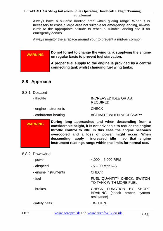
EuroFOX LAA 560kg tail wheel- Pilot Operating Handbook + Flight Training
Supplement
Data www.aeropro.sk and www.eurofoxuk.co.uk 8-56
Always have a suitable landing area within gliding range. When it is necessary to cross a large area not suitable for emergency landing, always climb to the appropriate altitude to reach a suitable landing site if an emergency occurs.
Always monitor the airspace around your to prevent a mid-air collision.
WARNING Do not forget to change the wing tank supplying the engine
on regular basis to prevent fuel starvation.
A proper fuel supply to the engine is provided by a central
connecting tank whilst changing fuel wing tanks.
8.8 Approach
8.8.1 Descent
- throttle INCREASED IDLE OR AS REQUIRED
- engine instruments CHECK
- carburettor heating ACTIVATE WHEN NECESSARY
WARNING During long approaches and when descending from a
considerable height, it is not advisable to reduce the engine
throttle control to idle. In this case the engine becomes
overcooled and a loss of power might occur. When
descending, apply increased idle so that engine
instrument readings range within the limits for normal use.
8.8.2 Downwind
- power 4,000 – 5,000 RPM
- airspeed 75 – 90 Mph IAS
- engine instruments CHECK
- fuel FUEL QUANTITY CHECK, SWITCH TO TANK WITH MORE FUEL
- brakes CHECK FUNCTION BY SHORT BRAKING (check proper system resistance)
-safety belts TIGHTEN

EuroFOX LAA 560kg tail wheel- Pilot Operating Handbook + Flight Training
Supplement
Data www.aeropro.sk and www.eurofoxuk.co.uk 8-57
- base leg and final leg airspace CHECK OF FREE SPACE
- landing site SITUATION
8.9 Normal landing
8.9.1 On Base Leg
- power 3,000 RPM
- airspeed 75 Mph IAS
- engine instruments CHECK
- wing flaps TAKE-OFF
- trimming TRIM
- final leg airspace CHECK FOR OTHER TRAFFIC
8.9.2 On Final
- airspeed 55 Mph IAS
- power ADJUST AS NEEDED
- carburettor heating ACTIVATE WHEN NECESSARY
- engine instruments CHECK
- wing flaps LANDING
- trimming TRIM
- engine instruments WITHIN LIMITS
- check of clear landing site ( people, obstacles).
8.9.3 Landing
Always judge, based on your experience, whether the available runway is sufficient for A normal landing. Always make a realistic estimation and be ready for baulked landings.
At a height of about 30 ft reduce the engine speed to idle. Maintain speed of 55 Mph IAS till flare. When flaring at a height of 1,5 to 3 ft above ground, decelerate gradually by pulling the control stick backward. At a speed of about 40 to 45 Mph IAS the aircraft touches-down.
When landing with a significant crosswind component do not set the flap to landing position – use take-off setting to touch down at higher speed to ensure proper control over the aircraft before it touches the ground.

EuroFOX LAA 560kg tail wheel- Pilot Operating Handbook + Flight Training
Supplement
Data www.aeropro.sk and www.eurofoxuk.co.uk 8-58
Entry speed to side slip .............................. 75 Mph IAS
8.9.4 After landing
- brakes APPLY WHEN NECESSARY
- wing flaps RETRACT
- trim TAIL HEAVY
8.9.5 Engine Stopping
- power cool down the engine at 2,000 RPM when necessary
- engine instruments CHECK
- turn radio to 121,5 CHECK ELT IS NOT ACTIVATED.
- avionics and other switches OFF
- ignition OFF
- master switch OFF
- avionics and other switches OFF
- main fuel valve SHUT
- tank fuel valves SHUT
- secure the aircraft chocks or other way to prevent the aircraft from unintended movement, lock the controls (using safety belts)
During normal operation the engine is usually cooled enough during the approach and landing. Make sure that all avionics and other instruments are switched off before the engine is stopped.
Do not use parking brake to hold unattended aircraft, especially when the aircraft is located in hanger.
8.9.6 Post-Flight Check
- check - damage to fuel system. fuel leakage
- damage to oil system, oil leakage
- damage to cooling circuit, liquid leakage
- damage to electrical system, ignition
- check the aircraft exterior for damage to:
- fuselage - wings, flaperons

EuroFOX LAA 560kg tail wheel- Pilot Operating Handbook + Flight Training
Supplement
Data www.aeropro.sk and www.eurofoxuk.co.uk 8-59
- tail unit
- landing gear
- fiberglass covers
- wash down the aircraft, remove dirt and bugs
- cover the cockpit with a protective cover
8.10 Short field take off and landing procedures
The standard take off procedure should be followed. The only difference is that the full throttle is applied with brakes on – do not forget to have elevator in full up (stick back) position to prevent the danger of the aircraft nosing over. Brakes are released when the maximum RPM is achieved from the engine. To clear possible obstacles in the runway direction climb at speed for best rate of climb – see section 8.6
When approaching a short field make sure that the approach speed of 75 Mph IAS is carefully maintained and full flaps are set.
8.11 Balked landing procedures
- power MAX. 5500 R.P.M
- airspeed 75 Mph IAS
- engine instruments CHECK
- wing flaps TAKE-OFF
- trimming TRIM
- wing flaps RETRACT AT A HEIGHT OF 150 FT
- trimming TRIM
- power MAX. 5500 RPM
- climb 75 Mph IAS

EuroFOX LAA 560kg tail wheel- Pilot Operating Handbook + Flight Training
Supplement
Data www.aeropro.sk and www.eurofoxuk.co.uk 8-60
8.12 Information on stalls, spins and any other useful pilot
information
WARNING Aerobatics, intentional stalls and spins are prohibited.
8.12.1 Rain
When flying in the rain, no additional steps are required. Aircraft qualities and performance are not substantially changed.

EuroFOX LAA 560kg tail wheel- Pilot Operating Handbook + Flight Training
Supplement
Data www.aeropro.sk and www.eurofoxuk.co.uk 9-61
9. Aircraft Ground Handling and Servicing
9.1 Servicing fuel, oil, coolant
9.1.1 Servicing fuel
1. Verify the main switch OFF position
2. Remove fuel tank cap
3. Service with fuel of proper type until level rises to the filler openings (or any required level)
4. Replace fuel cap and check for security
5. Wash any spilled fuel from wings with a clean water
6. Repeat for opposite fuel tank.
It is not advisable to change the type of fuel during engine operation. Refuelling should be carried out in places not endangering either the aircraft, its pilots or the environment. Prior to refuelling it is always necessary to check fuel for the absence of water. Sampling should be carried out from both any jerry cans used and from all aircraft tanks via the fuel system through drain sump. When refuelling from a jerry can, a funnel must be used containing a strainer to trap impurities, or, even better, with a buckskin leather which can trap any fuel moisture content. Fuel tank draining is performed similarly by means of the drain valve.
When filling fuel into tanks, be careful to avoid staining the cockpit window panels and glass with fuel as it contains corrosive components that will cause fast deterioration and damage to cockpit glazing. Make sure that fuel tanks are closed when refuelling is finished.
9.1.2 Servicing oil
The proper oil type should be used – see this manual or engine manual. .
1. Make sure that ignition and master switch are off
2. Remove the top engine cowling.
3. Open the oil tank.
4. When a level is not between minimum and maximum marks (or not high enough for expected longer operation), add oil. Do not add oil above the MAX level – the oil will overflow out of the engine.

EuroFOX LAA 560kg tail wheel- Pilot Operating Handbook + Flight Training
Supplement
Data www.aeropro.sk and www.eurofoxuk.co.uk 9-62
5. Replace oil tank cap
6. Replace the top engine cowling
The oil is to be changed every 50 or 100 hours of operation – see Maintenance manual and engine documentation for details. The first oil change is to be performed after initial 25 hours of operation of a new or overhauled engine.
9.1.3 Servicing coolant
The proper coolant type should be used – see this manual or Rotax engine manual.
1. Make sure that ignition and master switch are off
2. Remove the top engine cowling.
3. Remove the cap of the coolant tank
4. Add estimated quantity of coolant
5. Replace coolant tank cap
6. Replace the top engine cowling
9.2 Landing gear tyre dimension and pressure
Track .................................................................................... 1.96 m
Wheel base .......................................................................... 1.3 m
Main landing gear wheel tyre ............................................... 14x4 Tyre pressure ......................................................................... 200 kPa
Nose wheel tyre ....................................................................... 12x4 Tyre pressure ......................................................................... 200 kPa
9.3 Ground handling and tie-down instructions
9.3.1 Aircraft moving instruction
1. Make sure that parking brake is off
2. Check the space around the aircraft and in the proposed direction of movement
3. Push and hold the tail down - use handle located on fuselage close to rudder leading edge
4. Push the aircraft in the desired direction

EuroFOX LAA 560kg tail wheel- Pilot Operating Handbook + Flight Training
Supplement
Data www.aeropro.sk and www.eurofoxuk.co.uk 9-63
Aircraft can be also ground handled using a nose wheel tow bar – optional equipment, ask your dealer for details.
CAUTION Never push, pull, or lift the aircraft by use of control surfaces
9.3.2 Aircraft tie-down instruction
1. Turn the aircraft into wind, if possible
2. Lock the controls (using safety belts)
3. Make sure that parking brake is on, install wheel chocks when possible.
4. Attach ropes to the ring located on the lower wing surface (front strut attachment)
5. Attach rope the nose wheel
6. Attach rope to the tail (between tail skid and fuselage)
7. Secure all ropes to the tie-down points
It is recommended to install a soft foam rubber or fabric cover into the engine intakes to prevent foreign matter form accumulating inside the engine cowling. Before using make sure they do not collide with wheel fairings preventing any damage.
CAUTION Never push, pull, or lift the aircraft by use of control surfaces

EuroFOX LAA 560kg tail wheel- Pilot Operating Handbook + Flight Training
Supplement
Data www.aeropro.sk and www.eurofoxuk.co.uk 10-64
10. Required Placards and Markings
10.1 Airspeed indicator range markings and Overview of
speed limits:
Marking MPH (Indicated Air Speed) Operations
Marking IAS Operations
White Arc 41 93
Flaps operating range. Lower limit
is maximum weight zero thrust
stall speed in the landing
configuration. Upper limit is
maximum speed allowable with
flaps extended.
Green Arc 50 109
Normal operating range. Lower
limit is maximum weight zero
thrust stall with flaps retracted,
upper limit is manoeuvring speed
.
Yellow Arc 109 143 Caution range – Operation must
be conducted with caution and
only in smooth air
Speed IAS Mph Remarks
VNE Never exceed speed 143 VNE
VA Manoeuvring speed 109 VA
VFE Maximum wing-flaps extended speed
93 VFE
VS0 Stall speed 41
VS0
VS1 Minimum steady flight
speed
50
VS1

EuroFOX LAA 560kg tail wheel- Pilot Operating Handbook + Flight Training
Supplement
Data www.aeropro.sk and www.eurofoxuk.co.uk 10-65
10.2 Operating limitation placard on instrument panel
Or equivalent in knots
10.3 If parachute fitted
10.4 Passenger warning
This aircraft was manufactured in accordance with CS VLA
airworthiness standards and does not conform to standard category
airworthiness requirements.
WARNING – Emergency Parachute
Pull handle to deploy
WARNING – Danger rocket exit area
Unapproved equipment – see POH
Manufacturer: AEROPRO s.r.o., 949 07 Nitra, Slovakia
Max. take-off weight: 560 Kgs
Empty weight: 289 Kgs
Max baggage weight: 20 Kgs
Min/Max cockpit load: 55/220 Kgs
Never exceed speed (Mph) VNE 143 IAS
Max. Flap Extended speed (Mph) VFE 93 IAS
Stalling speed - wings level, flaps down VS0 41 IAS
Loading limits +4G - -2G
C of G limits (Nose wheel version) 10.20 Inches – 14.30 Inches

EuroFOX LAA 560kg tail wheel- Pilot Operating Handbook + Flight Training
Supplement
Data www.aeropro.sk and www.eurofoxuk.co.uk 10-66
10.5 “No intentional spins”
The following placard should be located on the instrument panel
10.6 Miscellaneous placards and markings
Occupant warning – to be placed inside cabin
This aircraft has not been certified to
an international requirement To be placed by the fuel tank filler cap
Fuel tanks capacity: 86 litres
Fuel specification:
Mogas EN228 Min Ron 90 or AVGAS
100LL To be placed inside cabin
No Smoking
Approved for flight in VFR conditions
To be placed on the panel in view of the pilot
Engine Limitations Max take off (5 min max): 5800 rpm
Max continuous: 5500 rpm
Idle (Approx) 1600 rpm
Max CHT: 150 Deg C
Max Water Temp: 110 Deg C
Max/Min Oil Temp: 140/50 Deg C
Max/Min Oil Pressure: 1.5/7.0 Bar
Max/Min Fuel Pressure: 0.15/0.4 Bar
AEROBATICS and INTENTIONAL
SPINS ARE PROHIBITED
EuroFOX LAA 560kg tail wheel- Pilot Operating Handbook + Flight Training
Supplement
Data www.aeropro.sk and www.eurofoxuk.co.uk 11-67
11. Supplementary information
11.1 Familiarisation flight procedures
The familiarisation flight procedure depends on the pilot’s experience. The whole familiarisation should start with the careful study of this document (Pilot Operating Handbook and Flight training supplement). The maintenance manual should be read as well.
The recommended procedure for an experienced pilot usually consists of:
- Local flight of duration of approximately 30 minutes with instructor
- 5 to 10 circuits with instructor
- 5 flights – emergency situations
- local flight of 30 minutes – solo
- 5 circuits solo
Always perform as many flights as required to be able to properly control the aircraft, the syllabus above is for reference only.
11.2 Pilot operating advisories
It is always recommended that familiarisation flights should take place on fine weather days
11.3 Further Information
Further study is available from many books, pelase consult the lates recommendations from the LAA. Another invaluable source is other pilots and instructors.
11.4 Starting and pre-flight checks
Starting, pre-flight, pre take off and pre landing check lists. This list is a guide and requirements will vary depending on the exact fit of the individual aircraft. It is recommended that the pilot compiles his or her own list using this table as a guide only.

EuroFOX LAA 560kg tail wheel- Pilot Operating Handbook + Flight Training
Supplement
Data www.aeropro.sk and www.eurofoxuk.co.uk 11-68
Starting
Park brake On
Doors Closed and secure
Harnesses Secure and comfortable
Radio and TX Off
Flap Neutral
Master switch On
Strobe landing light On
Fuel tap + pump On and on
Mags On
Throttle + Choke Set, choke on
Lookout Clear prop
Start Turn starter
Oil P &T Check, Oil P rising?
Starter engage and volt light Light out
Pre-flight / Take off
Throttle 2000 rpm
Flying Controls Full and free
Doors and Harness Closed, locked, secure
Stowage items Secure
Radio TX On
Trim Set take off
T & P’s All in range
RPM – Mag check Up to 3800 rpm check
Choke Off
Fuel and pump Sufficient on and on
Flaps Set take off
Lookout and line up Check all clear
Landing
Brakes Check pressure OK
Undercarriage Check no damage
Propeller Set fine if VP
Fuel and pump Sufficient on and on
Flaps Set landing as POH
Landing light On
Instruments T & P’s all ok
Carb heat Set as required
Doors and harnesses Closed, locked, secure
Park and shutdown Hope you enjoyed the flight