EUROCONTROL Specification for Surveillance Data Exchange ... · CNS/ATM Ground System Status...
32
CNS/ATM Ground System Status Reports EUROCONTROL-SPEC-0149-26 Edition :1.1 Released Edition Page i EUROCONTROL Specification for Surveillance Data Exchange ASTERIX Part 26 Category 025 CNS/ATM Ground System Status Reports DOCUMENT IDENTIFIER : EUROCONTROL-SPEC-0149-26 Edition Number : 1.1 Edition Date : 09/11/2015 Status : Released Edition Intended for : General Public Category : EUROCONTROL Specification
Transcript of EUROCONTROL Specification for Surveillance Data Exchange ... · CNS/ATM Ground System Status...

CNS/ATM Ground System Status Reports EUROCONTROL-SPEC-0149-26
Edition :1.1 Released Edition Page i
EUROCONTROL Specification for Surveillance Data Exchange ASTERIX Part 26 Category 025
CNS/ATM Ground System Status Reports
DOCUMENT IDENTIFIER : EUROCONTROL-SPEC-0149-26
Edition Number : 1.1
Edition Date : 09/11/2015
Status : Released Edition
Intended for : General Public
Category : EUROCONTROL Specification

CNS/ATM Ground System Status Reports EUROCONTROL-SPEC-0149-26
Edition :1.1 Released Edition Page ii
DOCUMENT CHARACTERISTICS
TITLE
EUROCONTROL Specification for Surveillance Data Exchange – ASTERIX Part 26
Category 025: CNS/ATM Ground System Status Reports Publications Reference: SPEC-0149-26
ISBN Number: 978-2-87497-028-3
Document Identifier Edition Number: 1.1
EUROCONTROL-SPEC-0149-26 Edition Date: 09/11/2015
Abstract
This document specifies the contents of ASTERIX Category 025 reports for the transmission of the status of CNS/ATM Ground Systems.
Keywords Data Exchange Messages SAC SIC Data Category Data Field Data Item UAP ASTERIX
Contact Person(s) Tel Unit
Alexander Engel +32-2-729 3355 DPS/STAN
STATUS, AUDIENCE AND ACCESSIBILITY Status Intended for Accessible via
Working Draft � General Public � Intranet �
Draft � EUROCONTROL � Extranet �
Proposed Issue � Restricted � Internet (www.eurocontrol.int) �
Released Issue �

CNS/ATM Ground System Status Reports EUROCONTROL-SPEC-0149-26
Edition :1.1 Released Edition Page iii
DOCUMENT APPROVAL
This document has been approved by the ASTERIX Maintenance Group (AMG).
For management approval of the complete set of ASTERIX documentation refer to Part 1.

CNS/ATM Ground System Status Reports EUROCONTROL-SPEC-0149-26
Edition :1.1 Released Edition Page iv
DOCUMENT CHANGE RECORD
The following table records the complete history of the successive editions of the present document.
EDITION DATE REASON FOR CHANGE SECTIONS
PAGES AFFECTED
0.1 April 2013 First draft of a proposed new category to cover the status reporting for surveillance ground systems of various techniques.
ALL
0.2 September 2013 Internal Review ALL
0.3 November 2013 Review following WG-51/SG-4 Meeting ALL
0.4 May 2014 Development Meeting 23.05.2014 ALL
0.5 January 2015 Input to EUROCAE WG-51/SG4 February 2015 ALL
1.0 September 2015 Data Item I025/015 reduced to 1 octet 5.2.3
1.1 November 2015 Correction in bit numbering of data item I025/105 5.2.7

CNS/ATM Ground System Status Reports EUROCONTROL-SPEC-0149-26
Edition :1.1 Released Edition Page v
Publications EUROCONTROL Headquarters 96 Rue de la Fusée B-1130 BRUSSELS Tel: +32 (0)2 729 4715 Fax: +32 (0)2 729 5149 E-mail: [email protected]

CNS/ATM Ground System Status Reports EUROCONTROL-SPEC-0149-26
Edition :1.1 Released Edition Page vi
TABLE OF CONTENTS
DOCUMENT CHARACTERISTICS .......................... .............................................................. ii
DOCUMENT APPROVAL ................................. .................................................................... iii
DOCUMENT CHANGE RECORD ......................................................................................... iv
1. INTRODUCTION ............................................................................................. 1
1.1 Scope 1
2. REFERENCES ................................................................................................ 3
2.1 General ........................................... ............................................................................ 3
2.2 Reference Documents ............................... ................................................................ 3
3. DEFINITIONS, ACRONYMS AND ABBREVIATIONS ........... ......................... 5
3.1 Definitions ....................................... ........................................................................... 5
3.2 Acronyms and Abbreviations ........................ ........................................................... 6
4. GENERAL PRINCIPLES ................................ ................................................. 7
4.1 General ........................................... ............................................................................ 7
4.2 Time Management ................................... .................................................................. 7
4.3 Unused Bits in Data Items. ........................ ................................................................ 7
4.4 Definitions and Addressing Concepts ............... ...................................................... 8
4.4.1 Addressing Concepts: Assigning SAC/SIC Codes ...................................................... 8
4.5 Ground System Status Reports ...................... .......................................................... 8
4.5.1 Types of Ground System Status Reports .................................................................... 8
4.5.2 Report Composition .................................................................................................... 9
4.6 Composition of Reports ............................ ................................................................ 9
4.6.1 Sequence of Data Items .............................................................................................. 9
4.6.2 Presence of Data Items ............................................................................................... 9
5. LAYOUT OF CNS/ATM GROUND SYSTEM STATUS REPORTS .... ........... 10
5.1 Standard Data Items ............................... ................................................................. 10
5.2 Description of Standard Data Items ................ ....................................................... 11
5.2.1 Data Item I025/000, Report Type .............................................................................. 11
5.2.2 Data Item I025/010, Data Source Identifier ............................................................... 13
5.2.3 Data Item I025/015, Service Identification ................................................................. 13
5.2.4 Data Item I025/020, Service Designator .................................................................... 14
5.2.5 Data Item I025/070, Time of Day............................................................................... 16
5.2.6 Data Item I025/100, System and Service Status ....................................................... 17
5.2.7 Data Item I025/105, System and Service Error Codes .............................................. 18
5.2.8 Data Item I025/120, Component Status .................................................................... 20
5.2.9 Data Item I025/140, Service Statistics ....................................................................... 21

CNS/ATM Ground System Status Reports EUROCONTROL-SPEC-0149-26
Edition :1.1 Released Edition Page vii
5.2.10 Data Item I025/200 Message Identification ............................................................... 23
5.3 Standard User Application Profile ................. ......................................................... 24

CNS/ATM Ground System Status Reports EUROCONTROL-SPEC-0149-26
Edition :1.1 Released Edition Page viii
This page is intentionally left blank

CNS/ATM Ground System Status Reports EUROCONTROL-SPEC-0149-26
Edition :1.1 Released Edition Page 1
1. INTRODUCTION
1.1 Scope
1.1.1 This document describes the structure and contents of ASTERIX records for the transmission of status reports from a CNS/ATM Ground System. This term is used to cover a multitude of ground systems, that may provide differing types of service applying various techniques.

CNS/ATM Ground System Status Reports EUROCONTROL-SPEC-0149-26
Edition : 1.1 Released Edition Page 2
This page is intentionally left blank

CNS/ATM Ground System Status Reports EUROCONTROL-SPEC-0149-26
Edition : 1.1 Released Edition Page 3
2. REFERENCES
2.1 General
The following Documents and Standards contain provisions which, through references in this text, constitute provisions of this EUROCONTROL Specification.
At the time of publication of this EUROCONTROL Specification, the editions indicated for the referenced documents and standards were valid.
Any revision of referenced ICAO Documents shall be immediately taken into account to revise this EUROCONTROL Specification.
Revisions of the other referenced documents shall not form part of the provisions of this EUROCONTROL Specification until they are formally reviewed and incorporated into this EUROCONTROL Specification.
In the case of a conflict between the requirements of this EUROCONTROL Specification and the contents of the other referenced documents, this EUROCONTROL Specification shall take precedence.
2.2 Reference Documents
1. EUROCONTROL Specification SPEC-0149, edition 2.2, 17 October 2014 “EUROCONTROL Specification for Surveillance Data Exchange – Part 1 All Purpose Structured EUROCONTROL Surveillance Information Exchange – ASTERIX”.

CNS/ATM Ground System Status Reports EUROCONTROL-SPEC-0149-26
Edition : 1.1 Released Edition Page 4
This page is intentionally left blank

CNS/ATM Ground System Status Reports EUROCONTROL-SPEC-0149-26
Edition : 1.1 Released Edition Page 5
3. DEFINITIONS, ACRONYMS AND ABBREVIATIONS
3.1 Definitions
For the purposes of this EUROCONTROL Specification, the following definitions shall apply:
3.1.1 Catalogue of Data Items:
List of all the possible Data Items of each Data Category describing the Data Items by their reference, structure, size and units (where applicable).
3.1.3 Data Category: Classification of the data in order to permit inter alia an easy identification.
3.1.4 Data Field: Physical implementation for the purpose of communication of a Data Item, it is associated with a unique Field Reference Number and is the smallest unit of transmitted information.
3.1.5 Data Item: The smallest unit of information in each Data Category.
3.1.6 Record: A collection of transmitted Data Fields of the same Category preceded by a Field Specification field, signalling the presence/absence of the various Data Fields.
3.1.7 User Application Profile:
The mechanism for assigning Data Items to Data Fields, and containing all necessary information which needs to be standardised for the successful encoding and decoding of the reports.
CNS/ATM Ground System Status Reports EUROCONTROL-SPEC-0149-26
Edition : 1.1 Released Edition Page 6
3.2 Acronyms and Abbreviations
For the purposes of this EUROCONTROL Specification the following shall apply:
ADS-B Automatic Dependent Surveillance - Broadcast AMG ASTERIX Maintenance Group ASTERIX All purpose STructured Eurocontrol suRveillance Information
eXchange CAT Data Category FRN Field Reference Number FSPEC Field Specification FX Field Extension Indicator
ICAO International Civil Aviation Organization ICD Interface Control Document LEN Length Indicator LSB Least Significant Bit NM Nautical Mile, unit of distance (1852 metres) REP Field Repetition Indicator s second, unit of time SAC System Area Code SIC System Identification Code SP Special Purpose Indicator UAP User Application Profile (see Definitions) UTC Co-ordinated Universal Time

CNS/ATM Ground System Status Reports EUROCONTROL-SPEC-0149-26
Edition : 1.1 Released Edition Page 7
4. GENERAL PRINCIPLES
4.1 General
This document describes the application of ASTERIX to CNS/ATM Ground System Status Reports.
4.2 Time Management
The time stamping shall comply with the Coordinated Universal Time (UTC) as specified in ICAO Annex 5.
4.3 Unused Bits in Data Items.
Decoders of ASTERIX data shall never assume and rely on specific settings of spare or unused bits. However in order to improve the readability of binary dumps of ASTERIX records, it is recommended to set all spare bits to zero.

CNS/ATM Ground System Status Reports EUROCONTROL-SPEC-0149-26
Edition : 1.1 Released Edition Page 8
4.4 Definitions and Addressing Concepts
4.4.1 Addressing Concepts: Assigning SAC/SIC Codes By convention a dedicated and unambiguous SAC/SIC code shall be assigned to every Ground System Service.
4.5 Ground System Status Reports
4.5.1 Types of Ground System Status Reports
Three types of service reports have been identified:
• Service and System Status Report (Message Type 001)
• Component Status Report (Message Type 002)
• Service Statistics Report (Message Type 003)
4.5.1.1 Service and System Status Report
These reports shall convey the status of individual services provided by the ground system as well as the individual components of the system that support the service. Each ground system may provide several services, and the status of each service shall be reported independently in each service status report.
4.5.1.2 Component Status Report
These reports shall be sent to signal the status of individual components independent from their use in a service. The component is identified by its Component ID (data item I025/120) and it is up to the receiving system to properly interpret this number. It is up to the management of the receiving system to determine the impact of a component failure.
4.5.1.3 Service Statistics Report
These reports shall be sent to provide statistical information about an identified service.
4.5.1.4 Message Generation Principles
Message Types 001 and 002 shall be generated periodically and optionally whenever a change of the status happens. The generation of the different message types shall be agreed between the communication partners and shall be described in the system’s Interface Control Document (ICD).
The generation of message type 003 shall be agreed between the communication partners.

CNS/ATM Ground System Status Reports EUROCONTROL-SPEC-0149-26
Edition : 1.1 Released Edition Page 9
4.5.2 Report Composition
A single UAP has been standardised and shall be used to transmit service reports from a Ground System to user systems.
The composition of reports of Category 025 follows the principle according to Part 1 of ASTERIX edition 2.2 or later. Each report is composed according to the following principle:
CAT = 025 LEN FSPEC DATA ITEM DATA ITEM DATA ITEM …
Where:
• CAT = 025 is a one-octet field indicating Ground System Status reports;
• LEN is a two-octet field indicating the total length in octets of the Category 025 report, including the CAT and LEN fields;
• FSPEC is the Field Specification.
4.6 Composition of Reports
4.6.1 Sequence of Data Items
Reports shall be composed of Data Items assembled in the order defined by the Field Reference Number (FRN) in the associated UAP.
4.6.2 Presence of Data Items
When sent, items shall always be transmitted in a Record with the corresponding FSPEC bits set to one.

CNS/ATM Ground System Status Reports EUROCONTROL-SPEC-0149-26
Edition : 1.1 Released Edition Page 10
5. LAYOUT OF CNS/ATM GROUND SYSTEM STATUS REPORTS
5.1 Standard Data Items
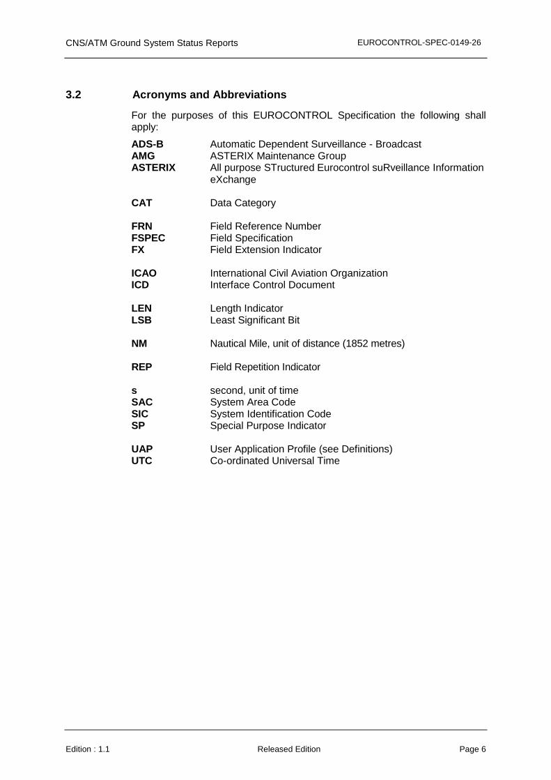
The standardised Data Items which shall be used for the transmission of CNS/ATM Ground System Status reports are defined in Table 1 and described in the following pages.
Table 1 - Standard Data Items of Category 025
Data Item Ref. No.
Description System Resolution
I025/000 Report Type N.A.
I025/010 Data Source Identifier N.A.
I025/015 Service Identification N.A.
I025/020 Service Designator N.A.
I025/070 Time of Day 1/128 s
I025/100 System and Service Status N.A.
I025/105 System and Service Error Codes N.A.
I025/120 Component Status N.A.
I025/140 Service Statistics N.A.
I025/200 Message Identification N.A.

CNS/ATM Ground System Status Reports EUROCONTROL-SPEC-0149-26
Edition : 1.1 Released Edition Page 11
5.2 Description of Standard Data Items
5.2.1 Data Item I025/000, Report Type Definition : This Data Item allows for a more convenient handling of the
reports at the receiver side by further defining the type of transaction.
Format : One-octet fixed length Data Item. Structure:
Octet no. 1
8 7 6 5 4 3 2 1
Report Type RG
bits-8/2 Report Type bit-1 Cat 025 Report Generation =0: Periodic Report =1: Event Driven Report
NOTES
1. In applications where transactions of various types are exchanged, the Report Type Data Item facilitates the proper report handling at the receiver side.
2. All Report Type values are reserved for common standard use. 3. The following set of Report Types are standardised for Category 025
records:
• 001 Service and System Status report (see 4.5.1.1. above)
• 002 Component Status report (see 4.5.1.2. above)
• 003 Service Statistics report (see 4.5.1.3. above)
4. The list of items present for the three report types is defined in the following table.
M stands for mandatory, O for optional, X for never present.
CNS/ATM Ground System Status Reports EUROCONTROL-SPEC-0149-26
Edition : 1.1 Released Edition Page 12
Table 2 - Report Types
Type Item
001 Service and System
Status
002 Component
Status
003 Service
Statistics
I025/000 Report Type
M M M
I025/010 Data Source
Identifier
M M M
I025/015 Service
Identification
M X M
I025/020 Service
Designator
O X O
I025/070 Time of Day
M M M
I025/100 System & Service
Status
O
X X
I025/105 Service Error
Codes
O X X
I025/120 Component
Status
O M X
I025/140 Service Statistics
X X M
I025/200 Message
Identification
O O O
CNS/ATM Ground System Status Reports EUROCONTROL-SPEC-0149-26
Edition : 1.1 Released Edition Page 13
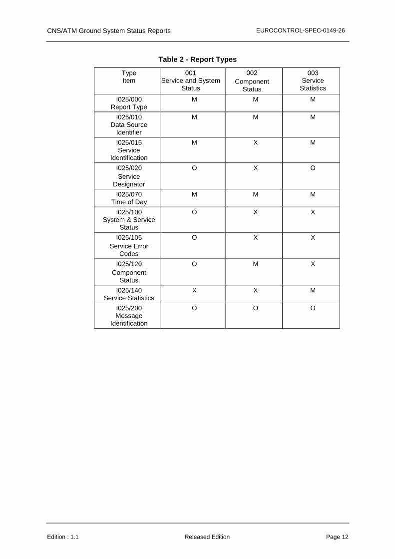
5.2.2 Data Item I025/010, Data Source Identifier Definition : Identification of the Ground System from which the data is
received. Format : Two-octet fixed length Data Item. Structure:
Octet no. 1 Octet no. 2
16 15 14 13 12 11 10 9 8 7 6 5 4 3 2 1
SAC SIC
bits-16/9 (SAC) System Area Code bits-8/1 (SIC) System Identification Code
NOTE - The up-to-date list of SACs is published on the EUROCONTROL Web Site (http://www.eurocontrol.int/asterix).
NOTE - The SICs are allocated by the national authority responsible for the surveillance infrastructure.
5.2.3 Data Item I025/015, Service Identification Definition : Identifies the service being reported. Format : One-octet fixed length Data Item. Structure:
Octet no. 1
8 7 6 5 4 3 2 1
SID
bits-8/1 (SID) Service Identification
Note: The service identification is allocated by the system.

CNS/ATM Ground System Status Reports EUROCONTROL-SPEC-0149-26
Edition : 1.1 Released Edition Page 14
5.2.4 Data Item I025/020, Service Designator Definition : Designator of the service being reported. Format : Six-octet fixed length Data Item. Structure:
Octet no. 1 Octet no. 2
48 47 46 45 44 43 42 41 40 39 38 37 36 35 34 33
Character 1 Character 2 Character 3
Octet no. 3 Octet no. 4
32 31 30 29 28 27 26 25 24 23 22 21 20 19 18 17
Character 4 Character 5
Octet no. 5 Octet no. 6
16 15 14 13 12 11 10 9 8 7 6 5 4 3 2 1
Character 6 Character 7 Character 8
bits-48/1 Service Designator. Characters 1-8 (coded on 6 Bits each) defining the text readable designator for each Service.

CNS/ATM Ground System Status Reports EUROCONTROL-SPEC-0149-26
Edition : 1.1 Released Edition Page 15
Each character of the service designator is encoded as defined below (see ICAO Annex 10, Volume IV, page 3-77, table 3-9):
b6 0 0 1 1 b5 0 1 0 1
b4 b3 b2 b1 0 0 0 0 P SP1 0 0 0 0 1 A Q 1 0 0 1 0 B R 2 0 0 1 1 C S 3 0 1 0 0 D T 4 0 1 0 1 E U 5 0 1 1 0 F V 6 0 1 1 1 G W 7 1 0 0 0 H X 8 1 0 0 1 I Y 9 1 0 1 0 J Z 1 0 1 1 K 1 1 0 0 L 1 1 0 1 M 1 1 1 0 N 1 1 1 1 O
SP1 = SPACE code
For each character the following bit numbering convention shall be observed:
b6 b5 b4 b3 b2 b1
Notes:
1. Assignments of Service designators to specific services/systems and interpretation of these fields are implementation dependent.
2. Examples of Service Designators are “1090ADSB”, “WAM”, “1090TISB”, etc.
3. Multiple Service Type Designators may be used to describe a single service where applicable

CNS/ATM Ground System Status Reports EUROCONTROL-SPEC-0149-26
Edition : 1.1 Released Edition Page 16
5.2.5 Data Item I025/070, Time of Day Definition : Absolute time stamping expressed as UTC time. Format : Three-octet fixed length Data Item. Structure:
Octet no. 1
24 23 22 21 20 19 18 17
TIME
Octet no. 2 Octet no. 3
16 15 14 13 12 11 10 9 8 7 6 5 4 3 2 1
OF DAY LSB
bit-1 (LSB) = (2-7)s = 1/128 s
NOTES
1. The time of day value is reset to zero each day at midnight.

CNS/ATM Ground System Status Reports EUROCONTROL-SPEC-0149-26
Edition : 1.1 Released Edition Page 17
5.2.6 Data Item I025/100, System and Service Status Definition : Information concerning the status of the Service Volume. Format : A one octet extensible field. Structure:
Octet no. 1
8 7 6 5 4 3 2 1
NOGO OPS
SSTAT FX
bit-8 (NOGO) Operational Release Status of the Data
= 0 Data is released for operational use = 1 Data must not be used operationally
bit-7/6 (OPS) Operational Service Mode = 0 Operational = 1 Operational but in Standby
= 2 Maintenance = 3 reserved for future use bits-5/2 (SSTAT) System and Service State
= 0 Running = 1 Failed = 2 Degraded = 3 Undefined = 4 – 15 reserved for future use
bit-1 (FX) = 0 No extension = 1 Extension
NOTES
1. Bit 8 (NOGO), when set to “1” indicates that the data transmitted by the system/service is not released for operational use. This indication is independent from the status of the system itself or that of the service. It just indicates that the system or service volume output must not be used for operational services but may be used for, e.g. test and validation purposes. The indication GO/NO-GO indicates a mode of the system rather than a status. Usually this bit will be set by operator input.
2. Bit 7/6 (OPS), when set to “1” indicates that the system is running but not operationally used (e.g. for a standby system in a redundant configuration).
3. Bits 5/2 (SSTAT): This information informs about the state of the overall service volume status. The actual implementation of this field is service dependent and should be described in the system/service specification. However, it is expected that – as far as this information is available – a mapping is performed between the states of individual components as reported in data item I025/120. As an example, if one component fails but the system is still operational (at least partially), the service status should change to “degraded”.
CNS/ATM Ground System Status Reports EUROCONTROL-SPEC-0149-26
Edition : 1.1 Released Edition Page 18
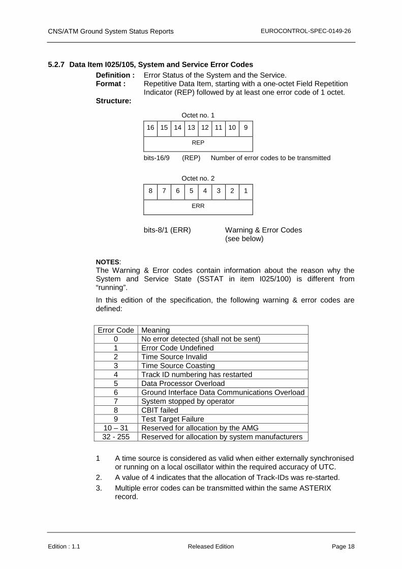
5.2.7 Data Item I025/105, System and Service Error Codes Definition : Error Status of the System and the Service. Format : Repetitive Data Item, starting with a one-octet Field Repetition
Indicator (REP) followed by at least one error code of 1 octet. Structure:
Octet no. 1
16 15 14 13 12 11 10 9
REP
bits-16/9 (REP) Number of error codes to be transmitted
Octet no. 2
8 7 6 5 4 3 2 1
ERR
bits-8/1 (ERR) Warning & Error Codes
(see below)
NOTES: The Warning & Error codes contain information about the reason why the System and Service State (SSTAT in item I025/100) is different from “running”.
In this edition of the specification, the following warning & error codes are defined:
Error Code Meaning 0 No error detected (shall not be sent) 1 Error Code Undefined 2 Time Source Invalid 3 Time Source Coasting 4 Track ID numbering has restarted 5 Data Processor Overload 6 Ground Interface Data Communications Overload 7 System stopped by operator 8 CBIT failed 9 Test Target Failure
10 – 31 Reserved for allocation by the AMG 32 - 255 Reserved for allocation by system manufacturers
1 A time source is considered as valid when either externally synchronised
or running on a local oscillator within the required accuracy of UTC. 2. A value of 4 indicates that the allocation of Track-IDs was re-started. 3. Multiple error codes can be transmitted within the same ASTERIX
record.
CNS/ATM Ground System Status Reports EUROCONTROL-SPEC-0149-26
Edition : 1.1 Released Edition Page 19
4. Error codes in the range 0 to 31 shall be allocated centrally by the AMG. Error codes in the range from 32 to 255 are available for specification by the system manufacturers. They are not standardised and shall be described in the Interface Control Document (ICD) of the respective system.

CNS/ATM Ground System Status Reports EUROCONTROL-SPEC-0149-26
Edition : 1.1 Released Edition Page 20
5.2.8 Data Item I025/120, Component Status
Definition: Indications of status of various system components and, when applicable, error codes.
Format : Repetitive Data Item, starting with a one-octet Field Repetition Indicator (REP) followed by at least one block of 3 octets.
Structure:
Octet no. 1
32 31 30 29 28 27 26 25
REP
bits-32/25 (REP) Number of Component Status Reports
Octet no. 2 Octet no. 3
24 23 22 21 20 19 18 17 16 15 14 13 12 11 10 9
CID
bits-24/9 (CID) Component ID
The Component ID is implementation specific
A Component ID of 65535 indicates that the following error code applies to all components defined.
Octet no. 4
8 7 6 5 4 3 2 1
Error Code CS
Bits-8/3 (Error Code) 0: No Error Detected
1: Error Code Undefined
2-15 Reserved for allocation by the AMG
16-63 Reserved for allocation by system manufacturers
bits-2/1 (CS) Component State
=0: Running
=1: Failed
=2: Maintenance
=3: reserved
NOTES: Error codes in the range 2 to 15 shall be allocated centrally by the AMG. Error codes in the range from 16 to 63 are available for specification by the system manufacturers. They are not standardised and shall be described in the Interface Control Document (ICD) of the respective system.

CNS/ATM Ground System Status Reports EUROCONTROL-SPEC-0149-26
Edition : 1.1 Released Edition Page 21
5.2.9 Data Item I025/140, Service Statistics Definition : Statistics concerning the service. Provides counts of various
message types that have been received since the report was last sent.
Format : Repetitive Data Item, starting with a one-octet Field Repetition Indicator (REP) followed by at least one block of 6 octets.
Structure:
Octet no. 1
56 55 54 53 52 51 50 49
REP
Octet no. 2 Octet no. 3
48 47 46 45 44 43 42 41 40 39 38 37 36 35 34 33
TYPE REF SPARE
Octet no. 4 Octet no. 5
32 31 30 29 28 27 26 25 24 23 22 21 20 19 18 17
COUNTER VALUE
Octet no. 6 Octet no. 7
16 15 14 13 12 11 10 9 8 7 6 5 4 3 2 1
COUNTER VALUE
bits-56/49 (REP) Number of counters following
bits-48/41 (TYPE) Type of report counter, encoded as follows
= 0 Number of unknown messages received
= 1 Number of ‘too old’ messages received
= 2 Number of failed message conversions
= 3 Total Number of messages received
= 4 Total number of messages transmitted
= 5-19 Reserved for AMG ≥ 20 implementation specific
bit-40 (REF) Reference from which the messages are
counted = 0 From UTC midnight = 1 From the previous report

CNS/ATM Ground System Status Reports EUROCONTROL-SPEC-0149-26
Edition : 1.1 Released Edition Page 22
bits-39/33 (SPARE) Spare bits set to 0 bits-32/1 (COUNTER 32-bit counter value
VALUE)
Notes:
There is no special significance attributed to the numbering of the TYPE field. However the range from 0 to 19 is intended to cover generic messages which may be applicable to many types of service.

CNS/ATM Ground System Status Reports EUROCONTROL-SPEC-0149-26
Edition : 1.1 Released Edition Page 23
5.2.10 Data Item I025/200 Message Identification
Definition: Identification of a unique message.
Format: Three-octet fixed length Data Item.
Structure:
Octet 1 Octet 2
24 23 22 21 20 19 18 17 16 15 14 13 12 11 10 9
Message Identification Number
Octet 3
8 7 6 5 4 3 2 1
Message Identification Number (cont)
bits-24/1 Message Identification Number
Notes:
1. The Message Identification Number is to be used to uniquely identify each message. If messages are being sent on redundant links then this number shall be identical for the same message on each link. This will allow the receiver to easily identify and discard duplicate messages.
2. It is not required that Message Identification Numbers be assigned in ascending order by time of message transmission.
CNS/ATM Ground System Status Reports EUROCONTROL-SPEC-0149-26
Edition : 1.1 Released Edition Page 24
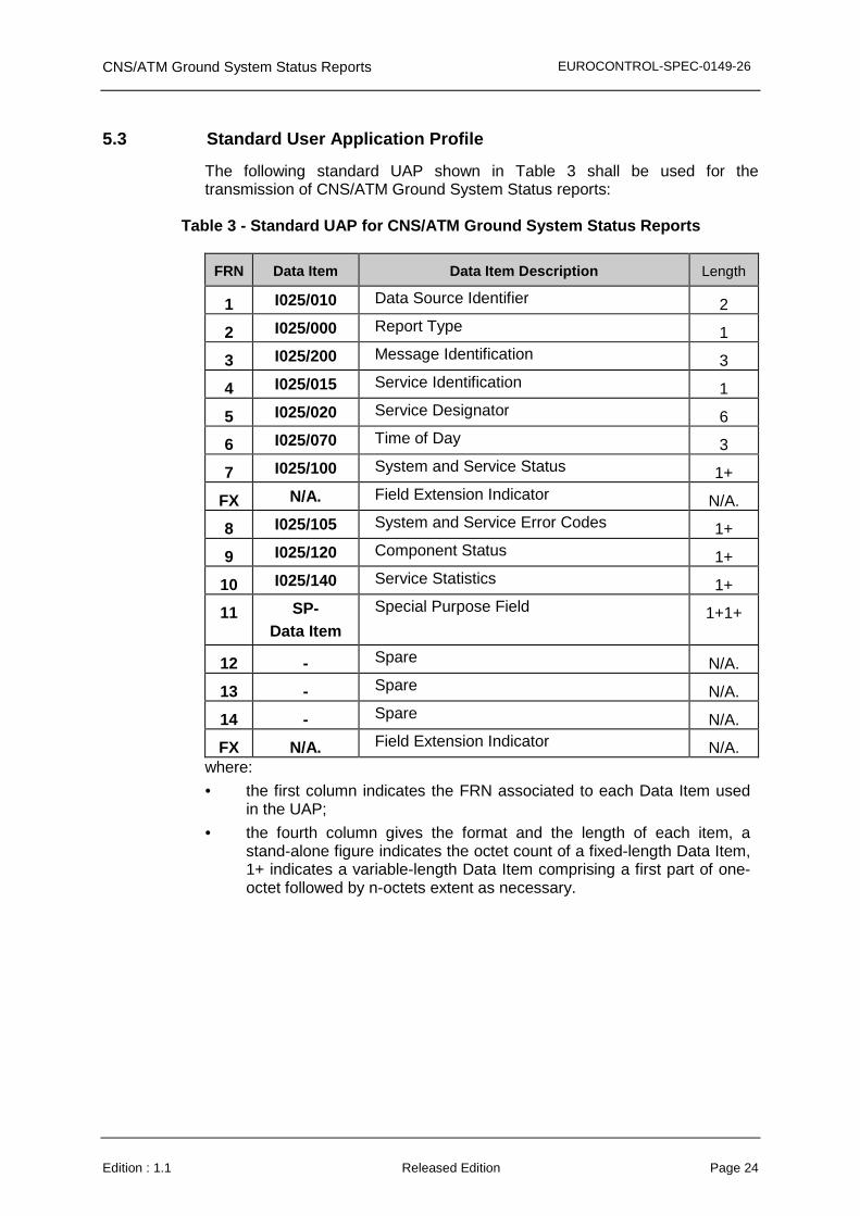
5.3 Standard User Application Profile
The following standard UAP shown in Table 3 shall be used for the transmission of CNS/ATM Ground System Status reports:
Table 3 - Standard UAP for CNS/ATM Ground System S tatus Reports
FRN Data Item Data Item Description Length
1 I025/010 Data Source Identifier 2
2 I025/000 Report Type 1
3 I025/200 Message Identification 3
4 I025/015 Service Identification 1
5 I025/020 Service Designator 6
6 I025/070 Time of Day 3
7 I025/100 System and Service Status 1+
FX N/A. Field Extension Indicator N/A.
8 I025/105 System and Service Error Codes 1+
9 I025/120 Component Status 1+
10 I025/140 Service Statistics 1+
11 SP- Data Item
Special Purpose Field 1+1+
12 - Spare N/A.
13 - Spare N/A.
14 - Spare N/A.
FX N/A. Field Extension Indicator N/A. where:
• the first column indicates the FRN associated to each Data Item used in the UAP;
• the fourth column gives the format and the length of each item, a stand-alone figure indicates the octet count of a fixed-length Data Item, 1+ indicates a variable-length Data Item comprising a first part of one-octet followed by n-octets extent as necessary.