EUROCONTROL Specification for A-SMGCS Services · Specification supersedes priorThis EUROCONTROL...
123
EUROCONTROL Specification for Advanced-Surface Movement Guidance and Control System (A-SMGCS) Services EUROCONTROL Edition: 1.0 Edition date: 01/03/2018 Reference nr: EUROCONTROL-SPEC-171
Transcript of EUROCONTROL Specification for A-SMGCS Services · Specification supersedes priorThis EUROCONTROL...
EUROCONTROL Specificationfor Advanced-Surface Movement Guidance and Control System (A-SMGCS) Services
EUROCONTROL
Edition: 1.0Edition date: 01/03/2018Reference nr: EUROCONTROL-SPEC-171

EUROPEAN ORGANISATION FOR THE SAFETY OF AIR NAVIGATION
EUROCONTROL Specification for
Advanced-Surface Movement Guidance and
Control System (A-SMGCS) Services
DOCUMENT IDENTIFIER : EUROCONTROL-SPEC-171
Edition Number : 1.0 Edition Date : 01 March 2018 Status : Released Issue Intended for : General Public Category : EUROCONTROL Specification
EUROCONTROL Specification for A-SMGCS Services
Page 2 Released Issue Edition: 1.0
DOCUMENT CHARACTERISTICS TITLE
EUROCONTROL Specification for A-SMGCS Services
Publications Reference: SPEC-171 ISBN Number: 978-2-87497-097-9
Document Identifier Edition Number: 1.0 EUROCONTROL-SPEC-171 Edition Date: 01 March 2018
Abstract
This EUROCONTROL Specification describes the Services (Surveillance, Airport Safety Support, Routing and Guidance) and requirements of the Advanced-Surface Movement Guidance and Control System (A-SMGCS) to support their implementation at an aerodrome.
It is intended to be used in conjunction with the EUROCAE document ED-87 Minimum Aviation System Performance Specification (MASPS) for A-SMGCS.
The implementation of an A-SMGCS and its various services is a local decision based on the needs of an aerodrome and any national or regional mandates.
This Specification contributes to the implementation of the essential requirements of the interoperability Regulation of the Single European Sky (SES) thereby providing a means of compliance.
Keywords A-SMGCS CMAC Manoeuvring Area Routing AGL Follow The Greens Mobile Runway Incursion Airport Safety Support Guidance Movement Area Surveillance CATC HMI RMCA Transponder
Contact Person(s) Tel Unit Stéphane DUBUISSON Roger LANE or email : [email protected]
+33 169 88 7636 +33 169 88 7445
ATM/RDS/APT
STATUS, AUDIENCE AND ACCESSIBILITY Status Intended for Accessible via
Working Draft General Public Intranet Draft EUROCONTROL Extranet Proposed Issue Restricted Internet (www.eurocontrol.int) Released Issue
EUROCONTROL Specification for A-SMGCS Services
Edition: 1.0 Released Issue Page 3
EUROCONTROL Specification for A-SMGCS Services
Page 4 Released Issue Edition: 1.0
DOCUMENT CHANGE RECORD The following table records the complete history of the successive editions of the present document.
EDITION NUMBER
EDITION DATE REASON FOR CHANGE PAGES
AFFECTED
1.0 01 March 2018 First edition. All
Publications EUROCONTROL Headquarters 96 Rue de la Fusée B-1130 BRUSSELS Tel: +32 (0)2 729 4715 Fax: +32 (0)2 729 5149 E-mail: [email protected]
EUROCONTROL Specification for A-SMGCS Services
Edition: 1.0 Released Issue Page 5
CONTENTS LIST OF FIGURES ..................................................................................................... 9
LIST OF TABLES ..................................................................................................... 10
EXECUTIVE SUMMARY .......................................................................................... 11
1. Introduction .................................................................................................... 12 1.1 A-SMGCS Overview .............................................................................................. 12
1.1.1 What is an A-SMGCS? .................................................................................. 12 1.1.2 A-SMGCS Local Implementation Decision ................................................. 13
1.2 Purpose of the Document .................................................................................... 14 1.3 Scope of the Document ........................................................................................ 15 1.4 Maintenance of the Specification ........................................................................ 15 1.5 Conventions .......................................................................................................... 15 1.6 Abbreviations ........................................................................................................ 16 1.7 Definitions .............................................................................................................. 18 1.8 Reference Material ................................................................................................ 22 1.9 Document Structure .............................................................................................. 23
2. A-SMGCS Actors and Responsibilities ........................................................ 24 2.1 Introduction ........................................................................................................... 24 2.2 Surveillance Service ............................................................................................. 25 2.3 Airport Safety Support Service ............................................................................ 25 2.4 Routing Service ..................................................................................................... 26 2.5 Guidance Service .................................................................................................. 26
3. A-SMGCS Services ......................................................................................... 27 3.1 Introduction ........................................................................................................... 27 3.2 Surveillance Service ............................................................................................. 27 3.3 Airport Safety Support Service ............................................................................ 28
3.3.1 General ........................................................................................................... 28 3.3.2 Stages of Alert ............................................................................................... 28 3.3.3 Protected Areas ............................................................................................. 29
3.3.3.1 Runway Protected Area (RPA) ............................................................. 29 3.3.3.2 Restricted Areas .................................................................................... 30
3.3.4 Presentation of Alerts to Controllers .......................................................... 30 3.3.5 Runway Monitoring and Conflict Alerting (RMCA) .................................... 31 3.3.6 Conflicting ATC Clearances (CATC) ............................................................ 32 3.3.7 Conformance Monitoring Alerts for Controllers (CMAC) .......................... 33 3.3.8 Constraints for CATC and CMAC Alerts ..................................................... 35
3.4 Routing Service ..................................................................................................... 36 3.4.1 General ........................................................................................................... 36 3.4.2 Presentation of Routes to Controllers ........................................................ 36 3.4.3 Generation of Planned Routes Without Controller Interaction ................. 37 3.4.4 Controller Interaction With the Routing Service ........................................ 38
EUROCONTROL Specification for A-SMGCS Services
Page 6 Released Issue Edition: 1.0
3.4.5 Provision of Taxi Times to Airport-CDM ..................................................... 39 3.5 Guidance Service .................................................................................................. 39
3.5.1 General ........................................................................................................... 39 3.5.2 Automated Switching of the Taxiway Centreline Lights (TCL) ................. 39
3.5.2.1 General ................................................................................................... 39 3.5.2.2 Presentation of TCL to Controllers ..................................................... 40
3.5.3 Automated Switching of Stop Bars ............................................................. 41 3.5.4 Automated Activation of Advanced-Visual Docking Guidance Systems
(A-VDGS) ........................................................................................................ 41
4. Operational Procedures ................................................................................. 42 4.1 Introduction ........................................................................................................... 42 4.2 Controllers ............................................................................................................. 42
4.2.1 Surveillance Service ..................................................................................... 42 4.2.2 Airport Safety Support Service .................................................................... 42
4.2.2.1 General ................................................................................................... 42 4.2.2.2 Procedures for a RMCA INFORMATION Alert..................................... 42 4.2.2.3 Procedures for a RMCA ALARM Alert ................................................. 43 4.2.2.4 Procedures for a CATC Alert ................................................................ 43 4.2.2.5 Procedures for a CMAC INFORMATION Alert..................................... 43 4.2.2.6 Procedures for a CMAC ALARM Alert ................................................. 43
4.2.3 Routing Service ............................................................................................. 43 4.2.4 Guidance Service .......................................................................................... 44
4.2.4.1 Automated Switching of the Taxiway Centreline Lights (TCL) ......... 44 4.2.4.2 Automated Switching of Stop Bars ..................................................... 45
4.3 Flight Crew ............................................................................................................. 45 4.3.1 Surveillance Service ..................................................................................... 45 4.3.2 Airport Safety Support Service .................................................................... 47 4.3.3 Routing Service ............................................................................................. 47 4.3.4 Guidance Service .......................................................................................... 47
4.4 Vehicle Drivers ...................................................................................................... 47 4.4.1 Surveillance Service ..................................................................................... 47 4.4.2 Airport Safety Support Service .................................................................... 48 4.4.3 Routing Service ............................................................................................. 48 4.4.4 Guidance Service .......................................................................................... 48 4.4.5 Occasional Airside Operating Vehicles ...................................................... 48
4.5 All Weather Operations ........................................................................................ 49 4.5.1 Introduction ................................................................................................... 49 4.5.2 Airport Operations under Normal Visibility ................................................ 49 4.5.3 Airport Operations during Reduced Aerodrome Visibility Conditions .... 49
4.6 Use of A-SMGCS in Degraded Mode ................................................................... 49
5. System Overview ............................................................................................ 51 5.1 System Overview .................................................................................................. 51 5.2 Databases .............................................................................................................. 52
5.2.1 Mobile Information Database ....................................................................... 52 5.2.2 Airport Operations Status Database ........................................................... 52
5.3 Controller Working Position ................................................................................ 53
EUROCONTROL Specification for A-SMGCS Services
Edition: 1.0 Released Issue Page 7
5.3.1 Human-Machine Interface (HMI) ................................................................... 53 5.3.1.1 General Overview .................................................................................. 53 5.3.1.2 Labelling of Mobiles .............................................................................. 53
5.3.2 Electronic Clearance Input (ECI) .................................................................. 55 5.4 Recording and Playback ...................................................................................... 55 5.5 Surveillance Service ............................................................................................. 56 5.6 Airport Safety Support Service ............................................................................ 57 5.7 Routing Service ..................................................................................................... 58 5.8 Guidance Service .................................................................................................. 60
6. A-SMGCS Requirements ................................................................................ 61 6.1 General ................................................................................................................... 61 6.2 Surveillance Service ............................................................................................. 63 6.3 Airport Safety Support Service ............................................................................ 64
6.3.1 General ........................................................................................................... 64 6.3.2 RMCA.............................................................................................................. 65 6.3.3 CATC .............................................................................................................. 66 6.3.4 CMAC.............................................................................................................. 66
6.3.4.1 CMAC General ....................................................................................... 66 6.3.4.2 CMAC INFORMATION Alerts ................................................................ 67 6.3.4.3 CMAC ALARM Alerts ............................................................................ 67 6.3.4.4 CMAC INFORMATION or ALARM Alerts.............................................. 68
6.4 Routing Service ..................................................................................................... 70 6.4.1 General ........................................................................................................... 70 6.4.2 Generation of Planned Routes WITHOUT Controller Interaction ............. 71 6.4.3 Controller Interaction WITH the Routing Service ....................................... 72 6.4.4 Provision of Taxi Times ................................................................................ 72
6.5 Guidance Service .................................................................................................. 74 6.5.1 General ........................................................................................................... 74 6.5.2 Automated Switching of TCL ....................................................................... 74 6.5.3 Automated Switching of Stop Bars ............................................................. 76 6.5.4 Automated Activation of A-VDGS ................................................................ 76
Informative - Detailed Description of RMCA Alerts .................. 78 Appendix ASingle Runway ..................................................................................................... 78 Parallel or Converging Runways ....................................................................... 81 Intersecting / Crossing Runways ....................................................................... 81
Informative - Detailed Description of CATC Alerts .................. 83 Appendix BCATC HMI ............................................................................................................. 83 Line-Up vs Line-Up .............................................................................................. 85 Line-Up vs Cross or Enter .................................................................................. 85 Line-Up vs Take-Off ............................................................................................ 86 Line-Up vs Land .................................................................................................. 86 Cross or Enter vs Line-Up .................................................................................. 87 Cross or Enter vs Cross or Enter ...................................................................... 87 Cross or Enter vs Take-Off ................................................................................. 88 Cross or Enter vs Land ....................................................................................... 88

EUROCONTROL Specification for A-SMGCS Services
Page 8 Released Issue Edition: 1.0
Take-Off vs Line-Up ............................................................................................ 89 Take-Off vs Cross or Enter ................................................................................. 89 Take-Off vs Take-Off ........................................................................................... 89 Take-Off vs Land ................................................................................................. 91 Land vs Line-Up .................................................................................................. 93 Land vs Cross or Enter ....................................................................................... 93 Land vs Take-Off ................................................................................................. 94 Land vs Land ....................................................................................................... 96
Informative - Detailed Description of CMAC Alerts .................. 98 Appendix CROUTE DEVIATION ............................................................................................. 98 NO PUSH-BACK APPROVAL ............................................................................. 99 NO TAXI APPROVAL ......................................................................................... 100 STATIONARY ..................................................................................................... 101 NO CONTACT .................................................................................................... 103 NO TRANSFER .................................................................................................. 104 NO TAKE-OFF CLEARANCE ............................................................................ 105 NO LANDING CLEARANCE .............................................................................. 106 LANDING ON WRONG RUNWAY ..................................................................... 107 RED STOP BAR CROSSED .............................................................................. 108 LINING UP ON THE WRONG RUNWAY ........................................................... 109 RUNWAY INCURSION ....................................................................................... 110 RUNWAY OR TAXI TYPE .................................................................................. 111 RUNWAY CLOSED ............................................................................................ 112 TAXIWAY CLOSED ............................................................................................ 113 RESTRICTED AREA INCURSION ..................................................................... 114 HIGH SPEED ...................................................................................................... 115
Informative - Traceability to Regulatory Requirements ......... 116 Appendix D
EUROCONTROL Specification for A-SMGCS Services
Edition: 1.0 Released Issue Page 9
LIST OF FIGURES
Figure 1: A-SMGCS Overview ....................................................................................................... 12 Figure 2: A-SMGCS Regulatory and Standardisation Framework ............................................ 14 Figure 3: A-SMGCS Business Organisations. ............................................................................. 24 Figure 4: The RPAs Defined in Blue/Pink for Brussels Airport (EBBR) .................................... 29 Figure 5: Example of a CAT I RPA ............................................................................................... 30 Figure 6: Example of a Planned Route (Aircraft Still on Stand) ................................................ 36 Figure 7: Example of a Cleared and Pending Route to a Holding Point ................................... 37 Figure 8: Example of Route Modification via the HMI ................................................................ 38 Figure 9: HMI Representation of TCL ........................................................................................... 40 Figure 10: Example of an A-VDGS. .............................................................................................. 41 Figure 11: Example HMI of an Intermediate Clearance Limit on a Route ................................. 44 Figure 12: Typical Transponder Control Panels ......................................................................... 46 Figure 13: Transponder Settings on the Aerodrome .................................................................. 46 Figure 14: Vehicle Transmitter Antenna ...................................................................................... 48 Figure 15: Example of Operational Status Indicators. ............................................................... 49 Figure 16: Example of Degraded Modes ...................................................................................... 50 Figure 17: Example of an A-SMGCS Architecture ...................................................................... 51 Figure 18: Example HMI with Different Colour Labels................................................................ 54 Figure 19: Surveillance Service Interfaces .................................................................................. 56 Figure 20: Airport Safety Support Service Interfaces................................................................. 57 Figure 21: Routing Service Interfaces ......................................................................................... 58 Figure 22: Guidance Service Interfaces ....................................................................................... 60

EUROCONTROL Specification for A-SMGCS Services
Page 10 Released Issue Edition: 1.0
LIST OF TABLES
Table 1: Services/Functions Dependencies ................................................................................ 13 Table 2: Surveillance - Actors and Responsibilities ................................................................... 25 Table 3: Airport Safety Support - Actors and Responsibilities ................................................. 25 Table 4: Routing - Actors and Responsibilities .......................................................................... 26 Table 5: Guidance - Actors and Responsibilities ....................................................................... 26 Table 6: Situations for CATC Alerts ............................................................................................. 32 Table 7: Description of CMAC Alerts ........................................................................................... 35 Table 8: Traceability to the General Essential Requirement of Reg No 552/2004.................. 118 Table 9: Traceability to the Specific Essential Requirement of Reg No 552/2004 ................. 120
EUROCONTROL Specification for A-SMGCS Services
Edition: 1.0 Released Issue Page 11
EXECUTIVE SUMMARY
This EUROCONTROL Specification describes the Services (Surveillance, Airport Safety Support, Routing and Guidance) of an Advanced-Surface Movement Guidance and Control System (A-SMGCS) for the Single European Sky (SES). It provides a Specification for A-SMGCS Services to be implemented at an aerodrome. This Specification supersedes prior EUROCONTROL A-SMGCS documentation that referred to Level 1 and 2 material and complements EUROCAE document ED-87 Minimum Aviation System Performance Specification (MASPS) for A-SMGCS.
This Specification takes into account the experience gained from the European implementation of A-SMGCS Surveillance and Runway Monitoring and Conflict Alerting (RMCA) Services and includes the new Services (Airport Safety Support, Routing and Guidance) that have been subject to validation in the SESAR programme. The Services are as follows:
The Surveillance Service - is the first and minimum service to be implemented and is an essential enabler for the introduction of the other services. It consists of an automated system capable of providing airport traffic situational awareness through the representation on a Human Machine Interface (HMI) of identification, position and tracking of aircraft and vehicles within a predefined Coverage Volume.
The Airport Safety Support Service - provides an automated alerting service to Controllers. It detects and triggers at least one of the following types of alert: RMCA, Conflicting ATC Clearances (CATC) and Conformance Monitoring Alerts for Controllers (CMAC). The Airport Safety Support Service is using the Surveillance Service, the Routing Service and the input of electronic Clearances.
The Routing Service - generates individual routes for mobiles based on the trajectory start and end points and known constraints (e.g. standard taxi routes, taxiway closures). In most cases these trajectory points for aircraft are the assigned runway holding point and parking stand, or for vehicles, two positions on the movement area. Routes can be created or modified by the Controller at any time. Routes can be characterised (i.e. planned, cleared and pending route) according to the Clearance given to the mobile. Additionally taxi times are calculated and can be provided for planning purposes to the Airport-Collaborative Decision Making (A-CDM) platform.
The Guidance Service - provides visual information to Flight Crew or Vehicle Drivers to allow them to follow a defined route. The Guidance Service is using the Routing Service in conjunction with Controller inputs to allow the automated switching of Taxiway Centreline Lights (TCL) and/or stop bars. Additionally, Advanced-Visual Guidance Docking Systems (A-VDGS) can be integrated to provide enhanced guidance in the vicinity of the stands and automated activation of the A-VDGS linked to Surveillance. The Guidance Service improves the movement of mobiles on the movement area and reduces the Controllers’ workload.
The implementation of an A-SMGCS and its various services is a local decision based on the needs of an aerodrome and any national or regional mandates. Whichever of the services are selected for implementation, discussion is required between the Air Navigation Service Provider (ANSP), airport operator and regulator in order to define the local rules and parameters for each chosen service.
EUROCONTROL Specifications have a voluntary status and are developed to support Member States and stakeholders. This Specification contributes to the implementation of the essential requirements of the interoperability Regulation of the Single European Sky (SES) thereby providing a means of compliance.
EUROCONTROL Specification for A-SMGCS Services
Page 12 Released Issue Edition: 1.0
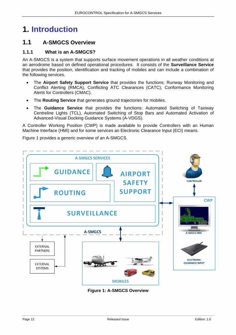
1. Introduction 1.1 A-SMGCS Overview 1.1.1 What is an A-SMGCS? An A-SMGCS is a system that supports surface movement operations in all weather conditions at an aerodrome based on defined operational procedures. It consists of the Surveillance Service that provides the position, identification and tracking of mobiles and can include a combination of the following services.
• The Airport Safety Support Service that provides the functions: Runway Monitoring and Conflict Alerting (RMCA), Conflicting ATC Clearances (CATC), Conformance Monitoring Alerts for Controllers (CMAC).
• The Routing Service that generates ground trajectories for mobiles.
• The Guidance Service that provides the functions: Automated Switching of Taxiway Centreline Lights (TCL), Automated Switching of Stop Bars and Automated Activation of Advanced-Visual Docking Guidance Systems (A-VDGS).
A Controller Working Position (CWP) is made available to provide Controllers with an Human Machine Interface (HMI) and for some services an Electronic Clearance Input (ECI) means.
Figure 1 provides a generic overview of an A-SMGCS.
Figure 1: A-SMGCS Overview
EUROCONTROL Specification for A-SMGCS Services
Edition: 1.0 Released Issue Page 13
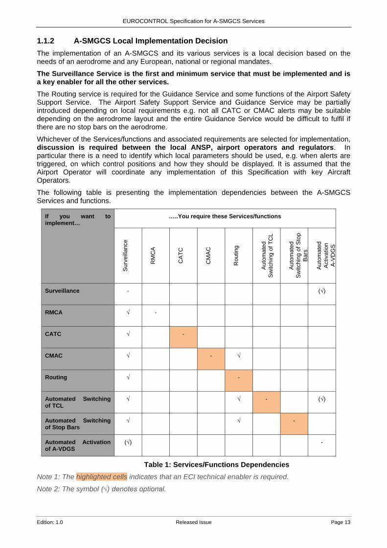
1.1.2 A-SMGCS Local Implementation Decision The implementation of an A-SMGCS and its various services is a local decision based on the needs of an aerodrome and any European, national or regional mandates.
The Surveillance Service is the first and minimum service that must be implemented and is a key enabler for all the other services. The Routing service is required for the Guidance Service and some functions of the Airport Safety Support Service. The Airport Safety Support Service and Guidance Service may be partially introduced depending on local requirements e.g. not all CATC or CMAC alerts may be suitable depending on the aerodrome layout and the entire Guidance Service would be difficult to fulfil if there are no stop bars on the aerodrome.
Whichever of the Services/functions and associated requirements are selected for implementation, discussion is required between the local ANSP, airport operators and regulators. In particular there is a need to identify which local parameters should be used, e.g. when alerts are triggered, on which control positions and how they should be displayed. It is assumed that the Airport Operator will coordinate any implementation of this Specification with key Aircraft Operators.
The following table is presenting the implementation dependencies between the A-SMGCS Services and functions.
If you want to implement…
…..You require these Services/functions
Sur
veill
ance
RM
CA
CA
TC
CM
AC
Rou
ting
Aut
omat
ed
Sw
itchi
ng o
f TC
L
Aut
omat
ed
Sw
itchi
ng o
f Sto
p B
ars
Aut
omat
ed
Act
ivat
ion
A-V
DG
S
Surveillance
- (√)
RMCA
√ -
CATC
√ -
CMAC
√ - √
Routing
√ -
Automated Switching of TCL
√ √ - (√)
Automated Switching of Stop Bars
√ √ -
Automated Activation of A-VDGS
(√) -
Table 1: Services/Functions Dependencies Note 1: The highlighted cells indicates that an ECI technical enabler is required.
Note 2: The symbol (√) denotes optional.
EUROCONTROL Specification for A-SMGCS Services
Page 14 Released Issue Edition: 1.0
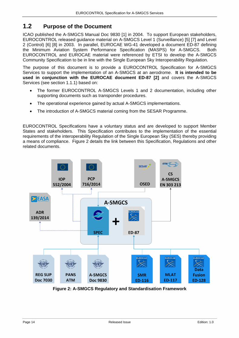
1.2 Purpose of the Document ICAO published the A-SMGCS Manual Doc 9830 [1] in 2004. To support European stakeholders, EUROCONTROL released guidance material on A-SMGCS Level 1 (Surveillance) [5] [7] and Level 2 (Control) [6] [8] in 2003. In parallel, EUROCAE WG-41 developed a document ED-87 defining the Minimum Aviation System Performance Specification (MASPS) for A-SMGCS. Both EUROCONTROL and EUROCAE material were referenced by ETSI to develop the A-SMGCS Community Specification to be in line with the Single European Sky Interoperability Regulation.
The purpose of this document is to provide a EUROCONTROL Specification for A-SMGCS Services to support the implementation of an A-SMGCS at an aerodrome. It is intended to be used in conjunction with the EUROCAE document ED-87 [2] and covers the A-SMGCS Services (see section 1.1.1) based on:
• The former EUROCONTROL A-SMGCS Levels 1 and 2 documentation, including other supporting documents such as transponder procedures.
• The operational experience gained by actual A-SMGCS implementations.
• The introduction of A-SMGCS material coming from the SESAR Programme.
EUROCONTROL Specifications have a voluntary status and are developed to support Member States and stakeholders. This Specification contributes to the implementation of the essential requirements of the interoperability Regulation of the Single European Sky (SES) thereby providing a means of compliance. Figure 2 details the link between this Specification, Regulations and other related documents.
Figure 2: A-SMGCS Regulatory and Standardisation Framework
EUROCONTROL Specification for A-SMGCS Services
Edition: 1.0 Released Issue Page 15
1.3 Scope of the Document This Specification document aims at defining the operational concept and requirements for the A-SMGCS Services. The reference to ‘levels’ is no longer used and has been superseded by using ‘names’ for the Services:
• Surveillance Service.
• Airport Safety Support Service.
• Routing Service.
• Guidance Service. The Surveillance, Airport Safety Support and Routing Services concentrate on supporting Controllers only, where as the Guidance Service includes direct support to Flight Crew and Vehicle Drivers. This document identifies operational and functional requirements from a user’s perspective applicable to the A-SMGCS Services.
Technical and performance requirements defining desired characteristics or properties of the system are detailed in EUROCAE document ED-87 [2].
Note 1:The name ‘Airport Safety Support Service’ is generic, encompassing different terms often used for Airport Safety Nets and Airport Safety Support Tools.
Note 2: The Airport Safety Support Service links to the essential operational change "Airport Safety Nets for Controllers" of the European ATM Master Plan [10] that is planned for synchronised deployment in a total of 24 airports in Europe by 2021, in accordance with the Commission Implementing Regulation (EU) No 716/2014 of 27 June 2014 [12] on the establishment of the Pilot Common Project (PCP).
Note 3: This Specification does not cover the planning of new aerodrome structures, maintenance, datalink services, departure management/sequencing, on-board mobile alerts and detection of pedestrians/animals or Foreign Object Debris.
1.4 Maintenance of the Specification This EUROCONTROL Specification has been developed under the EUROCONTROL Regulatory and Advisory Framework (ERAF) and is maintained by EUROCONTROL in accordance with this Framework.
New validated elements of A-SMGCS Services that are ready for deployment, will be incorporated in a future edition of this document.
1.5 Conventions EUROCONTROL Specifications are voluntary in status; however, drafting conventions include ‘normative’ language to indicate which section 6 requirements must be complied with in order to claim compliance with the specification.
The following drafting conventions are used:
• Shall – indicates a requirement which is mandatory or necessary to provide conformity with this specification.
• Should – indicates a requirement which is recommended.
• May – indicates a requirement which is optional or permitted.
EUROCONTROL Specification for A-SMGCS Services
Page 16 Released Issue Edition: 1.0
Note: The words shall/should/may in sections other than section 6 are used for narrative purposes and are not describing requirements.
Every requirement in this EUROCONTROL Specification is preceded by a structured identifier, which can be used to uniquely reference the requirement from associated documents and traceability tools. Such identifiers have the form:
ASMGCS-[Category]-[numeric identifier] where:
[Category]: is a sequence of four characters to identify the category to which the requirement applies.
[numeric identifier]: is a number to uniquely identify a requirement within a category.
The categories are:
• GENL: General.
• SURV: Surveillance Service.
• SAFE: Airport Safety Support Service.
• ROUT: Routing Service.
• GUID: Guidance Service.
1.6 Abbreviations A-CDM Airport-Collaborative Decision Making
ADS-B Automatic Dependent Surveillance Broadcast
AGL Airfield Ground Lighting
AIBT Actual In-Block Time
AIP Aeronautical Information Publication
ALDT Actual Landing Time
ANSP Air Navigation Service Provider
AOBT Actual Off-Block Time
AoR Area of Responsibility
APTR Alternative Parallel Taxi Routing
A-SMGCS Advanced-Surface Movement Guidance and Control System
ATC Air Traffic Control
ATM Air Traffic Management
ATOT Actual Take-Off Time
ATS Air Traffic Service(s)
ATSU Air Traffic Service Unit
A-VDGS Advanced –Visual Docking Guidance System
CAT Category (Referring to ILS Equipment)
CATC Conflicting ATC Clearances
CMAC Conformance Monitoring Alerts for Controllers
CS Community Specification
EUROCONTROL Specification for A-SMGCS Services
Edition: 1.0 Released Issue Page 17
CWP Controller Working Position
D Distance (a notation used for expressing distance)
DMAN Departure Manager
EATMN European Air Traffic Management Network
EC European Commission
ECAC European Civil Aviation Conference
ECI Electronic Clearance Input
EFS Electronic Flight Strips
EIBT Estimated In-Block Time
ELDT Estimated Landing Time
EOBT Estimated Off-Block Time
ER Essential Requirement
ERAF EUROCONTROL Regulatory and Advisory Framework
ETOT Estimated Take-Off Time
ETSI European Telecommunications Standards Institute
EUROCAE European Organisation for Civil Aviation Equipment
EXIT Estimated Taxi-In Time
EXOT Estimated Taxi-Out Time
FMS Flight Management System
FOD Foreign Object Debris
FtG Follow the Greens
HMI Human Machine Interface
ICAO International Civil Aviation Organisation
ILS Instrument Landing System
ITWP Integrated Tower Working Position
LAHSO Land And Hold Short Operation
LVP Low Visibility Procedures
MASPS Minimum Aviation System Performance Specification
MLAT Multilateration
PCP Pilot Common Project
RAVC Reduced Aerodrome Visibility Conditions
RMCA Runway Monitoring and Conflict Alerting
RPA Runway Protected Area
R/T Radio Telephony
RWY Runway
SES Single European Sky
SESAR Single European Sky ATM Research
SMR Surface Movement Radar

EUROCONTROL Specification for A-SMGCS Services
Page 18 Released Issue Edition: 1.0
SSR Secondary Surveillance Radar
T, T1, T2 Time (a notation used for expressing time)
TCAS Traffic Collision Avoidance System
TCL Taxiway Centreline Lights
TMA Terminal Manoeuvring Area
TOBT Target Off-Block Time
TSAT Target Start-Up Approval Time
TTOT Target Take-Off Time
1.7 Definitions This section provides definitions derived for the purpose of this Specification. Most of the definitions are taken from the ICAO Doc 9830 [1], the ICAO Annex 14 [4] or the EUROCAE document ED-87 [2], in that case it is indicated in the definition. ICAO definitions are used as a first option. In general, other definitions are only used where there is no ICAO definition.
Advanced-Surface Movement Guidance and Control System A system providing as a minimum Surveillance and can include Airport Safety Support, Routing and Guidance to aircraft and vehicles in order to maintain the airport throughput under all local weather conditions whilst maintaining the required level of safety. Definition based on ICAO Doc 9830 [1] modified to take into account the newly defined services.
Airport Operator The entity responsible for the operational management of the airport and in some cases is also the provider of surface management on aprons and taxiways.
Alert An indication of an existing or pending situation during aerodrome operations, or an indication of abnormal A-SMGCS operation, that requires attention/action. Note: The term alert covers warnings, cautions, advisories and alarms reflecting different levels of urgency or equipment performance. Definition ICAO Doc 9830 [1].
Alert Situation Any situation relating to aerodrome operations which has been defined as requiring particular attention or action. Definition EUROCAE document ED-87 [2].
All Weather Operations.
Any surface movement, take-off, departure, approach or landing operations in conditions where visual reference is limited by weather conditions. Definition ICAO Doc 9365 [16].
Apron A defined area on a land aerodrome, intended to accommodate aircraft for purposes of loading or unloading passengers, mail or cargo, fuelling, parking or maintenance. Definition ICAO Doc 9830 [1] and ICAO Annex 14 [4].
Area of Responsibility Defined geographic volume within which a Controller has the authority for the provision of Air Traffic Services. Note: Depending on local procedures, AoRs can be overlapping and may be based on other criteria e.g. inbound/outbound traffic.
Clearance Authorisation for an aircraft to proceed under conditions specified by an air traffic control unit.

EUROCONTROL Specification for A-SMGCS Services
Edition: 1.0 Released Issue Page 19
Note 1: For convenience, the term ‘air traffic control clearance’ is frequently abbreviated to ‘clearance’ when used in appropriate contexts. Note 2: The abbreviated term ‘clearance’ may be prefixed by the words ‘taxi’, ‘take-off’, ‘departure’,’en-route’, ‘approach’ or ‘landing’ to indicate the particular portion of flight to which the air traffic control clearance relates. Definition ATC Clearance ICAO Doc 4444 [3]. Note: In addition to the above Note 2, the abbreviated term ‘clearance’ may also be prefixed by the words “enter’’ or ‘’cross’’.
Clearance Limit The point to which an aircraft is granted an air traffic control clearance. Definition ICAO Doc 4444 [3].
Controller Working Position The position covering both ATC Towers and Apron Towers, including necessary Air Traffic Service (ATS) systems.
Cooperative mobile Mobile, which is equipped with systems capable of automatically and continuously providing information including its identity to the A-SMGCS. Note: As several cooperative surveillance technologies exist, a mobile is cooperative on an aerodrome only if the mobile and the aerodrome are equipped with cooperative surveillance technologies which are interoperable.
Cooperative surveillance Is a surveillance technique collecting information from mobiles equipped with a transmitting element (transponder on board the aircraft or transmitter device on board vehicles).
The cooperative surveillance may be: Either dependent on the cooperative mobile, when the mobile automatically generates the position information and transmits it to the surveillance sensor, for instance via ADS-B; or independent on the cooperative mobile, when the mobile position is detected by the surveillance sensor, i.e. Mode S Multilateration.
Coverage Volume The geographic volume of interest on and around the airport, within which the A-SMGCS must provide the required surveillance performance capabilities. Definition EUROCAE document ED-87 [2]. Note: The term Coverage Volume includes the Final Approach, Initial Climb out, Manoeuvring Area and Aprons.
Data Fusion A generic term used to describe the process of combining surveillance information from two or more sensor systems or sources. Definition EUROCAE document ED-87 [2].
Electronic Clearance Input A generic term used to describe the means for a Controller to input Clearances or instructions.
False Alert Alert which does not correspond to an actual alert situation. Definition EUROCAE document ED-87 [2]. Note: The definition refers only to alerts which have been raised although the specified trigger conditions have not been fulfilled and does not address nuisance alerts.
Guidance Visual information provided to Flight Crew or Vehicle Drivers to allow them to follow an assigned route.
EUROCONTROL Specification for A-SMGCS Services
Page 20 Released Issue Edition: 1.0
Heading The direction in which the longitudinal axis of an aircraft is pointed, usually expressed in degrees from North (true, magnetic, compass or grid). Definition ICAO Doc 4444 [3].
Identification The correlation of a known aircraft or vehicle callsign with the displayed target of that aircraft or vehicle on the display of the surveillance system. Definition ICAO Doc 9830 [1].
Identity A group of letters, figures or a combination thereof which is either identical to, or the coded equivalent of, the mobile call sign to be used in air-ground communications, and which is used to identify the mobile in ground-ground air traffic services communications. Based on ‘Aircraft identification’. Definition ICAO Doc 4444 [3] and modified, aircraft replaced with mobile.
Incursion Any occurrence at an aerodrome involving the incorrect presence of an aircraft, vehicle or person, or any part thereof, on the protected areas of a surface designated for the landing, take-off, taxiing and parking of aircraft. Definition ICAO Doc 9830 [1] .
Intruder Any mobile which is detected in a manoeuvring area into which it is not allowed to enter.
Manoeuvring area That part of an aerodrome to be used for the take-off, landing and taxiing of aircraft, excluding aprons. Definition ICAO Annex 14 [4].
Mobile A mobile is either an aircraft, aircraft being towed or a vehicle. Note: when referring to an aircraft or a vehicle, and not another obstacle, the term ‘Mobile’ is preferred to ‘Target’. The term ‘Target’ is only used when considering an image of a mobile or other obstacle displayed on a surveillance screen.
Movement area That part of an aerodrome to be used for the take-off, landing and taxiing of aircraft, consisting of the manoeuvring area and apron(s). Definition ICAO Annex 14 [4].
Non-Cooperative mobile Mobile which is not equipped with systems capable of automatically and continuously providing information including its identity to the A-SMGCS. Definition ‘Non-cooperative target’ EUROCAE document ED-87 [2] in which ‘target’ is replaced by ‘mobile’ (see mobile definition).
Non-Cooperative surveillance Is a surveillance technique detecting mobiles without requiring any action on their behalf or the carriage of a transmitting element (transponder on board the aircraft or transmitter device on board vehicles).
Nuisance Alert Nuisance alerts are those which arise when a specified Alert Situation is correctly detected but is deemed to be unnecessary by the user. Definition EUROCAE document ED-87 [2].
Obstacle All fixed (whether temporary or permanent) and mobile objects, or parts thereof, that:
a) are located on an area intended for the surface movement of aircraft or
b) that extend above a defined surface intended to protect aircraft in flight or
c) stand outside those defined surfaces and that have been assessed as being a hazard to air navigation.

EUROCONTROL Specification for A-SMGCS Services
Edition: 1.0 Released Issue Page 21
Definition ICAO Annex 14 [4].
Participating mobile A Mobile whose identity is known by the aerodrome authority and likely to move on the airport movement areas. A participating mobile is either cooperative or non-cooperative.
Reduced Visibility Visibility conditions insufficient for personnel of control units to exercise control over all traffic on the basis of visual surveillance.
Restricted Area An area on an aerodrome where the presence of a mobile is permanently or temporarily forbidden.
Route A track from a defined start point to a defined endpoint on the movement area. Definition ICAO Doc 9830 [1].
Routing The planning and assignment of a route to individual aircraft and vehicles to provide safe, expeditious and efficient movement from its current position to its intended position.
Runway A defined rectangular area on a land aerodrome prepared for the landing and Take-Off of aircraft. Definition ICAO Doc 4444 [3].
Runway Incursion Any occurrence at an aerodrome involving the incorrect presence of an aircraft, vehicle or person on the protected area of a surface designated for the landing and Take-Off of aircraft. Definition ICAO Doc 9870 [14].
Runway Protected Area The area around a particular runway, including the runway holding positions (according to the category of operations in force - CAT I/II/III) and the sensitive area around the ends of the runway.
Runway Threshold The beginning of that portion of the runway usable for landing. Definition ICAO Annex 14 [4].
Stand A stand is a designated area on an apron intended to be used for the parking of an aircraft. Definition ICAO Doc 9830 [1].
Surveillance The identification and accurate positional information of aircraft, vehicles and obstacles within the required Coverage Volume.
Target An aircraft, vehicle or other obstacle, whose image is displayed on the A-SMGCS HMI. Note: When referring to an aircraft or a vehicle, and not another obstacle, the term ‘Mobile’ is preferred to ‘Target’ The term ‘Target’ is only used when considering an image of a mobile or other obstacle displayed on the A-SMGCS HMI.
Taxiway A defined path on a land aerodrome established for the taxiing of aircraft and intended to provide a link between one part of the aerodrome and another, including:
EUROCONTROL Specification for A-SMGCS Services
Page 22 Released Issue Edition: 1.0
a) Aircraft stand taxilane. A portion of an apron designated as a taxiway and intended to provide access to aircraft stands only.
b) Apron taxiway. A portion of a taxiway system located on an apron and intended to provide a through taxi route across the apron.
c) Rapid exit taxiway. A taxiway connected to a runway at an acute angle and designed to allow landing aeroplanes to turn off at higher speeds than are achieved on other exit taxiways thereby minimizing runway occupancy times.
Definition ICAO Doc 4444 [3]
Transponder The term transponder is used to indicate the avionics equipment used on board aircraft. Note: This term solely refers to specific on-board aircraft equipment. For vehicles, the term vehicle transmitter is used.
Vehicle Transmitter The term vehicle transmitter is used to indicate the transmitting equipment used on board vehicles. Note: For aircraft, the term transponder is used.
1.8 Reference Material [1] ICAO Advanced Surface Movement Control and Guidance Systems (A-SMGCS) Manual,
Doc 9830 AN/452, First Edition 2004. [2] EUROCAE document ED-87 Minimum Aviation System Performance Specification
(MASPS) for A-SMGCS – The relevant version ED-87D will published in 2018. [3] ICAO Doc 4444 Procedures for Air Navigation Services -Air Traffic Management 16th
Edition, 2016. [4] ICAO Annex 14 Aerodrome Design and Operations, Volume I, Edition 7, 2016. [5] EUROCONTROL Operational Concept and Requirements for A-SMGCS Implementation
Level 1,June 2010 – Superseded by this document. [6] EUROCONTROL Operational Concept and Requirements for A-SMGCS Implementation
Level 2, June 2010 - Superseded by this document. [7] EUROCONTROL Functional Requirements for A-SMGCS Implementation Level 1, June
2010 - Superseded by this document. [8] EUROCONTROL Functional Requirements for A-SMGCS Implementation Level 2, June
2010 - Superseded by this document. [9] Commission Regulation (EU) No 73/2010 on the quality of aeronautical data and
aeronautical information, 26 January 2010. [10] European ATM Master Plan Executive View - Edition 2015. [11] EUROCONTROL Airport CDM Implementation Manual V5, 31 March 2017. [12] Commission Implementing Regulation (EU) No 716/2014 on the establishment of the Pilot
Common Project (PCP), 27 June 2014. [13] EUROCONTROL ITWP HMI Description V4, 20 January 2017. [14] ICAO Manual on the Prevention of Runway Incursions, Doc 9870 First Edition, 2007. [15] Commission Regulation (EU) No 139/2014 laying down the requirements and
administrative procedures related to aerodromes, 12 February 2014 (EASA Aerodrome IR).
[16] ICAO Manual of All-Weather Operations Doc 9365 4th Edition 2017. [17] EUROCAE document ED-117A - Minimum Operational Performance Specification
(MOPS) for Mode S Multilateration Systems for Use in A-SMGCS, issued in September 2016.
EUROCONTROL Specification for A-SMGCS Services
Edition: 1.0 Released Issue Page 23
[18] EUROCAE document ED-128 - Guidelines for Surveillance Data Fusion in Advanced Surface Movement Guidance and Control Systems (A-SMGCS) Levels 1 and 2, issued in October 2007.
1.9 Document Structure Introduction
Section 1 provides the purpose and scope of this document, its structure, the reference documents and defines the terms used throughout the document.
A-SMGCS Actors and Responsibilities Section 2 presents the various actors that can use the A-SMGCS Services.
A-SMGCS Services Section 3 presents the different A-SMGCS Services.
Operational Procedures Section 4 introduces the procedures for the different actors that are associated with the use of the A-SMGCS Services.
System Overview and Interoperability Section 5 presents a high-level description of the system components of an A-SMGCS and explains how it is operated with other ATC and Airport systems.
A-SMGCS Requirements Section 6 contains the requirements associated to the Services defined in section 3.
Appendices Informative detailed description of Airport Safety Support functions - RMCA, CATC and CMAC. There is also an informative appendix on traceability to regulatory requirements.
EUROCONTROL Specification for A-SMGCS Services
Page 24 Released Issue Edition: 1.0
2. A-SMGCS Actors and Responsibilities 2.1 Introduction Various actors are involved in the A-SMGCS environment. The business domain and objectives of each actor determine their level of participation/involvement.
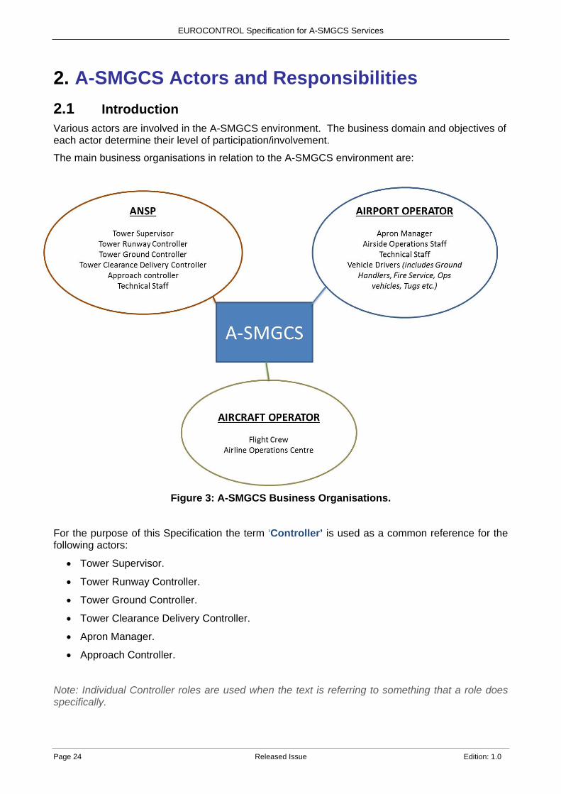
The main business organisations in relation to the A-SMGCS environment are:
Figure 3: A-SMGCS Business Organisations.
For the purpose of this Specification the term ‘Controller’ is used as a common reference for the following actors:
• Tower Supervisor.
• Tower Runway Controller.
• Tower Ground Controller.
• Tower Clearance Delivery Controller.
• Apron Manager.
• Approach Controller.
Note: Individual Controller roles are used when the text is referring to something that a role does specifically.
EUROCONTROL Specification for A-SMGCS Services
Edition: 1.0 Released Issue Page 25
For the purpose of this Specification the term ‘Vehicle Driver’ is used as a common reference for the following actors:
• Ground Handler Vehicle Driver (including Tug drivers).
• Airport Operator Vehicle Driver (for Airside Operational Vehicles such as runway checker, bird scarer).
• ANSP Vehicle Driver (for Airside Operational Vehicles).
• Emergency Services Vehicle Driver (e.g. Fire brigade and ambulance vehicles).
• Security Services Vehicle Driver (e.g. Police forces, Airport Security Service).
• Occasional Airside Vehicle Driver.
The following sections are introducing per service/actor, an insight of tasks and responsibilities that are further developed in section 4 Operational Procedures.
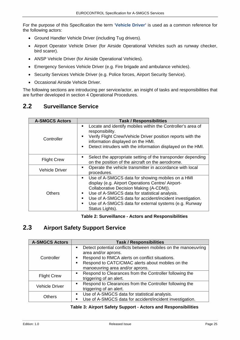
2.2 Surveillance Service
A-SMGCS Actors Task / Responsibilities
Controller
Locate and identify mobiles within the Controller’s area of responsibility.
Verify Flight Crew/Vehicle Driver position reports with the information displayed on the HMI.
Detect intruders with the information displayed on the HMI.
Flight Crew Select the appropriate setting of the transponder depending on the position of the aircraft on the aerodrome.
Vehicle Driver Operate the vehicle transmitter in accordance with local procedures.
Others
Use of A-SMGCS data for showing mobiles on a HMI display (e.g. Airport Operations Centre/ Airport-Collaborative Decision Making (A-CDM)).
Use of A-SMGCS data for statistical analysis. Use of A-SMGCS data for accident/incident investigation. Use of A-SMGCS data for external systems (e.g. Runway
Status Lights).
Table 2: Surveillance - Actors and Responsibilities
2.3 Airport Safety Support Service
A-SMGCS Actors Task / Responsibilities
Controller
Detect potential conflicts between mobiles on the manoeuvring area and/or aprons.
Respond to RMCA alerts on conflict situations. Respond to CATC/CMAC alerts about mobiles on the
manoeuvring area and/or aprons.
Flight Crew Respond to Clearances from the Controller following the triggering of an alert.
Vehicle Driver Respond to Clearances from the Controller following the triggering of an alert.
Others Use of A-SMGCS data for statistical analysis. Use of A-SMGCS data for accident/incident investigation.
Table 3: Airport Safety Support - Actors and Responsibilities
EUROCONTROL Specification for A-SMGCS Services
Page 26 Released Issue Edition: 1.0
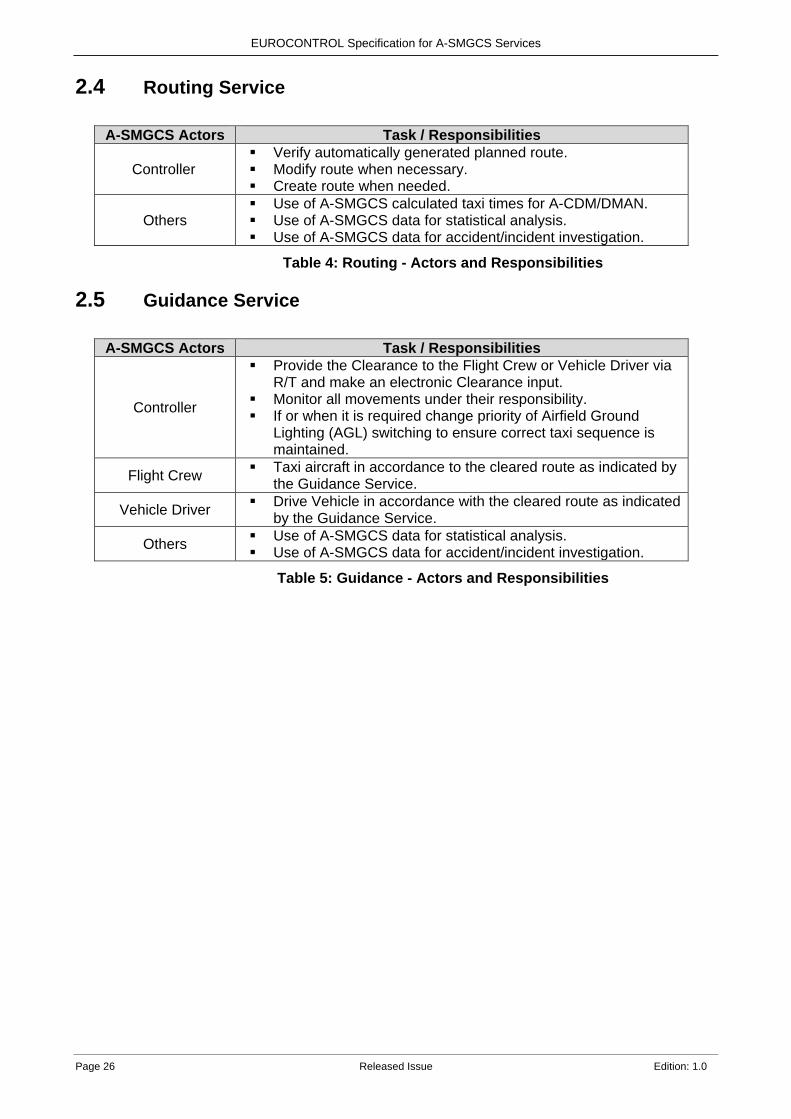
2.4 Routing Service
A-SMGCS Actors Task / Responsibilities
Controller Verify automatically generated planned route. Modify route when necessary. Create route when needed.
Others Use of A-SMGCS calculated taxi times for A-CDM/DMAN. Use of A-SMGCS data for statistical analysis. Use of A-SMGCS data for accident/incident investigation.
Table 4: Routing - Actors and Responsibilities
2.5 Guidance Service
A-SMGCS Actors Task / Responsibilities
Controller
Provide the Clearance to the Flight Crew or Vehicle Driver via R/T and make an electronic Clearance input.
Monitor all movements under their responsibility. If or when it is required change priority of Airfield Ground
Lighting (AGL) switching to ensure correct taxi sequence is maintained.
Flight Crew Taxi aircraft in accordance to the cleared route as indicated by the Guidance Service.
Vehicle Driver Drive Vehicle in accordance with the cleared route as indicated by the Guidance Service.
Others Use of A-SMGCS data for statistical analysis. Use of A-SMGCS data for accident/incident investigation.
Table 5: Guidance - Actors and Responsibilities

EUROCONTROL Specification for A-SMGCS Services
Edition: 1.0 Released Issue Page 27
3. A-SMGCS Services 3.1 Introduction This section of the document describes in detail the four main A-SMGCS Services:
• Surveillance Service.
• Airport Safety Support Service.
• Routing Service.
• Guidance Service.
3.2 Surveillance Service The Surveillance Service represents the foundation of an A-SMGCS implementation, allowing the subsequent introduction of other A-SMGCS Services such as Airport Safety Support, Routing and Guidance.
The Service provides situational awareness of aerodrome traffic through the identification, position and tracking of aircraft and vehicles within a predefined Coverage Volume. For the positive identification of targets at least one cooperative sensor is necessary. To detect any mobile, in particular intruders or aircraft with an inoperable transponder, at least one non-cooperative sensor is needed. Examples of sensors can be found in section 5.5.
The Surveillance Service can include aircraft on approach within the Coverage Volume so that Controllers can use the A-SMGCS, without having to look at an additional screen, to assist them in their task of controlling inbound aircraft and integrating the arrivals with departures or mobiles crossing active runways.
The design, implementation and maintenance of the Surveillance Service must take into account the aerodrome environment and operational procedures in order to minimise radio interference and radio reflections. Changes to structures, environment or procedures can cause significant degradation on the performance of the Surveillance Service and need to be carefully considered.
The Surveillance Service provides a synthetic representation of the aerodrome traffic situation based on the following features:
• Aerodrome Environment.
• Position of all cooperative and non-cooperative mobiles and obstacles on the movement area.
• Identity of all cooperative mobiles on the movement area. The Surveillance Service allows the Controller:
• to confirm the identity of all participating mobiles according to the defined identification procedures (section 4.2.1).
• to anticipate situations that can result in collisions between all aircraft and aircraft and vehicles, especially in conditions when visual contact cannot be maintained.
• to manually correlate targets (link a target with a callsign) for the rare cases where there is an operational need to, e.g. areas of poor cooperative surveillance coverage and the need to track non-cooperative targets such as towed aircraft.
• to detect and indicate the position of potential intruders.
The Surveillance Service provides benefits to Controllers by:
EUROCONTROL Specification for A-SMGCS Services
Page 28 Released Issue Edition: 1.0
• Providing a representation of the actual aerodrome traffic on a display, independent of line-of-sight connection between the Controller and the mobile.
• Providing the position and the identity of all cooperative mobiles, within the Coverage Volume independent of visibility conditions and Controller line of sight.
• Supporting an expeditious management of traffic. A-SMGCS output recordings are kept and used to store the surveillance and track data. This data can be very useful for analysis, statistics (such as taxi times and off block times) and playback purposes. Additionally, the Surveillance Service can provide external systems, such as the A-CDM Platform, with accurate event times e.g. Actual Landing Time (ALDT).
3.3 Airport Safety Support Service 3.3.1 General The A-SMGCS Airport Safety Support Service contributes to airside operations as a safety improvement, enabling Controllers to prevent hazards/incidents resulting from Controller, Flight Crew or Vehicle Driver operational errors or deviations. This Service depends on the Surveillance Service being in operation. The Airport Safety Support Service supports Controllers by:
• Anticipating potential conflicts (e.g. hazardous situations between aircraft or aircraft and vehicles).
• Detecting conflicts and incursions. • Detecting mobiles that are not following given Clearances. • Providing alerts.
The Airport Safety Support Service comprises the following three functions: • Runway Monitoring and Conflict Alerting (RMCA). • Conflicting ATC Clearances (CATC). • Conformance Monitoring Alerts for Controllers (CMAC).
The Airport Safety Support Service may be partially introduced depending on local requirements e.g. not all CATC or CMAC alerts may be suitable depending on the aerodrome layout.
The RMCA function acts as a short term alerting tool, whereas the CATC and CMAC serve to be more predictive tools that aim at preventing situations where an RMCA alert may be triggered.
For the CATC and CMAC alerts to function correctly it is important that the system receives the Controller’s Clearances, therefore, the Controller must be provided with an Electronic Clearance Input (ECI) means e.g. Electronic Flight Strips (EFS).
Some of the CMAC alerts work on the assumption that every mobile entering the Runway Protected Area (RPA) or Restricted Area must have received a Clearance from the Controller.
3.3.2 Stages of Alert The Airport Safety Support Service provides an appropriate alert or indication to Controllers for each detected conflict, non-conformance to procedure or instruction. Based on the experience and practices of current A-SMGCS in operation in Europe, two stages of alert have been defined as follows:
• Stage 1 alert is an INFORMATION alert. It is used to inform the Controller of a potential hazardous situation. According to the situation, the Controller receiving a Stage 1 alert may take a specific action to resolve the situation.
• Stage 2 alert is an ALARM alert. It is used to inform the Controller that a critical situation is developing requiring immediate action.
EUROCONTROL Specification for A-SMGCS Services
Edition: 1.0 Released Issue Page 29
Depending on the detected situation, alerts may be triggered as follows: • Only a Stage 1 alert. • A Stage 2 alert may follow a Stage 1 alert if the potentially hazardous situation becomes
critical. • Only a Stage 2 alert.
The alert and the alert stage assignment depends on the aerodrome and the operating procedures.
The end of an alert can be either a manual Controller input (e.g. undoing a Clearance), or automated based on local parameters when the condition no longer exists.
3.3.3 Protected Areas Many of the alerts, in the Airport Safety Support Service, require the designation of a protected area around the runway, known as the Runway Protected Area (RPA) and other areas on the aerodrome known as Restricted Areas.
Note: Whether cooperative or non-cooperative, all mobiles must have a Clearance to enter the RPA, otherwise it is considered to be an intruder and an alert will be triggered.
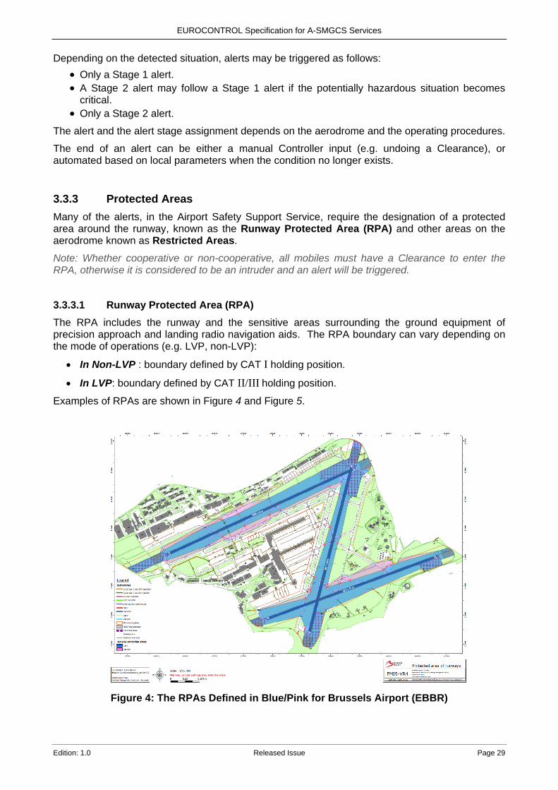
3.3.3.1 Runway Protected Area (RPA) The RPA includes the runway and the sensitive areas surrounding the ground equipment of precision approach and landing radio navigation aids. The RPA boundary can vary depending on the mode of operations (e.g. LVP, non-LVP):
• In Non-LVP : boundary defined by CAT I holding position.
• In LVP: boundary defined by CAT II/III holding position.
Examples of RPAs are shown in Figure 4 and Figure 5.
Figure 4: The RPAs Defined in Blue/Pink for Brussels Airport (EBBR)

EUROCONTROL Specification for A-SMGCS Services
Page 30 Released Issue Edition: 1.0
Figure 5: Example of a CAT I RPA
The RPA is one of the parameters used for the triggering of some alerts. If the A-SMGCS has good surveillance and a reliable prediction algorithm then it could also be used to detect a potential Runway Incursion by a mobile before it enters the RPA based on its trajectory and speed.
3.3.3.2 Restricted Areas Restricted Area incursions deal only with ground traffic outside of an RPA. An ALARM is provided to the Controller when an unauthorised mobile enters a Restricted Area, or similarly as with the RPA, when an unauthorised mobile is predicted to enter based on its trajectory and speed using good surveillance and a reliable prediction algorithm.
3.3.4 Presentation of Alerts to Controllers Alerts are visually presented to the Controller and indicate the:
• Stage of alert (INFORMATION or ALARM).
• Type of alert situation (e.g. RMCA, CATC or CMAC).
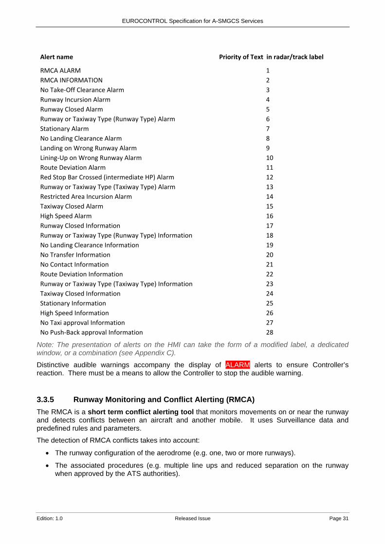
• Identification of the concerned cooperative mobile(s). It is very unlikely that more than one alert will be triggered at the same time. However, if this does occur it is important that all active alerts are displayed somewhere on the HMI and the question of how to display the alerts to the controller is raised, especially with regard to the amount of information presented on the HMI. As alerts can be displayed in different places e.g. the label, an alert window, EFS, it can be beneficial to reduce screen clutter to display the alert with the highest priority on just the label (providing that the other active alerts are still displayed elsewhere). As RMCA alerts are indicating a short term conflict situation which requires immediate attention they are considered as the highest priority and should have preference for display over CATC and CMAC alerts. The following list is an example of how the priority for display on the label can be allocated, priority 1 is higher than priority 2 etc. The example priorities in no way diminish the importance of any of the alerts, in particular runway occurrence related alerts.
EUROCONTROL Specification for A-SMGCS Services
Edition: 1.0 Released Issue Page 31
Alert name Priority of Text in radar/track label
RMCA ALARM 1 RMCA INFORMATION 2 No Take-Off Clearance Alarm 3 Runway Incursion Alarm 4 Runway Closed Alarm 5 Runway or Taxiway Type (Runway Type) Alarm 6 Stationary Alarm 7 No Landing Clearance Alarm 8 Landing on Wrong Runway Alarm 9 Lining-Up on Wrong Runway Alarm 10 Route Deviation Alarm 11 Red Stop Bar Crossed (intermediate HP) Alarm 12 Runway or Taxiway Type (Taxiway Type) Alarm 13 Restricted Area Incursion Alarm 14 Taxiway Closed Alarm 15 High Speed Alarm 16 Runway Closed Information 17 Runway or Taxiway Type (Runway Type) Information 18 No Landing Clearance Information 19 No Transfer Information 20 No Contact Information 21 Route Deviation Information 22 Runway or Taxiway Type (Taxiway Type) Information 23 Taxiway Closed Information 24 Stationary Information 25 High Speed Information 26 No Taxi approval Information 27 No Push-Back approval Information 28
Note: The presentation of alerts on the HMI can take the form of a modified label, a dedicated window, or a combination (see Appendix C).
Distinctive audible warnings accompany the display of ALARM alerts to ensure Controller’s reaction. There must be a means to allow the Controller to stop the audible warning.
3.3.5 Runway Monitoring and Conflict Alerting (RMCA) The RMCA is a short term conflict alerting tool that monitors movements on or near the runway and detects conflicts between an aircraft and another mobile. It uses Surveillance data and predefined rules and parameters.
The detection of RMCA conflicts takes into account:
• The runway configuration of the aerodrome (e.g. one, two or more runways).
• The associated procedures (e.g. multiple line ups and reduced separation on the runway when approved by the ATS authorities).

EUROCONTROL Specification for A-SMGCS Services
Page 32 Released Issue Edition: 1.0
• The position and type of the mobiles (e.g. arrival, departure or vehicle) according to the set time parameters and their relative speeds and positions when within or about to enter the RPA.
• Aircraft in the vicinity of the runway (e.g. on final approach, climb out and helicopters crossing).
• Meteorological conditions.
RMCA generates an INFORMATION alert or an ALARM alert based on the above conditions and conflict situations (see Appendix A).
Note: Conflicts between vehicles are not considered by A-SMGCS as this is covered by the rules of the road. 3.3.6 Conflicting ATC Clearances (CATC) It is important to note that the term ‘Conflicting’ in the title refers to the fact that certain electronic Clearances input by a Controller do not comply with the local ATC rules/procedures, it does not mean that the aircraft/vehicles have ended up in conflict with each other. CATC provides an alert when the Controller inputs an electronic Clearance via the HMI, that according to a set of locally agreed rules is not permitted from an operational and safety point of view when compared to any other previously input electronic Clearance.
The detection of CATC provides an early prediction of a situation that, if not corrected, would end up in a hazardous situation, that in turn would normally be detected by the RMCA, if in operation.
The HMI can be adapted to give a predictive indication (see Appendix B) to the Controller that if a specific Clearance is input it triggers a CATC alert. This helps the Controller’s situational awareness and normally prevents an incident due to a wrong Clearance being issued.
The situations in Table 6 are considered for the triggering of a CATC alert. The ‘First Clearance Input’ is the Clearance that is entered first and the ‘Second Clearance Input’ triggers an alert. The situations are further described in Appendix B.
First Clearance Input Second Clearance Input
LINE-UP LINE-UP, CROSS, ENTER, TAKE-OFF, LAND
CROSS or ENTER LINE-UP, CROSS, ENTER, TAKE-OFF, LAND
TAKE-OFF LINE-UP, CROSS, ENTER, TAKE-OFF, LAND
LAND LINE-UP, CROSS, ENTER, TAKE-OFF, LAND
Table 6: Situations for CATC Alerts

EUROCONTROL Specification for A-SMGCS Services
Edition: 1.0 Released Issue Page 33
3.3.7 Conformance Monitoring Alerts for Controllers (CMAC) CMAC provides Controllers with appropriate alerts when the A-SMGCS detects the non-conformance to procedures or Clearances of mobiles on runways, taxiways and in the apron/stand area.
The integration of ECI with information such as flight plan, surveillance, routing, published rules and procedures allows the system to detect inconsistencies and alerts the Controller.
The main benefit of this is the early detection of Controller, Flight Crew / Vehicle Driver errors that, if not detected and resolved, might result in a hazardous situation.
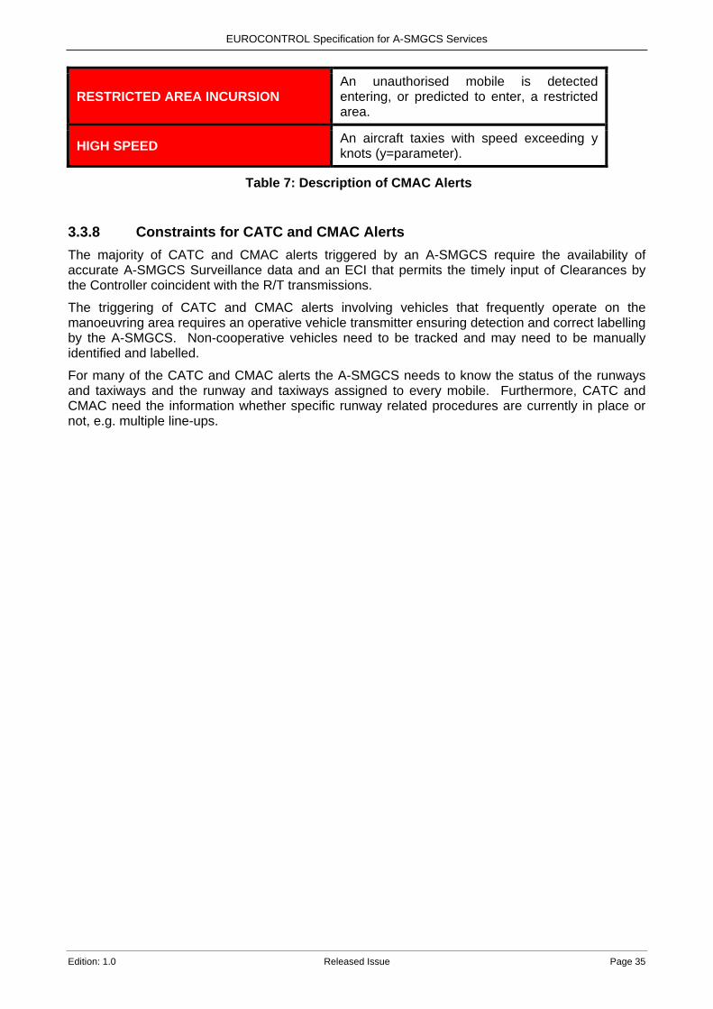
The RMCA function will remain as a last minute warning system based on the positions and speeds of the mobiles. The CMAC alerts in Table 7 have been defined and detailed information on each alert can be found in Appendix C. The yellow background indicates Information alerts and red background Alarm alerts.
Alert Name Brief description
ROUTE DEVIATION A mobile deviates from its cleared route on a taxiway/taxilane.
NO PUSH / NO TAXI APPROVAL An aircraft pushes-back or taxies without Clearance from a Controller.
STATIONARY
A mobile is given a Clearance (e.g. Push-Back, Taxi, Cross, Enter, Line-Up, Take-Off) but doesn’t move within a certain time period, or an aircraft was taxiing and stops for a certain time period.
NO CONTACT An arriving aircraft is at a defined distance or time from the runway and has not contacted the Tower.
NO TRANSFER A departing aircraft has taken off and is at a defined distance or time from the aerodrome and has not been transferred to the departure controller.
NO TAKE-OFF CLEARANCE An aircraft is cleared to Line-Up and it takes-off without a Take-Off Clearance.
NO LANDING CLEARANCE An aircraft is close to the runway without a Landing Clearance.
LANDING ON THE WRONG RUNWAY An arriving aircraft is detected to be aligned to a runway that differs to the assigned runway.
LINING-UP ON THE WRONG RUNWAY A departing aircraft is detected lining-up on a runway that differs to the assigned runway.

EUROCONTROL Specification for A-SMGCS Services
Page 34 Released Issue Edition: 1.0
RUNWAY TYPE An aircraft is assigned a runway that is not suitable for the aircraft type e.g. runway is too short.
TAXIWAY TYPE An aircraft is assigned a taxiway that is not suitable for the aircraft type e.g. taxiway is limited to certain types of aircraft.
RUNWAY CLOSED A runway assigned to an aircraft is closed.
TAXIWAY CLOSED The assigned taxi route is planned to go through a closed taxiway.
HIGH SPEED An aircraft taxies with speed exceeding x knots (x=parameter).
ROUTE DEVIATION A mobile deviates from its cleared route on a taxiway (close to an active runway).
STATIONARY An arriving aircraft or mobile crossing a runway has stopped within the RPA and does not move within a certain time period.
NO TAKE-OFF CLEARANCE An aircraft is cleared to Line-Up and it takes-off without a Take-Off Clearance.
NO LANDING CLEARANCE An aircraft is close to the runway without a Landing Clearance.
LANDING ON THE WRONG RUNWAY An arriving aircraft is detected to be aligned to a runway that differs to the assigned runway.
RED STOP BAR CROSSED A mobile crosses a RED stop bar (Intermediate Holding Point or AoR boundary).
LINING-UP ON THE WRONG RUNWAY A departing aircraft is detected lining up on a runway that differs to the assigned runway.
RUNWAY INCURSION A mobile is detected entering, or predicted to enter, the RPA without a Land / Line-Up / Take-Off / Cross / Enter Clearance.
RUNWAY TYPE An aircraft is on a runway that is not suitable for the aircraft type.
TAXIWAY TYPE An aircraft is on a taxiway that is not suitable for the aircraft type.
RUNWAY CLOSED An aircraft has entered a closed runway.
TAXIWAY CLOSED An aircraft has entered a closed taxiway.
EUROCONTROL Specification for A-SMGCS Services
Edition: 1.0 Released Issue Page 35
RESTRICTED AREA INCURSION An unauthorised mobile is detected entering, or predicted to enter, a restricted area.
HIGH SPEED An aircraft taxies with speed exceeding y knots (y=parameter).
Table 7: Description of CMAC Alerts
3.3.8 Constraints for CATC and CMAC Alerts The majority of CATC and CMAC alerts triggered by an A-SMGCS require the availability of accurate A-SMGCS Surveillance data and an ECI that permits the timely input of Clearances by the Controller coincident with the R/T transmissions.
The triggering of CATC and CMAC alerts involving vehicles that frequently operate on the manoeuvring area requires an operative vehicle transmitter ensuring detection and correct labelling by the A-SMGCS. Non-cooperative vehicles need to be tracked and may need to be manually identified and labelled.
For many of the CATC and CMAC alerts the A-SMGCS needs to know the status of the runways and taxiways and the runway and taxiways assigned to every mobile. Furthermore, CATC and CMAC need the information whether specific runway related procedures are currently in place or not, e.g. multiple line-ups.
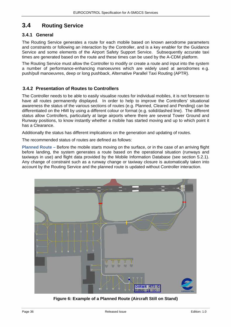
EUROCONTROL Specification for A-SMGCS Services
Page 36 Released Issue Edition: 1.0
3.4 Routing Service 3.4.1 General The Routing Service generates a route for each mobile based on known aerodrome parameters and constraints or following an interaction by the Controller, and is a key enabler for the Guidance Service and some elements of the Airport Safety Support Service. Subsequently accurate taxi times are generated based on the route and these times can be used by the A-CDM platform. The Routing Service must allow the Controller to modify or create a route and input into the system a number of performance-enhancing manoeuvres which are widely used at aerodromes e.g. push/pull manoeuvres, deep or long pushback, Alternative Parallel Taxi Routing (APTR).
3.4.2 Presentation of Routes to Controllers The Controller needs to be able to easily visualise routes for individual mobiles, it is not foreseen to have all routes permanently displayed. In order to help to improve the Controllers’ situational awareness the status of the various sections of routes (e.g. Planned, Cleared and Pending) can be differentiated on the HMI by using a different colour or format (e.g. solid/dashed line). The different status allow Controllers, particularly at large airports where there are several Tower Ground and Runway positions, to know instantly whether a mobile has started moving and up to which point it has a Clearance.
Additionally the status has different implications on the generation and updating of routes.
The recommended status of routes are defined as follows:
Planned Route – Before the mobile starts moving on the surface, or in the case of an arriving flight before landing, the system generates a route based on the operational situation (runways and taxiways in use) and flight data provided by the Mobile Information Database (see section 5.2.1). Any change of constraint such as a runway change or taxiway closure is automatically taken into account by the Routing Service and the planned route is updated without Controller interaction.
Figure 6: Example of a Planned Route (Aircraft Still on Stand)
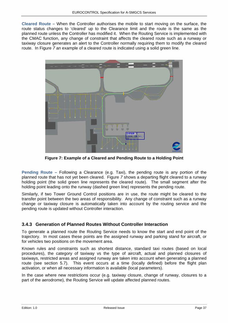
EUROCONTROL Specification for A-SMGCS Services
Edition: 1.0 Released Issue Page 37
Cleared Route – When the Controller authorises the mobile to start moving on the surface, the route status changes to ‘cleared’ up to the Clearance limit and the route is the same as the planned route unless the Controller has modified it. When the Routing Service is implemented with the CMAC function, any change of constraint that affects the cleared route such as a runway or taxiway closure generates an alert to the Controller normally requiring them to modify the cleared route. In Figure 7 an example of a cleared route is indicated using a solid green line.
Figure 7: Example of a Cleared and Pending Route to a Holding Point
Pending Route – Following a Clearance (e.g. Taxi), the pending route is any portion of the planned route that has not yet been cleared. Figure 7 shows a departing flight cleared to a runway holding point (the solid green line represents the cleared route). The small segment after the holding point leading onto the runway (dashed green line) represents the pending route.
Similarly, if two Tower Ground Control positions are in use, the route might be cleared to the transfer point between the two areas of responsibility. Any change of constraint such as a runway change or taxiway closure is automatically taken into account by the routing service and the pending route is updated without Controller interaction.
3.4.3 Generation of Planned Routes Without Controller Interaction To generate a planned route the Routing Service needs to know the start and end point of the trajectory. In most cases these points are the assigned runway and parking stand for aircraft, or for vehicles two positions on the movement area.
Known rules and constraints such as shortest distance, standard taxi routes (based on local procedures), the category of taxiway vs the type of aircraft, actual and planned closures of taxiways, restricted areas and assigned runway are taken into account when generating a planned route (see section 5.7). This event occurs at a time (locally defined) before the flight plan activation, or when all necessary information is available (local parameters).
In the case where new restrictions occur (e.g. taxiway closure, change of runway, closures to a part of the aerodrome), the Routing Service will update affected planned routes.

EUROCONTROL Specification for A-SMGCS Services
Page 38 Released Issue Edition: 1.0
3.4.4 Controller Interaction With the Routing Service Due to operational events or changes, a Controller must be able to either modify an existing route or create a new route. Route Modification – A modification to a generated route can either happen before the corresponding mobile has begun to move (e.g. planned route), or after the mobile starts moving (e.g. revision of a cleared/pending route).
Some common route changes such as a change of runway, stand or holding point, must be easily and quickly performed by the Controller e.g. using drop down menus on the HMI.
To facilitate the modification of an existing route where the destination is unchanged, the Controller can be supported by the HMI providing graphical advice based on operational rules/constraints known to the system. Figure 8 shows an example of a cleared route (green line) being modified. The Controller has selected a point at the end of the solid yellow line and the HMI is proposing a new route indicated by a dotted yellow line to the original Holding Point.
Figure 8: Example of Route Modification via the HMI
In certain situations, the Controller may have to ignore the standard rules and input a route that contravenes the aerodrome rules/constraints, e.g. an aircraft deviates from its cleared route and the Controller is obliged to route the aircraft the wrong way down a taxiway in order to reach its destination.
Route Creation – Controllers may create a route via the HMI for mobiles that do not have a generated route.
Depending on the local environment, creation of routes may be used in specific areas of busy airports where the system generation is not deemed necessary or possible e.g. due to missing stand information. In addition, it could also be a standard method for an entire movement area at less busy airports where the Controller input procedures are acceptable.
EUROCONTROL Specification for A-SMGCS Services
Edition: 1.0 Released Issue Page 39
3.4.5 Provision of Taxi Times to Airport-CDM The route generation function can calculate the time it takes for the mobile to taxi/drive on a given route, typically by assessing the length of this route and its topography (e.g. lengths of straight and curved segments, number and sharpness of turns, gradients).
Taxi time calculation may take into account real time measurement from the surveillance position of aircraft movements along the route.
The A-CDM Manual section 3.4 [11] details how the taxi time is used by the A-CDM platform in order to calculate the following:
• For outbound flights – Target Take-Off Time (TTOT). • For inbound flights and Ground Movements - Estimated In-Block Time (EIBT).
As the speed of mobiles on the surface is variable (Flight Crews taxi at different speeds, large aircraft turn more slowly, etc.), it is foreseen to calculate the taxi time in seconds, but display them in ‘whole’ minutes.
3.5 Guidance Service 3.5.1 General The Guidance Service provides individual guidance information using visual aids to any mobile which has a cleared taxi route. It comprises the following three functions:
• Automated switching of Taxiway Centreline Lights (TCL). • Automated switching of stop bars. • Automated activation of Advanced-Visual Guidance Docking Systems (A-VDGS).
Whilst other non-A-SMGCS guidance means are partly or fully depending on on-board installations, guidance via TCL is purely a ground-based service which works in conjunction with the A-SMGCS Surveillance and Routing Services as well as Clearances given by the Controller.
The Guidance Service improves the navigation and flow of mobiles on the movement area and reduces the workload of the Controllers.
3.5.2 Automated Switching of the Taxiway Centreline Lights (TCL) 3.5.2.1 General Automated switching of TCL can provide individual guidance information to any mobile which has a cleared route. This function associates the cleared route of a mobile with the Clearance provided by the Controller and illuminates the TCL to a specified distance ahead of the mobile in question, switching them on and off automatically.
Note: When referring to TCL this includes apron taxilane lights, APTR and lead in and lead out lights on a stand. Longitudinal spacing between mobiles is the responsibility of the Flight Crew or Vehicle Driver in non-LVP weather situations. Hence, the Automated TCL doesn’t necessarily need to provide this spacing in good visibility.
The Guidance Service takes into account other traffic for spacing to guide the mobile as it progresses along its assigned route and allocates priority between mobiles based on local operating rules (e.g. Runway exit versus parallel taxiways, aircraft versus vehicle, aircraft converging or crossing at intersections and taxiways passing close to push back routes or other taxiways where insufficient wingtip separation exists).
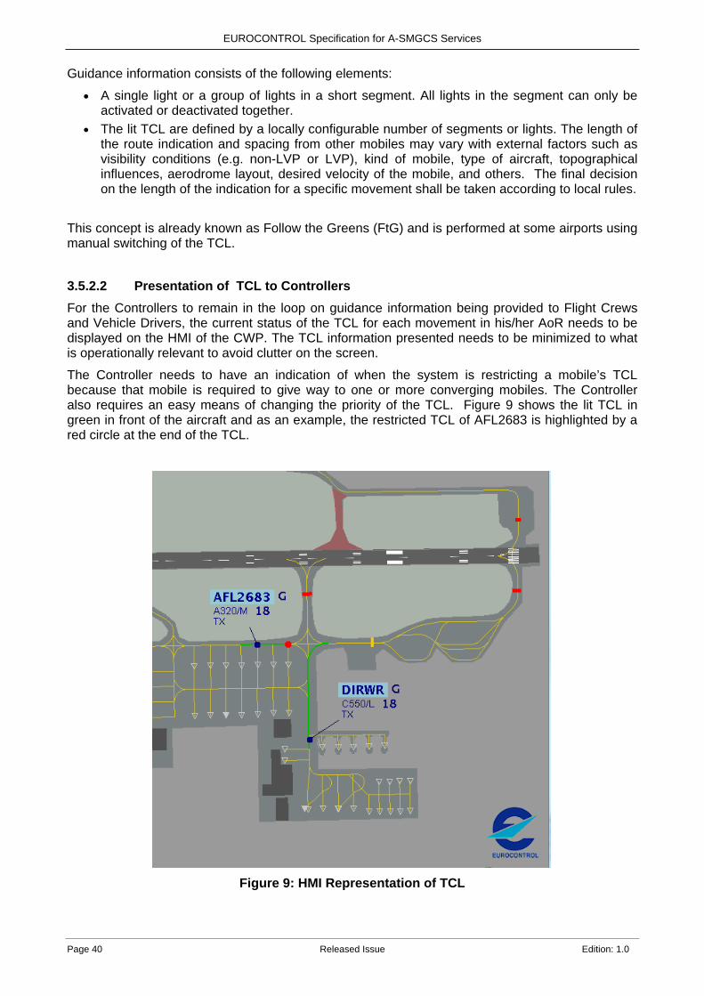
EUROCONTROL Specification for A-SMGCS Services
Page 40 Released Issue Edition: 1.0
Guidance information consists of the following elements:
• A single light or a group of lights in a short segment. All lights in the segment can only be activated or deactivated together.
• The lit TCL are defined by a locally configurable number of segments or lights. The length of the route indication and spacing from other mobiles may vary with external factors such as visibility conditions (e.g. non-LVP or LVP), kind of mobile, type of aircraft, topographical influences, aerodrome layout, desired velocity of the mobile, and others. The final decision on the length of the indication for a specific movement shall be taken according to local rules.
This concept is already known as Follow the Greens (FtG) and is performed at some airports using manual switching of the TCL.
3.5.2.2 Presentation of TCL to Controllers
For the Controllers to remain in the loop on guidance information being provided to Flight Crews and Vehicle Drivers, the current status of the TCL for each movement in his/her AoR needs to be displayed on the HMI of the CWP. The TCL information presented needs to be minimized to what is operationally relevant to avoid clutter on the screen.
The Controller needs to have an indication of when the system is restricting a mobile’s TCL because that mobile is required to give way to one or more converging mobiles. The Controller also requires an easy means of changing the priority of the TCL. Figure 9 shows the lit TCL in green in front of the aircraft and as an example, the restricted TCL of AFL2683 is highlighted by a red circle at the end of the TCL.
Figure 9: HMI Representation of TCL

EUROCONTROL Specification for A-SMGCS Services
Edition: 1.0 Released Issue Page 41
3.5.3 Automated Switching of Stop Bars This function provides the capability to switch off stop bars following a Clearance input by the Controller as described in section 4.2.4.2. They can either be placed at a RWY Holding Position (as already in use at many airports) or across a taxiway.
In the latter case, they can support spacing between crossing or converging ground trajectories by clearly indicating where to stop e.g to sequence traffic at taxiway intersections. Additionally, stop bars can be used to maintain block spacing in LVP. The TCL segments must not be activated at least 90 metres after a lit stop bar [4].
3.5.4 Automated Activation of Advanced-Visual Docking Guidance Systems (A-VDGS)
The A-VDGS provides docking guidance to the correct parking position for each particular aircraft, including multiple centre lines if they are present at the stand. It should also provide a verification of the aircraft type during the docking process.
Integrating A-VDGS with the Surveillance Service provides a more accurate initiation process and a continuous guidance from the taxiway/apron to the final stop position at the assigned stand.
Additionally, an A-VDGS can provide external systems, such as the A-CDM Platform, with accurate event times e.g. Actual In/Off-Block Time (AIBT/AOBT).
Note 1: The A-VDGS can be automatically initiated based on time estimates which are output from the Routing Service.
Note 2: The A-VDGS may also provide awareness of stand and TWY availability to the Routing Service since the docking progress or stand status may affect the availability of routes close to the parking positions and apron area.
Figure 10: Example of an A-VDGS.
EUROCONTROL Specification for A-SMGCS Services
Page 42 Released Issue Edition: 1.0
4. Operational Procedures 4.1 Introduction The operational procedures described in this section focus on the following actors and their use of the A-SMGCS Services:
• Controllers. • Flight Crew. • Vehicle Drivers.
The operational procedures also address “All Weather Operations” and “Use of A-SMGCS in Degraded Mode”.
Note 1: The procedures do not describe all the other tasks that the Controllers perform on a day to day basis in accordance with ICAO Doc 4444 [3].
Note 2: The introduction of the procedures related to the A-SMGCS Services will require the involvement of the regulator and a subsequent update of the local AIP.
4.2 Controllers 4.2.1 Surveillance Service Controllers monitor via the HMI all flight operations and vehicles movements within the Coverage Volume.
Controllers identify mobiles via the HMI. The Surveillance Service displays the ‘identity’ of all mobiles in a label attached to the corresponding target. This information allows the Controller to determine the positions of mobiles and issue Clearances to Flight Crews or provide instructions to Vehicle Drivers, within the Controller’s area of responsibility.
Note: The correctness of the position can additionally be verified by means of a position report by R/T between Flight Crew or Vehicle Driver and the Controller.
4.2.2 Airport Safety Support Service 4.2.2.1 General Working procedures for the Controllers must be adapted to ensure that all Clearances given to aircraft or vehicles are input in the ATC system by the Controller in a timely manner (input at the same time as the R/T Clearance is given, without necessarily waiting for read back).
The Airport Safety Support Service is compatible with local procedures and working methods in order to efficiently assist the Controller (and build confidence). These working methods may vary with respect to traffic load or meteorological conditions.
In particular, the detection of conflict / infringements takes into account local working methods implemented according to the ICAO relevant provisions, e.g. multiple line-ups, intersection departures, conditional Clearance.
4.2.2.2 Procedures for a RMCA INFORMATION Alert • Assess the situation; including verifying whether the alert is a false alert in order to determine
the appropriate action. • An instruction/Clearance is provided to resolve the situation in order that the INFORMATION
alert does not develop into an ALARM. • Controller should monitor the situation to ensure that it ends safely.
EUROCONTROL Specification for A-SMGCS Services
Edition: 1.0 Released Issue Page 43
4.2.2.3 Procedures for a RMCA ALARM Alert • Assess the situation; including verifying whether the alert is a false alert in order to determine
the appropriate action. • An immediate instruction or Clearance is provided to one (or both) of the mobiles involved in
the conflict or infringement. • The Controller should monitor the situation to ensure that it ends safely.
4.2.2.4 Procedures for a CATC Alert • Assess the situation; including verifying whether the alert is a false alert in order to determine
the appropriate action. • An appropriate action, normally the cancellation of the last input Clearance suppresses the
alert, and if the Controller has already given the last Clearance to the mobile, then the Clearance also needs to be cancelled using R/T.
• If the Controller chooses to override the alert then he/she should monitor the situation to ensure that it ends safely.
4.2.2.5 Procedures for a CMAC INFORMATION Alert • Assess the situation; including verifying whether the alert is a false alert in order to determine
the appropriate action. • An instruction/Clearance is provided to resolve the situation in order that the INFORMATION
alert does not develop into an ALARM. • The Controller should monitor the situation to ensure that it ends safely.
4.2.2.6 Procedures for a CMAC ALARM Alert • Assess the situation; including verifying whether the alert is a false alert in order to determine
the appropriate action. • An immediate instruction or Clearance is provided to the mobile involved in the infringement. • The Controller should monitor the situation to ensure that it ends safely.
4.2.3 Routing Service The planned route creation occurs for arriving aircraft at a defined time or distance from arrival and for departing aircraft at a defined time parameter prior to off blocks. If the Controller considers that the generated planned route is not suitable because of additional information/constraints that are not known to the Routing Service, the Controller is able to easily select an alternative route (see section 3.4.4). When the Controller issues the initial ‘Push-Back, Taxi, Tow or Proceed’ instruction to the Flight Crew or Vehicle Driver by R/T, the Controller synchronously makes the corresponding input via the HMI, which changes the Route status on the HMI from Planned to Cleared (see section 3.4.2). Any change of route given by the Controller on the R/T must also be accompanied by a route modification via the HMI. If required, the Controller:
• May change a route outside his/her AoR according to operational circumstances, e.g. Flight Crew requesting a new holding point on the departure runway to the Ground Controller.
• Must be able to amend the route according to the operational situation or following a request from the Flight Crew. When a route is amended while the aircraft has already started to taxi, then the new route starting point is based on the current aircraft position.
• Must be able to input a Clearance limit on the calculated route via the HMI. The ’intermediate’ Clearance limit shall be shown on the route with clear distinction between the
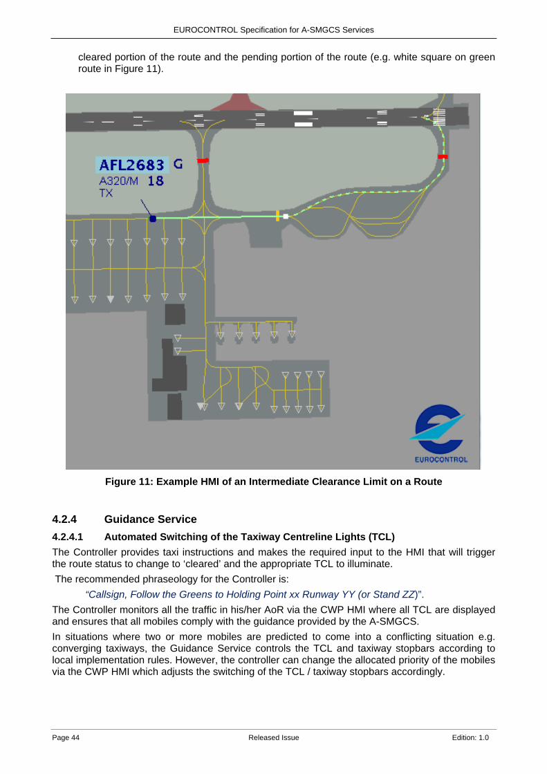
EUROCONTROL Specification for A-SMGCS Services
Page 44 Released Issue Edition: 1.0
cleared portion of the route and the pending portion of the route (e.g. white square on green route in Figure 11).
Figure 11: Example HMI of an Intermediate Clearance Limit on a Route
4.2.4 Guidance Service 4.2.4.1 Automated Switching of the Taxiway Centreline Lights (TCL) The Controller provides taxi instructions and makes the required input to the HMI that will trigger the route status to change to ‘cleared’ and the appropriate TCL to illuminate. The recommended phraseology for the Controller is:
“Callsign, Follow the Greens to Holding Point xx Runway YY (or Stand ZZ)”. The Controller monitors all the traffic in his/her AoR via the CWP HMI where all TCL are displayed and ensures that all mobiles comply with the guidance provided by the A-SMGCS. In situations where two or more mobiles are predicted to come into a conflicting situation e.g. converging taxiways, the Guidance Service controls the TCL and taxiway stopbars according to local implementation rules. However, the controller can change the allocated priority of the mobiles via the CWP HMI which adjusts the switching of the TCL / taxiway stopbars accordingly.
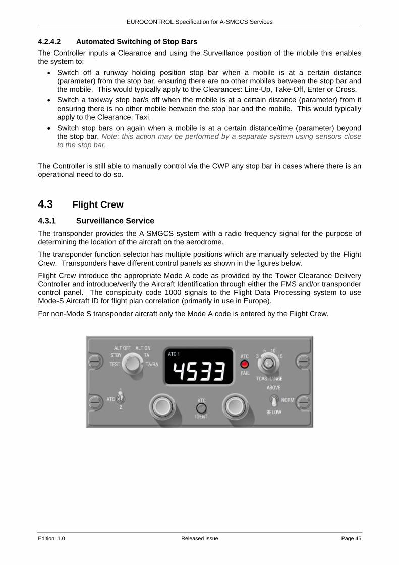
EUROCONTROL Specification for A-SMGCS Services
Edition: 1.0 Released Issue Page 45
4.2.4.2 Automated Switching of Stop Bars The Controller inputs a Clearance and using the Surveillance position of the mobile this enables the system to:
• Switch off a runway holding position stop bar when a mobile is at a certain distance (parameter) from the stop bar, ensuring there are no other mobiles between the stop bar and the mobile. This would typically apply to the Clearances: Line-Up, Take-Off, Enter or Cross.
• Switch a taxiway stop bar/s off when the mobile is at a certain distance (parameter) from it ensuring there is no other mobile between the stop bar and the mobile. This would typically apply to the Clearance: Taxi.
• Switch stop bars on again when a mobile is at a certain distance/time (parameter) beyond the stop bar. Note: this action may be performed by a separate system using sensors close to the stop bar.
The Controller is still able to manually control via the CWP any stop bar in cases where there is an operational need to do so.
4.3 Flight Crew 4.3.1 Surveillance Service The transponder provides the A-SMGCS system with a radio frequency signal for the purpose of determining the location of the aircraft on the aerodrome.
The transponder function selector has multiple positions which are manually selected by the Flight Crew. Transponders have different control panels as shown in the figures below.
Flight Crew introduce the appropriate Mode A code as provided by the Tower Clearance Delivery Controller and introduce/verify the Aircraft Identification through either the FMS and/or transponder control panel. The conspicuity code 1000 signals to the Flight Data Processing system to use Mode-S Aircraft ID for flight plan correlation (primarily in use in Europe).
For non-Mode S transponder aircraft only the Mode A code is entered by the Flight Crew.
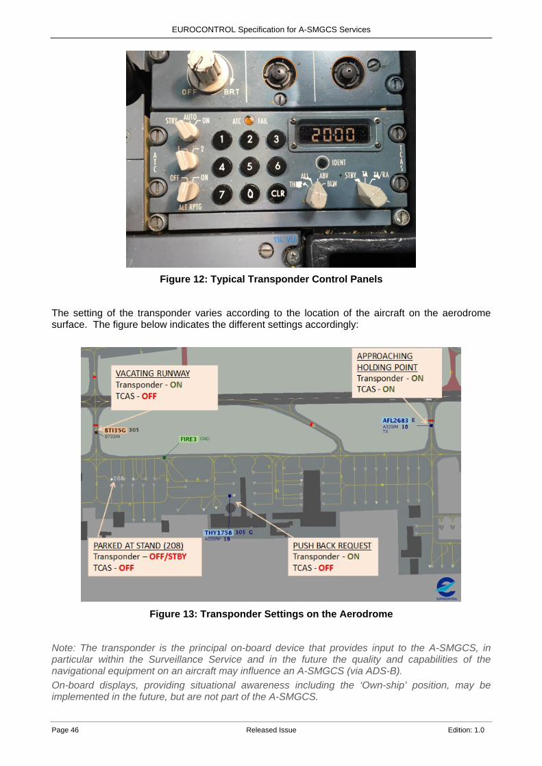
EUROCONTROL Specification for A-SMGCS Services
Page 46 Released Issue Edition: 1.0
Figure 12: Typical Transponder Control Panels
The setting of the transponder varies according to the location of the aircraft on the aerodrome surface. The figure below indicates the different settings accordingly:
Figure 13: Transponder Settings on the Aerodrome
Note: The transponder is the principal on-board device that provides input to the A-SMGCS, in particular within the Surveillance Service and in the future the quality and capabilities of the navigational equipment on an aircraft may influence an A-SMGCS (via ADS-B). On-board displays, providing situational awareness including the ‘Own-ship’ position, may be implemented in the future, but are not part of the A-SMGCS.

EUROCONTROL Specification for A-SMGCS Services
Edition: 1.0 Released Issue Page 47
Example of transponder operating procedures for Aeronautical Information Publication (AIP)
Aircraft operators intending to use [ICAO-indicator] airport shall ensure that the Mode S transponders are able to operate when the aircraft is on the ground. Flight Crew shall:
• Select AUTO mode and assigned Mode A code.
• If AUTO mode is not available Select ON (e.g. XPDR) and assigned Mode A code.
• From the request for push back or taxi whichever is earlier.
• After landing, continuously until the aircraft is fully parked on stand.
• When fully parked on stand select STBY. Whenever the aircraft is capable of reporting Aircraft Identification (i.e. call sign used in flight), the Aircraft’s Identification should also be entered from the request for push back or taxi whichever is earlier (through the FMS or the Transponder Control Panel). Flight Crew must use the ICAO defined format for entry of the Aircraft Identification (e.g. AFR6380, SAS589, BAW61RL). To ensure that the performance of systems based on SSR frequencies (including airborne TCAS units and SSR radars) is not compromised; TCAS should not be selected before approaching the holding point. It should then be deselected after vacating the runway. For aircraft taxiing without flight plan, Mode A code 2000 should be selected.
4.3.2 Airport Safety Support Service No specific procedure applicable within the scope of this document for Flight Crew.
4.3.3 Routing Service No specific procedure applicable within the scope of this document for Flight Crew.
4.3.4 Guidance Service The Flight Crew read back the instructions detailed in section 4.2.4.1 and proceed as follows.
• If green (or alternating green and yellow) TCL are shown in front of the mobile they can follow the lights.
• If there are no green (or alternating green and yellow) TCL; or if there are activated red TCL or there is a red stop bar, then they must stop the aircraft.
• Yellow or flashing lights they exercise caution.
4.4 Vehicle Drivers 4.4.1 Surveillance Service Every Vehicle Driver using a vehicle on the manoeuvring area should have an operative vehicle transmitter ensuring detection and correct labelling by the A-SMGCS and operate the vehicle in accordance with local procedures.
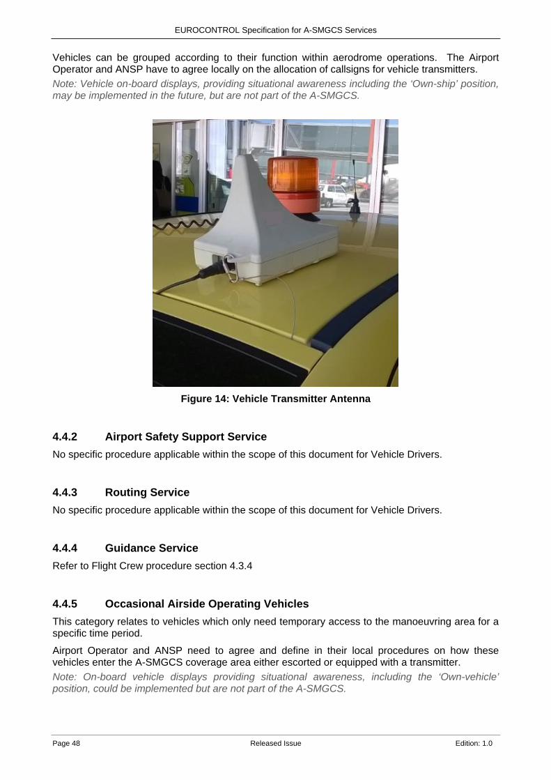
EUROCONTROL Specification for A-SMGCS Services
Page 48 Released Issue Edition: 1.0
Vehicles can be grouped according to their function within aerodrome operations. The Airport Operator and ANSP have to agree locally on the allocation of callsigns for vehicle transmitters. Note: Vehicle on-board displays, providing situational awareness including the ‘Own-ship’ position, may be implemented in the future, but are not part of the A-SMGCS.
Figure 14: Vehicle Transmitter Antenna
4.4.2 Airport Safety Support Service No specific procedure applicable within the scope of this document for Vehicle Drivers.
4.4.3 Routing Service No specific procedure applicable within the scope of this document for Vehicle Drivers.
4.4.4 Guidance Service Refer to Flight Crew procedure section 4.3.4
4.4.5 Occasional Airside Operating Vehicles This category relates to vehicles which only need temporary access to the manoeuvring area for a specific time period.
Airport Operator and ANSP need to agree and define in their local procedures on how these vehicles enter the A-SMGCS coverage area either escorted or equipped with a transmitter. Note: On-board vehicle displays providing situational awareness, including the ‘Own-vehicle’ position, could be implemented but are not part of the A-SMGCS.
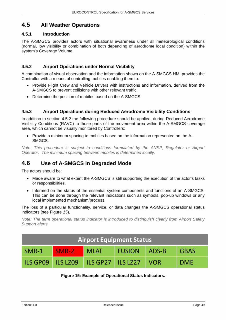
EUROCONTROL Specification for A-SMGCS Services
Edition: 1.0 Released Issue Page 49
4.5 All Weather Operations 4.5.1 Introduction The A-SMGCS provides actors with situational awareness under all meteorological conditions (normal, low visibility or combination of both depending of aerodrome local condition) within the system’s Coverage Volume.
4.5.2 Airport Operations under Normal Visibility A combination of visual observation and the information shown on the A-SMGCS HMI provides the Controller with a means of controlling mobiles enabling them to:
• Provide Flight Crew and Vehicle Drivers with instructions and information, derived from the A-SMGCS to prevent collisions with other relevant traffic.
• Determine the position of mobiles based on the A-SMGCS.
4.5.3 Airport Operations during Reduced Aerodrome Visibility Conditions In addition to section 4.5.2 the following procedure should be applied, during Reduced Aerodrome Visibility Conditions (RAVC) to those parts of the movement area within the A-SMGCS coverage area, which cannot be visually monitored by Controllers:
• Provide a minimum spacing to mobiles based on the information represented on the A-SMGCS.
Note: This procedure is subject to conditions formulated by the ANSP, Regulator or Airport Operator. The minimum spacing between mobiles is determined locally.
4.6 Use of A-SMGCS in Degraded Mode The actors should be:
• Made aware to what extent the A-SMGCS is still supporting the execution of the actor’s tasks or responsibilities.
• Informed on the status of the essential system components and functions of an A-SMGCS. This can be done through the relevant indications such as symbols, pop-up windows or any local implemented mechanism/process.
The loss of a particular functionality, service, or data changes the A-SMGCS operational status indicators (see Figure 15).
Note: The term operational status indicator is introduced to distinguish clearly from Airport Safety Support alerts.
Figure 15: Example of Operational Status Indicators.
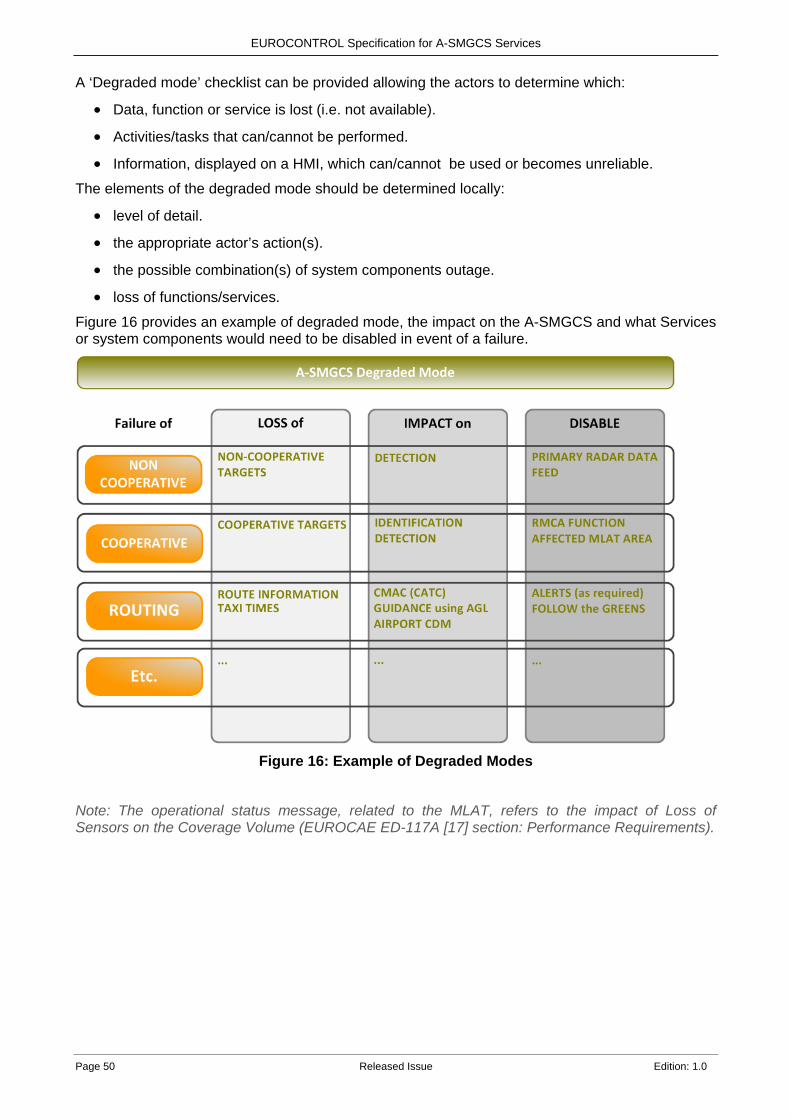
EUROCONTROL Specification for A-SMGCS Services
Page 50 Released Issue Edition: 1.0
A ‘Degraded mode’ checklist can be provided allowing the actors to determine which:
• Data, function or service is lost (i.e. not available).
• Activities/tasks that can/cannot be performed.
• Information, displayed on a HMI, which can/cannot be used or becomes unreliable. The elements of the degraded mode should be determined locally:
• level of detail.
• the appropriate actor’s action(s).
• the possible combination(s) of system components outage.
• loss of functions/services. Figure 16 provides an example of degraded mode, the impact on the A-SMGCS and what Services or system components would need to be disabled in event of a failure.
Figure 16: Example of Degraded Modes
Note: The operational status message, related to the MLAT, refers to the impact of Loss of Sensors on the Coverage Volume (EUROCAE ED-117A [17] section: Performance Requirements).
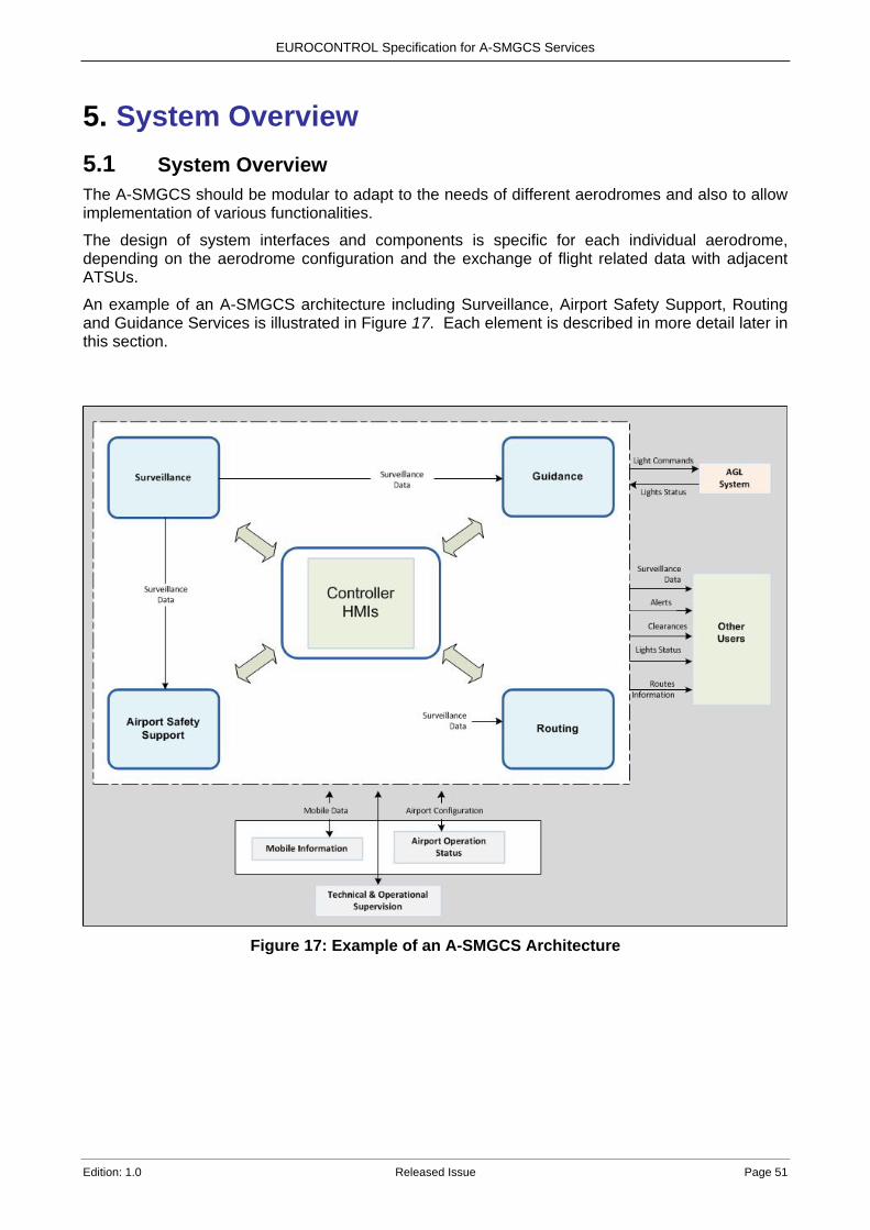
EUROCONTROL Specification for A-SMGCS Services
Edition: 1.0 Released Issue Page 51
5. System Overview 5.1 System Overview The A-SMGCS should be modular to adapt to the needs of different aerodromes and also to allow implementation of various functionalities.
The design of system interfaces and components is specific for each individual aerodrome, depending on the aerodrome configuration and the exchange of flight related data with adjacent ATSUs.
An example of an A-SMGCS architecture including Surveillance, Airport Safety Support, Routing and Guidance Services is illustrated in Figure 17. Each element is described in more detail later in this section.
Figure 17: Example of an A-SMGCS Architecture
EUROCONTROL Specification for A-SMGCS Services
Page 52 Released Issue Edition: 1.0
5.2 Databases For the purpose of this specification two main databases are defined as being required in an A-SMGCS. However, the term database in this context does not imply the need to implement a commercial database management system but a means to store and distribute data.
5.2.1 Mobile Information Database A Mobile Information database stores information related to each mobile, such as,
for aircraft: identity, type, flight plan, SSR code, stand, Clearances, planned route, cleared route, assigned runway, timing information, de-icing information, aircraft status (e.g. assumed, pending, transferred).
for vehicles: identity, type, type of movement, Clearances, planned route, cleared route, timing information.
This database stores information coming from several sources, for example, the Flight Data Provider (such as Network Manager, ANSP), Airspace User, A-CDM platform, A-SMGCS Services and CWP. Local rules need to be defined to identify which information is made available to the A-SMGCS; these rules also address the updating and publication of such information.
5.2.2 Airport Operations Status Database Airport Operations Status database contains environment data and status of its infrastructure such as runway in use, taxiway status and meteorological conditions.
The database stores information coming from the Airport Operator and the ANSP.
Some of the information that can be found in the Airport Operations Status database: • The aerodrome map including runways, taxiways, aprons, restricted area, buildings and
AoRs. • Reference points (including status of lights where applicable): RWY thresholds, holding
points, stop bars, centreline lighting, etc. • The operational use of runways – which runways are being used for arrivals, departures,
mixed mode or even as a taxiway. • The planned opening and closing of runways/taxiways for inspection, maintenance or snow
removal. • Constraints (e.g. one-way TWYs, TWYs with wingspan or weight restrictions, etc). • The activation and de-activation of LVP. The knowledge of whether LVP are in force
changes the parameters of when RMCA alerts are triggered and also the Clearance limit of a route to a holding point e.g. CATI and III holding points are normally in different locations.
• The status of A-SMGCS functions e.g. RMCA. • The indication that an emergency is in progress at the aerodrome. • Temporary closed areas. • Relevant Fixed Obstacles. • ATC rules/procedures (e.g multiple line-up, land after).
Note: Commission Regulation (EU) No 73/2010 of 26 January 2010 [9] details requirements on the quality of aeronautical data and aeronautical information for the single European sky.
EUROCONTROL Specification for A-SMGCS Services
Edition: 1.0 Released Issue Page 53
5.3 Controller Working Position To provide Controllers with a graphical user interface and with the means to interact with the aerodrome ATC systems, a CWP is needed, including one or more HMI displays. HMI examples used in this document are taken from the EUROCONTROL Integrated Tower Working Position (ITWP) demonstrator and are fully detailed in the EUROCONTROL HMI document [13].
5.3.1 Human-Machine Interface (HMI) 5.3.1.1 General Overview On the HMI display, the aerodrome environment and traffic information (position and identity) should be provided to give up-to-date traffic information and to provide aerodrome situational awareness.
The majority of the Routing, Airport Safety Support and Guidance services require the CWP to be able to allow the input of Clearances via an electronic means into the system.
The HMI is an integral part of the A-SMGCS; it gathers information from other parts of the system, displays the necessary information to the Controller, and provides means for the Controller to interact with the system.
The HMI provides a labelled display showing the identities and calculated positions of mobiles, superimposed on a map of the aerodrome. If non-cooperative surveillance is provided by SMR, the HMI may also display a raw video image.
Aerodrome environment data (e.g. runways, service roads) and information derived from other systems could be integrated and made visible on the HMI, such as:
• Status of ATS systems: landing systems, visual aids, ATIS. • Air Traffic Monitor (Approach radar). • Meteorological information. • Information relating to emergency services.
The HMI needs to be customised to the Controller’s AoR and must be interactive to allow easy and intuitive Controller input and configuration, for example to:
• Hide/unhide vehicles in certain areas of the movement area such as service roads. • Display and be able to filter different types of traffic (e.g. IFR / VFR rotorcraft,
transits/inbounds/outbounds). • Filter SMR video to avoid unnecessary clutter.
The identification of the detected mobiles and their unambiguous representation on the HMI is essential. Depending on the quality of the video signal if used, valuable information about the detected aircraft size and orientation can be obtained. This also helps to detect intruders which do not have an operating transponder or transmitter.
5.3.1.2 Labelling of Mobiles The labelling of mobiles plays an important role and should be designed by Human Performance experts. The HMI should provide different label types for aircraft and vehicles. For airports with a high proportion of towed aircraft; a dedicated label category has proven to be beneficial. Minimising the overlapping of labels should be a feature of the HMI, e.g. by providing an easy method of manually de-conflicting or a suitable algorithm.
As illustrated in Figure 18, labels are attached to symbols representing the mobiles' positions to display their identity and supplementary information. Additional data can be formatted so it appears on different lines or shown as a minimum display with the full content (extended label) being displayed when needed.
The label can also show an indication of the Clearance status (e.g. cleared to land/line-up/take-off/push-back or taxi), that has been input using symbols which act as an aide memoire for the
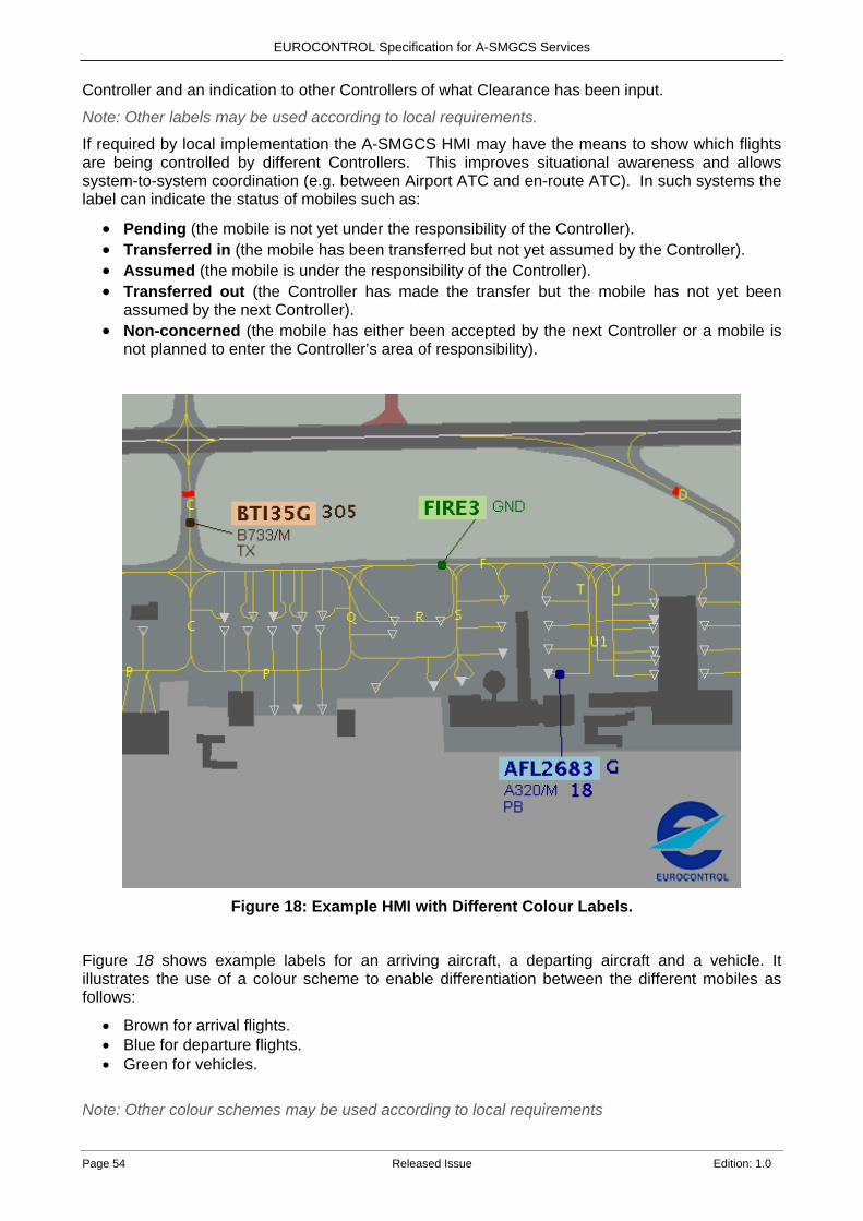
EUROCONTROL Specification for A-SMGCS Services
Page 54 Released Issue Edition: 1.0
Controller and an indication to other Controllers of what Clearance has been input.
Note: Other labels may be used according to local requirements.
If required by local implementation the A-SMGCS HMI may have the means to show which flights are being controlled by different Controllers. This improves situational awareness and allows system-to-system coordination (e.g. between Airport ATC and en-route ATC). In such systems the label can indicate the status of mobiles such as:
• Pending (the mobile is not yet under the responsibility of the Controller). • Transferred in (the mobile has been transferred but not yet assumed by the Controller). • Assumed (the mobile is under the responsibility of the Controller). • Transferred out (the Controller has made the transfer but the mobile has not yet been
assumed by the next Controller). • Non-concerned (the mobile has either been accepted by the next Controller or a mobile is
not planned to enter the Controller’s area of responsibility).
Figure 18: Example HMI with Different Colour Labels.
Figure 18 shows example labels for an arriving aircraft, a departing aircraft and a vehicle. It illustrates the use of a colour scheme to enable differentiation between the different mobiles as follows:
• Brown for arrival flights. • Blue for departure flights. • Green for vehicles.
Note: Other colour schemes may be used according to local requirements
EUROCONTROL Specification for A-SMGCS Services
Edition: 1.0 Released Issue Page 55
The label for the arriving aircraft indicates:
• Aircraft identification (BTI35G) and the parking stand (305) on line 1. • Aircraft type/ wake vortex category (B733/M) on line 2. • Current Clearance (TX=Taxi) on line 3.
The label for the departing aircraft indicates:
• Aircraft identification (AFL2683) and planned holding point (G) on line 1. • Aircraft type/wake vortex category (A320/M) and assigned departure runway (RWY18) on
line 2. • Current Clearance (PB=Push Back) on line 3.
The label for the vehicle indicates:
• Vehicle identification (FIRE 3) and responsible Controller (GND). Note: For this example, GND indicates the mobile is being controlled by the Tower Ground Controller.
5.3.2 Electronic Clearance Input (ECI) The introduction of new functions such as Airport Safety Support (CATC and CMAC) and Guidance (FtG) requires that the A-SMGCS is provided with Clearances given by the Controller.
The integration of Electronic Clearance Inputs also becomes important for incorporating the Tower with Approach and Departure sectors enabling system coordination such as showing the status of flights e.g. pending, assumed and transferred.
The CWP must be able to allow the input of Controller Clearances, such as Push-Back, Taxi, Line -Up, Conditional Line-Up, Take-Off, Land, Cross, Enter, Hold Short, Go-Around and Abort. These Clearances are compared with the surveillance position of the mobile and the flight plan in order to detect any non-conformance to procedures or instructions. They are also used to enable the correct triggering of TCL and stop bars for the Guidance Service. Note: The ECI is either a part of a separate system or can be integrated into the A-SMGCS HMI.
5.4 Recording and Playback Recording and playback provide a means for occurrence investigation. Depending on national authorities, data to be recorded will be defined locally and the A-SMGCS can be capable of recording service data and its playback.
The playback aims at reproducing an exact replay of the situation (display and inputs) presented on the Controller HMI.
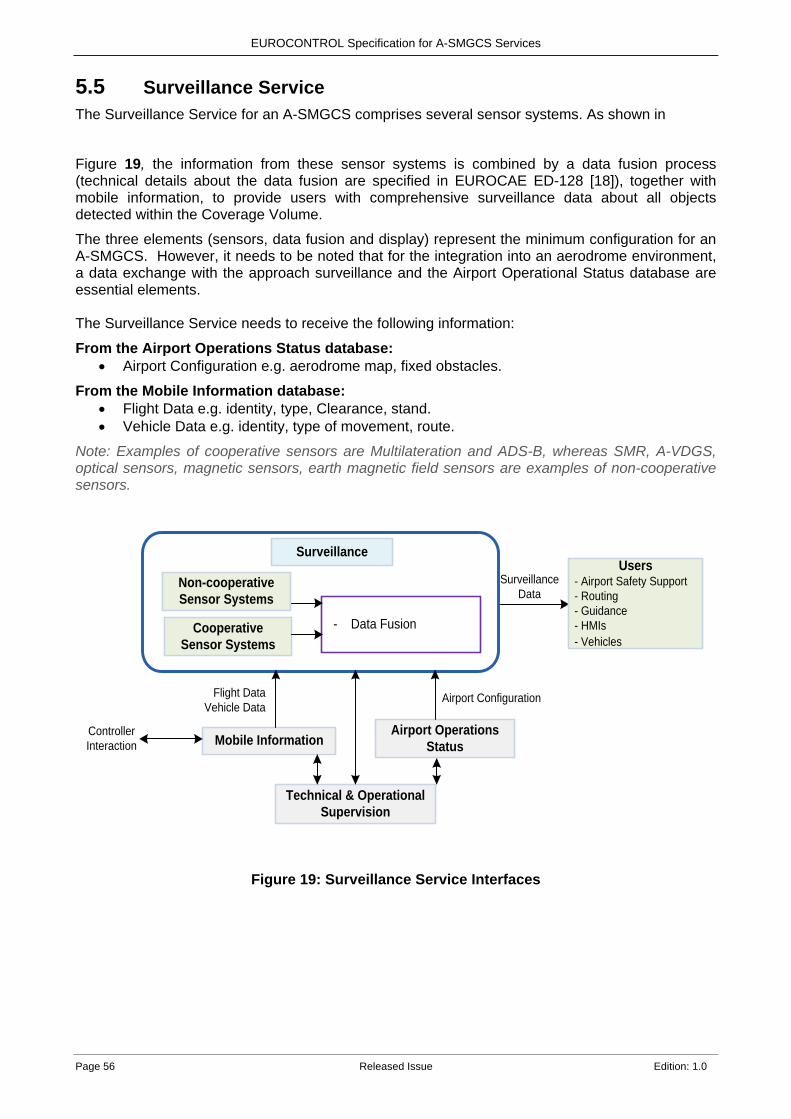
EUROCONTROL Specification for A-SMGCS Services
Page 56 Released Issue Edition: 1.0
5.5 Surveillance Service The Surveillance Service for an A-SMGCS comprises several sensor systems. As shown in
Figure 19, the information from these sensor systems is combined by a data fusion process (technical details about the data fusion are specified in EUROCAE ED-128 [18]), together with mobile information, to provide users with comprehensive surveillance data about all objects detected within the Coverage Volume.
The three elements (sensors, data fusion and display) represent the minimum configuration for an A-SMGCS. However, it needs to be noted that for the integration into an aerodrome environment, a data exchange with the approach surveillance and the Airport Operational Status database are essential elements. The Surveillance Service needs to receive the following information:
From the Airport Operations Status database: • Airport Configuration e.g. aerodrome map, fixed obstacles.
From the Mobile Information database: • Flight Data e.g. identity, type, Clearance, stand. • Vehicle Data e.g. identity, type of movement, route.
Note: Examples of cooperative sensors are Multilateration and ADS-B, whereas SMR, A-VDGS, optical sensors, magnetic sensors, earth magnetic field sensors are examples of non-cooperative sensors.
Surveillance
- Data Fusion
Non-cooperativeSensor Systems
CooperativeSensor Systems
Mobile InformationAirport Operations
Status
Technical & Operational Supervision
SurveillanceData
Airport ConfigurationFlight DataVehicle Data
Controller Interaction
Users- Airport Safety Support- Routing- Guidance- HMIs- Vehicles
Figure 19: Surveillance Service Interfaces

EUROCONTROL Specification for A-SMGCS Services
Edition: 1.0 Released Issue Page 57
5.6 Airport Safety Support Service The Airport Safety Support Service detects alert situations and triggers alerts based on the Surveillance output, Mobile Information and Airport Operations Status data, and needs to receive the following information:
From the Airport Operations Status database: • Runway and Taxiway status. • Taxiway configuration. • ATC rules/procedures.
From the Mobile Information database: • Clearances. • Cleared route information.
From the Surveillance service: • Identity (if it’s a cooperative mobile) and current position of each mobile.
All the alerts are distributed to the relevant users and may be presented on their HMIs according to their specific needs.
Airport Safety Support
Functions - RMCA - CATC - CMAC
Mobile InformationAirport Operations
Status
Technical & Operational Supervision
AlertsUsers
- Routing- Guidance- HMIs- ...
Surveillance
SurveillanceData
ClearancesCleared Routes
Airport Configuration
Controller Interaction
Figure 20: Airport Safety Support Service Interfaces
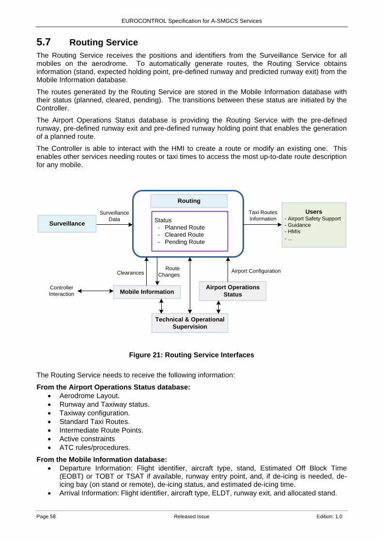
EUROCONTROL Specification for A-SMGCS Services
Page 58 Released Issue Edition: 1.0
5.7 Routing Service The Routing Service receives the positions and identifiers from the Surveillance Service for all mobiles on the aerodrome. To automatically generate routes, the Routing Service obtains information (stand, expected holding point, pre-defined runway and predicted runway exit) from the Mobile Information database.
The routes generated by the Routing Service are stored in the Mobile Information database with their status (planned, cleared, pending). The transitions between these status are initiated by the Controller.
The Airport Operations Status database is providing the Routing Service with the pre-defined runway, pre-defined runway exit and pre-defined runway holding point that enables the generation of a planned route.
The Controller is able to interact with the HMI to create a route or modify an existing one. This enables other services needing routes or taxi times to access the most up-to-date route description for any mobile.
Routing
Status - Planned Route - Cleared Route - Pending Route
Mobile InformationAirport Operations
Status
Technical & Operational Supervision
Taxi Routes Information
Users- Airport Safety Support- Guidance- HMIs- ...
Surveillance
SurveillanceData
Airport Configuration
Controller Interaction
ClearancesRoute
Changes
Figure 21: Routing Service Interfaces The Routing Service needs to receive the following information:
From the Airport Operations Status database: • Aerodrome Layout. • Runway and Taxiway status. • Taxiway configuration. • Standard Taxi Routes. • Intermediate Route Points. • Active constraints • ATC rules/procedures.
From the Mobile Information database: • Departure Information: Flight identifier, aircraft type, stand, Estimated Off Block Time
(EOBT) or TOBT or TSAT if available, runway entry point, and, if de-icing is needed, de-icing bay (on stand or remote), de-icing status, and estimated de-icing time.
• Arrival Information: Flight identifier, aircraft type, ELDT, runway exit, and allocated stand.
EUROCONTROL Specification for A-SMGCS Services
Edition: 1.0 Released Issue Page 59
• Towed Aircraft Information: Aircraft registration, Aircraft type, origin position and destination position.
• Vehicle information: Identifier, origin position, destination position and, for mobiles part of a moving entity, identifiers of other mobiles in the group.
• Manual route inputs. • Clearances.
From the Surveillance service: • Identity and current position of each mobile.
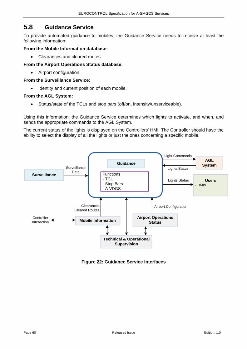
EUROCONTROL Specification for A-SMGCS Services
Page 60 Released Issue Edition: 1.0
5.8 Guidance Service To provide automated guidance to mobiles, the Guidance Service needs to receive at least the following information:
From the Mobile Information database:
• Clearances and cleared routes.
From the Airport Operations Status database:
• Airport configuration.
From the Surveillance Service:
• Identity and current position of each mobile.
From the AGL System:
• Status/state of the TCLs and stop bars (off/on, intensity/unserviceable).
Using this information, the Guidance Service determines which lights to activate, and when, and sends the appropriate commands to the AGL System.
The current status of the lights is displayed on the Controllers' HMI. The Controller should have the ability to select the display of all the lights or just the ones concerning a specific mobile.
Guidance
Functions- TCL- Stop Bars- A-VDGS
Mobile InformationAirport Operations
Status
Technical & Operational Supervision
Lights Status Users- HMIs- ...
Surveillance
SurveillanceData
ClearancesCleared Routes
Airport Configuration
Controller Interaction
AGLSystem
Lights Status
Light Commands
Figure 22: Guidance Service Interfaces
EUROCONTROL Specification for A-SMGCS Services
Edition: 1.0 Released Issue Page 61
6. A-SMGCS Requirements Whichever of the services and associated requirements are selected for implementation, discussion is required between the local ANSP, airport operators and regulators. In particular there is a need to identify which local parameters should be used, e.g. when and which alerts are triggered, on which control positions and how they should be displayed.
6.1 General
ASMGCS-[GENL]-[010] The A-SMGCS shall support surface movement operations of all mobiles within the Coverage Volume.
ASMGCS-[GENL]-[020] The A-SMGCS shall support surface movement operations in all weather conditions.
ASMGCS-[GENL]-[030] The Surveillance Service shall be the first and minimum service of an A-SMGCS.
ASMGCS-[GENL]-[040] A-SMGCS Services shall have a means to access the current information about mobiles and airport operations. Note: This information could be stored in databases, see section 5.2. ASMGCS-[GENL]-[050] The A-SMGCS should be capable of interfacing with external systems. Note: Depending on the functionality of the A-SMGCS implementation, external systems may be any of the following (the list is non-exhaustive):
• Approach surveillance system to take into account airborne aircraft. • Stand management systems. • Flight Data Processing System (FDPS). • MET systems. • Visual aids (e.g. AGL). • A-CDM Platform. • Electronic Flight Strips (EFS).
ASMGCS-[GENL]-[060] All A-SMGCS data exchange interfaces should make use of standardised formats.
ASMGCS-[GENL]-[070] The A-SMGCS shall be designed so that actors involved in the A-SMGCS environment are able to perform their tasks and responsibilities. Note: This requirement applies to the A-SMGCS actors: Controllers, Flight Crews, Vehicle Drivers and Other actors (see section 2.2 to 2.5).
ASMGCS-[GENL]-[080] The A-SMGCS shall be designed to accommodate any physical change of the aerodrome layout.
ASMGCS-[GENL]-[090] The A-SMGCS shall be designed to accommodate operational procedures applicable to RPAs and Restricted areas. Note: This includes the definition of which mobiles are authorised to enter restricted areas.
EUROCONTROL Specification for A-SMGCS Services
Page 62 Released Issue Edition: 1.0
ASMGCS-[GENL]-[100] The A-SMGCS shall be designed to accommodate different Controller roles. Note: These roles are normally those described in section 2.1, but could also be based on geographical criteria (areas of responsibility), on the phase of flight (taxi-in, taxi-out), traffic load, night versus day operations or any other local criteria. ASMGCS-[GENL]-[110] The A-SMGCS shall be designed to accommodate different AoRs and associated transfer of control procedures.
ASMGCS-[GENL]-[120] The operation of the HMI shall not impair the performance of essential Controller tasks.
ASMGCS-[GENL]-[130] The HMI shall be useable in all ambient light levels applicable to the Controller’s working environment.
ASMGCS-[GENL]-[140] The HMI shall display the aerodrome layout including runways, taxiways, aprons and buildings.
ASMGCS-[GENL]-[150] The HMI should display or provide access to the following information about mobiles, the following list is non-exhaustive:
• Vehicle type. • Aircraft type and flight identification. • Departure / Destination Aerodrome. • Estimates of Arrival / Departure Times (e.g. EOBT, TOBT, TSAT, ELDT, TLDT). • Assigned Stand, and current stand status (occupied/free). • Wake Vortex Category. • Network Manager Slot time (if applicable). • Assigned runway and SID/STAR/Approach Procedure. • Last assigned Clearance. • Speed. • Transponder code.
ASMGCS-[GENL]-[160] The A-SMGCS should be capable of recording A-SMGCS Service data and provide the capability for playback. Note: The nature of the data to be recorded e.g. screen recording, event logging, is a local decision. ASMGCS-[GENL]-[170] The operational status and performance of the A-SMGCS Services and essential system components shall be monitored in real time with suitable audio and operational status indicators. Note: The indicators shall show which Service(s) and/or system component(s) of the A-SMGCS are inoperative or operating in degraded mode. This also includes notification of failure recovery. ASMGCS-[GENL]-[180] In case of a failure of an A-SMGCS Service or an essential system component(s) within the Service, the actors shall not be presented with erroneous information in order to continue operations in the degraded mode. Note: For degraded mode operations see section 4.6 ASMGCS-[GENL]-[190] The A-SMGCS shall be designed to self-restart in case of a system failure, within a maximum recovery time. Note: The maximum recovery time is to be specified locally. A typical value would be of the order of a few minutes.
EUROCONTROL Specification for A-SMGCS Services
Edition: 1.0 Released Issue Page 63
ASMGCS-[GENL]-[200] After a restart, the A-SMGCS HMI shall display the current traffic situation, information about mobiles and information about airport operations.
6.2 Surveillance Service
ASMGCS-[SURV]-[010] The Surveillance Service shall include at least one cooperative sensor and at least one non-cooperative sensor. ASMGCS-[SURV]-[020] The Surveillance Service shall provide the identification, position and tracking of mobiles within a predefined Coverage Volume. ASMGCS-[SURV]-[030] The Surveillance Service shall be designed to minimise the following effects:
• Radio interference, including that produced by standard navigation, telecommunications and radar facilities (including airborne equipment).
• Signal reflections and shadowing caused by aircraft in flight, vehicles or aircraft on the ground, buildings, snow banks or other raised obstacles (fixed or temporary) in or near the aerodrome environment.
ASMGCS-[SURV]-[040] The Surveillance Service shall be designed to operate in meteorological conditions applicable to the aerodrome or any state of the aerodrome resulting from adverse weather.
ASMGCS-[SURV]-[050] The Surveillance Service shall use transponder signals for the purpose of determining the location and identity of cooperative aircraft. Note:The transponder operating procedures for Flight Crew are normally published in the AIP.
ASMGCS-[SURV]-[060] The Surveillance Service shall use transmitter signals for the purpose of determining the location and identity of cooperative vehicles.
ASMGCS-[SURV]-[070] The HMI shall display every mobile in the correct position with respect to the aerodrome layout and other traffic.
ASMGCS-[SURV]-[080] The Surveillance Service shall calculate the current speed and heading of mobiles within the Coverage Volume.
ASMGCS-[SURV]-[090] The Surveillance Service should ensure a seamless transition is provided between the surveillance from the approach radar and the surveillance from the A-SMGCS.
ASMGCS-[SURV]-[100] The HMI shall allow the manual assignment of an identification label to a non-identified target.
ASMGCS-[SURV]-[110] The Surveillance Service may provide the Actual Landing/In-Block/Off-Block/Take-Off Time (ALDT/AIBT/AOBT/ATOT) to external systems.

EUROCONTROL Specification for A-SMGCS Services
Page 64 Released Issue Edition: 1.0
6.3 Airport Safety Support Service 6.3.1 General
ASMGCS-[SAFE]-[010] The Airport Safety Support Service shall be designed on the basis of one or more of the following functions RMCA, CATC and CMAC.
ASMGCS-[SAFE]-[020] The Airport Safety Support Service shall use surveillance data, current information about mobiles and airport operations to enable the triggering of alerts for Controllers.
ASMGCS-[SAFE]-[030] The CWP shall provide an ECI for Controllers to input and cancel Clearances for all mobiles operating under their responsibility, to support the Airport Safety Support Service CATC and CMAC functions.
ASMGCS-[SAFE]-[040] The alerting parameters of the Airport Safety Support Service shall be configurable to local ATC procedures and working methods. ASMGCS-[SAFE]-[050] The display of Airport Safety Support Service alerts on the HMI shall be relevant to the Controller role and AoR. Note: Appendix C provides information on where alerts may be displayed and other criteria may be considered such as ‘Inside AoR’, ‘at a distance of my AoR’, ‘at a time from my AoR’, ‘Assume of Control’ etc. ASMGCS-[SAFE]-[060] The Airport Safety Support Service shall display all current alerts on the HMI relevant to the Controller role and AoR. Note: The display on the HMI can take the form of a modified label, a dedicated window, or a combination (see Appendix C for examples). ASMGCS-[SAFE]-[070] The Airport Safety Support Service shall provide to the Controller INFORMATION and ALARM alerts, ALARM being more critical than INFORMATION. Note: See section 3.3.2 for more information on stages of alerts. ASMGCS-[SAFE]-[080] A priority shall be defined according to each alert relevant to the aerodrome. Note: Section 3.3.4 provides an example of an alert prioritisation scheme. ASMGCS-[SAFE]-[090] The HMI shall display to the Controller an ALARM alert with a distinct “ALARM colour”. Note: The colour most commonly used with ALARM alerts is red. ASMGCS-[SAFE]-[100] The CWP shall provide an audio warning when an ALARM alert is triggered. Note: The use of audible warnings for INFORMATION alerts is a local implementation decision. ASMGCS-[SAFE]-[110] The audio warning accompanying an ALARM alert shall be distinct from other audio sounds in use. Note: The duration of the audio warning is a local implementation decision. ASMGCS-[SAFE]-[120] The CWP shall provide a means to the Controller to silence an audio warning accompanying an ALARM alert. ASMGCS-[SAFE]-[130] When a new ALARM alert is triggered after a previous audio warning has been silenced then the audio warning shall be reactivated.
EUROCONTROL Specification for A-SMGCS Services
Edition: 1.0 Released Issue Page 65
ASMGCS-[SAFE]-[140] The HMI shall display to the Controller an INFORMATION alert with a distinct “INFORMATION colour”. Note: The colour most commonly used with INFORMATION alerts is yellow. ASMGCS-[SAFE]-[150] All alerts shall remain displayed on the HMI until the terminating conditions have been satisfied. ASMGCS-[SAFE]-[160] For every displayed INFORMATION or ALARM alert, the HMI shall show the following information:
• Alert description • Identity of the mobile(s) in the alert situation.
Note: A non exhaustive description of alerts can be found in Appendices A, B and C.
ASMGCS-[SAFE]-[170] When several alerts are detected for the same mobile, the description of the alert having the highest priority shall, at least, be displayed in the mobile radar/track label and/or EFS on the HMI.
ASMGCS-[SAFE]-[180] The Controller may have a means via their assigned HMI to toggle between displaying or hiding an INFORMATION alert message.
ASMGCS-[SAFE]-[190] The Tower Supervisor shall be able to selectively deactivate/activate the display of Airport Safety Support Service alerts. Note: It is a local decision whether the alerts are selectable by function (RMCA, CATC, CMAC) or individually by name e.g. ‘Line-Up vs Land’, ‘Runway Incursion’. ASMGCS-[SAFE]-[200] The Airport Safety Support Service shall not generate more than a maximum number of false and nuisance alerts. Note: The maximum number for a given period is a local implementation decision based on the operational environment and safety requirements.
6.3.2 RMCA
ASMGCS-[SAFE]-[210] The RMCA function shall use the Surveillance Service to monitor the movement of mobiles within or approaching the RPA.
ASMGCS-[SAFE]-[220] The RMCA function shall predict short term conflicts between arriving or departing aircraft with a mobile in the RPA. Note : Prediction of conflicts between vehicles is not within the scope of this Specification.
ASMGCS-[SAFE]-[230] The RMCA function shall predict short term conflicts between arriving or departing aircraft with an aircraft operating above, or approaching, the RPA below a defined altitude (e.g. a helicopter crossing the aerodrome). ASMGCS-[SAFE]-[240] The RMCA function shall predict short term conflicts between arriving or departing aircraft with a mobile moving to or on a converging or intersecting runway.
ASMGCS-[SAFE]-[250] The RMCA function shall predict short term conflicts between arriving or departing aircraft with opposite direction arrival to the runway.
ASMGCS-[SAFE]-[260] The RMCA function shall predict short term conflicts between arriving or departing aircraft with a mobile approaching the runway (predicted to cross the runway-holding position).
ASMGCS-[SAFE]-[270] The RMCA function shall predict short term conflicts between unidentified
EUROCONTROL Specification for A-SMGCS Services
Page 66 Released Issue Edition: 1.0
traffic approaching the RPA that will potentially lead to a conflict with another mobile.
ASMGCS-[SAFE]-[280] The RMCA function shall trigger INFORMATION and ALARM alerts to the Controller when short term conflicts are predicted. Note 1: Appendix A provides scenarios of conflict prediction and alerts. Note 2: Alerts can be triggered based on flight time to the threshold and operational procedures. Example time values are:
• Non-LVP: INFORMATION Alert T1 ≈ 30’’, ALARM T2 ≈15’’ • LVP: INFORMATION Alert T1 ≈ 45’’, ALARM T2 ≈ 30’’
The time parameter may be replaced by a defined distance from threshold.
6.3.3 CATC
ASMGCS-[SAFE]-[290] The CATC function shall use the Surveillance Service to monitor the movement of mobiles within or approaching the RPA.
ASMGCS-[SAFE]-[300] The CATC function shall predict if the input of a Clearance, compared to previously input Clearances would not be in accordance with the ATC rules/procedures taking into account surveillance data and information about mobiles. Note 1: Appendix B provides examples of CATC alerts including the data required (e.g. surveillance, assigned runway, holding point, Clearances), triggering conditions and exemptions where applicable. Note 2: ATC rules/procedures could be stored in databases, see section 5.2. ASMGCS-[SAFE]-[310] The HMI may indicate to the Controller that a CATC alert will be triggered if a specific Clearance for a mobile is input. ASMGCS-[SAFE]-[320] The CATC function shall trigger an alert when an input Clearance, compared to previously input Clearances is not in accordance with the ATC rules/procedures taking into account surveillance data and information about mobiles. Note: The choice of INFORMATION or ALARM alert is subject to local implementation.
6.3.4 CMAC 6.3.4.1 CMAC General
ASMGCS-[SAFE]-[330] The CMAC function shall use the Surveillance Service to monitor the movement of mobiles within or approaching/departing the movement area.
ASMGCS-[SAFE]-[340] The CMAC function shall compare the surveillance data with information about mobiles and ATC rules/procedures. Note: ATC rules/procedures could be stored in databases, see section 5.2. ASMGCS-[SAFE]-[350] The CMAC function shall trigger an INFORMATION or ALARM alert when the movement of a mobile does not conform to Clearances or ATC rules/procedures. Note 1: The implementation of CMAC alerts will provide early detection of hazardous situations thereby reducing the occurrence of RMCA alerts. Note 2: Appendix C provides examples of Conformance Monitoring Alerts for Controllers.
ASMGCS-[SAFE]-[360] The CMAC function shall use the Routing Service to enable the implementation of the ‘Route Deviation’, ‘Taxiway Type’ (INFORMATION) and ‘Taxiway Closed’
EUROCONTROL Specification for A-SMGCS Services
Edition: 1.0 Released Issue Page 67
(INFORMATION) alerts.
ASMGCS-[SAFE]-[370] When stop bars are in use the CMAC function shall use their status to enable the implementation of the ‘Runway Incursion’ and ‘Red Stop Bar Crossed’ ALARM alerts.
6.3.4.2 CMAC INFORMATION Alerts
ASMGCS-[SAFE]-[380] The CMAC function shall trigger a ‘No Push-Back approval’ INFORMATION alert when an aircraft is moving from its stand where a Push-back is required without a Push-back Clearance input via the ECI. ASMGCS-[SAFE]-[390] The CMAC function shall trigger a ‘No Taxi approval’ INFORMATION alert when an aircraft is taxiing on the taxiway/apron without a Taxi Clearance input via the ECI.
ASMGCS-[SAFE]-[400] The CMAC function shall trigger a ‘Stationary’ INFORMATION alert when a mobile does not move after T seconds having received a Push-Back, Taxi, Line-Up, Take-Off, Cross, or Enter Clearance input via the ECI. Note: An example value would be T=90 seconds for Push-Back, Taxi, Cross, or Enter and T=120 seconds for Line-Up and Take-Off. ASMGCS-[SAFE]-[410] The CMAC function shall trigger a ‘Stationary’ INFORMATION alert when an aircraft that has received a Taxi Clearance input via the ECI and was taxiing, stops for T seconds or more before getting to the holding point area. Note: The parameter T needs to consider that aircraft frequently have to slow down/stop to give way to other mobiles. ASMGCS-[SAFE]-[420] The CMAC function shall trigger a ‘No Contact’ INFORMATION alert when an aircraft is approaching for landing and is T seconds or D nautical miles from the runway threshold without an Assume input via the ECI. Note: Example values would be T=120 seconds and D= 4 nautical miles. ASMGCS-[SAFE]-[430] The CMAC function should trigger a ‘No Transfer’ INFORMATION alert when a departing aircraft is at T seconds or D nautical miles from the departure runway or is passing a specified altitude, without a Transfer input via the ECI.
6.3.4.3 CMAC ALARM Alerts
ASMGCS-[SAFE]-[440] The CMAC function shall trigger a ‘Red Stop Bar Crossed’ ALARM alert when an aircraft is crossing a lit red stop bar. Note: This alert covers the use of stop bars on a taxiway. The Runway Incursion Alert covers the use of stop bars protecting a Runway. ASMGCS-[SAFE]-[450] The CMAC function shall trigger a ‘Stationary’ ALARM alert when an arriving aircraft or a mobile crossing a runway has stopped within the RPA and does not move after T seconds. Note: An example value would be T=15 seconds. ASMGCS-[SAFE]-[460] The CMAC function shall trigger a ‘Runway Incursion’ ALARM alert when a mobile enters the RPA without a Land, Line-Up, Take-Off, Enter or Cross Clearance input via the ECI. Note: If runway stop bars are in use the alert is triggered upon crossing the stop bar and if they are not in use the alert is triggered crossing a defined point.

EUROCONTROL Specification for A-SMGCS Services
Page 68 Released Issue Edition: 1.0
ASMGCS-[SAFE]-[470] If the CMAC function has an algorithm that predicts that a mobile will enter the RPA based on its trajectory and speed without an Enter or Cross Clearance input via the ECI, a ‘Runway Incursion’ ALARM alert shall be triggered before the mobile enters the RPA.
ASMGCS-[SAFE]-[480] The CMAC function shall trigger an ‘Incursion’ ALARM alert when an unauthorised mobile enters a Restricted Area.
ASMGCS-[SAFE]-[490] If the CMAC function has an algorithm that predicts that an unauthorised mobile will enter a Restricted Area based on its trajectory and speed, an ‘Incursion’ ALARM alert shall be triggered before the mobile enters the Restricted Area.
6.3.4.4 CMAC INFORMATION or ALARM Alerts
ASMGCS-[SAFE]-[500] The CMAC function shall trigger a ‘Route Deviation’ alert when a mobile is deviating by D or more metres from its cleared route. The alert type is INFORMATION if the mobile is deviating on an apron or taxiway or ALARM if the mobile is deviating a specified distance from and heading towards an active runway. Note: An example value would be D=25 metres. The parameter D may have different values depending on the taxiway segment and visibility conditions. It is recommended that this alert is suppressed for aircraft that are lining up on the runway to avoid nuisance alerts. ASMGCS-[SAFE]-[510] The CMAC function shall trigger a ‘No Take-Off Clearance’ INFORMATION or ALARM alert when an aircraft is taking off from a runway without a Take Off Clearance input via the ECI. Note 1: The triggering event can be when the aircraft is moving above a specific speed (e.g. >20kts) and/or is moving out of a locally defined area/s on a runway. The defined area is configured within the A-SMGCS and normally corresponds to the line-up area on the runway. Note 2: The alert type depends on whether other traffic is known to be within, or planned to enter, the RPA within a specified time. ASMGCS-[SAFE]-[520] The CMAC function shall trigger a ‘No Landing Clearance’ INFORMATION or ALARM alert when an aircraft is T seconds or D nautical miles from the runway threshold for landing without a “Clear to Land” or “Go Around” Clearance input via the ECI. Note: The alert type depends on whether other traffic is known to be within, or planned to enter, the RPA within a specified time. ASMGCS-[SAFE]-[530] The CMAC function shall trigger a ‘Landing on Wrong Runway’ INFORMATION or ALARM alert when an aircraft is aligned for landing on a runway different to the assigned runway. Note 1: This alert can also cover the situation where an aircraft is not aligned to the assigned runway e.g. aligned to a taxiway parallel to the assigned runway. Note 2: The alert type depends on whether other traffic is known to be within, or planned to enter, the RPA within a specified time. ASMGCS-[SAFE]-[540] The CMAC function shall trigger a ‘Lining-Up on Wrong Runway’ INFORMATION or ALARM alert when an aircraft is lining-up on a runway that differs from the assigned runway. Note: The alert type depends on whether other traffic is known to be within, or planned to enter, the RPA within a specified time. ASMGCS-[SAFE]-[550] The CMAC function shall trigger a ‘Runway Type’ alert when a non-suitable runway is assigned to an aircraft. The alert type is INFORMATION if the aircraft is not on the runway or ALARM if the aircraft is on the runway.
EUROCONTROL Specification for A-SMGCS Services
Edition: 1.0 Released Issue Page 69
Note: The parameters to check are aircraft type compared to local airport procedures and the runway characteristics. ASMGCS-[SAFE]-[560] The CMAC function shall trigger a ‘Taxiway Type’ alert when the cleared or pending route for an aircraft includes a non-suitable taxiway. The alert type is INFORMATION if the aircraft is foreseen to use the taxiway or ALARM if the aircraft is on the taxiway. Note: The parameters to check are aircraft type/weight/wingspan compared to the taxiway characteristics. ASMGCS-[SAFE]-[570] The CMAC function shall trigger a ‘Runway Closed’ alert when a runway assigned to an aircraft is closed. The alert type is INFORMATION if the aircraft is not on the closed runway or ALARM if the aircraft is on the closed runway. Note 1: This requirement also covers the situation where a runway is being used as a taxiway for aircraft or aircraft being towed. Note 2: For arriving aircraft whose ELDT is after the planned runway closure period, a time and a distance parameter may be used to avoid triggering alerts.
ASMGCS-[SAFE]-[580] The CMAC function shall trigger a ‘Taxiway Closed’ alert when a cleared or pending route of an aircraft/aircraft being towed uses a taxiway that is closed after the route has been assigned. The alert type is INFORMATION if the aircraft is not on the closed taxiway or ALARM if the aircraft is on the closed taxiway.
ASMGCS-[SAFE]-[590] The CMAC function shall trigger a ‘High Speed’ INFORMATION or ALARM alert when an aircraft is taxiing on a taxiway at a speed greater than a locally defined A-SMGCS parameter. Note: For example an INFORMATION alert could be triggered when the speed is >40kts and ALARM alert could be triggered when the speed >55kts.

EUROCONTROL Specification for A-SMGCS Services
Page 70 Released Issue Edition: 1.0
6.4 Routing Service 6.4.1 General
ASMGCS-[ROUT]-[010] The Routing Service shall enable the provision of routes for mobiles planned to operate or operating within the Coverage Volume. Note: Routes that do not follow taxiway/taxilane/APTR/runway centrelines and push-back paths are not part of the Routing Service. ASMGCS-[ROUT]-[020] The Routing Service shall use the Surveillance Service to identify the position of mobiles. Note: The ’current position’ of a mobile on a parking stand can be determined either by Surveillance data or stand and gate management information if the Surveillance data is not available. ASMGCS-[ROUT]-[030] The Routing Service shall assign a status to a route or portion(s) of a route. ASMGCS-[ROUT]-[040] The Routing Service should characterise the status of the route or portion(s) of a route as Planned, Cleared or Pending. Note: It is suggested that a planned route corresponds to the route generated before the mobile receives a Clearance. A cleared route corresponds to when the Controller authorises the mobile to start moving on the surface. After a Clearance has been given a pending route corresponds to any part of a planned route that has not yet been cleared. ASMGCS-[ROUT]-[050] The CWP shall provide an ECI for Controllers to input and cancel Clearances for all mobiles operating within their AoR, to support the Routing Service. Note: Clearances that impact the Routing Service include; Push-Back, Long Push-Back, Push-Back face N/E/S/W, Push and Pull Forward, Hold Short, Taxi, Line-Up, Cross or Enter. ASMGCS-[ROUT]-[066] The Routing Service shall change the status of a route according to Controller Clearances input via the ECI. ASMGCS-[ROUT]-[070] The Routing Service shall change the status of a route to its prior status following a Clearance cancellation input by the Controller via the ECI. ASMGCS-[ROUT]-[080] The Routing Service shall provide a means to the Controller to selectively display routes within the Coverage Volume on the HMI. Note: To avoid clutter on the display it is recommended to design a quick view function for visualising individual routes.
ASMGCS-[ROUT]-[090] The status of a route shall be clearly identifiable when the route is displayed on the HMI. Note: Examples of the display of routes can be found in section 3.4.2.
ASMGCS-[ROUT]-[100] The Routing Service shall display the route starting from the current position of the mobile and terminating at the end of the route. For arriving aircraft that are still airborne or have landed and not yet reached a runway exit, the starting point of the displayed route could be a pre-defined runway exit instead of the aircraft position. Note 1: The ‘current position’ of a mobile on a parking stand can be determined either by Surveillance data or stand and gate management information if the Surveillance data is not available. Note 2: The pre-defined runway exit is based on knowledge of local operating procedures and aircraft types and such information could be stored in databases, see section 5.2.

EUROCONTROL Specification for A-SMGCS Services
Edition: 1.0 Released Issue Page 71
ASMGCS-[ROUT]-[110] The Routing Service shall be capable of providing route information to the A-SMGCS Airport Safety Support and Guidance Services.
6.4.2 Generation of Planned Routes WITHOUT Controller Interaction
ASMGCS-[ROUT]-[120] The Routing Service shall generate planned Push Back and Taxi routes for aircraft operating within the Coverage Volume, independent of any defined AoRs.
ASMGCS-[ROUT]-[130] The Routing Service should generate planned routes for controlled vehicles operating:
• on or across the runway. • on taxiways in LVP. • towing an aircraft.
ASMGCS-[ROUT]-[140] The Routing Service shall generate planned routes taking into account operational availability and limitations of the aerodrome environment including the parking stands, push back paths, taxiways/taxilanes, remote de-icing bays and runway line-up points. Note: The aerodrome operational status information could be stored in databases, see section 5.2. ASMGCS-[ROUT]-[150] The Routing Service shall generate planned routes applying the push-back and taxiway/taxilane rules published in the AIP and in particular, standard routes and APTR procedures. Note: ATC rules/procedures could be stored in databases, see section 5.2 in particular local pushback rules such as push-back long, push-back face East/West. ASMGCS-[ROUT]-[160] The Routing Service shall generate planned routes taking into account the type or category of aircraft. Note: Typically the taxiway/taxilane rules and permitted aircraft types are defined in the AIP. ASMGCS-[ROUT]-[170] The Routing Service may generate planned routes according to optimisation criteria, in particular traffic density on specific taxiways or congested areas. ASMGCS-[ROUT]-[180] The Routing Service shall use the allocated stand for a departure or the pre-defined runway exit on the assigned runway for an arrival as the starting point of a planned route for an aircraft. Note: Typically pre-defined runway exits are based on knowledge of local operating procedures and aircraft types and such information could be stored in databases, see section 5.2. ASMGCS-[ROUT]-[190] The Routing Service shall update the starting point of the planned route when an arriving aircraft is detected taking an earlier runway exit or passing the pre-defined runway exit. ASMGCS-[ROUT]-[200] The Routing Service shall use the pre-defined line-up position associated with the holding position on the assigned runway for a departure or the allocated stand for an arrival as the end point of a planned route for an aircraft. ASMGCS-[ROUT]-[210] The Routing Service shall use a stand or any other pre-defined position on the movement area as the starting and end points of a planned route for a controlled vehicle. Note: Pre-defined positions on the movement area and rules for vehicles routes can be defined locally.
ASMGCS-[ROUT]-[220] The Routing Service shall automatically generate a planned route for aircraft based upon a configurable time.
EUROCONTROL Specification for A-SMGCS Services
Page 72 Released Issue Edition: 1.0
Note: For example, 15 minutes before E/TLDT for arrivals and 10 minutes before EOBT/TSAT for departures. ASMGCS-[ROUT]-[230] The Routing Service should automatically generate a planned route for a controlled vehicle based upon a configurable time or a pre-defined operational event. Note: For example, 15 minutes before a known towing movement. ASMGCS-[ROUT]-[240] The Routing Service shall automatically update the planned route when there is an operational or aerodrome infrastructure change affecting the route, in particular a change of aircraft type or change of stand/runway.
6.4.3 Controller Interaction WITH the Routing Service
ASMGCS-[ROUT]-[250] The Routing Service shall provide a means to the Controller to modify routes via the HMI. ASMGCS-[ROUT]-[260] The Routing Service shall provide a means to the Controller on the HMI to modify specific elements of a route. Note: Typically specific elements can be the stand, runway and holding position. A change may be communicated to an external system(s) according to local implementation. ASMGCS-[ROUT]-[270] When modifying a route, the Routing Service shall assist the Controller, by displaying selectable route options on the HMI, according to aerodrome circulation rules and the current operational configuration. ASMGCS-[ROUT]-[280] When modifying a route, the Routing Service should take into account any previous route modifications made by the Controller that remain applicable. ASMGCS-[ROUT]-[290] The Routing Service shall provide a means to the Controller to manually create a route for a mobile. The starting point of the route will be the mobile’s current position and the remaining part of the route with intermediate points and ending points will be entered via the HMI. ASMGCS-[ROUT]-[300] When creating or modifying a route, the Routing Service shall allow the Controller to select any route option on the HMI, regardless of aerodrome circulation rules and the current operational configuration. ASMGCS-[ROUT]-[310] The Routing Service shall provide an indication on the HMI when the Controller creates or modifies a route that infringes aerodrome rules or procedures. ASMGCS-[ROUT]-[320] The Routing Service should provide a notification on the HMI of other affected control positions of any route creation or modification being made by a Controller outside of their AoR.
6.4.4 Provision of Taxi Times
ASMGCS-[ROUT]-[330] The Routing Service shall compute the Estimated Taxi-In/Out Time (EXIT/EXOT) in seconds for an aircraft, from the starting point to the end point of any planned or updated planned route, taking into account the aerodrome layout and operational factors that can affect taxi times. Note: Taxi times can be affected by aircraft type, low visibility conditions, de-icing operations, runway crossing etc.
EUROCONTROL Specification for A-SMGCS Services
Edition: 1.0 Released Issue Page 73
ASMGCS-[ROUT]-[340] The Routing Service shall compute the estimated remaining taxi time in seconds for an aircraft, from its current position to the end point of any cleared or modified cleared route. ASMGCS-[ROUT]-[350] The Routing Service should provide a means to the Controller to selectively display the estimated or remaining taxi time on the HMI. Note: Taxi times can be displayed in minutes. Additionally the taxi time can be used by the A-CDM platform to calculate and display EIBT or E/TTOT. ASMGCS-[ROUT]-[360] The Routing Service may provide the EXIT/EXOT or remaining taxi time to external systems, in particular to an A-CDM Platform.
EUROCONTROL Specification for A-SMGCS Services
Page 74 Released Issue Edition: 1.0
6.5 Guidance Service 6.5.1 General
ASMGCS-[GUID]-[010] The Guidance Service shall be designed on the basis of one or more of the following functions: Automated Switching of TCL, Automated Switching of Stop Bars and Automated Activation of A-VDGS. Note:The implementation of one or more of the functions of the Guidance Service may require an amendment to the AIP.
ASMGCS-[GUID]-[020] The Guidance Service shall use the Surveillance Service to identify the position of mobiles, the Airport Safety Support Service to know when a route deviation is occurring and the Routing Service to identify the routes of mobiles.
ASMGCS-[GUID]-[030] The Guidance Service shall interface with the AGL System to trigger lighting commands. Note: This Specification assumes that the AGL System is capable of activating/deactivating the TCL by either single lamp control or segment control. ASMGCS-[GUID]-[040] The Guidance Service shall interface with the AGL System to receive the actual lighting status and colour information. Note: Lighting status refers to on or off, maintenance, failure or unknown. Colour information applies to some AGL systems where it is possible to display different colours e.g. Green for TCL and alternating Green with Blue/Amber for use with APTR.
ASMGCS-[GUID]-[050] The CWP shall provide an ECI for Controllers to input and cancel Clearances for all mobiles operating under their responsibility, to support the Guidance Service Automated Switching of TCL / Stop Bar functions.
ASMGCS-[GUID]-[060] The Guidance Service shall provide a means to the Controller to selectively display the lit TCL on the HMI.
ASMGCS-[GUID]-[070] The Guidance Service shall provide a means to the Controller to display stop bars and their status on the HMI.
ASMGCS-[GUID]-[080] The Guidance Service shall provide the Controller with a means to selectively switch on/off any stop bar. ASMGCS-[GUID]-[090] The Guidance Service shall provide the Tower Supervisor with a means to deactivate/activate the Guidance Service functions. Note: This requirement covers the situation where there is a need to override a function due to a failure.
6.5.2 Automated Switching of TCL
ASMGCS-[GUID]-[100] The Automated Switching of TCL function shall switch on the TCL in front of a mobile following the input of a Taxi, Line-Up, Cross, Tow or Proceed Clearance via the ECI.
ASMGCS-[GUID]-[110] The Automated Switching of TCL function may switch on the TCL behind an aircraft following the input of a Push-Back Clearance via the ECI. Note: Not all stands are equipped with TCL that indicate the push-back trajectory.
EUROCONTROL Specification for A-SMGCS Services
Edition: 1.0 Released Issue Page 75
ASMGCS-[GUID]-[120] The Automated Switching of TCL function shall identify the sequence of TCL (either single lamp or segments of lamps) that corresponds to a mobile’s route.
ASMGCS-[GUID]-[130] The Automated Switching of TCL function shall progressively switch TCL on in sequence in front of the mobile in order to guide the movement of a mobile along its cleared route based on the mobile’s current position. The TCL are switched off behind the mobile as it progresses along its route.
ASMGCS-[GUID]-[140] In the case of one mobile following another, the Guidance Service shall not activate TCL beyond the leading mobile's activated TCL or its actual position if no TCL are activated.
ASMGCS-[GUID]-[150] The Guidance Service shall be able to filter out vehicles operating on service roads adjacent to taxiways/taxi lanes. Note: This is to prevent the Guidance Service considering vehicles on service roads as potential conflicting traffic. ASMGCS-[GUID]-[160] The Automated Switching of TCL function shall control the flow of mobiles by switching the TCL on/off, taking into account spacing rules. Note: This includes applying the spacing between the lit TCL of two mobiles in trail on the same route. ASMGCS-[GUID]-[170] The Automated Switching of TCL function shall predict when mobiles are converging and the required spacing between them will not be achieved. Note: The local spacing rules may be based on first come first served at a junction, departures vs arrivals, aircraft types or schedule constraints. For spacing information see section 3.5.2.1.
ASMGCS-[GUID]-[180] The Automated Switching of TCL function shall switch off the TCL in front of the appropriate mobile(s) on the taxiway and give the priority to the other mobile to avoid the predicted converging situations where the spacing can not be achieved.
ASMGCS-[GUID]-[190] The Automated Switching of TCL function shall predict when two or more cleared routes will use a bi-directionnal taxiway in opposing directions within the same timeframe, causing a deadlock situation between mobiles.
ASMGCS-[GUID]-[200] The Automated Switching of TCL function shall switch off the TCL in front of the appropriate mobile(s) to avoid predicted deadlock situations.
ASMGCS-[GUID]-[210] The Automated Switching of TCL function should indicate on the HMI when a mobile’s TCLs are being restricted in order to prioritise converging mobiles or to avoid a deadlock situation. Note: The indication could be a red mark or line at the end of the TCL indication (see Figure 9). ASMGCS-[GUID]-[220] If the AGL system has the means to change the colour of single lamps or segments of TCL, the Automated Switching of TCL function may use this feature to indicate where a mobile has to stop. Note: The indication would appear when mobiles are approaching on converging taxiways but not when aircraft are taxiing in sequence.
ASMGCS-[GUID]-[230] The Automated Switching of TCL function shall provide a means to the Controller on the HMI to swap the priority between converging mobiles or mobiles in a predicted deadlock situation, switching the TCL accordingly.
EUROCONTROL Specification for A-SMGCS Services
Page 76 Released Issue Edition: 1.0
ASMGCS-[GUID]-[240] The Automated Switching of TCL function should activate the TCL on all the available runway exits (uni-directional from the runway towards the taxiway) up to a specified length when an arriving aircraft is T seconds or D nautical miles from the runway threshold. Note: This requirement would be applicable in the case where the TCL of the available runway exits are not permanently lit.
ASMGCS-[GUID]-[250] The Automated Switching of TCL function should determine when aircraft are queuing and reduce the distance between lit TCL segments to maximise taxiway throughput.
ASMGCS-[GUID]-[260] When the CMAC function detects a route deviation the Automated Switching of TCL function shall switch off the TCL for that mobile until a revised route and Clearance has been input.
6.5.3 Automated Switching of Stop Bars ASMGCS-[GUID]-[270] The Automated Switching of Stop Bars function shall switch taxiway and apron stop bars off/on to control the movement of a mobile along its cleared route. Note: The switching events may be depending on surveillance data, Taxi / Tow / Proceed Clearance given by the Controller, sequencing algorithm. ASMGCS-[GUID]-[280] The Automated Switching of Stop Bars function shall switch off the runway stop bar in front of an mobile following the input of a Line-Up, Cross or Enter Clearance via the ECI. ASMGCS-[GUID]-[290] The Automated Switching of Stop Bars function shall use the Surveillance Service to avoid the runway stop bar switching off too soon and to ensure that no other uncleared mobile is between the cleared mobile and the runway stop bar. ASMGCS-[GUID]-[300] The Automated Switching of Stop Bars function may switch off the runway stop bar in front of an aircraft following the input of a Conditional Line-Up Clearance via the ECI when the condition associated to the Clearance is satisfied. ASMGCS-[GUID]-[310] The Automated Switching of Stop Bars function shall switch off the runway stop bar in front of an aircraft following the input of a Take-Off Clearance via the ECI when no previous line-up Clearance has been input. ASMGCS-[GUID]-[320] The Automated Switching of Stop Bars function shall automatically switch on a runway stop bar when a mobile has passed over it by D metres or T seconds, unless there is a following mobile that also has a Clearance to pass the stop bar. Note: Other detection systems may exist locally that sense when a stop bar has been crossed and switch the stop bar on again. ASMGCS-[GUID]-[330] When the Automated Switching of Stop Bars function is illuminating a runway stop bar, any TCL installed beyond the runway stop bar shall be extinguished for a distance of at least 90 m. Note: When the runway stop bars are interlocked with the TCL, if the TCL beyond the runway stop bar are illuminated the runway stop bar is extinguished and vice versa.
6.5.4 Automated Activation of A-VDGS ASMGCS-[GUID]-[340] The Automated Activation of A-VDGS function shall switch on the A-VDGS of an unoccupied assigned stand when the position of the mobile is D metres or T seconds away from the stand.
EUROCONTROL Specification for A-SMGCS Services
Edition: 1.0 Released Issue Page 77
Note: It is assumed that the deactivation of the A-VDGS after an aircraft departs is handled by the A-VDGS. ASMGCS-[GUID]-[350] The Automated Activation of A-VDGS function may be used to enhance the Surveillance Service for mobiles approaching the stand.
ASMGCS-[GUID]-[360] The Automated Activation of A-VDGS function should provide the Actual In/Off Block Time (AIBT/AOBT) and stand status to external systems.
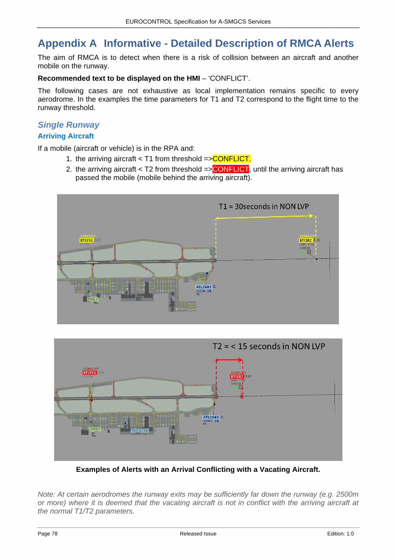
EUROCONTROL Specification for A-SMGCS Services
Page 78 Released Issue Edition: 1.0
Informative - Detailed Description of RMCA Alerts Appendix AThe aim of RMCA is to detect when there is a risk of collision between an aircraft and another mobile on the runway.
Recommended text to be displayed on the HMI – ‘CONFLICT’.
The following cases are not exhaustive as local implementation remains specific to every aerodrome. In the examples the time parameters for T1 and T2 correspond to the flight time to the runway threshold.
Single Runway Arriving Aircraft If a mobile (aircraft or vehicle) is in the RPA and:
1. the arriving aircraft < T1 from threshold =>CONFLICT. 2. the arriving aircraft < T2 from threshold =>CONFLICT, until the arriving aircraft has
passed the mobile (mobile behind the arriving aircraft).
Examples of Alerts with an Arrival Conflicting with a Vacating Aircraft.
Note: At certain aerodromes the runway exits may be sufficiently far down the runway (e.g. 2500m or more) where it is deemed that the vacating aircraft is not in conflict with the arriving aircraft at the normal T1/T2 parameters.
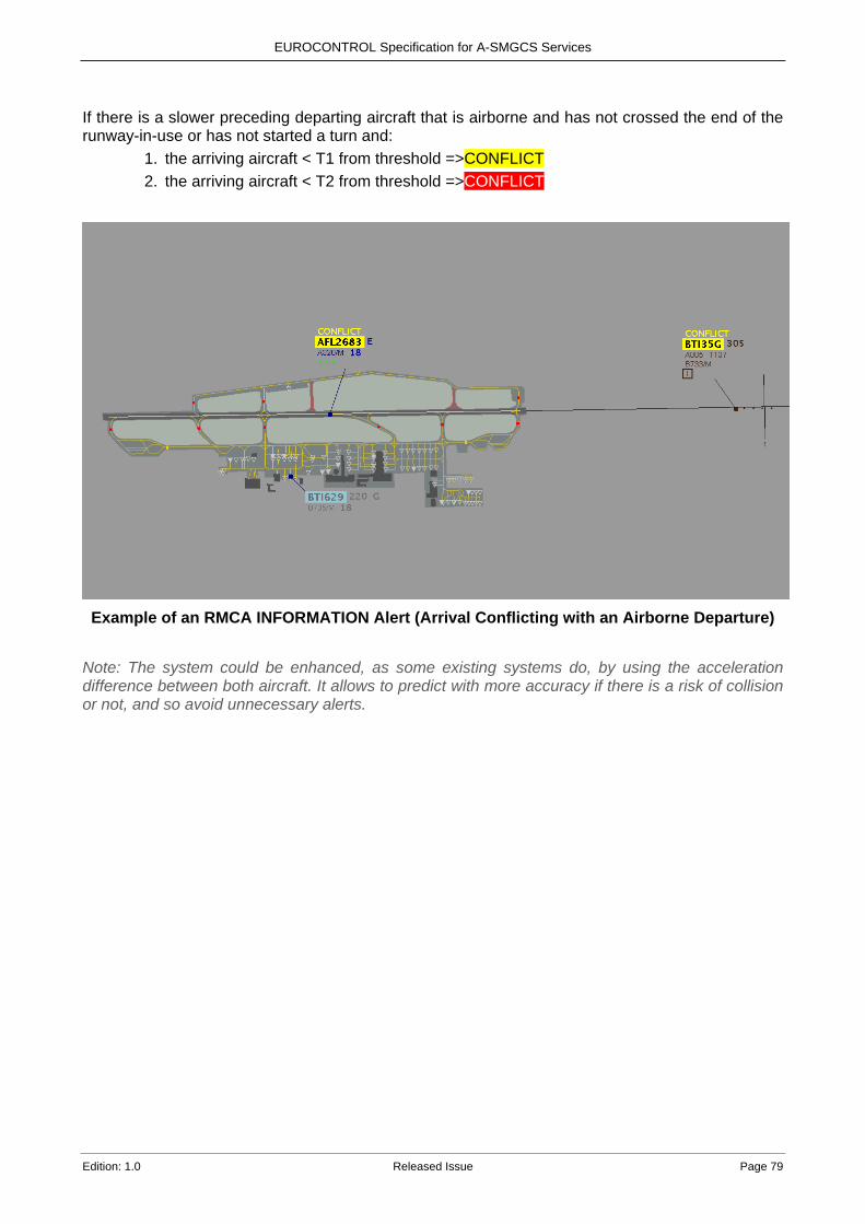
EUROCONTROL Specification for A-SMGCS Services
Edition: 1.0 Released Issue Page 79
If there is a slower preceding departing aircraft that is airborne and has not crossed the end of the runway-in-use or has not started a turn and:
1. the arriving aircraft < T1 from threshold =>CONFLICT 2. the arriving aircraft < T2 from threshold =>CONFLICT
Example of an RMCA INFORMATION Alert (Arrival Conflicting with an Airborne Departure)
Note: The system could be enhanced, as some existing systems do, by using the acceleration difference between both aircraft. It allows to predict with more accuracy if there is a risk of collision or not, and so avoid unnecessary alerts.

EUROCONTROL Specification for A-SMGCS Services
Page 80 Released Issue Edition: 1.0
If there is a vehicle within or intending to enter the RPA and there is an arriving aircraft: 1. the arriving aircraft < T1 from threshold =>CONFLICT 2. the arriving aircraft < T2 from threshold =>CONFLICT
Example of an RMCA ALARM (Arrival Conflicting with a Vehicle)
Departing Aircraft If a mobile (aircraft or vehicle) is in the RPA not behind the departing aircraft and:
1. the departing aircraft is taking off (e.g. speed < 50 knots) =>CONFLICT 2. the departing aircraft is taking off (e.g. speed > 50 knots) =>CONFLICT
Example of a Departing Aircraft Conflicting with a Mobile in the RPA
In the case of a multiple line-up (where it is permitted), the system shall trigger an CONFLICT alert if a departing aircraft is detected as moving past the line-up area where it is supposed to and is considered to have started its take-off roll behind a preceding departing aircraft. Note: The use of a CONFLICT alert in this case would most likely be too late as the Controller might not see it.
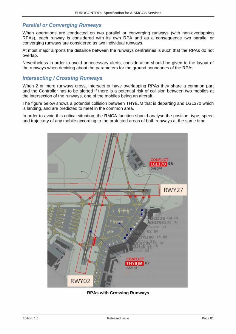
EUROCONTROL Specification for A-SMGCS Services
Edition: 1.0 Released Issue Page 81
Parallel or Converging Runways When operations are conducted on two parallel or converging runways (with non-overlapping RPAs), each runway is considered with its own RPA and as a consequence two parallel or converging runways are considered as two individual runways.
At most major airports the distance between the runways centrelines is such that the RPAs do not overlap.
Nevertheless in order to avoid unnecessary alerts, consideration should be given to the layout of the runways when deciding about the parameters for the ground boundaries of the RPAs.
Intersecting / Crossing Runways When 2 or more runways cross, intersect or have overlapping RPAs they share a common part and the Controller has to be alerted if there is a potential risk of collision between two mobiles at the intersection of the runways, one of the mobiles being an aircraft.
The figure below shows a potential collision between THY8JM that is departing and LGL370 which is landing, and are predicted to meet in the common area.
In order to avoid this critical situation, the RMCA function should analyse the position, type, speed and trajectory of any mobile according to the protected areas of both runways at the same time.
RPAs with Crossing Runways
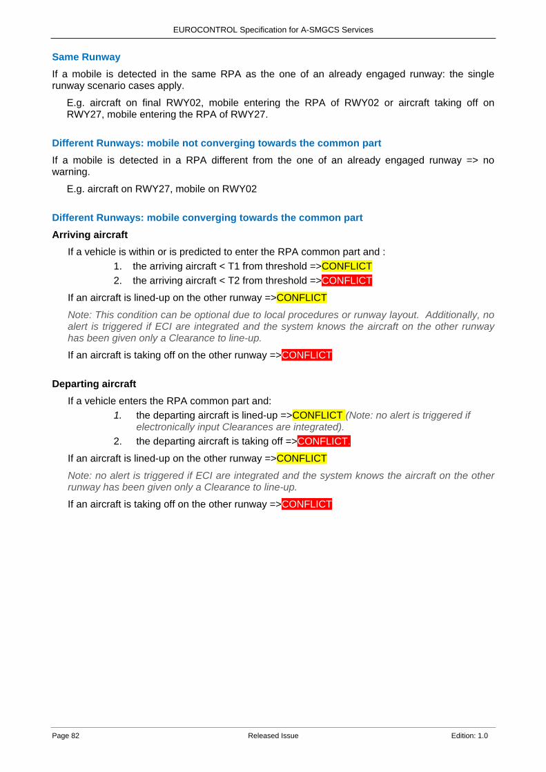
EUROCONTROL Specification for A-SMGCS Services
Page 82 Released Issue Edition: 1.0
Same Runway If a mobile is detected in the same RPA as the one of an already engaged runway: the single runway scenario cases apply.
E.g. aircraft on final RWY02, mobile entering the RPA of RWY02 or aircraft taking off on RWY27, mobile entering the RPA of RWY27.
Different Runways: mobile not converging towards the common part If a mobile is detected in a RPA different from the one of an already engaged runway => no warning.
E.g. aircraft on RWY27, mobile on RWY02
Different Runways: mobile converging towards the common part Arriving aircraft
If a vehicle is within or is predicted to enter the RPA common part and : 1. the arriving aircraft < T1 from threshold =>CONFLICT 2. the arriving aircraft < T2 from threshold =>CONFLICT
If an aircraft is lined-up on the other runway =>CONFLICT
Note: This condition can be optional due to local procedures or runway layout. Additionally, no alert is triggered if ECI are integrated and the system knows the aircraft on the other runway has been given only a Clearance to line-up.
If an aircraft is taking off on the other runway =>CONFLICT
Departing aircraft
If a vehicle enters the RPA common part and: 1. the departing aircraft is lined-up =>CONFLICT (Note: no alert is triggered if
electronically input Clearances are integrated). 2. the departing aircraft is taking off =>CONFLICT.
If an aircraft is lined-up on the other runway =>CONFLICT
Note: no alert is triggered if ECI are integrated and the system knows the aircraft on the other runway has been given only a Clearance to line-up.
If an aircraft is taking off on the other runway =>CONFLICT
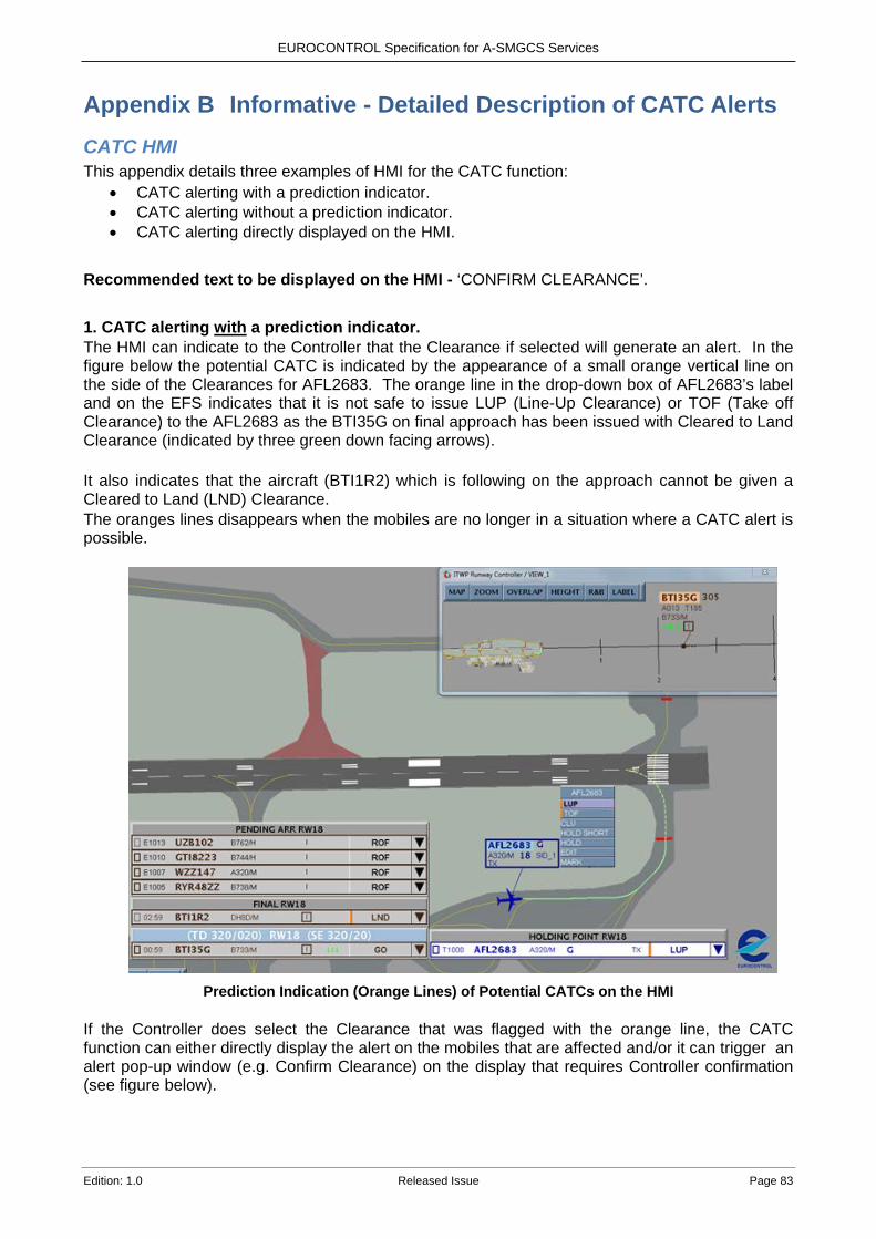
EUROCONTROL Specification for A-SMGCS Services
Edition: 1.0 Released Issue Page 83
Informative - Detailed Description of CATC Alerts Appendix BCATC HMI This appendix details three examples of HMI for the CATC function:
• CATC alerting with a prediction indicator. • CATC alerting without a prediction indicator. • CATC alerting directly displayed on the HMI.
Recommended text to be displayed on the HMI - ‘CONFIRM CLEARANCE’. 1. CATC alerting with a prediction indicator. The HMI can indicate to the Controller that the Clearance if selected will generate an alert. In the figure below the potential CATC is indicated by the appearance of a small orange vertical line on the side of the Clearances for AFL2683. The orange line in the drop-down box of AFL2683’s label and on the EFS indicates that it is not safe to issue LUP (Line-Up Clearance) or TOF (Take off Clearance) to the AFL2683 as the BTI35G on final approach has been issued with Cleared to Land Clearance (indicated by three green down facing arrows). It also indicates that the aircraft (BTI1R2) which is following on the approach cannot be given a Cleared to Land (LND) Clearance. The oranges lines disappears when the mobiles are no longer in a situation where a CATC alert is possible.
Prediction Indication (Orange Lines) of Potential CATCs on the HMI
If the Controller does select the Clearance that was flagged with the orange line, the CATC function can either directly display the alert on the mobiles that are affected and/or it can trigger an alert pop-up window (e.g. Confirm Clearance) on the display that requires Controller confirmation (see figure below).
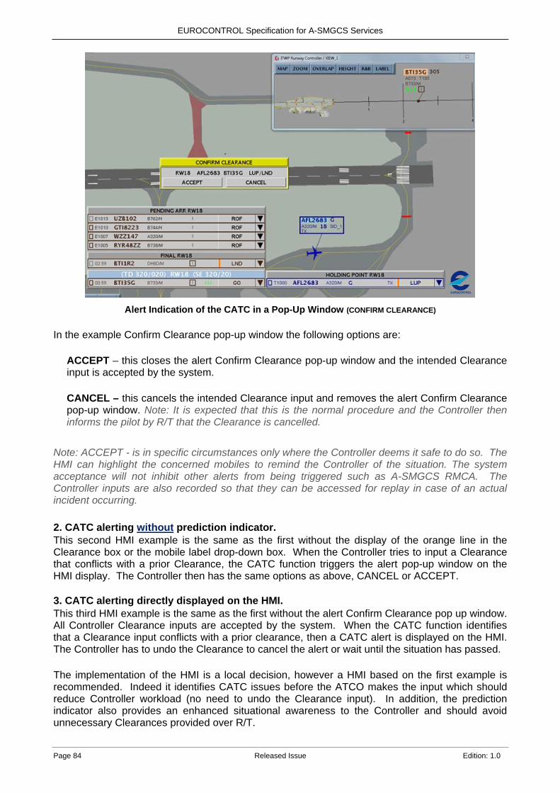
EUROCONTROL Specification for A-SMGCS Services
Page 84 Released Issue Edition: 1.0
Alert Indication of the CATC in a Pop-Up Window (CONFIRM CLEARANCE)
In the example Confirm Clearance pop-up window the following options are:
ACCEPT – this closes the alert Confirm Clearance pop-up window and the intended Clearance input is accepted by the system. CANCEL – this cancels the intended Clearance input and removes the alert Confirm Clearance pop-up window. Note: It is expected that this is the normal procedure and the Controller then informs the pilot by R/T that the Clearance is cancelled.
Note: ACCEPT - is in specific circumstances only where the Controller deems it safe to do so. The HMI can highlight the concerned mobiles to remind the Controller of the situation. The system acceptance will not inhibit other alerts from being triggered such as A-SMGCS RMCA. The Controller inputs are also recorded so that they can be accessed for replay in case of an actual incident occurring.
2. CATC alerting without prediction indicator. This second HMI example is the same as the first without the display of the orange line in the Clearance box or the mobile label drop-down box. When the Controller tries to input a Clearance that conflicts with a prior Clearance, the CATC function triggers the alert pop-up window on the HMI display. The Controller then has the same options as above, CANCEL or ACCEPT. 3. CATC alerting directly displayed on the HMI. This third HMI example is the same as the first without the alert Confirm Clearance pop up window. All Controller Clearance inputs are accepted by the system. When the CATC function identifies that a Clearance input conflicts with a prior clearance, then a CATC alert is displayed on the HMI. The Controller has to undo the Clearance to cancel the alert or wait until the situation has passed. The implementation of the HMI is a local decision, however a HMI based on the first example is recommended. Indeed it identifies CATC issues before the ATCO makes the input which should reduce Controller workload (no need to undo the Clearance input). In addition, the prediction indicator also provides an enhanced situational awareness to the Controller and should avoid unnecessary Clearances provided over R/T.
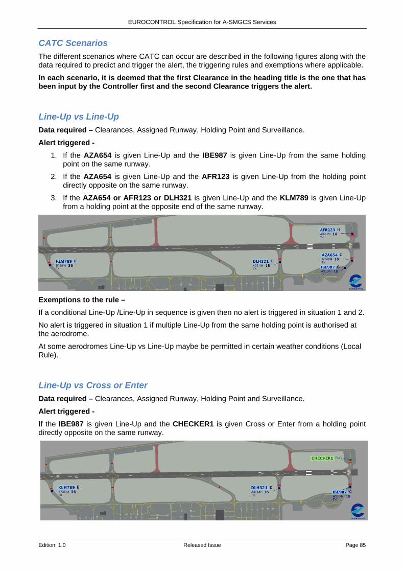
EUROCONTROL Specification for A-SMGCS Services
Edition: 1.0 Released Issue Page 85
CATC Scenarios The different scenarios where CATC can occur are described in the following figures along with the data required to predict and trigger the alert, the triggering rules and exemptions where applicable.
In each scenario, it is deemed that the first Clearance in the heading title is the one that has been input by the Controller first and the second Clearance triggers the alert.
Line-Up vs Line-Up Data required – Clearances, Assigned Runway, Holding Point and Surveillance. Alert triggered -
1. If the AZA654 is given Line-Up and the IBE987 is given Line-Up from the same holding point on the same runway.
2. If the AZA654 is given Line-Up and the AFR123 is given Line-Up from the holding point directly opposite on the same runway.
3. If the AZA654 or AFR123 or DLH321 is given Line-Up and the KLM789 is given Line-Up from a holding point at the opposite end of the same runway.
Exemptions to the rule – If a conditional Line-Up /Line-Up in sequence is given then no alert is triggered in situation 1 and 2.
No alert is triggered in situation 1 if multiple Line-Up from the same holding point is authorised at the aerodrome.
At some aerodromes Line-Up vs Line-Up maybe be permitted in certain weather conditions (Local Rule).
Line-Up vs Cross or Enter Data required – Clearances, Assigned Runway, Holding Point and Surveillance. Alert triggered - If the IBE987 is given Line-Up and the CHECKER1 is given Cross or Enter from a holding point directly opposite on the same runway.
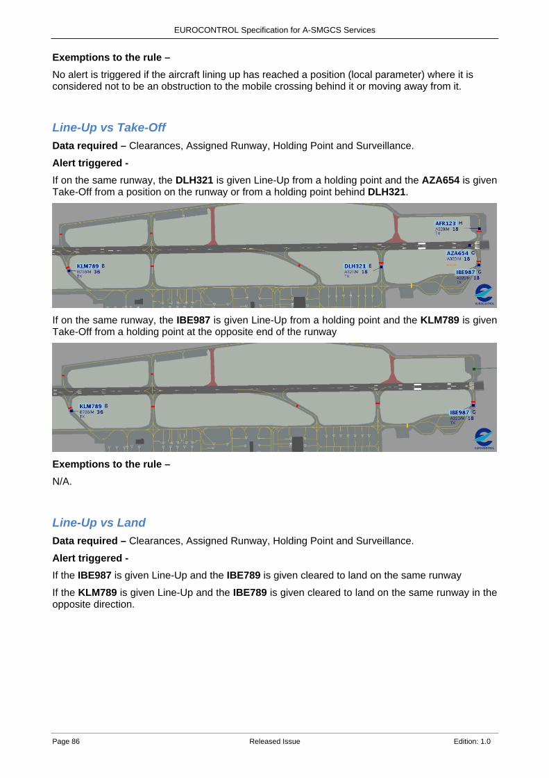
EUROCONTROL Specification for A-SMGCS Services
Page 86 Released Issue Edition: 1.0
Exemptions to the rule – No alert is triggered if the aircraft lining up has reached a position (local parameter) where it is considered not to be an obstruction to the mobile crossing behind it or moving away from it.
Line-Up vs Take-Off Data required – Clearances, Assigned Runway, Holding Point and Surveillance. Alert triggered - If on the same runway, the DLH321 is given Line-Up from a holding point and the AZA654 is given Take-Off from a position on the runway or from a holding point behind DLH321.
If on the same runway, the IBE987 is given Line-Up from a holding point and the KLM789 is given Take-Off from a holding point at the opposite end of the runway
Exemptions to the rule – N/A.
Line-Up vs Land Data required – Clearances, Assigned Runway, Holding Point and Surveillance. Alert triggered - If the IBE987 is given Line-Up and the IBE789 is given cleared to land on the same runway
If the KLM789 is given Line-Up and the IBE789 is given cleared to land on the same runway in the opposite direction.
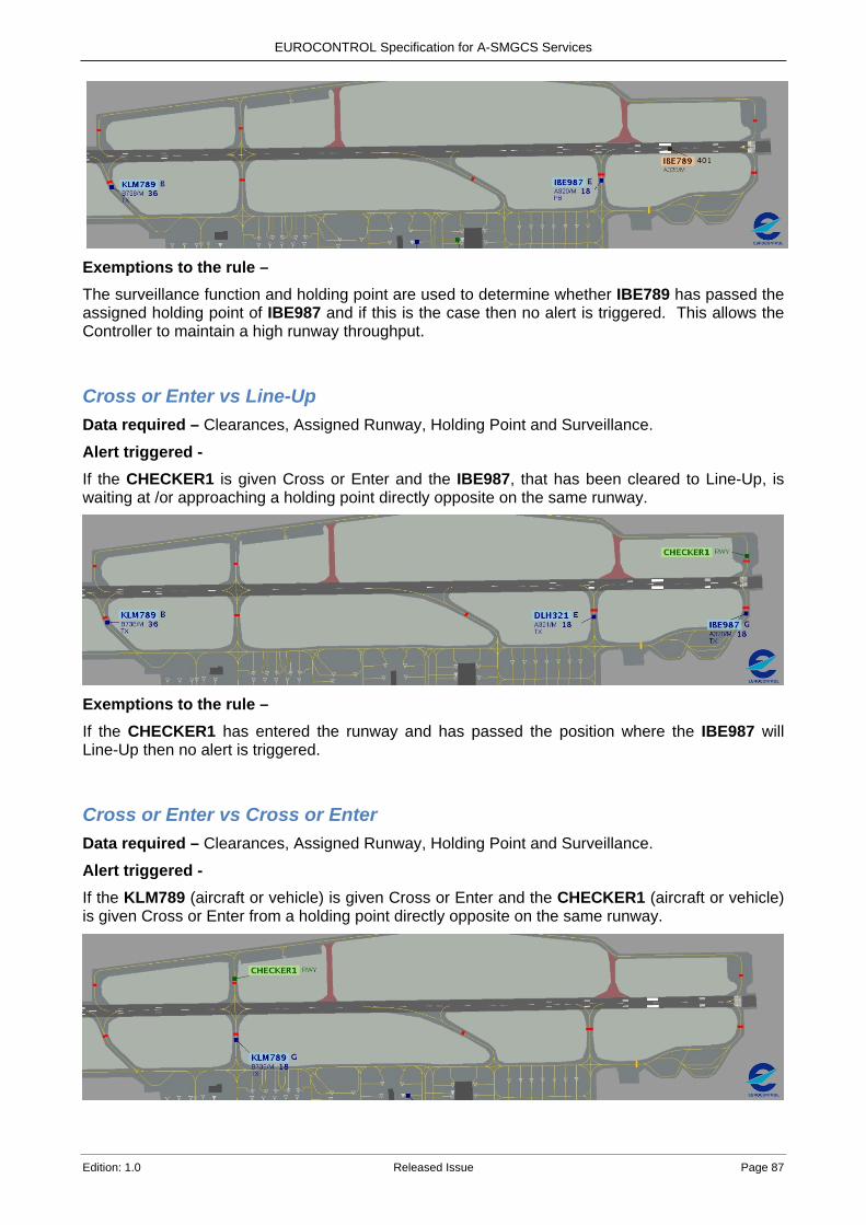
EUROCONTROL Specification for A-SMGCS Services
Edition: 1.0 Released Issue Page 87
Exemptions to the rule – The surveillance function and holding point are used to determine whether IBE789 has passed the assigned holding point of IBE987 and if this is the case then no alert is triggered. This allows the Controller to maintain a high runway throughput.
Cross or Enter vs Line-Up Data required – Clearances, Assigned Runway, Holding Point and Surveillance. Alert triggered - If the CHECKER1 is given Cross or Enter and the IBE987, that has been cleared to Line-Up, is waiting at /or approaching a holding point directly opposite on the same runway.
Exemptions to the rule – If the CHECKER1 has entered the runway and has passed the position where the IBE987 will Line-Up then no alert is triggered.
Cross or Enter vs Cross or Enter Data required – Clearances, Assigned Runway, Holding Point and Surveillance. Alert triggered - If the KLM789 (aircraft or vehicle) is given Cross or Enter and the CHECKER1 (aircraft or vehicle) is given Cross or Enter from a holding point directly opposite on the same runway.
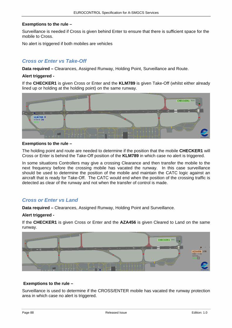
EUROCONTROL Specification for A-SMGCS Services
Page 88 Released Issue Edition: 1.0
Exemptions to the rule – Surveillance is needed if Cross is given behind Enter to ensure that there is sufficient space for the mobile to Cross. No alert is triggered if both mobiles are vehicles
Cross or Enter vs Take-Off Data required – Clearances, Assigned Runway, Holding Point, Surveillance and Route. Alert triggered - If the CHECKER1 is given Cross or Enter and the KLM789 is given Take-Off (whilst either already lined up or holding at the holding point) on the same runway.
Exemptions to the rule – The holding point and route are needed to determine if the position that the mobile CHECKER1 will Cross or Enter is behind the Take-Off position of the KLM789 in which case no alert is triggered.
In some situations Controllers may give a crossing Clearance and then transfer the mobile to the next frequency before the crossing mobile has vacated the runway. In this case surveillance should be used to determine the position of the mobile and maintain the CATC logic against an aircraft that is ready for Take-Off. The CATC would end when the position of the crossing traffic is detected as clear of the runway and not when the transfer of control is made.
Cross or Enter vs Land Data required – Clearances, Assigned Runway, Holding Point and Surveillance. Alert triggered - If the CHECKER1 is given Cross or Enter and the AZA456 is given Cleared to Land on the same runway.
Exemptions to the rule – Surveillance is used to determine if the CROSS/ENTER mobile has vacated the runway protection area in which case no alert is triggered.
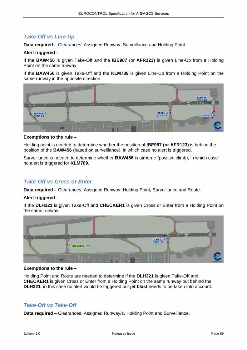
EUROCONTROL Specification for A-SMGCS Services
Edition: 1.0 Released Issue Page 89
Take-Off vs Line-Up Data required – Clearances, Assigned Runway, Surveillance and Holding Point. Alert triggered - If the BAW456 is given Take-Off and the IBE987 (or AFR123) is given Line-Up from a Holding Point on the same runway.
If the BAW456 is given Take-Off and the KLM789 is given Line-Up from a Holding Point on the same runway in the opposite direction.
Exemptions to the rule – Holding point is needed to determine whether the position of IBE987 (or AFR123) is behind the position of the BAW456 (based on surveillance), in which case no alert is triggered.
Surveillance is needed to determine whether BAW456 is airborne (positive climb), in which case no alert is triggered for KLM789.
Take-Off vs Cross or Enter Data required – Clearances, Assigned Runway, Holding Point, Surveillance and Route. Alert triggered - If the DLH321 is given Take-Off and CHECKER1 is given Cross or Enter from a Holding Point on the same runway.
Exemptions to the rule – Holding Point and Route are needed to determine if the DLH321 is given Take-Off and CHECKER1 is given Cross or Enter from a Holding Point on the same runway but behind the DLH321, in this case no alert would be triggered but jet blast needs to be taken into account.
Take-Off vs Take-Off Data required – Clearances, Assigned Runway/s, Holding Point and Surveillance.
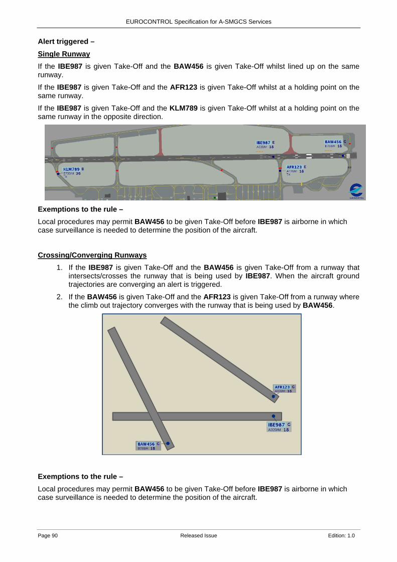
EUROCONTROL Specification for A-SMGCS Services
Page 90 Released Issue Edition: 1.0
Alert triggered – Single Runway If the IBE987 is given Take-Off and the BAW456 is given Take-Off whilst lined up on the same runway.
If the IBE987 is given Take-Off and the AFR123 is given Take-Off whilst at a holding point on the same runway.
If the IBE987 is given Take-Off and the KLM789 is given Take-Off whilst at a holding point on the same runway in the opposite direction.
Exemptions to the rule – Local procedures may permit BAW456 to be given Take-Off before IBE987 is airborne in which case surveillance is needed to determine the position of the aircraft.
Crossing/Converging Runways
1. If the IBE987 is given Take-Off and the BAW456 is given Take-Off from a runway that intersects/crosses the runway that is being used by IBE987. When the aircraft ground trajectories are converging an alert is triggered.
2. If the BAW456 is given Take-Off and the AFR123 is given Take-Off from a runway where the climb out trajectory converges with the runway that is being used by BAW456.
Exemptions to the rule – Local procedures may permit BAW456 to be given Take-Off before IBE987 is airborne in which case surveillance is needed to determine the position of the aircraft.
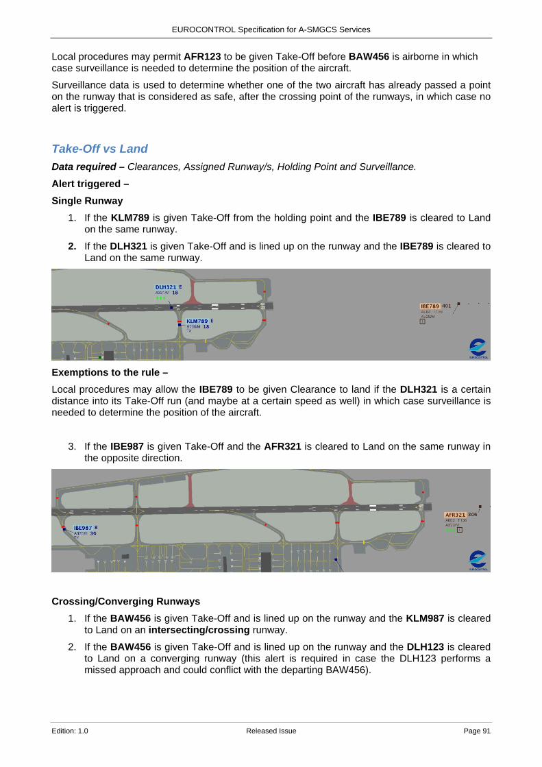
EUROCONTROL Specification for A-SMGCS Services
Edition: 1.0 Released Issue Page 91
Local procedures may permit AFR123 to be given Take-Off before BAW456 is airborne in which case surveillance is needed to determine the position of the aircraft.
Surveillance data is used to determine whether one of the two aircraft has already passed a point on the runway that is considered as safe, after the crossing point of the runways, in which case no alert is triggered.
Take-Off vs Land Data required – Clearances, Assigned Runway/s, Holding Point and Surveillance.
Alert triggered – Single Runway
1. If the KLM789 is given Take-Off from the holding point and the IBE789 is cleared to Land on the same runway.
2. If the DLH321 is given Take-Off and is lined up on the runway and the IBE789 is cleared to Land on the same runway.
Exemptions to the rule – Local procedures may allow the IBE789 to be given Clearance to land if the DLH321 is a certain distance into its Take-Off run (and maybe at a certain speed as well) in which case surveillance is needed to determine the position of the aircraft.
3. If the IBE987 is given Take-Off and the AFR321 is cleared to Land on the same runway in the opposite direction.
Crossing/Converging Runways
1. If the BAW456 is given Take-Off and is lined up on the runway and the KLM987 is cleared to Land on an intersecting/crossing runway.
2. If the BAW456 is given Take-Off and is lined up on the runway and the DLH123 is cleared to Land on a converging runway (this alert is required in case the DLH123 performs a missed approach and could conflict with the departing BAW456).
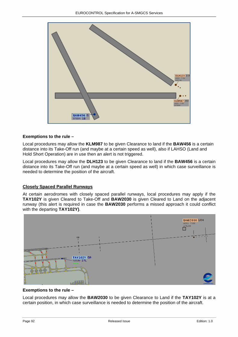
EUROCONTROL Specification for A-SMGCS Services
Page 92 Released Issue Edition: 1.0
Exemptions to the rule – Local procedures may allow the KLM987 to be given Clearance to land if the BAW456 is a certain distance into its Take-Off run (and maybe at a certain speed as well), also if LAHSO (Land and Hold Short Operation) are in use then an alert is not triggered.
Local procedures may allow the DLH123 to be given Clearance to land if the BAW456 is a certain distance into its Take-Off run (and maybe at a certain speed as well) in which case surveillance is needed to determine the position of the aircraft.
Closely Spaced Parallel Runways
At certain aerodromes with closely spaced parallel runways, local procedures may apply if the TAY102Y is given Cleared to Take-Off and BAW2030 is given Cleared to Land on the adjacent runway (this alert is required in case the BAW2030 performs a missed approach it could conflict with the departing TAY102Y).
Exemptions to the rule – Local procedures may allow the BAW2030 to be given Clearance to Land if the TAY102Y is at a certain position, in which case surveillance is needed to determine the position of the aircraft.
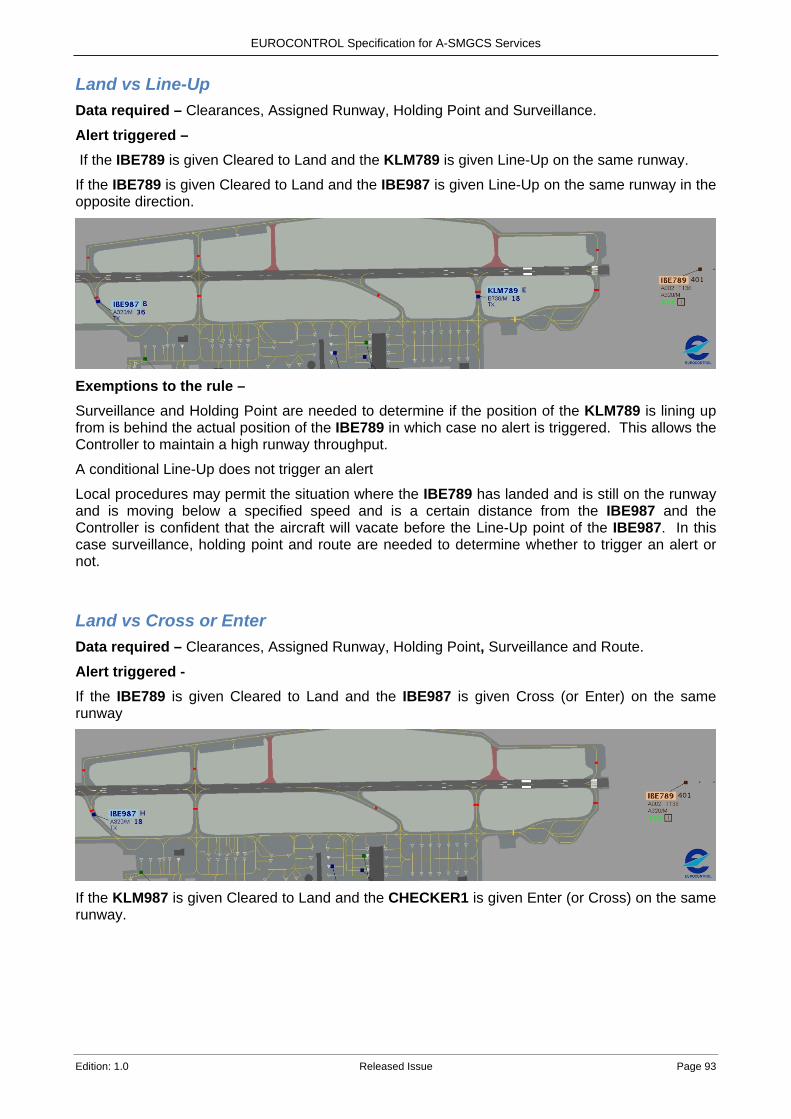
EUROCONTROL Specification for A-SMGCS Services
Edition: 1.0 Released Issue Page 93
Land vs Line-Up Data required – Clearances, Assigned Runway, Holding Point and Surveillance. Alert triggered – If the IBE789 is given Cleared to Land and the KLM789 is given Line-Up on the same runway.
If the IBE789 is given Cleared to Land and the IBE987 is given Line-Up on the same runway in the opposite direction.
Exemptions to the rule – Surveillance and Holding Point are needed to determine if the position of the KLM789 is lining up from is behind the actual position of the IBE789 in which case no alert is triggered. This allows the Controller to maintain a high runway throughput.
A conditional Line-Up does not trigger an alert
Local procedures may permit the situation where the IBE789 has landed and is still on the runway and is moving below a specified speed and is a certain distance from the IBE987 and the Controller is confident that the aircraft will vacate before the Line-Up point of the IBE987. In this case surveillance, holding point and route are needed to determine whether to trigger an alert or not.
Land vs Cross or Enter Data required – Clearances, Assigned Runway, Holding Point, Surveillance and Route. Alert triggered - If the IBE789 is given Cleared to Land and the IBE987 is given Cross (or Enter) on the same runway
If the KLM987 is given Cleared to Land and the CHECKER1 is given Enter (or Cross) on the same runway.

EUROCONTROL Specification for A-SMGCS Services
Page 94 Released Issue Edition: 1.0
Exemptions to the rule – Holding Point, Surveillance and Route are needed to determine if the position that the CHECKER1 is Crossing or Entering from is behind the actual position of the KLM987 in which case no alert is triggered. This allows the Controller to maintain a high runway throughput.
Local procedures may permit the situation where the IBE789 (or KLM987) has landed and is still on the runway and is moving below a specified speed and is a certain distance from the IBE987 (or CHECKER1) and the Controller has instructed the IBE789 (or KLM987) to vacate at an exit before the crossing point of the IBE987 (or CHECKER1). In this case surveillance, holding point and route are needed to determine whether to trigger an alert or not.
Land vs Take-Off Data required – Clearances, Assigned Runway/s, Holding Point and Surveillance. Alert triggered – Single Runway If the AZA456 is given Cleared to Land and the DLH321 is given Cleared to Take-Off on the same runway.
If the AZA456 is given Cleared to Land and the KLM789 is given Cleared to Take-Off on the same runway in the opposite direction.
Crossing/Converging Runways
If the KLM987 is given Cleared to Land and the BAW456 is given Cleared to Take-Off.
If the DLH123 is given Cleared to Land and the BAW456 is given Cleared to Take-Off from a converging runway (this alert is required in case the DLH123 performs a missed approach and could conflict with the departing BAW456).
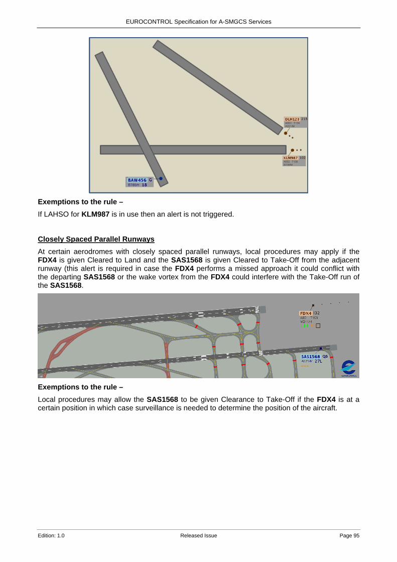
EUROCONTROL Specification for A-SMGCS Services
Edition: 1.0 Released Issue Page 95
Exemptions to the rule – If LAHSO for KLM987 is in use then an alert is not triggered.
Closely Spaced Parallel Runways
At certain aerodromes with closely spaced parallel runways, local procedures may apply if the FDX4 is given Cleared to Land and the SAS1568 is given Cleared to Take-Off from the adjacent runway (this alert is required in case the FDX4 performs a missed approach it could conflict with the departing SAS1568 or the wake vortex from the FDX4 could interfere with the Take-Off run of the SAS1568.
Exemptions to the rule – Local procedures may allow the SAS1568 to be given Clearance to Take-Off if the FDX4 is at a certain position in which case surveillance is needed to determine the position of the aircraft.
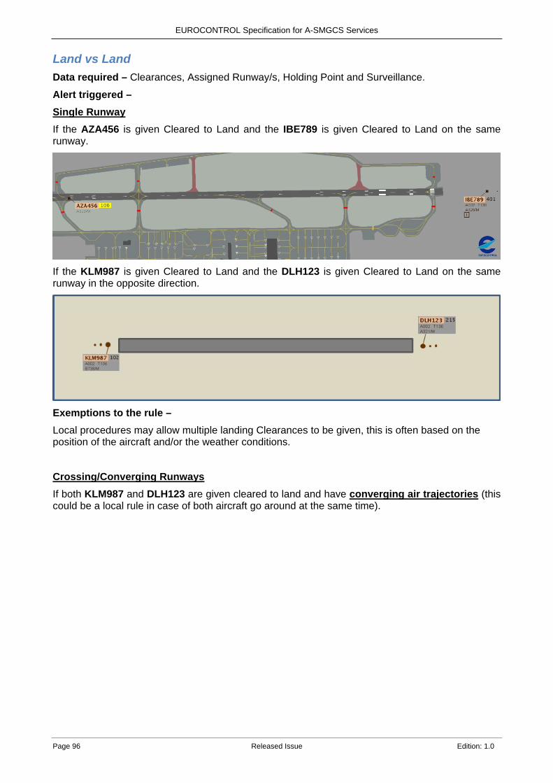
EUROCONTROL Specification for A-SMGCS Services
Page 96 Released Issue Edition: 1.0
Land vs Land Data required – Clearances, Assigned Runway/s, Holding Point and Surveillance. Alert triggered – Single Runway If the AZA456 is given Cleared to Land and the IBE789 is given Cleared to Land on the same runway.
If the KLM987 is given Cleared to Land and the DLH123 is given Cleared to Land on the same runway in the opposite direction.
Exemptions to the rule – Local procedures may allow multiple landing Clearances to be given, this is often based on the position of the aircraft and/or the weather conditions.
Crossing/Converging Runways
If both KLM987 and DLH123 are given cleared to land and have converging air trajectories (this could be a local rule in case of both aircraft go around at the same time).

EUROCONTROL Specification for A-SMGCS Services
Edition: 1.0 Released Issue Page 97
If both KLM987 and DLH123 are given cleared to land and have crossing trajectories.
Exemptions to the rule – Local procedures may allow multiple landing Clearances to be given; this is often based on the position of the aircraft and/or the weather conditions.
If LAHSO are in use then an alert is not triggered in case of crossing trajectories.
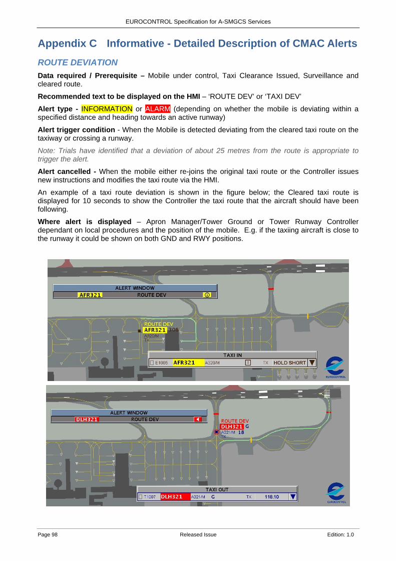
EUROCONTROL Specification for A-SMGCS Services
Page 98 Released Issue Edition: 1.0
Informative - Detailed Description of CMAC Alerts Appendix CROUTE DEVIATION Data required / Prerequisite – Mobile under control, Taxi Clearance Issued, Surveillance and cleared route. Recommended text to be displayed on the HMI – ‘ROUTE DEV’ or ‘TAXI DEV’ Alert type - INFORMATION or ALARM (depending on whether the mobile is deviating within a specified distance and heading towards an active runway)
Alert trigger condition - When the Mobile is detected deviating from the cleared taxi route on the taxiway or crossing a runway.
Note: Trials have identified that a deviation of about 25 metres from the route is appropriate to trigger the alert.
Alert cancelled - When the mobile either re-joins the original taxi route or the Controller issues new instructions and modifies the taxi route via the HMI. An example of a taxi route deviation is shown in the figure below; the Cleared taxi route is displayed for 10 seconds to show the Controller the taxi route that the aircraft should have been following.
Where alert is displayed – Apron Manager/Tower Ground or Tower Runway Controller dependant on local procedures and the position of the mobile. E.g. if the taxiing aircraft is close to the runway it could be shown on both GND and RWY positions.
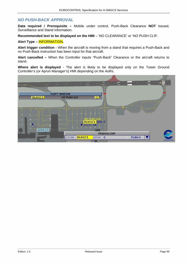
EUROCONTROL Specification for A-SMGCS Services
Edition: 1.0 Released Issue Page 99
NO PUSH-BACK APPROVAL Data required / Prerequisite – Mobile under control, Push-Back Clearance NOT Issued, Surveillance and Stand information. Recommended text to be displayed on the HMI – ‘NO CLEARANCE’ or ‘NO PUSH CLR’.
Alert Type – INFORMATION. Alert trigger condition - When the aircraft is moving from a stand that requires a Push-Back and no Push-Back instruction has been input for that aircraft.
Alert cancelled – When the Controller inputs “Push-Back” Clearance or the aircraft returns to stand.
Where alert is displayed - The alert is likely to be displayed only on the Tower Ground Controller’s (or Apron Manager’s) HMI depending on the AoRs.
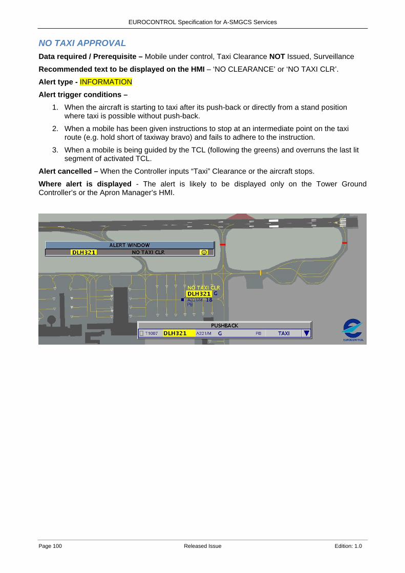
EUROCONTROL Specification for A-SMGCS Services
Page 100 Released Issue Edition: 1.0
NO TAXI APPROVAL Data required / Prerequisite – Mobile under control, Taxi Clearance NOT Issued, Surveillance Recommended text to be displayed on the HMI – ‘NO CLEARANCE’ or ‘NO TAXI CLR’.
Alert type - INFORMATION
Alert trigger conditions – 1. When the aircraft is starting to taxi after its push-back or directly from a stand position
where taxi is possible without push-back.
2. When a mobile has been given instructions to stop at an intermediate point on the taxi route (e.g. hold short of taxiway bravo) and fails to adhere to the instruction.
3. When a mobile is being guided by the TCL (following the greens) and overruns the last lit segment of activated TCL.
Alert cancelled – When the Controller inputs “Taxi” Clearance or the aircraft stops.
Where alert is displayed - The alert is likely to be displayed only on the Tower Ground Controller’s or the Apron Manager’s HMI.
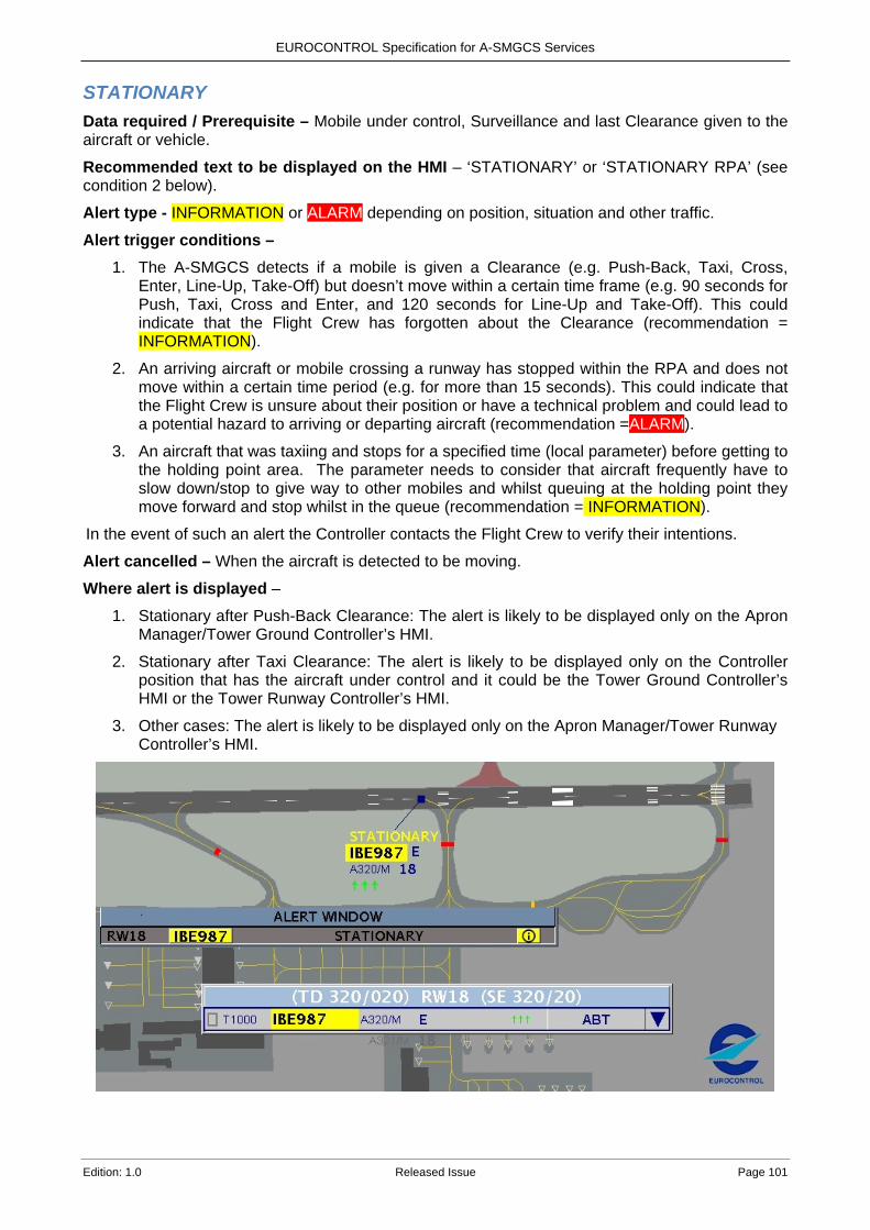
EUROCONTROL Specification for A-SMGCS Services
Edition: 1.0 Released Issue Page 101
STATIONARY Data required / Prerequisite – Mobile under control, Surveillance and last Clearance given to the aircraft or vehicle. Recommended text to be displayed on the HMI – ‘STATIONARY’ or ‘STATIONARY RPA’ (see condition 2 below).
Alert type - INFORMATION or ALARM depending on position, situation and other traffic.
Alert trigger conditions – 1. The A-SMGCS detects if a mobile is given a Clearance (e.g. Push-Back, Taxi, Cross,
Enter, Line-Up, Take-Off) but doesn’t move within a certain time frame (e.g. 90 seconds for Push, Taxi, Cross and Enter, and 120 seconds for Line-Up and Take-Off). This could indicate that the Flight Crew has forgotten about the Clearance (recommendation = INFORMATION).
2. An arriving aircraft or mobile crossing a runway has stopped within the RPA and does not move within a certain time period (e.g. for more than 15 seconds). This could indicate that the Flight Crew is unsure about their position or have a technical problem and could lead to a potential hazard to arriving or departing aircraft (recommendation =ALARM).
3. An aircraft that was taxiing and stops for a specified time (local parameter) before getting to the holding point area. The parameter needs to consider that aircraft frequently have to slow down/stop to give way to other mobiles and whilst queuing at the holding point they move forward and stop whilst in the queue (recommendation = INFORMATION).
In the event of such an alert the Controller contacts the Flight Crew to verify their intentions.
Alert cancelled – When the aircraft is detected to be moving.
Where alert is displayed –
1. Stationary after Push-Back Clearance: The alert is likely to be displayed only on the Apron Manager/Tower Ground Controller’s HMI.
2. Stationary after Taxi Clearance: The alert is likely to be displayed only on the Controller position that has the aircraft under control and it could be the Tower Ground Controller’s HMI or the Tower Runway Controller’s HMI.
3. Other cases: The alert is likely to be displayed only on the Apron Manager/Tower Runway Controller’s HMI.
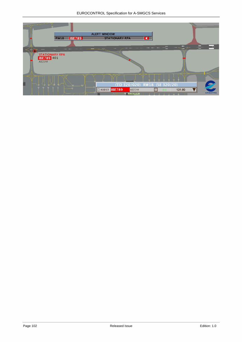
EUROCONTROL Specification for A-SMGCS Services
Page 102 Released Issue Edition: 1.0
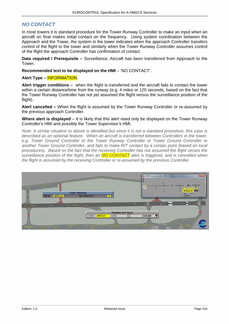
EUROCONTROL Specification for A-SMGCS Services
Edition: 1.0 Released Issue Page 103
NO CONTACT In most towers it is standard procedure for the Tower Runway Controller to make an input when an aircraft on final makes initial contact on the frequency. Using system coordination between the Approach and the Tower, the system in the tower indicates when the approach Controller transfers control of the flight to the tower and similarly when the Tower Runway Controller assumes control of the flight the approach Controller has confirmation of contact. Data required / Prerequisite – Surveillance, Aircraft has been transferred from Approach to the Tower. Recommended text to be displayed on the HMI – ‘NO CONTACT’. Alert Type – INFORMATION.
Alert trigger conditions – when the flight is transferred and the aircraft fails to contact the tower within a certain distance/time from the runway (e.g. 4 miles or 120 seconds, based on the fact that the Tower Runway Controller has not yet assumed the flight versus the surveillance position of the flight). Alert cancelled – When the flight is assumed by the Tower Runway Controller or re-assumed by the previous approach Controller.
Where alert is displayed – It is likely that this alert need only be displayed on the Tower Runway Controller’s HMI and possibly the Tower Supervisor’s HMI.
Note: A similar situation to above is identified but since it is not a standard procedure, this case is described as an optional feature. When an aircraft is transferred between Controllers in the tower, e.g. Tower Ground Controller to the Tower Runway Controller or Tower Ground Controller to another Tower Ground Controller, and fails to make R/T contact by a certain point (based on local procedures). Based on the fact that the receiving Controller has not assumed the flight verses the surveillance position of the flight, then an NO CONTACT alert is triggered, and is cancelled when the flight is assumed by the receiving Controller or re-assumed by the previous Controller.
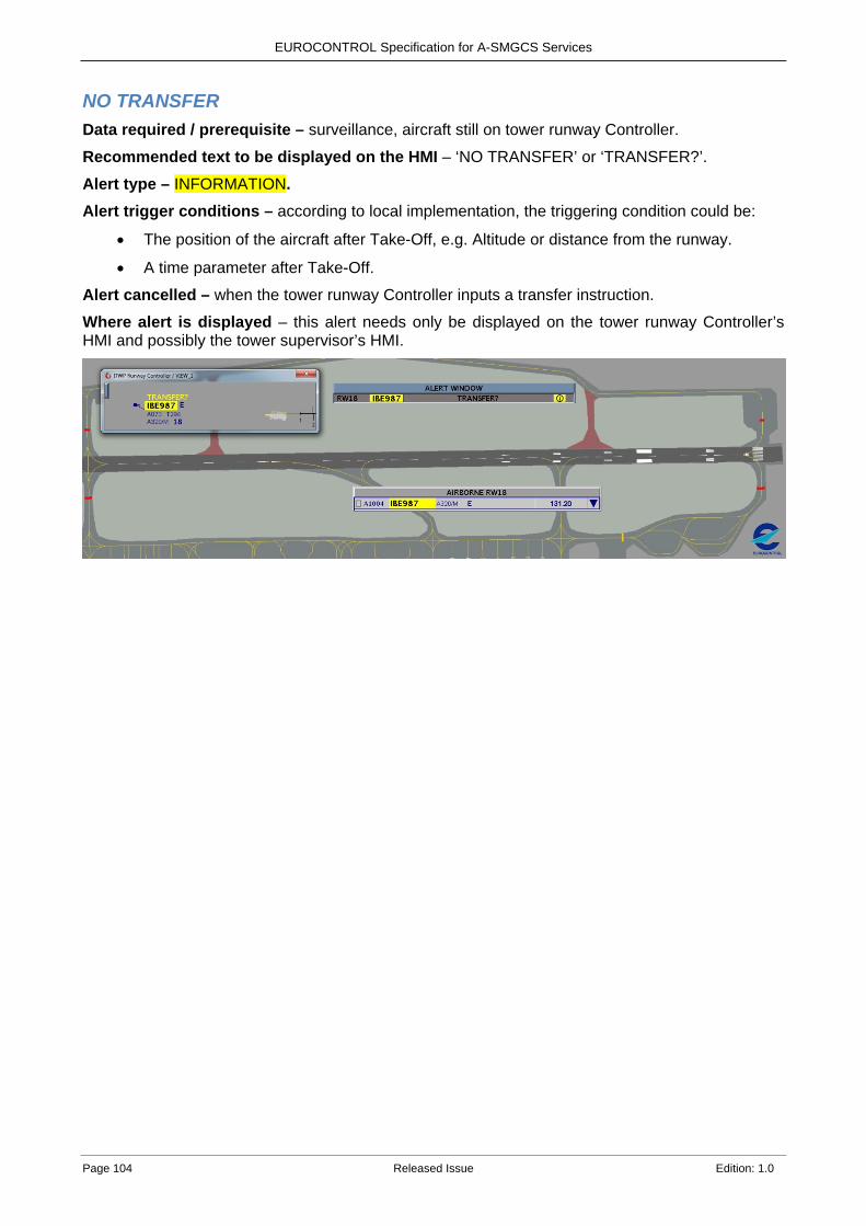
EUROCONTROL Specification for A-SMGCS Services
Page 104 Released Issue Edition: 1.0
NO TRANSFER Data required / prerequisite – surveillance, aircraft still on tower runway Controller.
Recommended text to be displayed on the HMI – ‘NO TRANSFER’ or ‘TRANSFER?’. Alert type – INFORMATION. Alert trigger conditions – according to local implementation, the triggering condition could be:
• The position of the aircraft after Take-Off, e.g. Altitude or distance from the runway.
• A time parameter after Take-Off. Alert cancelled – when the tower runway Controller inputs a transfer instruction.
Where alert is displayed – this alert needs only be displayed on the tower runway Controller’s HMI and possibly the tower supervisor’s HMI.
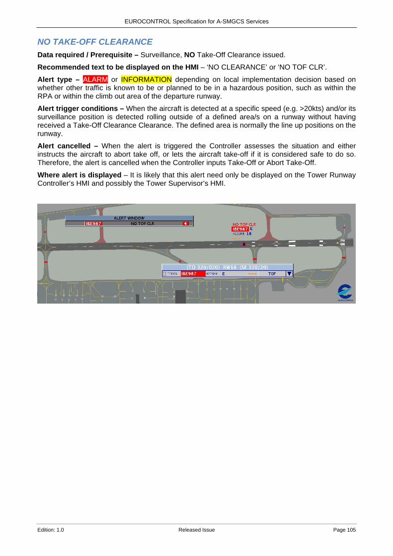
EUROCONTROL Specification for A-SMGCS Services
Edition: 1.0 Released Issue Page 105
NO TAKE-OFF CLEARANCE Data required / Prerequisite – Surveillance, NO Take-Off Clearance issued. Recommended text to be displayed on the HMI – ‘NO CLEARANCE’ or ‘NO TOF CLR’. Alert type – ALARM or INFORMATION depending on local implementation decision based on whether other traffic is known to be or planned to be in a hazardous position, such as within the RPA or within the climb out area of the departure runway.
Alert trigger conditions – When the aircraft is detected at a specific speed (e.g. >20kts) and/or its surveillance position is detected rolling outside of a defined area/s on a runway without having received a Take-Off Clearance Clearance. The defined area is normally the line up positions on the runway.
Alert cancelled – When the alert is triggered the Controller assesses the situation and either instructs the aircraft to abort take off, or lets the aircraft take-off if it is considered safe to do so. Therefore, the alert is cancelled when the Controller inputs Take-Off or Abort Take-Off.
Where alert is displayed – It is likely that this alert need only be displayed on the Tower Runway Controller’s HMI and possibly the Tower Supervisor’s HMI.
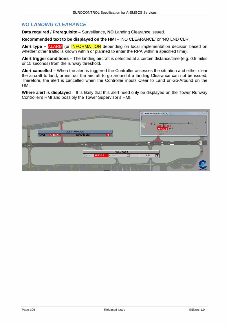
EUROCONTROL Specification for A-SMGCS Services
Page 106 Released Issue Edition: 1.0
NO LANDING CLEARANCE Data required / Prerequisite – Surveillance, NO Landing Clearance issued. Recommended text to be displayed on the HMI – ‘NO CLEARANCE’ or ‘NO LND CLR’.
Alert type – ALARM (or INFORMATION depending on local implementation decision based on whether other traffic is known within or planned to enter the RPA within a specified time).
Alert trigger conditions – The landing aircraft is detected at a certain distance/time (e.g. 0.5 miles or 15 seconds) from the runway threshold.
Alert cancelled – When the alert is triggered the Controller assesses the situation and either clear the aircraft to land, or instruct the aircraft to go around if a landing Clearance can not be issued. Therefore, the alert is cancelled when the Controller inputs Clear to Land or Go-Around on the HMI.
Where alert is displayed – It is likely that this alert need only be displayed on the Tower Runway Controller’s HMI and possibly the Tower Supervisor’s HMI.
EUROCONTROL Specification for A-SMGCS Services
Edition: 1.0 Released Issue Page 107
LANDING ON WRONG RUNWAY Data required / Prerequisite – Surveillance, Assigned landing runway.
Recommended text to be displayed on the HMI – ‘WRONG RWY’ or ‘LND WRONG RWY?’
Alert type – ALARM (or INFORMATION depending on local implementation decision based on whether other traffic is known within or planned to enter the RPA within a specified time).
Alert trigger conditions – An arriving aircraft is detected to be aligned to a runway that differs to the assigned runway.
Note: This alert can also cover the situation where an aircraft is not aligned to the assigned runway e.g. aligned to a taxiway parallel to the assigned runway.
Alert cancelled – When the alert is triggered the Controller assesses the situation and either instructs the aircraft to go around, or lets the aircraft land if it is considered safe to do so (does not apply if the Runway is Closed). Therefore, the alert is cancelled when the Controller inputs Go-Around or inputs the new runway (if there is time) or when the aircraft is detected as having vacated the runway.
Where alert is displayed – It is likely that this alert need only be displayed on the Tower Runway Controller’s HMI and possibly the Tower Supervisor’s HMI.
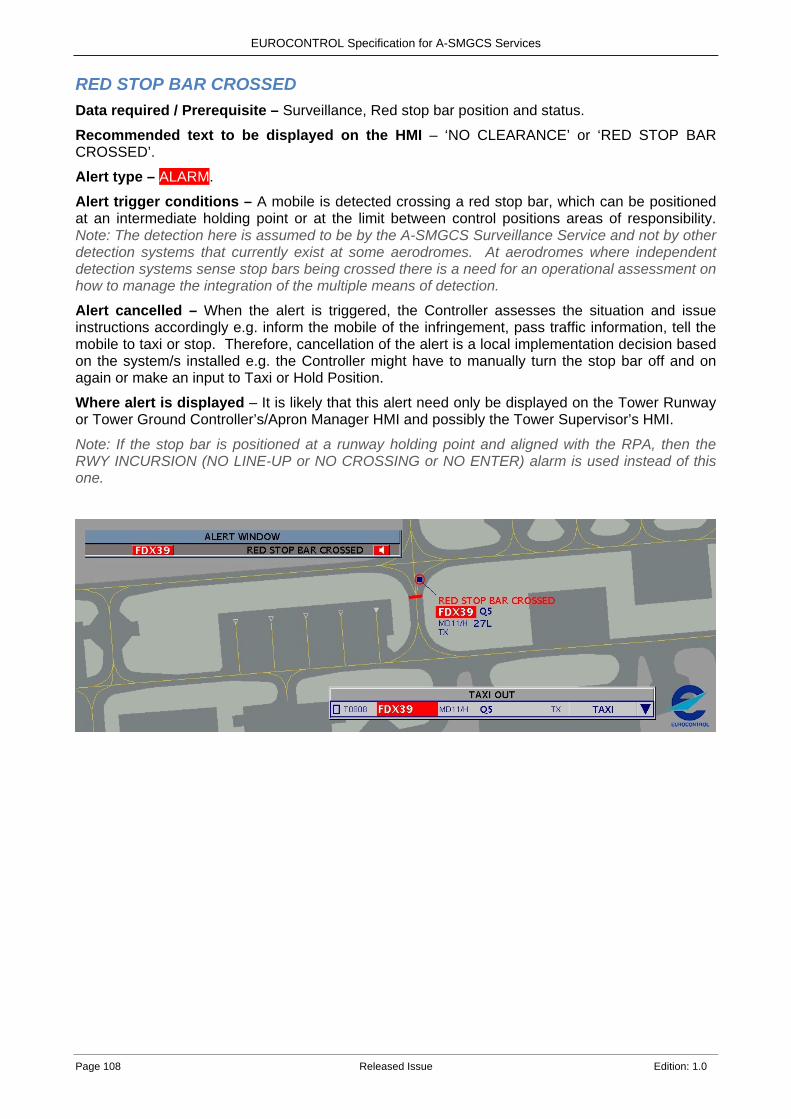
EUROCONTROL Specification for A-SMGCS Services
Page 108 Released Issue Edition: 1.0
RED STOP BAR CROSSED Data required / Prerequisite – Surveillance, Red stop bar position and status.
Recommended text to be displayed on the HMI – ‘NO CLEARANCE’ or ‘RED STOP BAR CROSSED’.
Alert type – ALARM.
Alert trigger conditions – A mobile is detected crossing a red stop bar, which can be positioned at an intermediate holding point or at the limit between control positions areas of responsibility. Note: The detection here is assumed to be by the A-SMGCS Surveillance Service and not by other detection systems that currently exist at some aerodromes. At aerodromes where independent detection systems sense stop bars being crossed there is a need for an operational assessment on how to manage the integration of the multiple means of detection.
Alert cancelled – When the alert is triggered, the Controller assesses the situation and issue instructions accordingly e.g. inform the mobile of the infringement, pass traffic information, tell the mobile to taxi or stop. Therefore, cancellation of the alert is a local implementation decision based on the system/s installed e.g. the Controller might have to manually turn the stop bar off and on again or make an input to Taxi or Hold Position.
Where alert is displayed – It is likely that this alert need only be displayed on the Tower Runway or Tower Ground Controller’s/Apron Manager HMI and possibly the Tower Supervisor’s HMI.
Note: If the stop bar is positioned at a runway holding point and aligned with the RPA, then the RWY INCURSION (NO LINE-UP or NO CROSSING or NO ENTER) alarm is used instead of this one.
EUROCONTROL Specification for A-SMGCS Services
Edition: 1.0 Released Issue Page 109
LINING UP ON THE WRONG RUNWAY Data required / Prerequisite – Surveillance, Assigned Runway.
Recommended text to be displayed on the HMI – ‘WRONG RWY’ or ‘LUP WRONG RWY?’
Alert type –ALARM (or INFORMATION depending on local implementation decision based on whether other traffic is known within or planned to enter RPA within a specified time).
Alert trigger conditions – A departing aircraft is detected lining up on a runway that differs to the assigned runway.
Alert cancelled – When the alert is triggered the Controller assesses the situation and gives the aircraft instructions to proceed to the correct runway. Therefore, the alert is cancelled when the A-SMGCS detects that the aircraft is no longer lined up on the incorrect runway, or the Controller changes the runway to match the runway where the aircraft is positioned.
Where alert is displayed – It is likely that this alert need only be displayed on the Tower Runway Controller’s HMI and possibly the Tower Supervisor’s HMI.
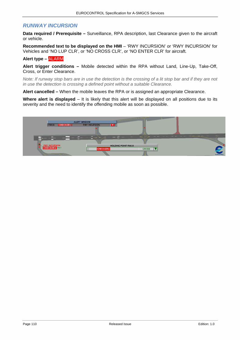
EUROCONTROL Specification for A-SMGCS Services
Page 110 Released Issue Edition: 1.0
RUNWAY INCURSION Data required / Prerequisite – Surveillance, RPA description, last Clearance given to the aircraft or vehicle.
Recommended text to be displayed on the HMI – ‘RWY INCURSION’ or ‘RWY INCURSION’ for Vehicles and ‘NO LUP CLR’, or ‘NO CROSS CLR’, or ‘NO ENTER CLR’ for aircraft.
Alert type – ALARM. Alert trigger conditions – Mobile detected within the RPA without Land, Line-Up, Take-Off, Cross, or Enter Clearance.
Note: If runway stop bars are in use the detection is the crossing of a lit stop bar and if they are not in use the detection is crossing a defined point without a suitable Clearance.
Alert cancelled – When the mobile leaves the RPA or is assigned an appropriate Clearance.
Where alert is displayed – It is likely that this alert will be displayed on all positions due to its severity and the need to identify the offending mobile as soon as possible.
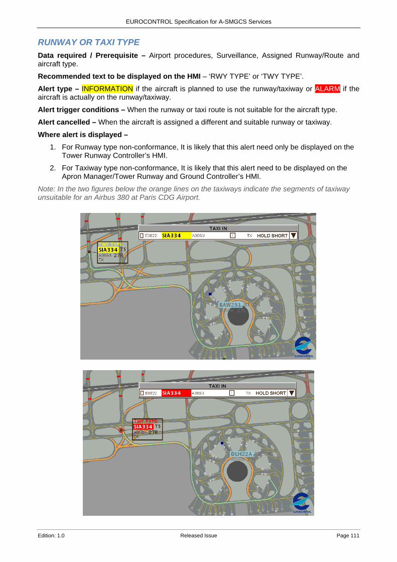
EUROCONTROL Specification for A-SMGCS Services
Edition: 1.0 Released Issue Page 111
RUNWAY OR TAXI TYPE Data required / Prerequisite – Airport procedures, Surveillance, Assigned Runway/Route and aircraft type.
Recommended text to be displayed on the HMI – ‘RWY TYPE’ or ‘TWY TYPE’. Alert type – INFORMATION if the aircraft is planned to use the runway/taxiway or ALARM if the aircraft is actually on the runway/taxiway.
Alert trigger conditions – When the runway or taxi route is not suitable for the aircraft type.
Alert cancelled – When the aircraft is assigned a different and suitable runway or taxiway.
Where alert is displayed – 1. For Runway type non-conformance, It is likely that this alert need only be displayed on the
Tower Runway Controller’s HMI.
2. For Taxiway type non-conformance, It is likely that this alert need to be displayed on the Apron Manager/Tower Runway and Ground Controller’s HMI.
Note: In the two figures below the orange lines on the taxiways indicate the segments of taxiway unsuitable for an Airbus 380 at Paris CDG Airport.
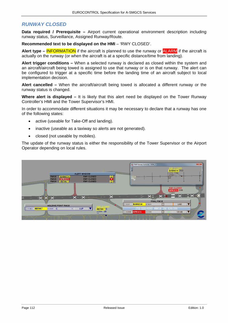
EUROCONTROL Specification for A-SMGCS Services
Page 112 Released Issue Edition: 1.0
RUNWAY CLOSED Data required / Prerequisite – Airport current operational environment description including runway status, Surveillance, Assigned Runway/Route.
Recommended text to be displayed on the HMI – ‘RWY CLOSED’. Alert type – INFORMATION if the aircraft is planned to use the runway or ALARM if the aircraft is actually on the runway (or when the aircraft is at a specific distance/time from landing).
Alert trigger conditions – When a selected runway is declared as closed within the system and an aircraft/aircraft being towed is assigned to use that runway or is on that runway. The alert can be configured to trigger at a specific time before the landing time of an aircraft subject to local implementation decision.
Alert cancelled – When the aircraft/aircraft being towed is allocated a different runway or the runway status is changed.
Where alert is displayed – It is likely that this alert need be displayed on the Tower Runway Controller’s HMI and the Tower Supervisor’s HMI. In order to accommodate different situations it may be necessary to declare that a runway has one of the following states:
• active (useable for Take-Off and landing).
• inactive (useable as a taxiway so alerts are not generated).
• closed (not useable by mobiles).
The update of the runway status is either the responsibility of the Tower Supervisor or the Airport Operator depending on local rules.
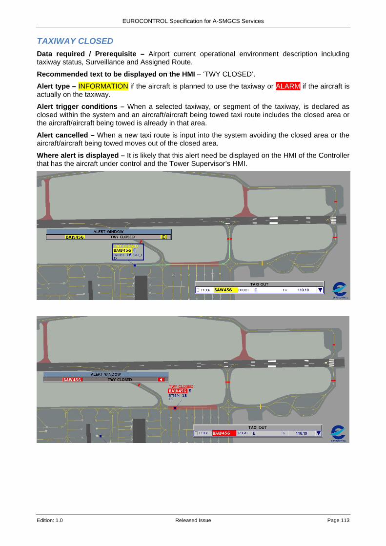
EUROCONTROL Specification for A-SMGCS Services
Edition: 1.0 Released Issue Page 113
TAXIWAY CLOSED Data required / Prerequisite – Airport current operational environment description including taxiway status, Surveillance and Assigned Route.
Recommended text to be displayed on the HMI – ‘TWY CLOSED’. Alert type – INFORMATION if the aircraft is planned to use the taxiway or ALARM if the aircraft is actually on the taxiway.
Alert trigger conditions – When a selected taxiway, or segment of the taxiway, is declared as closed within the system and an aircraft/aircraft being towed taxi route includes the closed area or the aircraft/aircraft being towed is already in that area.
Alert cancelled – When a new taxi route is input into the system avoiding the closed area or the aircraft/aircraft being towed moves out of the closed area.
Where alert is displayed – It is likely that this alert need be displayed on the HMI of the Controller that has the aircraft under control and the Tower Supervisor’s HMI.
EUROCONTROL Specification for A-SMGCS Services
Page 114 Released Issue Edition: 1.0
RESTRICTED AREA INCURSION Data required / Prerequisite – Surveillance, Restricted Area description.
Recommended text to be displayed on the HMI – ‘INCURSION’ or ‘RA INCURSION’. Alert type – ALARM.
Alert trigger conditions – When an unauthorised mobile is detected within a Restricted Area e.g. an area outside of the RPA that has been defined locally to protect something on the aerodrome like navigation equipment or a sensitive area.
Alert cancelled – When the mobile leaves the Restricted Area.
Where alert is displayed – Apron Manager/Tower Ground or Tower Runway Controller dependant on local implementation decision.
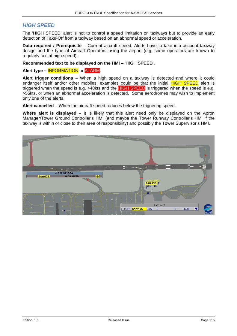
EUROCONTROL Specification for A-SMGCS Services
Edition: 1.0 Released Issue Page 115
HIGH SPEED The ‘HIGH SPEED’ alert is not to control a speed limitation on taxiways but to provide an early detection of Take-Off from a taxiway based on an abnormal speed or acceleration.
Data required / Prerequisite – Current aircraft speed. Alerts have to take into account taxiway design and the type of Aircraft Operators using the airport (e.g. some operators are known to regularly taxi at high speed).
Recommended text to be displayed on the HMI – ‘HIGH SPEED’. Alert type – INFORMATION or ALARM.
Alert trigger conditions – When a high speed on a taxiway is detected and where it could endanger itself and/or other mobiles, examples could be that the initial HIGH SPEED alert is triggered when the speed is e.g. >40kts and the HIGH SPEED is triggered when the speed is e.g. >55kts, or when an abnormal acceleration is detected. Some aerodromes may wish to implement only one of the alerts.
Alert cancelled – When the aircraft speed reduces below the triggering speed.
Where alert is displayed – It is likely that this alert need only be displayed on the Apron Manager/Tower Ground Controller’s HMI (and maybe the Tower Runway Controller’s HMI if the taxiway is within or close to their area of responsibility) and possibly the Tower Supervisor’s HMI.

EUROCONTROL Specification for A-SMGCS Services
Page 116 Released Issue Edition: 1.0
Informative - Traceability to Regulatory Appendix DRequirements
Single European Sky – The interoperability Regulation Appendix D contains two tables providing traceability between the Single European Sky REGULATION (EC) No 552/2004 OF THE EUROPEAN PARLIAMENT AND OF THE COUNCIL of 10 March 2004 (the interoperability Regulation) as amended by REGULATION (EC) No 1070/2009 and the EUROCONTROL A-SMGCS Specification.
The first table provides A-SMGCS Specification references to the general Essential Requirements defined in Annex II Part A of the regulation No 552/2004. The second table provides A-SMGCS Specification references specific Essential Requirements defined in Annex II Part B of the regulation No 552/2004.
Reg 552/2004 Annex II Part A
General Essential Requirements
Description EUROCONTROL
A-SMGCS Specification reference
ER1: Seamless operation
ER1-[GENL]-01
Air traffic management systems and their constituents shall be designed, built, maintained, and operated using the appropriate and validated procedures, in such a way as to ensure the seamless operation of the EATMN at all times and for all phases of flight. Seamless operation can be expressed, in particular, in terms of information sharing, including the relevant operational status information, common understanding of information, comparable processing performances, and the associated procedures enabling common operational performances agreed for the whole or parts of the EATMN.
ASMGCS-[GENL]-[010] ASMGCS-[GENL]-[020] ASMGCS-[GENL]-[040] ASMGCS-[GENL]-[050] ASMGCS-[GENL]-[060] ASMGCS-[GENL]-[070] ASMGCS-[GENL]-[080] ASMGCS-[GENL]-[090] ASMGCS-[GENL]-[100] ASMGCS-[SURV]-[010] ASMGCS-[SURV]-[020] ASMGCS-[ROUT]-[360] ASMGCS-[GUID]-[350] ASMGCS-[GUID]-[360]
ER2: Support for new concepts of operation
ER2-[GENL]-01
The EATMN, its systems and their constituents shall support, on a coordinated basis, new agreed and validated concepts of operation that improve the quality, sustainability and effectiveness of air navigation services, in particular in terms of safety and capacity.
ASMGCS-[GENL]-[020] the Airport SafetySupport Service (6.3) the Routing Service (6.4) the Guidance Service (6.5)
ER2-[GENL]-02
The potential of new concepts, such as collaborative decision-making, increasing automation and alternative methods of delegation of separation responsibility, shall be examined taking due account of technological developments and of their safe implementation, following validation.
ASMGCS-[GENL]-[100] ASMGCS-[GENL]-[110] ASMGCS-[ROUT]-[320]

EUROCONTROL Specification for A-SMGCS Services
Edition: 1.0 Released Issue Page 117
ER3: Safety
ER3-[GENL]-01 Systems and operations of the EATMN shall achieve agreed high levels of safety. Agreed safety management and reporting methodologies shall be established to achieve this.
ASMGCS-[GENL]-[160] ASMGCS-[GENL]-[170]
ER3-[GENL]-02 In respect of appropriate ground-based systems, or parts thereof, these high levels of safety shall be enhanced by safety nets, which shall be subject to agreed common performance characteristics.
The Airport SafetySupport Service (6.3) ASMGCS-[GUID]-[160] ASMGCS-[GUID]-[170] ASMGCS-[GUID]-[180] ASMGCS-[GUID]-[190] ASMGCS-[GUID]-[200] ASMGCS-[GUID]-[260] ASMGCS-[GUID]-[290] ASMGCS-[GUID]-[320]
ER3-[GENL]-03
A harmonised set of safety requirements for the design, implementation, maintenance and operation of systems and their constituents, both for normal and degraded modes of operation, shall be defined with a view to achieving the agreed safety levels, for all phases of flight and for the entire EATMN.
ASMGCS-[GENL]-[170] ASMGCS-[GENL]-[180] ASMGCS-[GENL]-[190] ASMGCS-[GENL]-[200] ASMGCS-[GUID]-[040] ASMGCS-[GUID]-[080] ASMGCS-[GUID]-[090]
ER3-[GENL]-04
Systems shall be designed, built, maintained, and operated, using the appropriate and validated procedures, in such a way that the tasks assigned to the control staff are compatible with human capabilities, in both the normal and degraded modes of operation, and are consistent with required safety levels.
ASMGCS-[GENL]-[110] ASMGCS-[GENL]-[120] ASMGCS-[GENL]-[130] ASMGCS-[ROUT]-[090] ASMGCS-[ROUT]-[310] ASMGCS-[ROUT]-[320] ASMGCS-[GUID]-[210]
ER3-[GENL]-05 Systems shall be designed, built, maintained, and operated using the appropriate and validated procedures, in such a way as to be free from harmful interference in their normal operational environment.
ASMGCS-[SURV]-[030] ASMGCS-[SURV]-[040]
ER4: Civil-military coordination
ER4-[GENL]-01
The EATMN, its systems and their constituents shall support the progressive implementation of civil/military coordination, to the extent necessary for effective airspace and air traffic flow management, and the safe and efficient use of airspace by all users, through the application of the concept of the flexible use of airspace.
N/A
ER4-[GENL]-02
To achieve these objectives, the EATMN, its systems and their constituents shall support the timely sharing of correct and consistent information covering all phases of flight, between civil and military parties.
N/A

EUROCONTROL Specification for A-SMGCS Services
Page 118 Released Issue Edition: 1.0
ER4-[GENL]-03 Account should be taken of national security requirements. N/A
ER5: Environmental constraints
ER5-[GENL]-01 Systems and operations of the EATMN shall take into account the need to minimise environmental impact in accordance with Community legislation.
N/A
ER6: Principles governing the logical architecture of systems
ER6-[GENL]-01
Systems shall be designed and progressively integrated with the objective of achieving a coherent and increasingly harmonised, evolutionary and validated logical architecture within the EATMN.
N/A
ER7: Principles governing the construction of systems
ER7-[GENL]-01
Systems shall be designed, built, and maintained on the grounds of sound engineering principles, in particular those relating to modularity, enabling interchangeability of constituents, high availability, and redundancy and fault tolerance of critical constituents.
N/A
Table 8: Traceability to the General Essential Requirement of Reg No 552/2004
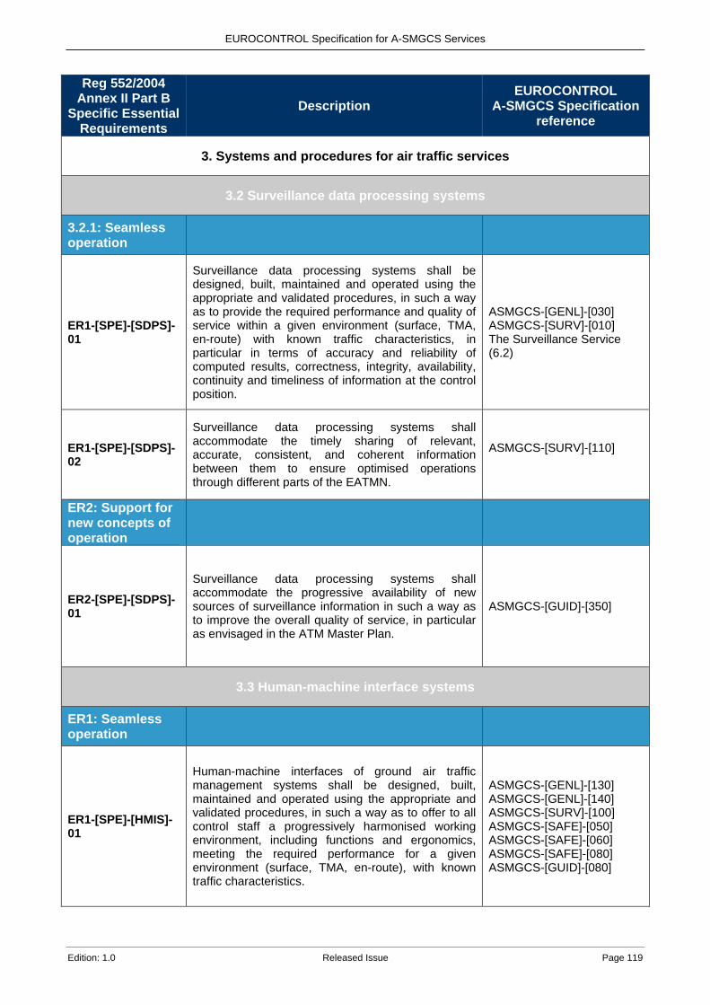
EUROCONTROL Specification for A-SMGCS Services
Edition: 1.0 Released Issue Page 119
Reg 552/2004 Annex II Part B
Specific Essential Requirements
Description EUROCONTROL
A-SMGCS Specification reference
3. Systems and procedures for air traffic services
3.2 Surveillance data processing systems
3.2.1: Seamless operation
ER1-[SPE]-[SDPS]-01
Surveillance data processing systems shall be designed, built, maintained and operated using the appropriate and validated procedures, in such a way as to provide the required performance and quality of service within a given environment (surface, TMA, en-route) with known traffic characteristics, in particular in terms of accuracy and reliability of computed results, correctness, integrity, availability, continuity and timeliness of information at the control position.
ASMGCS-[GENL]-[030] ASMGCS-[SURV]-[010] The Surveillance Service (6.2)
ER1-[SPE]-[SDPS]-02
Surveillance data processing systems shall accommodate the timely sharing of relevant, accurate, consistent, and coherent information between them to ensure optimised operations through different parts of the EATMN.
ASMGCS-[SURV]-[110]
ER2: Support for new concepts of operation
ER2-[SPE]-[SDPS]-01
Surveillance data processing systems shall accommodate the progressive availability of new sources of surveillance information in such a way as to improve the overall quality of service, in particular as envisaged in the ATM Master Plan.
ASMGCS-[GUID]-[350]
3.3 Human-machine interface systems
ER1: Seamless operation
ER1-[SPE]-[HMIS]-01
Human-machine interfaces of ground air traffic management systems shall be designed, built, maintained and operated using the appropriate and validated procedures, in such a way as to offer to all control staff a progressively harmonised working environment, including functions and ergonomics, meeting the required performance for a given environment (surface, TMA, en-route), with known traffic characteristics.
ASMGCS-[GENL]-[130] ASMGCS-[GENL]-[140] ASMGCS-[SURV]-[100] ASMGCS-[SAFE]-[050] ASMGCS-[SAFE]-[060] ASMGCS-[SAFE]-[080] ASMGCS-[GUID]-[080]
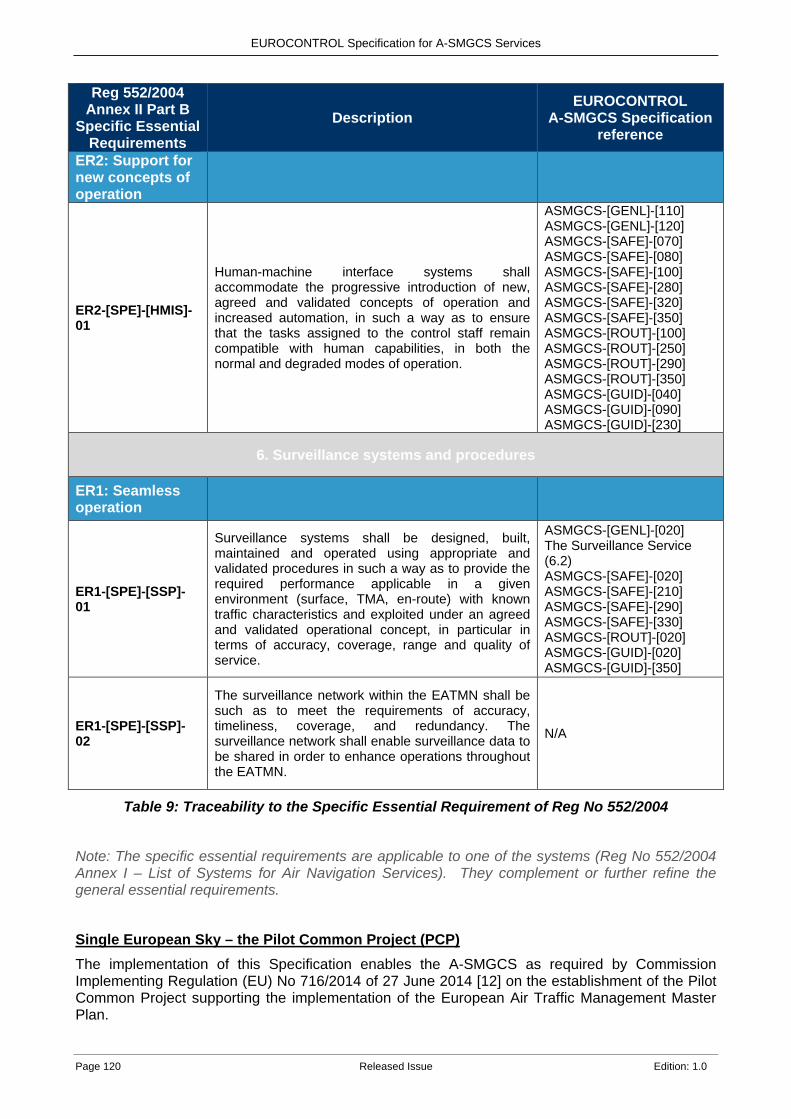
EUROCONTROL Specification for A-SMGCS Services
Page 120 Released Issue Edition: 1.0
Reg 552/2004 Annex II Part B
Specific Essential Requirements
Description EUROCONTROL
A-SMGCS Specification reference
ER2: Support for new concepts of operation
ER2-[SPE]-[HMIS]-01
Human-machine interface systems shall accommodate the progressive introduction of new, agreed and validated concepts of operation and increased automation, in such a way as to ensure that the tasks assigned to the control staff remain compatible with human capabilities, in both the normal and degraded modes of operation.
ASMGCS-[GENL]-[110] ASMGCS-[GENL]-[120] ASMGCS-[SAFE]-[070] ASMGCS-[SAFE]-[080] ASMGCS-[SAFE]-[100] ASMGCS-[SAFE]-[280] ASMGCS-[SAFE]-[320] ASMGCS-[SAFE]-[350] ASMGCS-[ROUT]-[100] ASMGCS-[ROUT]-[250] ASMGCS-[ROUT]-[290] ASMGCS-[ROUT]-[350] ASMGCS-[GUID]-[040] ASMGCS-[GUID]-[090] ASMGCS-[GUID]-[230]
6. Surveillance systems and procedures
ER1: Seamless operation
ER1-[SPE]-[SSP]-01
Surveillance systems shall be designed, built, maintained and operated using appropriate and validated procedures in such a way as to provide the required performance applicable in a given environment (surface, TMA, en-route) with known traffic characteristics and exploited under an agreed and validated operational concept, in particular in terms of accuracy, coverage, range and quality of service.
ASMGCS-[GENL]-[020] The Surveillance Service (6.2) ASMGCS-[SAFE]-[020] ASMGCS-[SAFE]-[210] ASMGCS-[SAFE]-[290] ASMGCS-[SAFE]-[330] ASMGCS-[ROUT]-[020] ASMGCS-[GUID]-[020] ASMGCS-[GUID]-[350]
ER1-[SPE]-[SSP]-02
The surveillance network within the EATMN shall be such as to meet the requirements of accuracy, timeliness, coverage, and redundancy. The surveillance network shall enable surveillance data to be shared in order to enhance operations throughout the EATMN.
N/A
Table 9: Traceability to the Specific Essential Requirement of Reg No 552/2004
Note: The specific essential requirements are applicable to one of the systems (Reg No 552/2004 Annex I – List of Systems for Air Navigation Services). They complement or further refine the general essential requirements.
Single European Sky – the Pilot Common Project (PCP) The implementation of this Specification enables the A-SMGCS as required by Commission Implementing Regulation (EU) No 716/2014 of 27 June 2014 [12] on the establishment of the Pilot Common Project supporting the implementation of the European Air Traffic Management Master Plan.

EUROCONTROL Specification for A-SMGCS Services
Edition: 1.0 Released Issue Page 121
Aerodome IR The implementation of this Specification enables the A-SMGCS as required by Commission Regulation (EU) No 139/2014 of 12 February 2014 [15] laying down requirements and administrative procedures related to aerodromes pursuant to Regulation (EC) No 216/2008 of the European Parliament and of the Council (aerodome IR).
ADR.OPS.B.030 Surface movement guidance and control system The aerodrome operator shall ensure that a surface movement guidance and control system is provided at the aerodrome, meeting the EASA AMC/GM requirements AMC1 ADR.OPS.B.030 and GM1 ADR.OPS.B.030 of ED Decision 2014/012/R.

EUROCONTROL
© March 2018 – European Organisation for the Safety of Air Navigation (EUROCONTROL)
This document is published by EUROCONTROL for information purposes. It may be copied
in whole or in part, provided that EUROCONTROL is mentioned as the source and it is not used for
commercial purposes (i.e. for financial gain). The information in this document may not be modified
without prior written permission from EUROCONTROL.
www.eurocontrol.int