EUROCONTROL Guidelines · 2019-02-18 · EUROCONTROL Guidelines for P-RNAV Infrastructure...
35
EUROCONTROL EUROCONTROL Guidelines for P-RNAV Infrastructure Assessment EUROCONTROL Guidelines Edition 1.2 Edition date: 16/04/2008 Reference nr: EUROCONTROL-GUID-114 ISBN: 978-2-87497-054-2
Transcript of EUROCONTROL Guidelines · 2019-02-18 · EUROCONTROL Guidelines for P-RNAV Infrastructure...

EUROCONTROL
EUROCONTROL Guidelines forP-RNAV Infrastructure Assessment
EUROCONTROL Guidelines
Edition 1.2Edition date: 16/04/2008
Reference nr: EUROCONTROL-GUID-114ISBN: 978-2-87497-054-2

EUROPEAN ORGANISATION FOR THE SAFETY OF AIR NAVIGATION
EUROCONTROL
EUROPEAN AIR TRAFFIC MANAGEMENT PROGRAMME
EUROCONTROL Guideline for P-RNAV Infrastructure
Assessment
DOCUMENT IDENTIFIER: EUROCONTROL - GUID - 0114
Edition Number : V 1.2 Edition Date : 16 April 2008 Status : ANT Endorsed Intended for : EATMP Stakeholders

EUROCONTROL Guideline for P-RNAV Infrastructure Assessment
Page ii EUROCONTROL Navigation Domain Edition Number: V 1.2
DOCUMENT CHARACTERISTICS
TITLE
EUROCONTROL Guideline for P-RNAV Infrastructure Assessment
EATMP Infocentre Reference: GUID - 0114
Document Identifier Edition Number: V 1.2 Edition Date: 16 Apr 2008
Abstract This document describes the methods and processes that should be used to evaluate if a specific navigation infrastructure is suitable to support P-RNAV procedures. Infrastructure that is suitable to support P-RNAV is also suitable to support ICAO RNAV-1 procedures as defined in the Performance Based Navigation Manual, ICAO Doc 9613 (Final Working Draft Version 5.1, dated 7 March 2007, available on http://www.icao.int/pbn).
Keywords P-RNAV DME DME/DME GNSS Infrastructure Navigation Aids RNAV-1 ANSP PBN
Contact Person(s) Tel Unit Gerhard BERZ 9 3734 DAP / APN
STATUS, AUDIENCE AND ACCESSIBILITY Status Intended for Accessible via
Working Draft General Public Intranet Draft EATMP Stakeholders Extranet Proposed Issue Restricted Audience Internet (www.eurocontrol.int) Released Issue Printed & electronic copies of the document can be obtained from
the EATMP Infocentre (see page iii)
ELECTRONIC SOURCE Path: C:\Documents and Settings\ddsantos\Desktop On HBRUWF80K
Host System Software Size Windows_NT Microsoft Word 10.0 367 Kb

EUROCONTROL Guideline for P-RNAV Infrastructure Assessment
Edition Number: V 1.2 EUROCONTROL Navigation Domain Page iii
EATMP Infocentre EUROCONTROL Headquarters 96 Rue de la Fusée B-1130 BRUSSELS Tel: +32 (0)2 729 51 51 Fax: +32 (0)2 729 99 84 E-mail: [email protected] Open on 08:00 - 15:00 UTC from Monday to Thursday, incl.
DOCUMENT APPROVAL
The following table identifies all management authorities who have successively approved the present issue of this document.

EUROCONTROL Guideline for P-RNAV Infrastructure Assessment
Page iv EUROCONTROL Navigation Domain Edition Number: V 1.2
DOCUMENT CHANGE RECORD
The following table records the complete history of the successive editions of the present document. EDITION NUMBER
EDITION DATE
INFOCENTRE REFERENCE REASON FOR CHANGE PAGES
AFFECTED
1.0 8.10.07 Proposed Issue for ANT Approval all
1.1 12.11.07 Inclusion of ANT Comments 10,11
1.2 16.04.08 Update to include Pre-89 DME issue and clarification of relation to procedure design 12, 15, 22

EUROCONTROL Guideline for P-RNAV Infrastructure Assessment
Edition Number: V 1.2 EUROCONTROL Navigation Domain Page v
CONTENTS
DOCUMENT CHARACTERISTICS.............................................................................ii
DOCUMENT APPROVAL..........................................................................................iii
DOCUMENT CHANGE RECORD..............................................................................iv
EXECUTIVE SUMMARY.............................................................................................1
1. INTRODUCTION...................................................................................................2 1.1 Background ...............................................................................................................................2 1.2 Purpose and Scope...................................................................................................................2 1.3 Audience ...................................................................................................................................3
1.3.1 Description of Actors .........................................................................................................3
1.3.2 Interactions during the Assessment Process ....................................................................4
1.3.3 Delegation of Responsibility for Area Navigation Infrastructure Assessment...................5
1.4 Use of Software Tools...............................................................................................................5 1.5 Knowledge of Flight Management System Functionalities and Track Deviations ....................5
2. AREA NAVIGATION INFRASTRUCTURE REQUIREMENTS.............................7 2.1 Type of RNAV Infrastructure.....................................................................................................7
2.1.1 Infrastructure Options........................................................................................................7
2.1.2 GNSS Infrastructure ..........................................................................................................7
2.1.3 Conventional Infrastructure ...............................................................................................7
2.2 RNAV Procedure Service Volume and DME Coverage Criteria...............................................8
2.2.1 RNAV Procedure Service Volume.....................................................................................8
2.2.2 Designated Operational Coverage (DOC) ........................................................................8
2.2.3 Geometric Constraints due to FMS Tuning.......................................................................9
2.2.4 Figure of Merit (FOM)........................................................................................................9
2.2.5 ILS - Coupled DME Facilities ............................................................................................9
2.2.6 Use of Software Tools versus Flight Inspection ................................................................9
2.3 Accuracy..................................................................................................................................10
2.3.1 Introduction......................................................................................................................10

EUROCONTROL Guideline for P-RNAV Infrastructure Assessment
Page vi EUROCONTROL Navigation Domain Edition Number: V 1.2
2.3.2 Total System Error...........................................................................................................10
2.3.3 DME/DME Accuracy Formula .........................................................................................10
2.3.4 Aircraft and Signal in Space DME Accuracy Allocations ................................................11
2.3.5 Relationship between Accuracy and Route Spacing ......................................................11
2.3.6 Relationship between Infrastructure Assessment and Procedure Design......................12
2.4 Other Requirements................................................................................................................12
2.4.1 Co-Channel Facilities ......................................................................................................12
2.4.2 Multipath ..........................................................................................................................12
2.4.3 Specific Considerations for SID’s and STAR’s................................................................12
3. DME/DME INFRASTRUCTURE ASSESSMENT PROCESS .............................14 3.1 Introduction .............................................................................................................................14 3.2 Process Overview ...................................................................................................................14 3.3 Input Data Collection...............................................................................................................14 3.4 Identify Individual Qualifying DME Facilities ...........................................................................15 3.5 Establish Supporting DME Pairs.............................................................................................15 3.6 Identify Specific Issues............................................................................................................15
3.6.1 Critical DME.....................................................................................................................15
3.6.2 Identify DME Facilities with a Potential to have Negative Effects ...................................16
3.7 Prepare and Conduct Flight Inspection...................................................................................16
3.7.1 Review Existing Flight Inspection Records .....................................................................16
3.7.2 Prepare Flight Inspection Data........................................................................................16
3.7.3 Flight Inspection Equipment Considerations...................................................................17
3.7.4 Periodicity of Flight Inspection.........................................................................................17
3.8 Finalize Assessment and Implementation Measures .............................................................18
4. TECHNICAL TOPICS .........................................................................................19 4.1 Negative Elevation Angles ......................................................................................................19 4.2 DME Facilities not under ANSP Control and Service-Level Agreements...............................19 4.3 Critical DME Facilities .............................................................................................................19 4.4 Gaps in DME/DME RNAV Service..........................................................................................20
4.4.1 Dead Reckoning..............................................................................................................20
4.4.2 Inertial Navigation Systems (INS or IRU)........................................................................21
4.4.3 Resiting Existing or Installing New DME Facilities ..........................................................21
4.5 RNAV Offsets and Direct-To’s ................................................................................................21

EUROCONTROL Guideline for P-RNAV Infrastructure Assessment
Edition Number: V 1.2 EUROCONTROL Navigation Domain Page vii
4.6 DME Transponders First Installed Prior to 1989.....................................................................22
5. References.........................................................................................................23 5.1 ICAO........................................................................................................................................23 5.2 EUROCONTROL ....................................................................................................................23 5.3 JAA..........................................................................................................................................23
6. Abbreviations and Acronyms ..........................................................................24

EUROCONTROL Guideline for P-RNAV Infrastructure Assessment
Page viii EUROCONTROL Navigation Domain Edition Number: V 1.2
Left blank intentionally

EUROCONTROL Guideline for P-RNAV Infrastructure Assessment
Edition Number: V 1.2 EUROCONTROL Navigation Domain Page 1
EXECUTIVE SUMMARY
This document describes the methods and processes that should be used to evaluate if a specific navigation infrastructure is suitable to support P-RNAV procedures. Infrastructure that is suitable to support P-RNAV is also suitable to support ICAO RNAV-1 procedures as defined in the Performance Based Navigation Manual, ICAO Doc 9613 (Final Working Draft Version 5.1, dated 7 March 2007, available on http://www.icao.int/pbn).
Section 1 gives the generic context and background information. Section 2 describes the requirements for P-RNAV infrastructure assessment. Section 3 explains all the steps required to conduct such an assessment, while section 4 gives more detail on specific technical topics.

EUROCONTROL Guideline for P-RNAV Infrastructure Assessment
Page 2 EUROCONTROL Navigation Domain Edition Number: V 1.2
1. INTRODUCTION
1.1 Background
Air Navigation Service Providers (ANSP) have a responsibility to provide infrastructure (e.g., navigation aids) that is “sufficient” to support all procedures, including RNAV. This generic provision responsibility and the demand for “sufficiency” are documented as follows:
Convention on International Civil Aviation (ICAO Doc 7300/8, Article 28): “Each … state undertakes … to provide … radio services … and other navigation facilities to facilitate international air navigation …”
ICAO Annex 11, Air Traffic Services (RNP Routes, Attachment B), “…infrastructure must be provided sufficient to support …”
JAA TGL 10, section 4c) “The design of a procedure and the supporting navigation infrastructure (including consideration for the need of redundant aids) have been assessed and validated to the satisfaction of the responsible airspace authority demonstrating aircraft compatibility and adequate performance for the entire procedure. This assessment includes flight checking where appropriate.”
These standards and specifications define the responsibility for the infrastructure assessments task, which becomes more complex when intended to support RNAV applications. Detailed guidance on the relationship between navigation infrastructure, navigation specifications and their application in a specific airspace are contained in ICAO Doc 9613, Performance Based Navigation Manual.
Individual navigation specifications invoke particular requirements on navigation infrastructure. Among the various specifications, RNAV-1 is currently being broadly implemented (Doc 9613, Volume II, Part B, Chapter 3). The RNAV-1 specification is the result of harmonization between the existing regional specifications P-RNAV (based on TGL-10) in Europe and U.S.-RNAV (based on AC90-100). While the principles and processes described in this guidance material are generally applicable to the provision of RNAV infrastructure, specific requirements have been derived from TGL-10 and RNAV-1 in order to support P-RNAV. Infrastructure that supports airspace users approved for P-RNAV also supports RNAV-1 approved users.
1.2 Purpose and Scope
This guidance material is intended to provide the necessary guidance for ANSP to conduct infrastructure assessments in order to satisfy the requirements of P-RNAV, in particular assumption c) in section 4 of JAA TGL-10. The document is consistent with the Performance Based Navigation

EUROCONTROL Guideline for P-RNAV Infrastructure Assessment
Edition Number: V 1.2 EUROCONTROL Navigation Domain Page 3
Manual by providing additional detail guidance. It can be used both to determine compliance with P-RNAV, as well as to consider what infrastructure changes could be undertaken in order to achieve it.
Performance Based Navigation provides procedures that can be flown with a variety of navigation aids and airborne sensors. However, each combination of navigation aid and sensor still needs to be assessed to see if the requirements to support a specific procedure are met. Consequently, this document discusses both GNSS and especially DME based RNAV. The focus on DME is due to fact that accuracy error budgets become relevant in qualifying DME infrastructure for RNAV-1. The role of VOR, which requires explicit authorization (TGL10 section 5.1.2 b), is discussed in section 2.1.3.
Closely related to RNAV infrastructure assessment is RNAV procedure validation, which looks at flyability and other operational aspects, and RNAV flight inspection, for which separate Eurocontrol guidance documents are available. This guidance is consistent with the corresponding parts in ICAO Documents 8168 (PANS-OPS) and 8071 (Manual on Testing of Radio Navigation Aids).
Note that the term “procedure” has been used consistently throughout the document to indicate both specific procedures (as published on a procedure chart) as well as RNAV routes.
1.3 Audience
1.3.1 Description of Actors
This document intends to be primarily useful for navigation service providers, particularly organisations and groups responsible for the planning and operating of navigation infrastructure. A secondary purpose is to document to regulatory authorities, airspace users and navigation data providers what assumptions are used in conducting the infrastructure assessment. While the exact organizational arrangements in each state may vary considerably, the following actors within the ANSP function (e.g., not necessarily the traditional ANSP organisation) are involved in the assessment:
Airspace Planning: Usually part of the operational division of an ANSP, airspace planners define the operational requirements for new or existing procedures. They are responsible for assessing the impact of procedures on ATC operations, including the provision of safe separation.
Procedure Design: Based on the coordination with airspace planners, the procedure design office is responsible for defining a new procedure in accordance with ICAO PANS-OPS. This typically includes the creation of procedure charts and all associated data, which is needed for publication in the AIP and transmission to the airborne navigation data providers. They may also be responsible for RNAV procedure validation, and may coordinate flight validation tasks with the flight inspection organisation, if applicable.

EUROCONTROL Guideline for P-RNAV Infrastructure Assessment
Page 4 EUROCONTROL Navigation Domain Edition Number: V 1.2
Designated Engineering Authority: The designated engineering authority is responsible to assess that the navigation signals in space of both ground and space based navigation equipment meet the appropriate requirements to support a specific procedure. The engineering authority is typically part of the technical division of an ANSP and usually carries out its task under a regulatory charter. The engineering authority carries out the infrastructure assessment in response to the needs of the procedure design office, assists in defining flight inspection tasks and completes the evaluation of the flight inspection report. They will coordinate relevant actions with maintenance personnel. The engineering authority will also consider service volume modifications in cooperation with frequency planners.
Flight Inspection Organization: This organization conducts the flight inspection of RNAV procedures and supporting facilities, if required. For the purposes of the infrastructure assessment, this only includes confirming signal in space assumptions. However, in the frame of RNAV procedure commissioning, some or all of the associated RNAV procedure flight validation may be conducted at the same time.
1.3.2 Interactions during the Assessment Process
The need for a new or modified RNAV procedure can be due to various reasons, such as requests by airports, airspace users, regulatory requirements or airspace redesign and optimization. Airspace planners and procedure designers will work together to precisely define the operational requirements and develop a proposed procedure that meets those requirements. The proposed procedure design, as well as any specific operational requirements (such as in section 4.5, RNAV offset’s and direct-to’s), are then communicated to the engineering authority.
The engineering authority then reviews the procedure and conducts the infrastructure assessment. If necessary, the engineering authority will review assumptions about the procedure or possibilities for optimization with the procedure designer and the airspace planner. Finally, the engineering authority will prepare the flight inspection together with the procedure designer and the flight inspector, and the flight inspection organisation will conduct the flight inspection.
Depending on the findings of the procedure design, the engineering authority analysis and/or the flight inspection results, infrastructure or even operational requirements may have to be modified. This may involve changes to the procedure itself or to specific aspects of the ground infrastructure. Such changes should be discussed by all actors to ensure that the impact of those changes is clearly understood.
As the implementation of (ICAO harmonized-) RNAV procedures is a relatively new subject in service provision, ANSP’s should make sure that all staff involved in such implementations are appropriately trained.
EUROCONTROL Guideline for P-RNAV Infrastructure Assessment
Edition Number: V 1.2 EUROCONTROL Navigation Domain Page 5
1.3.3 Delegation of Responsibility for Area Navigation Infrastructure Assessment
Nominally, the responsibility for assessing the suitability of navigation signals lies with the engineering authority. While the procedure designer may be able to undertake some of this task with the support of appropriate software tools to model signal in space coverage, these cannot replace in their entirety the need to consult with the engineering authority. This is because the engineering authority has the most up to date knowledge of signal in space performance of a particular navigation aid, both historical and actual. Therefore, close cooperation between procedure design office and navaid engineering staff is required.
1.4 Use of Software Tools
Appropriate tools should be used to assess RNAV infrastructure. While the assessment could be conducted using manual analysis and flight inspection, the use of a software tool is recommended in order to make the assessment more efficient. The software tool should be tailored to allow evaluating the infrastructure to meet the requirements imposed by the P-RNAV navigation specification, as described in this document. In particular, the calculations should be in accordance with the accuracy error budget described herein. Such a tool could, but does not have to be integrated with procedure design tools.
In general, RNAV assessment tools should include a 3D terrain model with sufficient resolution and accuracy to allow predicting the line of sight visibility of navaids along a procedure service volume, including an analysis of their respective subtended angles and a variety of other geometric constraints. Note that the accuracy of the terrain model in the near field of the DME antenna can have a significant impact on the accuracy of the line of sight prediction.
It is not recommended to include any electromagnetic propagation modelling, since producing a realistic environment model would require significant effort and sophistication, while the need to conduct some flight inspection would not be eliminated. Nonetheless, a generic method such as 4/3 earth radius should be used.
Note: A new version of the EUROCONTROL-provided DEMETER software tool, tailored to assist the processes defined in this document, is expected to be released in 2008.
1.5 Knowledge of Flight Management System Functionalities and Track Deviations
This guidance material reflects the constraints and capabilities of RNAV positioning due to FMS logic. Consequently, the infrastructure assessment as outlined here can be completed without any specific additional knowledge of FMS technology. Note that this is based on a best effort in consulting with

EUROCONTROL Guideline for P-RNAV Infrastructure Assessment
Page 6 EUROCONTROL Navigation Domain Edition Number: V 1.2
aircraft and avionics manufacturers. It is still possible that some specific aircraft and avionics configurations produce unacceptable track deviations. While this is the responsibility of the specific operator, the PBN manual also recommends that RNAV track keeping accuracy be analyzed (Vol. II, Part B, Chapter 3.2.8). This permits to identify such operators and to recommend appropriate regulatory action, if necessary. The track monitoring activity is not intended to impose an undue burden on service providers.
EUROCONTROL Guideline for P-RNAV Infrastructure Assessment
Edition Number: V 1.2 EUROCONTROL Navigation Domain Page 7
2. AREA NAVIGATION INFRASTRUCTURE REQUIREMENTS
2.1 Type of RNAV Infrastructure
2.1.1 Infrastructure Options
RNAV procedures should always allow the use of GNSS. However, some older RNAV avionic systems do not include GNSS. In order to provide a back up to GNSS and to accommodate DME/DME or DME/DME/Inertial - only equipped users, DME based RNAV service should also be provided where practical.
2.1.2 GNSS Infrastructure
Because GNSS (and ABAS using RAIM in particular) is available on a worldwide basis, not much needs to be done in terms of infrastructure assessment. Nonetheless, it should be noted that the responsibility for providing services based on GNSS within the airspace of a particular State remains within that state. Consequently, the ANSP should assess that the interference environment is satisfactory for the planned procedures. This can be accomplished by a variety of means, such as through specific ground and/or airborne interference measurements, by reviewing existing GNSS recordings, etc. (see ICAO Doc 9849, GNSS Manual, Doc 8071, Testing of Radio Navigation Aids and Annex 10).
2.1.3 Conventional Infrastructure
The main assessment task is therefore to evaluate if the DME infrastructure adequately supports the candidate RNAV procedure. Consequently, this is the main subject of this guidance material. While VOR/DME can also provide RNAV guidance, it has been found too difficult to establish harmonized criteria given fleet equipage levels and actual signal in space performance for adequately supporting the accuracies required by RNAV-1. While some cases may exist where VOR/DME provides a useful service, such as in close proximity to airports, these are not addressed here. Given the standardization challenges of VOR for TMA RNAV applications, states are encouraged not to rely on VOR. Consequently, the only role given to VOR is as a means of crosschecking (for example, to detect map-shifts) and to ensure that FMS’es do not encounter inaccurate guidance if reverting through a DME/DME coverage gap. As the implementation of RNAV matures and the number of VOR stations is reduced, the role of VOR is expected to diminish further.
Note: In the current revision of TGL10, which will result in AMC 20-16, VOR is no longer listed as a sensor eligible to support RNAV. VOR is only discussed as a reversionary capability in the case of loss of RNAV guidance.

EUROCONTROL Guideline for P-RNAV Infrastructure Assessment
Page 8 EUROCONTROL Navigation Domain Edition Number: V 1.2
2.2 RNAV Procedure Service Volume and DME Coverage Criteria
2.2.1 RNAV Procedure Service Volume
The airspace or service volume required for an RNAV procedure is given by the boundaries of its procedure design surfaces (e.g., primary and secondary areas). The infrastructure assessment should consider a sufficiently large area to either side of the procedure centreline to include or bound these surfaces appropriately. In the vertical dimension, the infrastructure is assessed for the minimum altitude of the published procedure. The term service volume will be used herein for RNAV procedures, while the term coverage volume will always refer to individual DME facilities supporting an RNAV procedure.
2.2.2 Designated Operational Coverage (DOC)
Designated Operational Coverage (DOC) is the term used to declare the coverage boundary of a navaid. The ANSP is responsible to ensure that the navaid meets Annex 10 requirements within DOC, including minimum field strength. Thus, for a DME to be used in the infrastructure assessment process, its DOC needs to include the associated RNAV service volume. The basic approach to the infrastructure assessment is for the ANSP to ensure that a minimum set of qualifying DME is available. The DME/DME RNAV procedure can only be implemented if a suitable minimum set of DME facilities within DOC range is confirmed. Attaining such a minimum set may in some cases require an extension of DOC, either omni-directionally or on a sector basis, and could include specific altitude constraints. A DOC extension will need to be coordinated with the appropriate spectrum authority.
In addition to identifying a minimum set of qualifying DME, ANSP are also responsible to ensure that all of the DME that are within DOC range along the procedure under evaluation provide signals in compliance with Annex 10. In particular, if a procedure is in a location where there has not been any flight inspection, and/or deleterious effects such as multipath are expected due to the nature of the surrounding terrain, signal quality needs to be verified. Conversely, an ANSP has no responsibility to verify signal quality outside of DOC, even if such signals are receivable.
However, in areas where many DME within DOC are available, the burden to check all such DME may become excessive. This can be the case at large aerodromes with high density operations. Based on available flight inspection data, evidence, experience and expert judgement by the engineering authority it is possible to reduce the amount of flight inspection. This can be further supported by a monitoring of aircraft track keeping during the initial operations phase.

EUROCONTROL Guideline for P-RNAV Infrastructure Assessment
Edition Number: V 1.2 EUROCONTROL Navigation Domain Page 9
2.2.3 Geometric Constraints due to FMS Tuning
Due to the implementation of DME selection for RNAV in FMS, DME facilities should not be relied upon if the facility is at a distance of more than 160NM or less than 3NM, independent of the published DOC. Furthermore, if the elevation angle from the facility to the aircraft is more than 40 degrees, it should also be excluded.
2.2.4 Figure of Merit (FOM)
Some aircraft FMS make use of the Figure of Merit (FOM) coded in the ARINC 424 database for selecting DME facilities. The FOM is a value that can be adjusted by database providers, and does not necessarily match the DOC. It can also be different between providers, and FMS can interpret the FOM differently. It is the responsibility of the aircraft operator to ensure that needed DME facilities are not excluded from a navigation solution due to FOM. This is why it is important to ensure that the DOC for a DME facility is published in the state AIP. Aeronautical data providers are encouraged to ensure that the FOM appropriately reflects the largest DOC range that is authorized for a particular DME facility.
2.2.5 ILS - Coupled DME Facilities
Some RNAV systems do not use ILS coupled DME facilities. This is partly because some of these facilities have intentional offsets. Consequently, ILS associated DME facilities are not suitable to support all potential RNAV users and should be excluded from the assessment. Also, care must be taken when using low power facilities at extended ranges.
2.2.6 Use of Software Tools versus Flight Inspection
The initial infrastructure assessment should be conducted by using a software tool to identify DME facilities that meet the requirements and constraints identified above. The results of this coverage analysis should further be confirmed by flight inspection data, to ensure that stable and accurate DME signals are available with sufficient field strength. It is generally sufficient to flight inspect the RNAV procedure centreline, except when coverage of required facilities is expected to only partially cover the RNAV service volume. Some or all of the flight inspection may be omitted if sufficient experience/evidence exists with the adequate performance of a specific DME or set of DME’s in a particular airspace.

EUROCONTROL Guideline for P-RNAV Infrastructure Assessment
Page 10 EUROCONTROL Navigation Domain Edition Number: V 1.2
2.3 Accuracy
2.3.1 Introduction
In addition to ensuring the availability of sufficient DME coverage, accuracy must also be considered. In the context of this guidance material, discussion of accuracy is focussed on contributions to the signal provided by the ground-based infrastructure: the signal must meet (or exceed) the accuracy requirement at all points in the defined RNAV procedure service volume. While the accuracy requirement for individual DME signals in space to support RNAV is consistent with the existing accuracy requirements in ICAO Annex 10, it is necessary to also verify if the overall error budget for P-RNAV (as described in this document) is being met under the given geometry. Consequently, airborne equipment and piloting aspects need to be considered as well. This is especially true if DME support of P-RNAV becomes marginal to the point of having gaps in coverage.
2.3.2 Total System Error
Lateral Track keeping accuracy for P-RNAV is defined as Total System Error (TSE) and is required to be equal or less than ±1NM for 95% of the flight time. TSE is derived from the Root Sum Square (RSS) of Navigation System Error (NSE) and Flight Technical Error (FTE). NSE incorporates Position Estimation Error (PEE), Path Definition Error (PDE) and display error. For the purposes of the infrastructure assessment, PDE and display error can be assumed to be negligible. PEE is composed of the signal-in-space error and the airborne receiver error. This section focuses on the dominant allocations in TSE, namely NSE and FTE.
The first level of accuracy partitioning is between the Flight Technical Error (FTE) and the Navigation System Error (NSE). For P-RNAV, a value of 0.5 NM (95%) is used for FTE. This is consistent with ICAO Doc 8168 (PANS-OPS) and Doc 9613, which generally consider being established on a procedure when within half of full scale deflection (full scale in terminal area RNAV mode is ±1NM). While the use of flight director or autopilot is recommended, 0.5NM FTE is achievable in manual flight. As FTE and NSE are treated as independent errors, this FTE allocation provides for a maximum permissible NSE of ±0.866NM (95%) using the root sum square formula. These errors are treated as circular errors, and no further allocation into along- and cross-track components is done.
2.3.3 DME/DME Accuracy Formula
The NSE is partitioned into two contributions: one from the airborne equipment (interrogator) and one from the ground equipment (transponder), including signal in space propagation effects. As the minimum requirement for providing RNAV with DME ranges is to have 2 DME’s available with suitable geometry

EUROCONTROL Guideline for P-RNAV Infrastructure Assessment
Edition Number: V 1.2 EUROCONTROL Navigation Domain Page 11
and sufficient range, the following DME RNAV accuracy formula has been agreed (PBN Manual, Vol. II, Part B, Chapter 3.3.3.3.2.g ):
( ) ( )( )α
σσσσσ
sin22
2,2
2,2
2,1
2,1
2/1SISDMEairDMESISDMEairDME
DMEDME
+++≤
Where: σSIS = 0.05 NM (or larger value if required),
σair is MAX {(0.085 NM, (0.125% of distance)},
α = subtended angle (must be within 30o to 150o).
This formula is used to determine if a specific DME pair is able to support the intended procedure. It is assumed that DME positioning is zero-mean, and thus the two σDME/DME result is evaluated against the maximum NSE of 0.866NM derived above. This maximum NSE is also used as the limit in evaluating INS coasting over coverage gaps.
2.3.4 Aircraft and Signal in Space DME Accuracy Allocations
The allocation for σair is based on FAA TSO C66C or equivalent certification standards. Note that the range dependent term starts to dominate at ranges exceeding 68NM. Despite being many years old, this is the most modern DME interrogator certification standard. Meeting performance equivalent to TSO C66C is required by the RNAV-1 and RNAV-2 specifications in the PBN Manual. TGL-10 stipulates that the typical performance of eligible aircraft satisfies the overall accuracy requirement. This implies that the responsible airspace authorities allow the infrastructure assessment to be based on the assumption that P-RNAV approved aircraft meet the performance of TSO C66C, consistent with the PBN manual.
The Signal-in-Space allocation (0.1NM, 95%) includes an allocation for the ground transponder (0.081 NM according to Annex 10) and the remainder for propagation effects such as multi-path.
2.3.5 Relationship between Accuracy and Route Spacing
Accuracy is specified for RNAV on a 95% probability basis. This covers normal performance of the navigation system. It does not cover rare-normal performance or performance due to system failures. It also excludes blunder errors, which by their nature can lead to significant deviations. Route spacing is directly linked to normal performance, but has to take account of the potential for system failures and provide adequate safeguards to monitor and detect large track deviations. Therefore, the route spacing will have to consider the environment in which RNAV is being implemented, including the available surveillance system performance and the contribution of any monitoring tools. These elements are outside of the scope of this document
EUROCONTROL Guideline for P-RNAV Infrastructure Assessment
Page 12 EUROCONTROL Navigation Domain Edition Number: V 1.2
which deals only with the available navigation infrastructure as it relates to the Position Estimation Error (PEE).
2.3.6 Relationship between Infrastructure Assessment and Procedure Design
The components of the accuracy error budget used for infrastructure assessment and procedure design have been harmonized at the ICAO level. However, as their respective objectives differ, the application of those components is not identical. Procedure design ensures sufficient protection from obstacles, whereas infrastructure assessment adds an additional layer of robustness to ensure that a minimum set of actual DME facilities adequately supports the procedure, taking into account all signal in space aspects. It is possible that an RNAV procedure is feasible from an obstacle clearance point of view, but not from an infrastructure point of view.
2.4 Other Requirements
2.4.1 Co-Channel Facilities
With proper DOC declaration and frequency assignment methods, avionics should not be able to lock onto co-channel DME facilities (e.g., geographically separated facilities with the same frequency and pulse spacing). However, a few isolated cases of such tracking errors have been reported, presumably due to specific atmospheric conditions. Additionally, some FMS exclude co-channel facilities if they are within line of sight. Consequently, such facilities should be excluded from the infrastructure assessment. Note that avionics may lock onto a co-channel facility if the intended, closer facility is out for maintenance. Scanning DME interrogators are not able to decode the facility IDENT, preventing most pilots from detecting co-channel errors.
2.4.2 Multipath
Depending on the geometry between terrain, the DME site and the RNAV procedure, signal reflections can occur, which distort the time delay measurement. This is possible for example in hilly and mountainous areas or near lakes, and can include cases where the reflected signal is stronger than the direct signal. Such phenomena should be detected in flight inspection. If a facility is found to provide misleading signals in a relevant area, the procedure should not be authorized for RNAV using DME/DME only.
2.4.3 Specific Considerations for SID’s and STAR’s
Especially in areas with significant terrain, the infrastructure assessment needs to ensure that sufficient RNAV service is provided even at the lowest altitudes used for the RNAV procedure. Consequently, the minimum vertical profile is to be evaluated, including any restrictions such as minimum crossing altitudes or minimum climb gradients. The effects of differences in barometric
EUROCONTROL Guideline for P-RNAV Infrastructure Assessment
Edition Number: V 1.2 EUROCONTROL Navigation Domain Page 13
altitudes are assumed negligible given the achievable accuracy of signal reception modelling based on terrain data only. Basing the assessment on true altitudes (or standard pressure altitudes above the transition level) is therefore acceptable.
For SID’s, DME ranges need to be available for a sufficient amount of time before the FMS can be expected to provide a position solution. This time is 30 seconds (PBN Manual, Vol. II, Part B, Chapter 3.3.3.3.2.b ). Consequently, for a SID to be used by DME/DME only equipped aircraft, the RNAV portion of the SID can only begin at a point that is derived from the minimum altitude where sufficient DME coverage exists plus a distance along the SID taking into account an appropriate maximum speed of such aircraft. The procedure design office should coordinate maximum speed assumptions with the specific users to ensure that the assumed operating scenario is realistic.
Most aircraft with DME/DME/Inertial systems are capable of providing suitable RNAV from take-off by means of the runway threshold update (TOGA Switch). Inertial coasting on the runway update can provide sufficient accuracy for P-RNAV for several minutes. Inertial coasting is further discussed in section 4.4.2.
If DME/DME only users need to be able to fly the RNAV SID, and DME/DME coverage is not available as of 500ft above aerodrome elevation, then the initial part of the SID needs to be based on conventional navigation. This may have an impact on airspace capacity.
For Terminal Area SID and STAR procedures where DME coverage is a challenge, it is recommended to always conduct flight inspection in order to confirm the specific altitudes of DME reception. Note that while on STAR’s DME tracking will continue below line of sight, DME acquisition on SID’s generally begins right at line of sight. Hence, the flight inspection should always be conducted in the correct direction (climbing or descending along the procedure).

EUROCONTROL Guideline for P-RNAV Infrastructure Assessment
Page 14 EUROCONTROL Navigation Domain Edition Number: V 1.2
3. DME/DME INFRASTRUCTURE ASSESSMENT PROCESS
3.1 Introduction
This section describes the process that should be followed in order to assess whether DME/DME RNAV infrastructure meets the requirements as specified in section 2. While this assessment is nominally geared towards existing DME/DME infrastructure, it can also be used to evaluate how infrastructure changes will optimize RNAV service. More discussion on optimization considerations, such as the treatment of DME/DME gaps, is contained in section 4.4. Note that this assessment process proves that DME based RNAV is possible using a specific minimum set of qualifying DME facilities. This does not mean that aircraft operations on the procedure will actually use the exact same set of DME facilities.
3.2 Process Overview
Step 1: Collect Necessary Data
Step 2: Identify Individual Qualifying DME Facilities
Step 3: Establish Supporting DME Pairs
Step 4: Identify Specific Issues
Step 5: Prepare and Conduct Flight Inspection
Step 6: Finalize Assessment and Implementation Measures
Note that steps 2, 3, 4 and 6 are best conducted with the support of software tools. More information on the use of tools is contained in section 1.4. The steps in this process may need to be iterated if any limitations are identified whose mitigation has an impact on the foreseen procedure.
3.3 Input Data Collection
The engineering authority should receive all the necessary information from the procedure design and airspace planning office. This includes all waypoint coordinates, path terminators and any vertical profile restrictions (minimum climb gradients, minimum crossing altitudes, speed categories etc.), offset, direct-to or other operational requirements, as well as the outer boundaries of the secondary protection surfaces.
EUROCONTROL Guideline for P-RNAV Infrastructure Assessment
Edition Number: V 1.2 EUROCONTROL Navigation Domain Page 15
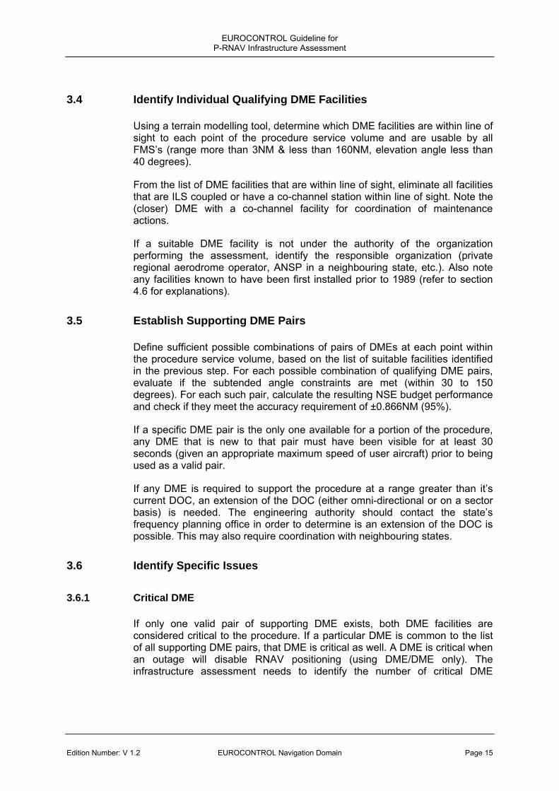
3.4 Identify Individual Qualifying DME Facilities
Using a terrain modelling tool, determine which DME facilities are within line of sight to each point of the procedure service volume and are usable by all FMS’s (range more than 3NM & less than 160NM, elevation angle less than 40 degrees).
From the list of DME facilities that are within line of sight, eliminate all facilities that are ILS coupled or have a co-channel station within line of sight. Note the (closer) DME with a co-channel facility for coordination of maintenance actions.
If a suitable DME facility is not under the authority of the organization performing the assessment, identify the responsible organization (private regional aerodrome operator, ANSP in a neighbouring state, etc.). Also note any facilities known to have been first installed prior to 1989 (refer to section 4.6 for explanations).
3.5 Establish Supporting DME Pairs
Define sufficient possible combinations of pairs of DMEs at each point within the procedure service volume, based on the list of suitable facilities identified in the previous step. For each possible combination of qualifying DME pairs, evaluate if the subtended angle constraints are met (within 30 to 150 degrees). For each such pair, calculate the resulting NSE budget performance and check if they meet the accuracy requirement of ±0.866NM (95%).
If a specific DME pair is the only one available for a portion of the procedure, any DME that is new to that pair must have been visible for at least 30 seconds (given an appropriate maximum speed of user aircraft) prior to being used as a valid pair.
If any DME is required to support the procedure at a range greater than it’s current DOC, an extension of the DOC (either omni-directional or on a sector basis) is needed. The engineering authority should contact the state’s frequency planning office in order to determine is an extension of the DOC is possible. This may also require coordination with neighbouring states.
3.6 Identify Specific Issues
3.6.1 Critical DME
If only one valid pair of supporting DME exists, both DME facilities are considered critical to the procedure. If a particular DME is common to the list of all supporting DME pairs, that DME is critical as well. A DME is critical when an outage will disable RNAV positioning (using DME/DME only). The infrastructure assessment needs to identify the number of critical DME

EUROCONTROL Guideline for P-RNAV Infrastructure Assessment
Page 16 EUROCONTROL Navigation Domain Edition Number: V 1.2
facilities that support a procedure. Refer to section 4.3 for considerations related to critical DME facilities.
3.6.2 Identify DME Facilities with a Potential to have Negative Effects
In addition to the qualifying DME pairs, identify DME facilities for the flight inspection to evaluate for any deleterious effects on the navigation solution, e.g., those providing receivable signals that may not meet Annex 10 requirements. These are DME facilities whose signals are receivable at far distances at low elevation angles (such as facilities along the previous flight path), or have significant terrain or other reflectors near the site and/or propagation path. Military facilities (TACAN), old and out of State installations may also deserve specific consideration. Because avionics are required to exclude such DME facilities from their RNAV solution, this activity is not required and is thus not intended to impose an undue flight inspection burden on the service provider. However, due to the fact that the presence of such signals could impact specific operators, a preliminary investigation prior to approving the RNAV procedure for operations may be justified.
3.7 Prepare and Conduct Flight Inspection
3.7.1 Review Existing Flight Inspection Records
For each DME in the list of supporting pairs, review existing flight inspection records. Note any specific issues, such as AGC unlocks in certain areas, which may deserve special attention. If sufficient recent records are available which cover all or part of the candidate DME facilities in the relevant airspace, all or part of the flight inspection may be omitted.
3.7.2 Prepare Flight Inspection Data
Prepare the list of DME facilities to be flight inspected and communicate any findings (such as incomplete coverage of entire procedure volume) to the flight inspection organisation, including any specific factors to be considered. This data needs to be made available together with the same input data that was required for the assessment performed with modelling (including the path definition, vertical profile, etc).
It is recommended that the procedure design office and the engineering authority coordinate closely with the flight inspection organisation (and ATC operational staff) in the planning and preparation of the infrastructure assessment and flight inspection to make sure that all aspects are considered as efficiently as possible. This will minimize the operational impact of the flight inspection.
The role of flight inspection is to confirm signal in space compliance with ICAO Annex 10, e.g. coverage (availability) and accuracy of individual DME facilities supporting RNAV, as discussed in section 2. No amount of modelling can
EUROCONTROL Guideline for P-RNAV Infrastructure Assessment
Edition Number: V 1.2 EUROCONTROL Navigation Domain Page 17
accurately predict what the signal in space will look like in all cases. Especially at lower altitudes, adverse influences due to reflections and shading are possible.
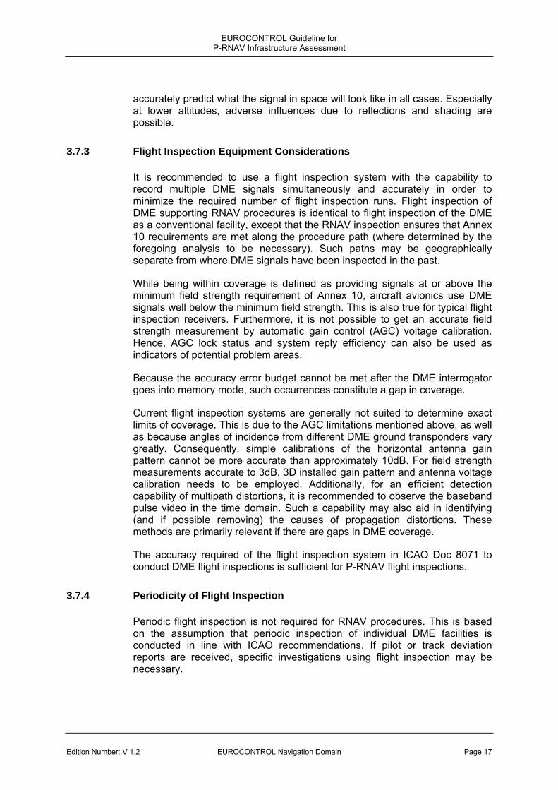
3.7.3 Flight Inspection Equipment Considerations
It is recommended to use a flight inspection system with the capability to record multiple DME signals simultaneously and accurately in order to minimize the required number of flight inspection runs. Flight inspection of DME supporting RNAV procedures is identical to flight inspection of the DME as a conventional facility, except that the RNAV inspection ensures that Annex 10 requirements are met along the procedure path (where determined by the foregoing analysis to be necessary). Such paths may be geographically separate from where DME signals have been inspected in the past.
While being within coverage is defined as providing signals at or above the minimum field strength requirement of Annex 10, aircraft avionics use DME signals well below the minimum field strength. This is also true for typical flight inspection receivers. Furthermore, it is not possible to get an accurate field strength measurement by automatic gain control (AGC) voltage calibration. Hence, AGC lock status and system reply efficiency can also be used as indicators of potential problem areas.
Because the accuracy error budget cannot be met after the DME interrogator goes into memory mode, such occurrences constitute a gap in coverage.
Current flight inspection systems are generally not suited to determine exact limits of coverage. This is due to the AGC limitations mentioned above, as well as because angles of incidence from different DME ground transponders vary greatly. Consequently, simple calibrations of the horizontal antenna gain pattern cannot be more accurate than approximately 10dB. For field strength measurements accurate to 3dB, 3D installed gain pattern and antenna voltage calibration needs to be employed. Additionally, for an efficient detection capability of multipath distortions, it is recommended to observe the baseband pulse video in the time domain. Such a capability may also aid in identifying (and if possible removing) the causes of propagation distortions. These methods are primarily relevant if there are gaps in DME coverage.
The accuracy required of the flight inspection system in ICAO Doc 8071 to conduct DME flight inspections is sufficient for P-RNAV flight inspections.
3.7.4 Periodicity of Flight Inspection
Periodic flight inspection is not required for RNAV procedures. This is based on the assumption that periodic inspection of individual DME facilities is conducted in line with ICAO recommendations. If pilot or track deviation reports are received, specific investigations using flight inspection may be necessary.

EUROCONTROL Guideline for P-RNAV Infrastructure Assessment
Page 18 EUROCONTROL Navigation Domain Edition Number: V 1.2
3.8 Finalize Assessment and Implementation Measures
The engineering authority should assess the flight inspection report to see if the assumptions in the initial assessment have been confirmed, or if any unforeseen effects have been discovered and take the appropriate action for remedy.
If any DME facilities are identified as being deleterious to the navigation solution, they need to be removed from the list of supporting DMEs and corresponding pairs (if applicable). While it is possible to identify such DME facilities on a procedure chart for de-selection by the pilot during a low-workload period of flight, it is not recommended to base the procedure on DME/DME or DME/DME/Inertial in such a case. Except for signal adjustments taking place during periodic maintenance actions, no such cases have been reported so far. Thus, this should be a rare phenomenon.
All DME facilities that are found to support the procedure need to have their AIP facility entries verified to ensure that the DOC matches the required and verified range. If necessary, a DOC extension process needs to be initiated. This information can be used by aircraft database providers to ensure that valid (and needed) DME facilities are not excluded from the RNAV solution due to the FOM being too small. Any critical DME, or any facility requiring deselection (if permitted), should be clearly designated on the procedure chart and in the AIP (see section 4.3).
Depending on the findings of the assessment, maintenance actions may be recommended. In particular, if the flight inspection reveals a measurable, consistent bias due to misalignment of the transponder delay setting, it is recommended to arrange for maintenance personnel to readjust this delay to as close as possible to the nominal value.
If the assessment has identified required DME facilities that are not maintained by the entity responsible for the RNAV procedure, service level agreements may be necessary (see section 4.2). Additionally, DME’s identified to have a co-channel facility within line of sight and taken out of service during maintenance may cause unacceptable navigation performance for some users. Consequently, the procedure should be suspended (for DME users) during maintenance of such a facility.
All findings and assumptions of the assessment should be appropriately documented and compiled in a report. The report needs to be archived in a way that it can be consulted when procedure changes are being considered.

EUROCONTROL Guideline for P-RNAV Infrastructure Assessment
Edition Number: V 1.2 EUROCONTROL Navigation Domain Page 19
4. TECHNICAL TOPICS
4.1 Negative Elevation Angles
Especially in terrain constrained areas, there may be a desire to rely on DME facilities at negative elevation angles with respect to the procedure (for example, a STAR leading into a valley airport with a DME on a nearby mountain). While this is generally not foreseen in ICAO standards, experience so far indicates that there are no specific reasons not to allow this. Also, no FMS logic has been identified that would exclude such facilities.
However, since DME aircraft antennas are usually mounted on the bottom of the fuselage and ground transponder antennas not optimized to radiate below the horizontal plain, significant variations in received signal strength are possible along the procedure. Consequently, if a DME is to be relied upon that is above the procedure altitude, careful flight inspection is required to confirm good signal reception. It is recommended to include additional signal margin before accepting the use of such a DME and include a note in the AIP. Additionally, track keeping performance should be specifically monitored during the initial operations phase of the procedure.
4.2 DME Facilities not under ANSP Control and Service-Level Agreements
If a required facility is not under the control and maintenance of the ANSP that is providing for operations on the RNAV procedure, it is necessary to coordinate maintenance actions, especially if the facility is critical. If the facility is not critical, the ANSP should evaluate what redundancy remains if such a facility goes out of service. This may also depend on the equipage level of the procedure users (e.g., how many aircraft on the procedure are equipped with DME/DME RNAV only) and the operational environment.
In some cases it may be prudent to establish a service level agreement (SLA). The need and the required level of formality for such agreements has to be decided by the civil aviation authority of the state or states involved.
4.3 Critical DME Facilities
It is the responsibility of the appropriate authority in view of traffic density, environment and equipage mix to determine the acceptability of critical DME facilities.
If critical DME facilities are identified according to the process in section 3.6.1, the impact of a critical DME outage needs to be assessed in coordination with operational experts. It is advisable to conduct scheduled maintenance on such a facility only when it is not in operational use. If a critical DME facility is
EUROCONTROL Guideline for P-RNAV Infrastructure Assessment
Page 20 EUROCONTROL Navigation Domain Edition Number: V 1.2
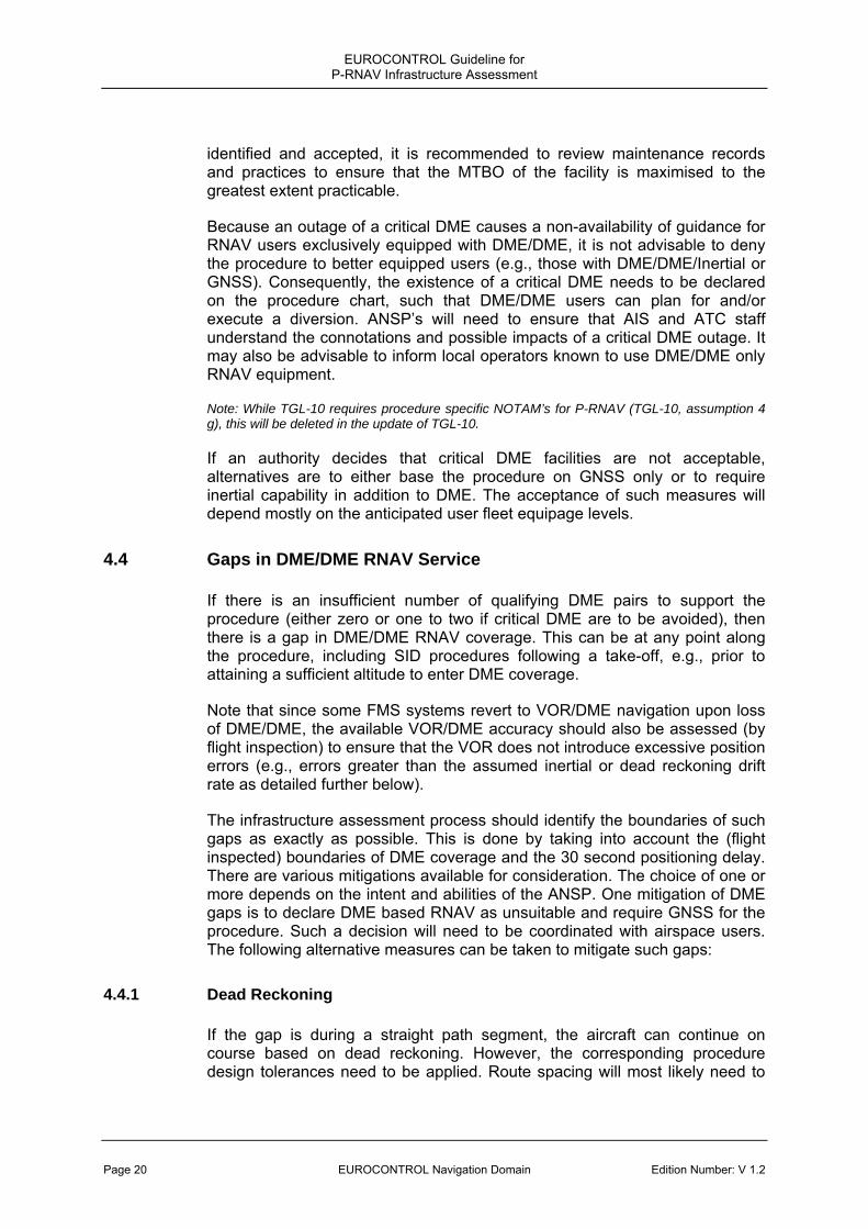
identified and accepted, it is recommended to review maintenance records and practices to ensure that the MTBO of the facility is maximised to the greatest extent practicable.
Because an outage of a critical DME causes a non-availability of guidance for RNAV users exclusively equipped with DME/DME, it is not advisable to deny the procedure to better equipped users (e.g., those with DME/DME/Inertial or GNSS). Consequently, the existence of a critical DME needs to be declared on the procedure chart, such that DME/DME users can plan for and/or execute a diversion. ANSP’s will need to ensure that AIS and ATC staff understand the connotations and possible impacts of a critical DME outage. It may also be advisable to inform local operators known to use DME/DME only RNAV equipment.
Note: While TGL-10 requires procedure specific NOTAM’s for P-RNAV (TGL-10, assumption 4 g), this will be deleted in the update of TGL-10.
If an authority decides that critical DME facilities are not acceptable, alternatives are to either base the procedure on GNSS only or to require inertial capability in addition to DME. The acceptance of such measures will depend mostly on the anticipated user fleet equipage levels.
4.4 Gaps in DME/DME RNAV Service
If there is an insufficient number of qualifying DME pairs to support the procedure (either zero or one to two if critical DME are to be avoided), then there is a gap in DME/DME RNAV coverage. This can be at any point along the procedure, including SID procedures following a take-off, e.g., prior to attaining a sufficient altitude to enter DME coverage.
Note that since some FMS systems revert to VOR/DME navigation upon loss of DME/DME, the available VOR/DME accuracy should also be assessed (by flight inspection) to ensure that the VOR does not introduce excessive position errors (e.g., errors greater than the assumed inertial or dead reckoning drift rate as detailed further below).
The infrastructure assessment process should identify the boundaries of such gaps as exactly as possible. This is done by taking into account the (flight inspected) boundaries of DME coverage and the 30 second positioning delay. There are various mitigations available for consideration. The choice of one or more depends on the intent and abilities of the ANSP. One mitigation of DME gaps is to declare DME based RNAV as unsuitable and require GNSS for the procedure. Such a decision will need to be coordinated with airspace users. The following alternative measures can be taken to mitigate such gaps:
4.4.1 Dead Reckoning
If the gap is during a straight path segment, the aircraft can continue on course based on dead reckoning. However, the corresponding procedure design tolerances need to be applied. Route spacing will most likely need to

EUROCONTROL Guideline for P-RNAV Infrastructure Assessment
Edition Number: V 1.2 EUROCONTROL Navigation Domain Page 21
be increased. This requires an appropriate iteration with the procedure design specialist and the airspace planning office.
4.4.2 Inertial Navigation Systems (INS or IRU)
If an ANSP chooses to require DME/DME/Inertial systems, it will make the procedure unavailable to users equipped with DME/DME only systems. It requires assessing the coasting performance of the inertial system given the navigation accuracy achieved prior to entering the gap, and the expected speed of the aircraft. The following set of criteria can be used for an assessment of inertial drift performance:
Initial position error is either the last DME/DME achieved accuracy or 0.17NM (95%, NSE) for a runway update. The inertial drift rate is 8NM/hour (95%). The speed to be assumed should generally correspond to the slowest expected user. This can be derived from PANS-OPS speed categories.
The gap that can be covered by inertial coasting is dependent on meeting the same 0.866NM (95%) NSE requirement as for DME/DME.
For SID’s, not all DME/DME/Inertial equipped aircraft are capable of performing a runway update (e.g., TOGA switch). If this is required, it needs to be appropriately communicated to airspace users.
Note that TGL-10 requires applicants to establish coasting times, which may be based on an acceptable drift rate model as agreed by the responsible aircraft operations authority.
4.4.3 Resiting Existing or Installing New DME Facilities
Using the geometry criteria outlined in section 2, the ideal location of one or more additional DME facilities can be determined. The desired locations then need to be matched up with realistic sites. Ideally, this will be in locations where the ANSP already operates other infrastructure. As the investment associated with this mitigation only caters to a small segment of airspace users, it is vital that this mitigation does not result in unreasonable cost to operators with modern avionics.
4.5 RNAV Offsets and Direct-To’s
Air Traffic Controllers frequently employ offsets to RNAV routes or procedures. These offsets can be quite large. Also, some waypoints of a route of procedure may be omitted by issuing a direct-to shortcut. Nominally, the assessment process described herein is not able to cater to such practices, e.g., the controller will remain responsible to maintain separation, terrain clearance and monitor route conformance. However, if airspace planners are able to specify a maximum offset or direct-to requirement, the engineering authority could potentially support this with an appropriate area based infrastructure assessment, following the same principles described in this

EUROCONTROL Guideline for P-RNAV Infrastructure Assessment
Page 22 EUROCONTROL Navigation Domain Edition Number: V 1.2
document. As an alternative to offsets, if operational requirements permit, it is advisable to design and publish a new RNAV procedure or route parallel to the existing route.
4.6 DME Transponders First Installed Prior to 1989
DME ground facilities installed prior to 1 January, 1989 are not required to meet all current Annex 10 requirements. Consequently, the compliance of such equipment to current Annex 10 requirements should be verified, in particular with respect to the timing reference. If the transponder is using the second pulse as a timing reference, special caution is needed both in the assessment of multipath and in the application of the accuracy error budget. The key concern with second pulse timing is that a delayed first pulse could distort the second pulse timing reference significantly. Consequently, the environment of the transponder needs to be analyzed to see if there are any potential reflectors (large building fronts or roofs, mountains or lakes) that could cause reflections into the procedure path with delays that correspond to the spacing of the DME pulse pairs. Such areas deserve specific attention during the flight inspection. A second issue is that the interrogator pulse spacing becomes relevant if the transponder uses second pulse timing, because the interrogator uses the first pulse as a reference. Consequently, the pulse spacing tolerance needs to be taken into account in the accuracy error budget. This can be done by adding the term into the Signal-in-Space allocation:
2Pr
22opagationengTolerancPulseSpacirTranspondeSIS σσσσ ++=
Where: σPulseSpacingTolerance = 0.02 NM
Remaining terms see sections 2.3.3. and 2.3.4
Depending on the multipath environment, this may lead to values of σSIS larger than 0.05NM.
EUROCONTROL Guideline for P-RNAV Infrastructure Assessment
Edition Number: V 1.2 EUROCONTROL Navigation Domain Page 23
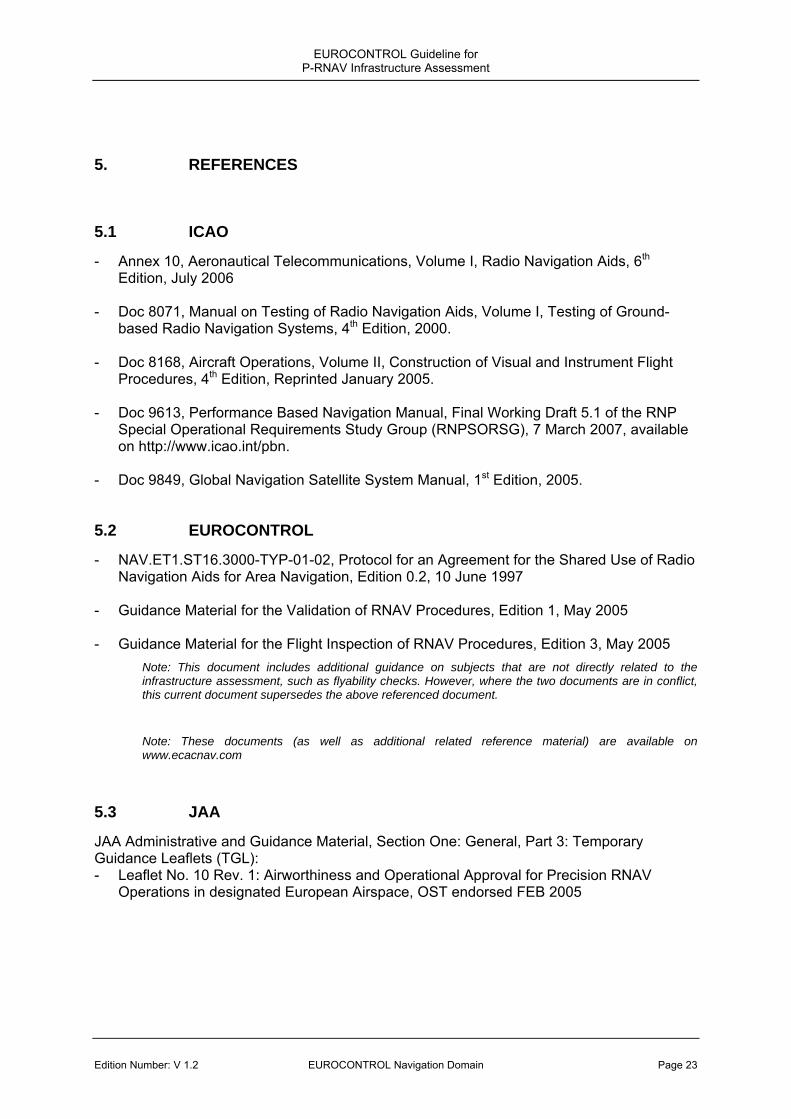
5. REFERENCES
5.1 ICAO
- Annex 10, Aeronautical Telecommunications, Volume I, Radio Navigation Aids, 6th Edition, July 2006
- Doc 8071, Manual on Testing of Radio Navigation Aids, Volume I, Testing of Ground-
based Radio Navigation Systems, 4th Edition, 2000. - Doc 8168, Aircraft Operations, Volume II, Construction of Visual and Instrument Flight
Procedures, 4th Edition, Reprinted January 2005. - Doc 9613, Performance Based Navigation Manual, Final Working Draft 5.1 of the RNP
Special Operational Requirements Study Group (RNPSORSG), 7 March 2007, available on http://www.icao.int/pbn.
- Doc 9849, Global Navigation Satellite System Manual, 1st Edition, 2005.
5.2 EUROCONTROL
- NAV.ET1.ST16.3000-TYP-01-02, Protocol for an Agreement for the Shared Use of Radio Navigation Aids for Area Navigation, Edition 0.2, 10 June 1997
- Guidance Material for the Validation of RNAV Procedures, Edition 1, May 2005 - Guidance Material for the Flight Inspection of RNAV Procedures, Edition 3, May 2005
Note: This document includes additional guidance on subjects that are not directly related to the infrastructure assessment, such as flyability checks. However, where the two documents are in conflict, this current document supersedes the above referenced document.
Note: These documents (as well as additional related reference material) are available on www.ecacnav.com
5.3 JAA
JAA Administrative and Guidance Material, Section One: General, Part 3: Temporary Guidance Leaflets (TGL): - Leaflet No. 10 Rev. 1: Airworthiness and Operational Approval for Precision RNAV
Operations in designated European Airspace, OST endorsed FEB 2005

EUROCONTROL Guideline for P-RNAV Infrastructure Assessment
Page 24 EUROCONTROL Navigation Domain Edition Number: V 1.2
6. ABBREVIATIONS AND ACRONYMS
3D Three - Dimensional ABAS Aircraft Based Augmentation System AGC Automatic Gain Control AIP Aeronautical Information Publication AMC Acceptable Means of Compliance (JAA) ANSP Air Navigation Service Provider APN Airspace, Network Planning and Navigation Division (EUROCONTROL) ATC Air Traffic Control ATM Air Traffic Management dB Decibel DME Distance Measuring Equipment Doc Document DOC Designated Operational Coverage FAA Federal Aviation Administration (U.S.A.) FMS Flight Management System FOM Figure Of Merit FTE Flight Technical Error GNSS Global Navigation Satellite System ICAO International Civil Aviation Organization IDENT Identification (of a Navigation Aid) ILS Instrument Landing System INS Inertial Navigation System IRS Inertial Reference System JAA Joint Aviation Authorities (Europe) NOTAM Notice to Airmen NSE Navigation System Error NM Nautical Mile PANS-OPS Procedures for Air Navigation Services - Operations PBN Performance Based Navigation PEE Position Estimation Error P-RNAV Precision RNAV RAIM Receiver Autonomous Integrity Monitoring RNAV Area Navigation RNP Required Navigation Performance SID Standard Instrument Departure SLA Service Level Agreement STAR Standard Instrument Arrival

EUROCONTROL Guideline for P-RNAV Infrastructure Assessment
Edition Number: V 1.2 EUROCONTROL Navigation Domain Page 25
TACAN Tactical Air Navigation (“Military DME” with additional bearing signals) TGL Temporary Guidance Leaflet (JAA) TMA Terminal Control Area TOGA Take-Off Go-Around (engine power setting and other functions) TSE Total System Error TSO Technical Standard Order (FAA) VOR Very High Frequency Omni-directional Range
---- End ----

EUROCONTROL
© European Organisation for the Safety of Air Navigation
(EUROCONTROL)
This document is published by EUROCONTROL for information purposes.
It may be copied in whole or in part, provided that EUROCONTROL is
mentioned as the source and it is not used for commercial purposes
(i.e. for financial gain). The information in this document may not be modified
without prior written permission from EUROCONTROL.
www.eurocontrol.int