Eurocode 8 Timber and Masonry structures - DPHU Background and Applications Eurocode 8 Timber and...
36
Brussels, 18-20 February 2008 – Dissemination of information workshop 1 EUROCODES Background and Applications Eurocode 8 Timber and Masonry structures E C Carvalho, Chairman TC250/SC8
Transcript of Eurocode 8 Timber and Masonry structures - DPHU Background and Applications Eurocode 8 Timber and...

Brussels, 18-20 February 2008 – Dissemination of information workshop 1
EUROCODESBackground and Applications
Eurocode 8Timber and Masonry structures
E C Carvalho, Chairman TC250/SC8

Brussels, 18-20 February 2008 – Dissemination of information workshop 2
EUROCODESBackground and Applications
EN 1998-1
Section 8
Specific rules for timber structures

Brussels, 18-20 February 2008 – Dissemination of information workshop 3
EUROCODESBackground and Applications
Timber is generally considered to be a good structural material for construction in seismic areas due to its:
• Reasonable strength in tension and in compression
• Light weight
both being relevant properties for the seismic performance of structures

Brussels, 18-20 February 2008 – Dissemination of information workshop 4
EUROCODESBackground and Applications
Typical values of unit mass and strength for various structural materials and corresponding ratios
Structural material
Unit mass ρ
(kg/m3)
Strength fRange of
values(MPa)
Ratio f/ρ(10-3 MPa /
kg/m3)
Wood Compression and tension 550 20 – 30 35 – 55
Structural steel Compression and tension 7800 275 - 355 35 - 45
Compression 2400 25 - 80 10 - 30Concrete
Tension 2400 2 – 3,5 0,8 - 1,5Reinforced concrete Bending 2500 10 - 25 4 - 10
Compression 2100 4 - 8 1,9 – 3,8Masonry
Tension 2100 0,3 – 0,5 0,1 - 02

Brussels, 18-20 February 2008 – Dissemination of information workshop 5
EUROCODESBackground and Applications
The good performance of wood is reflect by its range of values f/ρ similar to structural steel
• response of timber elements up to failure is approximately linear elastic
• timber elements do not present large deformational ductility
• collapse is sudden, mostly associated with defects inherent to the natural origin of timber
but

Brussels, 18-20 February 2008 – Dissemination of information workshop 6
EUROCODESBackground and Applications
For timber structures EN 1998-1 distinguishes between dissipative and low-dissipativestructural behaviour (as for concrete, steel and composite)
However, in view of the limited ability of timber to behave nonlinearly:
• Energy dissipation should be mostly in connections
• Timber elements should respond linearly
Some (little) NL behaviour in compression perpendicular to grain may be expected.
Tension perpendicular to grain markedly brittle.
Brussels, 18-20 February 2008 – Dissemination of information workshop 7
EUROCODESBackground and Applications
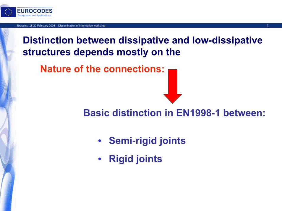
Distinction between dissipative and low-dissipative structures depends mostly on the
Nature of the connections:
Basic distinction in EN1998-1 between:
• Semi-rigid joints
• Rigid joints

Brussels, 18-20 February 2008 – Dissemination of information workshop 8
EUROCODESBackground and Applications
Dissipation of energy in connections:
1. Cyclic yielding of metallic (normally steel) dowel type fasteners of the connections (nails, staples, screws, dowels or bolts)
Stable mechanism with large hysteretic cycles
2. Crushing of the wood fibres bearing against the dowel
Thin hysteretic loops with significant degradation (due to the cavity being formed in front of the dowel)
Two main sources:

Brussels, 18-20 February 2008 – Dissemination of information workshop 9
EUROCODESBackground and Applications
Response of the connections depends mostly on the interaction between the two mechanisms
Achieve good dissipative behaviour with proper balance between:
• Wood crushing
More significant parameter:Slenderness of the dowel type element
• Dowel yielding

Brussels, 18-20 February 2008 – Dissemination of information workshop 10
EUROCODESBackground and Applications
Ductility Classes
Dissipative structures
Ductility Class Medium (DCM)
Choice of the DCs left to the designer but National Authorities may limit the use of the various DCs
Ductility Class High (DCH)
Low-dissipative structures
Ductility Class Low (DCL)

Brussels, 18-20 February 2008 – Dissemination of information workshop 11
EUROCODESBackground and Applications
Ductility classification depends mostly on:
• Structural type/redundancy
Determine properties of dissipative zones by testing (prEN 12512)
or
Use deemed to satisfy rules (in EN 1998-1)
• Nature of structural connections

Brussels, 18-20 February 2008 – Dissemination of information workshop 12
EUROCODESBackground and Applications
Materials and properties of dissipative zones:• General requirements as in EN 1995-1-1
(and EN 1993-1 for steel elements)
• Additional requirements for DCM and DCHGlued joints may not be considered dissipativeDensity of particle board panels ≥ 650 kg/m3
Thickness of particle board and fibre board panels ≥ 13 mmThickness of plywood sheating ≥ 9 mm
Nailed shear panel systems superior to conventional bracingAvoid pull out of nails under transverse loading (avoid smooth nails or apply provisions against withdrawal)

Brussels, 18-20 February 2008 – Dissemination of information workshop 13
EUROCODESBackground and Applications
Behaviour factors DCM and DCH (q = 1,5 for DCL)
Structural types DCM DCHWall panels with glued diaphragms connected with nails and bolts
Glued panelsq = 2,0
Nailed panelsq = 3,0
Wall panels with nailed diaphragms connected with nails and bolts
-Nailed panels
q = 5,0(q = 4,0)
Trusses Doweled and boltedjoints
q = 2,0
Nailed jointsq = 3,0
Mixed structures with timber framing and non-load bearing infills
q = 2,0 -
Hyperstatic portal frame with doweled and bolted joints
μ ≥ 4q = 2,5
μ ≥ 6q = 4,0
(q = 2,5)( ) for lower slenderness dowels

Brussels, 18-20 February 2008 – Dissemination of information workshop 14
EUROCODESBackground and Applications
Underlying requirements for the allowed q factors for timber structures:
Dissipative zones able to sustain, without strength degradation larger than 20%, 3 fully reversed cycles at ductility demand of:
Rotational ductility in portal frames or distortional displacement ductility in shear panels
• μ = 4 for DCM
• μ = 6 for DCH
Buildings regular in elevation (if non-regular, reduce by 20% the values indicated for q)
Brussels, 18-20 February 2008 – Dissemination of information workshop 15
EUROCODESBackground and Applications
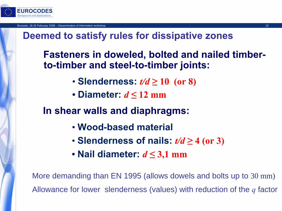
Deemed to satisfy rules for dissipative zones
More demanding than EN 1995 (allows dowels and bolts up to 30 mm)
Allowance for lower slenderness (values) with reduction of the q factor
Fasteners in doweled, bolted and nailed timber-to-timber and steel-to-timber joints:
• Slenderness: t/d ≥ 10 (or 8)• Diameter: d ≤ 12 mm
In shear walls and diaphragms:
• Slenderness of nails: t/d ≥ 4 (or 3)• Nail diameter: d ≤ 3,1 mm
• Wood-based material

Brussels, 18-20 February 2008 – Dissemination of information workshop 16
EUROCODESBackground and Applications
Detailing for DCM and DCHDissipative zones in parts of the structure not affecting its overall stability
• Connections
Connections in compression members prevented from separatingTight fitted bolts and dowels in pre-drilled holes.
Dowels, smooth nails and staples with provisions against withdrawalProvisions against splitting (metal or plywood plates)
Maximum diameter of bolts and dowels: 16 mm (larger diameters allowed with toothed ring connectors for confinement)

Brussels, 18-20 February 2008 – Dissemination of information workshop 17
EUROCODESBackground and Applications
Detailing for DCM and DCHIncrease the effectiveness of the sheating material and edge connections
• Diaphragms (rules more demanding than EN 1995-1-1)
Disregard allowance in EN1995-1-1 for increased resistance and increased spacing of edge connectors
Continuity of beams
Height-to-width ratio (slenderness) of beams: t/d ≤ 4 (in the absence of transverse blocking)
Reduce spacing of fasteners if ag S ≥ 0,2 g (respect minimum spacing of EN 1995-1-1; provide «generous» size of timber elements to allow space for nailing)
Brussels, 18-20 February 2008 – Dissemination of information workshop 18
EUROCODESBackground and Applications
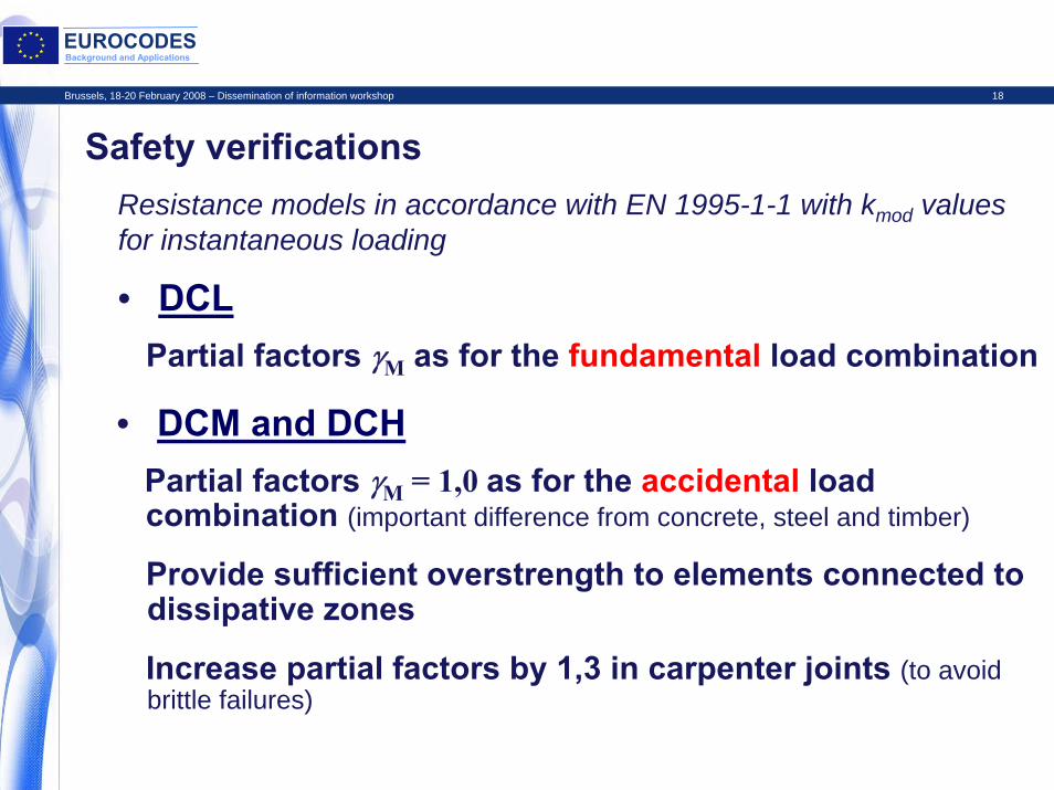
Safety verificationsResistance models in accordance with EN 1995-1-1 with kmod values for instantaneous loading
• DCLPartial factors γM as for the fundamental load combination
Provide sufficient overstrength to elements connected to dissipative zones
Increase partial factors by 1,3 in carpenter joints (to avoid brittle failures)
• DCM and DCHPartial factors γM = 1,0 as for the accidental load combination (important difference from concrete, steel and timber)

Brussels, 18-20 February 2008 – Dissemination of information workshop 19
EUROCODESBackground and Applications
EN 1998-1
Section 9
Specific rules for masonry structures

Brussels, 18-20 February 2008 – Dissemination of information workshop 20
EUROCODESBackground and Applications
Masonry is generally considered to present specific problems for construction in seismic areas due to its:
• Poor strength in tension• Weight
• Brittle response in tension and compression
all being relevant properties for the seismic performance of structures

Brussels, 18-20 February 2008 – Dissemination of information workshop 21
EUROCODESBackground and Applications
Typical values of unit mass and strength for various structural materials and corresponding ratios
Structural material
Unit mass ρ
(kg/m3)
Strength fRange of
values(MPa)
Ratio f/ρ(10-3 MPa /
kg/m3)
Wood Compression and tension 550 20 – 30 35 – 55
Structural steel Compression and tension 7800 275 - 355 35 - 45
Compression 2400 25 - 80 10 - 30Concrete
Tension 2400 2 – 3,5 0,8 - 1,5Reinforced concrete Bending 2500 10 - 25 4 - 10
Compression 2100 4 - 8 1,9 – 3,8MasonryTension 2100 0,3 – 0,5 0,1 - 02

Brussels, 18-20 February 2008 – Dissemination of information workshop 22
EUROCODESBackground and Applications
The specific problems of the seismic performance of masonry is reflect by the low of values f/ρ both in compression and tension
• Densely distributed wallsMasonry structures may present:
• Dissipation of energy in a distributed fashion by widespread cracking (which has to be controlled either by tying or by distributed reinforcement)
however
• Good robustness (if all elements are appropriately tied together)
Hence the seismic behaviour of masonry structures may be very much influenced by design

Brussels, 18-20 February 2008 – Dissemination of information workshop 23
EUROCODESBackground and Applications
For masonry structures EN 1998-1 distinguishes between:
• Unreinforced masonry construction
Unreinforced masonry akin to the concept of Low-Dissipative structures
Use of unreinforced masonry (EN1996) is recommended only for Low seismicity cases (recommended NDP)
• Confined masonry construction
• Reinforced masonry construction
Unreinforced masonry (EN1998-1) may not be used if ag S > 0,20 g (recommended NDP that should depend on the requirements for materials properties)

Brussels, 18-20 February 2008 – Dissemination of information workshop 24
EUROCODESBackground and Applications
Materials and bonding patterns• General requirements as in EN 1996-1-1• Additional requirements (all recommended NDPs)
Minimum strength of unitsNormal to bed face: fb ≥ 5 N/mm2
Parallel to bed face: fb ≥ 2 N/mm2
Minimum strength of mortarUnreinforced and confined: fm ≥ 5 N/mm2
Reinforced: fm ≥ 10 N/mm2
Masonry bond for perpend jointsFully grouted joints with mortarUngrouted jointsUngrouted with mechanical interlocking
Large number of NDPs reflect and is intended to accommodate the large variety of materials and construction practices for masonry across Europe

Brussels, 18-20 February 2008 – Dissemination of information workshop 25
EUROCODESBackground and Applications
Upper limits of behaviour factors(recommended NDPs)
Type of construction Q
Unreinforced masonry in accordance with EN 1996 alone 1,5
Unreinforced masonry in accordance with EN 1998 1,5 – 2,5
Confined masonry 2,0 – 3,0
Reinforced masonry 2,5 – 3,0

Brussels, 18-20 February 2008 – Dissemination of information workshop 26
EUROCODESBackground and Applications
Structural analysis
• Uncracked or cracked (recommended) stiffness
• Cracked stiffness approx. 50%
• If appropriate (existance of coupling beams/spandrels) a frame analysis may be used
• Redistribution of base shear among walls

Brussels, 18-20 February 2008 – Dissemination of information workshop 27
EUROCODESBackground and Applications
Construction rules and geometric conditions• General
Connections between floors and walls
Floor continuity and effective diaphragm effect
Shear walls in two orthogonal directions• Shear walls
Minimum effective thickness tef,min
Maximum height to thickness ratio (hef /tef )max
Minimum length to height ratio (l/h)min

Brussels, 18-20 February 2008 – Dissemination of information workshop 28
EUROCODESBackground and Applications
Geometric requirements for shear wallsMasonry type tef,min (mm) (hef /tef)max (l/h)min
Unreinforced, with natural stone units
350 9 0,5
Unreinforced, with any other type of units
240 12 0,4
Unreinforced, with any other type of units, in cases of low seismicity
170 15 0,35
Confined masonry 240 15 0,3Reinforced masonry 240 15 No
restrictiontef thickness of the wall (EN 1996-1-1);hef effective height of the wall (EN 1996-1-1);h greater clear height of the openings adjacent to the wall;l length of the wall.

Brussels, 18-20 February 2008 – Dissemination of information workshop 29
EUROCODESBackground and Applications
Additional requirements for unreinforced masonry
• Horizontal concrete beams or steel ties at floor levels in all walls
All beams (or ties) interconnected
• Concrete beams reinforcement with at least 2 cm2
Peripheral beams essential

Brussels, 18-20 February 2008 – Dissemination of information workshop 30
EUROCODESBackground and Applications
Additional requirements for confined masonry
• Horizontal and vertical confining elements bonded together and cast against the masonry
• Longitudinal reinforcement of confining elements with at least 3 cm2 or 1% of cross sectional area
• Confining elements larger than 150 mm (interconnect the two masonry leaves in case of double-leaf masonry)
• Stirrups d ≥ 5 mm spaced ≤ 150 mm
• Reinforcing steel Class B or C (EN 1992-1-1)
• Lap splices longer than 60 diameters

Brussels, 18-20 February 2008 – Dissemination of information workshop 31
EUROCODESBackground and Applications
Additional requirements for confined masonry (cont.)
• Vertical confining elements:At both edges of walls
At both sides of openings larger than 1,5 m2
Within wall spaced, at most, 5 m
At wall intersections more than 1,5 from other confining element
• Horizontal confining elements:At every floor levelWith vertical spacing not larger than 4 m

Brussels, 18-20 February 2008 – Dissemination of information workshop 32
EUROCODESBackground and Applications
Additional requirements for reinforced masonry
• Horizontal reinforcement in bed joints spaced not more than 600 mm
• Horizontal reinforcement not less than 0,05% of cross sectional area of wall
• Reinforcing steel not less than 4 mm in diameter, bent around bars at edges of walls
• Vertical reinforcement (in pockets or holes in the units) not less than 0,08% of cross sectional area of wall
• Reinforcing steel Class B or C (EN 1992-1-1)
• Lap splices longer than 60 diameters

Brussels, 18-20 February 2008 – Dissemination of information workshop 33
EUROCODESBackground and Applications
Additional requirements for reinforced masonry (cont.)
• Vertical reinforcement not less than 200 mm2 and provided with 5 mm stirrups at 150 mm spacing:
At both free edges of all walls
At every wall intersection
Within wall spaced, at most, 5 m

Brussels, 18-20 February 2008 – Dissemination of information workshop 34
EUROCODESBackground and Applications
Safety verificationsResistance models in accordance with EN 1996-1-1
Specific partial factor γm for masonry and γs for steel to be defined as NDPs
Recommended values:
For masonry:γm = 2/3 of the value from EN 1996-1-1, but
not less than 1,5
For steel:γs = 1,0

Brussels, 18-20 February 2008 – Dissemination of information workshop 35
EUROCODESBackground and Applications
“Simple masonry buildings”
Concept applicable only for Importance Classes I and II
Explicit safety verification not mandatory
Safety verification implicit with the fulfilment of some geometrical conditions

Brussels, 18-20 February 2008 – Dissemination of information workshop 36
EUROCODESBackground and Applications
“Simple masonry buildings” conditions:
Regularity in planCompact in plan shapeShear walls in both orthogonal directions and approximately symmetrical
Maximum number of storeys and minimum relative area of walls depending on ag S and type of masonry
Two parallel walls in both orthogonal directions, placed close to the edges of the building75% of weight supported by shear wallsVariation of mass and wall area between adjacent storeys limited to 20% (recommended NDP)