Eurocode 2: Design of concrete structures - egr.msu.edu Research PhD/Euro Code Concrete... ·...
100
BRITISH STANDARD BS EN 1992-1-2:2004 Eurocode 2: Design of concrete structures — Part 1-2: General rules — Structural fire design The European Standard EN 1992-1-2:2004 has the status of a British Standard ICS 13.220.50; 91.010.30; 91.080.40 Licensed Copy: na na, Imperial College of Science and Technology (JISC), Mon Jun 25 17:42:35 GMT+00:00 2007, Uncontrolled Copy, (c) BSI
Transcript of Eurocode 2: Design of concrete structures - egr.msu.edu Research PhD/Euro Code Concrete... ·...
BRITISH STANDARD BS EN 1992-1-2:2004
Eurocode 2: Design of concrete structures —
Part 1-2: General rules — Structural fire design
The European Standard EN 1992-1-2:2004 has the status of a British Standard
ICS 13.220.50; 91.010.30; 91.080.40
���������������� ������������������������������� �������������
Lice
nsed
Cop
y: n
a na
, Im
peria
l Col
lege
of S
cien
ce a
nd T
echn
olog
y (J
ISC
), M
on J
un 2
5 17
:42:
35 G
MT
+00
:00
2007
, Unc
ontr
olle
d C
opy,
(c)
BS
I
BS EN 1992-1-2:2004
This British Standard was published under the authority of the Standards Policy and Strategy Committee on 9 February 2005
© BSI 9 February 2005
ISBN 0 580 45414 2
National forewordThis British Standard is the official English language version of EN 1992-1-2:2004. It supersedes DD ENV 1992-1-2:1996 which is withdrawn.
The structural Eurocodes are divided into packages by grouping Eurocodes for each of the main materials, concrete, steel, composite concrete and steel, timber, masonry and aluminium, this is to enable a common date of withdrawal (DOW) for all the relevant parts that are needed for a particular design. The conflicting national standards will be withdrawn at the end of the coexistence period, after all the EN Eurocodes of a package are available.
Following publication of the EN, there is a period of 2 years allowed for the national calibration period during which the national annex is issued, followed by a three year coexistence period. During the coexistence period Member States will be encouraged to adapt their national provisions to withdraw conflicting national rules before the end of the coexistent period. The Commission in consultation with Member States is expected to agree the end of the coexistence period for each package of Eurocodes.
At the end of this co-existence period, any national standards will be withdrawn. In this case, there are no corresponding national standards
The UK participation in its preparation was entrusted by Technical Committee B/525, Building and civil engineering structures, to Subcommittee B/525/2, Structural use of concrete, which has the responsibility to:
A list of organizations represented on this subcommittee can be obtained on request to its secretary.
Where a normative part of this EN allows for a choice to be made at the national level, the range and possible choice will be given in the normative text, and a note will qualify it as a Nationally Determined Parameter (NDP). NDPs can be a specific value for a factor, a specific level or class, a particular method or a particular application rule if several are proposed in the EN.
To enable EN 1992-1-2 to be used in the UK, the NDPs will be published in a National Annex, which will be made available by BSI in due course, after pubic consultation has taken place.
Cross-referencesThe British Standards which implement international or European publications referred to in this document may be found in the BSI Catalogue under the section entitled “International Standards Correspondence Index”, or by using the “Search” facility of the BSI Electronic Catalogue or of British Standards Online.
This publication does not purport to include all the necessary provisions of a contract. Users are responsible for its correct application.
Compliance with a British Standard does not of itself confer immunity from legal obligations.
— aid enquirers to understand the text;
— present to the responsible international/European committee any enquiries on the interpretation, or proposals for change, and keep the UK interests informed;
— monitor related international and European developments and promulgate them in the UK.
Summary of pages
This document comprises a front cover, an inside front cover, the EN title page, pages 2 to 97 and a back cover.
The BSI copyright notice displayed in this document indicates when the document was last issued.
Amendments issued since publication
Amd. No. Date Comments
Lice
nsed
Cop
y: n
a na
, Im
peria
l Col
lege
of S
cien
ce a
nd T
echn
olog
y (J
ISC
), M
on J
un 2
5 17
:42:
35 G
MT
+00
:00
2007
, Unc
ontr
olle
d C
opy,
(c)
BS
I
EUROPEAN STANDARD
NORME EUROPÉENNE
EUROPÄISCHE NORM
EN 1992-1-2
December 2004
ICS 13.220.50; 91.010.30; 91.080.40 Supersedes ENV 1992-1-2:1995
English version
Eurocode 2: Design of concrete structures - Part 1-2: General rules - Structural fire design
Eurocode 2: Calcul des structures en béton - Partie 1-2: Règles générales - Calcul du comportement au feu
Eurocode 2: Planung von Stahlbeton- und Spannbetontragwerken - Teil 1-2: Allgemeine Regeln -
Tragwerksbemessung für den Brandfall
This European Standard was approved by CEN on 8 July 2004. CEN members are bound to comply with the CEN/CENELEC Internal Regulations which stipulate the conditions for giving this European Standard the status of a national standard without any alteration. Up-to-date lists and bibliographical references concerning such national standards may be obtained on application to the Central Secretariat or to any CEN member. This European Standard exists in three official versions (English, French, German). A version in any other language made by translation under the responsibility of a CEN member into its own language and notified to the Central Secretariat has the same status as the official versions. CEN members are the national standards bodies of Austria, Belgium, Cyprus, Czech Republic, Denmark, Estonia, Finland, France, Germany, Greece, Hungary, Iceland, Ireland, Italy, Latvia, Lithuania, Luxembourg, Malta, Netherlands, Norway, Poland, Portugal, Slovakia, Slovenia, Spain, Sweden, Switzerland and United Kingdom.
EUROPEAN COMMITTEE FOR STANDARDIZATION C O M I T É E U R O P É E N D E N O R M A L I S A T I O N E U R O P Ä I S C H E S K O M I T E E F Ü R N O R M U N G
Management Centre: rue de Stassart, 36 B-1050 Brussels
© 2004 CEN All rights of exploitation in any form and by any means reserved worldwide for CEN national Members.
Ref. No. EN 1992-1-2:2004: E
Lice
nsed
Cop
y: n
a na
, Im
peria
l Col
lege
of S
cien
ce a
nd T
echn
olog
y (J
ISC
), M
on J
un 2
5 17
:42:
35 G
MT
+00
:00
2007
, Unc
ontr
olle
d C
opy,
(c)
BS
I
EN 1992-1-2:2004 (E)
2
Contents List 1 General 1.1 Scope 1.1.1 Scope of Eurocode 2 1.1.2 Scope of Part 1-2 of Eurocode 2 1.2 Normative references 1.3 Assumptions 1.4 Distinctions between principles and application rules 1.5 Definitions 1.6 Symbols 1.6.1 Supplementary symbols to EN 1992-1-1 1.6.2 Supplementary subscripts to EN 1992-1-1 2 Basis of design 2.1 Requirements 2.1.1 General 2.1.2 Nominal fire exposure 2.1.3 Parametric fire exposure 2.2 Actions 2.3 Design values of material properties 2.4 Verification methods
2.4.1 General 2.4.2 Member analysis 2.4.3 Analysis of part of the structure 2.4.4 Global structural analysis
3 Material properties 3.1 General 3.2 Strength and deformation properties at elevated temperatures
3.2.1 General 3.2.2 Concrete
3.2.2.1 Concrete under compression 3.2.2.2 Tensile strength
3.2.3 Reinforcing steel 3.2.4 Prestressing steel
3.3 Thermal and physical properties of concrete with siliceous and calcareous aggregates 3.3.1 Thermal elongation
3.3.2 Specific heat 3.3.3 Thermal conductivity 3.4 Thermal elongation of reinforcing and prestressing steel 4 Design procedures 4.1 General 4.2 Simplified calculation method
4.2.1 General 4.2.2 Temperature profiles 4.2.3 Reduced cross-section 4.2.4 Strength reduction 4.2.4.1 General
Lice
nsed
Cop
y: n
a na
, Im
peria
l Col
lege
of S
cien
ce a
nd T
echn
olog
y (J
ISC
), M
on J
un 2
5 17
:42:
35 G
MT
+00
:00
2007
, Unc
ontr
olle
d C
opy,
(c)
BS
I

EN 1992-1-2:2004 (E)
3
4.2.4.2 Concrete 4.2.4.3 Steel
4.3 Advanced calculation methods 4.3.1 General 4.3.2 Thermal response 4.3.3 Mechanical response 4.3.4 Validation of advanced calculation models 4.4 Shear, torsion and anchorage 4.5 Spalling 4.5.1 Explosive spalling 4.5.2 Falling off of concrete 4.6 Joints 4.7 Protective layers 5 Tabulated data 5.1 Scope 5.2 General design rules 5.3 Columns
5.3.1 General 5.3.2 Method A for assessing fire resistance of columns 5.3.3 Method B for assessing fire resistance of columns
5.4 Walls 5.4.1 Non load-bearing walls (partitions) 5.4.2 Load-bearing solid walls 5.4.3 Fire walls
5.5 Tensile members 5.6 Beams
5.6.1 General 5.6.2 Simply supported beams 5.6.3 Continuous beams 5.6.4 Beams exposed on all sides
5.7 Slabs 5.7.1 General 5.7.2 Simply supported solid slabs 5.7.3 Continuous solid slabs 5.7.4 Flat slabs 5.7.5 Ribbed slabs
6 High strength concrete (HSC) 6.1 General 6.2 Spalling 6.3 Thermal properties 6.4 Structural design 6.4.1 Calculation of load-carrying capacity 6.4.2 Simplified calculation method 6.4.2.1 Columns and walls 6.4.2.2 Beams and slabs 6.4.3 Tabulated data
Lice
nsed
Cop
y: n
a na
, Im
peria
l Col
lege
of S
cien
ce a
nd T
echn
olog
y (J
ISC
), M
on J
un 2
5 17
:42:
35 G
MT
+00
:00
2007
, Unc
ontr
olle
d C
opy,
(c)
BS
I

EN 1992-1-2:2004 (E)
4
Informative annexes A Temperature profiles B Simplified calculation methods C Buckling of columns under fire conditions D Calculation methods for shear, torsion and anchorage E Simplified calculation method for beams and slabs Foreword This European Standard EN 1992-1-2 , “Design of concrete structures - Part 1-2 General rules - Structural fire design", has been prepared by Technical Committee CEN/TC250 ”Structural Eurocodes”, the Secretariat of which is held by BSI. CEN/TC250 is responsible for all Structural Eurocodes. This European Standard shall be given the status of a National Standard, either by publication of an identical text or by endorsement, at the latest by June 2005, and conflicting National Standards shall be withdrawn at latest by March 2010. This European standard supersedes ENV 1992-1-2: 1995. According to the CEN-CENELEC Internal Regulations, the National Standard Organisations of the following countries are bound to implement these European Standard: Austria, Belgium, Cyprus, Czech Republic, Denmark, Estonia, Finland, France, Germany, Greece, Hungary, Iceland, Ireland, Italy, Latvia, Lithuania, Luxembourg, Malta, Netherlands, Norway, Poland, Portugal, Slovakia, Slovenia, Spain, Sweden, Switzerland and United Kingdom. Background of the Eurocode programme In 1975, the Commission of the European Community decided on an action programme in the field of construction, based on article 95 of the Treaty. The objective of the programme was the elimination of technical obstacles to trade and the harmonisation of technical specifications. Within this action programme, the Commission took the initiative to establish a set of harmonised technical rules for the design of construction works which, in a first stage, would serve as an alternative to the national rules in force in the Member States and, ultimately, would replace them. For fifteen years, the Commission, with the help of a Steering Committee with Representatives of Member States, conducted the development of the Eurocodes programme, which led to the first generation of European codes in the 1980s. In 1989, the Commission and the Member States of the EU and EFTA decided, on the basis of an agreement1 between the Commission and CEN, to transfer the preparation and the 1 Agreement between the Commission of the European Communities and the European Committee for Standardisation (CEN) concerning the
work on EUROCODES for the design of building and civil engineering works (BC/CEN/03/89).
Lice
nsed
Cop
y: n
a na
, Im
peria
l Col
lege
of S
cien
ce a
nd T
echn
olog
y (J
ISC
), M
on J
un 2
5 17
:42:
35 G
MT
+00
:00
2007
, Unc
ontr
olle
d C
opy,
(c)
BS
I

EN 1992-1-2:2004 (E)
5
publication of the Eurocodes to the CEN through a series of Mandates, in order to provide them with a future status of European Standard (EN). This links de facto the Eurocodes with the provisions of all the Council’s Directives and/or Commission’s Decisions dealing with European standards (e.g. the Council Directive 89/106/EEC on construction products - CPD - and Council Directives 93/37/EEC, 92/50/EEC and 89/440/EEC on public works and services and equivalent EFTA Directives initiated in pursuit of setting up the internal market). The Structural Eurocode programme comprises the following standards generally consisting of a number of Parts:
EN 1990 Eurocode: Basis of Structural Design EN 1991 Eurocode 1: Actions on structures EN 1992 Eurocode 2: Design of concrete structures EN 1993 Eurocode 3: Design of steel structures EN 1994 Eurocode 4: Design of composite steel and concrete structures EN 1995 Eurocode 5: Design of timber structures EN 1996 Eurocode 6: Design of masonry structures EN 1997 Eurocode 7: Geotechnical design EN 1998 Eurocode 8: Design of structures for earthquake resistance EN 1999 Eurocode 9: Design of aluminium structures Eurocode standards recognise the responsibility of regulatory authorities in each Member State and have safeguarded their right to determine values related to regulatory safety matters at national level where these continue to vary from State to State. Status and field of application of Eurocodes The Member States of the EU and EFTA recognise that Eurocodes serve as reference documents for the following purposes : – as a means to prove compliance of building and civil engineering works with the essential
requirements of Council Directive 89/106/EEC, particularly Essential Requirement N°1 – Mechanical resistance and stability – and Essential Requirement N°2 – Safety in case of fire ;
– as a basis for specifying contracts for construction works and related engineering services ; – as a framework for drawing up harmonised technical specifications for construction products
(ENs and ETAs) The Eurocodes, as far as they concern the construction works themselves, have a direct relationship with the Interpretative Documents2 referred to in Article 12 of the CPD, although they are of a different nature from harmonised product standards3. Therefore, technical aspects arising from the Eurocodes work need to be adequately considered by CEN Technical
2 According to Art. 3.3 of the CPD, the essential requirements (ERs) shall be given concrete form in interpretative documents for the creation of
the necessary links between the essential requirements and the mandates for harmonised ENs and ETAGs/ETAs. 3 According to Art. 12 of the CPD the interpretative documents shall :
a) give concrete form to the essential requirements by harmonising the terminology and the technical bases and indicating classes or levels for each requirement where necessary ;
b) indicate methods of correlating these classes or levels of requirement with the technical specifications, e.g. methods of calculation and of proof, technical rules for project design, etc. ;
c) serve as a reference for the establishment of harmonised standards and guidelines for European technical approvals. The Eurocodes, de facto, play a similar role in the field of the ER 1 and a part of ER 2.
Lice
nsed
Cop
y: n
a na
, Im
peria
l Col
lege
of S
cien
ce a
nd T
echn
olog
y (J
ISC
), M
on J
un 2
5 17
:42:
35 G
MT
+00
:00
2007
, Unc
ontr
olle
d C
opy,
(c)
BS
I

EN 1992-1-2:2004 (E)
6
Committees and/or EOTA Working Groups working on product standards with a view to achieving full compatibility of these technical specifications with the Eurocodes. The Eurocode standards provide common structural design rules for everyday use for the design of whole structures and component products of both a traditional and an innovative nature. Unusual forms of construction or design conditions are not specifically covered and additional expert consideration will be required by the designer in such cases. National Standards implementing Eurocodes The National Standards implementing Eurocodes will comprise the full text of the Eurocode (including any annexes), as published by CEN, which may be preceded by a National title page and National foreword, and may be followed by a National Annex. The National Annex may only contain information on those parameters which are left open in the Eurocode for national choice, known as Nationally Determined Parameters, to be used for the design of buildings and civil engineering works to be constructed in the country concerned, i.e. :
– values and/or classes where alternatives are given in the Eurocode, – values to be used where a symbol only is given in the Eurocode, – country specific data (geographical, climatic, etc.), e.g. snow map, – the procedure to be used where alternative procedures are given in the Eurocode, – decisions on the application of informative annexes, – references to non-contradictory complementary information to assist the user to apply the
Eurocode. Links between Eurocodes and products harmonised technical specifications (ENs and ETAs) There is a need for consistency between the harmonised technical specifications for construction products and the technical rules for works4. Furthermore, all the information accompanying the CE Marking of the construction products which refer to Eurocodes should clearly mention which Nationally Determined Parameters have been taken into account. Additional information specific to EN 1992-1-2 EN 1992- 1-2 describes the Principles, requirements and rules for the structural design of buildings exposed to fire, including the following aspects. Safety requirements EN 1992-1-2 is intended for clients (e.g. for the formulation of their specific requirements), designers, contractors and relevant authorities. The general objectives of fire protection are to limit risks with respect to the individual and society, neighbouring property, and where required, environment or directly exposed property, in the case of fire.
4 see Art.3.3 and Art.12 of the CPD, as well as clauses 4.2, 4.3.1, 4.3.2 and 5.2 of ID 1.
Lice
nsed
Cop
y: n
a na
, Im
peria
l Col
lege
of S
cien
ce a
nd T
echn
olog
y (J
ISC
), M
on J
un 2
5 17
:42:
35 G
MT
+00
:00
2007
, Unc
ontr
olle
d C
opy,
(c)
BS
I
EN 1992-1-2:2004 (E)
7
Construction Products Directive 89/106/EEC gives the following essential requirement for the limitation of fire risks: "The construction works must be designed and build in such a way, that in the event of an outbreak of fire
- the load bearing resistance of the construction can be assumed for a specified period of time
- the generation and spread of fire and smoke within the works are limited - the spread of fire to neighbouring construction works is limited - the occupants can leave the works or can be rescued by other means - the safety of rescue teams is taken into consideration".
According to the Interpretative Document N° 2 "Safety in case of fire" the essential requirement may be observed by following various possibilities for fire safety strategies prevailing in the Member states like conventional fire scenarios (nominal fires) or “natural” (parametric) fire scenarios, including passive and/or active fire protection measures. The fire parts of Structural Eurocodes deal with specific aspects of passive fire protection in terms of designing structures and parts thereof for adequate load bearing resistance and for limiting fire spread as relevant. Required functions and levels of performance can be specified either in terms of nominal (standard) fire resistance rating, generally given in national fire regulations or by referring to fire safety engineering for assessing passive and active measures, see EN 1991-1-2.
Supplementary requirements concerning, for example: - the possible installation and maintenance of sprinkler systems, - conditions on occupancy of building or fire compartment, - the use of approved insulation and coating materials, including their maintenance,
are not given in this document, because they are subject to specification by the competent authority.
Numerical values for partial factors and other reliability elements are given as recommended values that provide an acceptable level of reliability. They have been selected assuming that an appropriate level of workmanship and of quality management applies.
Design procedures
A full analytical procedure for structural fire design would take into account the behaviour of the structural system at elevated temperatures, the potential heat exposure and the beneficial effects of active and passive fire protection systems, together with the uncertainties associated with these three features and the importance of the structure (consequences of failure). At the present time it is possible to undertake a procedure for determining adequate performance which incorporates some, if not all, of these parameters and to demonstrate that the structure, or its components, will give adequate performance in a real building fire. However, where the procedure is based on a nominal (standard) fire the classification system, which call for specific periods of fire resistance, takes into account (though not explicitly), the features and uncertainties described above.
Lice
nsed
Cop
y: n
a na
, Im
peria
l Col
lege
of S
cien
ce a
nd T
echn
olog
y (J
ISC
), M
on J
un 2
5 17
:42:
35 G
MT
+00
:00
2007
, Unc
ontr
olle
d C
opy,
(c)
BS
I
EN 1992-1-2:2004 (E)
8
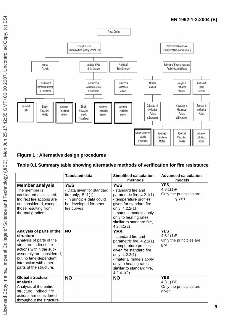
Application of design procedures is illustrated in Figure 0.1. The prescriptive approach and the performance-based approach are identified. The prescriptive approach uses nominal fires to generate thermal actions. The performance-based approach, using fire safety engineering, refers to thermal actions based on physical and chemical parameters. Additional information for alternative methods in this standard is given in Table 0.1. For design according to this part, EN 1991-1-2 is required for the determination of thermal and mechanical actions to the structure. Design aids Where simple calculation models are not available, the Eurocode fire parts give design solutions in terms of tabulated data (based on tests or advanced calculation models), which may be used within the specified limits of validity. It is expected, that design aids based on the calculation models given in EN 1992-1-2, will be prepared by interested external organisations. The main text of EN 1992-1-2, together with informative Annexes A, B, C, D and E, includes most of the principal concepts and rules necessary for structural fire design of concrete structures. National Annex for EN 1992-1-2 This standard gives alternative procedures, values and recommendations for classes with notes indicating where national choices may have to be made. Therefore the National Standard implementing EN 1992-1-2 should have a National Annex containing the Eurocode all Nationally Determined Parameters to be used for the design of buildings, and where required and applicable, for civil engineering works to be constructed in the relevant country. National choice is allowed in EN 1992-1-2 through clauses:
- 2.1.3 (2) - 2.3 (2)P - 3.2.3 (5) - 3.2.4 (2) - 3.3.3 (1) - 4.1 (1)P - 4.5.1 (2) - 5.2 (3)
- 5.3.2 (2) - 5.6.1 (1) - 5.7.3 (2) - 6.1 (5) - 6.2 (2) - 6.3.1 (1) - 6.4.2.1 (3) - 6.4.2.2 (2)
Lice
nsed
Cop
y: n
a na
, Im
peria
l Col
lege
of S
cien
ce a
nd T
echn
olog
y (J
ISC
), M
on J
un 2
5 17
:42:
35 G
MT
+00
:00
2007
, Unc
ontr
olle
d C
opy,
(c)
BS
I
EN 1992-1-2:2004 (E)
9
TabulatedData
SimpleCalculation
Models
AdvancedCalculation
Models
Calculation ofMechanical Actions
at Boundaries
MemberAnalysis
SimpleCalculation
Models(if available)
AdvancedCalculation
Models
Calculation ofMechanical Actions
at Boundaries
Analysis of Partof the Structure
AdvancedCalculation
Models
Selection ofMechanical
Actions
Analysis ofEntire Structure
Prescriptive Rules(Thermal Actions given by Nominal Fire
SimpleCalculationModels
(if available)
AdvancedCalculation
Models
Calculation ofMechanical
Actionsat Boundaries
MemberAnalysis
AdvancedCalculation
Models
Calculation ofMechanical
Actionsat Boundaries
Analysis ofPart of theStructure
AdvancedCalculation
Models
Selection ofMechanical
Actions
Analysis ofEntire
Structure
Selection of Simple or AdvancedFire Development Models
Performance-Based Code(Physically based Thermal Actions)
Project Design
Figure 1 : Alternative design procedures Table 0.1 Summary table showing alternative methods of verification for fire resistance Tabulated data
Simplified calculation
methods Advanced calculation
models Member analysis The member is considered as isolated. Indirect fire actions are not considered, except those resulting from thermal gradients
YES - Data given for standard fire only, 5..1(1) - In principle data could be developed for other fire curves
YES - standard fire and parametric fire, 4.2.1(1) - temperature profiles given for standard fire only, 4.2.2(1) - material models apply only to heating rates similar to standard fire, 4.2.4.1(2)
YES, 4.3.1(1)P Only the principles are
given
Analysis of parts of the structure Analysis of parts of the structure Indirect fire actions within the sub-assembly are considered, but no time-dependent interaction with other parts of the structure.
NO YES - standard fire and parametric fire, 4.2.1(1) - temperature profiles given for standard fire only, 4.2.2(1) - material models apply only to heating rates similar to standard fire, 4.2.4.1(2)
YES 4.3.1(1)P Only the principles are given
Global structural analysis Analysis of the entire structure. Indirect fire actions are considered throughout the structure
NO NO YES 4.3.1(1)P Only the principles are given
Lice
nsed
Cop
y: n
a na
, Im
peria
l Col
lege
of S
cien
ce a
nd T
echn
olog
y (J
ISC
), M
on J
un 2
5 17
:42:
35 G
MT
+00
:00
2007
, Unc
ontr
olle
d C
opy,
(c)
BS
I
EN 1992-1-2:2004 (E)
10
SECTION 1 GENERAL 1.1 Scope 1.1.1 Scope of Eurocode 2 (1)P Eurocode 2 applies to the design of buildings and civil engineering works in concrete. It complies with the principles and requirements for the safety and serviceability of structures, the basis of their design and verification that are given in EN 1990 – Basis of structural design. (2)P Eurocode 2 is only concerned with requirements for resistance, serviceability, durability and fire resistance concrete structures. Other requirements, e.g. concerning thermal or sound insulation, are not considered. (3)P Eurocode 2 is intended to be used in conjunction with:
– EN 1990 “Basis of structural design” – EN 1991 “Actions on structures” – hEN´s for construction products relevant for concrete structures – ENV 13670-1 “Execution of concrete structures . Part 1: Common rules” – EN 1998 “Design of structures for earthquake resistance”, when concrete structures are
built in seismic regions (4)P Eurocode 2 is subdivided in various parts:
- Part 1-1: General rules and rules for buildings - Part 1-2: General rules – Structural fire design - Part 2: Concrete bridges - Part 3: Liquid retaining and containment structures
1.1.2 Scope of Part 1-2 of Eurocode 2 (1)P This Part 1-2 of EN 1992 deals with the design of concrete structures for the accidental situation of fire exposure and is intended to be used in conjunction with EN 1992-1-1 and EN 1991-1-2. This part 1-2 only identifies differences from, or supplements to, normal temperature design. (2)P This Part 1-2 of EN 1992 deals only with passive methods of fire protection. Active methods are not covered. (3)P This Part 1-2 of EN 1992 applies to concrete structures that are required to fulfil certain functions when exposed to fire, in terms of:
- avoiding premature collapse of the structure (load bearing function) - limiting fire spread (flame, hot gases, excessive heat) beyond designated areas (separating
function) (4)P This Part 1-2 of EN 1992 gives principles and application rules (see EN 1991-1-2) for designing structures for specified requirements in respect of the aforementioned functions and the levels of performance.
Lice
nsed
Cop
y: n
a na
, Im
peria
l Col
lege
of S
cien
ce a
nd T
echn
olog
y (J
ISC
), M
on J
un 2
5 17
:42:
35 G
MT
+00
:00
2007
, Unc
ontr
olle
d C
opy,
(c)
BS
I
EN 1992-1-2:2004 (E)
11
(5)P This Part 1-2 of EN 1992 applies to structures, or parts of structures, that are within the scope of EN 1992-1-1 and are designed accordingly. However, it does not cover:
- structures with prestressing by external tendons - shell structures
(6)P The methods given in this Part 1-2 of EN 1992 are applicable to normal weight concrete up to strength class C90/105 and for lightweight concrete up to strength class LC55/60. Additional and alternative rules for strength classes above C50/60 are given in section 6. 1.2 Normative references The following normative documents contain provisions that, through reference in this text, constitute provisions of this European Standard. For dated references, subsequent amendments to, or revisions of, any of these publications do not apply. However, parties to agreements based on this European Standard are encouraged to investigate the possibility of applying the most recent editions of the normative documents indicated below. For undated references, the latest edition of the normative document referred to applies. EN 1363-2: Fire resistance tests – Part 2: Alternatives and additional procedures;
EN 1990: Eurocode: Basis of structural design; EN 1991-1-2: Eurocode 1 - Actions on structures - Part 1-2: General actions - Actions on structures exposed to fire; EN 1992-1-1: Eurocode 2. Design of concrete structures - Part 1.1: General rules and rules for buildings EN 10080: Steel for the reinforcement of concrete - Weldable reinforcing steel - General EN 10138-2: Prestressing steels - Part 2: Wire EN 10138-3: Prestressing steels - Part 3: Strand EN 10138-4: Prestressing steels - Part 4: Bar 1.3 Assumptions The general assumptions given in EN 1990 and EN 1992-1-2 apply. 1.4 Distinction between principles and application rules (1) The rules given in EN 1990 apply. 1.5 Definitions For the purposes of this Part 1-2 of EN 1992, the definitions of EN 1990 and of EN 1991-1-2 apply with the additional definitions: 1.5.1 Critical temperature of reinforcement: The temperature of reinforcement at which failure of the member in fire situation (Criterion R) is expected to occur at a given steel stress level. 1.5.2 Fire wall: A wall separating two spaces (generally two buildings) that is designed for fire resistance and structural stability, and may include resistance to horizontal loading such that, in case of fire and failure of the structure on one side of the wall, fire spread beyond the wall is avoided.
Lice
nsed
Cop
y: n
a na
, Im
peria
l Col
lege
of S
cien
ce a
nd T
echn
olog
y (J
ISC
), M
on J
un 2
5 17
:42:
35 G
MT
+00
:00
2007
, Unc
ontr
olle
d C
opy,
(c)
BS
I
EN 1992-1-2:2004 (E)
12
1.5.3 Maximum stress level: For a given temperature, the stress level at which the stress-strain relationship of steel is truncated to provide a yield plateau. 1.5.4 Part of structure: isolated part of an entire structure with appropriate support and boundary conditions. 1.5.5 Protective layers: Any material or combination of materials applied to a structural member for the purpose of increasing its fire resistance. 1.5.6 Reduced cross section: Cross section of the member in structure fire design used in the reduced cross section method. It is obtained from the residual cross section by removing parts of the cross section with assumed zero strength and stiffness.
1.6 Symbols 1.6.1 Supplementary symbols to EN1992-1-1
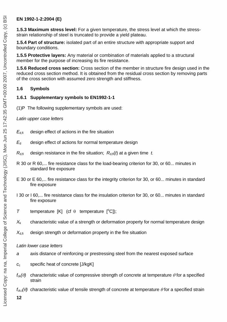
(1)P The following supplementary symbols are used: Latin upper case letters
Ed,fi design effect of actions in the fire situation Ed design effect of actions for normal temperature design Rd,fi design resistance in the fire situation; Rd,fi(t) at a given time t. R 30 or R 60,... fire resistance class for the load-bearing criterion for 30, or 60... minutes in
standard fire exposure E 30 or E 60,... fire resistance class for the integrity criterion for 30, or 60... minutes in standard
fire exposure I 30 or I 60,... fire resistance class for the insulation criterion for 30, or 60... minutes in standard
fire exposure T temperature [K] (cf θ temperature [oC]); Xk characteristic value of a strength or deformation property for normal temperature design Xd,fi design strength or deformation property in the fire situation
Latin lower case letters
a axis distance of reinforcing or prestressing steel from the nearest exposed surface cc specific heat of concrete [J/kgK] fck(θ) characteristic value of compressive strength of concrete at temperature θ for a specified
strain
fck,t(θ) characteristic value of tensile strength of concrete at temperature θ for a specified strain
Lice
nsed
Cop
y: n
a na
, Im
peria
l Col
lege
of S
cien
ce a
nd T
echn
olog
y (J
ISC
), M
on J
un 2
5 17
:42:
35 G
MT
+00
:00
2007
, Unc
ontr
olle
d C
opy,
(c)
BS
I
EN 1992-1-2:2004 (E)
13
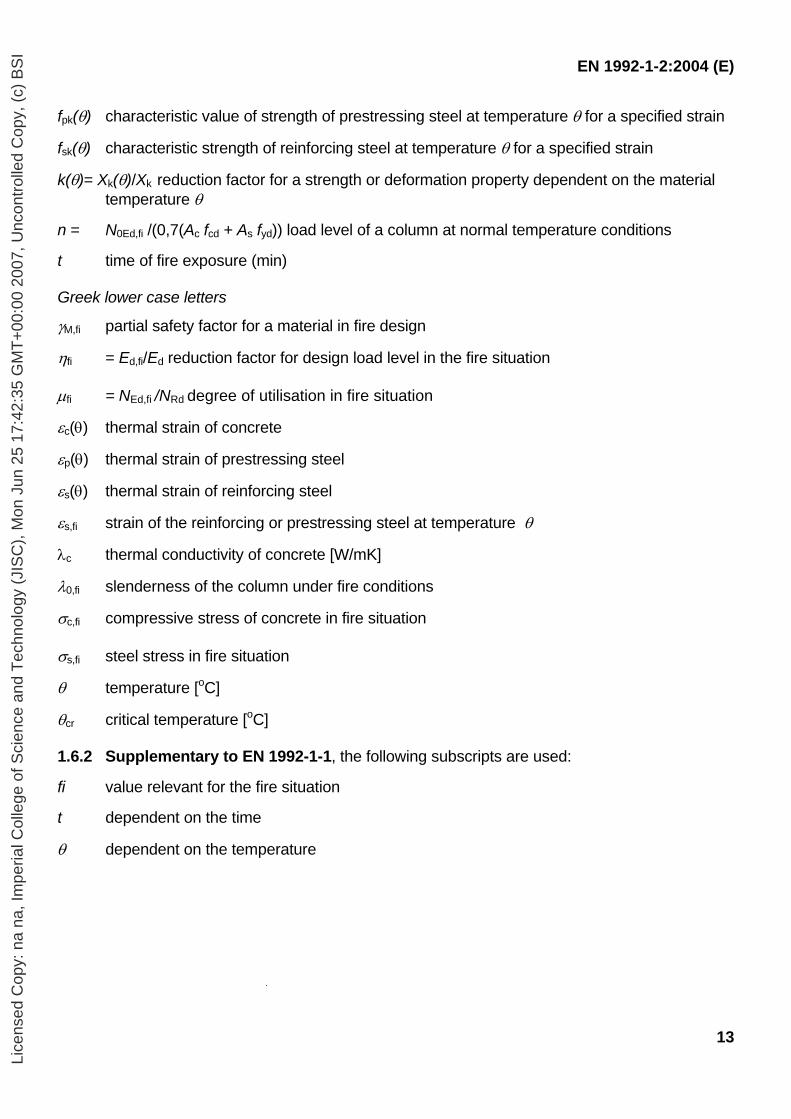
fpk(θ) characteristic value of strength of prestressing steel at temperature θ for a specified strain
fsk(θ) characteristic strength of reinforcing steel at temperature θ for a specified strain
k(θ)= Xk(θ)/Xk reduction factor for a strength or deformation property dependent on the material temperature θ
n = N0Ed,fi /(0,7(Ac fcd + As fyd)) load level of a column at normal temperature conditions t time of fire exposure (min) Greek lower case letters
γM,fi partial safety factor for a material in fire design
ηfi = Ed,fi/Ed reduction factor for design load level in the fire situation µfi = NEd,fi /NRd degree of utilisation in fire situation
εc(θ) thermal strain of concrete
εp(θ) thermal strain of prestressing steel
εs(θ) thermal strain of reinforcing steel
εs,fi strain of the reinforcing or prestressing steel at temperature θ
λc thermal conductivity of concrete [W/mK]
λ0,fi slenderness of the column under fire conditions
σc,fi compressive stress of concrete in fire situation σs,fi steel stress in fire situation
θ temperature [oC]
θcr critical temperature [oC]
1.6.2 Supplementary to EN 1992-1-1, the following subscripts are used: fi value relevant for the fire situation t dependent on the time
θ dependent on the temperature
Lice
nsed
Cop
y: n
a na
, Im
peria
l Col
lege
of S
cien
ce a
nd T
echn
olog
y (J
ISC
), M
on J
un 2
5 17
:42:
35 G
MT
+00
:00
2007
, Unc
ontr
olle
d C
opy,
(c)
BS
I
EN 1992-1-2:2004 (E)
14
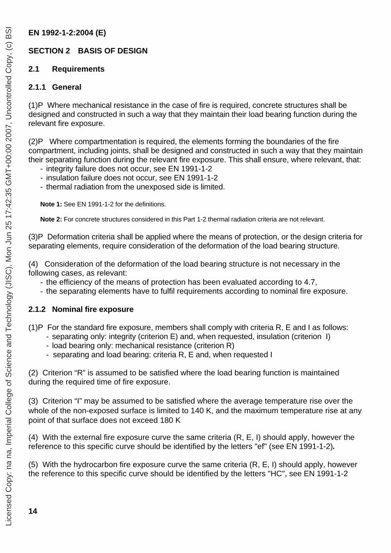
SECTION 2 BASIS OF DESIGN 2.1 Requirements 2.1.1 General (1)P Where mechanical resistance in the case of fire is required, concrete structures shall be designed and constructed in such a way that they maintain their load bearing function during the relevant fire exposure. (2)P Where compartmentation is required, the elements forming the boundaries of the fire compartment, including joints, shall be designed and constructed in such a way that they maintain their separating function during the relevant fire exposure. This shall ensure, where relevant, that:
- integrity failure does not occur, see EN 1991-1-2 - insulation failure does not occur, see EN 1991-1-2 - thermal radiation from the unexposed side is limited.
Note 1: See EN 1991-1-2 for the definitions. Note 2: For concrete structures considered in this Part 1-2 thermal radiation criteria are not relevant.
(3)P Deformation criteria shall be applied where the means of protection, or the design criteria for separating elements, require consideration of the deformation of the load bearing structure. (4) Consideration of the deformation of the load bearing structure is not necessary in the following cases, as relevant:
- the efficiency of the means of protection has been evaluated according to 4.7, - the separating elements have to fulfil requirements according to nominal fire exposure.
2.1.2 Nominal fire exposure (1)P For the standard fire exposure, members shall comply with criteria R, E and I as follows:
- separating only: integrity (criterion E) and, when requested, insulation (criterion I) - load bearing only: mechanical resistance (criterion R) - separating and load bearing: criteria R, E and, when requested I
(2) Criterion “R” is assumed to be satisfied where the load bearing function is maintained during the required time of fire exposure. (3) Criterion “I” may be assumed to be satisfied where the average temperature rise over the whole of the non-exposed surface is limited to 140 K, and the maximum temperature rise at any point of that surface does not exceed 180 K
(4) With the external fire exposure curve the same criteria (R, E, I) should apply, however the reference to this specific curve should be identified by the letters "ef" (see EN 1991-1-2). (5) With the hydrocarbon fire exposure curve the same criteria (R, E, I) should apply, however the reference to this specific curve should be identified by the letters "HC", see EN 1991-1-2
Lice
nsed
Cop
y: n
a na
, Im
peria
l Col
lege
of S
cien
ce a
nd T
echn
olog
y (J
ISC
), M
on J
un 2
5 17
:42:
35 G
MT
+00
:00
2007
, Unc
ontr
olle
d C
opy,
(c)
BS
I
EN 1992-1-2:2004 (E)
15
(6) Where a vertical separating element with or without load-bearing function has to comply with impact resistance requirement (criterion M), the element should resist a horizontal concentrated load as specified in EN 1363 Part 2. 2.1.3 Parametric fire exposure (1) The load-bearing function should be maintained during the complete endurance of the fire including the decay phase, or a specified period of time. (2) For the verification of the separating function the following applies, assuming that the normal temperature is 20°C:
- the average temperature rise of the unexposed side of the construction should be limited to 140 K and the maximum temperature rise of the unexposed side should not exceed 180 K during the heating phase until the maximum gas temperature in the fire compartment is reached;
- the average temperature rise of the unexposed side of the construction should be limited to ∆θ1 and the maximum temperature rise of the unexposed side should not exceed ∆θ2 during the decay phase. Note: The values of ∆θ1 and ∆θ2 for use in a Country may be found in its National Annex. The recommended values are ∆θ1 = 200 K and ∆θ2 = 240 K.
2.2 Actions (1)P The thermal and mechanical actions shall be taken from EN 1991-1-2. (2) In addition to EN 1991-1-2, the emissivity related to the concrete surface should be taken as 0,7.
2.3 Design values of material properties (1)P Design values of mechanical (strength and deformation) material properties Xd,fi are defined as follows:
Xd,fi = kθ Xk / γM,fi (2.1)
where: Xk is the characteristic value of a strength or deformation property (generally fk or Ek) for
normal temperature design to EN 1992-1-1; kθ is the reduction factor for a strength or deformation property (Xk,θ / Xk), dependent on
the material temperature, see 3.2.; γM,fi is the partial safety factor for the relevant material property, for the fire situation.
(2)P Design values of thermal material properties Xd,fi are defined as follows:
- if an increase of the property is favourable for safety:
Xd,fi = Xk,θ /γM,fi (2.2a)
- if an increase of the property is unfavourable for safety:
Xd,fi = γM,fi Xk,θ (2.2b)
where:
Lice
nsed
Cop
y: n
a na
, Im
peria
l Col
lege
of S
cien
ce a
nd T
echn
olog
y (J
ISC
), M
on J
un 2
5 17
:42:
35 G
MT
+00
:00
2007
, Unc
ontr
olle
d C
opy,
(c)
BS
I
EN 1992-1-2:2004 (E)
16
Xk,θ is the value of a material property in fire design, generally dependent on the material temperature, see section 3;
γM,fi is the partial safety factor for the relevant material property, for the fire situation.
Note 1: The value of γM,fi for use in a Country may be found in its National Annex. The recommended value is: For thermal properties of concrete and reinforcing and prestressing steel: γM,fi = 1,0 For mechanical properties of concrete and reinforcing and prestressing steel: γM,fi = 1,0 Note 2: If the recommended values are modified, the tabulated data may require modification.
2.4 Verification methods 2.4.1 General (1)P The model of the structural system adopted for design to this Part 1.2 of EN 1992 shall reflect the expected performance of the structure in fire. (2)P It shall be verified for the relevant duration of fire exposure t :
Ed,fi ≤ Rd,t,fi (2.3)
where Ed,fi is the design effect of actions for the fire situation, determined in accordance with
EN 1991-1-2, including effects of thermal expansions and deformations Rd,t,fi is the corresponding design resistance in the fire situation.
(3) The structural analysis for the fire situation should be carried out according to Section 5 of EN 1990.
Note: For verifying standard fire resistance requirements, a member analysis is sufficient.
(4) Where application rules given in this Part 1-2 are valid only for the standard temperature-time curve, this is identified in the relevant clauses (5) Tabulated data given in section 5 are based on the standard temperature-time curve. (6)P As an alternative to design by calculation, fire design may be based on the results of fire tests, or on fire tests in combination with calculations, see EN 1990, Section 5. 2.4.2 Member analysis (1) The effect of actions should be determined for time t = 0 using combination factors ψ 1,1 or ψ1,2 according to EN 1991-1-2 Section 4. (2) As a simplification to (1) the effects of actions may be obtained from a structural analysis for normal temperature design as:
Ed,fi = ηfi Ed (2.4)
Where Ed is the design value of the corresponding force or moment for normal temperature
design, for a fundamental combination of actions (see EN 1990); ηfi is the reduction factor for the design load level for the fire situation.
(3) The reduction factor ηfi for load combination (6.10) in EN 1990 should be taken as:
Lice
nsed
Cop
y: n
a na
, Im
peria
l Col
lege
of S
cien
ce a
nd T
echn
olog
y (J
ISC
), M
on J
un 2
5 17
:42:
35 G
MT
+00
:00
2007
, Unc
ontr
olle
d C
opy,
(c)
BS
I
EN 1992-1-2:2004 (E)
17
ηfi = QG
QGk,1Q,1kG
k,1fik
+ + γγψ (2.5)
or for load combination (6.10a) and (6.10b) in EN 1990 as the smaller value given by the two following expressions:
ηfi = QG
QGk,11,0Q,1kG
k,1fik
+ +
ψγγψ (2.5a)
ηfi = Q + G
Q + G fi
k,1Q,1kG
k,1k
γξγψ
(2.5b)
where
Qk,1 is the principal variable load; Gk is the characteristic value of a permanent action; γG is the partial factor for a permanent action; γQ,1 is the partial factor for variable action 1; ψfi is the combination factor for frequent or quasi-permanent values given either by ψ1,1
or ψ2,1, see EN1991-1-2 ξ is a reduction factor for unfavourable permanent action G
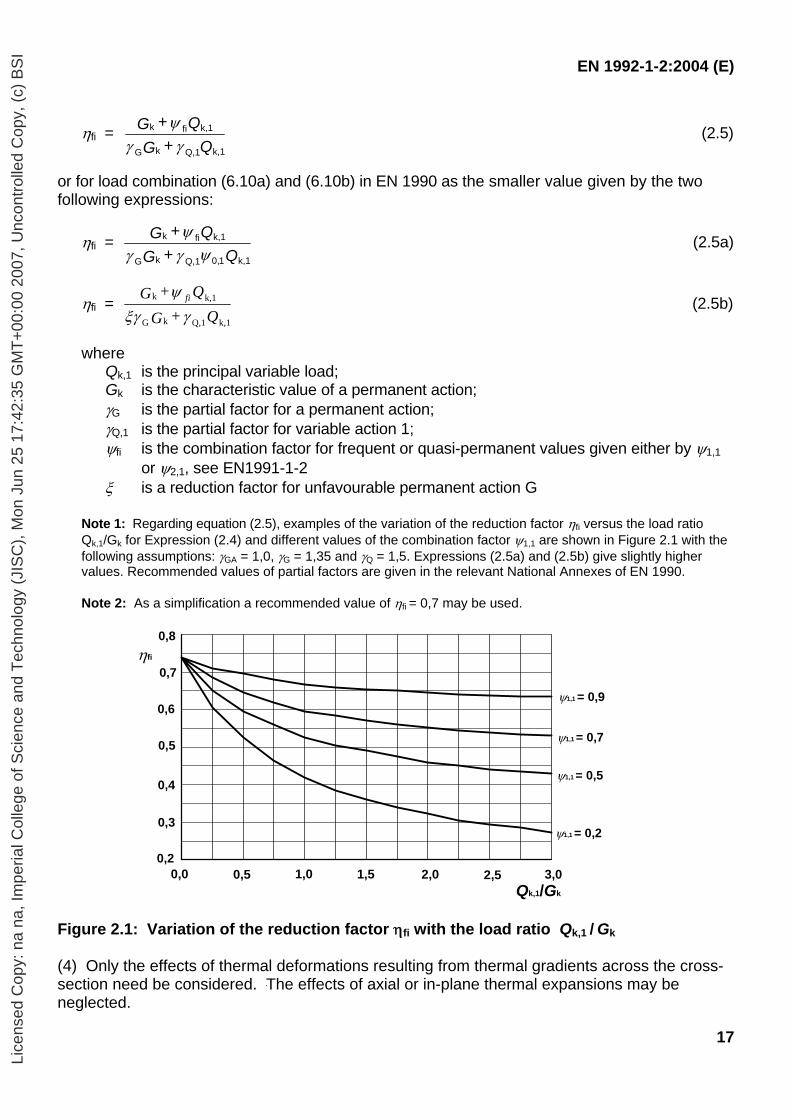
Note 1: Regarding equation (2.5), examples of the variation of the reduction factor ηfi versus the load ratio Qk,1/Gk for Expression (2.4) and different values of the combination factor ψ1,1 are shown in Figure 2.1 with the following assumptions: γGA = 1,0, γG = 1,35 and γQ = 1,5. Expressions (2.5a) and (2.5b) give slightly higher values. Recommended values of partial factors are given in the relevant National Annexes of EN 1990.
Note 2: As a simplification a recommended value of ηfi = 0,7 may be used.
Figure 2.1: Variation of the reduction factor ηfi with the load ratio Qk,1 / Gk (4) Only the effects of thermal deformations resulting from thermal gradients across the cross-section need be considered. The effects of axial or in-plane thermal expansions may be neglected.
0 1 1 2 2 3 30
0
0
1
1
1
1
Qk,1/Gk
ψ1,1 = 0,9
ψ1,1 = 0,7
ψ1,1 = 0,5
ψ1,1 = 0,2
ηfi
0,0 0,5 1,0 1,5 2,0 3,02,5
0,5
0,7
0,8
0,2
0,3
0,4
0,6
Lice
nsed
Cop
y: n
a na
, Im
peria
l Col
lege
of S
cien
ce a
nd T
echn
olog
y (J
ISC
), M
on J
un 2
5 17
:42:
35 G
MT
+00
:00
2007
, Unc
ontr
olle
d C
opy,
(c)
BS
I
EN 1992-1-2:2004 (E)
18
(5) The boundary conditions at supports and ends of member, applicable at time t = 0, are assumed to remain unchanged throughout the fire exposure. (6) Tabulated data, simplified or general calculation methods given in 5, 4.2 and 4.3 respectively are suitable for verifying members under fire conditions. 2.4.3 Analysis of part of the structure (1) 2.4.2 (1) applies. (2) As an alternative to carrying out a global structural analysis for the fire situation at time t = 0 the reactions at supports and internal forces and moments at boundaries of part of the structure may be obtained from structural analysis for normal temperature as given in 2.4.2 (3) The part of the structure to be analysed should be specified on the basis of the potential thermal expansions and deformations such, that their interaction with other parts of the structure can be approximated by time-independent support and boundary conditions during fire exposure. (4)P Within the part of the structure to be analysed, the relevant failure mode in fire exposure, the temperature-dependent material properties and member stiffnesses, effects of thermal expansions and deformations (indirect fire actions) shall be taken into account
(5) The boundary conditions at supports and forces and moments at boundaries of part of the structure, applicable at time t = 0, are assumed to remain unchanged throughout the fire exposure 2.4.4 Global structural analysis (1)P When global structural analysis for the fire situation is carried out, the relevant failure mode in fire exposure, the temperature-dependent material properties and member stiffnesses, effects of thermal expansions and deformations (indirect fire actions) shall be taken into account.
Lice
nsed
Cop
y: n
a na
, Im
peria
l Col
lege
of S
cien
ce a
nd T
echn
olog
y (J
ISC
), M
on J
un 2
5 17
:42:
35 G
MT
+00
:00
2007
, Unc
ontr
olle
d C
opy,
(c)
BS
I
EN 1992-1-2:2004 (E)
19
SECTION 3 MATERIAL PROPERTIES 3.1 General (1)P The values of material properties given in this section shall be treated as characteristic values (see 2.3 (1)P). (2) The values may be used with the simplified (see 4.2) and the advanced calculation method (see 4.3). Alternative formulations of material laws may be applied, provided the solutions are within the range of experimental evidence.
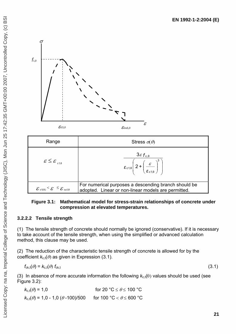
Note: Material properties for lightweight aggregate concrete are not given in this Eurocode. (3)P The mechanical properties of concrete, reinforcing and prestressing steel at normal temperature (20°C) shall be taken as those given in EN 1992-1-1 for normal temperature design. 3.2 Strength and deformation properties at elevated temperatures 3.2.1 General (1)P Numerical values on strength and deformation properties given in this section are based on steady state as well as transient state tests and sometimes a combination of both. As creep effects are not explicitly considered, the material models in this Eurocode are applicable for heating rates between 2 and 50 K/min. For heating rates outside the above range, the reliability of the strength and deformation properties shall be demonstrated explicitly. 3.2.2 Concrete 3.2.2.1 Concrete under compression (1)P The strength and deformation properties of uniaxially stressed concrete at elevated temperatures shall be obtained from the stress-strain relationships as presented in Figure 3.1. (2) The stress-strain relationships given in Figure 3.1 are defined by two parameters:
- the compressive strength fc,θ - the strain εc1,θ corresponding to fc,θ.
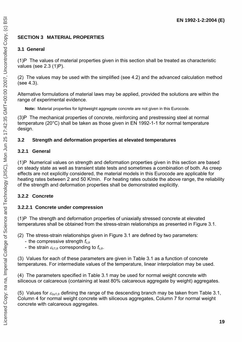
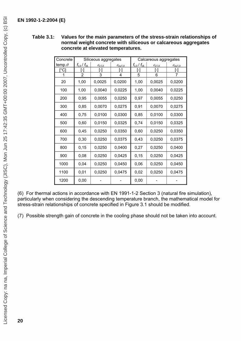
(3) Values for each of these parameters are given in Table 3.1 as a function of concrete temperatures. For intermediate values of the temperature, linear interpolation may be used. (4) The parameters specified in Table 3.1 may be used for normal weight concrete with siliceous or calcareous (containing at least 80% calcareous aggregate by weight) aggregates. (5) Values for εcu1,θ defining the range of the descending branch may be taken from Table 3.1, Column 4 for normal weight concrete with siliceous aggregates, Column 7 for normal weight concrete with calcareous aggregates.
Lice
nsed
Cop
y: n
a na
, Im
peria
l Col
lege
of S
cien
ce a
nd T
echn
olog
y (J
ISC
), M
on J
un 2
5 17
:42:
35 G
MT
+00
:00
2007
, Unc
ontr
olle
d C
opy,
(c)
BS
I
EN 1992-1-2:2004 (E)
20
Table 3.1: Values for the main parameters of the stress-strain relationships of normal weight concrete with siliceous or calcareous aggregates concrete at elevated temperatures.
Concrete Siliceous aggregates Calcareous aggregates temp.θ fc,θ / fck εc1,θ εcu1,θ fc,θ / fck εc1,θ εcu1,θ
[°C] [-] [-] [-] [-] [-] [-] 1 2 3 4 5 6 7
20 1,00 0,0025 0,0200 1,00 0,0025 0,0200
100 1,00 0,0040 0,0225 1,00 0,0040 0,0225
200 0,95 0,0055 0,0250 0,97 0,0055 0,0250
300 0,85 0,0070 0,0275 0,91 0,0070 0,0275
400 0,75 0,0100 0,0300 0,85 0,0100 0,0300
500 0,60 0,0150 0,0325 0,74 0,0150 0,0325
600 0,45 0,0250 0,0350 0,60 0,0250 0,0350
700 0,30 0,0250 0,0375 0,43 0,0250 0,0375
800 0,15 0,0250 0,0400 0,27 0,0250 0,0400
900 0,08 0,0250 0,0425 0,15 0,0250 0,0425
1000 0,04 0,0250 0,0450 0,06 0,0250 0,0450
1100 0,01 0,0250 0,0475 0,02 0,0250 0,0475
1200 0,00 - - 0,00 - -
(6) For thermal actions in accordance with EN 1991-1-2 Section 3 (natural fire simulation), particularly when considering the descending temperature branch, the mathematical model for stress-strain relationships of concrete specified in Figure 3.1 should be modified. (7) Possible strength gain of concrete in the cooling phase should not be taken into account.
Lice
nsed
Cop
y: n
a na
, Im
peria
l Col
lege
of S
cien
ce a
nd T
echn
olog
y (J
ISC
), M
on J
un 2
5 17
:42:
35 G
MT
+00
:00
2007
, Unc
ontr
olle
d C
opy,
(c)
BS
I
EN 1992-1-2:2004 (E)
21
σ
εc1,θ εcu1,θε
fc,θ
Range Stress σ(θ)
c1,θε ε≤
⎟⎟
⎠
⎞
⎜⎜
⎝
⎛⎟⎟⎠
⎞⎜⎜⎝
⎛3
θ,1cθ,1c
θ,c
2
3
ε+ε
fε
ε
c1(θ ) cu1,θε ε ε< ≤ For numerical purposes a descending branch should be adopted. Linear or non-linear models are permitted.
Figure 3.1: Mathematical model for stress-strain relationships of concrete under
compression at elevated temperatures. 3.2.2.2 Tensile strength (1) The tensile strength of concrete should normally be ignored (conservative). If it is necessary to take account of the tensile strength, when using the simplified or advanced calculation method, this clause may be used. (2) The reduction of the characteristic tensile strength of concrete is allowed for by the coefficient kc,t(θ) as given in Expression (3.1).
fck,t(θ) = kc,t(θ) fck,t (3.1)
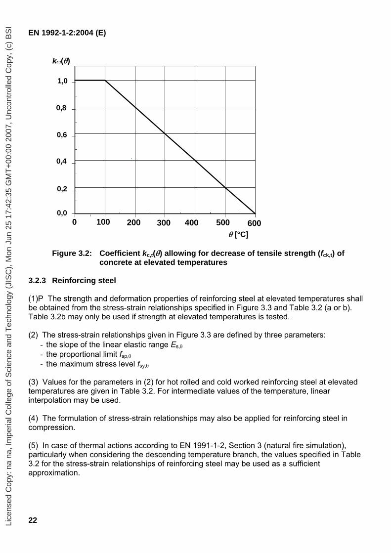
(3) In absence of more accurate information the following kc,t(θ) values should be used (see Figure 3.2):
kc,t(θ) = 1,0 for 20 °C ≤ θ ≤ 100 °C
kc,t(θ) = 1,0 - 1,0 (θ -100)/500 for 100 °C < θ ≤ 600 °C
Lice
nsed
Cop
y: n
a na
, Im
peria
l Col
lege
of S
cien
ce a
nd T
echn
olog
y (J
ISC
), M
on J
un 2
5 17
:42:
35 G
MT
+00
:00
2007
, Unc
ontr
olle
d C
opy,
(c)
BS
I
EN 1992-1-2:2004 (E)
22
0 100 200 300 400 500 6000
0
0
1
1
1
kc,t(θ)
0,8
0,6
0,4
0,2
1,0
0,0100 200 300 400 5000 600
θ [°C] Figure 3.2: Coefficient kc,t(θ) allowing for decrease of tensile strength (fck,t) of
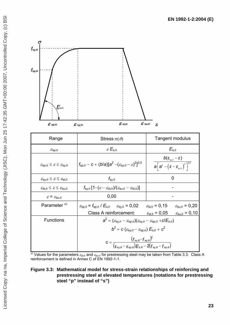
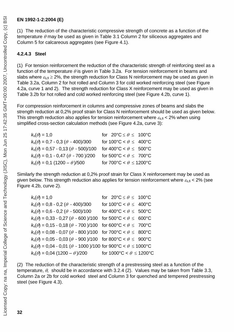
concrete at elevated temperatures 3.2.3 Reinforcing steel (1)P The strength and deformation properties of reinforcing steel at elevated temperatures shall be obtained from the stress-strain relationships specified in Figure 3.3 and Table 3.2 (a or b). Table 3.2b may only be used if strength at elevated temperatures is tested. (2) The stress-strain relationships given in Figure 3.3 are defined by three parameters:
- the slope of the linear elastic range Es,θ - the proportional limit fsp,θ - the maximum stress level fsy,θ
(3) Values for the parameters in (2) for hot rolled and cold worked reinforcing steel at elevated temperatures are given in Table 3.2. For intermediate values of the temperature, linear interpolation may be used. (4) The formulation of stress-strain relationships may also be applied for reinforcing steel in compression. (5) In case of thermal actions according to EN 1991-1-2, Section 3 (natural fire simulation), particularly when considering the descending temperature branch, the values specified in Table 3.2 for the stress-strain relationships of reinforcing steel may be used as a sufficient approximation.
Lice
nsed
Cop
y: n
a na
, Im
peria
l Col
lege
of S
cien
ce a
nd T
echn
olog
y (J
ISC
), M
on J
un 2
5 17
:42:
35 G
MT
+00
:00
2007
, Unc
ontr
olle
d C
opy,
(c)
BS
I
EN 1992-1-2:2004 (E)
23
σ
ε sp,Θ ε sy,Θ ε st,Θ ε su,Θ ε
fsy,Θ
fsp,Θ
Es,θ
Range Stress σ(θ) Tangent modulus
εsp,θ ε Es,θ Es,θ
εsp,θ ≤ ε ≤ εsy,θ fsp,θ − c + (b/a)[a2 −(εsy,θ − ε)2]0,5 ( )b ε ε
a a ε εsy,
0,522sy,
( )θ
θ
−
⎡ ⎤− −⎣ ⎦
εsy,θ ≤ ε ≤ εst,θ fsy,θ 0
εst,θ ≤ ε ≤ εsu,θ fsy,θ [1−(ε − εst,θ)/(εsu,θ − εst,θ)] -
ε = εsu,θ 0,00 -
Parameter *) εsp,θ = fsp,θ / Es,θ εsy,θ = 0,02 εst,θ = 0,15 εsu,θ = 0,20Class A reinforcement: εst,θ = 0,05 εsu,θ = 0,10
Functions a2 = (εsy,θ − εsp,θ)(εsy,θ − εsp,θ +c/Es,θ)
b2 = c (εsy,θ − εsp,θ) Es,θ + c2
( )( ) ( )ffEεε
ffcsp,θsy,θs,θsp,θsy,θ
sp,θsy,θ2
2 −−−−
=
*) Values for the parameters εpt,θ and εpu,θ for prestressing steel may be taken from Table 3.3. Class A reinforcement is defined in Annex C of EN 1992-1-1.
Figure 3.3: Mathematical model for stress-strain relationships of reinforcing and
prestressing steel at elevated temperatures (notations for prestressing steel “p” instead of “s”)
Lice
nsed
Cop
y: n
a na
, Im
peria
l Col
lege
of S
cien
ce a
nd T
echn
olog
y (J
ISC
), M
on J
un 2
5 17
:42:
35 G
MT
+00
:00
2007
, Unc
ontr
olle
d C
opy,
(c)
BS
I
EN 1992-1-2:2004 (E)
24
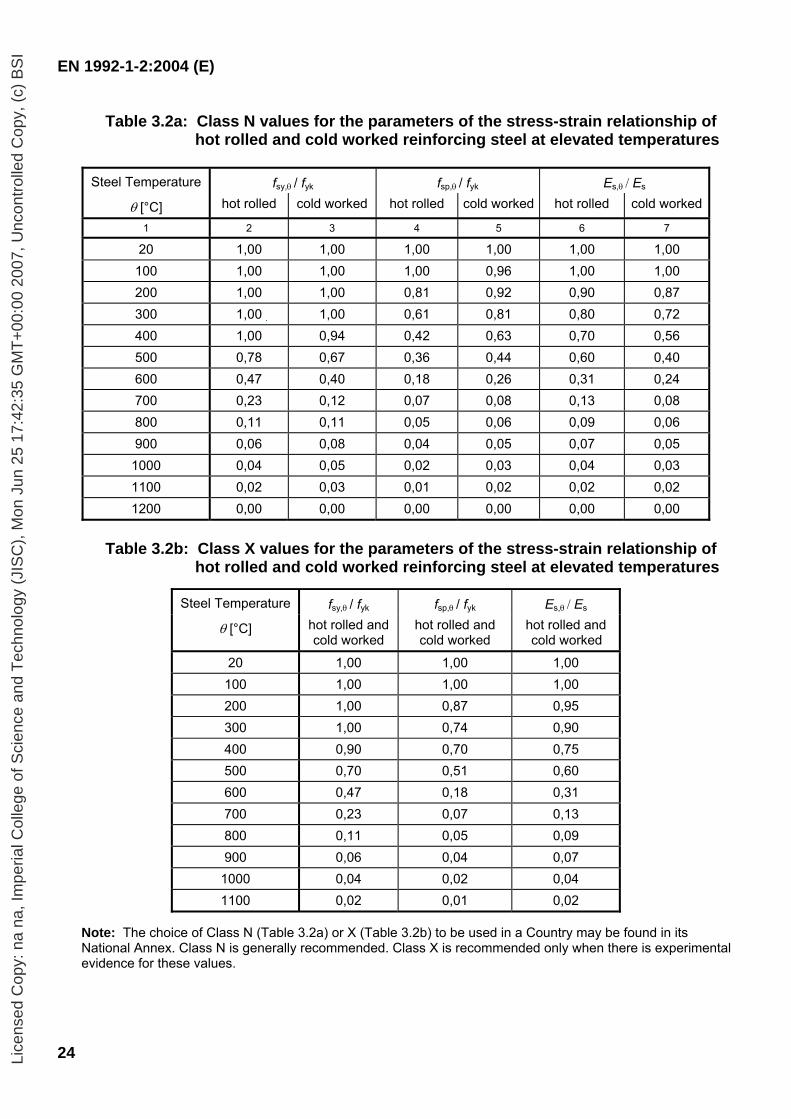
Table 3.2a: Class N values for the parameters of the stress-strain relationship of hot rolled and cold worked reinforcing steel at elevated temperatures
Steel Temperature fsy,θ / fyk fsp,θ / fyk Es,θ / Es
θ [°C] hot rolled cold worked hot rolled cold worked hot rolled cold worked
1 2 3 4 5 6 7
20 1,00 1,00 1,00 1,00 1,00 1,00 100 1,00 1,00 1,00 0,96 1,00 1,00 200 1,00 1,00 0,81 0,92 0,90 0,87 300 1,00 1,00 0,61 0,81 0,80 0,72 400 1,00 0,94 0,42 0,63 0,70 0,56 500 0,78 0,67 0,36 0,44 0,60 0,40 600 0,47 0,40 0,18 0,26 0,31 0,24 700 0,23 0,12 0,07 0,08 0,13 0,08 800 0,11 0,11 0,05 0,06 0,09 0,06 900 0,06 0,08 0,04 0,05 0,07 0,05
1000 0,04 0,05 0,02 0,03 0,04 0,03 1100 0,02 0,03 0,01 0,02 0,02 0,02 1200 0,00 0,00 0,00 0,00 0,00 0,00
Table 3.2b: Class X values for the parameters of the stress-strain relationship of
hot rolled and cold worked reinforcing steel at elevated temperatures
Steel Temperature fsy,θ / fyk fsp,θ / fyk Es,θ / Es
θ [°C] hot rolled and cold worked
hot rolled and cold worked
hot rolled and cold worked
20 1,00 1,00 1,00 100 1,00 1,00 1,00 200 1,00 0,87 0,95 300 1,00 0,74 0,90 400 0,90 0,70 0,75 500 0,70 0,51 0,60 600 0,47 0,18 0,31 700 0,23 0,07 0,13 800 0,11 0,05 0,09 900 0,06 0,04 0,07
1000 0,04 0,02 0,04 1100 0,02 0,01 0,02
Note: The choice of Class N (Table 3.2a) or X (Table 3.2b) to be used in a Country may be found in its National Annex. Class N is generally recommended. Class X is recommended only when there is experimental evidence for these values.
Lice
nsed
Cop
y: n
a na
, Im
peria
l Col
lege
of S
cien
ce a
nd T
echn
olog
y (J
ISC
), M
on J
un 2
5 17
:42:
35 G
MT
+00
:00
2007
, Unc
ontr
olle
d C
opy,
(c)
BS
I
EN 1992-1-2:2004 (E)
25
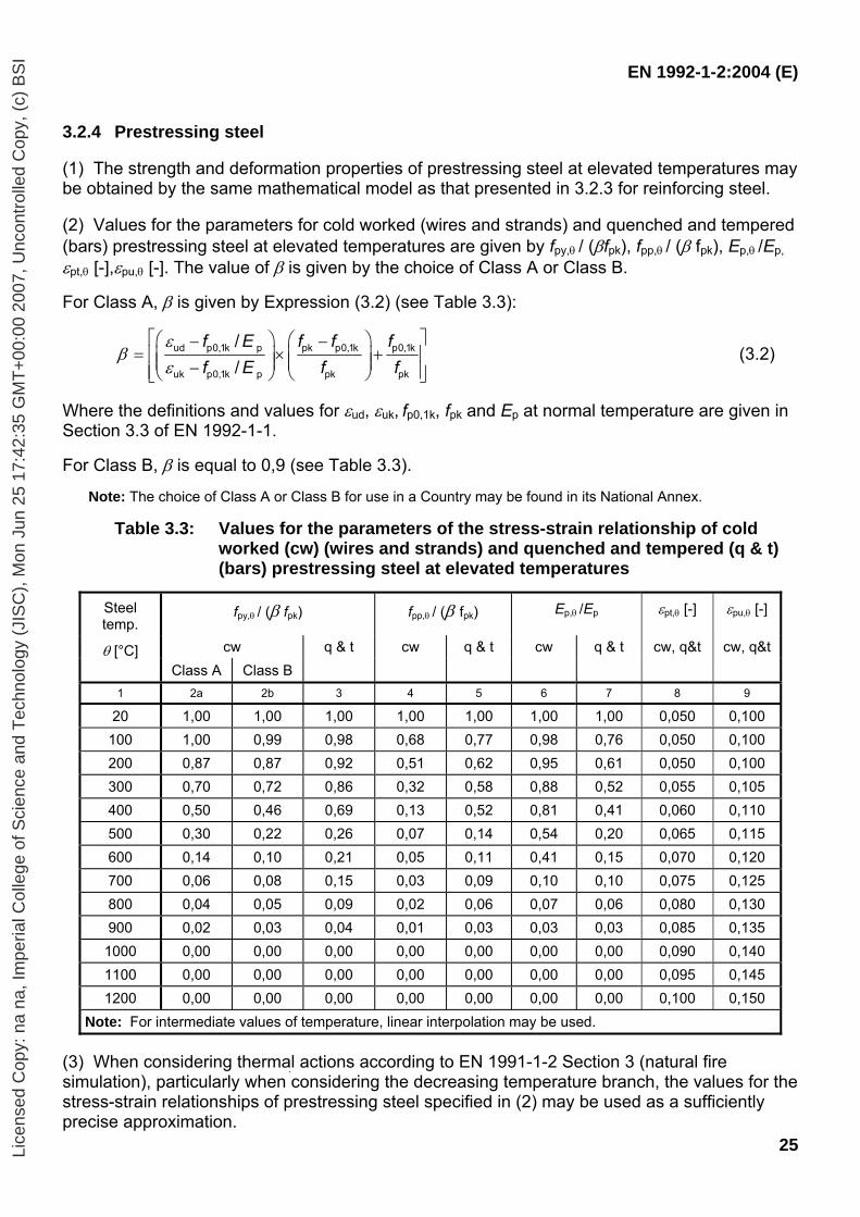
3.2.4 Prestressing steel (1) The strength and deformation properties of prestressing steel at elevated temperatures may be obtained by the same mathematical model as that presented in 3.2.3 for reinforcing steel. (2) Values for the parameters for cold worked (wires and strands) and quenched and tempered (bars) prestressing steel at elevated temperatures are given by fpy,θ / (βfpk), fpp,θ / (β fpk), Ep,θ /Ep, εpt,θ [-],εpu,θ [-]. The value of β is given by the choice of Class A or Class B.
For Class A, β is given by Expression (3.2) (see Table 3.3):
f E f f ff E f f
ud p0,1k p pk p0,1k p0,1k
uk p0,1k p pk pk
//
εβ
ε
⎡ ⎤⎛ ⎞ ⎛ ⎞− −= × +⎢ ⎥⎜ ⎟ ⎜ ⎟⎜ ⎟ ⎜ ⎟−⎢ ⎥⎝ ⎠ ⎝ ⎠⎣ ⎦
(3.2)
Where the definitions and values for εud, εuk, fp0,1k, fpk and Ep at normal temperature are given in Section 3.3 of EN 1992-1-1.
For Class B, β is equal to 0,9 (see Table 3.3).
Note: The choice of Class A or Class B for use in a Country may be found in its National Annex.
Table 3.3: Values for the parameters of the stress-strain relationship of cold worked (cw) (wires and strands) and quenched and tempered (q & t) (bars) prestressing steel at elevated temperatures
Steel temp.
fpy,θ / (β fpk) fpp,θ / (β fpk) Ep,θ /Ep εpt,θ [-] εpu,θ [-]
cw θ [°C] Class A Class B
q & t cw q & t cw q & t cw, q&t cw, q&t
1 2a 2b 3 4 5 6 7 8 9
20 1,00 1,00 1,00 1,00 1,00 1,00 1,00 0,050 0,100 100 1,00 0,99 0,98 0,68 0,77 0,98 0,76 0,050 0,100 200 0,87 0,87 0,92 0,51 0,62 0,95 0,61 0,050 0,100 300 0,70 0,72 0,86 0,32 0,58 0,88 0,52 0,055 0,105 400 0,50 0,46 0,69 0,13 0,52 0,81 0,41 0,060 0,110 500 0,30 0,22 0,26 0,07 0,14 0,54 0,20 0,065 0,115 600 0,14 0,10 0,21 0,05 0,11 0,41 0,15 0,070 0,120 700 0,06 0,08 0,15 0,03 0,09 0,10 0,10 0,075 0,125 800 0,04 0,05 0,09 0,02 0,06 0,07 0,06 0,080 0,130 900 0,02 0,03 0,04 0,01 0,03 0,03 0,03 0,085 0,135 1000 0,00 0,00 0,00 0,00 0,00 0,00 0,00 0,090 0,140 1100 0,00 0,00 0,00 0,00 0,00 0,00 0,00 0,095 0,145 1200 0,00 0,00 0,00 0,00 0,00 0,00 0,00 0,100 0,150
Note: For intermediate values of temperature, linear interpolation may be used. (3) When considering thermal actions according to EN 1991-1-2 Section 3 (natural fire simulation), particularly when considering the decreasing temperature branch, the values for the stress-strain relationships of prestressing steel specified in (2) may be used as a sufficiently precise approximation.
Lice
nsed
Cop
y: n
a na
, Im
peria
l Col
lege
of S
cien
ce a
nd T
echn
olog
y (J
ISC
), M
on J
un 2
5 17
:42:
35 G
MT
+00
:00
2007
, Unc
ontr
olle
d C
opy,
(c)
BS
I
EN 1992-1-2:2004 (E)
26
3.3 Thermal and physical properties of concrete with siliceous and calcareous
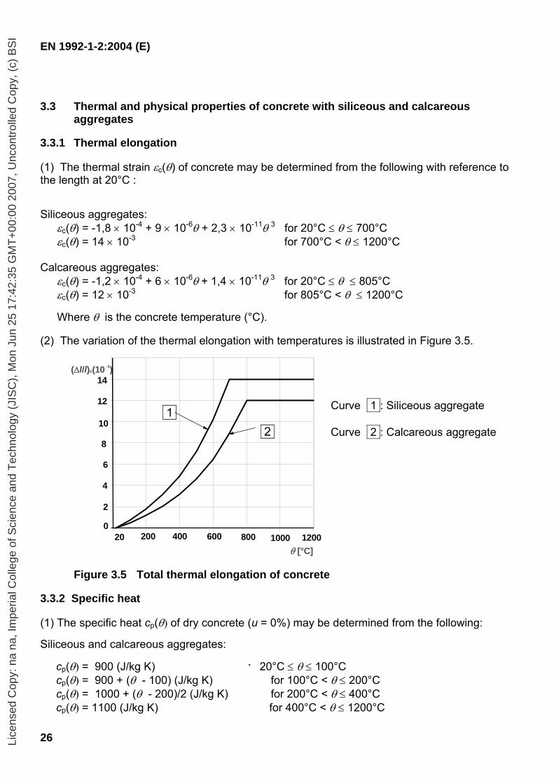
aggregates 3.3.1 Thermal elongation (1) The thermal strain εc(θ) of concrete may be determined from the following with reference to the length at 20°C : Siliceous aggregates:
εc(θ) = -1,8 × 10⁻⁴ + 9 × 10⁻⁶θ + 2,3 × 10⁻¹¹θ 3 for 20°C ≤ θ ≤ 700°C εc(θ) = 14 × 10-3 for 700°C < θ ≤ 1200°C
Calcareous aggregates:
εc(θ) = -1,2 × 10⁻⁴ + 6 × 10⁻⁶θ + 1,4 × 10⁻¹¹θ 3 for 20°C ≤ θ ≤ 805°C εc(θ) = 12 × 10-3 for 805°C < θ ≤ 1200°C
Where θ is the concrete temperature (°C).
(2) The variation of the thermal elongation with temperatures is illustrated in Figure 3.5.
Curve 1 : Siliceous aggregate Curve 2 : Calcareous aggregate
Figure 3.5 Total thermal elongation of concrete
3.3.2 Specific heat (1) The specific heat cp(θ) of dry concrete (u = 0%) may be determined from the following: Siliceous and calcareous aggregates:
cp(θ) = 900 (J/kg K) r 20°C ≤ θ ≤ 100°C cp(θ) = 900 + (θ - 100) (J/kg K) for 100°C < θ ≤ 200°C cp(θ) = 1000 + (θ - 200)/2 (J/kg K) for 200°C < θ ≤ 400°C cp(θ) = 1100 (J/kg K) for 400°C < θ ≤ 1200°C
0 200 400 600 800 1,000 1,2000
2
4
6
8
10
12
14
16
8
2
10
0
θ [°C]
1 2
4
6
12
14
1000200 800400 120020 600
(∆l/l)c(10 )-3
Lice
nsed
Cop
y: n
a na
, Im
peria
l Col
lege
of S
cien
ce a
nd T
echn
olog
y (J
ISC
), M
on J
un 2
5 17
:42:
35 G
MT
+00
:00
2007
, Unc
ontr
olle
d C
opy,
(c)
BS
I
EN 1992-1-2:2004 (E)
27
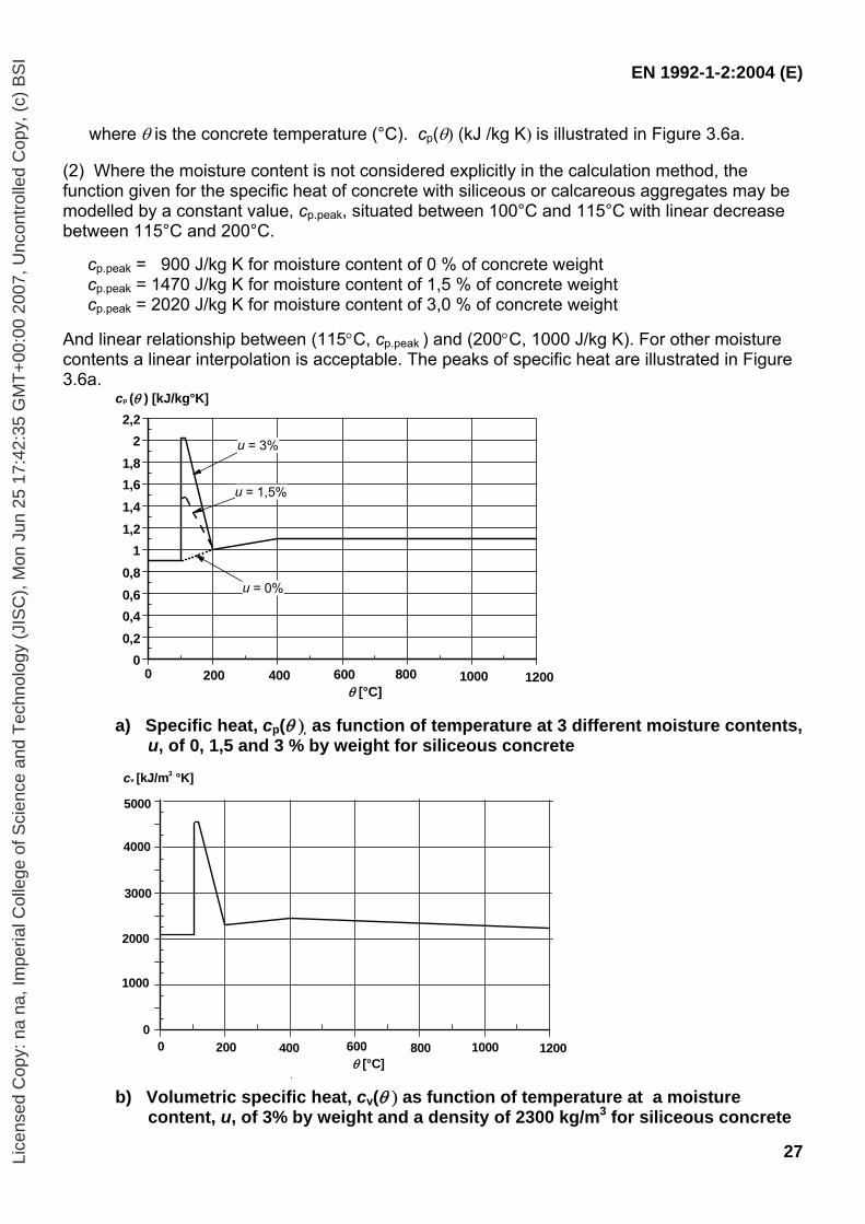
where θ is the concrete temperature (°C). cp(θ) (kJ /kg K) is illustrated in Figure 3.6a. (2) Where the moisture content is not considered explicitly in the calculation method, the function given for the specific heat of concrete with siliceous or calcareous aggregates may be modelled by a constant value, cp.peak, situated between 100°C and 115°C with linear decrease between 115°C and 200°C.
cp.peak = 900 J/kg K for moisture content of 0 % of concrete weight cp.peak = 1470 J/kg K for moisture content of 1,5 % of concrete weight cp.peak = 2020 J/kg K for moisture content of 3,0 % of concrete weight
And linear relationship between (115°C, cp.peak ) and (200°C, 1000 J/kg K). For other moisture contents a linear interpolation is acceptable. The peaks of specific heat are illustrated in Figure 3.6a.
0 200 400 600 800 1000 12000
0,20,40,60,8
11,21,41,61,8
22,2
θ [°C]
cp (θ ) [kJ/kg°K]
u = 3%
u = 0%
u = 1,5%
a) Specific heat, cp(θ ), as function of temperature at 3 different moisture contents, u, of 0, 1,5 and 3 % by weight for siliceous concrete
0
1000
2000
3000
4000
5000
cv [kJ/m °K]
0 200 400 600 800 1000 1200
3
θ [°C]
b) Volumetric specific heat, cv(θ ) as function of temperature at a moisture content, u, of 3% by weight and a density of 2300 kg/m3 for siliceous concrete
Lice
nsed
Cop
y: n
a na
, Im
peria
l Col
lege
of S
cien
ce a
nd T
echn
olog
y (J
ISC
), M
on J
un 2
5 17
:42:
35 G
MT
+00
:00
2007
, Unc
ontr
olle
d C
opy,
(c)
BS
I
EN 1992-1-2:2004 (E)
28
Figure 3.6: Specific heat and volumetric specific heat
(3) The variation of density with temperature is influenced by water loss and is defined as follows
ρ(θ ) = ρ(20°C) for 20°C ≤ θ ≤ 115°C ρ(θ ) = ρ(20°C)⋅(1 - 0,02(θ - 115)/85) for 115°C < θ ≤ 200°C ρ(θ ) = ρ(20°C)⋅(0,98 - 0,03(θ - 200)/200) for 200°C < θ ≤ 400°C ρ(θ ) = ρ(20°C)⋅(0,95 - 0,07(θ - 400)/800) for 400°C < θ ≤ 1200°C
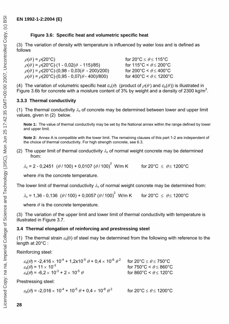
(4) The variation of volumetric specific heat cv(θ) (product of ρ(θ ) and cp(θ )) is illustrated in Figure 3.6b for concrete with a moisture content of 3% by weight and a density of 2300 kg/m3. 3.3.3 Thermal conductivity (1) The thermal conductivity λc of concrete may be determined between lower and upper limit values, given in (2) below.
Note 1: The value of thermal conductivity may be set by the National annex within the range defined by lower and upper limit.
Note 2: Annex A is compatible with the lower limit. The remaining clauses of this part 1-2 are independent of the choice of thermal conductivity. For high strength concrete, see 6.3.
(2) The upper limit of thermal conductivity λc of normal weight concrete may be determined from:
λc = 2 - 0,2451 (θ / 100) + 0,0107 (θ / 100)2 W/m K for 20°C ≤ θ ≤ 1200°C
where θ is the concrete temperature.
The lower limit of thermal conductivity λc of normal weight concrete may be determined from:
λc = 1,36 - 0,136 (θ / 100) + 0,0057 (θ / 100)2 W/m K for 20°C ≤ θ ≤ 1200°C
where θ is the concrete temperature.
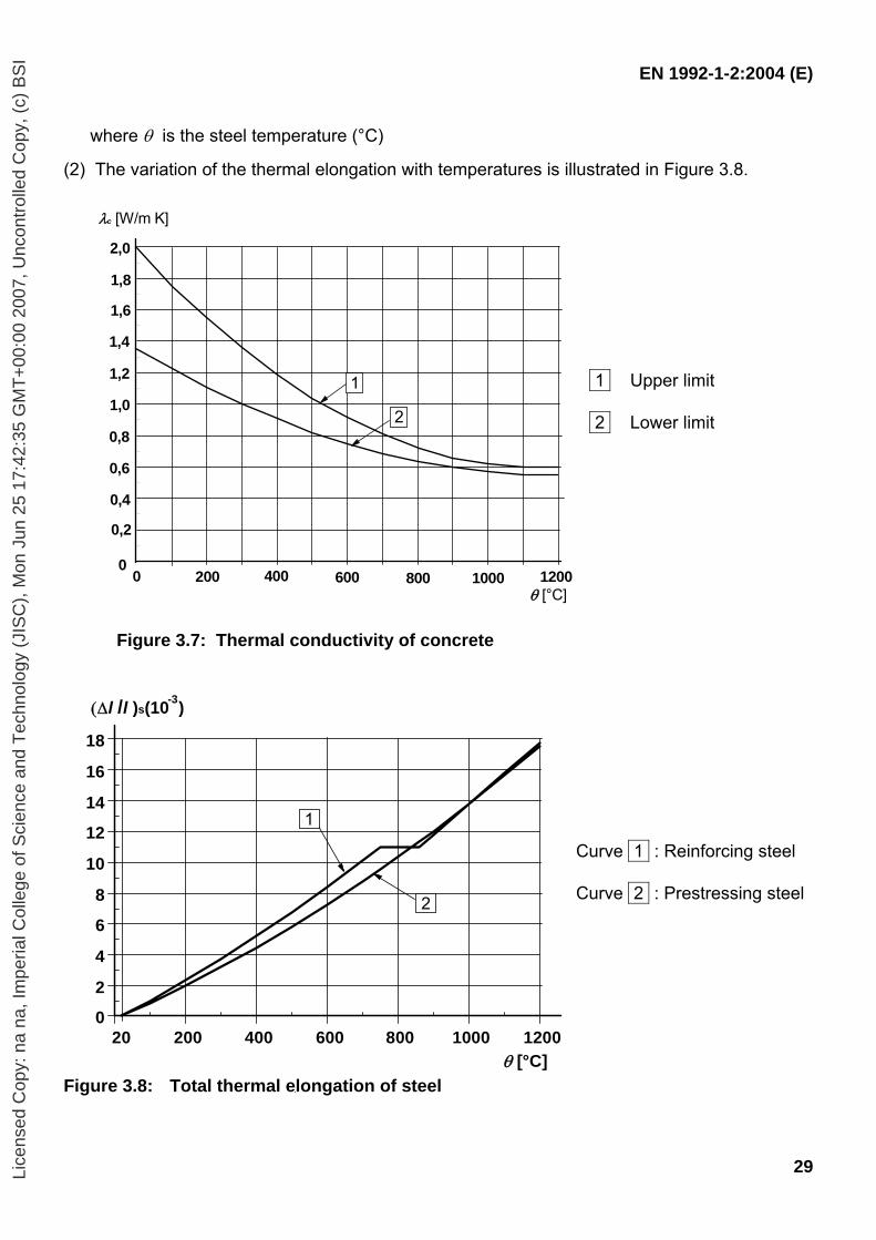
(3) The variation of the upper limit and lower limit of thermal conductivity with temperature is illustrated in Figure 3.7. 3.4 Thermal elongation of reinforcing and prestressing steel
(1) The thermal strain εs(θ) of steel may be determined from the following with reference to the length at 20°C : Reinforcing steel:
εs(θ) = -2,416 × 10-4 + 1,2x10⁻⁵ θ + 0,4 × 10⁻⁸ θ 2 for 20°C ≤ θ ≤ 750°C εs(θ) = 11 × 10-3 for 750°C < θ ≤ 860°C εs(θ) = -6,2 × 10⁻³ + 2 × 10⁻⁵ θ for 860°C < θ ≤ 120°C
Prestressing steel:
εp(θ) = -2,016 × 10-4 + 10-5 θ + 0,4 × 10⁻⁸ θ 2 for 20°C ≤ θ ≤ 1200°C
Lice
nsed
Cop
y: n
a na
, Im
peria
l Col
lege
of S
cien
ce a
nd T
echn
olog
y (J
ISC
), M
on J
un 2
5 17
:42:
35 G
MT
+00
:00
2007
, Unc
ontr
olle
d C
opy,
(c)
BS
I
EN 1992-1-2:2004 (E)
29
where θ is the steel temperature (°C)
(2) The variation of the thermal elongation with temperatures is illustrated in Figure 3.8.
1 Upper limit 2 Lower limit
Figure 3.7: Thermal conductivity of concrete
Curve 1 : Reinforcing steel Curve 2 : Prestressing steel
Figure 3.8: Total thermal elongation of steel
20 200 400 600 800 1000 12000
2
4
6
8
10
12
14
16
18
θ [°C]
2
(∆l /l )s(10 )-3
1
0 200 400 600 800 1000 12000
0,2
θ [°C]
0,4
0,6
0,8
1,0
1,2
1,4
1,6
λc [W/m K]
1,8
2,0
1
2
Lice
nsed
Cop
y: n
a na
, Im
peria
l Col
lege
of S
cien
ce a
nd T
echn
olog
y (J
ISC
), M
on J
un 2
5 17
:42:
35 G
MT
+00
:00
2007
, Unc
ontr
olle
d C
opy,
(c)
BS
I
EN 1992-1-2:2004 (E)
30
SECTION 4 DESIGN PROCEDURES 4.1 General (1)P The following design methods are permitted in order to satisfy 2.4.1 (2)P:
- detailing according to recognised design solutions (tabulated data or testing), see Section 5
- simplified calculation methods for specific types of members, see 4.2 - advanced calculation methods for simulating the behaviour of structural members,
parts of the structure or the entire structure, see 4.3.
Note 1: When calculation methods are used, reference is made to 4.6 for integrity function (E). Note 2: For insulation function (I) the ambient temperature is normally assumed to be 20°C. Note 3: The decision on the use of advanced calculation methods in a country may be found in its National Annex.
(2)P Spalling shall be avoided by appropriate measures or the influence of spalling on performance requirements (R and/or EI) shall be taken into account, see 4.5. (3) Sudden failure caused by excessive steel elongation from heating for prestressed members with unbonded tendons should be avoided. 4.2 Simplified calculation method 4.2.1 General (1) Simplified cross-section calculation methods may be used to determine the ultimate load-bearing capacity of a heated cross section and to compare the capacity with the relevant combination of actions, see 2.4.2.
Note1: Informative Annex B provides two alternative methods, B.1 “500°C isotherm method” and B.2 “Zone method” for calculating the resistance to bending moments and axial forces. Second order effects may be included with both models. The two methods are applicable to structures subjected to a standard fire exposure. Method B.1 may be used in conjunction with both standard and parametric fires. Method B.2 is recommended for use with small sections and slender columns but is only valid for standard fires. Note 2: Informative Annex C provides a zone method for analysing column sections with significant second order effects.
(2) For shear, torsion and anchorage see 4.4.
Note: Informative Annex D provides a simplified calculation method for shear, torsion and anchorage.
(3) Simplified methods for the design of beams and slabs where the loading is predominantly uniformly distributed and where the design at normal temperature is based on linear analysis may be used.
Note: Informative Annex E provides a simplified calculation method for the design of beams and slabs.
4.2.2 Temperature profiles (1) Temperatures in a concrete structure exposed to a fire may be determined from tests or by calculation.
Note: The temperature profiles given in Annex A may be used to determine the temperatures in cross-sections with siliceous aggregate exposed to a standard fire up to the time of maximum gas temperature. The profiles are conservative for most other aggregates.
Lice
nsed
Cop
y: n
a na
, Im
peria
l Col
lege
of S
cien
ce a
nd T
echn
olog
y (J
ISC
), M
on J
un 2
5 17
:42:
35 G
MT
+00
:00
2007
, Unc
ontr
olle
d C
opy,
(c)
BS
I
EN 1992-1-2:2004 (E)
31
4.2.3 Reduced cross-section (1) Simplified methods using a reduced cross-section may be used.
Note: Informative Annex B provides two methods using a reduced cross section. The method described in Annex B.1 is based on the hypothesis that concrete at a temperature more than 500 °C is neglected in the calculation of load-bearing capacity, while concrete at a temperature below 500 °C is assumed to retain its full strength. This method is applicable to a reinforced and prestressed concrete section with respect to axial load, bending moment and their combinations. The method described in Annex B.2 is based on the principle that the fire damaged cross-section is reduced by ignoring a damaged zone at the fire-exposed surfaces. The calculation should follow a specific procedure. The method is applicable to a reinforced and prestressed concrete section with respect to axial load, bending moment and their combinations.
4.2.4 Strength reduction 4.2.4.1 General (1) Values for the reduction of the characteristic compressive strength of concrete, and of the characteristic strength of reinforcing and prestressing steels are given in this section. They may be used with the simplified cross-section calculation methods described in 4.2.3. (2) The values for strength reduction given in 4.2.4.2 and 4.2.4.3 below should only be applied for heating rates similar to those appearing under standard fire exposure until the time of the maximum gas temperature. (3) Alternative formulations of material laws may be applied, provided the solutions are within the range of experimental evidence. 4.2.4.2 Concrete
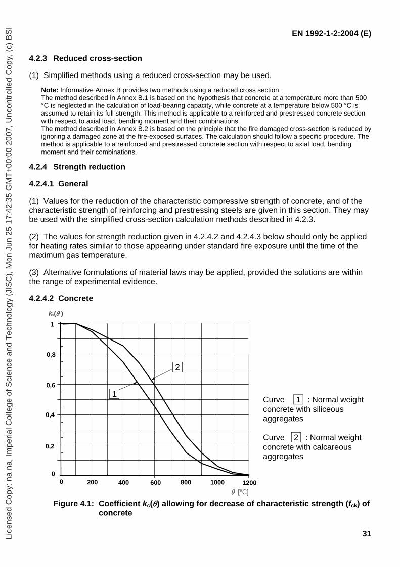
Curve 1 : Normal weight concrete with siliceous aggregates Curve 2 : Normal weight concrete with calcareous aggregates
Figure 4.1: Coefficient kc(θ) allowing for decrease of characteristic strength (fck) of concrete
0,8
1
0
1 0,6
0,2
0,4
1000200 800400 12000 600
kc(θ )
θ [°C]
2
Lice
nsed
Cop
y: n
a na
, Im
peria
l Col
lege
of S
cien
ce a
nd T
echn
olog
y (J
ISC
), M
on J
un 2
5 17
:42:
35 G
MT
+00
:00
2007
, Unc
ontr
olle
d C
opy,
(c)
BS
I
EN 1992-1-2:2004 (E)
32
(1) The reduction of the characteristic compressive strength of concrete as a function of the temperature θ may be used as given in Table 3.1 Column 2 for siliceous aggregates and Column 5 for calcareous aggregates (see Figure 4.1). 4.2.4.3 Steel (1) For tension reinforcement the reduction of the characteristic strength of reinforcing steel as a function of the temperature θ is given in Table 3.2a. For tension reinforcement in beams and slabs where εs,fi ≥ 2%, the strength reduction for Class N reinforcement may be used as given in Table 3.2a, Column 2 for hot rolled and Column 3 for cold worked reinforcing steel (see Figure 4.2a, curve 1 and 2). The strength reduction for Class X reinforcement may be used as given in Table 3.2b for hot rolled and cold worked reinforcing steel (see Figure 4.2b, curve 1). For compression reinforcement in columns and compressive zones of beams and slabs the strength reduction at 0,2% proof strain for Class N reinforcement should be used as given below. This strength reduction also applies for tension reinforcement where εs,fi < 2% when using simplified cross-section calculation methods (see Figure 4.2a, curve 3):
ks(θ) = 1,0 for 20°C ≤ θ ≤ 100°C ks(θ) = 0,7 - 0,3 (θ - 400)/300 for 100°C < θ ≤ 400°C
ks(θ) = 0,57 - 0,13 (θ - 500)/100 for 400°C < θ ≤ 500°C ks(θ) = 0,1 - 0,47 (θ - 700 )/200 for 500°C < θ ≤ 700°C ks(θ) = 0,1 (1200 – θ )/500 for 700°C < θ ≤ 1200°C
Similarly the strength reduction at 0,2% proof strain for Class X reinforcement may be used as given below. This strength reduction also applies for tension reinforcement where εs,fi < 2% (see Figure 4.2b, curve 2).
ks(θ) = 1,0 for 20°C ≤ θ ≤ 100°C ks(θ) = 0,8 - 0,2 (θ - 400)/300 for 100°C < θ ≤ 400°C
ks(θ) = 0,6 - 0,2 (θ - 500)/100 for 400°C < θ ≤ 500°C ks(θ) = 0,33 - 0,27 (θ - 600 )/100 for 500°C < θ ≤ 600°C
ks(θ) = 0,15 - 0,18 (θ - 700 )/100 for 600°C < θ ≤ 700°C ks(θ) = 0,08 - 0,07 (θ - 800 )/100 for 700°C < θ ≤ 800°C ks(θ) = 0,05 - 0,03 (θ - 900 )/100 for 800°C < θ ≤ 900°C
ks(θ) = 0,04 - 0,01 (θ - 1000 )/100 for 900°C < θ ≤ 1000°C ks(θ) = 0,04 (1200 – θ )/200 for 1000°C < θ ≤ 1200°C
(2) The reduction of the characteristic strength of a prestressing steel as a function of the temperature, θ, should be in accordance with 3.2.4 (2). Values may be taken from Table 3.3, Column 2a or 2b for cold worked steel and Column 3 for quenched and tempered prestressing steel (see Figure 4.3).
Lice
nsed
Cop
y: n
a na
, Im
peria
l Col
lege
of S
cien
ce a
nd T
echn
olog
y (J
ISC
), M
on J
un 2
5 17
:42:
35 G
MT
+00
:00
2007
, Unc
ontr
olle
d C
opy,
(c)
BS
I
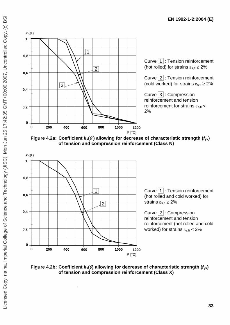
EN 1992-1-2:2004 (E)
33
Curve 1 : Tension reinforcement (hot rolled) for strains εs,fi ≥ 2% Curve 2 : Tension reinforcement (cold worked) for strains εs,fi ≥ 2% Curve 3 : Compression reinforcement and tension reinforcement for strains εs,fi < 2%
Figure 4.2a: Coefficient ks(θ ) allowing for decrease of characteristic strength (fyk) of tension and compression reinforcement (Class N)
Curve 1 : Tension reinforcement (hot rolled and cold worked) for strains εs,fi ≥ 2% Curve 2 : Compression reinforcement and tension reinforcement (hot rolled and cold worked) for strains εs,fi < 2%
Figure 4.2b: Coefficient ks(θ) allowing for decrease of characteristic strength (fyk)
of tension and compression reinforcement (Class X)
0,8
1
0
1
2
3
0,6
0,2
0,4
1000200 800400 12000 600
ks(θ )
θ [°C]
0,8
1
0
0,6
0,2
0,4
1000200 800400 12000 600
ks(θ )
θ [°C]
1
2
Lice
nsed
Cop
y: n
a na
, Im
peria
l Col
lege
of S
cien
ce a
nd T
echn
olog
y (J
ISC
), M
on J
un 2
5 17
:42:
35 G
MT
+00
:00
2007
, Unc
ontr
olle
d C
opy,
(c)
BS
I
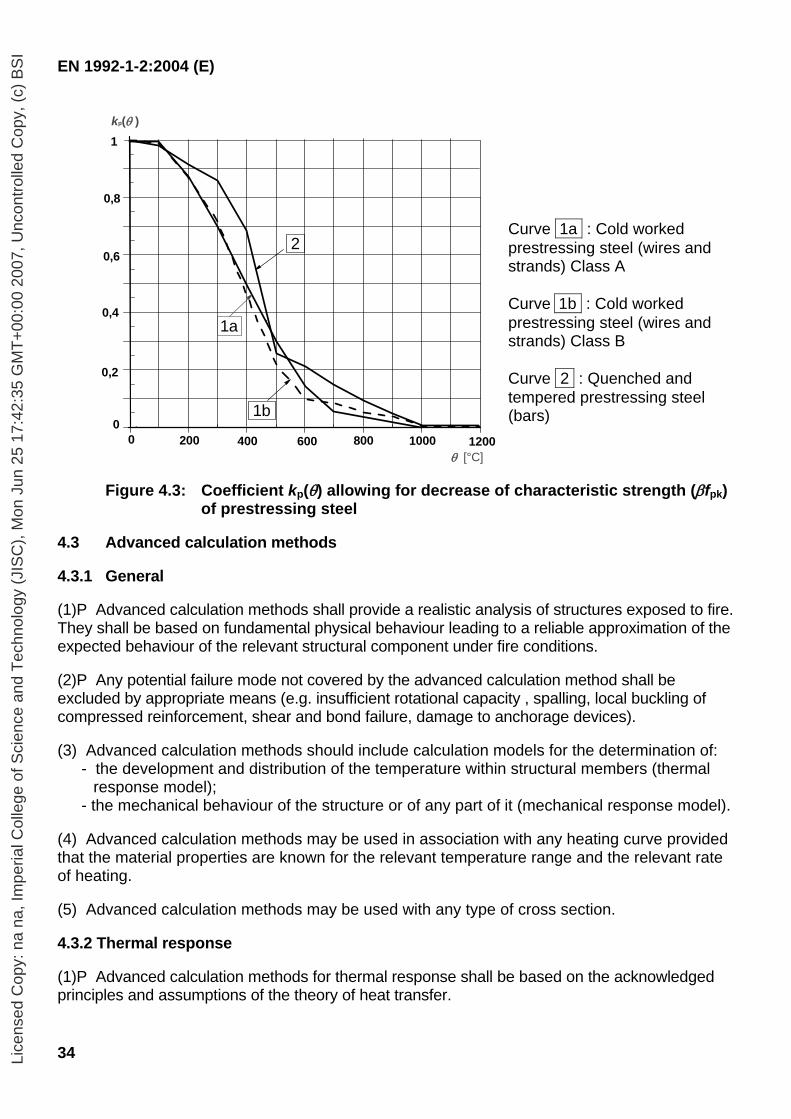
EN 1992-1-2:2004 (E)
34
Curve 1a : Cold worked prestressing steel (wires and strands) Class A
Curve 1b : Cold worked prestressing steel (wires and strands) Class B
Curve 2 : Quenched and tempered prestressing steel (bars)
Figure 4.3: Coefficient kp(θ) allowing for decrease of characteristic strength (βfpk) of prestressing steel
4.3 Advanced calculation methods 4.3.1 General (1)P Advanced calculation methods shall provide a realistic analysis of structures exposed to fire. They shall be based on fundamental physical behaviour leading to a reliable approximation of the expected behaviour of the relevant structural component under fire conditions. (2)P Any potential failure mode not covered by the advanced calculation method shall be excluded by appropriate means (e.g. insufficient rotational capacity , spalling, local buckling of compressed reinforcement, shear and bond failure, damage to anchorage devices). (3) Advanced calculation methods should include calculation models for the determination of:
- the development and distribution of the temperature within structural members (thermal response model);
- the mechanical behaviour of the structure or of any part of it (mechanical response model).
(4) Advanced calculation methods may be used in association with any heating curve provided that the material properties are known for the relevant temperature range and the relevant rate of heating. (5) Advanced calculation methods may be used with any type of cross section. 4.3.2 Thermal response (1)P Advanced calculation methods for thermal response shall be based on the acknowledged principles and assumptions of the theory of heat transfer.
0,8
1
0 1b
2 0,6
0,2
0,4
1000200 800400 12000 600
kp(θ )
θ [°C]
1a
Lice
nsed
Cop
y: n
a na
, Im
peria
l Col
lege
of S
cien
ce a
nd T
echn
olog
y (J
ISC
), M
on J
un 2
5 17
:42:
35 G
MT
+00
:00
2007
, Unc
ontr
olle
d C
opy,
(c)
BS
I
EN 1992-1-2:2004 (E)
35
(2)P The thermal response model shall include the consideration of: a) the relevant thermal actions specified in EN 1991-1-2; b) the temperature dependent thermal properties of the materials
(3) The influence of moisture content and of migration of the moisture within concrete or protective layers if any, may conservatively be neglected. (4) The temperature profile in a reinforced concrete element may be assessed omitting the presence of reinforcement. (5) The effects of non-uniform thermal exposure and of heat transfer to adjacent building components may be included where appropriate. 4.3.3 Mechanical response (1)P Advanced calculation methods for mechanical response shall be based on the acknowledged principles and assumptions of the theory of structural mechanics, taking into account the changes of mechanical properties with temperature. (2)P The effects of thermally induced strains and stresses both due to temperature rise and due to temperature differentials, shall be considered. (3)P The deformations at ultimate limit state implied by the calculation methods shall be limited as necessary to ensure that compatibility is maintained between all parts of the structure. (4)P Where relevant, the mechanical response of the model shall also take account of geometrical non-linear effects. (5) The total strain ε may be assumed to be:
ε = εth + εσ + εcreep + εtr (4.15)
where εth is the thermal strain, εσ is the instantaneous stress-dependent strain εcreep is the creep strain and εtr is the transient state strain
(6) The load bearing capacity of individual members, sub-assemblies or entire structures exposed to fire may be assessed by plastic methods of analysis (see EN 1992-1-1, Section 5). (7) The plastic rotation capacity of reinforced concrete sections should be estimated taking account of the increased ultimate strains εcu and εsu in hot condition. εcu will also be affected by the confinement reinforcement provided.
(8) The compressive zone of a section, especially if directly exposed to fire (e.g. hogging in continuous beams), should be checked and detailed with particular regard to spalling or falling-off of concrete cover. (9) In the analysis of individual members or sub-assemblies the boundary conditions should be checked and detailed in order to avoid failure due to the loss of adequate support for the members.
Lice
nsed
Cop
y: n
a na
, Im
peria
l Col
lege
of S
cien
ce a
nd T
echn
olog
y (J
ISC
), M
on J
un 2
5 17
:42:
35 G
MT
+00
:00
2007
, Unc
ontr
olle
d C
opy,
(c)
BS
I
EN 1992-1-2:2004 (E)
36
4.3.4 Validation of advance calculation methods (1)P A verification of the accuracy of the calculation models shall be made on the basis of relevant test results. (2) Calculation results may refer to temperatures, deformations and fire resistance times. (3)P The critical parameters shall be checked to ensure that the model complies with sound engineering principles, by means of a sensitivity analysis. (4) Critical parameters may refer, for example, to the buckling length, the size of the elements and the load level. 4.4 Shear, torsion and anchorage (1) When minimum dimensions given in Tabulated data are followed, further checks for shear, torsion and anchorage are not required. (2) Calculation methods for shear, torsion and anchorage may be used if they are supported by test information.
Note: Informative Annex D provides a simplified calculations methods for shear , torsion and anchorage.
4.5 Spalling 4.5.1 Explosive spalling (1)P Explosive spalling shall be avoided, or its influence on performance requirements (R and/or EI) shall be taken into account. (2) Explosive spalling is unlikely to occur when the moisture content of the concrete is less than k % by weight. Above k % a more accurate assessment of moisture content, type of aggregate, permeability of concrete and heating rate should be considered.
Note: The value of k for use in a Country may be found in its National Annex. The recommended value is 3. (3) It may be assumed that where members are designed to exposure class X0 and XC1 (see EN 1992-1-1), the moisture content of that member is less than k% by weight, where 2,5 ≤ k ≤ 3,0. (4) When using tabulated data no further check is required for normal weight concrete. 4.5.2 (2) is applicable when the axis distance, a, is 70 mm or more. (5) For beams, slabs and tensile members, if the moisture content of the concrete is more than k% by weight the influence of explosive spalling on load-bearing function R may be assessed by assuming local loss of cover to one reinforcing bar or bundle of bars in the cross section and then checking the reduced load-bearing capacity of the section. For this verification the temperature of the other reinforcing bars may be assumed to be that in an unspalled section. This verification is not required for any structural member for which the correct behaviour with relation to explosive spalling has been checked experimentally or for which complementary protection is applied and verified by testing.
Note: Where the number of bars is large enough, it may be assumed that an acceptable redistribution of stress is possible without loss of the stability (R). This includes: - solid slabs with evenly distributed bars, - beams with a width larger than 400 mm and containing more than 8 bars in the tensile area
Lice
nsed
Cop
y: n
a na
, Im
peria
l Col
lege
of S
cien
ce a
nd T
echn
olog
y (J
ISC
), M
on J
un 2
5 17
:42:
35 G
MT
+00
:00
2007
, Unc
ontr
olle
d C
opy,
(c)
BS
I
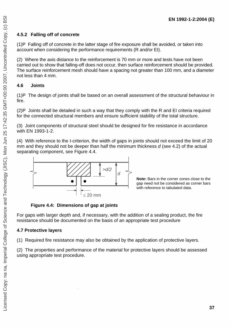
EN 1992-1-2:2004 (E)
37
4.5.2 Falling off of concrete (1)P Falling off of concrete in the latter stage of fire exposure shall be avoided, or taken into account when considering the performance requirements (R and/or EI). (2) Where the axis distance to the reinforcement is 70 mm or more and tests have not been carried out to show that falling-off does not occur, then surface reinforcement should be provided. The surface reinforcement mesh should have a spacing not greater than 100 mm, and a diameter not less than 4 mm. 4.6 Joints (1)P The design of joints shall be based on an overall assessment of the structural behaviour in fire. (2)P Joints shall be detailed in such a way that they comply with the R and EI criteria required for the connected structural members and ensure sufficient stability of the total structure. (3) Joint components of structural steel should be designed for fire resistance in accordance with EN 1993-1-2. (4) With reference to the I-criterion, the width of gaps in joints should not exceed the limit of 20 mm and they should not be deeper than half the minimum thickness d (see 4.2) of the actual separating component, see Figure 4.4.
Note: Bars in the corner zones close to the gap need not be considered as corner bars with reference to tabulated data.
Figure 4.4: Dimensions of gap at joints
For gaps with larger depth and, if necessary, with the addition of a sealing product, the fire resistance should be documented on the basis of an appropriate test procedure 4.7 Protective layers (1) Required fire resistance may also be obtained by the application of protective layers. (2) The properties and performance of the material for protective layers should be assessed using appropriate test procedure.
d>d/2
≤ 20 mm
Lice
nsed
Cop
y: n
a na
, Im
peria
l Col
lege
of S
cien
ce a
nd T
echn
olog
y (J
ISC
), M
on J
un 2
5 17
:42:
35 G
MT
+00
:00
2007
, Unc
ontr
olle
d C
opy,
(c)
BS
I
EN 1992-1-2:2004 (E)
38
5 Tabulated data 5.1 Scope (1) This section gives recognised design solutions for the standard fire exposure up to 240 minutes (see 4.1). The rules refer to member analysis according to 2.4.2.
Note: The tables have been developed on an empirical basis confirmed by experience and theoretical evaluation of tests. The data is derived from approximate conservative assumptions for the more common structural elements and is valid for the whole range of thermal conductivity in 3.3. More specific tabulated data can be found in the product standards for some particular types of concrete products or developed, on the basis of the calculation method in accordance with 4.2, 4.3 and 4.4.
(2) The values given in the tables apply to normal weight concrete (2000 to 2600 kg/m3, see EN 206-1) made with siliceous aggregates.
If calcareous aggregates or lightweight aggregates are used in beams or slabs the minimum dimension of the cross-section may be reduced by 10%. (3) When using tabulated data no further checks are required concerning shear and torsion capacity and anchorage details (see 4.4). (4) When using tabulated data no further checks are required concerning spalling, except for surface reinforcement (see 4.5.1 (4)). 5.2 General design rules (1) Requirements for separating function (Criterion E and I (see 2.1.2)) may be considered satisfied where the minimum thickness of walls or slabs is in accordance with Table 5.3. For joints reference should be made to 4.6. (2) For load bearing function (Criterion R), the minimum requirements concerning section sizes and axis distance of steel in the tables follows from:
Ed,fi/Rd,fi ≤ 1,0 (5.1)
where: Ed,fi is the design effect of actions in the fire situation. Rd,fi is the design load-bearing capacity (resistance) in the fire situation.
(3) Tabulated data in this section are based on a reference load level ηfi = 0,7, unless otherwise stated in the relevant clauses.
Note: Where the partial safety factors specified in the National Annexes of EN 1990 deviate from those indicated in 2.4.2, the above value ηfi = 0,7 may not be valid. In such circumstances the value of ηfi for use in a Country may be found in its National Annex.
(4) In order to ensure the necessary axis distance in tensile zones of simply supported beams and slabs, Tables 5.5, 5.6 and 5.8, Column 3 (one way), are based on a critical steel temperature of θcr = 500°C. This assumption corresponds approximately to Ed,fi = 0,7Ed and γs = 1,15 (stress level σs,fi/fyk = 0,60, see Expression (5.2)) where Ed denotes the design effect of actions according to EN 1992-1-1.
Lice
nsed
Cop
y: n
a na
, Im
peria
l Col
lege
of S
cien
ce a
nd T
echn
olog
y (J
ISC
), M
on J
un 2
5 17
:42:
35 G
MT
+00
:00
2007
, Unc
ontr
olle
d C
opy,
(c)
BS
I
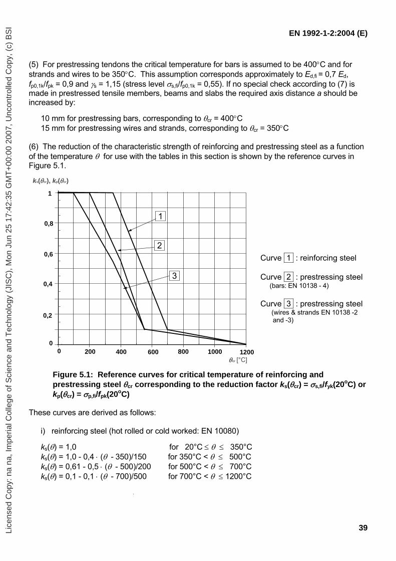
EN 1992-1-2:2004 (E)
39
(5) For prestressing tendons the critical temperature for bars is assumed to be 400°C and for strands and wires to be 350°C. This assumption corresponds approximately to Ed,fi = 0,7 Ed, fp0,1k/fpk = 0,9 and γs = 1,15 (stress level σs,fi/fp0,1k = 0,55). If no special check according to (7) is made in prestressed tensile members, beams and slabs the required axis distance a should be increased by:
10 mm for prestressing bars, corresponding to θcr = 400°C 15 mm for prestressing wires and strands, corresponding to θcr = 350°C
(6) The reduction of the characteristic strength of reinforcing and prestressing steel as a function of the temperature θ for use with the tables in this section is shown by the reference curves in Figure 5.1.
Curve 1 : reinforcing steel Curve 2 : prestressing steel (bars: EN 10138 - 4) Curve 3 : prestressing steel (wires & strands EN 10138 -2 and -3)
Figure 5.1: Reference curves for critical temperature of reinforcing and prestressing steel θcr corresponding to the reduction factor ks(θcr) = σs,fi/fyk(20oC) or kp(θcr) = σp,fi/fpk(20oC)
These curves are derived as follows:
i) reinforcing steel (hot rolled or cold worked: EN 10080)
ks(θ) = 1,0 for 20°C ≤ θ ≤ 350°C ks(θ) = 1,0 - 0,4 ⋅ (θ - 350)/150 for 350°C < θ ≤ 500°C ks(θ) = 0,61 - 0,5 ⋅ (θ - 500)/200 for 500°C < θ ≤ 700°C ks(θ) = 0,1 - 0,1 ⋅ (θ - 700)/500 for 700°C < θ ≤ 1200°C
0,8
1
0
1
2
3
0,6
0,2
0,4
1000200 800400 12000 600
ks(θcr), kp(θcr)
θcr [°C]
Lice
nsed
Cop
y: n
a na
, Im
peria
l Col
lege
of S
cien
ce a
nd T
echn
olog
y (J
ISC
), M
on J
un 2
5 17
:42:
35 G
MT
+00
:00
2007
, Unc
ontr
olle
d C
opy,
(c)
BS
I
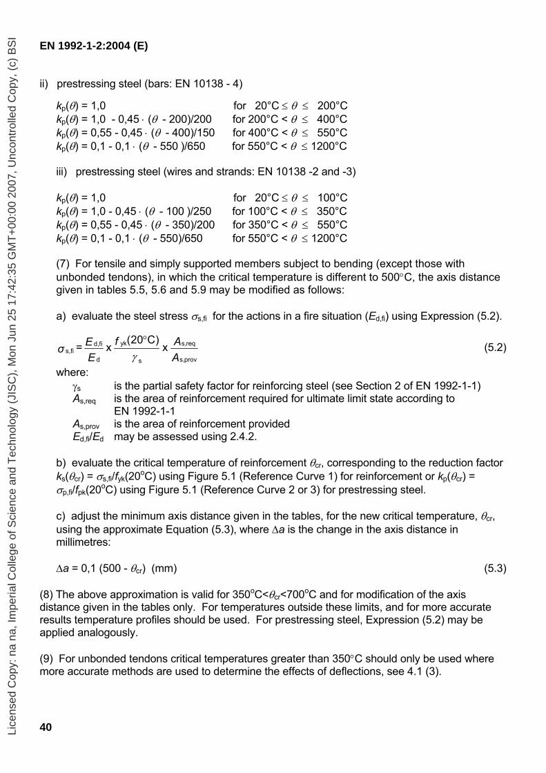
EN 1992-1-2:2004 (E)
40
ii) prestressing steel (bars: EN 10138 - 4)
kp(θ) = 1,0 for 20°C ≤ θ ≤ 200°C kp(θ) = 1,0 - 0,45 ⋅ (θ - 200)/200 for 200°C < θ ≤ 400°C kp(θ) = 0,55 - 0,45 ⋅ (θ - 400)/150 for 400°C < θ ≤ 550°C kp(θ) = 0,1 - 0,1 ⋅ (θ - 550 )/650 for 550°C < θ ≤ 1200°C iii) prestressing steel (wires and strands: EN 10138 -2 and -3) kp(θ) = 1,0 for 20°C ≤ θ ≤ 100°C kp(θ) = 1,0 - 0,45 ⋅ (θ - 100 )/250 for 100°C < θ ≤ 350°C kp(θ) = 0,55 - 0,45 ⋅ (θ - 350)/200 for 350°C < θ ≤ 550°C kp(θ) = 0,1 - 0,1 ⋅ (θ - 550)/650 for 550°C < θ ≤ 1200°C (7) For tensile and simply supported members subject to bending (except those with unbonded tendons), in which the critical temperature is different to 500°C, the axis distance given in tables 5.5, 5.6 and 5.9 may be modified as follows: a) evaluate the steel stress σs,fi for the actions in a fire situation (Ed,fi) using Expression (5.2).
f AEσE A
yk s,reqd,fis,fi
d s,provs
(20 C) = x x
γ°
(5.2)
where: γs is the partial safety factor for reinforcing steel (see Section 2 of EN 1992-1-1) As,req is the area of reinforcement required for ultimate limit state according to
EN 1992-1-1 As,prov is the area of reinforcement provided Ed,fi/Ed may be assessed using 2.4.2.
b) evaluate the critical temperature of reinforcement θcr, corresponding to the reduction factor ks(θcr) = σs,fi/fyk(20oC) using Figure 5.1 (Reference Curve 1) for reinforcement or kp(θcr) = σp,fi/fpk(20oC) using Figure 5.1 (Reference Curve 2 or 3) for prestressing steel.
c) adjust the minimum axis distance given in the tables, for the new critical temperature, θcr, using the approximate Equation (5.3), where ∆a is the change in the axis distance in millimetres:
∆a = 0,1 (500 - θcr) (mm) (5.3)
(8) The above approximation is valid for 350oC<θcr<700oC and for modification of the axis distance given in the tables only. For temperatures outside these limits, and for more accurate results temperature profiles should be used. For prestressing steel, Expression (5.2) may be applied analogously. (9) For unbonded tendons critical temperatures greater than 350°C should only be used where more accurate methods are used to determine the effects of deflections, see 4.1 (3).
Lice
nsed
Cop
y: n
a na
, Im
peria
l Col
lege
of S
cien
ce a
nd T
echn
olog
y (J
ISC
), M
on J
un 2
5 17
:42:
35 G
MT
+00
:00
2007
, Unc
ontr
olle
d C
opy,
(c)
BS
I
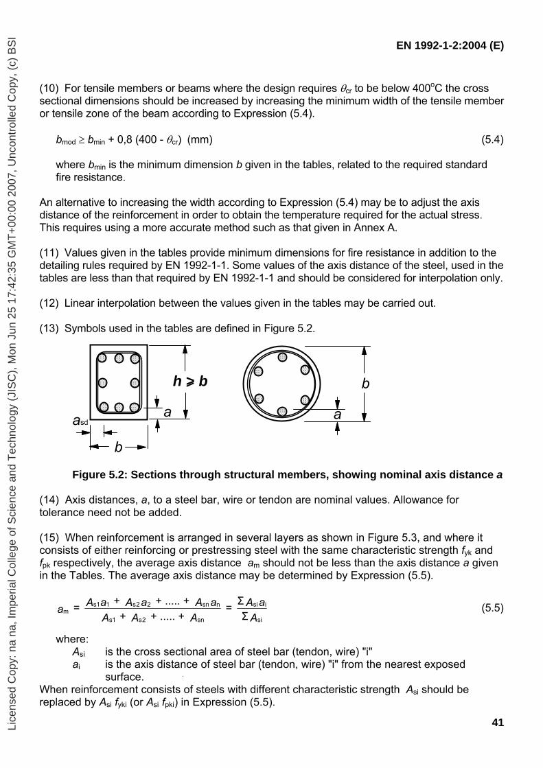
EN 1992-1-2:2004 (E)
41
(10) For tensile members or beams where the design requires θcr to be below 400oC the cross sectional dimensions should be increased by increasing the minimum width of the tensile member or tensile zone of the beam according to Expression (5.4).
bmod ≥ bmin + 0,8 (400 - θcr) (mm) (5.4)
where bmin is the minimum dimension b given in the tables, related to the required standard fire resistance.
An alternative to increasing the width according to Expression (5.4) may be to adjust the axis distance of the reinforcement in order to obtain the temperature required for the actual stress. This requires using a more accurate method such as that given in Annex A.
(11) Values given in the tables provide minimum dimensions for fire resistance in addition to the detailing rules required by EN 1992-1-1. Some values of the axis distance of the steel, used in the tables are less than that required by EN 1992-1-1 and should be considered for interpolation only. (12) Linear interpolation between the values given in the tables may be carried out. (13) Symbols used in the tables are defined in Figure 5.2.
h > b
b
asda
b
a
Figure 5.2: Sections through structural members, showing nominal axis distance a
(14) Axis distances, a, to a steel bar, wire or tendon are nominal values. Allowance for tolerance need not be added. (15) When reinforcement is arranged in several layers as shown in Figure 5.3, and where it consists of either reinforcing or prestressing steel with the same characteristic strength fyk and fpk respectively, the average axis distance am should not be less than the axis distance a given in the Tables. The average axis distance may be determined by Expression (5.5).
AaA
AAAaAaAaAa
si
isi
sn2s1s
nsn22s11sm Σ
Σ = + ..... + + + ..... + + = (5.5)
where:
Asi is the cross sectional area of steel bar (tendon, wire) "i" ai is the axis distance of steel bar (tendon, wire) "i" from the nearest exposed
surface. When reinforcement consists of steels with different characteristic strength Asi should be replaced by Asi fyki (or Asi fpki) in Expression (5.5).
Lice
nsed
Cop
y: n
a na
, Im
peria
l Col
lege
of S
cien
ce a
nd T
echn
olog
y (J
ISC
), M
on J
un 2
5 17
:42:
35 G
MT
+00
:00
2007
, Unc
ontr
olle
d C
opy,
(c)
BS
I
EN 1992-1-2:2004 (E)
42
(16) Where reinforcing and prestressing steel is used simultaneously (e.g. in a partially prestressed member), the axis distances of reinforcing and prestressing steel should be determined separately.
Note: Use of temperature graphs and simplified calculation methods is recommended.
a3
a ,2
a6
a7 a ,5a ,4
a3
a1
a5
1 2 3
45
76a ,1
a6
Figure 5.3: Dimensions used to calculate average axis distance am
(17) The minimum axis distance for any individual bar should not be less than either that required for R 30 for bars in a single layer or half the average axis distance for bars in multiple layers (see Expression (5.5)).
5.3 Columns 5.3.1 General (1) For assessing the fire resistance of columns, two methods, Method A and Method B are provided.
Note: Tabulated data is given for braced structures only. Tabulated data for unbraced structures may be found in a Country’s National Annex.
5.3.2 Method A (1) Fire resistance of reinforced and prestressed concrete columns, submitted mainly to compression in braced structures may be considered adequate if the values in Table 5.2a together with the following rules are applied. (2) The validity of the minimum values of the column width bmin and the axis distance of longitudinal reinforcement a given in Table 5.2a is limited as follows:
- effective length of the column (for definition see EN 1992-1-1 Section 5) under fire conditions: l0,fi ≤ 3 m
- first order eccentricity under fire conditions: e = M0Ed,fi / N0Ed,fi ≤ emax - amount of reinforcement: As < 0,04 Ac
Note 1: The value of emax, within limits 0,15h (or b) ≤ emax ≤ 0,4h (and b), for use in a Country may be found in its National Annex. The recommended value is 0,15h (and b).
Note 2: The effective length of a column under fire conditions lo,fi may be assumed to be equal to l o at normal temperature in all cases. For braced building structures where the required Standard fire exposure is higher than 30 minutes, the effective length l 0,fi may be taken as 0,5 l for intermediate floors and 0,5 l ≤ l 0,fi ≤ 0,7l for the upper floor, where l is the actual length of the column (centre to centre).
Lice
nsed
Cop
y: n
a na
, Im
peria
l Col
lege
of S
cien
ce a
nd T
echn
olog
y (J
ISC
), M
on J
un 2
5 17
:42:
35 G
MT
+00
:00
2007
, Unc
ontr
olle
d C
opy,
(c)
BS
I
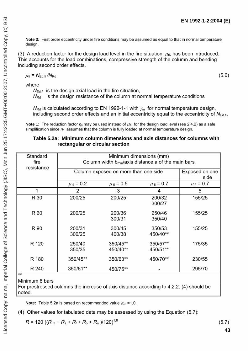
EN 1992-1-2:2004 (E)
43
Note 3: First order eccentricity under fire conditions may be assumed as equal to that in normal temperature design.
(3) A reduction factor for the design load level in the fire situation, µfi, has been introduced. This accounts for the load combinations, compressive strength of the column and bending including second order effects.
µfi = NEd.fi /NRd (5.6)
where NEd.fi is the design axial load in the fire situation, NRd is the design resistance of the column at normal temperature conditions NRd is calculated according to EN 1992-1-1 with γm for normal temperature design, including second order effects and an initial eccentricity equal to the eccentricity of NEd.fi.
Note 1: The reduction factor ηfi may be used instead of µfi for the design load level (see 2.4.2) as a safe simplification since ηfi assumes that the column is fully loaded at normal temperature design.
Table 5.2a: Minimum column dimensions and axis distances for columns with rectangular or circular section
Minimum dimensions (mm)
Column width bmin/axis distance a of the main bars
Column exposed on more than one side Exposed on one side
Standard fire
resistance
µ fi = 0.2 µ fi = 0.5 µ fi = 0.7 µ fi = 0.7 1 2 3 4 5
R 30
R 60
R 90
R 120
R 180
R 240
200/25
200/25
200/31 300/25
250/40 350/35
350/45**
350/61**
200/25
200/36 300/31
300/45 400/38
350/45** 450/40**
350/63**
450/75**
200/32 300/27
250/46 350/40
350/53
450/40**
350/57** 450/51**
450/70**
-
155/25
155/25
155/25
175/35
230/55
295/70 ** Minimum 8 bars For prestressed columns the increase of axis distance according to 4.2.2. (4) should be noted.
Note: Table 5.2a is based on recommended value αcc =1,0. (4) Other values for tabulated data may be assessed by using the Equation (5.7):
R = 120 ((Rηfi + Ra + Rl + Rb + Rn )/120)1,8 (5.7)
Lice
nsed
Cop
y: n
a na
, Im
peria
l Col
lege
of S
cien
ce a
nd T
echn
olog
y (J
ISC
), M
on J
un 2
5 17
:42:
35 G
MT
+00
:00
2007
, Unc
ontr
olle
d C
opy,
(c)
BS
I
EN 1992-1-2:2004 (E)
44
where
( ) ⎥⎦
⎤⎢⎣
⎡+
+−=
ωαωµηcc
fifi /85,0)1(00,183R
Ra = 1,60 (a – 30) Rl = 9,60 (5 – lo,fi) Rb = 0.09 b’ Rn = 0 for n = 4 (corner bars only) = 12 for n > 4 a is the axis distance to the longitudinal steel bars (mm); 25 mm ≤ a ≤ 80 mm l0,fi is the effective length of the column under fire conditions; 2 m ≤ l0,fi ≤ 6 m;
values corresponding to l0,fi = 2 m give safe results for columns with l0,fi < 2 m b’ = 2Ac/ (b+h) for rectangular cross-sections or the diameter of circular cross
sections 200 mm ≤ b’ ≤ 450 mm; h ≤ 1,5 b.
ω denotes the mechanical reinforcement ratio at normal temperature conditions :
cdc
yds
fAfA
=
αcc is coefficient for compressive strength (see EN 1992-1-1)
For first order eccentricity under fire conditions the limits of validity given in 5.3.2 (2) apply. 5.3.3 Method B (1) Fire resistance of reinforced concrete columns may be satisfied by the use of Table 5.2b and the following rules. Further information is given in Annex C. (2) Table 5.2b is valid only for columns in braced structures where:
the load level, n, at normal temperature conditions (see EN 1992-1-1, 5.8) is given by n = N0Ed,fi /(0,7(Ac fcd + As fyd)) (5.8a) the first order eccentricity under fire conditions, e, is given by e = M0Ed,fi /(N0Ed,fi) (5.8b)
e / b has been taken as ≤ 0,25 with emax = 100 mm
the slenderness of the column under fire conditions, λfi, is given by λfi = l0,fi / i (5.8c)
λfi has been taken as ≤ 30, which covers the majority of columns in normal buildings
where l0,fi is the effective length of the column under fire conditions b is the minimum dimension of the section on rectangular columns or the diameter on
circular columns
Lice
nsed
Cop
y: n
a na
, Im
peria
l Col
lege
of S
cien
ce a
nd T
echn
olog
y (J
ISC
), M
on J
un 2
5 17
:42:
35 G
MT
+00
:00
2007
, Unc
ontr
olle
d C
opy,
(c)
BS
I
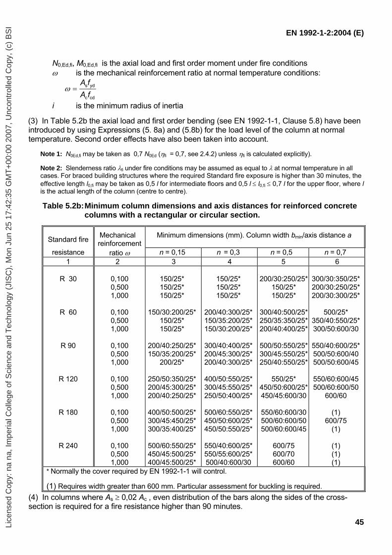
EN 1992-1-2:2004 (E)
45
N0,Ed,fi, M0,Ed,fi is the axial load and first order moment under fire conditions ω is the mechanical reinforcement ratio at normal temperature conditions:
cdc
yds
fAfA
=ω
i is the minimum radius of inertia
(3) In Table 5.2b the axial load and first order bending (see EN 1992-1-1, Clause 5.8) have been introduced by using Expressions (5. 8a) and (5.8b) for the load level of the column at normal temperature. Second order effects have also been taken into account.
Note 1: N0Ed,fi may be taken as 0,7 N0Ed (ηfi = 0,7, see 2.4.2) unless ηfi is calculated explicitly). Note 2: Slenderness ratio λfi under fire conditions may be assumed as equal to λ at normal temperature in all cases. For braced building structures where the required Standard fire exposure is higher than 30 minutes, the effective length l0,fi may be taken as 0,5 l for intermediate floors and 0,5 l ≤ l0,fi ≤ 0,7 l for the upper floor, where l is the actual length of the column (centre to centre). Table 5.2b: Minimum column dimensions and axis distances for reinforced concrete
columns with a rectangular or circular section.
Standard fire Mechanical
reinforcement Minimum dimensions (mm). Column width bmin/axis distance a
resistance ratio ω n = 0,15 n = 0,3 n = 0,5 n = 0,7 1 2 3 4 5 6
R 30
R 60
R 90
R 120
R 180
R 240
0,100 0,500 1,000
0,100 0,500 1,000
0,100 0,500 1,000
0,100 0,500 1,000
0,100 0,500 1,000
0,100 0,500 1,000
150/25* 150/25* 150/25*
150/30:200/25*
150/25* 150/25*
200/40:250/25* 150/35:200/25*
200/25*
250/50:350/25* 200/45:300/25* 200/40:250/25*
400/50:500/25* 300/45:450/25* 300/35:400/25*
500/60:550/25* 450/45:500/25* 400/45:500/25*
150/25* 150/25* 150/25*
200/40:300/25* 150/35:200/25* 150/30:200/25*
300/40:400/25* 200/45:300/25* 200/40:300/25*
400/50:550/25* 300/45:550/25* 250/50:400/25*
500/60:550/25* 450/50:600/25* 450/50:550/25*
550/40:600/25* 550/55:600/25* 500/40:600/30
200/30:250/25*
150/25* 150/25*
300/40:500/25* 250/35:350/25* 200/40:400/25*
500/50:550/25* 300/45:550/25* 250/40:550/25*
550/25*
450/50:600/25* 450/45:600/30
550/60:600/30 500/60:600/50 500/60:600/45
600/75 600/70 600/60
300/30:350/25* 200/30:250/25* 200/30:300/25*
500/25*
350/40:550/25* 300/50:600/30
550/40:600/25* 500/50:600/40 500/50:600/45
550/60:600/45 500/60:600/50
600/60
(1) 600/75
(1)
(1) (1) (1)
* Normally the cover required by EN 1992-1-1 will control. (1) Requires width greater than 600 mm. Particular assessment for buckling is required.
(4) In columns where As ≥ 0,02 Ac , even distribution of the bars along the sides of the cross-section is required for a fire resistance higher than 90 minutes.
Lice
nsed
Cop
y: n
a na
, Im
peria
l Col
lege
of S
cien
ce a
nd T
echn
olog
y (J
ISC
), M
on J
un 2
5 17
:42:
35 G
MT
+00
:00
2007
, Unc
ontr
olle
d C
opy,
(c)
BS
I
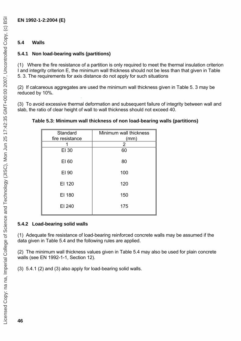
EN 1992-1-2:2004 (E)
46
5.4 Walls 5.4.1 Non load-bearing walls (partitions) (1) Where the fire resistance of a partition is only required to meet the thermal insulation criterion I and integrity criterion E, the minimum wall thickness should not be less than that given in Table 5. 3. The requirements for axis distance do not apply for such situations
(2) If calcareous aggregates are used the minimum wall thickness given in Table 5. 3 may be reduced by 10%. (3) To avoid excessive thermal deformation and subsequent failure of integrity between wall and slab, the ratio of clear height of wall to wall thickness should not exceed 40.
Table 5.3: Minimum wall thickness of non load-bearing walls (partitions)
Standard fire resistance
Minimum wall thickness (mm)
1 2 EI 30
EI 60
EI 90
EI 120
EI 180
EI 240
60
80
100
120
150
175
5.4.2 Load-bearing solid walls (1) Adequate fire resistance of load-bearing reinforced concrete walls may be assumed if the data given in Table 5.4 and the following rules are applied. (2) The minimum wall thickness values given in Table 5.4 may also be used for plain concrete walls (see EN 1992-1-1, Section 12). (3) 5.4.1 (2) and (3) also apply for load-bearing solid walls.
Lice
nsed
Cop
y: n
a na
, Im
peria
l Col
lege
of S
cien
ce a
nd T
echn
olog
y (J
ISC
), M
on J
un 2
5 17
:42:
35 G
MT
+00
:00
2007
, Unc
ontr
olle
d C
opy,
(c)
BS
I
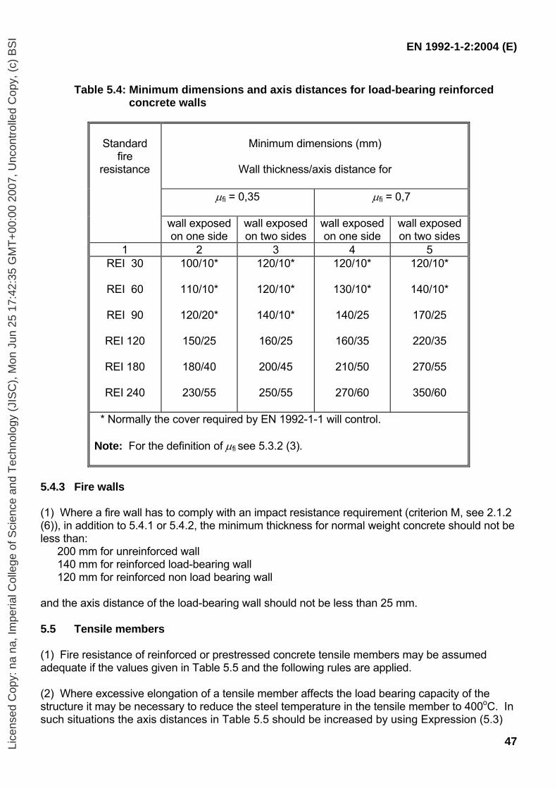
EN 1992-1-2:2004 (E)
47
Table 5.4: Minimum dimensions and axis distances for load-bearing reinforced concrete walls
Standard fire
resistance
Minimum dimensions (mm)
Wall thickness/axis distance for
µfi = 0,35 µfi = 0,7
wall exposed on one side
wall exposed on two sides
wall exposed on one side
wall exposed on two sides
1 2 3 4 5 REI 30
REI 60
REI 90
REI 120
REI 180
REI 240
100/10*
110/10*
120/20*
150/25
180/40
230/55
120/10*
120/10*
140/10*
160/25
200/45
250/55
120/10*
130/10*
140/25
160/35
210/50
270/60
120/10*
140/10*
170/25
220/35
270/55
350/60
* Normally the cover required by EN 1992-1-1 will control. Note: For the definition of µfi see 5.3.2 (3).
5.4.3 Fire walls (1) Where a fire wall has to comply with an impact resistance requirement (criterion M, see 2.1.2 (6)), in addition to 5.4.1 or 5.4.2, the minimum thickness for normal weight concrete should not be less than:
200 mm for unreinforced wall 140 mm for reinforced load-bearing wall 120 mm for reinforced non load bearing wall
and the axis distance of the load-bearing wall should not be less than 25 mm. 5.5 Tensile members (1) Fire resistance of reinforced or prestressed concrete tensile members may be assumed adequate if the values given in Table 5.5 and the following rules are applied. (2) Where excessive elongation of a tensile member affects the load bearing capacity of the structure it may be necessary to reduce the steel temperature in the tensile member to 400oC. In such situations the axis distances in Table 5.5 should be increased by using Expression (5.3)
Lice
nsed
Cop
y: n
a na
, Im
peria
l Col
lege
of S
cien
ce a
nd T
echn
olog
y (J
ISC
), M
on J
un 2
5 17
:42:
35 G
MT
+00
:00
2007
, Unc
ontr
olle
d C
opy,
(c)
BS
I
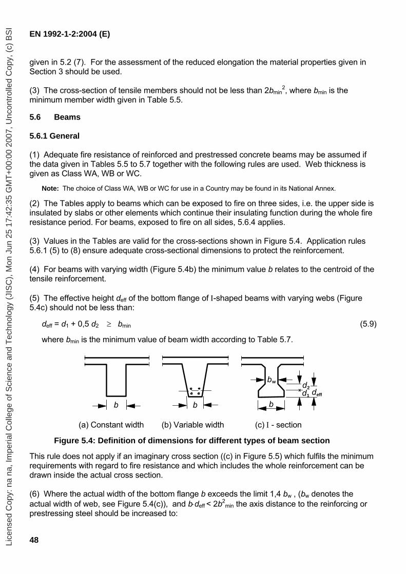
EN 1992-1-2:2004 (E)
48
given in 5.2 (7). For the assessment of the reduced elongation the material properties given in Section 3 should be used. (3) The cross-section of tensile members should not be less than 2bmin
2, where bmin is the minimum member width given in Table 5.5. 5.6 Beams 5.6.1 General (1) Adequate fire resistance of reinforced and prestressed concrete beams may be assumed if the data given in Tables 5.5 to 5.7 together with the following rules are used. Web thickness is given as Class WA, WB or WC.
Note: The choice of Class WA, WB or WC for use in a Country may be found in its National Annex. (2) The Tables apply to beams which can be exposed to fire on three sides, i.e. the upper side is insulated by slabs or other elements which continue their insulating function during the whole fire resistance period. For beams, exposed to fire on all sides, 5.6.4 applies. (3) Values in the Tables are valid for the cross-sections shown in Figure 5.4. Application rules 5.6.1 (5) to (8) ensure adequate cross-sectional dimensions to protect the reinforcement. (4) For beams with varying width (Figure 5.4b) the minimum value b relates to the centroid of the tensile reinforcement. (5) The effective height deff of the bottom flange of Ι-shaped beams with varying webs (Figure 5.4c) should not be less than:
deff = d1 + 0,5 d2 ≥ bmin (5.9)
where bmin is the minimum value of beam width according to Table 5.7.
b b b
bw
d1
d2x deff
(a) Constant width (b) Variable width (c) Ι - section
Figure 5.4: Definition of dimensions for different types of beam section This rule does not apply if an imaginary cross section ((c) in Figure 5.5) which fulfils the minimum requirements with regard to fire resistance and which includes the whole reinforcement can be drawn inside the actual cross section. (6) Where the actual width of the bottom flange b exceeds the limit 1,4 bw , (bw denotes the actual width of web, see Figure 5.4(c)), and b⋅deff < 2b2
min the axis distance to the reinforcing or prestressing steel should be increased to:
Lice
nsed
Cop
y: n
a na
, Im
peria
l Col
lege
of S
cien
ce a
nd T
echn
olog
y (J
ISC
), M
on J
un 2
5 17
:42:
35 G
MT
+00
:00
2007
, Unc
ontr
olle
d C
opy,
(c)
BS
I
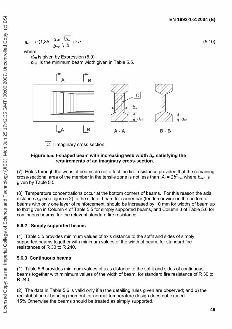
EN 1992-1-2:2004 (E)
49
abb
bdaa ) - (1,85 = w
min
effeff ≥ (5.10)
where: deff is given by Expression (5.9) bmin is the minimum beam width given in Table 5.5.
A
A
B
B A - A B - B
bw
deff deff
C
C : Imaginary cross section
Figure 5.5: I-shaped beam with increasing web width bw satisfying the requirements of an imaginary cross-section.
(7) Holes through the webs of beams do not affect the fire resistance provided that the remaining cross-sectional area of the member in the tensile zone is not less than Ac = 2b2
min where bmin is given by Table 5.5. (8) Temperature concentrations occur at the bottom corners of beams. For this reason the axis distance asd (see figure 5.2) to the side of beam for corner bar (tendon or wire) in the bottom of beams with only one layer of reinforcement, should be increased by 10 mm for widths of beam up to that given in Column 4 of Table 5.5 for simply supported beams, and Column 3 of Table 5.6 for continuous beams, for the relevant standard fire resistance. 5.6.2 Simply supported beams (1) Table 5.5 provides minimum values of axis distance to the soffit and sides of simply supported beams together with minimum values of the width of beam, for standard fire resistances of R 30 to R 240, 5.6.3 Continuous beams (1) Table 5.6 provides minimum values of axis distance to the soffit and sides of continuous beams together with minimum values of the width of beam, for standard fire resistance of R 30 to R 240, (2) The data in Table 5.6 is valid only if a) the detailing rules given are observed; and b) the redistribution of bending moment for normal temperature design does not exceed 15%.Otherwise the beams should be treated as simply supported.
Lice
nsed
Cop
y: n
a na
, Im
peria
l Col
lege
of S
cien
ce a
nd T
echn
olog
y (J
ISC
), M
on J
un 2
5 17
:42:
35 G
MT
+00
:00
2007
, Unc
ontr
olle
d C
opy,
(c)
BS
I
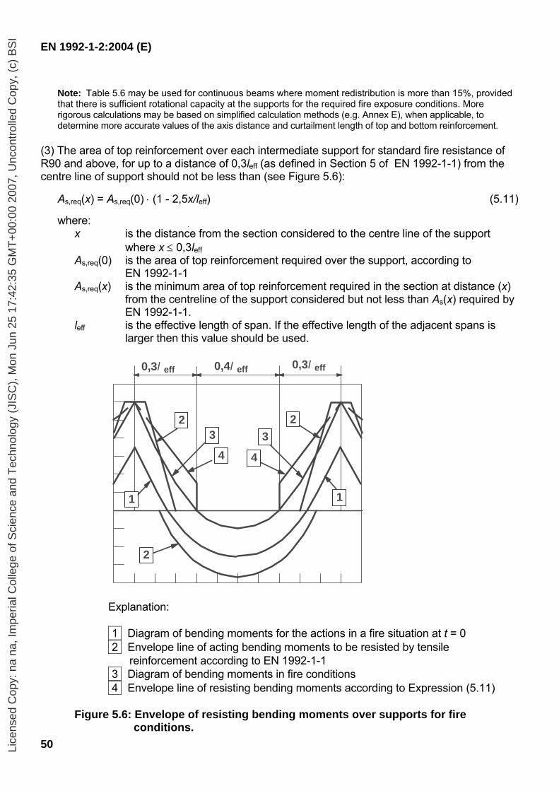
EN 1992-1-2:2004 (E)
50
Note: Table 5.6 may be used for continuous beams where moment redistribution is more than 15%, provided that there is sufficient rotational capacity at the supports for the required fire exposure conditions. More rigorous calculations may be based on simplified calculation methods (e.g. Annex E), when applicable, to determine more accurate values of the axis distance and curtailment length of top and bottom reinforcement.
(3) The area of top reinforcement over each intermediate support for standard fire resistance of R90 and above, for up to a distance of 0,3leff (as defined in Section 5 of EN 1992-1-1) from the centre line of support should not be less than (see Figure 5.6):
As,req(x) = As,req(0) ⋅ (1 - 2,5x/leff) (5.11)
where: x is the distance from the section considered to the centre line of the support
where x ≤ 0,3leff As,req(0) is the area of top reinforcement required over the support, according to
EN 1992-1-1 As,req(x) is the minimum area of top reinforcement required in the section at distance (x)
from the centreline of the support considered but not less than As(x) required by EN 1992-1-1.
leff is the effective length of span. If the effective length of the adjacent spans is larger then this value should be used.
0,3l eff 0,4l eff 0,3l eff
2
1 1
2 3
4 3
4
2
Explanation:
1 Diagram of bending moments for the actions in a fire situation at t = 0
2 Envelope line of acting bending moments to be resisted by tensile reinforcement according to EN 1992-1-1
3 Diagram of bending moments in fire conditions 4 Envelope line of resisting bending moments according to Expression (5.11)
Figure 5.6: Envelope of resisting bending moments over supports for fire
conditions.
Lice
nsed
Cop
y: n
a na
, Im
peria
l Col
lege
of S
cien
ce a
nd T
echn
olog
y (J
ISC
), M
on J
un 2
5 17
:42:
35 G
MT
+00
:00
2007
, Unc
ontr
olle
d C
opy,
(c)
BS
I

EN 1992-1-2:2004 (E)
51
Table 5.5: Minimum dimensions and axis distances for simply supported beams made with reinforced and prestressed concrete
Standard fire resistance
Minimum dimensions (mm)
Web thickness bw Possible combinations of a and bmin where a is the average axis
distance and bmin is the width of beam
Class WA Class WB Class WC
1 2 3 4 5 6 7 8
R 30
R 60
R 90
R 120
R 180
R 240
bmin= 80 a = 25
bmin= 120 a = 40
bmin= 150 a = 55
bmin= 200 a = 65
bmin= 240 a = 80
bmin= 280 a = 90
120 20
160 35
200 45
240 60
300 70
350 80
160 15*
200 30
300 40
300 55
400 65
500 75
200 15*
300 25
400 35
500 50
600 60
700 70
80
100
110
130
150
170
80
80
100
120
150
170
80
100
100
120
140
160
asd = a + 10mm (see note below)
For prestressed beams the increase of axis distance according to 5.2(5) should be noted. asd is the axis distance to the side of beam for the corner bars (or tendon or wire) of
beams with only one layer of reinforcement. For values of bmin greater than that given in Column 4 no increase of asd is required.
* Normally the cover required by EN 1992-1-1 will control.
Lice
nsed
Cop
y: n
a na
, Im
peria
l Col
lege
of S
cien
ce a
nd T
echn
olog
y (J
ISC
), M
on J
un 2
5 17
:42:
35 G
MT
+00
:00
2007
, Unc
ontr
olle
d C
opy,
(c)
BS
I
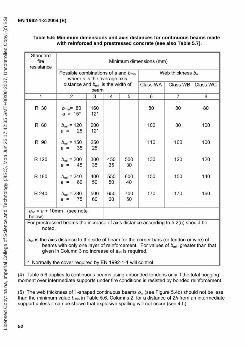
EN 1992-1-2:2004 (E)
52
Table 5.6: Minimum dimensions and axis distances for continuous beams made with reinforced and prestressed concrete (see also Table 5.7).
Standard
fire resistance
Minimum dimensions (mm)
Web thickness bw
Possible combinations of a and bmin
where a is the average axis distance and bmin is the width of
beam Class WA Class WB Class WC
1 2 3 4 5 6 7 8
R 30
R 60
R 90
R 120
R 180
R 240
bmin= 80 a = 15*
bmin= 120 a = 25
bmin= 150 a = 35
bmin= 200 a = 45
bmin= 240 a = 60
bmin= 280 a = 75
160 12*
200 12*
250 25
300 35
400 50
500 60
450 35
550 50
650 60
500 30
600 40
700 50
80
100
110
130
150
170
80
80
100
120
150
170
80
100
100
120
140
160
asd = a + 10mm (see note below)
For prestressed beams the increase of axis distance according to 5.2(5) should be noted.
asd is the axis distance to the side of beam for the corner bars (or tendon or wire) of
beams with only one layer of reinforcement. For values of bmin greater than that given in Column 3 no increase of asd is required.
* Normally the cover required by EN 1992-1-1 will control.
(4) Table 5.6 applies to continuous beams using unbonded tendons only if the total hogging moment over intermediate supports under fire conditions is resisted by bonded reinforcement. (5) The web thickness of Ι -shaped continuous beams bw (see Figure 5.4c) should not be less than the minimum value bmin in Table 5.6, Columns 2, for a distance of 2h from an intermediate support unless it can be shown that explosive spalling will not occur (see 4.5).
Lice
nsed
Cop
y: n
a na
, Im
peria
l Col
lege
of S
cien
ce a
nd T
echn
olog
y (J
ISC
), M
on J
un 2
5 17
:42:
35 G
MT
+00
:00
2007
, Unc
ontr
olle
d C
opy,
(c)
BS
I
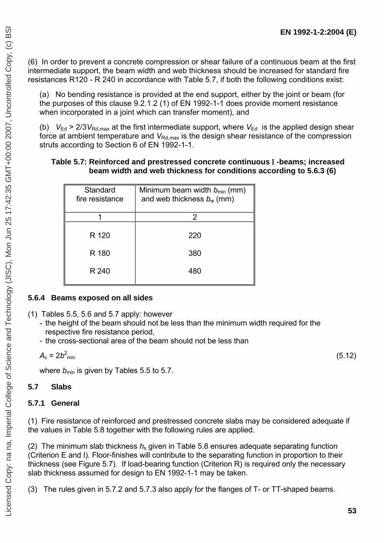
EN 1992-1-2:2004 (E)
53
(6) In order to prevent a concrete compression or shear failure of a continuous beam at the first intermediate support, the beam width and web thickness should be increased for standard fire resistances R120 - R 240 in accordance with Table 5.7, if both the following conditions exist:
(a) No bending resistance is provided at the end support, either by the joint or beam (for the purposes of this clause 9.2.1.2 (1) of EN 1992-1-1 does provide moment resistance when incorporated in a joint which can transfer moment), and (b) VEd > 2/3VRd,max at the first intermediate support, where VEd is the applied design shear force at ambient temperature and VRd,max is the design shear resistance of the compression struts according to Section 6 of EN 1992-1-1.
Table 5.7: Reinforced and prestressed concrete continuous Ι -beams; increased
beam width and web thickness for conditions according to 5.6.3 (6)
Standard fire resistance
Minimum beam width bmin (mm) and web thickness bw (mm)
1 2
R 120
R 180
R 240
220
380
480
5.6.4 Beams exposed on all sides (1) Tables 5.5, 5.6 and 5.7 apply: however
- the height of the beam should not be less than the minimum width required for the respective fire resistance period,
- the cross-sectional area of the beam should not be less than
Ac = 2b2min (5.12)
where bmin is given by Tables 5.5 to 5.7.
5.7 Slabs 5.7.1 General (1) Fire resistance of reinforced and prestressed concrete slabs may be considered adequate if the values in Table 5.8 together with the following rules are applied. (2) The minimum slab thickness hs given in Table 5.8 ensures adequate separating function (Criterion E and I). Floor-finishes will contribute to the separating function in proportion to their thickness (see Figure 5.7). If load-bearing function (Criterion R) is required only the necessary slab thickness assumed for design to EN 1992-1-1 may be taken. (3) The rules given in 5.7.2 and 5.7.3 also apply for the flanges of T- or TT-shaped beams.
Lice
nsed
Cop
y: n
a na
, Im
peria
l Col
lege
of S
cien
ce a
nd T
echn
olog
y (J
ISC
), M
on J
un 2
5 17
:42:
35 G
MT
+00
:00
2007
, Unc
ontr
olle
d C
opy,
(c)
BS
I
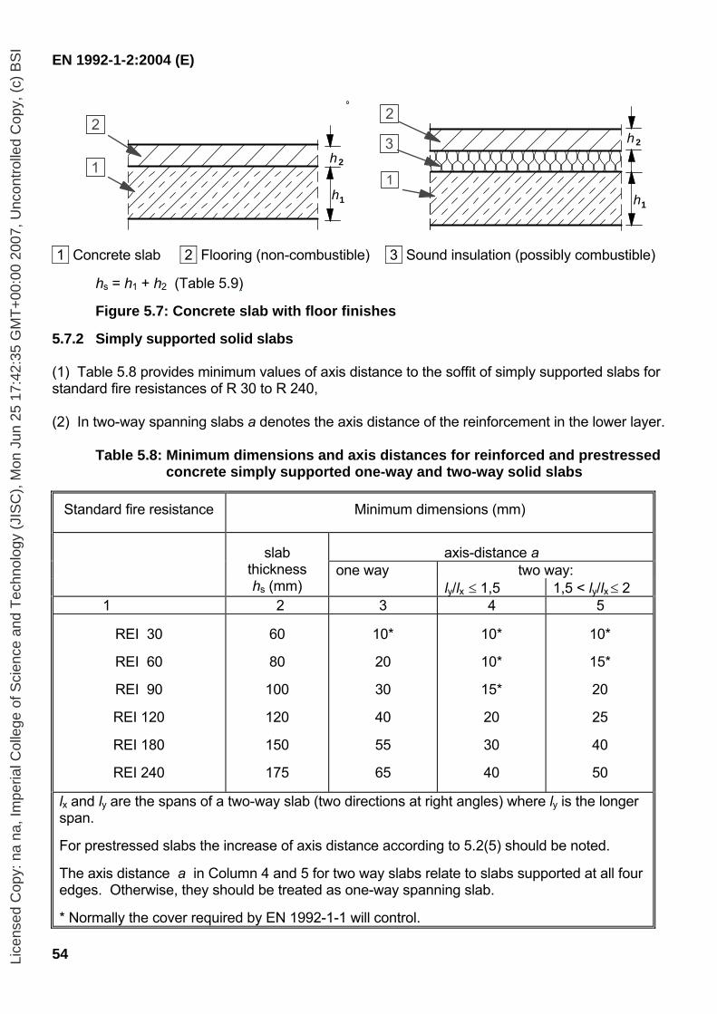
EN 1992-1-2:2004 (E)
54
h1
h 2 3
2
1 h1
h 2
2
1
1 Concrete slab 2 Flooring (non-combustible) 3 Sound insulation (possibly combustible) hs = h1 + h2 (Table 5.9)
Figure 5.7: Concrete slab with floor finishes 5.7.2 Simply supported solid slabs (1) Table 5.8 provides minimum values of axis distance to the soffit of simply supported slabs for standard fire resistances of R 30 to R 240, (2) In two-way spanning slabs a denotes the axis distance of the reinforcement in the lower layer.
Table 5.8: Minimum dimensions and axis distances for reinforced and prestressed concrete simply supported one-way and two-way solid slabs
Standard fire resistance Minimum dimensions (mm)
axis-distance a
one way two way:
slab
thickness hs (mm) ly/lx ≤ 1,5 1,5 < ly/lx ≤ 2
1 2 3 4 5
REI 30
REI 60
REI 90
REI 120
REI 180
REI 240
60
80
100
120
150
175
10*
20
30
40
55
65
10*
10*
15*
20
30
40
10*
15*
20
25
40
50
lx and ly are the spans of a two-way slab (two directions at right angles) where ly is the longer span. For prestressed slabs the increase of axis distance according to 5.2(5) should be noted. The axis distance a in Column 4 and 5 for two way slabs relate to slabs supported at all four edges. Otherwise, they should be treated as one-way spanning slab. * Normally the cover required by EN 1992-1-1 will control.
Lice
nsed
Cop
y: n
a na
, Im
peria
l Col
lege
of S
cien
ce a
nd T
echn
olog
y (J
ISC
), M
on J
un 2
5 17
:42:
35 G
MT
+00
:00
2007
, Unc
ontr
olle
d C
opy,
(c)
BS
I
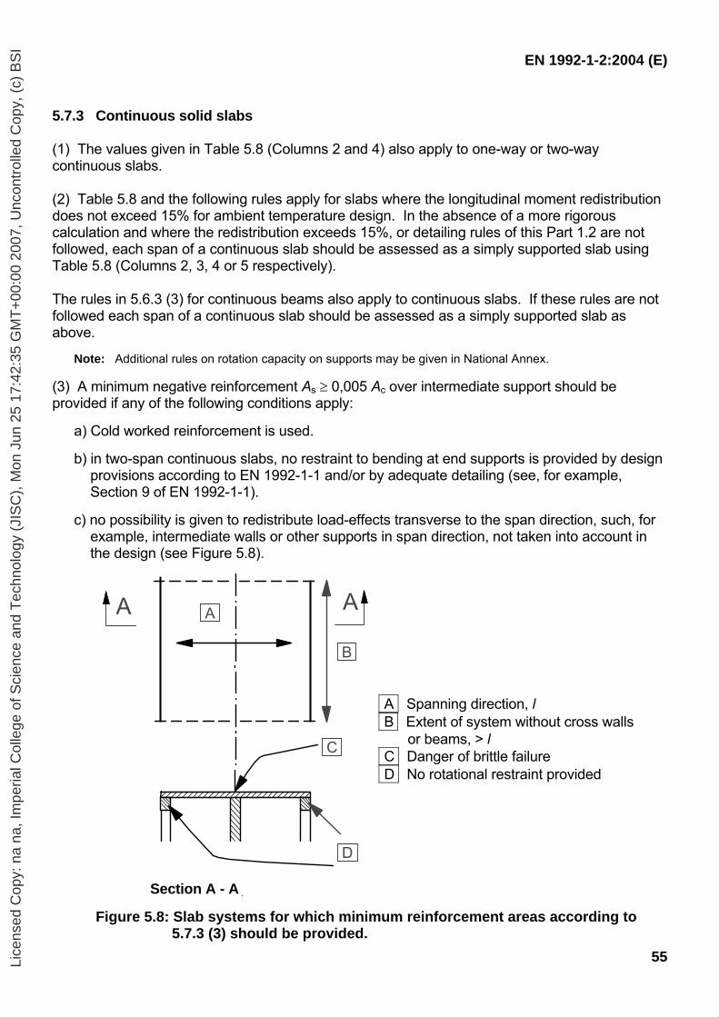
EN 1992-1-2:2004 (E)
55
5.7.3 Continuous solid slabs (1) The values given in Table 5.8 (Columns 2 and 4) also apply to one-way or two-way continuous slabs. (2) Table 5.8 and the following rules apply for slabs where the longitudinal moment redistribution does not exceed 15% for ambient temperature design. In the absence of a more rigorous calculation and where the redistribution exceeds 15%, or detailing rules of this Part 1.2 are not followed, each span of a continuous slab should be assessed as a simply supported slab using Table 5.8 (Columns 2, 3, 4 or 5 respectively). The rules in 5.6.3 (3) for continuous beams also apply to continuous slabs. If these rules are not followed each span of a continuous slab should be assessed as a simply supported slab as above.
Note: Additional rules on rotation capacity on supports may be given in National Annex.
(3) A minimum negative reinforcement As ≥ 0,005 Ac over intermediate support should be provided if any of the following conditions apply:
a) Cold worked reinforcement is used. b) in two-span continuous slabs, no restraint to bending at end supports is provided by design
provisions according to EN 1992-1-1 and/or by adequate detailing (see, for example, Section 9 of EN 1992-1-1).
c) no possibility is given to redistribute load-effects transverse to the span direction, such, for
example, intermediate walls or other supports in span direction, not taken into account in the design (see Figure 5.8).
A Spanning direction, l B Extent of system without cross walls
or beams, > l C Danger of brittle failure
D No rotational restraint provided
Section A - A
Figure 5.8: Slab systems for which minimum reinforcement areas according to
5.7.3 (3) should be provided.
A A A
B
C
D
Lice
nsed
Cop
y: n
a na
, Im
peria
l Col
lege
of S
cien
ce a
nd T
echn
olog
y (J
ISC
), M
on J
un 2
5 17
:42:
35 G
MT
+00
:00
2007
, Unc
ontr
olle
d C
opy,
(c)
BS
I
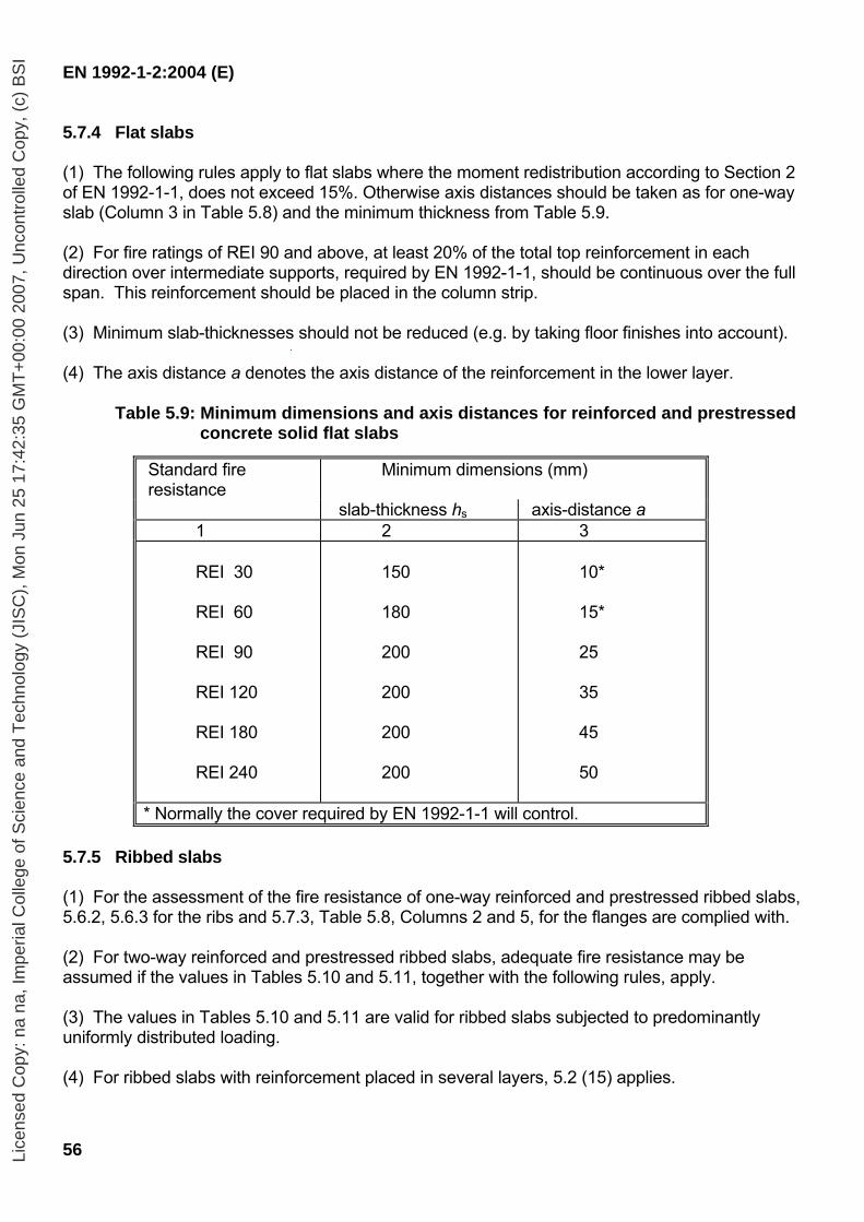
EN 1992-1-2:2004 (E)
56
5.7.4 Flat slabs (1) The following rules apply to flat slabs where the moment redistribution according to Section 2 of EN 1992-1-1, does not exceed 15%. Otherwise axis distances should be taken as for one-way slab (Column 3 in Table 5.8) and the minimum thickness from Table 5.9. (2) For fire ratings of REI 90 and above, at least 20% of the total top reinforcement in each direction over intermediate supports, required by EN 1992-1-1, should be continuous over the full span. This reinforcement should be placed in the column strip. (3) Minimum slab-thicknesses should not be reduced (e.g. by taking floor finishes into account). (4) The axis distance a denotes the axis distance of the reinforcement in the lower layer.
Table 5.9: Minimum dimensions and axis distances for reinforced and prestressed
concrete solid flat slabs
Standard fire resistance
Minimum dimensions (mm)
slab-thickness hs axis-distance a 1 2 3 REI 30 REI 60 REI 90 REI 120 REI 180 REI 240
150 180 200 200 200 200
10* 15* 25 35 45 50
* Normally the cover required by EN 1992-1-1 will control. 5.7.5 Ribbed slabs (1) For the assessment of the fire resistance of one-way reinforced and prestressed ribbed slabs, 5.6.2, 5.6.3 for the ribs and 5.7.3, Table 5.8, Columns 2 and 5, for the flanges are complied with. (2) For two-way reinforced and prestressed ribbed slabs, adequate fire resistance may be assumed if the values in Tables 5.10 and 5.11, together with the following rules, apply. (3) The values in Tables 5.10 and 5.11 are valid for ribbed slabs subjected to predominantly uniformly distributed loading.
(4) For ribbed slabs with reinforcement placed in several layers, 5.2 (15) applies.
Lice
nsed
Cop
y: n
a na
, Im
peria
l Col
lege
of S
cien
ce a
nd T
echn
olog
y (J
ISC
), M
on J
un 2
5 17
:42:
35 G
MT
+00
:00
2007
, Unc
ontr
olle
d C
opy,
(c)
BS
I
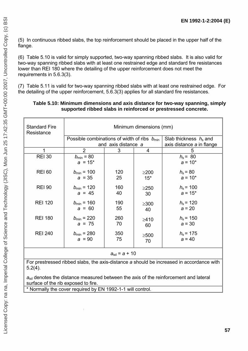
EN 1992-1-2:2004 (E)
57
(5) In continuous ribbed slabs, the top reinforcement should be placed in the upper half of the flange. (6) Table 5.10 is valid for simply supported, two-way spanning ribbed slabs. It is also valid for two-way spanning ribbed slabs with at least one restrained edge and standard fire resistances lower than REI 180 where the detailing of the upper reinforcement does not meet the requirements in 5.6.3(3). (7) Table 5.11 is valid for two-way spanning ribbed slabs with at least one restrained edge. For the detailing of the upper reinforcement, 5.6.3(3) applies for all standard fire resistances.
Table 5.10: Minimum dimensions and axis distance for two-way spanning, simply
supported ribbed slabs in reinforced or prestressed concrete.
Standard Fire Resistance
Minimum dimensions (mm)
Possible combinations of width of ribs bmin and axis distance a
Slab thickness hs and axis distance a in flange
1 2 3 4 5 REI 30
REI 60
REI 90
REI 120
REI 180
REI 240
bmin = 80 a = 15*
bmin = 100 a = 35
bmin = 120 a = 45 bmin = 160 a = 60 bmin = 220 a = 75 bmin = 280 a = 90
120 25
160 40
190 55
260 70
350 75
≥200 15*
≥250 30
≥300 40
≥410 60
≥500 70
hs = 80 a = 10*
hs = 80 a = 10*
hs = 100 a = 15* hs = 120 a = 20 hs = 150 a = 30 hs = 175 a = 40
asd = a + 10
For prestressed ribbed slabs, the axis-distance a should be increased in accordance with 5.2(4). asd denotes the distance measured between the axis of the reinforcement and lateral surface of the rib exposed to fire. * Normally the cover required by EN 1992-1-1 will control.
Lice
nsed
Cop
y: n
a na
, Im
peria
l Col
lege
of S
cien
ce a
nd T
echn
olog
y (J
ISC
), M
on J
un 2
5 17
:42:
35 G
MT
+00
:00
2007
, Unc
ontr
olle
d C
opy,
(c)
BS
I
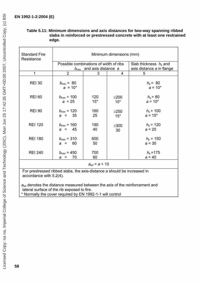
EN 1992-1-2:2004 (E)
58
Table 5.11: Minimum dimensions and axis distances for two-way spanning ribbed slabs in reinforced or prestressed concrete with at least one restrained edge.
Standard Fire Resistance
Minimum dimensions (mm)
Possible combinations of width of ribs bmin and axis distance a
Slab thickness hs and axis distance a in flange
1 2 3 4 5
REI 30
REI 60
REI 90
REI 120
REI 180
REI 240
bmin = 80 a = 10*
bmin = 100
a = 25
bmin = 120 a = 35
bmin = 160 a = 45
bmin = 310 a = 60
bmin = 450 a = 70
120 15*
160 25
190 40
600 50
700 60
≥200 10*
≥250 15*
≥300 30
hs = 80
a = 10*
hs = 80 a = 10*
hs = 100
a = 15*
hs = 120 a = 20
hs = 150
a = 30
hs =175 a = 40
asd = a + 10
For prestressed ribbed slabs, the axis-distance a should be increased in accordance with 5.2(4). asd denotes the distance measured between the axis of the reinforcement and lateral surface of the rib exposed to fire. * Normally the cover required by EN 1992-1-1 will control
Lice
nsed
Cop
y: n
a na
, Im
peria
l Col
lege
of S
cien
ce a
nd T
echn
olog
y (J
ISC
), M
on J
un 2
5 17
:42:
35 G
MT
+00
:00
2007
, Unc
ontr
olle
d C
opy,
(c)
BS
I
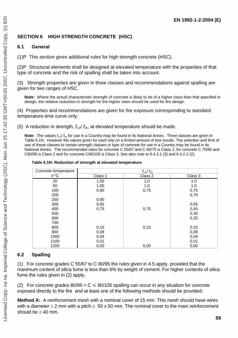
EN 1992-1-2:2004 (E)
59
SECTION 6 HIGH STRENGTH CONCRETE (HSC) 6.1 General (1)P This section gives additional rules for high strength concrete (HSC). (2)P Structural elements shall be designed at elevated temperature with the properties of that type of concrete and the risk of spalling shall be taken into account. (3) Strength properties are given in three classes and recommendations against spalling are given for two ranges of HSC.
Note: Where the actual characteristic strength of concrete is likely to be of a higher class than that specified in design, the relative reduction in strength for the higher class should be used for fire design.
(4) Properties and recommendations are given for fire exposure corresponding to standard temperature-time curve only. (5) A reduction in strength, fc,θ/ fck, at elevated temperature should be made.
Note: The values fc,θ/ fck for use in a Country may be found in its National Annex. Three classes are given in Table 6.1N. However the values given for each rely on a limited amount of test results. The selection and limit of use of these classes to certain strength classes or type of concrete for use in a Country may be found in its National Annex. The recommended class for concrete C 55/67 and C 60/75 is Class 1, for concrete C 70/85 and C80/95 is Class 2 and for concrete C90/105 is Class 3. See also note to 6.4.2.1 (3) and 6.4.2.2 (2).
Table 6.1N: Reduction of strength at elevated temperature
fc,θ/ fck Concrete temperature
θ °C Class 1 Class 2 Class 3 20 1,00 1,0 1,0 50 1,00 1,0 1,0 100 0,90 0,75 0,75 200 0,70 250 0,90 300 0,85 0,65 400 0,75 0,75 0,45 500 0,30 600 0,25 700 800 0,15 0,15 0,15 900 0,08 0,08
1000 0,04 0,04 1100 0,01 0,01 1200 0,00 0,00 0,00
6.2 Spalling (1) For concrete grades C 55/67 to C 80/95 the rules given in 4.5 apply, provided that the maximum content of silica fume is less than 6% by weight of cement. For higher contents of silica fume the rules given in (2) apply. (2) For concrete grades 80/95 < C 90/105 spalling can occur in any situation for concrete exposed directly to the fire and at least one of the following methods should be provided: Method A: A reinforcement mesh with a nominal cover of 15 mm. This mesh should have wires with a diameter ≥ 2 mm with a pitch ≤ 50 x 50 mm. The nominal cover to the main reinforcement should be ≥ 40 mm.
Lice
nsed
Cop
y: n
a na
, Im
peria
l Col
lege
of S
cien
ce a
nd T
echn
olog
y (J
ISC
), M
on J
un 2
5 17
:42:
35 G
MT
+00
:00
2007
, Unc
ontr
olle
d C
opy,
(c)
BS
I
EN 1992-1-2:2004 (E)
60
Method B: A type of concrete for which it has been demonstrated (by local experience or by testing) that no spalling of concrete occurs under fire exposure.
Method C: Protective layers for which it is demonstrated that no spalling of concrete occurs under fire exposure. Method D: Include in the concrete mix more than 2 kg/m3 of monofilament propylene fibres.
Note: The selection of Methods to be used in a Country may be found in its National Annex.
6.3 Thermal properties (1) Values given in clause 3.3 may be applied also for high strength concrete.
Note 1: The value of thermal conductivity for high strength concrete for use in a Country may be given in its National Annex within the range defined by lower and upper limit in clause 3.3.3. Note 2: Thermal conductivity of high strength concrete may be higher than that for normal strength concrete.
6.4 Structural design 6.4.1 Calculation of load bearing capacity (1)P The load-carrying capacity in the fire situation shall be determined considering the following:
- thermal exposure and the consequent temperature field in the member - reduction of material strength due to elevated temperatures - effects of restraint forces due to thermal expansion - second order effects
(2) This may be achieved by undertaking either a global structural analysis or a simplified member calculation. The global structural analysis should be based on verified information. The simplified calculation methods for columns, walls, beams and slabs are described below. 6.4.2 Simplified calculation methods (1)P The simplified calculation methods given in Annex B apply for high strength concrete. 6.4.2.1 Columns and walls (1) Verification of the load-carrying capacity of columns and walls in the fire situation may be conducted for a reduced cross-section, using the methods applicable for normal design, e.g. Annex B.1. (2) The reduced cross-section should be derived on the basis of the simplified method of Annex B, however incorporating an enhanced deduction of the fire damaged concrete due to the influence of second order effects. (3) In calculation of the effective cross-section the reduced concrete thickness is calculated from the depth of the 500 °C isotherm, a500, increased by a factor k. Hence in calculation of the reduced cross-section for columns and walls Expression (6.4) should be used.
az = k az, 500 (6.4)
Lice
nsed
Cop
y: n
a na
, Im
peria
l Col
lege
of S
cien
ce a
nd T
echn
olog
y (J
ISC
), M
on J
un 2
5 17
:42:
35 G
MT
+00
:00
2007
, Unc
ontr
olle
d C
opy,
(c)
BS
I
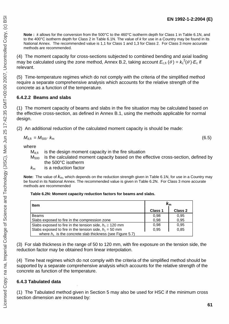
EN 1992-1-2:2004 (E)
61
Note : k allows for the conversion from the 500°C to the 460°C isotherm depth for Class 1 in Table 6.1N, and to the 400°C isotherm depth for Class 2 in Table 6.1N. The value of k for use in a Country may be found in its National Annex. The recommended value is 1,1 for Class 1 and 1,3 for Class 2. For Class 3 more accurate methods are recommended.
(4) The moment capacity for cross-sections subjected to combined bending and axial loading may be calculated using the zone method, Annex B.2, taking account Ec,fi (θ ) = kc
2(θ )·Ec if relevant.
(5) Time-temperature regimes which do not comply with the criteria of the simplified method require a separate comprehensive analysis which accounts for the relative strength of the concrete as a function of the temperature.
6.4.2.2 Beams and slabs (1) The moment capacity of beams and slabs in the fire situation may be calculated based on the effective cross-section, as defined in Annex B.1, using the methods applicable for normal design.
(2) An additional reduction of the calculated moment capacity is should be made:
Md,fi = M500 ⋅ km (6.5)
where Md,fi is the design moment capacity in the fire situation M500 is the calculated moment capacity based on the effective cross-section, defined by
the 500°C isotherm km is a reduction factor
Note: The value of km, which depends on the reduction strength given in Table 6.1N, for use in a Country may be found in its National Annex. The recommended value is given in Table 6.2N. For Class 3 more accurate methods are recommended
Table 6.2N: Moment capacity reduction factors for beams and slabs.
km Item
Class 1 Class 2 Beams 0,98 0,95 Slabs exposed to fire in the compression zone 0,98 0,95 Slabs exposed to fire in the tension side, h1 ≥ 120 mm 0,98 0,95 Slabs exposed to fire in the tension side, h1 = 50 mm 0,95 0,85
where h1 is the concrete slab thickness (see Figure 5.7) (3) For slab thickness in the range of 50 to 120 mm, with fire exposure on the tension side, the reduction factor may be obtained from linear interpolation. (4) Time heat regimes which do not comply with the criteria of the simplified method should be supported by a separate comprehensive analysis which accounts for the relative strength of the concrete as function of the temperature. 6.4.3 Tabulated data
(1) The Tabulated method given in Section 5 may also be used for HSC if the minimum cross section dimension are increased by:
Lice
nsed
Cop
y: n
a na
, Im
peria
l Col
lege
of S
cien
ce a
nd T
echn
olog
y (J
ISC
), M
on J
un 2
5 17
:42:
35 G
MT
+00
:00
2007
, Unc
ontr
olle
d C
opy,
(c)
BS
I
EN 1992-1-2:2004 (E)
62
- (k –1)a for walls and slabs exposed on one side only - 2(k –1)a for all other structural members and the axis distance is factored by k. Where k is the factor given in 6.4.2.1(3) a is axis distance required in Section 5.
Note: For columns the degree of utilisation in the fire situation µfi or load level of a column at normal temperature conditions n should be defined before calculating the increase of the cross-section dimensions by 2(k –1)a
Lice
nsed
Cop
y: n
a na
, Im
peria
l Col
lege
of S
cien
ce a
nd T
echn
olog
y (J
ISC
), M
on J
un 2
5 17
:42:
35 G
MT
+00
:00
2007
, Unc
ontr
olle
d C
opy,
(c)
BS
I
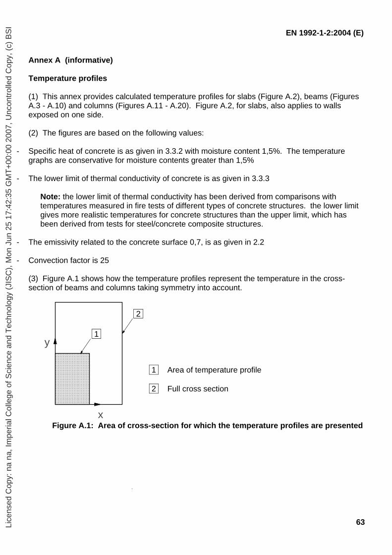
EN 1992-1-2:2004 (E)
63
Annex A (informative) Temperature profiles (1) This annex provides calculated temperature profiles for slabs (Figure A.2), beams (Figures A.3 - A.10) and columns (Figures A.11 - A.20). Figure A.2, for slabs, also applies to walls exposed on one side. (2) The figures are based on the following values:
- Specific heat of concrete is as given in 3.3.2 with moisture content 1,5%. The temperature graphs are conservative for moisture contents greater than 1,5%
- The lower limit of thermal conductivity of concrete is as given in 3.3.3
Note: the lower limit of thermal conductivity has been derived from comparisons with temperatures measured in fire tests of different types of concrete structures. the lower limit gives more realistic temperatures for concrete structures than the upper limit, which has been derived from tests for steel/concrete composite structures.
- The emissivity related to the concrete surface 0,7, is as given in 2.2 - Convection factor is 25
(3) Figure A.1 shows how the temperature profiles represent the temperature in the cross-section of beams and columns taking symmetry into account.
1 Area of temperature profile 2 Full cross section
Figure A.1: Area of cross-section for which the temperature profiles are presented
x
y 1
2
Lice
nsed
Cop
y: n
a na
, Im
peria
l Col
lege
of S
cien
ce a
nd T
echn
olog
y (J
ISC
), M
on J
un 2
5 17
:42:
35 G
MT
+00
:00
2007
, Unc
ontr
olle
d C
opy,
(c)
BS
I
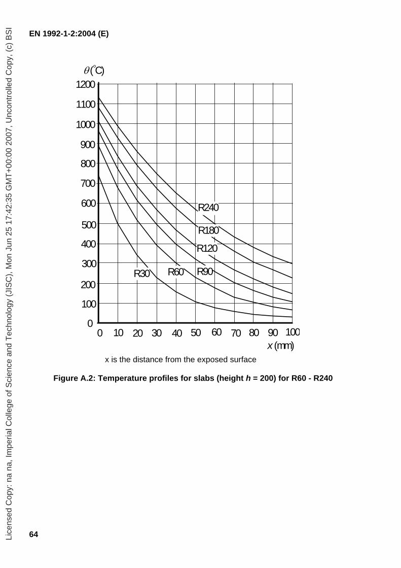
EN 1992-1-2:2004 (E)
64
x is the distance from the exposed surface
Figure A.2: Temperature profiles for slabs (height h = 200) for R60 - R240
x (mm)0 10 20 30 40 50 60 70 80 90 100
300
200
0
400
600
800
1000
1200 θ ( C)
1100
900
700
500
100
R30 R60 R90
R120
R180
R240
Lice
nsed
Cop
y: n
a na
, Im
peria
l Col
lege
of S
cien
ce a
nd T
echn
olog
y (J
ISC
), M
on J
un 2
5 17
:42:
35 G
MT
+00
:00
2007
, Unc
ontr
olle
d C
opy,
(c)
BS
I
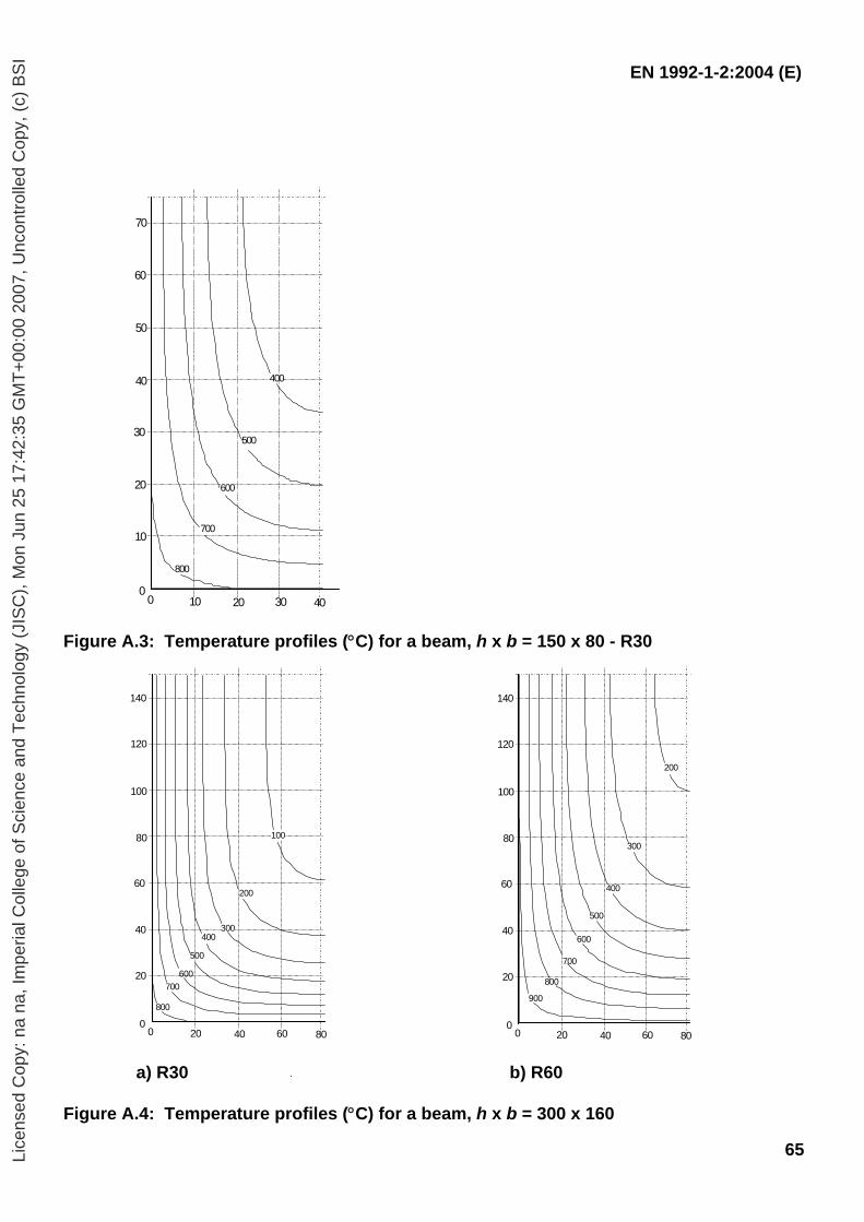
EN 1992-1-2:2004 (E)
65
Figure A.3: Temperature profiles (°C) for a beam, h x b = 150 x 80 - R30
a) R30 b) R60 Figure A.4: Temperature profiles (°C) for a beam, h x b = 300 x 160
400
500
600
700
800
0
10
20
30
40
50
60
70
0 20 4010 30
100
200
300400
500
0
20
40
60
80
100
120
140
0 40 8020 60
600700
800900
200
300
400
500
0
20
40
60
80
100
120
140
0 40 8020 60
600
700
800
Lice
nsed
Cop
y: n
a na
, Im
peria
l Col
lege
of S
cien
ce a
nd T
echn
olog
y (J
ISC
), M
on J
un 2
5 17
:42:
35 G
MT
+00
:00
2007
, Unc
ontr
olle
d C
opy,
(c)
BS
I
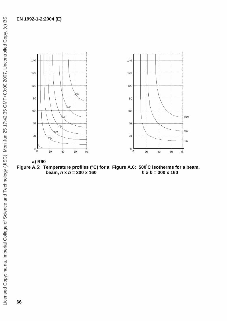
EN 1992-1-2:2004 (E)
66
a) R90 Figure A.5: Temperature profiles (°C) for a
beam, h x b = 300 x 160
Figure A.6: 500°C isotherms for a beam,
h x b = 300 x 160
400
500
0
20
40
60
80
100
120
140
0 40 8020 60
700
800
900
600
0
20
40
60
80
100
120
140
0 40 8020 60
R90
R60
R30
Lice
nsed
Cop
y: n
a na
, Im
peria
l Col
lege
of S
cien
ce a
nd T
echn
olog
y (J
ISC
), M
on J
un 2
5 17
:42:
35 G
MT
+00
:00
2007
, Unc
ontr
olle
d C
opy,
(c)
BS
I
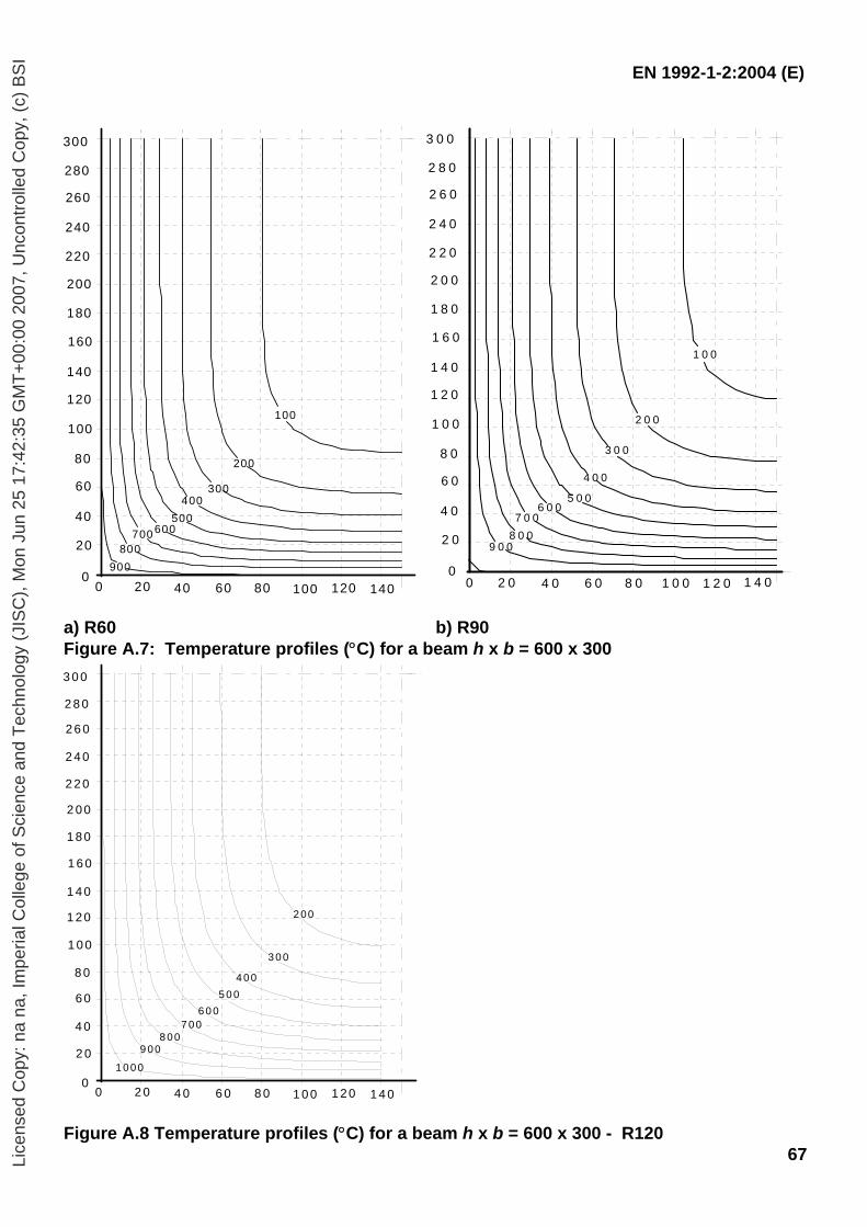
EN 1992-1-2:2004 (E)
67
a) R60 b) R90 Figure A.7: Temperature profiles (°C) for a beam h x b = 600 x 300
Figure A.8 Temperature profiles (°C) for a beam h x b = 600 x 300 - R120
1 0 0
2 0 0
3 0 0
4 0 0
5 0 06 0 0
7 0 08 0 0
9 0 0
0
2 0
4 0
6 0
8 0
1 0 0
1 2 0
1 4 0
1 6 0
1 8 0
2 0 0
2 2 0
2 4 0
2 6 0
2 8 0
3 0 0
0 2 0 4 0 6 0 8 0 1 0 0 1 2 0 1 4 0
100
200
300400
500600700
800900
0
20
40
60
80
100
120
140
160
180
200
220
240
260
280
300
0 20 40 60 80 100 120 140
1 0 0 0
2 00
3 0 0
4 0 05 0 0
6 0 07 00
8 009 00
0
2 0
4 0
6 0
8 0
1 0 0
1 2 0
1 4 0
1 6 0
1 8 0
2 0 0
2 2 0
2 4 0
2 6 0
2 8 0
3 0 0
0 2 0 4 0 6 0 8 0 1 0 0 1 2 0 1 4 0
Lice
nsed
Cop
y: n
a na
, Im
peria
l Col
lege
of S
cien
ce a
nd T
echn
olog
y (J
ISC
), M
on J
un 2
5 17
:42:
35 G
MT
+00
:00
2007
, Unc
ontr
olle
d C
opy,
(c)
BS
I
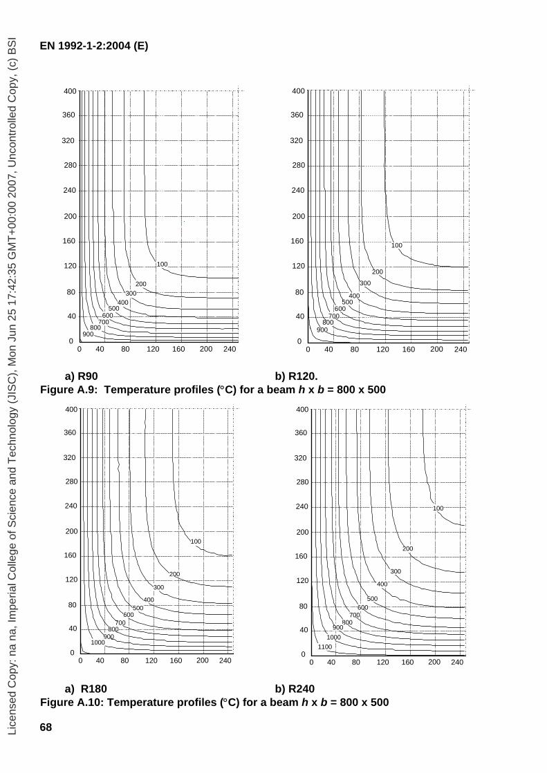
EN 1992-1-2:2004 (E)
68
a) R90 b) R120. Figure A.9: Temperature profiles (°C) for a beam h x b = 800 x 500
a) R180 b) R240 Figure A.10: Temperature profiles (°C) for a beam h x b = 800 x 500
0 40 80 120 160 200 240
280
0
40
80
120
160
200
240
320
360
400
200300
400500
600700
800900
100
0 40 80 120 160 200 240
280
0
40
80
120
160
200
240
320
360
400
200
300
400500
600700
800900
100
0 40 80 120 160 200 240
280
0
40
80
120
160
200
240
320
360
400
200
300
400500
600700
800900
100
1000
0 40 80 120 160 200 240
280
0
40
80
120
160
200
240
320
360
400
200
300
400
500600
700800
900
100
10001100
Lice
nsed
Cop
y: n
a na
, Im
peria
l Col
lege
of S
cien
ce a
nd T
echn
olog
y (J
ISC
), M
on J
un 2
5 17
:42:
35 G
MT
+00
:00
2007
, Unc
ontr
olle
d C
opy,
(c)
BS
I
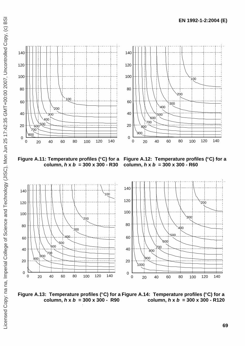
EN 1992-1-2:2004 (E)
69
Figure A.11: Temperature profiles (°C) for a column, h x b = 300 x 300 - R30
Figure A.12: Temperature profiles (°C) for a column, h x b = 300 x 300 - R60
Figure A.13: Temperature profiles (°C) for a
column, h x b = 300 x 300 - R90Figure A.14: Temperature profiles (°C) for a
column, h x b = 300 x 300 - R120
0
140
120
100
80
60
40
20
0 12010080604020 140
100
200300
400500600
700800
0
140
120
100
80
60
40
20
0 12010080604020 140
100
200
300400
500600
700800
900
0
140
120
100
80
60
40
20
0 12010080604020 140
100
200
300
400
500600
700800
900
0
140
120
100
80
60
40
20
0 12010080604020 140
1000
200
300
400
500
600700
800
900
Lice
nsed
Cop
y: n
a na
, Im
peria
l Col
lege
of S
cien
ce a
nd T
echn
olog
y (J
ISC
), M
on J
un 2
5 17
:42:
35 G
MT
+00
:00
2007
, Unc
ontr
olle
d C
opy,
(c)
BS
I
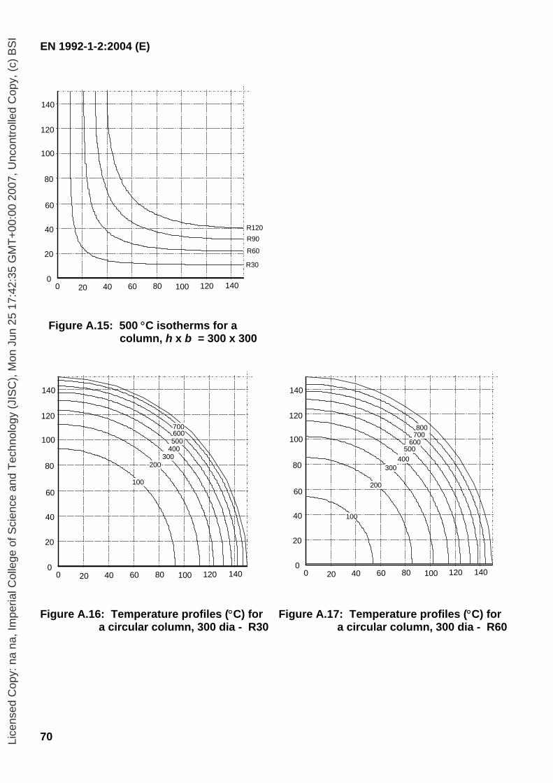
EN 1992-1-2:2004 (E)
70
Figure A.15: 500 °C isotherms for a
column, h x b = 300 x 300
Figure A.16: Temperature profiles (°C) for
a circular column, 300 dia - R30 Figure A.17: Temperature profiles (°C) for
a circular column, 300 dia - R60
0
140
120
100
80
60
40
20
0 12010080604020 140
R120R90
R60
R30
0
140
120
100
80
60
40
20
0 12010080604020 140
100
200300
400500
700600
0
140
120
100
80
60
40
20
0 12010080604020 140
100
200
300400
500600
700800
Lice
nsed
Cop
y: n
a na
, Im
peria
l Col
lege
of S
cien
ce a
nd T
echn
olog
y (J
ISC
), M
on J
un 2
5 17
:42:
35 G
MT
+00
:00
2007
, Unc
ontr
olle
d C
opy,
(c)
BS
I
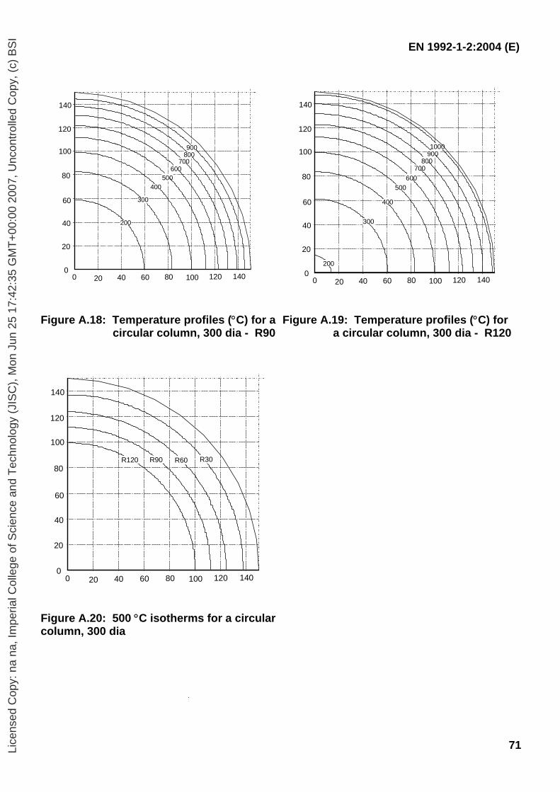
EN 1992-1-2:2004 (E)
71
Figure A.18: Temperature profiles (°C) for a
circular column, 300 dia - R90Figure A.19: Temperature profiles (°C) for
a circular column, 300 dia - R120
Figure A.20: 500 °C isotherms for a circular column, 300 dia
200
300
400500
600700
800900
0
140
120
100
80
60
40
20
0 12010080604020 140
200
300
400
500600
700800
9001000
0
140
120
100
80
60
40
20
0 12010080604020 140
0
140
120
100
80
60
40
20
0 12010080604020 140
R60R90R120 R30
Lice
nsed
Cop
y: n
a na
, Im
peria
l Col
lege
of S
cien
ce a
nd T
echn
olog
y (J
ISC
), M
on J
un 2
5 17
:42:
35 G
MT
+00
:00
2007
, Unc
ontr
olle
d C
opy,
(c)
BS
I
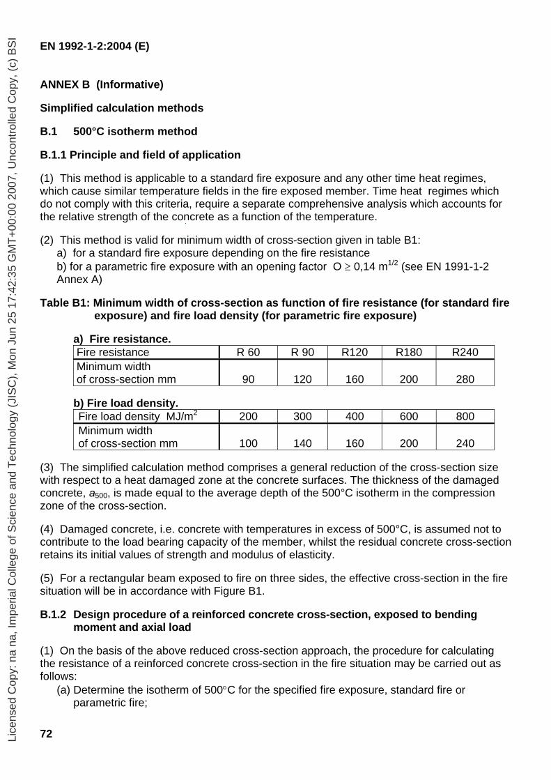
EN 1992-1-2:2004 (E)
72
ANNEX B (Informative) Simplified calculation methods B.1 500°C isotherm method
B.1.1 Principle and field of application
(1) This method is applicable to a standard fire exposure and any other time heat regimes, which cause similar temperature fields in the fire exposed member. Time heat regimes which do not comply with this criteria, require a separate comprehensive analysis which accounts for the relative strength of the concrete as a function of the temperature. (2) This method is valid for minimum width of cross-section given in table B1:
a) for a standard fire exposure depending on the fire resistance
b) for a parametric fire exposure with an opening factor O ≥ 0,14 m1/2 (see EN 1991-1-2 Annex A)
Table B1: Minimum width of cross-section as function of fire resistance (for standard fire
exposure) and fire load density (for parametric fire exposure) a) Fire resistance.
Fire resistance R 60 R 90 R120 R180 R240 Minimum width of cross-section mm
90
120
160
200
280
b) Fire load density.
Fire load density MJ/m2 200 300 400 600 800 Minimum width of cross-section mm
100
140
160
200
240
(3) The simplified calculation method comprises a general reduction of the cross-section size with respect to a heat damaged zone at the concrete surfaces. The thickness of the damaged concrete, a500, is made equal to the average depth of the 500°C isotherm in the compression zone of the cross-section. (4) Damaged concrete, i.e. concrete with temperatures in excess of 500°C, is assumed not to contribute to the load bearing capacity of the member, whilst the residual concrete cross-section retains its initial values of strength and modulus of elasticity.
(5) For a rectangular beam exposed to fire on three sides, the effective cross-section in the fire situation will be in accordance with Figure B1. B.1.2 Design procedure of a reinforced concrete cross-section, exposed to bending
moment and axial load (1) On the basis of the above reduced cross-section approach, the procedure for calculating the resistance of a reinforced concrete cross-section in the fire situation may be carried out as follows:
(a) Determine the isotherm of 500°C for the specified fire exposure, standard fire or parametric fire;
Lice
nsed
Cop
y: n
a na
, Im
peria
l Col
lege
of S
cien
ce a
nd T
echn
olog
y (J
ISC
), M
on J
un 2
5 17
:42:
35 G
MT
+00
:00
2007
, Unc
ontr
olle
d C
opy,
(c)
BS
I
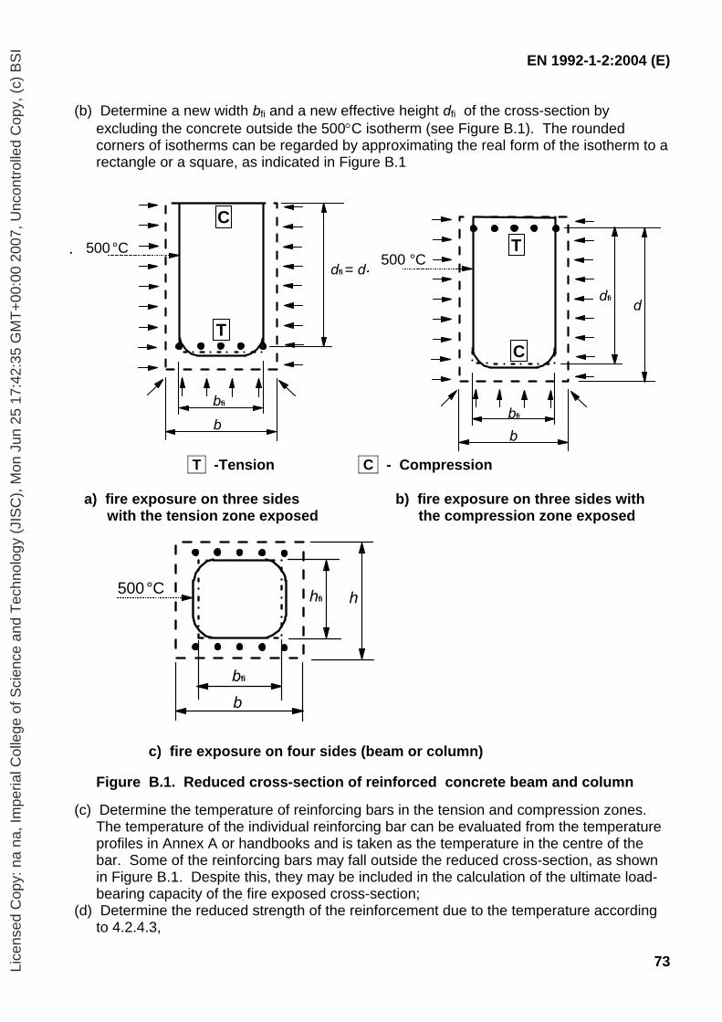
EN 1992-1-2:2004 (E)
73
(b) Determine a new width bfi and a new effective height dfi of the cross-section by excluding the concrete outside the 500°C isotherm (see Figure B.1). The rounded corners of isotherms can be regarded by approximating the real form of the isotherm to a rectangle or a square, as indicated in Figure B.1
T -Tension C - Compression
a) fire exposure on three sides with the tension zone exposed
b) fire exposure on three sides with the compression zone exposed
c) fire exposure on four sides (beam or column)
Figure B.1. Reduced cross-section of reinforced concrete beam and column
(c) Determine the temperature of reinforcing bars in the tension and compression zones. The temperature of the individual reinforcing bar can be evaluated from the temperature profiles in Annex A or handbooks and is taken as the temperature in the centre of the bar. Some of the reinforcing bars may fall outside the reduced cross-section, as shown in Figure B.1. Despite this, they may be included in the calculation of the ultimate load-bearing capacity of the fire exposed cross-section;
(d) Determine the reduced strength of the reinforcement due to the temperature according to 4.2.4.3,
bfi
b
dfi = d500 °C
T
C
bfi
b
dfi
50500 °C
d
C
T
dfi d
bfi
b
500 °C
bfi
b
hhfi500 °C
Lice
nsed
Cop
y: n
a na
, Im
peria
l Col
lege
of S
cien
ce a
nd T
echn
olog
y (J
ISC
), M
on J
un 2
5 17
:42:
35 G
MT
+00
:00
2007
, Unc
ontr
olle
d C
opy,
(c)
BS
I
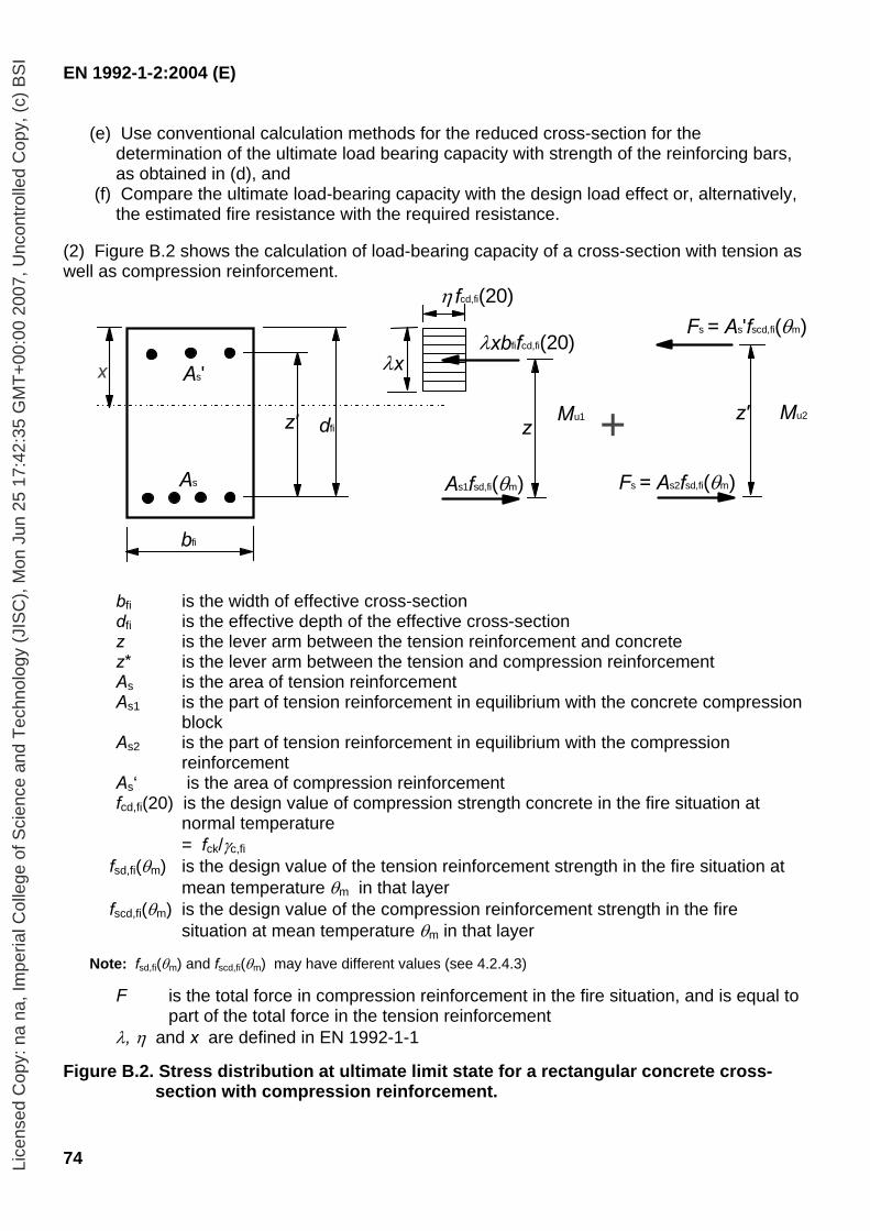
EN 1992-1-2:2004 (E)
74
(e) Use conventional calculation methods for the reduced cross-section for the determination of the ultimate load bearing capacity with strength of the reinforcing bars, as obtained in (d), and
(f) Compare the ultimate load-bearing capacity with the design load effect or, alternatively, the estimated fire resistance with the required resistance.
(2) Figure B.2 shows the calculation of load-bearing capacity of a cross-section with tension as well as compression reinforcement.
As
As'
z' dfi
bfi
z
η fcd,fi(20)
λxbfifcd,fi(20)
As1fsd,fi(θm)
z'
Fs = As2fsd,fi(θm)
Fs = As'fscd,fi(θm)
Mu2Mu1
x λx
+
bfi is the width of effective cross-section dfi is the effective depth of the effective cross-section z is the lever arm between the tension reinforcement and concrete z* is the lever arm between the tension and compression reinforcement As is the area of tension reinforcement As1 is the part of tension reinforcement in equilibrium with the concrete compression
block As2 is the part of tension reinforcement in equilibrium with the compression
reinforcement As‘ is the area of compression reinforcement fcd,fi(20) is the design value of compression strength concrete in the fire situation at
normal temperature = fck/γc,fi fsd,fi(θm) is the design value of the tension reinforcement strength in the fire situation at
mean temperature θm in that layer fscd,fi(θm) is the design value of the compression reinforcement strength in the fire
situation at mean temperature θm in that layer
Note: fsd,fi(θm) and fscd,fi(θm) may have different values (see 4.2.4.3)
F is the total force in compression reinforcement in the fire situation, and is equal to part of the total force in the tension reinforcement
λ, η and x are defined in EN 1992-1-1
Figure B.2. Stress distribution at ultimate limit state for a rectangular concrete cross-section with compression reinforcement.
Lice
nsed
Cop
y: n
a na
, Im
peria
l Col
lege
of S
cien
ce a
nd T
echn
olog
y (J
ISC
), M
on J
un 2
5 17
:42:
35 G
MT
+00
:00
2007
, Unc
ontr
olle
d C
opy,
(c)
BS
I
EN 1992-1-2:2004 (E)
75
(3) If all reinforcement bars are positioned in layers and have the same area, the following expressions may be used in calculating the axis distance, a (see Figure B.2). The average reduced strength of a reinforcement layer with respect to increased temperatures, is calculated in accordance with Expression (B.1).
νν
θΣθ
nkk )()( i= (B.1)
where, θ is the temperature in reinforcement bar i k(θ i) is a reduction of the strength of the reinforcement bar i due to the temperature θi
which is obtained from Figure 4.11 kν(θ) is the average reduction of the strength of reinforcement layer ν nν is the number of reinforcement bars in layer ν
(4) The axis distance, a, from bottom surface of the effective cross-section to the centroid of the reinforcement layers may be calculated using Expression (B.2).
)()(
θΣθΣ
ν
νν
kkaa = (B.2)
Where
aν is the axis distance from the bottom surface of the effective cross-section to reinforcement layer ν
(5) If only two layers exist the axis distance may be calculated using Expression (B.3)
( )a a a1 2= (B.3)
(6) If the reinforcement bars have different areas and are distributed arbitrary the following procedure must be used. The average steel strength of a reinforcement group, k(ϕ) fsd,fi, with respect to increased temperatures, may be calculated using Expression (B.4)
( )( )[ ]
A
Afkfk
s
ii
isd,iiifi,sd Σ
Σ θϕ = (B.4)
Where ks(θ i) is a reduction of the strength of reinforcement bar i fsd,i is the design strength of reinforcement bar i Ai is the cross-section area of reinforcement bar i
The axis distance, a (see Figure B.2), from the effective cross-section to the centroid of the reinforcement group is calculated in accordance with Expression (B.5).
a = [ ][ ]Afk
Afka
ii,sdisi
ii,sdisii
)(
)(
θ
θ
ΣΣ
(B.5)
Lice
nsed
Cop
y: n
a na
, Im
peria
l Col
lege
of S
cien
ce a
nd T
echn
olog
y (J
ISC
), M
on J
un 2
5 17
:42:
35 G
MT
+00
:00
2007
, Unc
ontr
olle
d C
opy,
(c)
BS
I
EN 1992-1-2:2004 (E)
76
Where ai is the axis distance from effective cross-section to reinforcement bar i
(7) The bending moment calculation of the cross-section is illustrated as follows:
M A f zu1 s1 sd,fi m( )θ= (B.6)
A fω
fb ds1 sd,fi m
kfi fi cd,fi
( )(20)θ
= (B.7)
M A f zu2 s2 scd,fi m( ) ´θ= ⋅ (B.8)
As = As1+As2 (B.9)
Where As is the total reinforcement area fsd,fi is the design tensile strength of reinforcement fscd,fi is the design strength for compressive reinforcement ωk is the design strength ratio of reinforcement for the fire-exposed cross-section bfi is the width of the fire exposed cross-section dfi is the efficient height of the fire exposed cross-section fcd,fi(20) is the design compressive strength of concrete (at normal temperature) z is the lever arm between tension reinforcement and concrete z´ is the lever between tension and compression reinforcement θm is the mean temperature of the reinforcement layer
When the moment contributions are assessed as shown above the total moment capacity is obtained from
Mu = Mu1 + Mu2 (B.10)
B.2 Zone method (1) The method of subdividing the cross-section into several zones is described below. This method, although more laborious, provides a more accurate method than the 500°C isotherm method especially for columns. The method is applicable to the standard temperature-time curve only. (2) The cross-section is divided into a number (n ≥ 3) of parallel zones of equal thickness (rectangular elements) where the mean temperature and the corresponding mean compressive strength fcd(θ) and modulus of elasticity (if applicable) of each zone is assessed. (3) The fire damaged cross-section is represented by a reduced cross-section ignoring a damaged zone of thickness az at the fire exposed sides, see Figure B.3. Reference is made to an equivalent wall (see Figure B.3 (a) and (d)). The point M is an arbitrary point on the centre-line of the equivalent wall used to determine the reduced compressive strength for the whole of the reduced cross section. When two opposite sides are exposed to fire the width is assumed to be 2w (see Figure B.3 (a)). For a rectangular cross-section exposed to fire on one face only, the width is assumed to be w (see Figure B.3 (c)). This is represented by a wall with a width
Lice
nsed
Cop
y: n
a na
, Im
peria
l Col
lege
of S
cien
ce a
nd T
echn
olog
y (J
ISC
), M
on J
un 2
5 17
:42:
35 G
MT
+00
:00
2007
, Unc
ontr
olle
d C
opy,
(c)
BS
I
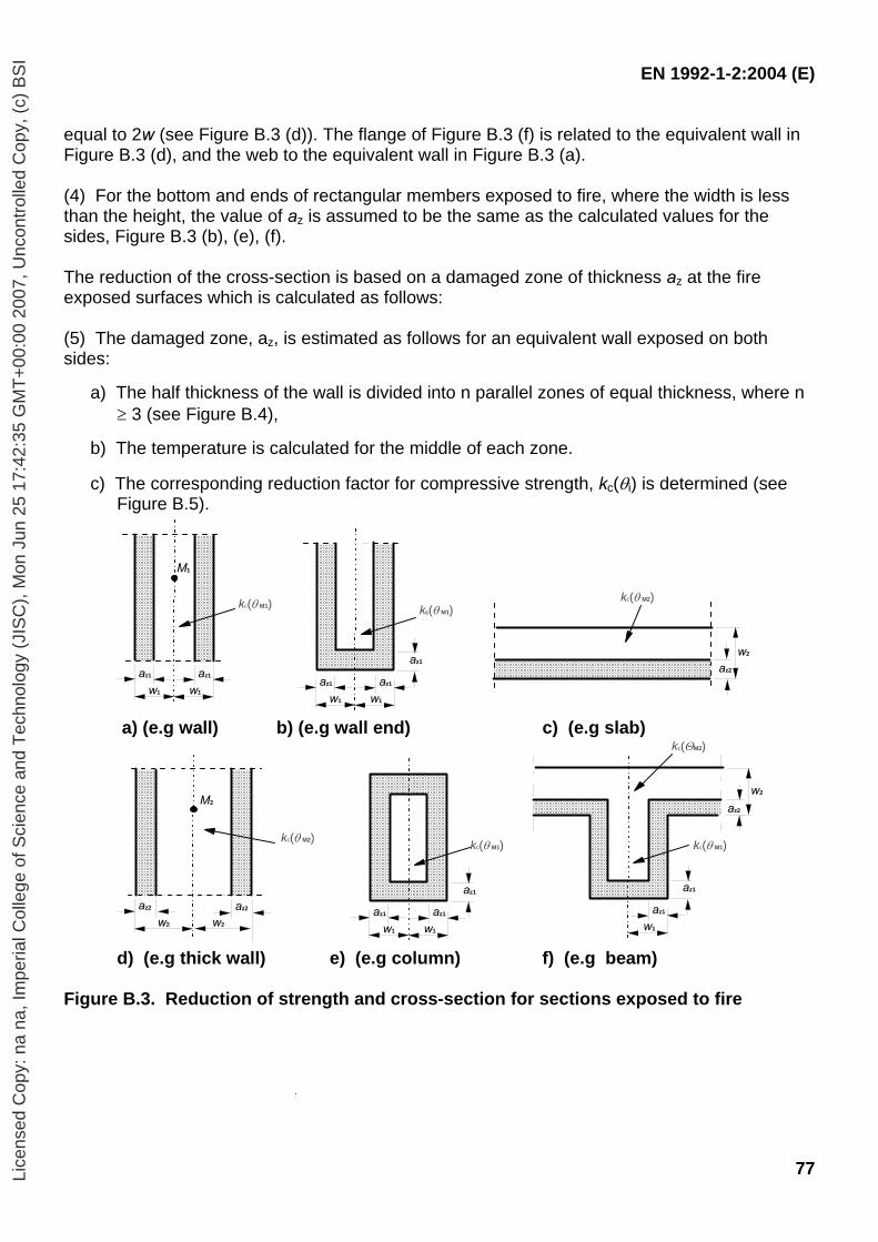
EN 1992-1-2:2004 (E)
77
equal to 2w (see Figure B.3 (d)). The flange of Figure B.3 (f) is related to the equivalent wall in Figure B.3 (d), and the web to the equivalent wall in Figure B.3 (a). (4) For the bottom and ends of rectangular members exposed to fire, where the width is less than the height, the value of az is assumed to be the same as the calculated values for the sides, Figure B.3 (b), (e), (f). The reduction of the cross-section is based on a damaged zone of thickness az at the fire exposed surfaces which is calculated as follows: (5) The damaged zone, az, is estimated as follows for an equivalent wall exposed on both sides:
a) The half thickness of the wall is divided into n parallel zones of equal thickness, where n ≥ 3 (see Figure B.4),
b) The temperature is calculated for the middle of each zone.
c) The corresponding reduction factor for compressive strength, kc(θi) is determined (see Figure B.5).
kc(θ M1)
az1
w1
az1
w1
az1w1
az1
w1
az1
M1
kc(θ M1) kc(θ M2)
az2
w2
a) (e.g wall) b) (e.g wall end) c) (e.g slab)
az1
w1
az1
w1
az1
kc(θ M1)M2kc(θ M2)
w2
az2
w2
az2
M2
w1
az2
w2
az1
az1
kc(ΘM2)
kc(θ M1)
d) (e.g thick wall) e) (e.g column) f) (e.g beam) Figure B.3. Reduction of strength and cross-section for sections exposed to fire
Lice
nsed
Cop
y: n
a na
, Im
peria
l Col
lege
of S
cien
ce a
nd T
echn
olog
y (J
ISC
), M
on J
un 2
5 17
:42:
35 G
MT
+00
:00
2007
, Unc
ontr
olle
d C
opy,
(c)
BS
I
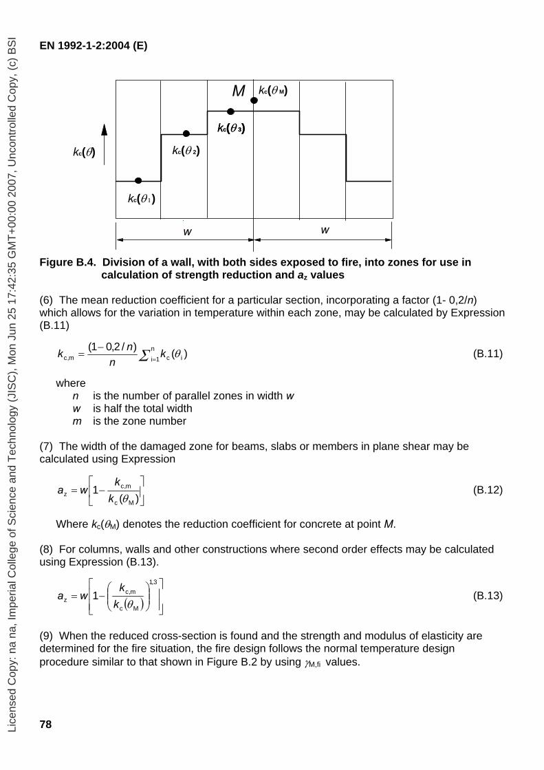
EN 1992-1-2:2004 (E)
78
kc(θ M)
kc(θ)
kc(θ 1)
kc(θ 2)
kc(θ 3)
w w
kc(θ 3)
M
Figure B.4. Division of a wall, with both sides exposed to fire, into zones for use in
calculation of strength reduction and az values (6) The mean reduction coefficient for a particular section, incorporating a factor (1- 0,2/n) which allows for the variation in temperature within each zone, may be calculated by Expression (B.11)
)()/2,01(ic
n1im,c θΣ k
nnk
=
−= (B.11)
where
n is the number of parallel zones in width w w is half the total width m is the zone number
(7) The width of the damaged zone for beams, slabs or members in plane shear may be calculated using Expression
⎥⎦
⎤⎢⎣
⎡−=
)(1
Mc
m,cz θk
kwa (B.12)
Where kc(θM) denotes the reduction coefficient for concrete at point M.
(8) For columns, walls and other constructions where second order effects may be calculated using Expression (B.13).
( ) ⎥⎥⎦
⎤
⎢⎢⎣
⎡⎟⎟⎠
⎞⎜⎜⎝
⎛−=
3,1
Mc
m,cz 1
θkk
wa (B.13)
(9) When the reduced cross-section is found and the strength and modulus of elasticity are determined for the fire situation, the fire design follows the normal temperature design procedure similar to that shown in Figure B.2 by using γM,fi values.
Lice
nsed
Cop
y: n
a na
, Im
peria
l Col
lege
of S
cien
ce a
nd T
echn
olog
y (J
ISC
), M
on J
un 2
5 17
:42:
35 G
MT
+00
:00
2007
, Unc
ontr
olle
d C
opy,
(c)
BS
I
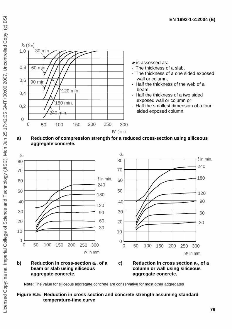
EN 1992-1-2:2004 (E)
79
w is assessed as: - The thickness of a slab, - The thickness of a one sided exposed wall or column, - Half the thickness of the web of a beam, - Half the thickness of a two sided exposed wall or column or - Half the smallest dimension of a four sided exposed column.
a) Reduction of compression strength for a reduced cross-section using siliceous aggregate concrete.
10
20
30
40
50
60
70
80
50 100 150 200 250 3000
0
240
180
12090
6030
w in mm
az
t in min.
b) Reduction in cross-section az, of a
beam or slab using siliceous aggregate concrete.
c) Reduction in cross section az, of a column or wall using siliceous aggregate concrete.
Note: The value for siliceous aggregate concrete are conservative for most other aggregates
Figure B.5: Reduction in cross section and concrete strength assuming standard
temperature-time curve
30 min.
60 min.
90 min.
120 min.
240 min.
180 min.
0 50 100 150 200 250 300w (mm)
0,2
0,4
0,6
0,8
1,0kc (θ M)
0
10
20
30
40
50
60
70
80
50 100 150 200 250 3000
0
240
180
12090
60
30
w in mm
az t in min.
Lice
nsed
Cop
y: n
a na
, Im
peria
l Col
lege
of S
cien
ce a
nd T
echn
olog
y (J
ISC
), M
on J
un 2
5 17
:42:
35 G
MT
+00
:00
2007
, Unc
ontr
olle
d C
opy,
(c)
BS
I

EN 1992-1-2:2004 (E)
80
B.3 Assessment of a reinforced concrete cross-section exposed to bending moment and axial load by the method based on estimation of curvature.
B.3.1 Buckling of columns under fire conditions (1) This clause deals with columns in which the structural behaviour is significantly influenced by second order effects under fire conditions. (2) Under fire conditions, the damage of the outer layers of the member due to high temperatures, combined with the drop of the elasticity modulus at the inner layers, results in a decrease of the stiffness of structural members under fire conditions. Because of this, second order effects can be significant for columns in the fire situation although at ambient temperature conditions their effect is negligible. (3) The assessment of a column under fire conditions as an isolated member may be made by using a method based on the estimation of curvature (see Section 5 of EN 1992-1) if the following rules are applied. (4) For braced building structures, indirect fire actions need not be considered if the decrease of the first order moments due to the decrease of stiffness of the column is not taken into account. (5) The effective length under fire conditions, l0,fi, may be taken as equal to l0 at normal temperature as a safe simplification. For a more accurate estimation the increase of the relative reaction at the ends of the column, due to the decrease of its stiffness can be taken into account. For this purpose a reduced cross-section of the column given by B.2 may be used. It should be noted that the equivalent stiffness of the reduced concrete section in this case should be:
(EI)z = [kc(θ M)]2⋅ Ec⋅ Iz where
kc(θ M) is a reduction coefficient for concrete at point M (see B.2) Ec is the elastic modulus of the concrete at normal temperature Iz is the 2nd moment of area of the reduced section
The elastic modulus of the reinforcement is Es,θ (see Table 3.2) B.3.2 Procedure for assessing fire resistance of column sections (1) This method is valid only for the assessment of columns in braced structures. (2) Determine the isotherm curves for the specified fire exposure, standard fire or parametric fire. (3) Divide the cross section into zones with approximate mean temperature of 20ºC, 100ºC, 200ºC, 300ºC ... up to 1100ºC (See Figure B6). (4) Determine the width wij, area Acij and co-ordinates xij yij of the centre of each zone. (5) Determine the temperature of reinforcing bars. The temperature of the individual reinforcing bar can be evaluated from the temperature profiles in Annex A or handbooks and is taken as the temperature in the centre of the bar.
Lice
nsed
Cop
y: n
a na
, Im
peria
l Col
lege
of S
cien
ce a
nd T
echn
olog
y (J
ISC
), M
on J
un 2
5 17
:42:
35 G
MT
+00
:00
2007
, Unc
ontr
olle
d C
opy,
(c)
BS
I
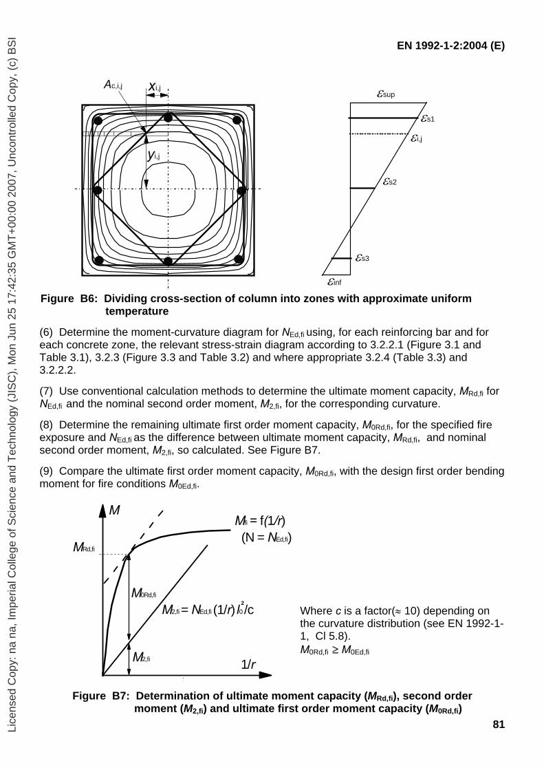
EN 1992-1-2:2004 (E)
81
Ac,i,j
yi,j
xi,j εsup
εi,j
εs1
εs2
εs3
εinf Figure B6: Dividing cross-section of column into zones with approximate uniform
temperature
(6) Determine the moment-curvature diagram for NEd,fi using, for each reinforcing bar and for each concrete zone, the relevant stress-strain diagram according to 3.2.2.1 (Figure 3.1 and Table 3.1), 3.2.3 (Figure 3.3 and Table 3.2) and where appropriate 3.2.4 (Table 3.3) and 3.2.2.2. (7) Use conventional calculation methods to determine the ultimate moment capacity, MRd,fi for NEd,fi and the nominal second order moment, M2,fi, for the corresponding curvature. (8) Determine the remaining ultimate first order moment capacity, M0Rd,fi, for the specified fire exposure and NEd,fi as the difference between ultimate moment capacity, MRd,fi, and nominal second order moment, M2,fi, so calculated. See Figure B7. (9) Compare the ultimate first order moment capacity, M0Rd,fi, with the design first order bending moment for fire conditions M0Ed,fi.
Where c is a factor(≈ 10) depending on the curvature distribution (see EN 1992-1-1, Cl 5.8). M0Rd,fi ≥ M0Ed,fi
Figure B7: Determination of ultimate moment capacity (MRd,fi), second order moment (M2,fi) and ultimate first order moment capacity (M0Rd,fi)
Mfi = f(1/r) (N = NEd,fi)
M2,fi
M0Rd,fi
M
1/r
MRd,fi
M2,fi = NEd,fi (1/r) l0 /c2
Lice
nsed
Cop
y: n
a na
, Im
peria
l Col
lege
of S
cien
ce a
nd T
echn
olog
y (J
ISC
), M
on J
un 2
5 17
:42:
35 G
MT
+00
:00
2007
, Unc
ontr
olle
d C
opy,
(c)
BS
I

EN 1992-1-2:2004 (E)
82
Annex C (informative) Buckling of columns under fire conditions (1) Tables C.1 to C.9 provide information for assessing columns in braced structures with a width up to 600 mm and slenderness up to λ = 80 for standard fire exposure. The tables are based on method given in B.3. Notations are a given in 5.3.3. See also notes 1 and 2 in 5.3.3(3). (2) Linear interpolation between the different column tables within this Annex is permitted.
Lice
nsed
Cop
y: n
a na
, Im
peria
l Col
lege
of S
cien
ce a
nd T
echn
olog
y (J
ISC
), M
on J
un 2
5 17
:42:
35 G
MT
+00
:00
2007
, Unc
ontr
olle
d C
opy,
(c)
BS
I
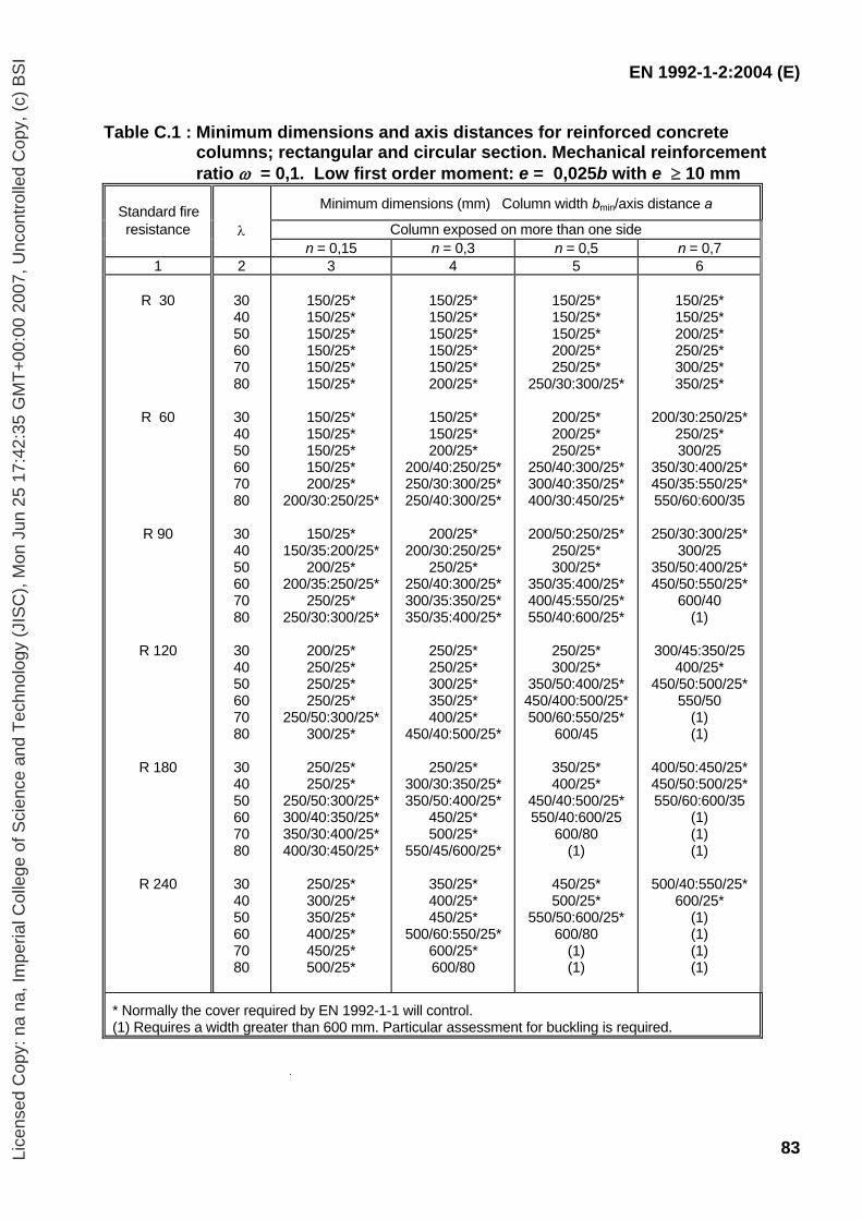
EN 1992-1-2:2004 (E)
83
Table C.1 : Minimum dimensions and axis distances for reinforced concrete columns; rectangular and circular section. Mechanical reinforcement ratio ω = 0,1. Low first order moment: e = 0,025b with e ≥ 10 mm
Standard fire
Minimum dimensions (mm) Column width bmin/axis distance a
resistance λ Column exposed on more than one side n = 0,15 n = 0,3 n = 0,5 n = 0,7 1 2 3 4 5 6
R 30
R 60
R 90
R 120
R 180
R 240
30 40 50 60 70 80
30 40 50 60 70 80
30 40 50 60 70 80
30 40 50 60 70 80
30 40 50 60 70 80
30 40 50 60 70 80
150/25* 150/25* 150/25* 150/25* 150/25* 150/25*
150/25* 150/25* 150/25* 150/25* 200/25*
200/30:250/25*
150/25* 150/35:200/25*
200/25* 200/35:250/25*
250/25* 250/30:300/25*
200/25* 250/25* 250/25* 250/25*
250/50:300/25* 300/25*
250/25* 250/25*
250/50:300/25* 300/40:350/25* 350/30:400/25* 400/30:450/25*
250/25* 300/25* 350/25* 400/25* 450/25* 500/25*
150/25* 150/25* 150/25* 150/25* 150/25* 200/25*
150/25* 150/25* 200/25*
200/40:250/25* 250/30:300/25* 250/40:300/25*
200/25*
200/30:250/25* 250/25*
250/40:300/25* 300/35:350/25* 350/35:400/25*
250/25* 250/25* 300/25* 350/25* 400/25*
450/40:500/25*
250/25* 300/30:350/25* 350/50:400/25*
450/25* 500/25*
550/45/600/25*
350/25* 400/25* 450/25*
500/60:550/25* 600/25* 600/80
150/25* 150/25* 150/25* 200/25* 250/25*
250/30:300/25*
200/25* 200/25* 250/25*
250/40:300/25* 300/40:350/25* 400/30:450/25*
200/50:250/25*
250/25* 300/25*
350/35:400/25* 400/45:550/25* 550/40:600/25*
250/25* 300/25*
350/50:400/25* 450/400:500/25* 500/60:550/25*
600/45
350/25* 400/25*
450/40:500/25* 550/40:600/25
600/80 (1)
450/25* 500/25*
550/50:600/25* 600/80
(1) (1)
150/25* 150/25* 200/25* 250/25* 300/25* 350/25*
200/30:250/25*
250/25* 300/25
350/30:400/25* 450/35:550/25* 550/60:600/35
250/30:300/25*
300/25 350/50:400/25* 450/50:550/25*
600/40 (1)
300/45:350/25
400/25* 450/50:500/25*
550/50 (1) (1)
400/50:450/25* 450/50:500/25* 550/60:600/35
(1) (1) (1)
500/40:550/25*
600/25* (1) (1) (1) (1)
* Normally the cover required by EN 1992-1-1 will control. (1) Requires a width greater than 600 mm. Particular assessment for buckling is required.
Lice
nsed
Cop
y: n
a na
, Im
peria
l Col
lege
of S
cien
ce a
nd T
echn
olog
y (J
ISC
), M
on J
un 2
5 17
:42:
35 G
MT
+00
:00
2007
, Unc
ontr
olle
d C
opy,
(c)
BS
I
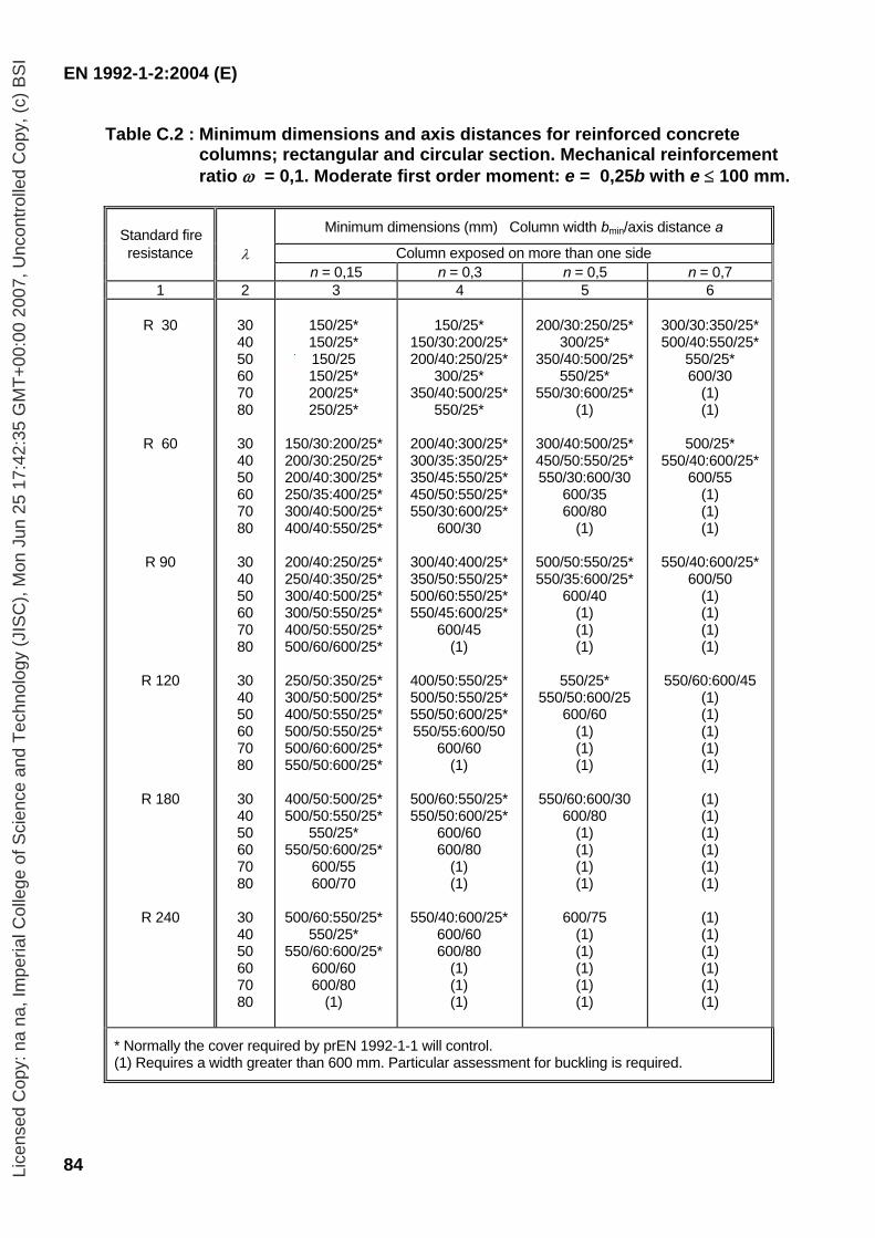
EN 1992-1-2:2004 (E)
84
Table C.2 : Minimum dimensions and axis distances for reinforced concrete columns; rectangular and circular section. Mechanical reinforcement ratio ω = 0,1. Moderate first order moment: e = 0,25b with e ≤ 100 mm.
Standard fire Minimum dimensions (mm) Column width bmin/axis distance a
resistance λ Column exposed on more than one side n = 0,15 n = 0,3 n = 0,5 n = 0,7 1 2 3 4 5 6
R 30
R 60
R 90
R 120
R 180
R 240
30 40 50 60 70 80
30 40 50 60 70 80
30 40 50 60 70 80
30 40 50 60 70 80
30 40 50 60 70 80
30 40 50 60 70 80
150/25* 150/25* 150/25 150/25* 200/25* 250/25*
150/30:200/25* 200/30:250/25* 200/40:300/25* 250/35:400/25* 300/40:500/25* 400/40:550/25*
200/40:250/25* 250/40:350/25* 300/40:500/25* 300/50:550/25* 400/50:550/25* 500/60/600/25*
250/50:350/25* 300/50:500/25* 400/50:550/25* 500/50:550/25* 500/60:600/25* 550/50:600/25*
400/50:500/25* 500/50:550/25*
550/25* 550/50:600/25*
600/55 600/70
500/60:550/25*
550/25* 550/60:600/25*
600/60 600/80
(1)
150/25*
150/30:200/25* 200/40:250/25*
300/25* 350/40:500/25*
550/25*
200/40:300/25* 300/35:350/25* 350/45:550/25* 450/50:550/25* 550/30:600/25*
600/30
300/40:400/25* 350/50:550/25* 500/60:550/25* 550/45:600/25*
600/45 (1)
400/50:550/25* 500/50:550/25* 550/50:600/25* 550/55:600/50
600/60 (1)
500/60:550/25* 550/50:600/25*
600/60 600/80
(1) (1)
550/40:600/25*
600/60 600/80
(1) (1) (1)
200/30:250/25*
300/25* 350/40:500/25*
550/25* 550/30:600/25*
(1)
300/40:500/25* 450/50:550/25* 550/30:600/30
600/35 600/80
(1)
500/50:550/25* 550/35:600/25*
600/40 (1) (1) (1)
550/25*
550/50:600/25 600/60
(1) (1) (1)
550/60:600/30
600/80 (1) (1) (1) (1)
600/75
(1) (1) (1) (1) (1)
300/30:350/25* 500/40:550/25*
550/25* 600/30
(1) (1)
500/25*
550/40:600/25* 600/55
(1) (1) (1)
550/40:600/25*
600/50 (1) (1) (1) (1)
550/60:600/45
(1) (1) (1) (1) (1)
(1) (1) (1) (1) (1) (1)
(1) (1) (1) (1) (1) (1)
* Normally the cover required by prEN 1992-1-1 will control. (1) Requires a width greater than 600 mm. Particular assessment for buckling is required.
Lice
nsed
Cop
y: n
a na
, Im
peria
l Col
lege
of S
cien
ce a
nd T
echn
olog
y (J
ISC
), M
on J
un 2
5 17
:42:
35 G
MT
+00
:00
2007
, Unc
ontr
olle
d C
opy,
(c)
BS
I
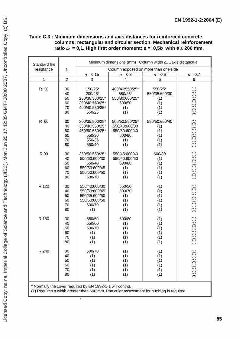
EN 1992-1-2:2004 (E)
85
Table C.3 : Minimum dimensions and axis distances for reinforced concrete columns; rectangular and circular section. Mechanical reinforcement ratio ω = 0,1. High first order moment: e = 0,5b with e ≤ 200 mm.
Standard fire Minimum dimensions (mm) Column width bmin/axis distance a
resistance λ Column exposed on more than one side n = 0,15 n = 0,3 n = 0,5 n = 0,7 1 2 3 4 5 6
R 30
R 60
R 90
R 120
R 180
R 240
30 40 50 60 70 80
30 40 50 60 70 80
30 40 50 60 70 80
30 40 50 60 70 80
30 40 50 60 70 80
30 40 50 60 70 80
150/25* 200/25*
250/30:300/25* 300/40:550/25* 400/40:550/25*
550/25
300/35:500/25* 350/40:550/25* 450/50:550/25*
550/30 550/35 550/40
350/50:550/25* 500/60:600/30
550/40 550/50:600/45 550/60:600/50
600/70
550/40:600/30 550/50:600/45 550/55:600/50 550/60:600/50
600/70 (1)
550/50 550/60 600/70
(1) (1) (1)
600/70
(1) (1) (1) (1) (1)
400/40:550/25*
550/25* 550/30:600/25*
600/50 (1) (1)
500/50:550/25* 550/40:600/30 550/50:600/40
600/80 (1) (1)
550/45:600/40 550/60:600/50
600/80 (1) (1) (1)
550/50 600/70
(1) (1) (1) (1)
600/80
(1) (1) (1) (1) (1)
(1) (1) (1) (1) (1) (1)
550/25*
550/35:600/30 (1) (1) (1) (1)
550/50:600/40
(1) (1) (1) (1) (1)
600/80
(1) (1) (1) (1) (1)
(1) (1) (1) (1) (1) (1)
(1) (1) (1) (1) (1) (1)
(1) (1) (1) (1) (1) (1)
(1) (1) (1) (1) (1) (1)
(1) (1) (1) (1) (1) (1)
(1) (1) (1) (1) (1) (1)
(1) (1) (1) (1) (1) (1)
(1) (1) (1) (1) (1) (1)
(1) (1) (1) (1) (1) (1)
* Normally the cover required by EN 1992-1-1 will control. (1) Requires a width greater than 600 mm. Particular assessment for buckling is required.
Lice
nsed
Cop
y: n
a na
, Im
peria
l Col
lege
of S
cien
ce a
nd T
echn
olog
y (J
ISC
), M
on J
un 2
5 17
:42:
35 G
MT
+00
:00
2007
, Unc
ontr
olle
d C
opy,
(c)
BS
I
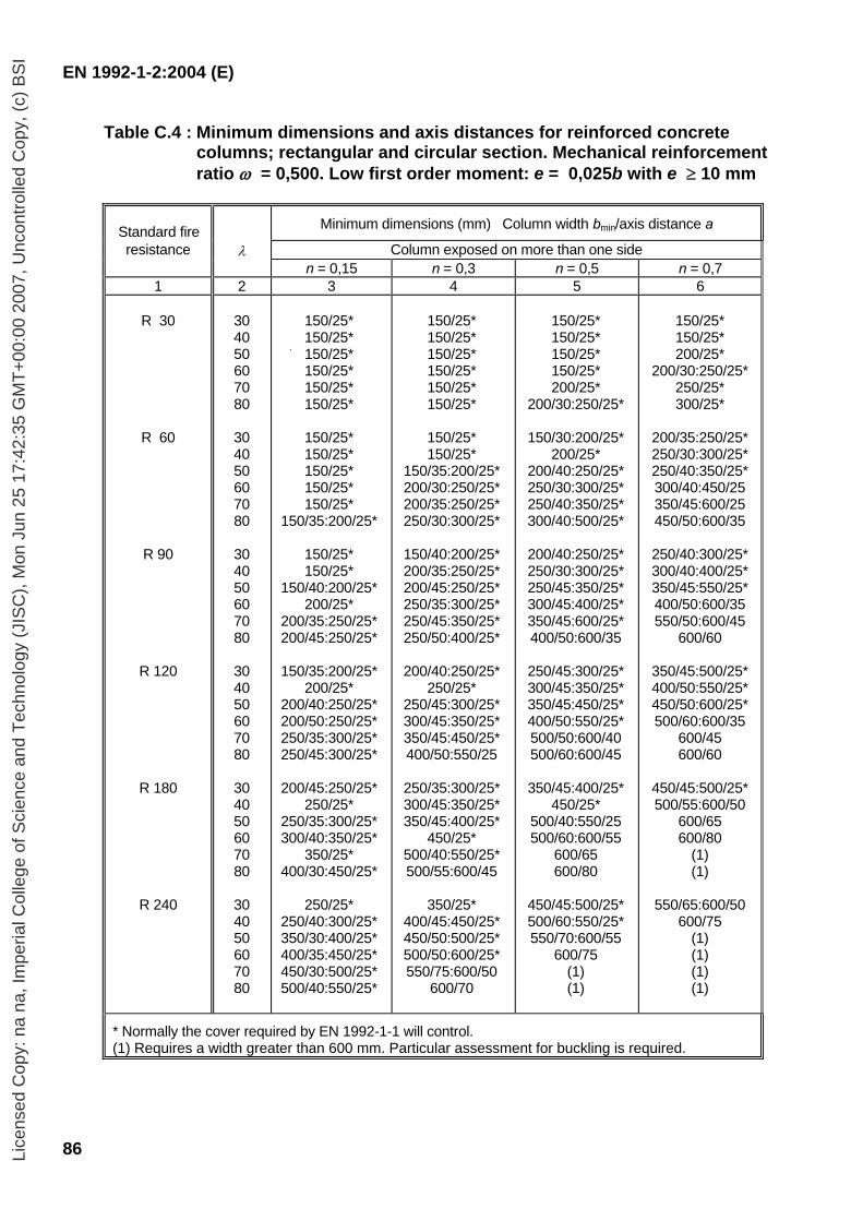
EN 1992-1-2:2004 (E)
86
Table C.4 : Minimum dimensions and axis distances for reinforced concrete columns; rectangular and circular section. Mechanical reinforcement ratio ω = 0,500. Low first order moment: e = 0,025b with e ≥ 10 mm
Standard fire Minimum dimensions (mm) Column width bmin/axis distance a
resistance λ Column exposed on more than one side n = 0,15 n = 0,3 n = 0,5 n = 0,7 1 2 3 4 5 6
R 30
R 60
R 90
R 120
R 180
R 240
30 40 50 60 70 80
30 40 50 60 70 80
30 40 50 60 70 80
30 40 50 60 70 80
30 40 50 60 70 80
30 40 50 60 70 80
150/25* 150/25* 150/25* 150/25* 150/25* 150/25*
150/25* 150/25* 150/25* 150/25* 150/25*
150/35:200/25*
150/25* 150/25*
150/40:200/25* 200/25*
200/35:250/25* 200/45:250/25*
150/35:200/25*
200/25* 200/40:250/25* 200/50:250/25* 250/35:300/25* 250/45:300/25*
200/45:250/25*
250/25* 250/35:300/25* 300/40:350/25*
350/25* 400/30:450/25*
250/25*
250/40:300/25* 350/30:400/25* 400/35:450/25* 450/30:500/25* 500/40:550/25*
150/25* 150/25* 150/25* 150/25* 150/25* 150/25*
150/25* 150/25*
150/35:200/25* 200/30:250/25* 200/35:250/25* 250/30:300/25*
150/40:200/25* 200/35:250/25* 200/45:250/25* 250/35:300/25* 250/45:350/25* 250/50:400/25*
200/40:250/25*
250/25* 250/45:300/25* 300/45:350/25* 350/45:450/25* 400/50:550/25
250/35:300/25* 300/45:350/25* 350/45:400/25*
450/25* 500/40:550/25* 500/55:600/45
350/25*
400/45:450/25* 450/50:500/25* 500/50:600/25* 550/75:600/50
600/70
150/25* 150/25* 150/25* 150/25* 200/25*
200/30:250/25*
150/30:200/25* 200/25*
200/40:250/25* 250/30:300/25* 250/40:350/25* 300/40:500/25*
200/40:250/25* 250/30:300/25* 250/45:350/25* 300/45:400/25* 350/45:600/25* 400/50:600/35
250/45:300/25* 300/45:350/25* 350/45:450/25* 400/50:550/25* 500/50:600/40 500/60:600/45
350/45:400/25*
450/25* 500/40:550/25 500/60:600/55
600/65 600/80
450/45:500/25* 500/60:550/25* 550/70:600/55
600/75 (1) (1)
150/25* 150/25* 200/25*
200/30:250/25* 250/25* 300/25*
200/35:250/25* 250/30:300/25* 250/40:350/25* 300/40:450/25 350/45:600/25 450/50:600/35
250/40:300/25* 300/40:400/25* 350/45:550/25* 400/50:600/35 550/50:600/45
600/60
350/45:500/25* 400/50:550/25* 450/50:600/25* 500/60:600/35
600/45 600/60
450/45:500/25* 500/55:600/50
600/65 600/80
(1) (1)
550/65:600/50
600/75 (1) (1) (1) (1)
* Normally the cover required by EN 1992-1-1 will control. (1) Requires a width greater than 600 mm. Particular assessment for buckling is required.
Lice
nsed
Cop
y: n
a na
, Im
peria
l Col
lege
of S
cien
ce a
nd T
echn
olog
y (J
ISC
), M
on J
un 2
5 17
:42:
35 G
MT
+00
:00
2007
, Unc
ontr
olle
d C
opy,
(c)
BS
I
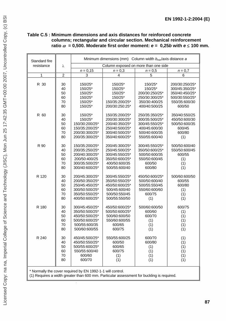
EN 1992-1-2:2004 (E)
87
Table C.5 : Minimum dimensions and axis distances for reinforced concrete columns; rectangular and circular section. Mechanical reinforcement ratio ω = 0,500. Moderate first order moment: e = 0,25b with e ≤ 100 mm.
Standard fire Minimum dimensions (mm) Column width bmin/axis distance a
resistance λ Column exposed on more than one side n = 0,15 n = 0,3 n = 0,5 n = 0,7 1 2 3 4 5 6
R 30
R 60
R 90
R 120
R 180
R 240
30 40 50 60 70 80
30 40 50 60 70 80
30 40 50 60 70 80
30 40 50 60 70 80
30 40 50 60 70 80
30 40 50 60 70 80
150/25* 150/25* 150/25* 150/25* 150/25* 150/25*
150/25* 150/25*
150/30:200/25* 150/35:200/25* 200/30:300/25* 200/35:300/25*
150/35:200/25* 200/35:250/25* 200/40:300/25* 200/50:400/25 300/35:500/25* 300/40:600/25*
200/45:300/25* 200/50:350/25* 250/45:450/25* 300/50:500/25* 350/50:550/25* 400/50:600/25*
300/45:450/25* 350/50:500/25* 450/50:500/25* 500/50:600/25* 500/55:600/35 500/60:600/55
450/45:500/25* 450/50:550/25* 500/55:600/25* 550/55:600/40
600/60 600/70
150/25* 150/25* 150/25* 150/25*
150/35:200/25* 200/30:250:25*
150/35:200/25* 200/30:300/25* 200/40:350/25* 250/40:500/25* 300/40:500/25* 350/40:600/25*
200/45:300/25* 250/45:500/25* 300/45:550/25* 350/50:600/25* 400/50:600/35 500/55:600/40
300/45:550/25* 350/50:550/25* 450/50:600/25* 500/45:600/40 500/50:550/45 500/55:550/50
450/50:600/25* 500/50:600/25* 500/60:600/50 550/60:600/55
600/65 600/75
550/55:600/25
600/50 600/65 600/75
(1) (1)
150/25* 150/25*
200/30:250/25* 250/30:300/25* 350/30:400/25 400/40:500/25
250/35:350/25* 300/35:500/25* 300/45:550/25* 400/45:600/30 500/40:600/35 550/55:600/40
300/45:550/25* 350/50:600/25* 500/50:600/35 550/50:600/45
600/50 600/80
450/50:600/25* 500/50:600/40 500/55:550/45 550/60:600/60
600/75 (1)
500/60:600/50
600/60 600/70
(1) (1) (1)
600/70 600/80
(1) (1) (1) (1)
200/30:250/25* 300/45:350/25* 350/40:450/25* 500/30:550/25* 550/35:600/30
600/50
350/40:550/25 450/50:600/30 500/50:600/35
600/45 600/80
(1)
500/50:600/40 550/50:600/45
600/55 (1) (1) (1)
500/60:600/50
600/55 600/80
(1) (1) (1)
600/75
(1) (1) (1) (1) (1)
(1) (1) (1) (1) (1) (1)
* Normally the cover required by EN 1992-1-1 will control. (1) Requires a width greater than 600 mm. Particular assessment for buckling is required.
Lice
nsed
Cop
y: n
a na
, Im
peria
l Col
lege
of S
cien
ce a
nd T
echn
olog
y (J
ISC
), M
on J
un 2
5 17
:42:
35 G
MT
+00
:00
2007
, Unc
ontr
olle
d C
opy,
(c)
BS
I
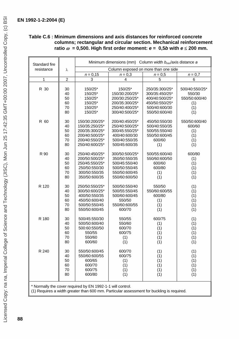
EN 1992-1-2:2004 (E)
88
Table C.6 : Minimum dimensions and axis distances for reinforced concrete columns; rectangular and circular section. Mechanical reinforcement ratio ω = 0,500. High first order moment: e = 0,5b with e ≤ 200 mm.
Standard fire Minimum dimensions (mm) Column width bmin/axis distance a
resistance λ Column exposed on more than one side n = 0,15 n = 0,3 n = 0,5 n = 0,7 1 2 3 4 5 6
R 30
R 60
R 90
R 120
R 180
R 240
30 40 50 60 70 80
30 40 50 60 70 80
30 40 50 60 70 80
30 40 50 60 70 80
30 40 50 60 70 80
30 40 50 60 70 80
150/25* 150/25* 150/25* 150/25* 150/25* 150/25*
150/30:200/25* 150/35:250/25* 200/35:300/25* 200/40:500/25* 200/40:550/25* 250/40:600/25*
250/40:450/25* 200/50:500/25* 250/45:550/25* 250/50:550/30 300/50:550/35 350/50:600/35
250/50:550/25* 300/50:600/25* 400/50:550/35 450/50:600/40 500/50:550/45 550/50:600/45
500/45:550/30 500/50:600/40 500:60:550/50
550/55 550/60 600/60
550/50:600/45 550/60:600/55
600/65 600/70 600/75 600/80
150/25*
150/30:200/25* 200/30:250/25* 200/35:300/25* 250/40:400/25* 300/40:500/25*
200/40:450/25* 250/40:500/25* 300/45:550/25* 400/40:600/30 500/40:550/35 500/45:600/35
300/50:500/25* 350/50:550/35 500/45:550/40 500/50:550/45 550/50:600/45 550/60:600/50
500/50:550/40 500/55:550/45 500/60:600/45
550/50 550/60:600/55
600/70
550/55 550/60 600/70 600/75
(1) (1)
600/70 600/75
(1) (1) (1) (1)
250/35:300/25* 300/35:450/25* 400/40:500/25* 450/50:550/25* 500/40:600/30 550/50:600/40
450/50:550/30 500/40:550/35 500/55:550/40 550/50:600/45
600/60 (1)
500/55:600/40 550/60:600/50
600/60 600/80
(1) (1)
550/50
550/60:600/55 600/80
(1) (1) (1)
600/75
(1) (1) (1) (1) (1)
(1) (1) (1) (1) (1) (1)
500/40:550/25*
550/30 550/50:600/40
(1) (1) (1)
550/50:600/40
600/60 (1) (1) (1) (1)
600/80
(1) (1) (1) (1) (1)
(1) (1) (1) (1) (1) (1)
(1) (1) (1) (1) (1) (1)
(1) (1) (1) (1) (1) (1)
* Normally the cover required by EN 1992-1-1 will control. (1) Requires a width greater than 600 mm. Particular assessment for buckling is required.
Lice
nsed
Cop
y: n
a na
, Im
peria
l Col
lege
of S
cien
ce a
nd T
echn
olog
y (J
ISC
), M
on J
un 2
5 17
:42:
35 G
MT
+00
:00
2007
, Unc
ontr
olle
d C
opy,
(c)
BS
I
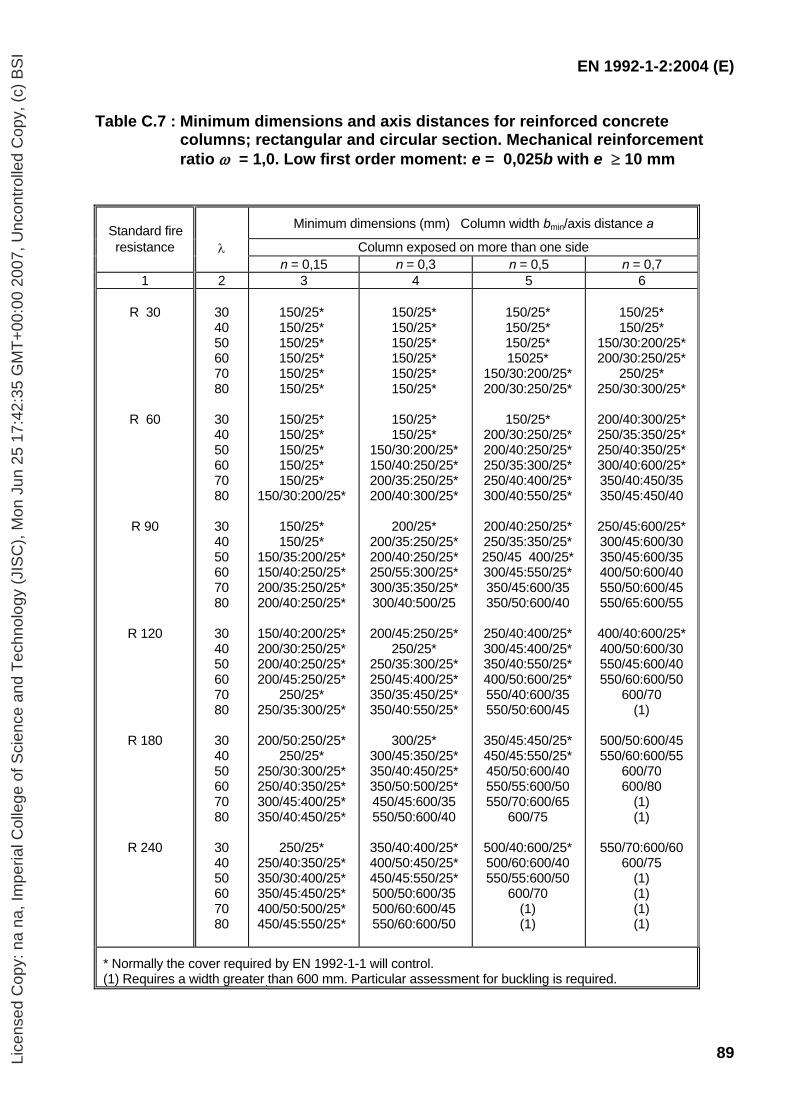
EN 1992-1-2:2004 (E)
89
Table C.7 : Minimum dimensions and axis distances for reinforced concrete columns; rectangular and circular section. Mechanical reinforcement ratio ω = 1,0. Low first order moment: e = 0,025b with e ≥ 10 mm
Standard fire
Minimum dimensions (mm) Column width bmin/axis distance a
resistance λ Column exposed on more than one side n = 0,15 n = 0,3 n = 0,5 n = 0,7 1 2 3 4 5 6
R 30
R 60
R 90
R 120
R 180
R 240
30 40 50 60 70 80
30 40 50 60 70 80
30 40 50 60 70 80
30 40 50 60 70 80
30 40 50 60 70 80
30 40 50 60 70 80
150/25* 150/25* 150/25* 150/25* 150/25* 150/25*
150/25* 150/25* 150/25* 150/25* 150/25*
150/30:200/25*
150/25* 150/25*
150/35:200/25* 150/40:250/25* 200/35:250/25* 200/40:250/25*
150/40:200/25* 200/30:250/25* 200/40:250/25* 200/45:250/25*
250/25* 250/35:300/25*
200/50:250/25*
250/25* 250/30:300/25* 250/40:350/25* 300/45:400/25* 350/40:450/25*
250/25*
250/40:350/25* 350/30:400/25* 350/45:450/25* 400/50:500/25* 450/45:550/25*
150/25* 150/25* 150/25* 150/25* 150/25* 150/25*
150/25* 150/25*
150/30:200/25* 150/40:250/25* 200/35:250/25* 200/40:300/25*
200/25*
200/35:250/25* 200/40:250/25* 250/55:300/25* 300/35:350/25* 300/40:500/25
200/45:250/25*
250/25* 250/35:300/25* 250/45:400/25* 350/35:450/25* 350/40:550/25*
300/25*
300/45:350/25* 350/40:450/25* 350/50:500/25* 450/45:600/35 550/50:600/40
350/40:400/25* 400/50:450/25* 450/45:550/25* 500/50:600/35 500/60:600/45 550/60:600/50
150/25* 150/25* 150/25* 15025*
150/30:200/25* 200/30:250/25*
150/25*
200/30:250/25* 200/40:250/25* 250/35:300/25* 250/40:400/25* 300/40:550/25*
200/40:250/25* 250/35:350/25* 250/45 400/25* 300/45:550/25* 350/45:600/35 350/50:600/40
250/40:400/25* 300/45:400/25* 350/40:550/25* 400/50:600/25* 550/40:600/35 550/50:600/45
350/45:450/25* 450/45:550/25* 450/50:600/40 550/55:600/50 550/70:600/65
600/75
500/40:600/25* 500/60:600/40 550/55:600/50
600/70 (1) (1)
150/25* 150/25*
150/30:200/25* 200/30:250/25*
250/25* 250/30:300/25*
200/40:300/25* 250/35:350/25* 250/40:350/25* 300/40:600/25* 350/40:450/35 350/45:450/40
250/45:600/25* 300/45:600/30 350/45:600/35 400/50:600/40 550/50:600/45 550/65:600/55
400/40:600/25* 400/50:600/30 550/45:600/40 550/60:600/50
600/70 (1)
500/50:600/45 550/60:600/55
600/70 600/80
(1) (1)
550/70:600/60
600/75 (1) (1) (1) (1)
* Normally the cover required by EN 1992-1-1 will control. (1) Requires a width greater than 600 mm. Particular assessment for buckling is required.
Lice
nsed
Cop
y: n
a na
, Im
peria
l Col
lege
of S
cien
ce a
nd T
echn
olog
y (J
ISC
), M
on J
un 2
5 17
:42:
35 G
MT
+00
:00
2007
, Unc
ontr
olle
d C
opy,
(c)
BS
I
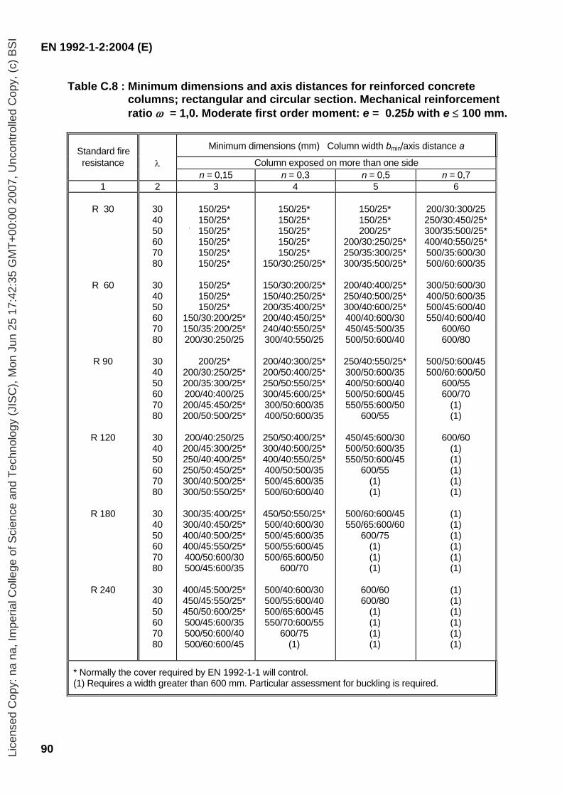
EN 1992-1-2:2004 (E)
90
Table C.8 : Minimum dimensions and axis distances for reinforced concrete columns; rectangular and circular section. Mechanical reinforcement ratio ω = 1,0. Moderate first order moment: e = 0.25b with e ≤ 100 mm.
Standard fire Minimum dimensions (mm) Column width bmin/axis distance a
resistance λ Column exposed on more than one side n = 0,15 n = 0,3 n = 0,5 n = 0,7 1 2 3 4 5 6
R 30
R 60
R 90
R 120
R 180
R 240
30 40 50 60 70 80
30 40 50 60 70 80
30 40 50 60 70 80
30 40 50 60 70 80
30 40 50 60 70 80
30 40 50 60 70 80
150/25* 150/25* 150/25* 150/25* 150/25* 150/25*
150/25* 150/25* 150/25*
150/30:200/25* 150/35:200/25* 200/30:250/25
200/25*
200/30:250/25* 200/35:300/25* 200/40:400/25 200/45:450/25* 200/50:500/25*
200/40:250/25 200/45:300/25* 250/40:400/25* 250/50:450/25* 300/40:500/25* 300/50:550/25*
300/35:400/25* 300/40:450/25* 400/40:500/25* 400/45:550/25* 400/50:600/30 500/45:600/35
400/45:500/25* 450/45:550/25* 450/50:600/25* 500/45:600/35 500/50:600/40 500/60:600/45
150/25* 150/25* 150/25* 150/25* 150/25*
150/30:250/25*
150/30:200/25* 150/40:250/25* 200/35:400/25* 200/40:450/25* 240/40:550/25* 300/40:550/25
200/40:300/25* 200/50:400/25* 250/50:550/25* 300/45:600/25* 300/50:600/35 400/50:600/35
250/50:400/25* 300/40:500/25* 400/40:550/25* 400/50:500/35 500/45:600/35 500/60:600/40
450/50:550/25* 500/40:600/30 500/45:600/35 500/55:600/45 500/65:600/50
600/70
500/40:600/30 500/55:600/40 500/65:600/45 550/70:600/55
600/75 (1)
150/25* 150/25* 200/25*
200/30:250/25* 250/35:300/25* 300/35:500/25*
200/40:400/25* 250/40:500/25* 300/40:600/25* 400/40:600/30 450/45:500/35 500/50:600/40
250/40:550/25* 300/50:600/35 400/50:600/40 500/50:600/45 550/55:600/50
600/55
450/45:600/30 500/50:600/35 550/50:600/45
600/55 (1) (1)
500/60:600/45 550/65:600/60
600/75 (1) (1) (1)
600/60 600/80
(1) (1) (1) (1)
200/30:300/25 250/30:450/25* 300/35:500/25* 400/40:550/25* 500/35:600/30 500/60:600/35
300/50:600/30 400/50:600/35 500/45:600/40 550/40:600/40
600/60 600/80
500/50:600/45 500/60:600/50
600/55 600/70
(1) (1)
600/60
(1) (1) (1) (1) (1)
(1) (1) (1) (1) (1) (1)
(1) (1) (1) (1) (1) (1)
* Normally the cover required by EN 1992-1-1 will control. (1) Requires a width greater than 600 mm. Particular assessment for buckling is required.
Lice
nsed
Cop
y: n
a na
, Im
peria
l Col
lege
of S
cien
ce a
nd T
echn
olog
y (J
ISC
), M
on J
un 2
5 17
:42:
35 G
MT
+00
:00
2007
, Unc
ontr
olle
d C
opy,
(c)
BS
I
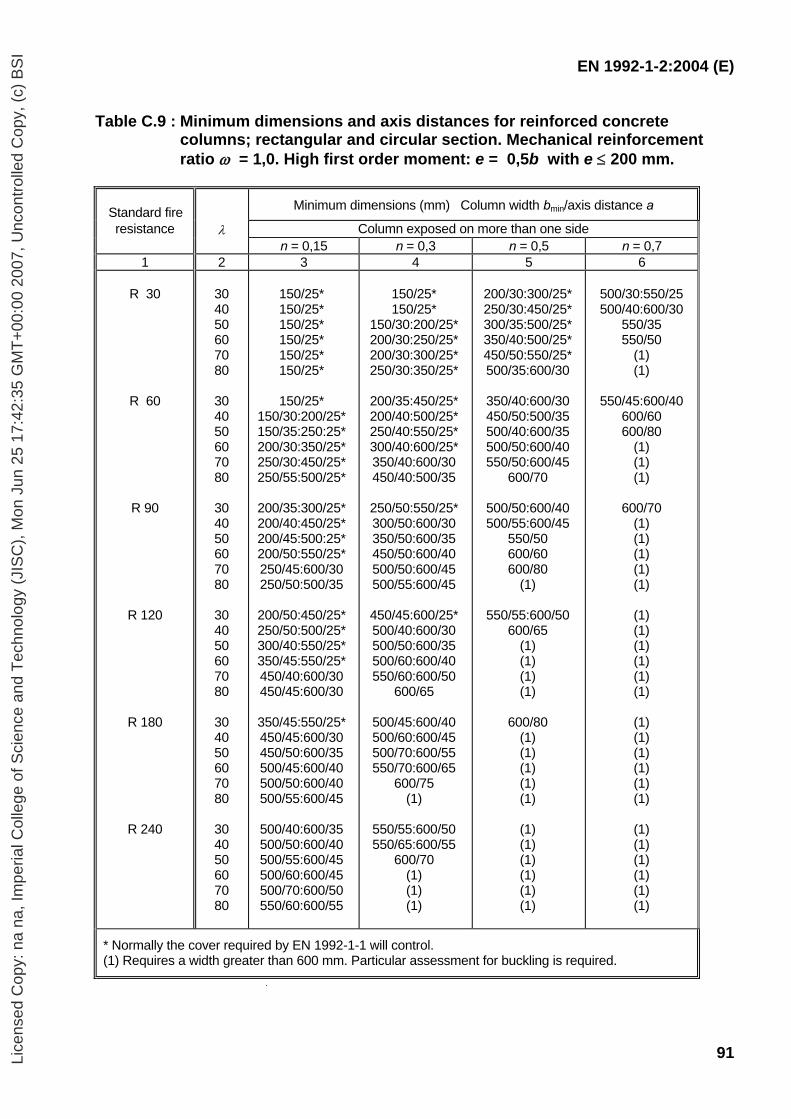
EN 1992-1-2:2004 (E)
91
Table C.9 : Minimum dimensions and axis distances for reinforced concrete columns; rectangular and circular section. Mechanical reinforcement ratio ω = 1,0. High first order moment: e = 0,5b with e ≤ 200 mm.
Standard fire Minimum dimensions (mm) Column width bmin/axis distance a
resistance λ Column exposed on more than one side n = 0,15 n = 0,3 n = 0,5 n = 0,7 1 2 3 4 5 6
R 30
R 60
R 90
R 120
R 180
R 240
30 40 50 60 70 80
30 40 50 60 70 80
30 40 50 60 70 80
30 40 50 60 70 80
30 40 50 60 70 80
30 40 50 60 70 80
150/25* 150/25* 150/25* 150/25* 150/25* 150/25*
150/25*
150/30:200/25* 150/35:250:25* 200/30:350/25* 250/30:450/25* 250/55:500/25*
200/35:300/25* 200/40:450/25* 200/45:500:25* 200/50:550/25* 250/45:600/30 250/50:500/35
200/50:450/25* 250/50:500/25* 300/40:550/25* 350/45:550/25* 450/40:600/30 450/45:600/30
350/45:550/25* 450/45:600/30 450/50:600/35 500/45:600/40 500/50:600/40 500/55:600/45
500/40:600/35 500/50:600/40 500/55:600/45 500/60:600/45 500/70:600/50 550/60:600/55
150/25* 150/25*
150/30:200/25* 200/30:250/25* 200/30:300/25* 250/30:350/25*
200/35:450/25* 200/40:500/25* 250/40:550/25* 300/40:600/25* 350/40:600/30 450/40:500/35
250/50:550/25* 300/50:600/30 350/50:600/35 450/50:600/40 500/50:600/45 500/55:600/45
450/45:600/25* 500/40:600/30 500/50:600/35 500/60:600/40 550/60:600/50
600/65
500/45:600/40 500/60:600/45 500/70:600/55 550/70:600/65
600/75 (1)
550/55:600/50 550/65:600/55
600/70 (1) (1) (1)
200/30:300/25* 250/30:450/25* 300/35:500/25* 350/40:500/25* 450/50:550/25* 500/35:600/30
350/40:600/30 450/50:500/35 500/40:600/35 500/50:600/40 550/50:600/45
600/70
500/50:600/40 500/55:600/45
550/50 600/60 600/80
(1)
550/55:600/50 600/65
(1) (1) (1) (1)
600/80
(1) (1) (1) (1) (1)
(1) (1) (1) (1) (1) (1)
500/30:550/25 500/40:600/30
550/35 550/50
(1) (1)
550/45:600/40
600/60 600/80
(1) (1) (1)
600/70
(1) (1) (1) (1) (1)
(1) (1) (1) (1) (1) (1)
(1) (1) (1) (1) (1) (1)
(1) (1) (1) (1) (1) (1)
* Normally the cover required by EN 1992-1-1 will control. (1) Requires a width greater than 600 mm. Particular assessment for buckling is required.
Lice
nsed
Cop
y: n
a na
, Im
peria
l Col
lege
of S
cien
ce a
nd T
echn
olog
y (J
ISC
), M
on J
un 2
5 17
:42:
35 G
MT
+00
:00
2007
, Unc
ontr
olle
d C
opy,
(c)
BS
I
EN 1992-1-2:2004 (E)
92
ANNEX D (Informative) Calculation methods for shear, torsion and anchorage
Note: Shear failures due to fire are very uncommon. However, the calculation methods given in this Annex are not fully verified.
D.1 General rules (1) The shear, torsion and anchorage capacity may be calculated according to the methods given in EN 1992-1-1 using reduced material properties and reduced prestress for each part of the cross section. (2) When using the simplified calculation method of 4.2, EN 1992-1-1 may be applied directly to the reduced cross section. (3) When using the simplified calculation method of 4.2, if no shear reinforcement is provided or the shear capacity relies mainly on the reduced tensile strength of the concrete, the actual shear behaviour of the concrete at elevated temperatures must be considered. In the absence of more accurate information concerning the reduction of the tensile strength of concrete, the values of kct(θ) given Figure 3.2 may be applied. (4) When using the simplified calculation method of 4.2, for elements in which the shear capacity is dependent on the tensile strength, special consideration should be given where tensile stresses are caused by non-linear temperature distributions (e.g. voided slabs, thick beams, etc). A reduction in shear strength should be taken in accordance with these increased tensile stresses. D.2 Shear and torsion reinforcement
(1) For the assessment of resistance to normal actions (axial and bending) the temperature profile may be determined without taking into account the steel and ascribing to the reinforcement the temperature in the concrete at the same point. (2) This approximation is acceptable for longitudinal reinforcement, but is not strictly true for links (see Figure D.1). The links pass through zones with different temperatures (generally the corner and bottom of a beam are warmer than the top) and distribute the heat from the warmer zone to the cooler one. Hence the temperature of a link is lower than that of the surrounding concrete and tends to become uniform along its whole length. (3) Even neglecting this small favourable effect, the link is not uniformly strained in its length, in fact the maximum stress occurs near a shear or torsion crack. It is therefore necessary to define a reference temperature evaluated at a significant position in the cross section. (4) On the basis of this reference temperature the shear or torsion resistance in fire is
determined as follows.
Lice
nsed
Cop
y: n
a na
, Im
peria
l Col
lege
of S
cien
ce a
nd T
echn
olog
y (J
ISC
), M
on J
un 2
5 17
:42:
35 G
MT
+00
:00
2007
, Unc
ontr
olle
d C
opy,
(c)
BS
I
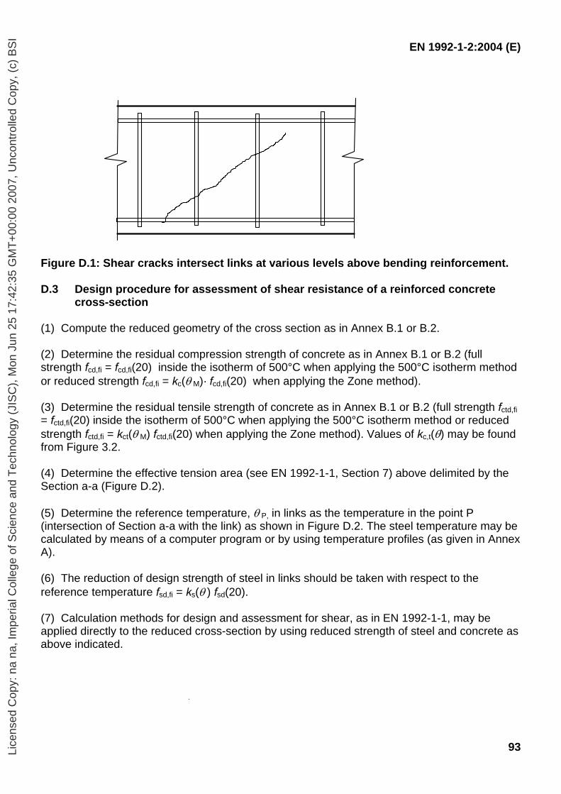
EN 1992-1-2:2004 (E)
93
Figure D.1: Shear cracks intersect links at various levels above bending reinforcement.
D.3 Design procedure for assessment of shear resistance of a reinforced concrete
cross-section (1) Compute the reduced geometry of the cross section as in Annex B.1 or B.2. (2) Determine the residual compression strength of concrete as in Annex B.1 or B.2 (full strength fcd,fi = fcd,fi(20) inside the isotherm of 500°C when applying the 500°C isotherm method or reduced strength fcd,fi = kc(θ M)· fcd,fi(20) when applying the Zone method). (3) Determine the residual tensile strength of concrete as in Annex B.1 or B.2 (full strength fctd,fi = fctd,fi(20) inside the isotherm of 500°C when applying the 500°C isotherm method or reduced strength fctd,fi = kct(θ M) fctd,fi(20) when applying the Zone method). Values of kc,t(θ) may be found from Figure 3.2. (4) Determine the effective tension area (see EN 1992-1-1, Section 7) above delimited by the Section a-a (Figure D.2). (5) Determine the reference temperature, θ P, in links as the temperature in the point P (intersection of Section a-a with the link) as shown in Figure D.2. The steel temperature may be calculated by means of a computer program or by using temperature profiles (as given in Annex A). (6) The reduction of design strength of steel in links should be taken with respect to the reference temperature fsd,fi = ks(θ ) fsd(20). (7) Calculation methods for design and assessment for shear, as in EN 1992-1-1, may be applied directly to the reduced cross-section by using reduced strength of steel and concrete as above indicated.
Lice
nsed
Cop
y: n
a na
, Im
peria
l Col
lege
of S
cien
ce a
nd T
echn
olog
y (J
ISC
), M
on J
un 2
5 17
:42:
35 G
MT
+00
:00
2007
, Unc
ontr
olle
d C
opy,
(c)
BS
I

EN 1992-1-2:2004 (E)
94
A Effective tension area
Figure D.2: The reference temperature θ p should be evaluated at points P along the line ‘a -a’ for the calculation of the shear resistance. The effective tension area may be obtained from EN 1992-1 (SLS of cracking).
D.4 Design procedure for assessment of torsion resistance of a reinforced concrete
cross-section (1) Carry out the rules (1) to (3) of D.3. (2) Determine the reference temperature, θ p, in links as the temperature in the point P (intersection of segment a-a with the link) as shown in Figure D.3. The steel temperature may be calculated by means of a computer program or by using temperature profiles (as given in Annex A). (3) The reduction of design strength of steel in links should be taken with respect to the reference temperature fsd,fi = ks(θ ) fsd(20). (4) Calculation methods for design and assessment for torsion, as in EN 1992-1-1, may be applied directly to the reduced cross-section by using reduced strength of steel and concrete as described above.
Figure D.3: The reference temperature θ p should be evaluated at points P along the line
‘a -a’ for the calculation of torsion resistance.
a
a aa aa
P P P
A
a a
a
a
a
aa
a P P
Lice
nsed
Cop
y: n
a na
, Im
peria
l Col
lege
of S
cien
ce a
nd T
echn
olog
y (J
ISC
), M
on J
un 2
5 17
:42:
35 G
MT
+00
:00
2007
, Unc
ontr
olle
d C
opy,
(c)
BS
I
EN 1992-1-2:2004 (E)
95
ANNEX E (Informative) Simplified calculation method for beams and slabs E.1 General (1) This simplified method only applies where the loading is predominantly uniformly distributed and the design at ambient temperature has been based on linear analysis or linear analysis with limited redistribution as described in Section 5 of EN 1992-1-1.
Note: The method can be applied for continuous beams or slabs where moment redistribution is higher than 15% if sufficient rotational capacity is provided at the supports for the required fire exposure conditions.
(2) This simplified method of calculation provides an extension to the use of the tabular method for beams exposed on three sides and slabs, Tables 5.5 to 5.11. It determines the effect on bending resistance for situations where the axis distance, a, to bottom reinforcement is less than that required by the tables. The minimum cross-section dimensions (bmin, bw, hs) given in Tables 5.5 to 5.11 should not be reduced. This method uses strength reduction factors based on Figure 5.1 (3) This simplified method may be used to justify reducing the axis distance a. Otherwise the rules given in 5.6 and 5.7 should be followed. This method is not valid for continuous beams where, in the areas of negative moment, the width bmin or bw, is less than 200 mm and the height hs, is less than 2b, where bmin is the value given in Column 5 of Table 5.5. E.2 Simply supported beams and slabs (1) It should be verified that
MEd,fi ≤ MRd,fi (E.1) (2) The loading under fire conditions should be determined from EN 1991-1-2. (3) The maximum fire design moment MEd,fi for predominantly uniformly distributed load may be calculated using Expression (E.2).
MEd,fi = wEd,fi leff2 / 8 (E.2)
where
wEd,fi is the uniformly distributed load (kN/m) under fire conditions leff is the effective length of beam or slab
(4) The moment of resistance MRd.fi for design for the fire situation may be calculated using Expression (E.3).
MRd,fi = (γs /γs,fi ) × ks(θ) × MEd (As,prov /As,req) (E.3)
Lice
nsed
Cop
y: n
a na
, Im
peria
l Col
lege
of S
cien
ce a
nd T
echn
olog
y (J
ISC
), M
on J
un 2
5 17
:42:
35 G
MT
+00
:00
2007
, Unc
ontr
olle
d C
opy,
(c)
BS
I
EN 1992-1-2:2004 (E)
96
where: γs is the partial material factor for steel used in EN 1992-1-1 γs,fi is the partial material factor for steel under fire conditions ks(θ) is a strength reduction factor of the steel for the given temperature θ under the
required fire resistance. θ may be taken from Annex A for the chosen axis distance
MEd is the applied moment for cold design to EN 1992-1-1 As,prov is the area of tensile steel provided As,req is the area of tensile steel required for the design at ambient temperature to EN
1992-1-1
As,prov /As,req should not be taken as greater than 1,3. E.3 Continuous beams and slabs (1) Static equilibrium of flexural moments and shear forces should be ensured for the full length of continuous beams and slabs under the design fire conditions. (2) In order to satisfy equilibrium for fire design, moment redistribution from the span to the supports is permitted where sufficient area of reinforcement is provided over the supports to take the design fire loading. This reinforcement should extend a sufficient distance into the span to ensure a safe bending moment envelope. (3) The moment of resistance MRd,fi,Span of the section at the position of maximum sagging moment should be calculated for fire conditions in accordance with E.2 (4). The maximum free bending moment for applied loads in the fire situation for uniformly distributed load, MEd,fi = wEd,fi leff
2 / 8, should be fitted to this moment of resistance such that the support moments MRd1,fi and MRd2,fi provide equilibrium as shown in Figure E.1. This may be carried out by choosing the moment to be supported at one end as equal to or less than the moment of resistance at that support (calculated using Expression (E.4)), and then calculating the moment required at the other support. (4) In the absence of more rigorous calculations, the moment of resistance at supports for design for the fire situation may be calculated using Expression (E.4).
MRd,fi = (γs /γs,fi ) MEd (As,prov /As,req) (d-a)/d (E.4)
where γs, γs,fi, MEd, As,prov, As,req are as defined in E.2 a is the required average bottom axis distance given in Table 5.5, Column 5 for beams
and Table 5.8, Column 3 for slabs d is the effective depth of section
As,prov /As,req should not be taken as greater than 1,3.
Lice
nsed
Cop
y: n
a na
, Im
peria
l Col
lege
of S
cien
ce a
nd T
echn
olog
y (J
ISC
), M
on J
un 2
5 17
:42:
35 G
MT
+00
:00
2007
, Unc
ontr
olle
d C
opy,
(c)
BS
I
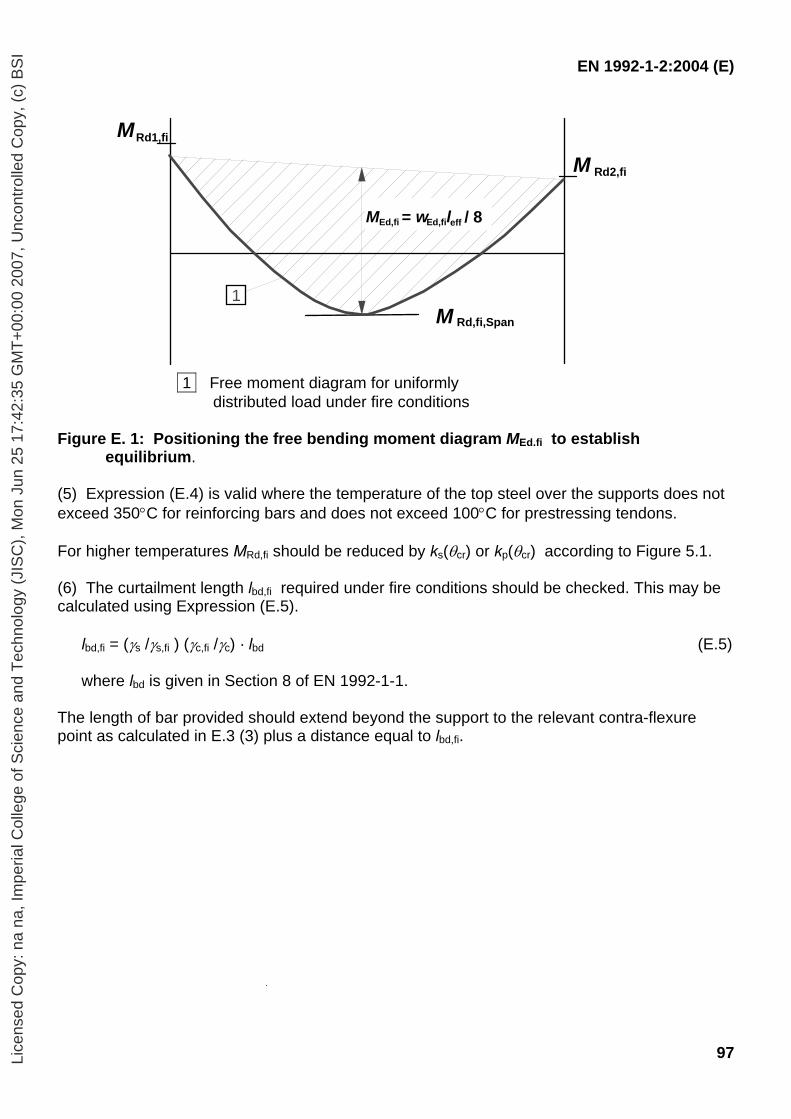
EN 1992-1-2:2004 (E)
97
Rd1,fi
M Rd,fi,Span
M Rd2,fi
M
M = w l / 8Ed,fi Ed,fi eff
1
1 Free moment diagram for uniformly
distributed load under fire conditions Figure E. 1: Positioning the free bending moment diagram MEd.fi to establish
equilibrium. (5) Expression (E.4) is valid where the temperature of the top steel over the supports does not exceed 350°C for reinforcing bars and does not exceed 100°C for prestressing tendons. For higher temperatures MRd,fi should be reduced by ks(θcr) or kp(θcr) according to Figure 5.1. (6) The curtailment length lbd,fi required under fire conditions should be checked. This may be calculated using Expression (E.5).
lbd,fi = (γs /γs,fi ) (γc,fi /γc) · lbd (E.5) where lbd is given in Section 8 of EN 1992-1-1.
The length of bar provided should extend beyond the support to the relevant contra-flexure point as calculated in E.3 (3) plus a distance equal to lbd,fi.
Lice
nsed
Cop
y: n
a na
, Im
peria
l Col
lege
of S
cien
ce a
nd T
echn
olog
y (J
ISC
), M
on J
un 2
5 17
:42:
35 G
MT
+00
:00
2007
, Unc
ontr
olle
d C
opy,
(c)
BS
I
BS EN 1992-1-2:2004
BSI
389 Chiswick High Road
London
W4 4AL
BSI — British Standards InstitutionBSI is the independent national body responsible for preparing British Standards. It presents the UK view on standards in Europe and at the international level. It is incorporated by Royal Charter.
Revisions
British Standards are updated by amendment or revision. Users of British Standards should make sure that they possess the latest amendments or editions.
It is the constant aim of BSI to improve the quality of our products and services. We would be grateful if anyone finding an inaccuracy or ambiguity while using this British Standard would inform the Secretary of the technical committee responsible, the identity of which can be found on the inside front cover. Tel: +44 (0)20 8996 9000. Fax: +44 (0)20 8996 7400.
BSI offers members an individual updating service called PLUS which ensures that subscribers automatically receive the latest editions of standards.
Buying standards
Orders for all BSI, international and foreign standards publications should be addressed to Customer Services. Tel: +44 (0)20 8996 9001. Fax: +44 (0)20 8996 7001. Email: [email protected]. Standards are also available from the BSI website at http://www.bsi-global.com.
In response to orders for international standards, it is BSI policy to supply the BSI implementation of those that have been published as British Standards, unless otherwise requested.
Information on standards
BSI provides a wide range of information on national, European and international standards through its Library and its Technical Help to Exporters Service. Various BSI electronic information services are also available which give details on all its products and services. Contact the Information Centre. Tel: +44 (0)20 8996 7111. Fax: +44 (0)20 8996 7048. Email: [email protected].
Subscribing members of BSI are kept up to date with standards developments and receive substantial discounts on the purchase price of standards. For details of these and other benefits contact Membership Administration. Tel: +44 (0)20 8996 7002. Fax: +44 (0)20 8996 7001. Email: [email protected].
Information regarding online access to British Standards via British Standards Online can be found at http://www.bsi-global.com/bsonline.
Further information about BSI is available on the BSI website at http://www.bsi-global.com.
Copyright
Copyright subsists in all BSI publications. BSI also holds the copyright, in the UK, of the publications of the international standardization bodies. Except as permitted under the Copyright, Designs and Patents Act 1988 no extract may be reproduced, stored in a retrieval system or transmitted in any form or by any means – electronic, photocopying, recording or otherwise – without prior written permission from BSI.
This does not preclude the free use, in the course of implementing the standard, of necessary details such as symbols, and size, type or grade designations. If these details are to be used for any other purpose than implementation then the prior written permission of BSI must be obtained.
Details and advice can be obtained from the Copyright & Licensing Manager. Tel: +44 (0)20 8996 7070. Fax: +44 (0)20 8996 7553. Email: [email protected].
Lice
nsed
Cop
y: n
a na
, Im
peria
l Col
lege
of S
cien
ce a
nd T
echn
olog
y (J
ISC
), M
on J
un 2
5 17
:42:
35 G
MT
+00
:00
2007
, Unc
ontr
olle
d C
opy,
(c)
BS
I

![How to Design Concrete Structures Using Eurocode 2[1]](https://static.fdocuments.net/doc/165x107/577cdd1a1a28ab9e78ac38c6/how-to-design-concrete-structures-using-eurocode-21.jpg)