Exploiting Light Interferences to Generate Micrometer-High ...

Network Protocols and AlgorithmsISSN 1943-3581
2016, Vol.8, No.1
Eurobalise-Train communication modelling to
assess interferences in railway control signalling
systems
Lara Rodriguez, Christian Pinedo, Igor Lopez
Marina Aguado, Jasone Astorga, Marivi Higuero
Faculty of Engineering, University of the Basque Country UPV/EHU,
Alameda Urquijo s/n, 48013 Bilbao, Spain
Tel: +34-946-01-4024 E-mail: {laramaria.rodriguez, christian.pinedo, igor.lopez,
marina.aguado, marivi.higuero, jasone.astorga}@ehu.eus
Inigo Adin, Guillermo Bistue, Jaizki Mendizabal
CEIT and TECNUN (University of Navarra),
Paseo Manuel Lardizabal 15, 20009 San Sebastian, Spain
Tel: +34-943-21-2800 E-mail: {iadin, gbistue, jmendizabal}@ceit.es
Received: Dec. 15, 2015 Accepted: March 14, 2016 Published: March 31, 2016
DOI:10.5296/npa.v8i1.8731 URL: http://dx.doi.org/10.5296/npa.v8i1.8731
Abstract
The evolution of the railway sector depends, to a great extent, on the deployment ofadvanced railway signalling systems. These signalling systems are based on communicationarchitectures that must cope with complex electromagnetical environments. This paper isoutlined in the context of developing the necessary tools to allow the quick deployment ofthese signalling systems by contributing to an easier analysis of their behaviour under theeffect of electromagnetical interferences. Specifically, this paper presents the modelling ofthe Eurobalise-train communication flow in a general purpose simulation tool. It is critical toguarantee this communication link since any lack of communication may lead to a stop of thetrain and availability problems. In order to model precisely this communication link we usedreal measurements done in a laboratory equipped with elements defined in the suitable subsets.Through the simulation study carried out, we obtained performance indicators of the physicallayer such as the received power, SNR and BER. The modelling presented in this paper is arequired step to be able to provide quality of service indicators related to perturbed scenarios.
Keywords: balise, BTM, ERTMS, Eurobalise, interference, model, simulation.
58 www.macrothink.org/npa

Network Protocols and AlgorithmsISSN 1943-3581
2016, Vol.8, No.1
1 Introduction
The boost towards a more sustainable society considerably relies on the use of publicguided transport systems such as the railway. In these environments, signalling systems area critical component. Specifically, the railway signalling system makes use of railway com-munication technologies and specific architectures linked to a very complex electromagneticalenvironment.
In the European Union, the signalling system for high speed lines is the European RailTraffic Management System (ERTMS). In fact, ERTMS is also spreading to regional railwaysand main lines out of the European Union.
ERTMS consists of two subsystems: the European Rail Train Control System (ETCS)—focused on the control of the safety of the trains—and GSM-R—aimed at a permanent radiocommunication between the command centre and the trains. Nowadays, many railway operat-ors are deploying some of the levels of ERTMS. Thus, the in-lab analysis and simulation toolsare critical with the aim of reducing significantly the required activities for the deployment(studies, checks and validation).
The context of the work presented is the development of a full ERTMS simulation frame-work to allow the analysis of the signalling system, safety and availability of the railway serviceunder normal or abnormal conditions such as a disturbed electromagnetical environment. Infact, the model here presented integrates in a railway simulation framework [1] that modelsall the protocol stack required for the ETCS application and the permanent communicationtechnology (GSM-R, LTE, . . . ) between the train and the command centre (RBC).
The objective of this paper is to detail the way to model the Eurobalise-train communica-tion, which is one of the key communication interfaces between ground and train defined inERTMS. A preliminary version of this work was already presented in [2]. Now, in this paper,we provide a fully detailed explanation of the modelling process with an special emphasis in themeasurements that were performed in order to characterize the communication airgap beforemodelling and validating it.
The most powerful tool available today for electromagnetic analysis is the computer simu-lator. There are several commercial packages capable of performing accurate 3D simulations,taking into account different boundary conditions [3, 4, 5]. These platforms can replicatevirtually any physical system. However, there are two main drawbacks: On the one hand, theuse of computational resources may be high even for simple models, and on the other it may bedifficult to relate the performance obtained with the basic design parameters. BTM antennasare defined as almost rectangular loops, and therefore, the analysis of this particular systemmay be carried out applying the basic electromagnetic equations to the system [6]. This is theapproach followed by our proposal. We obtain greater insight into the physical problem, and asa consequence, the conclusions obtained can be used to optimize the system with quantitativeand qualitative rules. In order to simplify the expressions, a symbolic mathematical solver hasbeen used. This methodology requires less computational resources than the conventional EMsimulator.
This document is structured as follows: Section 2 introduces ERTMS and particularlythe operation of the Eurobalise-train communication; Section 3 details the in-lab setup tocharacterize this communication, a previous required step to successfully model the commu-
59 www.macrothink.org/npa
Network Protocols and AlgorithmsISSN 1943-3581
2016, Vol.8, No.1
nication; then, Section 4 explains the process to model it and details all the assumptions andsimplifications presented in every model of the reality; finally, Section 5 shows the tests carriedout to validate the model and the results obtained from the simulations.
2 Eurobalises in ERTMS
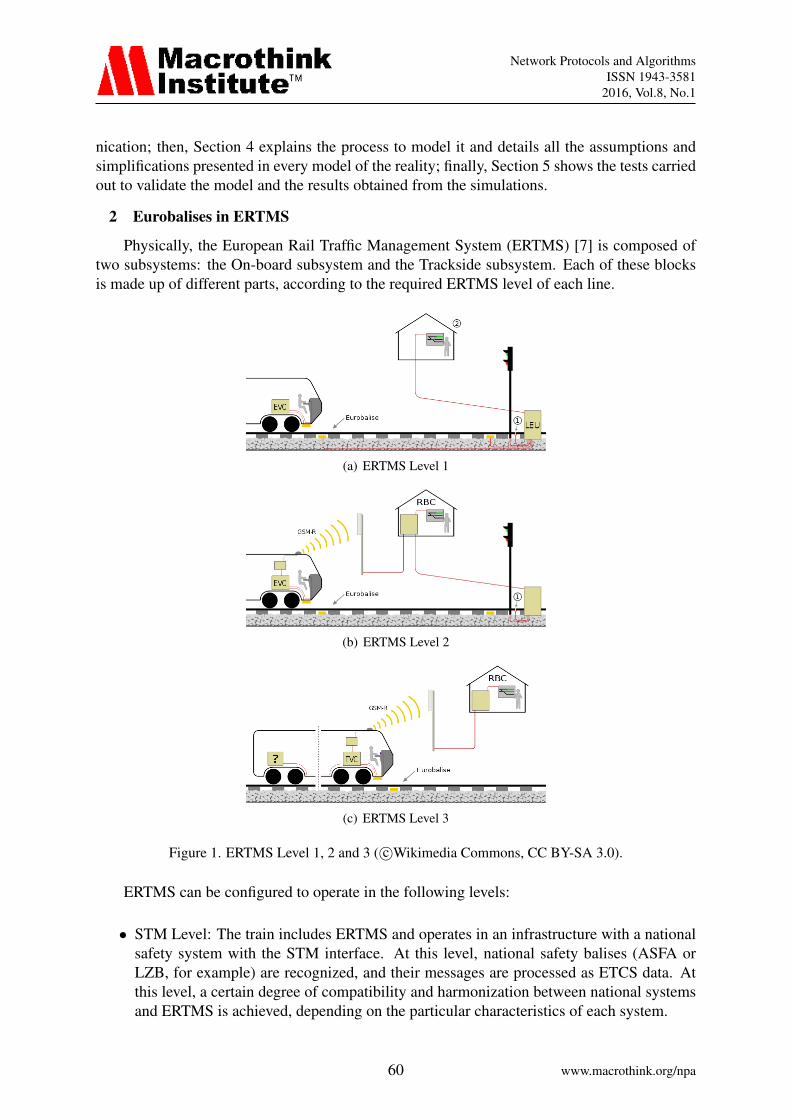
Physically, the European Rail Traffic Management System (ERTMS) [7] is composed oftwo subsystems: the On-board subsystem and the Trackside subsystem. Each of these blocksis made up of different parts, according to the required ERTMS level of each line.
(a) ERTMS Level 1
(b) ERTMS Level 2
(c) ERTMS Level 3
Figure 1. ERTMS Level 1, 2 and 3 ( c©Wikimedia Commons, CC BY-SA 3.0).
ERTMS can be configured to operate in the following levels:
• STM Level: The train includes ERTMS and operates in an infrastructure with a nationalsafety system with the STM interface. At this level, national safety balises (ASFA orLZB, for example) are recognized, and their messages are processed as ETCS data. Atthis level, a certain degree of compatibility and harmonization between national systemsand ERTMS is achieved, depending on the particular characteristics of each system.
60 www.macrothink.org/npa

Network Protocols and AlgorithmsISSN 1943-3581
2016, Vol.8, No.1
• Level 0: The train includes ERTMS but the infrastructure is equipped with no ERTMSor any compatible system. At this level, ERTMS does not take part on any track-traincommunication, therefore is not recommended for normal operation. It may be useful inspecial situations, for instance in case of a system break down.
• Level 1 (see Fig. 1(a)): The train includes ERTMS, and the railway contains Eurobalises.Euroloop may be also present. The RF communication between the train and the balisesprovides the appropriate speed limit for each spot.
• Level 2 (see Fig. 1(b)): In this case, the operation is controlled by a Control Centre (RBC)and Eurobalises. This system allows continuous communication between the train andthe control centre. The most relevant transmitted data are real time train position, speedlimits and dynamic signals. Train integrity and position is still managed through trackcircuits.
• Level 3 (see Fig. 1(c)): This level is similar to Level 2, but the supervision of trainintegrity and position is based on the information transmitted by the train. In order toaccomplish this task, GNSS positioning systems are incorporated. One of the crucialadvances of this level is the possibility to adapt moving block operation, which is a keypoint to improve traffic optimization and safety. Nowadays, this Level is still underdevelopment, due to the massive complexities of the integration of all the subsystemsrequired.
Currently, most part of the ERTMS signalling systems deployed are Level 1 and Level 2.Therefore, the communication between the train and the Eurobalise is a key point of ERTMS.Any error introduced at this level may compromise the correct development of the entiresystem. Moreover, the communication channel is particularly challenging due to the inherentinterferences present in the railway environment.
Next, the two components of this communication, the Eurobalise in the track and the BaliseTransmission Module (BTM) On-board the train, are explained in detail.
2.1 Eurobalise
The Eurobalise is a device placed between the rails of a track that transmits messages tothe On-board ERTMS, more precisely to the BTM of the On-board ERTMS.
There are two types of balises: Fixed Data Balise, which transmits always the same mes-sage, and Switchable or Controllable Eurobalise, which are able to communicate dynamic datato the train such as signal indications. The former are programmed to send the same informationeach time they are activated, e.g. balise track position, speed limit or track geometry. On theother hand, if the balise is connected to other elements, it may receive and send dynamic datato the train. In any case, the information is sent as fixed length messages, referred in ETCSdocumentation as telegrams.
The Eurobalises are passive devices, with no external battery required. Most part of thetime the Eurobalise is in sleep mode, being activated when a train provides an appropriate tele-powering signal. This activation is carried out by the BTM, purposely located at the bottom ofthe cab. The interaction between the Eurobalise and BTM is depicted in Fig. 2.
61 www.macrothink.org/npa

Network Protocols and AlgorithmsISSN 1943-3581
2016, Vol.8, No.1
BTM Module
Excitation signal
generator
BTM sending antenna
BTM receiving antenna
Eurobalise receiving antenna
Eurobalise sending antenna
Telegram storageTelegram sending
module
Eurobalise
Telegram processing module
Excitation signal
Eurobalise information
Figure 2. Interaction between Eurobalise and BTM On-board.
The activation of the Eurobalise takes place when the voltage generated by the electro-magnetic field, which is ultimately induced by the BTM, reaches a minimum value. Oncethese values are achieved, the Eurobalise enters the active mode and sends the correspondingmessages, according to the specified format, modulation and bit rate. The process ends whenthe tele-powering signal is too weak to assure the operation of the Eurobalise.
During the activation period, the telegram is sent in a cyclic manner. Since the bit rateof this message is constant, the number of messages received depends on two main factors:The telegram length (341 bits for short telegrams and 1023 bits for long telegrams) and thetrain speed. In order to validate the communication process, the BTM must receive at least onecomplete and valid telegram.
In order to successfully transmit the information, the balise must meet the following re-quirements defined in the ERTMS specification documents [8][9, page 21]:
• Frequency range: 3.951–4.516 MHz
• Transmission bit rate: 564.48 kbits/s
• Modulation scheme: CPFSK
• Eurobalise activation volume (related to the BTM antenna):
– X into [-1300 ; +1300] mm
– Y into [-1400 ; +1400] mm
– Z into [+220 ; +460] mm
2.2 Balise Transmission Module
The on-board train equipment receives the Eurobalise signal through the Balise Trans-mission Module (BTM). This system is defined by each signalling product manufacturer and
62 www.macrothink.org/npa

Network Protocols and AlgorithmsISSN 1943-3581
2016, Vol.8, No.1
carries out several functions: Balise tele-powering, signal acquisition, filtering, demodulationand decoding and finally, communication with the rest of the equipment.
3 Communication characterization
The communication airgap between the Eurobalise and the BTM needs to be defined anddescribed in terms of distances and power losses in order to implement it into the communi-cation modelling. For that, the standard laboratory setup has been built with the appropriatesubsystems. The following subsection shows the process and the results.
3.1 Antennas and equipment
The measurements have been carried out with an Agilent 8714ET network analyser, AgilentE4432B signal generator and a HP E4402B spectrum analyser. The antennas have been imple-mented following the instructions included in SUBSET-085 [10] and SUBSET-116 [8], withthe main characteristics listed below:
• Measuring Antenna: This antenna has been fabricated as indicated in SUBSET-116. Theloop has been implemented laying out a Cu 200 mm x 200 mm squared track on a PCBboard. An additional metallic plane of 400 mm x 400 mm has been fixed to the PCBby means of four plastic material columns. The separation between both planes is 75mm. This antenna is also proposed for measuring the interferers at the BTM location,on-board [11].
• Balise antenna: A 488 mm x 358 mm Standard Reference Loop has been implementedaccording to SUBSET-085 [10]. This component emulates the behaviour of the Eurobal-ise itself. It has eight sections of 5mm x 20mm copper bar. A 3 mm air gap separateseach part. At each joint a PCB has been fixed with the required LC tuning circuit. Theprocedure for the calculation of the components can be found in Annex H of the subset.In this case the loop was tuned to 4.23 MHz and 29.095 MHz.
3.2 Measurement methodology
The first step has been the characterization of the balise antenna emulating the Eurobaliseand the BTM receiving antenna. The S11 parameter of the receiving antenna has been measuredwith a network analyser - Agilent 8714ET. Fig. 3 shows the S11 of the BTM receiving antenna.Even if the values of the port reflection are relatively high for an antenna, it shows that it hasbeen designed for 4.2 MHz.
Now, the current flowing through the measuring loop has to be determined. The trans-mission test has been carried out injecting -10 dBm signal at 4.2 MHz into the Eurobaliseantenna with the signal generator - Agilent E4438C. For this characterization, both antennasare situated face to face, centred. The power received by the BTM receiving antenna has beenregistered with the spectrum analyser - HP E4402B. Fig. 4 shows the expected current for a-10 dBm power input. As it can be observed, from 1 MHz to 5MHz, the loop is effectivelytuned to 4.2 MHz and then, the communication Balise antenna - BTM receiving antennais maximized at that frequency. The measurements are repeated for different vertical andhorizontal displacements. The most significant values are shown in the next subsection.
63 www.macrothink.org/npa

Network Protocols and AlgorithmsISSN 1943-3581
2016, Vol.8, No.1
Figure 3. S11 of the BTM receiving antenna.
Figure 4. Current measured on the standard reference loop - Eurobalise.
3.3 Results
Fig. 5 shows the power received at the Measuring receiving antenna when a power of -10dBm is applied to this Balise antenna, at 4.2 MHz. The power received is maximum for a centreseparation equal to zero. In this position both antennas present their vertical symmetry axisaligned. The induced flux decreases when the antennas are displaced. The figure also showsthe distinctive lobe pattern of the curve. This is due to the cancellation of electromagnetic fluxat a specific point caused by the different sign of the contribution of each balise antenna arm.As expected, the measurement procedure with a lower airgap distance presents higher values,at least up to 0.7 m from the centre. From that curve and considering a -10dBm input power,the airgap losses can be deduced in order to implement the communication modelling in thenext section.
64 www.macrothink.org/npa

Network Protocols and AlgorithmsISSN 1943-3581
2016, Vol.8, No.1
Figure 5. Received power depending on the airgap distance to the centre of the Balise antenna.
4 Communication modelling
The study of the communication channel between the track and the train has been carriedout with the Discrete Event Simulator (DES) Riverbed Modeler, formerly known as OpnetModeler. This simulator provides a wide range of libraries, allowing us to model real networksand make use of most of the technologies. One of its disadvantages is the lack of models whichinclude near field communications used by Eurobalises. Thus, a specific model for near fieldcommunications has been developed. Next, a detailed explanation of the model is presented.
4.1 Nodes
The first step in this study is the creation of the nodes that are going to implement thefunctionalities for the Eurobalise and the BTM. The models used by Riverbed Modeler arecomposed of modules and processes so those elements are the ones which have been designedfor our models.
Fig. 6 shows the Eurobalise. It consists of 3 modules as shown in Fig. 6(b): telegramgenerator, radio transmitter and antenna.
(a) Node (b) Modules (c) telegram generator module
Figure 6. Model of the Eurobalise.
65 www.macrothink.org/npa

Network Protocols and AlgorithmsISSN 1943-3581
2016, Vol.8, No.1
The main module of the balise, telegram generator (see Fig. 6(c)), is responsible forgenerating the telegrams. It is constantly monitoring the area around the balise to detect ifany train is within the activation volume. In that case, the Eurobalise creates the telegram withthe adequate length and format and starts transmitting it periodically until no train is insidethe activation area. Although the Eurobalise sends a continuous flow of bits and RiverbedModeler only works with packets, which are called telegrams in the case of Eurobalises, weadjust the periodicity of sending telegrams according to the transmission rate of the Eurobaliseand the size of the telegram in order to send a continuous flow of bits as it happens with realEurobalises.
On the other hand, the model for the BTM is detailed in Fig. 7. The BTM also consists of3 modules shown in Fig. 7(b): telegram receiver, radio receiver and antenna.
(a) Node (b) Modules
Figure 7. Model of the BTM.
The telegram receiver of the BTM only receives from the lower modules the telegramswhich are transmitted without errors once they have passed correctly through the wirelesschannel of Riverbed Modeler. Thus, this module can count the number of correct telegramsthat are received from the Eurobalise.
4.2 Wireless channel
Riverbed Modeler allows to exhaustively model the physical characteristics of the wirelesscommunications. The wireless channel is modelled as a pipeline of stages, which are processedsequentially. Those stages are divided in transmission stages and reception stages. Each ofthem is in charge of a specific function (verification of frequency ranges, antenna gainingcalculation, bit error rate calculation, . . . ). For example, Fig. 8 shows the transmission stagesfor the transmission module of the Eurobalise.
Both modules, the radio transmitter and receiver modules of the Eurobalise and BTMrespectively, use the default pipelines provided by Riverbed (known as dra). However, some ofthem have been modified in order to adapt them to the specific characteristics of the Eurobalise-BTM communication.
Thus, in the radio transmitter two stages have been modified:
• closure stage: this stage defines if a wireless node can receive a packet sent by a trans-mitter. A new stage called eurobalise closure has been created to verify if the receiver,
66 www.macrothink.org/npa

Network Protocols and AlgorithmsISSN 1943-3581
2016, Vol.8, No.1
Figure 8. Transmission stages of the wireless pipeline in the transmission module of the Eurobalise.
the BTM, is within the activation area. If not, that node does not receive the telegramsent by the balise.
• chanmatch stage: the new stage called eurobalise chanmmatch checks if the transmitterand receiver share the same frequency range, bandwidth, data rate and modulation. If anyof the previous parameters do not match, the receiver will consider that packet as noise.
Furthermore, in the radio receiver other stages have been modified:
• power stage: this stage calculates the the power of the telegram received at the BTM.The modifications done at this pipeline are explained in detail in Section 4.2.1.
• BER stage: this stage calculates the Bit Error Rate (BER) based on the Signal to NoiseRatio (SNR) value obtained by previous stages and the modulation used in the commu-nication. We use the default dra ber stage provided by Riverbed Modeler, but it wasrequired to implement the CPFSK Coherent (1) and CPFSK Non-Coherent (2) modula-tions, which are the modulations used in the Eurobalize-BTM communication and arenot implemented in Riverbed Modeler:
Pb =1
2erfc
(√Eb
2No
)(1)
Pb =1
2e−
EbNo (2)
where Pb is the bit error probability, Eb/No is the energy per bit to noise power spectraldensity ratio and erfc(z) is the complementary error function.
• error stage: once the BER is known, this stage calculates the number of wrong bitsin the packet or telegram. Depending on the number of erroneous bits and the errorcorrection algorithm implemented by the wireless communication, the packet is finallyaccepted or discarded. The Cyclic Redundancy Check (CRC) algorithm implemented inthe Eurobalise-BTM communication checks the integrity of not only the actual packetbut also part of previous packet. So, we implemented a new stage called eurobalise errorto cope with this peculiarity.
67 www.macrothink.org/npa

Network Protocols and AlgorithmsISSN 1943-3581
2016, Vol.8, No.1
4.2.1 Near field transmission
The power stage uses the dra power implementation by default to calculate the receivedpower of one packet by utilizing the Friis transmission equation:
Pr
Pt
= GtGr
(λ
4πR
)2
(3)
where Pr/Pt is the ratio between the received power by the receiving antenna and the transmit-ted power by the transmitting antenna, Gt and Gr are the antenna gains of the transmitting andreceiving antenna respectively, λ is the wavelength and R is the distance between the antennas.
In order to use this equation antennas must meet the far field requirement:
R >2D2
λ(4)
whereD is the is the largest physical linear dimension of the antenna, for example, the diameterof a dish antenna.
However, Eurobalise-BTM communications do not meet the far field requirement (4) andthus, they are considered to be near field communications, where the Friis transmission equa-tion should not be used to estimate the received power.
Consequently, instead of using the Friis transmission equation we have implemented anew eurobalise power stage that implements the measurements obtained in Section 3. Moreprecisely, this new pipeline stage implements the Fig. 5 in a matrix to obtain the received powerof the transmission depending on the distance between the Eurobalise and the BTM when thepacket was transmitted.
5 Validation & Results
The main objective of the simulations carried out in this section is to validate the modeldeveloped in Section 4 by crossing it with the real measurements obtained in Section 3. Inorder to perform the simulations we define a basic simulation scenario that consists of oneEurobalise and one BTM inside a train. The train has a trajectory that emulates a rail track andthe Eurobalise is located somewhere in that rail track (see Fig. 9). In this way, we are able tovalidate the activation of the Eurobalise when the train enters in the activation volume and thepass to sleep mode when the train leaves that activation volume.
Figure 9. Simulation scenario.
Table 1 shows the configuration parameters of the balise. The value of these parametershas been defined from the requirements of the Eurobalise detailed in Section 2.1.
68 www.macrothink.org/npa

Network Protocols and AlgorithmsISSN 1943-3581
2016, Vol.8, No.1
Table 1. Configuration parameters of the Eurobalise for the simulation.
Parameter ValueData rate (bps) 564,480Bandwidth (KHz) 565Min Frequency (MHz) 3.951Power (W) 0.316a
Bit capacity (bits) InfinityPk capacity (bits) 1,000
aThis value must not be zero to avoid problems withthe simulator but in fact it is not used for the calculationof the received power, the values measured in Fig. 5 areused instead.
In order to verify the correct modelling of the Eurobalise and BTM in the simulator wehave to verify three main issues: the connectivity, the received power in near field, and theBER and SNR of the communication.
Firstly, we collect statistics about the number of telegrams sent by the Eurobalise andreceived by the BTM. Fig. 10 shows that the number of sent and received telegrams is thesame and so, it is verified that the communication between both devices is performed correctly.Furthermore, that figure proves that the sent and reception of telegrams is performed in aspecific period of time, only when the train is inside the activation volume of the Eurobalise.
Figure 10. Transmitted and received telegrams in the simulation.
Once verified that the transmission of telegrams is performed successfully, the objectiveis to verify that the received power of the telegrams is correct according to the measurementsdone in the laboratory. Thus, Fig. 11 shows the variation of the power of the received telegramswhile the train is moving over the balise. This figure is identical to the Fig. 5 and consequentlywe can assure that we have modelled realistically the received power of the Eurobalise-BTMcommunication channel.
Finally, we also measure in the model the SNR and BER to evaluate in the future theimpact of the electromagnetical noise in the quality of the signal received. Fig. 12 shows theevolution of the SNR during the period of communication between the Eurobalise and the
69 www.macrothink.org/npa

Network Protocols and AlgorithmsISSN 1943-3581
2016, Vol.8, No.1
Figure 11. Power of received telegrams in the simulation.
BTM. The shape is similar to the power received because currently we are only applying adefault background noise which is a kind of white noise. Otherwise, the BER value shown inFig. 12 is constant. Its value is very close to zero because the SNR value is so good that thereare no errors in the transmission.
Figure 12. SNR and BER of received telegrams in the simulation.
6 Conclusion
The Eurobalise-BTM communication is part of the train-ground communications of theERTMS railway signalling system. It suffers interferences and perturbations due to the com-plex electromagnetical environment of the railway domain. This is a risk that could lead tocommunication problems and, finally, to affect the railway operation. Since this signallingcommunication is critical for safety, a wrong reception of the information provided by theEurobalise could provoke the activation of the service brake as it is indicated in the SUBSET-026 [12, Section 3.16.2].
70 www.macrothink.org/npa

Network Protocols and AlgorithmsISSN 1943-3581
2016, Vol.8, No.1
In this paper we describe the modelling of the communication between the Eurobalise andthe BTM located on-board the train in a general purpose DES tool, Riverbed Modeler. Thismodel provides indicators of the physical layer such as the power received, SNR and BER,which have been modelled and verified according to real measurements.
The next step of our research work will be the characterization and modelling of the mostcommon interferences in this environment and the integration of this model in our railwaysimulation framework [1]. In this way, it would be possible to analyse and establish therelationship between the interferences and the quality of service indicators of ERTMS in orderto guarantee the availability of the train service.
Acknowledgement
The work described in this paper is partially supported by the EU FP7-SEC-2011-1 Col-laborative Research Project entitled SECRET—SECurity of Railways against ElectromagneticaTtacks—and by the EU FP7 Research Project entitled EATS—ETCS Advanced Design Test-ing and Smart Train Positioning System. This work is also supported by the Spanish Min-istry of Economy and Competitiveness through the SAREMSIG TEC2013-47012-C2 project—Contribution to a Safe Railway Operation: Evaluating the effect of Electromagnetic Disturb-ances on Railway Control Signalling Systems. This work is partially produced within theTraining and Research Unit UFI11/16 funded by the UPV/EHU.
References
[1] C. Pinedo, M. Aguado, I. Lopez, and J. Astorga, “Modelling and Simulationof ERTMS for Current and Future Mobile Technologies,” International Journalof Vehicular Technology, vol. 2015, p. 11, Nov. 2015. [Online]. Available:http://dx.doi.org/10.1155/2015/912417
[2] L. Rodriguez, C. Pinedo, I. Lopez, M. Aguado, J. Astorga, M. Higuero, I. Adin,and G. Bistue, “V2I en campo cercano: modelado de las comunicaciones EurobalizaTren para analisis de interferencias a sistemas de senalizacion ferroviaria,” in Proc. XIIJornadas de Ingenieria Telematica (JITEL 2015), Palma de Mallorca, Spain, Oct. 2015.[Online]. Available: http://jitel15.uib.es/?q=sesiones/actas
[3] S. Gong, Z. Liu, L. Luo, G. Zhou, and S. Wang, “The optimization study of the on-boardantenna of btm based on electromagnetic model,” in IEEE ICIRT 2013 - Proceedings:IEEE International Conference on Intelligent Rail Transportation, 2013, pp. 37–41.[Online]. Available: http://dx.doi.org/10.1109/ICIRT.2013.6696264
[4] J. Sancho, J. Mendizbal, I. Gurutzeaga, A. Villaro, I. Adin, and G. Bistue, “Hfantenna design optimization for railway spot signalling systems,” Microwave andOptical Technology Letters, vol. 53, no. 12, pp. 2742–2746, 2011. [Online]. Available:http://dx.doi.org/10.1002/mop.26400
[5] H. Zhao, S. Sun, and W. Li, “Dynamic characteristics modelling and adaptabilityresearch of the balise transmission module in high speed railways,” in WIT Transactionson the Built Environment, vol. 114, 2010, pp. 475–482. [Online]. Available:http://dx.doi.org/10.2495/CR100441
71 www.macrothink.org/npa

Network Protocols and AlgorithmsISSN 1943-3581
2016, Vol.8, No.1
[6] D. Liang, H. Zhao, and H. Quan, “Research on dynamic pattern of balise up-linksignal based on the electromagnetic field theory,” in IEEE ICIRT 2013 - Proceedings:IEEE International Conference on Intelligent Rail Transportation, 2013, pp. 154–158.[Online]. Available: http://dx.doi.org/10.1109/ICIRT.2013.6696285
[7] S. Abed, “European rail traffic management system - an overview,” in Proc. 1st IntEnergy, Power and Control (EPC-IQ) Conf, 2010, pp. 173–180. [Online]. Available:http://ieeexplore.ieee.org/stamp/stamp.jsp?arnumber=5767307
[8] European Railway Agency (ERA), “FFFIS for Eurobalise,” Mandatory SpecificationSUBSET-036 v3.0.0, Feb. 2012. [Online]. Available: http://www.era.europa.eu/Document-Register/Pages/Set-2-FFFIS-for-Eurobalise.aspx
[9] UNISIG, “Eurobalise On-board Equipment, Susceptibility Test Specification,” MandatorySpecification SUBSET-116 v1.0.0, Oct. 2011.
[10] UNISIG, “Test Specification for Eurobalise FFFIS,” Mandatory SpecificationSUBSET-085 v3.0.0, Feb. 2012. [Online]. Available: http://www.era.europa.eu/Document-Register/Pages/Test-specification-for-Eurobalise-FFFIS.aspx
[11] I. Adin, J. Mendizabal, S. Arrizabalaga, U. Alvarado, G. Solas, and J. Rodriguez,“Rolling stock emission testing methodology assessment for balise transmissionmodule system interoperability,” Measurement, 2016, January. [Online]. Available:http://dx.doi.org/10.1016/j.measurement.2015.08.036
[12] European Railway Agency (ERA), “ERTMS/ETCS System Require-ments Specification,” Mandatory Specification SUBSET-026 v3.4.0, Jan.2015. [Online]. Available: http://www.era.europa.eu/Document-Register/Pages/Set-2-System-Requirements-Specification.aspx
Copyright Disclaimer
Copyright reserved by the author(s).
This article is an open-access article distributed under the terms and conditions of the CreativeCommons Attribution license (http://creativecommons.org/licenses/by/3.0/).
72 www.macrothink.org/npa