ETSI TS 144 018 V11.7 - ETSI - Welcome to the World of ... TS 44.018 version 11.7.0 Release 11 ETSI...
469
ETSI TS 144 018 V11.7.0 (2014-03) Digital cellular telecommunications system (Phase 2+); Mobile radio interface layer 3 specification; Radio Resource Control (RRC) protocol (3GPP TS 44.018 version 11.7.0 Release 11) GLOBAL SYSTEM FOR MOBILE COMMUNICATIONS R Technical Specification
Transcript of ETSI TS 144 018 V11.7 - ETSI - Welcome to the World of ... TS 44.018 version 11.7.0 Release 11 ETSI...
ETSI TS 144 018 V11.7.0 (2014-03)
Digital cellular telecommunications system (Phase 2+); Mobile radio interface layer 3 specification;
Radio Resource Control (RRC) protocol (3GPP TS 44.018 version 11.7.0 Release 11)
GLOBAL SYSTEM FOR MOBILE COMMUNICATIONS
R
Technical Specification

ETSI
ETSI TS 144 018 V11.7.0 (2014-03)13GPP TS 44.018 version 11.7.0 Release 11
Reference RTS/TSGG-0244018vb70
Keywords GSM
ETSI
650 Route des Lucioles F-06921 Sophia Antipolis Cedex - FRANCE
Tel.: +33 4 92 94 42 00 Fax: +33 4 93 65 47 16
Siret N° 348 623 562 00017 - NAF 742 C
Association à but non lucratif enregistrée à la Sous-Préfecture de Grasse (06) N° 7803/88
Important notice
The present document can be downloaded from: http://www.etsi.org
The present document may be made available in electronic versions and/or in print. The content of any electronic and/or print versions of the present document shall not be modified without the prior written authorization of ETSI. In case of any
existing or perceived difference in contents between such versions and/or in print, the only prevailing document is the print of the Portable Document Format (PDF) version kept on a specific network drive within ETSI Secretariat.
Users of the present document should be aware that the document may be subject to revision or change of status. Information on the current status of this and other ETSI documents is available at
http://portal.etsi.org/tb/status/status.asp
If you find errors in the present document, please send your comment to one of the following services: http://portal.etsi.org/chaircor/ETSI_support.asp
Copyright Notification
No part may be reproduced or utilized in any form or by any means, electronic or mechanical, including photocopying and microfilm except as authorized by written permission of ETSI.
The content of the PDF version shall not be modified without the written authorization of ETSI. The copyright and the foregoing restriction extend to reproduction in all media.
© European Telecommunications Standards Institute 2014.
All rights reserved.
DECTTM, PLUGTESTSTM, UMTSTM and the ETSI logo are Trade Marks of ETSI registered for the benefit of its Members. 3GPPTM and LTE™ are Trade Marks of ETSI registered for the benefit of its Members and
of the 3GPP Organizational Partners. GSM® and the GSM logo are Trade Marks registered and owned by the GSM Association.
ETSI
ETSI TS 144 018 V11.7.0 (2014-03)23GPP TS 44.018 version 11.7.0 Release 11
Intellectual Property Rights IPRs essential or potentially essential to the present document may have been declared to ETSI. The information pertaining to these essential IPRs, if any, is publicly available for ETSI members and non-members, and can be found in ETSI SR 000 314: "Intellectual Property Rights (IPRs); Essential, or potentially Essential, IPRs notified to ETSI in respect of ETSI standards", which is available from the ETSI Secretariat. Latest updates are available on the ETSI Web server (http://ipr.etsi.org).
Pursuant to the ETSI IPR Policy, no investigation, including IPR searches, has been carried out by ETSI. No guarantee can be given as to the existence of other IPRs not referenced in ETSI SR 000 314 (or the updates on the ETSI Web server) which are, or may be, or may become, essential to the present document.
Foreword This Technical Specification (TS) has been produced by ETSI 3rd Generation Partnership Project (3GPP).
The present document may refer to technical specifications or reports using their 3GPP identities, UMTS identities or GSM identities. These should be interpreted as being references to the corresponding ETSI deliverables.
The cross reference between GSM, UMTS, 3GPP and ETSI identities can be found under http://webapp.etsi.org/key/queryform.asp.
ETSI
ETSI TS 144 018 V11.7.0 (2014-03)33GPP TS 44.018 version 11.7.0 Release 11
Contents
Intellectual Property Rights ................................................................................................................................ 2
Foreword ............................................................................................................................................................. 2
Foreword ........................................................................................................................................................... 18
1 Scope ...................................................................................................................................................... 19
1.1 Scope of the Technical Specification ............................................................................................................... 19
1.2 Application to the interface structures .............................................................................................................. 19
1.3 Structure of layer 3 procedures ......................................................................................................................... 19
1.4 Test procedures ................................................................................................................................................ 19
1.5 Use of logical channels ..................................................................................................................................... 20
1.6 Overview of control procedures ....................................................................................................................... 20
1.6.1 List of procedures ....................................................................................................................................... 20
1.7 Applicability of implementations ..................................................................................................................... 21
1.7.1 Voice Group Call Service (VGCS) and Voice Broadcast Service (VBS)................................................... 21
1.7.2 General Packet Radio Service (GPRS) ....................................................................................................... 22
1.7.3 Multimedia Broadcast/Multicast Service (MBMS) .................................................................................... 22
1.8 Restrictions ....................................................................................................................................................... 22
2 References .............................................................................................................................................. 22
2.1 Abbreviations ................................................................................................................................................... 26
2.1.1 Random values ............................................................................................................................................ 26
2.1.2 Vocabulary .................................................................................................................................................. 26
3 Radio Resource management procedures ............................................................................................... 29
3.1 Overview/General ............................................................................................................................................ 29
3.1.1 General ........................................................................................................................................................ 29
3.1.2 Services provided to upper layers ............................................................................................................... 29
3.1.2.1 Idle mode .............................................................................................................................................. 29
3.1.2.2 Dedicated mode ..................................................................................................................................... 29
3.1.2.3 Group receive mode .............................................................................................................................. 30
3.1.2.4 Group transmit mode............................................................................................................................. 30
3.1.2.5 Packet idle mode ................................................................................................................................... 31
3.1.2.6 Packet transfer mode ............................................................................................................................. 31
3.1.2.7 Dual transfer mode (DTM) ................................................................................................................... 31
3.1.3 Services required from data link and physical layers .................................................................................. 31
3.1.4 Change of dedicated channels ..................................................................................................................... 31
3.1.4.1 Change of dedicated channels using SAPI = 0 ...................................................................................... 31
3.1.4.2 Change of dedicated channels using other SAPIs than 0 ...................................................................... 32
3.1.5 Procedure for Service Request and Contention Resolution ........................................................................ 32
3.1.6 Preemption .................................................................................................................................................. 33
3.2 Idle mode procedures and general procedures in packet idle and packet transfer modes ................................. 34
3.2.1 Mobile Station side ..................................................................................................................................... 34
3.2.2 Network side ............................................................................................................................................... 35
3.2.2.1 System information broadcasting .......................................................................................................... 35
3.2.2.2 Paging ................................................................................................................................................... 37
3.2.2.3 Sending of ETWS Primary Notification ............................................................................................... 37
3.2.3 Inter-RAT cell re-selection based on priority information .......................................................................... 38
3.2.3.1 General .................................................................................................................................................. 38
3.2.3.2 Common priorities information ............................................................................................................. 38
3.2.3.3 Provision of individual priorities information ....................................................................................... 39
3.2.4 (void) ..................................................................................................................................................... 39
3.3 RR connection establishment ........................................................................................................................... 39
3.3.1 RR connection establishment initiated by the mobile station ..................................................................... 39
3.3.1.1 Entering the dedicated mode : immediate assignment procedure ......................................................... 40
3.3.1.1.1 Permission to access the network .................................................................................................... 40
3.3.1.1.1a Implicit reject indication from the network ..................................................................................... 40
3.3.1.1.2 Initiation of the immediate assignment procedure ........................................................................... 41

ETSI
ETSI TS 144 018 V11.7.0 (2014-03)43GPP TS 44.018 version 11.7.0 Release 11
3.3.1.1.3 Answer from the network ................................................................................................................ 42
3.3.1.1.3.1 On receipt of a CHANNEL REQUEST message ...................................................................... 42
3.3.1.1.3.2 Assignment rejection ................................................................................................................. 43
3.3.1.1.3.2a Implicit Reject procedure ........................................................................................................... 43
3.3.1.1.4 Assignment completion ................................................................................................................... 43
3.3.1.1.4.1 Early classmark sending ............................................................................................................ 44
3.3.1.1.4.2 Service information sending ...................................................................................................... 45
3.3.1.1.5 Abnormal cases ............................................................................................................................... 45
3.3.1.2 Entering the group transmit mode: uplink access procedure ................................................................. 46
3.3.1.2.1 Mobile station side .......................................................................................................................... 46
3.3.1.2.1.1 Uplink investigation procedure - talker priority not supported by the network ......................... 46
3.3.1.2.1.1a Uplink investigation procedure - talker priority supported by the network ............................... 46
3.3.1.2.1.2 Uplink access procedure with talker priority not supported by the network .............................. 47
3.3.1.2.1.2a Uplink access procedure - with talker priority supported by the network using uplink access procedure ........................................................................................................................ 47
3.3.1.2.1.2a.1 Talker priority normal, privileged or emergency ................................................................. 47
3.3.1.2.1.2a.2 Emergency mode reset request ............................................................................................. 48
3.3.1.2.1.2b Priority uplink request procedure ............................................................................................... 49
3.3.1.2.1.2b.1 Talker priority privileged or emergency ............................................................................... 49
3.3.1.2.1.2b.2 Emergency mode reset request ............................................................................................. 49
3.3.1.2.1.2b.3 Validation of priority uplink requests for ciphered voice group calls .................................. 50
3.3.1.2.1.2c Uplink access procedure for sending application-specific data ................................................. 50
3.3.1.2.1.2c.1 General ................................................................................................................................. 50
3.3.1.2.1.2c.2 Using the Voice Group Call Channel ................................................................................... 50
3.3.1.2.1.2c.3 Using the RACH .................................................................................................................. 50
3.3.1.2.2 Network side - talker priority not supported by the network ........................................................... 51
3.3.1.2.2a Network side - network supports talker priority using uplink access procedure ............................. 51
3.3.1.2.2a.1 Uplink FREE.............................................................................................................................. 51
3.3.1.2.2a.1.1 Uplink Access cause - Normal, Privileged, or Emergency priority request ......................... 51
3.3.1.2.2a.1.2 Uplink Access cause - Emergency mode reset request ........................................................ 51
3.3.1.2.2a.2 Uplink BUSY ............................................................................................................................. 52
3.3.1.2.2a.2.1 Uplink Access with cause priority less than or equal to current talker priority .................... 52
3.3.1.2.2a.2.2 Uplink Access with cause priority higher than current talker priority.................................. 52
3.3.1.2.2a.2.3 Uplink Access with cause Emergency mode reset request ................................................... 52
3.3.1.2.2b Network side - network supports talker priority using priority uplink procedure ........................... 52
3.3.1.2.2b.1 Uplink FREE.............................................................................................................................. 52
3.3.1.2.2b.1.1 Uplink Access cause - Normal, Privileged, or Emergency priority request ......................... 52
3.3.1.2.2b.1.2 Uplink Access cause - Emergency mode reset request ........................................................ 52
3.3.1.2.2b.2 Uplink BUSY ............................................................................................................................. 53
3.3.1.2.2b.2.1 Priority Uplink Request with cause priority less than or equal to current talker priority ..... 53
3.3.1.2.2b.2.2 Priority Uplink Request with cause priority higher than current talker priority ................... 53
3.3.1.2.2b.2.3 Priority Uplink Request with cause Emergency mode reset request .................................... 53
3.3.1.2.2b.2.4 Validation of Priority Uplink Requests for ciphered voice group calls ................................ 53
3.3.1.2.2c Network side – network supports sending application-specific data by mobile station .................. 54
3.3.1.2.2c.1 General ....................................................................................................................................... 54
3.3.1.2.2c.2 Using the Voice Group Call Channel ........................................................................................ 54
3.3.1.2.2c.3 Using the RACH ........................................................................................................................ 54
3.3.1.2.3 Abnormal cases ............................................................................................................................... 54
3.3.1.3 Dedicated mode and GPRS ................................................................................................................... 54
3.3.1.4 Preliminary Access Barring Check ....................................................................................................... 54
3.3.2 Paging procedure for RR connection establishment ................................................................................... 55
3.3.2.1 Paging initiation by the network ........................................................................................................... 55
3.3.2.1.1 Paging initiation using paging subchannel on CCCH...................................................................... 55
3.3.2.1.2 Paging initiation using paging subchannel on PCCCH ................................................................... 56
3.3.2.1.3 Paging initiation using PACCH ....................................................................................................... 56
3.3.2.2 Paging response ..................................................................................................................................... 57
3.3.2.3 Abnormal cases ..................................................................................................................................... 57
3.3.3 Notification procedure ................................................................................................................................ 57
3.3.3.1 Notification of a call.............................................................................................................................. 57
3.3.3.2 Joining a VGCS or VBS call ................................................................................................................. 58
3.3.3.2.1 General ............................................................................................................................................ 58
3.3.3.2.2 Segmentation of notifications .......................................................................................................... 59
ETSI
ETSI TS 144 018 V11.7.0 (2014-03)53GPP TS 44.018 version 11.7.0 Release 11
3.3.3.2.2.1 General ....................................................................................................................................... 59
3.3.3.2.2.2 Segmentation of notifications on NCH ...................................................................................... 59
3.3.3.2.2.4 Segmentation of notifications on PCH ....................................................................................... 61
3.3.3.3 Reduced NCH monitoring mechanism.................................................................................................. 62
3.3.3.4 Notification response procedure ............................................................................................................ 63
3.4 Procedures in dedicated mode and in group transmit mode ............................................................................. 63
3.4.1 SACCH procedures..................................................................................................................................... 63
3.4.1.1 General .................................................................................................................................................. 63
3.4.1.2 Measurement Report and Enhanced Measurement Report ................................................................... 64
3.4.1.2.1 Parameters for Measurements and Reporting .................................................................................. 65
3.4.1.2.1.1 Deriving the 3G Neighbour Cell list from the 3G Neighbour Cell Description sent on BCCH or on SACCH ................................................................................................................. 66
3.4.1.2.1.1a Deriving the E-UTRAN Neighbour Cell list from the Repeated E-UTRAN Neighbour Cell information sent on BCCH or on SACCH ......................................................................... 67
3.4.1.2.1.2 Deriving the GSM Neighbour Cell list from the BSICs and the BA (list) ................................. 68
3.4.1.2.1.3 Deriving the Neighbour Cell list from the GSM Neighbour Cell list and the 3G Neighbour Cell list ....................................................................................................................................... 68
3.4.1.2.1.4 Real Time Differences ............................................................................................................... 68
3.4.1.2.1.5 Report Priority Description ........................................................................................................ 69
3.4.1.2.1.6 GPRS Parameters ....................................................................................................................... 69
3.4.1.2.1.7 The 3G Cell Reselection list ...................................................................................................... 69
3.4.1.2.1.7a (void).......................................................................................................................................... 69
3.4.1.2.1.7b Closed Subscriber Group Information ....................................................................................... 69
3.4.1.2.1.7c The 3G Frequency list ................................................................................................................ 69
3.4.1.2.1.8 CCN Support description ........................................................................................................... 70
3.4.1.2.1.9 3G_CCN_ACTIVE Description ................................................................................................ 70
3.4.1.2.1.9a E-UTRAN_CCN_ACTIVE Description .................................................................................... 70
3.4.1.2.1.10 GSM Neighbour Cell Selection parameters ............................................................................... 71
3.4.1.2.1.11 Fast Acquisition of System Information .................................................................................... 71
3.4.1.2.1.12 Reporting of CSG Cells and Hybrid Cells ................................................................................. 72
3.4.1.3 Extended measurement report $(MAFA)$ ............................................................................................ 72
3.4.2 Transfer of messages and link layer service provision ............................................................................... 73
3.4.3 Channel assignment procedure ................................................................................................................... 73
3.4.3.1 Channel assignment initiation ............................................................................................................... 73
3.4.3.2 Assignment completion ......................................................................................................................... 75
3.4.3.3 Abnormal cases ..................................................................................................................................... 75
3.4.4 Handover procedure .................................................................................................................................... 76
3.4.4.1 Handover initiation................................................................................................................................ 77
3.4.4.2 Physical channel establishment ............................................................................................................. 80
3.4.4.2.1 Finely synchronized cell case .......................................................................................................... 80
3.4.4.2.2 Non synchronized cell case ............................................................................................................. 81
3.4.4.2.3 Pseudo-synchronized cell case ........................................................................................................ 81
3.4.4.2.4 Pre-synchronized cell case............................................................................................................... 81
3.4.4.3 Handover completion ............................................................................................................................ 82
3.4.4.4 Abnormal cases ..................................................................................................................................... 82
3.4.4a Handover to UTRAN procedure ................................................................................................................. 83
3.4.4a.1 Handover to UTRAN initiation ............................................................................................................. 84
3.4.4a.2 Handover to UTRAN completion ......................................................................................................... 84
3.4.4a.3 Abnormal cases ..................................................................................................................................... 84
3.4.4b Handover to CDMA2000 procedure ........................................................................................................... 85
3.4.4b.1 Handover to CDMA2000 initiation ....................................................................................................... 85
3.4.4b.2 Handover to CDMA2000 completion ................................................................................................... 85
3.4.4b.3 Abnormal cases ..................................................................................................................................... 85
3.4.4c Intermode handover to GERAN Iu mode procedure ................................................................................... 86
3.4.4c.1 General .................................................................................................................................................. 86
3.4.4c.2 Initiation of the handover to GERAN Iu mode procedure ..................................................................... 86
3.4.4c.3 Completion of the Handover to GERAN Iu Mode procedure ............................................................... 86
3.4.4c.4 Abnormal cases ..................................................................................................................................... 87
3.4.4d CS to PS SRVCC procedure ....................................................................................................................... 87
3.4.4d.1 CS to PS SRVCC procedure initiation .................................................................................................. 87
3.4.4d.2 CS to PS SRVCC procedure completion .............................................................................................. 88
3.4.4d.3 Abnormal cases ..................................................................................................................................... 88
ETSI
ETSI TS 144 018 V11.7.0 (2014-03)63GPP TS 44.018 version 11.7.0 Release 11
3.4.5 Frequency redefinition procedure ............................................................................................................... 88
3.4.5.1 Abnormal cases ..................................................................................................................................... 89
3.4.6 Channel mode modify procedure ................................................................................................................ 89
3.4.6.1 Normal channel mode modify procedure .............................................................................................. 89
3.4.6.1.1 Initiation of the channel mode modify procedure ............................................................................ 89
3.4.6.1.2 Completion of channel mode modify procedure ............................................................................. 90
3.4.6.1.3 Abnormal cases ............................................................................................................................... 90
3.4.6.2 Channel mode modify procedure for a voice group call talker ............................................................. 90
3.4.6.2.1 Initiation of the channel mode modify procedure ............................................................................ 90
3.4.6.2.2 Completion of mode change procedure ........................................................................................... 91
3.4.6.2.3 Abnormal cases ............................................................................................................................... 91
3.4.7 Ciphering mode setting procedure .............................................................................................................. 91
3.4.7.1 Ciphering mode setting initiation .......................................................................................................... 91
3.4.7.2 Ciphering mode setting completion ...................................................................................................... 91
3.4.7a Selective Ciphering of Downlink SACCH ................................................................................................. 92
3.4.8 Additional channel assignment procedure .................................................................................................. 92
3.4.8.1 Additional assignment procedure initiation .......................................................................................... 93
3.4.8.2 Additional assignment procedure completion ....................................................................................... 93
3.4.8.3 Abnormal cases ..................................................................................................................................... 93
3.4.9 Partial channel release procedure ................................................................................................................ 93
3.4.9.1 Partial release procedure initiation ........................................................................................................ 93
3.4.9.2 Abnormal cases ..................................................................................................................................... 93
3.4.10 Classmark change procedure ...................................................................................................................... 94
3.4.11 Classmark interrogation procedure ............................................................................................................. 94
3.4.11.1 Classmark interrogation initiation ......................................................................................................... 94
3.4.11.2 Classmark interrogation completion ..................................................................................................... 94
3.4.12 Indication of notifications and paging information ..................................................................................... 95
3.4.13 RR connection release procedure ................................................................................................................ 95
3.4.13.1 Normal release procedure ..................................................................................................................... 95
3.4.13.1.1 Channel release procedure initiation in dedicated mode and in group transmit mode .................... 95
3.4.13.1.1a Channel release procedure initiation in dual transfer mode ............................................................. 97
3.4.13.1.2 Abnormal cases ............................................................................................................................... 97
3.4.13.2 Radio link failure in dedicated mode or dual transfer mode ................................................................. 97
3.4.13.2.1 Mobile side ...................................................................................................................................... 98
3.4.13.2.2 Network side .................................................................................................................................... 98
3.4.13.3 RR connection abortion in dedicated mode or dual transfer mode ....................................................... 98
3.4.13.4 Uplink release procedure ....................................................................................................................... 99
3.4.13.5 Radio link failure in group transmit mode ............................................................................................ 99
3.4.13.5.1 Mobile side ...................................................................................................................................... 99
3.4.13.5.2 Network side .................................................................................................................................... 99
3.4.13.6 RR connection abortion requested by upper layers ............................................................................... 99
3.4.14 Receiving a RR STATUS message by a RR entity................................................................................... 100
3.4.15 Group receive mode procedures ............................................................................................................... 100
3.4.15.1 Mobile station side .............................................................................................................................. 100
3.4.15.1.1 Reception of the VGCS or VBS channel ....................................................................................... 100
3.4.15.1.1.1 General ..................................................................................................................................... 100
3.4.15.1.1.2 Reception on ciphered VGCS or VBS channel ........................................................................ 100
3.4.15.1.2 Monitoring of downlink messages and related procedures ............................................................ 100
3.4.15.1.2.1 (void)........................................................................................................................................ 101
3.4.15.1.2.2 (void)........................................................................................................................................ 101
3.4.15.1.2.3 Channel mode modify procedure ............................................................................................. 101
3.4.15.1.2.4 Notification and paging information ........................................................................................ 101
3.4.15.1.2.4.1 Use of Reduced NCH monitoring ............................................................................................ 101
3.4.15.1.2.5 Uplink status messages ............................................................................................................ 101
3.4.15.1.2.6 Channel release message .......................................................................................................... 101
3.4.15.1.2.7 Information on paging channel restructuring ........................................................................... 102
3.4.15.1.3 Uplink reply procedure .................................................................................................................. 102
3.4.15.1.4 Leaving the group receive mode ................................................................................................... 102
3.4.15.1.4.1 Returning to idle mode............................................................................................................. 102
3.4.15.1.4.2 Going to group transmit mode ................................................................................................. 102
3.4.15.2 Network side ....................................................................................................................................... 103
3.4.15.2.1 Provision of messages on the VGCS or VBS channel downlink ................................................... 103

ETSI
ETSI TS 144 018 V11.7.0 (2014-03)73GPP TS 44.018 version 11.7.0 Release 11
3.4.15.2.1.1 General ..................................................................................................................................... 103
3.4.15.2.1.2 Provision of general information messages ............................................................................. 103
3.4.15.2.1.3 Provision of messages related to the voice group call uplink channel ..................................... 104
3.4.15.2.1.4 Provision of messages related to the voice broadcast uplink channel ...................................... 104
3.4.15.2.2 Release of the VGCS or VBS Channels ........................................................................................ 104
3.4.15.2a VBS/VGCS reconfiguration procedure ............................................................................................... 105
3.4.15.2a.1 Normal behaviour .......................................................................................................................... 105
3.4.15.2a.2 Abnormal cases ............................................................................................................................. 105
3.4.15.3 Failure cases ........................................................................................................................................ 106
3.4.15.3a Additional Information procedure ....................................................................................................... 106
3.4.15.3b SMS to on going group call procedure ................................................................................................ 106
3.4.16 Configuration change procedure ............................................................................................................... 107
3.4.16.1 Configuration change initiation ........................................................................................................... 107
3.4.16.2 Configuration change completion ....................................................................................................... 107
3.4.16.3 Abnormal cases ................................................................................................................................... 107
3.4.17 Mapping of user data substreams onto timeslots in a multislot configuration .......................................... 107
3.4.18 Handling of classmark information at band change .................................................................................. 108
3.4.19 (void) ........................................................................................................................................................ 108
3.4.20 (void) ........................................................................................................................................................ 108
3.4.21 Application Procedures ............................................................................................................................. 108
3.4.21.1 General ................................................................................................................................................ 108
3.4.21.2 Location Services (LCS) ..................................................................................................................... 108
3.4.21.2A Earthquake and Tsunami Warning System (ETWS) ........................................................................... 109
3.4.21.3 Application Information Transfer ....................................................................................................... 109
3.4.21.3.1 Normal Procedure without Segmentation ...................................................................................... 109
3.4.21.3.2 Normal Procedure with Segmentation ........................................................................................... 109
3.4.21.3.3 Abnormal Cases............................................................................................................................. 110
3.4.22 RR procedures related to packet resource establishment while in dedicated mode .................................. 110
3.4.22.1 Packet request procedure while in dedicated mode ............................................................................. 110
3.4.22.1.1 Entering the dual transfer mode ..................................................................................................... 111
3.4.22.1.1.1 Permission to access the network ............................................................................................. 111
3.4.22.1.1.2 Initiation of establishment of the packet request procedure ..................................................... 111
3.4.22.1.1.3 Answer from the network ........................................................................................................ 112
3.4.22.1.1.3.1 Packet assignment .................................................................................................................... 112
3.4.22.1.1.3.2 RR reallocation only ................................................................................................................ 113
3.4.22.1.1.3.3 Packet request rejection ........................................................................................................... 113
3.4.22.1.1.4 Packet request completion ....................................................................................................... 113
3.4.22.1.1.5 Abnormal cases ........................................................................................................................ 113
3.4.22.2 Packet notification procedure in dedicated mode ................................................................................ 115
3.4.22.2.1 Packet notification initiation by the network ................................................................................. 115
3.4.22.2.2 Packet notification response .......................................................................................................... 115
3.4.22.3 Packet downlink assignment in dedicated mode ................................................................................. 115
3.4.22.3.1 Initiation of the packet downlink assignment procedure in dedicated mode ................................. 115
3.4.22.3.2 Packet downlink assignment completion ....................................................................................... 116
3.4.22.3.3 Abnormal cases ............................................................................................................................. 116
3.4.22.4 Modification of packet resources while in DTM ................................................................................ 117
3.4.23 RR procedures related to packet resource maintenance while in dual transfer mode ............................... 118
3.4.23.1 General ................................................................................................................................................ 118
3.4.23.2 RR and packet resource reallocation whilst in dual transfer mode ..................................................... 118
3.4.23.2.1 General .......................................................................................................................................... 118
3.4.23.2.2 Normal resource reallocation case ................................................................................................. 119
3.4.23.2.3 Abnormal cases ............................................................................................................................. 119
3.4.24 RR procedures related to packet resource release while in dual transfer mode ........................................ 121
3.4.25 GPRS suspension procedure ..................................................................................................................... 121
3.4.25.1 General ................................................................................................................................................ 121
3.4.25.2 MS in class B mode of operation ........................................................................................................ 121
3.4.25.3 Dual transfer mode not supported ....................................................................................................... 122
3.4.26 GPRS Transparent Transport Procedure ................................................................................................... 122
3.4.27 RR procedures related to dedicated mode MBMS notification ................................................................ 122
3.4.27.1 General ................................................................................................................................................ 122
3.4.27.2 MBMS announcement procedure in dedicated mode ......................................................................... 123
3.4.27.2.1 General .......................................................................................................................................... 123
ETSI
ETSI TS 144 018 V11.7.0 (2014-03)83GPP TS 44.018 version 11.7.0 Release 11
3.4.27.2.2 MBMS announcement initiation by the network ........................................................................... 123
3.4.27.2.3 MBMS notification response ......................................................................................................... 123
3.4.28 Transmission of application-specific data by the talker ............................................................................ 123
3.4.28.1 General ................................................................................................................................................ 123
3.5 RR procedures on CCCH related to temporary block flow establishment ..................................................... 124
3.5.1 Packet paging procedure using CCCH...................................................................................................... 124
3.5.1.1 Packet paging initiation by the network .............................................................................................. 124
3.5.1.2 On receipt of a packet paging request ................................................................................................. 125
3.5.1.3 Packet Paging for MBMS notification on CCCH ............................................................................... 125
3.5.1.3.1 General .......................................................................................................................................... 125
3.5.1.3.2 MBMS pre-notification ................................................................................................................. 125
3.5.1.3.3 MBMS notification ........................................................................................................................ 126
3.5.1.3.4 Response to MBMS notification ................................................................................................... 126
3.5.2 Packet access procedure using CCCH ...................................................................................................... 127
3.5.2.1 Entering the packet transfer mode: packet access procedure .............................................................. 127
3.5.2.1.1 Permission to access the network .................................................................................................. 127
3.5.2.1.2 Initiation of the packet access procedure: channel request ............................................................ 128
3.5.2.1.3 Packet immediate assignment ........................................................................................................ 131
3.5.2.1.3.1 On receipt of a CHANNEL REQUEST or EGPRS PACKET CHANNEL REQUEST message .................................................................................................................................... 131
3.5.2.1.3.2 One phase packet access .......................................................................................................... 133
3.5.2.1.3.3 Single block packet access ....................................................................................................... 134
3.5.2.1.3.3a Multiblock packet access ......................................................................................................... 135
3.5.2.1.3.4 Packet access rejection ............................................................................................................. 136
3.5.2.1.4 Packet access completion .............................................................................................................. 136
3.5.2.1.5 Abnormal cases ............................................................................................................................. 136
3.5.2.2 Sending an RLC/MAC control message: single block packet access procedure ................................ 137
3.5.3 Packet downlink assignment procedure using CCCH .............................................................................. 137
3.5.3.1 Entering the packet transfer mode: packet downlink assignment procedure ....................................... 137
3.5.3.1.2 Initiation of the packet downlink assignment procedure ............................................................... 137
3.5.3.1.3 Packet downlink assignment completion ....................................................................................... 139
3.5.3.1.4 Abnormal cases ............................................................................................................................. 140
3.5.3.2 Sending an RLC/MAC control message: single block packet downlink assignment procedure ......... 140
3.5.3.2a Sending an RLC/MAC control message: multiple blocks packet downlink assignment procedure.... 140
3.5.4 MBMS packet access procedure using CCCH.......................................................................................... 141
3.5.4.1 General ................................................................................................................................................ 141
3.5.4.2 On receipt of a CHANNEL REQUEST message................................................................................ 141
3.5.4.3 On receipt of an IMMEDIATE ASSIGNMENT message .................................................................. 142
3.5.4.4 On receipt of an IMMEDIATE ASSIGNMENT REJECT message ................................................... 142
3.5.4.5 On receipt of an MBMS ASSIGNMENT message ............................................................................. 142
3.5.4.6 Abnormal cases ................................................................................................................................... 142
3.6 RR Procedures in packet transfer mode ......................................................................................................... 142
3.6.1 RR Connection establishment using enhanced DTM CS establishment ................................................... 142
3.6.2 Completion of RR Connection establishment ........................................................................................... 143
3.6.2.1 Connection established in response to an encapsulated IMMEDIATE ASSIGNMENT message ...... 143
3.6.2.2 Connection established in response to an encapsulated DTM ASSIGNMENT COMMAND message ............................................................................................................................................... 143
3.7 DTM Handover procedure ............................................................................................................................. 143
3.7.1 General ...................................................................................................................................................... 143
3.7.2 DTM Handover from GERAN A/Gb mode to GERAN A/Gb mode procedure ........................................ 143
3.7.2.1 Abnormal cases ................................................................................................................................... 144
3.7.3 DTM Handover from GERAN A/Gb mode to UTRAN procedure ........................................................... 145
3.8 Network sharing ............................................................................................................................................. 145
3.8.1 General ...................................................................................................................................................... 145
3.8.2 Network side ............................................................................................................................................. 145
3.8.3 Mobile station side .................................................................................................................................... 146
3.8.4 Abnormal cases ......................................................................................................................................... 147
4 Elementary procedures for Mobility Management ............................................................................... 147
5 Elementary procedures for circuit-switched Call Control .................................................................... 148
6 Support for packet services .................................................................................................................. 148
ETSI
ETSI TS 144 018 V11.7.0 (2014-03)93GPP TS 44.018 version 11.7.0 Release 11
7 Examples of structured procedures ...................................................................................................... 148
8 Handling of unknown, unforeseen, and erroneous protocol data ......................................................... 148
8.1 General ........................................................................................................................................................... 148
8.2 Message too short ........................................................................................................................................... 149
8.3 (void) .............................................................................................................................................................. 149
8.4 Unknown or unforeseen message type ........................................................................................................... 149
8.5 Non-semantical mandatory information element errors ................................................................................. 149
8.5.1 Radio resource management ..................................................................................................................... 150
8.6 Unknown and unforeseen IEs in the non-imperative message part ................................................................ 150
8.6.1 IEIs unknown in the message ................................................................................................................... 150
8.6.2 Out of sequence IEs .................................................................................................................................. 150
8.6.3 Repeated IEs ............................................................................................................................................. 150
8.7 Non-imperative message part errors ............................................................................................................... 150
8.7.1 Syntactically incorrect optional IEs .......................................................................................................... 150
8.7.2 Conditional IE errors ................................................................................................................................ 151
8.8 Messages with semantically incorrect contents .............................................................................................. 151
8.9 Incomplete rest octets ..................................................................................................................................... 151
9 Message functional definitions and contents ........................................................................................ 152
9.1 Messages for Radio Resources management .................................................................................................. 153
9.1.1 Additional assignment .............................................................................................................................. 154
9.1.1.1 Mobile Allocation ............................................................................................................................... 155
9.1.1.2 Starting Time....................................................................................................................................... 155
9.1.2 Assignment command............................................................................................................................... 155
9.1.2.1 Mode of the First Channel (Channel Set 1) and Mode of Channel Set "X" (2=<X=<8) ..................... 156
9.1.2.2 Description of the Second Channel ..................................................................................................... 156
9.1.2.3 Mode of the Second Channel .............................................................................................................. 157
9.1.2.4 Mobile Allocation and Frequency List, after the starting time ............................................................ 157
9.1.2.5 Starting Time....................................................................................................................................... 157
9.1.2.6 Reference cell frequency list ............................................................................................................... 157
9.1.2.7 Cell Channel Description .................................................................................................................... 158
9.1.2.8 Cipher Mode Setting ........................................................................................................................... 158
9.1.2.9 VGCS target mode Indication ............................................................................................................. 158
9.1.2.10 Description of the multislot allocation ................................................................................................ 158
9.1.2.11 Multi Rate configuration ..................................................................................................................... 158
9.1.2.12 VGCS Ciphering Parameters .............................................................................................................. 159
9.1.3 Assignment complete ................................................................................................................................ 159
9.1.4 Assignment failure .................................................................................................................................... 159
9.1.5 Channel mode modify ............................................................................................................................... 159
9.1.5.1 Channel Description ............................................................................................................................ 160
9.1.5.2 VGCS target mode Indication ............................................................................................................. 160
9.1.5.3 Multi Rate configuration ..................................................................................................................... 160
9.1.5.4 VGCS Ciphering Parameters .............................................................................................................. 160
9.1.6 Channel mode modify acknowledge ......................................................................................................... 161
9.1.7 Channel release ......................................................................................................................................... 161
9.1.7.1 Group Channel Description / Group Channel Description 2 ............................................................... 162
9.1.7.2 Group Cipher Key Number ................................................................................................................. 162
9.1.7.3 UTRAN Freq List ............................................................................................................................... 163
9.1.7.4 Cell Channel Description .................................................................................................................... 163
9.1.7.5 VGCS Ciphering Parameters .............................................................................................................. 163
9.1.7.6 Talker Identity ..................................................................................................................................... 163
9.1.7.7 Talker Priority Status .......................................................................................................................... 163
9.1.7.8 VGCS AMR Configuration ................................................................................................................. 163
9.1.7.9 Individual priorities ............................................................................................................................. 163
9.1.8 Channel request ........................................................................................................................................ 163
9.1.9 Ciphering mode command ........................................................................................................................ 165
9.1.10 Ciphering mode complete ......................................................................................................................... 166
9.1.10.1 Mobile Equipment Identity ................................................................................................................. 166
9.1.11 Classmark change ..................................................................................................................................... 167
9.1.11.1 Additional Mobile Station Classmark Information ............................................................................. 167
9.1.11.2 Mobile Station Classmark ................................................................................................................... 167
ETSI
ETSI TS 144 018 V11.7.0 (2014-03)103GPP TS 44.018 version 11.7.0 Release 11
9.1.11a UTRAN Classmark Change ...................................................................................................................... 167
9.1.11b cdma2000 Classmark Change ................................................................................................................... 168
9.1.11c (void) ........................................................................................................................................................ 169
9.1.11d GERAN IU Mode Classmark Change ...................................................................................................... 169
9.1.12 Classmark enquiry .................................................................................................................................... 169
9.1.12a (void) ........................................................................................................................................................ 170
9.1.12b Configuration change command ............................................................................................................... 170
9.1.12b.1 Description of the multislot allocation ................................................................................................ 170
9.1.12b.2 Mode of Channel Set "X" ( 1=<X<=8) ............................................................................................... 170
9.1.12c Configuration change acknowledge .......................................................................................................... 171
9.1.12d Configuration change reject ...................................................................................................................... 171
9.1.12e DTM Assignment Command .................................................................................................................... 172
9.1.12e.1 (void) ................................................................................................................................................... 172
9.1.12e.2 RR Packet Uplink Assignment and RR Packet Downlink Assignment IEs ........................................ 172
9.1.12e.3 MultiRate configuration ...................................................................................................................... 173
9.1.12e.4 Ciphering Mode Setting ...................................................................................................................... 173
9.1.12e.5 (void) ................................................................................................................................................... 173
9.1.12e.6 Mobile Allocation and Frequency List ................................................................................................ 173
9.1.12e.7 Mobile Allocation C2, Frequency List C2, Channel Description C2 and Description of the Downlink Packet Channel Assignment Type 2 ................................................................................... 173
9.1.12f DTM Assignment Failure ......................................................................................................................... 174
9.1.12g DTM Information ..................................................................................................................................... 174
9.1.12g.1 Routeing Area Identification ............................................................................................................... 174
9.1.12h DTM Reject .............................................................................................................................................. 175
9.1.12i DTM Request............................................................................................................................................ 175
9.1.13 Frequency redefinition .............................................................................................................................. 176
9.1.13.1 Cell Channel Description .................................................................................................................... 176
9.1.13.2 Carrier Indication ................................................................................................................................ 176
9.1.13.3 Mobile Allocation C2 and Channel Description C2 ............................................................................ 176
9.1.13a (void) ........................................................................................................................................................ 177
9.1.13b GPRS suspension request ......................................................................................................................... 177
9.1.13b.1 General ................................................................................................................................................ 177
9.1.13b.2 Routeing Area Identification ............................................................................................................... 177
9.1.13b.3 Temporary Logical Link Identity ........................................................................................................ 177
9.1.14 Handover access ....................................................................................................................................... 177
9.1.15 Handover command .................................................................................................................................. 179
9.1.15.1 Synchronization Indication ................................................................................................................. 180
9.1.15.2 Mode of the First Channel (Channel Set 1) and Mode of Channel Set "X" (2=<X<=8) ..................... 180
9.1.15.3 Description of the Second Channel ..................................................................................................... 180
9.1.15.4 Mode of the Second Channel .............................................................................................................. 181
9.1.15.5 Frequency Channel Sequence, Frequency List, Frequency short list and Mobile Allocation, after time. .................................................................................................................................................... 181
9.1.15.6 Starting Time....................................................................................................................................... 181
9.1.15.7 Reference cell frequency list ............................................................................................................... 182
9.1.15.8 Real Time Difference .......................................................................................................................... 182
9.1.15.9 Timing Advance .................................................................................................................................. 182
9.1.15.10 Cipher Mode Setting ........................................................................................................................... 182
9.1.15.11 VGCS target mode indication ............................................................................................................. 182
9.1.15.12 Description of the multislot allocation ................................................................................................ 183
9.1.15.13 MultiRateconfiguration ....................................................................................................................... 183
9.1.15.14 Dynamic ARFCN Mapping ................................................................................................................ 183
9.1.15.15 VGCS Target cell Ciphering information ........................................................................................... 183
9.1.15.16 Dedicated Service Information............................................................................................................ 183
9.1.15a Inter System To UTRAN Handover Command ........................................................................................ 184
9.1.15b Inter System To cdma2000 Handover Command ..................................................................................... 184
9.1.15c HANDOVER TO GERAN Iu MODE Command .................................................................................... 185
9.1.15d Inter System To E-UTRAN Handover Command .................................................................................... 185
9.1.16 Handover complete ................................................................................................................................... 185
9.1.16.1 Mobile Observed Time Difference ..................................................................................................... 186
9.1.16.2 Mobile Observed Time Difference on Hyperframe level .................................................................... 186
9.1.17 Handover failure ....................................................................................................................................... 186
9.1.17.1 PS Cause ............................................................................................................................................. 186
ETSI
ETSI TS 144 018 V11.7.0 (2014-03)113GPP TS 44.018 version 11.7.0 Release 11
9.1.18 Immediate assignment .............................................................................................................................. 186
9.1.18.0a Dedicated mode or TBF ...................................................................................................................... 187
9.1.18.0b Channel Description ............................................................................................................................ 187
9.1.18.0c Packet Channel Description ................................................................................................................ 187
9.1.18.0d Request Reference ............................................................................................................................... 188
9.1.18.0e Timing Advance .................................................................................................................................. 188
9.1.18.1 Mobile Allocation ............................................................................................................................... 188
9.1.18.2 Starting Time....................................................................................................................................... 188
9.1.18.3 IA Rest Octets (Frequency parameters, before time) .......................................................................... 188
9.1.18.4 IA Rest Octets (assignment of uplink or downlink TBF) .................................................................... 188
9.1.18a (void) ........................................................................................................................................................ 189
9.1.18b Immediate packet assignment ................................................................................................................... 189
9.1.19 Immediate assignment extended ............................................................................................................... 189
9.1.19.1 Unnecessary IEs .................................................................................................................................. 190
9.1.19.2 Mobile Allocation ............................................................................................................................... 190
9.1.19.3 Starting Time....................................................................................................................................... 190
9.1.19.4 Maximum message length ................................................................................................................... 190
9.1.19.5 IAX Rest Octets .................................................................................................................................. 191
9.1.20 Immediate assignment reject..................................................................................................................... 191
9.1.20.1 Use of the indexes ............................................................................................................................... 191
9.1.20.2 Filling of the message ......................................................................................................................... 191
9.1.20.2a Request Reference ............................................................................................................................... 192
9.1.20.3 Wait Indication .................................................................................................................................... 192
9.1.20.4 IAR Rest Octets .................................................................................................................................. 192
9.1.21 Measurement report .................................................................................................................................. 192
9.1.21a Notification/FACCH ................................................................................................................................. 192
9.1.21a.1 (void) ................................................................................................................................................... 195
9.1.21a.2 (void) ................................................................................................................................................... 195
9.1.21a.3 (void) ................................................................................................................................................... 195
9.1.21a.4 (void) ................................................................................................................................................... 195
9.1.21b Notification/NCH ..................................................................................................................................... 195
9.1.21b.1 (void) ................................................................................................................................................... 196
9.1.21b.2 (void) ................................................................................................................................................... 196
9.1.21c (void) ........................................................................................................................................................ 196
9.1.21d Notification response ................................................................................................................................ 196
9.1.21e (void) ........................................................................................................................................................ 197
9.1.21f Packet Assignment .................................................................................................................................... 197
9.1.21f.1 RR Packet Uplink Assignment and RR Packet Downlink Assignment IEs ........................................ 197
9.1.21f.2 (void) ................................................................................................................................................... 198
9.1.21f.3 Frequency List C2, Mobile Allocation C2 and Description of the Downlink Packet Channel Assignment Type 2 ............................................................................................................................. 198
9.1.21g Packet Notification ................................................................................................................................... 198
9.1.21g.1 P-TMSI ............................................................................................................................................... 198
9.1.21g.2 Mobile identity .................................................................................................................................... 198
9.1.21h VBS/VGCS reconfigure ........................................................................................................................... 199
9.1.21i VBS/VGCS reconfigure2 ......................................................................................................................... 200
9.1.21j MBMS Announcement ............................................................................................................................. 200
9.1.22 Paging request type 1 ................................................................................................................................ 201
9.1.22.1 Unnecessary IE ................................................................................................................................... 202
9.1.22.2 Channels needed for Mobiles 1 and 2 ................................................................................................. 202
9.1.22.3 Mobile Identities ................................................................................................................................. 202
9.1.22.4 P1 Rest Octets ..................................................................................................................................... 202
9.1.23 Paging request type 2 ................................................................................................................................ 202
9.1.23.1 Channels needed for Mobiles 1 and 2 ................................................................................................. 203
9.1.23.2 Mobile Identity 3 ................................................................................................................................. 203
9.1.23.3 P2 Rest Octets ..................................................................................................................................... 203
9.1.24 Paging request type 3 ................................................................................................................................ 203
9.1.24.1 Channels needed for Mobiles 1 and 2 ................................................................................................. 204
9.1.24.2 P3 Rest Octets ..................................................................................................................................... 204
9.1.25 Paging response ........................................................................................................................................ 204
9.1.25.1 Mobile Station Classmark ................................................................................................................... 205
9.1.25.2 Additional Update Parameters ............................................................................................................ 205

ETSI
ETSI TS 144 018 V11.7.0 (2014-03)123GPP TS 44.018 version 11.7.0 Release 11
9.1.26 Partial release ............................................................................................................................................ 205
9.1.26.1 Channel Description ............................................................................................................................ 205
9.1.27 Partial release complete ............................................................................................................................ 206
9.1.28 Physical information ................................................................................................................................. 206
9.1.28a (void) ........................................................................................................................................................ 206
9.1.29 RR Status .................................................................................................................................................. 206
9.1.30a Synchronization channel information ....................................................................................................... 207
9.1.30b COMPACT Synchronization channel information ................................................................................... 207
9.1.31 System information type 1 ........................................................................................................................ 208
9.1.32 System information type 2 ........................................................................................................................ 208
9.1.33 System information type 2bis ................................................................................................................... 209
9.1.34 System information type 2ter .................................................................................................................... 209
9.1.34a System information type 2quater .............................................................................................................. 210
9.1.34b System information type 2n ...................................................................................................................... 211
9.1.35 System information type 3 ........................................................................................................................ 211
9.1.36 System information type 4 ........................................................................................................................ 212
9.1.36.1 CBCH Channel description ................................................................................................................. 213
9.1.36.2 CBCH Mobile Allocation ................................................................................................................... 213
9.1.36.3 SI 4 Rest Octets ................................................................................................................................... 213
9.1.37 System information type 5 ........................................................................................................................ 213
9.1.38 System information type 5bis ................................................................................................................... 213
9.1.39 System information type 5ter .................................................................................................................... 214
9.1.40 System information type 6 ........................................................................................................................ 215
9.1.40.1 Cell Identity......................................................................................................................................... 215
9.1.40.2 Location Area Identification ............................................................................................................... 215
9.1.40.3 Cell Options ........................................................................................................................................ 215
9.1.40.4 NCC permitted .................................................................................................................................... 215
9.1.41 System information type 7 ........................................................................................................................ 216
9.1.42 System information type 8 ........................................................................................................................ 216
9.1.43 System information Type 9 ....................................................................................................................... 217
9.1.43a System information Type 13 ..................................................................................................................... 217
9.1.43b (void) ........................................................................................................................................................ 218
9.1.43c (void) ........................................................................................................................................................ 218
9.1.43d System information type 16 ...................................................................................................................... 218
9.1.43e System information type 17 ...................................................................................................................... 218
9.1.43f System information type 19 ...................................................................................................................... 219
9.1.43g System information type 18 ...................................................................................................................... 219
9.1.43h System information type 20 ...................................................................................................................... 220
9.1.43i System information type 14 ...................................................................................................................... 220
9.1.43j System information type 15 ...................................................................................................................... 221
9.1.43k System information Type 13alt ................................................................................................................. 221
9.1.43m System information type 21 ...................................................................................................................... 222
9.1.43n System information type 22 ...................................................................................................................... 222
9.1.43o System information type 23 ...................................................................................................................... 222
9.1.44 Talker indication ....................................................................................................................................... 223
9.1.44a Priority Uplink Request ............................................................................................................................ 223
9.1.44b Data Indication .......................................................................................................................................... 224
9.1.44c Data Indication 2 ....................................................................................................................................... 225
9.1.45 Uplink access ............................................................................................................................................ 225
9.1.46 Uplink busy ............................................................................................................................................... 226
9.1.46.1 Talker Priority and Emergency Indication .......................................................................................... 226
9.1.46.2 Token .................................................................................................................................................. 226
9.1.46.3 Talker Identity ..................................................................................................................................... 226
9.1.46.4 Uplink Access Indication .................................................................................................................... 227
9.1.47 Uplink free ................................................................................................................................................ 227
9.1.48 Uplink release ........................................................................................................................................... 227
9.1.49 VGCS uplink grant ................................................................................................................................... 228
9.1.49a VGCS Additional Information .................................................................................................................. 228
9.1.49b VGCS SMS Information ........................................................................................................................... 229
9.1.50 System information type 10 $(ASCI)$ ..................................................................................................... 230
9.1.50a System information type 10bis $(ASCI)$ ................................................................................................. 231
9.1.50b System information type 10ter $(ASCI)$ ................................................................................................. 231
ETSI
ETSI TS 144 018 V11.7.0 (2014-03)133GPP TS 44.018 version 11.7.0 Release 11
9.1.51 EXTENDED MEASUREMENT ORDER ............................................................................................... 232
9.1.52 Extended measurement report................................................................................................................... 232
9.1.53 Application Information ........................................................................................................................... 233
9.1.54 MEASUREMENT INFORMATION ....................................................................................................... 233
9.1.55 ENHANCED MEASUREMENT REPORT ............................................................................................. 246
9.1.56 Service Information message .................................................................................................................... 249
9.1.56.1 Temporary Logical Link Identity ........................................................................................................ 249
9.1.56.2 Routeing Area Identification ............................................................................................................... 250
9.1.57 VGCS Neighbour Cell Information message ............................................................................................ 250
9.1.58 NOTIFY APPLICATION DATA ............................................................................................................. 251
9.2 Messages for mobility management ............................................................................................................... 251
9.3 Messages for circuit-switched call control ..................................................................................................... 251
9.4 GPRS Mobility Management Messages ......................................................................................................... 251
9.5 GPRS Session Management Messages........................................................................................................... 252
9.6 GTTP Messages ............................................................................................................................................. 252
9.6.1 GPRS Information .................................................................................................................................... 252
9.6.1.1 TLLI .................................................................................................................................................... 252
9.6.1.2 LLC PDU Container ........................................................................................................................... 252
10 General message format and information elements coding.................................................................. 253
10.1 Overview ........................................................................................................................................................ 253
10.2 Protocol Discriminator ................................................................................................................................... 253
10.3 Skip indicator ................................................................................................................................................. 253
10.3.1 Skip indicator ............................................................................................................................................ 253
10.4 Message Type ................................................................................................................................................. 254
10.5 Other information elements ............................................................................................................................ 256
10.5.1 Common information elements. ................................................................................................................ 257
10.5.1.0 General ................................................................................................................................................ 257
10.5.1.1 Cell identity ......................................................................................................................................... 257
10.5.1.2 Ciphering Key Sequence Number ....................................................................................................... 258
10.5.1.3 Location Area Identification ............................................................................................................... 258
10.5.1.4 Mobile Identity .................................................................................................................................... 258
10.5.1.5 Mobile Station Classmark 1 ................................................................................................................ 258
10.5.1.6 Mobile Station Classmark 2 ................................................................................................................ 258
10.5.1.7 Mobile Station Classmark 3 ................................................................................................................ 258
10.5.1.8 Spare Half Octet .................................................................................................................................. 258
10.5.1.9 Descriptive group or broadcast call reference ..................................................................................... 258
10.5.1.10 Group Cipher Key Number ................................................................................................................. 258
10.5.1.10a (void) ................................................................................................................................................... 258
10.5.1.11 (void) ................................................................................................................................................... 258
10.5.1.12 (void) ................................................................................................................................................... 258
10.5.1.13 (void) ................................................................................................................................................... 258
10.5.2 Radio Resource management information elements. ................................................................................ 258
10.5.2.1a BA Range ............................................................................................................................................ 258
10.5.2.1b Cell Channel Description .................................................................................................................... 260
10.5.2.1b.1 General description ........................................................................................................................ 260
10.5.2.1b.2 Bit map 0 format ............................................................................................................................ 261
10.5.2.1b.3 Range 1024 format ........................................................................................................................ 262
10.5.2.1b.4 Range 512 format .......................................................................................................................... 263
10.5.2.1b.5 Range 256 format .......................................................................................................................... 264
10.5.2.1b.6 Range 128 format .......................................................................................................................... 265
10.5.2.1b.7 Variable bit map format ................................................................................................................. 266
10.5.2.1c BA List Pref ........................................................................................................................................ 266
10.5.2.1d UTRAN Freq List ............................................................................................................................... 267
10.5.2.1e Cell selection indicator after release of all TCH and SDCCH IE........................................................ 267
10.5.2.2 Cell Description .................................................................................................................................. 269
10.5.2.3 Cell Options (BCCH) .......................................................................................................................... 269
10.5.2.3a Cell Options (SACCH) ....................................................................................................................... 270
10.5.2.4 Cell Selection Parameters ................................................................................................................... 271
10.5.2.4a (void) ................................................................................................................................................... 273
10.5.2.5 Channel Description ............................................................................................................................ 273
10.5.2.5a Channel Description 2 ......................................................................................................................... 274
ETSI
ETSI TS 144 018 V11.7.0 (2014-03)143GPP TS 44.018 version 11.7.0 Release 11
10.5.2.5c Channel Description 3 ......................................................................................................................... 276
10.5.2.6 Channel Mode ..................................................................................................................................... 276
10.5.2.7 Channel Mode 2 .................................................................................................................................. 277
10.5.2.7a UTRAN Classmark information element ............................................................................................ 278
10.5.2.7b (void) ................................................................................................................................................... 278
10.5.2.7c Classmark Enquiry Mask .................................................................................................................... 278
10.5.2.7d GERAN Iu Mode Classmark information element ............................................................................. 279
10.5.2.8 Channel Needed .................................................................................................................................. 279
10.5.2.8a (void) ................................................................................................................................................... 280
10.5.2.8b Channel Request Description 2 ........................................................................................................... 280
10.5.2.9 Cipher Mode Setting ........................................................................................................................... 283
10.5.2.10 Cipher Response ................................................................................................................................. 283
10.5.2.11 Control Channel Description ............................................................................................................... 284
10.5.2.11a DTM Information Details ................................................................................................................... 286
10.5.2.11b Dynamic ARFCN Mapping ................................................................................................................ 287
10.5.2.12 Frequency Channel Sequence ............................................................................................................. 288
10.5.2.13 Frequency List ..................................................................................................................................... 289
10.5.2.13.1 General description ........................................................................................................................ 289
10.5.2.13.2 Bit map 0 format ............................................................................................................................ 289
10.5.2.13.3 Range 1024 format ........................................................................................................................ 290
10.5.2.13.4 Range 512 format .......................................................................................................................... 292
10.5.2.13.5 Range 256 format .......................................................................................................................... 293
10.5.2.13.6 Range 128 format .......................................................................................................................... 296
10.5.2.13.7 Variable bit map format ................................................................................................................. 298
10.5.2.14 Frequency Short List ........................................................................................................................... 298
10.5.2.14a Frequency Short List 2 ........................................................................................................................ 298
10.5.2.14b Group Channel Description ................................................................................................................. 298
10.5.2.14c GPRS Resumption .............................................................................................................................. 301
10.5.2.14d GPRS broadcast information ............................................................................................................... 301
10.5.2.14e Enhanced DTM CS Release Indication ............................................................................................... 302
10.5.2.14f Group Channel Description 2 .............................................................................................................. 302
10.5.2.15 Handover Reference ............................................................................................................................ 303
10.5.2.16 IA Rest Octets ..................................................................................................................................... 304
10.5.2.17 IAR Rest Octets .................................................................................................................................. 314
10.5.2.18 IAX Rest Octets .................................................................................................................................. 315
10.5.2.19 L2 Pseudo Length ............................................................................................................................... 315
10.5.2.20 Measurement Results .......................................................................................................................... 316
10.5.2.20a (void) ................................................................................................................................................... 319
10.5.2.21 Mobile Allocation ............................................................................................................................... 319
10.5.2.21a Mobile Time Difference ...................................................................................................................... 320
10.5.2.21aa MultiRate configuration ...................................................................................................................... 320
10.5.2.21ab Mobile Time Difference on Hyperframe level .................................................................................... 324
10.5.2.21b Multislot Allocation ............................................................................................................................ 325
10.5.2.21c (void) ................................................................................................................................................... 326
10.5.2.22 Neighbour Cell Description ................................................................................................................ 326
10.5.2.22a Neighbour Cell Description 2 ............................................................................................................. 327
10.5.2.22b (void) ................................................................................................................................................... 328
10.5.2.22c NT/N Rest Octets ................................................................................................................................ 328
10.5.2.23 P1 Rest Octets ..................................................................................................................................... 330
10.5.2.24 P2 Rest Octets ..................................................................................................................................... 335
10.5.2.25 P3 Rest Octets ..................................................................................................................................... 337
10.5.2.25a Packet Channel Description ................................................................................................................ 338
10.5.2.25b Dedicated mode or TBF ...................................................................................................................... 339
10.5.2.25c RR Packet Uplink Assignment ............................................................................................................ 340
10.5.2.25d RR Packet Downlink Assignment ....................................................................................................... 346
10.5.2.25e RR Packet Downlink Assignment Type 2 ........................................................................................... 349
10.5.2.26 Page Mode........................................................................................................................................... 355
10.5.2.26a (void) ................................................................................................................................................... 355
10.5.2.26b (void) ................................................................................................................................................... 355
10.5.2.26c (void) ................................................................................................................................................... 355
10.5.2.26d (void) ................................................................................................................................................... 355
10.5.2.27 NCC Permitted .................................................................................................................................... 355
ETSI
ETSI TS 144 018 V11.7.0 (2014-03)153GPP TS 44.018 version 11.7.0 Release 11
10.5.2.28 Power Command ................................................................................................................................. 356
10.5.2.28a Power Command and access type ....................................................................................................... 357
10.5.2.29 RACH Control Parameters .................................................................................................................. 358
10.5.2.30 Request Reference ............................................................................................................................... 359
10.5.2.30a Random Reference/ Establishment Cause ........................................................................................... 360
10.5.2.31 RR Cause ............................................................................................................................................ 360
10.5.2.32 SI 1 Rest Octets ................................................................................................................................... 361
10.5.2.33 SI 2bis Rest Octets .............................................................................................................................. 362
10.5.2.33a SI 2ter Rest Octets ............................................................................................................................... 362
10.5.2.33b SI 2quater Rest Octets ......................................................................................................................... 364
10.5.2.33c SI 2n Rest Octets ................................................................................................................................. 376
10.5.2.34 SI 3 Rest Octets ................................................................................................................................... 378
10.5.2.35 SI 4 Rest Octets ................................................................................................................................... 381
10.5.2.35a SI 6 Rest Octets ................................................................................................................................... 384
10.5.2.36 SI 7 Rest Octets ................................................................................................................................... 386
10.5.2.37 SI 8 Rest Octets ................................................................................................................................... 387
10.5.2.37a SI 9 Rest Octets ................................................................................................................................... 387
10.5.2.37b SI 13 Rest Octets ................................................................................................................................. 388
10.5.2.37c (void) ................................................................................................................................................... 392
10.5.2.37d (void) ................................................................................................................................................... 392
10.5.2.37e SI 16 Rest Octets ................................................................................................................................. 392
10.5.2.37f SI 17 Rest Octets ................................................................................................................................. 393
10.5.2.37g SI 19 Rest Octets ................................................................................................................................. 393
10.5.2.37h SI 18 Rest Octets ................................................................................................................................. 395
10.5.2.37i SI 20 Rest Octets ................................................................................................................................. 397
10.5.2.37j SI 14 Rest Octets ................................................................................................................................. 397
10.5.2.37k SI 15 Rest Octets ................................................................................................................................. 398
10.5.2.37l SI 13alt Rest Octets ............................................................................................................................. 399
10.5.2.37m SI 21 Rest Octets ................................................................................................................................. 400
10.5.2.37n SI 22 Rest Octets ................................................................................................................................. 402
10.5.2.37o SI 23 Rest Octets ................................................................................................................................. 403
10.5.2.38 Starting Time....................................................................................................................................... 406
10.5.2.39 Synchronization Indication ................................................................................................................. 407
10.5.2.40 Timing Advance .................................................................................................................................. 408
10.5.2.41 Time Difference .................................................................................................................................. 408
10.5.2.41a TLLI .................................................................................................................................................... 408
10.5.2.42 TMSI/P-TMSI ..................................................................................................................................... 409
10.5.2.42a VGCS target mode Indication ............................................................................................................. 409
10.5.2.42b VGCS Ciphering Parameters .............................................................................................................. 410
10.5.2.43 Wait Indication .................................................................................................................................... 411
10.5.2.44 SI10 rest octets $(ASCI)$ ................................................................................................................... 411
10.5.2.45 EXTENDED MEASUREMENT RESULTS ...................................................................................... 414
10.5.2.46 Extended Measurement Frequency List .............................................................................................. 416
10.5.2.47 Suspension Cause ................................................................................................................................ 416
10.5.2.48 APDU ID ............................................................................................................................................ 417
10.5.2.49 APDU Flags ........................................................................................................................................ 417
10.5.2.50 APDU Data ......................................................................................................................................... 418
10.5.2.51 Handover To UTRAN Command ....................................................................................................... 418
10.5.2.52 Handover To cdma2000 Command .................................................................................................... 419
10.5.2.53 (void) ................................................................................................................................................... 419
10.5.2.54 (void) ................................................................................................................................................... 419
10.5.2.55 (void) ................................................................................................................................................... 419
10.5.2.56 (void) ................................................................................................................................................... 419
10.5.2.57 Service Support ................................................................................................................................... 419
10.5.2.58 MBMS p-t-m Channel Description ..................................................................................................... 420
10.5.2.58a MBMS Session Parameters List .......................................................................................................... 420
10.5.2.59 Dedicated Service Information............................................................................................................ 421
10.5.2.60 MPRACH Description ........................................................................................................................ 421
10.5.2.61 Restriction Timer ................................................................................................................................ 422
10.5.2.62 MBMS Session Identity ...................................................................................................................... 423
10.5.2.63 Reduced group or broadcast call reference ......................................................................................... 423
10.5.2.64 Talker Priority status ........................................................................................................................... 424
ETSI
ETSI TS 144 018 V11.7.0 (2014-03)163GPP TS 44.018 version 11.7.0 Release 11
10.5.2.65 Talker Identity ..................................................................................................................................... 424
10.5.2.66 Token .................................................................................................................................................. 425
10.5.2.67 PS Cause ............................................................................................................................................. 425
10.5.2.68 VGCS AMR Configuration ................................................................................................................. 426
10.5.2.69 Carrier Indication ................................................................................................................................ 426
10.5.2.70 SI10bis Rest Octets ............................................................................................................................. 427
10.5.2.71 SI10ter Rest Octets .............................................................................................................................. 428
10.5.2.72 Application Data ................................................................................................................................. 428
10.5.2.73 Data Identity ........................................................................................................................................ 428
10.5.2.74 Uplink Access Indication .................................................................................................................... 429
10.5.2.75 Individual priorities ............................................................................................................................. 429
10.5.2.76 Feature Indicator ................................................................................................................................. 431
10.5.2.77 (void) ................................................................................................................................................... 431
10.5.2.79 DL-DCCH-Message ............................................................................................................................ 434
10.5.2.80 CN to MS transparent information ...................................................................................................... 434
10.5.2.81 PLMN Index ....................................................................................................................................... 435
10.5.3 Mobility management information elements. ........................................................................................... 435
10.5.4 Call control information elements. ........................................................................................................... 435
10.5.5 GPRS mobility management information elements .................................................................................. 435
10.5.5.0 General ................................................................................................................................................ 435
10.5.5.1 (void) ................................................................................................................................................... 436
10.5.5.2 (void) ................................................................................................................................................... 436
10.5.5.3 (void) ................................................................................................................................................... 436
10.5.5.4 (void) ................................................................................................................................................... 436
10.5.5.5 (void) ................................................................................................................................................... 436
10.5.5.6 (void) ................................................................................................................................................... 436
10.5.5.7 (void) ................................................................................................................................................... 436
10.5.5.8 (void) ................................................................................................................................................... 436
10.5.5.8a (void) ................................................................................................................................................... 436
10.5.5.9 (void) ................................................................................................................................................... 436
10.5.5.10 (void) ................................................................................................................................................... 436
10.5.5.11 (void) ................................................................................................................................................... 436
10.5.5.12 (void) ................................................................................................................................................... 436
10.5.5.12a (void) ................................................................................................................................................... 436
10.5.5.13 (void) ................................................................................................................................................... 436
10.5.5.14 (void) ................................................................................................................................................... 436
10.5.5.15 Routing area identification .................................................................................................................. 436
10.5.5.16 (void) ................................................................................................................................................... 437
10.5.5.17 (void) ................................................................................................................................................... 437
10.5.5.18 (void) ................................................................................................................................................... 437
10.5.5.19 (void) ................................................................................................................................................... 437
10.5.5.20 (void) ................................................................................................................................................... 437
10.5.5.21 (void) ................................................................................................................................................... 437
10.5.5.22 (void) ................................................................................................................................................... 437
10.5.5.23 (void) ................................................................................................................................................... 437
10.5.5.24 (void) ................................................................................................................................................... 437
10.5.5.25 (void) ................................................................................................................................................... 437
10.5.6 Session management information elements .............................................................................................. 437
10.5.7 GPRS Common information elements ...................................................................................................... 437
10.5.8 GTTP information elements. .................................................................................................................... 437
10.5.8.1 LLC PDU Container ........................................................................................................................... 437
11 List of system parameters ..................................................................................................................... 438
11.1 Timers and counters for radio resource management ..................................................................................... 438
11.1.1 Timers on the mobile station side ............................................................................................................. 438
11.1.2 Timers on the network side ....................................................................................................................... 443
11.1.3 Other parameters ....................................................................................................................................... 445
11.2 Timers of mobility management .................................................................................................................... 445
11.3 Timers of circuit-switched call control ........................................................................................................... 445
Annex A (informative): Example of subaddress information element coding ................................ 446
ETSI
ETSI TS 144 018 V11.7.0 (2014-03)173GPP TS 44.018 version 11.7.0 Release 11
Annex B (normative): Compatibility checking ................................................................................ 447
Annex C (normative): Low layer information coding principles ................................................... 448
Annex D (informative): Examples of bearer capability information element coding .................... 449
Annex E (informative): Comparison between call control procedures specified in 3GPP TS 24.008 and ITU-T Recommendation Q.931 .............................. 450
Annex F (informative): GSM specific cause values for radio resource management .................... 451
Annex G (informative): GSM specific cause values for mobility management............................... 453
Annex H (informative): GSM specific cause values for call control ................................................ 454
Annex I (informative): GSM specific cause values for session management ................................. 455
Annex J (informative): Algorithm to encode frequency list information elements ....................... 456
J.1 Introduction .................................................................................................................................................... 456
J.2 General principle ............................................................................................................................................ 456
J.3 Performances .................................................................................................................................................. 458
J.4 Encoding algorithm ........................................................................................................................................ 459
J.5 Decoding ........................................................................................................................................................ 461
J.6 A detailed example ......................................................................................................................................... 462
Annex K (informative): Default Codings of Information Elements ................................................. 464
K.1 Common information elements ...................................................................................................................... 464
K.2 Radio Resource management information elements ...................................................................................... 464
Annex L (normative): Additional Requirements for backward compatibility with PCS 1900 for NA revision 0 ME ................................................................................... 465
Annex M (informative): Application of the 'previously listed field' rule by mobile stations supporting network sharing ........................................................................ 466
M.1 Example for the Additional_ACC field .......................................................................................................... 466
M.2 Example for the PS_ACC field ...................................................................................................................... 466
M.2.1 With Common_PLMN_PS_ACC field broadcast .................................................................................... 466
M.2.2 With Common_PLMN_PS_ACC field not broadcast .............................................................................. 466
Annex N (informative): Change History ............................................................................................ 467
History ............................................................................................................................................................ 468
ETSI
ETSI TS 144 018 V11.7.0 (2014-03)183GPP TS 44.018 version 11.7.0 Release 11
Foreword This Technical Specification has been produced by the 3rd Generation Partnership Project (3GPP).
The contents of the present document are subject to continuing work within the TSG and may change following formal TSG approval. Should the TSG modify the contents of the present document, it will be re-released by the TSG with an identifying change of release date and an increase in version number as follows:
Version x.y.z
where:
x the first digit:
1 presented to TSG for information;
2 presented to TSG for approval;
3 or greater indicates TSG approved document under change control.
y the second digit is incremented for all changes of substance, i.e. technical enhancements, corrections, updates, etc.
z the third digit is incremented when editorial only changes have been incorporated in the document.
ETSI
ETSI TS 144 018 V11.7.0 (2014-03)193GPP TS 44.018 version 11.7.0 Release 11
1 Scope The present document specifies the procedures used at the radio interface (Reference Point Um, see 3GPP TS 24.002) for Radio Resource (RR) management.
Notation "Reserved sub-clause number" is used to indicate which sub-clauses of the specification were moved from this part of the standard to the other part when this standard was split between RAN and CN parts.
When the notations for "further study" or "FS" or "FFS" are present in this specification they mean that the indicated text is not a normative portion of this standard.
These procedures are defined in terms of messages exchanged over the control channels of the radio interface. The control channels are described in 3GPP TS 44.003.
The structured functions and procedures of this protocol and the relationship with other layers and entities are described in general terms in 3GPP TS 24.007.
1.1 Scope of the Technical Specification The procedures currently described in the present document are for radio resource management for circuit-switched and GPRS services.
3GPP TS 24.010 contains functional procedures for support of supplementary services.
3GPP TS 24.011 contains functional procedures for support of point-to-point short message services.
3GPP TS 44.012 contains functional description of short message - cell broadcast.
3GPP TS 44.060 contains procedures for radio link control and medium access control (RLC/MAC) of packet data physical channels.
3GPP TS 44.071 contains functional descriptions and procedures for support of location services.
3GPP TS 24.008 contains the procedures for CN protocols.
NOTE: "layer 3" includes the functions and protocols described in this Technical Specification. The terms "data link layer" and "layer 2" are used interchangeably to refer to the layer immediately below layer 3.
1.2 Application to the interface structures The layer 3 procedures apply to the interface structures defined in 3GPP TS 44.003. They use the functions and services provided by layer 2 defined in 3GPP TS 44.005 and 3GPP TS 44.006. 3GPP TS 24.007 gives the general description of layer 3 including procedures, messages format and error handling.
1.3 Structure of layer 3 procedures A building block method is used to describe the layer 3 procedures.
The basic building blocks are "elementary procedures" provided by the protocol control entities of the three sublayers, i.e. radio resource management, mobility management and connection management sublayer.
Complete layer 3 transactions consist of specific sequences of elementary procedures. The term "structured procedure" is used for these sequences.
1.4 Test procedures Test procedures of the GSM radio interface signalling are described in 3GPP TS 51.010 and 3GPP TS 51.02x series.
ETSI
ETSI TS 144 018 V11.7.0 (2014-03)203GPP TS 44.018 version 11.7.0 Release 11
1.5 Use of logical channels The logical control channels are defined in 3GPP TS 45.002. In the following those control channels are considered which carry signalling information or specific types of user packet information:
i) Broadcast Control CHannel (BCCH): downlink only, used to broadcast Cell specific information;
ii) Synchronization CHannel (SCH): downlink only, used to broadcast synchronization and BSS identification information;
iii) Paging CHannel (PCH): downlink only, used to send page requests to Mobile Stations (MSs);
iv) Random Access CHannel (RACH): uplink only, used to request a Dedicated Control CHannel;
v) Access Grant CHannel (AGCH): downlink only, used to allocate a Dedicated Control CHannel;
vi) Standalone Dedicated Control CHannel (SDCCH): bi-directional;
vii) Fast Associated Control CHannel (FACCH): bi-directional, associated with a Traffic CHannel;
viii) Slow Associated Control CHannel (SACCH): bi-directional, associated with a SDCCH or a Traffic CHannel;
ix) Cell Broadcast CHannel (CBCH): downlink only used for general (not point to point) short message information;
x) Notification CHannel (NCH): downlink only, used to notify mobile stations of VBS (Voice Broadcast Service) calls or VGCS (Voice Group Call Service) calls.
Two service access points are defined on signalling layer 2 which are discriminated by their Service Access Point Identifiers (SAPI) (see 3GPP TS 44.006):
i) SAPI 0: supports the transfer of signalling information including user-user information;
ii) SAPI 3: supports the transfer of user short messages.
Layer 3 selects the service access point, the logical control channel and the mode of operation of layer 2 (acknowledged, unacknowledged or random access, see 3GPP TS 44.005 and 3GPP TS 44.006) as required for each individual message.
1.6 Overview of control procedures
1.6.1 List of procedures
The following procedures are specified in this Technical Specification:
a) Clause 3 specifies elementary procedures for Radio Resource management:
- system information broadcasting (sub-clause 3.2.2);
- RR connection establishment (sub-clause 3.3):
- entering the dedicated mode: immediate assignment procedure (sub-clause 3.3.1.1);
- paging procedure for RR connection establishment (sub-clause 3.3.2);
- notification procedure (sub-clause 3.3.3).
- Procedures in dedicated mode and in group transmit mode (sub-clause 3.4):
- measurement report procedure (sub-clause 3.4.1.2);
- intracell change of channels (sub-clause 3.4.3);
- intercell change of channels (sub-clause 3.4.4);
ETSI
ETSI TS 144 018 V11.7.0 (2014-03)213GPP TS 44.018 version 11.7.0 Release 11
- frequency redefinition procedure (sub-clause 3.4.5);
- channel mode change procedure (sub-clause 3.4.6);
- ciphering mode setting procedure (sub-clause 3.4.7);
- additional channel assignment procedure (sub-clause 3.4.8);
- partial channel release procedure (sub-clause 3.4.9).
- radio resources connection release (sub-clause 3.4.13);
- specific RR procedures for voice broadcast channels and voice group call channels (sub-clause 3.4.15);
- application procedures (sub-clause 3.4.21);
- RR procedures on CCCH related to temporary block flow establishment (sub-clause 3.5):
- packet paging procedure using CCCH (sub-clause 3.5.1);
- packet access procedure using CCCH (sub-clause 3.5.2).
- packet downlink assignment procedure using CCCH (sub-clause 3.5.3);
- RR procedures on DCCH related to temporary block flow establishment:
- Assignment to Packet Data Channel procedure (sub-clause 3.4.19);
- Network controlled cell reselection (sub-clause 3.4.20).
- RR procedure on DCCH related to MBMS:
- packet paging procedure for MBMS related to dedicated MBMS notification (sub-clause 3.4.27).
- RR procedures on CCCH related to MBMS:
- packet paging procedure for MBMS notification using CCCH (sub-clause 3.5.1.3);
- packet access procedure for MBMS using CCCH (sub-clause 3.5.4).
- Procedures related to the simultaneous handover of dedicated and packet resources (sub-clause 3.7).
Clause 8 specifies actions to be taken on various error conditions and also provides rules to ensure compatibility with future enhancements of the protocol.
1.7 Applicability of implementations The applicability of procedures of this technical specification for the mobile station is dependent on the services and functions which are to be supported by a mobile station. For the MS, the Revision level indicating Release 1999 is linked to the full support of the RR protocol and procedures in 3GPP TS 44.018 Release 1999.
1.7.1 Voice Group Call Service (VGCS) and Voice Broadcast Service (VBS)
For mobile stations supporting the Voice Group Call Service or the Voice Broadcast Service, it is explicitly mentioned throughout this technical specification if a certain procedure is applicable only for such a service and, if necessary, how mobile stations not supporting such a service shall behave.
For VGCS and VBS, the following possible mobile station implementations exist:
- support of listening to voice broadcast calls (VBS listening);
- support of originating a voice broadcast call (VBS originating);
- support of listening to voice group calls (VGCS listening);
ETSI
ETSI TS 144 018 V11.7.0 (2014-03)223GPP TS 44.018 version 11.7.0 Release 11
- support of talking in voice group calls (VGCS talking. This always includes the implementation for VGCS listening);
- support of originating a voice group call (VGCS originating. This always includes the implementation for VGCS talking).
Apart from the explicitly mentioned combinations, all possible combinations are optional and supported by this technical specification.
A VGCS capable mobile station shall support USIM-based VGCS ciphering.
The related terms are used in this technical specification, if information on these implementation options is required.
1.7.2 General Packet Radio Service (GPRS)
For mobile stations supporting the General Packet Radio Service (GPRS), it is explicitly mentioned throughout the technical specification if a certain procedure is applicable only for such a service and, if necessary, how mobile stations not supporting such a service shall behave.
A GPRS MS may operate in one of the following MS operation modes, see 3GPP TS 23.060:
- MS operation mode A;
- MS operation mode B; or
- MS operation mode C.
The MS operation mode depends on the services that the MS is attached to, i.e., only GPRS or both GPRS and non-GPRS services, and upon the MS's capabilities to operate GPRS and other GSM services simultaneously. Mobile stations that are capable to operate GPRS services are referred to as GPRS MSs.
NOTE: Other GSM technical specifications may refer to the MS operation modes A, B, and C as GPRS class-A MS, GPRS class-B MS, and GPRS class-C MS.
It should be noted that it is possible that for a GPRS MS, the GMM procedures currently described in the present document do not support combinations of VGCS, VBS and GPRS. The possible interactions are not studied yet.
1.7.3 Multimedia Broadcast/Multicast Service (MBMS)
For mobile stations supporting the Multimedia Broadcast/Multicast Service (MBMS) feature, it is explicitly mentioned throughout the technical specification if a certain procedure is applicable only for such a service and, if necessary, how mobile stations not supporting such a service shall behave.
The support of dedicated mode MBMS notification is mandatory for mobile stations and optional for networks supporting the Multimedia Broadcast/Multicast Service (MBMS) feature. The dedicated mode MBMS notification consists of the Service Information Sending procedure and the MBMS announcement of mobile stations in dedicated mode.
1.8 Restrictions Independently of what is stated elsewhere in this and other 3GPP specifications, mobile station support for PBCCH and PCCCH is optional for A/Gb-mode of operation. The network shall never enable PBCCH and PCCCH.
2 References The following documents contain provisions which, through reference in this text, constitute provisions of the present document.
• References are either specific (identified by date of publication, edition number, version number, etc.) or non-specific.
ETSI
ETSI TS 144 018 V11.7.0 (2014-03)233GPP TS 44.018 version 11.7.0 Release 11
• For a specific reference, subsequent revisions do not apply.
• For a non-specific reference, the latest version applies. In the case of a reference to a 3GPP document (including a GSM document), a non-specific reference implicitly refers to the latest version of that document in the same Release as the present document.
[1] (void)
[2] 3GPP TR 21.905: "Vocabulary for 3GPP Specifications".
[3] (void)
[4] (void)
[5] (void)
[6] 3GPP TS 22.011: "Technical Specification Group Services and System Aspects; Service accessibility".
[7] (void)
[8] (void)
[9] (void)
[10] 3GPP TS 23.003: "Numbering, addressing and identification".
[11] 3GPP TS 43.013: "Discontinuous Reception (DRX) in the GSM system".
[12] (void)
[12a] 3GPP TS 43.059: "Functional Stage 2 Description of Location Services in GERAN".
[13] (void)
[14] 3GPP TS 23.022: "Functions related to Mobile Station (MS) in idle mode and group receive mode".
[15] 3GPP TS 24.002: "GSM - UMTS Public Land Mobile Network (PLMN) access reference configuration".
[16] 3GPP TS 44.003: "Mobile Station - Base Station System (MS - BSS) interface; Channel structures and access capabilities".
[17] 3GPP TS 44.004: "Layer 1; General requirements".
[18] 3GPP TS 44.005: "Data Link (DL) layer; General aspects".
[19] 3GPP TS 44.006: "Mobile Station - Base Station System (MS - BSS) interface; Data Link (DL) layer specification".
[20] 3GPP TS 24.007: "Mobile radio interface signalling layer 3; General aspects".
[21] 3GPP TS 24.010: "Mobile radio interface layer 3 Supplementary services specification; General aspects".
[22] 3GPP TS 24.011: "Point-to-Point (PP) Short Message Service (SMS) support on mobile radio interface".
[23] 3GPP TS 44.012: "Short Message Service Cell Broadcast (SMSCB) support on the mobile radio interface".
[23a] 3GPP TS 44.071: "Location Services (LCS); Mobile radio interface layer 3 Location Services (LCS) specification".
[23b] 3GPP TS 44.031 "Location Services; Mobile Station (MS) - Serving Mobile Location Centre (SMLC); Radio Resource LCS Protocol (RRLP)".
ETSI
ETSI TS 144 018 V11.7.0 (2014-03)243GPP TS 44.018 version 11.7.0 Release 11
[24] 3GPP TS 24.080: "Mobile radio interface layer 3 supplementary services specification - Formats and coding".
[25] (void)
[26] (void)
[27] (void)
[28] (void)
[29] (void)
[30] (void)
[31] (void)
[32] 3GPP TS 45.002: "Multiplexing and multiple access on the radio path".
[33] 3GPP TS 45.005: "Radio transmission and reception".
[34] 3GPP TS 45.008: "Radio subsystem link control".
[35] 3GPP TS 45.010: "Radio subsystem synchronization".
[36] (void)
[37] (void)
[38] (void)
[39] 3GPP TS 51.010: "Mobile Station (MS) conformance specification".
[40] (void)
[41] (void)
[42] (void)
[43] (void)
[44] (void)
[45] (void)
[46] (void)
[47] (void)
[48] (void)
[49] (void)
[50] (void)
[51] (void)
[52] (void)
[53] ITU-T Recommendation Q.931: "ISDN user-network interface layer 3 specification for basic control".
[54] (void)
[55] (void)
[56] (void)
[57] (void)
ETSI
ETSI TS 144 018 V11.7.0 (2014-03)253GPP TS 44.018 version 11.7.0 Release 11
[58] (void)
[59] (void)
[60] (void)
[61] (void)
[62] (void)
[63] (void)
[64] (void)
[65] (void)
[66] (void)
[67] (void)
[68] (void)
[69] (void)
[70] (void)
[71] (void)
[72] (void)
[73] (void)
[74] 3GPP TS 23.060: "General Packet Radio Service (GPRS); Service Description; Stage 2".
[75] (void)
[76] 3GPP TS 44.060: "General Packet Radio Service (GPRS); Mobile Station (MS) - Base Station System (BSS) interface; Radio Link Control / Medium Access Control (RLC/MAC) protocol".
[77] (void)
[78] (void)
[79] 3GPP TS 24.008: "Mobile Radio Interface Layer 3 specification; Core Network Protocols - Stage 3".
[80] TIA/EIA/IS-2000-5-A: "Upper Layer (Layer 3) Signaling Standard for cdma2000 Spread Spectrum Systems".
[81] TIA/EIA/IS-833: "G3G CDMA-MC to GSM-MAP".
[82] TIA/EIA/IS-2000-4-A: "Link Access Control (LAC) Standard for cdma2000 Spread Spectrum Systems".
[83] 3GPP TS 45.009: "Link Adaptation".
[84] 3GPP TS 26.103: "Speech Codec List for GSM and UMTS".
[85] Michel MOULY, "CSN.1 Specification, Version 2.0", Cell & Sys, ISBN: 2-9510062-0-9. Web: http://perso.wanadoo.fr/cell.sys/.
[86] 3GPP TS 45.003: "Channel Coding".
[87] 3GPP TS 31.102: "Characteristics of the USIM application".
[91] 3GPP TS 25.224: "Physical Layer Procedures (TDD)".
[88] 3GPP TS 25.331: "Radio Resource Control (RRC); Protocol Specification".
[89] 3GPP TS 25.101: "User Equipment (UE) radio transmission and reception (FDD)".
ETSI
ETSI TS 144 018 V11.7.0 (2014-03)263GPP TS 44.018 version 11.7.0 Release 11
[92] 3GPP TS 28.062: "Inband Tandem Free Operation (TFO) of speech codecs; stage 3".
[93] 3GPP TS 43.068: "Voice Group Call Service (VGCS); Stage 2".
[94] 3GPP TS 23.216: "Single Radio Voice Call Continuity (SRVCC); Stage 2".
[95] 3GPP TS 29.280: "3GPP EPS Sv interface (MME to MSC) for SRVCC".
[96] 3GPP TS 36.104: "Evolved Universal Terrestrial Radio Access (E-UTRA); Base Station (BS) radio transmission and reception".
[97] 3GPP TS 36.211: "Evolved Universal Terrestrial Radio Access (E-UTRA); Physical Channels and Modulation".
[98] 3GPP TS 36.331: "Evolved Universal Terrestrial Radio Access (E-UTRA); Radio Resource Control (RRC); Protocol specification".
[99] 3GPP TS 23.041: "Technical realization of Cell Broadcast Service (CBS)".
[100] 3GPP TS 23.272: "Circuit Switched (CS) fallback in Evolved Packet System (EPS); Stage 2".
[101] 3GPP TS 24.301: "Non-Access-Stratum (NAS) protocol for Evolved Packet System (EPS); Stage 3".
[102] 3GPP TS 23.122: "Non-Access-Stratum (NAS) functions related to Mobile Station (MS) in idle mode".
[103] 3GPP TS 23.251: "Network Sharing; Architecture and functional description".
[104] 3GPP TS 23.228: "IP Multimedia Subsystem (IMS); Stage 2".
[105] 3GPP TS 25.123: "Requirements for support of radio resource management (TDD)".
[106] 3GPP TS 25.133: "Requirements for support of radio resource management (FDD)".
2.1 Abbreviations For the purposes of the present document, the abbreviations given in 3GPP TR 21.905 apply.
2.1.1 Random values
In a number of places in the present document, it is mentioned that some value must take a "random" value, in a given range, or more generally with some statistical distribution. Such cases interest only the Mobile Station.
It is required that there is a low probability that two MSs in the same conditions (including the case of two MSs of the same type from the same manufacturer) will choose the same value. Moreover, it is required that, if it happens that two MSs in similar conditions choose the same value, the probability of their choices being identical at the next occasion is the same as if their first choices had been different.
The meaning of such a specification is that any statistical test for these values, done on a series of similar events, will obtain a result statistically compatible with the specified distribution. This shall hold even in the cases where the tests are conducted with a subset of possible events, with some common parameters. Moreover, basic tests of independence of the values within the series shall pass.
Data against which correlation with the values shall not be found are the protocol state, or the IMSI, or identities or other unrelated information broadcast by the network, or the current TDMA frame number.
2.1.2 Vocabulary
The following terms are used in this Technical Specification:
- idle mode: In this mode, the mobile station is not allocated any dedicated channel; it listens to the CCCH and the BCCH.

ETSI
ETSI TS 144 018 V11.7.0 (2014-03)273GPP TS 44.018 version 11.7.0 Release 11
- group receive mode: (only applicable for mobile stations supporting VGCS listening or VBS listening) In this mode, the mobile station is not allocated a dedicated channel with the network; it listens to the downlink of a voice broadcast channel or voice group call channel allocated to the cell. Occasionally, the mobile station has to listen to the BCCH of the serving cell as defined in 3GPP TS 23.022 and 3GPP TS 45.008. When talker priority is supported, and the network requires priority talker requests to be signalled on the RACH, the mobile station may temporarily leave the group receive mode, and establish a SDCCH, in order to initiate a priority uplink request. Once the priority uplink request has been sent, the SDCCH is released and the mobile returns to group receive mode.
- dedicated mode: In this mode, the mobile station is allocated at least two dedicated channels, only one of them being a SACCH.
- group transmit mode: (only applicable for mobile stations supporting VGCS talking) In this mode, one mobile station of a voice group call is allocated two dedicated channels, one of them being a SACCH. These channels can be allocated to one mobile station at a time but to different mobile stations during the voice group call. Additionally, when talker priority is supported by the network, further mobile stations may establish RR connections on the group channel in order to initiate an uplink access.
- packet idle mode: (only applicable for mobile stations supporting GPRS) In this mode, mobile station is not allocated any radio resource on a packet data physical channel; it listens to the PBCCH and PCCCH or, if those are not provided by the network, to the BCCH and the CCCH, see 3GPP TS 44.060.
- packet transfer mode: (only applicable for mobile stations supporting GPRS) In this mode, the mobile station is allocated radio resource on one or more packet data physical channels for the transfer of LLC PDUs.
- dual transfer mode: (only applicable for mobile stations supporting GPRS and DTM) In this mode, the mobile station is allocated radio resources providing an RR connection and one or more Temporary Block Flow (3GPP TS 44.060) on one or more physical channels. The allocation of radio resource for the RR connection and the Temporary Block Flows is co-ordinated by the network to comply with the capabilities of the mobile station in dual transfer mode.
- main DCCH: In Dedicated mode and group transmit mode, only two channels are used as DCCH, one being a SACCH, the other being a SDCCH or a FACCH; the SDCCH or FACCH is called here "the main DCCH".
- A channel is activated if it can be used for transmission, in particular for signalling, at least with UI frames. On the SACCH, whenever activated, it must be ensured that a contiguous stream of layer 2 frames is sent.
- A TCH is connected if circuit mode user data can be transferred. A TCH cannot be connected if it is not activated. A TCH which is activated but not connected is used only for signalling, i.e. as a DCCH.
- The data link of SAPI 0 on the main DCCH is called the main signalling link. Any message specified to be sent on the main signalling link is sent in acknowledged mode except when otherwise specified.
- The term "to establish" a link is a short form for "to establish the multiframe mode" on that data link. It is possible to send UI frames on a data link even if it is not established as soon as the corresponding channel is activated. Except when otherwise indicated, a data link layer establishment is done without an information field.
- "channel set" is used to identify TCHs that carry related user information flows, e.g., in a multislot configuration used to support circuit switched connection(s), which therefore need to be handled together.
- A temporary block flow (TBF) is a physical connection used by the two RR peer entities to support the uni-directional transfer of LLC PDUs on packet data physical channels, see 3GPP TS 44.060.
- RLC/MAC block: A RLC/MAC block is the protocol data unit exchanged between RLC/MAC entities, see 3GPP TS 44.060.
- A GMM context is established when a GPRS attach procedure is successfully completed.
- Network operation mode
The three different network operation modes I, II, and III are defined in 3GPP TS 23.060.
The network operation mode shall be indicated as system information. For proper operation, the network operation mode should be the same in each cell of one routing area.
- GPRS MS operation mode
ETSI
ETSI TS 144 018 V11.7.0 (2014-03)283GPP TS 44.018 version 11.7.0 Release 11
The three different GPRS MS operation modes A, B, and C are defined in 3GPP TS 23.060.
- DTM handover is a feature used by the network to command a mobile station to move from its old (source) cell to a new (target) cell while operating in dual transfer mode and continue the operation of its ongoing circuit switched service and one or more of its ongoing packet switched services in the new cell. The mobile station is allocated one circuit switched radio resource and packet switched radio resources applicable to the new cell within a DTM HANDOVER COMMAND message.
- Downlink Dual Carrier is a capability of the mobile station to receive on two radio frequency channels simultaneously. It is only applicable for mobiles which support EGPRS.
- CSG Cells Reporting
Refers to the ability of the mobile station to report measurements, CSG-ID and routing parameters of CSG cells in dedicated mode and dual transfer mode. For UTRAN cells, routing parameters include Cell Identity and optionally the PLMN-ID.
- Extended Access Barring (EAB) is an optional feature used by the network to control whether or not mobile stations configured for EAB are allowed to attempt system access (see 3GPP TS 22.011). When EAB is in use within a given cell a mobile station configured for EAB reads system information to acquire EAB related information which it uses in conjunction with its Access Class (i.e. a single value in the range 0,1, …9) to determine if it can attempt a system access.
- Selective Ciphering of Downlink SACCH, when ciphering is started between the network and the mobile station, refers to:
- the mechanism used by the network in downlink to cipher or not to cipher any given individual SACCH block selectively according to its content; and accordingly the ability of the mobile station to decode any given individual SACCH block whether it is ciphered or not. See sub-clause 3.4.7a.
- Network sharing: network sharing is an optional feature that allows different core network operators to connect to the same shared radio access network (see 3GPP TS 23.251). When network sharing is in use within a given cell, the network broadcasts within system information the PLMN identities of the PLMNs sharing the cell. A mobile station supporting network sharing uses this information for its PLMN (re)selection processes and indicates the selected PLMN to the BSS.
- Common PLMN: when network sharing is in use within a given cell, the Common PLMN refers to the PLMN of which the PLMN ID is broadcast in the SYSTEM INFORMATION TYPE 3 and SYSTEM INFORMATION TYPE 4 messages (as part of the Location Area Identification). See sub-clauses 9.1.35, 9.1.36 and 3GPP TS 23.251, 3GPP TS 24.008.
- Additional PLMN: when network sharing is in use within a given cell, an Additional PLMN refers to a PLMN of which the PLMN ID is broadcast in the SYSTEM INFORMATION TYPE 22 message (see sub-clause 10.5.2.37n).
- Domain-specific access control: domain-specific access control is an optional feature that allows the network to send, on a PLMN specific basis, different access control information for the CS and PS domains (see 3GPP TS 22.011). A mobile station supporting domain-specific access control uses this information for its access control check process. Support of domain-specific access control is possible only if network sharing is supported.
- IP Multimedia Subsystem (IMS)
- The IP Multimedia Subsystem comprises all CN elements for provision of IP multimedia services, see 3GPP TS 23.228 [104].
- Single Radio Voice Call Continuity (SRVCC)
- refers to voice call continuity between IMS over PS access and CS access for calls that are anchored in IMS when the MS is capable of transmitting/receiving on only one of those access networks at a given time; a mobile station supporting SRVCC is enhanced for IMS Service Continuity with the additional MS capabilities described in 3GPP TS 23.216 for SRVCC from E-UTRAN to UTRAN (HSPA) or GERAN or from UTRAN (HSPA) to E-UTRAN or GERAN or from GERAN to E-UTRAN or UTRAN (HSPA). SRVCC from GERAN to E-UTRAN or UTRAN (HSPA) is known also as CS to PS SRVCC.
ETSI
ETSI TS 144 018 V11.7.0 (2014-03)293GPP TS 44.018 version 11.7.0 Release 11
3 Radio Resource management procedures
3.1 Overview/General
3.1.1 General
Radio Resource management procedures include the functions related to the management of the common transmission resources, e.g. the physical channels and the data link connections on control channels.
The general purpose of Radio Resource procedures is to establish, maintain and release RR connections that allow a point-to-point dialogue between the network and a mobile station. This includes the cell selection/reselection and the handover procedures. Moreover, Radio Resource management procedures include the reception of the uni-directional BCCH and CCCH when no RR connection is established. This permits automatic cell selection/reselection.
If VGCS listening or VBS listening are supported, the radio resource management also includes the functions for the reception of the voice group call channel or the voice broadcast channel, respectively, and the automatic cell reselection of the mobile station in Group receive mode.
If VGCS talking is supported, the radio resource management also includes the functions for the seizure and release of the voice group call channel.
If GPRS point-to-point services are supported, the radio resource management procedures includes functions related to the management of transmission resources on packet data physical channels. This includes the broadcast of system information to support a mobile station in packet idle and packet transfer modes, see also 3GPP TS 44.060.
NOTE 1: This chapter includes some procedures used for multislot operation and for the TCH/H + TCH/H configuration which need not be supported by simple mobile stations.
NOTE 2: The procedures and the information content relating to the TCH/H + TCH/H configuration in RR messages is for further study.
If dedicated mode MBMS Notification is supported, the radio resource management procedures includes functions to allow the announcement of the starting MBMS services.
3.1.2 Services provided to upper layers
A RR connection is a physical connection used by the two peer entities to support the upper layers' exchange of information flows.
3.1.2.1 Idle mode
In idle mode no RR connection exists.
The RR procedures include (on the mobile station side) those for automatic cell selection/reselection. The RR entity indicates to upper layers the unavailability of a BCCH/CCCH and the cell change when decided by the RR entity. Upper layers are advised of the BCCH broadcast information when a new cell has been selected, or when a relevant part of this information changes.
For cell-reselection the BA (list), together with the 3G Cell Reselection list and/or the E-UTRAN Neighbour Cell list for a multi-RAT MS, shall be used.
In Idle mode, upper layers can require the establishment of an RR connection.
3.1.2.2 Dedicated mode
In dedicated mode, the RR connection is a physical point-to-point bi-directional connection, and includes a SAPI 0 data link connection operating in multiframe mode on the main DCCH. If dedicated mode is established, RR procedures provide the following services:
ETSI
ETSI TS 144 018 V11.7.0 (2014-03)303GPP TS 44.018 version 11.7.0 Release 11
- establishment/release of multiframe mode on data link layer connections other than SAPI 0, on the main DCCH or on the SACCH associated with the channel carrying the main signalling link;
- transfer of messages on any data link layer connection;
- indication of temporary unavailability of transmission (suspension, resuming);
- indication of loss of RR connection;
- automatic cell reselection and handover to maintain the RR connection;
- setting/change of the transmission mode on the physical channels, including change of type of channel, change of the coding/decoding/transcoding mode and setting of ciphering;
- allocation/release of an additional channel (for the TCH/H + TCH/H configuration);
- allocation/release of additional channels for multislot operation;
- release of an RR connection.
3.1.2.3 Group receive mode
Only applicable for mobile stations supporting VGCS listening or VBS listening.
In this mode, the RR procedures on the mobile station side provide the services:
- local connection to the voice broadcast channel or voice group call channel;
- reception of messages in unacknowledged mode;
- automatic cell reselection for the mobile station in Group receive mode;
- uplink reply procedure to indicate that the mobile station is listening to the voice group call or voice broadcast call;
- local disconnection from the received voice group call or broadcast call channels.
For mobile stations supporting both VGCS listening and VGCS transmit, in addition, the RR procedures on the mobile station side provide the service:
- uplink access procedures to establish the RR connection;
- priority uplink request procedures to establish the RR connection, if talker priority is supported by the mobile station.
- Uplink access procedures to establish the RR connection for sending application-specific data to the network
3.1.2.4 Group transmit mode
Only applicable for mobile stations supporting VGCS talking.
In group transmit mode, the RR connection is a physical point-to-point bi-directional connection, and includes a SAPI 0 and possibly a SAPI 3 data link connection(s) operating in multiframe mode on the main DCCH. If the group transmit mode is established, RR procedures provide the following services:
- transfer of messages on the SAPI 0 and optionally on the SAPI 3 of the data link layer connection;
- indication of loss of RR connection;
- automatic cell reselection and handover to maintain the RR connection;
- setting of the transmission mode on the physical channels, change of type of channel and setting of ciphering;
- release of the RR connection.
ETSI
ETSI TS 144 018 V11.7.0 (2014-03)313GPP TS 44.018 version 11.7.0 Release 11
3.1.2.5 Packet idle mode
Only applicable for mobile stations supporting GPRS.
In packet idle mode, no temporary block flow exists (see 3GPP TS 44.060). Upper layers may require the transfer of a LLC PDU, which implicitly triggers the establishment of a temporary block flow.
3.1.2.6 Packet transfer mode
Only applicable for mobile stations supporting GPRS.
In packet transfer mode, the mobile station is allocated radio resources providing a temporary block flow on one or more packet data physical channels. If the mobile station supports Downlink Dual Carrier, these physical channels may be on different radio frequency channels. The RR sublayer provides the following services, see also 3GPP TS 44.060:
- transfer of LLC PDUs in acknowledged mode;
- transfer of LLC PDUs in unacknowledged mode.
Depending on the GPRS mode of operation (class A or B), the mobile station may leave both packet idle mode and packet transfer mode before entering dedicated mode, group receive mode or group transmit mode.
Cell reselection in packet idle and packet transfer modes is specified in 3GPP TS 45.008. The RR entity on the mobile station side indicates to the upper layers the availability of a cell and a cell change when decided by the RR sublayer. Upper layers are advised of system information broadcast in the cell when a new cell has been selected, or when a relevant part of this information changes.
3.1.2.7 Dual transfer mode (DTM)
In dual transfer mode, the mobile station is simultaneously in dedicated mode and in packet transfer mode.This feature is optional for the mobile station and the network. It is only applicable for a mobile station supporting GPRS, EGPRS or EGPRS2. Dual transfer mode is a subset of class A mode of operation, only possible if there is radio resource allocation co-ordination in the network. Simultaneous handover of resources to maintain the RR connection and the temporary block flows (see 3GPP TS 44.060) may occur in dual transfer mode if both the mobile station and the network support DTM handover (see sub-clause 3.7).
3.1.3 Services required from data link and physical layers
The RR sublayer uses the services provided by the data link layer as defined in 3GPP TS 44.005.
Moreover, the RR sublayer directly uses services provided by the physical layer such as BCCH searching and transfer of RLC/MAC blocks, as defined in 3GPP TS 44.004.
3.1.4 Change of dedicated channels
3.1.4.1 Change of dedicated channels using SAPI = 0
In case a change of dedicated channels is required using a dedicated assignment and handover procedure, respectively, the RR sublayer will request the data link layer to suspend multiple frame operation before the mobile station leaves the old channel. When the channel change has been completed, layer 3 will request the data link layer to resume multiple frame operation again. The layer 2 suspend/resume procedures are described in 3GPP TS 44.005 and 3GPP TS 44.006.
These procedures are specified in such a way that a loss of a layer 3 message cannot occur on the radio interface. However, messages sent from the mobile station to the network may be duplicated by the data link layer if a message has been transmitted but not yet completely acknowledged before the mobile station leaves the old channel (see 3GPP TS 44.006).
As the RR sublayer is controlling the channel change, a duplication of RR messages does not occur. However, there are some procedures for which a duplication is possible, e.g. DTMF procedures. For all upper layer procedures using the transport service of the GSM RR sub-layer (e.g., MM and CM procedures but not GMM or Session Management procedures), the request messages sent by the mobile station contain a sequence number in order to allow the network to detect duplicated messages, which are then ignored by the network. The same sequence number is used to protect
ETSI
ETSI TS 144 018 V11.7.0 (2014-03)323GPP TS 44.018 version 11.7.0 Release 11
against message duplication caused by channel changes between GSM and UTRAN and also by other UTRAN procedures (e.g. hard handover). The procedures for sequenced transmission on layer 3 are described in 3GPP TS 24.007.
3.1.4.2 Change of dedicated channels using other SAPIs than 0
For SAPIs other than 0, the data link procedures described in 3GPP TS 44.006 do not provide any guarantee against message loss or duplication.
Therefore, if an application uses a SAPI other than 0 and if this application is sensitive to message loss or duplication, then it has to define its own protection mechanism. No general protection mechanism is provided by the protocol defined in this Technical Specification.
3.1.5 Procedure for Service Request and Contention Resolution
Upon seizure of the assigned dedicated channel or group channel, the mobile station establishes the main signalling link on this channel by sending a layer 2 SABM frame containing a layer 3 service request message. The data link layer will store this message to perform the contention resolution. The service request message will be returned by the network in the UA frame.
The data link layer in the mobile station compares the content of the information field (i.e. the layer 3 service request message) received in the UA frame with the stored message and leaves the channel in case they do not match. This procedure resolves contentions in the case where several mobile stations have accessed at the same random access slot and with the same random reference and one has succeeded due to capture. The full description of the procedure is given in 3GPP TS 44.006.
NOTE: When this procedure is used to respond to an encapsulated IMMEDIATE ASSIGNMENT message or an encapsulated DTM ASSIGNMENT message (see sub-clause 3.6), random access and contention resolution are not used.
The purpose of the service request message is to indicate to the network which service the mobile station is requesting. This then allows the network to decide how to proceed (e.g. to authenticate or not).
The service request message must contain the identity of the mobile station and may include further information which can be sent without encryption.
The layer 3 service request message is typically one of the following:
- CM SERVICE REQUEST;
- LOCATION UPDATING REQUEST;
- IMSI DETACH;
- PAGING RESPONSE;
- CM RE-ESTABLISHMENT REQUEST;
- NOTIFICATION RESPONSE;
- IMMEDIATE SETUP.
If talker priority is supported, the layer 3 service request message may be:
- PRIORITY UPLINK REQUEST.
If VGCS talking is supported, the layer 3 service request message may be:
- TALKER INDICATION (applicable only to seizure of a group channel)
If sending application-specific data is supported, the layer 3 service request message may be:
- DATA INDICATION
- DATA INDICATION 2
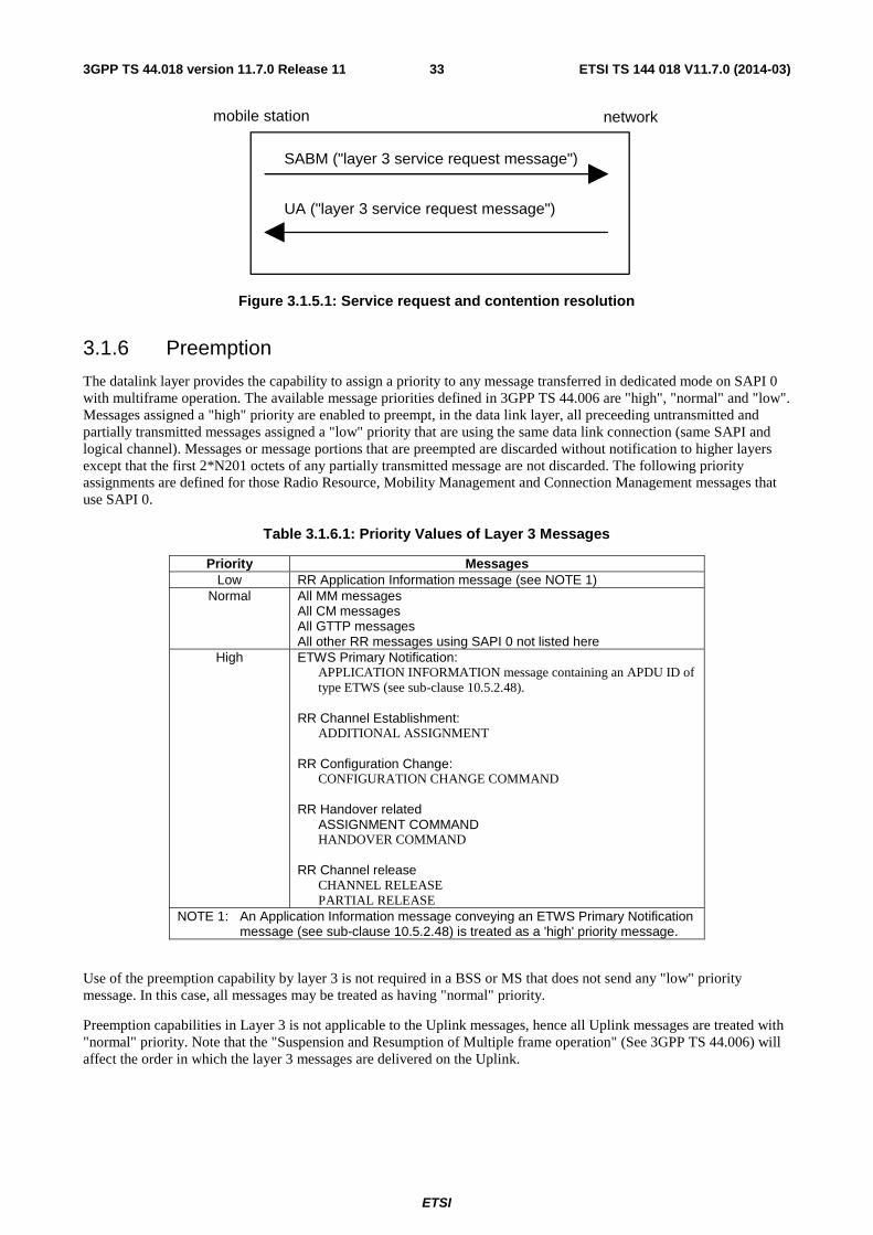
ETSI
ETSI TS 144 018 V11.7.0 (2014-03)333GPP TS 44.018 version 11.7.0 Release 11
mobile station network
SABM ("layer 3 service request message")
UA ("layer 3 service request message")
Figure 3.1.5.1: Service request and contention resolution
3.1.6 Preemption
The datalink layer provides the capability to assign a priority to any message transferred in dedicated mode on SAPI 0 with multiframe operation. The available message priorities defined in 3GPP TS 44.006 are "high", "normal" and "low". Messages assigned a "high" priority are enabled to preempt, in the data link layer, all preceeding untransmitted and partially transmitted messages assigned a "low" priority that are using the same data link connection (same SAPI and logical channel). Messages or message portions that are preempted are discarded without notification to higher layers except that the first 2*N201 octets of any partially transmitted message are not discarded. The following priority assignments are defined for those Radio Resource, Mobility Management and Connection Management messages that use SAPI 0.
Table 3.1.6.1: Priority Values of Layer 3 Messages
Priority Messages Low RR Application Information message (see NOTE 1)
Normal All MM messages All CM messages All GTTP messages All other RR messages using SAPI 0 not listed here
High ETWS Primary Notification: APPLICATION INFORMATION message containing an APDU ID of type ETWS (see sub-clause 10.5.2.48). RR Channel Establishment: ADDITIONAL ASSIGNMENT RR Configuration Change: CONFIGURATION CHANGE COMMAND RR Handover related ASSIGNMENT COMMAND HANDOVER COMMAND RR Channel release CHANNEL RELEASE PARTIAL RELEASE
NOTE 1: An Application Information message conveying an ETWS Primary Notification message (see sub-clause 10.5.2.48) is treated as a 'high' priority message.
Use of the preemption capability by layer 3 is not required in a BSS or MS that does not send any "low" priority message. In this case, all messages may be treated as having "normal" priority.
Preemption capabilities in Layer 3 is not applicable to the Uplink messages, hence all Uplink messages are treated with "normal" priority. Note that the "Suspension and Resumption of Multiple frame operation" (See 3GPP TS 44.006) will affect the order in which the layer 3 messages are delivered on the Uplink.

ETSI
ETSI TS 144 018 V11.7.0 (2014-03)343GPP TS 44.018 version 11.7.0 Release 11
3.2 Idle mode procedures and general procedures in packet idle and packet transfer modes
3.2.1 Mobile Station side
In idle mode, the MS listens to the BCCH and to the paging sub-channel for the paging group the MS belongs to in idle mode (cf. 3GPP TS 43.013); it measures the radio propagation for connection with other cells.
In packet idle and packet transfer modes (applicable only to a GPRS mobile station), the mobile station listens to either the PBCCH, if that is present in the cell, or BCCH. The requirements for the monitoring of system information is further specified in 3GPP TS 44.060. Moreover, the mobile station measures the radio propagation for connection with other cells.
A mobile station camping on the cell as a result of a cell change order or redirection from E-UTRAN to GERAN is not required to perform the complete acquisition of the system information of the cell on BCCH before proceeding with a RR connection establishment (see sub-clause 3.3). The mobile station shall perform the acquisition on the BCCH of the cell of the following messages if not provided in the MobilityFromEUTRACommand or, respectively, in the E-UTRA RRCConnectionRelease message (see 3GPP TS 36.331):
- SYSTEM INFORMATION TYPE 3,
- for a GPRS capable mobile station in a cell supporting GPRS, SYSTEM INFORMATION TYPE 13, and
- SYSTEM INFORMATION TYPE 1 if broadcast in the cell (see 3GPP TS 45.002).
If SYSTEM INFORMATION TYPE 3 and, for a GPRS capable mobile station in a cell supporting GPRS, SYSTEM INFORMATION TYPE 13 were received in the MobilityFromEUTRACommand message or in the E-UTRA RRCConnectionRelease message but SYSTEM INFORMATION TYPE 1 was not included, the mobile station shall assume that SYSTEM INFORMATION TYPE 1 is not broadcast in the cell.
In packet idle mode (applicable only to a GPRS mobile station), the mobile station listens to the paging sub-channels on the PCCCH or CCCH. Paging sub-channels are monitored according to the paging group determined for the mobile station and its current discontinuous reception (DRX) mode. The determination of paging group for the mobile station is defined in 3GPP TS 45.002. The DRX procedures are defined in 3GPP TS 44.060 and 3GPP TS 45.002.
Mobile station support for reception of Earthquake and Tsunami Warning System (ETWS) Primary Notification messages is optional. In idle mode or in packet idle mode (applicable only to a GPRS mobile station), the mobile station may determine that an ETWS event has occurred (see sub-clause 3.2.2.3 and 9.1.22) in which case it shall leave DRX mode, start timer T3232, start reading all paging groups and attempt to acquire an ETWS Primary Notification message. The mobile station shall attempt to assemble all segments of the ETWS Primary Notification message, having the same Primary Notification Identifier (PNI) value, before delivering the complete message to the upper layers.
While attempting to acquire the ETWS Primary Notification message a mobile station shall continue to follow (packet) idle mode and connection establishment procedures. Upon initiating cell reselection or connection establishment procedures while attempting to acquire an ETWS Primary Notification message, a mobile station shall discard any partially received ETWS Primary Notification message and stop timer T3232. The mobile station shall not attempt to acquire an ETWS Primary Notification message while performing a connection establishment procedure or while performing cell reselection.
If the mobile station detects a change in the PNI value prior to acquiring a complete ETWS Primary Notification message, it shall abort the current message, restart timer T3232 and attempt to acquire the new message.
When the mobile station successfully acquires a complete ETWS Primary Notification message it shall stop timer T3232 and enter DRX mode. If timer T3232 expires the mobile station shall abort the current message and enter DRX mode.
A UTRAN capable mobile station in idle mode or packet idle mode attempts to read predefined configuration information from UTRAN Channels, as specified in 3GPP TS 45.008. This is only applicable to a mobile station supporting circuit-switched services.
Measurements are treated to assess the need of a cell change as specified in 3GPP TS 45.008. When the decision to change cells is made, the mobile station switches to the BCCH or PBCCH of the new cell. The broadcast information is then checked to verify the allowance to camp on this cell (cf. sub-clause 3.2.2). Dependent on the mobile station type
ETSI
ETSI TS 144 018 V11.7.0 (2014-03)353GPP TS 44.018 version 11.7.0 Release 11
and configuration, the mobile station may be required to try to read further BCCH and PBCCH information. If allowed, the cell change is confirmed, and the broadcast information is then treated for Mobility Management actions (cf. clause 4). Similarly, physical contexts are updated (list of neighbouring cells frequencies, thresholds for some actions, etc. (cf. 3GPP TS 45.008 and sub-clause 3.2.2)).
A mobile station configured for Extended Access Barring (EAB) shall read the SI3 Rest Octets IE in an attempt to determine if the SYSTEM INFORMATION TYPE 21 message is sent in the cell. If the SI3 Rest Octets IE does not provide this information the mobile station shall read the SI9 Rest Octets IE to make this determination (If SI 9 is sent):
- If the SYSTEM INFORMATION TYPE 21 message is sent the mobile station shall read it in an attempt to acquire EAB information (see sub-clause 10.5.2.37m).
- If the SYSTEM INFORMATION TYPE 21 message is not sent or is sent but does not include EAB information the mobile station shall consider EAB information it may have previously received to be invalid.
A mobile station supporting network sharing shall read the SYSTEM INFORMATION TYPE 3 message in an attempt to determine if the SYSTEM INFORMATION TYPE 22 message is sent in the cell:
- If the SYSTEM INFORMATION TYPE 22 message is sent the mobile station shall read it in an attempt to acquire network sharing information (see sub-clause 10.5.2.37n).
- If the SYSTEM INFORMATION TYPE 22 message is not sent or is sent but does not include network sharing information the mobile station shall consider network sharing as not supported in the cell and the network sharing information it may have previously received to be invalid.
A UTRAN and/or E-UTRAN capable mobile station supporting network sharing shall read the SYSTEM INFORMATION TYPE 22 message in an attempt to determine if the SYSTEM INFORMATION TYPE 23 message is sent in the cell:
- If the SYSTEM INFORMATION TYPE 23 message is sent the mobile station shall read it in an attempt to acquire UTRAN and/or E-UTRAN information for cell-reselection (as applicable) as described in sub-clause 10.5.2.37o.
- If the SYSTEM INFORMATION TYPE 23 message is sent but does not include UTRAN and/or E-UTRAN information for cell-reselection the mobile station shall consider UTRAN and/or E-UTRAN information for cell-reselection as not available in the cell and the previous information it may have received to be invalid.
- If the SYSTEM INFORMATION TYPE 23 message is not sent the mobile station shall acquire UTRAN and/or E-UTRAN information for cell-reselection from the SI2ter/SI2quater messages.
3.2.2 Network side
3.2.2.1 System information broadcasting
SYSTEM INFORMATION TYPE 2 to 4 messages, and optionally TYPE 1, 2bis, 2ter, 7, 8, 13, 16 and 17 and further types are regularly broadcast by the network on the BCCH. Based on this information the mobile station is able to decide whether and how it may gain access to the system via the current cell. The SYSTEM INFORMATION TYPE 2bis message shall be sent if and only if the EXT-IND bit in the Neighbour Cell Description IE in both the TYPE 2 and TYPE 2bis messages indicates that each IE only carries part of the BA. SYSTEM INFORMATION TYPE 2ter message shall be sent if and only if this is indicated in SYSTEM INFORMATION TYPE 3 message.
A GSM 900 mobile station which only supports the primary GSM band P-GSM 900 (cf. 3GPP TS 45.005) may consider the EXT-IND bit in the Neighbour Cell Description IE in the SYSTEM INFORMATION TYPE 2 message as a spare bit. If it does so it shall assume that the information element carries the complete BA and it shall ignore any SYSTEM INFORMATION TYPE 2bis and 2ter messages.
SYSTEM INFORMATION TYPE 2quater messages may be sent to provide further information for Enhanced Measurement Report. It may also include UTRAN and/or E-UTRAN information for cell-reselection, measurement and reporting. A mobile station with no UTRAN capability should ignore 3G related information in this message. A mobile station with no E-UTRAN capability should ignore E-UTRAN related information in this message. SYSTEM INFORMATION TYPE 2quater message shall be sent if and only if this is indicated in SYSTEM INFORMATION TYPE 3 message.
ETSI
ETSI TS 144 018 V11.7.0 (2014-03)363GPP TS 44.018 version 11.7.0 Release 11
The SI2 ter Rest Octet information element in the SI2ter message may provide information on UTRAN Cells and 3G Measurement Parameters. Information received in this message is only used for cell reselection in idle mode. The SYSTEM INFORMATION TYPE 2ter messages shall contain at least one 2G neighbouring cell description the ARFCN of which does not belong to the frequency band of the 2G neighbouring cells described in the SYSTEM INFORMATION TYPE 2 message.
When the SI2ter_MP_CHANGE_MARK parameter is changed in this information element, the MS shall re-read 3G Measurement parameters in all instances of SI2ter (by using SI2ter_INDEX and SI2ter_COUNT). When the SI2ter_3G_CHANGE_MARK is changed in this information element, the MS shall re-read UTRAN FDD Description and UTRAN TDD Description in all instances of SI2ter (by using SI2ter_INDEX and SI2ter_COUNT).
SYSTEM INFORMATION TYPE 2n messages may be sent to provide parameters affecting cell reselection for the neighbouring cells. SYSTEM INFORMATION TYPE 2n message shall be sent on BCCH (Ext) if and only if this is indicated in SYSTEM INFORMATION TYPE 13 message.
When the SI2n_CHANGE_MARK parameter is changed in this message, the MS shall re-read all the parameters in SI2n Rest Octets IE in a full set of SYSTEM INFORMATION 2n messages.
If the additional cell reselection parameters are broadcast then SYSTEM INFORMATION TYPE 3 message shall always contain these parameters. In addition to SYSTEM INFORMATION TYPE 3 at least either SYSTEM INFORMATION TYPE 4 or SYSTEM INFORMATION TYPE 7 and 8 messages shall contain these parameters too. SYSTEM INFORMATION TYPE 7 and 8 messages shall be sent if and only if this is indicated in SYSTEM INFORMATION TYPE 4 message.
SYSTEM INFORMATION TYPE 15 message is broadcast if dynamic ARFCN mapping is used in the PLMN. In this case ARFCN values are allocated and dynamically mapped to physical frequencies, see 3GPP TS 45.005. The presence of dynamic ARFCN mapping shall be indicated in Cell Options (BCCH) IE. When the value of the parameter DM_CHANGE_MARK is changed in the SYSTEM INFORMATION TYPE 15 message, the mobile station shall re-read information on dynamic mapping in a full set of SYSTEM INFORMATION 15 messages.
After the release of a dedicated connection, when returning to idle mode or packet idle mode, the mobile station may keep the dynamic ARFCN mapping information for the PLMN of the chosen cell under the following conditions:
- there has not been any handover during the connection; or
- the mobile station chooses the last cell (identified by the BCCH carrier and BSIC) that was used during the connection and there has not been any handover including dynamic ARFCN mapping information after reception of the dynamic ARFCN mapping information.
Otherwise, the mobile station shall acquire new dynamic ARFCN mapping information.
If additional SoLSA specific parameters are broadcast then SYSTEM INFORMATION TYPE 16 and 17 messages, shall always contain these parameters. In addition to SYSTEM INFORMATION TYPE 16 and 17 messages at least either SYSTEM INFORMATION TYPE 4 or SYSTEM INFORMATION TYPE 7 and 8 messages shall contain these SoLSA specific parameters too. SYSTEM INFORMATION TYPE 16 and 17 messages shall be sent if and only if this is indicated in SYSTEM INFORMATION TYPE 3 message. The SoLSA information of any SYSTEM INFORMATION message shall be the same.
The SYSTEM INFORMATION TYPE 18 and 20 messages are sent when non-GSM broadcast information must be transmitted. The scheduling and repetition rate of these messages is determined by the system operator and is indicated in SYSTEM INFORMATION TYPE 9 message. Mobile stations without non-GSM capabilities defined for SI 18 and SI 20 should ignore these messages. An MS with non-GSM capabilities shall decode and identify information related to the respective Non-GSM protocol by reading the Non-GSM Protocol Discriminator field.
The SYSTEM INFORMATION TYPE 21 message is broadcast by the network if Extended Access Barring is in use in the cell.
The SYSTEM INFORMATION TYPE 22 message shall be broadcast by the network if network sharing (with or without domain-specific access control) is in use in the cell. The presence of SI 22 messages shall be indicated in SI 3 message. Additionally, in this case, the network may broadcast the SYSTEM INFORMATION TYPE 23 message to provide PLMN-specific UTRAN and/or E-UTRAN information for cell re-selection. The presence of SI 23 messages shall be indicated in SI 22 message.
SYSTEM INFORMATION TYPE 19 messages shall be provided if COMPACT neighbour cells exist (see 3GPP TS 45.008). The presence of SI 19 messages shall be indicated in SI 9 message.

ETSI
ETSI TS 144 018 V11.7.0 (2014-03)373GPP TS 44.018 version 11.7.0 Release 11
The support of GPRS shall be indicated in SYSTEM INFORMATION TYPE 3 message. In addition, the support of GPRS shall be indicated in either SYSTEM INFORMATION TYPE 4 or SYSTEM INFORMATION TYPE 7 and 8 messages. If GPRS is supported, SYSTEM INFORMATION TYPE 13 message shall be sent. SI 13 message shall not be sent if GPRS is not supported. Additional requirements for the broadcast of system information in a cell supporting GPRS are specified in 3GPP TS 44.060.
NOTE 1: The allowed scheduling of SYSTEM INFORMATION messages on the BCCH are specified in 3GPP TS 45.002.
NOTE 2: The network should take into account limitations of certain mobile stations to understand SYSTEM INFORMATION TYPE 2bis, TYPE 2ter, the EXT-IND bit in the Neighbour Cell Description, the indication of 2ter in SYSTEM INFORMATION TYPE 3 and formats used in the Neighbour Cell Description IE and Cell Channel Description IE used in SYSTEM INFORMATION messages, see this sub-clause, sub-clause 10.5.2.1b, and sub-clause 10.5.2.22.
NOTE 3: The network should take into account the limitations of earlier versions of mobile equipment to understand the 3-digit MNC format of the location area identification, see sub-clause 10.5.1.3.
The information broadcast may be grouped in the following classes:
- information giving unique identification of the current network, location area and cell;
- information used for candidate cell measurements for handover and cell selection procedures;
- information describing the current control channel structure;
- information controlling the random access channel utilization;
- information defining different options supported within the cell; and
- information about the length of the part of the message belonging to the phase 1 protocol.
The network may send to the mobile station BCCH scheduling information as specified below:
1) The BCCH scheduling information may be contained in the SYSTEM INFORMATION TYPE 9 messages. If so, SYSTEM INFORMATION TYPE 3 specifies where to find SYSTEM INFORMATION TYPE 9 messages carrying BCCH scheduling information.
2) If the mobile station has received BCCH scheduling information, it shall assume that this BCCH scheduling information is valid in the location area until new scheduling information is received. It may store the information in the ME and assume its validity after switch on in the same location area.
3) The network need not indicate the schedule of all SYSTEM INFORMATION messages in SYSTEM INFORMATION 9. For any System Information message, the MS shall monitor all blocks specified in 3GPP TS 45.002 for that System Information message and all blocks specified in the SYSTEM INFORMATION TYPE 9 message for that System Information message.
4) When the mobile station detects that the BCCH information is not scheduled as defined in the last received SI 9 message, it shall read the SYSTEM INFORMATION TYPE 3 message. If presence of BCCH scheduling information in SYSTEM INFORMATION TYPE 9 message is indicated, it shall try to read the information and continue as in 2 above. If presence of BCCH scheduling information in SYSTEM INFORMATION TYPE 9 message is not indicated, it shall assume that there is no valid BCCH scheduling information.
3.2.2.2 Paging
The network is required to send valid layer 3 messages continuously on all paging subchannels on CCCH.
3.2.2.3 Sending of ETWS Primary Notification
The network initiates the delivery of an ETWS Primary Notification message (see 3GPP TS 23.041) by broadcasting the PAGING REQUEST TYPE 1 message on all paging subchannels on CCCH with the ETWS Primary Notification field present within the P1 Rest Octets IE. These paging messages are sent continuously during the ETWS warning period.
ETSI
ETSI TS 144 018 V11.7.0 (2014-03)383GPP TS 44.018 version 11.7.0 Release 11
Each paging message carries a segment of the actual ETWS Primary Notification message, i.e. segmentation is applicable if an ETWS Primary Notification message is too large to fit into the P1 Rest Octets of a single PAGING REQUEST TYPE 1 message. In order to allow a mobile station to receive the segments in any order, the size of a specific segment (retransmitted during the ETWS warning period) shall not be altered. Segments belonging to the same ETWS Primary Notification message shall be given the same Primary Notification Identifier (PNI) value.
3.2.3 Inter-RAT cell re-selection based on priority information
3.2.3.1 General
The network may provide priority information to enable priority-based cell reselection (see 3GPP TS 45.008). Inter-RAT cell reselection based on priority information applies only in case of autonomous cell reselection.
Two sets of priorities are defined for inter-RAT cell re-selection based on priority information: common priorities (see sub-clause 3.2.3.2) and individual priorities (see sub-clause 3.2.3.3). The mobile station shall delete all priorities when switched off.
While providing common or individual priorities, the network shall ensure that the GERAN priority value is different from all E-UTRAN priority values and from all UTRAN priority values, and that all UTRAN priority values are different from all E-UTRAN priority values. In addition, if for some E-UTRAN frequencies THRESH_E-UTRAN_high_Q is provided in the Enhanced Cell Reselection Parameters Description IE in the SI2quater message or, if network sharing is supported by the network (see sub-clause 3.8), in the SI23 message, the network shall ensure that the priority value for any frequency for which THRESH_E-UTRAN_high_Q is provided is different from the priority value for all frequencies for which THRESH_E-UTRAN_high_Q is not provided.
The mobile station shall determine each set, considering only individual priorities (respectively common priorities) when building the set of individual (respectively common) priorities. The mobile station shall perform the following steps, in the specified order:
- If the same priority value is assigned to GERAN and to one or more UTRAN or E-UTRAN frequencies then all such UTRAN and E-UTRAN priority values are considered as not in the set of priorities.
- If the same priority value is assigned to one or more UTRAN frequencies and one or more E-UTRAN frequencies, then all such priority values are considered as not in the set of priorities.
- If the same priority value is assigned to one or more E-UTRAN frequencies for which THRESH_E-UTRAN_high_Q is provided and one or more E-UTRAN frequencies for which THRESH_E-UTRAN_high_Q is not provided then all such priority values are considered as not in the set of priorities.
NOTE 1: These steps mean that if, for example, there are two UTRAN priority values, one E-UTRAN priority value (for a frequency for which THRESH_E-UTRAN_high_Q is provided) and one E-UTRAN priority value (for a frequency for which THRESH_E-UTRAN_high_Q is not provided) that are all the same, then all four priority values are considered as not in the set of priorities.
A set of individual priorities is valid if it contains at least one priority.
A set of common priorities is valid if both of the following conditions are met:
- The set of priorities includes a priority for GERAN;
- The mobile station does not have a valid set of individual priorities.
If the mobile station has a valid set of priorities, the priorities in this set shall be used for priority-based reselection as specified in 3GPP TS 45.008.
NOTE 2: It is possible that individual priorities inherited from UTRAN or E-UTRAN (see sub-clause 3.2.3.3) do not contain a priority for GERAN.
3.2.3.2 Common priorities information
A mobile station may receive common priorities information in the Priority and E-UTRAN Parameters Description IE in the SYSTEM INFORMATION TYPE 2quater message.

ETSI
ETSI TS 144 018 V11.7.0 (2014-03)393GPP TS 44.018 version 11.7.0 Release 11
A mobile station supporting network sharing may receive PLMN specific UTRAN and E-UTRAN common priorities in the SYSTEM INFORMATION TYPE 23 message. If the SYSTEM INFORMATION TYPE 23 message is broadcast in the cell, a mobile station supporting network sharing shall use only UTRAN and E-UTRAN common priorities provided in this message.
3.2.3.3 Provision of individual priorities information
A mobile station shall store individual priorities information if received in the Individual Priorities IE in the CHANNEL RELEASE message, PACKET MEASUREMENT ORDER message or in the PACKET CELL CHANGE ORDER message (see 3GPP TS 44.060). If received in a PACKET CELL CHANGE ORDER message, the mobile station shall use the parameters provided in the Individual Priorities IE only upon successful completion of the network controlled cell reselection procedure as described in 3GPP TS 44.060.
If the T3230 timeout value is provided the mobile station shall set timer T3230 to the value received and start timer T3230 (or restart timer T3230 with the timeout value provided if already running).
If the Individual Priorities IE contains priorities for more than 16 UTRAN FDD frequencies, more than 16 UTRAN TDD frequencies, or more than 8 E-UTRAN frequencies, then the mobile station may ignore the contents of the Individual Priorities IE and, in this case, shall delete any stored individual priorities.
NOTE: Each signalled frequency is counted whether or not the mobile station supports that frequency.
Stored individual priorities shall be deleted by the mobile station when any of the following occurs:
- a PLMN selection is performed and results in a change of PLMN and the new PLMNis not an equivalent PLMN, see 3GPP TS 23.122; or
- the mobile station is switched off; or
- a CHANNEL RELEASE message, PACKET MEASUREMENT ORDER message or PACKET CELL CHANGE ORDER is received with an indication that the individual priorities shall be deleted; or
- new individual priorities are received ; or
- timer T3230 expires.
At inter-RAT cell reselection from UTRAN or E-UTRAN to GERAN or cell selection or handover that results in a change of RAT from UTRAN or E-UTRAN to GERAN, the MS shall inherit individual priority information if the corresponding timer (T320 if the last serving RAT was E-UTRA; T322 if the last serving RAT was UTRA) has not expired. In this case the mobile station shall start timer T3230 with the timeout value set to the remaining validity time of the corresponding timer from the source RAT. If this inherited individual priority information includes more than one individual priority for GERAN frequencies, then the mobile station shall apply only the one applicable to the BCCH carrier of the first serving GERAN cell after the change of RAT as the individual priority for all GERAN cells for as long as the mobile station remains in GERAN. In this case the mobile station shall not apply the other GERAN individual priority(ies) until the MS leaves GERAN (see 3GPP TS 25.331, 3GPP TS 36.331).
NOTE: The network may provide individual priorities information for inter-RAT frequencies not configured by system information.
3.2.4 (void)
3.3 RR connection establishment
3.3.1 RR connection establishment initiated by the mobile station
The purpose of the immediate assignment procedure is to establish an RR connection between the mobile station and the network.
ETSI
ETSI TS 144 018 V11.7.0 (2014-03)403GPP TS 44.018 version 11.7.0 Release 11
3.3.1.1 Entering the dedicated mode : immediate assignment procedure
The immediate assignment procedure can only be initiated by the RR entity of the mobile station. Initiation is triggered by request from the MM sublayer or LLC layer to enter the dedicated mode or by the RR entity in response to a PAGING REQUEST message, to initiate a notification response procedure or to initiate a priority uplink request procedure. Upon such a request:
- if access to the network is allowed (as defined in sub-clause 3.3.1.1.1), the RR entity of the mobile station initiates the immediate assignment procedure as defined in sub-clause 3.3.1.1.2;
- otherwise, it rejects the request.
The request from the MM sublayer to establish an RR connection specifies an establishment cause. Similarly, the request from the RR entity to establish a RR connection in response to a PAGING REQUEST 1, 2 or 3 message specifies one of the establishment causes "answer to paging"; the request from the RR entity to establish an RR connection in order to initiate a notification response procedure or a priority uplink request procedure specifies one of the establishment causes " procedures that can be completed with a SDCCH".
3.3.1.1.1 Permission to access the network
All mobile stations with an inserted SIM are members of one out of 10 access classes numbered 0 to 9. The access class number is stored in the SIM. In addition, mobile stations may be members of one or more out of 5 special access classes (access classes 11 to 15) (see 3GPP TS 22.011), this is also held on the SIM card.
The system information messages on the BCCH broadcast the list of authorized access classes and authorized special access classes, and whether emergency calls are allowed in the cell to all mobile stations or only to the members of authorized special access classes. When network sharing is in use in the cell (see sub-clause 3.8), this information may be broadcast individually for each of the PLMN sharing the cell, and may include different domain-specific access control information for the CS and PS domains.
A mobile station supporting network sharing shall determine whether or not access to the network is allowed using the applicable access control information corresponding to the selected PLMN. In addition, if domain-specific access control is used, a mobile station supporting domain-specific access control shall determine whether or not access to the network is allowed for the domain originating the access attempt, using the access control information corresponding to this domain.
For a mobile originated access attempt, a mobile station configured for EAB shall perform a preliminary access barring check (see sub-clause 3.3.1.4). If the preliminary access barring check indicates network access is barred then access to the network is not allowed. Otherwise, the mobile station shall proceed according to the remainder of this sub-clause.
If the establishment cause for the request of the MM sublayer is not "emergency call", access to the network is allowed if and only if the mobile station is a member of at least one authorized:
- access class; or
- special access class.
If the establishment cause for the request of the MM sublayer is "emergency call", access to the network is allowed if and only if:
- emergency calls are allowed to all mobile stations in the cell; or
- the mobile station is a member of at least one authorized special access class.
3.3.1.1.1a Implicit reject indication from the network
The network may at any time include an implicit reject indication for the PS domain or the CS domain within an IMMEDIATE ASSIGNMENT message using the IA Rest Octets IE (see sub-clause 10.5.2.16) or within an IMMEDIATE ASSIGNMENT REJECT or an IMMEDIATE ASSIGNMENT EXTENDED or an IMMEDIATE PACKET ASSIGNMENT message using the Feature Indicator IE (see sub-clause 10.5.2.76) or within a PAGING REQUEST TYPE 1 message using the P1 Rest Octets IE (see sub-clause 10.5.2.23) or within a PAGING REQUEST TYPE 2 message using the P2 Rest Octets IE (see sub-clause 10.5.2.24) or within a PAGING REQUEST TYPE 3 message using the P3 Rest Octets IE (see sub-clause 10.5.2.25).
ETSI
ETSI TS 144 018 V11.7.0 (2014-03)413GPP TS 44.018 version 11.7.0 Release 11
3.3.1.1.2 Initiation of the immediate assignment procedure
The RR entity of a mobile station configured for NAS signalling low priority (see 3GPP TS 23.060), when attempting to establish a CS connection other than in case of an emergency call or when the mobile station is a member of an authorized special access class or sending a paging response shall, while ignoring MS identities included within PAGING REQUEST messages, start listening to the downlink CCCH until successfully decoding one of the RR messages listed in sub-clause 3.3.1.1.1a. If the RR message indicates an implicit reject for the CS domain (see sub-clause 3.3.1.1.1a) the mobile station shall abort the immediate assignment procedure and initiate the Implicit Reject procedure (see sub-clause 3.3.1.1.3.2a).
The RR entity of a mobile station initiates the immediate assignment procedure by scheduling the sending of CHANNEL REQUEST (or EGPRS PACKET CHANNEL REQUEST) messages on the RACH and leaving idle mode (in particular, the mobile station shall ignore PAGING REQUEST messages).
The mobile station then sends maximally M + 1 CHANNEL REQUEST (or EGPRS PACKET CHANNEL REQUEST) messages on the RACH in a way such that:
- when requesting resources for a PS connection other than in the case of sending a paging response, the mobile station shall send the first CHANNEL REQUEST (or EGPRS PACKET CHANNEL REQUEST) message in the first available TDMA frame belonging to the mobile station"s RACH.
- in all other cases, the number of slots belonging to the mobile station's RACH between initiation of the immediate assignment procedure and the first CHANNEL REQUEST (or EGPRS PACKET CHANNEL REQUEST message) (excluding the slot containing the message itself) is a random value drawn randomly for each new initial assignment initiation with uniform probability distribution in the set {0, 1, ..., max (T,8) - 1};
- the number of slots belonging to the mobile station's RACH between two successive CHANNEL REQUEST (or EGPRS PACKET CHANNEL REQUEST) messages (excluding the slots containing the messages themselves) is a random value drawn randomly for each new transmission with uniform probability distribution in the set {S, S + 1, ..., S + T - 1};
Here, T is the value of the parameter "Tx-integer" broadcast on the BCCH;
M is the value of the parameter "max retrans" broadcast on the BCCH;
S is a parameter depending on the CCCH configuration and on the value of Tx-integer as defined in table 3.3.1.1.2.1.
The CHANNEL REQUEST messages are sent on the RACH (cf. sub-clause 1.5) and contain as parameters:
- an establishment cause which corresponds to the establishment cause given by the MM sublayer and the broadcast NECI value, or which corresponds to one of the establishment causes "answer to paging" given by the RR entity in response to a PAGING REQUEST message including the Channel Needed information, or which corresponds to one of the establishment causes " procedures that can be completed with a SDCCH" given by the RR entity in order to initiate a notification response procedure or a priority uplink request procedure;
- a random reference which is drawn randomly from a uniform probability distribution for every new transmission.
After sending the first CHANNEL REQUEST message, the mobile station shall start listening to the BCCH; it shall also listen to the full downlink CCCH timeslot corresponding to its CCCH group.
A mobile station configured for NAS signalling low priority that has initiated the immediate assignment procedure other than for an emergency call or when it is a member of an authorized special access class or sending a paging response and has sent one or more CHANNEL REQUEST messages shall proceed as follows:
- If the mobile station receives an IMMEDIATE ASSIGNMENT, an IMMEDIATE ASSIGNMENT EXTENDED or an IMMEDIATE ASSIGNMENT REJECT message corresponding to one of its last 3 transmitted CHANNEL REQUEST messages it shall act on that message as described in sub-clause 3.3.1.1.3.
- If the mobile station succesfully decodes an RR message, which is not a response corresponding to one of its last 3 transmitted CHANNEL REQUEST, that indicates an implicit reject for the CS domain (see sub-clause 3.3.1.1.1a) it shall start timer T3126 (if not already running) and initiate the implicit reject procedure as described in sub-clause 3.3.1.1.3.2a.
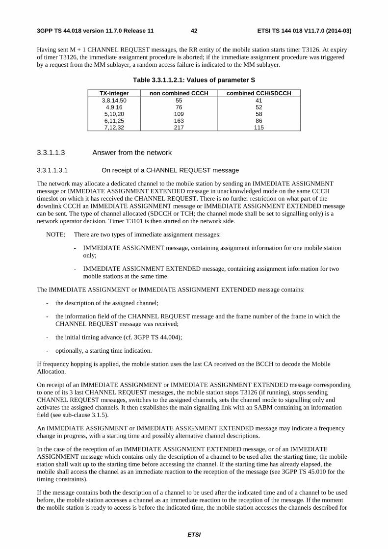
ETSI
ETSI TS 144 018 V11.7.0 (2014-03)423GPP TS 44.018 version 11.7.0 Release 11
Having sent M + 1 CHANNEL REQUEST messages, the RR entity of the mobile station starts timer T3126. At expiry of timer T3126, the immediate assignment procedure is aborted; if the immediate assignment procedure was triggered by a request from the MM sublayer, a random access failure is indicated to the MM sublayer.
Table 3.3.1.1.2.1: Values of parameter S
TX-integer non combined CCCH combined CCH/SDCCH 3,8,14,50 55 41
4,9,16 76 52 5,10,20 109 58 6,11,25 163 86 7,12,32 217 115
3.3.1.1.3 Answer from the network
3.3.1.1.3.1 On receipt of a CHANNEL REQUEST message
The network may allocate a dedicated channel to the mobile station by sending an IMMEDIATE ASSIGNMENT message or IMMEDIATE ASSIGNMENT EXTENDED message in unacknowledged mode on the same CCCH timeslot on which it has received the CHANNEL REQUEST. There is no further restriction on what part of the downlink CCCH an IMMEDIATE ASSIGNMENT message or IMMEDIATE ASSIGNMENT EXTENDED message can be sent. The type of channel allocated (SDCCH or TCH; the channel mode shall be set to signalling only) is a network operator decision. Timer T3101 is then started on the network side.
NOTE: There are two types of immediate assignment messages:
- IMMEDIATE ASSIGNMENT message, containing assignment information for one mobile station only;
- IMMEDIATE ASSIGNMENT EXTENDED message, containing assignment information for two mobile stations at the same time.
The IMMEDIATE ASSIGNMENT or IMMEDIATE ASSIGNMENT EXTENDED message contains:
- the description of the assigned channel;
- the information field of the CHANNEL REQUEST message and the frame number of the frame in which the CHANNEL REQUEST message was received;
- the initial timing advance (cf. 3GPP TS 44.004);
- optionally, a starting time indication.
If frequency hopping is applied, the mobile station uses the last CA received on the BCCH to decode the Mobile Allocation.
On receipt of an IMMEDIATE ASSIGNMENT or IMMEDIATE ASSIGNMENT EXTENDED message corresponding to one of its 3 last CHANNEL REQUEST messages, the mobile station stops T3126 (if running), stops sending CHANNEL REQUEST messages, switches to the assigned channels, sets the channel mode to signalling only and activates the assigned channels. It then establishes the main signalling link with an SABM containing an information field (see sub-clause 3.1.5).
An IMMEDIATE ASSIGNMENT or IMMEDIATE ASSIGNMENT EXTENDED message may indicate a frequency change in progress, with a starting time and possibly alternative channel descriptions.
In the case of the reception of an IMMEDIATE ASSIGNMENT EXTENDED message, or of an IMMEDIATE ASSIGNMENT message which contains only the description of a channel to be used after the starting time, the mobile station shall wait up to the starting time before accessing the channel. If the starting time has already elapsed, the mobile shall access the channel as an immediate reaction to the reception of the message (see 3GPP TS 45.010 for the timing constraints).
If the message contains both the description of a channel to be used after the indicated time and of a channel to be used before, the mobile station accesses a channel as an immediate reaction to the reception of the message. If the moment the mobile station is ready to access is before the indicated time, the mobile station accesses the channels described for
ETSI
ETSI TS 144 018 V11.7.0 (2014-03)433GPP TS 44.018 version 11.7.0 Release 11
before the starting time. The mobile station then changes to the channel described for after the starting time at the indicated time. New parameters can be the mobile allocation and MAIO. Other parameters describing the channel to be used before the starting time are taken from the description of the channel defined for use after the starting time. If the moment the mobile station is ready to access is after the starting time, the mobile station accesses the channel described for after the starting time.
If frequency hopping is applied, the mobile station uses the last CA received on the BCCH.
3.3.1.1.3.2 Assignment rejection
If no channel is available for assignment, the network may send to the mobile station an IMMEDIATE ASSIGNMENT REJECT message in unacknowledged mode on the same CCCH timeslot on which the channel request message was received. There is no further restriction on what part of the downlink CCCH timeslot an IMMEDIATE ASSIGNMENT REJECT message can be sent. This message contains the request reference and a wait indication.
On receipt of an IMMEDIATE ASSIGNMENT REJECT message corresponding to one of its 3 last CHANNEL REQUEST messages, the mobile station, stops sending CHANNEL REQUEST messages, starts timer T3122 with the indicated value, ("wait indication" information element), starts T3126 if it has not already been started, and listens to the downlink CCCH until T3126 expires. During this time, additional IMMEDIATE ASSIGNMENT REJECT messages are ignored, but any immediate assignment corresponding to any other of its 3 last CHANNEL REQUEST messages make the mobile station follow the procedure in sub-clause 3.3.1.1.3.1. If no such immediate assignment is received, the mobile station returns to CCCH idle mode (listening to its paging channel).
As an option the mobile station may return to CCCH idle mode as soon as it has received responses from the network on all, or in case more than 3 were sent the last 3, of its CHANNEL REQUEST messages.
The mobile station is not allowed to make a new attempt to establish a non emergency RR connection in the same cell until T3122 expires. Provided that an IMMEDIATE ASSIGNMENT REJECT message has not been received for an emergency RR connection attempt, the mobile station may attempt to enter the dedicated mode for an emergency call in the same cell before T3122 has expired.
The Wait Indication IE (i.e. T3122) relates to the cell from which it was received.
The mobile station in packet idle mode (only applicable to mobile station supporting GPRS) may initiate packet access in the same cell before T3122 has expired, see 3GPP TS 44.060 and sub-clause 3.5.2.1.3.4.
After T3122 expiry, no CHANNEL REQUEST message shall be sent as a response to a page until a PAGING REQUEST message for the mobile station is received.
3.3.1.1.3.2a Implicit Reject procedure
A mobile station for which timer T3126 or T3146 is running shall proceed as follows:
- While T3126 or T3146 is running, the mobile station listens to the downlink CCCH for a response from the network and is not allowed to make a new access attempt.
- If a response corresponding to any of the last 3 transmitted CHANNEL REQUEST or EGPRS PACKET CHANNEL REQUEST messages is received the mobile station shall stop T3126 or T3146 and act on that message as described in sub-clause 3.3.1.1.3 (if attempting a CS domain access) or as decribed in sub-clause 3.5.2.1.3 (if attempting a PS domain access).
- If T3126 or T3146 expires the mobile station proceeds according to the remainder of this sub-clause.
If the mobile station initiates this procedure due to to implicit reject indication received for the CS domain (respectively PS domain) it starts timer T3234 (respectively timer T3236) and returns to idle mode. The mobile station is not allowed to make a mobile originated access attempt for the CS domain (respectively PS domain) in the same cell until T3234 (respectively T3236) expires or is stopped. If the mobile station receives a PAGING REQUEST message while T3234/T3236 is running it shall stop T3234/T3236 and respond to the PAGING REQUEST message.
3.3.1.1.4 Assignment completion
The immediate assignment procedure is terminated on the network side when the main signalling link is established. Timer T3101 is stopped and the MM sublayer on the network side is informed that the RR entity has entered the dedicated mode.
ETSI
ETSI TS 144 018 V11.7.0 (2014-03)443GPP TS 44.018 version 11.7.0 Release 11
On the mobile station side, the procedure is terminated when the establishment of the main signalling link is confirmed. The MM sublayer is informed that the RR entity has entered the dedicated mode.
A DTM capable mobile station in GMM READY state shall perform a Cell Update procedure when it enters dedicated mode from packet idle mode in a cell that supports dual transfer mode. This can be done as early as possible after access but shall be done after sending a CLASSMARK CHANGE message.
3.3.1.1.4.1 Early classmark sending
Early classmark sending consists in the mobile station sending as early as possible after access a CLASSMARK CHANGE message to provide the network with additional classmark information. In addition an MS supporting UTRAN shall send a UTRAN CLASSMARK CHANGE message; an MS supporting CDMA2000 shall send a CDMA2000 CLASSMARK CHANGE message and an MS supporting GERAN Iu mode shall send a GERAN IU MODE CLASSMARK CHANGE message. When a CLASSMARK CHANGE message and one or more additional UTRAN CLASSMARK CHANGE or CDMA2000 CLASSMARK CHANGE or GERAN IU MODE CLASSMARK CHANGE messages are to be sent, the CLASSMARK CHANGE message shall be sent first.
A mobile station which implements the "Controlled Early Classmark Sending" option shall perform the early classmark sending if and only if it is accepted by the network, as indicated in the last reception in the accessed cell of the SYSTEM INFORMATION TYPE 3 message or the PACKET SYSTEM INFORMATION TYPE 2 message (3GPP TS 44.060). If the PACKET SYSTEM INFORMATION TYPE 2 messages have been received, but the Early Classmark Sending Control flag is not included, the mobile station may either read the SYSTEM INFORMATION TYPE 3 message or it shall assume that the early classmark sending is allowed in the cell.
A mobile station which implements support for multiple band shall also implement the "Controlled Early Classmark Sending" option.
A mobile station which implements the support of one or more 3G Radio Access Technology shall also implement the "Controlled Early Classmark Sending" option; in this case neither UTRAN CLASSMARK CHANGE, CDMA2000 CLASSMARK CHANGE nor GERAN IU MODE CLASSMARK CHANGE message shall be sent by the mobile if prohibited by the 3G Early Classmark Sending Restriction parameter in the last reception in the accessed cell of the SYSTEM INFORMATION TYPE 3 message or the PACKET SYSTEM INFORMATION TYPE 2 message (see 3GPP TS 44.060). If the PACKET SYSTEM INFORMATION TYPE 2 messages have been received, but the 3G Early Classmark Sending Restriction flag is not included, the mobile station shall assume neither UTRAN, CDMA2000 nor GERAN IU MODE CLASSMARK CHANGE message shall be sent with the Early Classmark Sending.
A mobile station which implements the "multislot capability" option shall also implement the "Controlled Early Classmark Sending" option.
A mobile station that implements some form of treatment of UCS2 alphabet (see 3GPP TS 23.038) encoded character string (e.g., in short message, or in USSD string) may indicate so in the classmark. (An example is a Mobile Equipment able to display UCS2 encoded character string.) In such a case, it should also implement the "Controlled Early Classmark Sending" option. It is the mobile station responsibility to provide the UCS2 support information in due time. If the network needs this information and the mobile station did not provide it, the network may assume that the Mobile Equipment does not support UCS2.
A mobile station which implements the R-GSM band (see 3GPP TS 45.005) shall also implement the "Controlled Early Classmark Sending" option.
A mobile station which implements the extended measurement function shall also implement the "Controlled Early Classmark Sending" option.
A mobile station which implements the "GPRS" option shall also implement the "Controlled Early Classmark Sending" option.
A mobile station which implements the "SoLSA" option shall also implement the "Controlled Early Classmark Sending" option.
A mobile station which implements the "EDGE" option shall also implement the "Controlled Early Classmark Sending" option.
A mobile station which implements the "LCS" option shall also implement the "Controlled Early Classmark Sending" option.
ETSI
ETSI TS 144 018 V11.7.0 (2014-03)453GPP TS 44.018 version 11.7.0 Release 11
A mobile station that implements the GERAN Feature Package 2 (see 3GPP TS 24.008) shall also implement the "Controlled Early Classmark Sending" option.
A mobile station which implements the "VAMOS" option shall also implement the "Controlled Early Classmark Sending" option.
A mobile station which implements the "Controlled Early Classmark Sending" option shall indicate it in the classmark (ES IND bit).
3.3.1.1.4.2 Service information sending
Service information sending consists in a mobile station in class A mode of operation sending a SERVICE INFORMATION message and in a mobile station in class B mode of operation sending a GPRS SUSPENSION REQUEST message, providing additional service information to the network.
A mobile station in class A mode of operation which supports the MBMS feature and requires notification of commencing MBMS sessions during dedicated mode operation, shall perform the service information sending procedure:
- at the earliest opportunity after the early Classmark sending procedure and any DTM related signalling, if and only if the dedicated mode MBMS notification feature is supported in the cell as indicated in the GPRS Cell Options (see 3GPP TS 44.060) or DTM INFORMATION message or System Information Type 6 message; or
- if the P-TMSI of the MS is reallocated during the CS connection and the dedicated mode MBMS notification feature is supported in the cell as indicated in the GPRS Cell Options (see 3GPP TS 44.060) or DTM INFORMATION message or System Information Type 6 message; or
- on the main DCCH of a target cell after successfully completing the handover procedure, if indicated to do so in the HANDOVER COMMAND message (see sub-clause 3.4.4.1) and the dedicated mode MBMS notification feature is supported in the target cell as indicated in the GPRS Cell Options (see 3GPP TS 44.060) or DTM INFORMATION message or System Information Type 6 message.
3.3.1.1.5 Abnormal cases
If a lower layer failure occurs on the mobile station side on the new channel before the successful establishment of the main signalling link, the allocated channels are released; the subsequent behaviour of the mobile station depends on the type of failure and previous actions.
- If the failure is due to information field mismatch in the contention resolution procedure, see sub-clause 3.1.5, and no repetition as described in this paragraph has been performed, the immediate assignment procedure shall be repeated.
- If the failure is due to any other reason or if a repetition triggered by a contention resolution failure has been performed. The mobile station returns to idle mode (RR connection establishment failure), transactions in progress are aborted and cell reselection then may take place.
If the information available in the mobile station, after the reception of an IMMEDIATE ASSIGNMENT message does not satisfactorily define a channel, an RR connection establishment failure has occurred.
If the Mobile Allocation IE indexes frequencies in more than one frequency band then a RR connection establishment failure has occurred.
If an IMMEDIATE ASSIGNMENT message indicates (a) channel(s) in a different frequency band to which the CHANNEL REQUEST message was sent then, if the frequency band is supported by the mobile station, the mobile station shall access the indicated channel(s) with the same power control level as used for the CHANNEL REQUEST message.
If an IMMEDIATE ASSIGNMENT message indicates a channel in non-supported frequency band then a RR connection establishment failure has occurred.
On the network side, if timer T3101 elapses before the main signalling link is established, the newly allocated channels are released and the request is forgotten. Note that the network has no means to distinguish repeated attempts from initial attempts from a mobile station.
ETSI
ETSI TS 144 018 V11.7.0 (2014-03)463GPP TS 44.018 version 11.7.0 Release 11
3.3.1.2 Entering the group transmit mode: uplink access procedure
Only applicable for mobile stations supporting "VGCS transmit".
The purpose of the uplink control procedure is to establish an RR connection on a VGCS channel between a mobile station which is in group receive mode on that channel and the network.
The mobile station enters the group transmit mode when a successful establishment of the RR connection is indicated. The channel mode assumed by the mobile station is the one derived from the channel description.
When the network supports talker priority or sending application-specific data, it shall provide on the NCH in combination with the UPLINK_BUSY message on the group call channel downlink, the method that the MS shall use to issue priority talker requests.
NOTE: The only indication of support of talker priority by the network is the presence of the Talker Priority and Emergency Indication IE in the UPLINK BUSY message (see sub-clause 9.1.46.1).
3.3.1.2.1 Mobile station side
3.3.1.2.1.1 Uplink investigation procedure - talker priority not supported by the network
The mobile station in group receive mode shall consider the uplink as free if the last message indicating the uplink as being free was received less than 480 ms ago and if no UPLINK BUSY message has been received since the last message indicating the uplink as free.
On receipt of a request from the upper layer to access the uplink and if the uplink is not free, the mobile station starts the timer T3128.
If the uplink is free or becomes free before expiry of timer T3128, then the uplink investigation procedure is terminated, the mobile station shall stop T3128, and start the uplink access procedure.
NOTE: The start of the uplink access procedure is not subject to the access class of the mobile station.
If the uplink is not indicated free before the timer expires, the mobile station shall remain in the group receive mode and indicate a reject of the uplink request to the upper layer.
3.3.1.2.1.1a Uplink investigation procedure - talker priority supported by the network
The mobile station in group receive mode shall consider the uplink as free if the last message indicating the uplink as being free was received less than 480 ms ago and if no UPLINK BUSY message has been received since the last message indicating the uplink as free.
On receipt of a privilege, emergency priority or emergency reset request from the upper layer to access the uplink, the mobile station shall verify that the requested priority is permitted according to the SIM/USIM. If the mobile station is not permitted to use the requested talker priority then it shall indicate a rejection of the uplink request to the upper layers.
On receipt of a request from the upper layer to access the uplink and if the uplink is busy with a priority equal or higher than the requested priority, the mobile station starts the timer T3128.
If the uplink is free, becomes free before expiry of timer T3128 or the current talker priority is less than the priority of the request from the upper layer, then the uplink investigation procedure is terminated, the mobile station shall stop T3128 if running, and start the uplink access. If the uplink is busy, the MS shall determine whether to start the uplink access or priority uplink request procedure based on the priority uplink access parameter broadcast on the NCH and the uplink access indication in the latest UPLINK BUSY message received in the cell.
If the priority uplink access parameter broadcast on the NCH indicates "RACH access" but the latest UPLINK BUSY message received in the cell indicates that the voice group call channel is available for uplink access requests, the MS shall start an uplink access procedure; otherwise the MS starts the priority uplink request procedure.
If the priority uplink access parameter broadcast on the NCH indicates "Group Channel" then the MS always shall start an uplink access procedure.
NOTE: The start of the uplink access procedure is not subject to the access class of the mobile station.
ETSI
ETSI TS 144 018 V11.7.0 (2014-03)473GPP TS 44.018 version 11.7.0 Release 11
If the mobile station is unable to start the uplink access or priority uplink request procedure before timer T3128 expires, the mobile station shall remain in the group receive mode and indicate a reject of the uplink request to the upper layer.
3.3.1.2.1.2 Uplink access procedure with talker priority not supported by the network
The mobile station shall send UPLINK ACCESS messages on the voice group call channel with the appropriate establishment cause. These messages shall be sent unciphered. The first UPLINK ACCESS message shall be transmitted by the mobile station with a random delay between 0 and 20 ms.
Having sent the first UPLINK ACCESS message, the mobile station starts timer T3130. The mobile station shall send the UPLINK ACCESS message repeatedly with an interval of 100ms plus a random delay between 0 and 20 ms up to five times. At expiry of timer T3130, the mobile station shall repeat the same procedure if the uplink is free. Timer T3130 may be started a maximum of 3 times. On expiry of timer T3130 for the third time a rejection of the uplink request is indicated to the upper layers.
The UPLINK ACCESS messages contain a random reference which is drawn randomly from a uniform probability distribution. The UPLINK ACCESS messages repetitions shall contain the same random reference as the one contained in the first message.
If an uplink identity code (UIC) of the current cell has been provided by the network in the UPLINK FREE message, the mobile station shall use this UIC IE for the coding of the UPLINK ACCESS messages (see 3GPP TS 45.003). If no UIC is provided, the mobile station shall use the BSIC received from the current cell, for instance from the initial synchronization.
If no VGCS UPLINK GRANT or UPLINK BUSY message is received by the mobile station 480 ms after having sent the first UPLINK ACCESS message, the mobile station shall stop sending UPLINK ACCESS messages and wait in order to receive a VGCS UPLINK GRANT or UPLINK BUSY message.
On receipt of a VGCS UPLINK GRANT message corresponding to one of its UPLINK ACCESS messages, the mobile station stops T3130, stops sending UPLINK ACCESS messages, and establishes the main signalling link with an SABM containing the TALKER INDICATION message in the information field. The ciphering key sequence number shall be included in the TALKER INDICATION message if the group call is ciphered. Early classmark sending shall be performed if applicable. If a UA is received containing the message sent, the mobile station enters the group transmit mode and indicates the successful seizure of the uplink to the upper layer. If a UA is received with a message different from the message sent, the mobile station shall remain in the group receive mode and indicate the rejection of the uplink request to the upper layers.
On receipt of a VGCS_UPLINK_GRANT message aimed to another mobile station (i.e. not corresponding to one of its UPLINK ACCESS messages sent for this uplink request), the mobile station shall stop timer T3130 and shall not send UPLINK ACCESS message and shall start timer T3224. If the mobile station receive an UPLINK BUSY message before timer T3224 expires, it shall stop timer T3224 and remain in the group receive mode and shall indicate a rejection of the uplink request to the upper layers. Otherwise it shall follow the same procedures as for expiry of timer T3130.
When receiving an UPLINK BUSY message, the mobile station stops T3130 and stops sending UPLINK ACCESS messages. The mobile shall remain in the group receive mode and shall indicate a rejection of the uplink request to the upper layers.
3.3.1.2.1.2a Uplink access procedure - with talker priority supported by the network using uplink access procedure
3.3.1.2.1.2a.1 Talker priority normal, privileged or emergency
The mobile station shall send UPLINK ACCESS messages on the voice group call channel with the appropriate establishment cause. These messages shall be sent unciphered. The first UPLINK ACCESS message shall be transmitted by the mobile station with a random delay between 0 and 20 ms.
Having sent the first UPLINK ACCESS message, the mobile station starts timer T3130. The mobile station shall send the UPLINK ACCESS message repeatedly up to five times. The interval between two sequential messages shall be 100ms plus a random delay between 0 and 20ms if the priority of the current uplink access is normal, or 80ms plus a random delay between 0 and 20ms if the priority of the current uplink access is privileged or emergency. At expiry of timer T3130, the mobile station shall repeat the same procedure if the uplink is free or the current talker priority is less

ETSI
ETSI TS 144 018 V11.7.0 (2014-03)483GPP TS 44.018 version 11.7.0 Release 11
than that of this uplink request. Timer T3130 may be started a maximum of 3 times. On expiry of timer T3130 for the third time a rejection of the uplink request is indicated to the upper layers.
The UPLINK ACCESS messages contain a random reference which is drawn randomly from a uniform probability distribution. The UPLINK ACCESS messages repetitions shall contain the same random reference as the one contained in the first message.
If an uplink identity code (UIC) of the current cell has been provided by the network in the UPLINK FREE message, the mobile station shall use this UIC IE for the coding of the UPLINK ACCESS messages (see 3GPP TS 45.003). If no UIC is provided, the mobile station shall use the BSIC received from the current cell, for instance from the initial synchronization.
If no VGCS UPLINK GRANT or UPLINK BUSY message is received by the mobile station 480 ms after having sent the first UPLINK ACCESS message for this uplink request, the mobile station shall stop sending UPLINK ACCESS messages and wait in order to receive a VGCS UPLINK GRANT or UPLINK BUSY message.
On receipt of a VGCS UPLINK GRANT message corresponding to one of its UPLINK ACCESS messages, the mobile station stops T3130, stops sending UPLINK ACCESS messages, and establishes the main signalling link with an SABM/UA exchange containing the TALKER INDICATION message in the information field, as described in sub-clause 3.3.1.2.1.2.2.
On receipt of a VGCS_UPLINK_GRANT message aimed to another mobile station (i.e. not corresponding to one of its UPLINK ACCESS messages sent for this uplink request), the mobile station shall stop timer T3130 and shall not send UPLINK ACCESS message and shall start timer T3224. If an UPLINK BUSY message is received before timer T3224 expires, the mobile station shall stop the timer. If the UPLINK BUSY message indicates a priority lower than the priority of the current uplink access, the mobile station shall resend the UPLINK_ACCESS message, otherwise, it shall remain in the group receive mode and shall indicate a rejection of the uplink request to the upper layers. If timer T3224 expires, the mobile station shall follow the same procedures as for expiry of timer T3130.
When receiving an UPLINK BUSY message indicating a priority that is equal or higher than the priority of the current uplink access, the mobile station stops T3130 and stops sending UPLINK ACCESS messages for this uplink request. The mobile shall remain in the group receive mode and shall indicate a rejection of the uplink request to the upper layers.
When receiving an UPLINK BUSY message indicating that the voice group call channel is not available for uplink access requests the mobile station stops T3130, stops sending UPLINK ACCESS messages and initiates the priority uplink request procedure.
When receiving an UPLINK RELEASE message during RR connection establishment on the group channel, the mobile station shall remain in the group receive mode and shall indicate a rejection of the uplink request to the upper layers.
3.3.1.2.1.2a.2 Emergency mode reset request
The mobile station shall send UPLINK ACCESS messages on the voice group call channel with the appropriate establishment cause. These messages shall be sent unciphered. The first UPLINK ACCESS message shall be transmitted by the mobile station with a random delay between 0 and 20 ms.
Having sent the first UPLINK ACCESS message, the mobile station starts timer T3130. The mobile station shall send the UPLINK ACCESS message repeatedly up to five times. The interval between two sequential messages shall be 80ms plus a random delay between 0 and 20ms. At expiry of timer T3130, the mobile station shall repeat the same procedure if the emergency mode is still set. Timer T3130 may be started a maximum of 3 times. On expiry of timer T3130 for the third time a rejection of the uplink request is indicated to the upper layers.
The UPLINK ACCESS messages contain a random reference which is drawn randomly from a uniform probability distribution. The UPLINK ACCESS messages repetitions shall contain the same random reference as the one contained in the first message.
If an uplink identity code (UIC) of the current cell has been provided by the network in the UPLINK FREE message, the mobile station shall use this UIC IE for the coding of the UPLINK ACCESS messages (see 3GPP TS 45.003). If no UIC is provided, the mobile station shall use the BSIC received from the current cell, for instance from the initial synchronization.
ETSI
ETSI TS 144 018 V11.7.0 (2014-03)493GPP TS 44.018 version 11.7.0 Release 11
When receiving an UPLINK BUSY message indicating that the voice group call channel is not available for uplink access requests the mobile station stops T3130, stops sending UPLINK ACCESS messages for this uplink request and initiates the priority uplink request procedure.
On receipt of an VGCS UPLINK GRANT message corresponding to one of its UPLINK ACCESS messages for the current uplink access, the mobile station stops T3130, stops sending additional UPLINK ACCESS messages for this UPLINK REQUEST, and establishes the main signalling link with an SABM/UA exchange containing the TALKER INDICATION message in the information field, as described in 3.3.1.2.1.2.2.
When receiving an UPLINK BUSY or UPLINK FREE message indicating that the emergency mode is not set or a VGCS UPLINK GRANT message aimed to another mobile station (i.e. not corresponding to one of its UPLINK ACCESS messages sent for this uplink request), the mobile station stops T3130 and stops sending additional UPLINK ACCESS messages for this uplink request. The mobile shall remain in the group receive mode and shall indicate a rejection of the uplink request to the upper layers if the emergency mode is still set.
When receiving an UPLINK RELEASE message during RR connection establishment on the group channel, the mobile station shall remain in the group receive mode and shall indicate a rejection of the uplink request to the upper layers.
3.3.1.2.1.2b Priority uplink request procedure
3.3.1.2.1.2b.1 Talker priority privileged or emergency
The mobile station shall temporarily leave group receive mode and initiate the immediate assignment procedure, as specified in 3.3.1.1. The mobile station shall store for comparison purposes the frame number of the frame in which the CHANNEL REQUEST message was sent to initiate the Priority Uplink access. The establishment of a signalling link is then initiated by use of a SABM, with information field containing the PRIORITY UPLINK REQUEST message (see subclause 3.1.5). The mobile identity, reduced group call reference, random reference and the type of request shall be included in the PRIORITY UPLINK REQUEST message. Once a UA is received from the network, containing the message sent, the mobile station waits for the signalling link to be released. On receipt of a CHANNEL RELEASE message (with the group channel description) the mobile station sends a DISCONNECT message to the network, returns to group receive mode, and starts T3130.
On receipt of a VGCS UPLINK GRANT message with request reference corresponding to the random reference and frame number stored in the MS, the mobile station stops T3130, and establishes the main signalling link with a SABM/ UA exchange containing the TALKER INDICATION message in the information field. The ciphering key sequence number shall be included in the TALKER INDICATION message. Early classmark sending shall be performed if applicable. If a UA is received containing the message sent, the mobile station enters the group transmit mode and indicates the successful seizure of the uplink to the upper layer. If a UA is received with a message different from the message sent, the mobile station shall remain in the group receive mode and indicate the rejection of the uplink request to the upper layers.
On receipt of a VGCS_UPLINK_GRANT message aimed to another mobile station (i.e. not corresponding to the random reference and frame number stored in the MS), the mobile station shall stop timer T3130 and start timer T3224. If an UPLINK BUSY message is received before timer T3224 expires, the mobile station shall stop the timer. If the UPLINK BUSY message indicates a priority lower than the priority of the current priority uplink request, the mobile station shall resend the PRIORITY UPLINK REQUEST message, otherwise, it shall remain in the group receive mode and shall indicate a rejection of the priority uplink request to the upper layers. If timer T3224 expires, the mobile station shall follow the same procedures as for expiry of timer T3130.
When receiving an UPLINK BUSY message indicating a priority that is equal or higher than the priority of the current priority uplink request, the mobile station stops T3130. The mobile shall remain in the group receive mode and shall indicate a rejection of the priority uplink request to the upper layers.
At expiry of timer T3130, the mobile station shall repeat the same procedure if the current talker priority is less than that of the requested priority, use the uplink access procedure if the uplink is free or use the uplink access procedure if the latest UPLINK BUSY message received in the cell indicates that the voice group call channel is available for uplink access requests. A maximum of three attempts is allowed and after that a rejection of the priority uplink request is indicated to the upper layers.
3.3.1.2.1.2b.2 Emergency mode reset request
The mobile station shall temporarily leave the group receive mode and initiate the immediate assignment procedure, as specified in 3.3.1.1. The establishment of a signalling link is then initiated by use of a SABM, with information field
ETSI
ETSI TS 144 018 V11.7.0 (2014-03)503GPP TS 44.018 version 11.7.0 Release 11
containing the PRIORITY UPLINK REQUEST message with cause Reset Emergency Talker Indication (see subclause 3.1.5). The mobile identity, reduced group call reference, and random reference shall be included in the PRIORITY UPLINK message. Once a UA is received from the network, containing the message sent, the mobile station waits for the signalling link to be released. On receipt of a CHANNEL RELEASE message (with the group channel description) the mobile station sends a DISCONNECT to the network and returns to group receive mode.
3.3.1.2.1.2b.3 Validation of priority uplink requests for ciphered voice group calls
When validation of priority uplink requests is required by the operator, the MS shall store the token received from the network in UPLINK BUSY and periodic UPLINK BUSY messages on the main signalling link. When a listener sends a PRIORITY UPLINK REQUEST message, the MS shall include the token as a parameter and follow the procedures specified in 3.3.1.2.1.2b.1 and 3.3.1.2.1.2b.2.
The MS shall always use the latest available token.
If an UPLINK BUSY message is received with a new token and a priority that is less than that of a MSs outstanding priority uplink request, the mobile station shall stop T3130, temporarily leave the group receive mode in order to resend the PRIORITY UPLINK REQUEST with the new token and return to the group receive mode to wait for the VGCS UPLINK GRANT message.
If at expiry of T3130 the uplink is still busy and the mobile station repeats the priority uplink request procedure, the MS shall use a different token, if available.
3.3.1.2.1.2c Uplink access procedure for sending application-specific data
3.3.1.2.1.2c.1 General
The transmission of application-specific data by the mobile station in group receive mode to the network is carried out by the mobile temporarily leaving group receive mode, establishing a L2 connection and sending a L3 message containing the application-specific data in the SABM frame used to establish the main signalling link on a dedicated channel. The dedicated channel may be either the group call channel or another channel assigned by the network.
3.3.1.2.1.2c.2 Using the Voice Group Call Channel
If an UPLINK FREE message has been received and no subsequent UPLINK BUSY message has been received, or the last UPLINK BUSY message received in the cell indicates that the group channel shall be used to send application-specific data, the mobile station shall send UPLINK ACCESS messages on the voice group call channel with the establishment cause "UL request for sending application-specific data" to request a L2 connection. The mobile station shall then wait for a VGCS UPLINK GRANT message. When the VGCS UPLINK GRANT message is received by the mobile station, it establishes the main signalling link by sending a SABM command containing a DATA INDICATION message in the information field (see sub-clause 3.1.5).
Once contention resolution is complete, no further data shall be transmitted by the mobile station on the dedicated channel.. On receipt of an UPLINK RELEASE message, the MS returns to group receive mode.
3.3.1.2.1.2c.3 Using the RACH
If the most recent UPLINK BUSY message received in the cell indicates that RACH Access shall be used (and no UPLINK FREE message has been received more recently), the mobile station shall temporarily leave group receive mode and send a CHANNEL REQUEST message on the RACH with the appropriate establishment cause (see sub-clause 9.1.8). On receipt of an IMMEDIATE ASSIGNMENT, the main signalling link is then established as specified in 3.1.5 by use of a SABM with information field containing the DATA INDICATION 2 message.
Once contention resolution is complete, no further data shall be transmitted by the mobile station on the dedicated channel. On receipt of an CHANNEL RELEASE message, the mobile station returns to group receive mode.
ETSI
ETSI TS 144 018 V11.7.0 (2014-03)513GPP TS 44.018 version 11.7.0 Release 11
3.3.1.2.2 Network side - talker priority not supported by the network
On receipt of an UPLINK ACCESS message the network shall perform, if necessary, contention resolution and grant the uplink to one mobile station by sending a VGCS UPLINK GRANT message to the mobile station in unacknowledged mode on the main signalling link. Furthermore, the network shall provide UPLINK BUSY messages on the main signalling link in all cells of the group call area. After having sent the first message, the network starts T3115. If the timer expires before the reception of a correctly decoded frame from the MS, the network repeats the VGCS UPLINK GRANT message to the mobile station, reset and restarts timer T3115. If the VGCS UPLINK GRANT message has been repeated Ny2 times without a correctly decoded frame being received from the MS, the network shall stop sending VGCS UPLINK GRANT messages and provide an UPLINK FREE message on the main signalling channel and wait for a new UPLINK ACCESS message. The correct decoding of a frame means that the decoding algorithm and the error detection tests, if any, indicate no error.
After the data link layer is established, the RR entity of the network shall analyse the TALKER INDICATION message received from the mobile station, adapt the RR procedures to the new classmark if necessary and provide the mobile subscriber identity and ciphering key sequence number to the upper layer.
3.3.1.2.2a Network side - network supports talker priority using uplink access procedure
3.3.1.2.2a.1 Uplink FREE
3.3.1.2.2a.1.1 Uplink Access cause - Normal, Privileged, or Emergency priority request
As per sub-clause 3.3.1.2.2, with the following exceptions:
- The UPLINK BUSY message shall contain the priority of the uplink request;
- The UPLINK BUSY message shall be transmitted every T3151 seconds;
- In the case of an uplink request with priority set to emergency that is accepted by the network (see 3GPP TS 48.008), the emergency indication shall be set in all UPLINK BUSY messages.
- The UPLINK BUSY message shall contain the Uplink Access Indication IE to inform the mobile station of the channel to be used in the cell for priority uplink access. If "RACH Access" is indicated on the NCH and the group call channel uplink in the cell is not used, the network shall indicate "Group Channel" in the UPLINK BUSY message; otherwise, the network shall indicate "RACH Access" in the UPLINK BUSY message.
3.3.1.2.2a.1.2 Uplink Access cause - Emergency mode reset request
On receipt of an UPLINK ACCESS message with cause Emergency mode reset request when the emergency mode is set, the network shall perform, if necessary, contention resolution and grant the uplink to one mobile station by sending a VGCS UPLINK GRANT message to the mobile station in unacknowledged mode on the main signalling link. After having sent the first message, the network starts T3115. If the timer expires before the reception of a correctly decoded frame from the MS, the network repeats the VGCS UPLINK GRANT message to the mobile station, reset and restarts timer T3115. If the VGCS UPLINK GRANT message has been repeated Ny2 times without a correctly decoded frame being received from the MS, the network shall stop sending VGCS UPLINK GRANT messages and wait for a new UPLINK ACCESS message. The correct decoding of a frame means that the decoding algorithm and the error detection tests, if any, indicate no error.
After the data link layer is established, the RR entity of the network shall analyse the TALKER INDICATION message received from the mobile station. The mobile subscriber identity is provided to the upper layer. The network shall then send an UPLINK RELEASE message to the mobile station.
ETSI
ETSI TS 144 018 V11.7.0 (2014-03)523GPP TS 44.018 version 11.7.0 Release 11
If emergency mode is not set within the network then the network discards the Emergency mode reset request.
3.3.1.2.2a.2 Uplink BUSY
3.3.1.2.2a.2.1 Uplink Access with cause priority less than or equal to current talker priority
The Uplink Access request shall be discarded.
3.3.1.2.2a.2.2 Uplink Access with cause priority higher than current talker priority
On receipt of an UPLINK ACCESS message the network shall perform, if necessary, contention resolution and grant the uplink of the voice group channel to one mobile station by sending a VGCS UPLINK GRANT message to the mobile station in unacknowledged mode on the main signalling link.
After having sent the first message, the network starts T3115. If the timer expires before the reception of a correctly decoded frame from the MS, the network repeats the VGCS UPLINK GRANT message to the mobile station, reset and restarts timer T3115. If the VGCS UPLINK GRANT message has been repeated Ny2 times without a correctly decoded frame being received from the MS, the network shall stop sending VGCS UPLINK GRANT messages. The correct decoding of a frame means that the decoding algorithm and the error detection tests, if any, indicate no error.
After the data link layer is established, the RR entity of the network shall analyse the TALKER INDICATION message received from the mobile station, adapt the RR procedures to the new classmark if necessary and provide the mobile subscriber identity and ciphering key sequence number to the upper layer.
The network shall provide UPLINK BUSY messages on the main signalling link in all cells of the group call area, containing the latest validated priority. The UPLINK BUSY message shall be transmitted every T3151 seconds.
3.3.1.2.2a.2.3 Uplink Access with cause Emergency mode reset request
As per sub-clause 3.3.1.2.2a.1.2, with the following exception:
- If the emergency mode reset request is accepted by the network (see 3GPP TS 48.008), the network shall provide UPLINK BUSY messages, with the emergency mode not set and the priority set to normal, on the main signalling link in all of the cells of the group call area. These UPLINK BUSY messages shall be transmitted every T3151 seconds.
3.3.1.2.2b Network side - network supports talker priority using priority uplink procedure
3.3.1.2.2b.1 Uplink FREE
3.3.1.2.2b.1.1 Uplink Access cause - Normal, Privileged, or Emergency priority request
As per sub-clause 3.3.1.2.2, with the exception that the UPLINK BUSY messages are transmitted every T3151 seconds.
3.3.1.2.2b.1.2 Uplink Access cause - Emergency mode reset request
As per subclause 3.3.1.2.2a.1.2.
ETSI
ETSI TS 144 018 V11.7.0 (2014-03)533GPP TS 44.018 version 11.7.0 Release 11
3.3.1.2.2b.2 Uplink BUSY
3.3.1.2.2b.2.1 Priority Uplink Request with cause priority less than or equal to current talker priority
The Priority Uplink Request shall be discarded.
3.3.1.2.2b.2.2 Priority Uplink Request with cause priority higher than current talker priority
On receipt of a PRIORITY UPLINK REQUEST message the network stops timer T3101 and releases the dedicated signalling link established by the MS. The RR entity of the network shall analyse the message and provide the message parameters to the upper layer. The network shall perform contention resolution, if necessary. The network shall release the current talker and grant the uplink to one mobile station by sending a VGCS UPLINK GRANT message to the mobile station in unacknowledged mode on the main signalling link. The VGCS UPLINK GRANT shall contain the request reference parameter with the random reference set to the value received in the PRIORITY UPLINK REQUEST and the frame number of the frame in which the CHANNEL REQUEST message was sent to establish the dedicated signalling link.
After having sent the first message, the network starts T3115. If the timer expires before the reception of a correctly decoded frame from the MS, the network repeats the VGCS UPLINK GRANT message to the mobile station, reset and restarts timer T3115. If the VGCS UPLINK GRANT message has been repeated Ny2 times without a correctly decoded frame being received from the MS, the network shall stop sending VGCS UPLINK GRANT messages. The correct decoding of a frame means that the decoding algorithm and the error detection tests, if any, indicate no error.
After the data link layer is established, the RR entity of the network shall analyse the TALKER INDICATION message received from the mobile station, adapt the RR procedures to the new classmark if necessary and provide the mobile subscriber identity and ciphering key sequence number to the upper layer.
The network shall provide UPLINK BUSY messages on the main signalling link in all cells of the group call area, containing the latest validated priority. The UPLINK BUSY message shall be transmitted every T3151 seconds.
3.3.1.2.2b.2.3 Priority Uplink Request with cause Emergency mode reset request
On receipt of a PRIORITY UPLINK REQUEST message with cause Reset Emergency Talker Indication the network stops timer T3101 and releases the dedicated signalling link established by the MS. The RR entity of the network shall analyse the message and provide the message parameters to the upper layer. The network shall perform contention resolution, if necessary, and reset the Emergency Indication of the group call. The current talker is not released.
3.3.1.2.2b.2.4 Validation of Priority Uplink Requests for ciphered voice group calls
When validation of priority uplink requests is required by the operator, the network shall broadcast a randomly generated 32bit token in an UPLINK BUSY message each time the uplink becomes busy after being free. The 32bit token is randomly generated on a per BSS basis. A new token shall subsequently be broadcast each time a periodic UPLINK BUSY message is sent (i.e. every T3151 seconds). If, on T3151 expiry, the old token has not been used it remains valid for a further T3157 seconds along with the new token. Once T3157 expires only the new token is valid.
On receipt of a PRIORITY UPLINK REQUEST message the network stops timer T3101 and releases the dedicated signalling link established by the MS. The RR entity of the network shall analyse the message and if a token is received in the message and it matches that stored in the network, the network shall provide the message parameters to the upper layer and continue handling the request as defined in 3.3.1.2.2b.2.2 and 3.3.1.2.2b.2.3. In addition, a new token and the priority of the accepted request is broadcast in an UPLINK BUSY message on the main signalling link after T3155 seconds and T3151 is reset and restarted. If a token is not received in the message, or the token received does not match that stored in the network, the network shall ignore the request.
The dedicated signalling link established by the MS is always acknowledged and released by sending UA (Priority Uplink Request) followed by Channel Release, whether or not the network accepts or ignores the request.

ETSI
ETSI TS 144 018 V11.7.0 (2014-03)543GPP TS 44.018 version 11.7.0 Release 11
3.3.1.2.2c Network side – network supports sending application-specific data by mobile station
3.3.1.2.2c.1 General
The transmission of application-specific data by the mobile station in group receive mode to the network is carried out by the mobile temporarily leaving group receive mode, establishing a L2 connection and sending a L3 message containing the application-specific data in the SABM frame used to establish the main signalling link on a dedicated channel. The dedicated channel may be either the group call channel or another channel assigned by the network.
The network shall send UPLINK BUSY messages every T3151 seconds in all cells in the group call area while the uplink for this group call is busy in any cell.
The mobile station behaviour is described in sub-clause 3.3.1.2.1.2c.
3.3.1.2.2c.2 Using the Voice Group Call Channel
On receipt of an UPLINK ACCESS message on the voice group call channel indicating a cause "UL request for sending application-specific data" the network shall grant the uplink of the voice group channel by sending a VGCS UPLINK GRANT message to the mobile station in unacknowledged mode on the main signalling link. After the data link layer is established (see sub-clauses 3.3.1.2.1.2c.2 and 3.1.5) the BSS releases the uplink channel by sending an UPLINK RELEASE message.
3.3.1.2.2c.3 Using the RACH
On receipt of a CHANNEL REQUEST message with the appropriate establishment cause for sending application-specific data (see sub-clause 9.1.8), the BSS shall allocate a channel to the mobile station by sending an IMMEDIATE ASSIGNMENT message. As soon as contention resolution is completed (see sub-clause 3.1.5 and 3.3.1.2.1.2c.3) and the data link layer is established, the BSS sends an CHANNEL RELEASE message to the mobile.
3.3.1.2.3 Abnormal cases
If a lower link failure has occurred or an indication of the release of the data link layer was provided by the lower layer and no RR release request was previously received from the upper layer, the network shall provide an UPLINK FREE message on the main signalling channel and wait for a new UPLINK ACCESS message.
The network shall discard an UPLINK ACCESS message or PRIORITY UPLINK REQUEST message that contains an unknown cause field.
3.3.1.3 Dedicated mode and GPRS
A mobile station whose Channel Request message contained a packet access establishment cause may receive an Immediate Assignment message to a Channel which is to be used in dedicated mode. A mobile station supporting the "GPRS" option shall not obey this command.
3.3.1.4 Preliminary Access Barring Check
The preliminary access barring check shall indicate network access is barred if all of the following conditions are satisfied:
- the establishment cause for the request received from the MM sublayer is not "emergency call".
- the SYSTEM INFORMATION TYPE 21 message is broadcast in the cell and includes EAB information;
- the mobile station is a member of a subcategory of mobile stations targeted by the EAB information;
- the EAB Authorization Mask sent in the EAB information indicates the mobile station"s access class is not authorized;
- the mobile station is not a member of any of the authorized special access classes (i.e. an Access Class in the range 11-15) permitted by the network;
ETSI
ETSI TS 144 018 V11.7.0 (2014-03)553GPP TS 44.018 version 11.7.0 Release 11
Otherwise, the preliminary access barring check shall indicate network access is not barred.
When network sharing is in use in the cell, a mobile station supporting network sharing shall check the above conditions using the broadcast information corresponding to the selected PLMN.
3.3.2 Paging procedure for RR connection establishment
The network can initiate the establishment of an RR connection by the paging procedure for RR connection establishment. Such a procedure can only be initiated by the network.
3.3.2.1 Paging initiation by the network
The network initiates the paging procedure to trigger RR connection establishment by broadcasting a paging request message on the appropriate paging subchannel on CCCH or PCCCH, and starts timer T3113. The paging subchannels on CCCH and PCCCH are specified in 3GPP TS 45.002 and 3GPP TS 43.013.
The network may also send paging related information on PACCH to a mobile station in packet transfer mode, see sub-clause 3.3.2.1.3.
The network may also broadcast paging related information on any voice broadcast or voice group call channel downlink. The network shall indicate in the Notification/FACCH message sent on the voice broadcast or voice group call channel whether the paging is for a mobile terminating call, USSD or short message, if such information was provided to the BSS by the MSC in the Paging Information IE (see 3GPP TS 48.008).
3.3.2.1.1 Paging initiation using paging subchannel on CCCH
Paging initiation using the paging subchannel on CCCH is used when sending paging information to a mobile station in idle mode. It is also used when sending paging information to a mobile station in packet idle mode, if PCCCH is not present in the cell.
NOTE 1: There are 3 types of paging messages which may be used on CCCH:
- PAGING REQUEST TYPE 1;
- PAGING REQUEST TYPE 2; and
- PAGING REQUEST TYPE 3.
In a PAGING REQUEST message on CCCH to trigger RR connection establishment, the mobile station shall be identified by the TMSI (non-GPRS TMSI) or its IMSI. If the mobile station is identified by the TMSI, it shall proceed as specified in sub-clause 3.3.2.2.
If the mobile station in packet idle mode is identified by its IMSI, it shall parse the message for a corresponding Packet Page Indication field:
- if the Packet Page Indication field indicates a paging procedure for RR connection establishment, or the field is not present in the message, the mobile station shall proceed as specified in sub-clause 3.3.2.2;
- if the Packet Page Indication field indicates a packet paging procedure, the mobile station shall proceed as specified in sub-clause 3.5.1.2.
A PAGING REQUEST message on CCCH includes for each mobile station that is paged to trigger RR connection establishment an indication which defines how mobiles of different capabilities shall code the establishment cause field in the CHANNEL REQUEST message. The information received in the CHANNEL REQUEST can be used by the network to assign a suitable channel.
A PAGING REQUEST message on CCCH may include more than one mobile station identification.
A PAGING REQUEST TYPE 1 message on CCCH may have additionally a notification message coded in the P1 rest octets information element. The notification for one group call may be segmented over two PCH blocks. When the notification is segmented over two PCH blocks the second segment shall be sent at the next but one PCH block after the PCH block containing the first segment. The mobile station may receive the second segment before the first segment.
ETSI
ETSI TS 144 018 V11.7.0 (2014-03)563GPP TS 44.018 version 11.7.0 Release 11
A PAGING REQUEST message on CCCH may also include priority levels related to the mobile station identifications. A mobile station in group receive mode supporting eMLPP shall take into account this information to decide whether to respond to this PAGING REQUEST and, if the call is answered, the mobile station shall store the priority level for the duration of the call. A mobile station not supporting eMLPP shall ignore this information element when received in a PAGING REQUEST message.
NOTE 2: A mobile station not supporting VGCS or VBS may ignore this information element when received in a PAGING REQUEST message, since the priority level is also provided in the SETUP message.
If VGCS or VBS is supported by the network, messages sent on the PCH may also include an indication of the change of the information sent on the NCH (see sub-clause 3.3.3.2).
The choice of the message type depends on the number of mobile stations to be paged and of the types of identities that are used. The maximum number of paged mobile stations per message is 4 when using only TMSIs for identification of the mobile stations.
The mobile station in idle mode is required to receive and analyse the paging messages and immediate assignment messages sent on the paging subchannel corresponding to its paging subgroup, as specified in 3GPP TS 45.002.
NOTE 3: The possible immediate assignment messages are: the IMMEDIATE ASSIGNMENT, the IMMEDIATE ASSIGNMENT EXTENDED and the IMMEDIATE ASSIGNMENT REJECT messages.
The paging and immediate assignment type messages contain a page mode information element. This information element controls possible additional requirements on mobile stations belonging to the paging subgroup corresponding to the paging subchannel the message was sent on. This implies that a given mobile station shall take into account the page mode information element of any message sent on its own paging subchannel whatever the nature of this message (paging messages or immediate assignment messages). This further implies that the mobile station does not take into account page mode information element of messages sent on paging subchannels other than its own paging subchannel. The requirements yielded by the page mode information element are as follows:
a) normal paging: no additional requirements;
b) extended paging: the mobile station is required in addition to receive and analyse the next but one message on the PCH;
c) paging reorganization: The mobile station shall receive all messages on the CCCH regardless of the BS-AG-BLKS-RES setting. It is required to receive all BCCH messages. When the mobile station receives the next message to its (possibly new) paging subgroup the subsequent action is defined in the page mode information element in that message;
d) same as before: No change of page mode from the previous page mode.
Note that a mobile station takes into account the page mode information only in messages of its own paging subchannel whatever the currently applied requirements (a, b, c or d).
When the mobile station selects a new PCH, the initial page mode in the mobile station shall be set to paging reorganization. If a message in the paging subchannel is not received correctly, the message is ignored and the previous page mode is assumed.
3.3.2.1.2 Paging initiation using paging subchannel on PCCCH
Paging initiation using a paging subchannel on PCCCH, see 3GPP TS 44.060, applies when sending paging information to a mobile station in packet idle mode and PCCCH is provided in the cell.
The paging initiation procedure and the paging request message used on PCCCH are specified in 3GPP TS 44.060.
3.3.2.1.3 Paging initiation using PACCH
Paging initiation using PACCH, see 3GPP TS 44.060, applies to a mobile station in packet transfer mode or in broadcast/multicast receive mode if so ordered by the network.
The paging initiation procedure and the message used to carry paging related information on PACCH are specified in 3GPP TS 44.060.

ETSI
ETSI TS 144 018 V11.7.0 (2014-03)573GPP TS 44.018 version 11.7.0 Release 11
3.3.2.2 Paging response
Upon receipt of a paging request message, or other message containing information to trigger the establishment of a RR connection, and if access to the network is allowed, the addressed mobile station shall, when camped on a cell as specified in 3GPP TS 23.022, initiate the immediate assignment procedure as specified in sub-clause 3.3.1. The establishment of the main signalling link is then initiated by use of an SABM with information field containing the PAGING RESPONSE message (see sub-clause 3.1.5). The MM sublayer in the mobile station is informed that the RR entity has entered the dedicated mode.
If the PAGING RESPONSE message is being sent as part of a CS FallBack procedure, then the mobile station shall set the CSMT flag in the Additional Update Parameters IE.
Upon receipt of the PAGING RESPONSE message the network stops timer T3113. The MM sublayer in the network is informed that an RR connection exists.
3.3.2.3 Abnormal cases
Lower layer failure occurring during the immediate assignment procedure is treated as specified for that procedure.
If timer T3113 expires and a PAGING RESPONSE message has not been received, the network may repeat the paging request message and start timer T3113 again. The number of successive paging attempts is a network dependent choice.
mobile station network
PAGING REQUEST
RANDOM ACCESS
IMM ASSIGN
SABM (PAGING RESPONSE)
Start T3113
Start T3101
Stop T3101,T3113
Figure 3.3.2.3.1: Paging sequence
3.3.3 Notification procedure
The support of notification procedure is mandatory for mobile stations supporting "VGCS receive" and/or "VBS receive".
The network informs the mobile station of starting or on-going voice broadcast calls and voice group calls with the notification procedure.
In cases where the mobile station has initiated a VGCS call, if the channel mode modify procedure is applied to turn the dedicated channel into a VGCS channel and ciphering may be applied for that call, in this case the network should suspend transmission of notification messages until ciphering with the group cipher key has started on the group channel.
3.3.3.1 Notification of a call
The mobile station may receive a notification that a voice broadcast call or a voice group call is established. Notifications may be sent on the NCH, on the PCH, or on the FACCH when in dedicated mode or group receive mode. The presence of an NCH is indicated on the PCH in the Pi Rest Octets IE. A notification contains the group call reference and possibly other related information. This notification may be contained:
- in a NOTIFICATION/NCH message sent on the NCH to notify mobile stations of VBS or VGCS calls in the current cell, possibly together with a description of the related VBS or VGCS channel, and if the call is ciphered the value of the related VSTK_RAND and CELL_GLOBAL_COUNT. If talker priority is supported by the
ETSI
ETSI TS 144 018 V11.7.0 (2014-03)583GPP TS 44.018 version 11.7.0 Release 11
network then the notification shall contain the status of the emergency mode if the emergency mode is set and the priority uplink access method. When the notification is segmented over two Notification/NCH messages, the status of the emergency mode shall only be present in the block that contains the group channel description; If the group call is using AMR in the cell then this shall be indicated in the description of the VGCS/VBS channel together with an indication of whether the channel is FR or HR. The notification may indicate whether or not SMS data confidentiality and SMS guaranteed privacy are required.
- in a NOTIFICATION/FACCH message sent in unacknowledged mode on the main DCCH to notify mobile stations in dedicated mode or on the main DCCH of a VGCS or VBS channel, of another VBS or VGCS call in the current cell, possibly together with a description of the related VBS or VGCS channel, and if the call is ciphered the value of the related VSTK_RAND, CELL_GLOBAL_COUNT and bit 22 of COUNT (related to TDMA frame number as defined in 3GPP TS 43.020). If talker priority is supported by the network then the notification shall contain the status of the emergency mode and the priority uplink access method; The notification shall also contain the AMR codec configuration if the notifications contains a channel description that indicates that AMR is being used. The notification may indicate whether or not SMS data confidentiality and SMS guaranteed privacy are required.
- in the rest octets part of a PAGING REQUEST TYPE 1 message. The notification may contain a description of the related VBS or VGCS channel and if the call is ciphered the value of the related VSTK_RAND and the CELL_GLOBAL_COUNT. The notification shall also contain the AMR codec configuration if the notifications contains a channel description that indicates that AMR is being used.
If the contents of the notification cannot be contained within one message, then the notification can be segmented as described in 3.3.3.2.2.
When the network supports ciphered group calls the CELL_GLOBAL_COUNT shall be provided on the NCH. When the MS camps on a cell it should read the NCH and determine if CELL_GLOBAL_COUNT is provided.
When the MS obtains its CELL_GLOBAL_COUNT via a message on the main DCCH that contains the VGCS Ciphering Parameters information element, it must check if the CELL_GLOBAL_COUNT provided in the message is up to date by comparing bit 22 of COUNT in the message with the actual value of COUNT. If the value of bit 22 of COUNT in the message is "1" but the actual value is "0", then the value of CELL_GLOBAL_COUNT obtained from any of the above messages on the main DCCH shall be incremented by one (modulo 4).
The CELL_GLOBAL_COUNT is optionally transmitted in the PAGING REQUEST TYPE 1 message on the PCH and in the Notification/FACCH message when these messages contain a notification for a ciphered group call. If the group call is ciphered but the CELL_GLOBAL_COUNT is not provided in notification on the PCH, then the mobile station may obtain the CELL_GLOBAL_COUNT from the NCH, if not already obtained.
The notifications for ciphered group calls that contain a group channel description shall also contain the VSTK_RAND.
Once the MS has obtained the CELL_GLOBAL_COUNT for the serving cell it shall maintain its own copy of the parameter, incrementing the CELL_GLOBAL_COUNT by one (modulo 4) each time bit 22 of COUNT changes from "1" to "0".
Only one AMR codec configuration is allowed per cell for all VGCS/VBS calls using FR AMR and one for all VGCS/VBS calls using HR AMR.
A mobile station supporting neither VGCS listening nor VBS listening may ignore the notifications sent on the NCH or PCH. It may also ignore the notifications sent on the main DCCH except that a RR-STATUS message shall be sent to the network with cause #97, "message not existent or not implemented".
Upon receipt of every notification message a mobile station supporting VGCS listening or VBS listening shall give an indication containing the notified group call reference(s) to upper layers in the mobile station.
3.3.3.2 Joining a VGCS or VBS call
3.3.3.2.1 General
In order to join a VGCS or a VBS call the following procedures apply.
In this sub-clause, the term notification refers to the notification which has triggered the decision to join a VGCS or VBS call. The notification for one VGCS/VBS call may by segmented across two messages, as described in sub-clause 3.3.3.2.2.

ETSI
ETSI TS 144 018 V11.7.0 (2014-03)593GPP TS 44.018 version 11.7.0 Release 11
If the notification on the main DCCH concerns a VBS or VGCS in the current cell and does not contain a description of the VGCS or VBS channel, the mobile station shall read the corresponding notification on the NCH. If the notification is for a VGCS/VBS call that is ciphered and contains a description of the VGCS or VBS channel but the ciphering mechanism parameters (VSTK_RAND or CELL_GLOBAL_COUNT) or the corresponding group key on the USIM are not available, then the notification shall be discarded.
If the description of the VGCS or VBS channel was included in the notification for the current cell, RR connection establishment shall not be initiated, instead, the mobile station shall enter the group receive mode, unless the group call is ciphered and the ciphering mechanism parameters (ie VSTK_RAND or CELL_GLOBAL_COUNT) or the corresponding group key on the USIM are not available. In this case the notification shall be discarded.
If no description for the VGCS or VBS channel is included in the notification, the mobile station shall establish a RR connection in dedicated mode in order to initiate the notification response procedure.
When the group call is ciphered then the MS shall calculate the ciphering keys for use on the group channel using the group key with the following parameters, as described in 3GPP TS 43.020:
- VSTK_RAND (provided in the notification);
- CELL_GLOBAL_COUNT (provided in the notification);
- Cell Global Identifier (CGI) (provided in system information type 3 and 4);
- Group Cipher Key Number (provided in the group call reference that is contained within the notification).
The group cipher keys need to be recalculated whenever CELL_GLOBAL_COUNT changes. The MS obtains the identity of its ciphering algorithm from its USIM, as described in 3GPP TS 43.020.
When the VGCS mobile station is allocated a dedicated channel that is ciphered, the channel shall be ciphered with the individual ciphering keys of this mobile station.
In the case that AMR is used on the VGCS/VBS group channel, the mobile station shall obtain the AMR codec configuration for the channel. This configuration may be obtained the notification/NCH, notification/FACCH, Notification/PCH, the Channel Release message or from the system information type 6 message. The network shall provide the configuration in the system information type 6 message if AMR is being used on the VGCS/VBS channel. Additionally, the mobile station shall set the codec configuration parameters Noise Suppression Control Bit (NSCB) and the Initial Codec Mode Indicator (ICMI) to 0 (see subclause 10.5.2.21aa, MultiRate configuration).
3.3.3.2.2 Segmentation of notifications
3.3.3.2.2.1 General
Segmented notifications are only applicable to ciphered group calls. The second segment is used to contain additional parameters related to the VGCS ciphering mechanism (VSTK_RAND, CELL_GLOBAL_COUNT).
Notifications can be segmented on the NCH, FACCH and PCH as described in the following sub-clauses. All segments of a segmented notification shall be transmitted and reassembled on the same logical channel (ie NCH, FACCH or PCH).
3.3.3.2.2.2 Segmentation of notifications on NCH
The first segment of a segmented notification on the NCH contains the following fields;
- Group call Reference with group channel description;
- Indication that the group call is a ciphered group call, as indicated by Group Cipher Key within the group call reference;
- Optionally CELL_GLOBAL_COUNT;
- Segment Id is set to 0;
- Status of the Emergency mode if talker priority is supported by the network and emergency mode is set;
- Priority uplink access method, if talker priority or sending of application data is supported by the network;
ETSI
ETSI TS 144 018 V11.7.0 (2014-03)603GPP TS 44.018 version 11.7.0 Release 11
- Indication of whether AMR is being used (either FR or HR);
- Indication of whether or not SMS data confidentiality is required;
- Indication of whether or not SMS guaranteed privacy is required.
The second segment of a segmented notification on the NCH contains the following fields:
- Same Group call reference as first segment or a Reduced Group Call reference that contains the same group or broadcast call reference and service flag as contained in the Group Call Reference in the first segment.
- No group channel description;
- VSTK_RAND and optionally CELL_GLOBAL_COUNT;
- Segment Id is set to 1.
When the MS receives a segment of a segmented notification for a group call that it is a member of and for which no previous segment has been received, it shall store the received segment and start timer T3206 for the given group call. The MS shall stop timer T3206 in any of the following cases
- The MS joins another group call;
- The MS reselects to another cell;
- The value of NLN changes;
- The MS receives the missing segment.
If timer T3206 expires, or if the MS has to stop T3206 for any other reason than receiving the missing segment, the MS shall discard the associated stored segment. 3.3.3.2.2.3 Segmentation of notifications on FACCH
The first segment of a segmented notification on the FACCH contains the following fields;
- Group call reference with group channel description;
- Indication that the group call is a ciphered group call, as indicated by Group Cipher Key Number within the group call reference;
- Optionally CELL_GLOBAL_COUNT;
- Status of the Emergency mode if talker priority supported by the network ;
- Priority uplink access method for talker priority-related uplink access requests, if talker priority is supported by the network;
- AMR codec configuration, if the group channel description indicates that AMR is being used (either FR or HR);
- Indication of whether or not SMS data confidentiality is required;
- Indication of whether or not SMS guaranteed privacy is required.
The second segment of a segmented notification on the FACCH contains the following fields:
- Same group call reference as first segment, with no group channel description;
- VSTK_RAND and optionally CELL_GLOBAL_COUNT.
When the MS receives the first segment of a segmented notification for a group call that it is a member of, it shall store the received segment and start timer T3208 for the given group call. The MS shall stop timer T3208 in any of the following cases
- The MS joins another call;
- The MS performs handover to another cell;
- The MS receives the associated second segment;
ETSI
ETSI TS 144 018 V11.7.0 (2014-03)613GPP TS 44.018 version 11.7.0 Release 11
- The MS receives a VGCS Reconfigure message.
If timer T3208 expires, or if the MS has to stop T3208 for any other reason than receiving the second segment, the MS shall discard the associated stored segment. If the MS wants to join this group call at expiry of T3208,it shall read the NCH to obtain the full description of the group call.
When the MS receives the second segment of a notification of a group call that it is member of before receiving the associated first segment then the MS shall discard the second segment. If the MS wants to join this group call it shall read the NCH to obtain the full description of the group call.
3.3.3.2.2.4 Segmentation of notifications on PCH
The first segment of a segmented notification on the PCH contains the following fields;
- Group call reference and group channel description;
- Indication that the group call is a ciphered group call, as indicated by Group Cipher Key within the group call reference;
- Optionally CELL_GLOBAL_COUNT;
- AMR codec configuration, if the group channel description indicates that AMR is being used (either FR or HR).
The MS determines that the message contains the first segment of a segmented notification if the message contains both an indication that the group call is ciphered and the group channel description, but does not contain the VSTK_RAND.
The second segment of a segmented notification on the PCH contains the following fields:
- Same group call reference as first segment, or reduced group call reference;
- VSTK_RAND and optionally CELL_GLOBAL_COUNT.
The MS determines that the message contains the second segment of a segmented notification if the message contains both an indication that the group call is ciphered and the VSTK_RAND, but does not contain the group channel description.
The MS shall only combine the first segment of the notification with the second segment if they have the same group call reference.
When the MS receives the first segment of a notification of a group call that it is member of but the second segment is not correctly received at the next but one PCH block after receiving the first segment, and the MS wants to join this group call, then the MS may either read further PCH blocks in an attempt to find the missing segment or read the NCH to obtain the full description of the group call. When the MS reads further blocks on the PCH to find the missing segment, the MS shall start timer T3210. If timer T3210 expires, the associated segment shall be discarded and the MS shall stop reading the PCH for the missing segment.
When the MS receives the second segment of a notification of a group call that it is member of before receiving the associated first segment, and the MS wants to join this group call, then the MS may either read further PCH blocks in an attempt to find the missing segment or read the NCH to obtain the full description of the group call. When the MS reads further blocks on the PCH to find the missing segment, the MS shall start timer T3210. If timer T3210 expires, the associated segment shall be discarded and the MS shall stop reading the PCH for the missing segment.
The MS shall stop timer T3210 if:
- The missing segment is correctly received;
- The MS leaves Idle mode (the MS discards the associated segment);
- The MS determines that notifications for another group call are being sent on the PCH (the MS discards the associated segment).

ETSI
ETSI TS 144 018 V11.7.0 (2014-03)623GPP TS 44.018 version 11.7.0 Release 11
3.3.3.3 Reduced NCH monitoring mechanism
This sub-clause applies to mobile stations which read the NCH in idle mode in order to receive the notification messages for the voice broadcast call and the voice group call, which read the PCH or PPCH to receive pagings and which aim at reducing the reception load.
A reduced NCH monitoring mechanism shall be used on the NCH. When the mobile station in idle mode enters a cell and deduces from the BCCH that an NCH is present, it shall read the NCH until it has received at least two messages on the NCH indicating NLN, with the two last received NLN being identical. Then it may stop reading the NCH until it receives on the PCH an NLN(PCH) different from the last previously received NLN or on the SACCH an NLN(SACCH) different from the last previously received NLN or on the PPCH an NLN(PPCH) different from the last previously received NLN.
For this, parameters are provided:
NLN: Notification List Number. The NLN is a modulo 4 counter. A change of NLN indicates that new notifications are provided on the NCH. The network shall ensure that a mobile station receives the NLN as often as necessary for a good functioning of the reduced monitoring.
NLN status: The NLN status is a single bit field which indicates the status of the content of the NOTIFICATION/NCH messages for a particular NLN value. A change of the NLN status field indicates a change of information on the NCH which is not related to new calls (e.g. There may have been a release of a previous notified call, a change in status of the emergency mode etc...).
The network has to provide both NLN and NLN status parameters.
These parameters are defined on the NCH, PCH, SACCH and PPCH:
NLN(NCH): Notification List Number (contained in certain NOTIFICATION messages on the NCH as required by the reduced NCH monitoring function).
NLN(PCH): Notification List Number (contained in all PAGING REQUEST TYPE 2 messages, PAGING REQUEST TYPE 3 messages and those PAGING REQUEST TYPE 1 messages with P1 rest octets value part of length >=1 on the PCH).
NLN(SACCH): Notification List Number (contained in all SYSTEM INFORMATION TYPE 6 messages on the SACCH when there are NCH blocks allocated ).
NLN(PPCH): Notification List Number (contained in all PACKET PAGING REQUEST messages containing at least one page request for an RR connection establishment and optionally contained in other PACKET PAGING REQUEST messages).
NLN status(PCH): NLN status (contained in all PAGING REQUEST TYPE 2 messages, PAGING REQUEST TYPE 3 messages and those PAGING REQUEST TYPE 1 messages with P1 rest octets value part of length >=1 on the PCH).
NLN status(SACCH): NLN status (contained in all SYSTEM INFORMATION TYPE 6 messages on the SACCH when there are NCH blocks allocated).
NLN status(PPCH): NLN status (contained in all PACKET PAGING REQUEST messages containing at least one page request for an RR connection establishment and optionally contained in other PACKET PAGING REQUEST messages).
When there are no VGCS or VBS calls active in the cell, the network shall transmit notification messages with an empty notification list (not necessarily in every NCH block) but with NLN(NCH).
A mobile station supporting neither VGCS listening nor VBS listening shall ignore the NLN(NCH),NLN(PCH), NLN(SACCH), NLN(PPCH) and NLN status fields.
If a mobile station (supporting VGCS listening and/or VBS listening) receives a NLN parameters on the NLN(PCH) or NLN(SACCH) or NLN(PPCH) field different from the last received NLN value it shall read the NCH until it has received at least two messages on the NCH indicating NLN with the two last received NLN being identical.
ETSI
ETSI TS 144 018 V11.7.0 (2014-03)633GPP TS 44.018 version 11.7.0 Release 11
If a message in the paging subchannel on CCCH is not received correctly, or if a paging message on CCCH does not contain the information on the notification status, the mobile station shall read the NCH until it has received at least two messages on the NCH indicating NLN, with the two last received NLN being identical.
If a message in the paging subchannel on PCCCH is not received correctly and the mobile station has previously received notification status on PCCCH in that cell, the mobile station shall read the NCH until it has received at least two messages on the NCH indicating NLN, with the two last received NLN being identical.
If a packet paging message on PCCCH contains at least one page request for an RR connection establishment and does not contain the information on the notification status, the mobile station shall assume that information on the notification status on PCCCH is not provided in this cell. In this case the mobile shall perform reduced NCH mechanism by reading NLN(PCH) and NLN status(PCH) on PCH until the MS received information on the notification status on PCCCH.
3.3.3.4 Notification response procedure
In order to initiate the notification response procedure, if access to the network is allowed, the mobile station shall, when camped on a cell as specified in 3GPP TS 43.022, initiate the immediate assignment procedure as specified in 3.3.1. The establishment of the main signalling link is then initiated by use of an SABM with information field containing the NOTIFICATION RESPONSE message (see sub-clause 3.1.5). The Group or Broadcast Call Reference and the Service Flag in the Descriptive Group or Broadcast Call Reference Information Element shall be identical as received in the corresponding IE in the notification or paging messages. The MM sublayer in the mobile station is informed that the RR entity has entered the dedicated mode.
Upon receipt of the NOTIFICATION RESPONSE message the network stops timer T3101. The MM sublayer in the network may be informed that an RR connection exists; in this case, the MM sublayer may initiate MM common procedures.
The network may use the dedicated connection to order the mobile station to enter the group receive mode.
3.4 Procedures in dedicated mode and in group transmit mode Procedures described in this sub-clause apply to the dedicated mode and/or the group transmit mode.
Those procedures which are specific for group transmit mode or refer to transitions to the group transmit mode are only applicable for mobile stations supporting VGCS talking.
Direct transition between dedicated mode and group transmit mode is possible in both directions by use of the following procedures:
- Channel assignment procedure;
- Handover procedure;
- Channel mode modify procedure.
3.4.1 SACCH procedures
3.4.1.1 General
In dedicated mode and group transmit mode, the SACCH is used in signalling layer at least for measurement results transmission from the mobile station.
The SACCH has the particularity that continuous transmission must occur in both directions at least on the channel carrying the main signalling link. For that purpose, in the mobile station to network direction, measurement result messages are sent at each possible occasion when nothing else has to be sent (see sub-clause 3.4.1.2). Similarly, SYSTEM INFORMATION TYPE 5, 6 and optionally 5bis and 5ter messages are sent in the network to mobile station direction in UI frames when nothing else has to be sent.
The network may in addition send MEASUREMENT INFORMATION messages on the SACCH, which may order the MS to use the enhanced measurement report.
ETSI
ETSI TS 144 018 V11.7.0 (2014-03)643GPP TS 44.018 version 11.7.0 Release 11
In a multislot configuration the SYSTEM INFORMATION TYPE 5, 6 and optionally 5bis, 5ter and MEASUREMENT INFORMATION messages shall be sent on the SACCH associated with the channel carrying the main signalling link.
In a multislot configuration the mobile station shall ignore all messages received on the SACCH(s) that are not associated with the channel carrying the main signalling link.
On a VGCS channel, the network may send additional or alternative system information messages for both mobile stations in group transmit mode and those in group receive mode (see sub-clause 3.4.15.2.1).
A mobile station with extended measurement capabilities which receives EXTENDED MEASUREMENT ORDER (EMO) messages on the SACCH, shall perform and report extended measurements, see sub-clause 3.4.1.3.
The SYSTEM INFORMATION TYPE 5bis message shall be sent if and only if the EXT IND bit in the Neighbour Cell Description information element in both the SYSTEM INFORMATION TYPE 5 and TYPE 5bis messages indicates that each information element only carries part of the BA.
A GSM 900 mobile station which only supports the primary GSM band P-GSM 900 (cf. 3GPP TS 45.005) may consider the EXT-IND bit in the Neighbour cell description IE in the SYSTEM INFORMATION TYPE 5 message bit as a spare bit, assume that the information element carries the complete BA, and ignore any SYSTEM INFORMATION TYPE 5bis messages.
NOTE: The network should take into account limitations of certain mobile stations to understand SYSTEM INFORMATION TYPE 5ter and TYPE 5bis messages, the EXT-IND bit in the Neighbour cell description, and formats used in the Neighbour cell description information element and Cell Channel Description information element used in SYSTEM INFORMATION messages, see sub-clause 10.5.2.1b, and sub-clause 10.5.2.22.
Problems occurring in the reception of SACCH frames are interpreted as a loss of communication means and appropriate procedures are then triggered as specified in 3GPP TS 45.008.
3.4.1.2 Measurement Report and Enhanced Measurement Report
When in dedicated mode or group transmit mode, the mobile station regularly sends either MEASUREMENT REPORT or ENHANCED MEASUREMENT REPORT messages to the network. These messages contain measurement results about reception characteristics from the current cell and from neighbour cells. The BA (list) which is the initial basis for the measurements is derived from information received on the BCCH in System Information 2 and optionally 2bis and/or 2ter messages and on the SACCH in System Information 5 and optionally 5bis and/or 5ter messages. MEASUREMENT INFORMATION and SI2quater messages may add information for the GSM Neighbour Cell List and provide 3G Neighbour Cell list and/or E-UTRAN Neighbour Cell list. If System Information 23 message is broadcast in the cell, a mobile station supporting network sharing shall build the 3G Neighbour Cell list and/or E-UTRAN Neighbour Cell list as described in sub-clause 3.4.1.2.1.
The Mobile Station shall use ENHANCED MEASUREMENT REPORT messages instead of MEASUREMENT REPORT messages if that is indicated by the parameter REPORT_TYPE and if at least one BSIC is allocated to each BA (list) frequency. For report with the MEASUREMENT REPORT message, reporting is performed on three separate lists: the BA (list), the 3G Neighbour Cell List (for a multi-RAT MS supporting UTRAN) and the E-UTRAN Neighbour Cell list (for a multi-RAT MS supporting "E-UTRA Measurement and Reporting"). For report with the ENHANCED MEASUREMENT REPORT message, reporting is performed on the Neighbour Cell List (defined in sub-clause 3.4.1.2.1.3) and the E-UTRAN Neighbour Cell list (for a multi-RAT MS supporting "E-UTRA Measurement and Reporting").
The mobile station shall indicate its support for 'E-UTRA Measurement and Reporting' in the Mobile Station Classmark 3 IE (see 3GPP TS 24.008).
In addition, the MS with ECSD options implemented shall use fast inband procedure for downlink quality reporting if the use of such procedure has been ordered by the BSC.
ETSI
ETSI TS 144 018 V11.7.0 (2014-03)653GPP TS 44.018 version 11.7.0 Release 11
When the information is received in more than one message the mobile station shall only combine information relating to the BA (list) from messages received on the same channel and indicating the same value of the BCCH allocation sequence number (BA_IND) without any message indicating a different value of BA_IND received in between. After intracell change of channel (i.e. via ASSIGNMENT COMMAND, DTM ASSIGNMENT COMMAND, or HANDOVER COMMAND message) where the frequency band is not changed (GSM and E-GSM are considered to belong to the same frequency band), the MS may use the BA (list) received on SACCH in system information 5 and optionally 5bis and/or 5ter messages in the previous channel configuration during the time it has not yet received a new list in the new channel. In case the BCCH allocation sequence number (BA_IND) received in the new channel indicates the same value as the one already being used by the mobile station, the mobile station is not required to re-build the BA(list) in the new channel. If neighbour cell information for the serving cell is not available, the mobile station shall indicate this in the MEASUREMENT REPORT message. These measurement results are obtained as specified in 3GPP TS 45.008.
These messages are sent on the slow ACCH, in unacknowledged mode.
If no other message is scheduled on the SACCH at the instant when a layer 2 frame is due to be sent, then the mobile station shall send a MEASUREMENT REPORT message, an ENHANCED MEASUREMENT REPORT or an EXTENDED MEASUREMENT REPORT message (see sub-clause 3.4.1.3) in that frame. The interval between two successive layer 2 frames containing messages for measurement reporting shall not exceed one layer 2 frame.
3.4.1.2.1 Parameters for Measurements and Reporting
Parameters from the Measurement Information, SI2quater or PSI3quater messages allow an MS to build lists which are used for Measurement reporting, Enhanced Measurement reporting and for CCN mode settings. If the SI23 message is broadcast in the cell and the MS supports network sharing then:
- a multi-RAT MS supporting E-UTRANshall use parameters from the SI23 message instead of parameters from the SI2quater message to build the E-UTRAN Neighbour Cell list.
- a multi-RAT MS supporting UTRAN shall use parameters received in theMEASUREMENT INFORMATION message instead of parameters from the SI2quater message or SI23 message to build the 3G Neighbour Cell list.
A full set of MEASUREMENT INFORMATION messages is defined by a number of different instances indicated by the parameter MI_COUNT. Consistent sets of system information messages are defined in 3GPP TS 44.060. Two different instances of MEASUREMENT INFORMATION (respectively: SI2quater and SI23) messages are two MEASUREMENT INFORMATION (respectively: SI2quater and SI23) messages with different MI_INDEX (respectively: SI2quater_INDEX and SI23_INDEX) parameter values.
In the SI2quater message, the parameters with identical names in the GPRS specific structures (i.e. structures with the prefix GPRS) and in the non-GPRS specific structures (i.e. structures without the prefix GPRS) can have different values. For Measurement reporting and Enhanced Measurement reporting the MS shall ignore the parameters in the GPRS specific structures unless otherwise specified (e.g. sub-clause 3.4.1.2.1.2 and sub-clause 3.4.1.2.1.4). If the SI2quater message is not broadcast or all instances are not yet received or non-GPRS specific parameters in the SI2quater message are omitted, the MS in idle mode or dedicated mode or group transmit mode shall assume the default values defined in 3GPP TS 45.008.
The parameters for Measurements and Reporting received in a MEASUREMENT INFORMATION message shall override the old values.
Upon leaving dedicated mode or group transmit mode and entering idle mode, the MS shall delete the parameters received in all instances of the MEASUREMENT INFORMATION message and read the parameters from the SI2quater message and, for an MS supporting network sharing, the parameters from the SI23 message (if broadcast by the network), or use the parameters which were stored before entering the dedicated mode if they are still valid or assume the default values if the SI2quater message is not broadcast or non-GPRS specific parameters are omitted.
When fast acquisition of system information is not being used in the cell, the following procedures shall apply. The conditions for applying the fast acquisition of system information procedure are described in sub-clause 3.4.1.2.1.11. In Idle mode a multi-RAT MS supporting UTRAN camping on BCCH shall read and decode a consistent set of SI2quater messages to form a 3G Neighbour Cell list (each instance can be used as received). When the 3G_BA_IND parameter is changed in idle mode, the MS shall re-read all instances of the consistent set of SI2quater messages and rebuild the 3G Neighbour Cell list. A multi-RAT MS supporting UTRAN camping on PBCCH shall construct the 3G Neighbour Cell list from PSI3quater messages, see 3GPP TS 44.060. This list (either from SI2quater or from PSI3quater) shall then be used for reporting when the MS enters dedicated mode, until the MS has received a given number of instances of
ETSI
ETSI TS 144 018 V11.7.0 (2014-03)663GPP TS 44.018 version 11.7.0 Release 11
MEASUREMENT INFORMATION messages that contain 3G Neighbour Cell Description. This number of instances is defined by the 3G-WAIT parameter. When the 3G_BA_IND parameter is changed when on SACCH, the MS shall also re-read all instances, rebuild the 3G Neighbour Cell list, and use the new list for reporting based on the parameter 3G-Wait.
When the fast acquisition of system information procedure is being used in the cell, the procedure defined in sub-clause 3.4.1.2.1.11 shall be used.
For the GSM neighbour cell list the MS shall combine the BA (list) received in SI5/SI5bis/SI5ter with the BSIC list received in one or more instances, in ascending order of MI_INDEX, of the MEASUREMENT INFORMATION message with the same BA_IND value as the BA (list). When the BA_IND is changed the MS shall rebuild the combined list (the BSIC list shall also be rebuilt). The GSM neighbour cell list is also defined by the combination of the BA (list) received in SI2/SI2bis/SI2ter and the BSIC list received in one or more instances, in ascending order of SI2quater_INDEX, of the SI2quater message. When the BA_IND is changed the MS shall rebuild the combined list (the BSIC list shall also be rebuilt).
The MS shall combine the BA (list) received in SI5/SI5bis/SI5ter (respectively SI2/SI2bis/SI2ter) messages with the Real Time Differences parameters received in the MEASUREMENT INFORMATION (respectively SI2quater) message with the same BA_IND value as the BA (list). When the BA_IND is changed the MS shall re-read the Real Time Differences parameters in all instances.
The MS shall combine the Neighbour Cell list derived from SI5/SI5bis/SI5ter/MEASUREMENT INFORMATION messages (respectively SI2/SI2bis/SI2ter/SI2quater) with the REP_PRIORITY parameters received in the MEASUREMENT INFORMATION (respectively SI2quater) message with the same BA_IND and 3G_BA_IND values respectively as the Neighbour Cell list. When the BA_IND or 3G_BA_IND are changed the MS shall re-read the REP_PRIORITY parameters in all instances.
The MS shall combine the GSM Neighbour Cell list with the CCN_SUPPORTED parameters received in the SI2quater messages with the same BA_IND value as the GSM Neighbour Cell list. When the BA_IND is changed the MS shall re-read the CCN_SUPPORTED parameters in all instances.
If the MP_CHANGE_MARK parameter is changed, the MS shall re-read the Real Time differences, REP_PRIORITY, CCN_SUPPORTED, Measurement Parameters, 3G Measurement Parameters, Serving Cell Priority Parameters Description (SI2quater message only), 3G Priority Parameters Description (SI2quater message only) and 3G Measurement Control Parameters (MEASUREMENT INFORMATION message only) in all instances. The MS shall start using the parameters as soon as they have been received. In the case that not all the parameters have been received in a full set of instances, then the default values shall be used.
If the 3G_BA_IND parameter is changed a multi-RAT MS supporting E-UTRAN shall re-read the E-UTRAN Parameters Description. If SI23 message is broadcast in the cell a multi-RAT MS supporting network sharing shall re-read the Priority and E-UTRAN Parameters Description of the selected PLMN only when the SI 23_BA_IND parameter in the SI23 message is changed. The MS shall start using the parameters as soon as they have been received. In the case that not all the parameters have been received in a full set of instances, then the default values shall be used.
When attempting to decode a consistent set of SI2quater (respectively, a full set of MEASUREMENT INFORMATION) messages, if none of the BA_IND, 3G_BA_IND (for a Multi-RAT MS supporting UTRAN and/or E-UTRAN), and MP_CHANGE_MARK values obtained from the first received SI2quater (respectively MEASUREMENT INFORMATION) message instance has changed since the previous acquisition then the mobile station can consider the parameters from SI2quater (respectively MEASUREMENT INFORMATION) as unchanged and should not decode the other SI2quater (respectively MEASUREMENT INFORMATION) message instances of the set.
When attempting to decode a consistent set of SI23 messages, if none of the SI 23_BA_IND and SI23_CHANGE_MARK values obtained from the first received SI23 message instance has changed since the previous acquisition then a multi-RAT mobile station supporting network sharing can consider the parameters from SI23 as unchanged and should not decode the other SI23 message instances of the set.
3.4.1.2.1.1 Deriving the 3G Neighbour Cell list from the 3G Neighbour Cell Description sent on BCCH or on SACCH
This applies only to a multi-RAT MS supporting UTRAN. One or more instances of the MEASUREMENT INFORMATION message or SI2quater message may provide 3G Neighbour Cell Description information. This information is used to build the 3G Neighbour Cell list. The 3G Neighbour Cell list may contain up to 96 3G Neighbour Cells and/or UTRAN frequencies for RSSI reporting.
ETSI
ETSI TS 144 018 V11.7.0 (2014-03)673GPP TS 44.018 version 11.7.0 Release 11
Each 3G Neighbour Cell Description received in the MEASUREMENT INFORMATION message or in the SI2quater message is added to the 3G Neighbour Cell list, starting with the index equal to the parameter Index_Start_3G. If this parameter is not present then the value 0 shall be used.
For each 3G Neighbour Cell Description, the cells / UTRAN frequencies received in SI2quater or MEASUREMENT INFORMATION message are indexed in the following order:
1) UTRAN FDD cells / UTRAN FDD frequencies: FDD ARFCNs are indexed in the order of occurrence in the 3G Neighbour Cell description. For each FDD ARFCN indicating UTRAN FDD cells, the cells are indexed in the order of increasing values of the decoded FDD_CELL_INFORMATION parameters. 2) UTRAN TDD cells / UTRAN TDD frequencies: TDD ARFCNs are indexed in the order of occurrence in the 3G Neighbour Cell description. For each TDD ARFCN indicating UTRAN TDD cells, the cells are indexed in the order of increasing values of the decoded TDD_CELL_INFORMATION parameters. 3) CDMA 2000 cells: the cells are indexed in the order of occurrence in the 3G Neighbour Cell description.
If a 3G Neighbour Cell Description includes non-supported frequencies or Radio Access Technologies, this shall not be considered as an error; indices in the 3G Neighbour Cell list shall be incremented accordingly.
If more than one cell / UTRAN frequency with the same index in the 3G Neighbour Cell list are provided by different instances of 3G Neighbour Cell Descriptions, the cell / UTRAN frequency from the message instance with the highest index shall be used. In case the same 3G Cell / UTRAN frequency occurs more than once in the resulting 3G Neighbour Cell list, each occurrence shall be assigned an index but only the cell / UTRAN frequency with the highest index in the 3G Neighbour Cell list shall be referred to in measurement reports.
If a cell / UTRAN frequency is provided for an index higher than 95 in the 3G Neighbour Cell list, this shall not be considered as an error; the cell / UTRAN frequency shall not be included in the 3G Neighbour Cell list.
The MS behaviour is not specified if the number of 3G frequencies or cells exceeds the MS monitoring capabilities as defined in 3GPP TS 45.008.
3.4.1.2.1.1a Deriving the E-UTRAN Neighbour Cell list from the Repeated E-UTRAN Neighbour Cell information sent on BCCH or on SACCH
This applies only to a multi-RAT MS supporting E-UTRAN. One or more instances of the MEASUREMENT INFORMATION message or SI2quater message may provide E-UTRAN Neighbour Cell Description information in one or more instances of the Repeated E-UTRAN Neighbour Cells IE. This is used to build the E-UTRAN Neighbour Cell list. The fast acquisition of system information procedure, as defined in subclause 3.4.1.2.1.11, shall be used to acquire E-UTRAN measurement parameters and neighbour cell information from SI2quater and MEASUREMENT INFORMATION. In the case network sharing is in use in the cell, the SI23 message may provide PLMN specific E-UTRAN frequencies in Priority and E-UTRAN Parameters Description. A multi-RAT MS supporting network sharing shall use this information to build the E-UTRAN Neighbour Cell list for the selected PLMN.
The E-UTRAN Neighbour Cell list may contain up to 8 E-UTRAN frequencies. For each E-UTRAN frequency, zero or more E-UTRAN neighbour cells may be specified that are not allowed for cell reselection. The list of not allowed cells is defined in the Not Allowed Cells IEs (alternatively, defined in PLMN-specific Repeated E-UTRAN Not Allowed Cells in the SI23 message).
Each EARFCN in each instance of the Repeated E-UTRAN Neighbour Cells IE is added to the E-UTRAN Neighbour Cell list in the order in which they appear in the IE. Different instances of the Repeated E-UTRAN Neighbour Cells IE shall be evaluated in ascending order of the SI2quater_INDEX (respectively MI_INDEX) of the SI2quater (respectively MEASUREMENT INFORMATION) message that they are received in.
Alternatively, each EARFCN in each instance of the PLMN-specific Repeated E-UTRAN Neighbour Frequency and Priority IE in SYSTEM INFORMATION TYPE 23 message is added to the E-UTRAN Neighbour Cell list in the order in which they appear in the IE. Different instances of the PLMN-specific Repeated E-UTRAN Neighbour Frequency and Priority IE shall be evaluated in ascending order of the SI23_INDEX (respectively MI_INDEX) of the SYSTEM INFORMATION TYPE 23 (respectively MEASUREMENT INFORMATION) message instances that they are received in.
In case the same E-UTRAN frequency occurs more than once in the resulting E-UTRAN Neighbour Cell list, each occurrence shall be assigned an index but only the E-UTRAN frequency with the highest index in the E-UTRAN Neighbour Cell list shall be referred to in measurement reports.
ETSI
ETSI TS 144 018 V11.7.0 (2014-03)683GPP TS 44.018 version 11.7.0 Release 11
The mobile station behaviour is not specified if the number of E-UTRAN frequencies exceeds the MS monitoring capabilities as defined in 3GPP TS 45.008.
When SI23 message is broadcast in the cell and network sharing is supported by the multi-RAT MS, the MS shall read the SI23 message instances of the selected PLMN in order to build the E-UTRAN Neighbour Cell list. When the SI 23_BA_IND parameter is changed in idle mode, the MS shall re-read the SI23 message instances of the selected PLMN and rebuild the E-UTRAN Neighbour Cell list. The E-UTRAN Neighbour Cell list derived from the SI23 message shall then be used for measurement reporting when the MS enters dedicated mode, until it has received all relevant instances of the MEASUREMENT INFORMATION message.
3.4.1.2.1.2 Deriving the GSM Neighbour Cell list from the BSICs and the BA (list)
One or more instances of the Measurement Information message may provide BSIC information. This is used to build the GSM Neighbour Cell list. The GSM Neighbour Cell list may contain up to 96 Neighbour Cells.
The BSICs are associated to the frequencies in the BA (list) with the same BA_IND value. The BSICs may be received before the corresponding BA (list). The first BSIC in each instance applies to the frequency in the BA (list) referenced by the parameter BA_Index_Start_BSIC. For each successive BSIC, one bit indicates if the BSIC applies to the same frequency as the previous BSIC or to the next frequency in the BA (list), as defined in sub-clause 9.1.54, Measurement Information message.
In case the same cell (ARFCN+BSIC) occurs more than once in the resulting GSM Neighbour Cell list, each occurrence shall be assigned an GSM Neighbour Cell list index but only the cell with the highest GSM Neighbour Cell list index shall be used and referred to in measurement reports.
If GPRS BSIC Description is provided in the SI2quater message (see sub-clause 3.4.1.2.1.6), it shall be saved and used by a non-GPRS mobile station as initial BSIC information in connected mode.
3.4.1.2.1.3 Deriving the Neighbour Cell list from the GSM Neighbour Cell list and the 3G Neighbour Cell list
For report with the ENHANCED MEASUREMENT REPORT message, the Neighbour Cell list is the concatenation of the GSM Neighbour Cell list and the 3G Neighbour Cell list (if any). In this concatenation the value of the parameter Absolute_Index_Start_EMR is added to the 3G Neighbour Cell list indices. The Neighbour Cell list may contain up to 96 Neighbour Cells. If the same index occurs for a GSM Cell and a 3G Cell, the GSM Cell shall be used.
NOTE: For report with the MEASUREMENT REPORT message, the concatenated list is not used. Instead, the two lists are used separately, as defined in sub-clause 10.5.2.20, 'Measurement Results'.
3.4.1.2.1.4 Real Time Differences
One or more instances of the Measurement Information message may provide Real Time Difference information. This is used to build the Real Time Difference list. The mobile station may use Real Time Difference parameters before receiving the BSIC information defined in sub-clause 3.4.1.2. The Real Time Difference list may contain up to 96 Real Time Difference parameters.
The Real Time Difference list is associated with the BA (list) having the same BA_IND value. Each frequency in the BA (list) may be associated to 0, 1 or more Real Time Difference parameters. The Real Time Difference parameters may be received before the corresponding BA (list). The parameter BA_Index_Start_RTD in each structure indicates the index of the frequency in the BA (list) to be taken as a starting reference. A sub-structure is included for each frequency referenced. Each of those sub-structures indicates if 0, 1 or more RTD parameters are present for this frequency. If a frequency in the BA (list) is not provided with Real Time Difference information by any of the message instances with correct BA_IND, it shall be assumed that no information is available for that frequency, see sub-clause 9.1.54 'Measurement Information message'. If more than 96 Real Time Difference parameters are provided for the Real Time Difference list, this shall not be considered as an error.
If GPRS Real Time Differences Description is provided in the SI2quater message (see sub-clause 3.4.1.2.1.6), it may also be used by a non-GPRS mobile station in Idle mode.
The MS is not required to take into account more RTDs than cells on the frequency.
ETSI
ETSI TS 144 018 V11.7.0 (2014-03)693GPP TS 44.018 version 11.7.0 Release 11
3.4.1.2.1.5 Report Priority Description
Report Priority information can be received in one instance of the MEASUREMENT INFORMATION message. The Report Priority information is associated with the Neighbour Cell list (see sub-clause 3.4.1.2.1.3) having the same BA_IND value and 3G_BA_IND value. Each REP_PRIORITY bit of this field relates to indices of the Neighbour Cell list, starting with index 0. The Report Priority information may be received before the corresponding Neighbour Cell list.
Indices exceeding the value 95 shall be ignored. If there are fewer indices than the number of Neighbour Cells, the value 0 shall be assumed for the missing bits.
3.4.1.2.1.6 GPRS Parameters
A set of information may be received in the SI2quater message to be used for GPRS neighbour cell measurement and (NC) Measurement reporting when the cell has no PBCCH allocated, see 3GPP TS 44.060. This information comprises GPRS Report Priority Description, GPRS BSIC Description, GPRS Real Time Differences Description, GPRS Measurement Parameters, GPRS 3G Measurement Parameters, NC Measurement Parameters and GPRS E-UTRAN Measurement Parameters. The use of the parameters is similar to parameters without the term "GPRS".
3.4.1.2.1.7 The 3G Cell Reselection list
This applies only to a multi-RAT MS. One or more instances of the SI2quater and/or SI2ter messages may provide 3G Cells. If 3G Cells are provided in both of these messages, the union of the cells shall be included in the 3G Cell Reselection list. If network sharing is used in the cell, a mobile station supporting network sharing shall instead use information provided in the SI23 message to build the 3G Cell reselection list. The 3G Cell Reselection list may contain up to 96 3G Cells. 3G Cells not provided explicitly in the SI2ter message or in the SI2quater message (frequencies on their own) are not included in these 96 cells. Up to 8 frequencies on their own, can be added to these 96 cells including when applicable, 3G frequencies broadcast in the SI23 message.
NOTE: Frequencies in the SI2quater message for which the parameter NR_OF_FDD_CELLS or NR_OF_TDD_CELLS is set to 31 are only added to the 3G Cell Reselection list (frequencies on their own). Frequencies for which NR_OF_FDD_CELLS is set to 0 (and FDD_Indic0 is set to 0) are added to the 3G Neighbour Cell list and are only used for RSSI reporting (subject to the restrictions given in 3GPP TS 45.008). Frequencies for which NR_OF_FDD_CELLS is set to a value from 17 to 30 or NR_OF_TDD_CELLS is set to a value of 0 with TDD_indic0 set to 0 or to a value from 21 to 30 are not added to the 3G Cell Reselection list, they are handled as described in sub-clause 10.5.2.33b.
The MS behaviour is not specified if the number of 3G frequencies or cells exceeds the MS monitoring capabilities as defined in 3GPP TS 45.008.
3.4.1.2.1.7a (void)
3.4.1.2.1.7b Closed Subscriber Group Information
This applies only to a multi-RAT MS supporting UTRAN and/or E-UTRAN. One or more instances of the SI2quater message or MEASUREMENT INFORMATION message may provide the E-UTRAN CSG Description IE and/or the 3G CSG Description IE. An MS supporting cell reselection to UTRAN and/or E-UTRAN shall use this information as described in 3GPP TS 45.008.
If an MS receives a CSG_PSC_SPLIT IE and/or a CSG_PCI_SPLIT IE it shall store this information and shall consider it as being valid for the specified frequencies for a period of up to 24 hours or until a new CSG_PSC_SPLIT IE and/or a new CSG_PCI_SPLIT IE is received, whichever occurs first.
Any valid "CSG PSC Split Information" received from a UTRAN frequency and stored by the mobile station shall take precedence over the information received from the CSG_PSC_SPLIT IE for that frequency. Any valid "CSG PCI Split Information" received from an E-UTRAN frequency and stored by the mobile station shall take precedence over the information received from the CSG_PCI_SPLIT IE for that frequency.
3.4.1.2.1.7c The 3G Frequency list
The 3G Frequency list consists of the set of UTRAN frequencies contained in the 3G Cell Reselection list (derived from the SI2quater and/or the SI2 ter messages) or in the 3G Neighbour Cell list (derived from the MEASUREMENT
ETSI
ETSI TS 144 018 V11.7.0 (2014-03)703GPP TS 44.018 version 11.7.0 Release 11
INFORMATION message) or, if network sharing is supported in the cell, in the set of UTRAN frequencies contained in the SI23 message. The 3G Frequency list includes all frequencies with cells contained in the 3G Neighbour Cell list and (where applicable) frequencies on their own provided by the SI2quater message and/or the SI2ter message or frequencies provided in the SI23 message.
When multiple cells on the same frequency or multiple references to the same frequency are included in the 3G Neighbour Cell list or 3G Cell Reselection list an index into the 3G Frequency list is allocated for that frequency only the first time it is encountered as outlined below.
Indices for the 3G Frequency list are allocated according to the following steps. When indices are allocated using the 3G Neighbour Cell list derived from the MEASUREMENT INFORMATION message, steps 2 and 3 shall be ignored.
1) Frequencies contained in the 3G Neighbour Cell list are allocated indices that start from 0 and are incremented for each frequency. An index value of 0 refers to the first UTRAN frequency (TDD-ARFCN or FDD-ARFCN) contained in the 3G Neighbour Cell list; an index value of 1 refers to the second frequency contained in the 3G Neighbour Cell list; and so on. Indices to the 3G Frequency list are allocated according to the order in which 3G cells appear in the 3G Neighbour Cell list. An entry in the 3G Neighbour Cell list indicating a frequency for RSSI reporting shall not result in the allocation of an index.
2) UTRAN frequencies on their own provided by the SI2quater message (i.e. frequencies for which the parameter NR_OF_FDD_CELLS or NR_OF_TDD_CELLS is set to 31) are allocated indices that start from 31 and continue in descending order. Indices are first allocated according to increasing order of the SI2quater_INDEX field within a consistent set of SI2quater messages then according to their order of occurrence within the 3G Neighbour Cell description IE for a given SI2quater_INDEX.
3) UTRAN frequencies on their own provided by the SI2ter message are allocated indices that start from (31 - N_UTRAN_OWN_SI2QUATER) and continue in descending order. Indices are first allocated according to increasing order of the SI2ter_INDEX field within a consistent set of SI2ter messages then according to their order of occurrence within the UTRAN FDD Description and/or UTRAN TDD Description IEs for a given SI2ter_INDEX. N_UTRAN_OWN_SI2QUATER is defined as the number of the UTRAN frequencies on their own provided by the SI2quater message.
3.4.1.2.1.8 CCN Support description
The SI2quater message may also contain information, the CCN Support description, to be used when CCN is enabled in the serving cell, see 3GPP TS 44.060. This CCN Support description is associated with the GSM Neighbour Cell list (see 3.4.1.2.1.2) having the same BA_IND value. Each CCN_SUPPORTED bit of this field relates to indices of the GSM Neighbour Cell list, starting with index 0. The CCN Support description may be received before the corresponding GSM Neighbour Cell list.
Indices exceeding the value 95 or the number of cells in the GSM Neighbour Cell List shall be ignored. If there are fewer indices than the number of cells in the GSM Neighbour Cell List, the value 0 shall be assumed for the missing bits.
When this information is not present but CCN is enabled in the serving cell, the mobile station shall assume that CCN is enabled towards all neighbour cells.
3.4.1.2.1.9 3G_CCN_ACTIVE Description
The SI2quater message may also contain the 3G_CCN_ACTIVE parameter in order to indicate whether the MS shall perform the CCN procedures in the serving cell when re-selecting to a 3G neighbour cell, see 3GPP TS 44.060.
The 3G_CCN_ACTIVE parameter indicates if CCN is activated in serving cell towards all 3G neighbour cells.
3.4.1.2.1.9a E-UTRAN_CCN_ACTIVE Description
The SI2quater message may also contain the E-UTRAN_CCN_ACTIVE parameter in order to indicate whether the MS shall perform the CCN procedures in the serving cell when re-selecting to an E-UTRAN neighbour cell, see 3GPP TS 44.060.
The E-UTRAN_CCN_ACTIVE parameter indicates if CCN is activated in the serving cell towards all E-UTRAN neighbour cells.

ETSI
ETSI TS 144 018 V11.7.0 (2014-03)713GPP TS 44.018 version 11.7.0 Release 11
3.4.1.2.1.10 GSM Neighbour Cell Selection parameters
The SI2n message contains cell reselection parameters for the GSM neighbouring cells. These GSM Neighbour Cell Selection parameters are associated with the GSM Neighbour Cell list (see 3.4.1.2.1.2) having the same BA_IND value. For the application of this information, see 3GPP TS 45.008.
The GSM Neighbour Cell Selection parameters may be received before the corresponding GSM Neighbour Cell list.
3.4.1.2.1.11 Fast Acquisition of System Information
For a multi-RAT MS, the fast acquisition of system information procedure shall be applied to UTRAN if the 3G Priority Parameters Description IE is present in the SI2quater message or 3G Supplementary Parameters Description IE is present in the MEASUREMENT INFORMATION message. The procedure shall apply to E-UTRAN if the E-UTRAN Parameters Description IE is present in the SI2quater or MEASUREMENT INFORMATION messages.
The network shall ensure that UTRAN (respectively E-UTRAN) neighbour cell list, UTRAN (respectively E-UTRAN) measurement parameters and UTRAN (respectively E-UTRAN) priority information are contained in consecutive instances of SI2quater message and that, immediately following this information, 3G CSG Description (respectively E-UTRAN CSG Description) parameters are contained in consecutive instances of the message together forming a UTRAN information set (respectively E-UTRAN information set). Similarly, in the case of MEASUREMENT INFORMATION messages, the network shall ensure that UTRAN (respectively E-UTRAN) neighbour cell list and UTRAN (respectively E-UTRAN) measurement parameters are contained in consecutive instances of the message and that, immediately following this information, 3G CSG Description (respectively E-UTRAN CSG Description) parameters are contained in consecutive instances of the message together forming a UTRAN information set (respectively E-UTRAN information set).
The UTRAN_Start (respectively E-UTRAN_Start) bit and the UTRAN_Stop (respectively E-UTRAN_Stop) bit shall be set as specified below:
- The first instance of the SI2quater or MEASUREMENT INFORMATION message containing UTRAN (respectively E-UTRAN) neighbour cell list and/or UTRAN (respectively E-UTRAN) measurement parameters and/or UTRAN (respectively E-UTRAN) priority information shall have the UTRAN_Start (respectively E-UTRAN_Start) bit set to value "1". The last instance of the SI2quater or MEASUREMENT INFORMATION message containing UTRAN (respectively E-UTRAN) neighbour cell list and/or UTRAN (respectively E-UTRAN) measurement parameters and/or UTRAN (respectively E-UTRAN) priority information shall have the UTRAN_Stop (respectively E-UTRAN_Stop) bit set to value "1".; or
- Alternatively, if all instances of the SI2quater or MEASUREMENT INFORMATION message contain UTRAN (respectively E-UTRAN) neighbour cell list and/or UTRAN (respectively E-UTRAN) measurement parameters and/or UTRAN (respectively E-UTRAN) priority information, the network may instead set UTRAN_Start (respectively E-UTRAN_Start) bit and UTRAN_Stop (respectively E-UTRAN_Stop) bit to "0" in every instance containing these bits.
Not including or not setting of UTRAN_Start (respectively E-UTRAN_Start) bit and/or UTRAN_Stop (respectively E-UTRAN_Stop) bit according to the above is considered as an abnormal case in which the mobile station"s behaviour is implementation specific.
The network shall ensure that the Serving cell priority parameters are included in at least one instance of the SI2quater message containing the UTRAN (respectively E-UTRAN) neighbour cell list, measurement parameters, or priority information. If the network repeats the Serving cell priority parameters within a consistent set of messages, then the network shall ensure that same set of Serving cell priority parameters are included in all repeated instances.
The network may repeat a UTRAN information set or an E-UTRAN information set within a consistent set of messages, provided that the information contained in all repeated information sets is the same. On BCCH, the MS needs only receive and decode the information in a single information set.
In idle mode or packet idle mode a multi-RAT MS supporting UTRAN and camping on BCCH shall read and decode all instances of SI2quater messages containing the UTRAN information set. When the 3G_BA_IND parameter is changed in idle mode or packet idle mode, the MS shall acquire the new UTRAN information set and rebuild the 3G Neighbour Cell list. The 3G Neighbour Cell list derived from SI2quater shall then be used for reporting when the MS enters dedicated mode, until it has received all instances of MEASUREMENT INFORMATION messages containing the UTRAN information set. In this case, the newly constructed 3G Neighbour Cell list shall be used. When the 3G_BA_IND parameter is changed when on SACCH, the MS shall also re-read all the instances of
ETSI
ETSI TS 144 018 V11.7.0 (2014-03)723GPP TS 44.018 version 11.7.0 Release 11
MEASUREMENT INFORMATION messages containing the new UTRAN information set, rebuild the 3G Neighbour Cell list, and use the new list for reporting.
In idle mode or packet idle mode a multi-RAT MS supporting E-UTRAN and camping on BCCH shall read and decode all instances of SI2quater messages containing the E-UTRAN information set. When the 3G_BA_IND parameter is changed in idle mode or packet idle mode, the MS shall acquire the new E-UTRAN information set and rebuild the E-UTRAN Neighbour Cell list. The E-UTRAN Neighbour Cell list shall then be used for reporting when the MS enters dedicated mode, until it has received all instances of MEASUREMENT INFORMATION messages containing the E-UTRAN information set. In this case, the newly constructed E-UTRAN Neighbour Cell list shall be used. When the 3G_BA_IND parameter is changed when on SACCH, the MS shall also re-read all the instances of MEASUREMENT INFORMATION messages containing the new E-UTRAN information set, rebuild the E-UTRAN Neighbour Cell list, and use the new list for reporting.
3.4.1.2.1.12 Reporting of CSG Cells and Hybrid Cells
A multi-RAT mobile station in dedicated mode or dual transfer mode may report a UTRAN CSG cell or hybrid cell if:
- the mobile station has received the UTRAN CSG Cells Reporting Description IE from the network in the SI2quater or MEASUREMENT INFORMATION message; and
- the mobile station has determined that it is allowed to access the CSG cell or hybrid cell, i.e. the CSG ID and the PLMN ID of the CSG cell or hybrid cell matches both a CSG ID and an associated PLMN ID stored in the mobile station"s CSG Whitelist (see 3GPP TS 23.122) and the PLMN ID of the CSG cell or hybrid cell matches:
- RPLMN ID or a PLMN ID in the EPLMN list and
- in dedicated mode after handover, the PLMN ID received in the System Information Type 6 message;
- in dual transfer mode, the RPLMN ID or a PLMN ID in the EPLMN list received during the latest registration or registration update with CS domain.
Further conditions and measurement reporting restrictions are specified in 3GPP TS 45.008.
The mobile station shall not report UTRAN CSG cells if it receives a MEASUREMENT INFORMATION message that does not include the UTRAN CSG Cells Reporting Description IE.
A mobile station shall report a detected UTRAN CSG cell, or hybrid cell which meets all the conditions and measurement reporting restrictions applicable to CSG cells, by including the UTRAN_CSG_Measurement_Report IE in the Measurement Results IE when reporting with the MEASUREMENT REPORT message or by including the UTRAN CSG Measurement Report IE in the ENHANCED MEASUREMENT REPORT message.
A hybrid cell which does not meet all the conditions and measurement reporting restrictions applicable to CSG cells shall be reported according to the rules for reporting non-CSG cells.
NOTE: The autonomous search function used to detect a CSG cell and determine whether a detected cell is a hybrid cell or not is implementation dependent and no performance requirements apply for this function while the mobile station is in dedicated or dual transfer mode.
3.4.1.3 Extended measurement report $(MAFA)$
Only applicable to mobile stations which support extended measurement.
When in dedicated mode or group transmit mode, a mobile station may receive an EXTENDED MEASUREMENT ORDER message, from the network. As defined in 3GPP TS 45.008, the mobile station shall then perform measurements on the frequencies specified by this EXTENDED MEASUREMENT ORDER message for one reporting period. The mobile station shall thereafter send an EXTENDED MEASUREMENT REPORT message. This message contains the measurement results as defined in 3GPP TS 45.008.
If the mobile station has not started to send its EXTENDED MEASUREMENT REPORT message within 10 seconds after the reception of the EXTENDED MEASUREMENT ORDER message, no EXTENDED MEASUREMENT REPORT message shall be sent. The mobile station shall after a successful channel change abort any pending measurements or reporting related to an EXTENDED MEASUREMENT ORDER message received on the old channel.
ETSI
ETSI TS 144 018 V11.7.0 (2014-03)733GPP TS 44.018 version 11.7.0 Release 11
If a mobile station receives an EXTENDED MEASUREMENT ORDER message indicating the same value of the sequence code as an EXTENDED MEASUREMENT ORDER message received earlier on the same channel without having received any EXTENDED MEASUREMENT ORDER message indicating a different value of the sequence code in between, that EXTENDED MEASUREMENT ORDER message shall be ignored. If the mobile station, before the reporting related to an EXTENDED MEASUREMENT ORDER message has started, receives a new EXTENDED MEASUREMENT ORDER message with a different value of the sequence code, any pending measurements or reporting related to the earlier EXTENDED MEASUREMENT ORDER message shall be aborted and the new message treated.
The EXTENDED MEASUREMENT ORDER message and the EXTENDED MEASUREMENT REPORT message are sent on the SACCH, in unacknowledged mode.
3.4.2 Transfer of messages and link layer service provision
When in dedicated mode or in group transmit mode, upper layers can send messages in multiframe or unacknowledged mode on SAPI 0. In group receive mode optionally messages in multiframe mode can be send on SAPI 3.
Moreover, but only when in dedicated mode, upper layers have access to the full link layer services for SAPIs other than 0, with the exception of the error indication and local end release that are directly treated by the RR sublayer, as specified in particular places of clause 3.
3.4.3 Channel assignment procedure
In dedicated mode, dual transfer mode or in group transmit mode, an intracell change of channel can be requested by upper layers for changing the channel type, or decided by the RR sublayer, e.g. for an internal handover. This change may be performed through the dedicated channel assignment procedure.
The purpose of the channel assignment procedure is to completely modify the physical channel configuration of the mobile station without frequency redefinition or change in synchronization while staying in the same cell.
This procedure shall not be used for changing between dependent configurations, i.e. those sharing Radio Resource for the main signalling link. An example of dependent channels is a full rate channel and one of the corresponding half rate channels. In multislot operation however, it is allowed to use the same timeslots before and after the assignment, as long as the main signalling link has been changed. The only procedures provided for changing between dependent configurations for the main signalling link are the additional assignment and the partial release procedures.
The channel assignment procedure happens only in dedicated mode, dual transfer mode and in group transmit mode. This procedure cannot be used in the idle mode; in this case the immediate assignment procedure is used.
The channel assignment procedure includes:
- the suspension of normal operation except for RR management (layer 3);
- the release of the main signalling link, and of the other data links as defined in sub-clause 3.1.4, the disconnection of TCHs if any, and the release of packet resources, if in dual transfer mode;
- the deactivation of previously assigned channels (layer 1);
- the activation of the new channels and their connection if applicable;
- the triggering of the establishment of the data link connections for SAPI = 0.
The channel assignment procedure is always initiated by the network.
3.4.3.1 Channel assignment initiation
The network initiates the channel assignment procedure by sending an ASSIGNMENT COMMAND message to the mobile station on the main signalling link. It then starts timer T3107.
NOTE: The network should take into account limitations of certain mobile stations to understand formats used in the Frequency List IE and Cell Channel Description IE used in the ASSIGNMENT COMMAND message, see sub-clause 10.5.2.13 and sub-clause 10.5.2.1b.
ETSI
ETSI TS 144 018 V11.7.0 (2014-03)743GPP TS 44.018 version 11.7.0 Release 11
When sending this message on the network side, and when receiving it on the mobile station side, all transmission of signalling layer messages except for those RR messages needed for this procedure and for abnormal cases is suspended until resumption is indicated. These RR messages can be deduced from sub-clauses 3.4.3 and 8.8 Radio Resource management.
Upon receipt of the ASSIGNMENT COMMAND message, the mobile station initiates a local end release of link layer connections and packet resources, if in dual transfer mode, disconnects the physical channels, commands the switching to the assigned channels and initiates the establishment of lower layer connections (this includes the activation of the channels, their connection and the establishment of the main signalling links).
The ASSIGNMENT COMMAND message contains the description of the new configuration, including for the multislot configuration and the TCH/H + TCH/H + ACCHs configuration, the exact ACCHs to be used and a power command. The power level defined in this power command shall be used by the mobile station for the initial power on the new channel(s). It shall not affect the power used on the old channel(s). The message may also contain definitions of the channel mode to be applied for one or several channel sets. If a previously undefined channel set is defined by the ASSIGNMENT COMMAND message, a definition of the channel mode for the new channel set shall be included in the message.
If the channel mode to be applied corresponds to an initial assignment of a multi-rate speech codec, the ASSIGNMENT COMMAND message shall contain the MultiRate Configuration IE, which defines the set of codec modes and related information to use on the new channel.
If the assignment is related to an intra-cell handover from a multi-rate speech codec to a multi-rate speech codec, the MultiRate Configuration IE shall be included in the case of full rate to half rate or in the case of a change of multi-rate speech version. If not included in those cases, the mobile station shall behave as if the MultiRate Configuration IE was inconsistent. If not included in other cases, the MS shall use on the new channel the AMR configuration it was using on the old channel when it received the ASSIGNMENT COMMAND message.
An ASSIGNMENT COMMAND message may indicate a frequency change in progress, with a starting time and possibly alternative channel descriptions.
In the case of the reception of an ASSIGNMENT COMMAND message which contains only the description of a channel to be used after the starting time, the mobile station shall wait up to the starting time before accessing the channel. If the starting time has already elapsed, the mobile shall access the channel as an immediate reaction to the reception of the message (see 3GPP TS 45.010 for the timing constraints).
If the message contains both the description of a channel to be used after the indicated time and of a channel to be used before, the mobile station accesses a channel as an immediate reaction to the reception of the message. If the moment the mobile station is ready to access is before the indicated time, the mobile station accesses the channels described for before the starting time. The mobile station then changes to the channel described for after the starting time at the indicated time. New parameters can be frequency list, MAIO and HSN. Other parameters describing the allocated channels must be identical to the parameters described for before the starting time. If the moment the mobile station is ready to access is after the starting time, the mobile station accesses the channel described for after the starting time.
If frequency hopping is applied, the cell allocation if present in the message is used to decode the mobile allocation. If the cell allocation is not included, the mobile station uses its current cell allocation, the current CA is the last CA received on the BCCH. Afterward, the current CA may be changed by some messages sent on the main signalling link containing a CA (the possible messages are: ASSIGNMENT COMMAND, HANDOVER COMMAND and FREQUENCY REDEFINITION). Note that there are cases in which the current CA is undefined, see sub-clause 3.4.3.3.
The ASSIGNMENT COMMAND message may contain a cipher mode setting IE. In that case, this ciphering mode has to be applied on the new channel. If no such information is present, the ciphering mode and the use of Selective Ciphering of Downlink SACCH (see sub-clause 3.4.7a) are the same as on the previous channel. In either case the ciphering key shall not be changed as long as the key length remains unchanged. However, in case of a switch between ciphering algorithms requiring different key lengths, i.e. 64 or 128 bits, a change from the 64 bit key to the 128 bit key or vice versa must be performed. If the cipher mode setting IE indicates 'start ciphering' the mobile station supporting Selective Ciphering of Downlink SACCH shall be able to decode both ciphered and not-ciphered SACCH blocks (see sub-clause 3.4.7a). The ASSIGNMENT COMMAND message shall not contain a cipher mode setting IE that indicates "start ciphering" unless a CIPHERING MODE COMMAND message has been transmitted earlier in the RR connection or ciphering has been started earlier in UTRAN: if such an ASSIGNMENT COMMAND message is received it shall be regarded as erroneous, an ASSIGNMENT FAILURE with cause "Protocol error unspecified" message shall be returned immediately, and no further action taken.
ETSI
ETSI TS 144 018 V11.7.0 (2014-03)753GPP TS 44.018 version 11.7.0 Release 11
In a voice group call, the ASSIGNMENT COMMAND message may contain a VGCS target mode information element defining which RR mode is to be used on the new channel (i.e. dedicated mode or group transmit mode). If this information element is not present, the mode shall be assumed to be the same as on the previous channel. When the VGCS target mode information element indicates that the RR mode of the new channel is group transmit mode the information element shall also indicate the group cipher key number for the group cipher key to be used on the new channel or if the new channel is non ciphered. If the information element is not present, the ciphering mode and group cipher key shall be the same as on the previous channel. Additionally, when the RR mode of the new channel is group transmit mode and the group cipher key number indicates that the new channel is ciphered (ie group key number is non zero), then the VGCS Ciphering Parameters Information Element shall be included to provide the VSTK_RAND and Cell_Global_Count. Mobile stations not supporting VGCS talking shall ignore the ASSIGNMENT COMMAND message if the VGCS target mode information element or the VGCS Ciphering Parameters Information Element are included in the message and shall send an RR STATUS message to the network with cause #96. If the ASSIGNMENT COMMAND message contains a cipher mode setting information element together with either a VGCS target mode information element indicating a RR mode of group transmit mode, or a VGCS Ciphering Parameters information element, then a mobile station supporting VGCS talking shall regard the message as erroneous, an ASSIGNMENT FAILURE message with cause "Protocol error unspecified" shall be returned immediately, and no further action taken.
If the ASSIGNMENT COMMAND message assigns a VGCS mobile station to a dedicated channel, then the message may contain a cipher mode setting IE. In that case, this ciphering mode has to be applied on the new channel. If no such information is present, the ciphering mode is the same as on the previous channel, provided that the previous channel was also a dedicated channel. If no such information is present and the RR mode of the previous channel was group transmit mode, the new ciphering mode is "no ciphering". In either case the ciphering key to be used on the dedicated channel is the individual GSM ciphering key. The ASSIGNMENT COMMAND message shall not contain a cipher mode setting IE that indicates "start ciphering" unless a CIPHERING MODE COMMAND message has been transmitted earlier in the RR connection or a group cipher key number different from zero has been transmitted for this voice group call. If an ASSIGNMENT COMMAND message is received that contains a cipher mode setting IE indicating "start ciphering" and the mobile station has received neither a CIPHERING MODE COMMAND message in the RR connection, nor a group cipher key number different from zero for this voice group call, via any channel, then the ASSIGNMENT COMMAND message shall be considered as erroneous, the mobile station shall send an ASSIGNMENT FAILURE with cause "Protocol error unspecified", and no further action taken.
When the VGCS Ciphering Parameters are included in the Assignment Command the MS shall adjust and maintain the Cell Global Count using the procedure described in sub-clause 3.3.3.1. The MS shall then calculate the ciphering keys as described in 3GPP TS 43.020. Also, the MS shall fetch from the USIM the identity of its ciphering algorithm to use on the resource, as described in 3GPP TS 43.020.
3.4.3.2 Assignment completion
After the main signalling link is successfully established, the mobile station returns an ASSIGNMENT COMPLETE message, specifying cause "normal event", to the network on the main DCCH.
The sending of this message on the mobile station side and its receipt on the network side allow the resumption of the transmission of signalling layer messages other than those belonging to RR management.
At the receipt of the ASSIGNMENT COMPLETE message, the network releases the previously allocated resources and stops timer T3107.
3.4.3.3 Abnormal cases
If the mobile station has no current CA and if it needs a CA to analyse the ASSIGNMENT COMMAND message, it stays on the current channel(s) and sends an ASSIGNMENT FAILURE message with cause "no cell allocation available".
If the ASSIGNMENT COMMAND message instructs the mobile station to use a Channel Description or Mode that it does not support, or if the Channel Mode to use is not defined for all channel sets, then the mobile station shall return an ASSIGNMENT FAILURE message with cause "channel mode unacceptable", and the mobile station shall remain on the current channel(s) and uses the old Channel Description or Channel Mode(s).
If the mobile station receives an ASSIGNMENT COMMAND message containing an inconsistent MultiRate Configuration IE, then the mobile station shall return an ASSIGNMENT FAILURE message with cause "channel mode unacceptable", and the mobile station shall remain on the current channel(s) and uses the old Channel Description or Channel Mode(s).
ETSI
ETSI TS 144 018 V11.7.0 (2014-03)763GPP TS 44.018 version 11.7.0 Release 11
The MultiRate Configuration IE shall be considered as inconsistent by the MS if:
- the active set does not include any codec mode or the active set includes more than four codec modes; or
- one or more codec modes of the active codec set are not supported by the assigned channel; or
- the threshold and hysteresis values are not set according to requirements given in 3GPP TS 45.009.
If during the initial assignment of the multirate speech the mobile station receives an ASSIGNMENT COMMAND message and the MultiRate Configuration IE is not present, then the mobile station shall return an ASSIGNMENT FAILURE message with cause "channel mode unacceptable", and the mobile station shall remain on the current channel(s) and uses the old Channel Description or Channel Mode(s).
If the ASSIGNMENT COMMAND message instructs the mobile station to use a frequency that it is not capable of, then the mobile station shall return an ASSIGNMENT FAILURE message with cause "frequency not implemented", and the mobile station shall remain on the current channel(s).
If the mobile station receives an ASSIGNMENT COMMAND message with a Frequency List IE indicating frequencies that are not all in one band, then the mobile station shall stay on the current channel(s) and send an ASSIGNMENT FAILURE message with cause "frequency not implemented". If the mobile station receives an ASSIGNMENT COMMAND message with a Mobile Allocation IE indexing frequencies that are not all in one band, then the mobile station shall stay on the current channel(s) and send an ASSIGNMENT FAILURE message with cause "frequency not implemented".
NOTE: An ASSIGNMENT COMMAND message sent to a multi band mobile station shall not be considered invalid because it indicates frequencies that are all in a different frequency band to that of the current channel.
On the mobile station side, if a lower layer failure happens on the new channel before the ASSIGNMENT COMPLETE message has been sent, the mobile station deactivates the new channels, reactivates the old channels, reconnects the TCHs if any and triggers the establishment of the main signalling link. It then sends a ASSIGNMENT FAILURE message, cause "protocol error unspecified" on the main DCCH and resumes the normal operation, as if no assignment attempt had occurred. The operational parameters (e.g. ciphering mode) when returning on the old channel are those applied before the procedure.
When receiving the ASSIGNMENT FAILURE message, the network stops T3107.
If a lower layer failure happens while attempting to connect back to the old channels, the radio link failure procedure is applied (see sub-clause 3.4.13.2 for dedicated mode and sub-clause 3.4.13.5 for group transmit mode).
On the network side, if timer T3107 elapses before either the ASSIGNMENT COMPLETE message has been received on the new channels or an ASSIGNMENT FAILURE message is received on the old channels, the old channels and the new channels are released if they both were dedicated channels and, unless the mobile station has re-established the call, all contexts related to the connections with that mobile station are cleared. If one of the channels was a VGCS channel, it shall be maintained and the uplink shall be set free. If both channels were VGCS channels, the network shall maintain one of the channels and the uplink shall be set free.
On the network side, lower layer failure occurring on the old channels after the sending of the ASSIGNMENT COMMAND message are ignored. Lower layer failures occurring after the receipt of the SABM Frame on the new main signalling link are treated following the general rules (cf. sub-clause 3.5.2).
3.4.4 Handover procedure
In dedicated mode, dual transfer mode or group transmit mode, an intercell or intracell change of channel(s) can be requested by the network RR sublayer. This change may be performed through the handover procedure. In case of intercell change in dual transfer mode, the DTM handover procedure can be used to change one dedicated channel together with one or more packet data channels (see sub-clause 3.7).
The network RR sublayer shall not request an intercell or intracell change of channel when a mobile station has temporarily entered the dedicated mode on a SDCCH, in order to initiate a priority uplink request.
For a talker in group transmit mode, the network RR sublayer shall delay the allocation of resources for handover of the talker to the voice group call channel of the target cell if the uplink of the target cell has already been granted to a subscriber with priority (this collision case may occur if the network supports uplink access option (i) as defined in
ETSI
ETSI TS 144 018 V11.7.0 (2014-03)773GPP TS 44.018 version 11.7.0 Release 11
3GPP TS 43.068). If the allocation of the uplink to the new subscriber is confirmed, the network shall cancel the handover resource request and release the current talker. If the request for the uplink is rejected, the network proceeds with the handover of the current talker. Alternatively instead of delaying the handover, it may be continued to a different cell if possible.
NOTE: The decision to do a handover and the choice of the new cell is out of the scope of this technical specification.
The purpose of the handover procedure is to completely modify the channels allocated to the mobile station e.g. when the cell is changed. A change in the channel configuration nature is possible. This procedure is used only while in dedicated mode, dual transfer mode or group transmit mode.
The handover procedure shall not be used for changing between dependent configurations (see sub-clause 3.4.3).
The handover procedure includes:
- The suspension of normal operation except for RR management (layer 3).
- The disconnection of the main signalling link, and of the other links via local end release (layer 2), and the disconnection of the TCH(s) if any.
- The abortion of the packet resources (see 3GPP TS 44.060), if in class A mode of operation.
- The disconnection and the deactivation of previously assigned channels and their release (layer 1).
- The activation of the new channels, and their connection if applicable.
- The triggering of the establishment of data link connection for SAPI = 0 on the new channels.
The handover procedure is always initiated by the network.
3.4.4.1 Handover initiation
The network initiates the handover procedure by sending a HANDOVER COMMAND message to the mobile station on the main DCCH. It then starts timer T3103.
The network should not initiate a handover which may result in the transmission of a HANDOVER ACCESS message by the MS (see sub-clauses 3.4.4.2.1, 3.4.4.2.2, 3.4.4.2.3, 3.4.4.2.4) if the new traffic channel is in VAMOS mode. If it is determined from the HANDOVER COMMAND message that the assigned traffic channel is potentially in VAMOS mode (e.g. TSC Set 2 assigned, or VAMOS mode signaled), this shall not be considered as an error.
If the HANDOVER COMMAND message refers to a cell to which the mobile station is not synchronised to, this shall not be considered as an error (see 3GPP TS 45.008).
NOTE: The network should take into account limitations of certain mobile stations to understand formats used in the Frequency List IE, Frequency Short List IE, and Cell Channel Description IE used in the HANDOVER COMMAND message, see sub-clause 10.5.2.13, sub-clause 10.5.2.14, and sub-clause 10.5.2.1b.
When sending this message on the network side, and when receiving it on the mobile station side, all transmission of signalling layer messages except for those RR messages needed for this procedure and for abnormal cases, is suspended until resuming is indicated. These RR messages can be deduced from sub-clauses 3.4.3 and 8.5.1 "Radio Resource management".
Upon receipt of the HANDOVER COMMAND message, the mobile station initiates, as described in sub-clause 3.1.4, the release of link layer connections, disconnects the physical channels (including the packet resources, if in class A mode of operation), commands the switching to the assigned channels and initiates the establishment of lower layer connections (this includes the activation of the channels, their connection and the establishment of the data links).
The HANDOVER COMMAND message contains:
- The characteristics of the new channels, including for the multislot configuration and the TCH/H + TCH/H + ACCHs configuration the exact ACCHs to be used. The message may also contain definitions of the channel mode to be applied for one or several channel sets. If a previously undefined channel set is defined by the
ETSI
ETSI TS 144 018 V11.7.0 (2014-03)783GPP TS 44.018 version 11.7.0 Release 11
HANDOVER COMMAND message, a definition of the channel mode for the new channel set shall be included in the message.
- The characteristics of the new cell that are necessary to successfully communicate (e.g. frequency list in the case of slow frequency hopping), including the data that allows the mobile station to use the pre-knowledge about synchronization it acquires by the measurement process (i.e. BSIC + BCCH frequency).
- A power command (cf. 3GPP TS 45.008). The power level defined in this power command shall be used by the mobile station for the initial power on the new channel(s). It shall not affect the power used on the old channel(s).
- An indication of the physical channel establishment procedure to be used.
- A handover reference, used as specified in the following sub-clause. The choice of the handover reference by the network is out of the scope of this specification and left to the manufacturers.
- Optionally a timing advance to be used on the new cell.
- Optionally a cipher mode setting. In that case, this ciphering mode has to be applied on the new channel. If no such information is present, the ciphering mode is the same as on the previous channel. In either case the ciphering key shall not be changed as long as the key length remains unchanged. However, in case of a switch between ciphering algorithms requiring different key lengths, i.e. 64 or 128 bits, a change from the 64 bit key to the 128 bit key or vice versa must be performed. If the cipher mode setting IE indicates 'start ciphering' the mobile station supporting Selective Ciphering of Downlink SACCH shall be able to decode both ciphered and not-ciphered SACCH blocks (see sub-clause 3.4.7a). In the case of GERAN A/Gb mode to GERAN A/Gb mode handover, if the HANDOVER COMMAND message contains a cipher mode setting IE that indicates "start ciphering" and neither an RR Ciphering Mode Setting procedure (see sub-clause 3.4.7) nor a UTRAN RRC Security Mode Control procedure (see 3GPP TS 25.331) has been successfully completed prior to the handover for this CS connection the HANDOVER COMMAND message shall be regarded as erroneous, a HANDOVER FAILURE message with cause "Protocol error unspecified" shall be returned immediately, and no further action taken. In the case of UTRAN to GERAN A/Gb mode handover or GERAN Iu mode to GERAN A/Gb mode handover or E-UTRAN to GERAN A/Gb mode SRVCC handover (see 3GPP TS 23.216 [94], 3GPP TS 29.280 [95]), the HANDOVER COMMAND message, which is sent transparently via RNC/BSC/eNB from BSS to the mobile station, shall always contain the cipher mode setting IE to indicate the ciphering mode to be used in GERAN A/Gb mode. If the cipher mode setting IE indicates "start ciphering" and neither an RR Ciphering Mode Setting procedure (see sub-clause 3.4.7) nor a UTRAN RRC Security Mode Control procedure (see 3GPP TS 25.331) has been successfully completed prior to the handover for this CS connection, the HANDOVER COMMAND message shall be regarded as erroneous and the applicable procedure as specified in 3GPP TS 25.331 for the case of an Invalid HANDOVER FROM UTRAN COMMAND message shall be followed; a HANDOVER FAILURE message with cause "Protocol error unspecified" shall be included in the HANDOVER FROM UTRAN FAILURE message. In the case of CDMA2000 to GERAN A/Gb mode handover, the HANDOVER COMMAND message, which is sent transparently via RNC from BSS to the mobile station, shall always contain the cipher mode setting IE.
- Optionally, in a voice group call, a VGCS target mode information element defining which RR mode is to be used on the new channel (i.e. dedicated mode or group transmit mode). If this information element is not present, the mode shall be assumed to be the same as on the previous channel. When the RR mode on the new channel is group transmit mode, the VGCS target mode information element shall also indicate the group cipher key number for the group cipher key to be used on the new channel or if the new channel is non ciphered. Additionally, when the RR mode is group transmit mode and the group cipher key number is non zero, then the VGCS Ciphering Parameters information element shall contain the CELL_GLOBAL_COUNT and optionally contain the VSTK_RAND, the target cell identity, the cell"s location area. If the VGCS target mode information element is not present, the ciphering mode and ciphering key shall be assumed to be the same as on the previous channel. If any of the following parameters are not included in the VGCS Ciphering Parameters information element, the parameter shall be assumed to be the same as on the previous channel: VSTK_RAND, the target cell identity, or the cell's location area. The network shall include the VSTK_RAND (within the VGCS Ciphering Parameters IE) if the group call is ciphered, the new RR mode is group transmit mode and the old RR mode is dedicated mode or is not known. Mobile stations not supporting VGCS talking shall ignore the HANDOVER COMMAND message if the VGCS target mode information element or VGCS Ciphering Parameters information element is included in the message and shall send an RR STATUS message to the network with cause #96. If the HANDOVER COMMAND message contains a cipher mode setting information element together with either a VGCS target mode information element indicating a RR mode of group transmit mode, or a VGCS Ciphering Parameters information element, , then a mobile station supporting VGCS talking
ETSI
ETSI TS 144 018 V11.7.0 (2014-03)793GPP TS 44.018 version 11.7.0 Release 11
shall regard the message as erroneous, an HANDOVER FAILURE message with cause "Protocol error unspecified" shall be returned immediately, and no further action taken.
- Optionally, in a voice group call, if the RR mode of the new channel is dedicated mode, a cipher mode setting IE. In that case, this ciphering mode shall be applied on the new channel. If no such information is present, the ciphering mode is the same as on the previous channel, provided that the previous channel was also a dedicated channel. If no such information is present and the previous channel had RR mode group transmit mode, the new ciphering mode is "no ciphering". In either case the ciphering key to be used on the dedicated channel is the individual GSM ciphering key. The HANDOVER COMMAND message shall not contain a cipher mode setting IE that indicates "start ciphering", unless a CIPHERING MODE COMMAND message has been transmitted earlier in the RR connection or a group cipher key number different from zero has been transmitted for this voice group call. If a HANDOVER COMMAND message is received that contains a cipher mode setting IE indicating "start ciphering" and the mobile station has received neither a CIPHERING MODE COMMAND message earlier in the RR connection nor a group cipher key number different from zero for this voice group call, via any channel, then the HANDOVER COMMAND message shall be considered as erroneous, the mobile station shall send an HANDOVER FAILURE with cause "Protocol error unspecified", and no further action taken.
- Optionally, when the channel mode indicates that a multi-rate speech codec must be applied, the MultiRateconfiguration to be used in the new cell. The MultiRate Configuration IE defines the set of codec mode and related information to use after the handover. When accessing the new channel, the mobile station shall use for the Initial Codec Mode the mode specified in the MultiRate Configuration IE, if present, or apply by default the implicit rule defined in 3GPP TS 45.009.
- Optionally, if the network supports dedicated mode MBMS notification and the mobile previously completed the service information sending to the network, an indication of whether the service information sending should be completed on the main DCCH of the new cell.
- Optionally, if the target network and the MS support network sharing and DTM, the PLMN Index corresponding to the selected PLMN.
In addition, a HANDOVER COMMAND message may indicate a frequency change in progress, with a starting time and possibly alternative channel descriptions.
In the case of the reception of a HANDOVER COMMAND message which contains only the description of a channel to be used after the starting time, the mobile station shall wait up to the starting time before accessing the channel. If the starting time has already elapsed, the mobile shall access the channel as an immediate reaction to the reception of the message (see 3GPP TS 45.010 for the timing constraints).
In the case of a handover towards a GERAN cell to which the mobile station is not synchronised to and in the case of an intersystem handover to GERAN, at the reception of a HANDOVER COMMAND message which contains only the description of a channel to be used after the starting time, the mobile station shall wait up to the starting time before accessing the new channel. If the starting time has already elapsed, the mobile shall access the new channel as an immediate reaction to the reception of the message (see 3GPP TS 45.010 for the timing constraints). Between the reception of the HANDOVER COMMAND and the starting time there is no requirement for the mobile station to receive or transmit on the old channel.
NOTE: This case may result to a long interruption and should not be used.
If the message contains both the description of a channel to be used after the indicated time and of a channel to be used before, the mobile station accesses a channel as an immediate reaction to the reception of the message. If the moment the mobile station is ready to access is before the indicated time, the mobile station accesses the channels described for before the starting time. The mobile station then changes to the channel described for after the starting time at the indicated time. New parameters can be frequency list, MAIO and HSN. Other parameters describing the allocated channels must be identical to the parameters described for before the starting time. If the moment the mobile station is ready to access is after the starting time, the mobile station accesses the channel described for after the starting time.
In the case of a handover from a GERAN cell, if the channel mode indicates that a multi-rate speech codec must be applied, and the MultiRateConfiguration IE is not included in the HANDOVER COMMAND message, then the mobile station shall use on the new channel the AMR configuration it was using on the old channel when it received the HANDOVER COMMAND message. The MultiRate Configuration IE shall be included in the case of full rate channel to half rate channel handover or in the case of a change of multi-rate speech version.. If not included in thosecases, the mobile station shall behave as if the MultiRate Configuration IE was inconsistent (see sub-clause 3.4.4.4).
ETSI
ETSI TS 144 018 V11.7.0 (2014-03)803GPP TS 44.018 version 11.7.0 Release 11
In the case of an intersystem handover to GERAN, if the channel mode indicates that a multi-rate speech codec must be applied, the MultiRateConfiguration IE shall be included in the HANDOVER COMMAND message. If not included the mobile station shall treat the HANDOVER COMMAND message as invalid and shall perform the corresponding RRC error handling, see 3GPP TS 25.331.
In the case of a VGCS talker that is handed over to a ciphered VGCS group channel the MS shall calculate the voice group ciphering keys from the following parameters, as described in 3GPP TS 43.020:
- VSTK_RAND;
- CGI (as supplied in the Handover Command);
- CELL_GLOBAL_COUNT (value of parameter in the target cell, as supplied in the Handover Command);
- Group Cipher Key Number (value obtained via the Handover Command);
- B22_COUNT - Bit 22 of COUNT ( as defined in 3GPP TS 43.020).
The HANDOVER COMMAND message shall provide the VGCS talker with the above parameters if the values have changed on handover or if the MS was not using VGCS/VBS ciphering prior to handover.
When the VGCS talker is handed over to a channel that is ciphered with VGCS ciphering, the talker adjust and maintain the CELL_GLOBAL_COUNT provided in the HANDOVER COMMAND message as described in sub-clause 3.3.3.1. Also, this talker shall fetch from the USIM the identity of its ciphering algorithm to use on the new resource, as described in 3GPP TS 43.020.
In the case of a VGCS talker that is handover a dedicated channel, the setting of the Cipher Mode IE in the HANDOVER COMMAND message shall indicate if the dedicated resource is ciphered. If the new resource is ciphered then the MS shall assume the following:
- the Cipher Mode Setting IE shall indicate the identity of the ciphering algorithm to use on the dedicated channel;. If this information is not present the MS shall use the algorithm that was last used when on a ciphered dedicated channel;
- the ciphering key sequence number shall be the same value as when the MS was last used on a ciphered dedicated channel.
3.4.4.2 Physical channel establishment
Four procedures are defined. The support of three of them is mandatory in the mobile station. The pseudo-synchronization case is optional in the mobile station. A pseudo-synchronized handover can be commanded only to a mobile station that can support it, as indicated in the classmark.
3.4.4.2.1 Finely synchronized cell case
If the mobile station knows that the timing advance with the new cell is not out of range, i.e. smaller than or equal to the maximum timing advance that can be coded as specified in 3GPP TS 44.004, or if the new cell does accept out of range timing advance as indicated in the HANDOVER COMMAND message, the mobile station proceeds as follows.
After having switched to the assigned channels, the mobile station sends four times the HANDOVER ACCESS message in four successive layer 1 frames on the main DCCH. This message is sent in an access burst. Its content is reduced to the handover reference information element. The transmission of these four messages is optional if so indicated by the network in the HANDOVER COMMAND message.
Before completion of the 4 access bursts on the DCCH, additional access bursts may also be sent on the SACCH.
In those cells that support extended TA values if TA value in new cell is greater than 63 and the HANDOVER COMMAND message indicates that the transmission of four HANDOVER ACCESS messages is optional the MS shall not transmit these four messages. MS shall not send additional bursts on the SACCH.
It then activates the channels in sending and receiving mode and connects the channels if need be.
If applicable, ciphering is immediately started . The access bursts are not ciphered, including when sent on the group channel.
ETSI
ETSI TS 144 018 V11.7.0 (2014-03)813GPP TS 44.018 version 11.7.0 Release 11
3.4.4.2.2 Non synchronized cell case
After having switched to the assigned channels, the mobile station starts repeating the HANDOVER ACCESS message in successive layer 1 frames on the main DCCH and optionally on the SACCH. This message is sent in an access burst. Its content is reduced to the handover reference information element. The mobile station starts timer T3124 at the start point of the timeslot in which the HANDOVER ACCESS message is sent the first time on the main DCCH.
The mobile station then activates the channels in receiving mode and connects the channels if need be (only for reception).
If applicable, deciphering is then immediately started . The access bursts are not ciphered, including when sent on the group channel.
When the network has the RF characteristics that are necessary, it sends in unacknowledged mode a PHYSICAL INFORMATION message to the mobile station on the main DCCH. If applicable, ciphering and deciphering is immediately started (i.e., before even the reception of a correct access burst), and the message is sent enciphered.
The PHYSICAL INFORMATION message contains various physical layer related information, allowing a proper transmission by the mobile station.
When sending the PHYSICAL INFORMATION message, the network starts timer T3105. If this timer times out before the reception of a correctly decoded layer 2 frame in format A or B (see 3GPP TS 44.006), or a correctly decoded TCH frame from the mobile station, the network repeats the PHYSICAL INFORMATION message and restarts timer T3105. The maximum number of repetitions is Ny1.
The correct decoding of a frame means that the decoding algorithm and the error detection tests, if any, indicate no error.
When the mobile station receives a PHYSICAL INFORMATION message, it stops timer T3124, stops sending access bursts, activates the physical channels in sending and receiving mode and connects the channels if need be. If the allocated channel is an SDCCH (+ SACCH), performance of the mobile station must enable the mobile station to accept a correct PHYSICAL INFORMATION message sent by the network in any block while T3124 is running.
3.4.4.2.3 Pseudo-synchronized cell case
The details of the use of this procedure are described in 3GPP TS 45.010. The mobile station computes the timing advance to be used with the new cell from the real time difference value given in the HANDOVER COMMAND message. If the mobile station knows that the timing advance with the new cell is not out of range , i.e. smaller or equal to the maximum timing advance that can be coded as specified in 3GPP TS 44.004, or if the new cell accepts an out of range timing advance as indicated in the HANDOVER COMMAND message, the mobile station switches to the new channel and proceeds as follows.
After having switched to the assigned channels, the mobile station sends in four successive slots on the main DCCH a HANDOVER ACCESS message. This message is sent in random mode and thus does not follow the basic format. Its content is reduced to the handover reference information element. The transmission of these four messages is optional if so indicated by the network in the HANDOVER COMMAND message.
Before completion of the 4 access bursts on the DCCH, additional access bursts may also be sent on the SACCH.
In those cells that support extended TA values if TA value in new cell is greater than 63 and the HANDOVER COMMAND message indicates that the transmission of four HANDOVER ACCESS messages is optional the MS shall not transmit these four messages. The MS shall not send additional bursts on the SACCH.
The mobile station then activates the channels in sending and receiving mode and connects the channels if need be. The mobile station may activate the channels in receiving mode and connect the channels while sending access bursts.
If applicable, ciphering is then immediately started. The access bursts are not ciphered, including when sent on the group channel.
3.4.4.2.4 Pre-synchronized cell case
The details of the use of this procedure are described in 3GPP TS 45.010. The mobile station switches to the new channel and proceeds as follows.
ETSI
ETSI TS 144 018 V11.7.0 (2014-03)823GPP TS 44.018 version 11.7.0 Release 11
After having switched to the assigned channels, the mobile station sends in four successive slots on the main DCCH a HANDOVER ACCESS message. This message is sent in an access burst and thus does not follow the basic format. Its content is reduced to the handover reference information element. The transmission of these four messages is optional if so indicated by the network in the HANDOVER COMMAND message.
Before completion of the 4 access bursts on the DCCH, additional access bursts may also be sent on the SACCH.
In those cells that support extended TA values if TA value in new cell is greater than 63 and the HANDOVER COMMAND message indicates that the transmission of four HANDOVER ACCESS messages is optional the MS shall not transmit these four messages. MS shall not send additional bursts on the SACCH.
The mobile station then activates the channel in sending and receiving mode and connects the channels if need be. The timing advance value to be used with the new cell is:
- either the value contained in the HANDOVER COMMAND message if the timing advance information element is present; or
- the default value for pre-synchronized handover as defined in 3GPP TS 45.010, if the timing advance information element is not included in the HANDOVER COMMAND message. The MS may activate the channels in receiving mode and connect the channels while sending access bursts.
If applicable, ciphering is immediately started. The access bursts are not ciphered, including when sent on the group channel.
3.4.4.3 Handover completion
After lower layer connections are successfully established, the mobile station returns a HANDOVER COMPLETE message, specifying cause "normal event", to the network on the main DCCH.
The sending of this message on the mobile station side and its receipt on the network side allow the resumption of the transmission of signalling layer messages other than those for RR management.
When receiving the HANDOVER COMPLETE message, the network stops timer T3103 and releases the old channels.
If requested to do so in the HANDOVER COMMAND message, the mobile station includes the observed time difference it has measured when performing the handover, corrected by half the timing advance, in the HANDOVER COMPLETE message (detailed specifications are given in 3GPP TS 45.010).
If the new cell and the mobile station support DTM, the network shall send the DTM INFORMATION message on the main DCCH after the HANDOVER COMPLETE message has been received.
3.4.4.4 Abnormal cases
In the case of a synchronous or pseudo-synchronous handover, if the mobile station knows that the timing advance with the new cell is out of range, i.e. is bigger than the maximum timing advance that can be coded as specified in 3GPP TS 44.004, and if the new cell does not accept out of range timing advance as indicated in the HANDOVER COMMAND message, the mobile station sends a HANDOVER FAILURE message, cause "handover impossible, timing advance out of range", on the main signalling link and does not attempt that handover.
If the HANDOVER COMMAND message instructs the mobile station to use a Channel Description or Mode that it does not support, or if the Channel Mode to use is not defined for all channel sets, then the MS shall return a HANDOVER FAILURE message with cause "channel mode unacceptable", and the MS shall remain on the current channel(s) and uses the old Channel Description or Mode(s).
If the mobile station receives a HANDOVER COMMAND message containing an inconsistent MultiRateConfiguration IE, then the mobile station shall return a HANDOVER FAILURE message with cause "channel mode unacceptable", and the mobile station shall remain on the current channel(s) and uses the old Channel Description or Mode(s).
The MultiRate Configuration IE shall be considered as inconsistent by the MS if:
- the active set does not include any codec mode or the active set includes more than four codec modes; or
- one or more codec modes of the active codec set are not supported by the assigned channel; or
- the threshold and hysteresis values are not set according to requirements given in 3GPP TS 45.009.
ETSI
ETSI TS 144 018 V11.7.0 (2014-03)833GPP TS 44.018 version 11.7.0 Release 11
If the HANDOVER COMMAND message instructs the mobile station to use a frequency that it is not capable of, then the mobile station shall return a HANDOVER FAILURE message with cause "frequency not implemented", and the mobile station shall remain on the current channel(s).
If the mobile station receives a HANDOVER COMMAND message with a Frequency List IE or Frequency Short List IE indicating frequencies that are not all in one band, then the mobile station shall stay on the current channel(s) and send a HANDOVER FAILURE message with cause "frequency not implemented". If the mobile station receives a HANDOVER COMMAND message with a Mobile Allocation IE indexing frequencies that are not all in one band, then the mobile station shall stay on the current channel(s) and send a HANDOVER FAILURE message with cause "frequency not implemented".
NOTE: A HANDOVER COMMAND message sent to a multi band mobile station shall not be considered invalid because it indicates target channel frequencies that are all in a different frequency band to that of the ARFCN in the Cell Description IE.
On the mobile station side, if timer T3124 times out (only in the non- synchronized case) or if a lower layer failure happens on the new channel before the HANDOVER COMPLETE message has been sent, the mobile station deactivates the new channels, reactivates the old channels, reconnects the TCHs if any and triggers the establishment of the main signalling link. It then sends a HANDOVER FAILURE message on the main signalling link and resumes normal operation as if no handover attempt had occurred. The operational parameters (e.g. ciphering mode) when returning on the old channel are those applied before the HANDOVER COMMAND message was received.
When the HANDOVER FAILURE message has been received, the network releases the new channels if they were dedicated channels and stops timers T3105 and stops T3103 in the non-synchronized case. If the new channels were VGCS channels, they shall be maintained.
If a DTM capable mobile station is in a cell supporting dual transfer mode and is in GMM READY state, it shall perform a Cell Update procedure immediately after sending the HANDOVER FAILURE message.
If a lower layer failure happens while attempting to connect back to the old channels, the standard rules are applied (cf. sub-clause 3.4.13.2 for dedicated mode and sub-clause 3.4.13.5 for group transmit mode).
On the network side, if timer T3103 elapses before either the HANDOVER COMPLETE message is received on the new channels, or a HANDOVER FAILURE message is received on the old channels, or the mobile station has re-established the call, the old channels are released if they were dedicated channels and all contexts related to the connections with that mobile station are cleared. If the old channel was a VGCS channel, it shall be maintained and the uplink shall be set free.
On the network side, if neither a correctly layer 2 frame in format A or B nor a correctly TCH frame have been received from the mobile station on the new channel, the newly allocated channels are released if they were dedicated channels. If the new channels were VGCS channels, they shall be maintained and the uplink shall be set free.
On the network side, lower layer failures occurring on the old channels after the sending of the HANDOVER COMMAND message are ignored. Lower layer failures occurring after the receipt of the SABM frame on the new main signalling link are treated following a general scheme (cf. sub-clause 3.4.13.2 for dedicated mode and sub-clause 3.4.13.5 for group transmit mode).
3.4.4a Handover to UTRAN procedure
Only valid for a UTRAN capable MS. In dedicated mode or dual transfer mode, a change to UTRAN channel(s) can be requested by the network RR sublayer. This change is performed through the handover to UTRAN procedure.
NOTE: The decision to do a handover to UTRAN and the choice of the new cell is out of the scope of this technical specification.
The handover to UTRAN procedure includes:
- The suspension of normal operation except for RR management (layer 3);
- The disconnection of the main signalling link, and of the other links via local end release (layer 2), and the disconnection of the TCH(s) if any;
- The disconnection and the deactivation of previously assigned channels and their release (layer 1);
ETSI
ETSI TS 144 018 V11.7.0 (2014-03)843GPP TS 44.018 version 11.7.0 Release 11
- The abortion of the packet resources (see 3GPP TS 44.060), if in class A mode of operation;
- The establishment of UTRAN channel(s), see 3GPP TS 25.331.
The handover to UTRAN procedure is always initiated by the network.
3.4.4a.1 Handover to UTRAN initiation
The network initiates the handover to UTRAN procedure by sending an INTER SYSTEM TO UTRAN HANDOVER COMMAND message to the mobile station on the main DCCH. It then starts timer T3121.
If the INTER SYSTEM TO UTRAN HANDOVER COMMAND refers to a not known cell (see 3GPP TS 25.133 and 3GPP TS 25.123), this shall not be considered as an error.
When sending this message on the network side, and when receiving it on the mobile station side, all transmission of signalling layer messages except for those RR messages needed for this procedure and for abnormal cases, is suspended until resuming is indicated. These RR messages can be deduced from sub-clause 3.4.3 and 8.5.1 "Radio Resource management".
Upon receipt of the INTER SYSTEM TO UTRAN HANDOVER COMMAND message, the mobile station initiates, as described in sub-clause 3.1.4, the release of link layer connections and disconnects the physical channels (including the packet resources, if in class A mode of operation). Switching to the assigned cell(s) and physical channel establishment is described in 3GPP TS 25.331.
3.4.4a.2 Handover to UTRAN completion
NOTE: After lower layer connections are successfully established, the mobile station returns a Handover to UTRAN Complete message on UTRAN channels(s), see 3GPP TS 25.331.
When receiving the Handover to UTRAN Complete message (3GPP TS 25.331), the network stops timer T3121 and releases the old channels.
If there are any upper layer messages for which LAPDm has not yet received acknowledgement from the network, the MS shall, after the handover has been successfully completed, send the messages to the network using the newly established radio connection to the UTRAN.
3.4.4a.3 Abnormal cases
If the INTER SYSTEM TO UTRAN HANDOVER COMMAND message instructs the mobile station to use a frequency that it is not capable of, then the mobile station shall stay on the current channel(s) and return a HANDOVER FAILURE message with cause "frequency not implemented".
If the INTER SYSTEM TO UTRAN HANDOVER COMMAND message instructs the mobile station to use a UTRAN predefined configuration that the mobile station has not read or instructs to use a default configuration not implemented by the mobile station, then the mobile station shall stay on the current channel(s) and return a HANDOVER FAILURE message with cause "UTRAN configuration unknown".
If connection is not possible on the UTRAN channel(s) (see 3GPP TS 25.331), the MS reactivates the old channel(s) and reconnects TCHs and triggers the establishment of the main signalling link. It then sends a HANDOVER FAILURE message on the main signalling link and resumes normal operation.
When sending a HANDOVER FAILURE message in response to an INTERSYSTEM TO UTRAN HANDOVER COMMAND, the mobile station shall erase all the UTRAN predefined configurations.
When the HANDOVER FAILURE message has been received, the network releases the UTRAN channel(s) if they were dedicated channels and stops timer T3121.
If a lower layer failure happens while attempting to connect back to the old channels, the standard rules are applied (cf. sub-clause 3.4.13.2 for dedicated mode).
On the network side, if timer T3121 elapses before either the Handover to UTRAN Complete (3GPP TS 25.331) message is received on the UTRAN channel(s), or a HANDOVER FAILURE message is received on the old channels, or the mobile station has re-established the call, the old channels are released if they were dedicated channels and all contexts related to the connections with that mobile station are cleared.
ETSI
ETSI TS 144 018 V11.7.0 (2014-03)853GPP TS 44.018 version 11.7.0 Release 11
On the network side, lower layer failures occurring on the old channels after the sending of the INTER SYSTEM TO UTRAN HANDOVER COMMAND message are ignored.
3.4.4b Handover to CDMA2000 procedure
Only valid for a CDMA2000 capable MS. In dedicated mode or dual transfer mode, a change to CDMA2000 channel(s) can be requested by the network RR sublayer. This change is performed through the handover to CDMA2000 procedure.
NOTE: The decision to do a handover to CDMA2000 and the choice of the new cell is out of the scope of this technical specification.
The handover to CDMA2000 procedure includes:
- The suspension of normal operation except for RR management (layer 3);
- The disconnection of the main signalling link, and of the other links via local end release (layer 2), and the disconnection of the TCH(s) if any;
- The disconnection and the deactivation of previously assigned channels and their release (layer 1);
- The abortion of the packet resources (see 3GPP TS 44.060), if in class A mode of operation;
- The establishment of CDMA2000 channel(s), see TIA/EIA/IS-833 and TIA/EIA/IS-2000-5-A.
The handover to CDMA2000 procedure is always initiated by the network.
3.4.4b.1 Handover to CDMA2000 initiation
The network initiates the handover to CDMA2000 procedure by sending an INTER SYSTEM TO CDMA2000 HANDOVER COMMAND message to the mobile station on the main DCCH. It then starts timer T3123.
If the INTER SYSTEM TO CDMA2000 HANDOVER COMMAND refers to a not known base station (see TIA/EIA/IS-98-D), this shall not be considered as an error.
When sending this message on the network side, and when receiving it on the mobile station side, all transmission of signalling layer messages except for those RR messages needed for this procedure and for abnormal cases, is suspended until resuming is indicated. These RR messages can be deduced from sub-clause 3.4.3 and 8.5.1 "Radio Resource management".
Upon receipt of the INTER SYSTEM TO CDMA2000 HANDOVER COMMAND message, the mobile station initiates, as described in sub-clause 3.1.4, the release of link layer connections and disconnects the physical channels (including the packet resources, if in class A mode of operation). Switching to the assigned base stations and physical channel establishment is described in TIA/EIA/IS-2000-5-A.
3.4.4b.2 Handover to CDMA2000 completion
NOTE: After lower layer connections are successfully established, the mobile station returns a Handoff Completion Message on CDMA2000 channels(s), see TIA/EIA/IS-833.
When receiving the Handoff Completion Message (TIA/EIA/IS-833), the network stops timer T3123 and releases the old channels.
3.4.4b.3 Abnormal cases
If the INTER SYSTEM TO CDMA2000 HANDOVER COMMAND message instructs the mobile station to use a frequency that it is not capable of, then the mobile station shall return a HANDOVER FAILURE message with cause "frequency not implemented", and the mobile station shall remain on the current channel(s).
If connection is not possible on the CDMA2000 channel(s) (see TIA/EIA/IS-2000-5-A), the MS reactivates the old channels, reconnects TCHs and triggers the establishment of the main signalling link. It then sends a HANDOVER FAILURE message on the main signalling link and resumes normal operation.
ETSI
ETSI TS 144 018 V11.7.0 (2014-03)863GPP TS 44.018 version 11.7.0 Release 11
When the HANDOVER FAILURE message has been received, the network releases the CDMA2000 channel(s) if they were dedicated channels and stops timer T3123.
If a lower layer failure happens while attempting to connect back to the old channels, the standard rules are applied (cf. sub-clause 3.4.13.2 for dedicated mode).
On the network side, if timer T3123 elapses before either the Handoff Completion Message (TIA/EIA/IS-833) is received on the CDMA2000 channel(s), or a HANDOVER FAILURE message is received on the old channels, or the mobile station has re-established the call, the old channels are released if they were dedicated channels and all contexts related to the connections with that mobile station are cleared.
On the network side, lower layer failures occurring on the old channels after the sending of the INTER SYSTEM TO CDMA2000 HANDOVER COMMAND message are ignored.
3.4.4c Intermode handover to GERAN Iu mode procedure
3.4.4c.1 General
This sub-clause is only valid for a GERAN Iu mode capable MS. In dedicated mode or dual transfer mode, a change to GERAN Iu mode channel(s) can be requested by the network RR sublayer. This change is performed through the intermode handover to GERAN Iu procedure.
NOTE: The decision to do a handover to GERAN Iu mode and the choice of the new cell is out of the scope of this technical specification.
The handover to GERAN Iu mode procedure includes:
- The suspension of normal operation except for RR management (layer 3);
- The disconnection of the main signalling link, and of the other links via local end release (layer 2), and the disconnection of the TCH(s) if any;
- The disconnection and the deactivation of previously assigned channels and their release (layer 1);
- The abortion of the packet resources (see 3GPP TS 44.060), if in class A mode of operation;
- The establishment of the channel(s) in GERAN Iu mode, see 3GPP TS 44.118.
3.4.4c.2 Initiation of the handover to GERAN Iu mode procedure
The network initiates the handover to GERAN Iu mode procedure by sending an HANDOVER TO GERAN Iu MODE COMMAND message to the mobile station on the main DCCH. It then starts timer T3121.
If the HANDOVER TO GERAN Iu MODE COMMAND message refers to a not known cell (see 3GPP TS 45.008), this shall not be considered as an error.
When sending this message on the network side, and when receiving it on the mobile station side, all transmission of signalling layer messages except for those RR messages needed for this procedure and for abnormal cases, is suspended until resumption is indicated. These RR messages can be deduced from sub-clause 3.4.3 and sub-clause 8.5.1.
Upon receipt of the HANDOVER TO GERAN Iu MODE COMMAND message, the mobile station initiates, as described in sub-clause 3.1.4, the release of link layer connections and disconnects the physical channels (including the packet resources, if in class A mode of operation). Switching to the assigned cell(s) and physical channel establishement is described in 3GPP TS 44.118.
3.4.4c.3 Completion of the Handover to GERAN Iu Mode procedure
NOTE: After lower layer connections are successfully established, the mobile station returns a RADIO BEARER RECONFIGURATION COMPLETE message on GERAN Iu mode, see 3GPP TS 44.118.
When receiving the RADIO BEARER RECONFIGURATION COMPLETE message (3GPP TS 44.118), the network stops timer T3121 and releases the old channels.
ETSI
ETSI TS 144 018 V11.7.0 (2014-03)873GPP TS 44.018 version 11.7.0 Release 11
3.4.4c.4 Abnormal cases
If the intermode HANDOVER TO GERAN Iu MODE COMMAND message instructs the mobile station to use a frequency that it is not capable of, then the mobile station shall stay on the current channel(s) and return a HANDOVER FAILURE message with cause "frequency not implemented".
If connection is not possible on the channel(s) in GERAN Iu mode (see 3GPP TS 44.118), the MS reactivates the old channel(s) and reconnects TCHs and triggers the establishment of the main signalling link. It then sends a HANDOVER FAILURE message on the main signalling link and resumes normal operation.
When the HANDOVER FAILURE message has been received, the network releases the new channel(s) if they were dedicated channels and stops timer T3121.
If a lower layer failure happens while attempting to connect back to the old channels, the standard rules are applied (cf. sub-clause 3.4.13.2 for dedicated mode).
On the network side, if timer T3121 expires, the old channels are released if they were dedicated channels and all contexts related to the connections with that mobile station are cleared.
On the network side, lower layer failures occurring on the old channels after the sending of the HANDOVER TO GERAN Iu MODE COMMAND message are ignored.
3.4.4d CS to PS SRVCC procedure
This procedure is only valid for a CS to PS SRVCC capable MS. In dedicated mode or dual transfer mode, a change to E-UTRAN / UTRAN PS bearer can be requested by the network RR sublayer. This change is performed through the CS to PS SRVCC procedure.
The CS to PS SRVCC procedure includes:
- The suspension of normal operation except for RR management (layer 3);
- The disconnection of the main signalling link, and of the other links via local end release (layer 2), and the disconnection of the TCH(s) if any;
- The disconnection and the deactivation of previously assigned channels and their release (layer 1);
- The abortion of the packet resources (see 3GPP TS 44.060), if applicable;
- The establishment of E-UTRAN / UTRAN PS bearers, see 3GPP TS 36.331, 3GPP TS 25.331.
The SRVCC to E-UTRAN/UTRAN procedure is always initiated by the network. The decision to perform CS to PS SRVCC procedure and the choice of the new cell is out of the scope of this technical specification.
In case of dual transfer mode, when this procedure is initiated there is no handover functionality related to the PS domain (i.e. no PS Handover is initiated and the CS to PS SRVCC procedure is therefore the same for both dedicated mode and dual transfer mode).
3.4.4d.1 CS to PS SRVCC procedure initiation
The network initiates the CS to PS SRVCC procedure by sending an INTER SYSTEM TO E-UTRAN HANDOVER COMMAND or INTER SYSTEM TO UTRAN HANDOVER COMMAND message to the mobile station on the main DCCH. The network then starts timer T3121.
If the INTER SYSTEM TO UTRAN HANDOVER COMMAND refers to an unknown cell (see 3GPP TS 25.133 and 3GPP TS 25.123), this shall not be considered as an error.
When sending one of these messages on the network side, and when receiving it on the mobile station side, all transmission of signalling layer messages, except for those RR messages needed for this procedure and for abnormal cases, is suspended until resumption is indicated. These RR messages can be deduced from sub-clause 3.4.3 and 8.5.1 "Radio Resource management".

ETSI
ETSI TS 144 018 V11.7.0 (2014-03)883GPP TS 44.018 version 11.7.0 Release 11
Upon receipt of the INTER SYSTEM TO E-UTRAN HANDOVER COMMAND or INTER SYSTEM TO UTRAN HANDOVER COMMAND message, the mobile station initiates, as described in sub-clause 3.1.4, the release of link layer connections and disconnects the physical channels (including the packet resources, if applicable).
Switching to the assigned cell(s) and physical channel establishment in E-UTRAN or UTRAN is described in 3GPP TS 36.331 and 3GPP TS 25.331.
3.4.4d.2 CS to PS SRVCC procedure completion
NOTE: After lower layer connections are successfully established, the mobile station sends a RRCConnectionReconfigurationComplete message on E-UTRAN channels(s), see 3GPP TS 36.331 or a Handover to UTRAN Complete message on UTRAN channel(s), see 3GPP TS 25.331.
When receiving the RRCConnectionReconfigurationComplete message (3GPP TS 36.331), the network stops timer T3121 and releases the old channels.
When receiving the Handover to UTRAN Complete message (3GPP TS 25.331), the network stops timer T3121 and releases the old channels.
If there are any upper layer messages for which LAPDm has not yet received acknowledgement from the network, the MS shall, after the handover has been successfully completed, discard these messages.
3.4.4d.3 Abnormal cases
For CS to PS SRVCC to UTRAN (HSPA) the same abnormal cases as defined in 3.4.4a.3 apply.
If the INTER SYSTEM TO E-UTRAN HANDOVER COMMAND message instructs the mobile station to use a frequency that it is not capable of, then the mobile station shall stay on the current channel(s) and return a HANDOVER FAILURE message with cause "frequency not implemented".
If connection is not possible on the E-UTRAN channel(s) (see 3GPP TS 36.331), the MS reactivates the old channel(s) and reconnects TCHs and triggers the establishment of the main signalling link. It then sends a HANDOVER FAILURE message on the main signalling link and resumes normal operation.
When the HANDOVER FAILURE message has been received, the network releases the E-UTRAN dedicated bearer and stops timer T3121.
If a lower layer failure happens while attempting to connect back to the old channels, the standard rules are applied (cf. sub-clause 3.4.13.2 for dedicated mode).
On the network side, if timer T3121 elapses before either the RRCConnectionReconfigurationComplete (3GPP TS 36.331) message is received on the E-UTRAN channel(s), or a HANDOVER FAILURE message is received on the old channels, or the mobile station has re-established the call, the old channels are released if they were dedicated channels and all contexts related to the connections with that mobile station are cleared.
On the network side, lower layer failures occurring on the old channels after the sending of the INTER SYSTEM TO E-UTRAN HANDOVER COMMAND message are ignored.
3.4.5 Frequency redefinition procedure
In dedicated mode, dual transfer mode and group transmit mode, this procedure is used by the network to change the frequencies and hopping sequences of the allocated channels. This is meaningful only in the case of frequency hopping.
The network sends to the mobile station a FREQUENCY REDEFINITION message containing the new parameters together with a starting time indication.
NOTE: The network should take into account limitations of certain mobile stations to understand formats used in the Cell Channel Description IE used in the FREQUENCY REDEFINITION message, see sub-clause 10.5.2.13.
For a mobile in dual transfer mode with resources assigned on two channels, the Frequency redefinition procedure may be applied to either or both channels.
ETSI
ETSI TS 144 018 V11.7.0 (2014-03)893GPP TS 44.018 version 11.7.0 Release 11
When receiving such a message, the mobile station modifies the frequencies/hopping sequences it uses at the exact indicated time slot, i.e. the indicated time slot is the first with new parameters. All other functions are not disturbed by this change. New parameters can be the cell channel description, the mobile allocation and the MAIO. In case of multislot configuration, the Channel Description IE shall describe the channel carrying the main signalling link, the new parameters however, shall be used for all assigned timeslots. Other parameters describing the allocated channels must be identical to the current parameters.
3.4.5.1 Abnormal cases
If the mobile station receives a FREQUENCY REDEFINITION message with a Mobile Allocation IE indexing frequencies that are not all in one band and a Starting Time IE indicating a time that has not elapsed, then the mobile station shall stay on the current channel(s) and send a RR STATUS message with cause "frequency not implemented".
If the mobile station receives a FREQUENCY REDEFINITION message with a Mobile Allocation IE indexing frequencies that are not all in one band and a Starting Time IE indicating a time that has elapsed, then the mobile station shall locally abort the radio connection and, if permitted, attempt Call Re-establishment.
If the mobile station receives a FREQUENCY REDEFINITION message on a channel for which it has a pending redefinition (defined by the immediate assignment, assignment or handover procedure or a previous frequency redefinition procedure) the frequencies, hopping and starting time parameters defined by the new frequency redefinition procedure supersedes those of the pending one.
NOTE: A FREQUENCY REDEFINITION message sent to a multi band mobile station shall not be considered invalid because it indicates new frequencies that are all in a different frequency band to that of the ARFCN of the serving cell.
If the mobile station in dual transfer mode with assigned resources on two channels receives a FREQUENCY REDEFINITION message which neither contains a Carrier Indication IE nor contains frequency parameters for both carriers (i.e. the Channel Description C2 and the Mobile Allocation C2 IEs are not included), then the mobile station shall stay on the current channel(s) and send a RR STATUS message with cause "semantically incorrect message".
3.4.6 Channel mode modify procedure
In dedicated mode, dual transfer mode or group transmit mode, higher layers can request the setting of the channel mode.
The channel mode modify procedure allows the network to request the mobile station to set the channel mode for one channel or one channel set. The procedure shall not be used if the multislot configuration contains more than one channel set. The channel mode covers the coding, decoding and transcoding mode used on the indicated channel.
This message shall not be used to modify the mode of a non-multislot configured traffic channel when the MS has requested a multislot configuration, ie it cannot be used to modify the mode of a traffic channel when the channel was assigned during the immediate assignment procedure and the user has requested a multislot configuration.
This procedure is always initiated by the network.
NOTE: Direct transitions between full rate speech coder version 1 and full rate speech coder version 2 (and vice versa) may cause unpleasant audio bursts.
3.4.6.1 Normal channel mode modify procedure
3.4.6.1.1 Initiation of the channel mode modify procedure
The network initiates the procedure by sending a CHANNEL MODE MODIFY message to the mobile station. This message contains:
- a channel description of the channel(s) on which the mode in the CHANNEL MODE MODIFY message shall be applied; and
- the mode to be used on that channel, or on all the channels of a channel set in a multislot configuration.
ETSI
ETSI TS 144 018 V11.7.0 (2014-03)903GPP TS 44.018 version 11.7.0 Release 11
- Optionally, when the channel mode indicates that a multi-rate speech codec must be applied, the MultiRateconfiguration to be used. The MultiRateConfiguration IE defines the set of codec modes and related information to use after the mode modify procedure.
If the channel mode is changed from a non multi-rate speech codec to a multi-rate speech codec or if the channel mode is changed from a multi-rate speech codec to another mutli-rate speech version but the old multi-rate speech version and the new multi-rate speech version are not the same, the CHANNEL MODE MODIFY message shall contain the MultiRate Configuration IE, which defines the set of codec modes and related information to use as a new mode.
If the old channel mode and the new channel mode are both multi-rate speech codec and if the old multi-rate speech version and the new multi-rate speech version are the same, the MultiRate Configuration IE may not be present. If not present, the MS shall go on with the current multi-rate speech configuration.
3.4.6.1.2 Completion of channel mode modify procedure
When it has received the CHANNEL MODE MODIFY message, the mobile station sets the mode for the indicated channel, and if that is in a multislot configuration, the whole channel set and then replies by a CHANNEL MODE MODIFY ACKNOWLEDGE message indicating the ordered channel mode.
This applies whether the mode commanded by the CHANNEL MODE MODIFY is different from the one used by the mobile station or whether it is already in use.
3.4.6.1.3 Abnormal cases
If the new mode is multi-rate speech codec and if the MultiRate Configuration IE is inconsistent, the MS shall ignore the CHANNEL MODE MODIFY message and shall not send CHANNEL MODE MODIFY ACKNOWLEDGE message to the network.
No other specific action for a lower layer failure is specified in this sub-clause. If the mobile station does not support the indicated mode, it shall retain the old mode and return the associated channel mode information in the CHANNEL MODE MODIFY ACKNOWLEDGE message.
3.4.6.2 Channel mode modify procedure for a voice group call talker
3.4.6.2.1 Initiation of the channel mode modify procedure
The network initiates the procedure by sending a CHANNEL MODE MODIFY message to the mobile station. This message contains:
- a channel description of the channel on which the CHANNEL MODE MODIFY message is sent; and
- the new channel mode to be used on the channel; and
- optionally, the VGCS target mode information element defining which RR mode (i.e. dedicated mode or group transmit mode) is to be used with the new channel mode. If this information element is not present, the RR mode shall be assumed to be the same as with the previous channel mode. The VGCS target mode information element shall also indicate the group cipher key number for the group cipher key to be used after the channel mode change. If the information element is not present, the ciphering mode and ciphering key shall be the same as with the previous channel mode. Mobile stations not supporting VGCS talking shall ignore the CHANNEL MODE MODIFY message if the VGCS target mode information element is included in the message and shall send an RR STATUS message to the network with cause #96.
When the RR mode to be used after the channel mode change is group transmit mode and the group cipher key number indicates that the resource is ciphered (ie group key number is non zero), then the VGCS Ciphering Parameters Information Element shall be included to provide the VSTK_RAND and Cell_Global_Count. The MS shall adjust and maintain the Cell Global Count using the procedure described in sub-clause 3.3.3.1. The MS shall then calculate the ciphering keys as described in 3GPP TS 43.020. Also, the MS shall fetch from the USIM the identity of its ciphering algorithm to use on the resource, as described in 3GPP TS 43.020.
When the RR mode used before the channel mode change and the RR mode to be used after the channel mode change are both dedicated mode and the channel was ciphered before the channel mode change, then new channel shall continue to be ciphered after the channel mode change with the same ciphering algorithm and ciphering keys as previously used.
ETSI
ETSI TS 144 018 V11.7.0 (2014-03)913GPP TS 44.018 version 11.7.0 Release 11
If a VGCS target mode information element indicating a RR mode of dedicated mode and a non zero group cipher key number is included, the mobile station shall behave as if it would not support the indicated channel mode.
3.4.6.2.2 Completion of mode change procedure
When it has received the CHANNEL MODE MODIFY message, the mobile station changes the mode for the indicated channel and then replies by a CHANNEL MODE MODIFY ACKNOWLEDGE message indicating the new channel mode.
3.4.6.2.3 Abnormal cases
No specific action for a lower layer failure is specified in this sub-clause. If the mobile station does not support the indicated mode, it shall retain the old mode and return the associated channel mode information in the CHANNEL MODE MODIFY ACKNOWLEDGE message.
3.4.7 Ciphering mode setting procedure
In dedicated mode, the ciphering mode setting procedure is used by the network to set the ciphering mode, i.e. whether or not the transmission is ciphered, and if so which algorithm to use. The procedure shall only be used to change from "not ciphered" mode to "ciphered" mode, or vice-versa, or to pass a CIPHERING MODE COMMAND message to the mobile station while remaining in the "not ciphered" mode. The ciphering mode setting procedure is always triggered by the network and it only applies to dedicated resources.
The cipher mode setting procedure shall not be applied in group transmit mode.
3.4.7.1 Ciphering mode setting initiation
The network initiates the ciphering mode setting procedure by sending a CIPHERING MODE COMMAND message to the mobile station on the main signalling link, indicating whether ciphering shall be used or not, and if yes which algorithm to use.
Additionally, the network may, by the use of the cipher response information element, request the mobile station to include its IMEISV in the CIPHERING MODE COMPLETE message.
The new mode is applied for reception on the network side after the message has been sent.
3.4.7.2 Ciphering mode setting completion
Whenever the mobile station receives a valid CIPHERING MODE COMMAND message, it shall, if a SIM is present and considered valid by the ME and the ciphering key sequence number stored on the SIM indicates that a ciphering key is available, load the ciphering key stored on the SIM into the ME. A valid CIPHERING MODE COMMAND message is defined to be one of the following:
- one that indicates "start ciphering" and is received by the mobile station in the "not ciphered" mode;
- one that indicates "no ciphering" and is received by the MS in the "not ciphered" mode; or
- one that indicates "no ciphering" and is received by the mobile station in the "ciphered" mode.
Other CIPHERING MODE COMMAND messages shall be regarded as erroneous, an RR STATUS message with cause "Protocol error unspecified" shall be returned, and no further action taken.
Upon receipt of the CIPHERING MODE COMMAND message indicating ciphering, the mobile station shall start transmission and reception in the indicated mode. A mobile station supporting Selective Ciphering of Downlink SACCH shall be able to decode both ciphered and not-ciphered SACCH blocks (see sub-clause 3.4.7a).
When the appropriate action on the CIPHERING MODE COMMAND has been taken, the mobile station sends back a CIPHERING MODE COMPLETE message. If the "cipher response" field of the cipher response information element in the CIPHERING MODE COMMAND message specified "IMEI must be included" the mobile station shall include its IMEISV in the CIPHERING MODE COMPLETE message.

ETSI
ETSI TS 144 018 V11.7.0 (2014-03)923GPP TS 44.018 version 11.7.0 Release 11
Upon receipt of the CIPHERING MODE COMPLETE message or any other correct layer 2 frame which was sent in the new mode, the network starts transmission in the new mode.
mobile station network
CIPH MOD CMD
start receptionin new mode
starttransmission andreception in new mode
start transmissionin new mode
CIPH MOD COM
Figure 3.4.7.2.1: Ciphering mode setting sequence
Upon starting ciphering with algorithm A5/1, the network may change the contents of the Neighbour Cell Description and Neighbour Cell Description 2 information elements and SI 6 Rest Octets spare padding (see sub-clauses 10.5.2.22, 10.5.2.22a and 10.5.2.35a, respectively) in the System Information messages to be sent to the mobile station, compared to those sent prior to ciphering and (for the Neighbour Cell Description and Neighbour Cell Description 2 information elements) those broadcast on the BCCH. In this case, such changes should be performed immediately after reception of the CIPHERING MODE COMPLETE message by the network.
3.4.7a Selective Ciphering of Downlink SACCH
Selective Ciphering of Downlink SACCH, when ciphering is started between the network and the mobile station in dedicated mode or dual-transfer mode, refers to the mechanism used by the network in downlink to cipher or not to cipher any given individual SACCH block selectively according to its content; and to the ability of the mobile station to decode downlink SACCH blocks whether any given individual SACCH block is ciphered or not.
The use of Selective Ciphering of Downlink SACCH is under control of the network. The network may use Selective Ciphering of Downlink SACCH only if supported by the mobile station, as indicated in the MS Classmark 3 IE (see 3GPP TS 24.008). The network shall ensure that when Selective Ciphering of Downlink SACCH is used, it is used as long as ciphering is active during the RR connection.
If Selective Ciphering of Downlink SACCH is used, the network shall ensure that:
- a SACCH block shall not be ciphered if it contains any of the following RR messages: SYSTEM INFORMATION TYPE 5, SYSTEM INFORMATION TYPE 5bis, SYSTEM INFORMATION TYPE 5ter, SYSTEM INFORMATION TYPE 6, SYSTEM INFORMATION TYPE 14, MEASUREMENT INFORMATION, EXTENDED MEASUREMENT ORDER; and
- a SACCH block shall be ciphered if it contains SAPI 3 data (SMS), see 3GPP TS 44.006, optionally it should not be ciphered if carrying a CP-Ack message (see 3GPP TS 24.011).
A mobile station that supports Selective Ciphering of Downlink SACCH may use the above information to deter mine if Selective Ciphering of Downlink SACCH is used or not.
3.4.8 Additional channel assignment procedure
NOTE: In the present state of 3GPP TS 44.003, this procedure is only possible for the TCH/H + ACCHs to TCH/H + TCH/H + ACCHs transition. As a consequence it is not needed for simple mobile stations. The description of the procedure is in general terms to cope with possible evolution.
In dedicated mode, a change of channel configuration to include an additional channel can be requested by upper layers.
The additional channel assignment procedure shall not be applied in group transmit mode,

ETSI
ETSI TS 144 018 V11.7.0 (2014-03)933GPP TS 44.018 version 11.7.0 Release 11
The purpose of the additional assignment procedure is to allocate an additional dedicated channel to a mobile station while keeping the previously allocated channels. In particular the main DCCH and the SACCH are not modified, and signalling exchanges are not interrupted.
The additional assignment procedure may happen only in dedicated mode. It is used for instance for the transition from the TCH/H + ACCHs configuration to the TCH/H + TCH/H + ACCHs configuration.
The additional assignment procedure is always initiated by the network.
3.4.8.1 Additional assignment procedure initiation
The network initiates the procedure by sending an ADDITIONAL ASSIGNMENT message to the mobile station on the main DCCH. The ADDITIONAL ASSIGNMENT message contains the description of the newly assigned channel.
On receipt of the message, the mobile station activates the new channel.
3.4.8.2 Additional assignment procedure completion
The mobile station sends an ASSIGNMENT COMPLETE message to the network on the channel, on which it receives the ADDITIONAL ASSIGNMENT message.
3.4.8.3 Abnormal cases
A lower layer failure occurring during the procedure is treated according to the general case (see sub-clause 3.4.13.2).
The network considers the channel as allocated from the sending of the ADDITIONAL ASSIGNMENT message. As a consequence, if a re-establishment occurs, the network will consider the context as if the mobile station has received the message, and the new configuration allocated after the re-establishment may differ from the one the mobile station had before the re-establishment.
3.4.9 Partial channel release procedure
In dedicated mode, a change of channel configuration to release one channel can be requested by upper layers.
The partial channel release procedure shall not be applied in group transmit mode.
The purpose of this procedure is to deactivate part of the dedicated channels in use. The channel configuration remains dedicated.
NOTE: In the present state of 3GPP TS 44.003, this procedure is only possible for the TCH/H + TCH/H + ACCHs to TCH/H + ACCHs transition. As a consequence it is not needed for simple mobile stations.
The partial release procedure is always initiated by the network.
3.4.9.1 Partial release procedure initiation
The network initiates the partial release by sending a PARTIAL RELEASE message to the mobile station on the main DCCH.
On receipt of the PARTIAL RELEASE message the mobile station:
- Initiates the disconnection of all the link layer connections carried by the channel to be released;
- Simultaneously initiates the connection on remaining channels of the data link layer connections that have been released;
- Deactivates the physical channels to be released;
- Sends a PARTIAL RELEASE COMPLETE to the network on the (possibly new) main signalling link.
3.4.9.2 Abnormal cases
A lower layer failure is treated following the general rules as specified in sub-clause 3.4.13.2.
ETSI
ETSI TS 144 018 V11.7.0 (2014-03)943GPP TS 44.018 version 11.7.0 Release 11
Moreover, on the network side, the channel configuration nature is set from the sending of the PARTIAL RELEASE message onward. As a consequence, any new assignment after a re-establishment may concern a different channel configuration nature from the one known by the mobile station before the re-establishment.
3.4.10 Classmark change procedure
In dedicated mode or in group transmit mode, this procedure allows the mobile station to indicate to the network a change of characteristics reflected in the classmark (e.g. due to addition of power amplification). Furthermore, a mobile station which implements the "controlled early classmark sending" option may also send a CLASSMARK CHANGE message and/or a UTRAN CLASSMARK CHANGE message and/or a CDMA2000 CLASSMARK CHANGE message and/or a GERAN IU MODE CLASSMARK CHANGE message as described in sub-clause 3.3.1.1.4.1, even if no change of characteristics has occurred.
The mobile station sends a CLASSMARK CHANGE message to the network. This message contains the new mobile station classmark 2 information element. It may also contain a Classmark 3 Information Element. There is no acknowledgement from the network at layer 3.
A UTRAN capable MS, independently of sending a CLASSMARK CHANGE message, sends a UTRAN CLASSMARK CHANGE message to the network. This message contains the INTER RAT HANDOVER INFO defined in 3GPP TS 25.331. There is no acknowledgement from the network at layer 3.
NOTE: For the network, UTRAN predefined configuration status information may be invalid if the PLMN where predefined configurations were read and the PLMN of the connected cell do not use common predefined configurations.
A CDMA2000 capable MS sends a CDMA2000 CLASSMARK CHANGE message to the network.
A GERAN Iu mode capable MS, independently of sending a CLASSMARK CHANGE message, sends a GERAN IU MODE CLASSMARK CHANGE message to the network. This message contains the MS GERAN IU MODE RADIO ACCESS CAPABLITY IE defined in 3GPP TS 44.118. There is no acknowledgement from the network at layer 3.
If the CLASSMARK CHANGE and one or more of these additional messages are to be sent by the MS, the CLASSMARK CHANGE message shall be sent first.
3.4.11 Classmark interrogation procedure
This procedure allows the network to request additional classmark information from the mobile station (e.g. if the information initially sent by the mobile station is not sufficient for network decisions). For a multi-RAT MS this procedure allows in addition the network to request INTER RAT HANDOVER INFO or CDMA2000 MS Capability information and/or GERAN Iu mode MS radio capability.
3.4.11.1 Classmark interrogation initiation
The network initiates the classmark interrogation procedure by sending a CLASSMARK ENQUIRY message to the mobile station on the main DCCH.
3.4.11.2 Classmark interrogation completion
On receipt of the CLASSMARK ENQUIRY message the mobile station sends a CLASSMARK CHANGE and/or a UTRAN CLASSMARK CHANGE and/or a CDMA2000 CLASSMARK CHANGE and/or a GERAN IU MODE CLASSMARK CHANGE message to the network on the main DCCH. The Classmark Enquiry Mask information element in the CLASSMARK ENQUIRY message indicates the type of request. If the Classmark Enquiry Mask information element is not included in the CLASSMARK ENQUIRY message, this indicates a request for CLASSMARK CHANGE message.
The CLASSMARK CHANGE message contains the mobile station classmark 2 information element. It may also contain a Classmark 3 Information Element.
The UTRAN CLASSMARK CHANGE message contains the INTER RAT HANDOVER INFO (UTRAN specific information).
The CDMA2000 CLASSMARK CHANGE message contains CDMA2000 UE capability information.
ETSI
ETSI TS 144 018 V11.7.0 (2014-03)953GPP TS 44.018 version 11.7.0 Release 11
The GERAN IU MODE CLASSMARK CHANGE message contains MS GERAN IU MODE RADIO ACCESS CAPABILITY IE (see 3GPPP TS 44.118).
If the CLASSMARK CHANGE and one or more of these additional messages are to be sent by the MS, the CLASSMARK CHANGE message shall be sent first.
3.4.12 Indication of notifications and paging information
Only applicable for mobile stations supporting VGCS or VBS.
In dedicated mode or in group transmit mode, the RR entity shall provide indications to the upper layer on all received notifications for voice group calls or voice broadcast calls according to the VGCS or VBS subscription data stored in the mobile station. The indication shall include the notified group or broadcast call reference and possibly the related priority VSTK_RAND and CELL_GLOBAL_COUNT, if provided.
In group transmit mode, if the mobile station has decoded a paging message with the own mobile station identity on the PCH or on the voice group call channel downlink, the RR entity shall provide an indication to the upper layers, together with the related priority, if applicable.
In group transmit mode, if the RR entity receives information on the voice group call channel of the existence of a paging message in its paging subgroup of the PCH, the RR entity shall pass this information to the upper layers together with the related priority if provided (see also sub-clauses 3.3.2 and 3.3.3).
In group transmit mode, when a paging message that contains an indication of the paging is received on the VBS or VGCS channel, this indication shall be passed to the upper layer. If no paging cause is present in the paging message the VBS/VGCS mobile station shall assume that the paging is for a mobile terminating call.
3.4.13 RR connection release procedure
3.4.13.1 Normal release procedure
The release of the RR connection can be requested by upper layers.
The purpose of this procedure is to deactivate all the dedicated channels in use. When the channels are released and the mobile station is not IMSI attached for GPRS services (clause 4), the mobile station returns to the CCCH configuration, idle mode.
If the mobile station is IMSI attached for GPRS services the following four cases apply:
- If the mobile station has no radio resources (i.e., no temporary block flow) allocated on a PDCH, the mobile station returns to the PCCCH or CCCH configuration, packet idle mode;
- If the mobile station is operating in dual transfer mode when the RR connection is released, the radio resources allocated on a PDCH are released, the mobile station returns to the PCCCH or CCCH configuration, packet idle mode;
- If the mobile station is operating in dual transfer mode when the RR connection is released and the mobile station and the network support enhanced DTM CS release procedure, the mobile station may maintain its radio resources allocated on one or more PDCH(s) and enter packet transfer mode;
- Otherwise, if the mobile station has radio resources allocated on a PDCH, the mobile station enters packet transfer mode.
The channel release procedure can be used in a variety of cases, including TCH release after a call release, and DCCH release when a dedicated channel allocated for signalling is released.
In dedicated mode and group transmit mode, the channel release procedure is always initiated by the network.
3.4.13.1.1 Channel release procedure initiation in dedicated mode and in group transmit mode
The network initiates the channel release by sending a CHANNEL RELEASE message to the mobile station on the main DCCH, starts timer T3109 and deactivates the SACCH.
ETSI
ETSI TS 144 018 V11.7.0 (2014-03)963GPP TS 44.018 version 11.7.0 Release 11
On receipt of a CHANNEL RELEASE message the mobile station starts timer T3110 and disconnects the main signalling link. When T3110 times out, or when the disconnection is confirmed, the mobile station deactivates all channels, considers the RR connection as released, and returns to CCCH idle mode, returns to PCCCH or CCCH packet idle mode or enters packet transfer mode.
NOTE 1: Data Links other than the main signalling link are disconnected by local end link release.
If case of dedicated mode, on the network side, when the main signalling link is disconnected, the network stops timer T3109 and starts timer T3111. When timer T3111 times out, the network deactivates the channels, they are then free to be allocated to another connection.
NOTE 2: The sole purpose of timer T3111 is to let some time to acknowledge the disconnection and to protect the channel in case of loss of the acknowledge frame.
If timer T3109 times out, the network deactivates the channels; they are then free to be allocated to another connection.
The CHANNEL RELEASE message will include an RR cause indication as follows:
#0: if it is a normal release, e.g. at the end of a call or at normal release of a DCCH.
#1: to indicate an unspecified abnormal release.
#2, #3 or #4: to indicate a specific release event.
#5: if the channel is to be assigned for servicing a higher priority call (e.g. an emergency call).
#65: if e.g. a handover procedure is stopped because the call has been cleared.
The CHANNEL RELEASE message may include the information element BA Range which may be used by a mobile station in its selection algorithm (see 3GPP TS 45.008 and 3GPP TS 23.022).
The CHANNEL RELEASE message may include the information element "Cell selection indicator after release of all TCH and SDCCH" which shall be used by the mobile station in its cell selection algorithm after release of all TCH and SDCCH (see 3GPP TS 45.008).
The CHANNEL RELEASE message may include Individual priorities IE to convey individual priorities information to the MS (see subclause 3.2.3.3). When the MS receives an Individual priorities IE it shall start an instance of timer T3230 with the value supplied in the Individual priorities IE.
Mobile stations not supporting VGCS or VBS listening shall ignore Group Channel Description (or Group Channel Description 2), Group Cipher Key Number, Cell Channel Description, Talker Identity and Talker Priority Status information elements if present in the message and perform the channel release procedure as normal.
For mobile stations supporting VGCS listening, the following procedures apply:
The CHANNEL RELEASE message may include the Group Channel Description, Group Channel Description 2, and possibly the Cell Channel Description information element(s). In this case, the mobile station shall release the layer 2 link, enter the group receive mode and give an indication to the upper layer. The BSS may provide the Group Channel Description 2 in the CHANNEL RELEASE message to the current talker only when the voice group call channel cannot be fully described by the Group Channel Description IE and the Cell Channel Description IE. If a CHANNEL RELEASE message with neither Group Channel Description, nor Group Channel Description 2, nor Cell Channel Description is received, or if those information elements do not properly specify a group channel, the normal behaviour applies.
If ciphering is applied on the VGCS or VBS channel, the network shall provide in the CHANNEL RELEASE message with the Group Cipher Key Number information element for the group cipher key to be used by the mobile station for reception of the VGCS or VBS channel. If this information element is not included, no ciphering is applied on the VGCS or VBS channel. When the group cipher key indicates that the group call is ciphered (ie group key is non zero), then the VGCS Ciphering Parameters Information Element shall be included to provide the VSTK_RAND and Cell_Global_Count. The MS shall adjust and maintain the Cell Global Count using the procedure described in sub-clause 3.3.3.1. The MS shall then calculate the ciphering keys as described in 3GPP TS 43.020. Also, the MS shall fetch from the USIM the identity of its ciphering algorithm to use on the VGCS or VBS channel, as described in 3GPP TS 43.020.
For mobile stations supporting VGCS talking, the following procedures apply:
ETSI
ETSI TS 144 018 V11.7.0 (2014-03)973GPP TS 44.018 version 11.7.0 Release 11
If the VGCS talking subscriber is being pre-empted by a higher priority talker, then the network shall include the talker priority status information element. The network shall also include, when available, the talker identity associated with the new talker.
A mobile station not supporting the "GPRS" option shall consider the GPRS Resumption information element as an information element unknown in the CHANNEL RELEASE message and perform the RR connection release procedure as normal.
For a mobile station supporting the "GPRS" option, the following additional procedures also apply:
- The CHANNEL RELEASE message may include the information element GPRS Resumption. If the GPRS Resumption information element indicates that the network has resumed GPRS services, the RR sublayer of the mobile station shall indicate a RR GPRS resumption complete to the MM sublayer, see clause 4. If the GPRS Resumption information element indicates that the network has not successfully resumed GPRS services, the RR sublayer of the mobile station shall indicate a RR GPRS resumption failure to the MM sublayer, see clause 4.
- If the mobile station has performed the GPRS suspension procedure (see sub-clause 3.4.25) and the GPRS Resumption information element is not included in the message, the RR sublayer of the mobile station shall indicate a RR GPRS resumption failure to the MM sublayer, see clause 4.
- If the mobile station has not performed the GPRS suspension procedure and the GPRS Resumption information element is not included in the message, the mobile station shall perform the RR connection release procedure as normal.
3.4.13.1.1a Channel release procedure initiation in dual transfer mode
If the mobile station and the network support enhanced DTM CS release procedure, the network may delay the release of the RR connection until the mobile station has received the needed system information, in order to maintain the radio resources on the PDCH(s) after the release of the RR connection.
The network initiates enhanced DTM CS release procedure by sending the PACKET CS RELEASE INDICATION message as specified in 3GPP TS 44.060.
If the acquisition of system information is completed, the network shall send a CHANNEL RELEASE message on the main DCCH with the Enhanced DTM CS Release Indication field indicating that the mobile station is allowed to continue in packet transfer mode after the release of the RR connection. Upon receipt of the CHANNEL RELEASE message the mobile station starts timer T3110 and disconnects the main signalling link. When T3110 times out, or when the disconnection is confirmed, the mobile station deactivates all dedicated channels, considers the RR connection as released and enters packet transfer mode.
The network may for any reason send a CHANNEL RELEASE message on the main DCCH with the Enhanced DTM CS Release Indication field indicating that the mobile station is not allowed to continue in packet transfer mode after the release of the RR connection. Upon receipt of the CHANNEL RELEASE message the mobile station starts timer T3110 and disconnects the main signalling link. When T3110 times out, or when the disconnection is confirmed, the mobile station deactivates all channels, considers the RR connection as released, and enters packet idle mode.
3.4.13.1.2 Abnormal cases
Abnormal cases are taken into account in the main part of the description of the procedure.
3.4.13.2 Radio link failure in dedicated mode or dual transfer mode
The main part of these procedures concerns the "normal" cases, i.e. those without any occurrence of loss of communication means. A separate paragraph at the end of the description of each procedure treats the cases of loss of communication, called a radio link failure. In dedicated mode, in most of the cases the reaction of the mobile station or the network is the same. Those reactions are described in this sub-clause to avoid repetitions.
A radio link failure can be detected by several ways:
1) By analysis of reception at layer 1, as specified in 3GPP TS 45.008 and sub-clause 3.4.1.1.
2) By a data link layer failure as specified in 3GPP TS 44.006, on the main signalling link. A data link failure on any other data link shall not be considered as a radio link failure.

ETSI
ETSI TS 144 018 V11.7.0 (2014-03)983GPP TS 44.018 version 11.7.0 Release 11
3) When a lower layer failure happens while the mobile station attempts to connect back to the old channels in a channel assignment procedure, handover procedure, DTM handover procedure or DTM assignment procedure with relocation of the RR connection.
4) In some cases where timers are started to detect the lack of answer from the other party, as described in clause 3.
The two first cases are known by the term "lower layer failure".
3.4.13.2.1 Mobile side
When a radio link failure is detected by the mobile station,
- the MS shall perform a local end release on all signalling links unless otherwise specified;
- the mobile station shall deactivate all dedicated channels;
- if the mobile station is in dual transfer mode, it shall abort the packet resources;
- the RR sublayer of the mobile station shall indicate an RR connection failure to the MM sublayer unless otherwise specified.
NOTE: Upper layers may decide on a re-establishment (see 3GPP TS 24.008).
When a mobile station which has performed the GPRS suspension procedure (sub-clause 3.4.25) detects a radio link failure, the RR sublayer of the mobile station shall indicate a RR GPRS resumption failure to the MM sublayer, see clause 4.
3.4.13.2.2 Network side
In dedicated mode, the reaction of the network to a lower layer failure depends on the context. Except when otherwise specified, it is to release the connection either with the channel release procedure as specified in sub-clause 3.5.1, or with the following procedure. The network starts timer T3109 and deactivates the SACCH (and hence to stop transmission on the SACCH). If the mobile station is in dual transfer mode, the network also aborts all the allocated packet resources.
When a radio link failure has been detected, an indication is passed to the upper Mobility Management sublayer on the network side.
When timer T3109 expires, the network can regard the channels as released and free for allocation.
This procedure relies on the fact that if a mobile station does not receive the SACCH for some time, it completely releases the channels (cf. 3GPP TS 45.008).
NOTE: The network should maintain for a while the transaction context in order to allow call re-establishment. The length of timer is for further study.
When a mobile station which has performed the GPRS suspension procedure (sub-clause 3.4.25) detects a radio link failure, the RR sublayer of the mobile station shall indicate a RR GPRS resumption failure to the MM sublayer, see 3GPP TS 24.008.
3.4.13.3 RR connection abortion in dedicated mode or dual transfer mode
The mobile station aborts the RR connection by initiating a normal release of the main signalling link, performing local end releases on all other signalling links, disconnecting all traffic channels, if any, and aborting all the packet resources, if any.
When a mobile station which has performed the GPRS suspension procedure (sub-clause 3.4.25) aborts the RR connection, the RR sublayer of the mobile station shall indicate a RR GPRS resumption failure to the MM sublayer, see 3GPP TS 24.008.
ETSI
ETSI TS 144 018 V11.7.0 (2014-03)993GPP TS 44.018 version 11.7.0 Release 11
3.4.13.4 Uplink release procedure
If the uplink release is requested by the upper layer in group transmit mode, the mobile station shall send an UPLINK RELEASE message on the voice group call channel uplink, perform a release of the main signalling link and go back to the group receive mode.
If the uplink release is requested by the upper layer when the VGCS talker is on a dedicated channel, the mobile station shall send an UPLINK RELEASE message on the dedicated channel. When a mobile station receives a CHANNEL RELEASE message from the network, the mobile station shall perform a release of the main signalling link. The mobile station enters group receive mode if the CHANNEL RELEASE message includes the Group Channel Description (or Group Channel Description 2) and possibly the Cell Channel Description information element(s), otherwise it enters idle mode.
If the UPLINK RELEASE message is received from the network on the voice group call channel downlink, the MS shall perform a release of the main signalling link and go back to the group receive mode.
3.4.13.5 Radio link failure in group transmit mode
The main part of these procedures concerns the "normal" cases, i.e. those without any occurrence of loss of communication means. A separate paragraph at the end of the description of each procedure treats the cases of loss of communication, called a radio link failure. In group transmit mode, in most of the cases the reaction of the mobile station or the network is the same. Those reactions are described in this sub-clause to avoid repetitions.
A radio link failure can be detected by several ways:
1) By analysis of reception at layer 1, as specified in 3GPP TS 45.008 and sub-clause 3.4.1.1.
2) By a data link layer failure as specified in 3GPP TS 44.006, on the main signalling link. A data link failure on any other data link shall not be considered as a radio link failure.
3) When a lower layer failure happens while the mobile station attempts to connect back to the old channels in a channel assignment procedure or handover procedure.
4) In some cases where timers are started to detect the lack of answer from the other party, as described in clause 3.
The two first cases are known by the term "lower layer failure".
3.4.13.5.1 Mobile side
When a radio link failure is detected by the mobile station:
- the MS shall perform a local end release on all signalling links;
- the mobile station shall go back to idle mode and, when possible, to group receive mode;
- the RR sublayer of the mobile station shall indicate an RR connection failure to the MM sublayer unless otherwise specified.
3.4.13.5.2 Network side
When the uplink has been allocated and the network detects a lower layer failure, the network shall set the uplink free and provide an UPLINK FREE message on the main signalling channel, when appropriate.
When a radio link failure has been detected, an indication is passed to the upper Mobility Management sublayer on the network side.
3.4.13.6 RR connection abortion requested by upper layers
The purpose of this procedure is to abort the RR connection and bar the current cell. The procedure is requested by upper layers when they determine that the network has failed an authentication check (see 3GPP TS 24.008).
On request of the upper layers the MS shall locally abort the RR connection and behave as if a lower layer failure has occurred. The MS shall treat the current cell as barred (see 3GPP TS 23.022).
ETSI
ETSI TS 144 018 V11.7.0 (2014-03)1003GPP TS 44.018 version 11.7.0 Release 11
3.4.14 Receiving a RR STATUS message by a RR entity.
If the RR entity of the mobile station receives a RR STATUS message no transition and no specific action shall be taken as seen from the radio interface, i.e. local actions are possible.
The actions to be taken on receiving a RR STATUS message in the network are an implementation dependent option see also clause 8.
3.4.15 Group receive mode procedures
Only applicable for support of VGCS listening or VBS listening.
3.4.15.1 Mobile station side
3.4.15.1.1 Reception of the VGCS or VBS channel
3.4.15.1.1.1 General
In group receive mode, the mobile station receives the downlink of the voice broadcast channel or voice group call channel for which the channel description was provided within the notification message or in the related command message. The mobile station should also listen to the CCCH of the serving cell. Moreover, it measures the received levels on the serving cell and on the neighbour cells to assess the need for a cell reselection as specified in 3GPP TS 45.008. The general cell reselection procedure for the mobile station in group receive mode is described in 3GPP TS 23.022. If the group call is ciphered then the MS on cell reselection shall recalculate the cipher keys and obtain the identity of its ciphering algorithm as described in sub-clause 3.4.15.1.1.2.
Information on neighbour cells used for cell reselection and reception of the VGCS or VBS channel in the neighbour cells may be provided on the downlink messages (see sub-clause 3.4.15.1.2). If no such information is provided or information is missing, the mobile station shall try to read this information on the BCCH and NCH of the neighbour cells.
3.4.15.1.1.2 Reception on ciphered VGCS or VBS channel
The MS shall derive the group cipher key using the following parameters:
- VSTK_RAND - obtained via the notification message;
- CELL_GLOBAL_COUNT - obtained via the NCH, Notification/FACCH or Paging Request Type 1;
- CGI - obtained via System Information 3 or 4;
- Group Cipher Key Number - obtained via the group call reference.
The derivation of the key from the above parameters is explained in 3GPP TS 43.020.
The MS shall obtain the identity of its ciphering algorithm from its USIM, as described in 3GPP TS 43.020.
3.4.15.1.2 Monitoring of downlink messages and related procedures
Mobile stations in group receive mode shall monitor messages related to the following procedures on the VGCS or VBS channel downlink and act appropriately in order to be able to keep receiving the VGCS or VBS channel downlink.
All messages for mobile stations in group receive mode shall be sent in UI format on the VGCS or VBS channel downlink. Mobile stations in group receive mode shall ignore all messages which are not sent in UI format or which are not related to the following mentioned procedures.
The mobile should also monitor messages on the PCH or NCH of the current cell.
ETSI
ETSI TS 144 018 V11.7.0 (2014-03)1013GPP TS 44.018 version 11.7.0 Release 11
3.4.15.1.2.1 (void)
3.4.15.1.2.2 (void)
3.4.15.1.2.3 Channel mode modify procedure
The mobile station shall receive CHANNEL MODE MODIFY messages. The mobile station shall use the new channel mode but shall not transmit any response to the network.
3.4.15.1.2.4 Notification and paging information
The mobile station shall monitor messages related to notification and paging procedures.
The RR entity shall provide indications on all received notifications for voice group calls or voice broadcast calls to the upper layer. The indication shall include the notified group or broadcast call reference and, if provided, and if the mobile station supports eMLPP the related priority.
On request by the upper layer to join another voice broadcast call or voice group call for which a corresponding notification has been received on the VGCS or VBS channel downlink, the RR entity shall read the corresponding notification on the NCH.
If the mobile station has received a paging message with its own mobile station identity on the PCH or on the voice broadcast channel or voice group call channel downlink, the RR entity shall provide an indication to the upper layers, together with the related priority, if applicable.
When a paging message that contains an indication of the paging cause (mobile terminating call or short message) is received on the VBS or VGCS channel, this indication shall also be passed to the upper layer. If no paging cause is present in the paging message the VBS/VGCS mobile station shall assume that the paging is for a mobile terminating call.
3.4.15.1.2.4.1 Use of Reduced NCH monitoring
This sub-clause applies to mobile stations which are in group receive mode or group transmit mode of dedicated mode and which in addition want to receive notification messages for other voice broadcast calls or voice group calls and which aim at reducing the reception load.
When the MS in group receive mode or group transmit mode enters a cell, it may read the NCH until it has received at least two messages on the NCH indicating NLN, with the two last received NLN being identical. Then it may stop reading the NCH until it receives on the SACCH an NLN(SACCH) different from the last previously received NLN.
For this, a parameter is provided on the SACCH in the SYSTEM INFORMATION TYPE 6 message:
- NLN(SACCH): Notification List Number.
If a mobile station receives on the SACCH an NLN(SACCH) different from the last received NLN it may read the NCH until it has received at least two messages on the NCH indicating NLN with the two last received NLN being identical.
If a message in the SACCH is not received correctly the MS may read the NCH until it has received at least two messages on the NCH indicating NLN, with the two last received NLN being identical.
3.4.15.1.2.5 Uplink status messages
Mobile stations supporting VGCS talking shall monitor the VGCS uplink control related messages UPLINK FREE and UPLINK BUSY.
3.4.15.1.2.6 Channel release message
The mobile station shall receive CHANNEL RELEASE messages. On receipt of a CHANNEL RELEASE message, the RR entity shall go to idle mode and give an indication to the upper layer. (See also sub-clause 3.4.15.1.4.1,
4th paragraph.)
ETSI
ETSI TS 144 018 V11.7.0 (2014-03)1023GPP TS 44.018 version 11.7.0 Release 11
3.4.15.1.2.7 Information on paging channel restructuring
On receipt of a SYSTEM INFORMATION TYPE 6 message indicating that paging channel restructuring has taken place, if the mobile station wants to be able to read its paging subchannel while in group receive mode or group transmit mode, the mobile station should read the related messages on the BCCH to know the position of its paging group.
3.4.15.1.3 Uplink reply procedure
In Group Receive mode, on receipt of an UPLINK FREE message with an uplink access request indication from the network on the voice group call channel downlink or voice broadcast channel downlink, the mobile station shall send two UPLINK ACCESS messages on the voice group call channel uplink or voice broadcast channel uplink with establishment cause "Reply on uplink access request" and then stop immediately transmitting on the uplink.
The first UPLINK ACCESS message shall be transmitted by the mobile station with a random delay between 0 and 20 ms. The second UPLINK ACCESS messages shall be repeated after a further period of 100 ms plus a random delay between 0 and 20 ms. The UPLINK ACCESS messages shall be sent unciphered.
If an uplink identity code (UIC) of the current cell has been provided by the network in the UPLINK FREE message, the mobile station shall use this UIC for the coding of the UPLINK ACCESS messages. If no UIC is provided, the mobile station shall use the BSIC received of the serving cell, for instance as received from the initial synchronization.
3.4.15.1.4 Leaving the group receive mode
3.4.15.1.4.1 Returning to idle mode
If the mobile station enters a new cell in which:
- notifications for the current group or broadcast call are sent; but
- no VGCS or VBS channel description for the current group or broadcast call is provided,
the mobile station shall go to idle mode and give an indication to the upper (sub-)layers.
NOTE: Upper (sub-)layers then can request the establishment of an RR connection in order to be informed about the channel description by the network.
If the mobile station enters a cell in which notifications for the current group or broadcast call are not sent, the mobile station shall disconnect locally the TCH, go to idle mode and give an indication to the upper (sub-)layers.
On request by the upper layer in order to respond to a paging message the RR entity shall go to the idle mode in order to establish a dedicated RR connection.
On receipt of a CHANNEL RELEASE message in UI format from the network the RR entity shall go to idle mode and give an indication to the upper layer.
If the upper layer requests to abort the group receive mode, the mobile station shall go back to idle mode.
3.4.15.1.4.2 Going to group transmit mode
Only applicable for mobile stations supporting VGCS talking.
If the upper layer requests an uplink access, the mobile station shall perform the uplink investigation procedure as defined in sub-clause 3.3.1.2.1.1 and 3.3.1.2.1.1a.
If the uplink investigation procedure is not successful, the mobile station shall give an indication to the upper layers and remain in group receive mode.
If the uplink investigation procedure is successful, the uplink access procedure as defined in sub-clause 3.3.1.2.1.2 and 3.3.1.2.1.2a or the priority uplink request procedure as defined in sub-clause 3.3.1.2.1.2b is initiated.
If the uplink access procedure or priority uplink request procedure is successful, the mobile station shall give an indication to the upper layers and enter the group transmit mode.
ETSI
ETSI TS 144 018 V11.7.0 (2014-03)1033GPP TS 44.018 version 11.7.0 Release 11
If the uplink access procedure or priority uplink request procedure is not successful, the mobile station shall give an indication to the upper layers and remain in group receive mode.
3.4.15.2 Network side
3.4.15.2.1 Provision of messages on the VGCS or VBS channel downlink
3.4.15.2.1.1 General
The network shall provide all messages directed to mobile stations in group receive mode (see sub-clause 3.4.15.1.2) in unacknowledged mode. Those messages which are also sent to the mobile station in group transmit mode in acknowledged mode have therefore to be repeated in addition as UI messages on the VGCS channel downlink if they shall also be received by mobile stations in group receive mode.
When the VGCS/VBS call is ciphered the BSS shall derive the ciphering keys from the following parameters, as described in 3GPP TS 43.020:
- Short term key as supplied at group call setup in the cell
- CELL_GLOBAL_COUNT
- Cell Global Identifier (CGI)
The ciphering key needs to be recalculated whenever CELL_GLOBAL_COUNT changes.
The ciphering algorithm is specified at resource assignment.
3.4.15.2.1.2 Provision of general information messages
In the case where the group call area exceeds one cell, the network should provide the SYSTEM INFORMATION TYPE 6 message on the SACCH related to the voice broadcast channel or voice group call channel.
In addition, if the group call area exceeds one cell, the network should provide SYSTEM INFORMATION TYPE 5 (possibly together with TYPE 5bis and 5ter) on the SACCH related to the voice broadcast channel or voice group call channel.
- The SYSTEM INFORMATION TYPE 5, TYPE 5bis and TYPE 5ter messages provide information on the BCCH frequency of the neighbour cells.
- The SYSTEM INFORMATION TYPE 6 message provides information on the location area of the current cell, possibly the status of the NCH (see conditions in sub-clause 3.3.3), and an indication of whether paging channel restructuring has taken place, and an indication of the AMR codec configuration if AMR is being used on the VGCS/VBS group channel.
- $(ASCI)$ The SYSTEM INFORMATION TYPE 10 message provides information for cell re-selection in group receive mode.
The network may also provide layer 3 messages for notification on the VGCS or VBS channel downlink FACCH.
The network may in addition provide SYSTEM INFORMATION TYPE 10bis messages on the SACCH of a voice group call channel to describe the location of the group call channel in neighbour cells. In such a case, if the description of the group call channel for a neighbour cell (including frequency parameters) does not fit in a SYSTEM INFORMATION TYPE 10bis message, the network shall send in addition a SYSTEM INFORMATION TYPE 10ter message for that neighbour cell.
In case the information in a SYSTEM INFORMATION TYPE 10bis (or TYPE 10ter) becomes invalid, the network shall immediately send a VGCS Neighbour Cell Information message on the FACCH of the group call channel. This shall indicate which parameters are now invalid for which neighbour cells, and shall include as much replacement information as possible.
A mobile station in group receive mode shall consider any information relating to a neighbour cell received in a SYSTEM INFORMATION TYPE 10bis (respectively TYPE 10ter) message with sequence number n or in a VGCS Neighbour Cell Information message with sequence number n as valid unless:
ETSI
ETSI TS 144 018 V11.7.0 (2014-03)1043GPP TS 44.018 version 11.7.0 Release 11
- a VGCS Neighbour Cell Information message is received which explicitly indicates that the information for that cell is invalid, or
- any SYSTEM INFORMATION TYPE 10bis or TYPE 10ter message is received with sequence number m (where m = (n + 1) mod 4 ) and a VGCS Neighbour Cell Information message has not been received which explicitly indicates that the information in the SYSTEM INFORMATION TYPE 10bis (respectively TYPE 10ter) message with sequence number n for that cell remains valid, or
- a SYSTEM INFORMATION TYPE 10bis (respectively TYPE 10ter) message is received containing information for that cell with sequence number m (where m > n mod 4 ), or
- any SYSTEM INFORMATION TYPE 10bis or TYPE 10ter message is received with sequence number m (where m > (n + 1) mod 4 ).
3.4.15.2.1.3 Provision of messages related to the voice group call uplink channel
Only applicable for the support of VGCS talking.
The network shall provide UPLINK FREE messages on the main signalling link of all voice group call channels when the uplink is set free. The provision of UPLINK FREE messages shall be repeated as long as no uplink is granted to a mobile station. When talker priority is supported by the network, the UPLINK FREE message shall indicate the status of the emergency mode.
The network shall provide an UPLINK BUSY message on the main signalling link of all voice group call when the uplink has been granted to a mobile station. When talker priority is supported by the network, the UPLINK BUSY message shall indicate the current talker priority and the status of the emergency mode. When validation of PRIORITY UPLINK REQUEST messages is required, the UPLINK BUSY message shall also include a token (see subclause 3.3.1.2.2b.2.4).
When the network supports uplink access option (i), as defined in 3GPP TS 43.068, and performs a handover of the talking service subscriber the network shall immediately send an updated UPLINK BUSY message:
- In the handover target cell when the BSS allocates the resources for a handover of the talking service subscriber to the voice group call channel in the target cell;
- In the handover target cell when BSS releases the resources allocated for the handover of the talking service subscriber to the voice group call channel in the target cell;
- In the handover source cell after reception of a HANDOVER SUCCEEDED message;
- In the current cell after the talking service subscriber has been switched within the cell from the group call channel to a dedicated channel or vice versa.
The network may send UPLINK FREE messages containing an uplink access request on the main signalling channel of the VGCS channels in order to obtain knowledge on whether any listening mobile is present in a cell or not. If there is no UPLINK ACCESS message, responding to the uplink access request or for the uplink access procedure, received by the network, the network may decide to clear the VGCS channel in that cell.
3.4.15.2.1.4 Provision of messages related to the voice broadcast uplink channel
The network may send UPLINK FREE messages containing an uplink access request on the main signalling channel of the VBS channels in order to obtain knowledge on whether any listening mobile is present in a cell or not. If there is no mobile station responding to the uplink access request, the network may decide to clear the VBS channel in that cell.
3.4.15.2.2 Release of the VGCS or VBS Channels
If a release request for a voice group call is received from the upper layer, the network, after having released the RR connection with the mobile station in group transmit mode, shall stop the notification procedures for that voice group call and clear all related voice group call channels.
If a release request for a voice broadcast call is received from the upper layer, the network shall stop the notification procedures for that voice broadcast call and locally disconnect any channel related to the voice broadcast call.
ETSI
ETSI TS 144 018 V11.7.0 (2014-03)1053GPP TS 44.018 version 11.7.0 Release 11
3.4.15.2a VBS/VGCS reconfiguration procedure
3.4.15.2a.1 Normal behaviour
This procedure is used by the network to indicate a change in Group Channel Description, and if required, in the Cell Channel Description, at a given time for VBS and VGCS listeners in group receive mode and the VGCS talker in group transmit mode. The VBS/VGCS RECONFIGURE and VBS/VGCS RECONFIGURE2 messages are sent in unacknowledged mode (to mobile stations in group receive mode) or acknowledged mode (to mobile stations in group transmit mode) on the main DCCH of a VBS or VGCS channel.
The network sends a VBS/VGCS RECONFIGURE message containing the new group channel description together with a starting time indication. If the Cell Channel Description is to be changed then the Additional Segment field in the VBS/VGCS RECONFIGURE message shall indicate that the VBS/VGCS RECONFIGURE2 message is to follow. If the Cell Channel Description is unchanged then the Additional Segment field is set to "0" and no VBS/VGCS RECONFIGURE2 message is sent. The VBS/VGCS RECONFIGURE2 message shall be sent on the main DCCH with the same starting time as indicated in the VBS/VGCS RECONFIGURE message.
Optionally, the VBS/VGCS RECONFIGURE and VBS/VGCS RECONFIGURE2 messages may be resent multiple times before starting time on the main DCCH of a VBS or VGCS channel.
On receiving the VBS/VGCS RECONFIGURE message with Additional Segment set to "0" the mobile station shall wait until starting time before applying the new physical channel configuration, frequencies and/or hopping sequences to the VBS or VGCS call that the mobile station is currently listening to. If the mobile station was in group transmit mode and received the message in an I frame, it shall then, in addition, re-establish the main signalling link by sending a SABM containing a Talker Indication message (see sub-clause 3.1.5).
On receiving the VBS/VGCS RECONFIGURE message with Additional Segment set to "1" the mobile station shall wait to receive the VBS/VGCS RECONFIGURE2 message with the same starting and then wait until starting time to apply the new physical channel configuration, frequencies and/or hopping sequences using the new Cell Channel Description to the VBS or VGCS call that the mobile station is currently listening to. If the mobile station was in group transmit mode and received the message in an I frame, it shall then, in addition, re-establish the main signalling link by sending a SABM containing a Talker Indication message (see sub-clause 3.1.5).
On receiving only the VBS/VGCS RECONFIGURE2 message the mobile station shall wait to receive the VBS/VGCS RECONFIGURE message with the same starting time and then wait until starting time to apply the new physical channel configuration, frequencies and/or hopping sequences using the new Cell Channel Description to the VBS or VGCS call that the mobile station is currently listening to. If the mobile station was in group transmit mode and received the message in an I frame, it shall then, in addition, re-establish the main signalling link by sending a SABM containing a Talker Indication message (see sub-clause 3.1.5).
If the Starting Time in the VBS/VGCS RECONFIGURE message indicates a time that has elapsed with Additional Segment set to "0", then the mobile station shall switch to the new Group Channel Description immediately.
NOTE: The network implementation should take into account the possible presence of mobiles which do not recognize the VGCS/VBS RECONFIGURE or VBS/VGCS RECONFIGURE2 messages. An appropriate message (e.g. Channel Release) should be sent to indicate to such mobiles that the current group call channel is no longer in use. Such mobiles must determine the new location of the group channel by reading the NCH.
3.4.15.2a.2 Abnormal cases
If the starting time in the VBS/VGCS RECONFIGURE has elapsed with Additional Segment set to "1" and the mobile has not received the VBS/VGCS RECONFIGURE2 message, then the mobile station shall locally abort the radio connection and search all possible channel positions on the current cell and the neighbour cells for which a channel description is known for that call.
If the starting time in the VBS/VGCS RECONFIGURE2 message has elapsed and the mobile has not received the VBS/VGCS RECONFIGURE message, then the mobile station shall locally abort the radio connection and search all possible channel positions on the current cell and the neighbour cells for which a channel description is known for that call.
If the starting times in the received set of VBS/VGCS RECONFIGURE and VBS/VGCS RECONFIGURE2 messages are different then the mobile station shall ignore both of the messages.
ETSI
ETSI TS 144 018 V11.7.0 (2014-03)1063GPP TS 44.018 version 11.7.0 Release 11
3.4.15.3 Failure cases
If the mobile station loses the voice group call channel or voice broadcast channel, the mobile station shall search all possible channel positions on the current cell and the neighbour cells for which a channel description is known for that call.
3.4.15.3a Additional Information procedure
In group receive mode, the network sends the talker"s details on the main DCCH in either a VGCS ADDITIONAL INFORMATION or an UPLINK BUSY message. The VGCS ADDITIONAL INFORMATION message is sent in unacknowledged mode on the main DCCH of the voice group channel. In addition the transmission of the VGCS ADDITIONAL INFORMATION message is repeated every T3153 seconds on the SACCH, until the talker is released.
The MS shall pass the information to the upper layers.
3.4.15.3b SMS to on going group call procedure
The network may send VGCS mobile stations that are in group receive mode or group transmit mode a short message by sending it one or more RP-Data messages (see 3GPP TS 24.011). An RP-Data message is sent to the mobile stations by using one or more instances of the VGCS SMS Information message. Each VGCS SMS Information message contains an SMS reference number that identifies a particular RP-Data message. The VGCS SMS Information message is sent in unacknowledged mode on the SACCH of the group channel to the VGCS mobile stations that are in group receive mode and any VGCS talking subscriber that is using the uplink of the group channel. When the talker is on a dedicated channel the VGCS SMS Information message is sent in unacknowledged mode on the SACCH of this channel. The network may retransmit an SMS Information message for a period of up to 30s (including the initial transmission).
The network shall insert an SMS reference number in the VGCS SMS Information message to identify the particular RP-Data message. In the case that the RP-Data message has to be segmented over multiple VGCS SMS Information messages, the network shall insert a segment number in each message segment to identify the segment. The first segment shall contain a segment number of zero, with the segment number incremented by one in each subsequent segment.
The VGCS mobile station shall start an instance of T3112 for the RP-Data message when it first receives a segment of the message. The instance of timer T3112 relating to the message shall be stopped when:
- the MS receives the complete RP-Data message;
- the MS receives a VGCS SMS Information message with an SMS reference number which is more than 4 higher (modulo 16) than that of this message;
- the MS changes its channel;
- the voice group call is cleared.
If T3112 is stopped and the RP-Data message has not been completely received, the VGCS mobile station shall discard the segments of the RP-Data message.
The VGCS mobile station shall (as far as possible) pass correctly received RP-Data messages to the upper layers in order of increasing SMS reference number. The MS shall store the parameter V(G) which is the SMS reference number of the message which is to be delivered next to the upper layer. The MS initialises the value of V(G) to the value in the first received segment on the current channel.
If an RP-Data message is completely received which has an SMS reference number equal to V(G) it is passed to the upper layer, and V(G) is incremented by one (mod 16).
If an RP-Data message is completely received which has an SMS reference number which is not equal to V(G) then the MS shall start timer T3114 for that message. Timer T3114 is stopped when the message is passed to the upper layer.
On expiry of the timer T3114 for a message, each message (or any segments thereof) which has a sequence number between V(G) (inclusive) and the SMS reference number of the message for which timer T3114 expired (inclusive) shall be:
discarded and the corresponding timer T3112 stopped, if the message has not been completely received, or
ETSI
ETSI TS 144 018 V11.7.0 (2014-03)1073GPP TS 44.018 version 11.7.0 Release 11
passed to the upper layers in order, and the corresponding timer T3114 stopped, if it has been completely received.
V(G) shall then be set to the SMS reference number of the message for which timer T3114 expired plus one modulo 16.
All messages for which T3114 is running shall be passed to the upper layers, in order of increasing SMS reference number and the corresponding instances of timer T3114 stopped, if:
- the MS changes its channel, or
- the voice group call is cleared
NOTE: The delivery of the RP-Data message to the group call is not guaranteed. No confirmation is sent of the receipt of the RP-Data message by the VGCS mobile station.
3.4.16 Configuration change procedure
This is only applicable for multislot configuration. This message shall not be used to change a non-multislot configured channel to a multislot configured channel.
The configuration change procedure is used by the network to change the number of timeslots used in a multislot configuration. The procedure can also be used to change the channel mode of one or several channels and change their allocation. The main signalling link however, cannot be changed by the configuration change procedure. If a change of the main signalling link is needed, the assignment or handover procedures shall be used.
The network shall not initiate a new configuration change procedure before a response to the previous CONFIGURATION CHANGE COMMAND message has been received from the mobile station.
3.4.16.1 Configuration change initiation
The procedure starts when the network sends a CONFIGURATION CHANGE COMMAND to the mobile station on the main DCCH. The message indicates:
- which timeslots to use in uplink;
- which timeslots to use in downlink; and
- which channel set each timeslot belongs to.
The message may also contain definitions of the channel mode to be applied for one or several channel sets. If a previously undefined channel set is defined by the CONFIGURATION CHANGE COMMAND a definition of the channel mode for the new channel set shall be included in the message.
3.4.16.2 Configuration change completion
When the mobile station receives the CONFIGURATION CHANGE COMMAND it changes its configuration in accordance with the message contents and returns a CONFIGURATION CHANGE ACKNOWLEDGE on the same channel as the command message was received, confirming the new channel configuration. This applies irrespective of whether the new configuration is different from the one already in use by the mobile station or if it is the same.
3.4.16.3 Abnormal cases
If the CONFIGURATION CHANGE COMMAND message instructs the mobile station to use a Channel Configuration or Mode(s) that it does not support, or if the channel mode to use is not defined for all channel sets, the mobile station shall return a CONFIGURATION CHANGE REJECT message with cause 'channel mode unacceptable', and the mobile station shall remain on the current channel(s) and use the old Channel Configuration and Channel Mode(s).
3.4.17 Mapping of user data substreams onto timeslots in a multislot configuration
For multislot configurations the following rules for mapping of the user data substreams onto timeslots shall apply for each channel set:
ETSI
ETSI TS 144 018 V11.7.0 (2014-03)1083GPP TS 44.018 version 11.7.0 Release 11
- at initial assignment (using assignment procedure), the lowest numbered user data substream shall be mapped to the lowest numbered timeslot etc. in ascending order (the user data substreams are numbered 0 to (n-1), where n is the number of substreams);
- at channel changes using handover procedure or assignment procedure (where none of the timeslots are present in both the old and the new configuration), the lowest numbered user data substream shall be mapped to the lowest numbered timeslot etc. in ascending order (the user data substreams are numbered 0 to (n-1), where n is the number of substreams);
- at channel changes using assignment procedure (where at least one of the timeslots is the same in both the old and the new configuration) or configuration change procedure:
- user data substream(s) mapped to timeslot(s) that are present in both the old and the new configuration shall continue to be mapped to the same timeslot(s) as before the channel change; and
- possibly added timeslot(s) shall carry the lowest numbered available user data substream so that the lowest numbered data substream among the added is mapped to the lowest numbered added timeslot and so on in ascending order.
NOTE: The user data substream number is a number that need not be the same as the inband number used for transparent services. The user data substream number is only used as a point of reference to a specific user data substream.
3.4.18 Handling of classmark information at band change
The coding of some fields in the Mobile Station Classmark 1 and in the Mobile Station Classmark 2 information elements depends on the band in use as described in sub-clause 10.5.1.5 and sub-clause 10.5.1.6. When a command to change the frequency band (GSM 900, DCS 1800) has been received (by, e.g., an IMMEDIATE ASSIGNMENT message, an ASSIGNMENT COMMAND message, a HANDOVER COMMAND message, a DTM HANDOVER COMMAND message or a FREQUENCY REDEFINITION message) the following applies:
- When an IMMEDIATE ASSIGNMENT message is received, "the band used" for the purpose of coding the classmark information in the service request message, see sub-clause 3.1.5, shall be understood as the band used for the CHANNEL REQUEST message or (one of) the band(s) indicated by the IMMEDIATE ASSIGNMENT message.
- For other cases "the band used" for the purpose of coding the classmark information shall be understood as one of the bands used or attempted to be used within the 2 seconds preceding the passing of the layer 3 message containing the classmark information to the layer 2 send queue as described in 3GPP TS 44.006.
NOTE: This definition means that when a band change is being done the network must take appropriate actions to handle possible ambiguities in the frequency band related information in the classmark.
3.4.19 (void)
3.4.20 (void)
3.4.21 Application Procedures
3.4.21.1 General
While in dedicated mode, the following applications associated with the Radio Resource management layer may be supported in the network and MS:
3.4.21.2 Location Services (LCS)
Common procedures are defined in the Radio Resource management layer to assist these applications.
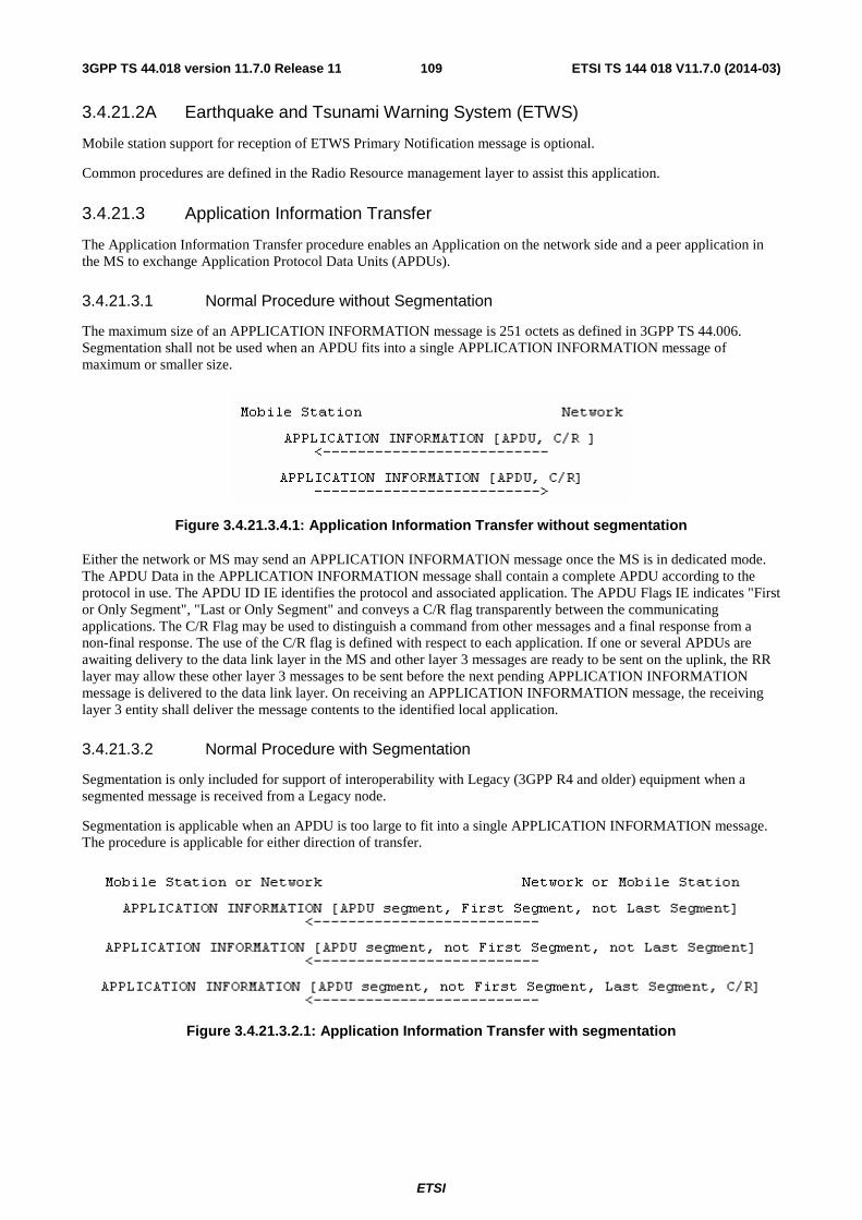
ETSI
ETSI TS 144 018 V11.7.0 (2014-03)1093GPP TS 44.018 version 11.7.0 Release 11
3.4.21.2A Earthquake and Tsunami Warning System (ETWS)
Mobile station support for reception of ETWS Primary Notification message is optional.
Common procedures are defined in the Radio Resource management layer to assist this application.
3.4.21.3 Application Information Transfer
The Application Information Transfer procedure enables an Application on the network side and a peer application in the MS to exchange Application Protocol Data Units (APDUs).
3.4.21.3.1 Normal Procedure without Segmentation
The maximum size of an APPLICATION INFORMATION message is 251 octets as defined in 3GPP TS 44.006. Segmentation shall not be used when an APDU fits into a single APPLICATION INFORMATION message of maximum or smaller size.
Figure 3.4.21.3.4.1: Application Information Transfer without segmentation
Either the network or MS may send an APPLICATION INFORMATION message once the MS is in dedicated mode. The APDU Data in the APPLICATION INFORMATION message shall contain a complete APDU according to the protocol in use. The APDU ID IE identifies the protocol and associated application. The APDU Flags IE indicates "First or Only Segment", "Last or Only Segment" and conveys a C/R flag transparently between the communicating applications. The C/R Flag may be used to distinguish a command from other messages and a final response from a non-final response. The use of the C/R flag is defined with respect to each application. If one or several APDUs are awaiting delivery to the data link layer in the MS and other layer 3 messages are ready to be sent on the uplink, the RR layer may allow these other layer 3 messages to be sent before the next pending APPLICATION INFORMATION message is delivered to the data link layer. On receiving an APPLICATION INFORMATION message, the receiving layer 3 entity shall deliver the message contents to the identified local application.
3.4.21.3.2 Normal Procedure with Segmentation
Segmentation is only included for support of interoperability with Legacy (3GPP R4 and older) equipment when a segmented message is received from a Legacy node.
Segmentation is applicable when an APDU is too large to fit into a single APPLICATION INFORMATION message. The procedure is applicable for either direction of transfer.
Figure 3.4.21.3.2.1: Application Information Transfer with segmentation
ETSI
ETSI TS 144 018 V11.7.0 (2014-03)1103GPP TS 44.018 version 11.7.0 Release 11
The sending layer 3 entity shall segment an APDU by dividing it into one or more segments exactly fitting into maximum sized APPLICATION INFORMATION messages plus a final segment fitting into an APPLICATION INFORMATION message of maximum size or smaller. Once segmented, the resulting APPLICATION INFORMATION messages shall be transferred in sequence to the data link layer for transmission, without being intersperced by other level 3 messages. The first APPLICATION INFORMATION message in the sequence shall indicate "First Segment" and "Not Last Segment". Subsequent APPLICATION INFORMATION messages except for the last shall indicate "Not First Segment" and "Not Last Segment". The last APPLICATION INFORMATION message shall indicate "Not First Segment" and "Last Segment" and shall include a C/R flag as provided by the sending application.
The receiving layer 3 entity shall reassemble any segmented APDU before transfer to the local application. The receiver may employ a timer to detect possible loss of APDU segments. If employed, the timer shall be started when the first APDU segment is received and cancelled after the last segment is received.
3.4.21.3.3 Abnormal Cases
APPLICATION INFORMATION messages are sent using "low" priority at the data link layer except for the case of ETWS, see sub-clause 3.1.6. This can lead to message loss or truncation when preempted by other "high" priority messages. A receiving layer 3 entity shall detect APDU truncation if an APPLICATION INFORMATION message is received carrying an APDU or APDU segment that is shorter than indicated by the length indicator for the APDU Data IE. This test is reliable because preemption in the data link layer guarantees that at least the first 2*N201 octets of any truncated message will be reliably transferred.
An APPLICATION INFORMATION transfer error shall be detected due to any of the following:
a) Receipt of a truncated APDU or APDU segment;
b) While performing APDU reassembly:
- receipt of any other layer 3 message defined to use SAPI 0 on the main DCCH;
- receipt of an APDU or APDU segment indicating "First or Only Segment";
- expiration of the reassembly timer (if supported);
c) While not performing APDU reassembly, receipt of an APDU segment indicating "not First or only segment";
d) Detection of any other error for a received message as defined in clause 8.
If APDU reassembly was in process when the error occurred, the receiving layer 3 entity shall discard the partially reassembled APDU and reprocess any received APDU or APDU segment that caused the error provided not an error defined in clause 8. In all other cases, any received APDU or APDU segment shall be discarded.
3.4.22 RR procedures related to packet resource establishment while in dedicated mode
The establishment of a packet resource is supported by procedures on the main DCCH when the mobile station is in dedicated mode. The procedures are only applicable to a mobile station supporting both GPRS and DTM. The procedures are optional for the network.
These procedures constitute a complement to the corresponding procedures for temporary block flow establishment using CCCH or PCCCH while in idle mode defined in 3GPP TS 44.018 and 3GPP TS 44.060, respectively.
The packet request procedure is initiated by the MS and it is described in sub-clause 3.4.22.1. The packet notification procedure is initiated by the network and it is described in sub-clause 3.4.22.2. The packet downlink assignment is initiated by the network and it is described in sub-clause 3.4.22.3.
3.4.22.1 Packet request procedure while in dedicated mode
The packet request procedure using the main DCCH may be used to establish a packet resource to support the transfer of LLC PDUs in the direction from the mobile station to the network.
ETSI
ETSI TS 144 018 V11.7.0 (2014-03)1113GPP TS 44.018 version 11.7.0 Release 11
3.4.22.1.1 Entering the dual transfer mode
While in dedicated mode, the establishment of an uplink packet resource may be initiated by the RR entity of the mobile station using the packet request procedure. The procedure is triggered by a request from upper layers to transfer an LLC PDU; see 3GPP TS 24.007. The request from upper layers specifies:
- TLLI;
- radio priority;
- requested RLC mode associated with the packet transfer;
- LLC frame type;
- establishment cause;
- QoS information for the requested packet session; and
- optionally, the PFI.
Upon such a request, the RR entity of the mobile station:
- if access to the network is allowed (sub-clause 3.4.22.1.1.1), it initiates the packet request procedure as defined in sub-clause 3.4.22.1.1.2;
- otherwise, it rejects the request.
If the request from upper layers indicates any signalling procedure the acknowledged RLC mode shall be requested.
If both the mobile station and the BSS support multiple TBF procedures, or if the mobile station supports RLC non-persistent mode, the BSS may order its preferred RLC mode when establishing uplink packet resources, independently of the RLC mode requested by the mobile station. In particular, if the mobile station supports RLC non-persistent mode the network may allocate an EGPRS TBF that uses this RLC mode.
3.4.22.1.1.1 Permission to access the network
Access to the network is allowed if dual transfer mode is supported in the cell.
NOTE: belonging to an authorised access class or special class, radio priority level and LSA permission are not considered since they only apply to a mobile station in idle mode.
3.4.22.1.1.2 Initiation of establishment of the packet request procedure
The mobile station initiates the establishment of the packet resource by sending a DTM REQUEST message on the main DCCH.
The DTM REQUEST message contains:
- TLLI;
- Channel Request Description;
- Packet establishment cause which indicates, as applicable, a request to send user data, cell update, page response or a mobility management message;
- PFI, if the PFC procedures are supported by the MS and irrespective of the network support of PFC procedures;
- Multiple TBF Capability, irrespective of the network support of Multiple TBF procedures;
- RLC Non-persistent Mode Capability, irrespective of the network support of RLC Non-persistent Mode; and
- MS capabilities related to support of Reduced Latency or FANR, Uplink EGPRS2 and Downlink EGPRS2, irrespective of the network support of these features.
Having sent the DTM REQUEST message, the mobile station starts timer T3148.
ETSI
ETSI TS 144 018 V11.7.0 (2014-03)1123GPP TS 44.018 version 11.7.0 Release 11
3.4.22.1.1.3 Answer from the network
3.4.22.1.1.3.1 Packet assignment
On receipt of a DTM REQUEST message the network may allocate an uplink packet resource. The packet uplink resource is assigned to the mobile station in one of the DTM assignment messages:
- DTM ASSIGNMENT COMMAND; or
- PACKET ASSIGNMENT.
These messages are sent in acknowledged mode. The DTM ASSIGNMENT COMMAND message may be sent on the SDCCH and on the FACCH. The PACKET ASSIGNMENT message shall be sent only on FACCH. If frequency hopping is applied, the mobile station shall use the cell allocation defined for the cell to decode the mobile allocation.
The allocation of the uplink packet resource may imply the reallocation of the resource for the RR connection. In this case, the DTM ASSIGNMENT COMMAND message is used and the timer T3107 is started on the network side. The DTM ASSIGNMENT COMMAND message shall not be used to change to a dependent configuration. The DTM ASSIGNMENT COMMAND message may be used to change the ciphering mode by including the Ciphering Mode Setting IE when a mobile station supports the reception of this IE in the DTM ASSIGNMENT COMMAND message. If Ciphering Mode Setting IE is not present the ciphering mode and the use of Selective Ciphering of Downlink SACCH (see sub-clause 3.4.7a) are unchanged after the mobile station has switched to the assigned channels. If the Ciphering Mode Setting IE indicates 'start ciphering' the mobile station supporting Selective Ciphering of Downlink SACCH shall be able to decode both ciphered and not-ciphered SACCH blocks (see sub-clause 3.4.7a). The DTM ASSIGNMENT COMMAND message shall not contain a Cipher Mode Setting IE that indicates "start ciphering" unless a CIPHERING MODE COMMAND message has been transmitted earlier in the RR connection or ciphering has been started earlier in UTRAN. If such a DTM ASSIGNMENT COMMAND message is received it shall be regarded as erroneous, a DTM ASSIGNMENT FAILURE with cause "Protocol error unspecified" message shall be returned immediately, and no further action taken.
When sending the DTM ASSIGNMENT COMMAND message on the network side, and when receiving it on the mobile station side, all transmission of signalling layer messages except for those RR messages needed for this procedure and for abnormal cases is suspended until resumption is indicated. These RR messages can be deduced from sub-clauses 3.4.22.1 and 8.8 Radio Resource management.
The PACKET ASSIGNMENT message is only used when the packet resource is a PDCH and no reallocation of the RR connection is needed.
On receipt of:
- DTM ASSIGNMENT COMMAND message; or
- PACKET ASSIGNMENT message;
the mobile station shall stop T3148.
If the received DTM ASSIGNMENT COMMAND or PACKET ASSIGNMENT message includes uplink packet resources, the mobile station shall proceed with the packet access. If, in addition, the received DTM ASSIGNMENT COMMAND or PACKET ASSIGNMENT message includes concurrent downlink packet resources, the mobile station shall also obey the packet downlink assignment. If the received message includes downlink packet resources and no uplink packet resources, the mobile station shall abort the packet access procedure and proceed with the procedure specified in sub-clause 3.4.22.3, and then attempt an establishment of uplink TBF, using the applicable procedure specified in 3GPP TS 44.060.
If the network supports multiple TBF procedures, it shall indicate this support in the Multiple TBF Capability field in the GPRS Cell Options IE included in the DTM ASSIGNMENT COMMAND and the PACKET ASSIGNMENT messages.
Upon receipt of the DTM ASSIGNMENT COMMAND message, the mobile station initiates a local end release of link layer connections, disconnects the physical channels, commands the switching to the assigned channel and initiates the establishment of lower layer connection (this includes the activation of the channel, their connection and the establishment of the main signalling link).
ETSI
ETSI TS 144 018 V11.7.0 (2014-03)1133GPP TS 44.018 version 11.7.0 Release 11
If the channel mode to be applied corresponds to an initial assignment of a multi-rate speech codec, the DTM ASSIGNMENT COMMAND message shall contain the MultiRate Configuration IE, which defines the set of codec modes and related information to use on the new channel.
If the assignment is related to an assignment from a multi-rate speech codec to a multi-rate speech codec, the MultiRate Configuration IE shall be included in the DTM ASSIGNMENT COMMAND message in the case of full rate to half rate change. If not included in this case, the mobile station shall behave as if the MultiRate Configuration IE was inconsistent. If not included in other cases, the MS shall use on the new channel the AMR configuration it was using on the old channel when it received the DTM ASSIGNMENT COMMAND message.
3.4.22.1.1.3.2 RR reallocation only
If the mobile station receives an ASSIGNMENT COMMAND or HANDOVER COMMAND message during the packet access procedure, the mobile station shall abort the packet access procedure, stop timer T3148 and proceed with the channel assignment procedure as specified in sub-clause 3.4.3 or the handover procedure as specified in sub-clause 3.4.4. The mobile station shall then attempt an establishment of uplink TBF, using the procedure specified in sub-clause 3.4.22.
If the mobile station receives a CHANNEL RELEASE message during the packet access procedure, the mobile station shall abort the packet access procedure, stop timer T3148 and proceed with the RR connection release procedure as specified in sub-clause 3.4.13. The mobile station shall then attempt an establishment of uplink TBF.
If the mobile station receives an INTER SYSTEM TO UTRAN HANDOVER COMMAND message during the packet access procedure, the mobile station shall abort the packet access procedure, stop timer T3148 and proceed with the handover to UTRAN procedure as specified in sub-clause 3.4.4a. If a mobile station which is not UTRAN capable receives this message, the error handling as defined in sub-clause 8.4 applies.
3.4.22.1.1.3.3 Packet request rejection
If the network cannot allocate the requested packet resource it may send the mobile station a DTM REJECT message in acknowledged mode on the main DCCH. This message contains a wait time ("wait indication" information element).
On receipt of the DTM REJECT message, the mobile station stops T3148, notifies upper layers of a packet resource establishment failure and starts timer T3142 with the indicated value.
The mobile station is not allowed to make a new attempt for packet access in the same cell until T3142 expires. The value of the wait indication (i.e. T3142) relates to the cell from which it was received.
3.4.22.1.1.4 Packet request completion
The completion of the packet request procedure depends on the actual assignment message used by the network.
- When the network sends a DTM ASSIGNMENT COMMAND message (i.e. reallocation of the CS resource is required), after the main signalling link is successfully established, the mobile station returns an ASSIGNMENT COMPLETE message, specifying cause "normal event", to the network on the main DCCH. The packet request procedure is completed for the mobile station when the ASSIGNMENT COMPLETE message is sent and for the network when it is received. The network then stops timer T3107. The sending of the ASSIGNMENT COMPLETE message on the mobile station side and its receipt on the network side allow the resumption of the transmission of signalling layer messages other than those belonging to RR management.
- When the network sends a PACKET ASSIGNMENT message, the packet request procedure is completed for the network when assignment message is sent and for the mobile station when it is received.
When the packet request procedure is completed, the mobile station has entered the dual transfer mode.
3.4.22.1.1.5 Abnormal cases
In the following cases, a resource establishment failure has occurred:
a) If a DTM ASSIGNMENT COMMAND message indicates resources in a non-supported frequency band.
ETSI
ETSI TS 144 018 V11.7.0 (2014-03)1143GPP TS 44.018 version 11.7.0 Release 11
b) If the information available in the mobile station after the reception of a DTM ASSIGNMENT COMMAND or PACKET ASSIGNMENT message does not satisfactorily define uplink packet resources or concurrent uplink and downlink packet resources if both were included in the message.
c) If a DTM ASSIGNMENT COMMAND message includes a mobile allocation or a frequency list that indexes frequencies in more than one frequency band.
d) If a DTM ASSIGNMENT COMMAND or PACKET ASSIGNMENT message assigns resources not compliant with the multislot capabilities of the mobile station.
e) If the mobile station has no current Cell Allocation (Cell Channel Description) and if it needs a Cell Allocation to analyse the DTM ASSIGNMENT COMMAND message or the PACKET ASSIGNMENT message.
f) If the DTM ASSIGNMENT COMMAND message instructs the mobile station to use a channel description or mode that it does not support.
g) If the DTM ASSIGNMENT COMMAND or PACKET ASSIGNMENT message does not include any uplink or downlink packet resources.
h) At expiry of timer T3148.
i) If the DTM ASSIGNMENT COMMAND message includes a Channel Mode IE indicating multi-rate speech codec but the Multi-Rate configuration IE is missing and no old multi-rate configuration exists.
j) If the DTM ASSIGNMENT COMMAND message includes a Channel Mode IE indicating multi-rate speech codec and the possibly included Multi-Rate configuration IE is inconsistent.
The MultiRate Configuration IE shall be considered as inconsistent by the mobile station if:
- the active set does not include any codec mode or the active set includes more than four codec modes; or
- one or more codec modes of the active codec set are not supported by the assigned channel; or
- the threshold and hysteresis values are not set according to requirements given in 3GPP TS 45.009.
k) If a PACKET ASSIGNMENT message is received on SDCCH.
l) If the DTM ASSIGNMENT COMMAND message or PACKET ASSIGNMENT message includes the description of a SDCCH channel.
m) If the DTM ASSIGNMENT COMMAND message includes a mode of ciphering not supported by the mobile station.
In any of these cases, the mobile station shall remain in dedicated mode. In addition, if the mobile station has received a DTM ASSIGNMENT COMMAND, it shall return a DTM ASSIGNMENT FAILURE message on the main DCCH with one of the following corresponding cause values:
- In case of abnormal cases a), c) above, "frequency not implemented";
- In case of abnormal cases b), d), g), l), m) above, "protocol error unspecified";
- In case of abnormal case e) above, "no cell allocation available";
- In case of abnormal cases f), i), j) above, "channel mode unacceptable".
Upper layers shall also be notified (resource establishment failure).
In addition:
- If the network commands the mobile station to reallocate the RR connection and the establishment of the main DCCH fails, all the allocated packet resources described in the new configuration are released; the mobile station shall revert to the old channel in dedicated mode, trigger the establishment of the main DCCH and send a DTM ASSIGNMENT FAILURE message on the main DCCH with cause value "lower layer failure".
- If a lower layer failure happens while attempting to connect back to the old channel, the radio link failure procedure is applied (see sub-clause 3.4.13.2).
ETSI
ETSI TS 144 018 V11.7.0 (2014-03)1153GPP TS 44.018 version 11.7.0 Release 11
When receiving the DTM ASSIGNMENT FAILURE message, the network stops T3107.
On the network side, if timer T3107 elapses before either the ASSIGNMENT COMPLETE message has been received on the new channel or a DTM ASSIGNMENT FAILURE message is received on the old channel; the old channel and the new channel are released. On the network side, lower layer failures occurring on the old channel after the sending of the DTM ASSIGNMENT COMMAND message are ignored. Lower layer failures occurring after the receipt of the SABM frame on the new main DCCH are treated following the general rules (cf. sub-clause 3.5.2).
3.4.22.2 Packet notification procedure in dedicated mode
The packet notification procedure is initiated by the RR entity of the network side. It is triggered by a page request from the GMM sublayer, see 3GPP TS 24.007.
3.4.22.2.1 Packet notification initiation by the network
The network initiates the packet notification procedure by sending the mobile station a PACKET NOTIFICATION message on the main DCCH.
The network shall not send the PACKET NOTIFICATION message to a mobile station that does not support dual transfer mode operation. If a mobile station not supporting dual transfer mode receives this message, the error handling as defined in sub-clause 8.4 applies.
3.4.22.2.2 Packet notification response
Upon receipt of the PACKET NOTIFICATION message, the RR sublayer of the mobile station indicates the receipt of a packet paging request to the GMM sublayer; see 3GPP TS 24.007.
3.4.22.3 Packet downlink assignment in dedicated mode
The packet downlink assignment procedure in dedicated mode may be used to establish a packet resource to support the transfer of LLC PDUs in the direction from the network to the mobile station.
This procedure is only applicable to a mobile station in dedicated mode and with no TBF allocated. If the mobile station already has an ongoing TBF, the establishment of the downlink packet resource is performed on the PACCH; see 3GPP TS 44.060.
The establishment of a downlink packet resource is initiated by the RR entity on the network side using the packet downlink assignment procedure in dedicated mode. The procedure is triggered by a request from upper layers to transfer an LLC PDU; see 3GPP TS 24.007. The request from upper layers specifies a QoS profile, an RLC mode, DRX parameters and an MS classmark associated with the packet transfer. The BSS may order its preferred RLC mode independently of the RLC mode signalled from upper layers. If the mobile station supports RLC non-persistent mode the network may allocate an EGPRS TBF that uses this RLC mode.
3.4.22.3.1 Initiation of the packet downlink assignment procedure in dedicated mode
The network initiates the packet downlink assignment procedure in dedicated mode by sending a DTM assignment message (i.e. DTM ASSIGNMENT COMMAND or a PACKET ASSIGNMENT) in acknowledged mode. The DTM ASSIGNMENT COMMAND message may be sent on the SDCCH and on the FACCH. The PACKET ASSIGNMENT message shall be sent only on FACCH.
When sending the DTM ASSIGNMENT COMMAND message on the network side, and when receiving it on the mobile station side, all transmission of signalling layer messages except for those RR messages needed for this procedure and for abnormal cases is suspended until resumption is indicated. These RR messages can be deduced from sub-clauses 3.4.22.3 and 8.8 Radio Resource management.
The allocation of the downlink packet resource may imply the reallocation of the resource for the RR connection. In this case, the DTM ASSIGNMENT COMMAND message is used and the timer T3107 is started on the network side. The DTM ASSIGNMENT COMMAND message shall not be used to change to a dependent configuration. The DTM ASSIGNMENT COMMAND message may be used to change the ciphering mode by including the Ciphering Mode Setting IE when a mobile station supports the reception of this IE in the DTM ASSIGNMENT COMMAND message. The DTM ASSIGNMENT COMMAND message shall not contain a Cipher Mode Setting IE that indicates "start ciphering" unless a CIPHERING MODE COMMAND message has been transmitted earlier in the RR connection or
ETSI
ETSI TS 144 018 V11.7.0 (2014-03)1163GPP TS 44.018 version 11.7.0 Release 11
ciphering has been started earlier in UTRAN. If such a DTM ASSIGNMENT COMMAND message is received it shall be regarded as erroneous, a DTM ASSIGNMENT FAILURE with cause "Protocol error unspecified" message shall be returned immediately, and no further action taken.
The network shall not send any of the DTM assignment messages to a mobile station that does not support dual transfer mode operation. If a mobile station not supporting dual transfer mode receives any of these messages, the error handling as defined in sub-clause 8.4 applies.
Upon receipt of the DTM ASSIGNMENT COMMAND message, the mobile station initiates a local end release of link layer connections, disconnects the physical channels, commands the switching to the assigned channel and initiates the establishment of lower layer connection (this includes the activation of the channel, their connection and the establishment of the main signalling link).
If the channel mode to be applied corresponds to an initial assignment of a multi-rate speech codec, the DTM ASSIGNMENT COMMAND message shall contain the MultiRate Configuration IE, which defines the set of codec modes and related information to use on the new channel.
If the assignment is related to an assignment from a multi-rate speech codec to a multi-rate speech codec, the MultiRate Configuration IE shall be included in the DTM ASSIGNMENT COMMAND message in the case of full rate to half rate change. If not included in this case, the mobile station shall behave as if the MultiRate Configuration IE was inconsistent. If not included in other cases, the MS shall use on the new channel the AMR configuration it was using on the old channel when it received the DTM ASSIGNMENT COMMAND message.
3.4.22.3.2 Packet downlink assignment completion
The completion of the packet downlink assignment procedure while in dedicated mode depends on the actual assignment message used by the network:
- when the network sends a DTM ASSIGNMENT COMMAND message (i.e. reallocation of the RR connection is required), after the main signalling link is successfully established, the mobile station returns an ASSIGNMENT COMPLETE message, specifying cause "normal event", to the network on the main DCCH. The packet downlink assignment procedure is completed for the mobile station when the ASSIGNMENT COMPLETE message is sent and for the network when it is received. The network then stops timer T3107. The sending of the ASSIGNMENT COMPLETE message on the mobile station side and its receipt on the network side allow the resumption of the transmission of signalling layer messages other than those belonging to RR management.
- when the network sends a PACKET ASSIGNMENT message, the packet downlink assignment procedure is completed for the network when assignment message is sent and for the mobile station when it is received.
3.4.22.3.3 Abnormal cases
In the following cases, a resource establishment failure has occurred:
a) If a DTM ASSIGNMENT COMMAND message indicates packet resources in a non-supported frequency band.
b) If the information available in the mobile station after the reception of a DTM ASSIGNMENT COMMAND or PACKET ASSIGNMENT message does not satisfactorily define downlink packet resources.
c) If a DTM ASSIGNMENT COMMAND message includes a mobile allocation or a frequency list that indexes frequencies in more than one frequency band.
d) If a DTM ASSIGNMENT COMMAND or PACKET ASSIGNMENT message assigns resources not compliant with the multislot capabilities of the mobile station.
e) If the mobile station has no current CA and if it needs a CA to analyse the DTM ASSIGNMENT COMMAND message.
f) If the DTM ASSIGNMENT COMMAND message instructs the mobile station to use a channel description or mode that it does not support.
g) If the DTM ASSIGNMENT COMMAND or PACKET ASSIGNMENT message does not include any downlink packet resources, or if it includes uplink packet resources.
ETSI
ETSI TS 144 018 V11.7.0 (2014-03)1173GPP TS 44.018 version 11.7.0 Release 11
h) If the DTM ASSIGNMENT COMMAND message includes a Channel Mode IE indicating multi-rate speech codec but the Multi-Rate configuration IE is missing and no old multi-rate configuration exists.
i) If the DTM ASSIGNMENT COMMAND message includes a Channel Mode IE indicating multi-rate speech codec and the possibly included Multi-Rate configuration IE is inconsistent.
The MultiRate Configuration IE shall be considered as inconsistent by the mobile station if:
- the active set does not include any codec mode or the active set includes more than four codec modes; or
- one or more codec modes of the active codec set are not supported by the assigned channel; or
- the threshold and hysteresis values are not set according to requirements given in 3GPP TS 45.009.
j ) If a PACKET ASSIGNMENT message is received on SDCCH.
k) If the DTM ASSIGNMENT COMMAND message or PACKET ASSIGNMENT message includes the description of a SDCCH channel.
l) If the DTM ASSIGNMENT COMMAND message includes a mode of ciphering not supported by the mobile station.
In any of these cases, the mobile station shall remain in dedicated mode.
If the mobile station has received a DTM ASSIGNMENT COMMAND message, it shall return a DTM ASSIGNMENT FAILURE message on the main DCCH with one of the following corresponding cause values:
- In case of abnormal cases a), c) above, "frequency not implemented";
- In case of abnormal cases b), d), g), k), l) above, "protocol error unspecified";
- In case of abnormal case e) above, "no cell allocation available";
- In case of abnormal case f), h), i) above, "channel mode unacceptable".
In addition:
- If the network commands the mobile station to reallocate the RR connection and the establishment of the main DCCH fails, all the allocated packet resources described in the new configuration are released; the mobile station shall revert to the old channel in dedicated mode, trigger the establishment of the main DCCH and send a DTM ASSIGNMENT FAILURE message on the old main DCCH with cause value "lower layer failure".
- If a lower layer failure happens while attempting to connect back to the old channel, the radio link failure procedure is applied (see sub-clause 3.4.13.2).
When receiving the DTM ASSIGNMENT FAILURE message, the network stops T3107.
On the network side, if timer T3107 elapses before either the ASSIGNMENT COMPLETE message has been received on the new channel or a DTM ASSIGNMENT FAILURE message is received on the old channel; the old channel and the new channel are released.
On the network side, lower layer failures occurring on the old channel after the sending of the DTM ASSIGNMENT COMMAND message are ignored. Lower layer failures occurring after the receipt of the SABM frame on the new main DCCH are treated following the general rules (cf. sub-clause 3.5.2).
3.4.22.4 Modification of packet resources while in DTM
When the mobile station is in dual transfer mode, the network or mobile station may wish to modify only the allocated packet resources. When the mobile station has one or more ongoing TBFs, the procedures described in 3GPP TS 44.060 shall be used.
ETSI
ETSI TS 144 018 V11.7.0 (2014-03)1183GPP TS 44.018 version 11.7.0 Release 11
3.4.23 RR procedures related to packet resource maintenance while in dual transfer mode
3.4.23.1 General
Once the mobile station enters the dual transfer mode, the existent procedures apply (see 3GPP TS 44.060). Some exceptions to the existent procedures while in dual transfer mode are:
- When all packet resources have been released (or aborted), the mobile station returns to dedicated mode.
- When the mobile station is in dual transfer mode, it shall ignore any PACKET CELL CHANGE ORDER or PACKET ASSIGNMENT messages and shall remain in dual transfer mode.
- When the mobile station receives a HANDOVER COMMAND, HANDOVER TO UTRAN COMMAND, HANDOVER TO CDMA2000 COMMAND, HANDOVER TO IU MODE COMMAND or ASSIGNMENT COMMAND message, it shall abandon the packet resource immediately, enter dedicated mode and perform the handover or assignment procedure, respectively.
- When the mobile station receives a DTM ASSIGNMENT COMMAND message whilst in dual transfer mode, it shall follow procedures specified in sub-clause 3.4.23.2.
- As stated in 3GPP TS 45.008, no GPRS measurement reporting is performed.
In case the network has to change the frequency parameters and needs to specify a start time for the RR connection, the frequency redefinition procedure shall be used (see sub-clause 3.4.5) If the RR connection can be started immediately after resource reallocation with change of frequency parameters, the DTM ASSIGNMENT COMMAND message or the frequency redefinition procedure shall be used.
In case the network has to change the channel mode of the traffic channel, the channel mode modify procedure shall be used (see sub-clause 3.4.6).
The mobile station remains in dual transfer mode until the RR connection or all the packet resources are released.
When the mobile station receives a DTM ASSIGNMENT COMMAND message encapsulated in a PACKET CS COMMAND message, it shall follow procedures specified in sub-clause 3.4.23.2.2 and 3.4.23.2.3 with the exceptions described in 3GPP TS 44.060.
3.4.23.2 RR and packet resource reallocation whilst in dual transfer mode
3.4.23.2.1 General
In dual transfer mode an intracell change of channel can be requested by upper layers for changing the channel type, or decided by the RR sublayer, e.g. for an internal handover or for the reallocation of all the resources of the mobile station. The purpose is to modify completely the physical channel configuration of the mobile station without change in synchronization while staying in the same cell.
The mobile station and the network shall change neither the RLC mode nor TBF mode of an already established TBF during resource reallocation. The change of RLC mode or TBF mode shall be achieved through release of the TBF and establishment of a new TBF with the new RLC mode or TBF mode.
The usage of the DTM ASSIGNMENT COMMAND message depends on whether the mobile station supports multiple TBF procedures, DTM enhancements or Downlink Dual Carrier:
- If the mobile station does not support any of multiple TBF procedures, DTM enhancements or Downlink Dual Carrier, the DTM ASSIGNMENT COMMAND message is used by the network to reallocate the DTM resources assigned to a mobile station when the CS channel needs to be reallocated. All of the ongoing TBFs shall be addressed by the DTM ASSIGNMENT COMMAND message. The procedures in 3GPP TS 44.060 shall be used to establish an additional TBF or to release an ongoing TBF.
- If the mobile station supports multiple TBF procedures, DTM enhancements or Downlink Dual Carrier, the DTM ASSIGNMENT COMMAND message may be used by the network, when the CS channel needs to be reallocated, in order to reallocate the DTM resources assigned to a mobile station, to assign new uplink and downlink TBFs and to implicitly release TBFs.
ETSI
ETSI TS 144 018 V11.7.0 (2014-03)1193GPP TS 44.018 version 11.7.0 Release 11
This procedure includes:
- the suspension of normal operation except for RR management (layer 3);
- the release of the main signalling link and of the other data links as defined in sub-clause 3.1.4;
- the disconnection of TCHs and PDTCHs;
- the deactivation of previously assigned channels (layer 1);
- the activation of the new channels and their connection if applicable;
- the triggering of the establishment of the data link connections for SAPI = 0.
3.4.23.2.2 Normal resource reallocation case
The reallocation of resources assigned to a mobile station is initiated by the network using a DTM ASSIGNMENT COMMAND message. Once the DTM ASSIGNMENT COMMAND message has been transmitted the timer T3107 is started on the network side. The DTM ASSIGNMENT COMMAND message may be used to change the ciphering mode by including the Ciphering Mode Setting IE when a mobile station supports the reception of this IE in the DTM ASSIGNMENT COMMAND message. The DTM ASSIGNMENT COMMAND message shall not contain a Cipher Mode Setting IE that indicates "start ciphering" unless a CIPHERING MODE COMMAND message has been transmitted earlier in the RR connection or ciphering has been started earlier in UTRAN. If such a DTM ASSIGNMENT COMMAND message is received it shall be regarded as erroneous, a DTM ASSIGNMENT FAILURE with cause "Protocol error unspecified" message shall be returned immediately, and no further action taken.
Upon receipt of the DTM ASSIGNMENT COMMAND message, the mobile station initiates a local end release of link layer connections, disconnects the physical channels, commands the switching to the assigned channel and initiates the establishment of lower layer connection (this includes the activation of the channel, their connection and the establishment of the main signalling link).
Upon receipt of the DTM ASSIGNMENT COMMAND message, the mobile station shall then switch to the assigned PDCHs and follow the applicable procedures specified in 3GPP TS 44.060. Neither the TLLI (in A/Gb mode) nor the G-RNTI (in Iu mode) shall be included in any of the uplink RLC data blocks in that case. If the mobile station supports multiple TBF procedures or DTM enhancements and the network addresses only a subset of the ongoing TBFs, the mobile station shall consider all ongoing TBFs not addressed by the DTM ASSIGNMENT COMMAND message as released. If while waiting for the frame number indicated by the TBF starting time the mobile station receives the DTM ASSIGNMENT COMMAND message, the mobile station shall act upon the most recently received uplink or downlink assignment and shall ignore the previous uplink or downlink assignment.
After the main signalling link is successfully established, the mobile station returns an ASSIGNMENT COMPLETE message, specifying cause "normal event", to the network on the main DCCH. The reallocation of resources is completed for the mobile station when the ASSIGNMENT COMPLETE message is sent and for the network when it is received. The network then stops timer T3107. The sending of the ASSIGNMENT COMPLETE message on the mobile station side and its receipt on the network side allow the resumption of the transmission of signalling layer messages other than those belonging to RR management.
If the mobile station has requested one or more new uplink TBFs (as specified in 3GPP TS 44.060) and a DTM ASSIGNMENT COMMAND message is received from the network before resources are allocated for the requested uplink TBFs, the mobile station shall:
- follow the reallocation procedure as specified in this sub-clause;
- if the mobile station supports multiple TBF procedures or DTM enhancements it shall stop the instance of the RLC timer T3168 associated with the uplink TBF receiving a resource allocation (as specified in 3GPP TS 44.060);
- wait for the network response to the outstanding uplink TBF requests on the newly allocated resources.
3.4.23.2.3 Abnormal cases
In the following cases, a resource re-allocation failure has occurred :
a) If a DTM ASSIGNMENT COMMAND message indicates resources in a non-supported frequency band.
ETSI
ETSI TS 144 018 V11.7.0 (2014-03)1203GPP TS 44.018 version 11.7.0 Release 11
b) If the information available in the mobile station after the reception of a DTM ASSIGNMENT COMMAND message does not satisfactorily define uplink packet resources if uplink packet resources were established or downlink packet resources if downlink packet resources were established.
c) If a DTM ASSIGNMENT COMMAND message includes a mobile allocation or a frequency list that indexes frequencies in more than one frequency band.
d) If a DTM ASSIGNMENT COMMAND message assigns resources not compliant with the multislot capabilities of the mobile station.
e) If the mobile station has no current CA and if it needs a CA to analyse the DTM ASSIGNMENT COMMAND message.
f) If the DTM ASSIGNMENT COMMAND message instructs the mobile station to use a channel description or mode that it does not support.
g) If the DTM ASSIGNMENT COMMAND message does not include any uplink or downlink packet resources, except if encapsulated in a PACKET CS COMMAND message (as specified in 3GPP TS 44.060).
h) If the DTM ASSIGNMENT COMMAND message includes a Channel Mode IE indicating multi-rate speech codec but the Multi-Rate configuration IE is missing and no old multi-rate configuration exists.
i) If the DTM ASSIGNMENT COMMAND message includes a Channel Mode IE indicating multi-rate speech codec and the possibly included Multi-Rate configuration IE is inconsistent.
The MultiRate Configuration IE shall be considered as inconsistent by the mobile station if:
- the active set does not include any codec mode or the active set includes more than four codec modes; or
- one or more codec modes of the active codec set are not supported by the assigned channel; or
- the threshold and hysteresis values are not set according to requirements given in 3GPP TS 45.009.
j) If the DTM assignment command message, sent to a mobile station that does not support any of multiple TBF procedures, DTM enhancements or Downlink Dual Carrier, addresses more or fewer TBFs than the MS currently has been allocated. If the DTM assignment command message, sent to a mobile station that supports multiple TBF procedures, DTM enhancements or Downlink Dual Carrier, contains uplink assignments (including PFI values) for which no TBF was requested.
k) If the DTM ASSIGNMENT COMMAND message includes the description of a SDCCH channel.
l) If the DTM ASSIGNMENT COMMAND message includes a mode of ciphering not supported by the mobile station.
In any of these cases, the mobile station shall remain in DTM mode on the old configuration and return a DTM ASSIGNMENT FAILURE message on the current main DCCH with one of the following corresponding cause values:
- In case of abnormal cases a), c) above, "frequency not implemented";
- In case of abnormal cases b), d), g), k), j), l) above, "protocol error unspecified";
- In case of abnormal case e) above, "no cell allocation available";
- In case of abnormal cases f), h), i) above, "channel mode unacceptable".
In addition:
- If the establishment of the new main DCCH fails, all the allocated packet resources described in the new configuration in the DTM ASSIGNMENT COMMAND message are released; the mobile station shall revert to the old channel in dedicated mode, trigger the establishment of the main DCCH and send a DTM ASSIGNMENT FAILURE message on the main DCCH with cause value "lower layer failure" ; if an uplink TBF was active when the mobile station received the DTM ASSIGNMENT COMMAND message, the mobile station shall initiate the establishment of a new uplink TBF using the appropriate DTM procedure on the main DCCH, defined in sub-clause 3.4.22.1.
ETSI
ETSI TS 144 018 V11.7.0 (2014-03)1213GPP TS 44.018 version 11.7.0 Release 11
- If a lower layer failure happens on the circuit switched resource while attempting to connect back to the old channel, the radio link failure procedure is applied (see sub-clause 3.4.13.2).
- If a lower layer failure happens on re-allocated packet resources (such as T3180 or T3190 expiry ; see 3GPP TS 44.060) before the ASSIGNMENT COMPLETE message has been sent, all packet resources are released ; the mobile station shall revert to dedicated mode on the new channel ; if an uplink TBF was active when the mobile station received the DTM ASSIGNMENT COMMAND message, the mobile station shall initiate the establishment of a new uplink TBF using the appropriate DTM procedure on the main DCCH, defined in sub-clause 3.4.22.1 once the new main DCCH has been successfully established.
When receiving the DTM ASSIGNMENT FAILURE message, the network stops T3107.
On the network side, if timer T3107 elapses before either the ASSIGNMENT COMPLETE message has been received on the new channel or a DTM ASSIGNMENT FAILURE message is received on the old channel; the old channel and the new channel are released.
On the network side, lower layer failures occurring on the old channel after the sending of the DTM ASSIGNMENT COMMAND message are ignored. Lower layer failures occurring after the receipt of the SABM frame on the new main DCCH are treated following the general rules (cf. sub-clause 3.5.2).
3.4.24 RR procedures related to packet resource release while in dual transfer mode
The release of a TBF shall follow the procedures in 3GPP TS 44.060.
In the case of the release of the RR connection while in dual transfer mode, the mobile station may abandon the packet resources and, once in idle mode and packet idle mode, it may start a new establishment as described in 3GPP TS 44.060, or, if redirected to UTRAN according to the information element "Cell selection indicator after release of all TCH and SDCCH", as described in 3GPP TS 25.331, or, if redirected to E-UTRAN according to the information element "Cell selection indicator after release of all TCH and SDCCH", as described in 3GPP TS 36.331.
If the mobile station and the network support the enhanced DTM CS release procedure, the network may delay the release of the RR connection until the mobile station has received the needed system information, in order to maintain the radio resources on the PDCH(s)after the release of the RR connection.
3.4.25 GPRS suspension procedure
3.4.25.1 General
This procedure enables the network to suspend GPRS services packet flow in the downlink direction. The support of this procedure is conditional to the support of GPRS by the mobile station.
When a mobile station which is IMSI attached for GPRS services (see 3GPP TS 24.008) enters the dedicated mode, and when the mobile station limitations make it unable to handle both dedicated mode and either packet idle mode or packet transfer mode simultaneously, the mobile station shall perform the GPRS suspension procedure.
The RR sublayer of the mobile station shall indicate a RR GPRS suspend condition to the MM sublayer, see 3GPP TS 24.008.
3.4.25.2 MS in class B mode of operation
The GPRS suspension procedure shall be used to suspend GPRS services when the mobile station is in class B mode of operation and a circuit switched service is initiated. It is also used when a mobile station in CS/PS mode of operation in UTRAN reverts to class B mode of operation in GSM.
The GPRS suspension procedure is initiated by the mobile station by sending a GPRS SUSPENSION REQUEST message with the appropriate suspension cause. This can be done as early as possible after access but shall be done after sending a CLASSMARK CHANGE message.
ETSI
ETSI TS 144 018 V11.7.0 (2014-03)1223GPP TS 44.018 version 11.7.0 Release 11
3.4.25.3 Dual transfer mode not supported
The GPRS suspension procedure shall be used to suspend GPRS services:
a) when the mobile station in a class A mode of operation is handed over to a cell where the support of Class A mode of operation is not possible (e.g. a DTM mobile station entering a cell not supporting DTM);
b) when the GPRS attached mobile station is in a cell that does not support DTM and a circuit switched service is initiated.
In case a), when the mobile station concludes that DTM is not supported in the new cell after the handover procedure is completed, it shall initiate the GPRS suspension procedure by sending a GPRS SUSPENSION REQUEST message with the suspension cause set to "DTM not supported in the cell".
In case b), the GPRS suspension procedure is initiated by the mobile station by sending a GPRS SUSPENSION REQUEST message with the suspension cause set to "DTM not supported in the cell". This can be done as early as possible after access but shall be done after sending a CLASSMARK CHANGE message.
3.4.26 GPRS Transparent Transport Procedure
While in dedicated mode, upper layers in the mobile station or in the network may request the transport of GPRS information transparently over the radio interface when DTM operation is supported by both the mobile station and the network. This procedure is only applicable when
- the information from upper layers is signalling information; and
- the GTTP length of the message is below the maximum indicated by the network.
On the mobile station side signalling is any LLC PDU carried on LLC SAPI 1. In any other case, the RR procedures related to packet resource establishment while in dedicated mode apply.
The information from upper layers shall be carried inside the GTTP Information message. The GTTP Information message contains:
- the TLLI of the MS; and
- the LLC PDU.
If the mobile station supporting network sharing has received the PLMN Index (see sub-clause 3.4.4.1) in the HANDOVER COMMAND or DTM HANDOVER COMMAND message, it shall include it in the GTTP information message in the Skip Indicator (see sub-clause 10.3.1) if a foreign or random TLLI is used.
If the indicated TLLI is not assigned to the mobile station, the mobile station shall ignore the received message.
The GTTP messages are sent using "normal" priority at the data link layer.
3.4.27 RR procedures related to dedicated mode MBMS notification
3.4.27.1 General
The MBMS announcement of an mobile station is supported by procedures on the main DCCH when the mobile station is in dedicated mode. The procedures are only applicable to a mobile station supporting MBMS. The procedures are optional for the network.
The packet request procedure is initiated by the MS and it is described in sub-clause 3.4.22.1. The packet notification procedure is initiated by the network and it is described in sub-clause 3.4.22.2. The packet downlink assignment is initiated by the network and it is described in sub-clause 3.4.22.3.
ETSI
ETSI TS 144 018 V11.7.0 (2014-03)1233GPP TS 44.018 version 11.7.0 Release 11
3.4.27.2 MBMS announcement procedure in dedicated mode
3.4.27.2.1 General
The MBMS announcement procedure is initiated by the RR entity of the network side. It is triggered by the network being informed of a starting MBMS session or of an ongoing MBMS broadcast session with an updated MBMS service area list, see 3GPP TS 48.018.
3.4.27.2.2 MBMS announcement initiation by the network
The network initiates the MBMS announcement procedure by sending the mobile station a MBMS ANNOUNCEMENT message on the main DCCH.
The network shall not send the MBMS ANNOUNCEMENT message to a mobile station that does not support the MBMS service or to a mobile station that has not completed the Service Information Sending procedure. If a mobile station not supporting MBMS receives this message, the error handling as defined in sub-clause 8.4 applies.
3.4.27.2.3 MBMS notification response
Upon receipt of the MBMS ANNOUNCEMENT message including the identity of an MBMS service to which the MBMS capable mobile station has not joined, the RR sublayer of the mobile station shall discard the MBMS ANNOUNCEMENT message.
Upon receipt of the MBMS ANNOUNCEMENT message including the identity of an MBMS service to which the MBMS capable mobile station has joined and indicating a session that the mobile has not received, the RR sublayer of the mobile station indicates the receipt of a message, and passes the MBMS specific information contained within the MBMS ANNOUNCEMENT message, to the GMM sublayer.
If the Restriction Timer IE is included in the received MBMS ANNOUNCEMENT message, the mobile station shall set and start an instance of T3222 to the value indicated in the Restriction Timer IE, otherwise if the Estimated Session Duration is included in the received MBMS ANNOUNCEMENT message the mobile station shall set and start both an instance of T3222 and the session duration timer for this MBMS session with a value equal to the Estimated Session Duration. The mobile station shall store the MBMS specific information contained in the MBMS ANNOUNCEMENT message. If T3222 expires the mobile station shall discard the stored MBMS information associated with this instance of T3222.
If the mobile station in dedicated mode successfully completes the handover procedure, any MPRACH description or MBMS p-t-m channel description and MBMS Session Parameters List stored from a previously received MBMS ANNOUNCEMENT message shall be deleted.
If the mobile station enters packet idle mode before the expiry of T3222 or where no instance of T3222 was set and the MBMS ANNOUNCEMENT message did not include the MBMS p-t-m channel description, the mobile station shall stop T3222, if started, and shall follow the MBMS Packet Access Procedure (3GPP TS 44.060).
If the mobile station enters packet idle mode before the expiry of T3222 and the MBMS ANNOUNCEMENT message included the MBMS p-t-m channel description, the mobile station shall stop T3222 and shall start listening to downlink RLC blocks identified by the assigned TFI on the defined PDCHs either at the point in time denoted by the MBMS Radio Bearer Starting Time, if present and not already elapsed, or immediately otherwise (3GPP TS 44.060).
NOTE: If the MBMS ANNOUNCEMENT message includes the MBMS p-t-m channel description, it shall also include the MBMS Session Parameters List (and vice versa).
3.4.28 Transmission of application-specific data by the talker
3.4.28.1 General
This procedure is applicable only for the talker.
The transmission of application-specific data by the talker is carried out by the mobile transmitting a DATA INDICATION message on the main signalling link.
ETSI
ETSI TS 144 018 V11.7.0 (2014-03)1243GPP TS 44.018 version 11.7.0 Release 11
3.5 RR procedures on CCCH related to temporary block flow establishment
The establishment of a temporary block flow (TBF) on a packet data physical channel is supported by procedures on CCCH when PCCCH is not provided in the cell. The procedures for temporary block flow establishment using CCCH are only applicable to a mobile station supporting GPRS. The procedures are optional for the network.
These procedures constitute a complement to the corresponding procedures for temporary block flow establishment using PCCCH, defined in 3GPP TS 44.060, and include the procedures using CCCH for packet paging (sub-clause 3.5.1), packet access (sub-clause 3.5.2), packet downlink assignment (sub-clause 3.5.3) and MBMS packet access (sub-clause 3.5.4).
3.5.1 Packet paging procedure using CCCH
The network can initiate the packet paging procedure in order to cause upper layers in the mobile station to respond, see clause 4. The packet paging procedure can only be initiated by the network.
3.5.1.1 Packet paging initiation by the network
The packet paging procedure is initiated by the RR entity of the network side. It is triggered by a page request from the MM sublayer, see 3GPP TS 24.007, or by an MBMS session start procedure or by an MBMS session update procedure in case of an MBMS notification, see 3GPP TS 48.018.
The network initiates the paging procedure by sending a paging request message on an appropriate paging subchannel on CCCH or PCCCH. Paging initiation using a paging subchannel on CCCH is used when sending paging information to a mobile station and PCCCH is not present in the cell.
NOTE 1: There are three types of paging request messages that are applicable:
- PAGING REQUEST TYPE 1;
- PAGING REQUEST TYPE 2; and
- PAGING REQUEST TYPE 3.
In a PAGING REQUEST message used for the packet paging procedure, the mobile station shall be identified by the P-TMSI (GPRS TMSI) or its IMSI. If the mobile station is identified by the P-TMSI, it shall proceed as specified in sub-clause 3.5.1.2.
In a paging request message used for MBMS notification, the MBMS session shall be identified by the TMGI and, if available, the MBMS Session Identity of that session, see sub-clause 3.5.1.3.
If the mobile station identified by its IMSI, it shall parse the message for a corresponding Packet Page Indication field:
- if the Packet Page Indication field indicates a paging procedure for RR connection establishment, or the field is not present in the message, the mobile station shall proceed as specified in sub-clause 3.3.2.2;
- if the Packet Page Indication field indicates a packet paging procedure, the mobile station shall proceed as specified in sub-clause 3.5.1.2.
A PAGING REQUEST message may include more than one mobile station identification.
The mobile station in packet idle mode is required to receive and analyse the paging messages and immediate assignment messages sent on the paging subchannels on CCCH corresponding to the paging groups determined for it in packet idle mode, as specified in 3GPP TS 45.002. These messages contain a page mode information element.
NOTE 2: The possible immediate assignment messages are: the IMMEDIATE ASSIGNMENT, the IMMEDIATE ASSIGNMENT EXTENDED, the IMMEDIATE PACKET ASSIGNMENT if supported and the IMMEDIATE ASSIGNMENT REJECT messages.
The treatment of page mode information, including the procedure when the mobile station selects a new PCH, and the procedure if a message in a paging subchannel is not received correctly are defined in sub-clause 3.3.2.1.1.
ETSI
ETSI TS 144 018 V11.7.0 (2014-03)1253GPP TS 44.018 version 11.7.0 Release 11
3.5.1.2 On receipt of a packet paging request
On the receipt of a paging request message, the RR sublayer of addressed mobile station indicates the receipt of a paging request to the MM sublayer, see 3GPP TS 24.007.
3.5.1.3 Packet Paging for MBMS notification on CCCH
3.5.1.3.1 General
The packet paging procedure for MBMS notification is initiated by the network upon receipt of an MBMS-SESSION-START-REQUEST PDU or of an MBMS-SESSION-UPDATE-REQUEST PDU from the SGSN, see 3GPP TS 48.018. The MBMS notification may be repeated during the session.
The packet paging procedure for MBMS notification consists of the following steps:
- optionally, the pre-notification of the MBMS session; and
- the notification of the MBMS session.
A mobile station in broadcast/multicast receive mode shall remain in broadcast/multicast receive mode if a paging procedure for a new MBMS session is not completed.
The network initiates the paging procedure for MBMS notification of an MBMS session by sending a paging message including either an MBMS pre-notification or an MBMS notification for that session on one or more paging subchannels on CCCH. The paging request message may be of type:
- PAGING REQUEST TYPE 1 message; or
- PAGING REQUEST TYPE 2 message.
The MBMS session shall be identified by the TMGI and, if available, the MBMS Session Identity of that session as contained in the MBMS-SESSION-START-REQUEST PDU or in the MBMS-SESSION-UPDATE-REQUEST PDU received from the SGSN.
The following requirements apply:
- If in the paging message the mobile station is at the same time (pre-)notified (see sub-clauses 3.5.1.3.2 and 3.5.1.3.3) and paged, the mobile station shall discard all (pre-)notification(s) in that message and proceed as described in sub-clause 3.3.2 or 3.5.1.1 and 3.5.1.2 accordingly.
- If in the paging message the mobile station is at the same time pre-notified (see sub-clause 3.5.1.3.2) and notified (see sub-clause 3.5.1.3.3), the mobile station shall discard all pre-notifications in that message and proceed as described in sub-clause 3.5.1.3.3.
3.5.1.3.2 MBMS pre-notification
In order to pre-notify an MBMS session on a CCCH, the network shall send a relevant paging request message (see sub-clause 3.5.1.3.1) including the TMGI and, if available, the MBMS Session Identity of that session. The network shall not include the MBMS Notification information.
Upon reception of a paging message including a pre-notifcation for an MBMS session, and if the mobile station requires reception of that session, the mobile station shall consider that session as being pre-notified (i.e. the mobile station is pre-notified). If the mobile station determines several pre-notified sessions in this message, the mobile station shall discard all pre-notifications but the pre-notification for the highest priority session. The mobile station in packet idle mode or MAC-Idle state shall then enter non-DRX mode, start timer T3220 and proceed as specified in sub-clause 3.5.1.3.3.
NOTE: In case all pre-notified sessions have the same priority, the selection of the highest priority session is implementation-dependent.
While timer T3220 is running, the mobile station shall stop timer T3220 and discard the pre-notification if:
- Any other RR procedure on CCCH not related to MBMS is triggered. The mobile station shall then proceed as per that procedure.
ETSI
ETSI TS 144 018 V11.7.0 (2014-03)1263GPP TS 44.018 version 11.7.0 Release 11
- A notification is received for a higher priority session. The mobile station shall then proceed as described in sub-clause 3.5.1.3.3.
If while timer T3220 is running the mobile station receives a pre-notification for a higher priority session, the mobile station shall discard the pre-notification for the lower priority session, remain in non-DRX mode, restart timer T3220 and proceed as specified in sub-clause 3.5.1.3.3.
Upon expiry of timer T3220, the mobile station in packet idle mode or MAC-Idle state shall return to DRX mode and discard the pre-notification. The mobile station in broadcast/multicast receive mode shall discard the pre-notification and remain in broadcast/multicast receive mode.
A mobile station in broadcast/multicast receive mode that is receiving an MBMS session shall ignore repeated pre-notifications of that session.
3.5.1.3.3 MBMS notification
In order to notify an MBMS session on CCCH, the network shall send a relevant paging request message (see sub-clause 3.5.1.3.1) including the following information:
- the TMGI and, if available, the MBMS Session Identity of that session;
- an indication whether counting shall be performed or not;
- optionally the MBMS p-t-m channel description allocated to that session and the estimated duration of the MBMS session or, if the MBMS session is ongoing, the estimated remaining duration of the MBMS session;
- optionally the MPRACH description.
NOTE 1: If the MBMS Session Repetition Number IE is included in the MBMS-SESSION-START-REQUEST PDU or in the MBMS-SESSION-UPDATE-REQUEST PDU (see 3GPP TS 48.018), the value part of this IE may be used by the network for e.g. deciding whether or not to perform the counting procedure or, in conjunction with the values of Allocation/Retention Priority IE (see 3GPP TS 48.018), whether or not to establish an MBMS radio bearer for the session.
Upon reception of a paging message including the notification of an MBMS session and if the mobile station requires reception of this session, the mobile station shall consider that session as being notified (i.e. the mobile station is notified). If the mobile station determines several notified sessions in this message, the mobile station shall act upon the notification for the highest priority session. The mobile station shall then stop timer T3220, if running, and proceed as specified in sub-clause 3.5.1.3.4.
NOTE 2: In case all notified sessions have the same priority, the selection of the highest priority session is implementation-dependent.
NOTE 3: Depending on its capabilities, the MS may act upon the notification for lower priority MBMS sessions provided it does not affect any of the following procedures for the highest priority MBMS session: response to MBMS notification (see sub-clause 3.5.1.3.4), MBMS packet access procedure on CCCH (see sub-clause 3.5.4).
A mobile station in broadcast/multicast receive mode that is receiving an MBMS session shall ignore repeated notifications of that session.
3.5.1.3.4 Response to MBMS notification
If the MBMS notification indicates that no counting shall be performed and contains no MBMS p-t-m channel description, the mobile station shall remain in or enter non-DRX mode and start timer T3214. The mobile station shall stop timer T3214 (specified in 3GPP TS 44.060) and proceed as specified in 3GPP TS 44.060 upon reception of an MBMS ASSIGNMENT message for that MBMS session. A mobile station in packet idle mode shall enter DRX mode upon expiry of T3214, and discard any corresponding notification. A mobile station in broadcast/multicast receive mode, i.e. engaged in one or more parallel MBMS session(s), shall remain in broadcast/multicast receive mode on expiry of T3214 and discard the corresponding notification.
While timer T3214 is running, the mobile station shall stop timer T3214 if:
ETSI
ETSI TS 144 018 V11.7.0 (2014-03)1273GPP TS 44.018 version 11.7.0 Release 11
- Any other RR procedure on CCCH not related to MBMS is triggered. The mobile station shall then proceed as per that procedure.
- A notification is received for a higher priority session. The mobile station shall then proceed as per that notification. Depending on its capabilities, the MS may act upon the notification for the lower priority MBMS session provided it does not affect any of the following procedures for the higher priority MBMS session: response to MBMS notification (see present sub-clause), MBMS packet access procedure on CCCH (see sub-clause 3.5.4).
If the MBMS notification indicates that counting shall be performed the mobile station shall perform an MBMS packet access procedure as specified in the sub-clause 3.5.4.
If the MBMS notification includes an MBMS p-t-m channel description, the mobile station shall set and start the session duration timer for this MBMS session with a value equal to the Estimated Session Duration (included in the MBMS Session Parameters List). If an MBMS Radio Bearer Starting Time parameter is not indicated or if the indicated starting time has elapsed, the mobile station shall switch to the assigned PDCH(s), start T3190 and listen for downlink RLC/MAC blocks for that session. If an MBMS Radio Bearer Starting Time parameter, that indicates a starting time that has not elapsed, is included, the mobile station shall wait until the point in time denoted by the MBMS Radio Bearer Starting Time parameter. It shall then switch to the assigned PDCHs, start timer T3190 and listen for downlink RLC/MAC blocks for that session. When receiving the first valid RLC/MAC block for that session, the mobile station shall restart timer T3190 and behave as described in 3GPP TS 44.060.
Upon expiry of T3190, the mobile station shall abort the procedure and return to packet idle mode or MAC-Idle state. The mobile station in broadcast/multicast receive mode shall abort the procedure and remain in broadcast/multicast receive mode.
3.5.2 Packet access procedure using CCCH
The packet access procedure using CCCH may be used to establish a temporary block flow to support the transfer of LLC PDUs in the direction from the mobile station to the network. Establishment using one phase and two phase packet access, see 3GPP TS 44.060, are supported. The two phase packet access is supported by means of the single block or multiple block packet access option in this procedure, allowing the transfer of a PACKET RESOURCE REQUEST and possibly an ADDITIONAL MS RADIO ACCESS CAPABILITIES message to the network.
The single block packet access option in this procedure may also be used by a mobile station in packet idle mode to transfer an RLC/MAC control message other than the PACKET RESOURCE REQUEST message to the network, see sub-clause 3.5.2.2.
The single block MBMS access option in this procedure shall be used by a mobile station in packet idle mode to transfer the RLC/MAC control message MBMS SERVICE REQUEST message network, see sub-clause 3.5.4.
3.5.2.1 Entering the packet transfer mode: packet access procedure
The establishment of an uplink temporary block flow may be initiated by the RR entity of the mobile station using the packet access procedure. The procedure is triggered by a request from upper layers to transfer a LLC PDU, see 3GPP TS 24.007. The request from upper layers specifies radio priority and an RLC mode associated with the packet transfer or it indicates that the packet to be transferred contains signalling.
Upon such a request,
- if access to the network is allowed (sub-clause 3.5.2.1.1), the RR entity of the mobile station initiates the packet access procedure as defined in sub-clause 3.5.2.1.2;
- otherwise, it rejects the request.
If the request from upper layers indicates signalling, the highest radio priority level shall be used at determination if access to the network is allowed, and the acknowledged RLC mode shall be requested.
3.5.2.1.1 Permission to access the network
For a mobile originated access attempt, a mobile station configured for EAB shall perform a preliminary access barring check (see sub-clause 3.3.1.4) unless it receives an indication from the upper layers to override EAB. If the preliminary
ETSI
ETSI TS 144 018 V11.7.0 (2014-03)1283GPP TS 44.018 version 11.7.0 Release 11
access barring check indicates network access is barred then access to the network is not allowed. Otherwise, the mobile station shall proceed according to the remainder of this sub-clause.
Access to the network is allowed:
- if the mobile station is a member of at least one authorized access class or special access class as defined in sub-clause 3.3.1.1.1; and
- if packet access is allowed in the cell for the radio priority level associated with the packet transfer, as indicated by the PRIORITY_ACCESS_THR parameter broadcast in SI 13 message;
- if the cell belongs to one of the allowed LSAs for the mobile station, as indicated on the SIM, in the case where the mobile station is a LSA only access subscriber.
3.5.2.1.2 Initiation of the packet access procedure: channel request
A mobile station configured for NAS signalling low priority (see 3GPP TS 24.008), when attempting to establish a PS connection other than when (a) it is a member of an authorized special access class or (b) in case of a paging response or (c) it receives an indication from the upper layers to override NAS signalling low priority, shall, while ignoring MS identities included within PAGING REQUEST messages, start listening to the downlink CCCH until successfully decoding one of the RR messages listed in sub-clause 3.3.1.1.1a. If the RR message indicates an implicit reject for the PS domain (see sub-clause 3.3.1.1.1a) the mobile station shall abort the packet access procedure and initiate the implicit reject procedure (see sub-clause 3.3.1.1.3.2a).
A mobile stationinitiates the packet access procedure by leaving idle mode and scheduling the sending of CHANNEL REQUEST or EGPRS PACKET CHANNEL REQUEST messages on RACH as decribed in sub-clause 3.3.1.1.2. The cause to be used in the CHANNEL REQUEST message for a non-EGPRS TBF mode capable MS or an EGPRS TBF mode capable MS in a non-EGPRS capable cell depends on the purpose of the packet access procedure as follows:
- If the purpose of the packet access procedure is to send user data and the requested RLC mode is unacknowledged mode, the mobile station shall request a single block packet access and attempt a two phase packet access.
- If the purpose of the packet access procedure is to send user data and the requested RLC mode is acknowledged mode, the mobile station shall request either a one phase packet access or a single block packet access.
- If the purpose of the packet access procedure is to send a Page Response, a Cell update (the mobile station was in GMM READY state before the cell reselection) or for any other GPRS Mobility Management or GPRS Session Management procedure, the mobile station shall request a one phase packet access.
- If the purpose of the packet access procedure is to send a Measurement Report, the mobile station shall request a single block packet access.
- If the purpose of the packet access procedure is to send a PACKET PAUSE message, the mobile station shall request a single block packet access. Upon sending the first CHANNEL REQUESTmessage the mobile station shall start timer T3204. If timer T3204 expires before an IMMEDIATE ASSIGNMENT message granting a single block period on an assigned packet uplink resource is received, the packet access procedure is aborted. If the mobile station receives an IMMEDIATE ASSIGNMENT message during the packet access procedure indicating a packet downlink assignment procedure, the mobile station shall ignore the message.
- If the purpose of the packet access procedure is to send an MBMS SERVICE REQUEST message to the network, the mobile station shall request a single block MBMS access.
- If the purpose of the packet access procedure is to send a signalling message and the mobile station is configured for NAS signalling low priority it shall use the single block packet access option.
EGPRS TBF mode capable mobile stations shall monitor the GPRS Cell Options IE on the BCCH (SI13) for the cell's EGPRS capability and, if the mobile station is also Reduced Latency capable, the cell"s Reduced Latency Access capability. In the GPRS Cell Options IE it is also indicated if the EGPRS PACKET CHANNEL REQUEST message is supported in the cell and if Reduced Latency Access is supported in the cell. If the mobile station supports the IMMEDIATE PACKET ASSIGNMENT message, the mobile station shall monitor cell"s capability for IMMEDIATE PACKET ASSIGNMENT message within paging messages received on its own paging sub-channel. The following table specifies which message and which establishment cause shall be used by an EGPRS mobile station when accessing an EGPRS capable cell depending on the purpose of the packet access procedure, and mobile station"s and

ETSI
ETSI TS 144 018 V11.7.0 (2014-03)1293GPP TS 44.018 version 11.7.0 Release 11
cell"s capabilities; this table covers the case where PBCCH is not present in the cell (see 3GPP TS 44.060 for the case where PBCCH is present in the cell). The network shall not indicate Reduced Latency Access is supported if the EGPRS PACKET CHANNEL REQUEST message is not indicated as supported. The network shall not indicate IMMEDIATE PACKET ASSIGNMENT message is supported if the EGPRS PACKET CHANNEL REQUEST message is not indicated as supported.
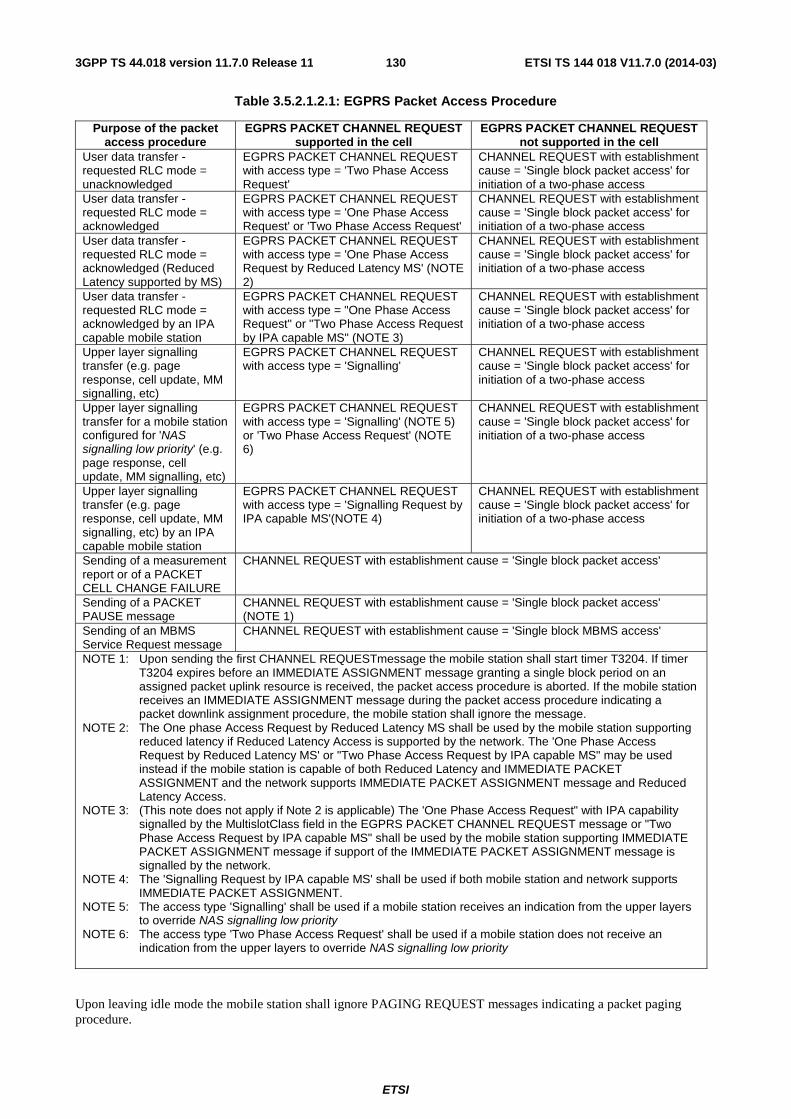
ETSI
ETSI TS 144 018 V11.7.0 (2014-03)1303GPP TS 44.018 version 11.7.0 Release 11
Table 3.5.2.1.2.1: EGPRS Packet Access Procedure
Purpose of the packet access procedure
EGPRS PACKET CHANNEL REQUEST supported in the cell
EGPRS PACKET CHANNEL REQUEST not supported in the cell
User data transfer - requested RLC mode = unacknowledged
EGPRS PACKET CHANNEL REQUEST with access type = 'Two Phase Access Request'
CHANNEL REQUEST with establishment cause = 'Single block packet access' for initiation of a two-phase access
User data transfer - requested RLC mode = acknowledged
EGPRS PACKET CHANNEL REQUEST with access type = 'One Phase Access Request' or 'Two Phase Access Request'
CHANNEL REQUEST with establishment cause = 'Single block packet access' for initiation of a two-phase access
User data transfer - requested RLC mode = acknowledged (Reduced Latency supported by MS)
EGPRS PACKET CHANNEL REQUEST with access type = 'One Phase Access Request by Reduced Latency MS' (NOTE 2)
CHANNEL REQUEST with establishment cause = 'Single block packet access' for initiation of a two-phase access
User data transfer - requested RLC mode = acknowledged by an IPA capable mobile station
EGPRS PACKET CHANNEL REQUEST with access type = "One Phase Access Request" or "Two Phase Access Request by IPA capable MS" (NOTE 3)
CHANNEL REQUEST with establishment cause = 'Single block packet access' for initiation of a two-phase access
Upper layer signalling transfer (e.g. page response, cell update, MM signalling, etc)
EGPRS PACKET CHANNEL REQUEST with access type = 'Signalling'
CHANNEL REQUEST with establishment cause = 'Single block packet access' for initiation of a two-phase access
Upper layer signalling transfer for a mobile station configured for 'NAS signalling low priority' (e.g. page response, cell update, MM signalling, etc)
EGPRS PACKET CHANNEL REQUEST with access type = 'Signalling' (NOTE 5) or 'Two Phase Access Request' (NOTE 6)
CHANNEL REQUEST with establishment cause = 'Single block packet access' for initiation of a two-phase access
Upper layer signalling transfer (e.g. page response, cell update, MM signalling, etc) by an IPA capable mobile station
EGPRS PACKET CHANNEL REQUEST with access type = 'Signalling Request by IPA capable MS'(NOTE 4)
CHANNEL REQUEST with establishment cause = 'Single block packet access' for initiation of a two-phase access
Sending of a measurement report or of a PACKET CELL CHANGE FAILURE
CHANNEL REQUEST with establishment cause = 'Single block packet access'
Sending of a PACKET PAUSE message
CHANNEL REQUEST with establishment cause = 'Single block packet access' (NOTE 1)
Sending of an MBMS Service Request message
CHANNEL REQUEST with establishment cause = 'Single block MBMS access'
NOTE 1: Upon sending the first CHANNEL REQUESTmessage the mobile station shall start timer T3204. If timer T3204 expires before an IMMEDIATE ASSIGNMENT message granting a single block period on an assigned packet uplink resource is received, the packet access procedure is aborted. If the mobile station receives an IMMEDIATE ASSIGNMENT message during the packet access procedure indicating a packet downlink assignment procedure, the mobile station shall ignore the message.
NOTE 2: The One phase Access Request by Reduced Latency MS shall be used by the mobile station supporting reduced latency if Reduced Latency Access is supported by the network. The 'One Phase Access Request by Reduced Latency MS' or "Two Phase Access Request by IPA capable MS" may be used instead if the mobile station is capable of both Reduced Latency and IMMEDIATE PACKET ASSIGNMENT and the network supports IMMEDIATE PACKET ASSIGNMENT message and Reduced Latency Access.
NOTE 3: (This note does not apply if Note 2 is applicable) The 'One Phase Access Request" with IPA capability signalled by the MultislotClass field in the EGPRS PACKET CHANNEL REQUEST message or "Two Phase Access Request by IPA capable MS" shall be used by the mobile station supporting IMMEDIATE PACKET ASSIGNMENT message if support of the IMMEDIATE PACKET ASSIGNMENT message is signalled by the network.
NOTE 4: The 'Signalling Request by IPA capable MS' shall be used if both mobile station and network supports IMMEDIATE PACKET ASSIGNMENT.
NOTE 5: The access type 'Signalling' shall be used if a mobile station receives an indication from the upper layers to override NAS signalling low priority
NOTE 6: The access type 'Two Phase Access Request' shall be used if a mobile station does not receive an indication from the upper layers to override NAS signalling low priority
Upon leaving idle mode the mobile station shall ignore PAGING REQUEST messages indicating a packet paging procedure.

ETSI
ETSI TS 144 018 V11.7.0 (2014-03)1313GPP TS 44.018 version 11.7.0 Release 11
A mobile station belonging to GPRS MS class A or B shall continue to monitor its paging subchannel on CCCH for PAGING REQUEST messages indicating an establishment of RR connection. A mobile station belonging to GPRS MS class B may abort the packet access procedure at the receipt of a PAGING REQUEST messages indicating an establishment of RR connection.
The CHANNEL REQUEST or EGPRS PACKET CHANNEL REQUEST messages are sent on RACH and contain the parameters:
- an establishment cause which indicates packet access, and as applicable, a request for one phase packet access, single block packet access or a single block MBMS access for a CHANNEL REQUEST (sub-clause 9.1.8), or a request for one phase access or two phase access or short access or sending of signalling data for an EGPRS PACKET CHANNEL REQUEST (see 3GPP TS 44.060);
- a random reference which is drawn randomly from an uniform probability distribution for every new transmission;
- a capability indication which indicates the support of IMMEDIATE PACKET ASSIGNMENT for an EGPRS PACKET CHANNEL REQUEST (see 3GPP TS 44.060).
After sending the first CHANNEL REQUEST or EGPRS PACKET CHANNEL REQUEST message, the mobile station shall start listening to the BCCH; it shall also listen to the full downlink CCCH timeslot corresponding to its CCCH group. The mobile station shall perform signal strength measurements as they are defined for packet idle mode, see 3GPP TS 45.008.
A mobile station configured for NAS signalling low priority that has initiated the packet access procedure other than when (a) it is a member of an authorized special access class or (b) for sending a Page Response or (c) it receives an indication from the upper layers to override NAS signalling low priority, and has sent one or more CHANNEL REQUEST or EGPRS PACKET CHANNEL REQUEST messages shall proceed as follows:
- If the mobile station receives an IMMEDIATE ASSIGNMENT, an IMMEDIATE ASSIGNMENT EXTENDED, an IMMEDIATE PACKET ASSIGNMENT (if supported) or an IMMEDIATE ASSIGNMENT REJECT message corresponding to one of its last 3 transmitted CHANNEL REQUEST or EGPRS PACKET CHANNEL REQUEST messages it shall act on that message as described in sub-clause 3.5.2.1.3.
- If the mobile station succesfully decodes an RR message, which is not a response corresponding to one of its last 3 transmitted CHANNEL REQUEST or EGPRS CHANNEL REQUEST messages, that indicates an implicit reject for the PS domain (see sub-clause 3.3.1.1.1a) it shall start timer T3146 (if not already running) and initiate the implicit reject procedure as described in sub-clause 3.3.1.1.3.2a.
Having sent the maximum number of CHANNEL REQUEST or EGPRS PACKET CHANNEL REQUEST messages, the mobile station starts timer T3146. At expiry of timer T3146, the packet access procedure is aborted, a random access failure is indicated to upper layers and autonomous cell re-selection is performed according to 3GPP TS 43.022.
If the mobile station receives an IMMEDIATE ASSIGNMENT or IMMEDIATE PACKET ASSIGNMENT message (if supported) during the packet access procedure indicating a packet downlink assignment procedure, the mobile station shall abort the packet access procedure and respond to the IMMEDIATE ASSIGNMENT or the IMMEDIATE PACKET ASSIGNMENT message as specified in sub-clause 3.5.3.1.2 or sub-clause 3.5.3.2. If the Packet Downlink Assignment IE in IMMEDIATE ASSIGNMENT message or IPA Downlink Assignment struct in IMMEDIATE PACKET ASSIGNMENT message indicates a downlink TBF, the mobile station shall then attempt an establishment of uplink TBF, using the procedure specified in 3GPP TS 44.060 which is applicable in packet transfer mode. If the Packet Downlink Assignment IE in IMMEDIATE ASSIGNMENT message indicates a downlink single block then the mobile station shall wait for the allocated single block and react on the received message before reattempting the uplink TBF establishment.
3.5.2.1.3 Packet immediate assignment
3.5.2.1.3.1 On receipt of a CHANNEL REQUEST or EGPRS PACKET CHANNEL REQUEST message
On receipt of a CHANNEL REQUEST message indicating a packet access, the network may allocate a temporary flow identity and assign a packet uplink resource comprising one PDCH for an uplink temporary block flow in GPRS TBF mode. On receipt of a EGPRS PACKET CHANNEL REQUEST message, the network may allocate a temporary flow
ETSI
ETSI TS 144 018 V11.7.0 (2014-03)1323GPP TS 44.018 version 11.7.0 Release 11
identity and assign a packet uplink resource comprising one PDCH for an uplink temporary block flow in EGPRS TBF mode or GPRS TBF mode.
If the establishment cause in the CHANNEL REQUEST message indicates a request for a single block packet access, the network shall grant only the single block period on the assigned packet uplink resource if the network allocates resource for the mobile station. If the establishment cause in the EGPRS PACKET CHANNEL REQUEST message indicates a request for a two phase access, the network shall grant one or two radio blocks for the mobile station (within a Multi Block allocation) to send a PACKET RESOURCE REQUEST and possibly an ADDITIONAL MS RADIO ACCESS CAPABILITIES messages on the assigned packet uplink resource if the network allocates resource for the mobile station.
If the establishment cause in the CHANNEL REQUEST message indicates a request for one phase packet access, the network may grant either a one phase packet access or a single block packet access for the mobile station. If a single block packet access is granted, it forces the mobile station to perform a two phase packet access. If the establishment cause in the EGPRS PACKET CHANNEL REQUEST message indicates a request for one phase packet access or sending signalling data, the network may grant either a one phase packet access or a two phase access (within a Multi Block allocation). If a multiple block packet access is granted, it forces the mobile station to perform a two phase packet access.
The packet uplink resource is assigned to the mobile station in an IMMEDIATE ASSIGNMENT or an IMMEDIATE PACKET ASSIGNMENT message (if supported) sent in unacknowledged mode on the same CCCH timeslot on which the network has received the CHANNEL REQUEST or the EGPRS PACKET CHANNEL REQUEST message. The network may assign packet resource to the mobile station in an IMMEDIATE PACKET ASSIGNMENT message if the received EGPRS PACKET CHANNEL REQUEST message indicates the support of this assignment message. There is no further restriction on what part of the downlink CCCH timeslot the IMMEDIATE ASSIGNMENT and IMMEDIATE PACKET ASSIGNMENT message can be sent. Timer T3141 is started on the network side.
The IMMEDIATE ASSIGNMENT message contains:
- the information field of the CHANNEL REQUEST or the EGPRS PACKET CHANNEL REQUEST message and the frame number of the frame in which the CHANNEL REQUEST or the EGPRS PACKET CHANNEL REQUEST message was received;
- the packet channel description;
- the initial timing advance;
- the packet uplink assignment or EGPRS packet uplink assignment construction.
The IMMEDIATE PACKET ASSIGNMENT message contains parameters relevant to the assignment of packet resources as specified in subclauses 3.5.2.1.3.2 and 3.5.2.1.3.3.
If frequency hopping is applied, the network may use the indirect encoding or the direct encoding of the frequency configuration in the Packet Channel Description information element in IMMEDIATE ASSIGNMENT message or in the IPA Uplink Assignment struct, IPA Downlink Assignment struct, or IPA Single Block Uplink Assignment struct in IMMEDIATE PACKET ASSIGNMENT message. If the indirect encoding is used, the mobile station uses information received in system information or stored from a previous assignment to determine the frequency parameters, see 3GPP TS 44.060. If the direct encoding is used, the mobile station uses the cell allocation defined for the cell to decode the mobile allocation.
If the indirect encoding is used, the IMMEDIATE ASSIGNMENT or IMMEDIATE PACKET ASSIGNMENT message may contain a CHANGE_MARK_1 field. If that is present, the mobile station shall verify the validity of the SI13_CHANGE_MARK associated with the GPRS mobile allocation to which the message refers, see 3GPP TS 44.060. If the CHANGE_MARK_1 field and the SI13_CHANGE_MARK do not match, the message does not satisfactorily define a PDCH.
If the mobile station receives an IMMEDIATE ASSIGNMENT message and the Dedicated mode or TBF information element indicates that this is the first message in a two-message assignment, the mobile station shall continue to listen to the full CCCH. The network may send a second IMMEDIATE ASSIGNMENT message to the mobile station within two multiframe periods following the first IMMEDIATE ASSIGNMENT message, specifying the packet channel description and, if required, a mobile allocation for the assignment. The two IMMEDIATE ASSIGNMENT messages in a two-message assignment shall have the same contents of the Request Reference information elements.
ETSI
ETSI TS 144 018 V11.7.0 (2014-03)1333GPP TS 44.018 version 11.7.0 Release 11
If the mobile station does not receive the second IMMEDIATE ASSIGNMENT messages in a two-message assignment within two multiframe periods following the first message, the mobile station shall discard the first IMMEDIATE ASSIGNMENT message received.
On receipt of an IMMEDIATE ASSIGNMENT message or, in case of a two-message assignment, a matching pair of IMMEDIATE ASSIGNMENT messages corresponding to one of its 3 last CHANNEL REQUEST or EGPRS PACKET CHANNEL REQUEST messages, the mobile station stops T3146 (if running), stops sending CHANNEL REQUEST or EGPRS PACKET CHANNEL REQUEST messages, and switches to the assigned PDCH.
The content of the packet uplink assignment construction (respectively EGPRS packet uplink assignment construction indicates which type of packet access is granted: one phase packet access or single (respectively multiple) block packet access.
3.5.2.1.3.2 One phase packet access
In the case the one phase packet access is granted, the packet uplink assignment construction contains:
- the temporary flow identity;
- the USF value
- the channel coding scheme for RLC data blocks;
- the power control parameters;
- the polling bit;
- optionally, the timing advance index (see 3GPP TS 45.010);
- optionally, the TBF starting time.
In addition, the EGPRS packet uplink assignment construction also contains:
- the EGPRS modulation and coding scheme;
- information whether retransmitted uplink data blocks shall be resegmented or not;
- the EGPRS window size to be used within the transmission; and
- optionally a request for the mobile station to send its radio access capability information.
In addition, if sent in response to a one phase access with access type indicating "One Phase Access Request by Reduced Latency MS" as defined in 3GPP TS 44.060, the EGPRS packet uplink assignment construction also allows:
- the possibility to assign an uplink EGPRS TBF on a maximum of two uplink PDCH pairs situated on consecutive or on non-consecutive timeslots for RTTI configuration;
- the inclusion of an indication if RTTI or BTTI USF mode is used;
- the inclusion of an indication of whether the SSN-based or Time-Based approach shall be used for PAN fields.
The medium access method is dynamic allocation and the RLC mode is acknowledged mode, see 3GPP TS 44.060.
If the timing advance index (TAI) is included in the packet uplink assignment construction, the mobile station shall use the continuous update timing advance mechanism, see 3GPP TS 45.010, using PTCCH in the same timeslot as the assigned PDCH. If a timing advance index (TAI) field is not included, the continuous update timing advance mechanism shall not be used.
In case the packet uplink assignment or EGPRS packet uplink assignment construction contains a TBF starting time and the mobile station receives the message before the TBF starting time has expired, it shall wait until the frame number indicated by the TBF starting time before accessing the channel. If the mobile station receives the message after the TBF starting time has expired, it shall ignore the TBF starting time and may immediately access the channel. If the medium access method is dynamic allocation, the mobile station shall start timer T3164. Regardless of which allocation mode is used, the mobile station shall proceed with the contention resolution at one phase access defined in 3GPP TS 44.060.
ETSI
ETSI TS 144 018 V11.7.0 (2014-03)1343GPP TS 44.018 version 11.7.0 Release 11
If the Polling bit is set to 1, MS shall send a PACKET CONTROL ACKNOWLEDGEMENT message (see 44.060) on the assigned PDCH, in the uplink block specified by the TBF Starting Time. In this case the TBF Starting Time is used both to indicate when the assigned PDCH becomes valid and to specify the uplink block. If the TBF Starting Time is not present or has expired, the MS shall ignore the polling request.
When the mobile station switches to the assigned PDCH, it shall take the power control parameters received in the IMMEDIATE ASSIGNMENT or the IMMEDIATE PACKET ASSIGNMENT message into account, perform signal strength measurements and apply output power control procedures as they are defined for packet transfer mode, see 3GPP TS 45.008.
In the case the one phase packet access is granted to MS supporting IMMEDIATE PACKET ASSIGNEMENT, the IPA Uplink Assignment struct sent in the IMMEDIATE PACKET ASSIGNMENT message may assign packet uplink resource for multiple mobile stations and contain following parameters specific to different mobile stations:
- the temporary flow identity;
- the USF value;
- the EGPRS channel coding command for RLC data block;
- the timing advance value;
- the Radio Access Capabilities Request bit.
In addition, the IPA Uplink Assignment struct contains the timeslot number which is common to all mobile stations addressed in this construction. Relevant default values shall be used for the RLC window size, Alpha, RESEGMENT and USF_GRANULARITY parameters as specified in subclause 10.5.2.78.
If the Radio Access Capability Request bit is set to 1, mobile stations addressed in the IPA Uplink Assignment struct in the IMMEDIATE PACKET ASSIGNMENT message shall send MS Radio Access Capability 2 IE in PACKET RESOURCE REQUEST message.
When assigning an EGPRS TBF, the network may request information about radio access capabilities of the mobile station on one or several frequency bands within the IMMEDIATE ASSIGNMENT or the IMMEDIATE PACKET ASSIGNMENT message; the list of frequency bands is ordered by the network starting with the most important and ending with the least important one. The mobile station shall provide the network with its radio access capabilities for the frequency bands it supports, in the same priority order as the one specified by the network, by sending a PACKET RESOURCE REQUEST message, and an ADDITIONAL MS RADIO ACCESS CAPABILITIES if all the requested informations do not fit in the PACKET RESOURCE REQUEST. If the mobile station does not support any frequency band requested by the network, it shall report its radio access capabilities for the BCCH frequency band. The mobile station shall indicate in the PACKET RESOURCE REQUEST if it will send more information about its radio access capabilities in the ADDITIONAL MS RADIO ACCESS CAPABILITIES message. The PACKET RESOURCE REQUEST and the ADDITIONAL MS RADIO ACCESS CAPABILITIES shall be sent within the one or two first radio blocks allocated for the mobile station on the assigned PDCH.
The network may request a retransmission of the PACKET RESOURCE REQUEST and the ADDITIONAL MS RADIO ACCESS CAPABILITIES messages. A request for retransmission of one or both of these messages shall be indicated in the PACKET UPLINK ACK/NACK message. The mobile station has to indicate within the PACKET RESOURCE REQUEST if the message is a retransmitted one.
In the case of an uplink EGPRS TBF assignment in RTTI configuration where an IMMEDIATE ASSIGNMENT message is sent in response to a one phase access with access type indicating "One Phase Access Request by Reduced Latency MS" as defined in 3GPP TS 44.060, the assigned timeslots of the uplink PDCH pair(s) and the corresponding downlink PDCH pair (as defined in 3GPP TS 44.060) associated with each assigned uplink PDCH pair are indicated by a combination of the TN given by the Packet Channel Description information element and information in the EGPRS Packet Uplink Assignment construction of the IA Rest Octets information element as described in sub-clause 10.5.2.16.
3.5.2.1.3.3 Single block packet access
In the case the single block packet access is granted, the packet uplink resource description contains:
- the power control parameter setting;
- the TBF starting time.
ETSI
ETSI TS 144 018 V11.7.0 (2014-03)1353GPP TS 44.018 version 11.7.0 Release 11
In the case the single block packet access is granted to a mobile station supporting IMMEDIATE PACKET ASSIGNMENT message, the IPA Single Block Uplink Assignment struct sent in the IMMEDIATE PACKET ASSIGNMENT message may assign one uplink block for multiple mobile stations and contains the following parameters specific to different mobile stations:
- the power control parameter setting;
- the timing advance value;
- the relative TBF starting time; and
- the frequency parameters.
In addition, the IPA Single Block Uplink Assignment struct contains the timeslot number which is common to all mobile stations addressed in this construction.
If the mobile station receives the IMMEDIATE ASSIGNMENT or IMMEDIATE PACKET ASSIGNMENT message before the TBF starting time has expired, it shall wait until the block period indicated by the TBF starting time. The network shall use the TBF starting time to indicate the first frame number belonging to the single block period granted for packet access. The mobile station may either use the assigned block period to send a PACKET RESOURCE REQUEST message to initiate the two phase packet access procedure defined in 3GPP TS 44.060, or to send an RLC/MAC control message other than the PACKET RESOURCE REQUEST message to the network, see sub-clause 3.5.2.2.
If the mobile station receives the IMMEDIATE ASSIGNMENT or IMMEDIATE PACKET ASSIGNMENT message after the TBF starting time has expired, a failure has occurred.
If a failure occurs and the packet access attempt was due to a request from upper layers to transfer a LLC PDU, a TBF establishment failure has occurred and the mobile station proceeds as specified in sub-clause 3.5.2.1.5. If a failure occurs and the packet access attempt was due to the sending of an RLC/MAC control message, the packet access is aborted, the mobile station returns to packet idle mode.
3.5.2.1.3.3a Multiblock packet access
In the case the multiblock packet access is granted, the EGPRS packet uplink assignment description contains:
- timeslot number of the allocation and the number of blocks allocated;
- the power control parameter setting;
- the TBF starting time.
When assigning a multiblock packet access, the network may request information about radio access capabilities of the mobile station on one or several frequency bands within the IMMEDIATE ASSIGNMENT message and allocate one or two radio blocks for uplink control messages accordingly ; the list of frequency bands is ordered by the network starting with the most important and ending with the least important one. The mobile station shall then provide the network with its radio access capabilities for the frequency bands it supports, in the same priority order as the one specified by the network, by sending a PACKET RESOURCE REQUEST message in the first radio block on the assigned PDCH, and an ADDITIONAL MS RADIO ACCESS CAPABILITIES immediately after the PACKET RESOURCE REQUEST message on the assigned PDCH if all the requested informations do not fit in the PACKET RESOURCE REQUEST and two radio blocks have been allocated by the network. If the mobile station does not support any frequency band requested by the network, it shall report its radio access capabilities for the BCCH frequency band in the PACKET RESOURCE REQUEST message. The mobile station shall indicate in the PACKET RESOURCE REQUEST if it will send more information about its radio access capabilities in the ADDITIONAL MS RADIO ACCESS CAPABILITIES message. If the mobile station has been allocated two radio blocks and all the requested informations fit in the PACKET RESOURCE REQUEST message, no ADDITIONAL MS RADIO ACCESS CAPABILITIES message shall be sent (see 3GPP TS 44.060). Instead, some uplink control block (e.g. packet measurement report, packet uplink dummy control block) may be sent by the mobile station.
The network may indicate in the next PACKET UPLINK ASSIGNMENT message a request for retransmission of the ADDITIONAL MS RADIO ACCESS CAPABILITIES message (see 3GPP TS 44.060).
If the mobile station receives the IMMEDIATE ASSIGNMENT message before the TBF starting time has expired, it shall wait until the block period indicated by the TBF starting time. The network shall use the TBF starting time to
ETSI
ETSI TS 144 018 V11.7.0 (2014-03)1363GPP TS 44.018 version 11.7.0 Release 11
indicate the first frame number belonging to the multi block period granted for packet access. If the mobile station receives the IMMEDIATE ASSIGNMENT message after the TBF starting time has expired, a failure has occurred.
If a failure occurs and the packet access attempt was due to a request from upper layers to transfer a LLC PDU, a TBF establishment failure has occurred and the mobile station proceeds as specified in sub-clause 3.5.2.1.5. If a failure occurs and the packet access attempt was due to the sending of an RLC/MAC control message, the packet access is aborted, the mobile station returns to packet idle mode.
3.5.2.1.3.4 Packet access rejection
The network may send to the mobile station an IMMEDIATE ASSIGNMENT REJECT message in unacknowledged mode on the same CCCH timeslot on which the channel request message was received. There is no further restriction on what part of the downlink CCCH timeslot an IMMEDIATE ASSIGNMENT REJECT message can be sent. This message contains the request reference and a wait indication.
On receipt of an IMMEDIATE ASSIGNMENT REJECT message corresponding to one of its 3 last CHANNEL REQUEST messages, the mobile station stops sending CHANNEL REQUEST messages, starts timer T3142 with the indicated value, ("wait indication" information element), starts T3146 if it has not already been started, and listens to the downlink CCCH until T3146 expires. During this time, additional IMMEDIATE ASSIGNMENT REJECT messages are ignored, but any immediate assignment corresponding to any other of its 3 last CHANNEL REQUEST messages make the mobile station follow the procedure in sub-clause 3.5.2.1.3.1. If no such immediate assignment is received, the mobile station returns to packet idle mode and notify higher layers (TBF establishment failure).
If the purpose of the packet access procedure is to send a PACKET PAUSE message and an IMMEDIATE ASSIGNMENT REJECT message is received, the packet access procedure is aborted.
If the mobile station has received responses from the network on all, or in case more than 3 were sent the last 3, of its CHANNEL REQUEST messages, it shall immediately return to packet idle mode and notify higher layers.
The mobile station is not allowed to make a new attempt for packet access in the same cell until T3142 expires, but may attempt packet access in an other cell after successful cell reselection for radio conditions reasons (see 3GPP TS 45.008). The value of the wait indication (i.e. T3142) relates to the cell from which it was received.
The mobile station may initiate RR connection establishment in the same cell before T3142 has expired, see sub-clause 3.3.1.1.3.2.
3.5.2.1.4 Packet access completion
The one phase packet access procedure is completed at a successful contention resolution. The mobile station has entered the packet transfer mode. Timer T3141 is stopped on the network side. Timer T3164 is stopped on the mobile station side.
3.5.2.1.5 Abnormal cases
If a failure occurs on the mobile station side before a successful contention resolution procedure is completed, the allocated temporary block flow is released; the mobile station returns to packet idle mode, upper layers are notified (TBF establishment failure), transactions in progress are aborted:
- If a TLLI mismatch has occurred during the contention resolution procedure, and the repetition of the packet access has been repeated the maximum number of times as defined in 3GPP TS 44.060, a TBF establishment failure has occurred.
- If the information available in the mobile station, after the reception of an IMMEDIATE ASSIGNMENT or IMMEDIATE PACKET ASSIGNMENT message or the second IMMEDIATE ASSIGNMENT message of a two-message assignment, does not satisfactorily define a PDCH, a TBF establishment failure has occurred.
- If the mobile allocation indexes frequencies in more than one frequency band then a TBF establishment failure has occurred.
- If an IMMEDIATE ASSIGNMENT or IMMEDIATE PACKET ASSIGNMENT message indicates a PDCH in a non-supported frequency band then a TBF establishment failure has occurred.
On the network side, if timer T3141 elapses before a successful contention resolution procedure is completed, the newly allocated temporary block flow is released as specified in 3GPP TS 44.060 and the packet access is forgotten.

ETSI
ETSI TS 144 018 V11.7.0 (2014-03)1373GPP TS 44.018 version 11.7.0 Release 11
3.5.2.2 Sending an RLC/MAC control message: single block packet access procedure
The sending of an RLC/MAC control message other than the PACKET RESOURCE REQUEST message from a mobile station in packet idle mode to the network may be initiated by the RR entity on the mobile station side using the packet access procedure. If access to the network is allowed (sub-clause 3.5.2.1.1), the packet access is done according to the procedures defined in sub-clauses 3.5.2.1.2 and 3.5.2.1.3, using the single block packet access option defined in sub-clause 3.5.2.1.3.3.
Further action depends on the RLC/MAC control message sent by the mobile station, see 3GPP TS 44.060. Unless otherwise indicated by the RLC/MAC control message, the mobile station remains in packet idle mode.
3.5.3 Packet downlink assignment procedure using CCCH
The packet downlink assignment procedure using CCCH may be used to establish a temporary block flow to support the transfer of LLC PDUs in the direction from the network to the mobile station.
This procedure may also be used to assign a single downlink block on a PDCH to support the transfer of an RLC/MAC control message from the network to a mobile station in packet idle mode, see sub-clause 3.5.3.2.
3.5.3.1 Entering the packet transfer mode: packet downlink assignment procedure
The establishment of a downlink temporary block flow may be initiated by the RR entity on the network side using the packet downlink assignment procedure. The procedure is triggered by a request from upper layers to transfer a LLC PDU, see 3GPP TS 24.007. The request from upper layers specifies an optional Priority level, a QoS profile including the requested RLC mode, optional DRX parameters, and optional IMSI and an optional MS Radio Access Capability associated with the packet transfer. The BSS may order its preferred RLC mode independently of the RLC mode signalled from upper layers. If the mobile station supports RLC non-persistent mode the network may allocate an EGPRS TBF that uses this RLC mode.
Upon such a request, the network shall determine whether the mobile station is in packet idle mode or packet transfer mode. The packet downlink assignment procedure using CCCH is applicable when the mobile station is in packet idle mode and when there is no PCCCH present in the cell.
The network may allocate a temporary flow identity and assign a packet downlink resource comprising one PDCH for a downlink temporary block flow.
3.5.3.1.2 Initiation of the packet downlink assignment procedure
The network initiates the packet downlink assignment procedure by sending an IMMEDIATE ASSIGNMENT or IMMEDIATE PACKET ASSIGNMENT message (if supported) in unacknowledged mode on the CCCH timeslot corresponding to CCCH group the mobile station belongs to appropriate CCCH group is calculated from the IMSI, see 3GPP TS 45.002. The behaviour of the network when the RR entity does not receive the IMSI from the upper layers is implementation dependent for the calculation of the CCCH group where the IMMEDIATE ASSIGNMENT or IMMEDIATE PACKET ASSIGNMENT message has to be sent. If the mobile station is in non-DRX mode or if the RR entity does not receive the IMSI or the DRX parameters from the upper layers, there is no further restriction on what part of the downlink CCCH timeslot the IMMEDIATE ASSIGNMENT, or IMMEDIATE PACKET ASSIGNMENT message, or the first part of the IMMEDIATE ASSIGNMENT message (in the case of a two-message assignment), can be sent. If the mobile station applies DRX, the IMMEDIATE ASSIGNMENT, or IMMEDIATE PACKET ASSIGNMENT message , or the first part of the IMMEDIATE ASSIGNMENT message (in the case of a two-message assignment), shall be sent in a CCCH block corresponding to a paging group determined for the mobile station in packet idle mode, see 3GPP TS 45.002.
The IMMEDIATE ASSIGNMENT message contains:
- the packet channel description;
- the initial timing advance;
- the packet downlink assignment construction.
ETSI
ETSI TS 144 018 V11.7.0 (2014-03)1383GPP TS 44.018 version 11.7.0 Release 11
The contents of the packet downlink assignment construction determines the further action. At the establishment of a downlink temporary block flow, the packet downlink assignment construction shall contain:
- the TLLI;
- the temporary flow identity;
- the RLC mode;
- the power control parameters;
- the polling bit;
- the initial timing advance validity flag;
- optionally, EGPRS Window Size (see 3GPP TS 44.060) and Link Quality Measurement Mode (see 3GPP TS 44.060);
- optionally, the timing advance index (see 3GPP TS 45.010);
- optionally, the TBF starting time;
- optionally, the NPM Transfer Time (see 3GPP TS 44.060);
- optionally, the Event-Based FANR indication (see 3GPP TS 44.060);
- optionally, the TTI Configuration (see 3GPP TS 44.060).
At the establishment of a downlink temporary block flow for MS supporting IMMEDIATE PACKET ASSIGNMENT message, the IPA Downlink Assignment struct sent in IMMEDIATE PACKET ASSIGNMENT message may assign packet downlink resources for multiple mobile stations and contains the following parameters specific to different mobile stations:
- the TLLI;
- the temporary flow identity;
- the power control parameters;
- optionally, the timing advance value.
In addition, the IPA Downlink Assignment struct also contains the following parameters which are common to all mobile stations addressed in this structure:
- the timeslot number;
- optionally the link quality measurement mode;
- the RLC mode;
- the frequency parameters;
Relevant default values shall be used for the RLC window size and Alpha parameters as specified in in subclause 10.5.2.78.
If frequency hopping is applied, the network may use the indirect encoding or the direct encoding of the frequency configuration in the Packet Channel Description information element in IMMEDIATE ASSIGNMENT message or in IPA Downlink Assignment struct in IMMEDIATE PACKET ASSIGNMENT message. If the indirect encoding is used, the mobile station uses information received in system information or stored from a previous assignment to determine the frequency parameters, see 3GPP TS 44.060. If the direct encoding is used, the mobile station uses the cell allocation defined for the cell to decode the mobile allocation.
If the indirect encoding is used, the IMMEDIATE ASSIGNMENT or the IMMEDIATE PACKET ASSIGNMENT message may contain a CHANGE_MARK_1 field. If that is present, the mobile station shall verify the validity of the SI change mark associated with the GPRS mobile allocation to which the message refers, see 3GPP TS 44.060. If the CHANGE_MARK_1 field and the SI change mark do not match, the message does not satisfactorily define a PDCH.
ETSI
ETSI TS 144 018 V11.7.0 (2014-03)1393GPP TS 44.018 version 11.7.0 Release 11
If the mobile station receives an IMMEDIATE ASSIGNMENT message and the Dedicated mode or TBF information element indicates that this is the first message in a two-message assignment, the mobile station shall start listen to the full CCCH. The network may send a second IMMEDIATE ASSIGNMENT message to the mobile station within two multiframe periods following the first IMMEDIATE ASSIGNMENT message, specifying the packet channel description and, if required, a mobile allocation for the assignment. The two IMMEDIATE ASSIGNMENT messages in a two-message assignment shall have the same contents of the Request Reference information elements.
If the mobile station was operating in DRX mode when it received the first message of a two-message assignment, the network shall not send the second IMMEDIATE ASSIGNMENT message within the two block periods immediately following the first message.
If the mobile station does not receive the second IMMEDIATE ASSIGNMENT messages in a two-message assignment within two multiframe periods following the first message, the mobile station shall discard the first IMMEDIATE ASSIGNMENT message received. After the two multiframe periods following the first message, the mobile station may resume to DRX mode.
On receipt of an IMMEDIATE ASSIGNMENT or IMMEDIATE PACKET ASSIGNMENT message or, in case of a two-message assignment, a matching pair of IMMEDIATE ASSIGNMENT messages, the mobile station stops monitoring downlink CCCH and switches to the assigned PDCH and starts listening for downlink RLC/MAC blocks identified by the assigned TFI; it starts timer T3190.
The IMMEDIATE ASSIGNMENT message may indicate a TBF starting time. If the mobile station receives the message before the TBF starting time has expired, it shall wait until the frame number indicated by the TBF starting time, start timer T3190 and switch to the assigned PDCH. If the mobile station receives the message after the TBF starting time has expired, it shall ignore the indicated TBF starting time, immediately start timer T3190 and switch to the assigned PDCH.
When the mobile station switches to the assigned PDCH, it shall take the power control parameters received in the IMMEDIATE ASSIGNMENT or the IMMEDIATE PACKET ASSIGNMENT message into account, perform signal strength measurements and apply output power control procedures as they are defined for packet transfer mode, see 3GPP TS 45.008.
If the Polling bit is set to 1, MS shall send a PACKET CONTROL ACKNOWLEDGEMENT message (see 44.060) on the assigned PDCH, in the uplink block specified by the TBF Starting Time. In this case the TBF Starting Time is used both to indicate when the assigned PDCH becomes valid and to specify the uplink block. If the TBF Starting Time is not present or has expired, the MS shall ignore the polling request.
An IMMEDIATE ASSIGNMENT message may indicate a timing advance index (TAI) in the packet timing advance IE. The mobile station shall then use the continuous update timing advance mechanism, see 3GPP TS 45.010, using PTCCH in the same timeslot as the assigned PDCH. If there is no indication of a timing advance index, the continuous update timing advance mechanism shall not be used.
The TA_VALID flag indicates if the value of the Timing Advance IE is valid or not.
If the network does not have a valid timing advance value for the mobile station to include in the IMMEDIATE ASSIGNMENT or the IMMEDIATE PACKET ASSIGNMENT message, the network shall use the procedures defined in 3GPP TS 44.060 on the assigned TBF, or the polling mechanism defined in the above paragraph if the PACKET CONTROL ACKNOWLEDGEMENT format is set to four access bursts, to obtain a timing advance value and to update the initially assigned timing advance value before the mobile station is required to transmit other than access burst on the newly assigned channel.
The packet downlink construction may optionally contain the EGPRS Window Size (see 3GPP TS 44.060) and Link Quality Measurement Mode (see 3GPP TS 44.060). The presence of these fields indicates EGPRS TBF mode (see 3GPP TS 44.060). If these fields are not present, this indicates GPRS TBF mode.
3.5.3.1.3 Packet downlink assignment completion
After having sent the packet downlink assignment, the network starts sending downlink RLC/MAC blocks on the assigned packet downlink resource and the packet downlink assignment procedure is completed at the network side.
On the mobile station side, the procedure is completed when the mobile station receives an RLC/MAC block identified by the assigned temporary flow identity. The mobile station stops timer T3190. The mobile station has entered packet transfer mode.

ETSI
ETSI TS 144 018 V11.7.0 (2014-03)1403GPP TS 44.018 version 11.7.0 Release 11
3.5.3.1.4 Abnormal cases
If a failure occurs on the mobile station side before the packet downlink assignment procedure is completed (TBF establishment failure), the temporary block flow is released; the mobile station returns to packet idle mode:
- If the mobile station does not receive a RLC/MAC block on the assigned PDCHs before timer T3190 expires, then a TBF establishment failure has occurred.
- If the information available in the mobile station, after the reception of an IMMEDIATE ASSIGNMENT or IMMEDIATE PACKET ASSIGNMENT message or the second IMMEDIATE ASSIGNMENT message of a two-message assignment, does not satisfactorily define a PDCH, then a TBF establishment failure has occurred.
- If the mobile allocation in the frequency parameters indexes frequencies in more than one frequency band, then a TBF establishment failure has occurred.
If an IMMEDIATE ASSIGNMENT or IMMEDIATE PACKET ASSIGNMENTmessage indicates a PDCH in a non-supported frequency band, then a TBF establishment failure has occurred.
3.5.3.2 Sending an RLC/MAC control message: single block packet downlink assignment procedure
The sending of an RLC/MAC control message to a mobile station in packet idle mode may be initiated by the RR entity on network side using the packet downlink assignment procedure. The procedure is used to assign a single downlink block on a PDCH for the transfer of the RLC/MAC control message. Using this procedure, the network shall not apply segmentation of the RLC/MAC control message.
The single downlink block assignment is done according to the procedure defined in sub-clause 3.5.3.1.2, with the following exceptions:
The packet downlink assignment construction in the IMMEDIATE ASSIGNMENT message shall contain only:
- the TLLI; and
- the TBF starting time.
If the mobile station receives the IMMEDIATE ASSIGNMENT message before the TBF starting time has expired, it shall wait until the frame number indicated by the TBF starting time. The network shall use the TBF starting time to indicate the first frame number belonging to the single block period assigned to the mobile station. The mobile station shall switch to the assigned PDCH and attempt to decode an RLC/MAC control message in the assigned downlink block. Further action depends on the RLC/MAC control message sent by the network, see 3GPP TS 44.060. Unless otherwise indicated by the RLC/MAC control message, the mobile station remains in packet idle mode. If the mobile station remains in packet idle mode, it shall continue to monitor downlink CCCH once the block period indicated by the TBF starting time has passed.
If the mobile station fails to decode or does not receive an RLC/MAC control message in the assigned downlink block, it shall remain in packet idle mode and continue to monitor downlink CCCH once the block period indicated by the TBF starting time has passed.
If the mobile station receives the IMMEDIATE ASSIGNMENT message after the TBF starting time has expired, it shall ignore the assignment.
If a failure occurs on the mobile station side due to any other reason, the mobile station shall ignore the assignment.
3.5.3.2a Sending an RLC/MAC control message: multiple blocks packet downlink assignment procedure
The sending of an RLC/MAC control message to a mobile station in packet idle mode may be initiated by the RR entity on network side using the packet downlink assignment procedure. The procedure is used to assign multiple downlink blocks on a PDCH for the transfer of the RLC/MAC control message. Using this procedure, the network may apply segmentation of the RLC/MAC control message.
The multiple downlink blocks assignment is done according to the procedure defined in sub-clause 3.5.3.1.2, with the following exceptions:
ETSI
ETSI TS 144 018 V11.7.0 (2014-03)1413GPP TS 44.018 version 11.7.0 Release 11
The multiple blocks packet downlink assignment construction in the IMMEDIATE ASSIGNMENT message shall contain only:
- the TBF starting time;
- the number of allocated blocks;
- optionally, the TMGI;
- optionally, the MBMS session identity;
- optionally, the TLLI / G-RNTI;
- optionally, the MS_ID and packet timing advance parameters.
If the message contains the TLLI / G-RNTI not addressing the mobile station, the message shall be ignored.
If the mobile station receives the IMMEDIATE ASSIGNMENT message before the TBF starting time has expired, it shall wait until the frame number indicated by the TBF starting time. The network shall use the TBF starting time to indicate the first frame number belonging to the multiple block period assigned to the mobile station. The mobile station shall switch to the assigned PDCH and attempt to decode an RLC/MAC control message in the assigned downlink block(s). Further action depends on the RLC/MAC control message sent by the network, see 3GPP TS 44.060. Unless otherwise indicated by the RLC/MAC control message, the mobile station remains in packet idle mode. If the mobile station remains in packet idle mode, it shall continue to monitor downlink CCCH.
If the mobile station fails to decode or does not receive an RLC/MAC control message in the assigned downlink block(s), it shall remain in packet idle mode and continue to monitor downlink CCCH.
If the mobile station receives the IMMEDIATE ASSIGNMENT message after the TBF starting time has expired, it shall ignore the assignment.
If a failure occurs on the mobile station side due to any other reason, the mobile station shall ignore the assignment.
3.5.4 MBMS packet access procedure using CCCH
3.5.4.1 General
If access to the network is allowed (sub-clause 3.5.2.1.1), the MBMS packet access is done according to the procedures defined in sub-clauses 3.5.2.1.2 and 3.5.2.1.3, using the single block MBMS access option.
The initiation of the MBMS packet access procedure is defined in 3GPP TS 44.060.
A mobile station shall continue to monitor its paging subchannel on CCCH for PAGING REQUEST messages indicating an establishment of RR connection or a packet paging procedure during the MBMS packet access procedure. A mobile station shall abort the MBMS packet access procedure at the receipt of a PAGING REQUEST message indicating an establishment of RR connection or a packet paging procedure.
3.5.4.2 On receipt of a CHANNEL REQUEST message
On receipt of a CHANNEL REQUEST message with access type indicating "Single block MBMS access", the network shall grant only the single block period on the assigned packet uplink resource if the network allocates resource for the mobile station.
The packet uplink resource is assigned to the mobile station in an IMMEDIATE ASSIGNMENT message sent in unacknowledged mode on the same CCCH timeslot on which the network has received the CHANNEL REQUEST message. The packet uplink resource description shall contain:
- the power control parameter setting;
- the TBF starting time.
ETSI
ETSI TS 144 018 V11.7.0 (2014-03)1423GPP TS 44.018 version 11.7.0 Release 11
If uplink resources are not available, the network may reject the access request by sending a IMMEDIATE ASSIGNMENT REJECT message (see sub-clause 3.5.4.4).
3.5.4.3 On receipt of an IMMEDIATE ASSIGNMENT message
If the mobile station receives the IMMEDIATE ASSIGNMENT message or, in case of a two-message assignment, a matching pair of IMMEDIATE ASSIGNMENT messages corresponding to one of its 3 last CHANNEL REQUEST messages, before the TBF starting time has expired, the mobile station shall wait until the block period indicated by the TBF starting time. The network shall use the TBF starting time to indicate the first frame number belonging to the single block period granted for packet access. The mobile station may use the assigned block period to send an MBMS SERVICE REQUEST message, as defined in 3GPP TS 44.060.
If the mobile station receives the IMMEDIATE ASSIGNMENT message after the TBF starting time has expired, a failure has occurred and the mobile station proceeds as specified in sub-clause 3.5.4.6.
While timer T3214 is running the mobile shall accept reception of repeated IMMEDIATE ASSIGNMENT messages, on the same CCCH timeslot on which the mobile station has sent the CHANNEL REQUEST message, and re-send the MBMS SERVICE REQUEST message, as defined in 3GPP TS 44.060.
3.5.4.4 On receipt of an IMMEDIATE ASSIGNMENT REJECT message
The network may send an IMMEDIATE ASSIGNMENT REJECT message to the mobile station in response to the CHANNEL REQUEST message. The mobile station shall then react according to the description in sub-clause 3.3.1.1.3.2.
3.5.4.5 On receipt of an MBMS ASSIGNMENT message
The MBMS assignment procedure using CCCH may be used in order to assign the radio bearer resources for an MBMS session in the cell or to notify the mobile station(s) that a radio bearer for that MBMS session is not established in the cell.
The assignment for the MBMS session is done by using the multiple blocks packet downlink assignment procedure (non-distribution or distribution MBMS assignment) as specified in the sub-clause 3.5.3.2a.
When the mobile station receives an MBMS ASSIGNMENT message for an MBMS session, it shall stop any ongoing packet access procedure for that MBMS session and proceed as defined in 3GPP TS 44.060.
3.5.4.6 Abnormal cases
If the mobile station receives an IMMEDIATE ASSIGNMENT message that contains faulty parameters, the mobile station shall abort the MBMS access procedure.
3.6 RR Procedures in packet transfer mode
3.6.1 RR Connection establishment using enhanced DTM CS establishment
The initiation of the procedure and the assignment of resources for the establishment of the RR connection are described in 3GPP TS 44.060.
In respect of the establishment of the RR connection, the mobile station shall act on the starting time information element, if present in an IMMEDIATE ASSIGNMENT message, as specified in sub-clause 3.3.1.1.3.1.
The establishment of the main signalling link is described in sub-clause 3.1.5. In the case of a network initiated establishment (i.e. not following the sending of a PACKET CS REQUEST message), the layer 2 SABM frame shall contain a PAGING RESPONSE message. Otherwise (i.e. the mobile station has sent a PACKET CS REQUEST message), an appropriate layer 3 service request message shall be sent in the layer 2 SABM frame.
The completion of the establishment of the RR connection is described in sub-clause 3.6.2.
ETSI
ETSI TS 144 018 V11.7.0 (2014-03)1433GPP TS 44.018 version 11.7.0 Release 11
3.6.2 Completion of RR Connection establishment
3.6.2.1 Connection established in response to an encapsulated IMMEDIATE ASSIGNMENT message
The RR connection establishment procedure is terminated on the network side when the main signalling link is established. Timer T3101 is stopped, the MM sublayer on the network side is informed that the RR entity has entered the dedicated mode and the network may release the old packet resources.
On the mobile station side, the procedure is terminated when the establishment of the main signalling link is confirmed. The MM sublayer is informed that the RR entity has entered the dedicated mode.
3.6.2.2 Connection established in response to an encapsulated DTM ASSIGNMENT COMMAND message
For the handling of the packet resources upon reception of the encapsulated DTM ASSIGNMENT COMMAND message the sub-clauses 3.4.23.2.2 and 3.4.23.2.3 are applicable.
The RR connection establishment procedure is terminated on the network side when the main signalling link is established. Timer T3107 is stopped, the MM sublayer on the network side is informed that the RR entity has entered the dual transfer mode, and the network may release the old packet resources.
On the mobile station side, the procedure is terminated when the establishment of the main signalling link is confirmed. The MM sublayer is informed that the RR entity has entered the dual transfer mode.
3.7 DTM Handover procedure
3.7.1 General
In dual transfer mode an intercell change of dedicated and packet data channel(s) can be requested by the network RR sublayer. This change may be performed using the DTM handover procedure.
This procedure is optional and is only applicable in dual transfer mode when both the mobile station and the network support DTM handover. The mobile station shall indicate its support for DTM handover in the Mobile Station Classmark 3 IE and the MS Radio Access Capability IE. The purpose of the procedure is to handover the dedicated channel and one or more of the packet resources while in dual transfer mode when a cell is changed. The DTM handover procedure is a combination of the handover procedure for circuit switched handover, defined in sub-clause 3.4.4, and the procedure for packet switched handover, defined in 3GPP TS 44.060.
NOTE: The decision to initiate a DTM handover and the choice of the new cell is out of the scope of this technical specification.
The DTM handover procedure is always initiated by the network.
3.7.2 DTM Handover from GERAN A/Gb mode to GERAN A/Gb mode procedure
The DTM handover procedure includes:
- The suspension of normal operation except for RR management (layer 3).
- The disconnection of the main signalling link, and of the other links via local end release (layer 2), and the disconnection of the TCH.
- The mobile station suspension of the packet resources used in the old cell (see 3GPP TS 44.060) until the MS determines the DTM handover procedure to be successfully completed at which point these packet resources are released.
ETSI
ETSI TS 144 018 V11.7.0 (2014-03)1443GPP TS 44.018 version 11.7.0 Release 11
- The mobile station disconnection and deactivation of the dedicated channel used in the old cell (see 3GPP TS 44.018) until the MS determines the DTM handover procedure to be successfully completed at which point the dedicated channel is released (at layer 1).
- The activation of the new channels, and their connection if applicable.
- The triggering of the establishment of data link connection for SAPI = 0 on the new channels.
- The activation of the new PDCH(s) and the resumption of the packet resources (see 3GPP TS 44.060).
For the circuit switched domain the requirements and procedures listed in sub-clauses 3.4.4.1, 3.4.4.2 and 3.4.4.3 are valid with the following exceptions:
- Handover of VGCS is not supported by the DTM handover procedure.
- MBMS service information sending completion is not supported by the DTM handover procedure.
- The DTM HANDOVER COMMAND message applies instead of the HANDOVER COMMAND message and is sent on the PACCH (see 3GPP TS 44.060).
- Sending of DTM Information is not needed.
For the packet switched domain the requirements and procedures described for PS handover in 3GPP TS 44.060 are valid with the following exceptions:
- The synchronisation of the physical channels is not performed in the PS domain, i.e. the mobile station shall not send the PS HANDOVER ACCESS message.
- The target BSS considers the DTM handover procedure to be successfully completed upon receiving a HANDOVER COMPLETE message on the main DCCH according to sub-clause 3.4.4.3.
- Timer T3216 shall not be started for DTM handover.
- The DTM HANDOVER COMMAND message applies instead of the PS HANDOVER COMMAND message.
3.7.2.1 Abnormal cases
The failure cases and actions defined in sub-clause 3.4.4.4, shall apply for DTM handover from GERAN A/Gb mode to GERAN A/Gb mode with the following exceptions:
- The DTM HANDOVER COMMAND message applies instead of the HANDOVER COMMAND message and is sent on the PACCH.
In addition, a mobile station operating in A/Gb mode shall consider the DTM handover to A/Gb mode to have failed if the DTM HANDOVER COMMAND message:
a) violates the mobile station"s DTM multislot capabilities; or
b) does not include at least one uplink TBF; or
c) provides one or more downlink TBFs with PFIs that are different from those currently allocated; or
d) provides one or more uplink TBFs with PFIs that are different from those currently allocated except when there are no ongoing uplink TBFs in which case a single uplink TBF with a PFI that indicates signalling shall be allocated.
If these additional error cases occur, the mobile station shall remain in DTM in the old cell and return a HANDOVER FAILURE message on the current main DCCH with the PS Cause IE set as follows:
- in case a) above, "DTM multislot capabilities violated"; or
- in case b) above, "No uplink TBF"; or
- in case c) above, "Too many TBFs"; or
- in case d) above, "Too many TBFs".
ETSI
ETSI TS 144 018 V11.7.0 (2014-03)1453GPP TS 44.018 version 11.7.0 Release 11
If there are no errors in the DTM HANDOVER COMMAND message related to the CS domain and there are no common errors then the RR Cause IE shall indicate "Normal Event". Any error that is common to both the CS domain and the PS domain shall be reported in the RR Cause IE.
The transmission of a HANDOVER FAILURE message terminates the DTM handover procedure in the mobile station.
After terminating the DTM handover procedure the mobile station shall resume all uplink and downlink TBFs that were ongoing in the old cell prior to receiving the DTM HANDOVER COMMAND message and for which T3180 (uplink TBFs) and T3190 (downlink TBFs) are still running (see 3GPP TS 44.060).
For each TBF that is resumed the corresponding RLC state machine shall reflect its state when the last RLC data block was transmitted for that TBF in the old cell (uplink TBFs) and the last RLC data block was received for that TBF in the old cell (downlink TBFs) (see 3GPP TS 44.060).
3.7.3 DTM Handover from GERAN A/Gb mode to UTRAN procedure
For the successful case of DTM Handover from GERAN A/Gb mode to UTRAN, the behaviour of the MS in the old cell is as specified for DTM Handover from GERAN A/Gb mode to GERAN A/Gb mode (see sub-clause 3.7.2). The behaviour of the MS in the new cell is as specified for Inter-RAT Handover to UTRAN in 3GPP TS 25.331. The behaviour of the old BSS is as specified in sub-clause 3.7.2.
The definition of abnormal cases for the mobile is specified in 3GPP TS 25.331. If the UE/MS receives a HANDOVER TO UTRAN COMMAND message, which contains a protocol error causing the variable PROTOCOL_ERROR_REJECT to be set to TRUE (see 3GPP TS 25.331), the MS sends a HANDOVER FAILURE message on the main DCCH to the old cell. The appropriate cause shall be included (see sub-clause 3.4.4a.3).
The definition of abnormal cases for the old BSS and the behaviour of the old BSS in such cases (including on receipt of a HANDOVER FAILURE) is as specified in sub-clause 3.7.2.1.
3.8 Network sharing
3.8.1 General
A network supporting network sharing (see sub-clause 3.8.2):
- shall broadcast network sharing information indicating the core network operators sharing the Radio Access Network;
- shall configure the contents of the SYSTEM INFORMATION TYPE 5/5bis/5ter and SYSTEM INFORMATION TYPE 6 messages to indicate the selected PLMN when the mobile station supports network sharing;
- may broadcast domain-specific access control information. Only networks and mobile stations supporting network sharing may support domain-specific access control.
- may broadcast when applicable PLMN-specific UTRAN and/or E-UTRAN information for inter-RAT cell re-selection.
A mobile station supporting network sharing shall use this information for PLMN (re)selection, cell reselection, E-UTRAN measurement reporting and to determine whether or not access to the network is allowed, possibly on a domain (CS or PS) basis.
NOTE: In a network supporting network sharing, a mobile station not supporting network sharing may reselect cells of other RATs not belonging to an equivalent PLMN of the registered PLMN. Setting different priorities for frequencies belonging to different PLMNs but in the same RAT may favour one PLMN over the other in areas shared by these PLMNs.
3.8.2 Network side
A cell where network sharing is supported shall broadcast the SYSTEM INFORMATION TYPE 22 message in which it shall indicate:
ETSI
ETSI TS 144 018 V11.7.0 (2014-03)1463GPP TS 44.018 version 11.7.0 Release 11
- whether or not mobile stations supporting network sharing are allowed to select the Common PLMN; and
- the PLMN ID (MCC and MNC) of up to four Additional PLMNs; and
- the permitted NCCs for cell (re)selection and measurement reporting corresponding to each of the up to four Additional PLMNs.
Additionally and individually for each of the up to four Additional PLMNs SYSTEM INFORMATION TYPE 22 may indicate the applicable access control information to be used for accessing the network (see sub-clauses 3.3.1.1.1, 3.5.2.1.1.).
The network may also indicate in the SYSTEM INFORMATION TYPE 21 message access control information for EAB used for the preliminary access barring check (see sub-clause 3.3.1.4) individually for each of the up to four Additional PLMNs.
If domain-specific access control is used for a PLMN (Common PLMN and/or any of the up to four Additional PLMNs), the network shall include the corresponding information in the SYSTEM INFORMATION TYPE 22 message and SYSTEM INFORMATION TYPE 21 message as applicable.
The network may include PLMN-specific UTRAN and/or E-UTRAN information for inter-RAT cell re-selection purpose in the SYSTEM INFORMATION TYPE 23 message. When the SYSTEM INFORMATION TYPE 23 message is broadcast, the network shall broadcast the UTRAN and/or E-UTRAN information for inter-RAT cell re-selection related to a given PLMN in consecutive instances of the SYSTEM INFORMATION TYPE 23 message.
NOTE: So as to take into account the monitoring capabilities (see 3GPP TS 45.008) of mobile stations not supporting network sharing, the network may provide updates of the UTRAN/E-UTRAN frequencies lists broadcast within the SI2ter/SI2quater messages that are not applicable to mobile stations supporting network sharing (see sub-clause 3.8.3).
The network shall use the PLMN index provided by a mobile station supporting network sharing (see sub-clause 3.8.3) to map it upon the list of PLMN IDs it broadcasts in order to derive the PLMN selected by the mobile station and to route the initial access to the appropriate CN node (see subclause 10.3.1 and 3GPP TS 48.008 for the CS domain, see 3GPP TS 48.018 for the PS domain). The network shall indicate the selected PLMN when configuring the neighbour cell information included in the SYSTEM INFORMATION TYPE 5/5bis/5ter messages for a mobile station supporting network sharing.
The network shall indicate the selected PLMN ID when configuring the Location Area Identification IE included in the SYSTEM INFORMATION TYPE 6 message for a mobile station supporting network sharing. Otherwise, it shall configure the Location Area Identification IE to indicate the common PLMN.
3.8.3 Mobile station side
A mobile station supporting network sharing shall read the SYSTEM INFORMATION TYPE 22 message if broadcast in the cell and acquire the Network Sharing Information.
The mobile station shall use this information to determine the PLMNs available in this cell for (re)selection, the applicable access control information for the selected PLMN and the allowed NCC for measurement reporting and cell reselection (see 3GPP TS 45.008, 3GPP TS 23.003) for the selected PLMN.
The mobile station shall consider the Common PLMN (only if the Common PLMN is indicated as allowed in the SYSTEM INFORMATION TYPE 22 message) and each indicated Additional PLMN in its PLMN selection process as specified in 3GPP TS 23.122.
Once a PLMN is selected, the mobile station shall only use the information applicable to this PLMN (i.e. PLMN ID, access control information, NCC Permitted) within the serving cell, until it is either modified, becomes invalid or a different PLMN or a new cell is reselected, whichever occurs first. If the applicable information is made invalid in the cell (see sub-clause 3.2.1), the mobile station shall assume network sharing is not used in the cell until it can again determine that network sharing is used.
For the mobile station, "applicable to this PLMN" shall be understood as meaning either "explicitly broadcast within SYSTEM INFORMATION messages for this PLMN" or "derived by the mobile station using a field explicitly provided by SYSTEM INFORMATION messages for a PLMN listed previous to its selected PLMN"; using a "previously listed field" means the mobile station attempts to find a PLMN previous to its selected PLMN for which a

ETSI
ETSI TS 144 018 V11.7.0 (2014-03)1473GPP TS 44.018 version 11.7.0 Release 11
field of interest is explicitly provided by SYSTEM INFORMATION messages. The Annex M provides examples of using a "previously listed field".
A UTRAN and/or E-UTRAN capable mobile station supporting network sharing shall also read the SYSTEM INFORMATION TYPE 23 message if broadcast in the cell, to acquire PLMN-specific UTRAN and/or E-UTRAN information used for inter-RAT cell re-selection.
If so indicated by the SI_CHANGE_ALT field provided in the SYSTEM INFORMATION TYPE 13 message (see sub-clause 10.5.2.37b), a UTRAN and/or E-UTRAN capable mobile station supporting network sharing shall ignore any change in system information signalled by a SI_CHANGE_FIELD value '2' provided in the same message.
When accessing the network, the mobile station shall indicate the selected PLMN index as follows:
- For access to CS domain via Initial Layer 3 message (see 3GPP TS 24.008 and sub-clause 10.3.1).
- For access to PS domain via AS signalling (see 3GPP TS 44.060).
3.8.4 Abnormal cases
The mobile station shall ignore any information provided for an Additional PLMN in the SYSTEM INFORMATION TYPE 22 message if this Additional PLMN is the same as the Common PLMN.
If the same Additional PLMN ID is provided more than once in the SYSTEM INFORMATION TYPE 22 message, the mobile station shall use the information corresponding to the first instance of that Additional PLMN.
If the number of Additional PLMNs broadcast in the SYSTEM INFORMATION TYPE 21 message as part of the EAB Network Sharing Information (see sub-clause 10.5.2.37m) differs from the number of Additional PLMNs broadcast in the SYSTEM INFORMATION TYPE 22 message as part of the Network Sharing Information (see sub-clause 10.5.2.37n) a mobile station supporting network sharing and configured for EAB shall ignore the EAB Network Sharing Information in the SYSTEM INFORMATION TYPE 21 message and assume the EAB Authorization Mask and EAB Subcategory information otherwise included in this message applies to all PLMNs in this cell (i.e. Common PLMN and all Additional PLMNs).
If the SYSTEM INFORMATION TYPE 21 message indicates that EAB is used for an Additional PLMN for which the previously listed EAB Authorization Mask/Subcategory apply, but no corresponding Additional EAB Authorization Mask / Additional EAB Subcategory fields and EAB Authorization Mask / EAB Subcategory fields are provided by the network (see Table 10.5.2.37m.2), the mobile station shall assume that EAB is not used for this Additional PLMN in this cell.
If the SYSTEM INFORMATION TYPE 21 message indicates that domain-specific access control is used for EAB for an Additional PLMN for which the previously listed EAB Authorization Mask/Subcategory apply, but no corresponding PS EAB Authorization Mask / PS EAB Subcategory fields and Common PS EAB Authorization Mask / Common PS EAB Subcategory fields are provided by the network (see Table 10.5.2.37m.2), the mobile station shall assume that domain-specific access control for EAB is not used for this Additional PLMN in this cell.
If the SYSTEM INFORMATION TYPE 22 message indicates that domain-specific access control is used for an Additional PLMN for which the previously listed Access Control Class bitmap applies, but no corresponding PS_ACC field and Common_PLMN_PS_ACC field are provided by the network (see Table 10.5.2.37n.2), the mobile station shall assume that domain-specific access control is not used for this Additional PLMN in this cell. If this occurs, this will not preclude a mobile station from using domain-specific access control information for EAB.
If the number of Additional PLMNs broadcast in the SYSTEM INFORMATION TYPE 23 message as part of the IRAT Cell Reselection Information (see sub-clause 10.5.2.37o) differs from the number of Additional PLMNs broadcast in the SYSTEM INFORMATION TYPE 22 message as part of the Network Sharing Information (see sub-clause 10.5.2.37n) a mobile station supporting network sharing shall ignore the IRAT Cell reselection Information in the SYSTEM INFORMATION TYPE 23 message and assume the SYSTEM INFORMATION TYPE 2ter/2quater messages fully apply to all PLMNs in this cell (i.e. Common PLMN and all Additional PLMNs).
4 Elementary procedures for Mobility Management See 3GPP TS 24.008.
ETSI
ETSI TS 144 018 V11.7.0 (2014-03)1483GPP TS 44.018 version 11.7.0 Release 11
5 Elementary procedures for circuit-switched Call Control
See 3GPP TS 24.008.
6 Support for packet services See 3GPP TS 24.008.
7 Examples of structured procedures See 3GPP TS 24.008.
8 Handling of unknown, unforeseen, and erroneous protocol data
8.1 General The procedures specified in this technical specification apply to those messages which pass the checks described in this sub-clause.
This sub-clause also specifies procedures for the handling of unknown, unforeseen, and erroneous protocol data by the receiving entity. These procedures are called "error handling procedures", but in addition to providing recovery mechanisms for error situations they define a compatibility mechanism for future extensions of the protocols.
Sub-clauses 8.1 to 8.8 shall be applied in order of precedence.
Most error handling procedures are mandatory for the mobile station.
Detailed error handling procedures in the network are implementation dependent and may vary from PLMN to PLMN. However, when extensions of this protocol are developed, networks will be assumed to have the error handling that is indicated in this sub-clause as mandatory ("shall") and that is indicated as strongly recommended ("should"). Sub-clauses 8.2, 8.3, 8.4, 8.5 and 8.7.2 do not apply to the error handling in the network applied to the receipt of initial layer 3 message: If the network diagnoses an error described in one of these sub-clauses in the initial layer 3 message received from the mobile station, it shall either:
- try to recognize the classmark and then take further implementation dependent actions; or
- release the RR-connection.
Also, the error handling of the network is only considered as mandatory or strongly recommended when certain thresholds for errors are not reached during a dedicated connection.
In this sub-clause the following terminology is used:
- An IE is defined to be syntactically incorrect in a message if it contains at least one value defined as "reserved" in sub-clause 10, or if its value part violates rules of clause 10. However it is not a syntactical error that a type 4 IE specifies in its length indicator a greater length than defined in clause 10.
- A message is defined to have semantically incorrect contents if it contains information which, possibly dependent on the state of the receiver, is in contradiction to the resources of the receiver and/or to the procedural part (i.e. Clauses 3, 4, 5) of this technical specification.
ETSI
ETSI TS 144 018 V11.7.0 (2014-03)1493GPP TS 44.018 version 11.7.0 Release 11
8.2 Message too short When a message is received that is too short to contain a complete message type information element, that message shall be ignored, cf. 3GPP TS 24.007.
8.3 (void)
8.4 Unknown or unforeseen message type If a mobile station or the network receives a GTTP message with message type not defined for the PD or not implemented by the receiver, it shall ignore the message.
If a mobile station receives an RR message with message type not defined for the PD or not implemented by the receiver in unacknowledged mode, it shall ignore the message.
If a mobile station receives an RR message with message type not defined for the PD or not implemented by the receiver in acknowledged mode, it shall return a status message (RR STATUS) with cause # 97 "message type non-existent or not implemented".
If the network receives an RR message with message type not defined for the PD or not implemented by the receiver in a protocol state where reception of an unsolicited message with the given PD from the mobile station is not foreseen in the protocol, the network actions are implementation dependent. Otherwise, if the network receives an RR message with message type not defined for the PD or not implemented by the receiver, it shall ignore the message except that it should return a status message (RR STATUS) with cause #97 "message type non-existent or not implemented".
NOTE: A message type not defined for the PD in the given direction is regarded by the receiver as a message type not defined for the PD, see 3GPP TS 24.007.
If the mobile station receives an RR message not compatible with the protocol state, the mobile station shall ignore the message except for the fact that, if an RR connection exists, it returns a status message (RR STATUS) with cause #98 "Message type not compatible with protocol state".
If the network receives an RR message not compatible with the protocol state, the network actions are implementation dependent.
8.5 Non-semantical mandatory information element errors When on receipt of a message,
- an "imperative message part" error; or
- a "missing mandatory IE" error;
is diagnosed or when a message containing:
- a syntactically incorrect mandatory IE; or
- an IE unknown in the message, but encoded as "comprehension required" (see 3GPP TS 24.007); or
- an out of sequence IE encoded as "comprehension required" (see 3GPP TS 24.007);
is received:
- the mobile station shall proceed as follows:
- for RR protocol, if the message is not one of the messages listed in sub-clause 8.5.1 the mobile station shall ignore the message except for the fact that, if an RR connection exists, it shall return a status message (RR STATUS) with cause # 96 "Invalid mandatory information";
- for GTTP, the mobile station shall ignore the message.
- the network shall proceed as follows:

ETSI
ETSI TS 144 018 V11.7.0 (2014-03)1503GPP TS 44.018 version 11.7.0 Release 11
- for RR protocol, the network shall either:
- try to treat the message (the exact further actions are implementation dependent); or
- ignore the message except that it should return a status message (RR STATUS) with cause # 96 "Invalid mandatory information".
- for GTTP, the network shall ignore the message.
8.5.1 Radio resource management
For the mobile station the following procedures shall apply:
a) If the message is a CHANNEL RELEASE message, the actions taken shall be the same as specified in sub-clause 3.4.13 "RR connection release".
b) If the message is a PARTIAL RELEASE message, the reactions of the MS are for further study.
8.6 Unknown and unforeseen IEs in the non-imperative message part
8.6.1 IEIs unknown in the message
The MS shall ignore all IEs unknown in a message which are not encoded as "comprehension required" (see 3GPP TS 24.007).
The network shall take the same approach.
8.6.2 Out of sequence IEs
The MS shall ignore all out of sequence IEs in a message which are not encoded as "comprehension required" (see 3GPP TS 24.007).
The network should take the same approach.
8.6.3 Repeated IEs
If an information element with format T, TV, or TLV is repeated in a message in which repetition of the information element is not specified in clause 9 of this technical specification, only the contents of the information element appearing first shall be handled and all subsequent repetitions of the information element shall be ignored. When repetition of information elements is specified, only the contents of specified repeated information elements shall be handled. If the limit on repetition of information elements is exceeded, the contents of information elements appearing first up to the limit of repetitions shall be handled and all subsequent repetitions of the information element shall be ignored.
The network should follow the same procedures.
8.7 Non-imperative message part errors This category includes:
- syntactically incorrect optional IEs;
- conditional IE errors.
8.7.1 Syntactically incorrect optional IEs
The MS shall treat all optional IEs that are syntactically incorrect in a message as not present in the message.
ETSI
ETSI TS 144 018 V11.7.0 (2014-03)1513GPP TS 44.018 version 11.7.0 Release 11
The network shall take the same approach.
8.7.2 Conditional IE errors
When the MS upon receipt of an RR message diagnoses a "missing conditional IE" error or an "unexpected conditional IE" error or when it receives an RR message containing at least one syntactically incorrect conditional IE, it shall ignore the message except for the fact that, if an RR connection exists, it shall return a status message (RR STATUS) with cause value # 100 "conditional IE error".
When the MS or the network upon receipt of a GTTP message diagnoses a "missing conditional IE" error or an "unexpected conditional IE" error or when it receives a GTTP message containing at least one syntactically incorrect conditional IE, it shall ignore the message.
When the network receives an RR message and diagnose a "missing conditional IE" error or an "unexpected conditional IE" error or when it receives an RR message containing at least one syntactically incorrect conditional IE, the network shall either:
- try to treat the message (the exact further actions are implementation dependent); or
- ignore the message except that it should return a status message (RR STATUS) with cause # 100 "conditional IE error".
8.8 Messages with semantically incorrect contents When a message with semantically incorrect contents is received, the foreseen reactions of the procedural part of 3GPP TS 44.018 are performed. If however no such reactions are specified, the MS shall ignore the message except for the RR protocol in which case, if an RR connection exists, it returns a status message (RR STATUS) with cause value # 95 "semantically incorrect message".
The network should follow the same procedure except that a status message is not normally transmitted.
8.9 Incomplete rest octets When the number of octets in a rest octets information element is too small to contain the complete set of components, these components may be truncated by the sending entity (i.e. the network) to fit into the rest octets information element. Whether or not truncation is allowed depends on the construction of the rest octets information element and must be explicitly specified in the relevant rest octet definition (truncated concatenation).
If truncation is allowed, the mobile station shall assume the value 'L' for the missing components.
If the trunctation is not specified for the relevant rest octet definition, the sending entity must ensure that the complete set of components fits into the rest octets.
A truncated concatenation is an ordered sequence of components encapsulated in curly brackets and followed by the '//' postfix. The components are the terms appearing at the first level of the concatenation construction.
The truncated concatenation is equivalent either to the null string or to a concatenation including any number of the components of the sequence put in the same consecutive order and starting with the first component.
As an example, the set:
{ < a > < b > < c > }//
is equivalent to:
{ < a > < b > < c > } or { < a > < b > } or { < a > } or null

ETSI
ETSI TS 144 018 V11.7.0 (2014-03)1523GPP TS 44.018 version 11.7.0 Release 11
9 Message functional definitions and contents This sub-clause defines the structure of the messages of those layer 3 protocols defined in 3GPP TS 44.018. These are standard L3 messages as defined in 3GPP TS 24.007 with the exception of those sent on the SCH, RACH, and the HANDOVER ACCESS message.
Each definition given in the present sub-clause includes:
a) a brief description of the message direction and use, including whether the message has:
1. Local significance, i.e. relevant only on the originating or terminating access;
2. Access significance, i.e. relevant in the originating and terminating access, but not in the network;
3. Dual significance, i.e. relevant in either the originating or terminating access and in the network; or
4. Global significance, i.e. relevant in the originating and terminating access and in the network.
b) a table listing the information elements known in the message and their order of their appearance in the message. All information elements that may be repeated are explicitly indicated. (V and LV formatted IEs, which compose the imperative part of the message, occur before T, TV, and TLV formatted IEs which compose the non-imperative part of the message, cf. 3GPP TS 24.007.) In a (maximal) sequence of consecutive information elements with half octet length, the first information element with half octet length occupies bits 1 to 4 of octet N, the second bits 5 to 8 of octet N, the third bits 1 to 4 of octet N+1 etc. Such a sequence always has an even number of elements.
For each information element the table indicates:
1. the information element identifier, in hexadecimal notation, if the IE has format T, TV, or TLV. Usually, there is a default IEI for an information element type; default IEIs of different IE types of the same protocol are different. If the IEI has half octet length, it is specified by a notation representing the IEI as a hexadecimal digit followed by a "-" (example: B-).
NOTE The same IEI may be used for different information element types in different messages of the same protocol.
2. the name of the information element (which may give an idea of the semantics of the element). The name of the information element (usually written in italics) followed by "IE" or "information element" is used in 3GPP TS 44.018 as reference to the information element within a message.
3. the name of the type of the information element (which indicates the coding of the value part of the IE), and generally, the referenced sub-clause of clause 10 of 3GPP TS 44.018 describing the value part of the information element.
4. the presence requirement indication (M, C, or O) for the IE as defined in 3GPP TS 24.007.
5. The format of the information element (T, V, TV, LV, TLV) as defined in 3GPP TS 24.007.
6. The length of the information element (or permissible range of lengths), in octets, in the message, where "?" means that the maximum length of the IE is only constrained by link layer protocol. This indication is non-normative.
c) sub-clauses specifying, where appropriate, conditions for IEs with presence requirement C or O in the relevant message which together with other conditions specified in 3GPP TS 44.018 define when the information elements shall be included or not, what non-presence of such IEs means, and - for IEs with presence requirement C - the static conditions for presence and/or non-presence of the IEs (cf. 3GPP TS 24.007).

ETSI
ETSI TS 144 018 V11.7.0 (2014-03)1533GPP TS 44.018 version 11.7.0 Release 11
9.1 Messages for Radio Resources management Table 9.1.1 summarizes the messages for Radio Resources management.
Table 9.1.1: Messages for Radio Resources management
Channel establishment messages: Reference ADDITIONAL ASSIGNMENT 9.1.1 IMMEDIATE ASSIGNMENT 9.1.18 IMMEDIATE PACKET ASSIGNMENT 9.1.18b IMMEDIATE ASSIGNMENT EXTENDED 9.1.19 IMMEDIATE ASSIGNMENT REJECT 9.1.20 DTM ASSIGMENT FAILURE 9.1.12f DTM REJECT 9.1.12h DTM REQUEST 9.1.12i PACKET ASSIGNMENT 9.1.21f
Ciphering messages: Reference CIPHERING MODE COMMAND 9.1.9 CIPHERING MODE COMPLETE 9.1.10
Handover messages: Reference ASSIGNMENT COMMAND 9.1.2 ASSIGNMENT COMPLETE 9.1.3 ASSIGNMENT FAILURE 9.1.4 DTM ASSIGMENT COMMAND 9.1.12e INTER SYSTEM TO UTRAN HANDOVER COMMAND 9.1.15a HANDOVER ACCESS 9.1.14 HANDOVER COMMAND 9.1.15 HANDOVER COMPLETE 9.1.16 HANDOVER FAILURE 9.1.17 PHYSICAL INFORMATION 9.1.28 INTER SYSTEM TO CDMA2000 HANDOVER COMMAND 9.1.15b INTER SYSTEM TO E-UTRAN HANDOVER COMMAND 9.1.15d
Channel release messages: Reference CHANNEL RELEASE 9.1.7 PARTIAL RELEASE 9.1.26 PARTIAL RELEASE COMPLETE 9.1.27
Paging messages: Reference PACKET NOTIFICATION 9.1.21g PAGING REQUEST TYPE 1 9.1.22 PAGING REQUEST TYPE 2 9.1.23 PAGING REQUEST TYPE 3 9.1.24 PAGING RESPONSE 9.1.25
System information messages: Reference SYSTEM INFORMATION TYPE 1 9.1.31 SYSTEM INFORMATION TYPE 2 9.1.32 SYSTEM INFORMATION TYPE 2bis 9.1.33 SYSTEM INFORMATION TYPE 2ter 9.1.34 SYSTEM INFORMATION TYPE 2quater 9.1.34a SYSTEM INFORMATION TYPE 2n 9.1.34b SYSTEM INFORMATION TYPE 3 9.1.35 SYSTEM INFORMATION TYPE 4 9.1.36 SYSTEM INFORMATION TYPE 5 9.1.37 SYSTEM INFORMATION TYPE 5bis 9.1.38 SYSTEM INFORMATION TYPE 5ter 9.1.39 SYSTEM INFORMATION TYPE 6 9.1.40 SYSTEM INFORMATION TYPE 7 9.1.41 SYSTEM INFORMATION TYPE 8 9.1.42 SYSTEM INFORMATION TYPE 9 9.1.43 SYSTEM INFORMATION TYPE 10 9.1.50 SYSTEM INFORMATION TYPE 10bis 9.1.50a SYSTEM INFORMATION TYPE 10ter 9.1.50b SYSTEM INFORMATION TYPE 13 9.1.43a SYSTEM INFORMATION TYPE 13alt 9.1.43k

ETSI
ETSI TS 144 018 V11.7.0 (2014-03)1543GPP TS 44.018 version 11.7.0 Release 11
SYSTEM INFORMATION TYPE 14 9.1.43i SYSTEM INFORMATION TYPE 15 9.1.43j SYSTEM INFORMATION TYPE 16 9.1.43d SYSTEM INFORMATION TYPE 17 9.1.43e SYSTEM INFORMATION TYPE 18 9.1.43g SYSTEM INFORMATION TYPE 19 9.1.43f SYSTEM INFORMATION TYPE 20 9.1.43h SYSTEM INFORMATION TYPE 21 9.1.43m SYSTEM INFORMATION TYPE 22 9.1.43n DTM INFORMATION 9.1.12g
Specific messages for VBS/VGCS: Reference NOTIFICATION/FACCH 9.1.21a NOTIFICATION/NCH 9.1.21b NOTIFICATION RESPONSE 9.1.21d VBS/VGCS RECONFIGURE 9.1.21h VBS/VGCS RECONFIGURE2 9.1.21i TALKER INDICATION 9.1.44 UPLINK ACCESS 9.1.45 UPLINK BUSY 9.1.46 UPLINK FREE 9.1.47 UPLINK RELEASE 9.1.48 VGCS UPLINK GRANT 9.1.49 PRIORITY UPLINK REQUEST 9.1.44a VGCS Neighbour Cell Information 9.1.57 DATA INDICATION 9.1.44b DATA INDICATION 2 9.1.44c NOTIFY APPLICATION DATA 9.1.58
Measurement specific messages: Reference EXTENDED MEASUREMENT ORDER 9.1.51 EXTENDED MEASUREMENT REPORT 9.1.52 MEASUREMENT REPORT 9.1.21 MEASUREMENT INFORMATION 9.1.54 ENHANCED MEASUREMENT REPORT 9.1.55
Miscellaneous messages: Reference CHANNEL MODE MODIFY 9.1.5 CHANNEL MODE MODIFY ACKNOWLEDGE 9.1.6 CHANNEL REQUEST 9.1.8 CLASSMARK CHANGE 9.1.11 CLASSMARK ENQUIRY 9.1.12 UTRAN CLASSMARK CHANGE 9.1.11a cdma2000 CLASSMARK CHANGE 9.1.11b GERAN IU MODE CLASSMARK CHANGE 9.1.11d FREQUENCY REDEFINITION 9.1.13 SYNCHRONIZATION CHANNEL INFORMATION 9.1.30 RR STATUS 9.1.29 GPRS SUSPENSION REQUEST 9.1.13b
Configuration Change messages: Reference CONFIGURATION CHANGE COMMAND 9.1.12b CONFIGURATION CHANGE ACKNOWLEDGE 9.1.12c CONFIGURATION CHANGE REJECT 9.1.12d
Application messages: Reference APPLICATION INFORMATION 9.1.53
9.1.1 Additional assignment
This message is sent on the main DCCH by the network to the mobile station to allocate an additional dedicated channel while keeping the previously allocated channels. See table 9.1.1.1.
Message type: ADDITIONAL ASSIGNMENT
Significance: dual
Direction: network to mobile station
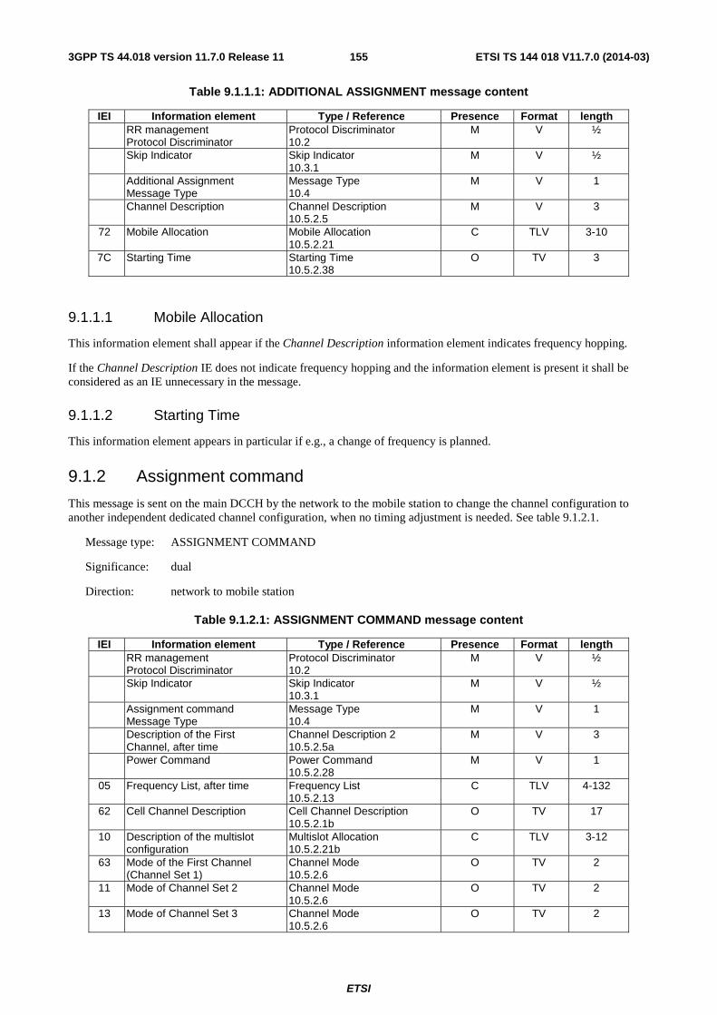
ETSI
ETSI TS 144 018 V11.7.0 (2014-03)1553GPP TS 44.018 version 11.7.0 Release 11
Table 9.1.1.1: ADDITIONAL ASSIGNMENT message content
IEI Information element Type / Reference Presence Format length RR management
Protocol Discriminator Protocol Discriminator 10.2
M V ½
Skip Indicator Skip Indicator 10.3.1
M V ½
Additional Assignment Message Type
Message Type 10.4
M V 1
Channel Description Channel Description 10.5.2.5
M V 3
72 Mobile Allocation Mobile Allocation 10.5.2.21
C TLV 3-10
7C Starting Time Starting Time 10.5.2.38
O TV 3
9.1.1.1 Mobile Allocation
This information element shall appear if the Channel Description information element indicates frequency hopping.
If the Channel Description IE does not indicate frequency hopping and the information element is present it shall be considered as an IE unnecessary in the message.
9.1.1.2 Starting Time
This information element appears in particular if e.g., a change of frequency is planned.
9.1.2 Assignment command
This message is sent on the main DCCH by the network to the mobile station to change the channel configuration to another independent dedicated channel configuration, when no timing adjustment is needed. See table 9.1.2.1.
Message type: ASSIGNMENT COMMAND
Significance: dual
Direction: network to mobile station
Table 9.1.2.1: ASSIGNMENT COMMAND message content
IEI Information element Type / Reference Presence Format length RR management
Protocol Discriminator Protocol Discriminator 10.2
M V ½
Skip Indicator Skip Indicator 10.3.1
M V ½
Assignment command Message Type
Message Type 10.4
M V 1
Description of the First Channel, after time
Channel Description 2 10.5.2.5a
M V 3
Power Command Power Command 10.5.2.28
M V 1
05 Frequency List, after time Frequency List 10.5.2.13
C TLV 4-132
62 Cell Channel Description Cell Channel Description 10.5.2.1b
O TV 17
10 Description of the multislot configuration
Multislot Allocation 10.5.2.21b
C TLV 3-12
63 Mode of the First Channel (Channel Set 1)
Channel Mode 10.5.2.6
O TV 2
11 Mode of Channel Set 2 Channel Mode 10.5.2.6
O TV 2
13 Mode of Channel Set 3 Channel Mode 10.5.2.6
O TV 2
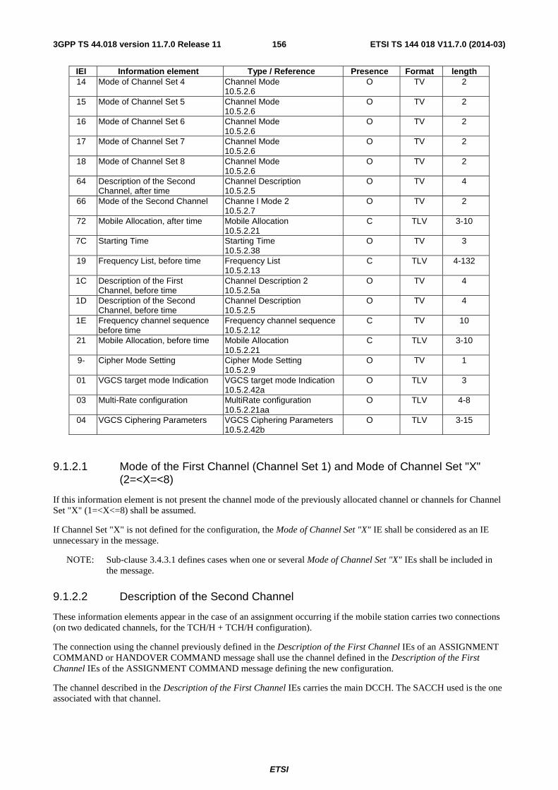
ETSI
ETSI TS 144 018 V11.7.0 (2014-03)1563GPP TS 44.018 version 11.7.0 Release 11
IEI Information element Type / Reference Presence Format length 14 Mode of Channel Set 4 Channel Mode
10.5.2.6 O TV 2
15 Mode of Channel Set 5 Channel Mode 10.5.2.6
O TV 2
16 Mode of Channel Set 6 Channel Mode 10.5.2.6
O TV 2
17 Mode of Channel Set 7 Channel Mode 10.5.2.6
O TV 2
18 Mode of Channel Set 8 Channel Mode 10.5.2.6
O TV 2
64 Description of the Second Channel, after time
Channel Description 10.5.2.5
O TV 4
66 Mode of the Second Channel Channe l Mode 2 10.5.2.7
O TV 2
72 Mobile Allocation, after time Mobile Allocation 10.5.2.21
C TLV 3-10
7C Starting Time Starting Time 10.5.2.38
O TV 3
19 Frequency List, before time Frequency List 10.5.2.13
C TLV 4-132
1C Description of the First Channel, before time
Channel Description 2 10.5.2.5a
O TV 4
1D Description of the Second Channel, before time
Channel Description 10.5.2.5
O TV 4
1E Frequency channel sequence before time
Frequency channel sequence 10.5.2.12
C TV 10
21 Mobile Allocation, before time Mobile Allocation 10.5.2.21
C TLV 3-10
9- Cipher Mode Setting Cipher Mode Setting 10.5.2.9
O TV 1
01 VGCS target mode Indication VGCS target mode Indication 10.5.2.42a
O TLV 3
03 Multi-Rate configuration MultiRate configuration 10.5.2.21aa
O TLV 4-8
04 VGCS Ciphering Parameters VGCS Ciphering Parameters 10.5.2.42b
O TLV 3-15
9.1.2.1 Mode of the First Channel (Channel Set 1) and Mode of Channel Set "X" (2=<X=<8)
If this information element is not present the channel mode of the previously allocated channel or channels for Channel Set "X" (1=<X<=8) shall be assumed.
If Channel Set "X" is not defined for the configuration, the Mode of Channel Set "X" IE shall be considered as an IE unnecessary in the message.
NOTE: Sub-clause 3.4.3.1 defines cases when one or several Mode of Channel Set "X" IEs shall be included in the message.
9.1.2.2 Description of the Second Channel
These information elements appear in the case of an assignment occurring if the mobile station carries two connections (on two dedicated channels, for the TCH/H + TCH/H configuration).
The connection using the channel previously defined in the Description of the First Channel IEs of an ASSIGNMENT COMMAND or HANDOVER COMMAND message shall use the channel defined in the Description of the First Channel IEs of the ASSIGNMENT COMMAND message defining the new configuration.
The channel described in the Description of the First Channel IEs carries the main DCCH. The SACCH used is the one associated with that channel.
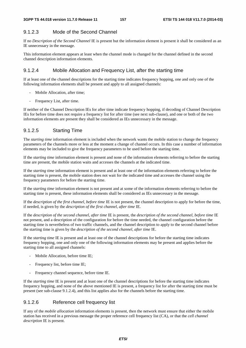
ETSI
ETSI TS 144 018 V11.7.0 (2014-03)1573GPP TS 44.018 version 11.7.0 Release 11
9.1.2.3 Mode of the Second Channel
If no Description of the Second Channel IE is present but the information element is present it shall be considered as an IE unnecessary in the message.
This information element appears at least when the channel mode is changed for the channel defined in the second channel description information elements.
9.1.2.4 Mobile Allocation and Frequency List, after the starting time
If at least one of the channel descriptions for the starting time indicates frequency hopping, one and only one of the following information elements shall be present and apply to all assigned channels:
- Mobile Allocation, after time;
- Frequency List, after time.
If neither of the Channel Description IEs for after time indicate frequency hopping, if decoding of Channel Description IEs for before time does not require a frequency list for after time (see next sub-clause), and one or both of the two information elements are present they shall be considered as IEs unnecessary in the message.
9.1.2.5 Starting Time
The starting time information element is included when the network wants the mobile station to change the frequency parameters of the channels more or less at the moment a change of channel occurs. In this case a number of information elements may be included to give the frequency parameters to be used before the starting time.
If the starting time information element is present and none of the information elements referring to before the starting time are present, the mobile station waits and accesses the channels at the indicated time.
If the starting time information element is present and at least one of the information elements referring to before the starting time is present, the mobile station does not wait for the indicated time and accesses the channel using the frequency parameters for before the starting time.
If the starting time information element is not present and at some of the information elements referring to before the starting time is present, these information elements shall be considered as IEs unnecessary in the message.
If the description of the first channel, before time IE is not present, the channel description to apply for before the time, if needed, is given by the description of the first channel, after time IE.
If the description of the second channel, after time IE is present, the description of the second channel, before time IE not present, and a description of the configuration for before the time needed, the channel configuration before the starting time is nevertheless of two traffic channels, and the channel description to apply to the second channel before the starting time is given by the description of the second channel, after time IE.
If the starting time IE is present and at least one of the channel descriptions for before the starting time indicates frequency hopping, one and only one of the following information elements may be present and applies before the starting time to all assigned channels:
- Mobile Allocation, before time IE;
- Frequency list, before time IE;
- Frequency channel sequence, before time IE.
If the starting time IE is present and at least one of the channel descriptions for before the starting time indicates frequency hopping, and none of the above mentioned IE is present, a frequency list for after the starting time must be present (see sub-clause 9.1.2.4), and this list applies also for the channels before the starting time.
9.1.2.6 Reference cell frequency list
If any of the mobile allocation information elements is present, then the network must ensure that either the mobile station has received in a previous message the proper reference cell frequency list (CA), or that the cell channel description IE is present.
ETSI
ETSI TS 144 018 V11.7.0 (2014-03)1583GPP TS 44.018 version 11.7.0 Release 11
If the cell channel description IE is present, it is used to decode the mobile allocation IEs in the message, as well as in later messages until reception of a new reference cell frequency list or the cell is left.
9.1.2.7 Cell Channel Description
If present, this information element shall be used to decode the Mobile Allocation IE in the same message and in subsequent messages.
9.1.2.8 Cipher Mode Setting
If this information element is omitted, the mode of ciphering is not changed after the mobile station has switched to the assigned channel.
Only applicable for mobile stations supporting VGCS talking:
- The cipher mode setting IE shall not be included if the ASSIGNMENT COMMAND message is sent on a VGCS channel or dedicated channel in order to assign a VGCS channel.
- The cipher mode setting IE shall be included if the ASSIGNMENT COMMAND message is sent on a ciphered VGCS channel in order to assign a dedicated channel. If the information element is not present, the MS shall use ciphering mode "no ciphering" on the assigned channel.
9.1.2.9 VGCS target mode Indication
This information element is identified as "comprehension required". Only mobile stations supporting "VGCS talking" are required to accept the presence of the element. The presence of the element shall trigger an exception handling if received by a mobile station not supporting "VGCS talking".
This IE indicates which mode is to be used on the new channel (i.e. dedicated mode or group transmit mode). If this information element is not present, the mode shall be the same as on the previous channel.
The IE also indicates the group cipher key number for the group cipher key to be used on the new channel or if the new channel is non ciphered. If the information element is not present, the ciphering mode shall be the same as on the previous channel.
NOTE: A mobile station supporting VGCS talking shall not consider a syntactical error when this IE is present and the channel mode is not speech.
9.1.2.10 Description of the multislot allocation
This information element is included if so indicated by the channel type and TDMA offset field in the Channel Description information element and is used to assign channels that do not carry a main signalling link in a multislot configuration. It indicates how the used timeslots are divided into separate channel sets.
If the Channel Description IE does not require the presence of the information element the Description of the multislot allocation IE shall be considered as an IE unnecessary in the message.
If multislot configuration is indicated by the Channel Description IE but the Multislot Allocation IE is not present, all channels in the configuration belong to one channel set, "Channel Set 1".
NOTE: As a change of timeslot number cannot occur for the channel described after the starting time, the Multislot Allocation IE does not have to be included more than once.
9.1.2.11 Multi Rate configuration
This information element appears if the Mode of the First Channel indicates a multi-rate speech codec, and if the assigned configuration is new, i.e. it is different from the MultiRateconfiguration of a previously allocated channel in the cell.

ETSI
ETSI TS 144 018 V11.7.0 (2014-03)1593GPP TS 44.018 version 11.7.0 Release 11
9.1.2.12 VGCS Ciphering Parameters
This information element is only applicable to a VGCS mobile station. It is only included if the assigned resource is ciphered using VGCS ciphering.
9.1.3 Assignment complete
This message is sent on the main DCCH from the mobile station to the network to indicate that the mobile station has established the main signalling link successfully. See table 9.1.3.1.
Message type: ASSIGNMENT COMPLETE
Significance: dual
Direction: mobile station to network
Table 9.1.3.1: ASSIGNMENT COMPLETE message content
IEI Information element Type / Reference Presence Format length RR management
Protocol Discriminator Protocol Discriminator 10.2
M V 1/2
Skip Indicator Skip Indicator 10.3.1
M V 1/2
Assignment Complete Message Type
Message Type 10.4
M V 1
RR Cause RR Cause 10.5.2.31
M V 1
9.1.4 Assignment failure
This message is sent on the main DCCH on the old channel from the mobile station to the network to indicate that the mobile station has failed to seize the new channel. See table 9.1.4.1.
Message type: ASSIGNMENT FAILURE
Significance: dual
Direction: mobile station to network
Table 9.1.4.1: ASSIGNMENT FAILURE message content
IEI Information element Type / Reference Presence Format length RR management
Protocol Discriminator Protocol Discriminator 10.2
M V 1/2
Skip Indicator Skip Indicator 10.3.1
M V 1/2
Assignment Failure Message Type
Message Type 10.4
M V 1
RR cause RR Cause 10.5.2.31
M V 1
9.1.5 Channel mode modify
This message is sent on the main DCCH by the network to the mobile station to request the setting of the mode for the indicated channel(s). The message can be used to change the channel mode of a Multislot Configuration which only contains one channel set. See table 9.1.5.1.
Message type: CHANNEL MODE MODIFY
Significance: local
Direction: network to mobile station
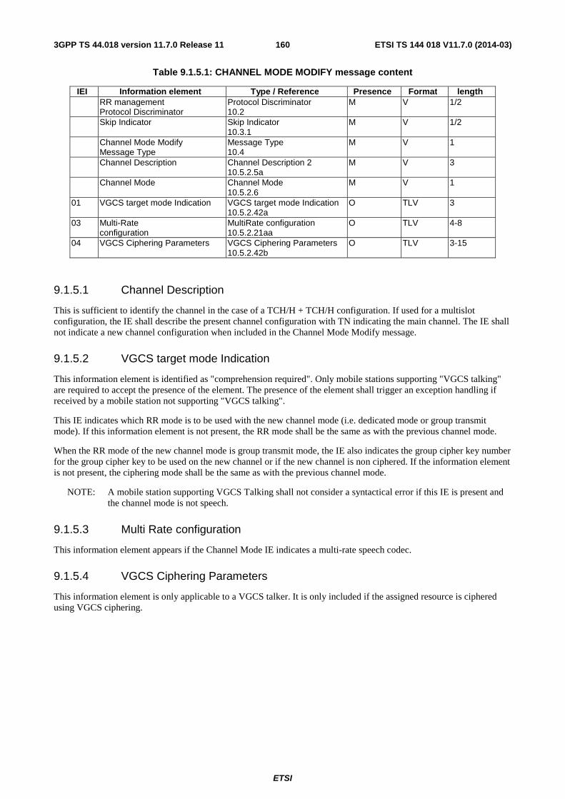
ETSI
ETSI TS 144 018 V11.7.0 (2014-03)1603GPP TS 44.018 version 11.7.0 Release 11
Table 9.1.5.1: CHANNEL MODE MODIFY message content
IEI Information element Type / Reference Presence Format length RR management
Protocol Discriminator Protocol Discriminator 10.2
M V 1/2
Skip Indicator Skip Indicator 10.3.1
M V 1/2
Channel Mode Modify Message Type
Message Type 10.4
M V 1
Channel Description Channel Description 2 10.5.2.5a
M V 3
Channel Mode Channel Mode 10.5.2.6
M V 1
01 VGCS target mode Indication VGCS target mode Indication 10.5.2.42a
O TLV 3
03 Multi-Rate configuration
MultiRate configuration 10.5.2.21aa
O TLV 4-8
04 VGCS Ciphering Parameters VGCS Ciphering Parameters 10.5.2.42b
O TLV 3-15
9.1.5.1 Channel Description
This is sufficient to identify the channel in the case of a TCH/H + TCH/H configuration. If used for a multislot configuration, the IE shall describe the present channel configuration with TN indicating the main channel. The IE shall not indicate a new channel configuration when included in the Channel Mode Modify message.
9.1.5.2 VGCS target mode Indication
This information element is identified as "comprehension required". Only mobile stations supporting "VGCS talking" are required to accept the presence of the element. The presence of the element shall trigger an exception handling if received by a mobile station not supporting "VGCS talking".
This IE indicates which RR mode is to be used with the new channel mode (i.e. dedicated mode or group transmit mode). If this information element is not present, the RR mode shall be the same as with the previous channel mode.
When the RR mode of the new channel mode is group transmit mode, the IE also indicates the group cipher key number for the group cipher key to be used on the new channel or if the new channel is non ciphered. If the information element is not present, the ciphering mode shall be the same as with the previous channel mode.
NOTE: A mobile station supporting VGCS Talking shall not consider a syntactical error if this IE is present and the channel mode is not speech.
9.1.5.3 Multi Rate configuration
This information element appears if the Channel Mode IE indicates a multi-rate speech codec.
9.1.5.4 VGCS Ciphering Parameters
This information element is only applicable to a VGCS talker. It is only included if the assigned resource is ciphered using VGCS ciphering.

ETSI
ETSI TS 144 018 V11.7.0 (2014-03)1613GPP TS 44.018 version 11.7.0 Release 11
9.1.6 Channel mode modify acknowledge
This message is sent on the main DCCH by the mobile station to the network to indicate the successful or unsuccessful execution of a channel mode modify request. See table 9.1.6.1.
Message type: CHANNEL MODE MODIFY ACKNOWLEDGE
Significance: local
Direction: mobile station to network
Table 9.1.6.1: CHANNEL MODE MODIFY ACKNOWLEDGE message content
IEI Information element Type / Reference Presence Format length RR management
Protocol Discriminator Protocol Discriminator 10.2
M V 1/2
Skip Indicator Skip Indicator 10.3.1
M V 1/2
Channel Mode Modify Acknowledge Message Type
Message Type 10.4
M V 1
Channel Description Channel Description 2 10.5.2.5a
M V 3
Channel Mode Channel Mode 10.5.2.6
M V 1
9.1.7 Channel release
This message is sent on the main DCCH from the network to the mobile station to initiate deactivation of the dedicated channel used. See table 9.1.7.1.
Message type: CHANNEL RELEASE
Significance: dual
Direction: network to mobile station
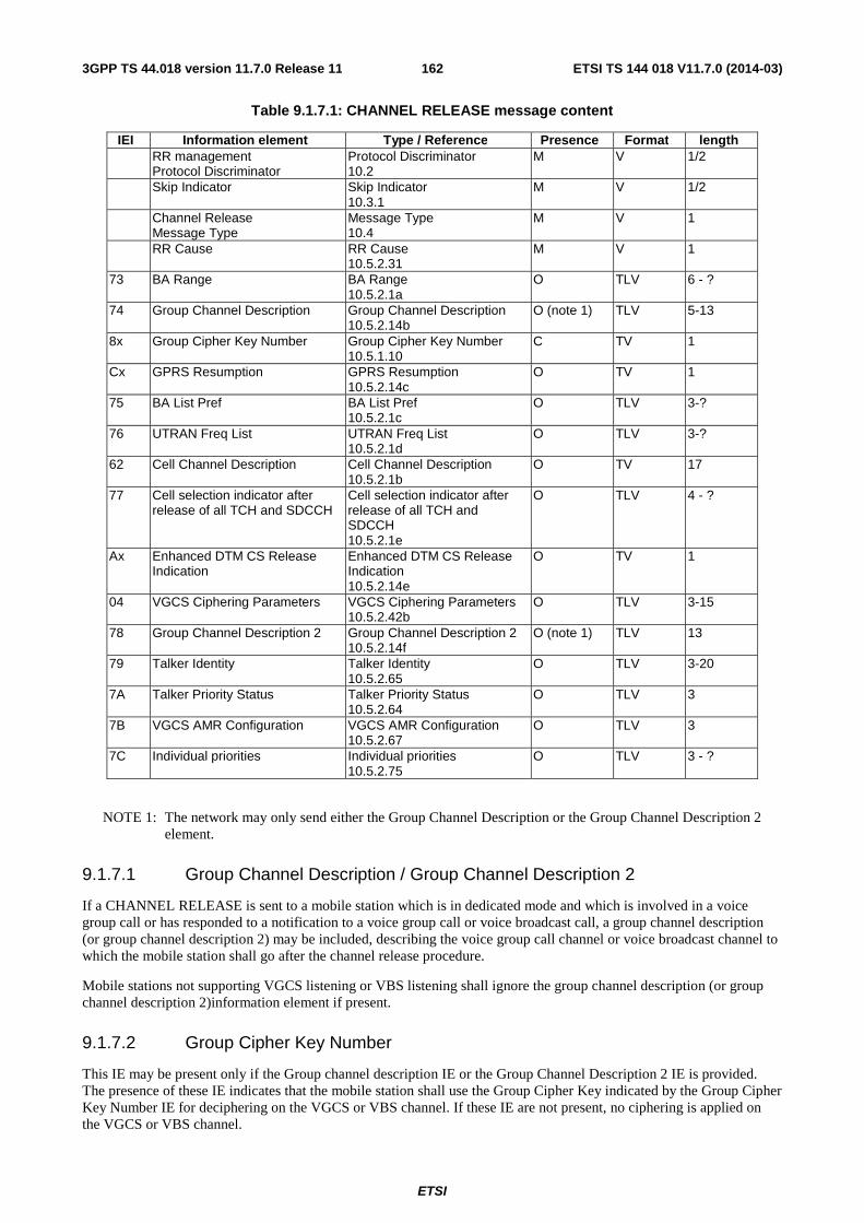
ETSI
ETSI TS 144 018 V11.7.0 (2014-03)1623GPP TS 44.018 version 11.7.0 Release 11
Table 9.1.7.1: CHANNEL RELEASE message content
IEI Information element Type / Reference Presence Format length RR management
Protocol Discriminator Protocol Discriminator 10.2
M V 1/2
Skip Indicator Skip Indicator 10.3.1
M V 1/2
Channel Release Message Type
Message Type 10.4
M V 1
RR Cause RR Cause 10.5.2.31
M V 1
73 BA Range BA Range 10.5.2.1a
O TLV 6 - ?
74 Group Channel Description Group Channel Description 10.5.2.14b
O (note 1) TLV 5-13
8x Group Cipher Key Number Group Cipher Key Number 10.5.1.10
C TV 1
Cx GPRS Resumption GPRS Resumption 10.5.2.14c
O TV 1
75 BA List Pref BA List Pref 10.5.2.1c
O TLV 3-?
76 UTRAN Freq List UTRAN Freq List 10.5.2.1d
O TLV 3-?
62 Cell Channel Description Cell Channel Description 10.5.2.1b
O TV 17
77 Cell selection indicator after release of all TCH and SDCCH
Cell selection indicator after release of all TCH and SDCCH 10.5.2.1e
O TLV 4 - ?
Ax Enhanced DTM CS Release Indication
Enhanced DTM CS Release Indication 10.5.2.14e
O TV 1
04 VGCS Ciphering Parameters VGCS Ciphering Parameters 10.5.2.42b
O TLV 3-15
78 Group Channel Description 2 Group Channel Description 2 10.5.2.14f
O (note 1) TLV 13
79 Talker Identity Talker Identity 10.5.2.65
O TLV 3-20
7A Talker Priority Status Talker Priority Status 10.5.2.64
O TLV 3
7B VGCS AMR Configuration VGCS AMR Configuration 10.5.2.67
O TLV 3
7C Individual priorities Individual priorities 10.5.2.75
O TLV 3 - ?
NOTE 1: The network may only send either the Group Channel Description or the Group Channel Description 2 element.
9.1.7.1 Group Channel Description / Group Channel Description 2
If a CHANNEL RELEASE is sent to a mobile station which is in dedicated mode and which is involved in a voice group call or has responded to a notification to a voice group call or voice broadcast call, a group channel description (or group channel description 2) may be included, describing the voice group call channel or voice broadcast channel to which the mobile station shall go after the channel release procedure.
Mobile stations not supporting VGCS listening or VBS listening shall ignore the group channel description (or group channel description 2)information element if present.
9.1.7.2 Group Cipher Key Number
This IE may be present only if the Group channel description IE or the Group Channel Description 2 IE is provided. The presence of these IE indicates that the mobile station shall use the Group Cipher Key indicated by the Group Cipher Key Number IE for deciphering on the VGCS or VBS channel. If these IE are not present, no ciphering is applied on the VGCS or VBS channel.
ETSI
ETSI TS 144 018 V11.7.0 (2014-03)1633GPP TS 44.018 version 11.7.0 Release 11
Mobile stations not supporting VGCS listening or VBS listening shall ignore this information element.
9.1.7.3 UTRAN Freq List
This IE should only be sent to UTRAN capable mobile station. This information element is used to describe the UTRAN frequencies used by the network.
9.1.7.4 Cell Channel Description
This IE may be present if the following conditions are satisfied:
- the CHANNEL RELEASE message is ordering the release of the uplink to the originator or to the talker of a VGCS call over a dedicated channel; and
- the Group Channel Description IE is included in the message and is describing a hopping channel.
It shall not be included in any other case.
Mobile stations not supporting VGCS talking or VGCS originating shall ignore this information element if present.
9.1.7.5 VGCS Ciphering Parameters
This information element is only applicable to a VGCS mobile station. It is only included if the group channel is ciphered.
9.1.7.6 Talker Identity
This information element is only applicable to a VGCS talking subscriber. Mobile stations not supporting VGCS talking shall ignore this information element if present.
9.1.7.7 Talker Priority Status
This information element is only applicable to a VGCS talking subscriber. Mobile stations not supporting VGCS talking shall ignore this information element if present.
9.1.7.8 VGCS AMR Configuration
This information element is only applicable to a VGCS talking subscriber. Mobile stations not supporting VGCS talking shall ignore this information element if present.
9.1.7.9 Individual priorities
This information element is sent to provide MS-specific priorities for priority-based cell reselection. The individual priorities shall override the priorities received through system information or individual priorities received previously. The timer T3230 is used to control the availability of the individual priorities.
9.1.8 Channel request
This message is sent in random mode on the RACH. It does not follow the basic format. The possible formats are presented directly below, without reference to information fields. The order of bit transmission is defined in 3GPP TS 44.004.
The message is only one octet long, coded as shown in figure 9.1.8.1 and table 9.1.8.1.
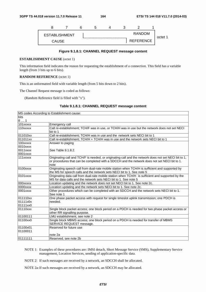
ETSI
ETSI TS 144 018 V11.7.0 (2014-03)1643GPP TS 44.018 version 11.7.0 Release 11
8 7 6 5 4 3 2 1
ESTABLISHMENT
CAUSE
RANDOM
REFERENCEoctet 1
Figure 9.1.8.1: CHANNEL REQUEST message content
ESTABLISHMENT CAUSE (octet 1)
This information field indicates the reason for requesting the establishment of a connection. This field has a variable length (from 3 bits up to 6 bits).
RANDOM REFERENCE (octet 1)
This is an unformatted field with variable length (from 5 bits down to 2 bits).
The Channel Request message is coded as follows:
(Random Reference field is filled with "x").
Table 9.1.8.1: CHANNEL REQUEST message content
MS codes According to Establishment cause: bits 8 .... 1 101xxxxx Emergency call 110xxxxx Call re-establishment; TCH/F was in use, or TCH/H was in use but the network does not set NECI
bit to 1 011010xx Call re-establishment; TCH/H was in use and the network sets NECI bit to 1 011011xx Call re-establishment; TCH/H + TCH/H was in use and the network sets NECI bit to 1 100xxxxx 0010xxxx 0011xxxx 0001xxxx
Answer to paging See Table 9.1.8.2.
111xxxxx Originating call and TCH/F is needed, or originating call and the network does not set NECI bit to 1, or procedures that can be completed with a SDCCH and the network does not set NECI bit to 1. note
0100xxxx Originating speech call from dual-rate mobile station when TCH/H is sufficient and supported by the MS for speech calls and the network sets NECI bit to 1. See note 5
0101xxxx Originating data call from dual-rate mobile station when TCH/H is sufficient and supported by the MS for data calls and the network sets NECI bit to 1. See note 5
000xxxxx Location updating and the network does not set NECI bit to 1. See note 2c. 0000xxxx Location updating and the network sets NECI bit to 1. See note 2c. 0001xxxx Other procedures which can be completed with an SDCCH and the network sets NECI bit to 1.
See note 1 011110xx 01111x0x 01111xx0
One phase packet access with request for single timeslot uplink transmission; one PDCH is needed.
01110xxx Single block packet access; one block period on a PDCH is needed for two phase packet access or other RR signalling purpose.
01100111 LMU establishment, see note 2 01100xx0 Single block MBMS access; one block period on a PDCH is needed for transfer of MBMS
SERVICE REQUEST message. 01100x01 01100011
Reserved for future use note 2a
01111111 Reserved, see note 2b
NOTE 1: Examples of these procedures are: IMSI detach, Short Message Service (SMS), Supplementary Service management, Location Services, sending of application-specific data.
NOTE 2: If such messages are received by a network, an SDCCH shall be allocated.
NOTE 2a: If such messages are received by a network, an SDCCH may be allocated.
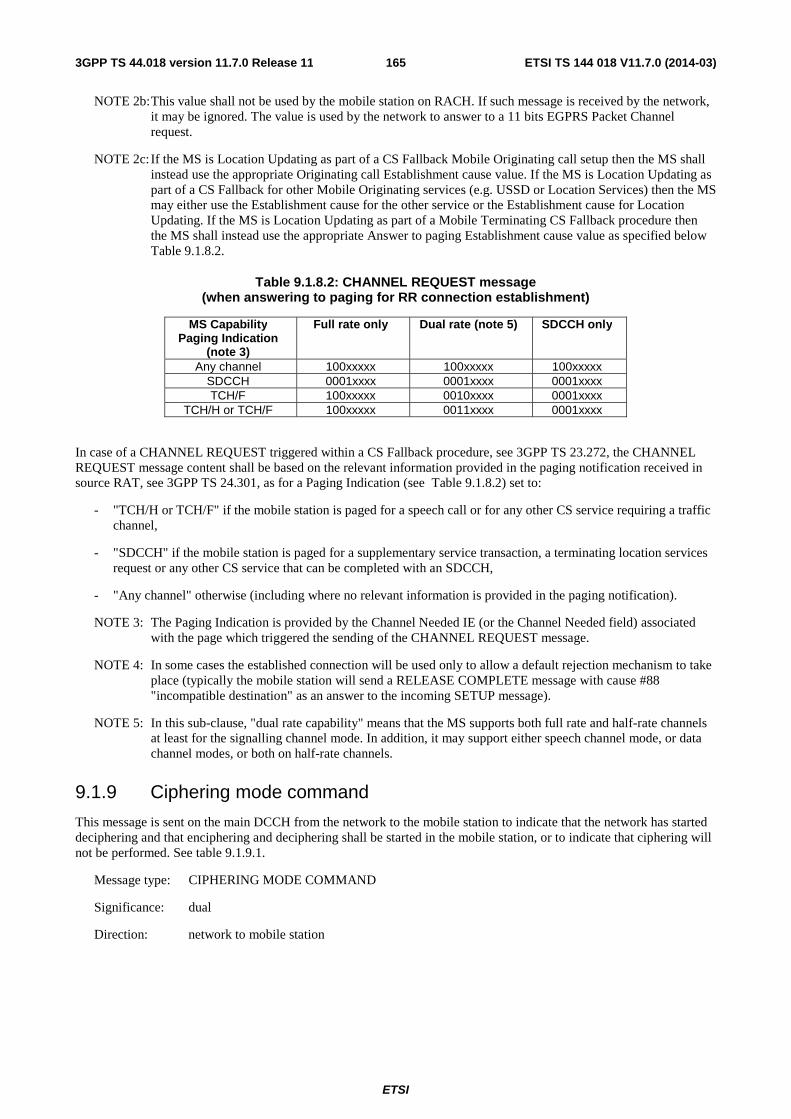
ETSI
ETSI TS 144 018 V11.7.0 (2014-03)1653GPP TS 44.018 version 11.7.0 Release 11
NOTE 2b: This value shall not be used by the mobile station on RACH. If such message is received by the network, it may be ignored. The value is used by the network to answer to a 11 bits EGPRS Packet Channel request.
NOTE 2c: If the MS is Location Updating as part of a CS Fallback Mobile Originating call setup then the MS shall instead use the appropriate Originating call Establishment cause value. If the MS is Location Updating as part of a CS Fallback for other Mobile Originating services (e.g. USSD or Location Services) then the MS may either use the Establishment cause for the other service or the Establishment cause for Location Updating. If the MS is Location Updating as part of a Mobile Terminating CS Fallback procedure then the MS shall instead use the appropriate Answer to paging Establishment cause value as specified below Table 9.1.8.2.
Table 9.1.8.2: CHANNEL REQUEST message (when answering to paging for RR connection establishment)
MS Capability Paging Indication
(note 3)
Full rate only Dual rate (note 5) SDCCH only
Any channel 100xxxxx 100xxxxx 100xxxxx SDCCH 0001xxxx 0001xxxx 0001xxxx TCH/F 100xxxxx 0010xxxx 0001xxxx
TCH/H or TCH/F 100xxxxx 0011xxxx 0001xxxx
In case of a CHANNEL REQUEST triggered within a CS Fallback procedure, see 3GPP TS 23.272, the CHANNEL REQUEST message content shall be based on the relevant information provided in the paging notification received in source RAT, see 3GPP TS 24.301, as for a Paging Indication (see Table 9.1.8.2) set to:
- "TCH/H or TCH/F" if the mobile station is paged for a speech call or for any other CS service requiring a traffic channel,
- "SDCCH" if the mobile station is paged for a supplementary service transaction, a terminating location services request or any other CS service that can be completed with an SDCCH,
- "Any channel" otherwise (including where no relevant information is provided in the paging notification).
NOTE 3: The Paging Indication is provided by the Channel Needed IE (or the Channel Needed field) associated with the page which triggered the sending of the CHANNEL REQUEST message.
NOTE 4: In some cases the established connection will be used only to allow a default rejection mechanism to take place (typically the mobile station will send a RELEASE COMPLETE message with cause #88 "incompatible destination" as an answer to the incoming SETUP message).
NOTE 5: In this sub-clause, "dual rate capability" means that the MS supports both full rate and half-rate channels at least for the signalling channel mode. In addition, it may support either speech channel mode, or data channel modes, or both on half-rate channels.
9.1.9 Ciphering mode command
This message is sent on the main DCCH from the network to the mobile station to indicate that the network has started deciphering and that enciphering and deciphering shall be started in the mobile station, or to indicate that ciphering will not be performed. See table 9.1.9.1.
Message type: CIPHERING MODE COMMAND
Significance: dual
Direction: network to mobile station
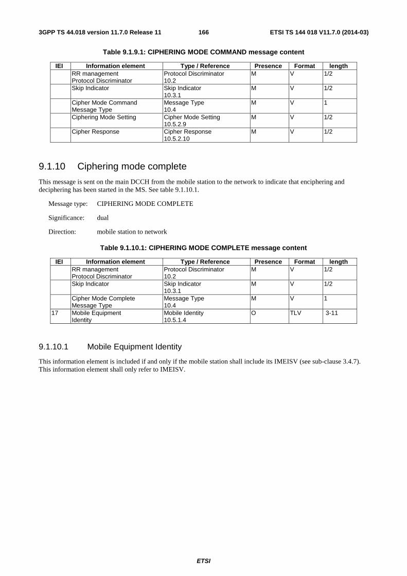
ETSI
ETSI TS 144 018 V11.7.0 (2014-03)1663GPP TS 44.018 version 11.7.0 Release 11
Table 9.1.9.1: CIPHERING MODE COMMAND message content
IEI Information element Type / Reference Presence Format length RR management
Protocol Discriminator Protocol Discriminator 10.2
M V 1/2
Skip Indicator Skip Indicator 10.3.1
M V 1/2
Cipher Mode Command Message Type
Message Type 10.4
M V 1
Ciphering Mode Setting Cipher Mode Setting 10.5.2.9
M V 1/2
Cipher Response Cipher Response 10.5.2.10
M V 1/2
9.1.10 Ciphering mode complete
This message is sent on the main DCCH from the mobile station to the network to indicate that enciphering and deciphering has been started in the MS. See table 9.1.10.1.
Message type: CIPHERING MODE COMPLETE
Significance: dual
Direction: mobile station to network
Table 9.1.10.1: CIPHERING MODE COMPLETE message content
IEI Information element Type / Reference Presence Format length RR management
Protocol Discriminator Protocol Discriminator 10.2
M V 1/2
Skip Indicator Skip Indicator 10.3.1
M V 1/2
Cipher Mode Complete Message Type
Message Type 10.4
M V 1
17 Mobile Equipment Identity
Mobile Identity 10.5.1.4
O TLV 3-11
9.1.10.1 Mobile Equipment Identity
This information element is included if and only if the mobile station shall include its IMEISV (see sub-clause 3.4.7). This information element shall only refer to IMEISV.
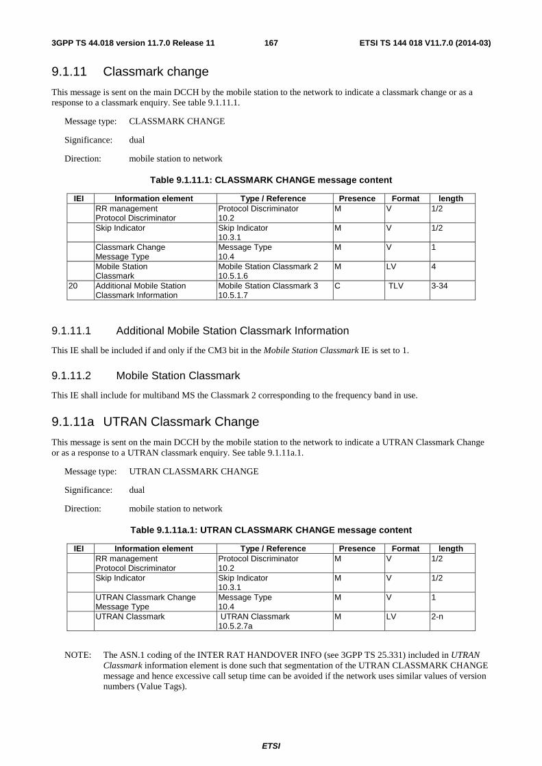
ETSI
ETSI TS 144 018 V11.7.0 (2014-03)1673GPP TS 44.018 version 11.7.0 Release 11
9.1.11 Classmark change
This message is sent on the main DCCH by the mobile station to the network to indicate a classmark change or as a response to a classmark enquiry. See table 9.1.11.1.
Message type: CLASSMARK CHANGE
Significance: dual
Direction: mobile station to network
Table 9.1.11.1: CLASSMARK CHANGE message content
IEI Information element Type / Reference Presence Format length RR management
Protocol Discriminator Protocol Discriminator 10.2
M V 1/2
Skip Indicator Skip Indicator 10.3.1
M V 1/2
Classmark Change Message Type
Message Type 10.4
M V 1
Mobile Station Classmark
Mobile Station Classmark 2 10.5.1.6
M LV 4
20 Additional Mobile Station Classmark Information
Mobile Station Classmark 3 10.5.1.7
C TLV 3-34
9.1.11.1 Additional Mobile Station Classmark Information
This IE shall be included if and only if the CM3 bit in the Mobile Station Classmark IE is set to 1.
9.1.11.2 Mobile Station Classmark
This IE shall include for multiband MS the Classmark 2 corresponding to the frequency band in use.
9.1.11a UTRAN Classmark Change
This message is sent on the main DCCH by the mobile station to the network to indicate a UTRAN Classmark Change or as a response to a UTRAN classmark enquiry. See table 9.1.11a.1.
Message type: UTRAN CLASSMARK CHANGE
Significance: dual
Direction: mobile station to network
Table 9.1.11a.1: UTRAN CLASSMARK CHANGE message content
IEI Information element Type / Reference Presence Format length RR management
Protocol Discriminator Protocol Discriminator 10.2
M V 1/2
Skip Indicator Skip Indicator 10.3.1
M V 1/2
UTRAN Classmark Change Message Type
Message Type 10.4
M V 1
UTRAN Classmark UTRAN Classmark 10.5.2.7a
M LV 2-n
NOTE: The ASN.1 coding of the INTER RAT HANDOVER INFO (see 3GPP TS 25.331) included in UTRAN Classmark information element is done such that segmentation of the UTRAN CLASSMARK CHANGE message and hence excessive call setup time can be avoided if the network uses similar values of version numbers (Value Tags).
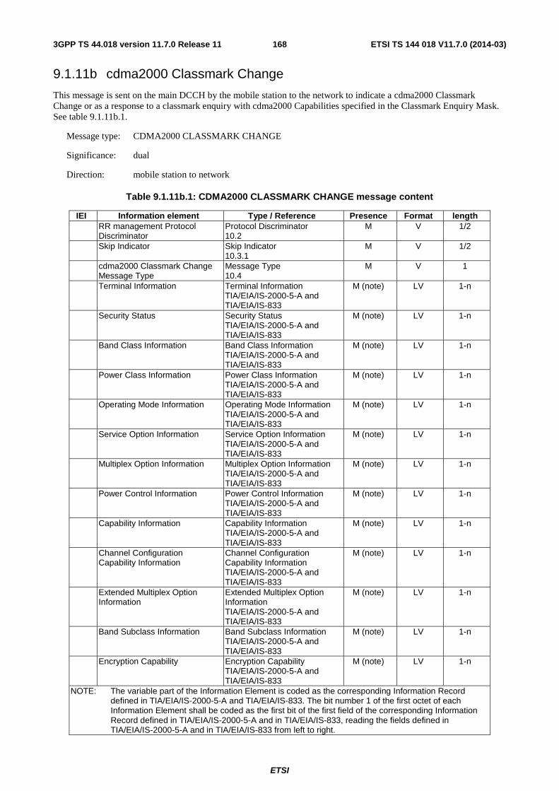
ETSI
ETSI TS 144 018 V11.7.0 (2014-03)1683GPP TS 44.018 version 11.7.0 Release 11
9.1.11b cdma2000 Classmark Change
This message is sent on the main DCCH by the mobile station to the network to indicate a cdma2000 Classmark Change or as a response to a classmark enquiry with cdma2000 Capabilities specified in the Classmark Enquiry Mask. See table 9.1.11b.1.
Message type: CDMA2000 CLASSMARK CHANGE
Significance: dual
Direction: mobile station to network
Table 9.1.11b.1: CDMA2000 CLASSMARK CHANGE message content
IEI Information element Type / Reference Presence Format length RR management Protocol
Discriminator Protocol Discriminator 10.2
M V 1/2
Skip Indicator Skip Indicator 10.3.1
M V 1/2
cdma2000 Classmark Change Message Type
Message Type 10.4
M V 1
Terminal Information Terminal Information TIA/EIA/IS-2000-5-A and TIA/EIA/IS-833
M (note) LV 1-n
Security Status Security Status TIA/EIA/IS-2000-5-A and TIA/EIA/IS-833
M (note) LV 1-n
Band Class Information Band Class Information TIA/EIA/IS-2000-5-A and TIA/EIA/IS-833
M (note) LV 1-n
Power Class Information Power Class Information TIA/EIA/IS-2000-5-A and TIA/EIA/IS-833
M (note) LV 1-n
Operating Mode Information Operating Mode Information TIA/EIA/IS-2000-5-A and TIA/EIA/IS-833
M (note) LV 1-n
Service Option Information Service Option Information TIA/EIA/IS-2000-5-A and TIA/EIA/IS-833
M (note) LV 1-n
Multiplex Option Information Multiplex Option Information TIA/EIA/IS-2000-5-A and TIA/EIA/IS-833
M (note) LV 1-n
Power Control Information Power Control Information TIA/EIA/IS-2000-5-A and TIA/EIA/IS-833
M (note) LV 1-n
Capability Information Capability Information TIA/EIA/IS-2000-5-A and TIA/EIA/IS-833
M (note) LV 1-n
Channel Configuration Capability Information
Channel Configuration Capability Information TIA/EIA/IS-2000-5-A and TIA/EIA/IS-833
M (note) LV 1-n
Extended Multiplex Option Information
Extended Multiplex Option Information TIA/EIA/IS-2000-5-A and TIA/EIA/IS-833
M (note) LV 1-n
Band Subclass Information Band Subclass Information TIA/EIA/IS-2000-5-A and TIA/EIA/IS-833
M (note) LV 1-n
Encryption Capability Encryption Capability TIA/EIA/IS-2000-5-A and TIA/EIA/IS-833
M (note) LV 1-n
NOTE: The variable part of the Information Element is coded as the corresponding Information Record defined in TIA/EIA/IS-2000-5-A and TIA/EIA/IS-833. The bit number 1 of the first octet of each Information Element shall be coded as the first bit of the first field of the corresponding Information Record defined in TIA/EIA/IS-2000-5-A and in TIA/EIA/IS-833, reading the fields defined in TIA/EIA/IS-2000-5-A and in TIA/EIA/IS-833 from left to right.
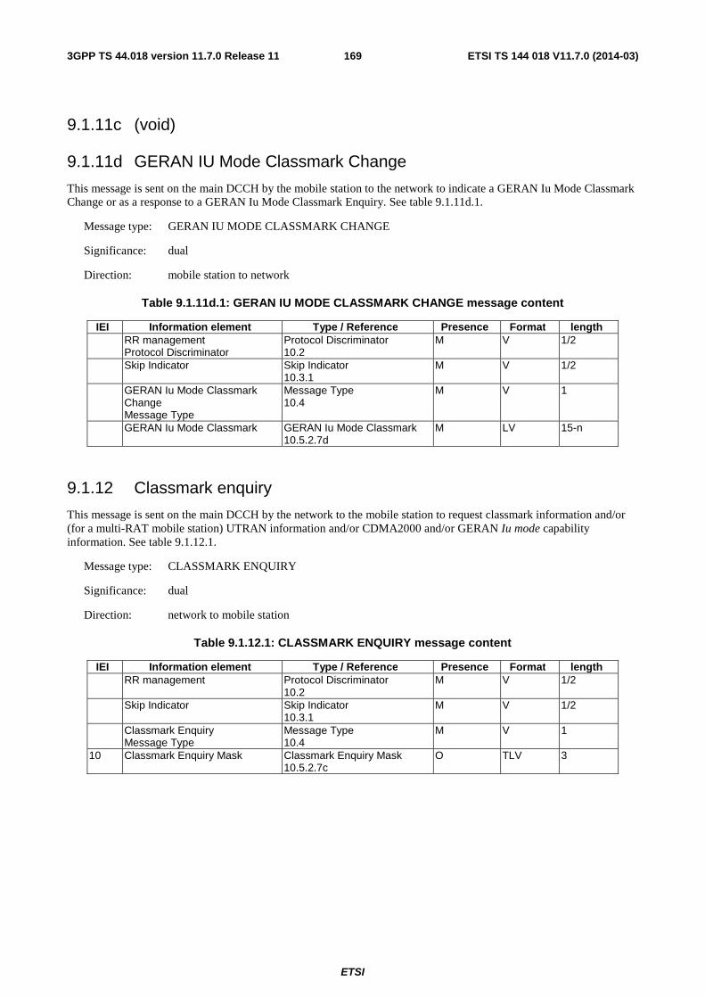
ETSI
ETSI TS 144 018 V11.7.0 (2014-03)1693GPP TS 44.018 version 11.7.0 Release 11
9.1.11c (void)
9.1.11d GERAN IU Mode Classmark Change
This message is sent on the main DCCH by the mobile station to the network to indicate a GERAN Iu Mode Classmark Change or as a response to a GERAN Iu Mode Classmark Enquiry. See table 9.1.11d.1.
Message type: GERAN IU MODE CLASSMARK CHANGE
Significance: dual
Direction: mobile station to network
Table 9.1.11d.1: GERAN IU MODE CLASSMARK CHANGE message content
IEI Information element Type / Reference Presence Format length RR management
Protocol Discriminator Protocol Discriminator 10.2
M V 1/2
Skip Indicator Skip Indicator 10.3.1
M V 1/2
GERAN Iu Mode Classmark Change Message Type
Message Type 10.4
M V 1
GERAN Iu Mode Classmark GERAN Iu Mode Classmark 10.5.2.7d
M LV 15-n
9.1.12 Classmark enquiry
This message is sent on the main DCCH by the network to the mobile station to request classmark information and/or (for a multi-RAT mobile station) UTRAN information and/or CDMA2000 and/or GERAN Iu mode capability information. See table 9.1.12.1.
Message type: CLASSMARK ENQUIRY
Significance: dual
Direction: network to mobile station
Table 9.1.12.1: CLASSMARK ENQUIRY message content
IEI Information element Type / Reference Presence Format length RR management Protocol Discriminator
10.2 M V 1/2
Skip Indicator Skip Indicator 10.3.1
M V 1/2
Classmark Enquiry Message Type
Message Type 10.4
M V 1
10 Classmark Enquiry Mask Classmark Enquiry Mask 10.5.2.7c
O TLV 3
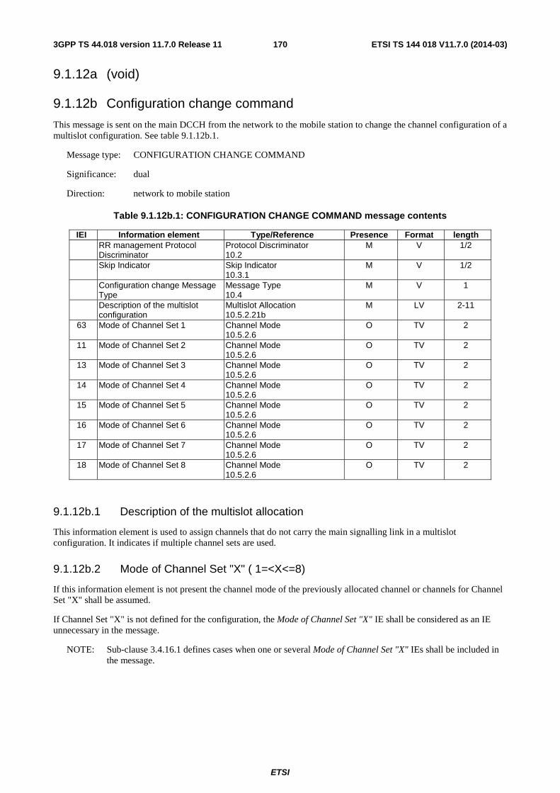
ETSI
ETSI TS 144 018 V11.7.0 (2014-03)1703GPP TS 44.018 version 11.7.0 Release 11
9.1.12a (void)
9.1.12b Configuration change command
This message is sent on the main DCCH from the network to the mobile station to change the channel configuration of a multislot configuration. See table 9.1.12b.1.
Message type: CONFIGURATION CHANGE COMMAND
Significance: dual
Direction: network to mobile station
Table 9.1.12b.1: CONFIGURATION CHANGE COMMAND message contents
IEI Information element Type/Reference Presence Format length RR management Protocol
Discriminator Protocol Discriminator 10.2
M V 1/2
Skip Indicator Skip Indicator 10.3.1
M V 1/2
Configuration change Message Type
Message Type 10.4
M V 1
Description of the multislot configuration
Multislot Allocation 10.5.2.21b
M LV 2-11
63 Mode of Channel Set 1 Channel Mode 10.5.2.6
O TV 2
11 Mode of Channel Set 2 Channel Mode 10.5.2.6
O TV 2
13 Mode of Channel Set 3 Channel Mode 10.5.2.6
O TV 2
14 Mode of Channel Set 4 Channel Mode 10.5.2.6
O TV 2
15 Mode of Channel Set 5 Channel Mode 10.5.2.6
O TV 2
16 Mode of Channel Set 6 Channel Mode 10.5.2.6
O TV 2
17 Mode of Channel Set 7 Channel Mode 10.5.2.6
O TV 2
18 Mode of Channel Set 8 Channel Mode 10.5.2.6
O TV 2
9.1.12b.1 Description of the multislot allocation
This information element is used to assign channels that do not carry the main signalling link in a multislot configuration. It indicates if multiple channel sets are used.
9.1.12b.2 Mode of Channel Set "X" ( 1=<X<=8)
If this information element is not present the channel mode of the previously allocated channel or channels for Channel Set "X" shall be assumed.
If Channel Set "X" is not defined for the configuration, the Mode of Channel Set "X" IE shall be considered as an IE unnecessary in the message.
NOTE: Sub-clause 3.4.16.1 defines cases when one or several Mode of Channel Set "X" IEs shall be included in the message.
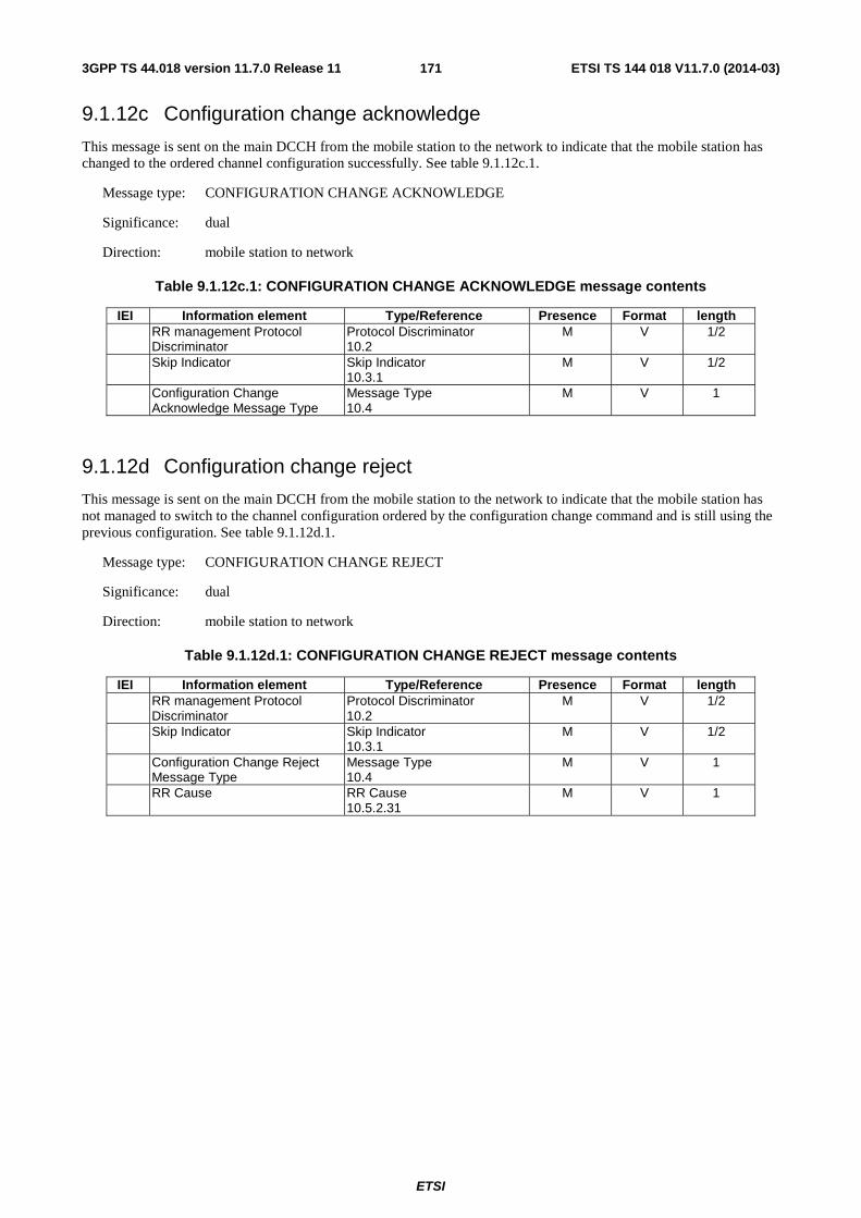
ETSI
ETSI TS 144 018 V11.7.0 (2014-03)1713GPP TS 44.018 version 11.7.0 Release 11
9.1.12c Configuration change acknowledge
This message is sent on the main DCCH from the mobile station to the network to indicate that the mobile station has changed to the ordered channel configuration successfully. See table 9.1.12c.1.
Message type: CONFIGURATION CHANGE ACKNOWLEDGE
Significance: dual
Direction: mobile station to network
Table 9.1.12c.1: CONFIGURATION CHANGE ACKNOWLEDGE message contents
IEI Information element Type/Reference Presence Format length RR management Protocol
Discriminator Protocol Discriminator 10.2
M V 1/2
Skip Indicator Skip Indicator 10.3.1
M V 1/2
Configuration Change Acknowledge Message Type
Message Type 10.4
M V 1
9.1.12d Configuration change reject
This message is sent on the main DCCH from the mobile station to the network to indicate that the mobile station has not managed to switch to the channel configuration ordered by the configuration change command and is still using the previous configuration. See table 9.1.12d.1.
Message type: CONFIGURATION CHANGE REJECT
Significance: dual
Direction: mobile station to network
Table 9.1.12d.1: CONFIGURATION CHANGE REJECT message contents
IEI Information element Type/Reference Presence Format length RR management Protocol
Discriminator Protocol Discriminator 10.2
M V 1/2
Skip Indicator Skip Indicator 10.3.1
M V 1/2
Configuration Change Reject Message Type
Message Type 10.4
M V 1
RR Cause RR Cause 10.5.2.31
M V 1
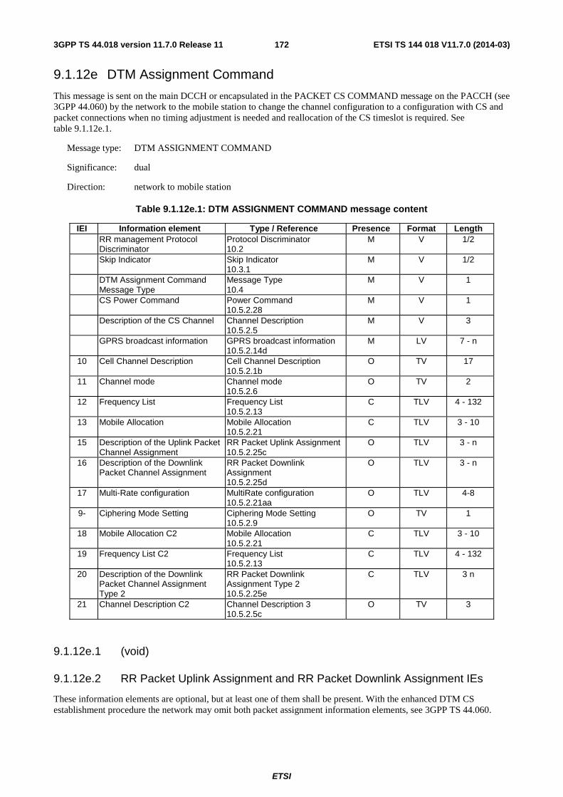
ETSI
ETSI TS 144 018 V11.7.0 (2014-03)1723GPP TS 44.018 version 11.7.0 Release 11
9.1.12e DTM Assignment Command
This message is sent on the main DCCH or encapsulated in the PACKET CS COMMAND message on the PACCH (see 3GPP 44.060) by the network to the mobile station to change the channel configuration to a configuration with CS and packet connections when no timing adjustment is needed and reallocation of the CS timeslot is required. See table 9.1.12e.1.
Message type: DTM ASSIGNMENT COMMAND
Significance: dual
Direction: network to mobile station
Table 9.1.12e.1: DTM ASSIGNMENT COMMAND message content
IEI Information element Type / Reference Presence Format Length RR management Protocol
Discriminator Protocol Discriminator 10.2
M V 1/2
Skip Indicator Skip Indicator 10.3.1
M V 1/2
DTM Assignment Command Message Type
Message Type 10.4
M V 1
CS Power Command Power Command 10.5.2.28
M V 1
Description of the CS Channel Channel Description 10.5.2.5
M V 3
GPRS broadcast information GPRS broadcast information 10.5.2.14d
M LV 7 - n
10 Cell Channel Description Cell Channel Description 10.5.2.1b
O TV 17
11 Channel mode Channel mode 10.5.2.6
O TV 2
12 Frequency List Frequency List 10.5.2.13
C TLV 4 - 132
13 Mobile Allocation Mobile Allocation 10.5.2.21
C TLV 3 - 10
15 Description of the Uplink Packet Channel Assignment
RR Packet Uplink Assignment 10.5.2.25c
O TLV 3 - n
16 Description of the Downlink Packet Channel Assignment
RR Packet Downlink Assignment 10.5.2.25d
O TLV 3 - n
17 Multi-Rate configuration MultiRate configuration 10.5.2.21aa
O TLV 4-8
9- Ciphering Mode Setting Ciphering Mode Setting 10.5.2.9
O TV 1
18 Mobile Allocation C2 Mobile Allocation 10.5.2.21
C TLV 3 - 10
19 Frequency List C2 Frequency List 10.5.2.13
C TLV 4 - 132
20 Description of the Downlink Packet Channel Assignment Type 2
RR Packet Downlink Assignment Type 2 10.5.2.25e
C TLV 3 n
21 Channel Description C2 Channel Description 3 10.5.2.5c
O TV 3
9.1.12e.1 (void)
9.1.12e.2 RR Packet Uplink Assignment and RR Packet Downlink Assignment IEs
These information elements are optional, but at least one of them shall be present. With the enhanced DTM CS establishment procedure the network may omit both packet assignment information elements, see 3GPP TS 44.060.
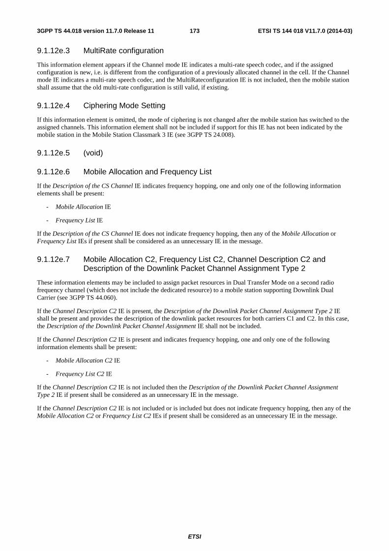
ETSI
ETSI TS 144 018 V11.7.0 (2014-03)1733GPP TS 44.018 version 11.7.0 Release 11
9.1.12e.3 MultiRate configuration
This information element appears if the Channel mode IE indicates a multi-rate speech codec, and if the assigned configuration is new, i.e. is different from the configuration of a previously allocated channel in the cell. If the Channel mode IE indicates a multi-rate speech codec, and the MultiRateconfiguration IE is not included, then the mobile station shall assume that the old multi-rate configuration is still valid, if existing.
9.1.12e.4 Ciphering Mode Setting
If this information element is omitted, the mode of ciphering is not changed after the mobile station has switched to the assigned channels. This information element shall not be included if support for this IE has not been indicated by the mobile station in the Mobile Station Classmark 3 IE (see 3GPP TS 24.008).
9.1.12e.5 (void)
9.1.12e.6 Mobile Allocation and Frequency List
If the Description of the CS Channel IE indicates frequency hopping, one and only one of the following information elements shall be present:
- Mobile Allocation IE
- Frequency List IE
If the Description of the CS Channel IE does not indicate frequency hopping, then any of the Mobile Allocation or Frequency List IEs if present shall be considered as an unnecessary IE in the message.
9.1.12e.7 Mobile Allocation C2, Frequency List C2, Channel Description C2 and Description of the Downlink Packet Channel Assignment Type 2
These information elements may be included to assign packet resources in Dual Transfer Mode on a second radio frequency channel (which does not include the dedicated resource) to a mobile station supporting Downlink Dual Carrier (see 3GPP TS 44.060).
If the Channel Description C2 IE is present, the Description of the Downlink Packet Channel Assignment Type 2 IE shall be present and provides the description of the downlink packet resources for both carriers C1 and C2. In this case, the Description of the Downlink Packet Channel Assignment IE shall not be included.
If the Channel Description C2 IE is present and indicates frequency hopping, one and only one of the following information elements shall be present:
- Mobile Allocation C2 IE
- Frequency List C2 IE
If the Channel Description C2 IE is not included then the Description of the Downlink Packet Channel Assignment Type 2 IE if present shall be considered as an unnecessary IE in the message.
If the Channel Description C2 IE is not included or is included but does not indicate frequency hopping, then any of the Mobile Allocation C2 or Frequency List C2 IEs if present shall be considered as an unnecessary IE in the message.
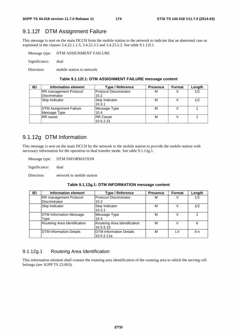
ETSI
ETSI TS 144 018 V11.7.0 (2014-03)1743GPP TS 44.018 version 11.7.0 Release 11
9.1.12f DTM Assignment Failure
This message is sent on the main DCCH from the mobile station to the network to indicate that an abnormal case as explained in the clauses 3.4.22.1.1.5, 3.4.22.3.3 and 3.4.23.2.3. See table 9.1.12f.1.
Message type: DTM ASSIGNMENT FAILURE
Significance: dual
Direction: mobile station to network
Table 9.1.12f.1: DTM ASSIGNMENT FAILURE message content
IEI Information element Type / Reference Presence Format Length RR management Protocol
Discriminator Protocol Discriminator 10.2
M V 1/2
Skip Indicator Skip Indicator 10.3.1
M V 1/2
DTM Assignment Failure Message Type
Message Type 10.4
M V 1
RR cause RR Cause 10.5.2.31
M V 1
9.1.12g DTM Information
This message is sent on the main DCCH by the network to the mobile station to provide the mobile station with necessary information for the operation in dual transfer mode. See table 9.1.12g.1.
Message type: DTM INFORMATION
Significance: dual
Direction: network to mobile station
Table 9.1.12g.1: DTM INFORMATION message content
IEI Information element Type / Reference Presence Format Length RR management Protocol
Discriminator Protocol Discriminator 10.2
M V 1/2
Skip Indicator Skip Indicator 10.3.1
M V 1/2
DTM Information Message Type
Message Type 10.4
M V 1
Routeing Area Identification Routeing Area Identification 10.5.5.15
M V 6
DTM Information Details DTM Information Details 10.5.2.11a
M LV 4-n
9.1.12g.1 Routeing Area Identification
This information element shall contain the routeing area identification of the routeing area to which the serving cell belongs (see 3GPP TS 23.003).
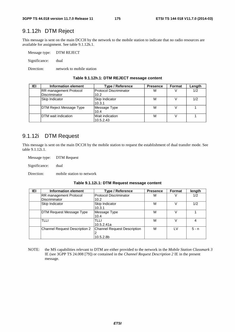
ETSI
ETSI TS 144 018 V11.7.0 (2014-03)1753GPP TS 44.018 version 11.7.0 Release 11
9.1.12h DTM Reject
This message is sent on the main DCCH by the network to the mobile station to indicate that no radio resources are available for assignment. See table 9.1.12h.1.
Message type: DTM REJECT
Significance: dual
Direction: network to mobile station
Table 9.1.12h.1: DTM REJECT message content
IEI Information element Type / Reference Presence Format Length RR management Protocol
Discriminator Protocol Discriminator 10.2
M V 1/2
Skip Indicator Skip Indicator 10.3.1
M V 1/2
DTM Reject Message Type Message Type 10.4
M V 1
DTM wait indication Wait indication 10.5.2.43
M V 1
9.1.12i DTM Request
This message is sent on the main DCCH by the mobile station to request the establishment of dual transfer mode. See table 9.1.12i.1.
Message type: DTM Request
Significance: dual
Direction: mobile station to network
Table 9.1.12i.1: DTM Request message content
IEI Information element Type / Reference Presence Format length RR management Protocol
Discriminator Protocol Discriminator 10.2
M V 1/2
Skip Indicator Skip Indicator 10.3.1
M V 1/2
DTM Request Message Type Message Type 10.4
M V 1
TLLI TLLI 10.5.2.41a
M V 4
Channel Request Description 2 Channel Request Description 2 10.5.2.8b
M LV 5 - n
NOTE: the MS capabilities relevant to DTM are either provided to the network in the Mobile Station Classmark 3 IE (see 3GPP TS 24.008 [79]) or contained in the Channel Request Description 2 IE in the present message.
ETSI
ETSI TS 144 018 V11.7.0 (2014-03)1763GPP TS 44.018 version 11.7.0 Release 11
9.1.13 Frequency redefinition
This message is sent on the main DCCH from the network to the MS to indicate that the frequencies and the hopping sequence of the allocated channels shall be changed. See table 9.1.13.1
Message type: FREQUENCY REDEFINITION
Significance: dual
Direction: network to MS
Table 9.1.13.1: FREQUENCY REDEFINITION message content
IEI Information element Type / Reference Presence Format length RR management Protocol
Discriminator Protocol Discriminator 10.2
M V ½
Skip Indicator Skip Indicator 10.3.1
M V ½
Frequency Redefinition Message Type
Message Type 10.4
M V 1
Channel Description Channel Description 10.5.2.5
M V 3
Mobile Allocation Mobile Allocation 10.5.2.21
M LV 1-9
Starting Time Starting Time 10.5.2.38
M V 2
62 Cell Channel Description Cell Channel Description 10.5.2.1b
O TV 17
9- Carrier Indication Carrier Indication 10.5.2.69
C TV 1
11 Mobile Allocation C2 Mobile Allocation 10.5.2.21
C TLV 2-10
12 Channel Description C2 Channel Description 3 10.5.2.5c
C TV 3
9.1.13.1 Cell Channel Description
If it does not appear, the cell channel description is assumed to be unchanged.
9.1.13.2 Carrier Indication
This information element shall only be included if the mobile station is in dual transfer mode, has been assigned packet resources on two carriers, and the Frequency Redefinition message is applicable only to one carrier. The IE shall indicate which carrier the message applies to. In this case the frequency parameters applicable to the indicated carrier are provided in the Channel Description IE and the Mobile Allocation IE.
9.1.13.3 Mobile Allocation C2 and Channel Description C2
These information element shall be included if the Frequency Redefinition message is used to change the frequency parameters for both carriers being used by a downlink dual carrier capable mobile station in dual transfer mode (in this case the Carrier Indication IE is not present). The frequency parameters applicable to carrier 1 are provided in the Channel Description and the Mobile Allocation IEs, while the frequency parameters applicable to carrier 2 are provided in the Channel Description C2 and the Mobile Allocation C2 IEs.
Either the Carrier Indication IE, or the two Mobile Allocation C2 and Channel Description C2 IEs shall be present, not all three IEs.
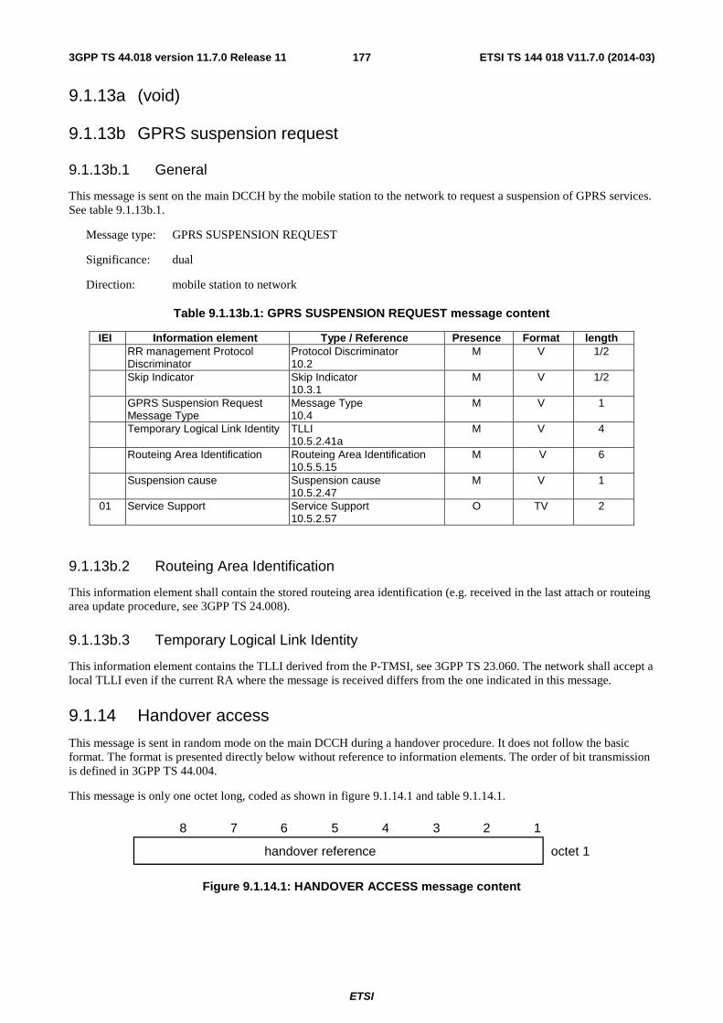
ETSI
ETSI TS 144 018 V11.7.0 (2014-03)1773GPP TS 44.018 version 11.7.0 Release 11
9.1.13a (void)
9.1.13b GPRS suspension request
9.1.13b.1 General
This message is sent on the main DCCH by the mobile station to the network to request a suspension of GPRS services. See table 9.1.13b.1.
Message type: GPRS SUSPENSION REQUEST
Significance: dual
Direction: mobile station to network
Table 9.1.13b.1: GPRS SUSPENSION REQUEST message content
IEI Information element Type / Reference Presence Format length RR management Protocol
Discriminator Protocol Discriminator 10.2
M V 1/2
Skip Indicator Skip Indicator 10.3.1
M V 1/2
GPRS Suspension Request Message Type
Message Type 10.4
M V 1
Temporary Logical Link Identity TLLI 10.5.2.41a
M V 4
Routeing Area Identification Routeing Area Identification 10.5.5.15
M V 6
Suspension cause Suspension cause 10.5.2.47
M V 1
01 Service Support Service Support 10.5.2.57
O TV 2
9.1.13b.2 Routeing Area Identification
This information element shall contain the stored routeing area identification (e.g. received in the last attach or routeing area update procedure, see 3GPP TS 24.008).
9.1.13b.3 Temporary Logical Link Identity
This information element contains the TLLI derived from the P-TMSI, see 3GPP TS 23.060. The network shall accept a local TLLI even if the current RA where the message is received differs from the one indicated in this message.
9.1.14 Handover access
This message is sent in random mode on the main DCCH during a handover procedure. It does not follow the basic format. The format is presented directly below without reference to information elements. The order of bit transmission is defined in 3GPP TS 44.004.
This message is only one octet long, coded as shown in figure 9.1.14.1 and table 9.1.14.1.
8 7 6 5 4 3 2 1
octet 1handover reference
Figure 9.1.14.1: HANDOVER ACCESS message content

ETSI
ETSI TS 144 018 V11.7.0 (2014-03)1783GPP TS 44.018 version 11.7.0 Release 11
Table 9.1.14.1: HANDOVER ACCESS message content
HANDOVER REFERENCE This is an unformatted 8 bit field. (also described in sub-clause 10.5.2.15)
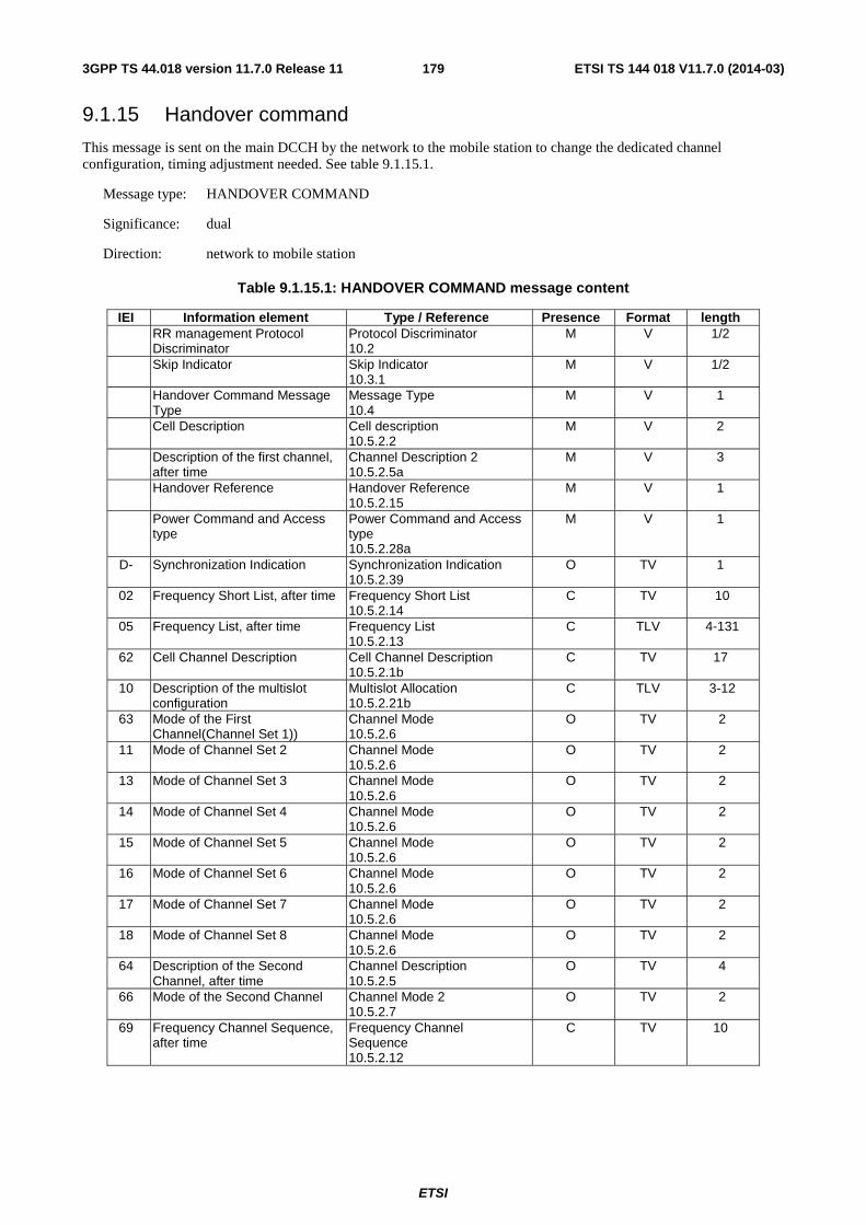
ETSI
ETSI TS 144 018 V11.7.0 (2014-03)1793GPP TS 44.018 version 11.7.0 Release 11
9.1.15 Handover command
This message is sent on the main DCCH by the network to the mobile station to change the dedicated channel configuration, timing adjustment needed. See table 9.1.15.1.
Message type: HANDOVER COMMAND
Significance: dual
Direction: network to mobile station
Table 9.1.15.1: HANDOVER COMMAND message content
IEI Information element Type / Reference Presence Format length RR management Protocol
Discriminator Protocol Discriminator 10.2
M V 1/2
Skip Indicator Skip Indicator 10.3.1
M V 1/2
Handover Command Message Type
Message Type 10.4
M V 1
Cell Description Cell description 10.5.2.2
M V 2
Description of the first channel, after time
Channel Description 2 10.5.2.5a
M V 3
Handover Reference Handover Reference 10.5.2.15
M V 1
Power Command and Access type
Power Command and Access type 10.5.2.28a
M V 1
D- Synchronization Indication Synchronization Indication 10.5.2.39
O TV 1
02 Frequency Short List, after time Frequency Short List 10.5.2.14
C TV 10
05 Frequency List, after time Frequency List 10.5.2.13
C TLV 4-131
62 Cell Channel Description Cell Channel Description 10.5.2.1b
C TV 17
10 Description of the multislot configuration
Multislot Allocation 10.5.2.21b
C TLV 3-12
63 Mode of the First Channel(Channel Set 1))
Channel Mode 10.5.2.6
O TV 2
11 Mode of Channel Set 2 Channel Mode 10.5.2.6
O TV 2
13 Mode of Channel Set 3 Channel Mode 10.5.2.6
O TV 2
14 Mode of Channel Set 4 Channel Mode 10.5.2.6
O TV 2
15 Mode of Channel Set 5 Channel Mode 10.5.2.6
O TV 2
16 Mode of Channel Set 6 Channel Mode 10.5.2.6
O TV 2
17 Mode of Channel Set 7 Channel Mode 10.5.2.6
O TV 2
18 Mode of Channel Set 8 Channel Mode 10.5.2.6
O TV 2
64 Description of the Second Channel, after time
Channel Description 10.5.2.5
O TV 4
66 Mode of the Second Channel Channel Mode 2 10.5.2.7
O TV 2
69 Frequency Channel Sequence, after time
Frequency Channel Sequence 10.5.2.12
C TV 10
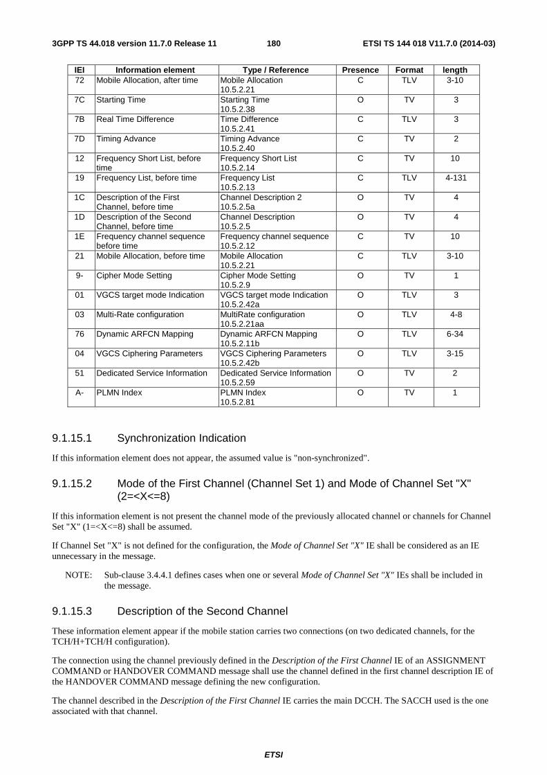
ETSI
ETSI TS 144 018 V11.7.0 (2014-03)1803GPP TS 44.018 version 11.7.0 Release 11
IEI Information element Type / Reference Presence Format length 72 Mobile Allocation, after time Mobile Allocation
10.5.2.21 C TLV 3-10
7C Starting Time Starting Time 10.5.2.38
O TV 3
7B Real Time Difference Time Difference 10.5.2.41
C TLV 3
7D Timing Advance Timing Advance 10.5.2.40
C TV 2
12 Frequency Short List, before time
Frequency Short List 10.5.2.14
C TV 10
19 Frequency List, before time Frequency List 10.5.2.13
C TLV 4-131
1C Description of the First Channel, before time
Channel Description 2 10.5.2.5a
O TV 4
1D Description of the Second Channel, before time
Channel Description 10.5.2.5
O TV 4
1E Frequency channel sequence before time
Frequency channel sequence 10.5.2.12
C TV 10
21 Mobile Allocation, before time Mobile Allocation 10.5.2.21
C TLV 3-10
9- Cipher Mode Setting Cipher Mode Setting 10.5.2.9
O TV 1
01 VGCS target mode Indication VGCS target mode Indication 10.5.2.42a
O TLV 3
03 Multi-Rate configuration MultiRate configuration 10.5.2.21aa
O TLV 4-8
76 Dynamic ARFCN Mapping Dynamic ARFCN Mapping 10.5.2.11b
O TLV 6-34
04 VGCS Ciphering Parameters VGCS Ciphering Parameters 10.5.2.42b
O TLV 3-15
51 Dedicated Service Information Dedicated Service Information 10.5.2.59
O TV 2
A- PLMN Index PLMN Index 10.5.2.81
O TV 1
9.1.15.1 Synchronization Indication
If this information element does not appear, the assumed value is "non-synchronized".
9.1.15.2 Mode of the First Channel (Channel Set 1) and Mode of Channel Set "X" (2=<X<=8)
If this information element is not present the channel mode of the previously allocated channel or channels for Channel Set "X" (1=<X<=8) shall be assumed.
If Channel Set "X" is not defined for the configuration, the Mode of Channel Set "X" IE shall be considered as an IE unnecessary in the message.
NOTE: Sub-clause 3.4.4.1 defines cases when one or several Mode of Channel Set "X" IEs shall be included in the message.
9.1.15.3 Description of the Second Channel
These information element appear if the mobile station carries two connections (on two dedicated channels, for the TCH/H+TCH/H configuration).
The connection using the channel previously defined in the Description of the First Channel IE of an ASSIGNMENT COMMAND or HANDOVER COMMAND message shall use the channel defined in the first channel description IE of the HANDOVER COMMAND message defining the new configuration.
The channel described in the Description of the First Channel IE carries the main DCCH. The SACCH used is the one associated with that channel.

ETSI
ETSI TS 144 018 V11.7.0 (2014-03)1813GPP TS 44.018 version 11.7.0 Release 11
9.1.15.4 Mode of the Second Channel
If the Description of the Second Channel IE is not present and the information element is present it shall be considered as an IE unnecessary in the message.
This element appears at least when the channel mode is changed for the channel defined in the Description of the Second Channel information element.
9.1.15.5 Frequency Channel Sequence, Frequency List, Frequency short list and Mobile Allocation, after time.
If at least one of the channel descriptions for after time indicates frequency hopping, one and only one of the following information elements shall be present:
- Frequency Channel Sequence, after time;
- Frequency list, after time;
- Frequency Short List, after time;
- Mobile Allocation, after time.
If neither of the Channel Description IEs indicate frequency hopping, if they are not required for the decoding of Channel Description IEs for before time, and if any of the four information elements are present they shall be considered as IEs unnecessary in the message.
The Frequency Channel Sequence information element shall not be used unless all the ARFCNs that it indicates are in the P-GSM band.
9.1.15.6 Starting Time
The starting time information element is included when the network wants the mobile station to change the frequency parameters of the channels more or less at the moment a change of channel occurs. In this case a number of information elements may be included to give the frequency parameters to be used before the starting time.
The starting time information element refers to the new cell time.
If the starting time information element is present and none of the information elements referring to before the starting time are present, the mobile station waits and accesses the channels at the indicated time.
If the starting time information element is present and at least one of the information elements referring to before the starting time is present, the mobile station does not wait for the indicated time and accesses the channel using the frequency parameters for before the starting time.
If the starting time information element is not present and some of the information elements referring to before the starting time is present, these information elements shall be considered as IEs unnecessary in the message.
If the description of the first channel, before time IE is not present, the channel description to apply for before the time, if needed, is given by the description of the first channel, after time IE.
If the description of the second channel, after time IE is present, the description of the second channel, before time IE not present, and a description of the configuration for before the time needed, the channel configuration before the starting time is nevertheless of two traffic channels, and the channel description to apply to the second channel before the starting time is given by the description of the second channel, after time IE.

ETSI
ETSI TS 144 018 V11.7.0 (2014-03)1823GPP TS 44.018 version 11.7.0 Release 11
If the starting time IE is present and at least one of the channel descriptions for before the starting time indicates frequency hopping, one and only one of the following information elements may be present and applies before the starting time to all assigned channels:
- Mobile Allocation, before time IE;
- Frequency Short list, before time IE;
- Frequency list, before time IE;
- Frequency channel sequence, before time IE.
If the starting time IE is present and at least one of the channel descriptions for before the starting time indicates frequency hopping, and none of the above mentioned IE is present, a frequency list for after the starting time must be present (see sub-clause 9.1.2.4), and this list applies also for the channels before the starting time.
9.1.15.7 Reference cell frequency list
If any of the mobile allocation information elements is present, then the cell channel description IE must be present. It is used to decode the mobile allocation IEs in the message.
In addition, if no information elements pertaining to before the starting time is present in the message, the frequency list defined by the cell channel description IE is used to decode the mobile allocation IEs in later messages received in the new cell until reception of a new reference cell frequency list or the new cell is left.
9.1.15.8 Real Time Difference
This information element shall appear if the Synchronization Indication information element indicates a pseudo-synchronous handover otherwise it shall be considered as an unnecessary information element.
9.1.15.9 Timing Advance
This information element shall appear if the "synchronization indication" element indicates a presynchronized handover. If not included for a presynchronized handover, then the default value as defined in 3GPP TS 45.010 shall be used. For other types of handover it shall be considered as an unnecessary information element.
9.1.15.10 Cipher Mode Setting
If this information element is omitted, the mode of ciphering is not changed after the mobile station has switched to the assigned channel.
In the case of inter-RAT or inter-mode handover to GERAN A/Gb mode, the HANDOVER COMMAND message shall always contain the cipher mode setting IE (see sub-clause 3.4.4.1).
Only applicable for mobile stations supporting VGCS talking:
The cipher mode setting IE shall not be included if the HANDOVER COMMAND message is sent on a VGCS channel or on a dedicated channel for a handover to a VGCS channel.
The cipher mode setting IE shall be included if the HANDOVER COMMAND message is sent on a ciphered VGCS channel for a handover to a dedicated channel. If the information element is not present, the MS shall use ciphering mode "no ciphering" on the assigned channel.
9.1.15.11 VGCS target mode indication
This information element is identified as "comprehension required". Only mobile stations supporting "VGCS talking" are required to accept the presence of the element. The presence of the element shall trigger an exception handling if received by a mobile station not supporting "VGCS talking".
This IE indicates which mode is to be used on the new channel (i.e. dedicated mode or group transmit mode). If this information element is not present, the mode shall be the same as on the previous channel.
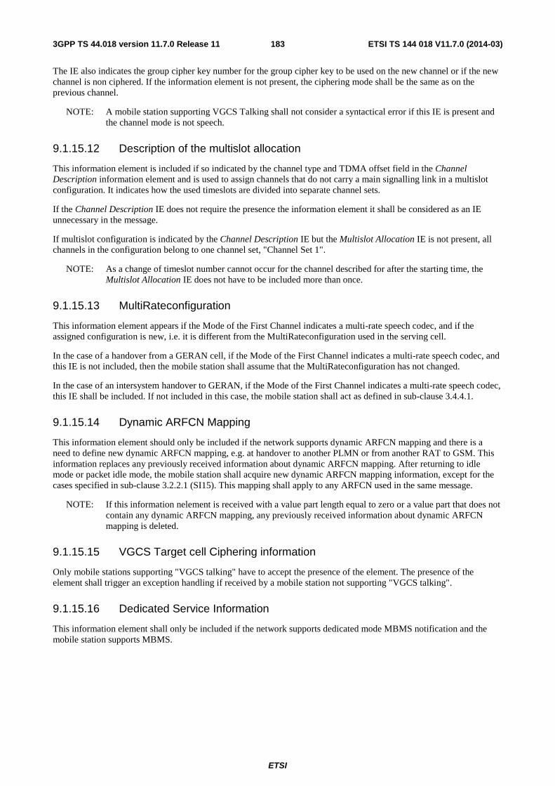
ETSI
ETSI TS 144 018 V11.7.0 (2014-03)1833GPP TS 44.018 version 11.7.0 Release 11
The IE also indicates the group cipher key number for the group cipher key to be used on the new channel or if the new channel is non ciphered. If the information element is not present, the ciphering mode shall be the same as on the previous channel.
NOTE: A mobile station supporting VGCS Talking shall not consider a syntactical error if this IE is present and the channel mode is not speech.
9.1.15.12 Description of the multislot allocation
This information element is included if so indicated by the channel type and TDMA offset field in the Channel Description information element and is used to assign channels that do not carry a main signalling link in a multislot configuration. It indicates how the used timeslots are divided into separate channel sets.
If the Channel Description IE does not require the presence the information element it shall be considered as an IE unnecessary in the message.
If multislot configuration is indicated by the Channel Description IE but the Multislot Allocation IE is not present, all channels in the configuration belong to one channel set, "Channel Set 1".
NOTE: As a change of timeslot number cannot occur for the channel described for after the starting time, the Multislot Allocation IE does not have to be included more than once.
9.1.15.13 MultiRateconfiguration
This information element appears if the Mode of the First Channel indicates a multi-rate speech codec, and if the assigned configuration is new, i.e. it is different from the MultiRateconfiguration used in the serving cell.
In the case of a handover from a GERAN cell, if the Mode of the First Channel indicates a multi-rate speech codec, and this IE is not included, then the mobile station shall assume that the MultiRateconfiguration has not changed.
In the case of an intersystem handover to GERAN, if the Mode of the First Channel indicates a multi-rate speech codec, this IE shall be included. If not included in this case, the mobile station shall act as defined in sub-clause 3.4.4.1.
9.1.15.14 Dynamic ARFCN Mapping
This information element should only be included if the network supports dynamic ARFCN mapping and there is a need to define new dynamic ARFCN mapping, e.g. at handover to another PLMN or from another RAT to GSM. This information replaces any previously received information about dynamic ARFCN mapping. After returning to idle mode or packet idle mode, the mobile station shall acquire new dynamic ARFCN mapping information, except for the cases specified in sub-clause 3.2.2.1 (SI15). This mapping shall apply to any ARFCN used in the same message.
NOTE: If this information nelement is received with a value part length equal to zero or a value part that does not contain any dynamic ARFCN mapping, any previously received information about dynamic ARFCN mapping is deleted.
9.1.15.15 VGCS Target cell Ciphering information
Only mobile stations supporting "VGCS talking" have to accept the presence of the element. The presence of the element shall trigger an exception handling if received by a mobile station not supporting "VGCS talking".
9.1.15.16 Dedicated Service Information
This information element shall only be included if the network supports dedicated mode MBMS notification and the mobile station supports MBMS.
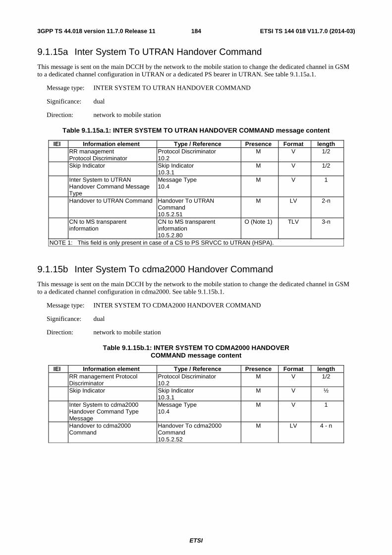
ETSI
ETSI TS 144 018 V11.7.0 (2014-03)1843GPP TS 44.018 version 11.7.0 Release 11
9.1.15a Inter System To UTRAN Handover Command
This message is sent on the main DCCH by the network to the mobile station to change the dedicated channel in GSM to a dedicated channel configuration in UTRAN or a dedicated PS bearer in UTRAN. See table 9.1.15a.1.
Message type: INTER SYSTEM TO UTRAN HANDOVER COMMAND
Significance: dual
Direction: network to mobile station
Table 9.1.15a.1: INTER SYSTEM TO UTRAN HANDOVER COMMAND message content
IEI Information element Type / Reference Presence Format length RR management
Protocol Discriminator Protocol Discriminator 10.2
M V 1/2
Skip Indicator Skip Indicator 10.3.1
M V 1/2
Inter System to UTRAN Handover Command Message Type
Message Type 10.4
M V 1
Handover to UTRAN Command Handover To UTRAN Command 10.5.2.51
M LV 2-n
CN to MS transparent information
CN to MS transparent information 10.5.2.80
O (Note 1) TLV 3-n
NOTE 1: This field is only present in case of a CS to PS SRVCC to UTRAN (HSPA).
9.1.15b Inter System To cdma2000 Handover Command
This message is sent on the main DCCH by the network to the mobile station to change the dedicated channel in GSM to a dedicated channel configuration in cdma2000. See table 9.1.15b.1.
Message type: INTER SYSTEM TO CDMA2000 HANDOVER COMMAND
Significance: dual
Direction: network to mobile station
Table 9.1.15b.1: INTER SYSTEM TO CDMA2000 HANDOVER COMMAND message content
IEI Information element Type / Reference Presence Format length RR management Protocol
Discriminator Protocol Discriminator 10.2
M V 1/2
Skip Indicator Skip Indicator 10.3.1
M V ½
Inter System to cdma2000 Handover Command Type Message
Message Type 10.4
M V 1
Handover to cdma2000 Command
Handover To cdma2000 Command 10.5.2.52
M LV 4 - n

ETSI
ETSI TS 144 018 V11.7.0 (2014-03)1853GPP TS 44.018 version 11.7.0 Release 11
9.1.15c HANDOVER TO GERAN Iu MODE Command
This message is sent on the main DCCH by the network to the mobile station to reconfigure the dedicated channels in GSM to a dedicated channel configuration in GERAN Iu mode. See table 9.1.15c.1.
Message type: HANDOVER TO GERAN Iu MODE COMMAND
Significance: dual
Direction: network to mobile station
Table 9.1.15c.1: HANDOVER TO GERAN Iu MODE COMMAND message content
IEI Information element Type / Reference Presence Format length RR management
Protocol Discriminator Protocol Discriminator 10.2
M V 1/2
Skip Indicator Skip Indicator 10.3.1
M V 1/2
HANDOVER TO GERAN Iu MODE COMMAND Message Type
Message Type 10.4
M V 1
RADIO BEARER RECONFIGURATION
RADIO BEARER RECONFIGURATION 3GPP TS 44.118
M LV 2-n
9.1.15d Inter System To E-UTRAN Handover Command
This message is sent on the main DCCH by the network to the mobile station to change the dedicated channel in GSM to a dedicated PS bearer in E-UTRAN. See table 9.1.15d.1.
Message type: INTER SYSTEM TO E-UTRAN HANDOVER COMMAND
Significance: dual
Direction: network to mobile station
Table 9.1.15d.1: INTER SYSTEM TO E-UTRAN HANDOVER COMMAND message content
IEI Information element Type / Reference Presence Format length RR management
Protocol Discriminator Protocol Discriminator 10.2
M V 1/2
Skip Indicator Skip Indicator 10.3.1
M V 1/2
INTER SYSTEM TO E-UTRAN HANDOVER COMMAND Message Type
Message Type 10.4
M V 1
DL-DCCH-Message DL-DCCH-Message 10.5.2.79
M LV 2-n
CN to MS transparent information
CN to MS transparent information 10.5.2.80
M LV 2-n
9.1.16 Handover complete
This message is sent on the main DCCH from the mobile station to the network to indicate that the mobile station has established the main signalling link successfully. See table 9.1.16.1.
Message type: HANDOVER COMPLETE
Significance: dual
Direction: mobile station to network
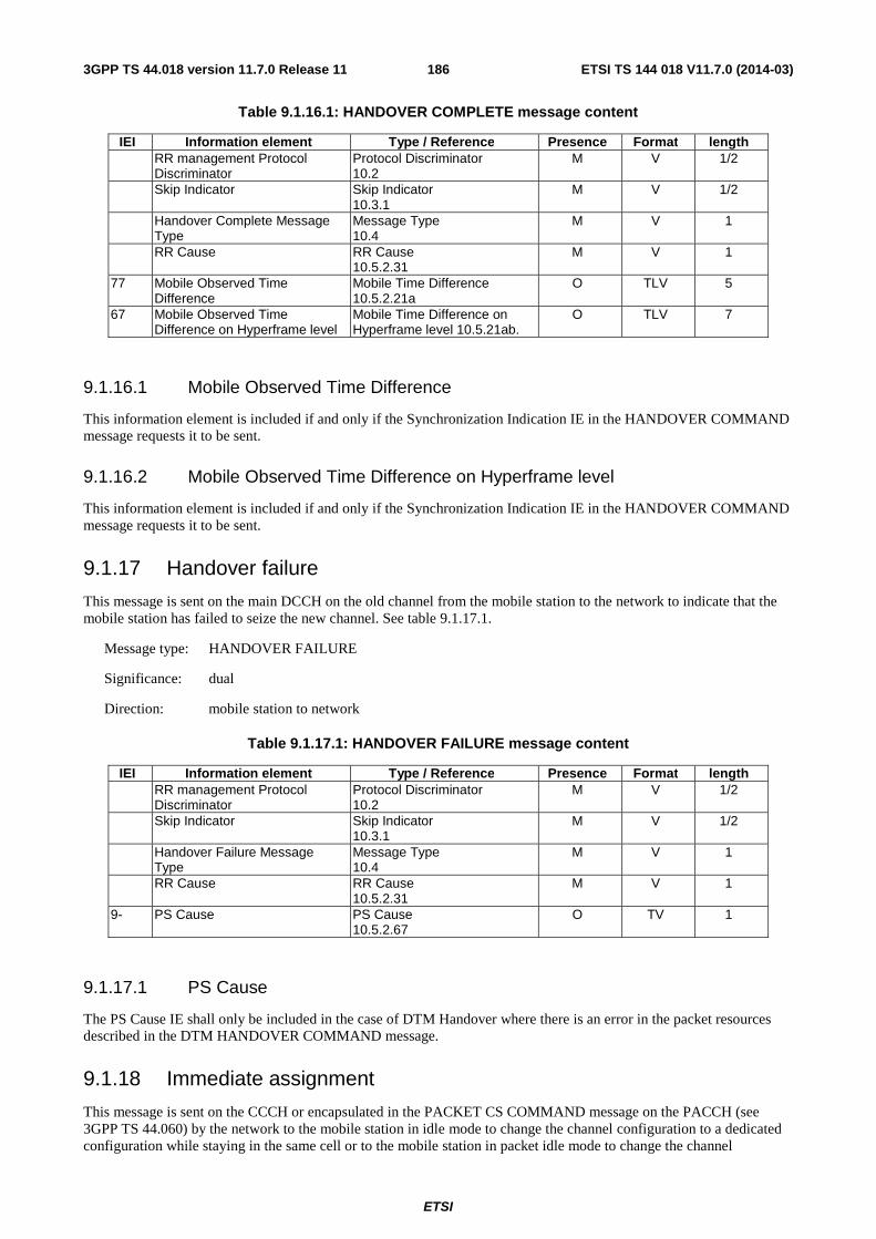
ETSI
ETSI TS 144 018 V11.7.0 (2014-03)1863GPP TS 44.018 version 11.7.0 Release 11
Table 9.1.16.1: HANDOVER COMPLETE message content
IEI Information element Type / Reference Presence Format length RR management Protocol
Discriminator Protocol Discriminator 10.2
M V 1/2
Skip Indicator Skip Indicator 10.3.1
M V 1/2
Handover Complete Message Type
Message Type 10.4
M V 1
RR Cause RR Cause 10.5.2.31
M V 1
77 Mobile Observed Time Difference
Mobile Time Difference 10.5.2.21a
O TLV 5
67 Mobile Observed Time Difference on Hyperframe level
Mobile Time Difference on Hyperframe level 10.5.21ab.
O TLV 7
9.1.16.1 Mobile Observed Time Difference
This information element is included if and only if the Synchronization Indication IE in the HANDOVER COMMAND message requests it to be sent.
9.1.16.2 Mobile Observed Time Difference on Hyperframe level
This information element is included if and only if the Synchronization Indication IE in the HANDOVER COMMAND message requests it to be sent.
9.1.17 Handover failure
This message is sent on the main DCCH on the old channel from the mobile station to the network to indicate that the mobile station has failed to seize the new channel. See table 9.1.17.1.
Message type: HANDOVER FAILURE
Significance: dual
Direction: mobile station to network
Table 9.1.17.1: HANDOVER FAILURE message content
IEI Information element Type / Reference Presence Format length RR management Protocol
Discriminator Protocol Discriminator 10.2
M V 1/2
Skip Indicator Skip Indicator 10.3.1
M V 1/2
Handover Failure Message Type
Message Type 10.4
M V 1
RR Cause RR Cause 10.5.2.31
M V 1
9- PS Cause PS Cause 10.5.2.67
O TV 1
9.1.17.1 PS Cause
The PS Cause IE shall only be included in the case of DTM Handover where there is an error in the packet resources described in the DTM HANDOVER COMMAND message.
9.1.18 Immediate assignment
This message is sent on the CCCH or encapsulated in the PACKET CS COMMAND message on the PACCH (see 3GPP TS 44.060) by the network to the mobile station in idle mode to change the channel configuration to a dedicated configuration while staying in the same cell or to the mobile station in packet idle mode to change the channel
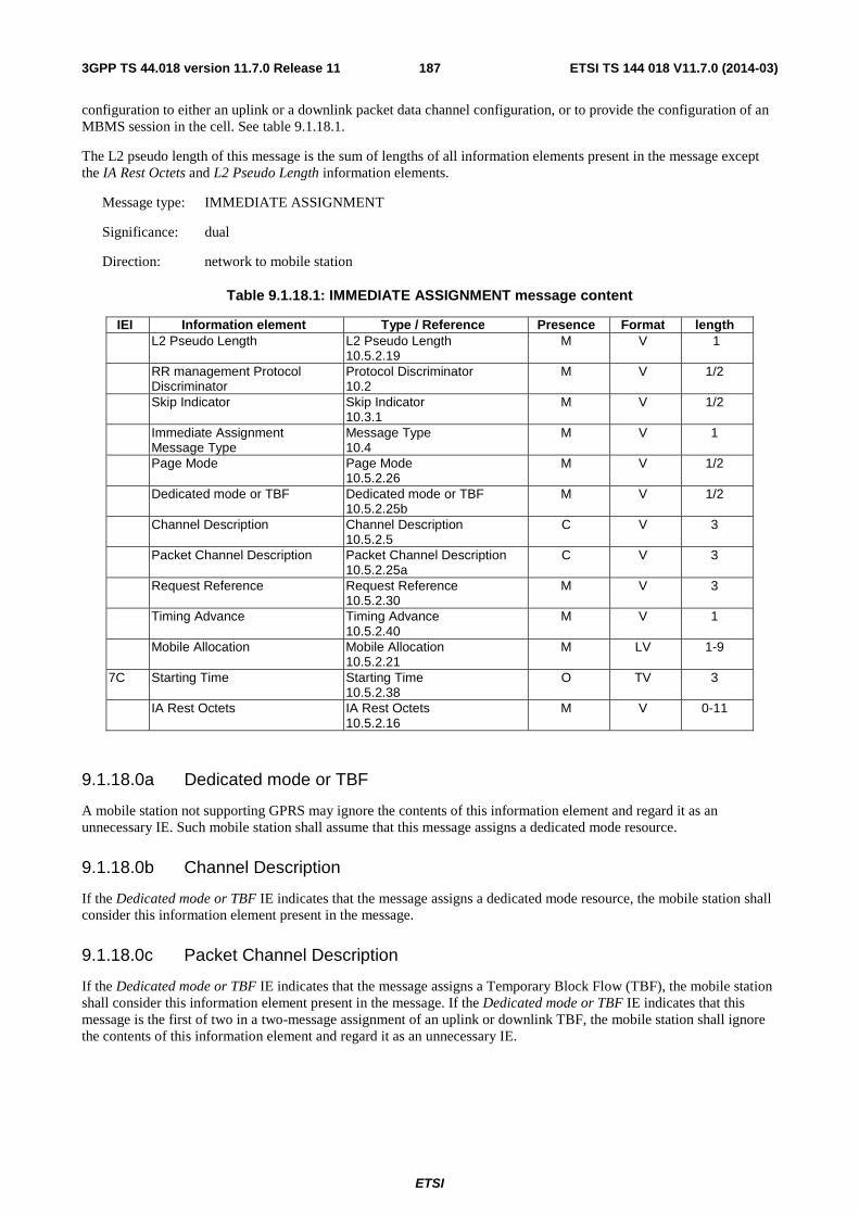
ETSI
ETSI TS 144 018 V11.7.0 (2014-03)1873GPP TS 44.018 version 11.7.0 Release 11
configuration to either an uplink or a downlink packet data channel configuration, or to provide the configuration of an MBMS session in the cell. See table 9.1.18.1.
The L2 pseudo length of this message is the sum of lengths of all information elements present in the message except the IA Rest Octets and L2 Pseudo Length information elements.
Message type: IMMEDIATE ASSIGNMENT
Significance: dual
Direction: network to mobile station
Table 9.1.18.1: IMMEDIATE ASSIGNMENT message content
IEI Information element Type / Reference Presence Format length L2 Pseudo Length L2 Pseudo Length
10.5.2.19 M V 1
RR management Protocol Discriminator
Protocol Discriminator 10.2
M V 1/2
Skip Indicator Skip Indicator 10.3.1
M V 1/2
Immediate Assignment Message Type
Message Type 10.4
M V 1
Page Mode Page Mode 10.5.2.26
M V 1/2
Dedicated mode or TBF Dedicated mode or TBF 10.5.2.25b
M V 1/2
Channel Description Channel Description 10.5.2.5
C V 3
Packet Channel Description Packet Channel Description 10.5.2.25a
C V 3
Request Reference Request Reference 10.5.2.30
M V 3
Timing Advance Timing Advance 10.5.2.40
M V 1
Mobile Allocation Mobile Allocation 10.5.2.21
M LV 1-9
7C Starting Time Starting Time 10.5.2.38
O TV 3
IA Rest Octets IA Rest Octets 10.5.2.16
M V 0-11
9.1.18.0a Dedicated mode or TBF
A mobile station not supporting GPRS may ignore the contents of this information element and regard it as an unnecessary IE. Such mobile station shall assume that this message assigns a dedicated mode resource.
9.1.18.0b Channel Description
If the Dedicated mode or TBF IE indicates that the message assigns a dedicated mode resource, the mobile station shall consider this information element present in the message.
9.1.18.0c Packet Channel Description
If the Dedicated mode or TBF IE indicates that the message assigns a Temporary Block Flow (TBF), the mobile station shall consider this information element present in the message. If the Dedicated mode or TBF IE indicates that this message is the first of two in a two-message assignment of an uplink or downlink TBF, the mobile station shall ignore the contents of this information element and regard it as an unnecessary IE.
ETSI
ETSI TS 144 018 V11.7.0 (2014-03)1883GPP TS 44.018 version 11.7.0 Release 11
9.1.18.0d Request Reference
If this message is used in an assignment of a downlink TBF, the network shall code this information element, e.g. by using a suitably offset frame number, such that the resource reference cannot be confused with any CHANNEL REQUEST message sent by a mobile station.
If the IA Rest Octets IE indicates that this message is the second message of a two-message assignment of an uplink or downlink TBF, this information element shall have the same contents as the first message of the assignment.
When set to the value '0111 1111', the RA information of the Request Reference IE indicates that an Extended RA field may be included in the IA Rest Octets. The mobile station shall use the information in the Extended RA field to identify the Immediate Assignment message corresponding to an EGPRS Packet Channel Request message. If the Extended RA field is not included, the mobile station shall assume that the Immediate Assignment message does not correspond to the EGPRS Packet Channel Request message.
When the mobile station receives the IMMEDIATE ASSIGNMENT message encapsulated in the PACKET CS COMMAND message on the PACCH (see 3GPP TS 44.060), it shall ignore the contents of this information element and regard it as an unnecessary IE.
9.1.18.0e Timing Advance
If the IA Rest Octets IE indicates that this message is the second message of a two-message assignment of an uplink or downlink TBF, the mobile station shall ignore the contents of this information element and regard it as an unnecessary IE.
9.1.18.1 Mobile Allocation
If this message assigns a dedicated mode resource and the Channel Description IE does not indicate frequency hopping, the length indicator of this information element shall be set to zero, and the mobile station shall consider the IE as an unnecessary IE.
If this message assigns a TBF and the Packet Channel Description IE does not indicate frequency hopping or if it uses indirect encoding of a hopping RF channel configuration, the length indicator of this information element shall be set to zero, and the mobile station shall consider the IE as an unnecessary IE.
9.1.18.2 Starting Time
This information element appears if e.g. a frequency change is in progress.
If this message is used in an assignment of an uplink or downlink TBF, the mobile station shall ignore the contents of the Starting Time information element if included and consider it as an unnecessary IE.
9.1.18.3 IA Rest Octets (Frequency parameters, before time)
The sum of the length of this IE and the L2 Pseudo Length of the message equals 22.
If the starting time IE is present but not the frequency parameters, before time construction, the mobile stations must wait until the starting time before accessing the channel.
If the starting time IE is present and the Channel Description IE does not indicate frequency hopping the mobile station shall consider the frequency parameters, before time construction as unnecessary in the message and the mobile must wait until the starting time before accessing the channel.
If the starting time IE is not present, the mobile station shall consider the frequency parameters, before time construction as unnecessary in the message.
9.1.18.4 IA Rest Octets (assignment of uplink or downlink TBF)
If the Dedicated mode or TBF IE indicates that this message is used in an assignment of a TBF, this information element shall contain a Packet Uplink Assignment, Packet Downlink Assignment, Second Part Packet Assignment construction or Multiple Blocks Packet Downlink Assignment construction.

ETSI
ETSI TS 144 018 V11.7.0 (2014-03)1893GPP TS 44.018 version 11.7.0 Release 11
If the Dedicated mode or TBF IE indicates that this message assigns a dedicated mode resource, but not that the mobile station is identified in the IA Rest Octets IE information element, the mobile station shall consider the Packet Uplink Assignment, Packet Downlink Assignment, Second Part Packet Assignment and Multiple Blocks Packet Downlink Assignment constructions as unnecessary in the message.
9.1.18a (void)
9.1.18b Immediate packet assignment
This message is sent on the CCCH by the network to multiple mobile stations in idle mode to assign either an uplink or a downlink packet data channel configuration in the cell. See table 9.1.18b.1.
The L2 pseudo length of this message is the sum of lengths of all information elements present in the message except the IPA Rest Octets and L2 Pseudo Length information elements.
NOTE: The network should take into account limitations of certain mobile stations to understand IMMEDIATE PACKET ASSIGNMENT message as these mobile stations may not be able to decode the Page Mode information element.
Message type: IMMEDIATE PACKET ASSIGNMENT
Significance: dual
Direction: network to mobile station
Table 9.1.18b.1: IMMEDIATE PACKET ASSIGNMENT message content
IEI Information element Type / Reference Presence Format length L2 Pseudo Length L2 Pseudo Length
10.5.2.19 M V 1
RR management Protocol Discriminator
Protocol Discriminator 10.2
M V 1/2
Skip Indicator Skip Indicator 10.3.1
M V 1/2
Immediate Packet Assignment Message Type
Message Type 10.4
M V 1
Page Mode Page Mode 10.5.2.26
M V 1/2
Feature Indicator Feature Indicator 10.5.2.76
M V 1/2
IPA Rest Octets IPA Rest Octets 10.5.2.78
M V 19
9.1.19 Immediate assignment extended
This message is sent on the CCCH by the network to two mobile stations in idle mode to change their channel configurations to different dedicated configurations while they stay in the same cell. See table 9.1.19.1
The L2 pseudo length of this message is the sum of lengths of all information elements present in the message except the IAX Rest Octets and L2 Pseudo Length information elements.
Message type: IMMEDIATE ASSIGNMENT EXTENDED
Significance: dual
Direction: network to mobile station
Table 9.1.19.1: IMMEDIATE ASSIGNMENT EXTENDED message content
IEI Information element Type / Reference Presence Format length L2 Pseudo Length L2 Pseudo Length
10.5.2.19 M V 1
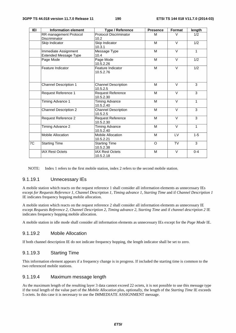
ETSI
ETSI TS 144 018 V11.7.0 (2014-03)1903GPP TS 44.018 version 11.7.0 Release 11
IEI Information element Type / Reference Presence Format length RR management Protocol
Discriminator Protocol Discriminator 10.2
M V 1/2
Skip Indicator Skip Indicator 10.3.1
M V 1/2
Immediate Assignment Extended Message Type
Message Type 10.4
M V 1
Page Mode Page Mode 10.5.2.26
M V 1/2
Feature Indicator Feature Indicator 10.5.2.76
M V 1/2
Channel Description 1 Channel Description 10.5.2.5
M V 3
Request Reference 1 Request Reference 10.5.2.30
M V 3
Timing Advance 1 Timing Advance 10.5.2.40
M V 1
Channel Description 2 Channel Description 10.5.2.5
M V 3
Request Reference 2 Request Reference 10.5.2.30
M V 3
Timing Advance 2 Timing Advance 10.5.2.40
M V 1
Mobile Allocation Mobile Allocation 10.5.2.21
M LV 1-5
7C Starting Time Starting Time 10.5.2.38
O TV 3
IAX Rest Octets IAX Rest Octets 10.5.2.18
M V 0-4
NOTE: Index 1 refers to the first mobile station, index 2 refers to the second mobile station.
9.1.19.1 Unnecessary IEs
A mobile station which reacts on the request reference 1 shall consider all information elements as unnecessary IEs except for Requests Reference 1, Channel Description 1, Timing advance 1, Starting Time and if Channel Description 1 IE indicates frequency hopping mobile allocation.
A mobile station which reacts on the request reference 2 shall consider all information elements as unnecessary IE except Requests Reference 2, Channel Description 2, Timing advance 2, Starting Time and if channel description 2 IE indicates frequency hopping mobile allocation.
A mobile station in idle mode shall consider all information elements as unnecessary IEs except for the Page Mode IE.
9.1.19.2 Mobile Allocation
If both channel description IE do not indicate frequency hopping, the length indicator shall be set to zero.
9.1.19.3 Starting Time
This information element appears if a frequency change is in progress. If included the starting time is common to the two referenced mobile stations.
9.1.19.4 Maximum message length
As the maximum length of the resulting layer 3 data cannot exceed 22 octets, it is not possible to use this message type if the total length of the value part of the Mobile Allocation plus, optionally, the length of the Starting Time IE exceeds 5 octets. In this case it is necessary to use the IMMEDIATE ASSIGNMENT message.

ETSI
ETSI TS 144 018 V11.7.0 (2014-03)1913GPP TS 44.018 version 11.7.0 Release 11
9.1.19.5 IAX Rest Octets
The sum of the length of this IE and the L2 Pseudo Length of the message equals 22.
9.1.20 Immediate assignment reject
This message is sent on the CCCH or encapsulated in the PACKET CS COMMAND message on the PACCH (see 3GPP TS 44.060) by the network to up to four mobile stations to indicate that no channel is available for assignment. See table 9.1.20.1. This message has L2 pseudo length 19.
Message type: IMMEDIATE ASSIGNMENT REJECT
Significance: dual
Direction: network to mobile station
Table 9.1.20.1: IMMEDIATE ASSIGNMENT REJECT message content
IEI Information element Type / Reference Presence Format length L2 Pseudo Length L2 Pseudo Length
10.5.2.19 M V 1
RR management Protocol Discriminator
Protocol Discriminator 10.2
M V 1/2
Skip Indicator Skip Indicator 10.3.1
M V 1/2
Immediate Assignment Reject Message Type
Message Type 10.4
M V 1
Page Mode Page Mode 10.5.2.26
M V 1/2
Feature Indicator Feature Indicator 10.5.2.76
M V 1/2
Request Reference 1 Request Reference 10.5.2.30
M V 3
Wait Indication 1 Wait Indication 10.5.2.43
M V 1
Request Reference 2 Request Reference 10.5.2.30
M V 3
Wait Indication 2 Wait Indication 10.5.2.43
M V 1
Request Reference 3 Request Reference 10.5.2.30
M V 3
Wait Indication 3 Wait Indication 10.5.2.43
M V 1
Request Reference 4 Request Reference 10.5.2.30
M V 3
Wait Indication 4 Wait Indication 10.5.2.43
M V 1
IAR Rest Octets IAR Rest Octets 10.5.2.17
M V 3
NOTE: Index 1 refers to the first mobile station, index 2 refers to the second MS and so on.
9.1.20.1 Use of the indexes
A request reference information element and the following wait indication information element refer to the same mobile station. So it is possible to reject up to four channel requests with this message.
9.1.20.2 Filling of the message
If necessary the request reference information element and the wait indication information element should be duplicated to fill the message.
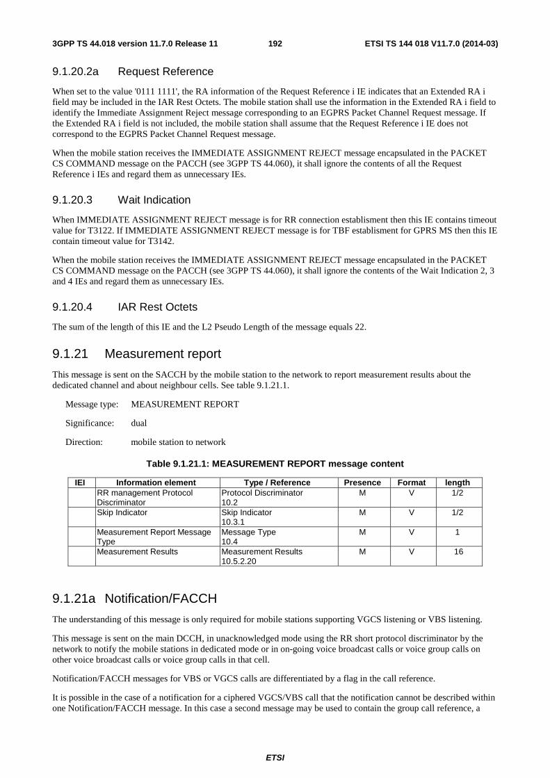
ETSI
ETSI TS 144 018 V11.7.0 (2014-03)1923GPP TS 44.018 version 11.7.0 Release 11
9.1.20.2a Request Reference
When set to the value '0111 1111', the RA information of the Request Reference i IE indicates that an Extended RA i field may be included in the IAR Rest Octets. The mobile station shall use the information in the Extended RA i field to identify the Immediate Assignment Reject message corresponding to an EGPRS Packet Channel Request message. If the Extended RA i field is not included, the mobile station shall assume that the Request Reference i IE does not correspond to the EGPRS Packet Channel Request message.
When the mobile station receives the IMMEDIATE ASSIGNMENT REJECT message encapsulated in the PACKET CS COMMAND message on the PACCH (see 3GPP TS 44.060), it shall ignore the contents of all the Request Reference i IEs and regard them as unnecessary IEs.
9.1.20.3 Wait Indication
When IMMEDIATE ASSIGNMENT REJECT message is for RR connection establisment then this IE contains timeout value for T3122. If IMMEDIATE ASSIGNMENT REJECT message is for TBF establisment for GPRS MS then this IE contain timeout value for T3142.
When the mobile station receives the IMMEDIATE ASSIGNMENT REJECT message encapsulated in the PACKET CS COMMAND message on the PACCH (see 3GPP TS 44.060), it shall ignore the contents of the Wait Indication 2, 3 and 4 IEs and regard them as unnecessary IEs.
9.1.20.4 IAR Rest Octets
The sum of the length of this IE and the L2 Pseudo Length of the message equals 22.
9.1.21 Measurement report
This message is sent on the SACCH by the mobile station to the network to report measurement results about the dedicated channel and about neighbour cells. See table 9.1.21.1.
Message type: MEASUREMENT REPORT
Significance: dual
Direction: mobile station to network
Table 9.1.21.1: MEASUREMENT REPORT message content
IEI Information element Type / Reference Presence Format length RR management Protocol
Discriminator Protocol Discriminator 10.2
M V 1/2
Skip Indicator Skip Indicator 10.3.1
M V 1/2
Measurement Report Message Type
Message Type 10.4
M V 1
Measurement Results Measurement Results 10.5.2.20
M V 16
9.1.21a Notification/FACCH
The understanding of this message is only required for mobile stations supporting VGCS listening or VBS listening.
This message is sent on the main DCCH, in unacknowledged mode using the RR short protocol discriminator by the network to notify the mobile stations in dedicated mode or in on-going voice broadcast calls or voice group calls on other voice broadcast calls or voice group calls in that cell.
Notification/FACCH messages for VBS or VGCS calls are differentiated by a flag in the call reference.
It is possible in the case of a notification for a ciphered VGCS/VBS call that the notification cannot be described within one Notification/FACCH message. In this case a second message may be used to contain the group call reference, a
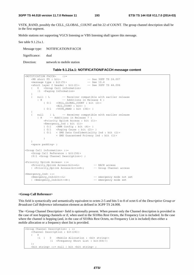
ETSI
ETSI TS 144 018 V11.7.0 (2014-03)1933GPP TS 44.018 version 11.7.0 Release 11
VSTK_RAND, possibly the CELL_GLOBAL_COUNT and bit 22 of COUNT. The group channel description shall be in the first segment.
Mobile stations not supporting VGCS listening or VBS listening shall ignore this message.
See table 9.1.21a.1.
Message type: NOTIFICATION/FACCH
Significance: dual
Direction: network to mobile station
Table 9.1.21a.1: NOTIFICATION/FACCH message content
<NOTIFICATION FACCH> ::= <RR short PD : bit> -- See 3GPP TS 24.007 <message type : bit(5)> -- See 10.4 <short layer 2 header : bit(2)> -- See 3GPP TS 44.006 { 0 <Group Call information> |1 <Paging Information> } { null | L -- Receiver compatible with earlier release | H -- Additions in Release 6 : { 0|1 <CELL_GLOBAL_COUNT : bit (2)> <B22_COUNT : bit> } { 0|1 <VSTK_RAND : bit (36)> } } { null | L -- Receiver compatible with earlier release | H -- Additions in Release 7 : <Priority Uplink Access : bit (1)> <Emergency_Ind : bit (1)> { 0|1 <AMR Config : bit (4)> } { 0|1 <Paging Cause : bit (2)> } { 0|1 < SMS Data Confidentiality Ind : bit (1)> < SMS Guaranteed Privacy Ind : bit (1)> } } <spare padding> ; <Group Call information> ::= <Group Call Reference : bit(36)> {0|1 <Group Channel Description>} ; <Priority Uplink Access> ::= <Priority_Uplink Access:bit==L> -- RACH access | <Priority_Uplink Access:bit==H>; -- Group Channel access <Emergency_Ind> ::= <Emergency_Ind:bit==L> -- emergency mode not set | <Emergency_Ind:bit==H>; -- emergency mode set
<Group Call Reference>
This field is syntactically and semantically equivalent to octets 2-5 and bits 5 to 8 of octet 6 of the Descriptive Group or Broadcast Call Reference information element as defined in 3GPP TS 24.008.
The <Group Channel Description> field is optionally present. When present only the Channel description is provided in the case of non hopping channels or if, when used in the SI10bis Rest Octets, the Frequency List is included. In the case where the channel is hopping (and, in the case of SI10bis Rest Octets, no Frequency List is included) then either a mobile allocation or a frequency short list is provided.
<Group Channel Description> : := <Channel Description : bit(24)> { 0 |1 { 0 <Mobile Allocation : <bit string>> |1 <Frequency Short List : bit(64)>} }; <bit string> ::= null | bit <bit string> ;
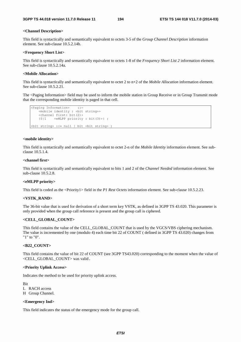
ETSI
ETSI TS 144 018 V11.7.0 (2014-03)1943GPP TS 44.018 version 11.7.0 Release 11
<Channel Description>
This field is syntactically and semantically equivalent to octets 3-5 of the Group Channel Description information element. See sub-clause 10.5.2.14b.
<Frequency Short List>
This field is syntactically and semantically equivalent to octets 1-8 of the Frequency Short List 2 information element. See sub-clause 10.5.2.14a.
<Mobile Allocation>
This field is syntactically and semantically equivalent to octet 2 to n+2 of the Mobile Allocation information element. See sub-clause 10.5.2.21.
The <Paging Information> field may be used to inform the mobile station in Group Receive or in Group Transmit mode that the corresponding mobile identity is paged in that cell.
<Paging Information> ::= <mobile identity : <bit string>> <channel first: bit(2)> {0|1 <eMLPP priority : bit(3)>} ; <bit string> ::= null | bit <bit string> ;
<mobile identity>
This field is syntactically and semantically equivalent to octet 2-n of the Mobile Identity information element. See sub-clause 10.5.1.4.
<channel first>
This field is syntactically and semantically equivalent to bits 1 and 2 of the Channel Needed information element. See sub-clause 10.5.2.8.
<eMLPP priority>
This field is coded as the <Priority1> field in the P1 Rest Octets information element. See sub-clause 10.5.2.23.
<VSTK_RAND>
The 36-bit value that is used for derivation of a short term key VSTK, as defined in 3GPP TS 43.020. This parameter is only provided when the group call reference is present and the group call is ciphered.
<CELL_GLOBAL_COUNT>
This field contains the value of the CELL_GLOBAL_COUNT that is used by the VGCS/VBS ciphering mechanism. The value is incremented by one (modulo 4) each time bit 22 of COUNT ( defined in 3GPP TS 43.020) changes from "1" to "0".
<B22_COUNT>
This field contains the value of bit 22 of COUNT (see 3GPP TS43.020) corresponding to the moment when the value of <CELL_GLOBAL_COUNT> was valid.
<Priority Uplink Access>
Indicates the method to be used for priority uplink access.
Bit L RACH access H Group Channel.
<Emergency Ind>
This field indicates the status of the emergency mode for the group call.
ETSI
ETSI TS 144 018 V11.7.0 (2014-03)1953GPP TS 44.018 version 11.7.0 Release 11
L Emergency mode not set.
H Emergency mode set.
<AMR Config>
This field indicates the set of AMR codec modes to be used on a group channel using speech version 3. It is coded as the binary representation of the parameter Config-NB-Code of one of the preferred AMR configurations defined in 3GPP TS 28.062 [92].
<Paging Cause>
This field indicates whether the paging contained in the field "Paging Information" is for a mobile terminating call, USSD or short message. Mobile stations shall ignore the contents of this field when the notification does not contain paging information.
bit 2 1 0 0 Paging is for a mobile terminating call 0 1 Paging is for a mobile terminating short message. 1 0 Paging is for a USSD 1 1 Spare – if received, mobile shall treat as for a mobile terminating call <SMS Data Confidentiality Ind>
This field shall be included periodically (the frequency with which this field is included is implementation dependent) if the network supports the transfer of mobile originated point-to-point short messages via the group call channel. The value is provided by the network (see 3GPP TS 43.068).
If this field is not present the most recently received value in either a Notification/FACCH message or Notification/NCH message shall be used. If no previous value has been received, a default value of "1" shall be assumed.
0 SMS data confidentiality not required.
1 SMS data confidentiality required.
<SMS Guaranteed Privacy Ind>
This field shall be included periodically (the frequency with which this field is included is implementation dependent) if the network supports the transfer of mobile originated point-to-point short messages via the group call channel. The value is provided by the network (see 3GPP TS 43.068).
If this field is not present the most recently received value in either a Notification/FACCH message or Notification/NCH message shall be used. If no previous value has been received, a default value of "1" shall be assumed.
0 SMS guaranteed privacy not required.
1 SMS guaranteed privacy required.
9.1.21a.1 (void)
9.1.21a.2 (void)
9.1.21a.3 (void)
9.1.21a.4 (void)
9.1.21b Notification/NCH
The understanding of this message is only required for mobile stations supporting VGCS listening or VBS listening.
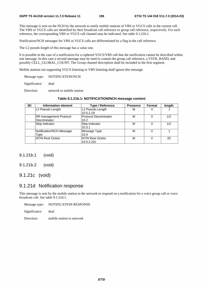
ETSI
ETSI TS 144 018 V11.7.0 (2014-03)1963GPP TS 44.018 version 11.7.0 Release 11
This message is sent on the NCH by the network to notify mobile stations of VBS or VGCS calls in the current cell. The VBS or VGCS calls are identified by their broadcast call reference or group call reference, respectively. For each reference, the corresponding VBS or VGCS call channel may be indicated. See table 9.1.21b.1.
Notification/NCH messages for VBS or VGCS calls are differentiated by a flag in the call reference.
The L2 pseudo length of this message has a value one.
It is possible in the case of a notification for a ciphered VGCS/VBS call that the notification cannot be described within one message. In this case a second message may be used to contain the group call reference, a VSTK_RAND, and possibly CELL_GLOBAL_COUNT. The Group channel description shall be included in the first segment.
Mobile stations not supporting VGCS listening or VBS listening shall ignore this message.
Message type: NOTIFICATION/NCH
Significance: dual
Direction: network to mobile station
Table 9.1.21b.1: NOTIFICATION/NCH message content
IEI Information element Type / Reference Presence Format length L2 Pseudo Length L2 Pseudo Length
10.5.2.19 M V 1
RR management Protocol Discriminator
Protocol Discriminator 10.2
M V 1/2
Skip Indicator Skip Indicator 10.3.1
M V 1/2
Notification/NCH Message Type
Message Type 10.4
M V 1
NT/N Rest Octets NT/N Rest Octets 10.5.2.22c
M V 20
9.1.21b.1 (void)
9.1.21b.2 (void)
9.1.21c (void)
9.1.21d Notification response
This message is sent by the mobile station to the network to respond on a notification for a voice group call or voice broadcast call. See table 9.1.21d.1.
Message type: NOTIFICATION RESPONSE
Significance: dual
Direction: mobile station to network
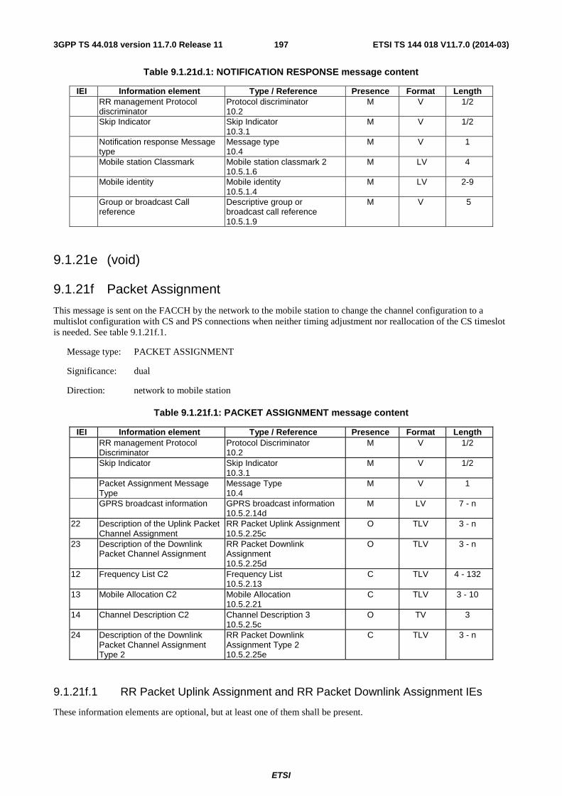
ETSI
ETSI TS 144 018 V11.7.0 (2014-03)1973GPP TS 44.018 version 11.7.0 Release 11
Table 9.1.21d.1: NOTIFICATION RESPONSE message content
IEI Information element Type / Reference Presence Format Length RR management Protocol
discriminator Protocol discriminator 10.2
M V 1/2
Skip Indicator Skip Indicator 10.3.1
M V 1/2
Notification response Message type
Message type 10.4
M V 1
Mobile station Classmark Mobile station classmark 2 10.5.1.6
M LV 4
Mobile identity Mobile identity 10.5.1.4
M LV 2-9
Group or broadcast Call reference
Descriptive group or broadcast call reference 10.5.1.9
M V 5
9.1.21e (void)
9.1.21f Packet Assignment
This message is sent on the FACCH by the network to the mobile station to change the channel configuration to a multislot configuration with CS and PS connections when neither timing adjustment nor reallocation of the CS timeslot is needed. See table 9.1.21f.1.
Message type: PACKET ASSIGNMENT
Significance: dual
Direction: network to mobile station
Table 9.1.21f.1: PACKET ASSIGNMENT message content
IEI Information element Type / Reference Presence Format Length RR management Protocol
Discriminator Protocol Discriminator 10.2
M V 1/2
Skip Indicator Skip Indicator 10.3.1
M V 1/2
Packet Assignment Message Type
Message Type 10.4
M V 1
GPRS broadcast information GPRS broadcast information 10.5.2.14d
M LV 7 - n
22 Description of the Uplink Packet Channel Assignment
RR Packet Uplink Assignment 10.5.2.25c
O TLV 3 - n
23 Description of the Downlink Packet Channel Assignment
RR Packet Downlink Assignment 10.5.2.25d
O TLV 3 - n
12 Frequency List C2 Frequency List 10.5.2.13
C TLV 4 - 132
13 Mobile Allocation C2 Mobile Allocation 10.5.2.21
C TLV 3 - 10
14 Channel Description C2 Channel Description 3 10.5.2.5c
O TV 3
24 Description of the Downlink Packet Channel Assignment Type 2
RR Packet Downlink Assignment Type 2 10.5.2.25e
C TLV 3 - n
9.1.21f.1 RR Packet Uplink Assignment and RR Packet Downlink Assignment IEs
These information elements are optional, but at least one of them shall be present.

ETSI
ETSI TS 144 018 V11.7.0 (2014-03)1983GPP TS 44.018 version 11.7.0 Release 11
9.1.21f.2 (void)
9.1.21f.3 Frequency List C2, Mobile Allocation C2 and Description of the Downlink Packet Channel Assignment Type 2
These information elements may be included to assign packet resources on a second radio frequency channel, which does not include the dedicated resource, to a mobile station supporting Downlink Dual Carrier (see 3GPP TS 44.060).
If the Channel Description C2 IE is present, the Description of the Downlink Packet Channel Assignment Type 2 IE shall be present and provides the description of the downlink packet resources for both carriers C1 and C2. In this case, the Description of the Downlink Packet Channel Assignment IE shall not be included.
If the Channel Description C2 IE is present and indicates frequency hopping, one and only one of the following information elements shall be present:
- Mobile Allocation C2 IE
- Frequency List C2 IE
If the Mobile allocation C2 IE is present, then the network must ensure that the mobile station has received in a previous message the proper reference cell frequency list.
If the Channel Description C2 IE is not included then the Description of the Downlink Packet Channel Assignment Type 2 IE if present shall be considered as an unnecessary IE in the message.
If the Channel Description C2 IE is not included or is included but does not indicate frequency hopping, then any of the Mobile Allocation C2 or Frequency List C2 IEs if present shall be considered as an unnecessary IE in the message.
9.1.21g Packet Notification
This message is sent on the main DCCH by the network to trigger the mobile station to perform a cell update procedure. See table 9.1.21g.1.
Message type: PACKET NOTIFICATION
Significance: dual
Direction: network to mobile station
Table 9.1.21g.1: PACKET NOTIFICATION message content
IEI Information element Type / Reference Presence Format Length RR management Protocol
Discriminator Protocol Discriminator 10.2
M V 1/2
Skip Indicator Skip Indicator 10.3.1
M V 1/2
Packet Notification Message Type
Message Type 10.4
M V 1
10 Packet TMSI P-TMSI 10.5.2.42
C TV 5
11 Mobile identity Mobile identity 10.5.1.4
C TLV 3-11
9.1.21g.1 P-TMSI
If this IE is included the Mobile identity IE shall not be included.
NOTE: The condition when to include P-TMSI in this message is defined in TS 48.018.
9.1.21g.2 Mobile identity
This IE shall be included if and only if the P-TMSI IE is not included.
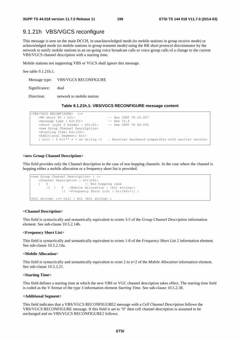
ETSI
ETSI TS 144 018 V11.7.0 (2014-03)1993GPP TS 44.018 version 11.7.0 Release 11
9.1.21h VBS/VGCS reconfigure
This message is sent on the main DCCH, in unacknowledged mode (to mobile stations in group receive mode) or acknowledged mode (to mobile stations in group transmit mode) using the RR short protocol discriminator by the network to notify mobile stations in an on-going voice broadcast calls or voice group calls of a change to the current VBS/VGCS channel description with a starting time.
Mobile stations not supporting VBS or VGCS shall ignore this message.
See table 9.1.21h.1.
Message type: VBS/VGCS RECONFIGURE
Significance: dual
Direction: network to mobile station
Table 9.1.21h.1: VBS/VGCS RECONFIGURE message content
<VBS/VGCS RECONFIGURE> ::= <RR short PD : bit> -- See 3GPP TS 24.007 <message type : bit(5)> -- See 10.4 <short layer 2 header : bit(2)> -- See 3GPP TS 44.006 <new Group Channel Description> <Starting Time: bit(16)> <Additional Segment: bit> { null | 0 bit** = < no string >} - Receiver backward compatible with earlier version
<new Group Channel Description>
This field provides only the Channel description in the case of non hopping channels. In the case where the channel is hopping either a mobile allocation or a frequency short list is provided.
<new Group Channel Description> : := <Channel Description : bit(24)> { 0 -- Non hopping case |1 { 0 <Mobile Allocation : <bit string>> |1 <Frequency Short List : bit(64)>}} ; <bit string> ::= null | bit <bit string> ;
<Channel Description>
This field is syntactically and semantically equivalent to octets 3-5 of the Group Channel Description information element. See sub-clause 10.5.2.14b.
<Frequency Short List>
This field is syntactically and semantically equivalent to octets 1-8 of the Frequency Short List 2 information element. See sub-clause 10.5.2.14a.
<Mobile Allocation>
This field is syntactically and semantically equivalent to octet 2 to n+2 of the Mobile Allocation information element. See sub-clause 10.5.2.21.
<Starting Time>
This field defines a starting time at which the new VBS or VGC channel description takes effect. The starting time field is coded as the V format of the type 3 information element Starting Time. See sub-clause 10.5.2.38.
<Additional Segment>
This field indicates that a VBS/VGCS RECONFIGURE2 message with a Cell Channel Description follows the VBS/VGCS RECONFIGURE message. If this field is set to "0" then cell channel description is assumed to be unchanged and no VBS/VGCS RECONFIGURE2 follows.
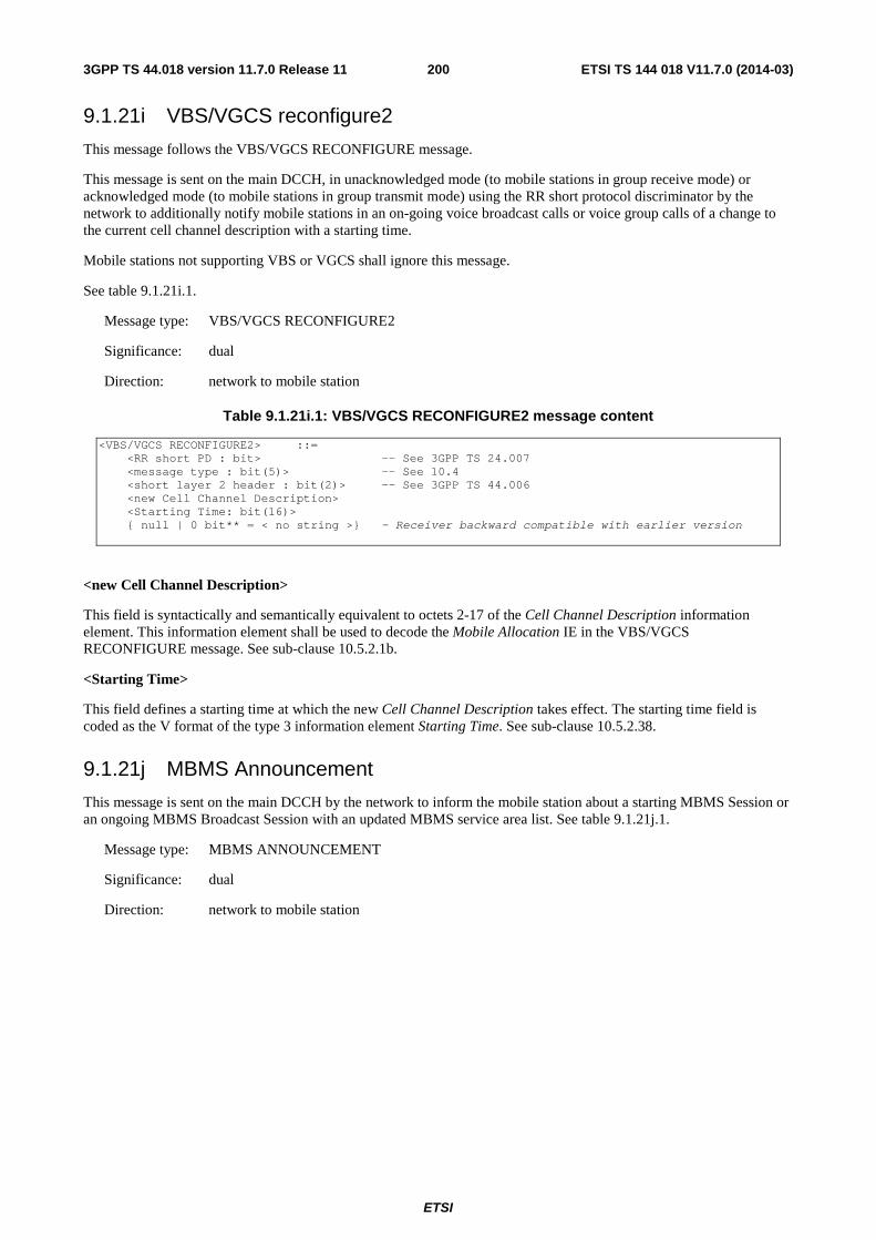
ETSI
ETSI TS 144 018 V11.7.0 (2014-03)2003GPP TS 44.018 version 11.7.0 Release 11
9.1.21i VBS/VGCS reconfigure2
This message follows the VBS/VGCS RECONFIGURE message.
This message is sent on the main DCCH, in unacknowledged mode (to mobile stations in group receive mode) or acknowledged mode (to mobile stations in group transmit mode) using the RR short protocol discriminator by the network to additionally notify mobile stations in an on-going voice broadcast calls or voice group calls of a change to the current cell channel description with a starting time.
Mobile stations not supporting VBS or VGCS shall ignore this message.
See table 9.1.21i.1.
Message type: VBS/VGCS RECONFIGURE2
Significance: dual
Direction: network to mobile station
Table 9.1.21i.1: VBS/VGCS RECONFIGURE2 message content
<VBS/VGCS RECONFIGURE2> ::= <RR short PD : bit> -- See 3GPP TS 24.007 <message type : bit(5)> -- See 10.4 <short layer 2 header : bit(2)> -- See 3GPP TS 44.006 <new Cell Channel Description> <Starting Time: bit(16)> { null | 0 bit** = < no string >} - Receiver backward compatible with earlier version
<new Cell Channel Description>
This field is syntactically and semantically equivalent to octets 2-17 of the Cell Channel Description information element. This information element shall be used to decode the Mobile Allocation IE in the VBS/VGCS RECONFIGURE message. See sub-clause 10.5.2.1b.
<Starting Time>
This field defines a starting time at which the new Cell Channel Description takes effect. The starting time field is coded as the V format of the type 3 information element Starting Time. See sub-clause 10.5.2.38.
9.1.21j MBMS Announcement
This message is sent on the main DCCH by the network to inform the mobile station about a starting MBMS Session or an ongoing MBMS Broadcast Session with an updated MBMS service area list. See table 9.1.21j.1.
Message type: MBMS ANNOUNCEMENT
Significance: dual
Direction: network to mobile station
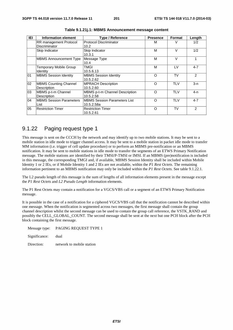
ETSI
ETSI TS 144 018 V11.7.0 (2014-03)2013GPP TS 44.018 version 11.7.0 Release 11
Table 9.1.21j.1: MBMS Announcement message content
IEI Information element Type / Reference Presence Format Length RR management Protocol
Discriminator Protocol Discriminator 10.2
M V 1/2
Skip Indicator Skip Indicator 10.3.1
M V 1/2
MBMS Announcement Type Message Type 10.4
M V 1
Temporary Mobile Group Identity
TMGI 10.5.6.13
M LV 4-7
01 MBMS Session Identity MBMS Session Identity 10.5.2.62
O TV 2
02 MBMS Counting Channel Description
MPRACH Description 10.5.2.60
O TLV 3-n
03 MBMS p-t-m Channel Description
MBMS p-t-m Channel Description 10.5.2.58
O TLV 4-n
04 MBMS Session Parameters List
MBMS Session Parameters List 10.5.2.58a
O TLV 4-7
05 Restriction Timer Restriction Timer 10.5.2.61
O TV 2
9.1.22 Paging request type 1
This message is sent on the CCCH by the network and may identify up to two mobile stations. It may be sent to a mobile station in idle mode to trigger channel access. It may be sent to a mobile station in packet idle mode to transfer MM information (i.e. trigger of cell update procedure) or to perform an MBMS pre-notification or an MBMS notification. It may be sent to mobile stations in idle mode to transfer the segments of an ETWS Primary Notification message. The mobile stations are identified by their TMSI/P-TMSI or IMSI. If an MBMS (pre)notification is included in this message, the corresponding TMGI and, if available, MBMS Session Identity shall be included within Mobile Identity 1 or 2 IEs, or if Mobile Identity 1 and 2 IEs are not available, within the P1 Rest Octets. The remaining information pertinent to an MBMS notification may only be included within the P1 Rest Octets. See table 9.1.22.1.
The L2 pseudo length of this message is the sum of lengths of all information elements present in the message except the P1 Rest Octets and L2 Pseudo Length information elements.
The P1 Rest Octets may contain a notification for a VGCS/VBS call or a segment of an ETWS Primary Notification message.
It is possible in the case of a notification for a ciphered VGCS/VBS call that the notification cannot be described within one message. When the notification is segmented across two messages, the first message shall contain the group channel description whilst the second message can be used to contain the group call reference, the VSTK_RAND and possibly the CELL_GLOBAL_COUNT. The second message shall be sent at the next but one PCH block after the PCH block containing the first message.
Message type: PAGING REQUEST TYPE 1
Significance: dual
Direction: network to mobile station
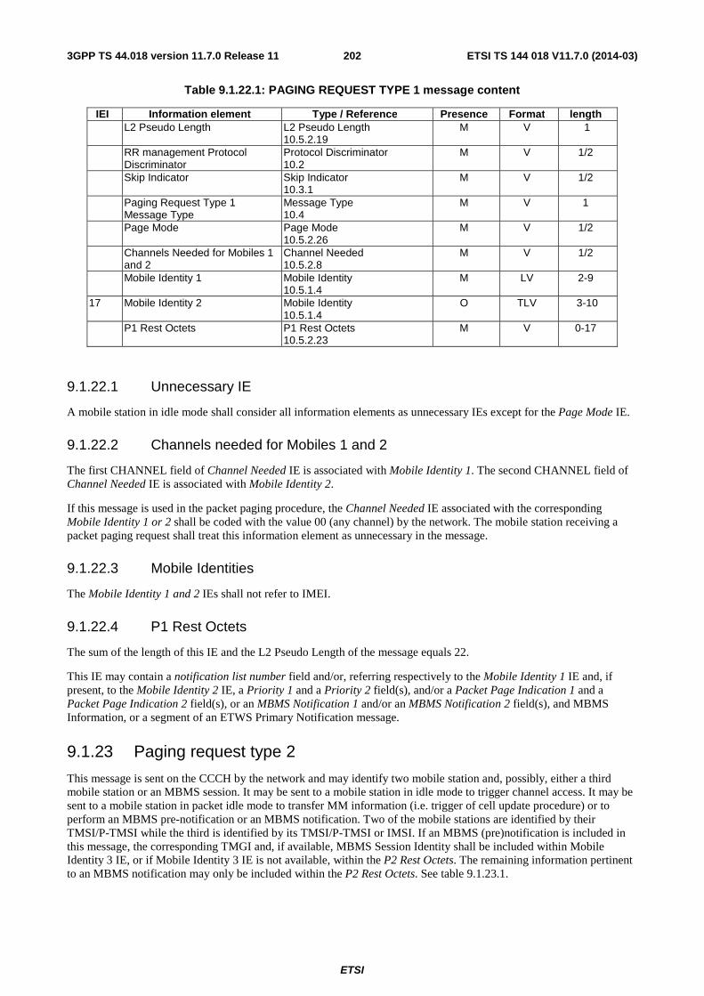
ETSI
ETSI TS 144 018 V11.7.0 (2014-03)2023GPP TS 44.018 version 11.7.0 Release 11
Table 9.1.22.1: PAGING REQUEST TYPE 1 message content
IEI Information element Type / Reference Presence Format length L2 Pseudo Length L2 Pseudo Length
10.5.2.19 M V 1
RR management Protocol Discriminator
Protocol Discriminator 10.2
M V 1/2
Skip Indicator Skip Indicator 10.3.1
M V 1/2
Paging Request Type 1 Message Type
Message Type 10.4
M V 1
Page Mode Page Mode 10.5.2.26
M V 1/2
Channels Needed for Mobiles 1 and 2
Channel Needed 10.5.2.8
M V 1/2
Mobile Identity 1 Mobile Identity 10.5.1.4
M LV 2-9
17 Mobile Identity 2 Mobile Identity 10.5.1.4
O TLV 3-10
P1 Rest Octets P1 Rest Octets 10.5.2.23
M V 0-17
9.1.22.1 Unnecessary IE
A mobile station in idle mode shall consider all information elements as unnecessary IEs except for the Page Mode IE.
9.1.22.2 Channels needed for Mobiles 1 and 2
The first CHANNEL field of Channel Needed IE is associated with Mobile Identity 1. The second CHANNEL field of Channel Needed IE is associated with Mobile Identity 2.
If this message is used in the packet paging procedure, the Channel Needed IE associated with the corresponding Mobile Identity 1 or 2 shall be coded with the value 00 (any channel) by the network. The mobile station receiving a packet paging request shall treat this information element as unnecessary in the message.
9.1.22.3 Mobile Identities
The Mobile Identity 1 and 2 IEs shall not refer to IMEI.
9.1.22.4 P1 Rest Octets
The sum of the length of this IE and the L2 Pseudo Length of the message equals 22.
This IE may contain a notification list number field and/or, referring respectively to the Mobile Identity 1 IE and, if present, to the Mobile Identity 2 IE, a Priority 1 and a Priority 2 field(s), and/or a Packet Page Indication 1 and a Packet Page Indication 2 field(s), or an MBMS Notification 1 and/or an MBMS Notification 2 field(s), and MBMS Information, or a segment of an ETWS Primary Notification message.
9.1.23 Paging request type 2
This message is sent on the CCCH by the network and may identify two mobile station and, possibly, either a third mobile station or an MBMS session. It may be sent to a mobile station in idle mode to trigger channel access. It may be sent to a mobile station in packet idle mode to transfer MM information (i.e. trigger of cell update procedure) or to perform an MBMS pre-notification or an MBMS notification. Two of the mobile stations are identified by their TMSI/P-TMSI while the third is identified by its TMSI/P-TMSI or IMSI. If an MBMS (pre)notification is included in this message, the corresponding TMGI and, if available, MBMS Session Identity shall be included within Mobile Identity 3 IE, or if Mobile Identity 3 IE is not available, within the P2 Rest Octets. The remaining information pertinent to an MBMS notification may only be included within the P2 Rest Octets. See table 9.1.23.1.
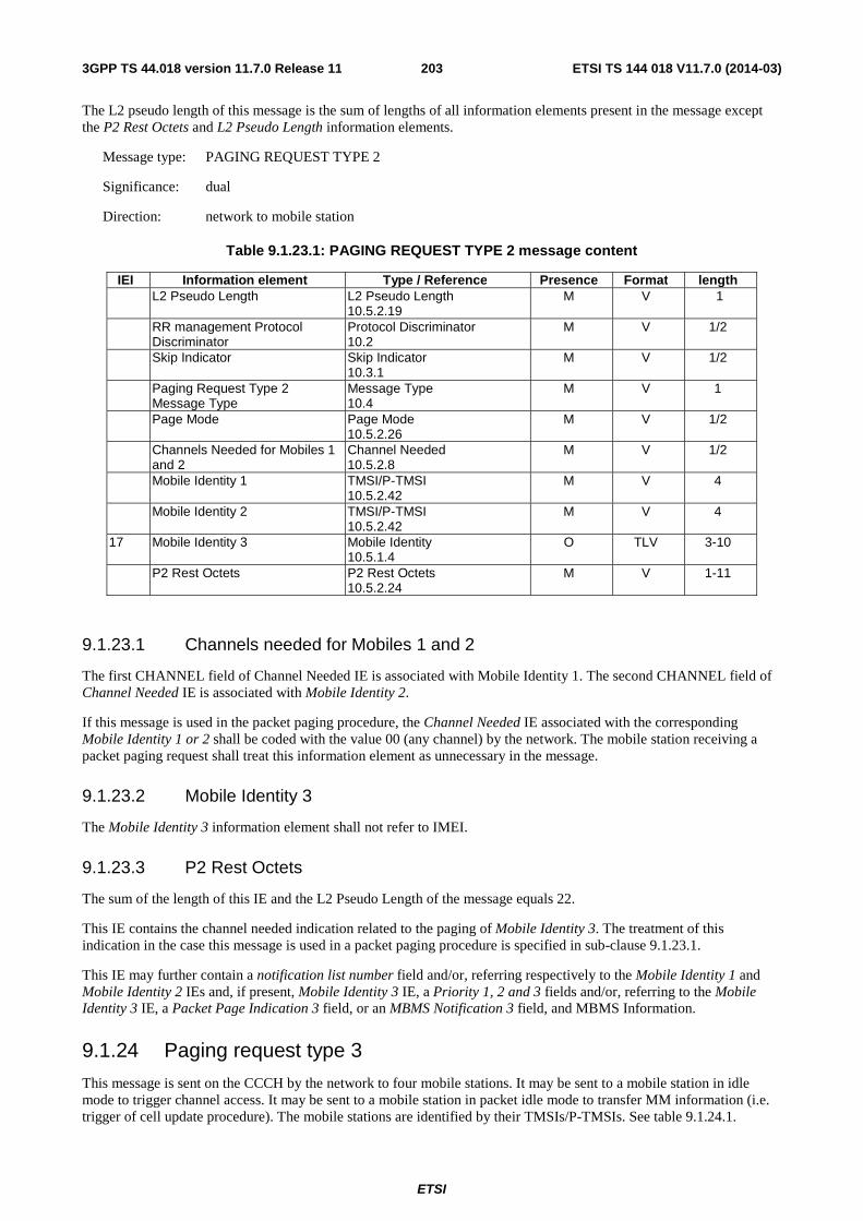
ETSI
ETSI TS 144 018 V11.7.0 (2014-03)2033GPP TS 44.018 version 11.7.0 Release 11
The L2 pseudo length of this message is the sum of lengths of all information elements present in the message except the P2 Rest Octets and L2 Pseudo Length information elements.
Message type: PAGING REQUEST TYPE 2
Significance: dual
Direction: network to mobile station
Table 9.1.23.1: PAGING REQUEST TYPE 2 message content
IEI Information element Type / Reference Presence Format length L2 Pseudo Length L2 Pseudo Length
10.5.2.19 M V 1
RR management Protocol Discriminator
Protocol Discriminator 10.2
M V 1/2
Skip Indicator Skip Indicator 10.3.1
M V 1/2
Paging Request Type 2 Message Type
Message Type 10.4
M V 1
Page Mode Page Mode 10.5.2.26
M V 1/2
Channels Needed for Mobiles 1 and 2
Channel Needed 10.5.2.8
M V 1/2
Mobile Identity 1 TMSI/P-TMSI 10.5.2.42
M V 4
Mobile Identity 2 TMSI/P-TMSI 10.5.2.42
M V 4
17 Mobile Identity 3 Mobile Identity 10.5.1.4
O TLV 3-10
P2 Rest Octets P2 Rest Octets 10.5.2.24
M V 1-11
9.1.23.1 Channels needed for Mobiles 1 and 2
The first CHANNEL field of Channel Needed IE is associated with Mobile Identity 1. The second CHANNEL field of Channel Needed IE is associated with Mobile Identity 2.
If this message is used in the packet paging procedure, the Channel Needed IE associated with the corresponding Mobile Identity 1 or 2 shall be coded with the value 00 (any channel) by the network. The mobile station receiving a packet paging request shall treat this information element as unnecessary in the message.
9.1.23.2 Mobile Identity 3
The Mobile Identity 3 information element shall not refer to IMEI.
9.1.23.3 P2 Rest Octets
The sum of the length of this IE and the L2 Pseudo Length of the message equals 22.
This IE contains the channel needed indication related to the paging of Mobile Identity 3. The treatment of this indication in the case this message is used in a packet paging procedure is specified in sub-clause 9.1.23.1.
This IE may further contain a notification list number field and/or, referring respectively to the Mobile Identity 1 and Mobile Identity 2 IEs and, if present, Mobile Identity 3 IE, a Priority 1, 2 and 3 fields and/or, referring to the Mobile Identity 3 IE, a Packet Page Indication 3 field, or an MBMS Notification 3 field, and MBMS Information.
9.1.24 Paging request type 3
This message is sent on the CCCH by the network to four mobile stations. It may be sent to a mobile station in idle mode to trigger channel access. It may be sent to a mobile station in packet idle mode to transfer MM information (i.e. trigger of cell update procedure). The mobile stations are identified by their TMSIs/P-TMSIs. See table 9.1.24.1.
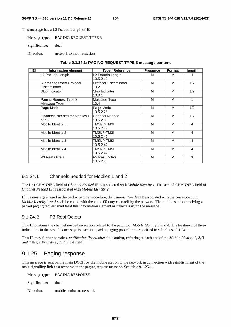
ETSI
ETSI TS 144 018 V11.7.0 (2014-03)2043GPP TS 44.018 version 11.7.0 Release 11
This message has a L2 Pseudo Length of 19.
Message type: PAGING REQUEST TYPE 3
Significance: dual
Direction: network to mobile station
Table 9.1.24.1: PAGING REQUEST TYPE 3 message content
IEI Information element Type / Reference Presence Format length L2 Pseudo Length L2 Pseudo Length
10.5.2.19 M V 1
RR management Protocol Discriminator
Protocol Discriminator 10.2
M V 1/2
Skip Indicator Skip Indicator 10.3.1
M V 1/2
Paging Request Type 3 Message Type
Message Type 10.4
M V 1
Page Mode Page Mode 10.5.2.26
M V 1/2
Channels Needed for Mobiles 1 and 2
Channel Needed 10.5.2.8
M V 1/2
Mobile Identity 1 TMSI/P-TMSI 10.5.2.42
M V 4
Mobile Identity 2 TMSI/P-TMSI 10.5.2.42
M V 4
Mobile Identity 3 TMSI/P-TMSI 10.5.2.42
M V 4
Mobile Identity 4 TMSI/P-TMSI 10.5.2.42
M V 4
P3 Rest Octets P3 Rest Octets 10.5.2.25
M V 3
9.1.24.1 Channels needed for Mobiles 1 and 2
The first CHANNEL field of Channel Needed IE is associated with Mobile Identity 1. The second CHANNEL field of Channel Needed IE is associated with Mobile Identity 2.
If this message is used in the packet paging procedure, the Channel Needed IE associated with the corresponding Mobile Identity 1 or 2 shall be coded with the value 00 (any channel) by the network. The mobile station receiving a packet paging request shall treat this information element as unnecessary in the message.
9.1.24.2 P3 Rest Octets
This IE contains the channel needed indication related to the paging of Mobile Identity 3 and 4. The treatment of these indications in the case this message is used in a packet paging procedure is specified in sub-clause 9.1.24.1.
This IE may further contain a notification list number field and/or, referring to each one of the Mobile Identity 1, 2, 3 and 4 IEs, a Priority 1, 2, 3 and 4 field.
9.1.25 Paging response
This message is sent on the main DCCH by the mobile station to the network in connection with establishment of the main signalling link as a response to the paging request message. See table 9.1.25.1.
Message type: PAGING RESPONSE
Significance: dual
Direction: mobile station to network
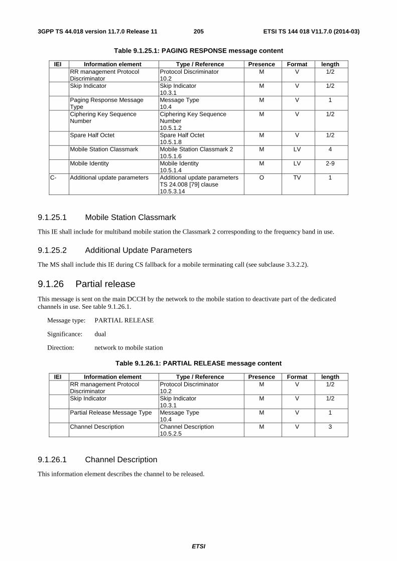
ETSI
ETSI TS 144 018 V11.7.0 (2014-03)2053GPP TS 44.018 version 11.7.0 Release 11
Table 9.1.25.1: PAGING RESPONSE message content
IEI Information element Type / Reference Presence Format length RR management Protocol
Discriminator Protocol Discriminator 10.2
M V 1/2
Skip Indicator Skip Indicator 10.3.1
M V 1/2
Paging Response Message Type
Message Type 10.4
M V 1
Ciphering Key Sequence Number
Ciphering Key Sequence Number 10.5.1.2
M V 1/2
Spare Half Octet Spare Half Octet 10.5.1.8
M V 1/2
Mobile Station Classmark Mobile Station Classmark 2 10.5.1.6
M LV 4
Mobile Identity Mobile Identity 10.5.1.4
M LV 2-9
C- Additional update parameters Additional update parameters TS 24.008 [79] clause 10.5.3.14
O TV 1
9.1.25.1 Mobile Station Classmark
This IE shall include for multiband mobile station the Classmark 2 corresponding to the frequency band in use.
9.1.25.2 Additional Update Parameters
The MS shall include this IE during CS fallback for a mobile terminating call (see subclause 3.3.2.2).
9.1.26 Partial release
This message is sent on the main DCCH by the network to the mobile station to deactivate part of the dedicated channels in use. See table 9.1.26.1.
Message type: PARTIAL RELEASE
Significance: dual
Direction: network to mobile station
Table 9.1.26.1: PARTIAL RELEASE message content
IEI Information element Type / Reference Presence Format length RR management Protocol
Discriminator Protocol Discriminator 10.2
M V 1/2
Skip Indicator Skip Indicator 10.3.1
M V 1/2
Partial Release Message Type Message Type 10.4
M V 1
Channel Description Channel Description 10.5.2.5
M V 3
9.1.26.1 Channel Description
This information element describes the channel to be released.
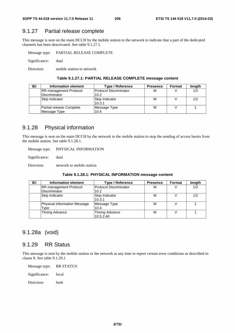
ETSI
ETSI TS 144 018 V11.7.0 (2014-03)2063GPP TS 44.018 version 11.7.0 Release 11
9.1.27 Partial release complete
This message is sent on the main DCCH by the mobile station to the network to indicate that a part of the dedicated channels has been deactivated. See table 9.1.27.1.
Message type: PARTIAL RELEASE COMPLETE
Significance: dual
Direction: mobile station to network
Table 9.1.27.1: PARTIAL RELEASE COMPLETE message content
IEI Information element Type / Reference Presence Format length RR management Protocol
Discriminator Protocol Discriminator 10.2
M V 1/2
Skip Indicator Skip Indicator 10.3.1
M V 1/2
Partial release Complete Message Type
Message Type 10.4
M V 1
9.1.28 Physical information
This message is sent on the main DCCH by the network to the mobile station to stop the sending of access bursts from the mobile station. See table 9.1.28.1.
Message type: PHYSICAL INFORMATION
Significance: dual
Direction: network to mobile station
Table 9.1.28.1: PHYSICAL INFORMATION message content
IEI Information element Type / Reference Presence Format length RR management Protocol
Discriminator Protocol Discriminator 10.2
M V 1/2
Skip Indicator Skip Indicator 10.3.1
M V 1/2
Physical Information Message Type
Message Type 10.4
M V 1
Timing Advance Timing Advance 10.5.2.40
M V 1
9.1.28a (void)
9.1.29 RR Status
This message is sent by the mobile station or the network at any time to report certain error conditions as described in clause 8. See table 9.1.29.1.
Message type: RR STATUS
Significance: local
Direction: both
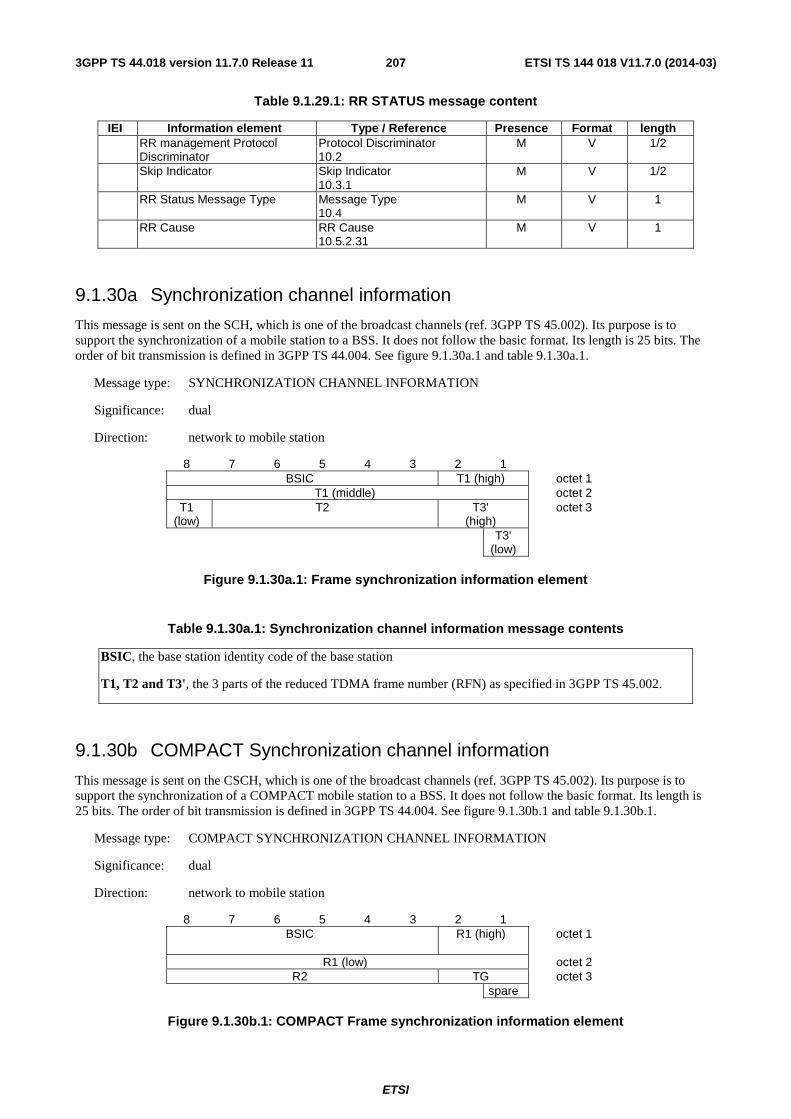
ETSI
ETSI TS 144 018 V11.7.0 (2014-03)2073GPP TS 44.018 version 11.7.0 Release 11
Table 9.1.29.1: RR STATUS message content
IEI Information element Type / Reference Presence Format length RR management Protocol
Discriminator Protocol Discriminator 10.2
M V 1/2
Skip Indicator Skip Indicator 10.3.1
M V 1/2
RR Status Message Type Message Type 10.4
M V 1
RR Cause RR Cause 10.5.2.31
M V 1
9.1.30a Synchronization channel information
This message is sent on the SCH, which is one of the broadcast channels (ref. 3GPP TS 45.002). Its purpose is to support the synchronization of a mobile station to a BSS. It does not follow the basic format. Its length is 25 bits. The order of bit transmission is defined in 3GPP TS 44.004. See figure 9.1.30a.1 and table 9.1.30a.1.
Message type: SYNCHRONIZATION CHANNEL INFORMATION
Significance: dual
Direction: network to mobile station
8 7 6 5 4 3 2 1 BSIC T1 (high) octet 1
T1 (middle) octet 2 T1
(low) T2 T3'
(high) octet 3
T3' (low)
Figure 9.1.30a.1: Frame synchronization information element
Table 9.1.30a.1: Synchronization channel information message contents
BSIC, the base station identity code of the base station
T1, T2 and T3', the 3 parts of the reduced TDMA frame number (RFN) as specified in 3GPP TS 45.002.
9.1.30b COMPACT Synchronization channel information
This message is sent on the CSCH, which is one of the broadcast channels (ref. 3GPP TS 45.002). Its purpose is to support the synchronization of a COMPACT mobile station to a BSS. It does not follow the basic format. Its length is 25 bits. The order of bit transmission is defined in 3GPP TS 44.004. See figure 9.1.30b.1 and table 9.1.30b.1.
Message type: COMPACT SYNCHRONIZATION CHANNEL INFORMATION
Significance: dual
Direction: network to mobile station
8 7 6 5 4 3 2 1 BSIC
R1 (high) octet 1
R1 (low) octet 2 R2 TG octet 3
spare
Figure 9.1.30b.1: COMPACT Frame synchronization information element
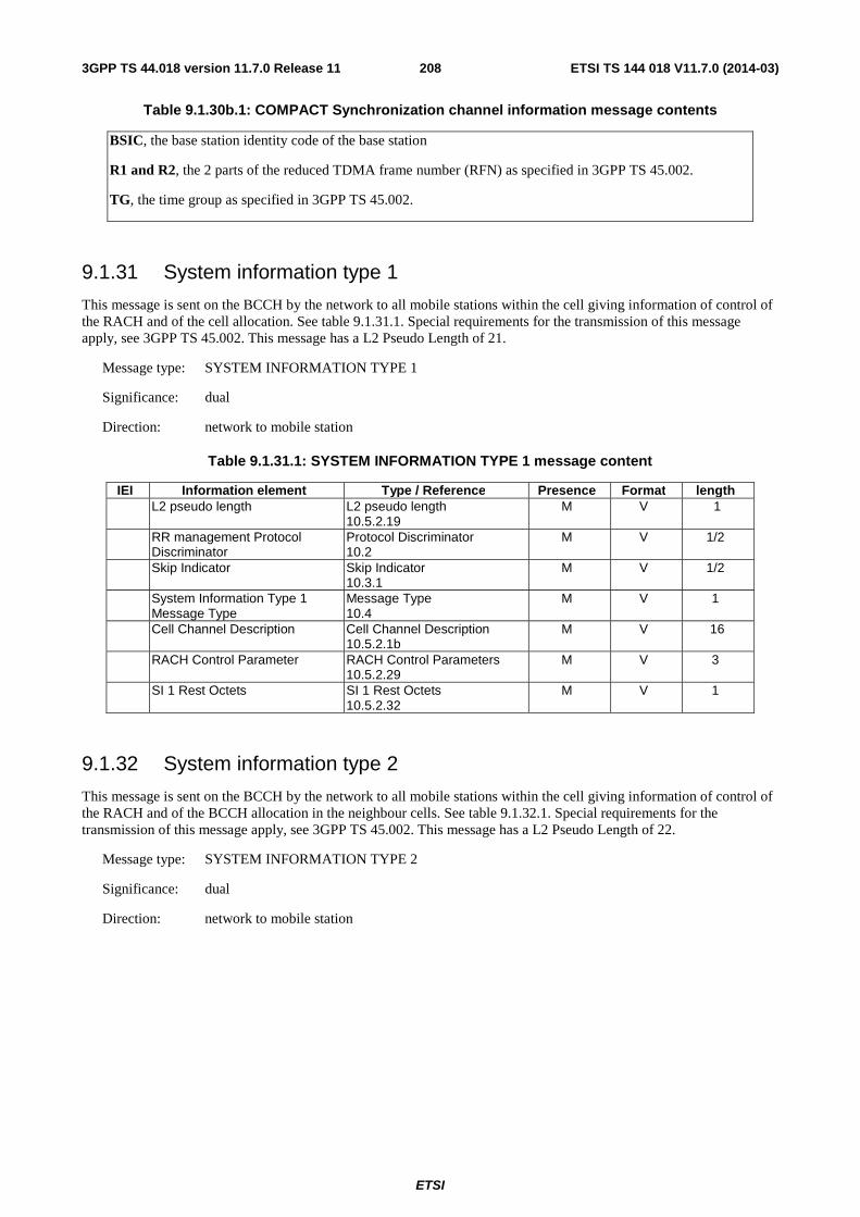
ETSI
ETSI TS 144 018 V11.7.0 (2014-03)2083GPP TS 44.018 version 11.7.0 Release 11
Table 9.1.30b.1: COMPACT Synchronization channel information message contents
BSIC, the base station identity code of the base station
R1 and R2, the 2 parts of the reduced TDMA frame number (RFN) as specified in 3GPP TS 45.002.
TG, the time group as specified in 3GPP TS 45.002.
9.1.31 System information type 1
This message is sent on the BCCH by the network to all mobile stations within the cell giving information of control of the RACH and of the cell allocation. See table 9.1.31.1. Special requirements for the transmission of this message apply, see 3GPP TS 45.002. This message has a L2 Pseudo Length of 21.
Message type: SYSTEM INFORMATION TYPE 1
Significance: dual
Direction: network to mobile station
Table 9.1.31.1: SYSTEM INFORMATION TYPE 1 message content
IEI Information element Type / Reference Presence Format length L2 pseudo length L2 pseudo length
10.5.2.19 M V 1
RR management Protocol Discriminator
Protocol Discriminator 10.2
M V 1/2
Skip Indicator Skip Indicator 10.3.1
M V 1/2
System Information Type 1 Message Type
Message Type 10.4
M V 1
Cell Channel Description Cell Channel Description 10.5.2.1b
M V 16
RACH Control Parameter RACH Control Parameters 10.5.2.29
M V 3
SI 1 Rest Octets SI 1 Rest Octets 10.5.2.32
M V 1
9.1.32 System information type 2
This message is sent on the BCCH by the network to all mobile stations within the cell giving information of control of the RACH and of the BCCH allocation in the neighbour cells. See table 9.1.32.1. Special requirements for the transmission of this message apply, see 3GPP TS 45.002. This message has a L2 Pseudo Length of 22.
Message type: SYSTEM INFORMATION TYPE 2
Significance: dual
Direction: network to mobile station
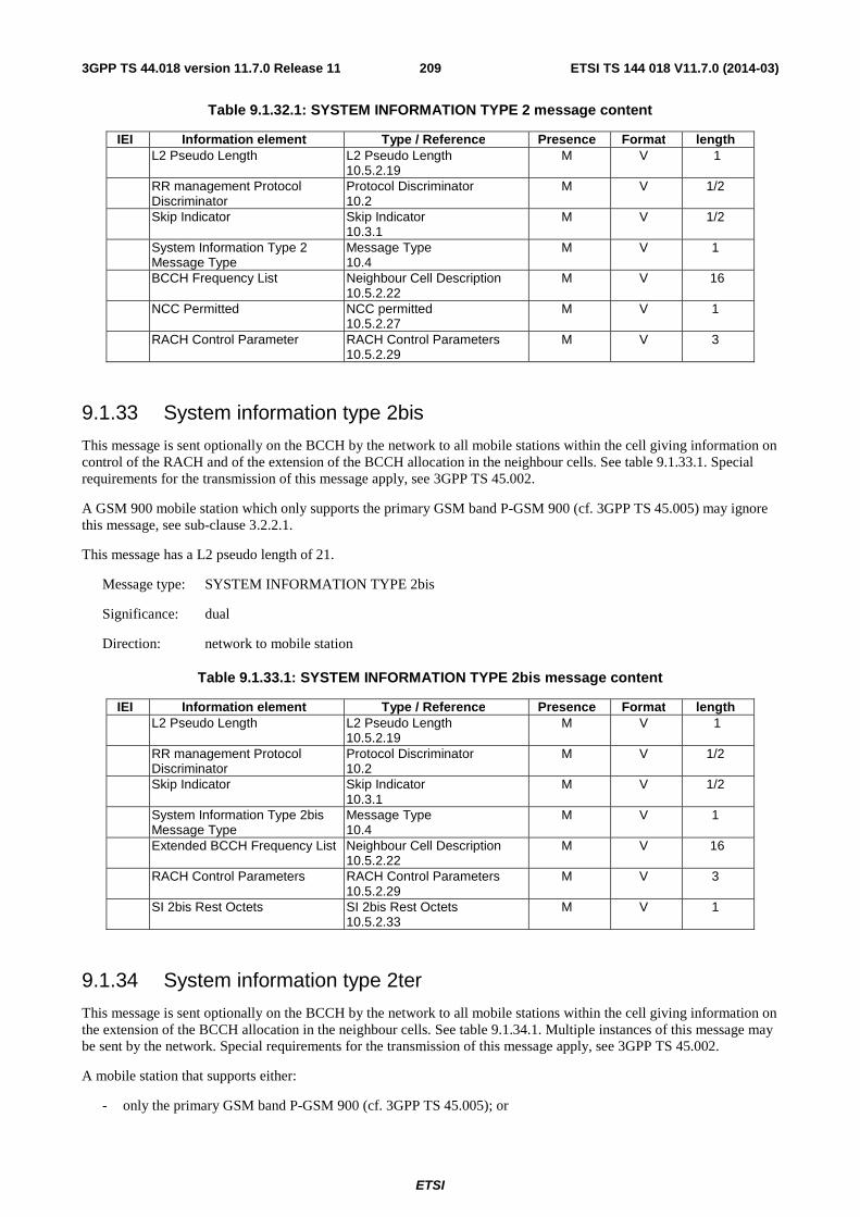
ETSI
ETSI TS 144 018 V11.7.0 (2014-03)2093GPP TS 44.018 version 11.7.0 Release 11
Table 9.1.32.1: SYSTEM INFORMATION TYPE 2 message content
IEI Information element Type / Reference Presence Format length L2 Pseudo Length L2 Pseudo Length
10.5.2.19 M V 1
RR management Protocol Discriminator
Protocol Discriminator 10.2
M V 1/2
Skip Indicator Skip Indicator 10.3.1
M V 1/2
System Information Type 2 Message Type
Message Type 10.4
M V 1
BCCH Frequency List Neighbour Cell Description 10.5.2.22
M V 16
NCC Permitted NCC permitted 10.5.2.27
M V 1
RACH Control Parameter RACH Control Parameters 10.5.2.29
M V 3
9.1.33 System information type 2bis
This message is sent optionally on the BCCH by the network to all mobile stations within the cell giving information on control of the RACH and of the extension of the BCCH allocation in the neighbour cells. See table 9.1.33.1. Special requirements for the transmission of this message apply, see 3GPP TS 45.002.
A GSM 900 mobile station which only supports the primary GSM band P-GSM 900 (cf. 3GPP TS 45.005) may ignore this message, see sub-clause 3.2.2.1.
This message has a L2 pseudo length of 21.
Message type: SYSTEM INFORMATION TYPE 2bis
Significance: dual
Direction: network to mobile station
Table 9.1.33.1: SYSTEM INFORMATION TYPE 2bis message content
IEI Information element Type / Reference Presence Format length L2 Pseudo Length L2 Pseudo Length
10.5.2.19 M V 1
RR management Protocol Discriminator
Protocol Discriminator 10.2
M V 1/2
Skip Indicator Skip Indicator 10.3.1
M V 1/2
System Information Type 2bis Message Type
Message Type 10.4
M V 1
Extended BCCH Frequency List Neighbour Cell Description 10.5.2.22
M V 16
RACH Control Parameters RACH Control Parameters 10.5.2.29
M V 3
SI 2bis Rest Octets SI 2bis Rest Octets 10.5.2.33
M V 1
9.1.34 System information type 2ter
This message is sent optionally on the BCCH by the network to all mobile stations within the cell giving information on the extension of the BCCH allocation in the neighbour cells. See table 9.1.34.1. Multiple instances of this message may be sent by the network. Special requirements for the transmission of this message apply, see 3GPP TS 45.002.
A mobile station that supports either:
- only the primary GSM band P-GSM 900 (cf. 3GPP TS 45.005); or
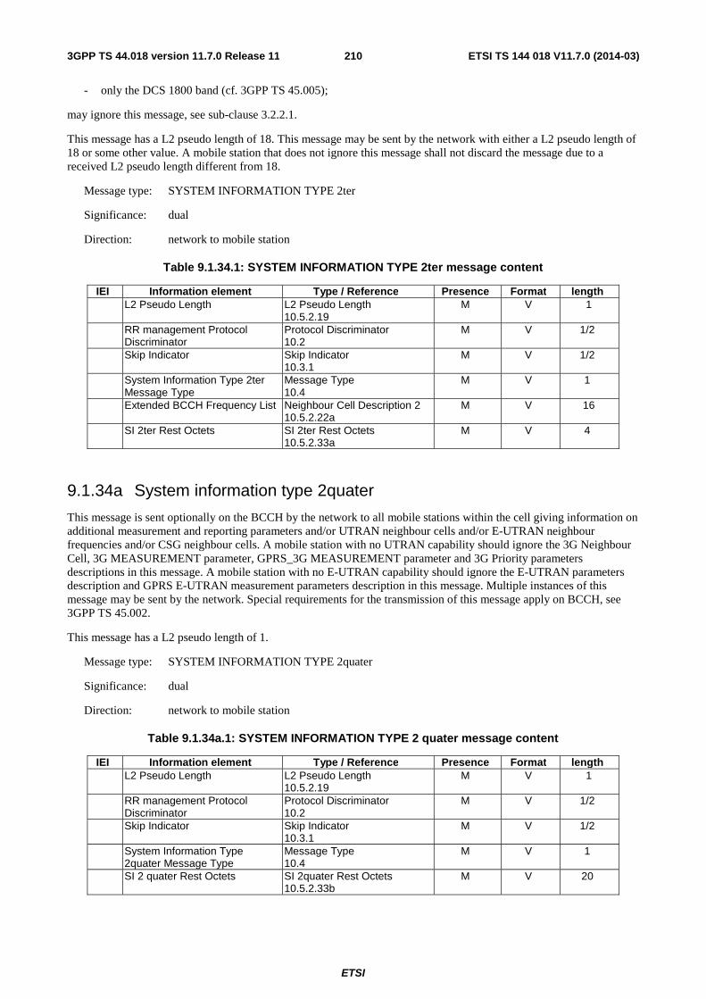
ETSI
ETSI TS 144 018 V11.7.0 (2014-03)2103GPP TS 44.018 version 11.7.0 Release 11
- only the DCS 1800 band (cf. 3GPP TS 45.005);
may ignore this message, see sub-clause 3.2.2.1.
This message has a L2 pseudo length of 18. This message may be sent by the network with either a L2 pseudo length of 18 or some other value. A mobile station that does not ignore this message shall not discard the message due to a received L2 pseudo length different from 18.
Message type: SYSTEM INFORMATION TYPE 2ter
Significance: dual
Direction: network to mobile station
Table 9.1.34.1: SYSTEM INFORMATION TYPE 2ter message content
IEI Information element Type / Reference Presence Format length L2 Pseudo Length L2 Pseudo Length
10.5.2.19 M V 1
RR management Protocol Discriminator
Protocol Discriminator 10.2
M V 1/2
Skip Indicator Skip Indicator 10.3.1
M V 1/2
System Information Type 2ter Message Type
Message Type 10.4
M V 1
Extended BCCH Frequency List Neighbour Cell Description 2 10.5.2.22a
M V 16
SI 2ter Rest Octets SI 2ter Rest Octets 10.5.2.33a
M V 4
9.1.34a System information type 2quater
This message is sent optionally on the BCCH by the network to all mobile stations within the cell giving information on additional measurement and reporting parameters and/or UTRAN neighbour cells and/or E-UTRAN neighbour frequencies and/or CSG neighbour cells. A mobile station with no UTRAN capability should ignore the 3G Neighbour Cell, 3G MEASUREMENT parameter, GPRS_3G MEASUREMENT parameter and 3G Priority parameters descriptions in this message. A mobile station with no E-UTRAN capability should ignore the E-UTRAN parameters description and GPRS E-UTRAN measurement parameters description in this message. Multiple instances of this message may be sent by the network. Special requirements for the transmission of this message apply on BCCH, see 3GPP TS 45.002.
This message has a L2 pseudo length of 1.
Message type: SYSTEM INFORMATION TYPE 2quater
Significance: dual
Direction: network to mobile station
Table 9.1.34a.1: SYSTEM INFORMATION TYPE 2 quater message content
IEI Information element Type / Reference Presence Format length L2 Pseudo Length L2 Pseudo Length
10.5.2.19 M V 1
RR management Protocol Discriminator
Protocol Discriminator 10.2
M V 1/2
Skip Indicator Skip Indicator 10.3.1
M V 1/2
System Information Type 2quater Message Type
Message Type 10.4
M V 1
SI 2 quater Rest Octets SI 2quater Rest Octets 10.5.2.33b
M V 20
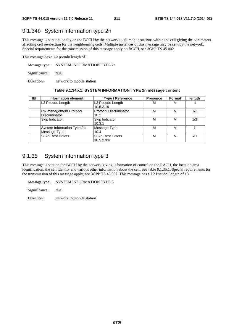
ETSI
ETSI TS 144 018 V11.7.0 (2014-03)2113GPP TS 44.018 version 11.7.0 Release 11
9.1.34b System information type 2n
This message is sent optionally on the BCCH by the network to all mobile stations within the cell giving the parameters affecting cell reselection for the neighbouring cells. Multiple instances of this message may be sent by the network. Special requirements for the transmission of this message apply on BCCH, see 3GPP TS 45.002.
This message has a L2 pseudo length of 1.
Message type: SYSTEM INFORMATION TYPE 2n
Significance: dual
Direction: network to mobile station
Table 9.1.34b.1: SYSTEM INFORMATION TYPE 2n message content
IEI Information element Type / Reference Presence Format length L2 Pseudo Length L2 Pseudo Length
10.5.2.19 M V 1
RR management Protocol Discriminator
Protocol Discriminator 10.2
M V 1/2
Skip Indicator Skip Indicator 10.3.1
M V 1/2
System Information Type 2n Message Type
Message Type 10.4
M V 1
SI 2n Rest Octets SI 2n Rest Octets 10.5.2.33c
M V 20
9.1.35 System information type 3
This message is sent on the BCCH by the network giving information of control on the RACH, the location area identification, the cell identity and various other information about the cell. See table 9.1.35.1. Special requirements for the transmission of this message apply, see 3GPP TS 45.002. This message has a L2 Pseudo Length of 18.
Message type: SYSTEM INFORMATION TYPE 3
Significance: dual
Direction: network to mobile station
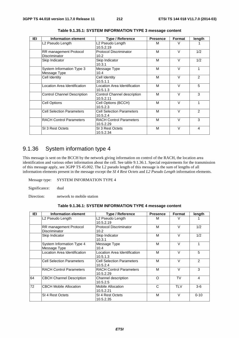
ETSI
ETSI TS 144 018 V11.7.0 (2014-03)2123GPP TS 44.018 version 11.7.0 Release 11
Table 9.1.35.1: SYSTEM INFORMATION TYPE 3 message content
IEI Information element Type / Reference Presence Format length L2 Pseudo Length L2 Pseudo Length
10.5.2.19 M V 1
RR management Protocol Discriminator
Protocol Discriminator 10.2
M V 1/2
Skip Indicator Skip Indicator 10.3.1
M V 1/2
System Information Type 3 Message Type
Message Type 10.4
M V 1
Cell Identity Cell Identity 10.5.1.1
M V 2
Location Area Identification Location Area Identification 10.5.1.3
M V 5
Control Channel Description Control Channel description 10.5.2.11
M V 3
Cell Options Cell Options (BCCH) 10.5.2.3
M V 1
Cell Selection Parameters Cell Selection Parameters 10.5.2.4
M V 2
RACH Control Parameters RACH Control Parameters 10.5.2.29
M V 3
SI 3 Rest Octets SI 3 Rest Octets 10.5.2.34
M V 4
9.1.36 System information type 4
This message is sent on the BCCH by the network giving information on control of the RACH, the location area identification and various other information about the cell. See table 9.1.36.1. Special requirements for the transmission of this message apply, see 3GPP TS 45.002. The L2 pseudo length of this message is the sum of lengths of all information elements present in the message except the SI 4 Rest Octets and L2 Pseudo Length information elements.
Message type: SYSTEM INFORMATION TYPE 4
Significance: dual
Direction: network to mobile station
Table 9.1.36.1: SYSTEM INFORMATION TYPE 4 message content
IEI Information element Type / Reference Presence Format length L2 Pseudo Length L2 Pseudo Length
10.5.2.19 M V 1
RR management Protocol Discriminator
Protocol Discriminator 10.2
M V 1/2
Skip Indicator Skip Indicator 10.3.1
M V 1/2
System Information Type 4 Message Type
Message Type 10.4
M V 1
Location Area Identification Location Area Identification 10.5.1.3
M V 5
Cell Selection Parameters Cell Selection Parameters 10.5.2.4
M V 2
RACH Control Parameters RACH Control Parameters 10.5.2.29
M V 3
64 CBCH Channel Description Channel description 10.5.2.5
O TV 4
72 CBCH Mobile Allocation Mobile Allocation 10.5.2.21
C TLV 3-6
SI 4 Rest Octets SI 4 Rest Octets 10.5.2.35
M V 0-10
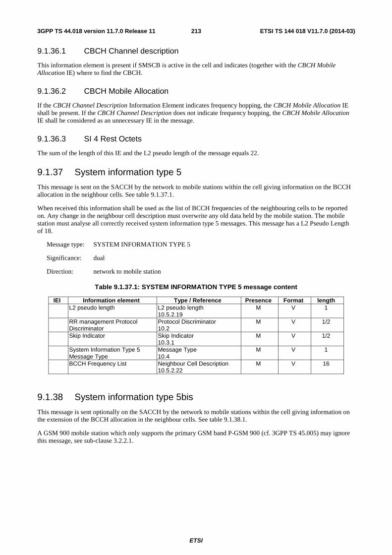
ETSI
ETSI TS 144 018 V11.7.0 (2014-03)2133GPP TS 44.018 version 11.7.0 Release 11
9.1.36.1 CBCH Channel description
This information element is present if SMSCB is active in the cell and indicates (together with the CBCH Mobile Allocation IE) where to find the CBCH.
9.1.36.2 CBCH Mobile Allocation
If the CBCH Channel Description Information Element indicates frequency hopping, the CBCH Mobile Allocation IE shall be present. If the CBCH Channel Description does not indicate frequency hopping, the CBCH Mobile Allocation IE shall be considered as an unnecessary IE in the message.
9.1.36.3 SI 4 Rest Octets
The sum of the length of this IE and the L2 pseudo length of the message equals 22.
9.1.37 System information type 5
This message is sent on the SACCH by the network to mobile stations within the cell giving information on the BCCH allocation in the neighbour cells. See table 9.1.37.1.
When received this information shall be used as the list of BCCH frequencies of the neighbouring cells to be reported on. Any change in the neighbour cell description must overwrite any old data held by the mobile station. The mobile station must analyse all correctly received system information type 5 messages. This message has a L2 Pseudo Length of 18.
Message type: SYSTEM INFORMATION TYPE 5
Significance: dual
Direction: network to mobile station
Table 9.1.37.1: SYSTEM INFORMATION TYPE 5 message content
IEI Information element Type / Reference Presence Format length L2 pseudo length L2 pseudo length
10.5.2.19 M V 1
RR management Protocol Discriminator
Protocol Discriminator 10.2
M V 1/2
Skip Indicator Skip Indicator 10.3.1
M V 1/2
System Information Type 5 Message Type
Message Type 10.4
M V 1
BCCH Frequency List Neighbour Cell Description 10.5.2.22
M V 16
9.1.38 System information type 5bis
This message is sent optionally on the SACCH by the network to mobile stations within the cell giving information on the extension of the BCCH allocation in the neighbour cells. See table 9.1.38.1.
A GSM 900 mobile station which only supports the primary GSM band P-GSM 900 (cf. 3GPP TS 45.005) may ignore this message, see sub-clause 3.2.2.1.
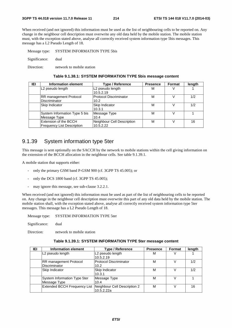
ETSI
ETSI TS 144 018 V11.7.0 (2014-03)2143GPP TS 44.018 version 11.7.0 Release 11
When received (and not ignored) this information must be used as the list of neighbouring cells to be reported on. Any change in the neighbour cell description must overwrite any old data held by the mobile station. The mobile station must, with the exception stated above, analyse all correctly received system information type 5bis messages. This message has a L2 Pseudo Length of 18.
Message type: SYSTEM INFORMATION TYPE 5bis
Significance: dual
Direction: network to mobile station
Table 9.1.38.1: SYSTEM INFORMATION TYPE 5bis message content
IEI Information element Type / Reference Presence Format length L2 pseudo length L2 pseudo length
10.5.2.19 M V 1
RR management Protocol Discriminator
Protocol Discriminator 10.2
M V 1/2
Skip Indicator Skip Indicator 10.3.1
M V 1/2
System Information Type 5 bis Message Type
Message Type 10.4
M V 1
Extension of the BCCH Frequency List Description
Neighbour Cell Description 10.5.2.22
M V 16
9.1.39 System information type 5ter
This message is sent optionally on the SACCH by the network to mobile stations within the cell giving information on the extension of the BCCH allocation in the neighbour cells. See table 9.1.39.1.
A mobile station that supports either:
- only the primary GSM band P-GSM 900 (cf. 3GPP TS 45.005); or
- only the DCS 1800 band (cf. 3GPP TS 45.005);
- may ignore this message, see sub-clause 3.2.2.1.
When received (and not ignored) this information must be used as part of the list of neighbouring cells to be reported on. Any change in the neighbour cell description must overwrite this part of any old data held by the mobile station. The mobile station shall, with the exception stated above, analyse all correctly received system information type 5ter messages. This message has a L2 Pseudo Length of 18.
Message type: SYSTEM INFORMATION TYPE 5ter
Significance: dual
Direction: network to mobile station
Table 9.1.39.1: SYSTEM INFORMATION TYPE 5ter message content
IEI Information element Type / Reference Presence Format length L2 pseudo length L2 pseudo length
10.5.2.19 M V 1
RR management Protocol Discriminator
Protocol Discriminator 10.2
M V 1/2
Skip Indicator Skip Indicator 10.3.1
M V 1/2
System Information Type 5ter Message Type
Message Type 10.4
M V 1
Extended BCCH Frequency List Neighbour Cell Description 2 10.5.2.22a
M V 16
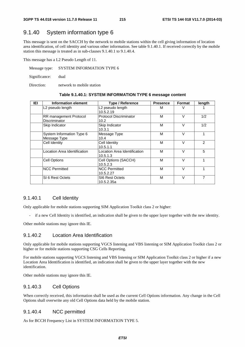
ETSI
ETSI TS 144 018 V11.7.0 (2014-03)2153GPP TS 44.018 version 11.7.0 Release 11
9.1.40 System information type 6
This message is sent on the SACCH by the network to mobile stations within the cell giving information of location area identification, of cell identity and various other information. See table 9.1.40.1. If received correctly by the mobile station this message is treated as in sub-clauses 9.1.40.1 to 9.1.40.4.
This message has a L2 Pseudo Length of 11.
Message type: SYSTEM INFORMATION TYPE 6
Significance: dual
Direction: network to mobile station
Table 9.1.40.1: SYSTEM INFORMATION TYPE 6 message content
IEI Information element Type / Reference Presence Format length L2 pseudo length L2 pseudo length
10.5.2.19 M V 1
RR management Protocol Discriminator
Protocol Discriminator 10.2
M V 1/2
Skip Indicator Skip Indicator 10.3.1
M V 1/2
System Information Type 6 Message Type
Message Type 10.4
M V 1
Cell Identity Cell Identity 10.5.1.1
M V 2
Location Area Identification Location Area Identification 10.5.1.3
M V 5
Cell Options Cell Options (SACCH) 10.5.2.3
M V 1
NCC Permitted NCC Permitted 10.5.2.27
M V 1
SI 6 Rest Octets SI6 Rest Octets 10.5.2.35a
M V 7
9.1.40.1 Cell Identity
Only applicable for mobile stations supporting SIM Application Toolkit class 2 or higher:
- if a new Cell Identity is identified, an indication shall be given to the upper layer together with the new identity.
Other mobile stations may ignore this IE.
9.1.40.2 Location Area Identification
Only applicable for mobile stations supporting VGCS listening and VBS listening or SIM Application Toolkit class 2 or higher or for mobile stations supporting CSG Cells Reporting.
For mobile stations supporting VGCS listening and VBS listening or SIM Application Toolkit class 2 or higher if a new Location Area Identification is identified, an indication shall be given to the upper layer together with the new identification.
Other mobile stations may ignore this IE.
9.1.40.3 Cell Options
When correctly received, this information shall be used as the current Cell Options information. Any change in the Cell Options shall overwrite any old Cell Options data held by the mobile station.
9.1.40.4 NCC permitted
As for BCCH Frequency List in SYSTEM INFORMATION TYPE 5.

ETSI
ETSI TS 144 018 V11.7.0 (2014-03)2163GPP TS 44.018 version 11.7.0 Release 11
9.1.41 System information type 7
This message is sent on the BCCH by the network giving information about cell reselection parameters to be used in that cell. See table 9.1.41.1. Special requirements for the transmission of this message apply, see 3GPP TS 45.002. The L2 pseudo length of this message has the value 1.
Message type: SYSTEM INFORMATION TYPE 7
Significance: dual
Direction: network to mobile station
Table 9.1.41.1: SYSTEM INFORMATION TYPE 7 message content
IEI Information element Type / Reference Presence Format length L2 pseudo length L2 pseudo length
10.5.2.19 M V 1
RR management Protocol Discriminator
Protocol Discriminator 10.2
M V 1/2
Skip Indicator Skip Indicator 10.3.1
M V 1/2
System Information Type 7 Message Type
Message Type 10.4
M V 1
SI 7 Rest Octets SI 7 Rest Octets 10.5.2.36
M V 20
9.1.42 System information type 8
This message is sent on the BCCH by the network giving information about cell reselection parameters to be used in that cell. See table 9.1.42.1. Special requirements for the transmission of this message apply, see 3GPP TS 45.002. The L2 Pseudo Length of this message has the value 1.
Message type: SYSTEM INFORMATION TYPE 8
Significance: dual
Direction: network to mobile station
Table 9.1.42.1: SYSTEM INFORMATION TYPE 8 message content
IEI Information element Type / Reference Presence Format length L2 Pseudo Length L2 Pseudo Length
10.5.2.19 M V 1
RR management Protocol Discriminator
Protocol Discriminator 10.2
M V 1/2
Skip Indicator Skip Indicator 10.3.1
M V 1/2
System Information Type 8 Message Type
Message Type 10.4
M V 1
SI 8 Rest Octets SI 8 Rest Octets 10.5.2.37
M V 20

ETSI
ETSI TS 144 018 V11.7.0 (2014-03)2173GPP TS 44.018 version 11.7.0 Release 11
9.1.43 System information Type 9
This message is sent on the BCCH by the network to all mobile stations within the cell giving some, but not necessarily all information on the scheduling of information on the BCCH. See table 9.1.43.1. Special requirements for the transmission of this message apply, see sub-clause 3.2.2.1 and 3GPP TS 45.002. This message has a L2 Pseudo Length of 1.
Message type: SYSTEM INFORMATION TYPE 9
Significance: dual
Direction: network to mobile station
Table 9.1.43.1: SYSTEM INFORMATION TYPE 9 message content
IEI Information element Type / Reference Presence Format length L2 pseudo length L2 pseudo length
10.5.2.19 M V 1
RR management Protocol Discriminator
Protocol Discriminator 10.2
M V 1/2
Skip Indicator Skip Indicator 10.3.1
M V 1/2
System Information Type 9 Message Type
Message Type 10.4
M V 1
RACH Control Parameter RACH Control Parameters 10.5.2.29
M V 3
SI 9 Rest Octets SI 9 Rest Octets 10.5.2.37a
M V 17
9.1.43a System information Type 13
This message is sent on the BCCH if indicated in at least one of the SYSTEM INFORMATION TYPE 3, 4, 7 or 8 messages. The message is sent by the network to provide information related to GPRS in the cell. See table 9.1.43a.1. Special requirements for the transmission of this message apply, see 3GPP TS 45.002.
A mobile station not supporting GPRS shall treat this message as an unknown message type.
The L2 Pseudo Length of this message has the value 0.
Message type: SYSTEM INFORMATION TYPE 13
Significance: dual
Direction: network to mobile station
Table 9.1.43a.1: SYSTEM INFORMATION TYPE 13 message content
IEI Information element Type / Reference Presence Format length L2 Pseudo Length L2 Pseudo Length
10.5.2.19 M V 1
RR management Protocol Discriminator
Protocol Discriminator 10.2
M V 1/2
Skip Indicator Skip Indicator 10.3.1
M V 1/2
System Information Type 13 Message Type
Message Type 10.4
M V 1
SI 13 Rest Octets SI 13 Rest Octets 10.5.2.37b
M V 20
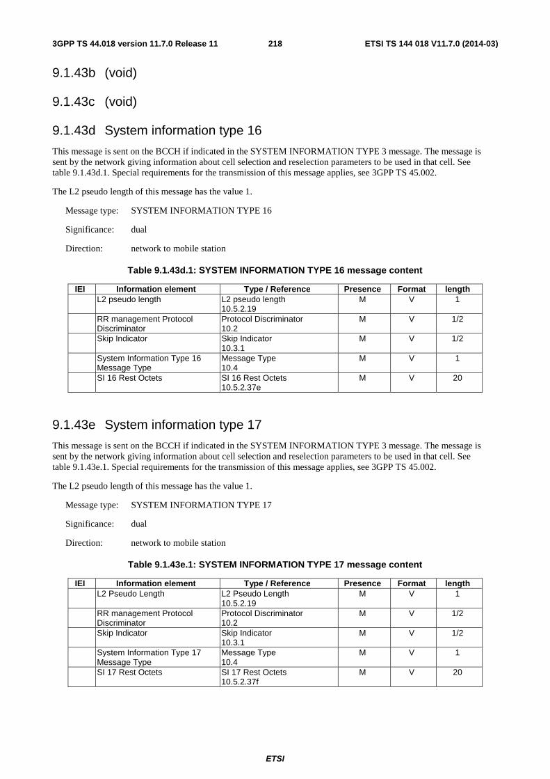
ETSI
ETSI TS 144 018 V11.7.0 (2014-03)2183GPP TS 44.018 version 11.7.0 Release 11
9.1.43b (void)
9.1.43c (void)
9.1.43d System information type 16
This message is sent on the BCCH if indicated in the SYSTEM INFORMATION TYPE 3 message. The message is sent by the network giving information about cell selection and reselection parameters to be used in that cell. See table 9.1.43d.1. Special requirements for the transmission of this message applies, see 3GPP TS 45.002.
The L2 pseudo length of this message has the value 1.
Message type: SYSTEM INFORMATION TYPE 16
Significance: dual
Direction: network to mobile station
Table 9.1.43d.1: SYSTEM INFORMATION TYPE 16 message content
IEI Information element Type / Reference Presence Format length L2 pseudo length L2 pseudo length
10.5.2.19 M V 1
RR management Protocol Discriminator
Protocol Discriminator 10.2
M V 1/2
Skip Indicator Skip Indicator 10.3.1
M V 1/2
System Information Type 16 Message Type
Message Type 10.4
M V 1
SI 16 Rest Octets SI 16 Rest Octets 10.5.2.37e
M V 20
9.1.43e System information type 17
This message is sent on the BCCH if indicated in the SYSTEM INFORMATION TYPE 3 message. The message is sent by the network giving information about cell selection and reselection parameters to be used in that cell. See table 9.1.43e.1. Special requirements for the transmission of this message applies, see 3GPP TS 45.002.
The L2 pseudo length of this message has the value 1.
Message type: SYSTEM INFORMATION TYPE 17
Significance: dual
Direction: network to mobile station
Table 9.1.43e.1: SYSTEM INFORMATION TYPE 17 message content
IEI Information element Type / Reference Presence Format length L2 Pseudo Length L2 Pseudo Length
10.5.2.19 M V 1
RR management Protocol Discriminator
Protocol Discriminator 10.2
M V 1/2
Skip Indicator Skip Indicator 10.3.1
M V 1/2
System Information Type 17 Message Type
Message Type 10.4
M V 1
SI 17 Rest Octets SI 17 Rest Octets 10.5.2.37f
M V 20
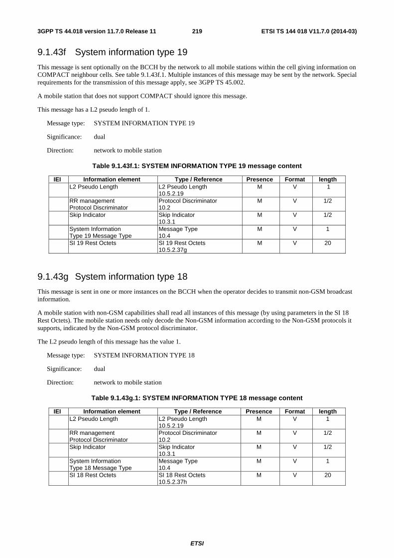
ETSI
ETSI TS 144 018 V11.7.0 (2014-03)2193GPP TS 44.018 version 11.7.0 Release 11
9.1.43f System information type 19
This message is sent optionally on the BCCH by the network to all mobile stations within the cell giving information on COMPACT neighbour cells. See table 9.1.43f.1. Multiple instances of this message may be sent by the network. Special requirements for the transmission of this message apply, see 3GPP TS 45.002.
A mobile station that does not support COMPACT should ignore this message.
This message has a L2 pseudo length of 1.
Message type: SYSTEM INFORMATION TYPE 19
Significance: dual
Direction: network to mobile station
Table 9.1.43f.1: SYSTEM INFORMATION TYPE 19 message content
IEI Information element Type / Reference Presence Format length L2 Pseudo Length L2 Pseudo Length
10.5.2.19 M V 1
RR management Protocol Discriminator
Protocol Discriminator 10.2
M V 1/2
Skip Indicator Skip Indicator 10.3.1
M V 1/2
System Information Type 19 Message Type
Message Type 10.4
M V 1
SI 19 Rest Octets SI 19 Rest Octets 10.5.2.37g
M V 20
9.1.43g System information type 18
This message is sent in one or more instances on the BCCH when the operator decides to transmit non-GSM broadcast information.
A mobile station with non-GSM capabilities shall read all instances of this message (by using parameters in the SI 18 Rest Octets). The mobile station needs only decode the Non-GSM information according to the Non-GSM protocols it supports, indicated by the Non-GSM protocol discriminator.
The L2 pseudo length of this message has the value 1.
Message type: SYSTEM INFORMATION TYPE 18
Significance: dual
Direction: network to mobile station
Table 9.1.43g.1: SYSTEM INFORMATION TYPE 18 message content
IEI Information element Type / Reference Presence Format length L2 Pseudo Length L2 Pseudo Length
10.5.2.19 M V 1
RR management Protocol Discriminator
Protocol Discriminator 10.2
M V 1/2
Skip Indicator Skip Indicator 10.3.1
M V 1/2
System Information Type 18 Message Type
Message Type 10.4
M V 1
SI 18 Rest Octets SI 18 Rest Octets 10.5.2.37h
M V 20
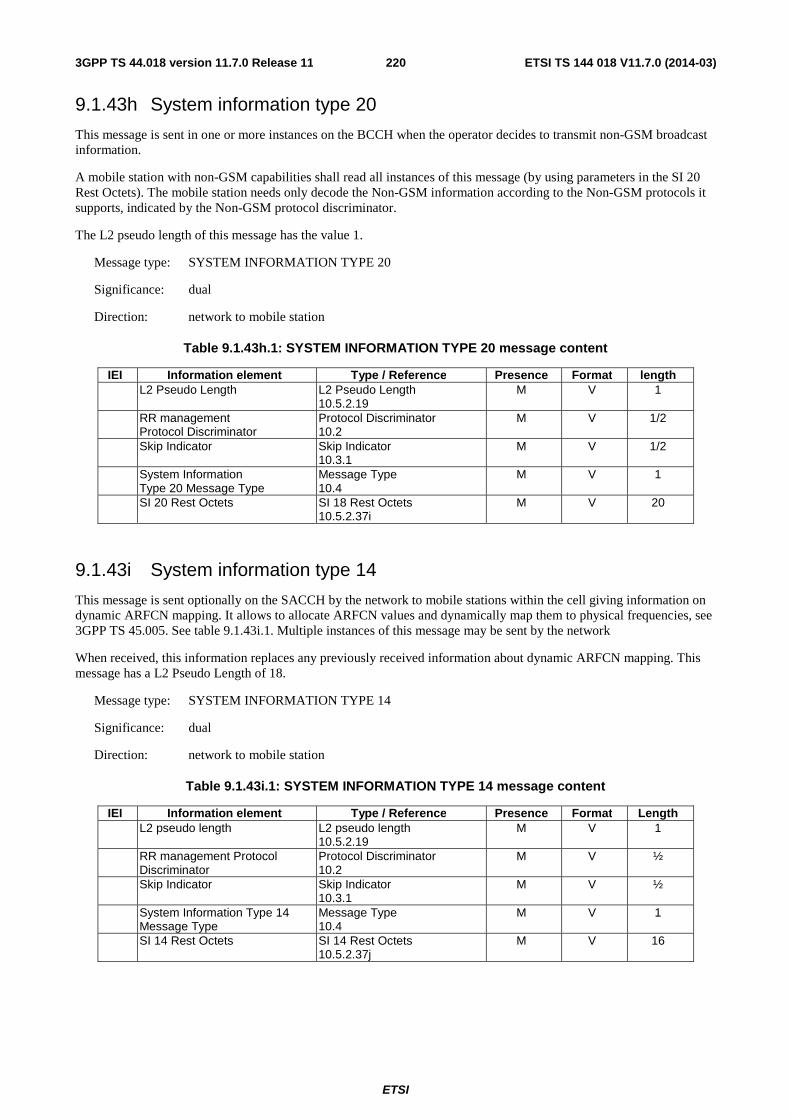
ETSI
ETSI TS 144 018 V11.7.0 (2014-03)2203GPP TS 44.018 version 11.7.0 Release 11
9.1.43h System information type 20
This message is sent in one or more instances on the BCCH when the operator decides to transmit non-GSM broadcast information.
A mobile station with non-GSM capabilities shall read all instances of this message (by using parameters in the SI 20 Rest Octets). The mobile station needs only decode the Non-GSM information according to the Non-GSM protocols it supports, indicated by the Non-GSM protocol discriminator.
The L2 pseudo length of this message has the value 1.
Message type: SYSTEM INFORMATION TYPE 20
Significance: dual
Direction: network to mobile station
Table 9.1.43h.1: SYSTEM INFORMATION TYPE 20 message content
IEI Information element Type / Reference Presence Format length L2 Pseudo Length L2 Pseudo Length
10.5.2.19 M V 1
RR management Protocol Discriminator
Protocol Discriminator 10.2
M V 1/2
Skip Indicator Skip Indicator 10.3.1
M V 1/2
System Information Type 20 Message Type
Message Type 10.4
M V 1
SI 20 Rest Octets SI 18 Rest Octets 10.5.2.37i
M V 20
9.1.43i System information type 14
This message is sent optionally on the SACCH by the network to mobile stations within the cell giving information on dynamic ARFCN mapping. It allows to allocate ARFCN values and dynamically map them to physical frequencies, see 3GPP TS 45.005. See table 9.1.43i.1. Multiple instances of this message may be sent by the network
When received, this information replaces any previously received information about dynamic ARFCN mapping. This message has a L2 Pseudo Length of 18.
Message type: SYSTEM INFORMATION TYPE 14
Significance: dual
Direction: network to mobile station
Table 9.1.43i.1: SYSTEM INFORMATION TYPE 14 message content
IEI Information element Type / Reference Presence Format Length L2 pseudo length L2 pseudo length
10.5.2.19 M V 1
RR management Protocol Discriminator
Protocol Discriminator 10.2
M V ½
Skip Indicator Skip Indicator 10.3.1
M V ½
System Information Type 14 Message Type
Message Type 10.4
M V 1
SI 14 Rest Octets SI 14 Rest Octets 10.5.2.37j
M V 16
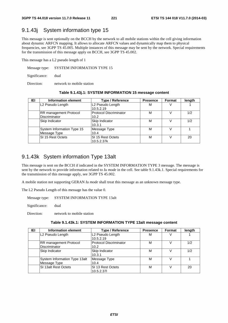
ETSI
ETSI TS 144 018 V11.7.0 (2014-03)2213GPP TS 44.018 version 11.7.0 Release 11
9.1.43j System information type 15
This message is sent optionally on the BCCH by the network to all mobile stations within the cell giving information about dynamic ARFCN mapping. It allows to allocate ARFCN values and dynamically map them to physical frequencies, see 3GPP TS 45.005. Multiple instances of this message may be sent by the network. Special requirements for the transmission of this message apply on BCCH, see 3GPP TS 45.002.
This message has a L2 pseudo length of 1
Message type: SYSTEM INFORMATION TYPE 15
Significance: dual
Direction: network to mobile station
Table 9.1.43j.1: SYSTEM INFORMATION 15 message content
IEI Information element Type / Reference Presence Format length L2 Pseudo Length L2 Pseudo Length
10.5.2.19 M V 1
RR management Protocol Discriminator
Protocol Discriminator 10.2
M V 1/2
Skip Indicator Skip Indicator 10.3.1
M V 1/2
System Information Type 15 Message Type
Message Type 10.4
M V 1
SI 15 Rest Octets SI 15 Rest Octets 10.5.2.37k
M V 20
9.1.43k System information Type 13alt
This message is sent on the BCCH if indicated in the SYSTEM INFORMATION TYPE 3 message. The message is sent by the network to provide information related to Iu mode in the cell. See table 9.1.43k.1. Special requirements for the transmission of this message apply, see 3GPP TS 45.002.
A mobile station not supporting GERAN Iu mode shall treat this message as an unknown message type.
The L2 Pseudo Length of this message has the value 0.
Message type: SYSTEM INFORMATION TYPE 13alt
Significance: dual
Direction: network to mobile station
Table 9.1.43k.1: SYSTEM INFORMATION TYPE 13alt message content
IEI Information element Type / Reference Presence Format length L2 Pseudo Length L2 Pseudo Length
10.5.2.19 M V 1
RR management Protocol Discriminator
Protocol Discriminator 10.2
M V 1/2
Skip Indicator Skip Indicator 10.3.1
M V 1/2
System Information Type 13alt Message Type
Message Type 10.4
M V 1
SI 13alt Rest Octets SI 13 Rest Octets 10.5.2.37l
M V 20
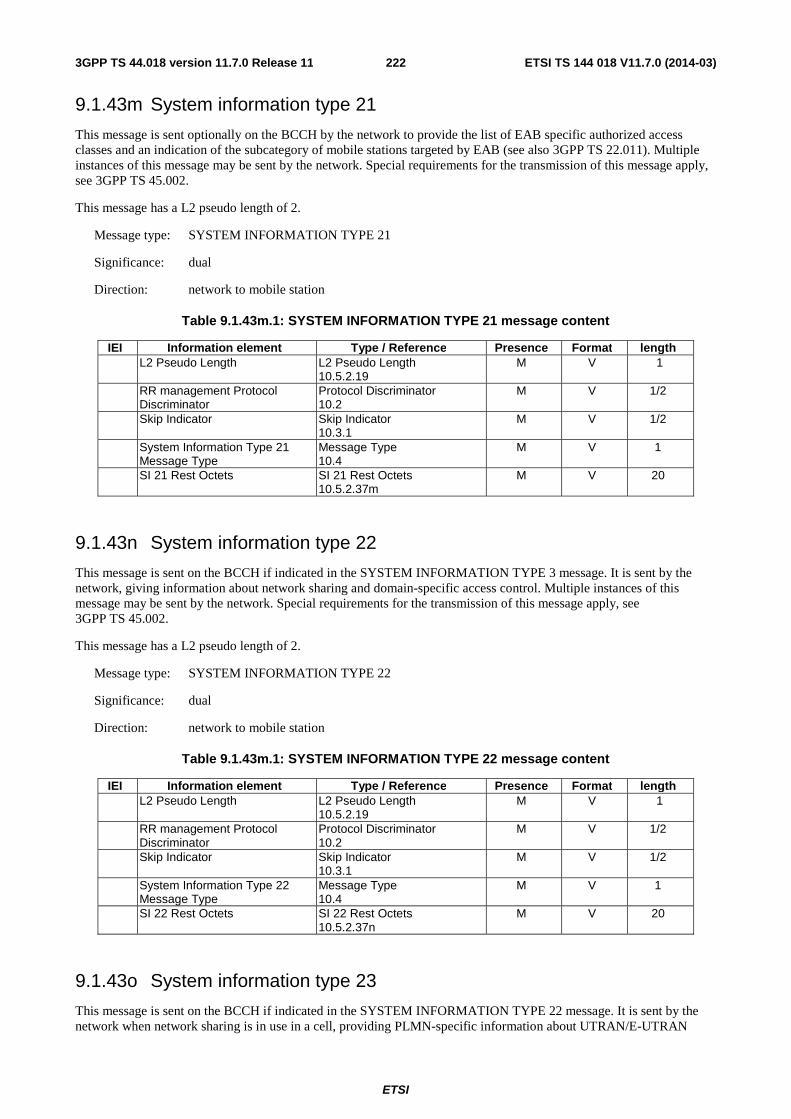
ETSI
ETSI TS 144 018 V11.7.0 (2014-03)2223GPP TS 44.018 version 11.7.0 Release 11
9.1.43m System information type 21
This message is sent optionally on the BCCH by the network to provide the list of EAB specific authorized access classes and an indication of the subcategory of mobile stations targeted by EAB (see also 3GPP TS 22.011). Multiple instances of this message may be sent by the network. Special requirements for the transmission of this message apply, see 3GPP TS 45.002.
This message has a L2 pseudo length of 2.
Message type: SYSTEM INFORMATION TYPE 21
Significance: dual
Direction: network to mobile station
Table 9.1.43m.1: SYSTEM INFORMATION TYPE 21 message content
IEI Information element Type / Reference Presence Format length L2 Pseudo Length L2 Pseudo Length
10.5.2.19 M V 1
RR management Protocol Discriminator
Protocol Discriminator 10.2
M V 1/2
Skip Indicator Skip Indicator 10.3.1
M V 1/2
System Information Type 21 Message Type
Message Type 10.4
M V 1
SI 21 Rest Octets SI 21 Rest Octets 10.5.2.37m
M V 20
9.1.43n System information type 22
This message is sent on the BCCH if indicated in the SYSTEM INFORMATION TYPE 3 message. It is sent by the network, giving information about network sharing and domain-specific access control. Multiple instances of this message may be sent by the network. Special requirements for the transmission of this message apply, see 3GPP TS 45.002.
This message has a L2 pseudo length of 2.
Message type: SYSTEM INFORMATION TYPE 22
Significance: dual
Direction: network to mobile station
Table 9.1.43m.1: SYSTEM INFORMATION TYPE 22 message content
IEI Information element Type / Reference Presence Format length L2 Pseudo Length L2 Pseudo Length
10.5.2.19 M V 1
RR management Protocol Discriminator
Protocol Discriminator 10.2
M V 1/2
Skip Indicator Skip Indicator 10.3.1
M V 1/2
System Information Type 22 Message Type
Message Type 10.4
M V 1
SI 22 Rest Octets SI 22 Rest Octets 10.5.2.37n
M V 20
9.1.43o System information type 23
This message is sent on the BCCH if indicated in the SYSTEM INFORMATION TYPE 22 message. It is sent by the network when network sharing is in use in a cell, providing PLMN-specific information about UTRAN/E-UTRAN
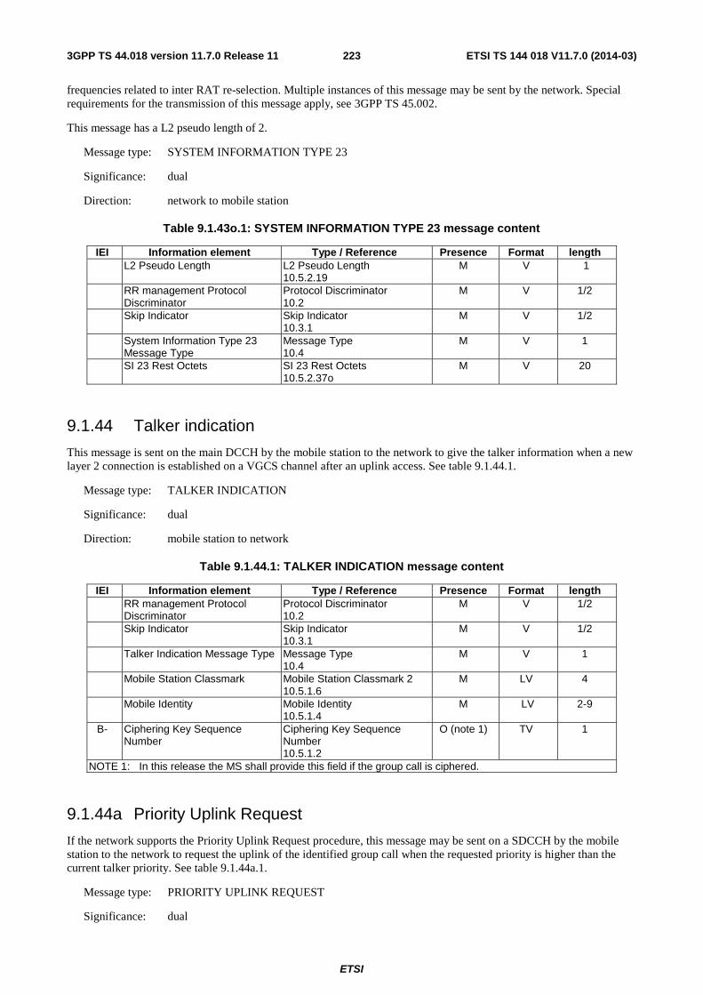
ETSI
ETSI TS 144 018 V11.7.0 (2014-03)2233GPP TS 44.018 version 11.7.0 Release 11
frequencies related to inter RAT re-selection. Multiple instances of this message may be sent by the network. Special requirements for the transmission of this message apply, see 3GPP TS 45.002.
This message has a L2 pseudo length of 2.
Message type: SYSTEM INFORMATION TYPE 23
Significance: dual
Direction: network to mobile station
Table 9.1.43o.1: SYSTEM INFORMATION TYPE 23 message content
IEI Information element Type / Reference Presence Format length L2 Pseudo Length L2 Pseudo Length
10.5.2.19 M V 1
RR management Protocol Discriminator
Protocol Discriminator 10.2
M V 1/2
Skip Indicator Skip Indicator 10.3.1
M V 1/2
System Information Type 23 Message Type
Message Type 10.4
M V 1
SI 23 Rest Octets SI 23 Rest Octets 10.5.2.37o
M V 20
9.1.44 Talker indication
This message is sent on the main DCCH by the mobile station to the network to give the talker information when a new layer 2 connection is established on a VGCS channel after an uplink access. See table 9.1.44.1.
Message type: TALKER INDICATION
Significance: dual
Direction: mobile station to network
Table 9.1.44.1: TALKER INDICATION message content
IEI Information element Type / Reference Presence Format length RR management Protocol
Discriminator Protocol Discriminator 10.2
M V 1/2
Skip Indicator Skip Indicator 10.3.1
M V 1/2
Talker Indication Message Type Message Type 10.4
M V 1
Mobile Station Classmark Mobile Station Classmark 2 10.5.1.6
M LV 4
Mobile Identity Mobile Identity 10.5.1.4
M LV 2-9
B- Ciphering Key Sequence Number
Ciphering Key Sequence Number 10.5.1.2
O (note 1) TV 1
NOTE 1: In this release the MS shall provide this field if the group call is ciphered.
9.1.44a Priority Uplink Request
If the network supports the Priority Uplink Request procedure, this message may be sent on a SDCCH by the mobile station to the network to request the uplink of the identified group call when the requested priority is higher than the current talker priority. See table 9.1.44a.1.
Message type: PRIORITY UPLINK REQUEST
Significance: dual
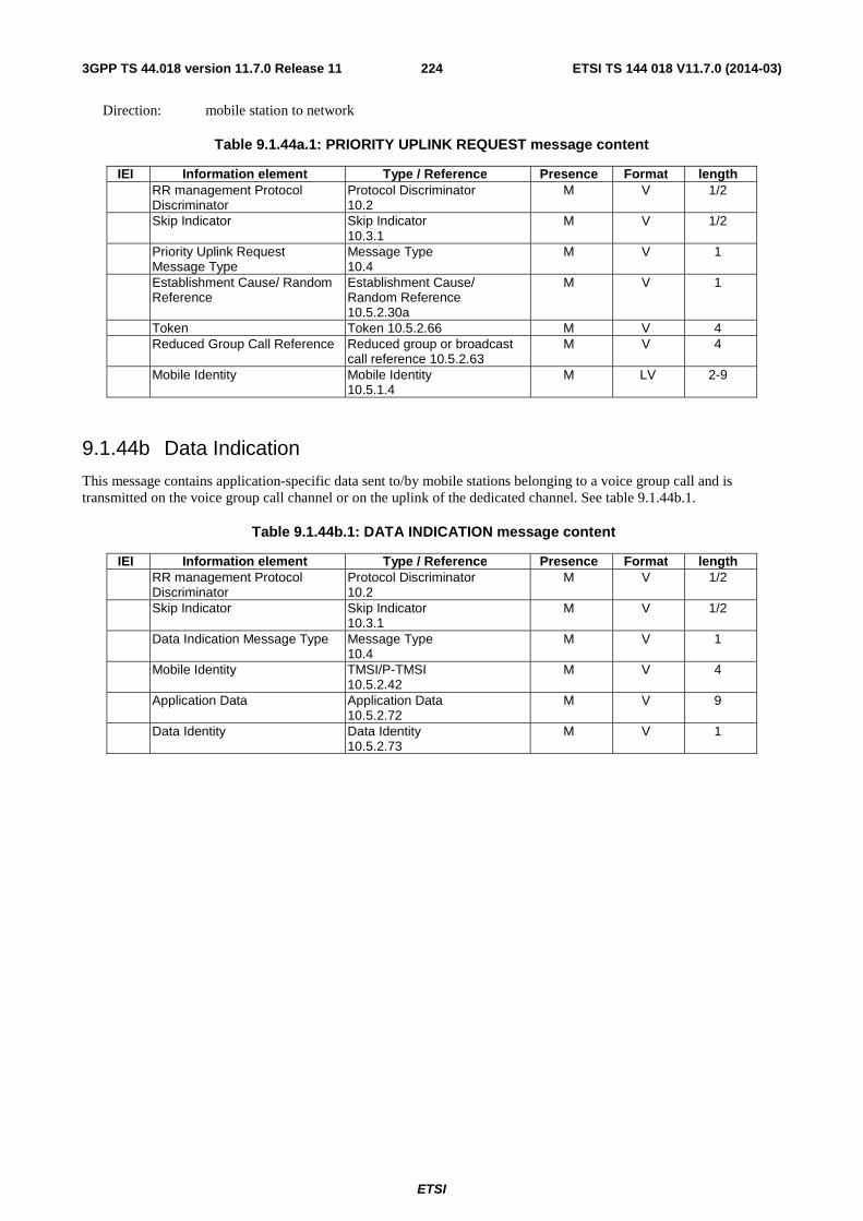
ETSI
ETSI TS 144 018 V11.7.0 (2014-03)2243GPP TS 44.018 version 11.7.0 Release 11
Direction: mobile station to network
Table 9.1.44a.1: PRIORITY UPLINK REQUEST message content
IEI Information element Type / Reference Presence Format length RR management Protocol
Discriminator Protocol Discriminator 10.2
M V 1/2
Skip Indicator Skip Indicator 10.3.1
M V 1/2
Priority Uplink Request Message Type
Message Type 10.4
M V 1
Establishment Cause/ Random Reference
Establishment Cause/ Random Reference 10.5.2.30a
M V 1
Token Token 10.5.2.66 M V 4 Reduced Group Call Reference Reduced group or broadcast
call reference 10.5.2.63 M V 4
Mobile Identity Mobile Identity 10.5.1.4
M LV 2-9
9.1.44b Data Indication
This message contains application-specific data sent to/by mobile stations belonging to a voice group call and is transmitted on the voice group call channel or on the uplink of the dedicated channel. See table 9.1.44b.1.
Table 9.1.44b.1: DATA INDICATION message content
IEI Information element Type / Reference Presence Format length RR management Protocol
Discriminator Protocol Discriminator 10.2
M V 1/2
Skip Indicator Skip Indicator 10.3.1
M V 1/2
Data Indication Message Type Message Type 10.4
M V 1
Mobile Identity TMSI/P-TMSI 10.5.2.42
M V 4
Application Data Application Data 10.5.2.72
M V 9
Data Identity Data Identity 10.5.2.73
M V 1
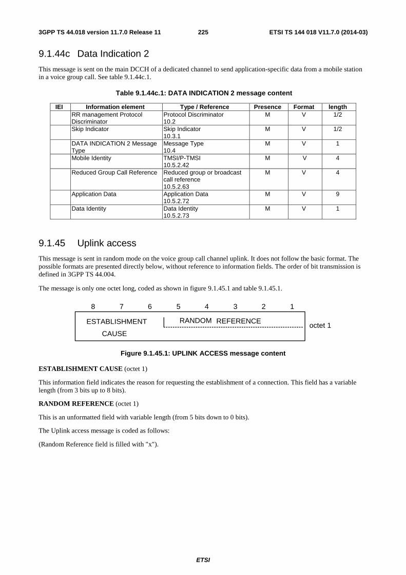
ETSI
ETSI TS 144 018 V11.7.0 (2014-03)2253GPP TS 44.018 version 11.7.0 Release 11
9.1.44c Data Indication 2
This message is sent on the main DCCH of a dedicated channel to send application-specific data from a mobile station in a voice group call. See table 9.1.44c.1.
Table 9.1.44c.1: DATA INDICATION 2 message content
IEI Information element Type / Reference Presence Format length RR management Protocol
Discriminator Protocol Discriminator 10.2
M V 1/2
Skip Indicator Skip Indicator 10.3.1
M V 1/2
DATA INDICATION 2 Message Type
Message Type 10.4
M V 1
Mobile Identity TMSI/P-TMSI 10.5.2.42
M V 4
Reduced Group Call Reference Reduced group or broadcast call reference 10.5.2.63
M V 4
Application Data Application Data 10.5.2.72
M V 9
Data Identity Data Identity 10.5.2.73
M V 1
9.1.45 Uplink access
This message is sent in random mode on the voice group call channel uplink. It does not follow the basic format. The possible formats are presented directly below, without reference to information fields. The order of bit transmission is defined in 3GPP TS 44.004.
The message is only one octet long, coded as shown in figure 9.1.45.1 and table 9.1.45.1.
8 7 6 5 4 3 2 1
ESTABLISHMENT
CAUSE
RANDOM REFERENCEoctet 1
Figure 9.1.45.1: UPLINK ACCESS message content
ESTABLISHMENT CAUSE (octet 1)
This information field indicates the reason for requesting the establishment of a connection. This field has a variable length (from 3 bits up to 8 bits).
RANDOM REFERENCE (octet 1)
This is an unformatted field with variable length (from 5 bits down to 0 bits).
The Uplink access message is coded as follows:
(Random Reference field is filled with "x").
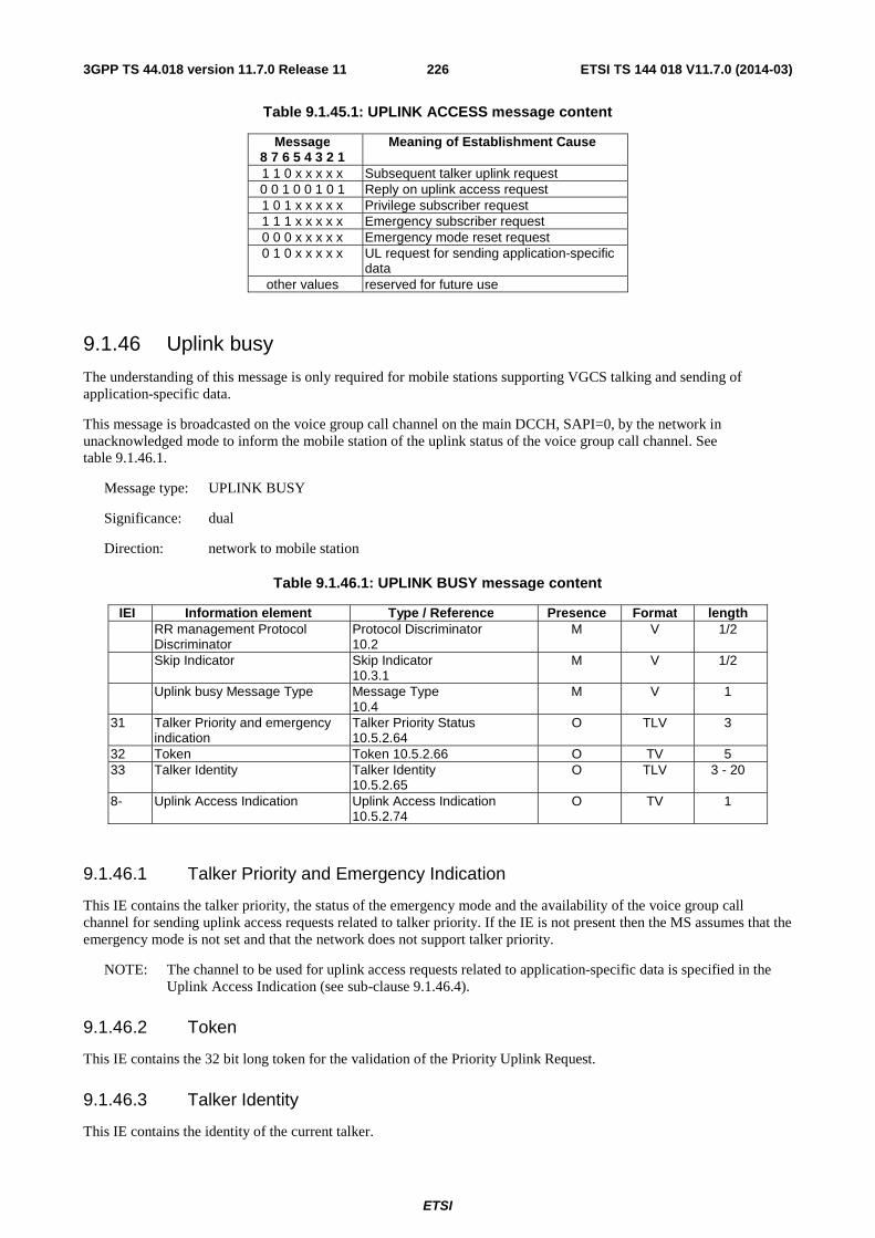
ETSI
ETSI TS 144 018 V11.7.0 (2014-03)2263GPP TS 44.018 version 11.7.0 Release 11
Table 9.1.45.1: UPLINK ACCESS message content
Message 8 7 6 5 4 3 2 1
Meaning of Establishment Cause
1 1 0 x x x x x Subsequent talker uplink request 0 0 1 0 0 1 0 1 Reply on uplink access request 1 0 1 x x x x x Privilege subscriber request 1 1 1 x x x x x Emergency subscriber request 0 0 0 x x x x x Emergency mode reset request 0 1 0 x x x x x UL request for sending application-specific
data other values reserved for future use
9.1.46 Uplink busy
The understanding of this message is only required for mobile stations supporting VGCS talking and sending of application-specific data.
This message is broadcasted on the voice group call channel on the main DCCH, SAPI=0, by the network in unacknowledged mode to inform the mobile station of the uplink status of the voice group call channel. See table 9.1.46.1.
Message type: UPLINK BUSY
Significance: dual
Direction: network to mobile station
Table 9.1.46.1: UPLINK BUSY message content
IEI Information element Type / Reference Presence Format length RR management Protocol
Discriminator Protocol Discriminator 10.2
M V 1/2
Skip Indicator Skip Indicator 10.3.1
M V 1/2
Uplink busy Message Type Message Type 10.4
M V 1
31 Talker Priority and emergency indication
Talker Priority Status 10.5.2.64
O TLV 3
32 Token Token 10.5.2.66 O TV 5 33 Talker Identity Talker Identity
10.5.2.65 O TLV 3 - 20
8- Uplink Access Indication Uplink Access Indication 10.5.2.74
O TV 1
9.1.46.1 Talker Priority and Emergency Indication
This IE contains the talker priority, the status of the emergency mode and the availability of the voice group call channel for sending uplink access requests related to talker priority. If the IE is not present then the MS assumes that the emergency mode is not set and that the network does not support talker priority.
NOTE: The channel to be used for uplink access requests related to application-specific data is specified in the Uplink Access Indication (see sub-clause 9.1.46.4).
9.1.46.2 Token
This IE contains the 32 bit long token for the validation of the Priority Uplink Request.
9.1.46.3 Talker Identity
This IE contains the identity of the current talker.

ETSI
ETSI TS 144 018 V11.7.0 (2014-03)2273GPP TS 44.018 version 11.7.0 Release 11
9.1.46.4 Uplink Access Indication
This IE indicates whether a mobile sending application-specific data should perform uplink access on the group call channel or via the RACH.
9.1.47 Uplink free
This message is sent on the main DCCH, in unacknowledged mode using the RR short protocol discriminator by the network to inform the mobile station of the uplink status of the voice group call channel. See table 9.1.47.1. The message indicates the uplink as free unless it is used by the network to request the mobile station to perform an uplink reply procedure.
Message type: UPLINK FREE
Significance: dual
Direction: network to mobile station
Table 9.1.47.1: UPLINK FREE message content
<UPLINK FREE> ::= < RR short PD : bit > -- See 3GPP TS 24.007 < message type : bit(5) > -- See 10.4 < short layer 2 header : bit(2) > -- See 3GPP TS 44.006 < Uplink Access Request bit > { L | H < Uplink Identity Code bit(6) >} { null | L -- Receiver compatible with earlier release | H -- Additions for Release-7 { 0|1 <Emergency_Ind: bit(1)>} } < spare padding > ; Uplink Access Request :
L Mobile station shall not perform the uplink reply procedure; H Mobile station shall perform the uplink reply procedure.
Uplink Identity Code :
This field is coded as the binary representation of the UIC.
If provided by the network, the Uplink Identity Code shall be used by the mobile for the coding of the UPLINK ACCESS message
Emergency_Ind:
This field indicates the status of the emergency mode for the group call.
0 Emergency mode not set. 1 Emergency mode set.
If Emergency_Ind is not present in the message, then it is assumed that the emergency mode is not set and talker priority is not supported by the network.
9.1.48 Uplink release
Only applicable for mobile stations supporting VGCS talking.
This message is sent on the uplink of the voice group call channel to initiate a deactivation of the group transmit mode and to set the uplink free or on the uplink by a talker on the dedicated channel or on the downlink of the voice group call channel in order to reject an uplink access which was already granted by the network. See table 9.1.48.1.
Message type: UPLINK RELEASE
ETSI
ETSI TS 144 018 V11.7.0 (2014-03)2283GPP TS 44.018 version 11.7.0 Release 11
Significance: local
Direction: both
Table 9.1.48.1: UPLINK RELEASE message content
IEI Information element Type / Reference Presence Format length RR management Protocol
Discriminator Protocol Discriminator 10.2
M V 1/2
Skip Indicator Skip Indicator 10.3.1
M V 1/2
Uplink Release Message Type Message Type 10.4
M V 1
RR Cause RR Cause 10.5.2.31
M V 1
9.1.49 VGCS uplink grant
The understanding of this message is only required for mobile stations supporting VGCS talking.
This message is sent in unacknowledged mode on the main signalling channel by the network to the mobile station to stop the sending of access bursts from the mobile station and to change the channel configuration to a dedicated configuration. See table 9.1.49.1.
Message type: VGCS UPLINK GRANT
Significance: dual
Direction: network to mobile station
Table 9.1.49.1: VGCS UPLINK GRANT message content
IEI Information element Type / Reference Presence Format length RR management Protocol
Discriminator Protocol Discriminator 10.2
M V 1/2
Skip Indicator Skip Indicator 10.3.1
M V 1/2
VGCS Uplink Grant Message Type
Message Type 10.4
M V 1
Request Reference Request Reference 10.5.2.30
M V 3
Timing Advance Timing Advance 10.5.2.40
M V 1
9.1.49a VGCS Additional Information
This message is sent on the main DCCH or SACCH of the voice group channel, in unacknowledged mode using the RR short protocol discriminator by the network to inform the mobile stations of the identity of the current talker.
Mobile stations not supporting VBS or VGCS shall ignore this message.
See Figure 9.1.49a and Table 9.1.49a.
Message type: VGCS ADDITIONAL INFORMATION
Significance: dual
Direction: network to mobile station
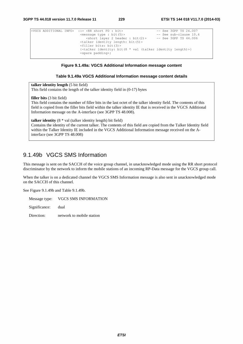
ETSI
ETSI TS 144 018 V11.7.0 (2014-03)2293GPP TS 44.018 version 11.7.0 Release 11
<VGCS ADDITIONAL INFO> ::= <RR short PD : bit> -- See 3GPP TS 24.007 <message type : bit(5)> -- See sub-clause 10.4 <short layer 2 header : bit(2)> -- See 3GPP TS 44.006 <talker identity length: bit(5)> <filler bits: bit(3)> {<talker identity: bit(8 * val (talker identity length)>} <spare padding>;
Figure 9.1.49a: VGCS Additional Information message content
Table 9.1.49a VGCS Additional Information message content details
talker identity length (5 bit field) This field contains the length of the talker identity field in (0-17) bytes
filler bits (3 bit field) This field contains the number of filler bits in the last octet of the talker identity field. The contents of this field is copied from the filler bits field within the talker identity IE that is received in the VGCS Additional Information message on the A-interface (see 3GPP TS 48.008).
talker identity (8 * val (talker identity length) bit field) Contains the identity of the current talker. The contents of this field are copied from the Talker Identity field within the Talker Identity IE included in the VGCS Additional Information message received on the A-interface (see 3GPP TS 48.008)
9.1.49b VGCS SMS Information
This message is sent on the SACCH of the voice group channel, in unacknowledged mode using the RR short protocol discriminator by the network to inform the mobile stations of an incoming RP-Data message for the VGCS group call.
When the talker is on a dedicated channel the VGCS SMS Information message is also sent in unacknowledged mode on the SACCH of this channel.
See Figure 9.1.49b and Table 9.1.49b.
Message type: VGCS SMS INFORMATION
Significance: dual
Direction: network to mobile station
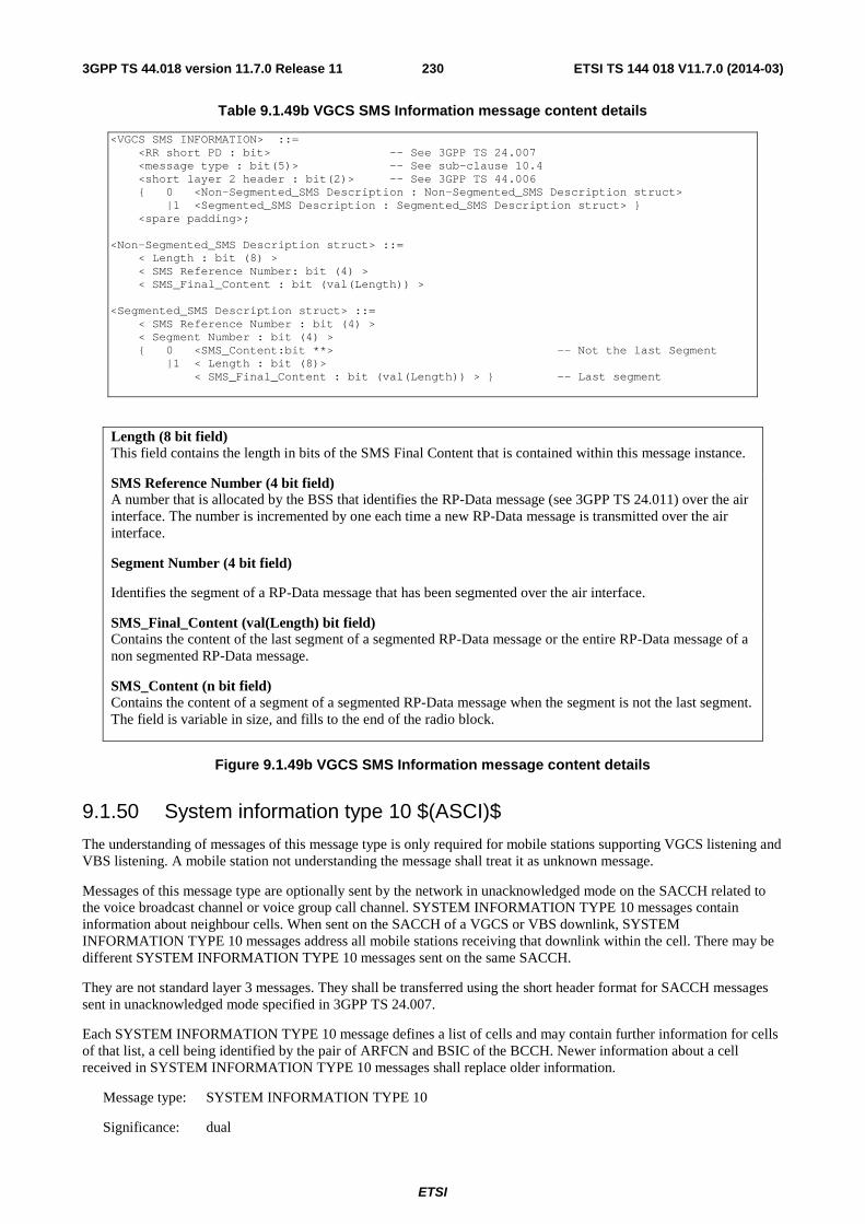
ETSI
ETSI TS 144 018 V11.7.0 (2014-03)2303GPP TS 44.018 version 11.7.0 Release 11
Table 9.1.49b VGCS SMS Information message content details
<VGCS SMS INFORMATION> ::= <RR short PD : bit> -- See 3GPP TS 24.007 <message type : bit(5)> -- See sub-clause 10.4 <short layer 2 header : bit(2)> -- See 3GPP TS 44.006 { 0 <Non-Segmented_SMS Description : Non-Segmented_SMS Description struct> |1 <Segmented_SMS Description : Segmented_SMS Description struct> } <spare padding>; <Non-Segmented_SMS Description struct> ::= < Length : bit (8) > < SMS Reference Number: bit (4) > < SMS_Final_Content : bit (val(Length)) > <Segmented_SMS Description struct> ::= < SMS Reference Number : bit (4) > < Segment Number : bit (4) > { 0 <SMS_Content:bit **> -- Not the last Segment |1 < Length : bit (8)> < SMS_Final_Content : bit (val(Length)) > } -- Last segment
Length (8 bit field) This field contains the length in bits of the SMS Final Content that is contained within this message instance.
SMS Reference Number (4 bit field) A number that is allocated by the BSS that identifies the RP-Data message (see 3GPP TS 24.011) over the air interface. The number is incremented by one each time a new RP-Data message is transmitted over the air interface.
Segment Number (4 bit field)
Identifies the segment of a RP-Data message that has been segmented over the air interface.
SMS_Final_Content (val(Length) bit field) Contains the content of the last segment of a segmented RP-Data message or the entire RP-Data message of a non segmented RP-Data message.
SMS_Content (n bit field) Contains the content of a segment of a segmented RP-Data message when the segment is not the last segment. The field is variable in size, and fills to the end of the radio block.
Figure 9.1.49b VGCS SMS Information message content details
9.1.50 System information type 10 $(ASCI)$
The understanding of messages of this message type is only required for mobile stations supporting VGCS listening and VBS listening. A mobile station not understanding the message shall treat it as unknown message.
Messages of this message type are optionally sent by the network in unacknowledged mode on the SACCH related to the voice broadcast channel or voice group call channel. SYSTEM INFORMATION TYPE 10 messages contain information about neighbour cells. When sent on the SACCH of a VGCS or VBS downlink, SYSTEM INFORMATION TYPE 10 messages address all mobile stations receiving that downlink within the cell. There may be different SYSTEM INFORMATION TYPE 10 messages sent on the same SACCH.
They are not standard layer 3 messages. They shall be transferred using the short header format for SACCH messages sent in unacknowledged mode specified in 3GPP TS 24.007.
Each SYSTEM INFORMATION TYPE 10 message defines a list of cells and may contain further information for cells of that list, a cell being identified by the pair of ARFCN and BSIC of the BCCH. Newer information about a cell received in SYSTEM INFORMATION TYPE 10 messages shall replace older information.
Message type: SYSTEM INFORMATION TYPE 10
Significance: dual
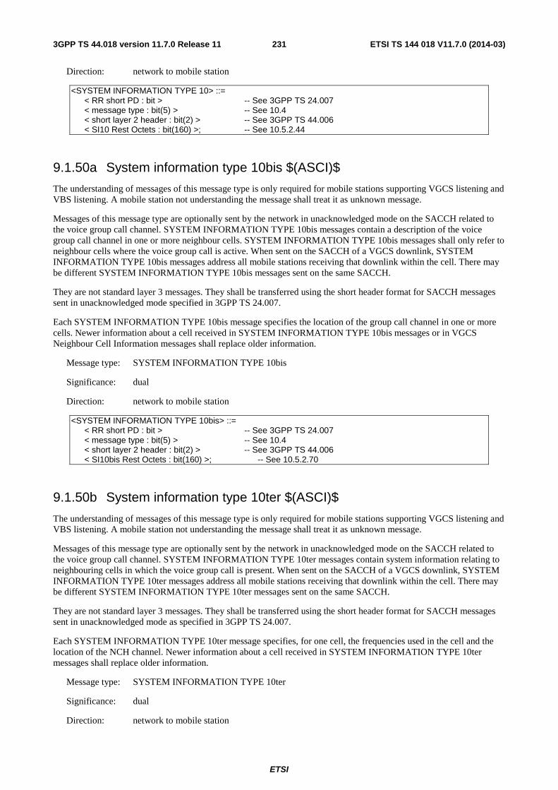
ETSI
ETSI TS 144 018 V11.7.0 (2014-03)2313GPP TS 44.018 version 11.7.0 Release 11
Direction: network to mobile station
<SYSTEM INFORMATION TYPE 10> ::= < RR short PD : bit > -- See 3GPP TS 24.007 < message type : bit(5) > -- See 10.4 < short layer 2 header : bit(2) > -- See 3GPP TS 44.006 < SI10 Rest Octets : bit(160) >; -- See 10.5.2.44
9.1.50a System information type 10bis $(ASCI)$
The understanding of messages of this message type is only required for mobile stations supporting VGCS listening and VBS listening. A mobile station not understanding the message shall treat it as unknown message.
Messages of this message type are optionally sent by the network in unacknowledged mode on the SACCH related to the voice group call channel. SYSTEM INFORMATION TYPE 10bis messages contain a description of the voice group call channel in one or more neighbour cells. SYSTEM INFORMATION TYPE 10bis messages shall only refer to neighbour cells where the voice group call is active. When sent on the SACCH of a VGCS downlink, SYSTEM INFORMATION TYPE 10bis messages address all mobile stations receiving that downlink within the cell. There may be different SYSTEM INFORMATION TYPE 10bis messages sent on the same SACCH.
They are not standard layer 3 messages. They shall be transferred using the short header format for SACCH messages sent in unacknowledged mode specified in 3GPP TS 24.007.
Each SYSTEM INFORMATION TYPE 10bis message specifies the location of the group call channel in one or more cells. Newer information about a cell received in SYSTEM INFORMATION TYPE 10bis messages or in VGCS Neighbour Cell Information messages shall replace older information.
Message type: SYSTEM INFORMATION TYPE 10bis
Significance: dual
Direction: network to mobile station
<SYSTEM INFORMATION TYPE 10bis> ::= < RR short PD : bit > -- See 3GPP TS 24.007 < message type : bit(5) > -- See 10.4 < short layer 2 header : bit(2) > -- See 3GPP TS 44.006 < SI10bis Rest Octets : bit(160) >; -- See 10.5.2.70
9.1.50b System information type 10ter $(ASCI)$
The understanding of messages of this message type is only required for mobile stations supporting VGCS listening and VBS listening. A mobile station not understanding the message shall treat it as unknown message.
Messages of this message type are optionally sent by the network in unacknowledged mode on the SACCH related to the voice group call channel. SYSTEM INFORMATION TYPE 10ter messages contain system information relating to neighbouring cells in which the voice group call is present. When sent on the SACCH of a VGCS downlink, SYSTEM INFORMATION TYPE 10ter messages address all mobile stations receiving that downlink within the cell. There may be different SYSTEM INFORMATION TYPE 10ter messages sent on the same SACCH.
They are not standard layer 3 messages. They shall be transferred using the short header format for SACCH messages sent in unacknowledged mode as specified in 3GPP TS 24.007.
Each SYSTEM INFORMATION TYPE 10ter message specifies, for one cell, the frequencies used in the cell and the location of the NCH channel. Newer information about a cell received in SYSTEM INFORMATION TYPE 10ter messages shall replace older information.
Message type: SYSTEM INFORMATION TYPE 10ter
Significance: dual
Direction: network to mobile station
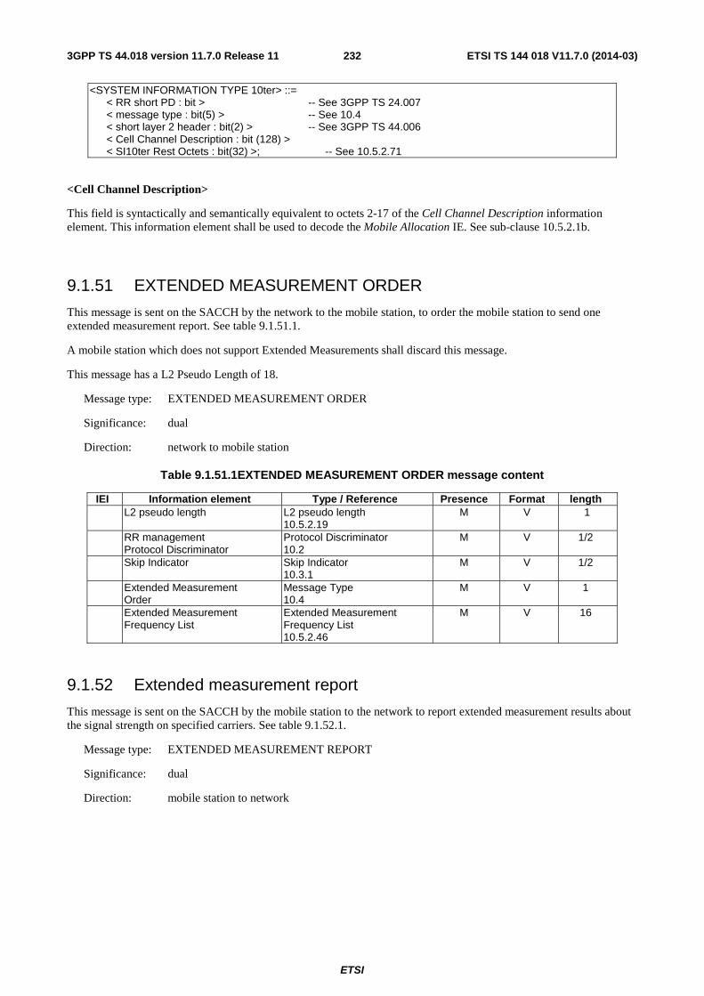
ETSI
ETSI TS 144 018 V11.7.0 (2014-03)2323GPP TS 44.018 version 11.7.0 Release 11
<SYSTEM INFORMATION TYPE 10ter> ::= < RR short PD : bit > -- See 3GPP TS 24.007 < message type : bit(5) > -- See 10.4 < short layer 2 header : bit(2) > -- See 3GPP TS 44.006 < Cell Channel Description : bit (128) > < SI10ter Rest Octets : bit(32) >; -- See 10.5.2.71
<Cell Channel Description>
This field is syntactically and semantically equivalent to octets 2-17 of the Cell Channel Description information element. This information element shall be used to decode the Mobile Allocation IE. See sub-clause 10.5.2.1b.
9.1.51 EXTENDED MEASUREMENT ORDER
This message is sent on the SACCH by the network to the mobile station, to order the mobile station to send one extended measurement report. See table 9.1.51.1.
A mobile station which does not support Extended Measurements shall discard this message.
This message has a L2 Pseudo Length of 18.
Message type: EXTENDED MEASUREMENT ORDER
Significance: dual
Direction: network to mobile station
Table 9.1.51.1EXTENDED MEASUREMENT ORDER message content
IEI Information element Type / Reference Presence Format length L2 pseudo length L2 pseudo length
10.5.2.19 M V 1
RR management Protocol Discriminator
Protocol Discriminator 10.2
M V 1/2
Skip Indicator Skip Indicator 10.3.1
M V 1/2
Extended Measurement Order
Message Type 10.4
M V 1
Extended Measurement Frequency List
Extended Measurement Frequency List 10.5.2.46
M V 16
9.1.52 Extended measurement report
This message is sent on the SACCH by the mobile station to the network to report extended measurement results about the signal strength on specified carriers. See table 9.1.52.1.
Message type: EXTENDED MEASUREMENT REPORT
Significance: dual
Direction: mobile station to network
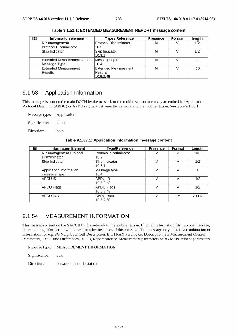
ETSI
ETSI TS 144 018 V11.7.0 (2014-03)2333GPP TS 44.018 version 11.7.0 Release 11
Table 9.1.52.1: EXTENDED MEASUREMENT REPORT message content
IEI Information element Type / Reference Presence Format length RR management
Protocol Discriminator Protocol Discriminator 10.2
M V 1/2
Skip Indicator Skip Indicator 10.3.1
M V 1/2
Extended Measurement Report Message Type
Message Type 10.4
M V 1
Extended Measurement Results
Extended Measurement Results 10.5.2.45
M V 16
9.1.53 Application Information
This message is sent on the main DCCH by the network or the mobile station to convey an embedded Application Protocol Data Unit (APDU) or APDU segment between the network and the mobile station. See table 9.1.53.1.
Message type: Application
Significance: global
Direction: both
Table 9.1.53.1: Application Information message content
IEI Information Element Type/Reference Presence Format Length RR management Protocol
Discriminator Protocol discriminator 10.2
M V 1/2
Skip Indicator Skip Indicator 10.3.1
M V 1/2
Application Information message type
Message type 10.4
M V 1
APDU ID APDU ID 10.5.2.48
M V 1/2
APDU Flags APDU Flags 10.5.2.49
M V 1/2
APDU Data APDU Data 10.5.2.50
M LV 2 to N
9.1.54 MEASUREMENT INFORMATION
This message is sent on the SACCH by the network to the mobile station. If not all information fits into one message, the remaining information will be sent in other instances of this message. This message may contain a combination of information for e.g. 3G Neighbour Cell Description, E-UTRAN Parameters Description, 3G Measurement Control Parameters, Real Time Differences, BSICs, Report priority, Measurement parameters or 3G Measurement parameters.
Message type: MEASUREMENT INFORMATION
Significance: dual
Direction: network to mobile station
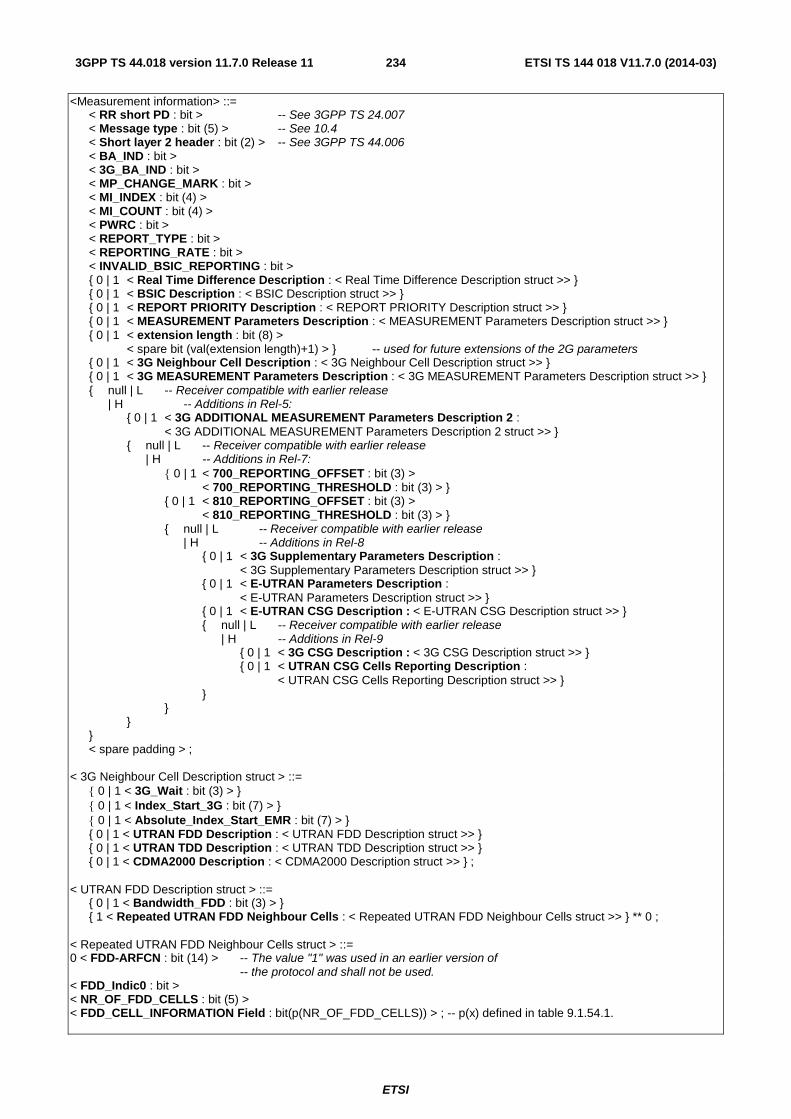
ETSI
ETSI TS 144 018 V11.7.0 (2014-03)2343GPP TS 44.018 version 11.7.0 Release 11
<Measurement information> ::= < RR short PD : bit > -- See 3GPP TS 24.007 < Message type : bit (5) > -- See 10.4 < Short layer 2 header : bit (2) > -- See 3GPP TS 44.006 < BA_IND : bit > < 3G_BA_IND : bit > < MP_CHANGE_MARK : bit > < MI_INDEX : bit (4) > < MI_COUNT : bit (4) > < PWRC : bit > < REPORT_TYPE : bit > < REPORTING_RATE : bit > < INVALID_BSIC_REPORTING : bit > { 0 | 1 < Real Time Difference Description : < Real Time Difference Description struct >> } { 0 | 1 < BSIC Description : < BSIC Description struct >> } { 0 | 1 < REPORT PRIORITY Description : < REPORT PRIORITY Description struct >> } { 0 | 1 < MEASUREMENT Parameters Description : < MEASUREMENT Parameters Description struct >> } { 0 | 1 < extension length : bit (8) > < spare bit (val(extension length)+1) > } -- used for future extensions of the 2G parameters { 0 | 1 < 3G Neighbour Cell Description : < 3G Neighbour Cell Description struct >> } { 0 | 1 < 3G MEASUREMENT Parameters Description : < 3G MEASUREMENT Parameters Description struct >> } { null | L -- Receiver compatible with earlier release | H -- Additions in Rel-5: { 0 | 1 < 3G ADDITIONAL MEASUREMENT Parameters Description 2 : < 3G ADDITIONAL MEASUREMENT Parameters Description 2 struct >> } { null | L -- Receiver compatible with earlier release | H -- Additions in Rel-7: { 0 | 1 < 700_REPORTING_OFFSET : bit (3) > < 700_REPORTING_THRESHOLD : bit (3) > } { 0 | 1 < 810_REPORTING_OFFSET : bit (3) > < 810_REPORTING_THRESHOLD : bit (3) > } { null | L -- Receiver compatible with earlier release | H -- Additions in Rel-8 { 0 | 1 < 3G Supplementary Parameters Description : < 3G Supplementary Parameters Description struct >> } { 0 | 1 < E-UTRAN Parameters Description : < E-UTRAN Parameters Description struct >> } { 0 | 1 < E-UTRAN CSG Description : < E-UTRAN CSG Description struct >> } { null | L -- Receiver compatible with earlier release | H -- Additions in Rel-9 { 0 | 1 < 3G CSG Description : < 3G CSG Description struct >> } { 0 | 1 < UTRAN CSG Cells Reporting Description : < UTRAN CSG Cells Reporting Description struct >> } } } } } < spare padding > ; < 3G Neighbour Cell Description struct > ::= { 0 | 1 < 3G_Wait : bit (3) > } { 0 | 1 < Index_Start_3G : bit (7) > } { 0 | 1 < Absolute_Index_Start_EMR : bit (7) > } { 0 | 1 < UTRAN FDD Description : < UTRAN FDD Description struct >> } { 0 | 1 < UTRAN TDD Description : < UTRAN TDD Description struct >> } { 0 | 1 < CDMA2000 Description : < CDMA2000 Description struct >> } ; < UTRAN FDD Description struct > ::= { 0 | 1 < Bandwidth_FDD : bit (3) > } { 1 < Repeated UTRAN FDD Neighbour Cells : < Repeated UTRAN FDD Neighbour Cells struct >> } ** 0 ; < Repeated UTRAN FDD Neighbour Cells struct > ::= 0 < FDD-ARFCN : bit (14) > -- The value "1" was used in an earlier version of -- the protocol and shall not be used. < FDD_Indic0 : bit > < NR_OF_FDD_CELLS : bit (5) > < FDD_CELL_INFORMATION Field : bit(p(NR_OF_FDD_CELLS)) > ; -- p(x) defined in table 9.1.54.1.
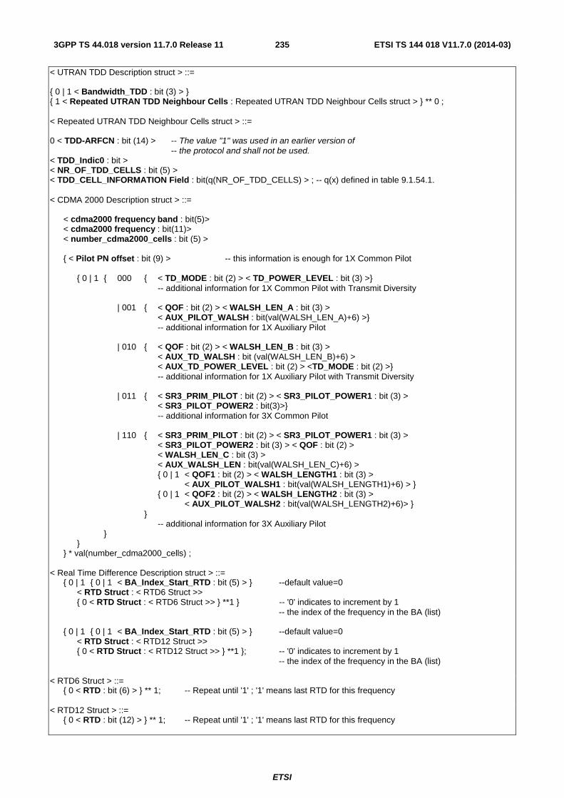
ETSI
ETSI TS 144 018 V11.7.0 (2014-03)2353GPP TS 44.018 version 11.7.0 Release 11
< UTRAN TDD Description struct > ::= { 0 | 1 < Bandwidth_TDD : bit (3) > } { 1 < Repeated UTRAN TDD Neighbour Cells : Repeated UTRAN TDD Neighbour Cells struct > } ** 0 ; < Repeated UTRAN TDD Neighbour Cells struct > ::= 0 < TDD-ARFCN : bit (14) > -- The value "1" was used in an earlier version of -- the protocol and shall not be used. < TDD_Indic0 : bit > < NR_OF_TDD_CELLS : bit (5) > < TDD_CELL_INFORMATION Field : bit(q(NR_OF_TDD_CELLS) > ; -- q(x) defined in table 9.1.54.1. < CDMA 2000 Description struct > ::= < cdma2000 frequency band : bit(5)> < cdma2000 frequency : bit(11)> < number_cdma2000_cells : bit (5) > { < Pilot PN offset : bit (9) > -- this information is enough for 1X Common Pilot { 0 | 1 { 000 { < TD_MODE : bit (2) > < TD_POWER_LEVEL : bit (3) >} -- additional information for 1X Common Pilot with Transmit Diversity | 001 { < QOF : bit (2) > < WALSH_LEN_A : bit (3) > < AUX_PILOT_WALSH : bit(val(WALSH_LEN_A)+6) >} -- additional information for 1X Auxiliary Pilot | 010 { < QOF : bit (2) > < WALSH_LEN_B : bit (3) > < AUX_TD_WALSH : bit (val(WALSH_LEN_B)+6) > < AUX_TD_POWER_LEVEL : bit (2) > <TD_MODE : bit (2) >} -- additional information for 1X Auxiliary Pilot with Transmit Diversity | 011 { < SR3_PRIM_PILOT : bit (2) > < SR3_PILOT_POWER1 : bit (3) > < SR3_PILOT_POWER2 : bit(3)>} -- additional information for 3X Common Pilot | 110 { < SR3_PRIM_PILOT : bit (2) > < SR3_PILOT_POWER1 : bit (3) > < SR3_PILOT_POWER2 : bit (3) > < QOF : bit (2) > < WALSH_LEN_C : bit (3) > < AUX_WALSH_LEN : bit(val(WALSH_LEN_C)+6) > { 0 | 1 < QOF1 : bit (2) > < WALSH_LENGTH1 : bit (3) > < AUX_PILOT_WALSH1 : bit(val(WALSH_LENGTH1)+6) > } { 0 | 1 < QOF2 : bit (2) > < WALSH_LENGTH2 : bit (3) > < AUX_PILOT_WALSH2 : bit(val(WALSH_LENGTH2)+6)> } } -- additional information for 3X Auxiliary Pilot } } } * val(number_cdma2000_cells) ; < Real Time Difference Description struct > ::= { 0 | 1 { 0 | 1 < BA_Index_Start_RTD : bit (5) > } --default value=0 < RTD Struct : < RTD6 Struct >> { 0 < RTD Struct : < RTD6 Struct >> } **1 } -- '0' indicates to increment by 1 -- the index of the frequency in the BA (list) { 0 | 1 { 0 | 1 < BA_Index_Start_RTD : bit (5) > } --default value=0 < RTD Struct : < RTD12 Struct >> { 0 < RTD Struct : < RTD12 Struct >> } **1 }; -- '0' indicates to increment by 1 -- the index of the frequency in the BA (list) < RTD6 Struct > ::= { 0 < RTD : bit (6) > } ** 1; -- Repeat until '1' ; '1' means last RTD for this frequency < RTD12 Struct > ::= { 0 < RTD : bit (12) > } ** 1; -- Repeat until '1' ; '1' means last RTD for this frequency

ETSI
ETSI TS 144 018 V11.7.0 (2014-03)2363GPP TS 44.018 version 11.7.0 Release 11
< BSIC Description struct > ::= { 0 | 1 < BA_Index_Start_BSIC : bit (5) > } -- default value=0 < BSIC : bit (6) > < Number_Remaining_BSIC: bit (7) > { < Frequency_Scrolling : bit > -- 0 means same frequency < BSIC : bit (6) > } * (val(Number_Remaining_BSIC)) ; < REPORT PRIORITY Description struct > ::= < Number_Cells : bit (7) > { REP_PRIORITY : bit } * (val(Number_Cells)) ; < MEASUREMENT PARAMETERS Description struct > ::= { 0 | 1 < MULTIBAND_REPORTING: bit (2) > } { 0 | 1 < SERVING_BAND_REPORTING: bit (2) > } < SCALE_ORD : bit (2) > { 0 | 1 < 900_REPORTING_OFFSET : bit (3) > < 900_REPORTING_THRESHOLD : bit (3) > } { 0 | 1 < 1800_REPORTING_OFFSET : bit (3) > < 1800_REPORTING_THRESHOLD : bit (3) > } { 0 | 1 < 400_REPORTING_OFFSET : bit (3) > < 400_REPORTING_THRESHOLD : bit (3) > } { 0 | 1 < 1900_REPORTING_OFFSET : bit (3) > < 1900_REPORTING_THRESHOLD : bit (3) > } { 0 | 1 < 850_REPORTING_OFFSET : bit (3) > < 850_REPORTING_THRESHOLD : bit (3) > } ; < 3G MEASUREMENT PARAMETERS Description struct > ::= < Qsearch_C : bit (4) > { 1 ! < Ignore : bit = < no string >> } -- this bit shall be ignored by the receiver -- for backward compatibility with earlier releases < FDD_REP_QUANT : bit (1) > -- FDD Parameters { 0 | 1 < FDD_MULTIRAT_REPORTING : bit (2) > } { 0 | 1 < FDD_REPORTING_OFFSET : bit (3) > < FDD_REPORTING_THRESHOLD : bit (3) > } { 0 | 1 < TDD_MULTIRAT_REPORTING : bit (2) > } -- TDD Parameters { 0 | 1 < TDD_REPORTING_OFFSET : bit (3) > < TDD_REPORTING_THRESHOLD : bit (3) > } { 0 | 1 < CDMA2000_MULTIRAT_REPORTING : bit (2) > } -- CDMA2000 Parameters { 0 | 1 < CDMA2000_REPORTING_OFFSET : bit (3) > < CDMA2000_REPORTING_THRESHOLD : bit (3) > } ; < 3G ADDITIONAL MEASUREMENT Parameters Description 2 struct > ::= { 0 | 1 < FDD_REPORTING_THRESHOLD_2 : bit (6) > } ; < 3G Supplementary Parameters Description struct > ::= < UTRAN_Start : bit > < UTRAN_Stop : bit > { 0 | 1 < 3G Measurement Control Parameters Description : < 3G Measurement Control Parameters Description struct >> } ; < 3G Measurement Control Parameters Description struct > ::= { 0 | 1 < DEFAULT_Measurement_Control_UTRAN : bit(1) > } { 1 < Repeated UTRAN Measurement Control Parameters : < Repeated UTRAN Measurement Control Parameters struct >> } ** 0 ; < Repeated UTRAN Measurement Control Parameters struct > ::= { 1 < UTRAN_FREQUENCY_INDEX : bit(5) > } ** 0 < Measurement_Control_UTRAN : bit(1) > ;
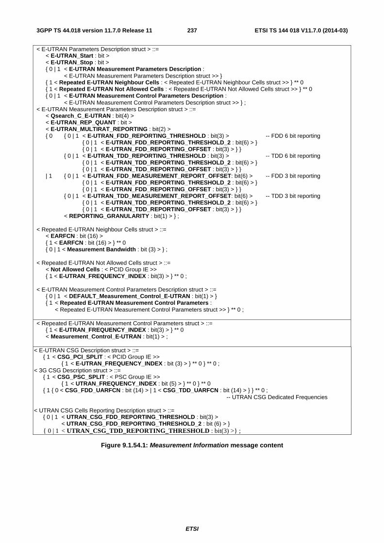
ETSI
ETSI TS 144 018 V11.7.0 (2014-03)2373GPP TS 44.018 version 11.7.0 Release 11
< E-UTRAN Parameters Description struct > ::= < E-UTRAN_Start : bit > < E-UTRAN_Stop : bit > { 0 | 1 < E-UTRAN Measurement Parameters Description : < E-UTRAN Measurement Parameters Description struct >> } { 1 < Repeated E-UTRAN Neighbour Cells : < Repeated E-UTRAN Neighbour Cells struct >> } ** 0 { 1 < Repeated E-UTRAN Not Allowed Cells : < Repeated E-UTRAN Not Allowed Cells struct >> } ** 0 { 0 | 1 < E-UTRAN Measurement Control Parameters Description : < E-UTRAN Measurement Control Parameters Description struct >> } ; < E-UTRAN Measurement Parameters Description struct > ::= < Qsearch_C_E-UTRAN : bit(4) > < E-UTRAN_REP_QUANT : bit > < E-UTRAN_MULTIRAT_REPORTING : bit(2) > { 0 { 0 | 1 < E-UTRAN_FDD_REPORTING_THRESHOLD : bit(3) > -- FDD 6 bit reporting { 0 | 1 < E-UTRAN_FDD_REPORTING_THRESHOLD_2 : bit(6) > } { 0 | 1 < E-UTRAN_FDD_REPORTING_OFFSET : bit(3) > } } { 0 | 1 < E-UTRAN_TDD_REPORTING_THRESHOLD : bit(3) > -- TDD 6 bit reporting { 0 | 1 < E-UTRAN_TDD_REPORTING_THRESHOLD_2 : bit(6) > } { 0 | 1 < E-UTRAN_TDD_REPORTING_OFFSET : bit(3) > } } | 1 { 0 | 1 < E-UTRAN_FDD_MEASUREMENT_REPORT_OFFSET: bit(6) > -- FDD 3 bit reporting { 0 | 1 < E-UTRAN_FDD_REPORTING_THRESHOLD_2 : bit(6) > } { 0 | 1 < E-UTRAN_FDD_REPORTING_OFFSET : bit(3) > } } { 0 | 1 < E-UTRAN_TDD_MEASUREMENT_REPORT_OFFSET: bit(6) > -- TDD 3 bit reporting { 0 | 1 < E-UTRAN_TDD_REPORTING_THRESHOLD_2 : bit(6) > } { 0 | 1 < E-UTRAN_TDD_REPORTING_OFFSET : bit(3) > } } < REPORTING_GRANULARITY : bit(1) > } ; < Repeated E-UTRAN Neighbour Cells struct > ::= < EARFCN : bit (16) > { 1 < EARFCN : bit (16) > } ** 0 { 0 | 1 < Measurement Bandwidth : bit (3) > } ; < Repeated E-UTRAN Not Allowed Cells struct > ::= < Not Allowed Cells : < PCID Group IE >> { 1 < E-UTRAN_FREQUENCY_INDEX : bit(3) > } ** 0 ; < E-UTRAN Measurement Control Parameters Description struct > ::= { 0 | 1 < DEFAULT_Measurement_Control_E-UTRAN : bit(1) > } { 1 < Repeated E-UTRAN Measurement Control Parameters : < Repeated E-UTRAN Measurement Control Parameters struct >> } ** 0 ; < Repeated E-UTRAN Measurement Control Parameters struct > ::= { 1 < E-UTRAN_FREQUENCY_INDEX : bit(3) > } ** 0 < Measurement_Control_E-UTRAN : bit(1) > ;
< E-UTRAN CSG Description struct > ::= { 1 < CSG_PCI_SPLIT : < PCID Group IE >> { 1 < E-UTRAN_FREQUENCY_INDEX : bit (3) > } ** 0 } ** 0 ; < 3G CSG Description struct > ::= { 1 < CSG_PSC_SPLIT : < PSC Group IE >> { 1 < UTRAN_FREQUENCY_INDEX : bit (5) > } ** 0 } ** 0 { 1 { 0 < CSG_FDD_UARFCN : bit (14) > | 1 < CSG_TDD_UARFCN : bit (14) > } } ** 0 ; -- UTRAN CSG Dedicated Frequencies < UTRAN CSG Cells Reporting Description struct > ::= { 0 | 1 < UTRAN_CSG_FDD_REPORTING_THRESHOLD : bit(3) > < UTRAN_CSG_FDD_REPORTING_THRESHOLD_2 : bit (6) > } { 0 | 1 < UTRAN_CSG_TDD_REPORTING_THRESHOLD : bit(3) >} ;
Figure 9.1.54.1: Measurement Information message content
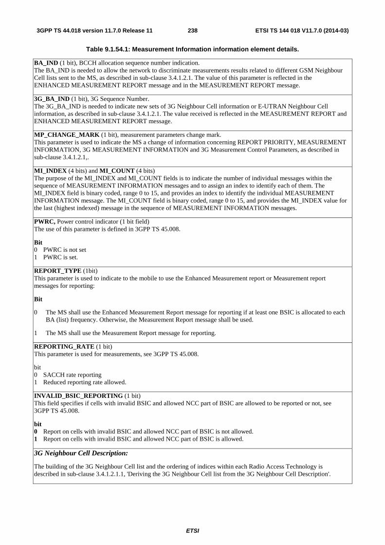
ETSI
ETSI TS 144 018 V11.7.0 (2014-03)2383GPP TS 44.018 version 11.7.0 Release 11
Table 9.1.54.1: Measurement Information information element details.
BA_IND (1 bit), BCCH allocation sequence number indication. The BA_IND is needed to allow the network to discriminate measurements results related to different GSM Neighbour Cell lists sent to the MS, as described in sub-clause 3.4.1.2.1. The value of this parameter is reflected in the ENHANCED MEASUREMENT REPORT message and in the MEASUREMENT REPORT message.
3G_BA_IND (1 bit), 3G Sequence Number. The 3G_BA_IND is needed to indicate new sets of 3G Neighbour Cell information or E-UTRAN Neighbour Cell information, as described in sub-clause 3.4.1.2.1. The value received is reflected in the MEASUREMENT REPORT and ENHANCED MEASUREMENT REPORT message.
MP_CHANGE_MARK (1 bit), measurement parameters change mark. This parameter is used to indicate the MS a change of information concerning REPORT PRIORITY, MEASUREMENT INFORMATION, 3G MEASUREMENT INFORMATION and 3G Measurement Control Parameters, as described in sub-clause 3.4.1.2.1,.
MI_INDEX (4 bits) and MI_COUNT (4 bits) The purpose of the MI_INDEX and MI_COUNT fields is to indicate the number of individual messages within the sequence of MEASUREMENT INFORMATION messages and to assign an index to identify each of them. The MI_INDEX field is binary coded, range 0 to 15, and provides an index to identify the individual MEASUREMENT INFORMATION message. The MI_COUNT field is binary coded, range 0 to 15, and provides the MI_INDEX value for the last (highest indexed) message in the sequence of MEASUREMENT INFORMATION messages.
PWRC, Power control indicator (1 bit field) The use of this parameter is defined in 3GPP TS 45.008.
Bit 0 PWRC is not set 1 PWRC is set.
REPORT_TYPE (1bit) This parameter is used to indicate to the mobile to use the Enhanced Measurement report or Measurement report messages for reporting:
Bit
0 The MS shall use the Enhanced Measurement Report message for reporting if at least one BSIC is allocated to each BA (list) frequency. Otherwise, the Measurement Report message shall be used.
1 The MS shall use the Measurement Report message for reporting.
REPORTING_RATE (1 bit) This parameter is used for measurements, see 3GPP TS 45.008.
bit 0 SACCH rate reporting 1 Reduced reporting rate allowed.
INVALID_BSIC_REPORTING (1 bit) This field specifies if cells with invalid BSIC and allowed NCC part of BSIC are allowed to be reported or not, see 3GPP TS 45.008.
bit 0 Report on cells with invalid BSIC and allowed NCC part of BSIC is not allowed. 1 Report on cells with invalid BSIC and allowed NCC part of BSIC is allowed.
3G Neighbour Cell Description:
The building of the 3G Neighbour Cell list and the ordering of indices within each Radio Access Technology is described in sub-clause 3.4.1.2.1.1, 'Deriving the 3G Neighbour Cell list from the 3G Neighbour Cell Description'.

ETSI
ETSI TS 144 018 V11.7.0 (2014-03)2393GPP TS 44.018 version 11.7.0 Release 11
3G WAIT (3 bits) When 3G_BA_IND is received in a changed state, this parameter indicates the number of instances of MEASUREMENT INFORMATION messages that contain 3G Neighbour Cell Description which shall be received before the MS reports on the new 3G Neighbour Cell list. Two different instances of MEASUREMENT INFORMATION messages are two MEASUREMENT INFORMATION messages with different MI_INDEX. See sub-clause 3.4.1.2.1.
bit 3 2 1 0 0 0 1 instance that contain 3G Neighbour Cell Description shall be received 0 0 1 2 instances that contain Neighbour Cell Description shall be received : : 1 1 1 8 instances that contain Neighbour Cell description shall be received
Index_Start_3G (7 bit) This optional information element indicates the binary value of the first index to use to build this instance of the 3G Neighbour Cell list. When missing, the value 0 is assumed. See sub-clause 3.4.1.2.1.1.
Absolute_Index_Start_EMR (7 bit) This parameter indicates in binary the value to be added to the indexes of the 3G Neighbour Cell list for reporting 3G Cells with the ENHANCED MEASUREMENT REPORT message (see sub-clause 3.4.1.2.1.1). If different values are received for this parameter in different instances of this message, the instance with the highest index shall be used. If this parameter is absent in all instances of the message, the value "0" shall be used.
NOTE: This parameter is not used for reporting 3G Cells with the MEASUREMENT REPORT message, see sub-clause 10.5.2.20, 'Measurement Results'.
UTRAN FDD Description:
Bandwidth_FDD (3bit field) This optional information element will be used for future releases of the protocol. When missing, this indicates the present FDD bandwidth. When present, this shall not be considered as an error; indices of the 3G Neighbour Cell list shall be incremented accordingly.
FDD_ARFCN (14 bit field) This optional information element is defined as the UARFCN in 3GPP TS 25.101. Any non-supported frequency shall not be considered as an error; indices of the 3G Neighbour Cell list shall be incremented accordingly.
FDD_Indic0, information 0 indicator (1 bit): This field indicates if the FDD_CELL_INFORMATION parameter value '0000000000' is a member of the set.
Bit 0 parameter value '0000000000' is not a member of the set 1 parameter value '0000000000' is a member of the set
NOTE: This bit FDD_Indic0 is equivalent to the bit F0 bit in the frequency list information element (see sub-clause 10.5.2.13.3).
NR_OF_FDD_CELLS (5 bit field) This field defines the number of FDD_CELL_INFORMATION parameters.
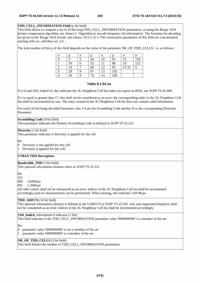
ETSI
ETSI TS 144 018 V11.7.0 (2014-03)2403GPP TS 44.018 version 11.7.0 Release 11
FDD_CELL_INFORMATION Field (p bit field) This field allows to compute a set of 10-bit-long FDD_CELL_INFORMATION parameters, re-using the Range 1024 format compression algorithm, see Annex J: 'Algorithm to encode frequency list information'. The formulas for decoding are given in the 'Range 1024 format' sub-clause, 10.5.2.13.3. The consecutive parameters of this field are concatenated, starting with w1, and then w2, w3…
The total number of bits p of this field depends on the value of the parameter NR_OF_FDD_CELLS = n, as follows:
n p n p n p n p 0 0 5 44 10 81 15 116 1 10 6 52 11 88 16 122 2 19 7 60 12 95 17-31 0 3 28 8 67 13 102 4 36 9 74 14 109
Table 9.1.54.1a.
If n=0 and FDD_Indic0=0, this indicates the 3G Neighbour Cell list index for report on RSSI, see 3GPP TS 45.008.
If n is equal or greater than 17, this shall not be considered as an error; the corresponding index in the 3G Neighbour Cell list shall be incremented by one. The entry created in the 3G Neighbour Cell list does not contain valid information.
For each (10-bit-long) decoded Parameter, bits 1-9 are the Scrambling Code and bit 10 is the corresponding Diversity Parameter.
Scrambling Code (9 bit field) This parameter indicates the Primary Scrambling Code as defined in 3GPP TS 25.213.
Diversity (1 bit field) This parameter indicates if diversity is applied for the cell:
Bit 0 Diversity is not applied for this cell 1 Diversity is applied for this cell.
UTRAN TDD Description:
Bandwidth_TDD (3 bit field) This optional information element refers to 3GPP TS 25.331.
Bit 321 000 3.84Mcps 001 1.28Mcps All other values shall not be interpreted as an error; indices of the 3G Neighbour Cell list shall be incremented accordingly (and no measurements can be performed). When missing, this indicates 3.84 Mcps.
TDD_ARFCN (14 bit field) This optional information element is defined as the UARFCN in 3GPP TS 25.102. Any non-supported frequency shall not be considered as an error; indices of the 3G Neighbour Cell list shall be incremented accordingly.
TDD_Indic0, information 0 indicator (1 bit): This field indicates if the TDD_CELL_INFORMATION parameter value '0000000000' is a member of the set.
Bit 0 parameter value '0000000000' is not a member of the set 1 parameter value '0000000000' is a member of the set
NR_OF_TDD_CELLS (5 bit field) This field defines the number of TDD_CELL_INFORMATION parameters.
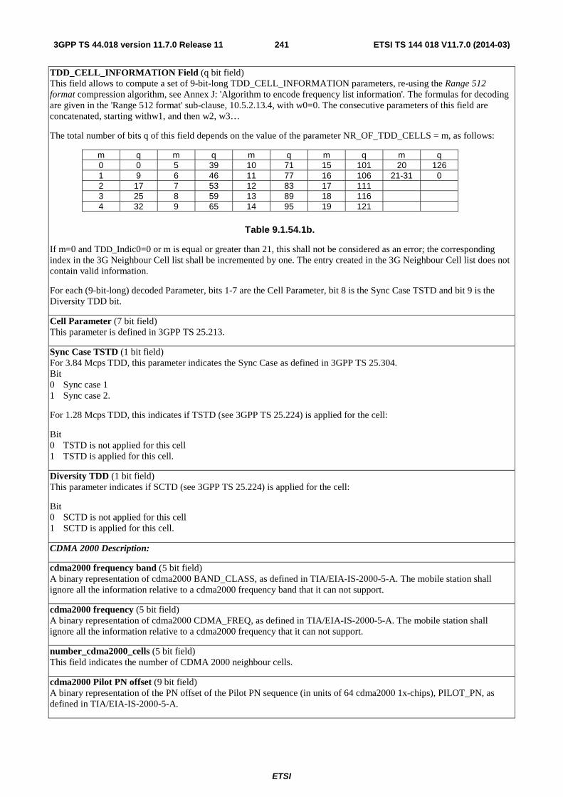
ETSI
ETSI TS 144 018 V11.7.0 (2014-03)2413GPP TS 44.018 version 11.7.0 Release 11
TDD_CELL_INFORMATION Field (q bit field) This field allows to compute a set of 9-bit-long TDD_CELL_INFORMATION parameters, re-using the Range 512 format compression algorithm, see Annex J: 'Algorithm to encode frequency list information'. The formulas for decoding are given in the 'Range 512 format' sub-clause, 10.5.2.13.4, with w0=0. The consecutive parameters of this field are concatenated, starting withw1, and then w2, w3…
The total number of bits q of this field depends on the value of the parameter NR_OF_TDD_CELLS = m, as follows:
m q m q m q m q m q 0 0 5 39 10 71 15 101 20 126 1 9 6 46 11 77 16 106 21-31 0 2 17 7 53 12 83 17 111 3 25 8 59 13 89 18 116 4 32 9 65 14 95 19 121
Table 9.1.54.1b.
If m=0 and TDD_Indic0=0 or m is equal or greater than 21, this shall not be considered as an error; the corresponding index in the 3G Neighbour Cell list shall be incremented by one. The entry created in the 3G Neighbour Cell list does not contain valid information.
For each (9-bit-long) decoded Parameter, bits 1-7 are the Cell Parameter, bit 8 is the Sync Case TSTD and bit 9 is the Diversity TDD bit.
Cell Parameter (7 bit field) This parameter is defined in 3GPP TS 25.213.
Sync Case TSTD (1 bit field) For 3.84 Mcps TDD, this parameter indicates the Sync Case as defined in 3GPP TS 25.304. Bit 0 Sync case 1 1 Sync case 2.
For 1.28 Mcps TDD, this indicates if TSTD (see 3GPP TS 25.224) is applied for the cell:
Bit 0 TSTD is not applied for this cell 1 TSTD is applied for this cell.
Diversity TDD (1 bit field) This parameter indicates if SCTD (see 3GPP TS 25.224) is applied for the cell:
Bit 0 SCTD is not applied for this cell 1 SCTD is applied for this cell.
CDMA 2000 Description:
cdma2000 frequency band (5 bit field) A binary representation of cdma2000 BAND_CLASS, as defined in TIA/EIA-IS-2000-5-A. The mobile station shall ignore all the information relative to a cdma2000 frequency band that it can not support.
cdma2000 frequency (5 bit field) A binary representation of cdma2000 CDMA_FREQ, as defined in TIA/EIA-IS-2000-5-A. The mobile station shall ignore all the information relative to a cdma2000 frequency that it can not support.
number_cdma2000_cells (5 bit field) This field indicates the number of CDMA 2000 neighbour cells.
cdma2000 Pilot PN offset (9 bit field) A binary representation of the PN offset of the Pilot PN sequence (in units of 64 cdma2000 1x-chips), PILOT_PN, as defined in TIA/EIA-IS-2000-5-A.
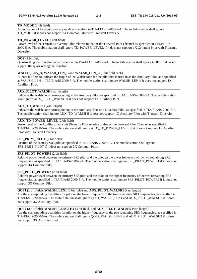
ETSI
ETSI TS 144 018 V11.7.0 (2014-03)2423GPP TS 44.018 version 11.7.0 Release 11
TD_MODE (2 bit field) An indication of transmit diversity mode is specified in TIA/EIA-IS-2000-5-A. The mobile station shall ignore TD_MODE if it does not support 1X Common Pilot with Transmit Diversity.
TD_POWER_LEVEL (3 bit field) Power level of the Transmit Diversity Pilot relative to that of the Forward Pilot Channel as specified in TIA/EIA/IS-2000-5-A. The mobile station shall ignore TD_POWER_LEVEL if it does not support 1X Common Pilot with Transmit Diversity.
QOF (2 bit field) Quasi-orthogonal function index is defined in TIA/EIA/IS-2000-5-A. The mobile station shall ignore QOF if it does not support the quasi-orthogonal function.
WALSH_LEN_A, WALSH_LEN_B and WALSH_LEN_C (3 bit field each) A three bit field to indicate the length of the Walsh code for the pilot that is used in as the Auxiliary Pilot, and specified as WALSH_LEN in TIA/EIA/IS-2000-5-A. The mobile station shall ignore WALSH_LEN if it does not support 1X Auxiliary Pilot.
AUX_PILOT_WALSH (var. length) Indicates the walsh code corresponding to the Auxiliary Pilot, as specified in TIA/EIA/IS-2000-5-A. The mobile station shall ignore AUX_PILOT_WALSH if it does not support 1X Auxiliary Pilot.
AUX_TD_WALSH (var. length) Indicates the walsh code corresponding to the Auxiliary Transmit Diversity Pilot, as specified in TIA/EIA/IS-2000-5-A. The mobile station shall ignore AUX_TD_WALSH if it does not support 1X Auxiliary Pilot with Transmit Diversity.
AUX_TD_POWER_LEVEL (2 bit field) Power level of the Auxiliary Transmit Diversity Pilot relative to that of the Forward Pilot Channel as specified in TIA/EIA/IS-2000-5-A. The mobile station shall ignore AUX_TD_POWER_LEVEL if it does not support 1X Auxiliry Pilot with Transmit Diversity.
SR3_PRIM_PILOT (2 bit field) Position of the primary SR3 pilot as specified in TIA/EIA/IS-2000-5-A. The mobile station shall ignore SR3_PRIM_PILOT if it does not support 3X Common Pilot.
SR3_PILOT_POWER1 (2 bit field) Relative power level between the primary SR3 pilot and the pilot on the lower frequency of the two remaining SR3 frequencies, as specified in TIA/EIA/IS-2000-5-A. The mobile station shall ignore SR3_PILOT_POWER1 if it does not support 3X Common Pilot.
SR3_PILOT_POWER2 (2 bit field) Relative power level between the primary SR3 pilot and the pilot on the higher frequency of the two remaining SR3 frequencies, as specified in TIA/EIA/IS-2000-5-A. The mobile station shall ignore SR3_PILOT_POWER2 if it does not support 3X Common Pilot.
QOF1 (1 bit field), WALSH_LEN1 (3 bit field) and AUX_PILOT_WALSH1 (var. length) Are the corresponding quantities for pilot on the lower frequency of the two remaining SR3 frequencies, as specified in TIA/EIA/IS-2000-5-A. The mobile station shall ignore QOF1, WALSH_LEN1 and AUX_PILOT_WALSH1 if it does not support 3X Auxiliary Pilot.
QOF2 (2 bit field), WALSH_LENGTH2 (3 bit field) and AUX_PILOT_WALSH2 (var. length) Are the corresponding quantities for pilot on the higher frequency of the two remaining SR3 frequencies, as specified in TIA/EIA/IS-2000-5-A. The mobile station shall ignore QOF2, WALSH_LEN2 and AUX_PILOT_WALSH2 if it does not support 3X Auxiliary Pilot.
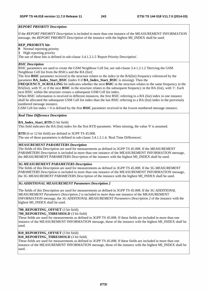
ETSI
ETSI TS 144 018 V11.7.0 (2014-03)2433GPP TS 44.018 version 11.7.0 Release 11
REPORT PRIORITY Description
If the REPORT PRIORITY Description is included in more than one instance of the MEASUREMENT INFORMATION message, the REPORT PRIORITY Description of the instance with the highest MI_INDEX shall be used.
REP_PRIORITY bit: 0 Normal reporting priority 1 High reporting priority The use of these bits is defined in sub-clause 3.4.1.2.1.5 'Report Priority Description'.
BSIC Description BSIC parameters are used to create the GSM Neighbour Cell list, see sub-clause 3.4.1.2.1.2 'Deriving the GSM Neighbour Cell list from the BSICs and the BA (list)'. The first BSIC parameter received in the structure relates to the index in the BA(list) frequency referenced by the parameter BA_Index_Start_BSIC (index 0 if BA_Index_Start_BSIC is missing). Then the FREQUENCY_SCROLLING bit indicates whether the next BSIC in the structure relates to the same frequency in the BA(list), with '0', or if the next BSIC in the structure relates to the subsequent frequency in the BA (list), with '1'. Each next BSIC within the structure creates a subsequent GSM Cell list index. When BSIC information is received in different instances, the first BSIC referring to a BA (list) index in one instance shall be allocated the subsequent GSM Cell list index than the last BSIC referring to a BA (list) index in the previously numbered message instance. GSM Cell list index = 0 is defined by the first BSIC parameter received in the lowest numbered message instance.
Real Time Difference Description
BA_Index_Start_RTD (5 bit field) This field indicates the BA (list) index for the first RTD parameter. When missing, the value '0' is assumed.
RTD (6 or 12 bit field) are defined in 3GPP TS 45.008. The use of these parameters is defined in sub-clause 3.4.1.2.1.4, 'Real Time Differences'.
MEASUREMENT PARAMETERS Description The fields of this Description are used for measurements as defined in 3GPP TS 45.008. If the MEASUREMENT PARAMETERS Description is included in more than one instance of the MEASUREMENT INFORMATION message, the MEASUREMENT PARAMETERS Description of the instance with the highest MI_INDEX shall be used.
3G MEASUREMENT PARAMETERS Description The fields of this Description are used for measurements as defined in 3GPP TS 45.008. If the 3G MEASUREMENT PARAMETERS Description is included in more than one instance of the MEASUREMENT INFORMATION message, the 3G MEASUREMENT PARAMETERS Description of the instance with the highest MI_INDEX shall be used.
3G ADDITIONAL MEASUREMENT Parameters Description 2
The fields of this Description are used for measurements as defined in 3GPP TS 45.008. If the 3G ADDITIONAL MEASUREMENT Parameters Description 2 is included in more than one instance of the MEASUREMENT INFORMATION message, the 3G ADDITIONAL MEASUREMENT Parameters Description 2 of the instance with the highest MI_INDEX shall be used.
700_REPORTING_OFFSET (3 bit field) 700_REPORTING_THRESHOLD (3 bit field) These fields are used for measurements as defined in 3GPP TS 45.008. If these fields are included in more than one instance of the MEASUREMENT INFORMATION message, those of the instance with the highest MI_INDEX shall be used.
810_REPORTING_OFFSET (3 bit field) 810_REPORTING_THRESHOLD (3 bit field) These fields are used for measurements as defined in 3GPP TS 45.008. If these fields are included in more than one instance of the MEASUREMENT INFORMATION message, those of the instance with the highest MI_INDEX shall be used.

ETSI
ETSI TS 144 018 V11.7.0 (2014-03)2443GPP TS 44.018 version 11.7.0 Release 11
3G Supplementary Parameters Description UTRAN_Start (1 bit field) This field indicates whether this instance of the message is the first one to contain UTRAN related parameters. It is coded as follows:
0 This is not the first instance of the message 1 This is the first instance of the message
UTRAN_Stop (1 bit field)
This field indicates whether this instance of the message is the last one to contain UTRAN related parameters. It is coded as follows:
0 This is not the last instance of the message 1 This is the last instance of the message
3G Measurement Control Parameters Description If this IE is present it overrides any old data held by the mobile station for these parameters.
If the 3G Neighbour Cell Description IE is included in the message, the contents of this IE shall be ignored.
DEFAULT_Measurement_Control_UTRAN (1 bit field) This field is used to control whether measurements are made on UTRAN neighbour cells. The definition of this field is same as the definition of Measurement_Control_UTRAN as defined in 3GPP TS 45.008. Any UTRAN frequency not explicitly listed in the Repeated UTRAN Measurement Control Parameters structure shall be assigned this value.
Repeated UTRAN Measurement Control Parameters UTRAN_FREQUENCY_INDEX (5 bit field) This field is an index into the 3G Frequency list (see sub-clause 3.4.1.2.1.7c).
Measurement_Control_UTRAN (1 bit field) This field is used to control whether measurements are made on UTRAN neighbour cells for the UTRAN frequency referenced by UTRAN_FREQUENCY_INDEX, as defined in 3GPP TS 45.008. This parameter applies to each UTRAN frequency indexed within this structure.
E-UTRAN Parameters Description E-UTRAN_Start (1 bit field)
This field indicates whether this instance of the message is the first one to contain E-UTRAN related parameters. It is coded as follows:
0 This is not the first instance of the message 1 This is the first instance of the message
E-UTRAN_Stop (1 bit field)
This field indicates whether this instance of the message is the last one to contain E-UTRAN related parameters. It is coded as follows:
0 This is not the last instance of the message 1 This is the last instance of the message
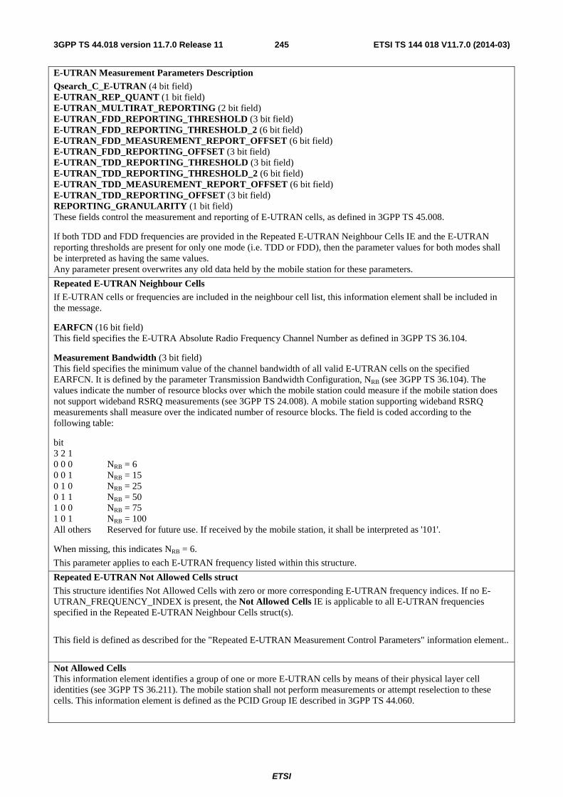
ETSI
ETSI TS 144 018 V11.7.0 (2014-03)2453GPP TS 44.018 version 11.7.0 Release 11
E-UTRAN Measurement Parameters Description Qsearch_C_E-UTRAN (4 bit field) E-UTRAN_REP_QUANT (1 bit field) E-UTRAN_MULTIRAT_REPORTING (2 bit field) E-UTRAN_FDD_REPORTING_THRESHOLD (3 bit field) E-UTRAN_FDD_REPORTING_THRESHOLD_2 (6 bit field) E-UTRAN_FDD_MEASUREMENT_REPORT_OFFSET (6 bit field) E-UTRAN_FDD_REPORTING_OFFSET (3 bit field) E-UTRAN_TDD_REPORTING_THRESHOLD (3 bit field) E-UTRAN_TDD_REPORTING_THRESHOLD_2 (6 bit field) E-UTRAN_TDD_MEASUREMENT_REPORT_OFFSET (6 bit field) E-UTRAN_TDD_REPORTING_OFFSET (3 bit field) REPORTING_GRANULARITY (1 bit field) These fields control the measurement and reporting of E-UTRAN cells, as defined in 3GPP TS 45.008.
If both TDD and FDD frequencies are provided in the Repeated E-UTRAN Neighbour Cells IE and the E-UTRAN reporting thresholds are present for only one mode (i.e. TDD or FDD), then the parameter values for both modes shall be interpreted as having the same values. Any parameter present overwrites any old data held by the mobile station for these parameters.
Repeated E-UTRAN Neighbour Cells If E-UTRAN cells or frequencies are included in the neighbour cell list, this information element shall be included in the message.
EARFCN (16 bit field) This field specifies the E-UTRA Absolute Radio Frequency Channel Number as defined in 3GPP TS 36.104.
Measurement Bandwidth (3 bit field) This field specifies the minimum value of the channel bandwidth of all valid E-UTRAN cells on the specified EARFCN. It is defined by the parameter Transmission Bandwidth Configuration, NRB (see 3GPP TS 36.104). The values indicate the number of resource blocks over which the mobile station could measure if the mobile station does not support wideband RSRQ measurements (see 3GPP TS 24.008). A mobile station supporting wideband RSRQ measurements shall measure over the indicated number of resource blocks. The field is coded according to the following table:
bit 3 2 1 0 0 0 NRB = 6 0 0 1 NRB = 15 0 1 0 NRB = 25 0 1 1 NRB = 50 1 0 0 NRB = 75 1 0 1 NRB = 100 All others Reserved for future use. If received by the mobile station, it shall be interpreted as '101'.
When missing, this indicates NRB = 6.
This parameter applies to each E-UTRAN frequency listed within this structure.
Repeated E-UTRAN Not Allowed Cells struct This structure identifies Not Allowed Cells with zero or more corresponding E-UTRAN frequency indices. If no E-UTRAN_FREQUENCY_INDEX is present, the Not Allowed Cells IE is applicable to all E-UTRAN frequencies specified in the Repeated E-UTRAN Neighbour Cells struct(s).
This field is defined as described for the "Repeated E-UTRAN Measurement Control Parameters" information element..
Not Allowed Cells This information element identifies a group of one or more E-UTRAN cells by means of their physical layer cell identities (see 3GPP TS 36.211). The mobile station shall not perform measurements or attempt reselection to these cells. This information element is defined as the PCID Group IE described in 3GPP TS 44.060.
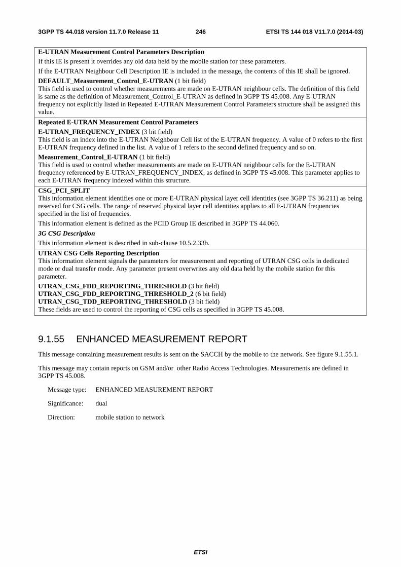
ETSI
ETSI TS 144 018 V11.7.0 (2014-03)2463GPP TS 44.018 version 11.7.0 Release 11
E-UTRAN Measurement Control Parameters Description If this IE is present it overrides any old data held by the mobile station for these parameters.
If the E-UTRAN Neighbour Cell Description IE is included in the message, the contents of this IE shall be ignored.
DEFAULT_Measurement_Control_E-UTRAN (1 bit field) This field is used to control whether measurements are made on E-UTRAN neighbour cells. The definition of this field is same as the definition of Measurement_Control_E-UTRAN as defined in 3GPP TS 45.008. Any E-UTRAN frequency not explicitly listed in Repeated E-UTRAN Measurement Control Parameters structure shall be assigned this value.
Repeated E-UTRAN Measurement Control Parameters E-UTRAN_FREQUENCY_INDEX (3 bit field) This field is an index into the E-UTRAN Neighbour Cell list of the E-UTRAN frequency. A value of 0 refers to the first E-UTRAN frequency defined in the list. A value of 1 refers to the second defined frequency and so on.
Measurement_Control_E-UTRAN (1 bit field) This field is used to control whether measurements are made on E-UTRAN neighbour cells for the E-UTRAN frequency referenced by E-UTRAN_FREQUENCY_INDEX, as defined in 3GPP TS 45.008. This parameter applies to each E-UTRAN frequency indexed within this structure.
CSG_PCI_SPLIT This information element identifies one or more E-UTRAN physical layer cell identities (see 3GPP TS 36.211) as being reserved for CSG cells. The range of reserved physical layer cell identities applies to all E-UTRAN frequencies specified in the list of frequencies.
This information element is defined as the PCID Group IE described in 3GPP TS 44.060.
3G CSG Description This information element is described in sub-clause 10.5.2.33b.
UTRAN CSG Cells Reporting Description This information element signals the parameters for measurement and reporting of UTRAN CSG cells in dedicated mode or dual transfer mode. Any parameter present overwrites any old data held by the mobile station for this parameter.
UTRAN_CSG_FDD_REPORTING_THRESHOLD (3 bit field) UTRAN_CSG_FDD_REPORTING_THRESHOLD_2 (6 bit field) UTRAN_CSG_TDD_REPORTING_THRESHOLD (3 bit field) These fields are used to control the reporting of CSG cells as specified in 3GPP TS 45.008.
9.1.55 ENHANCED MEASUREMENT REPORT
This message containing measurement results is sent on the SACCH by the mobile to the network. See figure 9.1.55.1.
This message may contain reports on GSM and/or other Radio Access Technologies. Measurements are defined in 3GPP TS 45.008.
Message type: ENHANCED MEASUREMENT REPORT
Significance: dual
Direction: mobile station to network
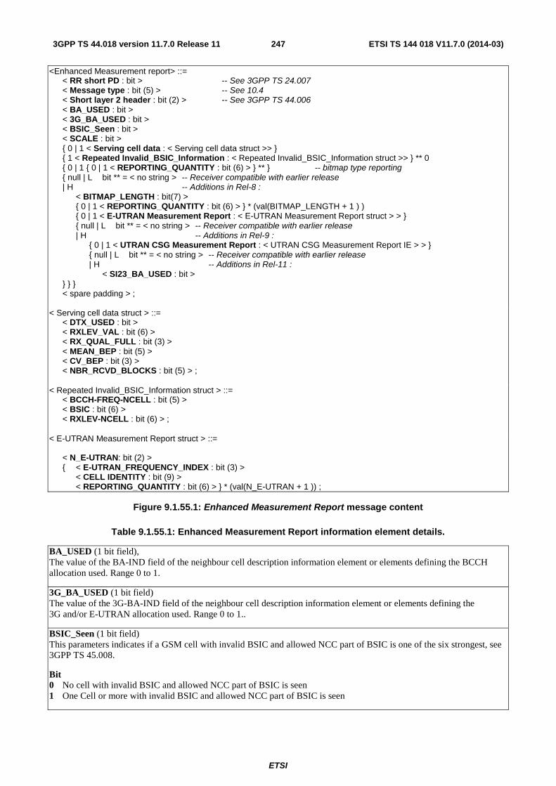
ETSI
ETSI TS 144 018 V11.7.0 (2014-03)2473GPP TS 44.018 version 11.7.0 Release 11
<Enhanced Measurement report> ::= < RR short PD : bit > -- See 3GPP TS 24.007 < Message type : bit (5) > -- See 10.4 < Short layer 2 header : bit (2) > -- See 3GPP TS 44.006 < BA_USED : bit > < 3G_BA_USED : bit > < BSIC_Seen : bit > < SCALE : bit > { 0 | 1 < Serving cell data : < Serving cell data struct >> } { 1 < Repeated Invalid_BSIC_Information : < Repeated Invalid_BSIC_Information struct >> } ** 0 { 0 | 1 { 0 | 1 < REPORTING_QUANTITY : bit (6) > } ** } -- bitmap type reporting { null | L bit ** = < no string > -- Receiver compatible with earlier release | H -- Additions in Rel-8 : < BITMAP_LENGTH : bit(7) > { 0 | 1 < REPORTING_QUANTITY : bit (6) > } * (val(BITMAP_LENGTH + 1 ) ) { 0 | 1 < E-UTRAN Measurement Report : < E-UTRAN Measurement Report struct > > } { null | L bit ** = < no string > -- Receiver compatible with earlier release | H -- Additions in Rel-9 : { 0 | 1 < UTRAN CSG Measurement Report : < UTRAN CSG Measurement Report IE > > } { null | L bit ** = < no string > -- Receiver compatible with earlier release | H -- Additions in Rel-11 : < SI23_BA_USED : bit > } } } < spare padding > ; < Serving cell data struct > ::= < DTX_USED : bit > < RXLEV_VAL : bit (6) > < RX_QUAL_FULL : bit (3) > < MEAN_BEP : bit (5) > < CV_BEP : bit (3) > < NBR_RCVD_BLOCKS : bit (5) > ; < Repeated Invalid_BSIC_Information struct > ::= < BCCH-FREQ-NCELL : bit (5) > < BSIC : bit (6) > < RXLEV-NCELL : bit (6) > ; < E-UTRAN Measurement Report struct > ::= < N_E-UTRAN: bit (2) > { < E-UTRAN_FREQUENCY_INDEX : bit (3) > < CELL IDENTITY : bit (9) > < REPORTING_QUANTITY : bit (6) > } * (val(N_E-UTRAN + 1 )) ;
Figure 9.1.55.1: Enhanced Measurement Report message content
Table 9.1.55.1: Enhanced Measurement Report information element details.
BA_USED (1 bit field), The value of the BA-IND field of the neighbour cell description information element or elements defining the BCCH allocation used. Range 0 to 1.
3G_BA_USED (1 bit field) The value of the 3G-BA-IND field of the neighbour cell description information element or elements defining the 3G and/or E-UTRAN allocation used. Range 0 to 1..
BSIC_Seen (1 bit field) This parameters indicates if a GSM cell with invalid BSIC and allowed NCC part of BSIC is one of the six strongest, see 3GPP TS 45.008.
Bit 0 No cell with invalid BSIC and allowed NCC part of BSIC is seen 1 One Cell or more with invalid BSIC and allowed NCC part of BSIC is seen
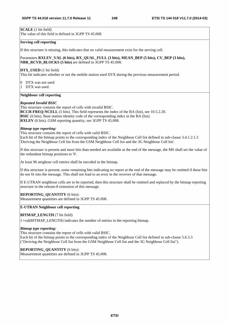
ETSI
ETSI TS 144 018 V11.7.0 (2014-03)2483GPP TS 44.018 version 11.7.0 Release 11
SCALE (1 bit field) The value of this field is defined in 3GPP TS 45.008.
Serving cell reporting
If this structure is missing, this indicates that no valid measurement exist for the serving cell.
Parameters RXLEV_VAL (6 bits), RX_QUAL_FULL (3 bits), MEAN_BEP (5 bits), CV_BEP (3 bits), NBR_RCVD_BLOCKS (5 bits) are defined in 3GPP TS 45.008.
DTX_USED (1 bit field) This bit indicates whether or not the mobile station used DTX during the previous measurement period.
0 DTX was not used 1 DTX was used.
Neighbour cell reporting
Repeated Invalid BSIC This structure contains the report of cells with invalid BSIC. BCCH-FREQ-NCELL (5 bits). This field represents the index of the BA (list), see 10.5.2.20. BSIC (6 bits). Base station identity code of the corresponding index in the BA (list). RXLEV (6 bits). GSM reporting quantity, see 3GPP TS 45.008.
Bitmap type reporting: This structure contains the report of cells with valid BSIC. Each bit of the bitmap points to the corresponding index of the Neighbour Cell list defined in sub-clause 3.4.1.2.1.3 'Deriving the Neighbour Cell list from the GSM Neighbour Cell list and the 3G Neighbour Cell list'.
If this structure is present and more bits than needed are available at the end of the message, the MS shall set the value of the redundant bitmap positions to '0'.
At least 96 neighour cell entries shall be encoded in the bitmap.
If this structure is present, some remaining bits indicating no report at the end of the message may be omitted if these bits do not fit into the message. This shall not lead to an error in the receiver of that message.
If E-UTRAN neighbour cells are to be reported, then this structure shall be omitted and replaced by the bitmap reporting structure in the release-8 extension of this message.
REPORTING_QUANTITY (6 bits): Measurement quantities are defined in 3GPP TS 45.008.
E-UTRAN Neighbour cell reporting
BITMAP_LENGTH (7 bit field)
1+val(BITMAP_LENGTH) indicates the number of entries in the reporting bitmap.
Bitmap type reporting: This structure contains the report of cells with valid BSIC. Each bit of the bitmap points to the corresponding index of the Neighbour Cell list defined in sub-clause 5.6.3.3 ("Deriving the Neighbour Cell list from the GSM Neighbour Cell list and the 3G Neighbour Cell list").
REPORTING_QUANTITY (6 bits): Measurement quantities are defined in 3GPP TS 45.008.
ETSI
ETSI TS 144 018 V11.7.0 (2014-03)2493GPP TS 44.018 version 11.7.0 Release 11
E-UTRAN Measurements Measurement reporting for E-UTRAN Cells is defined in 3GPP TS 45.008.
E-UTRAN_FREQUENCY_INDEX (3 bit field) This field contains the index of the frequency of the cell for which the measurement is reported. This field is defined in sub-clause 9.1.54.
CELL_IDENTITY (9 bit field) This field contains the physical layer cell identity (as defined in 3GPP TS 36.211) of the cell being reported.
REPORTING_QUANTITY (6 bit field) This is the reporting quantity for the E-UTRAN cell identified by the E-UTRAN frequency and physical layer cell identity. The quantities are defined in 3GPP TS 45.008 for the respective Radio Access Technology.
UTRAN CSG Measurement Report This information element contains the measurement report for a UTRAN CSG cell or detected hybrid cell. A UTRAN CSG cell or detected hybrid cell is identified by the Cell Identity and optionally the PLMN-ID.
This information element is defined as the UTRAN CSG Measurement Report IE described in 3GPP TS 44.060.
SI23_BA_USED (1 bit field) This field contains the value of the SI 23_BA_IND field in SYSTEM INFORMATION TYPE 23 message defining the E-UTRAN allocation used. In the case SYSTEM INFORMATION TYPE 23 message is not broadcast in the cell or if the mobile station does not support network sharing, this field shall be set to 0. Range 0 to 1.
9.1.56 Service Information message
This message is sent on the main DCCH by an MBMS capable mobile station, in class A mode of operation, to the network to indicate support of MBMS and additionally indicating whether the mobile station has joined an MBMS service. See table 9.1.56.1.
Message type: SERVICE INFORMATION
Significance: dual
Direction: mobile station to network
Table 9.1.56.1: Service Information message content
IEI Information element Type / Reference Presence Format length RR management
Protocol Discriminator Protocol Discriminator 10.2
M V 1/2
Skip Indicator Skip Indicator 10.3.1
M V 1/2
Service Information Message Type
Message Type 10.4
M V 1
Temporary Logical Link Identity TLLI 10.5.2.41a
M V 4
Routeing Area Identification Routeing Area Identification 10.5.5.15
M V 6
Service Support Service Support 10.5.2.57
M V 1
9.1.56.1 Temporary Logical Link Identity
This information element contains the TLLI derived from the P-TMSI, see 3GPP TS 23.060. The network shall accept a local TLLI even if the current RA where the message is received differs from the one indicated in this message.
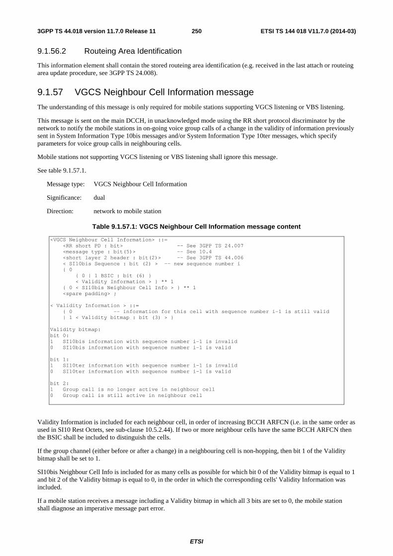
ETSI
ETSI TS 144 018 V11.7.0 (2014-03)2503GPP TS 44.018 version 11.7.0 Release 11
9.1.56.2 Routeing Area Identification
This information element shall contain the stored routeing area identification (e.g. received in the last attach or routeing area update procedure, see 3GPP TS 24.008).
9.1.57 VGCS Neighbour Cell Information message
The understanding of this message is only required for mobile stations supporting VGCS listening or VBS listening.
This message is sent on the main DCCH, in unacknowledged mode using the RR short protocol discriminator by the network to notify the mobile stations in on-going voice group calls of a change in the validity of information previously sent in System Information Type 10bis messages and/or System Information Type 10ter messages, which specify parameters for voice group calls in neighbouring cells.
Mobile stations not supporting VGCS listening or VBS listening shall ignore this message.
See table 9.1.57.1.
Message type: VGCS Neighbour Cell Information
Significance: dual
Direction: network to mobile station
Table 9.1.57.1: VGCS Neighbour Cell Information message content
<VGCS Neighbour Cell Information> ::= <RR short PD : bit> -- See 3GPP TS 24.007 <message type : bit(5)> -- See 10.4 <short layer 2 header : bit(2)> -- See 3GPP TS 44.006 < SI10bis Sequence : bit (2) > -- new sequence number i { 0 { 0 | 1 BSIC : bit (6) } < Validity Information > } ** 1 { 0 < SI10bis Neighbour Cell Info > } ** 1 <spare padding> ; < Validity Information > ::= { 0 -- information for this cell with sequence number i-1 is still valid | 1 < Validity bitmap : bit (3) > } Validity bitmap: bit 0: 1 SI10bis information with sequence number i-1 is invalid 0 SI10bis information with sequence number i-1 is valid bit 1: 1 SI10ter information with sequence number i-1 is invalid 0 SI10ter information with sequence number i-1 is valid bit 2: 1 Group call is no longer active in neighbour cell 0 Group call is still active in neighbour cell
Validity Information is included for each neighbour cell, in order of increasing BCCH ARFCN (i.e. in the same order as used in SI10 Rest Octets, see sub-clause 10.5.2.44). If two or more neighbour cells have the same BCCH ARFCN then the BSIC shall be included to distinguish the cells.
If the group channel (either before or after a change) in a neighbouring cell is non-hopping, then bit 1 of the Validity bitmap shall be set to 1.
SI10bis Neighbour Cell Info is included for as many cells as possible for which bit 0 of the Validity bitmap is equal to 1 and bit 2 of the Validity bitmap is equal to 0, in the order in which the corresponding cells' Validity Information was included.
If a mobile station receives a message including a Validity bitmap in which all 3 bits are set to 0, the mobile station shall diagnose an imperative message part error.
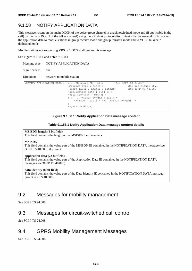
ETSI
ETSI TS 144 018 V11.7.0 (2014-03)2513GPP TS 44.018 version 11.7.0 Release 11
9.1.58 NOTIFY APPLICATION DATA
This message is sent on the main DCCH of the voice group channel in unacknowledged mode and (if applicable in the cell) on the main DCCH of the talker channel) using the RR short protocol discriminator by the network to broadcast the application data to mobile stations in group receive mode and group transmit mode and to VGCS talkers in dedicated mode.
Mobile stations not supporting VBS or VGCS shall ignore this message.
See Figure 9.1.58.1 and Table 9.1.58.1.
Message type: NOTIFY APPLICATION DATA
Significance: dual
Direction: network to mobile station
<NOTIFY APPLICATION DATA > ::= <RR short PD : bit> -- See 3GPP TS 24.007 <message type : bit(5)> -- See sub-clause 10.4 <short layer 2 header : bit(2)> -- See 3GPP TS 44.006 <application data : bit(72) > <data identity : bit(8) > { 0 | 1 <MSISDN length : bit(4)> <MSISDN : bit(8 * val (MSISDN length)) > } <spare padding>;
Figure 9.1.58.1: Notify Application Data message content
Table 9.1.58.1 Notify Application Data message content details
MSISDN length (4 bit field) This field contains the length of the MSISDN field in octets
MSISDN This field contains the value part of the MSISDN IE contained in the NOTIFICATION DATA message (see 3GPP TS 48.008), if present.
application data (72 bit field) This field contains the value part of the Application Data IE contained in the NOTIFICATION DATA message (see 3GPP TS 48.008)
data identity (8 bit field) This field contains the value part of the Data Identity IE contained in the NOTIFICATION DATA message (see 3GPP TS 48.008)
9.2 Messages for mobility management See 3GPP TS 24.008.
9.3 Messages for circuit-switched call control See 3GPP TS 24.008.
9.4 GPRS Mobility Management Messages See 3GPP TS 24.008.
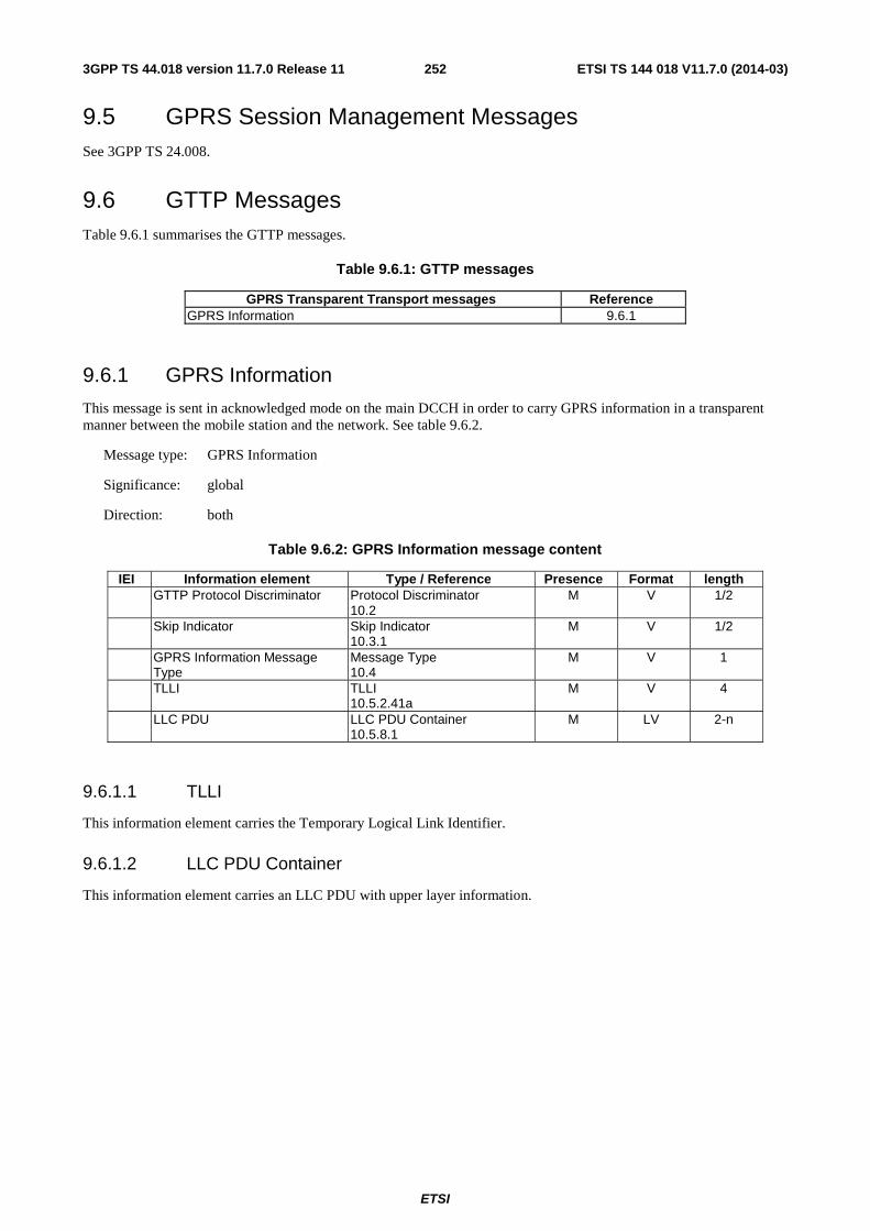
ETSI
ETSI TS 144 018 V11.7.0 (2014-03)2523GPP TS 44.018 version 11.7.0 Release 11
9.5 GPRS Session Management Messages See 3GPP TS 24.008.
9.6 GTTP Messages Table 9.6.1 summarises the GTTP messages.
Table 9.6.1: GTTP messages
GPRS Transparent Transport messages Reference GPRS Information 9.6.1
9.6.1 GPRS Information
This message is sent in acknowledged mode on the main DCCH in order to carry GPRS information in a transparent manner between the mobile station and the network. See table 9.6.2.
Message type: GPRS Information
Significance: global
Direction: both
Table 9.6.2: GPRS Information message content
IEI Information element Type / Reference Presence Format length GTTP Protocol Discriminator Protocol Discriminator
10.2 M V 1/2
Skip Indicator Skip Indicator 10.3.1
M V 1/2
GPRS Information Message Type
Message Type 10.4
M V 1
TLLI TLLI 10.5.2.41a
M V 4
LLC PDU LLC PDU Container 10.5.8.1
M LV 2-n
9.6.1.1 TLLI
This information element carries the Temporary Logical Link Identifier.
9.6.1.2 LLC PDU Container
This information element carries an LLC PDU with upper layer information.

ETSI
ETSI TS 144 018 V11.7.0 (2014-03)2533GPP TS 44.018 version 11.7.0 Release 11
10 General message format and information elements coding
The figures and text in this sub-clause describe the Information Elements contents.
10.1 Overview Within the RR protocols defined in 3GPP TS 44.018, every message with the exception of the messages sent on the BCCH, downlink CCCH, SCH, RACH, and the HANDOVER ACCESS message, is a standard L3 message as defined in 3GPP TS 24.007. This means that the message consists of the following parts:
a) protocol discriminator;
b) skip indicator;
c) message type;
d) other information elements, as required.
This organization is illustrated in the example shown in figure 10.1.1.
8 7 6 5 4 3 2 1 Skip Indicator Protocol discriminator octet 1
Message type octet 2 Other information elements as required etc.
Figure 10.1.1: General message organization example
Unless specified otherwise in the message descriptions of sub-clause 9, a particular information element shall not be present more than once in a given message.
The term "default" implies that the value defined shall be used in the absence of any assignment, or that this value allows negotiation of alternative values in between the two peer entities.
When a field extends over more than one octet, the order of bit values progressively decreases as the octet number increases. The least significant bit of the field is represented by the lowest numbered bit of the highest numbered octet of the field.
When a message is coded using CSN.1 notation, the definition of the CSN.1 syntax in CSN.1 Specification, Version 2.0, shall be used.
10.2 Protocol Discriminator The Protocol Discriminator (PD) and its use are defined in 3GPP TS 24.007.
10.3 Skip indicator
10.3.1 Skip indicator
Bits 5 to 8 of the first octet of every Radio Resource management message and GPRS Transparent Transport protocol message contain the skip indicator.
When network sharing is in use in a cell, and in the case of the PAGING RESPONSE message, a mobile station supporting network sharing shall encode the skip indicator as described within 3GPP TS 24.008. A supporting network receiving a PAGING RESPONSE message with a skip indicator different from "0000" shall consider the mobile station as supporting network sharing.
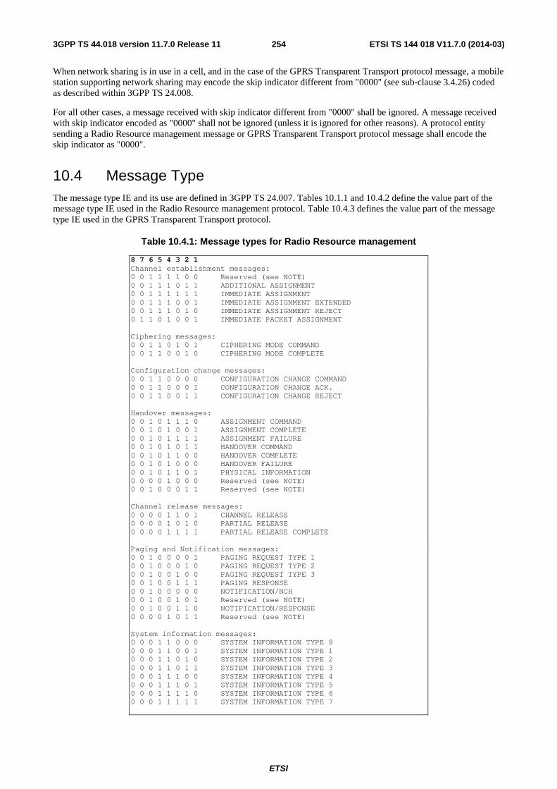
ETSI
ETSI TS 144 018 V11.7.0 (2014-03)2543GPP TS 44.018 version 11.7.0 Release 11
When network sharing is in use in a cell, and in the case of the GPRS Transparent Transport protocol message, a mobile station supporting network sharing may encode the skip indicator different from "0000" (see sub-clause 3.4.26) coded as described within 3GPP TS 24.008.
For all other cases, a message received with skip indicator different from "0000" shall be ignored. A message received with skip indicator encoded as "0000" shall not be ignored (unless it is ignored for other reasons). A protocol entity sending a Radio Resource management message or GPRS Transparent Transport protocol message shall encode the skip indicator as "0000".
10.4 Message Type The message type IE and its use are defined in 3GPP TS 24.007. Tables 10.1.1 and 10.4.2 define the value part of the message type IE used in the Radio Resource management protocol. Table 10.4.3 defines the value part of the message type IE used in the GPRS Transparent Transport protocol.
Table 10.4.1: Message types for Radio Resource management
8 7 6 5 4 3 2 1 Channel establishment messages: 0 0 1 1 1 1 0 0 Reserved (see NOTE) 0 0 1 1 1 0 1 1 ADDITIONAL ASSIGNMENT 0 0 1 1 1 1 1 1 IMMEDIATE ASSIGNMENT 0 0 1 1 1 0 0 1 IMMEDIATE ASSIGNMENT EXTENDED 0 0 1 1 1 0 1 0 IMMEDIATE ASSIGNMENT REJECT 0 1 1 0 1 0 0 1 IMMEDIATE PACKET ASSIGNMENT Ciphering messages: 0 0 1 1 0 1 0 1 CIPHERING MODE COMMAND 0 0 1 1 0 0 1 0 CIPHERING MODE COMPLETE Configuration change messages: 0 0 1 1 0 0 0 0 CONFIGURATION CHANGE COMMAND 0 0 1 1 0 0 0 1 CONFIGURATION CHANGE ACK. 0 0 1 1 0 0 1 1 CONFIGURATION CHANGE REJECT Handover messages: 0 0 1 0 1 1 1 0 ASSIGNMENT COMMAND 0 0 1 0 1 0 0 1 ASSIGNMENT COMPLETE 0 0 1 0 1 1 1 1 ASSIGNMENT FAILURE 0 0 1 0 1 0 1 1 HANDOVER COMMAND 0 0 1 0 1 1 0 0 HANDOVER COMPLETE 0 0 1 0 1 0 0 0 HANDOVER FAILURE 0 0 1 0 1 1 0 1 PHYSICAL INFORMATION 0 0 0 0 1 0 0 0 Reserved (see NOTE) 0 0 1 0 0 0 1 1 Reserved (see NOTE) Channel release messages: 0 0 0 0 1 1 0 1 CHANNEL RELEASE 0 0 0 0 1 0 1 0 PARTIAL RELEASE 0 0 0 0 1 1 1 1 PARTIAL RELEASE COMPLETE Paging and Notification messages: 0 0 1 0 0 0 0 1 PAGING REQUEST TYPE 1 0 0 1 0 0 0 1 0 PAGING REQUEST TYPE 2 0 0 1 0 0 1 0 0 PAGING REQUEST TYPE 3 0 0 1 0 0 1 1 1 PAGING RESPONSE 0 0 1 0 0 0 0 0 NOTIFICATION/NCH 0 0 1 0 0 1 0 1 Reserved (see NOTE) 0 0 1 0 0 1 1 0 NOTIFICATION/RESPONSE 0 0 0 0 1 0 1 1 Reserved (see NOTE) System information messages: 0 0 0 1 1 0 0 0 SYSTEM INFORMATION TYPE 8 0 0 0 1 1 0 0 1 SYSTEM INFORMATION TYPE 1 0 0 0 1 1 0 1 0 SYSTEM INFORMATION TYPE 2 0 0 0 1 1 0 1 1 SYSTEM INFORMATION TYPE 3 0 0 0 1 1 1 0 0 SYSTEM INFORMATION TYPE 4 0 0 0 1 1 1 0 1 SYSTEM INFORMATION TYPE 5 0 0 0 1 1 1 1 0 SYSTEM INFORMATION TYPE 6 0 0 0 1 1 1 1 1 SYSTEM INFORMATION TYPE 7
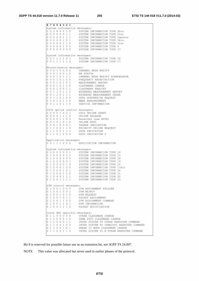
ETSI
ETSI TS 144 018 V11.7.0 (2014-03)2553GPP TS 44.018 version 11.7.0 Release 11
8 7 6 5 4 3 2 1 System information messages: 0 0 0 0 0 0 1 0 SYSTEM INFORMATION TYPE 2bis 0 0 0 0 0 0 1 1 SYSTEM INFORMATION TYPE 2ter 0 0 0 0 0 1 1 1 SYSTEM INFORMATION TYPE 2quater 0 0 0 0 0 1 0 1 SYSTEM INFORMATION TYPE 5bis 0 0 0 0 0 1 1 0 SYSTEM INFORMATION TYPE 5ter 0 0 0 0 0 1 0 0 SYSTEM INFORMATION TYPE 9 0 0 0 0 0 0 0 0 SYSTEM INFORMATION TYPE 13 System information messages: 0 0 1 1 1 1 0 1 SYSTEM INFORMATION TYPE 16 0 0 1 1 1 1 1 0 SYSTEM INFORMATION TYPE 17 Miscellaneous messages: 0 0 0 1 0 0 0 0 CHANNEL MODE MODIFY 0 0 0 1 0 0 1 0 RR STATUS 0 0 0 1 0 1 1 1 CHANNEL MODE MODIFY ACKNOWLEDGE 0 0 0 1 0 1 0 0 FREQUENCY REDEFINITION 0 0 0 1 0 1 0 1 MEASUREMENT REPORT 0 0 0 1 0 1 1 0 CLASSMARK CHANGE 0 0 0 1 0 0 1 1 CLASSMARK ENQUIRY 0 0 1 1 0 1 1 0 EXTENDED MEASUREMENT REPORT 0 0 1 1 0 1 1 1 EXTENDED MEASUREMENT ORDER 0 0 1 1 0 1 0 0 GPRS SUSPENSION REQUEST 0 0 0 1 0 1 1 0 MBMS ANNOUNCEMENT 0 0 1 1 0 1 1 0 SERVICE INFORMATION VGCS uplink control messages: 0 0 0 0 1 0 0 1 VGCS UPLINK GRANT 0 0 0 0 1 1 1 0 UPLINK RELEASE 0 0 0 0 1 1 0 0 Reserved (see NOTE) 0 0 1 0 1 0 1 0 UPLINK BUSY 0 0 0 1 0 0 0 1 TALKER INDICATION 0 1 1 0 0 1 1 0 PRIORITY UPLINK REQUEST 0 1 1 0 0 1 1 1 DATA INDICATION 0 1 1 0 1 0 0 0 DATA INDICATION 2 Application messages: 0 0 1 1 1 0 0 0 APPLICATION INFORMATION System information messages: 0 0 0 0 0 0 0 1 SYSTEM INFORMATION TYPE 14 0 1 0 0 0 0 1 1 SYSTEM INFORMATION TYPE 15 0 1 0 0 0 0 0 0 SYSTEM INFORMATION TYPE 18 0 1 0 0 0 0 0 1 SYSTEM INFORMATION TYPE 19 0 1 0 0 0 0 1 0 SYSTEM INFORMATION TYPE 20 0 1 0 0 0 1 0 0 SYSTEM INFORMATION TYPE 13alt 0 1 0 0 0 1 0 1 SYSTEM INFORMATION TYPE 2n 0 1 0 0 0 1 1 0 SYSTEM INFORMATION TYPE 21 0 1 0 0 0 1 1 1 SYSTEM INFORMATION TYPE 22 0 1 0 0 1 1 1 1 SYSTEM INFORMATION TYPE 23 DTM control messages: 0 1 0 0 1 0 0 0 DTM ASSIGNMENT FAILURE 0 1 0 0 1 0 0 1 DTM REJECT 0 1 0 0 1 0 1 0 DTM REQUEST 0 1 0 0 1 0 1 1 PACKET ASSIGNMENT 0 1 0 0 1 1 0 0 DTM ASSIGNMENT COMMAND 0 1 0 0 1 1 0 1 DTM INFORMATION 0 1 0 0 1 1 1 0 PACKET NOTIFICATION Inter RAT specific messages: 0 1 1 0 0 0 0 0 UTRAN CLASSMARK CHANGE 0 1 1 0 0 0 1 0 CDMA 2000 CLASSMARK CHANGE 0 1 1 0 0 0 1 1 INTER SYSTEM TO UTRAN HANDOVER COMMAND 0 1 1 0 0 1 0 0 INTER SYSTEM TO CDMA2000 HANDOVER COMMAND 0 1 1 0 0 1 0 1 GERAN IU MODE CLASSMARK CHANGE 0 1 1 0 0 1 1 0 INTER SYSTEM TO E-UTRAN HANDOVER COMMAND
Bit 8 is reserved for possible future use as an extension bit, see 3GPP TS 24.007.
NOTE This value was allocated but never used in earlier phases of the protocol.
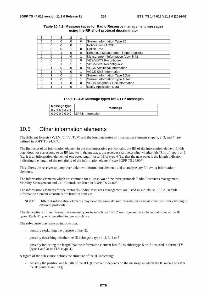
ETSI
ETSI TS 144 018 V11.7.0 (2014-03)2563GPP TS 44.018 version 11.7.0 Release 11
Table 10.4.2: Message types for Radio Resource management messages using the RR short protocol discriminator
5 4 3 2 1 0 0 0 0 0 System Information Type 10 0 0 0 0 1 Notification/FACCH 0 0 0 1 0 Uplink Free 0 0 1 0 0 Enhanced Measurement Report (uplink) 0 0 1 0 1 Measurement Information (downlink) 0 0 1 1 0 VBS/VGCS Reconfigure 0 0 1 1 1 VBS/VGCS Reconfigure2 0 1 0 0 0 VGCS Additional Information 0 1 0 0 1 VGCS SMS Information 0 1 0 1 0 System Information Type 10bis 0 1 0 1 1 System Information Type 10ter 0 1 1 0 0 VGCS Neighbour Cell Information 0 1 1 0 1 Notify Application Data
Table 10.4.3: Message types for GTTP messages
Message type Message
8 7 6 5 4 3 2 1 0 0 0 0 0 0 0 0 GPRS Information
10.5 Other information elements The different formats (V, LV, T, TV, TLV) and the four categories of information elements (type 1, 2, 3, and 4) are defined in 3GPP TS 24.007.
The first octet of an information element in the non-imperative part contains the IEI of the information element. If this octet does not correspond to an IEI known in the message, the receiver shall determine whether this IE is of type 1 or 2 (i.e. it is an information element of one octet length) or an IE of type 4 (i.e. that the next octet is the length indicator indicating the length of the remaining of the information element) (see 3GPP TS 24.007).
This allows the receiver to jump over unknown information elements and to analyse any following information elements.
The information elements which are common for at least two of the three protocols Radio Resources management, Mobility Management and Call Control, are listed in 3GPP TS 24.008.
The information elements for the protocols Radio Resources management are listed in sub-clause 10.5.2. Default information element identifiers are listed in annex K.
NOTE: Different information elements may have the same default information element identifier if they belong to different protocols.
The descriptions of the information element types in sub-clause 10.5.2 are organized in alphabetical order of the IE types. Each IE type is described in one sub-clause.
The sub-clause may have an introduction:
- possibly explaining the purpose of the IE;
- possibly describing whether the IE belongs to type 1, 2, 3, 4 or 5;
- possibly indicating the length that the information element has if it is either type 5 or if it is used in format TV (type 1 and 3) or TLV (type 4).
A figure of the sub-clause defines the structure of the IE indicating:
- possibly the position and length of the IEI. (However it depends on the message in which the IE occurs whether the IE contains an IEI.);
ETSI
ETSI TS 144 018 V11.7.0 (2014-03)2573GPP TS 44.018 version 11.7.0 Release 11
- the fields the IE value part is composed of;
- possibly the position and length of the length indicator. (However it depends on the IE type whether the IE contains a length indicator or not.);
- possibly octet numbers of the octets that compose the IE (see sub-clause a) below).
Finally, the sub-clause contains tables defining the structure and value range of the fields that compose the IE value part. The order of appearance for information elements in a message is defined in clause 9.
The order of the information elements within the imperative part of messages has been chosen so that information elements with 1/2 octet of content (type 1) go together in succession. The first type 1 information element occupies bits 1 to 4 of octet N, the second bits 5 to 8 of octet N, the third bits 1 to 4 of octet N + 1 etc. If the number of type 1 information elements is odd then bits 5 to 8 of the last octet occupied by these information elements contains a spare half octet IE in format V.
Where the description of information elements in this Technical Specification contains bits defined to be "spare bits", these bits shall set to the indicated value (0 or 1) by the sending side, and their value shall be ignored by the receiving side. With few exceptions, spare bits are indicated as being set to "0" in 3GPP TS 44.018.
The following rules apply for the coding of type 4 information elements:
a) The octet number of an octet (which is defined in the figure of a sub-clause) consists of a positive integer, possibly of an additional letter, and possibly of an additional asterisk, see sub-clause f). The positive integer identifies one octet or a group of octets.
b) Each octet group is a self contained entity. The internal structure of an octet group may be defined in alternative ways.
c) An octet group is formed by using some extension mechanism. The preferred extension mechanism is to extend an octet (N) through the next octet(s) (Na, Nb, etc.) by using bit 8 in each octet as an extension bit.
The bit value "0" indicates that the octet group continues through to the next octet. The bit value "1" indicates that this octet is the last octet of the group. If one octet (Nb) is present, the preceding octets (N and Na) shall also be present.
In the format descriptions appearing in sub-clause 10.5.1 to 10.5.4, bit 8 is marked "0/1 ext" if another octet follows. Bit 8 is marked "1 ext" if this is the last octet in the extension domain.
Additional octets may be defined in later versions of the protocols ("1 ext" changed to "0/1 ext") and equipments shall be prepared to receive such additional octets; the contents of these octets shall be ignored. However the length indicated in clauses 9 and 10 only takes into account this version of the protocols.
d) In addition to the extension mechanism defined above, an octet (N) may be extended through the next octet(s) (N+1, N+2 etc.) by indications in bits 7-1 (of octet N).
e) The mechanisms in c) and d) may be combined.
f) Optional octets are marked with asterisks (*).
10.5.1 Common information elements.
10.5.1.0 General
The content of the common information elements identified below is specified in the corresponding sub-clauses in 3GPP TS 24.008.
10.5.1.1 Cell identity
See 3GPP TS 24.008.
ETSI
ETSI TS 144 018 V11.7.0 (2014-03)2583GPP TS 44.018 version 11.7.0 Release 11
10.5.1.2 Ciphering Key Sequence Number
See 3GPP TS 24.008.
10.5.1.3 Location Area Identification
See 3GPP TS 24.008.
10.5.1.4 Mobile Identity
See 3GPP TS 24.008.
10.5.1.5 Mobile Station Classmark 1
See 3GPP TS 24.008.
10.5.1.6 Mobile Station Classmark 2
See 3GPP TS 24.008.
10.5.1.7 Mobile Station Classmark 3
See 3GPP TS 24.008.
10.5.1.8 Spare Half Octet
See 3GPP TS 24.008.
10.5.1.9 Descriptive group or broadcast call reference
See 3GPP TS 24.008.
10.5.1.10 Group Cipher Key Number
See 3GPP TS 24.008.
10.5.1.10a (void)
10.5.1.11 (void)
10.5.1.12 (void)
10.5.1.13 (void)
10.5.2 Radio Resource management information elements.
10.5.2.1a BA Range
The purpose of the BA Range information element is to provide the mobile station with ARFCN range information which can be used in the cell selection procedure.
The BA Range information element is coded as shown in figure 10.5.21a.1 and table 10.5.2.1a.1.
The BA Range is a type 4 information element with a minimum length of 6 octets. No upper length limit is specified except for that given by the maximum number of octets in a L3 message (see 3GPP TS 44.006).
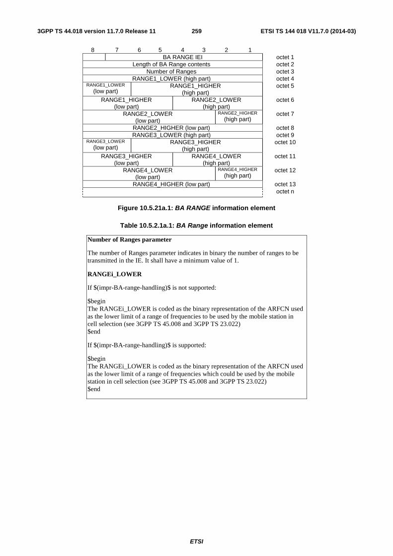
ETSI
ETSI TS 144 018 V11.7.0 (2014-03)2593GPP TS 44.018 version 11.7.0 Release 11
8 7 6 5 4 3 2 1 BA RANGE IEI octet 1
Length of BA Range contents octet 2 Number of Ranges octet 3
RANGE1_LOWER (high part) octet 4 RANGE1_LOWER
(low part) RANGE1_HIGHER
(high part) octet 5
RANGE1_HIGHER (low part)
RANGE2_LOWER (high part)
octet 6
RANGE2_LOWER (low part)
RANGE2_HIGHER (high part)
octet 7
RANGE2_HIGHER (low part) octet 8 RANGE3_LOWER (high part) octet 9
RANGE3_LOWER (low part)
RANGE3_HIGHER (high part)
octet 10
RANGE3_HIGHER (low part)
RANGE4_LOWER (high part)
octet 11
RANGE4_LOWER (low part)
RANGE4_HIGHER (high part)
octet 12
RANGE4_HIGHER (low part) octet 13
octet n
Figure 10.5.21a.1: BA RANGE information element
Table 10.5.2.1a.1: BA Range information element
Number of Ranges parameter
The number of Ranges parameter indicates in binary the number of ranges to be transmitted in the IE. It shall have a minimum value of 1.
RANGEi_LOWER
If $(impr-BA-range-handling)$ is not supported:
$begin The RANGEi_LOWER is coded as the binary representation of the ARFCN used as the lower limit of a range of frequencies to be used by the mobile station in cell selection (see 3GPP TS 45.008 and 3GPP TS 23.022) $end
If $(impr-BA-range-handling)$ is supported:
$begin The RANGEi_LOWER is coded as the binary representation of the ARFCN used as the lower limit of a range of frequencies which could be used by the mobile station in cell selection (see 3GPP TS 45.008 and 3GPP TS 23.022) $end
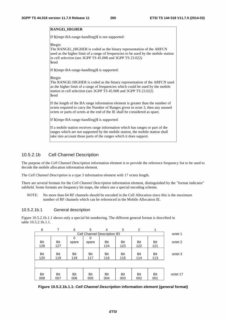
ETSI
ETSI TS 144 018 V11.7.0 (2014-03)2603GPP TS 44.018 version 11.7.0 Release 11
RANGEi_HIGHER
If $(impr-BA-range-handling)$ is not supported:
$begin The RANGEi_HIGHER is coded as the binary representation of the ARFCN used as the higher limit of a range of frequencies to be used by the mobile station in cell selection (see 3GPP TS 45.008 and 3GPP TS 23.022) $end
If $(impr-BA-range-handling)$ is supported:
$begin The RANGEi HIGHER is coded as the binary representation of the ARFCN used as the higher limit of a range of frequencies which could be used by the mobile station in cell selection (see 3GPP TS 45.008 and 3GPP TS 23.022) $end
If the length of the BA range information element is greater than the number of octets required to carry the Number of Ranges given in octet 3, then any unused octets or parts of octets at the end of the IE shall be considered as spare.
If $(impr-BA-range-handling)$ is supported:
If a mobile station receives range information which has ranges or part of the ranges which are not supported by the mobile station, the mobile station shall take into account those parts of the ranges which it does support.
10.5.2.1b Cell Channel Description
The purpose of the Cell Channel Description information element is to provide the reference frequency list to be used to decode the mobile allocation information element.
The Cell Channel Description is a type 3 information element with 17 octets length.
There are several formats for the Cell Channel Description information element, distinguished by the "format indicator" subfield. Some formats are frequency bit maps, the others use a special encoding scheme.
NOTE: No more than 64 RF channels should be encoded in the Cell Allocation since this is the maximum number of RF channels which can be referenced in the Mobile Allocation IE.
10.5.2.1b.1 General description
Figure 10.5.2.1b.1.1 shows only a special bit numbering. The different general format is described in table 10.5.2.1b.1.1.
8 7 6 5 4 3 2 1 Cell Channel Description IEI octet 1
Bit 128
Bit 127
0 spare
0 spare
Bit 124
Bit 123
Bit 122
Bit 121
octet 2
Bit 120
Bit 119
Bit 118
Bit 117
Bit 116
Bit 115
Bit 114
Bit 113
octet 3
Bit 008
Bit 007
Bit 006
Bit 005
Bit 004
Bit 003
Bit 002
Bit 001
octet 17
Figure 10.5.2.1b.1.1: Cell Channel Description information element (general format)

ETSI
ETSI TS 144 018 V11.7.0 (2014-03)2613GPP TS 44.018 version 11.7.0 Release 11
Table 10.5.2.1b.1.1: Cell Channel Description information element, general format
FORMAT-ID, Format Identifier (Bit 128 and next)
The different formats are distinguished by the bits of higher number. The possible values are the following:
Bit Bit Bit Bit Bit format notation 128 127 124 123 122
0 0 X X X bit map 0 1 0 0 X X 1024 range
1 0 1 0 0 512 range 1 0 1 0 1 256 range
1 0 1 1 0 128 range 1 0 1 1 1 variable bit map
All other combinations are reserved for future use.
A GSM 900 mobile station which only supports the primary GSM band P-GSM 900 (cf. 3GPP TS 45.005) may consider all values except the value for bit map 0 as reserved.
The significance of the remaining bits depends on the FORMAT-ID. The different cases are specified in the next sub-clauses.
Mobile stations shall treat all ARFCNs in the set {0, 1, 2 ... 1023} as valid ARFCN values even if the mobile station is unable to transmit or receive on that ARFCN.
10.5.2.1b.2 Bit map 0 format
8 7 6 5 4 3 2 1 Cell Channel Description IEI octet 1
0 0 0 0 CA CA CA CA
FORMAT-ID spare spare ARFCN
124 ARFCN
123 ARFCN
122 ARFCN
121 octet 2
CA ARFCN
120
CA ARFCN
119
CA ARFCN
118
CA ARFCN
117
CA ARFCN
116
CA ARFCN
115
CA ARFCN
114
CA ARFCN
113
octet 3
CA ARFCN
008
CA ARFCN
007
CA ARFCN
006
CA ARFCN
005
CA ARFCN
004
CA ARFCN
003
CA ARFCN
002
CA ARFCN
001
octet 17
Figure 10.5.2.1b.2.1: Cell Channel Description information element, bit map 0 format
Table 10.5.2.1b.2.1: Cell channel Description information element, bit map 0 format
CA ARFCN N, Cell Allocation Absolute RF Channel Number N (octet 2 etc.)
For a RF channel with ARFCN = N belonging to the cell allocation the CA ARFCN N bit is coded with a "1"; N = 1, 2, .. , 124.
For a RF channel with ARFCN = N not belonging to the cell allocation the CA ARFCN N bit is coded with a "0"; N = 1, 2 .. , 124.
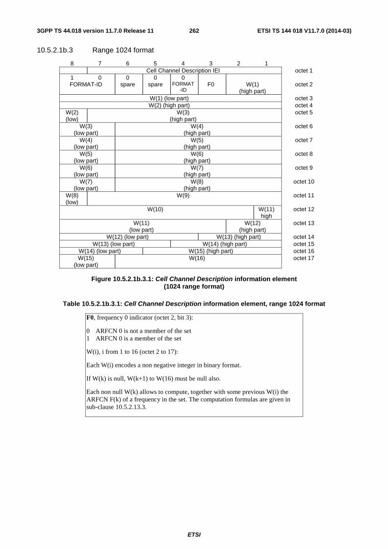
ETSI
ETSI TS 144 018 V11.7.0 (2014-03)2623GPP TS 44.018 version 11.7.0 Release 11
10.5.2.1b.3 Range 1024 format
8 7 6 5 4 3 2 1 Cell Channel Description IEI octet 1
1 0 0 0 0 FORMAT-ID spare spare FORMAT
-ID F0 W(1)
(high part) octet 2
W(1) (low part) octet 3 W(2) (high part) octet 4
W(2) (low)
W(3) (high part)
octet 5
W(3) (low part)
W(4) (high part)
octet 6
W(4) (low part)
W(5) (high part)
octet 7
W(5) (low part)
W(6) (high part)
octet 8
W(6) (low part)
W(7) (high part)
octet 9
W(7) (low part)
W(8) (high part)
octet 10
W(8) (low)
W(9) octet 11
W(10) W(11) high
octet 12
W(11) (low part)
W(12) (high part)
octet 13
W(12) (low part) W(13) (high part) octet 14 W(13) (low part) W(14) (high part) octet 15
W(14) (low part) W(15) (high part) octet 16 W(15)
(low part) W(16) octet 17
Figure 10.5.2.1b.3.1: Cell Channel Description information element
(1024 range format)
Table 10.5.2.1b.3.1: Cell Channel Description information element, range 1024 format
F0, frequency 0 indicator (octet 2, bit 3):
0 ARFCN 0 is not a member of the set 1 ARFCN 0 is a member of the set
W(i), i from 1 to 16 (octet 2 to 17):
Each W(i) encodes a non negative integer in binary format.
If W(k) is null, W(k+1) to W(16) must be null also.
Each non null W(k) allows to compute, together with some previous W(i) the ARFCN F(k) of a frequency in the set. The computation formulas are given in sub-clause 10.5.2.13.3.
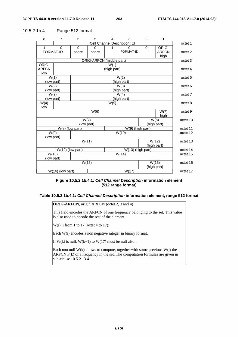
ETSI
ETSI TS 144 018 V11.7.0 (2014-03)2633GPP TS 44.018 version 11.7.0 Release 11
10.5.2.1b.4 Range 512 format
8 7 6 5 4 3 2 1 Cell Channel Description IEI octet 1 1 0 0 0 1 0 0 ORIG- FORMAT-ID spare spare FORMAT-ID ARFCN
high octet 2
ORIG-ARFCN (middle part) octet 3 ORIG- ARFCN
low
W(1) (high part)
octet 4
W(1) (low part)
W(2) (high part)
octet 5
W(2) (low part)
W(3) (high part)
octet 6
W(3) (low part)
W(4) (high part)
octet 7
W(4) low
W(5) octet 8
W(6) W(7) high
octet 9
W(7) (low part)
W(8) (high part)
octet 10
W(8) (low part) W(9) (high part) octet 11 W(9)
(low part) W(10) octet 12
W(11)
W(12) (high part)
octet 13
W(12) (low part) W(13) (high part) octet 14 W(13)
(low part) W(14) octet 15
W(15)
W(16) (high part)
octet 16
W(16) (low part) W(17) octet 17
Figure 10.5.2.1b.4.1: Cell Channel Description information element (512 range format)
Table 10.5.2.1b.4.1: Cell Channel Description information element, range 512 format
ORIG-ARFCN, origin ARFCN (octet 2, 3 and 4)
This field encodes the ARFCN of one frequency belonging to the set. This value is also used to decode the rest of the element.
W(i), i from 1 to 17 (octet 4 to 17):
Each W(i) encodes a non negative integer in binary format.
If W(k) is null, W(k+1) to W(17) must be null also.
Each non null W(k) allows to compute, together with some previous W(i) the ARFCN F(k) of a frequency in the set. The computation formulas are given in sub-clause 10.5.2.13.4.
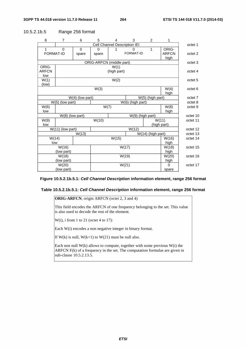
ETSI
ETSI TS 144 018 V11.7.0 (2014-03)2643GPP TS 44.018 version 11.7.0 Release 11
10.5.2.1b.5 Range 256 format
8 7 6 5 4 3 2 1 Cell Channel Description IEI octet 1 1 0 0 0 1 0 1 ORIG- FORMAT-ID spare spare FORMAT-ID ARFCN
high octet 2
ORIG-ARFCN (middle part) octet 3 ORIG- ARFCN
low
W(1) (high part)
octet 4
W(1) (low)
W(2) octet 5
W(3) W(4) high
octet 6
W(4) (low part) W(5) (high part) octet 7 W(5) (low part) W(6) (high part) octet 8
W(6) low
W(7) W(8) high
octet 9
W(8) (low part) W(9) (high part) octet 10 W(9) low
W(10) W(11) (high part)
octet 11
W(11) (low part) W(12) octet 12 W(13) W(14) (high part) octet 13
W(14) low
W(15) W(16) high
octet 14
W(16) (low part)
W(17) W(18) high
octet 15
W(18) (low part)
W(19) W(20) high
octet 16
W(20) (low part)
W(21) 0 spare
octet 17
Figure 10.5.2.1b.5.1: Cell Channel Description information element, range 256 format
Table 10.5.2.1b.5.1: Cell Channel Description information element, range 256 format
ORIG-ARFCN, origin ARFCN (octet 2, 3 and 4)
This field encodes the ARFCN of one frequency belonging to the set. This value is also used to decode the rest of the element.
W(i), i from 1 to 21 (octet 4 to 17):
Each W(i) encodes a non negative integer in binary format.
If W(k) is null, W(k+1) to W(21) must be null also.
Each non null W(k) allows to compute, together with some previous W(i) the ARFCN F(k) of a frequency in the set. The computation formulas are given in sub-clause 10.5.2.13.5.
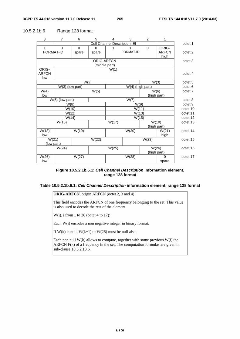
ETSI
ETSI TS 144 018 V11.7.0 (2014-03)2653GPP TS 44.018 version 11.7.0 Release 11
10.5.2.1b.6 Range 128 format
8 7 6 5 4 3 2 1 Cell Channel Description IEI octet 1 1 0 0 0 1 1 0 ORIG- FORMAT-ID spare spare FORMAT-ID ARFCN
high octet 2
ORIG-ARFCN (middle part)
octet 3
ORIG- ARFCN
low
W(1) octet 4
W(2) W(3) octet 5 W(3) (low part) W(4) (high part) octet 6
W(4) low
W(5) W(6) (high part)
octet 7
W(6) (low part) W(7) octet 8 W(8) W(9) octet 9
W(10) W(11) octet 10 W(12) W(13) octet 11 W(14) W(15) octet 12
W(16) W(17) W(18) (high part)
octet 13
W(18) low
W(19) W(20) W(21) high
octet 14
W(21) (low part)
W(22) W(23) octet 15
W(24) W(25) W(26) (high part)
octet 16
W(26) low
W(27) W(28) 0 spare
octet 17
Figure 10.5.2.1b.6.1: Cell Channel Description information element,
range 128 format
Table 10.5.2.1b.6.1: Cell Channel Description information element, range 128 format
ORIG-ARFCN, origin ARFCN (octet 2, 3 and 4)
This field encodes the ARFCN of one frequency belonging to the set. This value is also used to decode the rest of the element.
W(i), i from 1 to 28 (octet 4 to 17):
Each W(i) encodes a non negative integer in binary format.
If W(k) is null, W(k+1) to W(28) must be null also.
Each non null W(k) allows to compute, together with some previous W(i) the ARFCN F(k) of a frequency in the set. The computation formulas are given in sub-clause 10.5.2.13.6.
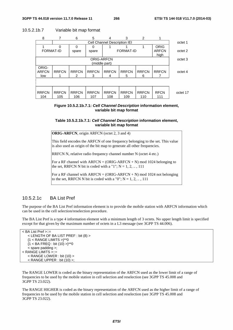
ETSI
ETSI TS 144 018 V11.7.0 (2014-03)2663GPP TS 44.018 version 11.7.0 Release 11
10.5.2.1b.7 Variable bit map format
8 7 6 5 4 3 2 1 Cell Channel Description IEI octet 1
1 0 0 0 1 1 1 ORIG FORMAT-ID spare spare FORMAT-ID ARFCN
high octet 2
ORIG-ARFCN (middle part)
octet 3
ORIG- ARFCN
low
RRFCN
1
RRFCN
2
RRFCN
3
RRFCN
4
RRFCN
5
RRFCN
6
RRFCN
7
octet 4
RRFCN
104
RRFCN
105
RRFCN
106
RRFCN
107
RRFCN
108
RRFCN
109
RRFCN
110
RFCN 111
octet 17
Figure 10.5.2.1b.7.1: Cell Channel Description information element,
variable bit map format
Table 10.5.2.1b.7.1: Cell Channel Description information element, variable bit map format
ORIG-ARFCN, origin ARFCN (octet 2, 3 and 4)
This field encodes the ARFCN of one frequency belonging to the set. This value is also used as origin of the bit map to generate all other frequencies.
RRFCN N, relative radio frequency channel number N (octet 4 etc.)
For a RF channel with ARFCN = (ORIG-ARFCN + N) mod 1024 belonging to the set, RRFCN N bit is coded with a "1"; N = 1, 2, .. , 111
For a RF channel with ARFCN = (ORIG-ARFCN + N) mod 1024 not belonging to the set, RRFCN N bit is coded with a "0"; N = 1, 2, .. , 111
10.5.2.1c BA List Pref
The purpose of the BA List Pref information element is to provide the mobile station with ARFCN information which can be used in the cell selection/reselection procedure.
The BA List Pref is a type 4 information element with a minimum length of 3 octets. No upper length limit is specified except for that given by the maximum number of octets in a L3 message (see 3GPP TS 44.006).
< BA List Pref >::= < LENGTH OF BA LIST PREF : bit (8) > {1 < RANGE LIMITS >}**0 {1 < BA FREQ : bit (10) >}**0 < spare padding >; < RANGE LIMITS >::= < RANGE LOWER : bit (10) > < RANGE UPPER : bit (10) >;
The RANGE LOWER is coded as the binary representation of the ARFCN used as the lower limit of a range of frequencies to be used by the mobile station in cell selection and reselection (see 3GPP TS 45.008 and 3GPP TS 23.022).
The RANGE HIGHER is coded as the binary representation of the ARFCN used as the higher limit of a range of frequencies to be used by the mobile station in cell selection and reselection (see 3GPP TS 45.008 and 3GPP TS 23.022).
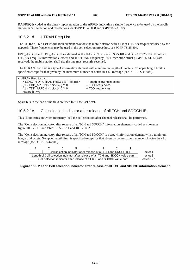
ETSI
ETSI TS 144 018 V11.7.0 (2014-03)2673GPP TS 44.018 version 11.7.0 Release 11
BA FREQ is coded as the binary representation of the ARFCN indicating a single frequency to be used by the mobile station in cell selection and reselection (see 3GPP TS 45.008 and 3GPP TS 23.022).
10.5.2.1d UTRAN Freq List
The UTRAN Freq List information element provides the mobile station with a list of UTRAN frequencies used by the network. These frequencies may be used in the cell selection procedure, see 3GPP TS 25.304.
FDD_ARFCN and TDD_ARFCN are defined as the UARFCN in 3GPP TS 25.101 and 3GPP TS 25.102. If both an UTRAN Freq List information element and an UTRAN Frequency List Description struct (3GPP TS 44.060) are received, the mobile station shall use the one most recently received.
The UTRAN Freq List is a type 4 information element with a minimum length of 3 octets. No upper length limit is specified except for that given by the maximum number of octets in a L3 message (see 3GPP TS 44.006).
< UTRAN Freq List >::= < LENGTH OF UTRAN FREQ LIST : bit (8) > -- length following in octets { 1 < FDD_ARFCN > : bit (14) } ** 0 -- FDD frequencies { 1 < TDD_ARFCN > : bit (14) } ** 0 -- TDD frequencies <spare bit>**;
Spare bits in the end of the field are used to fill the last octet.
10.5.2.1e Cell selection indicator after release of all TCH and SDCCH IE
This IE indicates on which frequency /cell the cell selection after channel release shall be performed.
The "Cell selection indicator after release of all TCH and SDCCH" information element is coded as shown in figure 10.5.2.1e.1 and tables 10.5.2.1e.1 and 10.5.2.1e.2.
The "Cell selection indicator after release of all TCH and SDCCH" is a type 4 information element with a minimum length of 4 octets. No upper length limit is specified except for that given by the maximum number of octets in a L3 message (see 3GPP TS 44.006).
8 7 6 5 4 3 2 1 Cell selection indicator after release of all TCH and SDCCH IEI octet 1
Length of Cell selection indicator after release of all TCH and SDCCH value part octet 2 Cell selection indicator after release of all TCH and SDCCH value part octet 3 - n
Figure 10.5.2.1e.1: Cell selection indicator after release of all TCH and SDCCH information element
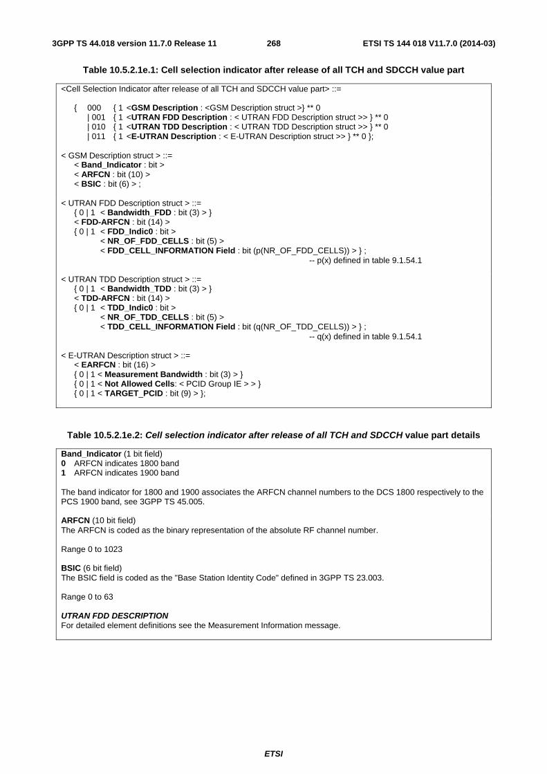
ETSI
ETSI TS 144 018 V11.7.0 (2014-03)2683GPP TS 44.018 version 11.7.0 Release 11
Table 10.5.2.1e.1: Cell selection indicator after release of all TCH and SDCCH value part
<Cell Selection Indicator after release of all TCH and SDCCH value part> ::= { 000 { 1 <GSM Description : <GSM Description struct >} ** 0 | 001 { 1 <UTRAN FDD Description : < UTRAN FDD Description struct >> } ** 0 | 010 { 1 <UTRAN TDD Description : < UTRAN TDD Description struct >> } ** 0 | 011 { 1 <E-UTRAN Description : < E-UTRAN Description struct >> } ** 0 }; < GSM Description struct > ::= < Band_Indicator : bit > < ARFCN : bit (10) > < BSIC : bit (6) > ; < UTRAN FDD Description struct > ::= { 0 | 1 < Bandwidth_FDD : bit (3) > } < FDD-ARFCN : bit (14) > { 0 | 1 < FDD_Indic0 : bit > < NR_OF_FDD_CELLS : bit (5) > < FDD_CELL_INFORMATION Field : bit (p(NR_OF_FDD_CELLS)) > } ; -- p(x) defined in table 9.1.54.1 < UTRAN TDD Description struct > ::= { 0 | 1 < Bandwidth_TDD : bit (3) > } < TDD-ARFCN : bit (14) > { 0 | 1 < TDD_Indic0 : bit > < NR_OF_TDD_CELLS : bit (5) > < TDD_CELL_INFORMATION Field : bit (q(NR_OF_TDD_CELLS)) > } ; -- q(x) defined in table 9.1.54.1 < E-UTRAN Description struct > ::= < EARFCN : bit (16) > { 0 | 1 < Measurement Bandwidth : bit (3) > } { 0 | 1 < Not Allowed Cells: < PCID Group IE > > } { 0 | 1 < TARGET_PCID : bit (9) > };
Table 10.5.2.1e.2: Cell selection indicator after release of all TCH and SDCCH value part details
Band_Indicator (1 bit field) 0 ARFCN indicates 1800 band 1 ARFCN indicates 1900 band The band indicator for 1800 and 1900 associates the ARFCN channel numbers to the DCS 1800 respectively to the PCS 1900 band, see 3GPP TS 45.005. ARFCN (10 bit field) The ARFCN is coded as the binary representation of the absolute RF channel number. Range 0 to 1023 BSIC (6 bit field) The BSIC field is coded as the "Base Station Identity Code" defined in 3GPP TS 23.003. Range 0 to 63 UTRAN FDD DESCRIPTION For detailed element definitions see the Measurement Information message.
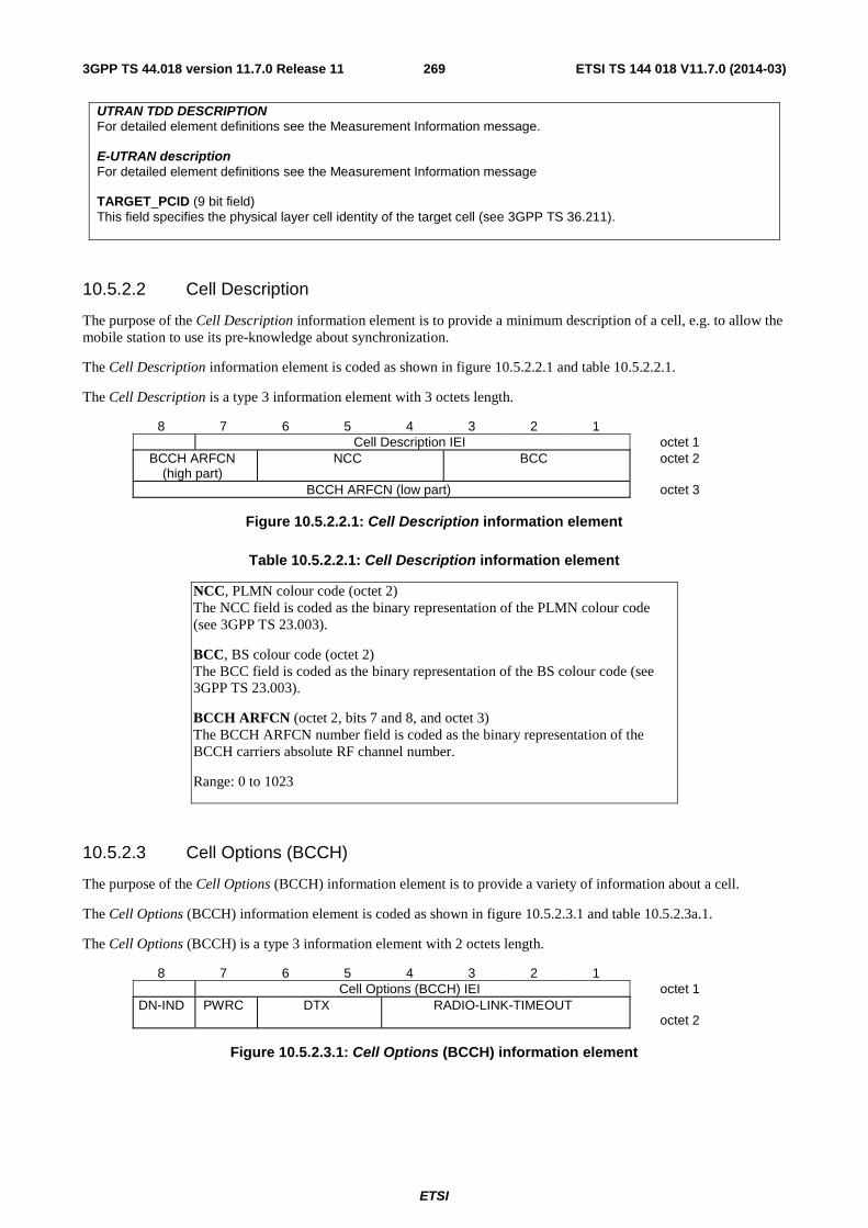
ETSI
ETSI TS 144 018 V11.7.0 (2014-03)2693GPP TS 44.018 version 11.7.0 Release 11
UTRAN TDD DESCRIPTION For detailed element definitions see the Measurement Information message. E-UTRAN description For detailed element definitions see the Measurement Information message TARGET_PCID (9 bit field) This field specifies the physical layer cell identity of the target cell (see 3GPP TS 36.211).
10.5.2.2 Cell Description
The purpose of the Cell Description information element is to provide a minimum description of a cell, e.g. to allow the mobile station to use its pre-knowledge about synchronization.
The Cell Description information element is coded as shown in figure 10.5.2.2.1 and table 10.5.2.2.1.
The Cell Description is a type 3 information element with 3 octets length.
8 7 6 5 4 3 2 1 Cell Description IEI octet 1
BCCH ARFCN (high part)
NCC BCC octet 2
BCCH ARFCN (low part) octet 3
Figure 10.5.2.2.1: Cell Description information element
Table 10.5.2.2.1: Cell Description information element
NCC, PLMN colour code (octet 2) The NCC field is coded as the binary representation of the PLMN colour code (see 3GPP TS 23.003).
BCC, BS colour code (octet 2) The BCC field is coded as the binary representation of the BS colour code (see 3GPP TS 23.003).
BCCH ARFCN (octet 2, bits 7 and 8, and octet 3) The BCCH ARFCN number field is coded as the binary representation of the BCCH carriers absolute RF channel number.
Range: 0 to 1023
10.5.2.3 Cell Options (BCCH)
The purpose of the Cell Options (BCCH) information element is to provide a variety of information about a cell.
The Cell Options (BCCH) information element is coded as shown in figure 10.5.2.3.1 and table 10.5.2.3a.1.
The Cell Options (BCCH) is a type 3 information element with 2 octets length.
8 7 6 5 4 3 2 1 Cell Options (BCCH) IEI octet 1
DN-IND PWRC DTX RADIO-LINK-TIMEOUT octet 2
Figure 10.5.2.3.1: Cell Options (BCCH) information element
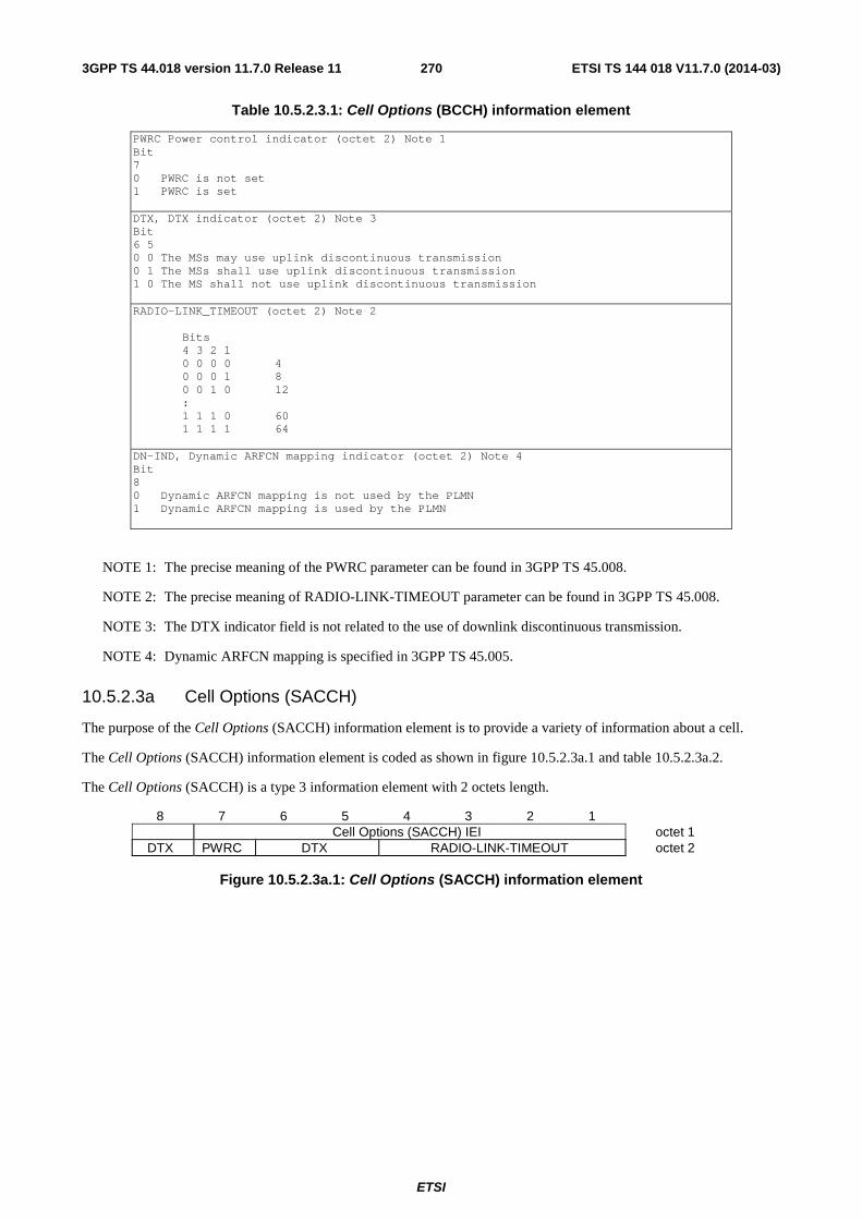
ETSI
ETSI TS 144 018 V11.7.0 (2014-03)2703GPP TS 44.018 version 11.7.0 Release 11
Table 10.5.2.3.1: Cell Options (BCCH) information element
PWRC Power control indicator (octet 2) Note 1 Bit 7 0 PWRC is not set 1 PWRC is set DTX, DTX indicator (octet 2) Note 3 Bit 6 5 0 0 The MSs may use uplink discontinuous transmission 0 1 The MSs shall use uplink discontinuous transmission 1 0 The MS shall not use uplink discontinuous transmission RADIO-LINK_TIMEOUT (octet 2) Note 2
Bits 4 3 2 1 0 0 0 0 4 0 0 0 1 8 0 0 1 0 12 : 1 1 1 0 60 1 1 1 1 64
DN-IND, Dynamic ARFCN mapping indicator (octet 2) Note 4 Bit 8 0 Dynamic ARFCN mapping is not used by the PLMN 1 Dynamic ARFCN mapping is used by the PLMN
NOTE 1: The precise meaning of the PWRC parameter can be found in 3GPP TS 45.008.
NOTE 2: The precise meaning of RADIO-LINK-TIMEOUT parameter can be found in 3GPP TS 45.008.
NOTE 3: The DTX indicator field is not related to the use of downlink discontinuous transmission.
NOTE 4: Dynamic ARFCN mapping is specified in 3GPP TS 45.005.
10.5.2.3a Cell Options (SACCH)
The purpose of the Cell Options (SACCH) information element is to provide a variety of information about a cell.
The Cell Options (SACCH) information element is coded as shown in figure 10.5.2.3a.1 and table 10.5.2.3a.2.
The Cell Options (SACCH) is a type 3 information element with 2 octets length.
8 7 6 5 4 3 2 1 Cell Options (SACCH) IEI octet 1
DTX PWRC DTX RADIO-LINK-TIMEOUT octet 2
Figure 10.5.2.3a.1: Cell Options (SACCH) information element
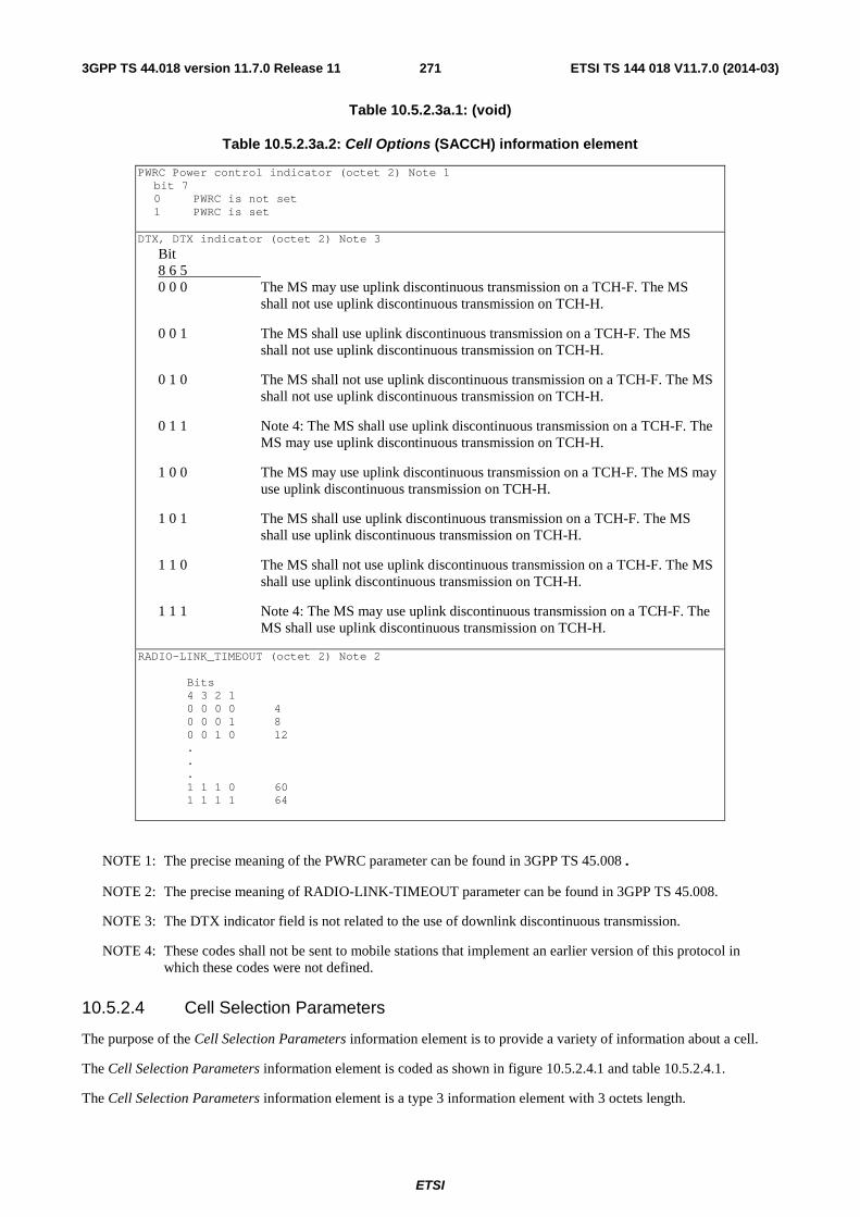
ETSI
ETSI TS 144 018 V11.7.0 (2014-03)2713GPP TS 44.018 version 11.7.0 Release 11
Table 10.5.2.3a.1: (void)
Table 10.5.2.3a.2: Cell Options (SACCH) information element
PWRC Power control indicator (octet 2) Note 1 bit 7 0 PWRC is not set 1 PWRC is set
DTX, DTX indicator (octet 2) Note 3
Bit 8 6 5 0 0 0 The MS may use uplink discontinuous transmission on a TCH-F. The MS
shall not use uplink discontinuous transmission on TCH-H.
0 0 1 The MS shall use uplink discontinuous transmission on a TCH-F. The MS shall not use uplink discontinuous transmission on TCH-H.
0 1 0 The MS shall not use uplink discontinuous transmission on a TCH-F. The MS shall not use uplink discontinuous transmission on TCH-H.
0 1 1 Note 4: The MS shall use uplink discontinuous transmission on a TCH-F. The MS may use uplink discontinuous transmission on TCH-H.
1 0 0 The MS may use uplink discontinuous transmission on a TCH-F. The MS may use uplink discontinuous transmission on TCH-H.
1 0 1 The MS shall use uplink discontinuous transmission on a TCH-F. The MS shall use uplink discontinuous transmission on TCH-H.
1 1 0 The MS shall not use uplink discontinuous transmission on a TCH-F. The MS shall use uplink discontinuous transmission on TCH-H.
1 1 1 Note 4: The MS may use uplink discontinuous transmission on a TCH-F. The MS shall use uplink discontinuous transmission on TCH-H.
RADIO-LINK_TIMEOUT (octet 2) Note 2
Bits 4 3 2 1 0 0 0 0 4 0 0 0 1 8 0 0 1 0 12 . . . 1 1 1 0 60 1 1 1 1 64
NOTE 1: The precise meaning of the PWRC parameter can be found in 3GPP TS 45.008.
NOTE 2: The precise meaning of RADIO-LINK-TIMEOUT parameter can be found in 3GPP TS 45.008.
NOTE 3: The DTX indicator field is not related to the use of downlink discontinuous transmission.
NOTE 4: These codes shall not be sent to mobile stations that implement an earlier version of this protocol in which these codes were not defined.
10.5.2.4 Cell Selection Parameters
The purpose of the Cell Selection Parameters information element is to provide a variety of information about a cell.
The Cell Selection Parameters information element is coded as shown in figure 10.5.2.4.1 and table 10.5.2.4.1.
The Cell Selection Parameters information element is a type 3 information element with 3 octets length.

ETSI
ETSI TS 144 018 V11.7.0 (2014-03)2723GPP TS 44.018 version 11.7.0 Release 11
8 7 6 5 4 3 2 1 Cell Selection Parameters IEI octet 1
CELL-RESELECT HYSTERESIS
MS-TXPWR-MAX-CCH octet 2
ACS NECI RXLEV-ACCESS-MIN octet 3
Figure 10.5.2.4.1: Cell Selection Parameters information element
Table 10.5.2.4.1: Cell Selection Parameters information element
CELL-RESELECT-HYSTERESIS (octet 2)
The usage of this information is defined in 3GPP TS 45.008
Bits 8 7 6
0 0 0 0 dB RXLEV hysteresis for LA re-selection 0 0 1 2 dB RXLEV hysteresis for LA re-selection 0 1 0 4 dB RXLEV hysteresis for LA re-selection 0 1 1 6 dB RXLEV hysteresis for LA re-selection 1 0 0 8 dB RXLEV hysteresis for LA re-selection 1 0 1 10 dB RXLEV hysteresis for LA re-selection 1 1 0 12 dB RXLEV hysteresis for LA re-selection 1 1 1 14 dB RXLEV hysteresis for LA re-selection
MS-TXPWR-MAX-CCH (octet 2)
The MS-TXPWR-MAX-CCH field is coded as the binary representation of the "power control level" in 3GPP TS 45.005 corresponding to the maximum TX power level an MS may use when accessing on a Control Channel CCH. This value shall be used by the Mobile Station according to 3GPP TS 45.008.
Range: 0 to 31.
RXLEV-ACCESS-MIN (octet 3)
The RXLEV-ACCESS-MIN field is coded as the binary representation of the minimum received signal level at the MS for which it is permitted to access the system.
Range: 0 to 63. (See 3GPP TS 45.008).
ACS, ADDITIONAL RESELECT PARAM IND (octet 3)
Bit 8:
In System Information type 3 message:
0 System information type 16 and 17 are not broadcast on the BCCH.
1 System information type 16 and 17 are broadcast on the BCCH. A mobile station which does not support System information type 16 and 17 may consider this bit as "0".
In System Information type 4 message:
0 The SI 4 rest octets, if present, and SI 7 and SI 8 rest octets, if so indicated in the SI 4 rest octets shall be used to derive the value of PI and possibly C2 parameters and/or other parameters
1 The value of PI and possibly C2 parameters and/or other parameters in a System information type 7 or type 8 message shall be used
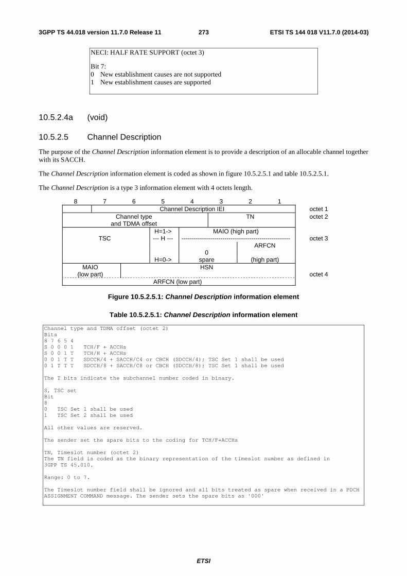
ETSI
ETSI TS 144 018 V11.7.0 (2014-03)2733GPP TS 44.018 version 11.7.0 Release 11
NECI: HALF RATE SUPPORT (octet 3)
Bit 7: 0 New establishment causes are not supported 1 New establishment causes are supported
10.5.2.4a (void)
10.5.2.5 Channel Description
The purpose of the Channel Description information element is to provide a description of an allocable channel together with its SACCH.
The Channel Description information element is coded as shown in figure 10.5.2.5.1 and table 10.5.2.5.1.
The Channel Description is a type 3 information element with 4 octets length.
8 7 6 5 4 3 2 1 Channel Description IEI octet 1
Channel type and TDMA offset
TN octet 2
H=1-> MAIO (high part) TSC --- H --- ----------------------------------------------------- octet 3
ARFCN 0 H=0-> spare (high part)
MAIO (low part)
HSN octet 4
ARFCN (low part)
Figure 10.5.2.5.1: Channel Description information element
Table 10.5.2.5.1: Channel Description information element
Channel type and TDMA offset (octet 2) Bits 8 7 6 5 4 S 0 0 0 1 TCH/F + ACCHs S 0 0 1 T TCH/H + ACCHs 0 0 1 T T SDCCH/4 + SACCH/C4 or CBCH (SDCCH/4); TSC Set 1 shall be used 0 1 T T T SDCCH/8 + SACCH/C8 or CBCH (SDCCH/8); TSC Set 1 shall be used The T bits indicate the subchannel number coded in binary. S, TSC set Bit 8 0 TSC Set 1 shall be used 1 TSC Set 2 shall be used All other values are reserved. The sender set the spare bits to the coding for TCH/F+ACCHs TN, Timeslot number (octet 2) The TN field is coded as the binary representation of the timeslot number as defined in 3GPP TS 45.010. Range: 0 to 7. The Timeslot number field shall be ignored and all bits treated as spare when received in a PDCH ASSIGNMENT COMMAND message. The sender sets the spare bits as '000'
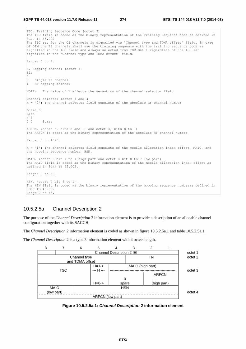
ETSI
ETSI TS 144 018 V11.7.0 (2014-03)2743GPP TS 44.018 version 11.7.0 Release 11
TSC, Training Sequence Code (octet 3) The TSC field is coded as the binary representation of the Training Sequence code as defined in 3GPP TS 45.002 The TSC set for the CS channels is signalled via "Channel type and TDMA offset" field. In case of DTM the PS channels shall use the training sequence with the training sequence code as signalled in the TSC field and always selected from TSC Set 1 regardless of the TSC set signalled in the 'Channel type and TDMA offset' field. Range: 0 to 7. H, Hopping channel (octet 3) Bit 5 0 Single RF channel 1 RF hopping channel NOTE: The value of H affects the semantics of the channel selector field Channel selector (octet 3 and 4) H = "0": The channel selector field consists of the absolute RF channel number Octet 3 Bits 4 3 0 0 Spare ARFCN, (octet 3, bits 2 and 1, and octet 4, bits 8 to 1) The ARFCN is coded as the binary representation of the absolute RF channel number Range: 0 to 1023 H = "1": The channel selector field consists of the mobile allocation index offset, MAIO, and the hopping sequence number, HSN. MAIO, (octet 3 bit 4 to 1 high part and octet 4 bit 8 to 7 low part) The MAIO field is coded as the binary representation of the mobile allocation index offset as defined in 3GPP TS 45.002. Range: 0 to 63. HSN, (octet 4 bit 6 to 1) The HSN field is coded as the binary representation of the hopping sequence numberas defined in 3GPP TS 45.002 Range 0 to 63.
10.5.2.5a Channel Description 2
The purpose of the Channel Description 2 information element is to provide a description of an allocable channel configuration together with its SACCH.
The Channel Description 2 information element is coded as shown in figure 10.5.2.5a.1 and table 10.5.2.5a.1.
The Channel Description 2 is a type 3 information element with 4 octets length.
8 7 6 5 4 3 2 1 Channel Description 2 IEI octet 1
Channel type and TDMA offset
TN octet 2
H=1-> MAIO (high part) TSC --- H --- ----------------------------------------------------- octet 3
ARFCN 0 H=0-> spare (high part)
MAIO (low part)
HSN octet 4
ARFCN (low part)
Figure 10.5.2.5a.1: Channel Description 2 information element
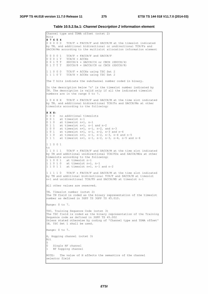
ETSI
ETSI TS 144 018 V11.7.0 (2014-03)2753GPP TS 44.018 version 11.7.0 Release 11
Table 10.5.2.5a.1: Channel Description 2 information element
Channel type and TDMA offset (octet 2) Bits 8 7 6 5 4 0 0 0 0 0 TCH/F + FACCH/F and SACCH/M at the timeslot indicated by TN, and additional bidirectional or undirectional TCH/Fs and SACCH/Ms according to the multislot allocation information element 0 0 0 0 1 TCH/F + FACCH/F and SACCH/F 0 0 0 1 T TCH/H + ACCHs 0 0 1 T T SDCCH/4 + SACCH/C4 or CBCH (SDCCH/4) 0 1 T T T SDCCH/8 + SACCH/C8 or CBCH (SDCCH/8) 1 1 0 0 0 TCH/F + ACCHs using TSC Set 2 1 1 1 0 T TCH/H + ACCHs using TSC Set 2 The T bits indicate the subchannel number coded in binary. In the description below "n" is the timeslot number indicated by TN. The description is valid only if all the indicated timeslot numbers are in the range 0 to 7. 1 0 X X X TCH/F + FACCH/F and SACCH/M at the time slot indicated by TN, and additional bidirectional TCH/Fs and SACCH/Ms at other timeslots according to the following: X X X: 0 0 0 no additional timeslots 0 0 1 at timeslot n-1 0 1 0 at timeslot n+1, n-1 0 1 1 at timeslot n+1, n-1 and n-2 1 0 0 at timeslot n+1, n-1, n-2, and n-3 1 0 1 at timeslot n+1, n-1, n-2, n-3 and n-4 1 1 0 at timeslot n+1, n-1, n-2, n-3, n-4 and n-5 1 1 1 at timeslot n+1, n-1, n-2, n-3, n-4, n-5 and n-6 1 1 0 0 1 to 1 1 0 1 1 TCH/F + FACCH/F and SACCH/M at the time slot indicated by TN and additional unidirectional TCH/FDs and SACCH/MDs at other timeslots according to the following: 1 1 0 0 1 at timeslot n-1 1 1 0 1 0 at timeslot n+1, n-1 1 1 0 1 1 at timeslot n+1, n-1 and n-2 1 1 1 1 0 TCH/F + FACCH/F and SACCH/M at the time slot indicated by TN and additional bidirectional TCH/F and SACCH/M at timeslot n+1 and unidirectional TCH/FD and SACCH/MD at timeslot n-1 All other values are reserved. TN, Timeslot number (octet 2) The TN field is coded as the binary representation of the timeslot number as defined in 3GPP TS 3GPP TS 45.010. Range: 0 to 7. TSC, Training Sequence Code (octet 3) The TSC field is coded as the binary representation of the Training Sequence code as defined in 3GPP TS 45.002 Unless stated otherwise by coding of "Channel type and TDMA offset" IE, TSC Set 1 shall be used. Range: 0 to 7. H, Hopping channel (octet 3) Bit 5 0 Single RF channel 1 RF hopping channel NOTE: The value of H affects the semantics of the channel selector field
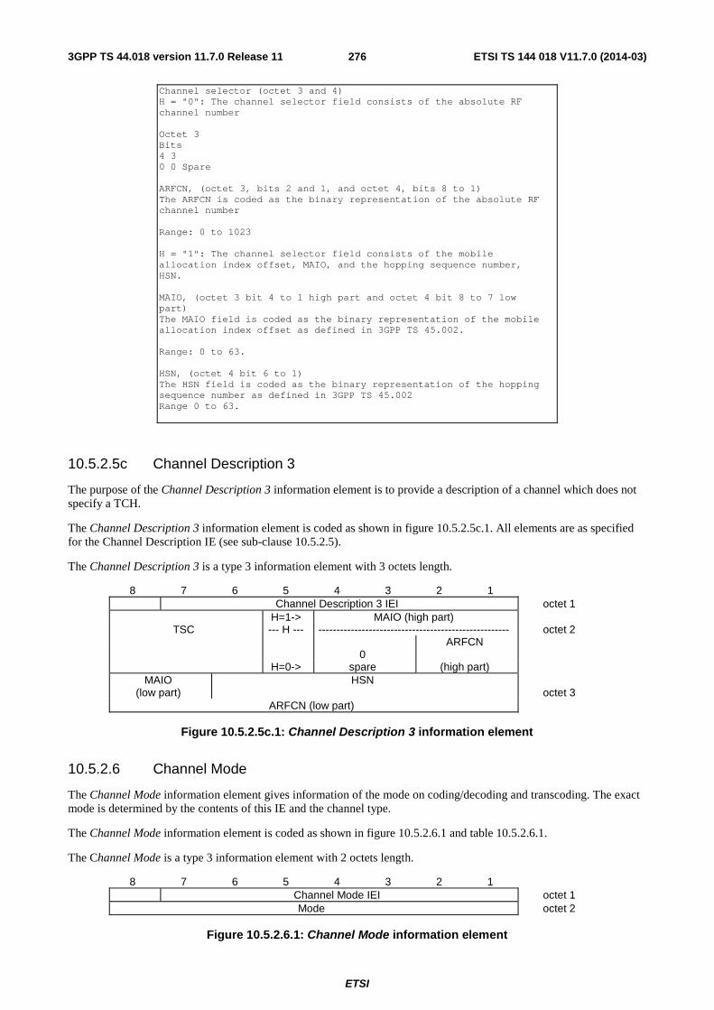
ETSI
ETSI TS 144 018 V11.7.0 (2014-03)2763GPP TS 44.018 version 11.7.0 Release 11
Channel selector (octet 3 and 4) H = "0": The channel selector field consists of the absolute RF channel number Octet 3 Bits 4 3 0 0 Spare ARFCN, (octet 3, bits 2 and 1, and octet 4, bits 8 to 1) The ARFCN is coded as the binary representation of the absolute RF channel number Range: 0 to 1023 H = "1": The channel selector field consists of the mobile allocation index offset, MAIO, and the hopping sequence number, HSN. MAIO, (octet 3 bit 4 to 1 high part and octet 4 bit 8 to 7 low part) The MAIO field is coded as the binary representation of the mobile allocation index offset as defined in 3GPP TS 45.002. Range: 0 to 63. HSN, (octet 4 bit 6 to 1) The HSN field is coded as the binary representation of the hopping sequence number as defined in 3GPP TS 45.002 Range 0 to 63.
10.5.2.5c Channel Description 3
The purpose of the Channel Description 3 information element is to provide a description of a channel which does not specify a TCH.
The Channel Description 3 information element is coded as shown in figure 10.5.2.5c.1. All elements are as specified for the Channel Description IE (see sub-clause 10.5.2.5).
The Channel Description 3 is a type 3 information element with 3 octets length.
8 7 6 5 4 3 2 1 Channel Description 3 IEI octet 1
H=1-> MAIO (high part) TSC --- H --- ----------------------------------------------------- octet 2
ARFCN 0 H=0-> spare (high part)
MAIO (low part)
HSN octet 3
ARFCN (low part)
Figure 10.5.2.5c.1: Channel Description 3 information element
10.5.2.6 Channel Mode
The Channel Mode information element gives information of the mode on coding/decoding and transcoding. The exact mode is determined by the contents of this IE and the channel type.
The Channel Mode information element is coded as shown in figure 10.5.2.6.1 and table 10.5.2.6.1.
The Channel Mode is a type 3 information element with 2 octets length.
8 7 6 5 4 3 2 1 Channel Mode IEI octet 1
Mode octet 2
Figure 10.5.2.6.1: Channel Mode information element

ETSI
ETSI TS 144 018 V11.7.0 (2014-03)2773GPP TS 44.018 version 11.7.0 Release 11
Table 10.5.2.6.1: Channel Mode information element
The mode field is encoded as follows: (octet 2) Bits 8 7 6 5 4 3 2 1 0 0 0 0 0 0 0 0 signalling only 0 0 0 0 0 0 0 1 speech full rate or half rate version 1 1 1 0 0 0 0 0 1 speech full rate or half rate version 1 in VAMOS mode (Note 3) 0 0 1 0 0 0 0 1 speech full rate or half rate version 2 1 1 0 0 0 0 1 0 speech full rate or half rate version 2 in VAMOS mode (Note 3) 0 1 0 0 0 0 0 1 speech full rate or half rate version 3 1 1 0 0 0 0 1 1 speech full rate or half rate version 3 in VAMOS mode (Note 3) 1 0 0 0 0 0 0 1 speech full rate or half rate version 4 1 0 0 0 0 0 1 0 speech full rate or half rate version 5 1 1 0 0 0 1 0 1 speech full rate or half rate version 5 in VAMOS mode (Note 3) 1 0 0 0 0 0 1 1 speech full rate or half rate version 6 0 1 1 0 0 0 0 1 data, 43.5 kbit/s (downlink)+14.5 kbps (uplink) 0 1 1 0 0 0 1 0 data, 29.0 kbit/s (downlink)+14.5 kbps (uplink) 0 1 1 0 0 1 0 0 data, 43.5 kbit/s (downlink)+29.0 kbps (uplink) 0 1 1 0 0 1 1 1 data, 14.5 kbit/s (downlink)+43.5 kbps (uplink) 0 1 1 0 0 1 0 1 data, 14.5 kbit/s (downlink)+29.0 kbps (uplink) 0 1 1 0 0 1 1 0 data, 29.0 kbit/s (downlink)+43.5 kbps (uplink) 0 0 1 0 0 1 1 1 data, 43.5 kbit/s radio interface rate 0 1 1 0 0 0 1 1 data, 32.0 kbit/s radio interface rate 0 1 0 0 0 0 1 1 data, 29.0 kbit/s radio interface rate 0 0 0 0 1 1 1 1 data, 14.5 kbit/s radio interface rate 0 0 0 0 0 0 1 1 data, 12.0 kbit/s radio interface rate 0 0 0 0 1 0 1 1 data, 6.0 kbit/s radio interface rate 0 0 0 1 0 0 1 1 data, 3.6 kbit/s radio interface rate 0 0 0 1 0 0 0 0 data, 64.0 kbit/s Transparent Data Bearer (Note 2) Other values are reserved for future use. Note 1: The speech versions are also referred as follows (see 3GPP TS 26.103): full rate or half rate version 1: GSM FR or GSM HR full rate or half rate version 2: GSM EFR (half rate version 2 not defined in this version of
the protocol) full rate or half rate version 3: FR AMR or HR AMR full rate or half rate version 4: OFR AMR-WB or OHR AMR-WB full rate or half rate version 5: FR AMR-WB (half rate version 5 not defined in this version of
the protocol) full rate or half rate version 6: OHR AMR (full rate version 6 not defined in this version of
the protocol)
Note 2: This code point is only used for channel assignments made in GAN mode.
Note 3: This code point is only used for a mobile station that indicates support for VAMOS-II (see 3GPP TS 24.008).
10.5.2.7 Channel Mode 2
The Channel Mode 2 information element gives information of the mode of coding/decoding and transcoding.
The Channel Mode 2 information element is coded as shown in figure 10.5.2.7.1 and table 10.5.2.7.1.
The Channel Mode 2 is a type 3 information element with 2 octets length.
8 7 6 5 4 3 2 1 Channel Mode IEI octet 1
Mode octet 2
Figure 10.5.2.7.1: Channel Mode 2 information element
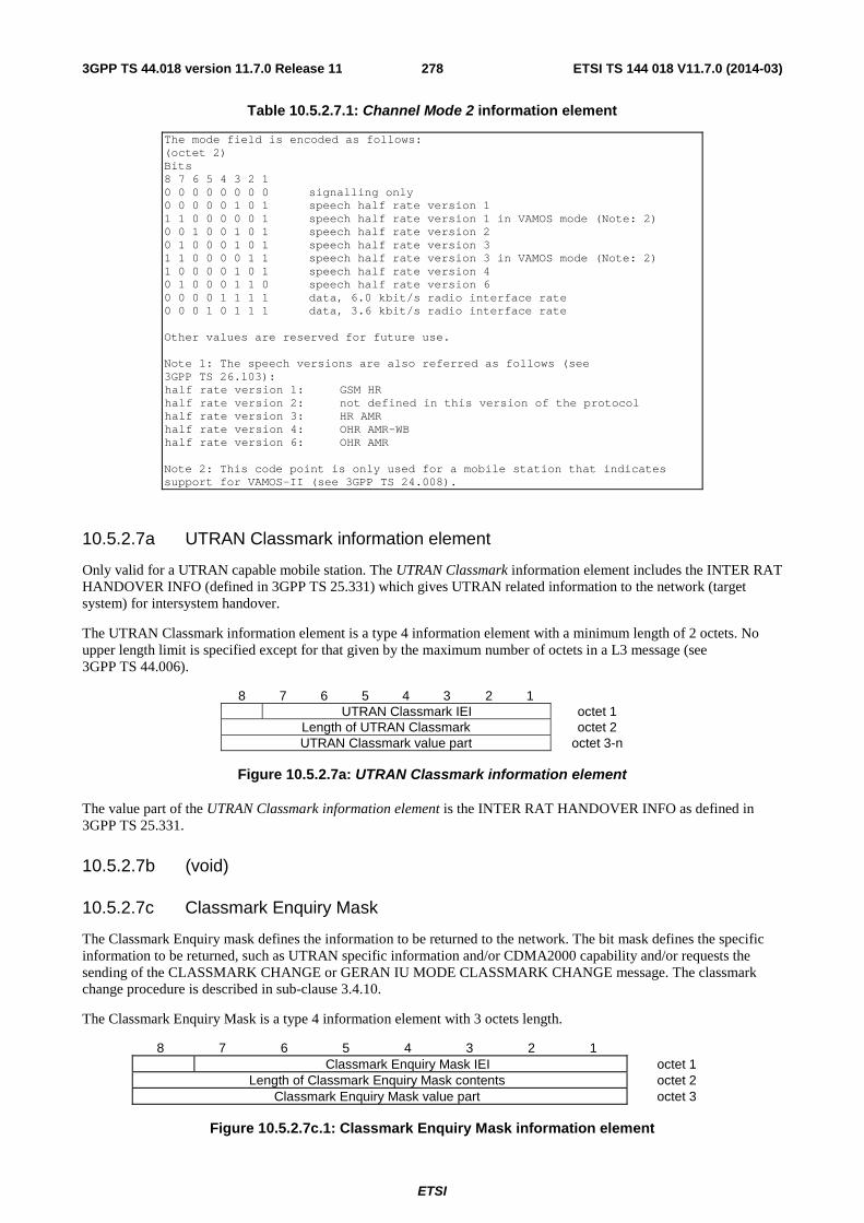
ETSI
ETSI TS 144 018 V11.7.0 (2014-03)2783GPP TS 44.018 version 11.7.0 Release 11
Table 10.5.2.7.1: Channel Mode 2 information element
The mode field is encoded as follows: (octet 2) Bits 8 7 6 5 4 3 2 1 0 0 0 0 0 0 0 0 signalling only 0 0 0 0 0 1 0 1 speech half rate version 1 1 1 0 0 0 0 0 1 speech half rate version 1 in VAMOS mode (Note: 2) 0 0 1 0 0 1 0 1 speech half rate version 2 0 1 0 0 0 1 0 1 speech half rate version 3 1 1 0 0 0 0 1 1 speech half rate version 3 in VAMOS mode (Note: 2) 1 0 0 0 0 1 0 1 speech half rate version 4 0 1 0 0 0 1 1 0 speech half rate version 6 0 0 0 0 1 1 1 1 data, 6.0 kbit/s radio interface rate 0 0 0 1 0 1 1 1 data, 3.6 kbit/s radio interface rate Other values are reserved for future use. Note 1: The speech versions are also referred as follows (see 3GPP TS 26.103): half rate version 1: GSM HR half rate version 2: not defined in this version of the protocol half rate version 3: HR AMR half rate version 4: OHR AMR-WB half rate version 6: OHR AMR Note 2: This code point is only used for a mobile station that indicates support for VAMOS-II (see 3GPP TS 24.008).
10.5.2.7a UTRAN Classmark information element
Only valid for a UTRAN capable mobile station. The UTRAN Classmark information element includes the INTER RAT HANDOVER INFO (defined in 3GPP TS 25.331) which gives UTRAN related information to the network (target system) for intersystem handover.
The UTRAN Classmark information element is a type 4 information element with a minimum length of 2 octets. No upper length limit is specified except for that given by the maximum number of octets in a L3 message (see 3GPP TS 44.006).
8 7 6 5 4 3 2 1 UTRAN Classmark IEI octet 1
Length of UTRAN Classmark octet 2 UTRAN Classmark value part octet 3-n
Figure 10.5.2.7a: UTRAN Classmark information element
The value part of the UTRAN Classmark information element is the INTER RAT HANDOVER INFO as defined in 3GPP TS 25.331.
10.5.2.7b (void)
10.5.2.7c Classmark Enquiry Mask
The Classmark Enquiry mask defines the information to be returned to the network. The bit mask defines the specific information to be returned, such as UTRAN specific information and/or CDMA2000 capability and/or requests the sending of the CLASSMARK CHANGE or GERAN IU MODE CLASSMARK CHANGE message. The classmark change procedure is described in sub-clause 3.4.10.
The Classmark Enquiry Mask is a type 4 information element with 3 octets length.
8 7 6 5 4 3 2 1 Classmark Enquiry Mask IEI octet 1
Length of Classmark Enquiry Mask contents octet 2 Classmark Enquiry Mask value part octet 3
Figure 10.5.2.7c.1: Classmark Enquiry Mask information element
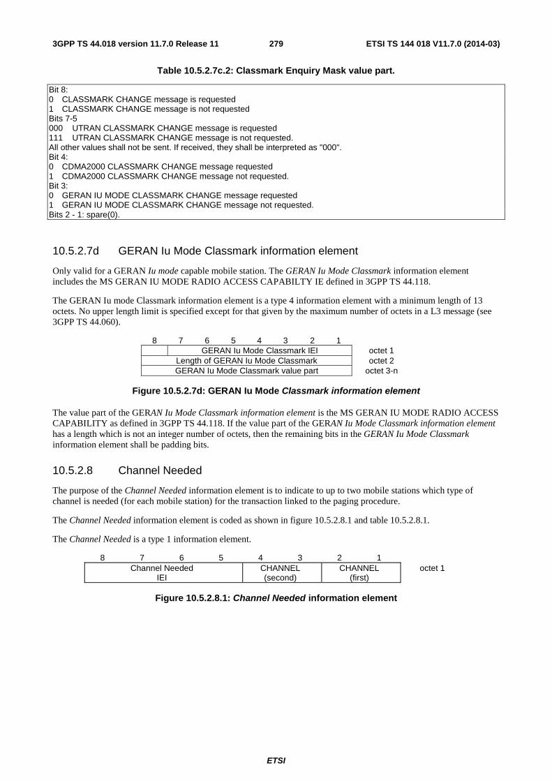
ETSI
ETSI TS 144 018 V11.7.0 (2014-03)2793GPP TS 44.018 version 11.7.0 Release 11
Table 10.5.2.7c.2: Classmark Enquiry Mask value part.
Bit 8: 0 CLASSMARK CHANGE message is requested 1 CLASSMARK CHANGE message is not requested Bits 7-5 000 UTRAN CLASSMARK CHANGE message is requested 111 UTRAN CLASSMARK CHANGE message is not requested. All other values shall not be sent. If received, they shall be interpreted as "000". Bit 4: 0 CDMA2000 CLASSMARK CHANGE message requested 1 CDMA2000 CLASSMARK CHANGE message not requested. Bit 3: 0 GERAN IU MODE CLASSMARK CHANGE message requested 1 GERAN IU MODE CLASSMARK CHANGE message not requested. Bits 2 - 1: spare(0).
10.5.2.7d GERAN Iu Mode Classmark information element
Only valid for a GERAN Iu mode capable mobile station. The GERAN Iu Mode Classmark information element includes the MS GERAN IU MODE RADIO ACCESS CAPABILTY IE defined in 3GPP TS 44.118.
The GERAN Iu mode Classmark information element is a type 4 information element with a minimum length of 13 octets. No upper length limit is specified except for that given by the maximum number of octets in a L3 message (see 3GPP TS 44.060).
8 7 6 5 4 3 2 1 GERAN Iu Mode Classmark IEI octet 1
Length of GERAN Iu Mode Classmark octet 2 GERAN Iu Mode Classmark value part octet 3-n
Figure 10.5.2.7d: GERAN Iu Mode Classmark information element
The value part of the GERAN Iu Mode Classmark information element is the MS GERAN IU MODE RADIO ACCESS CAPABILITY as defined in 3GPP TS 44.118. If the value part of the GERAN Iu Mode Classmark information element has a length which is not an integer number of octets, then the remaining bits in the GERAN Iu Mode Classmark information element shall be padding bits.
10.5.2.8 Channel Needed
The purpose of the Channel Needed information element is to indicate to up to two mobile stations which type of channel is needed (for each mobile station) for the transaction linked to the paging procedure.
The Channel Needed information element is coded as shown in figure 10.5.2.8.1 and table 10.5.2.8.1.
The Channel Needed is a type 1 information element.
8 7 6 5 4 3 2 1 Channel Needed
IEI CHANNEL (second)
CHANNEL (first)
octet 1
Figure 10.5.2.8.1: Channel Needed information element

ETSI
ETSI TS 144 018 V11.7.0 (2014-03)2803GPP TS 44.018 version 11.7.0 Release 11
Table 10.5.2.8.1: Channel Needed information element
CHANNEL (octet 1) Bits 2/4 1/3 0 0 Any channel. 0 1 SDCCH. 1 0 TCH/F (Full rate). 1 1 TCH/H or TCH/F (Dual rate). If this information element is used for only one mobile station, then the first CHANNEL field is used and the second CHANNEL field is spare.
10.5.2.8a (void)
10.5.2.8b Channel Request Description 2
The purpose of the Channel Request Description 2 information element is to indicate to the network the reason of the request to enter dual transfer mode and MS capabilities relevant to DTM.
The Channel Request Description 2 information element is coded as shown in figure 10.5.2.8b.1 and tables 10.5.2.8b.1 and 10.5.2.8b.2.
The Channel Request Description 2 information element is a type 4 information element with a minimum length of 6 octets. The maximum length of this information element is resulting from the encoding of the value part as specified below.
8 7 6 5 4 3 2 1 Channel Request Description 2 IEI octet 1
Length of Channel Request Description 2 value part octet 2 Channel Request Description 2 value part octet 3 - n
Figure 10.5.2.8b.1: Channel Request Description 2 information element
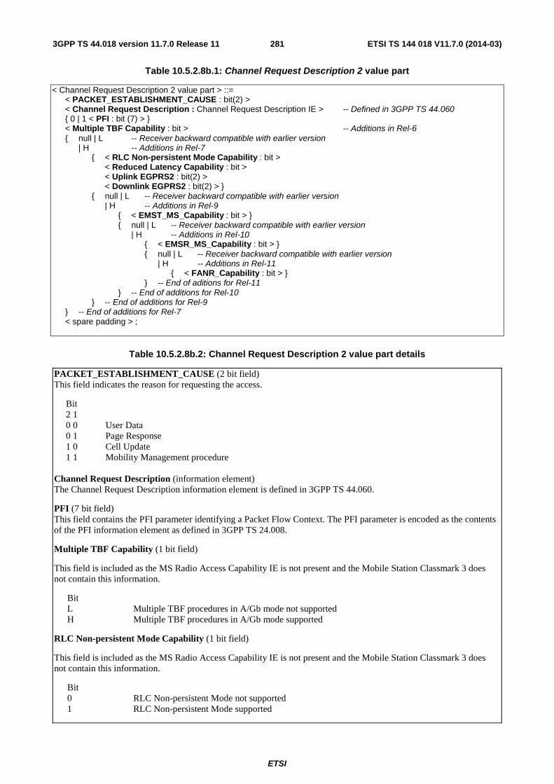
ETSI
ETSI TS 144 018 V11.7.0 (2014-03)2813GPP TS 44.018 version 11.7.0 Release 11
Table 10.5.2.8b.1: Channel Request Description 2 value part
< Channel Request Description 2 value part > ::= < PACKET_ESTABLISHMENT_CAUSE : bit(2) > < Channel Request Description : Channel Request Description IE > -- Defined in 3GPP TS 44.060 { 0 | 1 < PFI : bit (7) > } < Multiple TBF Capability : bit > -- Additions in Rel-6 { null | L -- Receiver backward compatible with earlier version | H -- Additions in Rel-7 { < RLC Non-persistent Mode Capability : bit > < Reduced Latency Capability : bit > < Uplink EGPRS2 : bit(2) > < Downlink EGPRS2 : bit(2) > } { null | L -- Receiver backward compatible with earlier version | H -- Additions in Rel-9 { < EMST_MS_Capability : bit > } { null | L -- Receiver backward compatible with earlier version | H -- Additions in Rel-10 { < EMSR_MS_Capability : bit > } { null | L -- Receiver backward compatible with earlier version | H -- Additions in Rel-11 { < FANR_Capability : bit > } } -- End of aditions for Rel-11 } -- End of additions for Rel-10 } -- End of additions for Rel-9 } -- End of additions for Rel-7 < spare padding > ;
Table 10.5.2.8b.2: Channel Request Description 2 value part details
PACKET_ESTABLISHMENT_CAUSE (2 bit field) This field indicates the reason for requesting the access.
Bit 2 1 0 0 User Data 0 1 Page Response 1 0 Cell Update 1 1 Mobility Management procedure
Channel Request Description (information element) The Channel Request Description information element is defined in 3GPP TS 44.060.
PFI (7 bit field) This field contains the PFI parameter identifying a Packet Flow Context. The PFI parameter is encoded as the contents of the PFI information element as defined in 3GPP TS 24.008.
Multiple TBF Capability (1 bit field)
This field is included as the MS Radio Access Capability IE is not present and the Mobile Station Classmark 3 does not contain this information.
Bit L Multiple TBF procedures in A/Gb mode not supported H Multiple TBF procedures in A/Gb mode supported
RLC Non-persistent Mode Capability (1 bit field)
This field is included as the MS Radio Access Capability IE is not present and the Mobile Station Classmark 3 does not contain this information.
Bit 0 RLC Non-persistent Mode not supported 1 RLC Non-persistent Mode supported
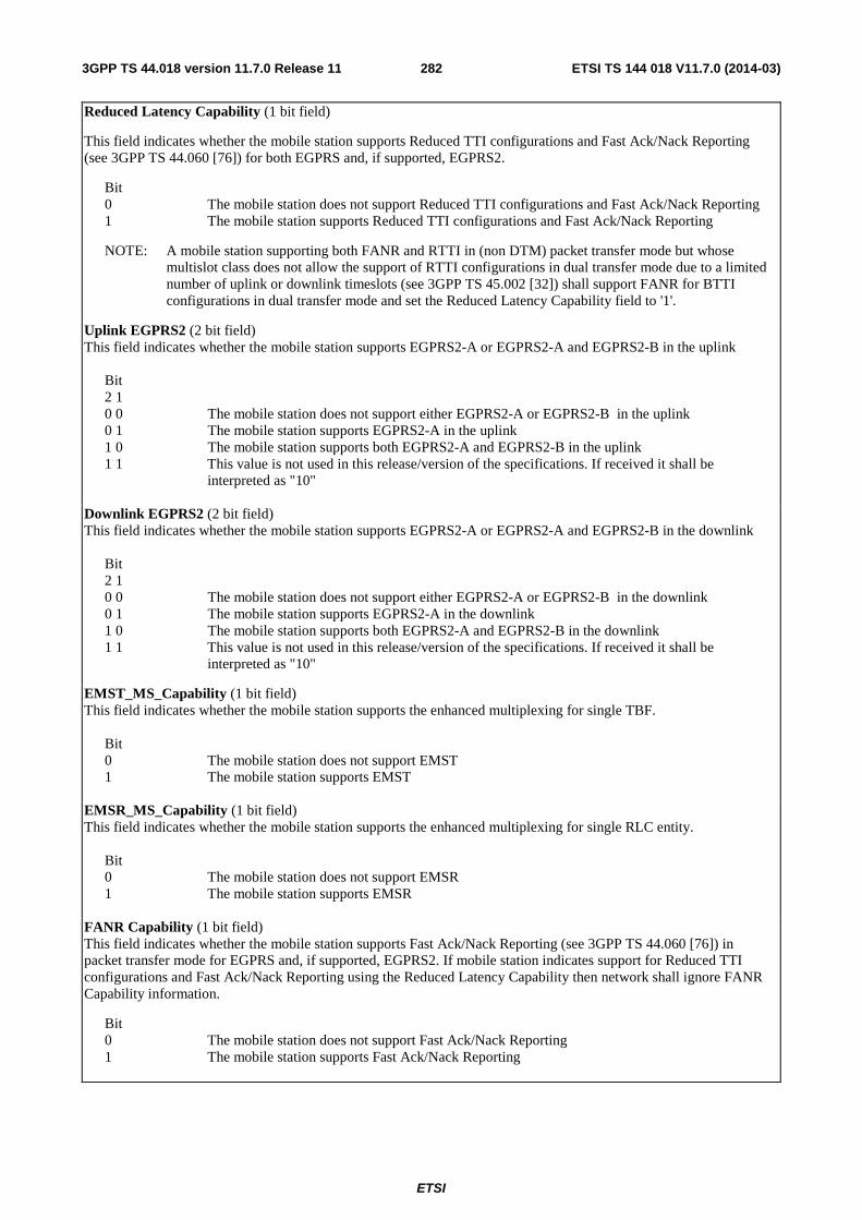
ETSI
ETSI TS 144 018 V11.7.0 (2014-03)2823GPP TS 44.018 version 11.7.0 Release 11
Reduced Latency Capability (1 bit field)
This field indicates whether the mobile station supports Reduced TTI configurations and Fast Ack/Nack Reporting (see 3GPP TS 44.060 [76]) for both EGPRS and, if supported, EGPRS2.
Bit 0 The mobile station does not support Reduced TTI configurations and Fast Ack/Nack Reporting 1 The mobile station supports Reduced TTI configurations and Fast Ack/Nack Reporting
NOTE: A mobile station supporting both FANR and RTTI in (non DTM) packet transfer mode but whose multislot class does not allow the support of RTTI configurations in dual transfer mode due to a limited number of uplink or downlink timeslots (see 3GPP TS 45.002 [32]) shall support FANR for BTTI configurations in dual transfer mode and set the Reduced Latency Capability field to '1'.
Uplink EGPRS2 (2 bit field) This field indicates whether the mobile station supports EGPRS2-A or EGPRS2-A and EGPRS2-B in the uplink
Bit 2 1 0 0 The mobile station does not support either EGPRS2-A or EGPRS2-B in the uplink 0 1 The mobile station supports EGPRS2-A in the uplink 1 0 The mobile station supports both EGPRS2-A and EGPRS2-B in the uplink 1 1 This value is not used in this release/version of the specifications. If received it shall be
interpreted as "10"
Downlink EGPRS2 (2 bit field) This field indicates whether the mobile station supports EGPRS2-A or EGPRS2-A and EGPRS2-B in the downlink
Bit 2 1 0 0 The mobile station does not support either EGPRS2-A or EGPRS2-B in the downlink 0 1 The mobile station supports EGPRS2-A in the downlink 1 0 The mobile station supports both EGPRS2-A and EGPRS2-B in the downlink 1 1 This value is not used in this release/version of the specifications. If received it shall be
interpreted as "10"
EMST_MS_Capability (1 bit field) This field indicates whether the mobile station supports the enhanced multiplexing for single TBF.
Bit 0 The mobile station does not support EMST 1 The mobile station supports EMST
EMSR_MS_Capability (1 bit field) This field indicates whether the mobile station supports the enhanced multiplexing for single RLC entity.
Bit 0 The mobile station does not support EMSR 1 The mobile station supports EMSR
FANR Capability (1 bit field) This field indicates whether the mobile station supports Fast Ack/Nack Reporting (see 3GPP TS 44.060 [76]) in packet transfer mode for EGPRS and, if supported, EGPRS2. If mobile station indicates support for Reduced TTI configurations and Fast Ack/Nack Reporting using the Reduced Latency Capability then network shall ignore FANR Capability information.
Bit 0 The mobile station does not support Fast Ack/Nack Reporting 1 The mobile station supports Fast Ack/Nack Reporting
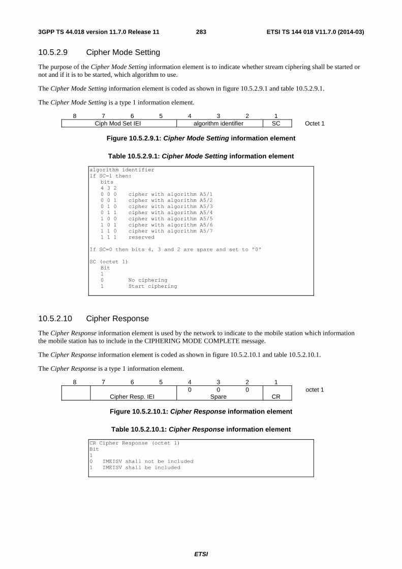
ETSI
ETSI TS 144 018 V11.7.0 (2014-03)2833GPP TS 44.018 version 11.7.0 Release 11
10.5.2.9 Cipher Mode Setting
The purpose of the Cipher Mode Setting information element is to indicate whether stream ciphering shall be started or not and if it is to be started, which algorithm to use.
The Cipher Mode Setting information element is coded as shown in figure 10.5.2.9.1 and table 10.5.2.9.1.
The Cipher Mode Setting is a type 1 information element.
8 7 6 5 4 3 2 1 Ciph Mod Set IEI algorithm identifier SC Octet 1
Figure 10.5.2.9.1: Cipher Mode Setting information element
Table 10.5.2.9.1: Cipher Mode Setting information element
algorithm identifier If SC=1 then:
bits 4 3 2 0 0 0 cipher with algorithm A5/1 0 0 1 cipher with algorithm A5/2 0 1 0 cipher with algorithm A5/3 0 1 1 cipher with algorithm A5/4 1 0 0 cipher with algorithm A5/5 1 0 1 cipher with algorithm A5/6 1 1 0 cipher with algorithm A5/7 1 1 1 reserved
If SC=0 then bits 4, 3 and 2 are spare and set to "0" SC (octet 1)
Bit 1 0 No ciphering 1 Start ciphering
10.5.2.10 Cipher Response
The Cipher Response information element is used by the network to indicate to the mobile station which information the mobile station has to include in the CIPHERING MODE COMPLETE message.
The Cipher Response information element is coded as shown in figure 10.5.2.10.1 and table 10.5.2.10.1.
The Cipher Response is a type 1 information element.
8 7 6 5 4 3 2 1 0 0 0 octet 1 Cipher Resp. IEI Spare CR
Figure 10.5.2.10.1: Cipher Response information element
Table 10.5.2.10.1: Cipher Response information element
CR Cipher Response (octet 1) Bit 1 0 IMEISV shall not be included 1 IMEISV shall be included
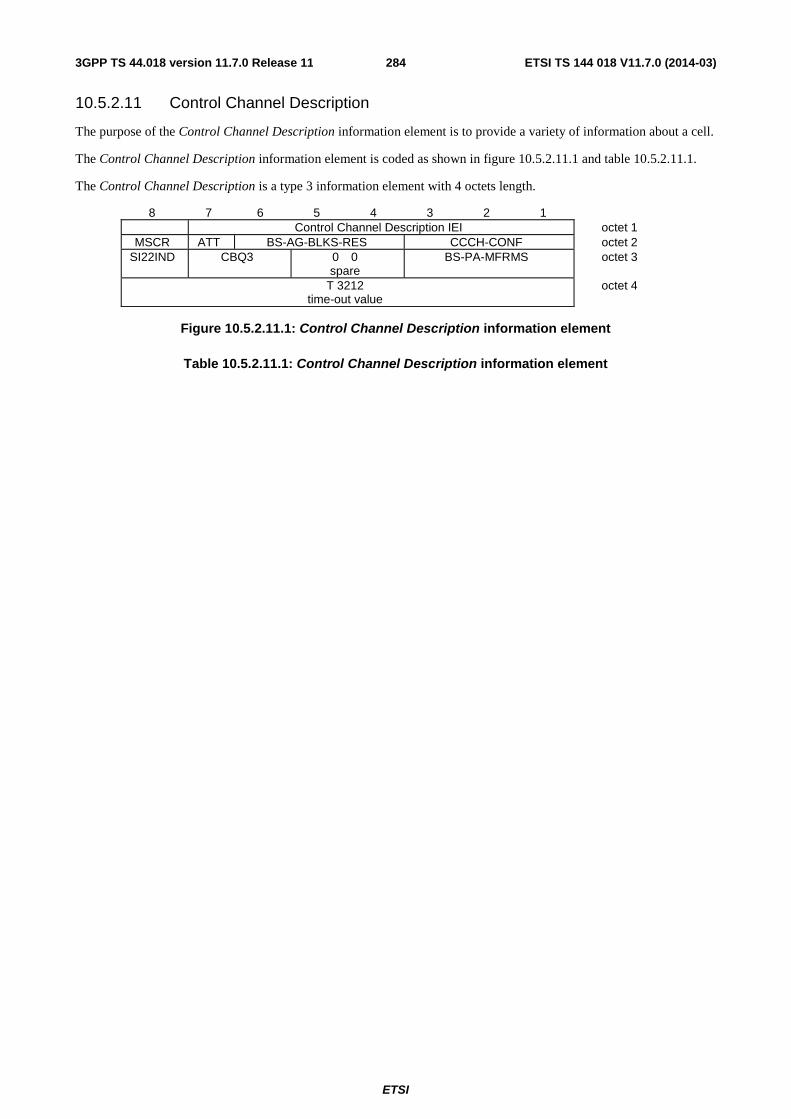
ETSI
ETSI TS 144 018 V11.7.0 (2014-03)2843GPP TS 44.018 version 11.7.0 Release 11
10.5.2.11 Control Channel Description
The purpose of the Control Channel Description information element is to provide a variety of information about a cell.
The Control Channel Description information element is coded as shown in figure 10.5.2.11.1 and table 10.5.2.11.1.
The Control Channel Description is a type 3 information element with 4 octets length.
8 7 6 5 4 3 2 1 Control Channel Description IEI octet 1
MSCR ATT BS-AG-BLKS-RES CCCH-CONF octet 2 SI22IND
CBQ3 0 0
spare BS-PA-MFRMS octet 3
T 3212 time-out value
octet 4
Figure 10.5.2.11.1: Control Channel Description information element
Table 10.5.2.11.1: Control Channel Description information element
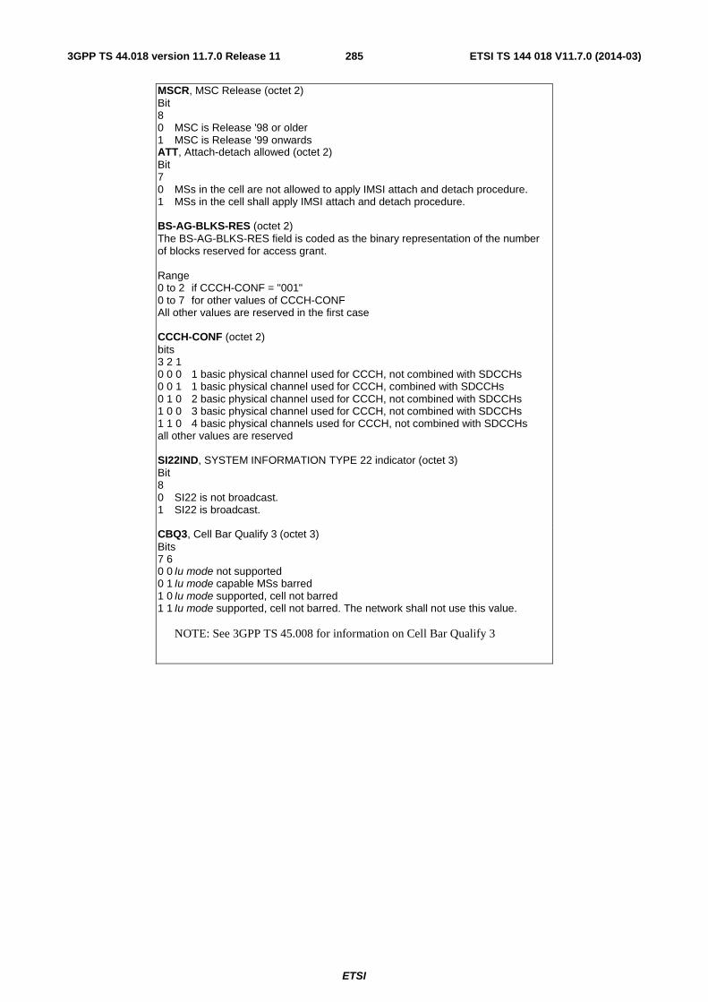
ETSI
ETSI TS 144 018 V11.7.0 (2014-03)2853GPP TS 44.018 version 11.7.0 Release 11
MSCR, MSC Release (octet 2) Bit 8 0 MSC is Release '98 or older 1 MSC is Release '99 onwards ATT, Attach-detach allowed (octet 2) Bit 7 0 MSs in the cell are not allowed to apply IMSI attach and detach procedure. 1 MSs in the cell shall apply IMSI attach and detach procedure. BS-AG-BLKS-RES (octet 2) The BS-AG-BLKS-RES field is coded as the binary representation of the number of blocks reserved for access grant. Range 0 to 2 if CCCH-CONF = "001" 0 to 7 for other values of CCCH-CONF All other values are reserved in the first case CCCH-CONF (octet 2) bits 3 2 1 0 0 0 1 basic physical channel used for CCCH, not combined with SDCCHs 0 0 1 1 basic physical channel used for CCCH, combined with SDCCHs 0 1 0 2 basic physical channel used for CCCH, not combined with SDCCHs 1 0 0 3 basic physical channel used for CCCH, not combined with SDCCHs 1 1 0 4 basic physical channels used for CCCH, not combined with SDCCHs all other values are reserved SI22IND, SYSTEM INFORMATION TYPE 22 indicator (octet 3) Bit 8 0 SI22 is not broadcast. 1 SI22 is broadcast. CBQ3, Cell Bar Qualify 3 (octet 3) Bits 7 6 0 0 Iu mode not supported 0 1 Iu mode capable MSs barred 1 0 Iu mode supported, cell not barred 1 1 Iu mode supported, cell not barred. The network shall not use this value.
NOTE: See 3GPP TS 45.008 for information on Cell Bar Qualify 3
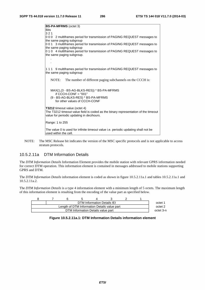
ETSI
ETSI TS 144 018 V11.7.0 (2014-03)2863GPP TS 44.018 version 11.7.0 Release 11
BS-PA-MFRMS (octet 3) Bits 3 2 1 0 0 0 2 multiframes period for transmission of PAGING REQUEST messages to the same paging subgroup 0 0 1 3 multiframes period for transmission of PAGING REQUEST messages to the same paging subgroup 0 1 0 4 multiframes period for transmission of PAGING REQUEST messages to the same paging subgroup. . . 1 1 1 9 multiframes period for transmission of PAGING REQUEST messages to the same paging subgroup
NOTE: The number of different paging subchannels on the CCCH is:
MAX(1,(3 - BS-AG-BLKS-RES)) * BS-PA-MFRMS if CCCH-CONF = "001" (9 - BS-AG-BLKS-RES) * BS-PA-MFRMS for other values of CCCH-CONF T3212 timeout value (octet 4) The T3212 timeout value field is coded as the binary representation of the timeout value for periodic updating in decihours. Range: 1 to 255 The value 0 is used for infinite timeout value i.e. periodic updating shall not be used within the cell.
NOTE: The MSC Release bit indicates the version of the MSC specific protocols and is not applicable to access
stratum protocols.
10.5.2.11a DTM Information Details
The DTM Information Details Information Element provides the mobile station with relevant GPRS information needed for correct DTM operation. This information element is contained in messages addressed to mobile stations supporting GPRS and DTM.
The DTM Information Details information element is coded as shown in figure 10.5.2.11a.1 and tables 10.5.2.11a.1 and 10.5.2.11a.2.
The DTM Information Details is a type 4 information element with a minimum length of 5 octets. The maximum length of this information element is resulting from the encoding of the value part as specified below.
8 7 6 5 4 3 2 1 DTM Information Details IEI octet 1
Length of DTM Information Details value part octet 2 DTM Information Details value part octet 3-n
Figure 10.5.2.11a.1: DTM Information Details information element
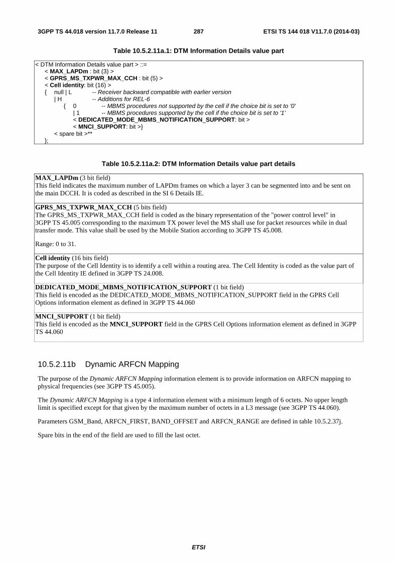
ETSI
ETSI TS 144 018 V11.7.0 (2014-03)2873GPP TS 44.018 version 11.7.0 Release 11
Table 10.5.2.11a.1: DTM Information Details value part
< DTM Information Details value part > ::= < MAX_LAPDm : bit (3) > < GPRS_MS_TXPWR_MAX_CCH : bit (5) > < Cell identity: bit (16) > { null | L -- Receiver backward compatible with earlier version | H -- Additions for REL-6 { 0 -- MBMS procedures not supported by the cell if the choice bit is set to '0' | 1 -- MBMS procedures supported by the cell if the choice bit is set to '1' < DEDICATED_MODE_MBMS_NOTIFICATION_SUPPORT: bit > < MNCI_SUPPORT: bit >} < spare bit >** };
Table 10.5.2.11a.2: DTM Information Details value part details
MAX_LAPDm (3 bit field) This field indicates the maximum number of LAPDm frames on which a layer 3 can be segmented into and be sent on the main DCCH. It is coded as described in the SI 6 Details IE.
GPRS_MS_TXPWR_MAX_CCH (5 bits field) The GPRS_MS_TXPWR_MAX_CCH field is coded as the binary representation of the "power control level" in 3GPP TS 45.005 corresponding to the maximum TX power level the MS shall use for packet resources while in dual transfer mode. This value shall be used by the Mobile Station according to 3GPP TS 45.008.
Range: 0 to 31.
Cell identity (16 bits field) The purpose of the Cell Identity is to identify a cell within a routing area. The Cell Identity is coded as the value part of the Cell Identity IE defined in 3GPP TS 24.008.
DEDICATED_MODE_MBMS_NOTIFICATION_SUPPORT (1 bit field) This field is encoded as the DEDICATED_MODE_MBMS_NOTIFICATION_SUPPORT field in the GPRS Cell Options information element as defined in 3GPP TS 44.060
MNCI_SUPPORT (1 bit field) This field is encoded as the MNCI_SUPPORT field in the GPRS Cell Options information element as defined in 3GPP TS 44.060
10.5.2.11b Dynamic ARFCN Mapping
The purpose of the Dynamic ARFCN Mapping information element is to provide information on ARFCN mapping to physical frequencies (see 3GPP TS 45.005).
The Dynamic ARFCN Mapping is a type 4 information element with a minimum length of 6 octets. No upper length limit is specified except for that given by the maximum number of octets in a L3 message (see 3GPP TS 44.060).
Parameters GSM_Band, ARFCN_FIRST, BAND_OFFSET and ARFCN_RANGE are defined in table 10.5.2.37j.
Spare bits in the end of the field are used to fill the last octet.

ETSI
ETSI TS 144 018 V11.7.0 (2014-03)2883GPP TS 44.018 version 11.7.0 Release 11
Table 10.5.2.11b.1: Dynamic ARFCN Mapping content
< Dynamic ARFCN Mapping >::= < LENGTH OF DYNAMIC ARFCN MAPPING : bit (8) > -- length of value part in octets < DYNAMIC ARFCN MAPPING Description : { 1 < DYNAMIC ARFCN MAPPING > } ** 0 > < spare bit >** ; < DYNAMIC ARFCN MAPPING >::= < GSM_Band : bit (4) > < ARFCN_FIRST : bit (10) > < BAND_OFFSET: bit (10) > < ARFCN_RANGE : bit (7) > ;
10.5.2.12 Frequency Channel Sequence
The purpose of the Frequency Channel Sequence information element is to provide the absolute radio frequency channel numbers used in the mobile hopping sequence. This information element shall only be used for radio frequency channels in the primary GSM band (see 3GPP TS 45.005).
The Frequency Channel Sequence information element is coded as shown in figure 10.5.2.12.1 and table 10.5.2.12.1.
The Frequency Channel Sequence is a type 3 information element with 10 octets length.
8 7 6 5 4 3 2 1 Frequency Channel Sequence IEI octet 1
0 spare
Lowest ARFCN octet 2
inc skip of ARFCN 01 inc skip of ARFCN 02 octet 3
inc skip of ARFCN 15 inc skip of ARFCN 16 octet 10
Figure 10.5.2.12.1: Frequency Channel Sequence information element
Table 10.5.2.12.1: Frequency Channel Sequence information element
Lowest ARFCN (octet 2) The lowest ARFCN field is coded as the binary representation of the lowest absolute RF channel number appearing in the sequence of channels used in the frequency hopping. Range: 1 to 124 All other values are reserved. Increment skip ARFCN n (octet 3 to 10) The increment skip ARFCN n is coded as the binary representation of the increment of the preceding absolute RF channel number appearing in the sequence of channels used in the frequency hopping: n = 1,...,16. Range: 0 to 15 The value 0 indicates that the increment value is 15 but the concerned channel is not used and the next field, i.e. Increment skip ARFCN n+1 (if present) must be added to the increment to determine the next absolute RF channel number in the sequence of channels used in the frequency hopping.

ETSI
ETSI TS 144 018 V11.7.0 (2014-03)2893GPP TS 44.018 version 11.7.0 Release 11
10.5.2.13 Frequency List
The purpose of the Frequency List information element is to provide the list of the absolute radio frequency channel numbers used in a frequency hopping sequence.
The Frequency List information element is a type 4 information element.
There are several formats for the Frequency List information element, distinguished by the "format indicator" subfield. Some formats are frequency bit maps, the others use a special encoding scheme.
10.5.2.13.1 General description
Table 10.5.2.13.1.1: Frequency List information element, general format
FORMAT-ID, Format Identifier (part of octet 3) The different formats are distinguished by the FORMAT-ID field. The possible values are the following: Bit Bit Bit Bit Bit format notation 8 7 4 3 2 0 0 X X X bit map 0 1 0 0 X X 1024 range 1 0 1 0 0 512 range 1 0 1 0 1 256 range 1 0 1 1 0 128 range 1 0 1 1 1 variable bit map All other combinations are reserved for future use. A GSM 900 mobile station which only supports the primary GSM band P-GSM 900 (cf. 3GPP TS 45.005) may consider all values except the value for bit map 0 as reserved. The significance of the remaining bits depends on the FORMAT-ID. The different cases are specified in the next sub-clauses.
10.5.2.13.2 Bit map 0 format
8 7 6 5 4 3 2 1 Frequency List IEI octet 1
0 0 0 1 0 0 0 0 Length of frequency list contents octet 2
0 0 0 0 FORMAT-ID spare ARFCN
124 ARFCN
123 ARFCN
122 ARFCN
121 octet 3
ARFCN 120
ARFCN 119
ARFCN 118
ARFCN 117
ARFCN 116
ARFCN 115
ARFCN 114
ARFCN 113
octet 4
ARFCN 008
ARFCN 007
ARFCN 006
ARFCN 005
ARFCN 004
ARFCN 003
ARFCN 002
ARFCN 001
octet 18
Figure 10.5.2.13.2.1: Frequency List information element, bit map 0 format

ETSI
ETSI TS 144 018 V11.7.0 (2014-03)2903GPP TS 44.018 version 11.7.0 Release 11
Table 10.5.2.13.2.1: Frequency List information element, bit map 0 format
ARFCN N, Absolute RF Channel Number N (octet 3 etc.) For a RF channel with ARFCN = N belonging to the frequency list the ARFCN N bit is coded with a "1"; N = 1, 2, .. , 124. For a RF channel with ARFCN = N not belonging to the frequency list the ARFCN N bit is coded with a "0"; N = 1, 2 .. , 124.
10.5.2.13.3 Range 1024 format
The information element contains a header, and W(1) to W(M) for some M. If, due to octet boundaries, some bits are not used at the end of the last octet, these bits must be set to 0.
8 7 6 5 4 3 2 1 Frequency List IEI octet 1
Length of frequency list contents octet 2 1 0 0 0 0 FORMAT-ID spare FORMA
T-ID F0 W(1)
(high part) octet 3
W(1) (low part) octet 4 W(2) to W(3) are on 9 bits, when present W(4) to W(7) are on 8 bits, when present W(8) to W(15) are on 7 bits, when present W(16) to W(31) are on 6 bits, when present W(2k) to W(2(k+1)-1) are on 10-k bits when present and so on
Figure 10.5.2.13.3.1: Frequency List information element (Range 1024 format)
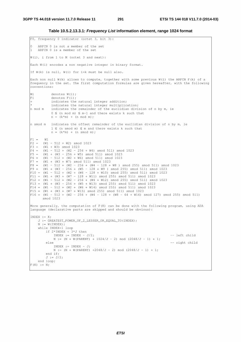
ETSI
ETSI TS 144 018 V11.7.0 (2014-03)2913GPP TS 44.018 version 11.7.0 Release 11
Table 10.5.2.13.3.1: Frequency List information element, range 1024 format
F0, frequency 0 indicator (octet 3, bit 3): 0 ARFCN 0 is not a member of the set 1 ARFCN 0 is a member of the set W(i), i from 1 to M (octet 3 and next): Each W(i) encodes a non negative integer in binary format. If W(k) is null, W(i) for i>k must be null also. Each non null W(k) allows to compute, together with some previous W(i) the ARFCN F(k) of a frequency in the set. The first computation formulas are given hereafter, with the following conventions: Wi denotes W(i); Fi denotes F(i); + indicates the natural integer addition; * indicates the natural integer multiplication; n mod m indicates the remainder of the euclidian division of n by m, ie
0 ≤ (n mod m) ≤ m-1 and there exists k such that n = (k*m) + (n mod m);
n smod m indicates the offset remainder of the euclidian division of n by m, ie
1 ≤ (n smod m) ≤ m and there exists k such that n = (k*m) + (n smod m);
F1 = W1 F2 = (W1 - 512 + W2) smod 1023 F3 = (W1 + W3) smod 1023 F4 = (W1 - 512 + (W2 - 256 + W4) smod 511) smod 1023 F5 = (W1 + (W3 - 256 + W5) smod 511) smod 1023 F6 = (W1 - 512 + (W2 + W6) smod 511) smod 1023 F7 = (W1 + (W3 + W7) smod 511) smod 1023 F8 = (W1 - 512 + (W2 - 256 + (W4 - 128 + W8 ) smod 255) smod 511) smod 1023 F9 = (W1 + (W3 - 256 + (W5 - 128 + W9 ) smod 255) smod 511) smod 1023 F10 = (W1 - 512 + (W2 + (W6 - 128 + W10) smod 255) smod 511) smod 1023 F11 = (W1 + (W3 + (W7 - 128 + W11) smod 255) smod 511) smod 1023 F12 = (W1 - 512 + (W2 - 256 + (W4 + W12) smod 255) smod 511) smod 1023 F13 = (W1 + (W3 - 256 + (W5 + W13) smod 255) smod 511) smod 1023 F14 = (W1 - 512 + (W2 + (W6 + W14) smod 255) smod 511) smod 1023 F15 = (W1 + (W3 + (W7 + W15) smod 255) smod 511) smod 1023 F16 = (W1 - 512 + (W2 - 256 + (W4 - 128 + (W8 - 64 + W16) smod 127) smod 255) smod 511)
smod 1023 More generally, the computation of F(K) can be done with the following program, using ADA language (declarative parts are skipped and should be obvious): INDEX := K; J := GREATEST_POWER_OF_2_LESSER_OR_EQUAL_TO(INDEX); N := W(INDEX); while INDEX>1 loop if 2*INDEX < 3*J then INDEX := INDEX - J/2; -- left child N := (N + W(PARENT) + 1024/J - 2) mod (2048/J - 1) + 1; else -- right child INDEX := INDEX - J; N := (N + W(PARENT) +2048/J - 2) mod (2048/J - 1) + 1; end if; J := J/2; end loop; F(K) := N;
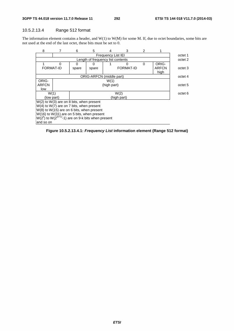
ETSI
ETSI TS 144 018 V11.7.0 (2014-03)2923GPP TS 44.018 version 11.7.0 Release 11
10.5.2.13.4 Range 512 format
The information element contains a header, and W(1) to W(M) for some M. If, due to octet boundaries, some bits are not used at the end of the last octet, these bits must be set to 0.
8 7 6 5 4 3 2 1 Frequency List IEI octet 1
Length of frequency list contents octet 2 1 0 0 0 1 0 0 ORIG- FORMAT-ID spare spare FORMAT-ID ARFCN
high octet 3
ORIG-ARFCN (middle part) octet 4 ORIG- ARFCN
low
W(1) (high part)
octet 5
W(1) (low part)
W(2) (high part)
octet 6
W(2) to W(3) are on 8 bits, when present W(4) to W(7) are on 7 bits, when present W(8) to W(15) are on 6 bits, when present W(16) to W(31) are on 5 bits, when present W(2k) to W(2(k+1)-1) are on 9-k bits when present and so on
Figure 10.5.2.13.4.1: Frequency List information element (Range 512 format)
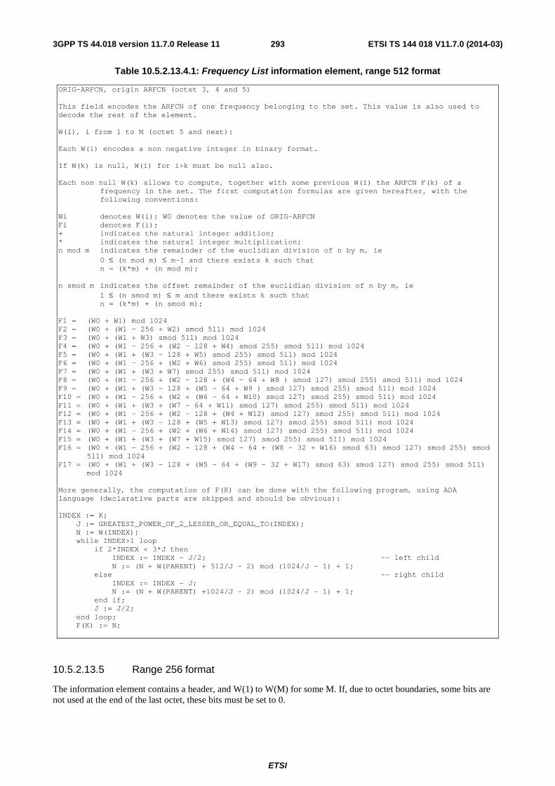
ETSI
ETSI TS 144 018 V11.7.0 (2014-03)2933GPP TS 44.018 version 11.7.0 Release 11
Table 10.5.2.13.4.1: Frequency List information element, range 512 format
ORIG-ARFCN, origin ARFCN (octet 3, 4 and 5) This field encodes the ARFCN of one frequency belonging to the set. This value is also used to decode the rest of the element. W(i), i from 1 to M (octet 5 and next): Each W(i) encodes a non negative integer in binary format. If W(k) is null, W(i) for i>k must be null also. Each non null W(k) allows to compute, together with some previous W(i) the ARFCN F(k) of a
frequency in the set. The first computation formulas are given hereafter, with the following conventions:
Wi denotes W(i); W0 denotes the value of ORIG-ARFCN Fi denotes F(i); + indicates the natural integer addition; * indicates the natural integer multiplication; n mod m indicates the remainder of the euclidian division of n by m, ie
0 ≤ (n mod m) ≤ m-1 and there exists k such that n = (k*m) + (n mod m);
n smod m indicates the offset remainder of the euclidian division of n by m, ie
1 ≤ (n smod m) ≤ m and there exists k such that n = (k*m) + (n smod m);
F1 = (W0 + W1) mod 1024 F2 = (W0 + (W1 - 256 + W2) smod 511) mod 1024 F3 = (W0 + (W1 + W3) smod 511) mod 1024 F4 = (W0 + (W1 - 256 + (W2 - 128 + W4) smod 255) smod 511) mod 1024 F5 = (W0 + (W1 + (W3 - 128 + W5) smod 255) smod 511) mod 1024 F6 = (W0 + (W1 - 256 + (W2 + W6) smod 255) smod 511) mod 1024 F7 = (W0 + (W1 + (W3 + W7) smod 255) smod 511) mod 1024 F8 = (W0 + (W1 - 256 + (W2 - 128 + (W4 - 64 + W8 ) smod 127) smod 255) smod 511) mod 1024 F9 = (W0 + (W1 + (W3 - 128 + (W5 - 64 + W9 ) smod 127) smod 255) smod 511) mod 1024 F10 = (W0 + (W1 - 256 + (W2 + (W6 - 64 + W10) smod 127) smod 255) smod 511) mod 1024 F11 = (W0 + (W1 + (W3 + (W7 - 64 + W11) smod 127) smod 255) smod 511) mod 1024 F12 = (W0 + (W1 - 256 + (W2 - 128 + (W4 + W12) smod 127) smod 255) smod 511) mod 1024 F13 = (W0 + (W1 + (W3 - 128 + (W5 + W13) smod 127) smod 255) smod 511) mod 1024 F14 = (W0 + (W1 - 256 + (W2 + (W6 + W14) smod 127) smod 255) smod 511) mod 1024 F15 = (W0 + (W1 + (W3 + (W7 + W15) smod 127) smod 255) smod 511) mod 1024 F16 = (W0 + (W1 - 256 + (W2 - 128 + (W4 - 64 + (W8 - 32 + W16) smod 63) smod 127) smod 255) smod
511) mod 1024 F17 = (W0 + (W1 + (W3 - 128 + (W5 - 64 + (W9 - 32 + W17) smod 63) smod 127) smod 255) smod 511)
mod 1024 More generally, the computation of F(K) can be done with the following program, using ADA language (declarative parts are skipped and should be obvious): INDEX := K; J := GREATEST_POWER_OF_2_LESSER_OR_EQUAL_TO(INDEX); N := W(INDEX); while INDEX>1 loop if 2*INDEX < 3*J then INDEX := INDEX - J/2; -- left child N := (N + W(PARENT) + 512/J - 2) mod (1024/J - 1) + 1; else -- right child INDEX := INDEX - J; N := (N + W(PARENT) +1024/J - 2) mod (1024/J - 1) + 1; end if; J := J/2; end loop; F(K) := N;
10.5.2.13.5 Range 256 format
The information element contains a header, and W(1) to W(M) for some M. If, due to octet boundaries, some bits are not used at the end of the last octet, these bits must be set to 0.
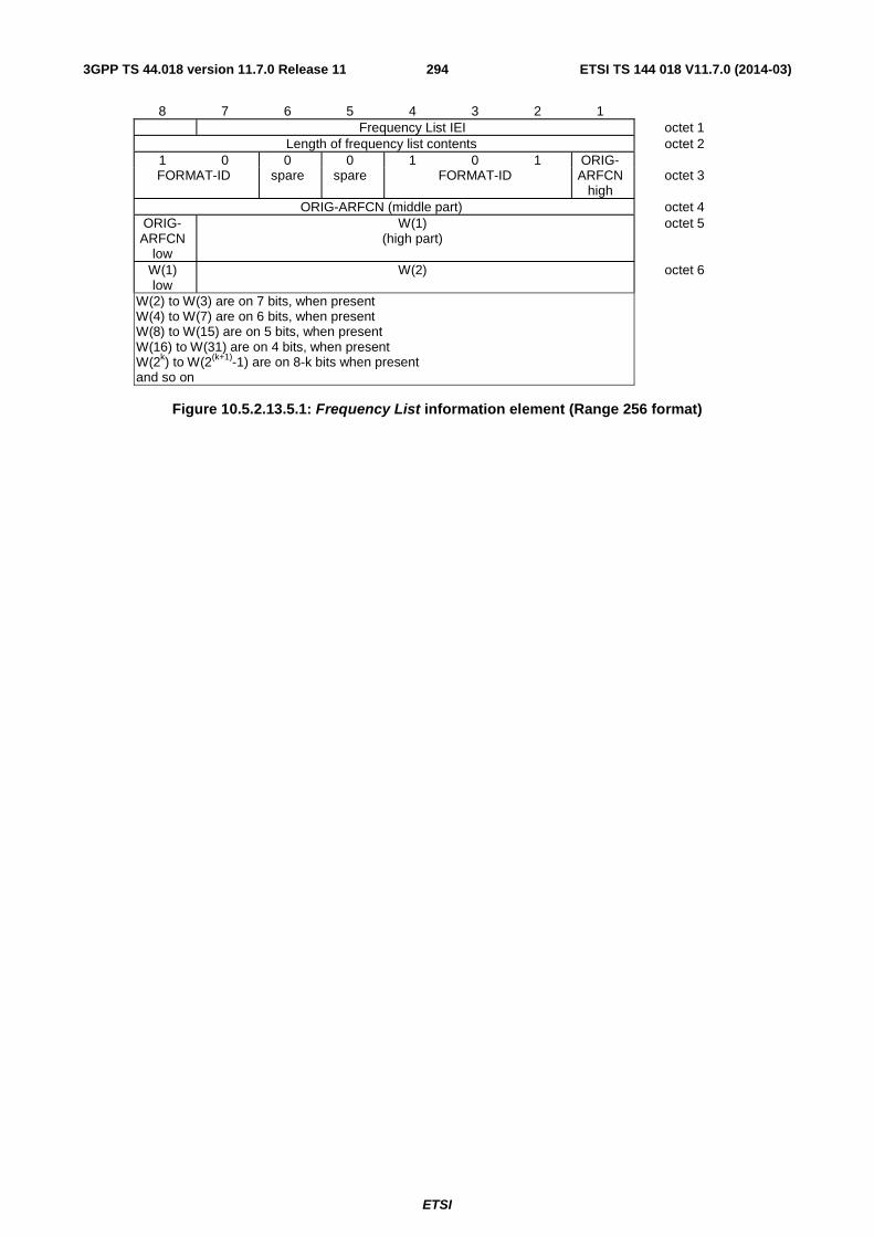
ETSI
ETSI TS 144 018 V11.7.0 (2014-03)2943GPP TS 44.018 version 11.7.0 Release 11
8 7 6 5 4 3 2 1 Frequency List IEI octet 1
Length of frequency list contents octet 2 1 0 0 0 1 0 1 ORIG- FORMAT-ID spare spare FORMAT-ID ARFCN
high octet 3
ORIG-ARFCN (middle part) octet 4 ORIG- ARFCN
low
W(1) (high part)
octet 5
W(1) low
W(2) octet 6
W(2) to W(3) are on 7 bits, when present W(4) to W(7) are on 6 bits, when present W(8) to W(15) are on 5 bits, when present W(16) to W(31) are on 4 bits, when present W(2k) to W(2(k+1)-1) are on 8-k bits when present and so on
Figure 10.5.2.13.5.1: Frequency List information element (Range 256 format)
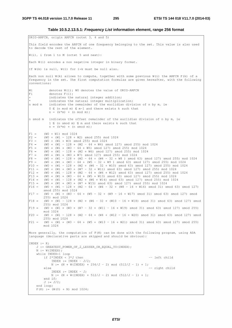
ETSI
ETSI TS 144 018 V11.7.0 (2014-03)2953GPP TS 44.018 version 11.7.0 Release 11
Table 10.5.2.13.5.1: Frequency List information element, range 256 format
ORIG-ARFCN, origin ARFCN (octet 3, 4 and 5) This field encodes the ARFCN of one frequency belonging to the set. This value is also used to decode the rest of the element. W(i), i from 1 to M (octet 5 and next): Each W(i) encodes a non negative integer in binary format. If W(k) is null, W(i) for i>k must be null also. Each non null W(k) allows to compute, together with some previous W(i) the ARFCN F(k) of a frequency in the set. The first computation formulas are given hereafter, with the following conventions: Wi denotes W(i); W0 denotes the value of ORIG-ARFCN Fi denotes F(i); + indicates the natural integer addition; * indicates the natural integer multiplication; n mod m indicates the remainder of the euclidian division of n by m, ie
0 ≤ (n mod m) ≤ m-1 and there exists k such that n = (k*m) + (n mod m);
n smod m indicates the offset remainder of the euclidian division of n by m, ie
1 ≤ (n smod m) ≤ m and there exists k such that n = (k*m) + (n smod m);
F1 = (W0 + W1) mod 1024 F2 = (W0 + (W1 - 128 + W2) smod 255) mod 1024 F3 = (W0 + (W1 + W3) smod 255) mod 1024 F4 = (W0 + (W1 - 128 + (W2 - 64 + W4) smod 127) smod 255) mod 1024 F5 = (W0 + (W1 + (W3 - 64 + W5) smod 127) smod 255) mod 1024 F6 = (W0 + (W1 - 128 + (W2 + W6) smod 127) smod 255) mod 1024 F7 = (W0 + (W1 + (W3 + W7) smod 127) smod 255) mod 1024 F8 = (W0 + (W1 - 128 + (W2 - 64 + (W4 - 32 + W8 ) smod 63) smod 127) smod 255) mod 1024 F9 = (W0 + (W1 + (W3 - 64 + (W5 - 32 + W9 ) smod 63) smod 127) smod 255) mod 1024 F10 = (W0 + (W1 - 128 + (W2 + (W6 - 32 + W10) smod 63) smod 127) smod 255) mod 1024 F11 = (W0 + (W1 + (W3 + (W7 - 32 + W11) smod 63) smod 127) smod 255) mod 1024 F12 = (W0 + (W1 - 128 + (W2 - 64 + (W4 + W12) smod 63) smod 127) smod 255) mod 1024 F13 = (W0 + (W1 + (W3 - 64 + (W5 + W13) smod 63) smod 127) smod 255) mod 1024 F14 = (W0 + (W1 - 128 + (W2 + (W6 + W14) smod 63) smod 127) smod 255) mod 1024 F15 = (W0 + (W1 + (W3 + (W7 + W15) smod 63) smod 127) smod 255) mod 1024 F16 = (W0 + (W1 - 128 + (W2 - 64 + (W4 - 32 + (W8 - 16 + W16) smod 31) smod 63) smod 127)
smod 255) mod 1024 F17 = (W0 + (W1 + (W3 - 64 + (W5 - 32 + (W9 - 16 + W17) smod 31) smod 63) smod 127) smod
255) mod 1024 F18 = (W0 + (W1 - 128 + (W2 + (W6 - 32 + (W10 - 16 + W18) smod 31) smod 63) smod 127) smod
255) mod 1024 F19 = (W0 + (W1 + (W3 + (W7 - 32 + (W11 - 16 + W19) smod 31) smod 63) smod 127) smod 255)
mod 1024 F20 = (W0 + (W1 - 128 + (W2 - 64 + (W4 + (W12 - 16 + W20) smod 31) smod 63) smod 127) smod
255) mod 1024 F21 = (W0 + (W1 + (W3 - 64 + (W5 + (W13 - 16 + W21) smod 31) smod 63) smod 127) smod 255)
mod 1024 More generally, the computation of F(K) can be done with the following program, using ADA language (declarative parts are skipped and should be obvious): INDEX := K; J := GREATEST_POWER_OF_2_LESSER_OR_EQUAL_TO(INDEX); N := W(INDEX); while INDEX>1 loop if 2*INDEX < 3*J then -- left child INDEX := INDEX - J/2; N := (N + W(INDEX) + 256/J - 2) mod (512/J - 1) + 1; else -- right child INDEX := INDEX - J; N := (N + W(INDEX) + 512/J - 2) mod (512/J - 1) + 1; end if; J := J/2; end loop; F(K) := (W(0) + N) mod 1024;
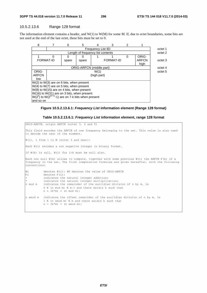
ETSI
ETSI TS 144 018 V11.7.0 (2014-03)2963GPP TS 44.018 version 11.7.0 Release 11
10.5.2.13.6 Range 128 format
The information element contains a header, and W(1) to W(M) for some M. If, due to octet boundaries, some bits are not used at the end of the last octet, these bits must be set to 0.
8 7 6 5 4 3 2 1 Frequency List IEI octet 1
Length of frequency list contents octet 2 1 0 0 0 1 1 0 ORIG- FORMAT-ID spare spare FORMAT-ID ARFCN
high octet 3
ORIG-ARFCN (middle part) octet 4 ORIG- ARFCN
low
W(1) (high part)
octet 5
W(2) to W(3) are on 6 bits, when present W(4) to W(7) are on 5 bits, when present W(8) to W(15) are on 4 bits, when present W(16) to W(31) are on 3 bits, when present W(2k) to W(2(k+1)-1) are on 7-k bits when present and so on
Figure 10.5.2.13.6.1: Frequency List information element (Range 128 format)
Table 10.5.2.13.6.1: Frequency List information element, range 128 format
ORIG-ARFCN, origin ARFCN (octet 3, 4 and 5) This field encodes the ARFCN of one frequency belonging to the set. This value is also used to decode the rest of the element. W(i), i from 1 to M (octet 5 and next): Each W(i) encodes a non negative integer in binary format. If W(k) is null, W(i) for i>k must be null also. Each non null W(k) allows to compute, together with some previous W(i) the ARFCN F(k) of a frequency in the set. The first computation formulas are given hereafter, with the following conventions: Wi denotes W(i); W0 denotes the value of ORIG-ARFCN Fi denotes F(i); + indicates the natural integer addition; * indicates the natural integer multiplication; n mod m indicates the remainder of the euclidian division of n by m, ie
0 ≤ (n mod m) ≤ m-1 and there exists k such that n = (k*m) + (n mod m);
n smod m indicates the offset remainder of the euclidian division of n by m, ie
1 ≤ (n smod m) ≤ m and there exists k such that n = (k*m) + (n smod m);
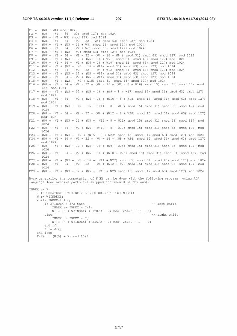
ETSI
ETSI TS 144 018 V11.7.0 (2014-03)2973GPP TS 44.018 version 11.7.0 Release 11
F1 = (W0 + W1) mod 1024 F2 = (W0 + (W1 - 64 + W2) smod 127) mod 1024 F3 = (W0 + (W1 + W3) smod 127) mod 1024 F4 = (W0 + (W1 - 64 + (W2 - 32 + W4) smod 63) smod 127) mod 1024 F5 = (W0 + (W1 + (W3 - 32 + W5) smod 63) smod 127) mod 1024 F6 = (W0 + (W1 - 64 + (W2 + W6) smod 63) smod 127) mod 1024 F7 = (W0 + (W1 + (W3 + W7) smod 63) smod 127) mod 1024 F8 = (W0 + (W1 - 64 + (W2 - 32 + (W4 - 16 + W8 ) smod 31) smod 63) smod 127) mod 1024 F9 = (W0 + (W1 + (W3 - 32 + (W5 - 16 + W9 ) smod 31) smod 63) smod 127) mod 1024 F10 = (W0 + (W1 - 64 + (W2 + (W6 - 16 + W10) smod 31) smod 63) smod 127) mod 1024 F11 = (W0 + (W1 + (W3 + (W7 - 16 + W11) smod 31) smod 63) smod 127) mod 1024 F12 = (W0 + (W1 - 64 + (W2 - 32 + (W4 + W12) smod 31) smod 63) smod 127) mod 1024 F13 = (W0 + (W1 + (W3 - 32 + (W5 + W13) smod 31) smod 63) smod 127) mod 1024 F14 = (W0 + (W1 - 64 + (W2 + (W6 + W14) smod 31) smod 63) smod 127) mod 1024 F15 = (W0 + (W1 + (W3 + (W7 + W15) smod 31) smod 63) smod 127) mod 1024 F16 = (W0 + (W1 - 64 + (W2 - 32 + (W4 - 16 + (W8 - 8 + W16) smod 15) smod 31) smod 63) smod
127) mod 1024 F17 = (W0 + (W1 + (W3 - 32 + (W5 - 16 + (W9 - 8 + W17) smod 15) smod 31) smod 63) smod 127)
mod 1024 F18 = (W0 + (W1 - 64 + (W2 + (W6 - 16 + (W10 - 8 + W18) smod 15) smod 31) smod 63) smod 127)
mod 1024 F19 = (W0 + (W1 + (W3 + (W7 - 16 + (W11 - 8 + W19) smod 15) smod 31) smod 63) smod 127) mod
1024 F20 = (W0 + (W1 - 64 + (W2 - 32 + (W4 + (W12 - 8 + W20) smod 15) smod 31) smod 63) smod 127)
mod 1024 F21 = (W0 + (W1 + (W3 - 32 + (W5 + (W13 - 8 + W21) smod 15) smod 31) smod 63) smod 127) mod
1024 F22 = (W0 + (W1 - 64 + (W2 + (W6 + W(14 - 8 + W22) smod 15) smod 31) smod 63) smod 127) mod
1024 F23 = (W0 + (W1 + (W3 + (W7 + (W15 - 8 + W23) smod 15) smod 31) smod 63) smod 127) mod 1024 F24 = (W0 + (W1 - 64 + (W2 - 32 + (W4 - 16 + (W8 + W24) smod 15) smod 31) smod 63) smod 127)
mod 1024 F25 = (W0 + (W1 + (W3 - 32 + (W5 - 16 + (W9 + W25) smod 15) smod 31) smod 63) smod 127) mod
1024 F26 = (W0 + (W1 - 64 + (W2 + (W6 - 16 + (W10 + W26) smod 15) smod 31) smod 63) smod 127) mod
1024 F27 = (W0 + (W1 + (W3 + (W7 - 16 + (W11 + W27) smod 15) smod 31) smod 63) smod 127) mod 1024 F28 = (W0 + (W1 - 64 + (W2 - 32 + (W4 + (W12 + W28 smod 15) smod 31) smod 63) smod 127) mod
1024 F29 = (W0 + (W1 + (W3 - 32 + (W5 + (W13 + W29 smod 15) smod 31) smod 63) smod 127) mod 1024 More generally, the computation of F(K) can be done with the following program, using ADA language (declarative parts are skipped and should be obvious): INDEX := K; J := GREATEST_POWER_OF_2_LESSER_OR_EQUAL_TO(INDEX); N := W(INDEX); while INDEX>1 loop if 2*INDEX < 3*J then -- left child INDEX := INDEX - J/2; N := (N + W(INDEX) + 128/J - 2) mod (256/J - 1) + 1; else -- right child INDEX := INDEX - J; N := (N + W(INDEX) + 256/J - 2) mod (256/J - 1) + 1; end if; J := J/2; end loop; F(K) := (W(0) + N) mod 1024;
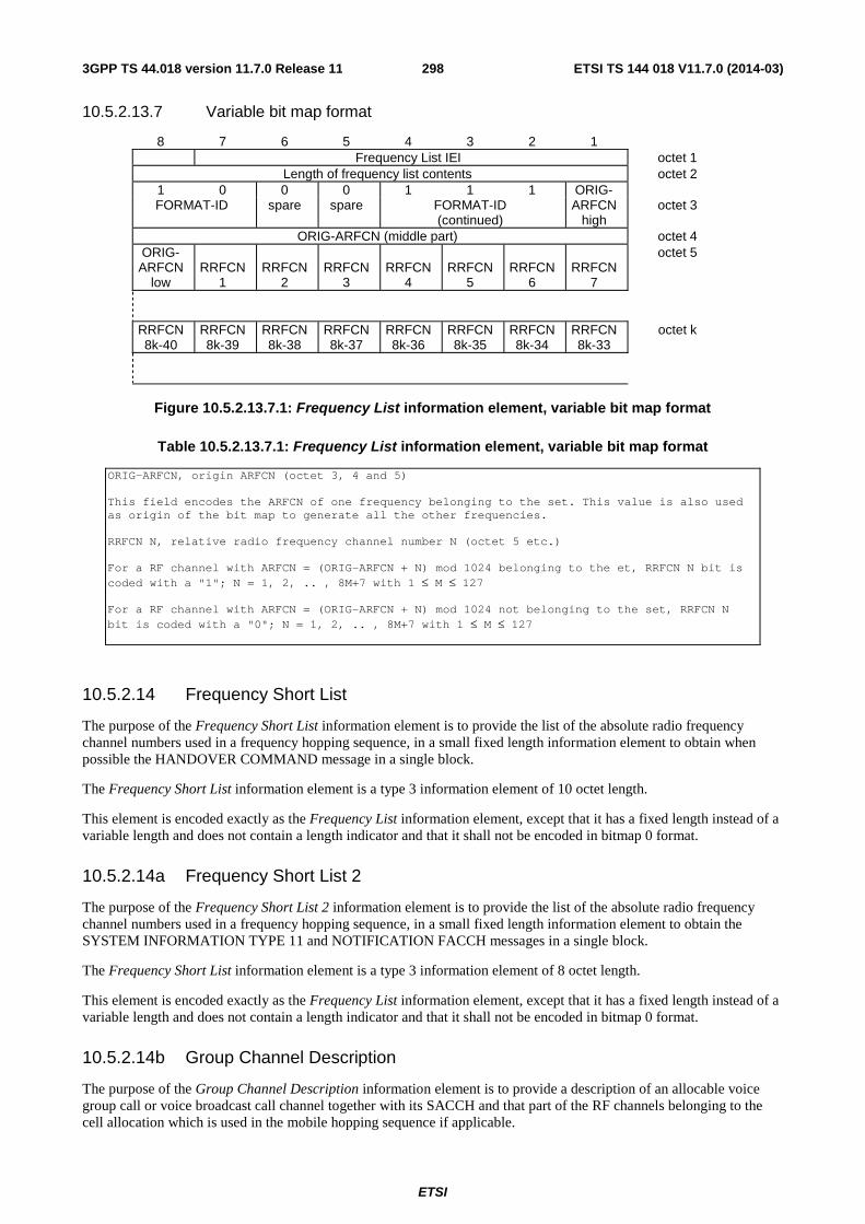
ETSI
ETSI TS 144 018 V11.7.0 (2014-03)2983GPP TS 44.018 version 11.7.0 Release 11
10.5.2.13.7 Variable bit map format
8 7 6 5 4 3 2 1 Frequency List IEI octet 1
Length of frequency list contents octet 2 1 0 0 0 1 1 1 ORIG- FORMAT-ID spare spare FORMAT-ID
(continued) ARFCN
high octet 3
ORIG-ARFCN (middle part) octet 4 ORIG- ARFCN
low
RRFCN
1
RRFCN
2
RRFCN
3
RRFCN
4
RRFCN
5
RRFCN
6
RRFCN
7
octet 5
RRFCN 8k-40
RRFCN 8k-39
RRFCN 8k-38
RRFCN 8k-37
RRFCN 8k-36
RRFCN 8k-35
RRFCN 8k-34
RRFCN 8k-33
octet k
Figure 10.5.2.13.7.1: Frequency List information element, variable bit map format
Table 10.5.2.13.7.1: Frequency List information element, variable bit map format
ORIG-ARFCN, origin ARFCN (octet 3, 4 and 5) This field encodes the ARFCN of one frequency belonging to the set. This value is also used as origin of the bit map to generate all the other frequencies. RRFCN N, relative radio frequency channel number N (octet 5 etc.) For a RF channel with ARFCN = (ORIG-ARFCN + N) mod 1024 belonging to the et, RRFCN N bit is coded with a "1"; N = 1, 2, .. , 8M+7 with 1 ≤ M ≤ 127 For a RF channel with ARFCN = (ORIG-ARFCN + N) mod 1024 not belonging to the set, RRFCN N bit is coded with a "0"; N = 1, 2, .. , 8M+7 with 1 ≤ M ≤ 127
10.5.2.14 Frequency Short List
The purpose of the Frequency Short List information element is to provide the list of the absolute radio frequency channel numbers used in a frequency hopping sequence, in a small fixed length information element to obtain when possible the HANDOVER COMMAND message in a single block.
The Frequency Short List information element is a type 3 information element of 10 octet length.
This element is encoded exactly as the Frequency List information element, except that it has a fixed length instead of a variable length and does not contain a length indicator and that it shall not be encoded in bitmap 0 format.
10.5.2.14a Frequency Short List 2
The purpose of the Frequency Short List 2 information element is to provide the list of the absolute radio frequency channel numbers used in a frequency hopping sequence, in a small fixed length information element to obtain the SYSTEM INFORMATION TYPE 11 and NOTIFICATION FACCH messages in a single block.
The Frequency Short List information element is a type 3 information element of 8 octet length.
This element is encoded exactly as the Frequency List information element, except that it has a fixed length instead of a variable length and does not contain a length indicator and that it shall not be encoded in bitmap 0 format.
10.5.2.14b Group Channel Description
The purpose of the Group Channel Description information element is to provide a description of an allocable voice group call or voice broadcast call channel together with its SACCH and that part of the RF channels belonging to the cell allocation which is used in the mobile hopping sequence if applicable.
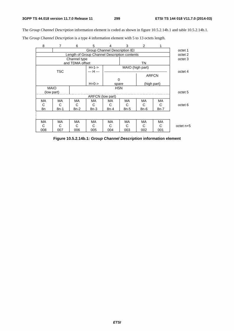
ETSI
ETSI TS 144 018 V11.7.0 (2014-03)2993GPP TS 44.018 version 11.7.0 Release 11
The Group Channel Description information element is coded as shown in figure 10.5.2.14b.1 and table 10.5.2.14b.1.
The Group Channel Description is a type 4 information element with 5 to 13 octets length.
8 7 6 5 4 3 2 1 Group Channel Description IEI octet 1
Length of Group Channel Description contents octet 2 Channel type
and TDMA offset
TN octet 3
H=1-> MAIO (high part) TSC --- H --- ----------------------------------------------------- octet 4
H=0->
0
spare
ARFCN
(high part)
MAIO (low part)
HSN octet 5
ARFCN (low part) MA C 8n
MA C
8n-1
MA C
8n-2
MA C
8n-3
MA C
8n-4
MA C
8n-5
MA C
8n-6
MA C
8n-7
octet 6
MA C
008
MA C
007
MA C
006
MA C
005
MA C
004
MA C
003
MA C
002
MA C
001
octet n+5
Figure 10.5.2.14b.1: Group Channel Description information element

ETSI
ETSI TS 144 018 V11.7.0 (2014-03)3003GPP TS 44.018 version 11.7.0 Release 11
Table 10.5.2.14b.1: Group Channel Description information element
Channel type and TDMA offset (octet 3) Bits 8 7 6 5 4 0 0 0 0 1 TCH/FS + ACCHs (speech codec version 1) 0 0 0 1 T TCH/HS + ACCHs (speech codec version 1) 1 0 0 0 0 TCH/FS + ACCHs (speech codec version 2) 1 0 0 0 1 TCH/AFS + ACCHs (speech codec version 3) 1 0 0 1 T TCH/AHS + ACCHs (speech codec version 3) 0 0 1 T T SDCCH/4 + SACCH/C4 0 1 T T T SDCCH/8 + SACCH/C8 The T bits indicate the subchannel number coded in binary. All other values are reserved for future use. A mobile station that is not able to recognise the channel type when set to a value that is defined as 'reserved for future use' in earlier versions of this specification, may be able to join the group call from the signalling point of view but is not able to decode any speech. TN, Timeslot number (octet 3) The TN field is coded as the binary representation of the timeslot number as defined in 3GPP TS 45.010. Range: 0 to 7. TSC, Training Sequence Code (octet 4) The TSC field is coded as the binary representation of the Training Sequence code as defined in 3GPP TS 45.002 Range: 0 to 7. H, Hopping channel (octet 4) Bit 5 0 Single RF channel 1 RF hopping channel NOTE 1: The value of H affects the semantics of the channel selector field NOTE 2: If H=0, the information element terminates with octet 5 Channel selector (octet 4 and 5) H = "0": The channel selector field consists of the absolute RF channel number Octet 4 Bits 4 3 0 0 Spare ARFCN, (octet 4, bits 2 and 1, and octet 5, bits 8 to 1) The ARFCN is coded as the binary representation of the absolute RF channel number Range: 0 to 1023 H = "1": The channel selector field consists of the mobile allocation index offset, MAIO, and the hopping sequence number, HSN. MAIO, (octet 4 bit 4 to 1 high part and octet 5 bit 8 to 7 low part) The MAIO field is coded as the binary representation of the mobile allocation index offset as defined in 3GPP TS 45.002. Range: 0 to 63. HSN, (octet 5 bit 6 to 1) The HSN field is coded as the binary representation of the hopping sequence number as defined in 3GPP TS 45.002 Range 0 to 63.

ETSI
ETSI TS 144 018 V11.7.0 (2014-03)3013GPP TS 44.018 version 11.7.0 Release 11
MA C i, Mobile allocation RF channel i (octet 6 etc.), i = 1, 2,..., NF The MA C i bit indicates whether or not the Mobile allocation frequency list includes the i'th frequency in the cell allocation frequency list. In the cell allocation frequency list the absolute RF channel numbers are placed in increasing order of ARFCN, except that ARFCN 0, if included in the set, is put in the last position in the list. For a RF channel belonging to the mobile allocation the MA C i bit is coded with a "1"; i = 1, 2,..., NF. For a RF channel not belonging to the mobile allocation the MA C i bit is coded with a "0"; i = 1, 2,..., NF. If NF mod 8 <> 0 then bits NF to 8n in octet 6 must be coded with a "0" in each.
10.5.2.14c GPRS Resumption
The purpose of the GPRS Resumption information element is to indicate whether the network has successfully resumed GPRS services or not.
The GPRS Resumption information element is coded as shown in figure 10.5.2.14c.1 and table 10.5.2.14c.1.
The GPRS Resumption is a type 1 information element.
8 7 6 5 4 3 2 1 GPRS resumption Spare ACK Octet 1
IEI 0 0 0
Figure 10.5.2.14c.1: GPRS Resumption information element
Table 10.5.2.14c.1: GPRS Resumption information element
The ACK field (1 bit) is the binary acknowledge of a successful resumption of GPRS services:
0 resumption of GPRS services not successfully acknowledged;
1 resumption of GPRS services successfully acknowledged.
10.5.2.14d GPRS broadcast information
The GPRS broadcast informationi information element provides the mobile station with relevant GPRS information needed for correct DTM operation. This information element is contained in messages addressed to mobile stations supporting GPRS and DTM.
The GPRS broadcast information information element is coded as shown in figure 10.5.2.14d.1 and tables 10.5.2.14d.1 and 10.5.2.14d.2.
The GPRS broadcast information is a type 4 information element with a minimum length of 7 octets. The maximum length of this information element is resulting from the encoding of the value part as specified below.
8 7 6 5 4 3 2 1 GPRS Broadcast Information IEI octet 1
Length of GPRS Broadcast Information value part octet 2 GPRS Broadcast Information value part octet 3 - n
Figure 10.5.2.14d.1: GPRS Broadcast Information information element
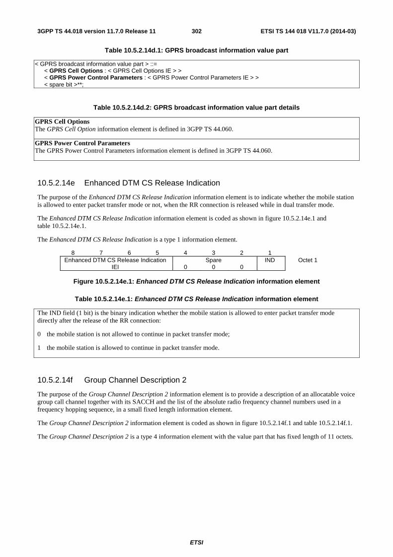
ETSI
ETSI TS 144 018 V11.7.0 (2014-03)3023GPP TS 44.018 version 11.7.0 Release 11
Table 10.5.2.14d.1: GPRS broadcast information value part
< GPRS broadcast information value part > ::= < GPRS Cell Options : < GPRS Cell Options IE > > < GPRS Power Control Parameters : < GPRS Power Control Parameters IE > > < spare bit >**;
Table 10.5.2.14d.2: GPRS broadcast information value part details
GPRS Cell Options The GPRS Cell Option information element is defined in 3GPP TS 44.060.
GPRS Power Control Parameters The GPRS Power Control Parameters information element is defined in 3GPP TS 44.060.
10.5.2.14e Enhanced DTM CS Release Indication
The purpose of the Enhanced DTM CS Release Indication information element is to indicate whether the mobile station is allowed to enter packet transfer mode or not, when the RR connection is released while in dual transfer mode.
The Enhanced DTM CS Release Indication information element is coded as shown in figure 10.5.2.14e.1 and table 10.5.2.14e.1.
The Enhanced DTM CS Release Indication is a type 1 information element.
8 7 6 5 4 3 2 1 Enhanced DTM CS Release Indication Spare IND Octet 1
IEI 0 0 0
Figure 10.5.2.14e.1: Enhanced DTM CS Release Indication information element
Table 10.5.2.14e.1: Enhanced DTM CS Release Indication information element
The IND field (1 bit) is the binary indication whether the mobile station is allowed to enter packet transfer mode directly after the release of the RR connection:
0 the mobile station is not allowed to continue in packet transfer mode;
1 the mobile station is allowed to continue in packet transfer mode.
10.5.2.14f Group Channel Description 2
The purpose of the Group Channel Description 2 information element is to provide a description of an allocatable voice group call channel together with its SACCH and the list of the absolute radio frequency channel numbers used in a frequency hopping sequence, in a small fixed length information element.
The Group Channel Description 2 information element is coded as shown in figure 10.5.2.14f.1 and table 10.5.2.14f.1.
The Group Channel Description 2 is a type 4 information element with the value part that has fixed length of 11 octets.
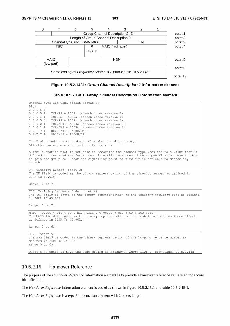
ETSI
ETSI TS 144 018 V11.7.0 (2014-03)3033GPP TS 44.018 version 11.7.0 Release 11
8 7 6 5 4 3 2 1 Group Channel Description 2 IEI octet 1
Length of Group Channel Description 2 octet 2 Channel type and TDMA offset TN octet 3
TSC 0 spare
MAIO (high part) octet 4
MAIO (low part)
HSN octet 5
Same coding as Frequency Short List 2 (sub-clause 10.5.2.14a)
octet 6
octet 13
Figure 10.5.2.14f.1: Group Channel Description 2 information element
Table 10.5.2.14f.1: Group Channel Description2 information element
Channel type and TDMA offset (octet 3) Bits 8 7 6 5 4 0 0 0 0 1 TCH/FS + ACCHs (speech codec version 1) 0 0 0 1 T TCH/HS + ACCHs (speech codec version 1) 1 0 0 0 0 TCH/FS + ACCHs (speech codec version 2) 1 0 0 0 1 TCH/AFS + ACCHs (speech codec version 3) 1 0 0 1 T TCH/AHS + ACCHs (speech codec version 3) 0 0 1 T T SDCCH/4 + SACCH/C4 0 1 T T T SDCCH/8 + SACCH/C8 The T bits indicate the subchannel number coded in binary. All other values are reserved for future use. A mobile station that is not able to recognise the channel type when set to a value that is defined as 'reserved for future use' in earlier versions of this specification, may be able to join the group call from the signalling point of view but is not able to decode any speech. TN, Timeslot number (octet 3) The TN field is coded as the binary representation of the timeslot number as defined in 3GPP TS 45.010. Range: 0 to 7. TSC, Training Sequence Code (octet 4) The TSC field is coded as the binary representation of the Training Sequence code as defined in 3GPP TS 45.002 Range: 0 to 7. MAIO, (octet 4 bit 4 to 1 high part and octet 5 bit 8 to 7 low part) The MAIO field is coded as the binary representation of the mobile allocation index offset as defined in 3GPP TS 45.002. Range: 0 to 63. HSN, (octet 5) The HSN field is coded as the binary representation of the hopping sequence number as defined in 3GPP TS 45.002 Range 0 to 63. Octet 6 to octet 13 have the same coding as Frequency Short List 2 (sub-clause 10.5.2.14a)
10.5.2.15 Handover Reference
The purpose of the Handover Reference information element is to provide a handover reference value used for access identification.
The Handover Reference information element is coded as shown in figure 10.5.2.15.1 and table 10.5.2.15.1.
The Handover Reference is a type 3 information element with 2 octets length.
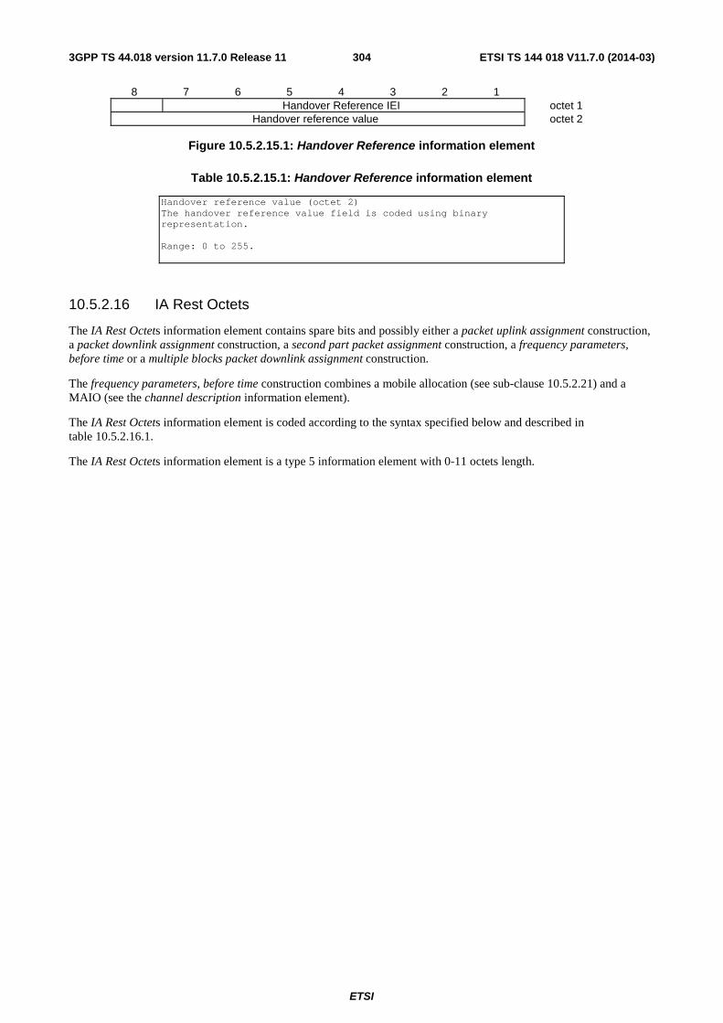
ETSI
ETSI TS 144 018 V11.7.0 (2014-03)3043GPP TS 44.018 version 11.7.0 Release 11
8 7 6 5 4 3 2 1 Handover Reference IEI octet 1
Handover reference value octet 2
Figure 10.5.2.15.1: Handover Reference information element
Table 10.5.2.15.1: Handover Reference information element
Handover reference value (octet 2) The handover reference value field is coded using binary representation. Range: 0 to 255.
10.5.2.16 IA Rest Octets
The IA Rest Octets information element contains spare bits and possibly either a packet uplink assignment construction, a packet downlink assignment construction, a second part packet assignment construction, a frequency parameters, before time or a multiple blocks packet downlink assignment construction.
The frequency parameters, before time construction combines a mobile allocation (see sub-clause 10.5.2.21) and a MAIO (see the channel description information element).
The IA Rest Octets information element is coded according to the syntax specified below and described in table 10.5.2.16.1.
The IA Rest Octets information element is a type 5 information element with 0-11 octets length.
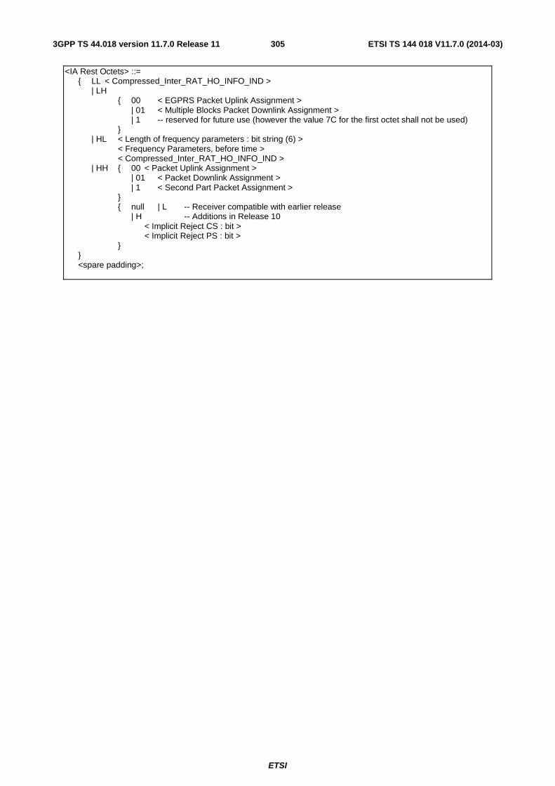
ETSI
ETSI TS 144 018 V11.7.0 (2014-03)3053GPP TS 44.018 version 11.7.0 Release 11
<IA Rest Octets> ::= { LL < Compressed_Inter_RAT_HO_INFO_IND > | LH { 00 < EGPRS Packet Uplink Assignment > | 01 < Multiple Blocks Packet Downlink Assignment > | 1 -- reserved for future use (however the value 7C for the first octet shall not be used) } | HL < Length of frequency parameters : bit string (6) > < Frequency Parameters, before time > < Compressed_Inter_RAT_HO_INFO_IND > | HH { 00 < Packet Uplink Assignment > | 01 < Packet Downlink Assignment > | 1 < Second Part Packet Assignment > } { null | L -- Receiver compatible with earlier release | H -- Additions in Release 10 < Implicit Reject CS : bit > < Implicit Reject PS : bit > } } <spare padding>;
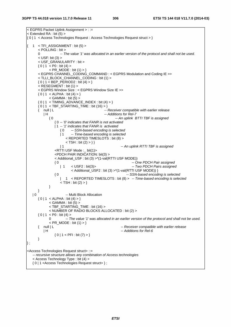
ETSI
ETSI TS 144 018 V11.7.0 (2014-03)3063GPP TS 44.018 version 11.7.0 Release 11
< EGPRS Packet Uplink Assignment > : := < Extended RA : bit (5) > { 0 | 1 < Access Technologies Request : Access Technologies Request struct > } { 1 < TFI_ASSIGNMENT : bit (5) > < POLLING : bit > 0 -- The value '1' was allocated in an earlier version of the protocol and shall not be used. < USF: bit (3) > < USF_GRANULARITY : bit > { 0 | 1 < P0 : bit (4) > < PR_MODE : bit (1) > } < EGPRS CHANNEL_CODING_COMMAND : < EGPRS Modulation and Coding IE >> < TLLI_BLOCK_CHANNEL_CODING : bit (1) > { 0 | 1 < BEP_PERIOD2 : bit (4) > } < RESEGMENT : bit (1) > < EGPRS Window Size : < EGPRS Window Size IE >> { 0 | 1 < ALPHA : bit (4) > } < GAMMA : bit (5) > { 0 | 1 < TIMING_ADVANCE_INDEX : bit (4) > } { 0 | 1 < TBF_STARTING_TIME : bit (16) > } { null | L -- Receiver compatible with earlier release | H -- Additions for Rel-7 { 0 -- An uplink BTTI TBF is assigned { 0 -- '0' indicates that FANR is not activated | 1 -- '1' indicates that FANR is activated { 0 -- SSN-based encoding is selected | 1 -- Time-based encoding is selected < REPORTED TIMESLOTS : bit (8) > < TSH : bit (2) > } } | 1 -- An uplink RTTI TBF is assigned <RTTI USF Mode :_ bit(1)> <PDCH PAIR INDICATION: bit(3) > < Additional_USF : bit (3) >*(1-val(RTTI USF MODE)) { 0 -- One PDCH Pair assigned | 1 < USF2 : bit(3)> -- Two PDCH Pairs assigned < Additional_USF2 : bit (3) >*(1-val(RTTI USF MODE)) } { 0 -- SSN-based encoding is selected | 1 < REPORTED TIMESLOTS : bit (8) > -- Time-based encoding is selected < TSH : bit (2) > } } } | 0 -- Multi Block Allocation { 0 | 1 < ALPHA : bit (4) > } < GAMMA : bit (5) > < TBF_STARTING_TIME : bit (16) > < NUMBER OF RADIO BLOCKS ALLOCATED : bit (2) > { 0 | 1 < P0 : bit (4) > 0 -- The value '1' was allocated in an earlier version of the protocol and shall not be used. < PR_MODE : bit (1) > } { null | L -- Receiver compatible with earlier release | H -- Additions for Rel-6 { 0 | 1 < PFI : bit (7) > } } } ; <Access Technologies Request struct> ::= -- recursive structure allows any combination of Access technologies < Access Technology Type : bit (4) > { 0 | 1 <Access Technologies Request struct> } ;
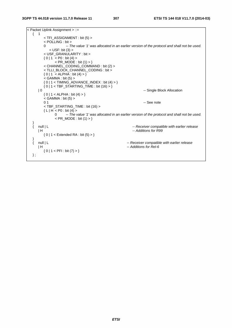
ETSI
ETSI TS 144 018 V11.7.0 (2014-03)3073GPP TS 44.018 version 11.7.0 Release 11
< Packet Uplink Assignment > ::= { 1 < TFI_ASSIGNMENT : bit (5) > < POLLING : bit > 0 -- The value '1' was allocated in an earlier version of the protocol and shall not be used. < USF: bit (3) > < USF_GRANULARITY : bit > { 0 | 1 < P0 : bit (4) > < PR_MODE : bit (1) > } < CHANNEL_CODING_COMMAND : bit (2) > < TLLI_BLOCK_CHANNEL_CODING : bit > { 0 | 1 < ALPHA : bit (4) > } < GAMMA : bit (5) > { 0 | 1 < TIMING_ADVANCE_INDEX : bit (4) > } { 0 | 1 < TBF_STARTING_TIME : bit (16) > } | 0 -- Single Block Allocation { 0 | 1 < ALPHA : bit (4) > } < GAMMA : bit (5) > 0 1 -- See note < TBF_STARTING_TIME : bit (16) > { L | H < P0 : bit (4) > 0 -- The value '1' was allocated in an earlier version of the protocol and shall not be used. < PR_MODE : bit (1) > } } { null | L -- Receiver compatible with earlier release | H -- Additions for R99 { 0 | 1 < Extended RA : bit (5) > } } { null | L -- Receiver compatible with earlier release | H -- Additions for Rel-6 { 0 | 1 < PFI : bit (7) > } } ;
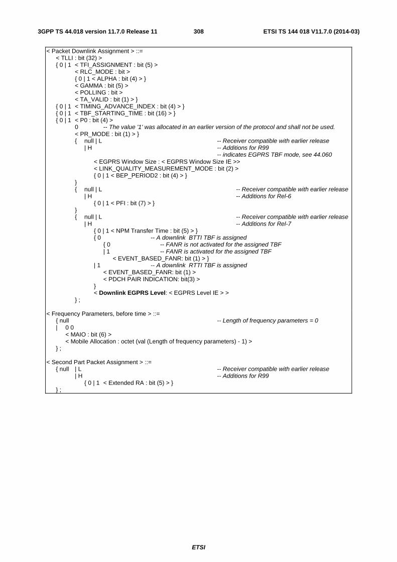
ETSI
ETSI TS 144 018 V11.7.0 (2014-03)3083GPP TS 44.018 version 11.7.0 Release 11
< Packet Downlink Assignment > ::= < TLLI : bit (32) > { 0 | 1 < TFI_ASSIGNMENT : bit (5) > < RLC_MODE : bit > { 0 | 1 < ALPHA : bit (4) > } < GAMMA : bit (5) > < POLLING : bit > < TA_VALID : bit (1) > } { 0 | 1 < TIMING_ADVANCE_INDEX : bit (4) > } { 0 | 1 < TBF_STARTING_TIME : bit (16) > } { 0 | 1 < P0 : bit (4) > 0 -- The value '1' was allocated in an earlier version of the protocol and shall not be used. < PR_MODE : bit (1) > } { null | L -- Receiver compatible with earlier release | H -- Additions for R99 -- indicates EGPRS TBF mode, see 44.060 < EGPRS Window Size : < EGPRS Window Size IE >> < LINK_QUALITY_MEASUREMENT_MODE : bit (2) > { 0 | 1 < BEP_PERIOD2 : bit (4) > } } { null | L -- Receiver compatible with earlier release | H -- Additions for Rel-6 { 0 | 1 < PFI : bit (7) > } } { null | L -- Receiver compatible with earlier release | H -- Additions for Rel-7 { 0 | 1 < NPM Transfer Time : bit (5) > } { 0 -- A downlink BTTI TBF is assigned { 0 -- FANR is not activated for the assigned TBF | 1 -- FANR is activated for the assigned TBF < EVENT_BASED_FANR: bit (1) > } | 1 -- A downlink RTTI TBF is assigned < EVENT_BASED_FANR: bit (1) > < PDCH PAIR INDICATION: bit(3) > } < Downlink EGPRS Level: < EGPRS Level IE > > } ; < Frequency Parameters, before time > ::= { null -- Length of frequency parameters = 0 | 0 0 < MAIO : bit (6) > < Mobile Allocation : octet (val (Length of frequency parameters) - 1) > } ; < Second Part Packet Assignment > ::= { null | L -- Receiver compatible with earlier release | H -- Additions for R99 { 0 | 1 < Extended RA : bit (5) > } } ;
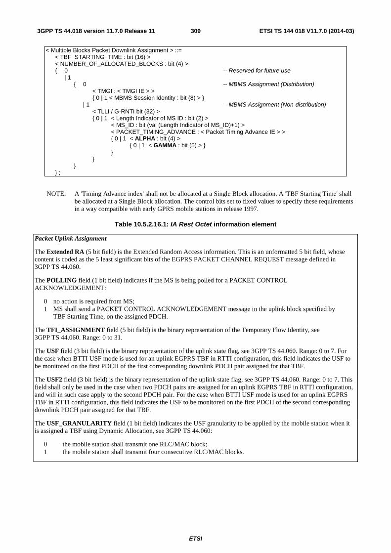
ETSI
ETSI TS 144 018 V11.7.0 (2014-03)3093GPP TS 44.018 version 11.7.0 Release 11
< Multiple Blocks Packet Downlink Assignment > ::= < TBF_STARTING_TIME : bit (16) > < NUMBER_OF_ALLOCATED_BLOCKS : bit (4) > { 0 -- Reserved for future use | 1 { 0 -- MBMS Assignment (Distribution) < TMGI : < TMGI IE > > { 0 | 1 < MBMS Session Identity : bit (8) > } | 1 -- MBMS Assignment (Non-distribution) < TLLI / G-RNTI bit (32) > { 0 | 1 < Length Indicator of MS ID : bit (2) > < MS_ID : bit (val (Length Indicator of MS_ID)+1) > < PACKET_TIMING_ADVANCE : < Packet Timing Advance IE > > { 0 | 1 < ALPHA : bit (4) > { 0 | 1 < GAMMA : bit (5) > } } } } } ;
NOTE: A 'Timing Advance index' shall not be allocated at a Single Block allocation. A 'TBF Starting Time' shall be allocated at a Single Block allocation. The control bits set to fixed values to specify these requirements in a way compatible with early GPRS mobile stations in release 1997.
Table 10.5.2.16.1: IA Rest Octet information element
Packet Uplink Assignment
The Extended RA (5 bit field) is the Extended Random Access information. This is an unformatted 5 bit field, whose content is coded as the 5 least significant bits of the EGPRS PACKET CHANNEL REQUEST message defined in 3GPP TS 44.060.
The POLLING field (1 bit field) indicates if the MS is being polled for a PACKET CONTROL ACKNOWLEDGEMENT:
0 no action is required from MS; 1 MS shall send a PACKET CONTROL ACKNOWLEDGEMENT message in the uplink block specified by TBF Starting Time, on the assigned PDCH.
The TFI_ASSIGNMENT field (5 bit field) is the binary representation of the Temporary Flow Identity, see 3GPP TS 44.060. Range: 0 to 31.
The USF field (3 bit field) is the binary representation of the uplink state flag, see 3GPP TS 44.060. Range: 0 to 7. For the case when BTTI USF mode is used for an uplink EGPRS TBF in RTTI configuration, this field indicates the USF to be monitored on the first PDCH of the first corresponding downlink PDCH pair assigned for that TBF.
The USF2 field (3 bit field) is the binary representation of the uplink state flag, see 3GPP TS 44.060. Range: 0 to 7. This field shall only be used in the case when two PDCH pairs are assigned for an uplink EGPRS TBF in RTTI configuration, and will in such case apply to the second PDCH pair. For the case when BTTI USF mode is used for an uplink EGPRS TBF in RTTI configuration, this field indicates the USF to be monitored on the first PDCH of the second corresponding downlink PDCH pair assigned for that TBF.
The USF_GRANULARITY field (1 bit field) indicates the USF granularity to be applied by the mobile station when it is assigned a TBF using Dynamic Allocation, see 3GPP TS 44.060:
0 the mobile station shall transmit one RLC/MAC block; 1 the mobile station shall transmit four consecutive RLC/MAC blocks.
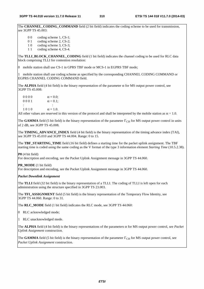
ETSI
ETSI TS 144 018 V11.7.0 (2014-03)3103GPP TS 44.018 version 11.7.0 Release 11
The CHANNEL_CODING_COMMAND field (2 bit field) indicates the coding scheme to be used for transmission, see 3GPP TS 45.003:
0 0 coding scheme 1, CS-1; 0 1 coding scheme 2, CS-2; 1 0 coding scheme 3, CS-3; 1 1 coding scheme 4, CS-4.
The TLLI_BLOCK_CHANNEL_CODING field (1 bit field) indicates the channel coding to be used for RLC data block comprising TLLI for contention resolution:
0 mobile station shall use CS-1 in GPRS TBF mode or MCS-1 in EGPRS TBF mode;
1 mobile station shall use coding scheme as specified by the corresponding CHANNEL CODING COMMAND or EGPRS CHANNEL CODING COMMAND field.
The ALPHA field (4 bit field) is the binary representation of the parameter α for MS output power control, see 3GPP TS 45.008:
0 0 0 0 α = 0.0; 0 0 0 1 α = 0.1; : : 1 0 1 0 α = 1.0.
All other values are reserved in this version of the protocol and shall be interpreted by the mobile station as α = 1.0.
The GAMMA field (5 bit field) is the binary representation of the parameter ΓCH for MS output power control in units of 2 dB, see 3GPP TS 45.008.
The TIMING_ADVANCE_INDEX field (4 bit field) is the binary representation of the timing advance index (TAI), see 3GPP TS 45.010 and 3GPP TS 44.004. Range: 0 to 15.
The TBF_STARTING_TIME field (16 bit field) defines a starting time for the packet uplink assignment. The TBF starting time is coded using the same coding as the V format of the type 3 information element Starting Time (10.5.2.38).
P0 (4 bit field) For description and encoding, see the Packet Uplink Assignment message in 3GPP TS 44.060.
PR_MODE (1 bit field) For description and encoding, see the Packet Uplink Assignment message in 3GPP TS 44.060.
Packet Downlink Assignment
The TLLI field (32 bit field) is the binary representation of a TLLI. The coding of TLLI is left open for each administration using the structure specified in 3GPP TS 23.003.
The TFI_ASSIGNMENT field (5 bit field) is the binary representation of the Temporary Flow Identity, see 3GPP TS 44.060. Range: 0 to 31.
The RLC_MODE field (1 bit field) indicates the RLC mode, see 3GPP TS 44.060:
0 RLC acknowledged mode;
1 RLC unacknowledged mode.
The ALPHA field (4 bit field) is the binary representations of the parameters α for MS output power control, see Packet Uplink Assignment construction.
The GAMMA field (5 bit field) is the binary representation of the parameter ΓCH for MS output power control, see Packet Uplink Assignment construction.
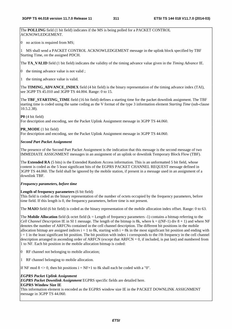
ETSI
ETSI TS 144 018 V11.7.0 (2014-03)3113GPP TS 44.018 version 11.7.0 Release 11
The POLLING field (1 bit field) indicates if the MS is being polled for a PACKET CONTROL ACKNOWLEDGEMENT.
0 no action is required from MS;
1 MS shall send a PACKET CONTROL ACKNOWLEDGEMENT message in the uplink block specified by TBF Starting Time, on the assigned PDCH.
The TA_VALID field (1 bit field) indicates the validity of the timing advance value given in the Timing Advance IE.
0 the timing advance value is not valid ;
1 the timing advance value is valid.
The TIMING_ADVANCE_INDEX field (4 bit field) is the binary representation of the timing advance index (TAI), see 3GPP TS 45.010 and 3GPP TS 44.004. Range: 0 to 15.
The TBF_STARTING_TIME field (16 bit field) defines a starting time for the packet downlink assignment. The TBF starting time is coded using the same coding as the V format of the type 3 information element Starting Time (sub-clause 10.5.2.38).
P0 (4 bit field) For description and encoding, see the Packet Uplink Assignment message in 3GPP TS 44.060.
PR_MODE (1 bit field) For description and encoding, see the Packet Uplink Assignment message in 3GPP TS 44.060.
Second Part Packet Assignment
The presence of the Second Part Packet Assignment is the indication that this message is the second message of two IMMEDIATE ASSIGNMENT messages in an assignment of an uplink or downlink Temporary Block Flow (TBF).
The Extended RA (5 bits) is the Extended Random Access information. This is an unformatted 5 bit field, whose content is coded as the 5 least significant bits of the EGPRS PACKET CHANNEL REQUEST message defined in 3GPP TS 44.060. The field shall be ignored by the mobile station, if present in a message used in an assignment of a downlink TBF.
Frequency parameters, before time
Length of frequency parameters (6 bit field) This field is coded as the binary representation of the number of octets occupied by the frequency parameters, before time field. If this length is 0, the frequency parameters, before time is not present.
The MAIO field (6 bit field) is coded as the binary representation of the mobile allocation index offset. Range: 0 to 63.
The Mobile Allocation field (k octet field (k = Length of frequency parameters -1) contains a bitmap referring to the Cell Channel Description IE in SI 1 message. The length of the bitmap is 8k, where k = ((NF-1) div 8 + 1) and where NF denotes the number of ARFCNs contained in the cell channel description. The different bit positions in the mobile allocation bitmap are assigned indices i = 1 to 8k, starting with i = 8k in the most significant bit position and ending with i = 1 in the least significant bit position. The bit position with index i corresponds to the i'th frequency in the cell channel description arranged in ascending order of ARFCN (except that ARFCN = 0, if included, is put last) and numbered from 1 to NF. Each bit position in the mobile allocation bitmap is coded:
0 RF channel not belonging to mobile allocation;
1 RF channel belonging to mobile allocation.
If NF mod 8 <> 0, then bit positions i = NF+1 to 8k shall each be coded with a "0".
EGPRS Packet Uplink Assignment EGPRS Packet Downlink Assignment EGPRS specific fields are detailed here. EGPRS Window Size IE This information element is encoded as the EGPRS window size IE in the PACKET DOWNLINK ASSIGNMENT message in 3GPP TS 44.060.
ETSI
ETSI TS 144 018 V11.7.0 (2014-03)3123GPP TS 44.018 version 11.7.0 Release 11
LINK_QUALITY_MEASUREMENT_MODE (2 bit field) This field is encoded as the LINK_QUALITY_MEASUREMENT_MODE in the PACKET DOWNLINK ASSIGNMENT message in 3GPP TS 44.060.
Access Technology Type This field indicates the access technology that is requested from the mobile station. The field is coded according to the definition in 3GPP TS 24.008. The access technology types requested from the MS in the Access Technologies Request structure shall be classified by priority, the most important first. The MS shall reply using the same order.
Among the three GSM 900 access technology types GSM P, GSM E and GSM R only one shall be requested by the network.
NUMBER OF RADIO BLOCKS ALLOCATED (2 bit field) This field indicates the number of blocks reserved for uplink transmission.
0 0 1 radio block reserved for uplink transmission; 0 1 2 radio blocks reserved for uplink transmission; 1 0 reserved for future use; 1 1 reserved for future use.
EGPRS Modulation and Coding The EGPRS Modulation and Coding information element is defined in 3GPP TS 44.060.
BEP_PERIOD2 (4 bit field) This field contains a constant which is used for filtering channel quality measurements in EGPRS. This field is encoded as the BEP_PERIOD2 in the PACKET DOWNLINK/UPLINK ASSIGNMENT messages in 3GPP TS 44.060. BEP_PERIOD2 when present shall be used instead of BEP_PERIOD. For details see 3GPP TS 45.008.
RESEGMENT (1 bit field) This field is defined in 3GPP TS 44.060.
Compressed_Inter_RAT_HO_INFO_IND (1 bit field): L A compressed version of the INTER RAT HANDOVER INFO message shall not be used; H A compressed version of the INTER RAT HANDOVER INFO message shall be used.
This information is used for determining whether a dual mode mobile station shall use a compressed version of the INTER RAT HANDOVER INFO message, see 3GPP TS 25.331.
PFI (7 bit field) This field contains the PFI parameter identifying a Packet Flow Context. The PFI parameter is encoded as the contents of the PFI information element as defined in 3GPP TS 24.008.
Number of Allocated Blocks This field indicates the number of blocks reserved for the transmission of RLC/MAC control message in the downlink.
0 0 0 0 1 radio block reserved for downlink transmission; 0 0 0 1 2 radio blocks reserved for downlink transmission; 0 0 1 0 3 radio blocks reserved for downlink transmission; 0 0 1 1 4 radio blocks reserved for downlink transmission; 0 1 0 0 5 radio blocks reserved for downlink transmission; 0 1 0 1 6 radio blocks reserved for downlink transmission; 0 1 1 0 7 radio blocks reserved for downlink transmission; 0 1 1 1 8 radio blocks reserved for downlink transmission; 1 0 0 0 9 radio blocks reserved for downlink transmission.
All other values are reserved for future use.
TMGI This field contains the Temporary Mobile Group Identity of the MBMS service. This field is encoded as defined in 3GPP TS 44.060.
MBMS Session Identity (8 bit field) This field contains the MBMS Session Identity of the concerned MBMS session.
ETSI
ETSI TS 144 018 V11.7.0 (2014-03)3133GPP TS 44.018 version 11.7.0 Release 11
MS_ID (1-4 bit field) This field addresses the mobile station, identified by the TLLI, receiving the MBMS radio bearer that is described in this message and identified by the MBMS Bearer Identity. If the MS_ID is allocated in this message the network shall omit it in the MBMS ASSIGNMENT message. This field is defined in 3GPP TS 44.060.
Packet Timing Advance If this parameter is allocated in this message the network shall omit it in the MBMS ASSIGNMENT message. This information element is defined in 3GPP TS 44.060.
ALPHA (4 bit field) If this parameter is allocated in this message the network shall omit it in the MBMS ASSIGNMENT message. For encoding and description see the Global Power Control Parameters IE specified in 3GPP TS 44.060.
GAMMA (5 bit field) The GAMMA field is the binary representation of the parameter ΓCH for MS output power control in units of 2 dB, see 3GPP TS 45.008. If this parameter is allocated in this message the network shall omit it in the MBMS ASSIGNMENT message. The GAMMA field is coded according to the following table:
bit 5 4 3 2 1 0 0 0 0 0 ΓCH = 0 dB 0 0 0 0 1 ΓCH = 2 dB : : : : 1 1 1 1 0 ΓCH = 60 dB 1 1 1 1 1 ΓCH = 62 dB
NPM Transfer Time (5 bit field) This field contains the NPM Transfer Time limitation in case of RLC non-persistent mode, and is encoded as the NPM Transfer Time IE in 3GPP TS 44.060.
EVENT_BASED_FANR (1 bit field) This field indicates whether the event-based FANR shall be used for the assigned TBF. The presence of this field means that FANR is activated for the assigned TBF. The coding of this information element is defined in 3GPP TS 44.060.
RTTI USF Mode (1 bit field) This field identifies whether RTTI or BTTI USF Mode is used for this uplink RTTI TBF. 0 BTTI USF Mode is used 1 RTTI USF Mode is used The Additional USF (3 bit field) is the binary representation of the uplink state flag, see 3GPP TS 44.060. Range: 0 to 7. This field is used only in the case when BTTI USF mode is used for an uplink EGPRS TBF in RTTI configuration and indicates the USF to be monitored on the second PDCH of the first corresponding downlink PDCH pair assigned for that TBF. The Additional USF2 (3 bit field) is the binary representation of the uplink state flag, see 3GPP TS 44.060. Range: 0 to 7. This field shall only be used in the case when two PDCH pairs are assigned for an uplink EGPRS TBF in RTTI configuration, and will in such case apply to the second PDCH pair. This field is used only in the case when BTTI USF mode is used for an uplink EGPRS TBF in RTTI configuration and indicates the USF to be monitored on the second PDCH of the second corresponding downlink PDCH pair assigned for that TBF.
ETSI
ETSI TS 144 018 V11.7.0 (2014-03)3143GPP TS 44.018 version 11.7.0 Release 11
PDCH PAIR INDICATION (3 bit field)
This field is the binary encoding of the relative placement of the timeslots constituting the uplink PDCH pair(s) and the corresponding downlink PDCH pair(s) in case of an uplink RTTI assignment, or the downlink PDCH pair(s) and the corresponding uplink PDCH pair(s) in case of a downlink RTTI assignment (see 3GPP TS 44.060). The placement is relative to the TN as indicated in the Packet Channel Description Information Element as described in subclause 10.5.2.25a. In the case the timeslot number indicated by the Packet Channel Description is TN=i, then this field is encoded as follows:
bit uplink PDCH pair(s) downlink PDCH pair(s) 3 2 1 0 0 0 [i, i+1] [i, i+1] 0 0 1 [i, i+1] [i-1, i ] 0 1 0 [i, i+1] [i-2, i] 0 1 1 [i, i+2] [i-1, i] 1 0 0 [i, i+1], [i+2, i+3] [i, i+1], [i+2, i+3] 1 0 1 not used 1 1 0 not used 1 1 1 not used REPORTED TIMESLOTS (8 bit field) The field indicates the timeslots for which feedback is provided by a time-based encoded PAN field and is defined in 3GPP TS 44.060. TSH (2 bit field) This field indicates the time-shift between the most recent radio block period for which feedback information is provided and the radio block period when the bitmap is sent and is defined in 3GPP TS 44.060. Downlink EGPRS Level The coding of this information element is defined in 3GPP TS 44.060. Implicit Reject CS (1 bit) A mobile station configured for NAS signalling low priority (see 3GPP TS 24.008) shall interpret this field as follows:
0 An implicit reject is not indicated for the CS domain.
1 An implicit reject is indicated for the CS domain.
Implicit Reject PS (1 bit) A mobile station configured for NAS signalling low priority (see 3GPP TS 24.008) shall interpret this field as follows:
0 An implicit reject is not indicated for the PS domain.
1 An implicit reject is indicated for the PS domain.
10.5.2.17 IAR Rest Octets
The IAR Rest Octets information element contains spare bits or possibly Extended RA informations.
The IAR Rest Octets information element is a type 5 information element with 3 octets length.
<IAR Rest Octets> ::= { 0 | 1 < Extended RA 1 : bit (5) > } { 0 | 1 < Extended RA 2 : bit (5) > } { 0 | 1 < Extended RA 3 : bit (5) > } { 0 | 1 < Extended RA 4 : bit (5) > } <spare padding> ;
Figure 10.5.2.17.1: IAR Rest Octets information element
ETSI
ETSI TS 144 018 V11.7.0 (2014-03)3153GPP TS 44.018 version 11.7.0 Release 11
The Extended RA i (5 bits) is the Extended Random Access information related to the Request Reference i (i within the range 1..4).
These are unformatted 5 bit fields, whose contents are coded as the 5 least significant bits of the EGPRS PACKET CHANNEL REQUEST message defined in 3GPP TS 44.060.
10.5.2.18 IAX Rest Octets
The IAX Rest Octets information element is coded according to the syntax specified below and described in table 10.5.2.18.1.
The IAX Rest Octets information element is a type 5 information element with 0-4 octets length.
<IAX Rest Octets> ::= < Compressed_Inter_RAT_HO_INFO_IND : bit > <spare padding> ;
Figure 10.5.2.18.1: IAX Rest Octets information element
Table 10.5.2.18.1: IAX Rest Octet information element
Compressed_Inter_RAT_HO_INFO_IND (1 bit field): L A compressed version of the INTER RAT HANDOVER INFO message shall not be used; H A compressed version of the INTER RAT HANDOVER INFO message shall be used.
This information is used for determining whether a multi-RAT mobile station shall use a compressed version of the INTER RAT HANDOVER INFO message, see 3GPP TS 25.331.
10.5.2.19 L2 Pseudo Length
The L2 Pseudo Length information element indicates the number of octets following it in the message which are to be interpreted in the scope of the phase 1 protocol, i.e. the total number of octets (excluding the Rest Octets) for which T, V, TV, LV, or TLV formatting is used (reference table 11.1/3GPP TS 24.007).
The L2 Pseudo Length information element is the first part of e.g. SYSTEM INFORMATION messages which are mentioned as exceptions in sub-clause 10.1. It occupies the first octet of such messages.
For any of the SYSTEM INFORMATION messages sent on the BCCH, a mobile station should ignore the contents of the L2 Pseudo Length value contained in the L2 Pseudo Length information element. For some specific messages, further requirements are specified in clause 9.
The L2 Pseudo Length Information element is an element with 2 octets length:
8 7 6 5 4 3 2 1 L2 Pseudo Length IEI octet 1
L2 Pseudo Length value 0 1 octet 2
Figure 10.5.2.19.1: L2 Pseudo Length information element
Table 10.5.2.19.1: L2 Pseudo Length information element
L2 pseudo length value (octet 2) The coding of the L2 pseudo length value field is the binary representation of the L2 pseudo length of the message in which the L2 pseudo length information element occurs.
NOTE: Bits 1 and 2 are not spare.
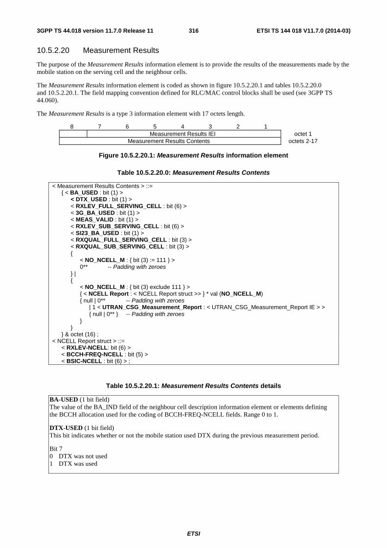
ETSI
ETSI TS 144 018 V11.7.0 (2014-03)3163GPP TS 44.018 version 11.7.0 Release 11
10.5.2.20 Measurement Results
The purpose of the Measurement Results information element is to provide the results of the measurements made by the mobile station on the serving cell and the neighbour cells.
The Measurement Results information element is coded as shown in figure 10.5.2.20.1 and tables 10.5.2.20.0 and 10.5.2.20.1. The field mapping convention defined for RLC/MAC control blocks shall be used (see 3GPP TS 44.060).
The Measurement Results is a type 3 information element with 17 octets length.
8 7 6 5 4 3 2 1 Measurement Results IEI octet 1
Measurement Results Contents octets 2-17
Figure 10.5.2.20.1: Measurement Results information element
Table 10.5.2.20.0: Measurement Results Contents
< Measurement Results Contents > ::= { < BA_USED : bit (1) > < DTX_USED : bit (1) > < RXLEV_FULL_SERVING_CELL : bit (6) > < 3G_BA_USED : bit (1) > < MEAS_VALID : bit (1) > < RXLEV_SUB_SERVING_CELL : bit (6) > < SI23_BA_USED : bit (1) > < RXQUAL_FULL_SERVING_CELL : bit (3) > < RXQUAL_SUB_SERVING_CELL : bit (3) > { < NO_NCELL_M : { bit (3) := 111 } > 0** -- Padding with zeroes } | { < NO_NCELL_M : { bit (3) exclude 111 } > { < NCELL Report : < NCELL Report struct >> } * val (NO_NCELL_M) { null | 0** -- Padding with zeroes | 1 < UTRAN_CSG_Measurement_Report : < UTRAN_CSG_Measurement_Report IE > > { null | 0** } -- Padding with zeroes } } } & octet (16) ; < NCELL Report struct > ::= < RXLEV-NCELL: bit (6) > < BCCH-FREQ-NCELL : bit (5) > < BSIC-NCELL : bit (6) > ;
Table 10.5.2.20.1: Measurement Results Contents details
BA-USED (1 bit field) The value of the BA_IND field of the neighbour cell description information element or elements defining the BCCH allocation used for the coding of BCCH-FREQ-NCELL fields. Range 0 to 1.
DTX-USED (1 bit field) This bit indicates whether or not the mobile station used DTX during the previous measurement period.
Bit 7 0 DTX was not used 1 DTX was used
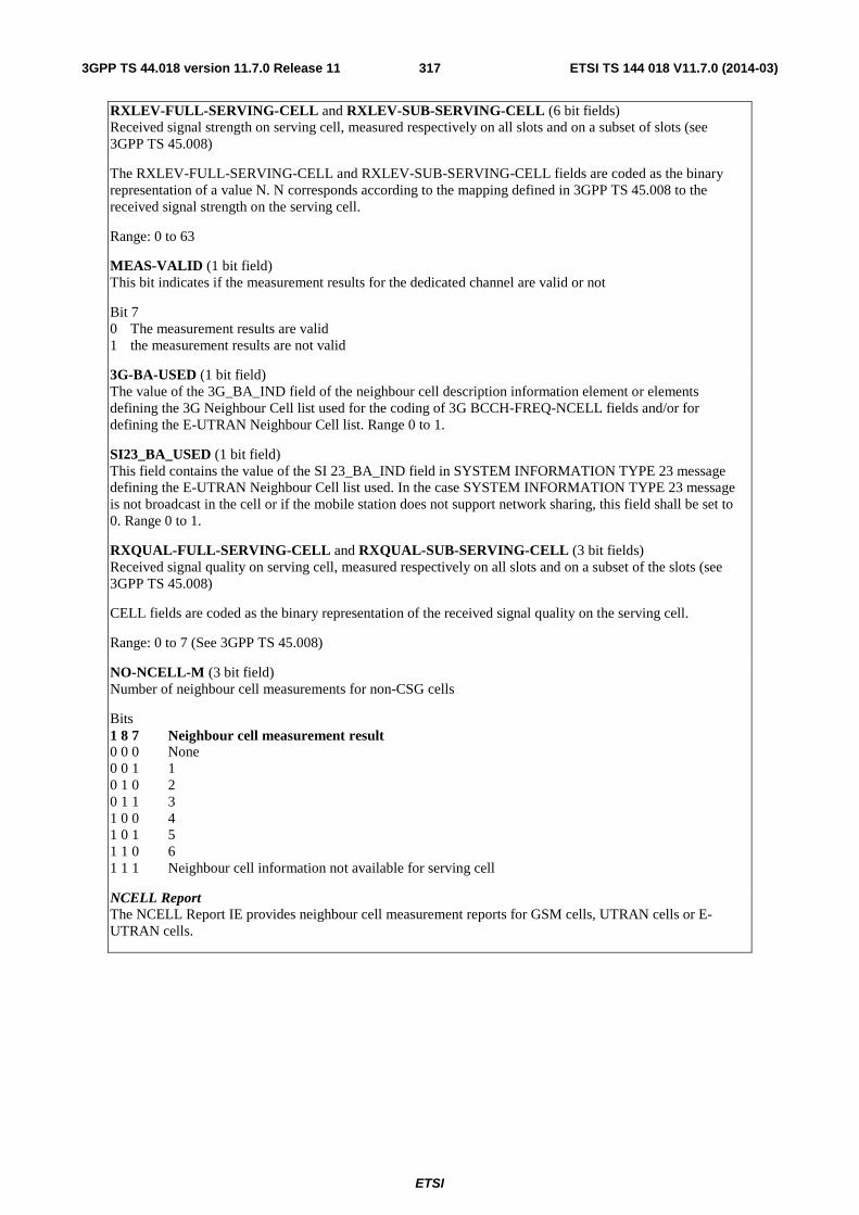
ETSI
ETSI TS 144 018 V11.7.0 (2014-03)3173GPP TS 44.018 version 11.7.0 Release 11
RXLEV-FULL-SERVING-CELL and RXLEV-SUB-SERVING-CELL (6 bit fields) Received signal strength on serving cell, measured respectively on all slots and on a subset of slots (see 3GPP TS 45.008)
The RXLEV-FULL-SERVING-CELL and RXLEV-SUB-SERVING-CELL fields are coded as the binary representation of a value N. N corresponds according to the mapping defined in 3GPP TS 45.008 to the received signal strength on the serving cell.
Range: 0 to 63
MEAS-VALID (1 bit field) This bit indicates if the measurement results for the dedicated channel are valid or not
Bit 7 0 The measurement results are valid 1 the measurement results are not valid
3G-BA-USED (1 bit field) The value of the 3G_BA_IND field of the neighbour cell description information element or elements defining the 3G Neighbour Cell list used for the coding of 3G BCCH-FREQ-NCELL fields and/or for defining the E-UTRAN Neighbour Cell list. Range 0 to 1.
SI23_BA_USED (1 bit field) This field contains the value of the SI 23_BA_IND field in SYSTEM INFORMATION TYPE 23 message defining the E-UTRAN Neighbour Cell list used. In the case SYSTEM INFORMATION TYPE 23 message is not broadcast in the cell or if the mobile station does not support network sharing, this field shall be set to 0. Range 0 to 1.
RXQUAL-FULL-SERVING-CELL and RXQUAL-SUB-SERVING-CELL (3 bit fields) Received signal quality on serving cell, measured respectively on all slots and on a subset of the slots (see 3GPP TS 45.008)
CELL fields are coded as the binary representation of the received signal quality on the serving cell.
Range: 0 to 7 (See 3GPP TS 45.008)
NO-NCELL-M (3 bit field) Number of neighbour cell measurements for non-CSG cells
Bits 1 8 7 Neighbour cell measurement result 0 0 0 None 0 0 1 1 0 1 0 2 0 1 1 3 1 0 0 4 1 0 1 5 1 1 0 6 1 1 1 Neighbour cell information not available for serving cell
NCELL Report The NCELL Report IE provides neighbour cell measurement reports for GSM cells, UTRAN cells or E-UTRAN cells.
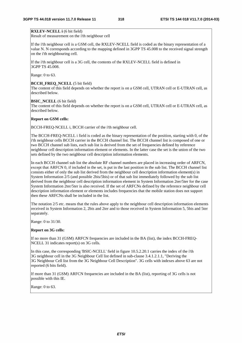
ETSI
ETSI TS 144 018 V11.7.0 (2014-03)3183GPP TS 44.018 version 11.7.0 Release 11
RXLEV-NCELL i (6 bit field) Result of measurement on the i'th neighbour cell
If the i'th neighbour cell is a GSM cell, the RXLEV-NCELL field is coded as the binary representation of a value N. N corresponds according to the mapping defined in 3GPP TS 45.008 to the received signal strength on the i'th neighbouring cell.
If the i'th neighbour cell is a 3G cell, the contents of the RXLEV-NCELL field is defined in 3GPP TS 45.008.
Range: 0 to 63.
BCCH_FREQ_NCELL (5 bit field) The content of this field depends on whether the report is on a GSM cell, UTRAN cell or E-UTRAN cell, as described below.
BSIC_NCELL (6 bit field) The content of this field depends on whether the report is on a GSM cell, UTRAN cell or E-UTRAN cell, as described below.
Report on GSM cells:
BCCH-FREQ-NCELL i, BCCH carrier of the i'th neighbour cell.
The BCCH-FREQ-NCELL i field is coded as the binary representation of the position, starting with 0, of the i'th neighbour cells BCCH carrier in the BCCH channel list. The BCCH channel list is composed of one or two BCCH channel sub lists, each sub list is derived from the set of frequencies defined by reference neighbour cell description information element or elements. In the latter case the set is the union of the two sets defined by the two neighbour cell description information elements.
In each BCCH channel sub list the absolute RF channel numbers are placed in increasing order of ARFCN, except that ARFCN 0, if included in the set, is put in the last position in the sub list. The BCCH channel list consists either of only the sub list derived from the neighbour cell description information element(s) in System Information 2/5 (and possible 2bis/5bis) or of that sub list immediately followed by the sub list derived from the neighbour cell description information element in System Information 2ter/5ter for the case System Information 2ter/5ter is also received. If the set of ARFCNs defined by the reference neighbour cell description information element or elements includes frequencies that the mobile station does not support then these ARFCNs shall be included in the list.
The notation 2/5 etc. means that the rules above apply to the neighbour cell description information elements received in System Information 2, 2bis and 2ter and to those received in System Information 5, 5bis and 5ter separately.
Range: 0 to 31/30.
Report on 3G cells:
If no more than 31 (GSM) ARFCN frequencies are included in the BA (list), the index BCCH-FREQ-NCELL 31 indicates report(s) on 3G cells.
In this case, the corresponding 'BSIC-NCELL' field in figure 10.5.2.20.1 carries the index of the i'th 3G neighbour cell in the 3G Neighbour Cell list defined in sub-clause 3.4.1.2.1.1, "Deriving the 3G Neighbour Cell list from the 3G Neighbour Cell Description". 3G cells with indexes above 63 are not reported (6 bits field).
If more than 31 (GSM) ARFCN frequencies are included in the BA (list), reporting of 3G cells is not possible with this IE.
Range: 0 to 63.
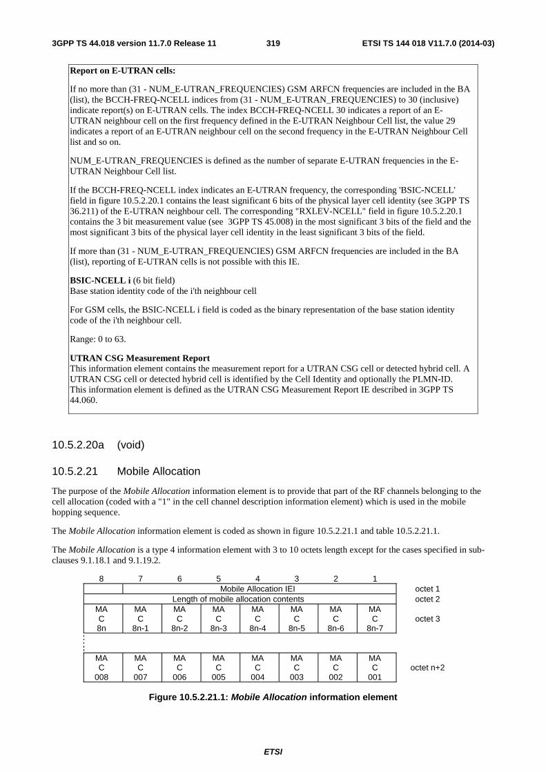
ETSI
ETSI TS 144 018 V11.7.0 (2014-03)3193GPP TS 44.018 version 11.7.0 Release 11
Report on E-UTRAN cells:
If no more than (31 - NUM_E-UTRAN_FREQUENCIES) GSM ARFCN frequencies are included in the BA (list), the BCCH-FREQ-NCELL indices from (31 - NUM_E-UTRAN_FREQUENCIES) to 30 (inclusive) indicate report(s) on E-UTRAN cells. The index BCCH-FREQ-NCELL 30 indicates a report of an E-UTRAN neighbour cell on the first frequency defined in the E-UTRAN Neighbour Cell list, the value 29 indicates a report of an E-UTRAN neighbour cell on the second frequency in the E-UTRAN Neighbour Cell list and so on.
NUM_E-UTRAN_FREQUENCIES is defined as the number of separate E-UTRAN frequencies in the E-UTRAN Neighbour Cell list.
If the BCCH-FREQ-NCELL index indicates an E-UTRAN frequency, the corresponding 'BSIC-NCELL' field in figure 10.5.2.20.1 contains the least significant 6 bits of the physical layer cell identity (see 3GPP TS 36.211) of the E-UTRAN neighbour cell. The corresponding "RXLEV-NCELL" field in figure 10.5.2.20.1 contains the 3 bit measurement value (see 3GPP TS 45.008) in the most significant 3 bits of the field and the most significant 3 bits of the physical layer cell identity in the least significant 3 bits of the field.
If more than (31 - NUM_E-UTRAN_FREQUENCIES) GSM ARFCN frequencies are included in the BA (list), reporting of E-UTRAN cells is not possible with this IE.
BSIC-NCELL i (6 bit field) Base station identity code of the i'th neighbour cell
For GSM cells, the BSIC-NCELL i field is coded as the binary representation of the base station identity code of the i'th neighbour cell.
Range: 0 to 63.
UTRAN CSG Measurement Report This information element contains the measurement report for a UTRAN CSG cell or detected hybrid cell. A UTRAN CSG cell or detected hybrid cell is identified by the Cell Identity and optionally the PLMN-ID. This information element is defined as the UTRAN CSG Measurement Report IE described in 3GPP TS 44.060.
10.5.2.20a (void)
10.5.2.21 Mobile Allocation
The purpose of the Mobile Allocation information element is to provide that part of the RF channels belonging to the cell allocation (coded with a "1" in the cell channel description information element) which is used in the mobile hopping sequence.
The Mobile Allocation information element is coded as shown in figure 10.5.2.21.1 and table 10.5.2.21.1.
The Mobile Allocation is a type 4 information element with 3 to 10 octets length except for the cases specified in sub-clauses 9.1.18.1 and 9.1.19.2.
8 7 6 5 4 3 2 1 Mobile Allocation IEI octet 1
Length of mobile allocation contents octet 2 MA C 8n
MA C
8n-1
MA C
8n-2
MA C
8n-3
MA C
8n-4
MA C
8n-5
MA C
8n-6
MA C
8n-7
octet 3
MA C
008
MA C
007
MA C
006
MA C
005
MA C
004
MA C
003
MA C
002
MA C
001
octet n+2
Figure 10.5.2.21.1: Mobile Allocation information element
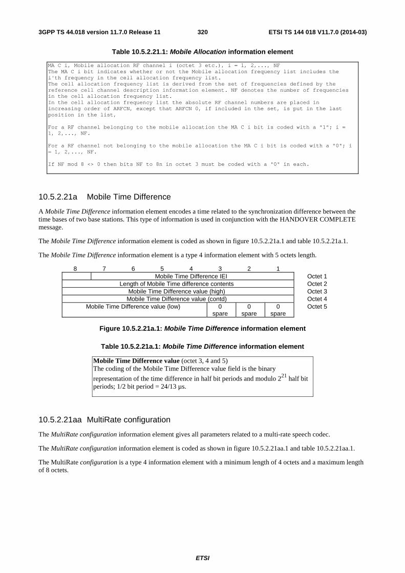
ETSI
ETSI TS 144 018 V11.7.0 (2014-03)3203GPP TS 44.018 version 11.7.0 Release 11
Table 10.5.2.21.1: Mobile Allocation information element
MA C i, Mobile allocation RF channel i (octet 3 etc.), i = 1, 2,..., NF The MA C i bit indicates whether or not the Mobile allocation frequency list includes the i'th frequency in the cell allocation frequency list. The cell allocation frequency list is derived from the set of frequencies defined by the reference cell channel description information element. NF denotes the number of frequencies in the cell allocation frequency list. In the cell allocation frequency list the absolute RF channel numbers are placed in increasing order of ARFCN, except that ARFCN 0, if included in the set, is put in the last position in the list, For a RF channel belonging to the mobile allocation the MA C i bit is coded with a "1"; i = 1, 2,..., NF. For a RF channel not belonging to the mobile allocation the MA C i bit is coded with a "0"; i = 1, 2,..., NF. If NF mod 8 <> 0 then bits NF to 8n in octet 3 must be coded with a "0" in each.
10.5.2.21a Mobile Time Difference
A Mobile Time Difference information element encodes a time related to the synchronization difference between the time bases of two base stations. This type of information is used in conjunction with the HANDOVER COMPLETE message.
The Mobile Time Difference information element is coded as shown in figure 10.5.2.21a.1 and table 10.5.2.21a.1.
The Mobile Time Difference information element is a type 4 information element with 5 octets length.
8 7 6 5 4 3 2 1 Mobile Time Difference IEI Octet 1
Length of Mobile Time difference contents Octet 2 Mobile Time Difference value (high) Octet 3
Mobile Time Difference value (contd) Octet 4 Mobile Time Difference value (low) 0
spare 0
spare 0
spare Octet 5
Figure 10.5.2.21a.1: Mobile Time Difference information element
Table 10.5.2.21a.1: Mobile Time Difference information element
Mobile Time Difference value (octet 3, 4 and 5) The coding of the Mobile Time Difference value field is the binary
representation of the time difference in half bit periods and modulo 221 half bit periods; 1/2 bit period = 24/13 µs.
10.5.2.21aa MultiRate configuration
The MultiRate configuration information element gives all parameters related to a multi-rate speech codec.
The MultiRate configuration information element is coded as shown in figure 10.5.2.21aa.1 and table 10.5.2.21aa.1.
The MultiRate configuration is a type 4 information element with a minimum length of 4 octets and a maximum length of 8 octets.
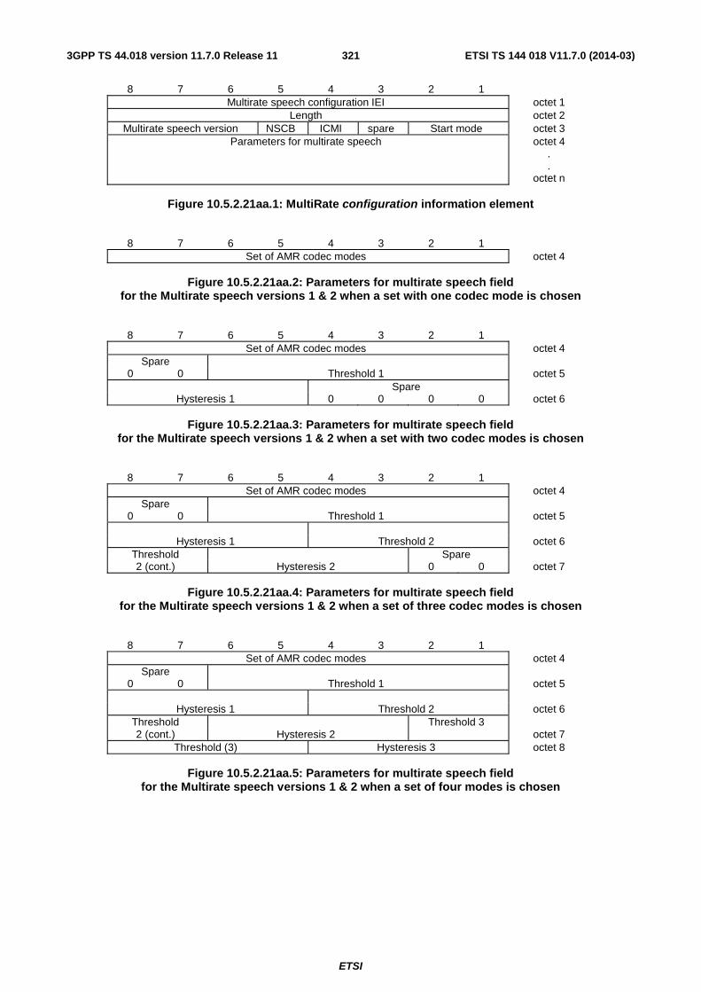
ETSI
ETSI TS 144 018 V11.7.0 (2014-03)3213GPP TS 44.018 version 11.7.0 Release 11
8 7 6 5 4 3 2 1 Multirate speech configuration IEI octet 1
Length octet 2 Multirate speech version NSCB ICMI spare Start mode octet 3
Parameters for multirate speech octet 4 . .
octet n
Figure 10.5.2.21aa.1: MultiRate configuration information element
8 7 6 5 4 3 2 1
Set of AMR codec modes octet 4
Figure 10.5.2.21aa.2: Parameters for multirate speech field for the Multirate speech versions 1 & 2 when a set with one codec mode is chosen
8 7 6 5 4 3 2 1
Set of AMR codec modes octet 4 Spare
0 0 Threshold 1 octet 5 Spare
Hysteresis 1 0 0 0 0 octet 6
Figure 10.5.2.21aa.3: Parameters for multirate speech field for the Multirate speech versions 1 & 2 when a set with two codec modes is chosen
8 7 6 5 4 3 2 1
Set of AMR codec modes octet 4 Spare
0 0 Threshold 1 octet 5
Hysteresis 1 Threshold 2 octet 6 Threshold Spare 2 (cont.) Hysteresis 2 0 0 octet 7
Figure 10.5.2.21aa.4: Parameters for multirate speech field
for the Multirate speech versions 1 & 2 when a set of three codec modes is chosen
8 7 6 5 4 3 2 1
Set of AMR codec modes octet 4 Spare
0 0 Threshold 1 octet 5
Hysteresis 1 Threshold 2 octet 6 Threshold Threshold 3 2 (cont.) Hysteresis 2 octet 7
Threshold (3) Hysteresis 3 octet 8
Figure 10.5.2.21aa.5: Parameters for multirate speech field for the Multirate speech versions 1 & 2 when a set of four modes is chosen
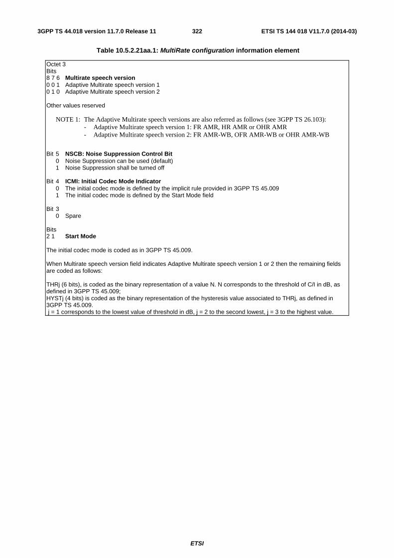
ETSI
ETSI TS 144 018 V11.7.0 (2014-03)3223GPP TS 44.018 version 11.7.0 Release 11
Table 10.5.2.21aa.1: MultiRate configuration information element
Octet 3 Bits 8 7 6 Multirate speech version 0 0 1 Adaptive Multirate speech version 1 0 1 0 Adaptive Multirate speech version 2 Other values reserved
NOTE 1: The Adaptive Multirate speech versions are also referred as follows (see 3GPP TS 26.103): - Adaptive Multirate speech version 1: FR AMR, HR AMR or OHR AMR - Adaptive Multirate speech version 2: FR AMR-WB, OFR AMR-WB or OHR AMR-WB
Bit 5 NSCB: Noise Suppression Control Bit 0 Noise Suppression can be used (default) 1 Noise Suppression shall be turned off Bit 4 ICMI: Initial Codec Mode Indicator 0 The initial codec mode is defined by the implicit rule provided in 3GPP TS 45.009 1 The initial codec mode is defined by the Start Mode field Bit 3 0 Spare Bits 2 1 Start Mode The initial codec mode is coded as in 3GPP TS 45.009. When Multirate speech version field indicates Adaptive Multirate speech version 1 or 2 then the remaining fields are coded as follows: THRj (6 bits), is coded as the binary representation of a value N. N corresponds to the threshold of C/I in dB, as defined in 3GPP TS 45.009; HYSTj (4 bits) is coded as the binary representation of the hysteresis value associated to THRj, as defined in 3GPP TS 45.009. j = 1 corresponds to the lowest value of threshold in dB, j = 2 to the second lowest, j = 3 to the highest value.
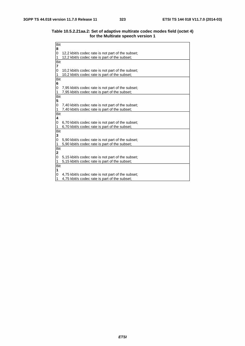
ETSI
ETSI TS 144 018 V11.7.0 (2014-03)3233GPP TS 44.018 version 11.7.0 Release 11
Table 10.5.2.21aa.2: Set of adaptive multirate codec modes field (octet 4) for the Multirate speech version 1
Bit 8 0 12,2 kbit/s codec rate is not part of the subset; 1 12,2 kbit/s codec rate is part of the subset; Bit 7 0 10,2 kbit/s codec rate is not part of the subset; 1 10,2 kbit/s codec rate is part of the subset; Bit 6 0 7,95 kbit/s codec rate is not part of the subset; 1 7,95 kbit/s codec rate is part of the subset; Bit 5 0 7,40 kbit/s codec rate is not part of the subset; 1 7,40 kbit/s codec rate is part of the subset; Bit 4 0 6,70 kbit/s codec rate is not part of the subset; 1 6,70 kbit/s codec rate is part of the subset; Bit 3 0 5,90 kbit/s codec rate is not part of the subset; 1 5,90 kbit/s codec rate is part of the subset; Bit 2 0 5,15 kbit/s codec rate is not part of the subset; 1 5,15 kbit/s codec rate is part of the subset; Bit 1 0 4,75 kbit/s codec rate is not part of the subset; 1 4,75 kbit/s codec rate is part of the subset;

ETSI
ETSI TS 144 018 V11.7.0 (2014-03)3243GPP TS 44.018 version 11.7.0 Release 11
Table 10.5.2.21aa.3: Set of adaptive multirate codec modes field (octets 4 & 5) for the Multirate speech version 2
Bit 8 (Octet 4) 0 spare Bit 7 (Octet 4) 0 spare Bit 6 (Octet 4) 0 spare Bit 5 (Octet 4) 0 23,85 kbit/s codec rate is not part of the subset; 1 23,85 kbit/s codec rate is part of the subset; Bit 4 (Octet 4) 0 15,85 kbit/s codec rate is not part of the subset; 1 15,85 kbit/s codec rate is part of the subset; Bit 3 (Octet 4) 0 12,65 kbit/s codec rate is not part of the subset; 1 12,65 kbit/s codec rate is part of the subset; Bit 2 (Octet 4) 0 8,85 kbit/s codec rate is not part of the subset; 1 8,85 kbit/s codec rate is part of the subset; Bit 1 (Octet 4) 0 6,60 kbit/s codec rate is not part of the subset; 1 6,60 kbit/s codec rate is part of the subset;
10.5.2.21ab Mobile Time Difference on Hyperframe level
A Mobile Time Difference on Hyperframe level information element encodes a time related to the synchronization difference between the time bases of two base stations. This type of information is used in conjunction with the HANDOVER COMPLETE message.
The Mobile Time Difference on Hyperframe level information element is coded as shown in figure 10.5.2.21ab.1 and table 10.5.2.21ab.1.
The Mobile Time Difference on Hyperframe level information element is a type 4 information element with 7 octets length.
8 7 6 5 4 3 2 1 Mobile Time Difference on Hyperframe level IEI Octet 1
Length of Mobile Time difference on Hyperframe level contents Octet 2 Mobile Time Difference on Hyperframe level value (high) Octet 3
Mobile Time Difference on Hyperframe level value (contd) Octet 4 Mobile Time Difference on Hyperframe level value (contd) Octet 5 Mobile Time Difference on Hyperframe level value (contd) Octet 6
Mobile Time
Difference on
Hyperframe level
value (low)
0 spare
0 spare
0 spare
0 spare
0 spare
0 spare
0 spare
Octet 7
Figure 10.5.2.21ab.1: Mobile Time Difference on Hyperframe level information element
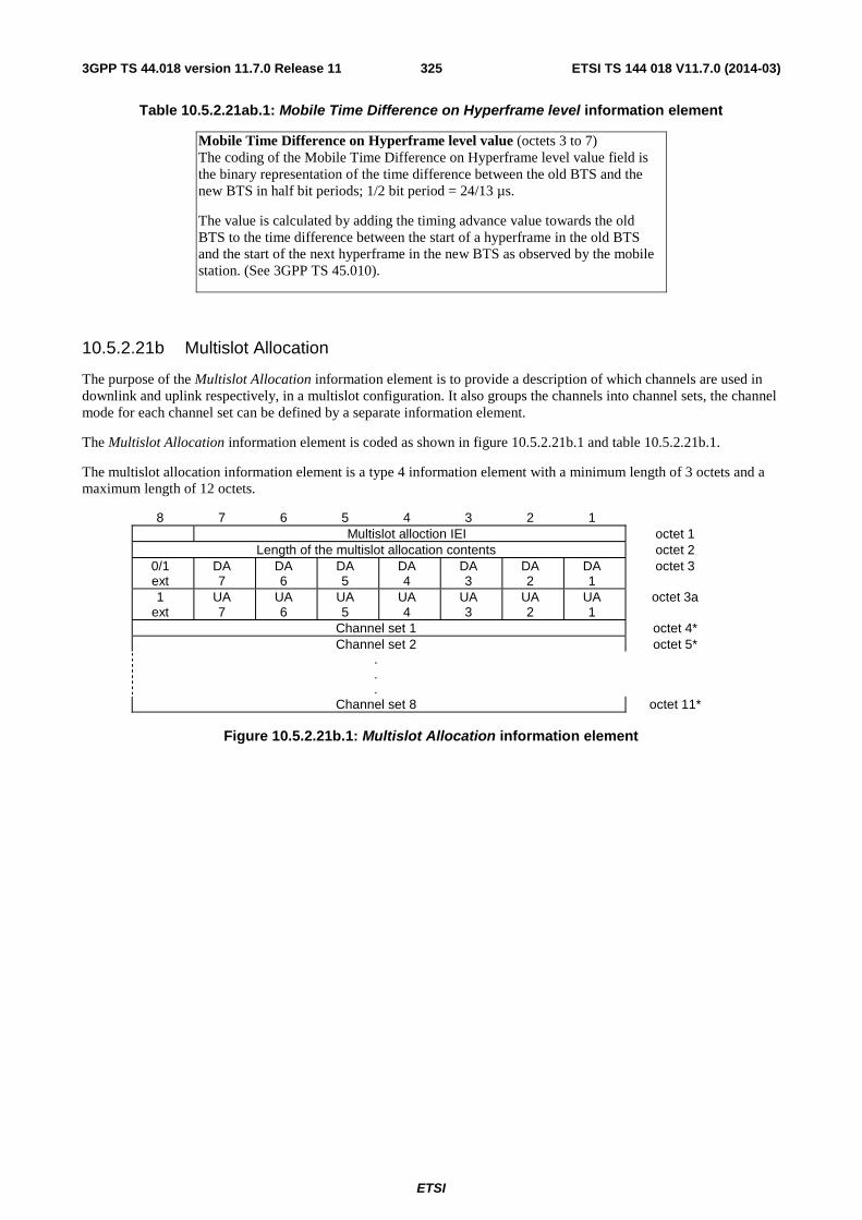
ETSI
ETSI TS 144 018 V11.7.0 (2014-03)3253GPP TS 44.018 version 11.7.0 Release 11
Table 10.5.2.21ab.1: Mobile Time Difference on Hyperframe level information element
Mobile Time Difference on Hyperframe level value (octets 3 to 7) The coding of the Mobile Time Difference on Hyperframe level value field is the binary representation of the time difference between the old BTS and the new BTS in half bit periods; 1/2 bit period = 24/13 µs.
The value is calculated by adding the timing advance value towards the old BTS to the time difference between the start of a hyperframe in the old BTS and the start of the next hyperframe in the new BTS as observed by the mobile station. (See 3GPP TS 45.010).
10.5.2.21b Multislot Allocation
The purpose of the Multislot Allocation information element is to provide a description of which channels are used in downlink and uplink respectively, in a multislot configuration. It also groups the channels into channel sets, the channel mode for each channel set can be defined by a separate information element.
The Multislot Allocation information element is coded as shown in figure 10.5.2.21b.1 and table 10.5.2.21b.1.
The multislot allocation information element is a type 4 information element with a minimum length of 3 octets and a maximum length of 12 octets.
8 7 6 5 4 3 2 1 Multislot alloction IEI octet 1
Length of the multislot allocation contents octet 2 0/1 ext
DA 7
DA 6
DA 5
DA 4
DA 3
DA 2
DA 1
octet 3
1 ext
UA 7
UA 6
UA 5
UA 4
UA 3
UA 2
UA 1
octet 3a
Channel set 1 octet 4* Channel set 2 octet 5*
.
.
.
Channel set 8 octet 11*
Figure 10.5.2.21b.1: Multislot Allocation information element
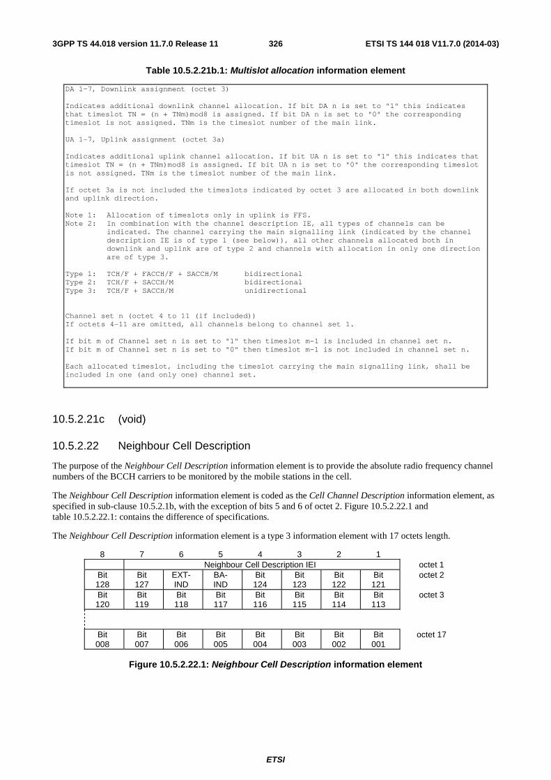
ETSI
ETSI TS 144 018 V11.7.0 (2014-03)3263GPP TS 44.018 version 11.7.0 Release 11
Table 10.5.2.21b.1: Multislot allocation information element
DA 1-7, Downlink assignment (octet 3) Indicates additional downlink channel allocation. If bit DA n is set to "1" this indicates that timeslot TN = (n + TNm)mod8 is assigned. If bit DA n is set to "0" the corresponding timeslot is not assigned. TNm is the timeslot number of the main link. UA 1-7, Uplink assignment (octet 3a) Indicates additional uplink channel allocation. If bit UA n is set to "1" this indicates that timeslot TN = (n + TNm)mod8 is assigned. If bit UA n is set to "0" the corresponding timeslot is not assigned. TNm is the timeslot number of the main link. If octet 3a is not included the timeslots indicated by octet 3 are allocated in both downlink and uplink direction. Note 1: Allocation of timeslots only in uplink is FFS. Note 2: In combination with the channel description IE, all types of channels can be
indicated. The channel carrying the main signalling link (indicated by the channel description IE is of type 1 (see below)), all other channels allocated both in downlink and uplink are of type 2 and channels with allocation in only one direction are of type 3.
Type 1: TCH/F + FACCH/F + SACCH/M bidirectional Type 2: TCH/F + SACCH/M bidirectional Type 3: TCH/F + SACCH/M unidirectional Channel set n (octet 4 to 11 (if included)) If octets 4-11 are omitted, all channels belong to channel set 1. If bit m of Channel set n is set to "1" then timeslot m-1 is included in channel set n. If bit m of Channel set n is set to "0" then timeslot m-1 is not included in channel set n. Each allocated timeslot, including the timeslot carrying the main signalling link, shall be included in one (and only one) channel set.
10.5.2.21c (void)
10.5.2.22 Neighbour Cell Description
The purpose of the Neighbour Cell Description information element is to provide the absolute radio frequency channel numbers of the BCCH carriers to be monitored by the mobile stations in the cell.
The Neighbour Cell Description information element is coded as the Cell Channel Description information element, as specified in sub-clause 10.5.2.1b, with the exception of bits 5 and 6 of octet 2. Figure 10.5.2.22.1 and table 10.5.2.22.1: contains the difference of specifications.
The Neighbour Cell Description information element is a type 3 information element with 17 octets length.
8 7 6 5 4 3 2 1 Neighbour Cell Description IEI octet 1
Bit 128
Bit 127
EXT- IND
BA- IND
Bit 124
Bit 123
Bit 122
Bit 121
octet 2
Bit 120
Bit 119
Bit 118
Bit 117
Bit 116
Bit 115
Bit 114
Bit 113
octet 3
Bit 008
Bit 007
Bit 006
Bit 005
Bit 004
Bit 003
Bit 002
Bit 001
octet 17
Figure 10.5.2.22.1: Neighbour Cell Description information element
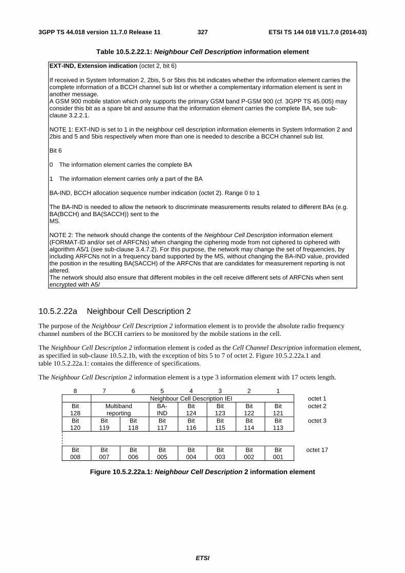
ETSI
ETSI TS 144 018 V11.7.0 (2014-03)3273GPP TS 44.018 version 11.7.0 Release 11
Table 10.5.2.22.1: Neighbour Cell Description information element
EXT-IND, Extension indication (octet 2, bit 6) If received in System Information 2, 2bis, 5 or 5bis this bit indicates whether the information element carries the complete information of a BCCH channel sub list or whether a complementary information element is sent in another message. A GSM 900 mobile station which only supports the primary GSM band P-GSM 900 (cf. 3GPP TS 45.005) may consider this bit as a spare bit and assume that the information element carries the complete BA, see sub-clause 3.2.2.1. NOTE 1: EXT-IND is set to 1 in the neighbour cell description information elements in System Information 2 and 2bis and 5 and 5bis respectively when more than one is needed to describe a BCCH channel sub list. Bit 6 0 The information element carries the complete BA 1 The information element carries only a part of the BA BA-IND, BCCH allocation sequence number indication (octet 2). Range 0 to 1 The BA-IND is needed to allow the network to discriminate measurements results related to different BAs (e.g. BA(BCCH) and BA(SACCH)) sent to the MS. NOTE 2: The network should change the contents of the Neighbour Cell Description information element (FORMAT-ID and/or set of ARFCNs) when changing the ciphering mode from not ciphered to ciphered with algorithm A5/1 (see sub-clause 3.4.7.2). For this purpose, the network may change the set of frequencies, by including ARFCNs not in a frequency band supported by the MS, without changing the BA-IND value, provided the position in the resulting BA(SACCH) of the ARFCNs that are candidates for measurement reporting is not altered. The network should also ensure that different mobiles in the cell receive different sets of ARFCNs when sent encrypted with A5/
10.5.2.22a Neighbour Cell Description 2
The purpose of the Neighbour Cell Description 2 information element is to provide the absolute radio frequency channel numbers of the BCCH carriers to be monitored by the mobile stations in the cell.
The Neighbour Cell Description 2 information element is coded as the Cell Channel Description information element, as specified in sub-clause 10.5.2.1b, with the exception of bits 5 to 7 of octet 2. Figure 10.5.2.22a.1 and table 10.5.2.22a.1: contains the difference of specifications.
The Neighbour Cell Description 2 information element is a type 3 information element with 17 octets length.
8 7 6 5 4 3 2 1 Neighbour Cell Description IEI octet 1
Bit 128
Multiband reporting
BA- IND
Bit 124
Bit 123
Bit 122
Bit 121
octet 2
Bit 120
Bit 119
Bit 118
Bit 117
Bit 116
Bit 115
Bit 114
Bit 113
octet 3
Bit 008
Bit 007
Bit 006
Bit 005
Bit 004
Bit 003
Bit 002
Bit 001
octet 17
Figure 10.5.2.22a.1: Neighbour Cell Description 2 information element
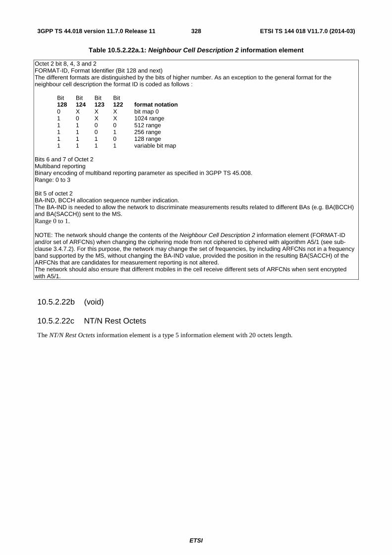
ETSI
ETSI TS 144 018 V11.7.0 (2014-03)3283GPP TS 44.018 version 11.7.0 Release 11
Table 10.5.2.22a.1: Neighbour Cell Description 2 information element
Octet 2 bit 8, 4, 3 and 2 FORMAT-ID, Format Identifier (Bit 128 and next) The different formats are distinguished by the bits of higher number. As an exception to the general format for the neighbour cell description the format ID is coded as follows :
Bit Bit Bit Bit 128 124 123 122 format notation 0 X X X bit map 0 1 0 X X 1024 range 1 1 0 0 512 range 1 1 0 1 256 range 1 1 1 0 128 range 1 1 1 1 variable bit map
Bits 6 and 7 of Octet 2 Multiband reporting Binary encoding of multiband reporting parameter as specified in 3GPP TS 45.008. Range: 0 to 3 Bit 5 of octet 2 BA-IND, BCCH allocation sequence number indication. The BA-IND is needed to allow the network to discriminate measurements results related to different BAs (e.g. BA(BCCH) and BA(SACCH)) sent to the MS. Range 0 to 1. NOTE: The network should change the contents of the Neighbour Cell Description 2 information element (FORMAT-ID and/or set of ARFCNs) when changing the ciphering mode from not ciphered to ciphered with algorithm A5/1 (see sub-clause 3.4.7.2). For this purpose, the network may change the set of frequencies, by including ARFCNs not in a frequency band supported by the MS, without changing the BA-IND value, provided the position in the resulting BA(SACCH) of the ARFCNs that are candidates for measurement reporting is not altered. The network should also ensure that different mobiles in the cell receive different sets of ARFCNs when sent encrypted with A5/1.
10.5.2.22b (void)
10.5.2.22c NT/N Rest Octets
The NT/N Rest Octets information element is a type 5 information element with 20 octets length.
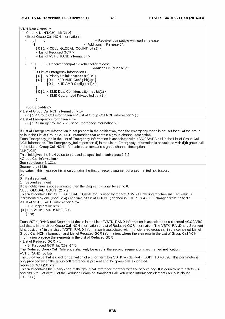
ETSI
ETSI TS 144 018 V11.7.0 (2014-03)3293GPP TS 44.018 version 11.7.0 Release 11
NT/N Rest Octets ::= {0 I 1 < NLN(NCH) : bit (2) >} <list of Group Call NCH information> { null | L -- Receiver compatible with earlier release | H -- Additions in Release 6°: { 0 | 1 < CELL_GLOBAL_COUNT: bit (2) >} < List of Reduced GCR > < List of VSTK_RAND information > } { null | L -- Receiver compatible with earlier release | H -- Additions in Release 7°: < List of Emergency information > { 0 | 1 < Priority Uplink access : bit(1)> } { 0 | 1 { 0|1 <FR AMR Config:bit(4)> } { 0|1 <HR AMR Config:bit(4)> } } { 0 | 1 < SMS Data Confidentiality Ind : bit(1)> < SMS Guaranteed Privacy Ind : bit(1)> } } <Spare padding>; < List of Group Call NCH information > ::= { 0 | 1 < Group Call information > < List of Group Call NCH information > } ; < List of Emergency information > ::= { 0 | 1 < Emergency_Ind > < List of Emergency information > } ; If List of Emergency Information is not present in the notification, then the emergency mode is not set for all of the group calls in the List of Group Call NCH information that contain a group channel description. Each Emergency_Ind in the List of Emergency Information is associated with a VGCS/VBS call in the List of Group Call NCH information. The Emergency_Ind at position (i) in the List of Emergency Information is associated with (i)th group call in the List of Group Call NCH information that contains a group channel description. NLN(NCH) This field gives the NLN value to be used as specified in sub-clause3.3.3 <Group Call information> See sub-clause 9.1.21a Segment Id (1 bit) Indicates if this message instance contains the first or second segment of a segmented notification. bit 0 First segment. 1 Second segment. If the notification is not segmented then the Segment Id shall be set to 0. CELL_GLOBAL_COUNT (2 bits) This field contains the CELL_GLOBAL_COUNT that is used by the VGCS/VBS ciphering mechanism. The value is incremented by one (modulo 4) each time bit 22 of COUNT ( defined in 3GPP TS 43.020) changes from "1" to "0". < List of VSTK_RAND information > ::= { 1 < Segment Id: bit > {0 | 1 < VSTK_RAND: bit (36) >} } **0; Each VSTK_RAND and Segment Id that is in the List of VSTK_RAND Information is associated to a ciphered VGCS/VBS call that is in the List of Group Call NCH information or List of Reduced GCR information. The VSTK_RAND and Segment Id at position (i) in the List of VSTK_RAND Information is associated with (i)th ciphered group call in the combined List of Group Call NCH information and List of Reduced GCR information, where the elements in the List of Group Call NCH information precede the elements in the List of Reduced GCR. < List of Reduced GCR > ::= { 1< Reduced GCR: bit (28) >} **0; The Reduced Group Call Reference shall only be used in the second segment of a segmented notification. VSTK_RAND (36 bit) The 36-bit value that is used for derivation of a short term key VSTK, as defined in 3GPP TS 43.020. This parameter is only provided when the group call reference is present and the group call is ciphered. Reduced GCR (28 bits) This field contains the binary code of the group call reference together with the service flag. It is equivalent to octets 2-4 and bits 5 to 8 of octet 5 of the Reduced Group or Broadcast Call Reference information element (see sub-clause 10.5.2.63)
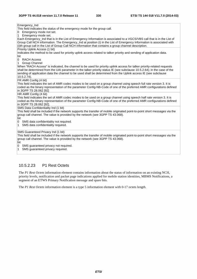
ETSI
ETSI TS 144 018 V11.7.0 (2014-03)3303GPP TS 44.018 version 11.7.0 Release 11
Emergency_Ind This field indicates the status of the emergency mode for the group call. 0 Emergency mode not set. 1 Emergency mode set. Each Emergency_Ind that is in the List of Emergency Information is associated to a VGCS/VBS call that is in the List of Group Call NCH information. The Emergency_Ind at position (i) in the List of Emergency Information is associated with (i)th group call in the List of Group Call NCH information that contains a group channel description. Priority Uplink Access (1 bit) Indicates the method to be used for priority uplink access related to talker priority and sending of application data. bit 0 RACH Access 1 Group Channel When "RACH Access" is indicated, the channel to be used for priority uplink access for talker priority-related requests shall be determined from the UAI parameter in the talker priority status IE (see subclause 10.5.2.64); in the case of the sending of application data the channel to be used shall be determined from the Uplink access IE (see subclause 10.5.2.74). FR AMR Config (4 bit) This field indicates the set of AMR codec modes to be used on a group channel using speech full rate version 3. It is coded as the binary representation of the parameter Config-NB-Code of one of the preferred AMR configurations defined in 3GPP TS 28.062 [92] HR AMR Config (4 bit) This field indicates the set of AMR codec modes to be used on a group channel using speech half rate version 3. It is coded as the binary representation of the parameter Config-NB-Code of one of the preferred AMR configurations defined in 3GPP TS 28.062 [92]. SMS Data Confidentiality Ind (1 bit) This field shall be included if the network supports the transfer of mobile originated point-to-point short messages via the group call channel. The value is provided by the network (see 3GPP TS 43.068). bit 0 SMS data confidentiality not required. 1 SMS data confidentiality required. SMS Guaranteed Privacy Ind (1 bit) This field shall be included if the network supports the transfer of mobile originated point-to-point short messages via the group call channel. The value is provided by the network (see 3GPP TS 43.068). bit 0 SMS guaranteed privacy not required. 1 SMS guaranteed privacy required.
10.5.2.23 P1 Rest Octets
The P1 Rest Octets information element contains information about the status of information on an existing NCH, priority levels, notification and packet page indications applied for mobile station identities, MBMS Notifications, a segment of an ETWS Primary Notification message and spare bits.
The P1 Rest Octets information element is a type 5 information element with 0-17 octets length.
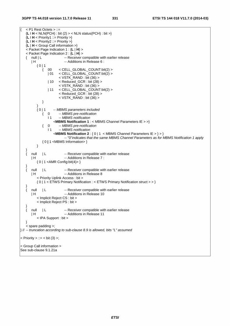
ETSI
ETSI TS 144 018 V11.7.0 (2014-03)3313GPP TS 44.018 version 11.7.0 Release 11
{ < P1 Rest Octets > ::= {L I H < NLN(PCH) : bit (2) > < NLN status(PCH) : bit >} {L I H < Priority1 ::= Priority >} {L I H < Priority2 ::= Priority >} {L | H < Group Call information >} < Packet Page Indication 1 : {L | H} > < Packet Page Indication 2 : {L | H} > { null | L -- Receiver compatible with earlier release | H -- Additions in Release 6 : { 0 | 1 { 00 < CELL_GLOBAL_COUNT:bit(2) > | 01 < CELL_GLOBAL_COUNT:bit(2) > < VSTK_RAND : bit (36) > | 10 < Reduced_GCR : bit (28) > < VSTK_RAND : bit (36) > | 11 < CELL_GLOBAL_COUNT:bit(2) > < Reduced_GCR : bit (28) > < VSTK_RAND : bit (36) > } } { 0 | 1 -- MBMS parameters included { 0 -- MBMS pre-notification I 1 -- MBMS notification <MBMS Notification 1 : < MBMS Channel Parameters IE > >} { 0 -- MBMS pre-notification I 1 -- MBMS notification <MBMS Notification 2 : { 0 | 1 < MBMS Channel Parameters IE > } > } -- "0"indicates that the same MBMS Channel Parameters as for MBMS Notification 1 apply { 0 | 1 <MBMS Information> } } } { null | L -- Receiver compatible with earlier release | H -- Additions in Release 7 : { 0 | 1 <AMR Config:bit(4)> } } { null | L -- Receiver compatible with earlier release | H -- Additions in Release 8 < Priority Uplink Access : bit > { 0 | 1 < ETWS Primary Notification : < ETWS Primary Notification struct > > } } { null | L -- Receiver compatible with earlier release | H -- Additions in Release 10 < Implicit Reject CS : bit > < Implicit Reject PS : bit > } { null | L -- Receiver compatible with earlier release | H -- Additions in Release 11 < IPA Support : bit > } < spare padding >; } // -- truncation according to sub-clause 8.9 is allowed, bits "L" assumed < Priority > ::= < bit (3) >; < Group Call information > See sub-clause 9.1.21a
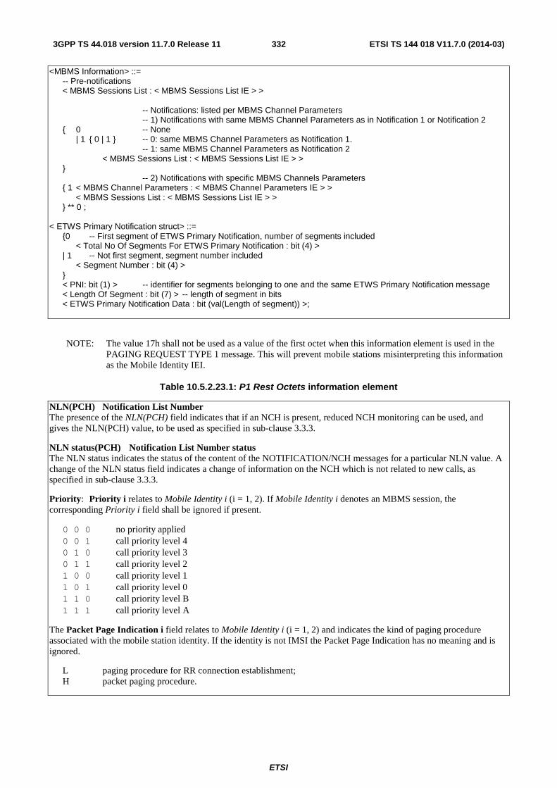
ETSI
ETSI TS 144 018 V11.7.0 (2014-03)3323GPP TS 44.018 version 11.7.0 Release 11
<MBMS Information> ::= -- Pre-notifications < MBMS Sessions List : < MBMS Sessions List IE > > -- Notifications: listed per MBMS Channel Parameters -- 1) Notifications with same MBMS Channel Parameters as in Notification 1 or Notification 2 { 0 -- None | 1 { 0 | 1 } -- 0: same MBMS Channel Parameters as Notification 1. -- 1: same MBMS Channel Parameters as Notification 2 < MBMS Sessions List : < MBMS Sessions List IE > > } -- 2) Notifications with specific MBMS Channels Parameters { 1 < MBMS Channel Parameters : < MBMS Channel Parameters IE > > < MBMS Sessions List : < MBMS Sessions List IE > > } ** 0 ; < ETWS Primary Notification struct> ::= {0 -- First segment of ETWS Primary Notification, number of segments included < Total No Of Segments For ETWS Primary Notification : bit (4) > | 1 -- Not first segment, segment number included < Segment Number : bit (4) > } < PNI: bit (1) > -- identifier for segments belonging to one and the same ETWS Primary Notification message < Length Of Segment : bit (7) > -- length of segment in bits < ETWS Primary Notification Data : bit (val(Length of segment)) >;
NOTE: The value 17h shall not be used as a value of the first octet when this information element is used in the PAGING REQUEST TYPE 1 message. This will prevent mobile stations misinterpreting this information as the Mobile Identity IEI.
Table 10.5.2.23.1: P1 Rest Octets information element
NLN(PCH) Notification List Number The presence of the NLN(PCH) field indicates that if an NCH is present, reduced NCH monitoring can be used, and gives the NLN(PCH) value, to be used as specified in sub-clause 3.3.3.
NLN status(PCH) Notification List Number status The NLN status indicates the status of the content of the NOTIFICATION/NCH messages for a particular NLN value. A change of the NLN status field indicates a change of information on the NCH which is not related to new calls, as specified in sub-clause 3.3.3.
Priority: Priority i relates to Mobile Identity i (i = 1, 2). If Mobile Identity i denotes an MBMS session, the corresponding Priority i field shall be ignored if present.
0 0 0 no priority applied 0 0 1 call priority level 4 0 1 0 call priority level 3 0 1 1 call priority level 2 1 0 0 call priority level 1 1 0 1 call priority level 0 1 1 0 call priority level B 1 1 1 call priority level A
The Packet Page Indication i field relates to Mobile Identity i (i = 1, 2) and indicates the kind of paging procedure associated with the mobile station identity. If the identity is not IMSI the Packet Page Indication has no meaning and is ignored.
L paging procedure for RR connection establishment; H packet paging procedure.
ETSI
ETSI TS 144 018 V11.7.0 (2014-03)3333GPP TS 44.018 version 11.7.0 Release 11
Reduced GCR (28 bits) This field contains the binary code of the group call reference together with the service flag. It is equivalent to octets 2-4 and bits 5 to 8 of octet 5 of the Reduced Group or Broadcast Call Reference information element (see sub-clause 10.5.2.63).
VSTK_RAND (36 bits) The 36-bit value that is used for derivation of a short term key VSTK, as defined in 3GPP TS 43.020. This parameter is only provided when the group call reference is present and the group call is ciphered.
CELL_GLOBAL_COUNT (2 bits) This field contains the CELL_GLOBAL_COUNT that is used by the VGCS/VBS ciphering mechanism. Mobiles that don"t support VGCS/VBS may ignore this parameter. The value is incremented by one (modulo 4) each time bit 22 of COUNT ( defined in 3GPP TS 43.020) changes from "1" to "0"..
The MBMS Notification i structure relates to Mobile Identity i (i = 1, 2) and contains information related to a specific MBMS session. If Mobile Identity i does not denote an MBMS session or is not a TMGI of interest for the mobile station the corresponding MBMS Notification information shall be ignored.
MBMS Sessions List This information element contains a list of MBMS sessions identified by their TMGI and if available MBMS Session Identity (see 3GPP TS 44.060). This information element is defined in 3GPP TS 44.060.
MBMS Channel Parameters This information element contains the MBMS channel parameters of one or more MBMS sessions. This information element is defined in 3GPP TS 44.060.
AMR_Config (4 bits) This field indicates the set of AMR codec modes to be used on a group channel using speech version 3. It is coded as the binary representation of the parameter Config-NB-Code of one of the preferred AMR configurations defined in 3GPP TS 28.062 [91], subclause 7.11.3.1.3.
Priority Uplink Access (1 bit) This field indicates the method to be used for priority uplink access related to talker priority and sending of application data.
bit 0 RACH Access 1 Group Channel
When "RACH Access" is indicated, the channel to be used for priority uplink access for talker priority-related requests shall be determined from the UAI parameter in the talker priority status IE (see subclause 10.5.2.64); in the case of the sending of application data the channel to be used shall be determined from the Uplink access IE (see subclause 10.5.2.74).
This bit shall be ignored by mobiles which do not support group receive mode.
Total No Of Segments For ETWS Primary Notification (4 bits) This field contains the number of segments for the ETWS Primary Notification message.
Bits 4 3 2 1 0 0 0 0 reserved 0 0 0 1 one segment 0 0 1 0 two segments . . . 1 1 1 1 fifteen segments
ETSI
ETSI TS 144 018 V11.7.0 (2014-03)3343GPP TS 44.018 version 11.7.0 Release 11
Segment Number (4 bits) This field contains the Segment Number of the ETWS Primary Notification message.
Bits 4 3 2 1 0 0 0 0 reserved 0 0 0 1 reserved 0 0 1 0 second segment 0 0 1 1 third segment . . . 1 1 1 1 fifteenth segment
PNI, Primary Notification Identifier (1 bit) This field is used as an identifier to determine the set of segments belonging to a certain ETWS Primary Notification message. This information element will have the same value (0 or 1) for all segments belonging to the same ETWS Primary Notification message.
Length Of Segment (7 bits) This field indicates the length of a segment in number of bits.
ETWS Primary Notification Data (n*8 bits) The ETWS Primary Notification data is coded as specified in 3GPP TS 23.041.
Implicit Reject CS (1 bit)
Implicit Reject PS (1 bit) A mobile station configured for NAS signalling low priority (see 3GPP TS 24.008) shall interpret these fields as described for the IA Rest Octets IE (see sub-clause 10.5.2.16).
IPA_Support (1 bit) The IPA_Support field indicates whether the network supports the IMMEDIATE PACKET ASSIGNMENT message. A mobile station supporting IPA (see 3GPP TS 24.008) shall interpret this field as described below:
0 IMMEDIATE PACKET ASSIGNMENT message is not supported 1 IMMEDIATE PACKET ASSIGNMENT message is supported on CCCH.
ETSI
ETSI TS 144 018 V11.7.0 (2014-03)3353GPP TS 44.018 version 11.7.0 Release 11
10.5.2.24 P2 Rest Octets
The P2 Rest Octets information element contains information on the channel needed by the network and information about the status of information on an existing NCH, priority levels and packet page indications applied for mobile station identities, MBMS Notification and spare bits.
The P2 Rest Octets information element is a type 5 information element with 1-11 octets length.
{ <P2 Rest Octets> ::= {L I H <CN3: bit (2)>} {L I H <NLN(PCH) : bit (2)> <NLN status(PCH) : bit>} {L I H <Priority1 ::= Priority>} {L I H <Priority2 ::= Priority>} {L I H <Priority3 ::= Priority>} < Packet Page Indication 3 : {L | H} > { null | L -- Receiver compatible with earlier release | H -- Additions in Release 6 : { 0 I 1 -- MBMS parameters included { 0 -- MBMS pre-notification I 1 -- MBMS notification <MBMS Notification 3 : < MBMS Channel Parameters IE > > } { 0 | 1 < MBMS Information > } } } { null | L -- Receiver compatible with earlier release | H -- Additions in Release 10 < Implicit Reject CS : bit > < Implicit Reject PS : bit > } { null | L -- Receiver compatible with earlier release | H -- Additions in Release 11 < IPA Support : bit > } <spare padding>; } // -- truncation according to sub-clause 8.9 is allowed, bits 'L' assumed <Priority> ::= <bit(3)>; <MBMS Information> ::= -- Pre-notifications < MBMS Sessions List : < MBMS Sessions List IE > > -- Notifications: listed per MBMS Channel Parameters -- 1) Notifications with same MBMS Channel Parameters as in Notification 3 { 0 -- None | 1 -- Same MBMS Channel Parameters as Notification 3 < MBMS Sessions List : < MBMS Sessions List IE > > } -- 2) Notifications with specific MBMS Channels Parameters { 1 < MBMS Channel Parameters : < MBMS Channel Parameters IE > > < MBMS Sessions List : < MBMS Sessions List IE > > } ** 0 ;
NOTE: The value 17h shall not be used as a value of the first octet when this information element is used in the PAGING REQUEST TYPE 2 message. This will prevent mobile stations misinterpreting this information as the Mobile Identity IEI.
ETSI
ETSI TS 144 018 V11.7.0 (2014-03)3363GPP TS 44.018 version 11.7.0 Release 11
Table 10.5.2.24.1: P2 Rest Octets information element
CN3 Channel Needed for Mobile Identity 3 The values and semantics used in the CN3 field are those of the CHANNEL field of Channel Needed IE (see sub-clause 10.5.2.8). The CN3 field is associated with the Mobile Identity 3 IE of the PAGING REQUEST TYPE 2 message.
If the CN3 field is not present, the default value is 00 (any channel). If Mobile Identity 3 denotes an MBMS session, the CN3 field shall be ignored if present.
NLN(PCH) Notification List Number See P1 Rest Octets.
NLN status(PCH) Notification List Number status See P1 Rest Octets.
Priority: Priority i relates to Mobile Identity i (i = 1, 2, 3). If Mobile Identity 3 denotes an MBMS session, the corresponding Priority 3 field shall be ignored if present.
0 0 0 no priority applied 0 0 1 call priority level 4 0 1 0 call priority level 3 0 1 1 call priority level 2 1 0 0 call priority level 1 1 0 1 call priority level 0 1 1 0 call priority level B 1 1 1 call priority level A
The Packet Page Indication 3 field relates to Mobile Identity 3 and indicates the kind of paging procedure associated with the mobile station identity. If the identity is not IMSI the Packet Page Indication has no meaning and is ignored.
L paging procedure for RR connection establishment; H packet paging procedure.
The MBMS Notification 3 field relates to Mobile Identity 3 and contains information related to a specific MBMS session. If Mobile Identity 3 does not denote an MBMS session or is not a TMGI of interest for the mobile station the corresponding MBMS Notification information shall be ignored.
See Table 10.5.2.23.1: "P1 Rest Octets information element" for the definitions of IEs used for MBMS related information.
Implicit Reject CS (1 bit)
Implicit Reject PS (1 bit) A mobile station configured for NAS signalling low priority (see 3GPP TS 24.008) shall interpret these fields as described for the IA Rest Octets IE (see sub-clause 10.5.2.16).
IPA_Support (1 bit) A mobile station supporting IPA (see 3GPP TS 24.008) shall interpret this field as described in the P1 Rest Octets IE (see sub-clause 10.5.2.23)
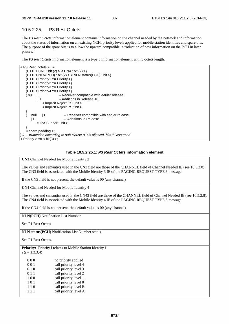
ETSI
ETSI TS 144 018 V11.7.0 (2014-03)3373GPP TS 44.018 version 11.7.0 Release 11
10.5.2.25 P3 Rest Octets
The P3 Rest Octets information element contains information on the channel needed by the network and information about the status of information on an existing NCH, priority levels applied for mobile station identities and spare bits. The purpose of the spare bits is to allow the upward compatible introduction of new information on the PCH in later phases.
The P3 Rest Octets information element is a type 5 information element with 3 octets length.
< P3 Rest Octets > ::= {L I H < CN3 : bit (2) > < CN4 : bit (2) >} {L I H < NLN(PCH) : bit (2) > < NLN status(PCH) : bit >} {L I H < Priority1 ::= Priority >} {L I H < Priority2 ::= Priority >} {L I H < Priority3 ::= Priority >} {L I H < Priority4 ::= Priority >} { null | L -- Receiver compatible with earlier release | H -- Additions in Release 10 < Implicit Reject CS : bit > < Implicit Reject PS : bit > } { null | L -- Receiver compatible with earlier release | H -- Additions in Release 11 < IPA Support : bit > } < spare padding >; } // -- truncation according to sub-clause 8.9 is allowed, bits 'L' assumed < Priority > ::= < bit(3) >;
Table 10.5.2.25.1: P3 Rest Octets information element
CN3 Channel Needed for Mobile Identity 3
The values and semantics used in the CN3 field are those of the CHANNEL field of Channel Needed IE (see 10.5.2.8). The CN3 field is associated with the Mobile Identity 3 IE of the PAGING REQUEST TYPE 3 message.
If the CN3 field is not present, the default value is 00 (any channel)
CN4 Channel Needed for Mobile Identity 4
The values and semantics used in the CN43 field are those of the CHANNEL field of Channel Needed IE (see 10.5.2.8). The CN4 field is associated with the Mobile Identity 4 IE of the PAGING REQUEST TYPE 3 message.
If the CN4 field is not present, the default value is 00 (any channel)
NLN(PCH) Notification List Number
See P1 Rest Octets
NLN status(PCH) Notification List Number status
See P1 Rest Octets.
Priority: Priority i relates to Mobile Station Identity i i (i = 1,2,3,4)
0 0 0 no priority applied 0 0 1 call priority level 4 0 1 0 call priority level 3 0 1 1 call priority level 2 1 0 0 call priority level 1 1 0 1 call priority level 0 1 1 0 call priority level B 1 1 1 call priority level A

ETSI
ETSI TS 144 018 V11.7.0 (2014-03)3383GPP TS 44.018 version 11.7.0 Release 11
Implicit Reject CS (1 bit)
Implicit Reject PS (1 bit) A mobile station configured for NAS signalling low priority (see 3GPP TS 24.008) shall interpret these fields as described for the IA Rest Octets IE (see sub-clause 10.5.2.16).
IPA_Support (1 bit) A mobile station supporting IPA (see 3GPP TS 24.008) shall interpret this field as described in the P1 Rest Octets IE (see sub-clause 10.5.2.23)
10.5.2.25a Packet Channel Description
The purpose of the Packet Channel Description information element is to provide a description of a packet data physical channel (PDCH).
The Packet Channel Description information element is coded according to the syntax specified below and described in table 10.58.
The Packet Channel Description is a type 3 information element with 4 octets length.
< Packet Channel Description > ::= < Channel type : bit (5) > < TN : bit (3) > < TSC : bit (3) > { 0 { 0 < spare bit > < ARFCN : bit (10) > -- non-hopping RF channel configuraion | 1 < spare bit > < MAIO : bit (6) > -- indirect encoding of hopping RF channel configuration < MA_NUMBER_IND : bit > { 0 < spare bits : bit (2) > | 1 < CHANGE_MARK_1 : bit (2) > } } | 1 < MAIO : bit (6) > -- direct encoding of hopping RF channel configuration < HSN : bit (6) > };
Table 10.5.2.25a.1: Packet Channel Description information element
The Channel type field (5 bit) shall be ignored by the receiver and all bits treated as spare. For backward compatibility reasons, the sender shall set the spare bits to binary '00001'.
The TN field (3 bit) is the binary representation of the timeslot number as defined in 3GPP TS 45.010. Range: 0 to 7
The TSC field (3 bit) is the binary representation of the training sequence code as defined in 3GPP TS 45.002. Range: 0 to 7.
Non-hopping RF channel configuration The ARFCN field (10 bit) is the binary representation of the absolute RF channel number, see 3GPP TS 45.005. Range: 0 to 1023.
Indirect encoding of hopping RF channel configuration The MAIO field (6 bit) is the binary representation of the mobile allocation index offset, see 3GPP TS 45.002. Range: 0 to 63.
The MA_NUMBER_IND field (1 bit) is the binary representation of the MA_NUMBER to use as reference to a GPRS mobile allocation:
0 MA_NUMBER = 14 1 MA_NUMBER = 15

ETSI
ETSI TS 144 018 V11.7.0 (2014-03)3393GPP TS 44.018 version 11.7.0 Release 11
The CHANGE_MARK_1 field (2 bit) is the binary representation of the allowed value of the SI change mark associated with the GPRS mobile allocation to which the MA_NUMBER refers. Range: 0 to 3.
If the indirect encoding is used, this information element may contain the CHANGE_MARK_1 field. If that is present, the mobile station being assigned the TBF shall verify the validity of the SI change mark associated with the GPRS mobile allocation to which this information element refers, see 3GPP TS 44.060. The CHANGE_MARK_1 field shall not be included in this information element if MA_NUMBER = 15 is used.
Direct encoding of hopping RF channel configuration The MAIO field (6 bit) is the binary representation of the mobile allocation index offset, see 3GPP TS 45.002. Range: 0 to 63.
The HSN field (6 bit) is the binary representation of the hopping sequence number, see 3GPP TS 45.002. Range: 0 to 63.
10.5.2.25b Dedicated mode or TBF
The Dedicated mode or TBF information element is used by the network to indicate to the mobile station whether the rest of the message shall be decoded as an IMMEDIATE ASSIGNMENT message allocating a channel in dedicated mode or whether the rest of the message shall be decoded as the allocation of a Temporary Block Flow.
This information element also indicates:
- whether the IMMEDIATE ASSIGNMENT message identifies a mobile station in the IA Rest Octets information elements for the assignment of a downlink TBF; and
- whether the IMMEDIATE ASSIGNMENT message is the first message of two IMMEDIATE ASSIGNMENT messages in a two-message assignment of an uplink or downlink TBF.
The Dedicated mode or TBF information element is coded as shown in figure 10.5.2.25b.1, table 10.5.2.25b.1 and Table 10.5.2.25b.2.
The Dedicated mode or TBF is a type 1 information element.
8 7 6 5 4 3 2 1 Dedicated mode
or TBF IEI spare
0
TMA down-
link
T/D octet 1
Figure 10.5.2.25b.1: Dedicated mode or TBF information element
Table 10.5.2.25b.1: Dedicated mode or TBF information element
T/D : TBF or dedicated mode (octet 1, bit 1) The coding of this field is given by Table 10.5.2.2.25b.2.
Downlink : Downlink TBF assignment to the mobile station identified in the IA Rast Octets IE (octet 1, bit 2) The coding of this field is given by Table 10.5.2.2.25b.2.
TMA : Two-message assignment (octet 1, bit 3) The coding of this field is given by Table 10.5.2.2.25b.2.
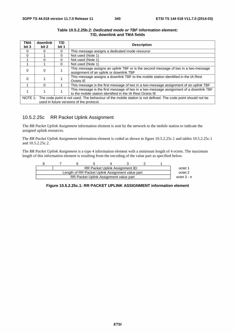
ETSI
ETSI TS 144 018 V11.7.0 (2014-03)3403GPP TS 44.018 version 11.7.0 Release 11
Table 10.5.2.25b.2: Dedicated mode or TBF information element: T/D, downlink and TMA fields
TMA bit 3
downlink bit 2
T/D bit 1 Description
0 0 0 This message assigns a dedicated mode resource 0 1 0 Not used (Note 1) 1 0 0 Not used (Note 1) 1 1 0 Not used (Note 1)
0 0 1 This message assigns an uplink TBF or is the second message of two in a two-message assignment of an uplink or downlink TBF
0 1 1 This message assigns a downlink TBF to the mobile station identified in the IA Rest Octets IE
1 0 1 This message is the first message of two in a two-message assignment of an uplink TBF
1 1 1 This message is the first message of two in a two-message assignment of a downlink TBF to the mobile station identified in the IA Rest Octets IE
NOTE 1: The code point is not used. The behaviour of the mobile station is not defined. The code point should not be used in future versions of the protocol.
10.5.2.25c RR Packet Uplink Assignment
The RR Packet Uplink Assignment information element is sent by the network to the mobile station to indicate the assigned uplink resources.
The RR Packet Uplink Assignment information element is coded as shown in figure 10.5.2.25c.1 and tables 10.5.2.25c.1 and 10.5.2.25c.2.
The RR Packet Uplink Assignment is a type 4 information element with a minimum length of 4 octets. The maximum length of this information element is resulting from the encoding of the value part as specified below.
8 7 6 5 4 3 2 1 RR Packet Uplink Assignment IEI octet 1
Length of RR Packet Uplink Assignment value part octet 2 RR Packet Uplink Assignment value part octet 3 - n
Figure 10.5.2.25c.1: RR PACKET UPLINK ASSIGNMENT information element
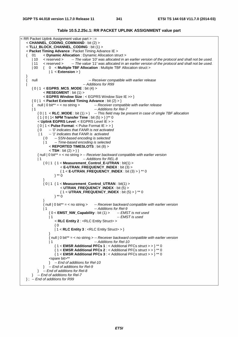
ETSI
ETSI TS 144 018 V11.7.0 (2014-03)3413GPP TS 44.018 version 11.7.0 Release 11
Table 10.5.2.25c.1: RR PACKET UPLINK ASSIGNMENT value part
< RR Packet Uplink Assignment value part > ::= < CHANNEL_CODING_COMMAND : bit (2) > < TLLI_BLOCK_CHANNEL_CODING : bit (1) > < Packet Timing Advance : Packet Timing Advance IE > { 01 < Dynamic Allocation : Dynamic Allocation struct > | 10 < reserved > -- The value '10' was allocated in an earlier version of the protocol and shall not be used. | 11 < reserved > -- The value '11' was allocated in an earlier version of the protocol and shall not be used. | 00 { 0 < Multiple TBF Allocation : Multiple TBF Allocation struct > | 1 < Extension > } } { null -- Receiver compatible with earlier release | -- Additions for R99 { 0 | 1 < EGPRS_MCS_MODE : bit (4) > < RESEGMENT : bit (1) > < EGPRS Window Size : < EGPRS Window Size IE >> } { 0 | 1 < Packet Extended Timing Advance : bit (2) > } { null | 0 bit** = < no string > -- Receiver compatible with earlier release | 1 -- Additions for Rel-7 { 0 | 1 < RLC_MODE : bit (1) > } -- This field may be present in case of single TBF allocation { 1 { 0 | 1< NPM Transfer Time : bit (5) > } }** 0 < Uplink EGPRS Level: < EGPRS Level IE > > { 0 | 1 < Pulse Format: < Pulse Format IE > > } { 0 -- '0' indicates that FANR is not activated | 1 -- '1' indicates that FANR is activated { 0 -- SSN-based encoding is selected | 1 -- Time-based encoding is selected < REPORTED TIMESLOTS : bit (8) > < TSH : bit (2) > } } { null | 0 bit** = < no string > -- Receiver backward compatible with earlier version | 1 -- Additions for REL-8 { 0 | 1 { 1 < Measurement_Control_E-UTRAN : bit(1) > < E-UTRAN_FREQUENCY_INDEX : bit (3) > { 1 < E-UTRAN_FREQUENCY_INDEX : bit (3) > } ** 0 } ** 0 } { 0 | 1 { 1 < Measurement_Control_UTRAN : bit(1) > < UTRAN_FREQUENCY_INDEX : bit (5) > { 1 < UTRAN_FREQUENCY_INDEX : bit (5) > } ** 0 } ** 0 } { null | 0 bit** = < no string > -- Receiver backward compatible with earlier version | 1 -- Additions for Rel-9 { 0 < EMST_NW_Capability : bit (1) > -- EMST is not used | 1 -- EMST is used < RLC Entity 2 : <RLC Entity Struct> > { 0 | 1 < RLC Entity 3 : <RLC Entity Struct> > } } { null | 0 bit** = < no string > -- Receiver backward compatible with earlier version | 1 -- Additions for Rel-10 { 1 < EMSR Additional PFCs 1 : < Additional PFCs struct > > } ** 0 { 1 < EMSR Additional PFCs 2 : < Additional PFCs struct > > } ** 0 { 1 < EMSR Additional PFCs 3 : < Additional PFCs struct > > } ** 0 <spare bit>** } -- End of additions for Rel-10 } -- End of additions for Rel-9 } -- End of additions for Rel-8 } -- End of additions for Rel-7 } ; -- End of additions for R99
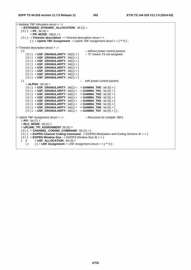
ETSI
ETSI TS 144 018 V11.7.0 (2014-03)3423GPP TS 44.018 version 11.7.0 Release 11
< Multiple TBF Allocation struct > ::= < EXTENDED_DYNAMIC_ALLOCATION : bit (1) > { 0 | 1 < P0 : bit (4) > < PR_MODE : bit(1) > } { 0 | 1 < Timeslot description : < Timeslot description struct > > { 1 < Uplink TBF Assignment : < Uplink TBF Assignment struct > > } ** 0 } ; < Timeslot description struct > ::= { 0 -- without power control params { 0 | 1 < USF_GRANULARITY : bit(1) > } -- "0" means TS not assigned { 0 | 1 < USF_GRANULARITY : bit(1) > } { 0 | 1 < USF_GRANULARITY : bit(1) > } { 0 | 1 < USF_GRANULARITY : bit(1) > } { 0 | 1 < USF_GRANULARITY : bit(1) > } { 0 | 1 < USF_GRANULARITY : bit(1) > } { 0 | 1 < USF_GRANULARITY : bit(1) > } { 0 | 1 < USF_GRANULARITY : bit(1) > } | 1 -- with power control params < ALPHA : bit (4) > { 0 | 1 < USF_GRANULARITY : bit(1) > < GAMMA_TN0 : bit (5) > } { 0 | 1 < USF_GRANULARITY : bit(1) > < GAMMA_TN1 : bit (5) > } { 0 | 1 < USF_GRANULARITY : bit(1) > < GAMMA_TN2 : bit (5) > } { 0 | 1 < USF_GRANULARITY : bit(1) > < GAMMA_TN3 : bit (5) > } { 0 | 1 < USF_GRANULARITY : bit(1) > < GAMMA_TN4 : bit (5) > } { 0 | 1 < USF_GRANULARITY : bit(1) > < GAMMA_TN5 : bit (5) > } { 0 | 1 < USF_GRANULARITY : bit(1) > < GAMMA_TN6 : bit (5) > } { 0 | 1 < USF_GRANULARITY : bit(1) > < GAMMA_TN7 : bit (5) > } } ; < Uplink TBF Assignment struct > ::= -- Recursive for multiple TBFs < PFI : bit (7) > < RLC_MODE : bit (1) > < UPLINK_TFI_ASSIGNMENT: bit (5) > { 0 | 1 < CHANNEL_CODING_COMMAND : bit (2) > } { 0 | 1 < EGPRS Channel Coding Command : < EGPRS Modulation and Coding Scheme IE > > } { 0 | 1 < EGPRS Window Size : < EGPRS Window Size IE > > } { 0 < USF_ALLOCATION : bit (3) > | 1 { 1 < USF Assignment: < USF Assignment struct > > } ** 0 } ;
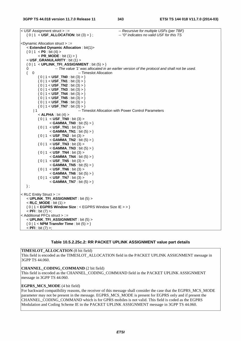
ETSI
ETSI TS 144 018 V11.7.0 (2014-03)3433GPP TS 44.018 version 11.7.0 Release 11
< USF Assignment struct > ::= -- Recursive for multiple USFs (per TBF) { 0 | 1 < USF_ALLOCATION: bit (3) > } ; -- "0" indicates no valid USF for this TS <Dynamic Allocation struct > ::= < Extended Dynamic Allocation : bit(1)> { 0 | 1 < P0 : bit (4) > < PR_MODE : bit (1) > } < USF_GRANULARITY : bit (1) > { 0 | 1 < UPLINK_TFI_ASSIGNMENT : bit (5) > } 0 -- The value '1' was allocated in an earlier version of the protocol and shall not be used. { 0 -- Timeslot Allocation { 0 | 1 < USF_TN0 : bit (3) > } { 0 | 1 < USF_TN1 : bit (3) > } { 0 | 1 < USF_TN2 : bit (3) > } { 0 | 1 < USF_TN3 : bit (3) > } { 0 | 1 < USF_TN4 : bit (3) > } { 0 | 1 < USF_TN5 : bit (3) > } { 0 | 1 < USF_TN6 : bit (3) > } { 0 | 1 < USF_TN7 : bit (3) > } | 1 -- Timeslot Allocation with Power Control Parameters < ALPHA : bit (4) > { 0 | 1 < USF_TN0 : bit (3) > < GAMMA_TN0 : bit (5) > } { 0 | 1 < USF_TN1 : bit (3) > < GAMMA_TN1 : bit (5) > } { 0 | 1 < USF_TN2 : bit (3) > < GAMMA_TN2 : bit (5) > } { 0 | 1 < USF_TN3 : bit (3) > < GAMMA_TN3 : bit (5) > } { 0 | 1 < USF_TN4 : bit (3) > < GAMMA_TN4 : bit (5) > } { 0 | 1 < USF_TN5 : bit (3) > < GAMMA_TN5 : bit (5) > } { 0 | 1 < USF_TN6 : bit (3) > < GAMMA_TN6 : bit (5) > } { 0 | 1 < USF_TN7 : bit (3) > < GAMMA_TN7 : bit (5) > } } ; < RLC Entity Struct > ::= < UPLINK_TFI_ASSIGNMENT : bit (5) > < RLC_MODE : bit (1) > { 0 | 1 < EGPRS Window Size : < EGPRS Window Size IE > > } < PFI : bit (7) >; < Additional PFCs struct > ::= < UPLINK_TFI_ASSIGNMENT : bit (5) > { 0 | 1 < NPM Transfer Time : bit (5) > } < PFI : bit (7) >;
Table 10.5.2.25c.2: RR PACKET UPLINK ASSIGNMENT value part details
TIMESLOT_ALLOCATION (8 bit field) This field is encoded as the TIMESLOT_ALLOCATION field in the PACKET UPLINK ASSIGNMENT message in 3GPP TS 44.060.
CHANNEL_CODING_COMMAND (2 bit field) This field is encoded as the CHANNEL_CODING_COMMAND field in the PACKET UPLINK ASSIGNMENT message in 3GPP TS 44.060.
EGPRS_MCS_MODE (4 bit field) For backward compatibility reasons, the receiver of this message shall consider the case that the EGPRS_MCS_MODE parameter may not be present in the message. EGPRS_MCS_MODE is present for EGPRS only and if present the CHANNEL_CODING_COMMAND which is for GPRS mobiles is not valid. This field is coded as the EGPRS Modulation and Coding Scheme IE in the PACKET UPLINK ASSIGNMENT message in 3GPP TS 44.060.
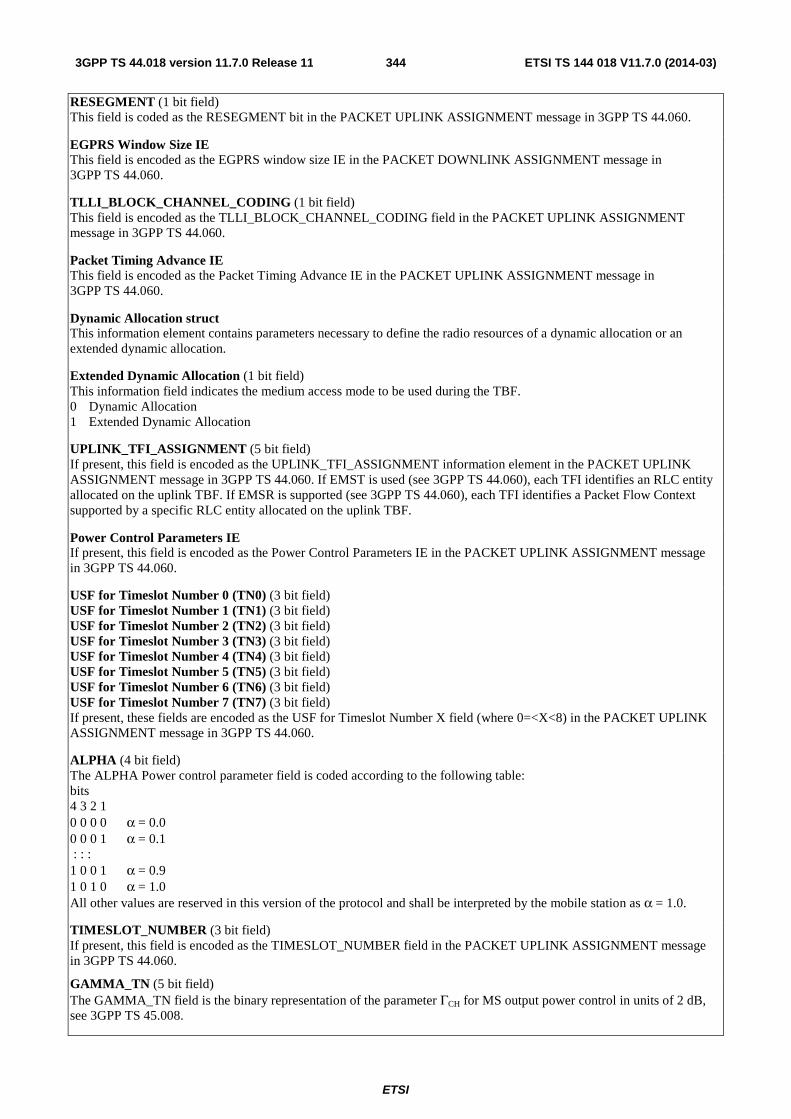
ETSI
ETSI TS 144 018 V11.7.0 (2014-03)3443GPP TS 44.018 version 11.7.0 Release 11
RESEGMENT (1 bit field) This field is coded as the RESEGMENT bit in the PACKET UPLINK ASSIGNMENT message in 3GPP TS 44.060.
EGPRS Window Size IE This field is encoded as the EGPRS window size IE in the PACKET DOWNLINK ASSIGNMENT message in 3GPP TS 44.060.
TLLI_BLOCK_CHANNEL_CODING (1 bit field) This field is encoded as the TLLI_BLOCK_CHANNEL_CODING field in the PACKET UPLINK ASSIGNMENT message in 3GPP TS 44.060.
Packet Timing Advance IE This field is encoded as the Packet Timing Advance IE in the PACKET UPLINK ASSIGNMENT message in 3GPP TS 44.060.
Dynamic Allocation struct This information element contains parameters necessary to define the radio resources of a dynamic allocation or an extended dynamic allocation.
Extended Dynamic Allocation (1 bit field) This information field indicates the medium access mode to be used during the TBF. 0 Dynamic Allocation 1 Extended Dynamic Allocation
UPLINK_TFI_ASSIGNMENT (5 bit field) If present, this field is encoded as the UPLINK_TFI_ASSIGNMENT information element in the PACKET UPLINK ASSIGNMENT message in 3GPP TS 44.060. If EMST is used (see 3GPP TS 44.060), each TFI identifies an RLC entity allocated on the uplink TBF. If EMSR is supported (see 3GPP TS 44.060), each TFI identifies a Packet Flow Context supported by a specific RLC entity allocated on the uplink TBF.
Power Control Parameters IE If present, this field is encoded as the Power Control Parameters IE in the PACKET UPLINK ASSIGNMENT message in 3GPP TS 44.060.
USF for Timeslot Number 0 (TN0) (3 bit field) USF for Timeslot Number 1 (TN1) (3 bit field) USF for Timeslot Number 2 (TN2) (3 bit field) USF for Timeslot Number 3 (TN3) (3 bit field) USF for Timeslot Number 4 (TN4) (3 bit field) USF for Timeslot Number 5 (TN5) (3 bit field) USF for Timeslot Number 6 (TN6) (3 bit field) USF for Timeslot Number 7 (TN7) (3 bit field) If present, these fields are encoded as the USF for Timeslot Number X field (where 0=<X<8) in the PACKET UPLINK ASSIGNMENT message in 3GPP TS 44.060.
ALPHA (4 bit field) The ALPHA Power control parameter field is coded according to the following table: bits 4 3 2 1 0 0 0 0 α = 0.0 0 0 0 1 α = 0.1 : : : 1 0 0 1 α = 0.9 1 0 1 0 α = 1.0 All other values are reserved in this version of the protocol and shall be interpreted by the mobile station as α = 1.0.
TIMESLOT_NUMBER (3 bit field) If present, this field is encoded as the TIMESLOT_NUMBER field in the PACKET UPLINK ASSIGNMENT message in 3GPP TS 44.060.
GAMMA_TN (5 bit field) The GAMMA_TN field is the binary representation of the parameter ΓCH for MS output power control in units of 2 dB, see 3GPP TS 45.008.
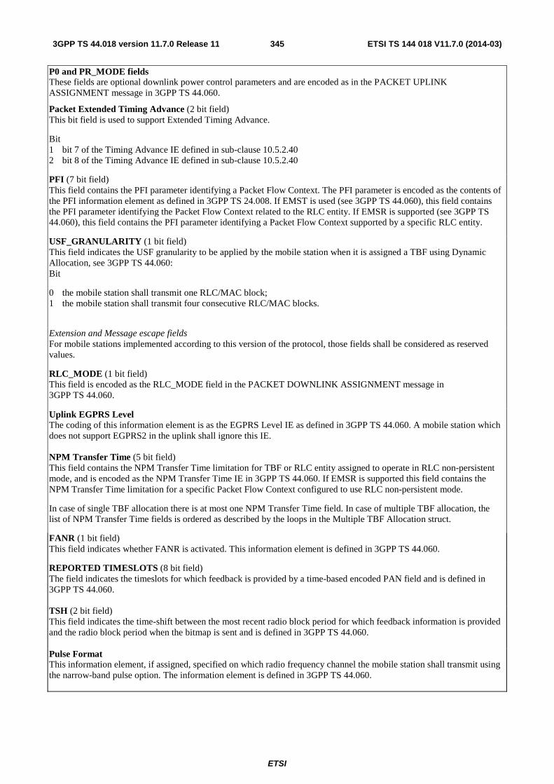
ETSI
ETSI TS 144 018 V11.7.0 (2014-03)3453GPP TS 44.018 version 11.7.0 Release 11
P0 and PR_MODE fields These fields are optional downlink power control parameters and are encoded as in the PACKET UPLINK ASSIGNMENT message in 3GPP TS 44.060.
Packet Extended Timing Advance (2 bit field) This bit field is used to support Extended Timing Advance.
Bit 1 bit 7 of the Timing Advance IE defined in sub-clause 10.5.2.40 2 bit 8 of the Timing Advance IE defined in sub-clause 10.5.2.40
PFI (7 bit field) This field contains the PFI parameter identifying a Packet Flow Context. The PFI parameter is encoded as the contents of the PFI information element as defined in 3GPP TS 24.008. If EMST is used (see 3GPP TS 44.060), this field contains the PFI parameter identifying the Packet Flow Context related to the RLC entity. If EMSR is supported (see 3GPP TS 44.060), this field contains the PFI parameter identifying a Packet Flow Context supported by a specific RLC entity.
USF_GRANULARITY (1 bit field) This field indicates the USF granularity to be applied by the mobile station when it is assigned a TBF using Dynamic Allocation, see 3GPP TS 44.060: Bit
0 the mobile station shall transmit one RLC/MAC block; 1 the mobile station shall transmit four consecutive RLC/MAC blocks.
Extension and Message escape fields For mobile stations implemented according to this version of the protocol, those fields shall be considered as reserved values.
RLC_MODE (1 bit field) This field is encoded as the RLC_MODE field in the PACKET DOWNLINK ASSIGNMENT message in 3GPP TS 44.060.
Uplink EGPRS Level The coding of this information element is as the EGPRS Level IE as defined in 3GPP TS 44.060. A mobile station which does not support EGPRS2 in the uplink shall ignore this IE. NPM Transfer Time (5 bit field) This field contains the NPM Transfer Time limitation for TBF or RLC entity assigned to operate in RLC non-persistent mode, and is encoded as the NPM Transfer Time IE in 3GPP TS 44.060. If EMSR is supported this field contains the NPM Transfer Time limitation for a specific Packet Flow Context configured to use RLC non-persistent mode.
In case of single TBF allocation there is at most one NPM Transfer Time field. In case of multiple TBF allocation, the list of NPM Transfer Time fields is ordered as described by the loops in the Multiple TBF Allocation struct.
FANR (1 bit field) This field indicates whether FANR is activated. This information element is defined in 3GPP TS 44.060.
REPORTED TIMESLOTS (8 bit field) The field indicates the timeslots for which feedback is provided by a time-based encoded PAN field and is defined in 3GPP TS 44.060. TSH (2 bit field) This field indicates the time-shift between the most recent radio block period for which feedback information is provided and the radio block period when the bitmap is sent and is defined in 3GPP TS 44.060. Pulse Format This information element, if assigned, specified on which radio frequency channel the mobile station shall transmit using the narrow-band pulse option. The information element is defined in 3GPP TS 44.060.
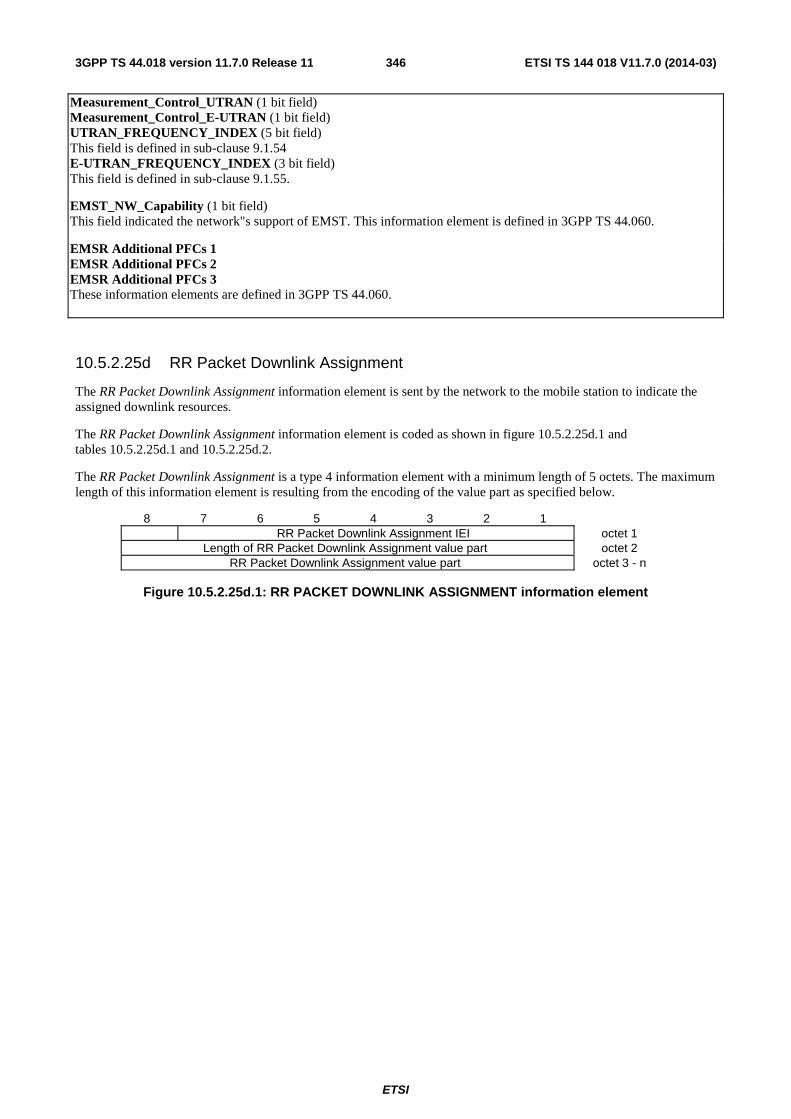
ETSI
ETSI TS 144 018 V11.7.0 (2014-03)3463GPP TS 44.018 version 11.7.0 Release 11
Measurement_Control_UTRAN (1 bit field) Measurement_Control_E-UTRAN (1 bit field) UTRAN_FREQUENCY_INDEX (5 bit field) This field is defined in sub-clause 9.1.54 E-UTRAN_FREQUENCY_INDEX (3 bit field) This field is defined in sub-clause 9.1.55.
EMST_NW_Capability (1 bit field) This field indicated the network"s support of EMST. This information element is defined in 3GPP TS 44.060.
EMSR Additional PFCs 1 EMSR Additional PFCs 2 EMSR Additional PFCs 3 These information elements are defined in 3GPP TS 44.060.
10.5.2.25d RR Packet Downlink Assignment
The RR Packet Downlink Assignment information element is sent by the network to the mobile station to indicate the assigned downlink resources.
The RR Packet Downlink Assignment information element is coded as shown in figure 10.5.2.25d.1 and tables 10.5.2.25d.1 and 10.5.2.25d.2.
The RR Packet Downlink Assignment is a type 4 information element with a minimum length of 5 octets. The maximum length of this information element is resulting from the encoding of the value part as specified below.
8 7 6 5 4 3 2 1 RR Packet Downlink Assignment IEI octet 1
Length of RR Packet Downlink Assignment value part octet 2 RR Packet Downlink Assignment value part octet 3 - n
Figure 10.5.2.25d.1: RR PACKET DOWNLINK ASSIGNMENT information element

ETSI
ETSI TS 144 018 V11.7.0 (2014-03)3473GPP TS 44.018 version 11.7.0 Release 11
Table 10.5.2.25d.1: RR PACKET DOWNLINK ASSIGNMENT value part
< RR Packet Downlink Assignment value part > ::= < MAC_MODE : bit (2) > < RLC_MODE : bit (1) > < TIMESLOT_ALLOCATION : bit (8) > < Packet Timing Advance : Packet Timing Advance IE > { 0 | 1 < P0 : bit (4) > 0 -- The value '1' was allocated in an earlier version of the protocol and shall not be used. < PR_MODE : bit (1) > } { 0 | 1 < Power Control Parameters : Power Control Parameters IE > } { 0 | 1 < DOWNLINK_TFI_ASSIGNMENT : bit (5) > } 0 -- The value '1' was allocated in an earlier version of the protocol and shall not be used. { null -- Receiver compatible with earlier release | { 0 | 1 -- indicates EGPRS TBF mode, see 3GPP TS 44.060 < EGPRS Window Size : < EGPRS Window Size IE >> < LINK_QUALITY_MEASUREMENT_MODE : bit (2) > } { 0 | 1 < Packet Extended Timing Advance : bit (2) > } { null | 0 bit** = < no string > -- Receiver backward compatible | 1 -- Additions for REL-6 { 1 < Multiple Downlink TBF Assignment : < Multiple Downlink TBF Assignment struct > > } ** 0 { null | 0 bit** = < no string > -- Receiver backward compatible with earlier release | 1 -- Additions for REL-7 < FANR: bit (1) > { 1 { 0 | 1< NPM Transfer Time : bit (5) > } < EVENT_BASED_FANR: bit (1) > }** 0 < Downlink EGPRS Level: < EGPRS Level IE > > { null | 0 bit** = < no string > -- Receiver backward compatible with earlier version | 1 -- Additions for REL-8 { 0 | 1 { 1 < Measurement_Control_E-UTRAN : bit(1) > < E-UTRAN_FREQUENCY_INDEX : bit (3) > { 1 < E-UTRAN_FREQUENCY_INDEX : bit (3) > } ** 0 } ** 0 } { 0 | 1 { 1< Measurement_Control_UTRAN : bit(1) > < UTRAN_FREQUENCY_INDEX : bit (5) > { 1 < UTRAN_FREQUENCY_INDEX : bit (5) > } ** 0 } ** 0 } { null | 0 bit** = < no string > -- Receiver backward compatible with earlier version | 1 -- Additions for Rel-9 { 0 -- EMST is not used | 1 < RLC Entity 2 : < RLC Entity Struct > > { 0 | 1 < RLC Entity 3 : < RLC Entity Struct > > } } { null | 0 bit** = < no string > -- Receiver backward compatible with earlier version | 1 -- Additions for Rel-10 { 1 < EMSR Additional PFCs 1 : < Additional PFCs struct > > } ** 0 { 1 < EMSR Additional PFCs 2 : < Additional PFCs struct > > } ** 0 { 1 < EMSR Additional PFCs 3 : < Additional PFCs struct > > } ** 0 <spare bit>** } -- End of additions for Rel-10 } -- End of additions for Rel-9 } -- End of additions for Rel-8 } -- End of additions for Rel-7 } -- End of additions for Rel-6 } ; -- End of additions for R99 < Multiple Downlink TBF Assignment struct > ::= { 0 | 1 < Uplink Control Timeslot : bit (3) > } < TIMESLOT_ALLOCATION : bit (8) > { 1 < Downlink TBF assignment : < Downlink TBF assignment struct > > } ** 0 ;
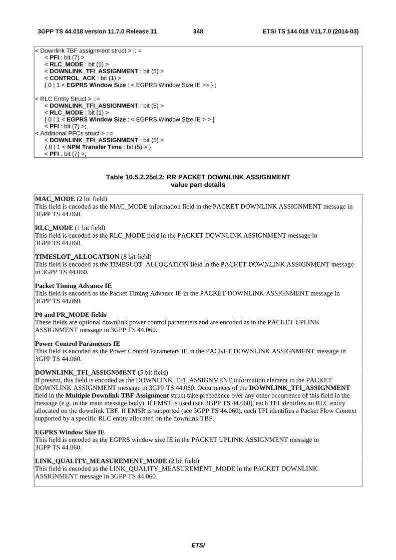
ETSI
ETSI TS 144 018 V11.7.0 (2014-03)3483GPP TS 44.018 version 11.7.0 Release 11
< Downlink TBF assignment struct > :: = < PFI : bit (7) > < RLC_MODE : bit (1) > < DOWNLINK_TFI_ASSIGNMENT : bit (5) > < CONTROL_ACK : bit (1) > { 0 | 1 < EGPRS Window Size : < EGPRS Window Size IE >> } ; < RLC Entity Struct > ::= < DOWNLINK_TFI_ASSIGNMENT : bit (5) > < RLC_MODE : bit (1) > { 0 | 1 < EGPRS Window Size : < EGPRS Window Size IE > > } < PFI : bit (7) >; < Additional PFCs struct > ::= < DOWNLINK_TFI_ASSIGNMENT : bit (5) > { 0 | 1 < NPM Transfer Time : bit (5) > } < PFI : bit (7) >;
Table 10.5.2.25d.2: RR PACKET DOWNLINK ASSIGNMENT value part details
MAC_MODE (2 bit field) This field is encoded as the MAC_MODE information field in the PACKET DOWNLINK ASSIGNMENT message in 3GPP TS 44.060.
RLC_MODE (1 bit field) This field is encoded as the RLC_MODE field in the PACKET DOWNLINK ASSIGNMENT message in 3GPP TS 44.060.
TIMESLOT_ALLOCATION (8 bit field) This field is encoded as the TIMESLOT_ALLOCATION field in the PACKET DOWNLINK ASSIGNMENT message in 3GPP TS 44.060.
Packet Timing Advance IE This field is encoded as the Packet Timing Advance IE in the PACKET DOWNLINK ASSIGNMENT message in 3GPP TS 44.060.
P0 and PR_MODE fields These fields are optional downlink power control parameters and are encoded as in the PACKET UPLINK ASSIGNMENT message in 3GPP TS 44.060.
Power Control Parameters IE This field is encoded as the Power Control Parameters IE in the PACKET DOWNLINK ASSIGNMENT message in 3GPP TS 44.060.
DOWNLINK_TFI_ASSIGNMENT (5 bit field) If present, this field is encoded as the DOWNLINK_TFI_ASSIGNMENT information element in the PACKET DOWNLINK ASSIGNMENT message in 3GPP TS 44.060. Occurrences of the DOWNLINK_TFI_ASSIGNMENT field in the Multiple Downlink TBF Assignment struct take precedence over any other occurrence of this field in the message (e.g. in the main message body). If EMST is used (see 3GPP TS 44.060), each TFI identifies an RLC entity allocated on the downlink TBF. If EMSR is supported (see 3GPP TS 44.060), each TFI identifies a Packet Flow Context supported by a specific RLC entity allocated on the downlink TBF.
EGPRS Window Size IE This field is encoded as the EGPRS window size IE in the PACKET UPLINK ASSIGNMENT message in 3GPP TS 44.060.
LINK_QUALITY_MEASUREMENT_MODE (2 bit field) This field is encoded as the LINK_QUALITY_MEASUREMENT_MODE in the PACKET DOWNLINK ASSIGNMENT message in 3GPP TS 44.060.
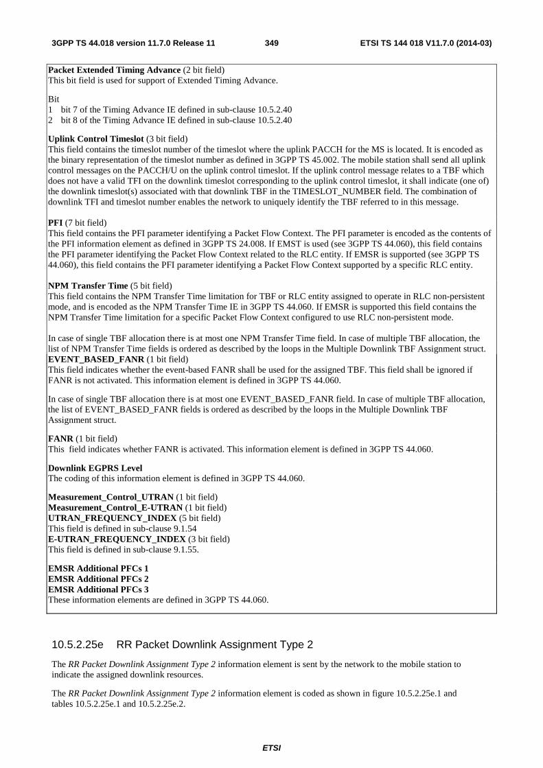
ETSI
ETSI TS 144 018 V11.7.0 (2014-03)3493GPP TS 44.018 version 11.7.0 Release 11
Packet Extended Timing Advance (2 bit field) This bit field is used for support of Extended Timing Advance.
Bit 1 bit 7 of the Timing Advance IE defined in sub-clause 10.5.2.40 2 bit 8 of the Timing Advance IE defined in sub-clause 10.5.2.40
Uplink Control Timeslot (3 bit field) This field contains the timeslot number of the timeslot where the uplink PACCH for the MS is located. It is encoded as the binary representation of the timeslot number as defined in 3GPP TS 45.002. The mobile station shall send all uplink control messages on the PACCH/U on the uplink control timeslot. If the uplink control message relates to a TBF which does not have a valid TFI on the downlink timeslot corresponding to the uplink control timeslot, it shall indicate (one of) the downlink timeslot(s) associated with that downlink TBF in the TIMESLOT_NUMBER field. The combination of downlink TFI and timeslot number enables the network to uniquely identify the TBF referred to in this message. PFI (7 bit field) This field contains the PFI parameter identifying a Packet Flow Context. The PFI parameter is encoded as the contents of the PFI information element as defined in 3GPP TS 24.008. If EMST is used (see 3GPP TS 44.060), this field contains the PFI parameter identifying the Packet Flow Context related to the RLC entity. If EMSR is supported (see 3GPP TS 44.060), this field contains the PFI parameter identifying a Packet Flow Context supported by a specific RLC entity. NPM Transfer Time (5 bit field) This field contains the NPM Transfer Time limitation for TBF or RLC entity assigned to operate in RLC non-persistent mode, and is encoded as the NPM Transfer Time IE in 3GPP TS 44.060. If EMSR is supported this field contains the NPM Transfer Time limitation for a specific Packet Flow Context configured to use RLC non-persistent mode. In case of single TBF allocation there is at most one NPM Transfer Time field. In case of multiple TBF allocation, the list of NPM Transfer Time fields is ordered as described by the loops in the Multiple Downlink TBF Assignment struct. EVENT_BASED_FANR (1 bit field) This field indicates whether the event-based FANR shall be used for the assigned TBF. This field shall be ignored if FANR is not activated. This information element is defined in 3GPP TS 44.060.
In case of single TBF allocation there is at most one EVENT_BASED_FANR field. In case of multiple TBF allocation, the list of EVENT_BASED_FANR fields is ordered as described by the loops in the Multiple Downlink TBF Assignment struct.
FANR (1 bit field) This field indicates whether FANR is activated. This information element is defined in 3GPP TS 44.060.
Downlink EGPRS Level The coding of this information element is defined in 3GPP TS 44.060.
Measurement_Control_UTRAN (1 bit field) Measurement_Control_E-UTRAN (1 bit field) UTRAN_FREQUENCY_INDEX (5 bit field) This field is defined in sub-clause 9.1.54 E-UTRAN_FREQUENCY_INDEX (3 bit field) This field is defined in sub-clause 9.1.55.
EMSR Additional PFCs 1 EMSR Additional PFCs 2 EMSR Additional PFCs 3 These information elements are defined in 3GPP TS 44.060.
10.5.2.25e RR Packet Downlink Assignment Type 2
The RR Packet Downlink Assignment Type 2 information element is sent by the network to the mobile station to indicate the assigned downlink resources.
The RR Packet Downlink Assignment Type 2 information element is coded as shown in figure 10.5.2.25e.1 and tables 10.5.2.25e.1 and 10.5.2.25e.2.

ETSI
ETSI TS 144 018 V11.7.0 (2014-03)3503GPP TS 44.018 version 11.7.0 Release 11
The RR Packet Downlink Assignment Type 2 is a type 4 information element with a minimum length of 5 octets. The maximum length of this information element is resulting from the encoding of the value part as specified below.
8 7 6 5 4 3 2 1 RR Packet Downlink Assignment Type 2 IEI octet 1
Length of RR Packet Downlink Assignment Type 2 value part octet 2 RR Packet Downlink Assignment Type 2 value part octet 3 - n
Figure 10.5.2.25e.1: RR PACKET DOWNLINK ASSIGNMENT TYPE 2 information element

ETSI
ETSI TS 144 018 V11.7.0 (2014-03)3513GPP TS 44.018 version 11.7.0 Release 11
Table 10.5.2.25e.1: RR PACKET DOWNLINK ASSIGNMENT TYPE 2 value part

ETSI
ETSI TS 144 018 V11.7.0 (2014-03)3523GPP TS 44.018 version 11.7.0 Release 11
< RR Packet Downlink Assignment Type 2 value part > ::= < RLC_MODE : bit (1) > { 0 | 1 < P0_C1 : bit (4) > < PR_MODE_C1 : bit (1) > { 0 | 1 < P0_C2 : bit (4) > < PR_MODE_C2 : bit (1) > } } { 0 | 1 < Power Control Parameters C1 : < Power Control Parameters IE > > } { 0 | 1 < Power Control Parameters C2 : < Power Control Parameters IE > > } { 0 | 1 < DOWNLINK_TFI_ASSIGNMENT : bit (5) > } < EGPRS Window Size : < EGPRS Window Size IE >> < LINK_QUALITY_MEASUREMENT_MODE : bit (2) > { 0 -- BTTI mode < FANR: bit (1) > { 1 < BTTI Multiple Downlink Assignment : < BTTI Multiple Downlink Assignment struct > > } ** 0 | 1 -- RTTI mode { 0 -- Single Carrier Assignment { 00 -- Default PDCH-pair configuration | 01 -- Unchanged | 10 -- Explicit PDCH pair configuration < DOWNLINK_PDCH_PAIRS_C1 : bit (8) > < UPLINK_PDCH_PAIRS_C1 : bit (8) > ! < PDCH pairs configuration error : { 1 1 } bit (*) = < no string > -- reserved } { 1 < RTTI Multiple Downlink Assignment SC : < RTTI Multiple Downlink Assignment SC struct > > } ** 0 | 1 -- Dual Carrier Assignment { 00 -- Default PDCH pair configuration | 01 -- Unchanged | 10 -- Explicit PDCH pair configuration < DOWNLINK_PDCH_PAIRS_C1 : bit (8) > < DOWNLINK_PDCH_PAIRS_C2 : bit (8) > < UPLINK_PDCH_PAIRS_C1 : bit (8) > < UPLINK_PDCH_PAIRS_C2 : bit (8) > ! < PDCH pairs configuration error : { 1 1 } bit (*) = < no string > -- reserved } { 1 < RTTI Multiple Downlink Assignment DC : < RTTI Multiple Downlink Assignment DC struct > > } ** 0 } } < Downlink EGPRS Level: < EGPRS Level IE > > { null | 0 bit** = < no string > -- Receiver backward compatible with earlier version | 1 -- Additions for REL-8 { 0 | 1 { 1 < Measurement_Control_E-UTRAN : bit(1) > < E-UTRAN_FREQUENCY_INDEX : bit (3) > { 1 < E-UTRAN_FREQUENCY_INDEX : bit (3) > } ** 0 } ** 0 } { 0 | 1 { 1< Measurement_Control_UTRAN : bit(1) > < UTRAN_FREQUENCY_INDEX : bit (5) > { 1 < UTRAN_FREQUENCY_INDEX : bit (5) > } ** 0 } ** 0 } { null | 0 bit** = < no string > -- Receiver backward compatible with earlier release | 1 -- Additions for Rel-99 { 0 -- EMST is not used | 1 < RLC Entity 2 : < RLC Entity Struct > > { 0 | 1 < RLC Entity 3 : < RLC Entity Struct > > } } { null | 0 bit** = < no string > -- Receiver backward compatible with earlier version | 1 -- Additions for Rel-10 { 1 < EMSR Additional PFCs 1 : < Additional PFCs struct > > } ** 0 { 1 < EMSR Additional PFCs 2 : < Additional PFCs struct > > } ** 0 { 1 < EMSR Additional PFCs 3 : < Additional PFCs struct > > } ** 0 { null | 0 bit** = < no string > -- Receiver backward compatible with earlier version | 1 -- Additions for Rel-11 < EGPRS Packet Downlink Ack/Nack Type 3 Support : bit(1) > <spare bit>** } -- End of additions for Rel-11 } -- End of additions for Rel-10 } -- End of additions for Rel-9 } ; -- End of additions for Rel-8

ETSI
ETSI TS 144 018 V11.7.0 (2014-03)3533GPP TS 44.018 version 11.7.0 Release 11
< BTTI Multiple Downlink Assignment struct > ::= { 0 | 1 < Uplink Control Timeslot: bit (3) > } { 0 | 1 < TIMESLOT_ALLOCATION_C1 : bit (8) > } { 0 | 1 < TIMESLOT_ALLOCATION_C2 : bit (8) > } { 1 < Downlink TBF assignment : < Downlink TBF assignment 2 struct > > } ** 0 ; < RTTI Multiple Downlink Assignment SC struct > ::= < RTTI_DOWNLINK_PDCH_PAIR_ASSIGNMENT_SC : bit (4) > { 1 < Downlink TBF assignment : < Downlink TBF assignment 2 struct > > } ** 0 ; < RTTI Multiple Downlink Assignment DC struct > ::= < RTTI_DOWNLINK_PDCH_PAIR_ASSIGNMENT_DC : bit (8) > { 1 < Downlink TBF assignment : < Downlink TBF assignment 2 struct > > } ** 0 ;
< Downlink TBF assignment 2 struct > :: = < PFI : bit (7) > < RLC_MODE : bit (1) > < TFI Assignment : bit (5) > < CONTROL_ACK : bit (1) > { 0 | 1 < NPM Transfer Time : bit (5) > } < EVENT_BASED_FANR: bit (1) > { 0 | 1 < Downlink EGPRS Window Size : < EGPRS Window Size IE > > } ; < RLC Entity Struct > ::= < DOWNLINK_TFI_ASSIGNMENT : bit (5) > < RLC_MODE : bit (1) > { 0 | 1 < EGPRS Window Size : < EGPRS Window Size IE > > } < PFI : bit (7) >; < Additional PFCs struct > ::= < DOWNLINK_TFI_ASSIGNMENT : bit (5) > { 0 | 1 < NPM Transfer Time : bit (5) > } < PFI : bit (7) >;
Table 10.5.2.25e.2: RR PACKET DOWNLINK ASSIGNMENT TYPE 2 value part details
RLC_MODE (1 bit field) This field is encoded as the RLC_MODE field in the PACKET DOWNLINK ASSIGNMENT message in 3GPP TS 44.060.
TIMESLOT_ALLOCATION_C1, TIMESLOT_ALLOCATION_C2 (8 bit field) These information fields indicate the timeslots assigned for use during the TBF on carrier 1 (respectively, carrier 2) of a dual carrier configuration. These fields are encoded as in the PACKET DOWNLINK ASSIGNMENT message in 3GPP TS 44.060.
P0_C1, P0_C2, PR_MODE_C1 and PR_MODE_C2 fields These fields are optional downlink power control parameters and are encoded as in the PACKET UPLINK ASSIGNMENT message in 3GPP TS 44.060.
Power Control Parameters C1, Power Control Parameters C2 These information elements are encoded as in the PACKET DOWNLINK ASSIGNMENT message in 3GPP TS 44.060.
DOWNLINK_TFI_ASSIGNMENT (5 bit field) If present, this field is encoded as the DOWNLINK_TFI_ASSIGNMENT information element in the PACKET DOWNLINK ASSIGNMENT message in 3GPP TS 44.060. Occurrences of the DOWNLINK_TFI_ASSIGNMENT field in the Downlink TBF Assignment 2 struct take precedence over any other occurrence of this field in the message (e.g. in the main message body). If EMST is used (see 3GPP TS 44.060), each TFI identifies an RLC entity allocated on the downlink TBF. If EMSR is supported (see 3GPP TS 44.060), each TFI identifies a Packet Flow Context supported by a specific RLC entity allocated on the downlink TBF.
EGPRS Window Size IE This field is encoded as the EGPRS window size IE in the PACKET UPLINK ASSIGNMENT message in 3GPP TS 44.060.
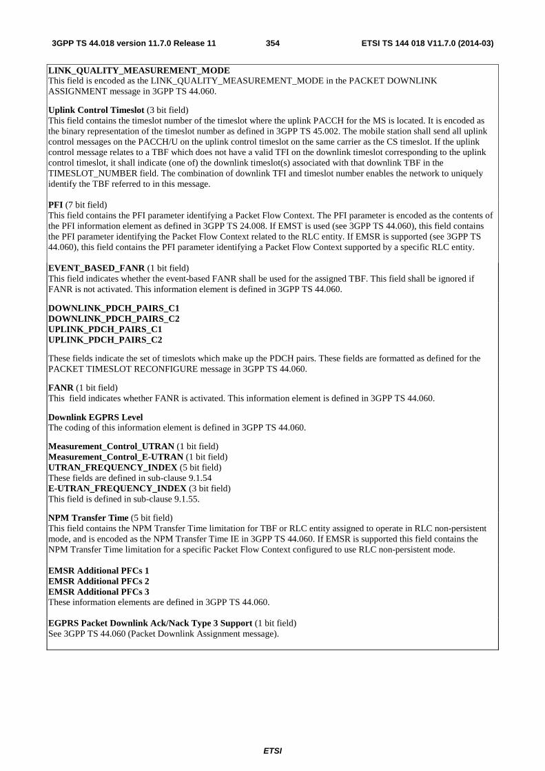
ETSI
ETSI TS 144 018 V11.7.0 (2014-03)3543GPP TS 44.018 version 11.7.0 Release 11
LINK_QUALITY_MEASUREMENT_MODE This field is encoded as the LINK_QUALITY_MEASUREMENT_MODE in the PACKET DOWNLINK ASSIGNMENT message in 3GPP TS 44.060.
Uplink Control Timeslot (3 bit field) This field contains the timeslot number of the timeslot where the uplink PACCH for the MS is located. It is encoded as the binary representation of the timeslot number as defined in 3GPP TS 45.002. The mobile station shall send all uplink control messages on the PACCH/U on the uplink control timeslot on the same carrier as the CS timeslot. If the uplink control message relates to a TBF which does not have a valid TFI on the downlink timeslot corresponding to the uplink control timeslot, it shall indicate (one of) the downlink timeslot(s) associated with that downlink TBF in the TIMESLOT_NUMBER field. The combination of downlink TFI and timeslot number enables the network to uniquely identify the TBF referred to in this message. PFI (7 bit field) This field contains the PFI parameter identifying a Packet Flow Context. The PFI parameter is encoded as the contents of the PFI information element as defined in 3GPP TS 24.008. If EMST is used (see 3GPP TS 44.060), this field contains the PFI parameter identifying the Packet Flow Context related to the RLC entity. If EMSR is supported (see 3GPP TS 44.060), this field contains the PFI parameter identifying a Packet Flow Context supported by a specific RLC entity. EVENT_BASED_FANR (1 bit field) This field indicates whether the event-based FANR shall be used for the assigned TBF. This field shall be ignored if FANR is not activated. This information element is defined in 3GPP TS 44.060.
DOWNLINK_PDCH_PAIRS_C1 DOWNLINK_PDCH_PAIRS_C2 UPLINK_PDCH_PAIRS_C1 UPLINK_PDCH_PAIRS_C2
These fields indicate the set of timeslots which make up the PDCH pairs. These fields are formatted as defined for the PACKET TIMESLOT RECONFIGURE message in 3GPP TS 44.060.
FANR (1 bit field) This field indicates whether FANR is activated. This information element is defined in 3GPP TS 44.060.
Downlink EGPRS Level The coding of this information element is defined in 3GPP TS 44.060.
Measurement_Control_UTRAN (1 bit field) Measurement_Control_E-UTRAN (1 bit field) UTRAN_FREQUENCY_INDEX (5 bit field) These fields are defined in sub-clause 9.1.54 E-UTRAN_FREQUENCY_INDEX (3 bit field) This field is defined in sub-clause 9.1.55.
NPM Transfer Time (5 bit field) This field contains the NPM Transfer Time limitation for TBF or RLC entity assigned to operate in RLC non-persistent mode, and is encoded as the NPM Transfer Time IE in 3GPP TS 44.060. If EMSR is supported this field contains the NPM Transfer Time limitation for a specific Packet Flow Context configured to use RLC non-persistent mode. EMSR Additional PFCs 1 EMSR Additional PFCs 2 EMSR Additional PFCs 3 These information elements are defined in 3GPP TS 44.060. EGPRS Packet Downlink Ack/Nack Type 3 Support (1 bit field) See 3GPP TS 44.060 (Packet Downlink Assignment message).
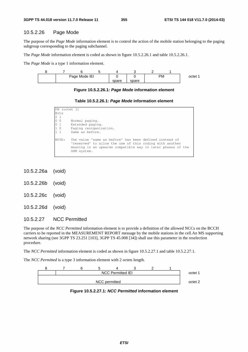
ETSI
ETSI TS 144 018 V11.7.0 (2014-03)3553GPP TS 44.018 version 11.7.0 Release 11
10.5.2.26 Page Mode
The purpose of the Page Mode information element is to control the action of the mobile station belonging to the paging subgroup corresponding to the paging subchannel.
The Page Mode information element is coded as shown in figure 10.5.2.26.1 and table 10.5.2.26.1.
The Page Mode is a type 1 information element.
8 7 6 5 4 3 2 1 Page Mode IEI 0
spare 0
spare PM octet 1
Figure 10.5.2.26.1: Page Mode information element
Table 10.5.2.26.1: Page Mode information element
PM (octet 1) Bits 2 1 0 0 Normal paging. 0 1 Extended paging. 1 0 Paging reorganization. 1 1 Same as before. NOTE: The value "same as before" has been defined instead of
"reserved" to allow the use of this coding with another meaning in an upwards compatible way in later phases of the GSM system.
10.5.2.26a (void)
10.5.2.26b (void)
10.5.2.26c (void)
10.5.2.26d (void)
10.5.2.27 NCC Permitted
The purpose of the NCC Permitted information element is to provide a definition of the allowed NCCs on the BCCH carriers to be reported in the MEASUREMENT REPORT message by the mobile stations in the cell.An MS supporting network sharing (see 3GPP TS 23.251 [103], 3GPP TS 45.008 [34]) shall use this parameter in the reselection procedure.
The NCC Permitted information element is coded as shown in figure 10.5.2.27.1 and table 10.5.2.27.1.
The NCC Permitted is a type 3 information element with 2 octets length.
8 7 6 5 4 3 2 1 NCC Permitted IEI octet 1
NCC permitted
octet 2
Figure 10.5.2.27.1: NCC Permitted information element
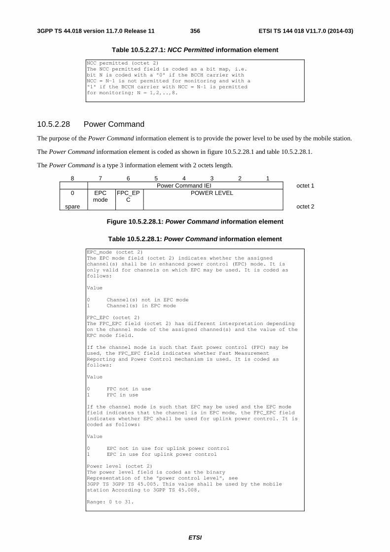
ETSI
ETSI TS 144 018 V11.7.0 (2014-03)3563GPP TS 44.018 version 11.7.0 Release 11
Table 10.5.2.27.1: NCC Permitted information element
NCC permitted (octet 2) The NCC permitted field is coded as a bit map, i.e. bit N is coded with a "0" if the BCCH carrier with NCC = N-1 is not permitted for monitoring and with a "1" if the BCCH carrier with NCC = N-1 is permitted for monitoring; N = 1,2,..,8.
10.5.2.28 Power Command
The purpose of the Power Command information element is to provide the power level to be used by the mobile station.
The Power Command information element is coded as shown in figure 10.5.2.28.1 and table 10.5.2.28.1.
The Power Command is a type 3 information element with 2 octets length.
8 7 6 5 4 3 2 1 Power Command IEI octet 1
0 EPC mode
FPC_EPC
POWER LEVEL
spare octet 2
Figure 10.5.2.28.1: Power Command information element
Table 10.5.2.28.1: Power Command information element
EPC_mode (octet 2) The EPC mode field (octet 2) indicates whether the assigned channel(s) shall be in enhanced power control (EPC) mode. It is only valid for channels on which EPC may be used. It is coded as follows: Value 0 Channel(s) not in EPC mode 1 Channel(s) in EPC mode FPC_EPC (octet 2) The FPC_EPC field (octet 2) has different interpretation depending on the channel mode of the assigned channed(s) and the value of the EPC mode field. If the channel mode is such that fast power control (FPC) may be used, the FPC_EPC field indicates whether Fast Measurement Reporting and Power Control mechanism is used. It is coded as follows: Value 0 FPC not in use 1 FPC in use If the channel mode is such that EPC may be used and the EPC mode field indicates that the channel is in EPC mode, the FPC_EPC field indicates whether EPC shall be used for uplink power control. It is coded as follows: Value 0 EPC not in use for uplink power control 1 EPC in use for uplink power control Power level (octet 2) The power level field is coded as the binary Representation of the "power control level", see 3GPP TS 3GPP TS 45.005. This value shall be used by the mobile station According to 3GPP TS 45.008. Range: 0 to 31.

ETSI
ETSI TS 144 018 V11.7.0 (2014-03)3573GPP TS 44.018 version 11.7.0 Release 11
10.5.2.28a Power Command and access type
The purpose of the Power Command and access type information element is to provide the power level to be used by the mobile station and the indication that the mobile station can avoid the transmission of handover access.
The Power Command and access type information element is coded as shown in figure 10.5.2.28a.1 and table 10.5.2.28a.1.
The Power Command and access type is a type 3 information element with 2 octets length.
8 7 6 5 4 3 2 1 Power Command and Access Type IEI octet 1
ATC EPC mode
FPC_EPC
POWER LEVEL
octet 2
Figure 10.5.2.28a.1: Power Command and access type information element
Table 10.5.2.28a.1: Power Command and access type information element
ATC (Access Type Control) (octet 2) Bit 8 0 Sending of Handover access is mandatory 1 Sending of Handover access is optional EPC_mode (octet 2) The EPC mode field (octet 2) indicates whether the assigned
channel(s) shall be in enhanced power control (EPC) mode. It is only valid for channels on which EPC may be used. It is coded as follows:
Value 0 Channel(s) not in EPC mode 1 Channel(s) in EPC mode FPC_EPC (octet 2) The FPC_EPC field (octet 2) has different interpretation depending
on the channel mode of the assigned channel (s) and the value of the EPC mode field.
If the channel mode is such that fast power control (FPC) may be
used, the FPC_EPC field indicates whether Fast Measurement Reporting and Power Control mechanism is used. It is coded as follows:
Value 0 FPC not in use 1 FPC in use If the channel mode is such that EPC may be used and the EPC mode
field indicates that the channel is in EPC mode, the FPC_EPC field indicates whether EPC shall be used for uplink power control. It is coded as follows:
Value 0 EPC not in use for uplink power control 1 EPC in use for uplink power control Power level (octet 2) The power level field is coded as the binary Representation of the "power control level", see
3GPP TS 3GPP TS 45.005. This value shall be used by the mobile station According to 3GPP TS 45.008.
Range: 0 to 31.
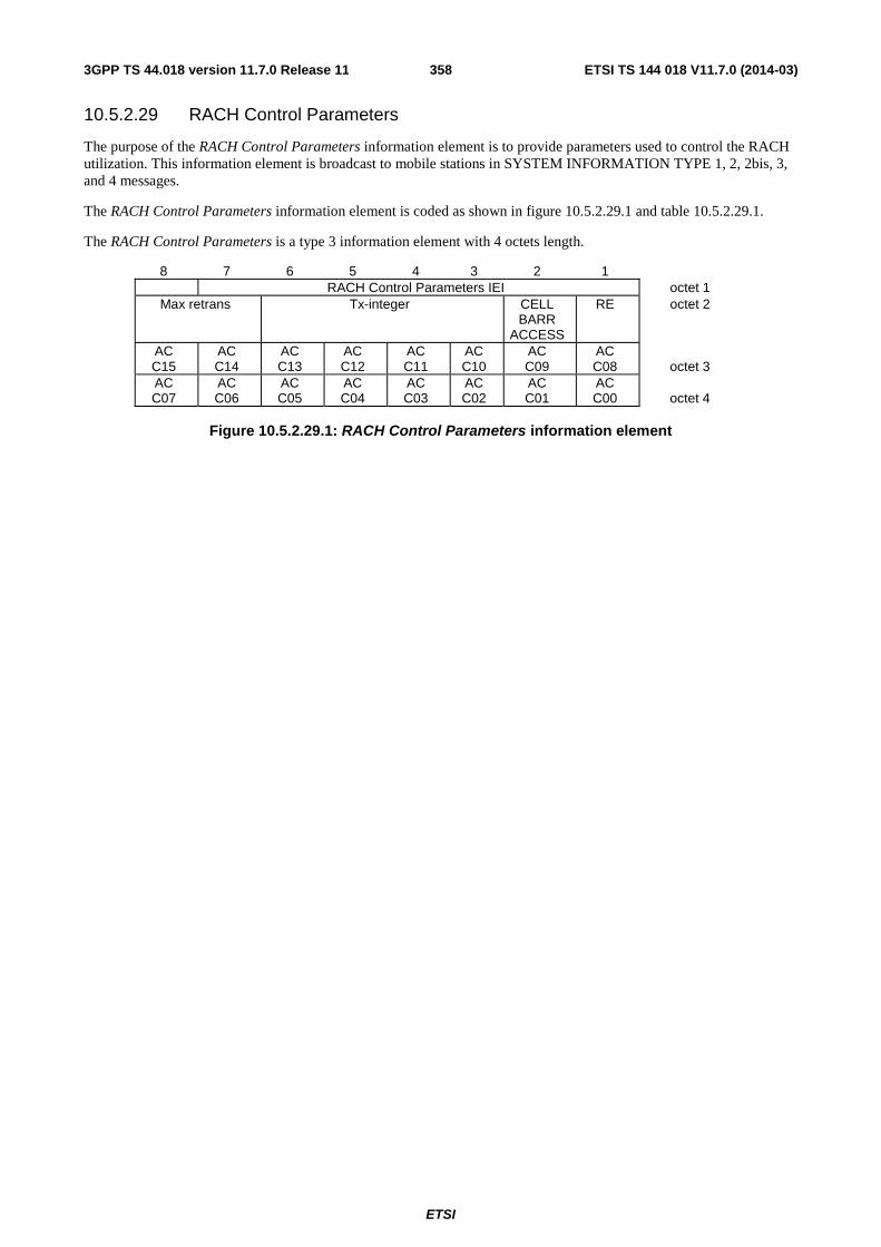
ETSI
ETSI TS 144 018 V11.7.0 (2014-03)3583GPP TS 44.018 version 11.7.0 Release 11
10.5.2.29 RACH Control Parameters
The purpose of the RACH Control Parameters information element is to provide parameters used to control the RACH utilization. This information element is broadcast to mobile stations in SYSTEM INFORMATION TYPE 1, 2, 2bis, 3, and 4 messages.
The RACH Control Parameters information element is coded as shown in figure 10.5.2.29.1 and table 10.5.2.29.1.
The RACH Control Parameters is a type 3 information element with 4 octets length.
8 7 6 5 4 3 2 1 RACH Control Parameters IEI octet 1
Max retrans Tx-integer CELL BARR
ACCESS
RE octet 2
AC C15
AC C14
AC C13
AC C12
AC C11
AC C10
AC C09
AC C08
octet 3
AC C07
AC C06
AC C05
AC C04
AC C03
AC C02
AC C01
AC C00
octet 4
Figure 10.5.2.29.1: RACH Control Parameters information element
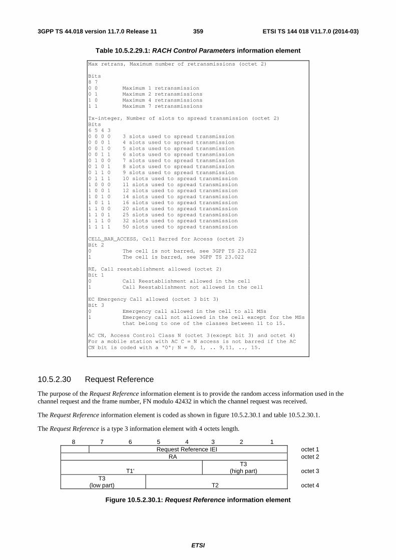
ETSI
ETSI TS 144 018 V11.7.0 (2014-03)3593GPP TS 44.018 version 11.7.0 Release 11
Table 10.5.2.29.1: RACH Control Parameters information element
Max retrans, Maximum number of retransmissions (octet 2) Bits 8 7 0 0 Maximum 1 retransmission 0 1 Maximum 2 retransmissions 1 0 Maximum 4 retransmissions 1 1 Maximum 7 retransmissions Tx-integer, Number of slots to spread transmission (octet 2) Bits 6 5 4 3 0 0 0 0 3 slots used to spread transmission 0 0 0 1 4 slots used to spread transmission 0 0 1 0 5 slots used to spread transmission 0 0 1 1 6 slots used to spread transmission 0 1 0 0 7 slots used to spread transmission 0 1 0 1 8 slots used to spread transmission 0 1 1 0 9 slots used to spread transmission 0 1 1 1 10 slots used to spread transmission 1 0 0 0 11 slots used to spread transmission 1 0 0 1 12 slots used to spread transmission 1 0 1 0 14 slots used to spread transmission 1 0 1 1 16 slots used to spread transmission 1 1 0 0 20 slots used to spread transmission 1 1 0 1 25 slots used to spread transmission 1 1 1 0 32 slots used to spread transmission 1 1 1 1 50 slots used to spread transmission CELL_BAR_ACCESS, Cell Barred for Access (octet 2) Bit 2 0 The cell is not barred, see 3GPP TS 23.022 1 The cell is barred, see 3GPP TS 23.022 RE, Call reestablishment allowed (octet 2) Bit 1 0 Call Reestablishment allowed in the cell 1 Call Reestablishment not allowed in the cell EC Emergency Call allowed (octet 3 bit 3) Bit 3 0 Emergency call allowed in the cell to all MSs 1 Emergency call not allowed in the cell except for the MSs
that belong to one of the classes between 11 to 15. AC CN, Access Control Class N (octet 3(except bit 3) and octet 4) For a mobile station with AC C = N access is not barred if the AC CN bit is coded with a "0"; N = 0, 1, .. 9,11, .., 15.
10.5.2.30 Request Reference
The purpose of the Request Reference information element is to provide the random access information used in the channel request and the frame number, FN modulo 42432 in which the channel request was received.
The Request Reference information element is coded as shown in figure 10.5.2.30.1 and table 10.5.2.30.1.
The Request Reference is a type 3 information element with 4 octets length.
8 7 6 5 4 3 2 1 Request Reference IEI octet 1
RA octet 2
T1' T3
(high part)
octet 3 T3
(low part)
T2
octet 4
Figure 10.5.2.30.1: Request Reference information element
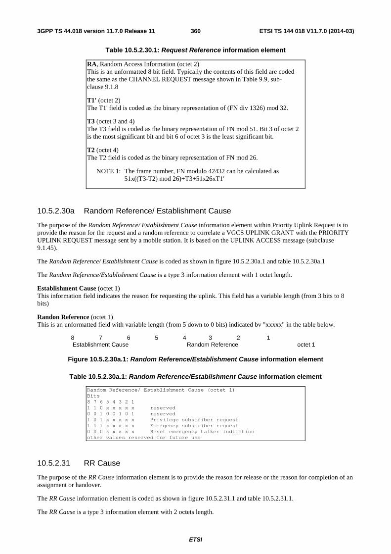
ETSI
ETSI TS 144 018 V11.7.0 (2014-03)3603GPP TS 44.018 version 11.7.0 Release 11
Table 10.5.2.30.1: Request Reference information element
RA, Random Access Information (octet 2) This is an unformatted 8 bit field. Typically the contents of this field are coded the same as the CHANNEL REQUEST message shown in Table 9.9, sub-clause 9.1.8
T1' (octet 2) The T1' field is coded as the binary representation of (FN div 1326) mod 32.
T3 (octet 3 and 4) The T3 field is coded as the binary representation of FN mod 51. Bit 3 of octet 2 is the most significant bit and bit 6 of octet 3 is the least significant bit.
T2 (octet 4) The T2 field is coded as the binary representation of FN mod 26.
NOTE 1: The frame number, FN modulo 42432 can be calculated as 51x((T3-T2) mod 26)+T3+51x26xT1'
10.5.2.30a Random Reference/ Establishment Cause
The purpose of the Random Reference/ Establishment Cause information element within Priority Uplink Request is to provide the reason for the request and a random reference to correlate a VGCS UPLINK GRANT with the PRIORITY UPLINK REQUEST message sent by a mobile station. It is based on the UPLINK ACCESS message (subclause 9.1.45).
The Random Reference/ Establishment Cause is coded as shown in figure 10.5.2.30a.1 and table 10.5.2.30a.1
The Random Reference/Establishment Cause is a type 3 information element with 1 octet length.
Establishment Cause (octet 1) This information field indicates the reason for requesting the uplink. This field has a variable length (from 3 bits to 8 bits)
Randon Reference (octet 1) This is an unformatted field with variable length (from 5 down to 0 bits) indicated bv "xxxxx" in the table below.
8 7 6 5 4 3 2 1 Establishment Cause Random Reference octet 1
Figure 10.5.2.30a.1: Random Reference/Establishment Cause information element
Table 10.5.2.30a.1: Random Reference/Establishment Cause information element
Random Reference/ Establishment Cause (octet 1) Bits 8 7 6 5 4 3 2 1 1 1 0 x x x x x reserved 0 0 1 0 0 1 0 1 reserved 1 0 1 x x x x x Privilege subscriber request 1 1 1 x x x x x Emergency subscriber request 0 0 0 x x x x x Reset emergency talker indication other values reserved for future use
10.5.2.31 RR Cause
The purpose of the RR Cause information element is to provide the reason for release or the reason for completion of an assignment or handover.
The RR Cause information element is coded as shown in figure 10.5.2.31.1 and table 10.5.2.31.1.
The RR Cause is a type 3 information element with 2 octets length.
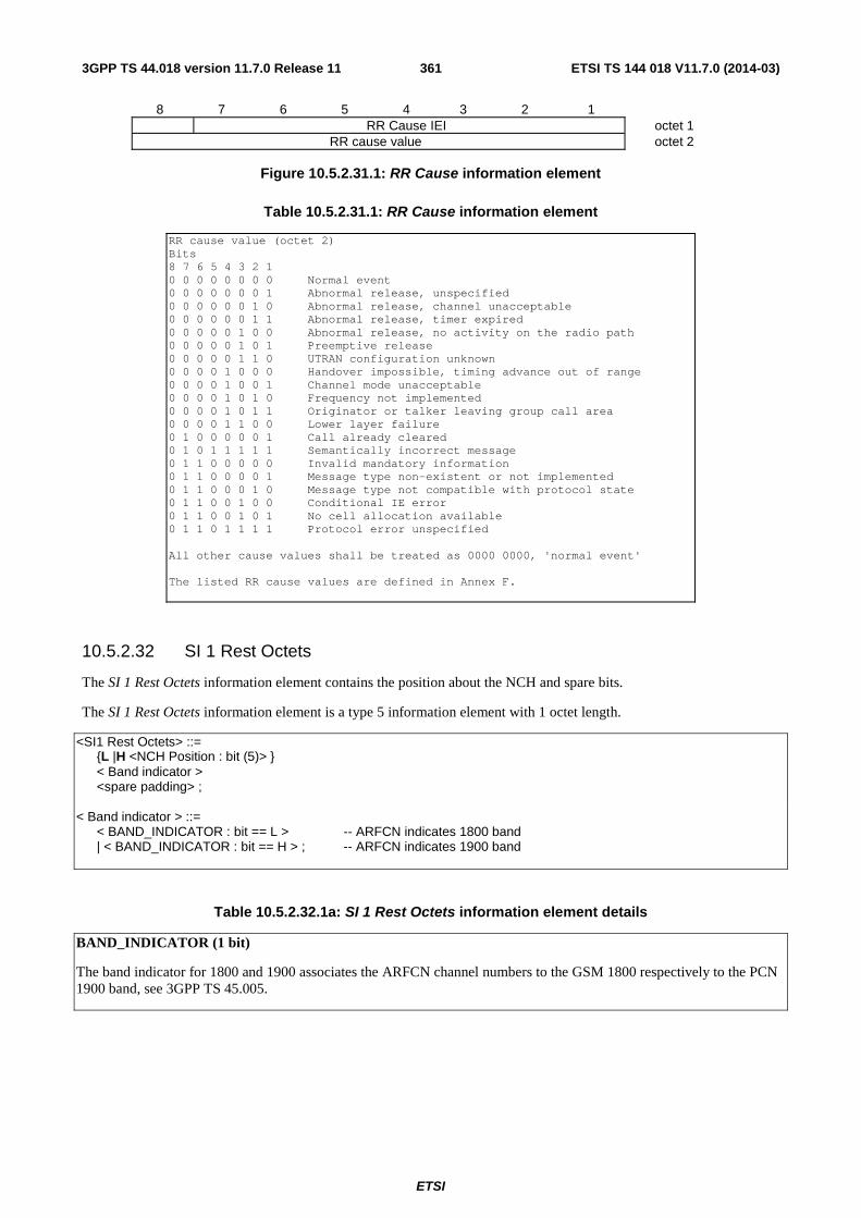
ETSI
ETSI TS 144 018 V11.7.0 (2014-03)3613GPP TS 44.018 version 11.7.0 Release 11
8 7 6 5 4 3 2 1 RR Cause IEI octet 1
RR cause value octet 2
Figure 10.5.2.31.1: RR Cause information element
Table 10.5.2.31.1: RR Cause information element
RR cause value (octet 2) Bits 8 7 6 5 4 3 2 1 0 0 0 0 0 0 0 0 Normal event 0 0 0 0 0 0 0 1 Abnormal release, unspecified 0 0 0 0 0 0 1 0 Abnormal release, channel unacceptable 0 0 0 0 0 0 1 1 Abnormal release, timer expired 0 0 0 0 0 1 0 0 Abnormal release, no activity on the radio path 0 0 0 0 0 1 0 1 Preemptive release 0 0 0 0 0 1 1 0 UTRAN configuration unknown 0 0 0 0 1 0 0 0 Handover impossible, timing advance out of range 0 0 0 0 1 0 0 1 Channel mode unacceptable 0 0 0 0 1 0 1 0 Frequency not implemented 0 0 0 0 1 0 1 1 Originator or talker leaving group call area 0 0 0 0 1 1 0 0 Lower layer failure 0 1 0 0 0 0 0 1 Call already cleared 0 1 0 1 1 1 1 1 Semantically incorrect message 0 1 1 0 0 0 0 0 Invalid mandatory information 0 1 1 0 0 0 0 1 Message type non-existent or not implemented 0 1 1 0 0 0 1 0 Message type not compatible with protocol state 0 1 1 0 0 1 0 0 Conditional IE error 0 1 1 0 0 1 0 1 No cell allocation available 0 1 1 0 1 1 1 1 Protocol error unspecified All other cause values shall be treated as 0000 0000, 'normal event' The listed RR cause values are defined in Annex F.
10.5.2.32 SI 1 Rest Octets
The SI 1 Rest Octets information element contains the position about the NCH and spare bits.
The SI 1 Rest Octets information element is a type 5 information element with 1 octet length.
<SI1 Rest Octets> ::= {L |H <NCH Position : bit (5)> } < Band indicator > <spare padding> ; < Band indicator > ::= < BAND_INDICATOR : bit == L > -- ARFCN indicates 1800 band | < BAND_INDICATOR : bit == H > ; -- ARFCN indicates 1900 band
Table 10.5.2.32.1a: SI 1 Rest Octets information element details
BAND_INDICATOR (1 bit)
The band indicator for 1800 and 1900 associates the ARFCN channel numbers to the GSM 1800 respectively to the PCN 1900 band, see 3GPP TS 45.005.
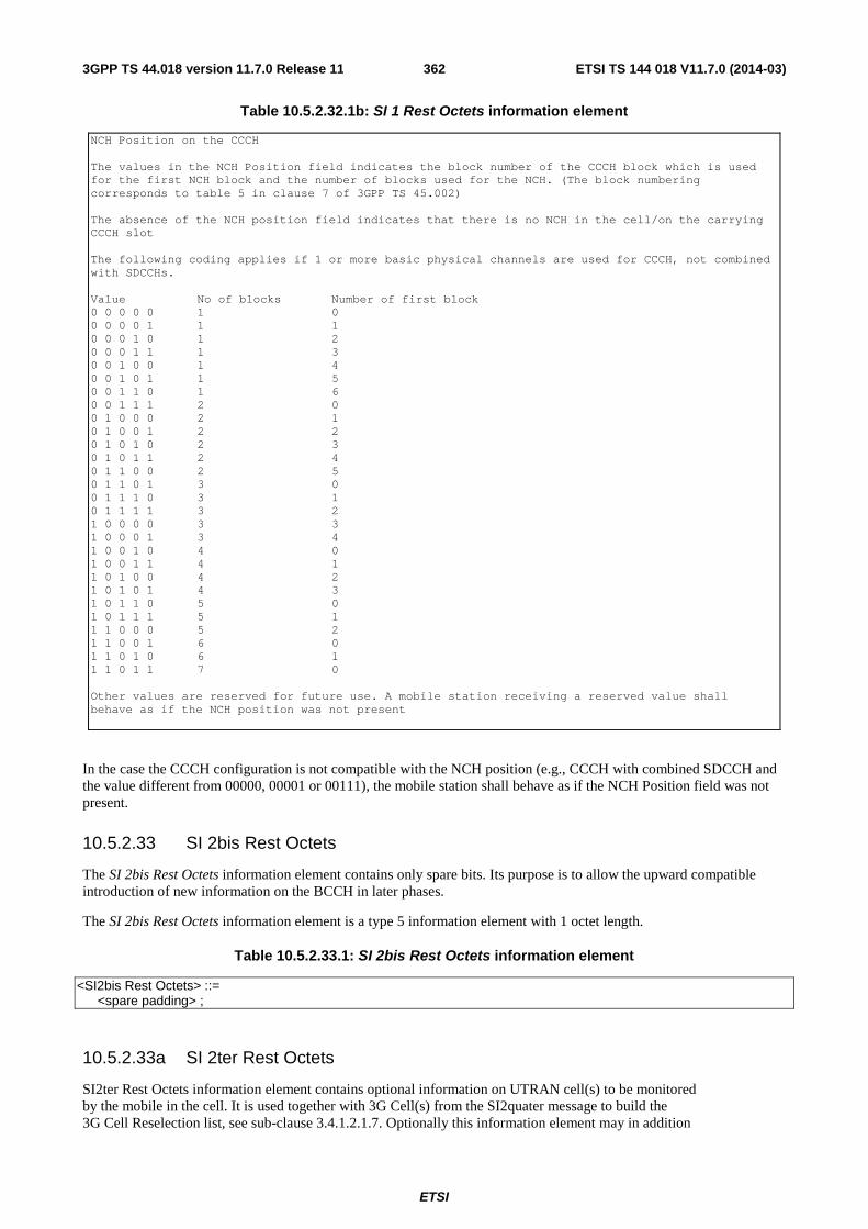
ETSI
ETSI TS 144 018 V11.7.0 (2014-03)3623GPP TS 44.018 version 11.7.0 Release 11
Table 10.5.2.32.1b: SI 1 Rest Octets information element
NCH Position on the CCCH The values in the NCH Position field indicates the block number of the CCCH block which is used for the first NCH block and the number of blocks used for the NCH. (The block numbering corresponds to table 5 in clause 7 of 3GPP TS 45.002) The absence of the NCH position field indicates that there is no NCH in the cell/on the carrying CCCH slot The following coding applies if 1 or more basic physical channels are used for CCCH, not combined with SDCCHs. Value No of blocks Number of first block 0 0 0 0 0 1 0 0 0 0 0 1 1 1 0 0 0 1 0 1 2 0 0 0 1 1 1 3 0 0 1 0 0 1 4 0 0 1 0 1 1 5 0 0 1 1 0 1 6 0 0 1 1 1 2 0 0 1 0 0 0 2 1 0 1 0 0 1 2 2 0 1 0 1 0 2 3 0 1 0 1 1 2 4 0 1 1 0 0 2 5 0 1 1 0 1 3 0 0 1 1 1 0 3 1 0 1 1 1 1 3 2 1 0 0 0 0 3 3 1 0 0 0 1 3 4 1 0 0 1 0 4 0 1 0 0 1 1 4 1 1 0 1 0 0 4 2 1 0 1 0 1 4 3 1 0 1 1 0 5 0 1 0 1 1 1 5 1 1 1 0 0 0 5 2 1 1 0 0 1 6 0 1 1 0 1 0 6 1 1 1 0 1 1 7 0 Other values are reserved for future use. A mobile station receiving a reserved value shall behave as if the NCH position was not present
In the case the CCCH configuration is not compatible with the NCH position (e.g., CCCH with combined SDCCH and the value different from 00000, 00001 or 00111), the mobile station shall behave as if the NCH Position field was not present.
10.5.2.33 SI 2bis Rest Octets
The SI 2bis Rest Octets information element contains only spare bits. Its purpose is to allow the upward compatible introduction of new information on the BCCH in later phases.
The SI 2bis Rest Octets information element is a type 5 information element with 1 octet length.
Table 10.5.2.33.1: SI 2bis Rest Octets information element
<SI2bis Rest Octets> ::= <spare padding> ;
10.5.2.33a SI 2ter Rest Octets
SI2ter Rest Octets information element contains optional information on UTRAN cell(s) to be monitored by the mobile in the cell. It is used together with 3G Cell(s) from the SI2quater message to build the 3G Cell Reselection list, see sub-clause 3.4.1.2.1.7. Optionally this information element may in addition
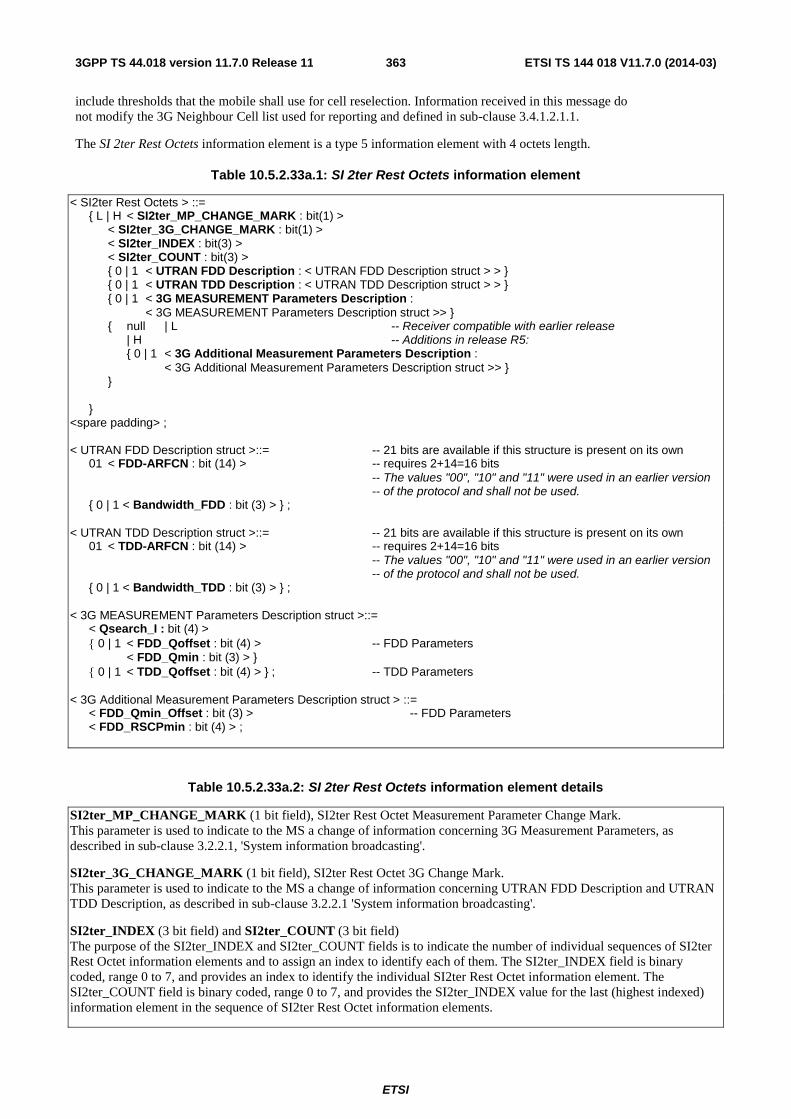
ETSI
ETSI TS 144 018 V11.7.0 (2014-03)3633GPP TS 44.018 version 11.7.0 Release 11
include thresholds that the mobile shall use for cell reselection. Information received in this message do not modify the 3G Neighbour Cell list used for reporting and defined in sub-clause 3.4.1.2.1.1.
The SI 2ter Rest Octets information element is a type 5 information element with 4 octets length.
Table 10.5.2.33a.1: SI 2ter Rest Octets information element
< SI2ter Rest Octets > ::= { L | H < SI2ter_MP_CHANGE_MARK : bit(1) > < SI2ter_3G_CHANGE_MARK : bit(1) > < SI2ter_INDEX : bit(3) > < SI2ter_COUNT : bit(3) > { 0 | 1 < UTRAN FDD Description : < UTRAN FDD Description struct > > } { 0 | 1 < UTRAN TDD Description : < UTRAN TDD Description struct > > } { 0 | 1 < 3G MEASUREMENT Parameters Description : < 3G MEASUREMENT Parameters Description struct >> } { null | L -- Receiver compatible with earlier release | H -- Additions in release R5: { 0 | 1 < 3G Additional Measurement Parameters Description : < 3G Additional Measurement Parameters Description struct >> } } } <spare padding> ; < UTRAN FDD Description struct >::= -- 21 bits are available if this structure is present on its own 01 < FDD-ARFCN : bit (14) > -- requires 2+14=16 bits -- The values "00", "10" and "11" were used in an earlier version -- of the protocol and shall not be used. { 0 | 1 < Bandwidth_FDD : bit (3) > } ; < UTRAN TDD Description struct >::= -- 21 bits are available if this structure is present on its own 01 < TDD-ARFCN : bit (14) > -- requires 2+14=16 bits -- The values "00", "10" and "11" were used in an earlier version -- of the protocol and shall not be used. { 0 | 1 < Bandwidth_TDD : bit (3) > } ; < 3G MEASUREMENT Parameters Description struct >::= < Qsearch_I : bit (4) > { 0 | 1 < FDD_Qoffset : bit (4) > -- FDD Parameters < FDD_Qmin : bit (3) > } { 0 | 1 < TDD_Qoffset : bit (4) > } ; -- TDD Parameters < 3G Additional Measurement Parameters Description struct > ::= < FDD_Qmin_Offset : bit (3) > -- FDD Parameters < FDD_RSCPmin : bit (4) > ;
Table 10.5.2.33a.2: SI 2ter Rest Octets information element details
SI2ter_MP_CHANGE_MARK (1 bit field), SI2ter Rest Octet Measurement Parameter Change Mark. This parameter is used to indicate to the MS a change of information concerning 3G Measurement Parameters, as described in sub-clause 3.2.2.1, 'System information broadcasting'.
SI2ter_3G_CHANGE_MARK (1 bit field), SI2ter Rest Octet 3G Change Mark. This parameter is used to indicate to the MS a change of information concerning UTRAN FDD Description and UTRAN TDD Description, as described in sub-clause 3.2.2.1 'System information broadcasting'.
SI2ter_INDEX (3 bit field) and SI2ter_COUNT (3 bit field) The purpose of the SI2ter_INDEX and SI2ter_COUNT fields is to indicate the number of individual sequences of SI2ter Rest Octet information elements and to assign an index to identify each of them. The SI2ter_INDEX field is binary coded, range 0 to 7, and provides an index to identify the individual SI2ter Rest Octet information element. The SI2ter_COUNT field is binary coded, range 0 to 7, and provides the SI2ter_INDEX value for the last (highest indexed) information element in the sequence of SI2ter Rest Octet information elements.
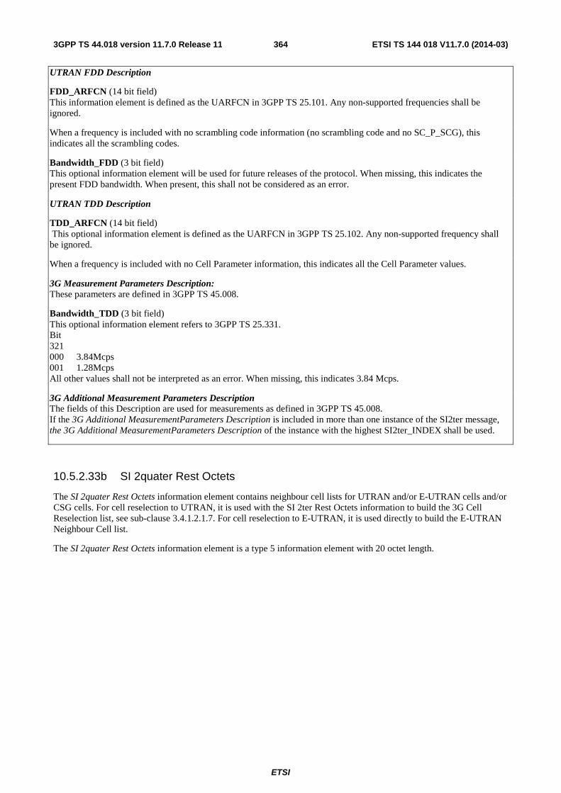
ETSI
ETSI TS 144 018 V11.7.0 (2014-03)3643GPP TS 44.018 version 11.7.0 Release 11
UTRAN FDD Description
FDD_ARFCN (14 bit field) This information element is defined as the UARFCN in 3GPP TS 25.101. Any non-supported frequencies shall be ignored.
When a frequency is included with no scrambling code information (no scrambling code and no SC_P_SCG), this indicates all the scrambling codes.
Bandwidth_FDD (3 bit field) This optional information element will be used for future releases of the protocol. When missing, this indicates the present FDD bandwidth. When present, this shall not be considered as an error.
UTRAN TDD Description
TDD_ARFCN (14 bit field) This optional information element is defined as the UARFCN in 3GPP TS 25.102. Any non-supported frequency shall be ignored.
When a frequency is included with no Cell Parameter information, this indicates all the Cell Parameter values.
3G Measurement Parameters Description: These parameters are defined in 3GPP TS 45.008.
Bandwidth_TDD (3 bit field) This optional information element refers to 3GPP TS 25.331. Bit 321 000 3.84Mcps 001 1.28Mcps All other values shall not be interpreted as an error. When missing, this indicates 3.84 Mcps.
3G Additional Measurement Parameters Description The fields of this Description are used for measurements as defined in 3GPP TS 45.008. If the 3G Additional MeasurementParameters Description is included in more than one instance of the SI2ter message, the 3G Additional MeasurementParameters Description of the instance with the highest SI2ter_INDEX shall be used.
10.5.2.33b SI 2quater Rest Octets
The SI 2quater Rest Octets information element contains neighbour cell lists for UTRAN and/or E-UTRAN cells and/or CSG cells. For cell reselection to UTRAN, it is used with the SI 2ter Rest Octets information to build the 3G Cell Reselection list, see sub-clause 3.4.1.2.1.7. For cell reselection to E-UTRAN, it is used directly to build the E-UTRAN Neighbour Cell list.
The SI 2quater Rest Octets information element is a type 5 information element with 20 octet length.

ETSI
ETSI TS 144 018 V11.7.0 (2014-03)3653GPP TS 44.018 version 11.7.0 Release 11
Table 10.5.2.33b.1: SI2quater Rest Octets information element
< SI2quater Rest Octets > ::= < BA_IND : bit (1) > < 3G_BA_IND : bit (1) > < MP_CHANGE_MARK : bit (1) > < SI2quater_INDEX : bit (4) > < SI2quater_COUNT : bit (4) > { 0 | 1 < Measurement_Parameters Description : < Measurement Parameters Description struct >> } { 0 | 1 < GPRS_Real Time Difference Description : < GPRS_Real Time Difference Description struct >> } { 0 | 1 < GPRS_BSIC Description : GPRS_BSIC Description struct > } { 0 | 1 < GPRS_REPORT PRIORITY Description : < GPRS_REPORT_PRIORITY Description struct >> } { 0 | 1 < GPRS_MEASUREMENT_Parameters Description : < GPRS_MEASUREMENT Parameters Description struct >> } { 0 | 1 < NC Measurement Parameters : < NC Measurement Parameters struct >> } { 0 | 1 < extension length : bit (8) > < < bit (val(extension length)+1) > & { < SI2q Extension Information > ! { Ignore: bit ** = <no string> } } > } { 0 | 1 < 3G Neighbour Cell Description : < 3G Neighbour Cell Description struct >> } { 0 | 1 < 3G Measurement Parameters Description : < 3G Measurement Parameters Description struct >> } { 0 | 1 < GPRS_3G_MEASUREMENT Parameters Description : < GPRS_3G MEASUREMENT Parameters Description struct >> } { null | L -- Receiver compatible with earlier release | H -- Additions in Rel-5: { 0 | 1 < 3G Additional Measurement Parameters Description : < 3G Additional Measurement Parameters Description struct >> } { 0 | 1 < 3G ADDITIONAL MEASUREMENT Parameters Description 2 : < 3G ADDITIONAL MEASUREMENT Parameters Description 2 struct >> } { null | L -- Receiver compatible with earlier release | H -- Additions in Rel-6: < 3G_CCN_ACTIVE : bit (1) > { null | L -- Receiver compatible with earlier release | H -- Additions in Rel-7: { 0 | 1 < 700_REPORTING_OFFSET : bit (3) > < 700_REPORTING_THRESHOLD : bit (3) > } { 0 | 1 < 810_REPORTING_OFFSET : bit (3) > < 810_REPORTING_THRESHOLD : bit (3) > } { null | L -- Receiver compatible with earlier release | H -- Additions in Rel-8 { 0 | 1 < Priority and E-UTRAN Parameters Description : < Priority and E-UTRAN Parameters Description struct >> } { 0 | 1 < 3G CSG Description : < 3G CSG Description struct >> } { 0 | 1 < E-UTRAN CSG Description : < E-UTRAN CSG Description struct >> } { null | L -- Receiver compatible with earlier release | H -- Additions in Rel-9 { 0 | 1 < Enhanced Cell Reselection Parameters Description : < Enhanced Cell Reselection Parameters IE >> } { 0 | 1 < CSG Cells Reporting Description : < CSG Cells Reporting Description struct >> } { null | L -- Receiver compatible with earlier release | H -- Additions in Rel-10 { 0 | 1 < INIT_PWR_RED : bit (1)> } < NC2_CSG_PCCN_permitted : bit (1) > } } } } } } < spare padding > ;

ETSI
ETSI TS 144 018 V11.7.0 (2014-03)3663GPP TS 44.018 version 11.7.0 Release 11
< 3G Neighbour Cell Description struct > ::= { 0 | 1 < Index_Start_3G : bit (7) } { 0 | 1 < Absolute_Index_Start_EMR : bit (7) } { 0 | 1 < UTRAN FDD Description : UTRAN FDD Description struct >> } { 0 | 1 < UTRAN TDD Description : UTRAN TDD Description struct >> } ; < UTRAN FDD Description struct > ::= { 0 | 1 < Bandwidth_FDD : bit (3) } { 1 < Repeated UTRAN FDD Neighbour Cells : Repeated UTRAN FDD Neighbour Cells struct >> } ** 0 ; < Repeated UTRAN FDD Neighbour Cells struct > ::= 0 < FDD-ARFCN : bit (14) > -- The value "1" was used in an earlier version of the protocol and shall not be used. < FDD_Indic0 : bit > < NR_OF_FDD_CELLS : bit (5) > < FDD_CELL_INFORMATION Field : bit(p(NR_OF_FDD_CELLS)) > ; -- p(x) defined in table 9.1.54.1 < UTRAN TDD Description struct > : := { 0 | 1 < Bandwidth_TDD : bit (3) } { 1 < Repeated UMTS TDD Neighbour Cells : Repeated UMTS TDD Neighbour Cells struct >> } ** 0 ; < Repeated UTRAN TDD Neighbour Cells struct > ::= 0 < TDD-ARFCN : bit (14) > -- The value "1" was used in an earlier version of the protocol and shall not be used. < TDD_Indic0 : bit > < NR_OF_TDD_CELLS : bit (5) > < TDD_CELL_INFORMATION Field : bit(q(NR_OF_TDD_CELLS) > ; -- q(x) defined in table 9.1.54.1 <MEASUREMENT PARAMETERS Description Struct > ::= < REPORT_TYPE : bit > < SERVING_BAND_REPORTING : bit (2) > ; < 3G MEASUREMENT PARAMETERS Description struct > ::= < Qsearch_I : bit (4) > < Qsearch_C_Initial : bit (1) > { 0 | 1 < FDD_Qoffset : bit (4) > -- FDD information < FDD_REP_QUANT : bit (1) > < FDD_MULTIRAT_REPORTING : bit (2) > < FDD_Qmin : bit (3) > } { 0 | 1 < TDD_Qoffset : bit (4) > -- TDD information < TDD_MULTIRAT_REPORTING : bit (2) > } ; < GPRS Real Time Difference Description struct > ::= { 0 | 1 { 0 | 1 < BA_Index_Start_RTD : bit (5) > } --default value=0 < RTD : < RTD6 Struct >> { 0 < RTD : < RTD6 Struct >> } **1 } -- '0' : increment by 1 the index of the BA (list) frequency { 0 | 1 { 0 | 1 < BA_Index_Start_RTD : bit (5) > } --default value=0 < RTD : < RTD12 Struct >> { 0 < RTD : < RTD12 Struct >> } **1 }; -- '0' : increment by 1 the index of the BA (list) frequency < RTD6 Struct > ::= { 0 < RTD : bit (6) > } ** 1; -- Repeat until '1' ; '1' means last RTD for this frequency < RTD12 Struct > ::= { 0 < RTD : bit (12) > } ** 1; -- Repeat until '1' ; '1' means last RTD for this frequency < GPRS BSIC Description struct > ::= { 0 | 1 < BA_Index_Start_BSIC : bit (5) > } -- default value=0 < BSIC : bit (6) > < Number_Remaining_BSIC: bit (7) > { < Frequency_Scrolling : bit > -- 0 means same frequency < BSIC : bit (6) > } * (val(Number_Remaining_BSIC)) ; < GPRS REPORT PRIORITY Description struct > ::= < Number_Cells : bit (7) > { REP_PRIORITY: bit } * (val(Number_Cells)) ;

ETSI
ETSI TS 144 018 V11.7.0 (2014-03)3673GPP TS 44.018 version 11.7.0 Release 11
< GPRS MEASUREMENT PARAMETERS Description struct > ::= < REPORT_TYPE : bit > < REPORTING_RATE : bit > < INVALID_BSIC_REPORTING : bit > { 0 | 1 < MULTIBAND_REPORTING : bit (2) > } { 0 | 1 < SERVING_BAND_REPORTING : bit (2) > } < SCALE_ORD : bit(2) > { 0 | 1 < 900_REPORTING_OFFSET : bit (3) > < 900_REPORTING_THRESHOLD : bit (3) > } { 0 | 1 < 1800_REPORTING_OFFSET : bit (3) > < 1800_REPORTING_THRESHOLD : bit (3) > } { 0 | 1 < 400_REPORTING_OFFSET : bit (3) > < 400_REPORTING_THRESHOLD : bit (3) > } { 0 | 1 < 1900_REPORTING_OFFSET : bit (3) > < 1900_REPORTING_THRESHOLD : bit (3) > } { 0 | 1 < 850_REPORTING_OFFSET : bit (3) > < 850_REPORTING_THRESHOLD : bit (3) > } ; < GPRS 3G MEASUREMENT PARAMETERS Description struct > ::= < Qsearch_P : bit (4) > { 1 ! < Ignore : bit = < no string >> } -- this bit shall be ignored by the receiver -- for backward compatibility with earlier releases { 0 | 1 < FDD_REP_QUANT : bit > -- FDD Parameters < FDD_MULTIRAT_REPORTING : bit (2) > } { 0 | 1 < FDD_REPORTING_OFFSET : bit (3) > < FDD_REPORTING_THRESHOLD : bit (3) > } { 0 | 1 < TDD_MULTIRAT_REPORTING : bit (2) > } -- TDD Parameters { 0 | 1 < TDD_REPORTING_OFFSET : bit (3) > < TDD_REPORTING_THRESHOLD : bit (3) > } ; < NC Measurement Parameters struct > ::= < NETWORK_CONTROL_ORDER : bit (2) > { 0 | 1 < NC_ NON_DRX_PERIOD : bit (3) > < NC_REPORTING_PERIOD_I : bit (3) > < NC_REPORTING_PERIOD_T : bit (3) > } ; < SI2q Extension Information > :: = { 0 | 1 < CCN Support Description : < CCN Support Description struct >> } <spare bit>** ; < CCN Support Description struct > ::= < Number_Cells : bit (7) > { CCN_SUPPORTED : bit } * (val(Number_Cells)) ; < 3G Additional Measurement Parameters Description struct > ::= < FDD_Qmin_Offset : bit (3) > -- FDD information < FDD_RSCPmin : bit (4) > ; < 3G Additional Measurement Parameters Description 2 struct > ::= { 0 | 1 < FDD_REPORTING_THRESHOLD_2 : bit (6) > } ; -- FDD information < Priority and E-UTRAN Parameters Description struct > ::= { 0 | 1 < Serving Cell Priority Parameters Description : < Serving Cell Priority Parameters Description struct >> } { 0 | 1 < 3G Priority Parameters Description : < 3G Priority Parameters Description struct >> } { 0 | 1 < E-UTRAN Parameters Description : < E-UTRAN Parameters Description struct >> } ;
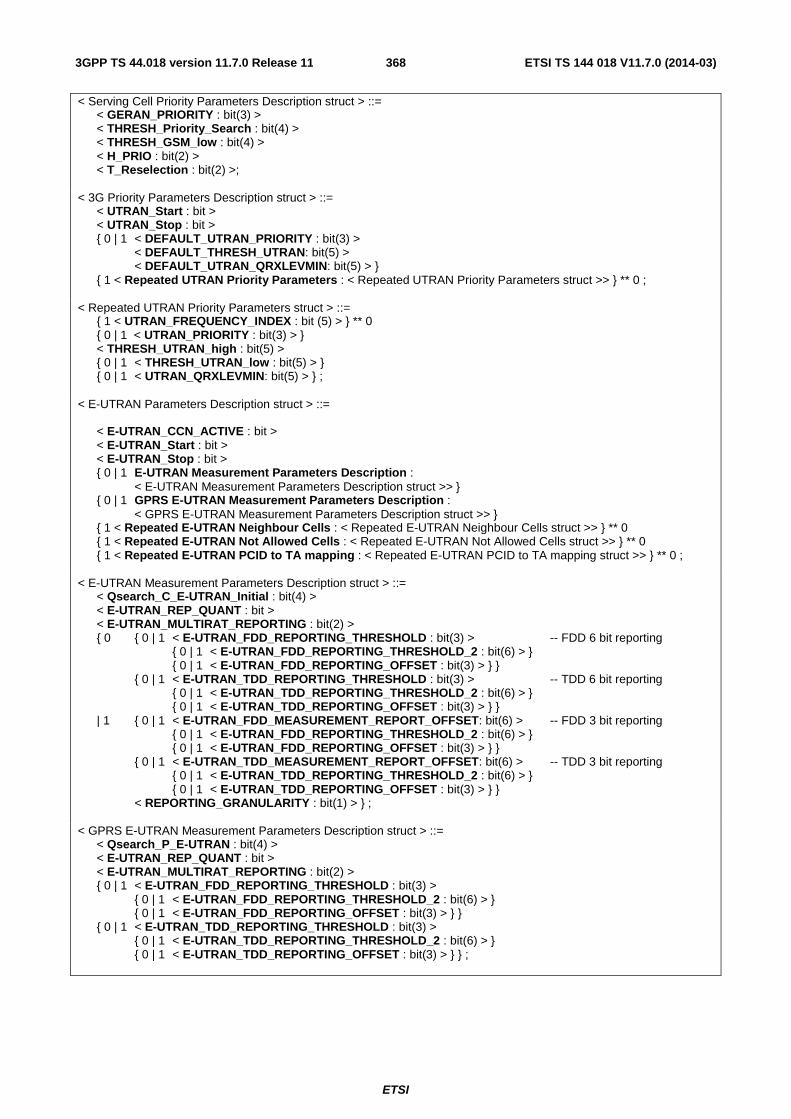
ETSI
ETSI TS 144 018 V11.7.0 (2014-03)3683GPP TS 44.018 version 11.7.0 Release 11
< Serving Cell Priority Parameters Description struct > ::= < GERAN_PRIORITY : bit(3) > < THRESH_Priority_Search : bit(4) > < THRESH_GSM_low : bit(4) > < H_PRIO : bit(2) > < T_Reselection : bit(2) >; < 3G Priority Parameters Description struct > ::= < UTRAN_Start : bit > < UTRAN_Stop : bit > { 0 | 1 < DEFAULT_UTRAN_PRIORITY : bit(3) > < DEFAULT_THRESH_UTRAN: bit(5) > < DEFAULT_UTRAN_QRXLEVMIN: bit(5) > } { 1 < Repeated UTRAN Priority Parameters : < Repeated UTRAN Priority Parameters struct >> } ** 0 ; < Repeated UTRAN Priority Parameters struct > ::= { 1 < UTRAN_FREQUENCY_INDEX : bit (5) > } ** 0 { 0 | 1 < UTRAN_PRIORITY : bit(3) > } < THRESH_UTRAN_high : bit(5) > { 0 | 1 < THRESH_UTRAN_low : bit(5) > } { 0 | 1 < UTRAN_QRXLEVMIN: bit(5) > } ; < E-UTRAN Parameters Description struct > ::= < E-UTRAN_CCN_ACTIVE : bit > < E-UTRAN_Start : bit > < E-UTRAN_Stop : bit > { 0 | 1 E-UTRAN Measurement Parameters Description : < E-UTRAN Measurement Parameters Description struct >> } { 0 | 1 GPRS E-UTRAN Measurement Parameters Description : < GPRS E-UTRAN Measurement Parameters Description struct >> } { 1 < Repeated E-UTRAN Neighbour Cells : < Repeated E-UTRAN Neighbour Cells struct >> } ** 0 { 1 < Repeated E-UTRAN Not Allowed Cells : < Repeated E-UTRAN Not Allowed Cells struct >> } ** 0 { 1 < Repeated E-UTRAN PCID to TA mapping : < Repeated E-UTRAN PCID to TA mapping struct >> } ** 0 ; < E-UTRAN Measurement Parameters Description struct > ::= < Qsearch_C_E-UTRAN_Initial : bit(4) > < E-UTRAN_REP_QUANT : bit > < E-UTRAN_MULTIRAT_REPORTING : bit(2) > { 0 { 0 | 1 < E-UTRAN_FDD_REPORTING_THRESHOLD : bit(3) > -- FDD 6 bit reporting { 0 | 1 < E-UTRAN_FDD_REPORTING_THRESHOLD_2 : bit(6) > } { 0 | 1 < E-UTRAN_FDD_REPORTING_OFFSET : bit(3) > } } { 0 | 1 < E-UTRAN_TDD_REPORTING_THRESHOLD : bit(3) > -- TDD 6 bit reporting { 0 | 1 < E-UTRAN_TDD_REPORTING_THRESHOLD_2 : bit(6) > } { 0 | 1 < E-UTRAN_TDD_REPORTING_OFFSET : bit(3) > } } | 1 { 0 | 1 < E-UTRAN_FDD_MEASUREMENT_REPORT_OFFSET: bit(6) > -- FDD 3 bit reporting { 0 | 1 < E-UTRAN_FDD_REPORTING_THRESHOLD_2 : bit(6) > } { 0 | 1 < E-UTRAN_FDD_REPORTING_OFFSET : bit(3) > } } { 0 | 1 < E-UTRAN_TDD_MEASUREMENT_REPORT_OFFSET: bit(6) > -- TDD 3 bit reporting { 0 | 1 < E-UTRAN_TDD_REPORTING_THRESHOLD_2 : bit(6) > } { 0 | 1 < E-UTRAN_TDD_REPORTING_OFFSET : bit(3) > } } < REPORTING_GRANULARITY : bit(1) > } ; < GPRS E-UTRAN Measurement Parameters Description struct > ::= < Qsearch_P_E-UTRAN : bit(4) > < E-UTRAN_REP_QUANT : bit > < E-UTRAN_MULTIRAT_REPORTING : bit(2) > { 0 | 1 < E-UTRAN_FDD_REPORTING_THRESHOLD : bit(3) > { 0 | 1 < E-UTRAN_FDD_REPORTING_THRESHOLD_2 : bit(6) > } { 0 | 1 < E-UTRAN_FDD_REPORTING_OFFSET : bit(3) > } } { 0 | 1 < E-UTRAN_TDD_REPORTING_THRESHOLD : bit(3) > { 0 | 1 < E-UTRAN_TDD_REPORTING_THRESHOLD_2 : bit(6) > } { 0 | 1 < E-UTRAN_TDD_REPORTING_OFFSET : bit(3) > } } ;
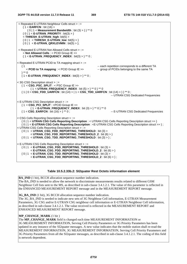
ETSI
ETSI TS 144 018 V11.7.0 (2014-03)3693GPP TS 44.018 version 11.7.0 Release 11
< Repeated E-UTRAN Neighbour Cells struct > ::= { 1 < EARFCN : bit (16) > { 0 | 1 < Measurement Bandwidth : bit (3) > } } ** 0 { 0 | 1 < E-UTRAN_PRIORITY : bit(3) > } < THRESH_E-UTRAN_high: bit(5) > { 0 | 1 < THRESH_E-UTRAN_low: bit(5) > } { 0 | 1 < E-UTRAN_QRXLEVMIN : bit(5) > }; < Repeated E-UTRAN Not Allowed Cells struct > ::= < Not Allowed Cells : < PCID Group IE >> { 1 < E-UTRAN_FREQUENCY_INDEX : bit(3) > } ** 0 ;
< Repeated E-UTRAN PCID to TA mapping struct > ::= { 1 -- each repetition corresponds to a different TA < PCID to TA mapping : < PCID Group IE >> -- group of PCIDs belonging to the same TA } ** 0 { 1 < E-UTRAN_FREQUENCY_INDEX : bit(3) > } ** 0 ; < 3G CSG Description struct > ::= { 1 < CSG_PSC_SPLIT : < PSC Group IE >> { 1 < UTRAN_FREQUENCY_INDEX : bit (5) > } ** 0 } ** 0 { 1 { 0 < CSG_FDD_UARFCN : bit (14) > | 1 < CSG_TDD_UARFCN : bit (14) > } } ** 0 ; -- UTRAN CSG Dedicated Frequencies < E-UTRAN CSG Description struct > ::= { 1 < CSG_PCI_SPLIT : <PCID Group IE >> { 1 < E-UTRAN_FREQUENCY_INDEX : bit (3) > } ** 0 } ** 0 { 1 < CSG_EARFCN : bit (16) > } ** 0 ; -- E-UTRAN CSG Dedicated Frequencies < CSG Cells Reporting Description struct > ::= { 0 | 1 < UTRAN CSG Cells Reporting Description : < UTRAN CSG Cells Reporting Description struct >> } { 0 | 1 < E-UTRAN CSG Cells Reporting Description : <E-UTRAN CSG Cells Reporting Description struct >> } ; < UTRAN CSG Cells Reporting Description struct > ::= { 0 | 1 < UTRAN_CSG_FDD_REPORTING_THRESHOLD : bit (3) > < UTRAN_CSG_FDD_REPORTING_THRESHOLD_2 : bit (6) > } { 0 | 1 < UTRAN_CSG_TDD_REPORTING_THRESHOLD : bit (3) > } ; < E-UTRAN CSG Cells Reporting Description struct > ::= { 0 | 1 < E-UTRAN_CSG_FDD_REPORTING_THRESHOLD : bit (3) > < E-UTRAN_CSG_FDD_REPORTING_THRESHOLD_2 : bit (6) > } { 0 | 1 < E-UTRAN_CSG_TDD_REPORTING_THRESHOLD : bit (3) > < E-UTRAN_CSG_FDD_REPORTING_THRESHOLD_2 : bit (6) > } ;
Table 10.5.2.33b.2: SI2quater Rest Octets information element
BA_IND (1 bit), BCCH allocation sequence number indication. The BA_IND is needed to allow the network to discriminate measurements results related to different GSM Neighbour Cell lists sent to the MS, as described in sub-clause 3.4.1.2.1. The value of this parameter is reflected in the ENHANCED MEASUREMENT REPORT message and in the MEASUREMENT REPORT message.
3G_BA_IND (1 bit), 3G BCCH allocation sequence number indication. The 3G_BA_IND is needed to indicate new sets of 3G Neighbour Cell information, E-UTRAN Measurement Parameters, 3G CSG and/or E-UTRAN CSG neighbour cell information or E-UTRAN Neighbour Cell information, as described in sub-clause 3.4.1.2.1. The value received is reflected in the MEASUREMENT REPORT and ENHANCED MEASUREMENT REPORT message.
MP_CHANGE_MARK (1 bit ) The MP_CHANGE_MARK field is changed each time MEASUREMENT INFORMATION or 3G MEASUREMENT INFORMATION, Serving Cell Priority Parameters or 3G Priority Parameters has been updated in any instance of the SI2quater messages. A new value indicates that the mobile station shall re-read the MEASUREMENT INFORMATION, 3G MEASUREMENT INFORMATION, Serving Cell Priority Parameters and 3G Priority Parameters from all the SI2quater messages, as described in sub-clause 3.4.1.2.1. The coding of this field is network dependent.
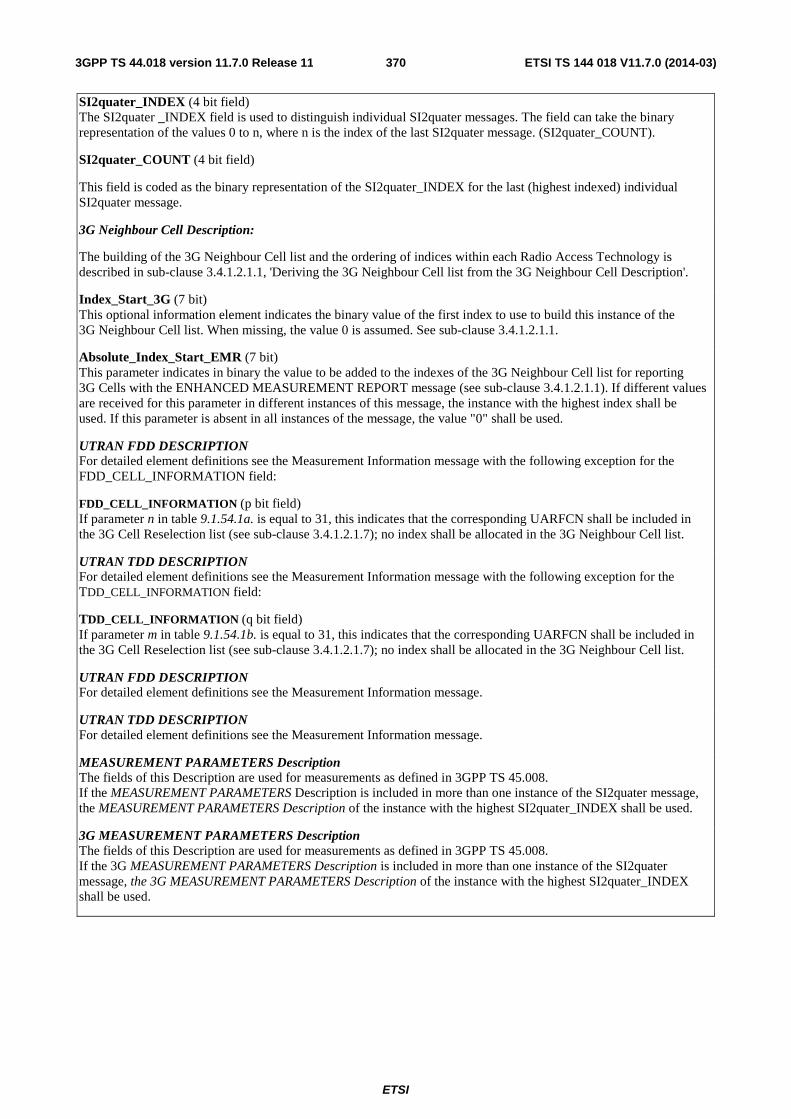
ETSI
ETSI TS 144 018 V11.7.0 (2014-03)3703GPP TS 44.018 version 11.7.0 Release 11
SI2quater_INDEX (4 bit field) The SI2quater _INDEX field is used to distinguish individual SI2quater messages. The field can take the binary representation of the values 0 to n, where n is the index of the last SI2quater message. (SI2quater_COUNT).
SI2quater_COUNT (4 bit field)
This field is coded as the binary representation of the SI2quater_INDEX for the last (highest indexed) individual SI2quater message.
3G Neighbour Cell Description:
The building of the 3G Neighbour Cell list and the ordering of indices within each Radio Access Technology is described in sub-clause 3.4.1.2.1.1, 'Deriving the 3G Neighbour Cell list from the 3G Neighbour Cell Description'.
Index_Start_3G (7 bit) This optional information element indicates the binary value of the first index to use to build this instance of the 3G Neighbour Cell list. When missing, the value 0 is assumed. See sub-clause 3.4.1.2.1.1.
Absolute_Index_Start_EMR (7 bit) This parameter indicates in binary the value to be added to the indexes of the 3G Neighbour Cell list for reporting 3G Cells with the ENHANCED MEASUREMENT REPORT message (see sub-clause 3.4.1.2.1.1). If different values are received for this parameter in different instances of this message, the instance with the highest index shall be used. If this parameter is absent in all instances of the message, the value "0" shall be used.
UTRAN FDD DESCRIPTION For detailed element definitions see the Measurement Information message with the following exception for the FDD_CELL_INFORMATION field:
FDD_CELL_INFORMATION (p bit field) If parameter n in table 9.1.54.1a. is equal to 31, this indicates that the corresponding UARFCN shall be included in the 3G Cell Reselection list (see sub-clause 3.4.1.2.1.7); no index shall be allocated in the 3G Neighbour Cell list.
UTRAN TDD DESCRIPTION For detailed element definitions see the Measurement Information message with the following exception for the TDD_CELL_INFORMATION field:
TDD_CELL_INFORMATION (q bit field) If parameter m in table 9.1.54.1b. is equal to 31, this indicates that the corresponding UARFCN shall be included in the 3G Cell Reselection list (see sub-clause 3.4.1.2.1.7); no index shall be allocated in the 3G Neighbour Cell list.
UTRAN FDD DESCRIPTION For detailed element definitions see the Measurement Information message.
UTRAN TDD DESCRIPTION For detailed element definitions see the Measurement Information message.
MEASUREMENT PARAMETERS Description The fields of this Description are used for measurements as defined in 3GPP TS 45.008. If the MEASUREMENT PARAMETERS Description is included in more than one instance of the SI2quater message, the MEASUREMENT PARAMETERS Description of the instance with the highest SI2quater_INDEX shall be used.
3G MEASUREMENT PARAMETERS Description The fields of this Description are used for measurements as defined in 3GPP TS 45.008. If the 3G MEASUREMENT PARAMETERS Description is included in more than one instance of the SI2quater message, the 3G MEASUREMENT PARAMETERS Description of the instance with the highest SI2quater_INDEX shall be used.
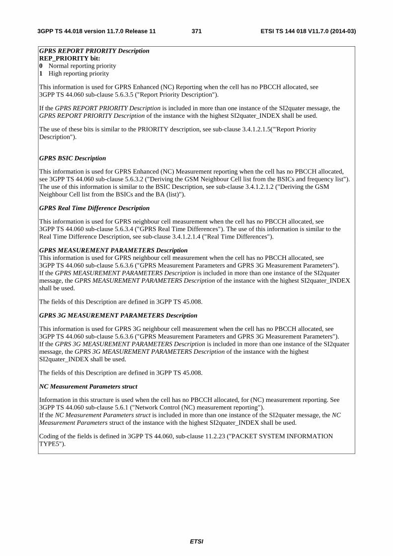
ETSI
ETSI TS 144 018 V11.7.0 (2014-03)3713GPP TS 44.018 version 11.7.0 Release 11
GPRS REPORT PRIORITY Description REP_PRIORITY bit: 0 Normal reporting priority 1 High reporting priority
This information is used for GPRS Enhanced (NC) Reporting when the cell has no PBCCH allocated, see 3GPP TS 44.060 sub-clause 5.6.3.5 ("Report Priority Description").
If the GPRS REPORT PRIORITY Description is included in more than one instance of the SI2quater message, the GPRS REPORT PRIORITY Description of the instance with the highest SI2quater_INDEX shall be used.
The use of these bits is similar to the PRIORITY description, see sub-clause 3.4.1.2.1.5("'Report Priority Description").
GPRS BSIC Description
This information is used for GPRS Enhanced (NC) Measurement reporting when the cell has no PBCCH allocated, see 3GPP TS 44.060 sub-clause 5.6.3.2 ("Deriving the GSM Neighbour Cell list from the BSICs and frequency list"). The use of this information is similar to the BSIC Description, see sub-clause 3.4.1.2.1.2 ("Deriving the GSM Neighbour Cell list from the BSICs and the BA (list)").
GPRS Real Time Difference Description
This information is used for GPRS neighbour cell measurement when the cell has no PBCCH allocated, see 3GPP TS 44.060 sub-clause 5.6.3.4 ("GPRS Real Time Differences"). The use of this information is similar to the Real Time Difference Description, see sub-clause 3.4.1.2.1.4 ("Real Time Differences").
GPRS MEASUREMENT PARAMETERS Description This information is used for GPRS neighbour cell measurement when the cell has no PBCCH allocated, see 3GPP TS 44.060 sub-clause 5.6.3.6 ("GPRS Measurement Parameters and GPRS 3G Measurement Parameters"). If the GPRS MEASUREMENT PARAMETERS Description is included in more than one instance of the SI2quater message, the GPRS MEASUREMENT PARAMETERS Description of the instance with the highest SI2quater_INDEX shall be used.
The fields of this Description are defined in 3GPP TS 45.008.
GPRS 3G MEASUREMENT PARAMETERS Description
This information is used for GPRS 3G neighbour cell measurement when the cell has no PBCCH allocated, see 3GPP TS 44.060 sub-clause 5.6.3.6 ("GPRS Measurement Parameters and GPRS 3G Measurement Parameters"). If the GPRS 3G MEASUREMENT PARAMETERS Description is included in more than one instance of the SI2quater message, the GPRS 3G MEASUREMENT PARAMETERS Description of the instance with the highest SI2quater_INDEX shall be used.
The fields of this Description are defined in 3GPP TS 45.008.
NC Measurement Parameters struct
Information in this structure is used when the cell has no PBCCH allocated, for (NC) measurement reporting. See 3GPP TS 44.060 sub-clause 5.6.1 ("Network Control (NC) measurement reporting"). If the NC Measurement Parameters struct is included in more than one instance of the SI2quater message, the NC Measurement Parameters struct of the instance with the highest SI2quater_INDEX shall be used.
Coding of the fields is defined in 3GPP TS 44.060, sub-clause 11.2.23 ("PACKET SYSTEM INFORMATION TYPE5").
ETSI
ETSI TS 144 018 V11.7.0 (2014-03)3723GPP TS 44.018 version 11.7.0 Release 11
CCN Support Description
CCN_SUPPORTED bit: 0 CCN is enabled towards the corresponding cell 1 CCN is disabled towards the corresponding cell
This information is used for determining whether the mobile station shall enter CCN mode when re-selecting a cell and CCN is enabled, see 3GPP TS 44.060.
If the CCN Support Description is included in more than one instance of the SI2quater message, the CCN Support Description of the instance with the highest SI2quater_INDEX shall be used.
The use of these bits is described in sub-clause 3.4.1.2.1.8("'CCN Support description'").
3G Additional Measurement Parameters Description The fields of this Description are used for measurements as defined in 3GPP TS 45.008. If the 3G Additional MeasurementParameters Description is included in more than one instance of the SI2quater message, the 3G Additional MeasurementParameters Description of the instance with the highest SI2quater_INDEX shall be used.
3G_CCN_ACTIVE (1 bit field) This field indicates whether CCN is enabled towards 3G neighbouring cells. It is coded as follows:
0 CCN towards 3G cells is disabled in the cell. 1 CCN towards 3G cells is enabled in the cell.
3G Additional Measurement Parameters Description 2 The fields of this Description are used for measurements as defined in 3GPP TS 45.008. If the 3G Additional Measurement Parameters Description 2 is included in more than one instance of the SI2quater message, the 3G Additional Measurement Parameters Description 2 of the instance with the highest SI2quater_INDEX shall be used.
700_REPORTING_OFFSET (3 bit field) 700_REPORTING_THRESHOLD (3 bit field) These fields are used for measurements as defined in 3GPP TS 45.008. If these fields are included in more than one instance of the SI2quater message, those of the instance with the highest SI2quater_INDEX shall be used.
810_REPORTING_OFFSET (3 bit field) 810_REPORTING_THRESHOLD (3 bit field) These fields are used for measurements as defined in 3GPP TS 45.008. If these fields are included in more than one instance of the SI2quater message, those of the instance with the highest SI2quater_INDEX shall be used.
Serving Cell Priority Parameters GERAN_PRIORITY (3 bit field) THRESH_Priority_Search (4 bit field) THRESH_GSM_low (4 bit field) H_PRIO (2 bit field) T_Reselection (2 bit field) These fields are used for the inter-RAT cell re-selection algorithm based on priority, as defined in 3GPP TS 45.008. Any parameter present overwrites any old data held by the mobile station for these parameters.

ETSI
ETSI TS 144 018 V11.7.0 (2014-03)3733GPP TS 44.018 version 11.7.0 Release 11
3G Priority Parameters Description UTRAN_Start (1 bit field) UTRAN_Stop (1 bit field) These fields are defined in sub-clause 9.1.54.
DEFAULT_UTRAN_PRIORITY (3 bit field) DEFAULT_THRESH_UTRAN (5 bit field) DEFAULT_UTRAN_QRXLEVMIN (5 bit field) These fields are used for the inter-RAT cell re-selection algorithm based on priority, as defined in 3GPP TS 45.008. Any UTRAN frequency included in the 3G Cell Reselection list which is not explicitly listed in the Repeated UTRAN Priority Parameters structure shall be assigned these default parameter values. In addition, any UTRAN frequency included in the 3G Frequency list which is explicitly listed in the Repeated UTRAN Priority Parameters structure but for which no UTRAN_QRXLEVMIN is explicitly signalled shall be assigned the value DEFAULT_UTRAN_QRXLEVMIN. The value of DEFAULT_THRESH_UTRAN shall apply to both THRESH_UTRAN_high and THRESH_UTRAN_low. The DEFAULT_UTRAN_PRIORITY field is encoded as the UTRAN_PRIORITY field; the DEFAULT_THRESH_UTRAN field is encoded as the THRESH_UTRAN_high field; the DEFAULT_UTRAN_QRXLEVMIN field is encoded as the UTRAN_QRXLEVMIN field.
Any parameter present overwrites any old data held by the mobile station for these parameters.
Repeated UTRAN Priority Parameters UTRAN_FREQUENCY_INDEX (5 bit field) This field is an index into the 3G Frequency list (see sub-clause 3.4.1.2.1.7c).. The following priority parameters apply to each UTRAN frequency indexed within this structure.
UTRAN_PRIORITY (3 bit field) THRESH_UTRAN_high (5 bit field) THRESH_UTRAN_low (5 bit field) If THRESH_UTRAN_low is not present, then THRESH_UTRAN_low shall take on the same value as THRESH_UTRAN_high. UTRAN_QRXLEVMIN (5 bit field)
These fields are used for the inter-RAT cell re-selection algorithm based on priority, as defined in 3GPP TS 45.008. These values apply to each of the frequencies indexed within this structure. Any parameter present overwrites any old data held by the mobile station for these parameters.
E-UTRAN Parameters Description If E-UTRAN cells or frequencies are included in the neighbour cell list, this information element shall be included in the message.
E-UTRAN_CCN_ACTIVE (1 bit field) This field indicates whether CCN is enabled towards E-UTRAN neighbouring cells. It is coded as follows:
0 The broadcast E-UTRAN_CCN_ACTIVE parameter shall apply if available. Otherwise, CCN towards E-UTRAN cells is disabled in the cell.
1 CCN towards E-UTRAN cells is enabled in the cell.
E-UTRAN_Start (1 bit field) E-UTRAN_Stop (1 bit field) These fields are defined in sub-clause 9.1.54.
ETSI
ETSI TS 144 018 V11.7.0 (2014-03)3743GPP TS 44.018 version 11.7.0 Release 11
E-UTRAN Measurement Parameters Description If the E-UTRAN MeasurementParameters Description is included in more than one instance of the SI2quater message, the E-UTRAN MeasurementParameters Description of the instance with the highest SI2quater_INDEX shall be used. Qsearch_C_E-UTRAN_Initial (4 bit field) E-UTRAN_MULTIRAT_REPORTING (2 bit field) E-UTRAN_REP_QUANT (1 bit field) E-UTRAN_FDD_REPORTING_THRESHOLD (3 bit field) E-UTRAN_FDD_REPORTING_THRESHOLD_2 (6 bit field) E-UTRAN_FDD_MEASUREMENT_REPORT_OFFSET (6 bit field) E-UTRAN_FDD_REPORTING_OFFSET (3 bit field) E-UTRAN_TDD_REPORTING_THRESHOLD (3 bit field) E-UTRAN_TDD_REPORTING_THRESHOLD_2 (6 bit field) E-UTRAN_TDD_MEASUREMENT_REPORT_OFFSET (6 bit field) E-UTRAN_TDD_REPORTING_OFFSET (3 bit field) REPORTING_GRANULARITY (1 bit field) These fields control the measurement and reporting of E-UTRAN cells in dedicated mode and dual transfer mode, as defined in 3GPP TS 45.008. If both TDD and FDD frequencies are provided in the Repeated E-UTRAN Neighbour Cells IE and the E-UTRAN reporting thresholds are present for only one mode (i.e. TDD or FDD), then the parameter values for both modes shall be interpreted as having the same values.
GPRS E-UTRAN Measurement Parameters Description If the GPRS E-UTRAN Measurement Parameters Description is included in more than one instance of the SI2quater message, the GPRS E-UTRAN Measurement Parameters Description of the instance with the highest SI2quater_INDEX shall be used. Qsearch_P_E-UTRAN (4 bit field) E-UTRAN_MULTIRAT_REPORTING (2 bit field) E-UTRAN_REP_QUANT (1 bit field) E-UTRAN_FDD_REPORTING_THRESHOLD (3 bit field) E-UTRAN_FDD_REPORTING_THRESHOLD_2 (6 bit field) E-UTRAN_TDD_REPORTING_THRESHOLD (3 bit field) E-UTRAN_TDD_REPORTING_THRESHOLD_2 (6 bit field) These fields control the GPRS neighbour cell measurement and (NC) Measurement reporting of E-UTRAN cells when the MS is not performing autonomous cell reselection, as defined in 3GPP TS 45.008. If both TDD and FDD frequencies are provided in the Repeated E-UTRAN Neighbour Cells IE and the E-UTRAN reporting thresholds are present for only one mode (i.e. TDD or FDD), then the parameter values for both modes shall be interpreted as having the same values. Repeated E-UTRAN Neighbour Cells If E-UTRAN cells or frequencies are included in the neighbour cell list, this information element shall be included in the message.
EARFCN (16 bit field) Measurement Bandwidth (3 bit field) These fields are defined in sub-clause 9.1.54.
E-UTRAN_PRIORITY (3 bit field) THRESH_E-UTRAN_high (5 bit field) THRESH_E-UTRAN_low (5 bit field) If THRESH_E-UTRAN_low is not present, then THRESH_E-UTRAN_low shall take on the same value as THRESH_E-UTRAN_high. E-UTRAN_QRXLEVMIN (5 bit field)
These fields are used for the inter-RAT cell re-selection algorithm based on priority, as defined in 3GPP TS 45.008. These values apply to each of the EARFCN values listed within this structure.
ETSI
ETSI TS 144 018 V11.7.0 (2014-03)3753GPP TS 44.018 version 11.7.0 Release 11
Repeated E-UTRAN Not Allowed Cells struct This structure identifies Not Allowed Cells with zero or more corresponding E-UTRAN frequency indices. If no E-UTRAN_FREQUENCY_INDEX is present, the Not Allowed Cells IE is applicable to all E-UTRAN frequencies specified in the Repeated E-UTRAN Neighbour Cells struct(s).
E-UTRAN_FREQUENCY_INDEX (3 bit field)
This field is defined in sub-clause 9.1.54.
Not Allowed Cells This information element is described in sub-clause 9.1.54
PCID to TA mapping This information element identifies, on the frequency or frequencies that this information element is associated with, one or more E-UTRAN cells by means of their physical layer cell identities (see 3GPP TS 36.211) that belong to the same Tracking Area. If no PCIDs or groups of PCIDs are indicated within this structure, then all PCIDs belong to the same Tracking Area.
This information element is defined as the PCID Group IE described in 3GPP TS 44.060.
3G CSG Description The fields of this description are used for inter-RAT cell reselection to UTRAN CSG cells as defined in 3GPP TS 45.008.
UTRAN_FREQUENCY_INDEX (5 bit field) Each instance of this field describes a UTRAN frequency in the 3G Frequency list where the CSG PSC SPLIT is valid. If the CSG_PSC_SPLIT IE is present but there are no instances of this field present in the message, then the CSG PSC SPLIT shall apply to all UTRAN frequencies in the 3G Cell Reselection list. This field is an index into the 3G Frequency list (see sub-clause 3.4.1.2.1.7c).
CSG_FDD_UARFCN (14 bit field) Each CSG_FDD_UARFCN describes a UTRAN FDD frequency dedicated to CSG cells. The field is formatted as a UARFCN as defined in 3GPP TS 25.101.
CSG_TDD_UARFCN (14 bit field) Each CSG_TDD_UARFCN describes a UTRAN TDD frequency dedicated to CSG cells. The field is formatted as a UARFCN as defined in 3GPP TS 25.102.
E-UTRAN CSG Description The fields of this description are used for inter-RAT cell reselection to E-UTRAN CSG cells as defined in 3GPP TS 45.008.
E-UTRAN_FREQUENCY_INDEX (3 bit field) Each instance of this field describes an E-UTRAN frequency in the E-UTRAN Neighbour Cell list where the CSG PCI SPLIT is valid. If the CSG_PCI_SPLIT field is present but there are no instances of this field present in the message, then the CSG PCI SPLIT shall apply to all E-UTRAN frequencies in the E-UTRAN Neighbour Cell list. This field is described in sub-clause 9.1.55.
CSG_EARFCN (16 bit field) Each CSG_EARFCN describes an E-UTRAN frequency dedicated to CSG cells. The field is formatted as an E-UTRA Absolute Radio Frequency Channel Number as defined in 3GPP TS 36.104.
CSG_PCI_SPLIT This information element is described in sub-clause 9.1.54.
CSG_PSC_SPLIT This information element identifies one or more primary scrambling code values for UTRAN FDD cells (see 3GPP TS 25.213) or cell parameter values for UTRAN TDD cells (see 3GPP TS 25.223) as being reserved for CSG cells. The range of reserved primary scrambling codes or cell parameters applies to all UTRAN frequencies specified in the list of frequencies.
This information element is defined as the PSC Group IE described in 3GPP TS 44.060.
ETSI
ETSI TS 144 018 V11.7.0 (2014-03)3763GPP TS 44.018 version 11.7.0 Release 11
Enhanced Cell Reselection Parameters Description This information element contains parameters for enhanced cell reselection procedures towards E-UTRAN cells, see 3GPP TS 45.008.
This information element is defined as the Enhanced Cell Reselection Parameters IE described in 3GPP TS 44.060.
CSG Cells Reporting Description This information element signals the parameters for measurement and reporting of UTRAN CSG cells in dedicated mode, dual transfer mode or packet transfer mode and/or the parameters for measurement and reporting of E-UTRAN CSG cells in packet transfer mode. Any parameter present overwrites any old data held by the mobile station for this parameter.
UTRAN CSG Cells Reporting Description
UTRAN_CSG_FDD_REPORTING_THRESHOLD (3 bit field) UTRAN_CSG_FDD_REPORTING_THRESHOLD_2 (6 bit field) UTRAN_CSG_TDD_REPORTING_THRESHOLD (3 bit field) These fields are defined in sub-clause 9.1.54.
E-UTRAN CSG Cells Reporting Description
E-UTRAN_CSG_FDD_REPORTING_THRESHOLD (3 bit field) E-UTRAN_CSG_FDD_REPORTING_THRESHOLD_2 (6 bit field) E-UTRAN_CSG_TDD_REPORTING_THRESHOLD (3 bit field) E-UTRAN_CSG_TDD_REPORTING_THRESHOLD_2 (6 bit field) These fields are used to control the reporting for CSG cells as specified in 3GPP TS 45.008.
INIT_PWR_RED (1 bit field) The INIT_PWR_RED field indicates whether or not a mobile station that supports the initial power reduction feature shall apply it as described in 3GPP TS 45.008. If this field is not present, no power reduction shall apply. The following coding shall be used:
0 RACH power reduction, INIT_PWR_RED=10 dB
1 RACH power reduction, INIT_PWR_RED=10 dB. In case of emergency calls, no power reduction shall apply.
NC2_CSG_PCCN_permitted (1 bit field) This field indicates whether a mobile station is permitted to send a PACKET CELL CHANGE NOTIFICATION message while in NC2 mode to report a detected CSG cell or hybrid cell (see 3GPP TS 44.060)
10.5.2.33c SI 2n Rest Octets
The SI 2n Rest Octets information element contains parameters affecting cell reselection for neighbouring cells.
The SI 2n Rest Octets information element is a type 5 information element with 20 octet length.
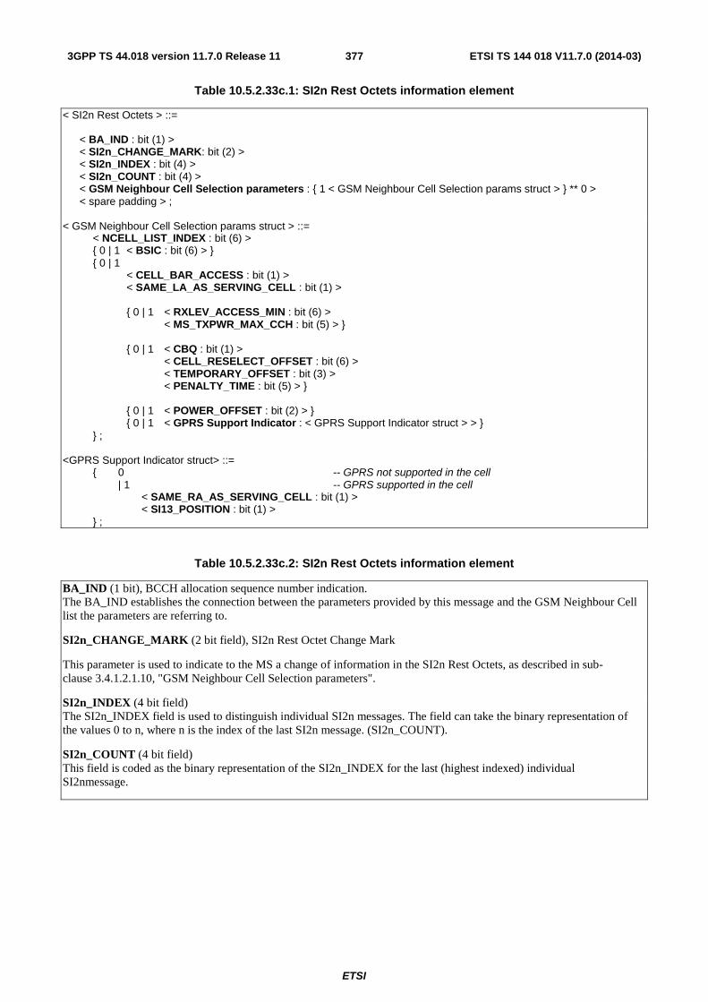
ETSI
ETSI TS 144 018 V11.7.0 (2014-03)3773GPP TS 44.018 version 11.7.0 Release 11
Table 10.5.2.33c.1: SI2n Rest Octets information element
< SI2n Rest Octets > ::= < BA_IND : bit (1) > < SI2n_CHANGE_MARK: bit (2) > < SI2n_INDEX : bit (4) > < SI2n_COUNT : bit (4) > < GSM Neighbour Cell Selection parameters : { 1 < GSM Neighbour Cell Selection params struct > } ** 0 > < spare padding > ; < GSM Neighbour Cell Selection params struct > ::= < NCELL_LIST_INDEX : bit (6) > { 0 | 1 < BSIC : bit (6) > } { 0 | 1 < CELL_BAR_ACCESS : bit (1) > < SAME_LA_AS_SERVING_CELL : bit (1) > { 0 | 1 < RXLEV_ACCESS_MIN : bit (6) > < MS_TXPWR_MAX_CCH : bit (5) > } { 0 | 1 < CBQ : bit (1) > < CELL_RESELECT_OFFSET : bit (6) > < TEMPORARY_OFFSET : bit (3) > < PENALTY_TIME : bit (5) > } { 0 | 1 < POWER_OFFSET : bit (2) > } { 0 | 1 < GPRS Support Indicator : < GPRS Support Indicator struct > > } } ; <GPRS Support Indicator struct> ::= { 0 -- GPRS not supported in the cell | 1 -- GPRS supported in the cell < SAME_RA_AS_SERVING_CELL : bit (1) > < SI13_POSITION : bit (1) > } ;
Table 10.5.2.33c.2: SI2n Rest Octets information element
BA_IND (1 bit), BCCH allocation sequence number indication. The BA_IND establishes the connection between the parameters provided by this message and the GSM Neighbour Cell list the parameters are referring to.
SI2n_CHANGE_MARK (2 bit field), SI2n Rest Octet Change Mark
This parameter is used to indicate to the MS a change of information in the SI2n Rest Octets, as described in sub-clause 3.4.1.2.1.10, "GSM Neighbour Cell Selection parameters".
SI2n_INDEX (4 bit field) The SI2n_INDEX field is used to distinguish individual SI2n messages. The field can take the binary representation of the values 0 to n, where n is the index of the last SI2n message. (SI2n_COUNT).
SI2n_COUNT (4 bit field) This field is coded as the binary representation of the SI2n_INDEX for the last (highest indexed) individual SI2nmessage.

ETSI
ETSI TS 144 018 V11.7.0 (2014-03)3783GPP TS 44.018 version 11.7.0 Release 11
GSM Neighbour Cell Selection params struct
General rules for handling neighbour cell parameter default values
If the first neighbour cell defined in SI2n with SI2n_INDEX = 0 does not include all the parameter values, the following default values shall be used:
RXLEV_ACCESS_MIN : Serving cell RXLEV_ACCESS_MIN MS_TXPWR_MAX_CCH : Serving cell MS_TXPWR_MAX_CCH CBQ : 0 CELL_RESELECT_OFFSET, TEMPORARY_OFFSET, and PENALTY_TIME : C2=C1, see 3GPP TS 45.008 POWER_OFFSET 0 dB CELL_BAR_ACCESS : Serving cell CELL_BAR_ACCESS SAME_LA_AS_SERVING_CELL : 1 (The cell is in the same Location Area as the serving cell) GPRS Support Indicator (struct not present) : SAME_RA_AS_SERVING_CELL : 1 (The cell is in the same Routeing Area as the serving cell) SI13_POSITION : As in the serving cell (not valid, if serving cell does not support GPRS) The following neighbour cells defined in the set of SI2n messages use the parameter values of the previous neighbour cell in the set of SI2n messages as their default values. This principle also applies when going from SI2n instance i over to SI2n instance i+1.
NCELL_LIST_INDEX (6 bit field) This field indicates the index to the GSM Neighbour Cell list to identify the neighbouring cell to which the parameters are given..
BSIC (6 bit field) This optional field is needed to identify the neighbour cell in case the GSM Neighbour Cell list is only a frequency list, see 3GPP TS 44.060 sub-clause 5.6.3.2
SAME_LA_AS_SERVING_CELL (1 bit field) This field indicates whether the cell is in the same location area as the serving cell. 0 the cell is in different location area as the serving cell 1 the cell is in the same location area as the serving cell SAME_RA_AS_SERVING_CELL (1 bit field) This field indicates whether the cell is in the same routeing area as the serving cell 0 the cell is in different routeing area as the serving cell 1 the cell is in the same routeing area as the serving cell For the description of the rest of the parameters in the GSM Neighbour Cell Selection params struct, see 3GPP TS 45.008.
10.5.2.34 SI 3 Rest Octets
The SI 3 Rest Octets information element is coded according to the syntax specified below and described in tables 10.5.2.34.1, 10.5.2.34.2 and 10.5.2.35.1 (see sub-clause 10.5.2.35).
The SI 3 Rest Octets information element is a type 5 information element with 4 octets length.

ETSI
ETSI TS 144 018 V11.7.0 (2014-03)3793GPP TS 44.018 version 11.7.0 Release 11
Table 10.5.2.34.1: SI 3 Rest Octets information element
<SI3 Rest Octet> ::= <Optional selection parameters> <Optional Power offset> <System Information 2ter Indicator> <Early Classmark Sending Control> <Scheduling if and where> { L | H <GPRS Indicator> } <3G Early Classmark Sending Restriction> { L | H < SI2quater Indicator : < SI2quater Indicator struct > > } <Iu Indicator> -- Conditional <System Information 21 Indicator> <spare padding> ; <Optional Selection Parameters> ::= L | H <Selection Parameters>; <Selection Parameters> ::= <CBQ: bit (1)> <CELL_RESELECT_OFFSET: bit (6)> <TEMPORARY_OFFSET: bit (3)> <PENALTY_TIME: bit (5)>; <Optional Power Offset> ::= L | H <Power Offset: bit (2)>; <System Information 2ter Indicator> ::= L | H; <Early Classmark Sending Control> ::= L | H; <Scheduling if and where>::= L | H <WHERE: bit (3)>; <GPRS Indicator> ::= < RA COLOUR : bit (3) > < SI13 POSITION : bit >; <3G Early Classmark Sending Restriction>::= L | H; < SI2quater Indicator struct > ::= < SI2quater_POSITION : bit > ; <Iu Indicator> ::= <SI13alt POSITION: bit >; <System Information 21 Indicator> ::= L | H < SI21_POSITION : bit > ;
Table 10.5.2.34.2: SI 3 Rest Octets information element details
CBQ, CELL_BAR_QUALIFY (1 bit field) CELL_BAR_QUALIFY is used by the network to control mobile station cell selection and reselection. The use and coding of this parameter is defined in 3GPP TS 45.008.
CELL_RESELECT_OFFSET (6 bit field) CELL_RESELECT_OFFSET is coded as the binary representation of the "CELL_RESELECT_OFFSET" in 3GPP TS 45.008. It is a value used by the mobile station to apply a positive or negative offset to the value of C2 as defined in 3GPP TS 23.022 and 3GPP TS 45.008.
TEMPORARY_OFFSET (3 bit field) The TEMPORARY_OFFSET field is coded as the binary representation of the "TEMPORARY_OFFSET" in 3GPP TS 45.008. It is used by the mobile station as part of its calculation of C2 for the cell reselection process as described in 3GPP TS 45.008. It is used to apply a negative offset to C2 for the duration of PENALTY_TIME.
PENALTY_TIME (5 bit field) The PENALTY_TIME is coded as the binary representation of the "PENALTY_TIME" in 3GPP TS 45.008. It defines the length of time for which TEMPORARY_OFFSET is active. The usage of PENALTY_TIME is described in 3GPP TS 23.022 and 3GPP TS 45.008.

ETSI
ETSI TS 144 018 V11.7.0 (2014-03)3803GPP TS 44.018 version 11.7.0 Release 11
Power Offset (2 bit field) Power Offset is used only by DCS 1800 Class 3 MSs to add a power offset to the value of MS_TXPWR_MAX_CCH used for its random access attempts. It is also used by the MS in its calculation of C1 and C2 parameters. Its use is defined in GSM 45.008.
If this parameter is transmitted on a BCCH carrier within the DCS 1800 band, its meaning shall be described below:
Value Meaning 00 0 dB power offset 01 2 dB power offset 10 4 dB power offset 11 6 dB power offset
If this parameter is transmitted on a BCCH carrier outside the DCS 1800 band, then all bit positions shall be treated as spare.
System Information 2ter Indicator (1 bit field)
L SYSTEM INFORMATION TYPE 2ter message is not available H SYSTEM INFORMATION TYPE 2ter message is available
Early Classmark Sending Control (1 bit field)
L Early Classmark Sending is forbidden H Early Classmark Sending is allowed
WHERE (3 bit field) If the WHERE field is not contained in the information element, this indicates that BCCH scheduling information is not sent in SYSTEM INFORMATION TYPE 9 on the BCCH.
If the WHERE field is contained in the information element, this indicates that BCCH scheduling information is sent in SYSTEM INFORMATION TYPE 9 on the BCCH and that SYSTEM INFORMATION TYPE 9 messages are sent in the blocks of the BCCH norm for which ((FN DIV 51) mod (8) = 4 AND (((FN DIV 51) DIV 8) mod (n+1))= 0), where n is the value encoded in binary in WHERE.
GPRS Indicator The GPRS Indicator contains the RA COLOUR field and the SI13_POSITION field. If the GPRS Indicator is contained in the information element, it indicates that GPRS is supported in the cell.
RA COLOUR (3 bit field) If the mobile station receives different values of the RA COLOUR field in two cells belonging to the same location area or there are two cells belonging to different location areas, the mobile station shall interpret the cell re-selection information as if the two cells belong to different routeing areas. Otherwise, the mobile station shall interpret the cell re-selection information as if the two cells belong to the same routeing area.
SI13_POSITION (1 bit field) The SI13 POSITION field indicates the minimum schedule for where the SYSTEM INFORMATION TYPE 13 message is sent on BCCH, see 3GPP TS 45.002:
0 SYSTEM INFORMATION TYPE 13 message is sent on BCCH Norm; 1 SYSTEM INFORMATION TYPE 13 message is sent on BCCH Ext.
3G Early Classmark Sending Restriction (1 bit field)
L Neither UTRAN, CDMA2000 nor GERAN IU MODE CLASSMARK CHANGE message shall be sent with the Early classmark sending
H The sending of UTRAN,CDMA2000 and GERAN IU MODE CLASSMARK CHANGE messages are controlled by the Early Classmark Sending Control parameter
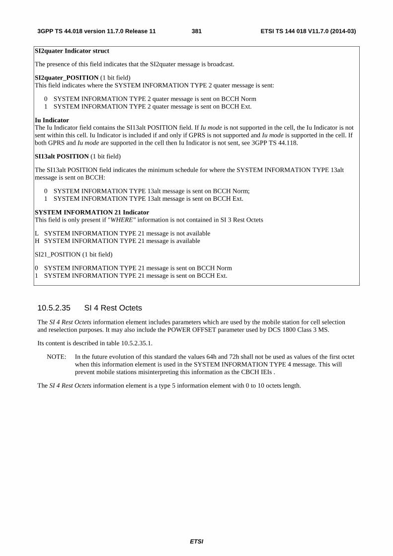
ETSI
ETSI TS 144 018 V11.7.0 (2014-03)3813GPP TS 44.018 version 11.7.0 Release 11
SI2quater Indicator struct
The presence of this field indicates that the SI2quater message is broadcast.
SI2quater_POSITION (1 bit field) This field indicates where the SYSTEM INFORMATION TYPE 2 quater message is sent:
0 SYSTEM INFORMATION TYPE 2 quater message is sent on BCCH Norm 1 SYSTEM INFORMATION TYPE 2 quater message is sent on BCCH Ext.
Iu Indicator The Iu Indicator field contains the SI13alt POSITION field. If Iu mode is not supported in the cell, the Iu Indicator is not sent within this cell. Iu Indicator is included if and only if GPRS is not supported and Iu mode is supported in the cell. If both GPRS and Iu mode are supported in the cell then Iu Indicator is not sent, see 3GPP TS 44.118.
SI13alt POSITION (1 bit field)
The SI13alt POSITION field indicates the minimum schedule for where the SYSTEM INFORMATION TYPE 13alt message is sent on BCCH:
0 SYSTEM INFORMATION TYPE 13alt message is sent on BCCH Norm; 1 SYSTEM INFORMATION TYPE 13alt message is sent on BCCH Ext.
SYSTEM INFORMATION 21 Indicator This field is only present if "WHERE" information is not contained in SI 3 Rest Octets
L SYSTEM INFORMATION TYPE 21 message is not available H SYSTEM INFORMATION TYPE 21 message is available
SI21_POSITION (1 bit field)
0 SYSTEM INFORMATION TYPE 21 message is sent on BCCH Norm 1 SYSTEM INFORMATION TYPE 21 message is sent on BCCH Ext.
10.5.2.35 SI 4 Rest Octets
The SI 4 Rest Octets information element includes parameters which are used by the mobile station for cell selection and reselection purposes. It may also include the POWER OFFSET parameter used by DCS 1800 Class 3 MS.
Its content is described in table 10.5.2.35.1.
NOTE: In the future evolution of this standard the values 64h and 72h shall not be used as values of the first octet when this information element is used in the SYSTEM INFORMATION TYPE 4 message. This will prevent mobile stations misinterpreting this information as the CBCH IEIs .
The SI 4 Rest Octets information element is a type 5 information element with 0 to 10 octets length.
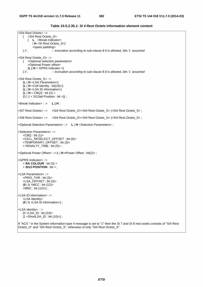
ETSI
ETSI TS 144 018 V11.7.0 (2014-03)3823GPP TS 44.018 version 11.7.0 Release 11
Table 10.5.2.35.1: SI 4 Rest Octets information element content
<SI4 Rest Octets> ::= { <SI4 Rest Octets_O> { L <Break indicator> | H <SI Rest Octets_S>} <spare padding> } // ; -- truncation according to sub-clause 8.9 is allowed, bits 'L' assumed <SI4 Rest Octets_O> ::= { <Optional selection parameters> <Optional Power offset> {L | H < GPRS Indicator >} } // ; -- truncation according to sub-clause 8.9 is allowed, bits 'L' assumed <SI4 Rest Octets_S> ::= {L | H <LSA Parameters>} {L | H <Cell Identity : bit(16)>} {L | H <LSA ID information>} {L | H < CBQ3 : bit (2) > {0 | 1 < SI13alt Position : bit >}} ; <Break Indicator> : := L | H ; <SI7 Rest Octets> ::= <SI4 Rest Octets_O><SI4 Rest Octets_S> |<SI4 Rest Octets_S> ; <SI8 Rest Octets> ::= <SI4 Rest Octets_O><SI4 Rest Octets_S> |<SI4 Rest Octets_S> ; <Optional Selection Parameters> ::= L | H <Selection Parameters> ; <Selection Parameters> ::= <CBQ : bit (1)> <CELL_RESELECT_OFFSET : bit (6)> <TEMPORARY_OFFSET : bit (3)> < PENALTY_TIME : bit (5)> ; <Optional Power Offset> ::= L | H <Power Offset : bit(2)> ; <GPRS Indicator> ::= < RA COLOUR : bit (3) > < SI13 POSITION : bit > ; <LSA Parameters> ::= <PRIO_THR : bit (3)> <LSA_OFFSET : bit (3)> {0 | 1 <MCC : bit (12)> <MNC : bit (12)>} ; <LSA ID information> ::= <LSA identity> {0 | 1 <LSA ID information>} ; <LSA identity> : := {0 <LSA_ID : bit (24)> |1 <ShortLSA_ID : bit (10)>} ; If "ACS " in the System information type 4 message is set to "1" then the SI 7 and SI 8 rest octets consists of "SI4 Rest Octets_O" and "SI4 Rest Octets_S", otherwise of only "SI4 Rest Octets_S".
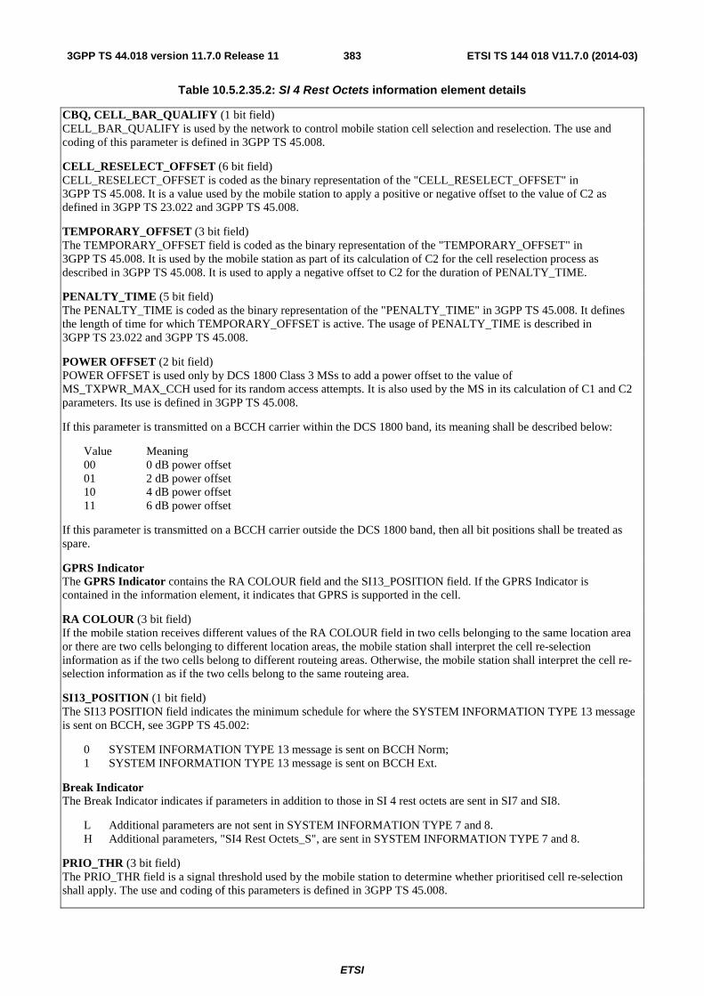
ETSI
ETSI TS 144 018 V11.7.0 (2014-03)3833GPP TS 44.018 version 11.7.0 Release 11
Table 10.5.2.35.2: SI 4 Rest Octets information element details
CBQ, CELL_BAR_QUALIFY (1 bit field) CELL_BAR_QUALIFY is used by the network to control mobile station cell selection and reselection. The use and coding of this parameter is defined in 3GPP TS 45.008.
CELL_RESELECT_OFFSET (6 bit field) CELL_RESELECT_OFFSET is coded as the binary representation of the "CELL_RESELECT_OFFSET" in 3GPP TS 45.008. It is a value used by the mobile station to apply a positive or negative offset to the value of C2 as defined in 3GPP TS 23.022 and 3GPP TS 45.008.
TEMPORARY_OFFSET (3 bit field) The TEMPORARY_OFFSET field is coded as the binary representation of the "TEMPORARY_OFFSET" in 3GPP TS 45.008. It is used by the mobile station as part of its calculation of C2 for the cell reselection process as described in 3GPP TS 45.008. It is used to apply a negative offset to C2 for the duration of PENALTY_TIME.
PENALTY_TIME (5 bit field) The PENALTY_TIME is coded as the binary representation of the "PENALTY_TIME" in 3GPP TS 45.008. It defines the length of time for which TEMPORARY_OFFSET is active. The usage of PENALTY_TIME is described in 3GPP TS 23.022 and 3GPP TS 45.008.
POWER OFFSET (2 bit field) POWER OFFSET is used only by DCS 1800 Class 3 MSs to add a power offset to the value of MS_TXPWR_MAX_CCH used for its random access attempts. It is also used by the MS in its calculation of C1 and C2 parameters. Its use is defined in 3GPP TS 45.008.
If this parameter is transmitted on a BCCH carrier within the DCS 1800 band, its meaning shall be described below:
Value Meaning 00 0 dB power offset 01 2 dB power offset 10 4 dB power offset 11 6 dB power offset
If this parameter is transmitted on a BCCH carrier outside the DCS 1800 band, then all bit positions shall be treated as spare.
GPRS Indicator The GPRS Indicator contains the RA COLOUR field and the SI13_POSITION field. If the GPRS Indicator is contained in the information element, it indicates that GPRS is supported in the cell.
RA COLOUR (3 bit field) If the mobile station receives different values of the RA COLOUR field in two cells belonging to the same location area or there are two cells belonging to different location areas, the mobile station shall interpret the cell re-selection information as if the two cells belong to different routeing areas. Otherwise, the mobile station shall interpret the cell re-selection information as if the two cells belong to the same routeing area.
SI13_POSITION (1 bit field) The SI13 POSITION field indicates the minimum schedule for where the SYSTEM INFORMATION TYPE 13 message is sent on BCCH, see 3GPP TS 45.002:
0 SYSTEM INFORMATION TYPE 13 message is sent on BCCH Norm; 1 SYSTEM INFORMATION TYPE 13 message is sent on BCCH Ext.
Break Indicator The Break Indicator indicates if parameters in addition to those in SI 4 rest octets are sent in SI7 and SI8.
L Additional parameters are not sent in SYSTEM INFORMATION TYPE 7 and 8. H Additional parameters, "SI4 Rest Octets_S", are sent in SYSTEM INFORMATION TYPE 7 and 8.
PRIO_THR (3 bit field) The PRIO_THR field is a signal threshold used by the mobile station to determine whether prioritised cell re-selection shall apply. The use and coding of this parameters is defined in 3GPP TS 45.008.
ETSI
ETSI TS 144 018 V11.7.0 (2014-03)3843GPP TS 44.018 version 11.7.0 Release 11
LSA_OFFSET (3 bit field) The LSA_OFFSET field applies an offset for LSA reselection between cells with same LSA priorities. The use and coding of this parameters is defined in 3GPP TS 45.008.
MCC and MNC (24 bit field) If the escape PLMN is broadcast in SI3 and SI4 the cell is used for SoLSA exclusive access and the MCC and MNC field shall be included. The MS shall then for all purposes use the MCC and MNC values received in the LSA Parameters instead of the ones received in the Location Area information element in SI3 and 4, eg when deriving the PLMN identity, the Location Area Identity and Cell Global Identity broadcast by the cell. The MCC and MNC value field is coded as specified in figure 10.5.2.37.1 and table 10.5.2.37.1.
Cell Identity (16 bit field) The purpose of the Cell Identity is to identify a cell within a location area (see sub-clause 10.5.1.1).
LSA_ID (24 bit field) The purpose of the LSA_ID field is to identify a LSA. The LSA ID value field is specified in 3GPP TS 23.003.
Short LSA_ID (10 bit field) The purpose of the Short LSA_ID field is to identify a LSA. The LSA ID defined by the Short LSA_ID is a LSA_ID as specified in 3GPP TS 23.003 with bit 0 set to "0" bit 1 to 10 set to the value of the Short LSA_ID field (LSB in bit 1, MSB in bit 10) and bit 11 to 23 set to "0".
CBQ3, Cell Bar Qualify 3 (2 bit field) The Cell Bar Qualify 3 is coded as shown in table 10.5.2.11.1.
SI13alt Position (1 bit field) The SI13alt Position is included if and only if GPRS is not supported and Iu mode is supported in the cell. If both GPRS and Iu mode are supported in the cell then SI13alt Position is not sent, see 3GPP TS 44.118.
The SI13alt Position field indicates the minimum schedule for where the SYSTEM INFORMATION TYPE 13alt message is sent on BCCH.
Bit 0 SYSTEM INFORMATION TYPE 13alt message is sent on BCCH Norm; 1 SYSTEM INFORMATION TYPE 13alt message is sent on BCCH Ext.
10.5.2.35a SI 6 Rest Octets
The SI 6 Rest Octet information element may contain information concerning the paging, notification channels, VBS and VGCS services of the cell.
The SI 6 Rest Octets information element is a type 5 information element with 7 octets length.
The value part is as shown below:
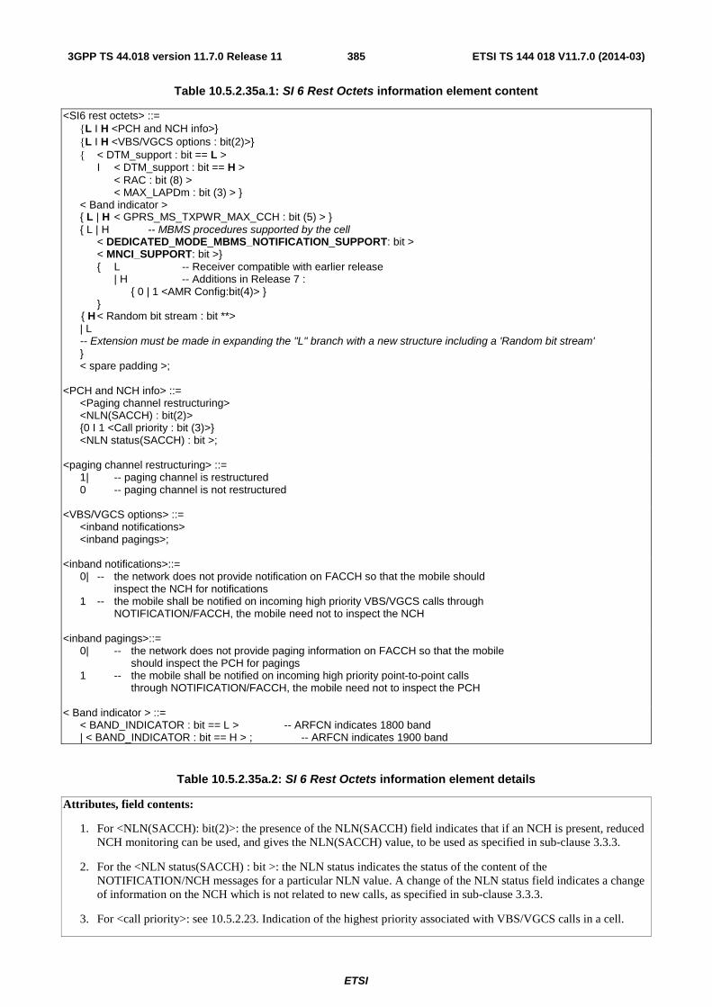
ETSI
ETSI TS 144 018 V11.7.0 (2014-03)3853GPP TS 44.018 version 11.7.0 Release 11
Table 10.5.2.35a.1: SI 6 Rest Octets information element content
<SI6 rest octets> ::= {L I H <PCH and NCH info>} {L I H <VBS/VGCS options : bit(2)>} { < DTM_support : bit == L > I < DTM_support : bit == H > < RAC : bit (8) > < MAX_LAPDm : bit (3) > } < Band indicator > { L | H < GPRS_MS_TXPWR_MAX_CCH : bit (5) > } { L | H -- MBMS procedures supported by the cell < DEDICATED_MODE_MBMS_NOTIFICATION_SUPPORT: bit > < MNCI_SUPPORT: bit >} { L -- Receiver compatible with earlier release | H -- Additions in Release 7 : { 0 | 1 <AMR Config:bit(4)> } } { H < Random bit stream : bit **> | L -- Extension must be made in expanding the "L" branch with a new structure including a 'Random bit stream' } < spare padding >; <PCH and NCH info> ::= <Paging channel restructuring> <NLN(SACCH) : bit(2)> {0 I 1 <Call priority : bit (3)>} <NLN status(SACCH) : bit >; <paging channel restructuring> ::= 1| -- paging channel is restructured 0 -- paging channel is not restructured <VBS/VGCS options> ::= <inband notifications> <inband pagings>; <inband notifications>::= 0| -- the network does not provide notification on FACCH so that the mobile should inspect the NCH for notifications 1 -- the mobile shall be notified on incoming high priority VBS/VGCS calls through NOTIFICATION/FACCH, the mobile need not to inspect the NCH <inband pagings>::= 0| -- the network does not provide paging information on FACCH so that the mobile should inspect the PCH for pagings 1 -- the mobile shall be notified on incoming high priority point-to-point calls through NOTIFICATION/FACCH, the mobile need not to inspect the PCH < Band indicator > ::= < BAND_INDICATOR : bit == L > -- ARFCN indicates 1800 band | < BAND_INDICATOR : bit == H > ; -- ARFCN indicates 1900 band
Table 10.5.2.35a.2: SI 6 Rest Octets information element details
Attributes, field contents:
1. For <NLN(SACCH): bit(2)>: the presence of the NLN(SACCH) field indicates that if an NCH is present, reduced NCH monitoring can be used, and gives the NLN(SACCH) value, to be used as specified in sub-clause 3.3.3.
2. For the <NLN status(SACCH) : bit >: the NLN status indicates the status of the content of the NOTIFICATION/NCH messages for a particular NLN value. A change of the NLN status field indicates a change of information on the NCH which is not related to new calls, as specified in sub-clause 3.3.3.
3. For <call priority>: see 10.5.2.23. Indication of the highest priority associated with VBS/VGCS calls in a cell.

ETSI
ETSI TS 144 018 V11.7.0 (2014-03)3863GPP TS 44.018 version 11.7.0 Release 11
DTM_support (1 bit field) This field indicates whether DTM is supported in the serving cell (i.e. whether the MS is allowed to initiate the packet request procedure while in dedicated mode). It is coded as follows:
Bit 0 L DTM is not supported in the serving cell H DTM is supported in the serving cell
RAC (8 bit field) This field codes the Routeing Area Code of the RA to which the serving cell belongs (see 3GPP TS 23.003).
MAX_LAPDm (3 bit field) This field indicates the maximum number of LAPDm frames on which a layer 3 can be segmented into and be sent on the main DCCH. It is coded as follows:
Bit 2 1 0 0 0 0 Any message segmented in up to 5 LAPDm frames (default value). 0 0 1 Any message segmented in up to 6 LAPDm frames. 0 1 0 Any message segmented in up to 7 LAPDm frames. 0 1 1 Any message segmented in up to 8 LAPDm frames. 1 0 0 Any message segmented in up to 9 LAPDm frames. 1 0 1 Any message segmented in up to 10 LAPDm frames. 1 1 0 Any message segmented in up to 11 LAPDm frames. 1 1 1 Any message segmented in up to 12 LAPDm frames.
If this parameter has not yet been received by the MS in the serving cell, the MS shall assume the default value of "000" (5 LAPDm frames)
BAND_INDICATOR (1 bit field) The band indicator for 1800 and 1900 associates the ARFCN channel numbers to the DCS 1800 respectively to the PCS 1900 band, see 3GPP TS 45.005.
GPRS_MS_TXPWR_MAX_CCH (5 bits field) The GPRS_MS_TXPWR_MAX_CCH field is coded as the binary representation of the "power control level" in 3GPP TS 45.005 corresponding to the maximum TX power level the MS shall use for packet resources while in dual transfer mode. This value shall be used by the Mobile Station according to 3GPP TS 45.008.
Range: 0 to 31.
DEDICATED_MODE_MBMS_NOTIFICATION_SUPPORT (1 bit field) This field is encoded as the DEDICATED_MODE_MBMS_NOTIFICATION_SUPPORT field in the GPRS Cell Options information element as defined in 3GPP TS 44.060
MNCI_SUPPORT (1 bit field) This field is encoded as the MNCI_SUPPORT field in the GPRS Cell Options information element as defined in 3GPP TS 44.060
AMR_Config (4 bit field) This field indicates the set of AMR codec modes to be used on a group channel using speech version 3. It is coded as the binary representation of the parameter Config-NB-Code of one of the preferred AMR configurations defined in 3GPP TS 28.062 [92], subclause 7.11.3.1.3.
Random bit stream For a given mobile station, the rest octets are filled with a random bit stream.
10.5.2.36 SI 7 Rest Octets
The SI 7 Rest Octets information element includes parameters which are used by the mobile station for cell selection and reselection purposes. It may also include the POWER OFFSET parameter used by a DCS 1800 Class 3 MS.
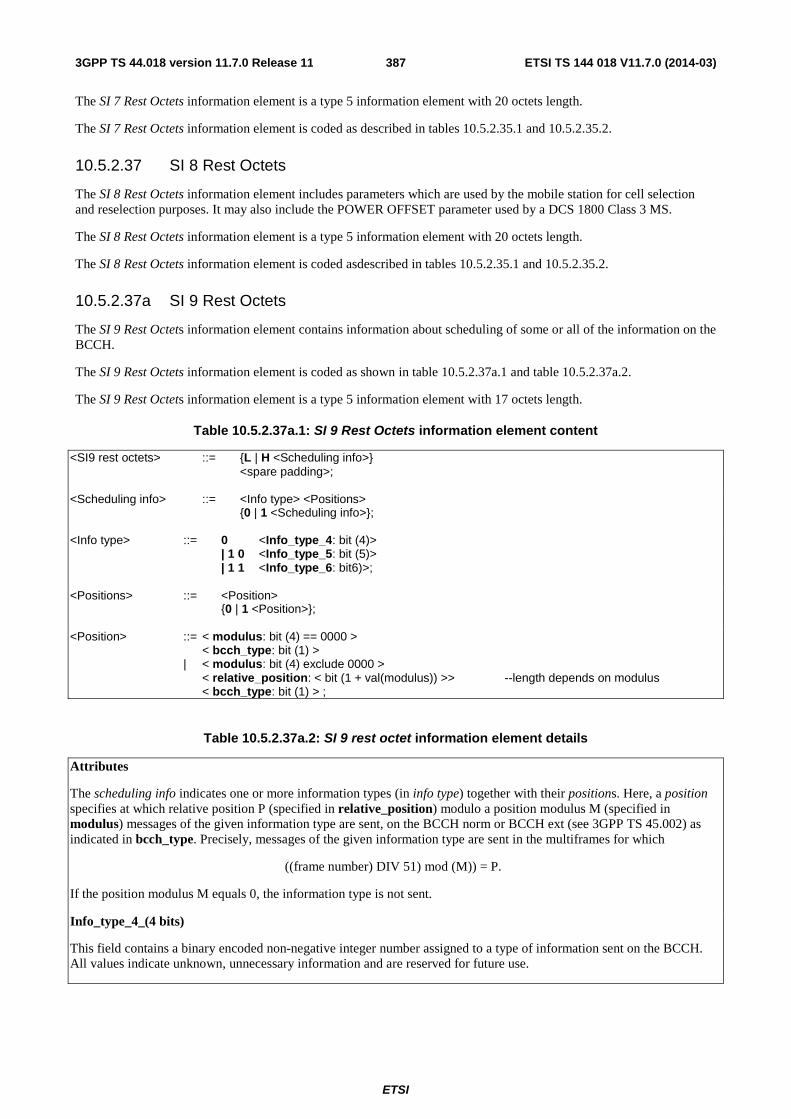
ETSI
ETSI TS 144 018 V11.7.0 (2014-03)3873GPP TS 44.018 version 11.7.0 Release 11
The SI 7 Rest Octets information element is a type 5 information element with 20 octets length.
The SI 7 Rest Octets information element is coded as described in tables 10.5.2.35.1 and 10.5.2.35.2.
10.5.2.37 SI 8 Rest Octets
The SI 8 Rest Octets information element includes parameters which are used by the mobile station for cell selection and reselection purposes. It may also include the POWER OFFSET parameter used by a DCS 1800 Class 3 MS.
The SI 8 Rest Octets information element is a type 5 information element with 20 octets length.
The SI 8 Rest Octets information element is coded asdescribed in tables 10.5.2.35.1 and 10.5.2.35.2.
10.5.2.37a SI 9 Rest Octets
The SI 9 Rest Octets information element contains information about scheduling of some or all of the information on the BCCH.
The SI 9 Rest Octets information element is coded as shown in table 10.5.2.37a.1 and table 10.5.2.37a.2.
The SI 9 Rest Octets information element is a type 5 information element with 17 octets length.
Table 10.5.2.37a.1: SI 9 Rest Octets information element content
<SI9 rest octets> ::= {L | H <Scheduling info>} <spare padding>; <Scheduling info> ::= <Info type> <Positions> {0 | 1 <Scheduling info>}; <Info type> ::= 0 <Info_type_4: bit (4)> | 1 0 <Info_type_5: bit (5)> | 1 1 <Info_type_6: bit6)>; <Positions> ::= <Position> {0 | 1 <Position>}; <Position> ::= < modulus: bit (4) == 0000 > < bcch_type: bit (1) > | < modulus: bit (4) exclude 0000 > < relative_position: < bit (1 + val(modulus)) >> --length depends on modulus < bcch_type: bit (1) > ;
Table 10.5.2.37a.2: SI 9 rest octet information element details
Attributes
The scheduling info indicates one or more information types (in info type) together with their positions. Here, a position specifies at which relative position P (specified in relative_position) modulo a position modulus M (specified in modulus) messages of the given information type are sent, on the BCCH norm or BCCH ext (see 3GPP TS 45.002) as indicated in bcch_type. Precisely, messages of the given information type are sent in the multiframes for which
((frame number) DIV 51) mod (M)) = P.
If the position modulus M equals 0, the information type is not sent.
Info_type_4_(4 bits)
This field contains a binary encoded non-negative integer number assigned to a type of information sent on the BCCH. All values indicate unknown, unnecessary information and are reserved for future use.
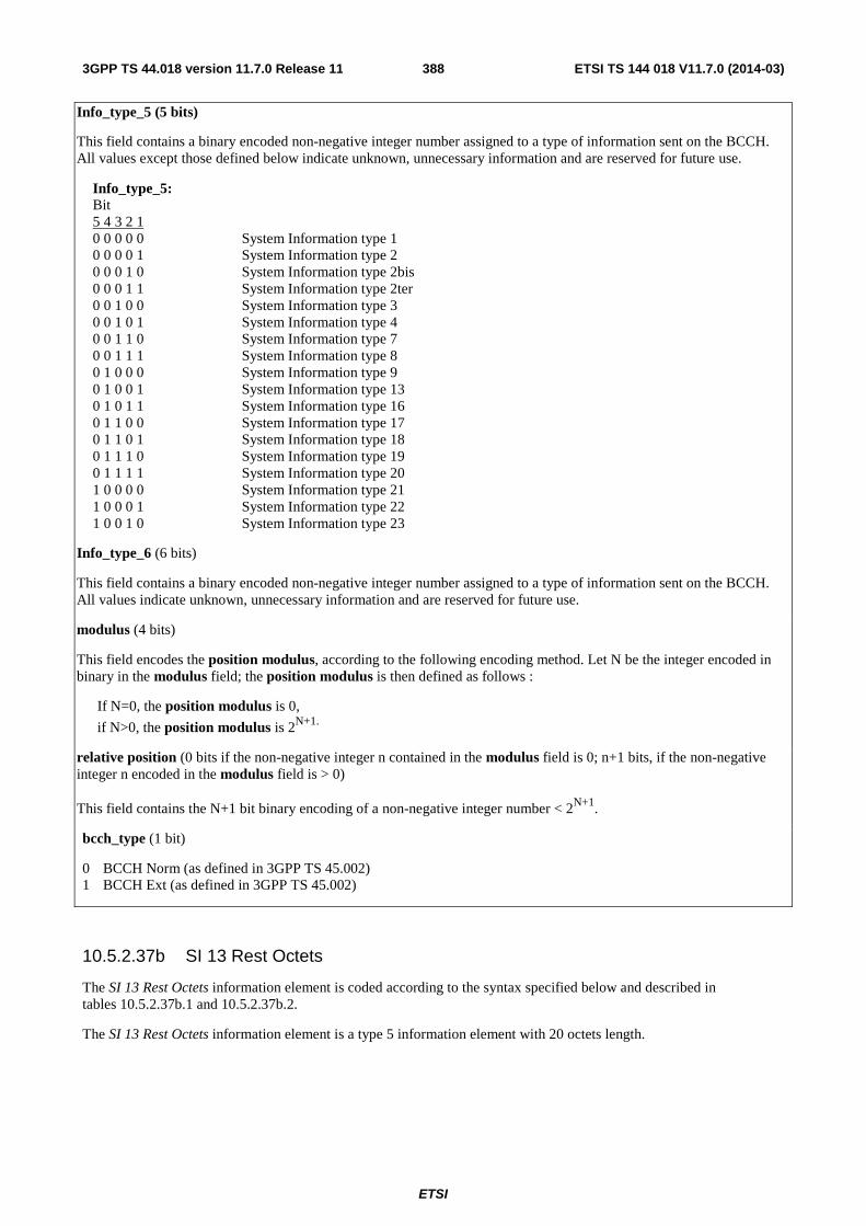
ETSI
ETSI TS 144 018 V11.7.0 (2014-03)3883GPP TS 44.018 version 11.7.0 Release 11
Info_type_5 (5 bits)
This field contains a binary encoded non-negative integer number assigned to a type of information sent on the BCCH. All values except those defined below indicate unknown, unnecessary information and are reserved for future use.
Info_type_5: Bit 5 4 3 2 1 0 0 0 0 0 System Information type 1 0 0 0 0 1 System Information type 2 0 0 0 1 0 System Information type 2bis 0 0 0 1 1 System Information type 2ter 0 0 1 0 0 System Information type 3 0 0 1 0 1 System Information type 4 0 0 1 1 0 System Information type 7 0 0 1 1 1 System Information type 8 0 1 0 0 0 System Information type 9 0 1 0 0 1 System Information type 13 0 1 0 1 1 System Information type 16 0 1 1 0 0 System Information type 17 0 1 1 0 1 System Information type 18 0 1 1 1 0 System Information type 19 0 1 1 1 1 System Information type 20 1 0 0 0 0 System Information type 21 1 0 0 0 1 System Information type 22 1 0 0 1 0 System Information type 23
Info_type_6 (6 bits)
This field contains a binary encoded non-negative integer number assigned to a type of information sent on the BCCH. All values indicate unknown, unnecessary information and are reserved for future use.
modulus (4 bits)
This field encodes the position modulus, according to the following encoding method. Let N be the integer encoded in binary in the modulus field; the position modulus is then defined as follows :
If N=0, the position modulus is 0,
if N>0, the position modulus is 2N+1.
relative position (0 bits if the non-negative integer n contained in the modulus field is 0; n+1 bits, if the non-negative integer n encoded in the modulus field is > 0)
This field contains the N+1 bit binary encoding of a non-negative integer number < 2N+1.
bcch_type (1 bit)
0 BCCH Norm (as defined in 3GPP TS 45.002) 1 BCCH Ext (as defined in 3GPP TS 45.002)
10.5.2.37b SI 13 Rest Octets
The SI 13 Rest Octets information element is coded according to the syntax specified below and described in tables 10.5.2.37b.1 and 10.5.2.37b.2.
The SI 13 Rest Octets information element is a type 5 information element with 20 octets length.
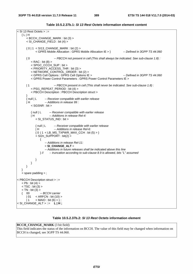
ETSI
ETSI TS 144 018 V11.7.0 (2014-03)3893GPP TS 44.018 version 11.7.0 Release 11
Table 10.5.2.37b.1: SI 13 Rest Octets information element content
< SI 13 Rest Octets > ::= { L | H < BCCH_CHANGE_MARK : bit (3) > < SI_CHANGE_FIELD : bit (4) > { 0 | 1 < SI13_CHANGE_MARK : bit (2) > < GPRS Mobile Allocation : GPRS Mobile Allocation IE > } -- Defined in 3GPP TS 44.060 { 0 -- PBCCH not present in cell (This shall always be indicated. See sub-clause 1.8) : < RAC : bit (8) > < SPGC_CCCH_SUP : bit > < PRIORITY_ACCESS_THR : bit (3) > < NETWORK_CONTROL_ORDER : bit (2) > < GPRS Cell Options : GPRS Cell Options IE > -- Defined in 3GPP TS 44.060 < GPRS Power Control Parameters : GPRS Power Control Parameters IE > | 1 -- PBCCH present in cell (This shall never be indicated. See sub-clause 1.8) : < PSI1_REPEAT_PERIOD : bit (4) > < PBCCH Description : PBCCH Description struct > } { null | L -- Receiver compatible with earlier release | H -- Additions in release 99 : < SGSNR : bit > { null | L -- Receiver compatible with earlier release | H -- Additions in release Rel-4: < SI_STATUS_IND : bit > { null | L -- Receiver compatible with earlier release | H -- Additions in release Rel-6: { 0 | 1 < LB_MS_TXPWR_MAX_CCH : bit (5) > } < SI2n_SUPPORT : bit(2) > { -- Additions in release Rel-11: < SI_CHANGE_ALT > -- Additions in future releases shall be indicated above this line } // -- truncation according to sub-clause 8.9 is allowed, bits "L" assumed } } } } < spare padding > ; < PBCCH Description struct > ::= < Pb : bit (4) > < TSC : bit (3) > < TN : bit (3) > { 00 -- BCCH carrier | 01 < ARFCN : bit (10) > | 1 < MAIO : bit (6) > } ; < SI_CHANGE_ALT > ::= L | H ;
Table 10.5.2.37b.2: SI 13 Rest Octets information element
BCCH_CHANGE_MARK (3 bit field) This field indicates the status of the information on BCCH. The value of this field may be changed when information on BCCH is changed, see 3GPP TS 44.060.

ETSI
ETSI TS 144 018 V11.7.0 (2014-03)3903GPP TS 44.018 version 11.7.0 Release 11
SI_CHANGE_FIELD (4 bit field) This field is the binary representation of which information was changed at the last indication in BCCH_CHANGE_MARK, see 3GPP TS 44.060. Range 0 to 15:
0 Update of unspecified SI message or SI messages; 1 Update of SI1 message; 2 Update of SI2, SI2 bis or SI2 ter message or any instance of SI2quater messages; 3 Update of SI3, SI4, SI7, SI8, SI16 or SI17 message; 4 Update of SI9 message; 5 Update of SI18 or SI20 message; 6 Update of SI19 message; 7 Update of SI15 message; 8 Update of SI2n message; 9 Update of SI22 or SI23 message;
All other values shall be interpreted as 'update of unknown SI message type'.
SI13_CHANGE_MARK (2 bit field) This field is the binary representation of the SI change mark identifying the GPRS Mobile Allocation provided in SI13 and PSI13 messages. Range: 0 to 3.
GPRS Mobile Allocation (information element) This information element is the representation of the GPRS mobile allocation provided in SI13 and PSI13 messages. It is identified by MA_NUMBER = 14 when referenced from a packet assignment message. The GPRS Mobile Allocation information element is defined in 3GPP TS 44.060. When used in SI13 or PSI13 message, this information element shall refer to the cell allocation defined for the cell in SI1 or PSI2.
RAC (8 bit field) This field is the binary representation of the Routing Area Code, see 3GPP TS 23.003.
SPGC_CCCH_SUP (bit field) This field indicates the support of the parameter SPLIT_PG_CYCLE on CCCH from the network side:
0 SPLIT_PG_CYCLE is not supported on CCCH in this cell; 1 SPLIT_PG_CYCLE is supported on CCCH in this cell.
The PRIORITY_ACCESS_THR field (3 bit) is the binary representation of the parameter PRIORITY_ACCESS_THR:
0 0 0 packet access is not allowed in the cell; 0 0 1 spare, shall be interpreted as '000' (packet access not allowed); 0 1 0 spare, shall be interpreted as '000' (packet access not allowed); 0 1 1 packet access is allowed for priority level 1; 1 0 0 packet access is allowed for priority level 1 to 2; 1 0 1 packet access is allowed for priority level 1 to 3; 1 1 0 packet access is allowed for priority level 1 to 4; 1 1 1 spare, shall be interpreted as '110' (packet access allowed).
The NETWORK_CONTROL_ORDER field (2 bit) is the binary representation of the parameter NETWORK_CONTROL_ORDER, see 3GPP TS 44.060:
0 0 NC0: MS controlled cell re-selection, no measurement reporting. 0 1 NC1: MS controlled cell re-selection, MS sends measurement reports. 1 0 NC2: Network controlled cell re-selection, MS sends measurement reports. 1 1 Reserved for future use, interpreted as NC0 by mobile station.
GPRS Cell Options (information element) The GPRS Cell Option information element is defined in 3GPP TS 44.060.
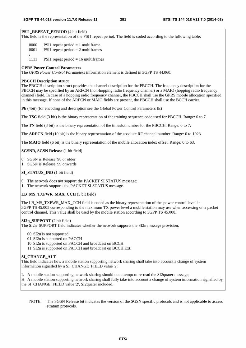
ETSI
ETSI TS 144 018 V11.7.0 (2014-03)3913GPP TS 44.018 version 11.7.0 Release 11
PSI1_REPEAT_PERIOD (4 bit field) This field is the representation of the PSI1 repeat period. The field is coded according to the following table:
0000 PSI1 repeat period = 1 multiframe 0001 PSI1 repeat period = 2 multiframes : 1111 PSI1 repeat period = 16 multiframes
GPRS Power Control Parameters The GPRS Power Control Parameters information element is defined in 3GPP TS 44.060.
PBCCH Description struct The PBCCH description struct provides the channel description for the PBCCH. The frequency description for the PBCCH may be specified by an ARFCN (non-hopping radio frequency channel) or a MAIO (hopping radio frequency channel) field. In case of a hopping radio frequency channel, the PBCCH shall use the GPRS mobile allocation specified in this message. If none of the ARFCN or MAIO fields are present, the PBCCH shall use the BCCH carrier.
Pb (4bit) (for encoding and description see the Global Power Control Parameters IE)
The TSC field (3 bit) is the binary representation of the training sequence code used for PBCCH. Range: 0 to 7.
The TN field (3 bit) is the binary representation of the timeslot number for the PBCCH. Range: 0 to 7.
The ARFCN field (10 bit) is the binary representation of the absolute RF channel number. Range: 0 to 1023.
The MAIO field (6 bit) is the binary representation of the mobile allocation index offset. Range: 0 to 63.
SGSNR, SGSN Release (1 bit field)
0 SGSN is Release '98 or older 1 SGSN is Release '99 onwards
SI_STATUS_IND (1 bit field)
0 The network does not support the PACKET SI STATUS message; 1 The network supports the PACKET SI STATUS message.
LB_MS_TXPWR_MAX_CCH (5 bit field)
The LB_MS_TXPWR_MAX_CCH field is coded as the binary representation of the 'power control level' in 3GPP TS 45.005 corresponding to the maximum TX power level a mobile station may use when accessing on a packet control channel. This value shall be used by the mobile station according to 3GPP TS 45.008.
SI2n_SUPPORT (2 bit field) The SI2n_SUPPORT field indicates whether the network supports the SI2n message provision.
00 SI2n is not supported 01 SI2n is supported on PACCH 10 SI2n is supported on PACCH and broadcast on BCCH 11 SI2n is supported on PACCH and broadcast on BCCH Ext.
SI_CHANGE_ALT This field indicates how a mobile station supporting network sharing shall take into account a change of system information signalled by a SI_CHANGE_FIELD value '2':
L A mobile station supporting network sharing should not attempt to re-read the SI2quater message; H A mobile station supporting network sharing shall fully take into account a change of system information signalled by the SI_CHANGE_FIELD value '2', SI2quater included.
NOTE: The SGSN Release bit indicates the version of the SGSN specific protocols and is not applicable to access stratum protocols.
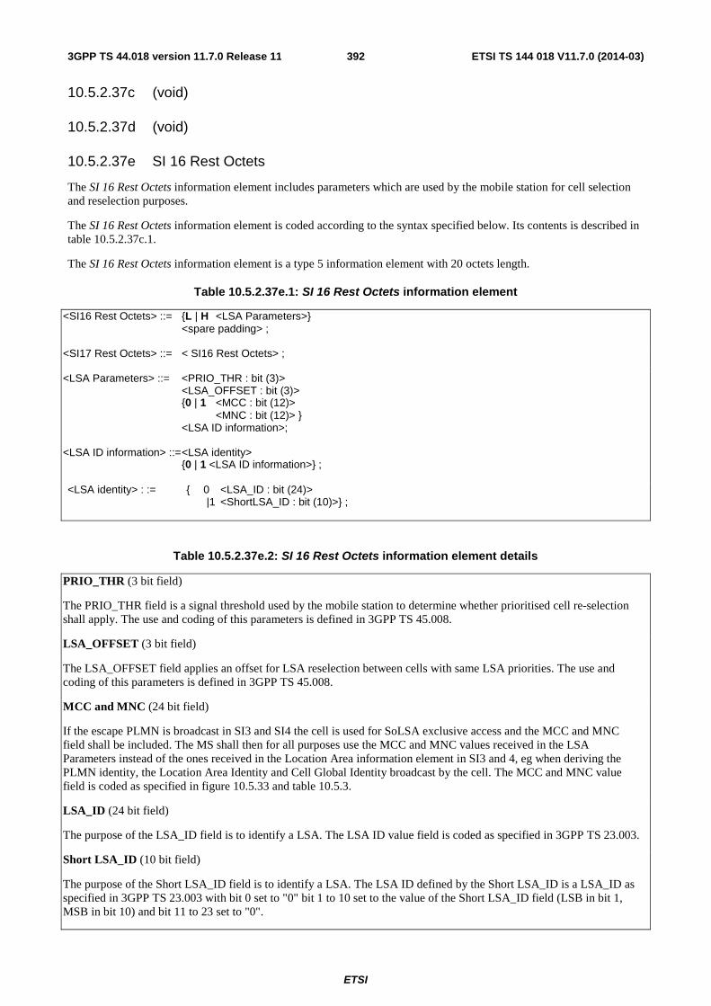
ETSI
ETSI TS 144 018 V11.7.0 (2014-03)3923GPP TS 44.018 version 11.7.0 Release 11
10.5.2.37c (void)
10.5.2.37d (void)
10.5.2.37e SI 16 Rest Octets
The SI 16 Rest Octets information element includes parameters which are used by the mobile station for cell selection and reselection purposes.
The SI 16 Rest Octets information element is coded according to the syntax specified below. Its contents is described in table 10.5.2.37c.1.
The SI 16 Rest Octets information element is a type 5 information element with 20 octets length.
Table 10.5.2.37e.1: SI 16 Rest Octets information element
<SI16 Rest Octets> ::= {L | H <LSA Parameters>} <spare padding> ; <SI17 Rest Octets> ::= < SI16 Rest Octets> ; <LSA Parameters> ::= <PRIO_THR : bit (3)> <LSA_OFFSET : bit (3)> {0 | 1 <MCC : bit (12)> <MNC : bit (12)> } <LSA ID information>; <LSA ID information> ::= <LSA identity> {0 | 1 <LSA ID information>} ; <LSA identity> : := { 0 <LSA_ID : bit (24)> |1 <ShortLSA_ID : bit (10)>} ;
Table 10.5.2.37e.2: SI 16 Rest Octets information element details
PRIO_THR (3 bit field)
The PRIO_THR field is a signal threshold used by the mobile station to determine whether prioritised cell re-selection shall apply. The use and coding of this parameters is defined in 3GPP TS 45.008.
LSA_OFFSET (3 bit field)
The LSA_OFFSET field applies an offset for LSA reselection between cells with same LSA priorities. The use and coding of this parameters is defined in 3GPP TS 45.008.
MCC and MNC (24 bit field)
If the escape PLMN is broadcast in SI3 and SI4 the cell is used for SoLSA exclusive access and the MCC and MNC field shall be included. The MS shall then for all purposes use the MCC and MNC values received in the LSA Parameters instead of the ones received in the Location Area information element in SI3 and 4, eg when deriving the PLMN identity, the Location Area Identity and Cell Global Identity broadcast by the cell. The MCC and MNC value field is coded as specified in figure 10.5.33 and table 10.5.3.
LSA_ID (24 bit field)
The purpose of the LSA_ID field is to identify a LSA. The LSA ID value field is coded as specified in 3GPP TS 23.003.
Short LSA_ID (10 bit field)
The purpose of the Short LSA_ID field is to identify a LSA. The LSA ID defined by the Short LSA_ID is a LSA_ID as specified in 3GPP TS 23.003 with bit 0 set to "0" bit 1 to 10 set to the value of the Short LSA_ID field (LSB in bit 1, MSB in bit 10) and bit 11 to 23 set to "0".

ETSI
ETSI TS 144 018 V11.7.0 (2014-03)3933GPP TS 44.018 version 11.7.0 Release 11
10.5.2.37f SI 17 Rest Octets
The SI 17 Rest Octets information element includes parameters, which are used by the mobile station for cell selection and reselection purposes.
The SI 17 Rest Octets information element is a type 5 information element with 20 octets length.
The SI 17 Rest Octets information element is coded as the SI 16 Rest Octets. Its contents is described in tables 10.5.2.37e.1 and 10.5.2.37e.2.
10.5.2.37g SI 19 Rest Octets
The SI 19 Rest Octets information element contains information for cell re-selection to COMPACT channels.
The SI 19 Rest Octets information element is a type 5 information element with 20 octets length.
The value part is coded as shown below.
Table 10.5.2.37g.1: SI 19 Rest Octets information element
< SI 19 Rest Octets > ::= < SI19_CHANGE_MARK : bit (2) > < SI19_INDEX : bit (3) > < SI19_LAST : bit (1) > < COMPACT Neighbour Cell Parameters : < COMPACT Neighbour Cell params struct > > < spare padding >; < COMPACT Neighbour Cell params struct > ::= { 1 < START_FREQUENCY : bit (10) > < COMPACT Cell selection params : COMPACT Cell Selection struct > < NR_OF_REMAINING_CELLS : bit (4) > < FREQ_DIFF_LENGTH : bit (3) > { < FREQUENCY_DIFF : bit (n) > < COMPACT Cell Selection struct > > } * val(NR_OF_REMAINING_CELLS } ** 0 ; < COMPACT Cell Selection struct > ::= { 0 <BCC : bit (3)> | 1 <BSIC : bit (6)> } < CELL_BARRED : bit (1) > 0 0 -- The values '01', '10' and '11' were allocated in an -- earlier version of the protocol and shall not be used. { < LA Different parameters : < LA Different struct > > } { 0 | 1 < MS_TXPWR_MAX_CCH : bit (5) > } { 0 | 1 < RXLEV ACCESS MIN : bit (6) > } { 0 | 1 < CELL_RESELECT_OFFSET : bit (6) > } { 0 | 1 < TEMPORARY_OFFSET: bit (3) < PENALTY_TIME : bit (5) > } { 0 | 1 < TIME_GROUP : bit (2) > } { 0 | 1 < GUAR_CONSTANT_PWR_BLKS : bit (2) >} ; < LA Different struct > : := { 0 | 1 < CELL_RESELECT_HYSTERISIS : bit (3) > ;
Table 10.5.2.37g.2: SI 19 Rest Octets information element details
SI19_CHANGE_MARK (2 bit field)
The SI19 change mark field is changed each time information has been updated in any of the SI19 messages. A new value indicates that the mobile station shall re-read the information from all the SI19 messages. The coding of this field is network dependent.
Range: 0-3.
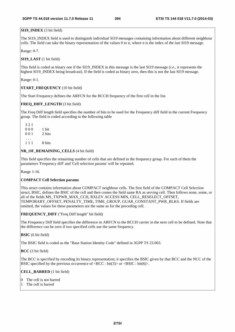
ETSI
ETSI TS 144 018 V11.7.0 (2014-03)3943GPP TS 44.018 version 11.7.0 Release 11
SI19_INDEX (3 bit field)
The SI19_INDEX field is used to distinguish individual SI19 messages containing information about different neighbour cells. The field can take the binary representation of the values 0 to n, where n is the index of the last SI19 message.
Range: 0-7.
SI19_LAST (1 bit field)
This field is coded as binary one if the SI19_INDEX in this message is the last SI19 message (i.e., it represents the highest SI19_INDEX being broadcast). If the field is coded as binary zero, then this is not the last SI19 message.
Range: 0-1.
START_FREQUENCY (10 bit field)
The Start Frequency defines the ARFCN for the BCCH frequency of the first cell in the list.
FREQ_DIFF_LENGTH (3 bit field)
The Freq Diff length field specifies the number of bits to be used for the Frequency diff field in the current Frequency group. The field is coded according to the following table
3 2 1 0 0 0 1 bit 0 0 1 2 bits . . . 1 1 1 8 bits
NR_OF_REMAINING_CELLS (4 bit field)
This field specifies the remaining number of cells that are defined in the frequency group. For each of them the parameters 'Frequency diff' and 'Cell selection params' will be repeated.
Range 1-16.
COMPACT Cell Selection params
This struct contains information about COMPACT neighbour cells. The first field of the COMPACT Cell Selection struct, BSIC, defines the BSIC of the cell and then comes the field same RA as serving cell. Then follows none, some, or all of the fields MS_TXPWR_MAX_CCH, RXLEV ACCESS MIN, CELL_RESELECT_OFFSET, TEMPORARY_OFFSET, PENALTY_TIME, TIME_GROUP, GUAR_CONSTANT_PWR_BLKS. If fields are omitted, the values for these parameters are the same as for the preceding cell.
FREQUENCY_DIFF ("Freq Diff length" bit field)
The Frequency Diff field specifies the difference in ARFCN to the BCCH carrier in the next cell to be defined. Note that the difference can be zero if two specified cells use the same frequency.
BSIC (6 bit field)
The BSIC field is coded as the "Base Station Identity Code" defined in 3GPP TS 23.003.
BCC (3 bit field)
The BCC is specified by encoding its binary representation; it specifies the BSIC given by that BCC and the NCC of the BSIC specified by the previous occurrence of <BCC : bit(3)> or <BSIC : bit(6)>.
CELL_BARRED (1 bit field)
0 The cell is not barred 1 The cell is barred

ETSI
ETSI TS 144 018 V11.7.0 (2014-03)3953GPP TS 44.018 version 11.7.0 Release 11
TIME_GROUP (2 bit field)
The TIME_GROUP defines which time group (see 3GPP TS 45.002) the cell belongs to
Bit 2 1 0 0 Time Group 0 0 1 Time Group 1 1 0 Time Group 2 1 1 Time Group 3
GUAR_CONSTANT_PWR_BLKS (2 bit field) This field indicates the guaranteed number of constant power blocks in the neighbour cell. These are the blocks that the MS can use to perform neighbour cell measurements (see 3GPP TS 45.008). Note that there may be more CPBCCH blocks or allowed paging blocks in the neighbour cell than what is indicated in this field, but never less. Bit 2 1 Blocks at constant power 0 0 4 0 1 5 1 0 6 1 1 12 (i.e. BS_PAG_BLKS_RES = 0 in that cell)
10.5.2.37h SI 18 Rest Octets
The SI 18 Rest Octets information element includes parameters for non-GSM networks.
The SI 18 Rest Octets information element is a type 5 information element and is 20 octets long.
Several Non-GSM information containers may be mapped into one instance of this information element, separated by a Non-GSM protocol discriminator. The last Non-GSM information container may be continued in a subsequent instance of this information element.
Table 10.5.2.37h.1: SI 18 Rest Octets information element
< SI 18 Rest Octets > ::= < SI18_CHANGE_MARK : bit (2) > < SI18_INDEX : bit (3) > < SI18_LAST : bit (1) > < spare bit > * 2 < Non-GSM Message : < Non-GSM Message struct > > ** -- The Non-GSM Message struct is repeated until: -- A) val(NR_OF_CONTAINER_OCTETS) = 0, or -- B) the SI message is fully used < spare padding > ; < Non-GSM Message struct > ::= < Non-GSM Protocol Discriminator : bit(3) > < NR_OF_CONTAINER_OCTETS : bit(5) > { < CONTAINER : bit(8) > } * (val(NR_OF_CONTAINER_OCTETS)) ;
Table 10.5.2.37h.2: SI 18 information element details
SI18_INDEX (3 bit field)
The SI18_INDEX field is used to distinguish individual SI18 messages. The field can take the binary representation of the values 0 to n, where n is the index of the last SI18 message.
Range: 0-7.
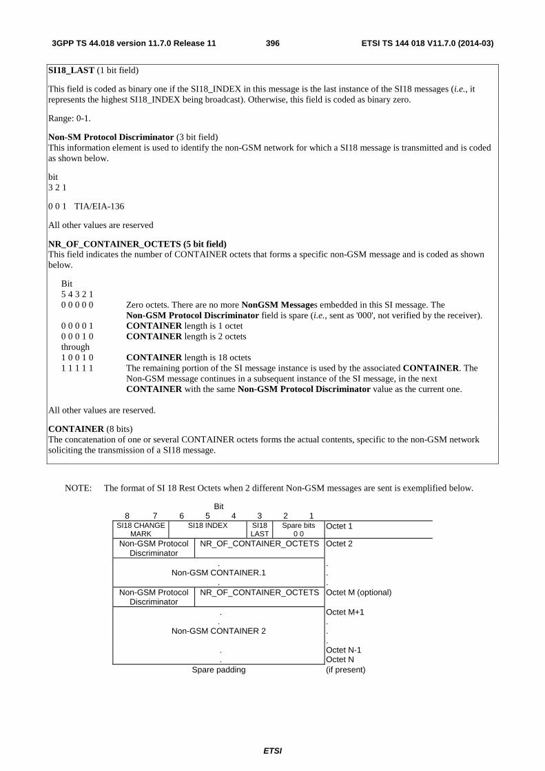
ETSI
ETSI TS 144 018 V11.7.0 (2014-03)3963GPP TS 44.018 version 11.7.0 Release 11
SI18_LAST (1 bit field)
This field is coded as binary one if the SI18_INDEX in this message is the last instance of the SI18 messages (i.e., it represents the highest SI18_INDEX being broadcast). Otherwise, this field is coded as binary zero.
Range: 0-1.
Non-SM Protocol Discriminator (3 bit field) This information element is used to identify the non-GSM network for which a SI18 message is transmitted and is coded as shown below.
bit 3 2 1
0 0 1 TIA/EIA-136
All other values are reserved
NR_OF_CONTAINER_OCTETS (5 bit field) This field indicates the number of CONTAINER octets that forms a specific non-GSM message and is coded as shown below.
Bit 5 4 3 2 1 0 0 0 0 0 Zero octets. There are no more NonGSM Messages embedded in this SI message. The
Non-GSM Protocol Discriminator field is spare (i.e., sent as '000', not verified by the receiver). 0 0 0 0 1 CONTAINER length is 1 octet 0 0 0 1 0 CONTAINER length is 2 octets through 1 0 0 1 0 CONTAINER length is 18 octets 1 1 1 1 1 The remaining portion of the SI message instance is used by the associated CONTAINER. The
Non-GSM message continues in a subsequent instance of the SI message, in the next CONTAINER with the same Non-GSM Protocol Discriminator value as the current one.
All other values are reserved.
CONTAINER (8 bits) The concatenation of one or several CONTAINER octets forms the actual contents, specific to the non-GSM network soliciting the transmission of a SI18 message.
NOTE: The format of SI 18 Rest Octets when 2 different Non-GSM messages are sent is exemplified below.
Bit 8 7 6 5 4 3 2 1
SI18 CHANGE MARK
SI18 INDEX SI18 LAST
Spare bits 0 0
Octet 1
Non-GSM Protocol Discriminator
NR_OF_CONTAINER_OCTETS Octet 2
. Non-GSM CONTAINER.1
.
.
.
. Non-GSM Protocol
Discriminator NR_OF_CONTAINER_OCTETS Octet M (optional)
. Octet M+1 .
Non-GSM CONTAINER 2 . . .
. .
Octet N-1 Octet N
Spare padding (if present)

ETSI
ETSI TS 144 018 V11.7.0 (2014-03)3973GPP TS 44.018 version 11.7.0 Release 11
10.5.2.37i SI 20 Rest Octets
The SI 20 Rest Octets information element includes parameters for non-GSM networks.
The SI 20 Rest Octets information element is a type 5 information element and is 20 octets long.
The SI 20 Rest Octets are defined as the SI 18 Rest Octets, see also sub-clause 10.5.2.37h.
10.5.2.37j SI 14 Rest Octets
The SI 14 Rest Octets information element contains information about dynamic ARFCN mapping. It allows to allocate ARFCN values and dynamically map them to physical frequencies, see 3GPP TS 45.005.
The SI 14 Rest Octets information element is a type 5 information element with 16 octet length.
Table 10.5.2.37j.1: SI14 message content
< SI14 Rest Octets > ::= < SI14_INDEX : bit (2) > < SI14_COUNT : bit (2) > < DM_CHANGE_MARK : bit (4) > < DYNAMIC ARFCN MAPPING Description : { 1 < DYNAMIC ARFCN MAPPING > } ** 0 > < spare padding > ; < DYNAMIC ARFCN MAPPING >::= < GSM_Band : bit (4) > < ARFCN_FIRST : bit (10) > -- Dynamic ARFCN mapping parameters < BAND_OFFSET : bit (10) > < ARFCN_RANGE : bit (7) > ;
Table 10.5.2.37j.2: SI14 message information
SI14_INDEX (2 bit field) The SI14_INDEX field is used to distinguish individual SI14 messages. The field can take the binary representation of the values 0 to n, where n is the index of the last SI14 message. (SI14_COUNT).
SI14_COUNT (2 bit field)
This field is coded as the binary representation of the SI14_INDEX for the last (highest indexed) individual SI14 message.
DM_CHANGE_MARK (4 bit field), Dynamic ARFCN Mapping Change Mark.
This parameter is used to indicate to the MS a change of information concerning Dynamic ARFCN Mapping.
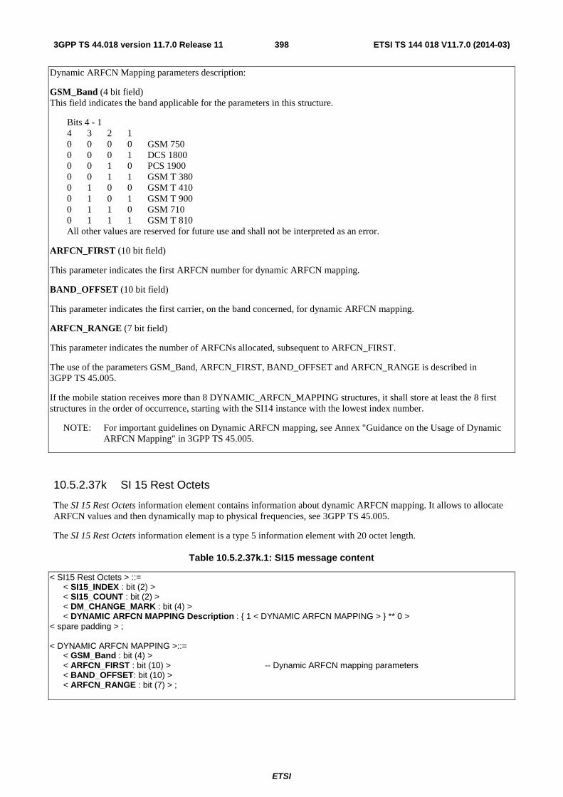
ETSI
ETSI TS 144 018 V11.7.0 (2014-03)3983GPP TS 44.018 version 11.7.0 Release 11
Dynamic ARFCN Mapping parameters description:
GSM_Band (4 bit field) This field indicates the band applicable for the parameters in this structure.
Bits 4 - 1 4 3 2 1 0 0 0 0 GSM 750 0 0 0 1 DCS 1800 0 0 1 0 PCS 1900 0 0 1 1 GSM T 380 0 1 0 0 GSM T 410 0 1 0 1 GSM T 900 0 1 1 0 GSM 710 0 1 1 1 GSM T 810 All other values are reserved for future use and shall not be interpreted as an error.
ARFCN_FIRST (10 bit field)
This parameter indicates the first ARFCN number for dynamic ARFCN mapping.
BAND_OFFSET (10 bit field)
This parameter indicates the first carrier, on the band concerned, for dynamic ARFCN mapping.
ARFCN_RANGE (7 bit field)
This parameter indicates the number of ARFCNs allocated, subsequent to ARFCN_FIRST.
The use of the parameters GSM_Band, ARFCN_FIRST, BAND_OFFSET and ARFCN_RANGE is described in 3GPP TS 45.005.
If the mobile station receives more than 8 DYNAMIC_ARFCN_MAPPING structures, it shall store at least the 8 first structures in the order of occurrence, starting with the SI14 instance with the lowest index number.
NOTE: For important guidelines on Dynamic ARFCN mapping, see Annex "Guidance on the Usage of Dynamic ARFCN Mapping" in 3GPP TS 45.005.
10.5.2.37k SI 15 Rest Octets
The SI 15 Rest Octets information element contains information about dynamic ARFCN mapping. It allows to allocate ARFCN values and then dynamically map to physical frequencies, see 3GPP TS 45.005.
The SI 15 Rest Octets information element is a type 5 information element with 20 octet length.
Table 10.5.2.37k.1: SI15 message content
< SI15 Rest Octets > ::= < SI15_INDEX : bit (2) > < SI15_COUNT : bit (2) > < DM_CHANGE_MARK : bit (4) > < DYNAMIC ARFCN MAPPING Description : { 1 < DYNAMIC ARFCN MAPPING > } ** 0 > < spare padding > ; < DYNAMIC ARFCN MAPPING >::= < GSM_Band : bit (4) > < ARFCN_FIRST : bit (10) > -- Dynamic ARFCN mapping parameters < BAND_OFFSET: bit (10) > < ARFCN_RANGE : bit (7) > ;
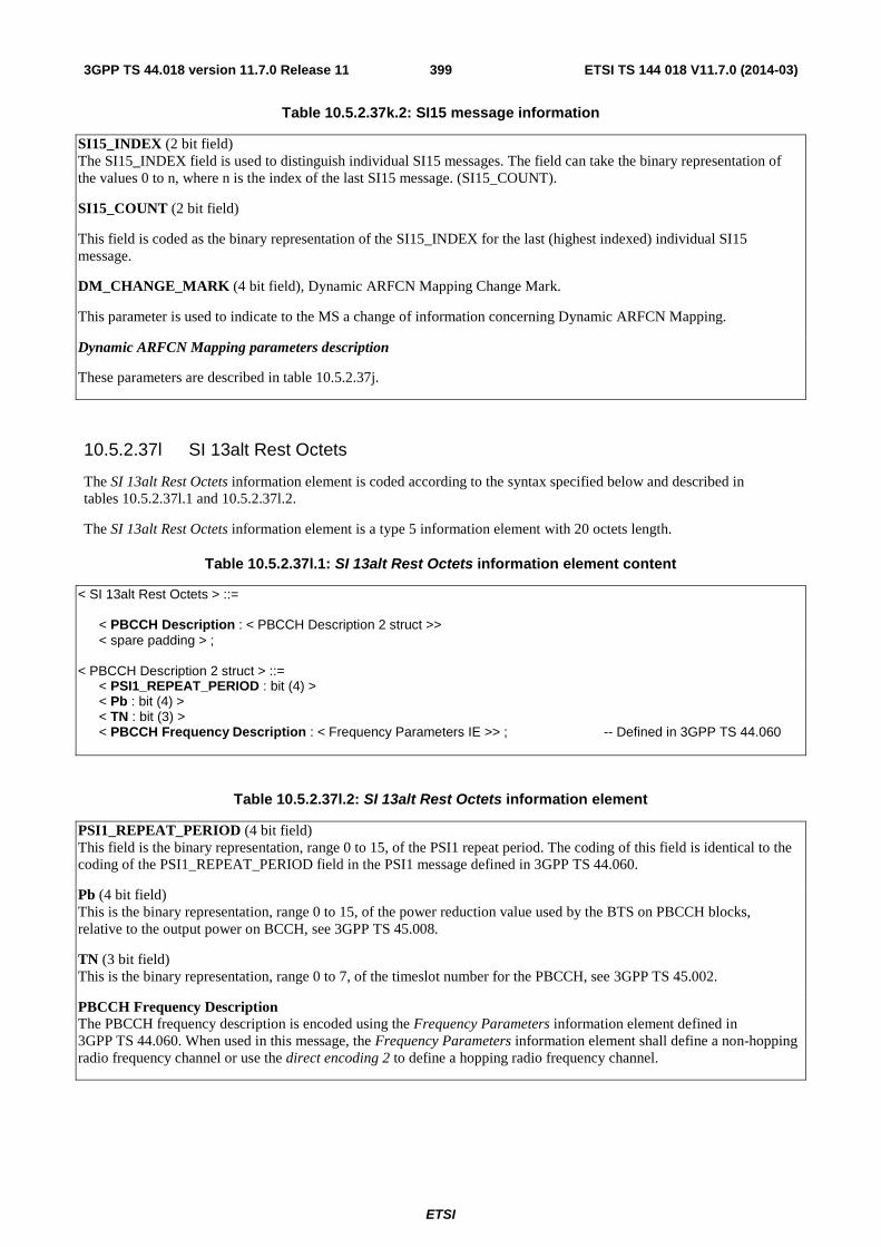
ETSI
ETSI TS 144 018 V11.7.0 (2014-03)3993GPP TS 44.018 version 11.7.0 Release 11
Table 10.5.2.37k.2: SI15 message information
SI15_INDEX (2 bit field) The SI15_INDEX field is used to distinguish individual SI15 messages. The field can take the binary representation of the values 0 to n, where n is the index of the last SI15 message. (SI15_COUNT).
SI15_COUNT (2 bit field)
This field is coded as the binary representation of the SI15_INDEX for the last (highest indexed) individual SI15 message.
DM_CHANGE_MARK (4 bit field), Dynamic ARFCN Mapping Change Mark.
This parameter is used to indicate to the MS a change of information concerning Dynamic ARFCN Mapping.
Dynamic ARFCN Mapping parameters description
These parameters are described in table 10.5.2.37j.
10.5.2.37l SI 13alt Rest Octets
The SI 13alt Rest Octets information element is coded according to the syntax specified below and described in tables 10.5.2.37l.1 and 10.5.2.37l.2.
The SI 13alt Rest Octets information element is a type 5 information element with 20 octets length.
Table 10.5.2.37l.1: SI 13alt Rest Octets information element content
< SI 13alt Rest Octets > ::= < PBCCH Description : < PBCCH Description 2 struct >> < spare padding > ; < PBCCH Description 2 struct > ::= < PSI1_REPEAT_PERIOD : bit (4) > < Pb : bit (4) > < TN : bit (3) > < PBCCH Frequency Description : < Frequency Parameters IE >> ; -- Defined in 3GPP TS 44.060
Table 10.5.2.37l.2: SI 13alt Rest Octets information element
PSI1_REPEAT_PERIOD (4 bit field) This field is the binary representation, range 0 to 15, of the PSI1 repeat period. The coding of this field is identical to the coding of the PSI1_REPEAT_PERIOD field in the PSI1 message defined in 3GPP TS 44.060.
Pb (4 bit field) This is the binary representation, range 0 to 15, of the power reduction value used by the BTS on PBCCH blocks, relative to the output power on BCCH, see 3GPP TS 45.008.
TN (3 bit field) This is the binary representation, range 0 to 7, of the timeslot number for the PBCCH, see 3GPP TS 45.002.
PBCCH Frequency Description The PBCCH frequency description is encoded using the Frequency Parameters information element defined in 3GPP TS 44.060. When used in this message, the Frequency Parameters information element shall define a non-hopping radio frequency channel or use the direct encoding 2 to define a hopping radio frequency channel.
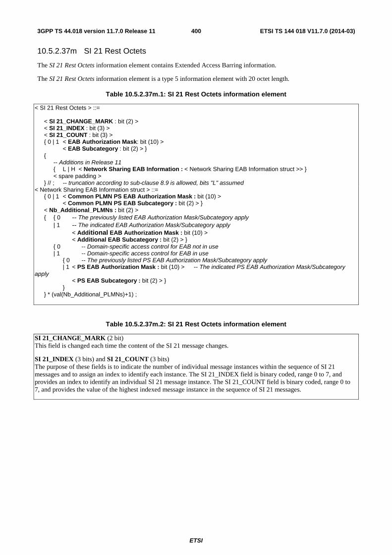
ETSI
ETSI TS 144 018 V11.7.0 (2014-03)4003GPP TS 44.018 version 11.7.0 Release 11
10.5.2.37m SI 21 Rest Octets
The SI 21 Rest Octets information element contains Extended Access Barring information.
The SI 21 Rest Octets information element is a type 5 information element with 20 octet length.
Table 10.5.2.37m.1: SI 21 Rest Octets information element
< SI 21 Rest Octets > ::= < SI 21_CHANGE_MARK : bit (2) > < SI 21_INDEX : bit (3) > < SI 21_COUNT : bit (3) > { 0 | 1 < EAB Authorization Mask: bit (10) > < EAB Subcategory : bit (2) > } { -- Additions in Release 11 { L | H < Network Sharing EAB Information : < Network Sharing EAB Information struct >> } < spare padding > } // ; -- truncation according to sub-clause 8.9 is allowed, bits "L" assumed < Network Sharing EAB Information struct > ::= { 0 | 1 < Common PLMN PS EAB Authorization Mask : bit (10) > < Common PLMN PS EAB Subcategory : bit (2) > } < Nb_Additional_PLMNs : bit (2) > { { 0 -- The previously listed EAB Authorization Mask/Subcategory apply | 1 -- The indicated EAB Authorization Mask/Subcategory apply < Additional EAB Authorization Mask : bit (10) > < Additional EAB Subcategory : bit (2) > } { 0 -- Domain-specific access control for EAB not in use | 1 -- Domain-specific access control for EAB in use { 0 -- The previously listed PS EAB Authorization Mask/Subcategory apply | 1 < PS EAB Authorization Mask : bit (10) > -- The indicated PS EAB Authorization Mask/Subcategory apply < PS EAB Subcategory : bit (2) > } } } * (val(Nb_Additional_PLMNs)+1) ;
Table 10.5.2.37m.2: SI 21 Rest Octets information element
SI 21_CHANGE_MARK (2 bit) This field is changed each time the content of the SI 21 message changes.
SI 21_INDEX (3 bits) and SI 21_COUNT (3 bits) The purpose of these fields is to indicate the number of individual message instances within the sequence of SI 21 messages and to assign an index to identify each instance. The SI 21_INDEX field is binary coded, range 0 to 7, and provides an index to identify an individual SI 21 message instance. The SI 21_COUNT field is binary coded, range 0 to 7, and provides the value of the highest indexed message instance in the sequence of SI 21 messages.
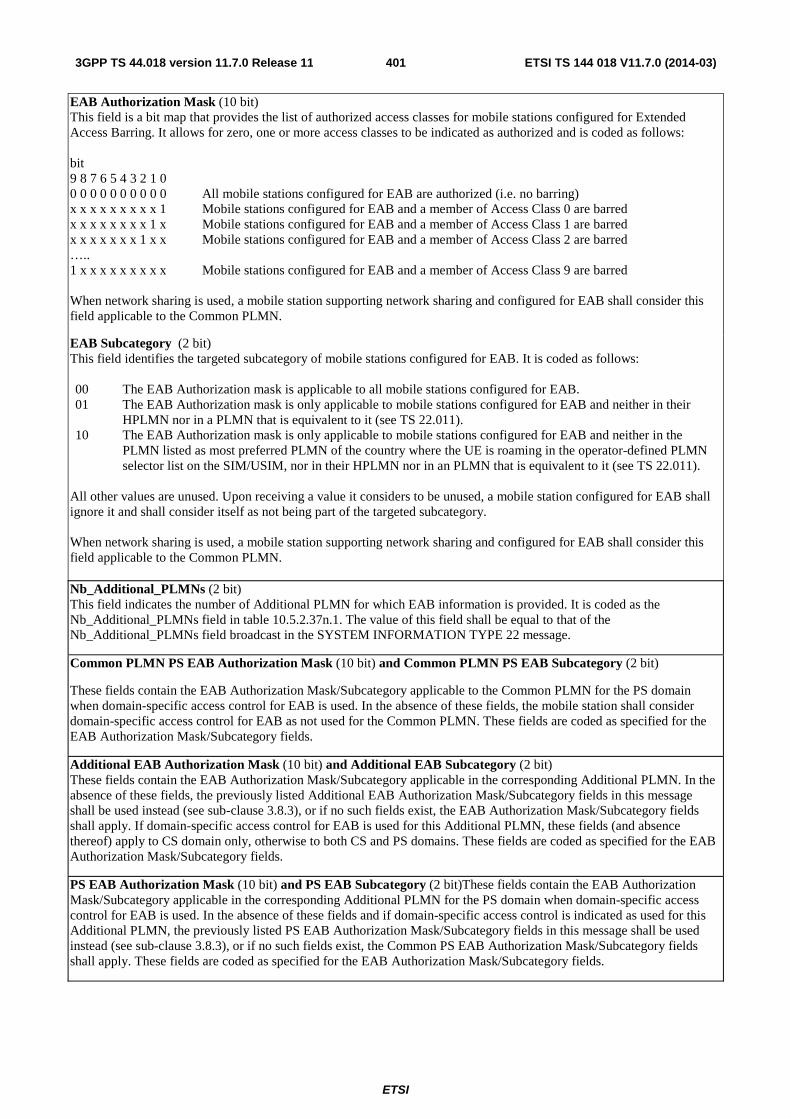
ETSI
ETSI TS 144 018 V11.7.0 (2014-03)4013GPP TS 44.018 version 11.7.0 Release 11
EAB Authorization Mask (10 bit) This field is a bit map that provides the list of authorized access classes for mobile stations configured for Extended Access Barring. It allows for zero, one or more access classes to be indicated as authorized and is coded as follows: bit 9 8 7 6 5 4 3 2 1 0 0 0 0 0 0 0 0 0 0 0 All mobile stations configured for EAB are authorized (i.e. no barring) x x x x x x x x x 1 Mobile stations configured for EAB and a member of Access Class 0 are barred x x x x x x x x 1 x Mobile stations configured for EAB and a member of Access Class 1 are barred x x x x x x x 1 x x Mobile stations configured for EAB and a member of Access Class 2 are barred ….. 1 x x x x x x x x x Mobile stations configured for EAB and a member of Access Class 9 are barred When network sharing is used, a mobile station supporting network sharing and configured for EAB shall consider this field applicable to the Common PLMN.
EAB Subcategory (2 bit) This field identifies the targeted subcategory of mobile stations configured for EAB. It is coded as follows: 00 The EAB Authorization mask is applicable to all mobile stations configured for EAB. 01 The EAB Authorization mask is only applicable to mobile stations configured for EAB and neither in their
HPLMN nor in a PLMN that is equivalent to it (see TS 22.011). 10 The EAB Authorization mask is only applicable to mobile stations configured for EAB and neither in the
PLMN listed as most preferred PLMN of the country where the UE is roaming in the operator-defined PLMN selector list on the SIM/USIM, nor in their HPLMN nor in an PLMN that is equivalent to it (see TS 22.011).
All other values are unused. Upon receiving a value it considers to be unused, a mobile station configured for EAB shall ignore it and shall consider itself as not being part of the targeted subcategory. When network sharing is used, a mobile station supporting network sharing and configured for EAB shall consider this field applicable to the Common PLMN. Nb_Additional_PLMNs (2 bit) This field indicates the number of Additional PLMN for which EAB information is provided. It is coded as the Nb_Additional_PLMNs field in table 10.5.2.37n.1. The value of this field shall be equal to that of the Nb_Additional_PLMNs field broadcast in the SYSTEM INFORMATION TYPE 22 message.
Common PLMN PS EAB Authorization Mask (10 bit) and Common PLMN PS EAB Subcategory (2 bit)
These fields contain the EAB Authorization Mask/Subcategory applicable to the Common PLMN for the PS domain when domain-specific access control for EAB is used. In the absence of these fields, the mobile station shall consider domain-specific access control for EAB as not used for the Common PLMN. These fields are coded as specified for the EAB Authorization Mask/Subcategory fields.
Additional EAB Authorization Mask (10 bit) and Additional EAB Subcategory (2 bit) These fields contain the EAB Authorization Mask/Subcategory applicable in the corresponding Additional PLMN. In the absence of these fields, the previously listed Additional EAB Authorization Mask/Subcategory fields in this message shall be used instead (see sub-clause 3.8.3), or if no such fields exist, the EAB Authorization Mask/Subcategory fields shall apply. If domain-specific access control for EAB is used for this Additional PLMN, these fields (and absence thereof) apply to CS domain only, otherwise to both CS and PS domains. These fields are coded as specified for the EAB Authorization Mask/Subcategory fields.
PS EAB Authorization Mask (10 bit) and PS EAB Subcategory (2 bit)These fields contain the EAB Authorization Mask/Subcategory applicable in the corresponding Additional PLMN for the PS domain when domain-specific access control for EAB is used. In the absence of these fields and if domain-specific access control is indicated as used for this Additional PLMN, the previously listed PS EAB Authorization Mask/Subcategory fields in this message shall be used instead (see sub-clause 3.8.3), or if no such fields exist, the Common PS EAB Authorization Mask/Subcategory fields shall apply. These fields are coded as specified for the EAB Authorization Mask/Subcategory fields.

ETSI
ETSI TS 144 018 V11.7.0 (2014-03)4023GPP TS 44.018 version 11.7.0 Release 11
10.5.2.37n SI 22 Rest Octets
The SI 22 Rest Octets information element contains network sharing and domain-specific access control information.
The SI 22 Rest Octets information element is a type 5 information element with 20 octet length.
Table 10.5.2.37n.1: SI 22 Rest Octets information element
< SI 22 Rest Octets > ::= < SI 22_CHANGE_MARK : bit (2) > < SI 22_INDEX : bit (3) > < SI 22_COUNT : bit (3) > { 0 | 1 < Network Sharing Information : < Network Sharing Information struct >> } < spare padding > ; < Network Sharing Information struct > ::= < SI23 Indicator : bit > < Common_PLMN_Allowed : bit > { 0 | 1 < Common_PLMN_PS_ACC : bit(16) > } < Nb_Additional_PLMNs : bit (2) > { { 0 | 1 < MCC : bit (12) > } < MNC : bit (12) > < NCC Permitted : bit (8) > { 0 -- The previously listed Access Control Class bitmap applies | 1 -- The indicated Access Control Class bitmap applies < Additional_ACC: bit (16) > } { 0 -- Domain-specific access control not in use | 1 -- Domain specific access control in use { 0 -- The previously listed PS Access Control Class bitmap applies | 1 < PS_ACC: bit(16) > } -- The indicated PS Access Control Class bitmap applies } } * ( val (Nb_Additional_PLMNs)+1) ;
Table 10.5.2.37n.2: SI 22 Rest Octets information element
SI 22_CHANGE_MARK (2 bit) This field is changed each time the content of the SI 22 message changes.
SI 22_INDEX (3 bits) and SI 22_COUNT (3 bits) The purpose of these fields is to indicate the number of individual message instances within the sequence of SI 22 messages and to assign an index to identify each instance. The SI 22_INDEX field is binary coded, range 0 to 7, and provides an index to identify an individual SI 22 message instance. The SI 22_COUNT field is binary coded, range 0 to 7, and provides the value of the highest indexed message instance in the sequence of SI 22 messages.
SI23 Indicator (one bit field) This field indicates whether or not the SYSTEM INFORMATION TYPE 23 message is broadcast by the network. It is coded as follows:
Bit 0 The SYSTEM INFORMATION TYPE 23 message is not available. 1 The SYSTEM INFORMATION TYPE 23 message is available.
Common_PLMN_Allowed (one bit field) This field indicates whether or not a MS supporting network sharing is allowed to select the Common PLMN. It is coded as follows:
Bit 0 The MS is not allowed to select the Common PLMN. 1 The MS is allowed to select the Common PLMN.
Common_PLMN_PS_ACC (16 bit field) This field contains a bitmap indicating the barring status for access control classes 0 to 15 (AC C0 to AC C15), applicable to the Common PLMN for the PS domain when domain-specific access control is used. Each AC CN is coded
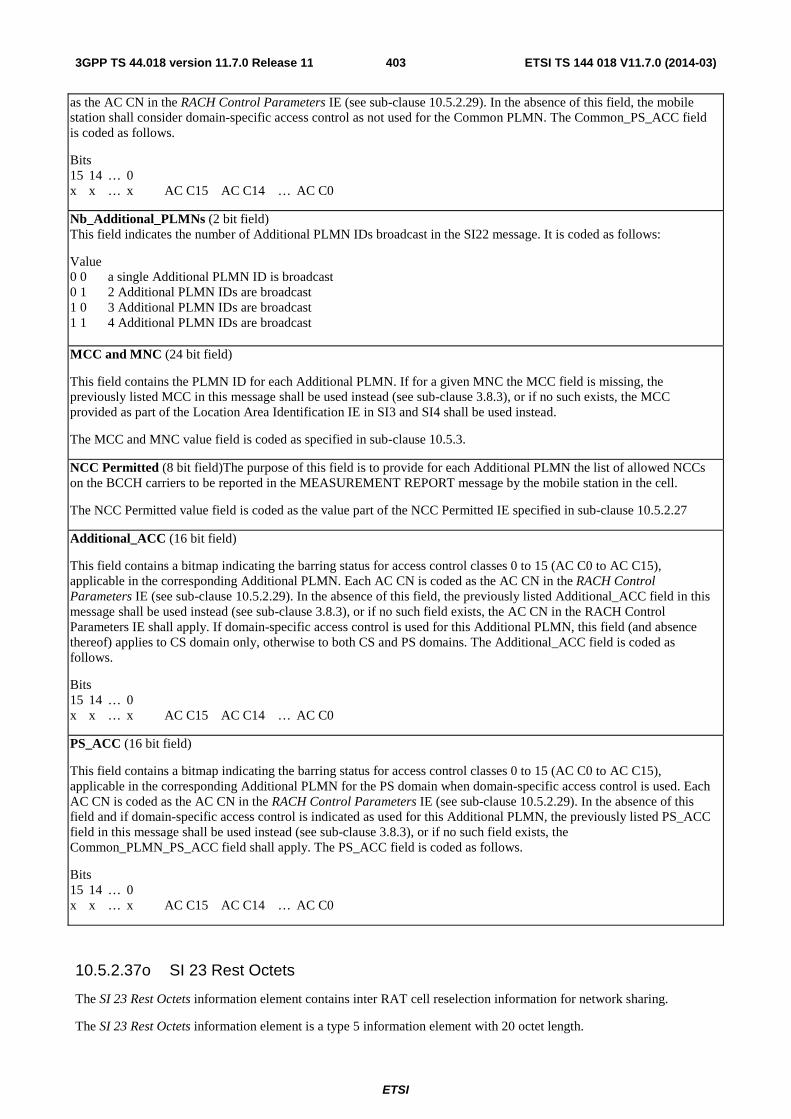
ETSI
ETSI TS 144 018 V11.7.0 (2014-03)4033GPP TS 44.018 version 11.7.0 Release 11
as the AC CN in the RACH Control Parameters IE (see sub-clause 10.5.2.29). In the absence of this field, the mobile station shall consider domain-specific access control as not used for the Common PLMN. The Common_PS_ACC field is coded as follows.
Bits 15 14 … 0 x x … x AC C15 AC C14 … AC C0
Nb_Additional_PLMNs (2 bit field) This field indicates the number of Additional PLMN IDs broadcast in the SI22 message. It is coded as follows:
Value 0 0 a single Additional PLMN ID is broadcast 0 1 2 Additional PLMN IDs are broadcast 1 0 3 Additional PLMN IDs are broadcast 1 1 4 Additional PLMN IDs are broadcast MCC and MNC (24 bit field)
This field contains the PLMN ID for each Additional PLMN. If for a given MNC the MCC field is missing, the previously listed MCC in this message shall be used instead (see sub-clause 3.8.3), or if no such exists, the MCC provided as part of the Location Area Identification IE in SI3 and SI4 shall be used instead.
The MCC and MNC value field is coded as specified in sub-clause 10.5.3.
NCC Permitted (8 bit field)The purpose of this field is to provide for each Additional PLMN the list of allowed NCCs on the BCCH carriers to be reported in the MEASUREMENT REPORT message by the mobile station in the cell.
The NCC Permitted value field is coded as the value part of the NCC Permitted IE specified in sub-clause 10.5.2.27
Additional_ACC (16 bit field)
This field contains a bitmap indicating the barring status for access control classes 0 to 15 (AC C0 to AC C15), applicable in the corresponding Additional PLMN. Each AC CN is coded as the AC CN in the RACH Control Parameters IE (see sub-clause 10.5.2.29). In the absence of this field, the previously listed Additional_ACC field in this message shall be used instead (see sub-clause 3.8.3), or if no such field exists, the AC CN in the RACH Control Parameters IE shall apply. If domain-specific access control is used for this Additional PLMN, this field (and absence thereof) applies to CS domain only, otherwise to both CS and PS domains. The Additional_ACC field is coded as follows.
Bits 15 14 … 0 x x … x AC C15 AC C14 … AC C0
PS_ACC (16 bit field)
This field contains a bitmap indicating the barring status for access control classes 0 to 15 (AC C0 to AC C15), applicable in the corresponding Additional PLMN for the PS domain when domain-specific access control is used. Each AC CN is coded as the AC CN in the RACH Control Parameters IE (see sub-clause 10.5.2.29). In the absence of this field and if domain-specific access control is indicated as used for this Additional PLMN, the previously listed PS_ACC field in this message shall be used instead (see sub-clause 3.8.3), or if no such field exists, the Common_PLMN_PS_ACC field shall apply. The PS_ACC field is coded as follows.
Bits 15 14 … 0 x x … x AC C15 AC C14 … AC C0
10.5.2.37o SI 23 Rest Octets
The SI 23 Rest Octets information element contains inter RAT cell reselection information for network sharing.
The SI 23 Rest Octets information element is a type 5 information element with 20 octet length.
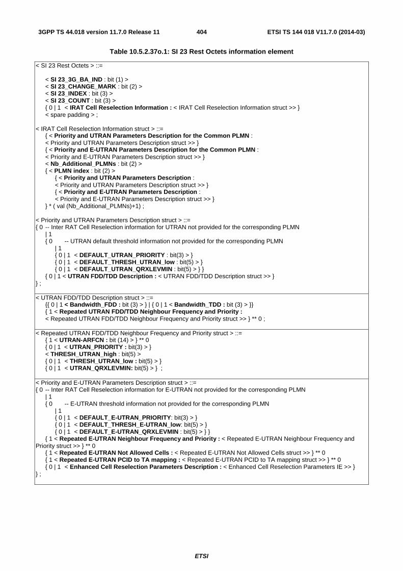
ETSI
ETSI TS 144 018 V11.7.0 (2014-03)4043GPP TS 44.018 version 11.7.0 Release 11
Table 10.5.2.37o.1: SI 23 Rest Octets information element
< SI 23 Rest Octets > ::= < SI 23_3G_BA_IND : bit (1) > < SI 23_CHANGE_MARK : bit (2) > < SI 23_INDEX : bit (3) > < SI 23_COUNT : bit (3) > { 0 | 1 < IRAT Cell Reselection Information : < IRAT Cell Reselection Information struct >> } < spare padding > ; < IRAT Cell Reselection Information struct > ::= { < Priority and UTRAN Parameters Description for the Common PLMN : < Priority and UTRAN Parameters Description struct >> } { < Priority and E-UTRAN Parameters Description for the Common PLMN : < Priority and E-UTRAN Parameters Description struct >> } < Nb_Additional_PLMNs : bit (2) > { < PLMN index : bit (2) > { < Priority and UTRAN Parameters Description : < Priority and UTRAN Parameters Description struct >> } { < Priority and E-UTRAN Parameters Description : < Priority and E-UTRAN Parameters Description struct >> } } * ( val (Nb_Additional_PLMNs)+1) ; < Priority and UTRAN Parameters Description struct > ::= { 0 -- Inter RAT Cell Reselection information for UTRAN not provided for the corresponding PLMN | 1 { 0 -- UTRAN default threshold information not provided for the corresponding PLMN | 1 { 0 | 1 < DEFAULT_UTRAN_PRIORITY : bit(3) > } { 0 | 1 < DEFAULT_THRESH_UTRAN_low : bit(5) > } { 0 | 1 < DEFAULT_UTRAN_QRXLEVMIN : bit(5) > } } { 0 | 1 < UTRAN FDD/TDD Description : < UTRAN FDD/TDD Description struct >> } } ; < UTRAN FDD/TDD Description struct > ::= {{ 0 | 1 < Bandwidth_FDD : bit (3) > } | { 0 | 1 < Bandwidth_TDD : bit (3) > }} { 1 < Repeated UTRAN FDD/TDD Neighbour Frequency and Priority : < Repeated UTRAN FDD/TDD Neighbour Frequency and Priority struct >> } ** 0 ; < Repeated UTRAN FDD/TDD Neighbour Frequency and Priority struct > ::= { 1 < UTRAN-ARFCN : bit (14) > } ** 0 { 0 | 1 < UTRAN_PRIORITY : bit(3) > } < THRESH_UTRAN_high : bit(5) > { 0 | 1 < THRESH_UTRAN_low : bit(5) > } { 0 | 1 < UTRAN_QRXLEVMIN: bit(5) > } ; < Priority and E-UTRAN Parameters Description struct > ::= { 0 -- Inter RAT Cell Reselection information for E-UTRAN not provided for the corresponding PLMN | 1 { 0 -- E-UTRAN threshold information not provided for the corresponding PLMN | 1 { 0 | 1 < DEFAULT_E-UTRAN_PRIORITY: bit(3) > } { 0 | 1 < DEFAULT_THRESH_E-UTRAN_low: bit(5) > } { 0 | 1 < DEFAULT_E-UTRAN_QRXLEVMIN : bit(5) > } } { 1 < Repeated E-UTRAN Neighbour Frequency and Priority : < Repeated E-UTRAN Neighbour Frequency and Priority struct >> } ** 0 { 1 < Repeated E-UTRAN Not Allowed Cells : < Repeated E-UTRAN Not Allowed Cells struct >> } ** 0 { 1 < Repeated E-UTRAN PCID to TA mapping : < Repeated E-UTRAN PCID to TA mapping struct >> } ** 0 { 0 | 1 < Enhanced Cell Reselection Parameters Description : < Enhanced Cell Reselection Parameters IE >> } } ;
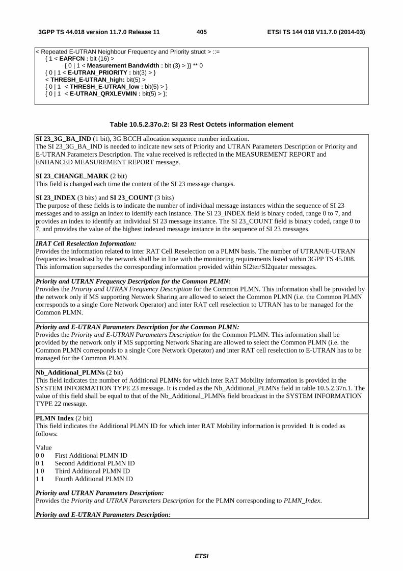
ETSI
ETSI TS 144 018 V11.7.0 (2014-03)4053GPP TS 44.018 version 11.7.0 Release 11
< Repeated E-UTRAN Neighbour Frequency and Priority struct > ::= { 1 < EARFCN : bit (16) > { 0 | 1 < Measurement Bandwidth : bit (3) > }} ** 0 { 0 | 1 < E-UTRAN_PRIORITY : bit(3) > } < THRESH_E-UTRAN_high: bit(5) > { 0 | 1 < THRESH_E-UTRAN_low : bit(5) > } { 0 | 1 < E-UTRAN_QRXLEVMIN : bit(5) > };
Table 10.5.2.37o.2: SI 23 Rest Octets information element
SI 23_3G_BA_IND (1 bit), 3G BCCH allocation sequence number indication. The SI 23_3G_BA_IND is needed to indicate new sets of Priority and UTRAN Parameters Description or Priority and E-UTRAN Parameters Description. The value received is reflected in the MEASUREMENT REPORT and ENHANCED MEASUREMENT REPORT message.
SI 23_CHANGE_MARK (2 bit) This field is changed each time the content of the SI 23 message changes.
SI 23_INDEX (3 bits) and SI 23_COUNT (3 bits) The purpose of these fields is to indicate the number of individual message instances within the sequence of SI 23 messages and to assign an index to identify each instance. The SI 23_INDEX field is binary coded, range 0 to 7, and provides an index to identify an individual SI 23 message instance. The SI 23_COUNT field is binary coded, range 0 to 7, and provides the value of the highest indexed message instance in the sequence of SI 23 messages.
IRAT Cell Reselection Information: Provides the information related to inter RAT Cell Reselection on a PLMN basis. The number of UTRAN/E-UTRAN frequencies broadcast by the network shall be in line with the monitoring requirements listed within 3GPP TS 45.008. This information supersedes the corresponding information provided within SI2ter/SI2quater messages.
Priority and UTRAN Frequency Description for the Common PLMN: Provides the Priority and UTRAN Frequency Description for the Common PLMN. This information shall be provided by the network only if MS supporting Network Sharing are allowed to select the Common PLMN (i.e. the Common PLMN corresponds to a single Core Network Operator) and inter RAT cell reselection to UTRAN has to be managed for the Common PLMN.
Priority and E-UTRAN Parameters Description for the Common PLMN: Provides the Priority and E-UTRAN Parameters Description for the Common PLMN. This information shall be provided by the network only if MS supporting Network Sharing are allowed to select the Common PLMN (i.e. the Common PLMN corresponds to a single Core Network Operator) and inter RAT cell reselection to E-UTRAN has to be managed for the Common PLMN.
Nb_Additional_PLMNs (2 bit) This field indicates the number of Additional PLMNs for which inter RAT Mobility information is provided in the SYSTEM INFORMATION TYPE 23 message. It is coded as the Nb_Additional_PLMNs field in table 10.5.2.37n.1. The value of this field shall be equal to that of the Nb_Additional_PLMNs field broadcast in the SYSTEM INFORMATION TYPE 22 message.
PLMN Index (2 bit) This field indicates the Additional PLMN ID for which inter RAT Mobility information is provided. It is coded as follows:
Value 0 0 First Additional PLMN ID 0 1 Second Additional PLMN ID 1 0 Third Additional PLMN ID 1 1 Fourth Additional PLMN ID
Priority and UTRAN Parameters Description: Provides the Priority and UTRAN Parameters Description for the PLMN corresponding to PLMN_Index.
Priority and E-UTRAN Parameters Description:
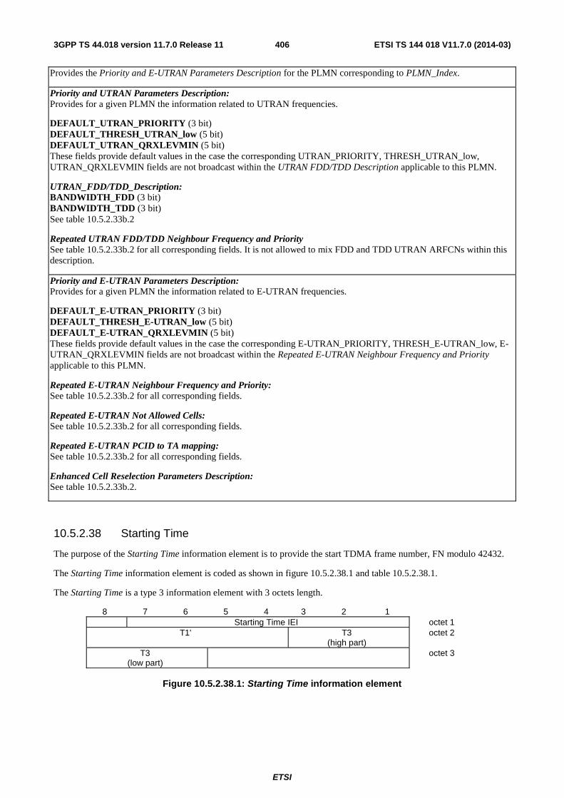
ETSI
ETSI TS 144 018 V11.7.0 (2014-03)4063GPP TS 44.018 version 11.7.0 Release 11
Provides the Priority and E-UTRAN Parameters Description for the PLMN corresponding to PLMN_Index.
Priority and UTRAN Parameters Description: Provides for a given PLMN the information related to UTRAN frequencies.
DEFAULT_UTRAN_PRIORITY (3 bit) DEFAULT_THRESH_UTRAN_low (5 bit) DEFAULT_UTRAN_QRXLEVMIN (5 bit) These fields provide default values in the case the corresponding UTRAN_PRIORITY, THRESH_UTRAN_low, UTRAN_QRXLEVMIN fields are not broadcast within the UTRAN FDD/TDD Description applicable to this PLMN.
UTRAN_FDD/TDD_Description: BANDWIDTH_FDD (3 bit) BANDWIDTH_TDD (3 bit) See table 10.5.2.33b.2
Repeated UTRAN FDD/TDD Neighbour Frequency and Priority See table 10.5.2.33b.2 for all corresponding fields. It is not allowed to mix FDD and TDD UTRAN ARFCNs within this description.
Priority and E-UTRAN Parameters Description: Provides for a given PLMN the information related to E-UTRAN frequencies.
DEFAULT_E-UTRAN_PRIORITY (3 bit) DEFAULT_THRESH_E-UTRAN_low (5 bit) DEFAULT_E-UTRAN_QRXLEVMIN (5 bit) These fields provide default values in the case the corresponding E-UTRAN_PRIORITY, THRESH_E-UTRAN_low, E-UTRAN_QRXLEVMIN fields are not broadcast within the Repeated E-UTRAN Neighbour Frequency and Priority applicable to this PLMN.
Repeated E-UTRAN Neighbour Frequency and Priority: See table 10.5.2.33b.2 for all corresponding fields.
Repeated E-UTRAN Not Allowed Cells: See table 10.5.2.33b.2 for all corresponding fields.
Repeated E-UTRAN PCID to TA mapping: See table 10.5.2.33b.2 for all corresponding fields.
Enhanced Cell Reselection Parameters Description: See table 10.5.2.33b.2.
10.5.2.38 Starting Time
The purpose of the Starting Time information element is to provide the start TDMA frame number, FN modulo 42432.
The Starting Time information element is coded as shown in figure 10.5.2.38.1 and table 10.5.2.38.1.
The Starting Time is a type 3 information element with 3 octets length.
8 7 6 5 4 3 2 1 Starting Time IEI octet 1
T1' T3 (high part)
octet 2
T3 (low part)
octet 3
Figure 10.5.2.38.1: Starting Time information element
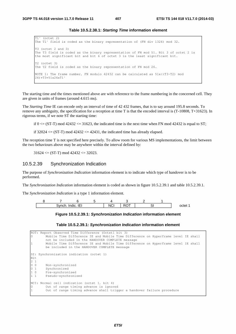
ETSI
ETSI TS 144 018 V11.7.0 (2014-03)4073GPP TS 44.018 version 11.7.0 Release 11
Table 10.5.2.38.1: Starting Time information element
T1' (octet 2) The T1' field is coded as the binary representation of (FN div 1326) mod 32. T3 (octet 2 and 3) The T3 field is coded as the binary representation of FN mod 51. Bit 3 of octet 2 is the most significant bit and bit 6 of octet 3 is the least significant bit. T2 (octet 3) The T2 field is coded as the binary representation of FN mod 26. NOTE 1: The frame number, FN modulo 42432 can be calculated as 51x((T3-T2) mod 26)+T3+51x26xT1'
The starting time and the times mentioned above are with reference to the frame numbering in the concerned cell. They are given in units of frames (around 4.615 ms).
The Starting Time IE can encode only an interval of time of 42 432 frames, that is to say around 195.8 seconds. To remove any ambiguity, the specification for a reception at time T is that the encoded interval is (T-10808, T+31623). In rigorous terms, if we note ST the starting time:
if 0 <= (ST-T) mod 42432 <= 31623, the indicated time is the next time when FN mod 42432 is equal to ST;
if 32024 <= (ST-T) mod 42432 <= 42431, the indicated time has already elapsed.
The reception time T is not specified here precisely. To allow room for various MS implementations, the limit between the two behaviours above may be anywhere within the interval defined by:
31624 <= (ST-T) mod 42432 <= 32023.
10.5.2.39 Synchronization Indication
The purpose of Synchronization Indication information element is to indicate which type of handover is to be performed.
The Synchronization Indication information element is coded as shown in figure 10.5.2.39.1 and table 10.5.2.39.1.
The Synchronization Indication is a type 1 information element.
8 7 6 5 4 3 2 1 Synch. Indic. IEI NCI ROT SI octet 1
Figure 10.5.2.39.1: Synchronization Indication information element
Table 10.5.2.39.1: Synchronization Indication information element
ROT: Report Observed Time Difference (Octet1 bit 3) 0 Mobile Time Difference IE and Mobile Time Difference on Hyperframe level IE shall
not be included in the HANDOVER COMPLETE message 1 Mobile Time Difference IE and Mobile Time Difference on Hyperframe level IE shall
be included in the HANDOVER COMPLETE message SI: Synchronization indication (octet 1) Bit 2 1 0 0 Non-synchronized 0 1 Synchronized 1 0 Pre-synchronised 1 1 Pseudo-synchronised NCI: Normal cell indication (octet 1, bit 4) 0 Out of range timing advance is ignored 1 Out of range timing advance shall trigger a handover failure procedure
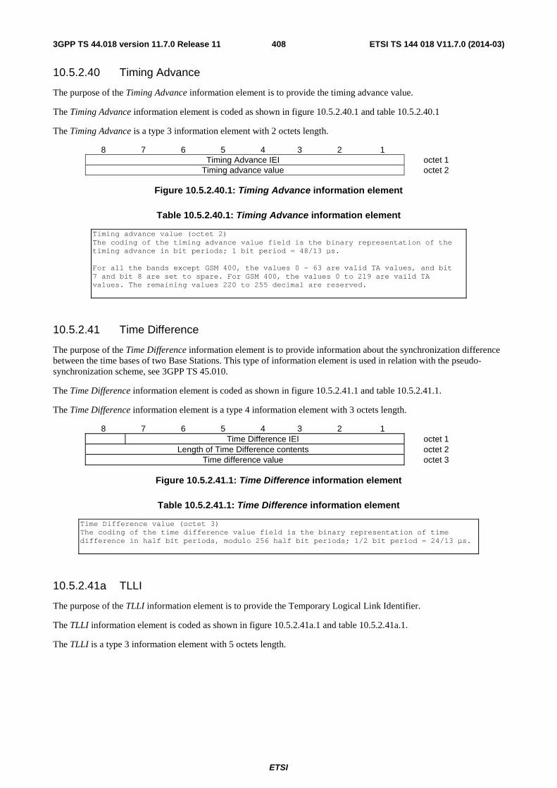
ETSI
ETSI TS 144 018 V11.7.0 (2014-03)4083GPP TS 44.018 version 11.7.0 Release 11
10.5.2.40 Timing Advance
The purpose of the Timing Advance information element is to provide the timing advance value.
The Timing Advance information element is coded as shown in figure 10.5.2.40.1 and table 10.5.2.40.1
The Timing Advance is a type 3 information element with 2 octets length.
8 7 6 5 4 3 2 1 Timing Advance IEI octet 1
Timing advance value octet 2
Figure 10.5.2.40.1: Timing Advance information element
Table 10.5.2.40.1: Timing Advance information element
Timing advance value (octet 2) The coding of the timing advance value field is the binary representation of the timing advance in bit periods; 1 bit period = 48/13 µs. For all the bands except GSM 400, the values 0 - 63 are valid TA values, and bit 7 and bit 8 are set to spare. For GSM 400, the values 0 to 219 are vaild TA values. The remaining values 220 to 255 decimal are reserved.
10.5.2.41 Time Difference
The purpose of the Time Difference information element is to provide information about the synchronization difference between the time bases of two Base Stations. This type of information element is used in relation with the pseudo-synchronization scheme, see 3GPP TS 45.010.
The Time Difference information element is coded as shown in figure 10.5.2.41.1 and table 10.5.2.41.1.
The Time Difference information element is a type 4 information element with 3 octets length.
8 7 6 5 4 3 2 1 Time Difference IEI octet 1
Length of Time Difference contents octet 2 Time difference value octet 3
Figure 10.5.2.41.1: Time Difference information element
Table 10.5.2.41.1: Time Difference information element
Time Difference value (octet 3) The coding of the time difference value field is the binary representation of time difference in half bit periods, modulo 256 half bit periods; 1/2 bit period = 24/13 µs.
10.5.2.41a TLLI
The purpose of the TLLI information element is to provide the Temporary Logical Link Identifier.
The TLLI information element is coded as shown in figure 10.5.2.41a.1 and table 10.5.2.41a.1.
The TLLI is a type 3 information element with 5 octets length.
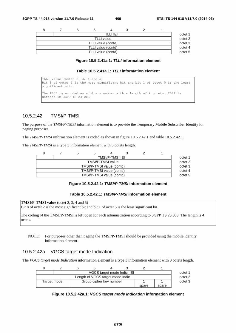
ETSI
ETSI TS 144 018 V11.7.0 (2014-03)4093GPP TS 44.018 version 11.7.0 Release 11
8 7 6 5 4 3 2 1 TLLI IEI octet 1
TLLI value octet 2 TLLI value (contd) octet 3 TLLI value (contd) octet 4 TLLI value (contd) octet 5
Figure 10.5.2.41a.1: TLLI information element
Table 10.5.2.41a.1: TLLI information element
TLLI value (octet 2, 3, 4 and 5) Bit 8 of octet 2 is the most significant bit and bit 1 of octet 5 is the least significant bit. The TLLI is encoded as a binary number with a length of 4 octets. TLLI is defined in 3GPP TS 23.003
10.5.2.42 TMSI/P-TMSI
The purpose of the TMSI/P-TMSI information element is to provide the Temporary Mobile Subscriber Identity for paging purposes.
The TMSI/P-TMSI information element is coded as shown in figure 10.5.2.42.1 and table 10.5.2.42.1.
The TMSI/P-TMSI is a type 3 information element with 5 octets length.
8 7 6 5 4 3 2 1 TMSI/P-TMSI IEI octet 1
TMSI/P-TMSI value octet 2 TMSI/P-TMSI value (contd) octet 3 TMSI/P-TMSI value (contd) octet 4 TMSI/P-TMSI value (contd) octet 5
Figure 10.5.2.42.1: TMSI/P-TMSI information element
Table 10.5.2.42.1: TMSI/P-TMSI information element
TMSI/P-TMSI value (octet 2, 3, 4 and 5) Bit 8 of octet 2 is the most significant bit and bit 1 of octet 5 is the least significant bit.
The coding of the TMSI/P-TMSI is left open for each administration according to 3GPP TS 23.003. The length is 4 octets.
NOTE: For purposes other than paging the TMSI/P-TMSI should be provided using the mobile identity information element.
10.5.2.42a VGCS target mode Indication
The VGCS target mode Indication information element is a type 3 information element with 3 octets length.
8 7 6 5 4 3 2 1 VGCS target mode Indic. IEI octet 1
Length of VGCS target mode Indic. octet 2 Target mode Group cipher key number 1
spare 1
spare octet 3
Figure 10.5.2.42a.1: VGCS target mode Indication information element
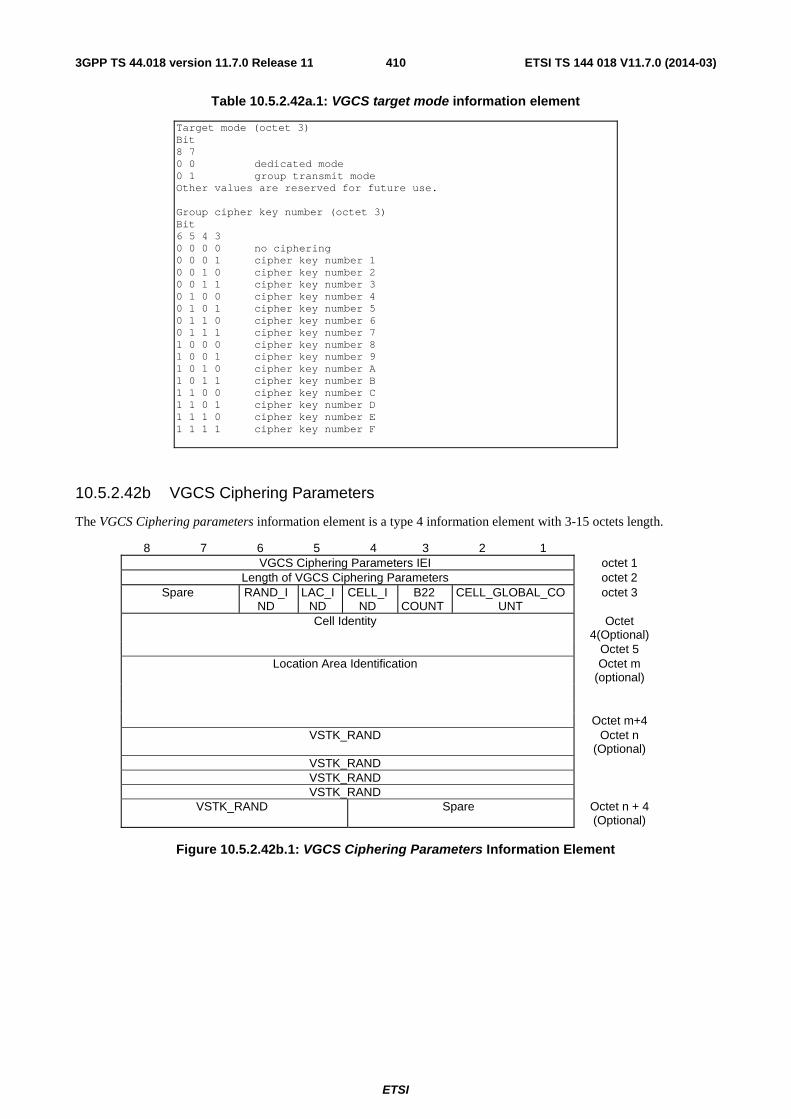
ETSI
ETSI TS 144 018 V11.7.0 (2014-03)4103GPP TS 44.018 version 11.7.0 Release 11
Table 10.5.2.42a.1: VGCS target mode information element
Target mode (octet 3) Bit 8 7 0 0 dedicated mode 0 1 group transmit mode Other values are reserved for future use. Group cipher key number (octet 3) Bit 6 5 4 3 0 0 0 0 no ciphering 0 0 0 1 cipher key number 1 0 0 1 0 cipher key number 2 0 0 1 1 cipher key number 3 0 1 0 0 cipher key number 4 0 1 0 1 cipher key number 5 0 1 1 0 cipher key number 6 0 1 1 1 cipher key number 7 1 0 0 0 cipher key number 8 1 0 0 1 cipher key number 9 1 0 1 0 cipher key number A 1 0 1 1 cipher key number B 1 1 0 0 cipher key number C 1 1 0 1 cipher key number D 1 1 1 0 cipher key number E 1 1 1 1 cipher key number F
10.5.2.42b VGCS Ciphering Parameters
The VGCS Ciphering parameters information element is a type 4 information element with 3-15 octets length.
8 7 6 5 4 3 2 1 VGCS Ciphering Parameters IEI octet 1
Length of VGCS Ciphering Parameters octet 2 Spare RAND_I
ND LAC_I
ND CELL_I
ND B22
COUNT CELL_GLOBAL_CO
UNT octet 3
Cell Identity Octet 4(Optional)
Octet 5 Location Area Identification Octet m
(optional)
Octet m+4 VSTK_RAND Octet n
(Optional) VSTK_RAND VSTK_RAND VSTK_RAND
VSTK_RAND Spare Octet n + 4 (Optional)
Figure 10.5.2.42b.1: VGCS Ciphering Parameters Information Element
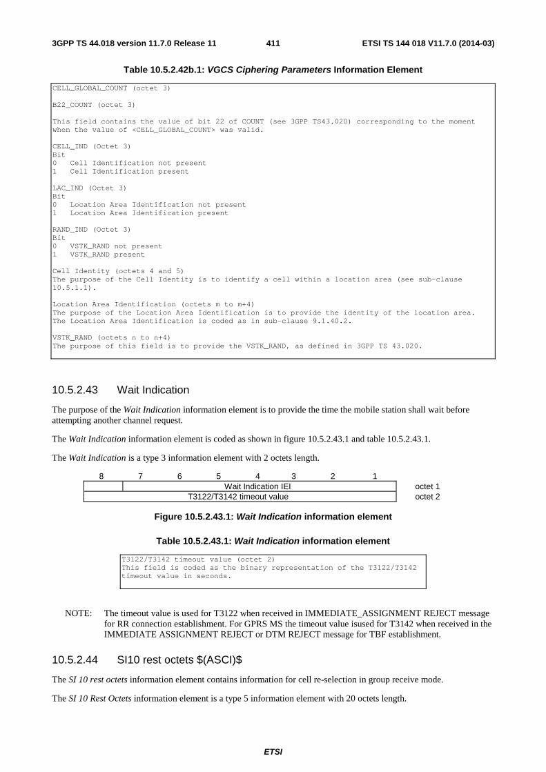
ETSI
ETSI TS 144 018 V11.7.0 (2014-03)4113GPP TS 44.018 version 11.7.0 Release 11
Table 10.5.2.42b.1: VGCS Ciphering Parameters Information Element
CELL_GLOBAL_COUNT (octet 3) B22_COUNT (octet 3) This field contains the value of bit 22 of COUNT (see 3GPP TS43.020) corresponding to the moment when the value of <CELL_GLOBAL_COUNT> was valid. CELL_IND (Octet 3) Bit 0 Cell Identification not present 1 Cell Identification present LAC_IND (Octet 3) Bit 0 Location Area Identification not present 1 Location Area Identification present RAND_IND (Octet 3) Bit 0 VSTK_RAND not present 1 VSTK_RAND present Cell Identity (octets 4 and 5) The purpose of the Cell Identity is to identify a cell within a location area (see sub-clause 10.5.1.1). Location Area Identification (octets m to m+4) The purpose of the Location Area Identification is to provide the identity of the location area. The Location Area Identification is coded as in sub-clause 9.1.40.2. VSTK_RAND (octets n to n+4) The purpose of this field is to provide the VSTK_RAND, as defined in 3GPP TS 43.020.
10.5.2.43 Wait Indication
The purpose of the Wait Indication information element is to provide the time the mobile station shall wait before attempting another channel request.
The Wait Indication information element is coded as shown in figure 10.5.2.43.1 and table 10.5.2.43.1.
The Wait Indication is a type 3 information element with 2 octets length.
8 7 6 5 4 3 2 1 Wait Indication IEI octet 1
T3122/T3142 timeout value octet 2
Figure 10.5.2.43.1: Wait Indication information element
Table 10.5.2.43.1: Wait Indication information element
T3122/T3142 timeout value (octet 2) This field is coded as the binary representation of the T3122/T3142 timeout value in seconds.
NOTE: The timeout value is used for T3122 when received in IMMEDIATE_ASSIGNMENT REJECT message for RR connection establishment. For GPRS MS the timeout value isused for T3142 when received in the IMMEDIATE ASSIGNMENT REJECT or DTM REJECT message for TBF establishment.
10.5.2.44 SI10 rest octets $(ASCI)$
The SI 10 rest octets information element contains information for cell re-selection in group receive mode.
The SI 10 Rest Octets information element is a type 5 information element with 20 octets length.
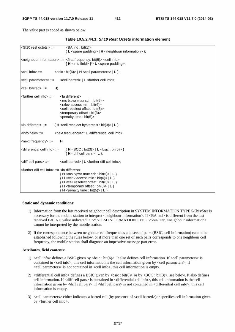
ETSI
ETSI TS 144 018 V11.7.0 (2014-03)4123GPP TS 44.018 version 11.7.0 Release 11
The value part is coded as shown below.
Table 10.5.2.44.1: SI 10 Rest Octets information element
<SI10 rest octets> ::= <BA ind : bit(1)> { L <spare padding> | H <neighbour information> }; <neighbour information> ::= <first frequency: bit(5)> <cell info> { H <info field> }** L <spare padding>; <cell info> ::= <bsic : bit(6)> { H <cell parameters> | L }; <cell parameters> ::= <cell barred> | L <further cell info>; <cell barred> ::= H; <further cell info> ::= <la different> <ms txpwr max cch : bit(5)> <rxlev access min : bit(6)> <cell reselect offset : bit(6)> <temporary offset : bit(3)> <penalty time : bit(5)> ; <la different> ::= { H <cell reselect hysteresis : bit(3)> | L }; <info field> ::= <next frequency>** L <differential cell info>; <next frequency> ::= H; <differential cell info> ::= { H <BCC : bit(3)> | L <bsic : bit(6)> } { H <diff cell pars> | L }; <diff cell pars> ::= <cell barred> | L <further diff cell info>; <further diff cell info> ::= <la different> { H <ms txpwr max cch : bit(5)> | L } { H <rxlev access min : bit(6)> | L } { H <cell reselect offset : bit(6)> | L } { H <temporary offset : bit(3)> | L } { H <penalty time : bit(5)> | L };
Static and dynamic conditions:
1) Information from the last received neighbour cell description in SYSTEM INFORMATION TYPE 5/5bis/5ter is necessary for the mobile station to interpret <neighbour information>. If <BA ind> is different from the last received BA IND value indicated in SYSTEM INFORMATION TYPE 5/5bis/5ter, <neighbour information> cannot be interpreted by the mobile station.
2) If the correspondence between neighbour cell frequencies and sets of pairs (BSIC, cell information) cannot be established following the rules below, or if more than one set of such pairs corresponds to one neighbour cell frequency, the mobile station shall diagnose an imperative message part error.
Attributes, field contents:
1) <cell info> defines a BSIC given by <bsic : bit(6)>. It also defines cell information. If <cell parameters> is contained in <cell info>, this cell information is the cell information given by <cell parameters>; if <cell parameters> is not contained in <cell info>, this cell information is empty.
2) <differential cell info> defines a BSIC given by <bsic : bit(6)> or by <BCC : bit(3)>, see below. It also defines cell information. If <diff cell pars> is contained in <differential cell info>, this cell information is the cell information given by <diff cell pars>; if <diff cell pars> is not contained in <differential cell info>, this cell information is empty.
3) <cell parameters> either indicates a barred cell (by presence of <cell barred>)or specifies cell information given by <further cell info>.
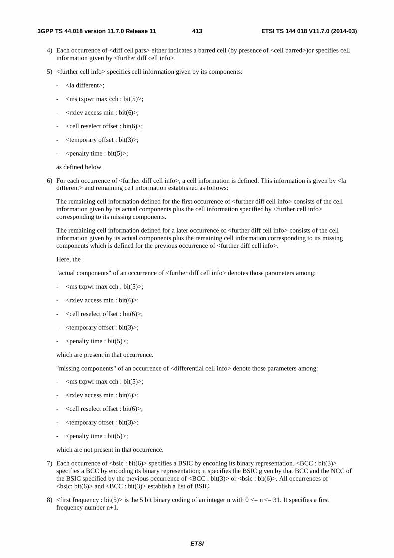
ETSI
ETSI TS 144 018 V11.7.0 (2014-03)4133GPP TS 44.018 version 11.7.0 Release 11
4) Each occurrence of <diff cell pars> either indicates a barred cell (by presence of <cell barred>)or specifies cell information given by <further diff cell info>.
5) <further cell info> specifies cell information given by its components:
- <la different>;
- <ms txpwr max cch : bit(5)>;
- <rxlev access min : bit(6)>;
- <cell reselect offset : bit(6)>;
- <temporary offset : bit(3)>;
- <penalty time : bit(5)>;
as defined below.
6) For each occurrence of <further diff cell info>, a cell information is defined. This information is given by <la different> and remaining cell information established as follows:
The remaining cell information defined for the first occurrence of <further diff cell info> consists of the cell information given by its actual components plus the cell information specified by <further cell info> corresponding to its missing components.
The remaining cell information defined for a later occurrence of <further diff cell info> consists of the cell information given by its actual components plus the remaining cell information corresponding to its missing components which is defined for the previous occurrence of <further diff cell info>.
Here, the
"actual components" of an occurrence of <further diff cell info> denotes those parameters among:
- <ms txpwr max cch : bit(5)>;
- <rxlev access min : bit(6)>;
- <cell reselect offset : bit(6)>;
- <temporary offset : bit(3)>;
- <penalty time : bit(5)>;
which are present in that occurrence.
"missing components" of an occurrence of <differential cell info> denote those parameters among:
- <ms txpwr max cch : bit(5)>;
- <rxlev access min : bit(6)>;
- <cell reselect offset : bit(6)>;
- <temporary offset : bit(3)>;
- <penalty time : bit(5)>;
which are not present in that occurrence.
7) Each occurrence of <bsic : bit(6)> specifies a BSIC by encoding its binary representation. <BCC : bit(3)> specifies a BCC by encoding its binary representation; it specifies the BSIC given by that BCC and the NCC of the BSIC specified by the previous occurrence of <BCC : bit(3)> or <bsic : bit(6)>. All occurrences of <bsic: bit(6)> and <BCC : bit(3)> establish a list of BSIC.
8) <first frequency : bit(5)> is the 5 bit binary coding of an integer n with 0 <= n <= 31. It specifies a first frequency number n+1.
ETSI
ETSI TS 144 018 V11.7.0 (2014-03)4143GPP TS 44.018 version 11.7.0 Release 11
9) <SI10 rest octets> defines a correspondence between neighbour cell frequencies and sets of pairs (BSIC, cell information) defining the parameters for cell re-selection of any corresponding neighbour cell with BCCH on that frequency and having that BSIC:
- Let a(1),..., a(n) be the list of neighbour cell frequencies, in the order determined by the mobile station. Let i be the first frequency number specified by <first frequency : bit(5)> (see above).
- The first BSIC and the cell information specified by <cell info> build a pair belonging to the set corresponding to a(i).
- If an m-th occurrence of <info field> is present (where m >=2), having established the correspondence of the (m-1)-th BSIC to a neighbour frequency a(k), the m-th BSIC and following <differential cell info>:
- belong to a(k), if <next frequency> is not present in the m-th occurrence of <info field>;
- belong to a((smod(k+t)), if <next frequency> is present exactly t times in the m-th occurrence of <info field>.
- Here, for an integer j, smod(j) := ((j-1) mod n) + 1.
10) If <la different> contains a <cell reselect hysteresis: bit(3)>, this means that the cell is to be considered by the mobile station to belong to a different location area and that for the cell, the cell reselect hysteresis specified in <cell reselect hysteresis : bit(3)> applies.
11) If <la different> doesn't contain a <cell reselect hysteresis: bit(3)>, this means that the cell is to be considered by the mobile station to belong to the same location area.
12) For <cell reselect hysteresis : bit(3)>: see sub-clause 10.5.2.4.
13) For <ms txpwr max cch : bit(5)>: see sub-clause 10.5.2.4.
14) For <rxlev access min : bit(6)> see sub-clause 10.5.2.4.
15) For <cell reselect offset : bit(6)>: see sub-clause 10.5.2.35.
16) For <temporary offset : bit(3)>: see sub-clause 10.5.2.35.
17) For <penalty time : bit(5)>: see sub-clause 10.5.2.35.
10.5.2.45 EXTENDED MEASUREMENT RESULTS
The purpose of the Extended Measurement Results information element is to provide the results of the measurements made by the mobile station on the carriers specified in the EXTENDED MEASUREMENT ORDER.
The Extended Measurement Results information element is coded as shown in figure 10.5.2.45.1 and table 10.5.2.45.1.
The Extended Measurement Results is a type 3 information element with 17 octets length.
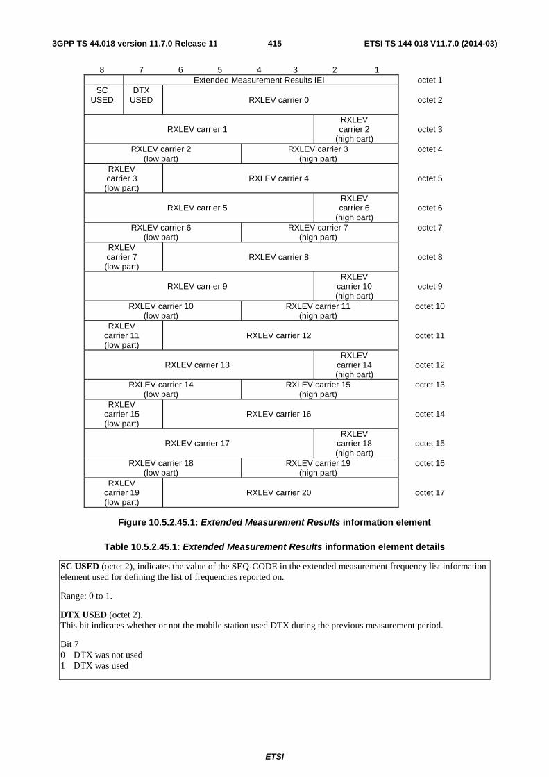
ETSI
ETSI TS 144 018 V11.7.0 (2014-03)4153GPP TS 44.018 version 11.7.0 Release 11
8 7 6 5 4 3 2 1 Extended Measurement Results IEI octet 1
SC USED
DTX USED
RXLEV carrier 0
octet 2
RXLEV carrier 1
RXLEV carrier 2
(high part)
octet 3
RXLEV carrier 2 (low part)
RXLEV carrier 3 (high part)
octet 4
RXLEV carrier 3 (low part)
RXLEV carrier 4
octet 5
RXLEV carrier 5
RXLEV carrier 6
(high part)
octet 6
RXLEV carrier 6 (low part)
RXLEV carrier 7 (high part)
octet 7
RXLEV carrier 7 (low part)
RXLEV carrier 8
octet 8
RXLEV carrier 9
RXLEV carrier 10 (high part)
octet 9
RXLEV carrier 10 (low part)
RXLEV carrier 11 (high part)
octet 10
RXLEV carrier 11 (low part)
RXLEV carrier 12
octet 11
RXLEV carrier 13
RXLEV carrier 14 (high part)
octet 12
RXLEV carrier 14 (low part)
RXLEV carrier 15 (high part)
octet 13
RXLEV carrier 15 (low part)
RXLEV carrier 16
octet 14
RXLEV carrier 17
RXLEV carrier 18 (high part)
octet 15
RXLEV carrier 18 (low part)
RXLEV carrier 19 (high part)
octet 16
RXLEV carrier 19 (low part)
RXLEV carrier 20
octet 17
Figure 10.5.2.45.1: Extended Measurement Results information element
Table 10.5.2.45.1: Extended Measurement Results information element details
SC USED (octet 2), indicates the value of the SEQ-CODE in the extended measurement frequency list information element used for defining the list of frequencies reported on.
Range: 0 to 1.
DTX USED (octet 2). This bit indicates whether or not the mobile station used DTX during the previous measurement period.
Bit 7 0 DTX was not used 1 DTX was used

ETSI
ETSI TS 144 018 V11.7.0 (2014-03)4163GPP TS 44.018 version 11.7.0 Release 11
RXLEV carrier 'N' (octets 2 to 17). This field is coded as the binary representation of a value M. M corresponds according to the mapping defined in 3GPP TS 45.008 to the received signal strength on carrier N. N is the index to the frequency in the sorted list of frequencies defined in the EXTENDED MEASUREMENT ORDER message. The list is sorted in increasing order of ARFCN, except that ARFCN 0, if included in th e EXTENDED MEASUREMENT ORDER, is put in the last position of the sorted list. If the EXTENDED MEASUREMENT ORDER contains more than 21 carriers, only the signal strength of the carriers 0-20 shall be measured and reported.
Range: 0 to 63
If the EXTENDED MEASUREMENT ORDER message contains less than 21 carriers, the fields in the EXTENDED MEASUREMENT REPORT not referring to any specified carrier shall have RXLEV values set to zero.
10.5.2.46 Extended Measurement Frequency List
The purpose of Extended Measurement Frequency List information element is to provide the absolute radio frequency channel numbers of carriers to measure signal strength on.
The Extended Measurement Frequency List information element is coded as the Cell Channel Description information element, as specified in sub-clause 10.5.2.1b, with the exception of bit 5 of octet 2. Figure 10.5.2.46.1 and table 10.5.2.46.1: contains the difference of specifications.
The Extended Measurement Frequency List information element is a type 3 information element with 17 octets length.
8 7 6 5 4 3 2 1 Extended Measurement Frequency List IEI octet 1
Bit 128
Bit 127
0 spare
SEQ- CODE
Bit 124
Bit 123
Bit 122
Bit 121
octet 2
Bit 120
Bit 119
Bit 118
Bit 117
Bit 116
Bit 115
Bit 114
Bit 113
octet 3
Bit 008
Bit 007
Bit 006
Bit 005
Bit 004
Bit 003
Bit 002
Bit 001
octet 17
Figure 10.5.2.46.1: Extended Measurement Frequency List information element
Table 10.5.2.46.1: Extended Measurement Frequency List information element details
SEQ-CODE, Sequence code (octet 2, bit 5). Range 0 to 1.
10.5.2.47 Suspension Cause
The purpose of the Suspension Cause information element is to provide the reason for the GPRS suspension.
The Suspension Cause information element is coded as shown in figure 10.5.2.47.1 and table 10.5.2.21aa.1.
The Suspension Cause is a type 3 information element with 2 octets length.
8 7 6 5 4 3 2 1 Suspension Cause IEI octet 1
Suspension cause value octet 2
Figure 10.5.2.47.1: Suspension Cause information element
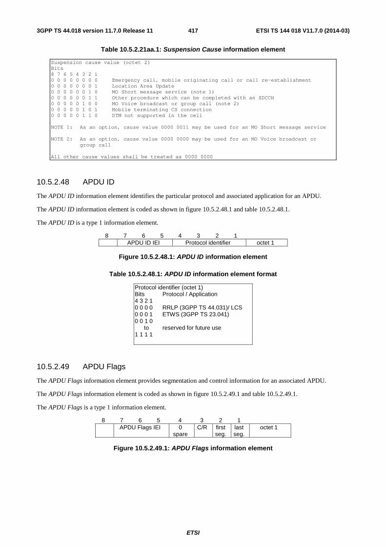
ETSI
ETSI TS 144 018 V11.7.0 (2014-03)4173GPP TS 44.018 version 11.7.0 Release 11
Table 10.5.2.21aa.1: Suspension Cause information element
Suspension cause value (octet 2) Bits 8 7 6 5 4 3 2 1 0 0 0 0 0 0 0 0 Emergency call, mobile originating call or call re-establishment 0 0 0 0 0 0 0 1 Location Area Update 0 0 0 0 0 0 1 0 MO Short message service (note 1) 0 0 0 0 0 0 1 1 Other procedure which can be completed with an SDCCH 0 0 0 0 0 1 0 0 MO Voice broadcast or group call (note 2) 0 0 0 0 0 1 0 1 Mobile terminating CS connection 0 0 0 0 0 1 1 0 DTM not supported in the cell NOTE 1: As an option, cause value 0000 0011 may be used for an MO Short message service NOTE 2: As an option, cause value 0000 0000 may be used for an MO Voice broadcast or
group call All other cause values shall be treated as 0000 0000
10.5.2.48 APDU ID
The APDU ID information element identifies the particular protocol and associated application for an APDU.
The APDU ID information element is coded as shown in figure 10.5.2.48.1 and table 10.5.2.48.1.
The APDU ID is a type 1 information element.
8 7 6 5 4 3 2 1 APDU ID IEI Protocol identifier octet 1
Figure 10.5.2.48.1: APDU ID information element
Table 10.5.2.48.1: APDU ID information element format
Protocol identifier (octet 1) Bits Protocol / Application 4 3 2 1 0 0 0 0 RRLP (3GPP TS 44.031)/ LCS 0 0 0 1 ETWS (3GPP TS 23.041) 0 0 1 0 to reserved for future use 1 1 1 1
10.5.2.49 APDU Flags
The APDU Flags information element provides segmentation and control information for an associated APDU.
The APDU Flags information element is coded as shown in figure 10.5.2.49.1 and table 10.5.2.49.1.
The APDU Flags is a type 1 information element.
8 7 6 5 4 3 2 1 APDU Flags IEI 0
spare C/R first
seg. last seg.
octet 1
Figure 10.5.2.49.1: APDU Flags information element
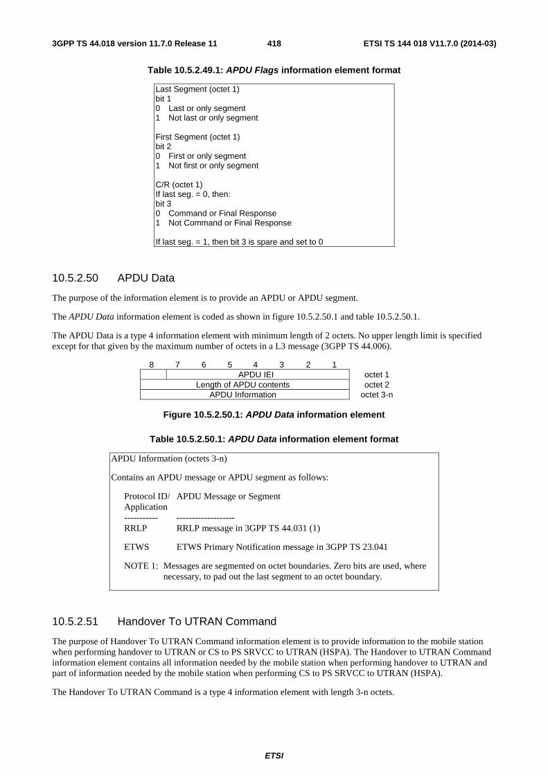
ETSI
ETSI TS 144 018 V11.7.0 (2014-03)4183GPP TS 44.018 version 11.7.0 Release 11
Table 10.5.2.49.1: APDU Flags information element format
Last Segment (octet 1) bit 1 0 Last or only segment 1 Not last or only segment First Segment (octet 1) bit 2 0 First or only segment 1 Not first or only segment C/R (octet 1) If last seg. = 0, then: bit 3 0 Command or Final Response 1 Not Command or Final Response If last seg. = 1, then bit 3 is spare and set to 0
10.5.2.50 APDU Data
The purpose of the information element is to provide an APDU or APDU segment.
The APDU Data information element is coded as shown in figure 10.5.2.50.1 and table 10.5.2.50.1.
The APDU Data is a type 4 information element with minimum length of 2 octets. No upper length limit is specified except for that given by the maximum number of octets in a L3 message (3GPP TS 44.006).
8 7 6 5 4 3 2 1 APDU IEI octet 1
Length of APDU contents octet 2 APDU Information octet 3-n
Figure 10.5.2.50.1: APDU Data information element
Table 10.5.2.50.1: APDU Data information element format
APDU Information (octets 3-n)
Contains an APDU message or APDU segment as follows:
Protocol ID/ APDU Message or Segment Application ----------- ------------------- RRLP RRLP message in 3GPP TS 44.031 (1)
ETWS ETWS Primary Notification message in 3GPP TS 23.041
NOTE 1: Messages are segmented on octet boundaries. Zero bits are used, where necessary, to pad out the last segment to an octet boundary.
10.5.2.51 Handover To UTRAN Command
The purpose of Handover To UTRAN Command information element is to provide information to the mobile station when performing handover to UTRAN or CS to PS SRVCC to UTRAN (HSPA). The Handover to UTRAN Command information element contains all information needed by the mobile station when performing handover to UTRAN and part of information needed by the mobile station when performing CS to PS SRVCC to UTRAN (HSPA).
The Handover To UTRAN Command is a type 4 information element with length 3-n octets.
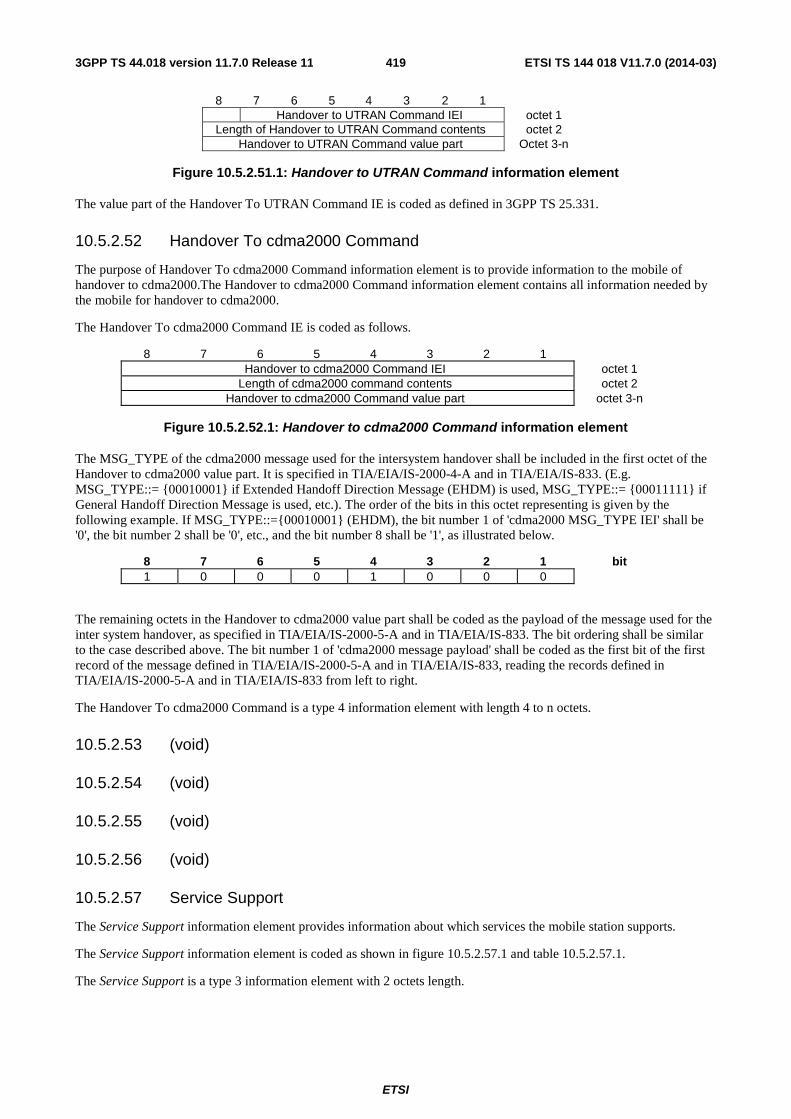
ETSI
ETSI TS 144 018 V11.7.0 (2014-03)4193GPP TS 44.018 version 11.7.0 Release 11
8 7 6 5 4 3 2 1 Handover to UTRAN Command IEI octet 1 Length of Handover to UTRAN Command contents octet 2
Handover to UTRAN Command value part Octet 3-n
Figure 10.5.2.51.1: Handover to UTRAN Command information element
The value part of the Handover To UTRAN Command IE is coded as defined in 3GPP TS 25.331.
10.5.2.52 Handover To cdma2000 Command
The purpose of Handover To cdma2000 Command information element is to provide information to the mobile of handover to cdma2000.The Handover to cdma2000 Command information element contains all information needed by the mobile for handover to cdma2000.
The Handover To cdma2000 Command IE is coded as follows.
8 7 6 5 4 3 2 1 Handover to cdma2000 Command IEI octet 1
Length of cdma2000 command contents octet 2 Handover to cdma2000 Command value part octet 3-n
Figure 10.5.2.52.1: Handover to cdma2000 Command information element
The MSG_TYPE of the cdma2000 message used for the intersystem handover shall be included in the first octet of the Handover to cdma2000 value part. It is specified in TIA/EIA/IS-2000-4-A and in TIA/EIA/IS-833. (E.g. MSG_TYPE::= {00010001} if Extended Handoff Direction Message (EHDM) is used, MSG_TYPE::= {00011111} if General Handoff Direction Message is used, etc.). The order of the bits in this octet representing is given by the following example. If MSG_TYPE::={00010001} (EHDM), the bit number 1 of 'cdma2000 MSG_TYPE IEI' shall be '0', the bit number 2 shall be '0', etc., and the bit number 8 shall be '1', as illustrated below.
8 7 6 5 4 3 2 1 bit 1 0 0 0 1 0 0 0
The remaining octets in the Handover to cdma2000 value part shall be coded as the payload of the message used for the inter system handover, as specified in TIA/EIA/IS-2000-5-A and in TIA/EIA/IS-833. The bit ordering shall be similar to the case described above. The bit number 1 of 'cdma2000 message payload' shall be coded as the first bit of the first record of the message defined in TIA/EIA/IS-2000-5-A and in TIA/EIA/IS-833, reading the records defined in TIA/EIA/IS-2000-5-A and in TIA/EIA/IS-833 from left to right.
The Handover To cdma2000 Command is a type 4 information element with length 4 to n octets.
10.5.2.53 (void)
10.5.2.54 (void)
10.5.2.55 (void)
10.5.2.56 (void)
10.5.2.57 Service Support
The Service Support information element provides information about which services the mobile station supports.
The Service Support information element is coded as shown in figure 10.5.2.57.1 and table 10.5.2.57.1.
The Service Support is a type 3 information element with 2 octets length.
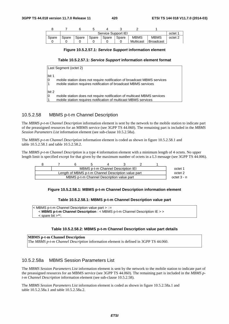
ETSI
ETSI TS 144 018 V11.7.0 (2014-03)4203GPP TS 44.018 version 11.7.0 Release 11
8 7 6 5 4 3 2 1 Service Support IEI octet 1
Spare 0
Spare 0
Spare 0
Spare 0
Spare 0
Spare 0
MBMS Multicast
MBMS Broadcast
octet 2
Figure 10.5.2.57.1: Service Support information element
Table 10.5.2.57.1: Service Support information element format
Last Segment (octet 2) bit 1 0 mobile station does not require notification of broadcast MBMS services 1 mobile station requires notification of broadcast MBMS services bit 2 0 mobile station does not require notification of multicast MBMS services 1 mobile station requires notification of multicast MBMS services
10.5.2.58 MBMS p-t-m Channel Description
The MBMS p-t-m Channel Description information element is sent by the network to the mobile station to indicate part of the preassigned resources for an MBMS service (see 3GPP TS 44.060). The remaining part is included in the MBMS Session Parameters List information element (see sub-clause 10.5.2.58a).
The MBMS p-t-m Channel Description information element is coded as shown in figure 10.5.2.58.1 and table 10.5.2.58.1 and table 10.5.2.58.2.
The MBMS p-t-m Channel Description is a type 4 information element with a minimum length of 4 octets. No upper length limit is specified except for that given by the maximum number of octets in a L3 message (see 3GPP TS 44.006).
8 7 6 5 4 3 2 1 MBMS p-t-m Channel Description IEI octet 1
Length of MBMS p-t-m Channel Description value part octet 2 MBMS p-t-m Channel Description value part octet 3 - n
Figure 10.5.2.58.1: MBMS p-t-m Channel Description information element
Table 10.5.2.58.1: MBMS p-t-m Channel Description value part
< MBMS p-t-m Channel Description value part > ::= < MBMS p-t-m Channel Description : < MBMS p-t-m Channel Description IE > > < spare bit >**;
Table 10.5.2.58.2: MBMS p-t-m Channel Description value part details
MBMS p-t-m Channel Description The MBMS p-t-m Channel Description information element is defined in 3GPP TS 44.060.
10.5.2.58a MBMS Session Parameters List
The MBMS Session Parameters List information element is sent by the network to the mobile station to indicate part of the preassigned resources for an MBMS service (see 3GPP TS 44.060). The remaining part is included in the MBMS p-t-m Channel Description information element (see sub-clause 10.5.2.58).
The MBMS Session Parameters List information element is coded as shown in figure 10.5.2.58a.1 and table 10.5.2.58a.1 and table 10.5.2.58a.2.
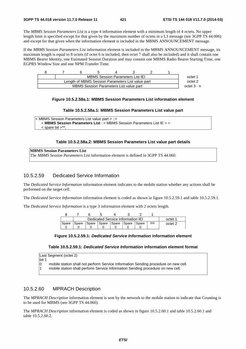
ETSI
ETSI TS 144 018 V11.7.0 (2014-03)4213GPP TS 44.018 version 11.7.0 Release 11
The MBMS Session Parameters List is a type 4 information element with a minimum length of 4 octets. No upper length limit is specified except for that given by the maximum number of octets in a L3 message (see 3GPP TS 44.006) and except for that given when the information element is included in the MBMS ANNOUNCEMENT message.
If the MBMS Session Parameters List information element is included in the MBMS ANNOUNCEMENT message, its maximum length is equal to 8 octets (if octet 6 is included, then octet 7 shall also be included) and it shall contain one MBMS Bearer Identity, one Estimated Session Duration and may contain one MBMS Radio Bearer Starting Time, one EGPRS Window Size and one NPM Transfer Time.
8 7 6 5 4 3 2 1 MBMS Session Parameters List IEI octet 1
Length of MBMS Session Parameters List value part octet 2 MBMS Session Parameters List value part octet 3 - n
Figure 10.5.2.58a.1: MBMS Session Parameters List information element
Table 10.5.2.58a.1: MBMS Session Parameters List value part
< MBMS Session Parameters List value part > ::= < MBMS Session Parameters List : < MBMS Session Parameters List IE > > < spare bit >**;
Table 10.5.2.58a.2: MBMS Session Parameters List value part details
MBMS Session Parameters List The MBMS Session Parameters List information element is defined in 3GPP TS 44.060.
10.5.2.59 Dedicated Service Information
The Dedicated Service Information information element indicates to the mobile station whether any actions shall be performed on the target cell.
The Dedicated Service Information information element is coded as shown in figure 10.5.2.59.1 and table 10.5.2.59.1.
The Dedicated Service Information is a type 3 information element with 2 octets length.
8 7 6 5 4 3 2 1 Dedicated Service Information IEI octet 1 Spare
0 Spare
0 Spare
0 Spare
0 Spare
0 Spare
0 Spare
0 SIS octet 2
Figure 10.5.2.59.1: Dedicated Service Information information element
Table 10.5.2.59.1: Dedicated Service Information information element format
Last Segment (octet 2) bit 1 0 mobile station shall not perform Service Information Sending procedure on new cell. 1 mobile station shall perform Service Information Sending procedure on new cell.
10.5.2.60 MPRACH Description
The MPRACH Description information element is sent by the network to the mobile station to indicate that Counting is to be used for MBMS (see 3GPP TS 44.060).
The MPRACH Description information element is coded as shown in figure 10.5.2.60.1 and table 10.5.2.60.1 and table 10.5.2.60.2.
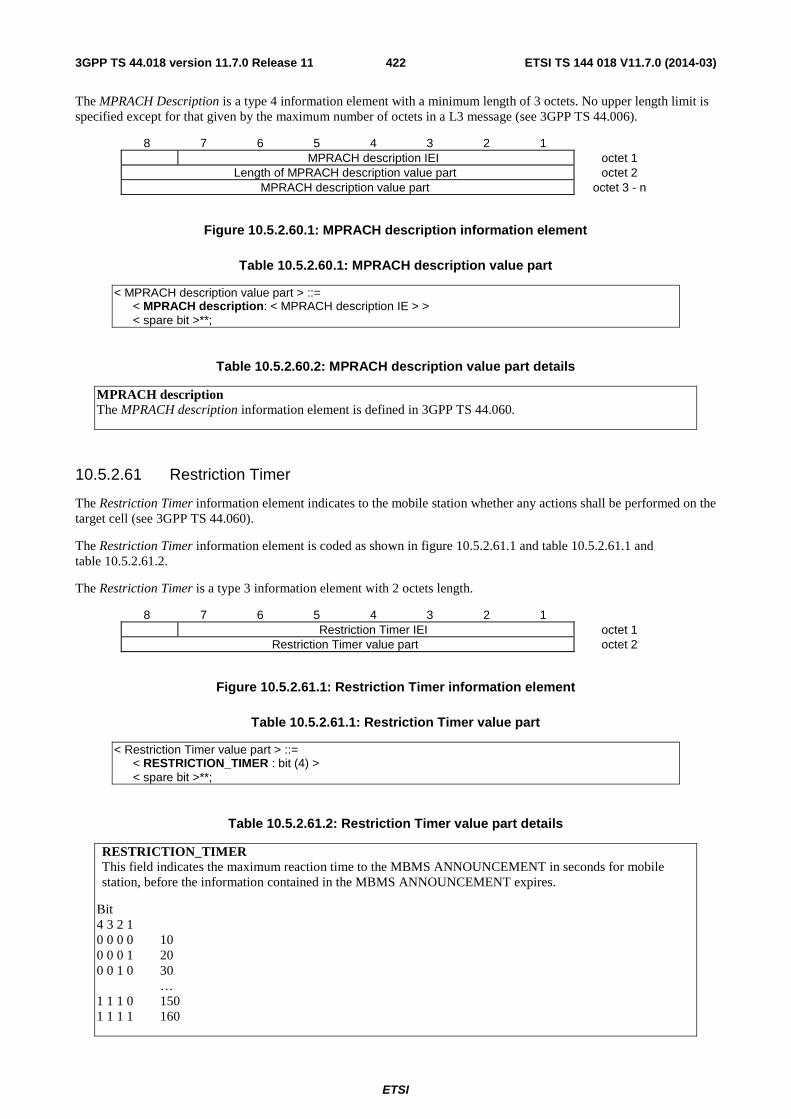
ETSI
ETSI TS 144 018 V11.7.0 (2014-03)4223GPP TS 44.018 version 11.7.0 Release 11
The MPRACH Description is a type 4 information element with a minimum length of 3 octets. No upper length limit is specified except for that given by the maximum number of octets in a L3 message (see 3GPP TS 44.006).
8 7 6 5 4 3 2 1 MPRACH description IEI octet 1
Length of MPRACH description value part octet 2 MPRACH description value part octet 3 - n
Figure 10.5.2.60.1: MPRACH description information element
Table 10.5.2.60.1: MPRACH description value part
< MPRACH description value part > ::= < MPRACH description: < MPRACH description IE > > < spare bit >**;
Table 10.5.2.60.2: MPRACH description value part details
MPRACH description The MPRACH description information element is defined in 3GPP TS 44.060.
10.5.2.61 Restriction Timer
The Restriction Timer information element indicates to the mobile station whether any actions shall be performed on the target cell (see 3GPP TS 44.060).
The Restriction Timer information element is coded as shown in figure 10.5.2.61.1 and table 10.5.2.61.1 and table 10.5.2.61.2.
The Restriction Timer is a type 3 information element with 2 octets length.
8 7 6 5 4 3 2 1 Restriction Timer IEI octet 1
Restriction Timer value part octet 2
Figure 10.5.2.61.1: Restriction Timer information element
Table 10.5.2.61.1: Restriction Timer value part
< Restriction Timer value part > ::= < RESTRICTION_TIMER : bit (4) > < spare bit >**;
Table 10.5.2.61.2: Restriction Timer value part details
RESTRICTION_TIMER This field indicates the maximum reaction time to the MBMS ANNOUNCEMENT in seconds for mobile station, before the information contained in the MBMS ANNOUNCEMENT expires.
Bit 4 3 2 1 0 0 0 0 10 0 0 0 1 20 0 0 1 0 30 … 1 1 1 0 150 1 1 1 1 160
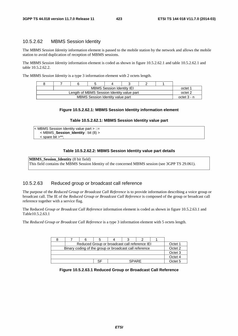
ETSI
ETSI TS 144 018 V11.7.0 (2014-03)4233GPP TS 44.018 version 11.7.0 Release 11
10.5.2.62 MBMS Session Identity
The MBMS Session Identity information element is passed to the mobile station by the network and allows the mobile station to avoid duplication of reception of MBMS sessions.
The MBMS Session Identity information element is coded as shown in figure 10.5.2.62.1 and table 10.5.2.62.1 and table 10.5.2.62.2.
The MBMS Session Identity is a type 3 information element with 2 octets length.
8 7 6 5 4 3 2 1 MBMS Session Identity IEI octet 1
Length of MBMS Session Identity value part octet 2 MBMS Session Identity value part octet 3 - n
Figure 10.5.2.62.1: MBMS Session Identity information element
Table 10.5.2.62.1: MBMS Session Identity value part
< MBMS Session Identity value part > ::= < MBMS_Session_Identity : bit (8) > < spare bit >**;
Table 10.5.2.62.2: MBMS Session Identity value part details
MBMS_Session_Identity (8 bit field) This field contains the MBMS Session Identity of the concerned MBMS session (see 3GPP TS 29.061).
10.5.2.63 Reduced group or broadcast call reference
The purpose of the Reduced Group or Broadcast Call Reference is to provide information describing a voice group or broadcast call. The IE of the Reduced Group or Broadcast Call Reference is composed of the group or broadcast call reference together with a service flag.
The Reduced Group or Broadcast Call Reference information element is coded as shown in figure 10.5.2.63.1 and Table10.5.2.63.1
The Reduced Group or Broadcast Call Reference is a type 3 information element with 5 octets length.
8 7 6 5 4 3 2 1 Reduced Group or broadcast call reference IEI Octet 1
Binary coding of the group or broadcast call reference Octet 2 Octet 3 Octet 4
SF SPARE Octet 5
Figure 10.5.2.63.1 Reduced Group or Broadcast Call Reference
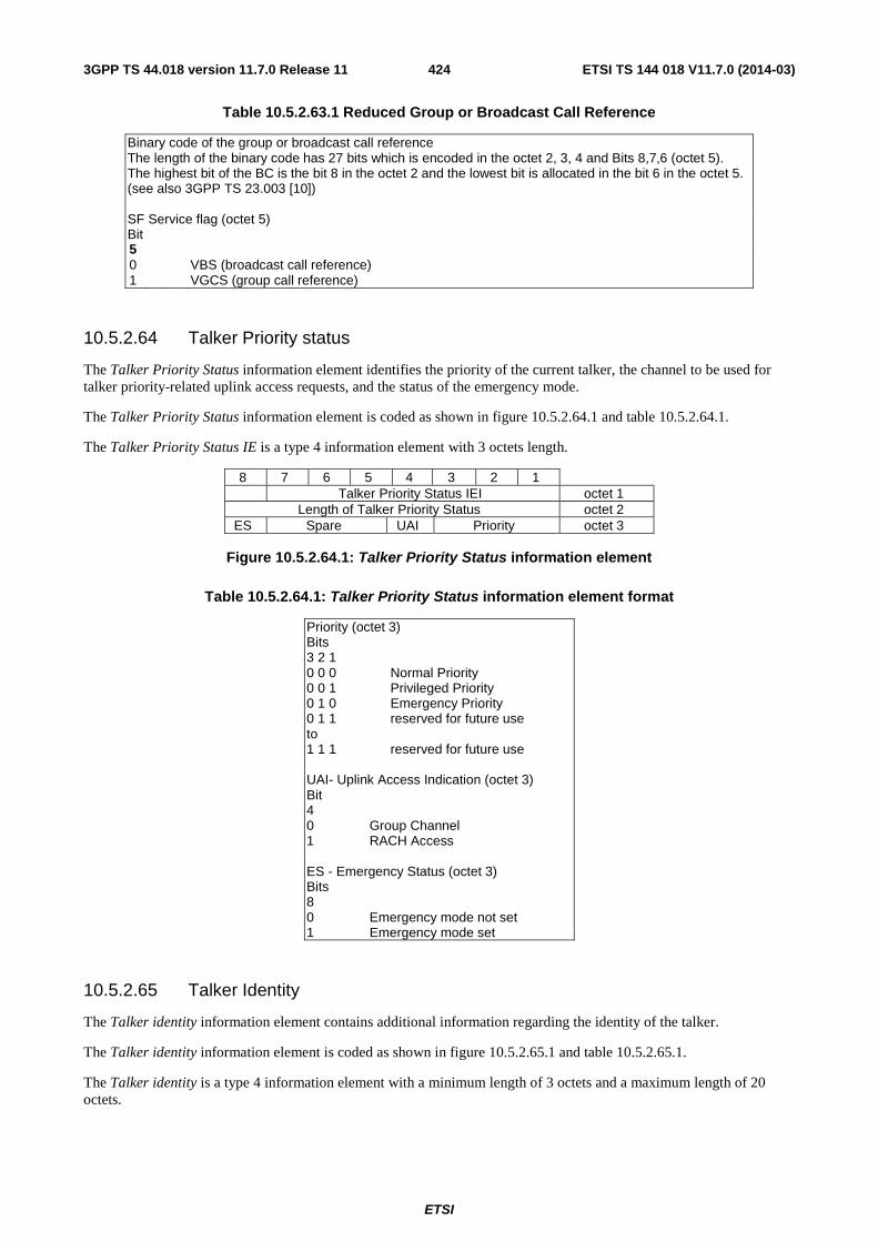
ETSI
ETSI TS 144 018 V11.7.0 (2014-03)4243GPP TS 44.018 version 11.7.0 Release 11
Table 10.5.2.63.1 Reduced Group or Broadcast Call Reference
Binary code of the group or broadcast call reference The length of the binary code has 27 bits which is encoded in the octet 2, 3, 4 and Bits 8,7,6 (octet 5). The highest bit of the BC is the bit 8 in the octet 2 and the lowest bit is allocated in the bit 6 in the octet 5. (see also 3GPP TS 23.003 [10]) SF Service flag (octet 5) Bit 5 0 VBS (broadcast call reference) 1 VGCS (group call reference)
10.5.2.64 Talker Priority status
The Talker Priority Status information element identifies the priority of the current talker, the channel to be used for talker priority-related uplink access requests, and the status of the emergency mode.
The Talker Priority Status information element is coded as shown in figure 10.5.2.64.1 and table 10.5.2.64.1.
The Talker Priority Status IE is a type 4 information element with 3 octets length.
8 7 6 5 4 3 2 1 Talker Priority Status IEI octet 1
Length of Talker Priority Status octet 2 ES Spare UAI Priority octet 3
Figure 10.5.2.64.1: Talker Priority Status information element
Table 10.5.2.64.1: Talker Priority Status information element format
Priority (octet 3) Bits 3 2 1 0 0 0 Normal Priority 0 0 1 Privileged Priority 0 1 0 Emergency Priority 0 1 1 reserved for future use to 1 1 1 reserved for future use UAI- Uplink Access Indication (octet 3) Bit 4 0 Group Channel 1 RACH Access ES - Emergency Status (octet 3) Bits 8 0 Emergency mode not set 1 Emergency mode set
10.5.2.65 Talker Identity
The Talker identity information element contains additional information regarding the identity of the talker.
The Talker identity information element is coded as shown in figure 10.5.2.65.1 and table 10.5.2.65.1.
The Talker identity is a type 4 information element with a minimum length of 3 octets and a maximum length of 20 octets.
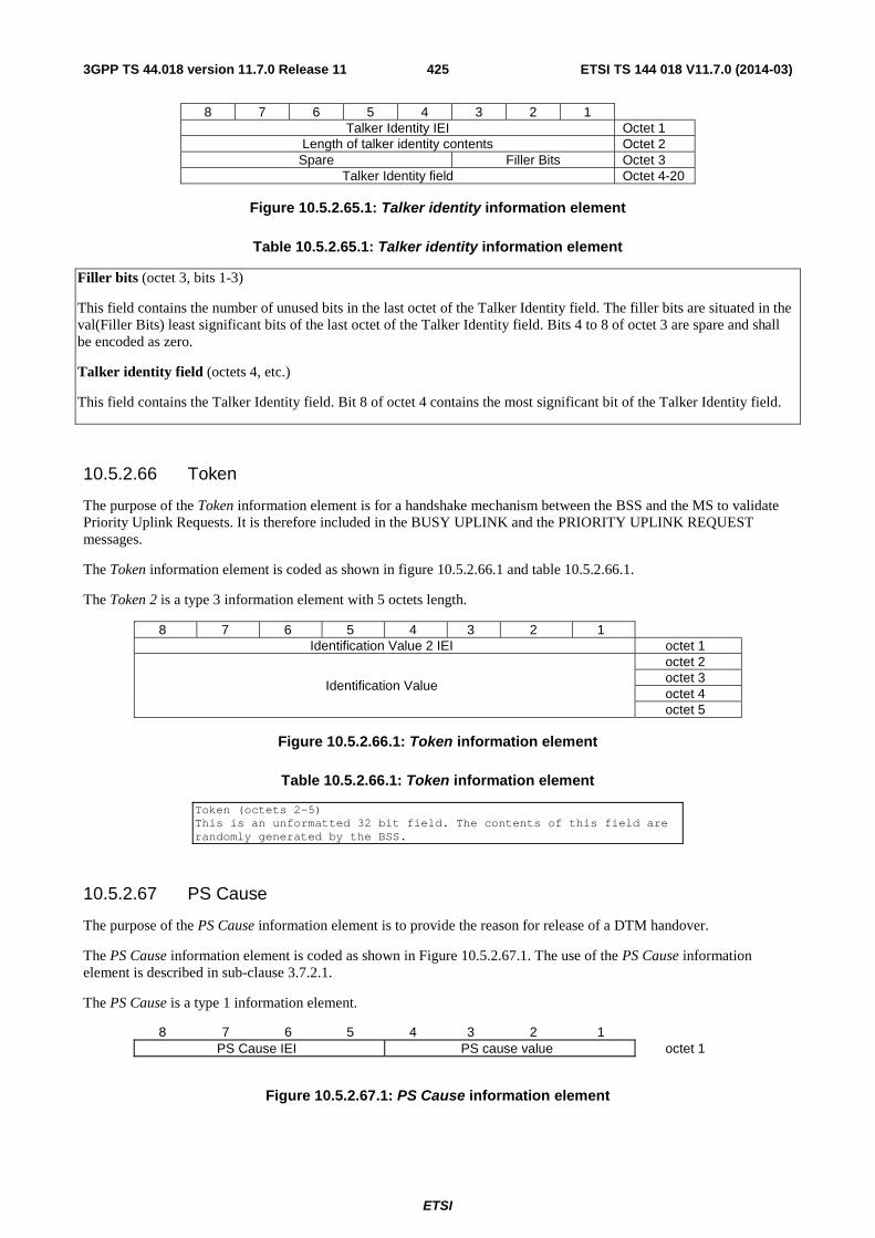
ETSI
ETSI TS 144 018 V11.7.0 (2014-03)4253GPP TS 44.018 version 11.7.0 Release 11
8 7 6 5 4 3 2 1 Talker Identity IEI Octet 1
Length of talker identity contents Octet 2 Spare Filler Bits Octet 3
Talker Identity field Octet 4-20
Figure 10.5.2.65.1: Talker identity information element
Table 10.5.2.65.1: Talker identity information element
Filler bits (octet 3, bits 1-3)
This field contains the number of unused bits in the last octet of the Talker Identity field. The filler bits are situated in the val(Filler Bits) least significant bits of the last octet of the Talker Identity field. Bits 4 to 8 of octet 3 are spare and shall be encoded as zero.
Talker identity field (octets 4, etc.)
This field contains the Talker Identity field. Bit 8 of octet 4 contains the most significant bit of the Talker Identity field.
10.5.2.66 Token
The purpose of the Token information element is for a handshake mechanism between the BSS and the MS to validate Priority Uplink Requests. It is therefore included in the BUSY UPLINK and the PRIORITY UPLINK REQUEST messages.
The Token information element is coded as shown in figure 10.5.2.66.1 and table 10.5.2.66.1.
The Token 2 is a type 3 information element with 5 octets length.
8 7 6 5 4 3 2 1 Identification Value 2 IEI octet 1
Identification Value
octet 2 octet 3 octet 4 octet 5
Figure 10.5.2.66.1: Token information element
Table 10.5.2.66.1: Token information element
Token (octets 2-5) This is an unformatted 32 bit field. The contents of this field are randomly generated by the BSS.
10.5.2.67 PS Cause
The purpose of the PS Cause information element is to provide the reason for release of a DTM handover.
The PS Cause information element is coded as shown in Figure 10.5.2.67.1. The use of the PS Cause information element is described in sub-clause 3.7.2.1.
The PS Cause is a type 1 information element.
8 7 6 5 4 3 2 1 PS Cause IEI PS cause value octet 1
Figure 10.5.2.67.1: PS Cause information element
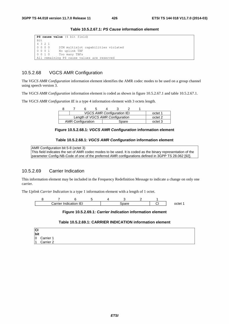
ETSI
ETSI TS 144 018 V11.7.0 (2014-03)4263GPP TS 44.018 version 11.7.0 Release 11
Table 10.5.2.67.1: PS Cause information element
PS cause value (4 bit field) Bit 4 3 2 1 0 0 0 0 DTM multislot capabilities violated 0 0 0 1 No uplink TBF 0 0 1 0 Too many TBFs All remaining PS cause values are reserved
10.5.2.68 VGCS AMR Configuration
The VGCS AMR Configuration information element identifies the AMR codec modes to be used on a group channel using speech version 3.
The VGCS AMR Configuration information element is coded as shown in figure 10.5.2.67.1 and table 10.5.2.67.1.
The VGCS AMR Configuration IE is a type 4 information element with 3 octets length.
8 7 6 5 4 3 2 1 VGCS AMR Configuration IEI octet 1
Length of VGCS AMR Configuration octet 2 AMR Configuration Spare octet 3
Figure 10.5.2.68.1: VGCS AMR Configuration information element
Table 10.5.2.68.1: VGCS AMR Configuration information element
AMR Configuration bit 5-8 (octet 3) This field indicates the set of AMR codec modes to be used. It is coded as the binary representation of the parameter Config-NB-Code of one of the preferred AMR configurations defined in 3GPP TS 28.062 [92].
10.5.2.69 Carrier Indication
This information element may be included in the Frequency Redefinition Message to indicate a change on only one carrier.
The Uplink Carrier Indication is a type 1 information element with a length of 1 octet.
8 7 6 5 4 3 2 1 Carrier Indication IEI Spare CI octet 1
Figure 10.5.2.69.1: Carrier Indication information element
Table 10.5.2.69.1: CARRIER INDICATION information element
CI bit 0 Carrier 1 1 Carrier 2
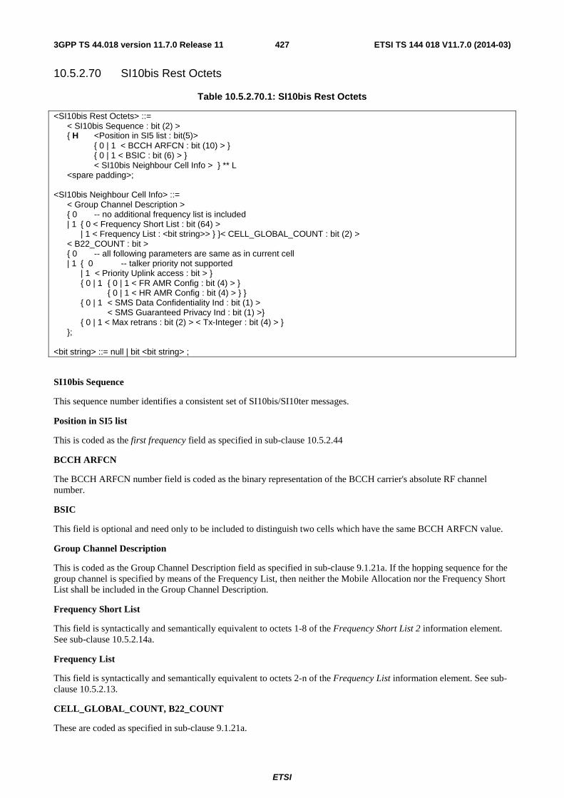
ETSI
ETSI TS 144 018 V11.7.0 (2014-03)4273GPP TS 44.018 version 11.7.0 Release 11
10.5.2.70 SI10bis Rest Octets
Table 10.5.2.70.1: SI10bis Rest Octets
<SI10bis Rest Octets> ::= < SI10bis Sequence : bit (2) > { H <Position in SI5 list : bit(5)> { 0 | 1 < BCCH ARFCN : bit (10) > } { 0 | 1 < BSIC : bit (6) > } < SI10bis Neighbour Cell Info > } ** L <spare padding>;
<SI10bis Neighbour Cell Info> ::=
< Group Channel Description > { 0 -- no additional frequency list is included | 1 { 0 < Frequency Short List : bit (64) > | 1 < Frequency List : <bit string>> } }< CELL_GLOBAL_COUNT : bit (2) > < B22_COUNT : bit > { 0 -- all following parameters are same as in current cell | 1 { 0 -- talker priority not supported | 1 < Priority Uplink access : bit > }
{ 0 | 1 { 0 | 1 < FR AMR Config : bit (4) > } { 0 | 1 < HR AMR Config : bit (4) > } } { 0 | 1 < SMS Data Confidentiality Ind : bit (1) > < SMS Guaranteed Privacy Ind : bit (1) >} { 0 | 1 < Max retrans : bit (2) > < Tx-Integer : bit (4) > } }; <bit string> ::= null | bit <bit string> ;
SI10bis Sequence
This sequence number identifies a consistent set of SI10bis/SI10ter messages.
Position in SI5 list
This is coded as the first frequency field as specified in sub-clause 10.5.2.44
BCCH ARFCN
The BCCH ARFCN number field is coded as the binary representation of the BCCH carrier's absolute RF channel number.
BSIC
This field is optional and need only to be included to distinguish two cells which have the same BCCH ARFCN value.
Group Channel Description
This is coded as the Group Channel Description field as specified in sub-clause 9.1.21a. If the hopping sequence for the group channel is specified by means of the Frequency List, then neither the Mobile Allocation nor the Frequency Short List shall be included in the Group Channel Description.
Frequency Short List
This field is syntactically and semantically equivalent to octets 1-8 of the Frequency Short List 2 information element. See sub-clause 10.5.2.14a.
Frequency List
This field is syntactically and semantically equivalent to octets 2-n of the Frequency List information element. See sub-clause 10.5.2.13.
CELL_GLOBAL_COUNT, B22_COUNT
These are coded as specified in sub-clause 9.1.21a.
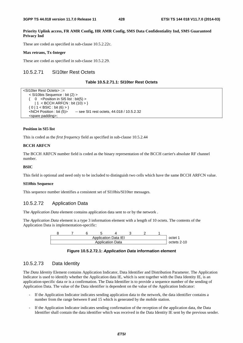
ETSI
ETSI TS 144 018 V11.7.0 (2014-03)4283GPP TS 44.018 version 11.7.0 Release 11
Priority Uplink access, FR AMR Config, HR AMR Config, SMS Data Confidentiality Ind, SMS Guaranteed Privacy Ind
These are coded as specified in sub-clause 10.5.2.22c.
Max retrans, Tx-Integer
These are coded as specified in sub-clause 10.5.2.29.
10.5.2.71 SI10ter Rest Octets
Table 10.5.2.71.1: SI10ter Rest Octets
<SI10ter Rest Octets> ::= < SI10bis Sequence : bit (2) > { 0 <Position in SI5 list : bit(5) > | 1 < BCCH ARFCN : bit (10) > } { 0 | 1 < BSIC : bit (6) > } <NCH Position : bit (5)> -- see SI1 rest octets, 44.018 / 10.5.2.32 <spare padding>;
Position in SI5 list
This is coded as the first frequency field as specified in sub-clause 10.5.2.44
BCCH ARFCN
The BCCH ARFCN number field is coded as the binary representation of the BCCH carrier's absolute RF channel number.
BSIC
This field is optional and need only to be included to distinguish two cells which have the same BCCH ARFCN value.
SI10bis Sequence
This sequence number identifies a consistent set of SI10bis/SI10ter messages.
10.5.2.72 Application Data
The Application Data element contains application data sent to or by the network .
The Application Data element is a type 3 information element with a length of 10 octets. The contents of the Application Data is implementation-specific:
8 7 6 5 4 3 2 1 Application Data IEI octet 1
Application Data octets 2-10
Figure 10.5.2.72.1: Application Data information element
10.5.2.73 Data Identity
The Data Identity Element contains Application Indicator, Data Identifier and Distribution Parameter. The Application Indicator is used to identify whether the Application data IE, which is sent together with the Data Identity IE, is an application-specific data or is a confirmation. The Data Identifier is to provide a sequence number of the sending of Application Data. The value of the Data identifier is dependent on the value of the Application Indicator:
- If the Application Indicator indicates sending application data to the network, the data identifier contains a number from the range between 0 and 15 which is generated by the mobile station.
- If the Application Indicator indicates sending confirmation of the reception of the application data, the Data Identifier shall contain the data identifier which was received in the Data Identity IE sent by the previous sender.
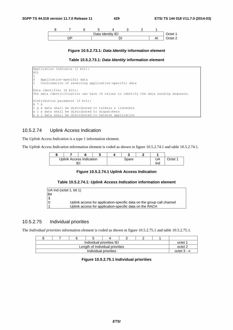
ETSI
ETSI TS 144 018 V11.7.0 (2014-03)4293GPP TS 44.018 version 11.7.0 Release 11
8 7 6 5 4 3 2 1 Data Identity IEI Octet 1
DP DI AI Octet 2
Figure 10.5.2.73.1: Data Identity information element
Table 10.5.2.73.1: Data Identity information element
Application Indicator (1 bit): Bit 1 0 Application-specific data 1 Confirmation of receiving application-specific data Data identifier (4 bit): The data identitification can have 16 values to identify the data sending sequence. Distribution parameter (3 bit): 8 7 6 1 x x data shall be distributed to talkers & listeners x 1 x data shall be distributed to dispatchers x x 1 data shall be distributed to network application
10.5.2.74 Uplink Access Indication
The Uplink Access Indication is a type 1 information element.
The Uplink Access Indication information element is coded as shown in figure 10.5.2.74.1 and table 10.5.2.74.1.
8 7 6 5 4 3 2 1 Uplink Access Indication
IEI Spare UA
Ind Octet 1
Figure 10.5.2.74.1 Uplink Access Indication
Table 10.5.2.74.1: Uplink Access Indication information element
UA Ind (octet 1, bit 1) Bit 1 0 Uplink access for application-specific data on the group call channel 1 Uplink access for application-specific data on the RACH
10.5.2.75 Individual priorities
The Individual priorities information element is coded as shown in figure 10.5.2.75.1 and table 10.5.2.75.1.
8 7 6 5 4 3 2 1 Individual priorities IEI octet 1
Length of Individual priorities octet 2 Individual priorities octet 3 - n
Figure 10.5.2.75.1 Individual priorities
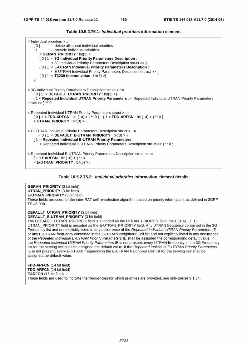
ETSI
ETSI TS 144 018 V11.7.0 (2014-03)4303GPP TS 44.018 version 11.7.0 Release 11
Table 10.5.2.75.1: Individual priorities information element
< Individual priorities > ::= { 0 | -- delete all stored individual priorities 1 -- provide individual priorities < GERAN_PRIORITY : bit(3) > { 0 | 1 < 3G Individual Priority Parameters Description : < 3G Individual Priority Parameters Description struct >> } { 0 | 1 < E-UTRAN Individual Priority Parameters Description : < E-UTRAN Individual Priority Parameters Description struct >> } { 0 | 1 < T3230 timeout value : bit(3) >} };
< 3G Individual Priority Parameters Description struct > ::= { 0 | 1 < DEFAULT_UTRAN_PRIORITY : bit(3) >} { 1 < Repeated Individual UTRAN Priority Parameters : < Repeated Individual UTRAN Priority Parameters struct >> } ** 0 ;
< Repeated Individual UTRAN Priority Parameters struct > ::= { 0 { 1 < FDD-ARFCN : bit (14) > } ** 0 | 1 { 1 < TDD-ARFCN : bit (14) > } ** 0 } < UTRAN_PRIORITY : bit(3) > ;
< E-UTRAN Individual Priority Parameters Description struct > ::= { 0 | 1 < DEFAULT_E-UTRAN_PRIORITY : bit(3) > } { 1 < Repeated Individual E-UTRAN Priority Parameters : < Repeated Individual E-UTRAN Priority Parameters Description struct >> } ** 0 ;
< Repeated Individual E-UTRAN Priority Parameters Description struct > ::= { 1 < EARFCN : bit (16) > } ** 0 < E-UTRAN_PRIORITY : bit(3) > ;
Table 10.5.2.75.2: Individual priorities information element details
GERAN_PRIORITY (3 bit field) UTRAN_PRIORITY (3 bit field) E-UTRAN_PRIORITY (3 bit field) These fields are used for the inter-RAT cell re-selection algorithm based on priority information, as defined in 3GPP TS 45.008. DEFAULT_UTRAN_PRIORITY (3 bit field) DEFAULT_E-UTRAN_PRIORITY (3 bit field) The DEFAULT_UTRAN_PRIORITY field is encoded as the UTRAN_PRIORITY field; the DEFAULT_E-UTRAN_PRIORITY field is encoded as the E-UTRAN_PRIORITY field. Any UTRAN frequency contained in the 3G Frequency list and not explicitly listed in any occurrence of the Repeated Individual UTRAN Priority Parameters IE or any E-UTRAN frequency contained in the E-UTRAN Neighbour Cell list and not explicitly listed in any occurrence of the Repeated Individual E-UTRAN Priority Parameters IE shall be assigned the corresponding default value. If the Repeated Individual UTRAN Priority Parameters IE is not present, every UTRAN frequency in the 3G Frequency list for the serving cell shall be assigned the default value. If the Repeated Individual E-UTRAN Priority Parameters IE is not present, every E-UTRAN frequency in the E-UTRAN Neighbour Cell list for the serving cell shall be assigned the default value. FDD-ARFCN (14 bit field) TDD-ARFCN (14 bit field) EARFCN (16 bit field) These fields are used to indicate the frequencies for which priorities are provided, see sub-clause 9.1.54.
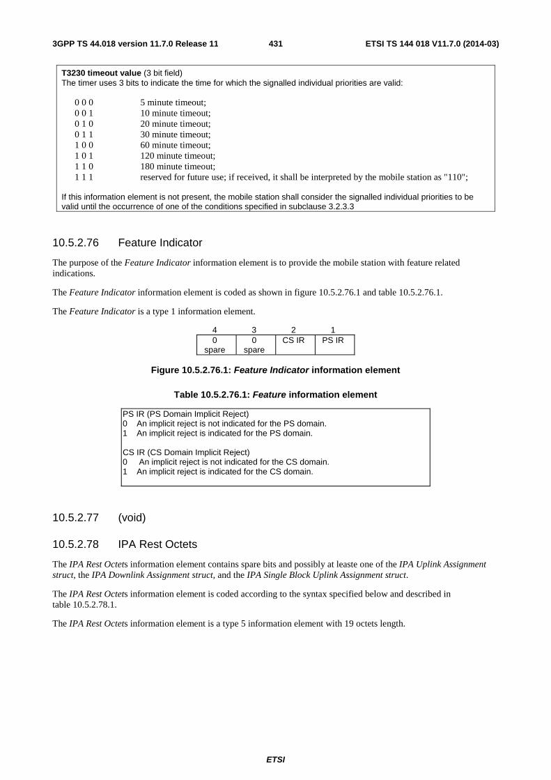
ETSI
ETSI TS 144 018 V11.7.0 (2014-03)4313GPP TS 44.018 version 11.7.0 Release 11
T3230 timeout value (3 bit field) The timer uses 3 bits to indicate the time for which the signalled individual priorities are valid:
0 0 0 5 minute timeout; 0 0 1 10 minute timeout; 0 1 0 20 minute timeout; 0 1 1 30 minute timeout; 1 0 0 60 minute timeout; 1 0 1 120 minute timeout; 1 1 0 180 minute timeout; 1 1 1 reserved for future use; if received, it shall be interpreted by the mobile station as "110";
If this information element is not present, the mobile station shall consider the signalled individual priorities to be valid until the occurrence of one of the conditions specified in subclause 3.2.3.3
10.5.2.76 Feature Indicator
The purpose of the Feature Indicator information element is to provide the mobile station with feature related indications.
The Feature Indicator information element is coded as shown in figure 10.5.2.76.1 and table 10.5.2.76.1.
The Feature Indicator is a type 1 information element.
4 3 2 1 0
spare 0
spare CS IR PS IR
Figure 10.5.2.76.1: Feature Indicator information element
Table 10.5.2.76.1: Feature information element
PS IR (PS Domain Implicit Reject) 0 An implicit reject is not indicated for the PS domain. 1 An implicit reject is indicated for the PS domain. CS IR (CS Domain Implicit Reject) 0 An implicit reject is not indicated for the CS domain. 1 An implicit reject is indicated for the CS domain.
10.5.2.77 (void)
10.5.2.78 IPA Rest Octets
The IPA Rest Octets information element contains spare bits and possibly at leaste one of the IPA Uplink Assignment struct, the IPA Downlink Assignment struct, and the IPA Single Block Uplink Assignment struct.
The IPA Rest Octets information element is coded according to the syntax specified below and described in table 10.5.2.78.1.
The IPA Rest Octets information element is a type 5 information element with 19 octets length.
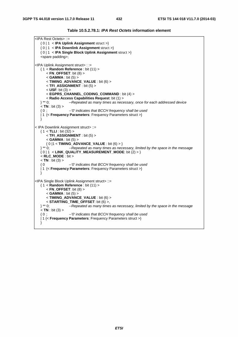
ETSI
ETSI TS 144 018 V11.7.0 (2014-03)4323GPP TS 44.018 version 11.7.0 Release 11
Table 10.5.2.78.1: IPA Rest Octets information element
<IPA Rest Octets> ::= { 0 | 1 < IPA Uplink Assignment struct >} { 0 | 1 < IPA Downlink Assignment struct >} { 0 | 1 < IPA Single Block Uplink Assignment struct >} <spare padding>; <IPA Uplink Assignment struct> : := { 1 < Random Reference : bit (11) > < FN_OFFSET: bit (8) > < GAMMA : bit (5) > < TIMING_ADVANCE_VALUE : bit (6) > < TFI_ASSIGNMENT : bit (5) > < USF: bit (3) > < EGPRS_CHANNEL_CODING_COMMAND : bit (4) > < Radio Access Capabilities Request: bit (1) > } ** 0; --Repeated as many times as necessary, once for each addressed device < TN : bit (3) > { 0 ; --'0' indicates that BCCH frequency shall be used | 1 {< Frequency Parameters: Frequency Parameters struct >} } < IPA Downlink Assignment struct> ::= { 1 < TLLI : bit (32) > < TFI_ASSIGNMENT : bit (5) > < GAMMA : bit (5) > { 0 |1 < TIMING_ADVANCE_VALUE : bit (6) > } } ** 0; --Repeated as many times as necessary, limited by the space in the message { 0 | 1 < LINK_QUALITY_MEASUREMENT_MODE: bit (2) > } < RLC_MODE : bit > < TN : bit (3) > { 0 --'0' indicates that BCCH frequency shall be used | 1 {< Frequency Parameters: Frequency Parameters struct >} } <IPA Single Block Uplink Assignment struct> ::= { 1 < Random Reference : bit (11) > < FN_OFFSET: bit (8) > < GAMMA : bit (5) > < TIMING_ADVANCE_VALUE : bit (6) > < STARTING_TIME_OFFSET: bit (6) >, } ** 0; --Repeated as many times as necessary, limited by the space in the message < TN : bit (3) > { 0 ; --'0' indicates that BCCH frequency shall be used | 1 {< Frequency Parameters: Frequency Parameters struct >} }
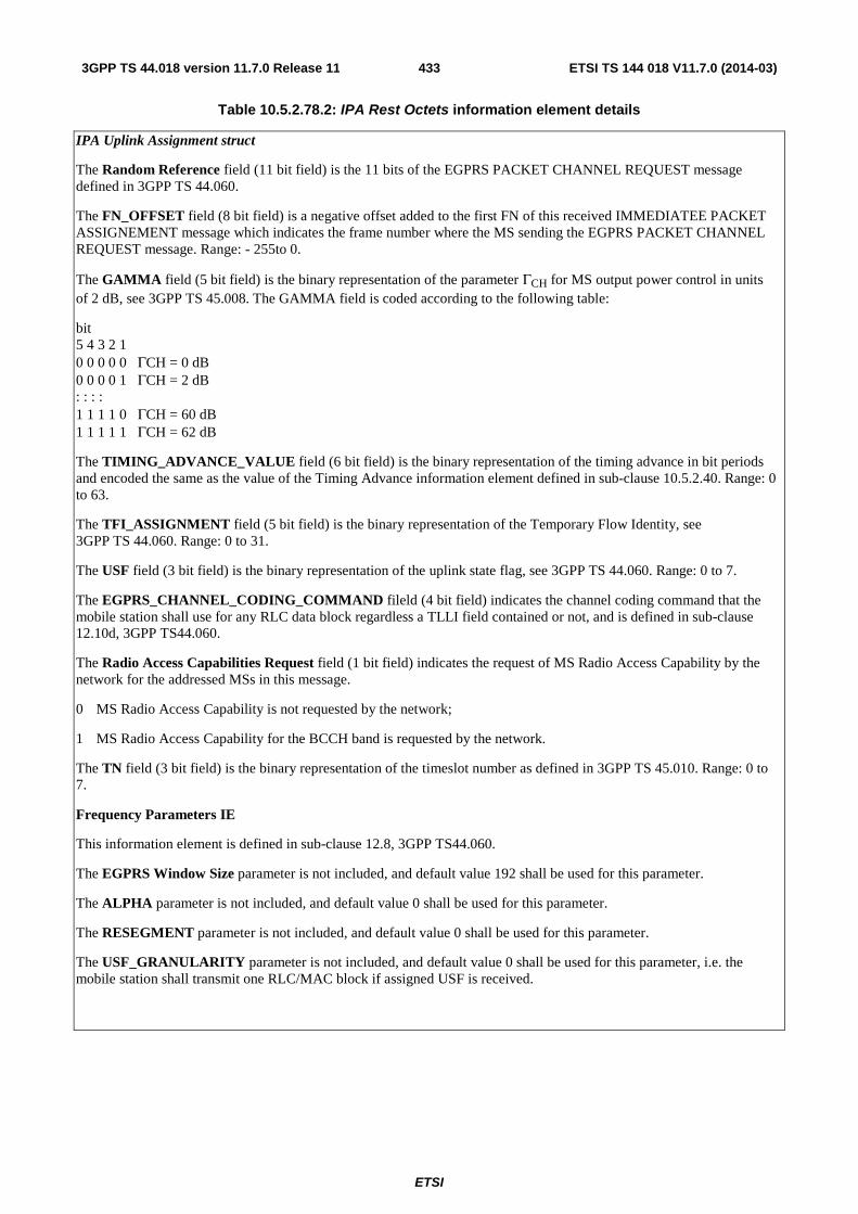
ETSI
ETSI TS 144 018 V11.7.0 (2014-03)4333GPP TS 44.018 version 11.7.0 Release 11
Table 10.5.2.78.2: IPA Rest Octets information element details
IPA Uplink Assignment struct
The Random Reference field (11 bit field) is the 11 bits of the EGPRS PACKET CHANNEL REQUEST message defined in 3GPP TS 44.060.
The FN_OFFSET field (8 bit field) is a negative offset added to the first FN of this received IMMEDIATEE PACKET ASSIGNEMENT message which indicates the frame number where the MS sending the EGPRS PACKET CHANNEL REQUEST message. Range: - 255to 0.
The GAMMA field (5 bit field) is the binary representation of the parameter ΓCH for MS output power control in units of 2 dB, see 3GPP TS 45.008. The GAMMA field is coded according to the following table:
bit 5 4 3 2 1 0 0 0 0 0 ΓCH = 0 dB 0 0 0 0 1 ΓCH = 2 dB : : : : 1 1 1 1 0 ΓCH = 60 dB 1 1 1 1 1 ΓCH = 62 dB
The TIMING_ADVANCE_VALUE field (6 bit field) is the binary representation of the timing advance in bit periods and encoded the same as the value of the Timing Advance information element defined in sub-clause 10.5.2.40. Range: 0 to 63.
The TFI_ASSIGNMENT field (5 bit field) is the binary representation of the Temporary Flow Identity, see 3GPP TS 44.060. Range: 0 to 31.
The USF field (3 bit field) is the binary representation of the uplink state flag, see 3GPP TS 44.060. Range: 0 to 7.
The EGPRS_CHANNEL_CODING_COMMAND fileld (4 bit field) indicates the channel coding command that the mobile station shall use for any RLC data block regardless a TLLI field contained or not, and is defined in sub-clause 12.10d, 3GPP TS44.060.
The Radio Access Capabilities Request field (1 bit field) indicates the request of MS Radio Access Capability by the network for the addressed MSs in this message.
0 MS Radio Access Capability is not requested by the network;
1 MS Radio Access Capability for the BCCH band is requested by the network.
The TN field (3 bit field) is the binary representation of the timeslot number as defined in 3GPP TS 45.010. Range: 0 to 7.
Frequency Parameters IE
This information element is defined in sub-clause 12.8, 3GPP TS44.060.
The EGPRS Window Size parameter is not included, and default value 192 shall be used for this parameter.
The ALPHA parameter is not included, and default value 0 shall be used for this parameter.
The RESEGMENT parameter is not included, and default value 0 shall be used for this parameter.
The USF_GRANULARITY parameter is not included, and default value 0 shall be used for this parameter, i.e. the mobile station shall transmit one RLC/MAC block if assigned USF is received.
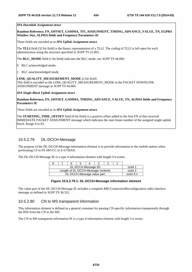
ETSI
ETSI TS 144 018 V11.7.0 (2014-03)4343GPP TS 44.018 version 11.7.0 Release 11
IPA Downlink Assignment struct
Random Reference, FN_OFFSET, GAMMA, TFI_ASSIGNMENT, TIMING_ADVANCE_VALUE, TN, EGPRS Window Size, ALPHA fields and Frequency Parameters IE
These fields are encoded as in IPA Uplink Assignment struct.
The TLLI field (32 bit field) is the binary representation of a TLLI. The coding of TLLI is left open for each administration using the structure specified in 3GPP TS 23.003.
The RLC_MODE field (1 bit field) indicates the RLC mode, see 3GPP TS 44.060:
0 RLC acknowledged mode;
1 RLC unacknowledged mode.
LINK_QUALITY_MEASUREMENT_MODE (2 bit field) This field is encoded as the LINK_QUALITY_MEASUREMENT_MODE in the PACKET DOWNLINK ASSIGNMENT message in 3GPP TS 44.060.
IPA Single Block Uplink Assignment struct
Random Reference, FN_OFFSET, GAMMA, TIMING_ADVANCE_VALUE, TN, ALPHA fields and Frequency Parameters IE
These fields are encoded as in IPA Uplink Assignment struct.
The STARTING_TIME_OFFSET field (6 bit field) is a positive offset added to the first FN of this received IMMEDIATE PACKET ASSIGNMENT message which indicates the start frame number of the assigned single uplink block. Range 0 to 63.
10.5.2.79 DL-DCCH-Message
The purpose of the DL-DCCH-Message information element is to provide information to the mobile station when performing CS to PS SRVCC to E-UTRAN.
The DL-DCCH-Message IE is a type 4 information element with length 3-n octets.
8 7 6 5 4 3 2 1 DL-DCCH-Message IEI octet 1
Length of DL-DCCH-Message contents octet 2 DL-DCCH-Message value part octet 3-n
Figure 10.5.2.79.1: DL-DCCH-Message information element
The value part of the DL-DCCH-Message IE includes a complete RRCConnectionReconfiguration radio interface message as defined in 3GPP TS 36.331.
10.5.2.80 CN to MS transparent information
This information element is defined as a general container for passing CN specific information transparently through the BSS from the CN to the MS.
The CN to MS transparent information IE is a type 4 information element with length 3-n octets.
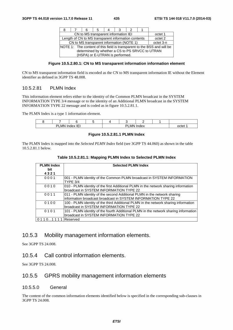
ETSI
ETSI TS 144 018 V11.7.0 (2014-03)4353GPP TS 44.018 version 11.7.0 Release 11
8 7 6 5 4 3 2 1 CN to MS transparent information IEI octet 1
Length of CN to MS transparent information contents octet 2 CN to MS transparent information (NOTE 1) octet 3-n
NOTE 1: The content of this field is transparent to the BSS and will be determined by whether a CS to PS SRVCC to UTRAN (HSPA) or E-UTRAN is performed.
Figure 10.5.2.80.1: CN to MS transparent information information element
CN to MS transparent information field is encoded as the CN to MS transparent information IE without the Element identifier as defined in 3GPP TS 48.008.
10.5.2.81 PLMN Index
This information element refers either to the identity of the Common PLMN broadcast in the SYSTEM INFORMATION TYPE 3/4 message or to the identity of an Additional PLMN broadcast in the SYSTEM INFORMATION TYPE 22 message and is coded as in figure 10.5.2.81.1.
The PLMN Index is a type 1 information element.
8 7 6 5 4 3 2 1 PLMN Index IEI PLMN Index octet 1
Figure 10.5.2.81.1 PLMN Index
The PLMN Index is mapped into the Selected PLMN Index field (see 3GPP TS 44.060) as shown in the table 10.5.2.81.1 below.
Table 10.5.2.81.1: Mapping PLMN Index to Selected PLMN Index
PLMN Index bit
4 3 2 1
Selected PLMN Index
0 0 0 1 001 - PLMN identity of the Common PLMN broadcast in SYSTEM INFORMATION TYPE 3/4
0 0 1 0 010 - PLMN identity of the first Additional PLMN in the network sharing information broadcast in SYSTEM INFORMATION TYPE 22
0 0 1 1 011 - PLMN identity of the second Additional PLMN in the network sharing information broadcast broadcast in SYSTEM INFORMATION TYPE 22
0 1 0 0 100 - PLMN identity of the third Additional PLMN in the network sharing information broadcast in SYSTEM INFORMATION TYPE 22
0 1 0 1 101 - PLMN identity of the fourth Additional PLMN in the network sharing information broadcast in SYSTEM INFORMATION TYPE 22
0 1 1 0…1 1 1 1 Reserved
10.5.3 Mobility management information elements.
See 3GPP TS 24.008.
10.5.4 Call control information elements.
See 3GPP TS 24.008.
10.5.5 GPRS mobility management information elements
10.5.5.0 General
The content of the common information elements identified below is specified in the corresponding sub-clauses in 3GPP TS 24.008.
ETSI
ETSI TS 144 018 V11.7.0 (2014-03)4363GPP TS 44.018 version 11.7.0 Release 11
10.5.5.1 (void)
10.5.5.2 (void)
10.5.5.3 (void)
10.5.5.4 (void)
10.5.5.5 (void)
10.5.5.6 (void)
10.5.5.7 (void)
10.5.5.8 (void)
10.5.5.8a (void)
10.5.5.9 (void)
10.5.5.10 (void)
10.5.5.11 (void)
10.5.5.12 (void)
10.5.5.12a (void)
10.5.5.13 (void)
10.5.5.14 (void)
10.5.5.15 Routing area identification
See 3GPP TS 24.008.
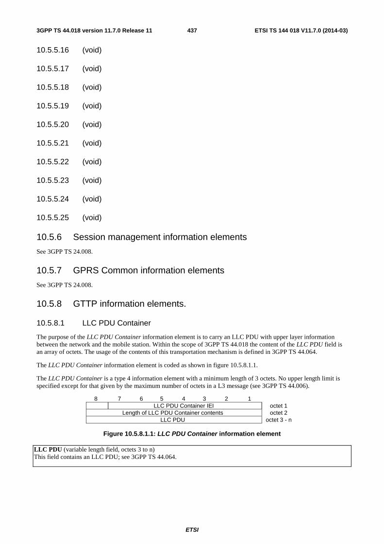
ETSI
ETSI TS 144 018 V11.7.0 (2014-03)4373GPP TS 44.018 version 11.7.0 Release 11
10.5.5.16 (void)
10.5.5.17 (void)
10.5.5.18 (void)
10.5.5.19 (void)
10.5.5.20 (void)
10.5.5.21 (void)
10.5.5.22 (void)
10.5.5.23 (void)
10.5.5.24 (void)
10.5.5.25 (void)
10.5.6 Session management information elements
See 3GPP TS 24.008.
10.5.7 GPRS Common information elements
See 3GPP TS 24.008.
10.5.8 GTTP information elements.
10.5.8.1 LLC PDU Container
The purpose of the LLC PDU Container information element is to carry an LLC PDU with upper layer information between the network and the mobile station. Within the scope of 3GPP TS 44.018 the content of the LLC PDU field is an array of octets. The usage of the contents of this transportation mechanism is defined in 3GPP TS 44.064.
The LLC PDU Container information element is coded as shown in figure 10.5.8.1.1.
The LLC PDU Container is a type 4 information element with a minimum length of 3 octets. No upper length limit is specified except for that given by the maximum number of octets in a L3 message (see 3GPP TS 44.006).
8 7 6 5 4 3 2 1 LLC PDU Container IEI octet 1
Length of LLC PDU Container contents octet 2 LLC PDU octet 3 - n
Figure 10.5.8.1.1: LLC PDU Container information element
LLC PDU (variable length field, octets 3 to n) This field contains an LLC PDU; see 3GPP TS 44.064.
ETSI
ETSI TS 144 018 V11.7.0 (2014-03)4383GPP TS 44.018 version 11.7.0 Release 11
11 List of system parameters The description of timers in the following table should be considered a brief summary. The precise details are found in clauses 3 to 6, which should be considered the definitive descriptions.
11.1 Timers and counters for radio resource management
11.1.1 Timers on the mobile station side
T3110: This timer is used to delay the channel deactivation after the receipt of a (full) CHANNEL RELEASE. Its purpose is to let some time for disconnection of the main signalling link.
Its value is set to such that the DISC frame is sent twice in case of no answer from the network. (It should be chosen to obtain a good probability of normal termination (i.e. no time out of T3109) of the channel release procedure.)
T3112 The timer is used by a VGCS mobile when receiving segmented RP-Data message on the SACCH. The timer is started when receiving the first segment of a segmented RP-Data message for a group call that the MS is a member of, for which no previous segment has been received.
It is stopped in the following situations:
- The MS receives the complete RP-Data message
- The MS discards the message as a result of timer T3114 expiring for some other message
- The MS deletes the segment(s) (with SMS reference number n) because it has received a segment with a SMS reference number which is more than 4 higher (modulo 16) than that of the message corresponding to this timer
- The MS changes its channel
- The voice group call is cleared
The value of the timer is 20 seconds.
T3114 The timer is used by a VGCS mobile when receiving a complete RP-Data message on the SACCH that is not the next in sequence message that is to be sent to the upper layer.
It is stopped in the following situations:
- The MS delivers the RP-Data message to the upper layer
- The MS changes its channel
- The voice group call is cleared
The value of the timer is 10 seconds.
T3122: This timer is used during random access or during dedicated channel assignment while in packet transfer mode, after the receipt of an IMMEDIATE ASSIGN REJECT message.
Its value is given by the network in the IMMEDIATE ASSIGN REJECT message.
T3124: This timer is used in the seizure procedure during a hand-over, when the two cells are not synchronized.
Its purpose is to detect the lack of answer from the network to the special signal.
Its value is set to 675 ms if the channel type of the channel allocated in the HANDOVER COMMAND is an SDCCH (+ SACCH); otherwise its value is set to 320 ms.
T3126: This timer is started either

ETSI
ETSI TS 144 018 V11.7.0 (2014-03)4393GPP TS 44.018 version 11.7.0 Release 11
after sending the maximum allowed number of CHANNEL REQUEST messages or EGPRS PACKET CHANNEL REQUEST messages during an immediate assignment procedure,
or
on receipt of an IMMEDIATE ASSIGNMENT REJECT message,
or
when a mobile station configured for NAS signalling low priority has initiated the immediate assignment procedure, sent one or more CHANNEL REQUEST messages and received an implicit reject for the CS domain (see sub-clause 3.3.1.1.2),
whichever occurs first.
It is stopped at receipt of an IMMEDIATE ASSIGNMENT message, an IMMEDIATE ASSIGNMENT EXTENDED message, or an IMMEDIATE PACKET ASSIGNMENT message (if supported).
At its expiry, the immediate assignment procedure is aborted and the mobile station proceeds as described in sub-clause 3.3.1.1.2 or the Implicit Reject procedure is completed as described in sub-clause 3.3.1.1.3.2a.
The minimum value of this timer is equal to the time taken by T+2S slots of the mobile station's RACH. S and T are defined in sub-clause 3.3.1.2. The maximum value of this timer is 5 seconds.
T3128: This timer is started when the mobile station starts the uplink investigation procedure and the uplink is busy.
It is stopped at receipt of the first UPLINK FREE message.
At its expiry, the uplink investigation procedure is aborted.
The value of this timer is set to 1 second.
T3130: This timer is started after sending the first UPLINK ACCESS message during a VGCS uplink access procedure, or sending the first PRIORITY UPLINK REQUEST message during a VGCS priority uplink request procedure.
It is stopped at receipt of a VGCS UPLINK GRANT message.
It may be started a maximum of 3 times. On expiry of timer T3130 for the third time a rejection of the uplink request is indicated to the upper layers.
The value of this timer is set to 5 seconds.
T3142: The timer is used during packet access on CCCH and during packet access while in dedicated mode. It is started after the receipt of an IMMEDIATE ASSIGNMENT REJECT or a DTM REJECT message.
Its value is given by the network in the IMMEDIATE ASSIGNMENT REJECT or DTM REJECT message.
T3146: This timer is started either
after sending the maximum allowed number of CHANNEL REQUEST or EGPRS PACKET CHANNEL REQUEST messages during a packet access procedure.
or
on receipt of an IMMEDIATE ASSIGNMENT REJECT message during a packet access procedure,
or

ETSI
ETSI TS 144 018 V11.7.0 (2014-03)4403GPP TS 44.018 version 11.7.0 Release 11
a mobile station configured for NAS signalling low priority has initiated the packet access procedure, has sent one or more CHANNEL REQUEST or EGPRS PACKET CHANNEL REQUEST messages and received an implicit reject for the PS domain (see sub-clause 3.5.2.1.2),
whichever occurs first.
It is stopped at receipt of an IMMEDIATE ASSIGNMENT message, an IMMEDIATE ASSIGNMENT EXTENDED message, or an IMMEDIATE PACKET ASSIGNMENT message (if supported).
At its expiry, the packet access procedure is aborted and the mobile station proceeds as described in sub-clause 3.5.2.1.2 or the Implicit Reject procedure is completed as described in sub-clause 3.3.1.1.3.2a.
The minimum value of this timer is equal to the time taken by T+2S slots of the mobile station's RACH. S and T are defined in sub-clause 3.3.1.2. The maximum value of this timer is 5 seconds.
T3148: This timer is used during DTM establishment in dedicated mode.
It is started after sending a DTM REQUEST message during a packet access procedure while in dedicated mode.
It is stopped at the receipt of one of the following messages:
- DTM ASSIGNMENT COMMAND;
- PACKET ASSIGNMENT;
- DTM REJECT;
- ASSIGNMENT COMMAND;
- HANDOVER COMMAND.
At its expiry, the packet access procedure is aborted.
Its value is 4 seconds.
T3164: This timer is used during packet access using CCCH. It is started at the receipt of an IMMEDIATE ASSIGNMENT message or an IMMEDIATE PACKET ASSIGNMENT message (if supported).
It is stopped at the transmission of a RLC/MAC block on the assigned temporary block flow, see 3GPP TS 44.060.
At expire, the mobile station returns to the packet idle mode.
The value of the timer is 5 seconds.
T3190: The timer is used during packet downlink assignment on CCCH. It is started at the receipt of an IMMEDIATE ASSIGNMENT message or an IMMEDIATE PACKET ASSIGNMENT message (if supported) when in dedicated mode.
It is stopped at the receipt of a RLC/MAC block on the assigned temporary block flow, see 3GPP TS 44.060.
At expiry, the mobile station returns to the packet idle mode.
The value of the timer is 5 seconds.
T3204: This timer is used by a mobile station with non-GSM capabilities. The timer is started after sending the first CHANNEL REQUEST during a packet access procedure. The CHANNEL REQUEST was sent requesting a single block packet access and the purpose of the packet access procedure is to send a PACKET PAUSE message.
It is stopped at the receipt of an IMMEDIATE ASSIGNMENT message granting a single block period on an assigned packet uplink resource.
ETSI
ETSI TS 144 018 V11.7.0 (2014-03)4413GPP TS 44.018 version 11.7.0 Release 11
At expiry, the packet access procedure is aborted.
The value of the timer is 1 second.
T3206 The timer is used by a VGCS mobile when receiving segmented notifications on the NCH. The timer is started when receiving a segment of a segmented notification for a group call that the MS is a member for which no previous segment has been received.
It is stopped in the following situations:
- The MS receives the second segment
- The MS joins another call
- The value of NLN changes
- The MS reselects to another cell
The value of the timer is 5 second.
T3208 The timer is used by a VGCS mobile when receiving segmented notifications on the FACCH. The timer is started when receiving the first segment of a segmented notification for a group call that the MS is a member for which no previous segment has been received.
It is stopped in the following situations:
- The MS receives the complete message
- The MS joins another call
- The MS performs Handover to another cell
The value of the timer is 1 second.
T3210 The timer is used by a VGCS mobile when receiving segmented notifications on the PCH. The timer is started when receiving the first segment of a segmented notification for a group call that the MS is a member for which no previous segment has been received.
It is stopped in the following situations:
- The MS receives the complete message
- The MS leaves Idle mode
- Notifications for another group call are received on the PCH
The value of the timer is 5 seconds.
T3220 The timer is used by an MBMS capable mobile station when receiving pre-notification of an MBMS session. The timer is started when receiving a PAGING REQUEST message containing an MBMS pre-notification that the mobile station shall receive.
It is stopped at the receipt of a PAGING REQUEST message containing a notification of the same session as when starting this timer, or if any other RR procedure on CCCH not related to MBMS is triggered or a notification is received for a higher priority session while the timer is running.
At expiry, the mobile station returns to DRX mode unless it is engaged in any other MBMS session and then stays in broadcast/multicast receive mode.
The value of the timer is 46 s.
T3222: An instance of the timer may be used by an MBMS capable mobile station in dedicated mode during the notification of MBMS. An instance of this timer may be started at the receipt of an MBMS ANNOUNCEMENT message when in dedicated mode.
The instance of this timer is stopped when the mobile enters packet idle mode.
ETSI
ETSI TS 144 018 V11.7.0 (2014-03)4423GPP TS 44.018 version 11.7.0 Release 11
At expiry of an instance of this timer, the mobile station discards the MBMS related information stored upon receipt of the corresponding MBMS ANNOUNCEMENT message.
The value of the timer is defined in sub-clause 3.4.27.2.3.
T3224: The timer start at on receipt of a VGCS_UPLINK_GRANT message aimed to another mobile station.
It is stopped when the mobile station received an UPLINK BUSY message.
At expiry, the mobile station shall follow the same procedures as for expiry of timer T3130.
The value of the timer is 1 s.
T3230: The timer is used to control the validity period of individual priorities. It is started on receipt of the individual priorities for cell reselection via dedicated signalling or on inter-RAT reselection to GERAN if the corresponding timer in the source RAT (i.e., T320 in E-UTRA, and T322 in UTRA) was running when reselection occurred.
When one of the conditions specified in subclause 3.2.3.3 is met, the MS shall stop T3230 and delete the corresponding individual priorities.
At expiry the mobile station shall delete the corresponding individual priorities.
T3232: The timer is used to control the length of the non-DRX mode period in which the mobile station is acquiring an ETWS Primary Notification message. It is started on receipt of a first PAGING REQUEST TYPE 1 message containing a valid segment of an ETWS Primary Notification message.
It is stopped in the following situations:
- The mobile station receives the complete ETWS Primary Notification message
- Upon initiating cell reselection or connection establishment procedures
The timer is restarted if the mobile station receives an indication of a new ETWS Primary Notification message prior to acquiring a complete ETWS Primary Notification message.
At expiry the mobile station shall discard all segments of the partially received ETWS Primary Notification message and re-enter DRX mode.
The value of the timer is 5 seconds.
T3234: The timer is used to prevent a mobile station configured for NAS signalling low priority from requesting CS resources (see sub-clause 3.3.1.1.3.2a). When a mobile station starts an implicit reject timer it selects a value randomly drawn from a uniform probability distribution within the set {10.0, 10.1, 10.2, …200.0} seconds (inclusive).
It is started when the Implicit Reject procedure is initiated following mobile station reception of an implicit reject indication for the CS domain prior to sending any CHANNEL REQUEST messages on the RACH or when T3126 expires (see sub-clause 3.3.1.1.3.2a).
It is stopped in the following cases:
- The mobile station responds to a PAGING REQUEST message
- The mobile station performs cell re-selection.
At expiry, the mobile station may once again request CS resources.
T3236: The timer is used to prevent a mobile station configured for NAS signalling low priority from requesting PS resources (see sub-clause 3.3.1.1.3.2a). When a mobile station starts an implicit reject timer it selects a value randomly drawn from a uniform probability distribution within the set {10.0, 10.1, 10.2, …200.0} seconds (inclusive).
ETSI
ETSI TS 144 018 V11.7.0 (2014-03)4433GPP TS 44.018 version 11.7.0 Release 11
It is started when the Implicit Reject procedure is initiated following mobile station reception of an implicit reject indication for the PS domain prior to sending any CHANNEL REQUEST or EGPRS PACKET CHANNEL REQUEST messages on the RACH or when T3146 expires (see sub-clause 3.3.1.1.3.2a).
It is stopped in the following cases:
- The mobile station responds to a PAGING REQUEST message
- The mobile station performs cell re-selection.
At expiry, the mobile station may once again request PS resources.
11.1.2 Timers on the network side
T3101: This timer is started when a channel is allocated with an IMMEDIATE ASSIGNMENT message. It is stopped when the MS has correctly seized the channels.
Its value is network dependent.
NOTE 1: It could be higher than the maximum time for a L2 establishment attempt.
T3103: This timer is started by the sending of a HANDOVER message and is normally stopped when the MS has correctly seized the new channel. Its purpose is to keep the old channels sufficiently long for the MS to be able to return to the old channels, and to release the channels if the MS is lost.
Its value is network dependent.
NOTE 2: It could be higher than the maximum transmission time of the HANDOVER COMMAND, plus the value of T3124, plus the maximum duration of an attempt to establish a data link in multiframe mode.)
T3105: This timer is used for the repetition of the PHYSICAL INFORMATION message during the hand-over procedure.
Its value is network dependent.
NOTE 3: This timer may be set to such a low value that the message is in fact continuously transmitted.
T3107: This timer is started by the sending of an ASSIGNMENT COMMAND or a DTM ASSIGNMENT COMMAND message and is normally stopped when the MS has correctly seized the new RR channels.
Its purpose is to release the new channels (and, in the case of Enhanced DTM CS establishment, the old PS resources) if the MS is lost and, except when used for Enhanced DTM CS Establishment, to keep the old channel sufficiently long for the MS to be able to return to the old channels.
Its value is network dependent.
NOTE 4: It could be higher than the maximum transmission time of the ASSIGNMENT COMMAND message plus twice the maximum duration of an attempt to establish a data link multiframe mode.
T3109: This timer is started when a lower layer failure is detected by the network, when it is not engaged in a RF procedure. It is also used in the channel release procedure.
Its purpose is to release the channels in case of loss of communication.
Its value is network dependent.
NOTE 5: Its value should be large enough to ensure that the MS detects a radio link failure.
T3111: This timer is used to delay the channel deactivation after disconnection of the main signalling link. Its purpose is to let some time for possible repetition of the disconnection.
Its value is equal to the value of T3110.
ETSI
ETSI TS 144 018 V11.7.0 (2014-03)4443GPP TS 44.018 version 11.7.0 Release 11
T3113: This timer is started when the network has sent a PAGING REQUEST message and is stopped when the network has received the PAGING RESPONSE message.
Its value is network dependent.
NOTE 6: The value could allow for repetitions of the Channel Request message and the requirements associated with T3101.
T3115: This timer is used for the repetition of the VGCS UPLINK GRANT message during the uplink access procedure or priority uplink request procedure.
Its value is network dependent.
NOTE 7: This timer may be set to such a low value that the message is in fact continuously transmitted.
T3121: This timer is started by the sending of an INTER SYSTEM TO UTRAN HANDOVER COMMAND message or of an INTER SYSTEM TO E-UTRAN HANDOVER COMMAND and is normally stopped when the MS has correctly seized the UTRAN channel(s) or E-UTRAN channel(s). Its purpose is to keep the old channels sufficiently long for the MS to be able to return to the old channels, and to release the channels if the MS is lost.
Its value is network dependent.
T3123: This timer is started by the sending of an INTER SYSTEM TO CDMA2000 HANDOVER COMMAND message and is normally stopped when the MS has correctly seized the CDMA2000 channel(s). Its purpose is to keep the old channels sufficiently long for the MS to be able to return to the old channels, and to release the channels if the MS is lost.
Its value is network dependent.
T3141: This timer is started when a temporary block flow is allocated with an IMMEDIATE ASSIGNMENT or an IMMEDIATE PACKET ASSIGNMENT message during a packet access procedure. It is stopped when the mobile station has correctly seized the temporary block flow.
Its value is network dependent.
T3151: This timer is used by the network to supervise the periodic transmission of the UPLINK BUSY message on the FACCH of the voice group call channel (see sub-clause 3.3.1.2.2a.2.2).
Its value is network dependent.
T3153: This timer is used by the network to supervise the periodic transmission of the VGCS ADDITIONAL INFORMATION message on the SACCH of the voice group call channel (see subclause 3.4.15.3a).
Its value is network dependent.
T3155: In a network supporting validation of Priority Uplink Requests, the timer T3155 supervises the broadcast of a new token after a valid Priority Uplink Request has been received.
If a Priority Uplink Request is received, and the token matches the token in the BSS then the request is accepted, the token is invalidated and T3155 is started. On T3155 expiry a new token, and the priority of the accepted request, shall be sent in the UPLINK BUSY message on the FACCH of the voice group call channels. The T3155 timer should be set to a value that allows other service subscribers who sent a Priority Uplink Request at the same time as the one accepted by the network, to be back on the voice group call channel, in order to receive the new token.
The default value for T3155 is 500ms.
ETSI
ETSI TS 144 018 V11.7.0 (2014-03)4453GPP TS 44.018 version 11.7.0 Release 11
T3157: In a network supporting validation of Priority Uplink Requests, the timer T3157 supervises an additional validity period for an unused (old) token. When T3151 (supervising the periodic UPLINK BUSY) expires a new token is sent in the UPLINK BUSY message on the FACCH of the voice group call channels and timer T3157 is started. If a Priority Uplink Request is received before T3157 expires and the token matches either token in the BSS (old or new), the request is considered to be valid, both tokens in the BSS are invalidated and T3157 is stopped. If T3157 expires (i.e. no valid Priority Uplink Request has been received within T3157 seconds) the old token is invalidated.
The value of timer T3157 is operator specific. The value chosen should allow for the reception of requests from service subscribers, who have left the group call channel before receipt of the UPLINK BUSY message with the new token.
Its default value is 1s.
11.1.3 Other parameters
Ny1: The maximum number of repetitions for the PHYSICAL INFORMATION message during a handover (see sub-clause 3.4.4.2.2). The value is network dependent.
Ny2: The maximum number of repetitions for the VGCS UPLINK GRANT message during an uplink access procedure or priority uplink request procedure (see sub-clause 3.3.1.2.2). The value is network dependent.
11.2 Timers of mobility management See 3GPP TS 24.008.
11.3 Timers of circuit-switched call control See 3GPP TS 24.008.

ETSI
ETSI TS 144 018 V11.7.0 (2014-03)4463GPP TS 44.018 version 11.7.0 Release 11
Annex A (informative): Example of subaddress information element coding See 3GPP TS 24.008.

ETSI
ETSI TS 144 018 V11.7.0 (2014-03)4473GPP TS 44.018 version 11.7.0 Release 11
Annex B (normative): Compatibility checking See 3GPP TS 24.008.

ETSI
ETSI TS 144 018 V11.7.0 (2014-03)4483GPP TS 44.018 version 11.7.0 Release 11
Annex C (normative): Low layer information coding principles See 3GPP TS 24.008.

ETSI
ETSI TS 144 018 V11.7.0 (2014-03)4493GPP TS 44.018 version 11.7.0 Release 11
Annex D (informative): Examples of bearer capability information element coding See 3GPP TS 24.008.

ETSI
ETSI TS 144 018 V11.7.0 (2014-03)4503GPP TS 44.018 version 11.7.0 Release 11
Annex E (informative): Comparison between call control procedures specified in 3GPP TS 24.008 and ITU-T Recommendation Q.931 See 3GPP TS 24.008.
ETSI
ETSI TS 144 018 V11.7.0 (2014-03)4513GPP TS 44.018 version 11.7.0 Release 11
Annex F (informative): GSM specific cause values for radio resource management This annex is informative.
Cause value = 0 Normal event;
indicates that the channel is released because of a normal event or that an assignment or handover is successfully, and normally, completed.
Cause value = 1 Abnormal release, unspecified;
indicates that the channel is released because of an abnormal event without specifying further reasons.
Cause value = 2 Abnormal release, channel unacceptable;
indicates that the channel type or channel characteristics are not acceptable.
Cause value = 3 Abnormal release, timer expired;
indicates that the release is caused by a timer expiry.
Cause value = 4 Abnormal release, no activity on the radio path;
indicates that some supervisory function has detected that the channel is not active.
Cause value = 5 Pre-emptive release;
indicates that the channel is released in order to be allocated to a call with priority (e.g. an emergency call).
Cause value = 6 UTRAN configuration unknown;
indicates that the MS does not know the UTRAN predefined configuration (i.e. was not read from UTRAN Channels) or that the MS does not have the capability to handle the requested default configuration.
Cause value = 8 Handover impossible, timing advance out of range;
indicates that a handover is unsuccessful because the target BTS is beyond the normal range and the target BTS would not accept an out of range timing advance.
Cause value = 9 Channel mode unacceptable
indicates that the MS does not have the capability to handle the requested mode or type of channel.
Cause value = 10 Frequency not implemented
indicates that the MS does not have the capability to operate on (at least one of) the requested frequency(ies).
Cause value = 11 Originator or talker leaving group call area
indicates that VGCS uplink or VBS call is released because the mobile talking is outside the group call area
Cause value = 12 Lower layer failure
indicates that a lower layer failed to establish a connection on the new channel.
Cause value = 65 Call already cleared;
ETSI
ETSI TS 144 018 V11.7.0 (2014-03)4523GPP TS 44.018 version 11.7.0 Release 11
indicates that a handover is unsuccessful because the connection has been released by the network or the remote user.
Cause value = 95 Semantically incorrect message;
See annex H, sub-clause H5.10.
Cause value = 96 Invalid mandatory information;
See annex H, sub-clause H6.1.
Cause value = 97 Message type non-existent or not implemented;
See annex H, sub-clause H6.2.
Cause value = 98 Message type not compatible with protocol state;
See annex H, sub-clause H6.3
Cause value = 100 Conditional IE error;
See annex H, sub-clause H6.5
Cause value = 101 No cell allocation available;
indicates that an assignment or handover is unsuccessful because the MS has no current CA.
Cause value = 111 Protocol error unspecified;
See annex H, sub-clause H6.8.

ETSI
ETSI TS 144 018 V11.7.0 (2014-03)4533GPP TS 44.018 version 11.7.0 Release 11
Annex G (informative): GSM specific cause values for mobility management See 3GPP TS 24.008.

ETSI
ETSI TS 144 018 V11.7.0 (2014-03)4543GPP TS 44.018 version 11.7.0 Release 11
Annex H (informative): GSM specific cause values for call control See 3GPP TS 24.008.

ETSI
ETSI TS 144 018 V11.7.0 (2014-03)4553GPP TS 44.018 version 11.7.0 Release 11
Annex I (informative): GSM specific cause values for session management See 3GPP TS 24.008.
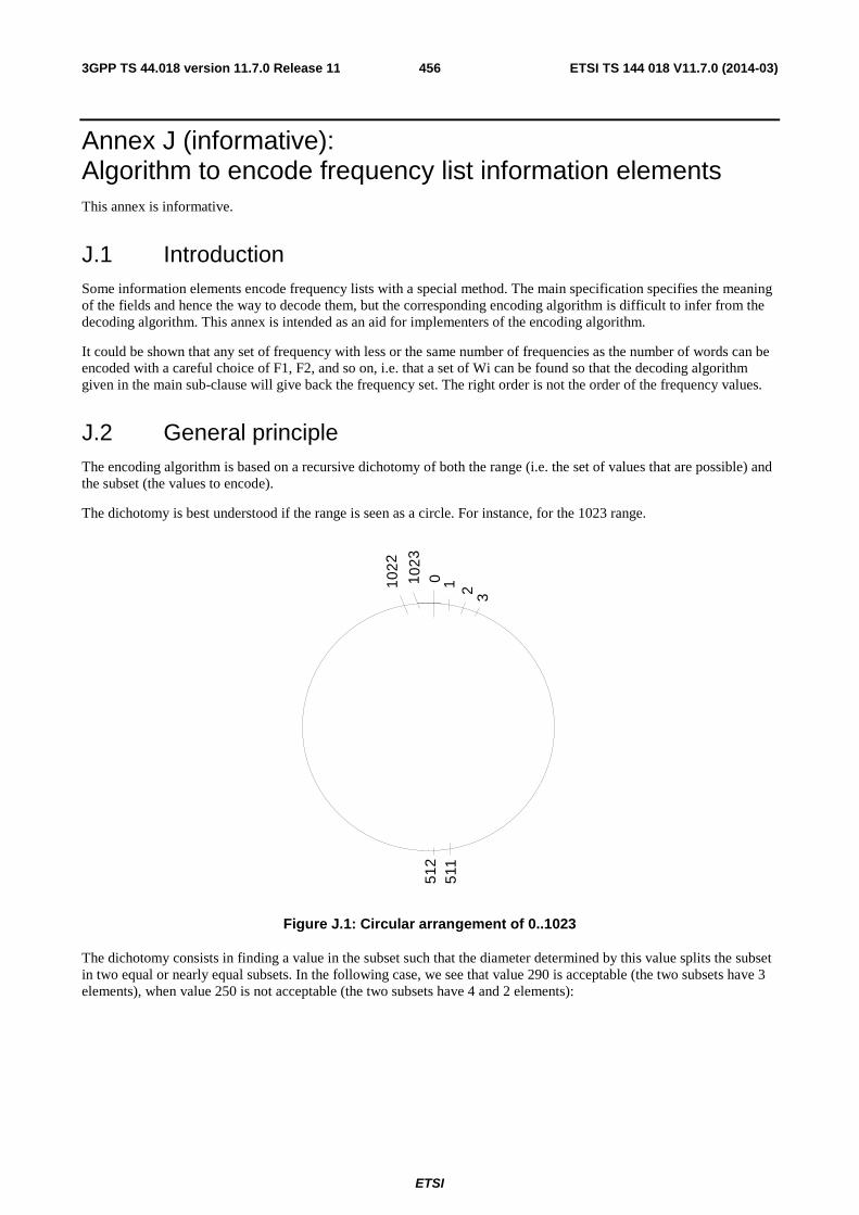
ETSI
ETSI TS 144 018 V11.7.0 (2014-03)4563GPP TS 44.018 version 11.7.0 Release 11
Annex J (informative): Algorithm to encode frequency list information elements This annex is informative.
J.1 Introduction Some information elements encode frequency lists with a special method. The main specification specifies the meaning of the fields and hence the way to decode them, but the corresponding encoding algorithm is difficult to infer from the decoding algorithm. This annex is intended as an aid for implementers of the encoding algorithm.
It could be shown that any set of frequency with less or the same number of frequencies as the number of words can be encoded with a careful choice of F1, F2, and so on, i.e. that a set of Wi can be found so that the decoding algorithm given in the main sub-clause will give back the frequency set. The right order is not the order of the frequency values.
J.2 General principle The encoding algorithm is based on a recursive dichotomy of both the range (i.e. the set of values that are possible) and the subset (the values to encode).
The dichotomy is best understood if the range is seen as a circle. For instance, for the 1023 range.
1 023
0 1 2 3
1022
512
511
.
Figure J.1: Circular arrangement of 0..1023
The dichotomy consists in finding a value in the subset such that the diameter determined by this value splits the subset in two equal or nearly equal subsets. In the following case, we see that value 290 is acceptable (the two subsets have 3 elements), when value 250 is not acceptable (the two subsets have 4 and 2 elements):
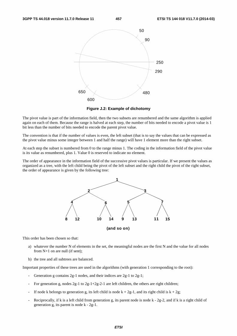
ETSI
ETSI TS 144 018 V11.7.0 (2014-03)4573GPP TS 44.018 version 11.7.0 Release 11
50
90
250
290
480
600
650
Figure J.2: Example of dichotomy
The pivot value is part of the information field, then the two subsets are renumbered and the same algorithm is applied again on each of them. Because the range is halved at each step, the number of bits needed to encode a pivot value is 1 bit less than the number of bits needed to encode the parent pivot value.
The convention is that if the number of values is even, the left subset (that is to say the values that can be expressed as the pivot value minus some integer between 1 and half the range) will have 1 element more than the right subset.
At each step the subset is numbered from 0 to the range minus 1. The coding in the information field of the pivot value is its value as renumbered, plus 1. Value 0 is reserved to indicate no element.
The order of appearance in the information field of the successive pivot values is particular. If we present the values as organized as a tree, with the left child being the pivot of the left subset and the right child the pivot of the right subset, the order of appearance is given by the following tree:
1
2 3
4 6 5 7
8 1 2 1 0 1 4 9 1 3 1 1 1 5
( a n d s o o n )
This order has been chosen so that:
a) whatever the number N of elements in the set, the meaningful nodes are the first N and the value for all nodes from N+1 on are null (if sent);
b) the tree and all subtrees are balanced.
Important properties of these trees are used in the algorithms (with generation 1 corresponding to the root):
- Generation g contains 2g-1 nodes, and their indices are 2g-1 to 2g-1;
- For generation g, nodes 2g-1 to 2g-1+2g-2-1 are left children, the others are right children;
- If node k belongs to generation g, its left child is node k + 2g-1, and its right child is k + 2g;
- Reciprocally, if k is a left child from generation g, its parent node is node k - 2g-2, and if k is a right child of generation g, its parent is node k - 2g-1.

ETSI
ETSI TS 144 018 V11.7.0 (2014-03)4583GPP TS 44.018 version 11.7.0 Release 11
J.3 Performances The number of bits needed to encode a given set of values depends on the number of values and on the range they can span.
For the application on the BCCH and the SACCH (CA and BA information ) 16 octets are available, and the number of frequencies that can be encoded in one information element is the following.
Range Number of frequencies 513 to 1024 2 to 16 (17 if frequency 0 is in) 257 to 512 2 to 18 129 to 256 2 to 22 113 to 128 2 to 29 up to 112 any
With two messages (for the BA) the number of frequencies that can be encoded is the following.
Range Number of frequencies 513 to 1024 2 to 36 (NOTE 1) 257 to 512 2 to 40 (NOTE 2) 225 to 256 2 to 51 (NOTE 3) up to 224 any
NOTE 1: A 1024 range can be split cyclically in to two 512 ranges each with less than 18 frequencies; each subset is coded in one message with 512 range format.
NOTE 2: A 512 range can be split in to two consecutive 256 ranges. If both sub-ranges contain 22 frequencies or less, it is possible to code each of these in a messages using the 256 range format. Otherwise one of the two ranges contains 23 frequencies or more: 22 of them can be coded in one message using the 256 range format and the remaining frequencies (numbering less than or equal to 18) can be coded in the other message using the 512 range format.
NOTE 3: The principles described in notes 1 and 2, above apply in this case.
The frequency short list information element allows the following.
Range Number of frequencies 513 to 1024 2 to 7 (8 if frequency 0 is in) 257 to 512 2 to 8 129 to 256 2 to 9 57 to 128 2 to 12 up to 56 any
The number of frequencies as a function of the range and the length in octets of the variable length frequency list information element (including the message type and length fields) is given by table J.1.
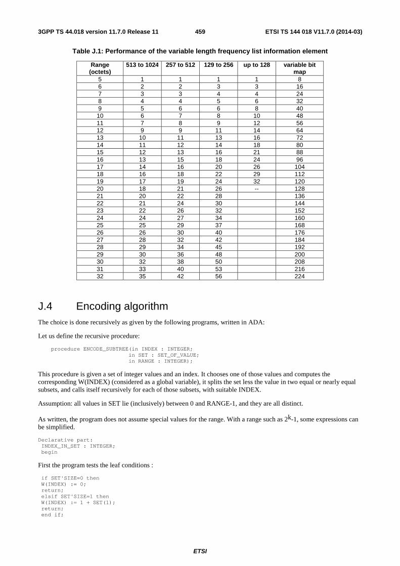
ETSI
ETSI TS 144 018 V11.7.0 (2014-03)4593GPP TS 44.018 version 11.7.0 Release 11
Table J.1: Performance of the variable length frequency list information element
Range (octets)
513 to 1024 257 to 512 129 to 256 up to 128 variable bit map
5 1 1 1 1 8 6 2 2 3 3 16 7 3 3 4 4 24 8 4 4 5 6 32 9 5 6 6 8 40 10 6 7 8 10 48 11 7 8 9 12 56 12 9 9 11 14 64 13 10 11 13 16 72 14 11 12 14 18 80 15 12 13 16 21 88 16 13 15 18 24 96 17 14 16 20 26 104 18 16 18 22 29 112 19 17 19 24 32 120 20 18 21 26 -- 128 21 20 22 28 136 22 21 24 30 144 23 22 26 32 152 24 24 27 34 160 25 25 29 37 168 26 26 30 40 176 27 28 32 42 184 28 29 34 45 192 29 30 36 48 200 30 32 38 50 208 31 33 40 53 216 32 35 42 56 224
J.4 Encoding algorithm The choice is done recursively as given by the following programs, written in ADA:
Let us define the recursive procedure:
procedure ENCODE_SUBTREE(in INDEX : INTEGER; in SET : SET_OF_VALUE; in RANGE : INTEGER);
This procedure is given a set of integer values and an index. It chooses one of those values and computes the corresponding W(INDEX) (considered as a global variable), it splits the set less the value in two equal or nearly equal subsets, and calls itself recursively for each of those subsets, with suitable INDEX.
Assumption: all values in SET lie (inclusively) between 0 and RANGE-1, and they are all distinct.
As written, the program does not assume special values for the range. With a range such as 2k-1, some expressions can be simplified.
Declarative part: INDEX_IN_SET : INTEGER; begin
First the program tests the leaf conditions :
if SET'SIZE=0 then W(INDEX) := 0; return; elsif SET'SIZE=1 then W(INDEX) := 1 + SET(1); return; end if;
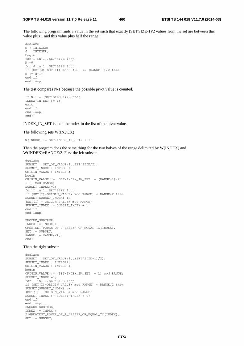
ETSI
ETSI TS 144 018 V11.7.0 (2014-03)4603GPP TS 44.018 version 11.7.0 Release 11
The following program finds a value in the set such that exactly (SET'SIZE-1)/2 values from the set are between this value plus 1 and this value plus half the range :
declare N : INTEGER; J : INTEGER; begin for I in 1..SET'SIZE loop N:=0; for J in 1..SET'SIZE loop if (SET(J)-SET(I)) mod RANGE <= (RANGE-1)/2 then N := N+1; end if; end loop;
The test compares N-1 because the possible pivot value is counted.
if N-1 = (SET'SIZE-1)/2 then INDEX_IN_SET := I; exit; end if; end loop; end;
INDEX_IN_SET is then the index in the list of the pivot value.
The following sets W(INDEX)
W(INDEX) := SET(INDEX_IN_SET) + 1;
Then the program does the same thing for the two halves of the range delimited by W(INDEX) and W(INDEX)+RANGE/2. First the left subset:
declare SUBSET : SET_OF_VALUE(1..SET'SIZE/2); SUBSET_INDEX : INTEGER; ORIGIN_VALUE : INTEGER; begin ORIGIN_VALUE := (SET(INDEX_IN_SET] + (RANGE-1)/2 + 1) mod RANGE; SUBSET_INDEX:=1; for I in 1..SET'SIZE loop if (SET(I)-ORIGIN_VALUE) mod RANGE) < RANGE/2 then SUBSET(SUBSET_INDEX) := (SET(I) - ORIGIN_VALUE) mod RANGE; SUBSET_INDEX := SUBSET_INDEX + 1; end if; end loop; ENCODE_SUBTREE( INDEX := INDEX + GREATEST_POWER_OF_2_LESSER_OR_EQUAL_TO(INDEX), SET := SUBSET, RANGE := RANGE/2); end;
Then the right subset:
declare SUBSET : SET_OF_VALUE(1..(SET'SIZE-1)/2); SUBSET_INDEX : INTEGER; ORIGIN_VALUE : INTEGER; begin ORIGIN_VALUE := (SET(INDEX_IN_SET] + 1) mod RANGE; SUBSET_INDEX:=1; for I in 1..SET'SIZE loop if (SET(I)-ORIGIN_VALUE) mod RANGE) < RANGE/2 then SUBSET(SUBSET_INDEX) := (SET(I) - ORIGIN_VALUE) mod RANGE; SUBSET_INDEX := SUBSET_INDEX + 1; end if; end loop; ENCODE_SUBTREE( INDEX := INDEX + 2*GREATEST_POWER_OF_2_LESSER_OR_EQUAL_TO(INDEX), SET := SUBSET,
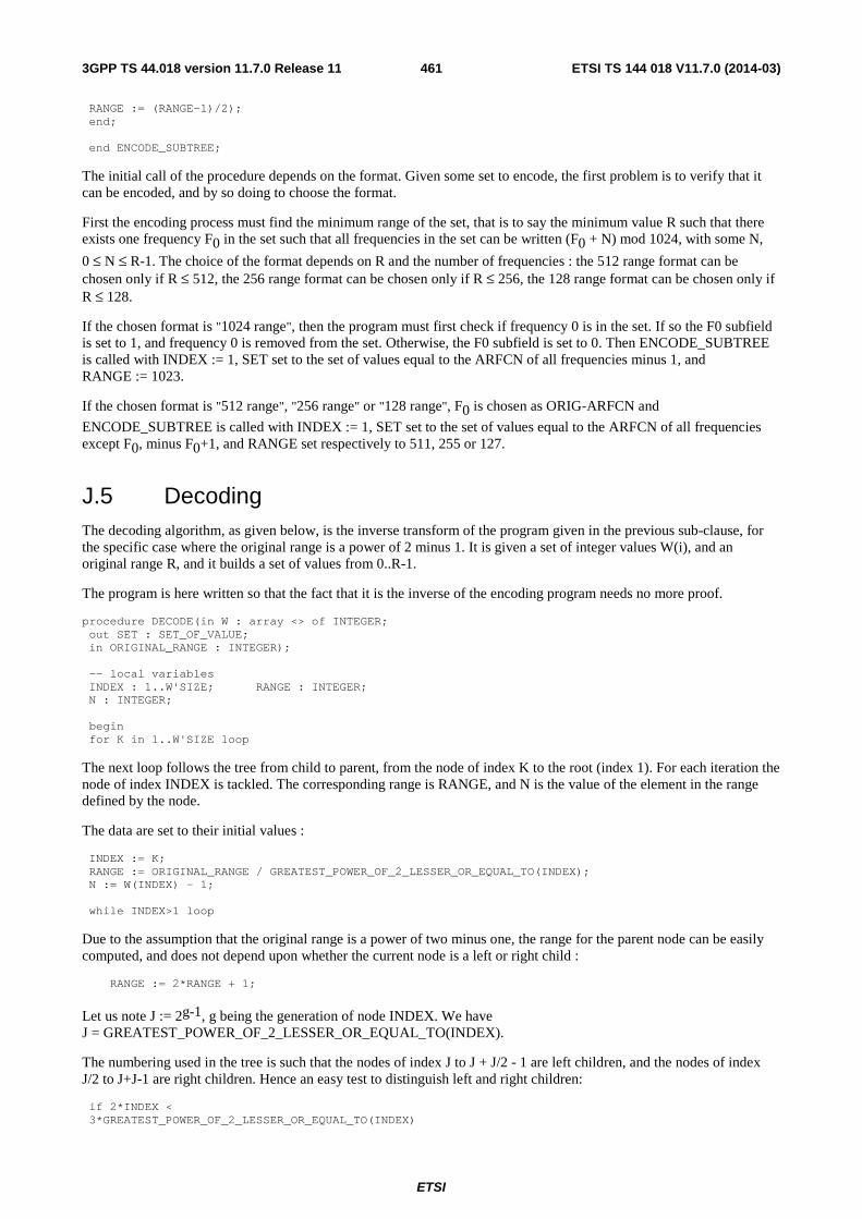
ETSI
ETSI TS 144 018 V11.7.0 (2014-03)4613GPP TS 44.018 version 11.7.0 Release 11
RANGE := (RANGE-1)/2); end; end ENCODE_SUBTREE;
The initial call of the procedure depends on the format. Given some set to encode, the first problem is to verify that it can be encoded, and by so doing to choose the format.
First the encoding process must find the minimum range of the set, that is to say the minimum value R such that there exists one frequency F0 in the set such that all frequencies in the set can be written (F0 + N) mod 1024, with some N,
0 ≤ N ≤ R-1. The choice of the format depends on R and the number of frequencies : the 512 range format can be chosen only if R ≤ 512, the 256 range format can be chosen only if R ≤ 256, the 128 range format can be chosen only if R ≤ 128.
If the chosen format is "1024 range", then the program must first check if frequency 0 is in the set. If so the F0 subfield is set to 1, and frequency 0 is removed from the set. Otherwise, the F0 subfield is set to 0. Then ENCODE_SUBTREE is called with INDEX := 1, SET set to the set of values equal to the ARFCN of all frequencies minus 1, and RANGE := 1023.
If the chosen format is "512 range", "256 range" or "128 range", F0 is chosen as ORIG-ARFCN and
ENCODE_SUBTREE is called with INDEX := 1, SET set to the set of values equal to the ARFCN of all frequencies except F0, minus F0+1, and RANGE set respectively to 511, 255 or 127.
J.5 Decoding The decoding algorithm, as given below, is the inverse transform of the program given in the previous sub-clause, for the specific case where the original range is a power of 2 minus 1. It is given a set of integer values W(i), and an original range R, and it builds a set of values from 0..R-1.
The program is here written so that the fact that it is the inverse of the encoding program needs no more proof.
procedure DECODE(in W : array <> of INTEGER; out SET : SET_OF_VALUE; in ORIGINAL_RANGE : INTEGER); -- local variables INDEX : 1..W'SIZE; RANGE : INTEGER; N : INTEGER; begin for K in 1..W'SIZE loop
The next loop follows the tree from child to parent, from the node of index K to the root (index 1). For each iteration the node of index INDEX is tackled. The corresponding range is RANGE, and N is the value of the element in the range defined by the node.
The data are set to their initial values :
INDEX := K; RANGE := ORIGINAL_RANGE / GREATEST_POWER_OF_2_LESSER_OR_EQUAL_TO(INDEX); N := W(INDEX) - 1; while INDEX>1 loop
Due to the assumption that the original range is a power of two minus one, the range for the parent node can be easily computed, and does not depend upon whether the current node is a left or right child :
RANGE := 2*RANGE + 1;
Let us note J := 2g-1, g being the generation of node INDEX. We have J = GREATEST_POWER_OF_2_LESSER_OR_EQUAL_TO(INDEX).
The numbering used in the tree is such that the nodes of index J to J + J/2 - 1 are left children, and the nodes of index J/2 to J+J-1 are right children. Hence an easy test to distinguish left and right children:
if 2*INDEX < 3*GREATEST_POWER_OF_2_LESSER_OR_EQUAL_TO(INDEX)

ETSI
ETSI TS 144 018 V11.7.0 (2014-03)4623GPP TS 44.018 version 11.7.0 Release 11
then -- left child
The next computation gives the index of the parent node of the node of index INDEX, for a left child :
INDEX := INDEX - GREATEST_POWER_OF_2_LESSER_OR_EQUAL_TO(INDEX)/2;
The next formula is the inverse of the renumbering appearing in the encoding for a left child. It gives the value of the parent node in the range defined by the grand-parent node:
N := (N + W(INDEX) - 1 + (RANGE-1)/2 + 1) mod RANGE; else -- right child
The next computation gives the index of the parent node of the node of index INDEX, for a right child :
INDEX := INDEX - GREATEST_POWER_OF_2_LESSER_OR_EQUAL_TO(INDEX);
The next formula is the inverse of the renumbering appearing in the encoding for a right child:
N := (N + W(INDEX) - 1 + 1) mod RANGE; end if; end loop; F(K) := N; end loop; end;
A careful study will show that the programs given in the main part of the Technical Specification are equivalent to the one presented here. The main difference is the use of different remnant variables to remove most of the calls to the function giving the greatest power of 2 less than or equal to some integer.
The decoding must be terminated by the correction specific to the format.
J.6 A detailed example Let us take the following subset of 16 elements of the set [0..1023] : [13, 71, 122, 191, 251, 321, 402, 476, 521, 575, 635, 701, 765, 831, 906, 981]
Range 1024 format will be used. Frequency 0 is not in the set, thus field F0 is set to 0. The set is renumbered, so as to give a subset of 0..1022 : [12, 70, 121, 190, 250, 320, 401, 475, 520, 574, 634, 700, 764, 830, 905, 980].
For the first node (corresponding to W(1)), the value 121 satisfies the requirements. The opposite value is 121 + 511 = 632. There are 8 values between 633 and 120 (namely the left-hand subset 634, 700, 764, 830, 905, 980, 12 and 70), and 7 values between 122 and 632 (namely the right-hand subset 190, 250, 320, 401, 475, 520 and 574).
The encoded value W(1) is 121 + 1, i.e. 122.
The second node (corresponding to W(2)) is the left-hand child of the first node. The corresponding subtree has to encode for the left-hand subset, renumbered beginning at 633. This gives the following 8 element subset of 0..510, ordered as resulting from the example of algorithm: [402, 460, 1, 67, 131, 197, 272, 347]. Out of these values, 1 splits the set in 4 and 3, and the encoded value W(2) is 2.
Similarly, the third node (W(3)) is the right-hand child of the first node and then the corresponding subtree encodes for the right-hand subset, renumbered starting at 122. This gives the following set of 0..510: [68, 128, 198, 279, 353, 398, 452]. Out of these values, 68 splits the set into 3 and 3, and the encoded value W(3) is 69.
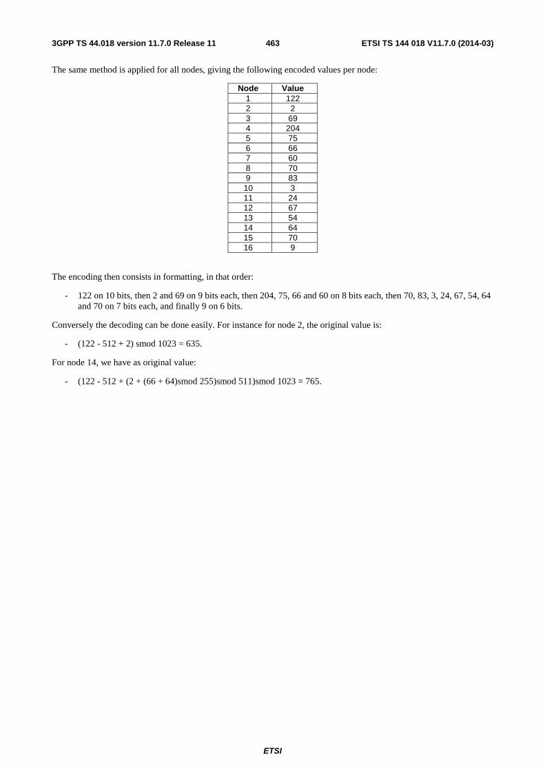
ETSI
ETSI TS 144 018 V11.7.0 (2014-03)4633GPP TS 44.018 version 11.7.0 Release 11
The same method is applied for all nodes, giving the following encoded values per node:
Node Value 1 122 2 2 3 69 4 204 5 75 6 66 7 60 8 70 9 83 10 3 11 24 12 67 13 54 14 64 15 70 16 9
The encoding then consists in formatting, in that order:
- 122 on 10 bits, then 2 and 69 on 9 bits each, then 204, 75, 66 and 60 on 8 bits each, then 70, 83, 3, 24, 67, 54, 64 and 70 on 7 bits each, and finally 9 on 6 bits.
Conversely the decoding can be done easily. For instance for node 2, the original value is:
- (122 - 512 + 2) smod 1023 = 635.
For node 14, we have as original value:
- (122 - 512 + (2 + (66 + 64)smod 255)smod 511)smod 1023 = 765.
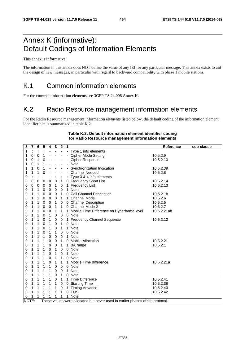
ETSI
ETSI TS 144 018 V11.7.0 (2014-03)4643GPP TS 44.018 version 11.7.0 Release 11
Annex K (informative): Default Codings of Information Elements This annex is informative.
The information in this annex does NOT define the value of any IEI for any particular message. This annex exists to aid the design of new messages, in particular with regard to backward compatibility with phase 1 mobile stations.
K.1 Common information elements For the common information elements see 3GPP TS 24.008 Annex K.
K.2 Radio Resource management information elements For the Radio Resource management information elements listed below, the default coding of the information element identifier bits is summarized in table K.2.
Table K.2: Default information element identifier coding for Radio Resource management information elements
8 7 6 5 4 3 2 1 Reference sub-clause 1 : : : - - - - Type 1 info elements 1 0 0 1 - - - - Cipher Mode Setting 10.5.2.9 1 0 1 0 - - - - Cipher Response 10.5.2.10 1 0 1 1 - - - - Note 1 1 0 1 - - - - Synchronization Indication 10.5.2.39 1 1 1 0 - - - - Channel Needed 10.5.2.8 0 : : : : : : : Type 3 & 4 info elements 0 0 0 0 0 0 1 0 Frequency Short List 10.5.2.14 0 0 0 0 0 1 0 1 Frequency List 10.5.2.13 0 1 1 0 0 0 0 1 Note 0 1 1 0 0 0 1 0 Cell Channel Description 10.5.2.1b 0 1 1 0 0 0 1 1 Channel Mode 10.5.2.6 0 1 1 0 0 1 0 0 Channel Description 10.5.2.5 0 1 1 0 0 1 1 0 Channel Mode 2 10.5.2.7 0 1 1 0 0 1 1 1 Mobile Time Difference on Hyperframe level 10.5.2.21ab 0 1 1 0 1 0 0 0 Note 0 1 1 0 1 0 0 1 Frequency Channel Sequence 10.5.2.12 0 1 1 0 1 0 1 0 Note 0 1 1 0 1 0 1 1 Note 0 1 1 0 1 1 0 0 Note 0 1 1 1 0 0 0 1 Note 0 1 1 1 0 0 1 0 Mobile Allocation 10.5.2.21 0 1 1 1 0 0 1 1 BA range 10.5.2.1 0 1 1 1 0 1 0 0 Note 0 1 1 1 0 1 0 1 Note 0 1 1 1 0 1 1 0 Note 0 1 1 1 0 1 1 1 Mobile Time difference 10.5.2.21a 0 1 1 1 1 0 0 0 Note 0 1 1 1 1 0 0 1 Note 0 1 1 1 1 0 1 0 Note 0 1 1 1 1 0 1 1 Time Difference 10.5.2.41 0 1 1 1 1 1 0 0 Starting Time 10.5.2.38 0 1 1 1 1 1 0 1 Timing Advance 10.5.2.40 0 1 1 1 1 1 1 0 TMSI 10.5.2.42 0 1 1 1 1 1 1 1 Note
NOTE: These values were allocated but never used in earlier phases of the protocol.

ETSI
ETSI TS 144 018 V11.7.0 (2014-03)4653GPP TS 44.018 version 11.7.0 Release 11
Annex L (normative): Additional Requirements for backward compatibility with PCS 1900 for NA revision 0 ME See 3GPP TS 24.008.
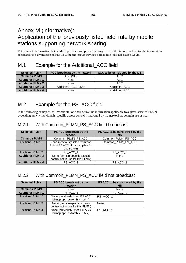
ETSI
ETSI TS 144 018 V11.7.0 (2014-03)4663GPP TS 44.018 version 11.7.0 Release 11
Annex M (informative): Application of the 'previously listed field' rule by mobile stations supporting network sharing This annex is informative. It intends to provide examples of the way the mobile station shall derive the information applicable to a given selected PLMN using the 'previously listed field' rule (see sub-clause 3.8.3).
M.1 Example for the Additional_ACC field Selected PLMN ACC broadcast by the network ACC to be considered by the MS Common PLMN ACC (SI3) ACC
Additional PLMN 1 None ACC Additional PLMN 2 None ACC Additional PLMN 3 Additional_ACC (SI22) Additional_ACC Additional PLMN 4 None Additional_ACC
M.2 Example for the PS_ACC field In the following examples, the mobile station shall derive the information applicable to a given selected PLMN depending on whether domain-specific access control is indicated by the network as being in use or not.
M.2.1 With Common_PLMN_PS_ACC field broadcast
Selected PLMN PS ACC broadcast by the network
PS ACC to be considered by the MS
Common PLMN Common_PLMN_PS_ACC Common_PLMN_PS_ACC Additional PLMN 1 None (previously listed Common
PLMN PS ACC bitmap applies for this PLMN)
Common_PLMN_PS_ACC
Additional PLMN 2 PS_ACC_1 PS_ACC_1 Additional PLMN 3 None (domain-specific access
control not in use for this PLMN) None
Additional PLMN 4 PS_ACC_2 PS_ACC_2
M.2.2 With Common_PLMN_PS_ACC field not broadcast
Selected PLMN PS ACC broadcast by the network
PS ACC to be considered by the MS
Common PLMN None None Additional PLMN 1 PS_ACC_1 PS_ACC_1 Additional PLMN 2 None (previously listed PS ACC
bitmap applies for this PLMN) PS_ACC_1
Additional PLMN 3 None (domain-specific access control not in use for this PLMN)
None
Additional PLMN 4 None (previously listed PS ACC bitmap applies for this PLMN)
PS_ACC_1
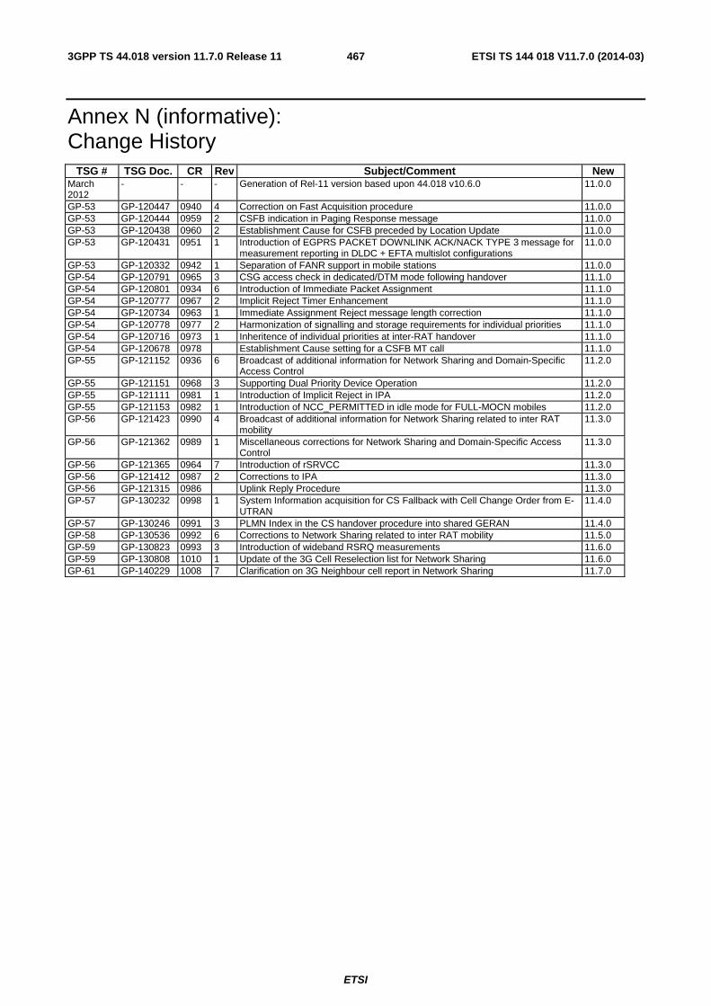
ETSI
ETSI TS 144 018 V11.7.0 (2014-03)4673GPP TS 44.018 version 11.7.0 Release 11
Annex N (informative): Change History
TSG # TSG Doc. CR Rev Subject/Comment New March 2012
- - - Generation of Rel-11 version based upon 44.018 v10.6.0 11.0.0
GP-53 GP-120447 0940 4 Correction on Fast Acquisition procedure 11.0.0 GP-53 GP-120444 0959 2 CSFB indication in Paging Response message 11.0.0 GP-53 GP-120438 0960 2 Establishment Cause for CSFB preceded by Location Update 11.0.0 GP-53 GP-120431 0951 1 Introduction of EGPRS PACKET DOWNLINK ACK/NACK TYPE 3 message for
measurement reporting in DLDC + EFTA multislot configurations 11.0.0
GP-53 GP-120332 0942 1 Separation of FANR support in mobile stations 11.0.0 GP-54 GP-120791 0965 3 CSG access check in dedicated/DTM mode following handover 11.1.0 GP-54 GP-120801 0934 6 Introduction of Immediate Packet Assignment 11.1.0 GP-54 GP-120777 0967 2 Implicit Reject Timer Enhancement 11.1.0 GP-54 GP-120734 0963 1 Immediate Assignment Reject message length correction 11.1.0 GP-54 GP-120778 0977 2 Harmonization of signalling and storage requirements for individual priorities 11.1.0 GP-54 GP-120716 0973 1 Inheritence of individual priorities at inter-RAT handover 11.1.0 GP-54 GP-120678 0978 Establishment Cause setting for a CSFB MT call 11.1.0 GP-55 GP-121152 0936 6 Broadcast of additional information for Network Sharing and Domain-Specific
Access Control 11.2.0
GP-55 GP-121151 0968 3 Supporting Dual Priority Device Operation 11.2.0 GP-55 GP-121111 0981 1 Introduction of Implicit Reject in IPA 11.2.0 GP-55 GP-121153 0982 1 Introduction of NCC_PERMITTED in idle mode for FULL-MOCN mobiles 11.2.0 GP-56 GP-121423 0990 4 Broadcast of additional information for Network Sharing related to inter RAT
mobility 11.3.0
GP-56 GP-121362 0989 1 Miscellaneous corrections for Network Sharing and Domain-Specific Access Control
11.3.0
GP-56 GP-121365 0964 7 Introduction of rSRVCC 11.3.0 GP-56 GP-121412 0987 2 Corrections to IPA 11.3.0 GP-56 GP-121315 0986 Uplink Reply Procedure 11.3.0 GP-57 GP-130232 0998 1 System Information acquisition for CS Fallback with Cell Change Order from E-
UTRAN 11.4.0
GP-57 GP-130246 0991 3 PLMN Index in the CS handover procedure into shared GERAN 11.4.0 GP-58 GP-130536 0992 6 Corrections to Network Sharing related to inter RAT mobility 11.5.0 GP-59 GP-130823 0993 3 Introduction of wideband RSRQ measurements 11.6.0 GP-59 GP-130808 1010 1 Update of the 3G Cell Reselection list for Network Sharing 11.6.0 GP-61 GP-140229 1008 7 Clarification on 3G Neighbour cell report in Network Sharing 11.7.0
ETSI
ETSI TS 144 018 V11.7.0 (2014-03)4683GPP TS 44.018 version 11.7.0 Release 11
History
Document history
V11.2.0 October 2012 Publication
V11.3.0 February 2013 Publication
V11.4.0 April 2013 Publication
V11.5.0 July 2013 Publication
V11.6.0 October 2013 Publication
V11.7.0 March 2014 Publication


![Draft ETSI EN 301 489-50 V2.2...2002/02/02 · 4G IMT-advanced ETSI TS 137 104 [21] ETSI TS 137 141 [12] ETSI TS 137 114 [31] ETSI TS 137 145-1 [13] ETSI TS 137 145-2 [14] WMAN (OFDMA)](https://static.fdocuments.net/doc/165x107/60e0dd64bbf8f11159724729/draft-etsi-en-301-489-50-v22-20020202-4g-imt-advanced-etsi-ts-137-104.jpg)