ETSI TS 132 251 V11.7 · 3GPP TS 32.251 version 11.7.0 ETSI Release 11 2 ETSI TS 132 251 V11.7.0...
94
ETSI TS 132 251 V11.7.0 (2013-07) Digital cellular telecommunications system (Phase 2+); Universal Mobile Telecommunications System (UMTS); LTE; Telecommunication management; Charging management; Packet Switched (PS) domain charging (3GPP TS 32.251 version 11.7.0 Release 11) Technical Specification
Transcript of ETSI TS 132 251 V11.7 · 3GPP TS 32.251 version 11.7.0 ETSI Release 11 2 ETSI TS 132 251 V11.7.0...
ETSI TS 132 251 V11.7.0 (2013-07)
Digital cellular telecommunications system (Phase 2+); Universal Mobile Telecommunications System (UMTS);
LTE; Telecommunication management;
Charging management; Packet Switched (PS) domain charging
(3GPP TS 32.251 version 11.7.0 Release 11)
Technical Specification
ETSI
ETSI TS 132 251 V11.7.0 (2013-07)13GPP TS 32.251 version 11.7.0 Release 11
Reference RTS/TSGS-0532251vb70
Keywords GSM,LTE,UMTS
ETSI
650 Route des Lucioles F-06921 Sophia Antipolis Cedex - FRANCE
Tel.: +33 4 92 94 42 00 Fax: +33 4 93 65 47 16
Siret N° 348 623 562 00017 - NAF 742 C
Association à but non lucratif enregistrée à la Sous-Préfecture de Grasse (06) N° 7803/88
Important notice
Individual copies of the present document can be downloaded from: http://www.etsi.org
The present document may be made available in more than one electronic version or in print. In any case of existing or perceived difference in contents between such versions, the reference version is the Portable Document Format (PDF).
In case of dispute, the reference shall be the printing on ETSI printers of the PDF version kept on a specific network drive within ETSI Secretariat.
Users of the present document should be aware that the document may be subject to revision or change of status. Information on the current status of this and other ETSI documents is available at
http://portal.etsi.org/tb/status/status.asp
If you find errors in the present document, please send your comment to one of the following services: http://portal.etsi.org/chaircor/ETSI_support.asp
Copyright Notification
No part may be reproduced except as authorized by written permission. The copyright and the foregoing restriction extend to reproduction in all media.
© European Telecommunications Standards Institute 2013.
All rights reserved.
DECTTM, PLUGTESTSTM, UMTSTM and the ETSI logo are Trade Marks of ETSI registered for the benefit of its Members. 3GPPTM and LTE™ are Trade Marks of ETSI registered for the benefit of its Members and
of the 3GPP Organizational Partners. GSM® and the GSM logo are Trade Marks registered and owned by the GSM Association.
ETSI
ETSI TS 132 251 V11.7.0 (2013-07)23GPP TS 32.251 version 11.7.0 Release 11
Intellectual Property Rights IPRs essential or potentially essential to the present document may have been declared to ETSI. The information pertaining to these essential IPRs, if any, is publicly available for ETSI members and non-members, and can be found in ETSI SR 000 314: "Intellectual Property Rights (IPRs); Essential, or potentially Essential, IPRs notified to ETSI in respect of ETSI standards", which is available from the ETSI Secretariat. Latest updates are available on the ETSI Web server (http://ipr.etsi.org).
Pursuant to the ETSI IPR Policy, no investigation, including IPR searches, has been carried out by ETSI. No guarantee can be given as to the existence of other IPRs not referenced in ETSI SR 000 314 (or the updates on the ETSI Web server) which are, or may be, or may become, essential to the present document.
Foreword This Technical Specification (TS) has been produced by ETSI 3rd Generation Partnership Project (3GPP).
The present document may refer to technical specifications or reports using their 3GPP identities, UMTS identities or GSM identities. These should be interpreted as being references to the corresponding ETSI deliverables.
The cross reference between GSM, UMTS, 3GPP and ETSI identities can be found under http://webapp.etsi.org/key/queryform.asp.
ETSI
ETSI TS 132 251 V11.7.0 (2013-07)33GPP TS 32.251 version 11.7.0 Release 11
Contents
Intellectual Property Rights ................................................................................................................................ 2
Foreword ............................................................................................................................................................. 2
Foreword ............................................................................................................................................................. 6
1 Scope ........................................................................................................................................................ 7
2 References ................................................................................................................................................ 8
3 Definitions, symbols and abbreviations ................................................................................................. 10
3.1 Definitions ........................................................................................................................................................ 10
3.2 Symbols ............................................................................................................................................................ 12
3.3 Abbreviations ................................................................................................................................................... 13
4 Architecture considerations .................................................................................................................... 15
4.1 High level EPS architecture.............................................................................................................................. 15
4.2 PS domain offline charging architecture .......................................................................................................... 16
4.3 PS domain online charging architecture ........................................................................................................... 18
5 PS domain charging principles and scenarios ........................................................................................ 19
5.1 PS charging principles ...................................................................................................................................... 19
5.1.1 Requirements .............................................................................................................................................. 19
5.1.2 Charging information .................................................................................................................................. 21
5.1.3 Identifiers and correlation ........................................................................................................................... 22
5.2 PS domain offline charging scenarios .............................................................................................................. 23
5.2.1 Basic principles ........................................................................................................................................... 23
5.2.1.1 IP-CAN bearer charging ....................................................................................................................... 23
5.2.1.2 MM context charging ............................................................................................................................ 24
5.2.1.3 Flow Based bearer Charging (FBC) ...................................................................................................... 25
5.2.1.4 SMS charging ........................................................................................................................................ 27
5.2.1.5 LCS charging ........................................................................................................................................ 27
5.2.1.6 MBMS context charging for GPRS ...................................................................................................... 27
5.2.1.6A MBMS context charging for EPS .......................................................................................................... 28
5.2.1.7 IP Flow Mobility (IFOM) Charging ...................................................................................................... 28
5.2.1.8 Sponsered Data Connectivity Charging ................................................................................................ 28
5.2.2 Rf message flows ........................................................................................................................................ 29
5.2.2.1 Triggers for charging events from S-GW .............................................................................................. 29
5.2.2.2 Triggers for charging events from P-GW .............................................................................................. 29
5.2.2.3 Triggers for charging events from ePDG .............................................................................................. 29
5.2.2.4 Triggers for charging events from MME .............................................................................................. 30
5.2.3 CDR generation .......................................................................................................................................... 30
5.2.3.1 Triggers for S-CDR charging information collection ........................................................................... 31
5.2.3.1.1 Triggers for S-CDR Charging Information Addition ...................................................................... 31
5.2.3.1.2 Triggers for S-CDR closure ............................................................................................................. 32
5.2.3.2 Triggers for M-CDR charging information collection .......................................................................... 32
5.2.3.2.1 Triggers for M-CDR charging information addition ....................................................................... 33
5.2.3.2.2 Triggers for M-CDR closure ........................................................................................................... 33
5.2.3.3 Triggers for SGW-CDR charging information collection ..................................................................... 33
5.2.3.3.1 Triggers for SGW-CDR Charging Information Addition ................................................................ 34
5.2.3.3.2 Triggers for SGW-CDR closure ...................................................................................................... 34
5.2.3.4 Triggers for PGW-CDR charging information collection ..................................................................... 35
5.2.3.4.1 Triggers for PGW-CDR Charging Information Addition ................................................................ 35
5.2.3.4.2 Triggers for PGW-CDR closure ...................................................................................................... 36
5.2.3.5 Triggers for SMS-CDR charging information collection ...................................................................... 37
5.2.3.6 Triggers for LCS-CDR charging information collection ...................................................................... 37
5.2.3.7 Triggers for S-MB-CDR and G-MB-CDR charging information collection for MBMS context charging for GPRS ................................................................................................................................ 38
5.2.3.7.1 Triggers for S-MB-CDR and G-MB-CDR Charging Information Creation .................................... 38
5.2.3.7.2 Triggers for S-MB-CDR and G-MB-CDR Charging Information Addition ................................... 38
ETSI
ETSI TS 132 251 V11.7.0 (2013-07)43GPP TS 32.251 version 11.7.0 Release 11
5.2.3.7.3 Triggers for S-MB-CDR and G-MB-CDR closure .......................................................................... 38
5.2.3.7A Triggers for MBMS-GW-CDR charging information collection for MBMS context charging for EPS ........................................................................................................................................................ 39
5.2.3.7A.1 Triggers for MBMS-GW-CDR Charging Information Creation ..................................................... 39
5.2.3.7A.2 Triggers for MBMS-GW-CDR Charging Information Addition ..................................................... 39
5.2.3.7A.3 Triggers for MBMS-GW-CDR closure ........................................................................................... 39
5.2.3.8 Triggers for ePDG-CDR charging information collection .................................................................... 39
5.2.3.8.1 Triggers for ePDG-CDR Charging Information Addition ............................................................... 40
5.2.3.8.2 Triggers for ePDG-CDR closure ..................................................................................................... 40
5.2.4 Void ............................................................................................................................................................ 41
5.2.5 Ga record transfer flows ............................................................................................................................. 41
5.2.6 Bp CDR file transfer ................................................................................................................................... 41
5.3 PS domain online charging scenarios ............................................................................................................... 41
5.3.1 Basic principles ........................................................................................................................................... 41
5.3.1.1 IP-CAN bearer charging ....................................................................................................................... 41
5.3.1.2 Flow Based Bearer Charging ................................................................................................................ 42
5.3.1.3 PS Furnish Charging Information procedure ........................................................................................ 43
5.3.1.4 Support of Failure Situations................................................................................................................. 43
5.3.2 Ro message flows ....................................................................................................................................... 43
5.3.2.1 Triggers for IP-CAN bearer Online Charging ....................................................................................... 44
5.3.2.1.1 Void ................................................................................................................................................. 44
5.3.2.1.2 Void ................................................................................................................................................. 44
5.3.2.2 Triggers for FBC Online Charging ....................................................................................................... 44
5.3.2.2.1 Triggers for starting and stopping an FBC Credit Control session .................................................. 45
5.3.2.2.2 Triggers for providing interim information for an FBC Credit Control session .............................. 45
5.3.2.3 PS Furnish Charging Information procedure ........................................................................................ 46
5.3.2.4 Support of Failure Situations................................................................................................................. 46
6 Definition of charging information ........................................................................................................ 47
6.1A Rf message content ..................................................................................................................................... 47
6.1A.1 Summary of Offline Charging Message Formats .................................................................................. 47
6.1A.2 Structure for the Accounting Message Formats .................................................................................... 47
6.1A.2.1 Accounting-Request Message ......................................................................................................... 47
6.1A.2.2 Accounting-Answer Message .......................................................................................................... 49
6.1B CDR content description on Bp interface ................................................................................................... 49
6.1.1 IP CAN bearer charging data in SGSN (S-CDR) ....................................................................................... 50
6.1.2 IP CAN bearer charging data in S-GW (SGW-CDR) ................................................................................. 51
6.1.3 FBC IP CAN bearer charging data in P-GW (PGW-CDR) ........................................................................ 53
6.1.4 Mobile Station mobility management data in SGSN (M-CDR) ................................................................. 56
6.1.5 SMS-MO data in SGSN/MME (S-SMO-CDR) .......................................................................................... 57
6.1.6 SMS-MT data in SGSN/MME (S-SMT-CDR) ........................................................................................... 58
6.1.7 Mobile terminated location request (LCS-MT-CDR) ................................................................................. 59
6.1.8 Mobile originated Location request (LCS-MO-CDR) ................................................................................ 60
6.1.9 Network induced Location request (LCS-NI-CDR) ................................................................................... 61
6.1.10 MBMS bearer context charging data in SGSN (S-MB-CDR) .................................................................... 62
6.1.11 MBMS bearer context charging data in GGSN (G-MB-CDR) ................................................................... 63
6.1.12 MBMS bearer context charging data in MBMS GW (MBMS-GW-CDR) ................................................. 63
6.1.13 IP CAN bearer charging data in ePDG (ePDG-CDR) ................................................................................ 64
6.2 Data description for PS Online Charging ......................................................................................................... 65
6.2.1 Diameter message contents ......................................................................................................................... 65
6.2.1.1 Summary of Online Charging Message Formats .................................................................................. 65
6.2.1.2 Structure for the Credit Control Message Formats ................................................................................ 65
6.2.1.2.1 Credit-Control-Request Message .................................................................................................... 66
6.2.1.2.2 Credit-Control-Answer Message ..................................................................................................... 67
6.2.2 Void ............................................................................................................................................................ 67
6.3 PS Charging Specific Parameters ..................................................................................................................... 68
6.3.1 Definition of PS charging information........................................................................................................ 68
6.3.1.1 PS charging information assignment for Service Information .............................................................. 68
6.3.1.1a 'SMS over MME Charging' information assignment for Service Information ...................................... 69
6.3.1.2 Definition of the PS Information ........................................................................................................... 70
6.3.2 Detailed Message Format for offline charging ........................................................................................... 72
6.3.3 Detailed Message Format for online charging ............................................................................................ 75
ETSI
ETSI TS 132 251 V11.7.0 (2013-07)53GPP TS 32.251 version 11.7.0 Release 11
6.4 Void .................................................................................................................................................................. 77
6.5 Bindings for EPC Offline Charging ................................................................................................................. 77
Annex A (normative): Charging Characteristics .............................................................................. 80
A.1 General ............................................................................................................................................................. 80
A.2 Charging Characteristics in Gn/Gp SGSN ....................................................................................................... 82
A.3 Charging Characteristics in S4-SGSN .............................................................................................................. 84
A.4 Charging Characteristics in MME .................................................................................................................... 84
A.5 Charging Characteristics in S-GW ................................................................................................................... 85
A.6 Charging Characteristics in P-GW ................................................................................................................... 85
Annex B (normative): Tx expiration; Failure Handling procedure and session failover mechanism description .................................................................................. 86
Annex C (informative): Bibliography ................................................................................................... 88
Annex D (informative): Change history ............................................................................................... 89
History .............................................................................................................................................................. 93
ETSI
ETSI TS 132 251 V11.7.0 (2013-07)63GPP TS 32.251 version 11.7.0 Release 11
Foreword This Technical Specification has been produced by the 3rd Generation Partnership Project (3GPP).
The contents of the present document are subject to continuing work within the TSG and may change following formal TSG approval. Should the TSG modify the contents of the present document, it will be re-released by the TSG with an identifying change of release date and an increase in version number as follows:
Version x.y.z
where:
x the first digit:
1 presented to TSG for information;
2 presented to TSG for approval;
3 or greater indicates TSG approved document under change control.
y the second digit is incremented for all changes of substance, i.e. technical enhancements, corrections, updates, etc.
z the third digit is incremented when editorial only changes have been incorporated in the document.
ETSI
ETSI TS 132 251 V11.7.0 (2013-07)73GPP TS 32.251 version 11.7.0 Release 11
1 Scope The present document is part of a series of documents specifying charging functionality and charging management in Packet Switched networks (GSM/UMTS, EPS). The 3GPP core network charging architecture and principles are specified in 3GPP TS 32.240 [1], which provides an umbrella for other charging management documents that specify:
• the content of the CDRs per domain / subsystem / service (offline charging);
• the content of real-time charging messages per domain / subsystem /service (online charging);
• the functionality of online and offline charging for those domains / subsystems / services;
• the interfaces that are used in the charging framework to transfer the charging information (i.e. CDRs or charging events).
The complete document structure for these TSs is defined in 3GPP TS 32.240 [1].
The present document specifies the Offline and Online Charging description for the Packet Switched (PS) domain based on the functional stage 2 description in 3GPP TS 23.060 [201], 3GPP TS 23.401[208] and 3GPP TS 23.402 [209]. This charging description includes the offline and online charging architecture and scenarios specific to the PS domain, as well as the mapping of the common 3GPP charging architecture specified in TS 32.240 [1] onto the PS domain. It further specifies the structure and content of the CDRs for offline charging, and the charging events for online charging. The present document is related to other 3GPP charging TSs as follows:
� The common 3GPP charging architecture is specified in TS 32.240 [1];
� The parameters, abstract syntax and encoding rules for the CDRs are specified in TS 32.298 [51];
� A transaction based mechanism for the transfer of CDRs within the network is specified in TS 32.295 [54];
� The file based mechanism used to transfer the CDRs from the network to the operator"s billing domain (e.g. the billing system or a mediation device) is specified in TS 32.297 [52];
� The 3GPP Diameter application that is used for PS domain offline and online charging is specified in TS 32.299 [50].
Note that a CAMEL based prepaid function and protocol is also specified for the PS domain (3GPP TS 23.078 [206] and 3GPP TS 29.078 [202]). CAMEL entities and functions are outside the scope of the present document.
All terms, definitions and abbreviations used in the present document, which are common across 3GPP TSs, are defined in 3GPP TR 21.905 [100]. Those that are common across charging management in PS domains, services or subsystems are provided in the umbrella document 3GPP TS 32.240 [1] and are copied into clause 3 of the present document for ease of reading. Finally, those items that are specific to the present document are defined exclusively in the present document.
Furthermore, requirements that govern the charging work are specified in 3GPP TS 22.115 [102].
ETSI
ETSI TS 132 251 V11.7.0 (2013-07)83GPP TS 32.251 version 11.7.0 Release 11
2 References The following documents contain provisions which, through reference in this text, constitute provisions of the present document.
• References are either specific (identified by date of publication, edition number, version number, etc.) or non-specific.
• For a specific reference, subsequent revisions do not apply.
• For a non-specific reference, the latest version applies. In the case of a reference to a 3GPP document (including a GSM document), a non-specific reference implicitly refers to the latest version of that document in the same Release as the present document.
[1] 3GPP TS 32.240: "Telecommunication management; Charging management; Charging architecture and principles".
[2]- [9] Void.
[10] 3GPP TS 32.250: "Telecommunication management; Charging management; Circuit Switched (CS) domain charging".
[11-19] Void.
[20] 3GPP TS 32.260: "Telecommunication management; Charging management; IP Multimedia Subsystem (IMS) charging".
[21]- [29] Void.
[30] 3GPP TS 32.270: "Telecommunication management; Charging management; Multimedia Messaging Service (MMS) charging".
[31] 3GPP TS 32.271: "Telecommunication management; Charging management; Location Services (LCS) charging".
[32] 3GPP TS 32.273: "Telecommunication management; Charging management; Multimedia Broadcast and Multicast Service (MBMS) charging"
[33] 3GPP TS 32.274: "Telecommunication management; Charging management; Short Message Service (SMS) charging".
[34]- [49] Void.
[50] 3GPP TS 32.299: "Telecommunication management; Charging management; Diameter charging application".
[51] 3GPP TS 32.298: "Telecommunication management; Charging management; Charging Data Record (CDR) encoding rules description".
[52] 3GPP TS 32.297: "Telecommunication management; Charging management; Charging Data Records (CDR) file format and transfer".
[53] 3GPP TS 32.296: "Telecommunication management; Charging management; Online Charging System (OCS) applications and interfaces".
[54] 3GPP TS 32.295: "Telecommunication management; Charging management; Charging Data Record (CDR) transfer".
[55]- [69] Void.
[70] Void.
[71] 3GPP TS 29.212: "Policy and Charging Control (PCC); Reference points".
[72] 3GPP TS 23.203: "Policy and Charging Control Architecture".
ETSI
ETSI TS 132 251 V11.7.0 (2013-07)93GPP TS 32.251 version 11.7.0 Release 11
[73]- [99] Void.
[100] 3GPP TR 21.905: "Vocabulary for 3GPP Specifications".
[101] Void.
[102] 3GPP TS 22.115 "Service aspects; Charging and billing".
[103]- [199] Void.
[200] 3GPP TS 22.060: "General Packet Radio Service (GPRS); Service description; Stage 1".
[201] 3GPP TS 23.060: "General Packet Radio Service (GPRS); Service description; Stage 2".
[202] 3GPP TS 29.078: "Customized Applications for Mobile network Enhanced Logic (CAMEL); CAMEL Application Part (CAP) specification".
[203] 3GPP TS 29.060: "General Packet Radio Service (GPRS); GPRS Tunnelling Protocol (GTP) across the Gn and Gp interface".
[204] Void.
[205] 3GPP TS 29.061: "Interworking between the Public Land Mobile Network (PLMN) supporting packet based services and Packet Data Networks (PDN)"
[206] 3GPP TS 23.078: "Customized Applications for Mobile network Enhanced Logic (CAMEL); Stage 2".
[207] 3GPP TS 23.246: "Multimedia Broadcast/Multicast Service (MBMS); Architecture and functional description".
[208] 3GPP TS 23.401: "GPRS Enhancements for E-UTRAN Access".
[209] 3GPP TS 23.402: "Architecture enhancements for non-3GPP accesses".
[210] 3GPP TS 29.274: "Evolved GPRS Tunnelling Protocol for Control Plane (GTPv2-C); Stage 3".
[211] 3GPP TS 29.275: "Proxy Mobile IPv6 (PMIPv6) based Mobility and Tunnelling protocols; Stage 3".
[212] 3GPP TS 23.261: "IP flow mobility and seamless Wireless Local Area Network (WLAN) offload; Stage 2".
[213] 3GPP TS 23.272: "Circuit Switched (CS) fallback in Evolved Packet System (EPS); Stage 2".
[214] - [400] Void.
[401] IETF RFC 3588 (2003): "Diameter Base Protocol".
[402] IETF RFC 4006: "Diameter Credit Control" Application
[403] Void.
ETSI
ETSI TS 132 251 V11.7.0 (2013-07)103GPP TS 32.251 version 11.7.0 Release 11
3 Definitions, symbols and abbreviations
3.1 Definitions For the purposes of the present document, the terms and definitions defined in 3GPP TR 21.905 [100], 3GPP TS 32.240 [1] and 3GPP TS 22.060 [200], and the following apply:
2G-/3G-: prefixes 2G- and 3G- refer to functionality that supports only GSM or UMTS, respectively, e.g. 2G-SGSN refers only to the GSM functionality of an SGSN When the term/prefix is omitted, reference is made independently from the GSM or UMTS functionality.
accounting: process of apportioning charges between the Home Environment, Serving Network and Subscriber.
billing: function whereby CDRs generated by the charging function(s) are transformed into bills requiring payment.
Billing Domain: Part of the operator network, which is outside the core network that receives and processes CDR files from the core network charging functions. It includes functions that can provide billing mediation and billing or other (e.g. statistical) end applications. It is only applicable to offline charging (see "Online Charging System" for equivalent functionality in online charging).
CAMEL: network feature that provides the mechanisms to support operator specific services even when roaming outside HPLMN.
CAMEL subscription information: identifies a subscriber as having CAMEL services.
CDR field Categories: the CDR fields are defined in the present document. They are divided into the following categories:
• Mandatory (M): field that shall always be present in the CDR.
• Conditional (C): field that shall be present in a CDR if certain conditions are met.
• Operator Provisionable: Mandatory (OM): A field that operators have provisioned to always be included in the CDR.
• Operator Provisionable: Conditional (OC): A field that operators have provisioned to be included in the CDR if certain conditions are met.
chargeable event: activity utilizing telecommunications network resources and related services for:
� user to user communication (e.g. a single call, a data communication session or a short message); or
� user to network communication (e.g. service profile administration); or
� inter-network communication (e.g. transferring calls, signalling, or short messages); or
� mobility (e.g. roaming or inter-system handover); and
� that the network operator may want to charge for.
As a minimum, a chargeable event characterises the resource / service usage and indicates the identity of the involved end user(s).
charged party: user involved in a chargeable event that has to pay parts or the whole charges of the chargeable event, or a third party paying the charges caused by one or all users involved in the chargeable event, or a network operator.
charging: a function within the telecommunications network and the associated OCS/BD components whereby information related to a chargeable event is collected, formatted and transferred in order to make it possible to determine usage for which the charged party may be billed.
Charging Data Record (CDR): A formatted collection of information about a chargeable event (e.g. time of call set-up, duration of the call, amount of data transferred, etc) for use in billing and accounting. For each party to be charged for parts of or all charges of a chargeable event a separate CDR shall be generated, i.e. more than one CDR may be
ETSI
ETSI TS 132 251 V11.7.0 (2013-07)113GPP TS 32.251 version 11.7.0 Release 11
generated for a single chargeable event, e.g. because of its long duration, or because more than one charged party is to be charged.
Charging event: a set of charging information forwarded by the CTF towards the CDF (offline charging) or towards the OCS (online charging). Each charging event matches exactly one chargeable event.
charging function: entity inside the core network domain, subsystem or service that is involved in charging for that domain, subsystem or service.
credit control: mechanism which directly interacts in real-time with an account and controls or monitors the charges, related to the service usage. Credit control is a process of: checking if credit is available, credit reservation, deduction of credit from the end user account when service is completed and refunding of reserved credit not used.
domain: part of a communication network that provides network resources using a certain bearer technology.
Fully qualified Partial CDR (FQPC): partial CDR that contains a complete set of the fields specified in the present document. This includes all the mandatory and conditional fields as well as those fields that the PLMN operator has provisioned to be included in the CDR. The first Partial CDR shall be a Fully qualified Partial CDR.
GPRS: packet switched bearer and radio services for GSM and UMTS systems.
GSM only: qualifier indicating that this clause or paragraph applies only to a GSM system. For multi-system cases this is determined by the current serving radio access network.
in GSM,...: qualifier indicating that this paragraph applies only to GSM System.
in UMTS,...: qualifier indicating that this paragraph applies only to UMTS System.
inter-system change: change of radio access between different radio access technologies such as GSM and UMTS.
IP-CAN bearer: An IP transmission path of defined capacity, delay and bit error rate, etc. See TS 21.905 [8] for the definition of bearer.
IP-CAN session: The association between a UE represented by an IPv4 address and/or an IPv6 prefix, and UE identity information, if available, and a PDN represented by a PDN ID (e.g. an APN). An IP-CAN session incorporates one or more IP-CAN bearers. Support for multiple IP-CAN bearers per IP-CAN session is IP-CAN specific. An IP-CAN session exists as long as UE IP addresses are established and announced to the IP network.
middle tier (charging) TS: used for the 3GPP charging TSs that specify the domain / subsystem / service specific, online and offline, charging functionality. These are all the TSs in the numbering range from 3GPP TS 32.250 [10] to 3GPP TS 32.271 [31], e.g. 3GPP TS 32.250 [10] for the CS domain, or 3GPP TS 32.270 [30] for the MMS service. Currently, there is only one "tier 1" TS in 3GPP, which is TS 32.240 [1] that specifies the charging architecture and principles. Finally, there are a number of top tier TSs in the 32.29x numbering range ([50] ff) that specify common charging aspects such as parameter definitions, encoding rules, the common billing domain interface or common charging applications.
near real-time: near real-time charging and billing information is to be generated, processed, and transported to a desired conclusion in less than 1 minute.
offline charging: charging mechanism where charging information does not affect, in real-time, the service rendered.
online charging: charging mechanism where charging information can affect, in real-time, the service rendered and therefore a direct interaction of the charging mechanism with bearer/session/service control is required.
Online Charging System: the entity that performs real-time credit control. Its functionality includes transaction handling, rating, online correlation and management of subscriber account balances.
packet switched domain: domain in which data is transferred between core network elements in packet switched mode.
partial CDR: CDR that provides information on part of a subscriber session. A long session may be covered by several partial CDRs. Two formats are considered for Partial CDRs. One that contains all of the necessary fields (FQPC); the second has a reduced format (RPC).
Real-time: real-time charging and billing information is to be generated, processed, and transported to a desired conclusion in less than 1 second.
ETSI
ETSI TS 132 251 V11.7.0 (2013-07)123GPP TS 32.251 version 11.7.0 Release 11
Reduced Partial CDR (RPC): partial CDRs that only provide mandatory fields and information regarding changes in the session parameters relative to the previous partial CDR. For example, location information is not repeated in these CDRs if the subscriber did not change its location.
settlement: payment of amounts resulting from the accounting process.
Selected IP Traffic Offload (SIPTO): Offload of selected types of IP traffic (e.g. internet traffic) towards a defined IP network close to the UE's point of attachment to the access network. SIPTO is applicable to traffic offload for the macro-cellular access network and for the H(e)NB subsystem.
subscriber: A subscriber is an entity (associated with one or more users) that is engaged in a Subscription with a service provider. The subscriber is allowed to subscribe and unsubscribe services, to register a user or a list of users authorised to enjoy these services, and also to set the limits relative to the use that associated users make of these services.
tariff period: part of one (calendar) day during which a particular tariff is applied. Defined by the time at which the period commences (the switch-over time) and the tariff to be applied after switch-over.
tariff: set of parameters defining the network utilisation charges for the use of a particular bearer / session / service.
UMTS only: qualifier indicating that this clause or paragraph applies only to a UMTS system. For multi-system cases this is determined by the current serving radio access network.
user: An entity, not part of the 3GPP System that uses network resources by means of a subscription. The user may or may not be identical to the subscriber holding that subscription.
User Equipment (UE): A device allowing a user access to network services. For the purpose of 3GPP specifications the interface between the UE and the network is the radio interface. A User Equipment can be subdivided into a number of domains, the domains being separated by reference points. Currently defined domains are the USIM and ME Domains. The ME Domain can further be subdivided into several components showing the connectivity between multiple functional groups. These groups can be implemented in one or more hardware devices. An example of such connectivity is the TE – MT interface. Further, an occurrence of a User Equipment is an MS for GSM as defined in GSM TS 04.02.
3.2 Symbols For the purposes of the present document the following symbols apply:
A Interface between an MSC and a BSC. Bp Reference point for the CDR file transfer from the Packet Switched CGF to the BD. C Interface between a HLR and a SMSC. D Interface between a MSC and a HLR. E Interface between a MSC and a SMSC. Ga Reference point between a CDF and the CGF for CDR transfer. Gb Interface between an SGSN and a BSC. Gc Interface between an GGSN and an HLR. Gd Interface between an SMS-GMSC and an SGSN, and between a SMS-IWMSC and an SGSN. Ge Interface between a SGSN and a CAMEL GSM SCF Gf Interface between an SGSN and an EIR. Gi Interface between the Packet-Switched domain and an external packet data network. Gn Interface between two GSNs within the same PLMN. Gp Interface between two GSNs in different PLMNs. Gr Interface between an SGSN and an HLR. Gs Interface between an SGSN and an MSC/VLR.Iu Interface between the 3G SGSN and the UTRAN Gy Online charging reference point between a PCEF and an OCS. Gz Offline charging reference point between a PCEF and a CGF. kbit/s Kilobits per second. 1 kbit/s = 210 bits per second. Mbit/s Megabits per second. 1 Mbit/s = 220 bits per second. R Reference point between a non-ISDN compatible TE and MT. Typically this reference point
supports a standard serial interface. Rf Offline Charging Reference Point between a PCN network element and CDF. Ro Online Charging Reference Point between a PCN network element and the OCS. Um Interface between the Mobile Station (MS) and the GSM fixed network part.
ETSI
ETSI TS 132 251 V11.7.0 (2013-07)133GPP TS 32.251 version 11.7.0 Release 11
Uu Interface between the Mobile Station (MS) and the UMTS fixed network part.
3.3 Abbreviations For the purposes of the present document, the abbreviations defined in 3GPP TR 21.905 [50] and the following apply:
3G 3rd Generation AoC Advice of Charge APN Access Point Name ARP Allocation and Retention Priority BD Billing Domain CAMEL Customized Applications for Mobile network Enhanced Logic CCA Credit Control Answer CCR Credit Control Request CDF Charging Data Function CDR Charging Data Record CG Charging Gateway CGF Charging Gateway Function CI Cell Identity CS Circuit Switched CSE CAMEL Service Environment CSG Closed Subscriber Group CSG ID Closed Subscriber Group Identity CTF Charging Trigger Function DCCA Diameter Credit Control Application EPC Evolved Packet Core ePDG Evolved Packet Data Gateway EPS Evolved Packet System ECUR Event Charging with Unit Reservation E-UTRAN Evolved Universal Terrestrial Radio Access Network FBC Flow Based bearer Charging FQPC Fully Qualified Partial CDR GERAN GSM EDGE Radio Access Network GGSN Gateway GPRS Support Node GPRS General Packet Radio Service GSM Global System for Mobile communication GTP GPRS Tunnelling Protocol GTP' The GPRS protocol used for CDR transport. It is derived from GTP with enhancements to improve
transport reliability necessary for CDRs. HeNB Home eNode B HNB Home Node B H(e)NB HNB and HeNB HLR Home Location Register HPLMN Home PLMN IEC Immediate Event Charging IETF Internet Engineering Task Force IFOM IP Flow Mobility IHOSS:OSP Internet Hosted Octet Stream Service: Octet Stream Protocol IMEI International Mobile Equipment Identity IMSI International Mobile Subscriber Identity IP Internet Protocol IP-CAN IP Connectivity Access Network IPv4 Internet Protocol version 4 IPv6 Internet Protocol version 6 ISDN Integrated Services Digital Network ITU-T International Telecommunication Union - Telecommunications standardization sector LAC Location Area Code LR Location Request M-CDR Mobility management generated - Charging Data Record MAPCON Multi Access PDN Connectivity MCC Mobile Country Code (part of IMSI) ME Mobile Equipment
ETSI
ETSI TS 132 251 V11.7.0 (2013-07)143GPP TS 32.251 version 11.7.0 Release 11
MLC Mobile Location Center MME Mobility Management Entity MMS Multimedia Messaging Service MNC Mobile Network Code (part of IMSI) MO Mobile Originated MO-LR Mobile Originated - Location Request MS Mobile Station MSISDN Mobile Station ISDN number MT Mobile Terminated MT-LR Mobile Terminated - Location Request NE Network Element NI Network Identifier (part of the APN) NI-LR Network Induced - Location Request OCF Online Charging Function OCS Online Charging System OI Operator Identifier (part of the APN) P-GW PDN Gateway PCEF Policy and Charging Enforcement Function PCN Packet switched Core network Node (SGSN, GGSN, S–GW, P–GW) PDN Packet Data Network PDP Packet Data Protocol (e.g. IP) PDU Packet Data Unit PGW-CDR P-GW (enhanced by FBC) generated – CDR PLMN Public Land Mobile Network PMIP Proxy Mobile IP PPP Point-to-Point Protocol PS Packet Switched QCI QoS Class Identifier QoS Quality of Service RAB Radio Access Bearer RAC Routing Area Code RANAP Radio Access Network Application Part RNC Radio Network Controller RPC Reduced Partial CDR SAC Service Area Code S-CDR SGSN (IP-CAN bearer) generated – CDR S-GW Serving Gateway SCUR Session Charging with Unit Reservation SDF Service Data Flow SGSN Serving GPRS Support Node SGW-CDR S-GW (IP-CAN bearer) generated – CDR SIPTO Selected IP Traffic Offload SMS Short Message Service S-SMO-CDR SGSN delivered Short message Mobile Originated – CDR S-SMT-CDR SGSN delivered Short message Mobile Terminated – CDR TR Technical Report TS Technical Specification TWAG Trusted WLAN Access Gateway TWAN Trusted WLAN Access Network UMTS Universal Mobile Telecommunications System USIM Universal Subscriber Identity Module UTRAN UMTS Terrestrial Radio Access Network
ETSI
ETSI TS 132 251 V11.7.0 (2013-07)153GPP TS 32.251 version 11.7.0 Release 11
4 Architecture considerations This clause describes the functional entities involved in the PS domain charging architecture. It also presents the mappings of the ubiquitous offline and online charging architecture specified in TS 32.240 [1] onto physical implementations that are standardised for the 3GPP PS domain.
4.1 High level EPS architecture The 3GPP PS domain provides procedures for packet core networks described in TS 23.060 [201], TS 23.401 [208] , TS 23.402 [209] and TS 23.272 [213].
For offline charging the following Packet switched Core network Nodes (PCN) may generate accounting metrics sets for PS domain CDRs:
- the SGSN, to record a user's access to PLMN resources, mobility management activities, SMS and LCS usage;
- the S-GW, to record a user's access to PLMN resources
- the ePDG, to record a user's access to PLMN resources
- the P-GW, to record a user's access to external networks.
- the GGSN, to record a user's access to external networks.
- the MME, to record a user's SMS;
The PCNs send the CDRs to the CGF in near real-time. The responsibility of the CGF is to provide non-volatile CDR storage and the Bp interface towards the Billing Domain. Further details on the CGF can be found in TS 32.240 [1] and TS 32.297 [52].
For more information about online charging in PS domains see clause 4.3.
When P-GW provides connectivity to GERAN/UTRAN (P-GW acts as a GGSN) it employs P-GW Charging defined in this specification. When the standalone GGSN provides connectivity to GERAN/UTRAN, it employs P-GW Charging as defined in this specification:
- Standalone GGSN Offline Charging is based on FBC IP-CAN bearer charging data in P-GW;
- Standalone GGSN Online Charging is based on PS Information used for Online Charging.
ETSI
ETSI TS 132 251 V11.7.0 (2013-07)163GPP TS 32.251 version 11.7.0 Release 11
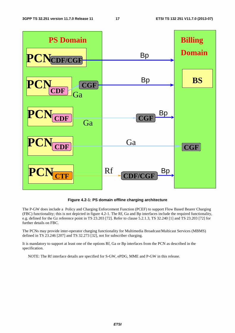
4.2 PS domain offline charging architecture As described in TS 32.240 [1], the CTF (an integrated component in each charging relevant NE) generates charging events and forwards them to the CDF. The CDF, in turn, generates CDRs which are then transferred to the CGF. Finally, the CGF creates CDR files and forwards them to the Billing Domain.
If PCN generating the charging information has an integrated CDF, hence a physical PCN can produce CDRs. The CGF may also be integrated in the PCN, or it may exist as a physically separate entity. If the CGF is external to the PCN, then the CDF forwards the CDRs to the CGF across the Ga interface. In this case, the relationship between PCN/CDF and CGF is m:1. If the CGF is integrated in the PCN, then there is only an internal interface between the CDF and the CGF. In this case, the relationship between PCN/CDF and CGF is 1:1. An integrated CGF may support the Ga interface from other PCN/CDFs.
If the CDF is external to the PCN, the charging events are transferred from the PCN to the CDF via the Rf interface specified in 3GPP TS 32.299 [50]. In this case, the relationship between PCN and CDF is m:1.
When an external CGF is used, this CGF may also be used by other, i.e. non-PS, network elements, according to network design and operator decision. It should be noted that the CGF may also be an integrated component of the BD – in this case, the Bp interface does not exist and is replaced by a proprietary solution internal to the BD.
Figure 4.2-1. depicts the architectural options described above.
ETSI
ETSI TS 132 251 V11.7.0 (2013-07)173GPP TS 32.251 version 11.7.0 Release 11
Figure 4.2-1: PS domain offline charging architecture
The P-GW does include a Policy and Charging Enforcement Function (PCEF) to support Flow Based Bearer Charging (FBC) functionality; this is not depicted in figure 4.2-1. The Rf, Ga and Bp interfaces include the required functionality, e.g. defined for the Gz reference point in TS 23.203 [72]. Refer to clause 5.2.1.3, TS 32.240 [1] and TS 23.203 [72] for further details on FBC.
The PCNs may provide inter-operator charging functionality for Multimedia Broadcast/Multicast Services (MBMS) defined in TS 23.246 [207] and TS 32.273 [32], not for subscriber charging.
It is mandatory to support at least one of the options Rf, Ga or Bp interfaces from the PCN as described in the specification.
NOTE: The Rf interface details are specified for S-GW, ePDG, MME and P-GW in this release.
Bp
PS Domain
PCN
BS
Bp
PCN CGF
Ga
Bp PCN CGF Ga
CDF/CGF
CDF
CDF
Billing
Domain
PCN CDF CGF Ga
Bp
CTF CDF/CGFRfPCN
ETSI
ETSI TS 132 251 V11.7.0 (2013-07)183GPP TS 32.251 version 11.7.0 Release 11
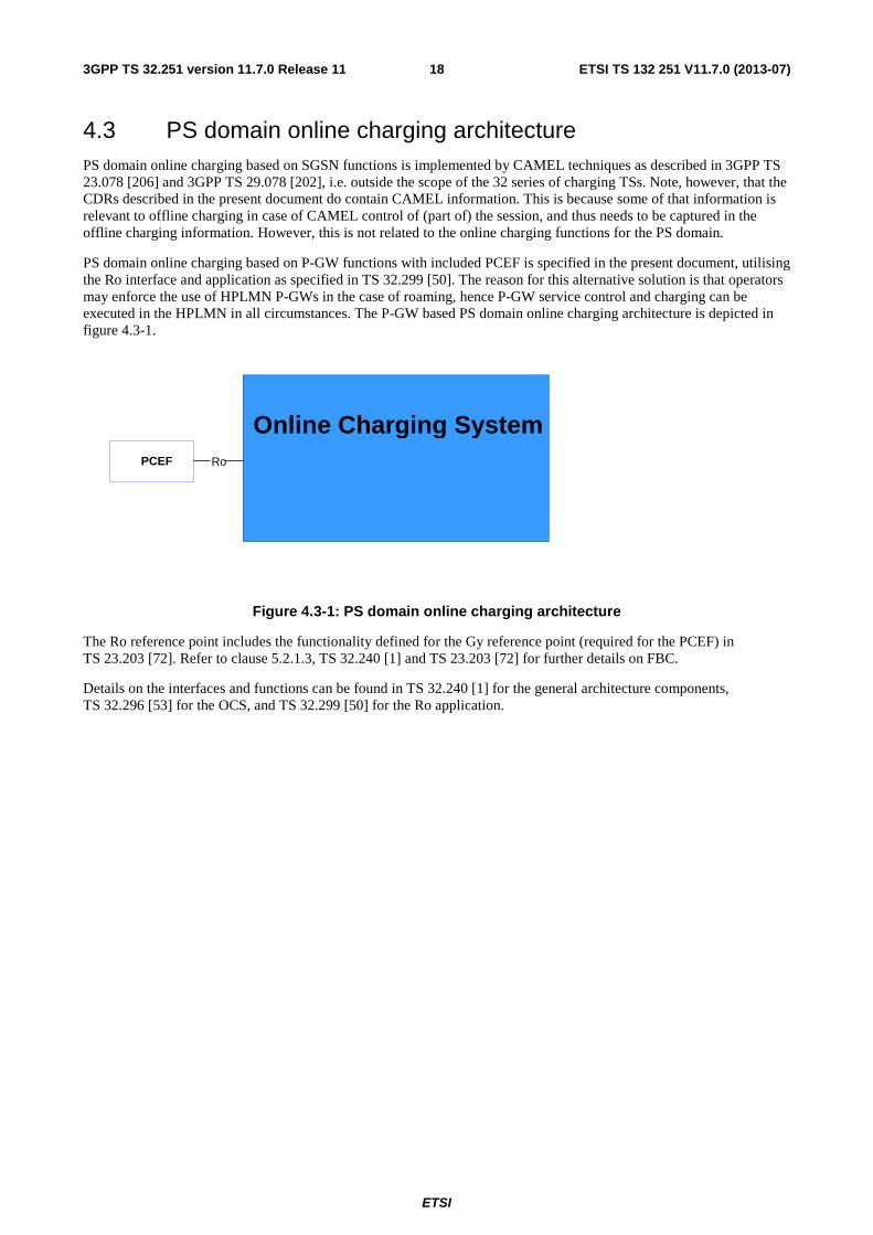
4.3 PS domain online charging architecture PS domain online charging based on SGSN functions is implemented by CAMEL techniques as described in 3GPP TS 23.078 [206] and 3GPP TS 29.078 [202], i.e. outside the scope of the 32 series of charging TSs. Note, however, that the CDRs described in the present document do contain CAMEL information. This is because some of that information is relevant to offline charging in case of CAMEL control of (part of) the session, and thus needs to be captured in the offline charging information. However, this is not related to the online charging functions for the PS domain.
PS domain online charging based on P-GW functions with included PCEF is specified in the present document, utilising the Ro interface and application as specified in TS 32.299 [50]. The reason for this alternative solution is that operators may enforce the use of HPLMN P-GWs in the case of roaming, hence P-GW service control and charging can be executed in the HPLMN in all circumstances. The P-GW based PS domain online charging architecture is depicted in figure 4.3-1.
Figure 4.3-1: PS domain online charging architecture
The Ro reference point includes the functionality defined for the Gy reference point (required for the PCEF) in TS 23.203 [72]. Refer to clause 5.2.1.3, TS 32.240 [1] and TS 23.203 [72] for further details on FBC.
Details on the interfaces and functions can be found in TS 32.240 [1] for the general architecture components, TS 32.296 [53] for the OCS, and TS 32.299 [50] for the Ro application.
Online Charging SystemPCEF Ro
ETSI
ETSI TS 132 251 V11.7.0 (2013-07)193GPP TS 32.251 version 11.7.0 Release 11
5 PS domain charging principles and scenarios
5.1 PS charging principles The charging functions specified for the PS domain relate to
� mobility management, refer to TS 23.060 [201];
� SMS transmissions / receptions, refer to TS 23.060 [201] , and TS 23.272 [213];
� IP-CAN bearers, refer to TS 23.060 [201], TS 23.401[208] and TS 23.402[209];
� LCS events, refer to TS 32.271 [31];
� individual service data flows within a IP-CAN bearer, refer to TS 23.203 [72].
� MBMS bearer contexts, refer to TS 23.246 [207] and TS 32.273 [32].
5.1.1 Requirements
The following are high-level charging requirements specific to the packet domain, derived from the requirements in 3GPP TS 22.115 [102], TS 23.060 [201], TS 23.401 [208], TS 23.402 [209] and TS 23.203 [72].
1) Every IP-CAN bearer shall be assigned a unique identity number for billing purposes. (i.e. the charging id).
2) Data volumes on both the uplink and downlink direction shall be counted separately. The data volumes shall reflect the data as delivered to and from the user.
3) The charging mechanisms shall provide the duration of the IP-CAN bearer with date and time information.
4) The network operator may define a subset of the charging information specified by Packet-Switched domain charging standards. This means that it shall be possible to configure the PCN for the CDR information generated.
5) The PCNs shall be capable of handling the Charging Characteristics. Charging Characteristics can be specific for a subscription or for subscribed IP-CAN bearer (i.e. per APN), see annex A for details.
6) The SGSN shall support charging of CAMEL services.
7) The SGSN shall support charging for location requests.
8) The SGSN may support online charging using CAMEL techniques.
9) The P-GW may support online charging using IETF based techniques.
10) The P-GW may be capable of identifying data volumes, elapsed time or events for individual service data flows (flow based bearer charging). One PCC rule identifies one service data flow.
11) When online charging is used in the P-GW, the credit control shall be per rating group.
12) P-GW shall allow reporting of the service usage per rating group or per combination of the rating group and service id. This reporting level can be activated per PCC rule.
13) The P-GW shall collect charging information for IP -CAN session as it would for one IP-CAN bearer in case of PMIP based connectivity is used .
14) Charging support in the SGSN shall apply only for SGSN with Gn/Gp connectivity.
15) The data volume shall be counted regardless of whether the subscriber"s traffic has been offloaded from the mobile operator"s network.
Editor"s Notes: This requirement should be rerefined after finalization of the architecture for Selected IP Traffic Offload charging.

ETSI
ETSI TS 132 251 V11.7.0 (2013-07)203GPP TS 32.251 version 11.7.0 Release 11
These requirements apply equally to PS domain online charging and offline charging.
ETSI
ETSI TS 132 251 V11.7.0 (2013-07)213GPP TS 32.251 version 11.7.0 Release 11
5.1.2 Charging information
Charging information in the PS domain network is collected for each MS/UE by the SGSNs, MMEs, S-GWs, ePDG and P-GWs, which are serving that MS/UE. The SGSN, S-GW, and ePDG collects charging information for each MS/UE related with the radio network usage, while the P-GW collects charging information for each MS related with the external data network usage. PCNs also collect charging information on usage of the PS domain network resources. For MBMS, charging information in the PS domain network is collected for each MBMS bearer context. The following paragraphs list the charging information to be collected by the PCNs for both online and offline charging.
For IP-CAN bearers, the PCNs shall collect the following charging information:
1. usage of the radio interface: the charging information shall describe the amount of data transmitted in MO and MT directions categorized with QoS and user protocols;
2. usage duration: duration of IP-CAN bearer is counted as the time interval from IP-CAN bearer activation to IP-CAN bearer deactivation;
3. usage of the general PS domain resources: the charging information shall describe the usage of other PS domain-related resources and the MSs PS domain network activity (e.g. mobility management);
4. destination and source: the charging information shall provide the actual source addresses used by the subscriber for the IP-CAN bearer. The charging information shall describe the destination addresses with a level of accuracy as determined by the Access Point Name (APN);
5. usage of the external data networks: the charging information shall describe the amount of data sent and received to and from the external data network. External networks can be identified by the Access Point Name (APN).
6. location of MS/UE: HPLMN, VPLMN, plus optional higher-accuracy location information.
7. User CSG information: a user consumes network services via a CSG cell or a hybrid cell according to the user CSG information. The charging information shall include CSG ID, access mode and CSG membership indication.
For service data flows defined for FBC, the P-GW shall collect the following charging information:
1. the information described above for IP-CAN bearer charging;
2. the amount of data transmitted in MO and MT directions categorized by rating group or combination of the rating group and service id when volume based charging applies;
3. the duration of service data flows is counted and categorized by rating group or combination of the rating group and service id when time based charging applies;
4. the amount of events and corresponding timestamps categorized by rating group or combination of the rating group and service id when event based charging applies.
For non-IP-CAN bearer related activities, the SGSN shall collect the following charging information:
1. mobility management actions for GPRS attached UEs/MSs;
2. short messages passing through the SGSN in MO and MT directions;
3. location requests passing through the SGSN, triggered by the UE/MS, by an external source, or by the network.
For MBMS bearer contexts, the PCNs shall collect the following charging information:
1. usage of the radio interface: the charging information shall describe the amount of data transmitted categorized with QoS and MBMS specific information defined in TS 32.273 [72];
2. usage duration: duration of MBMS bearer context is counted as the time interval from the local creation of the MBMS bearer context to the local deletion of the MBMS bearer context;
3. source: the charging information shall provide the source address used by the MBMS bearer service for the MBMS bearer context. The charging information may describe the destination addresses with a level of accuracy as determined by the Access Point Name (APN);
ETSI
ETSI TS 132 251 V11.7.0 (2013-07)223GPP TS 32.251 version 11.7.0 Release 11
4. location information: the charging information shall describe a list of the downstream nodes being sent the MBMS bearer service.
The MME shall collect short messages passing through the MME in MO and MT directions.
5.1.3 Identifiers and correlation
The EPC Charging Identifier assigned per IP-CAN bearer, is used for correlation purpose within PS domain, as specified in 3GPP TS 32.240 [1].
Within a PDN connection, the EPS default bearer remains established throughout the lifetime of this PDN connection and is assigned with its "EPS default bearer Charging Identifier". Other additional IP-CAN bearers (i.e. dedicated bearers) which may be activated and deactivated during this PDN connection, are each assigned with their own "IP-CAN bearer Charging Identifier". For correlation of charging information for the whole PDN connection, this "EPS default bearer Charging Identifier" is shared by all these IP-CAN bearers charging sessions activated during this PDN connection, as the "PDN connection Charging identifier".
For PMIP based connectivity, an "unique Charging Id" is assigned by the P-GW for the PDN connection (i.e as it would be one IP-CAN bearer).
During handover of a PDN connection between a GTP based connectivity access, and a PMIP based connectivity access for the P-GW (and reversely), the "EPS default bearer Charging identifier" and the "unique Charging Id" respectively, are maintained in order to ensure charging continuity for the whole PDN connection over the different accesses. Upon handover from GTP based connectivity to PMIP based connectivity, the previously assigned "EPS default bearer Charging Identifier" is used as the "unique Charging Id". Upon handover from PMIP based connectivity to GTP based connectivity, the previously assigned "unique Charging Id" is used as the "EPS default bearer Charging Identifier".
When multiple simultaneous PDN connections are established for a given APN, each PDN connection is associated with its own "PDN connection Charging identifier" or "unique Charging Id" and processed independently from the other PDN connections.
When a "MAPCON capable UE", as defined in 3GPP TS 23.402 [209], has simultaneous PDN connections through different access networks, each PDN connection is associated with its own "PDN connection Charging identifier" or "unique Charging Id" over the selected access for the PDN connection.When selective transfer of PDN connections between the different accesses is performed, each PDN connection is transferred, as for a single PDN connection.
When an "IFOM capable UE", as defined in 3GPP TS 23.402 [209], is simultaneously connected to 3GPP access and WLAN access for different IP flows within the same PDN connection, each service data flow is uniquely identified by a PCC Rule within the PDN connection.
When SIPTO function applies, as defined in TS 23.060 [201] and TS 23.401[208] the standard Charging behaviour for PDN connection activation/deactivation applies on the respective GW.
ETSI
ETSI TS 132 251 V11.7.0 (2013-07)233GPP TS 32.251 version 11.7.0 Release 11
5.2 PS domain offline charging scenarios
5.2.1 Basic principles
In order to provide the data required for the management activities outlined in TS 32.240 [1] (billing, accounting, statistics etc.), the SGSN shall be able to produce CDRs, and the MME, S-GW, ePDG and P-GW shall be able to produce CDRs or report charging events for CDRs generation by CDF, for each of the following:
• Charging Data related to IP-CAN bearers in the SGSN (S-CDR), S-GW (SGW-CDR) , ePDG (ePDG-CDR) and P-GW (PGW-CDR);
• Charging Data related to service data flows in the P-GW (PGW-CDR);
• Charging Data related to MM contexts (Mobile Station Mobility Management Data) in SGSN (M-CDR);
• SMS Mobile Originated Data (S-SMO-CDR) and SMS Mobile Terminated Data (SMS-SMT-CDR) in the SGSN;
• Charging Data related to mobile originated location requests (LCS-MO-CDR), mobile terminated location request (LCS-MT-CDR), and network induced location request (LCS-NI-CDR) passing through the SGSN;
• Charging Data related to MBMS bearer contexts (S-MB-CDR, G-MB-CDR, and MBMS-GW-CDR).
• SMS Mobile Originated Data (M-SMO-CDR) and SMS Mobile Terminated Data (M-SMT-CDR) in the MME;
The contents and purpose of each of these CDRs, as well as the chargeable events that trigger CDR creation, information addition, or closure are described in the following clauses. A detailed formal description of the CDR parameters defined in the present document is to be found in 3GPP TS 32.298 [51].
When the CDF is implemented as a separate entity (for the MME, S-GW, ePDG and the P-GW), the Charging events triggering and contents for CDRs handling by the CDF, are described in clause 5.2.2.
5.2.1.1 IP-CAN bearer charging
SGSN, ePDG, P-GW, and S-GW collect charging information per user per IP-CAN bearer. In case of P-GW is not aware of IP-CAN bearers, i.e. in case of PMIP based connectivity, P-GW collects charging information per IP-CAN session as it would be one IP-CAN bearer. IP-CAN bearer charging allows the PCNs to collect charging information related to data volumes sent to and received by the UE/MS, categorised by the QCI and ARP applied to the IP-CAN bearer. The user can be identified by MSISDN and/or IMSI, while the IP-CAN bearer can be determined by a unique identifier generated by the P-GW when creating a IP-CAN bearer. This identifier is also forwarded to the S-GW/ ePDG/SGSN so as to allow correlation of S-GW/ ePDG/SGSN IP-CAN bearer CDRs with the matching P-GW CDRs in the BD.
NOTE: The control plane IP address of SGSN or P-GW(acting as GGSN) is the IP address used at Gn/Gp interface. The control plane IP address of S-GW or P-GW is the IP address used at S5/S8 interface. The control plane IP address of ePDG or P-GW is the IP address used at S2b interface.
IP-CAN bearer specific offline charging in P-GW, is achieved by FBC offline charging, with specific rating group/service identifier, see clause 5.2.1.3
The main collected information items are duration of the IP-CAN bearer and data volume transferred during the lifetime of the IP-CAN bearer. The following chargeable events are defined for SGSN, S-GW and ePDG IP-CAN bearer charging:
� Start of IP-CAN bearer. Upon encountering this event, a new CDR for this IP-CAN bearer is created and the data volume is captured for the IP-CAN bearer.
� End of IP-CAN bearer in the SGSN/S-GW/ePDG. The CDR is closed upon encountering this trigger.
� Tracking Area Update of
o Inter-SGSN/inter S-GW. The IP-CAN bearer CDR is closed in SGSN/S-GW upon encountering this trigger.
ETSI
ETSI TS 132 251 V11.7.0 (2013-07)243GPP TS 32.251 version 11.7.0 Release 11
o Inter-MME. In S-GW a new MME address is added to CDR upon encountering this trigger.
o S4-SGSN to MME. In S-GW a new MME address is added to CDR upon encountering this trigger.
o MME to S4-SGSN. In S-GW a new S4-SGSN address is added to CDR upon encountering this trigger.
� Intersystem change (e.g. change of radio interface from GSM to UMTS or vice versa). This event closes the CDR. A new one is opened if the IP-CAN bearer is still active.
� PLMN change visible in the P-GW. This event closes the CDR. A new one is opened if the IP-CAN bearer is still active.
� MS Timezone change visible in the P-GW. This event closes the CDR. A new one is opened if the IP-CAN bearer is still active.
� Expiry of an operator configured time limit per IP-CAN bearer. This event closes the CDR, and a new one is opened if the IP-CAN bearer is still active.
� Expiry of an operator configured data volume limit per IP-CAN bearer. This event closes the CDR, and a new one is opened if the IP-CAN bearer is still active.
� Change of charging condition in the SGSN: e.g. QoS change, tariff time change, user CSG information change or direct tunnel establishment/removal. When this event is encountered, the current volume count is captured and a new volume count is started.
� Change of charging condition in the S-GW: e.g. QoS change, tariff time change, user location change, user CSG information change. When this event is encountered, the current volume counts are captured and a new volume counts are started.
� Change of charging condition in the ePDG: e.g. QoS change, tariff time change. When this event is encountered, the current volume counts are captured and a new volume counts are started.
� Expiry of an operator configured change of charging condition limit per IP-CAN bearer. This event closes the CDR, and a new one is opened if the IP-CAN bearer is still active.
� Management intervention may also force trigger a chargeable event.
When the CDF is implemented as a separate entity, all these chargeable events defined for IP-CAN bearer, trigger charging events reporting, for CDRs (S-GW, ePDG and P-GW CDRs) to be constructed, enriched or closed by CDF, according to description in clause 5.2.2.
5.2.1.2 MM context charging
The SGSN collects charging information for mobility management actions per attached UE/MS, i.e. per user. The user can be identified by MSISDN and/or IMSI. There can be only one MM context per UE/MS at a time, and only the SGSN is involved. Therefore there is no need for special MM context identifiers. The main information items collected are changes of location pertaining to the UE/MS. The following chargeable events are defined for MM context charging:
� Start of MM context (UE/MS attaches to a SGSN). A new M-CDR is created upon encountering this event.
� End of MM context: explicit or implicit GPRS detach, including SGSN change (inter-SGSN routing area update including intersystem change). This event triggers the closure of the M-CDR.
� Mobility Change, i.e. a change in the Routing Area. The new location information is captured for the M-CDR.
� Expiry of an operator configured time limit. This event triggers the closure of the M-CDR.
� Expiry of an operator configured mobility change limit. This event triggers the closure of the M-CDR.
� Intra-SGSN intersystem change (change of radio interface from GSM to UMTS or vice versa). This event triggers the closure of the M-CDR.
Management intervention may also force trigger a chargeable event.
ETSI
ETSI TS 132 251 V11.7.0 (2013-07)253GPP TS 32.251 version 11.7.0 Release 11
5.2.1.3 Flow Based bearer Charging (FBC)
IP-CAN bearer charging allows the P-GW to collect charging information related to data volumes sent to and received by the UE/MS, categorised by the QoS applied to the IP-CAN bearer. FBC is supported by the P-GW by the integration of a PCEF. With PCEF, the normal IP-CAN bearer charging is enhanced by the capability to categorise the service data flows within IP-CAN bearer data traffic by rating group or combination of the rating group and service id. I.e., while there is only one uplink an one downlink data volume count per IP-CAN bearer in IP-CAN bearer charging, FBC provides one count per each rating group or combination of the rating group and service id. The level of the reporting is defined per PCC rule. Details of this functionality are specified in TS 23.203 [72] and TS 32.240 [1].
NOTE: The P-GW can only include one QoS Information occurrence per service data container. This implies if an operator wishes to be able to separate usage according to QCI and ARP within their billing system they will need to ensure that services having different QCI and ARP do not have the same:
- rating group in cases where rating reporting is used;
- rating group/service id where rating group/service id reporting is used.
IP-CAN bearer specific offline charging is achieved with IP-CAN bearer specific rating group/service identifier defined in clause 5.3.1.1.
According to TS 23.203 [72], FBC shall support different charging models per PCC rule. These charging models may be based on volume and/or time and on number of events matching a specific service data flow template in PCC rule. In general the charging of a service data flow shall be linked to the IP-CAN bearer under which the service data flow has been activated. The following chargeable events are defined for FBC:
� Start of IP-CAN bearer. Upon encountering this event, a new PGW-CDR for this context is created.
� Start of service data flow. If service identifier level reporting is required by the PCC rule new counts and time stamps for this combination of the rating group and service id are started. If rating group level reporting is required by the PCC rule needed new counts and time stamps for this rating group are started. The type of counters shall depend on the measurement method configured for the PCC rule. When event based charging applies, the first occurrence of an event matching a service data flow template in PCC rule shall imply that a new count is started. When new events occur, the counter shall be increased. Each event shall be time stamped.
� Termination of service data flow. If service identifier level reporting is required by the PCC rule and this was the last active service data flow for this combination of the rating group and service id or if rating group level reporting is required by the PCC rule and this was the last active service data flow for this rating group, the counters and time stamps are closed and added to the PGW-CDR. For information on how the termination of service data flows is detected, refer to TS 23.203 [72].
� End of IP-CAN bearer in the P-GW. The PGW-CDR is closed upon encountering this trigger.
� Serving node (e.g. SGSN/S-GW/ePDG) change in the P-GW. New SGSN/S-GW/ePDG address is added to PGW-CDR.
� Expiry of an operator configured time limit per IP-CAN bearer. This event closes the PGW-CDR, and a new one is opened if the IP-CAN bearer is still active.
� Expiry of an operator configured time limit per rating group. The counters and time stamps are closed and added to the PGW-CDR. A new service data flow container is opened if any matching service data flow is still active.
� Expiry of an operator configured data volume limit per IP-CAN bearer. This event closes the PGW-CDR, and a new one is opened if the IP-CAN bearer is still active.
� Expiry of an operator configured data volume limit per rating group. The counters and time stamps are closed and added to the PGW-CDR. A new service data flow container is opened if any matching service data flow is still active.
� Expiry of an operator configured data event limit per rating group. The counters and time stamps are closed and added to the PGW-CDR. A new service data flow container is opened if any matching service data flow is still active.
ETSI
ETSI TS 132 251 V11.7.0 (2013-07)263GPP TS 32.251 version 11.7.0 Release 11
� Change of charging condition: IP-CAN bearer modification (e.g. QoS change, SGSN change, S-GW change, user location change,user CSG information change), tariff time change or failure handling procedure triggering. When this event is encountered, all current configured counts and time stamps are captured and new counts and time stamps for all active service data flows are started.
� Intersystem change (e.g. change of radio interface from GSM to UMTS, RAT change) visible in the P-GW. This event closes the PGW-CDR, and a new one is opened if the IP-CAN bearer is still active.
� PLMN change visible in the P-GW. This event closes the PGW-CDR. A new one is opened if the IP-CAN bearer is still active.
� MS Timezone change visible in the P-GW. This event closes the PGW-CDR. A new one is opened if the IP-CAN bearer is still active.
� SGSN change in the P-GW. New SGSN address is added to PGW-CDR.
� Expiry of an operator configured report of service flow data limit per IP-CAN bearer. This event closes the PGW-CDR, and a new one is opened if the IP-CAN bearer is still active.
� Completion of a time envelope as defined in 3GPP TS 32.299 [50]. This event closes a service data flow container. Further details are described in "Triggers for PGW-CDR Charging Information Addition" (clause 5.2.3.4.1). The need for reporting time envelopes may be statically configured for each rating group or dynamically controlled by online charging.
Management intervention may also force trigger a chargeable event.
Relevant service data flows for a certain IP-CAN bearer are determined when FBC is applied. PCC rules are used for this determination. One PCC rule identifies service data flow to be measured but it can also include certain characteristics related to that service data flow.
PCC rules can be activated, deactivated and modified any time during the IP-CAN bearer lifetime. PCC rule activation, deactivation and modification are not chargeable events. However these PCC rule changes may lead to "start of service data flow" and "termination of service data flow" chargeable events.
Policy and Charging Control rule can contain e.g.:
- service data flow template (filters) to identify packets belonging to certain service data flow,
- charging method to identify whether online/offline/both/neither charging interface is used,
- measurement method for offline charging to identify whether time/volume/events are measured for this service data flow,
- Charging key (i.e. rating group) for that service data flow,
- service identifier for that service data flow,
- Sponsor Identifier (offline charging only) ,
- Application Service Provider Identifier (offline charging only) ,
- application function record information to correlate the measurement with application level reports,
- reporting level for the service data flow (rating group or combination of the rating group and service id),
- precedence to the situations where two or more PCC rules are overlapping.
Policy and Charging Control rules can be:
- pre-defined in P-GW (can be activated either by the PCRF or PCEF itself) or,
- dynamically provisioned and activated by the PCRF over the Gx interface.
This is specified in TS 23.203 [72] and TS 29.212 [71].
According to TS 23.203 [72] , the PCRF can modify the following charging information in a dynamic PCC rule which is active in the PCEF: Charging key, Service identifier, Sponsor Identifier, Application Service Provider Identifier,
ETSI
ETSI TS 132 251 V11.7.0 (2013-07)273GPP TS 32.251 version 11.7.0 Release 11
Measurement method, and Service identifier level reporting. A change of any of this charging information will trigger a "start of service data flow" chargeable event when a valid counter does not exist corresponding to that changed PCC rule. A change of any of this charging information will trigger a "termination of service data flow" chargeable event when this was the last active service data flow for the counter corresponding to the original PCC rule.
When the CDF is implemented as a separate entity, all these FBC related chargeable events, trigger charging events reporting, for P-GW CDRs to be constructed, enriched or closed by CDF, according to description in clause 5.2.2.
Extended packet inspection can be done in the PCEF with pre-defined PCC rules. The PCEF also have the possibility to output service specific information related to the packet inspection in the CDR.
5.2.1.4 SMS charging
The SGSN and the MME collect charging information for each Short Message sent to, or received by, a MS/UE. There are two chargeable events for SMS charging in the SGSN and MME:
� the transfer of a SM through the SGSN and MME in MO direction;
� the transfer of a SM through the SGSN and MME in MT direction.
Management intervention may also force trigger a chargeable event.
5.2.1.5 LCS charging
The SGSN collects charging information for each Location Request for a MS/UE. The following chargeable events are specified for LCS.
� A location request for a MS/UE triggered by that MS/UE (LCS-MO);
� A location request for a MS/UE triggered by an external entity (LCS-MT);
� A location request for a MS/UE triggered by the network (LCS-NI).
Management intervention may also force trigger a chargeable event.
5.2.1.6 MBMS context charging for GPRS
The SGSN and GGSN collects charging information for each MBMS bearer service activated. The following chargeable events are specified for MBMS.
� Start of MBMS bearer context. Upon encountering this event, a new CDR for this MBMS bearer context is created and the data volume is captured for the MBMS bearer context.
� End of MBMS bearer context in the SGSN/GGSN. For the SGSN only, this trigger includes inter-SGSN routing area update (e.g. the last UE using the MBMS bearer context leaves the routeing area). The MBMS bearer context CDR is closed upon encountering this trigger.
� Expiry of an operator configured time limit per MBMS bearer context. This event closes the MBMS bearer context CDR, and a new one is opened if the MBMS bearer context is still active.
� Expiry of an operator configured data volume limit per MBMS bearer context. This event closes the MBMS bearer context CDR, and a new one is opened if the MBMS bearer context is still active.
� Change of charging condition: tariff time change. When this event is encountered, the current volume count is captured and a new volume count is started.
� Expiry of an operator configured change of charging condition limit per MBMS bearer context. This event closes the MBMS bearer context CDR, and a new one is opened if the MBMS bearer context is still active.
Management intervention may also force trigger a chargeable event.
ETSI
ETSI TS 132 251 V11.7.0 (2013-07)283GPP TS 32.251 version 11.7.0 Release 11
5.2.1.6A MBMS context charging for EPS
In EPS, MBMS GW is the function entity which may be stand alone or co-located with other network elements such as BM-SC or combined S-GW/PDN-GW. The MBMS GW collects charging information for each MBMS bearer service activated. The following chargeable events are specified for MBMS.
� Start of MBMS bearer context. Upon encountering this event, a new CDR for this MBMS bearer context is created and the data volume is captured for the MBMS bearer context.
� End of MBMS bearer context in the MBMS GW.
� Expiry of an operator configured time limit per MBMS bearer context. This event closes the MBMS bearer context CDR, and a new one is opened if the MBMS bearer context is still active.
� Expiry of an operator configured data volume limit per MBMS bearer context. This event closes the MBMS bearer context CDR, and a new one is opened if the MBMS bearer context is still active.
� Change of charging condition: tariff time change. When this event is encountered, the current volume count is captured and a new volume count is started.
� Expiry of an operator configured change of charging condition limit per MBMS bearer context. This event closes the MBMS bearer context CDR, and a new one is opened if the MBMS bearer context is still active.
Management intervention may also force trigger a chargeable event.
The MBMS control plane function is supported by MME for E-UTRAN access and by SGSN for UTRAN access.
5.2.1.7 IP Flow Mobility (IFOM) Charging
An "IFOM capable UE", as defined in 3GPP TS 23.402 [209], may be simultaneously connected to 3GPP access and WLAN access for different IP flows within the same PDN connection, as described in 3GPP TS 23.261 [212]. In the PGW, Flow Based Charging (as described in clause 5.2.1.3) applies to the corresponding service data flows, carried by appropriate IP-CAN bearer(s) activated for both accesses.
For a PDN connection, charging for each service data flow, is performed within the IP-CAN bearer charging session of the IP-CAN bearer it belongs to, according to its associated PCC Rule.
As described in 3GPP TS 23.261 [212], the UE may also move one or more IP flow(s) from 3GPP access to WLAN access (and reversely). The transfer of the corresponding service data flow(s) from one access to the other access, results in PCC Rule(s) removed from the IP-CAN bearer(s) of the source access, leading to 'termination of service data flow', and PCC Rule(s) installed into the IP-CAN bearer(s) of the target access.
For each service data flow, identified by its PCC Rule, this PCC Rule may be provided with a different description depending on the access type where it has to be enforced. In particular, the rating group may differ, as a way to apply charging differentiation per-access type. The charging method, measurement method, reporting level may also potentially be different, in case charging behaviour is not expected to be unified between both domains.
In order to ensure the accurate level of granularity of service data flows charging, the associated PCC Rule shall be defined with the service identifier level reporting.
For the case where dynamic PCC is not deployed, per-access Charging Characteristics and pre-defined PCC Rule(s) in PGW may be used as a way to apply charging differentiation.
5.2.1.8 Sponsered Data Connectivity Charging
According to TS 23.203 [72] two deployment scenarios exists for sponsored data connectivity. The Sponsor Identifier and Application Service Provider Identifier are provided for sponsored services to the PCRF from the AF over the Rx interface.
In the first scenario the PCRF assigns a service specific Charging Key for a sponsored IP flow. The Charging key is used by the PCEF to generate separate accounting records for offline charging and/or usage data records for online charging for the sponsored flows. Correlation of accounting records and usage data records from multiple users per sponsor and/or application service provider is then performed using the charging key.
ETSI
ETSI TS 132 251 V11.7.0 (2013-07)293GPP TS 32.251 version 11.7.0 Release 11
In a second scenario the Sponsor Identifier and Application Service Provider Identity is included in PCC-rules from the PCRF to the PCEF. For this scenario the same Charging Key may be used both for IP flows that are sponsored and for flows that are not sponsored. Accounting records generated by the PCEF for offline charging include the Sponsor Identity and the Application Service Provider Identity. Correlation of accounting records from multiple users per sponsor and/or application service provider can then be based on Sponsor Identity and Application Service Provider Identity instead of the Charging Key. Usage reporting for online charging including Sponsor Identity and Application Service Provider Identity has not been specified in this release of the specification. PCC-rules that include a Sponsor Identity and an Application Service Provider Identity should include a Charging Method that indicates offline charging.
5.2.2 Rf message flows
When the CDF is implemented as a separate entity, the offline charging functionality is based on the PCN nodes (MME, S-GW, ePDG and P-GW) reporting charging information for chargeable events. This reporting is achieved by sending Diameter Accounting Requests (ACR) [Start, Interim, Stop and Event] from the PCN network elements to the CDF.
The PCNs shall use the Charging Characteristics profiles to determine whether Charging events (Diameter Accounting Requests (ACR) [Start, Interim, Stop and Event]) reporting has to be activated or not.
The trigger conditions for the chargeable events described in 5.2.3.5 for the MME, 5.2.3.3 for the S-GW, 5.2.3.8 for the ePDG and in 5.2.3.4 for the P-GW are also applicable, and charging events are reported to the external CDF when these trigger conditions are met.
The following clauses provide the charging events reporting description for MME, S-GW, ePDG and P-GW.
5.2.2.1 Triggers for charging events from S-GW
When a Charging Event is reported to the CDF, it includes details such as Subscription-id (e.g IMSI..), Charging-id, SGW address etc. and also a container identifying, for the IP-CAN bearer, the volume count (separated for uplink and downlink traffic), with charging condition change information.
As stated above, the same trigger conditions described in 5.2.3.3 are applicable for charging information addition and ACR closure.
Accounting request (Start) is sent at IP-CAN bearer activation.
For an Accounting request (interim) to be sent with only one container reported, the Partial Record Reason "Maximum number of charging condition changes" should be set to value 1.
5.2.2.2 Triggers for charging events from P-GW
When a Charging Event is reported to the CDF, it includes details such as Subscription-id (e.g IMSI..), Charging-id, SGW address, ePDG address, TWAG address, FBC specific charging data etc.,and also a container identifying per rating group or combination of the rating group and service id within the same IP-CAN bearer ; the volume counts (separated for uplink and downlink traffic), elapsed time and/or number of events, with associated charging condition change information.
As stated above, the same trigger conditions described in 5.2.3.4 are applicable for charging information addition and ACR closure.
Accounting request (Start) is sent at IP-CAN bearer activation.
For an Accounting request (interim) to be sent with only one container reported, the Partial Record Reason "Maximum number of charging condition changes" should be set to value 1.
Editor"s Note : tight interworking with online charging and DCCA failure handling is ffs.
5.2.2.3 Triggers for charging events from ePDG
When a Charging Event is reported to the CDF, it includes details such as Subscription-id (e.g IMSI..), Charging-id, ePDG address etc. and also a container identifying for the IP-CAN bearer, the volume count (separated for uplink and downlink traffic), with charging condition change information.
ETSI
ETSI TS 132 251 V11.7.0 (2013-07)303GPP TS 32.251 version 11.7.0 Release 11
As stated above, the same trigger conditions described in 5.2.3.8 are applicable for charging information addition and ACR closure.
Accounting request (Start) is sent at IP-CAN bearer activation.
For an Accounting request (interim) to be sent with only one container reported, the Partial Record Reason "Maximum number of charging condition changes" should be set to value 1.
5.2.2.4 Triggers for charging events from MME
Each Short Message transferred through the MME to/from the SMSC, triggers a Charging Event towards the CDF:
• Short Message received by a UE via the MME (MT direction) from the SMSC;
• Short Message sent by a UE via the MME (MO direction) to the SMSC.
This Charging event reporting is achieved by the MME in Event mode, by sending Diameter Accounting Request (ACR) [Event] to the CDF, on successful or unsuccessful Short Message transfert transaction with UE.
5.2.3 CDR generation
The S-CDR, M-CDR, S-SMO-CDR, S-SMT-CDR, LCS-MO-CDR, LCS-MT-CDR, LCS-NI-CDR and S-MB-CDR are generated by the SGSN, the S-SMO-CDR, S-SMT-CDR by the MME,the SGW-CDR by the S-GW, the ePDG-CDR by the ePDG and the PGW-CDR and G-MB-CDR by the P-GW to collect charging information that they subsequently transfer to the Charging Gateway Function (CGF).
The PCNs shall use the Charging Characteristics to determine whether to activate or deactivate CDR generation. The Charging Characteristics are also used to set the coherent chargeable event conditions (e.g. time/volume limits that trigger CDR generation or information addition). Multiple Charging Characteristics "profiles" may be configured on the PCNs to allow different sets of trigger values. Further details of this functionality, including the mechanism of conveying the Charging Characteristics data item (HLR -> SGSN -> P-GW, HSS -> MME/ S4-SGSN -> S-GW -> P-GW, or AAA -> ePDG -> PGW), are specified in annex A. Charging Characteristics are not applicable to MBMS CDR generation.
If CDR generation is activated, it shall be possible to define separate trigger conditions values per Charging Characteristics profile for the following triggers:
• data volume limit;
• time (duration limit);
• maximum number of charging conditions changes (QoS change, Tariff Time change).
The following clauses describe the trigger conditions for the chargeable events described in clause 5.2.1.1 – 5.2.1.6A. In EPC offline charging, these chargeable events correspond to the triggers for collection of charging information and CDR generation by the SGSN/ MME/S-GW/ ePDG/P-GW.
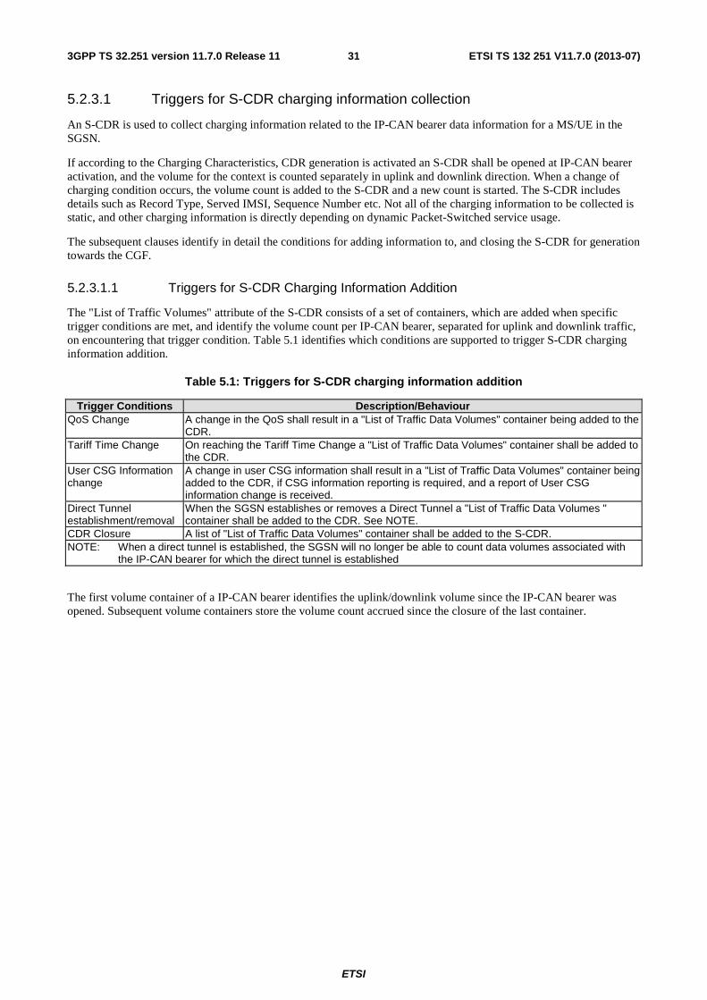
ETSI
ETSI TS 132 251 V11.7.0 (2013-07)313GPP TS 32.251 version 11.7.0 Release 11
5.2.3.1 Triggers for S-CDR charging information collection
An S-CDR is used to collect charging information related to the IP-CAN bearer data information for a MS/UE in the SGSN.
If according to the Charging Characteristics, CDR generation is activated an S-CDR shall be opened at IP-CAN bearer activation, and the volume for the context is counted separately in uplink and downlink direction. When a change of charging condition occurs, the volume count is added to the S-CDR and a new count is started. The S-CDR includes details such as Record Type, Served IMSI, Sequence Number etc. Not all of the charging information to be collected is static, and other charging information is directly depending on dynamic Packet-Switched service usage.
The subsequent clauses identify in detail the conditions for adding information to, and closing the S-CDR for generation towards the CGF.
5.2.3.1.1 Triggers for S-CDR Charging Information Addition
The "List of Traffic Volumes" attribute of the S-CDR consists of a set of containers, which are added when specific trigger conditions are met, and identify the volume count per IP-CAN bearer, separated for uplink and downlink traffic, on encountering that trigger condition. Table 5.1 identifies which conditions are supported to trigger S-CDR charging information addition.
Table 5.1: Triggers for S-CDR charging information addition
Trigger Conditions Description/Behaviour QoS Change A change in the QoS shall result in a "List of Traffic Data Volumes" container being added to the
CDR. Tariff Time Change On reaching the Tariff Time Change a "List of Traffic Data Volumes" container shall be added to
the CDR. User CSG Information change
A change in user CSG information shall result in a "List of Traffic Data Volumes" container being added to the CDR, if CSG information reporting is required, and a report of User CSG information change is received.
Direct Tunnel establishment/removal
When the SGSN establishes or removes a Direct Tunnel a "List of Traffic Data Volumes " container shall be added to the CDR. See NOTE.
CDR Closure A list of "List of Traffic Data Volumes" container shall be added to the S-CDR. NOTE: When a direct tunnel is established, the SGSN will no longer be able to count data volumes associated with
the IP-CAN bearer for which the direct tunnel is established
The first volume container of a IP-CAN bearer identifies the uplink/downlink volume since the IP-CAN bearer was opened. Subsequent volume containers store the volume count accrued since the closure of the last container.
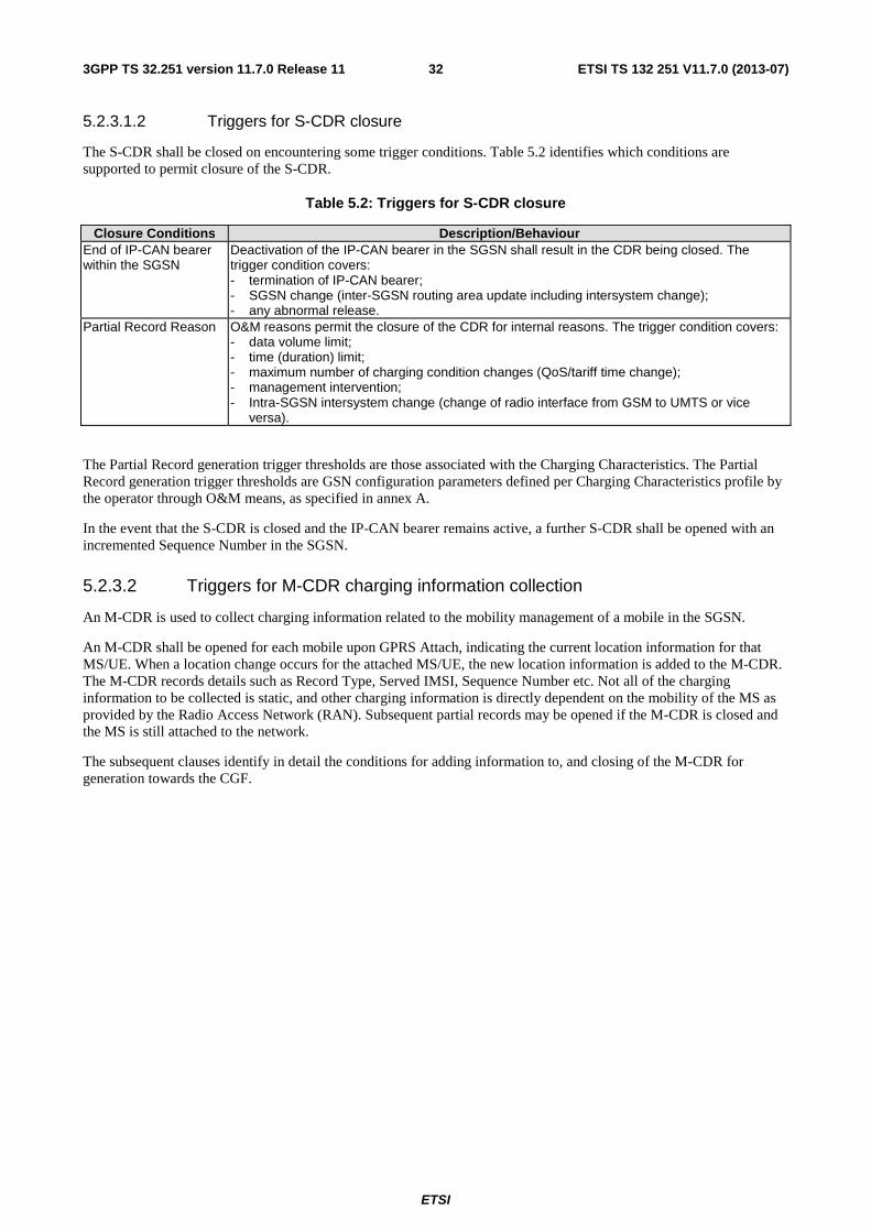
ETSI
ETSI TS 132 251 V11.7.0 (2013-07)323GPP TS 32.251 version 11.7.0 Release 11
5.2.3.1.2 Triggers for S-CDR closure
The S-CDR shall be closed on encountering some trigger conditions. Table 5.2 identifies which conditions are supported to permit closure of the S-CDR.
Table 5.2: Triggers for S-CDR closure
Closure Conditions Description/Behaviour End of IP-CAN bearer within the SGSN
Deactivation of the IP-CAN bearer in the SGSN shall result in the CDR being closed. The trigger condition covers: - termination of IP-CAN bearer; - SGSN change (inter-SGSN routing area update including intersystem change); - any abnormal release.
Partial Record Reason O&M reasons permit the closure of the CDR for internal reasons. The trigger condition covers: - data volume limit; - time (duration) limit; - maximum number of charging condition changes (QoS/tariff time change); - management intervention; - Intra-SGSN intersystem change (change of radio interface from GSM to UMTS or vice
versa).
The Partial Record generation trigger thresholds are those associated with the Charging Characteristics. The Partial Record generation trigger thresholds are GSN configuration parameters defined per Charging Characteristics profile by the operator through O&M means, as specified in annex A.
In the event that the S-CDR is closed and the IP-CAN bearer remains active, a further S-CDR shall be opened with an incremented Sequence Number in the SGSN.
5.2.3.2 Triggers for M-CDR charging information collection
An M-CDR is used to collect charging information related to the mobility management of a mobile in the SGSN.
An M-CDR shall be opened for each mobile upon GPRS Attach, indicating the current location information for that MS/UE. When a location change occurs for the attached MS/UE, the new location information is added to the M-CDR. The M-CDR records details such as Record Type, Served IMSI, Sequence Number etc. Not all of the charging information to be collected is static, and other charging information is directly dependent on the mobility of the MS as provided by the Radio Access Network (RAN). Subsequent partial records may be opened if the M-CDR is closed and the MS is still attached to the network.
The subsequent clauses identify in detail the conditions for adding information to, and closing of the M-CDR for generation towards the CGF.
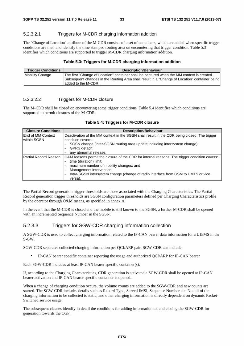
ETSI
ETSI TS 132 251 V11.7.0 (2013-07)333GPP TS 32.251 version 11.7.0 Release 11
5.2.3.2.1 Triggers for M-CDR charging information addition
The "Change of Location" attribute of the M-CDR consists of a set of containers, which are added when specific trigger conditions are met, and identify the time stamped routing area on encountering that trigger condition. Table 5.3 identifies which conditions are supported to trigger M-CDR charging information addition.
Table 5.3: Triggers for M-CDR charging information addition
Trigger Conditions Description/Behaviour Mobility Change The first "Change of Location" container shall be captured when the MM context is created.
Subsequent changes in the Routing Area shall result in a "Change of Location" container being added to the M-CDR.
5.2.3.2.2 Triggers for M-CDR closure
The M-CDR shall be closed on encountering some trigger conditions. Table 5.4 identifies which conditions are supported to permit closures of the M-CDR.
Table 5.4: Triggers for M-CDR closure
Closure Conditions Description/Behaviour End of MM Context within SGSN
Deactivation of the MM context in the SGSN shall result in the CDR being closed. The trigger condition covers: - SGSN change (inter-SGSN routing area update including intersystem change); - GPRS detach; - any abnormal release.
Partial Record Reason O&M reasons permit the closure of the CDR for internal reasons. The trigger condition covers: - time (duration) limit; - maximum number of mobility changes; and - Management intervention; - Intra-SGSN intersystem change (change of radio interface from GSM to UMTS or vice
versa).
The Partial Record generation trigger thresholds are those associated with the Charging Characteristics. The Partial Record generation trigger thresholds are SGSN configuration parameters defined per Charging Characteristics profile by the operator through O&M means, as specified in annex A.
In the event that the M-CDR is closed and the mobile is still known to the SGSN, a further M-CDR shall be opened with an incremented Sequence Number in the SGSN.
5.2.3.3 Triggers for SGW-CDR charging information collection
A SGW-CDR is used to collect charging information related to the IP-CAN bearer data information for a UE/MS in the S-GW.
SGW-CDR separates collected charging information per QCI/ARP pair. SGW-CDR can include
� IP-CAN bearer specific container reporting the usage and authorized QCI/ARP for IP-CAN bearer
Each SGW-CDR includes at least IP-CAN bearer specific container(s).
If, according to the Charging Characteristics, CDR generation is activated a SGW-CDR shall be opened at IP-CAN bearer activation and IP-CAN bearer specific container is opened..
When a change of charging condition occurs, the volume counts are added to the SGW-CDR and new counts are started. The SGW-CDR includes details such as Record Type, Served IMSI, Sequence Number etc. Not all of the charging information to be collected is static, and other charging information is directly dependent on dynamic Packet-Switched service usage.
The subsequent clauses identify in detail the conditions for adding information to, and closing the SGW-CDR for generation towards the CGF.
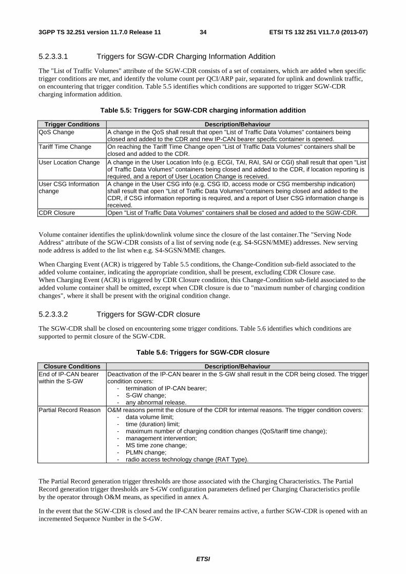
ETSI
ETSI TS 132 251 V11.7.0 (2013-07)343GPP TS 32.251 version 11.7.0 Release 11
5.2.3.3.1 Triggers for SGW-CDR Charging Information Addition
The "List of Traffic Volumes" attribute of the SGW-CDR consists of a set of containers, which are added when specific trigger conditions are met, and identify the volume count per QCI/ARP pair, separated for uplink and downlink traffic, on encountering that trigger condition. Table 5.5 identifies which conditions are supported to trigger SGW-CDR charging information addition.
Table 5.5: Triggers for SGW-CDR charging information addition
Trigger Conditions Description/Behaviour QoS Change A change in the QoS shall result that open "List of Traffic Data Volumes" containers being
closed and added to the CDR and new IP-CAN bearer specific container is opened. Tariff Time Change On reaching the Tariff Time Change open "List of Traffic Data Volumes" containers shall be
closed and added to the CDR. User Location Change A change in the User Location Info (e.g. ECGI, TAI, RAI, SAI or CGI) shall result that open "List
of Traffic Data Volumes" containers being closed and added to the CDR, if location reporting is required, and a report of User Location Change is received.
User CSG Information change
A change in the User CSG info (e.g. CSG ID, access mode or CSG membership indication) shall result that open "List of Traffic Data Volumes"containers being closed and added to the CDR, if CSG information reporting is required, and a report of User CSG information change is received.
CDR Closure Open "List of Traffic Data Volumes" containers shall be closed and added to the SGW-CDR.
Volume container identifies the uplink/downlink volume since the closure of the last container.The "Serving Node Address" attribute of the SGW-CDR consists of a list of serving node (e.g. S4-SGSN/MME) addresses. New serving node address is added to the list when e.g. S4-SGSN/MME changes.
When Charging Event (ACR) is triggered by Table 5.5 conditions, the Change-Condition sub-field associated to the added volume container, indicating the appropriate condition, shall be present, excluding CDR Closure case. When Charging Event (ACR) is triggered by CDR Closure condition, this Change-Condition sub-field associated to the added volume container shall be omitted, except when CDR closure is due to "maximum number of charging condition changes", where it shall be present with the original condition change.
5.2.3.3.2 Triggers for SGW-CDR closure
The SGW-CDR shall be closed on encountering some trigger conditions. Table 5.6 identifies which conditions are supported to permit closure of the SGW-CDR.
Table 5.6: Triggers for SGW-CDR closure
Closure Conditions Description/Behaviour End of IP-CAN bearer within the S-GW
Deactivation of the IP-CAN bearer in the S-GW shall result in the CDR being closed. The trigger condition covers:
- termination of IP-CAN bearer; - S-GW change; - any abnormal release.
Partial Record Reason O&M reasons permit the closure of the CDR for internal reasons. The trigger condition covers: - data volume limit; - time (duration) limit; - maximum number of charging condition changes (QoS/tariff time change); - management intervention; - MS time zone change; - PLMN change; - radio access technology change (RAT Type).
The Partial Record generation trigger thresholds are those associated with the Charging Characteristics. The Partial Record generation trigger thresholds are S-GW configuration parameters defined per Charging Characteristics profile by the operator through O&M means, as specified in annex A.
In the event that the SGW-CDR is closed and the IP-CAN bearer remains active, a further SGW-CDR is opened with an incremented Sequence Number in the S-GW.
ETSI
ETSI TS 132 251 V11.7.0 (2013-07)353GPP TS 32.251 version 11.7.0 Release 11
When Charging Event (ACR) is triggered by Table 5.6 conditions, the Change-Condition (at PS information level) associated to the CDR Closure, indicating the appropriate condition shall be present, and it shall be omitted otherwise.
5.2.3.4 Triggers for PGW-CDR charging information collection
An PGW-CDR is used to collect charging information related to the IP-CAN bearer data information for a UE/MS in the P-GW, where the data volumes, elapsed time or number of events within each PGW-CDR are separately counted per rating group or per combination of the rating group and service id. In case of P-GW is not aware of IP-CAN bearers, i.e. in case of PMIP based connectivity, P-GW collects charging information per IP-CAN session as it would be one IP-CAN bearer.
Many service data flow containers per IP-CAN bearer can be active simultaneously in PGW-CDR. A service data flow container is activated when traffic is detected and no matching active service data flow container exist; a service data flow container is closed when the termination of the last service data flow matching to the service data flow container is detected by the P-GW. When event based charging applies, the first occurrence of an event matching a service data flow template shall imply service data flow start. Details on FBC can be found in TS 23.203 [72] and TS 32.240 [1].
If, according to the Charging Characteristics profile, CDR generation is activated an PGW-CDR shall be opened at IP-CAN bearer activation, and the volume (separately in uplink and downlink direction), elapsed time and/or number of events are counted. When a change of charging condition occurs, all containers are added to the PGW-CDR. The PGW-CDR includes details such as Record Type, Served IMSI, Sequence Number etc. and the FBC specific charging data. Not all of the charging information to be collected is static, and other charging information is directly dependent on dynamic Packet-Switched service usage.
It shall be possible to activate both online and offline charging interfaces for same IP-CAN bearer. The default online and offline charging shall work independently of each other. Optionally it may be possible to operate in a tight interworking between online and offline charging mechanism i.e. only the specified quota re-authorisation triggers armed by OCS (including e.g. tariff time change, returned quotas, etc.) are used to close the service data flow containers for the PGW-CDR charging information addition.
The subsequent clauses identify in detail the conditions for adding information to, and closing the PGW-CDR for generation towards the CGF.
5.2.3.4.1 Triggers for PGW-CDR Charging Information Addition
IP-CAN bearer specific offline charging is achieved with IP-CAN bearer specific rating group/service identifier defined in clause 5.3.1.1.
The "List of Service Data" attribute of the PGW-CDR consists of a set of containers, which are added when specific trigger conditions are met. Each container identifies the configured counts (volume separated for uplink and downlink, elapsed time or number of events) per rating group or combination of the rating group and service id within the same IP-CAN bearer, on encountering that trigger condition. For envelope reporting, the containers represent complete and closed time envelopes determined by mechanisms defined in 3GPP TS 32.299 [50]. Table 5.8 identifies conditions that may be supported as recording triggers under consideration of additional DCCA triggers.
Some of the triggers are non-exclusive (e.g. IP-CAN bearer modification with a couple of reasons, IP-CAN bearer modification reasons that cause PGW-CDR closure).
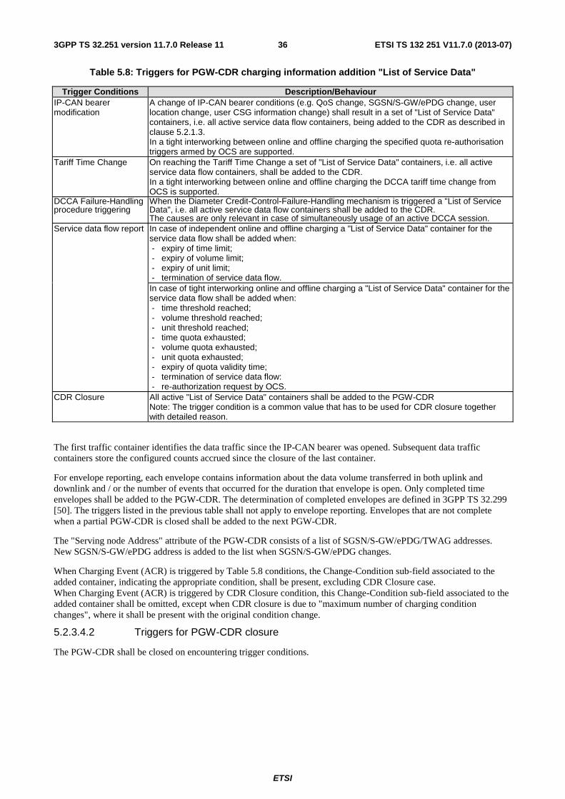
ETSI
ETSI TS 132 251 V11.7.0 (2013-07)363GPP TS 32.251 version 11.7.0 Release 11
Table 5.8: Triggers for PGW-CDR charging information addition "List of Service Data"
Trigger Conditions Description/Behaviour IP-CAN bearer modification
A change of IP-CAN bearer conditions (e.g. QoS change, SGSN/S-GW/ePDG change, user location change, user CSG information change) shall result in a set of "List of Service Data" containers, i.e. all active service data flow containers, being added to the CDR as described in clause 5.2.1.3. In a tight interworking between online and offline charging the specified quota re-authorisation triggers armed by OCS are supported.
Tariff Time Change On reaching the Tariff Time Change a set of "List of Service Data" containers, i.e. all active service data flow containers, shall be added to the CDR. In a tight interworking between online and offline charging the DCCA tariff time change from OCS is supported.
DCCA Failure-Handling procedure triggering
When the Diameter Credit-Control-Failure-Handling mechanism is triggered a "List of Service Data", i.e. all active service data flow containers shall be added to the CDR. The causes are only relevant in case of simultaneously usage of an active DCCA session.
Service data flow report In case of independent online and offline charging a "List of Service Data" container for the service data flow shall be added when: - expiry of time limit; - expiry of volume limit; - expiry of unit limit; - termination of service data flow.
In case of tight interworking online and offline charging a "List of Service Data" container for the service data flow shall be added when: - time threshold reached; - volume threshold reached; - unit threshold reached; - time quota exhausted; - volume quota exhausted; - unit quota exhausted; - expiry of quota validity time; - termination of service data flow: - re-authorization request by OCS.
CDR Closure All active "List of Service Data" containers shall be added to the PGW-CDR Note: The trigger condition is a common value that has to be used for CDR closure together with detailed reason.
The first traffic container identifies the data traffic since the IP-CAN bearer was opened. Subsequent data traffic containers store the configured counts accrued since the closure of the last container.
For envelope reporting, each envelope contains information about the data volume transferred in both uplink and downlink and / or the number of events that occurred for the duration that envelope is open. Only completed time envelopes shall be added to the PGW-CDR. The determination of completed envelopes are defined in 3GPP TS 32.299 [50]. The triggers listed in the previous table shall not apply to envelope reporting. Envelopes that are not complete when a partial PGW-CDR is closed shall be added to the next PGW-CDR.
The "Serving node Address" attribute of the PGW-CDR consists of a list of SGSN/S-GW/ePDG/TWAG addresses. New SGSN/S-GW/ePDG address is added to the list when SGSN/S-GW/ePDG changes.
When Charging Event (ACR) is triggered by Table 5.8 conditions, the Change-Condition sub-field associated to the added container, indicating the appropriate condition, shall be present, excluding CDR Closure case. When Charging Event (ACR) is triggered by CDR Closure condition, this Change-Condition sub-field associated to the added container shall be omitted, except when CDR closure is due to "maximum number of charging condition changes", where it shall be present with the original condition change.
5.2.3.4.2 Triggers for PGW-CDR closure
The PGW-CDR shall be closed on encountering trigger conditions.
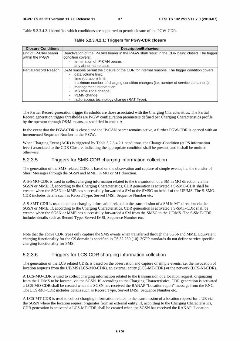
ETSI
ETSI TS 132 251 V11.7.0 (2013-07)373GPP TS 32.251 version 11.7.0 Release 11
Table 5.2.3.4.2.1 identifies which conditions are supported to permit closure of the PGW-CDR.
Table 5.2.3.4.2.1: Triggers for PGW-CDR closure
Closure Conditions Description/Behaviour End of IP-CAN bearer within the P-GW
Deactivation of the IP-CAN bearer in the P-GW shall result in the CDR being closed. The trigger condition covers:
- termination of IP-CAN bearer; - any abnormal release.
Partial Record Reason O&M reasons permit the closure of the CDR for internal reasons. The trigger condition covers: - data volume limit; - time (duration) limit; - maximum number of charging condition changes (i.e. number of service containers); - management intervention; - MS time zone change; - PLMN change; - radio access technology change (RAT Type).
The Partial Record generation trigger thresholds are those associated with the Charging Characteristics. The Partial Record generation trigger thresholds are P-GW configuration parameters defined per Charging Characteristics profile by the operator through O&M means, as specified in annex A.
In the event that the PGW-CDR is closed and the IP-CAN bearer remains active, a further PGW-CDR is opened with an incremented Sequence Number in the P-GW.
When Charging Event (ACR) is triggered by Table 5.2.3.4.2.1 conditions, the Change-Condition (at PS information level) associated to the CDR Closure, indicating the appropriate condition shall be present, and it shall be omitted otherwise.
5.2.3.5 Triggers for SMS-CDR charging information collection
The generation of the SMS related CDRs is based on the observation and capture of simple events, i.e. the transfer of Short Messages through the SGSN and MME, in MO or MT direction.
A S-SMO-CDR is used to collect charging information related to the transmission of a SM in MO direction via the SGSN or MME. If, according to the Charging Characteristics, CDR generation is activated a S-SMO-CDR shall be created when the SGSN or MME has successfully forwarded a SM to the SMSC on behalf of the UE/MS. The S-SMO-CDR includes details such as Record Type, Served IMSI, Sequence Number etc.
A S-SMT-CDR is used to collect charging information related to the transmission of a SM in MT direction via the SGSN or MME. If, according to the Charging Characteristics, CDR generation is activated a S-SMT-CDR shall be created when the SGSN or MME has successfully forwarded a SM from the SMSC to the UE/MS. The S-SMT-CDR includes details such as Record Type, Served IMSI, Sequence Number etc.
Note that the above CDR types only capture the SMS events when transferred through the SGSNand MME. Equivalent charging functionality for the CS domain is specified in TS 32.250 [10]. 3GPP standards do not define service specific charging functionality for SMS.
5.2.3.6 Triggers for LCS-CDR charging information collection
The generation of the LCS related CDRs is based on the observation and capture of simple events, i.e. the invocation of location requests from the UE/MS (LCS-MO-CDR), an external entity (LCS-MT-CDR) or the network (LCS-NI-CDR).
A LCS-MO-CDR is used to collect charging information related to the transmission of a location request, originating from the UE/MS to be located, via the SGSN. If, according to the Charging Characteristics, CDR generation is activated a LCS-MO-CDR shall be created when the SGSN has received the RANAP "Location report" message from the RNC. The LCS-MO-CDR includes details such as Record Type, Served IMSI, Sequence Number etc.
A LCS-MT-CDR is used to collect charging information related to the transmission of a location request for a UE via the SGSN where the location request originates from an external entity. If, according to the Charging Characteristics, CDR generation is activated a LCS-MT-CDR shall be created when the SGSN has received the RANAP "Location
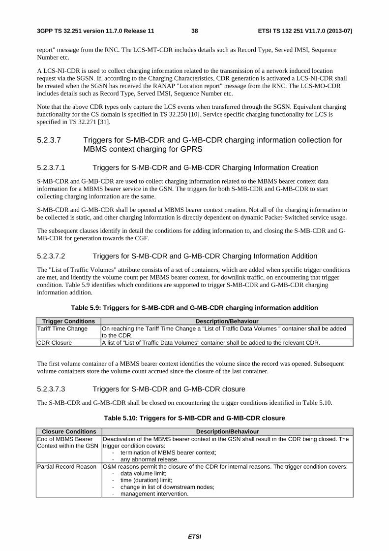
ETSI
ETSI TS 132 251 V11.7.0 (2013-07)383GPP TS 32.251 version 11.7.0 Release 11
report" message from the RNC. The LCS-MT-CDR includes details such as Record Type, Served IMSI, Sequence Number etc.
A LCS-NI-CDR is used to collect charging information related to the transmission of a network induced location request via the SGSN. If, according to the Charging Characteristics, CDR generation is activated a LCS-NI-CDR shall be created when the SGSN has received the RANAP "Location report" message from the RNC. The LCS-MO-CDR includes details such as Record Type, Served IMSI, Sequence Number etc.
Note that the above CDR types only capture the LCS events when transferred through the SGSN. Equivalent charging functionality for the CS domain is specified in TS 32.250 [10]. Service specific charging functionality for LCS is specified in TS 32.271 [31].
5.2.3.7 Triggers for S-MB-CDR and G-MB-CDR charging information collection for MBMS context charging for GPRS
5.2.3.7.1 Triggers for S-MB-CDR and G-MB-CDR Charging Information Creation
S-MB-CDR and G-MB-CDR are used to collect charging information related to the MBMS bearer context data information for a MBMS bearer service in the GSN. The triggers for both S-MB-CDR and G-MB-CDR to start collecting charging information are the same.
S-MB-CDR and G-MB-CDR shall be opened at MBMS bearer context creation. Not all of the charging information to be collected is static, and other charging information is directly dependent on dynamic Packet-Switched service usage.
The subsequent clauses identify in detail the conditions for adding information to, and closing the S-MB-CDR and G-MB-CDR for generation towards the CGF.
5.2.3.7.2 Triggers for S-MB-CDR and G-MB-CDR Charging Information Addition
The "List of Traffic Volumes" attribute consists of a set of containers, which are added when specific trigger conditions are met, and identify the volume count per MBMS bearer context, for downlink traffic, on encountering that trigger condition. Table 5.9 identifies which conditions are supported to trigger S-MB-CDR and G-MB-CDR charging information addition.
Table 5.9: Triggers for S-MB-CDR and G-MB-CDR charging information addition
Trigger Conditions Description/Behaviour Tariff Time Change On reaching the Tariff Time Change a "List of Traffic Data Volumes " container shall be added
to the CDR. CDR Closure A list of "List of Traffic Data Volumes" container shall be added to the relevant CDR.
The first volume container of a MBMS bearer context identifies the volume since the record was opened. Subsequent volume containers store the volume count accrued since the closure of the last container.
5.2.3.7.3 Triggers for S-MB-CDR and G-MB-CDR closure
The S-MB-CDR and G-MB-CDR shall be closed on encountering the trigger conditions identified in Table 5.10.
Table 5.10: Triggers for S-MB-CDR and G-MB-CDR closure
Closure Conditions Description/Behaviour End of MBMS Bearer Context within the GSN
Deactivation of the MBMS bearer context in the GSN shall result in the CDR being closed. The trigger condition covers:
- termination of MBMS bearer context; - any abnormal release.
Partial Record Reason O&M reasons permit the closure of the CDR for internal reasons. The trigger condition covers: - data volume limit; - time (duration) limit; - change in list of downstream nodes; - management intervention.
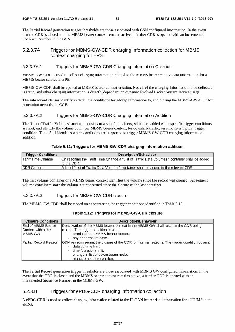
ETSI
ETSI TS 132 251 V11.7.0 (2013-07)393GPP TS 32.251 version 11.7.0 Release 11
The Partial Record generation trigger thresholds are those associated with GSN configured information. In the event that the CDR is closed and the MBMS bearer context remains active, a further CDR is opened with an incremented Sequence Number in the GSN.
5.2.3.7A Triggers for MBMS-GW-CDR charging information collection for MBMS context charging for EPS
5.2.3.7A.1 Triggers for MBMS-GW-CDR Charging Information Creation
MBMS-GW-CDR is used to collect charging information related to the MBMS bearer context data information for a MBMS bearer service in EPS.
MBMS-GW-CDR shall be opened at MBMS bearer context creation. Not all of the charging information to be collected is static, and other charging information is directly dependent on dynamic Evolved Packet System service usage.
The subsequent clauses identify in detail the conditions for adding information to, and closing the MBMS-GW-CDR for generation towards the CGF.
5.2.3.7A.2 Triggers for MBMS-GW-CDR Charging Information Addition
The "List of Traffic Volumes" attribute consists of a set of containers, which are added when specific trigger conditions are met, and identify the volume count per MBMS bearer context, for downlink traffic, on encountering that trigger condition. Table 5.11 identifies which conditions are supported to trigger MBMS-GW-CDR charging information addition.
Table 5.11: Triggers for MBMS-GW-CDR charging information addition
Trigger Conditions Description/Behaviour Tariff Time Change On reaching the Tariff Time Change a "List of Traffic Data Volumes " container shall be added
to the CDR. CDR Closure A list of "List of Traffic Data Volumes" container shall be added to the relevant CDR.
The first volume container of a MBMS bearer context identifies the volume since the record was opened. Subsequent volume containers store the volume count accrued since the closure of the last container.
5.2.3.7A.3 Triggers for MBMS-GW-CDR closure
The MBMS-GW-CDR shall be closed on encountering the trigger conditions identified in Table 5.12.
Table 5.12: Triggers for MBMS-GW-CDR closure
Closure Conditions Description/Behaviour End of MBMS Bearer Context within the MBMS GW
Deactivation of the MBMS bearer context in the MBMS GW shall result in the CDR being closed. The trigger condition covers:
- termination of MBMS bearer context; - any abnormal release.
Partial Record Reason O&M reasons permit the closure of the CDR for internal reasons. The trigger condition covers: - data volume limit; - time (duration) limit; - change in list of downstream nodes; - management intervention.
The Partial Record generation trigger thresholds are those associated with MBMS GW configured information. In the event that the CDR is closed and the MBMS bearer context remains active, a further CDR is opened with an incremented Sequence Number in the MBMS GW.
5.2.3.8 Triggers for ePDG-CDR charging information collection
A ePDG-CDR is used to collect charging information related to the IP-CAN bearer data information for a UE/MS in the ePDG.
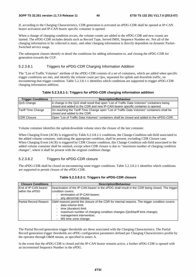
ETSI
ETSI TS 132 251 V11.7.0 (2013-07)403GPP TS 32.251 version 11.7.0 Release 11
If, according to the Charging Characteristics, CDR generation is activated an ePDG-CDR shall be opened at IP-CAN bearer activation and IP-CAN bearer specific container is opened.
When a change of charging condition occurs, the volume counts are added to the ePDG-CDR and new counts are started. The ePDG-CDR includes details such as Record Type, Served IMSI, Sequence Number etc. Not all of the charging information to be collected is static, and other charging information is directly dependent on dynamic Packet-Switched service usage.
The subsequent clauses identify in detail the conditions for adding information to, and closing the ePDG-CDR for generation towards the CGF.
5.2.3.8.1 Triggers for ePDG-CDR Charging Information Addition
The "List of Traffic Volumes" attribute of the ePDG-CDR consists of a set of containers, which are added when specific trigger conditions are met, and identify the volume count per Qos, separated for uplink and downlink traffic, on encountering that trigger condition. Table 5.2.3.8.1-1 identifies which conditions are supported to trigger ePDG-CDR charging information addition.
Table 5.2.3.8.1-1: Triggers for ePDG-CDR charging information addition
Trigger Conditions Description/Behaviour QoS Change A change in the QoS shall result that open "List of Traffic Data Volumes" containers being
closed and added to the CDR and new IP-CAN bearer specific container is opened. Tariff Time Change On reaching the Tariff Time Change open "List of Traffic Data Volumes" containers shall be
closed and added to the CDR. CDR Closure Open "List of Traffic Data Volumes" containers shall be closed and added to the ePDG-CDR.
Volume container identifies the uplink/downlink volume since the closure of the last container.
When Charging Event (ACR) is triggered by Table 5.2.3.8.1-1 conditions, the Change-Condition sub-field associated to the added volume container, indicating the appropriate condition, shall be present, excluding CDR Closure case. When Charging Event (ACR) is triggered by CDR Closure condition, this Change-Condition sub-field associated to the added volume container shall be omitted, except when CDR closure is due to "maximum number of charging condition changes", where it shall be present with the original condition change.
5.2.3.8.2 Triggers for ePDG-CDR closure
The ePDG-CDR shall be closed on encountering some trigger conditions. Table 5.2.3.8.2-1 identifies which conditions are supported to permit closure of the ePDG-CDR.
Table 5.2.3.8.2-1: Triggers for ePDG-CDR closure
Closure Conditions Description/Behaviour End of IP-CAN bearer within the ePDG
Deactivation of the IP-CAN bearer in the ePDG shall result in the CDR being closed. The trigger condition covers:
- termination of IP-CAN bearer; - any abnormal release.
Partial Record Reason O&M reasons permit the closure of the CDR for internal reasons. The trigger condition covers: - data volume limit; - time (duration) limit; - maximum number of charging condition changes (QoS/tariff time change); - management intervention; - MS time zone change;
The Partial Record generation trigger thresholds are those associated with the Charging Characteristics. The Partial Record generation trigger thresholds are ePDG configuration parameters defined per Charging Characteristics profile by the operator through O&M means, as specified in annex A.
In the event that the ePDG-CDR is closed and the IP-CAN bearer remains active, a further ePDG-CDR is opened with an incremented Sequence Number in the ePDG.
ETSI
ETSI TS 132 251 V11.7.0 (2013-07)413GPP TS 32.251 version 11.7.0 Release 11
When Charging Event (ACR) is triggered by Table 5.2.3.8.2-1 conditions, the Change-Condition (at PS information level) associated to the CDR Closure, indicating the appropriate condition shall be present, and it shall be omitted otherwise.
5.2.4 Void
5.2.5 Ga record transfer flows
In EPC, both fully qualified partial CDRs (FQPC) and reduced partial CDRs (RPC), as specified in TS 32.240 [1] may be supported on the Ga interface. In line with TS 32.240 [13], the support of FQPCs is mandatory, the support of RPCs is optional. For further details on the Ga protocol application refer to TS 32.295 [54].
5.2.6 Bp CDR file transfer
In EPC, both fully qualified partial CDRs (FQPC) and reduced partial CDRs (RPC), as specified in TS 32.240 [1] may be supported on the Bp interface. In line with TS 32.240 [13], the support of FQPCs is mandatory, the support of RPCs is optional. For further details on the Bp protocol application refer to TS 32.297 [52].
5.3 PS domain online charging scenarios
5.3.1 Basic principles
PS domain online charging may be performed in the SGSN using CAMEL techniques. This functionality is specified in TS 23.078 [206] and TS 29.078 [202] and is outside the scope of the present document.
PS domain online charging may be performed by the PCEF in the P-GW using the common Ro based credit control application specified in TS 32.299 [50]. In order to provide the data required for the management activities outlined in TS 32.240 [1] (credit control, accounting, statistics etc.), the PCEF shall be able to perform online charging for each of the following:
• Charging Data related to IP-CAN bearers;
• Charging Data related to service data flows.
The above items both pertain to sessions (IP-CAN bearers), hence session based online charging (SCUR) with centralized rating and centralized unit determination is required in the PCEF. The Credit Control Requests (CCR) and Credit Control Answers (CCA) specified for SCUR in TS 32.299 [50] (initial/update/termination) are issued towards the OCS / received from the OCS when certain conditions (chargeable events) are met. The PS domain specific contents and purpose of each of these messages, as well as the chargeable events that trigger them, are described in the following subclauses. A detailed formal description of the online charging parameters defined in the present document is to be found in 3GPP TS 32.299 [50]. Further information on the general principles of the common 3GPP online charging application can also be found in TS 32.299 [50] and TS 32.240 [1].
The credit control is always per rating group but the reporting level can be either per rating group or per combination of the rating group and service id. Reporting level is defined per PCC rule.
5.3.1.1 IP-CAN bearer charging
IP-CAN bearer online charging is achieved by FBC online charging, see clause 5.3.1.2. When the IP-CAN bearer is online charged by means of FBC, the quota handling shall also be based on the use of a Rating Group/Service Identifier. The value of this IP-CAN bearer specific Rating Group/Service Identifier shall be vendor specific.
The amount of data counted with IP-CAN bearer specific Rating Group/Service Identifier shall be the user plane payload at the tunnelling (e.g GTP-u, GRE Tunnel) interface. Time metering is started when IP-CAN bearer is activated.
ETSI
ETSI TS 132 251 V11.7.0 (2013-07)423GPP TS 32.251 version 11.7.0 Release 11
NOTE 1: P-GW is aware of bearers in case of GTP based connectivity. In case of any other PMIP based connectivity, P-GW is aware of IP-CAN sessions only. If P-GW is not aware of IP-CAN bearers, P-GW collects charging information per IP-CAN session as it would be just one IP-CAN bearer.
NOTE 2: The control plane IP address of SGSN or P-GW(acting as GGSN) is the IP address used at Gn/Gp interface. The control plane IP address of S-GW or P-GW is the IP address used at S5/S8 interface. The control plane IP address of ePDG or P-GW is the IP address used at S2b interface.
5.3.1.2 Flow Based Bearer Charging
IP-CAN bearer charging allows the P-GW to collect charging information related to data volumes sent to and received by the UE/MS, categorised by the QoS applied to the IP-CAN bearer. FBC is supported by the P-GW by the integrated PCEF. When the PCEF is present, the normal IP-CAN bearer charging is enhanced by the capability to categorise the service data flows within IP-CAN bearer data traffic by rating group or combination of the rating group and service id. I.e., while there is only one uplink an one downlink data volume count per IP-CAN bearer in IP-CAN bearer charging, FBC may provide one count per each rating group or combination of the rating group and service id. The level of the reporting is defined per PCC rule. Details of this functionality are specified in TS 23.203 [72] and TS 32.240 [1].
NOTE: The P-GW can only include one QoS Information occurrence per service data container. This implies if an operator wishes to be able to separate usage according to QCI and ARP within their billing system they will need to ensure that services having different QCI and ARP do not have the same:
- rating group in cases where rating reporting is used;
- rating group/service id where rating group/service id reporting is used.
Extended packet inspection can be done in the PCEF with pre-defined PCC rules. The PCEF also have the possibility to output service specific information related to the packet inspection in the online charging information.
According to TS 23.203 [72], FBC shall support different charging models per PCC rule. These charging models may be based on volume and/or time and on number of events matching a specific service data flow template in PCC rule. In general the charging of a service data flow shall be linked to the IP-CAN bearer under which the service data flow has been activated. In online charging the PCEF shall request the reservation of units prior to service delivery.
The following chargeable events are defined for FBC when online charging is activated:
� Network request for IP-CAN bearer activation before the Initiate IP-CAN bearer Activation message is sent. Associated with the network requested dedicated IP-CAN bearer activation procedure, as defined in TS 23.203 [72] and 23.060 [201], upon encountering this event, a CCR initial, indicating the request for activation of dedicated IP-CAN bearer is sent toward the OCS.
� Start of IP-CAN bearer. Upon encountering this event, a CCR initial, indicating the start of the IP-CAN bearer, is sent towards the OCS to authorize the IP-CAN bearer. For network requested dedicated IP-CAN bearer activation, this event triggers a CCR update, when the PCEF receives an Update PDP Context Request message with the RAN Procedures Ready flag. PCEF may request quota later when service usage is started.
� Start of service data flow. In case valid quota does not exist a CCR update is generated to request quota. The type of requested quota shall depend on measurement method configured for the PCC rule in case of decentralized unit determination. When event based charging applies, the first occurrence of an event matching a service data flow template in PCC rule shall be considered as the start of a service.
� Termination of service data flow. If reporting is per rating group and this is the last service data flow utilizing that specific rating group or if reporting is per combination of the rating group and service id and this is the last service data flow utilizing that specific rating group and service id, the required counters are updated. Termination of the service data flow itself does not trigger CCR update.
� End of IP-CAN bearer. Upon encountering this event, a CCR termination, indicating the end of the IP-CAN bearer, is sent towards the OCS together with the final counts.
� Ro specific chargeable events (e.g. threshold reached, QHT expires, quota exhaustion, validity time reached, forced re-authorization). Corresponding counts for the rating group(s) are closed and CCR update is triggered according the rules defined in TS 32.299 [50].
ETSI
ETSI TS 132 251 V11.7.0 (2013-07)433GPP TS 32.251 version 11.7.0 Release 11
� Change of charging condition: E.g. QoS change, user location change, user CSG information change. When this event is encountered and the corresponding re-authorization trigger is armed, all current counts are captured and sent towards the OCS with a CCR update.
� Tariff time change. When this event is encountered, all current counts are captured and a new counts are started. The counts are sent to the OCS in next CCR.
Management intervention may also force trigger a chargeable event.
PCC rules can be activated, deactivated and modified any time during the IP-CAN bearer lifetime. PCC rule activation, deactivation and modification are not chargeable events. However these PCC rule changes may lead to "start of service data flow" and "termination of service data flow" chargeable events. According to TS23.203[72] , the PCRF can modify the following charging information in a dynamic PCC rule which is active in the PCEF: Charging key, Service identifier, Measurement method, Service identifier level reporting. Change of Charging key, ServiceIdentifier, or measurement method will trigger a "start of service data flow" chargeable event when valid quota does not exist corresponding to that changed PCC rule. Change of Charging key, Service Identifier or measurement method, or/Service identifier level reporting will trigger a"termination of service data flow" chargeable event when this is the last service data flow utilizing the quota used for the original PCC rule.
5.3.1.3 PS Furnish Charging Information procedure
The OCS online charging function may use this procedure to add online charging session specific information to the PGW-CDR. The information can be sent per online session and in case FBC is enabled for a specific APN, the OCS online charging faction may also sent specific information per each online charged service by means this procedure.
5.3.1.4 Support of Failure Situations
In case the OCS fails, the P-GW shall support the Failure Handling procedure and Failover mechanism described in [50]. These mechanisms give flexibility to have different failure handling scenarios when the OCS fails.
Three different actions are described in [402]. P-GW shall support the following actions when the failure handling mechanism is executed:
• Terminate: The online session is finished. The associated IP-CAN bearer is released (ongoing sessions) or not established (new sessions). Failover for ongoing sessions is not supported. Failover for new sessions is always supported.
• Retry&Terminate: The online session is finished. The associated IP-CAN bearer is released (ongoing sessions) or not established (new sessions). Failover for ongoing sessions is supported. Failover for new sessions is always supported.
• Continue: The online session is finished. The associated IP-CAN bearer is established (new sessions) or not released (ongoing sessions). Failover for ongoing sessions is supported. Failover for new sessions is always supported.
In both cases, if the user is simultaneously online and offline charged, the failure situation shall be registered in the PGW-CDR. When the user is only online charged, the execution of the Failure Handling mechanism with value equal to Continue shall imply that a new PGW-CDR is opened.
5.3.2 Ro message flows
CCR initial, update and termination, as defined in TS 32.299 [50], are used by the P-GW to transfer the collected charging information towards the OCS. CCA is used by the OCS to assign quotas for the rating groups, and to instruct the P-GW whether to continue or terminate a service data flow(s) or IP-CAN bearer.
CCA is also used to communicate to the PCEF the Termination Action, i.e. the P-GW behaviour when the user has consumed the final granted units. The Termination Action is specified in TS 32.299 [50].
The P-GW uses Charging Characteristics profile to determine whether to activate or deactivate online charging. Further details of this functionality, including the mechanism of conveying the Charging Characteristics data item (HLR -> SGSN -> P-GW, or HSS->MME/S4-SGSN ->S-GW->P-GW, or AAA -> ePDG -> PGW), are specified in annex A.
ETSI
ETSI TS 132 251 V11.7.0 (2013-07)443GPP TS 32.251 version 11.7.0 Release 11
Editor"s note : "non-3GPP Charging Characteristics" conveyance from AGW to P-GW is ffs
The following clauses describe the trigger conditions for the chargeable events described in clause 5.3.1.1 and 5.3.1.2. In FBC online charging, these chargeable events correspond to the triggers for collection of charging information and CCR emission towards the OCS. The responses from the OCS and the detailed behaviour of the PCEF upon receiving those responses are also specified in the subclauses below.
5.3.2.1 Triggers for IP-CAN bearer Online Charging
IP-CAN bearer online charging is achieved by FBC online charging, see clause 5.3.2.2 below.
5.3.2.1.1 Void
5.3.2.1.2 Void
5.3.2.2 Triggers for FBC Online Charging
CCR initial / update / termination is used to convey charging information related to the IP-CAN bearer and service data flows collected in the PCEF. CCA is used by the OCS to return quotas for rating groups or to instruct the PCEF on the further handling of the IP-CAN bearer (terminate, continue, reroute, etc.). The CCR includes details such as CCR Type, Served IMSI, Sequence Number etc. The CCA includes details such as credit control quotas and session management instructions (continue, terminate, interim interval, etc). Not all of the charging information to be collected is static, and other charging information is directly dependent on dynamic Packet-Switched service usage.
FBC online charging is employed if it is activated for the IP-CAN bearer. The charging method in the PCC rule defines whether service data flow requires the online charging. The PCEF shall request the quota prior to service delivery. If only certain quotas are authorised by the OCS (e.g. due to insufficient credit), the rating groups for which no quota was authorised are handled according the received Result-Code AVP value. The quota supervision mechanism is further described in TS 32.299 [50]. Details on FBC can be found in TS 23.203 [72] and TS 29.212 [71].
CCR initial is sent to the OCS during the IP-CAN bearer activation. The OCS supplies a IP-CAN bearer authorisation and may supply volume, time or events quotas for the rating groups, based on the information provided by the PCEF, e.g. QoS, APN.
When start of the service data flow is detected and no valid quota exist, a CCR update is sent to request quota for the rating group unless the rating group is e.g. blacklisted. See TS 32.299 [50] for further information.
When a change of charging condition occurs and corresponding re-authorization trigger is armed, all MSCC instances are reported to the OCS with a CCR update with Reporting-Reason AVP value set to RATING_CONDITION_CHANGE together with Trigger-Type AVP indicating the accurate reason for the change.
When Ro specific chargeable event (e.g. threshold reached, QHT expires, quota exhaustion, validity time reached, forced re-authorization) occurs required MSCC instances are reported to OCS with a CCR update with corresponding Reporting-Reason AVP value. See TS 32.299 [50] for further information.
When tariff time change is encountered, the Tariff-Change-Usage AVP is used within the Used-Service-Units AVP to distinguish usage before and after the tariff time change. The MSCC instances are sent to the OCS in next CCR.
The OCS may specify the behaviour on consumption of the final granted units known as termination action. The required termination action is indicated with Final-Unit-Action AVP and possible values are TERMINATE and REDIRECT. See TS 32.299 [50] for further information.
TS 23.203 [72] specifies that it shall be possible to request online charging quotas for each charging key. Each quota allocated to a Diameter CC session has a unique Rating-Group AVP value. TS 23.203 [72] also specifies that PCEF shall report charging information for each combination of the charging key and service identifier when service identifier level reporting is present. As defined in TS 23.203 [72] the service identifier is a piece of information which provides the most detailed identification, specified for flow based charging, of a service data flow. The charging key is a piece of information used for rating purposes as defined in TS 23.203 [72]. The charging key and Service Identifier are mapped into the Rating-Group AVP and the Service-Identifier AVP respectively as defined in DCCA [402].
The subsequent clauses identify in detail the conditions for reporting online charging information, management of user and credit control sessions and PS domain quota supervision.
ETSI
ETSI TS 132 251 V11.7.0 (2013-07)453GPP TS 32.251 version 11.7.0 Release 11
5.3.2.2.1 Triggers for starting and stopping an FBC Credit Control session
CCR initial is sent to OCS when IP-CAN bearer is activated. For network requested dedicated IP-CAN bearer activation, the CCR initial is sent to the OCS when the PCEF determines a need for the IP-CAN bearer and before any signalling towards a mobile is initiated.
CCR terminate is sent to OCS when:
� IP-CAN bearer is deactivated
� Session termination is indicated by the OCS (e.g. Credit Limit Reached)
� Abort-Session-Request is received from the OCS, this also results in network initiated IP-CAN bearer deactivation.
5.3.2.2.2 Triggers for providing interim information for an FBC Credit Control session
CCR update is sent to OCS when:
� User starts to use certain service
� Start of service data flow (refer to 5.3.1.2)
� Termination of service data flow and this is the last service data flow utilizing corresponding to report level(refer to 5.3.1.2)
� Active service is removed from the allowed services
� Granted quota runs out
� Validity time for granted quota expires
� Update is requested by the OCS
� Change of charging conditions occur and according re-authorisation trigger re-authorisation is needed
� Management intervention
� Quota Holding Timer is expired
� For network requested dedicated IP-CAN bearer activation, reception of an Update PDP Context Request message with the RAN Procedures Ready flag.
ETSI
ETSI TS 132 251 V11.7.0 (2013-07)463GPP TS 32.251 version 11.7.0 Release 11
5.3.2.3 PS Furnish Charging Information procedure
The OCS online charging function may use this procedure to add online charging session specific information to the PGW-CDR by means of the Diameter Credit Control Application in the Ro interface. The data can be sent either in one Diameter Credit Control Credit-Control-Answer message or several Diameter Credit Control Credit-Control-Answer messages with append indicator.
The OCS online charging function can send multiple concatenated PS Furnish Charging Information elements per online charging session in the Ro interface. The OCS online charging function can also send multiple concatenated PS Furnish Information Element per each quota (i.e. per rating group).
The total maximum of free format data is 160 octets per service so the total maximum of free format data per online session is n*160 octets, where n indicates the number of rating groups activated per online session.
In the OCS online charging function a PS online charging session shall be identified by the P-GW control plane address and the ChargingId. In the P-GW, the PS online charging session and the PS offline charging session shall be identified by the same ChargingId. Therefore the ChargingId shall allow the P-GW to correlate an online charging session with an offline charging session.
This procedure can only apply when online and offline charging is performed simultaneously for the same session (IP-CAN bearer) or rating group. In any other case, the P-GW shall discard the additional charging information sent by the OCS in the Diameter Credit Control Credit-Control-Answer messages.
When the OCS sends session specific charging information, it must send the "PS-Furnish-Charging-Information" AVP at command level in the Credit-Control-Answer message. In this case, the information is added to the main body of the PGW-CDR. When the OCS sends service specific charging information , it must send the "PS-Furnish-Charging-Information" AVP at MSCC level in the Credit-Control-Answer message. In this case, the information is added to the specific service container in the PGW-CDR.
The PS Furnish Charging Information AVP is described in TS 32.299 [50].
5.3.2.4 Support of Failure Situations
In case the OCS fails the P-GW must support the Failure Handling procedure and Failover mechanism described in 3GPP TS 32.299 [50].
The Failure Handling Procedure affects the whole online session so in case FBC is enabled, the procedure shall affect all services activated during the IP-CAN bearer triggering the online charging session.
According to 3GPP TS 32.299 [50], timer Tx determines the maximum interval the P-GW shall wait for an answer to each credit control request sent to the OCS. In case FBC is enabled, it is possible that several concurrent Credit Control Request messages are triggered for the same online charging session. In this case, each Credit Control Request message shall reset the Tx timer. When Tx expires, P-GW shall execute the Failover and Failure Handling mechanisms according to the behaviour described in Annex B.
Three different actions are described in [402]. P-GW shall support the following actions when the failure handling mechanism is executed:
• Terminate: The online session is finished. The associated IP-CAN bearer is released (ongoing sessions) or not established (new sessions). Failover for ongoing sessions is not supported. Failover for new sessions is always supported.
• Retry&Terminate: The online session is finished. The associated IP-CAN bearer is released (ongoing sessions) or not established (new sessions). Failover for ongoing sessions is supported. Failover for new sessions is always supported.
• Continue: The online session is finished. The associated IP-CAN bearer is established (new sessions) or not released (ongoing sessions). Failover for ongoing sessions is supported. Failover for new sessions is always supported. It shall be operator configurable to limit the maximum duration of the IP-CAN bearer in this situation.
In case the user is simultaneously online and offline charged, the failure situation must be registered in the PGW-CDR. When the user is only online charged, the execution of the Failure Handling mechanism with value equal to Continue shall imply that a new PGW-CDR is opened.
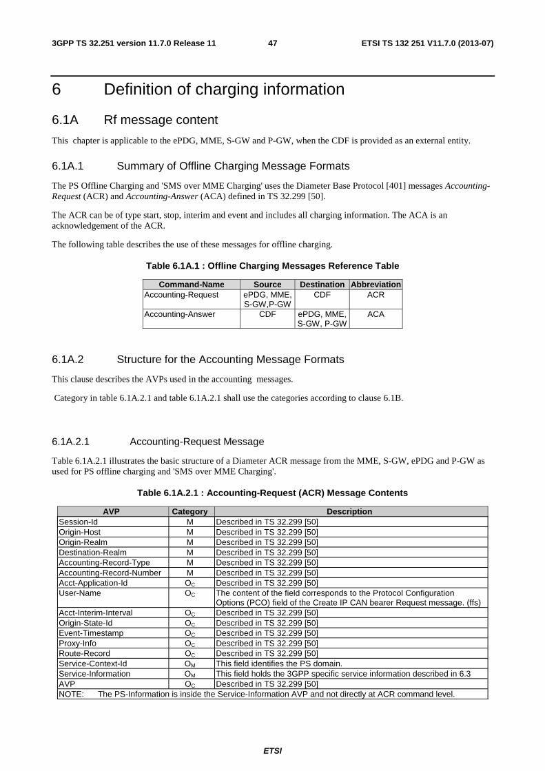
ETSI
ETSI TS 132 251 V11.7.0 (2013-07)473GPP TS 32.251 version 11.7.0 Release 11
6 Definition of charging information
6.1A Rf message content
This chapter is applicable to the ePDG, MME, S-GW and P-GW, when the CDF is provided as an external entity.
6.1A.1 Summary of Offline Charging Message Formats
The PS Offline Charging and 'SMS over MME Charging' uses the Diameter Base Protocol [401] messages Accounting-Request (ACR) and Accounting-Answer (ACA) defined in TS 32.299 [50].
The ACR can be of type start, stop, interim and event and includes all charging information. The ACA is an acknowledgement of the ACR.
The following table describes the use of these messages for offline charging.
Table 6.1A.1 : Offline Charging Messages Reference Table
Command-Name Source Destination Abbreviation Accounting-Request ePDG, MME,
S-GW,P-GW CDF ACR
Accounting-Answer CDF ePDG, MME, S-GW, P-GW
ACA
6.1A.2 Structure for the Accounting Message Formats
This clause describes the AVPs used in the accounting messages.
Category in table 6.1A.2.1 and table 6.1A.2.1 shall use the categories according to clause 6.1B.
6.1A.2.1 Accounting-Request Message
Table 6.1A.2.1 illustrates the basic structure of a Diameter ACR message from the MME, S-GW, ePDG and P-GW as used for PS offline charging and 'SMS over MME Charging'.
Table 6.1A.2.1 : Accounting-Request (ACR) Message Contents
AVP Category Description Session-Id M Described in TS 32.299 [50] Origin-Host M Described in TS 32.299 [50] Origin-Realm M Described in TS 32.299 [50] Destination-Realm M Described in TS 32.299 [50] Accounting-Record-Type M Described in TS 32.299 [50] Accounting-Record-Number M Described in TS 32.299 [50] Acct-Application-Id OC Described in TS 32.299 [50] User-Name OC The content of the field corresponds to the Protocol Configuration
Options (PCO) field of the Create IP CAN bearer Request message. (ffs) Acct-Interim-Interval OC Described in TS 32.299 [50] Origin-State-Id OC Described in TS 32.299 [50] Event-Timestamp OC Described in TS 32.299 [50] Proxy-Info OC Described in TS 32.299 [50] Route-Record OC Described in TS 32.299 [50] Service-Context-Id OM This field identifies the PS domain. Service-Information OM This field holds the 3GPP specific service information described in 6.3 AVP OC Described in TS 32.299 [50] NOTE: The PS-Information is inside the Service-Information AVP and not directly at ACR command level.

ETSI
ETSI TS 132 251 V11.7.0 (2013-07)483GPP TS 32.251 version 11.7.0 Release 11
NOTE: Detailed descriptions of the fields are provided in 3GPP TS 32.299 [50].
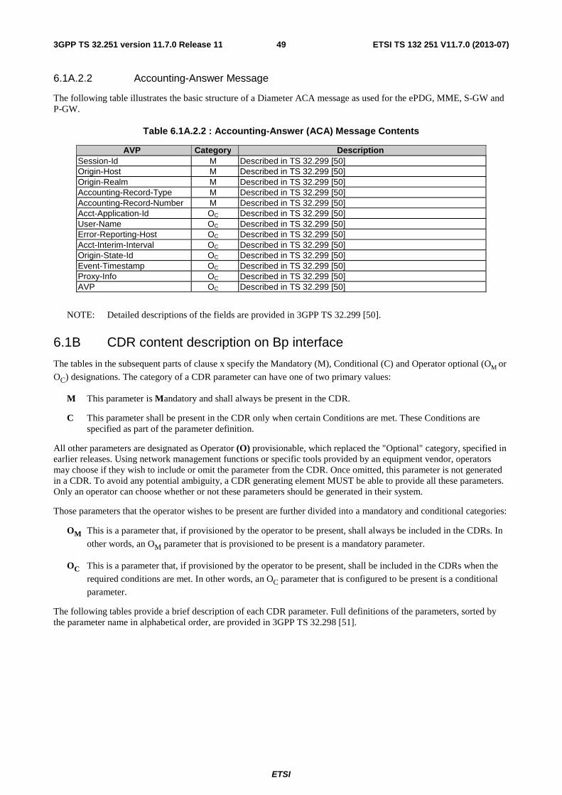
ETSI
ETSI TS 132 251 V11.7.0 (2013-07)493GPP TS 32.251 version 11.7.0 Release 11
6.1A.2.2 Accounting-Answer Message
The following table illustrates the basic structure of a Diameter ACA message as used for the ePDG, MME, S-GW and P-GW.
Table 6.1A.2.2 : Accounting-Answer (ACA) Message Contents
AVP Category Description Session-Id M Described in TS 32.299 [50] Origin-Host M Described in TS 32.299 [50] Origin-Realm M Described in TS 32.299 [50] Accounting-Record-Type M Described in TS 32.299 [50] Accounting-Record-Number M Described in TS 32.299 [50] Acct-Application-Id OC Described in TS 32.299 [50] User-Name OC Described in TS 32.299 [50] Error-Reporting-Host OC Described in TS 32.299 [50] Acct-Interim-Interval OC Described in TS 32.299 [50] Origin-State-Id OC Described in TS 32.299 [50] Event-Timestamp OC Described in TS 32.299 [50] Proxy-Info OC Described in TS 32.299 [50] AVP OC Described in TS 32.299 [50]
NOTE: Detailed descriptions of the fields are provided in 3GPP TS 32.299 [50].
6.1B CDR content description on Bp interface
The tables in the subsequent parts of clause x specify the Mandatory (M), Conditional (C) and Operator optional (OM or
OC) designations. The category of a CDR parameter can have one of two primary values:
M This parameter is Mandatory and shall always be present in the CDR.
C This parameter shall be present in the CDR only when certain Conditions are met. These Conditions are specified as part of the parameter definition.
All other parameters are designated as Operator (O) provisionable, which replaced the "Optional" category, specified in earlier releases. Using network management functions or specific tools provided by an equipment vendor, operators may choose if they wish to include or omit the parameter from the CDR. Once omitted, this parameter is not generated in a CDR. To avoid any potential ambiguity, a CDR generating element MUST be able to provide all these parameters. Only an operator can choose whether or not these parameters should be generated in their system.
Those parameters that the operator wishes to be present are further divided into a mandatory and conditional categories:
OM This is a parameter that, if provisioned by the operator to be present, shall always be included in the CDRs. In
other words, an OM parameter that is provisioned to be present is a mandatory parameter.
OC This is a parameter that, if provisioned by the operator to be present, shall be included in the CDRs when the
required conditions are met. In other words, an OC parameter that is configured to be present is a conditional
parameter.
The following tables provide a brief description of each CDR parameter. Full definitions of the parameters, sorted by the parameter name in alphabetical order, are provided in 3GPP TS 32.298 [51].
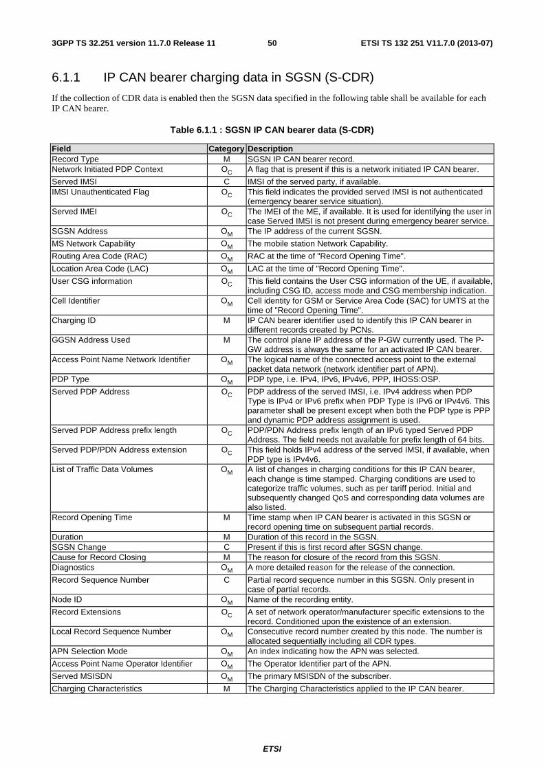
ETSI
ETSI TS 132 251 V11.7.0 (2013-07)503GPP TS 32.251 version 11.7.0 Release 11
6.1.1 IP CAN bearer charging data in SGSN (S-CDR)
If the collection of CDR data is enabled then the SGSN data specified in the following table shall be available for each IP CAN bearer.
Table 6.1.1 : SGSN IP CAN bearer data (S-CDR)
Field Category Description Record Type M SGSN IP CAN bearer record. Network Initiated PDP Context OC A flag that is present if this is a network initiated IP CAN bearer.
Served IMSI C IMSI of the served party, if available. IMSI Unauthenticated Flag OC This field indicates the provided served IMSI is not authenticated
(emergency bearer service situation). Served IMEI OC The IMEI of the ME, if available. It is used for identifying the user in
case Served IMSI is not present during emergency bearer service. SGSN Address OM The IP address of the current SGSN.
MS Network Capability OM The mobile station Network Capability.
Routing Area Code (RAC) OM RAC at the time of "Record Opening Time".
Location Area Code (LAC) OM LAC at the time of "Record Opening Time".
User CSG information OC This field contains the User CSG information of the UE, if available, including CSG ID, access mode and CSG membership indication.
Cell Identifier OM Cell identity for GSM or Service Area Code (SAC) for UMTS at the time of "Record Opening Time".
Charging ID M IP CAN bearer identifier used to identify this IP CAN bearer in different records created by PCNs.
GGSN Address Used M The control plane IP address of the P-GW currently used. The P-GW address is always the same for an activated IP CAN bearer.
Access Point Name Network Identifier OM The logical name of the connected access point to the external packet data network (network identifier part of APN).
PDP Type OM PDP type, i.e. IPv4, IPv6, IPv4v6, PPP, IHOSS:OSP.
Served PDP Address OC PDP address of the served IMSI, i.e. IPv4 address when PDP Type is IPv4 or IPv6 prefix when PDP Type is IPv6 or IPv4v6. This parameter shall be present except when both the PDP type is PPP and dynamic PDP address assignment is used.
Served PDP Address prefix length OC PDP/PDN Address prefix length of an IPv6 typed Served PDP Address. The field needs not available for prefix length of 64 bits.
Served PDP/PDN Address extension OC This field holds IPv4 address of the served IMSI, if available, when PDP type is IPv4v6.
List of Traffic Data Volumes OM A list of changes in charging conditions for this IP CAN bearer, each change is time stamped. Charging conditions are used to categorize traffic volumes, such as per tariff period. Initial and subsequently changed QoS and corresponding data volumes are also listed.
Record Opening Time M Time stamp when IP CAN bearer is activated in this SGSN or record opening time on subsequent partial records.
Duration M Duration of this record in the SGSN. SGSN Change C Present if this is first record after SGSN change. Cause for Record Closing M The reason for closure of the record from this SGSN. Diagnostics OM A more detailed reason for the release of the connection.
Record Sequence Number C Partial record sequence number in this SGSN. Only present in case of partial records.
Node ID OM Name of the recording entity.
Record Extensions OC A set of network operator/manufacturer specific extensions to the record. Conditioned upon the existence of an extension.
Local Record Sequence Number OM Consecutive record number created by this node. The number is allocated sequentially including all CDR types.
APN Selection Mode OM An index indicating how the APN was selected.
Access Point Name Operator Identifier OM The Operator Identifier part of the APN.
Served MSISDN OM The primary MSISDN of the subscriber.
Charging Characteristics M The Charging Characteristics applied to the IP CAN bearer.
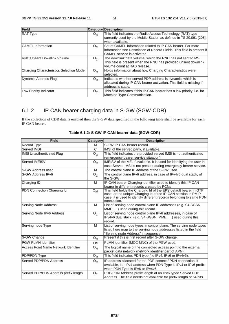
ETSI
ETSI TS 132 251 V11.7.0 (2013-07)513GPP TS 32.251 version 11.7.0 Release 11
Field Category Description RAT Type OC This field indicates the Radio Access Technology (RAT) type
currently used by the Mobile Station as defined in TS 29.061 [205], when available.
CAMEL Information OC Set of CAMEL information related to IP CAN bearer. For more information see Description of Record Fields. This field is present if CAMEL service is activated.
RNC Unsent Downlink Volume OC The downlink data volume, which the RNC has not sent to MS. This field is present when the RNC has provided unsent downlink volume count at RAB release.
Charging Characteristics Selection Mode OM Holds information about how Charging Characteristics were selected.
Dynamic Address Flag OC Indicates whether served PDP address is dynamic, which is allocated during IP CAN bearer activation. This field is missing if address is static.
Low Priority Indicator OC This field indicates if this IP-CAN bearer has a low priority, i.e. for Machine Type Communication.
6.1.2 IP CAN bearer charging data in S-GW (SGW-CDR)
If the collection of CDR data is enabled then the S-GW data specified in the following table shall be available for each IP CAN bearer.
Table 6.1.2: S-GW IP CAN bearer data (SGW-CDR)
Field Category Description Record Type M S-GW IP CAN bearer record. Served IMSI C IMSI of the served party, if available. IMSI Unauthenticated Flag OC This field indicates the provided served IMSI is not authenticated
(emergency bearer service situation). Served IMEISV OC IMEISV of the ME, if available. It is used for identifying the user in
case Served IMSI is not present during emergency bearer service. S-GW Address used M The control plane IP address of the S-GW used. S-GW Address IPv6 OC The control plane IPv6 address, in case of IPv4v6 dual stack, of
the S-GW. Charging ID M IP CAN bearer Charging identifier used to identify this IP CAN
bearer in different records created by PCNs PDN Connection Charging Id OM This field holds the Charging Id of the EPS default bearer in GTP
case, or the unique Charging Id of the IP-CAN session in PMIP case: it is used to identify different records belonging to same PDN connection.
Serving Node Address M List of serving node control plane IP addresses (e.g. S4-SGSN, MME, …) used during this record.
Serving Node IPv6 Address OC List of serving node control plane IPv6 addresses, in case of IPv4v6 dual stack, (e.g. S4-SGSN, MME, …) used during this record.
Serving node Type M List of serving node types in control plane. The serving node types listed here map to the serving node addresses listed in the field "Serving node Address" in sequence.
S-GW Change OC Present if this is first record after S-GW change.
PGW PLMN Identifier Oc PLMN identifier (MCC MNC) of the PGW used. Access Point Name Network Identifier OM The logical name of the connected access point to the external
packet data network (network identifier part of APN). PDP/PDN Type OM This field indicates PDN type (i.e IPv4, IPv6 or IPv4v6).
Served PDP/PDN Address OC IP address allocated for the PDP context / PDN connection, if available, i.e. IPv4 address when PDN Type is IPv4 or IPv6 prefix when PDN Type is IPv6 or IPv4v6.
Served PDP/PDN Address prefix length OC PDP/PDN Address prefix length of an IPv6 typed Served PDP Address. The field needs not available for prefix length of 64 bits.
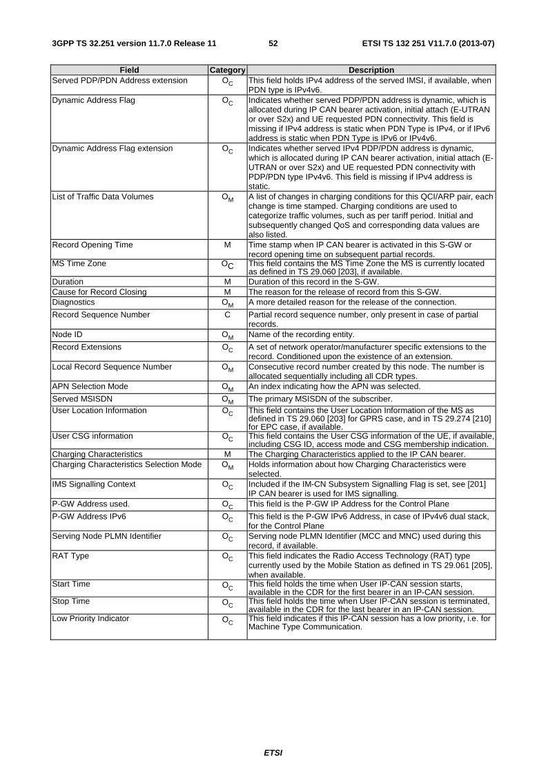
ETSI
ETSI TS 132 251 V11.7.0 (2013-07)523GPP TS 32.251 version 11.7.0 Release 11
Field Category Description Served PDP/PDN Address extension OC This field holds IPv4 address of the served IMSI, if available, when
PDN type is IPv4v6. Dynamic Address Flag OC Indicates whether served PDP/PDN address is dynamic, which is
allocated during IP CAN bearer activation, initial attach (E-UTRAN or over S2x) and UE requested PDN connectivity. This field is missing if IPv4 address is static when PDN Type is IPv4, or if IPv6 address is static when PDN Type is IPv6 or IPv4v6.
Dynamic Address Flag extension OC Indicates whether served IPv4 PDP/PDN address is dynamic, which is allocated during IP CAN bearer activation, initial attach (E-UTRAN or over S2x) and UE requested PDN connectivity with PDP/PDN type IPv4v6. This field is missing if IPv4 address is static.
List of Traffic Data Volumes OM A list of changes in charging conditions for this QCI/ARP pair, each change is time stamped. Charging conditions are used to categorize traffic volumes, such as per tariff period. Initial and subsequently changed QoS and corresponding data values are also listed.
Record Opening Time M Time stamp when IP CAN bearer is activated in this S-GW or record opening time on subsequent partial records.
MS Time Zone OC This field contains the MS Time Zone the MS is currently located as defined in TS 29.060 [203], if available.
Duration M Duration of this record in the S-GW. Cause for Record Closing M The reason for the release of record from this S-GW. Diagnostics OM A more detailed reason for the release of the connection.
Record Sequence Number C Partial record sequence number, only present in case of partial records.
Node ID OM Name of the recording entity.
Record Extensions OC A set of network operator/manufacturer specific extensions to the record. Conditioned upon the existence of an extension.
Local Record Sequence Number OM Consecutive record number created by this node. The number is allocated sequentially including all CDR types.
APN Selection Mode OM An index indicating how the APN was selected.
Served MSISDN OM The primary MSISDN of the subscriber. User Location Information OC This field contains the User Location Information of the MS as
defined in TS 29.060 [203] for GPRS case, and in TS 29.274 [210] for EPC case, if available.
User CSG information OC This field contains the User CSG information of the UE, if available, including CSG ID, access mode and CSG membership indication.
Charging Characteristics M The Charging Characteristics applied to the IP CAN bearer. Charging Characteristics Selection Mode OM Holds information about how Charging Characteristics were
selected. IMS Signalling Context OC Included if the IM-CN Subsystem Signalling Flag is set, see [201]
IP CAN bearer is used for IMS signalling. P-GW Address used. OC This field is the P-GW IP Address for the Control Plane
P-GW Address IPv6 OC This field is the P-GW IPv6 Address, in case of IPv4v6 dual stack, for the Control Plane
Serving Node PLMN Identifier OC Serving node PLMN Identifier (MCC and MNC) used during this record, if available.
RAT Type OC This field indicates the Radio Access Technology (RAT) type currently used by the Mobile Station as defined in TS 29.061 [205], when available.
Start Time OC This field holds the time when User IP-CAN session starts, available in the CDR for the first bearer in an IP-CAN session.
Stop Time OC This field holds the time when User IP-CAN session is terminated, available in the CDR for the last bearer in an IP-CAN session.
Low Priority Indicator OC This field indicates if this IP-CAN session has a low priority, i.e. for Machine Type Communication.
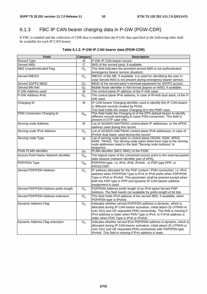
ETSI
ETSI TS 132 251 V11.7.0 (2013-07)533GPP TS 32.251 version 11.7.0 Release 11
6.1.3 FBC IP CAN bearer charging data in P-GW (PGW-CDR)
If FBC is enabled and the collection of CDR data is enabled then the P-GW data specified in the following table shall be available for each IP CAN bearer.
Table 6.1.3: P-GW IP CAN bearer data (PGW-CDR)
Field Category Description Record Type M P-GW IP CAN bearer record. Served IMSI C IMSI of the served party, if available. IMSI Unauthenticated Flag OC This field indicates the provided served IMSI is not authenticated
(emergency bearer service situation). Served IMEISV OC IMEISV of the ME, if available. It is used for identifying the user in
case Served IMSI is not present during emergency bearer service. Served 3GPP2 MEID OC MEID of the served party"s terminal equipment for 3GPP2 access. Served MN NAI OC Mobile Node Identifier in NAI format (based on IMSI), if available. P-GW Address used M The control plane IP address of the P-GW used. P-GW Address IPv6 OC The control plane IPv6 address, in case of IPv4v6 dual stack, of the P-
GW used. Charging ID M IP CAN bearer Charging identifier used to identify this IP CAN bearer
in different records created by PCNs This field holds the unique Charging Id in the PMIP case.
PDN Connection Charging Id OM This field holds the Charging Id of the EPS default bearer to identify different records belonging to same PDN connection. This field is present in GTP case only.
Serving node Address M List of SGSN/S-GW/TWAG control plane IP addresses, or the ePDG address used during this record.
Serving node IPv6 Address OC List of SGSN/S-GW/TWAG control plane IPv6 addresses, in case of IPv4v6 dual stack, used during this record.
Serving node Type M List of serving node types in control plane (SGSN, SGW, ePDG, AGW, TWAG). The serving node types listed here map to the serving node addresses listed in the field "Serving node Address" in sequence.
PGW PLMN Identifier Oc PLMN identifier (MCC MNC) of the PGW. Access Point Name Network Identifier OM The logical name of the connected access point to the external packet
data network (network identifier part of APN). PDP/PDN Type OM PDP/PDN type, i.e. IPv4, IPv6, IPv4v6 , or PDP type PPP, or
IHOSS:OSP. Served PDP/PDN Address OC IP address allocated for the PDP context / PDN connection, i.e. IPv4
address when PDP/PDN Type is IPv4 or IPv6 prefix when PDP/PDN Type is IPv6 or IPv4v6. This parameter shall be present except when both the PDP type is PPP and dynamic IP CAN bearer address assignment is used.
Served PDP/PDN Address prefix length OC PDP/PDN Address prefix length of an IPv6 typed Served PDP Address. The field needs not available for prefix length of 64 bits.
Served PDP/PDN Address extension OC This field holds IPv4 address of the served IMSI, if available, when PDP/PDN type is IPv4v6.
Dynamic Address Flag OC Indicates whether served PDP/PDN address is dynamic, which is allocated during IP CAN bearer activation, initial attach (E-UTRAN or over S2x) and UE requested PDN connectivity. This field is missing if IPv4 address is static when PDN Type is IPv4, or if IPv6 address is static when PDN Type is IPv6 or IPv4v6.
Dynamic Address Flag extension OC Indicates whether served IPv4 PDP/PDN address is dynamic, which is allocated during IP CAN bearer activation, initial attach (E-UTRAN or over S2x) and UE requested PDN connectivity with PDP/PDN type IPv4v6. This field is missing if IPv4 address is static.
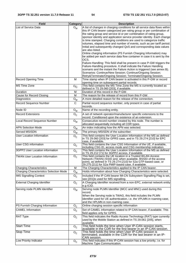
ETSI
ETSI TS 132 251 V11.7.0 (2013-07)543GPP TS 32.251 version 11.7.0 Release 11
Field Category Description List of Service Data OM A list of changes in charging conditions for all service data flows within
this IP CAN bearer categorized per rating group or per combination of the rating group and service id or per combination of rating group, sponsor identity and application service provider identity. Each change is time stamped. Charging conditions are used to categorize traffic volumes, elapsed time and number of events, such as per tariff period. Initial and subsequently changed QoS and corresponding data values are also listed. Online charging information (PS Furnish Charging Information) may be added per each service data flow container in case it is sent by the OCS. Failure-Handling: This field shall be present in case P-GW triggers the Failure-Handling procedure. It shall indicate the Failure Handling scenario and the instant the Failure Action is triggered (see annex B). Scenarios: Continue/New Session; Continue/Ongoing Session; Retry&Terminate/Ongoing Session; Terminate/Ongoing Session.
Record Opening Time M Time stamp when IP CAN bearer is activated in this P-GW or record opening time on subsequent partial records.
MS Time Zone OC This field contains the MS Time Zone the MS is currently located as defined in TS 29.060 [203], if available.
Duration M Duration of this record in the P-GW. Cause for Record Closing M The reason for the release of record from this P-GW. Diagnostics OM A more detailed reason for the release of the connection.
Record Sequence Number C Partial record sequence number, only present in case of partial records.
Node ID OM Name of the recording entity.
Record Extensions OC A set of network operator/manufacturer specific extensions to the record. Conditioned upon the existence of an extension.
Local Record Sequence Number OM Consecutive record number created by this node. The number is allocated sequentially including all CDR types.
APN Selection Mode OM An index indicating how the APN was selected.
Served MSISDN OM The primary MSISDN of the subscriber. User Location Information OC This field contains the User Location Information of the MS as defined
in TS 29.060 [203] for GPRS case, and in TS 29.274 [210] for EPC case, if available.
User CSG information OC This field contains the User CSG Information of the UE, if available, including CSG ID, access mode and CSG membership indication.
3GPP2 User Location information OC This field contains the User Location Information of the MS as defined in TS 29.212 [71] for 3GPP2 access, if available.
TWAN User Location Information OC This field contains the UE location in a Trusted WLAN Access Network (TWAN) (SSID and, when available, BSSID of the access point), as defined in TS 29.274 [210] for S2a GTP-based case, or 29.275 [211] for S2a PMIP-based case, if available.
Charging Characteristics M The Charging Characteristics applied to the IP CAN bearer. Charging Characteristics Selection Mode OM Holds information about how Charging Characteristics were selected.
IMS Signalling Context OC Included if the IP CAN bearer IM-CN Subsystem Signalling Flag is set, see [201]is used for IMS signalling.
External Charging Identifier OC A Charging Identifier received from a non-EPC, external network entity e.g ICID.
Serving node PLMN Identifier OM Serving node PLMN Identifier (MCC and MNC) used during this record. When the Serving node is TWAG, this field includes the PLMN identifier used for UE authentication, i.e. the VPLMN in roaming case, and the HPLMN in non-roaming case.
PS Furnish Charging Information OC Online charging session specific information
CAMEL Information OC Set of CAMEL information related to IP CAN bearer, if available. This field applies only for GPRS.
RAT Type OC This field indicates the Radio Access Technology (RAT) type currently used by the Mobile Station as defined in TS 29.061 [205], when available.
Start Time OC This field holds the time when User IP-CAN session starts, available in the CDR for the first bearer in an IP-CAN session.
Stop Time OC This field holds the time when User IP-CAN session is terminated, available in the CDR for the last bearer in an IP-CAN session.
Low Priority Indicator OC This field indicates if this IP-CAN session has a low priority, i.e. for Machine Type Communication.

ETSI
ETSI TS 132 251 V11.7.0 (2013-07)553GPP TS 32.251 version 11.7.0 Release 11
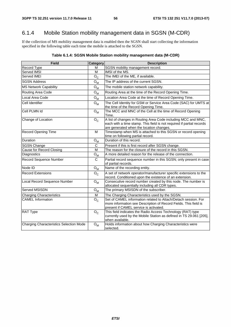
ETSI
ETSI TS 132 251 V11.7.0 (2013-07)563GPP TS 32.251 version 11.7.0 Release 11
6.1.4 Mobile Station mobility management data in SGSN (M-CDR)
If the collection of MS mobility management data is enabled then the SGSN shall start collecting the information specified in the following table each time the mobile is attached to the SGSN.
Table 6.1.4: SGSN Mobile Station mobility management data (M-CDR)
Field Category Description Record Type M SGSN mobility management record. Served IMSI M IMSI of the MS. Served IMEI OC The IMEI of the ME, if available.
SGSN Address OM The IP address of the current SGSN.
MS Network Capability OM The mobile station network capability.
Routing Area Code OM Routing Area at the time of the Record Opening Time.
Local Area Code OM Location Area Code at the time of Record Opening Time.
Cell Identifier OM The Cell Identity for GSM or Service Area Code (SAC) for UMTS at the time of the Record Opening Time.
Cell PLMN Id OM The MCC and MNC of the Cell at the time of Record Opening Time.
Change of Location OC A list of changes in Routing Area Code including MCC and MNC, each with a time stamp. This field is not required if partial records are generated when the location changes.
Record Opening Time M Timestamp when MS is attached to this SGSN or record opening time on following partial record.
Duration OM Duration of this record.
SGSN Change C Present if this is first record after SGSN change. Cause for Record Closing M The reason for the closure of the record in this SGSN. Diagnostics OM A more detailed reason for the release of the connection.
Record Sequence Number C Partial record sequence number in this SGSN; only present in case of partial records.
Node ID OM Name of the recording entity.
Record Extensions OC A set of network operator/manufacturer specific extensions to the record. Conditioned upon the existence of an extension.
Local Record Sequence Number OM Consecutive record number created by this node. The number is allocated sequentially including all CDR types.
Served MSISDN OM The primary MSISDN of the subscriber.
Charging Characteristics M The Charging Characteristics used by the SGSN. CAMEL Information OC Set of CAMEL information related to Attach/Detach session. For
more information see Description of Record Fields. This field is present if CAMEL service is activated.
RAT Type OC This field indicates the Radio Access Technology (RAT) type currently used by the Mobile Station as defined in TS 29.061 [205], when available.
Charging Characteristics Selection Mode OM Holds information about how Charging Characteristics were selected.
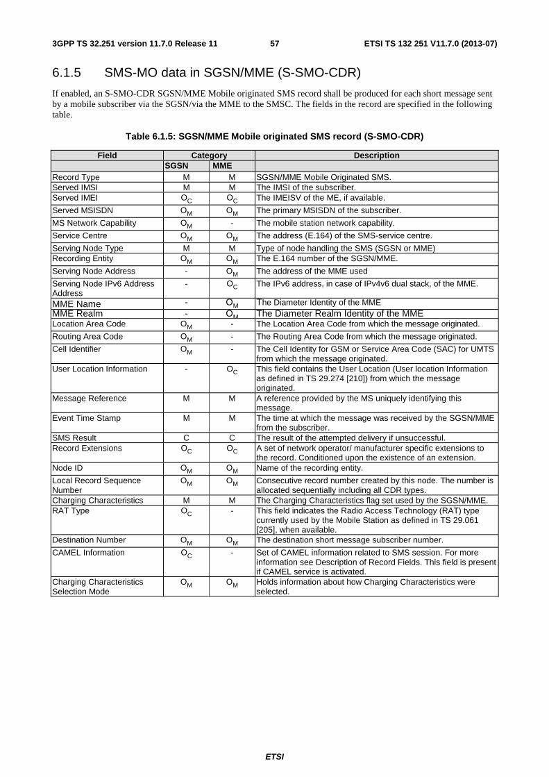
ETSI
ETSI TS 132 251 V11.7.0 (2013-07)573GPP TS 32.251 version 11.7.0 Release 11
6.1.5 SMS-MO data in SGSN/MME (S-SMO-CDR)
If enabled, an S-SMO-CDR SGSN/MME Mobile originated SMS record shall be produced for each short message sent by a mobile subscriber via the SGSN/via the MME to the SMSC. The fields in the record are specified in the following table.
Table 6.1.5: SGSN/MME Mobile originated SMS record (S-SMO-CDR)
Field Category Description SGSN MME
Record Type M M SGSN/MME Mobile Originated SMS. Served IMSI M M The IMSI of the subscriber. Served IMEI OC OC The IMEISV of the ME, if available.
Served MSISDN OM OM The primary MSISDN of the subscriber.
MS Network Capability OM - The mobile station network capability.
Service Centre OM OM The address (E.164) of the SMS-service centre.
Serving Node Type M M Type of node handling the SMS (SGSN or MME) Recording Entity OM OM The E.164 number of the SGSN/MME.
Serving Node Address - OM The address of the MME used
Serving Node IPv6 Address Address
- OC The IPv6 address, in case of IPv4v6 dual stack, of the MME.
MME Name - OM The Diameter Identity of the MME MME Realm - OM The Diameter Realm Identity of the MME Location Area Code OM - The Location Area Code from which the message originated.
Routing Area Code OM - The Routing Area Code from which the message originated.
Cell Identifier OM - The Cell Identity for GSM or Service Area Code (SAC) for UMTS from which the message originated.
User Location Information - OC This field contains the User Location (User location Information as defined in TS 29.274 [210]) from which the message originated.
Message Reference M M A reference provided by the MS uniquely identifying this message.
Event Time Stamp M M The time at which the message was received by the SGSN/MME from the subscriber.
SMS Result C C The result of the attempted delivery if unsuccessful. Record Extensions OC OC A set of network operator/ manufacturer specific extensions to
the record. Conditioned upon the existence of an extension. Node ID OM OM Name of the recording entity.
Local Record Sequence Number
OM OM Consecutive record number created by this node. The number is allocated sequentially including all CDR types.
Charging Characteristics M M The Charging Characteristics flag set used by the SGSN/MME. RAT Type OC - This field indicates the Radio Access Technology (RAT) type
currently used by the Mobile Station as defined in TS 29.061 [205], when available.
Destination Number OM OM The destination short message subscriber number.
CAMEL Information OC - Set of CAMEL information related to SMS session. For more information see Description of Record Fields. This field is present if CAMEL service is activated.
Charging Characteristics Selection Mode
OM OM Holds information about how Charging Characteristics were selected.
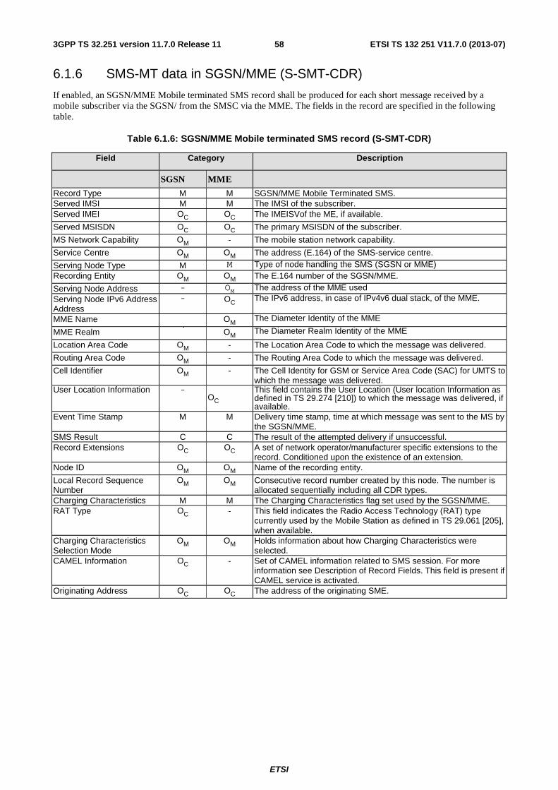
ETSI
ETSI TS 132 251 V11.7.0 (2013-07)583GPP TS 32.251 version 11.7.0 Release 11
6.1.6 SMS-MT data in SGSN/MME (S-SMT-CDR)
If enabled, an SGSN/MME Mobile terminated SMS record shall be produced for each short message received by a mobile subscriber via the SGSN/ from the SMSC via the MME. The fields in the record are specified in the following table.
Table 6.1.6: SGSN/MME Mobile terminated SMS record (S-SMT-CDR)
Field Category Description
SGSN MME
Record Type M M SGSN/MME Mobile Terminated SMS. Served IMSI M M The IMSI of the subscriber. Served IMEI OC OC The IMEISVof the ME, if available.
Served MSISDN OC OC The primary MSISDN of the subscriber.
MS Network Capability OM - The mobile station network capability.
Service Centre OM OM The address (E.164) of the SMS-service centre.
Serving Node Type M M Type of node handling the SMS (SGSN or MME) Recording Entity OM OM The E.164 number of the SGSN/MME.
Serving Node Address - OM The address of the MME used Serving Node IPv6 Address Address
- OC The IPv6 address, in case of IPv4v6 dual stack, of the MME.
MME Name � OM The Diameter Identity of the MME
MME Realm � OM The Diameter Realm Identity of the MME
Location Area Code OM - The Location Area Code to which the message was delivered.
Routing Area Code OM - The Routing Area Code to which the message was delivered.
Cell Identifier OM - The Cell Identity for GSM or Service Area Code (SAC) for UMTS to which the message was delivered.
User Location Information -OC
This field contains the User Location (User location Information as defined in TS 29.274 [210]) to which the message was delivered, if available.
Event Time Stamp M M Delivery time stamp, time at which message was sent to the MS by the SGSN/MME.
SMS Result C C The result of the attempted delivery if unsuccessful. Record Extensions OC OC A set of network operator/manufacturer specific extensions to the
record. Conditioned upon the existence of an extension. Node ID OM OM Name of the recording entity.
Local Record Sequence Number
OM OM Consecutive record number created by this node. The number is allocated sequentially including all CDR types.
Charging Characteristics M M The Charging Characteristics flag set used by the SGSN/MME. RAT Type OC - This field indicates the Radio Access Technology (RAT) type
currently used by the Mobile Station as defined in TS 29.061 [205], when available.
Charging Characteristics Selection Mode
OM OM Holds information about how Charging Characteristics were selected.
CAMEL Information OC - Set of CAMEL information related to SMS session. For more information see Description of Record Fields. This field is present if CAMEL service is activated.
Originating Address OC OC The address of the originating SME.
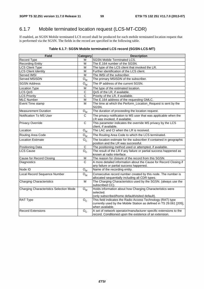
ETSI
ETSI TS 132 251 V11.7.0 (2013-07)593GPP TS 32.251 version 11.7.0 Release 11
6.1.7 Mobile terminated location request (LCS-MT-CDR)
If enabled, an SGSN Mobile terminated LCS record shall be produced for each mobile terminated location request that is performed via the SGSN. The fields in the record are specified in the following table.
Table 6.1.7: SGSN Mobile terminated LCS record (SGSN-LCS-MT)
Field Category Description Record Type M SGSN Mobile Terminated LCS. Recording Entity M The E.164 number of the SGSN. LCS Client Type M The type of the LCS client that invoked the LR. LCS Client Identity M Further identification of the LCS client. Served IMSI M The IMSI of the subscriber. Served MSISDN OM The primary MSISDN of the subscriber.
SGSN Address OM The IP address of the current SGSN.
Location Type M The type of the estimated location. LCS QoS C QoS of the LR, if available. LCS Priority C Priority of the LR, if available. MLC Number M The E.164 address of the requesting GMLC. Event Time stamp M The time at which the Perform_Location_Request is sent by the
SGSN. Measurement Duration OM The duration of proceeding the location request.
Notification To MS User C The privacy notification to MS user that was applicable when the LR was invoked, if available.
Privacy Override C This parameter indicates the override MS privacy by the LCS client, if available.
Location OM The LAC and CI when the LR is received.
Routing Area Code OM The Routing Area Code to which the LCS terminated.
Location Estimate OC The location estimate for the subscriber if contained in geographic position and the LR was successful.
Positioning Data C The positioning method used or attempted, if available. LCS Cause OC The result of the LR if any failure or partial success happened as
known at radio interface. Cause for Record Closing M The reason for closure of the record from this SGSN. Diagnostics C A more detailed information about the Cause for Record Closing if
any failure or partial success happened. Node ID OM Name of the recording entity.
Local Record Sequence Number OM Consecutive record number created by this node. The number is allocated sequentially including all CDR types.
Charging Characteristics M The Charging Characteristics used by the SGSN. (always use the subscribed CC).
Charging Characteristics Selection Mode OM Holds information about how Charging Characteristics were selected. (only subscribed/home default/visited default).
RAT Type OC This field indicates the Radio Access Technology (RAT) type currently used by the Mobile Station as defined in TS 29.061 [205], when available.
Record Extensions OC A set of network operator/manufacturer specific extensions to the record. Conditioned upon the existence of an extension.
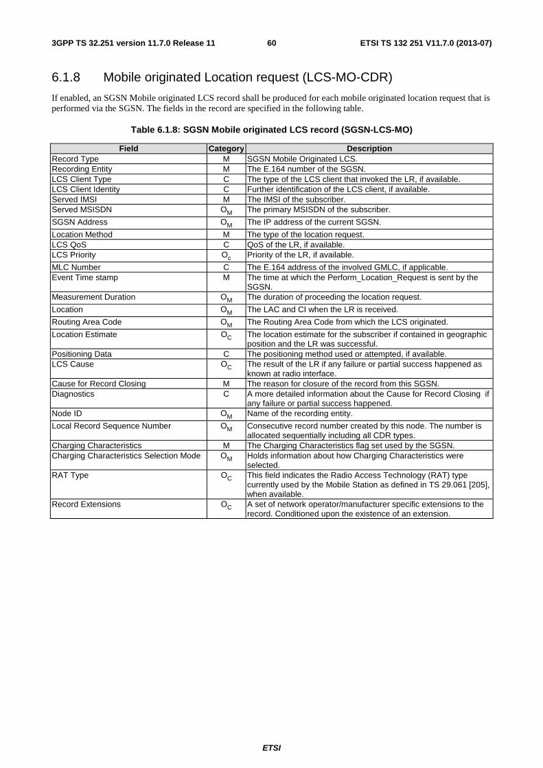
ETSI
ETSI TS 132 251 V11.7.0 (2013-07)603GPP TS 32.251 version 11.7.0 Release 11
6.1.8 Mobile originated Location request (LCS-MO-CDR)
If enabled, an SGSN Mobile originated LCS record shall be produced for each mobile originated location request that is performed via the SGSN. The fields in the record are specified in the following table.
Table 6.1.8: SGSN Mobile originated LCS record (SGSN-LCS-MO)
Field Category Description Record Type M SGSN Mobile Originated LCS. Recording Entity M The E.164 number of the SGSN. LCS Client Type C The type of the LCS client that invoked the LR, if available. LCS Client Identity C Further identification of the LCS client, if available. Served IMSI M The IMSI of the subscriber. Served MSISDN OM The primary MSISDN of the subscriber.
SGSN Address OM The IP address of the current SGSN.
Location Method M The type of the location request. LCS QoS C QoS of the LR, if available. LCS Priority Oc Priority of the LR, if available.
MLC Number C The E.164 address of the involved GMLC, if applicable. Event Time stamp M The time at which the Perform_Location_Request is sent by the
SGSN. Measurement Duration OM The duration of proceeding the location request.
Location OM The LAC and CI when the LR is received.
Routing Area Code OM The Routing Area Code from which the LCS originated.
Location Estimate OC The location estimate for the subscriber if contained in geographic position and the LR was successful.
Positioning Data C The positioning method used or attempted, if available. LCS Cause OC The result of the LR if any failure or partial success happened as
known at radio interface. Cause for Record Closing M The reason for closure of the record from this SGSN. Diagnostics C A more detailed information about the Cause for Record Closing if
any failure or partial success happened. Node ID OM Name of the recording entity.
Local Record Sequence Number OM Consecutive record number created by this node. The number is allocated sequentially including all CDR types.
Charging Characteristics M The Charging Characteristics flag set used by the SGSN. Charging Characteristics Selection Mode OM Holds information about how Charging Characteristics were
selected. RAT Type OC This field indicates the Radio Access Technology (RAT) type
currently used by the Mobile Station as defined in TS 29.061 [205], when available.
Record Extensions OC A set of network operator/manufacturer specific extensions to the record. Conditioned upon the existence of an extension.
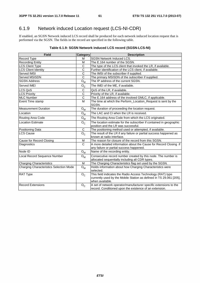
ETSI
ETSI TS 132 251 V11.7.0 (2013-07)613GPP TS 32.251 version 11.7.0 Release 11
6.1.9 Network induced Location request (LCS-NI-CDR)
If enabled, an SGSN Network induced LCS record shall be produced for each network induced location request that is performed via the SGSN. The fields in the record are specified in the following table.
Table 6.1.9: SGSN Network induced LCS record (SGSN-LCS-NI)
Field Category Description Record Type M SGSN Network Induced LCS. Recording Entity M The E.164 number of the SGSN. LCS Client Type C The type of the LCS client that invoked the LR, if available. LCS Client Identity C Further identification of the LCS client, if available. Served IMSI C The IMSI of the subscriber if supplied. Served MSISDN C The primary MSISDN of the subscriber if supplied. SGSN Address OM The IP address of the current SGSN.
Served IMEI OC The IMEI of the ME, if available.
LCS QoS C QoS of the LR, if available. LCS Priority C Priority of the LR, if available. MLC Number C The E.164 address of the involved GMLC, if applicable. Event Time stamp M The time at which the Perform_Location_Request is sent by the
SGSN. Measurement Duration OM The duration of proceeding the location request.
Location OM The LAC and CI when the LR is received.
Routing Area Code OM The Routing Area Code from which the LCS originated.
Location Estimate OC The location estimate for the subscriber if contained in geographic position and the LR was successful.
Positioning Data C The positioning method used or attempted, if available. LCS Cause OC The result of the LR if any failure or partial success happened as
known at radio interface. Cause for Record Closing M The reason for closure of the record from this SGSN. Diagnostics C A more detailed information about the Cause for Record Closing if
any failure or partial success happened. Node ID OM Name of the recording entity.
Local Record Sequence Number OM Consecutive record number created by this node. The number is allocated sequentially including all CDR types.
Charging Characteristics M The Charging Characteristics flag set used by the SGSN. Charging Characteristics Selection Mode OM Holds information about how Charging Characteristics were
selected. RAT Type OC This field indicates the Radio Access Technology (RAT) type
currently used by the Mobile Station as defined in TS 29.061 [205], when available.
Record Extensions OC A set of network operator/manufacturer specific extensions to the record. Conditioned upon the existence of an extension.
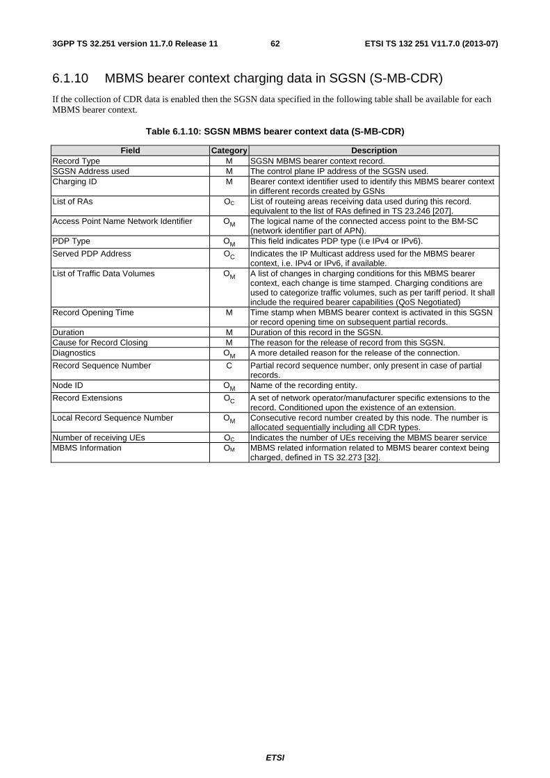
ETSI
ETSI TS 132 251 V11.7.0 (2013-07)623GPP TS 32.251 version 11.7.0 Release 11
6.1.10 MBMS bearer context charging data in SGSN (S-MB-CDR)
If the collection of CDR data is enabled then the SGSN data specified in the following table shall be available for each MBMS bearer context.
Table 6.1.10: SGSN MBMS bearer context data (S-MB-CDR)
Field Category Description Record Type M SGSN MBMS bearer context record. SGSN Address used M The control plane IP address of the SGSN used. Charging ID M Bearer context identifier used to identify this MBMS bearer context
in different records created by GSNs List of RAs OC List of routeing areas receiving data used during this record.
equivalent to the list of RAs defined in TS 23.246 [207]. Access Point Name Network Identifier OM The logical name of the connected access point to the BM-SC
(network identifier part of APN). PDP Type OM This field indicates PDP type (i.e IPv4 or IPv6).
Served PDP Address OC Indicates the IP Multicast address used for the MBMS bearer context, i.e. IPv4 or IPv6, if available.
List of Traffic Data Volumes OM A list of changes in charging conditions for this MBMS bearer context, each change is time stamped. Charging conditions are used to categorize traffic volumes, such as per tariff period. It shall include the required bearer capabilities (QoS Negotiated)
Record Opening Time M Time stamp when MBMS bearer context is activated in this SGSN or record opening time on subsequent partial records.
Duration M Duration of this record in the SGSN. Cause for Record Closing M The reason for the release of record from this SGSN. Diagnostics OM A more detailed reason for the release of the connection.
Record Sequence Number C Partial record sequence number, only present in case of partial records.
Node ID OM Name of the recording entity.
Record Extensions OC A set of network operator/manufacturer specific extensions to the record. Conditioned upon the existence of an extension.
Local Record Sequence Number OM Consecutive record number created by this node. The number is allocated sequentially including all CDR types.
Number of receiving UEs OC Indicates the number of UEs receiving the MBMS bearer service MBMS Information OM MBMS related information related to MBMS bearer context being
charged, defined in TS 32.273 [32].
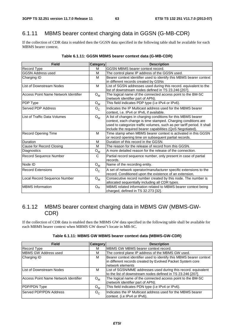
ETSI
ETSI TS 132 251 V11.7.0 (2013-07)633GPP TS 32.251 version 11.7.0 Release 11
6.1.11 MBMS bearer context charging data in GGSN (G-MB-CDR)
If the collection of CDR data is enabled then the GGSN data specified in the following table shall be available for each MBMS bearer context.
Table 6.1.11: GGSN MBMS bearer context data (G-MB-CDR)
Field Category Description Record Type M GGSN MBMS bearer context record. GGSN Address used M The control plane IP address of the GGSN used. Charging ID M Bearer context identifier used to identify this MBMS bearer context
in different records created by GSNs List of Downstream Nodes M List of SGSN addresses used during this record. equivalent to the
list of downstream nodes defined in TS 23.246 [207]. Access Point Name Network Identifier OM The logical name of the connected access point to the BM-SC
(network identifier part of APN). PDP Type OM This field indicates PDP type (i.e IPv4 or IPv6).
Served PDP Address OC Indicates the IP Multicast address used for the MBMS bearer context, i.e. IPv4 or IPv6, if available.
List of Traffic Data Volumes OM A list of changes in charging conditions for this MBMS bearer context, each change is time stamped. Charging conditions are used to categorize traffic volumes, such as per tariff period. It shall include the required bearer capabilities (QoS Negotiated).
Record Opening Time M Time stamp when MBMS bearer context is activated in this GGSN or record opening time on subsequent partial records.
Duration M Duration of this record in the GGSN. Cause for Record Closing M The reason for the release of record from this GGSN. Diagnostics OM A more detailed reason for the release of the connection.
Record Sequence Number C Partial record sequence number, only present in case of partial records.
Node ID OM Name of the recording entity.
Record Extensions OC A set of network operator/manufacturer specific extensions to the record. Conditioned upon the existence of an extension.
Local Record Sequence Number OM Consecutive record number created by this node. The number is allocated sequentially including all CDR types.
MBMS Information OM MBMS related information related to MBMS bearer context being charged, defined in TS 32.273 [32].
6.1.12 MBMS bearer context charging data in MBMS GW (MBMS-GW-CDR)
If the collection of CDR data is enabled then the MBMS GW data specified in the following table shall be available for each MBMS bearer context when MBMS GW doesn"t locate in MB-SC.
Table 6.1.11: MBMS GW MBMS bearer context data (MBMS-GW-CDR)
Field Category Description Record Type M MBMS GW MBMS bearer context record. MBMS GW Address used M The control plane IP address of the MBMS GW used. Charging ID M Bearer context identifier used to identify this MBMS bearer context
in different records created by Evolved Packet System core network elements
List of Downstream Nodes M List of SGSN/MME addresses used during this record. equivalent to the list of downstream nodes defined in TS 23.246 [207].
Access Point Name Network Identifier OM The logical name of the connected access point to the BM-SC (network identifier part of APN).
PDP/PDN Type OM This field indicates PDN type (i.e IPv4 or IPv6).
Served PDP/PDN Address OC Indicates the IP Multicast address used for the MBMS bearer context. (i.e IPv4 or IPv6).
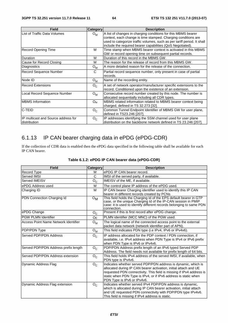
ETSI
ETSI TS 132 251 V11.7.0 (2013-07)643GPP TS 32.251 version 11.7.0 Release 11
Field Category Description List of Traffic Data Volumes OM A list of changes in charging conditions for this MBMS bearer
context, each change is time stamped. Charging conditions are used to categorize traffic volumes, such as per tariff period. It shall include the required bearer capabilities (QoS Negotiated).
Record Opening Time M Time stamp when MBMS bearer context is activated in this MBMS GW or record opening time on subsequent partial records.
Duration M Duration of this record in the MBMS GW. Cause for Record Closing M The reason for the release of record from this MBMS GW. Diagnostics OM A more detailed reason for the release of the connection.
Record Sequence Number C Partial record sequence number, only present in case of partial records.
Node ID OM Name of the recording entity.
Record Extensions OC A set of network operator/manufacturer specific extensions to the record. Conditioned upon the existence of an extension.
Local Record Sequence Number OM Consecutive record number created by this node. The number is allocated sequentially including all CDR types.
MBMS Information OM MBMS related information related to MBMS bearer context being charged, defined in TS 32.273 [32].
C-TEID OC Common Tunnel Endpoint Identifier of MBMS GW for user plane, defined in TS23.246 [207].
IP multicast and Source address for distribution
OC IP addresses identifying the SSM channel used for user plane distribution on the backbone network defined in TS 23.246 [207].
6.1.13 IP CAN bearer charging data in ePDG (ePDG-CDR)
If the collection of CDR data is enabled then the ePDG data specified in the following table shall be available for each IP CAN bearer.
Table 6.1.2: ePDG IP CAN bearer data (ePDG-CDR)
Field Category Description Record Type M ePDG IP CAN bearer record. Served IMSI C IMSI of the served party, if available. Served IMEISV OC IMEISV of the ME, if available.
ePDG Address used M The control plane IP address of the ePDG used. Charging ID M IP CAN bearer Charging identifier used to identify this IP CAN
bearer in different records created by PCNs PDN Connection Charging Id OM This field holds the Charging Id of the EPS default bearer in GTP
case, or the unique Charging Id of the IP-CAN session in PMIP case: it is used to identify different records belonging to same PDN connection.
ePDG Change OC Present if this is first record after ePDG change.
PGW PLMN Identifier Oc PLMN identifier (MCC MNC) of the PGW used. Access Point Name Network Identifier OM The logical name of the connected access point to the external
packet data network (network identifier part of APN). PDP/PDN Type OM This field indicates PDN type (i.e IPv4, IPv6 or IPv4v6).
Served PDP/PDN Address OC IP address allocated for the PDP context / PDN connection, if available, i.e. IPv4 address when PDN Type is IPv4 or IPv6 prefix when PDN Type is IPv6 or IPv4v6.
Served PDP/PDN Address prefix length OC PDP/PDN Address prefix length of an IPv6 typed Served PDP Address. The field needs not available for prefix length of 64 bits.
Served PDP/PDN Address extension OC This field holds IPv4 address of the served IMSI, if available, when PDN type is IPv4v6.
Dynamic Address Flag OC Indicates whether served PDP/PDN address is dynamic, which is allocated during IP CAN bearer activation, initial attach and UE requested PDN connectivity. This field is missing if IPv4 address is static when PDN Type is IPv4, or if IPv6 address is static when PDN Type is IPv6 or IPv4v6.
Dynamic Address Flag extension OC Indicates whether served IPv4 PDP/PDN address is dynamic, which is allocated during IP CAN bearer activation, initial attach and UE requested PDN connectivity with PDP/PDN type IPv4v6. This field is missing if IPv4 address is static.
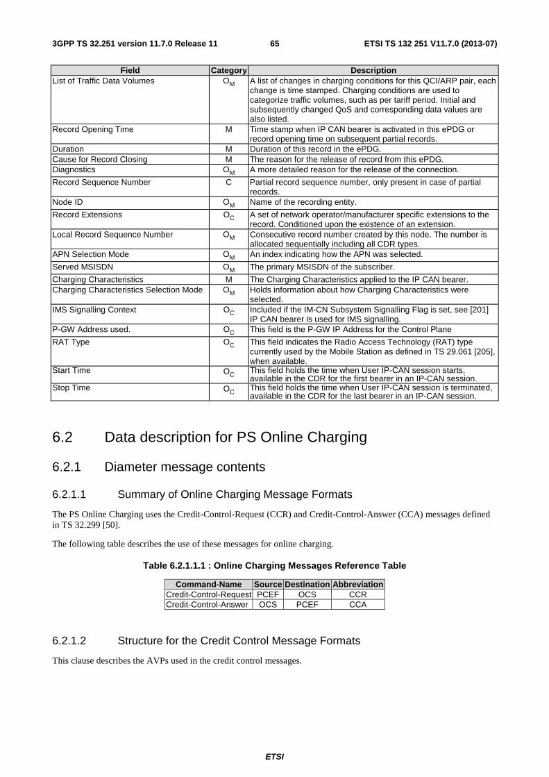
ETSI
ETSI TS 132 251 V11.7.0 (2013-07)653GPP TS 32.251 version 11.7.0 Release 11
Field Category Description List of Traffic Data Volumes OM A list of changes in charging conditions for this QCI/ARP pair, each
change is time stamped. Charging conditions are used to categorize traffic volumes, such as per tariff period. Initial and subsequently changed QoS and corresponding data values are also listed.
Record Opening Time M Time stamp when IP CAN bearer is activated in this ePDG or record opening time on subsequent partial records.
Duration M Duration of this record in the ePDG. Cause for Record Closing M The reason for the release of record from this ePDG. Diagnostics OM A more detailed reason for the release of the connection.
Record Sequence Number C Partial record sequence number, only present in case of partial records.
Node ID OM Name of the recording entity.
Record Extensions OC A set of network operator/manufacturer specific extensions to the record. Conditioned upon the existence of an extension.
Local Record Sequence Number OM Consecutive record number created by this node. The number is allocated sequentially including all CDR types.
APN Selection Mode OM An index indicating how the APN was selected.
Served MSISDN OM The primary MSISDN of the subscriber.
Charging Characteristics M The Charging Characteristics applied to the IP CAN bearer. Charging Characteristics Selection Mode OM Holds information about how Charging Characteristics were
selected. IMS Signalling Context OC Included if the IM-CN Subsystem Signalling Flag is set, see [201]
IP CAN bearer is used for IMS signalling. P-GW Address used. OC This field is the P-GW IP Address for the Control Plane
RAT Type OC This field indicates the Radio Access Technology (RAT) type currently used by the Mobile Station as defined in TS 29.061 [205], when available.
Start Time OC This field holds the time when User IP-CAN session starts, available in the CDR for the first bearer in an IP-CAN session.
Stop Time OC This field holds the time when User IP-CAN session is terminated, available in the CDR for the last bearer in an IP-CAN session.
6.2 Data description for PS Online Charging
6.2.1 Diameter message contents
6.2.1.1 Summary of Online Charging Message Formats
The PS Online Charging uses the Credit-Control-Request (CCR) and Credit-Control-Answer (CCA) messages defined in TS 32.299 [50].
The following table describes the use of these messages for online charging.
Table 6.2.1.1.1 : Online Charging Messages Reference Table
Command-Name Source Destination Abbreviation Credit-Control-Request PCEF OCS CCR Credit-Control-Answer OCS PCEF CCA
6.2.1.2 Structure for the Credit Control Message Formats
This clause describes the AVPs used in the credit control messages.
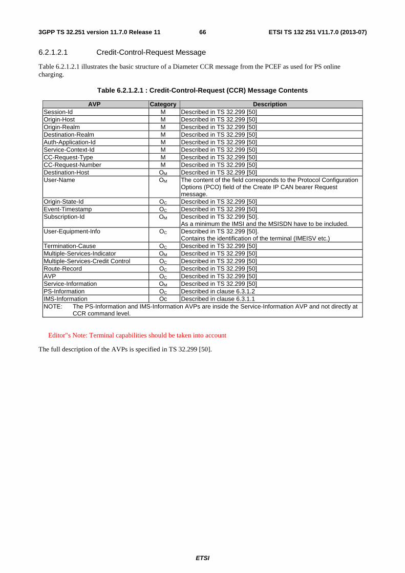
ETSI
ETSI TS 132 251 V11.7.0 (2013-07)663GPP TS 32.251 version 11.7.0 Release 11
6.2.1.2.1 Credit-Control-Request Message
Table 6.2.1.2.1 illustrates the basic structure of a Diameter CCR message from the PCEF as used for PS online charging.
Table 6.2.1.2.1 : Credit-Control-Request (CCR) Message Contents
AVP Category Description Session-Id M Described in TS 32.299 [50] Origin-Host M Described in TS 32.299 [50] Origin-Realm M Described in TS 32.299 [50] Destination-Realm M Described in TS 32.299 [50] Auth-Application-Id M Described in TS 32.299 [50] Service-Context-Id M Described in TS 32.299 [50] CC-Request-Type M Described in TS 32.299 [50] CC-Request-Number M Described in TS 32.299 [50] Destination-Host OM Described in TS 32.299 [50] User-Name OM The content of the field corresponds to the Protocol Configuration
Options (PCO) field of the Create IP CAN bearer Request message.
Origin-State-Id OC Described in TS 32.299 [50] Event-Timestamp OC Described in TS 32.299 [50] Subscription-Id OM Described in TS 32.299 [50].
As a minimum the IMSI and the MSISDN have to be included. User-Equipment-Info OC Described in TS 32.299 [50].
Contains the identification of the terminal (IMEISV etc.) Termination-Cause OC Described in TS 32.299 [50] Multiple-Services-Indicator OM Described in TS 32.299 [50] Multiple-Services-Credit Control OC Described in TS 32.299 [50] Route-Record OC Described in TS 32.299 [50] AVP OC Described in TS 32.299 [50] Service-Information OM Described in TS 32.299 [50] PS-Information OC Described in clause 6.3.1.2 IMS-Information Oc Described in clause 6.3.1.1 NOTE: The PS-Information and IMS-Information AVPs are inside the Service-Information AVP and not directly at
CCR command level.
Editor"s Note: Terminal capabilities should be taken into account
The full description of the AVPs is specified in TS 32.299 [50].
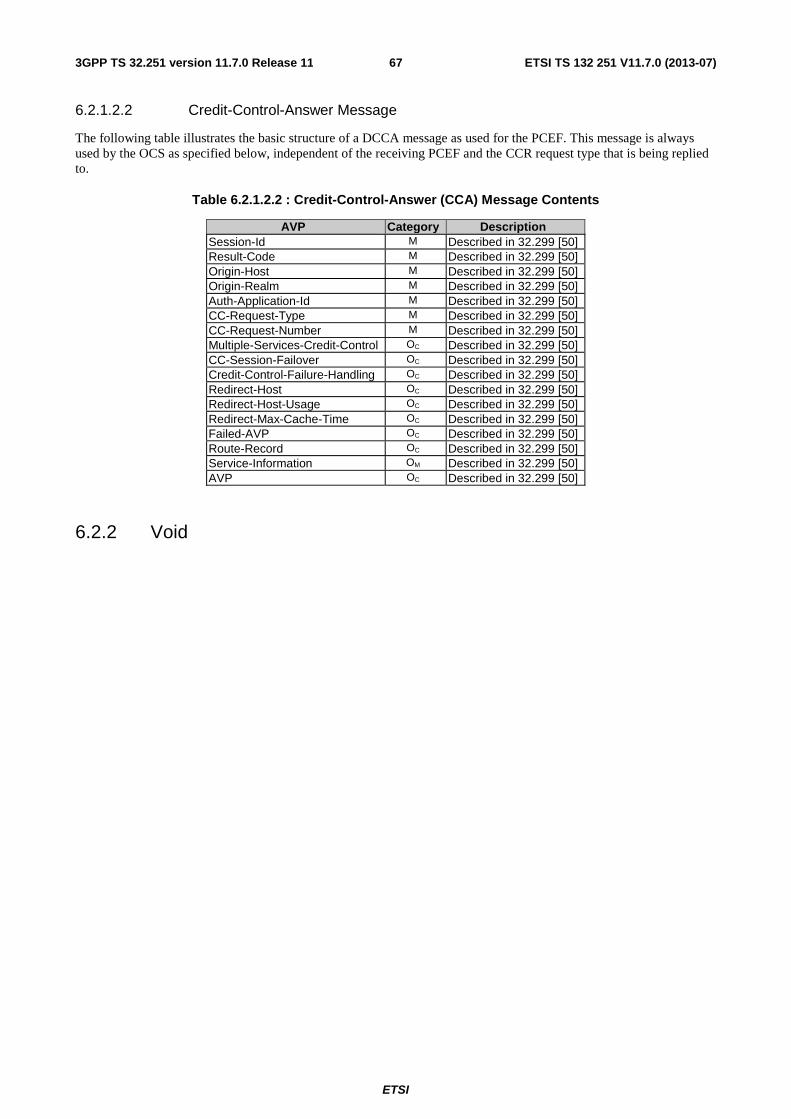
ETSI
ETSI TS 132 251 V11.7.0 (2013-07)673GPP TS 32.251 version 11.7.0 Release 11
6.2.1.2.2 Credit-Control-Answer Message
The following table illustrates the basic structure of a DCCA message as used for the PCEF. This message is always used by the OCS as specified below, independent of the receiving PCEF and the CCR request type that is being replied to.
Table 6.2.1.2.2 : Credit-Control-Answer (CCA) Message Contents
AVP Category Description Session-Id M Described in 32.299 [50] Result-Code M Described in 32.299 [50] Origin-Host M Described in 32.299 [50] Origin-Realm M Described in 32.299 [50] Auth-Application-Id M Described in 32.299 [50] CC-Request-Type M Described in 32.299 [50] CC-Request-Number M Described in 32.299 [50] Multiple-Services-Credit-Control OC Described in 32.299 [50] CC-Session-Failover OC Described in 32.299 [50] Credit-Control-Failure-Handling OC Described in 32.299 [50] Redirect-Host OC Described in 32.299 [50] Redirect-Host-Usage OC Described in 32.299 [50] Redirect-Max-Cache-Time OC Described in 32.299 [50] Failed-AVP OC Described in 32.299 [50] Route-Record OC Described in 32.299 [50] Service-Information OM Described in 32.299 [50] AVP OC Described in 32.299 [50]
6.2.2 Void
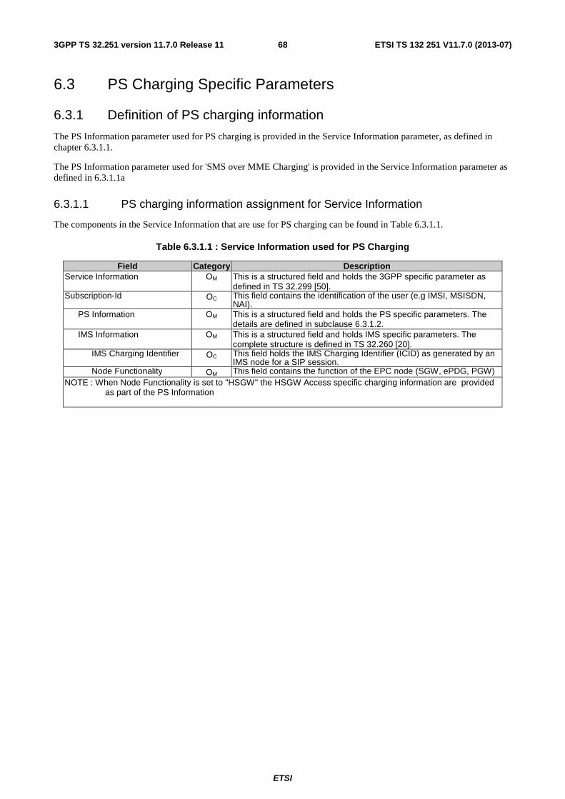
ETSI
ETSI TS 132 251 V11.7.0 (2013-07)683GPP TS 32.251 version 11.7.0 Release 11
6.3 PS Charging Specific Parameters
6.3.1 Definition of PS charging information
The PS Information parameter used for PS charging is provided in the Service Information parameter, as defined in chapter 6.3.1.1.
The PS Information parameter used for 'SMS over MME Charging' is provided in the Service Information parameter as defined in 6.3.1.1a
6.3.1.1 PS charging information assignment for Service Information
The components in the Service Information that are use for PS charging can be found in Table 6.3.1.1.
Table 6.3.1.1 : Service Information used for PS Charging
Field Category Description Service Information OM This is a structured field and holds the 3GPP specific parameter as
defined in TS 32.299 [50]. Subscription-Id OC This field contains the identification of the user (e.g IMSI, MSISDN,
NAI). PS Information OM This is a structured field and holds the PS specific parameters. The
details are defined in subclause 6.3.1.2. IMS Information OM This is a structured field and holds IMS specific parameters. The
complete structure is defined in TS 32.260 [20]. IMS Charging Identifier OC This field holds the IMS Charging Identifier (ICID) as generated by an
IMS node for a SIP session. Node Functionality OM This field contains the function of the EPC node (SGW, ePDG, PGW)NOTE : When Node Functionality is set to "HSGW" the HSGW Access specific charging information are provided
as part of the PS Information
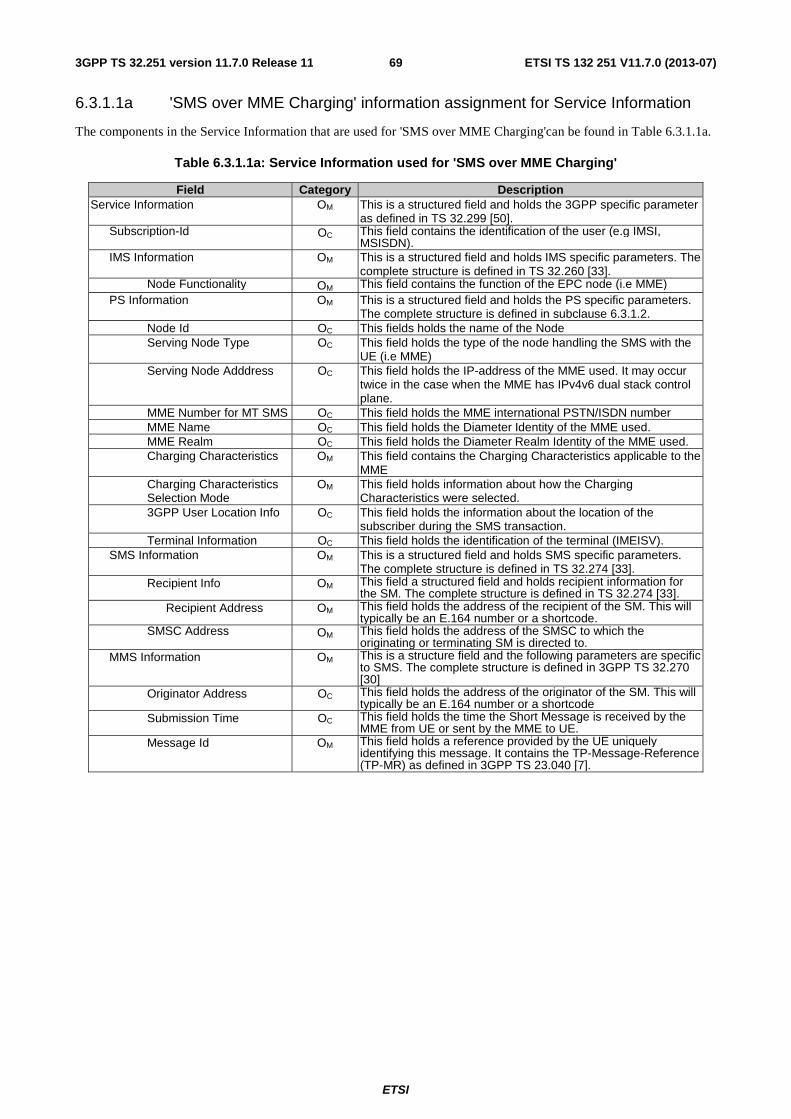
ETSI
ETSI TS 132 251 V11.7.0 (2013-07)693GPP TS 32.251 version 11.7.0 Release 11
6.3.1.1a 'SMS over MME Charging' information assignment for Service Information
The components in the Service Information that are used for 'SMS over MME Charging'can be found in Table 6.3.1.1a.
Table 6.3.1.1a: Service Information used for 'SMS over MME Charging'
Field Category Description Service Information OM This is a structured field and holds the 3GPP specific parameter
as defined in TS 32.299 [50]. Subscription-Id OC This field contains the identification of the user (e.g IMSI,
MSISDN). IMS Information OM This is a structured field and holds IMS specific parameters. The
complete structure is defined in TS 32.260 [33]. Node Functionality OM This field contains the function of the EPC node (i.e MME)
PS Information OM This is a structured field and holds the PS specific parameters. The complete structure is defined in subclause 6.3.1.2.
Node Id OC This fields holds the name of the Node Serving Node Type OC This field holds the type of the node handling the SMS with the
UE (i.e MME) Serving Node Adddress OC This field holds the IP-address of the MME used. It may occur
twice in the case when the MME has IPv4v6 dual stack control plane.
MME Number for MT SMS OC This field holds the MME international PSTN/ISDN number MME Name OC This field holds the Diameter Identity of the MME used. MME Realm OC This field holds the Diameter Realm Identity of the MME used. Charging Characteristics OM This field contains the Charging Characteristics applicable to the
MME Charging Characteristics Selection Mode
OM This field holds information about how the Charging Characteristics were selected.
3GPP User Location Info OC This field holds the information about the location of the subscriber during the SMS transaction.
Terminal Information OC This field holds the identification of the terminal (IMEISV). SMS Information OM This is a structured field and holds SMS specific parameters.
The complete structure is defined in TS 32.274 [33]. Recipient Info OM This field a structured field and holds recipient information for
the SM. The complete structure is defined in TS 32.274 [33]. Recipient Address OM This field holds the address of the recipient of the SM. This will
typically be an E.164 number or a shortcode. SMSC Address OM This field holds the address of the SMSC to which the
originating or terminating SM is directed to. MMS Information OM This is a structure field and the following parameters are specific
to SMS. The complete structure is defined in 3GPP TS 32.270 [30]
Originator Address OC This field holds the address of the originator of the SM. This will typically be an E.164 number or a shortcode
Submission Time OC This field holds the time the Short Message is received by the MME from UE or sent by the MME to UE.
Message Id OM This field holds a reference provided by the UE uniquely identifying this message. It contains the TP-Message-Reference (TP-MR) as defined in 3GPP TS 23.040 [7].
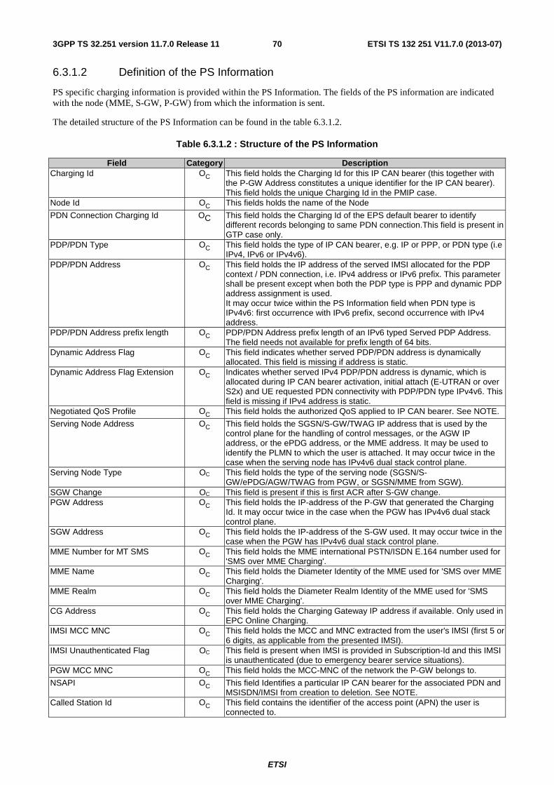
ETSI
ETSI TS 132 251 V11.7.0 (2013-07)703GPP TS 32.251 version 11.7.0 Release 11
6.3.1.2 Definition of the PS Information
PS specific charging information is provided within the PS Information. The fields of the PS information are indicated with the node (MME, S-GW, P-GW) from which the information is sent.
The detailed structure of the PS Information can be found in the table 6.3.1.2.
Table 6.3.1.2 : Structure of the PS Information
Field Category Description Charging Id OC This field holds the Charging Id for this IP CAN bearer (this together with
the P-GW Address constitutes a unique identifier for the IP CAN bearer). This field holds the unique Charging Id in the PMIP case.
Node Id OC This fields holds the name of the Node
PDN Connection Charging Id OC This field holds the Charging Id of the EPS default bearer to identify different records belonging to same PDN connection.This field is present in GTP case only.
PDP/PDN Type OC This field holds the type of IP CAN bearer, e.g. IP or PPP, or PDN type (i.e IPv4, IPv6 or IPv4v6).
PDP/PDN Address OC This field holds the IP address of the served IMSI allocated for the PDP context / PDN connection, i.e. IPv4 address or IPv6 prefix. This parameter shall be present except when both the PDP type is PPP and dynamic PDP address assignment is used. It may occur twice within the PS Information field when PDN type is IPv4v6: first occurrence with IPv6 prefix, second occurrence with IPv4 address.
PDP/PDN Address prefix length OC PDP/PDN Address prefix length of an IPv6 typed Served PDP Address. The field needs not available for prefix length of 64 bits.
Dynamic Address Flag OC This field indicates whether served PDP/PDN address is dynamically allocated. This field is missing if address is static.
Dynamic Address Flag Extension OC Indicates whether served IPv4 PDP/PDN address is dynamic, which is allocated during IP CAN bearer activation, initial attach (E-UTRAN or over S2x) and UE requested PDN connectivity with PDP/PDN type IPv4v6. This field is missing if IPv4 address is static.
Negotiated QoS Profile OC This field holds the authorized QoS applied to IP CAN bearer. See NOTE.
Serving Node Address OC This field holds the SGSN/S-GW/TWAG IP address that is used by the control plane for the handling of control messages, or the AGW IP address, or the ePDG address, or the MME address. It may be used to identify the PLMN to which the user is attached. It may occur twice in the case when the serving node has IPv4v6 dual stack control plane.
Serving Node Type OC This field holds the type of the serving node (SGSN/S-GW/ePDG/AGW/TWAG from PGW, or SGSN/MME from SGW).
SGW Change OC This field is present if this is first ACR after S-GW change. PGW Address OC This field holds the IP-address of the P-GW that generated the Charging
Id. It may occur twice in the case when the PGW has IPv4v6 dual stack control plane.
SGW Address OC This field holds the IP-address of the S-GW used. It may occur twice in the case when the PGW has IPv4v6 dual stack control plane.
MME Number for MT SMS OC This field holds the MME international PSTN/ISDN E.164 number used for 'SMS over MME Charging'.
MME Name OC This field holds the Diameter Identity of the MME used for 'SMS over MME Charging'.
MME Realm OC This field holds the Diameter Realm Identity of the MME used for 'SMS over MME Charging'.
CG Address OC This field holds the Charging Gateway IP address if available. Only used in EPC Online Charging.
IMSI MCC MNC OC This field holds the MCC and MNC extracted from the user's IMSI (first 5 or 6 digits, as applicable from the presented IMSI).
IMSI Unauthenticated Flag OC This field is present when IMSI is provided in Subscription-Id and this IMSI is unauthenticated (due to emergency bearer service situations).
PGW MCC MNC OC This field holds the MCC-MNC of the network the P-GW belongs to.
NSAPI OC This field Identifies a particular IP CAN bearer for the associated PDN and MSISDN/IMSI from creation to deletion. See NOTE.
Called Station Id OC This field contains the identifier of the access point (APN) the user is connected to.
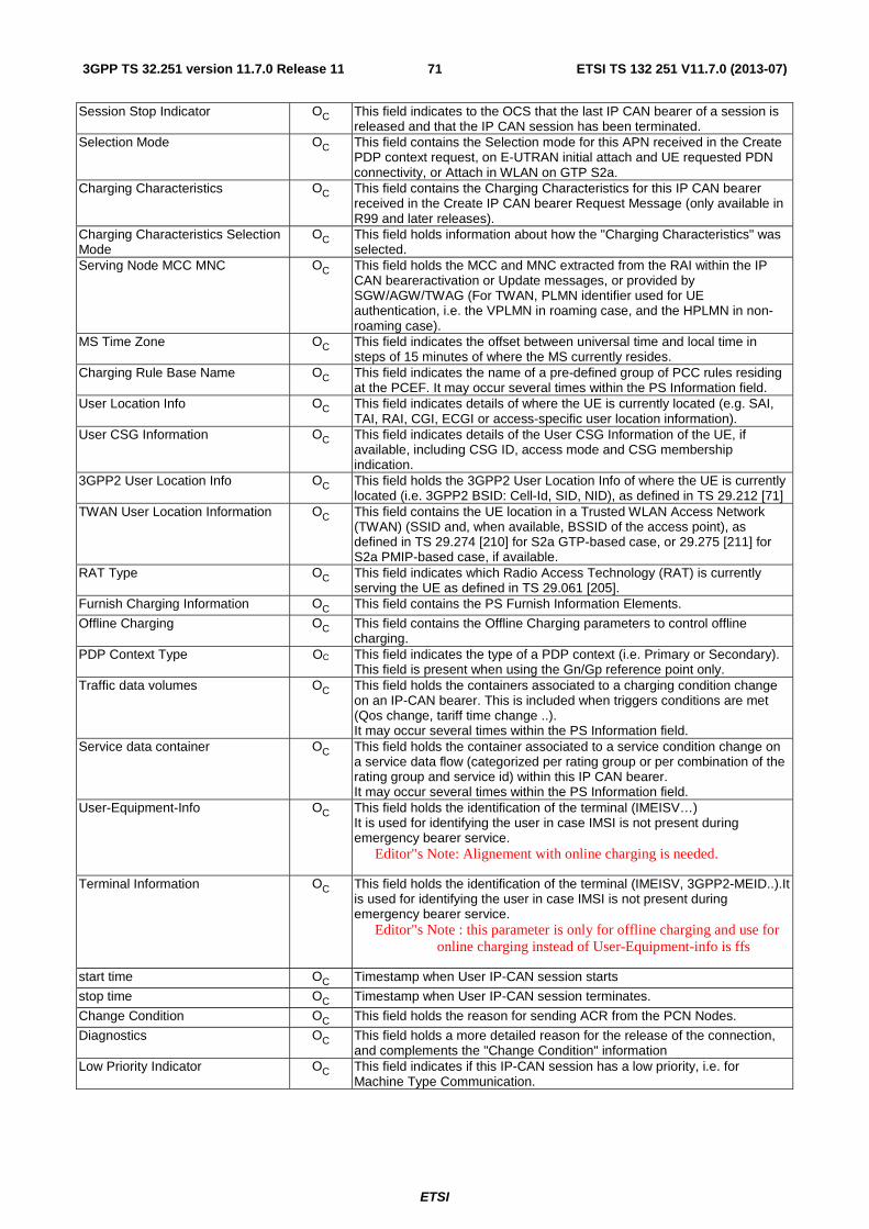
ETSI
ETSI TS 132 251 V11.7.0 (2013-07)713GPP TS 32.251 version 11.7.0 Release 11
Session Stop Indicator OC This field indicates to the OCS that the last IP CAN bearer of a session is released and that the IP CAN session has been terminated.
Selection Mode OC This field contains the Selection mode for this APN received in the Create PDP context request, on E-UTRAN initial attach and UE requested PDN connectivity, or Attach in WLAN on GTP S2a.
Charging Characteristics OC This field contains the Charging Characteristics for this IP CAN bearer received in the Create IP CAN bearer Request Message (only available in R99 and later releases).
Charging Characteristics Selection Mode
OC This field holds information about how the "Charging Characteristics" was selected.
Serving Node MCC MNC OC This field holds the MCC and MNC extracted from the RAI within the IP CAN beareractivation or Update messages, or provided by SGW/AGW/TWAG (For TWAN, PLMN identifier used for UE authentication, i.e. the VPLMN in roaming case, and the HPLMN in non-roaming case).
MS Time Zone OC This field indicates the offset between universal time and local time in steps of 15 minutes of where the MS currently resides.
Charging Rule Base Name OC This field indicates the name of a pre-defined group of PCC rules residing at the PCEF. It may occur several times within the PS Information field.
User Location Info OC This field indicates details of where the UE is currently located (e.g. SAI, TAI, RAI, CGI, ECGI or access-specific user location information).
User CSG Information OC This field indicates details of the User CSG Information of the UE, if available, including CSG ID, access mode and CSG membership indication.
3GPP2 User Location Info OC This field holds the 3GPP2 User Location Info of where the UE is currently located (i.e. 3GPP2 BSID: Cell-Id, SID, NID), as defined in TS 29.212 [71]
TWAN User Location Information OC This field contains the UE location in a Trusted WLAN Access Network (TWAN) (SSID and, when available, BSSID of the access point), as defined in TS 29.274 [210] for S2a GTP-based case, or 29.275 [211] for S2a PMIP-based case, if available.
RAT Type OC This field indicates which Radio Access Technology (RAT) is currently serving the UE as defined in TS 29.061 [205].
Furnish Charging Information OC This field contains the PS Furnish Information Elements.
Offline Charging OC This field contains the Offline Charging parameters to control offline charging.
PDP Context Type OC This field indicates the type of a PDP context (i.e. Primary or Secondary). This field is present when using the Gn/Gp reference point only.
Traffic data volumes OC This field holds the containers associated to a charging condition change on an IP-CAN bearer. This is included when triggers conditions are met (Qos change, tariff time change ..). It may occur several times within the PS Information field.
Service data container OC This field holds the container associated to a service condition change on a service data flow (categorized per rating group or per combination of the rating group and service id) within this IP CAN bearer. It may occur several times within the PS Information field.
User-Equipment-Info OC This field holds the identification of the terminal (IMEISV…) It is used for identifying the user in case IMSI is not present during emergency bearer service.
Editor"s Note: Alignement with online charging is needed.
Terminal Information OC This field holds the identification of the terminal (IMEISV, 3GPP2-MEID..).It is used for identifying the user in case IMSI is not present during emergency bearer service.
Editor"s Note : this parameter is only for offline charging and use for online charging instead of User-Equipment-info is ffs
start time OC Timestamp when User IP-CAN session starts
stop time OC Timestamp when User IP-CAN session terminates.
Change Condition OC This field holds the reason for sending ACR from the PCN Nodes.
Diagnostics OC This field holds a more detailed reason for the release of the connection, and complements the "Change Condition" information
Low Priority Indicator OC This field indicates if this IP-CAN session has a low priority, i.e. for Machine Type Communication.

ETSI
ETSI TS 132 251 V11.7.0 (2013-07)723GPP TS 32.251 version 11.7.0 Release 11
NOTE: For Network Requested Secondary IP CAN bearer Activation, the CCR Initial does not contain a value of NSAPI, whilst the Negotiated QoS profile reflects the requested QoS profile used in the activation request.
6.3.2 Detailed Message Format for offline charging
The following chapter specifies per Operation Type the charging data that are sent by MME, S-GW and P-GW.
The Operation Types are listed in the following order: S (start)/I (interim)/S (stop)/E (event). Therefore, when all Operation Types are possible it is marked as SISE. If only some Operation Types are allowed for a node, only the appropriate letters are used (i.e. SIS or E) as indicated in the table heading. The omission of an Operation Type for a particular field is marked with "-" (i.e. SI-E). Also, when an entire field is not allowed in a node the entire cell is marked as "-".
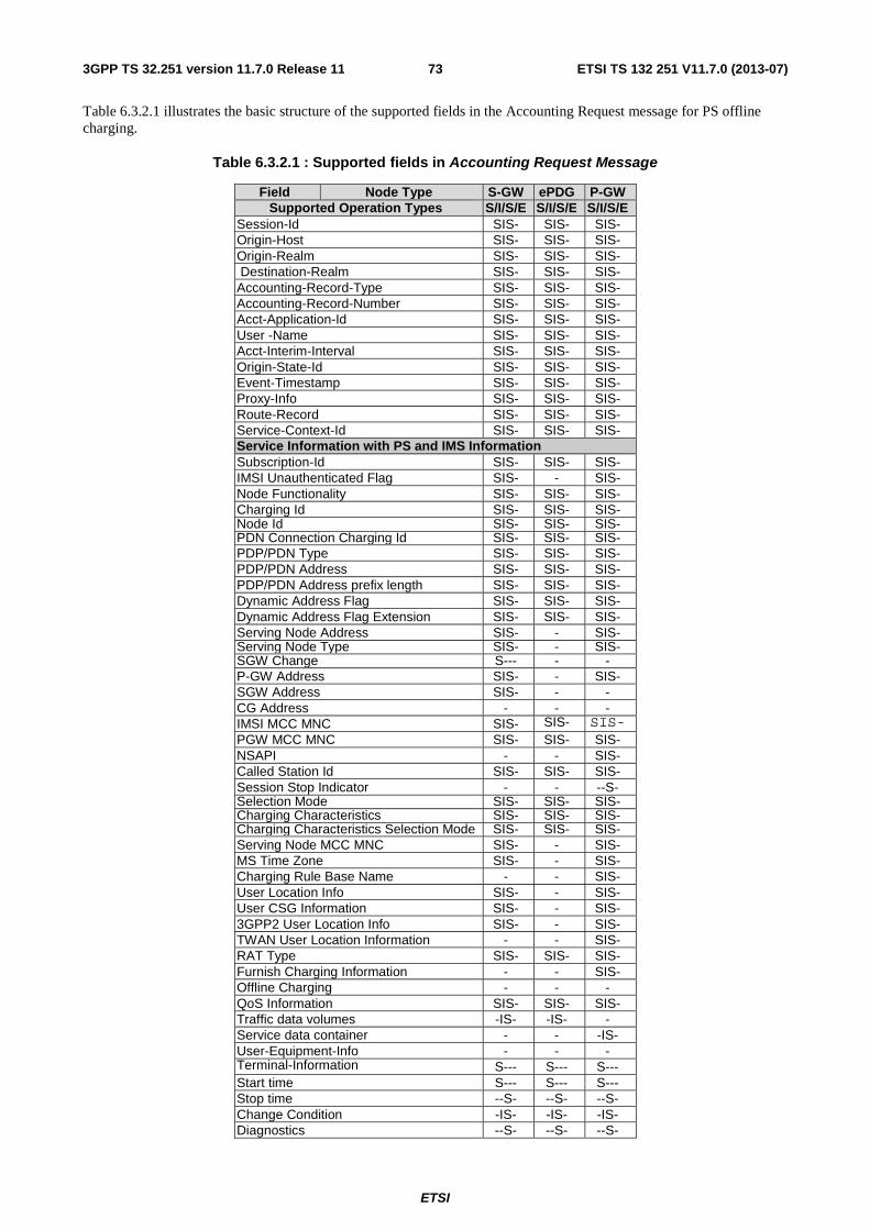
ETSI
ETSI TS 132 251 V11.7.0 (2013-07)733GPP TS 32.251 version 11.7.0 Release 11
Table 6.3.2.1 illustrates the basic structure of the supported fields in the Accounting Request message for PS offline charging.
Table 6.3.2.1 : Supported fields in Accounting Request Message
Field Node Type S-GW ePDG P-GW Supported Operation Types S/I/S/E S/I/S/E S/I/S/E
Session-Id SIS- SIS- SIS- Origin-Host SIS- SIS- SIS- Origin-Realm SIS- SIS- SIS- Destination-Realm SIS- SIS- SIS- Accounting-Record-Type SIS- SIS- SIS- Accounting-Record-Number SIS- SIS- SIS- Acct-Application-Id SIS- SIS- SIS- User -Name SIS- SIS- SIS- Acct-Interim-Interval SIS- SIS- SIS- Origin-State-Id SIS- SIS- SIS- Event-Timestamp SIS- SIS- SIS- Proxy-Info SIS- SIS- SIS- Route-Record SIS- SIS- SIS- Service-Context-Id SIS- SIS- SIS- Service Information with PS and IMS Information Subscription-Id SIS- SIS- SIS- IMSI Unauthenticated Flag SIS- - SIS- Node Functionality SIS- SIS- SIS- Charging Id SIS- SIS- SIS- Node Id SIS- SIS- SIS- PDN Connection Charging Id SIS- SIS- SIS- PDP/PDN Type SIS- SIS- SIS- PDP/PDN Address SIS- SIS- SIS- PDP/PDN Address prefix length SIS- SIS- SIS- Dynamic Address Flag SIS- SIS- SIS- Dynamic Address Flag Extension SIS- SIS- SIS- Serving Node Address SIS- - SIS- Serving Node Type SIS- - SIS- SGW Change S--- - - P-GW Address SIS- - SIS- SGW Address SIS- - - CG Address - - - IMSI MCC MNC SIS- SIS- SIS- PGW MCC MNC SIS- SIS- SIS- NSAPI - - SIS- Called Station Id SIS- SIS- SIS- Session Stop Indicator - - --S- Selection Mode SIS- SIS- SIS- Charging Characteristics SIS- SIS- SIS- Charging Characteristics Selection Mode SIS- SIS- SIS- Serving Node MCC MNC SIS- - SIS- MS Time Zone SIS- - SIS- Charging Rule Base Name - - SIS- User Location Info SIS- - SIS- User CSG Information SIS- - SIS- 3GPP2 User Location Info SIS- - SIS- TWAN User Location Information - - SIS- RAT Type SIS- SIS- SIS- Furnish Charging Information - - SIS- Offline Charging - - - QoS Information SIS- SIS- SIS- Traffic data volumes -IS- -IS- - Service data container - - -IS- User-Equipment-Info - - - Terminal-Information S--- S--- S--- Start time S--- S--- S--- Stop time --S- --S- --S- Change Condition -IS- -IS- -IS- Diagnostics --S- --S- --S-
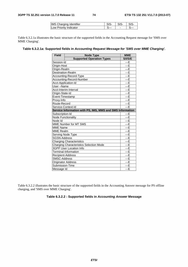
ETSI
ETSI TS 132 251 V11.7.0 (2013-07)743GPP TS 32.251 version 11.7.0 Release 11
IMS Charging Identifier SIS- SIS- SIS- Low Priority Indicator S--- - S---
Table 6.3.2.1a illustrates the basic structure of the supported fields in the Accounting Request message for 'SMS over MME Charging'.
Table 6.3.2.1a: Supported fields in Accounting Request Message for 'SMS over MME Charging'.
Field Node Type MME Supported Operation Types S/I/S/E
Session-Id ---E Origin-Host ---E Origin-Realm ---E Destination-Realm ---E Accounting-Record-Type ---E Accounting-Record-Number ---E Acct-Application-Id ---E User –Name ---E Acct-Interim-Interval ---E Origin-State-Id ---E Event-Timestamp ---E Proxy-Info ---E Route-Record ---E Service-Context-Id ---E Service Information with PS, IMS, MMS and SMS Information Subscription-Id ---E Node Functionality ---E Node Id ---E MME Number for MT SMS ---E MME Name ---E MME Realm ---E Serving Node Type ---E SGSN-Address ---E Charging Characteristics ---E Charging Characteristics Selection Mode ---E 3GPP User Location Info ---E Terminal-Information ---E Recipient-Address ---E SMSC-Address ---E Originator Address ---E Submission-Time ---E Message Id ---E
Table 6.3.2.2 illustrates the basic structure of the supported fields in the Accounting Answer message for PS offline charging, and 'SMS over MME Charging'.
Table 6.3.2.2 : Supported fields in Accounting Answer Message
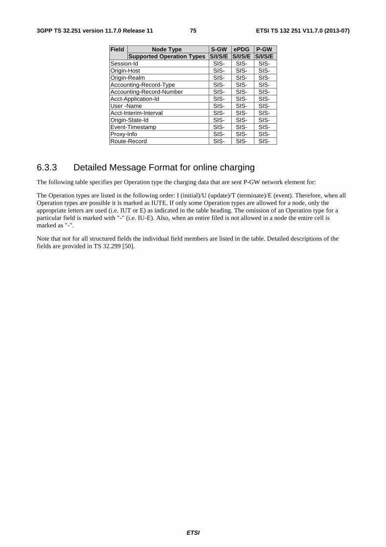
ETSI
ETSI TS 132 251 V11.7.0 (2013-07)753GPP TS 32.251 version 11.7.0 Release 11
Field Node Type S-GW ePDG P-GW Supported Operation Types S/I/S/E S/I/S/E S/I/S/E
Session-Id SIS- SIS- SIS- Origin-Host SIS- SIS- SIS- Origin-Realm SIS- SIS- SIS- Accounting-Record-Type SIS- SIS- SIS- Accounting-Record-Number SIS- SIS- SIS- Acct-Application-Id SIS- SIS- SIS- User -Name SIS- SIS- SIS- Acct-Interim-Interval SIS- SIS- SIS- Origin-State-Id SIS- SIS- SIS- Event-Timestamp SIS- SIS- SIS- Proxy-Info SIS- SIS- SIS- Route-Record SIS- SIS- SIS-
6.3.3 Detailed Message Format for online charging
The following table specifies per Operation type the charging data that are sent P-GW network element for:
The Operation types are listed in the following order: I (initial)/U (update)/T (terminate)/E (event). Therefore, when all Operation types are possible it is marked as IUTE. If only some Operation types are allowed for a node, only the appropriate letters are used (i.e. IUT or E) as indicated in the table heading. The omission of an Operation type for a particular field is marked with "-" (i.e. IU-E). Also, when an entire filed is not allowed in a node the entire cell is marked as "-".
Note that not for all structured fields the individual field members are listed in the table. Detailed descriptions of the fields are provided in TS 32.299 [50].
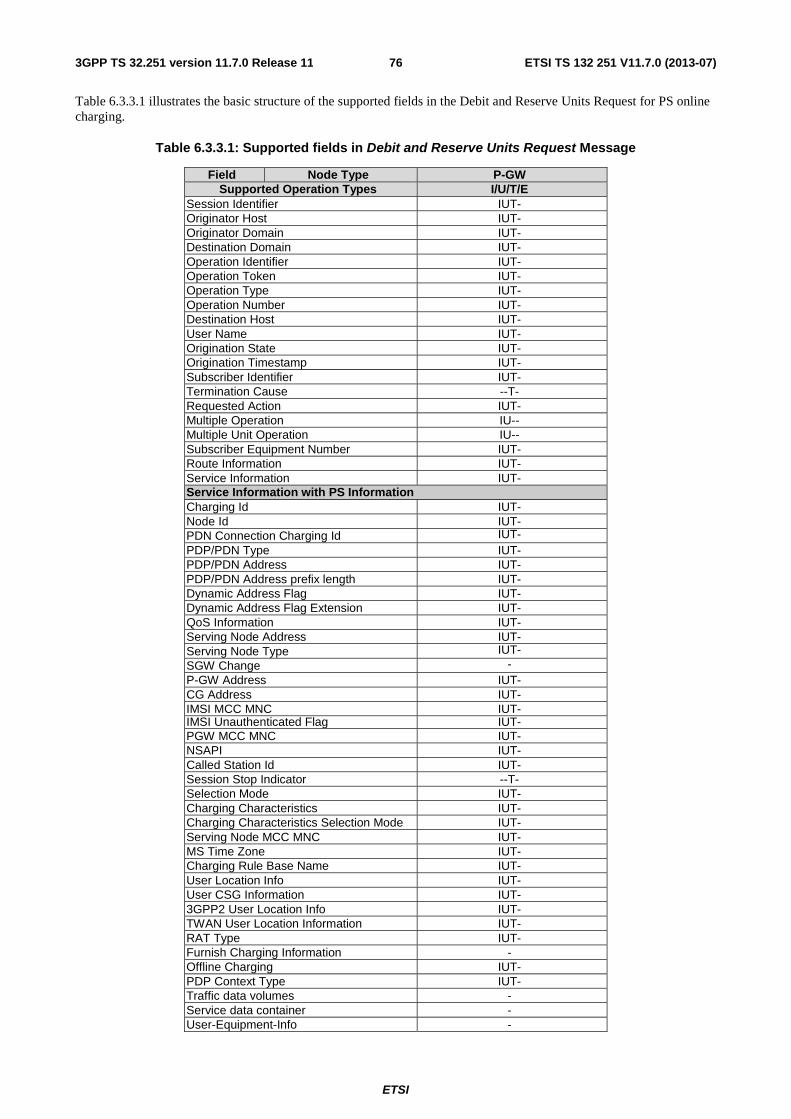
ETSI
ETSI TS 132 251 V11.7.0 (2013-07)763GPP TS 32.251 version 11.7.0 Release 11
Table 6.3.3.1 illustrates the basic structure of the supported fields in the Debit and Reserve Units Request for PS online charging.
Table 6.3.3.1: Supported fields in Debit and Reserve Units Request Message
Field Node Type P-GW Supported Operation Types I/U/T/E
Session Identifier IUT- Originator Host IUT- Originator Domain IUT- Destination Domain IUT- Operation Identifier IUT- Operation Token IUT- Operation Type IUT- Operation Number IUT- Destination Host IUT- User Name IUT- Origination State IUT- Origination Timestamp IUT- Subscriber Identifier IUT- Termination Cause --T- Requested Action IUT- Multiple Operation IU-- Multiple Unit Operation IU-- Subscriber Equipment Number IUT- Route Information IUT- Service Information IUT- Service Information with PS Information Charging Id IUT- Node Id IUT- PDN Connection Charging Id IUT- PDP/PDN Type IUT- PDP/PDN Address IUT- PDP/PDN Address prefix length IUT- Dynamic Address Flag IUT- Dynamic Address Flag Extension IUT- QoS Information IUT- Serving Node Address IUT- Serving Node Type IUT- SGW Change - P-GW Address IUT- CG Address IUT- IMSI MCC MNC IUT- IMSI Unauthenticated Flag IUT- PGW MCC MNC IUT- NSAPI IUT- Called Station Id IUT- Session Stop Indicator --T- Selection Mode IUT- Charging Characteristics IUT- Charging Characteristics Selection Mode IUT- Serving Node MCC MNC IUT- MS Time Zone IUT- Charging Rule Base Name IUT- User Location Info IUT- User CSG Information IUT- 3GPP2 User Location Info IUT- TWAN User Location Information IUT- RAT Type IUT- Furnish Charging Information - Offline Charging IUT- PDP Context Type IUT- Traffic data volumes - Service data container - User-Equipment-Info -
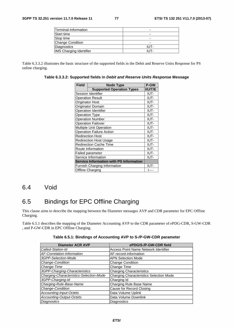
ETSI
ETSI TS 132 251 V11.7.0 (2013-07)773GPP TS 32.251 version 11.7.0 Release 11
Terminal-Information - Start time - Stop time - Change Condition - Diagnostics IUT- IMS Charging Identifier IUT-
Table 6.3.3.2 illustrates the basic structure of the supported fields in the Debit and Reserve Units Response for PS online charging.
Table 6.3.3.2: Supported fields in Debit and Reserve Units Response Message
Field Node Type P-GW Supported Operation Types I/U/T/E
Session Identifier IUT- Operation Result IUT- Originator Host IUT- Originator Domain IUT- Operation Identifier IUT- Operation Type IUT- Operation Number IUT- Operation Failover IUT- Multiple Unit Operation IUT- Operation Failure Action IUT- Redirection Host IUT- Redirection Host Usage IUT- Redirection Cache Time IUT- Route Information IUT- Failed parameter IUT- Service Information IUT- Service Information with PS Information Furnish Charging Information IUT- Offline Charging I----
6.4 Void
6.5 Bindings for EPC Offline Charging This clause aims to describe the mapping between the Diameter messages AVP and CDR parameter for EPC Offline Charging.
Table 6.5.1 describes the mapping of the Diameter Accounting AVP to the CDR parameter of ePDG-CDR, S-GW-CDR , and P-GW-CDR in EPC Offline Charging.
Table 6.5.1: Bindings of Accounting AVP to S-/P-GW-CDR parameter
Diameter ACR AVP ePDG/S-/P-GW-CDR field Called-Station-Id Access Point Name Network Identifier AF-Correlation-Information AF-record-information 3GPP-Selection-Mode APN Selection Mode Change-Condition Change Condition Change-Time Change Time 3GPP-Charging-Characteristics Charging Characteristics Charging-Characteristics-Selection-Mode Charging Characteristics Selection Mode 3GPP-Charging-Id Charging Id Charging-Rule-Base-Name Charging Rule Base Name Change-Condition Cause for Record Closing Accounting-Input-Octets Data Volume Uplink Accounting-Output-Octets Data Volume Downlink Diagnostics Diagnostics
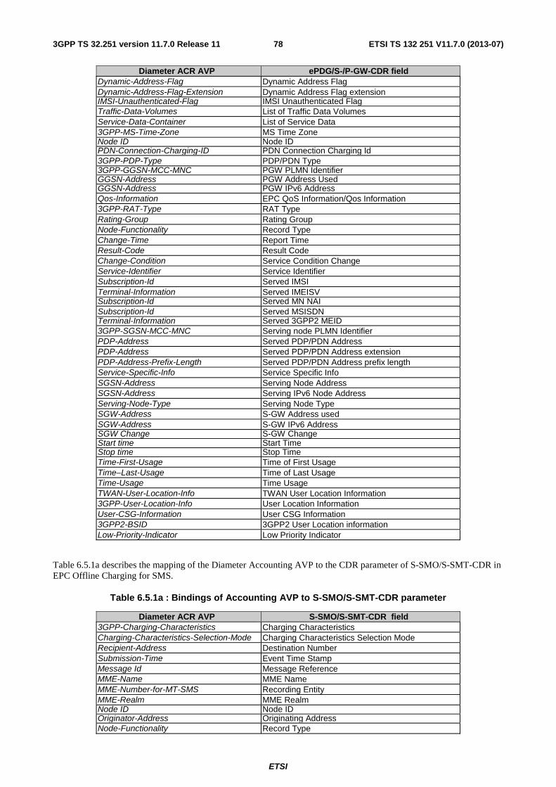
ETSI
ETSI TS 132 251 V11.7.0 (2013-07)783GPP TS 32.251 version 11.7.0 Release 11
Diameter ACR AVP ePDG/S-/P-GW-CDR field Dynamic-Address-Flag Dynamic Address Flag Dynamic-Address-Flag-Extension Dynamic Address Flag extension IMSI-Unauthenticated-Flag IMSI Unauthenticated Flag Traffic-Data-Volumes List of Traffic Data Volumes Service-Data-Container List of Service Data 3GPP-MS-Time-Zone MS Time Zone Node ID Node ID PDN-Connection-Charging-ID PDN Connection Charging Id 3GPP-PDP-Type PDP/PDN Type 3GPP-GGSN-MCC-MNC PGW PLMN Identifier GGSN-Address PGW Address Used GGSN-Address PGW IPv6 Address Qos-Information EPC QoS Information/Qos Information 3GPP-RAT-Type RAT Type Rating-Group Rating Group Node-Functionality Record Type Change-Time Report Time Result-Code Result Code Change-Condition Service Condition Change Service-Identifier Service Identifier Subscription-Id Served IMSI Terminal-Information Served IMEISV Subscription-Id Served MN NAI Subscription-Id Served MSISDN Terminal-Information Served 3GPP2 MEID 3GPP-SGSN-MCC-MNC Serving node PLMN Identifier PDP-Address Served PDP/PDN Address PDP-Address Served PDP/PDN Address extension PDP-Address-Prefix-Length Served PDP/PDN Address prefix length Service-Specific-Info Service Specific Info SGSN-Address Serving Node Address SGSN-Address Serving IPv6 Node Address Serving-Node-Type Serving Node Type SGW-Address S-GW Address used SGW-Address S-GW IPv6 Address SGW Change S-GW Change Start time Start Time Stop time Stop Time Time-First-Usage Time of First Usage Time–Last-Usage Time of Last Usage Time-Usage Time Usage TWAN-User-Location-Info TWAN User Location Information 3GPP-User-Location-Info User Location Information User-CSG-Information User CSG Information 3GPP2-BSID 3GPP2 User Location information Low-Priority-Indicator Low Priority Indicator
Table 6.5.1a describes the mapping of the Diameter Accounting AVP to the CDR parameter of S-SMO/S-SMT-CDR in EPC Offline Charging for SMS.
Table 6.5.1a : Bindings of Accounting AVP to S-SMO/S-SMT-CDR parameter
Diameter ACR AVP S-SMO/S-SMT-CDR field 3GPP-Charging-Characteristics Charging Characteristics Charging-Characteristics-Selection-Mode Charging Characteristics Selection Mode Recipient-Address Destination Number Submission-Time Event Time Stamp Message Id Message Reference MME-Name MME Name MME-Number-for-MT-SMS Recording Entity MME-Realm MME Realm Node ID Node ID Originator-Address Originating Address Node-Functionality Record Type

ETSI
ETSI TS 132 251 V11.7.0 (2013-07)793GPP TS 32.251 version 11.7.0 Release 11
Diameter ACR AVP S-SMO/S-SMT-CDR field Subscription-Id Served IMSI Terminal-Information Served IMEISV Subscription-Id Served MSISDN Serving-Node-Type Serving Node Type SGSN-Address Serving Node Address SGSN-Address Serving IPv6 Node Address SMSC-Address Service Centre 3GPP-User-Location-Info User Location Information
NOTE : The whole set of ePDG/MME//S/PGW-CDR parameters is described in the TS 32.298 [51].
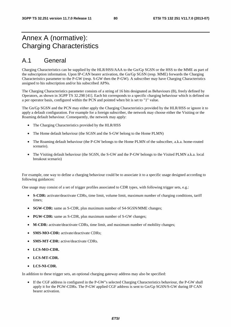
ETSI
ETSI TS 132 251 V11.7.0 (2013-07)803GPP TS 32.251 version 11.7.0 Release 11
Annex A (normative): Charging Characteristics
A.1 General Charging Characteristics can be supplied by the HLR/HSS/AAA to the Gn/Gp SGSN or the HSS to the MME as part of the subscription information. Upon IP-CAN bearer activation, the Gn/Gp SGSN (resp. MME) forwards the Charging Characteristics parameter to the P-GW (resp. S-GW then the P-GW). A subscriber may have Charging Characteristics assigned to his subscription and/or his subscribed APNs.
The Charging Characteristics parameter consists of a string of 16 bits designated as Behaviours (B), freely defined by Operators, as shown in 3GPP TS 32.298 [41]. Each bit corresponds to a specific charging behaviour which is defined on a per operator basis, configured within the PCN and pointed when bit is set to "1" value.
The Gn/Gp SGSN and the PCN may either apply the Charging Characteristics provided by the HLR/HSS or ignore it to apply a default configuration. For example for a foreign subscriber, the network may choose either the Visiting or the Roaming default behaviour. Consequently, the network may apply:
• The Charging Characteristics provided by the HLR/HSS
• The Home default behaviour (the SGSN and the S-GW belong to the Home PLMN)
• The Roaming default behaviour (the P-GW belongs to the Home PLMN of the subscriber, a.k.a. home-routed scenario).
• The Visiting default behaviour (the SGSN, the S-GW and the P-GW belongs to the Visited PLMN a.k.a. local breakout scenario)
For example, one way to define a charging behaviour could be to associate it to a specific usage designed according to following guidances:
One usage may consist of a set of trigger profiles associated to CDR types, with following trigger sets, e.g.:
• S-CDR: activate/deactivate CDRs, time limit, volume limit, maximum number of charging conditions, tariff times;
• SGW-CDR: same as S-CDR, plus maximum number of S4-SGSN/MME changes;
• PGW-CDR: same as S-CDR, plus maximum number of S-GW changes;
• M-CDR: activate/deactivate CDRs, time limit, and maximum number of mobility changes;
• SMS-MO-CDR: activate/deactivate CDRs;
• SMS-MT-CDR: active/deactivate CDRs.
• LCS-MO-CDR.
• LCS-MT-CDR.
• LCS-NI-CDR.
In addition to these trigger sets, an optional charging gateway address may also be specified:
• If the CGF address is configured in the P-GW"s selected Charging Characteristics behaviour, the P-GW shall apply it for the PGW-CDRs. The P-GW applied CGF address is sent to Gn/Gp SGSN/S-GW during IP CAN bearer activation.
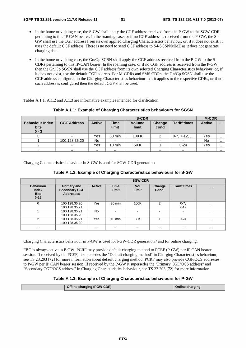
ETSI
ETSI TS 132 251 V11.7.0 (2013-07)813GPP TS 32.251 version 11.7.0 Release 11
• In the home or visiting case, the S-GW shall apply the CGF address received from the P-GW to the SGW-CDRs pertaining to this IP CAN bearer. In the roaming case, or if no CGF address is received from the P-GW, the S-GW shall use the CGF address from its own applied Charging Characteristics behaviour, or, if it does not exist, it uses the default CGF address. There is no need to send CGF address to S4-SGSN/MME as it does not generate charging data.
• In the home or visiting case, the Gn/Gp SGSN shall apply the CGF address received from the P-GW to the S-CDRs pertaining to this IP-CAN bearer. In the roaming case, or if no CGF address is received from the P-GW, then the Gn/Gp SGSN shall use the CGF address from its own selected Charging Characteristics behaviour, or, if it does not exist, use the default CGF address. For M-CDRs and SMS CDRs, the Gn/Gp SGSN shall use the CGF address configured in the Charging Characteristics behaviour that it applies to the respective CDRs, or if no such address is configured then the default CGF shall be used.
Tables A.1.1, A.1.2 and A.1.3 are informative examples intended for clarification.
Table A.1.1: Example of Charging Characteristics behaviours for SGSN
S-CDR M-CDR Behaviour Index
bits 0 - 3
CGF Address Active Time limit
Volume limit
Change cond
Tariff times Active …
0 - Yes 30 min 100 K 2 0-7, 7-12, … Yes .. 1 100.128.35.20 No - - - - No .. 2 - Yes 10 min 50 K 1 0-24 Yes .. .. .. .. .. .. .. .. .. ..
Charging Characteristics behaviour in S-GW is used for SGW-CDR generation
Table A.1.2: Example of Charging Characteristics behaviours for S-GW
SGW-CDR
Behaviour Index Bits 0-15
Primary and Secondary CGF
Addresses
Active Time Limit
Vol Limit
Change Cond.
Tariff times …
0 100.128.35.20 100.128.35.21
Yes 30 min 100K 2 0-7, 7-12
...
1 100.128.35.21 100.128.35.20
No - - - - …
2 100.128.35.21 100.128.35.20
Yes 10 min 50K 1 0-24 ...
… … … … … … … …
Charging Characteristics behaviour in P-GW is used for PGW-CDR generation / and for online charging.
FBC is always active in P-GW. PCRF may provide default charging method to PCEF (P-GW) per IP CAN bearer session. If received by the PCEF, it supersedes the "Default charging method" in Charging Characteristics behaviour, see TS 23.203 [72] for more information about default charging method. PCRF may also provide CGF/OCS addresses to P-GW per IP CAN bearer session. If received by the P-GW it supersedes the "Primary CGF/OCS address" and "Secondary CGF/OCS address" in Charging Characteristics behaviour, see TS 23.203 [72] for more information.
Table A.1.3: Example of Charging Characteristics behaviours for P-GW
Offline charging (PGW-CDR) Online charging
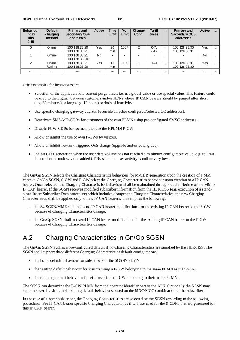
ETSI
ETSI TS 132 251 V11.7.0 (2013-07)823GPP TS 32.251 version 11.7.0 Release 11
Behaviour Index Bits 0-15
Default charging method
Primary and Secondary CGF
addresses
Active Time Limit
Vol Limit
Change Cond.
Tariff times
… Primary and Secondary OCS
addresses
Active …
0 Online 100.128.35.20 100.128.35.21
Yes 30 min
100K 2 0-7, 7-12
... 100.128.35.30 100.128.35.31
Yes …
1 Offline 100.128.35.21 100.128.35.20
No - - - - … - No …
2 Online /Offline
100.128.35.21 100.128.35.20
Yes 10 min
50K 1 0-24 ... 100.128.35.31 100.128.35.30
Yes …
… … … … … … … … … … … …
Other examples for behaviours are:
• Selection of the applicable idle context purge timer, i.e. use global value or use special value. This feature could be used to distinguish between customers and/or APNs whose IP CAN bearers should be purged after short (e.g. 30 minutes) or long (e.g. 12 hours) periods of inactivity.
• Use specific charging gateway address (override all other configured/selected CG addresses).
• Deactivate SMS-MO-CDRs for customers of the own PLMN using pre-configured SMSC addresses.
• Disable PGW-CDRs for roamers that use the HPLMN P-GW.
• Allow or inhibit the use of own P-GWs by visitors.
* Allow or inhibit network triggered QoS change (upgrade and/or downgrade).
• Inhibit CDR generation when the user data volume has not reached a minimum configurable value, e.g. to limit the number of no/low-value added CDRs when the user activity is null or very low.
The Gn/Gp SGSN selects the Charging Characteristics behaviour for M-CDR generation upon the creation of a MM context. Gn/Gp SGSN, S-GW and P-GW select the Charging Characteristics behaviour upon creation of a IP CAN bearer. Once selected, the Charging Characteristics behaviour shall be maintained throughout the lifetime of the MM or IP CAN bearer. If the SGSN receives modified subscriber information from the HLR/HSS (e.g. execution of a stand-alone Insert Subscriber Data procedure) which includes changes the Charging Characteristics, the new Charging Characteristics shall be applied only to new IP CAN bearers. This implies the following:
- the S4-SGSN/MME shall not send IP CAN bearer modifications for the existing IP CAN bearer to the S-GW because of Charging Characteristics change;
- the Gn/Gp SGSN shall not send IP CAN bearer modifications for the existing IP CAN bearer to the P-GW because of Charging Characteristics change.
A.2 Charging Characteristics in Gn/Gp SGSN The Gn/Gp SGSN applies a pre-configured default if no Charging Characteristics are supplied by the HLR/HSS. The SGSN shall support three different Charging Characteristics default configurations:
• the home default behaviour for subscribers of the SGSN's PLMN;
• the visiting default behaviour for visitors using a P-GW belonging to the same PLMN as the SGSN;
• the roaming default behaviour for visitors using a P-GW belonging to their home PLMN.
The SGSN can determine the P-GW PLMN from the operator identifier part of the APN. Optionally the SGSN may support several visiting and roaming default behaviours based on the MNC/MCC combination of the subscriber.
In the case of a home subscriber, the Charging Characteristics are selected by the SGSN according to the following procedures. For IP CAN bearer specific Charging Characteristics (i.e. those used for the S-CDRs that are generated for this IP CAN bearer):
ETSI
ETSI TS 132 251 V11.7.0 (2013-07)833GPP TS 32.251 version 11.7.0 Release 11
• If the MS requests a particular APN then:
* If the SGSN accepts this request (i.e. it has been verified against the subscription) then:
� If it has been matched against the wildcard APN then:
- If Charging Characteristics for the wildcard APN are present in the subscription information then they shall be used;
- If no Charging Characteristics are present for the wildcard APN but subscription related Charging Characteristics are present, then they shall be chosen;
- If neither of the two are present then the SGSN home default shall be applied.
� If it has been matched against a specific subscribed APN then:
- If Charging Characteristics for this APN are present in the subscription information then they shall be used;
- If no Charging Characteristics are present for the APN but subscription related Charging Characteristics are present, then they shall be chosen;
- If neither of the two are present then the SGSN home default shall be applied.
* If the SGSN rejects the request then Charging Characteristics selection does not apply.
• If the MS does not request an APN then:
* If the SGSN chooses a subscribed APN then:
� If Charging Characteristics for this APN are present in the subscription information then they shall be used;
� If no Charging Characteristics are present for the APN but subscription related Charging Characteristics are present, then they shall be chosen;
� If neither of the two are present then the SGSN home default shall be applied.
* If only the wildcard APN is present in the subscription, i.e. the SGSN applies its configured default APN then:
� If Charging Characteristics for the wildcard APN are present in the subscription information then they shall be used;
� If no Charging Characteristics are present for the wildcard APN but subscription related Charging Characteristics are present, then they shall be chosen;
� If neither of the two are present then the SGSN home default shall be applied.
For the non-IP CAN bearer specific CDR types, i.e. the M-CDRs and the SMS CDRs, the SGSN applies the subscription specific Charging Characteristics, or, if not supplied, it shall choose the home default behaviour as defined above.
In case of subscribers from other PLMNs, the SGSN may be configured to either apply the "home subscriber case" Charging Characteristics selection procedure defined above, or to ignore Charging Characteristics provided by the subscriber's HLR, and apply a default configuration instead. If default Charging Characteristics are selected for the foreign subscriber, then the SGSN shall choose either the visiting or roaming default behaviour for the IP CAN bearer specific Charging Characteristics, according to the roaming or visiting scenario, as described above. For M-CDRs and SMS CDRs, the operator can configure if the roaming or the visiting behaviour shall be applied, since no P-GW is involved.
Upon activation of a IP CAN bearer, the SGSN forwards the Charging Characteristics to the P-GW according to the following rules:
ETSI
ETSI TS 132 251 V11.7.0 (2013-07)843GPP TS 32.251 version 11.7.0 Release 11
• if Charging Characteristics were received from the HLR/HSS, then they shall be sent as provided by the HLR/HSS, regardless of the home, visiting, or roaming case, and regardless of whether the SGSN applies the HLR/HSS supplied Charging Characteristics or chooses to ignore them;
• if no Charging Characteristics were received from the HLR/HSS, then the SGSN does not forward any Charging Characteristics to the P-GW.
If no charging characteristics were received from the HLR/HSS or from another MME or SGSN, then SGSN does not provide any charging characteristics to any MME or SGSN in mobility cases.
If charging characteristics were received from HLR/HSS, but not for all the IP CAN bearers, then SGSN does not provide any charging characteristics to any MME or SGSN in mobility cases occuring through GTPv1.
A.3 Charging Characteristics in S4-SGSN The S4-SGSN does not utilize Charging Characteristics as it does not generate charging information.
Upon activation of a IP CAN session, the S4-SGSN forwards the Charging Characteristics to the S-GW according to the following rules:
• if Charging Characteristics were received from the HLR/HSS, then they shall be sent as provided by the HLR/HSS, regardless of the home, visiting, or roaming case according to the following rules:
� if Charging Characteristics for the PDN connection (e.g APN) is present in the subscription information it shall be forwarded;
� if no Charging Characteristics is present for the PDN connection (e.g APN) but subscription related Charging Characteristics is present, it shall be forwarded.
• if no Charging Characteristics were received from the HLR/HSS, then the S4-SGSN does not forward any Charging Characteristics to the S-GW.
If no charging characteristics were received from the HLR/HSS or from another MME or SGSN, then SGSN does not provide any charging characteristics to any MME or SGSN in mobility cases.
If charging characteristics were received from HLR/HSS, but not for all the IP CAN bearers, then SGSN does not provide any charging characteristics to any MME or SGSN in mobility cases occuring through GTPv1.
A.4 Charging Characteristics in MME The MME applies the subscription specific Charging Characteristics, or, if not supplied, it shall apply a pre-configured default behaviour for generation of SMS CDRs.
Upon activation of a IP CAN session, the MME forwards the Charging Characteristics to the S-GW according to the following rules:
• if Charging Characteristics were received from the HLR/HSS, then they shall be sent as provided by the HLR/HSS, regardless of the home, visiting, or roaming case according to the following rules:
� if Charging Characteristics for the PDN connection (e.g APN) are present in the subscription information they shall be forwarded;
� if no Charging Characteristics are present for the PDN connection (e.g APN) but subscription related Charging Characteristics are present, they shall be forwarded.
• if no Charging Characteristics were received from the HLR/HSS, then the MME does not forward any Charging Characteristics to the S-GW.
If no charging characteristics were received from the HLR/HSS or from another MME or SGSN, then MME does not provide any charging characteristics to any MME or SGSN in mobility cases.
If charging characteristics were received from HLR/HSS, but not for all the IP CAN bearers, then MME does not provide any charging characteristics to any MME or SGSN in mobility cases occuring through GTPv1.
ETSI
ETSI TS 132 251 V11.7.0 (2013-07)853GPP TS 32.251 version 11.7.0 Release 11
A.5 Charging Characteristics in S-GW The S-GW shall apply Charging Characteristics to its IP CAN bearers. It shall either apply the S4-SGSN/MME supplied parameters, or it may be configured to ignore the S4-SGSN/MME supplied Charging Characteristics in any combination of the following cases:
• visiting case, i.e. the the S-GW and the P-GW belong to the same PLMN, the subscriber belongs to a different PLMN;
• roaming case, i.e. the P-GW belongs to a different PLMN;
• home case, i.e. the subscriber belongs to the same PLMN as the S-GW and P-GW; or
• unconditionally, i.e. it always ignores the S4-SGSN/MME supplied parameters.
If the S-GW ignores the parameters supplied by the S4-SGSN/MME, it shall nevertheless accept the IP CAN session request. It shall then apply its own pre-configured Charging Characteristics as appropriate, i.e. the home, visiting or roamingbehaviour. The S-GW shall support the configuration of one set of default Charging Characteristics (i.e. home, visiting, roaming).
Upon activation of a IP CAN session, the S-GW forwards the Charging Characteristics to the P-GW according to the following rules:
• if Charging Characteristics were received from the S4-SGSN/MME, then they shall be sent as provided by the S4-SGSN/MME, regardless of the home or visiting case;
• if no Charging Characteristics were received from the S4-SGSN/MME, then the S-GW does not forward any Charging Characteristics to the P-GW.
A.6 Charging Characteristics in P-GW The P-GW shall apply Charging Characteristics to its IP CAN bearers. It shall either apply the SGSN/S-GW/ePDG supplied parameters, or it may be configured to ignore the SGSN/S-GW/ePDG supplied Charging Characteristics in any combination of the following cases:
• visiting case, i.e. the subscriber belongs to a different PLMN;
• roaming case, i.e. the subscriber belongs to same PLMN and the SGSN/S-GW/ePDG belongs to a different PLMN;
• home case, i.e. the subscriber belongs to the same PLMN as the SGSN/S-GW/ePDG and P-GW; or
• unconditionally, i.e. it always ignores the SGSN/S-GW/ePDG supplied parameters.
If the P-GW ignores the parameters supplied by the SGSN/S-GW/ePDG, it shall nevertheless accept the IP CAN session request. It shall then apply its own pre-configured Charging Characteristics as appropriate, i.e. the home, visiting or roaming behaviour. The P-GW shall support the configuration of one set of default Charging Characteristics (i.e. home, visiting, roaming) for each of its supported APNs.
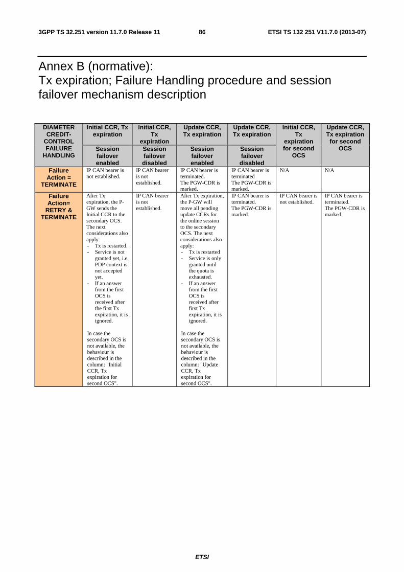
ETSI
ETSI TS 132 251 V11.7.0 (2013-07)863GPP TS 32.251 version 11.7.0 Release 11
Annex B (normative): Tx expiration; Failure Handling procedure and session failover mechanism description
DIAMETER CREDIT-
CONTROL FAILURE
HANDLING
Initial CCR, Tx expiration
Initial CCR, Tx
expiration
Update CCR, Tx expiration
Update CCR, Tx expiration
Initial CCR, Tx
expiration for second
OCS
Update CCR, Tx expiration
for second OCS Session
failover enabled
Session failover disabled
Session failover enabled
Session failover disabled
Failure Action =
TERMINATE
IP CAN bearer is not established.
IP CAN bearer is not established.
IP CAN bearer is terminated. The PGW-CDR is marked.
IP CAN bearer is terminated The PGW-CDR is marked.
N/A N/A
Failure Action=
RETRY & TERMINATE
After Tx expiration, the P-GW sends the Initial CCR to the secondary OCS. The next considerations also apply: - Tx is restarted. - Service is not
granted yet, i.e. PDP context is not accepted yet.
- If an answer from the first OCS is received after the first Tx expiration, it is ignored.
In case the secondary OCS is not available, the behaviour is described in the column: "Initial CCR, Tx expiration for second OCS".
IP CAN bearer is not established.
After Tx expiration, the P-GW will move all pending update CCRs for the online session to the secondary OCS. The next considerations also apply: - Tx is restarted - Service is only
granted until the quota is exhausted.
- If an answer from the first OCS is received after first Tx expiration, it is ignored.
In case the secondary OCS is not available, the behaviour is described in the column: "Update CCR, Tx expiration for second OCS".
IP CAN bearer is terminated. The PGW-CDR is marked.
IP CAN bearer is not established.
IP CAN bearer is terminated. The PGW-CDR is marked.
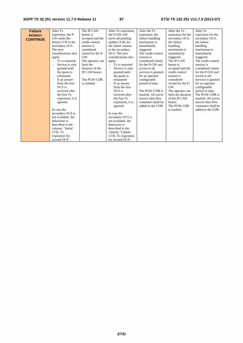
ETSI
ETSI TS 132 251 V11.7.0 (2013-07)873GPP TS 32.251 version 11.7.0 Release 11
Failure Action=
CONTINUE
After Tx expiration, the P-GW sends the Initial CCR to the secondary OCS. The next considerations also apply: - Tx is restarted - Service is only
granted until the quota is exhausted
- If an answer from the first OCS is received after the first Tx expiration, it is ignored.
In case the secondary OCS is not available, the behaviour is described in the column: "Initial CCR, Tx expiration for second OCS".
The IP CAN bearer is accepted and the credit-control session is considered closed for the P-GW. The operator can limit the duration of the IP CAN bearer. The PGW-CDR is marked.
After Tx expiration, the P-GW will move all pending update CCRs for the online session to the secondary OCS. The next considerations also apply: - Tx is restarted - Service is only
granted until the quota is exhausted
- If an answer from the first OCS is received after the first Tx expiration, it is ignored.
In case the secondary OCS is not available, the behaviour is described in the column: "Update CCR, Tx expiration for second OCS".
After the Tx expiration, the failure handling mechanism is immediately triggered: The credit-control session is considered closed for the P-GW and access to all services is granted for an operator configurable period of time. The PGW-CDR is marked. All active service data flow containers shall be added to the CDR.
After the Tx expiration for the secondary OCS, the failure handling mechanism is immediately triggered: The IP CAN bearer is accepted and the credit-control session is considered closed for the P-GW. The operator can limit the duration of the IP CAN bearer. The PGW-CDR is marked.
After Tx expiration for the secondary OCS, the failure handling mechanism is immediately triggered: The credit-control session is considered closed for the P-GW and access to all services is granted for an operator configurable period of time. The PGW-CDR is marked. All active service data flow containers shall be added to the CDR
ETSI
ETSI TS 132 251 V11.7.0 (2013-07)883GPP TS 32.251 version 11.7.0 Release 11
Annex C (informative): Bibliography
a) The 3GPP charging specifications
- 3GPP TS 32.252: "Telecommunication management; Charging management; Wireless Local Area Network (WLAN) charging".
b) Common 3GPP specifications
- 3GPP TS 22.101: "Service aspects; Service principles".
- 3GPP TS 23.002: "Network Architecture".
- 3GPP TS 23.003: "Numbering, addressing and identification".
- 3GPP TS 27.001: "General on Terminal Adaptation Functions (TAF) for Mobile Stations (MS)".
c) other Domain and Service specific 3GPP / ETSI specifications
- 3GPP TS 49.031: "Location Services (LCS); Base Station System Application Part LCS extension (BSSAP-LE)".
- 3GPP TS 24.008: "Mobile radio interface layer 3 specification; Core network protocols; Stage 3".
- 3GPP TS 23.040: "Technical realization of the Short Message Service (SMS)".
- 3GPP TS 32.215: "Telecommunication management; Charging management; Charging data description for the Packet Switched (PS) domain (Release 5)". Not propagated beyond Release 5.
d) Relevant ITU Recommendations
- ITU-T Recommendation D.93: "Charging and accounting in the international land mobile telephone service (provided via cellular radio systems)".
- ITU-T Recommendation E.164: "The international public telecommunication numbering plan".
- ITU-T Recommendation Q.767: "Application of the ISDN user part of CCITT signalling System No.7 for international ISDN interconnections".
- ITU-T Recommendation X.25: "Interface between Data Terminal Equipment (DTE) and Data Circuit-terminating Equipment (DCE) for terminals operating in the packet mode and connected to public data networks by dedicated circuit".
- ITU-T Recommendation X.121: "International numbering plan for public data networks".
e) Relevant IETF RFCs
- IETF RFC 959 (1985): "File Transfer Protocol".
- IETF RFC 1350: "The TFT Protocol (Revision 2)"
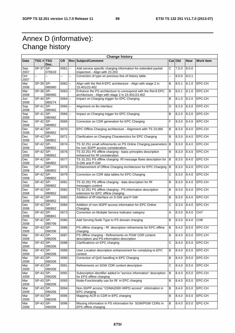
ETSI
ETSI TS 132 251 V11.7.0 (2013-07)893GPP TS 32.251 version 11.7.0 Release 11
Annex D (informative): Change history
Change history Date TSG # TSG
Doc. CR Rev Subject/Comment Cat Old New Work Item
Sep 2007
SP-37 SP-070619
0061 -- Add service specific charging information for extended packet inspection - Align with 23.203
C 7.5.0 8.0.0
Oct 2007
-- -- -- -- Correction of typo on previous line of history table -- 8.0.0 8.0.1
Mar 2008
SP-39 SP-080060
0062 -- Align with the Rel-8 EPC architecture - Align with stage 2 in 23.401/23.402
B 8.0.1 8.1.0 EPC-CH
Mar 2008
SP-39 SP-080060
0063 -- Enhance the PS architecture to correspond with the Rel-8 EPC architecture - Align with stage 2 in 23.401/23.402
B 8.0.1 8.1.0 EPC-CH
Jun 2008
SP-40 SP-080274
0064 -- Impact on Charging trigger for EPC Charging B 8.1.0 8.2.0 EPC-CH
Sep 2008
SP-41 SP-080462
0065 -- Alignment on Bx interface D 8.2.0 8.3.0 EPC-CH
Sep 2008
SP-41 SP-080462
0066 -- Impact on Charging trigger for EPC Charging B 8.2.0 8.3.0 EPC-CH
Dec 2008
SP-42 SP-080852
0069 - Correction on CDR generation for EPC Charging F 8.3.0 8.4.0 EPC-CH
Dec 2008
SP-42 SP-080852
0070 - EPC Offline Charging architecture - Alignment with TS 23.060 B 8.3.0 8.4.0 EPC-CH
Dec 2008
SP-42 SP-080852
0071 - Clarification on Charging Charaterictics for EPC Charging B 8.3.0 8.4.0 EPC-CH
Dec 2008
SP-42 SP-080852
0074 - TS 32.251 small refinements on PS Online Charging parameters for non-3GPP access consideration.
B 8.3.0 8.4.0 EPC-CH
Dec 2008
SP-42 SP-080852
0076 - TS 32.251 PS offline charging - basic principles description enhanced for Rf consideration
B 8.3.0 8.4.0 EPC-CH
Dec 2008
SP-42 SP-080852
0077 - TS 32.251 PS offline charging- Rf message flows description for S-GW and P-GW
B 8.3.0 8.4.0 EPC-CH
Dec 2008
SP-42 SP-080852
0078 - Enhancement of Offline Charging Architecture for EPC Charging B 8.3.0 8.4.0 EPC-CH
Dec 2008
SP-42 SP-080852
0079 - Correction on CDR data tables for EPC Charging C 8.3.0 8.4.0 EPC-CH
Dec 2008
SP-42 SP-080852
0081 - TS 32.251 PS offline charging - data description for Rf messages content
B 8.3.0 8.4.0 EPC-CH
Dec 2008
SP-42 SP-080852
0082 - TS 32.251 PS offline charging - PS information description extension for EPC offline charging
B 8.3.0 8.4.0 EPC-CH
Dec 2008
SP-42 SP-080852
0083 - Addition of Rf interface on S-GW and P-GW B 8.3.0 8.4.0 EPC-CH
Dec 2008
SP-42 SP-080852
0084 - Addition of non-3GPP access information for EPC Online Charging
C 8.3.0 8.4.0 EPC-CH
Dec 2008
SP-42 SP-080841
0073 - Correction on Multiple Service Indicator category A 8.3.0 8.4.0 CH7
Dec 2008
SP-42 SP-080706
0080 - Add Serving Node Type to PS domain charging B 8.3.0 8.4.0 CH8
Mar 2009
SP-43 SP-090206
0086 - PS offline charging - Rf description refinements for EPC offline charging
B 8.4.0 8.5.0 EPC-CH
Mar 2009
SP-43 SP-090206
0087 - PS offline charging - Refinements on PGW CDR content description and PS-information description
B 8.4.0 8.5.0 EPC-CH
Mar 2009
SP-43 SP-090206
0088 - Clarifications on EPC charging C 8.4.0 8.5.0 EPC-CH
Mar 2009
SP-43 SP-090206
0089 - User Location description enhancement for complying to EPC context
B 8.4.0 8.5.0 EPC-CH
Mar 2009
SP-43 SP-090206
0090 - Correction of QoS handling in EPC Charging B 8.4.0 8.5.0 EPC-CH
Mar 2009
SP-43 SP-090206
0091 - Refinements on SGW CDR content description C 8.4.0 8.5.0 EPC-CH
Mar 2009
SP-43 SP-090206
0092 - Subscription identifier added in "service information" description for EPS offline charging
B 8.4.0 8.5.0 EPC-CH
Mar 2009
SP-43 SP-090206
0093 - Node-Functionality use for Rf in EPC charging B 8.4.0 8.5.0 EPC-CH
Mar 2009
SP-43 SP-090206
0094 - Non-3GPP access "CDMA2000 HRPD access" information in EPC charging
B 8.4.0 8.5.0 EPC-CH
Mar 2009
SP-43 SP-090206
0095 - Mapping ACR to CDR in EPC charging B 8.4.0 8.5.0 EPC-CH
Mar 2009
SP-43 SP-090206
0096 - Missing information in PS information for SGW/PGW CDRs in EPS offline charging
B 8.4.0 8.5.0 EPC-CH
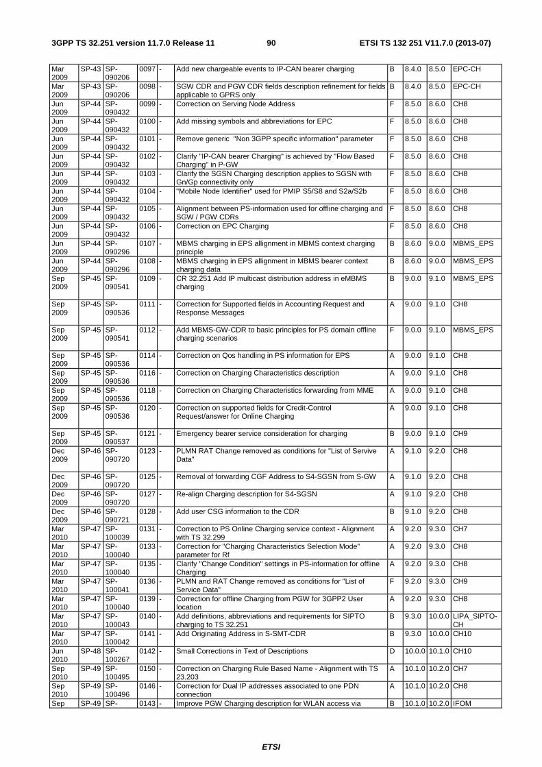
ETSI
ETSI TS 132 251 V11.7.0 (2013-07)903GPP TS 32.251 version 11.7.0 Release 11
Mar 2009
SP-43 SP-090206
0097 - Add new chargeable events to IP-CAN bearer charging B 8.4.0 8.5.0 EPC-CH
Mar 2009
SP-43 SP-090206
0098 - SGW CDR and PGW CDR fields description refinement for fields applicable to GPRS only
B 8.4.0 8.5.0 EPC-CH
Jun 2009
SP-44 SP-090432
0099 - Correction on Serving Node Address F 8.5.0 8.6.0 CH8
Jun 2009
SP-44 SP-090432
0100 - Add missing symbols and abbreviations for EPC F 8.5.0 8.6.0 CH8
Jun 2009
SP-44 SP-090432
0101 - Remove generic "Non 3GPP specific information" parameter F 8.5.0 8.6.0 CH8
Jun 2009
SP-44 SP-090432
0102 - Clarify "IP-CAN bearer Charging" is achieved by "Flow Based Charging" in P-GW
F 8.5.0 8.6.0 CH8
Jun 2009
SP-44 SP-090432
0103 - Clarify the SGSN Charging description applies to SGSN with Gn/Gp connectivity only
F 8.5.0 8.6.0 CH8
Jun 2009
SP-44 SP-090432
0104 - "Mobile Node Identifier" used for PMIP S5/S8 and S2a/S2b F 8.5.0 8.6.0 CH8
Jun 2009
SP-44 SP-090432
0105 - Alignment between PS-information used for offline charging and SGW / PGW CDRs
F 8.5.0 8.6.0 CH8
Jun 2009
SP-44 SP-090432
0106 - Correction on EPC Charging F 8.5.0 8.6.0 CH8
Jun 2009
SP-44 SP-090296
0107 - MBMS charging in EPS allignment in MBMS context charging principle
B 8.6.0 9.0.0 MBMS_EPS
Jun 2009
SP-44 SP-090296
0108 - MBMS charging in EPS allignment in MBMS bearer context charging data
B 8.6.0 9.0.0 MBMS_EPS
Sep 2009
SP-45 SP-090541
0109 - CR 32.251 Add IP multicast distribution address in eMBMS charging
B 9.0.0 9.1.0 MBMS_EPS
Sep 2009
SP-45 SP-090536
0111 - Correction for Supported fields in Accounting Request and Response Messages
A 9.0.0 9.1.0 CH8
Sep 2009
SP-45 SP-090541
0112 - Add MBMS-GW-CDR to basic principles for PS domain offline charging scenarios
F 9.0.0 9.1.0 MBMS_EPS
Sep 2009
SP-45 SP-090536
0114 - Correction on Qos handling in PS information for EPS A 9.0.0 9.1.0 CH8
Sep 2009
SP-45 SP-090536
0116 - Correction on Charging Characteristics description A 9.0.0 9.1.0 CH8
Sep 2009
SP-45 SP-090536
0118 - Correction on Charging Characteristics forwarding from MME A 9.0.0 9.1.0 CH8
Sep 2009
SP-45 SP-090536
0120 - Correction on supported fields for Credit-Control Request/answer for Online Charging
A 9.0.0 9.1.0 CH8
Sep 2009
SP-45 SP-090537
0121 - Emergency bearer service consideration for charging B 9.0.0 9.1.0 CH9
Dec 2009
SP-46 SP-090720
0123 - PLMN RAT Change removed as conditions for "List of Servive Data"
A 9.1.0 9.2.0 CH8
Dec 2009
SP-46 SP-090720
0125 - Removal of forwarding CGF Address to S4-SGSN from S-GW A 9.1.0 9.2.0 CH8
Dec 2009
SP-46 SP-090720
0127 - Re-align Charging description for S4-SGSN A 9.1.0 9.2.0 CH8
Dec 2009
SP-46 SP-090721
0128 - Add user CSG information to the CDR B 9.1.0 9.2.0 CH8
Mar 2010
SP-47 SP-100039
0131 - Correction to PS Online Charging service context - Alignment with TS 32.299
A 9.2.0 9.3.0 CH7
Mar 2010
SP-47 SP-100040
0133 - Correction for "Charging Characteristics Selection Mode" parameter for Rf
A 9.2.0 9.3.0 CH8
Mar 2010
SP-47 SP-100040
0135 - Clarify "Change Condition" settings in PS-information for offline Charging
A 9.2.0 9.3.0 CH8
Mar 2010
SP-47 SP-100041
0136 - PLMN and RAT Change removed as conditions for "List of Service Data"
F 9.2.0 9.3.0 CH9
Mar 2010
SP-47 SP-100040
0139 - Correction for offline Charging from PGW for 3GPP2 User location
A 9.2.0 9.3.0 CH8
Mar 2010
SP-47 SP-100043
0140 - Add definitions, abbreviations and requirements for SIPTO charging to TS 32.251
B 9.3.0 10.0.0 LIPA_SIPTO-CH
Mar 2010
SP-47 SP-100042
0141 - Add Originating Address in S-SMT-CDR B 9.3.0 10.0.0 CH10
Jun 2010
SP-48 SP-100267
0142 - Small Corrections in Text of Descriptions D 10.0.0 10.1.0 CH10
Sep 2010
SP-49 SP-100495
0150 - Correction on Charging Rule Based Name - Alignment with TS 23.203
A 10.1.0 10.2.0 CH7
Sep 2010
SP-49 SP-100496
0146 - Correction for Dual IP addresses associated to one PDN connection
A 10.1.0 10.2.0 CH8
Sep SP-49 SP- 0143 - Improve PGW Charging description for WLAN access via B 10.1.0 10.2.0 IFOM
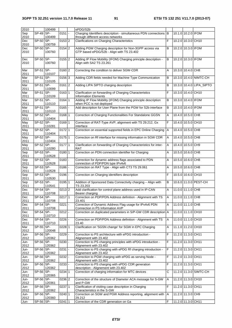
ETSI
ETSI TS 132 251 V11.7.0 (2013-07)913GPP TS 32.251 version 11.7.0 Release 11
2010 100499 ePDG/S2b Sep 2010
SP-49 SP-100499
0151 - Charging Identifiers description - simultaneous PDN connections through different access networks
B 10.1.0 10.2.0 IFOM
Dec 2010
SP-50 SP-100759
0153 2 Clarifications on Charging Characteristics F 10.2.0 10.3.0 CH10
Dec 2010
SP-50 SP-100760
0154 2 Adding PGW Charging description for Non-3GPP access via GTP based ePDG/S2b - Align with TS 23.402
B 10.2.0 10.3.0 IFOM
Dec 2010
SP-50 SP-100760
0155 2 Adding IP Flow Mobility (IFOM) Charging principle description - Align with SA2 TS 23.261
B 10.2.0 10.3.0 IFOM
Mar 2011
SP-51 SP-110107
0160 2 Correcting the condition to deliver SGW-CDR A 10.3.0 10.4.0 CH8
Mar 2011
SP-51 SP-110105
0156 3 Adding CDR fields needed for Machine Type Communication B 10.3.0 10.4.0 NIMTC-CH
Mar 2011
SP-51 SP-110099
0161 2 Adding LIPA SIPTO charging description B 10.3.0 10.4.0 LIPA_SIPTO
Mar 2011
SP-51 SP-110109
0163 1 Clarification on forwarding of Charging Characteristics Information Elements
F 10.3.0 10.4.0 CH10
Mar 2011
SP-51 SP-110110
0164 1 Adding IP Flow Mobility (IFOM) Charging principle description when PCC is not deployed
B 10.3.0 10.4.0 IFOM
Mar 2011
SP-51 SP-110110
0165 - Add description for User Plane from the PGW for S2b interface B 10.3.0 10.4.0 IFOM
May 2011
SP-52 SP-110404
0168 1 Correction of Charging Functionalities For Standalone GGSN A 10.4.0 10.5.0 CH8
May 2011
SP-52 SP-110281
0169 1 Correction of RAT-Type AVP, alignment with TS 29.212, Gx interface
F 10.4.0 10.5.0 CH10
May 2011
SP-52 SP-110404
0172 1 Correction on essential supported fields in EPC Online Charging A 10.4.0 10.5.0 CH8
May 2011
SP-52 SP-110404
0175 1 Correction on Rf interface for missing information in SGW CDR A 10.4.0 10.5.0 CH8
May 2011
SP-52 SP-110280
0177 1 Clarification on forwarding of Charging Characteristics for inter-RAT
A 10.4.0 10.5.0 CH9
Sep 2011
SP-53 SP-110528
0180 1 Correction on PDN connection identifier for Charging A 10.5.0 10.6.0 CH8
Sep 2011
SP-53 SP-110528
0183 - Correction for dynamic address flags associated to PDN connection of PDP/PDN type IPv4v6
A 10.5.0 10.6.0 CH8
Sep 2011
SP-53 SP-110528
0186 - Correction on RAT Type - Align with CT3 TS 29.061 A 10.5.0 10.6.0 CH8
Sep 2011
SP-53 SP-110530
0196 - Correction on Charging identifiers description F 10.5.0 10.6.0 CH10
Sep 2011
SP-53 SP-110541
0195 1 Addition of Sponsored Data Connectivity charging – Align with TS 23.203
B 10.6.0 11.0.0 PEST-CH
Dec 2011
SP-54 SP-110708
0213 2 Add clarification for control plane address used in IP-CAN Bearer charging
A 11.0.0 11.1.0 CH8
Dec 2011
SP-54 SP-110708
0217 1 Correction on PDP/PDN Address definition - Alignment with TS 23.401
A 11.0.0 11.1.0 CH8
Dec 2011
SP-54 SP-110708
0221 - Correction of Dynamic Address Flag usage for IPv4v6 PDN Connection in PS Information AVP
A 11.0.0 11.1.0 CH8
Dec 2011
SP-54 SP-110710
0212 - Correction on duplicated parameters in S/P-GW CDR description A 11.0.0 11.1.0 CH10
Dec 2011
SP-54 SP-110710
0226 - Correction on PDP/PDN Address definition - Alignment with TS 23.40
A 11.0.0 11.1.0 CH10
Mar 2012
SP-55 SP-120048
0228 1 Clarification on 'SGSN change' for SGW in EPC Charging A 11.1.0 11.2.0 CH10
Jun-2012
SP-56 SP-120362
0229 - Correction to PS architecture with ePDG introduction - Alignement with 23.402
F 11.2.0 11.3.0 CH11
Jun-2012
SP-56 SP-120362
0230 - Correction to PS charging principles with ePDG introduction - Alignement with 23.402
F 11.2.0 11.3.0 CH11
Jun-2012
SP-56 SP-120362
0231 - Correction to PS charging with ePDG Rf charging introduction - Alignement with 23.402
F 11.2.0 11.3.0 CH11
Jun-2012
SP-56 SP-120362
0232 - Correction to PGW charging with ePDG as serving Node - Alignement with 23.402
F 11.2.0 11.3.0 CH11
Jun-2012
SP-56 SP-120362
0233 - Correction to PS charging with ePDG CDR generation description - Alignement with 23.402
F 11.2.0 11.3.0 CH11
Jun-2012
SP-56 SP-120365
0234 1 Correction of charging information for MTC devices C 11.2.0 11.3.0 SIMTC-CH
Jun-2012
SP-56 SP-120361
0236 2 Correction of the structure of Diameter ACA message for S-GW and P-GW
A 11.2.0 11.3.0 CH10
Jun-2012
SP-56 SP-120362
0237 1 Clarification of visiting case description in Charging Characteristics in the S-GW
F 11.2.0 11.3.0 CH11
Jun-2012
SP-56 SP-120360
0240 1 Correction on SGW and PGW Address reporting, alignment with 29.212
A 11.2.0 11.3.0 CH9
Jun- SP-56 SP- 0241 1 Correction of the CDR generation on Ga F 11.2.0 11.3.0 CH11
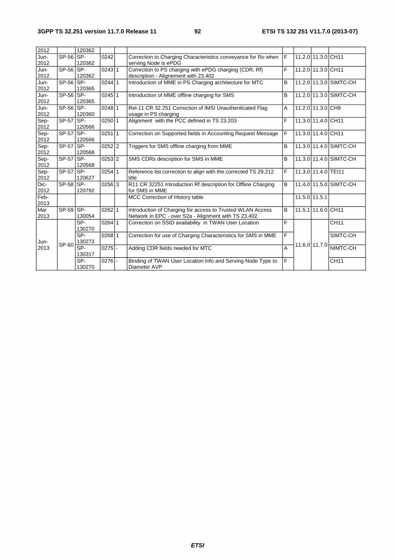
ETSI
ETSI TS 132 251 V11.7.0 (2013-07)923GPP TS 32.251 version 11.7.0 Release 11
2012 120362 Jun-2012
SP-56 SP-120362
0242 Correction to Charging Characteristics conveyance for Ro when serving Node is ePDG
F 11.2.0 11.3.0 CH11
Jun-2012
SP-56 SP-120362
0243 1 Correction to PS charging with ePDG charging (CDR, Rf) description - Alignement with 23.402
F 11.2.0 11.3.0 CH11
Jun-2012
SP-56 SP-120365
0244 1 Introduction of MME in PS Charging architecture for MTC B 11.2.0 11.3.0 SIMTC-CH
Jun-2012
SP-56 SP-120365
0245 1 Introduction of MME offline charging for SMS B 11.2.0 11.3.0 SIMTC-CH
Jun-2012
SP-56 SP-120360
0248 1 Rel-11 CR 32.251 Correction of IMSI Unauthenticated Flag usage in PS charging
A 11.2.0 11.3.0 CH9
Sep-2012
SP-57 SP-120566
0250 1 Alignment with the PCC defined in TS 23.203 F 11.3.0 11.4.0 CH11
Sep-2012
SP-57 SP-120566
0251 1 Correction on Supported fields in Accounting Request Message F 11.3.0 11.4.0 CH11
Sep-2012
SP-57 SP-120568
0252 2 Triggers for SMS offline charging from MME B 11.3.0 11.4.0 SIMTC-CH
Sep-2012
SP-57 SP-120568
0253 2 SMS CDRs description for SMS in MME B 11.3.0 11.4.0 SIMTC-CH
Sep-2012
SP-57 SP-120627
0254 1 Reference list correction to align with the corrected TS 29.212 title
F 11.3.0 11.4.0 TEI11
Dic-2012
SP-58 SP-120792
0256 3 R11 CR 32251 Introduction Rf description for Offline Charging for SMS in MME
B 11.4.0 11.5.0 SIMTC-CH
Feb-2013
MCC Correction of History table 11.5.0 11.5.1
Mar 2013
SP-59 SP-130054
0262 1 Introduction of Charging for access to Trusted WLAN Access Network in EPC - over S2a - Alignment with TS 23.402
B 11.5.1 11.6.0 CH11
Jun-2013 SP-60
SP-130270
0264 1 Correction on SSID availability in TWAN User Location F
11.6.0 11.7.0
CH11
SP-130273
0268 1 Correction for use of Charging Characteristics for SMS in MME F SIMTC-CH
SP-130317
0275 - Adding CDR fields needed for MTC A NIMTC-CH
SP-130270
0276 - Binding of TWAN User Location Info and Serving Node Type to Diameter AVP
F CH11

ETSI
ETSI TS 132 251 V11.7.0 (2013-07)933GPP TS 32.251 version 11.7.0 Release 11
History
Document history
V11.4.0 September 2012 Publication
V11.5.1 February 2013 Publication
V11.6.0 April 2013 Publication
V11.7.0 July 2013 Publication