ETISALAT Regulations
Subject Page Introduction 2 General telecom requirements 3 Civil requirements applicable for all types of buildings 3 Entry box 3 Entry pipes 3 Main telecom room 4 Floor telecom room 4 Roof-top telecom room 4 Risers from main telecom room to individual floors 5 Floor distribution box 5 Flat distribution-from indoor equipment cabinet 6 Villa floor distribution-from indoor equipment cabinet 6 Installation of in-building fibre drop cables 6 High-rise buildings 6 Single villas 7 Etisalat telecom requirements 7 Etisalat telecom requirements-Table 1 7 Etisalat telecom requirements-Table 2 8 Structured Cabling System (SCS) 9 Cabling & termination 9 Telecommunication cabling 9 Telecommunication socket 9 Accessories 10 Horizontal subsystem (UTP Cables) 10 Cable capacities in trays conduits 11 Indoor equipment cabinet 19” 11 A) Free standing types 11 B) Wall-mounted type cabinets 12 Under-floor systems 12 Main elements of under-floor raceway systems 12 Protection from electromagnetic interference 13 Electrical requirements 15 Important notes 15 List of annexures 16 www.etisalat.ae Design guide Index
-
Upload
laith-shakir -
Category
Documents
-
view
990 -
download
80
Transcript of ETISALAT Regulations

Subject PageIntroduction 2Generaltelecomrequirements 3Civilrequirementsapplicableforalltypesofbuildings 3Entrybox 3Entrypipes 3Maintelecomroom 4Floortelecomroom 4Roof-toptelecomroom 4Risersfrommaintelecomroomtoindividualfloors 5Floordistributionbox 5Flatdistribution-fromindoorequipmentcabinet 6Villafloordistribution-fromindoorequipmentcabinet 6Installationofin-buildingfibredropcables 6High-risebuildings 6Singlevillas 7Etisalattelecomrequirements 7Etisalattelecomrequirements-Table1 7Etisalattelecomrequirements-Table2 8StructuredCablingSystem(SCS) 9Cabling&termination 9Telecommunicationcabling 9Telecommunicationsocket 9Accessories 10Horizontalsubsystem(UTPCables) 10Cablecapacitiesintraysconduits 11Indoorequipmentcabinet19” 11A)Freestandingtypes 11B)Wall-mountedtypecabinets 12Under-floorsystems 12Mainelementsofunder-floorracewaysystems 12Protectionfromelectromagneticinterference 13Electricalrequirements 15Importantnotes 15Listofannexures 16
www.etisalat.ae Design guide
Index

www.etisalat.ae Design guide www.etisalat.ae Design guide
Introduction1
Introduction
Telecommunicationisnowanintegralpartofsocial,economicandpoliticalissuesoftheworld.Networksofthefuturewillbedigitalandintelligentandwillofferhightransmissioncapacityandflexiblebandwidth;inaddition,theywillbeeasilyaccessedandconnectedwhileitsserviceswillbepersonalandtailoredtoindividualneeds.Thesewillallowustointeractinwayspreviouslynotpossible-availableatanytimeandanyplace.Inadditiontoprovidingentertainmentandbusinessservices,networksofthefuturewillprovideeducation,healthandotherpublicservices.
Majoradvancesincommunicationstechnologyhavesubstantiallywidenedtherangeofservicescarriedbythenetwork.Satellites,microwaveradio,opticalcablelinks,digitalswitchingandtransmission,offerapotentialfortheimprovementofqualityandfortheextensionofaccesstothemostremoteareas.Thepaceoftechnologicalchangeisincreasingwhilethemagnitudeofdemandsthefuturewillmakeonourcreativityandcapacitytoadaptisgreat.Customerswilldemandmorethanjuststate-of-the-arttechnology;theywillwantconvenienceandincreasedcontrolintheirlivesthataffordableinformationaccesscanprovide.Whilebusinesseswilllookfortotaltelecommunicationssolutionsthatwillnotonlyenablethemtoremainproductiveandcompetegloballybutwillalsogivethemacompetitiveedge.
Etisalatcanbewell-placedtomeetthesechallengesaheadandmeetthevariedneedsofourlocalandinternationalcustomersandpavethewayfortheregion’snewdynamisminthetelecommunicationsindustrywellintothe21stcentury.
Astechnologyandmodeoftransportarechangingfast,abroadapproachtosuitallfuturetypeofserviceswillhavetobeborneinmind,whiledesigningtheinfrastructuresforbuildings.AproperlydesignedbuildingwithclearAccessPathsupportsthetripleplayservices,viztelephony,dataandvideoservices.Also,supportsfutureadvancedservices,warrantinghigherspeedsandhigherbandwidth,plannedtobeavailableinnearfuture,forfasterprovisionofservices.
Thepresentbookletistoprovideguidelinesforconsultants,contractorsandthedetailsonthein-buildingfacilitiesrequiredtobeconsideredatthedesignstage.
ThedetailsprovidedareageneralinsightandtheminimumrequirementsofEtisalatforthenewbuildings,primarilytodevelopanddeployFTTX(FibretoHome),basedonGPONtechnology.
2
www.etisalat.ae Design guide www.etisalat.ae Design guide
3 4
GeneraltelecomrequirementsToprovidetelecomservices,theinternalconcealedpipeandotherassociatedrequirementsvaryforthedifferentbuildingtypes.Thevarioustypesofbuildingsaregroupedascommercialbuildings,residentialtowers,warehouses,mediumhigh-risebuildings,shoppingcomplexes,retailhouses,rowhouses,independentvillas,campusvillas,labourcamps,mosques,petrolpumps,etc.
Thebuildingowners,builders,propertydevelopers,consultantsandcontractorsareadvisedtoprovidethevariousin–buildingrequirements,asapplicable,toensuretimelyprovisionofservices.
Civilrequirementsapplicableforalltypesofbuildings
Entrybox
Entryboxisanundergroundjointboxbuilt,exclusivelytoallowinstallationofEtisalatundergroundcablenetworktothecustomer’spremises.
•Theentryboxisareinforcedconcretestructure,withaheavydutyDuctileIronFrameandCoverofratinggrade‘A’andsizeis60x60x80cm.Thecovershallhavemarkingas“Telephones”
•Thelocationoftheentrybox,dependsonthelocationofexisting/proposedEtisalatexternallineplant
•Theentryboxshouldbeconstructedatamaximumdistanceof1meterfromplotline.Ifitisnotpracticaltoinstallwithintheplot,theninstallitoutsidetheplot.Makesureittouchestheboundarywall
•Duetothevariablesinvolved,itisessentialtoconsultEtisalatatthedesignstage,todecidethelocationoftheentryboxandentrypipe.Theconsultants/
contractorsmustnotdeviatefromthestipulatedlocation
•Anearthrodmustbeprovidedattheentrybox.Therequiredearthresistanceshouldnotexceedmorethan5ohms
•ForentryboxsizedetailspleaserefertoTableNo.1
Entrypipes(Lead-inducts)
TheentrypipesareuPVCducts.TheseductsaretobeextendedfromtheentryboxtowardspremisesandtowardsEtisalatlineplantlocation.
•Entrypipesshouldbelaidatadepthof60cmfromtheproposedfinishedpavinglevel.Theentrypipemustbeprotectedwithconcretetopreventdamages
•EntrypipeshouldbeextendedtotheentryboxandbeyondtothenearestexistingEtisalatplantlocation,or1meterfromplotlimitorasadvisedbyEtisalat
•TheentrypipeshouldbeofuPVCmaterialandofblackcolor
•Theopenendsoftheentrypipemustbeproperlysealed,toprevententryofsub-soilmaterialsandingressofwater
•Locationofentrypipesmustbeclearlymarked,abovegroundforeasylocation
•Buildingcontractorsshallberesponsibletolocatetheinstalledentrypipesonsite,ifrequestedbyEtisalat
•Noright-angledsharpbendsshouldbeinstalledthroughouttheductlength,exceptonewide-angle,longradiusbend(factorymade)attheterminatingendoftheduct,insidethemaintelecomroom.Alternatively,atthelocationofthewideanglebend,acablepullboxofminimumsize600(L)x700(W)x800(D)mmmustbeprovided
•Entrypipesmustbeassigned,exclusivelyforEtisalattelecommunicationservices
•Entrypipesmustbeprovidedwithadrawropemadeofnylonofminimum6mmdiameter
•Forthenumberandsizeofentrypipes,forthevarioustypesofbuildings,pleaserefertoTable1
Maintelecomroom
Maintelecomroomshouldbeadedicatedroom.Thisistobeprovidedeitheronthegroundfloororbasementorinthefirstfloorormezzaninefloorofthebuildingforthepurposeofterminatingtelecommunicationcablesandtohousethepresent&futuretelecomequipment.TheroommustbeexclusivelyforEtisalatuse
•TheroommustbeeasilyaccessibletoEtisalatPersonnel24hr./day,(alldaysincludingweekends).Theroommustbeclean,dryandfreefromdustandsecuredfromunauthorizedentry
•Adequatelightingandminimumoffour20ampand240voltA.C.Mainsoutletfromadedicatedcircuitbreakershouldbeprovided
•Theroommustbeair-conditionedanda“raisedfloor”ofminimum30cmshouldbeprovidedifrequired,dependingonthetelecomroomusage
•Theroommustbeprovidedwithagoodearthrodofnotmorethan5ohms
•Thedooropeningfortheroomshouldswingoutwards
•Thefloor,roofandsurroundingwallofthetelecomroom,shouldbefreeofanyconcealedwater/drainagepipesandair-conditioningductspassingthrough
•Theroommustbeprovidedwithanemergencylight,asmokedetectorandafirealarm
•Ifthetelecomroomisproposedinthebasement,anautomaticsumpdrainingsystemmustbeprovidedtohandlewaterseepages
•Theductentrytobuildingmustbesealedairandwatertight
•Forthemaintelecomroomsize,pleasereferTableNo.1
Floortelecomcloset
Floortelecomclosetisadedicatedclosetandrequiredoneachfloorforthepurposeofroutingand/orterminatingtelecommunicationcables.TheroomshouldbeexclusivelyforEtisalatuse
•TheclosetmustreadilybeaccessibletoEtisalatpersonnelandequipment24hr./day,allthedays,roundtheclockandthecloset,cleandry,andfreefromdustandsecuredfromunauthorizedentry
•Thedooropeningfortheclosetshouldswingoutwards,whenopened
•Forthefloortelecomclosetsize,pleasereferTableNo.1
Roof-toptelecomroom
Roof-toptelecomroom,isadedicatedroomtobeprovidedontheroof-topoftheproposedmulti-storeybuildings,exclusivelyforEtisalatuseandsecuredfromunauthorizedentry.Theminimumroof-toptelecomroomsizeshouldbe3(L)x3(W)x3(H)meter
•Thefloorloadingofthisareamustbemaximumpossible,tosupportfutureinstallationoftelecommunicationsequipment
•Anopeningofsize60x40cmtobeprovidedonthewalloftheroom,facingtheterrace,50cmbelowtheroomceiling
www.etisalat.ae Design guide www.etisalat.ae Design guide
5 6
•Thelocationoftheroomshouldbewithintheverticalstructureofthebuilding,withdueconsiderationsforloadsafetyprovisionsandtoextendrelatedfacilitiesrequiredsuchasair-conditioning,3-phasepower(DistributionBoard)DB,earthinglessthan5ohms,adequatelighting,one13amp240vACpowersocketandonetelephonesocket
•Theroommustbeprovidedwithanemergencylight,asmokedetectorandafirealarm
•TheroommustreadilybeaccessibletoEtisalatpersonnelandequipment24hreveryday,allthedays,roundtheclockandtheroommustbeclean,dryandfreefromdust
Risersfrommaintelecomroomto individual floors
Therisersarerequiredinmultiple-storeybuildingsfortheinstallationoftelecomfibreopticcablesfrommaintelecomroomtootherfloors,asdetailedbelow:-
•Galvanizedslottedironcabletrays(minimum200x50mmHDRF(HeavyDuty,ReturnFlange)shouldbeprovidedfromthemaintelephoneroom,toeachtelephoneclosetandextendeduptotherooftelephoneroom
•Theriserstoeachfloormustbesymmetricalandverticallyinlinewiththemaintelecomroom.However,wherethemaintelecomroom,floortelephoneclosetandrooftelecomroomsaretobelocatedonebelowtheotherinverticalline,acontinuouscabletrays/conduitsmustbeprovidedwithpullboxes/accesspanelsateveryturningpointandatintervalof15meterseach,uptothemaintelecomroom.Rightangleorsharpbendsaretobeavoided
•Ifabuildingconsistsofmorethanonetower,alltheabovespecifiedrequirementsarerequiredineachtower
Thetowersmustbeinter-connectedatthemaintelecomroom,byseparatecabletraysofminimum2nos.andsize200x50mmorthroughfloorracewayspassingthroughacommonareabetweenthetwobuildings.ThesizeofthefloorracewaysistobedecidedatthedesignstagebyEtisalat.Thesamerequirementsalsoapplytomezzanineandpenthousefloors.Thetelecomcabletraysshouldhaveadequateseparationfromelectricalcabletrays.Electricalcabletraysshouldnotcrossthetelecomcabletrays.
Floordistributionbox
Floordistributionboxesaremetallicboxes,concealed,locatedonthewall,wheretheinternalconduitfromeveryflatisterminated.Theseemptyboxes,shouldbelocatedclosetotherisersandcanbemorethanone,dependinguponthenumberofflatsandconduitsproposedtobeterminated.Thesedistributionboxesfacilitatetoroutethefibreopticcablestothepremisesdirectandthenumberofcablescorrespondstothenumberofflat/premises.
•Thedistributionboxesshouldbeofsizenotlessthan30(L)X30(H)X15(D)flushmountedonwallandshouldbefixedinsidethetelecomclosetofeachfloor.Asuitablehingedcovermustbeprovided
•Itshouldbeinstalledataheightof120cmabovethefinishedfloorlevel
•Theconduitsleadingfromthefloordistributionboxtowardsflat,shouldnotbelessthan25mmdiameter
•Adequatesafeworkingspaceistobeprovidedaroundeachlocation
•Thedistributionboxesonafloor,shouldnotbelinkedtoorserveanyotherfloorofthebuilding
•Thedistributionboxeslocationshouldneverbenearanyelectricaljunctionboxorbusbars.Adequatesafeworkingspaceshouldbeprovidedinfrontofeachbox
•Asingleconduitofatleast25mm(1inch)internaldia.,blackandofuPVCmaterialshouldbeprovidedfromeachfloordistributionboxtotheindoorequipmentcabinetofeachoffice,residence,flatandotherindependentareasinthesamefloor
•Etisalatshouldbeconsultedtoenhancetherequirements,ifthebuildingisdesignedforcommercialuse
Flatdistribution–fromindoorequipmentcabinet
•Asecuredindoorequipmentcabinetshouldbeofminimumsize12Uandwidth600mmanddepth515mmtohousetheOpticalNetworkUnit(ONU),powersocketsandpatchpanel/IDCmodulesandbattery.Thecabinetshouldbeflushmountedonwall.Thecabinetshouldbededicatedtoeachoffice/residentialflatandtobesitedinasecuredplace.Thelocationshallbesuitablefortechnician’saccess,whenrequired•Thelocationoftheindoorequipmentcabinetshouldbeatacommonpoint,wherealltheinternalconduitsmeetandtheStructuredCablingSystem(SCS)onastartopologycanbeinstalled.However,thefarthestsocketmustnotexceed90mfromthecabinet•Twopowersocketsarerequired,insidetheindoorequipmentcabinet,forpoweringtheopticalnetworkunitandbatteryrectifier
•Thecabinetdistributionboxlocationshouldnotbeadjacenttoanyelectricaldistributionorbusbars
•Thecabinetdistributionboxshouldbeinstalledataheightof120cmabovethefinishedfloorlevel
•Allinternalconduitsshouldbeofadiameternotlessthan25mm(1inch)toextendthestructuredcablesfromONUtoSCSsocketlocationsateachroom
Villadistribution-fromindoorequipmentcabinet
•Asecuredindoorequipmentcabinet,shouldbeofminimumsize12Uandwidth600mmanddepth515mmtohousetheOpticalNetworkUnit(ONU),powersocketsandpatchpanel/IDCmodulesandbattery.Thecabinetshouldbeflushmountedonwall.Thecabinetshouldbededicatedoneachvillaandtobesitedinasecuredplace.Thelocationmustbesuitablefortechnician’saccess,whenrequired
•Asecureddistributionboxofsize30(L)x30(H)x15(W)cmflushmountedonwallisrequiredineveryfloorofthevilla,fordistributingSCS,fromtheindoorcabinet
•Thefloordistributionboxshouldbekeptataconvenientandeasilyaccessiblelocationwherethefloordistributionconduitsareterminated.Itshouldbeinstalledataheightbetween40cmand120cmabovethefinishedfloorlevel
•ThedistributionboxesondifferentfloorsofavillashouldbeconnectedthroughaPVCconduit,ofa50mmdiameter
•Thedistributionboxshouldhaveone50mm(2inch)conduittotherooftopofthevilla,fromthecabinetorfromthetelephoneentryductlocation,inordertoprovideaccesstocablesfromtheantenna
Installation of in-building fibre drop cables
High-risebuildings
Thebuildingownershouldinstallaminimumof2corefibredropcables,fromthemaintelecomroomODFlocationtotheindoorcabinetlocationofeachflat/premises.TerminationofthesefibresshouldbebyEtisalatontheONUandODF.Installertoleaveanextralengthof3mofcableoneitherendforterminations.Thecablesmustbesuitablylabeled
www.etisalat.ae Design guide www.etisalat.ae Design guide
7 8
Singlevillas
Inthecaseofsinglevillas,EtisalatwillextendandterminatetheFOcable,directlyintheONU.
Inallothercases,the2coredropcablesshouldbeextendedtotheODFlocationinthetelecomroom,bytheowner.
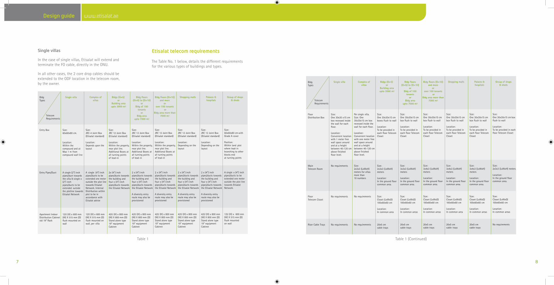
Etisalattelecomrequirements
TheTableNo.1below,detailsthedifferentrequirementsforthevarioustypesofbuildingsandtypes.
Single villa
Size:60x60x80 cm.
Location: Within thecompound and atMax 1 m fromcompound wall line
Size:JRC-4 Joint Box(Etisalat standard)
Location:Depends upon thelayout
Size:JRC 12 Joint Box(Etisalat standard)
Location:Within the property,near plot line.Additional Boxes atall turning pointsof lead-in
Size:JRC 12 Joint Box(Etisalat standard)
Location:Within the property,near plot line.Additional Boxes atall turning pointsof lead-in
Size:JRC 12 Joint Box(Etisalat standard)
Location:Within the property,near plot line.Additional Boxes atall turning pointsof lead-in
Size:JRC 12 Joint Box(Etisalat standard)
Location:Depending on thelayout
Size:JRC 12 Joint Box(Etisalat standard)
Location:Depending on thelayout
Size:60x60x80 cm withGrade A cover
Position:Within land plotwhere lead-inbranching to otherblocks endat turning points
Entry Box
BldgTypes
TelecomRequirements
A single (2”) inchpipes/duct towardsthe villa & single x(2”) inchpipes/ducts to beextended outsidethe plotline towardsEtisalat Network
A single (4”) inchpipes/ducts to beextended one meteroutside the plot linetowards EtisalatNetwork. InternalDistribution withinplot to be inaccordance withEtisalat advise
2x (4”) inchpipes/ducts towardsthe building andfour x (4”) inchpipes/ducts towardsthe Etisalat Network
2 x (4”) inchpipes/ducts towardsthe building andfour x (4”) inchpipes/ducts towardsthe Etisalat Network
A diversity entryroute may also beprovisioned
2 x (4”) inchpipes/ducts towardsthe building andfour x (4”) inchpipes/ducts towardsthe Etisalat Network
A diversity entryroute may also beprovisioned
2 x (4”) inchpipes/ducts towardsthe building andfour x (4”) inchpipes/ducts towardsthe Etisalat Network
A diversity entryroute may also beprovisioned
2 x (4”) inchpipes/ducts towardsthe building andfour x (4”) inchpipes/ducts towardsthe Etisalat Network
A diversity entryroute may also beprovisioned
A single x (4”) inchpipes/ducts to beextended one meteroutside the plot linetowards EtisalatNetwork.
Entry Pipes/ Duct
12U (H) x 600 mm(W) X 515 mm (D) flush mounted onwall
12U (H) x 600 mm(W) X 515 mm (D)flush mounted onwall, per villa
42U (H) x 800 mm(W) X 800 mm (D)Stand alone type19” equipmentCabinet
42U (H) x 800 mm(W) X 800 mm (D)Stand alone type19” equipmentCabinet
42U (H) x 800 mm(W) X 800 mm (D)Stand alone type19” equipmentCabinet
42U (H) x 800 mm(W) X 800 mm (D)Stand alone type19” equipmentCabinet
42U (H) x 800 mm(W) X 800 mm (D)Stand alone type19” equipmentCabinet
12U (H) x 600 mm(W) X 515 mm (D)flush mountedon wall
Apartment IndoorDistribution Cabinetstd 19“ Rack
Size:One 30x30 x15 cmbox recessed insidethe wall for eachfloor.
Location:Convenient locationwith 1 meter freewall space aroundand at a heightbetween 40-120 cmabove finishedfloor level.
Per single villa.Size: One30x30x15 cm boxrecessed inside thewall for each floor.
Location:Convenient locationwith one meter freewall space aroundand at a heightbetween 40-120 cmabove finishedfloor level.
Size:One 30x30x15 cmboxes flush to wall
Location:To be provided ineach floor TelecomCloset
Size:One 30x30x15 cmbox flush to wall
Location:To be provided ineach floor TelecomCloset
Size:One 30x30x15 cmbox flush to wall
Location:To be provided ineach floor TelecomCloset
Size:One 30x30x15 cmbox flush to wall
Location:To be provided ineach floor TelecomCloset
Size:One 30x30x15 cmbox flush to wall
Location:To be provided ineach floor Telecom Closet
Size:One 30x30x15 cm boxflush to wall
Location:To be provided in eachfloor Telecom Closet
FloorDistribution Box
No requirements Size:2x3x3 (LxWxH)meters for villasmore than10 numbers
Size:2x3x3 (LxWxH)meters
Location:In the ground floorcommon area.
Size:3x3x3 (LxWxH)meters
Location:In the ground floorcommon area.
Size:3x4x3 (LxWxH)meters
Location:In the ground floorcommon area.
Size:3x4x3 (LxWxH)meters
Location:In the ground floorcommon area.
Size:3x4x3 (LxWxH)meters
Location:In the ground floorcommon area.
Size:2x3x3 (LxWxH) meters
Location:In the ground floorcommon area.
MainTelecom Room
No requirements No requirements Size:Closet (LxWxD)100x60x60 cm
Location:In common area
Size:Closet (LxWxD)100x60x60 cm
Location:In common areas
Size:Closet (LxWxD)100x60x60 cm
Location:In common areas
Size:Closet (LxWxD)100x60x60 cm
Location:In common area
Size:Closet (LxWxD)100x60x60 cm
Location:In common areas
Size:Closet (LxWxD)100x60x60 cm
Location:In common areas
FloorTelecom Closet
No requirements No requirements 20x5 cmcable trays
20x5 cmcable trays
20x5 cmcable trays
20x5 cmcable trays
20x5 cmcable trays
No requirementsRiser Cable Trays
BldgTypes
TelecomRequirements
Complex ofvillas
Bldgs (G+5) or
Building areaupto 3000 m2
Bldg floors(G+6) to (G+10)
or Bldg of 100
tenantsor
Bldg areaupto 7000 m2
Bldg floors (G+10) and more
orover 100 tenants
or Bldg area more than
7000 m2
Shopping malls Palaces &hospitals
Group of shops& sheds
Single villa Complex ofvillas
Bldgs (G+5) or
Building areaupto 3000 m2
Bldg floors(G+6) to (G+10)
or Bldg of 100
tenantsor
Bldg areaupto 7000 m2
Bldg floors (G+10) and more
orover 100 tenants
or Bldg area more than
7000 m2
Shopping malls Palaces &hospitals
Group of shops& sheds
Table1 Table1(Continued)
www.etisalat.ae Design guide www.etisalat.ae Design guide
9 10
StructuredCablingSystem(SCS)
TodelivertheservicesfromtheONU,aSCSSystemonstartopologyisrequired.TheminimumrequirementisstandardCAT6cablewithRJ45connectivity.ASCSdesignbeingprojectspecific,adiscussion,withcompletedetailsisrecommendedwithsystemdesignersandEtisalat.
However,thefollowingarethegeneralminimumrequirementsofstructuredcablingsystems,forprovisionofservice.
Cabling&termination
Telecommunicationcabling
•ThecablesusedforthesewiringmustcomplywithminimumCAT6standards
•TheplannedSCScableshouldmeetthedesignedservicerequirementswithintheparticularflatlevelandshouldhavebuilt-inflexibility,tomeetgrowingneedsofthetenants•AllSCScablesaretobeproperlylabeledandterminated,intheRJ45socketsandin-patchpanelorinCAT6compliantIDCmodulesbytheowners
•Buildingownerisresponsibleforreplacementofin-buildingcablesandotherfixtures,ifthesebecomefaulty
•CablediagramsmustbesubmittedtoEtisalatforapprovalatthedesignstageandas-builtisrequiredoncompletion
•Cablesandotheraccessoriesrequiredforblockwiringmaybepurchasedfromanyreputablesourceprovidedthatthematerialmeetsstandards
•ThenameandcontacttelephonenumbersoftheSCSinstaller,shouldbelabeledatappropriatelocation
•CompletedSCSshouldbesubjecttoacceptancebyEtisalat.However,thedesignandperformanceoftheSCSsystemshouldbetheresponsibilityoftheinstaller/owner
•Anyupgradingrequiredinthein–buildingfacility,telecommunicationcables,duetoeitherenhanceddemand,changeinbuildingstatusordamageshouldbeprovidedbybuildingowner
•ThesupplyandterminationofUTPcablesonpatchpanelorIDCmodulesandsocketslocationsshouldbetheresponsibilityoftheinstallers/owners
•Etisalatwouldsupplyandinstall,mainODFs,miniODFsandopticalnetworkunits(ONUs).AlljumperingsandpatchingsintheODFs,patchpanelsinONUswouldbetheresponsibilityofEtisalat.Buildingowners/contractorsorothertechniciansaretotallyprohibitedtocarryoutthesefunctions
Telecommunicationsocket
AlloutletsshouldbeCategory6performance,outletsmountedinshutters,typicallyindual,tripleorquadformationinasingleordoublegangwhitefaceplate.AllRJ45outletsshouldbefittedwithspringloadedslidingshutterstopreventtheingressofdirtanddust.
•Provisionforatleastonedualsocketfortelecommunicationservicesshouldbemadeineveryroomincludingkitchen.Conduitwithnotlessthan25mmshouldbeconnectedbetweenthesocketlocations
•EverysocketmustbeconnectedwithaminimumoffourpairSCSCat6cable,followingstartopology.Incaseofhotelbuildings,theprovisionoftelecommunicationsocketshouldalsobeextendedtothebathrooms
•Telecommunicationsockets,cablesandassociatedfacilitieswithinthevariousroomsandpremisesaretobeprovidedbythebuildingowner
Accessories
AllaccessoryplatesshouldbedualorquadwhitePVCplated.Theuseofanyspecialfaceplate,whichmaybespecifictoanyothermanufacturer’sproductrange,suchasbrassfinish,etc.shouldbereviewed.
Thechoiceofoutletsdistribution,locationandtype,eitheritissingle,dual,orquad,theoptimumrequirementsineacharea,ultimatenumberofoutletsineverylocations,flexibilityandmaximumusage,shouldbetheresponsibilityofconsultants.
Horizontalsubsystem(UTPCables)
AllhorizontalcablesshouldbebasedontheCategory6performancecompliant.
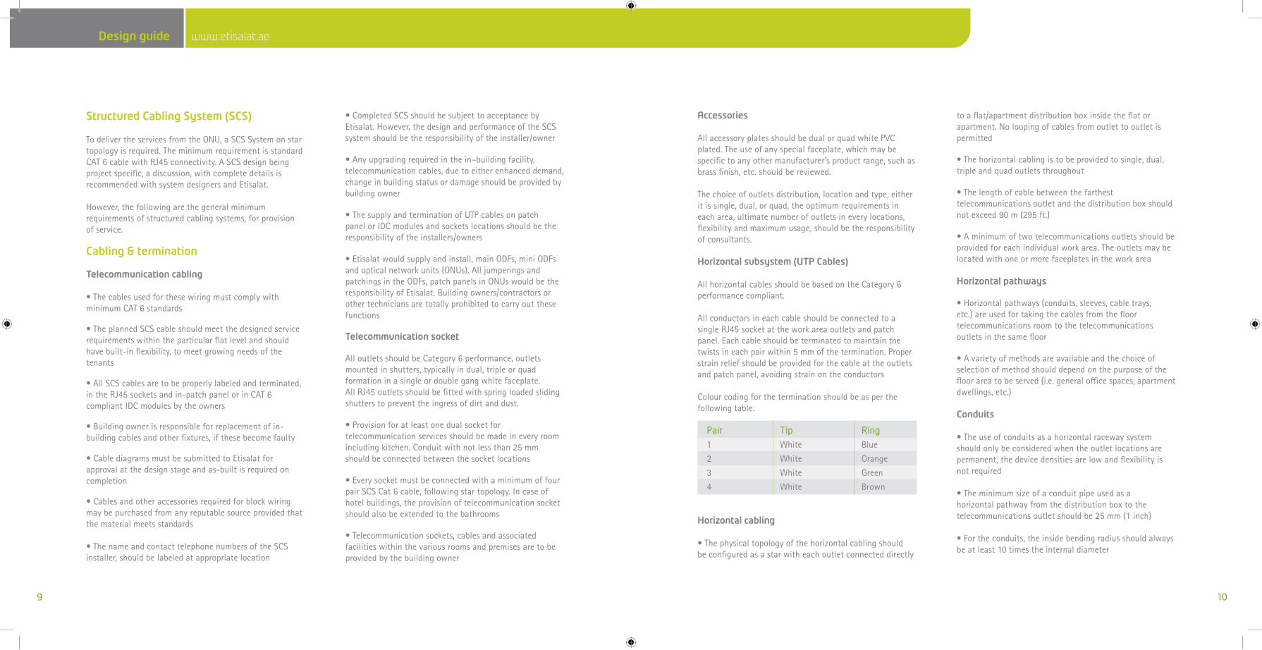
AllconductorsineachcableshouldbeconnectedtoasingleRJ45socketattheworkareaoutletsandpatchpanel.Eachcableshouldbeterminatedtomaintainthetwistsineachpairwithin5mmofthetermination.Properstrainreliefshouldbeprovidedforthecableattheoutletsandpatchpanel,avoidingstrainontheconductors
Colourcodingfortheterminationshouldbeasperthefollowingtable.
Horizontalcabling
•Thephysicaltopologyofthehorizontalcablingshouldbeconfiguredasastarwitheachoutletconnecteddirectly
toaflat/apartmentdistributionboxinsidetheflatorapartment.Noloopingofcablesfromoutlettooutletispermitted
•Thehorizontalcablingistobeprovidedtosingle,dual,tripleandquadoutletsthroughout
•Thelengthofcablebetweenthefarthesttelecommunicationsoutletandthedistributionboxshouldnotexceed90m(295ft.)
•Aminimumoftwotelecommunicationsoutletsshouldbeprovidedforeachindividualworkarea.Theoutletsmaybelocatedwithoneormorefaceplatesintheworkarea
Horizontalpathways
•Horizontalpathways(conduits,sleeves,cabletrays,etc.)areusedfortakingthecablesfromthefloortelecommunicationsroomtothetelecommunicationsoutletsinthesamefloor
•Avarietyofmethodsareavailableandthechoiceofselectionofmethodshoulddependonthepurposeofthefloorareatobeserved(i.e.generalofficespaces,apartmentdwellings,etc.)
Conduits
•Theuseofconduitsasahorizontalracewaysystemshouldonlybeconsideredwhentheoutletlocationsarepermanent,thedevicedensitiesarelowandflexibilityisnotrequired
•Theminimumsizeofaconduitpipeusedasahorizontalpathwayfromthedistributionboxtothetelecommunicationsoutletshouldbe25mm(1inch)
•Fortheconduits,theinsidebendingradiusshouldalwaysbeatleast10timestheinternaldiameter
Pair Tip Ring
1 White Blue
2 White Orange
3 White Green
4 White Brown
www.etisalat.ae Design guide www.etisalat.ae Design guide
11 12
•Minimumofonenylondrawwiremustbeinstalledinaconduit
•Pullboxesshouldbelocatedsuchthattheyarereadilyaccessibleatalltimes.Pullboxestobespacedatamaximumof15maparttominimizecablestressduringinstallationandtoprovideserviceabilityinthefuture
•Conduitsmustbefreefromsharpedges,topreventcabledamageduringandsubsequenttopulling
•Conduitsprotrudingthroughafloorshouldbeterminated;aminimumof50mmfromthefloortopreventwaterorotherliquidsfromflowingintotheconduits
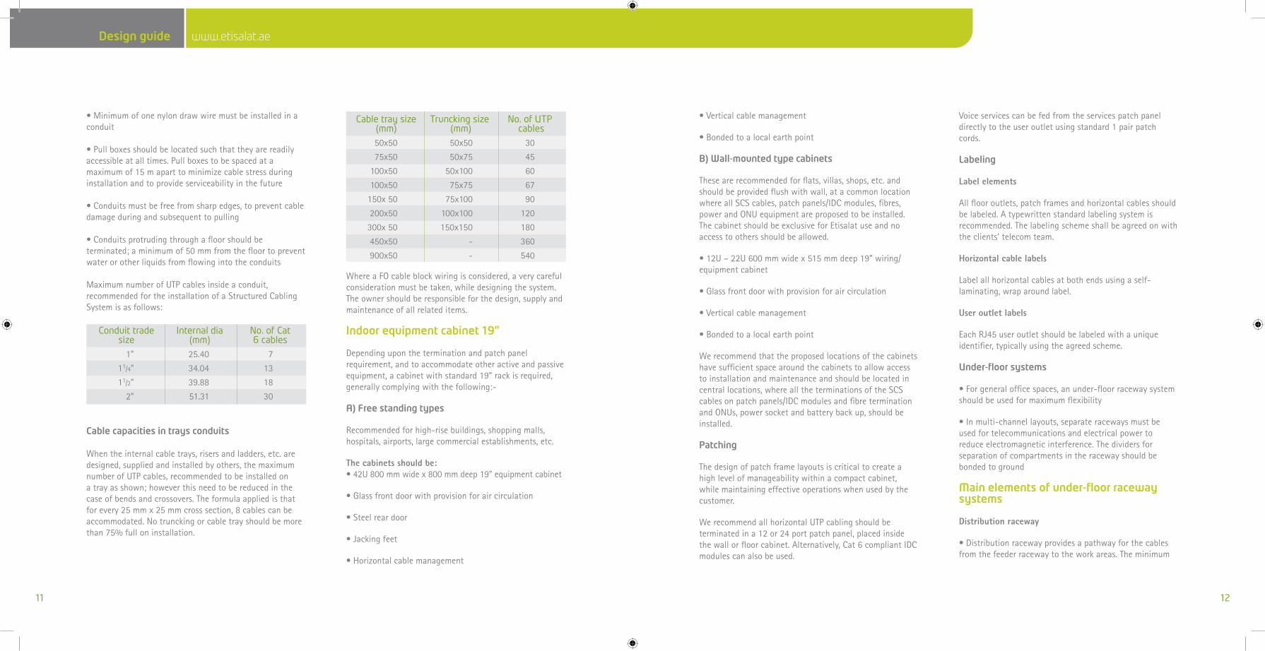
MaximumnumberofUTPcablesinsideaconduit,recommendedfortheinstallationofaStructuredCablingSystemisasfollows:
Cablecapacitiesintraysconduits
Whentheinternalcabletrays,risersandladders,etc.aredesigned,suppliedandinstalledbyothers,themaximumnumberofUTPcables,recommendedtobeinstalledonatrayasshown;howeverthisneedtobereducedinthecaseofbendsandcrossovers.Theformulaappliedisthatforevery25mmx25mmcrosssection,8cablescanbeaccommodated.Notrunckingorcabletrayshouldbemorethan75%fulloninstallation.
WhereaFOcableblockwiringisconsidered,averycarefulconsiderationmustbetaken,whiledesigningthesystem.Theownershouldberesponsibleforthedesign,supplyandmaintenanceofallrelateditems.
Indoorequipmentcabinet19”
Dependingupontheterminationandpatchpanelrequirement,andtoaccommodateotheractiveandpassiveequipment,acabinetwithstandard19”rackisrequired,generallycomplyingwiththefollowing:-
A)Freestandingtypes
Recommendedforhigh-risebuildings,shoppingmalls,hospitals,airports,largecommercialestablishments,etc.
The cabinets should be:•42U800mmwidex800mmdeep19”equipmentcabinet
•Glassfrontdoorwithprovisionforaircirculation
•Steelreardoor
•Jackingfeet
•Horizontalcablemanagement
•Verticalcablemanagement
•Bondedtoalocalearthpoint
B)Wall-mountedtypecabinets
Thesearerecommendedforflats,villas,shops,etc.andshouldbeprovidedflushwithwall,atacommonlocationwhereallSCScables,patchpanels/IDCmodules,fibres,powerandONUequipmentareproposedtobeinstalled.ThecabinetshouldbeexclusiveforEtisalatuseandnoaccesstoothersshouldbeallowed.
•12U–22U600mmwidex515mmdeep19”wiring/equipmentcabinet
•Glassfrontdoorwithprovisionforaircirculation
•Verticalcablemanagement
•Bondedtoalocalearthpoint
Werecommendthattheproposedlocationsofthecabinetshavesufficientspacearoundthecabinetstoallowaccesstoinstallationandmaintenanceandshouldbelocatedincentrallocations,wherealltheterminationsoftheSCScablesonpatchpanels/IDCmodulesandfibreterminationandONUs,powersocketandbatterybackup,shouldbeinstalled.
Patching
Thedesignofpatchframelayoutsiscriticaltocreateahighlevelofmanageabilitywithinacompactcabinet,whilemaintainingeffectiveoperationswhenusedbythecustomer.
WerecommendallhorizontalUTPcablingshouldbeterminatedina12or24portpatchpanel,placedinsidethewallorfloorcabinet.Alternatively,Cat6compliantIDCmodulescanalsobeused.
Voiceservicescanbefedfromtheservicespatchpaneldirectlytotheuseroutletusingstandard1pairpatchcords.
Labeling
Label elements
Allflooroutlets,patchframesandhorizontalcablesshouldbelabeled.Atypewrittenstandardlabelingsystemisrecommended.Thelabelingschemeshallbeagreedonwiththeclients’telecomteam.
Horizontal cable labels
Labelallhorizontalcablesatbothendsusingaself-laminating,wraparoundlabel.
User outlet labels
EachRJ45useroutletshouldbelabeledwithauniqueidentifier,typicallyusingtheagreedscheme.
Under-floor systems
•Forgeneralofficespaces,anunder-floorracewaysystemshouldbeusedformaximumflexibility
•Inmulti-channellayouts,separateracewaysmustbeusedfortelecommunicationsandelectricalpowertoreduceelectromagneticinterference.Thedividersforseparationofcompartmentsintheracewayshouldbebondedtoground
Main elements of under-floor raceway systems
Distribution raceway
•Distributionracewayprovidesapathwayforthecablesfromthefeederracewaytotheworkareas.Theminimum
Cabletraysize Trunckingsize No.ofUTP (mm) (mm) cables
50x50 50x50 30
75x50 50x75 45
100x50 50x100 60
100x50 75x75 67
150x50 75x100 90
200x50 100x100 120
300x50 150x150 180
450x50 - 360
900x50 - 540
Conduittrade Internaldia No.ofCat size (mm) 6cables
1” 25.40 7
11/4” 34.04 13
11/2” 39.88 18
2” 51.31 30
www.etisalat.ae Design guide www.etisalat.ae Design guide
13 14
sizeofthedistributionracewayshouldbe30mmheightx60mmwidthofcross-sectionalarea.Thesamesizemustbeusedforevery(multi-channel)layout
Feeder raceway
•Feederracewayprovidesapathwayforthecablesfromthedistributionboxinthefloortelecommunicationsroomtothedistributionraceways.Theminimumsizeofthefeederracewayshouldbe40mmheightx200mmwidthofcross-sectionalarea.Thesamesizemustbeusedforevery(multi-channel)layout
•Thefeederracewaysstartingpointinthefloortelecommunicationsroommustbeadjacenttothedistributionbox.TheFeederracewayshouldendatthelastdistributionracewayitisserving
Access unit•Theaccessunitprovidesaccessatthepointofintersectionofthefeederandthedistributionraceways
Cable trays
•Cabletraysaremostlyusedforfloorswithraisedtilesorfloorings
•Asageneralguideline,cabletraysthatintersectmustbeprovidedwithatransitionalbendradiusof150mminalldirections
•Exposedsheetmetaledgesmustbeprovidedwithbushingsorothermeansofprotectionsuchthatcableswillnotbedamagedduringorafterinstallation.Sincecabletraysareusuallymetallic,allsharpedges,burrsandscrewtipsthatmaycomeintocontactwithcablingshouldberemoved
•Theminimumaccessspacebetweenthesub-floorandtheundersideofthefloortileshouldbeminimum150mm(6in)
Etisalatshouldbeconsultedintheinitialdesignstagetodecideontherequirementsifthebuildingisdesignedforofficeuse.
Protectionfromelectromagneticinterference
ThefollowingrequirementsapplytoUTPcabling,aspathwaysandspacesusedtocarryorhousetelecommunicationscabling.
•Theproximityofcablingtoelectricalfacilitiesandequipmentthatgeneratehighlevelsofelectromagneticinterference(EMI)shouldbetakenintoaccountformetalliccabling
•SourcesofEMIinclude:powercables,photocopyequipment,electricmotors,transformers,fluorescentlighting,arcweldersandinductionheaters,etc.
ToavoidEMI,thetelecommunicationspathways,spacesandmetalliccablesshouldbeinstalledwiththefollowingclearances:
41.2m(4ft)fromlargemotorsortransformers40.3m(1ft)fromconduitandcablesusedforelectricalpowerdistribution412cm(5in)fromfluorescentlighting
•Pathwaysandmetalliccablesshouldcrossperpendiculartofluorescentlightingandelectricalpowercablesorconduits
SeparationdistancefrompowersourceDuringthedesignstages,separationofpowerandtheStructuredCablingSystems(SCS)mustbeconsidered.Unshieldeddatacablesshouldnotbeinstallednearsourcesofelectromagnetism.Theguidelinesarelistedonthenextpage.
PrivateBranchExchange(PBX)
Incasewherecommunicationsystemswithmorethan64extensions(i.e.PBXsystem)arerequired,specialfacilitiesneedtobeprovidedasfollows:
Equipmentroom
AroomfortheexclusiveuseofEtisalatisneededforthetelephoneequipment.Theroomshouldbeaccessedbytheundergroundcablesandthedistributiontothefloorcables.ThemaintelecomroomcanbeconsideredforPABXinstallationincaseofcommercialsingleownerbuilding.
Roomsize
•Forupto100extensions,theminimumfloorspacerequiredis2mx3m
•Forupto400extensions,thefloorspacerequiredis4mx4m
•ForlargesystemsEtisalatmustbeconsultedattheplanningstage
•Theroomshouldhaveaminimumheightof3m,beair-conditioned,clean,anddryandfreefromdust
Roomgeneralrequirements
•Theroomshouldbefarawayfromhighvoltageplant.Otherservices/utilityductsshouldnotrunthroughthisroomanditshouldnotbedirectlyunderatoiletorbathroom
•TheroomshouldprovidereadyaccesstoEtisalatpersonnelandequipmentbutmustbesecuredfromunauthorizedentry
•Theroommustbeproperlyprotectedfromtheriskoffloodingifprovidedinthebasementorlowerlevels
•Inmulti-PBXuserbuilding,eachPBXtohaveitsownroom
•RaisedflooringshouldbeprovidedwhenrequireddependingonthePBXtype
•ForlargePBXinstallations,air-conditionedbatteryroomadjacenttotheequipmentroomwillberequired.Etisalatwillsupplydetailsatthedesignstage.Thebatteryroomshouldbeprovidedwithanexhaustfan.Conduitortrayisrequiredbetweentheequipmentroomandthebatteryroom
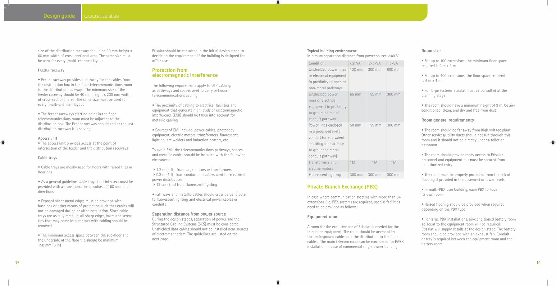
Condition
Unshieldedpowerlines
orelectricalequipment
inproximitytoopenor
non-metalpathways
Unshieldedpower
linesorelectrical
equipmentinproximity
togroundedmetal
conduitpathway
Powerlinesenclosed
inagroundedmetal
conduit(orequivalent
shieldinginproximity
togroundedmetal
conduitpathway)
Transformersand
electricmotors
Fluorescentlighting
<2kVA 2-5kVA 5kVA
130mm 300mm 600mm
65mm 155mm 300mm
50mm 155mm 300mm
1M 1M 1M
300mm 300mm 300mm
Typical building environmentMinimumseparationdistancefrompowersource<480V
www.etisalat.ae Design guide www.etisalat.ae Design guide
15 16
•DirectsunlightshouldnotfallinthePBXroom.Curtains/screensaretobeprovidedforthewindowsifany
•Powerconduitandtelecomcableconduitmustbeseparate
Electricalrequirements
•Aminimumoftwo13amp240vA/Cmainoutlets(via)UPSsystemshouldbeprovided.TheactualmainspowerrequirementswilldependonthesizeandtypeofthePBX
•Theroomshouldbeprovidedwithanearthnotmorethan5ohms
•Anti-staticflooringshouldbeprovided,includingthebatteryroom
•Theroomsmustbeprovidedwithanemergencylight,asmokedetectorandafirealarm
PABXcanbeinstalledinthemaintelecomroominthecaseofasingleowner.
Importantnote
1)Thisdesignguideexplainsingeneral,allEtisalatrequirementsthatwillfacilitatetheprovisionoftelecommunicationservicestonewbuildings,yettherequirementsindicatedinthe‘NOC’(NoObjectionCertificate)shouldbefullycomplied.2)Architects/consultants/designersmustliaisewithEtisalatatthedesignstageandobtainEtisalatapprovalonthefinaldesigndrawings.
3)Minimumtwosetsoftelephonedesigndrawingsmustbesubmittedforstudyandapproval,beforetendering.
4)Wheredeviations/comments/amendmentsareadvisedonthedesign,drawingsmustbecorrectedandre-submittedforapproval.
5)Onesetofapproved‘As-Built’drawingsmustbesubmittedalongwiththebuildingcompletioncertificate,whichwillbecertifiedbyEtisalat.
6)Etisalat’sresponsibilityislimitedtoprovisionandinstallationofODFs,terminationoffibres,patching/jumperingworksandOpticalNetworkUnits(ONUs).
7)TheownersareresponsibleforsupplyandinstallationofallinternalFOcablesfromODF(maintelecomroom)toONU(customerpremises)locations,provisionofwallmountedorstandalonecabinetstoaccommodateONU,power,patchpanels,etc.andcompletestructuredcablingsystem.
8)Theindoordrop2Ffibercables,shouldbefromapopularbrandandmake,conformingtoITUstandardG652singlemodefiberstandards.
9)Oncompletionoftherequirements,anycommentsandsnagsadvisedbyEtisalatbuildinginspector,mustbeattendedtobythecontractororownerofthebuildingsoon,toavoiddelaysintheissuanceofthebuildingcompletioncertificate.
Listofannexures
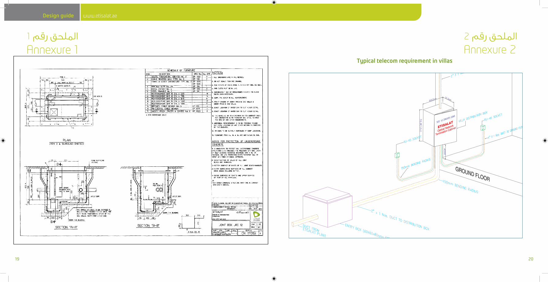
AnnexureItypeofentrybox(JRC4&JRC12)
AnnexureIItypicalexamples
www.etisalat.ae Design guide www.etisalat.ae Design guide
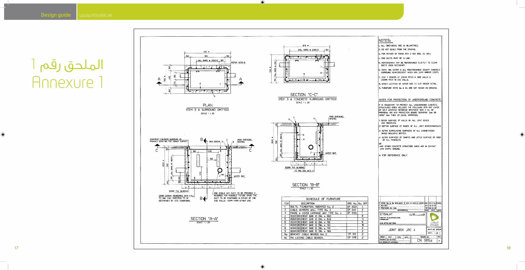
Annexure 1الملحق رقم 1
17 18
www.etisalat.ae Design guide www.etisalat.ae Design guide
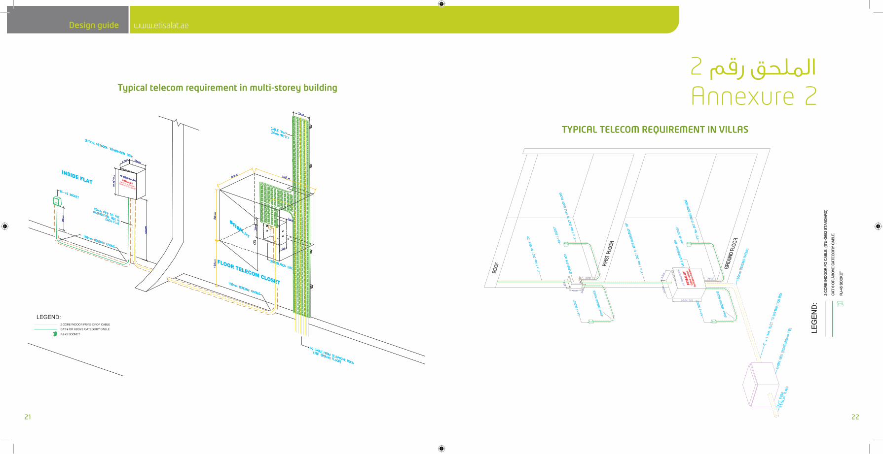
Typicaltelecomrequirementinvillas
Annexure 1الملحق رقم 1
Annexure 2الملحق رقم 2
19 20
www.etisalat.ae Design guide www.etisalat.ae Design guide
TYPICALTELECOMREQUIREMENTINVILLAS
Typicaltelecomrequirementinmulti-storeybuilding Annexure 2الملحق رقم 2
21 22