Ethernet-over-Coax Extender - surveillance-video.com · Ethernet-over-Coax Extender can be used to...
20
Ethernet-over-Coax Extender User Manual UD.6L0203D1083A01
Transcript of Ethernet-over-Coax Extender - surveillance-video.com · Ethernet-over-Coax Extender can be used to...

Ethernet-over-Coax Extender
User Manual
UD.6L0203D1083A01

User Manual of Ethernet-over-Coax Extender
1
Thank you for purchasing our product. If there is any question or request, please
do not hesitate to contact dealer.
This manual is applicable to DS-1H05-T, DS-1H05-T/E, DS-1H05-R, DS-1H05-4R,
DS-1H05-8R, DS-1H05-16R Ethernet-over-Coax Extender.
This manual may contain several technically incorrect places or printing errors,
and the content is subject to change without notice. The updates will be added
into the new version of this manual. We will readily improve or update the
products or procedures described in the manual.
User Manual of Ethernet-over-Coax Extender
1
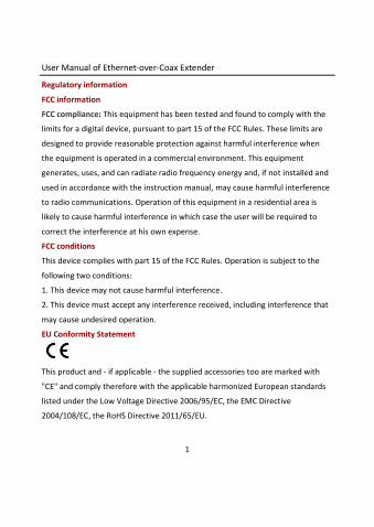
Regulatory information
FCC information
FCC compliance: This equipment has been tested and found to comply with the
limits for a digital device, pursuant to part 15 of the FCC Rules. These limits are
designed to provide reasonable protection against harmful interference when
the equipment is operated in a commercial environment. This equipment
generates, uses, and can radiate radio frequency energy and, if not installed and
used in accordance with the instruction manual, may cause harmful interference
to radio communications. Operation of this equipment in a residential area is
likely to cause harmful interference in which case the user will be required to
correct the interference at his own expense.
FCC conditions
This device complies with part 15 of the FCC Rules. Operation is subject to the
following two conditions:
1. This device may not cause harmful interference.
2. This device must accept any interference received, including interference that
may cause undesired operation.
EU Conformity Statement
This product and - if applicable - the supplied accessories too are marked with
"CE" and comply therefore with the applicable harmonized European standards
listed under the Low Voltage Directive 2006/95/EC, the EMC Directive
2004/108/EC, the RoHS Directive 2011/65/EU.
User Manual of Ethernet-over-Coax Extender
2
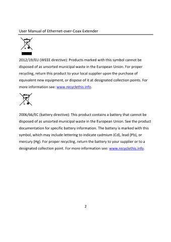
2012/19/EU (WEEE directive): Products marked with this symbol cannot be
disposed of as unsorted municipal waste in the European Union. For proper
recycling, return this product to your local supplier upon the purchase of
equivalent new equipment, or dispose of it at designated collection points. For
more information see: www.recyclethis.info.
2006/66/EC (battery directive): This product contains a battery that cannot be
disposed of as unsorted municipal waste in the European Union. See the product
documentation for specific battery information. The battery is marked with this
symbol, which may include lettering to indicate cadmium (Cd), lead (Pb), or
mercury (Hg). For proper recycling, return the battery to your supplier or to a
designated collection point. For more information see: www.recyclethis.info.
User Manual of Ethernet-over-Coax Extender
3
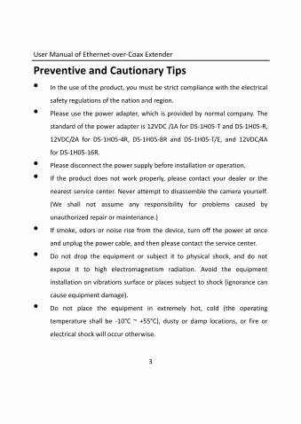
Preventive and Cautionary Tips
• In the use of the product, you must be strict compliance with the electrical
safety regulations of the nation and region.
• Please use the power adapter, which is provided by normal company. The
standard of the power adapter is 12VDC /1A for DS-1H05-T and DS-1H05-R,
12VDC/2A for DS-1H05-4R, DS-1H05-8R and DS-1H05-T/E, and 12VDC/4A
for DS-1H05-16R.
• Please disconnect the power supply before installation or operation.
• If the product does not work properly, please contact your dealer or the
nearest service center. Never attempt to disassemble the camera yourself.
(We shall not assume any responsibility for problems caused by
unauthorized repair or maintenance.)
• If smoke, odors or noise rise from the device, turn off the power at once
and unplug the power cable, and then please contact the service center.
• Do not drop the equipment or subject it to physical shock, and do not
expose it to high electromagnetism radiation. Avoid the equipment
installation on vibrations surface or places subject to shock (ignorance can
cause equipment damage).
• Do not place the equipment in extremely hot, cold (the operating
temperature shall be -10°C ~ +55°C), dusty or damp locations, or fire or
electrical shock will occur otherwise.
User Manual of Ethernet-over-Coax Extender
4
• The equipment shall be kept from rain and moisture.
• Exposing the equipment to direct sun light, low ventilation or heat source
such as heater or radiator is forbidden (ignorance can cause fire danger).
• Please use a soft and dry cloth when clean inside and outside surfaces of
the equipment, not to use alkaline detergents.
• Apparatus shall not be exposed to dripping or splashing and that no objects
filled with liquids, such as vases shall be placed on the apparatus.
• When the optical interface is not connecting with the fiber, please apply
the protective cap to the interface to avoid entry of dust.
• Improper use or replacement of the battery may result in hazard of
explosion. Replace with the same or equivalent type only. Dispose of used
batteries according to the instructions provided by the battery
manufacturer.
User Manual of Ethernet-over-Coax Extender
5
Table of Contents
Chapter 1 Introduction ......................................................................................... 6
1.1 Overview ............................................................................................ 6
1.2 Features .............................................................................................. 6
1.3 Model Description .............................................................................. 7
1.4 System Connections ............................................................................ 8
Chapter 2 Panels and Installation ......................................................................... 9
2.1 Panels of the Transmitter .................................................................... 9
2.2 Panels of the 1-channel Receiver ...................................................... 11
2.3 Panels of the Multi-channel Receiver ................................................ 12
2.4 Configuring Coax Transmission Bandwidth ........................................ 15
2.5 Installation ........................................................................................ 16
Appendix: Specifications .................................................................................... 17
User Manual of Ethernet-over-Coax Extender
6
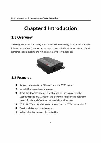
Chapter 1 Introduction
1.1 Overview
Adopting the newest Security Link Over Coax technology, the DS-1H05 Series
Ethernet-over-Coax Extender can be used to transmit the network data and CVBS
signal via coaxial cable to the remote device with low signal loss.
1.2 Features
Support transmission of Ethernet data and CVBS signal.
Up to 500m transmission distance.
Reach the downstream speed of 36Mbps for the transmitter, the
upstream speed of 11Mbps for the 1-channel receiver, and upstream
speed of 3Mbps (default) for the multi-channel receiver.
DS-1H05-T/E provides PoE power supply (meets IEEE802.af standard).
Easy installation and maintenance. Industrial design ensures high reliability.
User Manual of Ethernet-over-Coax Extender
7
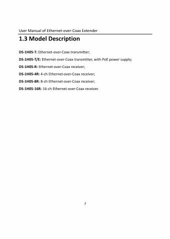
1.3 Model Description
DS-1H05-T: Ethernet-over-Coax transmitter;
DS-1H05-T/E: Ethernet-over-Coax transmitter, with PoE power supply;
DS-1H05-R: Ethernet-over-Coax receiver;
DS-1H05-4R: 4-ch Ethernet-over-Coax receiver;
DS-1H05-8R: 8-ch Ethernet-over-Coax receiver;
DS-1H05-16R: 16-ch Ethernet-over-Coax receiver.
User Manual of Ethernet-over-Coax Extender
8
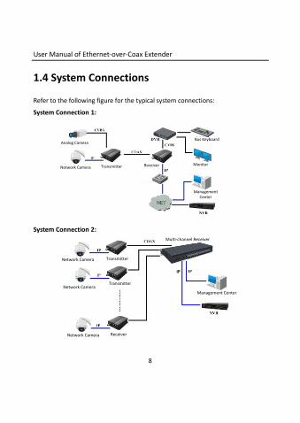
1.4 System Connections
Refer to the following figure for the typical system connections:
System Connection 1:
Analog Camera
Network Camera Transmitter Receiver Monitor
Bus Keyboard
Management Center
System Connection 2:
Network Camera
Network Camera
Network Camera
Transmitter
Transmitter
Receiver
Management Center
Multi-channel Receiver
Management Center
IP
User Manual of Ethernet-over-Coax Extender
9
Chapter 2 Panels and Installation
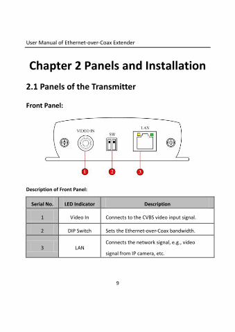
2.1 Panels of the Transmitter
Front Panel:
Description of Front Panel:
Serial No. LED Indicator Description
1 Video In Connects to the CVBS video input signal.
2 DIP Switch Sets the Ethernet-over-Coax bandwidth.
3 LAN Connects the network signal, e.g., video
signal from IP camera, etc.
User Manual of Ethernet-over-Coax Extender
10
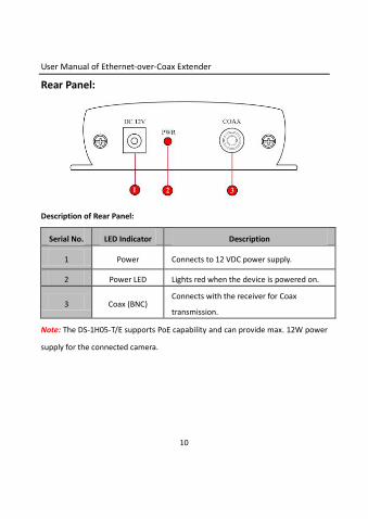
Rear Panel:
Description of Rear Panel:
Serial No. LED Indicator Description
1 Power Connects to 12 VDC power supply.
2 Power LED Lights red when the device is powered on.
3 Coax (BNC) Connects with the receiver for Coax
transmission.
Note: The DS-1H05-T/E supports PoE capability and can provide max. 12W power
supply for the connected camera.

User Manual of Ethernet-over-Coax Extender
11
2.2 Panels of the 1-channel Receiver Front Panel:
Description of Front Panel:
Serial No. LED Indicator Description
1 Video Out Sends the CVBS video signal to the terminal
device.
2 DIP Switch Sets the Ethernet-over-Coax bandwidth.
3 LAN Sends the network signal to the terminal
device.
User Manual of Ethernet-over-Coax Extender
12
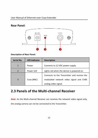
Rear Panel:
Description of Rear Panel:
Serial No. LED Indicator Description
1 Power Connects to 12 VDC power supply.
2 Power LED Lights red when the device is powered on.
3 Coax (BNC)
Connects to the Transmitter and receive the
modulated network video signal and CVBS
analog video signal.
2.3 Panels of the Multi-channel Receiver
Note: As the Multi-channel Receiver can receives the network video signal only,
the analog camera can not be connected to the Transmitter.
User Manual of Ethernet-over-Coax Extender
13
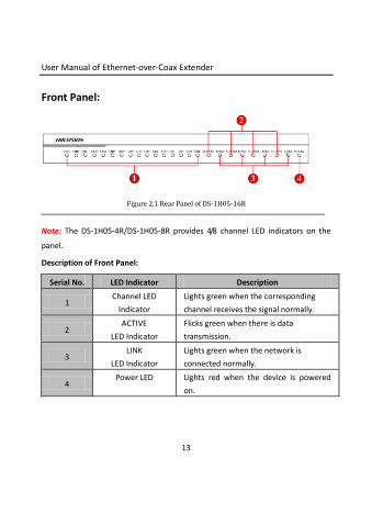
Front Panel:
Figure 2.1 Rear Panel of DS-1H05-16R
Note: The DS-1H05-4R/DS-1H05-8R provides 4/8 channel LED indicators on the
panel.
Description of Front Panel:
Serial No. LED Indicator Description
1 Channel LED
Indicator
Lights green when the corresponding
channel receives the signal normally.
2 ACTIVE
LED Indicator
Flicks green when there is data
transmission.
3 LINK
LED Indicator
Lights green when the network is
connected normally.
4 Power LED Lights red when the device is powered
on.
User Manual of Ethernet-over-Coax Extender
14
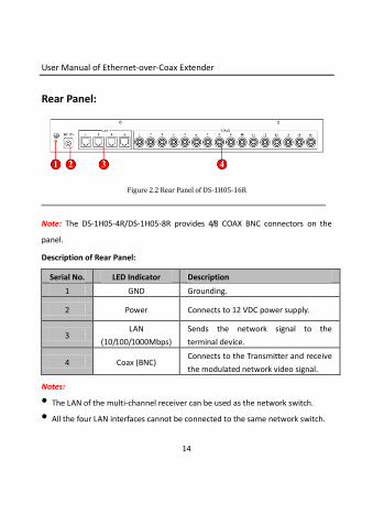
Rear Panel:
Figure 2.2 Rear Panel of DS-1H05-16R
Note: The DS-1H05-4R/DS-1H05-8R provides 4/8 COAX BNC connectors on the
panel.
Description of Rear Panel:
Serial No. LED Indicator Description
1 GND Grounding.
2 Power Connects to 12 VDC power supply.
3 LAN
(10/100/1000Mbps)
Sends the network signal to the
terminal device.
4 Coax (BNC) Connects to the Transmitter and receive
the modulated network video signal.
Notes:
• The LAN of the multi-channel receiver can be used as the network switch.
• All the four LAN interfaces cannot be connected to the same network switch.
User Manual of Ethernet-over-Coax Extender
15
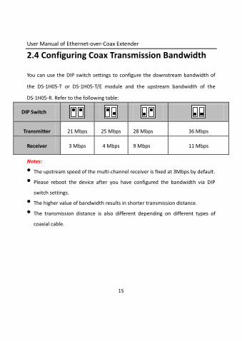
2.4 Configuring Coax Transmission Bandwidth
You can use the DIP switch settings to configure the downstream bandwidth of
the DS-1H05-T or DS-1H05-T/E module and the upstream bandwidth of the
DS-1H05-R. Refer to the following table:
DIP Switch
Transmitter 21 Mbps 25 Mbps 28 Mbps 36 Mbps
Receiver 3 Mbps 4 Mbps 9 Mbps 11 Mbps
Notes:
• The upstream speed of the multi-channel receiver is fixed at 3Mbps by default.
• Please reboot the device after you have configured the bandwidth via DIP
switch settings.
• The higher value of bandwidth results in shorter transmission distance.
• The transmission distance is also different depending on different types of
coaxial cable.
User Manual of Ethernet-over-Coax Extender
16
2.5 Installation
Prior to Installation
• Please thoroughly familiarize yourself with the information in this manual
prior to installation and operation.
• Verify that the package contents are correct by checking the items against the
packing list.
• Please contact with our company immediately in case of damaged or missing
items in the package.
Installing the Device
• The device is designed in compact metal shell with antirust and anticorrosive
surface coating.
• The device provides mounting holes on the side panels and can be directly
mounted to the cabinet, or placed on the desktop or rack.
• The cabinet should be with water-proof feature.

User Manual of Ethernet-over-Coax Extender
17
Appendix: Specifications
Model DS-1H05-T DS-1H05-T/E DS-1H05-R
Video Input Interface RJ-45/BNC RJ-45/BNC Coaxial BNC
Video Output Interface Coaxial BNC Coaxial BNC RJ-45/BNC
PoE — Support —
Power Consumption ≤ 5 W
≤ 20 W
(when PoE
power
supply is
enabled)
≤ 5 W
Power Supply 12 V DC
Working Humidity 10 % ~ 90 %
Working Temperature -10ºC ~ + 55 ºC
Dimensions (W×D×H) 80 × 96 × 27 mm
User Manual of Ethernet-over-Coax Extender
18
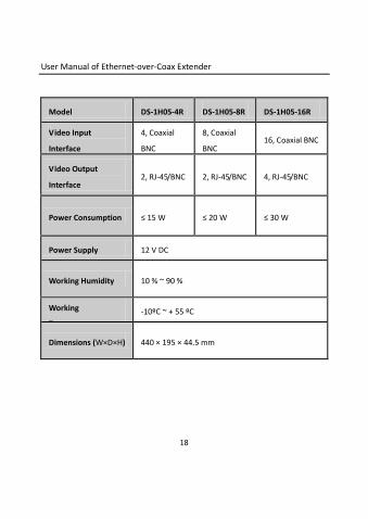
Model DS-1H05-4R DS-1H05-8R DS-1H05-16R
Video Input
Interface
4, Coaxial
BNC
8, Coaxial
BNC 16, Coaxial BNC
Video Output
Interface 2, RJ-45/BNC 2, RJ-45/BNC 4, RJ-45/BNC
Power Consumption ≤ 15 W ≤ 20 W ≤ 30 W
Power Supply 12 V DC
Working Humidity 10 % ~ 90 %
Working
Temperature
-10ºC ~ + 55 ºC
Dimensions (W×D×H) 440 × 195 × 44.5 mm