EtherCAT User's Manual - dynatorchdynatorch.com/beta/Dynatorch-Estun manual.pdf · LWR Logical...
94
EtherCAT User's Manual (Version: V1.05)
Transcript of EtherCAT User's Manual - dynatorchdynatorch.com/beta/Dynatorch-Estun manual.pdf · LWR Logical...
EtherCAT User's Manual
(Version: V1.05)

EtherCAT User's Manual
1
Chapter 1 Brief introduction of EtherCAT
1.1 What is EtherCAT
EtherCAT is an open network based on Ethernet to achieve real time control. It could support high speed and synchronized control. By using efficient network topology, the network structure with too manyconcentrator and complicated connections are avoided. It is very suitable to use this protocol in motion control and other factory automation applications.
EtherCAT is registered trademark and patented technology, licensed by Beckhoff Automation GmbH, Germany.
1.2 EtherCAT general introduction
EtherCAT technology breaks the limits of normal internet solution. Through this technology, we don’t need to receive Ethernet data, decode the data, and then copy the process data to different devices. EtherCATslave device could read the data marked with this device’s address information when the frame passes this device. As the same, some data will be written into the frame when it passes the device. In this way, data reading and data writing could be done within several nanoseconds.
EtherCAT uses standard Ethernet technology and support almost kinds of topologies, including the line type, tree type, star type and so on. Its physical layer could be 100 BASE-TXI twisted-pair wire, 100BASE-FX fiber or LVDS (low voltage differential signaling). It could also be done through switch or media converters or in order to achieve the combination of different Ethernet structure.
Relying on the ASICs for EtherCAT in the slave and DMA technology that reads network interface data, the processing of the protocol is done in the hardware. EtherCAT system could update the information for 1000 I/O within 30µs. It could exchange a frame as big as 1486 bytes within 300µs. This is almost like 12000 digital output or input. Controlling one servo with 100 8-byte I/O data only takes 100µs. Within this period, the system could update the actual positions and status presented by command value and control data. Distributed clock technology could make the cyclic synchronous error lower than 1µs.
1.3 Product introduction
ProNet servo drive achieves EtherCAT communication through EC100 network module. It is a real time Ethernet communication and the application layer applies CANopen Drive Profile (CiA 402).
EtherCAT User's Manual
2
Besides supporting the PV, PP, IP and other control mode defined in CANopen DS402, this module also supports CSP control mode. Clientscould switch the control mode by changing correspondent parameters. It is available from simple velocity control to high speed high precision position control.
1.4 CoE terms
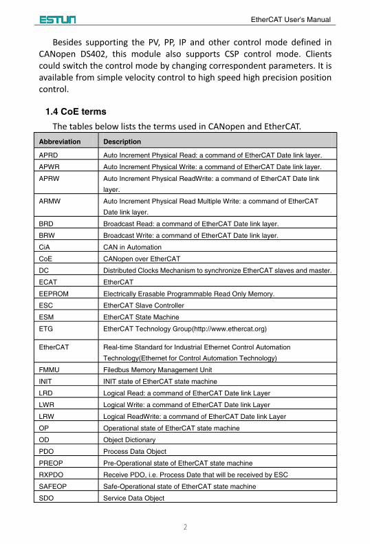
The tables below lists the terms used in CANopen and EtherCAT. Abbreviation Description
APRD Auto Increment Physical Read: a command of EtherCAT Date link layer.
APWR Auto Increment Physical Write: a command of EtherCAT Date link layer.
APRW Auto Increment Physical ReadWrite: a command of EtherCAT Date link
layer.
ARMW Auto Increment Physical Read Multiple Write: a command of EtherCAT
Date link layer.
BRD Broadcast Read: a command of EtherCAT Date link layer.
BRW Broadcast Write: a command of EtherCAT Date link layer.
CiA CAN in Automation
CoE CANopen over EtherCAT
DC Distributed Clocks Mechanism to synchronize EtherCAT slaves and master.
ECAT EtherCAT
EEPROM Electrically Erasable Programmable Read Only Memory.
ESC EtherCAT Slave Controller
ESM EtherCAT State Machine
ETG EtherCAT Technology Group(http://www.ethercat.org)
EtherCAT Real-time Standard for Industrial Ethernet Control Automation
Technology(Ethernet for Control Automation Technology)
FMMU Filedbus Memory Management Unit
INIT INIT state of EtherCAT state machine
LRD Logical Read: a command of EtherCAT Date link Layer
LWR Logical Write: a command of EtherCAT Date link Layer
LRW Logical ReadWrite: a command of EtherCAT Date link Layer
OP Operational state of EtherCAT state machine
OD Object Dictionary
PDO Process Data Object
PREOP Pre-Operational state of EtherCAT state machine
RXPDO Receive PDO, i.e. Process Date that will be received by ESC
SAFEOP Safe-Operational state of EtherCAT state machine
SDO Service Data Object
EtherCAT User's Manual
3
Abbreviation Description
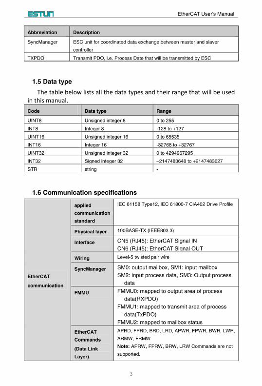
SyncManager ESC unit for coordinated data exchange between master and slaver
controller
TXPDO Transmit PDO, i.e. Process Date that will be transmitted by ESC
1.5 Data type
The table below lists all the data types and their range that will be used in this manual.Code Data type Range
UINT8 Unsigned integer 8 0 to 255
INT8 Integer 8 -128 to +127
UINT16 Unsigned integer 16 0 to 65535
INT16 Integer 16 -32768 to +32767
UINT32 Unsigned integer 32 0 to 4294967295
INT32 Signed integer 32 –2147483648 to +2147483627
STR string -
1.6 Communication specifications
EtherCAT
communication
applied
communication
standard
IEC 61158 Type12, IEC 61800-7 CiA402 Drive Profile
Physical layer 100BASE-TX (IEEE802.3)
Interface CN5 (RJ45): EtherCAT Signal IN
CN6 (RJ45): EtherCAT Signal OUT
Wiring Level-5 twisted pair wire
SyncManager SM0: output mailbox, SM1: input mailbox
SM2: input process data, SM3: Output process
data
FMMU FMMU0: mapped to output area of process
data(RXPDO)
FMMU1: mapped to transmit area of process
data(TxPDO)
FMMU2: mapped to mailbox status
EtherCAT
Commands
(Data Link
Layer)
APRD, FPRD, BRD, LRD, APWR, FPWR, BWR, LWR,
ARMW, FRMW
Note: APRW, FPRW, BRW, LRW Commands are not
supported.
EtherCAT User's Manual
4
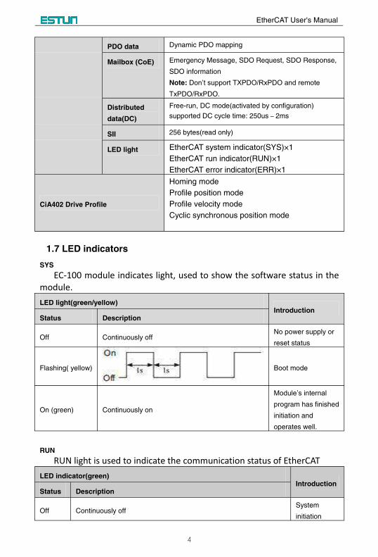
PDO data Dynamic PDO mapping
Mailbox (CoE) Emergency Message, SDO Request, SDO Response,
SDO information
Note: Don’t support TXPDO/RxPDO and remote TxPDO/RxPDO.
Distributed
data(DC)
Free-run, DC mode(activated by configuration)
supported DC cycle time: 250us-2ms
SII 256 bytes(read only)
LED light EtherCAT system indicator(SYS)×1
EtherCAT run indicator(RUN)×1
EtherCAT error indicator(ERR)×1
CiA402 Drive Profile
Homing mode
Profile position mode
Profile velocity mode
Cyclic synchronous position mode
1.7 LED indicators
SYS
EC-100 module indicates light, used to show the software status in the module. LED light(green/yellow)
IntroductionStatus Description
Off Continuously offNo power supply or
reset status
Flashing( yellow) Boot mode
On (green) Continuously on
Module’s internal program has finished
initiation and
operates well.
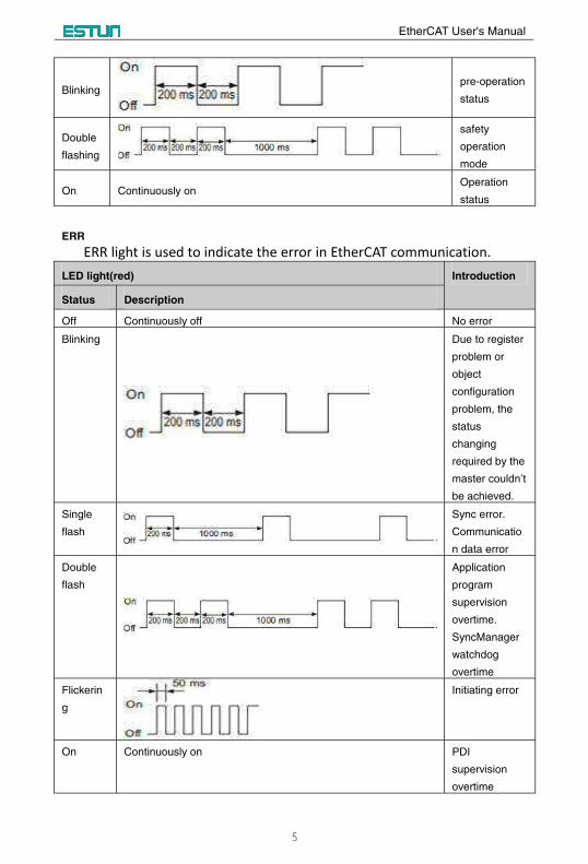
RUN
RUN light is used to indicate the communication status of EtherCATLED indicator(green)
IntroductionStatus Description
Off Continuously offSystem
initiation
EtherCAT User's Manual
5
Blinkingpre-operation
status
Double
flashing
safety
operation
mode
On Continuously onOperation
status
ERR
ERR light is used to indicate the error in EtherCAT communication. LED light(red) Introduction
Status Description
Off Continuously off No error
Blinking Due to register
problem or
object
configuration
problem, the
status
changing
required by the
master couldn’t be achieved.
Single
flash
Sync error.
Communicatio
n data error
Double
flash
Application
program
supervision
overtime.
SyncManager
watchdog
overtime
Flickerin
g
Initiating error
On Continuously on PDI
supervision
overtime
EtherCAT User's Manual
6
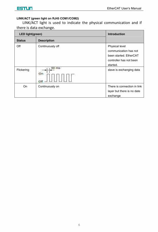
LINK/ACT (green light on RJ45 COM1/COM2)
LINK/ACT light is used to indicate the physical communication and if there is data exchange.
LED light(green) Introduction
Status Description
Off Continuously off Physical level
communication has not
been started. EtherCAT
controller has not been
started.
Flickering slave is exchanging data
On Continuously on There is connection in link
layer but there is no date
exchange
EtherCAT User's Manual
7
Chapter 2 Installation and connection
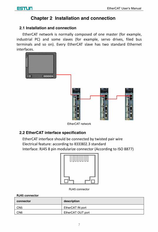
2.1 Installation and connection
EtherCAT network is normally composed of one master (for example, industrial PC) and some slaves (for example, servo drives, filed bus terminals and so on). Every EtherCAT slave has two standard Ethernet interfaces.
EtherCAT network
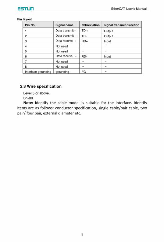
2.2 EtherCAT interface specification
EtherCAT interface should be connected by twisted pair wireElectrical feature: according to IEEE802.3 standard Interface: RJ45 8 pin modularize connector (According to ISO 8877)
RJ45 connector
RJ45 connector
connector description
CN5 EtherCAT IN port
CN6 EtherCAT OUT port
EtherCAT User's Manual
8
Pin layout
Pin No. Signal name abbreviation signal transmit direction
1 Data transmit+ TD+ Output
2 Data transmit- TD- Output
3 Data receive + RD+ Input
4 Not used - -
5 Not used - -
6 Data receive - RD- Input
7 Not used - -
8 Not used - -
Interface grounding grounding FG -
2.3 Wire specification
Level 5 or above.
Shield
Note: Identify the cable model is suitable for the interface. Identify items are as follows: conductor specification, single cable/pair cable, two pair/ four pair, external diameter etc.
EtherCAT User's Manual
67
Appendix B Parameters
B.1 Parameter list
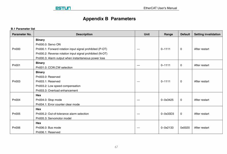
Parameter No. Descripition Unit Range Default Setting invalidation
Pn000
Binary
Pn000.0: Servo ON
Pn000.1: Forward rotation input signal prohibited (P-OT)
Pn000.2: Reverse rotation input signal prohibited (N-OT)
Pn000.3: Alarm output when instantaneous power loss
— 0~1111 0 After restart
Pn001Binary
Pn001.0: CCW,CW selection— 0~1111 0 After restart
Pn003
Binary
Pn003.0: Reserved
Pn003.1: Reserved
Pn003.2: Low speed compensation
Pn003.3: Overload enhancement
— 0~1111 0 After restart
Pn004
Hex
Pn004.0: Stop mode
Pn004.1: Error counter clear mode
— 0~0x3425 0 After restart
Pn005
Hex
Pn005.2: Out-of-tolerance alarm selection
Pn005.3: Servomotor model
— 0~0x33D3 0 After restart
Pn006
Hex
Pn006.0: Bus mode
Pn006.1: Reserved
— 0~0x2133 0x0020 After restart
EtherCAT User's Manual
68
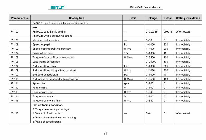
Parameter No. Descripition Unit Range Default Setting invalidation
Pn006.2: Low frequency jitter suppersion switch
Pn100
Hex
Pn100.0: Load inertia setting
Pn100.1: Online autotuning setting
— 0~0x0036 0x0011 After restart
Pn101 Machine rigidity setting — 0~36 6 Immediately
Pn102 Speed loop gain Hz 1~4000 250 Immediately
Pn103 Speed loop integral time constant 0.1ms 1~4096 200 Immediately
Pn104 Position loop gain 1/s 0~1000 40 Immediately
Pn105 Torque reference filter time constant 0.01ms 0~2500 100 Immediately
Pn106 Load inertia percentage — 0~20000 100 Immediately
Pn107 2nd speed loop gain Hz 1~4000 205 Immediately
Pn108 2nd speed loop integral time constant 0.1ms 1~4096 200 Immediately
Pn109 2nd position loop gain Hz 0~1000 40 Immediately
Pn110 2nd torque reference filter time constant 0.01ms 0~2500 100 Immediately
Pn111 Speed bias rpm 0~300 0 Immediately
Pn112 Feedforward % 0~100 0 Immediately
Pn113 Feedforward filter 0.1ms 0~640 0 Immediately
Pn114 Torque feedforward % 0~100 0 Immediately
Pn115 Torque feedforward filter 0.1ms 0~640 0 Immediately
Pn116
P/PI switching condition
0: Torque reference percentage
1: Value of offset counter
2: Value of acceleration speed setting
3: Value of speed setting
— 0~4 0 After restart
EtherCAT User's Manual
69
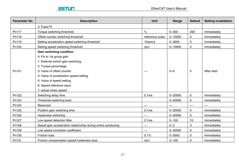
Parameter No. Descripition Unit Range Default Setting invalidation
4: Fixed PI
Pn117 Torque switching threshold % 0~300 200 Immediately
Pn118 Offset counter switching threshold reference pulse 0~10000 0 Immediately
Pn119 Setting acceleration speed switching threshold 10rpm/s 0~3000 0 Immediately
Pn120 Setting speed switching threshold rpm 0~10000 0 Immediately
Pn121
Gain switching condition
0: Fix to 1st group gain
1: External switch gain switching
2: Torque percentage
3: Value of offset counter
4: Value of acceleration speed setting
5: Value of speed setting
6: Speed reference input
7: actual motor speed
— 0~6 0 After start
Pn122 Switching delay time 0.1ms 0~20000 0 Immediately
Pn123 Threshold switching level 0~20000 0 Immediately
Pn124 Reserved — — — —
Pn125 Position gain switching time 0.1ms 0~20000 0 Immediately
Pn126 Hysteresis switching — 0~20000 0 Immediately
Pn127 Low speed detection filter 0.1ms 0~100 10 Immediately
Pn128 Speed gain acceleration relationship during online autotuning — 0~3 3 Immediately
Pn129 Low speed correction coefficient — 0~30000 0 Immediately
Pn130 Friction load 0.1% 0~3000 0 Immediately
Pn131 Friction compensation speed hysteresis area rpm 0~100 0 Immediately
EtherCAT User's Manual
70
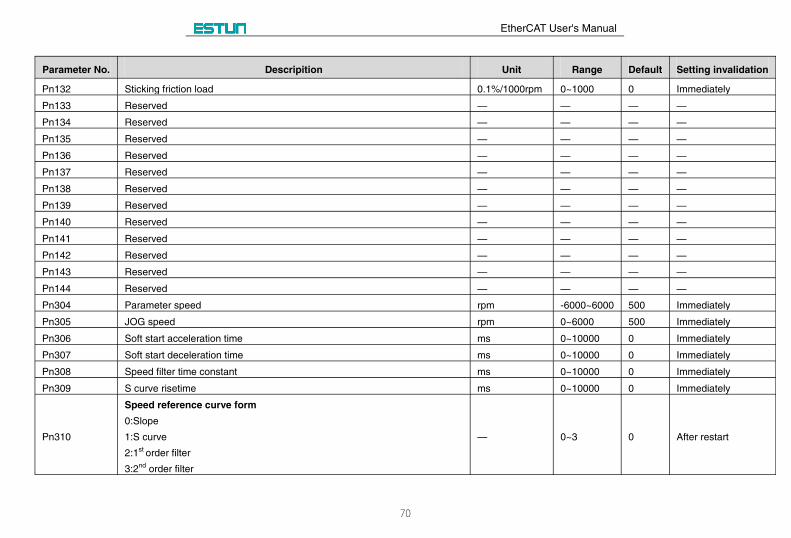
Parameter No. Descripition Unit Range Default Setting invalidation
Pn132 Sticking friction load 0.1%/1000rpm 0~1000 0 Immediately
Pn133 Reserved — — — —
Pn134 Reserved — — — —
Pn135 Reserved — — — —
Pn136 Reserved — — — —
Pn137 Reserved — — — —
Pn138 Reserved — — — —
Pn139 Reserved — — — —
Pn140 Reserved — — — —
Pn141 Reserved — — — —
Pn142 Reserved — — — —
Pn143 Reserved — — — —
Pn144 Reserved — — — —
Pn304 Parameter speed rpm -6000~6000 500 Immediately
Pn305 JOG speed rpm 0~6000 500 Immediately
Pn306 Soft start acceleration time ms 0~10000 0 Immediately
Pn307 Soft start deceleration time ms 0~10000 0 Immediately
Pn308 Speed filter time constant ms 0~10000 0 Immediately
Pn309 S curve risetime ms 0~10000 0 Immediately
Pn310
Speed reference curve form
0:Slope
1:S curve
2:1st order filter
3:2nd order filter
— 0~3 0 After restart
EtherCAT User's Manual
71
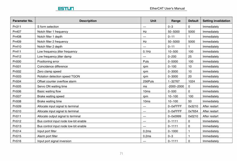
Parameter No. Descripition Unit Range Default Setting invalidation
Pn311 S form selection — 0~3 0 Immediately
Pn407 Notch filter 1 frequency Hz 50~5000 5000 Immediately
Pn408 Notch filter 1 depth — 0~11 1 Immediately
Pn409 Notch filter 2 frequency Hz 50~5000 5000 Immediately
Pn410 Notch filter 2 depth — 0~11 1 Immediately
Pn411 Low frequency jitter frequency 0.1Hz 10~500 100 Immediately
Pn412 Low frequency jitter damp — 0~200 25 Immediately
Pn500 Positioning error Puls 0~5000 100 Immediately
Pn501 Coincidence difference rpm 0~100 10 Immediately
Pn502 Zero clamp speed rpm 0~3000 10 Immediately
Pn503 Rotation detection speed TGON rpm 0~3000 20 Immediately
Pn504 Offset counter overflow alarm 256Puls 1~32767 1024 Immediately
Pn505 Servo ON waiting time ms -2000~2000 0 Immediately
Pn506 Basic waiting flow 10ms 0~500 0 Immediately
Pn507 Brake waiting speed rpm 10~100 100 Immediately
Pn508 Brake waiting time 10ms 10~100 50 Immediately
Pn509 Allocate input signal to terminal — 0~0xFFFF 0x3210 After restart
Pn510 Allocate input signal to terminal — 0~0xFFFF 0x7654 After restart
Pn511 Allocate output signal to terminal — 0~0x0999 0x0210 After restart
Pn512 Bus control input node low-bit enable — 0~1111 0 Immediately
Pn513 Bus control input node low-bit enable — 0~1111 0 Immediately
Pn514 Input port filter 0.2ms 0~1000 1 Immediately
Pn515 Alarm port filter 0.2ms 0~3 1 Immediately
Pn516 Input port signal inversion — 0~1111 0 Immediately
EtherCAT User's Manual
72
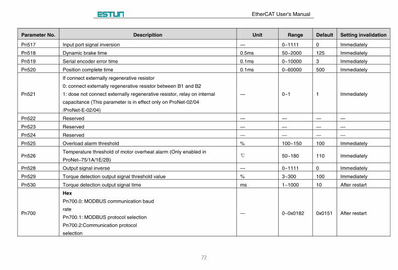
Parameter No. Descripition Unit Range Default Setting invalidation
Pn517 Input port signal inversion — 0~1111 0 Immediately
Pn518 Dynamic brake time 0.5ms 50~2000 125 Immediately
Pn519 Serial encoder error time 0.1ms 0~10000 3 Immediately
Pn520 Position complete time 0.1ms 0~60000 500 Immediately
Pn521
If connect externally regenerative resistor
0: connect externally regenerative resistor between B1 and B2
1: dose not connect externally regenerative resistor, relay on internal
capacitance (This parameter is in effect only on ProNet-02/04
/ProNet-E-02/04)
— 0~1 1 Immediately
Pn522 Reserved — — — —
Pn523 Reserved — — — —
Pn524 Reserved — — — —
Pn525 Overload alarm threshold % 100~150 100 Immediately
Pn526Temperature threshold of motor overheat alarm (Only enabled in
ProNet–75/1A/1E/2B) ℃ 50~180 110 Immediately
Pn528 Output signal inverse — 0~1111 0 Immediately
Pn529 Torque detection output signal threshold value % 3~300 100 Immediately
Pn530 Torque detection output signal time ms 1~1000 10 After restart
Pn700
Hex
Pn700.0: MODBUS communication baud
rate
Pn700.1: MODBUS protocol selection
Pn700.2:Communication protocol
selection
— 0~0x0182 0x0151 After restart
EtherCAT User's Manual
73
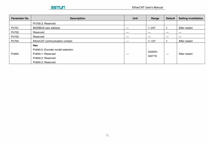
Parameter No. Descripition Unit Range Default Setting invalidation
Pn700.3: Reserved
Pn701 MODBUS axis address — 1~247 1 After restart
Pn702 Reserved — — — —
Pn703 Reserved — — — —
Pn704 EtherCAT communication contact — 1~127 1 After restart
Pn840
Hex
Pn840.0: Encoder model selection
Pn840.1: Reserved
Pn840.2: Reserved
Pn840.3: Reserved
—0x0003~
0x0718— After restart
EtherCAT User's Manual
74
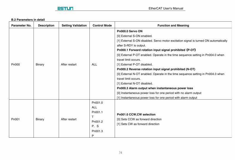
B.2 Parameters in detail
Parameter No. Description Setting Validation Control Mode Function and Meaning
Pn000 Binary After restart ALL
Pn000.0 Servo ON
[0] External S-ON enabled.
[1] External S-ON disabled. Servo motor excitation signal is turned ON automatically
after S-RDY is output.
Pn000.1 Forward rotation input signal prohibited ((P-OT))
[0] External P-OT enabled. Operate in the time sequence setting in Pn004.0 when
travel limit occurs.
[1] External P-OT disabled.
Pn000.2 Reverse rotation input signal prohibited (N-OT)
[0] External N-OT enabled. Operate in the time sequence setting in Pn004.0 when
travel limit occurs.
[1] External N-OT disabled.
Pn000.3 Alarm output when instantaneous power loss
[0] Instantaneous power loss for one period with no alarm output
[1] Instantaneous power loss for one period with alarm output
Pn001 Binary After restart
Pn001.0
ALL
Pn001.1
T
Pn001.2
P, S
Pn001.3
P
Pn001.0 CCW,CW selection
[0] Sets CCW as forward direction
[1] Sets CW as forward direction
EtherCAT User's Manual
75
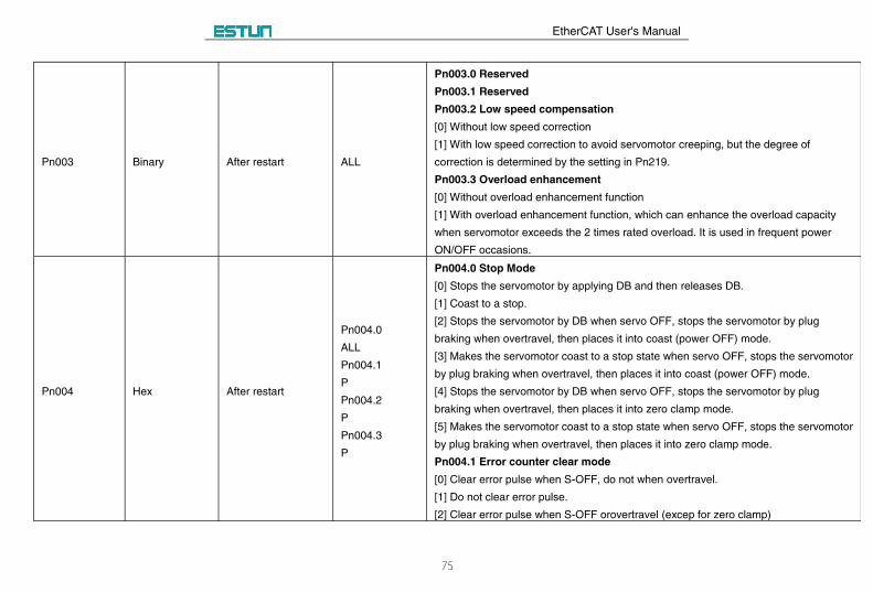
Pn003 Binary After restart ALL
Pn003.0 Reserved
Pn003.1 Reserved
Pn003.2 Low speed compensation
[0] Without low speed correction
[1] With low speed correction to avoid servomotor creeping, but the degree of
correction is determined by the setting in Pn219.
Pn003.3 Overload enhancement
[0] Without overload enhancement function
[1] With overload enhancement function, which can enhance the overload capacity
when servomotor exceeds the 2 times rated overload. It is used in frequent power
ON/OFF occasions.
Pn004 Hex After restart
Pn004.0
ALL
Pn004.1
P
Pn004.2
P
Pn004.3
P
Pn004.0 Stop Mode
[0] Stops the servomotor by applying DB and then releases DB.
[1] Coast to a stop.
[2] Stops the servomotor by DB when servo OFF, stops the servomotor by plug
braking when overtravel, then places it into coast (power OFF) mode.
[3] Makes the servomotor coast to a stop state when servo OFF, stops the servomotor
by plug braking when overtravel, then places it into coast (power OFF) mode.
[4] Stops the servomotor by DB when servo OFF, stops the servomotor by plug
braking when overtravel, then places it into zero clamp mode.
[5] Makes the servomotor coast to a stop state when servo OFF, stops the servomotor
by plug braking when overtravel, then places it into zero clamp mode.
Pn004.1 Error counter clear mode
[0] Clear error pulse when S-OFF, do not when overtravel.
[1] Do not clear error pulse.
[2] Clear error pulse when S-OFF orovertravel (excep for zero clamp)
EtherCAT User's Manual
76
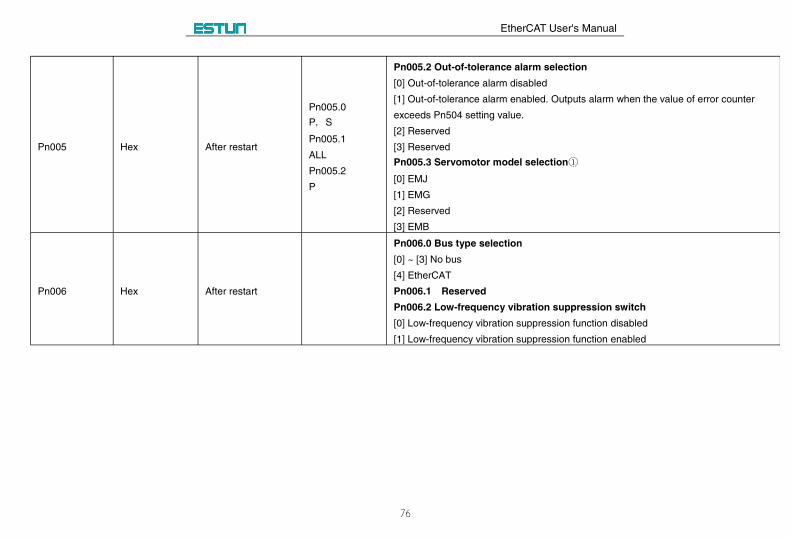
Pn005 Hex After restart
Pn005.0
P, S
Pn005.1
ALL
Pn005.2
P
Pn005.2 Out-of-tolerance alarm selection
[0] Out-of-tolerance alarm disabled
[1] Out-of-tolerance alarm enabled. Outputs alarm when the value of error counter
exceeds Pn504 setting value.
[2] Reserved
[3] Reserved
Pn005.3 Servomotor model selection①
[0] EMJ
[1] EMG
[2] Reserved
[3] EMB
Pn006 Hex After restart
Pn006.0 Bus type selection
[0] ~ [3] No bus
[4] EtherCAT
Pn006.1 Reserved
Pn006.2 Low-frequency vibration suppression switch
[0] Low-frequency vibration suppression function disabled
[1] Low-frequency vibration suppression function enabled
EtherCAT User's Manual
77
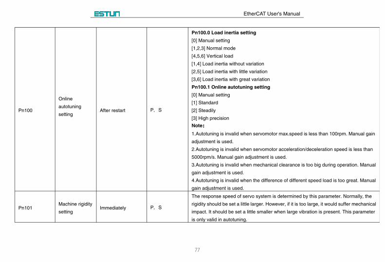
Pn100
Online
autotuning
settingAfter restart P, S
Pn100.0 Load inertia setting
[0] Manual setting
[1,2,3] Normal mode
[4,5,6] Vertical load
[1,4] Load inertia without variation
[2,5] Load inertia with little variation
[3,6] Load inertia with great variation
Pn100.1 Online autotuning setting
[0] Manual setting
[1] Standard
[2] Steadily
[3] High precision
Note::
1.Autotuning is invalid when servomotor max.speed is less than 100rpm. Manual gain
adjustment is used.
2.Autotuning is invalid when servomotor acceleration/deceleration speed is less than
5000rpm/s. Manual gain adjustment is used.
3.Autotuning is invalid when mechanical clearance is too big during operation. Manual
gain adjustment is used.
4.Autotuning is invalid when the difference of different speed load is too great. Manual
gain adjustment is used.
Pn101Machine rigidity
settingImmediately P, S
The response speed of servo system is determined by this parameter. Normally, the
rigidity should be set a little larger. However, if it is too large, it would suffer mechanical
impact. It should be set a little smaller when large vibration is present. This parameter
is only valid in autotuning.
EtherCAT User's Manual
78
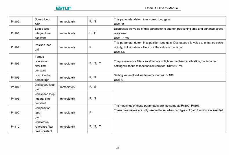
Pn102Speed loop
gainImmediately P, S
This parameter determines speed loop gain.
Unit: Hz
Pn103
Speed loop
integral time
constant
Immediately P, S
Decreases the value of this parameter to shorten positioning time and enhance speed
response.
Unit: 0.1ms
Pn104Position loop
gainImmediately P
This parameter determines position loop gain. Decreases this value to enhance servo
rigidity, but vibration will occur if the value is too large.
Unit: 1/s
Pn105
Torque
reference
filter time
constant
Immediately P, S, TTorque reference filter can eliminate or lighten mechanical vibration, but incorrect
setting will result to mechanical vibration. Unit:0.01ms
Pn106Load inertia
percentageImmediately P, S
Setting value=(load inertia/rotor inertia) 100
Unit: %
Pn1072nd speed loop
gainImmediately P, S
The meanings of these parameters are the same as Pn102~Pn105.
These parameters are only needed to set when two types of gain function are enabled.
Pn108
2nd speed loop
integral time
constant
Immediately P, S
Pn109
2nd position
loop
gain
Immediately P
Pn110
2nd torque
reference filter
time constant
Immediately P, S, T
EtherCAT User's Manual
79
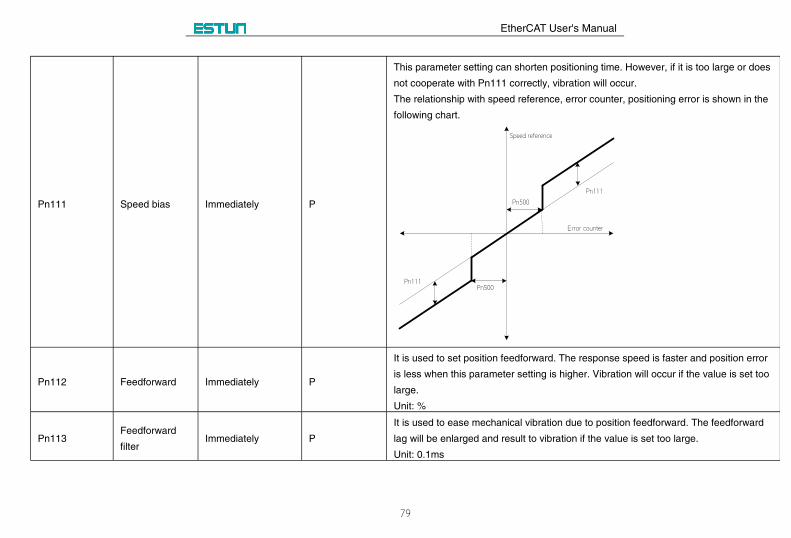
Pn111 Speed bias Immediately P
This parameter setting can shorten positioning time. However, if it is too large or does
not cooperate with Pn111 correctly, vibration will occur.
The relationship with speed reference, error counter, positioning error is shown in the
following chart.
Speed reference
Error counter
Pn500
Pn500Pn111
Pn111
Pn112 Feedforward Immediately P
It is used to set position feedforward. The response speed is faster and position error
is less when this parameter setting is higher. Vibration will occur if the value is set too
large.
Unit: %
Pn113Feedforward
filterImmediately P
It is used to ease mechanical vibration due to position feedforward. The feedforward
lag will be enlarged and result to vibration if the value is set too large.
Unit: 0.1ms
EtherCAT User's Manual
80
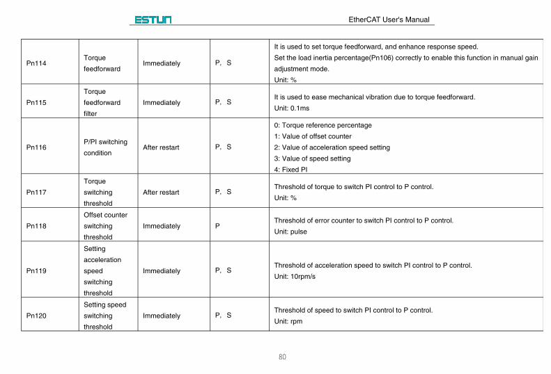
Pn114Torque
feedforwardImmediately P, S
It is used to set torque feedforward, and enhance response speed.
Set the load inertia percentage(Pn106) correctly to enable this function in manual gain
adjustment mode.
Unit: %
Pn115
Torque
feedforward
filter
Immediately P, SIt is used to ease mechanical vibration due to torque feedforward.
Unit: 0.1ms
Pn116P/PI switching
conditionAfter restart P, S
0: Torque reference percentage
1: Value of offset counter
2: Value of acceleration speed setting
3: Value of speed setting
4: Fixed PI
Pn117
Torque
switching
threshold
After restart P, SThreshold of torque to switch PI control to P control.
Unit: %
Pn118
Offset counter
switching
threshold
Immediately PThreshold of error counter to switch PI control to P control.
Unit: pulse
Pn119
Setting
acceleration
speed
switching
threshold
Immediately P, SThreshold of acceleration speed to switch PI control to P control.
Unit: 10rpm/s
Pn120
Setting speed
switching
threshold
Immediately P, SThreshold of speed to switch PI control to P control.
Unit: rpm
EtherCAT User's Manual
81
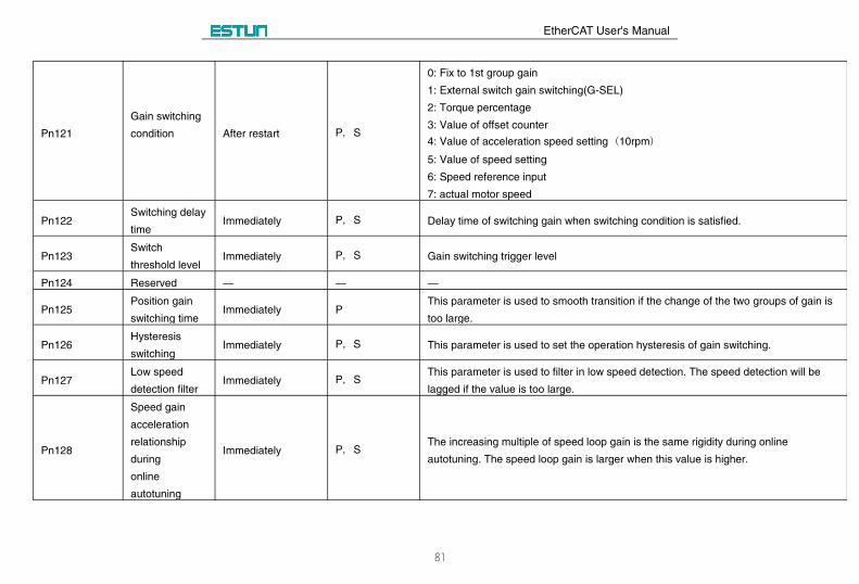
Pn121
Gain switching
condition After restart P, S
0: Fix to 1st group gain
1: External switch gain switching(G-SEL)
2: Torque percentage
3: Value of offset counter
4: Value of acceleration speed setting (10rpm)
5: Value of speed setting
6: Speed reference input
7: actual motor speed
Pn122Switching delay
timeImmediately P, S Delay time of switching gain when switching condition is satisfied.
Pn123Switch
threshold levelImmediately P, S Gain switching trigger level
Pn124 Reserved — — —
Pn125Position gain
switching timeImmediately P
This parameter is used to smooth transition if the change of the two groups of gain is
too large.
Pn126Hysteresis
switchingImmediately P, S This parameter is used to set the operation hysteresis of gain switching.
Pn127Low speed
detection filterImmediately P, S
This parameter is used to filter in low speed detection. The speed detection will be
lagged if the value is too large.
Pn128
Speed gain
acceleration
relationship
during
online
autotuning
Immediately P, SThe increasing multiple of speed loop gain is the same rigidity during online
autotuning. The speed loop gain is larger when this value is higher.
EtherCAT User's Manual
82
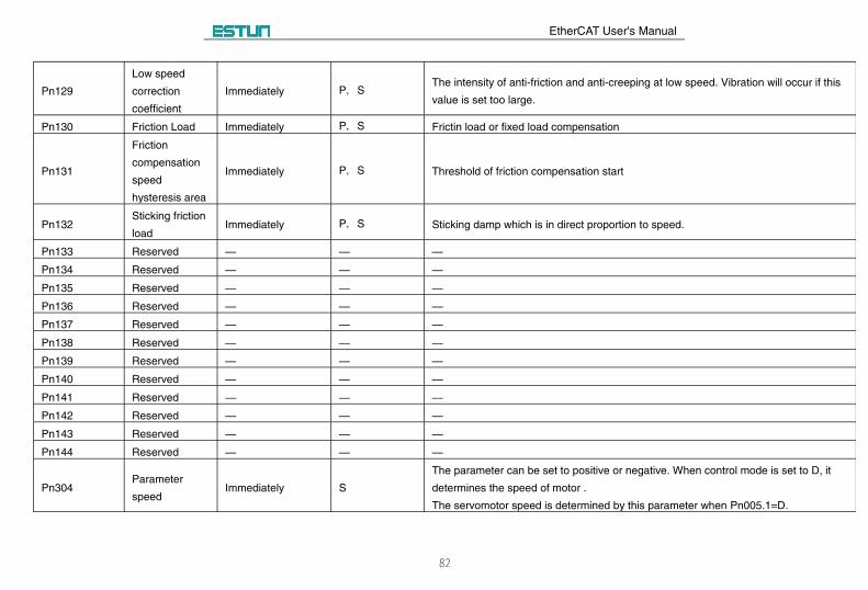
Pn129
Low speed
correction
coefficient
Immediately P, SThe intensity of anti-friction and anti-creeping at low speed. Vibration will occur if this
value is set too large.
Pn130 Friction Load Immediately P, S Frictin load or fixed load compensation
Pn131
Friction
compensation
speed
hysteresis area
Immediately P, S Threshold of friction compensation start
Pn132Sticking friction
loadImmediately P, S Sticking damp which is in direct proportion to speed.
Pn133 Reserved — — —
Pn134 Reserved — — —
Pn135 Reserved — — —
Pn136 Reserved — — —
Pn137 Reserved — — —
Pn138 Reserved — — —
Pn139 Reserved — — —
Pn140 Reserved — — —
Pn141 Reserved — — —
Pn142 Reserved — — —
Pn143 Reserved — — —
Pn144 Reserved — — —
Pn304Parameter
speedImmediately S
The parameter can be set to positive or negative. When control mode is set to D, it
determines the speed of motor .
The servomotor speed is determined by this parameter when Pn005.1=D.
EtherCAT User's Manual
83
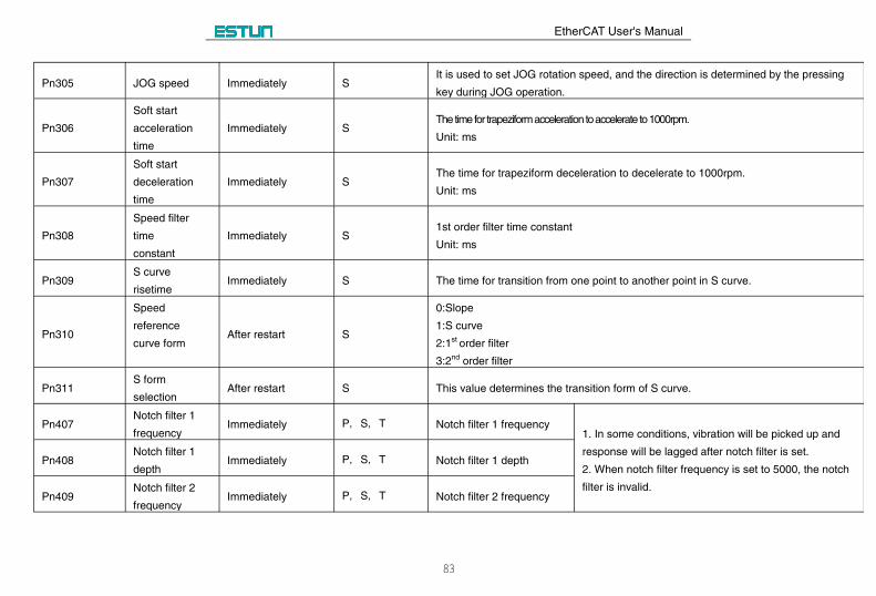
Pn305 JOG speed Immediately SIt is used to set JOG rotation speed, and the direction is determined by the pressing
key during JOG operation.
Pn306
Soft start
acceleration
time
Immediately SThe time for trapeziform acceleration to accelerate to 1000rpm.
Unit: ms
Pn307
Soft start
deceleration
time
Immediately SThe time for trapeziform deceleration to decelerate to 1000rpm.
Unit: ms
Pn308
Speed filter
time
constant
Immediately S1st order filter time constant
Unit: ms
Pn309S curve
risetimeImmediately S The time for transition from one point to another point in S curve.
Pn310
Speed
reference
curve formAfter restart S
0:Slope
1:S curve
2:1st order filter
3:2nd order filter
Pn311S form
selectionAfter restart S This value determines the transition form of S curve.
Pn407Notch filter 1
frequencyImmediately P, S, T Notch filter 1 frequency
1. In some conditions, vibration will be picked up and
response will be lagged after notch filter is set.
2. When notch filter frequency is set to 5000, the notch
filter is invalid.
Pn408Notch filter 1
depthImmediately P, S, T Notch filter 1 depth
Pn409Notch filter 2
frequencyImmediately P, S, T Notch filter 2 frequency
EtherCAT User's Manual
84
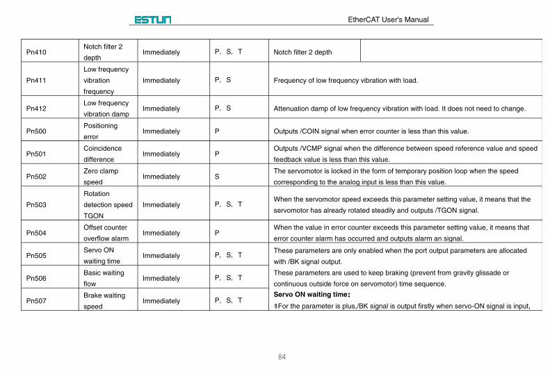
Pn410Notch filter 2
depthImmediately P, S, T Notch filter 2 depth
Pn411
Low frequency
vibration
frequency
Immediately P, S Frequency of low frequency vibration with load.
Pn412Low frequency
vibration dampImmediately P, S Attenuation damp of low frequency vibration with load. It does not need to change.
Pn500Positioning
errorImmediately P Outputs /COIN signal when error counter is less than this value.
Pn501Coincidence
differenceImmediately P
Outputs /VCMP signal when the difference between speed reference value and speed
feedback value is less than this value.
Pn502Zero clamp
speedImmediately S
The servomotor is locked in the form of temporary position loop when the speed
corresponding to the analog input is less than this value.
Pn503
Rotation
detection speed
TGON
Immediately P, S, TWhen the servomotor speed exceeds this parameter setting value, it means that the
servomotor has already rotated steadily and outputs /TGON signal.
Pn504Offset counter
overflow alarmImmediately P
When the value in error counter exceeds this parameter setting value, it means that
error counter alarm has occurred and outputs alarm an signal.
Pn505Servo ON
waiting timeImmediately P, S, T
These parameters are only enabled when the port output parameters are allocated
with /BK signal output.
These parameters are used to keep braking (prevent from gravity glissade or
continuous outside force on servomotor) time sequence.
Servo ON waiting time::
○1For the parameter is plus,/BK signal is output firstly when servo-ON signal is input,
Pn506Basic waiting
flowImmediately P, S, T
Pn507Brake waiting
speedImmediately P, S, T
EtherCAT User's Manual
85
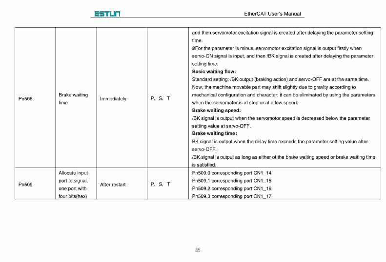
Pn508Brake waiting
timeImmediately P, S, T
and then servomotor excitation signal is created after delaying the parameter setting
time.
○2For the parameter is minus, servomotor excitation signal is output firstly when
servo-ON signal is input, and then /BK signal is created after delaying the parameter
setting time.
Basic waiting flow:
Standard setting: /BK output (braking action) and servo-OFF are at the same time.
Now, the machine movable part may shift slightly due to gravity according to
mechanical configuration and character; it can be eliminated by using the parameters
when the servomotor is at stop or at a low speed.
Brake waiting speed:
/BK signal is output when the servomotor speed is decreased below the parameter
setting value at servo-OFF.
Brake waiting time::
BK signal is output when the delay time exceeds the parameter setting value after
servo-OFF.
/BK signal is output as long as either of the brake waiting speed or brake waiting time
is satisfied.
Pn509
Allocate input
port to signal,
one port with
four bits(hex)
After restart P, S, T
Pn509.0 corresponding port CN1_14
Pn509.1 corresponding port CN1_15
Pn509.2 corresponding port CN1_16
Pn509.3 corresponding port CN1_17
EtherCAT User's Manual
86
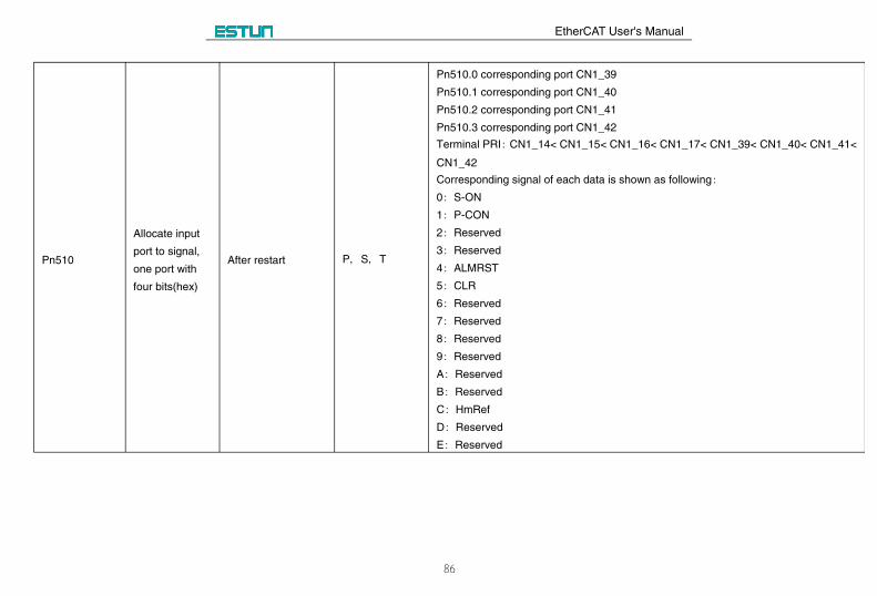
Pn510
Allocate input
port to signal,
one port with
four bits(hex)
After restart P, S, T
Pn510.0 corresponding port CN1_39
Pn510.1 corresponding port CN1_40
Pn510.2 corresponding port CN1_41
Pn510.3 corresponding port CN1_42
Terminal PRI: CN1_14< CN1_15< CN1_16< CN1_17< CN1_39< CN1_40< CN1_41<
CN1_42
Corresponding signal of each data is shown as following:
0: S-ON
1: P-CON
2: Reserved
3: Reserved
4: ALMRST
5: CLR
6: Reserved
7: Reserved
8: Reserved
9: Reserved
A: Reserved
B: Reserved
C: HmRef
D: Reserved
E: Reserved
EtherCAT User's Manual
87
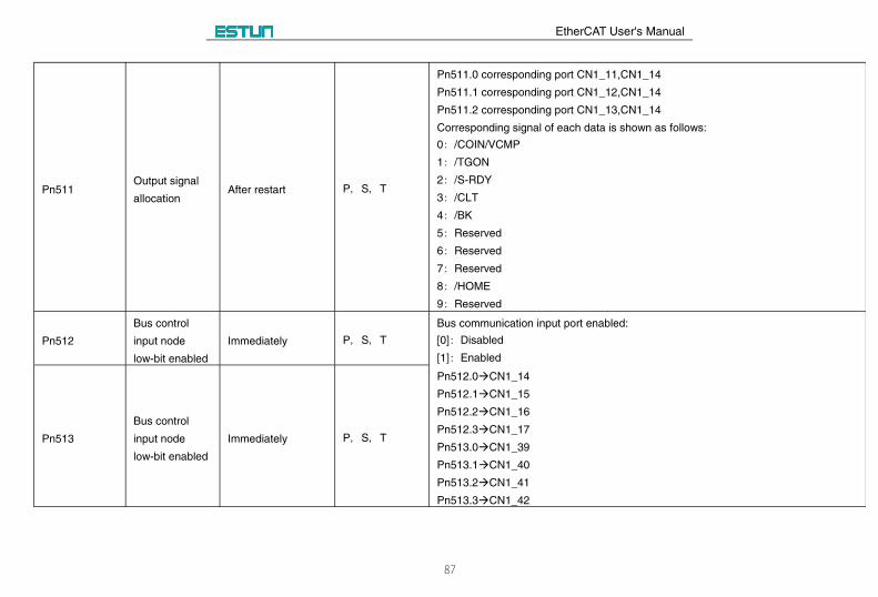
Pn511Output signal
allocationAfter restart P, S, T
Pn511.0 corresponding port CN1_11,CN1_14
Pn511.1 corresponding port CN1_12,CN1_14
Pn511.2 corresponding port CN1_13,CN1_14
Corresponding signal of each data is shown as follows:
0: /COIN/VCMP
1: /TGON
2: /S-RDY
3: /CLT
4: /BK
5: Reserved
6: Reserved
7: Reserved
8: /HOME
9: Reserved
Pn512
Bus control
input node
low-bit enabled
Immediately P, S, T
Bus communication input port enabled:
[0]: Disabled
[1]: Enabled
Pn512.0CN1_14
Pn512.1CN1_15
Pn512.2CN1_16
Pn512.3CN1_17
Pn513.0CN1_39
Pn513.1CN1_40
Pn513.2CN1_41
Pn513.3CN1_42
Pn513
Bus control
input node
low-bit enabled
Immediately P, S, T
EtherCAT User's Manual
88
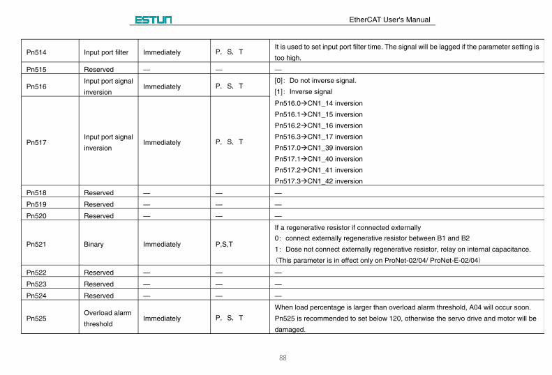
Pn514 Input port filter Immediately P, S, TIt is used to set input port filter time. The signal will be lagged if the parameter setting is
too high.
Pn515 Reserved — — —
Pn516Input port signal
inversion Immediately P, S, T
[0]: Do not inverse signal.
[1]: Inverse signal
Pn516.0CN1_14 inversion
Pn516.1CN1_15 inversion
Pn516.2CN1_16 inversion
Pn516.3CN1_17 inversion
Pn517.0CN1_39 inversion
Pn517.1CN1_40 inversion
Pn517.2CN1_41 inversion
Pn517.3CN1_42 inversion
Pn517Input port signal
inversion Immediately P, S, T
Pn518 Reserved — — —
Pn519 Reserved — — —
Pn520 Reserved — — —
Pn521 Binary Immediately P,S,T
If a regenerative resistor if connected externally
0: connect externally regenerative resistor between B1 and B2
1: Dose not connect externally regenerative resistor, relay on internal capacitance.
(This parameter is in effect only on ProNet-02/04/ ProNet-E-02/04)
Pn522 Reserved — — —
Pn523 Reserved — — —
Pn524 Reserved — — —
Pn525Overload alarm
thresholdImmediately P, S, T
When load percentage is larger than overload alarm threshold, A04 will occur soon.
Pn525 is recommended to set below 120, otherwise the servo drive and motor will be
damaged.
EtherCAT User's Manual
89
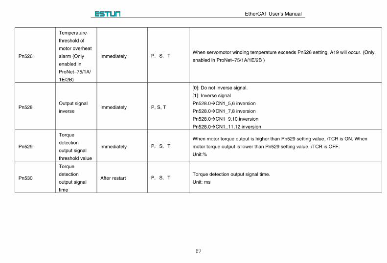
Pn526
Temperature
threshold of
motor overheat
alarm (Only
enabled in
ProNet–75/1A/
1E/2B)
Immediately P, S, TWhen servomotor winding temperature exceeds Pn526 setting, A19 will occur. (Only
enabled in ProNet–75/1A/1E/2B )
Pn528Output signal
inverseImmediately P, S, T
[0]: Do not inverse signal.
[1]: Inverse signal
Pn528.0CN1_5,6 inversion
Pn528.0CN1_7,8 inversion
Pn528.0CN1_9,10 inversion
Pn528.0CN1_11,12 inversion
Pn529
Torque
detection
output signal
threshold value
Immediately P, S, T
When motor torque output is higher than Pn529 setting value, /TCR is ON. When
motor torque output is lower than Pn529 setting value, /TCR is OFF.
Unit:%
Pn530
Torque
detection
output signal
time
After restart P, S, TTorque detection output signal time.
Unit: ms
EtherCAT User's Manual
90
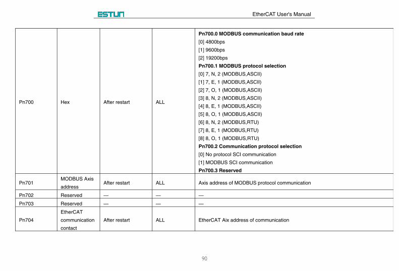
Pn700 Hex After restart ALL
Pn700.0 MODBUS communication baud rate
[0] 4800bps
[1] 9600bps
[2] 19200bps
Pn700.1 MODBUS protocol selection
[0] 7, N, 2 (MODBUS,ASCII)
[1] 7, E, 1 (MODBUS,ASCII)
[2] 7, O, 1 (MODBUS,ASCII)
[3] 8, N, 2 (MODBUS,ASCII)
[4] 8, E, 1 (MODBUS,ASCII)
[5] 8, O, 1 (MODBUS,ASCII)
[6] 8, N, 2 (MODBUS,RTU)
[7] 8, E, 1 (MODBUS,RTU)
[8] 8, O, 1 (MODBUS,RTU)
Pn700.2 Communication protocol selection
[0] No protocol SCI communication
[1] MODBUS SCI communication
Pn700.3 Reserved
Pn701MODBUS Axis
addressAfter restart ALL Axis address of MODBUS protocol communication
Pn702 Reserved — — —
Pn703 Reserved — — —
Pn704
EtherCAT
communication
contact
After restart ALL EtherCAT Aix address of communication
EtherCAT User's Manual
91
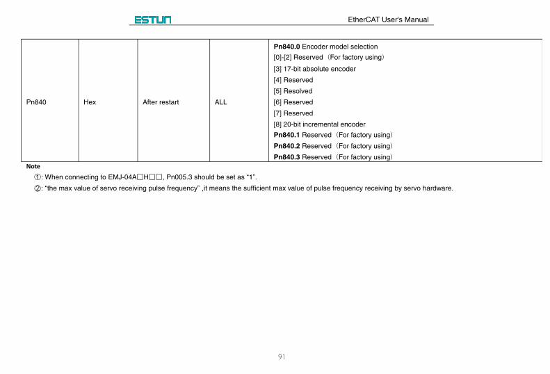
Pn840 Hex After restart ALL
Pn840.0 Encoder model selection
[0]-[2] Reserved (For factory using)
[3] 17-bit absolute encoder
[4] Reserved
[5] Resolved
[6] Reserved
[7] Reserved
[8] 20-bit incremental encoder
Pn840.1 Reserved (For factory using)
Pn840.2 Reserved (For factory using)
Pn840.3 Reserved (For factory using)
Note①: When connecting to EMJ-04A□H□□, Pn005.3 should be set as “1”.○2 : “the max value of servo receiving pulse frequency” ,it means the sufficient max value of pulse frequency receiving by servo hardware.
EtherCAT User's Manual
92
Appendix C Standard Wiring Examples
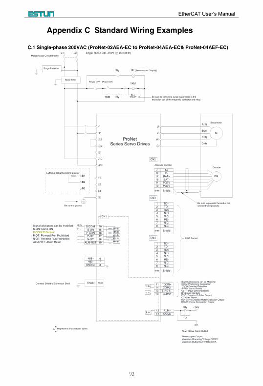
C.1 Single-phase 200VAC (ProNet-02AEA-EC to ProNet-04AEA-EC& ProNet-04AEF-EC)
Noise Filter
L1 L2
Power OFF Power ON
1KM 1SUP
1KM
1Ry
L1
L2
1
2
W
V
U
M
PG
Servomotor
Encoder
A(1)
B(2)
C(3)
D(4)
L2C
L1C CN2
Signal allocatons can be modified:
S-ON: Servo ON
P-CON: P Control
P-OT: Forward Run Prohibited
N-OT: Reverse Run Prohibited
ALM-RST: Alarm Reset
CN3
CN4 RJ45 Socket
Surge Protector
Molded-case Circuit Breaker
1Ry
1PL (Servo Alarm Display)
1
2
RD+3
N.C.4
N.C.5
RD-6
N.C.7
N.C.8
1
2
3
4
5
6
7
8
S+7
S-8
BAT+17
BAT-18
PG5V9
PG0V19
Shield
Absolute Encoder
Shell
ShieldShell
ShieldShell
Be sure to connect a surge suppressor to the
excitation coil of the magnetic contactor and relay.
Be sure to prepare the end of the
shielded wire properly.Be sure to ground
ALM: Servo Alarm Output
Photocoupler Output:
Maximum Operating Voltage:DC30V
Maximum Output Current:DC50mA
TD+
TD-
B1
B2
B3
B1
B2
B3
External Regenerator Resistor
RD+
N.C.
N.C.
RD-
N.C.
N.C.
TD+
TD-
TGON+11
COM214
S-RDY+13
COM214
Signal Allocations can be Modified:COIN: Positioning CompletionTGON:Rotation DetectionS-RDY:Servo ReadyCLT:Torque Limit DetectionBK:Brake InterlockPGC: Encoder C-Pulse OutputOT:Over TravelRD: Servo Enabled Motor Excitation OutputHOME: Home Completion Output
ALM+12
COM214
1Ry
1D
+24V
0V
CN1
+24VDICOM 20
S-ON 15
P-CON 16
P-OT 17
N-OT 18
ALM-RST 19
3.3KΩ
Connect Shield to Connector Shell. Shield Shell
485+
485-
GNDiso
67
8
P Represents Twisted-pair Wires
single-phase 200~230V (50/60Hz)+10%
-15%
ProNetSeries Servo Drives
Mike
Mike
P-CON is home switch input
EtherCAT User's Manual
93
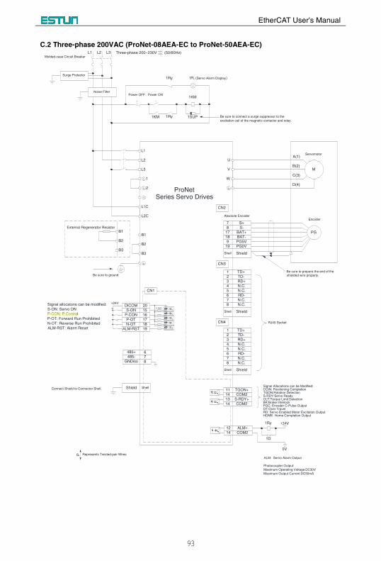
C.2 Three-phase 200VAC (ProNet-08AEA-EC to ProNet-50AEA-EC)
1
2
W
V
U
M
PG
Servomotor
Encoder
A(1)
B(2)
C(3)
D(4)
L2C
L1C CN2
Signal allocatons can be modified:
S-ON: Servo ON
P-CON: P Control
P-OT: Forward Run Prohibited
N-OT: Reverse Run Prohibited
ALM-RST: Alarm Reset
CN3
CN4 RJ45 Socket
1
2
RD+3
N.C.4
N.C.5
RD-6
N.C.7
N.C.8
1
2
3
4
5
6
7
8
S+7
S-8
BAT+17
BAT-18
PG5V9
PG0V19
Shield
Absolute Encoder
Shell
ShieldShell
ShieldShell
Be sure to prepare the end of the
shielded wire properly.Be sure to ground
ALM: Servo Alarm Output
Photocoupler Output:
Maximum Operating Voltage:DC30V
Maximum Output Current:DC50mA
TD+
TD-
B1
B2
B3
B1
B2
B3
External Regenerator Resistor
RD+
N.C.
N.C.
RD-
N.C.
N.C.
TD+
TD-
TGON+11
COM214
S-RDY+13
COM214
Signal Allocations can be Modified:COIN: Positioning CompletionTGON:Rotation DetectionS-RDY:Servo ReadyCLT:Torque Limit DetectionBK:Brake InterlockPGC: Encoder C-Pulse OutputOT:Over TravelRD: Servo Enabled Motor Excitation OutputHOME: Home Completion Output
ALM+12
COM214
1Ry
1D
+24V
0V
CN1
+24VDICOM 20
S-ON 15
P-CON 16
P-OT 17
N-OT 18
ALM-RST 19
3.3KΩ
Connect Shield to Connector Shell. Shield Shell
485+
485-
GNDiso
67
8
P Represents Twisted-pair Wires
Noise Filter
L1 L2 L3 Three-phase 200~230V (50/60Hz)+10%
-15%
Power OFF Power ON
1KM 1SUP
1KM
1Ry
L1
L2
L3
Surge Protector
Molded-case Circuit Breaker
1Ry
1PL (Servo Alarm Display)
Be sure to connect a surge suppressor to the
excitation coil of the magnetic contactor and relay.
ProNetSeries Servo Drives
Mike
Mike
P-CON is home switch input
EtherCAT User's Manual
94
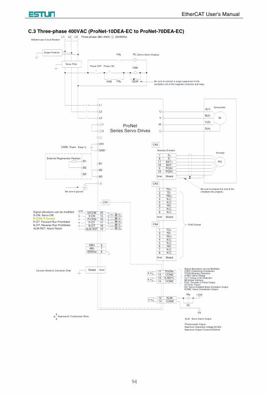
C.3 Three-phase 400VAC (ProNet-10DEA-EC to ProNet-70DEA-EC)
1
2
W
V
U
M
PG
Servomotor
Encoder
A(1)
B(2)
C(3)
D(4)
CN2
Signal allocatons can be modified:
S-ON: Servo ON
P-CON: P Control
P-OT: Forward Run Prohibited
N-OT: Reverse Run Prohibited
ALM-RST: Alarm Reset
CN3
CN4 RJ45 Socket
1
2
RD+3
N.C.4
N.C.5
RD-6
N.C.7
N.C.8
1
2
3
4
5
6
7
8
S+7
S-8
BAT+17
BAT-18
PG5V9
PG0V19
Shield
Absolute Encoder
Shell
ShieldShell
ShieldShell
Be sure to prepare the end of the
shielded wire properly.Be sure to ground
ALM: Servo Alarm Output
Photocoupler Output:
Maximum Operating Voltage:DC30V
Maximum Output Current:DC50mA
TD+
TD-
B1
B2
B3
B1
B2
B3
External Regenerator Resistor
RD+
N.C.
N.C.
RD-
N.C.
N.C.
TD+
TD-
TGON+11
COM214
S-RDY+13
COM214
Signal Allocations can be Modified:COIN: Positioning CompletionTGON:Rotation DetectionS-RDY:Servo ReadyCLT:Torque Limit DetectionBK:Brake InterlockPGC: Encoder C-Pulse OutputOT:Over TravelRD: Servo Enabled Motor Excitation OutputHOME: Home Completion Output
ALM+12
COM214
1Ry
1D
+24V
0V
CN1
+24VDICOM 20
S-ON 15
P-CON 16
P-OT 17
N-OT 18
ALM-RST 19
3.3KΩ
Connect Shield to Connector Shell. Shield Shell
485+
485-
GNDiso
67
8
P Represents Twisted-pair Wires
L1
L2
L3
Noise Filter
L1 L2 L3 Three-phase 380~440V (50/60Hz)+10%
-15%
Power OFF Power ON
1KM 1SUP
1KM
1RySurge Protector
Molded-case Circuit Breaker
1Ry
1PL (Servo Alarm Display)
Be sure to connect a surge suppressor to the
excitation coil of the magnetic contactor and relay.
GND
24V24VDC Power Supply
ProNetSeries Servo Drives
Mike
Mike
P-CON is home switch input
EtherCAT User's Manual
95
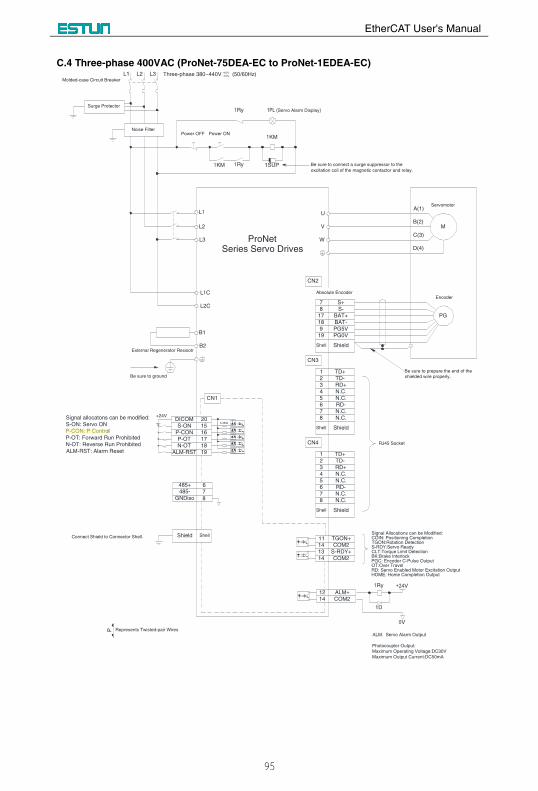
C.4 Three-phase 400VAC (ProNet-75DEA-EC to ProNet-1EDEA-EC)
L1
L2
W
V
U
M
PG
Servomotor
Encoder
A(1)
B(2)
C(3)
D(4)
CN2
Signal allocatons can be modified:
S-ON: Servo ON
P-CON: P Control
P-OT: Forward Run Prohibited
N-OT: Reverse Run Prohibited
ALM-RST: Alarm Reset
CN3
CN4 RJ45 Socket
1
2
RD+3
N.C.4
N.C.5
RD-6
N.C.7
N.C.8
1
2
3
4
5
6
7
8
S+7
S-8
BAT+17
BAT-18
PG5V9
PG0V19
Shield
Absolute Encoder
Shell
ShieldShell
ShieldShell
Be sure to prepare the end of the
shielded wire properly.Be sure to ground
ALM: Servo Alarm Output
Photocoupler Output:
Maximum Operating Voltage:DC30V
Maximum Output Current:DC50mA
TD+
TD-
B1
RD+
N.C.
N.C.
RD-
N.C.
N.C.
TD+
TD-
TGON+11
COM214
S-RDY+13
COM214
Signal Allocations can be Modified:COIN: Positioning CompletionTGON:Rotation DetectionS-RDY:Servo ReadyCLT:Torque Limit DetectionBK:Brake InterlockPGC: Encoder C-Pulse OutputOT:Over TravelRD: Servo Enabled Motor Excitation OutputHOME: Home Completion Output
ALM+12
COM214
1Ry
1D
+24V
0V
CN1
+24VDICOM 20
S-ON 15
P-CON 16
P-OT 17
N-OT 18
ALM-RST 19
3.3KΩ
Connect Shield to Connector Shell. Shield Shell
485+
485-
GNDiso
67
8
P Represents Twisted-pair Wires
B2
L3
Noise Filter
L1 L2 L3 Three-phase 380~440V (50/60Hz)+10%
-15%
Power OFF Power ON
1KM 1SUP
1KM
1RySurge Protector
Molded-case Circuit Breaker
1Ry
1PL (Servo Alarm Display)
Be sure to connect a surge suppressor to the
excitation coil of the magnetic contactor and relay.
External Regenerator Resisotr
L2C
L1C
ProNetSeries Servo Drives
Mike
Mike
Home switch input = P-CON
ProNet Series AC Servo User's Manual
- 52 -
3.6 Wiring for Noise Control
3.6.1 Noise Control
The servo drive uses high-speed switching elements in the main circuit. It may receive "switching noise" from these
high-speed switching elements.
To prevent malfunction due to noise, take the following actions:
• Position the input reference device and noise filter as close to the servo drive as possible.
• Always install a surge absorber in the relay, solenoid and electromagnetic contactor coils.
• The distance between a power line (servomotor main circuit cable) and a signal line must be at least 30 cm. Do not put
the power and signal lines in the same duct or bundle them together.
• Do not share the power supply with an electric welder or electrical discharge machine. When the servo drive is placed
near a high-frequency generator, install a noise filter on the input side of the power supply line. As for the wiring of noise
filter, refer to (1) Noise Filter shown below.
• For proper grounding technique, refer to (2) Correct Grounding.
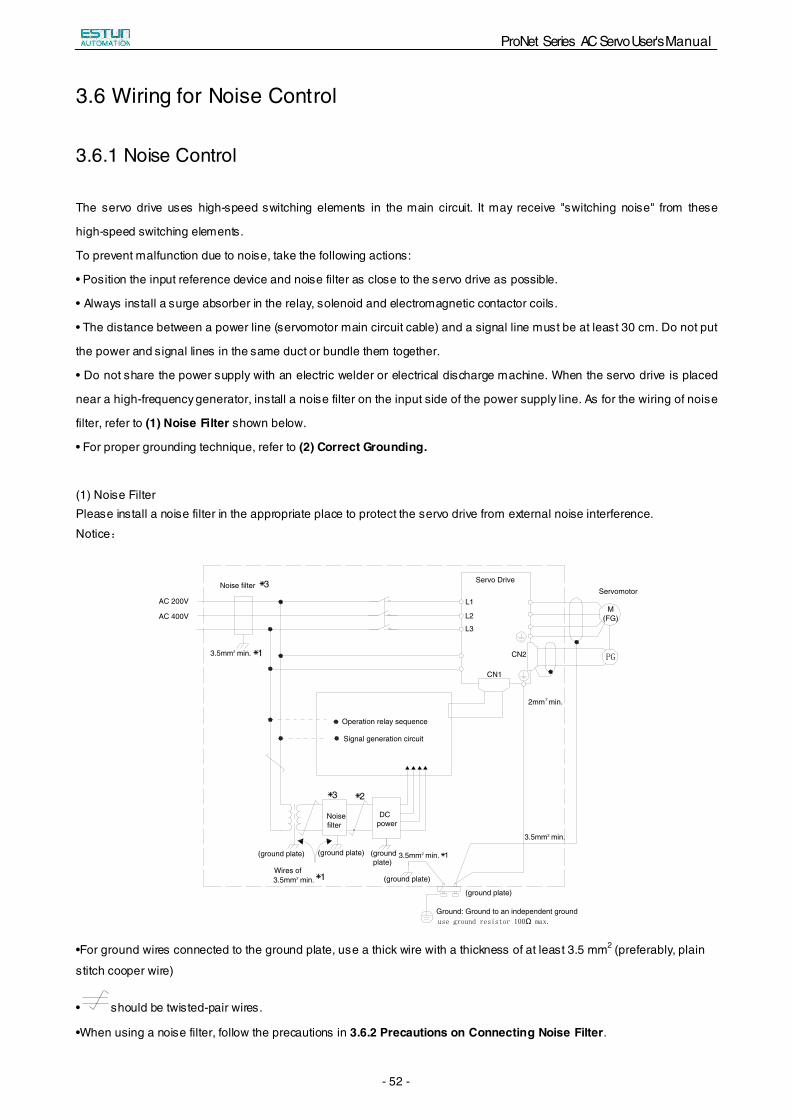
(1) Noise Filter Please install a noise filter in the appropriate place to protect the servo drive from external noise interference.
Notice:
AC 200V
AC 400V
Servo Drive
PG
use ground resistor 100Ω max.
Noise filter *3
2 *1
Operation relay sequence
Signal generation circuit
*3 *2
Noisefilter
DCpower
*1(ground plate)
Wires of *1
Ground: Ground to an independent ground
L1
L2
L3
CN1
CN2
M(FG)
Servomotor
(ground plate) (ground plate)
(ground plate)
(ground plate)
3.5mm min.
23.5mm min.
23.5mm min.
23.5mm min.
22mm min.
•For ground wires connected to the ground plate, use a thick wire with a thickness of at least 3.5 mm2 (preferably, plain
stitch cooper wire)
• should be twisted-pair wires.
•When using a noise filter, follow the precautions in 3.6.2 Precautions on Connecting Noise Filter.
ProNet Series AC Servo User's Manual
- 53 -
(2) Correct Grounding
Take the following grounding measures to prevent the servo drive from malfunctioning due to noise.
■ Grounding the Motor Frame
If the servomotor is grounded via the machine, a switching noise current will flow from the servo drive main circuit through
the servomotor stray capacitance.
Always connect servomotor frame terminal FG to the servo drive ground terminal. Also be sure to ground the ground
terminal .
■ Noise on the I/O Signal Line
If the I/O signal line receives noise, ground the 0 V line (SG) of the reference input line. If the main circuit wiring for the
motor is accommodated in a metal conduit, ground the conduit and its junction box. For all grounding, ground at one point
only.
(3)Precautions on installing on the control panel
■When the servo drive is installed on the control panel, a piece of metal plate should be fixed. It is used for fixing the servo
drive and other peripheral devices. The noise filter should be installed on the metal plate, and closed to the hole drill
through power lines on control panel. Use screws to fix the noise filter to the metal plate. The grounding terminals of noise
filter connects to the grounding terminals of control panel.
■ Servo drive should be fixed on a piece of metal plate. Make sure the heat sink towards ground. The grounding terminals
of servo drive connect to the grounding terminals of control panel.
3.6.2 Precautions on Connecting Noise Filter
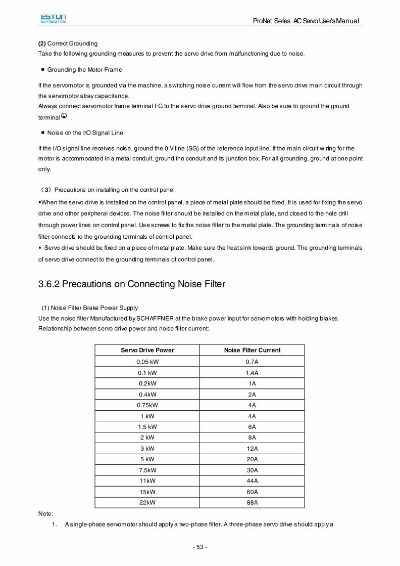
(1) Noise Filter Brake Power Supply
Use the noise filter Manufactured by SCHAFFNER at the brake power input for servomotors with holding brakes.
Relationship between servo drive power and noise filter current:
Servo Drive Power Noise Filter Current
0.05 kW 0.7A
0.1 kW 1.4A
0.2kW 1A
0.4kW 2A
0.75kW 4A
1 kW 4A
1.5 kW 6A
2 kW 8A
3 kW 12A
5 kW 20A
7.5kW 30A
11kW 44A
15kW 60A
22kW 88A
Note:
1. A single-phase servomotor should apply a two-phase filter. A three-phase servo drive should apply a
ProNet Series AC Servo User's Manual
- 54 -
three-phase filter.
2. Choose the right filter according the specifications of operating voltage, current, and manufacturer.
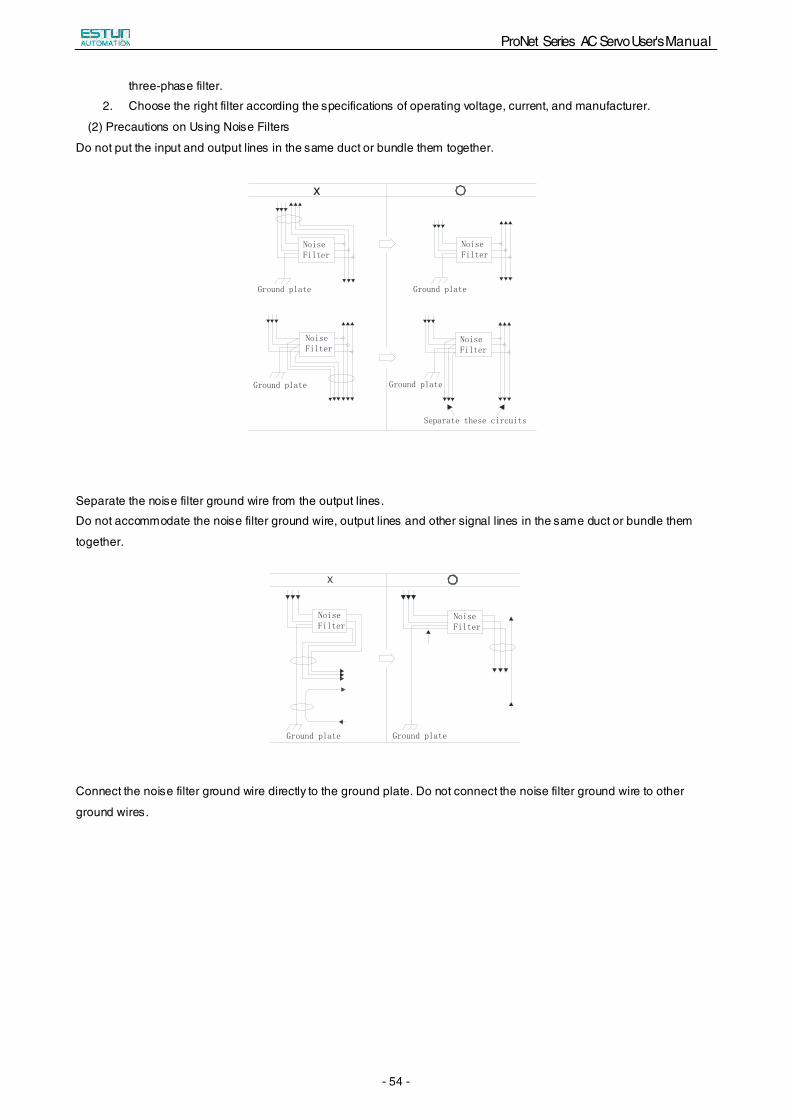
(2) Precautions on Using Noise Filters
Do not put the input and output lines in the same duct or bundle them together.
x
NoiseFilter
Ground plate
Separate these circuits
NoiseFilter
NoiseFilter
NoiseFilter
Ground plate
Ground plate Ground plate
Separate the noise filter ground wire from the output lines.
Do not accommodate the noise filter ground wire, output lines and other signal lines in the same duct or bundle them
together.
X
NoiseFilter
Ground plate
NoiseFilter
Ground plate
Connect the noise filter ground wire directly to the ground plate. Do not connect the noise filter ground wire to other
ground wires.
ProNet Series AC Servo User's Manual
- 55 -
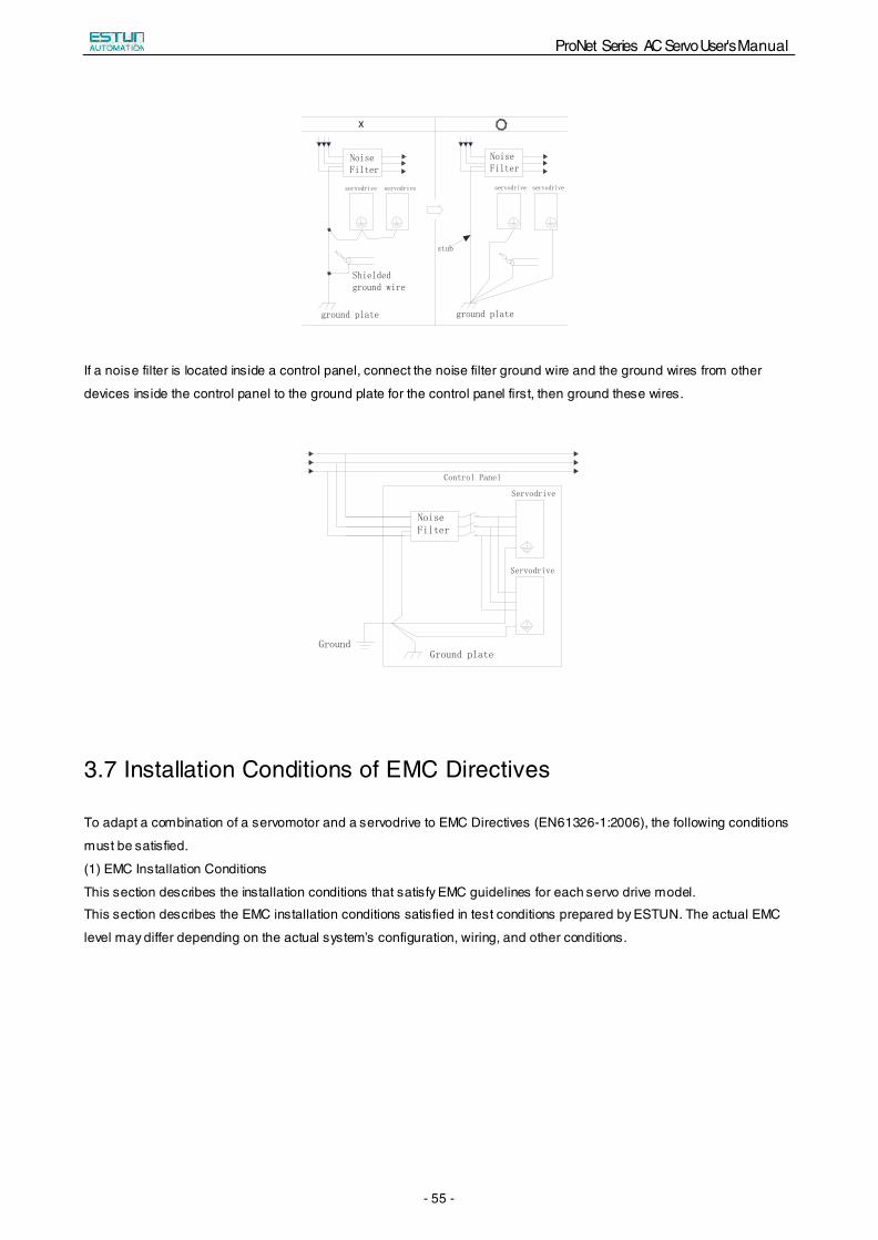
NoiseFilter
ground plate
Shieldedground wire
servodrive
stub
x
NoiseFilter
servodrive servodrive servodrive
ground plate
If a noise filter is located inside a control panel, connect the noise filter ground wire and the ground wires from other
devices inside the control panel to the ground plate for the control panel first, then ground these wires.
Control Panel
Servodrive
Servodrive
Ground plateGround
NoiseFilter
3.7 Installation Conditions of EMC Directives
To adapt a combination of a servomotor and a servodrive to EMC Directives (EN61326-1:2006), the following conditions
must be satisfied.
(1) EMC Installation Conditions
This section describes the installation conditions that satisfy EMC guidelines for each servo drive model.
This section describes the EMC installation conditions satisfied in test conditions prepared by ESTUN. The actual EMC
level may differ depending on the actual system’s configuration, wiring, and other conditions.
ProNet Series AC Servo User's Manual
- 56 -
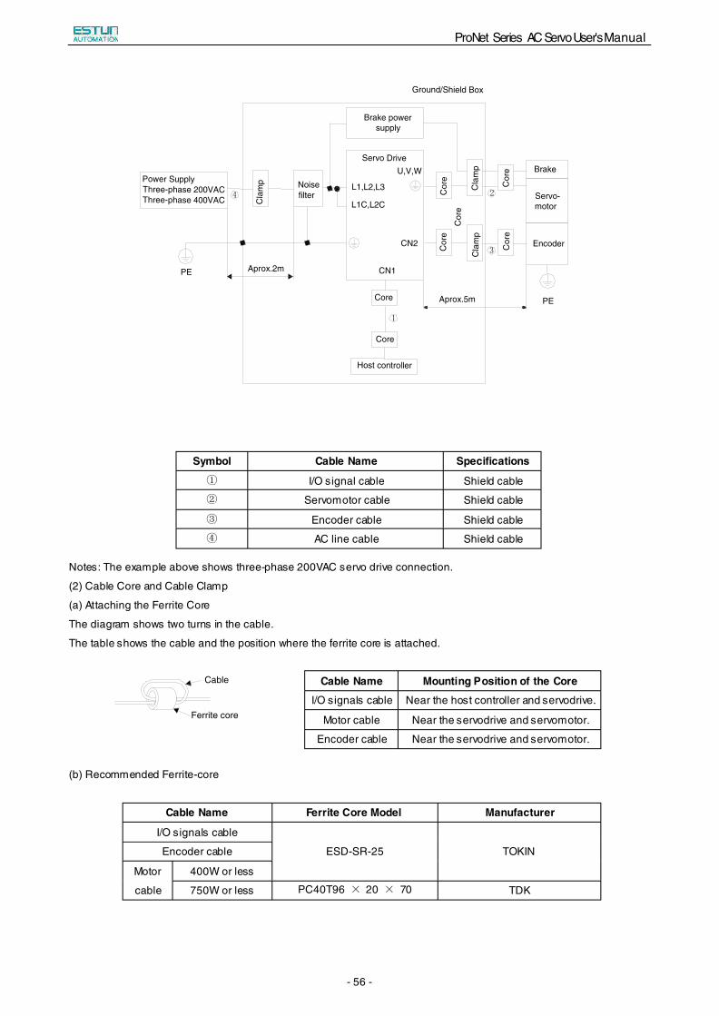
Aprox.2m
Noisefilter
1
4 2
3C
lam
p
Cor
e
Cor
eC
ore
Cor
eC
ore
Core
Core
Aprox.5m
Host controller
Cla
mp
Cla
mp
Brake
Servo-motor
Encoder
Servo Drive
PE
PE
U,V,W
Brake powersupply
L1C,L2C
L1,L2,L3
CN2
CN1
Power SupplyThree-phase 200VACThree-phase 400VAC
Ground/Shield Box
Notes: The example above shows three-phase 200VAC servo drive connection.
(2) Cable Core and Cable Clamp
(a) Attaching the Ferrite Core
The diagram shows two turns in the cable.
The table shows the cable and the position where the ferrite core is attached.
Cable
Ferrite core
(b) Recommended Ferrite-core
Cable Name Ferrite Core Model Manufacturer
I/O signals cable
ESD-SR-25 TOKIN Encoder cable
Motor
cable
400W or less
750W or less PC40T96 × 20 × 70 TDK
Symbol Cable Name Specifications
① I/O signal cable Shield cable
② Servomotor cable Shield cable
③ Encoder cable Shield cable
④ AC line cable Shield cable
Cable Name Mounting Position of the Core
I/O signals cable Near the host controller and servodrive.
Motor cable Near the servodrive and servomotor.
Encoder cable Near the servodrive and servomotor.
ProNet Series AC Servo User's Manual
- 57 -
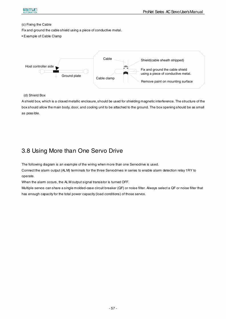
(c) Fixing the Cable
Fix and ground the cable shield using a piece of conductive metal.
• Example of Cable Clamp
Host controller side
Ground plate
Cable
Cable clamp
Shield(cable sheath stripped)
Fix and ground the cable shieldusing a piece of conductive metal.
Remove paint on mounting surface
(d) Shield Box
A shield box, which is a closed metallic enclosure, should be used for shielding magnetic interference. The structure of the
box should allow the main body, door, and cooling unit to be attached to the ground. The box opening should be as small
as poss ible.
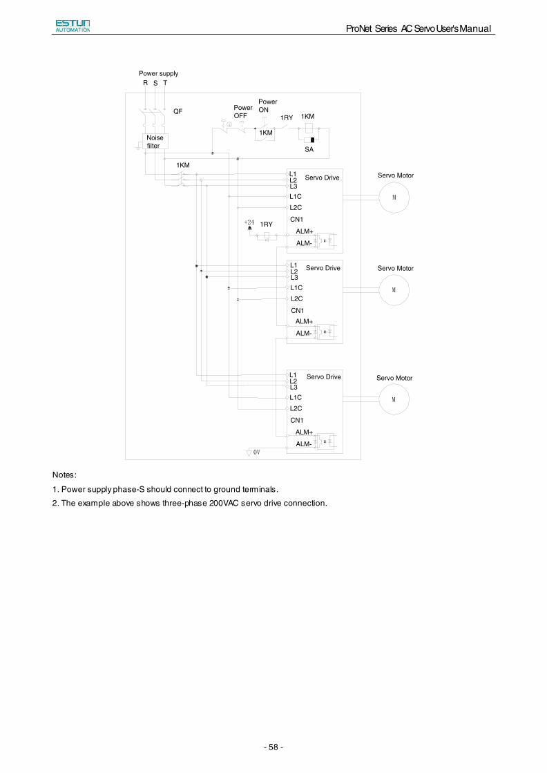
3.8 Using More than One Servo Drive
The following diagram is an example of the wiring when more than one Servodrive is used.
Connect the alarm output (ALM) terminals for the three Servodrives in series to enable alarm detection relay 1RY to
operate.
When the alarm occurs, the ALM output signal transistor is turned OFF.
Multiple servos can share a single molded-case circuit breaker (QF) or noise filter. Always select a QF or noise filter that
has enough capacity for the total power capacity (load conditions) of those servos.
ProNet Series AC Servo User's Manual
- 58 -
+24
0V
M
M
M
Power supply
QF
Noisefilter
1KM
PowerOFF
PowerON
1KM
1KM
1RY
SA
R S T
1RY
Servo DriveL1L2L3L1CL2C
CN1
L1L2L3L1CL2C
CN1
L1L2L3L1CL2C
CN1
ALM-
ALM+
ALM-
ALM+
ALM-
ALM+
Servo Drive
Servo Drive
Servo Motor
Servo Motor
Servo Motor
Notes:
1. Power supply phase-S should connect to ground terminals.
2. The example above shows three-phase 200VAC servo drive connection.
ProNet Series AC Servo User's Manual
- 59 -
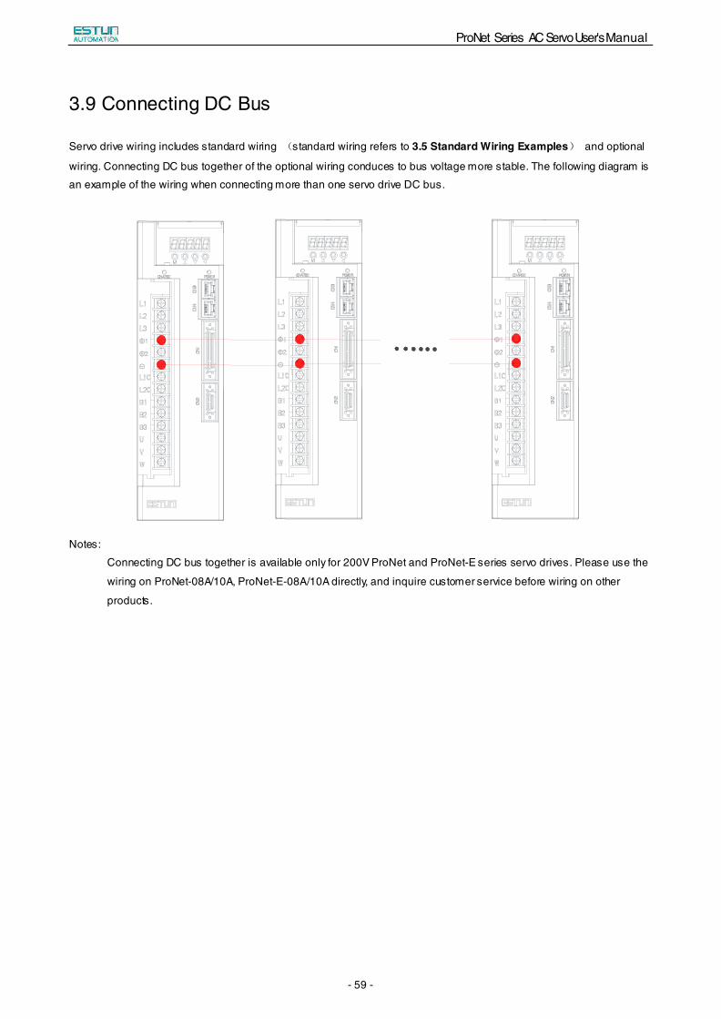
3.9 Connecting DC Bus
Servo drive wiring includes standard wiring (standard wiring refers to 3.5 Standard Wiring Examples) and optional
wiring. Connecting DC bus together of the optional wiring conduces to bus voltage more stable. The following diagram is
an example of the wiring when connecting more than one servo drive DC bus.
Notes:
Connecting DC bus together is available only for 200V ProNet and ProNet-E series servo drives. Please use the
wiring on ProNet-08A/10A, ProNet-E-08A/10A directly, and inquire customer service before wiring on other
products.
ProNet Series AC Servo User's Manual
- 60 -
Chapter 4
Operation
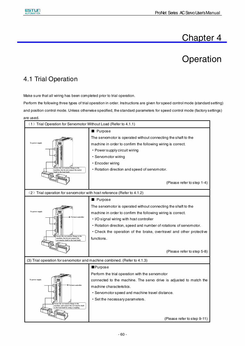
4.1 Trial Operation
Make sure that all wiring has been completed prior to trial operation.
Perform the following three types of trial operation in order. Instructions are given for speed control mode (standard setting)
and position control mode. Unless otherwise specified, the standard parameters for speed control mode (factory settings)
are used.
(1)Trial Operation for Servomotor Without Load (Refer to 4.1.1)
To power supply
Secure the servomotor flange to the machine, but do not connect the motor shaft to the load shaft.
■ Purpose
The servomotor is operated without connecting the shaft to the
machine in order to confirm the following wiring is correct.
·Power supply circuit wiring
·Servomotor wiring
·Encoder wiring
·Rotation direction and speed of servomotor.
(Please refer to step 1-4)
(2)Trial operation for servomotor with host reference (Refer to 4.1.2)
To power supply
Secure the servomotor flange to the machine, but do not connect the servomotor shaft to the load shaft.
To host controller
■ Purpose
The servomotor is operated without connecting the shaft to the
machine in order to confirm the following wiring is correct.
·I/O signal wiring with host controller
·Rotation direction, speed and number of rotations of servomotor.
·Check the operation of the brake, overtravel and other protective
functions.
(Please refer to step 5-8)
(3) Trial operation for servomotor and machine combined. (Refer to 4.1.3)
To power supply
Secure the servomotor flange to the machine, and connect the servomotor shaft to the load shaft by using a coupling.
To host controller
■Purpose
Perform the trial operation with the servomotor
connected to the machine. The servo drive is adjusted to match the
machine characteristics.
·Servomotor speed and machine travel distance.
·Set the necessary parameters.
(Please refer to step 9-11)
ProNet Series AC Servo User's Manual
- 61 -
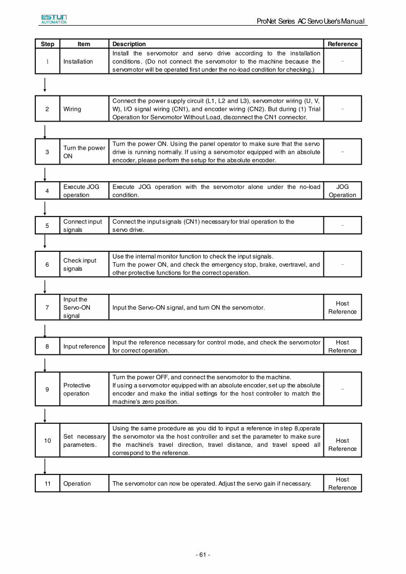
Step Item Description Reference
1 Installation Install the servomotor and servo drive according to the installation conditions. (Do not connect the servomotor to the machine because the servomotor will be operated first under the no-load condition for checking.)
-
2 Wiring Connect the power supply circuit (L1, L2 and L3), servomotor wiring (U, V, W), I/O signal wiring (CN1), and encoder wiring (CN2). But during (1) Trial Operation for Servomotor Without Load, disconnect the CN1 connector.
-
3 Turn the power ON
Turn the power ON. Using the panel operator to make sure that the servo drive is running normally. If using a servomotor equipped with an absolute encoder, please perform the setup for the absolute encoder.
-
4 Execute JOG operation
Execute JOG operation with the servomotor alone under the no-load condition.
JOG Operation
5 Connect input signals
Connect the input signals (CN1) necessary for trial operation to the servo drive.
-
6 Check input signals
Use the internal monitor function to check the input signals. Turn the power ON, and check the emergency stop, brake, overtravel, and other protective functions for the correct operation.
-
7 Input the Servo-ON signal
Input the Servo-ON signal, and turn ON the servomotor. Host
Reference
8 Input reference Input the reference necessary for control mode, and check the servomotor for correct operation.
Host Reference
9 Protective operation
Turn the power OFF, and connect the servomotor to the machine. If using a servomotor equipped with an absolute encoder, set up the absolute encoder and make the initial settings for the host controller to match the machine’s zero position.
-
10 Set necessary parameters.
Using the same procedure as you did to input a reference in step 8,operate the servomotor via the host controller and set the parameter to make sure the machine’s travel direction, travel distance, and travel speed all correspond to the reference.
Host Reference
11 Operation The servomotor can now be operated. Adjust the servo gain if necessary. Host
Reference
ProNet Series AC Servo User's Manual
- 62 -
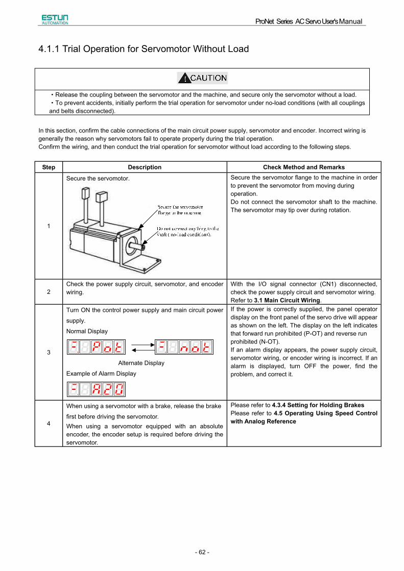
4.1.1 Trial Operation for Servomotor Without Load
·Release the coupling between the servomotor and the machine, and secure only the servomotor without a load.·To prevent accidents, initially perform the trial operation for servomotor under no-load conditions (with all couplings and belts disconnected).
In this section, confirm the cable connections of the main circuit power supply, servomotor and encoder. Incorrect wiring is generally the reason why servomotors fail to operate properly during the trial operation. Confirm the wiring, and then conduct the trial operation for servomotor without load according to the following steps.
Step Description Check Method and Remarks
1
Secure the servomotor. Secure the servomotor flange to the machine in order to prevent the servomotor from moving during operation. Do not connect the servomotor shaft to the machine. The servomotor may tip over during rotation.
2 Check the power supply circuit, servomotor, and encoder wiring.
With the I/O signal connector (CN1) disconnected, check the power supply circuit and servomotor wiring.Refer to 3.1 Main Circuit Wiring.
3
Turn ON the control power supply and main circuit power
supply.
Normal Display
Alternate Display
Example of Alarm Display
If the power is correctly supplied, the panel operator display on the front panel of the servo drive will appear as shown on the left. The display on the left indicates that forward run prohibited (P-OT) and reverse run prohibited (N-OT). If an alarm display appears, the power supply circuit, servomotor wiring, or encoder wiring is incorrect. If an alarm is displayed, turn OFF the power, find the problem, and correct it.
4
When using a servomotor with a brake, release the brake
first before driving the servomotor. When using a servomotor equipped with an absolute encoder, the encoder setup is required before driving the servomotor.
Please refer to 4.3.4 Setting for Holding Brakes Please refer to 4.5 Operating Using Speed Control with Analog Reference
ProNet Series AC Servo User's Manual
- 63 -
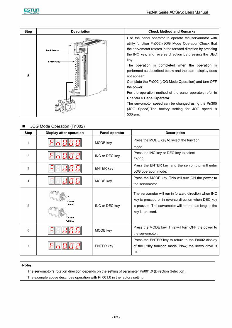
Step Description Check Method and Remarks
5
Use the panel operator to operate the servomotor with utility function Fn002 (JOG Mode Operation)Check that the servomotor rotates in the forward direction by pressing the INC key, and reverse direction by pressing the DEC key. The operation is completed when the operation is performed as described below and the alarm display does not appear.Complete the Fn002 (JOG Mode Operation) and turn OFF the power.For the operation method of the panel operator, refer to Chapter 5 Panel OperatorThe servomotor speed can be changed using the Pn305 (JOG Speed).The factory setting for JOG speed is 500rpm.
JOG Mode Operation (Fn002) Step Display after operation Panel operator Description
1 MODE key Press the MODE key to select the function
mode.
2 INC or DEC key Press the INC key or DEC key to select
Fn002.
3 ENTER key Press the ENTER key, and the servomotor will enter
JOG operation mode.
4 MODE key Press the MODE key. This will turn ON the power to
the servomotor.
5 INC or DEC key
The servomotor will run in forward direction when INC
key is pressed or in reverse direction when DEC key
is pressed. The servomotor will operate as long as the
key is pressed.
6 MODE key Press the MODE key. This will turn OFF the power to
the servomotor.
7 ENTER key
Press the ENTER key to return to the Fn002 display
of the utility function mode. Now, the servo drive is
OFF.
Note:The servomotor�s rotation direction depends on the setting of parameter Pn001.0 (Direction Selection).
The example above describes operation with Pn001.0 in the factory setting.
ProNet Series AC Servo User's Manual
- 64 -
Pn305
JOG Speed
Setting Range Setting Unit Factory Setting Setting Validation
0~6000 rpm 500 Immediately
Set the utility function Fn002 (JOG Mode Operation) to the reference value of servomotor speed.
The servomotor can be operated using only the panel operator without reference from the host controller.
Please note that the Forward Run Prohibited (P-OT) and Reverse Run Prohibited (N-OT) signals are invalid during JOG
mode operation.
4.1.2 Trial Operation for Servomotor without Load from Host Reference
Check that the servomotor move reference or I/O signals are correctly set from the host controller to the servo drive.
Also check the wiring and polarity between the host controller and servo drive, and the servo drive operation settings are
correct. This is the final check before connecting the servomotor to the machine.
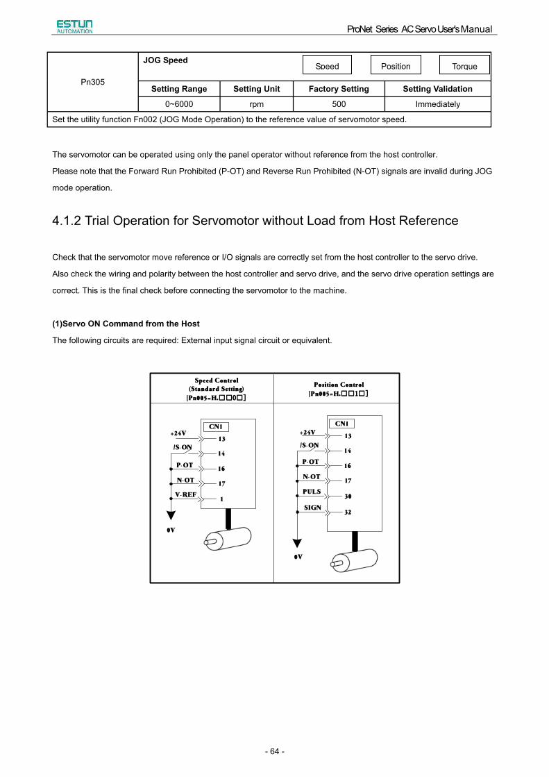
(1)Servo ON Command from the Host
The following circuits are required: External input signal circuit or equivalent.
0V
+24V
/S-ON
P-OT
N-OT
V-REF
13
30
17
16
14
CN1
13
1
17
16
14
CN1
32
+24V
/S-ON
P-OT
N-OT
PULS
SIGN
Speed Control(Standard Setting)
[Pn005=H.□□0□]
Position Control[Pn005=H.□□1□]
0V
Speed Position Torque
ProNet Series AC Servo User's Manual
- 65 -
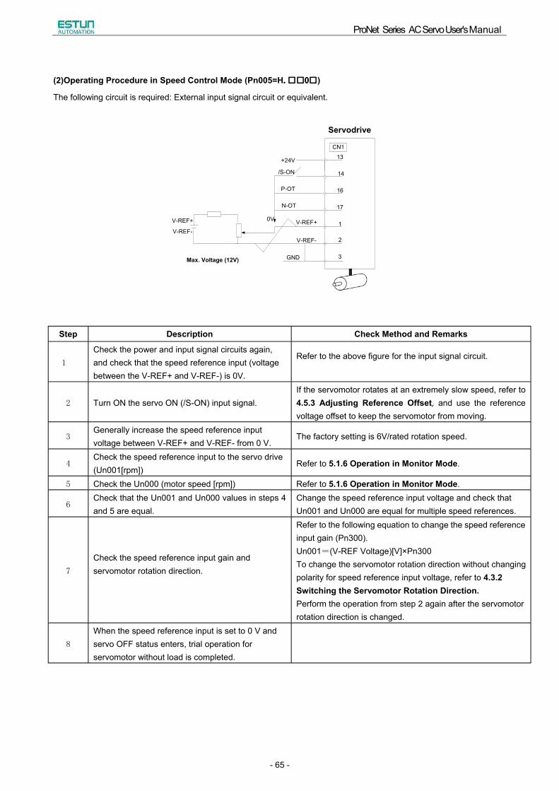
(2)Operating Procedure in Speed Control Mode (Pn005=H.□□0□)
The following circuit is required: External input signal circuit or equivalent.
+24V
/S-ON
P-OT
N-OT
1
17
16
14
13
2
3
V-REF+
V-REF-
GND
CN1
V-REF+
V-REF-
0V
Servodrive
Max. Voltage (12V)
Step Description Check Method and Remarks
1
Check the power and input signal circuits again, and check that the speed reference input (voltage between the V-REF+ and V-REF-) is 0V.
Refer to the above figure for the input signal circuit.
2 Turn ON the servo ON (/S-ON) input signal. If the servomotor rotates at an extremely slow speed, refer to 4.5.3 Adjusting Reference Offset, and use the reference voltage offset to keep the servomotor from moving.
3 Generally increase the speed reference input voltage between V-REF+ and V-REF- from 0 V.
The factory setting is 6V/rated rotation speed.
4 Check the speed reference input to the servo drive (Un001[rpm])
Refer to 5.1.6 Operation in Monitor Mode.
5 Check the Un000 (motor speed [rpm]) Refer to 5.1.6 Operation in Monitor Mode.
6 Check that the Un001 and Un000 values in steps 4 and 5 are equal.
Change the speed reference input voltage and check that Un001 and Un000 are equal for multiple speed references.
7
Check the speed reference input gain and servomotor rotation direction.
Refer to the following equation to change the speed reference input gain (Pn300). Un001=(V-REF Voltage)[V]×Pn300 To change the servomotor rotation direction without changing polarity for speed reference input voltage, refer to 4.3.2 Switching the Servomotor Rotation Direction.Perform the operation from step 2 again after the servomotor rotation direction is changed.
8
When the speed reference input is set to 0 V and servo OFF status enters, trial operation for servomotor without load is completed.
ProNet Series AC Servo User's Manual
- 66 -
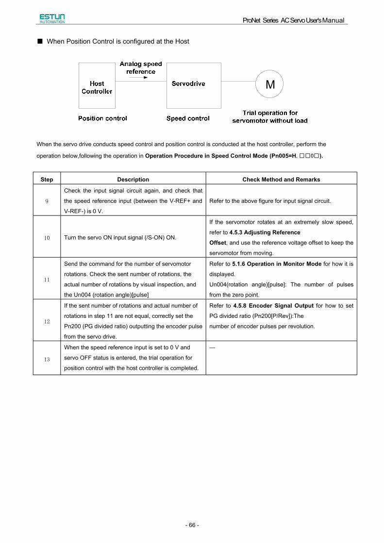
■ When Position Control is configured at the Host
When the servo drive conducts speed control and position control is conducted at the host controller, perform the
operation below,following the operation in Operation Procedure in Speed Control Mode (Pn005=H.□□0□).
Step Description Check Method and Remarks
9
Check the input signal circuit again, and check that
the speed reference input (between the V-REF+ and
V-REF-) is 0 V.
Refer to the above figure for input signal circuit.
10 Turn the servo ON input signal (/S-ON) ON.
If the servomotor rotates at an extremely slow speed,
refer to 4.5.3 Adjusting Reference
Offset, and use the reference voltage offset to keep the
servomotor from moving.
11
Send the command for the number of servomotor
rotations. Check the sent number of rotations, the
actual number of rotations by visual inspection, and
the Un004 (rotation angle)[pulse]
Refer to 5.1.6 Operation in Monitor Mode for how it is
displayed.
Un004(rotation angle)[pulse]: The number of pulses
from the zero point.
12
If the sent number of rotations and actual number of
rotations in step 11 are not equal, correctly set the
Pn200 (PG divided ratio) outputting the encoder pulse
from the servo drive.
Refer to 4.5.8 Encoder Signal Output for how to set
PG divided ratio (Pn200[P/Rev]):The
number of encoder pulses per revolution.
13
When the speed reference input is set to 0 V and
servo OFF status is entered, the trial operation for
position control with the host controller is completed.
�
ProNet Series AC Servo User's Manual
- 67 -
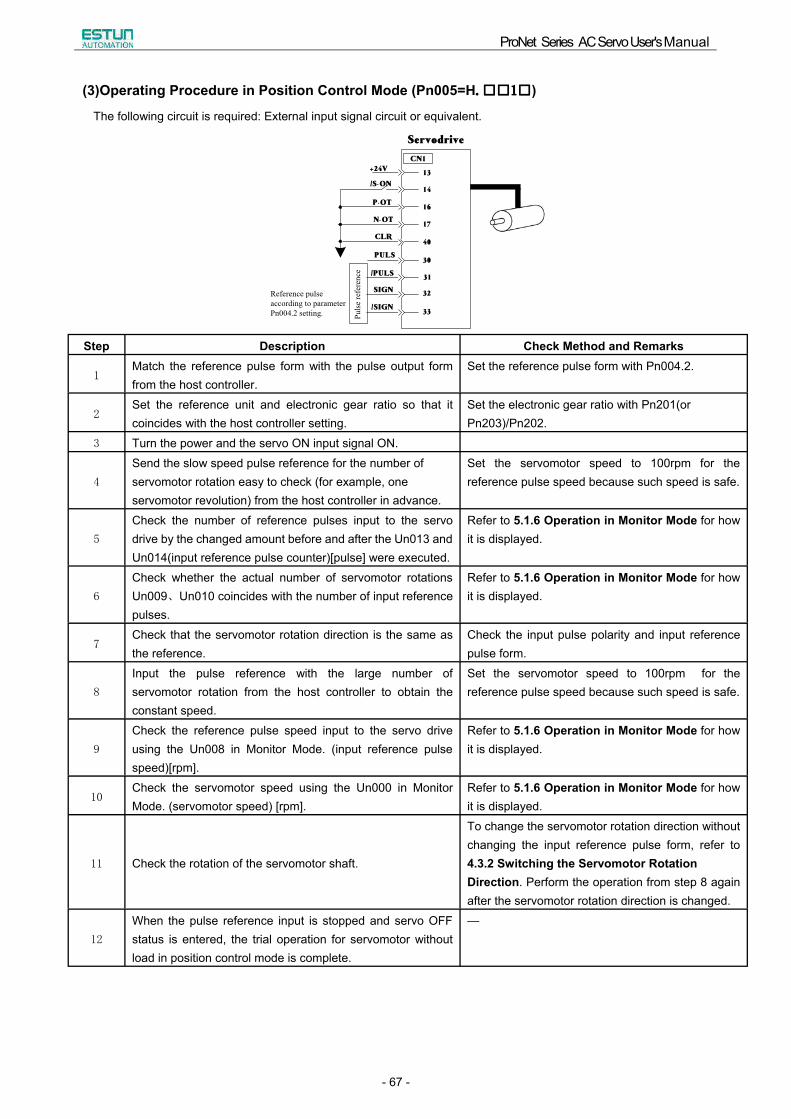
(3)Operating Procedure in Position Control Mode (Pn005=H.□□1□)
The following circuit is required: External input signal circuit or equivalent.
13
40
17
16
14
CN1
30
+24V
/S-ON
P-OT
N-OT
CLR
PULS
31
32
33
/PULS
SIGN
/SIGN
Servodrive
Reference pulse according to parameter Pn004.2 setting. Pu
lse
refe
renc
eStep Description Check Method and Remarks
1 Match the reference pulse form with the pulse output form from the host controller.
Set the reference pulse form with Pn004.2.
2 Set the reference unit and electronic gear ratio so that it coincides with the host controller setting.
Set the electronic gear ratio with Pn201(or Pn203)/Pn202.
3 Turn the power and the servo ON input signal ON.
4
Send the slow speed pulse reference for the number of servomotor rotation easy to check (for example, one servomotor revolution) from the host controller in advance.
Set the servomotor speed to 100rpm for the reference pulse speed because such speed is safe.
5
Check the number of reference pulses input to the servo drive by the changed amount before and after the Un013 and Un014(input reference pulse counter)[pulse] were executed.
Refer to 5.1.6 Operation in Monitor Mode for how it is displayed.
6
Check whether the actual number of servomotor rotations Un009、Un010 coincides with the number of input reference pulses.
Refer to 5.1.6 Operation in Monitor Mode for how it is displayed.
7 Check that the servomotor rotation direction is the same as the reference.
Check the input pulse polarity and input reference pulse form.
8
Input the pulse reference with the large number of servomotor rotation from the host controller to obtain the constant speed.
Set the servomotor speed to 100rpm for the reference pulse speed because such speed is safe.
9
Check the reference pulse speed input to the servo drive using the Un008 in Monitor Mode. (input reference pulse speed)[rpm].
Refer to 5.1.6 Operation in Monitor Mode for how it is displayed.
10 Check the servomotor speed using the Un000 in Monitor Mode. (servomotor speed) [rpm].
Refer to 5.1.6 Operation in Monitor Mode for how it is displayed.
11 Check the rotation of the servomotor shaft.
To change the servomotor rotation direction without changing the input reference pulse form, refer to 4.3.2 Switching the Servomotor Rotation Direction. Perform the operation from step 8 again after the servomotor rotation direction is changed.
12
When the pulse reference input is stopped and servo OFF status is entered, the trial operation for servomotor without load in position control mode is complete.
�
ProNet Series AC Servo User's Manual
- 68 -
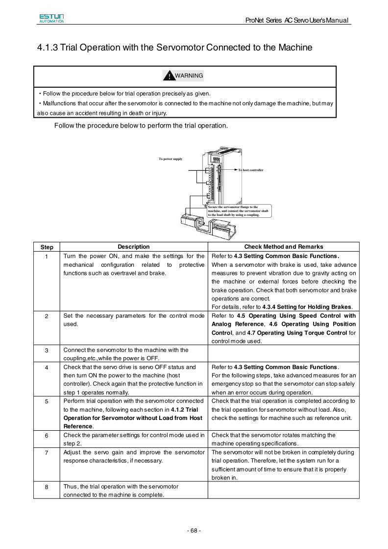
4.1.3 Trial Operation with the Servomotor Connected to the Machine
!WARNING
·Follow the procedure below for trial operation precisely as given.
·Malfunctions that occur after the servomotor is connected to the machine not only damage the machine, but may
also cause an accident resulting in death or injury.
Follow the procedure below to perform the trial operation.
To power supply
Secure the servomotor flange to the machine, and connect the servomotor shaft to the load shaft by using a coupling.
To host controller
Step Description Check Method and Remarks 1 Turn the power ON, and make the settings for the
mechanical configuration related to protective functions such as overtravel and brake.
Refer to 4.3 Setting Common Basic Functions.When a servomotor with brake is used, take advance measures to prevent vibration due to gravity acting on the machine or external forces before checking the brake operation. Check that both servomotor and brake operations are correct. For details, refer to 4.3.4 Setting for Holding Brakes.
2 Set the necessary parameters for the control mode used.
Refer to 4.5 Operating Using Speed Control with Analog Reference, 4.6 Operating Using Position Control, and 4.7 Operating Using Torque Control for control mode used.
3 Connect the servomotor to the machine with the coupling,etc.,while the power is OFF.
4 Check that the servo drive is servo OFF status and then turn ON the power to the machine (host controller). Check again that the protective function in step 1 operates normally.
Refer to 4.3 Setting Common Basic Functions . For the following steps, take advanced measures for an emergency stop so that the servomotor can stop safely when an error occurs during operation.
5 Perform trial operation with the servomotor connected to the machine, following each section in 4.1.2 Trial Operation for Servomotor without Load from Host Reference.
Check that the trial operation is completed according to the trial operation for servomotor without load. Also, check the settings for machine such as reference unit.
6 Check the parameter settings for control mode used in step 2.
Check that the servomotor rotates matching the machine operating specifications.
7 Adjust the servo gain and improve the servomotor response characteristics, if necessary.
The servomotor will not be broken in completely during trial operation. Therefore, let the system run for a sufficient amount of time to ensure that it is properly broken in.
8 Thus, the trial operation with the servomotor connected to the machine is complete.
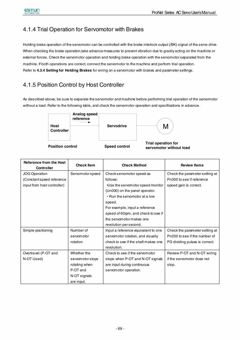
ProNet Series AC Servo User's Manual
- 69 -
4.1.4 Trial Operation for Servomotor with Brakes
Holding brake operation of the servomotor can be controlled with the brake interlock output (/BK) signal of the servo drive.
When checking the brake operation,take advance measures to prevent vibration due to gravity acting on the machine or
external forces. Check the servomotor operation and holding brake operation with the servomotor separated from the
machine. If both operations are correct, connect the servomotor to the machine and perform trial operation.
Refer to 4.3.4 Setting for Holding Brakes for wiring on a servomotor with brakes and parameter settings.
4.1.5 Position Control by Host Controller
As described above, be sure to separate the servomotor and machine before performing trial operation of the servomotor
without a load. Refer to the following table, and check the servomotor operation and specifications in advance.
M
Trial operation for servomotor without loadSpeed controlPosition control
Host Controller
Servodrive
Analog speed reference
Reference from the Host Controller
Check Item Check Method Review Items
JOG Operation (Constant speed reference input from host controller)
Servomotor speed Check servomotor speed as follows:·Use the servomotor speed monitor (Un000) on the panel operator.·Run the servomotor at a low speed. For example, input a reference speed of 60rpm, and check to see if the servomotor makes one revolution per second.
Check the parameter setting at Pn300 to see if reference speed gain is correct.
Simple positioning Number of servomotor rotation
Input a reference equivalent to one servomotor rotation, and visually check to see if the shaft makes one revolution.
Check the parameter setting at Pn200 to see if the number of PG dividing pulses is correct.
Overtravel (P-OT and N-OT Used)
Whether the servomotor stops rotating when P-OT and N-OT signals are input.
Check to see if the servomotor stops when P-OT and N-OT signals are input during continuous servomotor operation.
Review P-OT and N-OT wiring if the servomotor does not stop.
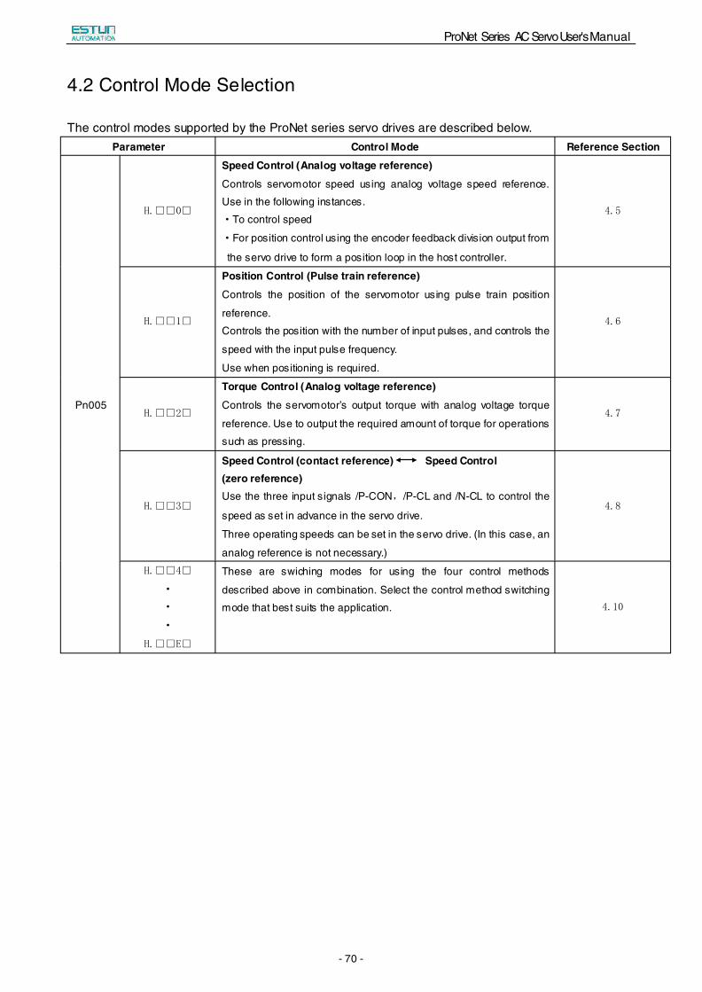
ProNet Series AC Servo User's Manual
- 70 -
4.2 Control Mode Selection
The control modes supported by the ProNet series servo drives are described below. Parameter Control Mode Reference Section
Pn005
H.□□0□
Speed Control (Analog voltage reference)
Controls servomotor speed using analog voltage speed reference.
Use in the following instances.
·To control speed
·For position control using the encoder feedback division output from
the servo drive to form a position loop in the host controller.
4.5
H.□□1□
Position Control (Pulse train reference)
Controls the position of the servomotor using pulse train position
reference.
Controls the position with the number of input pulses, and controls the
speed with the input pulse frequency.
Use when positioning is required.
4.6
H.□□2□
Torque Control (Analog voltage reference)
Controls the servomotor’s output torque with analog voltage torque
reference. Use to output the required amount of torque for operations
such as pressing.
4.7
H.□□3□
Speed Control (contact reference) Speed Control (zero reference) Use the three input signals /P-CON,/P-CL and /N-CL to control the
speed as set in advance in the servo drive.
Three operating speeds can be set in the servo drive. (In this case, an
analog reference is not necessary.)
4.8
H.□□4□
·
·
·
H.□□E□
These are swiching modes for using the four control methods
described above in combination. Select the control method switching
mode that best suits the application. 4.10
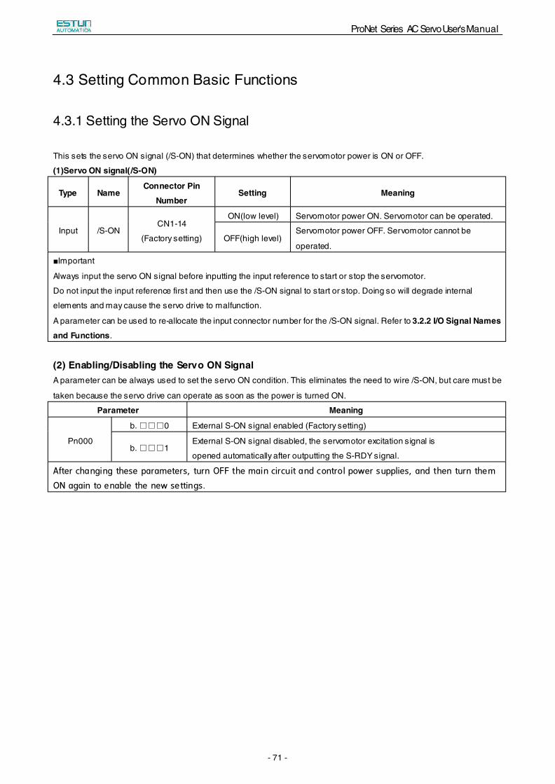
ProNet Series AC Servo User's Manual
- 71 -
4.3 Setting Common Basic Functions
4.3.1 Setting the Servo ON Signal
This sets the servo ON signal (/S-ON) that determines whether the servomotor power is ON or OFF.
(1)Servo ON signal(/S-ON)
Type Name Connector Pin
NumberSetting Meaning
Input /S-ON CN1-14
(Factory setting)
ON(low level) Servomotor power ON. Servomotor can be operated.
OFF(high level) Servomotor power OFF. Servomotor cannot be
operated.
■Important
Always input the servo ON signal before inputting the input reference to start or stop the servomotor.
Do not input the input reference first and then use the /S-ON signal to start or stop. Doing so will degrade internal
elements and may cause the servo drive to malfunction.
A parameter can be used to re-allocate the input connector number for the /S-ON signal. Refer to 3.2.2 I/O Signal Names
and Functions.
(2) Enabling/Disabling the Servo ON Signal A parameter can be always used to set the servo ON condition. This eliminates the need to wire /S-ON, but care must be
taken because the servo drive can operate as soon as the power is turned ON.
Parameter Meaning
Pn000
b.□□□0 External S-ON signal enabled (Factory setting)
b.□□□1 External S-ON signal disabled, the servomotor excitation signal is
opened automatically after outputting the S-RDY signal.
After changing these parameters, turn OFF the main circuit and control power supplies, and then turn them
ON again to enable the new settings.
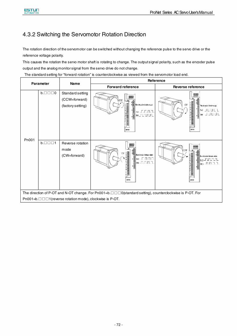
ProNet Series AC Servo User's Manual
- 72 -
4.3.2 Switching the Servomotor Rotation Direction
The rotation direction of the servomotor can be switched without changing the reference pulse to the servo drive or the
reference voltage polarity.
This causes the rotation the servo motor shaft is rotating to change. The output signal polarity, such as the encoder pulse
output and the analog monitor signal from the servo drive do not change.
The standard setting for “forward rotation” is counterclockwise as viewed from the servomotor load end.
Parameter Name Reference
Forward reference Reverse reference
Pn001
b.□□□0 Standard setting
(CCW=forward)
(factory setting)
b.□□□1 Reverse rotation
mode
(CW=forward)
The direction of P-OT and N-OT change. For Pn001=b.□□□0(standard setting), counterclockwise is P-OT. For
Pn001=b.□□□1(reverse rotation mode), clockwise is P-OT.
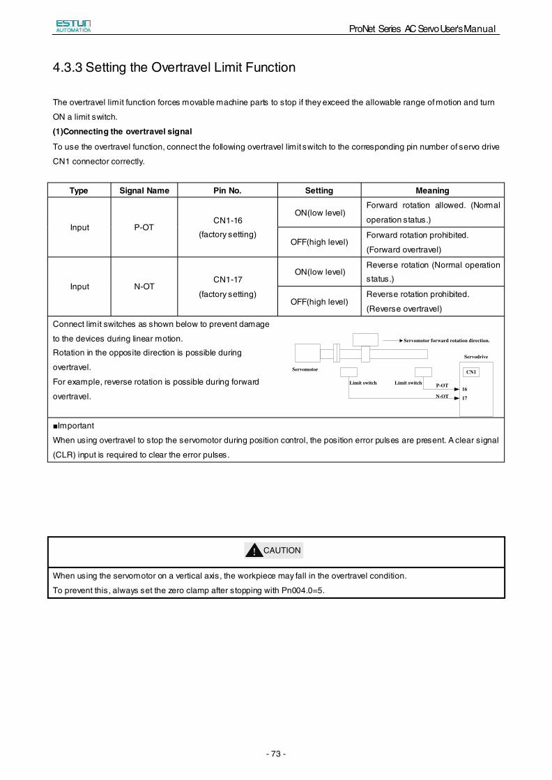
ProNet Series AC Servo User's Manual
- 73 -
4.3.3 Setting the Overtravel Limit Function
The overtravel limit function forces movable machine parts to stop if they exceed the allowable range of motion and turn
ON a limit switch.
(1)Connecting the overtravel signal
To use the overtravel function, connect the following overtravel limit switch to the corresponding pin number of servo drive
CN1 connector correctly.
Type Signal Name Pin No. Setting Meaning
Input P-OT CN1-16
(factory setting)
ON(low level) Forward rotation allowed. (Normal
operation status.)
OFF(high level) Forward rotation prohibited.
(Forward overtravel)
Input N-OT CN1-17
(factory setting)
ON(low level) Reverse rotation (Normal operation
status.)
OFF(high level) Reverse rotation prohibited.
(Reverse overtravel)
Connect limit switches as shown below to prevent damage
to the devices during linear motion.
Rotation in the opposite direction is possible during
overtravel.
For example, reverse rotation is possible during forward
overtravel.
Servomotor forward rotation direction.
Servodrive
Servomotor
Limit switch Limit switch P-OT
N-OT
CN1
16
17
■Important
When using overtravel to stop the servomotor during position control, the position error pulses are present. A clear signal
(CLR) input is required to clear the error pulses.
!CAUTION
When using the servomotor on a vertical axis, the workpiece may fall in the overtravel condition.
To prevent this, always set the zero clamp after stopping with Pn004.0=5.
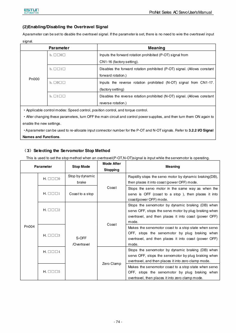
ProNet Series AC Servo User's Manual
- 74 -
(2)Enabling/Disabling the Overtravel Signal A parameter can be set to disable the overtravel signal. If the parameter is set, there is no need to wire the overtravel input
signal.
Parameter Meaning
Pn000
b.□□0□ Inputs the forward rotation prohibited (P-OT) signal from
CN1-16 (factory setting).
b.□□1□ Disables the forward rotation prohibited (P-OT) signal. (Allows constant
forward rotation.)
b.□0□□ Inputs the reverse rotation prohibited (N-OT) signal from CN1-17.
(factory setting)
b.□1□□ Disables the reverse rotation prohibited (N-OT) signal. (Allows constant
reverse rotation.)
·Applicable control modes: Speed control, position control, and torque control.
·After changing these parameters, turn OFF the main circuit and control power supplies, and then turn them ON again to
enable the new settings.
·A parameter can be used to re-allocate input connector number for the P-OT and N-OT signals. Refer to 3.2.2 I/O Signal
Names and Functions.
(3)Selecting the Servomotor Stop Method This is used to set the stop method when an overtravel(P-OT,N-OT)signal is input while the servomotor is operating.
Parameter Stop Mode Mode After
Stopping Meaning
Pn004
H.□□□0Stop by dynamic
brake Coast
Rapidlly stops the servo motor by dynamic braking(DB), then places it into coast (power OFF) mode.
H.□□□1 Coast to a stop Stops the servo motor in the same way as when the servo is OFF (coast to a stop ), then places it into coast(power OFF) mode.
H.□□□2
S-OFF
/Overtravel
Coast
Stops the servomotor by dynamic braking (DB) when servo OFF, stops the servo motor by plug braking when overtravel, and then places it into coast (power OFF) mode.
H.□□□3
Makes the servomotor coast to a stop state when servo OFF, stops the servomotor by plug braking when overtravel, and then places it into coast (power OFF) mode.
H.□□□4
Zero Clamp
Stops the servomotor by dynamic braking (DB) when servo OFF, stops the servomotor by plug braking when overtravel, and then places it into zero clamp mode.
H.□□□5
Makes the servomotor coast to a stop state when servo OFF, stops the servomotor by plug braking when overtravel, then places it into zero clamp mode.
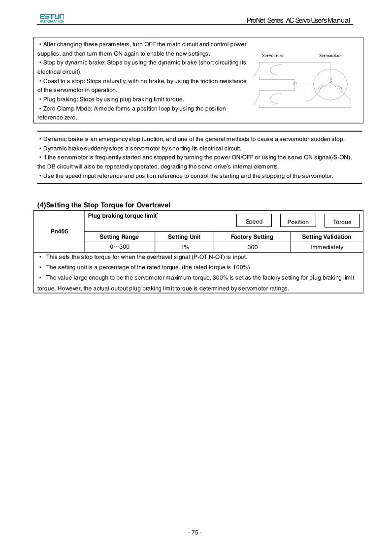
ProNet Series AC Servo User's Manual
- 75 -
·After changing these parameters, turn OFF the main circuit and control power supplies, and then turn them ON again to enable the new settings.·Stop by dynamic brake: Stops by using the dynamic brake (short circuiting its electrical circuit). ·Coast to a stop: Stops naturally, with no brake, by using the friction resistance of the servomotor in operation. ·Plug braking: Stops by using plug braking limit torque.·Zero Clamp Mode: A mode forms a position loop by using the position reference zero.
SSeerrvvoommoottoorrSSeerrvvooddrriivvee
·Dynamic brake is an emergency stop function, and one of the general methods to cause a servomotor sudden stop. ·Dynamic brake suddenly stops a servomotor by shorting its electrical circuit. ·If the servomotor is frequently started and stopped by turning the power ON/OFF or using the servo ON signal(/S-ON), the DB circuit will also be repeatedly operated, degrading the servo drive’s internal elements. ·Use the speed input reference and position reference to control the starting and the stopping of the servomotor.
(4)Setting the Stop Torque for Overtravel
Pn405
Plug braking torque limit`
Setting Range Setting Unit Factory Setting Setting Validation 0~300 1% 300 Immediately
· This sets the stop torque for when the overtravel signal (P-OT,N-OT) is input.
· The setting unit is a percentage of the rated torque. (the rated torque is 100%)
· The value large enough to be the servomotor maximum torque, 300% is set as the factory setting for plug braking limit
torque. However, the actual output plug braking limit torque is determined by servomotor ratings.
Speed Position Torque
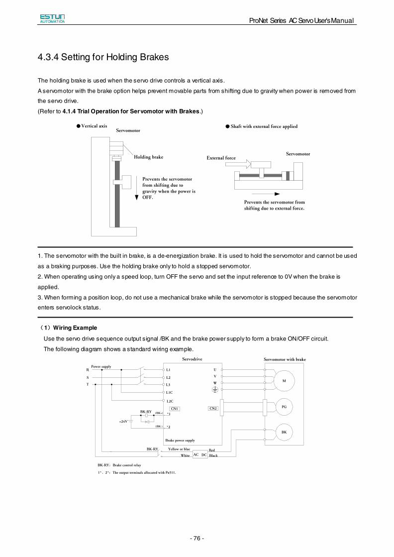
ProNet Series AC Servo User's Manual
- 76 -
4.3.4 Setting for Holding Brakes
The holding brake is used when the servo drive controls a vertical axis.
A servomotor with the brake option helps prevent movable parts from shifting due to gravity when power is removed from
the servo drive.
(Refer to 4.1.4 Trial Operation for Servomotor with Brakes.)
Vertical axisServomotor
Holding brake
Prevents the servomotor from shifting due to gravity when the power is OFF.
External forceServomotor
Prevents the servomotor from shifting due to external force.
Shaft with external force applied
1. The servomotor with the built in brake, is a de-energization brake. It is used to hold the servomotor and cannot be used
as a braking purposes. Use the holding brake only to hold a stopped servomotor.
2. When operating using only a speed loop, turn OFF the servo and set the input reference to 0V when the brake is
applied.
3. When forming a position loop, do not use a mechanical brake while the servomotor is stopped because the servomotor
enters servolock status.
(1)Wiring Example
Use the servo drive sequence output signal /BK and the brake power supply to form a brake ON/OFF circuit.
The following diagram shows a standard wiring example.
M
PG
BK
U
V
W
L1
L2
L3
L1C
L2C
*1
*2
CN1
Power supplyR
S
T
Servodrive
BK-RY (/BK+)
(/BK-)
+24V
BK-RY
Brake power supply
Yellow or blue
WhiteRedBlackAC DC
Servomotor with brake
BK-RY:Brake control relay
1*、2*:The output terminals allocated with Pn511.
CN2
ProNet Series AC Servo User's Manual
- 77 -
(2)Brake interlock output
Type Signal Name Connector Pin Number Setting Meaning
Output /BK Must be allocated ON(Low level) Releases the brake.
OFF(High level) Applies the brake.
This output signal controls the brake and is used only for a servomotor with a brake. This output signal is not used with
the factory setting.The output signal must be allocated by Pn511. It does not need to be connected for servomotor
without a brake.
(3)Allocating Brake Interlock Output (/Bk)
Brake interlock output (/BK) is not used with the factory setting.The output signal must be allocated.
Parameter Connector Pin Number
Meaning + Terminal - Terminal
Pn511 H.□□□4 CN1-11 CN1-12 The /BK signal is output from output terminal CN1-11,12.
Pn511 H.□□4□ CN1-5 CN1-6 The /BK signal is output from output terminal CN1-5,6.
Pn511 H.□4□□ CN1-9 CN1-10 The /BK signal is output from output terminal CN1-9,10.
■Important
When set to the factory setting, the brake signal is invalid.
For the allocation of servo drive output signals other than /BK signal, refer to 3.2.2 I/O Signal Names and Functions.
Parameter Pn511 description as following:
0 /COIN(/V-CMP)output
1 /TGON rotation detecting output
2 /S-RDY servo drive get ready output
3 /CLT torque limit output
4 /BK brake interlock output
5 /PGC encoder C pulse output
6 OT overtravel signal output
7 /RD servo enabled motor excitation output
8 /HOME home completion output
9 /TCR Torque Detection Output
Related parameter:
Parameter No.
Name Unit Setting Range
Default
Pn505 Servo ON waiting time ms -2000~2000 0
Pn506 Basic waiting flow 10ms 0~500 0
Pn507 Brake waiting speed rpm 10~100 100
Pn508 Brake waiting time 10ms 10~100 50
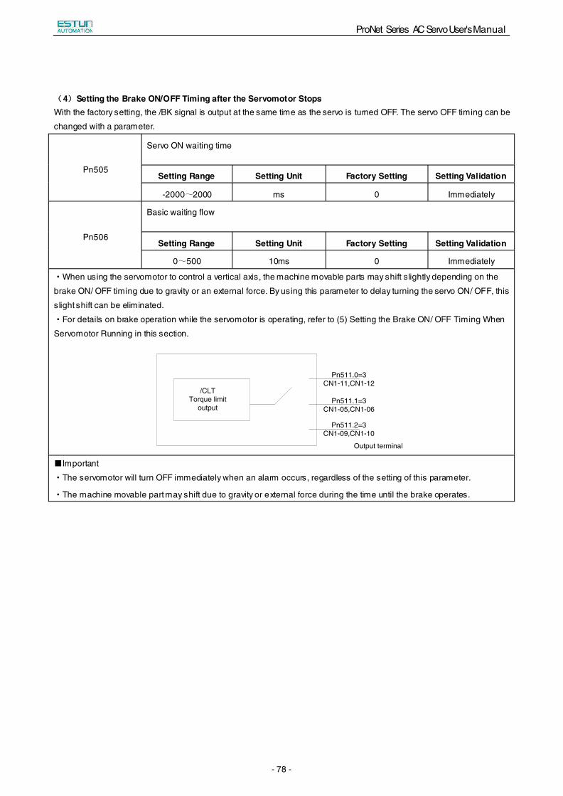
ProNet Series AC Servo User's Manual
- 78 -
(4)Setting the Brake ON/OFF Timing after the Servomotor Stops With the factory setting, the /BK signal is output at the same time as the servo is turned OFF. The servo OFF timing can be
changed with a parameter.
Pn505
Servo ON waiting time
Setting Range Setting Unit Factory Setting Setting Validation
-2000~2000 ms 0 Immediately
Pn506
Basic waiting flow
Setting Range Setting Unit Factory Setting Setting Validation
0~500 10ms 0 Immediately
·When using the servomotor to control a vertical axis, the machine movable parts may shift slightly depending on the
brake ON/ OFF timing due to gravity or an external force. By using this parameter to delay turning the servo ON/ OFF, this
slight shift can be eliminated.
·For details on brake operation while the servomotor is operating, refer to (5) Setting the Brake ON/ OFF Timing When
Servomotor Running in this section.
■Important
·The servomotor will turn OFF immediately when an alarm occurs, regardless of the setting of this parameter.
·The machine movable part may shift due to gravity or external force during the time until the brake operates.
/CLT Torque limit
output
Pn511.0=3 CN1-11,CN1-12
Pn511.1=3 CN1-05,CN1-06
Pn511.2=3 CN1-09,CN1-10
Output terminal
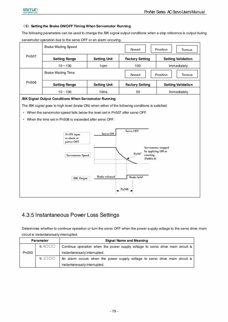
ProNet Series AC Servo User's Manual
- 79 -
(5)Setting the Brake ON/OFF Timing When Servomotor Running
The following parameters can be used to change the /BK signal output conditions when a stop reference is output during
servomotor operation due to the servo OFF or an alarm occuring.
Pn507
Brake Waiting Speed
Setting Range Setting Unit Factory Setting Setting Validation
10~100 1rpm 100 Immediately
Pn508
Brake Waiting Time
Setting Range Setting Unit Factory Setting Setting Validation
10~100 10ms 50 Immediately
/BK Signal Output Conditions When Servomotor Running
The /BK signal goes to high level (brake ON) when either of the following conditions is satisfied:
· When the servomotor speed falls below the level set in Pn507 after servo OFF.
· When the time set in Pn508 is exceeded after servo OFF.
4.3.5 Instantaneous Power Loss Settings
Determines whether to continue operation or turn the servo OFF when the power supply voltage to the servo drive main
circuit is instantaneously interrupted.
Parameter Signal Name and Meaning
Pn000
b.0□□□ Continue operation when the power supply voltage to servo drive main circuit is
instantaneously interrupted.
b.1□□□ An alarm occurs when the power supply voltage to servo drive main circuit is
instantaneously interrupted.
Speed Position Torque
Speed Position Torque
Pn508
Brake heldBrake released/BK Output
Servomotor Speed
/S-ON input or alarm or power OFF
Servo ONServo OFF
Servomotor stopped by applying DB or coasting.(Pn004.0)
Pn507
ProNet Series AC Servo User's Manual
- 80 -
4.4 Absolute Encoders
Absolute Encoder
Type Resolution
Output Range of
Multiturn Data Action when limit is exceeded
ProNet Series 16-bit/multiturn
17-bit/singleturn -32768~+32767
·When the upper limit (+32767)is exceeded in the
forward direction, the multiturn data is -32768·When the lower limit (-32768)is exceeded
in the reverse direction, the multiturn data is
+32767.
The absolute position can be read by the MODBUS protocol. In the actual control, the MODBUS protocol can read the
initial position when the servomotor is stopped (S-OFF), then the real-time position during the servomotor is running can
be found from the number of PG divided output pulses.
4.4.1 Selecting an Absolute Encoder
An absolute encoder can also be used as an incremental encoder.
Parameter Meaning
Pn002 b.□0□□ Use the absolute encoder as an absolute encoder. (Factory setting)
b.□1□□ Use the absolute encoder as an incremental encoder.
·The back-up battery is not required when using the absolute encoder as an incremental encoder.
·After changing these parameters, turn OFF the main circuit and control power supplies and then turn them ON
again to enable the new settings.
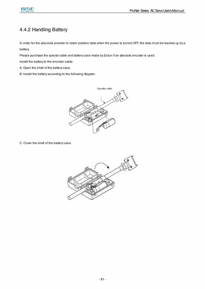
ProNet Series AC Servo User's Manual
- 81 -
4.4.2 Handling Battery
In order for the absolute encoder to retain position data when the power is turned OFF, the data must be backed up by a
battery.
Please purchase the special cable and battery case mabe by Estun if an absolute encoder is used.
Install the battary to the encoder cable:
A. Open the shell of the battery case.
B. Install the battery according to the following diagram.
Encoder cable
C. Cover the shell of the battery case.
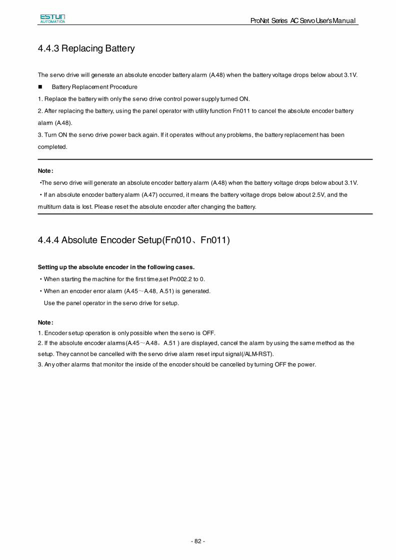
ProNet Series AC Servo User's Manual
- 82 -
4.4.3 Replacing Battery
The servo drive will generate an absolute encoder battery alarm (A.48) when the battery voltage drops below about 3.1V.
Battery Replacement Procedure
1. Replace the battery with only the servo drive control power supply turned ON.
2. After replacing the battery, using the panel operator with utility function Fn011 to cancel the absolute encoder battery
alarm (A.48).
3. Turn ON the servo drive power back again. If it operates without any problems, the battery replacement has been
completed.
Note:
·The servo drive will generate an absolute encoder battery alarm (A.48) when the battery voltage drops below about 3.1V.
·If an absolute encoder battery alarm (A.47) occurred, it means the battery voltage drops below about 2.5V, and the
multiturn data is lost. Please reset the absolute encoder after changing the battery.
4.4.4 Absolute Encoder Setup(Fn010、Fn011)
Setting up the absolute encoder in the following cases.
·When starting the machine for the first time,set Pn002.2 to 0.
·When an encoder error alarm (A.45~A.48, A.51) is generated.
Use the panel operator in the servo drive for setup.
Note:
1. Encoder setup operation is only possible when the servo is OFF.
2. If the absolute encoder alarms(A.45~A.48,A.51 ) are displayed, cancel the alarm by using the same method as the
setup. They cannot be cancelled with the servo drive alarm reset input signal(/ALM-RST).
3. Any other alarms that monitor the inside of the encoder should be cancelled by turning OFF the power.
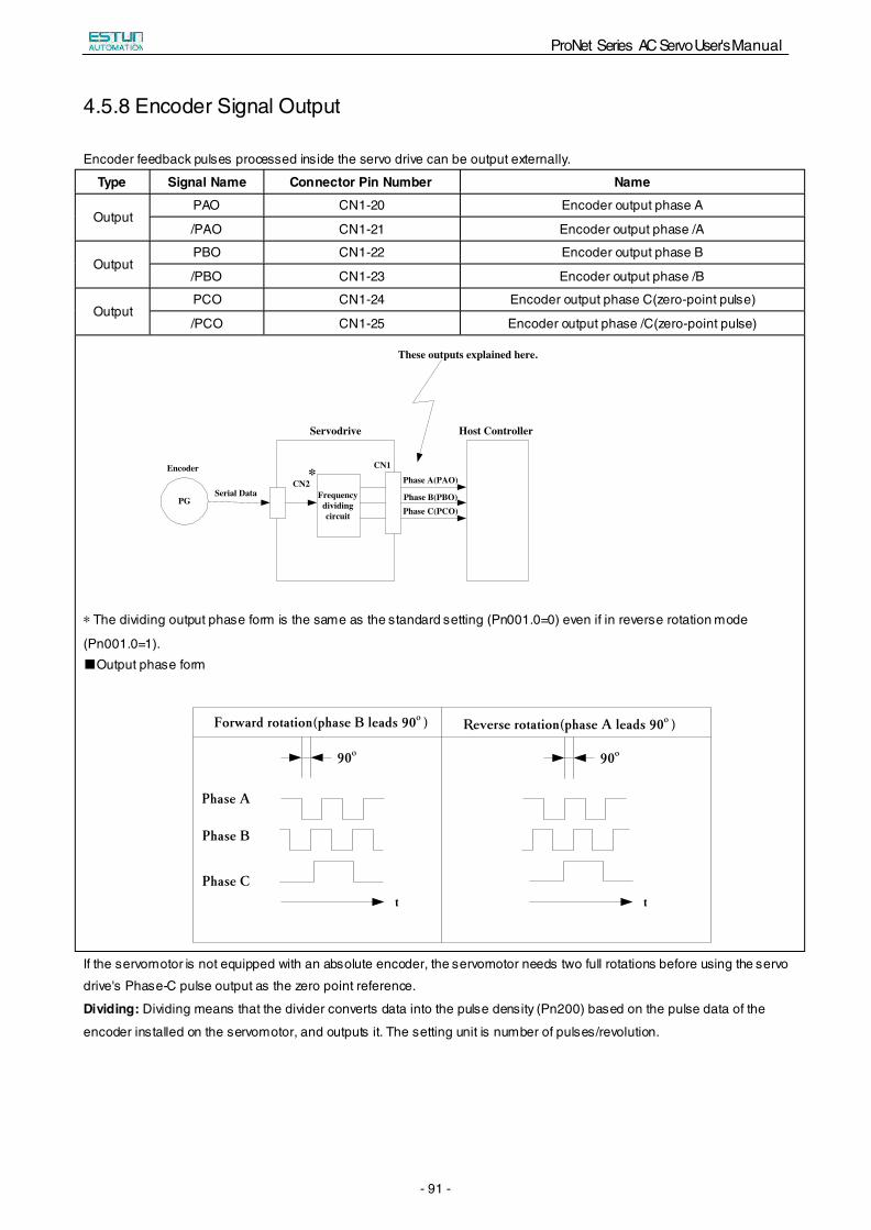
ProNet Series AC Servo User's Manual
- 91 -
4.5.8 Encoder Signal Output
Encoder feedback pulses processed inside the servo drive can be output externally.
Type Signal Name Connector Pin Number Name
Output PAO CN1-20 Encoder output phase A
/PAO CN1-21 Encoder output phase /A
Output PBO CN1-22 Encoder output phase B
/PBO CN1-23 Encoder output phase /B
Output PCO CN1-24 Encoder output phase C(zero-point pulse)
/PCO CN1-25 Encoder output phase /C(zero-point pulse)
Host Controller
PG
Encoder
Serial DataCN2
Frequency dividing circuit
CN1
Phase A(PAO)
Phase B(PBO)Phase C(PCO)
These outputs explained here.
*
Servodrive
* The dividing output phase form is the same as the standard setting (Pn001.0=0) even if in reverse rotation mode
(Pn001.0=1). ■Output phase form
Forward rotation(phase B leads 90º)
Phase A
Phase B
Phase C
Reverse rotation(phase A leads 90º)
90º
t t
90º
If the servomotor is not equipped with an absolute encoder, the servomotor needs two full rotations before using the servo
drive's Phase-C pulse output as the zero point reference.
Dividing: Dividing means that the divider converts data into the pulse density (Pn200) based on the pulse data of the
encoder installed on the servomotor, and outputs it. The setting unit is number of pulses/revolution.
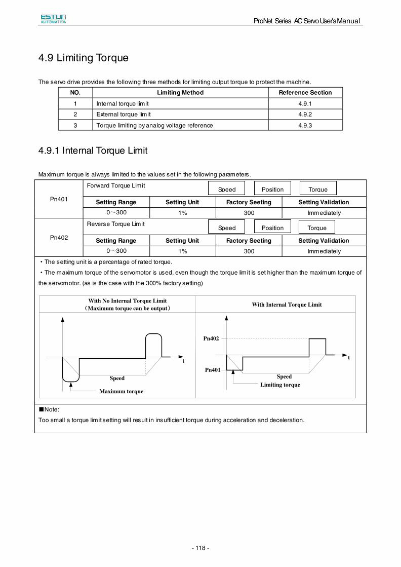
ProNet Series AC Servo User's Manual
- 118 -
4.9 Limiting Torque
The servo drive provides the following three methods for limiting output torque to protect the machine.
NO. Limiting Method Reference Section
1 Internal torque limit 4.9.1
2 External torque limit 4.9.2
3 Torque limiting by analog voltage reference 4.9.3
4.9.1 Internal Torque Limit
Maximum torque is always limited to the values set in the following parameters.
Pn401
Forward Torque Limit
Setting Range Setting Unit Factory Seeting Setting Validation 0~300 1% 300 Immediately
Pn402
Reverse Torque Limit
Setting Range Setting Unit Factory Seeting Setting Validation 0~300 1% 300 Immediately
·The setting unit is a percentage of rated torque.
·The maximum torque of the servomotor is used, even though the torque limit is set higher than the maximum torque of
the servomotor. (as is the case with the 300% factory setting)
t
Speed
Maximum torque
t
SpeedLimiting torque
Pn402
Pn401
With No Internal Torque Limit(Maximum torque can be output) With Internal Torque Limit
■Note:
Too small a torque limit setting will result in insufficient torque during acceleration and deceleration.
Position TorqueSpeed
Position TorqueSpeed
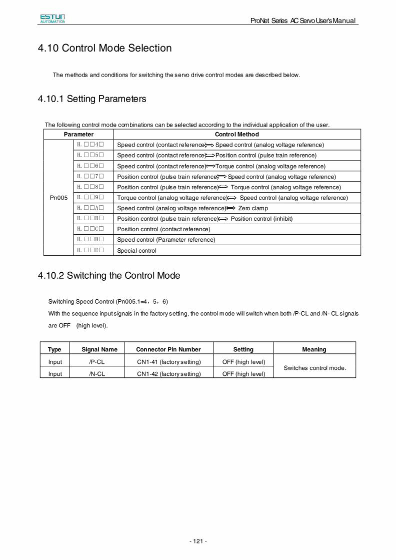
ProNet Series AC Servo User's Manual
- 121 -
4.10 Control Mode Selection
The methods and conditions for switching the servo drive control modes are described below.
4.10.1 Setting Parameters
The following control mode combinations can be selected according to the individual application of the user. Parameter Control Method
Pn005
H.□□4□ Speed control (contact reference) Speed control (analog voltage reference)
H.□□5□ Speed control (contact reference) Position control (pulse train reference)
H.□□6□ Speed control (contact reference) Torque control (analog voltage reference)
H.□□7□ Position control (pulse train reference) Speed control (analog voltage reference)
H.□□8□ Position control (pulse train reference) Torque control (analog voltage reference)
H.□□9□ Torque control (analog voltage reference) Speed control (analog voltage reference)
H.□□A□ Speed control (analog voltage reference) Zero clamp
H.□□B□ Position control (pulse train reference) Position control (inhibit)
H.□□C□ Position control (contact reference)
H.□□D□ Speed control (Parameter reference)
H.□□E□ Special control
4.10.2 Switching the Control Mode
Switching Speed Control (Pn005.1=4,5,6)
With the sequence input signals in the factory setting, the control mode will switch when both /P-CL and /N- CL signals
are OFF (high level).
Type Signal Name Connector Pin Number Setting Meaning
Input /P-CL CN1-41 (factory setting) OFF (high level) Switches control mode.
Input /N-CL CN1-42 (factory setting) OFF (high level)
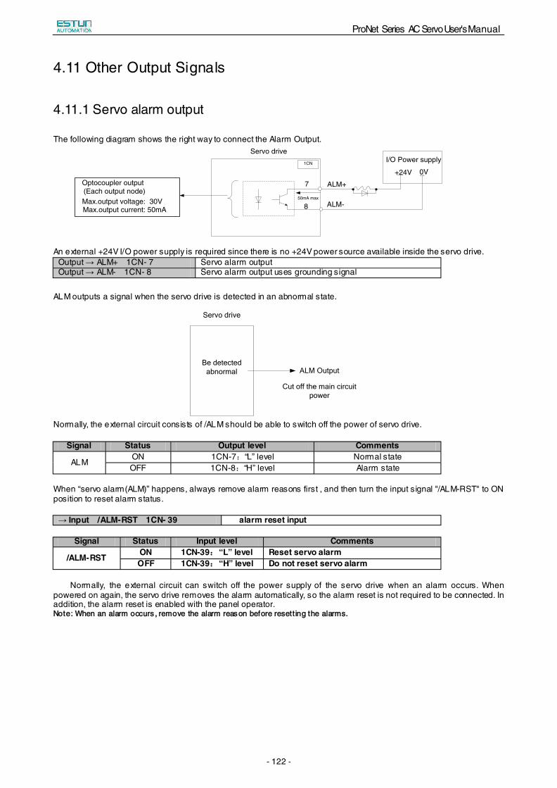
ProNet Series AC Servo User's Manual
- 122 -
4.11 Other Output Signals
4.11.1 Servo alarm output
The following diagram shows the right way to connect the Alarm Output.
I/O Power supply
+24V
Servo drive
7
8
ALM+
ALM-
0V1CN
50mA max
Optocoupler output(Each output node)Max.output voltage: 30VMax.output current: 50mA
An external +24V I/O power supply is required since there is no +24V power source available inside the servo drive. Output → ALM+ 1CN- 7 Servo alarm outputOutput → ALM- 1CN- 8 Servo alarm output uses grounding signal
ALM outputs a signal when the servo drive is detected in an abnormal state.
Be detected abnormal
Servo drive
ALM Output
Cut off the main circuit power
Normally, the external circuit consists of /ALM should be able to switch off the power of servo drive.
Signal Status Output level Comments
ALM ON 1CN-7:“L” level Normal stateOFF 1CN-8:“H” level Alarm state
When “servo alarm(ALM)” happens, always remove alarm reasons first , and then turn the input signal "/ALM-RST" to ON position to reset alarm status.
→ Input /ALM-RST 1CN- 39 alarm reset input
Signal Status Input level Comments
/ALM-RST ON 1CN-39:“L” level Reset servo alarmOFF 1CN-39:“H” level Do not reset servo alarm
Normally, the external circuit can switch off the power supply of the servo drive when an alarm occurs. When powered on again, the servo drive removes the alarm automatically, so the alarm reset is not required to be connected. In addition, the alarm reset is enabled with the panel operator. NNoottee:: WWhheenn aann aallaarrmm ooccccuurrss ,, rreemmoovvee tthhee aallaarrmm rreeaassoonn bbeeffoorree rreesseetttt iinngg tthhee aallaarrmmss..
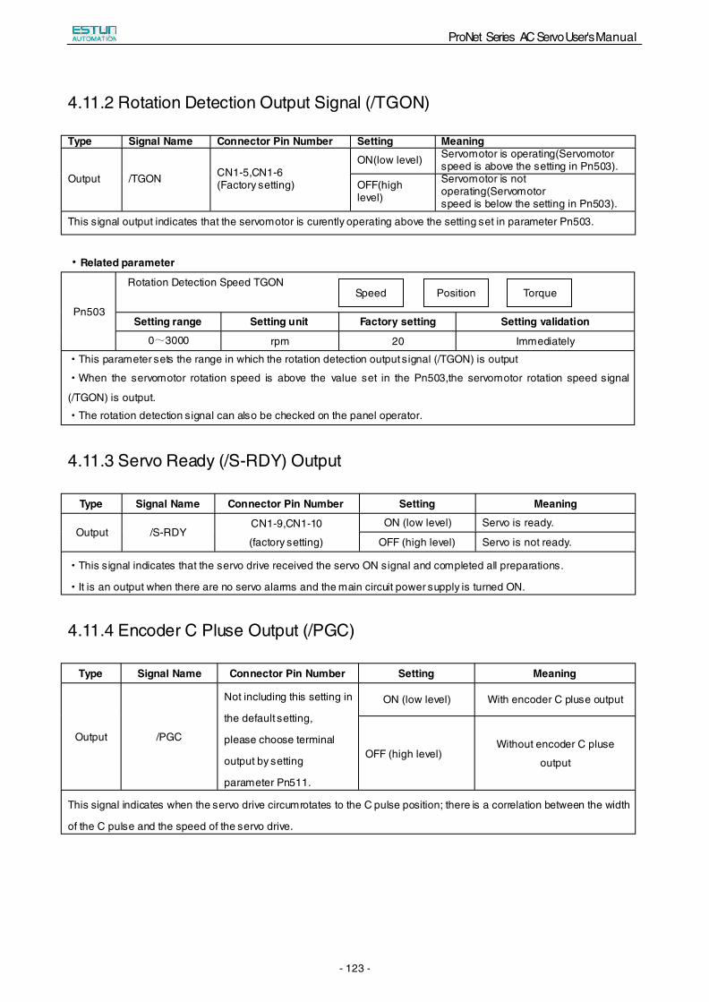
ProNet Series AC Servo User's Manual
- 123 -
4.11.2 Rotation Detection Output Signal (/TGON)
Type Signal Name Connector Pin Number Setting Meaning
Output /TGON CN1-5,CN1-6 (Factory setting)
ON(low level) Servomotor is operating(Servomotorspeed is above the setting in Pn503).
OFF(high level)
Servomotor is notoperating(Servomotor speed is below the setting in Pn503).
This signal output indicates that the servomotor is curently operating above the setting set in parameter Pn503.
·Related parameter
Pn503
Rotation Detection Speed TGON
Setting range Setting unit Factory setting Setting validation
0~3000 rpm 20 Immediately
·This parameter sets the range in which the rotation detection output signal (/TGON) is output
·When the servomotor rotation speed is above the value set in the Pn503,the servomotor rotation speed signal
(/TGON) is output.
·The rotation detection signal can also be checked on the panel operator.
4.11.3 Servo Ready (/S-RDY) Output
Type Signal Name Connector Pin Number Setting Meaning
Output /S-RDY CN1-9,CN1-10
(factory setting)
ON (low level) Servo is ready.
OFF (high level) Servo is not ready.
·This signal indicates that the servo drive received the servo ON signal and completed all preparations.
·It is an output when there are no servo alarms and the main circuit power supply is turned ON.
4.11.4 Encoder C Pluse Output (/PGC)
Type Signal Name Connector Pin Number Setting Meaning
Output /PGC
Not including this setting in
the default setting,
please choose terminal
output by setting
parameter Pn511.
ON (low level) With encoder C pluse output
OFF (high level) Without encoder C pluse
output
This signal indicates when the servo drive circumrotates to the C pulse position; there is a correlation between the width
of the C pulse and the speed of the servo drive.
Position Torque Speed
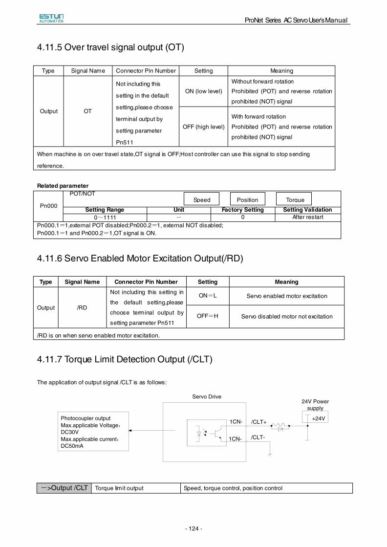
ProNet Series AC Servo User's Manual
- 124 -
4.11.5 Over travel signal output (OT)
Type Signal Name Connector Pin Number Setting Meaning
Output OT
Not including this
setting in the default
setting,please choose
terminal output by
setting parameter
Pn511
ON (low level)
Without forward rotation
Prohibited (POT) and reverse rotation
prohibited (NOT) signal
OFF (high level)
With forward rotation
Prohibited (POT) and reverse rotation
prohibited (NOT) signal
When machine is on over travel state,OT signal is OFF;Host controller can use this signal to stop sending
reference.
Related parameter
Pn000
POT/NOT
Setting Range Unit Factory Setting Setting Validation0~1111 - 0 After restart
Pn000.1=1,external POT disabled;Pn000.2=1, external NOT disabled;Pn000.1=1 and Pn000.2=1,OT signal is ON.
4.11.6 Servo Enabled Motor Excitation Output(/RD)
Type Signal Name Connector Pin Number Setting Meaning
Output /RD
Not including this setting in
the default setting,please
choose terminal output by
setting parameter Pn511
ON=L Servo enabled motor excitation
OFF=H Servo disabled motor not excitation
/RD is on when servo enabled motor excitation.
4.11.7 Torque Limit Detection Output (/CLT)
The application of output signal /CLT is as follows:
->Output /CLT Torque limit output Speed, torque control, position control
Position TorqueSpeed
24V Power supply
+24V
Servo Drive
1CN-
1CN-
/CLT+
/CLT-
Photocoupler outputMax.applicable Voltage:DC30VMax.applicable current:DC50mA
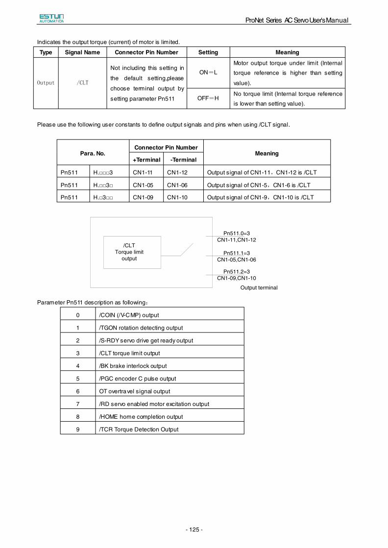
ProNet Series AC Servo User's Manual
- 125 -
Indicates the output torque (current) of motor is limited.
Type Signal Name Connector Pin Number Setting Meaning
Output /CLT
Not including this setting in
the default setting,please
choose terminal output by
setting parameter Pn511
ON=L Motor output torque under limit (Internal
torque reference is higher than setting
value).
OFF=H No torque limit (Internal torque reference
is lower than setting value).
Please use the following user constants to define output signals and pins when using /CLT signal.
Para. No. Connector Pin Number
Meaning +Terminal -Terminal
Pn511 H.□□□3 CN1-11 CN1-12 Output signal of CN1-11,CN1-12 is /CLT
Pn511 H.□□3□ CN1-05 CN1-06 Output signal of CN1-5,CN1-6 is /CLT
Pn511 H.□3□□ CN1-09 CN1-10 Output signal of CN1-9,CN1-10 is /CLT
Parameter Pn511 description as following:
0 /COIN (/V-CMP) output
1 /TGON rotation detecting output
2 /S-RDY servo drive get ready output
3 /CLT torque limit output
4 /BK brake interlock output
5 /PGC encoder C pulse output
6 OT overtravel signal output
7 /RD servo enabled motor excitation output
8 /HOME home completion output
9 /TCR Torque Detection Output
/CLT Torque limit
output
Pn511.0=3 CN1-11,CN1-12
Pn511.1=3 CN1-05,CN1-06
Pn511.2=3 CN1-09,CN1-10
Output terminal
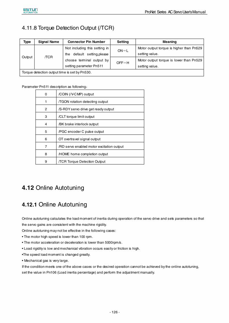
ProNet Series AC Servo User's Manual
- 126 -
4.11.8 Torque Detection Output (/TCR)
Type Signal Name Connector Pin Number Setting Meaning
Output /TCR
Not including this setting in
the default setting,please
choose terminal output by
setting parameter Pn511
ON=L Motor output torque is higher than Pn529
setting value.
OFF=H Motor output torque is lower than Pn529
setting value.
Torque detection output time is set by Pn530.
Parameter Pn511 description as following:
0 /COIN (/V-CMP) output
1 /TGON rotation detecting output
2 /S-RDY servo drive get ready output
3 /CLT torque limit output
4 /BK brake interlock output
5 /PGC encoder C pulse output
6 OT overtravel signal output
7 /RD servo enabled motor excitation output
8 /HOME home completion output
9 /TCR Torque Detection Output
4.12 Online Autotuning
4.12.1 Online Autotuning
Online autotuning calculates the load moment of inertia during operation of the servo drive and sets parameters so that
the servo gains are consistent with the machine rigidity.
Online autotuning may not be effective in the following cases:
• The motor high speed is lower than 100 rpm.
• The motor acceleration or deceleration is lower than 5000rpm/s.
• Load rigidity is low and mechanical vibration occurs easily or friction is high.
•The speed load moment is changed greatly.
• Mechanical gas is very large.
If the condition meets one of the above cases or the desired operation cannot be achieved by the online autotuning,
set the value in Pn106 (Load inertia percentage) and perform the adjustment manually.

ProNet Series AC Servo User's Manual
- 127 -
4.12.2 Online Autotuning Procedure
!WARNING
■Do not perform extreme adjustment or setting changes causing unstable servo operation.Failure to observe
this warning may result in injury and damages to the machine.
■ Adjust the gains slowly while confirming motor operation.
Start
Operate with factor setting.(Set Pn100=1)
Operation OK?
Continuous online autotuning(Pn100=1、2、3、4、5、6)
Operation OK?
Adjust the machine rigidity setting(Set at Pn101)
Operation OK?
Do not perform online autotuning.(Set Pn100=0)
End
Yes
No
No
No
No
Yes
Yes
Yes
Load moment of inertia varies?
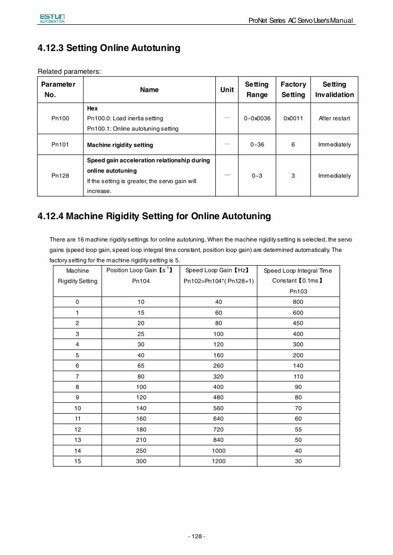
ProNet Series AC Servo User's Manual
- 128 -
4.12.3 Setting Online Autotuning
Related parameters:
Parameter No.
Name Unit Setting Range
Factory Setting
Setting Invalidation
Pn100
Hex Pn100.0: Load inertia setting
Pn100.1: Online autotuning setting
� 0~0x0036 0x0011 After restart
Pn101 Machine rigidity setting � 0~36 6 Immediately
Pn128
Speed gain acceleration relationship during
online autotuning
If the setting is greater, the servo gain will
increase.
� 0~3 3 Immediately
4.12.4 Machine Rigidity Setting for Online Autotuning
There are 16 machine rigidity settings for online autotuning, When the machine rigidity setting is selected, the servo
gains (speed loop gain, speed loop integral time constant, position loop gain) are determined automatically. The
factory setting for the machine rigidity setting is 5.
Machine
Rigidity Setting
Position Loop Gain【s-1 Speed Loop Gain【Hz】
Pn102=Pn104*( Pn128+1)
】
Pn104
Speed Loop Integral Time
Constant【0.1ms】
Pn103
0 10 40 800
1 15 60 600
2 20 80 450
3 25 100 400
4 30 120 300
5 40 160 200
6 65 260 140
7 80 320 110
8 100 400 90
9 120 480 80
10 140 560 70
11 160 640 60
12 180 720 55
13 210 840 50
14 250 1000 40
15 300 1200 30
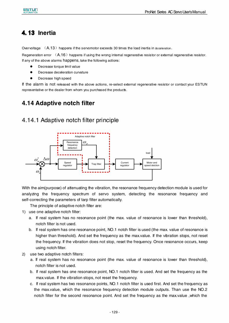
ProNet Series AC Servo User's Manual
- 129 -
44..1133 Inertia
Overvoltage (A.13)happens if the servomotor exceeds 30 times the load inertia in acceleration。
Regeneration error (A.16)happens if using the wrong internal regenerative resistor or external regenerative resistor. If any of the above alarms happens, take the following actions:
Decrease torque limit value
Decrease deceleration curvature
Decrease high speed
If the alarm is not released with the above actions, re-select external regenerative resistor or contact your ESTUN representative or the dealer from whom you purchased the products.
4.14 Adaptive notch filter
4.14.1 Adaptive notch filter principle
mω∗
Speed regulator
Current regulator
Motor and speed detction
mω
ω∆
pω
load
Adaptive notch filter
Resonance frequency detection
Trap filter
With the aim(purpose) of attenuating the vibration, the resonance frequency detection module is used for analyzing the frequency spectrum of servo system, detecting the resonance frequency and self-correcting the parameters of tarp filter automatically.
The principle of adaptive notch filter are: 1) use one adaptive notch filter:
a. If real system has no resonance point (the max. value of resonance is lower than threshold), notch filter is not used.
b. If real system has one resonance point, NO.1 notch filter is used (the max. value of resonance is higher than threshold). And set the frequency as the max.value. If the vibration stops, not reset the frequency. If the vibration does not stop, reset the frequency. Once resonance occurs, keep using notch filter.
2) use two adaptive notch filters:a. If real system has no resonance point (the max. value of resonance is lower than threshold),
notch filter is not used. b. If real system has one resonance point, NO.1 notch filter is used. And set the frequency as the
max.value. If the vibration stops, not reset the frequency. c. If real system has two resonance points, NO.1 notch filter is used first. And set the frequency as
the max.value, which the resonance frequency detection module outputs. Than use the NO.2 notch filter for the second resonance point. And set the frequency as the max.value ,which the
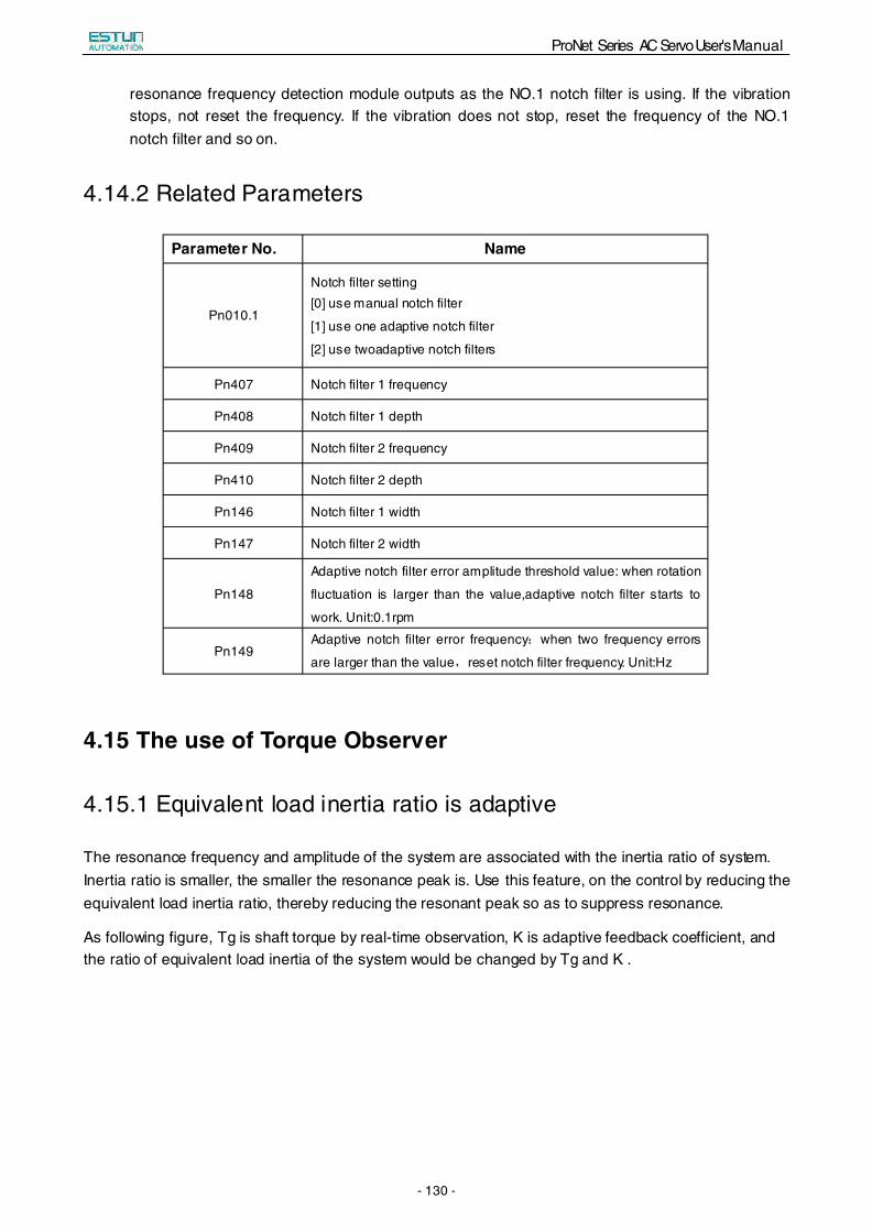
ProNet Series AC Servo User's Manual
- 130 -
resonance frequency detection module outputs as the NO.1 notch filter is using. If the vibration stops, not reset the frequency. If the vibration does not stop, reset the frequency of the NO.1 notch filter and so on.
4.14.2 Related Parameters
Parameter No. Name
Pn010.1
Notch filter setting [0] use manual notch filter
[1] use one adaptive notch filter
[2] use twoadaptive notch filters
Pn407 Notch filter 1 frequency
Pn408 Notch filter 1 depth
Pn409 Notch filter 2 frequency
Pn410 Notch filter 2 depth
Pn146 Notch filter 1 width
Pn147 Notch filter 2 width
Pn148
Adaptive notch filter error amplitude threshold value: when rotation
fluctuation is larger than the value,adaptive notch filter starts to
work. Unit:0.1rpm
Pn149 Adaptive notch filter error frequency:when two frequency errors
are larger than the value,reset notch filter frequency. Unit:Hz
4.15 The use of Torque Observer
4.15.1 Equivalent load inertia ratio is adaptive
The resonance frequency and amplitude of the system are associated with the inertia ratio of system. Inertia ratio is smaller, the smaller the resonance peak is. Use this feature, on the control by reducing the equivalent load inertia ratio, thereby reducing the resonant peak so as to suppress resonance.
As following figure, Tg is shaft torque by real-time observation, K is adaptive feedback coefficient, and the ratio of equivalent load inertia of the system would be changed by Tg and K .
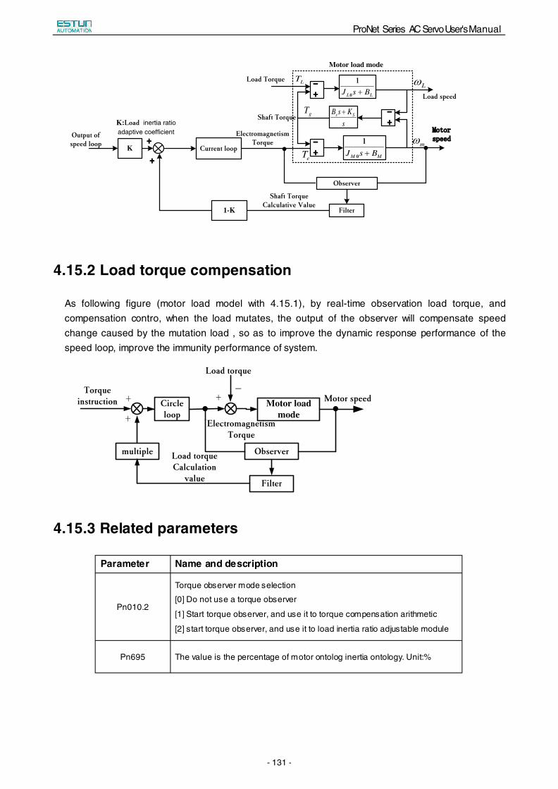
ProNet Series AC Servo User's Manual
- 131 -
K Current loop
sKsB Ss +
LL BsJ +0
1
MM BsJ +0
1
--++
mω
Lω--++
--++
gT
Motor load mode
Observer
Filter
Shaft TorqueCalculative Value
1-K
K:Load inertia ratio adaptive coefficient
++
++
Output of speed loop
Electromagnetism Torque
Load Torque
MMoottoorrssppeeeedd
Load speed
LT
eT
Shaft Torque
4.15.2 Load torque compensation
As following figure (motor load model with 4.15.1), by real-time observation load torque, and compensation contro, when the load mutates, the output of the observer will compensate speed change caused by the mutation load , so as to improve the dynamic response performance of the speed loop, improve the immunity performance of system.
Motor load mode
Observer
Motor speedTorque
instruction
Load torque
multiple
Filter
Electromagnetism Torque
+
+
+−
Circle loop
Load torque Calculation
value
4.15.3 Related parameters
Parameter Name and description
Pn010.2
Torque observer mode selection
[0] Do not use a torque observer
[1] Start torque observer, and use it to torque compensation arithmetic
[2] start torque observer, and use it to load inertia ratio adjustable module
Pn695 The value is the percentage of motor ontolog inertia ontology. Unit:%

ProNet Series AC Servo User's Manual
- 132 -
Pn696
1, 2, 3 gears are feedback coefficients of
observed shaft torque
The higher the gear, the more real-time observation , but the greater the
observation noise.
When the moment of inertia is larger, can use 2;
The moment of inertia is big and system of rigid, can use 3;
Small inertia, 2 ,3 gears shall not apply
4, 5, 6 gears are feedback coefficients of observed load torque
The higher the gear, the more real-time observation, but the greater the
observation noise.
When the moment of inertia is larger, can use 5;
The moment of inertia is big and system of rigid ,can use 6;
Small inertia, 5, and 6 gears shall not apply.
Pn697 The greater the low-pass filter time constant, the more you delay
Pn698 The compensation coefficient of observed disturber torque, the greater the
value, the more obvious the compensation effect. Unit:%
Pn699
The ration of Dummy load inertia ratio and Actual load inertia ratio, the
smaller the ratio of system, the better the effect of vibration suppression, but
the worse dynamic response performance, can take 50% then they can be
adjusted up and down.
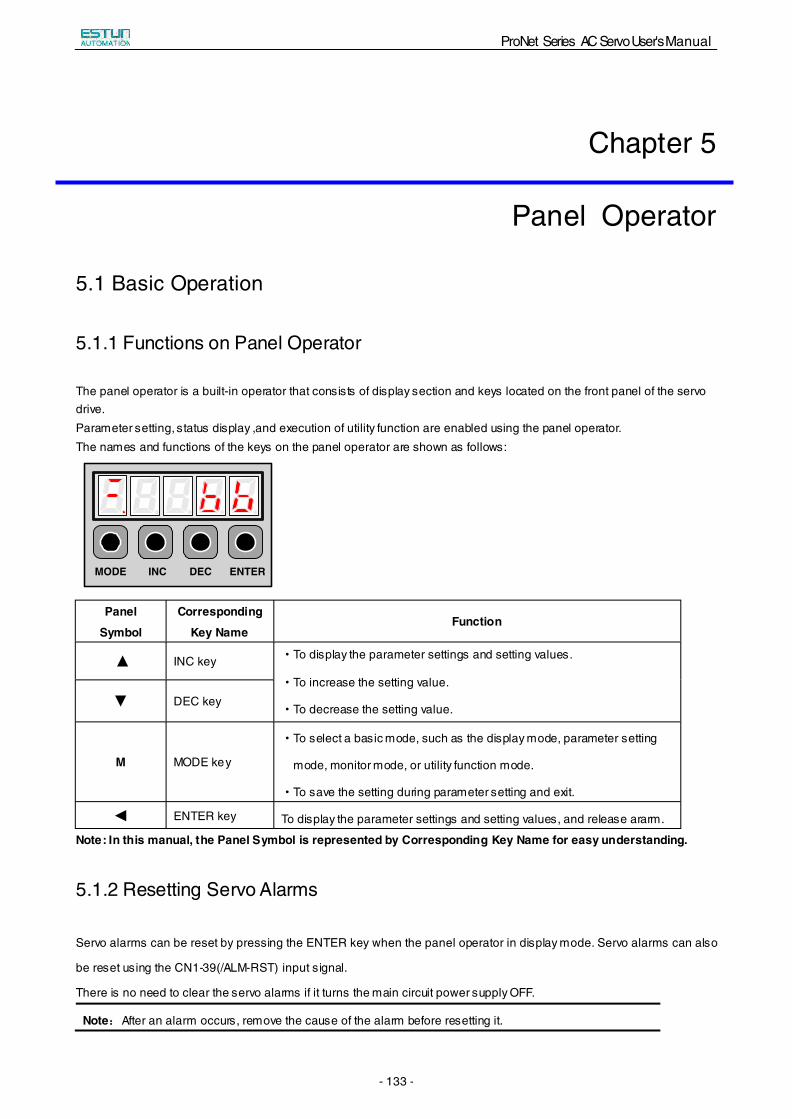
ProNet Series AC Servo User's Manual
- 133 -
Chapter 5
Panel Operator
5.1 Basic Operation
5.1.1 Functions on Panel Operator
The panel operator is a built-in operator that consists of display section and keys located on the front panel of the servo drive. Parameter setting, status display ,and execution of utility function are enabled using the panel operator. The names and functions of the keys on the panel operator are shown as follows:
MODE INC DEC ENTER
Note: In this manual, the Panel Symbol is represented by Corresponding Key Name for easy understanding.
5.1.2 Resetting Servo Alarms
Servo alarms can be reset by pressing the ENTER key when the panel operator in display mode. Servo alarms can also
be reset using the CN1-39(/ALM-RST) input signal.
There is no need to clear the servo alarms if it turns the main circuit power supply OFF.
Note:After an alarm occurs, remove the cause of the alarm before resetting it.
Panel
Symbol
Corresponding
Key Name Function
▲ INC key ·To display the parameter settings and setting values.
·To increase the setting value.
·To decrease the setting value.▼ DEC key
M MODE key
·To select a basic mode, such as the display mode, parameter setting
mode, monitor mode, or utility function mode.
·To save the setting during parameter setting and exit.
◄ ENTER key To display the parameter settings and setting values, and release ararm.
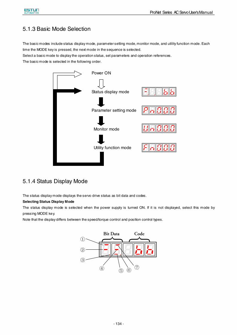
ProNet Series AC Servo User's Manual
- 134 -
5.1.3 Basic Mode Selection
The basic modes include status display mode, parameter setting mode, monitor mode, and utility function mode. Each
time the MODE key is pressed, the next mode in the sequence is selected.
Select a basic mode to display the operation status, set parameters and operation references.
The basic mode is selected in the following order.
Power ON
Status display mode
Parameter setting mode
Monitor mode
Utility function mode
5.1.4 Status Display Mode
The status display mode displays the servo drive status as bit data and codes.
Selecting Status Display Mode The status display mode is selected when the power supply is turned ON. If it is not displayed, select this mode by
pressing MODE key.
Note that the display differs between the speed/torque control and position control types. { {
Bit Data Code
⑦
①
②
③
④ ⑤ ⑥
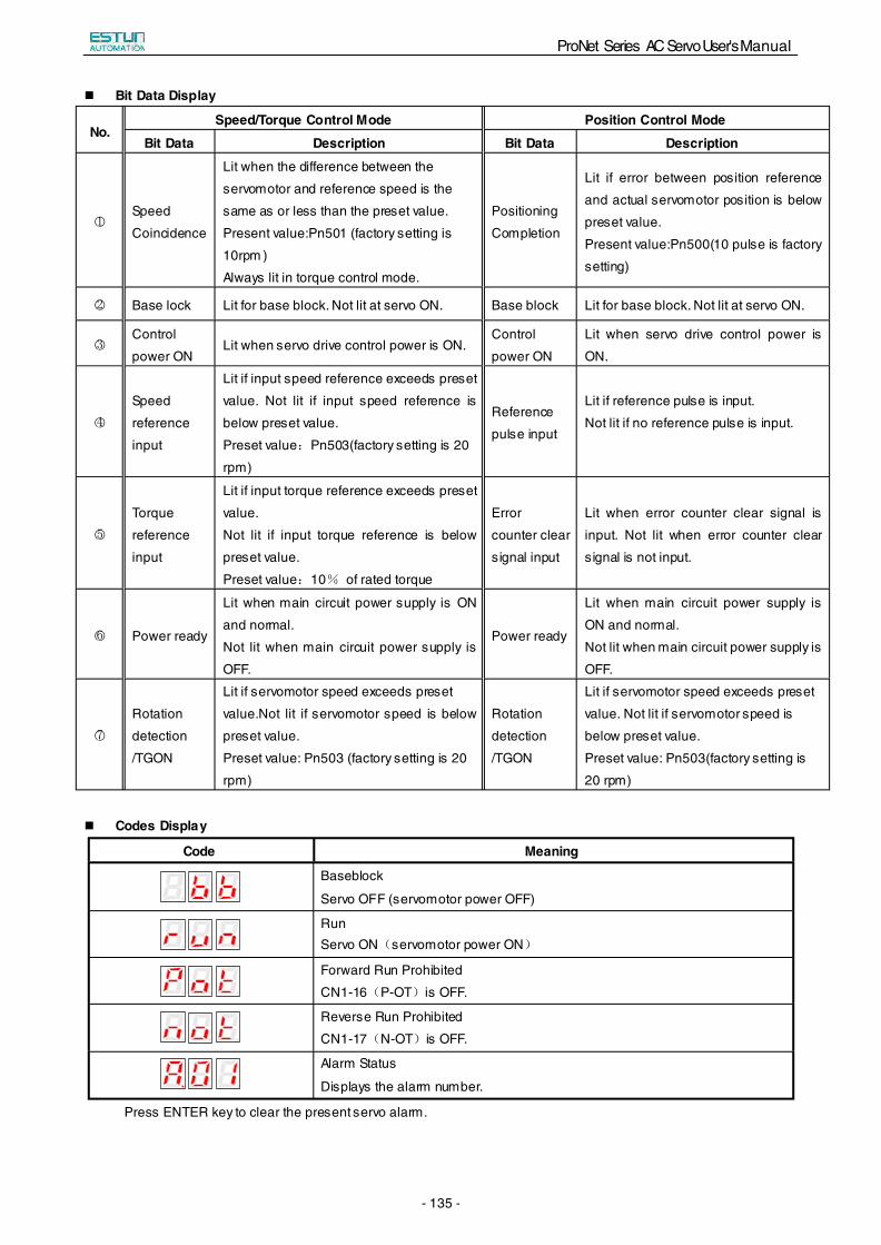
ProNet Series AC Servo User's Manual
- 135 -
Bit Data Display
No. Speed/Torque Control Mode Position Control Mode
Bit Data Description Bit Data Description
○1Speed
Coincidence
Lit when the difference between the
servomotor and reference speed is the
same as or less than the preset value.
Present value:Pn501 (factory setting is
10rpm
Positioning
Completion
)
Always lit in torque control mode.
Lit if error between position reference
and actual servomotor position is below
preset value.
Present value:Pn500(10 pulse is factory
setting)
○2 Base lock Lit for base block. Not lit at servo ON. Base block Lit for base block. Not lit at servo ON.
○3Control
power ON Lit when servo drive control power is ON.
Control
power ON
Lit when servo drive control power is
ON.
○4
Speed
reference
input
Lit if input speed reference exceeds preset
value. Not lit if input speed reference is
below preset value.
Preset value:Pn503(factory setting is 20
rpm)
Reference
pulse input
Lit if reference pulse is input.
Not lit if no reference pulse is input.
○5
Torque
reference
input
Lit if input torque reference exceeds preset
value.
Not lit if input torque reference is below
preset value.
Preset value:10% of rated torque
Error
counter clear
signal input
Lit when error counter clear signal is
input. Not lit when error counter clear
signal is not input.
○6 Power ready
Lit when main circuit power supply is ON
and normal.
Not lit when main circuit power supply is
OFF.
Power ready
Lit when main circuit power supply is
ON and normal.
Not lit when main circuit power supply is
OFF.
○7
Rotation
detection
/TGON
Lit if servomotor speed exceeds preset
value.Not lit if servomotor speed is below
preset value.
Preset value: Pn503 (factory setting is 20
rpm)
Rotation
detection
/TGON
Lit if servomotor speed exceeds preset
value. Not lit if servomotor speed is
below preset value.
Preset value: Pn503(factory setting is
20 rpm)
Codes Display
Code Meaning
Baseblock
Servo OFF (servomotor power OFF)
Run Servo ON(servomotor power ON)
Forward Run Prohibited
CN1-16(P-OT)is OFF.
Reverse Run Prohibited
CN1-17(N-OT)is OFF.
Alarm Status
Displays the alarm number.
Press ENTER key to clear the present servo alarm.
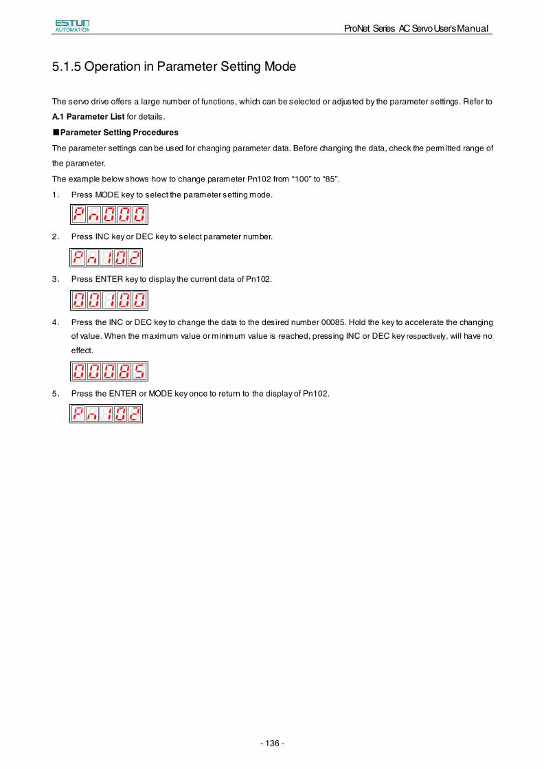
ProNet Series AC Servo User's Manual
- 136 -
5.1.5 Operation in Parameter Setting Mode
The servo drive offers a large number of functions, which can be selected or adjusted by the parameter settings. Refer to
A.1 Parameter List for details.
■Parameter Setting Procedures
The parameter settings can be used for changing parameter data. Before changing the data, check the permitted range of
the parameter.
The example below shows how to change parameter Pn102 from “100” to “85”.
1. Press MODE key to select the parameter setting mode.
2. Press INC key or DEC key to select parameter number.
3. Press ENTER key to display the current data of Pn102.
4. Press the INC or DEC key to change the data to the desired number 00085. Hold the key to accelerate the changing
of value. When the maximum value or minimum value is reached, pressing INC or DEC key respectively, will have no
effect.
5. Press the ENTER or MODE key once to return to the display of Pn102.

ProNet Series AC Servo User's Manual
- 137 -
5.1.6 Operation in Monitor Mode
The monitor mode allows the reference values input into the servo drive, I/O signal status, and servo drive internal status
to be monitored.
■Using the Monitor Mode
The example below shows how to display the value (1500) stored in Un001.
1.Press MODE key to select the monitor mode.
2.Press the INC or DEC key to select the monitor number to display.
3.Press the ENTER key to display the data for the monitor number selected at step 2.
4.Press the ENTER key once more to return to the monitor number display.
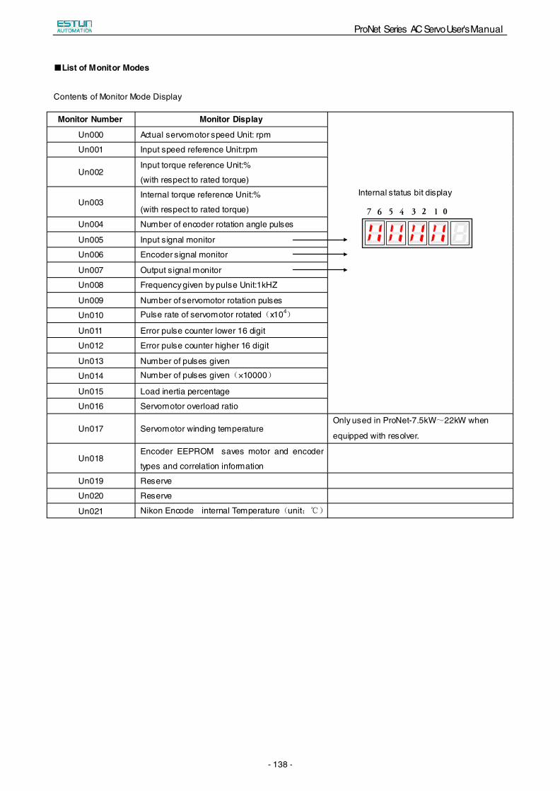
ProNet Series AC Servo User's Manual
- 138 -
■List of Monitor Modes
Contents of Monitor Mode Display
Monitor Number Monitor Display
Internal status bit display
Un000 Actual servomotor speed Unit: rpm
Un001 Input speed reference Unit:rpm
Un002 Input torque reference Unit:%
(with respect to rated torque)
Un003 Internal torque reference Unit:%
(with respect to rated torque)
Un004 Number of encoder rotation angle pulses
Un005 Input signal monitor
Un006 Encoder signal monitor
Un007 Output signal monitor
Un008 Frequency given by pulse Unit:1kHZ
Un009 Number of servomotor rotation pulses
Un010 Pulse rate of servomotor rotated(x104)
Un011 Error pulse counter lower 16 digit
Un012 Error pulse counter higher 16 digit
Un013 Number of pulses given
Un014 Number of pulses given(×10000)
Un015 Load inertia percentage
Un016 Servomotor overload ratio
Un017 Servomotor winding temperature Only used in ProNet-7.5kW~22kW when
equipped with resolver.
Un018 Encoder EEPROM saves motor and encoder
types and correlation information
Un019 Reserve
Un020 Reserve
Un021 Nikon Encode internal Temperature(unit:℃)
01234567
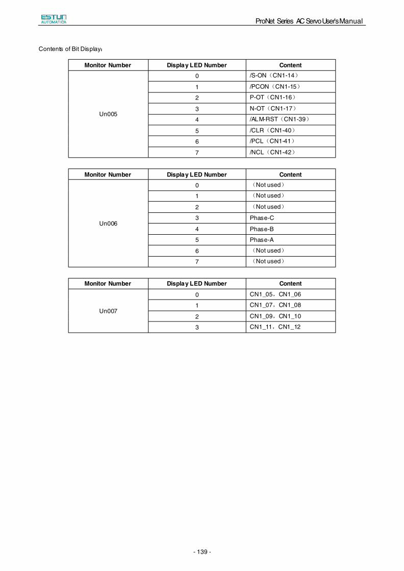
ProNet Series AC Servo User's Manual
- 139 -
Contents of Bit Display:
Monitor Number Display LED Number Content
Un005
0 /S-ON(CN1-14)
1 /PCON(CN1-15)
2 P-OT(CN1-16)
3 N-OT(CN1-17)
4 /ALM-RST(CN1-39)
5 /CLR(CN1-40)
6 /PCL(CN1-41)
7 /NCL(CN1-42)
Monitor Number Display LED Number Content
Un006
0 (Not used)
1 (Not used)
2 (Not used)
3 Phase-C
4 Phase-B
5 Phase-A
6 (Not used)
7 (Not used)
Monitor Number Display LED Number Content
Un007
0 CN1_05,CN1_06
1 CN1_07,CN1_08
2 CN1_09,CN1_10
3 CN1_11,CN1_12
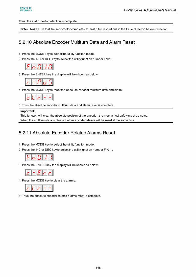
ProNet Series AC Servo User's Manual
- 148 -
Thus, the static inertia detection is complete.
Note:Make sure that the servomotor completes at least 6 full revolutions in the CCW direction before detection.
5.2.10 Absolute Encoder Multiturn Data and Alarm Reset
1. Press the MODE key to select the utility function mode.
2. Press the INC or DEC key to select the utility function number Fn010.
3. Press the ENTER key, the display will be shown as below.
4. Press the MODE key to reset the absolute encoder multiturn data and alarm.
5. Thus the absolute encoder multiturn data and alarm reset is complete.
Important: This function will clear the absolute position of the encoder; the mechanical safety must be noted. When the multiturn data is cleared, other encoder alarms will be reset at the same time.
5.2.11 Absolute Encoder Related Alarms Reset
1. Press the MODE key to select the utility function mode.
2. Press the INC or DEC key to select the utility function number Fn011.
3. Press the ENTER key, the display will be shown as below.
4. Press the MODE key to clear the alarms.
5. Thus the absolute encoder related alarms reset is complete.
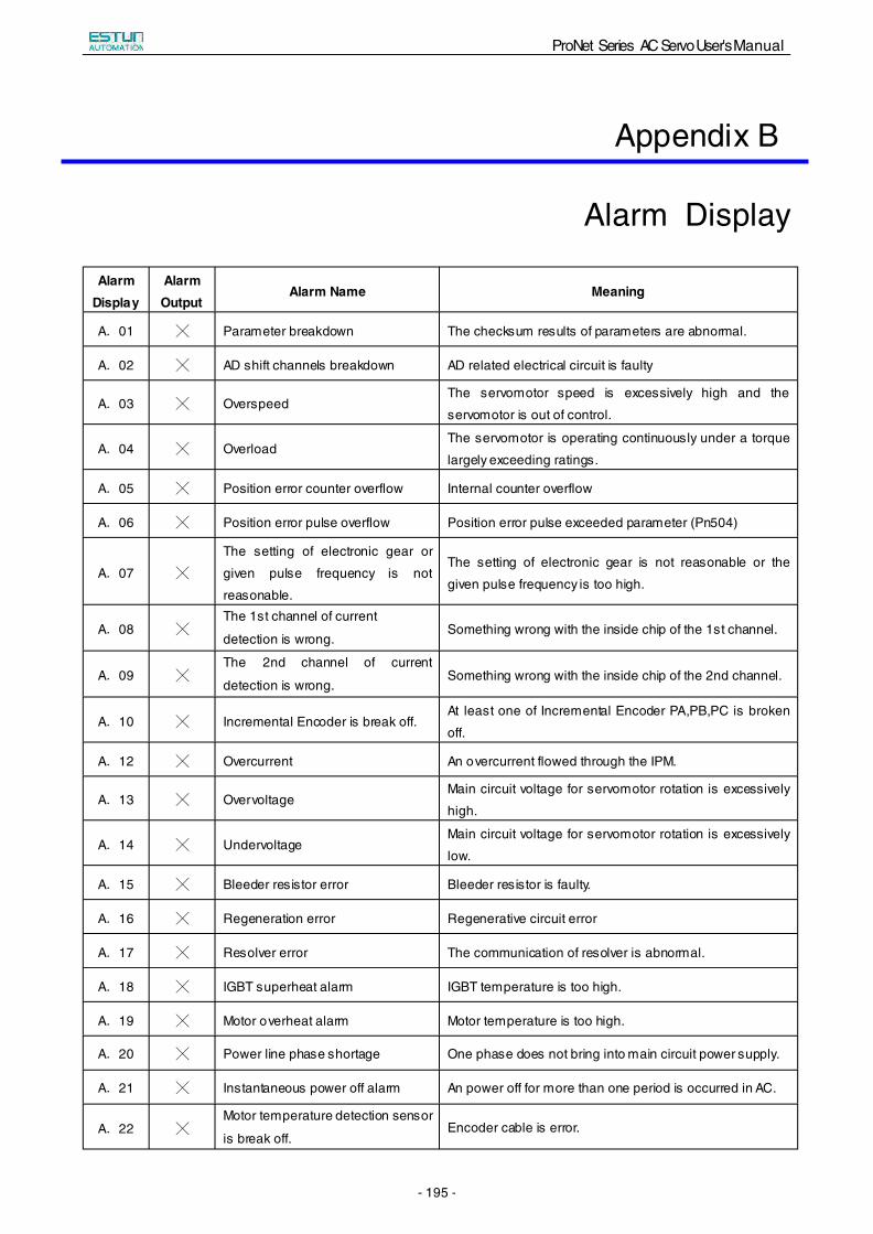
ProNet Series AC Servo User's Manual
- 195 -
Appendix B
Alarm Display
Alarm Display
Alarm Output
Alarm Name Meaning
A.01 ╳ Parameter breakdown The checksum results of parameters are abnormal.
A.02 ╳ AD shift channels breakdown AD related electrical circuit is faulty
A.03 ╳ Overspeed The servomotor speed is excessively high and the
servomotor is out of control.
A.04 ╳ Overload The servomotor is operating continuously under a torque
largely exceeding ratings.
A.05 ╳ Position error counter overflow Internal counter overflow
A.06 ╳ Position error pulse overflow Position error pulse exceeded parameter (Pn504)
A.07 ╳
The setting of electronic gear or
given pulse frequency is not
reasonable.
The setting of electronic gear is not reasonable or the
given pulse frequency is too high.
A.08 ╳The 1st channel of current
detection is wrong. Something wrong with the inside chip of the 1st channel.
A.09 ╳The 2nd channel of current
detection is wrong. Something wrong with the inside chip of the 2nd channel.
A.10 ╳ Incremental Encoder is break off. At least one of Incremental Encoder PA,PB,PC is broken
off.
A.12 ╳ Overcurrent An overcurrent flowed through the IPM.
A.13 ╳ Overvoltage Main circuit voltage for servomotor rotation is excessively
high.
A.14 ╳ Undervoltage Main circuit voltage for servomotor rotation is excessively
low.
A.15 ╳ Bleeder resistor error Bleeder resistor is faulty.
A.16 ╳ Regeneration error Regenerative circuit error
A.17 ╳ Resolver error The communication of resolver is abnormal.
A.18 ╳ IGBT superheat alarm IGBT temperature is too high.
A.19 ╳ Motor overheat alarm Motor temperature is too high.
A.20 ╳ Power line phase shortage One phase does not bring into main circuit power supply.
A.21 ╳ Instantaneous power off alarm An power off for more than one period is occurred in AC.
A.22 ╳Motor temperature detection sensor
is break off. Encoder cable is error.
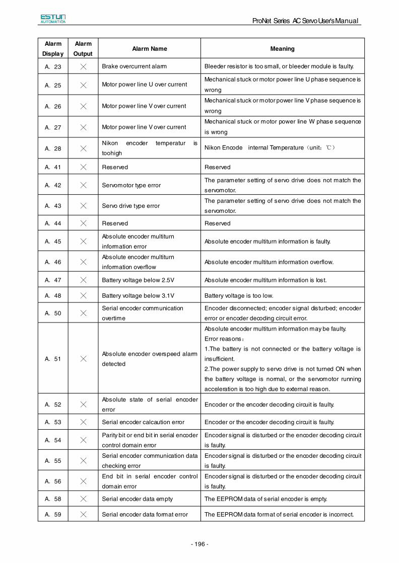
ProNet Series AC Servo User's Manual
- 196 -
Alarm Display
Alarm Output
Alarm Name Meaning
A.23 ╳ Brake overcurrent alarm Bleeder resistor is too small, or bleeder module is faulty.
A.25 ╳ Motor power line U over current Mechanical stuck or motor power line U phase sequence is
wrong
A.26 ╳ Motor power line V over current Mechanical stuck or motor power line V phase sequence is
wrong
A.27 ╳ Motor power line V over current Mechanical stuck or motor power line W phase sequence
is wrong
A.28 ╳Nikon encoder temperatur is
toohigh Nikon Encode internal Temperature(unit:℃)
A.41 ╳ Reserved Reserved
A.42 ╳ Servomotor type error The parameter setting of servo drive does not match the
servomotor.
A.43 ╳ Servo drive type error The parameter setting of servo drive does not match the
servomotor.
A.44 ╳ Reserved Reserved
A.45 ╳Absolute encoder multiturn
information error Absolute encoder multiturn information is faulty.
A.46 ╳Absolute encoder multiturn
information overflow Absolute encoder multiturn information overflow.
A.47 ╳ Battery voltage below 2.5V Absolute encoder multiturn information is lost.
A.48 ╳ Battery voltage below 3.1V Battery voltage is too low.
A.50 ╳Serial encoder communication
overtime
Encoder disconnected; encoder signal disturbed; encoder
error or encoder decoding circuit error.
A.51 ╳Absolute encoder overspeed alarm
detected
Absolute encoder multiturn information may be faulty.
Error reasons:
1.The battery is not connected or the battery voltage is
insufficient.
2.The power supply to servo drive is not turned ON when
the battery voltage is normal, or the servomotor running
acceleration is too high due to external reason.
A.52 ╳Absolute state of serial encoder
error Encoder or the encoder decoding circuit is faulty.
A.53 ╳ Serial encoder calcaution error Encoder or the encoder decoding circuit is faulty.
A.54 ╳Parity bit or end bit in serial encoder
control domain error
Encoder signal is disturbed or the encoder decoding circuit
is faulty.
A.55 ╳Serial encoder communication data
checking error
Encoder signal is disturbed or the encoder decoding circuit
is faulty.
A.56 ╳End bit in serial encoder control
domain error
Encoder signal is disturbed or the encoder decoding circuit
is faulty.
A.58 ╳ Serial encoder data empty The EEPROM data of serial encoder is empty.
A.59 ╳ Serial encoder data format error The EEPROM data format of serial encoder is incorrect.
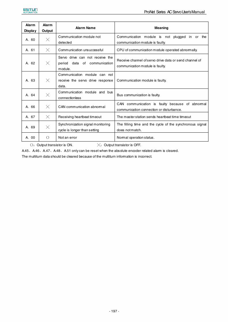
ProNet Series AC Servo User's Manual
- 197 -
Alarm Display
Alarm Output
Alarm Name Meaning
A.60 ╳Communication module not
detected
Communication module is not plugged in or the
communication module is faulty.
A.61 ╳ Communication unsuccessful CPU of communication module operated abnormally.
A.62 ╳
Servo drive can not receive the
period data of communication
module.
Receive channel of servo drive data or send channel of
communication module is faulty.
A.63 ╳
Communication module can not
receive the servo drive response
data.
Communication module is faulty.
A.64 ╳Communication module and bus
connectionless Bus communication is faulty.
A.66 ╳ CAN communication abnormal CAN communication is faulty because of abnormal
communication connection or disturbance.
A.67 ╳ Receiving heartbeat timeout The master station sends heartbeat time timeout
A.69 ╳Synchronization signal monitoring
cycle is longer than setting
The filling time and the cycle of the synchronous signal
does not match.
A.00 〇 Not an error Normal operation status.
〇:Output transistor is ON. ╳:Output transistor is OFF.
A.45、A.46、A.47、A.48、A.51 only can be reset when the absolute encoder related alarm is cleared.
The multiturn data should be cleared because of the multiturn information is incorrect.