Ete420 robot finalproject2008
18
Queensborough Community College Electrical and Computer Engineering Technology Course: ETE-420 Instructor: Mr. Raymond Kendall Computer Project Laboratory - Robot By: Marco Huerta and Kenneth Deonarine Dated handed in: 05/06/2008 Grade:___________ Created by Marco Huerta and Kenneth Deonarine 1
-
Upload
sherlyn-victoria -
Category
Business
-
view
100 -
download
0
Transcript of Ete420 robot finalproject2008

Queensborough Community College
Electrical and Computer Engineering Technology
Course: ETE-420
Instructor: Mr. Raymond Kendall
Computer Project Laboratory - Robot
By: Marco Huerta and Kenneth Deonarine
Dated handed in: 05/06/2008
Grade:___________
Created by Marco Huerta and Kenneth Deonarine 1

Robot #1: Power Supply
Quantity Measured value volts Expected (Calc.) value volt
Percentage difference %
VC 8.82V 9V 2%VB 5.65V 5.6V 0.17%VE 4.96V 5V 0.8%
Expected Values
Percentage difference
Created by Marco Huerta and Kenneth Deonarine 2

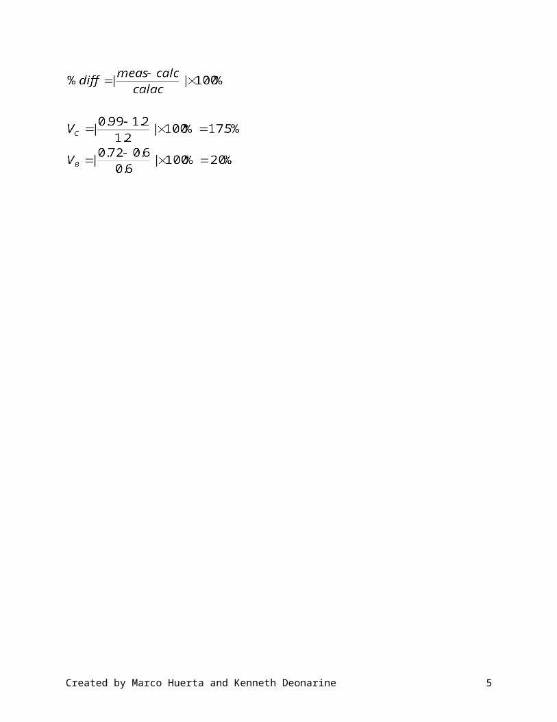
Robot #2: LED Driver Circuit
Quantity Measured value volts Expected (Calc.) value volt
Percentage difference %
VC 0.99V 1.2V 17.5%VB 0.72V 0.6V 20%VE 0V --- ---
Created by Marco Huerta and Kenneth Deonarine 3

Robot #3: Audio Oscillator, Speaker Driver, and Control circuitry
Timing Waveform
Created by Marco Huerta and Kenneth Deonarine 4
Robot #3 Continued:
Quiescent State Bias VoltagesQuantity Measured Value Volts Calculated value Volts Percentage Difference
%TR4 - VC 0 V 0 V ---TR4 - VB 0.04 V 0V ---TR4 - VE 0.62 V .6V 3.3%TR2 - VC 5.08 V 5 V 1.6%
Audio Oscillator Pulse Repetition RateQuantity Measured Value pps Calculated value pps Percentage Difference
%PPR 2500 pps 2506 pps 0.23%
Quiescent State Bias Voltages
Audio Oscillator Pulse Repetition RateTotal Period Pulse Repetition Rate
Created by Marco Huerta and Kenneth Deonarine 5

Robot #4: Motor Driver Circuit
Left MotorVCE (TR6) VB (TR6) Volts VB (TR5) Volts
Motor On 0.7 V 0.83V 1.60 VMotor Off 3.02 V --- ---
Right MotorVCE (TR7) VB (TR7) Volts VB (TR9) Volts
Motor On 0.7V 0.82V 1.59 VMotor Off 3.02V --- ---
Comments
The motion of the robot is controlled because 5V is applied from J2 to pin 12 and pin 14 on the 5501 socket (U6). For the right motor to function properly a positive voltage must go through R29 for TR8 to turn on. Then the voltage is applied through the base of TR7 and the left motor starts to work. The same is done for the right motor expect voltage goesthroughTR5 and TR6.
Created by Marco Huerta and Kenneth Deonarine 6

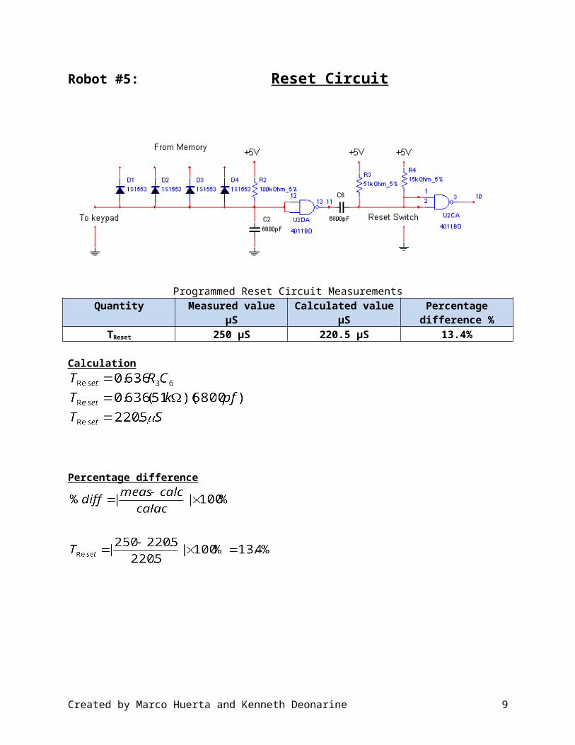
Robot #5: Reset Circuit
Programmed Reset Circuit MeasurementsQuantity Measured value µS Calculated value µS Percentage difference
%TReset 250 µS 220.5 µS 13.4%
Calculation
Percentage difference
Created by Marco Huerta and Kenneth Deonarine 7

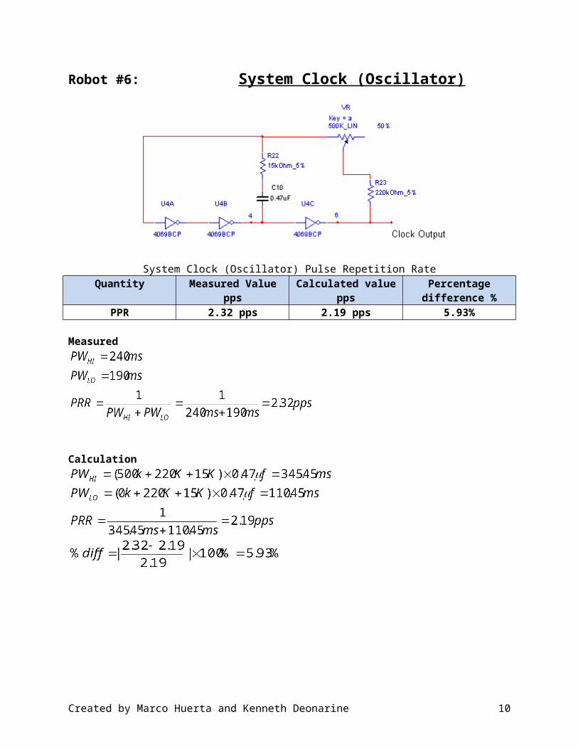
Robot #6: System Clock (Oscillator)
System Clock (Oscillator) Pulse Repetition Rate Quantity Measured Value pps Calculated value pps Percentage difference
%PPR 2.32 pps 2.19 pps 5.93%
Measured
Calculation
Created by Marco Huerta and Kenneth Deonarine 8
Robot #7: Memory Load Sequencer
Created by Marco Huerta and Kenneth Deonarine 9
Robot #8: Keypad and Interface Circuitry
Created by Marco Huerta and Kenneth Deonarine 10

Robot #9: Write Control Logic
Write Control Pulse WidthMeasured value µS Calculated value µS Percentage difference %
220 µS 220.5 µS .23 %
CalculatedPulse WidthPulse width = 0.636*R6*C5 = 220.5 µSPercent difference
Created by Marco Huerta and Kenneth Deonarine 11

Robot #10: Address Counter
Time DurationMeasured value s Calculated value s Percentage difference %
120 sec 102sec 17.6 %Calculated secPRR = 4HzTime DurationTD =256 / PRR =256/2500= 102sec
Percent Difference =
Created by Marco Huerta and Kenneth Deonarine 12

Robot #11: Memory Circuit
Created by Marco Huerta and Kenneth Deonarine 13

Created by Marco Huerta and Kenneth Deonarine 14

Conclusion Of Robot Project
In ET 420 Computer Project Laboratory Robot Project we constructed the Model 603A Digital Programmable Robot kit by Graymark. We built the various circuits; Power Supply, LED Driver Circuit, Audio Oscillator, Speaker Driver, and Control circuitry, Motor Driver Circuit, Reset Circuit, System Clock (Oscillator), Memory Load Sequencer, Keypad and Interface Circuitry, Write Control Logic, Address Counter, Memory Circuit by soldering the various components to the pre-made circuit board and assembled the mechanical parts of cogs, wheels, motors etc. We were able to successfully build our robot and make the speaker and motors work by using the remote control to issue commands such as beeping the speaker and right and left movements. We encountered a problem when we assembled the left motor cog not making contact with the other cogs that spun the left wheel. In order to compensate for this problem, we added two additional metal washers under the two rear motor circuit board connections points, this raised the back of the motor causing better cog contact with the left wheel assembly cogs. Another problem we had was current not getting to the motor to spin the wheels, we bypassed the current directly to the motors to verify the motors were working, verified the 2 AA batteries were good and then troubleshoot the battery holder. We discovered one of the battery holder leads was poorly constructed (not our lead to battery holder contact soldering), and replaced the battery holder, re-assembled the robot and the motors/wheels now responded to our remote control commands. We worked well as a team and our timely final results were proof of that partnership.
Created by Marco Huerta and Kenneth Deonarine 15