et - NIDEC COPAL ELECTRONICS RoHS Compliant Introduction The ET series is Copalʼs standard size...
14
ET RoHS Compliant ■ Introduction The ET series is Copal’s standard size high capacity toggle switch. The ET series are available in various current rating, switching functions, and terminals. The housing is made of self-extinguishing phenol resin which has excellent heat resistance, arc resistance, and tracking resistance. The contacts are designed to eliminate chattering and bouncing to prevent insulation deterioration. (ON) and (OFF):Momentary. ET Standard Size Toggle Switch ■Part Numbering ■Terminal Style and Dimentions E T 2 25 Z - Series code Actuator shape No. of poles Swiching function Terminal styles Current 1 1 pole 2 2 poles 3 3 poles 4 4 poles 6 6 poles 1 pole 3 poles 2 poles 4 poles 6 poles Key way Key way A K ON -- -- OFF B L ON -- (OFF) C M OFF -- (ON) D N ON -- ON E P ON OFF ON F R ON -- (ON) G S (ON) OFF (ON) H T ON OFF (ON) AC125V AC250V 03 3A 05 5A 3A 06 6A (2A) 10 10A (7A) Fig. Fig. Fig. None 10 12 13 32 Terminal style TAB # 250 Screw Terminal Solder Terminal Plate Connect SolderTerminal Solder Terminal K 12 AC125V AC250V 15 15A 10A 20 20A 12A 25 25A 15A 30 30A (25A) Fig. No. of poles Key way TAB # 250 (Style:-) Screw Terminal(Style:10) Solder Terminal Solder Terminal (Style: 12・ 13) Style:12 Style:32 ET103 □12 ET206 □12 Type ET103 □ 32 Type M3.5 × 0.6 M4 × 0.7 M4.5 × 0.75 ET115・215 Type Type Type ET120・220 ET125・225・230
Transcript of et - NIDEC COPAL ELECTRONICS RoHS Compliant Introduction The ET series is Copalʼs standard size...
ET RoHS Compliant
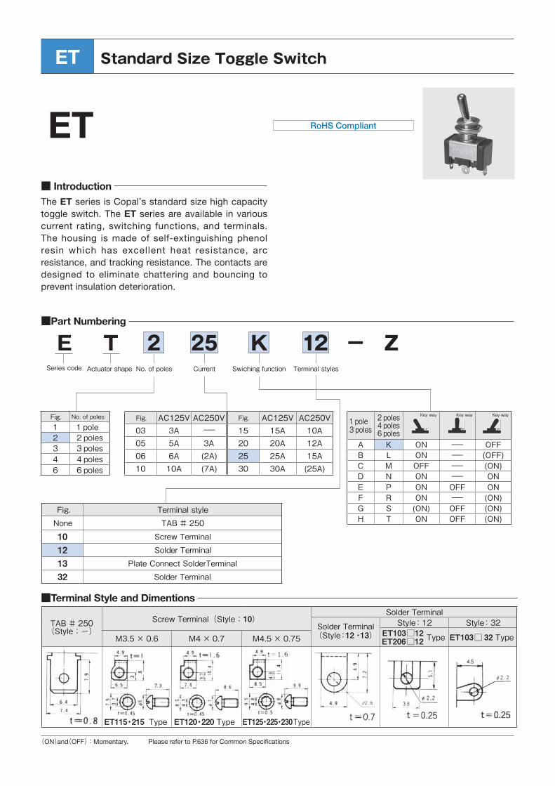
■ Introduction The ET series is Copal’s standard size high capacity toggle switch. The ET series are available in various current rating, switching functions, and terminals. The housing is made of self-extinguishing phenol resin which has excellent heat resistance, arc resistance, and tracking resistance. The contacts are designed to eliminate chattering and bouncing to prevent insulation deterioration.
(ON)and(OFF):Momentary. ���������������� � �����������������������
ET Standard Size Toggle Switch
■Part Numbering
■Terminal Style and Dimentions
E T 2 25 Z-Series code Actuator shape No. of poles Swiching function Terminal stylesCurrent
1 1 pole2 2 poles3 3 poles4 4 poles6 6 poles
1 pole3 poles
2 poles4 poles6 poles
Key way Key way
A K ON --
--
OFFB L ON -- (OFF)C M OFF -- (ON)D N ON -- ONE P ON OFF ONF R ON -- (ON)G S (ON) OFF (ON)H T ON OFF (ON)
AC125V AC250V03 3A05 5A 3A06 6A (2A)10 10A (7A)
Fig.
Fig. Fig.
None
10121332
Terminal styleTAB # 250
Screw TerminalSolder Terminal
Plate Connect SolderTerminalSolder Terminal
K 12
AC125V AC250V15 15A 10A20 20A 12A25 25A 15A30 30A (25A)
Fig.No. of poles Key way
TAB # 250(Style:-)
Screw Terminal(Style:10)Solder Terminal
Solder Terminal(Style:12・13)
Style:12 Style:32ET103□12ET206□12 Type ET103□ 32 TypeM3.5 × 0.6 M4× 0.7 M4.5 × 0.75
ET115・215 Type Type TypeET120・220 ET125・225・230
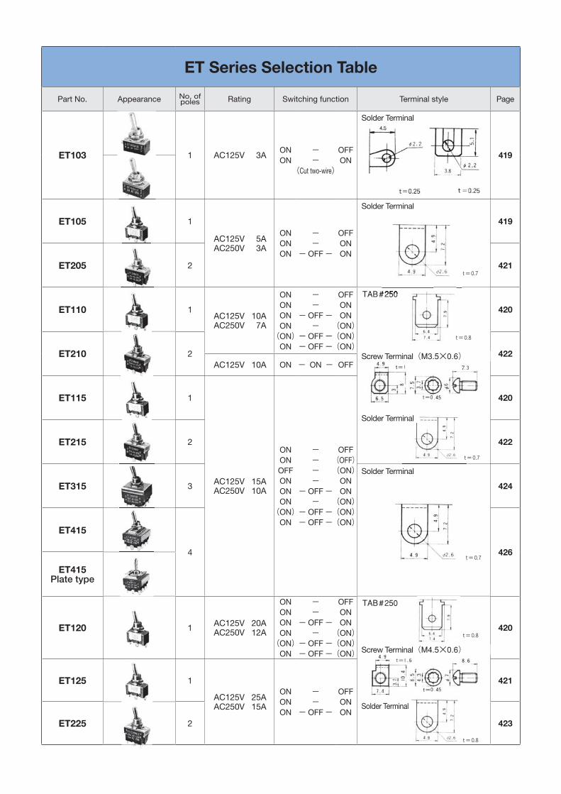
ET Series Selection Table
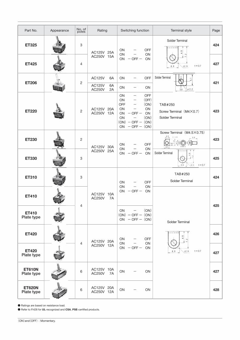
Part No. Appearance No. of poles Rating Switching function Terminal style Page
ET103 1 AC125V 3A ONON
--
(Cut two-wire)
OFFON
Solder
419
ET105 1
AC125V 5AAC250V 3A
ONONON
--
- OFF -
OFFONON
Solder
419
ET205 2 421
ET110 1AC125V 10AAC250V 7A
ONONONON(ON)
ON
--
- OFF --
- OFF -- OFF -
OFFONON(ON)(ON)(ON)
TAB#250
Screw(M3.5×0.6)
Solder
420
ET210 2 422AC125V 10A ON - ON - OFF
ET115 1
AC125V 15AAC250V 10A
ONONOFFONONON(ON)
ON
----
- OFF --
- OFF -- OFF -
OFF(OFF)(ON)
ONON(ON)(ON)(ON)
420
ET215 2 422
ET315 3
Solder
424
ET415
4 426
ET415Plate type
ET120 1 AC125V 20AAC250V 12A
ONONONON(ON)
ON
--
- OFF --
- OFF -- OFF -
OFFONON(ON)(ON)(ON)
TAB#250
Screw(M4.5×0.75)
Solder
420
ET125 1
AC125V 25AAC250V 15A
ONONON
--
- OFF -
OFFONON
421
ET225 2 423
Solder Terminal
Solder Terminal
Solder Terminal
Solder Terminal
Solder Terminal
Screw Terminal(M3.5×0.6)
Screw Terminal(M4.5×0.6)
Part No. Appearance No. of poles Rating Switching function Terminal style Page
ET325 3
AC125V 25AAC250V 15A
ONONON
--
- OFF -
OFFONON
Solder424
ET425 4 427
ET206 2AC125V 6A ON - OFF Solder
421AC125V 6AAC250V 2A ON - ON
ET220 2 AC125V 20AAC250V 12A
ONONOFFONONON(ON)
ON
----
- OFF --
- OFF -- OFF -
OFF(OFF)(ON)
ONON(ON)(ON)(ON)
TAB#250
Screw(M4×0.7)
Solder
423
ET230 2
AC125V 30AAC250V 25A
ONONON
--
- OFF -
OFFONON
Screw(M4.5×0.75)
423
ET330 3Solder
425
ET310 3
AC125V 10AAC250V 7A
ONONON
--
- OFF -
OFFONON
TAB#250
Solder424
ET410
4
Solder
425
ET410Plate type
ON(ON)
ON
-- OFF -- OFF -
(ON)(ON)(ON)
ET420
4 AC125V 20AAC250V 12A
ONONON
--
- OFF -
OFFONON
426
ET420Plate type 427
ET610NPlate type 6 AC125V 10A
AC250V 7A ON - ON 427
ET620NPlate type 6 AC125V 20A
AC250V 12A ON - ON 428
● Ratings are based on resistance load. ● Refer to P.428 for UL-recognized and CSA, PSE������������������
(ON)and(OFF):Momentary.
Solder Terminal
Solder Terminal
Solder Terminal
Solder Terminal
Solder Terminal
Solder Terminal
Screw Terminal(M4×0.7)
Screw Terminal(M4.5×0.75)

M12×1 (1)
((22))
(3)
M12×1
(1)(4)
(3)(6)
M12×1
(1)(4)
(3)(6)
■Panel Cut-Out Dimensions ET
Panel thickness : 5.5mm max.
With Locking Ring Without Locking Ring
●Refer to P.429 for a list of accessories.
Note : Panel thickness should be 5.5 mm max. unless otherwise specified.
L dimensionsTerminal
style
Part No.Solder Terminal
ET105A12-Z 24.6±1
ET105D12-Z 24.6±1
ET105E12-Z 24.6±1
■����������� �
Rating Initial contact resistance
Dielectric strength
Insulation resistance
Electricallife
ET103A32AC125V 3A 30mΩ Max.
(DC2V 100mA)AC1500V1 minute
100MΩ Min.(DC500V)
10,000cyclesET103V32
(Cut two-wire)
■����������� �
Rating Initial contact resistance
Dielectric strength
Insulation resistance
Electricallife
ET103A12 AC125V 3A 30mΩ Max.(DC2V 100mA)
AC1500V1 minute
100MΩ Min.(DC500V)
10,000cyclesET103V12
■����������� �
Rating Initial contact resistance
Dielectric strength
Insulation resistance
Electricallife
ET105A12AC125V 5AAC250V 3A
20mΩ Max.(DC2V 100mA)
AC1500V1minute
100MΩ Min.(DC500V)
20,000cyclesET105D12
ET105E12
Switchingfunction
Part No.
Key way Key way Key way
★ ET103A32-Z ON - OFFConnecting terminals 1-4 - -★ ET103V32-Z ON - ONConnecting terminals 1-4 - 3-6
Switchingfunction
Part No.
Key way Key way Key way
ET103A12-Z ON - OFFConnecting terminals 1-4 - -★ ET103V12-Z ON - ONConnecting terminals 1-4 - 3-6
Switchingfunction
Part No.
Key way Key way Key way
☆ ET105A12-Z ON - OFFConnecting terminals 1-3 - -☆ ET105D12-Z ON - ON☆ ET105E12-Z ON OFF ONConnecting terminals 2-3 - 2-1
ET103□32(1 pole)
ET103□12(1 pole)
ET105□12(1 pole)
Terminal numbers are shown on the bottom of the switch.
Terminal numbers are shown on the bottom of the switch.
Terminal numbers are shown on the bottom of the switch.
Terminal pins No.3 and No.6 are not available in switches with Switching Function “A”.
Terminal pins No.3 and No.6 are not available in switches with Switching Function “A”.
Terminal pin No.2 is not available in switches with Switching Function “A”.
★:Made to order products.☆:Semi-standard products.
M12×1
29
0.5
0.5
1
22
3
ETL dimensions
Terminalstyle
Part No. TAB#250 ScrewTerminal Solder Terminal
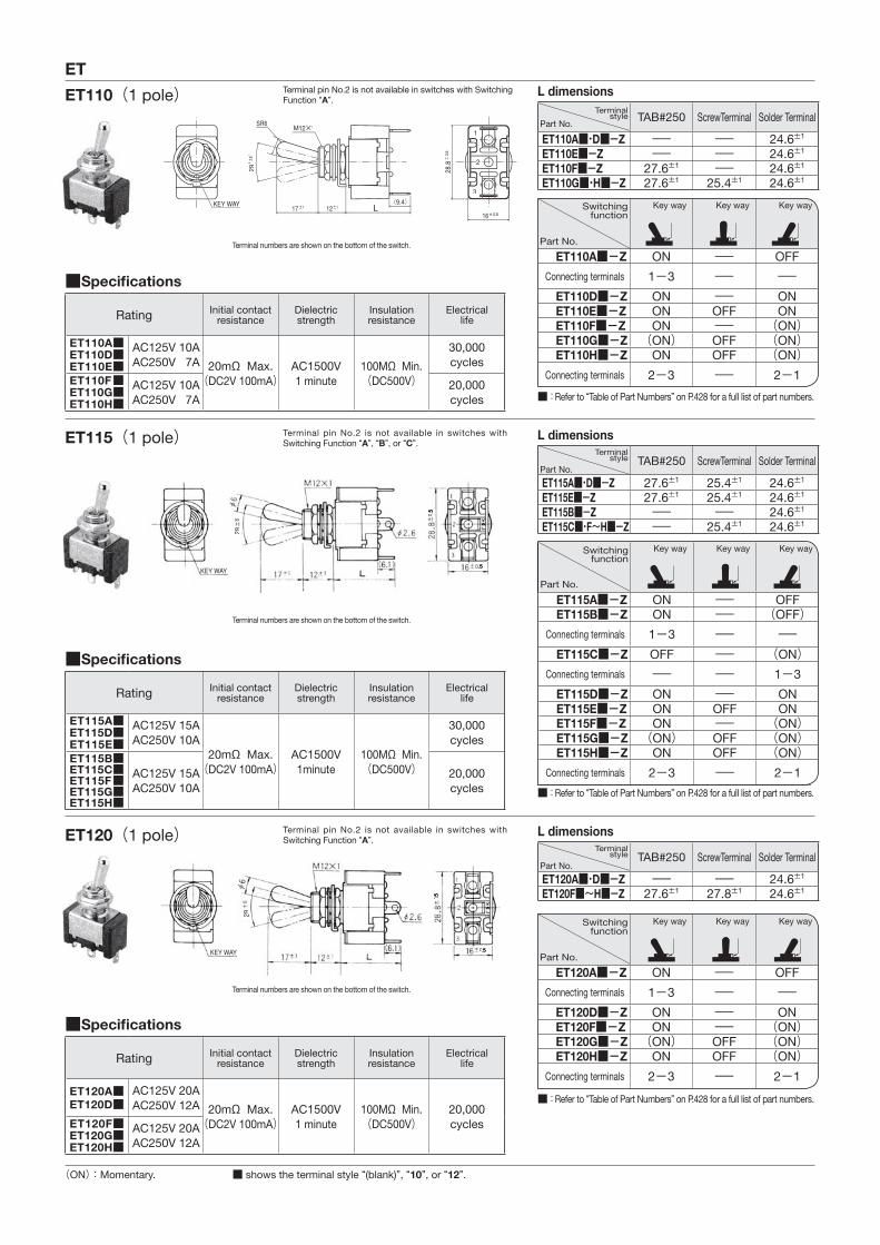
ET110A■・D■-Z - - 24.6±1
ET110E■-Z - - 24.6±1
ET110F■-Z 27.6±1 - 24.6±1
ET110G■・H■-Z 27.6±1 25.4±1 24.6±1
L dimensionsTerminal
stylePart No.
TAB#250 ScrewTerminal Solder Terminal
ET120A■・D■-Z - - 24.6±1
ET120F■~H■-Z 27.6±1 27.8±1 24.6±1
L dimensionsTerminal
stylePart No.
TAB#250 ScrewTerminal Solder Terminal
ET115A■・D■-Z 27.6±1 25.4±1 24.6±1
ET115E■-Z 27.6±1 25.4±1 24.6±1
ET115B■-Z - - 24.6±1
ET115C■・F~H■-Z - 25.4±1 24.6±1
■����������� �
Rating Initial contact resistance
Dielectric strength
Insulation resistance
Electricallife
ET110A■ET110D■ET110E■
AC125V 10AAC250V 7A 20mΩ Max.
(DC2V 100mA)AC1500V1 minute
100MΩ Min.(DC500V)
30,000cycles
ET110F■ET110G■ET110H■
AC125V 10AAC250V 7A
20,000cycles
■����������� �
Rating Initial contact resistance
Dielectric strength
Insulation resistance
Electricallife
ET120A■ET120D■
AC125V 20AAC250V 12A 20mΩ Max.
(DC2V 100mA)AC1500V1 minute
100MΩ Min.(DC500V)
20,000cyclesET120F■
ET120G■ET120H■
AC125V 20AAC250V 12A
■����������� �
Rating Initial contact resistance
Dielectric strength
Insulation resistance
Electricallife
ET115A■ET115D■ET115E■
AC125V 15AAC250V 10A
20mΩ Max.(DC2V 100mA)
AC1500V1minute
100MΩ Min.(DC500V)
30,000cycles
ET115B■ET115C■ET115F■ET115G■ET115H■
AC125V 15AAC250V 10A
20,000cycles
Switchingfunction
Part No.
Key way Key way Key way
ET110A■-Z ON - OFFConnecting terminals 1-3 - - ET110D■-Z ON - ON ET110E■-Z ON OFF ON ET110F■-Z ON - (ON) ET110G■-Z (ON) OFF (ON) ET110H■-Z ON OFF (ON)
Connecting terminals 2-3 - 2-1
Switchingfunction
Part No.
Key way Key way Key way
ET120A■-Z ON - OFFConnecting terminals 1-3 - - ET120D■-Z ON - ON ET120F■-Z ON - (ON) ET120G■-Z (ON) OFF (ON) ET120H■-Z ON OFF (ON)
Connecting terminals 2-3 - 2-1
Switchingfunction
Part No.
Key way Key way Key way
ET115A■-Z ON - OFF ET115B■-Z ON - (OFF)
Connecting terminals 1-3 - - ET115C■-Z OFF - (ON)
Connecting terminals - - 1-3 ET115D■-Z ON - ON ET115E■-Z ON OFF ON ET115F■-Z ON - (ON) ET115G■-Z (ON) OFF (ON) ET115H■-Z ON OFF (ON)
Connecting terminals 2-3 - 2-1
ET110(1 pole)
ET120(1 pole)
ET115(1 pole)
Terminal numbers are shown on the bottom of the switch.
Terminal numbers are shown on the bottom of the switch.
Terminal numbers are shown on the bottom of the switch.
Terminal pin No.2 is not available in switches with Switching Function “A”.
Terminal pin No.2 is not available in switches with Switching Function “A”.
Terminal pin No.2 is not available in switches with Switching Function “A”, “B”, or “C”.
■ shows the terminal style “(blank)”, “10”, or “12”.
■ : Refer to “Table of Part Numbers” on P.428 for a full list of part numbers.
■ : Refer to “Table of Part Numbers” on P.428 for a full list of part numbers.
■ : Refer to “Table of Part Numbers” on P.428 for a full list of part numbers.
(ON):Momentary.
29
0
0
0
0
29
M12×1
29
0.5
0.5
24
0.
0.5
Key Way
M12×1
ET
L dimensionsTerminal
stylePart No.
TAB#250 ScrewTerminal Solder Terminal
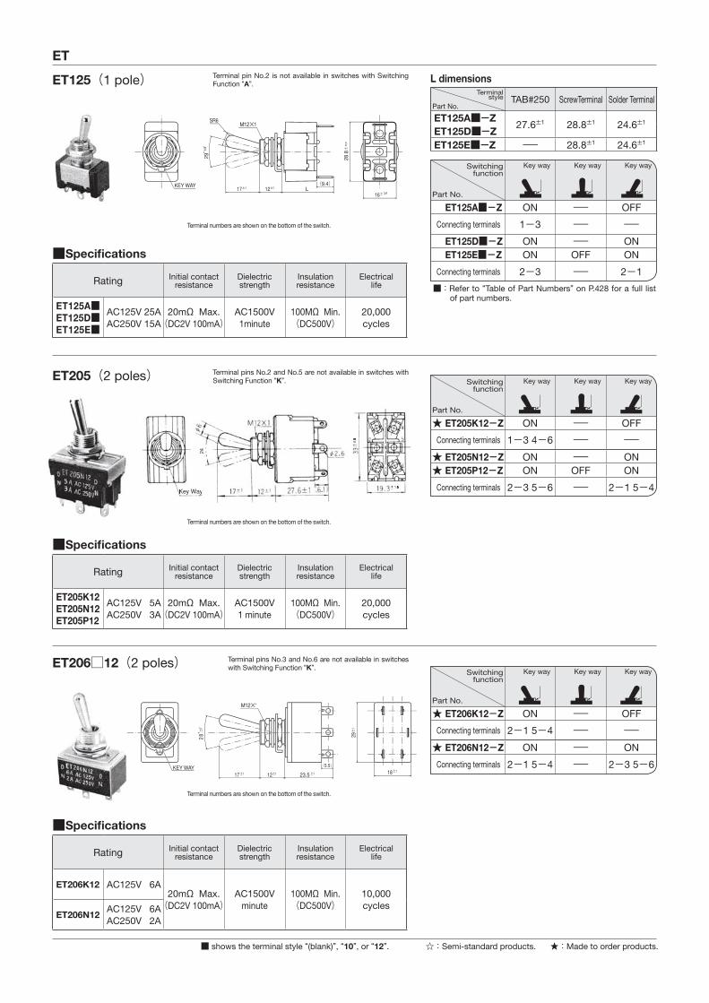
ET125A■-Z 27.6±1 28.8±1 24.6±1ET125D■-ZET125E■-Z - 28.8±1 24.6±1
■����������� �
Rating Initial contact resistance
Dielectric strength
Insulation resistance
Electricallife
ET125A■ET125D■ET125E■
AC125V 25AAC250V 15A
20mΩ Max.(DC2V 100mA)
AC1500V1minute
100MΩ Min.(DC500V)
20,000cycles
■����������� �
Rating Initial contact resistance
Dielectric strength
Insulation resistance
Electricallife
ET205K12ET205N12ET205P12
AC125V 5AAC250V 3A
20mΩ Max.(DC2V 100mA)
AC1500V1 minute
100MΩ Min.(DC500V)
20,000cycles
■����������� �
Rating Initial contact resistance
Dielectric strength
Insulation resistance
Electricallife
ET206K12 AC125V 6A20mΩ Max.(DC2V 100mA)
AC1500Vminute
100MΩ Min.(DC500V)
10,000cycles
ET206N12AC125V 6AAC250V 2A
Switchingfunction
Part No.
Key way Key way Key way
ET125A■-Z ON - OFFConnecting terminals 1-3 - - ET125D■-Z ON - ON ET125E■-Z ON OFF ON
Connecting terminals 2-3 - 2-1
Switchingfunction
Part No.
Key way Key way Key way
★ ET205K12-Z ON - OFFConnecting terminals 1-3 4-6 - -★ ET205N12-Z ON - ON★ ET205P12-Z ON OFF ON
Connecting terminals 2-3 5-6 - 2-1 5-4
Switchingfunction
Part No.
Key way Key way Key way
★ ET206K12-Z ON - OFFConnecting terminals 2-1 5-4 - -★ ET206N12-Z ON - ON
Connecting terminals 2-1 5-4 - 2-3 5-6
ET125(1 pole)
ET206□12(2 poles)
ET205(2 poles)
Terminal numbers are shown on the bottom of the switch.
Terminal numbers are shown on the bottom of the switch.
Terminal numbers are shown on the bottom of the switch.
Terminal pin No.2 is not available in switches with Switching Function “A”.
Terminal pins No.3 and No.6 are not available in switches with Switching Function “K”.
Terminal pins No.2 and No.5 are not available in switches with Switching Function “K”.
■ shows the terminal style “(blank)”, “10”, or “12”.
■ : Refer to “Table of Part Numbers” on P.428 for a full list of part numbers.
★:Made to order products.☆:Semi-standard products.
M12×1
24
0.5
0.524
0.5
0.5
ET
L dimensionsTerminal
style
Part No.TAB#250 ScrewTerminal Solder Terminal
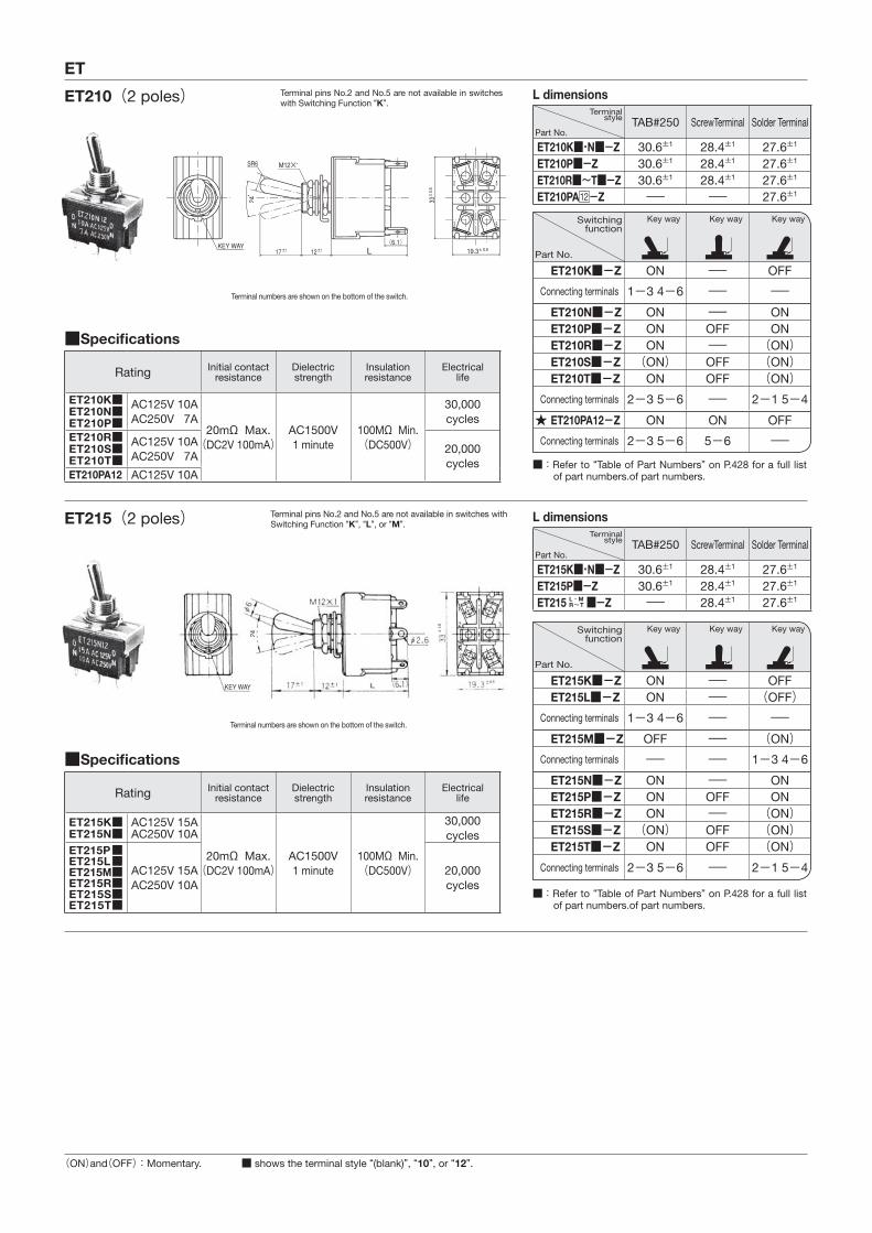
ET210K■・N■-Z 30.6±1 28.4±1 27.6±1
ET210P■-Z 30.6±1 28.4±1 27.6±1
ET210R■~T■-Z 30.6±1 28.4±1 27.6±1
ET210PA -Z - - 27.6±1
L dimensionsTerminal
style
Part No.TAB#250 ScrewTerminal Solder Terminal
ET215K■・N■-Z 30.6±1 28.4±1 27.6±1
ET215P■-Z 30.6±1 28.4±1 27.6±1
ET215 L・MR~T ■-Z - 28.4±1 27.6±1
■����������� �
Rating Initial contact resistance
Dielectric strength
Insulation resistance
Electricallife
ET210K■ET210N■ET210P■
AC125V 10AAC250V 7A
20mΩ Max.(DC2V 100mA)
AC1500V1 minute
100MΩ Min.(DC500V)
30,000cycles
ET210R■ET210S■ET210T■
AC125V 10AAC250V 7A 20,000
cyclesET210PA12 AC125V 10A
■����������� �
Rating Initial contact resistance
Dielectric strength
Insulation resistance
Electricallife
ET215K■ET215N■
AC125V 15AAC250V 10A
20mΩ Max.(DC2V 100mA)
AC1500V1 minute
100MΩ Min.(DC500V)
30,000cycles
ET215P■ET215L■ET215M■ET215R■ET215S■ET215T■
AC125V 15AAC250V 10A
20,000cycles
Switchingfunction
Part No.
Key way Key way Key way
ET210K■-Z ON - OFFConnecting terminals 1-3 4-6 - - ET210N■-Z ON - ON ET210P■-Z ON OFF ON ET210R■-Z ON - (ON) ET210S■-Z (ON) OFF (ON) ET210T■-Z ON OFF (ON)
Connecting terminals 2-3 5-6 - 2-1 5-4★ ET210PA12-Z ON ON OFF
Connecting terminals 2-3 5-6 5-6 -
Switchingfunction
Part No.
Key way Key way Key way
ET215K■-Z ON - OFF ET215L■-Z ON - (OFF)
Connecting terminals 1-3 4-6 - - ET215M■-Z OFF - (ON)
Connecting terminals - - 1-3 4-6 ET215N■-Z ON - ON ET215P■-Z ON OFF ON ET215R■-Z ON - (ON) ET215S■-Z (ON) OFF (ON) ET215T■-Z ON OFF (ON)
Connecting terminals 2-3 5-6 - 2-1 5-4
ET210(2 poles)
ET215(2 poles)
Terminal numbers are shown on the bottom of the switch.
Terminal numbers are shown on the bottom of the switch.
■ shows the terminal style “(blank)”, “10”, or “12”.
■ : Refer to “Table of Part Numbers” on P.428 for a full list of part numbers.of part numbers.
■ : Refer to “Table of Part Numbers” on P.428 for a full list of part numbers.of part numbers.
Terminal pins No.2 and No.5 are not available in switches with Switching Function “K”.
Terminal pins No.2 and No.5 are not available in switches with Switching Function “K”, “L”, or “M”.
(ON)and(OFF):Momentary.
M12×1
M12×1
ET
L dimensionsTerminal
style
Part No.TAB#250 ScrewTerminal Solder Terminal
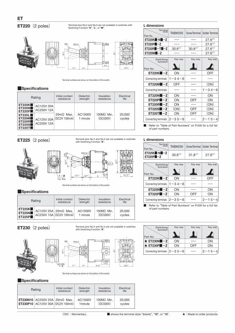
ET220K■・N■-Z - - 27.6±1
ET220P■-Z - - 27.6±1
ET220R■~T■-Z 30.6±1 30.8±1 27.6±1
ET220M■-Z - - 27.6±1
L dimensionsTerminal
stylePart No.
TAB#250 ScrewTerminal Solder Terminal
ET225K■・N■-ZET225P■-Z 30.6±1 31.8±1 27.6±1
■����������� �
Rating Initial contact resistance
Dielectric strength
Insulation resistance
Electricallife
ET220K■ET220N■ET220P■
AC125V 20AAC250V 12A
20mΩ Max.(DC2V 100mA)
AC1500V1 minute
100MΩ Min.(DC500V)
20,000cycles
ET220L■ET220M■ET220R■ET220S■ET220T■
AC125V 20AAC250V 12A
■����������� �
Rating Initial contact resistance
Dielectric strength
Insulation resistance
Electricallife
ET225K■ET225N■ET225P■
AC125V 25AAC250V 15A
20mΩ Max.(DC2V 100mA)
AC1500V1 minute
100MΩ Min.(DC500V)
20,000cycles
■����������� �
Rating Initial contact resistance
Dielectric strength
Insulation resistance
Electricallife
ET230N10ET230P10
AC250V 25AAC125V 30A
20mΩ Max.(DC2V 100mA)
AC1500V1minute
100MΩ Min.(DC500V)
20,000cycles
Switchingfunction
Part No.
Key way Key way Key way
ET220K■-Z ON - OFFConnecting terminals 1-3 4-6 - - ET220M■-Z OFF - (ON)
Connecting terminals - - 1-3 4-6 ET220N■-Z ON - ON ET220P■-Z ON OFF ON ET220R■-Z ON - (ON) ET220S■-Z (ON) OFF (ON) ET220T■-Z ON OFF (ON)
Connecting terminals 2-3 5-6 - 2-1 5-4
Switchingfunction
Part No.
Key way Key way Key way
ET225K■-Z ON - OFFConnecting terminals 1-3 4-6 - - ET225N■-Z ON - ON ET225P■-Z ON OFF ON
Connecting terminals 2-3 5-6 - 2-1 5-4
Switchingfunction
Part No.
Key way Key way Key way
★ ET230N■-Z ON - ON★ ET230P■-Z ON OFF ON
Connecting terminals 2-3 5-6 - 2-1 5-4
ET220(2 poles)
ET225(2 poles)
ET230(2 poles)
Terminal numbers are shown on the bottom of the switch.
Terminal numbers are shown on the bottom of the switch.
Terminal numbers are shown on the bottom of the switch.
■ shows the terminal style “(blank)”, “10”, or “12”.
■ : Refer to “Table of Part Numbers” on P.428 for a full list of part numbers.
■ : Refer to “Table of Part Numbers” on P.428 for a full list of part numbers.
(ON):Momentary.
Terminal pins No.2 and No.5 are not available in switches with Switching Function “K”.
Terminal pins No.2 and No.5 are not available in switches with Switching Function “K”.
Terminal pins No.2 and No.5 are not available in switches with Switching Function “K”, “L”, or “M”.
★:Made to order products.

M12×1
M12×1
M12×1
ET
L dimensionsTerminal
style
Part No.TAB#250 ScrewTerminal Solder Terminal
ET310A■-Z 34±2
- 29.1±1ET310D■-ZET310E■-Z 36.4±1
■����������� �
Rating Initial contact resistance
Dielectric strength
Insulation resistance
Electricallife
ET310A■ET310D■ET310E■
AC125V 10AAC250V 7A
20mΩ Max.(DC2V 100mA)
AC1500V1minute
100MΩ Min.(DC500V)
20,000cycles
■����������� �
Rating Initial contact resistance
Dielectric strength
Insulation resistance
Electricallife
ET325A12ET325D12ET325E12
AC125V 25AAC250V 15A
20mΩ Max.(DC2V 100mA)
AC1500V1 minute
100MΩ Min.(DC500V)
20,000cycles
■����������� �
Rating Initial contact resistance
Dielectric strength
Insulation resistance
Electricallife
ET315A12ET315D12ET315E12
AC125V 15AAC250V 10A 20mΩ Max.
(DC2V 100mA)AC1500V1minute
100MΩ Min.(DC500V)
20,000cyclesET315F12
ET315G12ET315H12
AC125V 15AAC250V 10A
Switchingfunction
Part No.
Key way Key way Key way
ET310A■-Z ON - OFF
Connecting terminals 1-3 4-67-9 - -
ET310D■-Z ON - ONET310E■-Z ON OFF ON
Connecting terminals 2-3 5-68-9 - 2-1 5-4
8-7
Switchingfunction
Part No.
Key way Key way Key way
★ET325A12-Z ON - OFF
Connecting terminals 1-3 4-67-9 - -
★ET325D12-Z ON - ON★ET325E12-Z ON OFF ON
Connecting terminals 2-3 5-68-9 - 2-1 5-4
8-7
Switchingfunction
Part No.
Key way Key way Key way
★ET315A12-Z ON - OFF
Connecting terminals 1-3 4-67-9 - -
★ET315D12-Z ON - ON★ET315E12-Z ON OFF ON★ET315F12-Z ON - (ON)★ET315G12-Z (ON) OFF (ON)★ET315H12-Z ON OFF (ON)
Connecting terminals 2-3 5-68-9 - 2-1 5-4
8-7
ET310(3 poles)
ET315□12(3 poles)
ET325□12(3 poles)
Terminal numbers are shown on the bottom of the switch.
Terminal numbers are shown on the bottom of the switch.
Terminal numbers are shown on the bottom of the switch.
■ shows the terminal style “(blank)” or “12”.
■ : Refer to “Table of Part Numbers” on P.428 for a full list of part numbers.
(ON):Momentary.
Terminal pins No.2, No.5, and No.8 are not available in switches with Switching Function “A”.
Terminal pins No.2, No.5, and No.8 are not available in switches with Switching Function “A”.
Terminal pins No.2, No.5, and No.8 are not available in switches with Switching Function “A”.
★:Made to order products.
M12×1
33.5
2-M3×0.5
33.5
ET
L dimensionsTerminal
style
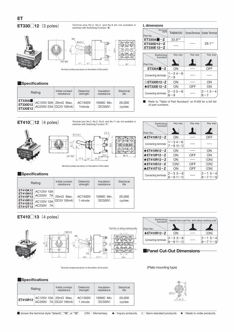
Part No.TAB#250 ScrewTerminal Solder Terminal
ET330A■-Z 33.9±2
- 29.1±1ET330D12-ZET330E12-Z -
■����������� �
Rating Initial contact resistance
Dielectric strength
Insulation resistance
Electricallife
ET330A■ET330D12ET330E12
AC125V 30AAC250V 25A
20mΩ Max.(DC2V 100mA)
AC1500V1minute
100MΩ Min.(DC500V)
20,000cycles
■����������� �
Rating Initial contact resistance
Dielectric strength
Insulation resistance
Electricallife
ET410R13AC125V 10AAC250V 7A
20mΩ Max.(DC2V 100mA)
AC1500V1 minute
100MΩ Min.(DC500V)
20,000cycles
■����������� �
Rating Initial contact resistance
Dielectric strength
Insulation resistance
Electricallife
ET410K12ET410N12ET410P12
AC125V 10AAC250V 7A 20mΩ Max.
(DC2V 100mA)AC1500V1 minute
100MΩ Min.(DC500V)
20,000cyclesET410R12
ET410S12ET410T12
AC125V 10AAC250V 7A
Switchingfunction
Part No.
Key way Key way Key way
ET330A■-Z ON - OFF
Connecting terminals 1-3 4-67-9 - -
☆ET330D12-Z ON - ON★ET330E12-Z ON OFF ON
Connecting terminals 2-3 5-68-9 - 2-1 5-4
8-7
Switchingfunction
Part No.
Viewed from part No. and rating marking side
★ET410R13-Z ON - (ON)
Connecting terminals 2-3 5-68-9 11-12 -
2-1 5-48-7 11-10
Switchingfunction
Part No.
Key way Key way Key way
★ET410K12-Z ON - OFF
Connecting terminals 1-3 4-67-9 10-12 - -
★ET410N12-Z ON - ON★ET410P12-Z ON OFF ON★ET410R12-Z ON - (ON)★ET410S12-Z (ON) OFF (ON)▲ET410T12-Z ON OFF (ON)
Connecting terminals 2-3 5-68-9 11-12 -
2-1 5-48-7 11-10
ET330□12(3 poles)
ET410□12(4 poles)
ET410□13(4 poles)
Terminal numbers are shown on the bottom of the switch.
Terminal numbers are shown on the bottom of the switch.
Terminal numbers are shown on the bottom of the switch.
■ shows the terminal style “(blank)”, “10”, or “12”.
■ : Refer to “Table of Part Numbers” on P.428 for a full list of part numbers.
(ON):Momentary.
Terminal pins No.2, No.5, and No.8 are not available in switches with Switching Function “A”.
Terminal pins No.2, No.5, No.8, and No.11 are not available in switches with Switching Function “K”.
★:Made to order products.
■Panel Cut-Out Dimensions
(Plate mounting type)
☆:Semi-standard products.▲ : Inquiry products.
ET
■����������� �
Rating Initial contact resistance
Dielectric strength
Insulation resistance
Electricallife
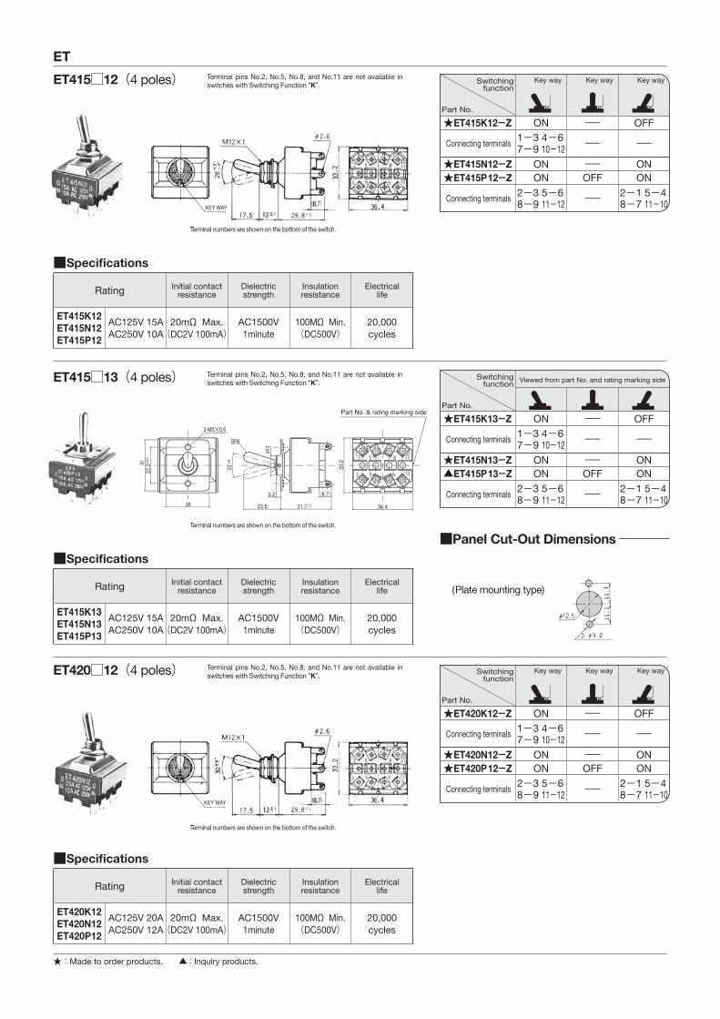
ET415K12ET415N12ET415P12
AC125V 15AAC250V 10A
20mΩ Max.(DC2V 100mA)
AC1500V1minute
100MΩ Min.(DC500V)
20,000cycles
■����������� �
Rating Initial contact resistance
Dielectric strength
Insulation resistance
Electricallife
ET420K12ET420N12ET420P12
AC125V 20AAC250V 12A
20mΩ Max.(DC2V 100mA)
AC1500V1minute
100MΩ Min.(DC500V)
20,000cycles
■����������� �
Rating Initial contact resistance
Dielectric strength
Insulation resistance
Electricallife
ET415K13ET415N13ET415P13
AC125V 15AAC250V 10A
20mΩ Max.(DC2V 100mA)
AC1500V1minute
100MΩ Min.(DC500V)
20,000cycles
Switchingfunction
Part No.
Key way Key way Key way
★ET415K12-Z ON - OFF
Connecting terminals 1-3 4-67-9 10-12 - -
★ET415N12-Z ON - ON★ET415P12-Z ON OFF ON
Connecting terminals 2-3 5-68-9 11-12 -
2-1 5-48-7 11-10
Switchingfunction
Part No.
Key way Key way Key way
★ET420K12-Z ON - OFF
Connecting terminals 1-3 4-67-9 10-12 - -
★ET420N12-Z ON - ON★ET420P12-Z ON OFF ON
Connecting terminals 2-3 5-68-9 11-12 -
2-1 5-48-7 11-10
Switchingfunction
Part No.
Viewed from part No. and rating marking side
★ET415K13-Z ON - OFF
Connecting terminals 1-3 4-67-9 10-12 - -
★ET415N13-Z ON - ON▲ET415P13-Z ON OFF ON
Connecting terminals 2-3 5-68-9 11-12 -
2-1 5-48-7 11-10
ET415□12(4 poles)
ET420□12(4 poles)
ET415□13(4 poles)
Terminal numbers are shown on the bottom of the switch.
Terminal numbers are shown on the bottom of the switch.
Terminal numbers are shown on the bottom of the switch.
★:Made to order products. ▲ : Inquiry products.
Terminal pins No.2, No.5, No.8, and No.11 are not available in switches with Switching Function “K”.
Terminal pins No.2, No.5, No.8, and No.11 are not available in switches with Switching Function “K”.
Terminal pins No.2, No.5, No.8, and No.11 are not available in switches with Switching Function “K”.
■Panel Cut-Out Dimensions
(Plate mounting type)
2-M3×0.5
2-M3×0.5
12M×1
34.5
4-M3×0.5
■����������� �
Rating Initial contact resistance
Dielectric strength
Insulation resistance
Electricallife
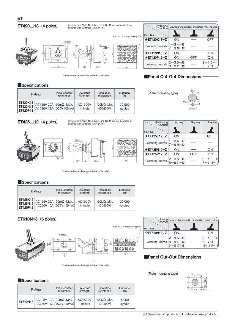
ET420K13ET420N13ET420P13
AC125V 20AAC250V 12A
20mΩ Max.(DC2V 100mA)
AC1500V1minute
100MΩ Min.(DC500V)
20,000cycles
■����������� �
Rating Initial contact resistance
Dielectric strength
Insulation resistance
Electricallife
ET425K12ET425N12ET425P12
AC125V 25AAC250V 15A
20mΩ Max.(DC2V 100mA)
AC1500V1minute
100MΩ Min.(DC500V)
20,000cycles
■����������� �
Rating Initial contact resistance
Dielectric strength
Insulation resistance
Electricallife
ET610N13AC125V 10AAC250V 7A
20mΩ Max.(DC2V 100mA)
AC1500V1 minute
100MΩ Min.(DC500V)
5,000cycles
Switchingfunction
Part No.
Key way Key way Key way
★ET425K12-Z ON - OFF
Connecting terminals 1-3 4-67-9 10-12 - -
★ET425N12-Z ON - ON★ET425P12-Z ON OFF ON
Connecting terminals 2-3 5-68-9 11-12 -
2-1 5-48-7 11-10
Switchingfunction
Part No.
Viewed from part No. and rating marking side
★ET420K13-Z ON - OFF
Connecting terminals 1-3 4-67-9 10-12 - -
★ET420N13-Z ON - ON★ET420P13-Z ON OFF ON
Connecting terminals 2-3 5-68-9 11-12 -
2-1 5-48-7 11-10
Switchingfunction
Part No.
Viewed from part No. and rating marking side
☆ET610N13-Z ON - ON
Connecting terminals2-3 5-68-9 11-1214-15 17-18
-2-1 5-48-7 11-1014-13 17-16
ET420□13(4 poles)
ET425□12(4 poles)
ET610N13(6 poles)
Terminal numbers are shown on the bottom of the switch.
Terminal numbers are shown on the bottom of the switch.
Terminal numbers are shown on the bottom of the switch.
ET
★:Made to order products.☆:Semi-standard products.
Terminal pins No.2, No.5, No.8, and No.11 are not available in switches with Switching Function “K”.
Terminal pins No.2, No.5, No.8, and No.11 are not available in switches with Switching Function “K”.
■Panel Cut-Out Dimensions
■Panel Cut-Out Dimensions
(Plate mounting type)
(Plate mounting type)

34.5
4-M3×0.5
ET
ET620N13(6 poles)
Terminal numbers are shown on the bottom of the switch.
■����������� �
Rating Initial contact resistance
Dielectric strength
Insulation resistance
Electricallife
ET620N13AC125V 20AAC250V 12A
20mΩ Max.(DC2V 100mA)
AC1500V1 minute
100MΩ Min.(DC500V)
5,000cycles
Switchingfunction
Part No.
Viewed from part No. and rating marking side
★ET620N13-Z ON - ON
Connecting terminals2-3 5-68-9 11-1214-15 17-18
-2-1 5-48-7 11-1014-13 17-16
■Panel Cut-Out Dimensions
(Plate mounting type)
■UL・CSA・ / Table of Part Numbers
Terminal Style Part No. ※1. Part No. ※1. Part No. ※1. Part No. ※1.
TAB terminals
★ ET110F-Z - ★ ET215N-Z 40.0 ET225P-Z★ ET110G-Z ★ ET120G-Z ☆ ET215P-Z 39.7 ▲ ET310E-Z★ ET110H-Z ★ ET125A-Z 26.6 ★ ET220R-Z ★ ET330A-Z ET115A-Z 29.4 ▲ ET125D-Z ★ ET220S-Z - -★ ET115D-Z ★ ET210S-Z ☆ ET225K-Z 39.4 - -★ ET115E-Z ★ ET215K-Z 39.3 ★ ET225N-Z - -
Screw terminals
★ ET110G10-Z ★ ET120G10-Z ★ ET215L10-Z ★ ET225N10-Z☆ ET115A10-Z ★ ET125A10-Z ▲ ET215R10-Z ★ ET225P10-Z★ ET115C10-Z ★ ET125D10-Z ★ ET215S10-Z -★ ET115D10-Z - ▲ ET215T10-Z ★ ET230N10-Z 54.4★ ET115E10-Z ★ ET215K10-Z ★ ET220R10-Z 53.6 ★ ET230P10-Z★ ET115F10-Z ☆ ET215N10-Z ★ ET220S10-Z -▲ ET115H10-Z ★ ET215P10-Z ★ ET225K10-Z -
Solder terminals
ET103A12-Z 21.0 ★ ET125D12-Z 26.0 ★ ET220P12-Z ★ ET410R13-Z 56.9★ ET103A32-Z 21.0 ★ ET125E12-Z ★ ET220R12-Z ★ ET410S12-Z★ ET103V12-Z 21.0 ★ ET205K12-Z ★ ET220S12-Z ▲ ET410T12-Z★ ET103V32-Z ★ ET205N12-Z ★ ET220T12-Z ★ ET415K12-Z☆ ET105A12-Z ★ ET205P12-Z ☆ ET225K12-Z 38.1 ★ ET415K13-Z 57.6☆ ET105D12-Z 25.8 ET206K12-Z 26.1 ET225N12-Z 38.6 ★ ET415N12-Z 56.8☆ ET105E12-Z ☆ ET206N12-Z 26.3 ET225P12-Z ★ ET415N13-Z☆ ET110A12-Z 25.8 ☆ ET210K12-Z ★ ET310A12-Z 54.0 ★ ET415P12-Z☆ ET110D12-Z ☆ ET210N12-Z 38.0 ☆ ET310D12-Z 54.6 ▲ ET415P13-Z★ ET110E12-Z ☆ ET210P12-Z 37.9 ☆ ET310E12-Z ★ ET420K12-Z★ ET110F12-Z ★ ET210R12-Z ★ ET315A12-Z ★ ET420K13-Z★ ET110G12-Z ★ ET210S12-Z ★ ET315D12-Z 54.7 ★ ET420N12-Z ET115A12-Z 25.9 ★ ET210T12-Z ★ ET315E12-Z ★ ET420N13-Z★ ET115B12-Z ★ ET210PA12-Z ★ ET315F12-Z ★ ET420P12-Z★ ET115C12-Z ☆ ET215K12-Z 37.9 ★ ET315G12-Z ★ ET420P13-Z 55.0 ET115D12-Z 25.9 ▲ ET215L12-Z ★ ET315H12-Z ★ ET425K12-Z★ ET115E12-Z 25.9 ★ ET215M12-Z ★ ET325A12-Z ★ ET425N12-Z★ ET115F12-Z ☆ ET215N12-Z 38.1 ★ ET325D12-Z ★ ET425P12-Z 106.0★ ET115G12-Z ★ ET215P12-Z 37.8 ★ ET325E12-Z ☆ ET610N13-Z 105.0★ ET115H12-Z 25.0 ★ ET215R12-Z ★ ET330A12-Z ★ ET620N13-Z☆ ET120A12-Z ET215S12-Z 38.4 ☆ ET330D12-Z 54.2 - -★ ET120D12-Z ★ ET215T12-Z ★ ET330E12-Z - -▲ ET120F12-Z ★ ET220K12-Z ★ ET410K12-Z 56.5 - -★ ET120G12-Z - ★ ET410N12-Z 57.4 - -★ ET120H12-Z ▲ ET220M12-Z ★ ET410P12-Z - -☆ ET125A12-Z 25.9 ★ ET220N12-Z ★ ET410R12-Z 56.5 - -
★:Made to order products.※1 : Switch mass (g) : includes accessories = hex nut, locking ring, lock washer and terminal screwNote: For overseas standards, see P.627.
����������������������������������������������!"�����$��%������������������������������&�����'�������������������������������'����������'�*���������
☆:Semi-standard products. ▲ : Inquiry products.
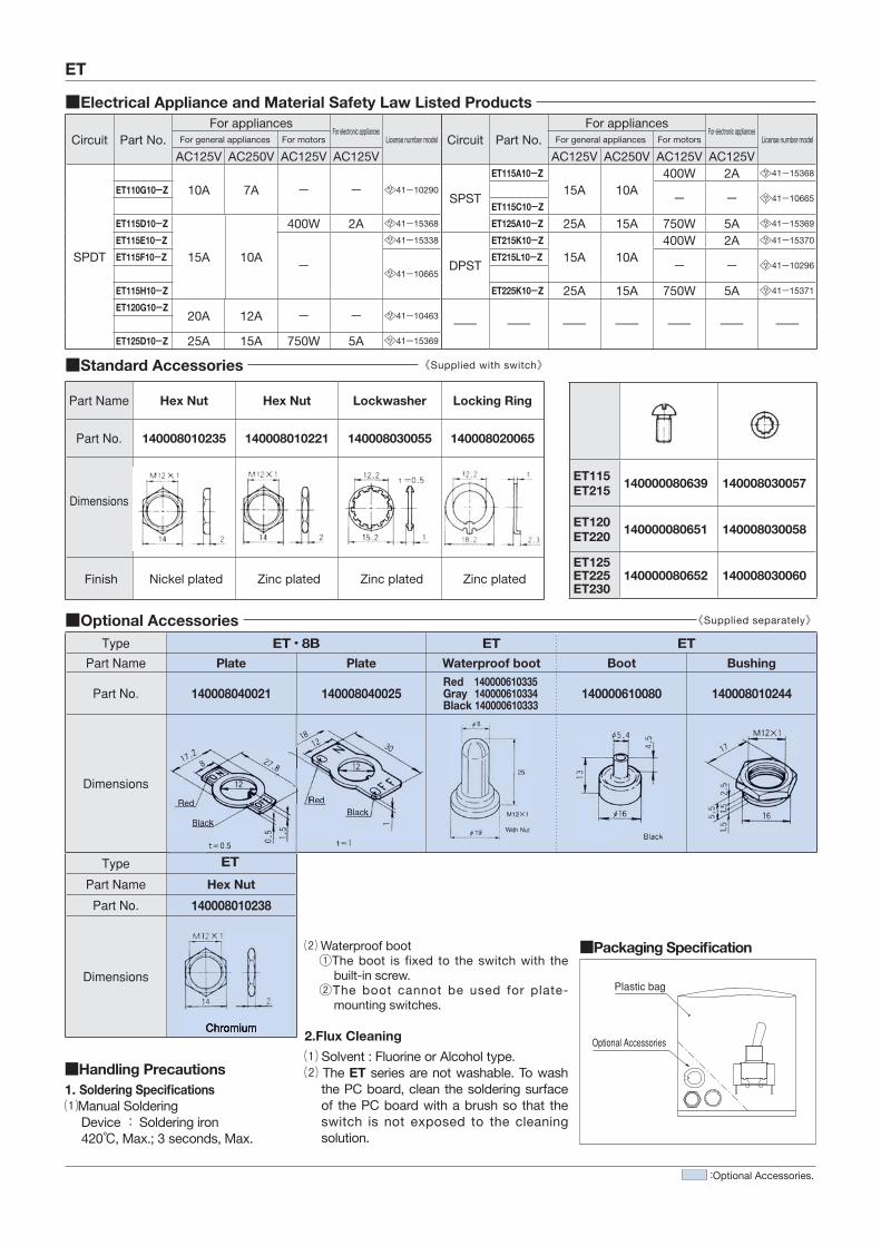
■Electrical Appliance and Material Safety Law Listed Products
Circuit Part No.For appliances
For electronic appliancesLicense number model Circuit Part No.
For appliancesFor electronic appliances
License number modelFor general appliances For motors For general appliances For motors
AC125V AC250V AC125V AC125V AC125V AC250V AC125V AC125V
SPDT
10A 7A - - 41-10290SPST
ET115A10-Z
15A 10A400W 2A 41-15368
ET110G10-Z - - 41-10665ET115C10-Z
ET115D10-Z
15A 10A
400W 2A 41-15368 ET125A10-Z 25A 15A 750W 5A 41-15369
ET115E10-Z
-
41-15338
DPST
ET215K10-Z
15A 10A400W 2A 41-15370
ET115F10-Z
41-10665
ET215L10-Z - - 41-10296
ET115H10-Z ET225K10-Z 25A 15A 750W 5A 41-15371
ET120G10-Z20A 12A - - 41-10463
- - - - - - -ET125D10-Z 25A 15A 750W 5A 41-15369
ET
■Standard Accessories 《Supplied with switch》
Part Name Hex Nut Hex Nut Lockwasher Locking Ring
Part No. 140008010235 140008010221 140008030055 140008020065
Dimensions
Finish Nickel plated Zinc plated Zinc plated Zinc plated
ET115ET215 140000080639 140008030057
ET120ET220 140000080651 140008030058
ET125ET225ET230
140000080652 140008030060
■Optional Accessories 《Supplied separately》
Type ET・8B ET ETPart Name Plate Plate Waterproof boot Boot Bushing
Part No. 140008040021 140008040025Red 140000610335Gray 140000610334Black 140000610333
140000610080 140008010244
Dimensions
Type ET
Part Name Hex Nut
Part No. 140008010238
Dimensions
Chromium
Red
Black
RedBlack
⑵ Waterproof boot①The boot is fixed to the switch with the
built-in screw.②The boot cannot be used for plate-
mounting switches.
■��������������������
Optional Accessories
Plastic bag
■Handling Precautions1. ��������������������� �⑴Manual Soldering
Device:Soldering iron420℃, Max.; 3 seconds, Max.
2.Flux Cleaning
⑴ Solvent : Fluorine or Alcohol type.⑵ The ET series are not washable. To wash
the PC board, clean the soldering surface of the PC board with a brush so that the switch is not exposed to the cleaning solution.
:Optional Accessories.