ESTIMATION RELATIVE AIRCRAFT USING Nicholas Brownsberger
306
/ ESTIMATION OF SONOBUOY POSITION RELATIVE TO AN AIRCRAFT USING EXTENDED KALMAN FILTERS Nicholas Mason Brownsberger
Transcript of ESTIMATION RELATIVE AIRCRAFT USING Nicholas Brownsberger

/
ESTIMATION OF SONOBUOY POSITIONRELATIVE TO AN AIRCRAFT
USING EXTENDED KALMAN FILTERS
Nicholas Mason Brownsberger


NAVAL POSTGRADUATE SCHOOL
Monterey, California
THESISEstimation of Sonobuoy
Relative to an AireUsing Extended Kalman
Position.raftFilters
by
Nicholas Mason Brownsberger
September 1979
Thesis Advisor: T) ,T Pollins
Approved for public release; distribution unlimited
T189584


SECURITY CLASSIFICATION OF THIS PAGE (When Data Etumrtd)
REPORT DOCUMENTATION PAGE READ INSTRUCTIONSBEFORE COMPLETING FORM
1. REPORT NUMBER 2. GOVT ACCESSION NO. 3. RECIPIENT'S CATALOG NUMBER
4. TITLE (end Submit)
Estimation of Sonobuoy PositionRelative to an AircraftUsing Extended Kalman Filters
S. TYPE OF REPORT a PERIOD COVEREDMaster's and Engineer'sThesis; September 1979
«. PERFORMING ORG. REPORT NUMBER
7. AUTHORf»>
Nicholas Mason Brownsberger
• . CONTRACT OR GRANT NUMBERC*)
9. PERFORMING ORGANIZATION NAME ANO ADDRESS
Naval Postgraduate SchoolMonterey, California 939^0
10. PROGRAM ELEMENT, PROJECT, TASKAREA a WORK UNIT NUMBERS
1 1. CONTROLLING OFFICE NAME ANO ADORESS
Naval Postgraduate SchoolMonterey, California 939^0
12. REPORT DATE
September 197913. NUMBER OF PAGES
14. MONITORING AGENCY NAME a AOORESSflf dlllerent from Conrrofl/n« Olllee)
Naval Postgraduate SchoolMonterey, California 939^0
IS. SECURITY CLASS, (ol thl* report)
UnclassifiedISa. DECLASSIFICATION' DOWNGRADING
SCHEDULE
18. DISTRIBUTION STATEMENT (ol thl. Report)
Approved for public release; distribution unlimited
17. DISTRIBUTION STATEMENT (ol Mia asarraet entered In Bloc* 30, II dlllerent /ran Report)
IS. SUPPLEMENTARY NOTES
1*. KEY WOROS (Continue on rereree aid* II neceeeery end Identity by block number)
SRS (Sonobuoy Reference System)Kalman FilterSonobuoy
20. ABSTRACT 'Continue on reveree aid* II neceeeery end Identity by black number)
In airborne anti-submarine warfare there is a need to moreaccurately determine the positions of sonobuoys on the surfaceof the water. This report develops two algorithms which employextended Kalman filters to determine estimated position. Thebearing from the aircraft to the sonobuoy is the primarymeasurement. Range information is not available. The firstalgorithm is a six-state filter which was reduced from the
DO | JAN^S 1473 EDITION OF 1 MOV «* IS OBSOLETES/N 102-014-660 1
I
SCCUNITY CLASSIFICATION OF THIS PAGE (When Dele gnlered)


JtCUWITY CLASSIFICATION OF THIS P IGEfWrn D»l« ErX.r.rf
13-state system developed, by the Orincon Corporation. Itsstates include relative position, relative velocity, andinertial misalignments. The second algorithm includes twocascaded Kalman filters. The primary two-state filter esti-mates sonobuoy position. A secondary filter estimates driftfrom information obtained from the primary filter. Bothalgorithms successfully estimated sonobuoy position forsimulated aircraft data. The effect of aircraft- to-sonobuoyrange, the frequency of measurement, and changes in altitudeare also analyzed.
DD Form 14731 Jan 73
S/N 0102-014-6601 SECURITY CLASSIFICATION OF THIS PAGErWh.n Dmlm Enfrmd)

Approved for public release; distribution unlimited
Estimation of Sonobuoy PositionRelative tc an Aircraft
Using Extended rCalman Filters
by
Nicholas Mason BrownsbergerLieutenant, United States Navy
B.S., United States Naval Academy, 1972
Submitted in partial fulfillment cf therequirements for the degrees of
MASTER OF SCIENCE IN AERONAUTICAL ENGINEERING-AND
AERONAUTICAL ENC-INEER
from the
NAVAL POSTGRADUATE SCHOOLSeptember 1979


ABSTRACT
In airborne anti-submarine warfare there is a need to
more accurately determine the positions of sonobuoys on the
surface of the vater. This report develops two algorithms
which employ extended Kalman filters to determine estimated
position. The bearing from the aircraft to the sonobuoy is
the primary measurement. Range information is not available.
The first algorithm is a six-state filter which was reduced
from the 13-state system developed by the Orincon Corporation
Its states include relative jjosition, relative velocity, and
inertial misalignments. The second algorithm includes two
cascaded Kalman filters. The primary two-state filter
estimates sonobuoy position. A secondary filter estimates
drift from information obtained from the primary filter.
Both algorithms successfully estimated sonobuoy position for
simulated aircraft data. The effect of a ircraf t-to-sono bucy
range, the frequency of measurement, and changes in altitude
are also analyzed.


TABLE OF CONTENTS
I. INTRODUCTION 10
II. FILTERS 13
III. MODELS 20
A. GENERAL APPROACHES TO SYSTEM MODELING 20
B. THE COORDINATE SYSTEM 22
C. THE SIX-STATE SYSTEM 23
D. THE TWO-STATE SYSTEM 37
IV. ANAYLSIS 43
A. THE SIMULATION 43
3. THE RESULTS 56
V. CONCULSION 87
VI. SUMMARY 59
APPENDIX A: THE COMPUTER PROGRAMS 92
APPENDIX 3: COMPUTER PROGRAM FOR DATA GENERATION 127
APPENDIX C: RMS POSITION ERRORS EOR RANGE,
FREQUENCY, AND ALTITUDE ANALYSIS 140
3I3LICGRAFHY 149
INITIAL DISTRIBUTION LIST 150


LIST OF FIGURES
1. Kalman filter notation 15
2. Divergence 18
3- Earth fixed coordinate system 22
4. Aircraft fixed coordinate system 22
5. Cascaded Kalman filters 38
6. Aircraft track for the 15 NM circular patternwith initial sonobuoy location and directionof drift indicated 46
7. Aircraft track for the 15 NM square patternwith initial sonobuoy location and directionof drift indicated 47
8. Aircraft's navigational output for the 15 NMsquare; navigational drift is 2.5 NM/Hr tothe north 48
9. Aircraft's navigational output for the 15 NMsquare; navigational drift is 2.5 NM/Hr northwith a Schuler cycle 49
10. The effect of drift in the aircraft navigationalplot 52
11. RMS statistics at time = k 55
12. Orincon's simulation flight path 57
13. Estimated position and relative errors for thesix-state system using Orincon's pattern 67
14. Estimated position and relative errors for thetwo-state system using Orincon's pattern 68
15- Estimated position and relative errors for thetwo-state system using Orincon's pattern 69
16. RMS position errors for the six-state system whileflying the circular pattern developed by OrinconCorp. 70


17 • RMS position errors for the two-state system whileflying the circular pattern developed by OrinconCorp. 71
18. RMS position errors for the two-state system whileflying the circular pattern developed by OrinconCorp. 72
19. Estimated position and relative errors for the six-state system using circular pattern at 15 NM 73
20. Estimated position and relative errors for thetwo-state system using circular pattern at 15 NM - 7^
21. Estimated position and relative errors for thetwo-state system using circular pattern at 15 NM - 75
22. RMS position errors for the six-state system whileflying a 15 NM circular pattern around the sonobuoy 76
23- RMS position errors for the two-state system whileflying a 15 NM circular pattern around thesonobuoy 77
2^. RMS position errors for the two-state system whileflying a 15 NM circular pattern around thesonobuoy 78
25- Estimated position and relative errors for thesix-state system using square pattern at 15 NM 79
26. Estimated position and relative errors for thetwo-state system using square pattern at 15 NM 80
27- Estimated position and relative errors for thetwo-state system using square pattern at 15 NM 81
28. RMS position errors for the six-state system whileflying a 15 NM square pattern around thesonobuoy 82
29- RMS position errors for the two-state system whileflying a 15 NM square pattern around thesonobuoy 83
30. RMS position errors for the two-state system whileflying a 15 NM square pattern around thesonobuoy 8^
31. RMS position error as a function of aircraft-to-sonobuoy range, ax, for the six-state and two-state systems 85


32. RMS position error as a function of measurementinterval, At, for the six-state and two-statesystems 86
33- Factors which influence the covariance 64
34. Flow chart: main program 92
35' Flow chart: subroutine FILTER six-state 93
36. Flow chart: subroutine FILTER two-state 94
37. Flow chart: data generation program 127
38. RMS errors for two-state system and six-statesystem using circular pattern at 5 NM 140
39. RMS errors for two-state system and six-statesystem using circular pattern at 30 NM 141
40. RMS errors for two-state system and six-statesystem using circular pattern at 45 NM 1^-2
41. RMS errors for two-state system and six-statesystem using square pattern with At = 4 sec. 143
42. RMS errors for two-state system and six-statesystem using square pattern with At = 10 sec. 144
43. RMS errors for two-state system and six-statesystem using square pattern with At = 30 sec . 145
44. RMS errors for two-state system and six-statesystem using circular pattern, Alt = 300' 146
45. RMS errors for two-state system and six-statesystem using circular pattern, Alt = 10,000' 147
46. RMS errors for two-state system and six-statesystem using circular pattern, Alt = 20,000' 148


ACKNOWLEDGEMENT
I would like to thank Dr. Birnbaum and Ms. PeggyPembroke of NADC for their responsiveness in answeringquestions and supplying computer information. And toDr. Collins I would like to express my gratitude forhis help and guidance without which this thesis couldnot have been completed. To my wife I would like tooffer my special thanks and love for her patience,understanding, and fortitude during a time whichtested both of us.
Nick Brownsberger

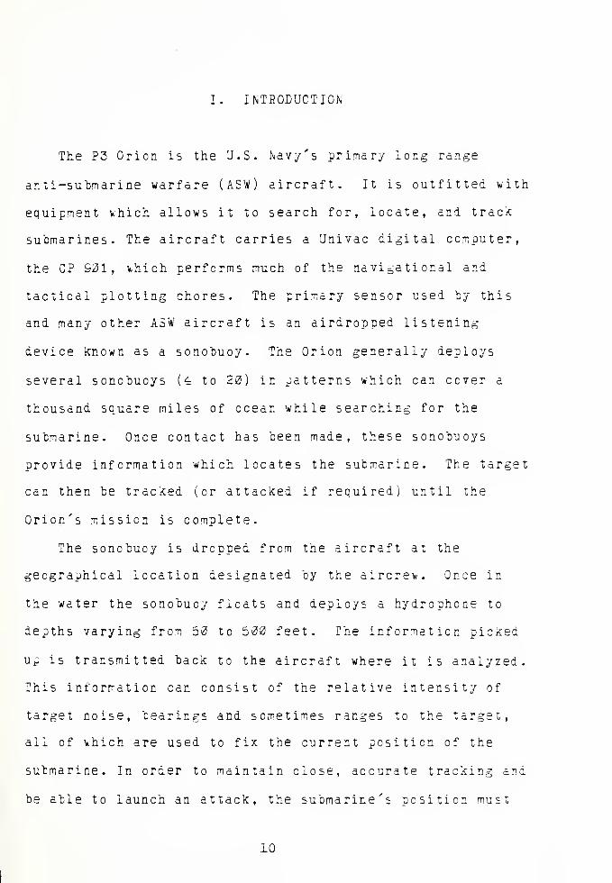
I. INTRODUCTION
The P3 Orion is the U.S. Navy's primary long range
anti-submarine warfare (ASW) aircraft. It is outfitted with
equipment which allows it to search for, locate, and track
submarines. The aircraft carries a Univac digital computer,
the CF 901, v,hich performs much of the navigational and
tactical plotting chores. The primary sensor used by this
and many other ASW aircraft is an airdropped listening
device known as a sonobuoy. The Orion generally deploys
several scnobuoys (4 to 20) in patterns which can cover a
thousand square miles of ocean while searching for the
submarine. Once contact has been made, these sonobuoys
provide information which locates the submarine. The target
can then be tracked (or attacked if required) until the
Orion's mission is complete.
The sonobuoy is dropped from the aircraft at the
geographical location designated by the aircrev.. Once in
the water the sonobuoy floats and deploys a hydrophone to
depths varying from 50 to 500 feet. The information picked
up is transmitted back to the aircraft where it is analyzed.
This information can consist of the relative intensity of
target noise, bearings and sometimes ranges to the target,
all of vhich are used to fix the current position of the
submarine. In order to maintain close, accurate tracking and
be able to launch an attack, the submarine's position must
10

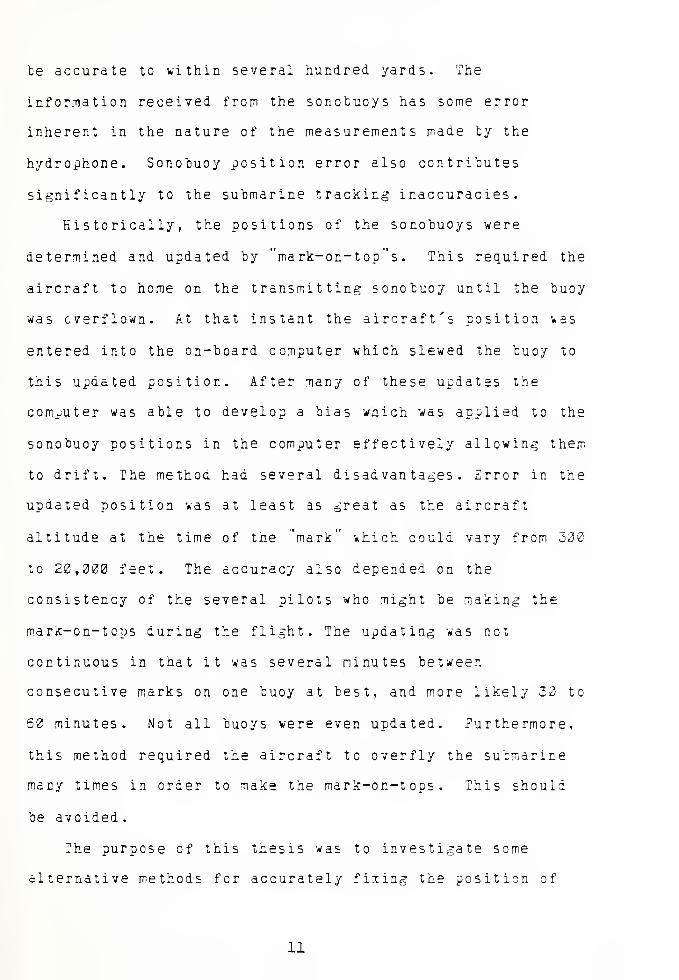
te accurate to within several hundred yards. The
information received from the sonobuoys has some error
inherent in the nature of the measurements made ty the
hydrophone. Sonobuoy position error also contributes
significantly to the submarine tracking inaccuracies.
Historically, the positions of the sonobuoys were
determined and updated by "mark-on-top"s . This required the
aircraft to home on the transmitting sonobuoy until the buoy
was overflown. At that instant the aircraft's position vas
entered into the on-board computer which slewed the buoy to
this updated position. After many of these updates the
computer was able to develop a bias which was applied to the
sonobuoy positions in the computer effectively allowing them
to drift. The methoa had several disadvantages. Error in the
updated position \*as at least as great as the aircraft
altitude at the time of the "mark" which could vary from 300
to 20,000 feet. The accuracy also depended en the
consistency of the several pilots who might be making the
mark-on-tcps during the flight. The updating was not
continuous in that it was several minutes between
consecutive marks on one buoy at best, and more likely 30 to
60 minutes. Not all buoys were even updated. Furthermore,
this method required the aircraft to overfly the submarine
many times in order to make the mark-on-tops. This should
be avoided.
The purpose of this thesis was to investigate some
alternative methods for accurately fixing the position of
11


sonobuoys. They should allow the aircraft to stand-off from
the sonobucy field and still produce more accurate fixing
than the historical method provided. The Naval Air
Development Center (NADC) at Warminster, PA. had already
partially developed such a system. This thesis was
undertaken in support of their work but v*as conducted
independently. Their system, the Sonobuoy Reference System
(SRS), was already installed on the aircraft and had the
capability of measuring the relative bearing to any
transmitting sonobuoy. Additional information available for
use included aircraft heading, altitude, and airspeed as
well as doppler velocity and drift angle. Also, the
aircraft's Inertial Navigational System (INS) provided
geographical position although the Schuler cycle and
inertial drifts could make this position several nautical
miles in error. On the other hand, aircraf t-to-scnobuoy
range and sea surface drift information were assumed not tc
be available. An attempt was made to determine sonobuoy
position at least relative to the aircraft with a less
accurate geographical position as a secondary objective.
Salman filtering techniques were used based primarily on
measurements of bearing from the aircraft to the sonobucy.
12


II. FILTEItS
Kalman filtering is a recursive technique for estimating
the state of a system. It was developed in the 1962's by R.
E. Kalman and improved upon previous methods by Wiener and
others. The Wiener filter is based on frequency domain
designs which are statistically optimal but are only
applicable to stationary processes. The Kalman filter is
based on state-space, time domain formulations and is
especially suited to digital computers. From a simplistic,
one-dimensional point of view, the Kalman filter recursively
averages noisy measurements to provide a more precise
estimate of the actual value.
Assume that a system can be linearly modeled with state
equations in matrix form as
X. = |, X, + A. U + T Vk ~k-l k4 k-i k-i k-t k-1
(1)
where X represents the states of the svstem at the Kthk
interval. (Only the discrete case \*as be considered in this
study.) <5 is the transition matrix and is used to"k
"propagate" the system from X tc £+1. U represents thek
control input to the system and W represents white,k
guassian noise with mean and Q variance, written N(3,Q )
k k
Measurements are required to update the system and are
13

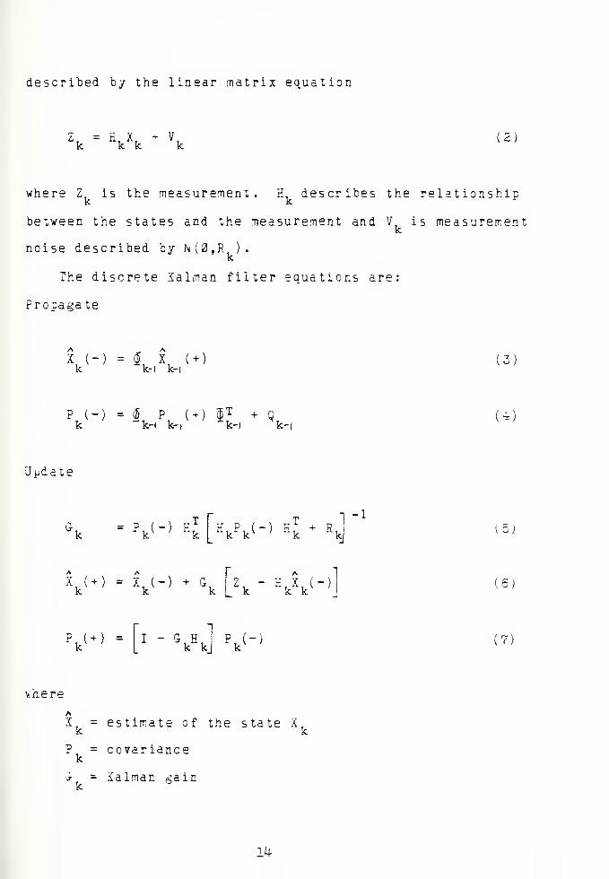
described by the linear matrix equation
Zk - \\ + \ (2)
where Z, is the measurement. H, describes the relationshipk k
between the states and the measurement and V, is measurementk
noise described by N(0,R ).k
The discrete Kalman filter equations are:
Propagate
K K (+
k-i k-i(3)
?k
(
")
X p (+) (jjT + Qk-i k-i k-i k-
U)
Update
S - pk <-> < g p ( _ ) ff
T + dnk k v ; "k n
kj
-1
(5j
Xk
( + ) = I (-) + Gk
Zk "W (6)
P. (+)k
I - G Hk k V-' (?)
vhere
AX. = estimate of the state X.
covanance
Salman gain
14


AThe estimate prior to the measurement is denoted by X
K(-)
and can be updated after the measurement to a new estimate
Adenoted X
K(+). This notation is shown in figure 1. The
covariance matrix provides a statistical measure of the
Auncertainty of X. Consider a 2 x 2 covariance matrix where
the error T in the estimate is defined as x - x :
P =
E(x* )
E(x. lz )
E(x, xI
-""2
E(x* )
a, a-
(£)
The diagonal elements represent the mean square errors of
the corresponding state variables x and x2
. The
off-diagonal elements are indicators of cross-correlation
between the states. The Kalman gain J is an optimal gain
choosen so as to minimize the sum of the diagonal terms of
the covariance matrix.
Hk-i,
Rk-i
hl a
*k-iH
p k-.'-i
?k-.<*>
Vi<
£ k«-l
k,*k
*k (*l
*k-i,°k-iO *k.°k
S>
<k-i
TIME
Eigure 1. Salman filter notation
15


If either the system mcdel or the measurement model is
non-linear, then non-linear filters must be used. Let the
non-linear system be described by
\ - ^K~r> + v, ;w,^n(0,q, ) (9.
zk
= h(v + vk I V
k-K(0,R
k ) (10)
where ©(X, ) represents the non-linear equations cf ther k-i
system. They can be linearized cy a Taylor series expansion
around the latest estimate of the state tc obtain (j> ( X ,) .
Likewise, h(X ) represents the non-linear measurementA
equations and by a Taylor series expanicns yields H(X. ).
(xk
) = j*uk
) + I(i k ) X - Xk k
11)
h(X, h(Xk
) + H(Xfc
) Xk
" Xk
(12)
where
fu ) = —3_dx J x-x
(13)
H(X, )
ka
3xh(X,
x--x
14)
Second order Taylor series terms are neglected. Now, the
extended Kalman filter can be implemented with the following
equat ions
:
16


Propagate
X, (-)k
= 4 {*k-i
(15)
V"* - iUvnt-)) ^.,( +) i(x, ,(-
k-l •k-i(16)
Update
G = P (-) H(Xk ( -)) H(X,.(")) P. (-) E(X. (-) )
T- 17!
v + v-> + ^ zk
" H ( xfc(~)
)
(18)
¥.(+ )
= 1 " *kH(I
k (-))Pk(- (19)
Higher order filters can be used if the linearization
errors are large. The second order Kalman filter employs
one more term in the Taylor series expansion by modifing the
update equations of the extended Kalman filter to account
for this tern. The iterated extended Kalman filter uses the
same equations as does the extended Kalman filter. However,
the calculations are repeated, each time linearizing about
the most recent estimate, until there is little further
improvement with each new iteration. The iterated extended
filter can greatly reduce the errors due to non-linearities,
mere so than the second order filter.
Kalman filters should be based en correctly modeled
systems and accurate noise statistics to ensure proper
17


performance. This is not always possible either due to
ignorance about the system or lack cf sufficient statistical
information. A filter which is not operating properly may
diverge. Apparent divergence describes that situation where
the true estimation errors are larger than the filter
predicted errors although they are bounded. True divergence
is characterized by errors which continue to grovi with time
and eventually become infinite. These divergence phenomenon
are depicted in figure 2.
There are several ways to overcome the divergence
problem when the modeling is not completely accurate such as
adding fictitious noise. This allows the filter a little
more freedom to adjust to whatever modeling inconsistencies
may exist, but makes the filter estimate appear more
erratic. Another method *hich helps overcome divergence is
finite memory filtering. Since Kalman gains tend to grow
smaller and smaller as time passes, they may reach a point
TRUE
THEORETICAL
TIME
(a) Apparent Divergence
TIME
Ob) True Divergence
Figure 2. Divergence
18


where new measurement information has no effect on the
estimates. Finite memory filtering effectively eliminates
old data which is no longer useful by keeping the gains
significant. This is sometimes called a "moving window .
Some simplifing techniques used in Kalman filters
include precomputed gains. Although forfeiting the optimal
Kalman gains, this has the advantage of reducing
computational burden. More importantly, the gains can be
controlled to overcome modeling weaknesses if necessary.
Another technique which can be used when more than one
measurement is provided to a filter is processing them one
at a time. This avoids taking the inverse of more than a
scalar when computing the updated covariance matrix P„(+).
This is possible if the simultaneous measurements are
considered to be taken sequentially over a zero time span.
19

III. MODELS
A. GENERAL APPROACHES TO SYSTEM MODELING
The aircraf t-sonobuoy system must be modeled in
state-space for use with the Kalman filter. There are at
least two approaches to the modeling of this problem
depending on the point of view. One intuitive approach is to
assume the sonobuoy drifts at a constant velocity and then
use aircraf t-to-sonobuoy bearing measurements to locate the
sonobuoy. The states become sonobuoy position and sonobuoy
velocity. Unfortunately, this problem is not observable.
The bearing measurements provide only information about
position? there is no rate of change information in the
bearings themselves. In addition, the aircraft must
maintain a track of its geographical position between
updates in order to determine the next expected measurement
for the Kalman filter. As mentioned before, this aircraft
position is subject to non-linear as well as linear
navigational drifts which are not taken into account in this
model. However, an observable system can be obtained by
reducing the number of states to sonobuoy position only and
introducing fictitious process noise to account for the
drift. This noise effectively allows sonobuoy position to
update so as to keep up with the drift. One approach
developed by this thesis is a variation of this concept.
20


Another approach considers only the relative position of
the sonotmoy with respect to the aircraft. Relative
velocities and relative accelerations must be taken into
account and these change radically as the aircraft flies in
the tactical situation. Sonobuoy jjosition is not obtained
directly. (When only the word "position" is used it will
indicate the position relative to an earth fixed coordinate
system, such as latitude and longitude. "Relative position"
will always mean the location with respect to an aircraft
fixed coordinate system.)
There are some other considerations which should be
addressed. The sonobuoy drift is generally slow (less than
5 NM/Hr most of the time) and constant. It is not
unreasonable to assume that the entire sonobuoy field drifts
at the same velocity. Another point is that aircraft
navigational drift can not be distinguished from sonobuoy
drift. In other words, the drift that is preceived by the
aircraft is the combination of sonobuoy drift and aircraft
navigational drift. If this navigational drift is linear
and not excessive it causes few problems. dowever,
non-linear navigational drifts, such as the Schuler cycle,
can cause large errors.
21

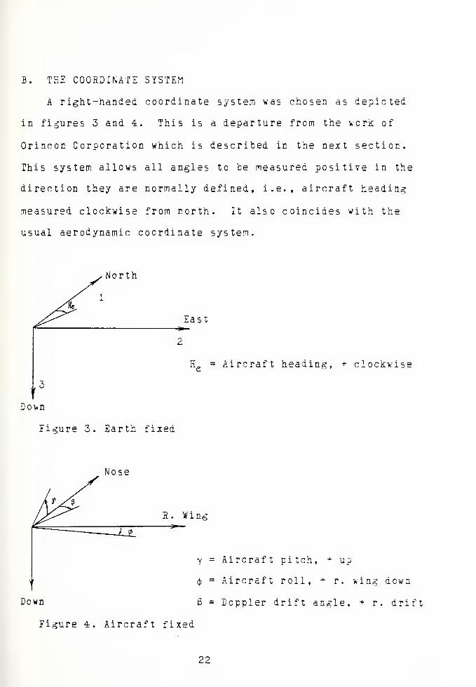
B. THE COORDINATE SYSTEM
A right-handed coordinate system was chosen as depicted
in figures 3 and 4. This is a departure from the work of
Orincon Corporation which is described in the next section.
This system allows all angles to be measured positive in the
direction they are normally defined, i.e., aircraft heading
measured clockwise from north. It also coincides with the
usual aerodynamic coordinate system.
North
East
H = Aircraft heading, + clockwise
3
Doi*n
Eigure 3. Earth fixed
Nose
Aircraft pitch, + up
Aircraft roll, + r. wing down
Doppler drift angle, + r . drift
22

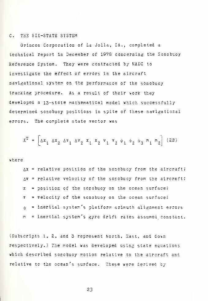
C. THE SIX-STATE SYSTEM
Orincon Corporation of La Jolla, CA., completed a
technical report in December of 1978 concerning the Sonobuoy
Reference System. They were contracted by NADC to
investigate the effect of errors in the aircraft
navigational system on the performance of the sonobuoy
tracking procedure. As a result of their v/ork they
developed a 13-state mathematical model which successfully
determined sonobuoy positions in spite of these navigational
errors. The complete state vector was
XT = AX
1AX
2AV
1AV
2X
lXZ
Vl
V2 *1
Xh *3 % m2
(22)
where
Ax
AV
x
V
m
relative position of the sonobuoy from the aircraft;
relative velocity cf the sonobuoy from the aircraft;
position of the sonobuoy on the ocean surface;
velocity of the sonobuoy on the ocean surface;
inertial system's platform azimuth alignment errors
inertial system's gyro drift rates assumed constant.
(Subscripts 1, 2, and 3 represent North, East, and dovn
respectively.) The model was developed using state equations
which described sonobuoy motion relative to the aircraft and
relative tc the ocean's surface. These were derived by
23


Orincon frcm
AX = X - (X1
+ Ea
(21
and other mechanization equations to obtain
A*. = A?"1
AX 2
Av1
Av,
1
= AV2
2= -R
j_
+ co ( x1
~R2
+oo U
2
= v.
- ial ~ AV " ^3 A
2(Kg
- Xa2
- A^2
) ~*3 A!"'^6
Z2
= V2
7=0V„ =
(22)
where
X1
H =
g =
to =
A =
aircraft inertial navigation system position
aircraft inertial navigation system error
vector from the center of the earth to the aircraft
acceleration due to gravity (assumed constant)
Schuler frequency yg/R
'
aircraft accelerometer outputs
The sonotuoys vere assumed to drift at a constant velocity
and the aircraft was assumed to fly at a constant altitude,
The inertial alignment errors were described by
2k


i>3
= ij^n cosx
(23)
inhere
Q, = earth rate
X = latitude
There were several sources of measuremer. t information.
Aircraft to sonobuoy bearing v,as available from the aircraft
interferometer system in the form of cosQ vhere 8 is the
angle between the direction to the scncbuoy and. the base
line of the antenna. Doppler velocity and. drift angle from
the aircraft doppler radar system provided information about
Av and Av„. The only other relevant source of measurement
information vould have come from JPS (Global Positioning
System) which would have provided error free aircraft
position.
Orincon performed a numerical observability analysis on
this system based on the observability matrix M, given by
\- Ii=l
£ H* R_1H $
k k k k24'
If this matriz is positive definite for H^2 then the system
is considered observable. In addition, an eigenvalue
analysis provided information as to the conditioning cf the
system. The result of their analysis indicated that the
25

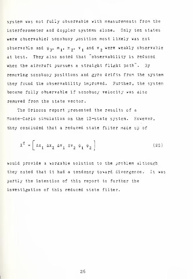
system was not fully observable with measurements from the
interferometer and doppler systems alone. Only ten states
were observable; sonobuoy position most likely was not
observable and \p ~, m ,, m2
, v. and v were weakly observable
at test. They also noted that "observability is reduced
when the aircraft pursues a straight flight path". By
removing sonobuoy positions and gyro drifts from the system
they found the observability improved. Further, the system
became fully observable if sonobuoy velocity was also
removed from the state vector.
The Orincon report presented the results of a
Monte-Carlo simulation on the 13-state system. However,
they concluded that a reduced state filter made up of
TX - AX
1AX
2AV
1AV
2 *1 *2 (25)
would provide a workable solution to the problem although
they noted that it had a tendency toward divergence. It was
partly the intention of this report to further the
investigation of this reduced state filter.
26


The state equations for the reduced six-state filter can
be obtained directly from Equations (22) and (23).
Ax, = Av,
Ax_ = Av.
Av = -R. + (j {xl
Av2
= -I2
+ J(x2
ty.=
4>2
sinX
i>2
= -\pl
sinX
xal " A2
1}
+ VZa2 " Ax 2> " *1*
(25)
where ill , m , and m are set to zero. In matrix form3 1 2
X =
[
AVAx„
AvL =
AV2
*1
L *J
1
1
-co2 -g
012_
(JJ gu
--fisinX
f2sinX
Ax
Ax.
Av
Av.
n 2/ I-R + oil -I
, ,
1 i al
-K-+ 0)1 "I -,2 2 a2
which can be abreviated
X =AA
i k^X + B (27)
Expressed in discrete time the state equation is
\+l = »Xk
+*k (26)
27


The discrete formulation of the plant matrix can be obtained
from
i -ti Si - A•H At
= e (29)
Developing this
si - A
S 1 1
1
2
S 1 1
1
2 nOJ S '
1
g
. 2CO s
I
"_L
~s
0' s ft sin AI
' -ftsinA s
(30)
from which the determinant of the system is
si - A = (s2
+ u2
)
2(s
2+ n
2 sin 2\)
231)
The inverse of this matrix and its Laplace transform are
presented on the following pages as Equations (32) and (33)
respectively.
28


CM
00
<<CM-
e
+
3
+
cn
c:
00
(3
•Hcn
si
c:
+
3
+
-~c
C
oo
CM
+
3
+
ID
OO
c•HCO
M
+
3
+
to
00
CM
a.
+
c
cn
c;
00I
3
+
CMc•HCO
CMa+
CMCO
CM3
+
cn
c:
00i
CM
+
cn
oo
3
+
CMa
cs
+
3
+
c-< •Hc CO
•H CMcn aa
i +
CMa
CMcHcn
CM
+CM
CD
r<CMc
<< •Hc 0)
•H CMcn CSc;
+CM
3
+
3
+
3
+
3
+
3
+
CM3
+
3
+
3I
3
+
II
I
I
29


' u '1 4J 1
1
4-1
/'—
\
r< <<c1-1
c1
4J ' •H/-N CO CO CO
*< c: c: ac ••w
'
^—
'
CN %-• CN 4-1 4-1
H CN C CN c 3 CO 3 ^-\ r~\
CO 3 •7-1 3 •H o << -<
c; co CO 1 o 1 c c\^*
1 l 1 ^< 1 •H T-l
CO u c << 4-1 r< CO CD
<< 3 r< •H CN 3 CN CS CI
CJ CM C CN CO c CO c s-^ ^—
'
1 a T-l c a •H o T-l C ID
4J •H CO 1-1 1 CO . u,
CD •H o3 CO CO 4-1 CN CN CO CJ
to CN •< CN 3 CJ *< a 1
o a C c: a a1°
1
•HCO
3 i-i
CD
•HCD
oo a.
31
c:00i
i i
0000
1
' 4-1 !
1 u '
/—
s
! 4-1 1
^ f~*. a
t-I c•HCD
1 u '
CO •-N •H ac: r< CD •w CN•^ CN a CN a CN c 3 4-1 4-1
a 3 •H 3 n^ 3 •H ^"N >*"s
•H CO CD CD 1r< <.
CO 1 cs 1 O 1 r< c £1 CJ a -< T-l T-l
4J << CD << 1 << •H CN CD '/I
3 CN O CN 4-1 CM CD C C3 aC c o C 3 C! c: •H ••w' *—*
T-l H 1 T-t CO T-l i CD CD cCD CO 4-1 CO o CD 4-1 CN O H
CN 3 CN. °
1
CM 3 a u CO
.-C a CD a a Cc O .-< •H•H 3
,O
1
•HCD
CD
1
31
CO
c: 00i cs
oo001
001
i
4-1 4-1
3 3c CD
o •HCD
-i| 3
o oCJ
o o
4-1 4-1
3 3C CO
•H O O o o oCO CJ
-<|3
4-1
3CO
4-1
3Co o
oo H
CD
31
o o
4J 4-1
3 3CO ao o H O o o.a en
31
h©i
30

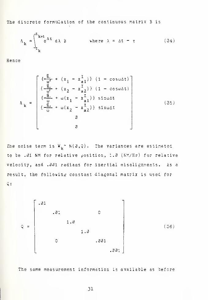
The discrete formulation of the continuous matrix S is
'k+l
Ak
= eAt
dX B where A = At - t (34)
Hence
{-h- + (x. - x1
. ) } (1 - cosojAtto 1 a 1
{-% + (x, - x1,) } (1 - coscoAt
to z a/
{-— + (i»(x. - x1
, ) } sincoAt1 al
{-
CO
io(x„ - x „ ) } sincoAt2 a2
3
3
(35)
The noise term is W ~ N(0,Q). The variances are estimated
to te .31 NM for relative position, 1.0 (NM/Hr) for relative
velocity, and .331 radians for inertial misalignments. As a
result, the following constant diagonal matrix is used for
Q:
Q =
.31
.31
1.0
1.3
.031
.301
36
The same measurement information is available as before
31


in the larger system, namely interferometer bearings and
doppler velocity and drift angle. These introduce non-
linearities and must he modeled as in Equation (10).
\ = h<V + vk
A Taylor series expansion as in Equation (11) about the
latest estimate of sonobuoy position provides a method of
linearization. As a result
K =3 Ax.
3 z
3 Ax.
3 z
3 Av.
*-*
3 z
3 Av,
3 z
3^3 z
3 i>,
(3?)
-i
To determine z and its partial derivatives, recall that
z = cosi = AX • R# (35
where AX is the unit vector representation of a line from
the aircraft to the sonobuoy and RB is the unit vector
describing the base line between the antenna pairs of the
in terf erome ter.
z . = cos 9
v--x
Ax.
AxRB
Ax,
AxRB
Ax.—- RB„Ax
Ax RB. + Ax„RB + h RB
(AxL
2+ Ax
2
2+ \})
h
where h is the aircraft altitude
(39)
32


inhere
" 9zl
3zi
La Ax. 3 Ax2
2 (40)
A-t a«x
a a.
3 Ax,•(z
A-K
X = X
(Ax.+Ax.+h )
1
(Ax.+Ax +h )
HB r
R32~
Ax/AXjRB, +A^IB2+HRBP
(AxJ + AxN
^ + h2
)
Axz(AxRB
;
+AxRBz+hRBp
(AXj + Ax2
+ h2
)
(41)
(42)
The doppler velocity, V,, is a measurement of aircraftd
speed relative to the ocean surface and doppler drift angle,
3, is a measure of the angle between aircraft track and
aircraft heading. These measurements can he related to the
state vector by assuming the sonobuoys drift at the same
velocity as the ocean surface. If this is true then
z2
- Vd
= (Av2
+ Av 2)
% (43)
Expanding in a Taylor series yields
z2
= (AvA2
+ AS 2)
1* (44
H -2
where
a z.
3 Av.
3 2,
3 Av.
x-x
(45
a z.
a Av.
a z.
a Av,
A-*
A* A
AAv
, . a 2 . a 2 , ^(Avj + Av2
)
Av
(AC2+ Av
2)
15
i^6;
(47:
33

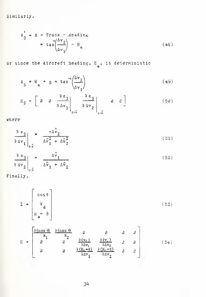
Similarly,
z - B = Track - Heading3
-i/Av„\= tan - H
vAv
or since the aircraft heading, H , is deterministic
(46)
-i/Avz = H + g = tan f
3 e\Av
1'
2
a z.
3 Av.
3 z
3 Av.
x=* A^X
where
3z3
3 Av
3z3
3 Av2
Finally,
-Av,
jr-x
AVj + Av2
AAv.
Av + Avx=x
2
(49;
(50)
(51)
(52)
Z =
CCS0
V
H - 8e
H =
3 (cos 6) 3 (cos e)
x, x„
2
3(vrf) 3 (v.j )
3Av! 3Av29 0fe+8) 3(H tf +8)
3Av, 3Av„
(54)
3^

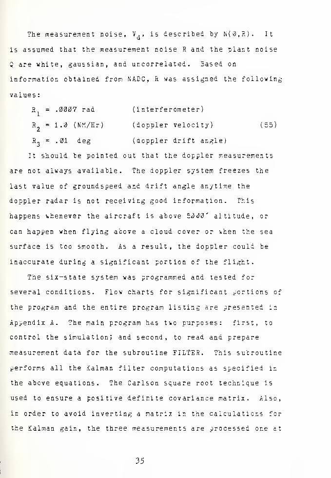
R = .0007 rad
R = 1.0 (NM/Hr)
R3
= .01 deg
The measurement noise, V,, is described by N(0,R). It
is assumed that the measurement noise R and the plant noise
Q are white, gaussian, and uncorrelated . Based on
information obtained from NACC, R was assigned the following
values :
( interferometer)
(doppler velocity) (55)
(floppier drift angle)
It should be pointed out that the doppler measurements
are not always available. The doppler system freezes the
last value of groundspeed and drift angle anytime the
doppler radar is not receiving good information. This
happens whenever the aircraft is above 50<30' altitude, or
can happen when flying above a cloud cover or ^hen the sea
surface is too smooth. As a result, the doppler could be
inaccurate during a significant portion of the flight.
The six-state system was programmed and tested for
several conditions. Flow charts for significant portions of
the program and the entire program listing are presented in
Appendix A. The main program has two purposes: first, to
control the simulation; and second, to read and prepare
measurement data for the subroutine FILTER. This subroutine
performs all the Salman filter computations as specified in
the above equations. The Carlson square root technique is
used to ensure a positive definite covariance matrix. Also,
in order to avoid inverting a matriz in the calculations for
the Kalman gain, the three measurements are processed one at
35


a time. The results of the simulation are presented in
section IV. 3.
36


D. THE TWO-STATE SYSTEM
An attempt was made earlier on in this research tc model
sonobuoy motion as
X, = X + U. Atk-H k k
U, = U,k+l k
(56
with a state vector made up of x , x , u ., and u . This
system proved to be unobservable although the simple
approach was appealing. Since sonobuoy drift rates are
generally slow, another attempt was made to model the system
without velocity. The equations reduced to
X, = X, + w,k+l k k
(57!
With only x and z as states, this system was observable.
3y describing large statistical values of system noise there
i*ould hopefully be enough freedom in the "update" tc
compensate for any sonobuoy drifts. Unfortunately, this
approach was not completely successful! hovever, it vas
observed that the general direction of sonobuoy drift kas
correct. As a result of these investigations a technique of
cascading Kalman filters was used to solve the tracking
problem. The intent was to use results from one filter as
measurement for a second filter. Then, the result cf the
37


second filter could be used as a deterministic control input
to better propagate the first filter.
Ti*o Kalman filters are used in this approach. Figure 5
shows how they are related (or cascaded). The first filter
models soncbuoy position and is based on the discrete state
equation
X, = X + U, At + W,k k k k
(58)
The state vector consists of the sonobuoy positions, Xj and
X2 • U is a deterministic input accounting for soncbuoy
drift and W is system noise. The interferometerfcC
measurement, cosQ, is used to update this filter.
z cose
1
x k position
fil ter
^ .
/ i
XK-i
^delay
i' 1 ' X k
Xk ~ Xk-,
At
zu
u k drift u k
fil ter
Figure 5. Cascaded Kalman filters
38

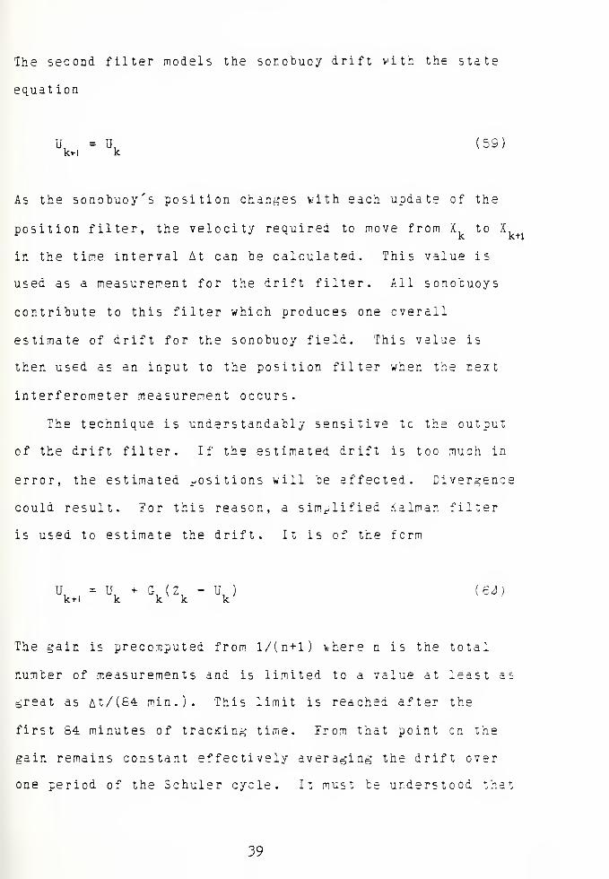
The second filter models the sonobuoy drift with the state
equat ion
k+l k(59)
As the sonobuoy's position changes with each update of the
position filter, the velocity required to move from X to X
in the time interval At can be calculated. This value is
used as a measurement for the drift filter. All sonotuoys
contribute to this filter which produces one overall
estimate of drift for the sonobuoy field. This value is
then used as an input to the position filter when the next
interferometer measurement occurs.
The technique is understandably sensitive tc the output
of the drift filter. If the estimated drift is too much in
error, the estimated positions will be affected. Divergence
could result. 7or this reason, a simplified Salman filter
is used to estimate the drift. It is of the form
U, » U +\ { \ ' \ ed >
The gain is precomputed from l/(n+l) where n is the total
number of measurements and is limited to a value at least as
great as £t/(S4 min.). This limit is reached after the
first S4 minutes of tracKin- time. From that point en the
gain remains constant effectively averaging the drift over
one period of the Schuler cycle. It must be understood that
39


the drift this filter estimates consists net only of
sonobuoy drift but aircraft drift as well and is, in fact,
the vector sum of these. An estimate which attempts to
follow the changing velocities through the Schuler cycle
tends to cause the position filters to diverge. This might
be the case if larger values of gain are used, averaging
only the last few measurements of drift. Therefore, many
measurements of drift are averaged which provides an
estimate for linear drift only. The lower limit of gain
prevents new drift measurements from being ignored and also
provides for flexibility in estimating the drift.
Unlike the six-state system, the interferometer
measurement is the only measurement required by the position
filter. The measurement equation is essentially the same as
in the preceeding section where z is determined, as shown in
Equation (39). Since there is only one term in z, the H
matrix is a row vector consisting of
n = 3 z
3x3 z
3 x.(61)
where the terms are given in Equations (41) and (42). It is
necessary to determine the ai rcraf t-to-sonobuoy range for
these values from
AX = X - X (62,
A
where X is the estimated soncbuoy position. X1 represents
40


the aircraft position and is considered deterministic.
Undoubtedly, X is in error due to aircraft navigational
drifts and therefore causes errors in the estimated
geographical position of the sonobuoy. But, since the
measurement of bearing is based on relative positions, the
estimate is relatively correct.
An observability analysis on the 2-state position filter
was performed again using
N
lik=l
kEk *'\ ^k (63)
Subtitution into this formula with N=2 yields
M =
f 3Z
13 x
I dz
l3x,
/3 2
3x,
f 3 Z I Id z
\dx, /.\3x
Idz
\dx.
v 3x.t+i
'3z_
<3x,
/3z \ /a z
V3x
i"i^3x
21+)
i+A
3z,3x .
I+l
'3 2
13 x2A+I
(64)
Expanding
,
M ='32
\3xlA+l
/ 3z
Ux.
'3z (3z '3 2
^ xU+ iV9x
2A+iV3
v
xiA
' 3 2
i3x.
'3 2
\3x,
'd Z
\3x2/
32f3z
V3x
li+lV3x
2i + l
(65)
*H


This matrix is positive definite for all except the case
when
3x1/
3z3x and
14+1
3z3x.
3z3x,
21+1
This occurs whenever the relative bearing from the aircraft
to the sonobuoy is not changing (i.e. when flying directly
toward or away from the sonobuoy). This is intuitively
correct since two or more bearings must cross in order to
determine a position.
The two-state system was programmed and tested to
determine the usefulness of this simplified filter. The
majority of the program is the same as the one used for the
six-state system. The significant differences occur in
subroutine FILTER. The Carlson square root technique is
used again but only one measurement instead of three is
processed. The drift filter is programmed in this
subroutine along with the position filter. A flow chart and
program listing are ^resected in Appendix A.
^2


IV. ANAYLSIb
A. THE SIMULATION
Actual data from the Orion was not easily obtainable for
this research. Consequently, a computer program had to be
written to generate the information required by these
algorithms. A flow chart in Appendix 3 describes the
program. An aircraft track was created by alternating lines
and curves of various lengths and then a determination of
noise free measurements was made as the track was flown.
(Measurement noise was added later during the simulations.)
Sonotuoys i*ere allowed to drift at a constant velocity, and
the aircraft's navigational drift was modeled with a
constant velocity and Schuler cycle variations as
X1
= X + K At + A sinoota a x x
(66)
inhere
X = aircraft inertial position
X = aircraft true positiona r
ui = Schuler frequency -^/g/R
'
The constant drift rate, K , was found by NAOC to have d
mean and a standard deviation of 2.5 NM/HH. Likewise, the
amplitude of the Schuler cycle, A , had 2 mean and a
standard deviation of .5 NM. The effect of wind was also
available in the program but was never included for analysis
^3


It v.as obvious that both algorithms vere extremely
sensitive to the aircraft flight path. Since there is no
"typical" flight path for an Orion during its on-station
period, several uniform patterns were selected which would
provide meaningful information on eacn algorithm's
performance. These base parameters were chosen:
airspeed 180 kts
altitude 3000 ft
range 15 NM ai rcraf t-to-s onobuoy
frequency 20 sec between measurements on one sonobuoy
A circular pattern was flown around a sonobuoy at a range of
about 15 hiv
. Initial sonobuoy placement was at (1,1) with
the aircraft flying clockwise starting at (15,0). This is
shown in Figure 6 which depicts a portion of the aircraft's
true track. Sonobuoy drift was west at 1 N'M/HRj aircraft
navigational drift was south at 1 NM/HB and included a
Schuler cycle (amplitude .5 NM) when specified. (This drift
would be indicated in Figures 12 thru 30 by the following
notation: DR=(a/c 150-1 + Schuler, b 270-1) .) The sonobuoy
remained near the center of the pattern allowing the range
to remain relatively constant. This was desirable since
this basic flight path was used to test the response of the
algorithms to variations in altitude and rar.-e. Similarly,
a square pattern >as flown counter-clockwise around a
(x, ,Xj ) measured in nautical miles from an arbitraryorigin near the aircraft's starting point.
44


sonotuoy at a range of 15 MM. Ir. this case the aircraft
began on-top the initial position of the sonobuoy at (-3,-3)
and preceeded to fly the track shov.n in Figure 7. The
sonotuoy was allowed to drift to the east at 2 NM/HR and the
aircraft's navigational system to the north at 2.5 NM/HR.
This pattern was used eventually to analyze performance at
different measuring frequencies. Figure 8 shows the output
of the aircraft's navigational system when it has a
northerly drift of 2.5 NM/HR while the aircraft is flying
the square pattern. Figure 9 shows this same pattern when a
Schuler cycle with an amplitude of .5 NM is also present.
45


-
' '
i
. .1 ..,.j_,-i~ ! j i1 ..
: L•
i
. ! 4 - ..M . |._
!
| j|
ij i 1 1
i 1MJ .: :
: M1 I : 1 1 ! . L M !
' ! ! lj i1 1
1 i —1
;
1 1i i
|
_...; IJ m~j . U M I Li i l~] i n i
! '
'
_ L_..._LI L : 1 : M
|| j ! M M '
... i i_JJ L j:
1
I
i ii
1 ; i i j j1 ! !
i M _JJ j., J .
i
i
:
I !M M M M 1 m.m !
m r _jj L U ;
I; i i
! M M M itililii!...J...J. i rt 1 !
i
: !i j
iI
ii
i
'.
;
:
i1 |
|i
||
i
| j
i j;
; !
!| ! ! ! !
;
1 !| !
i|
j
i i
1
ii ! j 1 ! i i 1 M j
| |!
j; j |
i
i
i 1 i ! i ..._.!. j | !i M i
1
: i _| I1 1 1
1 I
i M ! I i ii
III i i :i
!M j L_4~-
.
h ! nj
i i i
i i i i j| \
; i
|"I
i '
laxt^'x 5^»5> •: ; i ;
\i -. 1 y x ? . '
i
1 '! j
! ! j?9" ~x ; i | ; j I i j
Mil ,/ ! ! 1 I 1
.
„J_ | | j| | | j |
1 Ml , ,x*r
j i
i
'" "i
""
"x
r M i M M 1
:
i X jf
!*'!, .
i; X
I 1 M jM
1
' i ! -? i
. \ JK ;
_.
i ;;
i1 X i
>
IMil!; i
!
i X! 1 [ I i 1 i
II X ! ' 1
|1
ii
i1 Mm , yf
: (
*X
i ;
i : !
i i
i
j
Ix MM! i !
1 i | i ! | | |!
; 1 i
;
;;
|X
1
X 1 1 i 1 i ] 1 1 i ] i
:'!;]. "; * i
jh X\
!x !
X^zJ X
i X 1
^ :
JI.1 I S
1 1 I! ! 1 M M M i
Xi
j !
M 1 ! Ixj
II i i [ ; . ; x
1 !1
X i\
rat
X? !
!
X
1'' X : !
;i ;
)
x1
t ;:
11
ii
;XJ ;
i,
1
'
|! f j i
i ! ! 1 l 1 ii I
". , X
i
! ;
X .i Mi. . Jii
i
!
i
***l
< '1 X
X XKJ '
iM M M»j
xj \
| |I j i |
, X: U£ ..j
i' ||
| |
: j j' 1
'1
; ji i 1
X JV- x -x-xf 8 < k y»x x
i!
|1 | i 1 |
| {i
! ; !
ill!1 1 1 ! | {
! 1 1|
! j |!
11 ; j j |1 j
ii
M 1 i 1 | S ! ! 1 ! M i
MM! ji j
| |i M M M ;
i
i i . •i
i I I l i it j I ! [Mi r ;
nmrii1 MM! I | ! i
Mil j
: ! i ; ;'
!i
; ;! M 1
i !
;:
Ij j
! L i M M - — -'--;— .
-\ -:-1—
i j; ;
'I j
.;,,,.': M !
MM | ! i > Mi i
'
i i . - J 1 ; ! i '
-20. 10. 10. 20.
E-W POSITION (NM)
Figure 6. Aircraft track for the 15 NM circular patternwith initial sonobuoy location and direction of drift indicated
46


30.
20.
10.
COoQ_
eni
10.
-20.
-30.
!1
illi ! i
1
:
t„.L.
1
ii ! !
'!
'
ii Ml! 1
: :
'
..._.!. ..Li
i
i
liii !
"|""i
i i !|i
_: ;"l i ;.- ! 1 i ! i
i I
i
i
L.-jr
! ! !i
!
'
;i !
! I [ |1 1 1
I _LJ_jl1 1 !'
; j
! ) I i 1i
i If:
" -H--!
! i 1
! 1 1 1 ; i
__l_ :t XXX i1 f"
i
!.. 1 J......iii III'!
1 ! 1 |
i- - 1
ii
!j i i 1
I
: - ': 1i
ii n i i
;
r — 1
ii
j
' 1"1
I
i j r t i
"
"] 1 ! 1i 1 1 1 1 1 1 1
; i i ! n — II i
1
i 1
1 I I 1 l 1 I ! i
"
ii 1
' 1 !
i j! ! i ! 1
jit:!-';i 1 i
! I !
iI
. i I i
j1
< ... ij ;
i ii
1 'i
1
i
!i
i1 j 1 1 1 j
! i ij
! ;'
! 1i
1
:
-
i !
: !
I
1 i x1
,0
^9^ „ ; ^9S„ ' ^31 ^ w „, 1
liiii X x i
;I
X j|8X- x - -
i 'x X5 >£ X-: X : X50 X vX xf3X- v <Tx' x53 x 1 '
i
* X x x«i |
:
j
: *f? i X :X;X
'
;
x"^ Xi !
;
';
; ;
'
'
j ;X Jrx ;
\
i!
';
i! ;
i
: ^"x.x"j
; |
- T-X—X*);»
'
XXX| j | i ]
x jf^x ;
: 1 I i ! 1 ! ! ! i [ | 1 1 ! I ; t rafxji?!
1 .i. JSJB -i
ii ! ;
X ix X
xfxf;
i*
! >ei x i•
'
\ j- !
i !!
|
: X
Xj
f>
i
S! 1 1 !
I
rx x""\
|
„ Js«js ; !; j
: 1 ! i i ' IX :x ; X i
xf ^ X ! i i i: x ' x" x
i | ; ! ! !
""?Tx "x"
X )f>?j
j- 1 XXX
j»tr. v : Mill! ix.'rf'x
• i 111!! i !
;
-
\jrx\J<r;
!
X x™*31' '
i
!
:
ch *, | ]! | j ! :
X x ! x
i
x10* x '
!V*-'
jX ! )?
rX|
| 1 1 ! 1 1 i |xi'xix" ;
i 1 i 1 j i jj !'
X X X !
X103* X'
! | j | j | | |i ! X X15^
i 1
!
! i i j ! ; i ; i 1 i j i 1 1:X»X .X" j
j [ j. JOJJ ':
i
!i
;
X*!
i
i XXX!*!"x x
1
| |i
iX . >^ S X
,
X5 x x"
< X XT~
' X x" X™ ' ' I i 1 i i j M j
'-
'
i
'
'
•
' ^"x ! x : ' X- ,*- >rTr
[ :
i
!
* >"xxx'xxx'xxx'::"H * " x"*i ;j'
!
x12K X » ^B x x >^
rx X ><?8 X X >!*XV1J'XX?K * X,2 J - x *
,sf f
X|; ; i
yllS * X x'3
:]X >^X )
C X )
< x 5 x x X x : ^X X J?*X X £*X X 1?°x x x1'" : ;
* X X1 ' 3* 1 xf"i 1% X xfx x ;"t x xf'iax" 'xSW X x1
^: x'^x "
• 1 ' 1'
. 1 ;J ; ! i [ j \
l
i ! 1 i ! ! i |' •
,; j j j i 1 : | ! i
:
| ;I
: :;
J: ;
'i |
i j j
; i i !•
ii
i
; III 1 i 1 ; i j',
|1 j
i I| |
1 | ! !
; 1 1
:
- !| | i |
i H i ! ! !i 1
j1
! ! j
1 j j ! j'
!i
j
i i l l i.l M ii
;
i : ! ! 1i i
MiMi 1 I 1 - i } 1
1: | i i ,
]
':;'j
i
'i ;
;i
j1 1 i | | ! |
[ i j ! 1liii :
'
;
!
! .
;
.
i
i
j j
' ;'1
! '
:
'i j i j : i . ;
j i
H- —j—j—I 1
j ji
j jj
i
1 : < ! |'
!
i<
\ < ! ' ' '
!
;: | j
i
If
1[ ! s T ; ! i j 1 j '
j i j 1 1 ! |j ;
i i
1—;—i 1 1 1 11
i
— j . .1
I ..!. .. I. ..'. . i i
-20. 10. 10. 20.
E-W POSITION (NMJ
Figure 7. Aircraft track for the IS NM square patternwith initial sonobuoy location and direction of drift indicated.
ij-7


30.
20.
:o.
-10.
-20.
!
i— j a j-
fflfO?
'Up _j—I rfi®
i _a ; <3
a a5
d.2ia-n -cJ°Sn_ a -d^o-o_£2.a-a--a-<!?la-o---e?-9 a -a-a">o-o-o"l a-a -cPo-
a a a"3 a o'cf'o'o d'o
aa" - rf
5o|ocfo a cf'o O'rf ! o oa
J °rfi
4 °^1d o£> m
(jo©s n
o
a d?_ a.
d 04D '"X
'a' a"a * i
'8 ° ^
£5*
o- o
a
-O
a.
o c?'o o c?6 o O C?
5 d a
a11 a cd d°a 3 0**0 a a"
(TO[
a-cJ2-
a a
i ° a
o
.
o.
Q
° „a,- o
_ o ao
a a .
. .a a° ~
. . o a
a 3 ° a".
a aa
a o-
a - a--oa - a -
a o° -a a
a ao
a a
'-'in
fr&stf'o a.V""o 57rf
5o" 'V#a a
9a"a a rf*o q.rf'co g,£°g a^^ a o 5 6a a 5 7a o a 3
!? & §9
g o g?oj'I g r§ § Sf'3-8
! :
.i :
-30.-20. -10. 0. 10. 20.
E-W POSITION (NM)
Figure 8. Aircraft's navigational output for the 15 NMsquare; navigational drift is 2.5 NM/Hr to the north.
^8


30.
20.
10.
! :
i
! !
d°b o d olb o d"o o e?a o e?'c
d >"
O ^°d°©
fi?
3 °
O cf'd) O t#°<3 O d^O O d58 ©
^ q O b"' O O G?3 O O d 2 O
9to
.
tf7
I!
!;
<D d"o o o»o o e?" w n
o"o o- c?6 o © -«?s O T>
o'o O <$Q 3 o d 9 o o
rf"o
I1
i
Vi" ;
'
i
^io_
d"
o
^b o
4a
d9"
ccf
1o'i
goa
o
d"
d '
o
6- sr
8 oa-
o
b"
"
©T
°J3 O<*?"
d>B
% ol
Cb jJ6
°o
10.
-30.
3"
k<-
a
c?t_p--—
o
b"" -
o
d
«3 c?5-
CO
.<*!>..<if.
.^ So
do -a:
o
o d"2*
" O °3o d'fe d'b o d'b o dJ%> o
3o cx?o© ood^ooc od&c
-20.
d'Td o 'd'fc o d 135 a d 20
!) o d*&
j i_
-20. -10. 0. 10.
E-W POSITION (NM)
20.
Figure 9. Aircraft's navigational output for the 15 NM square;navigational drift is 2.5 NM/Hr north with a Schuler cycle.
^9


These patterns were used to generate the data vhich
included sonotuoy number, time of measurement and
measurement, aircraft latitude and longitude, altitude,
heading, pitch angle, roll angle, N-S acceleration, E-W
acceleration, and the antenna used for the measurement.
Also determined, tut used only for error analysis, were
sonobuoy position and true aircraft position. This
information was computed for the entire simulation period
and stored in a file to be used when needed.
Initial estimates of the state and the square root of
the covariance matrices were obtained as follows:
Six-state
X(0) =
x,(i3)-i (0)
zi(0)-2
ai(0) + .5
-1L cosK
-V, sinHS (0)D
.
.2025
.0025
(6?
Two-state
X(0) =*l(0)
x2
( ) + . 5
5D(0) = r Alt
Alt(68)
where S (0) indicates the diagonal elements of 5(0D
50

For the circular pattern
xl(d) = 1.
x2(0) = 1.
x (0) = 15.a
l
X (0) =0.a2
and for the square pattern
xL(0) = -3.
x2(0) = -3.
x (0) = -3,a
l
x (0) = -3.a 2
The initial values of the covariance were chosen so as to
describe the errors in the state associated with dropping a
sonobuoy from an aircraft. The two-state system operated
tetter vith a lower initial variance than did the six-state
system .
Simulations were run for a nominal period of two hours.
Each unit of data was sequentially read into the simulation
program from the storage file. Measurement noise was added
with the following normal distributions:
ccsQ N(0,.0007) in radians
doppler velocity N( 0,1.0) in NM/EH
doppler drift angle N(0,.01) in degrees
These values agree with the ones chosen for H as described
previously. A random number generator using an initial seed
was used to create the noise from the proper distributions.
After the estimate was made, errors were measured ard
manipulated in subroutine RESULT. This cycle was repeated
51


until the simulation was complete. (Refer again to Appendix
A for a flow diagram of the simulation process.)
Information vas gathered and is presented primarily in
two ways. First, for both the square and circular patterns
the results of the first run of the simulation are plotted.
(Figure 13 is an example.) The top portion of the results
shows the estimated positions of the sonobuoy on the
aircraft's navigational plot. It should be noted that these
are not true positions since inertial errors may be causing
this plot to drift. The bottom portion shows the
North-South and East-West errors in tne estimated positions.
These errors are the differences between the true and the
estimated relative positions of the sonobuoy. They are
depicted in Figure 10 and were computed from
AX, = AX, - AX,k k k
AX, = (X - X1
),k a k(X - X ),
a k
(69)
(70)
where AX, is the relative error at time k. The true aircraftk
/
N
[
N
I
/ AX
AX^
/ /
/ / A
// AX
y aX
//
\/
^ **
yX1
a
a^ Aircraft navigat ional 'clot
EE arth fixed coordinate system
Figure 10. The effect of the aircraft navigational plot
52


position is denoted by X and the true geographical position
of the sonobuoy is denoted by X. These values are known
from the simulated data. X is the filter's estimate of
position and X is a deterministic input from the aircraft'scL
navigational system. The errors indicated in these plots
are different from those perceived in the upper plot
whenever the aircraft's navigational picture is drifting.
The positive and negative values of the square root of the
covariance are also shown on these plots as solid lines.
Specifically,
N-S error = ±-/P'
E-W error = ± -/?Y 22
(Only jjosition errors are analyzed in this report.)
The second way in which the information was gathered
consisted of a shortened Monte-Carlo simulation. 7or each
scenerio under study, 20 two-hour simulations were run, each
with new values of measurement noise provided by the random
number generator from their respective distributions. The
objective was to compare the RMS errors predicted by the
covariance matrix in the filters to the actual RMS errors
observed in the simulations. Three RMS statistics v.ere
collected and plotted versus time as follows:
1. The square root of the covariance computed by the
Kalman filter is represented by a solid line on the
clots. It was commuted from
-LVp +lYp , n=20,n^ 11 n <—' 22
k = 1,2, (71
53

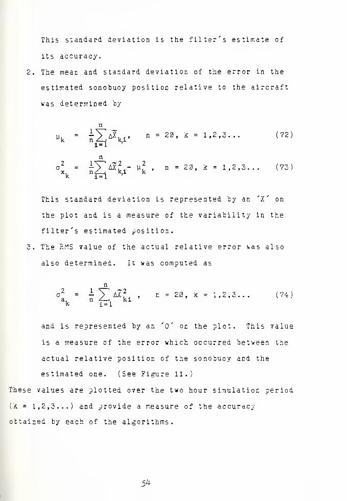
This standard deviation is the filter's estimate of
its accuracy.
2. The mean and standard deviation of the error in the
estimated sonobuoy position relative to the aircraft
was determined by
y = -X A^ki'n = 20, k = 1,2,3... (72)
ni=l
a2
= -V^AX 2 - p.2
, n = 20, k = 1,2,3. ..x. nZ_i ki kk 1=1
This standard deviation is represented by an 'X' on
the plot and is a measure of the variability in the
filter's estimated .position.
3. The RMS value of the actual relative error was also
also determined. It was computed as
Li
n -^—
i
i=lki
n = 20, k = 1,2,3. (74
and is represented by an '0' on the plot. This value
is a measure of the error which occurred between the
actual relative position of the sonobuoy and the
estimated one. (See Figure 11.)
These values are plotted over the two hour simulation period
(k = 1,2,3...) and provide a measure of the accuracy
obtained by each of the algorithms.
5k


-S 36-
Gx—*~
XXX XXXXXX 3-3—X—8 5 X-
-ax
x - X (X - x-
Fiture 11
a i a 1
RMS statistics at time = k.
55


B. THE RESULTS
Orincon Corporation performed much of their analysis
using the small circular pattern shovn in Figure 12. The
aircraft sped around this track at 36£ knots taking a
measurement every 20 seconds. Altitude was constant at 3000
feet. The initial position cf the sonobuoy was at (2,2) and
it drifted on a heading of 345 degrees at 5.5 N'M/HH while
the aircraft's navigational system drifted in the opposite
direction at 5.2 NM/HR. A Schuler cycle was alsc
superimposed on this drift.
The initial estimates of sonotuoy position and variances
used by the algorithms were different for this particular
pattern ir. order to coincide with the Orincon simulation as
much as possible. They were
Two-s tate
M) = sD(0) =
2.](74.
Six-state
-5.4 2
.
2 .
X<3) --Va cosH
-Va sinHSD (0)
-
5.
. 0025
.0025
(75)
56


> E
CIRCLEa = ~H m/s =-0.4 £
YA
= 200 m/s
Vfi
= 2.8 M/S
Figure 12. Orincon's simulation flight path.
57

Initially, both the six-state and the two-state
algorithms were tested using this flight path and
comparisons >ere made with the results cf Orincon's 13-state
system. It was discovered that the six-state system's
results did not change as a consequence of vhether or not a
Schuler cycle existed in the navigational system.
Therefore, the six-state system was run only with the
Schuler cycle active. The two-state system was run with and
without a Schuler cycle.
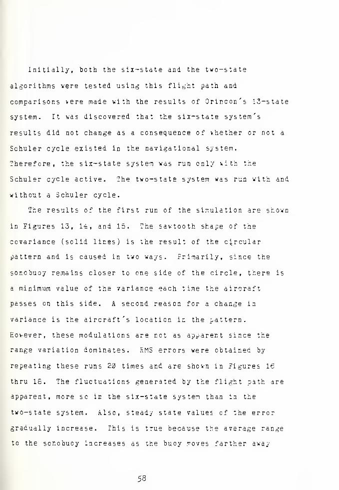
The results of the first run of the simulation are shown
in Figures 13, 14, and 15. The sawtooth shape of the
covariance (solid lines) is the result of the circular
pattern and is caused in two ways. Primarily, since the
soncbuoy remains closer to one side of the circle, there is
a minimum value of the variance each time the aircraft
passes on this side. A second reason for a change in
variance is the aircraft's location in the pattern.
However, these modulations are not as apparent since the
range variation dominates. RMS errors were obtained by
repeating these runs 20 times and are shown in Figures 16
thru 18. The fluctuations generated by the flight path are
apparent, more so in the six-state system than in the
two-state system. Also, steady state values cf the error
gradually increase. This is true because the average range
to the so no buoy increases as the buoy moves farther away
58


from the center of the pattern. (It will be demonstrated
later that the errors are range dependent.) The covariance
of the six-state system increases from 400 yards at 25
minutes to 800 yards at the end of the simulation. The
two-state system increases slowly from 250 yards until it is
hammered by the Schuler cycle. It is worthy of note that
vithout the navigational errors stemming from the Schuler
cycle the RMS errors of the two-state system are
considerably lover than those of the six-state system.
Table 1 compares the RMS errors of these two systems to
the results obtained by Orincon for their 13-state system.
(The values for the two-state and six-state systems are
taken from the covariance at a point 35 minutes into the
simulation.) The first line considers measurements of
bearing, doppler velocity, and drift angle. Navigational
errors are present including a Schuler cycle. As expected
there is an increase in relative position error because of
the reduction from 13 to 6 states. The next line considers
the effect of the Jlooal Positioning System (3-PS), with very
accurate aircraft positioning information, on the relative
13-state 6-sta te 2-s tate
Schuler
SRS-dv*DA394 453
No Schuler
SHS+DV+DA+GPS450 200
Table 1. Comparison cf RMS results in yards.
59

position errors of the sonotuoy. In the 13-state system
Orincon observed that the errors in the states pertaining to
the aircraft inertials improved markedly; relative position
errors most likely remained, the same. This is exactly vhat
was found in the analysis of the six-state system: that the
relative position errors were unaffected by navigational
errors. However, the two-state system is very much affected
by navigational errors. Relative position errors were
significantly less for the two-state system when accurate
aircraft positions were known.
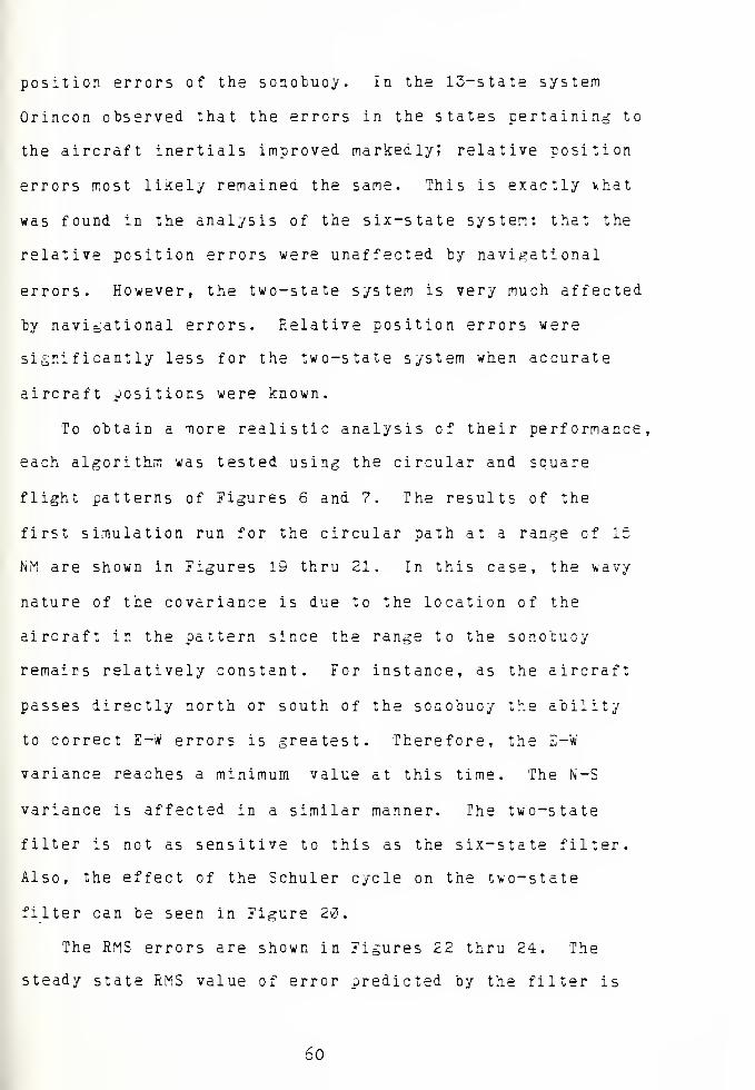
To obtain a more realistic analysis of their performance,
each algorithm was tested using the circular and square
flight patterns of Figures 6 and 7. The results of the
first simulation run for the circular path at a range cf 15
NM are shown in Figures 19 thru 21. In this case, the v.avy
nature of the covariance is due to the location of the
aircraft in the pattern since the range to the sonotuoy
remains relatively constant. For instance, as the aircraft
passes directly north or south of the sonobuoy the ability
to correct E-W errors is greatest. Therefore, the E-W
variance reaches a minimum value at this time. The N-S
variance is affected in a similar manner. The two-state
filter is not as sensitive to this as the six-state filter.
Also, the effect of the Schuler cycle on the two-state
filter can be seen in Figure 20.
The RMS errors are shown in Figures 22 thru 24. The
steady state RMS value of error predicted by the filter is
60


425 yards for the two-state and 750 yards for the six-state
system. The actual RMS error in the relative position of
the sonobuoy is 250 to 1200 yards for the two-state and 400
yards for the six-state system. Without Schuier cycle error
the two-state system drops to a steady 250 yards, better
than the six-state system. It is interesting to note that
the measured errors are significantly less than those
predicted ty the filter. Both measured values of RMS error,
a and a , are in close agreement; that is, the deviation ofx a
the filter's estimated position about its mean is generally
the same as the deviation of the estimated position about
the actual relative position of the sonobuoy. The closer
these values are to one another, the more confidence can te
placed in the analysis. The only exception to this is
Figure 23 which shows the reaction of the two-state filter
to the Schuier cycle. One complete cycle with a period of
84 minutes is obvious. The Kalman filter does not recognize
this cycle since the modeling equations do not account for
it. The dip in the center of the two peaks is once again
the result of flight path geometry. The aircraft is in such
a position relative to the sonobuoy that the measurements
provide enough information to correct for Schuier cycle
errors. However, it is not in this position long enough to
influence the errors anymore than it does.
The same analysis was performed using the square
pattern of Figure 7. This scenerio has mere drift than the
other and in a different direction providing the algorithms
61


with another motion to track. The outcome was generally the
same as can be seen in Figures 25 thru 30. There is no
measurable difference in the results from the tvo different
flight paths. Flying a straight path does not adversely
affect the results as was concluded by the Oricon
Corporation for their 13-state system. The wavy nature of
the covariance is again a result of the flight path. It is
not as smooth as before because a square pattern was flown
instead of a circular one. Another look at errors caused in
the two-state system by the Schuler cycle can be seen in
Figure 30. The algorithm does make some corrections to
these errors but they are not as effective as before. In
this case the time the aircraft was in a position to ma^ce
the corrections aid not coincide v,ith the time the peak
errors occurred. There appears to be no way to predict the
optimum time and place for the aircaft to te without knov.ing
when and hew the Schuler cycle is occurring.
The distance the aircraft is from the sonotuoy is
directly related to the accuracy the algorithms can achieve.
Simulations were performed at ranges of 5, 15, 33, and 45
nautical miles using a circular flight path with the
sonobuoy in the center. (The RMS plots can be fcund in
Appendix G.) The steady state errors were observed and are
plotted in Figure 31. Solid lines represent the RMS values
of the covariance and dashed lines represent the actual
errors. In all cases the errors increase with distance
>.hich is intuitively satisfying. Mathematically, the
62


covariance increases because the H matrix becomes smaller
with an increase in range. Consequently, the updated value
of the covariance, P(+), is larger from Equation (19). For
the six-state system there is an increase in actual error
from 240 yards at 5 NM to 750 yards at 45 NM . And for the
two-state system, actual errors increase from 13*3 yards at 5
NM to 500 yards at 45 NM. (Note that for the Uo-state
system, Schuler cycle errors, indicated by circles, peak
approximately 1300 yards above these plotted values! the
lower values, indicated by x's, were used since they were
more reliable for comparison between ranges.) There is a
slight decrease in the slopes of all the error curves as
distance increases. Hovever, this decrease is small and the
curves might well have been interpeted as linear within the
limits of the analysis.
The frequency at which measurements are made also
affects the accuracy of the estimate. Each algorithm \>as
tested with measurement intervals of 4, 10, 20, and 30
seconds on one sonobuoy. The outcomes of the steady state
RMS errors are plotted in Figure 32. (Once again the
two-state system's errors do not show the effect of the
Schuler cycle.) The actual errors in the six-state system
increase steadily as the measurement interval increases.
However, the covariance decreases rapidly at first to a
minimum value somewhere around 13 seconds and then increases
with increasing interval. An abbreviated run with a two
second measurement interval confirmed these results.
63


Propagation effect
Observability effect
Figure 33. Factors which influence the covariance.
Figure 33 helps to explain this outcome. There are tv.o
conditions which affect the covariance. The most obvious is
the increase in covariance due to an increase in the
propagation interval. This occurs because the plant matrix,
vhich is a function of time, affects the covariance in
Equation (16). The second condition is a consequence of the
model's observability. If the relative bearing betv-een the
aircraft and the scnobuoy does not change then the state is
not observable. In other words, two successive bearings
must intersect to determine an estimated position. By
allowing the interval between measurements to become too
small, the aircraft is unable to make a significant change
relative to the sonobuoy. The covariance increases as the
conditions approach those which maKe the problem
unobservable . There appears to be an optimum frequency with
which to make measurements en one buoy, namely 10 seconds
for this range of 15 NM and speed of 180 knots.
6^+


The two-state system exhibited similar characteristics
in Figure 32. In this case the covariance never does
increase in the range of intervals studied. The actual
errors remain constant. Since the plant matrix fcr this
system is equal to the identity matrix and the Q matrix is
prescribed to be constant, the propagation interval, &t,
does not effect the covariance. However, the effects of the
observability conditions do cause the covariance to increase
vhen At becomes too small. It is believed that as At
becomes smaller the actual errors would begin to increase
also .
The statistical plots for the range tests found in
Appendix B show that the Schuler cycle causes larger peaks
in the actual error as the range from the sonobuoy
increases. However, the peaks are decreasing with time.
Further simulation revealed that the peak errors decrease to
a steady value about 10J0 yards greater than non-Schuler
cycle errors. This coincides with the amplitude of the
Schuler cycle as it was programmed for this particular
flight path. Therefore, in the steady state a Schuler cycle
may cause additional estimation errors approximately equal
to its amplitude.
Altitude was also tested for any effect it might have en
these algorithms. Using the circular pattern at a range of
15 MM, altitudes of 300, 3000, 10,000, and 20,000 feet were
tested. Neither the six-state nor the two-state system
shoved any effect for these changes in altitude. It is
65


believed that at very small ranges (less than two nautical
miles) altitude might hamper good position estimation.
However, for the majority of the time altitude is of no
concern .
66

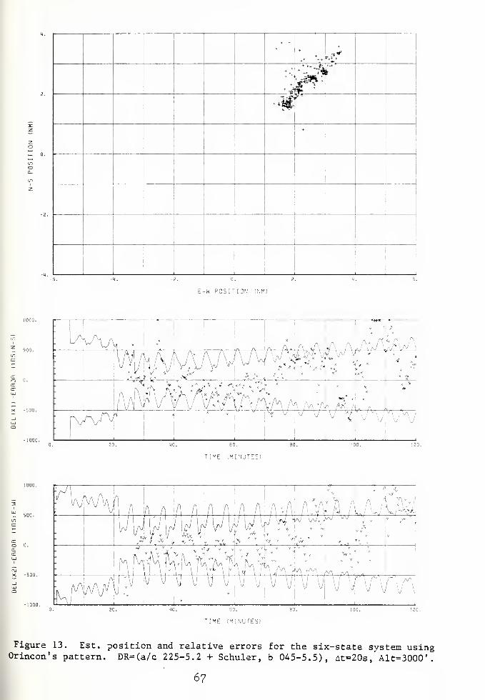
+
** V
* dfflt
-J. 0.
E-W POSITION iNM)
U V wi
w #-*J.-v .- <* V *
TIME (MINUTES)
TIME (MINUTESI
Figure 13. Est. position and relative errors for the six-state system usingOrincon's pattern. DR=(a/c 225-5.2 + Schuler, b 045-5.5), At=20s, Alt=3000'.
67


^
-2. 0.
E-W POSITION tNMI
TIME (MINUTES!
TIME (MINUTES!
Figure 14. Est. position and relative errors for the two-state system usingOrincon's pattern. DR=(a/c 225-5.2 + Schuler, b 045-5.5), At=20s, Alt=3000'.
68

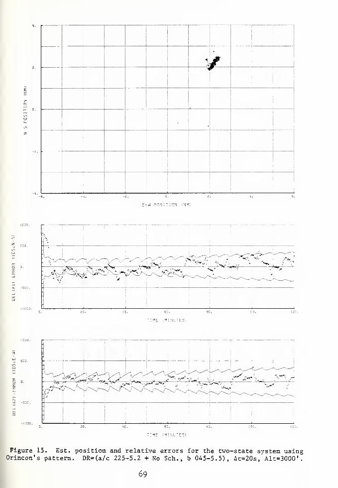
w<1
.
'
E-W POSITION INM!
^y^^^^^S^Zrs^'
T IME (MINUTES)
TIME :M!NU T ES)
Figure 15. Est. position and relative errors for the two-state system usingOrincon's pattern. DR=(a/c 225-5.2 + No Sen., b 045-5.5), At=20s, Alt=3000'.
69


u -
CO mi—
1
c3 CM
II
u 4J•H <t
~
01 ^SX! u"i
u •
LOM I
CJ m•H <r>%o
r-l
1+H j2
o> „
l~4 M•H 0)~* -—
<
3 3
£ U01 CO4J
CO +>igo ~l
u un4-1 i
CO uO4J CMen CN
X u•H ^^0) CO
*—
'
01 II
J3 UtJJ a1-4
•
IW a1-4
en•-j uM 31-4
HI U3
3 i-l
U•H o4J
1-1 >191 -a
a. T3i)
rn a.^pd —
i
i>
>• 01 .
vO T3 -i
—
o3 C
0) M Ou 0) m3 u
II
M 4-1 4-1
H CO r-4
In a <
CSQJL) yoya3 NQinsod sny
70


enjj
i
—
3
1-1 ••
cfl 'Si
H o3 OJU II
M 4-1
H <u
ACI) *"N
J3 u-i
4-1 •
u-l
00 1
c LA•H <r>>oH
<4-l J3
<u •
H >-4
•H CU
JS r-i
3 3,e
S u0) enW(A +>iM rsi
0) mu 1
tfl LTl
4-1 C-4
(0 NO
3 ^^u cfl
-w'
111 II
,C Kl4-1 P1-1
oU-| Q.
lJ
CO O1-4 ao1-1 eu1) a
Ce •rl
o MH OJJ
H >,0) ^3
B.*0OJ
C/3 Q.S oPi H
tu
>• <U .
i^~ T3 -<—
i
OC O
u l-i o1-4 0) CO3 4-1 II
04 4-1 4-1
•rt m .-n
Pn a. <;
tsaji) youy3 NOinsod swy
71


2:o
co
1_o
Q_+
Q_
CC —
'
LU COJ— O_J Q_
QCoCO
ex
txTD O"51 CC
CCLU
"O O"CO COcr cc
i i
a
o-on
X
$>
^6
T2^
a o
ucO
H •»
3 en
U ou CN(
•H II
U 4-1
<j0)
J3 *u00 •
c m1-1 i
>* lOH ~j14-1 o0) jo^H•H «
x: •
3u
e woi
u o'Si z>>00 CN
on V lO
UJ a 1
U CN^•J] CNz1
1—'J
s: 3 —
^
U CO
LU M II
z: fi Dei
Q
•
M-l ft
WU uou eMcu
ca —1
M—i Oi-l
—
1
5*>
[fl X3
O.T3OJ
-VI ft
§3H<u
>• OJ •
oo TD -FH O
c oCD l-i ou cu en3 U II
0C -J 4-1
•H CO iHfc. CL <
;qju yosdU3 Nouisod swy
72


+
!
* 6
% «&
I1
I
E-W POSITION (NM)
TIME IMINUTES)
[ME (MINUTES)
Figure 19. Est. position and relative errors for the six-state system usingcircular pattern at 15NM. DR=(a/c 180-1 + Schuler, b 270-1), At=20s, Alt=3000'
73

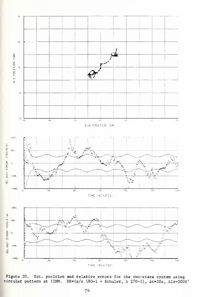
,__i*
1""""*
w
E-W POSITION (NM)
TIME (MINUTE:
TIME (MINUTES!
Figure 20. Est., position and relative errors for the two-state system usingcircular pattern at 15NM. DR=(a/c 180-1 + Schuler, b 270-1), At=20s, Alt=3000'
7^

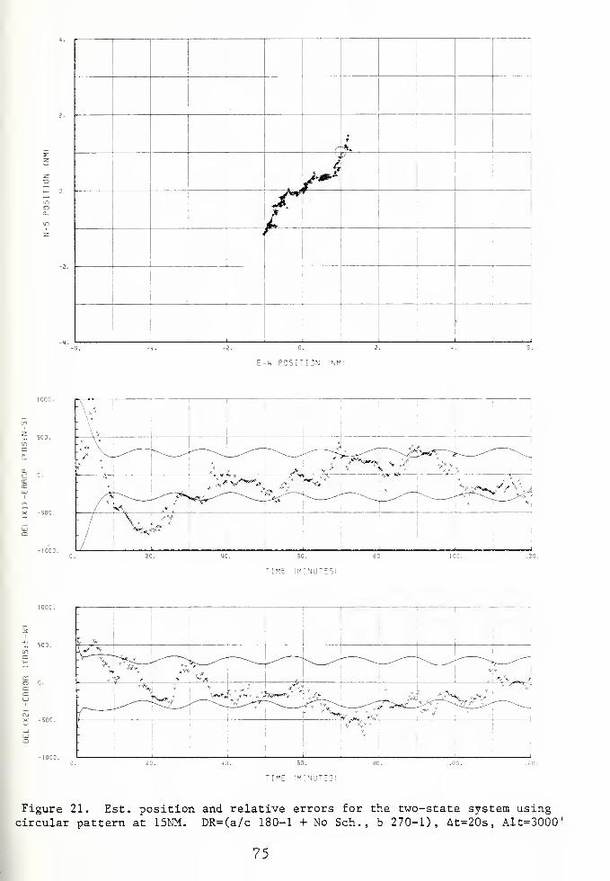
1
r
<
i
E-W POSITIGN INM)
\ '1
1
|
_i^_-X ' /
^
*X
/^^—***** ^—-^^ s?^-—<^ ^j-—-^_ " ^s-— ^ -y
- / \ *?
TIME (I1INUTE5I
TIME (MINUTES!
Figure 21. Est. position and relative errors for the two-state system usingcircular pattern at 15NM. DR=(a/c 180-1 + No Sen., b 270-1), At=20s, Alt=3000'
75

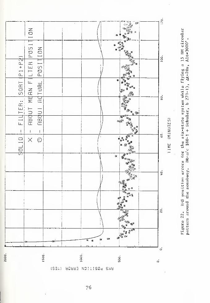
CL+
azC3CO
ccLU
Q
O
CO zo o
CC —
<
LU COI— o_J Q_
CL
cr
cr
ZD
cr cr
X
J en v
a; «_e
qr„ ox
^ "*
mr^3
E S$I*'
1
of*
<**
ti ox
MCO
i—
i
3U •
l-l -fl oO Oo
S c**>
3 II
•uLP| i—
1
1—1 <J
nj ~cn
M OC CN•-I II
>> -4^ <4-1
nCU /-v
l-H t—i
H 1
X! O2= r»
CNS0) XluCO «>, 1-1
CO CU
I-l,—
,
D aCO W J=LU C3 O1
—
4J CO
ID CO
Z 1 +X•H i—i
31co i
O01 cc
LU C i—1
s: u—ii— ^ -^
CD
4h h
erf
CD CM
!-i •
l-i >,CU o
3C XH C4J•H CO
CO
a cuax4J
yis -aSi C
3C
• l-i
cn aCN
cCU Hl-i <u
3 u60 J->
•H CO
fe a-
:sluj yoyy3 Nonisod swy
76


COLU
[fl
1—
1
3 •
U —U o•H ou c
en^ !!2 JJ
—iu-i <.—
<
«
Cfl 71
oM CNC 1!
fl 4-1
>> <3
i-(
U-i A,—
»
01 i—
I
r-l I
H CJ3 r>-
s IN
e 034J n
CQ M>, 1)
CO 1—
1
301 J2JJ Ufl CO4-1
'/I -(-
1
—
3 1
u oX)
0) rH
JJ y
M ~^^
*U nei
B] a'M
1j •
M >.1) o
3C -C
aH QJJ"H CO
w01
O. J=4-1
s TJpd c
3
• urn en
OJ3
4) hn V3 uM 4J
•H cd
In c.
aa
(sai) yoyy3 NQiiisod swy
77


o
eno ED
Q_+
Q_
CC —
«
uj ent— o_J Q_
azaen
ex
CC
ex"C3"
COex ex
a
o
X O
err
to
3 •
o -S-l Oi-l oo o2 I!
ui <
CO CDo60 cmC IIH 4.)
>>rH'-M ~
X-N
0) r-i
i-( 1
•-4 OX r»3 cn
e J3CU
uca •
>> j:en o
enai
•u1
—
ca 23 4-1
2 co +s: r-<'—
'
3 i
4-1 OLU 00
sz 0) i-i
l_4-i a
U co
•—
'
4-1 ll
cien QM
u •
u >>CU o
3C -3O•H C4J O•H en
ca
CD
a. -34-1
2 T3ptj C
3
• '-i
<j- cu
CNI
a) sj
'-4 01
3 4-1
00 4J•H Ctj
fa a.
(sai) yoyd3 NOlilSQd s^a
78


«R#*.
<
'
.*>*V*
r
H~3
i
....... 1... .... .. J
-2. 0. 2.
E-W POSITION INMJ
TIME (MINUTES!
TIME 'MINUTE5I
Figure 25. Est. position and relative errors for the six-state system usingsquare pattern at 15NM. DR=(a/c 000-2.5 + Schuler, b 090-2), At=20s, Alt=3000'
79


t*
J
t**
ri*
1
i
E-W POSITION 'NMI
TIME (MINUTE51
i ME :M[NUTES)
Figure 26. Est. position and relative errors for the two-state system usingsquare pattern at 15NM. DR=(a/c 000-2.5 + Schuler, b 090-2), At=20s, Alt=3000'
80

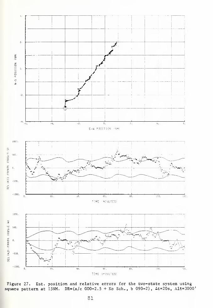
/J
(i
j
t
E-W POSITION iNM)
"IHE IMINUTES)
Figure 27. Est. position and relative errors for the two-state system using
square pattern at 15NM. DR=(a/c 000-2.5 + No Sch. , b 090-2), At=20s, Alt=3000
'
81

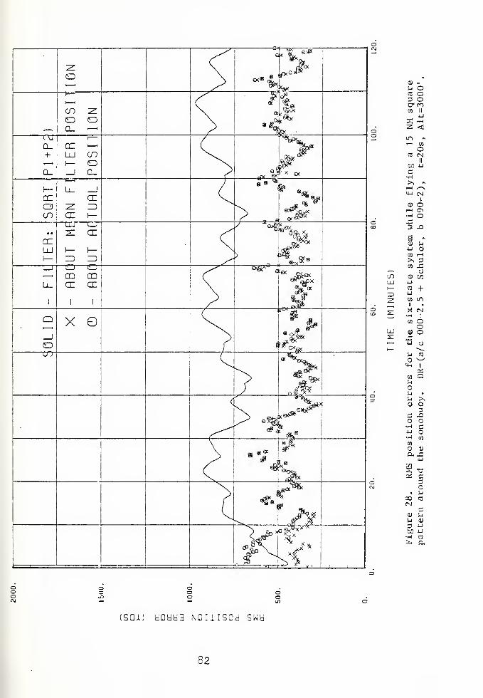
01 _u OV, oa oV enCO II
uz
t—
1
<lo „i
—
01o«J r-4
II
ill •u
aH>, ~—
1
^~\
Oj C-J
CD O1—
(
z^—1 Or*
3 ,ra
fS
11 j-i
JJ Den ^i>*, 3•J3 -3
;j
1) enu3 +u•J] LO
y. CMft ]
en Oc01 O•u CJ
u CO^s
'J-i '1
PSen a•j
1-1 •
'-. >,11 a
c ,aaH c
rj
H en
CO
ua,
~*
_j
~ -3
pd C3
• '-j
oo 3CN
cu 'm
u OJ
3 -J
Ml u—
i
-1
|x< a
(SQJU dCUU3 NDIlISOd swy
82

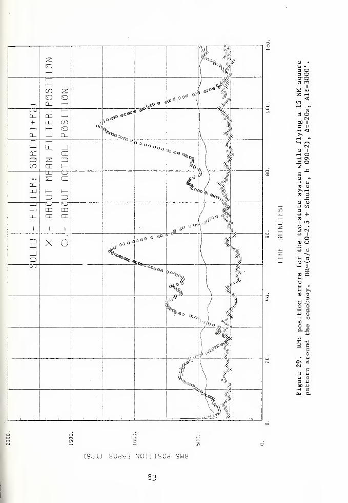
<u •
!-i -CO O3 Ococn en
II
CO
eo oCM
oo ii
C 4-i
H <>,>H «y-i /—>
CNV 1
r-4 Oi-l a\JZ o3
jaBcu **j men cu
>>Hcn 3
£.0) o
.—
.
4-1 C/l
cn CO
UJ *•> +1
—
en
;1 LO
2 o •
3 cn, 4J 1
oQJ O
LU u a^ --^
—
i
U CO
I
—
O v-/
M-l II
ctf
cn aS-i
ij •
u >>0) o
3a x>
o•H C4-1 O•H Cn
cn
O OJ
CL _C4-1
C/3
2 T32 c
3c
• u<y> co
CNC
cu )j
S-i 0)
3 4-1
an 4jH CO
to 0-
(SQA) yoyy3 NCiiisod swy
33


CU •
J-i -CO O3 OD-OCO CO
II
S -u
2 -H<
lT>.—1 *
co
cB OCM
00 II
C i->
t-I <3>•T-I «4-1 ^-.
CM1) 1
r-1 O•H ON4= O3 Xe0) -4J •
co .n^ o
,—
.
CD C/3
enLU CU O
4-> 2Z3z
CTJ
U +CO
.
l ms: O •—
IS cm4-> 1
LU oi: CU o_
i
XI oj
4-1
ou -~~-
O CO
i+-l -—
'
Crf
CO Oua>-< •
^ >,CU
C3
C XO•H CU O•H CO
CO
O CU
a. x.4-1
C/l
3 c3
• )-iO CO
enC!
CU )-i
U CU
3 4-1
00 4J•H CO
fX4 C
tsai) yGcjy3 Nouigod swy
34

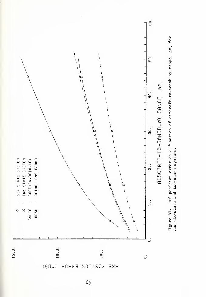
-I CDCO
z: 2: -^ ccLU LU LU o>—
i
—
LJ ccen en 2 CC>— >— CX LUen en •—
•
CC enLU LU CC z:l
—
i— > ccex ex a1— t— c_> _jen en —
'
exI i t— 3X o CC h-<~-t 3 o uen 1
—
en ex
I I I
o * 2 S_i a:o aen
\ \
J I I I I I
oi_n
aen
U
LM
„
X<„
<v
GOC03
l-i
>.
3-Q
,—
.
2: a2: en*—>
1
Ou
UJ 1
s ca
CC 1-1
enej
•H
>- a
c ew
3 O
CO SO^ HO CJ
CO 31 en
CO egh—
1en 0)
1
—
CO -u
en
Ll_ M >,
CC en
Uen u a)
(—j 0) Ucc
CO
,—\ en
r~r- H 1LL U O•H 3en J-J
a -ac
EG «2as <u
4-1
03
. -U1—
1 en
en 1
Xai -hf-i en
3(JO CU
fej u
ooLn
aoa
acr
csciju yoyy3 NOiisod swy
85


z ^ ^, cnLU LU LU1
—
t— u cccn cn 2 cn>— >— <X LUcn cn i—
i
cc cnLU LU (X zz1
—
i
—
:>• orCE cr a1
—
i
—
cj _jcn cn —
<X1 I i
—
r3X o cn i
—
•—
1
3 a ucn 1
—
cn ex
O >i a £—
.
cn-J CEOCO
oco
aLO
OJ
4J
LUcn CO
>u01
u>- Co •H
. Z3 4Jo cc c=r
COEsz dj
a Lj
cnCOcd
LU01
;z:
a1
5m •r-l
_j •U
CT u
> 3
CC <U
LU CO
(—2:
cn
CO .
*—'
M 35J
a h- ^ 4-1
CM 2:11
cn
LlJ 09
s:1!
LU •r-l uaz 4-1 CO
3 •H Ucn
cn 1
cr a3
^j 03 4-1
. 21BS aa =~
to
ri 01
ci uCO
01 uu cn
a 1
60 X•H '1-1
fe cn
ooLT>
Oao
CDaLO
:sgju yo^y2 NOiiSQd swy
86


V. CONCULSION
The following are the conculsions reached at the end of
this research:
1. The six-state algorithm developed in this report
produced estimates of relative sonobuoy position with a
standard deviation in the error of 500 yards at a range
of 20 NM. Aircraft drift, which included the Schuler
cycle, had no effect on this system since the states
were defined relative to the aircraft.
2. The two-state algorithm developed in this report
produced estimates of relative sonobuoy position with a
standard deviation of 300 yards plus an amount equal to
the amplitude of the Schuler cycle error at a range of
20 NM . When nc Schuler cycle navigational errors were
present, the two-state system cut-performed the
six-state system.
3. Both algorithms shoved an increase in steady state RMS
error with an increase in range.
4. The six-state system showed an increase in actual
steady state RMS error for an increase in the time
interval between measurements? however, the covariance
of this system indicated minimum error occurred with a
10 second interval on one sonobuoy at a range of 15 NM
and an aircraft speed of 180 lets. (This translates to a
lh degree change in relative bearing.) The two-state
87


system shewed no change in the actual steady state RMS
error for intervals between 4 and 33 seconds and only a
slight increase in these errors as a 60 second interval
was approached. The covariance of the system actually
decreased with increasing interval.
5. Neither system showed any dependence on altitudes
within the operational limits at a range of 15 MM.
6. No adverse effect was observed while flying straight
tracks as opposed to curved ores.
7. Steady state RMS error was affected by two conditions
as measurement intervals changed. The longer the
interval the more the error tended to increase,
especially for the six-state algorithm, as a result of
system propagation. The shorter the interval the more
the error tended to increase as the systems encroached
upon their non-observability condition. An optimum
measurement interval existed for each system which was a
function of range.
88

VI- SUMMARY
Both the six-state and the tv,o-state algorithms were
atle to successfully track the sonobuoy. However, the
six-state system was the best choice given the navigational
system in use by the Orion. It was capable of providing
estimated sonobuoy positions at a range of 22 NM such that
the errors had a standard deviation of 502 yards. The
computer time required to process one measurement was on the
order of 222 milliseconds. On the other hand, the much
simpler two-state system required only 2S milliseconds or
one seventh (y) the amount of computer time. However, its
estimate of sonobucy position was degraded by Schuler cycle
errors in the navigational system. Without these, this
system was subject to errors having a standard deviation of
322 yards at a range of 20 NM. The Schuler cycle
periodically increased these errors by an amount equal tc
its amplitude.
The algorithms i*ere very much affected by the aircraft's
flight path including the relative location of the sonobucy,
the range to the sonobuoy, and the amount of angular change
in the bearing to the sonobuoy as measurements v,ere taken.
Since the sonobuoy position was to be estimated in
tv» o-dimensions , the aircraft was required tc maneuver in
such a vay so as to provide information in both dimensions.
For example, as the aircraft crossed north or south cf the
89

sonobuoy the E-W errors decreased while the N-S errors
increased. The trend reversed when the aircraft flew east
or vest of the sonobuoy. It \»as also observed that steady
state RMS errors grew with range at a slightly decreasing
rate. They were twice as large at 45 NM as they were at 15
NM. Finally, the sonobuoy position was not observable if
the relative bearing to the sonobuoy did not change implying
that two lines of bearing must cross in order to obtain an
estimated position. If the amount of angular change between
each measurement was too small it began to affect the errors
because this condition was being approached. Anytime the
aircraft flew in such a way as to reduce the rate of bearing
change, or the frequency at which measurements were made >as
too high, this condition was prevalent. It was observed
that at least 1% degrees of change was required to avoid
this problem.
The sii-state system showed no tendency toward
divergence as long as initial conditions were reasonable.
The two-state system, on the other hand, did have a tendency
to diverge when the gains on the drift filter were not
adjusted correctly. For example, if the gain was to high
the estimated drift was heavily dependent on the last fev
measurements and was too quickly affected by changes in the
position filter. But, it was also necessary for the drift
filter to have non-zero gains in the steady state in order
to provide some insurance against an initially wrong
estimate of sonobuoy drift. With these modifications maae
90

the algorithm operated correctly during all tests and, in
fact, had less error in some cases than did the six-state
system.
It is the opinion of the author that either one of these
algorithms is an improvement on the nistorical method of
"mariting-on-top" the sonobuoy. further, it adds a great
deal mere uncertainty as to exactly ho* much accuracy could
be obtained in the old way. Non-linear navigational effects
were not even considered and the number of measurements made
to determine sonobuoy position was on the order of 10 or
less for any one sonobuoy pattern. Nevertheless, in an
operational sense the accuracies achieved here would need to
be improved. Without the non-linear navigational errors the
accuracies could have been much better. Eowever, the
results of this research do provide another perspective for
the problem at hand.
91

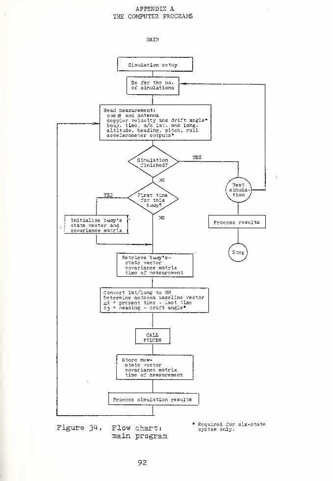
APPENDIX ATHE COMPUTER PROGRAMS
MAIN
Simulation setup
Do for the no.of simulations
Read measurement
i
cos & and antennadoppler velocity and drift angle -*
bouy, time, a/c lat . and long,altitude, heading, pitch, rollaccelerometer outputs*
YES
Initialize buoy'sstate vector andcovariance matrix
YES
Process results
Retrieve buoy's-state vectorcovariance matrixtime of measurement
(Stop)
Convert lat/long to NMDetermine antenna baseline vectorAt = present time -last timeZ3 = heading - drift angle*
CALLFILTER
Store new-state vectorcovariance matrixtime of measurement
Process simulation results
Figure Jk- . Flow chart:main program
* Required for six-statesystem only.
92


SUBROUTINE FILTERSIX -3 TATE
Calculateplant matrix ($.
constant matrix A,,.
Propagatestate vector
\ - h-A-i + Kcovariance matrix
3k
aK*ic-i<-i sk-AVVl ]
*
Do 1=1.3
YES
z. - cos a
Calculate
dz = z, - z.
H = Hj
R = R,
no
YES
'2 dCalculate
dz = z~ -
H = H2
R = R,
z3
B He
Calculate
dz = z, -
H = H..
R = R,
Updategain
-T Tf - vv
state vector
A - f ft< k
k kcovariance
\ sk
ci
TP = SS
+ G dz
T Jff ]*
MO
YES Xk " X
k
Sk "
_( Next)
©Figure 35 Flow chart
six-stateSubroutine FILTER
93


SUBROUTINE FILTERTWO -STATE
Save last position &velocity + .
Xk-f Uk-1
Propagatestate vector
Xk - X
k-1+
°k-lAt
covariance
sk
= K-i sk-i
+ Qk-i]i
Calculate
X " Xk
+ Xa
H(l,l) = HtlH(l ,2 )
= H12
Updategain
-T T T t
f = S^H^ C< = fXf + R G = ~ V
state vector
dz = a - z z = cose
x; = x- g dz
covariance
<= 3ktl-i ffT]
P = SST
Driftmeasurement
Zu
= (x£ - X^jJ/at , limit to 20 kts
gain
C = i limi 1- tn ^ rlinimumn + 1 34 min
inhibit first 5 dr ift calculations (C = 0)
n = 1+1
Drift
U* = U* + C (Z - V? ,k k-1 u k-1
Figure 36. Flow chart: SubroutineFILTER two-state
9/4.


GLOSSARY OF COMPUTER VARIABLES
SIMULATION PROGEAM
A Vector of aircraft accelerations
ALPHAI Result of -^—
^
or -fTf + R
ALT Altitude
ANGLE Direction of sonobuoy drift from North
ANT Antenna
AVEL Initial aircraft velocityT
AS Matrix result of I - ^~
B Matrix result of (eSS 1+ Q>
BOUY Sonobuoy RE channel or number
C Gain of drift filter
CA Result Of At/(84 min.)
C^ Constant matrix in six-state system's equations
CKL Rate of change of nautical miles for a change indegrees of longitude
D Array which holds all items requiring storage fromone measurement to the next
CELT Interval between measurements, At
DELX1 Relative position, axx
DELX2 Relative position, ax 2
DELX3 Relative position, ax3
DRIFT Magnitude of sonobuoy drift in yards
DSEED Seed for the random number venerator
DTIMS Array of initial drop times for the sonobuoy
DZ Res idual , dz
SDELX1 Error in the est. relative position of sonobuoy, &Lx l
95


ELELX2 Error in the est. relative position of sonobuoy, ax 2
EOSSO Matrix result of e $TSTS 23
EPSLN Age weighting factor,
ESST Matrix result of e S 5T
EX1 Error in est. geographical position of sonobuoy, a*!
EX2 Error in est. geographical position of sonobuoy, Ax2
F f vector from Carlson square root technique
TFFT Matrix result of ff
Tff
EFTA Matrix result of
FT Transpose of f
3- Gain matrix
GAMMA Aircraft pitch angle, y
GDZ Vector result of G dz
GR Gamma in radians
H Aircraft heading
H The H matrix when used in subroutine FILTER
HOUR Time in hours
HR Heading in radians
HT Transpose of the H matrix
I Index
I Identity matrix when used in subroutine FILTER
IEND Indicator of EOFT
ffIFFTA Matrix result of I - —^-
IN File from which data is read
INRES File from which true scnobuoy positions are read
IOUT Device on which print is made
IOUTF File in which results are written
96


IOUTZ File in which random vectors are inspected
IRUN Index for run number
IZ Index for measurement, z = 1,2,3
K Incremental measure of time
LAT Latitude
LATI The latitude of the origin of the local earth fixedcoordinate system
LONG Longitude
LONSI The longitude of the origin of the local earth fixedcoordinate system
MARK Indicates whether information is to be storedor retrieved
MEAM Mean estimated sonobuoy position, mi
MEAN2 Mean estimated sonobuoy position, u
2
MIN Time in minutes
N Total number of measurements made on all sonobuoys
N Index *hen used in subroutines IN ITAL and DATA
MRUNS Integer equivalent of RUNS
Plant matrix, $
OS Matrix result of $ S
OST Transpose of $ ST
OSSO Matrix result of $TSTS $
OX Matrix result of § X
? Covariance matrix
PHI Aircraft roll angle, f
PI TT
PR Phi in radians
Q Variance cf plant noise from N(0 f Q)
R Variance of measurement ncise from N(3,R)
97


RAD
RANGE
RANSE2
RBI
RB2
RB3
RBX
RNO
RUNS
S
SI
S2
SEC
SE
SIGMA
SIGMA?
SIGMAX
SKL
SNSXT
SST
ST
SUMP1
SUMP2
SUMSQ1
SUMSQ2
SUMX1
tt /180
Range to sonobuoy from aircraft
Squared value of range
Unit vector component of antenna baseline
Unit vector component of antenna baseline
Unit vector component of antenna baseline
Result of (RB1&x
x+ RB
2 ax 2+ RB
3ax
3)
Normally distributed random number from N
(
d , 1
)
Number of simulation runs to be made
Array in Carlson's square root technique whichrepresents square root of covariance matrix
Square root of variance, /Pn
Square root of variance, ^fiz
Time in seconds
Matrix result of S f
RMS error in the estimate about the actual location
RMS value from the Kalman filter, /Pj \ + F 2 2
RMS error in the estimate about the mean estimate
Rate of change of nautical miles for a change indegrees of latitude
Propagated matrix of S
Matrix result of S ST
Transpose of S matrix
Array for the sum of P(l,l
Array for the sum of P(2,2
over NRUNS
over NRUNS
Array for sum of ax over NRUNS
Array for sum of ax over NRUNS
Array for sum of a'x. over NRUNS
98


SUMX2 Array for sum of Ax 2 over NRUNS
TIME
Ul
U2
VAfil
VAR2
VARX1
VARX2
VELCT
VELCT2
x
XAI
XAT
XI
X2
X3
XB1
X32
XB1I
XB2I
XNEXT
Z
Last time in seconds the sonobuoy was processed Dy
the filter
Time from aircraft clock in seconds
Sonobuoy drift vector
Old value of U(l)
Old value of U(2)
Variance of the estimated sonobuoy position aboutthe actual location af
Variance of the estimated sonobuoy position aboutthe actual location o\
Variance of the estimated sonobuoy position aboutthe mean estimated oosition, a 2
,xl
Variance of the estimated sonobuoy position aboutthe mean estimated position, a 2
Relative velocity, aV
Squared value of relative veclocity
State vector
Aircraft inertial position, Xa
Aircraft true position, Xa
Old value of X(l)
Old value of X(2)
Vector including XB1, XB2, velocity of sonotuoy, andtwo zeros used in the six-state system
True geographical location of sonobuoy, x
True geographical location of sonobuoy, x
Array of initial sonobuoy positions
Array of initial sonobuoy positions
Propagated value of X
Measurement vector
1
99


ZHAT Estimate of z
ZN Normally distributed random number from N(z,R)
ZU Vector of velocity measurement for drift filter
100


C't-'C'CCCCCOOC O l^-OOO C!O O C" OOO T d O C? O ^c-^ _. rr r--^ C Od C_ G C OC c o o o c
> LP n r«- 7- •-* — . 1 r\j,f\t'^ f— 'r ^ O -- ^*i"'" *^" i-P "* r— ^~ ^ /—
« _^ (s -^ *• ' r> r **~ -~i -•- r~^ ^_, *\ -,- +?•* C °~~ X "** "" —C^nO^C^'—1 —< - — —
1 .. - .—t — _ir jo r*.' \r ^joj^ 1 ^j i~»-* r*': < *' '<* r~i ~*~
1"<~ •".*-*-,*-*-.— .7 * 7- -.--»- r _
c r^ !7 oo c ^r r '~ r. c c.
*" ^oc '" <~~ ~. c c 1 c ^ c 70c *~ ^ rccoccc?c '" c o n. c -
c: o 1 c t.
f^xroccc o ^~ c r " c oc r'c cc o c_ r- o c.o c~ ^ C- o '.- c_ ''_- c '— c - c '
'
r- ~ c? o o^ <~! "j r_ cr
c
I- t- h h t- 1 (—*-!-• I— *— I— »— t— i h •• r t- >- r r- I- ( I- r 1 f I— I— »— l-Kt— H i— f I- H 1- * S— »— - »—-
!—»—*—<? «? <? < <i <"<—<-• ^" *-**-* * *-*-•"<'<'«**<-<*- .' <_ if £ ^* <-, #r* <•»«--<; <r* < «•' *- «' .-* .-• -- .r - -- -- '* <~ -r* .*-
v —} '—
>--:f
-< ._ -
1
V j LL - J 1
I
C •— U.T"
~ — ^ >- >— c.
r\ _i — lJj
_; * _ _J .-• -lOWiJJ •
;> -r- '. .' I' 'II! - j _ '3— x ^ * /-*
:v).i 11 ___^ tr 'j..:j 11 ;•«—— . 1
101


"V c<~ *T L' C *- "0 rr o —
'
Ft r lT if LP -T If iT C -"
' - c- c <-' o cj c c c ch I- I- h h- h ( t- . - I-
-r <* « -— f '' < * < *C
c: c. c — '— <- r_• t.. a '_'
OOQCCCOCCOOOGCCCOCCCCOCCCOOCCCCCCCCCC""• -" vr n - j r- -r, cr- c — r\i i <f Lr -0 r>- ~ <"• ~- — r -n cc r> -j— « •_- c — ""
:—
><*•
.
- r; r^- kc. C o -O »C •£) '-C O i*- P~- n. r"-p— r- r~- r>- r— r-- x -r; cr: -r: co x x o^ •*" t s ~ ^"7 " ^ c u
one 'C ^~ rr c o c~c
' ~ c:o c c; c : <z t c_ c; ~ c c cr tj <"~ ^~ o c c c "cccco»— i— I— t— (--<— t— *~ J l-l-Ht-l-l-t— t— f— t— t I- h I- t- I- y- h- > t- K K S- h t- t~ \-
I
<T" <f *1 <^ <T <T < <"«-< ** < <~ ^ <: < < <T*r'?\*~<~-r'*\<-*' <"< <- « - <; « *- .^ ^ <
^_ o '_ £_ cj r_- c '_ c u t_' cj c- c- c: cj l; l_' c c c c- l v. i: c? l. c c l '_• c c_ cjc c —
— i/".
•—C 'OIL •
*."! • < • CL O wX »••. 4- C
'.j —"• -n > - «i
-r ~~ ~ - i i
1 ^ • Ju ^~
»r^ «-X> «CL? »
r: cr x xx • •
« • *
- <
_ l '/L'>r —
>
c s*' z~ ~ v '-
'JU
102


rcooocccococoococ«. ; rr\ ^" LT» vC ?— T J*
'— —Il"* "O t* tP C fw X '
o c o+ 'r .c--
O C — 'Z C c c c o c c c cc ci t- 1- (- 1- h (- 1- i- I- i 1 h I- I
:~ t. c: r. c f_: c c. c_: c_ c c c. a 1-
:c c ;
(- l—;
— c c: c r ' c r~ c~ c~ c ' r~
'
- t- t- v v- i~ t- t- \- y i- ;-iirr <* -r* <~ < *r <."* <" ^ * *-- <-
:c ci'C.ll l ir.cr^-c.
rr-
r ••-r
;( _ *.
.v. j
-- > *
r
IT,
ft (/I*;• '. *
X
i ~_ -v — < <
— <r -T —— ? —t- »r~ ~ I" — c<T -—»
r-~ • i- — — —
r <i c t/" '-. I— _
» — » » —--— • -"i
_ h-~Sl~.' i'<:A r
-Z r~ : 1
7<^2" ~.- ~ ~
i
(
'
CT X * -C < <3 —i—
11- <rl
_i —ir- 1 1 >^-T _ «C Ti JCC
_i —til—- • :_ _ r_ —'"J :
a.'3t_ J _ _t i >• '~ '< •< -
ii ii ii _•—i:
•I 1_ I-
.
I— II .1 ' — J
103


r~j c* c c c •" c.' ^ c nc r- ^c "^ o cc c r "> rjc c cc cc c c - c c c c tr c o cr o c o r^ c c '""*' r (
"~
** .r '.^ if* '-»"' -.r '-P ir n r c £ c c c •£ .? ^_ -*c c ^ ^ i*****- '-*- r- "*-r*- p*- "*— _ x *? t - * *
' ? zn ™ -~ c -T* c -" r* J* /*
' r^ r- r—
t~ (- h H >- I
C" C CLCLC t_'f_ c :. L. CJ c
K f h- t h h u- v- r t- -- r i- r ( - » h- i- J- r r- H K h- H »- t- r-
<- <-* «^ --* <-" - <t «^ <T<"'<T ,<*<f *'*«iT<*--T<1 *r"
'* <" <T <3 */ ^* <T *" < <^ *' *"" •' <" < <* < <*
• *
\3 o
-co
•I
r
L. cv i_ o. c
;.
:
30 -.". Xi
- •I -
I In o*v oc
ii ii —
•
it
.— ^-. vj
>: C2 _"; —
104


?r.noo^coo r-
c
*o OOC OCOQCOOCCOC C-2">-cr?Cr (\j *», * it ' "-- x Cf t -1 "; ""i * it or- ,iC, '?-Jf rf, -t
i—i — i— JVC f\i r\j r^j (x» ^ c\j c\* ^ (\t cv r\; <\j o fvjfvc ^; ~*.' <", ~-. *" o *„
oo r? i; c! o oooc o c c; c cc cc oooo ^— cr cr c c ~
^ r*— ™ r** *" —j cv rv *" .r* c *-- ^*
'"* ^~* r- n - ^ v
y i— j— i— h t-i-t- h—h h r >- y- y t- y- y- y- y- \- >~ y- t h I- t- - y- y- I- h r i- t- t— i- r v- k ;- >- y y- y i , i
x x
—i p
— Cx y
!— -k- >-
O '3 —" >" ^"~ ""Vl
o^;c r • u o o—
^ -/^-->t. uj ———i—
t ~ LJ c_ • '—' ' I " —
-+ + + + + ^2iT<:
^ij;^c_-crc :i " :i il ii ii XX'
jC«t"i- -"- '_; r.'. i/^ ^: _' x < X X x x x x x x x x r— it.
105

C' O '- o c c c c-r •» >r -r -r '" -" l.- r li .p t it ^ _r. o -C : _ : c c o c ? ~- r- -- *- r- r~ r- ------- :: .- x — _ ,-. x ; ^ -•
'..j-
r-,ir.r.^'".\r \?»".'N .,
t' in^p c\! f\j(\.f\Jc rv^.r "-. p ' r\.< c-^r r- "Y ,-s. ". r c.'j'' p: r\; r\ c\ r c\ r.,r .p^
I— t— |— I- «— >- |— — I- |- H I- H (-• I- H h t- I- h (- K t- |— t— *— •— • h (- > (-l~
I- I- I- f t- k t- - I- ' h h r (• (-
r < <r <.. <- * «, ^ -r" *«-*-. «-f <:«-«---—«- -~ *" «r. <-'<,' <T <' -i «- < <- *-<:<-"<. <- ^ <J <i <- <- <: *r" <-• «— »-- <-- < <-
'_L t£ c_'l.: CLCLC'-LtCCCCC'tJCC d'_c: crc r_: .'_;_ c:c c C( 'SL c ll',:,' lj -_r c_ r.
c
I- '/ —
<-: >/, '_
t— Ou..C **.
< -5 — :*: <
— -xr o — ".I
X ~ <! — t-
X I- X =
r- - U. C X
. - i — X
<
X H I
I- h
r ioo——-»— _i_j
— —— i_i T_ J_ X Li. '_
ii ,i ,i >. ii ii ii _j
n -r -n o p- 3 «p — — ii —< a:
! n/:GO • • • • _J
! — -— :->--;•-< > a.i >\;ii,i ijoi' o u-
~w i
* . •
• «r ' —4 » '
I
!
X -<. X X
x— •_: clj *Z'_:>— x v < <.
106

CCCCOOOOOOCCOOOCOOCOOOOCOCCOCOCCOOCOCOCCOCOCCODCr' * r< C l»- CO ~
: t-r r'" -J- -fi -O r— v ~ T. —"" ; ro r -"> Olv "" CT T? —"~- •"" J" '-P C*— cr -" n*—i'V " -?" -T -- — T T C
?C"?7'?i7!.!>-CCC2C :vOGCCrt-<i >. 'r— —->—*('. ;\j - r\,"\ir i-i'-^jP'^-^". r -' -',"'' -" -
*• r*.. f\ f.v.i»uf c\ r .
~~ '^; c .*"
\ c'i \<~ r " r*^ — i"*"". i' Trr.!'"T!f*"^','''i ro '° Y ^c r»" -r. r<";
i rn ;r, c\ f r^ r**' " r r-.
~*
C- oo o c oo <^ o o cr o c- r-^ o -o c c c c r c c cj ct cz ^ cr cj c r— cr cooc o ^ c - c '-^ c c. o c 'r
h(-Hhl-l-l-l--t-K>-t-l-l-Kl-»-kt-l-Ht-HI-h-Hi-(-Hi-l-h-l-t-l--l r- H \- I- \--I- I I— 1— »~ I— I
—
< *-?*"«*• <T <r < <"'<? * <r <* <! <* <T <-' <* ":«~ < <' *-; <^ <- . *z <~ <, * ' <: «r -^ i" -- r
t < <-<-«-- <-^ <- «— <—-'<-' ^ <f <-
c." '.: t_ c C2c:c:f- ll.cjct'-cu^hl'cl cocc c_ c." c c_ '_; c_ i . c r_ l-l. cm r. l.ll..lcl:
o v" .; _<.
I- 2_i J-.—- ^
.T —
t-
— Ol1
•
—
c
—I
IJ -—
* r-
ISI
I
-y x x xtill
X X X X4. -I- ^-
—.(-
-I- 1-
x i—
>— K I— '-/ i_ — ^— ~-—i • _~ '," ^- • ^ r
JO
II II M M 1
i. -_/> : r
I I U IU I 1/iCU I QO I I
I! II II II II II I! ! II il il II II il
>*I I
II I 2-
) -+<r ot\i^ c '^ -J 'j > J
o 1- r r-" -^ - - . Xi
I
~t -t
107


aoo'Jt-OcnoTOc'JCorccccccocccoo'Jt;r:occoco3CCCCOCC.'CCu—
• :\! r vfTJNi.?':-'". r •* u" -~ :-» re c ~ — " ""
' -d- .- CI c 1" C —• i •
.ri j- u"> vC "-• "fi ~ O — ~ - " -T '-" Z *- rr.
-r -." <r »* .T^t * -t <f ~ - r ."m^:t -~ ~- ~ s sc .?o »: -.' o -c c _;-—'--- ~-- -— -— r--r— r~N-r~. ". jz .' ~: ~r r x ~. -
e~ cjo --' cr cr w-o c ^~" or" cr- ^~ cr c c *z oo c c c c_ c c — r-- c~ o '— c c '~
*~* cr ' . c cr ^ c r-"3o cr *— — c -
'~.
h-H-r-r-t-r-hr-l-t-l-H-hrht-l-l-l > 1 - t- i- r - r I • I- r I I- r- h r hhH h i- I- 1 I— i— I— I— (-
<-- < «rT *" <r <J «- <~<: ** <; <f <* <" •** < «-f < *'<-*< -r- *-'«-<«.' <^ <-•<- -c' <' «-' <*«-' ^ <f <-<- <; <- «-- <- ^*<-* -f < <r <<
C C £.. L.C r- L U '- C_" '- t_ C C_" C '- '_ CI !_• u_ L C LLC .CLJL" 1W.L LJLL CCCC'i. ^CL CLL £_ C ~
r j +
— x~X i_ —— XI-*- <• X
c II 1- n ii "*sl
1- 1- Xh I-- VI l_
<; --. <- '; J_ "T
w i 2" Jl JL 1 —c -^ XiviM t- •— c
-,— i-.. x• ,- * J.
> >-
1 » — <. h — -- <r «l
l c -, i-i.'xn-"xx—— . -<. — i — r\ +. + CJ: I— «-i ii. I— ~Z. I— > <:~. -t ii <-: jl x x -» —i(-v h — •
"1" 2- II VI— ^ r - <..•< — _ U
;r: L.uj ^_ — c;—— -;. — _i
C LU t— <r- >> • • ~- • • -v •> I
| 1 -*v ^>
V- C X X U_ \ -N. ("" ^ —--* ^
1 II ^^—
^
.t _ _ . .—*. -^. • • i • • • ^
. „ r —>i— <^- -- —
cr »' * l : f~ >r".|_-—>^ —^'_; a x x 'S —
—
Z_ L LS'T -*t-——*N 1 1 t— i— • 7' • « i
—»_.;<(..— < "H t\J -s < < — — X--»^\MC.'J Vr-li-T L r. >uu - "^ —
- -t r— a.i t* —
i
• x _*_ L; • ->-ii ^L — — .'— — '- • »x^U |
--*— O Jl^-^ J i— ?— sy =3.*— I— -C' 1— )— | <.
._: — ii ii*• ^^ __' -* II ii _ •> >< • >-v r t— -< ^< —C — Ii 1!
• —.-*-» cr •",-'—- ""3- -r v _j -~ • •---.
—
•^-^—« \J -j LJ »*sJ *— rr\ nT 'O i ] .fm It ^1 ii ^ ^ — f^. ^sjm rl—l %J * » "2 •— "-.
!
— -<: - i- -x --. -._ - - •
I| —4 -H -— .1 —. —1—4 — -- -— —. -»- •i -_ wi —( —
i
- V.^— —
*
.1 ^i —>-— ii l_ 3" "_ "Nsj _ _ ^,
108

COCCnoCCOCCCCCOCUCOC'CCC OOOOC UOU 3C- r.i O C QGOO!7" C •—i 'N; i
-1" i"'-0 *!»--c 7" -" r- ^., ."; -t it or*- r: ."- c —i^'' irc^r J-^--ir' ,-<- .f it. vC r"-x :
c: r > r- c o c c rr- h f hi- rHfc. ^ : <r ", <r <z<r. <
C: CJ C C C !_ L C
rr.rf f r*~ vr <" <t «*" -r -T <J" <J -J-^TCvT-T-T-f -r <r <r <r »? •
r J- «— I— {— (-(—I—*— I— t- i— <— h- h Kr f r ' h I i— »- )— t- .— r i- I— (-
c~ *— < *r <T *" " «" «~ *l : «r7 <" -^ .-- <" «r <-' <,' .-^ < -r <~ <- *% <_ < <? -r <." *""<__ <r. *
13 L COLCCL'DC L CLCCCCCCf ( C '- C LJCCGCCr f
-
C C C C C C~ '~ f .— *— /— r~
II c
-<—I h
- I I
n r> ii —• • •>» ^_
XX -w.
--c o
—• r -Co" — •> —
- - . -U- » • —•- —
1— —<U. <T C *C
- c_ » -< t- p .1- — •-
- c • X •O i— ' '— < LT o> — ^J L -
X >—< *j " o - O -C*^
IXT
1- L_i_ .. —._!
h- xlx^- U_ lL <ZZ Oj •"!_ -I_ » I— »
IT <" v'c , Li. Li + L ;
i: 1. i-^ a. 3. II <>. :i
LL h-LLLL^! IS'S-fZ —1 r "
Li L*_ t- t— . '-'" L-" O L" I C 0~ '"
— c i/T~/~r*n j-i-c c? ii ii ••— ICO —
Cj -rT •-t«-'^I<"'-t'j-_1.~* '
109


O O JCC oocc o c:OOOC C" O O C O ^ TT C OO^CCC C O C O ~- c o ^oocoocc**- T. ^ C \ry> r?- ^- ^ q p— •- 7* r- ,» p. i -<~\ <f T ' ^~ - T O ^- fM .~P .+- LT fl^TTC^l^ f" <T '.T- <,'*** "^ C* C"^
rr f,.~r ,.f „i- r • * <.+ -.r ^ -r <*- O- -~ -~ IT .O -i _r a" -~ -" P£ J OC-C-C-OC-C C--— f^— — '— ~— r~— -— -— >~— •— T-.
<r >* <! <- -J- -r vt v* -r -+- -c <r .» <- -f -- ,r ^)- v- -r <r ~? ^r -- -j- <r -i -r -t •+ ? .* -<--)- <r »? r <r <* »>-- ?• <t- -cr
•'-cccccT^ccrccrcocccc e; c fr;-cr ocrcc cr re cccc c '. cere cj- |- !~ 1^ h h h h h- I- (- I- I- 1- (- I- h ( K h |- I- (- !- H- l-h- I- r I- I ^ h '• >- 1- ,- I I- k- I I- l~ I-
Di. c e:e c a e:ce e~ cc_ c_r~ c^c e'.Tur_L-.rx eceeeerLe: e c_ <„_ ce c_ c" :. c '_ e:
r
-
Mhc—
•
I r.
y. /)
O
~cy72
X
Q — X-
XX — u~
^ X - «o- X — .-^ !'
> m.r^
— »r > /»/x — -ce » •
r_3—<_? -J —
< —<r _j_j——x * x i : .
—ic\j
'' r>: — r--, - \- ll'-.'l ^- ~,
2. —— CO*t-<«
C ^e 4. + - vy„r iv
>
:e — — x -X x x — > x r >: c. e — -^ -
• ce - ' • » I I—— •~3v)'.0Z3z; —i--ji_
—i^-j——i c? '." iai.l'/ i': ii ii ly '^ —^->-^1KS+ _ ^. —i.\i ~- —. :^ ii ii —— r m ~_ 3_ _3c: t^-^o • i^— xx •—— i. j_—._ — — 1_ :
-i. 2 "J: _>'—-<> ^; — -_ ii i' ^- ^ * ——iyji-i-HSi:LiL>0(.n II II ri _,<:<—. -^ ; ,
-j ^. —. ;_• ^ v -»
;
er y ^ ^ ^* m 'i <. < _'
—
t r_"* _; — ^;*— ''j e?i ^-.
^<i Lrv-
r><• /<
.^l/" O^jr/^l/
'-- i— •'.'X.X7l/lL, eG't- ; 'l-
ti. :„ " c _:_i_ _j "X i ^<'_' •-
_ _ — ' I ,| ! | II -'_-<., j_ — 2
_: i— - >
:
" _T ."_? < < —: . -J ~Z. JL r- r~
>>>>- -
110

:CCf r ^N-x?-r 'vir^i-ir £
•i -r <r «.t <r < -c -r <* * f J- -r •* <r s u" ir ^r s is tfocooor '_ r r ccrcccccc^ccch l-t f I- I I- I- h r K t-t-K hl-l I- t hhl-*. < v < •" <' <'<*-*<.'«' -r »:. <" «-' < <. <7 •- <" <~ <T
C '-! CJ L. C; '-' C_ C. DCC CO CJ C l_ l2 C 'CCCX
• • *
i — - - u. +• ^-j r.
— 31— rs
^ ^ — f
- - -*.
• il JL'- I— i:
i .-v, C JL U- *' _
,'r II ... f- j: _ ~
: _s _ ii — ">j ^ i-
.
~ ~ ~r y ii r t
111

c c '- c c c: _: c c ^oc o oc u u cc c c t. -i a u ^c _. ~ c-» — ,- rv —i «fr <r c •*- 'C CT" C —• «\!f: <T '-" O ~- ~ tr O—"< ~~ -1" -"• -c *- -C 1 — ——> 'p-c\.c.ir\.r< r ',"\.f r\i <\i r"; '"n ii Tm.-i ".i<*fJ" U* U -f ' X If S~ -T -' -~ -i" -~ U' u~ IT" U i f i" u~ L. uT -" U -T X J" -T U~ -~ ••'
t t-t K (- 1- t— (- ( t- t- t r t- J— f- t— I— t— t I— y h I- f Hi I— I— H»— <- rff] *" <. <_ < <_ <~ «'' t_] <^ <?" < <" «-_ *-* <~ <* ' <" <~~ <* <l <r <r* « <* *"T <
r Y~ I-- Y- > r r H- r r h r i i r !
-** *"*' *_r «-^ < < **" «i *"? < <<"**"*-"'-
-- *
* r_ -k
* en,
_J .1 II <<L
r( J .1 _L.
112

r-f "*t?>- rvif <f-tr ." *- r c? c —m^ j- ir> -c *— ?c yo-m'^ <-l" cf~ - — t — "-.•
u"u' -r o <' j'? j <j o-C C cr— r-f-r—r— '—'»-!—*— ma ttxsccsxC'Cl~ lt -""> it ir u in -' -T -T if _^ iT l~ ir ir u _r> _r it ir u" .f
c "
'." r^n c; c c- o c c c c occcc c o c o c
c
I I h- !- I- 1-- 1- r I- 1- \r t-IKi— t- f— l-l-l- t— I— »-k-t— I-
-^• -cr <: <j t <T <I
_; <r ~ cj: l: :_ l.. c: cj L <— r— '_ c
ccc oc ccre I* -~ ,-r\.i.-r,<r
. 'J> 7 ~> C 0- CT CT OO ~ OO-T L" -T i.r LP l:~ If X J~ LO iT If lO LP LT i" L' IP <£ ^ C O vL
ccjcc ccccccc ~^c ^~^wC_c no c ct r I— t— f— I— 1— I— t— I- h r- y I- H h I- I- t- I- H
<T<:*^<-T*-f<-:-o* <i <: < t <t <. <: </ <r <: <- r < * * * *^*^ *- <'
U <_f_ . L LJC f_ "C L CL"JCL"nL C
!
'-C r*":
i— •- <3
—< w |) tt li uj
f- —'— —— _3 :~; —"— --!--_• • i -c hi— • • ii —• ii
— ~ —i • • «o. <. ~._ ii a. ii —i:-
1 1
/~— -^ i—. .— — —. i - \j—;<- 4 »
113


CJOCTUCC O ooo c_- -_ i^co—'r-.^--i~-<
OOOOCOOCOCC'- y t- I- K h ;- t- !- K r
«*;<* * <r <T <? <" <3 <: <-
'-
c c c cj c. ;_: '— (_ c l (-
f" • u
CLH » •
r~ r; • if
^ _i -o 1
L _. 2.1 -
U.t/3 IT• •
at a. (fir"">
.J '1 1
Xm — • •
ly. • t
A. CLI— • ••_;>t— r- <i •—— i_j •
Z/I3>— ^3—fVJ II il
U^ ! O. \;*)tL-^——•—
'—<—. II —I X^ J P~
iy. II ' ""!
» _' <r <•; + +a r— u M ^ -ji-r-^i'_~ .r>
.-> 2 ai ><:<£—
—
w _ z. <4'_!UU^
114


cc^occoc^- occo r-^ --Coroc oo o oococ^ooococ^coo cr c? o c t_j c cjq
c
<-•_" c r~- r.7-"_ -j — <mt o 1^ '-" 7 O —"~j-r r r\ o^ ~:>r--.<\j"^ *-\s c *— ":
^ '- —• r ~~ - r • .'. *- r •?•-> —
<
OCCCCCr -iHi-tHr-H-'^-i^ r\j «\j f\i r cm r j r- ;fM c\i o j f' c r~ rr, <•» — -<-—c < .r r -Jr -f T -f -T <? ? <r '-'" u"
ccccocccccccccocc ococcoccccocccccccc^cn^r c cc ~ c: c- c~
5ccc c5 c2 r_"~ ' .> c :_ ' - c coccccc c c cj c- cj c c cr. r~ cj o c oc c c c coccc o ~ f_ r o.
L-
| I- t , r > 1— 1 H 1- t h r h t- K >— H r H r H h- K h 1- f- t I- t f- t- I— ( i— t- r f- r— ! r t- h K- (— I-
x x x x v x x x x x x > x x .< x x x x x >' x x x X x x x >. x x x x < x > x > x x x x ;< x x x > xU_L I..LL-U L; LLC UJIj I- U- L> L --L' U_' 'j. L' Li L L U -
lj U-'iL LL- U U u U LL;L. u U_ I L. I L LLiuJ '.U-L. ' U L
p- T^ H •# 7"LL.
> < L ' •> 'Z.
-fV Ci >- • —
-
•—-;.- O jO - C\i K>' '7"> W ~- -? Cr -_ £ X O
clo. h- -y- » Ll-
;t C^ <j .
• — i_^
* «^ u- h- r r^ ».(_
•v _ t/: -> •• *i :-i~
-M < 1 * C\j Mf
i— c
r «--
"*>• -:: z. *- - f./0 •™~
>' + CNJC ^O —
1
— C£* -,' —w t; >. *-h vt ^ ^J HTJr -f ci/' r "j; o ^^ 'CZ
"*^ —>i -K- lT> __. _^3 ;-J • 1
—
>T i--
% "& <r 'r * ^-r: «"-.x; , i r- u
)
<:-;^»— l^\ -^ u 'J _.
— <; u. *— 1!"-
•Sj ^_;. / — __ _ a. 3 II 11 — r\
t — — ^_ t— •J t ii II
,:,iJlS 1—
'
_j Z- y) r—
ii ii ^:
O —
<
115


o c o cr '_ o c •-.; _' c c c a <-•c c c; c 3 c c o~oo c o o c o c '. o
u' -".
_~ • r> a" u .j." _"i m. -w J " «j c j-OinCNNS' i*- r-» r- f— r -~ -: r
h f— 1— f (- r i- I- r I- I H t- H I- r- I- h r- i h r i- r i r I r 1 •- r 1- !
>r x ,< >' > x ;< x x > x < x * >; x / v xy < x x x x x X X x x x x xL L jJJ ij U-L U I - Li-Li L !— '.. t' l. I '— '- !- Li !. L ; 1. U-l' ,.
Li_i ! I.'
t- r (- r
:":!. c c "I I- r r h I-
' V >. X X > X
I- <" -X
;_ -T. C i
0_ X h
C ^ C. (,'" C3 ll- " •—'-
Xf. » -l- O Li- - *>- Z.•O <: i_l £ C >--vJ •C •> «-••' [_ •—
'X r
~ -Sl r "v h- ~ 3 - -~ **- - ~ —
*
L Ji *- >' _i. f
—J *-0 d r- x - «
L~ — »-'">-
h -— Z_ -*- — ~- _ * r
v ?—
i— * H _.'JI- \
, 11—v c_j _ — i—
i
is: .j- 1_
116


ccccccocccco'::cccn': r_ ;c;oocc:c;coO OO C tJ c<-v f- •<*!-"> .C-or J'O —' r> " -> rr*. "J «M tM C\. rv: -,j ( »- <i- .-. r- -y—
•
~ o c o <_ '1
c: r a c occ ooo c:
^ r t-t-r Y- t~ I- i-l- I
x. XXX X X.X .x < -X xi. l u_u ;t u r ii u.i. u.
~ c o c ">c, c c cr a occcccc ^ c rr c <-„ — t -j>c c:
I— - t— "— f t t- i- h » l-l |^ i— I— f— •— f— •- h h t- h- I- ( l-i-
x > >cxxxxxxxx> < x x > x x x x x > • x x x x xu_l j_i. .u. ^ u L.'L_ij i— i a u u -u.i_ '.:
. ll l •. ii i. u- u; :. a.
; X X X X > X X X X
s >*
H -r4
•X-
r-
I
i' v>-i:-
X
•; a -•-
--r ft
> L ~ - -
- —• >jr:—
I* -;-
I. — o-
< 2f <^ :C
ii
< o * y <" -i —i*- .— ^
-. -J—If-I I
-v^- UX _ » <i o • —* rn *—< —I ! !
- u i— »-u »o <i -na u.——I— — <T •— •J '_3 ~- — —- > * n ll
:r o'.ji • 1 1>^ >». a. x •
:
Z ^ — I' — »C.-L :'.—'~si.
j_<r —>-—• _ ii i:-»— .
~ —. Li f < r Z - ~ ^ * <"'
r-'-
,T L -' l-Jt C '-" t_" X < '
<^ <i.^^T?<- tj *— .1. 2_
_ J _ i — X
117


: : i- c ~ r. . o oc -._ r_; c -
x — r —4 t>j r- -t J" o *- t; -r-
r <r ; iT^" u" lC ~. j' '- -' j'
. C '-" '--> U c; C '
»N_ ~-— *— "^ f
^ r ^ ^^ cr cr r^ '_ c —'Cf~ccf~CGcc'"vC'^c.c cqccoccccc t r^
t- i t-f-t- t-l— t-t-l— t- I— i- l-t— .— i— i- t h h- h- t- h- 1- !— I— h I- h- J— 1- K K h
V >< xxxxxxx> X.XXXXXXXXXXXXXXXXXX k- v- X X X >I 'I L - U-'ll ll OjL. L U- U U-L' '1 U- U L; L 1J.U-U 1' LL.ll L 1
i1
L LLI U l! U_ I. U I'
rvi
ILT »
I-' "
I C X >
>- ~ ~
^ -< 3 -" r i i >s
II II
'i ii — ,i "i ii 'i — -r -
118


r~ ' r r"icoo''joccor'coccccco r->'o c o " '^ o 'i - ccre c ™ c n c c.
^ r*~ -r 7^ (- ,..-•>-*" * ." £ r-~ x C O ^*r* •<"• r O O f~ T C ^ Mf\ >' -t ~ C ^ X 7 C —ir.•*' "" -T C
"X ": " u". 7- 'J _T _ '* ?7' ^-^? ?^0'"Or?"1 C'" i
'—'<—11—
'-- —- —i
— «-h r . r .:r\i t r , r j(
— t—i —
.
'r — —i — ,— .—i _ r\. (N. r1 r\j~ :r ,o r (\.f< < (Nj^jr- :\,r:e\j:\,r "• ^jCN." r- " ~ r
," o c '*-'"J c '** c c~. t?c r̂ cr c_^" ^ c~ c c o w c c cnccc cj* r-io rs c. .v cz 'z. cr o c cr c*
> h I- I- 'r- I- |- t- t- I- h !- t- I- h I- k I- I I— t-l-t— t-k-H-l— H »- Kt— J-Hr-»-»— »-H h t—
»
X X X X X X >'X X XX X > X X X.XXXXXXXXXXXXXXXXXX. X X X X X X X'_ !. U-l' LI U- L ll.'U U. '^L' ij l_- '. L! I :' Lt-U '_ IJ_I L- u ••' l—U L U.L U •_ L J- i. L' < :- i- L
JL
X — ^J
X C
c; —— > t— h-
~<r -
rNi •;? r_j
— - H _i—— — — ^\
— ^JCXXM-_; c ~i —'— 1 1
i —— 11 _
:_ l ^ _ x <i— c .
119

c r—c ooocjcoocooooooocooocoooooooooooc cj oc on r;oo <*":o c c_.
7.0—e\Jff <j _o - .^_ x: y C i— ^ .' f"'<f !" <: ^— ~C 3*C —""* rn ftl> 'C*- "" *7 O—<o m »r l." Of>- -"*• ^ —.",.,- -'-
"J.-. ;V,-<-, f rf -^ -<-, ,-<-,, , ^ ? -f -I -T T -J -t st -t -T -O ^>^ U' I.' S~\ LT, '.C LO u" O sC "J -C'- —'»">C C ~ ~~ l~— r~- I*- ~~ "~"
• :c (NjfMr. !M c\, rv. (\; r r. ^ <\ r\j r\ic\< r\; r- f\.r>jf- c\i<"* r\ji\lr cv-"Mr r» c-.j'Nj'vo r-. f\, r r- ~.i~ ^ * ~ -:vr "--,'j c_ c o
o
cjoo c :;cjc r~ o c;o o ooo c: o cc o c c c c v r; c o n <_:•'
"> cj r_; " c.'^cc c r_(• r h i- l- I- t r hi-Hh-l-t-l-rf-H H-KI h f- I (- H H H- h- (-• 1- K~ r i— H- *— •— t— v— K I- V t-- r >
x x x x x x >' x x x x x x x x x" x x x x > x x x » x x x x x x x x x >;' x x x v x x x x x x x x
U U_L U u ! - U-U '_ <-"->: Li. LI L-LL.U Li . LLiU '- LI L. I—' L '_ U-il.-L U L LL'U U LU'.l Li L L Ll_'J '. '__
'. L 1 ' U-
> Li <V
^ r , *
Li xi r '
h »<LLL
-^1 » ».f\._» — AJ -J
r- h
r_i—+ < <
_' X X
- 1/" 0^ - 1- — - £ ,
—r ^ i. C- X -'-'-- T ".r
N »C- H - •
3— •O'-L.U -2^ -i CO. - •_!
•
— - -. —
.
VT^-'j^L-CT — —o —tX | |
IXX | -C ,_ -£ ^ h X X *>
I 1 ~Z. 1j. II II X. ^L.C'—-^.-^ ' .: r— -__ I ij.>. >. i-CuxiW z i - ~. -' i' -—_± —
i „ iC S2.22.2 x <. «-. II <' ^- II II•
» • X <—I . I! IP II ,1
•— I— u. —<-\J '. u< < . _ x. <.<!-:
cj c? zd _; xx
120

_> C„ c ' J C. — O -"• O C '— Ci C C '""I '-" UOGOCCOOCCCCC O OCCCO 'JO cj _; c c c:
Mtoh"Ji' <j- r c *- ~" _* ~^—' J ""! -r i' i^r: c —• '"- "~ * r fi f*- ~ 3 - c —» r ~. 7 j~ ^. r»- -n
s-n-V'OITXS'-^'SS' CO X O T- -T C' J' J~ T U • C C C C C O O CCC-C-«rJ, — —j r- —i—
i
—
(^ c_;ccjCccccdocccc c c c t_^ cr oc c- c r~ cz c coccc"coc -3*" ic i;
^
I -I- h I- t \ h I-(- r H-hhU-i-hf h h I- > I— I— I— r- I- r ^ I- r \- V r H Y Y (- '- >- -
XXXXXXXXXXX. X XXXXXXXXXXXXXXXXXXXX ' > x x v > X X > X_ l_ t li/U I! ii I li'll i! dU I
1 t. U La li Itl U l: U. ILi-li.L.! L u L i'li ! U, i i. .. ' _
- ,i rn r~ <- <">
v >- X X
-
r. -r. <\j
C\j -
r\j|- • »— '._ <
•x i—, - X
i- X Z x >- K - >Xu »u- LL »>— • LICll.c
x 1/ on (/" ll n *• <s; ?, Z'JX? 0"
•*- «_ r (/" ~i- x *— » - .•\j
-i-(_ *-r <7 *
L < •• » r\:
»< h- rr H- -
h- » •j. h X" r-
* 7> *-
—1( I-'.-.
I • II '
X • •X • • C '_
-^ 2. .>. i. 3. A. 5S. II 2. <- T. ^ ^. —> •— <; .>. i ^l «_ i. i
xI
') ,^4 • _ ~ « _
121


,JC"JCCCT'OOCCCCOi^COO,r'OCUOCCr >£,r~T. y •" —"" ,rr tin -r .— cr 3" ~ .- r-,:«". <-;o o.^- i; c-
r (\; ^'\r i
<~ y, ,'Oi< <
-
', r«" m r" .•
-~ <r f -J" -r ~f -r <r -r <!• r,
, " y~ rr*, *>" <t ,-r, "O .* i
~~ ~<: c^' ^ ( ' .*r r*" n-r ' r* r<": i-o c*^ < ' • c*" r"*'i , <
c - c J c c ^ c c c c -" c c o c- c >- c c c c c c c; c~
r r H h t I r ! r < t— f— I— 1- \- \ r I r 1- I f- r- r~ h
> x > xxxxvx x x X X XX X X" X X X X XXX XkU LwLl I L1.U. u. li U Uil HL.L HiJt1 lLL:i.UilJU u
'— r\,m -T IX? z ^~ — -*. ~:
'<- T'l m rC ,i rr; r .1 r» t^ Vr^
;
c. r~_- 1~ r- "~ r" T r-~- f—
;
t- 1- h h- h i
—
h r- K- |- rx: X x x ^ x :< ;-- X X XLl — L u LL- w, L >:. l J_ L*.
J 3 •*. !
^~, r ' r * r
'
x •<:* > x > St > Nr l- ;-
t~ 1-
•r- —
t
(^
1
^c , A.
—
»
!,
c- >
—* » [_
—. >*~
— < X
U_>- • •— I—
2. ~
< «l_llmj l_
? —lT <:— «r
<r w—IUJ_. ^^
• i(^ u"<1C~ •
"s. _T <I _.<r
| 1
* O 1 • 'J>~^ x «o 2T
• '_ —' c *~- ^^
o — ' J" "\. »
II II—.11 ii r- "-I-
I I' — '.LL ^ f" U_'_l CM — _l • • >—
.
— '-Z.—* (_ _ - - —
• • < ^» • • »». -~Q• •• —*••»»•
-J H «c_ii icvk-
• • •~xji— • n'JV'L—— —• J" < ——i II 'I —
^_' L- X X Q. — J.i— -L- n- ir
—
X » —i—J • • Q
^ ii . »xr
—
1.'" 'Ju" ."iC l. »
L~ ^— • • " • -^
> r e C— j-
C r-i —" " • 1 1 »» (--
. Lw LL X "Si -
• XXh "»—
c _r m < < c_
L. L_ - * I »<->>r lt — - >
• • • ^-i m i
... ^r;I - -
I- ^^ — ^ »^.._ -<u.u.vxv
• j! * —X - X —
'
X .
_T lulZ X =-
_ 3 u r- __ >-
.
Li <Y ~ L. - ~. _
< XI I
'
h. ^_ x ;< '-l >' X < — ~
, .
^ >- r- _ _ — -' —
122


l-r* ^- .j~\ ,^ ^ <T •-. (3 _^ c ,ro ^-f- LC .0 *»- T 0* ~". — *~
J r<" <T LP C^- T ^>C1 —'"'-' P* *"
-r'
tv~ '~ ^ '~ —' " ' """ "* -T. *T. '— ~ O Oro ^-. rri" rr. ft .~t ff ro'.t r<~ rcm.-f .<- r* <*• f < ^^f'.^iv^n^ ^1- .r ^* -r <r -~ <r c < -J -3" sr r .r^-t<r'.4'-r-f^o -: oc c: c; c? c ? c c: o c r~ <_ c be o o o c o cj c o c oocooccrcc r, c: oo-T^crr^TCDc cI-- I- V- h h • l-H y 'r- 'r r h- K V- r- h t- h h 1- r- r h I- h t- I t— I— i— I— >• h I- - t J— >— 1- I- - »— •— •— .— »— t r-- I-
< X x x x > x > x x x x x ^ * x x x * x x x x x x x v x x x ^- x x - <- x x x x x *" -. x x- x x x X >J '.. Li..-U !_ILi I. LL. ;- '-' L ii L_L> 'i LUU L LI '-.- a. Li I: L<_ 11 U L. IJ LL.ij.Li Li. ' I U .. LL.U L' -L i I; I U J- I. '.: LL
\i:S
X .< _:_
^J 1 i— — •
XI; U — pj XICC •• •* ~
^JUJLL. —IC\J ^c -* +——
-
»
——C £L >+ X. ^ + 4- c
-t: tf
—jfrfC <^<' <»J _LJ
^.
!^ c~
L/!
<• ^.— <j:
~ •" > O- — '
—
X X 5- C '*- <—* A. ^
w- n ii i/" v ~-~.i—.1 • II II 3. LJ I
Z — — j- «C_.r-->-~
-J L.J Cj>—i M— 3 C_' ._ .
X -* ; «^' — C_ I— 'J . ^ <— .
-C.^ —i.\0" rJ-<r\j| -— £_ t-~V)t— »>.' -i X < /"on _3 _' x i— ;r »- -\'.
:— .:-':i y a. ^ Lot/" _?o c_j -\-_ _ II _i J^JS^ 'J-JfJLOLJ'l- s<£. — <*— ^.'j) ,y,ji<j _s> _; ii lo ii — _; ——— -
r «
~ o. _" ir _
—I ^v) '._.
tj^'-r ) l." '-; Si ^j t/''/*> £ J> > J> > '-'" LT '-^ _. _'
: — Ti ^j .r- ^J _ -.:
123


"••; r- c ,^ ' r ^g^j*^ ,"•.; ^ "o r^ en r° ft {"*"•. f" v r* y~<*-r j*«Tvr *•"•** -x lt -*MTV i-f* *t lT '.r lT uf* -_t _' c C GO-n J C
^- ^- >r <r <r <l" ? r *t <t «r <t <? v- <r *f -t <r - <* <r <^ -r <r c nJ <» *- -t *- -r * <r -t -r -- * <>- c <* r <- t- -f <f <r -t,— r ^ r ^ r~. ,—
, (—. f— -^ rj, qj. --. ,---. ^-. <j ,_, ^ --. ^-x r^ —_;
rj" — r- <~ r; ^ -j r^ — CT C C —! "TiT-
- O -'""' C d CI OC r - r~*CI O '
ht-J-Kh-KHh-r-t-!-* I- >- r i-- h I- k h h h n h - f- t- t- h 'r- y- <- »- h |- h- ; i :- 1— h- h r r r- - y ,XXXXXXXXX XXXXXXXXXXX O XXX XXXXX^XXXXXXXXXXXX-XX > > :
V '_LJ U t' '- I. U.L L U-t.' '- U U LL.'i. ;.! I—;.' L '-1 U LLU LI.LUL' 1. '. L LU!- I U_ : I .: l_JI ' u_ -.- : :« : — .
— •— -1 '1 _)
n —|~
L_ IiJ-1 r, i; ^ '_: _ j. _
12^

C rZ C CJ OCUC'JG T OCOOCCCCOCC 1* o r^
vT vT VT st T .* -v Occoi—)C o;I l-Ht I- H h h
X X X X <XXXXVXXXXXXXXXXXXX
C. C Oo C : oc
-* -T -i' -T -r -t vT <T vf ^T -.? v.' iT -Til." u* L' a" „"> -.' i-1" L'
c c~* o -^ f^ *- cr ~ o o c C- c 'z c c c_ c cj r - o "_i r~ t o o rz- c ~~ t r
. c. cr
H (~ I- i- I- I- K H r hh-t - i- ^ (- t- Y~ '•- > t- h-H-( t— J— 1— » r- r i-
X v x X x x -<. x x x v > x x X. x x ;
rj. cr c -. " ^* <•_
X x X "< X X '-*
HI- _ — l
<i .-. ^. —
'
-5 n — « «
i + — 'i
i_ ^.OC »— a. z: ^ : _, u m »—i ^^
^ i— _ 'i Z- i;
-u '-r-. cz:
125


r*~ ~-t> ~ —<r rr\ .t
l.- -i a :r r a <s rc. f : c "7 c ocft- H f— I— 1— k ^
^ >* < < > X >. >t '- -J- U L J_f :.'
I I
;_ '-, C_ AJ1 "J
Z! o 1^- ^ ii zr t— •
—
126


APPENDIX B
COMPUTER PROGRAM FOR DATA GENERATION
DATA GENERATION
Set initial conditions:
sonobouy position and velocityaircraft position and velocityaircraft headingdelt
LINE
Set:
PhiAccel -
Calculate:
aircraft position
CallFILE
CURVE
Calculate
:
PhiAccel
Calculate
:
aircraft position
FILE
CallTIME
Calcul ate
:
aircraft driftsonobouy numbersonobouy positionmeasu rements, I
Set:
gamnla «
Write
data intostorage file
CallFILE
©
Figure 37. Flow chart: data generation program.
127


GLOSSARY 01 COMPUTER VARIABLES
DATA GENERATION PROGRAM
A Vector of aircraft accelerations
AL Altitude in nautical miles
ALT Altitude
ANT Antenna
AVEL Initial aircraft velocity
AX1 Amplitude of Schuler cycle, A,.
AX2 Amplitude of Schuler cycle, A^
3 Intercept on N-S axis of straight track
BANG Sonotuoy drift direction
BOUY Sonobucy RE channel cr number
BVEL Sonobuoy drift direction
CKL Rate of change of nautical miles for a change indegrees of longitude
D Length of straight track
DELT Interval between measurements, At
DELV1 Relative velocity, Avj
DELV2 Relative velocity, Av 2
DELX1 Relative position, ^xl
DELX2 Relative position, ax 2
DH Total change in heading while on curved track
DSEEI) Seed for the random number generator
END Indicator of EOE
i Gravitational acceleration
GAMMA Aircraft pitch angle, y
128

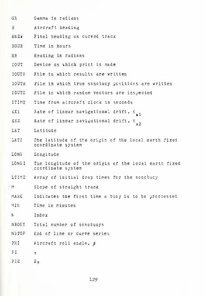
GR Gamma in radians
H Aircraft heading
KNEW Final heading on curved track
HOUR Time in hours
HR Heading in radians
IOUT Device on \*hich print is made
IOUTP File in which results are written
IOUTR File in which true sonobuoy positions are written
IOUTZ File in fchich random vectors are inspected
ITIME Time from aircraft clock in seconds
KXl Rate of linear navigational drift, K
KX2 Rate of linear navigational drift, K
LAT Latitude
LATI The latitude of the origin of the local earth fixedcoordinate system
LONG Longitude
LONGI The longitude of the origin of the local earth fixedcoordinate system
LTIME Array of initial drop times for the sonobuoy
M Slope of straight track
MARK Indicates the first time a buoy is to be proccessed
MIN Time in minutes
N Index
NBOUY Total number of sonobuoys
NSTOP End of line or curve series
PHI Aircraft roll angle,ft
PI TT
FI2 2^
129

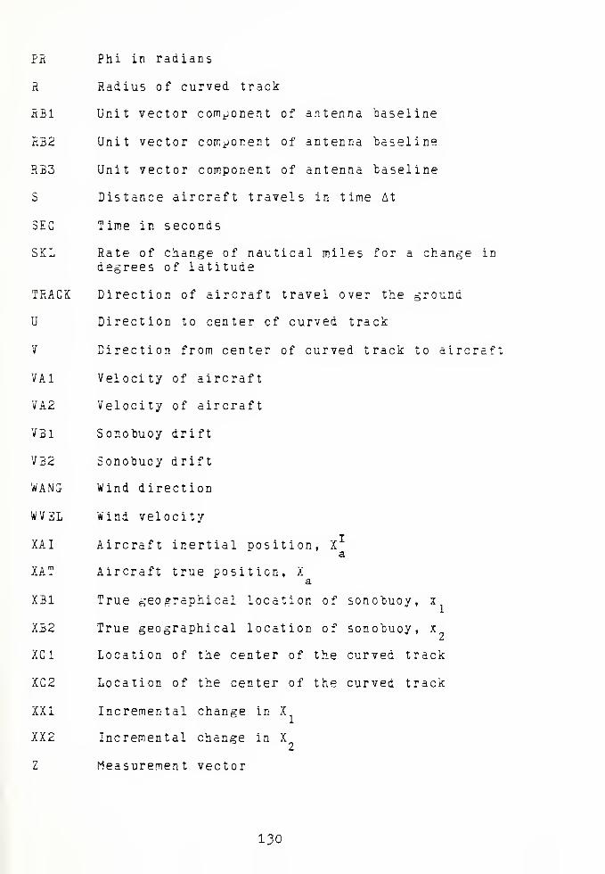
PR Phi in radians
R Radius of curved track
RBI Unit vector component of antenna baseline
RB2 Unit vector component of antenna baseline
RB3 Unit vector component of antenna baseline
S Distance aircraft travels in time At
SEC Time in seconds
SKL Rate of change of nautical miles for a change indegrees of latitude
TRACK Direction of aircraft travel over the ground
U Direction to center cf curved track
V Direction from center of curved track to aircraft
VA1 Velocity of aircraft
VA2 Velocity of aircraft
V31 Sonobuoy drift
VB2 Sonobucy drift
WANG Wind direction
WVEL Wind velocity
XAI Aircraft inertial position, Xa
XAT Aircraft true position, Xi
i nf <;oTinhiinv. x1
a
XB1 True geographical location of sonobuoy, x
XB2 True geographical location of sonobuoy, x
XC1 Location of the center of the curved track
XC2 Location of the center of the curved track
XXI Incremental change in X
XX2 Incremental change in X2
Z Measurement vector
130


ooooocccIP IT, LP. lP Li , LT -P ."
CCOCC3CCOOCCCC3C
; C OCUC u cocooooo:. c •- -c >- -r '; o ^ >j n- ~~ c- r- --
"
ir— Ci OC CJ c OO ~ <_ OUO C.O3 o OO C OO3o:>? -- C —"-
;
•'• .- ir o *- r ~ ~ — ". f J- -P C — cr _r
• i»- r- r-- |v. x, tt~ .; o a. ~ t x .»_ c i> c j> C^ 7* C _** J p
a cc cr cr L cr. r cr a- nr .j c l. c .">
X C" r_ C C . <_ L l_ L 1- '_ <_.
x
l_ t_
'.i c i c :_ q: l- •/ P r- rt r- o r c '-
LLLL LJ <_ L_ f. l_ X L_ CJ i_ l— L LC Cv fv ~ Ci Cl -.! -- CL L C •-'!_ '— i- !_.'L
a:
oo iy;
• ji • i ^
< x2_ —
'
i fj"- < 3 <L X <_ LP
X LO X o X W X X l/ X l/~ X C/ ^_ LO X ^
» LP, •
i—
l
• r-
C\J re c-i
fl LI
-J • rr :
~ • LP •
r rn t\i o i c
t— X i- X I- X H X t— X I— -< h X I— * t- XI- X >— X (—
x_ix_jx_jx—jx_ix_ix_ix_ix_ix; j»:_'x^_ .> ._ ^>
U _1 u
<£ < <-;
— ?L ^ ^. -^ <— ~ «i_L^ LU J> _ -> ^> _
131


t*. a cr c C: ^ tic: f ; o To o' c- cr* o; ^ C: c ^ '"'r- ^ C- f ^ ^' c D " i f- c c c ' T> i.f ,: cr
i_• c '.. (._ c c. c c_ l_ c l '_ r_ c_ cj <_ '-^ c t_ i_' c l. z. c '.: <_ c !_' r r c_ l •_ l '_ r_ _ r _ r
.
u
-L27i^
—c -*
O r—
•
CT- -LLCP -C -• I— i— X—
-^ _J _> O INn i_.w —<—
i
snj* *—* i—i-** *—
^j\ww>— >—
J- II LLiUJ <;<!
X
C ^AJ CL C_
x -t- •
_, •— JJC!
—oj^— * i. rr — «" <.
• aj—la i — -I— x— —i3 —i -J" X I i_ —•<! •* Li II ii -U
• •^iT(_J •^ —*l/) *!. H It»—
< r* I! '—' J'
c p || it • -'<-!— — */' 0:\i«—i -JO—' _
-•,-lt\i—— II ._ < -j r— I— —I >— _X ——• a. a. .-'_ ii i < ~ --. <t -I ~ -_ ._ <r
—^ <i -^ ~— ii — x _ <. <-__r_ < :
11 x i
<C II — _J
Ui X '_' (J i. -
oo
132


' vj- c O "**- CC j* O •— ^' : "^ >•*" t;"1 sO *- to 0^ C —" "* "^
• <r v.+- <r -c -J- < 'f. -"* LP i."mj"\ •_", it. -r -f\m <: -c c ^
: C "J OC Cj OC C <
w '^ c ':: ~ccrcc?cr'Jccc~occcc r cc^(
: i_ :_c r_ t- r_ i!_ l i_ cl c-c cj r
;.'c i_ cj i_ c:
coco a c -1 n i cr. c rt c- u.- := t.t < > ^ :* i>. c
. i_ i_ lj (_ r_ i '— '_. i— c (_ t_ i_ t_ r_ l.c '_ l l. l.
o
cmor-ca
— IT 1 »r-(VJ.-I
"*" ' 2 TT?
— <r —.—
,
O X. -C
<: r- —.."s, II ^. •
*• • * wn~ • ~ V. ——»<r C^l-h — ~ — J '
r\j^> ~ <"! <- x Q_ _—
»
-JX X ,_ * — 3 >
h ~ X + f ~^u • -L >
' l^J <J
K- —— <,I
"1 x~-• —'CO^I "" • •»—1^j •u— • <— y- — <i-c '— ^v-j '_; .j ^_ — >—
—*A -
' Vr C* i"^ •lie.1 j_-l- * ^ — ^ I
> II i_JU II II ' z.
•—• x xi^
(_;>< :<<rXt 15
Q a. I f1 C\J •»
r\ c\jc\j • —• x x •-
— C.J-li > ~ —i— II II —ZL— -K vr JL I — I.
I i_i ,^x<r. r.c>-Hi X 1- * >. —— -
C^ l
; >>> •_—— H-l— Z.~ > ll««CII> | « "•
I— J> ->• 3 J» X — f\i x X h
2 ^l— > J- — —O * -~— x-- ijl/ iNJt --^4i. 0C I— i—O "'O t— II Lt._u(— •-<
N^ J I Ir:_j~. w>_;'_-Li. < .^
rD ^" • • M ii— • r—>'-'; • «
>~»~-—ii ^» — i— , —— ; (— i
_: >^-— ^<: x—'XXi—' i—i -^ ~ 2i
.
-0
•* • •-_-—' •
— _- X X _ ? -~ -.- _,
i—>— 'jj j'^j'y d Cw'— -'
— -: >_H '_jc il r^.
133


> -Z, O C w o c c c c oo o c O C O T2 C: OO C O f
^ <v .•«>}- '_r. o t~- —_•>. -r * lt. ,£ !*- rr c C r-< r —, -t '"". O ,s- <X 3
;crc: ;^c oc "rr cooc c cc oc ooc c coo cc r^ c
Dorccocc: c
.ode
.--,-,— .-
,
\jr> r:-o
r r- r\
oc • c 3 c l? c
c ._ o f> ^ c :.'-
i_ LC!. LH L.
o *» c. nr c; ">r. c'n c a g rv c oc
C r. L r_ i_ L- L. L. i_ L C UCL C I_ (- c '_•_l CC C C C >.. I. l_ L.
rv-i
•NJ
r L/i
*- —
«
—«<" Jf\i ii—'XX^rOXX <l
<+Ii
U. Cl •I ^M •w :_> -OU<
c ~*r o —tXX •»
i- '.-:< -;- r^—< — ii ii —
.
c i- ): t | <_ I 1i :_ _ _j ^ x < p. r.'l> + U 'J. ii -i- x —— -i >>> tx—"K >—
r
> , •" ; r .x x (-— —. —. 4. a (/ « «;
r> — ;> j- — c j: <- —- <
iov ^:^~"i» —c a. J• • ,
.— . • •__(— • •i
1—i— _-•;'_"—
|| l— >—
c
j j i i au->ujc'j.3 2• • ll 1 1 •——4 • ,— ' ~ • • Li- JL
G. X <f
r, c
• C —
i
«a Li.- ll. XS - 1 :t X- + i—
t_'z:i L.
'/-.Sl -a i-
'^ 7 Z- —' + • * 0. '"'ZL.
: r -L. ^"J 7..
—i >—'
• r- — t— i— i j —. .^ n-J.""- _; • ^ _; j _^ ^ - ; ^ >- ^— i- ""» JO'J «v_. <^ ^^ •
-* Uj 2T <C C ~ > > ' L_ u Ol j < j— -.- < <
•o X X—1 1
• _ —
1
LJ3 C •"
J_
Lj~s ; ..< XJh II II
1
134

— r -r -r <r -J" -.? <j !
r: cc: 3 .: ".: c: ~.
C; Z ^r r- C- C ? d C
C "3 3 CJ G O C C 3C '3 U-'OCCCOC 3 C C C O 3 3 O C 3 CJ C '3 3 3 C C O C 3 TC ~ 3 —> »\J r<~i ..f un C *~ 'X: 7*0 —*
<*• "" ? '.P -C *— '" ~' '-- — "VJ C ' -^'jC O ">- T > C — "'' *" -+ -T 3
r -J"ir '-P IP '-P -P '-" .P.U" LP -P -C 333 ." 3 3 O i. 3 "~I
s- *- l~- f— r- >• P-- Is- *- zz . -j-j.;- x
r.r-. tv p-j cm Pj p r-.'V ip p„c\,;Vp ~s,r..r c.v^Ai' <"•*<-> < p,j;\.c\.p*r- r..;_r proofs rvr
.i.iic ' j. ' c- - C Cr-ii Ci. cc cra-'c t cr .•> & i. C (_ c: c_ c -' C- Cr o a r- & c rt 'i
.l'CC LLUC-L3CL3LLC3CLLUC.3LI. CLLLLLC'CCLLL'I
x - h X
xc_- X -T -3 —
:k 3x
<- i_^>-
<3
-:c
>> —
jC • XT -L»-i it O • 3 "_ >"
x l. ^ 33 hr - -
^<Cl 3 c <.EK2•a t-
"" + xx<hot— I i
— - «—
r
-: -;< 3 t .x v o I
s- — rvJ -< x r\i—
_i li I. r . II II II— -X j. i—X
J-i U '_ il jl >j^^. — r ' jic.<-3 _J t— (_ i_ _i t_j c_ -o — ' r < x >-I- C << u^ <I <r — x li. E »C
c 3^1— ~^(— h- — —id
I! -—I II x II -I- X x >- » h -
_im<t_ -_
—
» rn -^ - - - <:
>^ - ~ X —X -
Z* "~ 'J^—T X
L"Oi - x r »c;r
— •- _ •• r - •• <- •• <^J" C^ "^ ^-4 **— • •
""-.•
• <.' » ^—X "\ T- * -— »
—I -S 't— -t"l 1— zLL -T-;x- f, — •' —<-'_^.i_.^ -3—3- -»<l r -x < -<^.3- ----.- X - -_,_
^ L ••• ,•• CC *~ <~Z ~C
o -" 3T <1 ^ U_ c • • • O • • X —i I--^— c--
o>-.>>c: cz »j u-- h- — i ..
v—i •• 2. ct i; - «-
_: '-TI
I— iJJ ii _j e; JC r- 1- r- H ^ I— +
-n :'V —«?\lr~ Ii • • <J • • j _ _i _J_3_J_3^
UJU^^CS — ^^>->'.'i<-. J> J> J- — — i—iw<;i-i<I — -~— -^^_ — K —. .
>> II II <S) «" _J_-_j II _j H- fi.-O — — _-~- X h-Oi--l-HN<r -— X
-: '3 S.
-TO
135

CCOC CCCC C OCC COCOOCOGUCCCN~ a'- C^O *— ^ j
~~ -t LT* *0 *""- "f" C" O —' f\J f~ -.+ i.r\ o r*- cr c* o'. i .t ^ c j-> c^ c .7 cy.jMToc o c o cc n o o —>— .-
c\i<\p r\.r ^r.r>.M> r.c^-- ri(fimrf,ii mrr r" r^.-r .-r,. i
c o c; c c- '..: c c cc^cccc c oc o c c c: oroca '_' :;: c a: a. c r> •"".. c- rr c c c- c- e o c. o a c r/ u cr a ol l... C UC t-'C <_ (_ '- !_ I . '_ C(_ (_ C '- L i-.r.. !_><-. C '- r_
!C s C '_ CT C C
C' c a o l a.1.1. LCLu '. i_ CJC I H- (_ r Cj C L C '_
<
x"X
+ +
HI u
• • •
o(-
.
1 < C\J
X X
J jj _ ii c: _i _j <^_ ^; =i i
• _ # „
,
i_ t
j_ 'jj s :+ 1* .
+ i. + h:
O T_" II II II 'Z 'I 'X H I! J- II 'I ~.
-h +
,— *\j
r-h-
X XX II ll
136

jr* c r*- c^c- ,,"^-t '-," o ~~- cc 7' '; — r., f~ t -'" c ^ , 7 -~ —
•, r° -r .r o^fcrc —
*.. i< ^- -* c p- ~r ~-~z 1— cm
-'.r-- ~ s ->rri ,~ .r -r -r -r --J" -r r ^r if i*> -f t- r it pit j~ :r ~ .0 ^~ o •- o jj <.'
*- *- r-»
^
r— ^ ^ *-- K "- " '-" r
/- > ^-. ~- ^^ ^-.
.—, £-~ ^~ r- ^— ^j t-^ ^ r^ f— 1^ /- /— ^~ ^-. -^ r^ r^ — .
^ *"" — '— c c" ^Of-CC'— r —' r~ — r^ '— ' ~ ~ C z r;
:. |> C Li f: ff C U --' C '-'Li ' !_ f C- > .- Vr;^'^C LC LCLL '_ C L. CTC_ CLTl.^I-'- li
r '.- '• i.' .. :: c. 't r c: l- c '- - -.- - - "•- -
|_ "I
'L. <- '. '. i_ ... i '_ •_ L r_ '_ ' L. C .
1
C
C _" >
<
x
x r
1, t-
-, K ;>
• • • • ~;
>—
• • • •^_^-^_^;_— _ r _i '-. :<: a. :t r-i _£ -j _ ^ —
1_•
_ inc. n - iiaiu?."J1 -czL
si —• t — ^ —•is— 1.— "l — r. l: G '1 -
-cm .-»- <r j-i ,j x •j —>'\, ': t>
s~ * * ^2 « • v 3 ~ — -P ^~1 —* <. .' " '—
Uxl I — I I— I I— I I— _
•^ 11 .i ,— •: ; > .
:— _" r. — « < _ -< < _, x •< _ < x j > > 2 .' * s ~*
137


C.OOCCCvCOGOCOOOOOCCOCOOOOOOOCOOOCOCCOOOOCOOOOOOC-tt c-e t c f- t\i ."° t ir £ *- x j* o —• cm ci <t -no r- cc <j>o i—
i r- fi fir or^cc cro —' r > r' <r '..'"• -cr~- x c> o—COOCOOiT i—4i—ihh^i-i—<»-. ."\jc\jc\j c\if ,ic\i!\jfv r^jpi^^r.^ii 1 f~ r<"t ro r" <r -4- -r sr -r <r -j- -f «r -j" -f> upr.^crCCCCCCCCCOCCCCOCCOCCCCCCCCC COCCCCCCCCCCCC ^rr~cc:rr^cccoocooooc:oo^ccc:cooc;occj~c'r:oooc;ccC'^C'rc?'CC: 'r; cc:
c- c- a c c c tL-'a n a i tfaa t o 2 a c e o c; cc o-OTi. r rr cc ft- o: cr or or c c- c n c*L L L'C -LLLLLLL'LLLLULLL'CL'CL'LLL'-LLLrLCLL (_ (_C L. C L
C ^ C ,
•;s
i-
< (7 1 <s. o r.
*
Q- wi—a *
:
t-
o O- C.
< c :<: C ~"
1 1 _ ~*1
~Z1 —I'srz ** —
.
c •—4 u > _ ^JQ OC —
—
O c\i ~ <r X h• X L ci- <
<-i -£ > h- • <
u x u
i— X h
X _ ^-
_. • • TX —3 I I r> a • O - 3 _jt-C2
__ — w^it ii cc kjoi.;r->rv. • • ••"^__^.
— r~— t ; ii——•—
i »v* Z il 'i XjO.NO ,— ^h- ii a..-vj<—i -\i ii J ii n c ~ ~ ii ii u ii -i
_. I— H-h--——_, xi- ii 2: -j »jO_iOu;
rr c; cj<o n uj —j < --: x ><.x— ~,_j — •—— x; x <i. _ cc <i
.
; ' ;. _s _i :l- j_
— -hi/ 1
ii ,, CO-;, — _)
~r n — >* ii -^.'^ —. .1 i:
—
>- ~ c — <<r< ii > ^ ii <
— i- n
.«_• _,_> JO.
138


~ x x rcocncr ^ c <.
-- -JT, J f-." X C r- <\l ro. -J- L"\ .
3" Z ~z v "C X _r c X '~ .'•' y '.
-.r <r vr »rXXXOOXOCC XO
'
1 x x x ™ o o x o c c c c x—ir> 1-rL" C-Ntl' ~<\— r"jr
<r - x <- -t r •
cccc ". x
l ' ': :: '_ r, Z' or r.u. c- r. o ' ' -/ C; c. :« •-
< c i_ :_ i~ c '_ l c." c_ c_ c. c_'C. c c: c( x L '. f_ t
i - ' • •-
. i_ r: c r
I
.r
r
Xit
SL < —<-.
L' . X
S-nuix •C-zf-zz .y. ace
_: m <rx "< <£ I '-J '-^i J '_ _'
I— ~
_ ii Ji_cN ii ii ii i— ii ii ii ;— Xr— X !' " I! ——•I-
' ~~ r-^,rXt-.
X (- -f-
H - -<~ XCNit^J_J 2" c X'
X -J
x < - •— I— »X •Xi— < — x x ~-
J _IO. *rr II
-: c x x
.<* < — ' — ^v
139

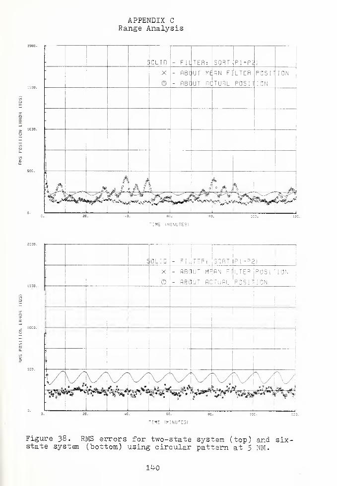
APPENDIX C
Range Analysis
C OLID - FILTER: SORT Pl+P^j
X
CD
- ABOUT MRAN FILTER POSITION
- ABOUT ACTUAL POSIT ION
!
•A 9. a a4o
On ° 3 e°% °3
QJk, L S a j% ,a$k
\
;' IIITIME IMINUTE5I
SOLID FILTER: SORT (P1+P3)
X - ABOUT M
CD!
- ABOUT A
AN FflLTER iPOSITI
TUAL POSITION
ION
TIME (MINUTES)
Figure 38. RMS errors for two-state system (top) and six-state system (bottom) using circular pattern at 5 NM.
140


-
SOLID - FILTER: SQRT P1+P2)
-
X
o
- ABOUT MEAN FILTER POSITION
- ABCJUT AQTUAL POSITION
L
C
o
D
S
oo
iHft.\ °
3/
\3.
°
3 \
L o %Sy^/Lr
°
*>
j» ; i ?^ 3
9 \ sa
JS
•
?Ai »X ^m ,'-
:^v<***%#*»^v
-
TIME (MINUTES!
:
'1 C OLID - FIL TER: SQRT
;
P1+P2)
- .1
«x<
X
o
- ABC
- =E
UT MEAN FILTER IpOSITIONJ J
UT ALlT ION
\
o9?
\x
^—,
—
J
i |
»
, 1
-
s?
* " n »,H *** j
-
- . 1i
TI ME (MINUTES)
Figure 39. RMS errors for two-state system (top) and six-state system (bottom) using circular pattern at 30 NM.
lto.


TIME IMINUTE31
o
:\OLID - FIL
I |
TER: isQRT JPI^PS!
i
( ^X - ABC
Q |
• RBC
!JT MFiflN FCLTER 'pOSIlilON1
!
UT PtfTUPL .position
- '.\\| |
|
i
1
- <**1
i
i' :
-
s 31i
-
f 11
J &3 5 «* A * "b°
-
F\*$?
* * It*
5* 9\ &
-
i
60.
TIME (MINUTES!
Figure ^0 . RMS errors for two-state system (top) and six-
state system (bottom) using circular pattern at k$ NM.
1^2


Frequency Analysis
'
I ME MINIJTES1
-; :
|
SOLID j-- FILJTER: |SQRT ( P i + P 2 J
.
X
o
- fiBC
- RBC
UT M^AN F IJL TEP °0S I TiIONi
'
UT ACTUAL POSITION
-
:
-
\^/"^
A V-^.
i !
7: * aaJto
KiiJkJM¥**$^SA*JiJ
'WWf ^ »? "¥Tnjnr" 1
TIME (MINUTES!
Figure 4-1. RMS errors for two-state system (top) and six-state system (bottom) using square pattern with t=4 sec.
143


'[ME (MINUTES)
Figure 42. RMS errors for two-state system (top) and six-state system (bottom) using square pattern with t=10 sec
144


-
c— OLID - FILjTER: SORT PI +P2)
-
X
o
- ABOUT M^HN FILTER POSITION
- flBCUT RGTUflL POSIT ION
ACL
-
c "6
o %
oj
if*
otO
O
1 \I
°0
\^jd1 O
oo
(SB\!
o ^_>-^^<^^—-f-—-v_
"l ^ z^~" i
° *i
1
1
TIME (MINUTES)
TIME (MINUTES)
Figure kj. RMS errors for two-state system (top) and. six-state system (bottom) using square pattern with t=30 sec
145

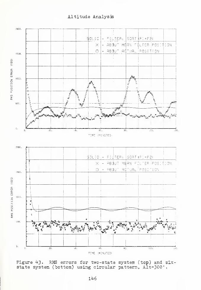
Altitude Analysis
SOLID - FILTER: SQRT PI +P^J
-
X
CD
- ABOUT MEAN FILTER POSlTjION
- fiBfJUT ACTUAL POSITION
-
-
<$?»3
CD
<#h>
/ °3
s •
'1
a
CD
a ° o
* Is•° * °l
c
a
.?&>
° urnfffli]
S.
*"$ °| &$ ^
- V^,
w~^
—
;
—"" ^—^< 1
—""A ly
-^
r* * '«Mti "f ,. o" T
,i
TIME (MJNUTE5I
SOLID FILTER: SORT PI t-P^Ax
o
ABOUT MEiRN FILTER iPOSlilON
ABOUT ACTUAL POSITION
==h-
T!ME (MINU7E3)
Figure ^3 • RMS errors for two-state system (top) and six-state system (bottom) using circular pattern, Alt=300'.
146


TIME (l-'INUTESi
SOLID TER: iSQRT (PI+P2
ABOUT M^RN [ |POSIlt[QN
o - RB(iuT rqturl position
;,?*•%»
',» » *
1 1 . ,' i l-l, *-m- — 1 *^&> . 1
TIME (MINUTES)
Figure 4-5. RMS errors for two-state system (top) and six-state system (bottom) using circular pattern, Alt=10,000'.
147


TIME (MINUTES)
50LID - FILTER: ,5QR' + P3)
X j- ABOUT M^flN FILTER |POS
O '- ReqUT fidTURL ;P0S I T* I ON
ON
%&>.&x -f tf
*
- ItA
1ft
»*#
ST ^»
TIME ;M[NUTE5I
Figure 46. RMS errors for two-state system (top) and six-state system (bottom) using circular pattern, Alt=20,000'
148

BIBLIOGRAPHY
Bryson, Jr., A. E. and Yu-Chi Ho, Applied Optimal Control ,
Hemisphere Publishing Corp. 1975-
Carlson, N. A., Fast Triangular Formulation of the Square RootFilter, Vol. II, No. 9, AIAA Journal, September 1973-
Demetry, J. S., Notes on the Theory and Applications of OptimalEstimation , Naval Postgraduate School, Monterey, California1970.
Gelb, A. and others, Applied Optimal Estimation , M.I.T. Press1974.
Leondes, C. T. Editor, Control and Dynamic Systems , Vol. 12,Academic Press, 1976.
Orincon Corporation Report 0C-R-78-A003-1 Sonobuoy ReferenceSystem , by Asher, R. M. , Judge, R., and Sorenson, H. W.,December 1978.
System Functional Description for Sonobuoy Reference System ,
FD-17 (I ^.3), Naval Air Development Center, June 1978.
System Functional Description for Navigation , FD-9 (I 3A-2)Naval Air Development Center, November 1977-
1^9


INITIAL DISTRIBUTION LIST
No. Copies
1. Defense Documentation Center 2Cameron StationAlexandria, Virginia 22314
2. Library, Code 0142 2
Naval Postgraduate SchoolMonterey, California 93940
3. Department Chairman, Code 62 1
Department of AeronauticsNaval Postgraduate SchoolMonterey, California 93940
4. Prof. D. J. Collins, 67Co 3Department of AeronauticsNaval Postgraduate SchoolMonterey, California 93940
5. LT N. M. Brownsberger 2
3802 La Miranda PIPittsburg, California 94565
6. Dr. D. Birnbaum, Code 2031 1
Naval Air Development CenterWarminister, Pennsylvania 18974
150


Thesis1 8 4 3 i
B8243 Brownsbergerc.l Estimation of
sonobuoy positionrelative to an aircraftusing extended kalmanfilters.
K) m »] 5 7 1 IB
Thesis 184 310B8243 Brownsbergerc.l Estimation of
sonobuoy positionrelative to an aircraftusing extended kalmanfilters.

thesB8243
Estimation of sonobuoy position relative
3 2768 002 08054 1
DUDLEY KNOX LIBRARY