
ESS 2000 Series Conveyor Belt Skirting System · D Corrections to Installation Procedure TT 25/5/09...
20
Revision M 07/07/2015 1 ESS 2000 Series Conveyor Belt Skirting System Installation Operations Manual Revision Description of Change Changed By Date A Cutting procedure added TT 26/3/07 B Added Final Checklist AS 28/5/07 C Updated Section 4 - Installation of Short Lengths TT 22/5/09 D Corrections to Installation Procedure TT 25/5/09 E Updated Melbourne Address & Removed SA Address SH 3/08/09 F Final Checklist Updated Items 4 & 5 Reversed SH 15/04/10 G Updated manuals with current drawings KO 04/03/11 H Removed Mts Isa contact details KO 12/6/12 I Updated format of manual KO 5/2/13 J Revised dwg F0249 KO 11/2/14 K Updated office details KO 11/3/14 L Updated ESS Logo & Karratha contact details KO 4/6/14 M Updated office details & F0249 KO 7/7/15
-
Upload
phamkhuong -
Category
Documents
-
view
217 -
download
0
Transcript of ESS 2000 Series Conveyor Belt Skirting System · D Corrections to Installation Procedure TT 25/5/09...
Revision M 07/07/2015
1
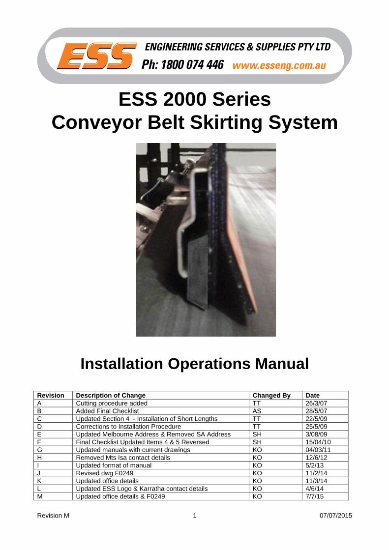
ESS 2000 Series
Conveyor Belt Skirting System
Installation Operations Manual
Revision Description of Change Changed By Date
A Cutting procedure added TT 26/3/07
B Added Final Checklist AS 28/5/07
C Updated Section 4 - Installation of Short Lengths TT 22/5/09
D Corrections to Installation Procedure TT 25/5/09
E Updated Melbourne Address & Removed SA Address SH 3/08/09
F Final Checklist Updated Items 4 & 5 Reversed SH 15/04/10
G Updated manuals with current drawings KO 04/03/11
H Removed Mts Isa contact details KO 12/6/12
I Updated format of manual KO 5/2/13
J Revised dwg F0249 KO 11/2/14
K Updated office details KO 11/3/14
L Updated ESS Logo & Karratha contact details KO 4/6/14
M Updated office details & F0249 KO 7/7/15

Revision M 07/07/2015
2
ENGINEERING SERVICES and SUPPLIES
OFFICE DETAILS
Location Address Phone & Fax
CURRUMBIN
11 – 13 Traders Way PO Box 121 Currumbin QLD 4223 [email protected]
Phone: (07) 5589 2000 Fax: (07) 5521 0347
EMERALD 8 Coaker Dr PO Box 1861 Emerald QLD 4720 [email protected]
Phone: (07) 4982 4855 Fax: (07) 4987 5118
GLADSTONE Unit 2/34 Chapple Street PO Box 1475 Gladstone QLD 4680 [email protected]
Phone: (07) 4972 3759 Fax: (07) 4972 2866
KALGOORLIE Unit A 255 Dugan St Kalgoorlie WA 6430 PO Box 10471 Kalgoorlie WA 6433 [email protected]
Phone: (08) 9021 7991 Fax: (08) 9021 7291
KARRATHA 26 Midas Road Malaga WA 6090 [email protected]
Phone: (08) 9248 4111 Fax: (08) 9272 5130
MACKAY 1 Progress Street Paget, QLD 4740 PO Box 5755 Mackay Mail Centre QLD 4741 [email protected]
Phone: (07) 4952 4600 Fax: (07) 4952 4717
MAITLAND Unit 2 Barton Court 6 Johnson Street Maitland NSW 2320 [email protected]
Phone: (02) 4932 3544 Fax: (02) 4932 3611
PERTH 26 Midas Road Malaga WA 6090 [email protected]
Phone: (08) 9248 4111 Fax: (08) 9272 5130
TOWNSVILLE 5/42 Carmel St Townsville QLD 4814 [email protected]
Phone: (07) 4755 2776 Fax: (07) 4779 6236
SOUTH AUSTRALIA 5 Cormorant Court. Middleton. SA . 5213 [email protected]
Mobile: 0408 948 175
VICTORIA Unit 4 / 314 Governor Road Braeside VIC 3195 [email protected]
Phone: (03) 9580 0388 Fax: (03) 9587 5199
WOLLONGONG Unit 1 / 20 Doyle Avenue PO Box 343 Unanderra NSW 2526 [email protected]
Phone: (02) 4272 4422 Fax: (02) 4272 4434
TOLL FREE 1800 074 446 FROM ANYWHERE IN AUSTRALIA
VSS TOLL FREE 1800 300 877
Revision M 07/07/2015
3
WARRANTY NOTE
ESS WARRANTS the ESS 2000 Series Conveyor Belt Skirting System to be free of defects both in materials and workmanship for a period of 12 months from the date of despatch of the product from the ESS factory. The warranty given by ESS in this regard will extend only to replacing or repairing product shown to be defective. The warranty also is subject to the following restrictions: (a) Installation of the product contrary to the instructions contained in the supplied
manual will void such warranty absolutely; (b) The warranty will not extend to any liability for injuries incurred and which result from
the use of the product contrary to the instructions in the manual;
(c) Save as prescribed by law, ESS will not be liable for any damage sustained by a purchaser or a third party by way of consequential loss arising out of defects in the product.
You are asked to note that ESS offers purchasers a service whereby either: (a) It will install the product and certify the correctness of such installation, or (b) Certify the correctness or otherwise of the installation of the product by third parties. This certification service is designed to ensure that you obtain the full benefit of the ESS warranty hereby provided. If you would like to take advantage of the installation certification service provided, please contact ESS regarding the service. Refer to the Final Checklist at the back of this manual. Visit the ESS website www.esseng.com.au to register your product warranty. THE CONTENTS OF THIS MANUAL ARE COPYRIGHT TO:
ESS ENGINEERING SERVICES AND SUPPLIES PTY LTD
ALL RIGHTS RESERVED
Information contained herein is for use in the operation of ESS 2000 Series Conveyor
Belt Skirting System, purchased from ESS and cannot be passed on to any other party
without express permission, in writing, from ESS.
Revision M 07/07/2015
4
INDEX
SECTION 1 SAFETY
SECTION 2 INTRODUCTION
SECTION 3 PREPARATION FOR INSTALLATION
SECTION 4 INSTALLATION
SECTION 5 COMMISSIONING
SECTION 6 TROUBLE SHOOTING
SECTION 7 INSTALLATION ARRANGEMENT DRAWING
SECTION 8
SECTION 9
EXPLODED PARTS DRAWING
FINAL CHECKLIST
Revision M 07/07/2015
5
SECTION 1 - SAFETY The ESS 2000 Conveyor Belt Skirting System is designed to be quickly and easily installed
and serviced by appropriate personnel.
Under no circumstances should servicing or installation of the ESS 2000 Skirt System be
carried out whilst the belt is in operation.
The conveyor must be shut down and locked out before any person enters or reaches into
the conveyor enclosure.
Ensure that only suitably qualified and trained personel install and service this product.
Ensure that all site and statutory safety procedures are followed.
All equipment, equipment access and installation / service procedures must comply with
AS1755, Conveyors – Safety Requirements.
ESS strongly recommends that a thorough Job Safety Analysis should be undertaken prior
to commencement of the installation to identify and manage hazards.
Revision M 07/07/2015
6
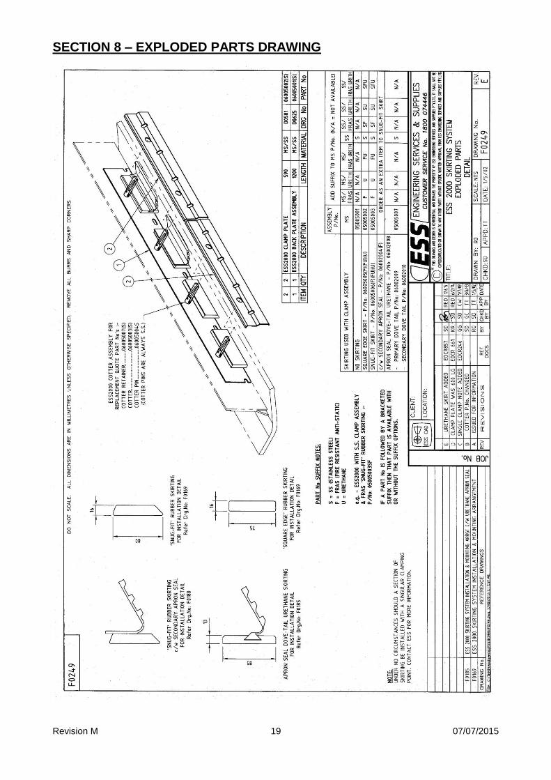
SECTION 2 - INTRODUCTION ESS 2000 Series is a conveyor belt skirting and sealing system comprising a rubber or urethane seal and a weld-on clamp assembly.
ESS 2000 Series attaches to the outside of the conveyor belt load skirts to provide an effective seal and prevent material loss and dust emissions.
Each ESS 2000 Skirting assembly comprises a 1200mm long backplate with four captive wedge or cotter assemblies and two 590mm long clamp plates. The backplate may be site cut to 600mm long and used with a single clamp plate. This enables skirt lengths of any multiple of 600mm to be accommodated using standard components. For skirt lengths that are not a multiple of 600mm, refer to Section 4.1 for installation details. The rubber seal is secured in place by the clamp plates which are in turn held by two captive wedges (or Cotters). This system allows ease of adjustment or replacement of the rubber seal.
Never install a Clamp Plate that is secured by only one captive wedge (Cotter).
Severe belt damage may result. Refer to Section 4.1 for installation details.
Revision M 07/07/2015
7
SECTION 3 - PREPARATION FOR INSTALLATION
3.1 CHECK INSTALLATION DRAWINGS -
Ensure that you have the correct drawings and equipment for your conveyor(s).
3.2 ASSEMBLE THE NECESSARY TOOLS & SAFETY EQUIPMENT
REQUIRED FOR THE INSTALLATION
3.3 OBSERVE THE CONVEYOR WHILE RUNNING AND CONVEYING
MATERIAL -
Determine loading point.
Note direction of conveyor belt travel.
Observe conveyor belt tracking. Conveyor belt must track centrally.
Observe idlers;
Ensure conveyor belt does not raise from idlers
Ensure idlers are spaced correctly so conveyor belt does not sag. If conveyor belt does sag under material loading, additional idlers
or ESS GUARDABELT Impact Cradle or GUARDASEAL Belt
Support Systems should be installed.
Observe Material on conveyor belt. Material should be loaded on centre of belt.
3.4 INSPECT WEAR LINERS AND CHUTE WALL -
Ensure wear liners and chute wall are in good condition (no cracks, holes, slits or grooves).
Ensure wear liners and chute wall are straight along bottom edge or material
will build up between wear liner and the skirting system.
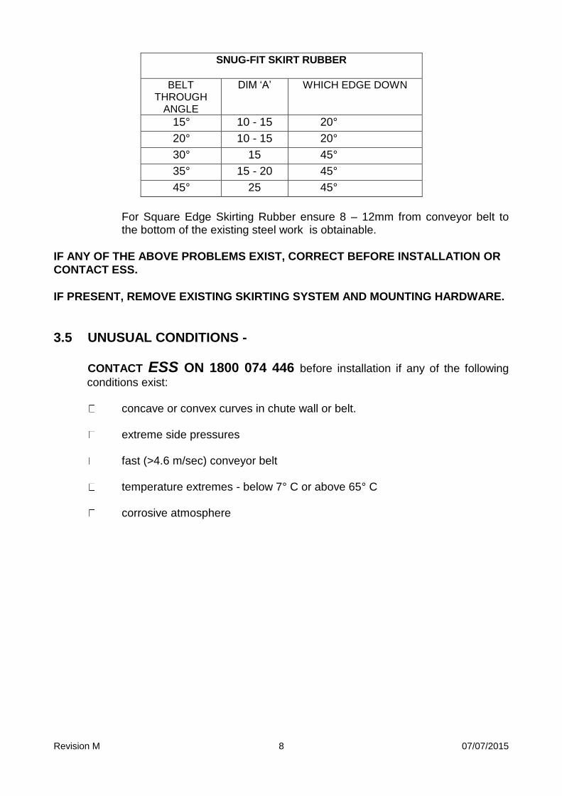
For Snug Fit Rubber Skirt ensure dimension ‘A’ from conveyor belt to the bottom of the existing steel work is obtainable. See table below, and drawing F0169 in section 7.
Revision M 07/07/2015
8
SNUG-FIT SKIRT RUBBER
BELT THROUGH
ANGLE
DIM ‘A’ WHICH EDGE DOWN
15° 10 - 15 20°
20° 10 - 15 20°
30° 15 45°
35° 15 - 20 45°
45° 25 45°
For Square Edge Skirting Rubber ensure 8 – 12mm from conveyor belt to the bottom of the existing steel work is obtainable.
IF ANY OF THE ABOVE PROBLEMS EXIST, CORRECT BEFORE INSTALLATION OR
CONTACT ESS.
IF PRESENT, REMOVE EXISTING SKIRTING SYSTEM AND MOUNTING HARDWARE.
3.5 UNUSUAL CONDITIONS -
CONTACT ESS ON 1800 074 446 before installation if any of the following
conditions exist:
concave or convex curves in chute wall or belt.
extreme side pressures
fast (>4.6 m/sec) conveyor belt
temperature extremes - below 7° C or above 65° C
corrosive atmosphere
Revision M 07/07/2015
9
SECTION 4 - INSTALLATION WARNING: BEFORE PROCEEDING WITH INSTALLATION, ENSURE THAT THE
CONVEYOR BELT DRIVE AND ALL ASSOCIATED EQUIPMENT IS
FULLY ISOLATED AND LOCKED OUT.
CONTACT WITH A MOVING CONVEYOR BELT OR ITS COMPONENTS
CAN RESULT IN SERIOUS INJURY OR DEATH.
4.1 Installation Procedure
1. If the steel skirt plates are greater than dimension A (Sect 3.4) from the belt surface, it may be necessary to extend the plates closer to the belt. A 150x10 flat bar welded to the outside of the chute or skirt side walls is an easy way to achieve this, as long as sufficient freeboard is available outside the skirt line.
2. Take an ESS 2000 Back Plate section and position it such that the bottom edge
is uniformly dimension A (Sect 3.4) from the belt, and one end is at the required start point of the skirt seal (preferably toward the tail end of the conveyor). The bottom edge of the ESS 2000 must not protrude below the bottom edge of the skirt plate or chute wall – see step 1 above.
Weld the backplate to the skirt / chute wall, using a 3mm x 25 long fillet weld at the top above each captive wedge, and plug weld in each lower slot. Use an appropriate welding blanket to protect the belt surface.
3. Repeat step 2 for the full skirt length, simply butting consecutive Backing Plates
against each other, maintaining dimension A from the belt. For skirt lengths that are multiples of 600mm, and the final or closing length required is 600mm, simply cut the backing plate in half (2 x 600mm sections), and fit the half length of Backplate with one full Clamp Plate. For closing lengths greater than 600mm, but less than 1200mm, cut a Backing Plate to 600mm and install as described above. Use the following procedures to complete the installation.
Revision M 07/07/2015
10
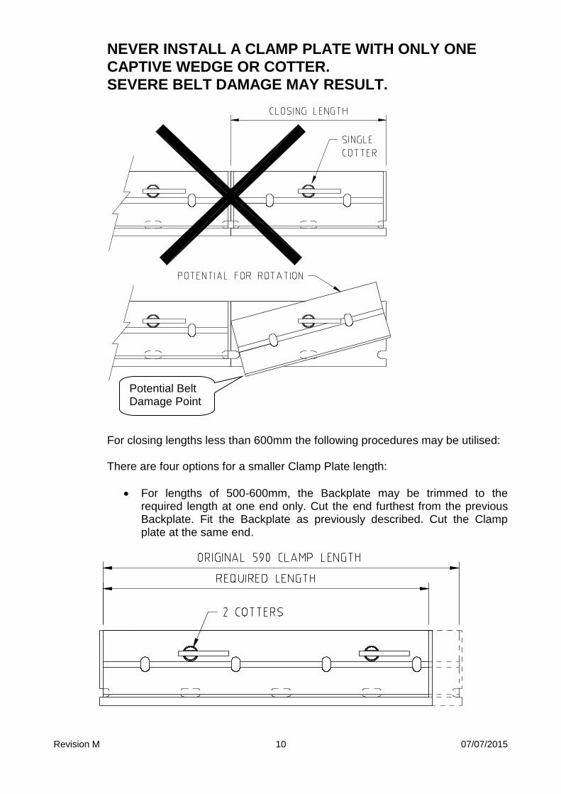
NEVER INSTALL A CLAMP PLATE WITH ONLY ONE
CAPTIVE WEDGE OR COTTER.
SEVERE BELT DAMAGE MAY RESULT.
For closing lengths less than 600mm the following procedures may be utilised: There are four options for a smaller Clamp Plate length:
For lengths of 500-600mm, the Backplate may be trimmed to the required length at one end only. Cut the end furthest from the previous Backplate. Fit the Backplate as previously described. Cut the Clamp plate at the same end.
Potential Belt Damage Point
Revision M 07/07/2015
11
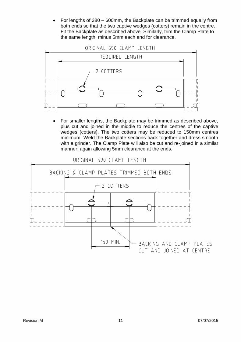
For lengths of 380 – 600mm, the Backplate can be trimmed equally from both ends so that the two captive wedges (cotters) remain in the centre. Fit the Backplate as described above. Similarly, trim the Clamp Plate to the same length, minus 5mm each end for clearance.
For smaller lengths, the Backplate may be trimmed as described above, plus cut and joined in the middle to reduce the centres of the captive wedges (cotters). The two cotters may be reduced to 150mm centres minimum. Weld the Backplate sections back together and dress smooth with a grinder. The Clamp Plate will also be cut and re-joined in a similar manner, again allowing 5mm clearance at the ends.
Revision M 07/07/2015
12
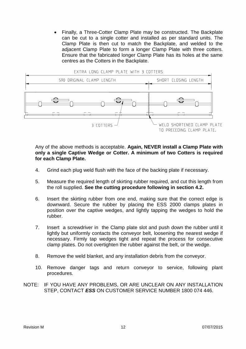
Finally, a Three-Cotter Clamp Plate may be constructed. The Backplate can be cut to a single cotter and installed as per standard units. The Clamp Plate is then cut to match the Backplate, and welded to the adjacent Clamp Plate to form a longer Clamp Plate with three cotters. Ensure that the fabricated longer Clamp Plate has its holes at the same centres as the Cotters in the Backplate.
Any of the above methods is acceptable. Again, NEVER install a Clamp Plate with
only a single Captive Wedge or Cotter. A minimum of two Cotters is required
for each Clamp Plate.
4. Grind each plug weld flush with the face of the backing plate if necessary.
5. Measure the required length of skirting rubber required, and cut this length from
the roll supplied. See the cutting procedure following in section 4.2.
6. Insert the skirting rubber from one end, making sure that the correct edge is downward. Secure the rubber by placing the ESS 2000 clamps plates in position over the captive wedges, and lightly tapping the wedges to hold the rubber.
7. Insert a screwdriver in the Clamp plate slot and push down the rubber until it
lightly but uniformly contacts the conveyor belt, loosening the nearest wedge if necessary. Firmly tap wedges tight and repeat the process for consecutive clamp plates. Do not overtighten the rubber against the belt, or the wedge.
8. Remove the weld blanket, and any installation debris from the conveyor. 10. Remove danger tags and return conveyor to service, following plant
procedures. NOTE: IF YOU HAVE ANY PROBLEMS, OR ARE UNCLEAR ON ANY INSTALLATION
STEP, CONTACT ESS ON CUSTOMER SERVICE NUMBER 1800 074 446.
Revision M 07/07/2015
13
4.2 Cutting Procedure for ESS 2000 Rubber Skirt Seals
Caution:
Ensure that the following procedure is carried out in a safe position away
from the conveyor belt. This procedure is to be undertaken in conjunction
with the Safe Working Practices outlined in this Installation Manual.
Any installation of equipment, and any equipment installed must comply with
AS 1755-2000 Conveyors – Safety requirements.
The following steps are recommended for the safe cutting of ESS Snug-Fit and Square Edge rubber skirt seals:
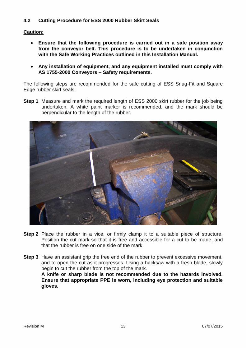
Step 1 Measure and mark the required length of ESS 2000 skirt rubber for the job being undertaken. A white paint marker is recommended, and the mark should be perpendicular to the length of the rubber.
Step 2 Place the rubber in a vice, or firmly clamp it to a suitable piece of structure. Position the cut mark so that it is free and accessible for a cut to be made, and that the rubber is free on one side of the mark.
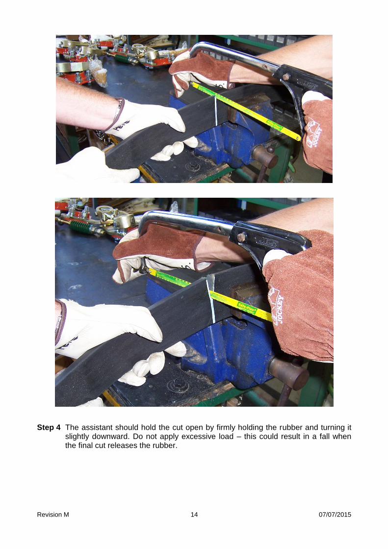
Step 3 Have an assistant grip the free end of the rubber to prevent excessive movement, and to open the cut as it progresses. Using a hacksaw with a fresh blade, slowly begin to cut the rubber from the top of the mark.
A knife or sharp blade is not recommended due to the hazards involved.
Ensure that appropriate PPE is worn, including eye protection and suitable
gloves.
Revision M 07/07/2015
14
Step 4 The assistant should hold the cut open by firmly holding the rubber and turning it slightly downward. Do not apply excessive load – this could result in a fall when the final cut releases the rubber.
Revision M 07/07/2015
15
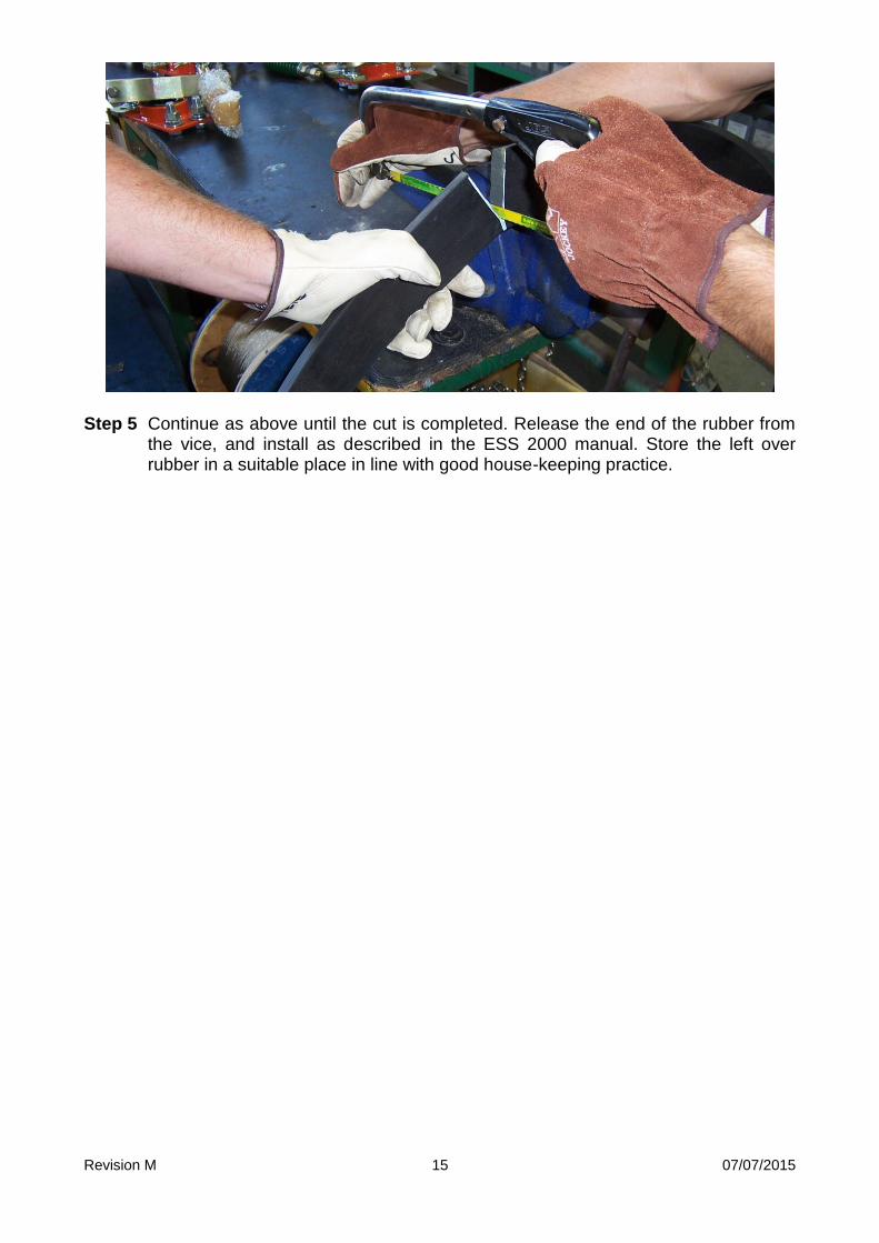
Step 5 Continue as above until the cut is completed. Release the end of the rubber from the vice, and install as described in the ESS 2000 manual. Store the left over rubber in a suitable place in line with good house-keeping practice.
Revision M 07/07/2015
16
SECTION 5 - COMMISSIONING
A note on safety:
No additional safety hazards are present with ESS 2000® Skirting other than normal conveyor belt dangers. In particular: Beware of moving conveyor belts. Beware of pinch points
Do not attempt to install, maintain or disassemble any part of a conveyor belt without first isolating and tagging the conveyor drive.
1. Following site safety and start-up procedures, start conveyor belt and run under
normal conditions for 10 minutes. Observe ESS 2000® Skirting and look for material leakage.
WARNING: BEFORE PROCEEDING WITH COMMISSIONING, ENSURE THAT THE
CONVEYOR BELT DRIVE IS FULLY ISOLATED AND LOCKED OUT. 2. Lockout / tagout all power to conveyor belt and conveyor accessories. 3. Adjust skirting rubber by following step 7 in Section 4.1. 4. Remove danger tags and return conveyor to service, following plant
procedures.
5. Start conveyor and run under normal conditions.
Revision M 07/07/2015
17
SECTION 6 – TROUBLESHOOTING
PROBLEM SOLUTION
1. Conveyor belt won’t run after installation.
Skirting Rubber is installed too tightly against conveyor belt.
2. Excessive Skirting Rubber wear.
Skirting Rubber is installed too tightly against conveyor belt.
3. Product leaking from under skirting.
Skirting rubber is not installed uniformly against the belt.

Revision M 07/07/2015
18
SECTION 7 – INSTALLATION ARRANGEMENT DRAWING
Revision M 07/07/2015
19
SECTION 8 – EXPLODED PARTS DRAWING
Revision M 07/07/2015
20
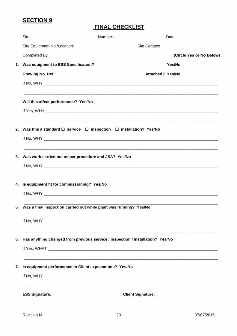
SECTION 9
FINAL CHECKLIST Site: ____________________________ Number: _____________________ Date: ___________________ Site Equipment No./Location: _________________________ Site Contact: _________________________
Completed By: _____________________________________ ((CCiirrccllee YYeess oorr NNoo BBeellooww))
1. Was equipment to ESS Specification? _______________________________ Yes/No
Drawing No. Ref: _________________________________________ Attached? Yes/No If No, WHY _______________________________________________________________________________ ________________________________________________________________________________________
Will this affect performance? Yes/No If Yes, WHY ______________________________________________________________________________ ________________________________________________________________________________________
2. Was this a standard service inspection installation? Yes/No If No, WHY _______________________________________________________________________________ ________________________________________________________________________________________
3. Was work carried out as per procedure and JSA? Yes/No If No, WHY _______________________________________________________________________________ ________________________________________________________________________________________
4. Is equipment fit for commissioning? Yes/No If No, WHY _______________________________________________________________________________ ________________________________________________________________________________________
5. Was a final inspection carried out while plant was running? Yes/No If No, WHY _______________________________________________________________________________ ________________________________________________________________________________________
6. Has anything changed from previous service / inspection / installation? Yes/No If Yes, WHAT _____________________________________________________________________________ ________________________________________________________________________________________
7. Is equipment performance to Client expectations? Yes/No If No, WHY _______________________________________________________________________________ ________________________________________________________________________________________
ESS Signature: ______________________________ Client Signature: ____________________________