ESR-1153 - TJI
36
ICC-ES Evaluation Reports are not to be construed as representing aesthetics or any other attributes not specifically addressed, nor are they to be construed as an endorsement of the subject of the report or a recommendation for its use. There is no warranty by ICC Evaluation Service, LLC, express or implied, as to any finding or other matter in this report, or as to any product covered by the report. Copyright © 2013 Page 1 of 24 1000 ICC-ES Evaluation Report ESR-1153* Reissued May 1, 2011 This report is subject to renewal on May 1, 2013. www.icc-es.org | (800) 423-6587 | (562) 699-0543 A Subsidiary of the International Code Council ® DIVISION: 06 00 00—WOOD, PLASTICS AND COMPOSITES Section: 06 17 33— Wood I-joists REPORT HOLDER: WEYERHAEUSER POST OFFICE BOX 8449 BOISE, IDAHO 83707-2449 (888) 453-8358 Trus.Joist.com [email protected] ADDITIONAL LISTEES: ANTHONY–DOMTAR, INC 1195 PEOPLES ROAD SAULT STE MARIE, ONTARIO P6C 3W7 CANADA REDBUILT™ LLC 200 EAST MALLARD DRIVE BOISE, IDAHO 83706 PACIFIC WOODTECH CORPORATION 1850 PARK LANE POST OFFICE BOX 465 BURLINGTON, WASHINGTON 98233 EVALUATION SUBJECT: TJI ® PREFABRICATED WOOD I-JOISTS 1.0 EVALUATION SCOPE Compliance with the following codes: 2012 and 2009 International Building Code ® (IBC) 2012 and 2009 International Residential Code ® (IRC) Properties evaluated: Structural Sound ratings Fire-resistance ratings 2.0 USES TJI joists are prefabricated wood I-joists used as floor joists, roof rafters, blocking panels and rim joists, to support code-required loads. Prefabricated wood I-joists described in this report comply with Section 2303.1.2 of the IBC, for allowable stress design; and Section R502.1.4 of the IRC. 3.0 DESCRIPTION 3.1 General: TJI joists are prefabricated wood I-joists having wood or wood-based flanges and Performance Plus ® oriented strand board (OSB) webs. Either the top and bottom flanges are parallel, forming a constant-depth joist; or the top flange has a single taper, forming a variable-depth joist. The web panels have the face grain oriented vertically, and the web-to-web connection is either butt jointed or serrated and glued to form a continuous web. The web-to-flange connection is a proprietary tongue-and- groove glued joint. Refer to Table 1 for TJI joist series and material descriptions. The TJI L65, TJI L90, TJI H90, TJI HD90, and TJI HS90, may also be trademarked as: TJI L460, TJI L560, TJI H560, TJI HD560, and TJI HS560, respectively. 3.2 Material Specifications: 3.2.1 Flanges: Flange material is either Microllam ® laminated veneer lumber (LVL), TimberStrand ® laminated strand lumber (LSL) or machine stress rated lumber (MSR). Microllam LVL and TimberStrand LSL are recognized in evaluation report ESR-1387. Table 1 of this report specifies flange widths and depths. Flange material and grades are as specified in the quality control manual that contains Weyerhaeuser manufacturing standards. 3.2.2 Webs: Web material is Performance Plus ® OSB conforming to DOC Voluntary Product Standard PS2, Exposure 1, along with further requirements set forth in the quality control manual that contains Weyerhaeuser manufacturing standards. Web material thickness requirements are noted in Table 1 of this report. 3.2.3 Adhesives: Adhesives are of the types specified in the quality control manual that contains Weyerhaeuser manufacturing standards. 4.0 DESIGN AND INSTALLATION 4.1 General: The design and installation of TJI joists described in this report must comply with Sections 4.2 through 4.16. Additionally, design of TJI joists is governed by the applicable code and corresponding editions of ANSI/AF&PA NDS, National Design Specification for Wood Construction (NDS). 4.2 Design Values: Table 3 specifies reference design moments, reactions, vertical shear forces, and joist stiffness (EI). Reference design reactions are based on minimum bearing lengths of 1 3 / 4 inches, 2 1 / 2 inches and 3 1 / 2 inches (45, 64 and 89 mm), *Revised March 2013
-
Upload
maria-nicholson -
Category
Documents
-
view
565 -
download
8
description
ICC Report TJIs (unlocked)
Transcript of ESR-1153 - TJI
ICC-ES Evaluation Reports are not to be construed as representing aesthetics or any other attributes not specifically addressed, nor are they to be construed as an endorsement of the subject of the report or a recommendation for its use. There is no warranty by ICC Evaluation Service, LLC, express or implied, as to any finding or other matter in this report, or as to any product covered by the report.
Copyright © 2013 Page 1 of 24 1000
ICC-ES Evaluation Report ESR-1153* Reissued May 1, 2011 This report is subject to renewal on May 1, 2013.
www.icc-es.org | (800) 423-6587 | (562) 699-0543 A Subsidiary of the International Code Council ®
DIVISION: 06 00 00—WOOD, PLASTICS AND COMPOSITES
Section: 06 17 33— Wood I-joists
REPORT HOLDER:
WEYERHAEUSER POST OFFICE BOX 8449 BOISE, IDAHO 83707-2449 (888) 453-8358 Trus.Joist.com [email protected] ADDITIONAL LISTEES:
ANTHONY–DOMTAR, INC 1195 PEOPLES ROAD SAULT STE MARIE, ONTARIO P6C 3W7 CANADA
REDBUILT™ LLC 200 EAST MALLARD DRIVE BOISE, IDAHO 83706
PACIFIC WOODTECH CORPORATION 1850 PARK LANE POST OFFICE BOX 465 BURLINGTON, WASHINGTON 98233 EVALUATION SUBJECT:
TJI® PREFABRICATED WOOD I-JOISTS
1.0 EVALUATION SCOPE
Compliance with the following codes:
2012 and 2009 International Building Code® (IBC)
2012 and 2009 International Residential Code® (IRC)
Properties evaluated:
Structural
Sound ratings
Fire-resistance ratings
2.0 USES
TJI joists are prefabricated wood I-joists used as floor joists, roof rafters, blocking panels and rim joists, to support code-required loads. Prefabricated wood I-joists described in this report comply with Section 2303.1.2 of the IBC, for allowable stress design; and Section R502.1.4 of the IRC.
3.0 DESCRIPTION
3.1 General:
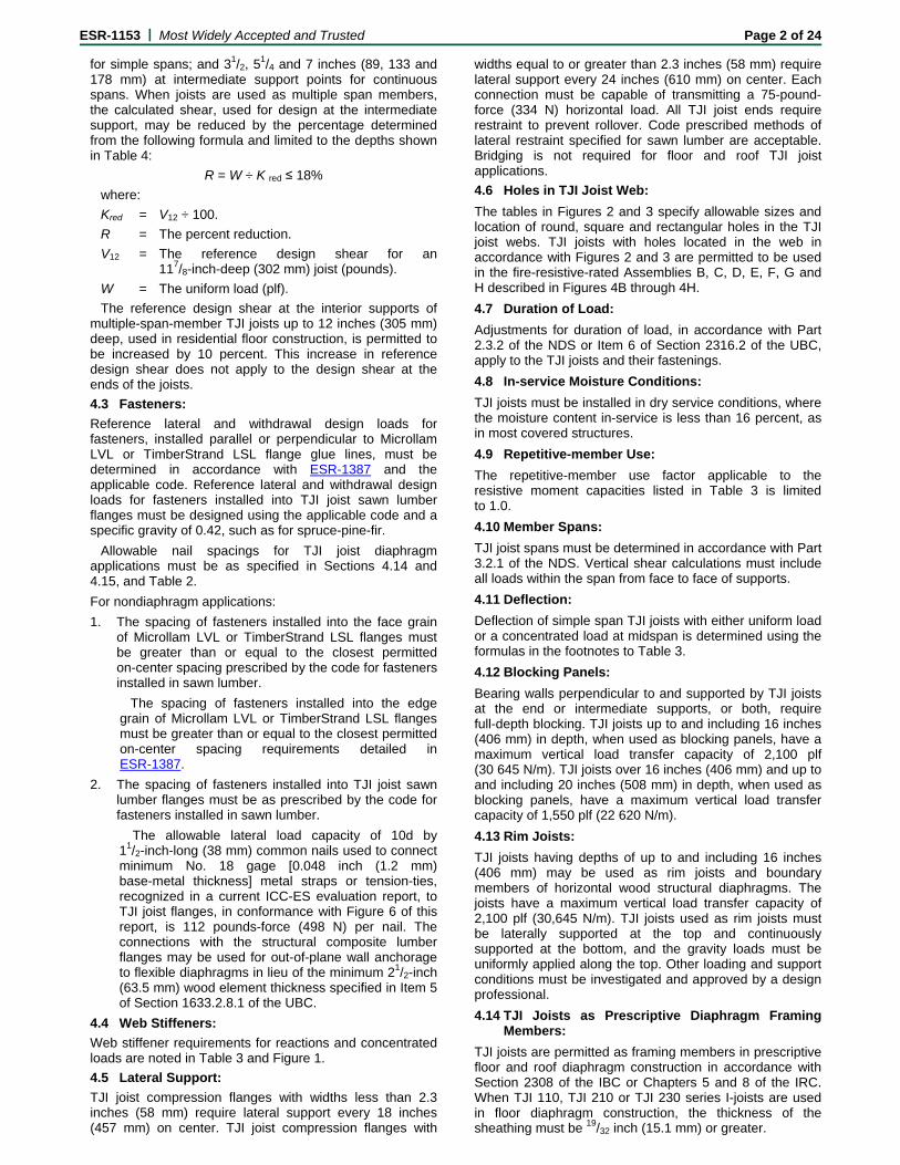
TJI joists are prefabricated wood I-joists having wood or wood-based flanges and Performance Plus® oriented strand board (OSB) webs. Either the top and bottom flanges are parallel, forming a constant-depth joist; or the top flange has a single taper, forming a variable-depth joist. The web panels have the face grain oriented vertically, and the web-to-web connection is either butt jointed or serrated and glued to form a continuous web. The web-to-flange connection is a proprietary tongue-and-groove glued joint. Refer to Table 1 for TJI joist series and material descriptions. The TJI L65, TJI L90, TJI H90, TJI HD90, and TJI HS90, may also be trademarked as: TJI L460, TJI L560, TJI H560, TJI HD560, and TJI HS560, respectively.
3.2 Material Specifications:
3.2.1 Flanges: Flange material is either Microllam® laminated veneer lumber (LVL), TimberStrand® laminated strand lumber (LSL) or machine stress rated lumber (MSR). Microllam LVL and TimberStrand LSL are recognized in evaluation report ESR-1387. Table 1 of this report specifies flange widths and depths. Flange material and grades are as specified in the quality control manual that contains Weyerhaeuser manufacturing standards.
3.2.2 Webs: Web material is Performance Plus® OSB conforming to DOC Voluntary Product Standard PS2, Exposure 1, along with further requirements set forth in the quality control manual that contains Weyerhaeuser manufacturing standards. Web material thickness requirements are noted in Table 1 of this report.
3.2.3 Adhesives: Adhesives are of the types specified in the quality control manual that contains Weyerhaeuser manufacturing standards.
4.0 DESIGN AND INSTALLATION
4.1 General:
The design and installation of TJI joists described in this report must comply with Sections 4.2 through 4.16. Additionally, design of TJI joists is governed by the applicable code and corresponding editions of ANSI/AF&PA NDS, National Design Specification for Wood Construction (NDS).
4.2 Design Values:
Table 3 specifies reference design moments, reactions, vertical shear forces, and joist stiffness (EI). Reference design reactions are based on minimum bearing lengths of 13/4 inches, 21/2 inches and 31/2 inches (45, 64 and 89 mm),
*Revised March 2013
ESR-1153 | Most Widely Accepted and Trusted Page 2 of 24
for simple spans; and 31/2, 51/4 and 7 inches (89, 133 and
178 mm) at intermediate support points for continuous spans. When joists are used as multiple span members, the calculated shear, used for design at the intermediate support, may be reduced by the percentage determined from the following formula and limited to the depths shown in Table 4:
R = W ÷ K red ≤ 18%
where:
Kred = V12 ÷ 100.
R = The percent reduction.
V12 = The reference design shear for an 117/8-inch-deep (302 mm) joist (pounds).
W = The uniform load (plf).
The reference design shear at the interior supports of multiple-span-member TJI joists up to 12 inches (305 mm) deep, used in residential floor construction, is permitted to be increased by 10 percent. This increase in reference design shear does not apply to the design shear at the ends of the joists.
4.3 Fasteners:
Reference lateral and withdrawal design loads for fasteners, installed parallel or perpendicular to Microllam LVL or TimberStrand LSL flange glue lines, must be determined in accordance with ESR-1387 and the applicable code. Reference lateral and withdrawal design loads for fasteners installed into TJI joist sawn lumber flanges must be designed using the applicable code and a specific gravity of 0.42, such as for spruce-pine-fir.
Allowable nail spacings for TJI joist diaphragm applications must be as specified in Sections 4.14 and 4.15, and Table 2.
For nondiaphragm applications:
1. The spacing of fasteners installed into the face grain of Microllam LVL or TimberStrand LSL flanges must be greater than or equal to the closest permitted on-center spacing prescribed by the code for fasteners installed in sawn lumber.
The spacing of fasteners installed into the edge grain of Microllam LVL or TimberStrand LSL flanges must be greater than or equal to the closest permitted on-center spacing requirements detailed in ESR-1387.
2. The spacing of fasteners installed into TJI joist sawn lumber flanges must be as prescribed by the code for fasteners installed in sawn lumber.
The allowable lateral load capacity of 10d by 11/2-inch-long (38 mm) common nails used to connect minimum No. 18 gage [0.048 inch (1.2 mm) base-metal thickness] metal straps or tension-ties, recognized in a current ICC-ES evaluation report, to TJI joist flanges, in conformance with Figure 6 of this report, is 112 pounds-force (498 N) per nail. The connections with the structural composite lumber flanges may be used for out-of-plane wall anchorage to flexible diaphragms in lieu of the minimum 21/2-inch (63.5 mm) wood element thickness specified in Item 5 of Section 1633.2.8.1 of the UBC.
4.4 Web Stiffeners:
Web stiffener requirements for reactions and concentrated loads are noted in Table 3 and Figure 1.
4.5 Lateral Support:
TJI joist compression flanges with widths less than 2.3 inches (58 mm) require lateral support every 18 inches (457 mm) on center. TJI joist compression flanges with
widths equal to or greater than 2.3 inches (58 mm) require lateral support every 24 inches (610 mm) on center. Each connection must be capable of transmitting a 75-pound-force (334 N) horizontal load. All TJI joist ends require restraint to prevent rollover. Code prescribed methods of lateral restraint specified for sawn lumber are acceptable. Bridging is not required for floor and roof TJI joist applications.
4.6 Holes in TJI Joist Web:
The tables in Figures 2 and 3 specify allowable sizes and location of round, square and rectangular holes in the TJI joist webs. TJI joists with holes located in the web in accordance with Figures 2 and 3 are permitted to be used in the fire-resistive-rated Assemblies B, C, D, E, F, G and H described in Figures 4B through 4H.
4.7 Duration of Load:
Adjustments for duration of load, in accordance with Part 2.3.2 of the NDS or Item 6 of Section 2316.2 of the UBC, apply to the TJI joists and their fastenings.
4.8 In-service Moisture Conditions:
TJI joists must be installed in dry service conditions, where the moisture content in-service is less than 16 percent, as in most covered structures.
4.9 Repetitive-member Use:
The repetitive-member use factor applicable to the resistive moment capacities listed in Table 3 is limited to 1.0.
4.10 Member Spans:
TJI joist spans must be determined in accordance with Part 3.2.1 of the NDS. Vertical shear calculations must include all loads within the span from face to face of supports.
4.11 Deflection:
Deflection of simple span TJI joists with either uniform load or a concentrated load at midspan is determined using the formulas in the footnotes to Table 3.
4.12 Blocking Panels:
Bearing walls perpendicular to and supported by TJI joists at the end or intermediate supports, or both, require full-depth blocking. TJI joists up to and including 16 inches (406 mm) in depth, when used as blocking panels, have a maximum vertical load transfer capacity of 2,100 plf (30 645 N/m). TJI joists over 16 inches (406 mm) and up to and including 20 inches (508 mm) in depth, when used as blocking panels, have a maximum vertical load transfer capacity of 1,550 plf (22 620 N/m).
4.13 Rim Joists:
TJI joists having depths of up to and including 16 inches (406 mm) may be used as rim joists and boundary members of horizontal wood structural diaphragms. The joists have a maximum vertical load transfer capacity of 2,100 plf (30,645 N/m). TJI joists used as rim joists must be laterally supported at the top and continuously supported at the bottom, and the gravity loads must be uniformly applied along the top. Other loading and support conditions must be investigated and approved by a design professional.
4.14 TJI Joists as Prescriptive Diaphragm Framing Members:
TJI joists are permitted as framing members in prescriptive floor and roof diaphragm construction in accordance with Section 2308 of the IBC or Chapters 5 and 8 of the IRC. When TJI 110, TJI 210 or TJI 230 series I-joists are used in floor diaphragm construction, the thickness of the sheathing must be 19/32 inch (15.1 mm) or greater.

ESR-1153 | Most Widely Accepted and Trusted Page 3 of 24
4.15 TJI Joists as Engineered Diaphragm Framing Members:
TJI 110, TJI 210, TJI 230, TJI 360, TJI 560, TJI 560D, TJI s31, TJI s33, TJI s47, TJI 100C and TJI 300C joists may be used as framing members in blocked and unblocked engineered diaphragms designed using Table 2306.2.1(1) of the IBC, or Tables 4.2A and 4.2C of the SDPWS, subject to the limitations specified in Table 2 of this report.
TJI L65, TJI L90, TJI H90, TJI HD90 and TJI HS90 joists may be used as framing members in diaphragms designed in accordance with the applicable code. The closest permitted sheathing nail spacing in a single row is 3 inches (76 mm) on center for 10d common nails or 2 inches (51 mm) on center for 8d common nails.
4.16 Cantilevered TJI Joists:
TJI joists are permitted to be installed with cantilevered ends, provided the cantilevers have a maximum length equal to one-third of the adjacent span and support uniform loads only, unless designed by a design professional.
4.17 TJI Joists with Flak Jacket™ Protection Used in IRC Section R501.3 Fire Protected Floors:
TJI® Joists with Flak Jacket™ protection applied to both sides of the web and vertical sides of the bottom flange are an alternative to the 2-by-10 dimension lumber, prescribed in the 2012 IRC Section R501.3 Exception 4, and have met the requirements of a floor assembly demonstrating equivalent floor performance. TJI® Joists with Flak Jacket™ protection are identified in the field by a Flak Jacket™ Protection stamp or label placed on the web of the I-joist member. Flak Jacket™ protection is applied in accordance with the TJI® Joist with Flak Jacket™ Protection Manufacturing Standard and quality control program.
The TJI® Joist Flak Jacket™ protection is limited to TJI® 210, 230, 360, 560 and 560D I-joists which have a minimum flange depth of 13/8-inches (34.9 mm). The flooring attachment to the I-joists must include the application of construction adhesive complying with ASTM D3498.
4.18 Fire-resistance-rated Roof-ceiling or Floor-ceiling Assemblies:
Refer to Figures 4A through 4F, and 4H, for details on one-hour fire-resistance-rated roof-ceiling or floor-ceiling assemblies. Refer to Figure 4G for details on two-hour fire-resistance-rated roof-ceiling or floor-ceiling assemblies. When assemblies A, B, C, D, E, and F are used as floor-ceiling assemblies over unusable crawl spaces, it is permitted to omit the ceiling membrane. Additionally, flooring is permitted to be omitted where unusable attic space occurs above, provided the lateral support requirements of Section 4.5 are met. Alternate floor or roof systems using lightweight concrete or gypsum concrete are permitted in accordance with Table 5
4.19 Sound Ratings:
Fire-resistance-rated assemblies B, D and G, as described in Figures 4B, 4D and 4G, have sound transmission class (STC) and impact insulation class (IIC) ratings as given in Table 6, provided they are constructed with the additional assembly components and floor coverings specified in Table 6.
5.0 CONDITIONS OF USE
The TJI Prefabricated Wood I-joists described in this report comply with or are suitable alternatives to joists and rafters specified in the codes specifically listed in Section 1.0, subject to the following conditions:
5.1 TJI joists are designed in accordance with this report.
5.2 Drawings and design details verifying compliance with this report are submitted to the code official for approval.
5.3 Reference design values for TJI joists and their fasteners are permitted to be increased for duration of load in accordance with the applicable code.
5.4 Where one-hour or two-hour fire-resistance-rated construction is required, construction complies with this report.
5.5 No cutting or notching of TJI joist flanges is permitted.
5.6 Sound rated assemblies described in Table 6, with STC and or IIC ratings of less than 50, are only applicable in jurisdictions using the IRC.
5.7 TJI joists are produced at the Weyerhaeuser plants located in Castleberry, Alabama; Eugene, Oregon; and Natchitoches, Louisiana; and at the RedBuilt™ LLC plant located in Stayton, Oregon; and the Anthony-Domtar plant located in Sault Ste. Marie, Ontario, Canada; and at the Pacific Woodtech plant located in Burlington, Washington; under a quality control program with inspections by PFS Corporation (AA-652), or APA—The Engineered Wood Association (AA-649).
6.0 EVIDENCE SUBMITTED
6.1 Data in accordance with the ICC-ES Acceptance Criteria for Prefabricated Wood I-joists (AC14), dated February 2012.
6.2 Reports of fire tests conducted in accordance with ASTM E119.
6.3 Reports of sound transmission tests conducted in accordance with ASTM E90, ASTM E413 and ASTM E492.
7.0 IDENTIFICATION
TJI prefabricated wood I-joists are identified by a stamp that includes the product designation, evaluation report number (ICC-ES ESR-1153), manufacturer's name or logo (iLevel, Weyerhaeuser), plant number, production date, and the name or logo of the inspection agency (PFS Corporation or APA).
ESR-1153 | Most Widely Accepted and Trusted Page 4 of 24
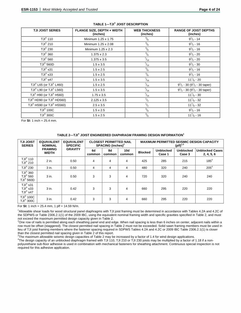
TABLE 1—TJI® JOIST DESCRIPTION
TJI JOIST SERIES FLANGE SIZE, DEPTH × WIDTH (inches)
WEB THICKNESS (inches)
RANGE OF JOIST DEPTHS (inches)
TJI® 110 Minimum 1.25 x 1.75 3/8 91/2 - 14
TJI® 210 Minimum 1.25 x 2.08 3/8 91/2 - 16
TJI® 230 Minimum 1.25 x 2.3 3/8 91/2 - 16
TJI® 360 1.375 x 2.3 3/8 91/2 - 20
TJI® 560 1.375 x 3.5 7/16 91/2 - 20
TJI® 560D 1.5 x 3.5 7/16 91/2 - 30
TJI® s31 1.5 x 2.5 3/8 91/2 - 16
TJI® s33 1.5 x 2.5 3/8 91/2 - 16
TJI® s47 1.5 x 3.5 7/16 117/8 - 20
TJI® L65 (or TJI® L460) 1.5 x 2.5 7/16 91/2 - 30 (91/2 - 30 taper)
TJI® L90 (or TJI® L560) 1.5 x 3.5 7/16 91/2 - 30 (91/2 - 30 taper)
TJI® H90 (or TJI® H560) 1.75 x 3.5 7/16 117/8 - 30
TJI® HD90 (or TJI® HD560) 2.125 x 3.5 1/2 117/8 - 32
TJI® HS90 (or TJI® HS560) 2.5 x 3.5 1/2 117/8 - 32
TJI® 100C 1.5 x 2.5 3/8 91/2 - 16
TJI® 300C 1.5 x 2.5 3/8 117/8 - 16
For SI: 1 inch = 25.4 mm.
TABLE 2—TJI® JOIST ENGINEERED DIAPHRAGM FRAMING DESIGN INFORMATION1
TJI JOIST SERIES
EQUIVALENT NOMINAL FRAMING
WIDTH
EQUIVALENTSPECIFIC GRAVITY
CLOSEST PERMITTED NAIL SPACING (inches)2
MAXIMUM PERMITTED SEISMIC DESIGN CAPACITY (plf)1,3
6d common
8d common
10d common
Blocked Unblocked
Case 1 Unblocked
Case 3 Unblocked Cases
2, 4, 5, 6
TJI® 110 TJI® 210
2 in. 0.50 4 4 4 425 285 215 1854
TJI® 230 3 in. 0.50 4 4 4 480 320 240 2054
TJI® 360 TJI® 560
TJI® 560D 3 in. 0.50 3 3 4 720 320 240 240
TJI® s31 TJI® s33 TJI® s47
3 in. 0.42 3 3 4 660 295 220 220
TJI® 100C TJI® 300C
3 in. 0.42 3 3 4 660 295 220 220
For SI: 1 inch = 25.4 mm, 1 plf = 14.59 N/m. 1Allowable shear loads for wood structural panel diaphragms with TJI joist framing must be determined in accordance with Tables 4.2A and 4.2C of the SDPWS or Table 2306.2.1(1) of the 2009 IBC, using the equivalent nominal framing width and specific gravities specified in Table 2, and must not exceed the maximum permitted design capacity given in Table 2. 2One row of nails is permitted along each sheathing panel end and edge. When nail spacing is less than 6 inches on center, adjacent nails within a row must be offset (staggered). The closest permitted nail spacing in Table 2 must not be exceeded. Solid sawn framing members must be used in lieu of TJI joist framing members where the fastener spacing required in SDPWS Tables 4.2A and 4.2C or 2009 IBC Table 2306.2.1(1) is closer than the closest permitted nail spacing given in Table 2 of this report. 3The maximum allowable seismic design capacities of Table 2 may be increased by a factor of 1.4 for wind design applications. 4The design capacity of an unblocked diaphragm framed with TJI 110, TJI 210 or TJI 230 joists may be multiplied by a factor of 1.18 if a non-polyurethane sub-floor adhesive is used in combination with mechanical fasteners for sheathing attachment. Continuous special inspection is not required for this adhesive application.
ESR-1153 | Most Widely Accepted and Trusted Page 5 of 24
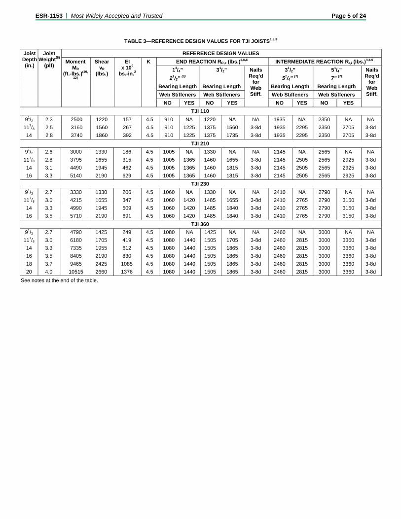
TABLE 3—REFERENCE DESIGN VALUES FOR TJI JOISTS1,2,3
Joist Depth (in.)
Joist Weight(8)
(plf)
REFERENCE DESIGN VALUES
Moment MR
(ft.-lbs.)(10,
12)
Shear vR
(lbs.)
EI x 106
bs.-in.2
K END REACTION RR,e (lbs.)4,5,6 INTERMEDIATE REACTION Rr,i (lbs.)4,5,6
13/4” 31/2” Nails Req’d
for Web Stiff.
31/2” 51/4” Nails Req’d
for Web Stiff.
21/2” (9) 51/4” (7) 7” (7) Bearing Length Bearing Length Bearing Length Bearing Length
Web Stiffeners Web Stiffeners Web Stiffeners Web Stiffeners
NO YES NO YES NO YES NO YES
TJI 110
91/2 2.3 2500 1220 157 4.5 910 NA 1220 NA NA 1935 NA 2350 NA NA
117/8 2.5 3160 1560 267 4.5 910 1225 1375 1560 3-8d 1935 2295 2350 2705 3-8d
14 2.8 3740 1860 392 4.5 910 1225 1375 1735 3-8d 1935 2295 2350 2705 3-8d
TJI 210
91/2 2.6 3000 1330 186 4.5 1005 NA 1330 NA NA 2145 NA 2565 NA NA
117/8 2.8 3795 1655 315 4.5 1005 1365 1460 1655 3-8d 2145 2505 2565 2925 3-8d
14 3.1 4490 1945 462 4.5 1005 1365 1460 1815 3-8d 2145 2505 2565 2925 3-8d
16 3.3 5140 2190 629 4.5 1005 1365 1460 1815 3-8d 2145 2505 2565 2925 3-8d
TJI 230
91/2 2.7 3330 1330 206 4.5 1060 NA 1330 NA NA 2410 NA 2790 NA NA
117/8 3.0 4215 1655 347 4.5 1060 1420 1485 1655 3-8d 2410 2765 2790 3150 3-8d
14 3.3 4990 1945 509 4.5 1060 1420 1485 1840 3-8d 2410 2765 2790 3150 3-8d
16 3.5 5710 2190 691 4.5 1060 1420 1485 1840 3-8d 2410 2765 2790 3150 3-8d
TJI 360
91/2 2.7 4790 1425 249 4.5 1080 NA 1425 NA NA 2460 NA 3000 NA NA
117/8 3.0 6180 1705 419 4.5 1080 1440 1505 1705 3-8d 2460 2815 3000 3360 3-8d
14 3.3 7335 1955 612 4.5 1080 1440 1505 1865 3-8d 2460 2815 3000 3360 3-8d
16 3.5 8405 2190 830 4.5 1080 1440 1505 1865 3-8d 2460 2815 3000 3360 3-8d
18 3.7 9465 2425 1085 4.5 1080 1440 1505 1865 3-8d 2460 2815 3000 3360 3-8d
20 4.0 10515 2660 1376 4.5 1080 1440 1505 1865 3-8d 2460 2815 3000 3360 3-8d
See notes at the end of the table.
ESR-1153 | Most Widely Accepted and Trusted Page 6 of 24
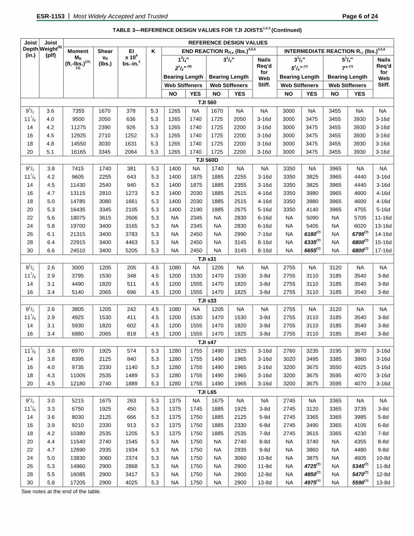
TABLE 3—REFERENCE DESIGN VALUES FOR TJI JOISTS1,2,3 (Continued)
Joist Depth (in.)
Joist Weight(8)
(plf)
REFERENCE DESIGN VALUES
Moment MR
(ft.-lbs.)(10,
12)
Shear vR
(lbs.)
EI x 106
bs.-in.2
K END REACTION RR,e (lbs.)4,5,6 INTERMEDIATE REACTION Rr,i (lbs.)4,5,6
13/4″ 31/2″ Nails Req’d
for Web Stiff.
31/2″ 51/4″ Nails Req’d
for Web Stiff.
21/2″ (9) 51/4″ (7) 7″ (7) Bearing Length Bearing Length Bearing Length Bearing Length
Web Stiffeners Web Stiffeners Web Stiffeners Web Stiffeners
NO YES NO YES NO YES NO YES
TJI 560
91/2 3.6 7355 1670 378 5.3 1265 NA 1670 NA NA 3000 NA 3455 NA NA
117/8 4.0 9500 2050 636 5.3 1265 1740 1725 2050 3-16d 3000 3475 3455 3930 3-16d
14 4.2 11275 2390 926 5.3 1265 1740 1725 2200 3-16d 3000 3475 3455 3930 3-16d
16 4.5 12925 2710 1252 5.3 1265 1740 1725 2200 3-16d 3000 3475 3455 3930 3-16d
18 4.8 14550 3030 1631 5.3 1265 1740 1725 2200 3-16d 3000 3475 3455 3930 3-16d
20 5.1 16165 3345 2064 5.3 1265 1740 1725 2200 3-16d 3000 3475 3455 3930 3-16d
TJI 560D
91/2 3.8 7415 1740 381 5.3 1400 NA 1740 NA NA 3350 NA 3965 NA NA
117/8 4.2 9605 2255 643 5.3 1400 1875 1885 2255 3-16d 3350 3825 3965 4440 3-16d
14 4.5 11430 2540 940 5.3 1400 1875 1885 2355 3-16d 3350 3825 3965 4440 3-16d
16 4.7 13115 2810 1273 5.3 1400 2030 1885 2515 4-16d 3350 3980 3965 4600 4-16d
18 5.0 14785 3080 1661 5.3 1400 2030 1885 2515 4-16d 3350 3980 3965 4600 4-16d
20 5.3 16435 3345 2105 5.3 1400 2190 1885 2675 5-16d 3350 4140 3965 4755 5-16d
22 5.6 18075 3615 2606 5.3 NA 2345 NA 2830 6-16d NA 5090 NA 5705 11-16d
24 5.8 19700 3400 3165 5.3 NA 2345 NA 2830 6-16d NA 5405 NA 6020 13-16d
26 6.1 21315 3400 3783 5.3 NA 2450 NA 2990 7-16d NA 6180(7) NA 6795(7) 14-16d
28 6.4 22915 3400 4463 5.3 NA 2450 NA 3145 8-16d NA 6335(7) NA 6800(7) 15-16d
30 6.6 24510 3400 5205 5.3 NA 2450 NA 3145 8-16d NA 6655(7) NA 6800(7) 17-16d
TJI s31
91/2 2.6 3000 1205 205 4.5 1080 NA 1205 NA NA 2755 NA 3120 NA NA
117/8 2.9 3795 1530 348 4.5 1200 1530 1470 1530 3-8d 2755 3110 3185 3540 3-8d
14 3.1 4490 1820 511 4.5 1200 1555 1470 1820 3-8d 2755 3110 3185 3540 3-8d
16 3.4 5140 2065 696 4.5 1200 1555 1470 1825 3-8d 2755 3110 3185 3540 3-8d
TJI s33
91/2 2.6 3805 1205 242 4.5 1080 NA 1205 NA NA 2755 NA 3120 NA NA
117/8 2.9 4925 1530 411 4.5 1200 1530 1470 1530 3-8d 2755 3110 3185 3540 3-8d
14 3.1 5930 1820 602 4.5 1200 1555 1470 1820 3-8d 2755 3110 3185 3540 3-8d
16 3.4 6880 2065 818 4.5 1200 1555 1470 1825 3-8d 2755 3110 3185 3540 3-8d
TJI s47
117/8 3.6 6970 1925 574 5.3 1280 1755 1490 1925 3-16d 2760 3235 3195 3670 3-16d
14 3.8 8395 2125 840 5.3 1280 1755 1490 1965 3-16d 3020 3495 3385 3860 3-16d
16 4.0 9735 2330 1140 5.3 1280 1755 1490 1965 3-16d 3200 3675 3550 4025 3-16d
18 4.3 11005 2535 1489 5.3 1280 1755 1490 1965 3-16d 3200 3675 3595 4070 3-16d
20 4.5 12180 2740 1889 5.3 1280 1755 1490 1965 3-16d 3200 3675 3595 4070 3-16d
TJI L65
91/2 3.0 5215 1675 263 5.3 1375 NA 1675 NA NA 2745 NA 3365 NA NA
117/8 3.3 6750 1925 450 5.3 1375 1745 1885 1925 3-8d 2745 3120 3365 3735 3-8d
14 3.6 8030 2125 666 5.3 1375 1750 1885 2125 5-8d 2745 3365 3365 3985 5-8d
16 3.9 9210 2330 913 5.3 1375 1750 1885 2330 6-8d 2745 3490 3365 4105 6-8d
18 4.2 10380 2535 1205 5.3 1375 1750 1885 2535 7-8d 2745 3615 3365 4230 7-8d
20 4.4 11540 2740 1545 5.3 NA 1750 NA 2740 8-8d NA 3740 NA 4355 8-8d
22 4.7 12690 2935 1934 5.3 NA 1750 NA 2935 9-8d NA 3860 NA 4480 9-8d
24 5.0 13830 3060 2374 5.3 NA 1750 NA 3060 10-8d NA 3875 NA 4605 10-8d
26 5.3 14960 2900 2868 5.3 NA 1750 NA 2900 11-8d NA 4725(7) NA 5345(7) 11-8d
28 5.5 16085 2900 3417 5.3 NA 1750 NA 2900 12-8d NA 4850(7) NA 5470(7) 12-8d
30 5.8 17205 2900 4025 5.3 NA 1750 NA 2900 13-8d NA 4975(7) NA 5590(7) 13-8d
See notes at the end of the table.
ESR-1153 | Most Widely Accepted and Trusted Page 7 of 24
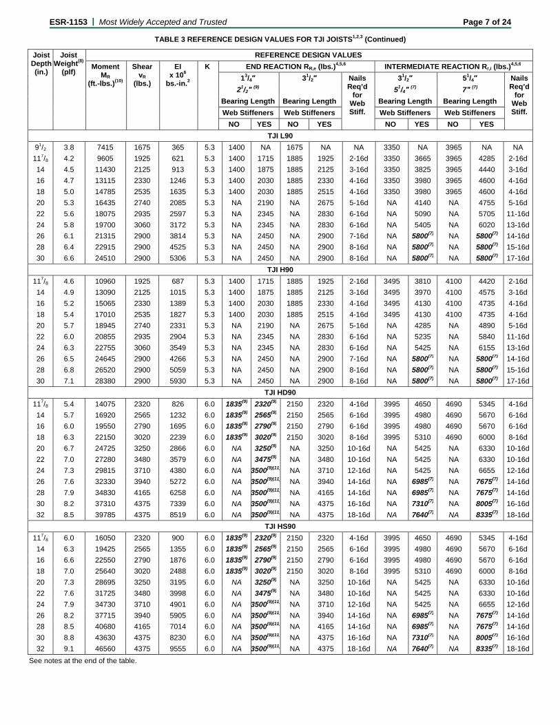
TABLE 3 REFERENCE DESIGN VALUES FOR TJI JOISTS1,2,3 (Continued)
Joist Depth (in.)
Joist Weight(8)
(plf)
REFERENCE DESIGN VALUES
Moment MR
(ft.-lbs.)(10)
Shear vR
(lbs.)
EI x 106
bs.-in.2
K END REACTION RR,e (lbs.)4,5,6 INTERMEDIATE REACTION Rr,i (lbs.)4,5,6
13/4″ 31/2″ Nails Req’d
for Web Stiff.
31/2″ 51/4″ Nails Req’d
for Web Stiff.
21/2″ (9) 51/4″ (7) 7″ (7) Bearing Length Bearing Length Bearing Length Bearing Length
Web Stiffeners Web Stiffeners Web Stiffeners Web Stiffeners
NO YES NO YES NO YES NO YES
TJI L90
91/2 3.8 7415 1675 365 5.3 1400 NA 1675 NA NA 3350 NA 3965 NA NA
117/8 4.2 9605 1925 621 5.3 1400 1715 1885 1925 2-16d 3350 3665 3965 4285 2-16d
14 4.5 11430 2125 913 5.3 1400 1875 1885 2125 3-16d 3350 3825 3965 4440 3-16d
16 4.7 13115 2330 1246 5.3 1400 2030 1885 2330 4-16d 3350 3980 3965 4600 4-16d
18 5.0 14785 2535 1635 5.3 1400 2030 1885 2515 4-16d 3350 3980 3965 4600 4-16d
20 5.3 16435 2740 2085 5.3 NA 2190 NA 2675 5-16d NA 4140 NA 4755 5-16d
22 5.6 18075 2935 2597 5.3 NA 2345 NA 2830 6-16d NA 5090 NA 5705 11-16d
24 5.8 19700 3060 3172 5.3 NA 2345 NA 2830 6-16d NA 5405 NA 6020 13-16d
26 6.1 21315 2900 3814 5.3 NA 2450 NA 2900 7-16d NA 5800(7) NA 5800(7) 14-16d
28 6.4 22915 2900 4525 5.3 NA 2450 NA 2900 8-16d NA 5800(7) NA 5800(7) 15-16d
30 6.6 24510 2900 5306 5.3 NA 2450 NA 2900 8-16d NA 5800(7) NA 5800(7) 17-16d
TJI H90
117/8 4.6 10960 1925 687 5.3 1400 1715 1885 1925 2-16d 3495 3810 4100 4420 2-16d
14 4.9 13090 2125 1015 5.3 1400 1875 1885 2125 3-16d 3495 3970 4100 4575 3-16d
16 5.2 15065 2330 1389 5.3 1400 2030 1885 2330 4-16d 3495 4130 4100 4735 4-16d
18 5.4 17010 2535 1827 5.3 1400 2030 1885 2515 4-16d 3495 4130 4100 4735 4-16d
20 5.7 18945 2740 2331 5.3 NA 2190 NA 2675 5-16d NA 4285 NA 4890 5-16d
22 6.0 20855 2935 2904 5.3 NA 2345 NA 2830 6-16d NA 5235 NA 5840 11-16d
24 6.3 22755 3060 3549 5.3 NA 2345 NA 2830 6-16d NA 5425 NA 6155 13-16d
26 6.5 24645 2900 4266 5.3 NA 2450 NA 2900 7-16d NA 5800(7) NA 5800(7) 14-16d
28 6.8 26520 2900 5059 5.3 NA 2450 NA 2900 8-16d NA 5800(7) NA 5800(7) 15-16d
30 7.1 28380 2900 5930 5.3 NA 2450 NA 2900 8-16d NA 5800(7) NA 5800(7) 17-16d
TJI HD90
117/8 5.4 14075 2320 826 6.0 1835(9) 2320(9) 2150 2320 4-16d 3995 4650 4690 5345 4-16d
14 5.7 16920 2565 1232 6.0 1835(9) 2565(9) 2150 2565 6-16d 3995 4980 4690 5670 6-16d
16 6.0 19550 2790 1695 6.0 1835(9) 2790(9) 2150 2790 6-16d 3995 4980 4690 5670 6-16d
18 6.3 22150 3020 2239 6.0 1835(9) 3020(9) 2150 3020 8-16d 3995 5310 4690 6000 8-16d
20 6.7 24725 3250 2866 6.0 NA 3250(9) NA 3250 10-16d NA 5425 NA 6330 10-16d
22 7.0 27280 3480 3579 6.0 NA 3475(9) NA 3480 10-16d NA 5425 NA 6330 10-16d
24 7.3 29815 3710 4380 6.0 NA 3500(9)(11) NA 3710 12-16d NA 5425 NA 6655 12-16d
26 7.6 32330 3940 5272 6.0 NA 3500(9)(11) NA 3940 14-16d NA 6985(7) NA 7675(7) 14-16d
28 7.9 34830 4165 6258 6.0 NA 3500(9)(11) NA 4165 14-16d NA 6985(7) NA 7675(7) 14-16d
30 8.2 37310 4375 7339 6.0 NA 3500(9)(11) NA 4375 16-16d NA 7310(7) NA 8005(7) 16-16d
32 8.5 39785 4375 8519 6.0 NA 3500(9)(11) NA 4375 18-16d NA 7640(7) NA 8335(7) 18-16d
TJI HS90
117/8 6.0 16050 2320 900 6.0 1835(9) 2320(9) 2150 2320 4-16d 3995 4650 4690 5345 4-16d
14 6.3 19425 2565 1355 6.0 1835(9) 2565(9) 2150 2565 6-16d 3995 4980 4690 5670 6-16d
16 6.6 22550 2790 1876 6.0 1835(9) 2790(9) 2150 2790 6-16d 3995 4980 4690 5670 6-16d
18 7.0 25640 3020 2488 6.0 1835(9) 3020(9) 2150 3020 8-16d 3995 5310 4690 6000 8-16d
20 7.3 28695 3250 3195 6.0 NA 3250(9) NA 3250 10-16d NA 5425 NA 6330 10-16d
22 7.6 31725 3480 3998 6.0 NA 3475(9) NA 3480 10-16d NA 5425 NA 6330 10-16d
24 7.9 34730 3710 4901 6.0 NA 3500(9)(11) NA 3710 12-16d NA 5425 NA 6655 12-16d
26 8.2 37715 3940 5905 6.0 NA 3500(9)(11) NA 3940 14-16d NA 6985(7) NA 7675(7) 14-16d
28 8.5 40680 4165 7014 6.0 NA 3500(9)(11) NA 4165 14-16d NA 6985(7) NA 7675(7) 14-16d
30 8.8 43630 4375 8230 6.0 NA 3500(9)(11) NA 4375 16-16d NA 7310(7) NA 8005(7) 16-16d
32 9.1 46560 4375 9555 6.0 NA 3500(9)(11) NA 4375 18-16d NA 7640(7) NA 8335(7) 18-16d
See notes at the end of the table.
ESR-1153 | Most Widely Accepted and Trusted Page 8 of 24
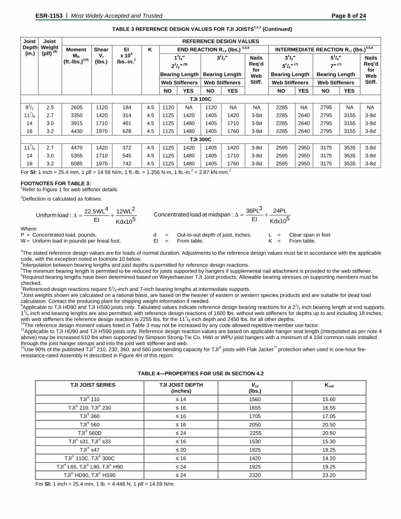
TABLE 3 REFERENCE DESIGN VALUES FOR TJI JOISTS1,2,3 (Continued)
Joist Depth (in.)
Joist Weight (plf) (8)
REFERENCE DESIGN VALUES
Moment MR
(ft.-lbs.)(10)
Shear Vr
(lbs.)
EI x 106
lbs.-in.2
K END REACTION Rr,e (lbs.) 4,5,6 INTERMEDIATE REACTION Rr,i (lbs.)4,5,6
13/4″ 31/2″ Nails Req’d
for Web Stiff.
31/2″ 51/4″ Nails Req’d
for Web Stiff.
21/2″ (9) 51/4″ (7) 7″ (7) Bearing Length Bearing Length Bearing Length Bearing Length
Web Stiffeners Web Stiffeners Web Stiffeners Web Stiffeners
NO YES NO YES NO YES NO YES
TJI 100C
91/2 2.5 2605 1120 184 4.5 1120 NA 1120 NA NA 2285 NA 2795 NA NA
117/8 2.7 3350 1420 314 4.5 1125 1420 1405 1420 3-8d 2285 2640 2795 3155 3-8d
14 3.0 3915 1710 461 4.5 1125 1480 1405 1710 3-8d 2285 2640 2795 3155 3-8d
16 3.2 4430 1970 628 4.5 1125 1480 1405 1760 3-8d 2285 2640 2795 3155 3-8d
TJI 300C
117/8 2.7 4470 1420 372 4.5 1125 1420 1405 1420 3-8d 2595 2950 3175 3535 3-8d
14 3.0 5355 1710 545 4.5 1125 1480 1405 1710 3-8d 2595 2950 3175 3535 3-8d
16 3.2 6085 1970 742 4.5 1125 1480 1405 1760 3-8d 2595 2950 3175 3535 3-8d
For SI: 1 inch = 25.4 mm, 1 plf = 14 59 N/m, 1 ft.-lb. = 1.356 N-m, 1 lb.-in.2 = 2.87 kN-mm.2
FOOTNOTES FOR TABLE 3: 1Refer to Figure 1 for web stiffener details 2Deflection is calculated as follows:
Where: P = Concentrated load, pounds. d = Out-to-out depth of joist, inches. L = Clear span in feet W = Uniform load in pounds per lineal foot. EI = From table. K = From table. 3The stated reference design values are for loads of normal duration. Adjustments to the reference design values must be in accordance with the applicable code, with the exception noted in footnote 10 below. 4Interpolation between bearing lengths and joist depths is permitted for reference design reactions. 5The minimum bearing length is permitted to be reduced for joists supported by hangers if supplemental nail attachment is provided to the web stiffener. 6Required bearing lengths have been determined based on Weyerhaeuser TJI Joist products. Allowable bearing stresses on supporting members must be checked. 7Referenced design reactions require 51/4-inch and 7-inch bearing lengths at intermediate supports. 8Joist weights shown are calculated on a rational basis, are based on the heavier of eastern or western species products and are suitable for dead load calculation. Contact the producing plant for shipping weight information if needed. 9Applicable to TJI HD90 and TJI HS90 joists only. Tabulated values indicate reference design bearing reactions for a 21/2 inch bearing length at end supports. 13/4 inch end bearing lengths are also permitted; with reference design reactions of 1600 lbs. without web stiffeners for depths up to and including 18 inches; with web stiffeners the reference design reaction is 2255 lbs. for the 117/8 inch depth and 2450 lbs. for all other depths. 10The reference design moment values listed in Table 3 may not be increased by any code allowed repetitive-member use factor. 11Applicable to TJI HD90 and TJI HS90 joists only. Reference design reaction values are based on applicable hanger seat length (interpolated as per note 4 above) may be increased 510 lbs when supported by Simpson Strong-Tie Co. HWI or WPU joist hangers with a minimum of 4 10d common nails installed through the joist hanger stirrups and into the joist web stiffener and web. 12Use 90% of the published TJI® 210, 230, 360, and 560 joist bending capacity for TJI® joists with Flak Jacket™ protection when used in one-hour fire-resistance-rated Assembly H described in Figure 4H of this report.
TABLE 4—PROPERTIES FOR USE IN SECTION 4.2
TJI JOIST SERIES TJI JOIST DEPTH (inches)
V12
(lbs.) Kred
TJI® 110 ≤ 14 1560 15.60
TJI® 210, TJI® 230 ≤ 16 1655 16.55
TJI® 360 ≤ 16 1705 17.05
TJI® 560 ≤ 16 2050 20.50
TJI® 560D ≤ 24 2255 20.50
TJI® s31, TJI® s33 ≤ 16 1530 15.30
TJI® s47 ≤ 20 1925 19.25
TJI® 110C, TJI® 300C ≤ 16 1420 14.20
TJI® L65, TJI® L90, TJI® H90 ≤ 24 1925 19.25
TJI® HD90, TJI® HS90 ≤ 24 2320 23.20
For SI: 1 inch = 25.4 mm, 1 lb. = 4.448 N, 1 plf = 14.59 N/m.
510Kdx
2WL12
EI
4WL5.22:load Uniform +=Δ
510Kdx
PL24
EI
3PL36 :midspan at load edConcentrat +=Δ
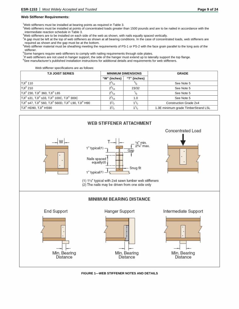
ESR-1153 | Most Widely Accepted and Trusted Page 9 of 24 Web Stiffener Requirements:
1Web stiffeners must be installed at bearing points as required in Table 3. 2Web stiffeners must be installed at points of concentrated loads greater than 1500 pounds and are to be nailed in accordance with the
intermediate reaction schedule in Table 3. 3Web stiffeners are to be installed on each side of the web as shown, with nails equally spaced vertically. 4A gap must be left at the top of web stiffeners as shown at all bearing conditions. In the case of concentrated loads, web stiffeners are
required as shown and the gap must be at the bottom. 5Web stiffener material must be sheathing meeting the requirements of PS-1 or PS-2 with the face grain parallel to the long axis of the
stiffener. 6Some hangers require web stiffeners to comply with nailing requirements through side plates. 7If web stiffeners are not used in hanger support, the side of the hanger must extend up to laterally support the top flange. 8See manufacturer’s published installation instructions for additional details and requirements for web stiffeners.
Web stiffener specifications are as follows:
TJI JOIST SERIES MINIMUM DIMENSIONS GRADE
“W” (inches) “T” (inches)
TJI® 110 25/16 5/8 See Note 5
TJI® 210 25/16 23/32 See Note 5
TJI® 230, TJI® 360, TJI® L65 25/16 7/8 See Note 5
TJI® s31, TJI® s33, TJI® 100C, TJI® 300C 25/16 1.0 See Note 5
TJI® s47, TJI® 560, TJI® 560D, TJI® L90, TJI® H90 31/2 11/2 Construction Grade 2x4
TJI® HD90, TJI® HS90 31/2 11/2 1.3E minimum grade TimberStrand LSL
FIGURE 1—WEB STIFFENER NOTES AND DETAILS
ESR-1153 | Most Widely Accepted and Trusted Page 10 of 24
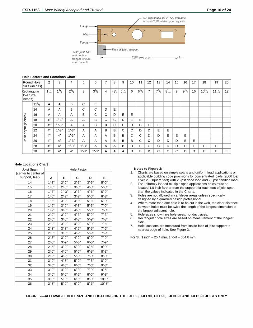
Hole Factors and Locations Chart
Round Hole Size (inches)
2 3 4 5 6 7 8 9 10 11 12 13 14 15 16 17 18 19 20
Rectangular Hole Size inches)
11/4 13/4 21/4 3 31/2 4 43/4 51/4 6 61/2 7 73/4 81/4 9 91/2 10 103/4 111/4 12
Jois
t dep
th (
inch
es)
117/8 A A B C E
14 A A B C C D E
16 A A A B C C D E E
18 4″ 1′-3″ A A B C C D E E
20 4″ 1′-3″ A A B B C C D D E E
22 4″ 1′-3″ 1′-3″ A A B B C C D D E E
24 4″ 4″ 1′-3″ A A A B B C C D D E E E
26 4″ 4″ 1′-3″ A A A B B B C C D D D E E
28 4″ 4″ 1′-3″ 1′-3″ A A A B B B C C D D D E E E
30 4″ 4″ 4″ 1′-3″ 1′-3″ A A A B B B C C C D D E E E
Hole Locations Chart
Joist Span (center to center of
support, feet)
Hole Factor
A
B
C
D
E 14 1′-3″ 2′-0″ 2′-6″ 3′-9″ 5′-0″ 15 1′-3″ 2′-0″ 3′-0″ 4′-0″ 5′-3″ 16 1′-3″ 2′’-3″ 3′-3″ 4′-6″ 5′-9″ 17 1′-6″ 2′-9″ 3′-9″ 5′-0″ 6′-3″ 18 1′-6″ 3′-0″ 4′-3″ 5′-6″ 6′-9″ 19 1′-9″ 3′-0″ 4′-3″ 5′-6″ 7′-0″ 20 1′-9″ 3′-0″ 4′-3″ 5′-6″ 7′-0″ 21 2′-0″ 3′-0″ 4′-3″ 5′-9″ 7′-3″ 22 2′-0″ 3′-0″ 4′-3″ 5′-9″ 7′-3″ 23 2′-0″ 3′-3″ 4′-3″ 5′-9″ 7′-6″ 24 2′-3″ 3′-3″ 4′-6″ 5′-9″ 7′-6″ 25 2′-3″ 3′-6″ 4′-9″ 5′-9″ 7′-9″ 26 2′-3″ 3′-9″ 4′-9″ 6′-0″ 7′-9″ 27 2′-6” 3’-9” 5’-0” 6’-3” 7’-9” 28 2’-6″ 4′-0″ 5′-3″ 6′-6″ 8′-0″ 29 2′-6″ 4′-0″ 5′-6″ 6′-9″ 8′-3″ 30 2′-9″ 4′-3″ 5′-9″ 7′-0″ 8′-6″ 31 3′-0″ 4′-3″ 5′-9″ 7′-3″ 8′-9″ 32 3′-0″ 4′-6″ 6′-0″ 7′-6″ 9′-3″ 33 3′-0″ 4′-9″ 6′-3″ 7′-9″ 9′-6″ 34 3′-0″ 5′-0″ 6′-6″ 8′-0″ 9′-9″ 35 3′-3″ 5′-0″ 6′-6″ 8′-3″ 10′-0″ 36 3′-3″ 5′-0″ 6′-9″ 8′-6″ 10′-3″
Notes to Figure 2:
1. Charts are based on simple spans and uniform load applications or applicable building code provisions for concentrated loads (2000 lbs. Over 2.5 square feet) with 25 psf dead load and 20 psf partition load.
2. For uniformly loaded multiple span applications holes must be located 1.0 inch farther from the support for each foot of joist span, than the values indicated in the Charts.
3. Holes are not allowed in cantilever areas unless specifically designed by a qualified design professional.
4. Where more than one hole is to be cut in the web, the clear distance between holes must be twice the length of the longest dimension of the largest adjacent hole.
5. Hole sizes shown are hole sizes, not duct sizes. 6. Rectangular hole sizes are based on measurement of the longest
side. 7. Hole locations are measured from inside face of joist support to
nearest edge of hole. See Figure 3. For SI: 1 inch = 25.4 mm, 1 foot = 304.8 mm.
FIGURE 2—ALLOWABLE HOLE SIZE AND LOCATION FOR THE TJI L65, TJI L90, TJI H90, TJI HD90 AND TJI HS90 JOISTS ONLY
ESR-1153 | Most Widely Accepted and Trusted Page 11 of 24
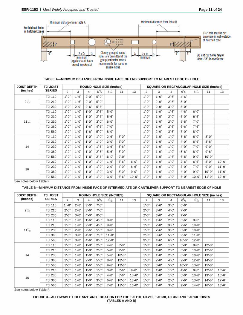
TABLE A—MINIMUM DISTANCE FROM INSIDE FACE OF END SUPPORT TO NEAREST EDGE OF HOLE
JOIST DEPTH (inches)
TJI JOIST SERIES
ROUND HOLE SIZE (inches) SQUARE OR RECTANGULAR HOLE SIZE (inches)
2 3 4 61/2 87/8 11 13 2 3 4 61/2 87/8 11 13
91/2
TJI 110 1′-0″ 1′-6″ 2′-0″ 5′-0″ 1′-0″ 1′-6″ 2′-6″ 4′-6″
TJI 210 1′-0″ 1′-6″ 2′-0″ 5′-0″ 1′-0″ 2′-0″ 2′-6″ 5′-0″
TJI 230 1′-0″ 2′-0″ 2′-6″ 5′-6″ 1′-0″ 2′-0″ 3′-0″ 5′-0″
117/8
TJI 110 1′-0″ 1′-0″ 1′-0″ 2′-6″ 5′-0″ 1′-0″ 1′-0″ 1′-6″ 4′-6″ 6′-0″
TJI 210 1′-0″ 1′-0″ 1′-0″ 2′-6″ 5′-6″ 1′-0″ 1′-0″ 2′-0″ 5′-0″ 6′-6″
TJI 230 1′-0″ 1′-0″ 1′-0″ 3′-0″ 6′-0″ 1′-0″ 1′-0″ 2′-0″ 5′-6″ 7′-0″
TJI 360 1′-0″ 1′-0″ 1′-6″ 4′-6″ 7′-0″ 1′-0″ 1′-0″ 2′-6″ 6′-6″ 7′-6″
TJI 560 1′-0″ 1′-0″ 1′-6″ 5′-0″ 8′-0″ 1′-0″ 2′-0″ 3′-6″ 7′-0″ 8′-0″
14
TJI 110 1′-0″ 1′-0″ 1′-0″ 1′-0″ 2′-6″ 5′-0″ 1′-0″ 1′-0″ 1′-0″ 3′-6″ 6′-0″ 8’-0”
TJI 210 1′-0″ 1′-0″ 1′-0″ 1’-0″ 3′-0″ 6′-0″ 1′-0″ 1′-0″ 1′-0″ 4′-0″ 6′-6″ 8’-6”
TJI 230 1′-0″ 1′-0″ 1′-0″ 1′-6″ 3′-6″ 6′-6″ 1′-0″ 1′-0″ 1′-0″ 4′-0″ 7′-0″ 9’-0”
TJI 360 1′-0″ 1′-0″ 1′-0″ 2′-6″ 5′-6″ 8′-0″ 1′-0″ 1′-0″ 1′-0″ 5′-6″ 8′-0″ 9’-6”
TJI 560 1′-0″ 1’-0” 1’-0” 2’-6” 6’-0” 9’-0” 1′-0″ 1′-0″ 1′-6″ 6′-6″ 9′-0″ 10’-0”
16
TJI 210 1′-0″ 1′-0″ 1′-0″ 1′-0″ 1′-6″ 3′-6″ 6′-0″ 1′-0″ 1′-0″ 1′-0″ 2′-6″ 6′-6″ 8’-0” 10’-6”
TJI 230 1′-0″ 1′-0″ 1′-0″ 1′-0″ 2′-0″ 4′-0″ 6′-6″ 1′-0″ 1′-0″ 1′-0″ 3′-0″ 7′-0″ 9’-0” 11’-0”
TJI 360 1′-0″ 1′-0″ 1′-0″ 1′-0″ 3′-0″ 6′-0″ 9′-0″ 1′-0″ 1′-0″ 1′-0″ 4′-0″ 9′-0″ 10’-0” 11’-6”
TJI 560 1′-0″ 1′-0″ 1′-0″ 1′-0″ 3′-0″ 6′-6″ 10′-0″ 1′-0″ 1′-0″ 1′-0″ 5′-0″ 10′-0″ 11’-0” 12’-0”
See notes below Table F. TABLE B—MINIMUM DISTANCE FROM INSIDE FACE OF INTERMEDIATE OR CANTILEVER SUPPORT TO NEAREST EDGE OF HOLE
JOIST DEPTH (inches)
TJI JOIST SERIES
ROUND HOLE SIZE (INCHES) SQUARE OR RECTANGULAR HOLE SIZE (inches)
2 3 4 61/2 87/8 11 13 2 3 4 61/2 87/8 11 13
91/2
TJI 110 1′ -6″ 2′-6″ 3′-0″ 7′-6″ 1′-6″ 2′-6″ 3′-6″ 6′-6″
TJI 210 2′-0″ 2′-6″ 3′-6″ 7′-6″ 2′-0″ 3′-0″ 4′-0″ 7′-0″
TJI 230 2′-6″ 3′-0″ 4′-0″ 8′-0″ 2′-6″ 3′-0″ 4′-6″ 7′-6″
117/8
TJI 110 1′-0″ 1′-0″ 1′-6″ 4′-0″ 8′-0″ 1′-0″ 1′-6″ 2′-6″ 6′-6″ 9′-0″
TJI 210 1′-0″ 1′-0″ 2′-0″ 4′-6″ 9′-0″ 1′-0″ 2′-0″ 3′-0″ 7′-6″ 10′-0″
TJI 230 1′-0″ 2′-0″ 2′-6″ 5′-0″ 9′-6″ 1′-0″ 2′-6″ 3′-6″ 8′-0″ 10′-0″
TJI 360 2′-0″ 3′-0″ 4′-0″ 7′-0″ 11′-0″ 2′-0″ 3′-6″ 5′-0″ 9′-6″ 11′-0″
TJI 560 1′-6″ 3′-0″ 4′-6″ 8′-0″ 12′-0″ 3′-0″ 4′-6″ 6′-0″ 10′-6″ 12′-0″
14
TJI 110 1′-0″ 1′-0″ 1′-0″ 2′-0″ 4′-6″ 8′-0″ 1′-0″ 1′-0″ 1′-0″ 5′-0″ 9′-0″ 12’-0”
TJI 210 1′-0″ 1′-0″ 1′-0″ 2′-6″ 5′-0″ 9′-0″ 1′-0″ 1′-0″ 2′-0″ 6′-0″ 10′-0″ 12’-6”
TJI 230 1′-0″ 1′-0″ 1′-0″ 3′-0″ 5′-6″ 10′-0″ 1′-0″ 1′-0″ 2′-6″ 6′-0″ 10′-6″ 13’-0”
TJI 360 1′-0″ 1′-0″ 2′-0″ 5′-6″ 8′-6″ 12′-6″ 1′-0″ 2′-0″ 4′-0″ 9′-0″ 12′-0″ 14’-0”
TJI 560 1′-0″ 1′-0″ 1′-6″ 5′-6″ 9′-6″ 13′-6″ 1′-0″ 3′-0″ 5′-0″ 10′-0″ 13′-6″ 15’-0”
16
TJI 210 1′-0″ 1′-0″ 1′-0″ 1′-0″ 3′-0″ 5′-6″ 9′-6″ 1′-0″ 1′-0″ 1′-0″ 4′-6″ 9′-6″ 12’-6” 15’-6”
TJI 230 1′-0″ 1′-0″ 1′-0″ 1′-6″ 4′-0″ 6′-6″ 10′-6″ 1′-0″ 1′-0″ 1′-0″ 5′-0″ 10′-6″ 13’-0” 16’-0”
TJI 360 1′-0″ 1′-0″ 1′-0″ 3′-0″ 6′-6″ 10′-0″ 13′-6″ 1′-0″ 1′-0″ 2′-0″ 7′-6″ 13′-0″ 14’-6” 17’-0”
TJI 560 1′-0″ 1′-0″ 1′-0″ 2′-6″ 7′-0″ 11′-0″ 15′-0″ 1′-0″ 1′-0″ 3′-6″ 9′-0″ 14′-6″ 16’-0” 18’-0”
See notes below Table F.
FIGURE 3—ALLOWABLE HOLE SIZE AND LOCATION FOR THE TJI 110, TJI 210, TJI 230, TJI 360 AND TJI 560 JOISTS (TABLES A AND B)
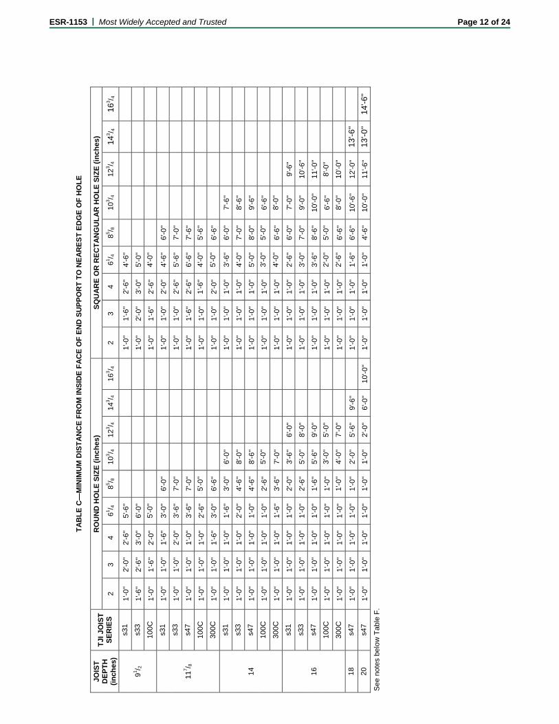
T
AB
LE
C—
MIN
IMU
M D
IST
AN
CE
FR
OM
INS
IDE
FA
CE
OF
EN
D S
UP
PO
RT
TO
NE
AR
ES
T E
DG
E O
F H
OL
E
JOIS
T
DE
PT
H
(in
ches
)
TJI
JO
IST
S
ER
IES
RO
UN
D H
OL
E S
IZE
(in
ch
es)
SQ
UA
RE
OR
RE
CT
AN
GU
LA
R H
OL
E S
IZE
(in
ch
es)
2 3
4 61 / 4
85 / 8
10
3 / 4
123 / 4
14
3 / 4
163 / 4
2
3 4
61 / 4
85 / 8
103 / 4
12
3 / 4
143 / 4
16
3 / 4
91 / 2
s31
1'-0
'' 2'
-0''
2'-6
'' 5'
-6''
1'
-0''
1'-6
'' 2'
-6''
4'-6
''
s33
1'-6
'' 2'
-6''
3'-0
'' 6'
-0''
1'
-0''
2'-0
'' 3'
-0''
5'-0
''
100C
1'
-0''
1'-6
'' 2'
-0''
5'-0
''
1'-0
'' 1'
-6''
2'-6
'' 4'
-0''
117 / 8
s31
1'-0
'' 1'
-0''
1'-6
'' 3'
-0''
6'-0
''
1'
-0''
1'-0
'' 2'
-0''
4'-6
'' 6'
-0''
s33
1'-0
'' 1'
-0''
2'-0
'' 3'
-6''
7'-0
''
1'
-0''
1'-0
'' 2'
-6''
5'-6
'' 7'
-0''
s47
1'-0
'' 1'
-0''
1'-0
'' 3'
-6''
7'-0
''
1'
-0''
1'-6
'' 2'
-6''
6'-6
'' 7'
-6''
100C
1'
-0''
1'-0
'' 1'
-0''
2'-6
'' 5'
-0''
1'-0
'' 1'
-0''
1'-6
'' 4'
-0''
5'-6
''
300C
1'
-0''
1'-0
'' 1'
-6''
3'-0
'' 6'
-6''
1'-0
'' 1'
-0''
2'-0
'' 5'
-0''
6'-6
''
14
s31
1'-0
'' 1'
-0''
1'-0
'' 1'
-6''
3'-0
'' 6'
-0''
1'
-0''
1'-0
'' 1'
-0''
3'-6
'' 6'
-0''
7'-6
''
s33
1'-0
'' 1'
-0''
1'-0
'' 2'
-0''
4'-6
'' 8'
-0''
1'
-0''
1'-0
'' 1'
-0''
4'-0
'' 7'
-0''
8'-6
''
s47
1'-0
'' 1'
-0''
1'-0
'' 1'
-0''
4'-6
'' 8'
-6''
1'
-0''
1'-0
'' 1'
-0''
5'-0
'' 8'
-0''
9'-6
''
100C
1'
-0''
1'-0
'' 1'
-0''
1'-0
'' 2'
-6''
5'-0
''
1'-0
'' 1'
-0''
1'-0
'' 3'
-0''
5'-0
'' 6'
-6''
300C
1'
-0''
1'-0
'' 1'
-0''
1'-6
'' 3'
-6''
7'-0
''
1'-0
'' 1'
-0''
1'-0
'' 4'
-0''
6'-6
'' 8'
-0''
16
s31
1'-0
'' 1'
-0''
1'-0
'' 1'
-0''
2'-0
'' 3'
-6''
6'-0
''
1'
-0''
1'-0
'' 1'
-0''
2'-6
'' 6'
-0''
7'-0
'' 9'
-6''
s33
1'-0
'' 1'
-0''
1'-0
'' 1'
-0''
2'-6
'' 5'
-0''
8'-0
''
1'
-0''
1'-0
'' 1'
-0''
3'-0
'' 7'
-0''
9'-0
'' 10
'-6''
s47
1'-0
'' 1'
-0''
1'-0
'' 1'
-0''
1'-6
'' 5'
-6''
9'-0
''
1'
-0''
1'-0
'' 1'
-0''
3'-6
'' 8'
-6''
10'-0
'' 11
'-0''
100C
1'
-0''
1'-0
'' 1'
-0''
1'-0
'' 1'
-0''
3'-0
'' 5'
-0''
1'-0
'' 1'
-0''
1'-0
'' 2'
-0''
5'-0
'' 6'
-6''
8'-0
''
300C
1'
-0''
1'-0
'' 1'
-0''
1'-0
'' 1'
-0''
4'-0
'' 7'
-0''
1'-0
'' 1'
-0''
1'-0
'' 2'
-6''
6'-6
'' 8'
-0''
10'-0
''
18
s47
1'-0
'' 1'
-0''
1'-0
'' 1'
-0''
1'-0
'' 2'
-0''
5'-6
'' 9'
-6''
1'
-0''
1'-0
'' 1'
-0''
1'-6
'' 6'
-6''
10'-6
'' 12
'-0''
13'-6
''
20
s47
1'-0
'' 1'
-0''
1'-0
'' 1'
-0''
1'-0
'' 1'
-0''
2'-0
'' 6'
-0''
10'-0
'' 1'
-0''
1'-0
'' 1'
-0''
1'-0
'' 4'
-6''
10'-0
'' 11
'-6''
13'-0
'' 14
'-6''
S
ee n
otes
bel
ow
Tab
le F
.
ESR-1153 | Most Widely Accepted and Trusted Page 12 of 24
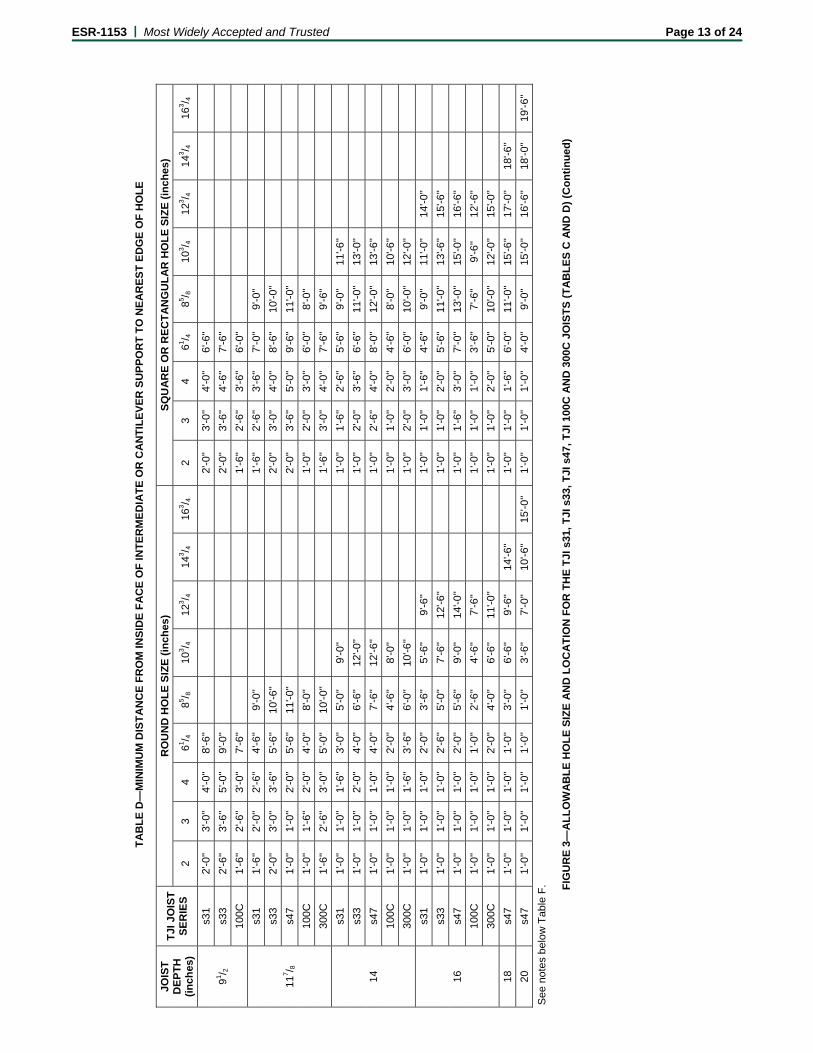
T
AB
LE
D—
MIN
IMU
M D
IST
AN
CE
FR
OM
INS
IDE
FA
CE
OF
IN
TE
RM
ED
IAT
E O
R C
AN
TIL
EV
ER
SU
PP
OR
T T
O N
EA
RE
ST
ED
GE
OF
HO
LE
JOIS
T
DE
PT
H
(in
ches
)
TJI
JO
IST
S
ER
IES
RO
UN
D H
OL
E S
IZE
(in
ch
es)
SQ
UA
RE
OR
RE
CT
AN
GU
LA
R H
OL
E S
IZE
(in
ch
es)
2 3
4 61 / 4
85 / 8
10
3 / 4
123 / 4
14
3 / 4
163 / 4
2
3 4
61 / 4
85 / 8
103 / 4
12
3 / 4
143 / 4
16
3 / 4
91 / 2
s31
2'-0
'' 3'
-0''
4'-0
'' 8'
-6''
2'
-0''
3'-0
'' 4'
-0''
6'-6
''
s33
2'-6
'' 3'
-6''
5'-0
'' 9'
-0''
2'
-0''
3'-6
'' 4'
-6''
7'-6
''
100C
1'
-6''
2'-6
'' 3'
-0''
7'-6
''
1'-6
'' 2'
-6''
3'-6
'' 6'
-0''
117 / 8
s31
1'-6
'' 2'
-0''
2'-6
'' 4'
-6''
9'-0
''
1'
-6''
2'-6
'' 3'
-6''
7'-0
'' 9'
-0''
s33
2'-0
'' 3'
-0''
3'-6
'' 5'
-6''
10'-6
''
2'
-0''
3'-0
'' 4'
-0''
8'-6
'' 10
'-0''
s47
1'-0
'' 1'
-0''
2'-0
'' 5'
-6''
11'-0
''
2'
-0''
3'-6
'' 5'
-0''
9'-6
'' 11
'-0''
100C
1'
-0''
1'-6
'' 2'
-0''
4'-0
'' 8'
-0''
1'-0
'' 2'
-0''
3'-0
'' 6'
-0''
8'-0
''
300C
1'
-6''
2'-6
'' 3'
-0''
5'-0
'' 10
'-0''
1'-6
'' 3'
-0''
4'-0
'' 7'
-6''
9'-6
''
14
s31
1'-0
'' 1'
-0''
1'-6
'' 3'
-0''
5'-0
'' 9'
-0''
1'
-0''
1'-6
'' 2'
-6''
5'-6
'' 9'
-0''
11'-6
''
s33
1'-0
'' 1'
-0''
2'-0
'' 4'
-0''
6'-6
'' 12
'-0''
1'
-0''
2'-0
'' 3'
-6''
6'-6
'' 11
'-0''
13'-0
''
s47
1'-0
'' 1'
-0''
1'-0
'' 4'
-0''
7'-6
'' 12
'-6''
1'
-0''
2'-6
'' 4'
-0''
8'-0
'' 12
'-0''
13'-6
''
100C
1'
-0''
1'-0
'' 1'
-0''
2'-0
'' 4'
-6''
8'-0
''
1'-0
'' 1'
-0''
2'-0
'' 4'
-6''
8'-0
'' 10
'-6''
300C
1'
-0''
1'-0
'' 1'
-6''
3’-6
'' 6'
-0''
10'-6
''
1'-0
'' 2'
-0''
3'-0
'' 6'
-0''
10'-0
'' 12
'-0''
16
s31
1'-0
'' 1'
-0''
1'-0
'' 2'
-0''
3'-6
'' 5'
-6''
9'-6
''
1'
-0''
1'-0
'' 1'
-6''
4'-6
'' 9'
-0''
11'-0
'' 14
'-0''
s33
1'-0
'' 1'
-0''
1'-0
'' 2'
-6''
5'-0
'' 7'
-6''
12'-6
''
1'
-0''
1'-0
'' 2'
-0''
5'-6
'' 11
'-0''
13'-6
'' 15
'-6''
s47
1'-0
'' 1'
-0''
1'-0
'' 2'
-0''
5'-6
'' 9'
-0''
14'-0
''
1'
-0''
1'-6
'' 3'
-0''
7'-0
'' 13
'-0''
15'-0
'' 16
'-6''
100C
1'
-0''
1'-0
'' 1'
-0''
1'-0
'' 2'
-6''
4'-6
'' 7'
-6''
1'-0
'' 1'
-0''
1'-0
'' 3’
-6''
7'-6
'' 9'
-6''
12'-6
''
300C
1'
-0''
1'-0
'' 1'
-0''
2'-0
'' 4'
-0''
6'-6
'' 11
'-0''
1'-0
'' 1'
-0''
2'-0
'' 5'
-0''
10'-0
'' 12
'-0''
15'-0
''
18
s47
1'-0
'' 1'
-0''
1'-0
'' 1'
-0''
3'-0
'' 6'
-6''
9'-6
'' 14
'-6''
1'
-0''
1'-0
'' 1'
-6''
6'-0
'' 11
'-0''
15'-6
'' 17
'-0''
18'-6
''
20
s47
1'-0
'' 1'
-0''
1'-0
'' 1'
-0''
1'-0
'' 3'
-6''
7'-0
'' 10
'-6''
15'-0
'' 1'
-0''
1'-0
'' 1'
-0''
4'-0
'' 9'
-0''
15'-0
'' 16
'-6''
18'-0
'' 19
'-6''
S
ee n
otes
bel
ow
Tab
le F
.
FIG
UR
E 3
—A
LL
OW
AB
LE
HO
LE
SIZ
E A
ND
LO
CA
TIO
N F
OR
TH
E T
JI s
31,
TJI
s33
, TJI
s4
7, T
JI 1
00C
AN
D 3
00C
JO
IST
S (
TA
BL
ES
C A
ND
D)
(Co
nti
nu
ed
)
ESR-1153 | Most Widely Accepted and Trusted Page 13 of 24
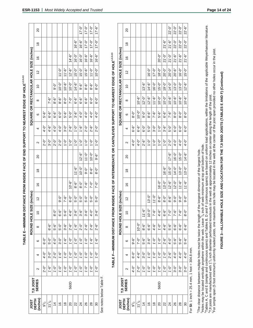
TA
BL
E E
—M
INIM
UM
DIS
TA
NC
E F
RO
M IN
SID
E F
AC
E O
F E
ND
SU
PP
OR
T T
O N
EA
RE
ST
ED
GE
OF
HO
LE
1,2
,3,4
,5
JOIS
T
DE
PT
H
(in
ches
)
TJI
JO
IST
S
ER
IES
RO
UN
D H
OL
E S
IZE
(in
ch
es)
SQ
UA
RE
OR
RE
CT
AN
GU
LA
R H
OL
E S
IZE
(in
ch
es)
2 4
6 8
10
12
16
18
20
2 4
6 8
10
12
16
18
20
91 / 2
560D
2'-0
'' 4'
-0''
6'-0
''
2'
-0''
4'-0
'' 5'
-6''
117 / 8
1'
-6''
3'-0
'' 5'
-0''
6'-6
''
3'-0
'' 4'
-6''
6'-6
'' 7'
-6''
14
1'-0
'' 2'
-0''
4'-0
'' 5'
-6''
8'-0
''
2'
-0''
4'-0
'' 6'
-6''
8'-6
'' 9'
-0''
16
1'-0
'' 1'
-6''
3'-0
'' 5'
-0''
6'-6
'' 9'
-0''
2'
-0''
4'-0
'' 6'
-0''
8'-6
'' 10
'-0''
11'-0
''
18
1'-0
'' 1'
-0''
1'-6
'' 3'
-6''
5'-6
'' 7'
-6''
1'
-0''
3'-0
'' 5'
-6''
8'-0
'' 10
'-6''
11'-6
''
20
1'-0
'' 1'
-0''
1'-0
'' 2'
-6''
4'-6
'' 6'
-0''
10'-6
''
1'
-0''
2'-6
'' 5'
-0''
7'-0
'' 10
'-0''
12'-6
'' 14
'-6''
22
1'-0
'' 1'
-0''
1'-0
'' 1'
-6''
3'-6
'' 5'
-0''
8'-6
'' 11
'-6''
1'
-0''
1'-0
'' 3'
-6''
6'-6
'' 14
'-6''
15'-0
'' 16
'-0''
16'-6
''
24
1'-0
'' 1'
-0''
1'-0
'' 2'
-0''
3'-6
'' 5'
-0''
8'-0
'' 10
'-0''
12'-6
'' 1'
-0''
1'-6
'' 4'
-0''
6'-6
'' 9'
-6''
15'-0
'' 16
'-0''
16'-6
'' 17
'-0''
26
1'-0
'' 1'
-0''
1'-0
'' 2'
-6''
3'-6
'' 5'
-0''
7'-6
'' 9'
-0''
11'-0
'' 1'
-0''
2'-0
'' 4'
-0''
6'-6
'' 8'
-6''
15'-6
'' 16
'-6''
17'-0
'' 1
7'-0
''
28
1'-0
'' 1'
-0''
1'-6
'' 2'
-6''
4'-0
'' 5'
-0''
7'-0
'' 8'
-6''
10'-0
'' 1'
-0''
2'-6
'' 4'
-0''
6'-0
'' 8'
-6''
11'-0
'' 16
'-6''
17'-0
'' 1
7'-0
''
30
1'-0
'' 1'
-0''
1'-6
'' 2'
-6''
3'-6
'' 5'
-0''
7'-0
'' 8'
-0''
9'-6
'' 1'
-0''
2'-0
'' 4'
-0''
6'-0
'' 8'
-0''
10'-0
'' 16
'-6''
17'-0
'' 17
'-6''
See
not
es b
elo
w T
able
F.
T
AB
LE
F—
MIN
IMU
M D
IST
AN
CE
FR
OM
INS
IDE
FA
CE
OF
IN
TE
RM
ED
IAT
E O
R C
AN
TIL
EV
ER
SU
PP
OR
T T
O N
EA
RE
ST
ED
GE
OF
HO
LE
1,2,
3,4,
5
JOIS
T
DE
PT
H
(in
ches
)
TJI
JO
IST
S
ER
IES
RO
UN
D H
OL
E S
IZE
(in
ch
es)
SQ
UA
RE
OR
RE
CT
AN
GU
LA
R H
OL
E S
IZE
(in
ch
es)
2 4
6 8
10
12
16
18
20
2 4
6 8
10
12
16
18
20
91 / 2
560D
4'-0
'' 6'
-0''
9'-6
''
4'
-0''
6'-6
'' 8'
-0''
117 / 8
2'
-0''
4'-6
'' 7'
-0''
10'-0
''
4'-0
'' 6'
-6''
10'-0
'' 10
'-6''
14
1'-0
'' 3'
-0''
5'-6
'' 8'
-6''
11'-6
''
2'
-6''
6'-0
'' 9'
-0''
12'-0
'' 13
'-6''
16
1'-0
'' 1'
-0''
3'-6
'' 6'
-6''
10'-0
'' 13
'-0''
1'
-0''
5'-0
'' 8'
-6''
12'-6
'' 14
'-6''
16'-0
''
18
1'-0
'' 1'
-0''
1'-0
'' 4'
-6''
7'-6
'' 11
'-0''
1'
-0''
3'-0
'' 7'
-6''
11'-6
'' 16
'-0''
17'-0
''
20
1'-0
'' 1'
-0''
1'-0
'' 1'
-0''
4'-6
'' 8'
-6''
16'-0
''
1'
-0''
1'-0
'' 5'
-6''
10'-0
'' 15
'-0''
18'-0
'' 20
'-0''
22
1'-0
'' 1'
-0''
2'-6
'' 4'
-6''
6'-6
'' 8'
-0''
13'-0
'' 16
'-6''
1'
-0''
3'-6
'' 6'
-6''
10'-0
'' 19
'-0''
20'-0
'' 21
'-0''
21'-6
''
24
1'-0
'' 2'
-6''
4'-0
'' 5'
-6''
7'-0
'' 8'
-6''
12'-6
'' 15
'-0''
17'-6
'' 2'
-0''
5'-0
'' 7'
-6''
10'-6
'' 14
'-0''
20'-0
'' 21
'-0''
21'-6
'' 22
'-0''
26
3'-0
'' 4'
-0''
5'-6
'' 6'
-6''
7'-6
'' 9'
-0''
12'-0
'' 14
'-0''
16'-0
'' 4'
-0''
6'-0
'' 8'
-0''
10'-6
'' 13
'-0''
20'-6
'' 21
'-6''
22'-0
'' 22
'-0''
28
3'-0
'' 4'
-0''
5'-6
'' 6'
-6''
7'-6
'' 9'
-0''
11'-6
'' 13
'-0''
15'-0
'' 4'
-0''
6'-0
'' 8'
-0''
10'-6
'' 13
'-0''
16'-0
'' 21
'-6''
22'-0
'' 22
'-0''
30
3'-0
'' 4'
-0''
5'-6
'' 6'
-6''
8'-0
'' 9'
-0''
11'-6
'' 13
'-0''
14'-6
'' 4'
-0''
6'-0
'' 8'
-0''
10'-6
'' 12
'-6''
15'-0
'' 21
'-6''
22'-0
'' 22
'-6''
For
SI:
1 in
ch =
25.
4 m
m, 1
foot
= 3
04.8
mm
.
1 The
cle
ar d
ista
nce
bet
wee
n m
ultip
le h
oles
mus
t be
twic
e th
e le
ngth
of t
he lo
nges
t dim
ensi
on o
f the
larg
est h
ole.
2 H
oles
ma
y be
loca
ted
vert
ical
ly a
nyw
here
with
in t
he w
eb. L
eave
1 / 8 in
ch o
f w
eb m
inim
um a
t top
and
bot
tom
of h
ole.
3 T
able
s A
, C a
nd E
(si
mpl
e an
d co
ntin
uous
spa
ns)
and
Tab
les
B, D
and
F (
cont
inu
ous
spa
ns)
are
base
d on
uni
form
load
app
licat
ions
, with
in th
e lim
itatio
ns o
f the
app
licab
le W
eye
rhae
use
r lit
erat
ure.
4 T
JI jo
ists
are
man
ufac
ture
d w
ith 1
1 / 2 in
ch d
iam
ete
r pe
rfo
rate
d kn
ocko
uts
in th
e w
eb
at a
ppro
xim
atel
y 12
inch
es o
n ce
nter
alo
ng th
e le
ngt
h of
the
jois
t. 5 F
or s
impl
e sp
an (
5 fo
ot m
inim
um)
unifo
rmly
load
ed
jois
ts, o
ne m
axim
um s
ize
hole
ma
y be
loca
ted
in th
e w
eb a
t the
cen
ter
of th
e jo
ist s
pan
prov
ided
no
othe
r ho
les
occu
r in
the
jois
t.
F
IGU
RE
3—
AL
LO
WA
BL
E H
OL
E S
IZE
AN
D L
OC
AT
ION
FO
R T
HE
TJI
560
D J
OIS
TS
(T
AB
LE
S E
AN
D F
) (C
on
tin
ued
)
ESR-1153 | Most Widely Accepted and Trusted Page 14 of 24
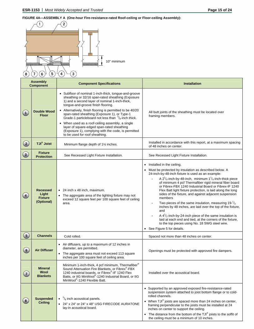
ESR-1153 | Most Widely Accepted and Trusted Page 15 of 24
FIGURE 4A—ASSEMBLY A (One-hour Fire-resistance-rated Roof-ceiling or Floor-ceiling Assembly):
Assembly
Component Component Specifications Installation
Double Wood Floor
• Subfloor of nominal 1-inch-thick, tongue-and-groove sheathing or 32/16 span-rated sheathing (Exposure 1) and a second layer of nominal 1-inch-thick, tongue-and-groove finish flooring.
• Alternatively, finish flooring is permitted to be 40/20 span-rated sheathing (Exposure 1), or Type-1 Grade-1 particleboard not less than 5/8-inch thick.
• When used as a roof-ceiling assembly, a single layer of square-edged span-rated sheathing (Exposure 1), complying with the code, is permitted to be used for roof sheathing.
All butt joints of the sheathing must be located over framing members.
TJI® Joist Minimum flange depth of 1½ inches. Installed in accordance with this report, at a maximum spacing of 48 inches on center.
Fixture Protection See Recessed Light Fixture Installation. See Recessed Light Fixture Installation.
Recessed
Light Fixture
(Optional)
• 24 inch x 48 inch, maximum.
• The aggregate area of the lighting fixture may not exceed 12 square feet per 100 square feet of ceiling area.
• Installed in the ceiling.
• Must be protected by insulation as described below. A 24-inch-by-48-inch fixture is used as an example:
- A 21/4-inch-by-48-inch, minimum 11/4-inch-thick piece of minimum 4 pcf Thermafiber rigid mineral fiber board or Fibrex-FBX 1240 Industrial Board or Fibrex-IF 1240 Flex Batt light fixture protection, is laid along the long sides of the fixture, and against adjacent suspension members
- Two pieces of the same insulation, measuring 19-1/2 inches by 48 inches, are laid over the top of the fixture, and
- A 41/2-inch-by-24-inch piece of the same insulation is laid at each end and tied, at the corners of the fixture, to the top pieces using No. 18 SWG steel wire.
• See Figure 5 for details.
Channels Cold rolled. Spaced not more than 48 inches on center.
Air Diffuser
• Air diffusers, up to a maximum of 12 inches in diameter, are permitted.
• The aggregate area must not exceed 113 square inches per 100 square feet of ceiling area.
Openings must be protected with approved fire dampers.
Mineral Wool
Blankets
Minimum 1-inch-thick, 4 pcf minimum, Thermafiber® Sound Attenuation Fire Blankets, or Fibrex®-FBX 1240 industrial boards, or Fibrex®-IF 1240 Flex Batts, or IIG MinWool®-1240 Industrial Board, or IIG MinWool®-1240 Flexible Batt.
Installed over the acoustical board.
Suspended
Ceiling
• 5/8 inch acoustical panels.
• 24” x 24” or 24” x 48” USG FIRECODE AURATONE lay-in acoustical board.
• Supported by an approved exposed fire-resistance-rated suspension system attached to joist bottom flange or to cold-rolled channels.
• When TJI® joists are spaced more than 24 inches on center, framing perpendicular to the joists must be installed at 24 inches on center to support the ceiling.
• The distance from the bottom of the TJI® joists to the soffit of the ceiling must be a minimum of 10 inches.
10” minimum
7
1
2
3
4
5
6
8
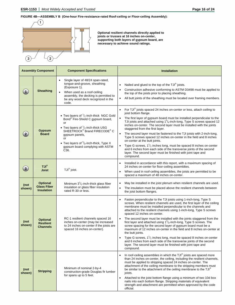
ESR-1153 | Most Widely Accepted and Trusted Page 16 of 24 FIGURE 4B—ASSEMBLY B (One-hour Fire-resistance-rated Roof-ceiling or Floor-ceiling Assembly):
Assembly Component Component Specifications Installation
Sheathing
• Single layer of 48/24 span-rated, tongue-and-groove, sheathing (Exposure 1).
• When used as a roof-ceiling assembly, the decking is permitted to be any wood deck recognized in the code.
• Nailed and glued to the top of the TJI® joists.
• Construction adhesive conforming to ASTM D3498 must be applied to the top of the joists prior to placing sheathing.
• All butt joints of the sheathing must be located over framing members.
Gypsum Board
• Two layers of 1/2-inch-thick NGC Gold Bond® Fire-Shield C gypsum board, or
• Two layers of 1/2-inch-thick USG SHEETROCK® Brand FIRECODE® C gypsum panels, or
• Two layers of 5/8-inch-thick, Type X gypsum board complying with ASTM C36.
• For TJI® joists spaced 24 inches on-center or less, attach ceiling to joist bottom flange.
• The first layer of gypsum board must be installed perpendicular to the TJI joists and attached using 15/8-inch-long, Type S screws spaced 12 inches on-center. The second layer must be installed with the joints staggered from the first layer.
• The second layer must be fastened to the TJI joists with 2-inch-long, Type S screws spaced 12 inches on-center in the field and 8 inches on-center at the butt joints.
• Type G screws, 11/2 inches long, must be spaced 8 inches on-center and 6 inches from each side of the transverse joints of the second layer. The second layer must be finished with joint tape and compound.
TJI® Joist TJI® joist.
• Installed in accordance with this report, with a maximum spacing of 24 inches on-center for floor-ceiling assemblies.
• When used in roof-ceiling assemblies, the joists are permitted to be spaced a maximum of 48 inches on-center.
(not shown)
Optional Glass Fiber Insulation
Minimum 31/2-inch-thick glass fiber insulation or glass fiber insulation rated R-30 or less.
• May be installed in the joist plenum when resilient channels are used.
• The insulation must be placed above the resilient channels between the joist bottom flanges.
(not shown)
Optional Resilient Channels
RC-1 resilient channels spaced 16 inches on-center (may be increased to 24 inches on-center if the joists are spaced 16 inches on-center).
• Fasten perpendicular to the TJI joists using 1-inch-long, Type S screws. When resilient channels are used, the first layer of the ceiling membrane must be installed perpendicular to the channels and attached to the resilient channels using 1-inch-long, Type S screws spaced 12 inches on-center.
• The second layer must be installed with the joints staggered from the first layer and attached using 15/8-inch-long, Type S screws. The screw spacing for the second layer of gypsum board must be a maximum of 12 inches on-center in the field and 8 inches on-center at the butt joints.
• Type G screws, 11/2 inches long, must be spaced 8 inches on-center and 6 inches from each side of the transverse joints of the second layer. The second layer must be finished with joint tape and compound.
(not shown)
Stripping Minimum of nominal 2-by-4 construction-grade Douglas fir lumber for spans up to 5 feet.
• In roof-ceiling assemblies in which the TJI® joists are spaced more than 24 inches on-center, the ceiling, including the resilient channels, must be applied to stripping spaced 24 inches on-center. The attachment of the ceiling membrane to the stripping members must be similar to the attachment of the ceiling membrane to the TJI® joists.
• Attached to the joist bottom flange using a minimum of two 10d box nails into each bottom flange. Stripping materials of equivalent strength and attachment are permitted when approved by the code official.
Optional resilient channels directly applied to joists or trusses at 16 inches on-center, supporting both layers of gypsum board, are necessary to achieve sound ratings.
1
3
2
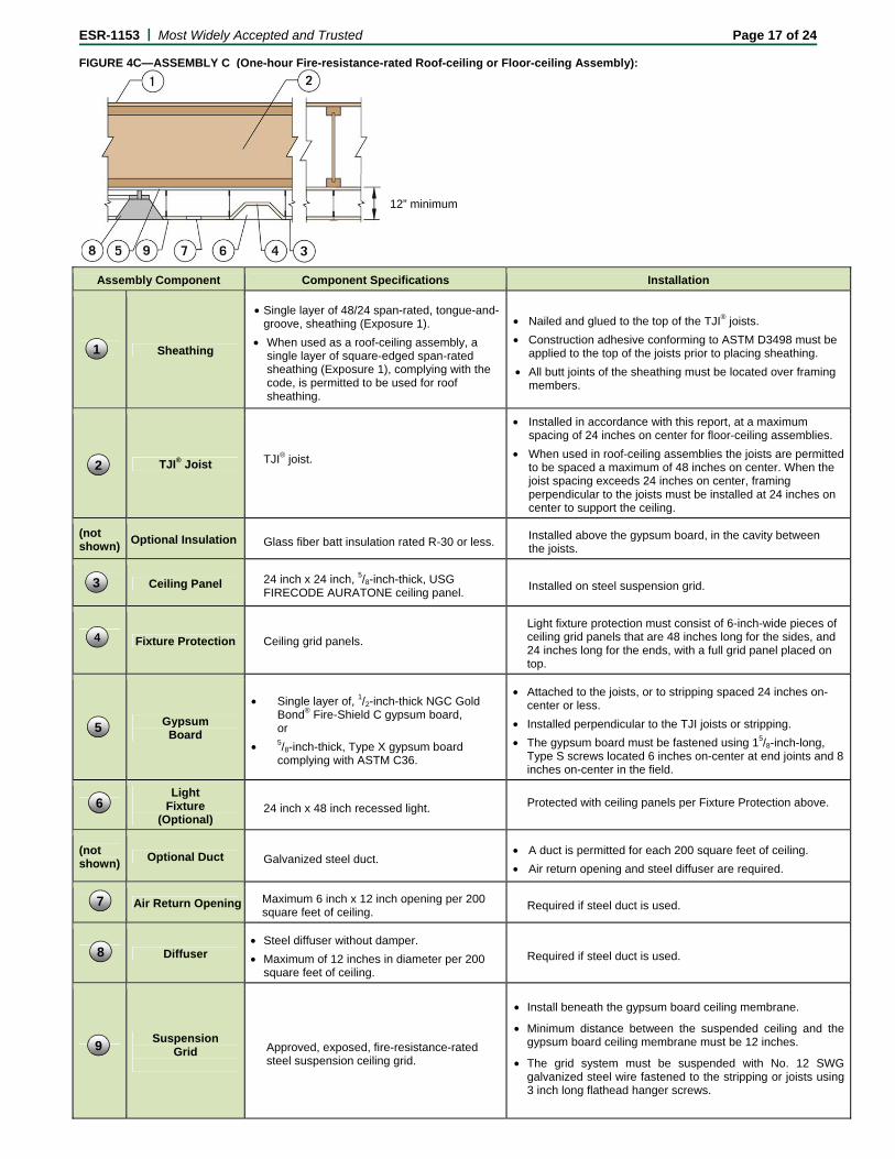
ESR-1153 | Most Widely Accepted and Trusted Page 17 of 24 FIGURE 4C—ASSEMBLY C (One-hour Fire-resistance-rated Roof-ceiling or Floor-ceiling Assembly):
Assembly Component Component Specifications Installation
Sheathing
• Single layer of 48/24 span-rated, tongue-and-groove, sheathing (Exposure 1).
• When used as a roof-ceiling assembly, a single layer of square-edged span-rated sheathing (Exposure 1), complying with the code, is permitted to be used for roof sheathing.
• Nailed and glued to the top of the TJI® joists.
• Construction adhesive conforming to ASTM D3498 must be applied to the top of the joists prior to placing sheathing.
• All butt joints of the sheathing must be located over framing members.
TJI® Joist TJI® joist.
• Installed in accordance with this report, at a maximum spacing of 24 inches on center for floor-ceiling assemblies.
• When used in roof-ceiling assemblies the joists are permitted to be spaced a maximum of 48 inches on center. When the joist spacing exceeds 24 inches on center, framing perpendicular to the joists must be installed at 24 inches on center to support the ceiling.
(not shown)
Optional Insulation Glass fiber batt insulation rated R-30 or less. Installed above the gypsum board, in the cavity between the joists.
Ceiling Panel 24 inch x 24 inch, 5/8-inch-thick, USG FIRECODE AURATONE ceiling panel.
Installed on steel suspension grid.
Fixture Protection Ceiling grid panels.
Light fixture protection must consist of 6-inch-wide pieces of ceiling grid panels that are 48 inches long for the sides, and 24 inches long for the ends, with a full grid panel placed on top.
Gypsum Board
• Single layer of, 1/2-inch-thick NGC Gold Bond® Fire-Shield C gypsum board, or
• 5/8-inch-thick, Type X gypsum board complying with ASTM C36.
• Attached to the joists, or to stripping spaced 24 inches on-center or less.
• Installed perpendicular to the TJI joists or stripping.
• The gypsum board must be fastened using 15/8-inch-long, Type S screws located 6 inches on-center at end joints and 8 inches on-center in the field.
Light
Fixture (Optional)
24 inch x 48 inch recessed light. Protected with ceiling panels per Fixture Protection above.
(not shown)
Optional Duct Galvanized steel duct. • A duct is permitted for each 200 square feet of ceiling.
• Air return opening and steel diffuser are required.
Air Return Opening Maximum 6 inch x 12 inch opening per 200 square feet of ceiling.
Required if steel duct is used.
Diffuser • Steel diffuser without damper.
• Maximum of 12 inches in diameter per 200 square feet of ceiling.
Required if steel duct is used.
Suspension
Grid
Approved, exposed, fire-resistance-rated steel suspension ceiling grid.
• Install beneath the gypsum board ceiling membrane.
• Minimum distance between the suspended ceiling and the gypsum board ceiling membrane must be 12 inches.
• The grid system must be suspended with No. 12 SWG galvanized steel wire fastened to the stripping or joists using 3 inch long flathead hanger screws.
12” minimum
7
2
3
4
6
8
1
5
9
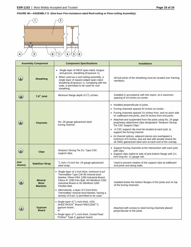
ESR-1153 | Most Widely Accepted and Trusted Page 18 of 24 FIGURE 4D—ASSEMBLY D (One-hour Fire-resistance-rated Roof-ceiling or Floor-ceiling Assembly):
Assembly Component Component Specifications Installation
Sheathing
• Single layer of 48/24 span-rated, tongue-and-groove, sheathing (Exposure 1).
• When used as a roof-ceiling assembly, a single layer of square-edged span-rated sheathing (Exposure 1), complying with the code, is permitted to be used for roof sheathing.
All butt joints of the sheathing must be located over framing members.
TJI® Joist Minimum flange depth of 13/8 inches. Installed in accordance with this report, at a maximum spacing of 24 inches on-center.
Channels No. 26 gauge galvanized steel furring channel.
• Installed perpendicular to joists.
• Furring channels spaced 24 inches on-center.
• Furring channels spaced 1½ inches from, and on each side of, wallboard end joints, and 24 inches from end joints.
• Attached and suspended from the joists using No. 24 gage proprietary attachment clips designated “Simpson Strong-Tie CSC Support Clips.”
• A CSC support clip must be located at each joist, to support the furring channel.
• At channel splices, adjacent pieces are overlapped a minimum of 6 inches, and are tied with double-strand No. 18 SWG galvanized steel wire at each end of the overlap.
Clips Simpson Strong-Tie Co. Type CSC support clips.
• Support furring channels at the intersection with each joist with clips.
• Support clips nailed to side of joist bottom flange with 1½ inch long No. 11 gauge nail.
(not shown)
Stabilizer Strap 3/4 inch x 6 inch No. 24 gauge galvanized steel strap.
Used to prevent rotation of the support clips at wallboard end joints and along walls.
Mineral Wool
Blankets
• Single layer of 1-inch-thick, minimum 6 pcf Thermafiber Type CW 90 mineral-wool blanket, Fibrex-FBX 1280 Industrial Board, Fibrex-IF 1280 Flex Batt, IIG MinWool 1260 Industrial Board or IIG MinWool 1260 Flexible Batt.
• Alternatively, a layer of 2-inch-thick, Thermafiber mineral-wool blanket, having a density of 8 pcf, is permitted to be used.
Installed below the bottom flanges of the joists and on top of the furring channels.
Gypsum Board
• Single layer of 1/2-inch-thick, USG SHEETROCK® Brand FIRECODE® C gypsum board , or
• Single layer of 1/2-inch-thick, CertainTeed ProRoc® Type C gypsum board.
Attached with screws to steel furring channels placed perpendicular to the joists.
2
3
4
1
6
7
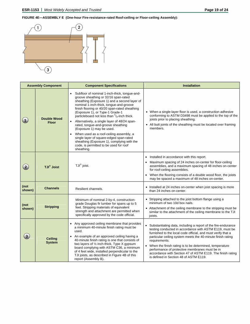
ESR-1153 | Most Widely Accepted and Trusted Page 19 of 24 FIGURE 4E—ASSEMBLY E (One-hour Fire-resistance-rated Roof-ceiling or Floor-ceiling Assembly):
Assembly Component Component Specifications Installation
Double Wood Floor
• Subfloor of nominal 1-inch-thick, tongue-and-groove sheathing or 32/16 span-rated sheathing (Exposure 1) and a second layer of nominal 1-inch-thick, tongue-and-groove finish flooring or 40/20 span-rated sheathing (Exposure 1), or Type-1 Grade-1 particleboard not less than 5/8-inch thick.
• Alternatively, a single layer of 48/24 span-rated, tongue-and-groove sheathing (Exposure 1) may be used.
• When used as a roof-ceiling assembly, a single layer of square-edged span-rated sheathing (Exposure 1), complying with the code, is permitted to be used for roof sheathing.
• When a single-layer floor is used, a construction adhesive conforming to ASTM D3498 must be applied to the top of the joists prior to placing sheathing.
• All butt joints of the sheathing must be located over framing members.
TJI® Joist TJI® joist.
• Installed in accordance with this report.
• Maximum spacing of 24 inches on-center for floor-ceiling assemblies, and a maximum spacing of 48 inches on-center for roof-ceiling assemblies.
• When the flooring consists of a double wood floor, the joists may be spaced a maximum of 48 inches on-center.
(not shown)
Channels Resilient channels. • Installed at 24 inches on-center when joist spacing is more than 24 inches on-center.
(not shown)
Stripping
Minimum of nominal 2-by-4, construction-grade Douglas fir lumber for spans up to 5 feet. Stripping materials of equivalent strength and attachment are permitted when specifically approved by the code official.
• Stripping attached to the joist bottom flange using a minimum of two 10d box nails.
• Attachment of the ceiling membrane to the stripping must be similar to the attachment of the ceiling membrane to the TJI joists.
Ceiling System
• Any approved ceiling membrane that provides a minimum 40-minute finish rating must be used.
• An example of an approved ceiling having a 40-minute finish rating is one that consists of two layers of ½ inch-thick, Type X gypsum board complying with ASTM C36, a minimum of 4 feet wide, installed perpendicular to the TJI joists, as described in Figure 4B of this report (Assembly B).
• Substantiating data, including a report of the fire-endurance testing conducted in accordance with ASTM E119, must be furnished to the local code official, and must verify that a particular ceiling system meets the 40-minute finish rating requirements.
• When the finish rating is to be determined, temperature performance of protective membranes must be in accordance with Section 47 of ASTM E119. The finish rating is defined in Section 48 of ASTM E119.
1
2
3
ESR-1153 | Most Widely Accepted and Trusted Page 20 of 24 FIGURE 4F—ASSEMBLY F (One-hour Fire-resistance-rated Roof-ceiling or Floor-ceiling Assembly):
Assembly Component Component Specifications Installation
Sheathing
• Single layer of 48/24 span-rated, tongue-and-groove, sheathing (Exposure 1).
• When used as a roof-ceiling assembly, a single layer of square-edged span-rated sheathing (Exposure 1), complying with the code, is permitted to be used for roof sheathing.
• Attached to the TJI® joist top flange with construction adhesive that meets ASTM D3498, and nailed using 8d common nails spaced a maximum of 6 inches on-center along the boundary and edges, and 12 inches on-center in the field.
• All butt joints of the sheathing must be located over framing members.
Gypsum Board
• Single layer of 5/8-inch-thick, USG SHEETROCK® Brand FIRECODE® C gypsum board, or
• Single layer of 5/8-inch-thick, CertainTeed ProRoc® Type C gypsum board.
Fastened to the resilient channels with 1-inch-long, Type S screws spaced 12 inches on-center in the field and 8 inches on-center at the butt joints.
TJI® Joist Nominal 2 x 4 or larger flanges.
• Installed in accordance with this report.
• When used in a floor-ceiling assembly, joist spacing must not exceed 24 inches on-center.
• When used in a roof-ceiling assembly, joist spacing is permitted to exceed 24 inches on-center.
Channels RC-1 resilient channels.
• Installed perpendicular to joists.
• Spaced at 16 inches on-center.
• Attached to the joists with 15/8-inch-long, Type S screws at each joist.
• Two channels must be provided at each gypsum-board butt joint, and extend to the next joist beyond the longitudinal joints.
(not shown)
Stripping
Minimum of nominal 2-by-4, construction-grade Douglas fir lumber for spans up to 5 feet. Stripping materials of equivalent strength and attachment are permitted when specifically approved by the code official.
• In roof-ceiling assemblies in which TJI® joists are spaced more than 24 inches on-center, the ceiling, including the resilient channels, must be attached to stripping spaced 24 inches on-center. The attachment of the ceiling membrane to the stripping members is similar to the attachment of the ceiling membrane to the joists.
• Stripping must be attached to the bottom flanges of the joists using a minimum of two 10d box nails.
Mineral Wool
Blankets
Single layer of 1½-inch-thick, minimum 2½ pcf, Thermafiber Sound Attenuation Fire Blankets, Fibrex-SAFB (Sound Attenuation Fire Batts), or IIG MinWool 1200 Sound Attenuation Fire Batts.
• Installed between the bottom flanges of the joists and on top of the resilient channels.
• Friction-fitted into place and supported by the resilient channels.
1
2
3
4
5
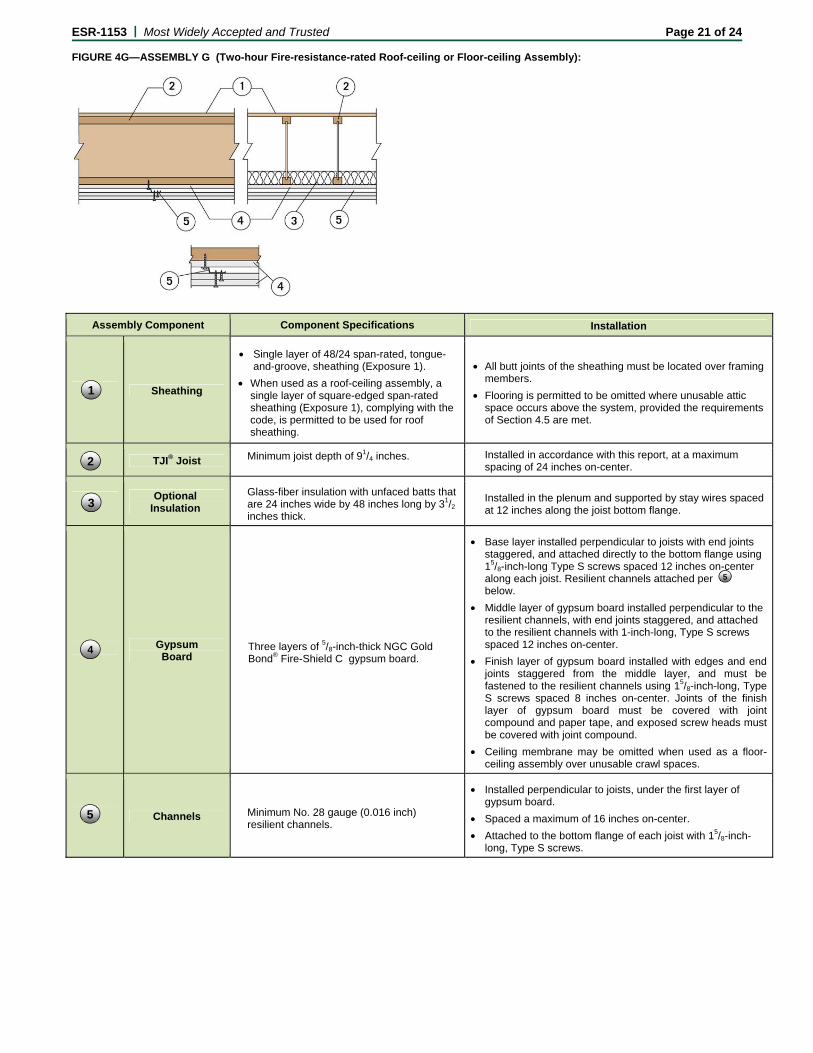
ESR-1153 | Most Widely Accepted and Trusted Page 21 of 24 FIGURE 4G—ASSEMBLY G (Two-hour Fire-resistance-rated Roof-ceiling or Floor-ceiling Assembly):
Assembly Component Component Specifications Installation
Sheathing
• Single layer of 48/24 span-rated, tongue-and-groove, sheathing (Exposure 1).
• When used as a roof-ceiling assembly, a single layer of square-edged span-rated sheathing (Exposure 1), complying with the code, is permitted to be used for roof sheathing.
• All butt joints of the sheathing must be located over framing members.
• Flooring is permitted to be omitted where unusable attic space occurs above the system, provided the requirements of Section 4.5 are met.
TJI® Joist Minimum joist depth of 91/4 inches. Installed in accordance with this report, at a maximum spacing of 24 inches on-center.
Optional Insulation
Glass-fiber insulation with unfaced batts that are 24 inches wide by 48 inches long by 31/2 inches thick.
Installed in the plenum and supported by stay wires spaced at 12 inches along the joist bottom flange.
Gypsum Board
Three layers of 5/8-inch-thick NGC Gold Bond® Fire-Shield C gypsum board.
• Base layer installed perpendicular to joists with end joints staggered, and attached directly to the bottom flange using 15/8-inch-long Type S screws spaced 12 inches on-center along each joist. Resilient channels attached per below.
• Middle layer of gypsum board installed perpendicular to the resilient channels, with end joints staggered, and attached to the resilient channels with 1-inch-long, Type S screws spaced 12 inches on-center.
• Finish layer of gypsum board installed with edges and end joints staggered from the middle layer, and must be fastened to the resilient channels using 15/8-inch-long, Type S screws spaced 8 inches on-center. Joints of the finish layer of gypsum board must be covered with joint compound and paper tape, and exposed screw heads must be covered with joint compound.
• Ceiling membrane may be omitted when used as a floor-ceiling assembly over unusable crawl spaces.
Channels Minimum No. 28 gauge (0.016 inch) resilient channels.
• Installed perpendicular to joists, under the first layer of gypsum board.
• Spaced a maximum of 16 inches on-center.
• Attached to the bottom flange of each joist with 15/8-inch-long, Type S screws.
2
4
1
3
5
5
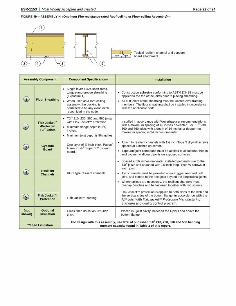
ESR-1153 | Most Widely Accepted and Trusted Page 22 of 24 FIGURE 4H—ASSEMBLY H (One-hour Fire-resistance-rated Roof-ceiling or Floor-ceiling Assembly)**:
Assembly Component Component Specifications Installation
Floor Sheathing
• Single layer 48/24 span-rated, tongue-and-groove sheathing (Exposure 1).
• When used as a roof-ceiling assembly, the decking is permitted to be any wood deck recognized in the code.
• Construction adhesive conforming to ASTM D3498 must be applied to the top of the joists prior to placing sheathing.
• All butt joints of the sheathing must be located over framing members. The floor sheathing shall be installed in accordance with the applicable code.
Flak JacketTM
-Protected TJI® Joists
• TJI® 210, 230, 360 and 560 joists with Flak Jacket™ protection.
• Minimum flange depth is 13/8 inches.
• Minimum joist depth is 9½ inches.
Installed in accordance with Weyerhaeuser recommendations, with a maximum spacing of 16 inches on-center. For TJI® 230, 360 and 560 joists with a depth of 14 inches or deeper the maximum spacing is 24 inches on-center.
Gypsum Board
One layer of ⅝-inch-thick, Pabco® Flame Curb® Super “C” gypsum board.
• Attach to resilient channels with 1⅛ inch Type S drywall screws spaced at 6 inches on center.
• Tape and joint compound must be applied to all fastener heads and gypsum wallboard joints on exposed surfaces.
Resilient Channels RC‐1 type resilient channels.
• Spaced at 16 inches on-center, installed perpendicular to the TJI® joists and attached with 1⅝ inch-long, Type W screws at each joist.
• Two channels must be provided at each gypsum-board butt joint, and extend to the next joist beyond the longitudinal joints.
• Where splices are necessary, the resilient channels must overlap 6-inches and be fastened together with two screws.
Flak Jacket™ Protection Flak Jacket™ coating.
Flak Jacket™ protection is applied to both sides of the web and the vertical sides of the bottom flange, in accordance with the TJI® Joist With Flak Jacket™ Protection Manufacturing Standard and quality control program.
(not shown)
Optional Insulation
Glass fiber insulation, 3½ inch thick.
Placed in I-joist cavity, between the I-joists and above the bottom flange.
**Load Limitation
For design with this assembly, use 90% of published TJI® 210, 230, 360 and 560 bending moment capacity found in Table 3 of this report.
Typical resilient channel and gypsum board attachment
2
1
3
4
5
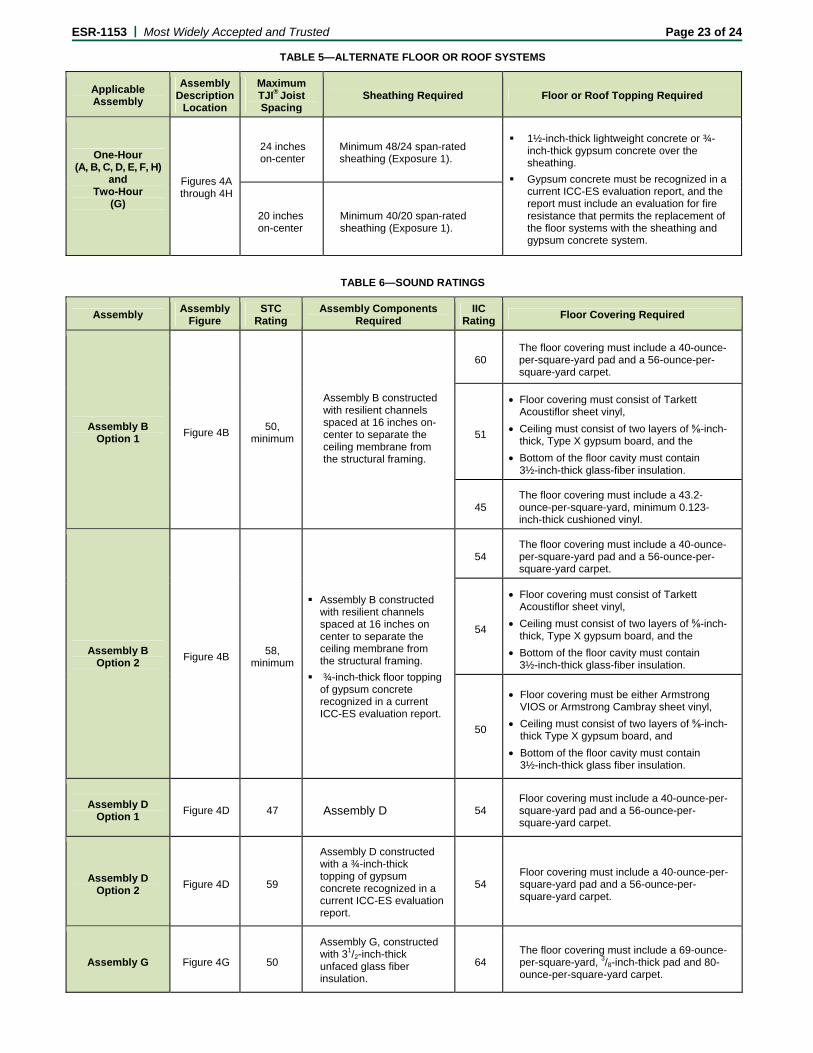
ESR-1153 | Most Widely Accepted and Trusted Page 23 of 24
TABLE 5—ALTERNATE FLOOR OR ROOF SYSTEMS
Applicable Assembly
Assembly Description
Location
Maximum TJI® Joist Spacing
Sheathing Required Floor or Roof Topping Required
One-Hour (A, B, C, D, E, F, H)
and Two-Hour
(G)
Figures 4A through 4H
24 inches on-center
Minimum 48/24 span-rated sheathing (Exposure 1).
1½-inch-thick lightweight concrete or ¾-inch-thick gypsum concrete over the sheathing.
Gypsum concrete must be recognized in a current ICC-ES evaluation report, and the report must include an evaluation for fire resistance that permits the replacement of the floor systems with the sheathing and gypsum concrete system.
20 inches on-center
Minimum 40/20 span-rated sheathing (Exposure 1).
TABLE 6—SOUND RATINGS
Assembly Assembly
Figure STC
Rating Assembly Components
Required IIC
Rating Floor Covering Required
Assembly B Option 1
Figure 4B 50,
minimum
Assembly B constructed with resilient channels spaced at 16 inches on-center to separate the ceiling membrane from the structural framing.
60 The floor covering must include a 40-ounce-per-square-yard pad and a 56-ounce-per-square-yard carpet.
51
• Floor covering must consist of Tarkett Acoustiflor sheet vinyl,
• Ceiling must consist of two layers of ⅝-inch-thick, Type X gypsum board, and the
• Bottom of the floor cavity must contain 3½-inch-thick glass-fiber insulation.
45 The floor covering must include a 43.2-ounce-per-square-yard, minimum 0.123-inch-thick cushioned vinyl.
Assembly B Option 2
Figure 4B 58,
minimum
Assembly B constructed with resilient channels spaced at 16 inches on center to separate the ceiling membrane from the structural framing.
¾-inch-thick floor topping of gypsum concrete recognized in a current ICC-ES evaluation report.
54 The floor covering must include a 40-ounce-per-square-yard pad and a 56-ounce-per-square-yard carpet.
54
• Floor covering must consist of Tarkett Acoustiflor sheet vinyl,
• Ceiling must consist of two layers of ⅝-inch-thick, Type X gypsum board, and the
• Bottom of the floor cavity must contain 3½-inch-thick glass-fiber insulation.
50
• Floor covering must be either Armstrong VIOS or Armstrong Cambray sheet vinyl,
• Ceiling must consist of two layers of ⅝-inch-thick Type X gypsum board, and
• Bottom of the floor cavity must contain 3½-inch-thick glass fiber insulation.
Assembly D Option 1
Figure 4D 47 Assembly D 54 Floor covering must include a 40-ounce-per-square-yard pad and a 56-ounce-per-square-yard carpet.
Assembly D Option 2
Figure 4D 59
Assembly D constructed with a ¾-inch-thick topping of gypsum concrete recognized in a current ICC-ES evaluation report.
54 Floor covering must include a 40-ounce-per-square-yard pad and a 56-ounce-per-square-yard carpet.
Assembly G Figure 4G 50
Assembly G, constructed with 31/2-inch-thick unfaced glass fiber insulation.
64 The floor covering must include a 69-ounce-per-square-yard, 3/8-inch-thick pad and 80-ounce-per-square-yard carpet.
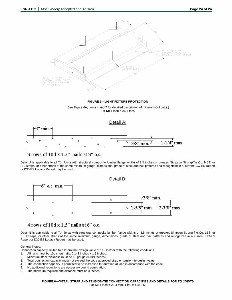
ESR-1153 | Most Widely Accepted and Trusted Page 24 of 24
FIGURE 5—LIGHT FIXTURE PROTECTION
(See Figure 4A, Items 4 and 7 for detailed description of mineral wool batts.) For SI: 1 inch = 25.4 mm.
Detail A:
Detail A is applicable to all TJI Joists with structural composite lumber flange widths of 2.5 inches or greater. Simpson Strong-Tie Co. MSTI or PAI straps, or other straps of the same minimum gauge, dimensions, grade of steel and nail patterns and recognized in a current ICC-ES Report or ICC-ES Legacy Report may be used.
Detail B:
Detail B is applicable to all TJI Joists with structural composite lumber flange widths of 3.5 inches or greater. Simpson Strong-Tie Co. LSTI or LTTI straps, or other straps of the same minimum gauge, dimensions, grade of steel and nail patterns and recognized in a current ICC-ES Report or ICC-ES Legacy Report may be used. General Notes: Connection capacity limited to a lateral nail design value of 112 lbs/nail with the following conditions. 1. All nails must be 10d short nails, 0.148 inches x 1.5 inches. 2. Minimum steel thickness must be 18 gauge (0.049 inches). 3. Total connection capacity must not exceed the code approved strap or tension-tie design value. 4. The connection capacity is permitted to be increased for duration of load in accordance with the code. 5. No additional reductions are necessary due to penetration. 6. The minimum required end distance must be 3 inches.
FIGURE 6—METAL STRAP AND TENSION-TIE CONNECTION CAPACITIES AND DETAILS FOR TJI JOISTS For SI: 1 inch = 25.4 mm, 1 lbf. = 4.448 N.
ICC-ES Verification of Attributes Reports are issued under the ICC-ES VAR Environmental Program. These reports are not to be construed as representing aesthetics or any other attributes not specifically addressed, nor are they to be construed as an endorsement of the subject of the report or a recommendation for its use. There is no warranty by ICC Evaluation Service, LLC, express or implied, as to any finding or other matter in this report, or as to any product covered by the report.
Copyright © 2012 Page 1 of 12
ICC-ES VAR Environmental Report VAR-1008 Reissued August 1, 2012 This report is subject to renewal August 1, 2013.
www.icc-es.org/ep | 1-800-423-6587 | (562) 699-0543 A Subsidiary of the International Code Council ®
DIVISION: 06 00 00—WOOD, PLASTICS AND COMPOSITES
Section: 06 17 13—Laminated Veneer Lumber Section: 06 17 23—Parallel Strand Lumber Section: 06 17 25—Laminated Strand Lumber REPORT HOLDER: WEYERHAEUSER POST OFFICE BOX 8449 BOISE, IDAHO 83707 888-iLevel8 (1-888-453-8358) www.woodbywy.com www.woodbywy.com/greenbuilding [email protected] ADDITIONAL LISTEES: REDBUILT™ LLC 200 EAST MALLARD DRIVE BOISE, IDAHO 83706 PACIFIC WOODTECH CORPORATION 1850 PARK LANE POST OFFICE BOX 465 BURLINGTON, WASHINGTON 98233 MURPHY ENGINEERED WOOD PRODUCTS DIVISION 412 WEST CENTRAL SUTHERLIN, OREGON 97479 ANTHONY-DOMTAR INC 1195 PEOPLES ROAD SAULT STE MARIE ONTARIO P6C 3W7 CANADA EVALUATION SUBJECT: Structural Wood Products:
Trus Joist® TJI® Joist
Trus Joist® TimberStrand® LSL
Trus Joist® Parallam® PSL
Trus Joist® Parallam® Plus PSL
Trus Joist® Microllam® LVL
Trus Joist® TJ® Shear Brace
Trus Joist® StrandGuard® TimberStrand® LSL
Weyerhaeuser Framer Series® Lumber Weyerhaeuser Pro Series™ Lumber Weyerhaeuser Lumber
Weyerhaeuser Green Stud
Weyerhaeuser Edge™ Engineered Wood Panels
Weyerhaeuser Edge Gold™ Engineered Wood Panels
Weyerhaeuser Radiant Barrier Sheathing
Weyerhaeuser Sheathing
Weyerhaeuser Plywood
Building Optimization Software:
Javelin® Design Software NextPhase® Site Solutions
1.0 EVALUATION SCOPE
Compliance with the following evaluation guidelines:
ICC-ES Environmental Criteria for Determination of Bio-based Material Content (EC102), dated March 2012
ICC-ES Evaluation Guideline for Determination of Regionally Extracted, Harvested or Manufactured Materials or Products (EG104), dated October 2008
ICC-ES Environmental Criteria for Determination of Formaldehyde Emissions of Composite Wood Products (EC108), dated March 2012
ICC-ES Environmental Criteria for Determination of Certified Wood and Certified Wood Content in Products (EC109), dated March 2012
Compliance eligibility with the applicable sections of the following codes, standards and green building rating systems:
2012 International Green Construction Code (IgCC) (see Table 2 for details)
2010 California Green Building Standards Code (CALGreen), Title 24, Part 11 (see Table 3 for details)
National Green Building Standard (ICC 700-2008) (see Table 4 for details)
LEED for Homes 2008 (see Table 5 for details)
LEED 2009 for New Construction and Major Renovations (see Table 6 for details)
Microllam®, Parallam®, TimberStrand®, StrandGuard®, Trus Joist®, TJI®, Framer Series®, Javelin® and NextPhase® are registered trademarks, and Edge™, Edge Gold™ and Pro Series™ are trademarks of Weyerhaeuser NR Company.
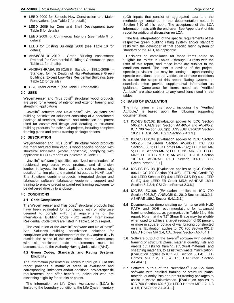
VAR-1008 | Most Widely Accepted and Trusted Page 2 of 12 LEED 2009 for Schools New Construction and Major
Renovations (see Table 7 for details)
LEED 2009 for Core and Shell Development (see Table 8 for details)
LEED 2009 for Commercial Interiors (see Table 9 for details)
LEED for Existing Buildings 2008 (see Table 10 for details)
ANSI/GBI 01-2010 - Green Building Assessment Protocol for Commercial Buildings Construction (see Table 11 for details)
ANSI/ASHRAE/USGBC/IES Standard 189.1-2009 – Standard for the Design of High-Performance Green Buildings, Except Low-Rise Residential Buildings (see Table 12 for details)
CSI GreenFormat™ (see Table 13 for details)
2.0 USES Weyerhaeuser and Trus Joist® structural wood products are used for a variety of interior and exterior framing and sheathing applications.
Javelin® software and NextPhase® Site Solutions are building optimization solutions consisting of a coordinated package of services, software, and fabrication equipment used for customized design and detailing of structural building products for individual projects, including complete framing plans and precut framing package options.
3.0 DESCRIPTION Weyerhaeuser and Trus Joist® structural wood products are manufactured from various wood species bonded with structural adhesives (where applicable) complying with applicable ICC-ES reports as indicated in Table 1.
Javelin® software ) specifies optimized combinations of residential engineered wood products and dimension lumber in layouts for floor, wall, and roof systems with detailed framing plan and material list outputs. NextPhase® Site Solutions combine products, integrated design and fabrication software, fabrication equipment, support and training to enable precut or panelized framing packages to be delivered directly to a jobsite.
4.0 CONDITIONS 4.1 Code Compliance: The Weyerhaeuser and Trus Joist® structural products that have been evaluated for compliance with or otherwise deemed to comply with, the requirements of the International Building Code (IBC) and/or International Residential Code (IRC) are listed in Table 1 of this report.
The evaluation of the Javelin® software and NextPhase® Site Solutions building optimization solutions for compliance with the requirements of the IBC and/or IRC is outside the scope of this evaluation report. Compliance with all applicable code requirements must be demonstrated to the Authority Having Jurisdiction (AHJ).
4.2 Green Codes, Standards and Rating Systems Eligibility:
The information presented in Tables 2 through 13 of this report provides a matrix of areas of evaluation and corresponding limitations and/or additional project-specific requirements, and offer benefit to individuals who are assessing eligibility for credits or points.
The information on Life Cycle Assessment (LCA) is limited to the boundary conditions, the Life Cycle Inventory
(LCI) inputs that consist of aggregated data and the methodology contained in the documentation noted in Section 5.10 of this report. The acceptance of this LCA information rests with the end-user. See Appendix A of this report for additional discussion on LCA.
The final interpretation of the specific requirements of the respective green building rating system and/or standard rests with the developer of that specific rating system or standard or the AHJ, as applicable.
Decisions on compliance for those items noted as “Eligible for Points” in Tables 2 through 13 rests with the user of this report, and those items are subject to the conditions noted. The user is advised of the project-specific provisions that may be contingent upon meeting specific conditions, and the verification of those conditions is outside the scope of this report. Rating systems or standards often provide supplemental information as guidance. Compliance for items noted as “Verified Attribute” are also subject to any conditions noted in the tables.
5.0 BASIS OF EVALUATION
The information in this report, including the “Verified Attribute,” is based upon the following supporting documentation: 5.1 ICC-ES EC102. [Evaluation applies to IgCC Section
505.2.4; CALGreen Section A4.405.4 and A5.405.2; ICC 700 Section 606.1(2); ANSI/GBI 01-2010 Section 10.2.1.1; ASHRAE 189.1 Section 9.4.1.3.]
5.2 ICC-ES EG104. [Evaluation applies to IgCC Section 505.2.5; CALGreen Section A5.405.1; ICC 700 Section 608.1; LEED Homes MR2.2(c); LEED NC MR 5; LEED Schools MR 5; LEED C&S MR 5; LEED CI MR5; LEED EB MR 3; ANSI/GBI 01-2010 Section 10.1.4.1; ASHRAE 189.1 Section 9.4.1.2; CSI GreenFormat 3.2.1.]
5.3 ICC-ES EC108. [Evaluation applies to IgCC Section 806.1; ICC 700 Section 901.4(6); LEED NC Credit EQ 4.4; LEED Schools EQ 4.4; LEED C&S EQ 4.4; LEED CI EQ 4.4; LEED EB Credit MR3; ASHRAE 189.1 Section 8.4.2.4; CSI GreenFormat 2.3.6.]
5.4 ICC-ES EC109. [Evaluation applies to ICC 700 Section 606.2(2); ANSI/GBI 01-2010 Section 10.3.2.1; ASHRAE 189.1 Section 9.4.1.3.1.]
5.5 Documentation demonstrating conformance with HUD PATH and DOE recommendations for advanced framing techniques, as summarized in Table 12 of this report. Note that the TJ® Shear Brace may be eligible when used to achieve a target reduction of 50 percent or more in square footage of wall bracing constructed on site. [Evaluation applies to ICC 700 Section 601.2; LEED Homes MR 1.4; CALGreen Section A5.404.1.]
5.6 Software output of the Javelin® software with detailed framing or structural plans, material quantity lists and on-site cut lists for framing, structural materials, and sheathing materials, to assist with waste minimization. [Evaluation applies to ICC 700 Section 601.4; LEED Homes MR 1.2, 1.3 & 1.5, CALGreen Section A4.404.1]
5.7 Software output of the NextPhase® Site Solutions software with detailed framing or structural plans, material quantity lists and precut framing packages to assist in waste minimization. [Evaluation applies to ICC 700 Section 601.5(1); LEED Homes MR 1.2, 1.3 & 1.5, CALGreen A4.404.1.]
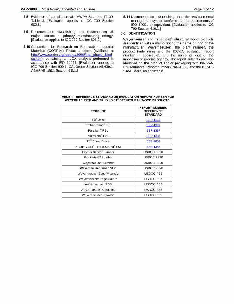
VAR-1008 | Most Widely Accepted and Trusted Page 3 of 12
5.8 Evidence of compliance with AWPA Standard T1-09, Table 3. [Evaluation applies to ICC 700 Section 602.8.]
5.9 Documentation establishing and documenting all major sources of primary manufacturing energy. [Evaluation applies to ICC 700 Section 606.3.]
5.10 Consortium for Research on Renewable Industrial Materials (CORRIM) Phase 1 report (available at http://www.corrim.org/reports/2006/final_phase_1/index.htm), containing an LCA analysis performed in accordance with ISO 14044. [Evaluation applies to ICC 700 Section 609.1; CALGreen Section A5.409.1; ASHRAE 189.1 Section 9.5.1.]
5.11 Documentation establishing that the environmental management system conforms to the requirements of ISO 14001 or equivalent. [Evaluation applies to ICC 700 Section 610.1.]
6.0 IDENTIFICATION Weyerhaeuser and Trus Joist® structural wood products are identified with a stamp noting the name or logo of the manufacturer (Weyerhaeuser), the plant number, the product trade name and the ICC-ES evaluation report number (if applicable), and the name or logo of the inspection or grading agency. The report subjects are also identified on the product and/or packaging with the VAR Environmental Report number (VAR-1008) and the ICC-ES SAVE Mark, as applicable.
TABLE 1—REFERENCE STANDARD OR EVALUATION REPORT NUMBER FOR WEYERHAEUSER AND TRUS JOIST® STRUCTURAL WOOD PRODUCTS
PRODUCT REPORT NUMBER/
REFERENCE STANDARD
TJI® Joist ESR-1153
TimberStrand® LSL ESR-1387
Parallam® PSL ESR-1387
Microllam® LVL ESR-1387
TJ® Shear Brace ESR-2652
StrandGuard® TimberStrand® LSL ESR-1387
Framer Series® Lumber USDOC PS20
Pro Series™ Lumber USDOC PS20
Weyerhaeuser Lumber USDOC PS20
Weyerhaeuser Green Stud USDOC PS20
Weyerhaeuser Edge™ panels USDOC PS2
Weyerhaeuser Edge Gold™ USDOC PS2
Weyerhaeuser RBS USDOC PS2
Weyerhaeuser Sheathing USDOC PS2
Weyerhaeuser Plywood USDOC PS1
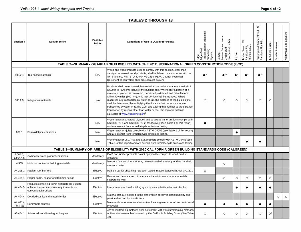
Section # Section Intent Possible Points Conditions of Use to Qualify for Points
Edge
Edge
Gol
dR
adia
nt B
arrie
r She
athi
ngSh
eath
ing
Plyw
ood
Lum
ber
Fram
er S
erie
s Lu
mbe
rG
reen
Stu
dPr
o Se
ries
Lum
ber
TJI J
oist
Tim
berS
trand
LSL
Para
llam
PSL
Mic
rolla
m L
VL
Stra
ndgu
ard
Tim
berS
trand
LSL
Pa
ralla
m P
lus
PSL
TJ S
hear
Bra
ce
Jave
lin S
oftw
are
Nex
tPha
se S
ite S
olut
ions
505.2.4 Bio-based materials N/A
Wood and wood products used to comply with this section, other than salvaged or reused wood products, shall be labeled in accordance with the SFI Standard, FSC STD-40-004 V2-1 EN, PEFC Council Technical Document or equivalent fiber procurement system.
●10 ●10 ●10 ●10 ●10
505.2.5 Indigenous materials N/A
Products shall be recovered, harvested, extracted and manufactured within a 500 mile (800 km) radius of the building site. Where only a portion of a material or product is recovered, harvested, extracted and manufactured within 500 miles (800 km), only that portion shall be included. Where resources are transported by water or rail, the distance to the building site shall be determined by multiplying the distance that the resources are transported by water or rail by 0.25, and adding that number to the distance transported by means other than water or rail. Use regional distance calculator at www.woodbywy.com2
○ ○ ○ ○ ○ ○
N/A Weyerhaeuser I-joists comply with ASTM D5055 (see Table 1 of this report) and are exempt from formaldehyde emissions testing. ●
N/A Weyerhaeuser LSL, PSL and LVL products comply with ASTM D5456 (see Table 1 of this report) and are exempt from formaldehyde emissions testing. ● ●
4.504.5,5.504.4.5 Composite wood product emissions Mandatory
EWP and lumber products do not apply to the composite wood product definition6
4.505 Moisture content of building materials MandatoryMoisture content of lumber may be measured with an appropriate handheld moisture meter7 ○
A4.205.1 Radiant roof barriers Elective Radiant barrier sheathing has been tested in accordance with ASTM C1371 ○A4.404.1 Proper beam, header and trimmer design Elective Beams and headers and trimmers are the minimum size to adequately
support the load ○ ○ ○ ○ ○
A4.404.3Products containing fewer materials are used to achieve the same end-use requirements as conventional products
Elective Use premanufactured building systems as a substitute for solid lumber ● ● ● ●
A4.404.4 Detailed cut list and material order Elective Material lists are included in the plans which specify material quantity and provide direction for on-site cuts. ○ ○
A4.405.4(3) & (5) Renewable sources Elective Materials from renewable sources (such as engineered wood and solid wood
products) ● ● ● ● ● ●
A5.404.1 Advanced wood framing techniques ElectiveAdvanced framing methods shall not conflict with structural framing methods or fire-rated assemblies required by the California Building Code. (See Table 14)
○ ○ ○ ○ ○ ○8
TABLE 2—SUMMARY OF AREAS OF ELIGIBILITY WITH THE 2012 INTERNATIONAL GREEN CONSTRUCTION CODE (IgCC)
TABLE 3—SUMMARY OF AREAS OF ELIGIBILITY WITH 2010 CALIFORNIA GREEN BUILDING STANDARDS CODE (CALGREEN)
806.1 Formaldehyde emissions
N/AWeyerhaeuser structural plywood and structural panel products comply with US DOC PS-1 and US DOC PS-2, respectively (see Table 1 of this report) and are exempt from formaldehyde emissions testing.
●
TABLES 2 THROUGH 13
VAR-1008 | Most Widely Accepted and Trusted Page 4 of 12
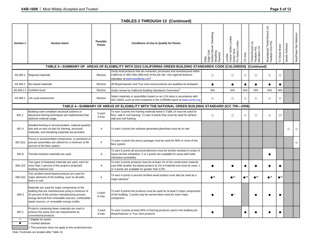
Section # Section Intent Possible Points Conditions of Use to Qualify for Points
Edge
Edge
Gol
dR
adia
nt B
arrie
r She
athi
ngSh
eath
ing
Plyw
ood
Lum
ber
Fram
er S
erie
s Lu
mbe
rG
reen
Stu
dPr
o Se
ries
Lum
ber
TJI J
oist
Tim
berS
trand
LSL
Para
llam
PSL
Mic
rolla
m L
VL
Stra
ndgu
ard
Tim
berS
trand
LSL
Pa
ralla
m P
lus
PSL
TJ S
hear
Bra
ce
Jave
lin S
oftw
are
Nex
tPha
se S
ite S
olut
ions
A5.405.1 Regional materials ElectiveVerify local products that are extracted, processed and manufactured within California or 500 miles (805 km) of the job site. Use regional distance calculator at www.woodbywy.com2
○ ○ ○ ○ ○ ○
A5.405.2 Bio-based materials Elective All Weyerhaeuser and Trus Joist wood products are qualified as biobased ● ● ● ● ● ●A5.405.2.1 Certified wood Elective Under review by California Building Standards Commision5 N/A N/A N/A N/A N/A N/A
A5.409.1 Life cycle assessment Elective Select materials or assemblies based on an LCA done in accordance with ISO 14044, such as that contained in the CORRIM report at www.corrim.org ○ ○ ○ ○ ○ ○
601.2Building-code-compliant structural systems or advanced framing techniques are implemented that optimize material usage
3 each9 max
To earn 3 points the framing methods listed in Table 14 must be used for floor, wall or roof framing. To earn 9 points they must be used for all floor, wall and roof framing
○ ○ ○ ○ ○ ○8
601.4 Detailed framing or structural plans, material quantity lists and on-site cut lists for framing, structural materials, and sheathing materials are provided
4 To earn 4 points the software generated plans/lists must be on site ○ ○
601.5(1) Precut or preassembled components, or panelized or precast assemblies are utilized for a minimum of 90 percent of the floor system
4 To earn 4 points the precut package must be used for 90% or more of the floor system ○
602.8 Termite-resistant materials are used 6 To earn 6 points all structural elements must be termite resistant in areas of heavy termite infestation. 2 or 4 points are available for areas with lower infestation probability
●
606.1(2) Two types of biobased materials are used, each for more than 1 percent of the project’s projected building material cost
6 To earn 6 points products must be at least 1% of the construction material cost AND another bio-based product at 1% of material cost must be used. 1 or 3 points are available for greater than 0.5%
● ● ● ● ● ●
606.2(2) Two certified wood-based products are used for major elements of the building, such as all walls, floors or roof
4To earn 4 points a second certified wood product must also be used as a major element1 ●10 ●10 ●10 ●10 ●10 ●10
606.3
Materials are used for major components of the building that are manufactured using a minimum of 33 percent of the primary manufacturing process energy derived from renewable sources, combustible waste sources, or renewable energy credits
2 each6 max
To earn 6 points the products must be used for at least 3 major components of the building. 2 points may be earned when used for each major component
● ●9 ● ● ●
607.1 Products containing fewer materials are used to achieve the same end-use requirements as conventional products
3 each9 max
To earn 3 points at least 80% of framing products used in the building are Weyerhaeuser or Trus Joist products ● ● ● ● ●
○ = Eligible for points● = Verified attribute
= This provision does not apply to this product/service
TABLE 3—SUMMARY OF AREAS OF ELIGIBILITY WITH 2010 CALIFORNIA GREEN BUILDING STANDARDS CODE (CALGREEN) (Continued)
TABLES 2 THROUGH 13 (Continued)
TABLE 4—SUMMARY OF AREAS OF ELIGIBILITY WITH THE NATIONAL GREEN BUILDING STANDARD (ICC 700—2008)
Note: Footnotes are located after Table 13.
VAR-1008 | Most Widely Accepted and Trusted Page 5 of 12
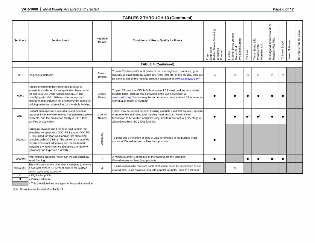
Section # Section Intent Possible Points Conditions of Use to Qualify for Points
Edge
Edge
Gol
dR
adia
nt B
arrie
r She
athi
ngSh
eath
ing
Plyw
ood
Lum
ber
Fram
er S
erie
s Lu
mbe
rG
reen
Stu
dPr
o Se
ries
Lum
ber
TJI J
oist
Tim
berS
trand
LSL
Para
llam
PSL
Mic
rolla
m L
VL
Stra
ndgu
ard
Tim
berS
trand
LSL
Pa
ralla
m P
lus
PSL
TJ S
hear
Bra
ce
Jave
lin S
oftw
are
Nex
tPha
se S
ite S
olut
ions
608.1 Indigenous materials 2 each10 max
To earn 2 points verify local products that are originated, produced, grow naturally or occur naturally within 500 miles (805 km) of the job site. This can be done by use of the regional distance calculator at www.woodbywy.com2
○ ○ ○ ○ ○ ○
609.1
A more environmentally preferable product or assembly is selected for an application based upon the use of a Life Cycle Assessment (LCA) tool complying with ISO 14044 or other recognized standards that compare the environmental impact of building materials, assemblies, or the whole building
3 each15 max
To gain 15 points an ISO 14044-complaint LCA must be done on a whole building basis, such as that contained in the CORRIM report at www.corrim.org. 3 points may be earned where comparative LCA is done for individual products or systems
● ● ● ● ● ●
610.1
Product manufacturer’s operations and business practices include environmental management system concepts, and the production facility is ISO 14001 certified or equivalent
1 per %10 max
1 point may be earned for each building products used that equals 1 percent or more of the estimated total building materials cost. Material cost breakdown to be verified and points adjusted to reflect actual percentage of all products from ISO 14001 facilities
● ● ●9 ●9 ● ●
901.4(1)
Structural plywood used for floor, wall, and/or roof sheathing complies with DOC PS 1 and/or DOC PS 2. OSB used for floor, wall, and/or roof sheathing complies with DOC PS 2. The panels are made with moisture-resistant adhesives and the trademark indicates the adhesives are Exposure 1 or Exterior (plywood) and Exposure 1 (OSB)
Man
dato
ry
To meet this a minimum of 85% of OSB or plywood in the building must consist of Weyerhaeuser or Trus Joist products ●
901.4(6) Non-emitting products, which can include structural wood framing 4 A minimum of 85% of product in the building are the identified
Weyerhaeuser or Trus Joist products ● ● ● ● ●
903.4.1(3)The moisture content of lumber is sampled to ensure it does not exceed 19 percent prior to the surface and/or wall cavity exposure
4To earn 4 points the moisture content of lumber must be determined to not exceed 19%, such as measuring with a moisture meter, prior to enclosure7 ○
○ = Eligible for points● = Verified attribute
= This provision does not apply to this product/service
Note: Footnotes are located after Table 13.
TABLES 2 THROUGH 13 (Continued)
TABLE 4 (Continued)
VAR-1008 | Most Widely Accepted and Trusted Page 6 of 12
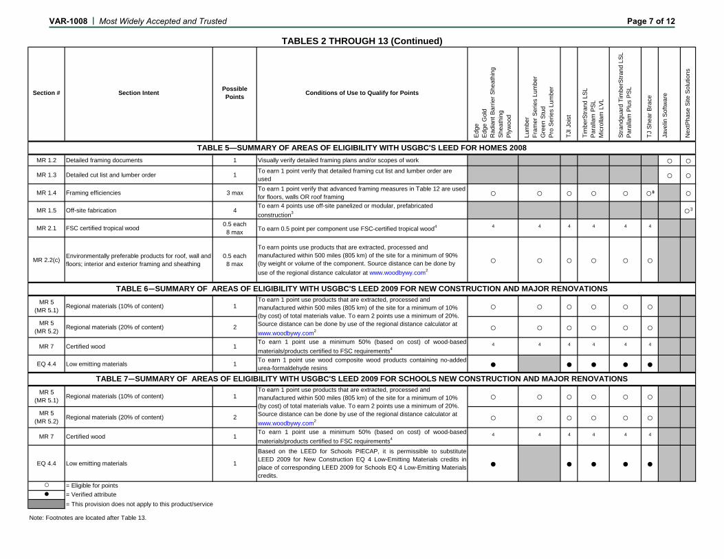
Section # Section Intent Possible Points Conditions of Use to Qualify for Points
Edge
Edge
Gol
dR
adia
nt B
arrie
r She
athi
ngSh
eath
ing
Plyw
ood
Lum
ber
Fram
er S
erie
s Lu
mbe
rG
reen
Stu
dPr
o Se
ries
Lum
ber
TJI J
oist
Tim
berS
trand
LSL
Para
llam
PSL
Mic
rolla
m L
VL
Stra
ndgu
ard
Tim
berS
trand
LSL
Pa
ralla
m P
lus
PSL
TJ S
hear
Bra
ce
Jave
lin S
oftw
are
Nex
tPha
se S
ite S
olut
ions
MR 1.2 Detailed framing documents 1 Visually verify detailed framing plans and/or scopes of work ○ ○MR 1.3 Detailed cut list and lumber order 1 To earn 1 point verify that detailed framing cut list and lumber order are
used ○ ○MR 1.4 Framing efficiencies 3 max To earn 1 point verify that advanced framing measures in Table 12 are used
for floors, walls OR roof framing ○ ○ ○ ○ ○ ○8 ○MR 1.5 Off-site fabrication 4
To earn 4 points use off-site panelized or modular, prefabricated construction3 ○3
MR 2.1 FSC certified tropical wood 0.5 each8 max To earn 0.5 point per component use FSC-certified tropical wood4 4 4 4 4 4 4
MR 2.2(c) Environmentally preferable products for roof, wall and floors; interior and exterior framing and sheathing
0.5 each8 max
To earn points use products that are extracted, processed and manufactured within 500 miles (805 km) of the site for a minimum of 90% (by weight or volume of the component. Source distance can be done by use of the regional distance calculator at www.woodbywy.com2
○ ○ ○ ○ ○ ○
MR 5(MR 5.1) Regional materials (10% of content) 1 ○ ○ ○ ○ ○ ○
MR 5(MR 5.2) Regional materials (20% of content) 2 ○ ○ ○ ○ ○ ○
MR 7 Certified wood 1To earn 1 point use a minimum 50% (based on cost) of wood-basedmaterials/products certified to FSC requirements4
4 4 4 4 4 4
EQ 4.4 Low emitting materials 1 To earn 1 point use wood composite wood products containing no-addedurea-formaldehyde resins ● ● ● ● ●
MR 5(MR 5.1) Regional materials (10% of content) 1 ○ ○ ○ ○ ○ ○
MR 5(MR 5.2) Regional materials (20% of content) 2 ○ ○ ○ ○ ○ ○
MR 7 Certified wood 1To earn 1 point use a minimum 50% (based on cost) of wood-basedmaterials/products certified to FSC requirements4
4 4 4 4 4 4
EQ 4.4 Low emitting materials 1
Based on the LEED for Schools PIECAP, it is permissible to substituteLEED 2009 for New Construction EQ 4 Low-Emitting Materials credits inplace of corresponding LEED 2009 for Schools EQ 4 Low-Emitting Materialscredits.
● ● ● ● ●
○ = Eligible for points● = Verified attribute
= This provision does not apply to this product/service
Note: Footnotes are located after Table 13.
TABLE 6—SUMMARY OF AREAS OF ELIGIBILITY WITH USGBC'S LEED 2009 FOR NEW CONSTRUCTION AND MAJOR RENOVATIONSTo earn 1 point use products that are extracted, processed and manufactured within 500 miles (805 km) of the site for a minimum of 10% (by cost) of total materials value. To earn 2 points use a minimum of 20%. Source distance can be done by use of the regional distance calculator at www.woodbywy.com2
TABLE 5—SUMMARY OF AREAS OF ELIGIBILITY WITH USGBC'S LEED FOR HOMES 2008
TABLE 7—SUMMARY OF AREAS OF ELIGIBILITY WITH USGBC'S LEED 2009 FOR SCHOOLS NEW CONSTRUCTION AND MAJOR RENOVATIONSTo earn 1 point use products that are extracted, processed and manufactured within 500 miles (805 km) of the site for a minimum of 10% (by cost) of total materials value. To earn 2 points use a minimum of 20%. Source distance can be done by use of the regional distance calculator at www.woodbywy.com2
TABLES 2 THROUGH 13 (Continued)
VAR-1008 | Most Widely Accepted and Trusted Page 7 of 12
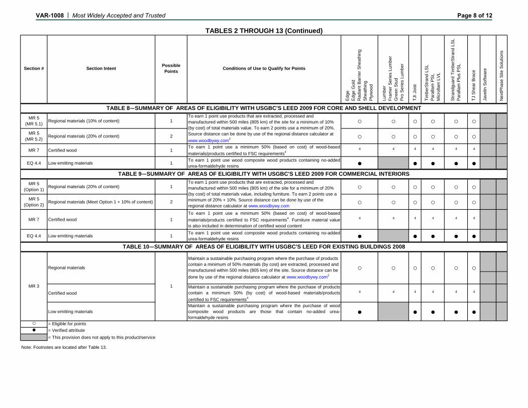
Section # Section Intent Possible Points Conditions of Use to Qualify for Points
Edge
Edge
Gol
dR
adia
nt B
arrie
r She
athi
ngSh
eath
ing
Plyw
ood
Lum
ber
Fram
er S
erie
s Lu
mbe
rG
reen
Stu
dPr
o Se
ries
Lum
ber
TJI J
oist
Tim
berS
trand
LSL
Para
llam
PSL
Mic
rolla
m L
VL
Stra
ndgu
ard
Tim
berS
trand
LSL
Pa
ralla
m P
lus
PSL
TJ S
hear
Bra
ce
Jave
lin S
oftw
are
Nex
tPha
se S
ite S
olut
ions
MR 5(MR 5.1) Regional materials (10% of content) 1 ○ ○ ○ ○ ○ ○
MR 5(MR 5.2) Regional materials (20% of content) 2 ○ ○ ○ ○ ○ ○
MR 7 Certified wood 1To earn 1 point use a minimum 50% (based on cost) of wood-basedmaterials/products certified to FSC requirements4
4 4 4 4 4 4
EQ 4.4 Low emitting materials 1 To earn 1 point use wood composite wood products containing no-addedurea-formaldehyde resins ● ● ● ● ●
MR 5(Option 1) Regional materials (20% of content) 1 ○ ○ ○ ○ ○ ○
MR 5(Option 2) Regional materials (Meet Option 1 + 10% of content) 2 ○ ○ ○ ○ ○ ○
MR 7 Certified wood 1To earn 1 point use a minimum 50% (based on cost) of wood-basedmaterials/products certified to FSC requirements4. Furniture material valueis also included in determination of certified wood content
4 4 4 4 4 4
EQ 4.4 Low emitting materials 1 To earn 1 point use wood composite wood products containing no-addedurea-formaldehyde resins ● ● ● ● ●
Certified woodMaintain a sustainable purchasing program where the purchase of productscontain a minimum 50% (by cost) of wood-based materials/productscertified to FSC requirements4
4 4 4 4 4 4
Low emitting materialsMaintain a sustainable purchasing program where the purchase of woodcomposite wood products are those that contain no-added urea-formaldehyde resins
● ● ● ● ●○ = Eligible for points● = Verified attribute
= This provision does not apply to this product/service
TABLES 2 THROUGH 13 (Continued)
TABLE 10—SUMMARY OF AREAS OF ELIGIBILITY WITH USGBC'S LEED FOR EXISTING BUILDINGS 2008
MR 3
Regional materials ○
To earn 1 point use products that are extracted, processed and manufactured within 500 miles (805 km) of the site for a minimum of 10% (by cost) of total materials value. To earn 2 points use a minimum of 20%. Source distance can be done by use of the regional distance calculator at www.woodbywy.com2
TABLE 8—SUMMARY OF AREAS OF ELIGIBILITY WITH USGBC'S LEED 2009 FOR CORE AND SHELL DEVELOPMENT
TABLE 9—SUMMARY OF AREAS OF ELIGIBILITY WITH USGBC'S LEED 2009 FOR COMMERCIAL INTERIORSTo earn 1 point use products that are extracted, processed and manufactured within 500 miles (805 km) of the site for a minimum of 20% (by cost) of total materials value, including furniture. To earn 2 points use a minimum of 20% + 10%. Source distance can be done by use of the regional distance calculator at www.woodbywy.com
○ ○○ ○ ○
1
Maintain a sustainable purchasing program where the purchase of products contain a minimum of 50% materials (by cost) are extracted, processed and manufactured within 500 miles (805 km) of the site. Source distance can be done by use of the regional distance calculator at www.woodbywy.com2
Note: Footnotes are located after Table 13.
VAR-1008 | Most Widely Accepted and Trusted Page 8 of 12
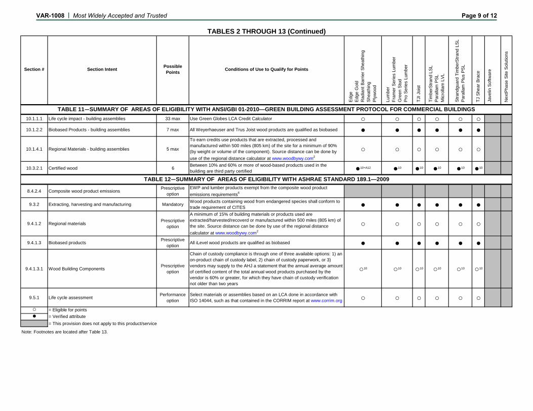
Section # Section Intent Possible Points Conditions of Use to Qualify for Points
Edge
Edge
Gol
dR
adia
nt B
arrie
r She
athi
ngSh
eath
ing
Plyw
ood
Lum
ber
Fram
er S
erie
s Lu
mbe
rG
reen
Stu
dPr
o Se
ries
Lum
ber
TJI J
oist
Tim
berS
trand
LSL
Para
llam
PSL
Mic
rolla
m L
VL
Stra
ndgu
ard
Tim
berS
trand
LSL
Pa
ralla
m P
lus
PSL
TJ S
hear
Bra
ce
Jave
lin S
oftw
are
Nex
tPha
se S
ite S
olut
ions
10.1.1.1 Life cycle impact - building assemblies 33 max Use Green Globes LCA Credit Calculator ○ ○ ○ ○ ○ ○10.1.2.2 Biobased Products - building assemblies 7 max All Weyerhaeuser and Trus Joist wood products are qualified as biobased ● ● ● ● ● ●
10.1.4.1 Regional Materials - building assemblies 5 max
To earn credits use products that are extracted, processed and manufactured within 500 miles (805 km) of the site for a minimum of 90% (by weight or volume of the component). Source distance can be done by use of the regional distance calculator at www.woodbywy.com2
○ ○ ○ ○ ○ ○
10.3.2.1 Certified wood 6 Between 10% and 60% or more of wood-based products used in the building are third party certified ●10+A12 ●10 ●10 ●10 ●10 ●10
8.4.2.4 Composite wood product emissions Prescriptiveoption
EWP and lumber products exempt from the composite wood product emissions requirements6
9.3.2 Extracting, harvesting and manufacturing Mandatory Wood products containing wood from endangered species shall conform to trade requirement of CITES ● ● ● ● ● ●
9.4.1.2 Regional materials Prescriptiveoption
A minimum of 15% of building materials or products used are extracted/harvested/recoverd or manufactured within 500 miles (805 km) of the site. Source distance can be done by use of the regional distance calculator at www.woodbywy.com2
○ ○ ○ ○ ○ ○
9.4.1.3 Biobased products Prescriptiveoption All iLevel wood products are qualified as biobased ● ● ● ● ● ●
9.4.1.3.1 Wood Building Components Prescriptiveoption
Chain of custody compliance is through one of three available options: 1) an on-product chain of custody label, 2) chain of custody paperwork, or 3) vendors may supply to the AHJ a statement that the annual average amount of certified content of the total annual wood products purchased by the vendor is 60% or greater, for which they have chain of custody verification not older than two years
○10 ○10 ○10 ○10 ○10 ○10
9.5.1 Life cycle assessment Performanceoption
Select materials or assemblies based on an LCA done in accordance with ISO 14044, such as that contained in the CORRIM report at www.corrim.org ○ ○ ○ ○ ○ ○
○ = Eligible for points● = Verified attribute
= This provision does not apply to this product/service
TABLE 12—SUMMARY OF AREAS OF ELIGIBILITY WITH ASHRAE STANDARD 189.1—2009
TABLES 2 THROUGH 13 (Continued)
Note: Footnotes are located after Table 13.
TABLE 11—SUMMARY OF AREAS OF ELIGIBILITY WITH ANSI/GBI 01-2010—GREEN BUILDING ASSESSMENT PROTOCOL FOR COMMERCIAL BUILDINGS
VAR-1008 | Most Widely Accepted and Trusted Page 9 of 12
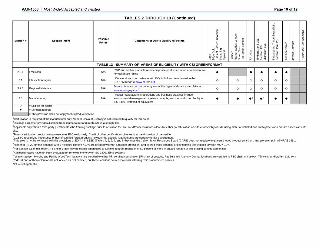
Section # Section Intent Possible Points Conditions of Use to Qualify for Points
Edge
Edge
Gol
dR
adia
nt B
arrie
r She
athi
ngSh
eath
ing
Plyw
ood
Lum
ber
Fram
er S
erie
s Lu
mbe
rG
reen
Stu
dPr
o Se
ries
Lum
ber
TJI J
oist
Tim
berS
trand
LSL
Para
llam
PSL
Mic
rolla
m L
VL
Stra
ndgu
ard
Tim
berS
trand
LSL
Pa
ralla
m P
lus
PSL
TJ S
hear
Bra
ce
Jave
lin S
oftw
are
Nex
tPha
se S
ite S
olut
ions
2.3.6 Emiisions N/A EWP and lumber products wood composite products contain no-added urea-formaldehyde resins ● ● ● ● ●
3.1 Life cycle Analysis N/A LCA was done in accordance with ISO 14044 and iscontained in the CORRIM report at www.corrim.org ○ ○ ○ ○ ○ ○
3.2.1 Regional Materials N/ASource distance can be done by use of the regional distance calculator at www.woodbywy.com2 ○ ○ ○ ○ ○ ○
3.3 Manufacturing N/AProduct manufacturer’s operations and business practices include environmental management system concepts, and the production facility is ISO 14001 certified or equivalent
● ● ●9 ●9 ● ●○ = Eligible for points● = Verified attribute
= This provision does not apply to this product/service
7Note that PS-20 lumber products with a moisture content >19% are shipped wet with fungicide protection. Engineered wood products and sheathing are shipped dry with MC < 10%.8Per Section 5.5 of this report, TJ Shear Brace may be eligible when used to achieve a target reduction of 50 percent or more in square footage of wall bracing constructed on site.9Additional listees have not been evaluated for renewable energy or ISO 14001 EMS systems
N/A = Not applicable
10Weyerhaeuser, Murphy and Pacific WoodTech locations are certified to either SFI certified sourcing or SFI chain of custody. RedBuilt and Anthony-Domtar locations are certified to FSC chain of custody. TJI joists or Microllam LVL from RedBuilt and Anthony-Domtar are not labeled as SFI certified, but these locations source materials following FSC procurement policies.
6This area is not be confused with the provisions of EQ 4.4 in LEED (Tables 4, 5, 6, 7, and 8) because the California Air Resources Board (CARB) does not regulate engineered wood product emissions and are exempt in ASHRAE 189.1.
3Applicable only when a third-party prefabricates the framing package prior to arrival on the site. NextPhase Solutions allows for either prefabrication off-site or assembly on-site using materials labeled and cut to precision-end-trim dimensions off-site.4Forest certification credit currently resources FSC exclusively. Credit of other certification schemes is at the discretion of the verifier.
2Distance calculator provides distance from source to mill and mill to site in a straight line.
1Certification is required of the manufacturer only. Vendor Chain of Custody is not required to qualify for this point.
5CGBSC recognizes importance of use of certified forest products however the specific requirements are currently under development.
TABLE 13—SUMMARY OF AREAS OF ELIGIBILITY WITH CSI GREENFORMAT
TABLES 2 THROUGH 13 (Continued)
VAR-1008 | Most Widely Accepted and Trusted Page 10 of 12
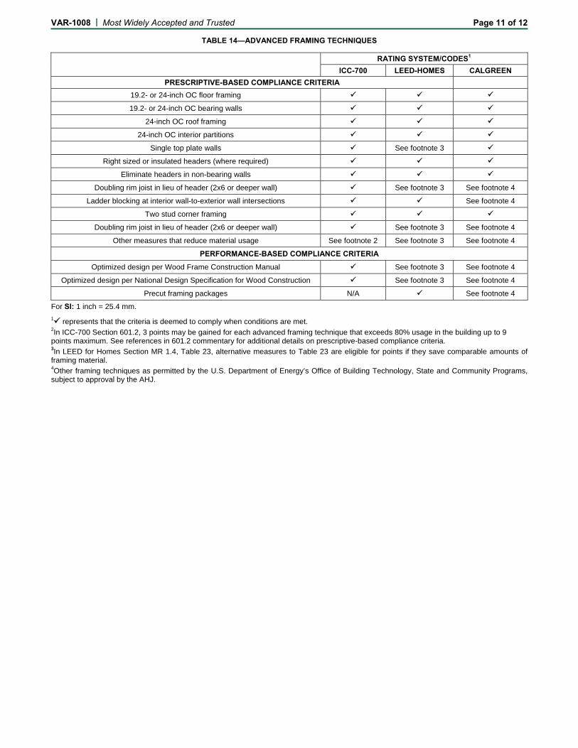
VAR-1008 | Most Widely Accepted and Trusted Page 11 of 12
TABLE 14—ADVANCED FRAMING TECHNIQUES
RATING SYSTEM/CODES1
ICC-700 LEED-HOMES CALGREEN PRESCRIPTIVE-BASED COMPLIANCE CRITERIA
19.2- or 24-inch OC floor framing
19.2- or 24-inch OC bearing walls
24-inch OC roof framing
24-inch OC interior partitions
Single top plate walls See footnote 3
Right sized or insulated headers (where required)
Eliminate headers in non-bearing walls
Doubling rim joist in lieu of header (2x6 or deeper wall) See footnote 3 See footnote 4
Ladder blocking at interior wall-to-exterior wall intersections See footnote 4
Two stud corner framing
Doubling rim joist in lieu of header (2x6 or deeper wall) See footnote 3 See footnote 4
Other measures that reduce material usage See footnote 2 See footnote 3 See footnote 4
PERFORMANCE-BASED COMPLIANCE CRITERIA
Optimized design per Wood Frame Construction Manual See footnote 3 See footnote 4
Optimized design per National Design Specification for Wood Construction See footnote 3 See footnote 4
Precut framing packages N/A See footnote 4
For SI: 1 inch = 25.4 mm.
1 represents that the criteria is deemed to comply when conditions are met.
2In ICC-700 Section 601.2, 3 points may be gained for each advanced framing technique that exceeds 80% usage in the building up to 9 points maximum. See references in 601.2 commentary for additional details on prescriptive-based compliance criteria. 3In LEED for Homes Section MR 1.4, Table 23, alternative measures to Table 23 are eligible for points if they save comparable amounts of framing material. 4Other framing techniques as permitted by the U.S. Department of Energy’s Office of Building Technology, State and Community Programs, subject to approval by the AHJ.
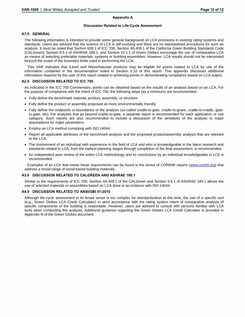
VAR-1008 | Most Widely Accepted and Trusted Page 12 of 12
Appendix A
Discussion Related to Life-Cycle Assessment A1.0 GENERAL
The following information is intended to provide some general background on LCA provisions in existing rating systems and standards. Users are advised that the science of LCA is still evolving and there are no standardized procedures for such an analysis. It must be noted that Section 609.1 of ICC 700, Section A5.409.1 of the California Green Building Standards Code (CALGreen), Section 9.5.1 of ASHRAE 189.1, and Section 10.1.1 of Green Globes encourage the use of comparative LCA as means of selecting preferable materials, systems or building assemblies. However, LCA results should not be interpreted beyond the scope of the boundary limits used in performing the LCA.
This VAR indicates that iLevel and Weyerhaeuser products may be eligible for points related to LCA by use of the information contained in the documentation noted in Section 5.10 of this report. This appendix discusses additional information required by the user of this report related to achieving points or demonstrating compliance based on LCA output.
A2.0 DISCUSSION RELATED TO ICC 700 As indicated in the ICC 700 Commentary, points can be obtained based on the results of an analysis based on an LCA. For the purpose of compliance with the intent of ICC 700, the following steps (as a minimum) are recommended:
• Fully define the benchmark material, product, assembly, or structure
• Fully define the product or assembly proposed as more environmentally friendly
• Fully define the endpoints or boundaries of the analysis (so-called cradle-to-gate, cradle-to-grave, cradle-to-cradle, gate-to-gate, etc). For analyses that go beyond cradle-to-gate, a separate report is recommended for each application or use category. Such reports are also recommended to include a discussion of the sensitivity of the analysis to major assumptions for major parameters.
• Employ an LCA method complying with ISO 14044.
• Report all applicable attributes of the benchmark analysis and the proposed product/assembly analysis that are relevant to the LCA.
• The involvement of an individual with experience in the field of LCA and who is knowledgeable in the latest research and standards related to LCA, from the earliest planning stages through completion of the final assessment, is recommended.
• An independent peer review of the entire LCA methodology and its conclusions by an individual knowledgeable in LCA is recommended.
Examples of an LCA that meets these requirements can be found in the series of CORRIM reports (www.corrim.org) that address a broad range of wood-based building materials.
A3.0 DISCUSSION RELATED TO CALGREEN AND ASHRAE 189.1 Similar to the requirements of ICC 700, Section A5.409.1 of the CALGreen and Section 9.5.1 of ASHRAE 189.1 allows the use of selected materials or assemblies based on LCA done in accordance with ISO 14044.
A4.0 DISCUSSION RELATED TO ANSI/GBI 01-2010 Although life-cycle assessment in its broad sense is too complex for standardization at this time, the use of a specific tool (e.g., Green Globes LCA Credit Calculator) in strict accordance with the rating system intent of comparative analysis of specific components of the building is reasonable. However, users are advised to consult with persons familiar with LCA tools when conducting this analysis. Additional guidance regarding the Green Globes LCA Credit Calculator is provided in Appendix N of the Green Globes document.