ESI-100USER Manual
28
USER Manual USER Manual 1.0.0 Edition 20210316 EtherCAT Slave Digital I/O Module ESI-100
Transcript of ESI-100USER Manual
USERManualUSERManual
1.0.0 Edition 20210316
EtherCAT Slave Digital I/O Module
ESI-100

ii©Vecow ESI-100 User Manual
Version Date Page Description Remark
1.00 2021/03/16 All Official Release
Record of Revision

iii©Vecow ESI-100 User Manual
This manual is released by Vecow Co., Ltd. for reference purpose only. All product offerings and specifications are subject to change without prior notice. It does not represent commitment of Vecow Co., Ltd. Vecow shall not be liable for direct, indirect, special, incidental, or consequential damages arising out of the use of the product or documentation or any infringements upon the rights of third parties, which may result from such use.
Disclaimer
This equipment has been tested and found to comply with the limits for a Class A digital device, pursuant to part 15 of the FCC Rules. These limits are designed to provide reasonable protection against harmful interference when the equipment is operated in a commercial environment. This equipment generates, uses, and can radiate radio frequency energy, and if it is not installed and used in accordance with the instruction manual, it may cause harmful interference to radio communications. Operation of this equipment in a residential area is likely to cause harmful interference in which case the user will be required to correct the interference at his own expense.
FCC
The products described in this manual complies with all applicable European Union (CE) directives if it has a CE marking. For computer systems to remain CE compliant, only CE-compliant parts may be used. Maintaining CE compliance also requires proper cable and cabling techniques.
CE
Declaration of Conformity
This document contains proprietary information protected by copyright. No part of this publication may be reproduced in any form or by any means, electric, photocopying, recording or otherwise, without prior written authorization by Vecow Co., Ltd. The rights of all the brand names, product names, and trademarks belong to their respective owners.
Copyright and Trademarks

iv©Vecow ESI-100 User Manual
Table of ContentsCHAPTER 1 GENERAL INTRODUCTION 1
1.1 Overview 11.2 Features 21.3 Product Specification 31.4 Layout and Dimensions 41.5 Pin Definition 51.6 I/O Interface Diagram 7
CHAPTER 2 SOFTWARE 102.1 EtherCAT Master Supported List 10
2.1.1 Beckhoff 10
2.1.2 Codesys 11
2.1.3 SDK 12
CHAPTER 3 MAILBOX (SDO) LIST 133.1 Register List 133.2 Comment Register 14

1©Vecow ESI-100 User Manual GENERAL INTRODUCTION
GENERAL INTRODUCTION
1.1 OverviewThank you for your selection of EtherCAT module ESI-100 digital input output interface.
EtherCAT become a reliable and low cost solution of real time control data communication standard. To utilize the EtherCAT as data communication highway of industrial control devices is more attractive than ever.
ESI-100 module is a multifunction digital I/O control module. We provide the dll’s of Window’s or Linux system, enabling you to code the flexible application as if it is an add-on card without the knowledge of EtherCAT protocol. But for the expert of EtherCAT, you can also use the basic EtherCAT command to your application.
Stable, high reliability and remote addressable module give you a new approach of application.
Any comment is welcome, please visit our website http://www.vecow.com/
1

2©Vecow ESI-100 User Manual GENERAL INTRODUCTION
1.2 Features• Compatible with all Vecow product series
• EtherCAT compliant slave module
• Bi-directional photo-coupler input with multiple input configuration
• Digital I/P as counter in put
• Photo-coupled NMOS output
• EtherCAT distributed clock (DC) function enabled
• No extra real time master stack software
• Easy to program as if traditional add-on card

3©Vecow ESI-100 User Manual GENERAL INTRODUCTION
1.3 Product SpecificationDigital InputPhoto Isolated Input 16
Logic High Level 3mA (max)
Logic Low Ievel 6mA (min)
Counter Input any digital input
Counter Speed 100Hz (max) square wave
Digital OutputMOS Output Points 16 (NMOS)
MOS Capacity 1A @48V DC
MechanicalDimension 160.0mm x 120.1mm x 61.2mm (6.30" x 4.73" x 2.42")
Weight 248g
EnvironmentPower Requirement 24V DC (18-36V DC) 0.5A
Operation Temperature 0°C to +70°C
Storage Temperature -20°C to +80°C
Operation Humidity 5 to 95% RH, non-condensing

4©Vecow ESI-100 User Manual GENERAL INTRODUCTION
1.4 Layout and Dimensions
JM0 : external power 18-36V DC connectorJM1 : Input connectorDISP0 : CardID or module address displayOK : system active LED, flashing per second
RUN : ESC (EtherCAT slave controller) status LED, while LED off : ESC initialization LED blinking (slow) : ESC in pre op state LED single flash : ESC in safe op stateLED on : ESC in op state LED flickering (fast) : ESC in bootrap state
ERROR : ESC (EtherCAT slave controller) error LED, whileLED off : ESC no error LED flickering (fast) : ESC error in bootrap state LED blinking (slow) : ESC error in pre op state LED single flash : local application error LED double flash : master is disconnectedLED on : local controller fail
P0 : EtherCAT RJ45 input socketP1 : EtherCAT RJ45 output socketInput LED : Input status displayOutput LED : Output status displayJM2 : Output connector

5©Vecow ESI-100 User Manual GENERAL INTRODUCTION
1.5 Pin Definition1.5.1 JM0 Pin Definitions
+V External power supply +24V (18 ~ 36V DC)
G External power supply ground
FG Frame ground for the device
1.5.2 JM1 Pin Definitions (Input Connector)
COM0 Common reference of input port0 COM1 Common reference of input port1
IN00 input point 0 of port 0 IN10 input point 0 of port 1
IN01 input point 1 of port 0 IN11 input point 1 of port 1
IN02 input point 2 of port 0 IN12 input point 2 of port 1
IN03 input point 3 of port 0 IN13 input point 3 of port 1
IN04 input point 4 of port 0 IN14 input point 4 of port 1
IN05 input point 5 of port 0 IN15 input point 5 of port 1
IN06 input point 6 of port 0 IN16 input point 6 of port 1
IN07 input point 7 of port 0 IN17 input point 7 of port 1
Dry ground of Dry contact input or 5V TTL input Dry ground of Dry contact input or
5V TTL input
for the input connection, please refer 6.1 Input diagram

6©Vecow ESI-100 User Manual GENERAL INTRODUCTION
1.5.3 JM2 Pin Definitions (Output Connector)
EC1 Common reference of output port1 (connect to external power) EC0 Common reference of output
port0 (connect to external power)
OUT10 output point 0 of port 1 OUT00 output point 0 of port 0
OUT11 output point 1 of port 1 OUT01 output point 1 of port 0
OUT12 output point 2 of port 1 OUT02 output point 2 of port 0
OUT13 output point 3 of port 1 OUT03 output point 3 of port 0
OUT14 output point 4 of port 1 OUT04 output point 4 of port 0
OUT15 output point 5 of port 1 OUT05 output point 5 of port 0
OUT16 output point 6 of port 1 OUT06 output point 6 of port 0
OUT17 output point 7 of port 1 OUT07 output point 7 of port 0
EGnd External power ground EGnd External power ground
for the output connection, please refer 6.2 Output diagram
7©Vecow ESI-100 User Manual GENERAL INTRODUCTION
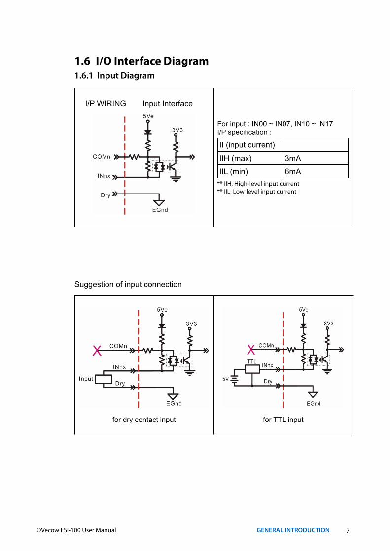
1.6 I/O Interface Diagram1.6.1 Input Diagram
For input : IN00 ~ IN07, IN10 ~ IN17I/P specification :
II (input current)
IIH (max) 3mA
IIL (min) 6mA** IIH, High-level input current** IIL, Low-level input current
I/P WIRING Input Interface
Suggestion of input connection
for dry contact input for TTL input

8©Vecow ESI-100 User Manual GENERAL INTRODUCTION
Positive polarity with source input Negative polarity with source input
Positive polarity with sink input Negative polarity with sink input

9©Vecow ESI-100 User Manual GENERAL INTRODUCTION
1.6.2 Output Diagram
For NMOS output : OUT00 ~ OUT07,OUT10 ~ OUT17
O/P specification :
VO (output voltage)
VO (max) 48V DC
IO (output current)
IO (cont) sink 1A (rms)
For NMOS output : OUT00 ~ OUT07,OUT10 ~ OUT17
O/P specification :
VO (output voltage)
VO (max) 48V DC
IO (output current)
IO (cont) source 1A (rms)
Suggestion of output connection
NMOS output PMOS output

10©Vecow ESI-100 User Manual SOFTWARE
2SOFTWARE
2.1 EtherCAT Master Supported ListMaster Windows Linux ESI File (xml)
Beckhoff O x O
Codesys O O O
EtherCAT Master SDK O O O
2.1.1 Beckhoff
The Windows Control and Automation Technology
The Beckhoff TwinCAT software system turns almost any compatible PC into a real-time controller with a multi-PLC system, NC axis control, programming environment and operating station. TwinCAT replaces conventional PLC and NC/CNC controllers as well as operating devices with :
• open, compatible PC hardware• embedded IEC 61131-3 software PLC, software NC and software CNC in Windows
NT/2000/XP/Vista, Windows 7, NT/XP Embedded, CE, Windows 10 LTSB• programming and run-time systems optionally together on one PC or separated• connection to all common fieldbuses• PC interfaces support• data communication with user interfaces and other programs by means of
open Microsoft standards (OPC, OCX, DLL, etc.)

11©Vecow ESI-100 User Manual SOFTWARE
Windows 10 IoT Enterprise (LTSB)
For the industrial area Windows 10 IoT Enterprise (LTSB, Long Term Servicing Branch) is available with the following features :• License activation is not necessary.• Updates and patches are not installed automatically.• The time when updates and patches are installed can be controlled.
The LTSB version has no access to the Microsoft Store and the assistant "Cortana" is also not available.
System Requirements
Component Description
Processor 1,75 GHz (or faster)
Main memory 1 GB for 32 bit or 2 GB for 64 bit
Free disc spaceminimum 10 GB (32 bit) or 13,5 GB (64 bit)When updates are installed the values can become even bigger over time.
2.1.2 Codesys
CODESYS provides an IDE (integrated development environment) for Windows. Using the CODESYS IDE, control applications can be developed, tested, and compiled for the CODESYS Windows/Linux runtime. A typical IDE project environment is presented in the image below.
12©Vecow ESI-100 User Manual SOFTWARE
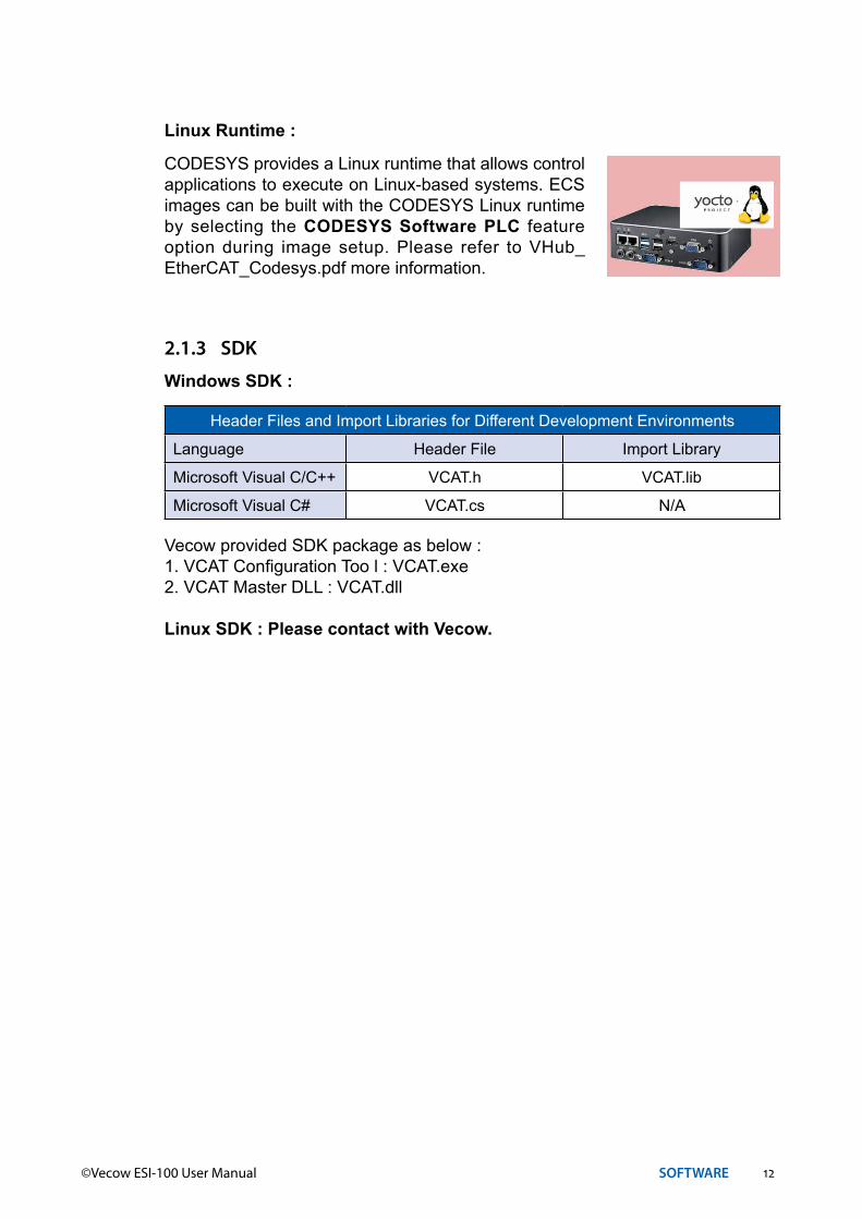
Linux Runtime :
CODESYS provides a Linux runtime that allows control applications to execute on Linux-based systems. ECS images can be built with the CODESYS Linux runtime by selecting the CODESYS Software PLC feature option during image setup. Please refer to VHub_EtherCAT_Codesys.pdf more information.
2.1.3 SDK
Windows SDK :
Header Files and Import Libraries for Different Development Environments
Language Header File Import Library
Microsoft Visual C/C++ VCAT.h VCAT.lib
Microsoft Visual C# VCAT.cs N/A
Vecow provided SDK package as below :1. VCAT Configuration Too l : VCAT.exe2. VCAT Master DLL : VCAT.dll
Linux SDK : Please contact with Vecow.

13©Vecow ESI-100 User Manual MAILBOX (SDO) LIST
3MAILBOX (SDO) LIST
3.1 Register ListDirect
address R/W Descriptions Mnemonics
2000H R/W card ID register CARD_ID
0x2000
2001H R/W Auto increment addressing AP_ADDRESS2002H R/W Addressing mode ADDRESS_MODE2003H R/W I/O led level LED_LEVEL2004H RO Firmware version FIRMWARE_VERSION2010H R/W select inport debounce frequency INPUT_DEBOUNCE2030H R/W WDT enable/disable WDT_CONTROL2031H R/W WDT config WDT_CONFIG2032H R/W WDT reload WDT_RELOAD2040H R/W Inport counter enable/disable IN_COUNTER_CONTROL2041H R/W In counter mask IN_COUNTER_MASK2048H R/W In_00 counter ~ In_07 counter IN_PORT0_COUNTER2049H R/W In_10 counter ~ In_17 counter IN_PORT1_COUNTER6000H R input state 8bit. (byte array) INPORT_U8
0x6000
6002H R/W Input polarity 8bit. (byte array) IN_POLARITY_U86020H R input state bit. (Boolean array) INPORT_BIT6030H R/W Input polarity bit. (Boolean array) IN_POLARITY_BIT6100H R input state 16 bit. (U16) INPORT_U166102H R/W Input polarity 16 bit. (U16) IN_POLARITY_U166200H R/W output state 8bit. (byte array) OUTPURT_U86202H R/W output polarity 8bit. (byte array) OUT_POLARITY_U86220H R/W output state bit. (Boolean array) OUTPURT_BIT6240H R/W output polarity bit. (Boolean array) OUT_POLARITY_BIT6300H R/W output state 16 bit. (U16) OUTPURT_U166302H R/W output polarity 16 bit. (U16) OUT_POLARITY_U16

14©Vecow ESI-100 User Manual MAILBOX (SDO) LIST
3.2 Comment RegisterCARD_ID
User defined modules ID
Index Data type AL-state Access SDO/PDO range Default
2000H UINT8Pre-OpSafe-Op
OpR/W SDO 0x00 ~ 0xFF 0x00
AP_ADDRESSAuto Increment Address
Index Data type AL-state Access SDO/PDO range Default
2001H UINT8Pre-OpSafe-Op
OpR/W SDO 0x00 ~ 0xFF 0x00
ADDRESS_MODESelect SEG7 show address
0x1 is CARD_ID, 0x2 is AP_address
Index Data type AL-state Access SDO/PDO range Default
2002H UINT8Pre-OpSafe-Op
OpR/W SDO 0x1 or 0x2 Show
CARD_ID
LED_LEVELLed light level, Light level = (LED_level + 1) * 2.5%
Index Data type AL-state Access SDO/PDO range Default
2003H UINT8Pre-OpSafe-Op
OpR/W SDO 0 ~ 39 30
FIRMWARE_VERSIONWhen value = 0x0120, Firmware Version is V1.2
Index Data type AL-state Access SDO/PDO Range Default
2004H UINT16Pre-OpSafe-Op
OpRO SDO
0x0000~
0xFFFFVersion

15©Vecow ESI-100 User Manual MAILBOX (SDO) LIST
3.2.1 Input Function
INPUT_DEBOUNCEChoose input debounce time level by port.Debounce = 0 is no debounce (pass)Debounce = 1 is 50Hz Debounce = 2 is 100HzDebounce = 3 is 200HzDebounce = 4 is 1KHz
Index Data type AL-state2010H UINT8 Array Pre-Op/Safe-Op/Op
Sub Index Data type Description Access SDO/PDO Range Default
00h UINT8 Number OfDebounce channel RO N/A 2 2
01h UINT8 Inport0 debounceR/W SDO 0 ~ 4 2
02h UINT8 Inport1 debounce
Debounce Table
Debounce ModeHEX Debounce counter value
based on 10KHz Number of samplessample
frequency (10KHz)
0 0 (PASS) 0 0 PASS1 50Hz 40 5 250Hz2 100Hz 20 5 500Hz3 200Hz 10 5 1KHz4 1KHz 2 5 5KHz
INPORT_U8Read input state by U8 type.
Index Data type AL-state6000H UINT8 Array Pre-Op/Safe-Op/Op
Sub Index Data type Description Access SDO/PDO Range Default
00h UINT8 Number OfIn port RO N/A 2 2
01h UINT8 Inport0 stateRO
SDO andPDO
mapping
0x00~
0xFF0xFF
02h UINT8 Inport1 state

16©Vecow ESI-100 User Manual MAILBOX (SDO) LIST
IN_POLARITY_U8Input polarity by U8 type.
Index Data type AL-state6002H UINT8 Array Pre-Op/Safe-Op/Op
Sub Index Data type Description Access SDO/PDO Range Default
00h UINT8 Number OfIn polarity RO N/A 2 2
01h UINT8 In0_polarityR/W
SDOandPDO
mapping
0x00~
0xFF0x00
02h UINT8 In1_polarity
INPORT_BITInput state by boolean type.
Index Data type AL-state6020H boolean Array Pre-Op/Safe-Op/Op
Sub Index Data type Description Access SDO/PDO Range Default
00h UINT8 Number OfIn polarity RO N/A 16 16
01h Boolean In00_state
RO SDOTrue
orFalse
True
02h Boolean In01_state03h Boolean In02_state04h Boolean In03_state05h Boolean In04_state06h Boolean In05_state07h Boolean In06_state08h Boolean In07_state09h Boolean In10_state
RO SDOTrue
orFalse
True
0Ah Boolean In11_state0Bh Boolean In12_state0Ch Boolean In13_state0Dh Boolean In14_state0Eh Boolean In15_state0Fh Boolean In16_state10h Boolean In17_state

17©Vecow ESI-100 User Manual MAILBOX (SDO) LIST
IN_POLARITY_BITInput polarity by boolean type.
Index Data type AL-state6030H boolean Array Pre-Op/Safe-Op/Op
Sub Index Data type Description Access SDO/PDO Range Default
00h UINT8 Number OfIn polarity RO N/A 16 16
01h Boolean In00_polarity
R/W SDOTrue
orFalse
True
02h Boolean In01_ polarity03h Boolean In02_ polarity04h Boolean In03_ polarity05h Boolean In04_ polarity06h Boolean In05_ polarity07h Boolean In06_ polarity08h Boolean In07_ polarity09h Boolean In10_ polarity
R/W SDOTrue
orFalse
True
0Ah Boolean In11_ polarity0Bh Boolean In12_ polarity0Ch Boolean In13_ polarity0Dh Boolean In14_ polarity0Eh Boolean In15_ polarity0Fh Boolean In16_ polarity10h Boolean In17_ polarity
INPORT_U16Read input state by U16 type.
Index Data type AL-state6100H UINT8 Array Pre-Op/Safe-Op/Op
Sub Index Data type Description Access SDO/PDO Range Default
00h UINT8 Number OfIn port RO N/A 1 1
01h UINT16 Inport1_0 state RO SDO0x0000
~0xFFFF
0xFFFF
IN_POLARITY_U16Input polarity by U16 type.
Index Data type AL-state6102H UINT8 Array Pre-Op/Safe-Op/Op
Sub Index Data type Description Access SDO/PDO Range Default
00h UINT8 Number OfIn polarity RO N/A 1 1
01h UINT16 In1_0_polarity R/W SDO0x0000
~0xFFFF
0x0000

18©Vecow ESI-100 User Manual MAILBOX (SDO) LIST
3.2.2 Output Function
OUTPURT_U8output state by U8 type.
Index Data type AL-state
6200H UINT8 Array Pre-Op/Safe-Op/Op
Sub Index Data type Description Access SDO/PDO Range Default
00h UINT8 Number OfOut port RO N/A 2 2
01h UINT8 Outport0 stateR/W
SDO andPDO
mapping
0x00~
0xFF0x00
02h UINT8 Outport1 state
OUT_POLARITY_U8Output polarity by U8 type.
Index Data type AL-state
6202H UINT8 Array Pre-Op/Safe-Op/Op
Sub Index Data type Description Access SDO/PDO Range Default
00h UINT8 Number OfOut port RO N/A 2 2
01h UINT8 Outport0 polarityR/W
SDO andPDO
mapping
0x00~
0xFF0x00
02h UINT8 Outport1 polarity

19©Vecow ESI-100 User Manual MAILBOX (SDO) LIST
OUTPURT_BIToutput state by Boolean type.
Index Data type AL-state6220H Boolean Array Pre-Op/Safe-Op/Op
Sub Index Data type Description Access SDO/PDO Range Default
00h UINT8 Number OfOut port RO N/A 16 16
01h Boolean Outport00 state
R/W SDOTrue
orFalse
False
02h Boolean Outport01 state03h Boolean Outport02 state04h Boolean Outport03 state05h Boolean Outport04 state06h Boolean Outport05 state07h Boolean Outport06 state08h Boolean Outport07 state09h Boolean Outport70 state
R/W SDOTrue
orFalse
False
0Ah Boolean Outport71 state0Bh Boolean Outport72 state0Ch Boolean Outport73 state0Dh Boolean Outport74 state0Eh Boolean Outport75 state0Fh Boolean Outport76 state10h Boolean Outport77 state
OUT_POLARITY_BIToutput polarity by Boolean type.
Index Data type AL-state6240H Boolean Array Pre-Op/Safe-Op/Op
Sub Index Data type Description Access SDO/PDO Range Default
00h UINT8 Number OfOut port RO N/A 16 16
01h Boolean Out00 polarity
R/W SDOTrue
orFalse
False
02h Boolean Out01 polarity03h Boolean Out02 polarity04h Boolean Out03 polarity05h Boolean Out04 polarity06h Boolean Out05 polarity07h Boolean Out06 polarity08h Boolean Out07 polarity09h Boolean Out70 polarity
R/W SDOTrue
orFalse
False
0Ah Boolean Out71 polarity0Bh Boolean Out72 polarity0Ch Boolean Out73 polarity0Dh Boolean Out74 polarity0Eh Boolean Out75 polarity0Fh Boolean Out76 polarity10h Boolean Out77 polarity

20©Vecow ESI-100 User Manual MAILBOX (SDO) LIST
OUTPURT_U16output state by U16 type.
Index Data type AL-state
6300H UINT16 Array Pre-Op/Safe-Op/Op
Sub Index Data type Description Access SDO/PDO Range Default
00h UINT8 Number OfIn port RO N/A 1 1
01h UINT16 Outport1_0 state R/W SDO0x0000
~0xFFFF
0xFFFF
OUT_POLARITY_U16Output polarity by U16 type.
Index Data type AL-state
6302H UINT16 Array Pre-Op/Safe-Op/Op
Sub Index Data type Description Access SDO/PDO Range Default
00h UINT8 Number OfIn polarity RO N/A 1 1
01h UINT16 Out1_0_polarity R/W SDO0x0000
~0xFFFF
0x0000
21©Vecow ESI-100 User Manual MAILBOX (SDO) LIST
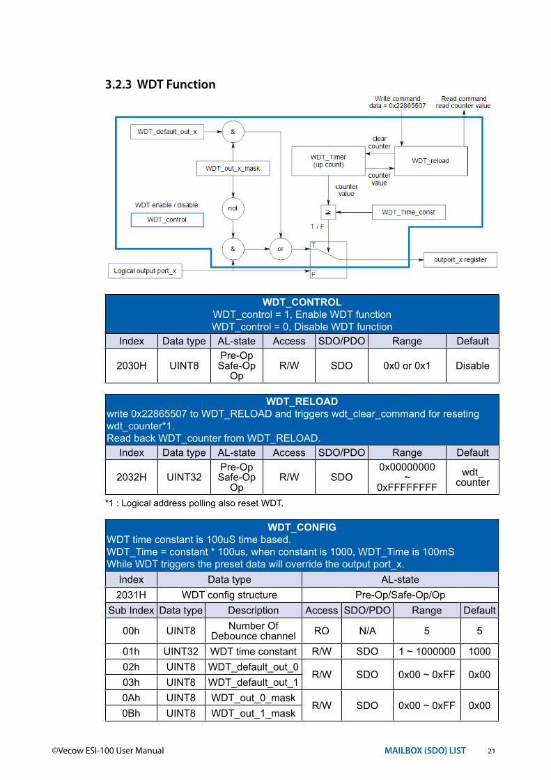
WDT_CONTROLWDT_control = 1, Enable WDT functionWDT_control = 0, Disable WDT function
Index Data type AL-state Access SDO/PDO Range Default
2030H UINT8Pre-OpSafe-Op
OpR/W SDO 0x0 or 0x1 Disable
WDT_RELOADwrite 0x22865507 to WDT_RELOAD and triggers wdt_clear_command for reseting wdt_counter*1.Read back WDT_counter from WDT_RELOAD.
Index Data type AL-state Access SDO/PDO Range Default
2032H UINT32Pre-OpSafe-Op
OpR/W SDO
0x00000000~
0xFFFFFFFFwdt_
counter
*1 : Logical address polling also reset WDT.
WDT_CONFIGWDT time constant is 100uS time based.WDT_Time = constant * 100us, when constant is 1000, WDT_Time is 100mSWhile WDT triggers the preset data will override the output port_x.
Index Data type AL-state2031H WDT config structure Pre-Op/Safe-Op/Op
Sub Index Data type Description Access SDO/PDO Range Default
00h UINT8 Number OfDebounce channel RO N/A 5 5
01h UINT32 WDT time constant R/W SDO 1 ~ 1000000 100002h UINT8 WDT_default_out_0
R/W SDO 0x00 ~ 0xFF 0x0003h UINT8 WDT_default_out_10Ah UINT8 WDT_out_0_mask
R/W SDO 0x00 ~ 0xFF 0x000Bh UINT8 WDT_out_1_mask
3.2.3 WDT Function

22©Vecow ESI-100 User Manual MAILBOX (SDO) LIST
IN_COUNTER_CONTROLIn_counter_control = 1, Enable in_counter functionIn_counter_control = 0, Disable in_counter function
Index Data type AL-state Access SDO/PDO Range Default
2040H UINT8Pre-OpSafe-Op
OpR/W SDO 0x0 or 0x1 Disable
IN_COUNTER_MASKinportx_counter_mask b0 for inx0_counter (x is port number)inportx_counter_mask b1 for inx1_counter (x is port number)
….inportx_counter_mask b7 for inx7_counter (x is port number)
Any bit =0, mask off (default)Any bit =1, no mask
Index Data type AL-state
2041H UINT8 array Pre-Op/Safe-Op/Op
Sub Index Data type Description Access SDO/PDO Range Default
00h UINT8 Number OfDebounce channel RO N/A 2 2
01h UINT8 Inport0_counter_maskR/W SDO
0x00~
0xFF0x00
02h UINT8 Inport1_counter_mask
3.2.4 In_counter Function

23©Vecow ESI-100 User Manual MAILBOX (SDO) LIST
IN_PORT0_COUNTERRead back in_counter value, or write/clear in_counter value
Index Data type AL-state
2048H UINT8 array Pre-Op/Safe-Op/Op
Sub Index Data type Description Access SDO/PDO Range Default
00h UINT8 Number OfDebounce channel RO N/A 8 8
01h UINT32 In00_counter
R/W SDO0x00000000
~0xFFFFFFFF
0x0000_0000
02h UINT32 In01_counter
03h UINT32 In02_counter
04h UINT32 In03_counter
05h UINT32 In04_counter
06h UINT32 In05_counter
07h UINT32 In06_counter
08h UINT32 In07_counter
IN_PORT1_COUNTERRead back in_counter value, or write/clear in_counter value
Index Data type AL-state
2049H UINT8 array Pre-Op/Safe-Op/Op
Sub Index Data type Description Access SDO/PDO Range Default
00h UINT8 Number OfDebounce channel RO N/A 8 8
01h UINT32 In10_counter
R/W SDO0x00000000
~0xFFFFFFFF
0x0000_0000
02h UINT32 In11_counter
03h UINT32 In12_counter
04h UINT32 In13_counter
05h UINT32 In14_counter
06h UINT32 In15_counter
07h UINT32 In16_counter
08h UINT32 In17_counter

For further support information, please visit www.vecow.com
This document is released for reference purpose only. All product offerings and specifications are subject to change without prior notice. No part of this publication may be reproduced in any form or by any means, electric, photocopying, or recording, without prior authorization from the publisher.The rights of all the brand names, product names, and trademarks belong to their respective owners. © Vecow Co., Ltd. 2021. All rights reserved.


![Highlights of ESI[truck] North America ESI[truck] North ...](https://static.fdocuments.net/doc/165x107/628b4a9ff91dad22754155f1/highlights-of-esitruck-north-america-esitruck-north-.jpg)