ESC Harrison County Power, LLC - WV Department of ...dep.wv.gov/daq/Documents/December 2016...
268
The business of sustainability ESC Harrison County Power, LLC Air Permit Application Combined-Cycle Power Plant Project Clarksburg, Harrison County, West Virginia November 2016 Environmental Resources Management 200 Princeton South, Suite 160 Ewing, NJ 08628 (609) 895-0050 www.erm.com
Transcript of ESC Harrison County Power, LLC - WV Department of ...dep.wv.gov/daq/Documents/December 2016...

The business of sustainability
ESC Harrison County Power, LLC Air Permit Application Combined-Cycle Power Plant Project Clarksburg, Harrison County, West Virginia
November 2016
Environmental Resources Management 200 Princeton South, Suite 160 Ewing, NJ 08628 (609) 895-0050
www.erm.com

ESC HARRISON COUNTY POWER, LLC i NOVEMBER 2016
TABLE OF CONTENTS
1.0 INTRODUCTION 1
1.1 PROJECT DESCRIPTION 1 1.1.1 Combustion Turbine/Duct Burners 2 1.1.2 Auxiliary Boiler 3 1.1.3 Fuel Gas Heater 3 1.1.4 Emergency Generator 4 1.1.5 Fire Water Pump 4 1.1.6 Dry Air Cooled Condenser 4
1.2 PROJECT SCHEDULE 5
1.3 APPLICATION ORGANIZATION 5
2.0 EXISTING AIR QUALITY 6
3.0 AIR PERMITTING CONSIDERATIONS 7
3.1 OVERVIEW 7
3.2 REGULATORY CONSIDERATIONS 7
3.3 AIR CONTAMINANT EMISSIONS 8 3.3.1 Emission Sources 8 3.3.2 Criteria Pollutant Potential Emissions 9
3.3.2.1 Combustion Turbine/Duct Burners 10 3.3.2.2 Auxiliary Boiler 13 3.3.2.3 Fuel Gas Heater 14 3.3.2.4 Emergency Generator and Fire Water Pump 15 3.3.2.5 Project Emissions Summary 16
3.3.3 Hazardous Air Pollutant Emissions 18 3.3.4 Greenhouse Gas Emissions 20
3.3.4.1 Combustion Equipment 20 3.3.4.2 Circuit Breakers 21
3.3.5 Ammonia Emissions 22
3.4 PREVENTION OF SIGNIFICANT DETERIORATION (PSD) 22 3.4.1 Applicability 22 3.4.2 Best Available Control Technology 25
3.4.2.1 BACT Analysis Process 26 3.4.2.2 BACT Analyses 28 3.4.2.3 Additional PSD Analyses 72

ESC HARRISON COUNTY POWER, LLC ii NOVEMBER 2016
3.5 NON-ATTAINMENT NEW SOURCE REVIEW (NA-NSR) 73
3.6 APPLICABLE REQUIREMENTS REVIEW 73 3.6.1 Federal Requirements 73
3.6.1.1 New Source Performance Standards (NSPS) 73 3.6.1.2 NSPS for GHGs (40 CFR Part 60) 75 3.6.1.3 Acid Rain Program (40 CFR Parts 72-76, 45 CSR 33) 75 3.6.1.4 National Emissions Standards for Hazardous Air
Pollutants 76 3.6.1.5 Compliance Assurance Monitoring 77 3.6.1.6 Chemical Accident Prevention Provisions 78 3.6.1.7 Cross-State Air Pollution Rule 78 3.6.1.8 Mandatory Reporting of Greenhouse Gases 79
3.6.2 State Requirements 80 3.6.2.1 45 CSR 02 (To Prevent and Control Particulate Air
Pollution from Combustion of Fuel in Indirect Heat Exchangers) 80
3.6.2.2 45 CSR 10 (To Prevent and Control Air Pollution from the Emission of Sulfur Oxides) 80
3.6.2.3 45 CSR 11 (Prevention of Air Pollution Emergency Episodes) 80
3.6.2.4 45 CSR 13 (Permits for Construction, Modification, Relocation and Operation of Stationary Sources of Air Pollutants, Notification Requirements, Administrative Updates, Temporary Permits, General Permits, Permission to Commence Construction, and Procedures for Evaluation) 80
3.6.2.5 45 CSR 14 (Permits for Construction and Major Modification of Major Stationary Sources of Air Pollution for the Prevention of Significant Deterioration) 81
3.6.2.6 45 CSR 16 (Standards of Performance for New Stationary Sources) 81
3.6.2.7 45 CSR 19 (Permits for Construction and Major Modification of Major Stationary Sources of Air Pollution Which Cause or Contribute to Nonattainment) 81
3.6.2.8 45 CSR 27 (To Prevent and Control the Emissions of Toxic Air Pollutants) 81
3.6.2.9 45 CSR 30 (Requirements for Operating Permits) 81 3.6.2.10 45 CSR 33 (Acid Rain Provisions and Permits) 82 3.6.2.11 45 CSR 34 (Emission Standards for Hazardous Air
Pollutants) 82
4.0 SUMMARY 83

ESC HARRISON COUNTY POWER, LLC iii NOVEMBER 2016
LIST OF TABLES
TABLE 3-1 ESC PROJECT - AIR CONTAMINANT EMISSION SOURCES
TABLE 3-2 STEADY STATE EMISSIONS – COMBUSTION TURBINE
TABLE 3-3 STARTUP AND SHUTDOWN EMISSIONS – COMBUSTION TURBINE
TABLE 3-4 TOTAL EMISSIONS – COMBUSTION TURBINE
TABLE 3-5 POTENTIAL EMISSIONS - AUXILIARY BOILER
TABLE 3-6 POTENTIAL EMISSIONS – FUEL GAS HEATER
TABLE 3-7 POTENTIAL EMISSIONS – EMERGENCY GENERATOR
TABLE 3-8 POTENTIAL EMISSIONS – FIRE WATER PUMP
TABLE 3-9 SHORT-TERM EMISSIONS SUMMARY
TABLE 3-10 ANNUAL EMISSIONS SUMMARY
TABLE 3-11 HAP EMISSIONS SUMMARY
TABLE 3-12 GHG EMISSIONS SUMMARY
TABLE 3-13 PSD AND NA-NSR APPLICABILITY SUMMARY
TABLE 3-14 PROPOSED NOX BACT
TABLE 3-15 PROPOSED CO BACT
TABLE 3-16 PROPOSED PM, PM10, AND PM2.5 BACT
TABLE 3-17 PROPOSED VOC BACT
TABLE 3-18 PROPOSED H2SO4 BACT
TABLE 3-19 PROPOSED GHG BACT
TABLE 3-20 EMISSION STANDARDS FOR EMERGENCY ENGINES

ESC HARRISON COUNTY POWER, LLC iv NOVEMBER 2016
LIST OF APPENDICES
APPENDIX A – CONCEPTUAL PLANT LAYOUT DRAWING
APPENDIX B – RACT/BACT/LAER CLEARINGHOUSE (RBLC) SEARCH SUMMARIES
APPENDIX C – GHG BACT SUPPLEMENT
APPENDIX D – COMPARISON OF GHG EMISSION RATES AND HEAT RATES FOR COMBUSTION TURBINES
APPENDIX E – AIR PERMIT APPLICATION FORMS
APPENDIX F – CHECK FOR AIR PERMITTING FEES

ESC HARRISON COUNTY POWER, LLC 1 NOVEMBER 2016
1.0 INTRODUCTION
1.1 PROJECT DESCRIPTION ESC Harrison County, LLC (ESC) proposes to construct, install, and operate a new natural gas fired combined-cycle combustion turbine (CT) electric power plant (Project). The Project site is located near the City of Clarksburg, Harrison County, West Virginia, in the Census Designated Place of Despard. The Project site is zoned for industrial use, and provides multiple strategic advantages that will allow the plant to produce low cost base load electricity. The proposed primary point of interconnection is a direct 138 kilovolt (kV) interconnection to the First Energy’s (Allegheny Power’s) existing Glen Falls 138 kV substation, about 2 miles north of the project site. Plant output will be sold into the Pennsylvania-New Jersey-Maryland Interconnection LLC (PJM) regional electric grid.
This new plant requires preconstruction approval of an air permit under the federal Prevention of Significant Deterioration (PSD) program (40 CFR 52.21) and under West Virginia Department of Environmental Protection (WVDEP or The Department) regulations 45 CSR 13 and 14.
The emission sources associated with the Project are:
• One (1) General Electric (GE) Frame 7HA.02 advanced combined-cycle CT, with a Heat Recovery Steam Generator (HRSG) equipped with Duct Burners (DB), both firing pipeline quality natural gas;
• One (1) Auxiliary Boiler with a maximum heat input of 77.8 million British Thermal Units per hour (MMBtu/hr) which will burn pipeline quality natural gas;
• One (1) Fuel Gas Heater with a maximum heat input of 5.5 MMBtu/hr which will burn pipeline quality natural gas;
• One (1) 2,000 kilowatt (kW) Emergency Generator fueled by ultra-low sulfur diesel (ULSD) fuel;
• One (1) 315 horsepower (hp) emergency Fire Water Pump fueled by ULSD; and
• Diesel fuel, lubricating oil, and aqueous ammonia storage tanks.

ESC HARRISON COUNTY POWER, LLC 2 NOVEMBER 2016
Cooling of the plant’s steam driven electric generator will be achieved using a Dry Air Cooled Condenser (DACC).
Appendix A contains a conceptual plant layout drawing.
1.1.1 Combustion Turbine/Duct Burners Electricity will be generated using one (1) combined-cycle CT, with a design maximum heat input of approximately 3,496.2 million British Thermal Units per hour (MMBtu/hr)1, on a Higher Heating Value (HHV) basis. The CT will drive a generator to produce electricity. The electricity generated by the CT will be routed through a local electrical substation and sold on the grid. The highly efficient combined-cycle CT (HCCT-1) will be equipped with an inlet evaporative cooling system used at higher ambient temperatures to increase the density of the combustion air, thereby increasing fuel and mass flow and, in turn, power output. The air density increase will be accomplished by evaporating water into the inlet air, which will decrease air temperature and correspondingly increase air density.
The CT will be coupled with a HRSG to produce steam and additional electricity. The HRSG contains a series of heat exchangers designed to recover the heat from the CT exhaust gas and produce steam, as in a boiler. The Project includes the installation of DB to produce additional steam in the HRSG for additional power output from the steam turbine generator. The maximum duct firing level is expected to be 1,001.3 MMBtu/hr on a HHV basis. The fuel for the DBs will be the same as for the CT: pipeline-quality natural gas.
Steam generated in the HRSG is routed to a steam driven turbine with a dedicated electric generator. This generator produces additional electricity
1 Combustion turbine output and heat input vary by several factors, including ambient temperature, relative humidity, fuel, load level, whether duct firing or evaporative cooling are in use, etc. 3,496.2 MMBtu/hr is the expected maximum heat input for the CT, which occurs in at an operating case with an ambient temperature of -12.2 °F, 80% relative humidity, natural gas firing, base load, with 100% duct firing, and with evaporative cooling off.
ESC HARRISON COUNTY POWER, LLC 3 NOVEMBER 2016
that will also be routed through a local electrical substation and sold on the grid. The CT will be equipped with dry low-NOx (DLN) combustors. These combustion controls, along with Selective Catalytic Reduction (SCR) systems, will control emissions of nitrogen oxides (NOx) from the CT. An Oxidation Catalyst will be used to control carbon monoxide (CO) and volatile organic compounds (VOC) emissions from the CT. The SCR and Oxidation Catalyst will be incorporated into the HRSG, at locations where the emission control reactions optimally occur. SCR involves the injection of aqueous ammonia (NH3) with a concentration of less than 20% by weight into the CT/DBs exhaust gas stream. Ammonia reacts with NOx in the CT exhaust gas stream, reducing it to elemental nitrogen (N2) and water vapor (H2O). The aqueous ammonia will be stored on-site in one (1) storage tank with a capacity of approximately 35,000 gallons. The aqueous ammonia storage tank will not normally vent to the atmosphere. It will be equipped with pressure relief valves that would only vent in the event of an over pressure situation. The Oxidation Catalyst does not require the use of reagents.
The CT/DB will have its own exhaust stack, which is expected to have a height of 205 feet above grade.
For permitting and emissions estimating purposes, this application assumes that the CT/DBs will operate 8,760 hours per year (hr/yr).
1.1.2 Auxiliary Boiler
A 77.8 MMBtu/hr Auxiliary Boiler (AB-1) will be used to produce steam for plant support. The Auxiliary Boiler will burn pipeline-quality natural gas. The Auxiliary Boiler will be equipped with low-NOx burners (LNB) to control NOx emissions.
For permitting and emissions estimating purposes, this application assumes that the Auxiliary Boiler will operate, on a Btu/yr basis, the equivalent of 4,576 hr/yr.
1.1.3 Fuel Gas Heater
A 5.5 MMBtu/hr Fuel Gas Heater (FGH-1) will be used to preheat the gaseous fuel received by the plant. Preheating the fuel prior to combustion in the combined-cycle CT (HCCT-1) increases the efficiency of the CT, safeguards the fuel pipelines from icing, and protects the CT from fuel condensates.
ESC HARRISON COUNTY POWER, LLC 4 NOVEMBER 2016
For permitting and emissions estimating purposes, this application assumes that the Fuel Gas Heater will operate 8,760 hr/yr.
1.1.4 Emergency Generator
A 2,000 kW Emergency Generator (EG-1) will be used for emergency backup electric power. The fuel for the Emergency Generator will be ULSD, with a sulfur content no greater than 0.0015% by weight. The Emergency Generator will be periodically operated for short periods per manufacturer’s maintenance instructions to ensure operational readiness in the event of an emergency.
The ULSD fuel for the Emergency Generator will be stored in a 3,000-gallon Emergency Generator Tank (ST-2).
The Emergency Generator will operate no more than 100 hr/yr for maintenance and readiness testing. Other than maintenance and readiness testing, this engine will be used only for emergency purposes. For permitting and emissions estimating purposes, this application assumes that the Emergency Generator will operate a maximum of 100 hr/yr.
1.1.5 Fire Water Pump
A 315 hp Fire Water Pump (FP-1) will be used for plant fire protection. The fuel for the Fire Water Pump will also be ULSD, with a sulfur content no greater than 0.0015% by weight. The Fire Water Pump will also be periodically operated for short periods per manufacturer’s maintenance instructions to ensure operational readiness in the event of an emergency.
The ULSD fuel for the Fire Water Pump will be stored in a 500-gallon Fire Water Pump Tank (ST-1).
The Fire Water Pump will operate no more than 100 hr/yr for maintenance and readiness testing. Other than maintenance and readiness testing, the Fire Water Pump will be used only for emergency purposes. For permitting and emissions estimating purposes, this application assumes that the Fire Water Pump will operate a maximum of 100 hr/yr.
1.1.6 Dry Air Cooled Condenser
The Project will use a DACC in lieu of a conventional wet cooling tower for steam turbine generator steam condensation. The steam produced in the HRSG will be used in the steam turbine to produce additional electrical power. Once the steam does its work in the steam turbine, it is exhausted and condensed under vacuum in the DACC. The cycle is a closed loop
ESC HARRISON COUNTY POWER, LLC 5 NOVEMBER 2016
system, and the condensate is reused as feed water to the HRSG. The DACC will minimize the use of water at the plant. The DACC will not generate particulate matter (PM) emissions typically associated with wet cooling tower drift losses. Therefore, the DACC is not considered an emissions source.
1.2 PROJECT SCHEDULE
ESC wishes to obtain WVDEP air permit approval by October 2017 to provide sufficient time for financing, equipment ordering, fabrication, construction, and installation, and achieving commercial operation by June 2020.
1.3 APPLICATION ORGANIZATION
This application is organized into the following major sections: • Section 2.0 provides a description of the existing site conditions; • Section 3.0 includes the emissions, regulatory and control technology
analyses; • Section 4.0 summarizes conclusions; • Appendix A contains conceptual plant layout drawings; • Appendix B contains RACT/BACT/LAER Clearinghouse (RBLC)
search summaries; • Appendix C contains a supplemental discussion and cost effectiveness
evaluation for GHG BACT; • Appendix D contains a comparison of combustion turbine GHG
emission rates and heat rates; • Appendix E contains completed and certified versions of all the
relevant WVDEP Division of Air Quality application forms and attachments; and
• Appendix F contains a check for $14,500, payable to the “WVDEP Air Pollution Control Fund”, for the applicable air permitting fees.
Note that the Air Quality Modeling Protocol for this Project is being submitted under a separate cover.

ESC HARRISON COUNTY POWER, LLC 6 NOVEMBER 2016
2.0 EXISTING AIR QUALITY
The United States Environmental Protection Agency (USEPA) and state agencies, such as the West Virginia Department of Environmental Protection (WVDEP), monitor concentrations of the “criteria” pollutants NOX, sulfur dioxide (SO2), particulate matter (PM), ozone, CO, and lead (Pb) in ambient air at locations throughout the United States. If monitoring data indicate that the concentration of a pollutant exceeds the National Ambient Air Quality Standard (NAAQS) in any area, then that area is classified as a “non-attainment area” for that pollutant, meaning that the area is not meeting the ambient standard. Conversely, any area in which the concentration of a criteria pollutant is below the NAAQS is classified as an “attainment area” indicating that the NAAQS is being met.
The attainment/non-attainment designations are made by states and USEPA on a pollutant-by-pollutant basis. Therefore, the air quality in an area may be designated attainment for some pollutants and non-attainment for other pollutants at the same time. For example, many cities are designated non-attainment for ozone, but are in attainment for the other criteria pollutants.
The Project location in Harrison County is in attainment for all of the NAAQS for criteria pollutants.
ESC HARRISON COUNTY POWER, LLC 7 NOVEMBER 2016
3.0 AIR PERMITTING CONSIDERATIONS
3.1 OVERVIEW
Potential air pollutant emissions from the Project were evaluated to ensure that the Project will meet all applicable regulatory limits and requirements. The proposed Project was also evaluated to determine whether its emissions are predicted to have any significant impacts on the existing ambient air quality in the region. This evaluation is to be completed through air quality dispersion modeling studies that predict the ambient air concentrations resulting from emission sources associated with the proposed Project. This ambient impact assessment will follow a protocol that is being filed separately from this application.
3.2 REGULATORY CONSIDERATIONS
The USEPA has defined concentration-based NAAQS, which are set at levels considered protective of the public health and welfare. Specifically, the NAAQS have been defined for six (6) “criteria” pollutants, which are PM, SO2, CO, nitrogen dioxide (NO2), ozone, and Pb. Three (3) forms of particulate matter are regulated: total suspended particulate (known as PM or TSP), PM10, and PM2.5.
Emission limits and air pollution control requirements are generally more stringent for sources located in areas that do not attain a NAAQS for a particular pollutant (known as “non-attainment” areas). The air quality in Harrison County and the vicinity of the proposed Project is in attainment (or unclassifiable) for all pollutants.
Potential emissions from new and modified sources in attainment areas are evaluated through the Prevention of Significant Deterioration (PSD) program. The goal of the PSD program is to ensure that emissions from major sources do not degrade air quality. Triggering PSD requires air pollution control known as the Best Available Control Technology (BACT) and additional impact assessments.
The proposed ESC Project has the potential to emit the criteria pollutants PM, PM10, PM2.5, CO, NO2, SO2, and Pb; ozone precursors; several hazardous air pollutants (HAPs); and greenhouse gases (GHGs). Because the area in which the proposed Project will be located is attainment/unclassifiable for the criteria pollutants, applicability of the

ESC HARRISON COUNTY POWER, LLC 8 NOVEMBER 2016
PSD regulation was assessed to ensure no adverse impacts would be caused by the Project. These evaluations are contained in Sections 3.4 (PSD).
Other Federal and State air quality regulations apply to the proposed Project. These regulations apply either because of the type of emission source to be constructed, or because of the pollutants to be emitted from the Project. These regulations, discussed in Section 3.6, specify limits on pollutant emissions, and impose recordkeeping and reporting requirements.
3.3 AIR CONTAMINANT EMISSIONS
3.3.1 Emission Sources
The Project emission sources include:
• One (1) GE Frame 7HA.02 advanced combined-cycle CT, with a design maximum heat input of 3,496.2 MMBtu/hr, and with a HRSG equipped with Duct Burners;
• One (1) 77.8 MMBtu/hr Auxiliary Boiler;
• One (1) 5.5 MMBtu/hr Fuel Gas Heater;
• One (1) 2,000 kW Emergency Generator;
• One (1) 315 hp emergency Fire Water Pump;
Table 3-1 summarizes the specifications for the proposed equipment.

ESC HARRISON COUNTY POWER, LLC 9 NOVEMBER 2016
Table 3-1 Project Air Contaminant Emission Sources
3.3.2 Criteria Pollutant Potential Emissions
Potential emissions from the Project were estimated using various calculation methodologies including vendor data, emission factors from USEPA’s Compilation of Air Pollutant Emission Factors (AP-42) publication, material balances, New Source Performance Standards (NSPS) emission standards, and/or engineering calculations. Backup emission calculations are provided in Attachment N of the Air Permit Application Forms package in Appendix E of this application.
Component (Number of
Units) Type/Model Size/Capacity Fuel(s) Proposed Maximum
Operations
CT/DBs (1) GE Frame 7HA.02
CT: 3,496.2 MMBtu/hr
DBs: 1,001.3 MMBtu/hr
Natural gas 8,760 hr/yr
Auxiliary Boiler (1)
To be determined prior to construction 77.8 MMBtu/hr
Natural gas
355,894 MMBtu/yr (equivalent to 4,576
hr/yr at 77.8 MMBtu/hr)
Fuel Gas Heater (1)
To be determined prior to construction 5.5 MMBtu/hr
Natural gas
8,760 hr/yr
Emergency Generator (1)
To be determined prior to construction 2,000 kW ULSD
100 hr/hr (limited to emergency use and
100 hr/yr for maintenance and readiness testing)
Emergency Fire Water Pump (1)
To be determined prior to construction 315 hp ULSD
100 hr/yr (limited to emergency use and
100 hr/yr for maintenance and readiness testing)

ESC HARRISON COUNTY POWER, LLC 10 NOVEMBER 2016
3.3.2.1 Combustion Turbine/Duct Burners
3.3.2.1.1 Steady State Operations
Potential emissions of NOx, CO, PM, PM10, PM2.5, VOC, and carbon dioxide (CO2) from the CT/DBs are based on manufacturer specifications provided by GE. SO2 and sulfuric acid (H2SO4) emissions are based on a sulfur content of the fuel of 0.4 grains per 100 standard cubic feet (gr/100 scf). Pb emissions were estimated using AP-42 emission factors.
Potential short-term emission rates (lb/hr) were determined based on the GE data, which encompasses the expected range of CT operating loads and ambient temperatures, with and without the use of inlet air evaporative cooling, and with and without duct firing. From the GE data, the potential short-term emission rates for NOx, CO, SO2, PM, PM10, PM2.5, VOC, H2SO4, and CO2 for the CT/DBs were established by selecting the maximum lb/hr emission rates across the expected operating load and ambient temperature ranges.
Potential annual emissions (tons/yr) were then calculated by multiplying the maximum short-term emission rates by 8,760 hr/yr, then dividing by 2,000 to convert pounds to tons.
Maximum short-term and annual emissions from the CT/DBs during steady state operations are summarized in Table 3-2.

ESC HARRISON COUNTY POWER, LLC 11 NOVEMBER 2016
Table 3-2 Steady State Emissions – Combustion Turbine/Duct Burners (1)
Pollutant
Short Term Emissions
(lb/hr)
Annual Emissions
(ton/yr)
VOC(2) 11.4 49.9 NOx(3) 32.9 144.1
CO 20.0 87.6 SO2 6.0 26.1
PM/PM10/PM2.5 22.6 99.0 Pb 0.002 0.01
H2SO4 3.8 16.7 CO2 528,000 2,312,640
CH4 9.9 43.4
N2O 1.0 4.3
GHG (Mass Basis) 528,011 2,312,688
GHG (CO2e Basis) 528,543 2,315,020
(1) Emissions are post-HRSG stack emissions. (2) VOC emissions are expressed as methane (CH4). (3) NOx emissions are expressed as nitrogen dioxide (NO2).
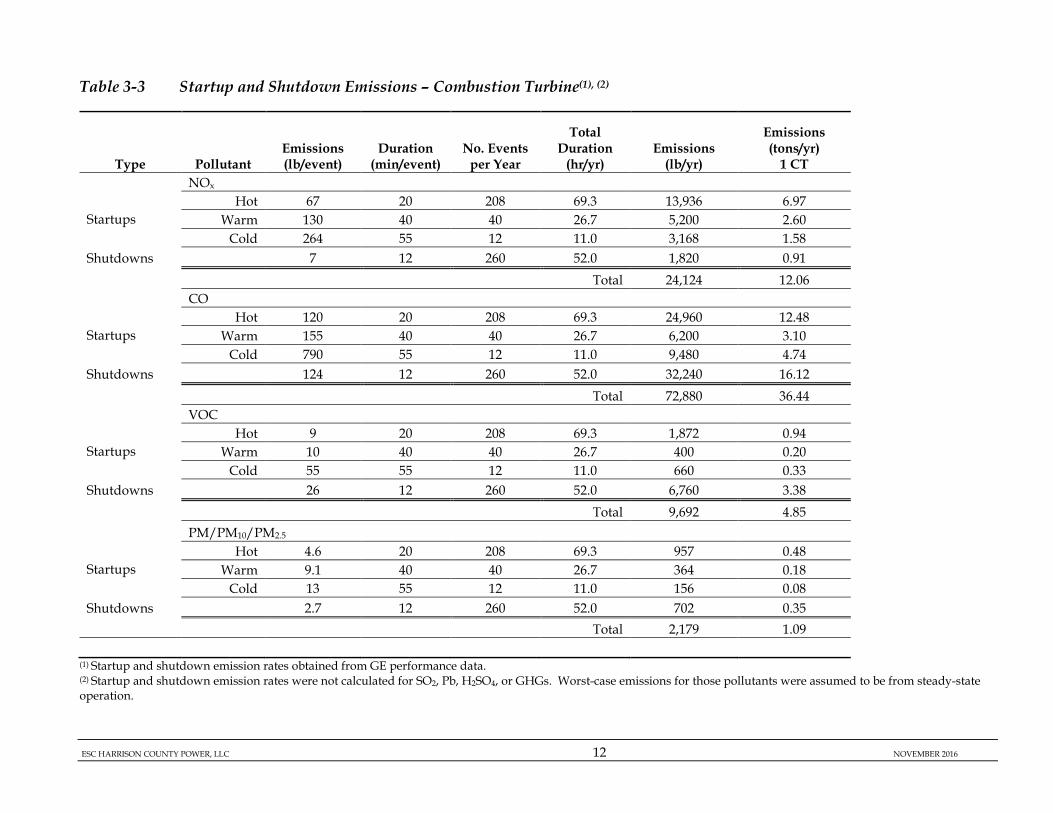
3.3.2.1.2 Startups and Shutdowns
The CT is projected to undergo 260 startups per year. Of these 260 startups, approximately 208 are projected to be hot startups, 40 are projected to be warm startups, and 12 are projected to be cold startups. Accordingly, approximately 260 shutdowns per year are projected.
A hot start is defined as a start following 8 hours of shutdown or less. A cold start is defined as a start following 72 hours of shutdown or more. Any start following more than 8 hours of shutdown or less than 72 hours of shutdown is classified as a warm start. Table 3-3 summarizes startup and shutdown emissions and event durations for the CT, as well as the total startup and shutdown emissions from the CT. To maximize operational flexibility, given the unpredictability of the number and types of startup and shutdown events that may actually occur, ESC is requesting combined annual emission limits for startup and shutdown events in the air permit, without a limit on the specific numbers of hot, warm, and cold starts.
ESC HARRISON COUNTY POWER, LLC 12 NOVEMBER 2016
Table 3-3 Startup and Shutdown Emissions – Combustion Turbine(1), (2)
Type Pollutant Emissions (lb/event)
Duration (min/event)
No. Events per Year
Total Duration
(hr/yr) Emissions
(lb/yr)
Emissions (tons/yr)
1 CT
NOx
Startups Hot 67 20 208 69.3 13,936 6.97
Warm 130 40 40 26.7 5,200 2.60 Cold 264 55 12 11.0 3,168 1.58
Shutdowns 7 12 260 52.0 1,820 0.91
Total 24,124 12.06
CO
Startups Hot 120 20 208 69.3 24,960 12.48
Warm 155 40 40 26.7 6,200 3.10 Cold 790 55 12 11.0 9,480 4.74
Shutdowns 124 12 260 52.0 32,240 16.12
Total 72,880 36.44
VOC
Startups Hot 9 20 208 69.3 1,872 0.94
Warm 10 40 40 26.7 400 0.20 Cold 55 55 12 11.0 660 0.33
Shutdowns 26 12 260 52.0 6,760 3.38
Total 9,692 4.85
PM/PM10/PM2.5
Startups Hot 4.6 20 208 69.3 957 0.48
Warm 9.1 40 40 26.7 364 0.18 Cold 13 55 12 11.0 156 0.08
Shutdowns 2.7 12 260 52.0 702 0.35
Total 2,179 1.09
(1) Startup and shutdown emission rates obtained from GE performance data. (2) Startup and shutdown emission rates were not calculated for SO2, Pb, H2SO4, or GHGs. Worst-case emissions for those pollutants were assumed to be from steady-state operation.

ESC HARRISON COUNTY POWER, LLC 13 NOVEMBER 2016
3.3.2.1.3 Total Combustion Turbine/Duct Burner Emissions Table 3-4 summarizes the total annual emissions from the CT/DBs, including emissions from both steady state operations and CT startup and shutdown events.
Table 3-4 Total Emissions – Combustion Turbine/Duct Burners(1)
Pollutant
Maximum Annual Steady State Emissions:
CT/DBs (tons/yr)
Startup and Shutdown
Emissions: CT (tons/yr)
Total Emissions:
CT/DBs (tons/yr)
VOC 49.9 4.8 54.8 NOx 144.1 12.1 156.2 CO 87.6 36.4 124.0 SO2 26.1 -- (1) 26.1
PM/PM10/PM2.5 99.0 1.09 100.1 Pb 0.01 -- (1) 0.01
H2SO4 16.7 -- (1) 16.7 GHG (CO2e Basis) 2,315,020 -- (1) 2,315,020
(1) Startup and shutdown emission rates were not calculated for SO2, Pb, H2SO4, or GHGs. Worst-case emissions for those pollutants were assumed to be from steady-state operation.
3.3.2.2 Auxiliary Boiler
Auxiliary Boiler emissions are based on performance information from a potential vendor. PM10 and PM2.5 emissions are assumed equal to PM emissions. Short-term SO2 emissions are conservatively based on a fuel sulfur content of 0.4 gr/100 scf. In addition, AP-42 factors are used for estimating emissions of Pb and HAPs from the boiler. HAP emissions are discussed in Section 3.3.3. The following assumptions were made to calculate Auxiliary Boiler emissions:
• Exclusive use of pipeline-quality natural gas fuel;
• Maximum annual heat input of 355,894 MMBtu per year (MMBtu/yr), which is equivalent to 4,576 hr/yr of operation at a maximum heat input of 77.8 MMBtu/hr.
Potential emissions of regulated pollutants from the Auxiliary Boiler are summarized in Table 3-5.

ESC HARRISON COUNTY POWER, LLC 14 NOVEMBER 2016
Table 3-5 Potential Emissions - Auxiliary Boiler
Pollutant Maximum Short Term
Emission Rate Maximum Annual
Emissions (lb/ hr) (tons/yr)
VOC 0.62 1.42 NOx 0.86 1.96 CO 2.88 6.58 SO2 0.09 0.20
PM/PM10/PM2.5 0.60 1.38 Pb 3.78E-05 8.64E-05
H2SO4 1.32E-02 3.02E-02 GHG (CO2e Basis) 9,107 20,837
3.3.2.3 Fuel Gas Heater
The vendor for the Fuel Gas Heater has not yet been selected. Fuel Gas Heater Emissions are estimated using emission factors from AP-42. PM10 and PM2.5 emissions are assumed to equal PM emissions. Short-term SO2 emissions are conservatively based on a fuel sulfur content of 0.4 gr/100 scf. HAP emissions are discussed in Section 3.3.3. The following assumptions were made to calculate Fuel Gas Heater emissions:
• Exclusive use of pipeline-quality natural gas fuel; and
• Maximum annual heat input of 47,918 MMBtu/yr, which is equivalent to 8,760 hr/yr of operation at a maximum heat input of 5.5 MMBtu/hr.
Potential emissions from the Fuel Gas Heater are summarized in Table 3-6.
Table 3-6 Potential Emissions - Fuel Gas Heater
Regulated Pollutant Maximum Short Term
Emissions Maximum Annual
Emissions (lb/hr) (tons/yr)
VOCs 0.04 0.17 NOX 0.20 0.86 CO 0.21 0.93 SO2 0.01 0.03
PM/PM10/PM2.5 0.04 0.19
Pb 2.66E-06 1.16E-05
H2SO4 9.29E-04 4.07E-03 GHG (CO2e Basis) 641 2,806

ESC HARRISON COUNTY POWER, LLC 15 NOVEMBER 2016
3.3.2.4 Emergency Generator and Fire Water Pump
Potential emissions of regulated pollutants from the Emergency Generator and Fire Water Pump are summarized in Tables 3-7 and 3-8, respectively. The vendors for the Emergency Generator have not yet been selected. Emissions for the Emergency Generator were estimated based on emission factors from potential vendors, and/or the applicable NSPS emission standards for stationary compression ignition (CI) reciprocating internal combustion engines (RICE) specified in 40 CFR 60, Subpart IIII.
PM10 and PM2.5 emissions are assumed to equal PM emissions. The emission factors assume operation at full load, which is reasonable given its expected use.
The vendor for the Fire Water Pump has not yet been selected. However, the Fire Water Pump emissions will not exceed the emission limits specified in NSPS Subpart IIII. As such, NOx, PM and PM10, and CO emissions from the Fire Water Pump are based on the applicable emission standards for these pollutants in NSPS Subpart IIII. Emissions of VOC, SO2 and HAPs and were based on AP-42 emission factors.
Per 40 CFR 60, Subpart IIII, total hours for maintenance and readiness testing will not exceed 100 hr/yr. Other than maintenance and readiness testing, these units are utilized only for emergency purposes, and guidance for estimating potential emissions from emergency units is to assume maximum annual operation of 100 hr/yr. For both the Emergency Generator and Fire Water Pump, potential emissions were calculated based on 100 hr/yr of operation.
HAP emission estimates are discussed in Section 3.3.3.

ESC HARRISON COUNTY POWER, LLC 16 NOVEMBER 2016
Table 3-7 Potential Emissions - Emergency Generator
Pollutant
Emergency Generator
Maximum Short Term Emissions
Emergency Generator
Maximum Annual Emissions
(lb/hr) (tons/yr)
VOC 0.65 0.03 NOx 32.22 1.61 CO 1.77 0.09 SO2 0.03 0.001
PM/PM10/PM2.5 0.15 0.01 Pb --- ---
H2SO4 3.58E-03 1.79E-04 GHG (CO2e Basis) 3,161 158
Table 3-8 Potential Emissions - Fire Water Pump
Pollutant
Fire Water Pump Maximum Short Term Emissions
Fire Water Pump Maximum Annual
Emissions
(lb/hr) (tons/yr)
VOC 0.06 0.003 NOx 1.87 0.09 CO 0.31 0.02 SO2 0.003 1.6E-04
PM/PM10/PM2.5 0.05 0.003 Pb --- ---
H2SO4 3.89E-04 1.94E-05 GHG (CO2e Basis) 344 17
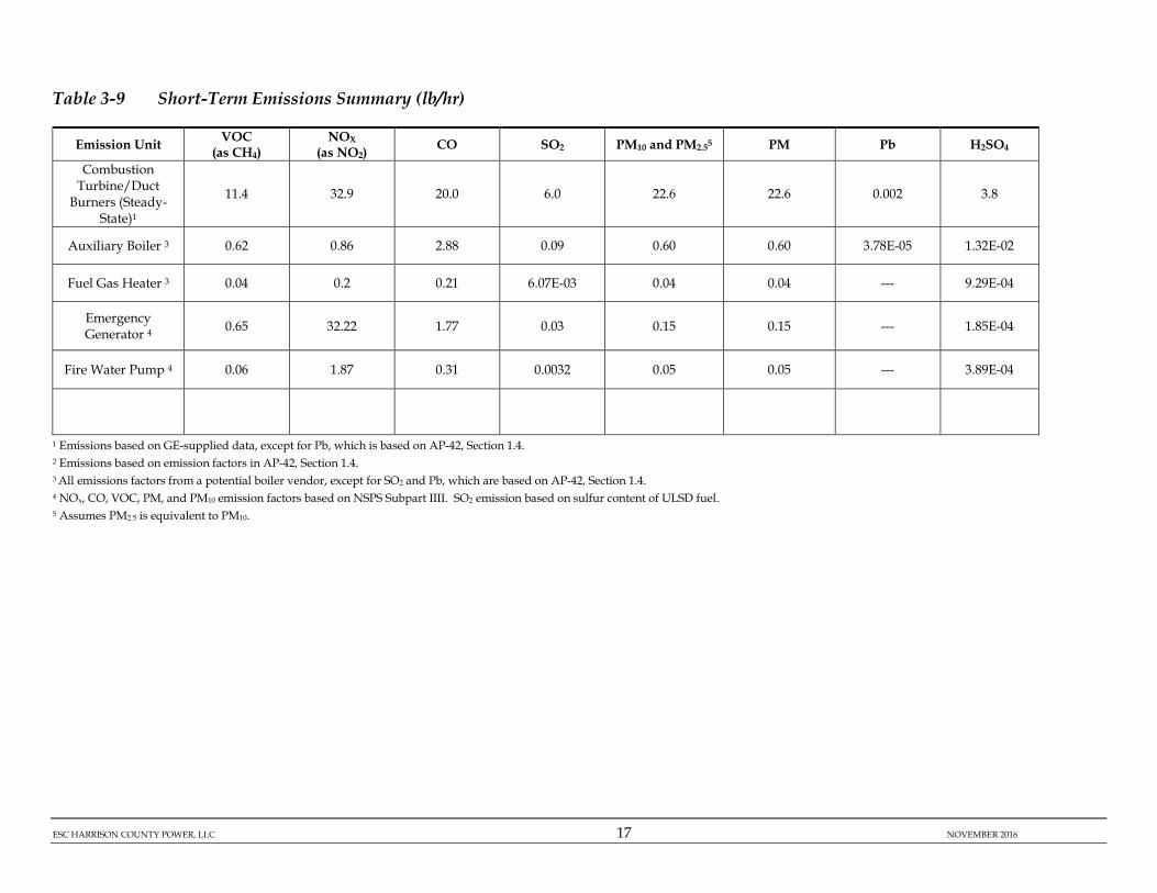
3.3.2.5 Project Emissions Summary
Table 3-9 summarizes the potential short-term emissions rates for the proposed Project. Potential annual emissions from the Project are summarized in Table 3-10.
ESC HARRISON COUNTY POWER, LLC 17 NOVEMBER 2016
Table 3-9 Short-Term Emissions Summary (lb/hr)
Emission Unit VOC (as CH4)
NOX (as NO2)
CO SO2 PM10 and PM2.55 PM Pb H2SO4
Combustion Turbine/Duct
Burners (Steady-State)1
11.4 32.9 20.0 6.0 22.6 22.6 0.002 3.8
Auxiliary Boiler 3 0.62 0.86 2.88 0.09 0.60 0.60 3.78E-05 1.32E-02
Fuel Gas Heater 3 0.04 0.2 0.21 6.07E-03 0.04 0.04 --- 9.29E-04
Emergency Generator 4 0.65 32.22 1.77 0.03 0.15 0.15 --- 1.85E-04
Fire Water Pump 4 0.06 1.87 0.31 0.0032 0.05 0.05 --- 3.89E-04
1 Emissions based on GE-supplied data, except for Pb, which is based on AP-42, Section 1.4. 2 Emissions based on emission factors in AP-42, Section 1.4. 3 All emissions factors from a potential boiler vendor, except for SO2 and Pb, which are based on AP-42, Section 1.4. 4 NOx, CO, VOC, PM, and PM10 emission factors based on NSPS Subpart IIII. SO2 emission based on sulfur content of ULSD fuel. 5 Assumes PM2.5 is equivalent to PM10.

ESC HARRISON COUNTY POWER, LLC 18 NOVEMBER 2016
Table 3-10 Annual Emissions Summary (tons/yr)
Unit VOC NOx CO SO2 PM10 PM PM2.5 Pb H2SO4 CO2e
CT/DBs: Steady State 49.9 144.1 87.6 26.1 99.0 99.0 99.0 0.01 16.7 2,315,020
CT: Startups & Shutdowns 4.8 12.1 36.4 -- 1.1 1.1 1.1 -- -- --
Auxiliary Boiler 1.42 1.96 6.58 0.20 1.38 1.38 1.38 8.6E-05 0.030 20,837
Fuel Gas Heater 0.17 0.86 0.93 0.03 0.19 0.19 0.19 -- 4.07E-03 2,806 Emergency Generator 0.03 1.61 0.09 1.46E-03 0.01 0.01 0.01 -- 3.58E-03 158
Fire Water Pump 0.003 0.09 0.02 1.59E-04 0.003 0.003 0.003 0.00 1.94E-05 17
Circuit Breakers -- -- -- -- -- -- -- -- -- 58
Total 56.4 160.7 131.7 26.3 101.7 101.7 101.7 0.01 16.8 2,338,896
3.3.3 Hazardous Air Pollutant Emissions
With the exception of formaldehyde emissions from the CT/DBs, appropriate AP-42 sections (Section 1.4 for External Combustion Sources - Natural Gas, Section 3.1 for Stationary Internal Combustion Sources – Stationary Gas Turbines, Section 3.3 for Gasoline and Diesel Industrial Engines, and Section 3.4 for Large Stationary Diesel and All Stationary Dual-fuel Engines) provide emission factors for organic and metal compounds resulting from combustion, some of which are HAPs. Formaldehyde emissions from the CT/DBs are based on an EPA emission factor for CTs.2 The formaldehyde emission factor of 3.0E-04 lb/MMBtu was obtained by taking the formaldehyde factor in Table 3 of EPA’s August 21, 2001 memo of 2.92E-03 lb/MMBtu, which was rounded up to 3.0E-03 lb/MMBtu. A control efficiency of 90% was then applied to account for the use of the Oxidation Catalyst, which results in a controlled formaldehyde emission factor of 3.0E-04 lb/MMBtu.
2 EPA, Office of Air Quality Planning and Standards (OAQPS), Emission Standards Division, Combustion Group, Hazardous Air Pollutant (HAP) Emission Control Technology for New Stationary Combustion Turbines, Sims Roy, Docket A-95-51, August 21, 2001, Table 3.

ESC HARRISON COUNTY POWER, LLC 19 NOVEMBER 2016
A removal efficiency of 90% was applied to all other organic HAP emissions from the CT/DBs, to account for the use of the Oxidation Catalyst.
Estimated HAP emissions from the proposed Project are summarized in Table 3-11. A facility is considered a "major" source of HAPs if it has the potential to emit 10 tons/yr or more of any individual HAP, or 25 tons/yr or more of all HAPs combined. As shown in Table 3-11, maximum emissions of any single HAP are4.64 tons/yr (hexane), and estimated total HAP emissions from the Project are 6.23 tons/yr. Therefore, the Project is not a major source of HAPs.

ESC HARRISON COUNTY POWER, LLC 20 NOVEMBER 2016
Table 3-11 HAP Emissions Summary
Hazardous Air Pollutant (HAP)
CT (lb/hr)
DBs (lb/hr)
Auxiliary Boiler (lb/hr)
Fuel Gas
Heater (lb/hr)
Emergency Generator
(lb/hr)
Fire Water Pump (lb/hr)
Facility Total
(tons/yr)
2-Methylnaphthalene NA 2.33E-06 1.81E-06 1.27E-07 NA NA 1.49E-05
Acetaldehyde 1.40E-02 NA NA NA 4.87E-04 1.61E-03 6.14E-02 Acrolein 2.24E-03 NA NA NA 1.52E-04 7.88E-04 9.81E-03 Arsenic NA 1.94E-04 1.51E-05 1.06E-06 NA NA 8.91E-04 Benzene 4.20E-03 2.04E-04 1.59E-04 1.12E-05 1.50E-02 1.96E-03 2.05E-02
Cadmium NA 1.07E-03 8.31E-05 5.84E-06 NA NA 4.90E-03 Chromium NA 1.36E-03 1.06E-04 7.44E-06 NA NA 6.24E-03
Cobalt NA 8.17E-05 6.34E-06 4.46E-07 NA NA 3.74E-04 Dichlorobenzene NA 1.17E-04 9.06E-05 6.37E-06 NA NA 7.46E-04
Ethylbenzene 1.12E-02 NA NA NA NA NA 4.90E-02 Fluoranthene NA 2.92E-07 2.27E-07 1.59E-08 NA NA 1.87E-06
Fluorene NA 2.72E-07 2.11E-07 1.49E-08 NA NA 1.74E-06 Formaldehyde 1.05E+00 7.29E-03 5.66E-03 3.98E-04 1.52E-03 2.48E-03 4.64E+00
Hexane NA 1.75E-01 1.36E-01 9.56E-03 NA NA 1.12E+00 Manganese NA 3.69E-04 2.87E-05 2.02E-06 NA NA 1.69E-03
Mercury NA 2.53E-04 1.96E-05 1.38E-06 NA NA 1.16E-03 Naphthalene 4.55E-04 5.93E-05 4.61E-05 3.24E-06 2.51E-03 1.78E-04 2.50E-03
Nickel NA 2.04E-03 1.59E-04 1.12E-05 NA NA 9.35E-03 Phenanathrene NA 1.65E-06 1.28E-06 9.03E-08 NA NA 1.06E-05
POM 7.69E-04 NA NA NA 4.10E-03 3.53E-04 3.59E-03 Pyrene NA 4.86E-07 3.78E-07 2.66E-08 NA NA 3.11E-06 Toluene 4.55E-02 3.31E-04 2.57E-04 1.81E-05 5.43E-03 8.59E-04 2.02E-01 Xylenes 2.24E-02 NA NA NA 3.73E-03 5.99E-04 9.82E-02
Maximum Individual HAP 4.64
Total HAPs 6.23
3.3.4 Greenhouse Gas Emissions
3.3.4.1 Combustion Equipment
Potential GHG emissions [i.e. CO2, methane (CH4) and nitrous oxide (N2O)] are estimated for all combustion sources associated with the Project. Potential emissions of CO2 from the CT/DBs were based on vendor specifications provided by GE. For all other pollutants and combustion equipment, the emission factors and methodology were obtained from USEPA’s Mandatory Greenhouse Gas Reporting Rule at 40 CFR 98. GHG emissions on an individual and carbon dioxide equivalent (CO2e) basis are summarized in Table 3-12. In 40 CFR 98, USEPA defines CO2e emissions to be equivalent to CO2 emissions plus 25 times the CH4
ESC HARRISON COUNTY POWER, LLC 21 NOVEMBER 2016
emissions plus 298 times the N2O emissions, utilizing the applicable Global Warming Potentials (GWPs). Potential GHG emissions from the CT/DBs, Auxiliary Boiler, Fuel Gas Heater, Emergency Generator, and Fire Water Pump are all based on their maximum annual heat inputs, the CO2, CH4 and N2O emission factors listed in 40 CFR 98, Subpart C (General Stationary Fuel Combustion Sources), and the applicable GWPs.
3.3.4.2 Circuit Breakers The Project includes the installation of circuit breakers that contain sulfur hexafluoride (SF6), which is a GHG. Planned SF6-containing circuit breakers include two (2) Generator Circuit Breakers, each with approximately 25 pounds (lb) of SF6, and three (3) Switchyard Breakers, each with approximately 325 lb of SF6. SF6 is a fluorinated compound with unique chemical properties that make it an efficient electrical insulator used for electrical insulation, arc quenching, and current interruption in high-voltage electrical equipment. SF6 is used in sealed and safe systems, which under normal circumstances do not leak gas to the atmosphere. Hence, SF6 leakage into the atmosphere is expected to be minimal. Potential SF6 fugitive emissions were calculated assuming a worst-case leak rate of 0.5% per year, which has been taken from USEPA’s technical paper titled, “SF6 Leak Rates from High Voltage Circuit Breakers - EPA Investigates Potential Greenhouse Gas Emissions Source,” by J. Blackman, Program Manager, USEPA and M. Averyt, ICF Consulting, and Z. Taylor, ICF Consulting. This leak rate was applied to the number of components and anticipated SF6 content of each component, as described above. The annual CO2e emission rate was calculated by multiplying the mass emission rate of SF6 by its GWP of SF6, 22,800.
Potential annual GHG emissions from the Project are summarized in Table 3-12.

ESC HARRISON COUNTY POWER, LLC 22 NOVEMBER 2016
Table 3-12 GHG Emissions Summary
Unit CO2 CH4 N2O SF6 CO2e
(tons/yr) (tons/yr) (tons/yr) (tons/yr) (tons/yr)
CT/DBs 2,312,640 43.4 4.3 -- 2,315,020 Auxiliary Boiler 20,816 3.9E-01 3.9E-02 -- 20,837 Fuel Gas Heater 2,803 5.3E-02 5.3E-03 2,806
Emergency Generator 158 6.4E-03 1.3E-03 -- 158 Fire Water Pump 17 6.9E-04 1.4E-04 -- 17 Circuit Breakers -- -- -- 2.56E-03 58
Total CO2e 2,336,433 44 4 2.56E-03 2,338,896 Emissions estimated based on 40 CFR 98, Subpart C. CO2e = CO2 emissions + 25(CH4 emissions) + 298(N2O emissions) + 22,800(SF6 emissions)
3.3.5 Ammonia Emissions
The SCR that will control NOx emissions from the CT/DBs uses aqueous ammonia with a concentration of less than 20% by weight. The ammonia will be injected via injection grids located upstream of the SCR catalyst. The SCR catalyst bed provides active sites where, as the exhaust gases pass through, the vast majority of the ammonia reacts with NOx in the exhaust stream, reducing it to elemental nitrogen and water vapor.
Small amounts of unreacted ammonia that pass through the catalyst and are emitted to the atmosphere are known as “ammonia slip”. A review of recently permitted combined-cycle natural gas-fired CT projects, including those that have included similar model GE units (Frame 7HA), indicates that many are permitted with ammonia slip limits of 5 ppmvd @ 15% O2. Accordingly, ESC proposes an ammonia slip limit of 5 ppmvd @ 15% O2.
3.4 PREVENTION OF SIGNIFICANT DETERIORATION (PSD)
3.4.1 Applicability The PSD regulations ensure that the air quality in attainment areas does not significantly deteriorate beyond baseline concentration levels. PSD regulations specifically apply to the construction of EPA-defined major stationary sources in areas designated as attainment or unclassified/attainment for at least one of the criteria pollutants. WVDEP has adopted EPA’s PSD regulations in their entirety and incorporated
ESC HARRISON COUNTY POWER, LLC 23 NOVEMBER 2016
them by reference in 45 CSR 14 (Permits for Construction and Major Modification of Major Stationary Sources of Air Pollution for the Prevention of Significant Deterioration). New major stationary sources are defined either as:
• Any one of 28 specific source categories, including fossil fuel-fired steam electric plants with a heat input capacity greater than 250 MMBtu/hr, that have the potential to emit 100 tons/yr or more of any regulated NSR pollutant;
• Any stationary source not within the specific source categories, with the potential to emit 250 tons/yr or more of any regulated NSR pollutant; or
• Any physical change that would occur at a stationary source not otherwise qualifying under the previous criteria as a major stationary source, if the change would constitute a major stationary source by itself.
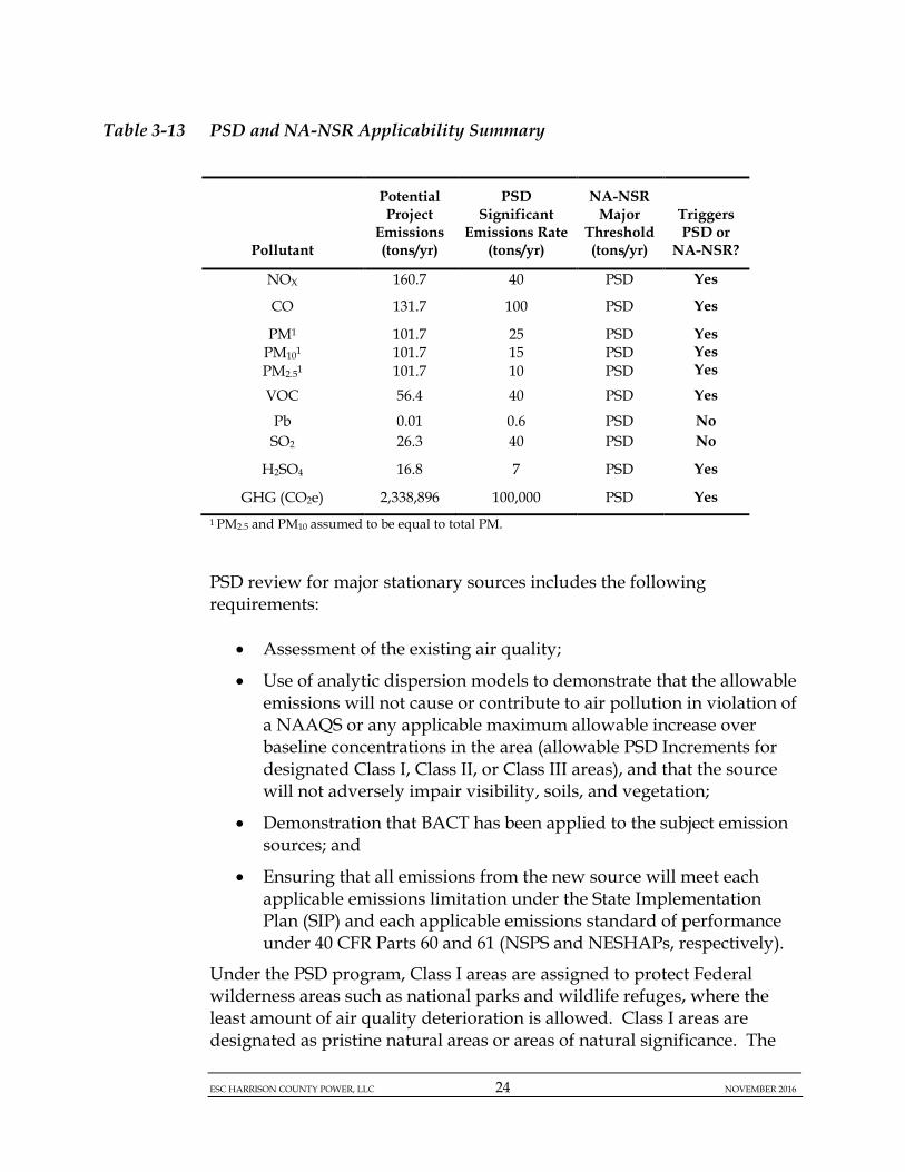
Combined-cycle CTs with HRSGs are considered fossil fuel-fired steam electric plants. Therefore, the applicable PSD major source threshold for the Project is 100 tons/yr of potential emissions. If it is determined that a pollutant exceeds the PSD major source threshold, each of the remaining pollutants is subject to PSD review if the potential to emit (PTE) exceeds the Significant Emission Rates (SERs) listed in Table 3-13. As shown in Table 3-13, the pollutants subject to PSD review are NOx, CO, PM, PM10, PM2.5, VOC, H2SO4, and GHG.
ESC HARRISON COUNTY POWER, LLC 24 NOVEMBER 2016
Table 3-13 PSD and NA-NSR Applicability Summary
Pollutant
Potential Project
Emissions (tons/yr)
PSD Significant
Emissions Rate (tons/yr)
NA-NSR Major
Threshold (tons/yr)
Triggers PSD or
NA-NSR?
NOX 160.7 40 PSD Yes
CO 131.7 100 PSD Yes
PM1 PM101 PM2.51
101.7 101.7 101.7
25 15 10
PSD PSD PSD
Yes Yes Yes
VOC 56.4 40 PSD Yes
Pb 0.01 0.6 PSD No SO2 26.3 40 PSD No
H2SO4 16.8 7 PSD Yes
GHG (CO2e) 2,338,896 100,000 PSD Yes 1 PM2.5 and PM10 assumed to be equal to total PM. PSD review for major stationary sources includes the following requirements:
• Assessment of the existing air quality;
• Use of analytic dispersion models to demonstrate that the allowable emissions will not cause or contribute to air pollution in violation of a NAAQS or any applicable maximum allowable increase over baseline concentrations in the area (allowable PSD Increments for designated Class I, Class II, or Class III areas), and that the source will not adversely impair visibility, soils, and vegetation;
• Demonstration that BACT has been applied to the subject emission sources; and
• Ensuring that all emissions from the new source will meet each applicable emissions limitation under the State Implementation Plan (SIP) and each applicable emissions standard of performance under 40 CFR Parts 60 and 61 (NSPS and NESHAPs, respectively).
Under the PSD program, Class I areas are assigned to protect Federal wilderness areas such as national parks and wildlife refuges, where the least amount of air quality deterioration is allowed. Class I areas are designated as pristine natural areas or areas of natural significance. The

ESC HARRISON COUNTY POWER, LLC 25 NOVEMBER 2016
Class II designation is used for all other areas, except heavily industrialized zones, which are Class III designations (40 CFR 51.166). Each classification differs in terms of the amount of growth allowed (PSD Increment) before significant deterioration of air quality occurs. If a proposed source is located within 100 km (62 miles) of a Class I area, the impacts must be evaluated at these areas based on the more stringent Class I PSD Increments, which are ambient increases in pollutant concentrations that must be met for a project to be approved. In addition, Federal Land Managers (FLMs) have discretion in determining which sources must evaluate impacts on Class I areas, often requiring Class I Area impact analyses for sources located outside the 100 km radius. The Class I areas and distances from the Project site are:
• Otter Creek Wilderness: 62 km, managed by the US Forest Service (USFS);
• Dolly Sods Wilderness: 86 km, managed by USFS; • Shenandoah National Park: 173 km, managed by the National Park
Service (NPS); and • James River Face Wilderness: 201 km, managed by USFS.
These areas will be evaluated and addressed in the separate air quality impact analysis report for the Project. The PSD permit will contain emission limits and other operating, monitoring, record keeping, and reporting requirements. The emission limits contained in the PSD permit are required to represent BACT. BACT is determined on a case-by-case basis, taking into account energy, environmental, and economic impacts. The Project’s demonstration of BACT is included in Section 3.4.2. The air quality impact analysis performed to demonstrate compliance with all PSD requirements and NAAQS is presented in the separate report.
3.4.2 Best Available Control Technology
Based on projected potential emissions, BACT is required for NOx, CO, PM, PM10, PM2.5, VOC, and GHG emissions from all Project emissions sources (CT/DBs, Auxiliary Boiler, Fuel Gas Heater, Emergency Generator, and Fire Water Pump). This section summarizes the BACT determinations for these pollutants.

ESC HARRISON COUNTY POWER, LLC 26 NOVEMBER 2016
3.4.2.1 BACT Analysis Process
BACT is defined in 45 CSR 14-2.12 of the WVDEP air pollution control regulations as:
2.12. "Best available control technology (BACT)" means an emissions limitation (including a visible emissions standard) based on the maximum degree of reduction for each regulated NSR pollutant which would be emitted from any proposed major stationary source or major modification which the Secretary, on a case-by-case basis, taking into account energy, environmental and economic impacts and other costs, determines is achievable for such source or modification through application of production processes or available methods, systems, and techniques, including fuel cleaning or treatment or innovative fuel combustion techniques for control of such pollutant. In no event shall application of best available control technology result in emissions of any pollutant which would exceed the emissions allowed by any federally enforceable emissions limitations or emissions limitations enforceable by the Secretary. If the Secretary determines that technological or economic limitations on the application of measurement methodology to a particular emissions unit would make the imposition of an emissions standard infeasible, a design, equipment work practice, operational standard or combination thereof, may be prescribed instead to satisfy the requirement for the application of best available control technology. Such standard shall, to the degree possible, set forth the emissions reduction achievable by implementation of such design, equipment, work practice or operation, and shall provide for compliance by means which achieve equivalent results.
BACT analyses are conducted using USEPA’s “top-down” BACT approach, as described in USEPA’s Draft New Source Review Workshop Manual3. The five (5) basic steps of a top-down BACT analysis are:
Step 1: Identify potential control technologies
3 (USEPA 1990).

ESC HARRISON COUNTY POWER, LLC 27 NOVEMBER 2016
Step 2: Eliminate technically infeasible options
Step 3: Rank remaining control technologies by control effectiveness
Step 4: Evaluate the most effective controls and document results
Step 5: Select BACT
The first step is to identify potentially “available” control options for each emission unit triggering PSD, for each pollutant under review. Available options consist of a comprehensive list of those technologies with a potentially practical application to the emission unit in question. The list includes technologies used to satisfy BACT requirements, innovative technologies, and controls applied to similar source categories.
For this analysis, the following sources were investigated to identify potentially available control technologies:
• USEPA’s RACT/BACT/LAER Clearinghouse (RBLC) database;
• USEPA’s New Source Review website;
• In-house experts;
• Similar permitting projects;
• State air regulatory agency contacts;
• Technical books and articles;
• The USEPA Region 4 National Combustion Turbine Spreadsheet;
• State permits issued for similar sources that have not yet been entered into the RBLC; and
• Guidance documents and personal communications with state agencies.
After identifying potential technologies, the second step is to eliminate technically infeasible options from further consideration. To be considered feasible for BACT, a technology must be both available and applicable.
The third step is to rank the technologies not eliminated in Step 2 in order of descending control effectiveness for each pollutant of concern. If the highest ranked technology is proposed as BACT, it is not necessary to perform any further technical or economic evaluation. Potential adverse impacts, however, must still be identified and evaluated.

ESC HARRISON COUNTY POWER, LLC 28 NOVEMBER 2016
The fourth step entails an evaluation of energy, environmental, and economic impacts for determining a final level of control. The evaluation begins with the most stringent control option and continues until a technology under consideration cannot be eliminated based on adverse energy, environmental, or economic impacts. The economic or “cost-effectiveness” analysis is conducted in a manner consistent with USEPA’s OAQPS Control Cost Manual, Fifth Edition4 and subsequent revisions.
The fifth and final step is to select as BACT the emission limit from application of the most effective of the remaining technologies under consideration for each pollutant of concern.
3.4.2.2 BACT Analyses
For the top-down BACT evaluation, a review was performed of the RBLC database, recent permits issued from across the U.S., the USEPA Region 4 Combustion Turbine Spreadsheet, and other available literature. Appendix B contains summaries of the RBLC search information.
3.4.2.2.1 NOx BACT
Combustion Turbine/Duct Burners
Step 1 - Identify Potential Control Technologies Several combustion and post-combustion technologies are available for controlling turbine NOx emissions. Combustion controls minimize the amount of NOx created during the combustion process, and post-combustion controls remove NOx from the exhaust stream after the combustion has occurred. The three (3) basic strategies for reducing NOx the from the combustion process are:
(1) Reduction of the peak combustion temperatures; (2) Reduction in the amount of time the air and fuel mixture is exposed
to the high combustion temperature; and (3) Reduction in the oxygen (O2) level in the primary combustion zone.
4 (USEPA 1996).

ESC HARRISON COUNTY POWER, LLC 29 NOVEMBER 2016
The following discusses potential control technologies for the proposed combined-cycle CT/DBs: Pre-Combustion Control Technologies The two (2) pre-combustion control technologies that reduce NOx emissions from CTs are water or steam injection, and DLN combustors. Water or Steam Injection The injection of water or steam into a CT’s combustors quenches the flame and absorbs heat, thus reducing combustion temperatures. The reduced temperatures in turn reduce the formation of thermal NOx. Combined with a post-combustion control technology, water or steam injection typically can achieve NOx emissions of 25 ppmvd @15% O2, but with the added economic, energy, and environmental expense of producing, storing, and consuming demineralized water. DLN Combustors Conventional combustors are diffusion-controlled, with fuel and air injected separately. This method of combustion results in combustion “hot spots,” which produce higher levels of thermal NOx. Lean premix and catalytic technologies are two available types of DLN combustors that are alternatives to conventional diffusion-controlled combustors. DLN combustors reduce the combustion hot spots that result in thermal NOx
formation. With lean premix DLN combustors, the mechanisms for reducing thermal NOx through formation are: (1) using excess air to reduce flame temperatures (i.e., lean combustion); (2) reducing combustor residence time to limit exposure in a high-temperature environment; (3) mixing fuel and air in an initial “pre-combustion” stage to produce a lean and uniform fuel/air mixture that is delivered to a secondary stage where combustion takes place; and/or (4) achieving two-stage combustion using a primary fuel-rich combustion stage to limit the amount of O2 available to combine with elemental nitrogen (N2) and then a secondary lean burn-stage to complete combustion in a cooler environment. Lean premix DLN combustors have only been developed for gaseous fuel-fired CTs. The more-advanced designs are capable of achieving 70 to 90% NOx emission reductions, with resulting NOx concentrations typically in the range of 9 to 25 ppmvd @15% O2.
ESC HARRISON COUNTY POWER, LLC 30 NOVEMBER 2016
As the name implies, catalytic combustors use a catalyst to allow the combustion reactions to occur at lower peak flame temperatures, which reduce thermal NOx formation. Catalytic combustors use a flameless catalytic combustion module, followed by completion of combustion at lower temperatures downstream of the catalyst. Post-Combustion Control Technologies The three (3) available post-combustion NOx emission controls for CTs are: (1) SCR; (2) SCONOx™ (also known as EMx™); and (3) Selective Non-Catalytic Reduction (SNCR). Both SCR and EMx™ use catalyst beds to control NOx emissions. Combined with DLN combustors or water/steam injection, these technologies are capable of achieving NOx emissions levels of 2 ppmvd @15% O2 for combined-cycle CTs. EMx ™uses a hydrogen regeneration gas to convert the NOx to elemental nitrogen (N2) and water. Like SCR, SNCR also uses ammonia to control NOx emissions, but without a catalyst. Selective Catalytic Reduction SCR is a post-combustion control technology designed to control NOx emissions from CTs. SCR systems for combined-cycle CTs are typically placed inside the HRSGs, and consist of a catalyst bed with an ammonia injection grid located upstream of the catalyst. The ammonia, in this case aqueous ammonia with a concentration of less than 20% by weight, is vaporized and injected directly into the exhaust stream, where it reacts with NOx and O2 in the presence of the catalyst to form N2 and water vapor.
These reactions normally occur at relatively high temperatures (e.g. 1,600 °F to 2,100 °F). However, the placement of a catalyst in the exhaust stream lowers the activation energy of the reaction, which allows the reaction to take place at lower temperatures (typically 650 °F to 850 °F). The catalyst consists of a support system with a catalyst coating typically of titanium dioxide (TiO2), vanadium pentoxide (V2O5), or zeolite. Typically, a small amount of ammonia is not consumed in the reactions and is emitted in the exhaust stream. These ammonia emissions are referred to as “ammonia slip.” EMx™

ESC HARRISON COUNTY POWER, LLC 31 NOVEMBER 2016
EM x™ uses a single catalyst to remove NOx emissions from CT exhaust gas by oxidizing nitric oxide (NO) to nitrogen dioxide (NO2), and then absorbing the NO2 onto a catalytic surface using a potassium carbonate (K2CO3) absorber coating. The potassium carbonate coating reacts with NO2 to form potassium nitrites and nitrates, which are deposited onto the catalyst surface. The optimal temperature window for operation of the EMx™ catalyst is from 300 ˚F to 700 ˚F. EM x™ does not use ammonia. Therefore, there are no ammonia emissions from this technology. When all of the potassium carbonate absorber coating has been converted to N2 compounds, NOx can no longer be absorbed and the catalyst must be regenerated. Regeneration is accomplished by passing a dilute hydrogen-reducing gas across the surface of the catalyst in the absence of O2. Hydrogen in the gas reacts with the nitrites and nitrates to form water and N2. Carbon dioxide (CO2) in the gas reacts with the potassium nitrite and nitrates to form potassium carbonate, which is the absorbing surface coating on the catalyst. The regeneration gas is produced by reacting natural gas with a carrier gas (such as steam) over a steam-reforming catalyst. Selective Non-Catalytic Reduction Like SCR, Selective Non-Catalytic Reduction (SNCR) involves injection of ammonia or urea CO(NH2)2 with proprietary conditioners into the exhaust gas stream without a catalyst. SNCR technology requires temperatures in the range of 1,600 to 2,100 °F. SNCR is not available for CTs, because CT exhaust temperatures are typically about 1,000 °F, significantly below the 1,600 °F minimum temperature required for effective SNCR performance. Step 2 - Eliminate Technically Infeasible Options Pre-Combustion Control Technologies Water or Steam Injection The use of water or steam injection is considered a feasible technology for reducing NOx emissions to about 25 ppmvd @ 15% O2 when firing gaseous fuel under most ambient conditions. Combined with SCR, water or steam injection can achieve NOx levels of 2 ppmvd @ 15% O2, but at slightly lower thermal efficiencies compared to DLN combustors. DLN Combustors DLN combustors are a feasible technology for reducing NOx emissions from the proposed CT. DLN combustors are capable of achieving NOx emission of 9 to 25 ppmvd @ 15% O2 over a relatively wide operating

ESC HARRISON COUNTY POWER, LLC 32 NOVEMBER 2016
range (e.g. 50% to 100% load). When combined with SCR, DLN combustors can achieve NOx emissions of 2 ppmvd @ 15% O2. A catalytic combustion technology known as XONON™ has been demonstrated successfully in a 1.5 MW simple-cycle CT pilot facility, and is commercially available for CTs rated at up to 10 MW. However, catalytic combustors such as XONON™ have not been demonstrated on industrial H Class CTs such as that proposed by ESC. Therefore, the XONON™ catalytic combustion technology is not considered feasible for the proposed CT/DBs. Post-Combustion Control Technologies Selective Catalytic Reduction SCR, with an ammonia slip of less than 5 ppmvd @ 15% O2, is considered a feasible technology for reducing CT NOx emissions to 2 ppmvd @ 15% O2 when firing gaseous fuel. SCR has been successfully installed and used on numerous simple-cycle and combined-cycle CTs. EMx™ The demonstrated application for EMx™ is currently limited to combined-cycle CTs under approximately 50 MW in size. The CT proposed for this Project is a nominal 350 MW unit. Therefore, EMx™ technology is not considered feasible for achieving the proposed NOx limit of 2.0 ppmvd @ 15% O2. Selective Non-Catalytic Reduction SNCR requires a temperature window that is higher than the exhaust temperatures from gaseous fuel-fired CTs. Therefore, SNCR is not considered technically feasible for the proposed CT/DBs. Step 3 - Rank Remaining Control Technologies by Control Effectiveness Based on the preceding discussions, the use of water/steam injection, DLN combustors, and SCR are the technically feasible NOx control technologies available for the proposed CT. DLN combustors were selected because they can achieve lower NOx emission rates from the CT over either water or steam injection, without the economic, energy, and environmental disbenefit of producing, storing, and consuming demineralized water. Furthermore, DLN combustors result in slight improvements in thermal efficiency over water/steam injection NOx control alternatives. When used in combination with SCR, these technologies can control NOx emissions from the CT/DBs to 2.0 ppmvd @ 15% O2.

ESC HARRISON COUNTY POWER, LLC 33 NOVEMBER 2016
There are potential environmental and energy impacts associated with the use of SCR. First, SCR require replacement of the catalyst beds after several years. The waste catalyst must be disposed of in accordance with state and federal regulations regarding normal waste disposal. Because of the precious metal content of the catalyst, they may also be recycled to recover the precious metals. Sulfur compounds in the exhaust gas may react with the ammonia reagent, forming ammonia salts, which may increase PM, PM10, and PM2.5 emissions. SCR also have energy impacts. Due to their location downstream of the CT exhaust, SCR catalysts increase the back pressure on the CT, which results in slightly decreased power output. This slightly decreased output leads to slightly increased pollutant emissions on a mass per unit power output basis.
Although there are potential environmental and energy impacts associated with the use of SCR, these impacts are not considered significant enough to preclude the use of SCR for NOx emission control. Available permits and BACT determinations were reviewed to identify NOx emission rates that have been achieved in practice for other comparable gaseous fuel-fired CT projects. The majority of the projects had permitted NOx emission rates equal to or greater than 2.0 ppmvd @ 15% O2. Only one (1) facility, for an IDC Bellingham combined-cycle plant proposed in Massachusetts, had a NOx emission limit below the 2.0 ppmvd @ 15% O2 level proposed as BACT by ESC. The IDC Bellingham facility was permitted with a not-to-exceed limit of 2.0 ppmvd @ 15% O2, but the permit also required the unit to maintain emissions below 1.5 ppmvd @ 15% O2 during normal operations. However, the IDC Bellingham facility was never built. Therefore, these emission limits were not achieved in practice. As a result, ESC’s proposed emission rate of 2.0 ppmvd @ 15% O2 is the lowest NOx emission rate achieved in practice for similar sources and, therefore, represents BACT for NOx emissions. Step 4 - Evaluate Most-Effective Controls and Document Results Based on the information presented in this BACT analysis, the proposed NOx emission rate of 2.0 ppmvd @ 15% O2 is the lowest NOx emission rate achieved in practice at similar sources. Therefore, an assessment of the economic and environmental impacts is not necessary. Step 5 – Select BACT

ESC HARRISON COUNTY POWER, LLC 34 NOVEMBER 2016
The proposed BACT for NOx emissions from the proposed CT/DBs is the use of DLN combustors and SCR, along with good combustion practices, to control NOx emissions to 2.0 ppmvd @ 15% O2 with and without duct firing. Auxiliary Boiler
For the Auxiliary Boiler, ESC proposed to minimize NOx emissions through good combustion practices, as well as low-NOx burners (LNB).
LNB are designed to recirculate hot, oxygen-depleted flue gas from the flame or firebox back into the combustion zone. By doing this, the average oxygen concentration is reduced in the flame without reducing the flame temperatures below which is necessary for optimal combustion efficiency. Reducing oxygen concentrations in the flame reduces the amount of fuel NOx generated. Although these efficient combustion techniques are targeted to reduce NOx emissions, they have a collateral impact of minimizing CO formation. ESC proposes a NOx emission level of 0.011 lb/MMBtu as BACT for the Auxiliary Boiler. A review of available permits and determinations for comparable boilers, ESC identified several recent permits for comparable boilers. The preponderance of the recently permitted boilers have NOx emission limits of 0.011 lb/MMBtu. There are several, but fewer, entries for boilers with permitted NOx limits of 0.01 lb/MMBtu, including:
• A 73.3 MMBtu/hr boiler at Luminant’s Eagle Mountain generating facility in Texas;
• A 45 MMBtu/hr boiler at CPV’s Pondera King Energy Center in Texas;
• A 45 MMBtu/hr boiler at Old Dominion Electric Cooperative’s Wildcat Point Generation Facility in Maryland;
• A 91.6 MMBtu/hr boiler at CPV Woodbridge Energy Center in New Jersey.
To the best of ESC’s knowledge, none of the above plants have completed construction or commenced operation at this time, with the exception of CPV Woodbridge Energy Center, which began operation in January 2016. Also, the above referenced plants involved LAER, rather than BACT determinations.

ESC HARRISON COUNTY POWER, LLC 35 NOVEMBER 2016
Furthermore, given the low baseline annual NOx emissions for the proposed Auxiliary Boiler (1.96 tons/yr), the decrease in NOx emissions if the boiler were required to achieve a NOx emission level of 0.01 lb/MMBtu would be no more than 0.18 tons/yr.
Therefore, ESC proposes BACT for the Auxiliary Boiler at a NOx emission level of 0.011 lb/MMBtu. This level will be achieved using good combustion practices, along with LNB.
Fuel Gas Heater
There is currently no technically feasible add-on control technology to reduce NOx emissions from gaseous fuel-fired Fuel Gas Heaters of the size proposed for the ESC Project. NOx is minimized in these units through good combustion practices, as well as LNB.
LNB are designed to recirculate hot, oxygen-depleted flue gas from the flame or firebox back into the combustion zone. By doing this, the average oxygen concentration is reduced in the flame without reducing the flame temperatures below which is necessary for optimal combustion efficiency. Reducing oxygen concentrations in the flame reduces the amount of fuel NOx generated. Although these efficient combustion techniques are targeted to reduce NOx emissions, they have a collateral impact of minimizing CO formation.
ESC proposes a NOx emission level of 0.036 lb/MMBtu as BACT for the Fuel Gas Heater. A review of available permits and determinations for comparable boilers, ESC identified several recent permits for comparable heaters. The most common NOx emission limit of recently permitted boilers is 0.035 lb/MMBtu, which is comparable to ESC’s proposed limit. Examples include:
• A 9.5 MMBtu/hr fuel gas heater at the CPV St. Charles Energy Center in Maryland; and
• A 8.5 MMBtu/hr fuel gas heater at the Berks Hollow Energy Associates plant in Pennsylvania.
To the best of ESC’s knowledge, none of the above plants have completed construction or commenced operation at this time. Also, the above referenced plants are believed to involve LAER, rather than BACT determinations.

ESC HARRISON COUNTY POWER, LLC 36 NOVEMBER 2016
There are two (2) entries with permitted NOx limits below 0.035 lb/MMBtu:
• A 13.32 MMBtu/hr dew point heater at Interstate Power and Light’s Marshalltown Generating Station in Iowa that is permitted for NOx emissions of 0.013 lb/MMBtu; and
• A 10 MMBtu/hr process heater at WTG Sonora Gas Plant LLC’s Sonora Gas Plant in Texas that is permitted for NOx emissions of 0.01 lb/MMBtu.
However, given the small size (5.5 MMBtu/hr) and low baseline level of annual NOx emissions for the proposed Fuel Gas Heater (0.93 tons/yr), the decrease in NOx emissions if the Fuel Gas Heater were required to achieve a NOx emission level of 0.01 lb/MMBtu would be no more than 0.62 tons/yr.
Therefore, ESC proposes BACT for the Fuel Gas Heater at a NOx emission level of 0.036 lb/MMBtu. This level will be achieved using good combustion practices, along with LNB.
Emergency Generator
ESC proposes BACT for NOX and VOC for the 2,000 kW Emergency Generator as the applicable emission rates specified in 40 CFR 60, Subpart IIII. The Subpart IIII emission standard is 4.8 grams per horsepower-hour (g/hp-hr) for NOx plus Non-Methane Hydrocarbons (NMHC).
The preponderance of the recently permitted emergency generators have NOx emission limits of 4.8 g/hp-hr. There are several, although comparably fewer, determinations that list NOx emission rates below 4.8 g/hp-hr, including:
• A 7.8 MMBtu/hr emergency generator at Hickory Run Energy Center in Pennsylvania that is permitted for NOx emissions of 1.46 g/hp-hr; and
• Eight (8) 757 hp emergency generators at PyraMax Ceramics, LLC in South Carolina, which are permitted for NOx emissions of 2.98 g/hp-hr.
Given the intended use of the Emergency Generator only for emergency purposes, with its operations limited to emergency events and no more than 100 hr/yr for maintenance and readiness testing, the environmental benefit associated with establishing emission limits below the Subpart IIII limit of 4.8 g/hp-hr is small. However, as BACT for the Emergency
ESC HARRISON COUNTY POWER, LLC 37 NOVEMBER 2016
Generator, ESC proposes an emission limit of 4.8 g/hp-hr for NOx plus NMHC along with the use of ULSD fuel and good combustion practices, and limiting operations to emergency events and no more than 100 hr/yr for maintenance and readiness testing.
Fire Water Pump
ESC proposes BACT for NOx and VOC for the 315-hp Fire Water Pump as 2.69 g/hp-hr, which is below the applicable emission rates specified in 40 CFR 60, Subpart IIII of 3.0 g/hp-hr for NOx plus NMHC. The Fire Water Pump will use ULSD fuel to ensure operation even during periods when natural gas is unavailable.
The preponderance of the recently permitted Fire Water Pumps have NOx emission limits in the range of 2.8 to 3.0 g/hp-hr. There are only two (2) determinations that list NOx emission rates below 2.69 g/hp-hr. These are:
• A 300 hp fire water pump at Oregon Clean Energy Center in Ohio that is permitted for NOx emissions of 2.57 g/hp-hr; and
• A 3.25 MMBtu/hr fire water pump at Hickory Run Energy Center in Pennsylvania that is permitted for NOx emissions of 0.66 g/hp-hr.
To the best of ESC’s knowledge, neither of the above plants have been constructed or commenced operation at this time.
Given the intended use of the Fire Water Pump only for emergency purposes, with its operations limited to emergency events and no more than 100 hr/yr for maintenance and readiness testing, the environmental benefit associated with establishing emission limits below the proposed limit of 2.69 g/hp-hr is small. Therefore, as BACT for the Fire Water Pump, ESC proposes an emission limit of 2.69 g/hp-hr for NOx plus NMHC along with the use of ULSD fuel and good combustion practices, and limiting operations to emergency events and no more than 100 hr/yr for maintenance and readiness testing.
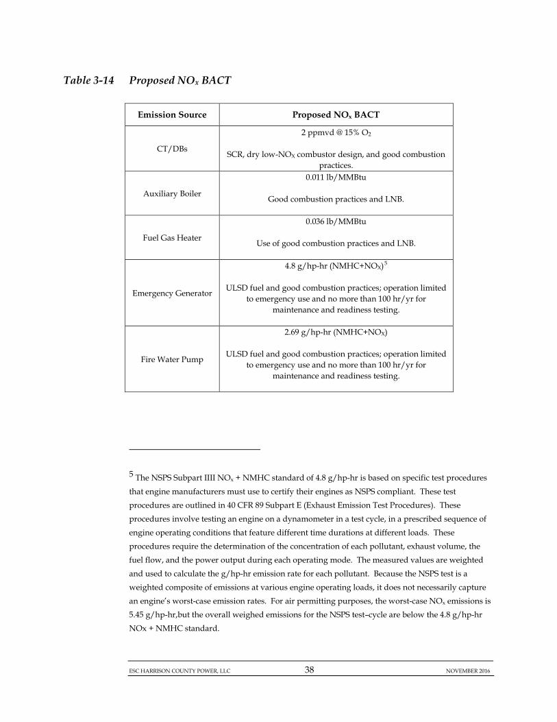
The proposed NOx BACT for all sources is summarized in Table 3-14.
ESC HARRISON COUNTY POWER, LLC 38 NOVEMBER 2016
Table 3-14 Proposed NOx BACT
Emission Source Proposed NOx BACT
CT/DBs
2 ppmvd @ 15% O2
SCR, dry low-NOX combustor design, and good combustion practices.
Auxiliary Boiler
0.011 lb/MMBtu
Good combustion practices and LNB.
Fuel Gas Heater
0.036 lb/MMBtu
Use of good combustion practices and LNB.
Emergency Generator
4.8 g/hp-hr (NMHC+NOX)5
ULSD fuel and good combustion practices; operation limited to emergency use and no more than 100 hr/yr for
maintenance and readiness testing.
Fire Water Pump
2.69 g/hp-hr (NMHC+NOX)
ULSD fuel and good combustion practices; operation limited to emergency use and no more than 100 hr/yr for
maintenance and readiness testing.
5 The NSPS Subpart IIII NOx + NMHC standard of 4.8 g/hp-hr is based on specific test procedures that engine manufacturers must use to certify their engines as NSPS compliant. These test procedures are outlined in 40 CFR 89 Subpart E (Exhaust Emission Test Procedures). These procedures involve testing an engine on a dynamometer in a test cycle, in a prescribed sequence of engine operating conditions that feature different time durations at different loads. These procedures require the determination of the concentration of each pollutant, exhaust volume, the fuel flow, and the power output during each operating mode. The measured values are weighted and used to calculate the g/hp-hr emission rate for each pollutant. Because the NSPS test is a weighted composite of emissions at various engine operating loads, it does not necessarily capture an engine’s worst-case emission rates. For air permitting purposes, the worst-case NOx emissions is 5.45 g/hp-hr,but the overall weighed emissions for the NSPS test–cycle are below the 4.8 g/hp-hr NOx + NMHC standard.

ESC HARRISON COUNTY POWER, LLC 39 NOVEMBER 2016
3.4.2.2.2 CO BACT
Combustion Turbine/Duct Burners
Step 1 - Identify Potential Control Technologies CO is formed during the combustion process as a result of incomplete combustion of the carbon present in the fuel. Effective combustor design and post-combustion control using an Oxidation Catalyst are the potential technologies for controlling CO emissions from CTs. As noted above in the NOx BACT analysis, the EMxTM and XONONTM technologies were determined not to be feasible for the proposed CT/DBs, so they have not been considered further here. Combustion Controls CO formation is minimized by designing the combustion system to allow complete mixing of the combustion air and fuel and maximize the oxidization of fuel carbon to CO2. Higher combustion temperatures tend to reduce CO formation, but increase NOx formation. Water/steam injection or DLN combustors tend to lower combustion temperatures in order to reduce NOx formation, potentially increasing CO formation. However, using good combustor design and following best operating practices minimizes CO formation while reducing combustion temperatures and NOx emissions. Oxidation Catalyst Oxidation Catalysts typically use precious metal catalyst beds. Like SCR systems for combined-cycle CTs, Oxidation Catalysts are typically located within the HRSG where the temperature is in the range of 700 °F to 1,100 °F. The catalyst enhances oxidation of CO to CO2, without the addition of any chemical reagents, because there is sufficient O2 in the exhaust gas stream for the oxidation reactions to proceed in the presence of the catalyst alone. Catalyst volume is dependent upon the exhaust flow, temperature, and the desired removal efficiency. The catalyst material is subject to loss of activity over time due to physical deterioration or chemical deactivation. Oxidation Catalyst vendors typically guarantee catalyst life for three (3) years. Both efficient combustion and add-on controls, such as Oxidation Catalysts, can be used alone or in combination to achieve CO emission reductions. Oxidation Catalysts have been successfully installed and used on numerous simple-cycle and combined-cycle CTs.
Step 2 - Eliminate Technically Infeasible Options

ESC HARRISON COUNTY POWER, LLC 40 NOVEMBER 2016
Using good combustor design, following best operating practices, and using Oxidation Catalyst are technically feasible options for controlling CO emissions from the proposed CT/DBs.
There are potential environmental and energy impacts associated with the use of Oxidation Catalysts. Oxidation Catalysts require replacement of the catalyst beds after several years. The waste catalyst must be disposed of in accordance with state and federal regulations regarding normal waste disposal. Because of the precious metal content of the catalyst, they may also be recycled to recover the precious metals. Some of the SO2 in the exhaust gas will oxidize to sulfur trioxide (SO3). The higher the operating temperature, the higher the potential for oxidation of SO2 to SO3. The SO3
may react with moisture in the flue gas to form H2SO4. The increase in H2SO4 emission may increase PM10 and PM2.5 emissions. The oxidation of CO results in increased CO2 emissions, and CO2 is a GHG. Oxidation Catalysts also have energy impacts. Due to their location downstream of the CT exhaust, Oxidation Catalysts increase the backpressure on CTs, which results in slightly decreased power output. This slightly decreased output leads to increased pollutant emissions on a mass per unit power output basis.
Although there are potential environmental and energy impacts associated with the use of Oxidation Catalysts, these impacts are not considered significant enough to preclude their use for CO emission control. Step 3 - Rank Remaining Control Technologies by Control Effectiveness Based on the preceding discussion, good combustion practices and Oxidation Catalysts are both available and technically feasible technologies to control CO emissions from CTs. Together, DLN combustors and good combustion practices, although primarily used to minimize NOx emissions, have been effective in minimizing CO emissions from CTs, including those with duct firing. These are the only practical efficient combustion alternatives currently available and used on combined-cycle CTs/DBs. ESC proposes to control CO emissions with these techniques to meet a CO emission limit of 2.0 ppmvd @ 15% O2, with and without duct firing. Available permits and BACT determinations were reviewed to identify CO emission rates that have been achieved in practice for other comparable gaseous fuel-fired CT projects. The majority of the projects had permitted CO emission rates equal to or greater than 2.0 ppmvd @ 15% O2. However, the following projects were identified that have CO emission rates lower than 2.0 ppmvd @ 15% O2.

ESC HARRISON COUNTY POWER, LLC 41 NOVEMBER 2016
(1) Competitive Power Ventures (CPV) Warren; (2) Kleen Energy Systems; and (3) Astoria Energy LLC
These projects are discussed in more detail below. CPV Warren CPV Warren is a combined-cycle power plant proposed to be located in Front Royal, Warren County, Virginia. Originally developed by Competitive Power Ventures (CPV), the project was sold to Virginia Electric Power and Power Company (Dominion Virginia Power) in 2008. A final PSD permit for a nominal 1,300 MW combined-cycle plant was issued by the Virginia Department of Environmental Quality (VDEQ) on December 21, 2010. This final PSD permit includes CO emission limits of 1.5 and 2.4 ppmvd @ 15% O2, on a 1-hour averaging basis, for operating conditions without and with duct firing, respectively. Based on publically available information, Dominion expects commercial operation of the Warren facility to occur in late 2014 or early 2015. The plant is expected to consist of three (3) Mitsubishi Model M501GAC CTs. Since the plant has not begun operation, these BACT limits for VOC have not yet been achieved in practice. Kleen Energy Systems The Kleen Energy Systems combined-cycle facility in Middletown, Connecticut began commercial operation in July 2011. The CTs used by Kleen Energy Systems are Siemens SGT6-5000F. The permitted CO emission limits are 1.5 and 0.9 ppmvd @ 15% O2 for operation with and without duct firing, respectively. Initial stack testing apparently demonstrated compliance with these CO emission limits. However, given the lack of long-term operation and compliance with these emission limits, these CO emission levels are not considered “achieved in practice” at this time. Astoria Energy LLC The Astoria Energy, LLC facility, located in the Astoria section of Queens, New York City is permitted for CO emissions of 1.5 ppmvd @ 15% O2, with or without duct firing. The Astoria Energy plant began operation in 2011 and uses GE Frame 7FA CTs. However, because the Astoria Energy plant was located in a CO non-attainment area, the 1.5 ppmvd @ 15% O2 was a LAER, rather than BACT, limit.

ESC HARRISON COUNTY POWER, LLC 42 NOVEMBER 2016
Step 4 - Evaluate Most-Effective Controls and Document Results The proposed CO emission rate of 2.0 ppmvd @ 15% O2 with and without duct firing is the lowest CO emission rate achieved or verified with long-term compliance records for other similar facilities. Since ESC is proposing to use a CT with DLN combustors and Oxidation Catalyst to reduce CO and VOC emissions (the top control alternative), an assessment of the economic and environmental impacts is not necessary. Step 5 - Select BACT BACT for CO emissions from the proposed CT/DBs is good combustion design and the use of an Oxidation Catalyst to control CO emissions to 2.0 ppmvd @ 15% O2, with and without duct firing.
Auxiliary Boiler
There is currently no technically feasible add-on control technology to reduce CO emissions from gaseous fuel-fired Auxiliary Boilers of the size proposed for the ESC Project. CO is minimized in these units through good combustion practices. A review of available permits and determinations for comparable boilers, ESC identified several recent permits for comparable boilers. The preponderance of the recently permitted boilers have CO emission limits in the range of 0.035 to 0.038 lb/MMBtu. There are several, but fewer, entries for boilers with permitted CO limits below the 0.035 to 0.038 lb/MMBtu range, including:
• A 33 MMBtu/hr boiler at CPV’s St. Charles Energy Center in Maryland that is permitted for 0.02 lb/MMBtu CO;
• A 41.64 MMBtu/hr boiler at MGM Mirage in Nevada that is permitted for 0.0184 lb/MMBtu CO;
• A 31.38 MMBtu/hr boiler at Harrah’s in Nevada that is permitted for 0.0172 lb/MMBtu CO;
• A 60.1 MMBtu/hr boiler at Interstate Power and Light’s Marshalltown Generating Station in Iowa that is permitted for 0.00164 lb/MMBtu CO;
• A 44 MMBtu/hr boiler at MGM Mirage in Nevada that is permitted for 0.0148 lb/MMBtu CO;
• 33.48 MMBtu/hr boilers at Harrah’s in Nevada that are permitted for 0.0075 lb/MMBtu CO;
ESC HARRISON COUNTY POWER, LLC 43 NOVEMBER 2016
• 35.4 MMBtu/hr boilers at Harrah’s in Nevada that are permitted for 0.0073 lb/MMBtu CO;
To the best of ESC’s knowledge, the two (2) boilers associated with power plants, CPV’s St. Charles Energy Center and Interstate Power and Light’s Marshalltown Generating Station, have completed construction or commenced operation at this time. Also, some of the above referenced boilers involved LAER, rather than BACT determinations.
Therefore, ESC proposes BACT for the Auxiliary Boiler at a CO emission level of 0.037 lb/MMBtu. This level will be achieved using good combustion practices.
Fuel Gas Heater
There is currently no technically feasible add-on control technology to reduce CO emissions from gaseous fuel-fired Fuel Gas Heaters of the size proposed for the ESC Project. CO is minimized in these units through good combustion practices that support effective combustion and minimize CO formation.
A review of available permits and determinations for comparable boilers/heaters, ESC did not identify any recent permits for with CO emission limits below the proposed limit of 0.039 lb/MMBtu.
Therefore, BACT is the use of good combustion practices to achieve an emission limit of 0.039 lb/MMBtu.
Emergency Generator and Fire Water Pump
ESC proposes that BACT for the Emergency Generator and Fire Water Pump is the CO emission rate of 0.3 g/hp-hr and 0.44 g/hp-hr, respectively. This is below the CO emission standard of 2.6 g/hp-hr specified in 40 CFR 60, Subpart IIII. This emergency equipment will be operated on ULSD fuel, with a sulfur content no greater than 0.0015% by weight.
Generally, for engines of the sizes proposed for the Project, good combustion practices are used to limit CO emissions. Review of recent permits and the RBLC for similar equipment indicates that good combustion practices are considered BACT. However, some of the BACT

ESC HARRISON COUNTY POWER, LLC 44 NOVEMBER 2016
determinations resulted in lower emissions levels using good combustion practices.
The only determinations that list CO emission rates below 0.3 g/hp-hr are: • Two (2) 1,341 hp emergency generators and three (3) fire water
pumps at Lake Charles Gasification Facility in Louisiana that are permitted for 0.21 and 0.29 g/hp-hr CO, respectively; and
• A 1,500 hp emergency generator at Peony Chemical Manufacturing Facility in Texas that is permitted for 0.126 g/hp-hr CO.
Given the intended use of the Emergency Generator and Fire Water Pump only for emergency purposes, with its operations limited to emergency events and no more than 100 hr/yr for maintenance and readiness testing, the environmental benefits associated with establishing emission limits below the proposed limits of 0.3 and 0.44 g/hp-hr are small. Therefore, as BACT for the Emergency Generator and Fire Water Pump, ESC proposes emission limits of 0.3 and 0.44 g/hp-hr for CO, along with the use of ULSD fuel and good combustion practices, and limiting operations to emergency events and no more than 100 hr/yr for maintenance and readiness testing.
The proposed CO BACT for all sources is summarized in Table 3-15.

ESC HARRISON COUNTY POWER, LLC 45 NOVEMBER 2016
Table 3-15 Proposed CO BACT
Emission Source Proposed CO BACT
CT/DBs
2 ppmvd @ 15% O2
Oxidation Catalysts and good combustion practices.
Auxiliary Boiler
0.037 lb/MMBtu
Good combustion practices.
Fuel Gas Heater
0.039 lb/MMBtu
Good combustion practices.
Emergency Generator
0.3 g/hp-hr
ULSD fuel and good combustion practices; operation limited
to emergency use and no more than 100 hr/yr for maintenance and readiness testing.
Fire Water Pump
0.44 g/hp-hr
ULSD fuel and good combustion practices; operation limited
to emergency use and no more than 100 hr/yr for maintenance and readiness testing.
3.4.2.2.3 PM, PM10, and PM2.5 BACT
Particulate matter emissions result from each combustion source associated with the Project. The following summarizes the BACT evaluation conducted for each significant piece of equipment with respect to PM, PM10, and PM2.5 emissions.
Combustion Turbine/Duct Burners PM from gaseous fuel combustion has been estimated to be less than 1 micron in equivalent aerodynamic diameter, has filterable and condensable fractions, and usually consists of hydrocarbons of larger molecular weight that are not fully combusted (USEPA, 2006). Because the

ESC HARRISON COUNTY POWER, LLC 46 NOVEMBER 2016
particulate matter typically is less than 2.5 microns in diameter, this BACT discussion assumes the control technologies for PM, PM10, and PM2.5 are the same. Step 1 – Identify Potential Control Technologies Pre-Combustion Control Technologies The major sources of PM, PM10, and PM2.5 emissions from gaseous fuel-fired CTs equipped with SCR for post-combustion control of NOx emissions are:
(1) the conversion of fuel sulfur to sulfates and ammonium sulfates; (2) unburned hydrocarbons that can lead to the formation of PM in the
exhaust stack; and (3) PM in the ambient air entering the CTs through their inlet air
filtration systems, and the aqueous ammonia dilution air. The use of clean-burning, low-sulfur fuels such as pipeline-quality natural gas will result in minimal formation of PM, PM10, and PM2.5 during combustion. Best combustion practices will ensure proper air/fuel mixing ratios to achieve complete combustion, minimizing emissions of unburned hydrocarbons that can lead to the formation of PM emissions. In addition to good combustion practices, the use of high-efficiency filtration of the inlet air will minimize the entrainment of PM into the CT exhaust streams. Post-Combustion Control Technologies There are several post-combustion PM control systems potentially feasible to reduce PM and PM10 emissions from CTs/DBs including:
(1) Cyclones/centrifugal collectors; (2) Fabric filters/baghouses; (3) Electrostatic precipitators (ESPs); and (4) Scrubbers.
Cyclones/centrifugal collectors are generally used in industrial applications to control large diameter particles (>10 microns). Cyclones impart a centrifugal force on the gas stream, which directs entrained particles outward. Upon contact with an outer wall, the particles slide down the cyclone wall, and are collected at the bottom of the unit. The design of a centrifugal collector provides for a means of allowing the clean gas to exit through the top of the device. Cyclones are inefficient at removing small particles.
ESC HARRISON COUNTY POWER, LLC 47 NOVEMBER 2016
Fabric filters/baghouses use a filter material to remove particles from a gas stream. The exhaust gas stream flows through filters/bags onto which particles are collected. Baghouses are typically employed for industrial applications to provide particulate emission control at relatively high efficiencies.
ESPs are used on a wide variety of industrial sources, including certain boilers. ESPs use electrical forces to move particles out of a flowing gas stream onto collector plates. The particles are given an electric charge by forcing them to pass through a region of gaseous ion flow called a “corona”. An electrical field generated by electrodes at the center of the gas stream forces the charged particles to ESP’s collecting plates.
Removal of the particles from the collecting plates is required to maintain sufficient surface area to clean the flowing gas stream. Removal must be performed in a manner to minimize re-entrainment of the collected particles. The particles are typically removed from the plates by “rapping” or knocking them loose, and collecting the fallen particles in a hopper below the plates.
Scrubber technology may also be employed to control PM in certain industrial applications. With wet scrubbers, flue gas passes through a water (or other solvent) stream, whereby particles in the gas stream are removed through inertial impaction and/or condensation of liquid droplets on the particles in the gas stream. Step 2 - Eliminate Technically Infeasible Options The pre-combustion control technologies identified above (i.e. clean-burning, low-sulfur fuels, good combustion practices, high-efficiency filtration of the CT inlet air) are available and technically feasible for reducing PM emissions from the CT exhaust streams. Each of the post-combustion control technologies described above (i.e. cyclones, baghouses, ESPs, scrubbers) are generally available. However, none of these technologies is considered practical or technically feasible for installation on gaseous fuel-fired CTs. The particles emitted from gaseous fuel-fired combustion are typically less than 1 micron in diameter. Cyclones are not effective on particles with diameters of 10 microns or less. Therefore, a cyclone/centrifugal collection device is not a technically feasible alternative.

ESC HARRISON COUNTY POWER, LLC 48 NOVEMBER 2016
Baghouses, ESPs, and scrubbers have never been applied to commercial CTs burning gaseous fuels. Baghouses, ESPs, and scrubbers are typically used on solid or liquid-fuel fired sources with high PM emission concentrations, and are not used in gaseous fuel-fired applications, which have inherently low PM emission concentrations. None of these control technologies are appropriate for use on gaseous fuel-fired CTs because of their very low PM emissions levels, and the small aerodynamic diameter of PM from gaseous fuel combustion. Review of the RBLC, as well as USEPA and state permit databases, indicates that post-combustion controls have not been required as BACT for gaseous fuel-fired fired combined-cycle CTs. Therefore, the use of baghouses, ESPs, and scrubbers is not considered technically feasible.
ESC proposes that PM, PM10, and PM2.5 BACT for the CT/DBs is the employment of good combustion practices, along with the use of a clean fuel (pipeline-quality natural gas), and inlet air filtration to achieve an emission limit of 18.2 lb/hr for PM, PM10, and PM2.5, with and without duct firing. Step 3 - Rank Remaining Control Technologies by Control Effectiveness The use of clean-burning fuels, good combustion practices, and inlet air filtration are the technically feasible technologies to control PM, PM10, and PM2.5 emissions to no more than 18.2 lb/hr, with and without duct firing. This is equivalent to an emission rate of 0.007 lb/MMBtu or less.
Review of recent permits and the RBLC for CTs/DBs indicates that the proposed PM, PM10, and PM2.5 emission rates are lower than those specified in permits for similar plants, such as the International Station Power Plant, Mankato Energy Center, Caithness Bellport Energy Center, and Cricket Valley Energy Project. These projects tend to have PM, PM10, and PM2.5 emission rates of about 0.012 lb/MMBtu. Step 4 - Evaluate Most Effective Controls and Document Results Based on the information presented in this BACT analysis, using good combustion practices, pipeline quality natural gas, and inlet air filtration to control PM, PM10, and PM2.5 emissions to no more than 18.2 lb/hr, with and without duct firing. This is consistent with BACT at other similar sources. Therefore, an assessment of the economic and environmental impacts is not necessary. Step 5 – Select BACT The proposed BACT for PM, PM10, and PM2.5 emissions from the CT/DBs is the use of clean-burning fuels, good combustion practices, and inlet air
ESC HARRISON COUNTY POWER, LLC 49 NOVEMBER 2016
filtration to control PM, PM10, and PM2.5 emissions to no more than 0.0068 lb/MMBtu, with and without duct firing.
Auxiliary Boiler
The technologies potentially available to control PM, PM10, and PM2.5 emissions from small boilers are:
(1) Cyclones/centrifugal collectors; (2) Fabric filters/baghouses; (3) ESPs; and (4) Scrubbers.
However, a similar rationale eliminates the use of cyclones due to their inability to control particles smaller than 10 microns in diameter. In addition, the other add-on particulate control techniques have not been employed to remove PM from natural gas-fired boilers, such as the proposed Auxiliary Boiler.
A review of the RBLC, as well as USEPA and state permit databases indicates that there are no small boilers employing post-combustion control equipment to reduce PM, PM10, and PM2.5 to achieve BACT. The determinations for small boilers identify the selection of clean fuels (i.e., low-sulfur, low-ash content) and good combustion practices as BACT for PM, PM10, and PM2.5 emissions.
The proposed Auxiliary Boiler is a unit capable of firing pipeline quality natural gas that will employ good combustion practices to minimize PM, PM10, and PM2.5 to achieve BACT emission levels.
Although BACT is a technology based standard, ESC evaluated the consistency of other relevant permits to identify the level of emissions determined as BACT. The proposed PM emission rate of 0.008 lb/MMBtu for the Auxiliary Boiler is comparable to similar units noted in the RBLC and in recently issued permits. A review of available permits and determinations for comparable boilers, ESC identified several recent permits for comparable boilers. The preponderance of the recently permitted boilers have PM emission limits in the range of 0.0007 to 0.008 lb/MMBtu. There are several, but fewer, entries for boilers with permitted PM limits below the 0.007 lb/MMBtu, including:

ESC HARRISON COUNTY POWER, LLC 50 NOVEMBER 2016
• A 60 MMBtu/hr boiler at Cricket Valley Energy facility in New
York that is permitted for 0.005 lb/MMBtu; • A 46 MMBtu/hr boiler at Klausner Holding USA, Inc. in South
Carolina that is permitted for 0.005 lb/MMBtu; • A 40 MMBtu/hr boiler at Hickory Run Energy Station in
Pennsylvania that is permitted for 0.005 lb/MMBtu; • A 40 MMBtu/hr boiler at the DTE Energy Company (DTE)
Renaissance Power Plant in Michigan that is permitted for 0.005 lb/MMBtu;
• A 93 MMBtu/hr boiler at the CPV St. Charles Energy Center in Maryland that is permitted for 0.005 lb/MMBtu;
• A 21 MMBtu/hr boiler at Pioneer Valley Energy Center in Massachusetts that is permitted for 0.0048 lb/MMBtu;
• A 29.4 MMBtu/hr boiler at Caithness Bellport Energy Center in New York that is permitted for 0.003 lb/MMBtu;
• A 29.4 MMBtu/hr boiler at Caithness Bellport Energy Center in New York that is permitted for 0.003 lb/MMBtu;
The RBLC and other permits reviewed for equipment that is installed and operating identify the use of natural gas and good combustion practices as BACT for PM, PM10, and PM2.5 for boilers. Accordingly, the proposed BACT for PM, PM10, and PM2.5 is an emission limit of 0.008 lb/MMBtu achieved using pipeline-quality natural gas and good combustion practices.
Fuel Gas Heater
The technologies potentially available to control PM, PM10, and PM2.5 emissions from small boilers are:
(1) Cyclones/centrifugal collectors; (2) Fabric filters/baghouses; (3) ESPs; and (4) Scrubbers.
However, a similar rationale eliminates the use of cyclones due to their inability to control particles smaller than 10 microns in diameter. In addition, the other add-on particulate control techniques have not been employed to remove PM from relatively small, natural gas-fired combustion units, such as the proposed Fuel Gas Heater.
ESC HARRISON COUNTY POWER, LLC 51 NOVEMBER 2016
A review of the RBLC, as well as USEPA and state permit databases indicates that there are no small boilers employing post-combustion control equipment to reduce PM, PM10, and PM2.5 to achieve BACT. The determinations for small boilers identify the selection of clean fuels (i.e., low-sulfur, low-ash content) and good combustion practices as BACT for PM, PM10, and PM2.5 emissions.
The proposed Fuel Gas Heater is a unit that will fire only pipeline quality natural gas and employ good combustion practices to minimize PM, PM10, and PM2.5 to achieve BACT emission levels.
Although BACT is a technology based standard, ESC evaluated the consistency of other relevant permits to identify the level of emissions determined as BACT. The proposed PM emission rate of 0.008 lb/MMBtu for the Fuel Gas Heater is comparable to similar units noted in the RBLC and in recently issued permits. A review of available permits and determinations for comparable boilers, ESC identified several recent permits for comparable boilers. The preponderance of the recently permitted boilers have PM emission limits in the range of 0.0007 to 0.008 lb/MMBtu.
The RBLC and other permits reviewed for equipment that is installed and operating identify the use of natural gas and good combustion practices as BACT for PM, PM10, and PM2.5 for small boilers. Accordingly, the proposed BACT for PM, PM10, and PM2.5 is an emission limit of 0.008 lb/MMBtu achieved using pipeline-quality natural gas and good combustion practices.
Emergency Generator and Fire Water Pump
ESC proposes that BACT for PM, PM10, and PM2.5 for the Emergency Generator and the Fire Water Pump is an emission limit of 0.025 g/hp-hr and 0.0.075 g/hp-hr , respectively. The emission standard for CI RICE specified in 40 CFR 60, Subpart IIII is 0.15 g/hp-hr. Based on the definition of BACT, the facility must at a minimum meet or improve upon the limit established in the NSPS. The facility proposes to operate the emergency equipment using ULSD as fuel.
A literature review to establish a list of potential control technologies available for emergency engines concludes that there are currently no facilities employing post-combustion controls on RICE engines of these sizes to achieve BACT for PM, PM10, and PM2.5. The use of good

ESC HARRISON COUNTY POWER, LLC 52 NOVEMBER 2016
combustion practices and clean fuels, such as ULSD, are relied upon to achieve BACT for PM, PM10, and PM2.5.
For the Emergency Generator, a review of recent permits and the RBLC includes determinations with emission levels as low as 0.02 g/hp-hr for similar sized engines, with BACT described as good combustion practices (e.g. a 1,341 hp emergency generator at Lake Charles Gasification Facility in Louisiana, which has reportedly ceased development). As evidenced by the wide variety of emission levels listed in the RBLC, different engine vendors and models specify a wide range of PM, PM10, and PM2.5 emissions.
For the Fire Water Pump, a review of recent permits and the RBLC for similar equipment indicates values in line with a 0.15 g/hp-hr limit or higher (i.e., Live Oaks, Wolverine and Pioneer Valley). However, there are instances of permit limits as low as 0.01 gr/hp-hr (e.g. a 444 hp fire pump engine at SNF Flopam, Inc. in Louisiana).
Given the limited operating role of the equipment to support the facility during emergency periods and for periodic maintenance and readiness testing, and the small emission reductions associated with achieving the lower PM, PM10, and PM2.5 emission rates listed in the RBLC; there is no appreciable environmental benefit associated with achieving PM, PM10, and PM2.5 emission levels below the proposed values of 0.025 g/hp-hr and 0.075 g/hp-hr for the Emergency Generator and the Fire Water Pump, respectively. Therefore, BACT for PM, PM10, and PM2.5 for the Emergency Generator and Fire Water Pump is the exclusive use of ULSD and good combustion practices to achieve an emission limit of 0.025 g/hp-hr and 0.075 g/hp-hr, respectively.
The proposed PM, PM10, and PM2.5 BACT for all sources is summarized in Table 3-16.

ESC HARRISON COUNTY POWER, LLC 53 NOVEMBER 2016
Table 3-16 Proposed PM, PM10, and PM2.5 BACT
Emission Source Proposed PM, PM10, and PM2.5 BACT
CT/DBs
0.0068 lb/MMBtu (with or without duct firing)
Exclusive use of pipeline-quality natural gas, good combustion practices,
CT inlet air filtration.
Auxiliary Boiler
0.008 lb/MMBtu
Exclusive use of pipeline-quality natural gas and good combustion
practices.
Fuel Gas Heater
0.008 lb/MMBtu
Exclusive use of pipeline-quality natural gas and good combustion
practices.
Emergency Generator
0.025 g/hp-hr
ULSD fuel and good combustion practices; operation limited to
emergency use and no more than 100 hr/yr for maintenance and readiness testing.
Fire Water Pump
0.075 g/hp-hr
ULSD fuel and good combustion practices; operation limited to
emergency use and no more than 100 hr/yr for maintenance and readiness testing.
3.4.2.2.4 VOC BACT
Combustion Turbine/Duct Burners Step 1 – Identify Potential Control Technologies Like CO emissions, VOC emissions occur from incomplete combustion.

ESC HARRISON COUNTY POWER, LLC 54 NOVEMBER 2016
Effective combustor design and post-combustion control using Oxidation Catalysts are the available technologies for controlling VOC emissions from CTs. The GE Frame 7HA industrial CT proposed by ESC is able to achieve relatively low uncontrolled VOC emissions because their combustors have firing temperatures of approximately 2,500 °F with exhaust temperatures of approximately 1,000 °F. A DLN combustor-equipped CT using an Oxidation Catalyst can achieve VOC emissions in the 1 to 2 ppmvd @ 15% O2 range. As noted above in the NOx BACT analysis, the EMxTM and XONONTM technologies were determined not to be feasible for the proposed CT/DBs, so they have not been considered further here. Good Combustion Controls As previously discussed, VOCs are formed from incomplete combustion of the carbon present in the fuel. VOC formation is minimized by designing the combustors to completely oxidize the fuel carbon to CO2. This is achieved by ensuring that the combustors are designed to allow complete mixing of the combustion air and fuel at combustion temperatures with an excess of combustion air. Higher combustion temperatures tend to reduce VOC formation, but at the expense of increased NOx formation. The use of water/steam injection or DLN combustors tends to lower combustion temperatures to reduce NOx formation, but potentially increases VOC formation. However, good combustor design and best operating practices will minimize VOC formation while reducing the combustion temperatures and NOx emissions. Oxidation Catalysts Oxidation Catalysts typically use precious metal catalyst beds. Like SCR systems for combined-cycle CTs, Oxidation Catalysts are typically placed inside the HRSGs. The catalyst enhances oxidation of VOC to CO2, without the addition of any chemical reagents. Oxidation Catalysts have been successfully installed on numerous simple- and combined-cycle CTs. Step 2 - Eliminate Technically Infeasible Options Good combustor design and the use of Oxidation Catalysts are both technically feasible options for controlling VOC emissions from the proposed CT/DBs. Step 3 - Rank Remaining Control Technologies by Control Effectiveness Based on the preceding discussions, using good combustor controls and Oxidation Catalysts are technically feasible CT VOC emission control technologies. ESC proposes to control VOC emissions using these
ESC HARRISON COUNTY POWER, LLC 55 NOVEMBER 2016
techniques to meet VOC emission limits of 2.0 and 1.0 ppmvd @ 15% O2
with and without duct firing, respectively. Available permits and BACT determinations were reviewed to identify VOC emission rates that have been achieved in practice for other comparable gaseous fuel-fired CT projects. The majority of the projects had permitted VOC emission rates equal to or greater than the levels proposed by ESC (2.0 and 1.0 ppmvd @ 15% O2 with and without duct firing, respectively). However, the following projects were identified with VOC emission rates lower than those proposed by ESC.
(1) FPL Turkey Point Power Plant; (2) FPL West County Energy Center; (3) Georgia Power Plant McDonough-Atkinson; (4) Calpine Russell City Energy Center; and (5) CPV Warren.
These projects are discussed in more detail below. FPL Turkey Point Power Plant FPL’s Turkey Point Power Plant Unit 5 is a combined-cycle plant located in Miami-Dade County, Florida. It has VOC permit limits of 1.9 and 1.3 ppmvd @ 15% O2 with and without duct firing, respectively. The 1.3 ppmvd @ 15% O2 limit without duct firing is less stringent than the 1.0 ppmvd @ 15% O2 limit proposed by ESC. The 1.9 ppmvd @ 15% O2 limit with duct firing is only slightly more stringent than the 2.0 ppmvd @ 15% O2 limit proposed by ESC. Turkey Point Unit 5 consists of four (4) GE Frame 7FA CTs, and began commercial operation in May 2007. The 1.9 and 2.0 ppmvd @ 15% O2 VOC limits with duct firing are effectively equivalent. FPL West County Energy Center FPL’s West County Energy Center Unit 3 is a combined-cycle plant located in Loxahatchee, northern Palm Beach County, Florida. It has VOC permit limits of 1.5 and 1.2 ppmvd @ 15% O2 with and without duct firing, respectively. The 1.2 ppmvd @ 15% O2 limit without duct firing is less stringent than the 1.0 ppmvd @ 15% O2 limit proposed by ESC. The 1.5 ppmvd @ 15% O2 limit with duct firing is more stringent than the 2.0 ppmvd @ 15% O2 limit proposed by ESC. West County Energy Center Unit 3 consists of three (3) Mitsubishi Power Systems Model M501G CTs, and began commercial operation in June 2011. Given the lack of long-term
ESC HARRISON COUNTY POWER, LLC 56 NOVEMBER 2016
operation and compliance with these emission limits, these CO emission levels are not considered achieved in practice at this time. Georgia Power Plant McDonough-Atkinson Georgia Power’s Plant McDonough-Atkinson Units 4, 5, and 6 are combined-cycle units located in Smyrna, Cobb County, Georgia. Each unit consists of two (2) Mitsubishi Heavy Industries, LTD (MHI) Model M501G CTs. Each unit has VOC permit limits of 1.8 and 1.0 ppmvd @ 15% O2 with and without duct firing, respectively. The 1.0 ppmvd @ 15% O2 limit (1-hour basis) without duct firing matches the 1.0 ppmvd @ 15% O2 limit proposed by ESC. The 1.8 ppmvd @ 15% O2 limit (3-hour average) with duct firing is slightly more stringent than the 2.0 ppmvd @ 15% O2 limit proposed by ESC. Units 4, 5, and 6 became operational in January 2012, May 2012, and October 2012, respectively. Given the lack of long-term operation and compliance with these emission limits, these CO emission levels are not considered achieved in practice at this time. Calpine Russell City Energy Center Calpine’s Russell City Energy Center has a VOC permit limit of 1.0 ppmvd @ 15% O2 with and without duct firing. The 1.0 ppmvd @ 15% O2 limit without duct firing which matches the limit proposed by ESC. The 1.0 ppmvd @ 15% O2 limit with duct firing is more stringent than the limit proposed by ESC. However, construction of the Russell City Energy Center has not been completed. Therefore, long-term demonstration of compliance with this VOC emission rate and averaging period has not been demonstrated in practice. CPV Warren CPV Warren is a combined-cycle power plant proposed to be located in Front Royal, Warren County, Virginia. Originally developed by Competitive Power Ventures (CPV), the project was sold to Virginia Electric Power and Power Company (Dominion Virginia Power) in 2008. A final PSD permit for a nominal 1,300 MW combined-cycle plant was issued by the Virginia Department of Environmental Quality (VDEQ) on December 21, 2010. This final PSD permit includes VOC emission limits of 0.7 ppm and 1.6 ppmvd @ 15% O2, on a 3-hour averaging basis, for operating conditions without and with duct firing, respectively. The CPV Warren facility was permitted with Oxidation Catalysts and good combustion practices for CO emission control. The plant has not yet been constructed. Based on publically available information, Dominion expects commercial operation of the Warren facility to occur in late 2014 or early 2015. The plant is expected to consist of three (3) Mitsubishi Model
ESC HARRISON COUNTY POWER, LLC 57 NOVEMBER 2016
M501GAC CTs. Since the plant has not begun operation, these BACT limits for VOC have not yet been achieved in practice. Step 4 - Evaluate Most Effective Controls and Document Results The proposed VOC emission rates of 2.0 and 1.0 ppmvd @ 15% O2 with and without duct firing, respectively, are the lowest VOC emission rates achieved or permitted for other similar facilities. Therefore, an assessment of the economic and environmental impacts is not necessary. Step 5 - Select BACT ESC proposed that BACT for VOC emissions from the CT/DBs is good combustion design and the use of Oxidation Catalysts to achieve VOC emissions rates of 2.0 and 1.0 ppmvd @ 15% O2 with and without duct firing, respectively. The proposed VOC emission rates of 2.0 and 1.0 ppmvd @ 15% O2 with and without duct firing, respectively, are the lowest VOC emission rates demonstrated in practice or permitted for other facilities using good combustion practices and Oxidation Catalysts.
Auxiliary Boiler
There is currently no technically feasible add-on control technology to reduce VOC emissions from gaseous fuel-fired Auxiliary Boilers of the size proposed for the ESC Project. VOC emissions are minimized in these units through good combustion practices and LNB which support effective combustion that minimizes VOC formation.
ESC proposes a VOC emission level of 0.008 lb/MMBtu as BACT for the Auxiliary Boiler. A review of available permits and RBLC determinations for small boilers identified several recent permits with VOC limits. Several RBLC determinations have VOC emission levels in the 0.002 to 0.006 lb/MMBtu range. One recent permit, Cricket Valley Energy Center in New York, is the only permit reviewed with a value below 0.002 lb/MMBtu. The permitted VOC emission limit for the 60 MMBtu/hr auxiliary boiler at Cricket Valley Energy Center is 0.0015 lb/MMBtu. However, because the Cricket Valley Energy Center has not been constructed at this time, the VOC value of 0.0015 lb/MMBtu has not been achieved in practice.
Given the expected limited hours of operation for the proposed Auxiliary Boiler, the decrease in VOC emissions if the boiler were required to achieve a VOC emission level of 0.002 lb/MMBtu would be no more than
ESC HARRISON COUNTY POWER, LLC 58 NOVEMBER 2016
0.4 tons/yr. Therefore, ESC concludes that BACT for VOC is an emission level of 0.008 lb/MMBtu. ESC will achieve this emission level by using pipeline quality natural gas and employing good combustion practices.
Fuel Gas Heater
There is currently no technically feasible add-on control technology to reduce VOC emissions from gaseous fuel-fired Fuel Gas Heaters of the size proposed for the ESC Project. VOC emissions are minimized in these units through good combustion practices, LNB, and FGR, which support effective combustion that minimizes VOC formation.
A review of available permits and RBLC determinations for small boilers identified several recent permits with VOC limits. The most stringent permit limits are generally in the range of 0.0015 lb/MMBtu to 0.006 lb/MMBtu. Projects containing VOC limits at the lower end of this range (Green Energy Partners at 0.002 lb/MMBtu, Hickory Run at 0.0015 lb/MMBtu, Cricket Valley at 0.0015 lb/MMBtu and Pioneer Valley at 0.003 lb/MMBtu) have not yet been constructed and, therefore, are not considered demonstrated. Moreover, the more recent VOC permit limits are in 0.005 to 0.006 lb/MMBtu range. ESC proposes a VOC emission level of 0.007 lb/MMBtu as BACT for the Fuel Gas Heater.
However, given the small size (5.4 MMBtu/hr) and low baseline level of annual VOC emissions for the proposed Fuel Gas Heater (0.17 tons/yr), the decrease in VOC emissions if the Fuel Gas Heater were required to achieve a VOC emission level of 0.002 lb/MMBtu would be no more than 0.12 tons/yr. Therefore, ESC concludes that BACT for VOC is an emission level of 0.007 lb/MMBtu. ESC will achieve this emission level by using pipeline quality natural gas and employing good combustion practices.
Emergency Generator and Fire Water Pump
See NOx BACT evaluations in Section 3.4.2.2.1 which addresses NOx plus NMHC as NOx and VOC BACT.
The proposed VOC BACT for all sources is summarized in Table 3-17.
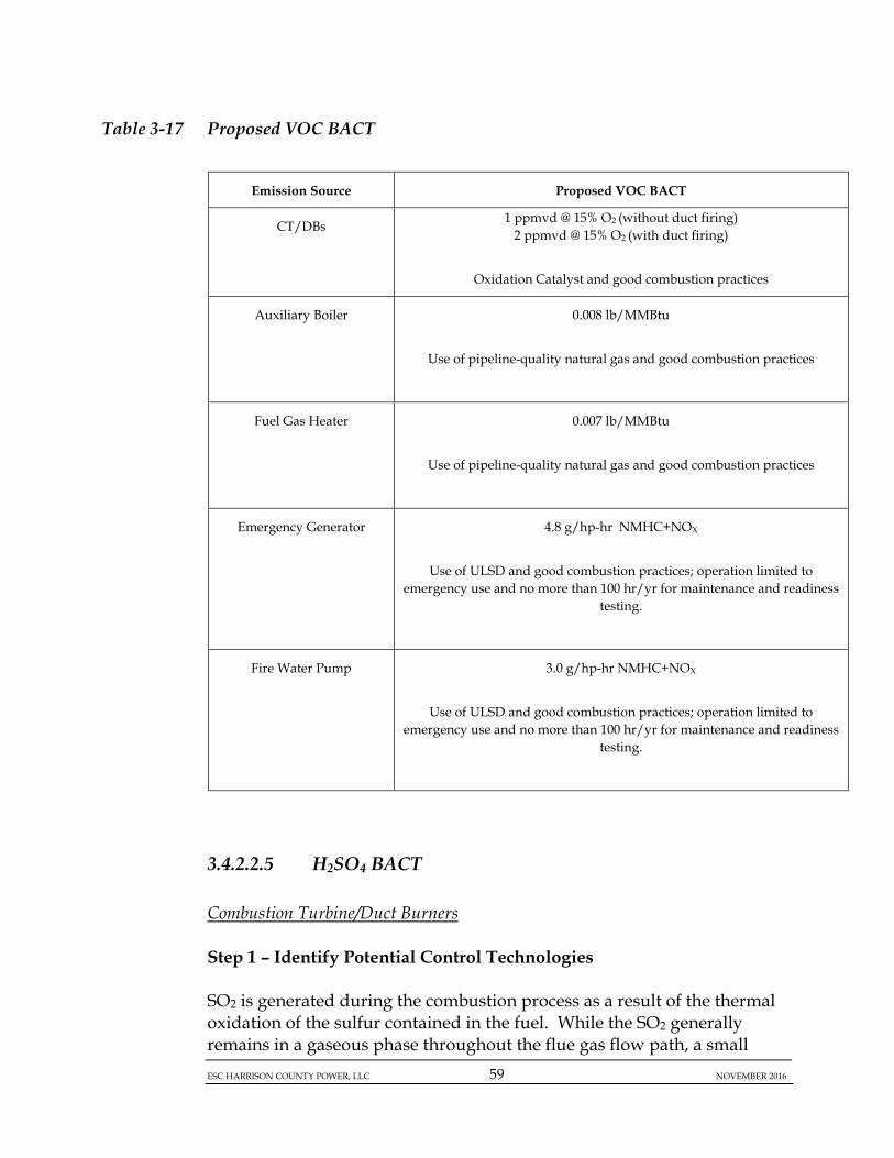
ESC HARRISON COUNTY POWER, LLC 59 NOVEMBER 2016
Table 3-17 Proposed VOC BACT
3.4.2.2.5 H2SO4 BACT
Combustion Turbine/Duct Burners
Step 1 – Identify Potential Control Technologies
SO2 is generated during the combustion process as a result of the thermal oxidation of the sulfur contained in the fuel. While the SO2 generally remains in a gaseous phase throughout the flue gas flow path, a small
Emission Source Proposed VOC BACT
CT/DBs 1 ppmvd @ 15% O2 (without duct firing)
2 ppmvd @ 15% O2 (with duct firing)
Oxidation Catalyst and good combustion practices
Auxiliary Boiler 0.008 lb/MMBtu
Use of pipeline-quality natural gas and good combustion practices
Fuel Gas Heater 0.007 lb/MMBtu
Use of pipeline-quality natural gas and good combustion practices
Emergency Generator 4.8 g/hp-hr NMHC+NOX
Use of ULSD and good combustion practices; operation limited to
emergency use and no more than 100 hr/yr for maintenance and readiness testing.
Fire Water Pump 3.0 g/hp-hr NMHC+NOX
Use of ULSD and good combustion practices; operation limited to
emergency use and no more than 100 hr/yr for maintenance and readiness testing.
ESC HARRISON COUNTY POWER, LLC 60 NOVEMBER 2016
portion may be oxidized to SO3. The SO3 can subsequently combine with water vapor to form H2SO4. H2SO4 emissions from the Project are subject to BACT requirements (estimated potential emissions of H2SO4 are greater than the 7 tons/yr PSD SER). This section summarizes the BACT analysis conducted for H2SO4.
Technologies generally employed to control SO2 and H2SO4 mist emissions from combustion sources consist of fuel treatment and post-combustion add-on controls that rely on chemical reactions within the control device to reduce the concentration of SO2 in the flue gas [also referred to as Flue Gas Desulfurization (FGD) systems]. Based upon a review of RBLC search results, existing permits for similar combined-cycle CTs, CT vendor information and technical literature, post-combustion controls have not been applied to CTs. Minimization of SO2 and H2SO4 mist emissions has been achieved in practice through combustion of pipeline quality natural gas. ESC proposes to control H2SO4 mist emissions through the exclusive use of pipeline quality natural gas with a maximum sulfur content of 0.4 gr/100 scf, which equates to an H2SO4 emission limit of 0.0009 lb/MMBtu.
The use of pipeline quality natural gas is the only available and, therefore, top level of control forH2SO4. Therefore, a ranking is not required to establish the top technology.
Based on EPA “top-down” BACT analysis guidance, analyses of economic, energy and environmental impacts is not required in this case as the “top” or most stringent control technology is selected for H2SO4. Regardless, there are no potential energy, environmental, or economic impacts that would preclude the use of pipeline quality natural gas in the combined-cycle CT/DBs.
ESC proposes exclusive use of natural gas in the CT/DBs to minimize emissions of H2SO4 mist, which represents the most stringent H2SO4 control available for combined-cycle CT/DBs.
Limiting the amount of sulfur in the fuel is a common practice for natural gas-fired power plants. The practical limitation is considered region-specific, depending on the source/specifications of the natural gas in the pipeline supplying the plant. Most BACT limits for H2SO4 are expressed either as a limit on fuel sulfur content or as an H2SO4 emission rate in lb/MMBtu.
ESC HARRISON COUNTY POWER, LLC 61 NOVEMBER 2016
Recent sulfur contents range from 0.1 to 2 gr/100 scf. For the Project, ESC proposes a maximum pipeline sulfur content of 0.4 gr/100 scf. More stringent H2SO4 emission limits in the RBLC are specific to projects with more stringent natural gas sulfur content specifications that are applicable to the geographic location of those projects. Because H2SO4 mist formation is directly related to fuel sulfur content, the applicable emissions limitations must also be directly linked to those specifications.
As the proposed H2SO4 emissions limits are equivalent to the most stringent identified limits that are considered achieved in practice, given the maximum expected natural gas sulfur content, they are sufficiently demonstrated as BACT for the combined-cycle CT/DBs in this application.
Auxiliary Boiler and Fuel Gas Heater
Emissions of H2SO4 from the Auxiliary Boiler and Fuel Gas Heater result from oxidation of fuel sulfur. For H2SO4, this evaluation does not identify and discuss each of the five individual steps of the “top-down” BACT process, since there are no post-combustion control technologies available for H2SO4 emissions from small natural gas-fired boilers and fuel gas heaters.
There are no NSPS H2SO4 standards applicable to natural gas-fired equipment of the size range specified for the proposed Auxiliary Boiler or Fuel Gas Heater.
ESC proposes exclusive use of natural gas with a maximum sulfur content of 0.4 gr/100 scf in the Auxiliary Boiler and Fuel Gas Heater to minimize emissions of H2SO4, which represents the most stringent controls available for this natural gas-fired equipment. The proposed H2SO4 emission rate, 0.00017 lb/MMBtu is based on an assumed 10% conversion of fuel sulfur to H2SO4. The proposed limits are consistent with the most stringent limits identified, in consideration of the proposed fuel sulfur content of 0.4 gr/100 scf.
Emergency Generator and Fire Water Pump
Emissions of H2SO4 from the Emergency Generator and Fire Water Pump result from oxidation of fuel sulfur. For H2SO4, this evaluation does not identify and discuss each of the five individual steps of the “top-down” BACT process, since there are no post-combustion control technologies available for H2SO4 emissions from small emergency diesel engines.
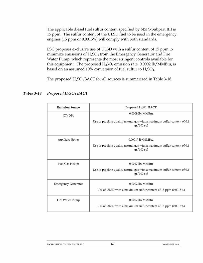
ESC HARRISON COUNTY POWER, LLC 62 NOVEMBER 2016
The applicable diesel fuel sulfur content specified by NSPS Subpart IIII is 15 ppm. The sulfur content of the ULSD fuel to be used in the emergency engines (15 ppm or 0.0015%) will comply with both standards.
ESC proposes exclusive use of ULSD with a sulfur content of 15 ppm to minimize emissions of H2SO4 from the Emergency Generator and Fire Water Pump, which represents the most stringent controls available for this equipment. The proposed H2SO4 emission rate, 0.0002 lb/MMBtu, is based on an assumed 10% conversion of fuel sulfur to H2SO4.
The proposed H2SO4 BACT for all sources is summarized in Table 3-18.
Table 3-18 Proposed H2SO4 BACT
Emission Source Proposed H2SO4 BACT
CT/DBs 0.0009 lb/MMBtu
Use of pipeline-quality natural gas with a maximum sulfur content of 0.4 gr/100 scf
Auxiliary Boiler 0.00017 lb/MMBtu
Use of pipeline-quality natural gas with a maximum sulfur content of 0.4 gr/100 scf
Fuel Gas Heater 0.0017 lb/MMBtu
Use of pipeline-quality natural gas with a maximum sulfur content of 0.4 gr/100 scf
Emergency Generator 0.0002 lb/MMBtu
Use of ULSD with a maximum sulfur content of 15 ppm (0.0015%)
Fire Water Pump 0.0002 lb/MMBtu
Use of ULSD with a maximum sulfur content of 15 ppm (0.0015%)

ESC HARRISON COUNTY POWER, LLC 63 NOVEMBER 2016
3.4.2.2.6 GHG BACT
The GHG Tailoring Rule regulates emissions from six (6) covered GHGs: CO2, CH4, N2O, HFCs, PFCs, and SF6. Typically, GHG emissions are listed in terms of CO2e. GHG emissions associated with combustion equipment are limited to CO2, CH4 and N2O. In calculating CO2e emissions, GWPs are used to normalize emissions of pollutants such as CH4 and N2O, which are deemed to have a greater detrimental impact on a per pound basis than CO2. The GWP for CO2 is set at 1, while CH4 and N2O have GWPs of 25 and 298, respectively. The evaluation of technologies to minimize GHG emissions typically focuses on CO2 emissions and mechanisms to reduce CO2 emissions, which dominates the CO2e emission value for combustion based equipment. As such, the BACT evaluation presented in this document refers to CO2 as the primary GHG pollutant for proposed Project equipment.
In general, there are two strategies available to minimize GHG emissions for electric generating units (EGUs): (1) add-on control via carbon capture systems to strip CO2 from the flue gas stream for subsequent re-use or sequestration, and (2) energy efficiency methods.
An important consideration for power plants is the source definition. USEPA permit guidance indicates that the Clean Air Act does not provide latitude for a permitting authority to redefine a source as part of a BACT evaluation. The proposed Project is a base load electric generating facility using gaseous fuel-fired combined-cycle CT technology. Only technologies that are relevant to the proposed equipment and fit within the business objectives of a facility should be considered in Step 1 of a BACT evaluation. For example, factors such as fuel type (coal versus solar or wind), or operational parameters (i.e., base load versus peak shaving) would be considered part of the “source definition” for power plants.
Combustion Turbine/Duct Burners Step 1 – Identify Potential Control Technologies Carbon Capture and Storage Carbon capture and storage (CCS) is the only potentially available add-on control option at this time. In order to capture CO2 emissions from the flue gas, CO2 must be separated from the exhaust stream. This can be accomplished by a variety of technologies that may include:

ESC HARRISON COUNTY POWER, LLC 64 NOVEMBER 2016
• Pre-combustion systems designed to separate CO2 and hydrogen in the high-pressure synthetic gas typically produced at Integrated Gasification Combined-Cycle (IGCC) power plants; and
• Post-combustion systems that separate CO2 from flue gas such as:
o Chemical absorption using an aqueous solution of amines as chemical solvents; or
o Physical absorption using physical absorption processes such as Rectisol or Selexol.
Separation can be facilitated using oxygen combustion, which employs oxygen instead of ambient air for make-up air supplied for combustion. Applicability of different processes to particular applications will depend on temperature, pressure, CO2 concentrations, and the presence or absence of contaminants in the gas or exhaust stream.
After CO2 is separated, it must be prepared for beneficial reuse or transport to a sequestration or storage facility, if a storage facility is not locally available for direct injection. In order to transport CO2, it must be compressed and delivered via pipeline to a storage facility. Although beneficial reuse options are developing, such as the use of captured material to enhance oil or gas recovery from well fields in the petroleum industry, currently, the demand for CO2 for such applications is well below the quantity of CO2 that is available for capture from EGUs. Without a market to use the recovered CO2, the material would instead require sequestration, or permanent storage. Sequestration of CO2 is generally accomplished by injecting captured CO2 at high pressures into deep subsurface formations for long-term storage. These subsurface formations must be either local to the point of capture, or accessible via pipeline, to enable the transportation of recovered CO2 to the permanent storage location. Storage facilities typically include:
1) Geologic formations; 2) Depleted oil and gas reservoirs; 3) Unmineable coal seams; 4) Saline formations; 5) Basalt formations; or 6) Terrestrial ecosystems.

ESC HARRISON COUNTY POWER, LLC 65 NOVEMBER 2016
Once injected, the pressurized CO2 remains “supercritical” and behaves like a liquid. Supercritical CO2 is denser and takes up less space than gaseous CO2. Once injected, the CO2 occupies pore spaces in the surrounding rock. Saline water that already resides in the pore space would be displaced by the denser CO2. Over time, the CO2 can dissolve in residual water, and chemical reactions between the dissolved CO2 and rock can create solid carbonate minerals, more permanently trapping the CO2. Thermal Efficiency An emissions reduction strategy focused on energy efficiency primarily deals with increasing the thermal efficiency of a CT. Higher thermal efficiency means that less fuel is required for a given output, which results in lower GHG emissions. Maximizing EGU efficiency is an alternative available to reduce the consumption of fuel required to generate a fixed amount of output. The largest efficiency losses for a combined-cycle CT are inherent in the design of the CT and the heat recovery system. The mechanical input to the CT compressor consumes energy, and is integral to how a CT works. Therefore, there is no opportunity for efficiency gains other than the differences in design between manufacturers or models. Heat recovery in the exhaust gas is another point of efficiency loss. Heat recovery efficiency depends upon the design of the heat recovery system, and varies between manufacturers and models.
The efficiency of the CT/DBs employed can vary widely. One alternative to reduce CO2 emissions is to maximize CT efficiency through various design techniques. Any increase in energy efficiency within the operation of the CT yields reductions in the generation of CO2 emissions on a per unit output basis. For example, CT suppliers typically offer several different models with a variety of efficiency ratings. Combustion Air Cooling A common method used to improve the energy efficiency of CTs is to cool the combustion air entering the CTs during the summer months. Cooling the combustion air via heat exchanger systems maximizes the expansion of the air molecules and enhances the work the expanding gases perform on the turbine blades, hence producing higher amounts of electricity. A higher electric output improves the overall efficiency of the EGU. Based on general guidance available and recent analyses conducted regarding

ESC HARRISON COUNTY POWER, LLC 66 NOVEMBER 2016
combustion air cooling, achievable reductions in fuel usage and CO2 emissions may range from 10 to 15%6 . Cogeneration/Combined Heat & Power Cogeneration, or Combined Heat and Power (CHP), is the operation of a combustion system to generate both heat for electric power generation and useful thermal energy for a process. The electric power is distributed for use, while the thermal energy is used locally to support heating systems or industrial processes. A CHP system allows for the use of energy in the form of heat to provide thermal energy that would otherwise be lost in cooling water for a traditional EGU. For CT systems, the more likely CHP technique would be to provide space heating for nearby buildings or to provide makeup heat to nearby coal-fired EGUs (likely application for power plants with CT and coal-fired EGUs onsite). The use of this otherwise lost heat would thereby improve the overall efficiency of the EGU or process, and subsequently reduce overall CO2 emissions, on an equivalent basis.
The use of a CHP system provides an opportunity to extract additional energy from heat otherwise lost in a traditional EGU. However, this type of system requires the removal of steam from the steam turbine, which reduces the amount of electric power generation recognized in the CHP. This electrical energy is instead transformed to thermal energy for use on a more local basis. The advantage to a CHP system is the net improvement of overall fuel efficiency compared to a traditional EGU operation. Lower Carbon Fuels Carbon dioxide is produced as a combustion product of any carbon-containing fuel. All fossil fuels contain varying amounts of fuel-bound carbon that is converted during the combustion process to produce CO and CO2. However, the use of lower carbon content gaseous fuels such as pipeline-quality natural gas, compared to the use of higher carbon-containing fuels such as coal, pet-coke or residual fuel oils, can reduce CO2 emissions from combustion.
Natural gas combustion results in significantly lower GHG emissions than coal combustion (117.0 lb/MMBtu for natural gas, versus 205.6 lb/MMBtu
6 (Hyperion Energy Center Best Available Control Technology (BACT) Analysis for Emissions of Carbon Dioxide, March 2009).
ESC HARRISON COUNTY POWER, LLC 67 NOVEMBER 2016
for bituminous coal).7 The use of lower carbon containing fuels in CTs is an effective means to reduce the generation of CO2 during the combustion process. Step 2 - Eliminate Technically Infeasible Options Carbon Capture and Storage In general, the availability of add-on control options to remove GHGs from an EGU exhaust stream is limited. CCS is the only potentially available add-on control option at this time, and even this technology is limited and infantile in its development.
Although numerous carbon capture, storage, and beneficial CO2 use demonstration projects are in various stages of planning and implementation across the globe, including several in the U.S. that are funded by the Department of Energy (DOE), the technologies needed for a full-scale generating facility are not yet commercially available. In fact, President Obama formed an Interagency Task Force on Carbon Capture and Storage, co-chaired by DOE and USEPA, in early 2010 to develop a federal strategy for overcoming the barriers to the widespread, cost-effective deployment of CCS within 10 years, with an ultimate goal of bringing several commercial demonstration projects online by 20168.
Without a market to use the recovered CO2, the material would instead require sequestration, or permanent storage. The geological formations near the ESC Project provide limited, if any, alternatives to adequately and permanently store recovered CO2.
Extensive characterization studies would be needed to determine the extent and storage potential for CO2 from ESC sources. These studies would take several years of investigation, including drilling characterization wells, and would likely require small-scale injection testing before determining their full-scale viability.
7 40 CFR 98, Subpart C, Table C-1.
8 U.S. Interagency Task Force on Carbon Capture and Storage. “Report of the Interagency Task Force on Carbon Capture and Storage.” August 2010. Available online: http://www.epa.gov/climatechange/downloads/CCS-Task-Force-Report-2010.pdf
ESC HARRISON COUNTY POWER, LLC 68 NOVEMBER 2016
There are neither local geologic reservoirs, nor pipelines dedicated to CO2 transport available near the proposed Project at this time. In addition, carbon capture technologies have yet to be demonstrated on a full-scale power generation facility. Therefore, options involving CCS are not currently considered feasible for this Project. Nevertheless, ESC is quantitatively evaluating cost-effectiveness of CCS as a hypothetical BACT option. This analysis is provided in Appendix C.
Thermal Efficiency The use of a CT with a higher thermal efficiency is a technically feasible alternative to one with a lower thermal efficiency rating. Combustion Air Cooling Although combustion air cooling is considered technically feasible, other options such as a more efficient CT are considered more effective in terms of overall net environmental benefit. The proposed CT will be equipped with inlet evaporative cooling systems, which are a form of combustion air cooling. Cogeneration/Combined Heat & Power For a CHP system to be beneficial, there must be a local need for thermal energy, because thermal energy cannot be effectively transported over extended distances. Given the proposed use of an extremely efficient CT operated in an efficient combined-cycle mode, there is no reasonable net environmental benefit of a CHP system for the proposed Project. Therefore, CHP is not considered technically feasible for this Project. Lower Carbon Fuels The use of lower carbon content gaseous fuels such as pipeline-quality natural gas, compared to the use of higher carbon-containing fuels such as coal, pet-coke or residual fuel oils, is a technically feasible alternative to reduce CO2 emissions. Step 3 - Rank Remaining Control Technologies by Control Effectiveness ESC proposes to use a high thermal efficiency CT model, GE Frame 7HA.02, operated in combined-cycle mode. The proposed CT feature an extremely low heat rate when operating in combined-cycle mode, which translates to high efficiency because a low heat rates means less fuel is combusted to produce a unit amount of electric power output.
ESC HARRISON COUNTY POWER, LLC 69 NOVEMBER 2016
The table in Appendix D of this application contains a comparison of GHG emission rate and heat rate information for various combustion turbines projects, both simple-cycle and combined-cycle. Available information regarding size, configuration, CO2 or GHG emission rates, and heat rates is summarized. The relevant information for the ESC Combustion Turbines is included in this table. Comparisons among the various CTs are somewhat complicated in that different bases can be used to establish certain parameters. For example, CT outputs can be specified on a net or gross basis, and can vary based on fuel, load, ambient temperature, whether duct firing is occurring, and other factors. GHG emission rates can be specified on a LHV or HHV basis. Nevertheless, in context, the ESC CT compares favorably with other recent CT projects in terms of output-based GHG emission rates and heat rates, which indicates that the proposed CT represents an efficient design that has been accepted as BACT for GHGs in other PSD permits. The proposed CT will be equipped with an inlet evaporative cooling system, which is a form of combustion air cooling. ESC proposes the use of pipeline-quality natural gas as the CT fuel. Natural gas is a lower carbon containing fuel that yields reduced GHG emissions. Step 4 - Evaluate Most Effective Controls and Document Results Based on the information presented in this BACT analysis and consistent with BACT at other similar sources, ESC proposes to employ the following GHG control techniques as part of this Project:
(1) Use of a high thermal efficiency CT model, GE Frame 7HA.02, operated in combined-cycle mode;
(2) Use of inlet evaporative cooling systems, which are a form of combustion air cooling;
(3) Use of lower carbon containing fuel (pipeline-quality natural gas); In addition, ESC proposes a facility-wide GHG emissions limit as GHG BACT for the Project. The proposed GHG emission limit from the CT/DBs, Auxiliary Boiler, Fuel Gas Heater, Emergency Generator, Fire Water Pump, and Circuit Breakers is 2,338,896 tons/yr, on a CO2e basis. GHG emissions from the Project’s combustion sources will be calculated in accordance with the methodology and emission factors noted in 40 CFR 98, Subparts C and D, as applicable. GHG emissions from the Project’s
ESC HARRISON COUNTY POWER, LLC 70 NOVEMBER 2016
Circuit Breakers will be calculated in accordance with the methodology and emission factors noted in 40 CFR 98, Subpart DD, as applicable. Step 5 - Select BACT For GHG BACT, ESC proposes to employ the following GHG control techniques:
(1) Use of a high thermal efficiency CT model, GE Frame 7HA.02, operated in combined-cycle mode;
(2) Use of inlet evaporative cooling systems, which are a form of combustion air cooling;
(3) Use of lower carbon containing fuel (pipeline-quality natural gas); ESC also proposes a facility-wide GHG emissions limit. The proposed GHG emission limit from the CT/DBs, Auxiliary Boiler, Fuel Gas Heater, Emergency Generator, Fire Water Pump, and Circuit Breakers is 2,338,896 tons/yr, on a CO2e basis. GHG emissions from the Project’s combustion sources will be calculated in accordance with the methodology and emission factors noted in 40 CFR 98, Subparts C and D, as applicable. GHG emissions from the Project’s Circuit Breakers will be calculated in accordance with the methodology and emission factors noted in 40 CFR 98, Subpart DD, as applicable.
Auxiliary Boiler
There are currently no technically feasible add-on control technologies to reduce GHG emissions from the Auxiliary Boiler. Therefore, GHG emissions from these sources will be controlled by the exclusive use of pipeline-quality natural gas and good combustion practices.
Emergency Generator and Fire Water Pump
There is currently no technically feasible add-on control technology to reduce GHG emissions from the Emergency Generator and Fire Water Pump. Therefore, ESC proposes to limit GHG emissions from these sources by using ULSD and good combustion practices.
Circuit Breakers
Sulfur hexafluoride (SF6) gas is typically used in the circuit breakers associated with electricity generation equipment. Potential sources of SF6 emissions include equipment leaks from SF6 containing equipment,

ESC HARRISON COUNTY POWER, LLC 71 NOVEMBER 2016
releases from gas cylinders used for equipment maintenance and repair operations, and SF6 handling operations.
(1) Use of dielectric oil or compressed air circuit breakers that contain no SF6 or other GHG pollutants; and
(2) Use of modern SF6 circuit breakers designed to be totally enclosed systems.
Potential alternatives to SF6 were addressed in the National Institute of Standards and Technology (NTIS) Technical Note 1425, Gases for Electrical Insulation and Arc Interruption: Possible Present and Future Alternatives to Pure SF6.17. According to this document, SF6 is a superior dielectric gas for nearly all high voltage applications. It is easy to use, exhibits exceptional insulation and arc-interruption properties, and has proven its performance by many years of use and investigation. It is clearly superior in performance to the air and oil insulated equipment used prior to the development of SF6-insulated equipment. The report concluded that although “…various gas mixtures show considerable promise for use in new equipment, particularly if the equipment is designed specifically for use with a gas mixture… it is clear that a significant amount of research must be performed for any new gas or gas mixture to be used in electrical equipment.” Therefore, ESC believes there are currently no technically feasible options to the use of SF6. Circuit breakers with insulating gases other than SF6 are not yet commercially available, and certainly any use of less effective insulation material to control emissions of just 58 tons/yr of CO2e would not be warranted, even if it were available. As such, non-SF6 circuit breakers will be eliminated. The only remaining feasible control is to use a modern, totally enclosed SF6 circuit breakers.
In comparison to older SF6 circuit breakers, modern breakers are designed as totally enclosed pressure systems with far lower potential for SF6 emissions. Therefore, ESC proposes to implement modern state-of-the-art, gas-tight circuit breakers with the implementation of an inspection and maintenance program to identify and repair leaks. ESC will monitor SF6 emissions from the circuit breakers annually according to the requirements of the Mandatory Greenhouse Gas Reporting Rule for Electrical Transmission and Distribution Equipment Use (40 CFR 98, Subpart DD). Annual emissions of SF6 will be calculated according to the mass balance approach in Equation DD-1 of Subpart DD.
The proposed GHG BACT for all sources is summarized in Table 3-19.
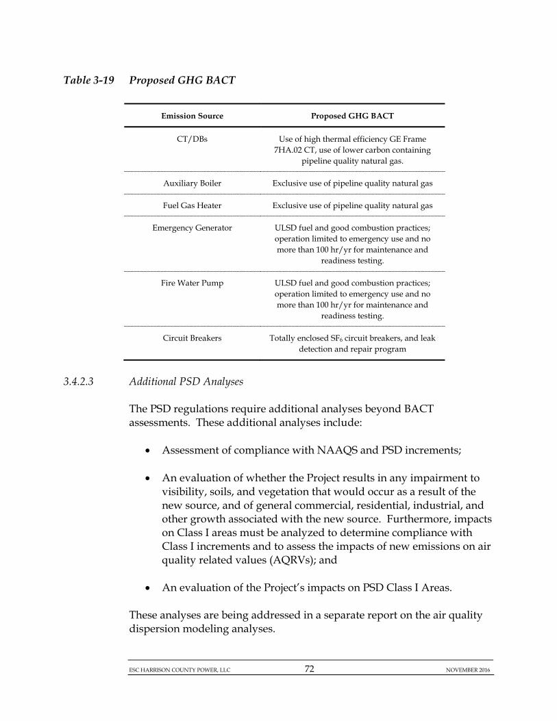
ESC HARRISON COUNTY POWER, LLC 72 NOVEMBER 2016
Table 3-19 Proposed GHG BACT
Emission Source Proposed GHG BACT
CT/DBs Use of high thermal efficiency GE Frame 7HA.02 CT, use of lower carbon containing
pipeline quality natural gas.
Auxiliary Boiler Exclusive use of pipeline quality natural gas
Fuel Gas Heater Exclusive use of pipeline quality natural gas
Emergency Generator ULSD fuel and good combustion practices; operation limited to emergency use and no more than 100 hr/yr for maintenance and
readiness testing.
Fire Water Pump ULSD fuel and good combustion practices; operation limited to emergency use and no more than 100 hr/yr for maintenance and
readiness testing.
Circuit Breakers Totally enclosed SF6 circuit breakers, and leak detection and repair program
3.4.2.3 Additional PSD Analyses
The PSD regulations require additional analyses beyond BACT assessments. These additional analyses include:
• Assessment of compliance with NAAQS and PSD increments;
• An evaluation of whether the Project results in any impairment to visibility, soils, and vegetation that would occur as a result of the new source, and of general commercial, residential, industrial, and other growth associated with the new source. Furthermore, impacts on Class I areas must be analyzed to determine compliance with Class I increments and to assess the impacts of new emissions on air quality related values (AQRVs); and
• An evaluation of the Project’s impacts on PSD Class I Areas.
These analyses are being addressed in a separate report on the air quality dispersion modeling analyses.

ESC HARRISON COUNTY POWER, LLC 73 NOVEMBER 2016
3.5 NON-ATTAINMENT NEW SOURCE REVIEW (NA-NSR)
The ESC Project is located in Harrison County, which is designated attainment for all criteria pollutants. There are no non-attainment areas. Therefore, the proposed Project is not subject to NA-NSR for any pollutants.
3.6 APPLICABLE REQUIREMENTS REVIEW
This section briefly outlines the federal and State air quality requirements to which the proposed ESC Project will be subject, in addition to the PSD and NA-NSR requirements presented previously.
3.6.1 Federal Requirements
3.6.1.1 New Source Performance Standards (NSPS)
3.6.1.1.1 Combustion Turbines/Duct Burners
The CT is subject to 40 CFR 60 Subpart KKKK, “Standards of Performance for Stationary Combustion Turbines.” All stationary gas turbines with a heat input at a peak load equal to or greater than 10.7 gigajoules per hour (10 MMBtu/hr), based on the higher heating value of the fuel, which commenced construction, modification, or reconstruction after 18 February 2005 are subject to this NSPS Subpart KKKK. Note that stationary CTs regulated under Subpart KKKK are exempt from the requirements of Subpart GG.
The Subpart KKKK emission limits are:
• NOx: 15 ppmvd @ 15% O2 or 0.43 lb/MW-hr gross energy output; and
• SO2: 0.90 lb/MW-hr gross energy output or 0.060 lb/MMBtu.
Subpart KKKK includes general compliance requirements (60.4333), monitoring requirements (60.4335-60.4370), reporting requirements (60.4375-60.4395), and performance testing (60.4400-60.4415). ESC will also be subject to applicable notification, monitoring and reporting and related applicable provisions of 40 CFR 60.7 and 60.8.
ESC HARRISON COUNTY POWER, LLC 74 NOVEMBER 2016
The proposed CT will meet the applicable emission limits and provisions of NSPS Subpart KKKK.
3.6.1.1.2 Auxiliary Boiler
The Auxiliary Boiler is subject to 40 CFR 60 Subpart Dc, “Standards of Performance for Small Industrial-Commercial-Institutional Steam Generating Units” because the rated heat input of the Auxiliary Boiler, 100 MMBtu/hr, is greater 10 MMBtu/hr and less than or equal to 100 MMBtu/hr. Subpart Dc requirements for an auxiliary boiler that only burns natural gas or other gaseous fuels include:
• Notification of the date of construction and actual startup (60.48c(a));
• Fuel and fuel use records (60.48c(f) and (g)); and
• Maintenance of required records for two (2) years from the date of the record (60.48c(i)).
The proposed Auxiliary Boiler will meet the applicable emission limits and provisions of NSPS Subpart Dc.
3.6.1.1.3 Fuel Gas Heater
The Fuel Gas Heater is not subject to any NSPS. 40 CFR 60 Subpart Dc, “Standards of Performance for Small Industrial-Commercial-Institutional Steam Generating Units” applies to units with rated heat inputs greater than 10 MMBtu/hr and less than 100 MMBtu/hr. With a maximum heat input of 5.5 MMBtu/hr, the Fuel Gas Heater is below the size threshold for 40 CFR 60 Subpart Dc applicability.
3.6.1.1.4 Emergency Generator and Fire Water Pump
The Emergency Generator and Fire Water Pump are subject to 40 CFR 60, Subpart IIII (Standards of Performance for Stationary Compression Ignition Internal Combustion Engines) and the associated fuel, monitoring, compliance, testing, notification, reporting, and recordkeeping requirements (40 CFR 60.4200 et seq.) and related applicable provisions of 40 CFR 60.7 and 60.8. Emission limits for the Emergency Generator and Fire Water Pump are noted in Tables 3-7 and 3-8, respectively. Note that both engines are not subject to the Tier 4 requirements under Subpart IIII because they both will have cylinder displacement less than 10 liters per cylinder (L/cyl.).

ESC HARRISON COUNTY POWER, LLC 75 NOVEMBER 2016
The emission standards in NSPS Subpart IIII applicable to the Emergency Generator and Fire Water Pump are summarized in Table 3-20 below. The proposed Emergency Generator and Fire Water Pump will meet the applicable emission limits and provisions of NSPS Subpart IIII.
Table 3-20 Emission Standards for Emergency Engines (g/hp-hr)
Emergency Engine Model Year NMHC+NOX CO PM
315 hp Fire Water Pump 225<kW<450 (300<hp<600) 2009 and after 3.0 2.6 0.15
2,000 kW Emergency Generator <10 L/cyl. and <2,237 kW (3,000 hp) 2006 and after 4.8 2.6 0.15
3.6.1.2 NSPS for GHGs (40 CFR Part 60) NSPS Subpart TTTT “Standards of Performance for Greenhouse Gas Emissions for Electric Generating Units (EGUs)” became effective on October 23, 2015. NSPS Subpart TTTT establishes CO2 emission standards for certain EGUs. Pursuant to 40 CFR §60.5509(a), Subpart TTTT, as it pertains to stationary simple-cycle combustion turbines, applies to units that commenced “construction” after January 8, 2014 or commenced “reconstruction” after June 18, 2014 and that meet the relevant applicability conditions in 40 CFR §60.5509(a)(1) and (2), which are:
1. Have base load ratings greater than 250 MMBtu/hr; and
2. Serve generators capable of selling greater than 25 MW of electricity to a utility power distribution system.
NSPS Subpart TTTT limits CO2 emissions from newly constructed CTs, such as the proposed CT, to 1,000 lb/MW-hr of electricity generated on a gross basis, on a 12-operating month rolling average. The proposed CT will comply with this standard.
3.6.1.3 Acid Rain Program (40 CFR Parts 72-76, 45 CSR 33)
The proposed CT meets the definition of an “affected unit” as defined in 40 CFR 72.6, and are therefore subject to the requirements of the Acid Rain Program, including emissions standards (40 CFR 72.9) and monitoring requirements (40 CFR 75), among other requirements. In addition, ESC is

ESC HARRISON COUNTY POWER, LLC 76 NOVEMBER 2016
required to apply for, and obtain, an Acid Rain permit, pursuant to 40 CFR 72.30. The terms of the Acid Rain permit will be incorporated into the facility’s Title V operating permit when it is issued by WVDEP in the future. Pursuant to 40 CFR 72.30(b)(2)(ii), the Acid Rain permit application must be submitted to the permitting authority at least 24 months before the date on which a unit commences operation. With commencement of operation expected in the first or second quarter of 2020, the Acid Rain permit application must be submitted sometime in the first or second quarter of 2018.
3.6.1.4 National Emissions Standards for Hazardous Air Pollutants
National Emissions Standards for Hazardous Air Pollutants (NESHAPs) are federal HAP requirements in 40 CFR 63 that apply generally to "major" sources of HAPs, defined as facilities with the potential to emit 10 tons/yr or more of any single HAP, or 25 tons/yr or more of all HAPs combined. The total potential HAP emissions for the facility are projected to be less than 10 tons/year for an individual HAP and less than 25 tons/yr for all HAPs combined. Therefore, the Project is not considered a major HAP source. HAP standards, known as Maximum Achievable Control Technology (MACT) standards, are established for classes or categories of sources. Some MACT standards, known as “area source MACT” standards, apply to minor source HAP facilities.
There are, at present, no area source category MACT standards for CTs such as the one proposed by ESC.
There is an area source MACT for Industrial Commercial, Institutional Boilers and Process Heaters, (40 CFR 63, Subpart JJJJJJ), known as “Area Source Boiler MACT”. The proposed Auxiliary Boiler or Fuel Gas Heater are considered “affected sources” under Subpart JJJJJJ, however, pursuant to 40 CFR 63.11195, natural gas-fired boilers/heaters are not subject to the requirements of Subpart JJJJJJ. Therefore, the Area Source Boiler MACT does not apply to the Auxiliary Boiler or Fuel Gas Heater.
The proposed diesel engine-powered Emergency Generator and Fire Water Pump are subject to 40 CFR Subpart ZZZZ for Stationary Reciprocating Internal Combustion Engines (“RICE MACT”). For the Emergency Generator, pursuant to 40 CFR 63.6590(b)(1)(i), ESC is only required to submit the initial notification according to 40 CFR 43.6645(f). For the Fire Water Pump, pursuant to 40 CFR 63.6590(c)(6), the facility will

ESC HARRISON COUNTY POWER, LLC 77 NOVEMBER 2016
comply with the requirements of Subpart ZZZZ by complying with the requirements of NSPS Subpart IIII.
3.6.1.5 Compliance Assurance Monitoring
Compliance Assurance Monitoring (CAM) applies to emissions units at “major” sources that are required to obtain a Title V operating permit, and that meet all three of the following criteria (40 CFR 64.2a):
“(1) The unit is subject to an emission limitation or standard for the applicable regulated air pollutant (or a surrogate thereof), other than an emission limitation or standard that is exempt under paragraph (b)(1) of this section; (2) The unit uses a control device to achieve compliance with any such emission limitation or standard; and (3) The unit has potential pre-control device emissions of the applicable regulated air pollutant that are equal to or greater than 100% of the amount, in tons/yr, required for a source to be classified as a major source.”
Exemptions from CAM in 40 CFR 64.2(b)(1) include:
(i) Emission limitations or standards proposed by the Administrator after November 15, 1990 pursuant to section 111 [NSPS] or 112 [NESHAP] of the Act.
(ii) Stratospheric ozone protection requirements under Title VI of the Act. (iii) Acid Rain Program requirements pursuant to sections 404, 405, 406, 407(a), 407(b), or 410 of the Act. (iv) Emission limitations or standards or other applicable requirements that apply solely under an emissions trading program approved or promulgated by the Administrator under the Act that allows for trading emissions within a source or between sources. (v) An emissions cap that meets the requirements specified in 70.4(b)(12) or 71.6(a)(13)(iii) of this chapter. (vi) Emission limitations or standards for which a Part 70 or 71 [Title

ESC HARRISON COUNTY POWER, LLC 78 NOVEMBER 2016
V operating] permit specifies a continuous compliance determination method, as defined in 64.1…
The proposed Project was evaluated for CAM applicability. Only the CT is equipped with control devices (SCR and Oxidation Catalyst) and has pre-controlled emissions of applicable regulated air pollutants emissions (NOx and CO) in excess of 100 tons/yr. However, the CT is subject to the NSPS Subpart KKKK, and will be equipped with Continuous Emissions Monitoring Systems (CEMS) for NOx and CO, which are considered a continuous compliance determination method. Therefore, the CT is exempt from CAM under 40 CFR 64.2(a)(1) and (b)(1)(i).
3.6.1.6 Chemical Accident Prevention Provisions
These provisions, in 40 CFR 68, apply to a wide variety of facilities that handle, manufacture, store, or use toxic or highly flammable substances. Ammonia is one of the potentially covered substances. However, the ammonia reagent planned for the SCR is aqueous ammonia, at a concentration of less than 20% by weight. The aqueous ammonia is planned to be stored in one (1) storage tank, with a capacity of 35,000 gallons. The use of aqueous ammonia with a concentration of less than 20% by weight ensures that the provisions of 40 CFR 68 will not apply.
3.6.1.7 Cross-State Air Pollution Rule
The Cross-State Air Pollution Rule (CSAPR), 40 CFR Parts 96 and 97, requires certain states, including West Virginia, to achieve significant, phased reductions in annual and ozone-season NOx emissions (as a precursor to PM2.5 and ozone formation) and annual SO2 emissions (as a precursor to PM2.5 formation), consistent with state-specific emissions budgets established by EPA.
As with the Acid Rain Program, the rule is based on a cap and trade system where each ton of emitted pollutant (e.g., ozone season NOx) is offset through the allocation or purchase of allowances. Emissions monitoring is required using methods specified in 40 CFR Part 75. In addition to monitoring, CSAPR requires reporting, recordkeeping and compliance requirements.
The CT is subject to CSAPR because West Virginia is an affected state, and the rule applies to any stationary, fossil-fuel-fired boiler or stationary,
ESC HARRISON COUNTY POWER, LLC 79 NOVEMBER 2016
fossil-fuel-fired CT serving at any time, on or after January 1, 2005, a generator with nameplate capacity of more than 25 MWe producing electricity for sale.
The Project will comply with the CSAPR requirements by implementing specified monitoring, recordkeeping, and reporting procedures (largely equivalent to procedures required under the ARP), acquiring the required allowances (if new unit allocations are insufficient to offset actual SO2 and NOx emissions) and complying with other applicable permitting and administrative requirements of the program.
3.6.1.8 Mandatory Reporting of Greenhouse Gases The Mandatory Greenhouse Gas Reporting Rule (40 CFR Part 98) applies to direct GHG emitters, fossil fuel suppliers, industrial gas suppliers, and facilities that inject CO2 underground for sequestration or other reasons. In general, the threshold for reporting is 25,000 metric tons or more of CO2e per year. Reporting is at the facility level, except for certain suppliers of fossil fuels and industrial GHGs.
At the ESC facility, the Auxiliary Boiler and Fuel Gas Heater are addressed in Subpart C (General Stationary Fuel Combustion Sources), and the CT is addressed in Subpart D (Electricity Generation). Pursuant to 40 CFR 98.30(b)(2), emergency generators and emergency equipment as defined in 40 CFR 98.6 are not included in the source category under Subpart C. Therefore, the Emergency Generator and the Fire Water Pump are exempt from reporting under the rule. Under Subparts C and D, emissions of CO2, CH4 and N2O must be determined and reported to USEPA in accordance with the following requirements:
• Procedure to estimate emissions (98.33, 98.43); • Monitoring and QA/QC Requirements (98.34, 98.44); • Procedures for Estimating Missing Data (98.35, 98.45); • Data Reporting Requirements (98.36, 98.46); and • Records that Must Be Retained (98.37, 98.47).
ESC will be required to submit an annual report of GHG emissions and data. The facility will be required to use the electronic GHG reporting tool (e-GGRT) developed by USEPA. The annual report of the previous calendar year’s data is due on March 31 of each year.
ESC HARRISON COUNTY POWER, LLC 80 NOVEMBER 2016
3.6.2 State Requirements
The proposed Project will be subject to a number of WVDEP air quality requirements including, but not limited to, the following:
3.6.2.1 45 CSR 02 (To Prevent and Control Particulate Air Pollution from Combustion of Fuel in Indirect Heat Exchangers)
The Auxiliary Boiler is a natural gas-fired indirect heat exchanger with a design heat input capacity greater than 10 MMBtu/hr. The Auxiliary Boiler will comply with the applicable PM emission limits and visible emission standards in the rule.
Note that the Fuel Gas Heater is a natural gas-fired indirect heat exchanger, but it has a design heat input capacity below 10 MMBtu/hr. Therefore, the Fuel Gas Heater is not subject to this rule.
3.6.2.2 45 CSR 10 (To Prevent and Control Air Pollution from the Emission of Sulfur Oxides)
The Auxiliary Boiler is a natural gas-fired indirect heat exchanger with a design heat input capacity greater than 10 MMBtu/hr. The Auxiliary Boiler will comply with the applicable SO2 emission limits in the rule.
The Fuel Gas Heater is a natural gas-fired indirect heat exchanger, but it has a design heat input capacity below 10 MMBtu/hr. Therefore, the Fuel Gas Heater is not subject to this rule.
3.6.2.3 45 CSR 11 (Prevention of Air Pollution Emergency Episodes)
When requested by the WVDEP Director, ESC will prepare standby plans for reducing air pollutant emissions during Air Pollution Alerts, Air Pollution Warnings, and Air Pollution Emergencies.
3.6.2.4 45 CSR 13 (Permits for Construction, Modification, Relocation and Operation of Stationary Sources of Air Pollutants, Notification Requirements, Administrative Updates, Temporary Permits, General Permits, Permission to Commence Construction, and Procedures for Evaluation)
This permit application is being submitted pursuant to 45 CSR 13 for the construction of the proposed Project.

ESC HARRISON COUNTY POWER, LLC 81 NOVEMBER 2016
3.6.2.5 45 CSR 14 (Permits for Construction and Major Modification of Major Stationary Sources of Air Pollution for the Prevention of Significant Deterioration)
As described above in Section 3.4, the proposed Project will be subject to PSD for NOx, CO, PM, PM10, PM2.5, VOC, H2SO4, and GHGs.
3.6.2.6 45 CSR 16 (Standards of Performance for New Stationary Sources)
As described above in Section 3.6.1.1, the proposed CT will be subject to NSPS Subpart KKKK and Subpart TTTT in 40 CFR 60. The proposed Auxiliary Boiler will be subject to NSPS Subpart Dc in 40 CFR 60. The proposed Emergency Generator and Fire Water Pump will be subject to NSPS Subpart IIII in 40 CFR 60.
The Fuel Gas Heater is below the size threshold for NSPS applicability.
3.6.2.7 45 CSR 19 (Permits for Construction and Major Modification of Major Stationary Sources of Air Pollution Which Cause or Contribute to Nonattainment)
As described above in Section 3.5, the ESC Project’s location in Harrison County is designated attainment for all criteria pollutants. There are no non-attainment areas. Therefore, the proposed Project is not subject to NA-NSR for any pollutants.
3.6.2.8 45 CSR 27 (To Prevent and Control the Emissions of Toxic Air Pollutants)
The proposed Project will not utilize equipment that will be subject to the provisions of this rule.
3.6.2.9 45 CSR 30 (Requirements for Operating Permits)
The proposed Project will require a Title V Operating Permit. Pursuant to 45 CSR 30-4.1.a.2, ESC must file a complete application to obtain the Title V operating permit within 12 months after the Project commences operation, which is expected to occur in 2020.

ESC HARRISON COUNTY POWER, LLC 82 NOVEMBER 2016
3.6.2.10 45 CSR 33 (Acid Rain Provisions and Permits)
As described above in Section 3.6.1.3, the proposed CT will be subject to certain provisions of the Acid Rain program, including the permitting provisions.
3.6.2.11 45 CSR 34 (Emission Standards for Hazardous Air Pollutants)
As described above in Section 3.6.1.4, the Emergency Generator and Fire Water Pump are subject to 40 CFR 63, Subpart ZZZZ (“RICE MACT”) and its associated fuel, monitoring, compliance, testing, notification, reporting, and recordkeeping requirements.

ESC HARRISON COUNTY POWER, LLC 83 NOVEMBER 2016
4.0 SUMMARY
The emissions sources evaluated in this application include the CT/DBs, Auxiliary Boiler, Fuel Gas Heater, Emergency Generator, and Fire Water Pump.
Emissions from the proposed Project trigger PSD requirements for NOx, CO, PM, PM10, PM2.5, VOC, H2SO4, and GHG. No pollutants trigger NA-NSR. Emissions of all other regulated pollutants, including HAPs, will be below regulatory thresholds.
Because emissions of NOx, CO, PM, PM10, PM2.5, VOC, H2SO4, and GHG trigger PSD, ESC is required to meet BACT for these pollutants, and conduct impact assessments to ensure that emissions will not adversely affect ambient air quality. BACT will be achieved using the following controls.
• NOx emissions will be controlled using SCR and dry low-NOx
combustor technologies for the CT/DBs; LNB for the Auxiliary Boiler; LNB for the Fuel Gas Heater; and efficient combustion and limited hours of operation for the Emergency Generator and the Fire Water Pump.
• CO emissions from the CT/DBs will be controlled using Oxidation Catalyst and good combustion practices. CO emissions from the Auxiliary Boiler and Fuel Gas Heater will be minimized with the use of pipeline-quality natural gas, as well as good combustion practices. CO emissions from the Emergency Generator and Fire Water Pump will be controlled using ULSD and good combustion practices.
• PM, PM10, and PM2.5 emissions from the CT/DBs will be controlled by the use of pipeline-quality natural gas, along with filtration of the inlet air. PM, PM10, and PM2.5 emissions from the Auxiliary Boiler and Fuel Gas Heater will be controlled by the use of pipeline-quality natural gas. PM, PM10, and PM2.5 emissions from the Emergency Generator and Fire Water Pump will be controlled by use of engines with emissions less than or equal to NSPS Subpart IIII standards, the ULSD and limited annual operating hours.
ESC HARRISON COUNTY POWER, LLC 84 NOVEMBER 2016
• VOC emissions from the CT/DBs will be controlled using an Oxidation Catalyst and good combustion practices. VOC emissions from the Auxiliary Boiler and Fuel Gas Heater will be controlled by the use of pipeline-quality natural gas, as well as good combustion practices. VOC emissions from the Emergency Generator and Fire Water Pump will be controlled using ULSD and good combustion practices.
• H2SO4 emissions from the CT/DBs, Auxiliary Boiler, and Fuel Gas Heater will be controlled by the use of pipeline-quality natural gas with a maximum sulfur content of 0.4 gr/100 scf. H2SO4 emissions from the Emergency Generator and Fire Water Pump will be controlled by the use of ULSD with a maximum sulfur content of 15 ppm (0.0015%).
• GHG emissions from the CT/DBs will be controlled by using a high efficiency CT, and the use of lower carbon containing fuel (i.e., pipeline-quality natural gas). GHG emissions from the Auxiliary Boiler and Fuel Gas Heater will be minimized by the exclusive use of pipeline-quality natural gas. GHG emissions from the Emergency Generator and Fire Water Pump will be minimized by the use of ULSD and limited annual operating hours. GHG emissions from the Circuit Breakers will be controlled by using totally enclosed SF6 circuit breakers and implementing a leak detection and repair program.
Emissions from the proposed Project are not predicted to cause any significant adverse impacts to air quality. Specifically, emissions from the proposed Project will not adversely affect ambient air quality or PSD increments. The Project’s impacts on visibility in the surrounding Class I areas are likely to be minimal.
In conclusion, an evaluation of the Project and its potential emissions indicates that the ESC Project will meet all applicable State and federal air quality requirements.

Appendices

Appendix A – Conceptual Plant Layout Drawing
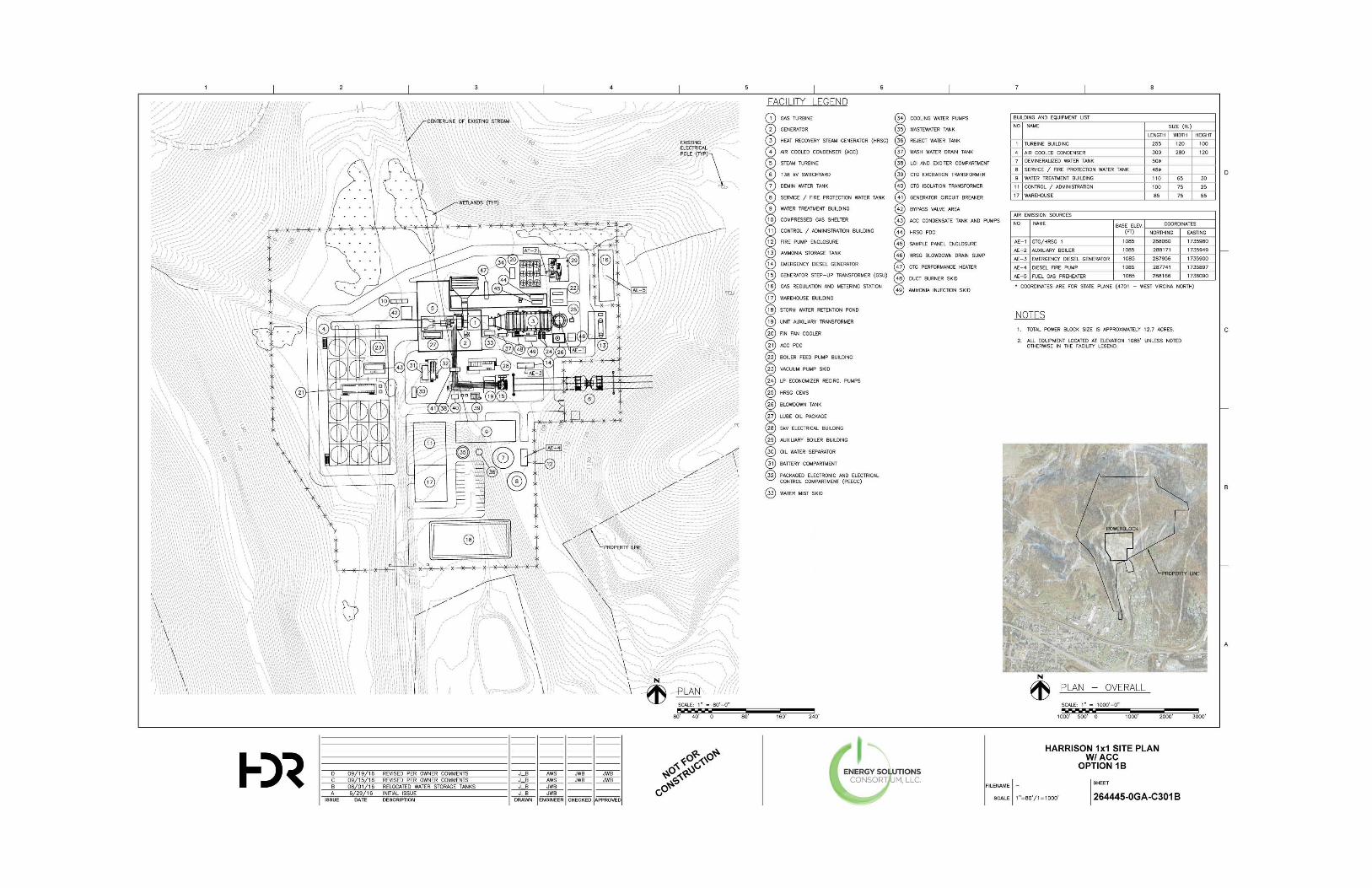

Appendix B – RBLC Search Summaries
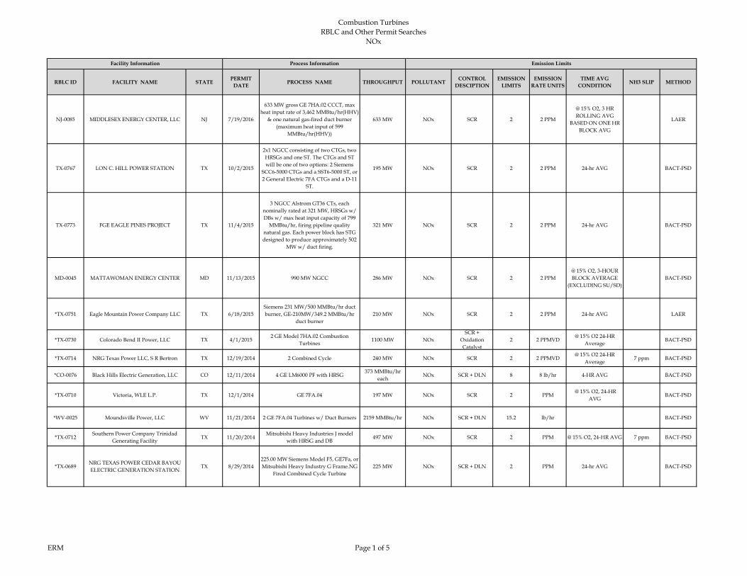
Combustion TurbinesRBLC and Other Permit Searches
NOx
ERM Page 1 of 5
RBLC ID FACILITY NAME STATE PERMIT DATE PROCESS NAME THROUGHPUT POLLUTANT CONTROL
DESCIPTIONEMISSION
LIMITSEMISSION
RATE UNITSTIME AVG
CONDITION NH3 SLIP METHOD
NJ-0085 MIDDLESEX ENERGY CENTER, LLC NJ 7/19/2016
633 MW gross GE 7HA.02 CCCT, max heat input rate of 3,462 MMBtu/hr(HHV)
& one natural gas-fired duct burner (maximum heat input of 599
MMBtu/hr(HHV))
633 MW NOx SCR 2 2 PPM
@ 15% O2, 3 HR ROLLING AVG
BASED ON ONE HR BLOCK AVG
LAER
TX-0767 LON C. HILL POWER STATION TX 10/2/2015
2x1 NGCC consisting of two CTGs, two HRSGs and one ST. The CTGs and ST will be one of two options: 2 Siemens
SCC6-5000 CTGs and a SST6-5000 ST, or 2 General Electric 7FA CTGs and a D-11
ST.
195 MW NOx SCR 2 2 PPM 24-hr AVG BACT-PSD
TX-0773 FGE EAGLE PINES PROJECT TX 11/4/2015
3 NGCC Alstrom GT36 CTs, each nominally rated at 321 MW, HRSGs w/ DBs w/ max heat input capacity of 799
MMBtu/hr, firing pipeline quality natural gas. Each power block has STG designed to produce approximately 502
MW w/ duct firing.
321 MW NOx SCR 2 2 PPM 24-hr AVG BACT-PSD
MD-0045 MATTAWOMAN ENERGY CENTER MD 11/13/2015 990 MW NGCC 286 MW NOx SCR 2 2 PPM @ 15% O2, 3-HOUR BLOCK AVERAGE
(EXCLUDING SU/SD)BACT-PSD
*TX-0751 Eagle Mountain Power Company LLC TX 6/18/2015Siemens 231 MW/500 MMBtu/hr duct burner, GE-210MW/349.2 MMBtu/hr
duct burner210 MW NOx SCR 2 2 PPM 24-hr AVG LAER
*TX-0730 Colorado Bend II Power, LLC TX 4/1/20152 GE Model 7HA.02 Combustion
Turbines1100 MW NOx
SCR + Oxidation Catalyst
2 2 PPMVD@ 15% O2 24-HR
AverageBACT-PSD
*TX-0714 NRG Texas Power LLC, S R Bertron TX 12/19/2014 2 Combined Cycle 240 MW NOx SCR 2 2 PPMVD @ 15% O2 24-HR
Average7 ppm BACT-PSD
*CO-0076 Black Hills Electric Generation, LLC CO 12/11/2014 4 GE LM6000 PF with HRSG373 MMBtu/hr
eachNOx SCR + DLN 8 8 lb/hr 4-HR AVG BACT-PSD
*TX-0710 Victoria, WLE L.P. TX 12/1/2014 GE 7FA.04 197 MW NOx SCR 2 PPM @ 15% O2, 24-HR
AVGBACT-PSD
*WV-0025 Moundsville Power, LLC WV 11/21/2014 2 GE 7FA.04 Turbines w/ Duct Burners 2159 MMBtu/hr NOx SCR + DLN 15.2 lb/hr BACT-PSD
*TX-0712Southern Power Company Trinidad
Generating FacilityTX 11/20/2014
Mitsubishi Heavy Industries J model with HRSG and DB
497 MW NOx SCR 2 PPM @ 15% O2, 24-HR AVG 7 ppm BACT-PSD
*TX-0689NRG TEXAS POWER CEDAR BAYOU ELECTRIC GENERATION STATION
TX 8/29/2014225.00 MW Siemens Model F5, GE7Fa, or Mitsubishi Heavy Industry G Frame.NG
Fired Combined Cycle Turbine225 MW NOx SCR + DLN 2 PPM 24-hr AVG BACT-PSD
Facility Information Process Information Emission Limits
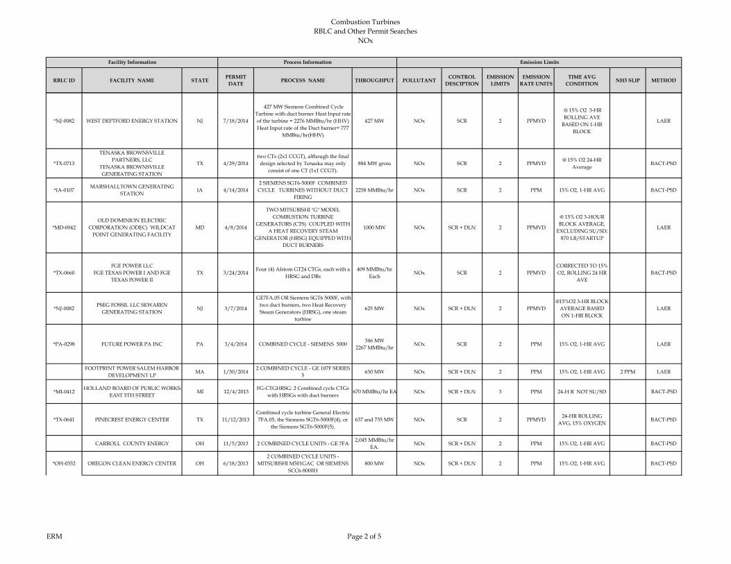
Combustion TurbinesRBLC and Other Permit Searches
NOx
ERM Page 2 of 5
RBLC ID FACILITY NAME STATE PERMIT DATE PROCESS NAME THROUGHPUT POLLUTANT CONTROL
DESCIPTIONEMISSION
LIMITSEMISSION
RATE UNITSTIME AVG
CONDITION NH3 SLIP METHOD
Facility Information Process Information Emission Limits
*NJ-0082 WEST DEPTFORD ENERGY STATION NJ 7/18/2014
427 MW Siemens Combined Cycle Turbine with duct burner Heat Input rate of the turbine = 2276 MMBtu/hr (HHV) Heat Input rate of the Duct burner= 777
MMBtu/hr(HHV)
427 MW NOx SCR 2 PPMVD
@ 15% O2 3-HR ROLLING AVE
BASED ON 1-HR BLOCK
LAER
*TX-0713
TENASKA BROWNSVILLEPARTNERS, LLC
TENASKA BROWNSVILLEGENERATING STATION
TX 4/29/2014two CTs (2x1 CCGT), although the final
design selected by Tenaska may only consist of one CT (1x1 CCGT).
884 MW gross NOx SCR 2 PPMVD@ 15% O2 24-HR
AverageBACT-PSD
*IA-0107MARSHALLTOWN GENERATING
STATIONIA 4/14/2014
2 SIEMENS SGT6-5000F COMBINED CYCLE TURBINES WITHOUT DUCT
FIRING2258 MMBtu/hr NOx SCR 2 PPM 15% O2, 1-HR AVG BACT-PSD
*MD-0042OLD DOMINION ELECTRIC
CORPORATION (ODEC) WILDCAT POINT GENERATING FACILITY
MD 4/8/2014
TWO MITSUBISHI "G" MODEL COMBUSTION TURBINE
GENERATORS (CTS) COUPLED WITH A HEAT RECOVERY STEAM
GENERATOR (HRSG) EQUIPPED WITH DUCT BURNERS
1000 MW NOx SCR + DLN 2 PPMVD
@ 15% O2 3-HOUR BLOCK AVERAGE,
EXCLUDING SU/SD; 870 LB/STARTUP
LAER
*TX-0660FGE POWER LLC
FGE TEXAS POWER I AND FGETEXAS POWER II
TX 3/24/2014Four (4) Alstom GT24 CTGs, each with a
HRSG and DBs409 MMBtu/hr
EachNOx SCR 2 PPMVD
CORRECTED TO 15% O2, ROLLING 24 HR
AVEBACT-PSD
*NJ-0082PSEG FOSSIL LLC SEWAREN
GENERATING STATIONNJ 3/7/2014
GE7FA.05 OR Siemens SGT6 5000F, with two duct burners, two Heat Recovery Steam Generators (HRSG), one steam
turbine
625 MW NOx SCR + DLN 2 PPMVD@15%O2 3-HR BLOCK
AVERAGE BASED ON 1-HR BLOCK
LAER
*PA-0298 FUTURE POWER PA INC PA 3/4/2014 COMBINED CYCLE - SIEMENS 5000346 MW
2267 MMBtu/hrNOx SCR 2 PPM 15% O2, 1-HR AVG LAER
FOOTPRINT POWER SALEM HARBOR DEVELOPMENT LP
MA 1/30/20142 COMBINED CYCLE - GE 107F SERIES
5630 MW NOx SCR + DLN 2 PPM 15% O2, 1-HR AVG 2 PPM LAER
*MI-0412HOLLAND BOARD OF PUBLIC WORKS-
EAST 5TH STREETMI 12/4/2013 FG-CTGHRSG: 2 Combined cycle CTGs
with HRSGs with duct burners670 MMBtu/hr EA NOx SCR + DLN 3 PPM 24-H R NOT SU/SD BACT-PSD
*TX-0641 PINECREST ENERGY CENTER TX 11/12/2013Combined cycle turbine General Electric 7FA.05, the Siemens SGT6-5000F(4), or
the Siemens SGT6-5000F(5). 637 and 735 MW NOx SCR 2 PPMVD
24-HR ROLLING AVG, 15% OXYGEN
BACT-PSD
CARROLL COUNTY ENERGY OH 11/5/2013 2 COMBINED CYCLE UNITS - GE 7FA2,045 MMBtu/hr
EA.NOx SCR + DLN 2 PPM 15% O2, 1-HR AVG BACT-PSD
*OH-0352 OREGON CLEAN ENERGY CENTER OH 6/18/20132 COMBINED CYCLE UNITS -
MITSUBISHI M501GAC OR SIEMENS SCC6-8000H
800 MW NOx SCR + DLN 2 PPM 15% O2, 1-HR AVG BACT-PSD
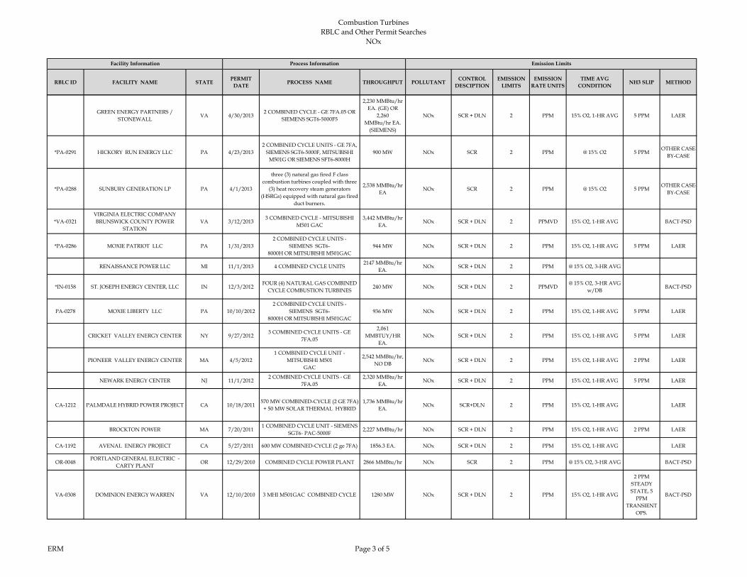
Combustion TurbinesRBLC and Other Permit Searches
NOx
ERM Page 3 of 5
RBLC ID FACILITY NAME STATE PERMIT DATE PROCESS NAME THROUGHPUT POLLUTANT CONTROL
DESCIPTIONEMISSION
LIMITSEMISSION
RATE UNITSTIME AVG
CONDITION NH3 SLIP METHOD
Facility Information Process Information Emission Limits
GREEN ENERGY PARTNERS / STONEWALL
VA 4/30/20132 COMBINED CYCLE - GE 7FA.05 OR
SIEMENS SGT6-5000F5
2,230 MMBtu/hr EA. (GE) OR
2,260MMBtu/hr EA.
(SIEMENS)
NOx SCR + DLN 2 PPM 15% O2, 1-HR AVG 5 PPM LAER
*PA-0291 HICKORY RUN ENERGY LLC PA 4/23/20132 COMBINED CYCLE UNITS - GE 7FA,
SIEMENS SGT6-5000F, MITSUBISHI M501G OR SIEMENS SFT6-8000H
900 MW NOx SCR 2 PPM @ 15% O2 5 PPMOTHER CASE-
BY-CASE
*PA-0288 SUNBURY GENERATION LP PA 4/1/2013
three (3) natural gas fired F class combustion turbines coupled with three
(3) heat recovery steam generators(HSRGs) equipped with natural gas fired
duct burners.
2,538 MMBtu/hr EA
NOx SCR 2 PPM @ 15% O2 5 PPMOTHER CASE-
BY-CASE
*VA-0321VIRGINIA ELECTRIC COMPANY BRUNSWICK COUNTY POWER
STATIONVA 3/12/2013
3 COMBINED CYCLE - MITSUBISHI M501 GAC
3,442 MMBtu/hr EA.
NOx SCR + DLN 2 PPMVD 15% O2, 1-HR AVG BACT-PSD
*PA-0286 MOXIE PATRIOT LLC PA 1/31/20132 COMBINED CYCLE UNITS -
SIEMENS SGT6-8000H OR MITSUBISHI M501GAC
944 MW NOx SCR + DLN 2 PPM 15% O2, 1-HR AVG 5 PPM LAER
RENAISSANCE POWER LLC MI 11/1/2013 4 COMBINED CYCLE UNITS2147 MMBtu/hr
EA.NOx SCR + DLN 2 PPM @ 15% O2, 3-HR AVG
*IN-0158 ST. JOSEPH ENERGY CENTER, LLC IN 12/3/2012FOUR (4) NATURAL GAS COMBINED
CYCLE COMBUSTION TURBINES240 MW NOx SCR + DLN 2 PPMVD
@ 15% O2, 3-HR AVG w/DB
BACT-PSD
PA-0278 MOXIE LIBERTY LLC PA 10/10/20122 COMBINED CYCLE UNITS -
SIEMENS SGT6-8000H OR MITSUBISHI M501GAC
936 MW NOx SCR + DLN 2 PPM 15% O2, 1-HR AVG 5 PPM LAER
CRICKET VALLEY ENERGY CENTER NY 9/27/20123 COMBINED CYCLE UNITS - GE
7FA.05
2,061MMBTUY/HR
EA.NOx SCR + DLN 2 PPM 15% O2, 1-HR AVG 5 PPM LAER
PIONEER VALLEY ENERGY CENTER MA 4/5/20121 COMBINED CYCLE UNIT -
MITSUBISHI M501GAC
2,542 MMBtu/hr, NO DB
NOx SCR + DLN 2 PPM 15% O2, 1-HR AVG 2 PPM LAER
NEWARK ENERGY CENTER NJ 11/1/20122 COMBINED CYCLE UNITS - GE
7FA.052,320 MMBtu/hr
EA.NOx SCR + DLN 2 PPM 15% O2, 1-HR AVG 5 PPM LAER
CA-1212 PALMDALE HYBRID POWER PROJECT CA 10/18/2011570 MW COMBINED-CYCLE (2 GE 7FA)
+ 50 MW SOLAR THERMAL HYBRID1,736 MMBtu/hr
EA.NOx SCR+DLN 2 PPM 15% O2, 1-HR AVG LAER
BROCKTON POWER MA 7/20/20111 COMBINED CYCLE UNIT - SIEMENS
SGT6- PAC-5000F2,227 MMBtu/hr NOx SCR + DLN 2 PPM 15% O2, 1-HR AVG 2 PPM LAER
CA-1192 AVENAL ENERGY PROJECT CA 5/27/2011 600 MW COMBINED-CYCLE (2 ge 7FA) 1856.3 EA. NOx SCR + DLN 2 PPM 15% O2, 1-HR AVG LAER
OR-0048PORTLAND GENERAL ELECTRIC -
CARTY PLANTOR 12/29/2010 COMBINED CYCLE POWER PLANT 2866 MMBtu/hr NOx SCR 2 PPM @ 15% O2, 3-HR AVG BACT-PSD
VA-0308 DOMINION ENERGY WARREN VA 12/10/2010 3 MHI M501GAC COMBINED CYCLE 1280 MW NOx SCR + DLN 2 PPM 15% O2, 1-HR AVG
2 PPM STEADY STATE, 5
PPM TRANSIENT
OPS.
BACT-PSD

Combustion TurbinesRBLC and Other Permit Searches
NOx
ERM Page 4 of 5
RBLC ID FACILITY NAME STATE PERMIT DATE PROCESS NAME THROUGHPUT POLLUTANT CONTROL
DESCIPTIONEMISSION
LIMITSEMISSION
RATE UNITSTIME AVG
CONDITION NH3 SLIP METHOD
Facility Information Process Information Emission Limits
GA-0138 LIVE OAKS POWER PLANT GA 4/8/2010 COMBINED CYCLE POWER PLANT 600 MW NOx SCR + DLN 2.5 PPM @ 15% O2, 3-HR AVG BACT-PSD
ID-0018IDAHO POWER CO. LANGLEY GULCH
POWER PLANTID 6/25/2010
1X1 COMBINED CYCLE POWER PLANT, SIEMENS SGT6-5000F CT
2375.28MMBtu/hr
NOx SCR 2 PPM @ 15% O2, 3-HR AVG BACT-PSD
TX-0590PONDERA CAPITAL MANAGEMENT
KING POWER STATIONTX 8/5/2010
4 SIEMENS SGT6-5000F OR GE 7FA W/ HRSG
1350 MW TOTAL NOx SCR + DLN 2 PPM 15% O2, 1-HR AVG LAER
RUSSELL CITY ENERGY CENTER CA 2/4/20102 SIEMENS/WESTINGHOUSE 501F W/
HRSG AND DUCT BURNERS2,039 MMBtu/hr
EA.NOx SCR + DLN 2 PPM 15% O2, 1-HR AVG BACT-PSD
TX-0548 MADISON BELL ENERGY CENTER TX 8/18/2009 2 GEF7EA CTs w/ DBs 275 MW ea. NOx SCR 2 PPMVD 15% O2 24-HR ROLLING AVG
BACT-PSD
FL-9002FP&L CAPE CANAVERAL ENERGY
CENTERFL 7/29/2009
3 Siemens SGT6-8000H (also permitted for MHI
501G)1250 MW TOTAL NOx SCR 2 PPMVD
@ 15% O2, 30 UNIT OPERATING DAYS
BACT-PSD
TX-0547NATURAL GAS-FIRED POWER
GENERATION FACILITYTX 6/22/2009
2 GE7FAS w/ HRSGs and DBs OR 2 MHI 501GS w/ HRSGs and DBs
620 MW OR 910MW
NOx SCR 2 PPMVD 15% O2 24-HR ROLLING AVG
5 PPM BACT-PSD
TX-0546 PATTILLO BRANCH POWER PLANT TX 6/17/20094 GE7121 COMBINED CYCLE CT W/
DB OR Siemens 5GT6-5000F350 MW ea. NOx SCR 2 PPMVD
15% O2 24-HR ROLLING AVG
BACT-PSD
OK-0129 CHOUTEAU POWER PLANT OK 1/23/2009 2 SIEMENS V84.3A COMBINED CYCLE1882 MMBtu/hr
eaNOx SCR + DLN 2 PPMVD
15% O2 24-HR ROLLING AVG
BACT-PSD
FL-0304 CANE ISLAND POWER PARK FL 9/8/2008300 MW COMBINED CYCLE
COMBUSTION TURBINE1860 MMBtu/hr NOx SCR 2 PPM
15% O2 24-HR ROLLING AVG
BACT-PSD
FL-0303FPL WEST COUNTY ENERGY CENTER
UNIT3
FL 7/30/2008THREE NOMINAL 250 MW CTG
(EACH) WITH SUPPLEMENTARY-FIRED HRSG, MHI 501G
2333 MMBtu/hr NOx SCR 2 PPMVD 15% O2 24-HR ROLLING AVG
5 PPM BACT-PSD
GA-0127SOUTHERN CO./GEORGIA POWER
PLANT MCDONOUGHGA 1/7/2008 3 MHI M501G COMBINED CYCLE 2,520 MW TOTAL NOx SCR + DLN 2 PPM @ 15% O2 BACT-PSD
CT-0151 KLEEN ENERGY SYSTEMS, LLC CT 2/25/2008
SIEMENS SGT6-5000F COMBUSTION TURBINE #1 AND #2 (NATURAL GAS
FIRED) WITH 445 MMBtu/hr NATURAL GAS DUCT BURNER
2.1 MMcf/hr NOx SCR 2 PPM@ 15% O2 1-HR
BLOCK (60-100% LOAD),
2 PPM STEADY STATE, 5
PPM TRANSIENT
OPS.
LAER
FL-0286 FPL WEST COUNTY ENERGY CENTER FL 1/10/2007COMBINED CYCLE COMBUSTION
GAS TURBINES -6 UNITS2333 MMBtu/hr NOx SCR 2 PPMVD
@ 15% O2 24-HR ROLLING AVG
BACT-PSD
CA-1144 BLYTHE ENERGY PROJECT II CA 4/25/2007 2 COMBUSTION TURBINES 170 MW NOx SCR 2 PPMVD 15% O2, 3-HR AVG BACT-PSD
NY-0098 ATHENS GENERATING PLANT NY 1/19/2007 FUEL COMBUSTION (GAS) 3100 MMBtu/hr NOx SCR 2 PPMVD
@ 15% O2 3 HOUR BLOCK
AVAEAGE/STEADY STATE
LAER
NY-0095CAITHNESS BELLPORT ENERGY
CENTERNY 5/10/2006 SWPC 501F 2221 MMtu/hr NOx SCR 2 PPMVD
@15%02, 3-HR ROLLING AVG
BACT-PSD
CO-0056ROCKY MOUNTAIN ENERGY CENTER,
LLCCO 5/2/2006
NATURAL-GAS FIRED, COMBINED-CYCLE TURBINE
300 MW NOx SCR + DLN 3 PPM 15% O2, 1-HR AVG BACT-PSD
WA-0328BP CHERRY POINT COGENERATION
PROJECTWA 1/11/2005
GE 7FA COMBUSTION TURBINE & HEAT RECOVERY STEAM
GENERATOR174 MW NOx SCR + DLN 2.5 PPM
@15%02, 3-HR ROLLING AVG
5 PPM BACT-PSD

Combustion TurbinesRBLC and Other Permit Searches
NOx
ERM Page 5 of 5
RBLC ID FACILITY NAME STATE PERMIT DATE PROCESS NAME THROUGHPUT POLLUTANT CONTROL
DESCIPTIONEMISSION
LIMITSEMISSION
RATE UNITSTIME AVG
CONDITION NH3 SLIP METHOD
Facility Information Process Information Emission Limits
NC-0101 FORSYTH ENERGY PLANT NC 9/29/2005TURBINE, COMBINED CYCLE,
NATURAL GAS, (3)1844.3 MMBtu/hr NOx SCR 2.5 PPM
@ 15% O2, 24-HR ROLLING AVG
BACT-PSD
NV-0035TRACY SUBSTATION EXPANSION
PROJECTNV 8/16/2005
TURBINE, COMBINED CYCLE COMBUSTION #1
WITH HRSG AND DUCT BURNER.306 MW NOx SCR 2 PPM
@15%02, 3-HR ROLLING AVG
BACT-PSD
OR-0041 WANAPA ENERGY CENTER OR 8/8/2005COMBUSTION TURBINE (GE 7241FA)
+ HEAT RECOVERY STEAM GENERATOR
2384.1 MMBtu/hr NOx SCR 2 PPMVD@15%02, 3-HR
ROLLING AVG5 PPM BACT-PSD
FL-0265 HINES POWER BLOCK 4 FL 6/8/2005 COMBINED CYCLE TURBINE 530 MW NOx SCR 2.5 PPM @ 15% O2 BACT-PSD
FL-0263 FPL TURKEY POINT POWER PLANT FL 2/8/2005170 MW COMBUSTION TURBINE, 4
UNITS170 MW NOx SCR 2 PPM
@ 15 % O2 STACK TEST (CT & DUCT
BURNER)5 PPM BACT-PSD
NY-0100 EMPIRE POWER PLANT NY 6/23/2005 FUEL COMBUSTION (NATURAL GAS) 2099 MMBtu/hr NOx SCR 2 PPMVD AT 15% O2 3-HOUR
BLOCK AVE./ STEADY STATE
LAER
NY-0100 EMPIRE POWER PLANT NY 6/23/2005FUEL COMBUSTION (NATURAL GAS)
DUCT BURNING646 MMBtu/hr NOx SCR + DLN 3 PPMVD
AT 15% O2 3-HOUR BLOCK AVE./
STEADY STATELAER
LA-0192 CRESCENT CITY POWER LA 6/6/2005 GAS TURBINES -187 MW (2) 2006 MMBtu/hr NOx SCR 3 PPM ANNUAL BACT-PSD
MI-0366 BERRIEN ENERGY, LLC MI 4/13/20053 COMBUSTION TURBINES AND
DUCT BURNERS1584 MMBtu/hr NOx SCR 2.5 PPM
@ 15% O2 24-HOUR ROLLING AVG EACH HOUR
10 PPM BACT-PSD
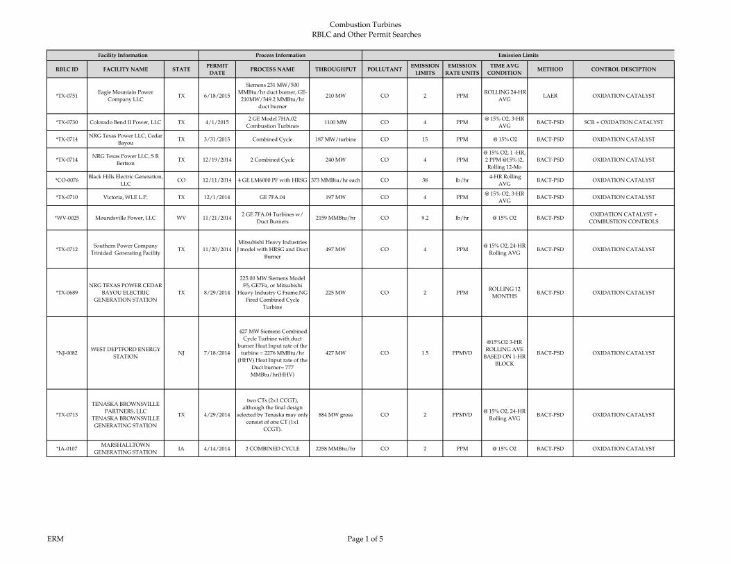
Combustion Turbines
RBLC and Other Permit Searches
CO
RBLC ID FACILITY NAME STATEPERMIT
DATEPROCESS NAME THROUGHPUT POLLUTANT
EMISSION
LIMITS
EMISSION
RATE UNITS
TIME AVG
CONDITIONMETHOD CONTROL DESCIPTION
*TX-0751Eagle Mountain Power
Company LLCTX 6/18/2015
Siemens 231 MW/500
MMBtu/hr duct burner, GE-
210MW/349.2 MMBtu/hr
duct burner
210 MW CO 2 PPM ROLLING 24-HR
AVGLAER OXIDATION CATALYST
*TX-0730 Colorado Bend II Power, LLC TX 4/1/20152 GE Model 7HA.02
Combustion Turbines1100 MW CO 4 PPM
@ 15% O2, 3-HR
AVGBACT-PSD SCR + OXIDATION CATALYST
*TX-0714NRG Texas Power LLC, Cedar
Bayou TX 3/31/2015 Combined Cycle 187 MW/turbine CO 15 PPM @ 15% O2 BACT-PSD OXIDATION CATALYST
*TX-0714NRG Texas Power LLC, S R
BertronTX 12/19/2014 2 Combined Cycle 240 MW CO 4 PPM
@ 15% O2, 1 -HR,
2 PPM @15% )2,
Rolling 12-Mo
BACT-PSD OXIDATION CATALYST
*CO-0076Black Hills Electric Generation,
LLCCO 12/11/2014 4 GE LM6000 PF with HRSG 373 MMBtu/hr each CO 38 lb/hr
4-HR Rolling
AVGBACT-PSD OXIDATION CATALYST
*TX-0710 Victoria, WLE L.P. TX 12/1/2014 GE 7FA.04 197 MW CO 4 PPM@ 15% O2, 3-HR
AVGBACT-PSD OXIDATION CATALYST
*WV-0025 Moundsville Power, LLC WV 11/21/20142 GE 7FA.04 Turbines w/
Duct Burners2159 MMBtu/hr CO 9.2 lb/hr @ 15% O2 BACT-PSD
OXIDATION CATALYST +
COMBUSTION CONTROLS
*TX-0712Southern Power Company
Trinidad Generating FacilityTX 11/20/2014
Mitsubishi Heavy Industries
J model with HRSG and Duct
Burner
497 MW CO 4 PPM@ 15% O2, 24-HR
Rolling AVGBACT-PSD OXIDATION CATALYST
*TX-0689
NRG TEXAS POWER CEDAR
BAYOU ELECTRIC
GENERATION STATION
TX 8/29/2014
225.00 MW Siemens Model
F5, GE7Fa, or Mitsubishi
Heavy Industry G Frame.NG
Fired Combined Cycle
Turbine
225 MW CO 2 PPMROLLING 12
MONTHSBACT-PSD OXIDATION CATALYST
*NJ-0082WEST DEPTFORD ENERGY
STATIONNJ 7/18/2014
427 MW Siemens Combined
Cycle Turbine with duct
burner Heat Input rate of the
turbine = 2276 MMBtu/hr
(HHV) Heat Input rate of the
Duct burner= 777
MMBtu/hr(HHV)
427 MW CO 1.5 PPMVD
@15%O2 3-HR
ROLLING AVE
BASED ON 1-HR
BLOCK
BACT-PSD OXIDATION CATALYST
*TX-0713
TENASKA BROWNSVILLE
PARTNERS, LLC
TENASKA BROWNSVILLE
GENERATING STATION
TX 4/29/2014
two CTs (2x1 CCGT),
although the final design
selected by Tenaska may only
consist of one CT (1x1
CCGT).
884 MW gross CO 2 PPMVD@ 15% O2, 24-HR
Rolling AVGBACT-PSD OXIDATION CATALYST
*IA-0107MARSHALLTOWN
GENERATING STATIONIA 4/14/2014 2 COMBINED CYCLE 2258 MMBtu/hr CO 2 PPM @ 15% O2 BACT-PSD OXIDATION CATALYST
Facility Information Process Information Emission Limits
ERM Page 1 of 5

CO
RBLC ID FACILITY NAME STATEPERMIT
DATEPROCESS NAME THROUGHPUT POLLUTANT
EMISSION
LIMITS
EMISSION
RATE UNITS
TIME AVG
CONDITIONMETHOD CONTROL DESCIPTION
Facility Information Process Information Emission Limits
*MD-0042
OLD DOMINION ELECTRIC
CORPORATION (ODEC)
WILDCAT POINT
GENERATING FACILITY
MD 4/8/2014
TWO MITSUBISHI "G"
MODEL COMBUSTION
TURBINE GENERATORS
(CTS) COUPLED WITH A
HEAT RECOVERY STEAM
GENERATOR (HRSG)
EQUIPPED WITH DUCT
BURNERS
1000 MW CO 1.5 PPMVD
@ 15% O2 3-
HOUR BLOCK
AVERAGE,
EXCLUDING
SU/SD;
13767.0000
LB/EVENT FOR
ALL STARTUPS
BACT-PSD OXIDATION CATALYST
*TX-0660
FGE POWER LLC
FGE TEXAS POWER I AND
FGE
TEXAS POWER II
TX 3/24/2014Four (4) Alstom GT24 CTGs,
each with a HRSG and DBs409 MMBtu/hr Each CO 2 PPMVD
@ 15% O2, 3-HR
AVGBACT-PSD OXIDATION CATALYST
*NJ-0082PSEG FOSSIL LLC SEWAREN
GENERATING STATIONNJ 3/7/2014
GE7FA.05 OR Siemens SGT6
5000F, with two duct
burners, two Heat Recovery
Steam Generators (HRSG),
one steam turbine
625 MW CO 2 PPMVD
3-HR ROLLING
AVE BASED ON
1-HR BLOCK
AVE
BACT-PSDOXIDATION CATALYST AND GOOD
COMBUSTION PRACTICES
*PA-0298 FUTURE POWER PA INC PA 3/4/2014COMBINED CYCLE -
SIEMENS 5000
346 MW
2267 MMBtu/hrCO 3 PPM @ 15% O2 BACT-PSD OXIDATION CATALYST
FOOTPRINT POWER SALEM
HARBOR DEVELOPMENT
LP
MA 1/30/20142 COMBINED CYCLE - GE
107F SERIES 5630 MW CO 2 PPM
@ 15% O2, 1-HR
AVGBACT-PSD OXIDATION CATALYST
*MI-0412
HOLLAND BOARD OF
PUBLIC WORKS-EAST 5TH
STREET
MI 12/4/2013
FG-CTGHRSG: 2 Combined
cycle CTGs with HRSGs with
duct burners
670 MMBtu/hr EA CO 4 PPM 24-H ROLL. AVG BACT-PSDOXIDATION CATALYST AND GOOD
COMBUSTION PRACTICES
*TX-0641PINECREST ENERGY
CENTERTX 11/12/2013
Combined cycle turbine
General Electric 7FA.05, the
Siemens SGT6-5000F(4), or
the Siemens SGT6-5000F(5).
637 and 735 MW CO 2 PPMVD
3-HR ROLL
AVG, 15%
OXYGEN, 80-
100% LOAD
BACT-PSD OXIDATION CATALYST
CARROLL COUNTY
ENERGYOH 11/5/2013
2 COMBINED CYCLE
UNITS - GE 7FA
2,045 MMBtu/hr
EA.CO 2 PPM
@ 15% O2, 1-HR
AVGBACT-PSD OXIDATION CATALYST
RENAISSANCE POWER LLC MI 11/1/20134 COMBINED CYCLE
UNITS2147 MMBtu/hr EA. CO 2 PPM @ 15% O2 BACT-PSD OXIDATION CATALYST
*OH-0352OREGON CLEAN ENERGY
CENTEROH 6/18/2013
2 COMBINED CYCLE
UNITS - MITSUBISHI
M501GAC OR SIEMENS
SCC6-8000H
800 MW CO 2 PPM@ 15% O2, 1-HR
AVGBACT-PSD OXIDATION CATALYST
GREEN ENERGY PARTNERS
/ STONEWALLVA 4/30/2013
2 COMBINED CYCLE - GE
7FA.05 OR SIEMENS SGT6-
5000F5
2,230 MMBtu/hr
EA. (GE) OR 2,260
MMBtu/hr EA.
(SIEMENS)
CO 2 PPM @ 15% O2 BACT-PSD OXIDATION CATALYST
ERM Page 2 of 5
Combustion Turbines
RBLC and Other Permit Searches
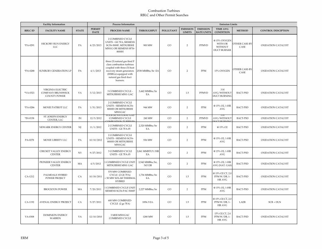
CO
RBLC ID FACILITY NAME STATEPERMIT
DATEPROCESS NAME THROUGHPUT POLLUTANT
EMISSION
LIMITS
EMISSION
RATE UNITS
TIME AVG
CONDITIONMETHOD CONTROL DESCIPTION
Facility Information Process Information Emission Limits
*PA-0291HICKORY RUN ENERGY
LLCPA 4/23/2013
2 COMBINED CYCLE
UNITS - GE 7FA, SIEMENS
SGT6-5000F, MITSUBISHI
M501G OR SIEMENS SFT6-
8000H
900 MW CO 2 PPMVD
@ 15% OXYGEN
WITH OR
WITHOUT
DUCT BURNER
OTHER CASE-BY-
CASEOXIDATION CATALYST
*PA-0288 SUNBURY GENERATION LP PA 4/1/2013
three (3) natural gas fired F
class combustion turbines
coupled with three (3) heat
recovery steam generators
(HSRGs) equipped with
natural gas fired duct
burners.
2538 MMBtu/hr EA CO 2 PPM 15% OXYGEN OTHER CASE-BY-
CASEOXIDATION CATALYST
*VA-0321
VIRGINIA ELECTRIC
COMPANY BRUNSWICK
COUNTY POWER
VA 3/12/20133 COMBINED CYCLE -
MITSUBISHI M501 GAC
3,442 MMBtu/hr
EA.CO 1.5 PPMVD
3 H
AVG/WITHOUT
DUCT BURNING
BACT-PSD OXIDATION CATALYST
*PA-0286 MOXIE PATRIOT LLC PA 1/31/2013
2 COMBINED CYCLE
UNITS - SIEMENS SGT6-
8000H OR MITSUBISHI
M501GAC
944 MW CO 2 PPM@ 15% O2, 1-HR
AVGBACT-PSD OXIDATION CATALYST
*IN-0158ST. JOSEPH ENERGY
CENTER, LLCIN 12/3/2012
FOUR (4) NATURAL GAS
COMBINED CYCLE
COMBUSTION TURBINES
240 MW CO 2 PPMVD
3 H
AVG/WITHOUT
DUCT BURNING
BACT-PSD OXIDATION CATALYST
NEWARK ENERGY CENTER NJ 11/1/20122 COMBINED CYCLE
UNITS - GE 7FA.05
2,320 MMBtu/hr
EA.CO 2 PPM @ 15% O2 BACT-PSD OXIDATION CATALYST
PA-0278 MOXIE LIBERTY LLC PA 10/10/2012
2 COMBINED CYCLE
UNITS - SIEMENS SGT6-
8000H OR MITSUBISHI
M501GAC
936 MW CO 2 PPM@ 15% O2, 1-HR
AVGBACT-PSD OXIDATION CATALYST
CRICKET VALLEY ENERGY
CENTERNY 9/27/2012
3 COMBINED CYCLE
UNITS - GE 7FA.05
2,061 MMBTUY/HR
EA.CO 2 PPM
@ 15% O2, 1-HR
AVGBACT-PSD OXIDATION CATALYST
PIONEER VALLEY ENERGY
CENTERMA 4/5/2012
1 COMBINED CYCLE UNIT -
MITSUBISHI M501 GAC
2,542 MMBtu/hr,
NO DBCO 2 PPM
@ 15% O2, 1-HR
AVG (NAT. GAS)BACT-PSD OXIDATION CATALYST
CA-1212PALMDALE HYBRID
POWER PROJECTCA 10/18/2011
570 MW COMBINED-
CYCLE (2 GE 7FA)
+ 50 MW SOLAR THERMAL
HYBRID
1,736 MMBtu/hr
EA.CO 1.5 PPM
@ 15% O2 CT, 2.0
PPM W/DB, 1-
HR AVG
BACT-PSD OXIDATION CATALYST
BROCKTON POWER MA 7/20/20111 COMBINED CYCLE UNIT -
SIEMENS SGT6-PAC-5000F2,227 MMBtu/hr CO 2 PPM
@ 15% O2, 1-HR
AVGBACT-PSD OXIDATION CATALYST
CA-1192 AVENAL ENERGY PROJECT CA 5/27/2011600 MW COMBINED-
CYCLE (2 ge 7FA)1856.3 EA. CO 1.5 PPM
@ 15% O2 CT, 2.0
PPM W/DB, 1-
HR AVG
LAER SCR + DLN
VA-0308DOMINION ENERGY
WARRENVA 12/10/2010
3 MHI M501GAC
COMBINED CYCLE1280 MW CO 1.5 PPM
15% O2 CT, 2.4
PPM W/DB, 1-
HR AVG
BACT-PSD OXIDATION CATALYST
ERM Page 3 of 5
Combustion Turbines
RBLC and Other Permit Searches

CO
RBLC ID FACILITY NAME STATEPERMIT
DATEPROCESS NAME THROUGHPUT POLLUTANT
EMISSION
LIMITS
EMISSION
RATE UNITS
TIME AVG
CONDITIONMETHOD CONTROL DESCIPTION
Facility Information Process Information Emission Limits
TX-0590
PONDERA
CAPITAL MANAGEMENT
KING POWER
TX 8/5/20104 SIEMENS SGT6-5000F OR
GE 7FA W/ HRSG1350 MW TOTAL CO 2 PPM
@ 15% O2, 3-HR
AVGBACT-PSD OXIDATION CATALYST
ID-0018
IDAHO POWER CO.
LANGLEY GULCH POWER
PLANT
ID 6/25/2010
1X1 COMBINED CYCLE
POWER PLANT, SIEMENS
SGT6-5000F CT
2375.28
MMBtu/hrCO 2 PPM
@ 15% O2, 3-HR
AVGBACT-PSD OXIDATION CATALYST
GA-0138 LIVE OAKS POWER PLANT GA 4/8/20103 MHI M501G COMBINED
CYCLE600 MW CO 2 PPM
@ 15% O2, 3-HR
AVGBACT-PSD SCR + DLN
RUSSELL CITY ENERGY
CENTERCA 2/4/2010
2
SIEMENS/WESTINGHOUS
E 501F W/ HRSG AND
DUCT BURNERS
2,039 MMBtu/hr
EA.CO 2 PPM
@ 15% O2, 1-HR
AVGBACT-PSD OXIDATION CATALYST
TX-0548MADISON BELL ENERGY
CENTERTX 8/18/2009 2 GEF7EA CTs w/ DBs 275 MW ea. CO 17.5 PPM
@ 15% O2, 1-HR
AVGBACT-PSD GOOD COMBUSTION
FL-9002FP&L CAPE CANAVERAL
ENERGY CENTERFL 7/29/2009
3 Siemens SGT6-8000H (also
permitted for MHI 501G)1250 MW TOTAL CO 5 PPM
@ 15% O2 CT, 7.6
PPM W/DB, 30
UNIT
OPERATING
DAYS
BACT-PSD GOOD COMBUSTION
TX-0547
NATURAL GAS- FIRED
POWER GENERATION
FACILITY
TX 6/22/2009
2 GE7FAS w/ HRSGs and
DBs OR 2 MHI
501GS w/ HRSGs and DBs
620 MW OR 910
MWCO 15 PPM
@ 15% O2, 24-HR
Rolling AVGBACT-PSD GOOD COMBUSTION
TX-0546PATTILLO BRANCH POWER
PLANTTX 6/17/2009
4 GE7121 COMBINED
CYCLE CT W/ DB OR
Siemens 5GT6-5000F
350 MW ea. CO 2 PPMVD@ 15% O2, 3-HR
AVGBACT-PSD OXIDATION CATALYST
OK-0129 CHOUTEAU POWER PLANT OK 1/23/20092 SIEMESN V84.3A
COMBINED CYCLE1882 MMBtu/hr ea CO 8 PPMVD
@ 15% O2, 1-HR
AVGBACT-PSD GOOD COMBUSTION
FL‐0304CANE ISLAND POWER
PARKFL 9/8/2008
300 MW COMBINED CYCLE
COMBUSTION TURBINE1860 MMBtu/hr CO 6 PPMVD 12‐MONTH BACT‐PSD GOOD COMBUSTION
FL-0303FPL WEST COUNTY
ENERGY CENTER UNIT 3FL 7/30/2008
THREE NOMINAL 250 MW
CTG (EACH) WITH
SUPPLEMENTARY-FIRED
HRSG, MHI 501G
2333 MMBtu/hr CO 4.1 PPMVD 24- HR AVG BACT-PSD GOOD COMBUSTION
LA‐0224ARSENAL HILL POWER
PLANTLA 3/20/2008
TWO COMBINED CYCLE
GAS TURBINES2110 MMBtu/hr CO 10 PPMVD
@15%O2
ANNUAL
AVERAGE
BACT‐PSD GOOD COMBUSTION
CT-0151KLEEN ENERGY SYSTEMS,
LLCCT 2/25/2008
SIEMENS SGT6-5000F
COMBUSTION TURBINE #1
AND #2 (NATURAL GAS
FIRED) WITH 445
MMBtu/hr NATURAL GAS
DUCT BURNER
2.1 MMcf/hr CO 0.9 PPMVD
'@15 % O2 (60-
100% LOAD) CT,
1.7 PPM w/DB, 1-
HR AVG
BACT-PSD OXIDATION CATALYST
GA-0127
SOUTHERN CO./GEORGIA
POWER PLANT
MCDONOUGH
GA 1/7/20083 MHI M501G COMBINED
CYCLE2,520 MW TOTAL CO 1.8 PPM
@ 15% O2, 3-HR
AVGBACT-PSD OXIDATION CATALYST
ERM Page 4 of 5
Combustion Turbines
RBLC and Other Permit Searches

Combustion Turbines
RBLC and Other Permit Searches
CO
RBLC ID FACILITY NAME STATEPERMIT
DATEPROCESS NAME THROUGHPUT POLLUTANT
EMISSION
LIMITS
EMISSION
RATE UNITS
TIME AVG
CONDITIONMETHOD CONTROL DESCIPTION
Facility Information Process Information Emission Limits
CA‐1144BLYTHE ENERGY PROJECT
IICA 4/25/2007 2 COMBUSTION TURBINES 170 MW CO 4 PPMVD
@ 15% O2, 3-HR
AVGBACT‐PSD OXIDATION CATALYST
FL‐0285PROGRESS BARTOW
POWER PLANTFL 1/26/2007
COMBINED CYCLE
COMBUSTION
TURBINE SYSTEM (4‐ON‐1)
1972 MMBtu/hr CO 8 PPMVD 24‐HR BLOCK
AVERAGEBACT‐PSD GOOD COMBUSTION
FL-0286FPL WEST COUNTY
ENERGY CENTERFL 1/10/2007
COMBINED CYCLE
COMBUSTION GAS
TURBINES -6 UNITS
2333 MMBtu/hr CO 4.1 PPMVD 24- HR AVG BACT-PSD GOOD COMBUSTION
MN‐0066
NORTHERN STATES POWER
CO. DBA XCEL ENERGY
‐RIVERSIDE
PLANT
MN 5/16/2006TURBINE, COMBINED
CYCLE (2)1885 MMBtu/hr CO 10 PPM @ 15% O2 BACT‐PSD GOOD COMBUSTION
NY-0095CAITHNESS BELLPORT
ENERGY CENTERNY 5/10/2006 SWPC 501F 2221 MMBtu/hr CO 2 PPMVD
@15%02 (90-
100% LOAD), 4
PPM (75-90%
LOAD), 1-HOUR
AVG
BACT-PSD OXIDATION CATALYST
CO‐0056ROCKY MOUNTAIN
ENERGY CENTER, LLCCO 5/2/2006
NATURAL‐GAS FIRED,
COMBINED‐CYCLE
TURBINE
300 MW CO 3 PPM @ 15% O2 BACT‐PSD OXIDATION CATALYST
NC-0101 FORSYTH ENERGY PLANT NC 9/29/2005TURBINE, COMBINED
CYCLE, NATURAL GAS, (3)1844.3 MMBtu/hr CO 11.6 PPM
@ 15% O2, 3-HR
AVGBACT-PSD GOOD COMBUSTION
NV‐0035TRACY SUBSTATION
EXPANSION PROJECTNV 8/16/2005
TURBINE, COMBINED
CYCLE COMBUSTION #2
WITH HRSG AND DUCT
BURNER.
306 MW CO 3.5 PPM@ 15% O2, 3-HR
AVGBACT‐PSD OXIDATION CATALYST
OR-0041 WANAPA ENERGY CENTER OR 8/8/2005
COMBUSTION TURBINE
(GE 7241FA) + HEAT
RECOVERY STEAM
GENERATOR
2384.1 MMBtu/hr CO 2 PPM@ 15% O2, 3-HR
AVGBACT-PSD OXIDATION CATALYST
FL-0265 HINES POWER BLOCK 4 FL 6/8/2005COMBINED CYCLE
TURBINE530 MW CO 8 PPM @ 15% O2 BACT-PSD GOOD COMBUSTION
LA‐0192 CRESCENT CITY POWER LA 6/6/2005 GAS TURBINES ‐187 MW (2) 2006 MMBtu/hr CO 4 PPM
@ 15%O2
ANNUAL
AVERAGE
BACT‐PSD OXIDATION CATALYST
MI-0366 BERRIEN ENERGY, LLC MI 4/13/20053 COMBUSTION TURBINES
AND DUCT BURNERS1584 MMBtu/hr CO 2 PPM
@ 15% O2, 3-HR
AVGBACT-PSD OXIDATION CATALYST
FL‐0263FPL TURKEY POINT POWER
PLANTFL 2/8/2005
170 MW COMBUSTION
TURBINE, 4 UNITS170 MW CO 7.6 PPM
@ 15 % O2
STACK TEST (CT
& DUCT
BURNER), 24-HR
AVG
BACT‐PSD GOOD COMBUSTION
WA-0328BP CHERRY POINT
COGENERATION PROJECTWA 1/11/2005
GE 7FA COMBUSTION
TURBINE & HEAT
RECOVERY STEAM
GENERATOR
174 MW CO 2 PPM@ 15% O2, 3-HR
AVGBACT-PSD OXIDATION CATALYST
ERM Page 5 of 5

Combustion Turbines
RBLC and Other Permit Searches
RBLCID FACILITY NAME STATEPERMIT
DATEPROCESS NAME THROUGHPUT POLLUTANT
EMISSION
LIMIT
EMISSION
RATE UNITS
TIME AVG
CONDITIONMETHOD CONTROL METHOD
*TX-0751Eagle Mountain Power
Company LLCTX 6/18/2015
Siemens 231 MW/500 MMBtu/hr duct
burner, GE-210MW/349.2 MMBtu/hr
duct burner
210 MW H2SO4 15.56 lb/hr BACT-PSDLow S Fuel/ Good Combustion
Practice
*TX-0730Colorado Bend II Power,
LLCTX 4/1/2015
2 GE Model 7HA.02 Combustion
Turbines1100 MW H2SO4 15.56 lb/hr BACT-PSD Natural Gas
*TX-0714NRG Texas Power LLC, S R
BertronTX 12/19/2014 2 Combined Cycle 240 MW H2SO4 0.5
GR S/100
DSCFBACT-PSD Natural Gas
*NJ-0082WEST DEPTFORD
ENERGY STATIONNJ 7/18/2014
427 MW Siemens Combined Cycle
Turbine with duct burner Heat Input
rate of the turbine = 2276 MMBtu/hr
(HHV) Heat Input rate of the Duct
burner= 777 MMBtu/hr(HHV)
427 MW H2SO4 0.98 lb/hrR
OTHER
CASE-BY-
CASE
NAT GAS
*IA-0107MARSHALLTOWN
GENERATING STATIONIA 4/14/2014 2 COMBINED CYCLE 2258 MMBtu/hr H2SO4 0.0032 lb/MMBtu BACT- PSD
Fuel
Specification
*MD-0042
OLD DOMINION
ELECTRIC
CORPORATION (ODEC)
WILDCAT POINT
GENERATING FACILITY
MD 4/08/2014
TWO MITSUBISHI "G" MODEL
COMBUSTION TURBINE
GENERATORS (CTS) COUPLED
WITH A HEAT RECOVERY STEAM
GENERATOR (HRSG) EQUIPPED
WITH DUCT BURNERS
1000 MW H2SO4
12.5 W/ DB
9.7 W/O DB
lb/hr 3-HOUR BLOCK
AVERAGEBACT-PSD
EXCLUSIVE USE OF PIPELINE
QUALITY NATURAL GAS AND
EFFICIENT TURBINE DESIGN
*NJ-0082
PSEG FOSSIL LLC
SEWAREN
GENERATING STATION
NJ 3/07/2014
GE7FA.05 OR Siemens SGT6 5000F,
with two duct burners, two Heat
Recovery Steam Generators (HRSG),
one steam turbine
625 MW H2SO4
2.93 GE W/ DB
AND
2.74 GE W/O
DB
lb/hr BACT-PSD NAT GAS + LOW SULFER FUEL
*PA-0298 FUTURE POWER PA INC PA 3/4/2014COMBINED CYCLE - SIEMENS
5000
346 MW
2267 MMBtu/hrH2SO4 0.0015 lb/MMBtu BACT
Fuel
Specification
FOOTPRINT POWER
SALEM HARBOR
DEVELOPMENT LP
MA 1/30/20142 COMBINED CYCLE - GE 107F
SERIES 5630 MW H2SO4 0.001 lb/MMBtu Stack Test BACT- PSD
Fuel
Specification
CARROLL COUNTY
ENERGYOH 11/5/2013 2 COMBINED CYCLE UNITS - GE 7FA
2,045 MMBtu/hr
EA.H2SO4
0.0012 CT ONLY
0.0016 CT+DBlb/MMBtu Stack Test BACT- PSD
Fuel
Specification
*OH-0352OREGON CLEAN ENERGY
CENTEROH 6/18/2013
2 COMBINED CYCLE UNITS -
MITSUBISHI M501GAC OR SIEMENS
SCC6-8000H
800 MW H2SO4
0.0004 (MHI) -
0.0007
(SIEMENS)
lb/MMBtu Stack Test BACT- PSDFuel
Specification
GREEN ENERGY
PARTNERS /
STONEWALL
VA 4/30/2013
2 COMBINED CYCLE - GE
7FA.05 OR SIEMENS SGT6-
5000F5
2,230 MMBtu/hr
EA. (GE) OR 2,260
MMBtu/hr EA.
(SIEMENS)
H2SO4 0.00014 lb/MMBtu Stack Test BACT- PSDFuel
Specification
Facility Information Process Information Emission Limits Notes
ERM Page 1 of 3
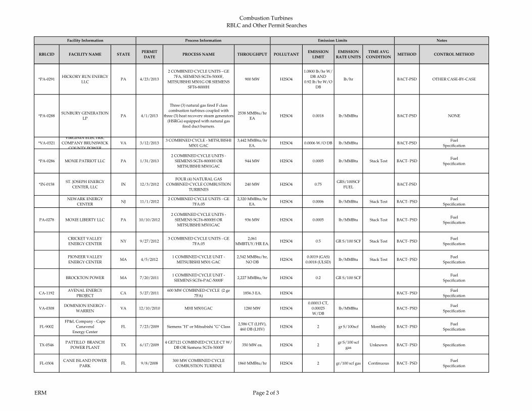
Combustion Turbines
RBLC and Other Permit Searches
RBLCID FACILITY NAME STATEPERMIT
DATEPROCESS NAME THROUGHPUT POLLUTANT
EMISSION
LIMIT
EMISSION
RATE UNITS
TIME AVG
CONDITIONMETHOD CONTROL METHOD
Facility Information Process Information Emission Limits Notes
*PA-0291HICKORY RUN ENERGY
LLCPA 4/23/2013
2 COMBINED CYCLE UNITS - GE
7FA, SIEMENS SGT6-5000F,
MITSUBISHI M501G OR SIEMENS
SFT6-8000H
900 MW H2SO4
1.0800 lb/hr W/
DB AND
0.92 lb/hr W/O
DB
lb/hr BACT-PSD OTHER CASE-BY-CASE
*PA-0288SUNBURY GENERATION
LPPA 4/1/2013
Three (3) natural gas fired F class
combustion turbines coupled with
three (3) heat recovery steam generators
(HSRGs) equipped with natural gas
fired duct burners.
2538 MMBtu/hr
EAH2SO4 0.0018 lb/MMBtu BACT-PSD NONE
*VA-0321
VIRGINIA ELECTRIC
COMPANY BRUNSWICK
COUNTY POWER
VA 3/12/20133 COMBINED CYCLE - MITSUBISHI
M501 GAC
3,442 MMBtu/hr
EA.H2SO4 0.0006 W/O DB lb/MMBtu BACT-PSD
Fuel
Specification
*PA-0286 MOXIE PATRIOT LLC PA 1/31/2013
2 COMBINED CYCLE UNITS -
SIEMENS SGT6-8000H OR
MITSUBISHI M501GAC
944 MW H2SO4 0.0005 lb/MMBtu Stack Test BACT- PSDFuel
Specification
*IN-0158ST. JOSEPH ENERGY
CENTER, LLCIN 12/3/2012
FOUR (4) NATURAL GAS
COMBINED CYCLE COMBUSTION
TURBINES
240 MW H2SO4 0.75GRS/100SCF
FUELBACT-PSD
NEWARK ENERGY
CENTERNJ 11/1/2012
2 COMBINED CYCLE UNITS - GE
7FA.05
2,320 MMBtu/hr
EA.H2SO4 0.0006 lb/MMBtu Stack Test BACT- PSD
Fuel
Specification
PA-0278 MOXIE LIBERTY LLC PA 10/10/2012
2 COMBINED CYCLE UNITS -
SIEMENS SGT6-8000H OR
MITSUBISHI M501GAC
936 MW H2SO4 0.0005 lb/MMBtu Stack Test BACT- PSDFuel
Specification
CRICKET VALLEY
ENERGY CENTERNY 9/27/2012
3 COMBINED CYCLE UNITS - GE
7FA.05
2,061
MMBTUY/HR EA.H2SO4 0.5 GR S/100 SCF Stack Test BACT- PSD
Fuel
Specification
PIONEER VALLEY
ENERGY CENTERMA 4/5/2012
1 COMBINED CYCLE UNIT -
MITSUBISHI M501 GAC
2,542 MMBtu/hr,
NO DBH2SO4
0.0019 (GAS)
0.0018 (ULSD)lb/MMBtu Stack Test BACT- PSD
Fuel
Specification
BROCKTON POWER MA 7/20/20111 COMBINED CYCLE UNIT -
SIEMENS SGT6-PAC-5000F2,227 MMBtu/hr H2SO4 0.2 GR S/100 SCF
Fuel
Specification
CA-1192AVENAL ENERGY
PROJECTCA 5/27/2011
600 MW COMBINED-CYCLE (2 ge
7FA)1856.3 EA. H2SO4 BACT- PSD
Fuel
Specification
VA-0308DOMINION ENERGY -
WARRENVA 12/10/2010 MHI M501GAC 1280 MW H2SO4
0.00013 CT,
0.00025
W/DB
lb/MMBtu BACT- PSDFuel
Specification
FL-9002
FP&L Company - Cape
Canaveral
Energy Center
FL 7/23/2009 Siemens "H" or Mitsubishi "G" Class2,586 CT (LHV),
460 DB (LHV)H2SO4 2 gr S/100scf Monthly BACT- PSD
Fuel
Specification
TX-0546PATTILLO BRANCH
POWER PLANTTX 6/17/2009
4 GE7121 COMBINED CYCLE CT W/
DB OR Siemens 5GT6-5000F350 MW ea. H2SO4 2
gr S/100 scf
gasUnknown BACT- PSD Specification
FL-0304CANE ISLAND POWER
PARKFL 9/8/2008
300 MW COMBINED CYCLE
COMBUSTION TURBINE1860 MMBtu/hr H2SO4 2 gr/100 scf gas Continuous BACT- PSD
Fuel
Specification
ERM Page 2 of 3

Combustion Turbines
RBLC and Other Permit Searches
RBLCID FACILITY NAME STATEPERMIT
DATEPROCESS NAME THROUGHPUT POLLUTANT
EMISSION
LIMIT
EMISSION
RATE UNITS
TIME AVG
CONDITIONMETHOD CONTROL METHOD
Facility Information Process Information Emission Limits Notes
LA-0224SWEPCO - Arsenal Hill
Power PlantLA 3/20/2008 Unknown
2,110 CCCT
250 DBH2SO4 1.85 lb/hr BACT- PSD
USE OF LOW-SULFUR PIPELINE
QUALITY NATURAL GAS AS FUEL
AND PROPER SCR DESIGN
NY-0095CAITHNESS BELLPORT
ENERGY CENTERNY 5/10/2006 SWPC 501F 2221 MMBtu/hr H2SO4 0.0004 lb/MMBtu BACT- PSD
Fuel
Specification
NV-0035
SIERRA PACIFIC POWER
COMPANY
TRACY SUBSTATION
EXPANSION
PROJECT
NV 8/16/2005
TURBINE, COMBINED CYCLE
COMBUSTION #1
WITH HRSG AND DUCT BURNER.
306 MW H2SO4 1 lb/hr BACT- PSDGood combustion practices and Fuel
specifications
FL-0263FPL TURKEY POINT
POWER PLANTFL 2/8/2005
170 MW COMBUSTION TURBINE, 4
UNITS170 MW H2SO4 2
gr S/100 scf
gasContinuous BACT- PSD
Fuel
Specification
ERM Page 3 of 3

Combustion Turbines
RBLC and Other Permit Searches
RBLCID FACILITY NAME STATEPERMIT
DATEPROCESS NAME THROUGHPUT POLLUTANT
EMISSION
RATE UNITS
EMISSION
RATE UNITS
TIME AVG
CONDITIONMETHOD CONTROL DESCIPTION
*TX-0751 Eagle Mountain Power Company LLC TX 6/18/2015
Siemens 231 MW/500 MMBtu/hr
duct burner, GE-210MW/349.2
MMBtu/hr duct burner
210 MW PM 35.47 lb/hr BACT-PSDGood Combustion Practices
/ Low S Fuel
*TX-0730 Colorado Bend II Power, LLC TX 4/1/20152 GE Model 7HA.02 Combustion
Turbines1100 MW PM 43 lb/hr BACT-PSD
Efficient Combustion / Nat
Gas
*WV-0025 Moundsville Power, LLC WV 11/21/20142 GE 7FA.04 Turbines w/ Duct
Burners2159 MMBtu/hr PM 7.6 lb/hr BACT-PSD
Nat Gas / Good Combustion
Practices / Inlet Air
Filtration
*NJ-0082 WEST DEPTFORD ENERGY STATION NJ 7/18/2014
427 MW Siemens Combined Cycle
Turbine with duct burner Heat
Input rate of the turbine = 2276
MMBtu/hr (HHV) Heat Input rate
of the Duct burner= 777
MMBtu/hr(HHV)
427 MW TSP 0.0048 lb/MMBtu
AVERAGE OF
THREE STACK
TEST RUNS
BACT-PSD NAT GAS
IA-0107MARSHALLTOWN GENERATING
STATIONIA 4/14/2014 2 COMBINED CYCLE 2258 MMBtu/hr PM 0.01 lb/MMBtu BACT-PSD NAT GAS / LOW S FUEL
*MD-0042
OLD DOMINION ELECTRIC
CORPORATION (ODEC) WILDCAT
POINT GENERATING FACILITY
MD 4/8/2014
TWO MITSUBISHI "G" MODEL
COMBUSTION TURBINE
GENERATORS (CTS) COUPLED
WITH A HEAT RECOVERY
STEAM GENERATOR (HRSG)
EQUIPPED WITH DUCT
BURNERS
1000 MW TSP 38 lb/hr
AVERAGE OF 3
STACK TEST
RUNS
BACT-PSD
USE OF PIPELINE
QUALITY NATURAL GAS
AND EFFICIENT TURBINE
DESIGN
*TX-0660
FGE POWER LLC
FGE TEXAS POWER I AND FGE
TEXAS POWER II
TX 3/24/2014Four (4) Alstom GT24 CTGs, each
with a HRSG and DBs409 MMBtu/hr Each PM 2.5 2 PPMVD BACT-PSD
Low sulfur fuel, good
combustion practices
*NJ-0082PSEG FOSSIL LLC SEWAREN
GENERATING STATIONNJ 3/7/2014
GE7FA.05 OR Siemens SGT6
5000F, with two duct burners, two
Heat Recovery Steam Generators
(HRSG), one steam turbine
625 MW TSP 14.6 lb/hr
AVERAGE OF
THREE ONE
HOUR TESTS
w/ DB
BACT-PSD NAT GAS
*PA-0298 FUTURE POWER PA INC PA 3/4/2014COMBINED CYCLE - SIEMENS
5000
346 MW
2267 MMBtu/hrPM 15.6 lb/MMBtu w/DB BACT-PSD NAT GAS / LOW S FUEL
FOOTPRINT POWER SALEM HARBOR
DEVELOPMENT LPMA 1/30/2014
2 COMBINED CYCLE - GE 107F
SERIES 5630 MW PM 0.0071 lb/MMBtu w/DB BACT-PSD NAT GAS / LOW S FUEL
*MI-0412HOLLAND BOARD OF PUBLIC
WORKS-EAST 5TH STREETMI 12/4/2013
FG-CTGHRSG: 2 Combined cycle
CTGs with HRSGs with duct
burners
670 MMBtu/hr EA PM 0.007 lb/MMBtu BACT-PSD
Good combustion practices
and the use of pipeline
quality natural gas.
*MI-0412HOLLAND BOARD OF PUBLIC
WORKS-EAST 5TH STREETMI 12/4/2013
FG-CTGHRSG: 2 Combined cycle
CTGs with HRSGs with duct
burners
670 MMBtu/hr EA PM 2.5, PM 10 0.0014 lb/MMBtu BACT-PSD
Good combustion practices
and the use of pipeline
quality natural gas.
*TX-0641 PINECREST ENERGY CENTER TX 11/12/2013
Combined cycle turbine General
Electric 7FA.05, the Siemens SGT6-
5000F(4), or the Siemens SGT6-
5000F(5).
637 and 735 MW PM 26.2 BACT-PSD
pipeline quality natural gas
and good combustion
practices
CARROLL COUNTY ENERGY OH 11/5/20132 COMBINED CYCLE UNITS - GE
7FA
2,045 MMBtu/hr
EA.PM 0.0078 lb/MMBtu BACT-PSD SCR + DLN
RENAISSANCE POWER LLC MI 11/1/2013 4 COMBINED CYCLE UNITS 2147 MMBtu/hr EA. PM 0.0042 lb/MMBtu BACT-PSD NAT GAS / LOW S FUEL
Facility Information Process Information Emission Limits Notes
ERM Page 1 of 4
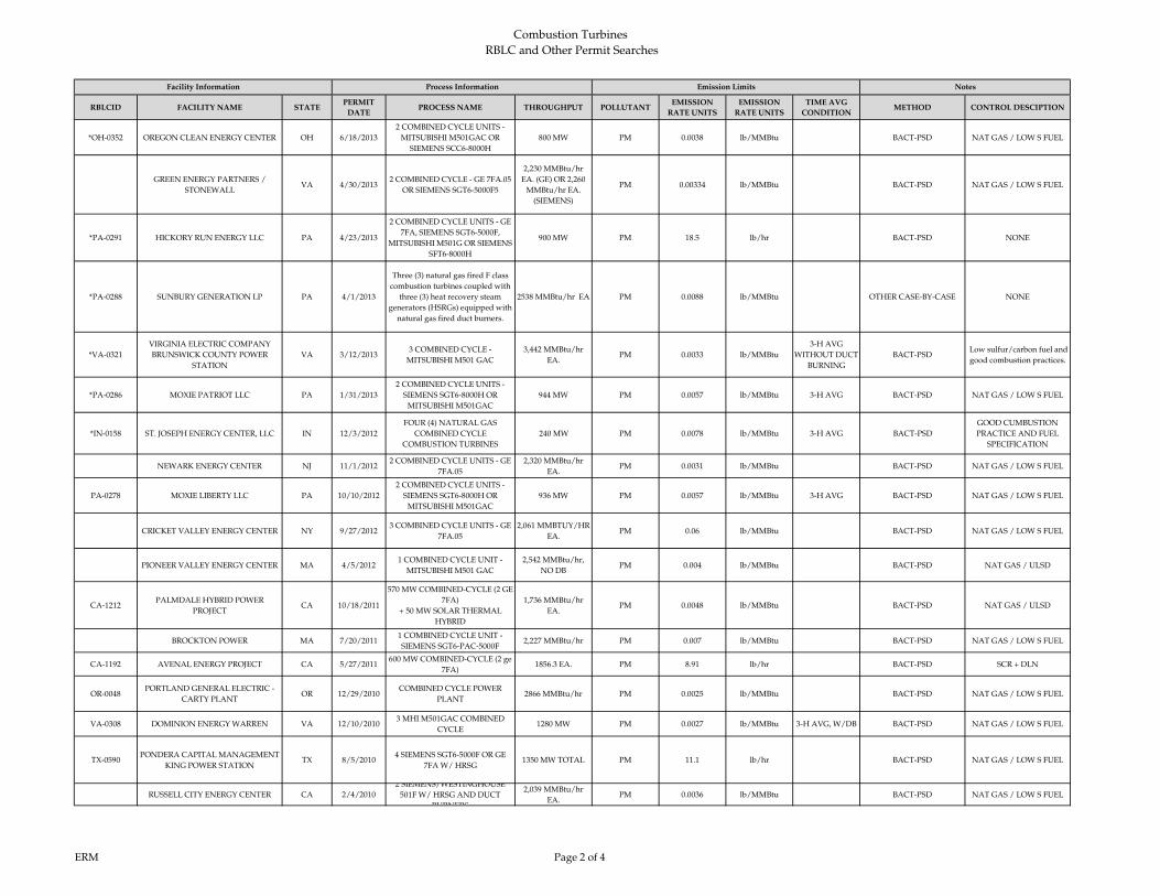
RBLCID FACILITY NAME STATEPERMIT
DATEPROCESS NAME THROUGHPUT POLLUTANT
EMISSION
RATE UNITS
EMISSION
RATE UNITS
TIME AVG
CONDITIONMETHOD CONTROL DESCIPTION
Facility Information Process Information Emission Limits Notes
*OH-0352 OREGON CLEAN ENERGY CENTER OH 6/18/2013
2 COMBINED CYCLE UNITS -
MITSUBISHI M501GAC OR
SIEMENS SCC6-8000H
800 MW PM 0.0038 lb/MMBtu BACT-PSD NAT GAS / LOW S FUEL
GREEN ENERGY PARTNERS /
STONEWALLVA 4/30/2013
2 COMBINED CYCLE - GE 7FA.05
OR SIEMENS SGT6-5000F5
2,230 MMBtu/hr
EA. (GE) OR 2,260
MMBtu/hr EA.
(SIEMENS)
PM 0.00334 lb/MMBtu BACT-PSD NAT GAS / LOW S FUEL
*PA-0291 HICKORY RUN ENERGY LLC PA 4/23/2013
2 COMBINED CYCLE UNITS - GE
7FA, SIEMENS SGT6-5000F,
MITSUBISHI M501G OR SIEMENS
SFT6-8000H
900 MW PM 18.5 lb/hr BACT-PSD NONE
*PA-0288 SUNBURY GENERATION LP PA 4/1/2013
Three (3) natural gas fired F class
combustion turbines coupled with
three (3) heat recovery steam
generators (HSRGs) equipped with
natural gas fired duct burners.
2538 MMBtu/hr EA PM 0.0088 lb/MMBtu OTHER CASE-BY-CASE NONE
*VA-0321
VIRGINIA ELECTRIC COMPANY
BRUNSWICK COUNTY POWER
STATION
VA 3/12/20133 COMBINED CYCLE -
MITSUBISHI M501 GAC
3,442 MMBtu/hr
EA.PM 0.0033 lb/MMBtu
3-H AVG
WITHOUT DUCT
BURNING
BACT-PSD Low sulfur/carbon fuel and
good combustion practices.
*PA-0286 MOXIE PATRIOT LLC PA 1/31/2013
2 COMBINED CYCLE UNITS -
SIEMENS SGT6-8000H OR
MITSUBISHI M501GAC
944 MW PM 0.0057 lb/MMBtu 3-H AVG BACT-PSD NAT GAS / LOW S FUEL
*IN-0158 ST. JOSEPH ENERGY CENTER, LLC IN 12/3/2012
FOUR (4) NATURAL GAS
COMBINED CYCLE
COMBUSTION TURBINES
240 MW PM 0.0078 lb/MMBtu 3-H AVG BACT-PSD
GOOD CUMBUSTION
PRACTICE AND FUEL
SPECIFICATION
NEWARK ENERGY CENTER NJ 11/1/20122 COMBINED CYCLE UNITS - GE
7FA.05
2,320 MMBtu/hr
EA.PM 0.0031 lb/MMBtu BACT-PSD NAT GAS / LOW S FUEL
PA-0278 MOXIE LIBERTY LLC PA 10/10/2012
2 COMBINED CYCLE UNITS -
SIEMENS SGT6-8000H OR
MITSUBISHI M501GAC
936 MW PM 0.0057 lb/MMBtu 3-H AVG BACT-PSD NAT GAS / LOW S FUEL
CRICKET VALLEY ENERGY CENTER NY 9/27/20123 COMBINED CYCLE UNITS - GE
7FA.05
2,061 MMBTUY/HR
EA.PM 0.06 lb/MMBtu BACT-PSD NAT GAS / LOW S FUEL
PIONEER VALLEY ENERGY CENTER MA 4/5/20121 COMBINED CYCLE UNIT -
MITSUBISHI M501 GAC
2,542 MMBtu/hr,
NO DBPM 0.004 lb/MMBtu BACT-PSD NAT GAS / ULSD
CA-1212PALMDALE HYBRID POWER
PROJECTCA 10/18/2011
570 MW COMBINED-CYCLE (2 GE
7FA)
+ 50 MW SOLAR THERMAL
HYBRID
1,736 MMBtu/hr
EA.PM 0.0048 lb/MMBtu BACT-PSD NAT GAS / ULSD
BROCKTON POWER MA 7/20/20111 COMBINED CYCLE UNIT -
SIEMENS SGT6-PAC-5000F2,227 MMBtu/hr PM 0.007 lb/MMBtu BACT-PSD NAT GAS / LOW S FUEL
CA-1192 AVENAL ENERGY PROJECT CA 5/27/2011600 MW COMBINED-CYCLE (2 ge
7FA)1856.3 EA. PM 8.91 lb/hr BACT-PSD SCR + DLN
OR-0048PORTLAND GENERAL ELECTRIC -
CARTY PLANTOR 12/29/2010
COMBINED CYCLE POWER
PLANT2866 MMBtu/hr PM 0.0025 lb/MMBtu BACT-PSD NAT GAS / LOW S FUEL
VA-0308 DOMINION ENERGY WARREN VA 12/10/20103 MHI M501GAC COMBINED
CYCLE1280 MW PM 0.0027 lb/MMBtu 3-H AVG, W/DB BACT-PSD NAT GAS / LOW S FUEL
TX-0590PONDERA CAPITAL MANAGEMENT
KING POWER STATIONTX 8/5/2010
4 SIEMENS SGT6-5000F OR GE
7FA W/ HRSG1350 MW TOTAL PM 11.1 lb/hr BACT-PSD NAT GAS / LOW S FUEL
RUSSELL CITY ENERGY CENTER CA 2/4/2010
2 SIEMENS/WESTINGHOUSE
501F W/ HRSG AND DUCT
BURNERS
2,039 MMBtu/hr
EA.PM 0.0036 lb/MMBtu BACT-PSD NAT GAS / LOW S FUEL
ERM Page 2 of 4
Combustion Turbines
RBLC and Other Permit Searches
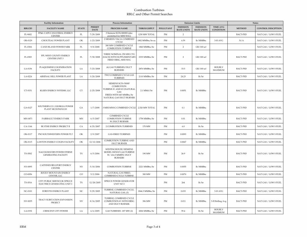
RBLCID FACILITY NAME STATEPERMIT
DATEPROCESS NAME THROUGHPUT POLLUTANT
EMISSION
RATE UNITS
EMISSION
RATE UNITS
TIME AVG
CONDITIONMETHOD CONTROL DESCIPTION
Facility Information Process Information Emission Limits Notes
FL-9002FP&L CAPE CANAVERAL ENERGY
CENTERFL 7/29/2009
3 Siemens SGT6-8000H (also
permitted for MHI 501G)1250 MW TOTAL PM 2 BACT-PSD NAT GAS / LOW S FUEL
OK-0129 CHOUTEAU POWER PLANT OK 1/23/20092 SIEMESN V84.3A COMBINED
CYCLE1882 MMBtu/hr ea PM 6.59 lb/MMBtu 3-H AVG N/A NAT GAS / LOW S FUEL
FL-0304 CANE ISLAND POWER PARK FL 9/8/2008300 MW COMBINED CYCLE
COMBUSTION TURBINE1860 MMBtu/hr PM 2 GR/100 scf NAT GAS / LOW S FUEL
FL-0303FPL WEST COUNTY ENERGY
CENTER UNIT 3FL 7/30/2008
THREE NOMINAL 250 MW CTG
(EACH) WITH SUPPLEMENTARY-
FIRED HRSG, MHI 501G
2333 MMBtu/hr PM 2 GR/100 scf BACT-PSD NAT GAS / LOW S FUEL
LA‐0136PLAQUEMINE COGENERATION
FACILITYLA 7/23/2008
(4) GAS TURBINES/DUCT
BURNERS2876 MMBtu/hr PM 33.5 GR/100 scf
HOURLY
MAXIMUMBACT‐PSD NAT GAS / LOW S FUEL
LA‐0224 ARSENAL HILL POWER PLANT LA 3/20/2008TWO COMBINED CYCLE GAS
TURBINES2110 MMBtu/hr PM 24.23 lb/hr BACT‐PSD NAT GAS / LOW S FUEL
CT‐0151 KLEEN ENERGY SYSTEMS, LLC CT 2/25/2008
SIEMENS SGT6‐5000F
COMBUSTION
TURBINE #1 AND #2 (NATURAL
GAS
FIRED) WITH 445 MMBtu/hr
NATURAL GAS DUCT BURNER
2.1 MMcf/hr PM 0.0051 lb/MMBtu BACT‐PSD NAT GAS / LOW S FUEL
GA-0127SOUTHERN CO./GEORGIA POWER
PLANT MCDONOUGHGA 1/7/2008 3 MHI M501G COMBINED CYCLE 2,520 MW TOTAL PM 0.1 lb/MMBtu BACT-PSD NAT GAS / LOW S FUEL
MN‐0071 FAIRBAULT ENERGY PARK MN 6/5/2007
COMBINED CYCLE
COMBUSTION TURBINE
W/DUCT BURNER
1758 MMBtu/hr PM 0.01 lb/MMBtu BACT‐PSD NAT GAS / LOW S FUEL
CA‐1144 BLYTHE ENERGY PROJECT II CA 4/25/2007 2 COMBUSTION TURBINES 170 MW PM 6.0 lb/hr BACT‐PSD NAT GAS / LOW S FUEL
OK‐0117 PSO SOUTHWESTERN POWER PLT OK 2/9/2007 GAS‐FIRED TURBINES PM 0.0093 lb/MMBtu BACT‐PSD NAT GAS / LOW S FUEL
OK‐0115 LAWTON ENERGY COGEN FACILITY OK 12/12/2006COMBUSTION TURBINE AND
DUCT BURNERPM 0.0067 lb/MMBtu BACT‐PSD NAT GAS / LOW S FUEL
TX‐0502NACOGDOCHES POWER STERNE
GENERATING FACILITYTX 6/5/2006
WESTINGHOUSE/SIEMENS
MODEL SW501F GAS TURBINE
W/ 416.5 MMBTU DUCT
BURNERS
190 MW PM 26.9 lb/hr BACT‐PSD NAT GAS / LOW S FUEL
NY‐0095CAITHNES BELLPORT ENERGY
CENTERNY 5/10/2006 COMBUSTION TURBINE 2221 MMBtu/hr PM 0.0055 lb/MMBtu BACT‐PSD NAT GAS / LOW S FUEL
CO‐0056ROCKY MOUNTAIN ENERGY
CENTER, LLCCO 5/2/2006
NATURAL‐GAS FIRED,
COMBINED‐CYCLE TURBINE300 MW PM 0.0074 lb/MMBtu BACT‐PSD NAT GAS / LOW S FUEL
TX‐0516CITY PUBLIC SERVICE JK SPRUCE
ELECTRICE GENERATING UNIT 2TX 12/28/2005
SPRUCE POWER GENERATOR
UNIT NO 2PM 264 lb/hr BACT‐PSD NAT GAS / LOW S FUEL
NC‐0101 FORSYTH ENERGY PLANT NC 9/29/2005TURBINE, COMBINED CYCLE,
NATURAL GAS, (3)1844.3 MMBtu/hr PM 0.019 lb/MMBtu 3-H AVG BACT‐PSD NAT GAS / LOW S FUEL
NV‐0035TRACY SUBSTATION EXPANSION
PROJECTNV 8/16/2005
TURBINE, COMBINED CYCLE
COMBUSTION #1 WITH HRSG
AND DUCT BURNER.
306 MW PM 0.011 lb/MMBtu 3-H Rolling Avg BACT‐PSD NAT GAS / LOW S FUEL
LA‐0192 CRESCENT CITY POWER LA 6/6/2005 GAS TURBINES ‐187 MW (2) 2006 MMBtu/hr PM 59.4 lb/hrHOURLY
MAXIMUMBACT‐PSD NAT GAS / LOW S FUEL
ERM Page 3 of 4
Combustion Turbines
RBLC and Other Permit Searches

RBLCID FACILITY NAME STATEPERMIT
DATEPROCESS NAME THROUGHPUT POLLUTANT
EMISSION
RATE UNITS
EMISSION
RATE UNITS
TIME AVG
CONDITIONMETHOD CONTROL DESCIPTION
Facility Information Process Information Emission Limits Notes
MI‐0366 BERRIEN ENERGY, LLC MI 4/13/20053 COMBUSTION TURBINES AND
DUCT BURNERS1584 MMBtu/hr PM 0.012 lb/MMBtu BACT‐PSD NAT GAS / LOW S FUEL
ERM Page 4 of 4
Combustion Turbines
RBLC and Other Permit Searches

Combustion Turbines
RBLC and Other Permit Searches
RBLCID FACILITY NAME STATEPERMIT
DATEPROCESS NAME THROUGHPUT POLLUTANT
EMISSION
LIMIT
EMISSION RATE
UNITSTIME AVG CONDITION METHOD CONTROL METHOD
*TX-0751Eagle Mountain Power
Company LLCTX 6/18/2015
Siemens 231 MW/500
MMBtu/hr duct burner, GE-
210MW/349.2 MMBtu/hr duct
burner
210 MW SO2 40.66 lb/hr BACT-PSDGood Combustion Practices, Low S
Fuel
*TX-0730Colorado Bend II
Power, LLCTX 4/1/2015
2 GE Model 7HA.02 Combustion
Turbines1100 MW SO2 2 GR/100SCF 1-HR AVG BACT-PSD NAT GAS/ Efficient Combustion
*NJ-0082WEST DEPTFORD
ENERGY STATIONNJ 7/18/2014
427 MW Siemens Combined
Cycle Turbine with duct burner
Heat Input rate of the turbine =
2276 MMBtu/hr (HHV) Heat
Input rate of the Duct burner=
777 MMBtu/hr(HHV)
427 MW SO2 6.56 lb/hr AVERAGE OF THREE
ONE HOUR TESTS BACT-PSD NAT GAS
*MD-0042
OLD DOMINION
ELECTRIC
CORPORATION
(ODEC) WILDCAT
POINT GENERATING
FACILITY
MD 4/08/2014
TWO MITSUBISHI "G" MODEL
COMBUSTION TURBINE
GENERATORS (CTS)
COUPLED WITH A HEAT
RECOVERY STEAM
GENERATOR (HRSG)
EQUIPPED WITH DUCT
BURNERS
1000 MW SO2
8.2 W/ DB
6.3 W/O DB
lb/hr 3-HOUR BLOCK
AVERAGEBACT-PSD
EXCLUSIVE USE OF PIPELINE
QUALITY NATURAL GAS AND
EFFICIENT TURBINE DESIGN
*TX-0660
FGE POWER LLC
FGE TEXAS POWER I
AND FGE
TEXAS POWER II
TX 3/24/2014Four (4) Alstom GT24 CTGs,
each with a HRSG and DBs409 MMBtu/hr Each SO2
1
AND
0.25
GRS/ 100 DSCF
HOURLY
AND
ANNUAL
BACT-PSDLow sulfur fuel, good combustion
practices
*NJ-0082
PSEG FOSSIL LLC
SEWAREN
GENERATING
STATION
NJ 3/07/2014
GE7FA.05 OR Siemens SGT6
5000F, with two duct burners,
two Heat Recovery Steam
Generators (HRSG), one steam
turbine
625 MW SO2
5.2000 GE
W/ DB
AND
4.9000 GE
W/O DB
lb/hr AVERAGE OF THREE
ONE HOUR TESTSBACT-PSD NAT GAS
*PA-0298FUTURE POWER PA
INCPA 3/4/2014
COMBINED CYCLE - SIEMENS
5000
346 MW
2267
MMBtu/hr
SO2 0.0023
lb/MMBtu
~0.8 GR S/100
SCF
BACT NAT GAS / LOW S FUEL
FOOTPRINT POWER
SALEM HARBOR
DEVELOPMENT LP
MA 1/30/20142 COMBINED CYCLE - GE 107F
SERIES 5630 MW SO2 0.0015
lb/MMBtu
~0.5 GR S/100
SCF
1-HR AVG BACT-PSD NAT GAS / LOW S FUEL
CARROLL COUNTY
ENERGYOH 11/5/2013
2 COMBINED CYCLE UNITS -
GE 7FA
2,045
MMBtu/hr EA.SO2 1
GR S/100 SCF OF
GASBACT-PSD NAT GAS / LOW S FUEL
*OH-0352OREGON CLEAN
ENERGY CENTEROH 6/18/2013
2 COMBINED CYCLE UNITS -
MITSUBISHI M501GAC OR
SIEMENS SCC6-8000H
800 MW SO2 0.0014
lb/MMBtu
0.5 GR S/100
SCF
BACT-PSD NAT GAS / LOW S FUEL
GREEN ENERGY
PARTNERS /
STONEWALL
VA 4/30/2013
2 COMBINED CYCLE - GE
7FA.05 OR SIEMENS SGT6-
5000F5
2,230 MMBtu/hr EA.
(GE) OR 2,260
MMBtu/hr EA.
(SIEMENS)
SO2 0.000261
lb/MMBtu
0.1 GR S/100
SCF
BACT-PSD NAT GAS / LOW S FUEL
*PA-0291HICKORY RUN
ENERGY LLCPA 4/23/2013
2 COMBINED CYCLE UNITS -
GE 7FA, SIEMENS SGT6-5000F,
MITSUBISHI M501G OR
SIEMENS SFT6-8000H
900 MW SO2
7.1900 W/
DB; AND
6.15 lb/hr
W/O DB
lb/hr BACT-PSD NAT GAS / LOW S FUEL
Facility Information Process Information Emission Limits Notes
ERM Page 1 of 3
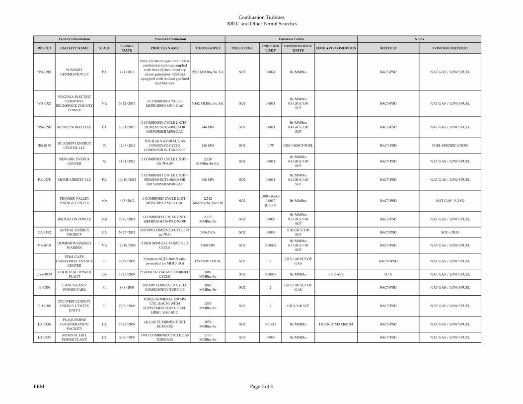
Combustion Turbines
RBLC and Other Permit Searches
RBLCID FACILITY NAME STATEPERMIT
DATEPROCESS NAME THROUGHPUT POLLUTANT
EMISSION
LIMIT
EMISSION RATE
UNITSTIME AVG CONDITION METHOD CONTROL METHOD
Facility Information Process Information Emission Limits Notes
*PA-0288SUNBURY
GENERATION LPPA 4/1/2013
three (3) natural gas fired F class
combustion turbines coupled
with three (3) heat recovery
steam generators (HSRGs)
equipped with natural gas fired
duct burners.
2538 MMBtu/hr EA SO2 0.0024 lb/MMBtu BACT-PSD NAT GAS / LOW S FUEL
*VA-0321
VIRGINIA ELECTRIC
COMPANY
BRUNSWICK COUNTY
POWER
VA 3/12/20133 COMBINED CYCLE -
MITSUBISHI M501 GAC3,442 MMBtu/hr EA. SO2 0.0011
lb/MMBtu
0.4 GR S/100
SCF
BACT-PSD NAT GAS / LOW S FUEL
*PA-0286 MOXIE PATRIOT LLC PA 1/31/2013
2 COMBINED CYCLE UNITS -
SIEMENS SGT6-8000H OR
MITSUBISHI M501GAC
944 MW SO2 0.0011
lb/MMBtu
0.4 GR S/100
SCF
BACT-PSD NAT GAS / LOW S FUEL
*IN-0158ST. JOSEPH ENERGY
CENTER, LLCIN 12/3/2012
FOUR (4) NATURAL GAS
COMBINED CYCLE
COMBUSTION TURBINES
240 MW SO2 0.75 GRS/100SCF FUEL BACT-PSD FUEL SPECIFICATION
NEWARK ENERGY
CENTERNJ 11/1/2012
2 COMBINED CYCLE UNITS -
GE 7FA.05
2,320
MMBtu/hr EA.SO2 0.0011
lb/MMBtu
0.4 GR S/100
SCF
BACT-PSD NAT GAS / LOW S FUEL
PA-0278 MOXIE LIBERTY LLC PA 10/10/2012
2 COMBINED CYCLE UNITS -
SIEMENS SGT6-8000H OR
MITSUBISHI M501GAC
936 MW SO2 0.0011
lb/MMBtu
0.4 GR S/100
SCF
BACT-PSD NAT GAS / LOW S FUEL
PIONEER VALLEY
ENERGY CENTERMA 4/5/2012
1 COMBINED CYCLE UNIT -
MITSUBISHI M501 GAC
2,542
MMBtu/hr, NO DBSO2
0.0019 (GAS)
0.0017
(ULSD)
lb/MMBtu BACT-PSD NAT GAS / ULSD
BROCKTON POWER MA 7/20/20111 COMBINED CYCLE UNIT -
SIEMENS SGT6-PAC-5000F
2,227
MMBtu/hrSO2 0.0006
lb/MMBtu
0.2 GR S/100
SCF
BACT-PSD NAT GAS / LOW S FUEL
CA-1192AVENAL ENERGY
PROJECTCA 5/27/2011
600 MW COMBINED-CYCLE (2
ge 7FA)1856.3 EA. SO2 0.0006
0.36 GR S/100
SCFBACT-PSD SCR + DLN
VA-0308DOMINION ENERGY
WARRENVA 12/10/2010
3 MHI M501GAC COMBINED
CYCLE1280 MW SO2 0.00028
lb/MMBtu
0.1 GR S/100
SCF
BACT-PSD NAT GAS / LOW S FUEL
FP&L CAPE
CANAVERAL ENERGY
CENTER
FL 7/29/20093 Siemens SGT6-8000H (also
permitted for MHI 501G)1250 MW TOTAL SO2 2
GR S/100 SCF OF
GASBACT•-PSD NAT GAS / LOW S FUEL
OK•-0129CHOUTEAU POWER
PLANTOK 1/23/2009
2 SIEMESN V84.3A COMBINED
CYCLE
1882
MMBtu/hrSO2 0.00056 lb/MMBtu 3‐HR AVG N/A NAT GAS / LOW S FUEL
FL‐0304CANE ISLAND
POWER PARKFL 9/8/2008
300 MW COMBINED CYCLE
COMBUSTION TURBINE
1860
MMBtu/hrSO2 2
GR S/100 SCF OF
GASBACT‐PSD NAT GAS / LOW S FUEL
FL•-0303
FPL WEST COUNTY
ENERGY CENTER
UNIT 3
FL 7/30/2008
THREE NOMINAL 250 MW
CTG (EACH) WITH
SUPPLEMENTARY•-FIRED
HRSG, MHI 501G
2333
MMBtu/hrSO2 2 GR S/100 SCF BACT‐PSD NAT GAS / LOW S FUEL
LA‐0136
PLAQUEMINE
COGENERATION
FACILITY
LA 7/23/2008(4) GAS TURBINES/DUCT
BURNERS
2876
MMBtu/hrSO2 0.01415 lb/MMBtu HOURLY MAXIMUM BACT‐PSD NAT GAS / LOW S FUEL
LA‐0224ARSENAL HILL
POWER PLANTLA 3/20/2008
TWO COMBINED CYCLE GAS
TURBINES
2110
MMBtu/hrSO2 0.0057 lb/MMBtu BACT‐PSD NAT GAS / LOW S FUEL
ERM Page 2 of 3

Combustion Turbines
RBLC and Other Permit Searches
RBLCID FACILITY NAME STATEPERMIT
DATEPROCESS NAME THROUGHPUT POLLUTANT
EMISSION
LIMIT
EMISSION RATE
UNITSTIME AVG CONDITION METHOD CONTROL METHOD
Facility Information Process Information Emission Limits Notes
CT‐0151KLEEN ENERGY
SYSTEMS, LLCCT 2/25/2008
SIEMENS SGT6‐5000F
COMBUSTION TURBINE #1
AND #2 (NATURAL GAS
FIRED) WITH 445 MMBtu/hr
NATURAL GAS DUCT BURNER
2.1 MMcf/hr SO2 0.0023
lb/MMBtu
0.8 GR/100
SCF
BACT-PSD NAT GAS / LOW S FUEL
FL‐0285PROGRESS BARTOW
POWER PLANTFL 1/26/2007
SIMPLE CYCLE COMBUSTION
TURBINE (ONE UNIT)
1972
MMBtu/hrSO2 2 GR/100SCF BACT‐PSD NAT GAS / LOW S FUEL
FL‐0285PROGRESS BARTOW
POWER PLANTFL 1/26/2007
COMBINED CYCLE
COMBUSTION
TURBINE SYSTEM (4‐ON‐1)
1972
MMBtu/hrSO2 2 GR/100SCF BACT‐PSD NAT GAS / LOW S FUEL
FL‐0286FPL WEST COUNTY
ENERGY CENTERFL 1/10/2007
COMBINED CYCLE
COMBUSTION GAS
TURBINES ‐6 UNITS
2333
MMBtu/hrSO2 2
G S/100 SCF OF
GASBACT‐PSD NAT GAS / LOW S FUEL
NY‐0095CAITHNES BELLPORT
ENERGY CENTERNY 5/10/2006 COMBUSTION TURBINE
2221
MMBtu/hrSO2 0.0011 lb/MMBtu BACT‐PSD NAT GAS / LOW S FUEL
NC‐0101FORSYTH ENERGY
PLANTNC 9/29/2005
TURBINE, COMBINED CYCLE,
NATURAL GAS, (3)
1844.3
MMBtu/hrSO2 0.0006 lb/MMBtu
based on 3‐hour
averageBACT‐PSD NAT GAS / LOW S FUEL
NC‐0101FORSYTH ENERGY
PLANTNC 9/29/2005
TURBINE & DUCT BURNER,
COMBINED CYCLE, NAT GAS,
3
1844.3
MMBtu/hrSO2 0.0006 lb/MMBtu 3‐hr avg BACT‐PSD NAT GAS / LOW S FUEL
FL‐0265HINES POWER BLOCK
4FL 6/8/2005 COMBINED CYCLE TURBINE 530 MW SO2 2 GR/100SCF CONTINUOUS BACT‐PSD NAT GAS / LOW S FUEL
LA‐0192CRESCENT CITY
POWERLA 6/6/2005 GAS TURBINES ‐187 MW (2)
2006
MMBtu/hrSO2 0.00503 lb/MMBtu HOURLY MAXIMUM BACT‐PSD NAT GAS / LOW S FUEL
FL‐0263FPL TURKEY POINT
POWER PLANTFL 2/8/2005
170 MW COMBUSTION
TURBINE, 4 UNITS170 MW SO2 2 GR S/100 SCF GAS BACT‐PSD NAT GAS / LOW S FUEL
ERM Page 3 of 3

Combustion Turbines
RBLC and Other Permit Searches
RBLC ID FACILITY NAME STATEPERMIT
DATEPROCESS NAME THROUGHPUT POLLUTANT
EMISSION
LIMITS
EMISSION RATE
UNITS
TIME AVG
CONDITIONMETHOD CONTROL METHOD
*TX-0751Eagle Mountain Power
Company LLCTX 6/18/2015
Siemens 231 MW/500 MMBtu/hr duct burner,
GE-210MW/349.2 MMBtu/hr duct burner210 MW VOC 2 PPM LAER OXIDATION CATALYST
*TX-0730Colorado Bend II
Power, LLCTX 4/1/2015 2 GE Model 7HA.02 Combustion Turbines 1100 MW VOC 4 PPM @ 15% O2, 3-HR AVG BACT-PSD
SCR + OXIDATION
CATALYST
*TX-0714NRG Texas Power LLC,
S R BertronTX 12/19/2014 2 Combined Cycle 240 MW VOC 1 PPM @15% O2 BACT-PSD OXIDATION CATALYST
*TX-0710 Victoria, WLE L.P. TX 12/1/2014 GE 7FA.04 197 MW VOC 4 PPM @ 15% O2, 3-HR AVG BACT-PSD OXIDATION CATALYST
*WV-0025 Moundsville Power,
LLCWV 11/21/2014 2 GE 7FA.04 Turbines w/ Duct Burners 2159 MMBtu/hr VOC 5.3 lb/hr @15% O2 BACT-PSD
OXIDATION CATALYST -
GOOD COMBUSTION
PRACTICES
*TX-0712
Southern Power
Company Trinidad
Generating Facility
TX 11/20/2014Mitsubishi Heavy Industries J model with HRSG
and Duct Burner497 MW VOC 4 PPM @ 15% O2, 1 HR BACT-PSD OXIDATION CATALYST
*NJ-0082WEST DEPTFORD
ENERGY STATIONNJ 7/18/2014
427 MW Siemens Combined Cycle Turbine with
duct burner Heat Input rate of the turbine = 2276
MMBtu/hr (HHV) Heat Input rate of the Duct
burner= 777 MMBtu/hr(HHV)
427 MW VOC 1 PPMVD
@15%O2 AVERAGE OF
THREE STACK TEST
RUNS
LAER OXIDATION CATALYST
*TX-0713
TENASKA
BROWNSVILLE
PARTNERS, LLC
TENASKA
BROWNSVILLE
GENERATING
STATION
TX 4/29/2014
two CTs (2x1 CCGT), although the final design
selected by Tenaska may only consist of one CT
(1x1 CCGT).
884 MW gross VOC 2 PPMVD @ 15% O2, 3-HR AVG BACT-PSD OXIDATION CATALYST
*MD-0041
CPV MARYLAND,
LLC
CPV ST. CHARLES
MD 4/23/20142 COMBINED CYCLE COMBUSTION
TURBINES, WITH DUCT FIRING725 MW VOC 2 PPMVD
@ 15% O2 3-HOUR
BLOCK AVERAGE,
EXCLUDING SU/SD
LAER OXIDATION CATALYST
IA-0107
MARSHALLTOWN
GENERATING
STATION
IA 4/14/2014 2 COMBINED CYCLE 2258 MMBtu/hr VOC 1 PPM @15% O2 BACT-PSD OXIDATION CATALYST
*TX-0660
FGE POWER LLC
FGE TEXAS POWER I
AND FGE
TEXAS POWER II
TX 3/24/2014Four (4) Alstom GT24 CTGs, each with a HRSG
and DBs
409 MMBtu/hrr
EachVOC 2 PPMVD @ 15% O2, 3-HR AVG BACT-PSD
OXIDATION CATALYST AND
GOOD COMBUSTION
PRACTICES
*NJ-0082
PSEG FOSSIL LLC
SEWAREN
GENERATING
STATION
NJ 3/7/2014
GE7FA.05 OR Siemens SGT6 5000F, with two
duct burners, two Heat Recovery Steam
Generators (HRSG), one steam turbine
625 MW VOC 2 PPMVD
@15%O2 AVERAGE OF
THREE ONE HOUR
TESTS
LAER
OXIDATION CATALYST AND
GOOD COMBUSTION
PRACTICES
*PA-0298FUTURE POWER PA
INCPA 3/4/2014 COMBINED CYCLE - SIEMENS 5000
346 MW
2267 MMBtu/hrVOC 2 PPM @15% O2 LAER OXIDATION CATALYST
FOOTPRINT POWER
SALEM HARBOR
DEVELOPMENT LP
MA 1/30/2014 2 COMBINED CYCLE - GE 107F SERIES 5 630 MW VOC 1 PPM @ 15% O2, 1-HR AVG LAER OXIDATION CATALYST
Facility Information Process Information Emission Limits Notes
ERM Page 1 of 4

Combustion Turbines
RBLC and Other Permit Searches
RBLC ID FACILITY NAME STATEPERMIT
DATEPROCESS NAME THROUGHPUT POLLUTANT
EMISSION
LIMITS
EMISSION RATE
UNITS
TIME AVG
CONDITIONMETHOD CONTROL METHOD
Facility Information Process Information Emission Limits Notes
*MI-0412
HOLLAND BOARD
OF PUBLIC WORKS-
EAST 5TH STREET
MI 12/4/2013FG-CTGHRSG: 2 Combined cycle CTGs with
HRSGs with duct burners670 MMBtu/hr EA VOC 4 PPM
@ 15% O2, AVE BASED
ON TEST PROTOCOLBACT-PSD
OXIDATION CATALYST AND
GOOD COMBUSTION
PRACTICES
*TX-0641PINECREST ENERGY
CENTERTX 11/12/2013
Combined cycle turbine General Electric 7FA.05,
the Siemens SGT6-5000F(4), or the Siemens SGT6-
5000F(5).
637 and 735 MW VOC 2 PPMVD @15% O2 BACT-PSD OXIDATION CATALYST
CARROLL COUNTY
ENERGYOH 11/5/2013 2 COMBINED CYCLE UNITS - GE 7FA
2,045 MMBtu/hr
EA.VOC 0.0013 lb/MMBtu BACT-PSD OXIDATION CATALYST
RENAISSANCE
POWER LLCMI 11/1/2013 4 COMBINED CYCLE UNITS
2147 MMBtu/hr
EA.VOC 2 PPM @15% O2 BACT-PSD OXIDATION CATALYST
*OH-0352OREGON CLEAN
ENERGY CENTEROH 6/18/2013
2 COMBINED CYCLE UNITS - MITSUBISHI
M501GAC OR SIEMENS SCC6-8000H800 MW VOC 2 PPM
@ 15% O2, 1-HR AVG
SIEMENSBACT-PSD OXIDATION CATALYST
GREEN ENERGY
PARTNERS /
STONEWALL
VA 4/30/20132 COMBINED CYCLE - GE 7FA.05 OR
SIEMENS SGT6-5000F5
2,230 MMBtu/hr
EA. (GE) OR 2,260
MMBtu/hr EA.
(SIEMENS)
VOC 1 PPM LAER OXIDATION CATALYST
*PA-0291HICKORY RUN
ENERGY LLCPA 4/23/2013
2 COMBINED CYCLE UNITS - GE 7FA,
SIEMENS SGT6-5000F, MITSUBISHI M501G OR
SIEMENS SFT6-8000H
900 MW VOC 1.5 PPMVD
@ 15% OXYGEN WITH
OR WITHOUT DUCT
BURNER
OTHER
CASE-BY-
CASE
OXIDATION CATALYST
*PA-0288SUNBURY
GENERATION LPPA 4/1/2013
Three (3) natural gas fired F class combustion
turbines coupled with three (3) heat recovery
steam generators (HSRGs) equipped with
natural gas fired duct burners.
2538 MMBtu/hr
EAVOC 1 PPM @15% O2
OTHER
CASE-BY-
CASE
OXIDATION CATALYST
*VA-0321
VIRGINIA ELECTRIC
COMPANY
BRUNSWICK
COUNTY POWER
VA 3/12/2013 3 COMBINED CYCLE - MITSUBISHI M501 AC3,442 MMBtu/hr
EA.VOC 0.7 PPMVD
3 H AVG/WITHOUT
DUCT BURNING BACT-PSD
OXIDATION CATALYST AND
GOOD COMBUSTION
PRACTICES
*PA-0286 MOXIE PATRIOT LLC PA 1/31/20132 COMBINED CYCLE UNITS - SIEMENS SGT6-
8000H OR MITSUBISHI M501GAC944 MW VOC 1 PPM @15% O2 BACT-PSD OXIDATION CATALYST
ERM Page 2 of 4
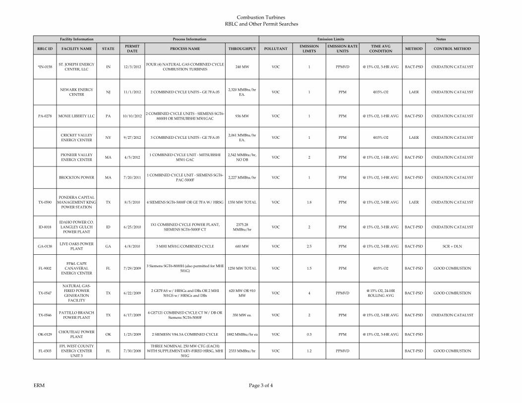
Combustion Turbines
RBLC and Other Permit Searches
RBLC ID FACILITY NAME STATEPERMIT
DATEPROCESS NAME THROUGHPUT POLLUTANT
EMISSION
LIMITS
EMISSION RATE
UNITS
TIME AVG
CONDITIONMETHOD CONTROL METHOD
Facility Information Process Information Emission Limits Notes
*IN-0158ST. JOSEPH ENERGY
CENTER, LLCIN 12/3/2012
FOUR (4) NATURAL GAS COMBINED CYCLE
COMBUSTION TURBINES240 MW VOC 1 PPMVD @ 15% O2, 3-HR AVG BACT-PSD OXIDATION CATALYST
NEWARK ENERGY
CENTERNJ 11/1/2012 2 COMBINED CYCLE UNITS - GE 7FA.05
2,320 MMBtu/hr
EA.VOC 1 PPM @15% O2 LAER OXIDATION CATALYST
PA-0278 MOXIE LIBERTY LLC PA 10/10/20122 COMBINED CYCLE UNITS - SIEMENS SGT6-
8000H OR MITSUBISHI M501GAC936 MW VOC 1 PPM @ 15% O2, 1-HR AVG BACT-PSD OXIDATION CATALYST
CRICKET VALLEY
ENERGY CENTERNY 9/27/2012 3 COMBINED CYCLE UNITS - GE 7FA.05
2,061 MMBtu/hr
EA.VOC 1 PPM @15% O2 LAER OXIDATION CATALYST
PIONEER VALLEY
ENERGY CENTERMA 4/5/2012
1 COMBINED CYCLE UNIT - MITSUBISHI
M501 GAC
2,542 MMBtu/hr,
NO DBVOC 2 PPM @ 15% O2, 1-HR AVG BACT-PSD OXIDATION CATALYST
BROCKTON POWER MA 7/20/20111 COMBINED CYCLE UNIT - SIEMENS SGT6-
PAC-5000F2,227 MMBtu/hr VOC 1 PPM @ 15% O2, 1-HR AVG BACT-PSD OXIDATION CATALYST
TX-0590
PONDERA CAPITAL
MANAGEMENT KING
POWER STATION
TX 8/5/2010 4 SIEMENS SGT6-5000F OR GE 7FA W/ HRSG 1350 MW TOTAL VOC 1.8 PPM @ 15% O2, 3-HR AVG LAER OXIDATION CATALYST
ID-0018
IDAHO POWER CO.
LANGLEY GULCH
POWER PLANT
ID 6/25/20101X1 COMBINED CYCLE POWER PLANT,
SIEMENS SGT6-5000F CT
2375.28
MMBtu/hrVOC 2 PPM @ 15% O2, 3-HR AVG BACT-PSD OXIDATION CATALYST
GA-0138LIVE OAKS POWER
PLANTGA 4/8/2010 3 MHI M501G COMBINED CYCLE 600 MW VOC 2.5 PPM @ 15% O2, 3-HR AVG BACT-PSD SCR + DLN
FL-9002
FP&L CAPE
CANAVERAL
ENERGY CENTER
FL 7/29/20093 Siemens SGT6-8000H (also permitted for MHI
501G)1250 MW TOTAL VOC 1.5 PPM @15% O2 BACT-PSD GOOD COMBUSTION
TX-0547
NATURAL GAS-
FIRED POWER
GENERATION
FACILITY
TX 6/22/20092 GE7FAS w/ HRSGs and DBs OR 2 MHI
501GS w/ HRSGs and DBs
620 MW OR 910
MWVOC 4 PPMVD
@ 15% O2, 24-HR
ROLLING AVGBACT-PSD GOOD COMBUSTION
TX-0546PATTILLO BRANCH
POWER PLANTTX 6/17/2009
4 GE7121 COMBINED CYCLE CT W/ DB OR
Siemens 5GT6-5000F350 MW ea. VOC 2 PPM @ 15% O2, 3-HR AVG BACT-PSD OXIDATION CATALYST
OK-0129CHOUTEAU POWER
PLANTOK 1/23/2009 2 SIEMESN V84.3A COMBINED CYCLE 1882 MMBtu/hr ea VOC 0.3 PPM @ 15% O2, 3-HR AVG BACT‐PSD
FL-0303
FPL WEST COUNTY
ENERGY CENTER
UNIT 3
FL 7/30/2008
THREE NOMINAL 250 MW CTG (EACH)
WITH SUPPLEMENTARY-FIRED HRSG, MHI
501G
2333 MMBtu/hr VOC 1.2 PPMVD BACT-PSD GOOD COMBUSTION
ERM Page 3 of 4
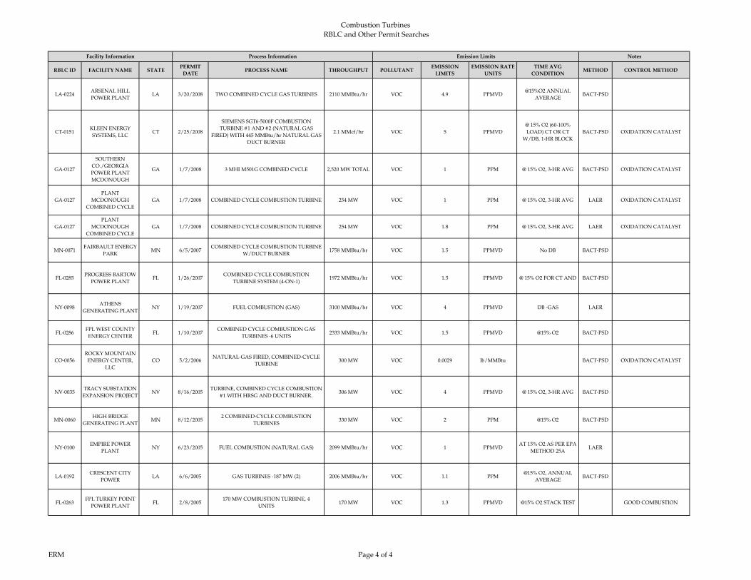
Combustion Turbines
RBLC and Other Permit Searches
RBLC ID FACILITY NAME STATEPERMIT
DATEPROCESS NAME THROUGHPUT POLLUTANT
EMISSION
LIMITS
EMISSION RATE
UNITS
TIME AVG
CONDITIONMETHOD CONTROL METHOD
Facility Information Process Information Emission Limits Notes
LA‐0224ARSENAL HILL
POWER PLANTLA 3/20/2008 TWO COMBINED CYCLE GAS TURBINES 2110 MMBtu/hr VOC 4.9 PPMVD
@15%O2 ANNUAL
AVERAGEBACT‐PSD
CT‐0151KLEEN ENERGY
SYSTEMS, LLCCT 2/25/2008
SIEMENS SGT6‐5000F COMBUSTION
TURBINE #1 AND #2 (NATURAL GAS
FIRED) WITH 445 MMBtu/hr NATURAL GAS
DUCT BURNER
2.1 MMcf/hr VOC 5 PPMVD
@ 15% O2 (60-100%
LOAD) CT OR CT
W/DB, 1‐HR BLOCK
BACT‐PSD OXIDATION CATALYST
GA-0127
SOUTHERN
CO./GEORGIA
POWER PLANT
MCDONOUGH
GA 1/7/2008 3 MHI M501G COMBINED CYCLE 2,520 MW TOTAL VOC 1 PPM @ 15% O2, 3-HR AVG BACT-PSD OXIDATION CATALYST
GA-0127
PLANT
MCDONOUGH
COMBINED CYCLE
GA 1/7/2008 COMBINED CYCLE COMBUSTION TURBINE 254 MW VOC 1 PPM @ 15% O2, 3-HR AVG LAER OXIDATION CATALYST
GA-0127
PLANT
MCDONOUGH
COMBINED CYCLE
GA 1/7/2008 COMBINED CYCLE COMBUSTION TURBINE 254 MW VOC 1.8 PPM @ 15% O2, 3-HR AVG LAER OXIDATION CATALYST
MN‐0071FAIRBAULT ENERGY
PARKMN 6/5/2007
COMBINED CYCLE COMBUSTION TURBINE
W/DUCT BURNER1758 MMBtu/hr VOC 1.5 PPMVD No DB BACT‐PSD
FL‐0285PROGRESS BARTOW
POWER PLANTFL 1/26/2007
COMBINED CYCLE COMBUSTION
TURBINE SYSTEM (4‐ON‐1)1972 MMBtu/hr VOC 1.5 PPMVD @ 15% O2 FOR CT AND BACT‐PSD
NY‐0098ATHENS
GENERATING PLANTNY 1/19/2007 FUEL COMBUSTION (GAS) 3100 MMBtu/hr VOC 4 PPMVD DB ‐GAS LAER
FL‐0286FPL WEST COUNTY
ENERGY CENTERFL 1/10/2007
COMBINED CYCLE COMBUSTION GAS
TURBINES ‐6 UNITS2333 MMBtu/hr VOC 1.5 PPMVD @15% O2 BACT‐PSD
CO‐0056
ROCKY MOUNTAIN
ENERGY CENTER,
LLC
CO 5/2/2006NATURAL‐GAS FIRED, COMBINED‐CYCLE
TURBINE300 MW VOC 0.0029 lb/MMBtu BACT‐PSD OXIDATION CATALYST
NV‐0035TRACY SUBSTATION
EXPANSION PROJECTNV 8/16/2005
TURBINE, COMBINED CYCLE COMBUSTION
#1 WITH HRSG AND DUCT BURNER.306 MW VOC 4 PPMVD @ 15% O2, 3-HR AVG BACT‐PSD
MN‐0060HIGH BRIDGE
GENERATING PLANTMN 8/12/2005
2 COMBINED‐CYCLE COMBUSTION
TURBINES330 MW VOC 2 PPM @15% O2 BACT‐PSD
NY‐0100EMPIRE POWER
PLANTNY 6/23/2005 FUEL COMBUSTION (NATURAL GAS) 2099 MMBtu/hr VOC 1 PPMVD
AT 15% O2 AS PER EPA
METHOD 25ALAER
LA‐0192CRESCENT CITY
POWERLA 6/6/2005 GAS TURBINES ‐187 MW (2) 2006 MMBtu/hr VOC 1.1 PPM
@15% O2, ANNUAL
AVERAGEBACT‐PSD
FL‐0263FPL TURKEY POINT
POWER PLANTFL 2/8/2005
170 MW COMBUSTION TURBINE, 4
UNITS170 MW VOC 1.3 PPMVD @15% O2 STACK TEST GOOD COMBUSTION
ERM Page 4 of 4

Combustion Turbines
RBLC and Other Permit Searches
RBLC ID FACILITY NAME STATE PERMIT DATE PROCESS NAME THROUPGHPUT POLLUTANT EMISSION LIMITEMISSION RATE
UNITSAVERAGING PERIOD METHOD CONTROL METHOD
*TX-0743AUSTIN ENERGY, SAND HILL ENERGY
CENTERTX 9/29/2014
GE 7FA.04 Gross Heat Rate is with
and without duct burner firing and
includes MSS
7943.00 Btu/kWh (HHV,
gross)GHG 930 lb of CO2/MW-hr
365-Day Rolling Average
and Initial Stack TestBACT-PSD None
*NJ-0082 WEST DEPTFORD ENERGY STATION NJ 7/18/2014
427 MW Siemens Combined Cycle
Turbine with duct burner Heat
Input rate of the turbine = 2276
MMbtu/hr (HHV) Heat Input rate
of the Duct burner= 777
MMbtu/hr(HHV)
427 MW GHG 947 lb of CO2e/MW-hr
CONSECUTIVE 12
MONTH (ROLLING 1
MONTH)
BACT-PSDTurbine efficiency and
Use of Natural gas
*TX-0748 FGE POWER, FGE TEXAS PROJECT TX 4/28/2014
Each of four (4) Alstom GT24 CTGs
have an approximate maximum
base-load electric power output of
230.7 MW. The maximum electric
power output from each steam
turbine is approximately 336 MW.
7625.00 Btu/kWh / 409
MMBtu/h4GHG
889
Includes w/ and w/o
DB and MSS
lb of CO2/MW-hr
GROSSBACT PSD
*IA-0107MARSHALLTOWN GENERATING
STATIONIA 4/14/2014
2 SIEMENS SGT6-5000F
COMBINED CYCLE TURBINES
WITHOUT DUCT FIRING
2258 MMBTU/HR GHG 951lb of CO2/MW-hr
GROSS
12-MONTH ROLLING
AVG.BACT-PSD
*MD-0042
OLD DOMINION ELECTRIC
CORPORATION (ODEC) WILDCAT
POINT GENERATING FACILITY
MD 4/8/2014
TWO MITSUBISHI "G" MODEL
COMBUSTION TURBINE
GENERATORS (CTS) COUPLED
WITH A HEAT RECOVERY STEAM
GENERATOR (HRSG) EQUIPPED
WITH DUCT BURNERS
7500.0000 BTU/KWH
(HEAT RATE) AT ALL
TIMES, EXCLUDING
SU/SD
1000 MW
GHG 946 W/ DB lb/MW-hr (AS CO2) 12-MONTH ROLLING BACT-PSD
EXCLUSIVE USE OF
PIPELINE-QUALITY
NATURAL GAS, AND
INSTALLATION OF
HIGH-EFFICIENCY CT
MODEL (MITSUBISHI
"G" MODEL)
*NJ-0082PSEG FOSSIL LLC SEWAREN
GENERATING STATIONNJ 3/7/2014
GE7FA.05 OR Siemens SGT6 5000F,
with two duct burners, two Heat
Recovery Steam Generators (HRSG),
one steam turbine
625 MW GHG 925 W/ DB lb/MW-hr (AS CO2)
CONSECUTIVE 12
MONTHS (ROLLING 1
MONTH )
BACT-PSD
FOOTPRINT POWER SALEM HARBOR
DEVELOPMENT LPMA 1/30/2014
2 COMBINED CYCLE - GE 107F
SERIES 5
7,247 Btu/kW-hr, net)
630 MWGHG 895 lb of CO2e/ net MW-hr 365- Day Rolling BACT- PSD
LA PALOMA ENERGY CENTER TX 11/6/20132 GE 7FA or Siemens SGT6-5000F
combined- cycle unitsGHG
934.5 W/DB (GE 7FA
option) lb CO2/MW-hr (gross) BACT-PSD
CARROLL COUNTY ENERGY OH 11/5/20132 COMBINED CYCLE UNITS - GE
7FA2,045 MMBTU/HR EA. GHG 859
lb CO2/MW-hr (gross)
at ISO ConditionsBACT-PSD
RENAISSANCE POWER LLC MI 11/1/2013 4 COMBINED CYCLE UNITS 2147 MMBTU/HR EA. GHG
1000 lb/MW-hr gross
12-month rolling
average
lb CO2/MW-hr (gross) 12-Month Rolling BACT PSD
*OH-0352 OREGON CLEAN ENERGY CENTER OH 6/18/2013
2 COMBINED CYCLE UNITS -
MITSUBISHI M501GAC OR
SIEMENS SCC6-8000H
800 MW GHGMitsubishi: 840
Siemens: 833 lb/MW-hr gross BACT PSD
State-of-the-art high
efficiency combustion
technology
GREEN ENERGY PARTNERS /
STONEWALLVA 4/30/2013
2 COMBINED CYCLE - GE 7FA.05
OR SIEMENS SGT6-5000F5
2,230 MMBTU/HR EA. (GE)
OR 2,260
MMBTU/HR EA.
(SIEMENS)
GHG
7,780 w/ DB
AND
7,340 w/o DB
HHV Btu/kW-hr gross BACT PSD
NotesFacility Information Process Information Emission Limits
ERM Page 1 of 2
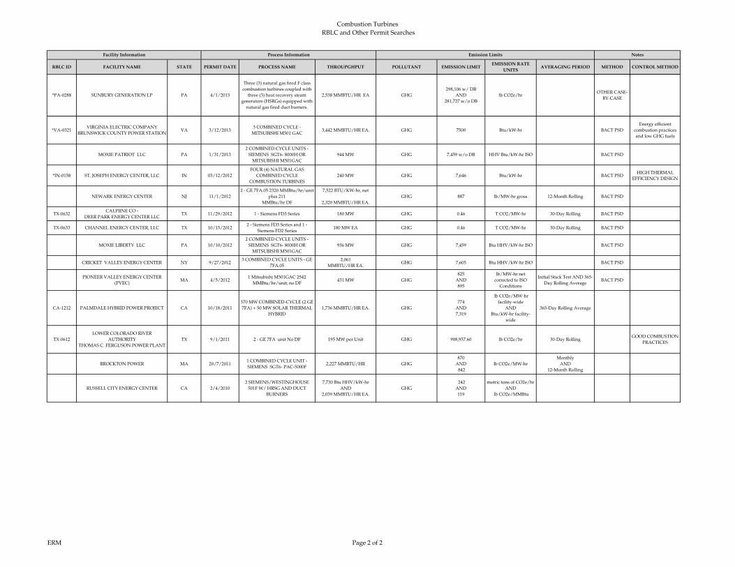
Combustion Turbines
RBLC and Other Permit Searches
RBLC ID FACILITY NAME STATE PERMIT DATE PROCESS NAME THROUPGHPUT POLLUTANT EMISSION LIMITEMISSION RATE
UNITSAVERAGING PERIOD METHOD CONTROL METHOD
NotesFacility Information Process Information Emission Limits
*PA-0288 SUNBURY GENERATION LP PA 4/1/2013
Three (3) natural gas fired F class
combustion turbines coupled with
three (3) heat recovery steam
generators (HSRGs) equipped with
natural gas fired duct burners.
2,538 MMBTU/HR EA GHG
298,106 w/ DB
AND
281,727 w/o DB
lb CO2e/hrOTHER CASE-
BY-CASE
*VA-0321VIRGINIA ELECTRIC COMPANY
BRUNSWICK COUNTY POWER STATIONVA 3/12/2013
3 COMBINED CYCLE -
MITSUBISHI M501 GAC3,442 MMBTU/HR EA. GHG 7500 Btu/kW-hr BACT PSD
Energy efficient
combustion practices
and low GHG fuels
MOXIE PATRIOT LLC PA 1/31/2013
2 COMBINED CYCLE UNITS -
SIEMENS SGT6- 8000H OR
MITSUBISHI M501GAC
944 MW GHG 7,459 w/o DB HHV Btu/kW-hr ISO BACT PSD
*IN-0158 ST. JOSEPH ENERGY CENTER, LLC IN 03/12/2012
FOUR (4) NATURAL GAS
COMBINED CYCLE
COMBUSTION TURBINES
240 MW GHG 7,646 Btu/kW-hr BACT PSDHIGH THERMAL
EFFICIENCY DESIGN
NEWARK ENERGY CENTER NJ 11/1/2012
2 - GE 7FA.05 2320 MMBtu/hr/unit
plus 211
MMBtu/hr DF
7,522 BTU/KW-hr, net
2,320 MMBTU/HR EA.
GHG 887 lb/MW-hr gross 12-Month Rolling BACT PSD
TX-0632CALPIINE CO -
DEER PARK ENERGY CENTER LLCTX 11/29/2012 1 - Siemens FD3 Series 180 MW GHG 0.46 T CO2/MW-hr 30-Day Rolling BACT PSD
TX-0633 CHANNEL ENERGY CENTER, LLC TX 10/15/20122 - Siemens FD3 Series and 1 -
Siemens FD2 Series 180 MW EA GHG 0.46 T CO2/MW-hr 30-Day Rolling BACT PSD
MOXIE LIBERTY LLC PA 10/10/2012
2 COMBINED CYCLE UNITS -
SIEMENS SGT6- 8000H OR
MITSUBISHI M501GAC
936 MW GHG 7,459 Btu HHV/kW-hr ISO BACT PSD
CRICKET VALLEY ENERGY CENTER NY 9/27/20123 COMBINED CYCLE UNITS - GE
7FA.05
2,061
MMBTU/HR EA.GHG 7,605 Btu HHV/kW-hr ISO BACT PSD
PIONEER VALLEY ENERGY CENTER
(PVEC)MA 4/5/2012
1 Mitsubishi M501GAC 2542
MMBtu/hr/unit; no DF431 MW GHG
825
AND
895
lb/MW-hr net
corrected to ISO
Conditions
Initial Stack Test AND 365-
Day Rolling AverageBACT PSD
CA-1212 PALMDALE HYBRID POWER PROJECT CA 10/18/2011
570 MW COMBINED-CYCLE (2 GE
7FA) + 50 MW SOLAR THERMAL
HYBRID
1,736 MMBTU/HR EA. GHG
774
AND
7,319
lb CO2e/MW-hr
facility-wide
AND
Btu/kW-hr facility-
wide
365-Day Rolling Average
TX-0612
LOWER COLORADO RIVER
AUTHORITY
THOMAS C. FERGUSON POWER PLANT
TX 9/1/2011 2 - GE 7FA unit No DF 195 MW per Unit GHG 908,957.60 lb CO2e/hr 30-Day RollingGOOD COMBUSTION
PRACTICES
BROCKTON POWER MA 20/7/20111 COMBINED CYCLE UNIT -
SIEMENS SGT6- PAC-5000F2,227 MMBTU/HR GHG
870
AND
842
lb CO2e/MW-hr
Monthly
AND
12-Month Rolling
RUSSELL CITY ENERGY CENTER CA 2/4/2010
2 SIEMENS/WESTINGHOUSE
501F W/ HRSG AND DUCT
BURNERS
7,730 Btu HHV/kW-hr
AND
2,039 MMBTU/HR EA.
GHG
242
AND
119
metric tons of CO2e/hr
AND
lb CO2e/MMBtu
ERM Page 2 of 2
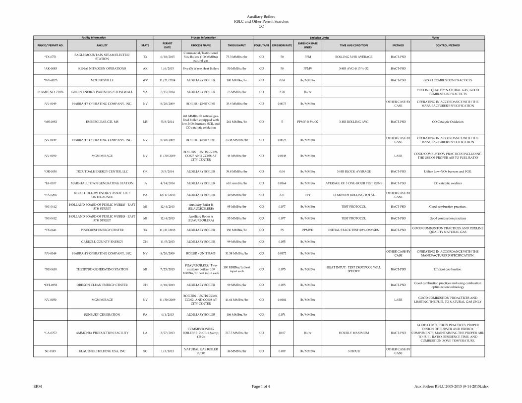
Auxiliary Boilers
RBLC and Other Permit Searches CO
RBLCID/ PERMIT NO. FACILITY STATEPERMIT
DATEPROCESS NAME THROUGHPUT POLLUTANT EMISSION RATE
EMISSION RATE
UNITSTIME AVG CONDITION METHOD CONTROL METHOD
*TX-0751EAGLE MOUNTAIN STEAM ELECTRIC
STATIONTX 6/18/2015
Commercial/Institutional
Size Boilers (100 MMBtu)
natural gas
73.3 MMBtu/hr CO 50 PPM ROLLING 3-HR AVERAGE BACT-PSD
*AK-0083 KENAI NITROGEN OPERATIONS AK 1/6/2015 Five (5) Waste Heat Boilers 50 MMBtu/hr CO 50 PPMV 3-HR AVG @ 15 % O2 BACT-PSD
*WV-0025 MOUNDSVILLE WV 11/21/2014 AUXILIARY BOILER 100 MMBtu/hr CO 0.04 lb/MMBtu BACT-PSD GOOD COMBUSTION PRACTICES
PERMIT NO. 73826 GREEN ENERGY PARTNERS/STONEWALL VA 7/15/2014 AUXILIARY BOILER 75 MMBtu/hr CO 2.78 lb/hrPIPELINE QUALITY NATURAL GAS, GOOD
COMBUSTION PRACTICES
NV-0049 HARRAH'S OPERATING COMPANY, INC. NV 8/20/2009 BOILER - UNIT CP01 35.4 MMBtu/hr CO 0.0073 lb/MMBtuOTHER CASE-BY-
CASE
OPERATING IN ACCORDANCE WITH THE
MANUFACTURER'S SPECIFICATION
*MS-0092 EMBERCLEAR GTL MS MS 5/8/2014
261 MMBtu/h natrual gas-
fired boiler, equipped with
low-NOx burners, SCR, and
CO catalytic oxidation
261 MMBtu/hr CO 5 PPMV @ 3% O2 3-HR ROLLING AVG BACT-PSD CO Catalytic Oxidation
NV-0049 HARRAH'S OPERATING COMPANY, INC. NV 8/20/2009 BOILER - UNIT CP03 33.48 MMBtu/hr CO 0.0075 lb/MMBtuOTHER CASE-BY-
CASE
OPERATING IN ACCORDANCE WITH THE
MANUFACTURER'S SPECIFICATION
NV-0050 MGM MIRAGE NV 11/30/2009
BOILERS - UNITS CC026,
CC027 AND CC028 AT
CITY CENTER
44 MMBtu/hr CO 0.0148 lb/MMBtu LAERGOOD COMBUSTION PRACTICES INCLUDING
THE USE OF PROPER AIR TO FUEL RATIO
*OR-0050 TROUTDALE ENERGY CENTER, LLC OR 3/5/2014 AUXILIARY BOILER 39.8 MMBtu/hr CO 0.04 lb/MMBtu 3-HR BLOCK AVERAGE BACT-PSD Utilize Low-NOx burners and FGR.
*IA-0107 MARSHALLTOWN GENERATING STATION IA 4/14/2014 AUXILIARY BOILER 60.1 mmBtu/hr CO 0.0164 lb/MMBtu AVERAGE OF 3 ONE-HOUR TEST RUNS BACT-PSD CO catalytic oxidizer
*PA-0296BERKS HOLLOW ENERGY ASSOC LLC/
ONTELAUNEEPA 12/17/2013 AUXILIARY BOILER 40 MMBtu/hr CO 3.31 TPY 12-MONTH ROLLING TOTAL
OTHER CASE-BY-
CASE
*MI-0412HOLLAND BOARD OF PUBLIC WORKS - EAST
5TH STREETMI 12/4/2013
Auxiliary Boiler B
(EUAUXBOILERB)95 MMBtu/hr CO 0.077 lb/MMBtu TEST PROTOCOL BACT-PSD Good combustion practices.
*MI-0412HOLLAND BOARD OF PUBLIC WORKS - EAST
5TH STREETMI 12/4/2013
Auxiliary Boiler A
(EUAUXBOILERA)55 MMBtu/hr CO 0.077 lb/MMBtu TEST PROTOCOL BACT-PSD Good combustion practices
*TX-0641 PINECREST ENERGY CENTER TX 11/21/2013 AUXILIARY BOILER 150 MMBtu/hr CO 75 PPMVD INITIAL STACK TEST @3% OXYGEN BACT-PSDGOOD COMBUSITON PRACTICES AND PIPELINE
QUALITY NATURAL GAS
CARROLL COUNTY ENERGY OH 11/5/2013 AUXILIARY BOILER 99 MMBtu/hr CO 0.055 lb/MMBtu
NV-0049 HARRAH'S OPERATING COMPANY, INC. NV 8/20/2009 BOILER - UNIT BA03 31.38 MMBtu/hr CO 0.0172 lb/MMBtuOTHER CASE-BY-
CASE
OPERATING IN ACCORDANCE WITH THE
MANUFACTURER'S SPECIFICATION.
*MI-0410 THETFORD GENERATING STATION MI 7/25/2013
FGAUXBOILERS: Two
auxiliary boilers; 100
MMBtu/hr heat input each
100 MMBtu/hr heat
input eachCO 0.075 lb/MMBtu
HEAT INPUT. TEST PROTOCOL WILL
SPECIFYBACT-PSD Efficient combustion.
*OH-0352 OREGON CLEAN ENERGY CENTER OH 6/18/2013 AUXILIARY BOILER 99 MMBtu/hr CO 0.055 lb/MMBtu BACT-PSDGood combustion practices and using combustion
optimization technology
NV-0050 MGM MIRAGE NV 11/30/2009
BOILERS - UNITS CC001,
CC002, AND CC003 AT
CITY CENTER
41.64 MMBtu/hr CO 0.0184 lb/MMBtu LAERGOOD COMBUSTION PROACTICES AND
LIMITING THE FUEL TO NATURAL GAS ONLY
SUNBURY GENERATION PA 4/1/2013 AUXILIARY BOILER 106 MMBtu/hr CO 0.074 lb/MMBtu
*LA-0272 AMMONIA PRODUCTION FACILITY LA 3/27/2013
COMMISSIONING
BOILERS 1; 2 (CB-1 &
CB-2)
217.5 MMBtu/hr CO 10.87 lb/hr HOURLY MAXIMUM BACT-PSD
GOOD COMBUSTION PRACTICES: PROPER
DESIGN OF BURNER AND FIREBOX
COMPONENTS; MAINTAINING THE PROPER AIR-
TO-FUEL RATIO, RESIDENCE TIME, AND
COMBUSTION ZONE TEMPERATURE.
SC-0149 KLAUSNER HOLDING USA, INC SC 1/3/2013NATURAL GAS BOILER
EU00346 MMBtu/hr CO 0.039 lb/MMBtu 3-HOUR
OTHER CASE-BY-
CASE
Facility Information Process Information Emission Limits Notes
ERM Page 1 of 4 Aux Boilers RBLC 2005-2015 (9-14-2015).xlsx

Auxiliary Boilers
RBLC and Other Permit Searches CO
RBLCID/ PERMIT NO. FACILITY STATEPERMIT
DATEPROCESS NAME THROUGHPUT POLLUTANT EMISSION RATE
EMISSION RATE
UNITSTIME AVG CONDITION METHOD CONTROL METHOD
Facility Information Process Information Emission Limits Notes
SC-0149 KLAUSNER HOLDING USA, INC SC 1/3/2013NATURAL GAS BOILER
EU00446 MMBtu/hr CO 0.039 lb/MMBtu 3-HOUR
OTHER CASE-BY-
CASE
SC-0149 KLAUSNER HOLDING USA, INC SC 1/3/2013NATURAL GAS BOILER
EU00546 MMBtu/hr CO 0.039 lb/MMBtu 3-HOUR
OTHER CASE-BY-
CASE
SC-0149 KLAUSNER HOLDING USA, INC SC 1/3/2013NATURAL GAS BOILER
EU00646 MMBtu/hr CO 0.039 lb/MMBtu 3-HOUR
OTHER CASE-BY-
CASE
*IN-0158 ST. JOSEPH ENEGRY CENTER, LLC IN 12/3/2012TWO (2) NATURAL GAS
AUXILIARY BOILERS80 MMBtu/hr CO 0.083 lb/MMBtu 3 HOURS BACT-PSD GOOD COMBUTSTION PRACTICES
NJ-0080 HESS NEWARK ENERGY CENTER NJ 11/1/2012Boiler less than 100
MMBtu/hr51.9 mmcubic ft/year CO 2.45 lb/hr AVERAGE OF THREE TESTS BACT-PSD Use of natural gas a clean fuel
*MD-0041 CPV ST. CHARLES MD 4/23/2014 AUXILLARY BOILER 93 MMBtu/hr CO 0.02 lb/MMBtu 3-HOUR AVERAGE BLOCK BACT-PSD GOOD COMBUSTION PRACTICES
FL-0335 SUWANNEE MILL FL 9/5/2012Four(4) Natural Gas Boilers -
46 MMBtu/hour46 MMBtu/hr CO 0.039 lb/MMBtu BACT-PSD Good Combustion Practice
NJ-0079 WOODBRIDGE ENERGY CENTER NJ 7/25/2012
Commercial/Institutional
size boilers less than 100
MMBtu/hr
2000 hours/year CO 3.44 lb/hr AVERAGE OF THREE TESTS BACT-PSD Use of natural gas and good combustion practices
*OH-0350 REPUBLIC STEEL OH 7/18/2012 Steam Boiler 65 MMBtu/hr CO 0.04 lb/MMBtu BACT-PSD Proper burner design and good combustion practices
FOOTPRINT POWER SALEM HARBOR MA 1/30/2014 AUXILIARY BOILER 80 MMBtu/hr CO 0.035 lb/MMBtu OXIDATION CATALYST
SC-0113 PYRAMAX CERAMICS, LLC SC 2/8/2012 BOILERS 5 MMBtu/hr CO 0 BACT-PSD
GOOD COMBUSTION PRACTICES.
CONSUMPTION OF NATURAL GAS AND
PROPANE.
CA-1212 PALMDALE HYBRID POWER PROJECT CA 10/18/2011 AUXILIARY BOILER 110 MMBtu/hr CO 500 PPMVD 3-HR AVG @3% O2 BACT-PSD
LA-0254NINEMILE POINT ELECTRIC GENERATING
PLANTLA 8/16/2011 AUXILIARY BOILER 338 MMBtu/hrR CO 84 lb/MMscf ANNUAL BACT-PSD
USE OF PIPELINE QUALITY NATURAL GAS AND
GOOD COMBUSTION PRACTICES
BROCTON POWER MA 7/20/2011 AUXILIARY BOILER 60 MMBtu/hr CO 0.08 lb/MMBtu
CA-1192 AVENAL ENERGY PROJECT CA 6/21/2011 AUXILIARY BOILER 37.4 MMBtu/hr CO 50 PPMVD 3-HR AVG, @3% O2 BACT-PSD
ULTRA LOW NOX BURNER, USE PUC QUALITY
NATURAL GAS, OPERATIONAL RESTRICTION OF
46, 675 MMBtu/yr
CA-1185 SANTA BARBARA AIRPORT CA 6/7/2011 Boiler, Forced Dratf 3 MMBtu/hr CO 100 PPMVD 40 MINUTES @ 3% O2OTHER CASE-BY-
CASEForced draft, full modulation, flue gas recirculation
LA-0240 FLOPAM INC. LA 6/14/2010 Boilers 25.1 MMBtu/hr CO 0.93 LB/H HOURLY MAXIMUM BACT-PSDGood equipment design and proper combustion
practices
CA-1191 VICTORVILLE 2 HYBRID POWER PROJECT CA 3/11/2010 AUXILIARY HEATER 40 MMBtu/hr CO 50 PPMVD 1-HR AVG, @3% O2 BACT-PSD OPERATIONAL RESTRICTION OF 1000 HR/YR
CA-1191 VICTORVILLE 2 HYBRID POWER PROJECT CA 3/11/2010 AUXILIARY BOILER 35 MMBtu/hr CO 50 PPMVD 1-HR AVG, @3% O2 BACT-PSD OPERATIONAL RESTRICTION OF 500 HR/YR
*MD-0042 WILDCAT POINT GENERATION FACILITY MD 4/8/2014 AUXILLARY BOILER 45 MMBtu/hr CO 0.036 lb/MMBtu 3-HOUR BLOCK AVERAGE BACT-PSD
EXCLUSIVE USE OF PIPELINE QUALITY
NATURAL GAS AND GOOD COMBUSTION
PRACTICES
RENAISSANCE POWER MI 11/1/2013 AUXILIARY BOILER 40 MMBtu/hr CO 0.036 lb/MMBtu
*PA-0291 HICKORY RUN ENERGY STATION PA 4/23/2013 AUXILIARY BOILER 40 MMBtu/hr CO 0.036 lb/MMBtuOTHER CASE-BY-
CASE
NV-0044 HARRAH'S OPERATING COMPANY, INC. NV 1/4/2007COMMERCIAL/INSTITUTI
ONAL-SIZE BOILERS35.4 MMBtu/hr CO 0.036 lb/MMBtu BACT-PSD GOOD COMBUSTION DESIGN
NY-0095 CAITHNES BELLPORT ENERGY CENTER NY 5/10/2006 AUXILIARY BOILER 29.4 MMBtu/hr CO 0.036 lb/MMBtu BACT-PSD GOOD COMBUSTION PRACTICES
OH-0310AMERICAN MUNICIPAL POWER
GENERATING STATIONOH 10/8/2009 AUXILIARY BOILER 150 MMBtu/hr CO 12.6 lb/hr BACT-PSD
ERM Page 2 of 4 Aux Boilers RBLC 2005-2015 (9-14-2015).xlsx
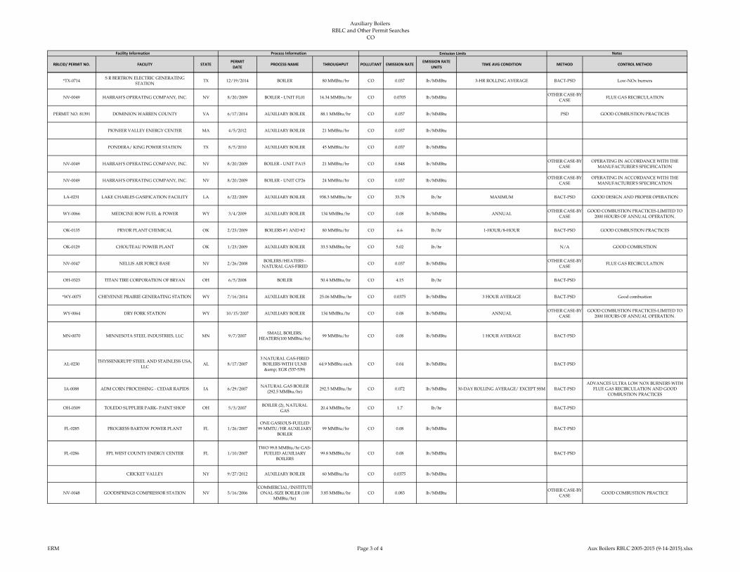
Auxiliary Boilers
RBLC and Other Permit Searches CO
RBLCID/ PERMIT NO. FACILITY STATEPERMIT
DATEPROCESS NAME THROUGHPUT POLLUTANT EMISSION RATE
EMISSION RATE
UNITSTIME AVG CONDITION METHOD CONTROL METHOD
Facility Information Process Information Emission Limits Notes
*TX-0714S R BERTRON ELECTRIC GENERATING
STATIONTX 12/19/2014 BOILER 80 MMBtu/hr CO 0.037 lb/MMBtu 3-HR ROLLING AVERAGE BACT-PSD Low-NOx burners
NV-0049 HARRAH'S OPERATING COMPANY, INC. NV 8/20/2009 BOILER - UNIT FL01 14.34 MMBtu/hr CO 0.0705 lb/MMBtuOTHER CASE-BY-
CASEFLUE GAS RECIRCULATION
PERMIT NO. 81391 DOMINION WARREN COUNTY VA 6/17/2014 AUXILIARY BOILER 88.1 MMBtu/hr CO 0.037 lb/MMBtu PSD GOOD COMBUSTION PRACTICES
PIONEER VALLEY ENERGY CENTER MA 4/5/2012 AUXILIARY BOILER 21 MMBtu/hr CO 0.037 lb/MMBtu
PONDERA/ KING POWER STATION TX 8/5/2010 AUXILIARY BOILER 45 MMBtu/hr CO 0.037 lb/MMBtu
NV-0049 HARRAH'S OPERATING COMPANY, INC. NV 8/20/2009 BOILER - UNIT PA15 21 MMBtu/hr CO 0.848 lb/MMBtuOTHER CASE-BY-
CASE
OPERATING IN ACCORDANCE WITH THE
MANUFACTURER'S SPECIFICATION
NV-0049 HARRAH'S OPERATING COMPANY, INC. NV 8/20/2009 BOILER - UNIT CP26 24 MMBtu/hr CO 0.037 lb/MMBtuOTHER CASE-BY-
CASE
OPERATING IN ACCORDANCE WITH THE
MANUFACTURER'S SPECIFICATION
LA-0231 LAKE CHARLES GASIFICATION FACILITY LA 6/22/2009 AUXILIARY BOILER 938.3 MMBtu/hr CO 33.78 lb/hr MAXIMUM BACT-PSD GOOD DESIGN AND PROPER OPERATION
WY-0066 MEDICINE BOW FUEL & POWER WY 3/4/2009 AUXILIARY BOILER 134 MMBtu/hr CO 0.08 lb/MMBtu ANNUALOTHER CASE-BY-
CASE
GOOD COMBUSTION PRACTICES-LIMITED TO
2000 HOURS OF ANNUAL OPERATION.
OK-0135 PRYOR PLANT CHEMICAL OK 2/23/2009 BOILERS #1 AND #2 80 MMBtu/hr CO 6.6 lb/hr 1-HOUR/8-HOUR BACT-PSD GOOD COMBUSTION PRACTICES
OK-0129 CHOUTEAU POWER PLANT OK 1/23/2009 AUXILIARY BOILER 33.5 MMBtu/hr CO 5.02 lb/hr N/A GOOD COMBUSTION
NV-0047 NELLIS AIR FORCE BASE NV 2/26/2008BOILERS/HEATERS -
NATURAL GAS-FIREDCO 0.037 lb/MMBtu
OTHER CASE-BY-
CASEFLUE GAS RECIRCULATION
OH-0323 TITAN TIRE CORPORATION OF BRYAN OH 6/5/2008 BOILER 50.4 MMBtu/hr CO 4.15 lb/hr BACT-PSD
*WY-0075 CHEYENNE PRAIRIE GENERATING STATION WY 7/16/2014 AUXILIARY BOILER 25.06 MMBtu/hr CO 0.0375 lb/MMBtu 3 HOUR AVERAGE BACT-PSD Good combustion
WY-0064 DRY FORK STATION WY 10/15/2007 AUXILIARY BOILER 134 MMBtu/hr CO 0.08 lb/MMBtu ANNUALOTHER CASE-BY-
CASE
GOOD COMBUSTION PRACTICES-LIMITED TO
2000 HOURS OF ANNUAL OPERATION.
MN-0070 MINNESOTA STEEL INDUSTRIES, LLC MN 9/7/2007SMALL BOILERS;
HEATERS(100 MMBtu/hr)99 MMBtu/hr CO 0.08 lb/MMBtu 1 HOUR AVERAGE BACT-PSD
AL-0230THYSSENKRUPP STEEL AND STAINLESS USA,
LLCAL 8/17/2007
3 NATURAL GAS-FIRED
BOILERS WITH ULNB
& EGR (537-539)
64.9 MMBtu each CO 0.04 lb/MMBtu BACT-PSD
IA-0088 ADM CORN PROCESSING - CEDAR RAPIDS IA 6/29/2007NATURAL GAS BOILER
(292.5 MMBtu/hr)292.5 MMBtu/hr CO 0.072 lb/MMBtu 30-DAY ROLLING AVERAGE/ EXCEPT SSM BACT-PSD
ADVANCES ULTRA LOW NOX BURNERS WITH
FLUE GAS RECIRCULATION AND GOOD
COMBUSTION PRACTICES
OH-0309 TOLEDO SUPPLIER PARK- PAINT SHOP OH 5/3/2007BOILER (2), NATURAL
GAS20.4 MMBtu/hr CO 1.7 lb/hr BACT-PSD
FL-0285 PROGRESS BARTOW POWER PLANT FL 1/26/2007
ONE GASEOUS-FUELED
99 MMTU/HR AUXILIARY
BOILER
99 MMBtu/hr CO 0.08 lb/MMBtu BACT-PSD
FL-0286 FPL WEST COUNTY ENERGY CENTER FL 1/10/2007
TWO 99.8 MMBtu/hr GAS-
FUELED AUXILIARY
BOILERS
99.8 MMBtu/hr CO 0.08 lb/MMBtu BACT-PSD
CRICKET VALLEY NY 9/27/2012 AUXILIARY BOILER 60 MMBtu/hr CO 0.0375 lb/MMBtu
NV-0048 GOODSPRINGS COMPRESSOR STATION NV 5/16/2006
COMMERCIAL/INSTITUTI
ONAL-SIZE BOILER (100
MMBtu/hr)
3.85 MMBtu/hr CO 0.083 lb/MMBtuOTHER CASE-BY-
CASEGOOD COMBUSTION PRACTICE
ERM Page 3 of 4 Aux Boilers RBLC 2005-2015 (9-14-2015).xlsx
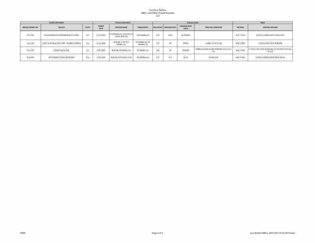
Auxiliary Boilers
RBLC and Other Permit Searches CO
RBLCID/ PERMIT NO. FACILITY STATEPERMIT
DATEPROCESS NAME THROUGHPUT POLLUTANT EMISSION RATE
EMISSION RATE
UNITSTIME AVG CONDITION METHOD CONTROL METHOD
Facility Information Process Information Emission Limits Notes
NV-0046 GOODSPRINGS COMPRESSOR STATION NV 5/16/2006COMMERCIAL/INSTITUTI
ONAL BOILER3.85 MMBtu/hr CO 0.083 lb/MMBtu BACT-PSD GOOD COMBUSTION PRACTICE
CA-1128 COTTAGE HEALTH CARE - PUEBLO STREET CA 5/16/2006BOILER: 5 TO 33.5
MMBtu/hr
25 MMBtu/hr (75
MMBtu/hrCO 50 PPMV 6-MIN AV @ 3% O2 BACT-PSD ULTRA-LOW NOX BURNER
CA-1127 GENENTECH, INC. CA 9/27/2005 BOILER: 50 MMBtu/hr 97 MMBtu/hr CO 50 PPMVDTHREE 30-MIN SAMP PERIODS AVG @ 3%
O2BACT-PSD
ULTRA LOW NOX BURNERS: NATCOM P-97-LOG-
35-2127
WA-0301 BP CHERRY POINT REFINERY WA 4/20/2005 BOILER, NATURAL GAS 363 MMBtu/hr CO 18.1 lb/hr 24 HR AVE BACT-PSD GOOD COMBUSTION PRACTICES
ERM Page 4 of 4 Aux Boilers RBLC 2005-2015 (9-14-2015).xlsx

Auxiliary Boilers
RBLC and Other Permit Searches GHG
RBLCID FACILITY STATEPERMIT
DATEPROCESS NAME THROUGHPUT
POLLUTA
NT
EMISSION
RATE
EMISSION RATE
UNITSTIME AVG CONDITION METHOD CONTROL METHOD
*AK-0083 KENAI NITROGEN OPERATIONS AK 1/6/2015 Five (5) Waste Heat Boilers 50 MMBtu/hrr CO2e 59.6 TONS/MMCF 3-HR AVG BACT-PSD
*WV-0025 MOUNDSVILLE WV 11/21/2014 AUXILIARY BOILER 100 CO2e 12,081 lb/hr BACT-PSD
*WY-0075 CHEYENNE PRAIRIE GENERATING STATION WY 7/16/2014 AUXILIARY BOILER 25.06 MMBtu/hr CO2e 12,855 TONS 12 MONTH ROLLING BACT-PSD Good combustion practices and energy efficiency
*IA-0107 MARSHALLTOWN GENERATING STATION IA 4/14/2014 AUXILIARY BOILER 60.1 MMBtu/hrr CO2e 17,313 TPY 12-MONTH ROLLING TOTAL BACT-PSD
*OR-0050 TROUTDALE ENERGY CENTER, LLC OR 3/5/2014 AUXILIARY BOILER 39.8 MMBtu/hrr CO2e 117 lb CO2/MMBtu 3-HR BLOCK AVERAGE BACT-PSD Clean fuels
*PA-0296BERKS HOLLOW ENERGY ASSOC LLC/
ONTELAUNEEPA 12/17/2013 AUXILIARY BOILER 40 MMBtu/hrr CO2e 12,346 TPY
OTHER CASE-BY-
CASE
*MI-0412HOLLAND BOARD OF PUBLIC WORKS - EAST
5TH STREETMI 12/4/2013
Auxiliary Boiler B
(EUAUXBOILERB)95 MMBtu/hrr CO2e 49,251 TPY 12-MO ROLLING TIME PERIOD BACT-PSD
*MI-0412HOLLAND BOARD OF PUBLIC WORKS - EAST
5TH STREETMI 12/4/2013
Auxiliary Boiler A
(EUAUXBOILERA)55 MMBtu/hr CO2e 28,514 TPY 12-MO ROLLING TIME PERIOD BACT-PSD
*MI-0410 THETFORD GENERATING STATION MI 7/25/2013
FGAUXBOILERS: Two
auxiliary boilers; 100
MMBtu/hr heat input each
100 MMBtu/hr heat
input eachCO2e 24,304 TPY 12-MO ROLL TIME PERIOD EACH MONTH BACT-PSD Efficient combustion; energy efficiency.
*OH-0352 OREGON CLEAN ENERGY CENTER OH 6/18/2013 AUXILIARY BOILER 99 MMBtu/hr CO2e 11,671 TPY PER ROLLING 12-MONTHS BACT-PSD
*LA-0272 AMMONIA PRODUCTION FACILITY LA 3/27/2013COMMISSIONING
BOILERS 1; 2 (CB-1; CB-2)217.5 MMBtu/hr CO2e 55,986 TPY ANNUAL MAXIMUM BACT-PSD
Energy efficiency measures: use of economizers and boiler
insulation; improved combustion measures (i.e., tuning,
optimization, and instrumentation); and minimization of
air infiltration.
*VA-0321 BRUNSWICK COUNTY POWER VA 3/12/2013 AUXILIARY BOILER 66.7 MMBtu/hr CO2e 117 lb/MMBtu BACT-PSD
*IN-0158 ST. JOSEPH ENEGRY CENTER, LLC IN 12/3/2012TWO (2) NATURAL GAS
AUXILIARY BOILERS80 MMBtu/hr CO2e 81,996 TONS 12 CONSECUTIVE MONTH PERIOD BACT-PSD
OPERATION AND MAINTENANCE PRACTICES;
COMBUSTION TURNING; OXYGEN TRIM CONTROLS
& ANALYZERS; ECONOMIZER; ENERGY EFFICIENT
REFRACTORY; CONDENSATE RETURN SYSTEM,
INSULATE STEAM AND HOT LINES.
IA-0105 IOWA FERTILIZER COMPANY IA 10/26/2012 AUXILIARY BOILER 472.4 MMBtu/hr CO2e 51,748 TPY ROLLING 12 MONTH TOTAL BACT-PSD Good combustion practices
Facility Information Process Information Emission Limits Notes
ERM Page 1 of 1 Aux Boilers RBLC 2005-2015 (9-14-2015).xlsx

Auxiliary Boilers
RBLC and Other Permit Searches H2SO4
RBLCID FACILITY STATEPERMIT
DATEPROCESS NAME THROUGHPUT
POLLUTA
NT
EMISSION
RATE
EMISSION RATE
UNITSTIME AVG CONDITION METHOD CONTROL METHOD
*MD-0041 CPV ST. CHARLES MD 4/23/2014 AUXILLARY BOILER 93 MMBtu/hr H2SO4 0.0001 lb/MMBtu 3-HR AVERAGE BACT-PSD
*IA-0107 MARSHALLTOWN GENERATING STATION IA 4/14/2014 AUXILLARY BOILER 60.1 MMBtu/hr H2SO4 0.0055 lb/hr AVERAGE OF 3 ONE-HOUR TEST RUNS BACT-PSD
*MD-0042 WILDCAT POINT GENERATION FACILITY MD 4/8/2014 AUXILLARY BOILER 45 MMBtu/hr H2SO4 0.004 lb/MMBtu 3-HOUR BLOCK AVERAGE BACT-PSDEXCLUSIVE USE OF PIPELINE QUALITY NATURAL
GAS
*PA-0296BERKS HOLLOW ENERGY ASSOC LLC/
ONTELAUNEEPA 12/17/2013 AUXILLARY BOILER 40 MMBtu/hr H2SO4 0.04 TPY BASED ON 12-MONTH ROLLING TOTAL
*OH-0352 OREGON CLEAN ENERGY CENTER OH 6/18/2013 AUXILLARY BOILER 99 MMBtu/H H2SO4 0.011 lb/hr BACT-PSD only burning natural gas 0.5 GR/100 SCF
*PA-0291 HICKORY RUN ENERGY STATION PA 4/23/2013 AUXILIARY BOILER 40 MMBtu/hr H2SO4 0.0005 lb/MMBtuOTHER CASE-BY-
CASE
*VA-0321 BRUNSWICK COUNTY POWER VA 3/12/2013 AUXILIARY BOILER 66.7 MMBtu/hr H2SO4 0.0086 lb/MMBtu BACT-PSD
Facility Information Process Information Emission Limits Notes
ERM Page 1 of 1 Aux Boilers RBLC 2005-2015 (9-14-2015).xlsx

Auxiliary Boilers
RBLC and Other Permit Searches NOx
RBLCID/ PERMIT
NO.FACILITY STATE
PERMIT
DATEPROCESS NAME THROUGHPUT
POLLUTA
NT
EMISSION
RATE
EMISSION RATE
UNITSTIME AVG CONDITION METHOD CONTROL METHOD
*TX-0751EAGLE MOUNTAIN STEAM ELECTRIC
STATIONTX 6/18/2015
Commercial/Institutional
Size Boilers (100 MMBtu)
natural gas
73.3 MMBtu/hr NOx 0.01 MMBtu/hr ROLLING 3-HR AVERAGE LAER Good combustion practices
*AK-0083 KENAI NITROGEN OPERATIONS AK 1/6/2015 Five (5) Waste Heat Boilers 50 MMBtu/hr NOx 7 PPMV 3-HR AVG @ 15 % O2 BACT-PSD
*TX-0714S R BERTRON ELECTRIC GENERATING
STATIONTX 12/19/2014 Boiler 80 MMBtu/hr NOx 0.036 lb/MMBtu 3-HR ROLLING AVERAGE BACT-PSD Utilize Low-NOx burners and FGR.
*WV-0025 MOUNDSVILLE WV 11/21/2014 AUXILIARY BOILER 100 NOx 2 lb/hr BACT-PSDUltra Low-NOx Burners, Flue-Gas Recirculation, & Good
Combustion Practices
*WY-0075 CHEYENNE PRAIRIE GENERATING STATION WY 7/16/2014 Auxiliary Boiler 25.06 MMBtu/h NOx 0.0175 lb/MMBtu 3 HOUR AVERAGE BACT-PSD Ultra low NOx burners and flue gas recirculation
PERMIT NO. 73826 GREEN ENERGY PARTNERS/STONEWALL VA 7/15/2014 AUXILIARY BOILER 75 MMBtu/hr NOx 0.011 lb/MMBtu
PERMIT NO. 81391 DOMINION WARREN COUNTY VA 6/17/2014 AUXILIARY BOILER 88.1 MMBtu/hr NOx 0.011 lb/MMBtu
*TX-0713TENASKA BROWNSVILLE GENERATING
STATIONTX 4/29/2014 BOILER 90 MMBtu/hr NOx 9 PPMVD @15% O2 BACT-PSD ultra low-NOx burners, limited use
*MD-0041 CPV ST. CHARLES MD 4/23/2014 AUXILLARY BOILER 93 MMBtu/hr NOx 0.11 lb/MMBtu 3-HOUR AVERAGE BLOCK LAER
EXCLUSIVE USE OF NATURAL GAS, ULTRA LOW-
NOX BURNERS, AND FLUE GAS RECIRCULATION
(FGR)
*IA-0107 MARSHALLTOWN GENERATING STATION IA 4/14/2014 AUXILLARY BOILER 60.1 mmBtu/hr NOx 0.013 lb/MMBtu AVERAGE OF 3 ONE-HOUR TEST RUNS BACT-PSD
*MD-0042 WILDCAT POINT GENERATION FACILITY MD 4/8/2014 AUXILLARY BOILER 45 MMBtu/hr NOx 0.01 lb/MMBtu 3-HOUR BLOCK AVERAGE LAEREXCLUSIVE USE OF PIPELINE QUALITY NATURAL
GAS AND GOOD COMBUSTION PRACTICES
*OR-0050 TROUTDALE ENERGY CENTER, LLC OR 3/5/2014 AUXILLARY BOILER 39.8 MMBtu/hr NOx 0.035 lb/MMBtu 3-HR BLOCK AVERAGE BACT-PSD Utilize Low-NOx burners and FGR.
FOOTPRINT POWER SALEM HARBOR MA 1/30/2014 AUXILIARY BOILER 80 MMBtu/hr NOx 0.011 lb/MMBtu
*PA-0296BERKS HOLLOW ENERGY ASSOC LLC/
ONTELAUNEEPA 12/17/2013 AUXILLARY BOILER 40 MMBtu/hr NOx 1.01 T/YR 12-MONTH ROLLING TOTAL
OTHER CASE-BY-
CASE
*MI-0412HOLLAND BOARD OF PUBLIC WORKS - EAST
5TH STREETMI 12/4/2013
Auxiliary Boiler B
(EUAUXBOILERB)95 MMBtu/hr NOx 0.05 lb/MMBtu TEST PROTOCOL BACT-PSD
Dry low NOx burners, flue gas recirculation and good
combustion practices.
*MI-0412HOLLAND BOARD OF PUBLIC WORKS - EAST
5TH STREETMI 12/4/2013
Auxiliary Boiler A
(EUAUXBOILERA)55 MMBtu/hr NOx 0.05 lb/MMBtu TEST PROTOCOL BACT-PSD Low NOx burners and good combustion practices
*TX-0641 PINECREST ENERGY CENTER TX 11/21/2013 AUXILIARY BOILER 150 MMBtu/hr NOx 16 PPMVD INITIAL STACK TEST, 3% OXYGEN BACT-PSD Low NOx burners
CARROLL COUNTY ENERGY OH 11/5/2013 AUXILIARY BOILER 99 MMBtu/hr NOx 0.02 lb/MMBtu
RENAISSANCE POWER MI 11/1/2013 AUXILIARY BOILER 40 MMBtu/jhr NOx 0.035 lb/MMBtu
*MI-0410 THETFORD GENERATING STATION MI 7/25/2013
FGAUXBOILERS: Two
auxiliary boilers; 100
MMBtu/hr heat input each
100 MMBtu/hr heat
input eachNOx 0.05 lb/MMBtu
HEAT INPUT. TEST PROTOCOL WILL
SPECIFYBACT-PSD Low NOx burners and flue gas recirculation.
*OH-0352 OREGON CLEAN ENERGY CENTER OH 6/18/2013 AUXILIARY BOILER 99 MMBtu/hr NOx 1.98 lb/hr BACT-PSD Low NOx burners and flue gas recirculation
*PA-0291 HICKORY RUN ENERGY STATION PA 4/23/2013 AUXILIARY BOILER 40 MMBtu/hr NOx 0.011 lb/MMBtuOTHER CASE-BY-
CASE
SUNBURY GENERATION PA 4/1/2013 AUXILIARY BOILER 106 MMBtu/hr NOx 0.036 lb/MMBtu
*LA-0272 AMMONIA PRODUCTION FACILITY LA 3/27/2013COMMISSIONING
BOILERS 1; 2 (CB-1; CB-2)217.5 MMBtu/hr NOx 11.92 lb/hr HOURLY MAXIMUM BACT-PSD
FLUE GAS RECIRCULATION, LOW NOX BURNERS,
AND GOOD COMBUSTION PRACTICES (I.E., PROPER
DESIGN OF BURNER AND FIREBOX COMPONENTS;
MAINTAINING THE PROPER AIR-TO-FUEL RATIO,
RESIDENCE TIME, AND COMBUSTION ZONE
TEMPERATURE).
Facility Information Process Information Emission Limits Notes
ERM Page 1 of 4 Aux Boilers RBLC 2005-2015 (9-14-2015).xlsx
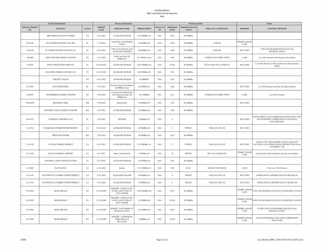
Auxiliary Boilers
RBLC and Other Permit Searches NOx
RBLCID/ PERMIT
NO.FACILITY STATE
PERMIT
DATEPROCESS NAME THROUGHPUT
POLLUTA
NT
EMISSION
RATE
EMISSION RATE
UNITSTIME AVG CONDITION METHOD CONTROL METHOD
Facility Information Process Information Emission Limits Notes
BRUNSWICK COUNTY POWER VA 3/12/2013 AUXILIARY BOILER 66.7 MMBtu/hr NOx 0.011 lb/MMBtu
SC-0149 KLAUSNER HOLDING USA, INC SC 1/3/2013NATURAL GAS BOILER
EU00446 MMBtu/hr NOx 0.036 lb/MMBtu 3-HOUR
OTHER CASE-BY-
CASE
*IN-0158 ST. JOSEPH ENEGRY CENTER, LLC IN 12/3/2012TWO (2) NATURAL GAS
AUXILIARY BOILERS80 MMBtu/hr NOx 0.032 lb/MMBtu 3 HOURS BACT-PSD
LOW NOX BURNER WITH FLUE GAS
RECIRCULATION
NJ-0080 HESS NEWARK ENERGY CENTER NJ 11/1/2012Boiler less than 100
MMBtu/hr51.9 MMscf/year NOx 0.05 lb/MMBtu AVERAGE OF THREE TESTS LAER Low NOx burners and flue gas recirculation
IA-0105 IOWA FERTILIZER COMPANY IA 10/26/2012 AUXILIARY BOILER 472.4 MMBtu/hr NOx 0.0125 lb/MMBtu 30 DAY ROLLING AVERAGE BACT-PSDLow NOx Burners (LNB) and Flue Gas Recirculation
(FGR)
CHANNEL ENERGY CENTER, LLC TX 10/15/2012 AUXILIARY BOILER 430 MMBtu/hr NOx 0.05 lb/MMBtu
CRICKET VALLEY NY 9/27/2012 AUXILIARY BOILER 60 MMBTU NOx 0.011 lb/MMBtu
FL-0335 SUWANNEE MILL FL 9/5/2012Four(4) Natural Gas Boilers -
46 MMBtu/hour46 MMBtu/hr NOx 0.036 lb/MMBtu BACT-PSD Low NOx Burner and Flue Gas Recirculation
NJ-0079 WOODBRIDGE ENERGY CENTER NJ 7/25/2012
Commercial/Institutional
size boilers less than 100
MMBtu/hr
91.6 MMBtu NOx 0.01 lb/MMBtu AVERAGE OF THREE TESTS LAER Low NOx burners
*OH-0350 REPUBLIC STEEL OH 7/18/2012 Steam Boiler 65 MMBtu/H NOx 0.07 lb/MMBtu BACT-PSD
PIONEER VALLEY ENERGY CENTER MA 4/5/2012 AUXILIARY BOILER 21 MMBtu/hr NOx 0.029 lb/MMBtu
SC-0113 PYRAMAX CERAMICS, LLC SC 2/8/2012 BOILERS 5 MMBtu/hr NOx 0 BACT-PSD
GOOD DESIGN AND COMBUSTION PRACTICES, LOW
NOX BURNERS, COMBUSTION OF NATURAL
GAS/PROPANE.
CA-1212 PALMDALE HYBRID POWER PROJECT CA 10/18/2011 AUXILIARY BOILER 110 MMBtu/hr NOx 9 PPMVD 3-HR AVG @3% O2 BACT-PSD
BROCTON POWER MA 7/20/2011 AUXILIARY BOILER 60 MMBtu/hr NOx 0.011 lb/MMBtu
CA-1192 AVENAL ENERGY PROJECT CA 6/21/2011 AUXILIARY BOILER 37.4 MMBtu/hr NOx 9 PPMVD 3-HR AVG @3% O2 BACT-PSD
ULTRA LOW NOX BURNER, USE PUC QUALITY
NATURAL GAS, OPERATIONAL RESTRICTION OF 46,
675 MMBTU/YR
CA-1185 SANTA BARBARA AIRPORT CA 6/7/2011 Boiler, Forced Dratf 3 MMBtu/hr NOx 12 PPMVD @3% O2, 40 MINUTESOTHER CASE-BY-
CASEForced draft, full modulation, flue gas recirculation
PONDERA/ KING POWER STATION TX 8/5/2010 AUXILIARY BOILER 45 MMBtu/hr NOx 0.01 lb/MMBtu
LA-0240 FLOPAM INC. LA 6/14/2010 Boilers 25.1 MMBtu/hr NOx 0.38 lb/hr HOURLY MAXIMUM LAER Ultra Low NOx Burners
CA-1191 VICTORVILLE 2 HYBRID POWER PROJECT CA 3/11/2010 AUXILIARY HEATER 40 MMBtu/hr NOx 9 PPMVD 1-HR AVG @3% O2 BACT-PSD OPERATIONAL RESTRICTION OF 1000 HR/YR
CA-1191 VICTORVILLE 2 HYBRID POWER PROJECT CA 3/11/2010 AUXILIARY BOILER 35 MMBtu/hr NOx 9 PPMVD 1-HR AVG @3% O2 BACT-PSD OPERATIONAL RESTRICTION OF 500 HR/YR
NV-0050 MGM MIRAGE NV 11/30/2009
BOILERS - UNITS CC001,
CC002, AND CC003 AT
CITY CENTER
41.64 MMBtu/hr NOx 0.011 lb/MMBtuOTHER CASE-BY-
CASELOW NOX BURNER AND FLUE GAS RECIRCULATION
NV-0050 MGM MIRAGE NV 11/30/2009
BOILERS - UNITS CC004,
CC005, AND CC006 AT
CITY CENTER
4.2 MMBtu/hr NOx 0.0143 lb/MMBtuOTHER CASE-BY-
CASELOW-NOX BURNER AND FLUE GAS RECIRCULATION
NV-0050 MGM MIRAGE NV 11/30/2009BOILER - UNIT MB090 AT
MANDALAY BAY4.3 MMBtu/hr NOx 0.014 lb/MMBtu
OTHER CASE-BY-
CASE
ULTRA-LOW NOX BURNER AND FLUE GAS
RECIRCULATION
NV-0050 MGM MIRAGE NV 11/30/2009
BOILERS - UNITS BE102
THRU BE105 AT
BELLAGIO
2 MMBtu/hr NOx 0.0123 lb/MMBtuOTHER CASE-BY-
CASE
LOW-NOX BURNER AND GOOD COMBUSTION
PRACTICES
ERM Page 2 of 4 Aux Boilers RBLC 2005-2015 (9-14-2015).xlsx
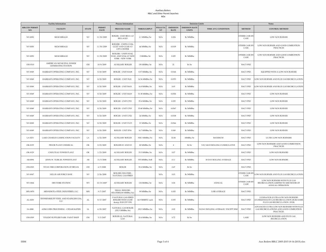
Auxiliary Boilers
RBLC and Other Permit Searches NOx
RBLCID/ PERMIT
NO.FACILITY STATE
PERMIT
DATEPROCESS NAME THROUGHPUT
POLLUTA
NT
EMISSION
RATE
EMISSION RATE
UNITSTIME AVG CONDITION METHOD CONTROL METHOD
Facility Information Process Information Emission Limits Notes
NV-0050 MGM MIRAGE NV 11/30/2009BOILER - UNIT BE111 AT
BELLAGIO2.1 MMBtu/hr NOx 0.024 lb/MMBtu
OTHER CASE-BY-
CASELOW NOX BURNER
NV-0050 MGM MIRAGE NV 11/30/2009
BOILERS - UNITS CC026,
CC027 AND CC028 AT
CITY CENTER
44 MMBtu/hr NOx 0.0109 lb/MMBtuOTHER CASE-BY-
CASE
LOW NOX BURNER AND GOOD COMBUSTION
PRACTICES
NV-0050 MGM MIRAGE NV 11/30/2009
BOILERS - UNITS NY42,
NY43, AND NY44 AT NEW
YORK - NEW YORK
2 MMBtu/hr NOx 0.025 lb/MMBtuOTHER CASE-BY-
CASE
LOW NOX BURNER AND GOOD COMBUSTION
PRACTICES
OH-0310AMERICAN MUNICIPAL POWER
GENERATING STATIONOH 10/8/2009 AUXILIARY BOILER 150 MMBtu/hr NOx 21 lb/hr BACT-PSD
NV-0049 HARRAH'S OPERATING COMPANY, INC. NV 8/20/2009 BOILER - UNIT HA08 8.37 MMBtu/hr NOx 0.0146 lb/MMBtu BACT-PSD EQUIPPED WITH A LOW-NOX BURNER
NV-0049 HARRAH'S OPERATING COMPANY, INC. NV 8/20/2009 BOILER - UNIT FL01 14.34 MMBtu/hr NOx 0.0353 lb/MMBtu BACT-PSD LOW NOX BURNER AND FLUE GAS RECIRCULATION
NV-0049 HARRAH'S OPERATING COMPANY, INC. NV 8/20/2009 BOILER - UNIT BA01 16.8 MMBtu/hr NOx 0.03 lb/MMBtu BACT-PSD LOW-NOX BURNER AND BLUE GAS RECIRCULATION
NV-0049 HARRAH'S OPERATING COMPANY, INC. NV 8/20/2009 BOILER - UNIT BA03 31.38 MMBtu/hr NOx 0.0306 lb/MMBtu BACT-PSD LOW-NOX BURNER
NV-0049 HARRAH'S OPERATING COMPANY, INC. NV 8/20/2009 BOILER - UNIT CP01 35.4 MMBtu/hr NOx 0.035 lb/MMBtu BACT-PSD LOW NOX BURNER
NV-0049 HARRAH'S OPERATING COMPANY, INC. NV 8/20/2009 BOILER - UNIT CP03 33.48 MMBtu/hr NOx 0.0367 lb/MMBtu BACT-PSD LOW NOX BURNER
NV-0049 HARRAH'S OPERATING COMPANY, INC. NV 8/20/2009 BOILER - UNIT CP26 24 MMBtu/hr NOx 0.0108 lb/MMBtu BACT-PSD LOW NOX BURNER
NV-0049 HARRAH'S OPERATING COMPANY, INC. NV 8/20/2009 BOILER - UNIT PA15 21 MMBtu/hr NOx 0.0366 lb/MMBtu BACT-PSD LOW NOX BURNER
NV-0049 HARRAH'S OPERATING COMPANY, INC. NV 8/20/2009 BOILER - UNIT IP04 16.7 MMBtu/hr NOx 0.049 lb/MMBtu BACT-PSD LOW NOX BURNER
LA-0231 LAKE CHARLES GASIFICATION FACILITY LA 6/22/2009 AUXILIARY BOILER 938.3 MMBtu/hr NOx 32.84 MMBtu/hr MAXIMUM BACT-PSD ULTRA LOW NOX BURNERS
OK-0135 PRYOR PLANT CHEMICAL OK 2/23/2009 BOILERS #1 AND #2 80 MMBtu/hr NOx 4 lb/hr 3-H/168-H ROLLING CUMMULATIVE BACT-PSDLOW-NOX BURNERS AND GOOD COMBUSTION
PRACTICES
OK-0129 CHOUTEAU POWER PLANT OK 1/23/2009 AUXILIARY BOILER 33.5 MMBtu/hr NOx 0.07 lb/MMBtu BACT-PSD LOW-NOX BURNERS
AR-0094 JOHN W. TURK JR. POWER PLANT AR 11/5/2008 AUXILIARY BOILER 555 MMBtu/hrR NOx 0.11 lb/MMBtu 30 DAY ROLLING AVERAGE BACT-PSD LOW NOX BURNERS
OH-0323 TITAN TIRE CORPORATION OF BRYAN OH 6/5/2008 BOILER 50.4 MMBtu/hr NOx 2.47 lb/hr BACT-PSD
NV-0047 NELLIS AIR FORCE BASE NV 2/26/2008BOILERS/HEATERS -
NATURAL GAS-FIREDNOx 0.03 lb/MMBtu
OTHER CASE-BY-
CASELOW-NOX BURNER AND FLUE GAS RECIRCULATION
WY-0064 DRY FORK STATION WY 10/15/2007 AUXILIARY BOILER 134 MMBtu/hr NOx 0.04 lb/MMBtu ANNUALOTHER CASE-BY-
CASE
LOW NOX BURNERS WITH FLUE GAS
RECIRCULATION-LIMITED TO 2000 HOURS OF
ANNUAL OPERATION
MN-0070 MINNESOTA STEEL INDUSTRIES, LLC MN 9/7/2007SMALL BOILERS;
HEATERS(100 MMBtu/hr)99 MMBtu/hr NOx 0.035 lb/MMBtu 3-HR AVERAGE BACT-PSD
AL-0230THYSSENKRUPP STEEL AND STAINLESS USA,
LLCAL 8/17/2007
3 NATURAL GAS-FIRED
BOILERS WITH ULNB
& EGR (537-539)
64.9 MMBTU each NOx 0.035 lb/MMBtu BACT-PSD
ULNB & EGR (ULTRA-LOW NOX BURNERS
(ULNB)(EXHAUST GAS RECIRCULATION (EGR) SAME
FLUE GAS RECIRCULATION (FGR)
IA-0088 ADM CORN PROCESSING - CEDAR RAPIDS IA 6/29/2007NATURAL GAS BOILER
(292.5 MMBtu/hr)292.5 MMBtu/hr NOx 0.02 lb/MMBtu 30-DAY ROLLING AVERAGE/ EXCEPT SSM BACT-PSD
ADVANCED ULTRA LOW NOX BURNERS WITH FLUE
GAS RECIRCULATIONS AND GOOD COMBUSTION
PRACTICES.
OH-0309 TOLEDO SUPPLIER PARK- PAINT SHOP OH 5/3/2007BOILER (2), NATURAL
GAS20.4 MMBtu/hr NOx 0.72 lb/hr LAER
LOW NOX BURNERS AND FLUE GAS
RECIRCULATION
ERM Page 3 of 4 Aux Boilers RBLC 2005-2015 (9-14-2015).xlsx
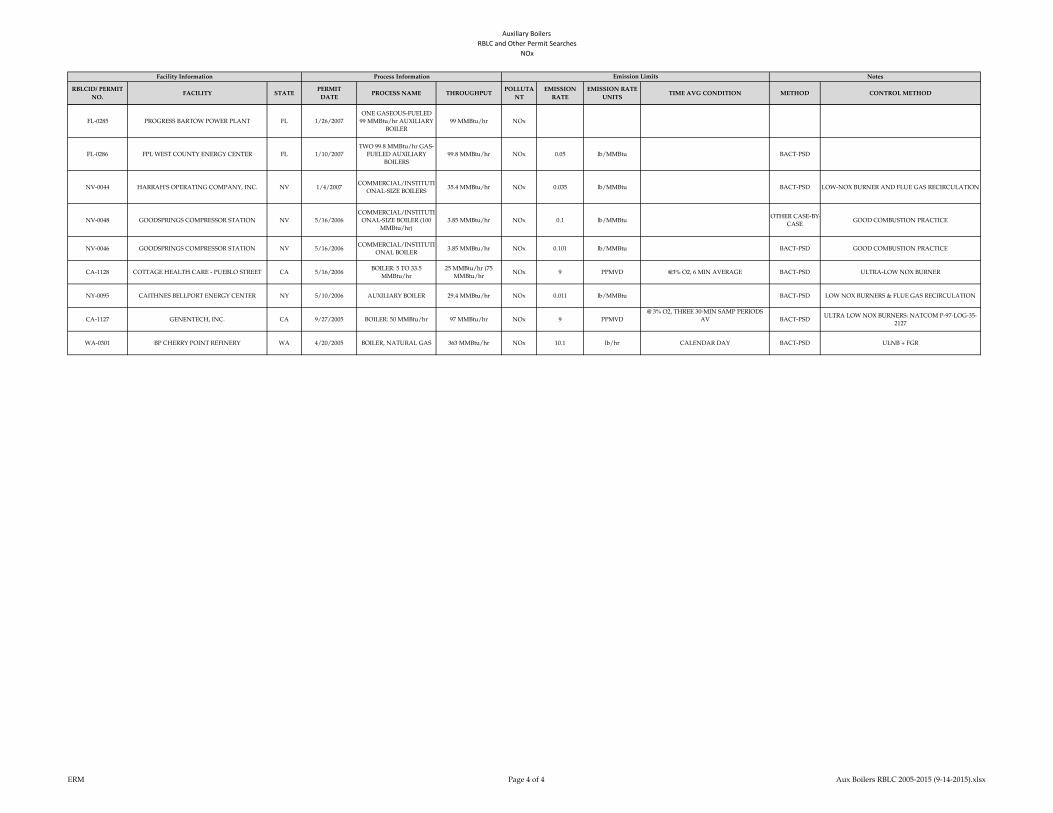
Auxiliary Boilers
RBLC and Other Permit Searches NOx
RBLCID/ PERMIT
NO.FACILITY STATE
PERMIT
DATEPROCESS NAME THROUGHPUT
POLLUTA
NT
EMISSION
RATE
EMISSION RATE
UNITSTIME AVG CONDITION METHOD CONTROL METHOD
Facility Information Process Information Emission Limits Notes
FL-0285 PROGRESS BARTOW POWER PLANT FL 1/26/2007
ONE GASEOUS-FUELED
99 MMBtu/hr AUXILIARY
BOILER
99 MMBtu/hr NOx
FL-0286 FPL WEST COUNTY ENERGY CENTER FL 1/10/2007
TWO 99.8 MMBtu/hr GAS-
FUELED AUXILIARY
BOILERS
99.8 MMBtu/hr NOx 0.05 lb/MMBtu BACT-PSD
NV-0044 HARRAH'S OPERATING COMPANY, INC. NV 1/4/2007COMMERCIAL/INSTITUTI
ONAL-SIZE BOILERS35.4 MMBtu/hr NOx 0.035 lb/MMBtu BACT-PSD LOW-NOX BURNER AND FLUE GAS RECIRCULATION
NV-0048 GOODSPRINGS COMPRESSOR STATION NV 5/16/2006
COMMERCIAL/INSTITUTI
ONAL-SIZE BOILER (100
MMBtu/hr)
3.85 MMBtu/hr NOx 0.1 lb/MMBtuOTHER CASE-BY-
CASEGOOD COMBUSTION PRACTICE
NV-0046 GOODSPRINGS COMPRESSOR STATION NV 5/16/2006COMMERCIAL/INSTITUTI
ONAL BOILER3.85 MMBtu/hr NOx 0.101 lb/MMBtu BACT-PSD GOOD COMBUSTION PRACTICE
CA-1128 COTTAGE HEALTH CARE - PUEBLO STREET CA 5/16/2006BOILER: 5 TO 33.5
MMBtu/hr
25 MMBtu/hr (75
MMBtu/hrNOx 9 PPMVD @3% O2, 6 MIN AVERAGE BACT-PSD ULTRA-LOW NOX BURNER
NY-0095 CAITHNES BELLPORT ENERGY CENTER NY 5/10/2006 AUXILIARY BOILER 29.4 MMBtu/hr NOx 0.011 lb/MMBtu BACT-PSD LOW NOX BURNERS & FLUE GAS RECIRCULATION
CA-1127 GENENTECH, INC. CA 9/27/2005 BOILER: 50 MMBtu/hr 97 MMBtu/hr NOx 9 PPMVD
@ 3% O2, THREE 30-MIN SAMP PERIODS
AV BACT-PSDULTRA LOW NOX BURNERS: NATCOM P-97-LOG-35-
2127
WA-0301 BP CHERRY POINT REFINERY WA 4/20/2005 BOILER, NATURAL GAS 363 MMBtu/hr NOx 10.1 lb/hr CALENDAR DAY BACT-PSD ULNB + FGR
ERM Page 4 of 4 Aux Boilers RBLC 2005-2015 (9-14-2015).xlsx

Auxiliary Boilers
RBLC and Other Permit Searches PM
RBLCID FACILITY STATEPERMIT
DATEPROCESS NAME THROUGHPUT POLLUTANT
EMISSION
RATE
EMISSION RATE
UNITSTIME AVG CONDITION METHOD CONTROL METHOD
*MI-0412HOLLAND BOARD OF PUBLIC WORKS -
EAST 5TH STREETMI 12/4/2013
Auxiliary Boiler B
(EUAUXBOILERB)95 MMBtu/hr
PM,
FILTERABLE0.0018 lb/MMBtu TEST PROTOCOL BACT-PSD Good combustion practices
*WV-0025 MOUNDSVILLE WV 11/21/2014 AUXILIARY BOILER 100 PM 0.5 lb/hr BACT-PSD Use of Natural Gas & Good Combustion Practices
*WY-0075CHEYENNE PRAIRIE GENERATING
STATIONWY 7/16/2014 Auxiliary Boiler 25.06 MMBtu/hr PM 0.0175 lb/MMBtu 3 HOUR AVERAGE BACT-PSD good combustion practices
PERMIT NO. 81391 DOMINION WARREN COUNTY VA 6/17/2014 AUXILIARY BOILER 88.1 MMBtu/hr PM 0.24 lb/hrr
*MS-0092 EMBERCLEAR GTL MS MS 5/8/2014
261 MMBtu/hr natrual gas-
fired boiler, equipped with
low-NOx burners, SCR,
and CO catalytic oxidation
261 MMBtu/hr PM 1.31 lb/hr 3-HR AVERAGE BACT-PSD
*MI-0412HOLLAND BOARD OF PUBLIC WORKS -
EAST 5TH STREETMI 12/4/2013
Auxiliary Boiler A
(EUAUXBOILERA)55 MMBtu/hr
PM,
FILTERABLE0.0018 lb/MMBtu TEST PROTOCOL BACT-PSD Good combustion practices
*MI-0410 THETFORD GENERATING STATION MI 7/25/2013
FGAUXBOILERS: Two
auxiliary boilers; 100
MMBtu/hr heat input each
100 MMBtu/hr heat
input each
PM,
FILTERABLE0.0018 lb/MMBtu
HEAT INPUT; TEST PROTOCOL WILL
SPECIFYBACT-PSD Efficient combustion; natural gas fuel.
SC-0149 KLAUSNER HOLDING USA, INC SC 1/3/2013NATURAL GAS BOILER
EU00446 MMBtu/hr
PM,
FILTERABLE0.002 lb/MMBtu 3-HOUR
OTHER CASE-
BY-CASE
*PA-0296BERKS HOLLOW ENERGY ASSOC LLC/
ONTELAUNEEPA 12/17/2013 Auxiliary Boiler 40 MMBtu/hr PM 0.46 TPY BASED ON 12-MONTH ROLLING TOTAL
OTHER CASE-
BY-CASE
MN-0070 MINNESOTA STEEL INDUSTRIES, LLC MN 9/7/2007SMALL BOILERS;
HEATERS(100 MMBtu/hr)99 MMBtu/hr PM 0.0025 GR/DSCF 3 HOUR AVERAGE BACT-PSD
NY-0095 CAITHNES BELLPORT ENERGY CENTER NY 5/10/2006 AUXILIARY BOILER 29.4 MMBtu/hr PM 0.0033 lb/MMBtu BACT-PSD LOW SULFUR FUEL
*TX-0641 PINECREST ENERGY CENTER TX 11/21/2013 AUXILIARY BOILER 150 MMBtu/hr PM 1.14 lb/hr BACT-PSD
CARROLL COUNTY ENERGY OH 11/5/2013 AUXILIARY BOILER 99 MMBtu/hr PM 0.008 lb/MMBtu
RENAISSANCE POWER MI 11/1/2013 AUXILIARY BOILER 40 MMBtu/hr PM 0.005 lb/MMBtu
CA-1192 AVENAL ENERGY PROJECT CA 6/21/2011 AUXILIARY BOILER 37.4 MMBtu/hr PM 0.0034 GR/DSCF BACT-PSDUSE PUC QUALITY NATURAL GAS, OPERATIONAL
LIMIT OF 46,675 MMBTU/YR
*MD-0041 CPV ST. CHARLES MD 4/23/2014 AUXILLARY BOILER 93 MMBtu/hr PM 0.005 lb/MMBtu 3-HOUR AVERAGE BACT-PSDUSE OF PIPELINE QUALITY NATURAL GAS AND
GOOD COMBUSTION PRACTICES
*PA-0291 HICKORY RUN ENERGY STATION PA 4/23/2013 AUXILIARY BOILER 40 MMBtu/hr PM 0.005 lb/MMBtuOTHER CASE-
BY-CASE
SC-0149 KLAUSNER HOLDING USA, INC SC 1/3/2013NATURAL GAS BOILER
EU00446 MMBtu/hr PM 0.005 lb/MMBtu 3-HOUR
OTHER CASE-
BY-CASE
*LA-0272 AMMONIA PRODUCTION FACILITY LA 3/27/2013COMMISSIONING
BOILERS 1; 2 (CB-1; CB-2)217.5 MMBtu/hr PM 1.94 lb/hr HOURLY MAXIMUM BACT-PSD
GOOD COMBUSTION PRACTICES: PROPER DESIGN
OF BURNER AND FIREBOX COMPONENTS;
MAINTAINING THE PROPER AIR-TO-FUEL RATIO,
*MI-0412HOLLAND BOARD OF PUBLIC WORKS -
EAST 5TH STREETMI 12/4/2013
Auxiliary Boiler B
(EUAUXBOILERB)95 MMBtu/hr PM 0.007 lb/MMBtu TEST PROTOCOL BACT-PSD Good combustion practices
*MI-0412HOLLAND BOARD OF PUBLIC WORKS -
EAST 5TH STREETMI 12/4/2013
Auxiliary Boiler A
(EUAUXBOILERA)55 MMBtu/hr PM 0.007 lb/MMBtu TEST PROTOCOL BACT-PSD Good combustion practices
NJ-0080 HESS NEWARK ENERGY CENTER NJ 11/1/2012Boiler less than 100
MMBtu/hr51.9 MMscf/year
PM,
FILTERABLE0.22 lb/hr AVERAGE OF THREE TESTS N/A use of natural gas a clean fuel
NJ-0080 HESS NEWARK ENERGY CENTER NJ 11/1/2012Boiler less than 100
MMBtu/hr51.9 MMscf/year PM 0.33 lb/hr AVERAGE OF THREE TESTS BACT-PSD use of natural gas a clean fuel
*MI-0410 THETFORD GENERATING STATION MI 7/25/2013
FGAUXBOILERS: Two
auxiliary boilers; 100
MMBtu/hr heat input each
100 MMBtu/hr heat
input eachPM 0.007 lb/MMBtu
HEAT INPUT; TEST PROTOCOL SPECIFY
AVGBACT-PSD Efficient combustion; natural gas fuel.
CHANNEL ENERGY CENTER, LLC TX 10/15/2012 AUXILIARY BOILER 430 MMBtu/hr PM 7.8 lb/hr per unit
Facility Information Process Information Emission Limits Notes
ERM Page 1 of 3 Aux Boilers RBLC 2005-2015 (9-14-2015).xlsx

Auxiliary Boilers
RBLC and Other Permit Searches PM
RBLCID FACILITY STATEPERMIT
DATEPROCESS NAME THROUGHPUT POLLUTANT
EMISSION
RATE
EMISSION RATE
UNITSTIME AVG CONDITION METHOD CONTROL METHOD
Facility Information Process Information Emission Limits Notes
CRICKET VALLEY NY 9/27/2012 AUXILIARY BOILER 60 MMBtu PM 0.005 lb/MMBtu
FL-0335 SUWANNEE MILL FL 9/5/2012Four(4) Natural Gas
Boilers - 46 MMBtu/hrour46 MMBtu/hr PM 2 GR OF S/100 SCF BACT-PSD Good Combustion Practice
NJ-0079 WOODBRIDGE ENERGY CENTER NJ 7/25/2012
Commercial/Institutional
size boilers less than 100
MMBtu/hr
2000 hours/yearPM,
FILTERABLE0.17 lb/hr AVERAGE OF THREE TESTS
OTHER CASE-
BY-CASEUse of Natural gas
NJ-0079 WOODBRIDGE ENERGY CENTER NJ 7/25/2012
Commercial/Institutional
size boilers less than 100
MMBtu/hr
2000 hours/year PM 0.46 lb/hr AVERAGE OF THREE TESTSOTHER CASE-
BY-CASEUse of Natural gas
PIONEER VALLEY ENERGY CENTER MA 4/5/2012 AUXILIARY BOILER 21 MMBtu/hr PM 0.0048 lb/MMBtu
CA-1212 PALMDALE HYBRID POWER PROJECT CA 10/18/2011 AUXILIARY BOILER 110 MMBtu/hr PM 0.8 lb/hr BACT-PSD USE PUC QUALITY NATURAL GAS
LA-0254NINEMILE POINT ELECTRIC GENERATING
PLANTLA 8/16/2011 AUXULIARY BOILER 338 MMBtu/hr PM 7.6 lb/MMscf ANNUAL AVERAGE BACT-PSD
USE OF PIPELINE QUALITY NATURAL GAS AND
GOOD COMBUSTION PRACTICES
*VA-0321 BRUNSWICK COUNTY POWER VA 3/12/2013 AUXILIARY BOILER 66.7 MMBtu/hr PM 0.007 lb/MMBtu BACT-PSD Low sulfur/carbon fuel and good combustion practices
PONDERA/ KING POWER STATION TX 8/5/2010 AUXILIARY BOILER 45 MMBtu/hr PM 0.32 lb/hr per unit
LA-0240 FLOPAM INC. LA 6/14/2010 Boilers 25.1 MMBtu/hr PM-10 0.1 lb/hr HOURLY MAXIMUM BACT-PSDGood equipment design and proper combustion
practices,
LA-0240 FLOPAM INC. LA 6/14/2010 Boilers 25.1 MMBtu/hr PM 0.13 lb/hr HOURLY MAXIMUM BACT-PSDGood equipment design and proper combustion
practices,
CA-1191 VICTORVILLE 2 HYBRID POWER PROJECT CA 3/11/2010 AUXILIARY HEATER 40 MMBtu/hr PM 0.2GRAINS PER 100
DSCFBACT-PSD
OPERATIONAL RESTRICTION OF 500 HR/YR, USE
PUC QUALITY NATURAL GAS
CA-1191 VICTORVILLE 2 HYBRID POWER PROJECT CA 3/11/2010 AUXILIARY BOILER 35 MMBtu/hr PM 0.2GRAINS PER 100
DSCFBACT-PSD
OPERATIONAL RESTRICTION OF 500 HR/YR, USE
PUC QUALITY NATURAL GAS
*AK-0083 KENAI NITROGEN OPERATIONS AK 1/6/2015 Five (5) Waste Heat Boilers 50 MMBtu/hrr PM 0.0074 lb/MMBtu 3-HR AVG BACT-PSD
*MD-0042 WILDCAT POINT GENERATION FACILITY MD 4/8/2014 AUXILLARY BOILER 45 MMBtu/hr PM 0.0075 lb/MMBtu 3-HOUR BLOCK AVERAGE BACT-PSDEXCLUSIVE USE OF PIPELINE QUALITY NATURAL
GAS AND GOOD COMBUSTION PRACTICES
*IN-0158 ST. JOSEPH ENEGRY CENTER, LLC IN 12/3/2012TWO (2) NATURAL GAS
AUXILIARY BOILERS80 MMBtu/hr PM 0.0075 lb/MMBtu 3 HOURS BACT-PSD
GOOD COMBUSTION PRACTICES AND FUEL
SPECIFICATIONS
NV-0050 MGM MIRAGE NV 11/30/2009
BOILERS - UNITS CC026,
CC027 AND CC028 AT
CITY CENTER
44 MMBtu/hr PM 0.0075 lb/MMBtu LAERLIMITING THE FUEL TO NATURAL GAS ONLY
AND GOOD COMBUSTION PRACTICES
OH-0310AMERICAN MUNICIPAL POWER
GENERATING STATIONOH 10/8/2009 AUXILIARY BOILER 150 MMBtu/hr PM 1.14 lb/hr BACT-PSD
NV-0049 HARRAH'S OPERATING COMPANY, INC. NV 8/20/2009 BOILER - UNIT CP03 33.48 MMBtu/hr PM 0.0075 lb/MMBtuOTHER CASE-
BY-CASE
OPERATING IN ACCORDANCE WITH THE
MANUFACTURER'S SPECIFICATION
NV-0049 HARRAH'S OPERATING COMPANY, INC. NV 8/20/2009 BOILER - UNIT CP26 24 MMBtu/hr PM 0.0075 lb/MMBtuOTHER CASE-
BY-CASE
OPERATING IN ACCORDANCE WITH THE
MANUFACTURER'S SPECIFICATION
NV-0044 HARRAH'S OPERATING COMPANY, INC. NV 1/4/2007COMMERCIAL/INSTITU
TIONAL-SIZE BOILERS35.4 MMBtu/hr PM 0.0075 lb/MMBtu BACT-PSD USE OF NATURAL GAS AS THE ONLY FUEL
NV-0049 HARRAH'S OPERATING COMPANY, INC. NV 8/20/2009 BOILER - UNIT BA03 31.38 MMBtu/hr PM 0.0076 lb/MMBtuOTHER CASE-
BY-CASE
OPERATING IN ACCORDANCE WITH THE
MANUFACTURER'S SPECIFICATION
NV-0049 HARRAH'S OPERATING COMPANY, INC. NV 8/20/2009 BOILER - UNIT CP01 35.4 MMBtu/hr PM 0.0076 lb/MMBtuOTHER CASE-
BY-CASE
OPERATING IN ACCORDANCE WITH THE
MANUFACTURER'S SPECIFICATION
NV-0049 HARRAH'S OPERATING COMPANY, INC. NV 8/20/2009 BOILER - UNIT PA15 21 MMBtu/hr PM 0.0076 lb/MMBtu BACT-PSDOPERATING IN ACCORDANCE WITH THE
MANUFACTURER'S SPECIFICATION
AL-0230THYSSENKRUPP STEEL AND STAINLESS
USA, LLCAL 8/17/2007
3 NATURAL GAS-FIRED
BOILERS WITH ULNB;
EGR (537-539)
64.9 MMBtu each PM 0.0076 lb/MMBtu BACT-PSD
ERM Page 2 of 3 Aux Boilers RBLC 2005-2015 (9-14-2015).xlsx
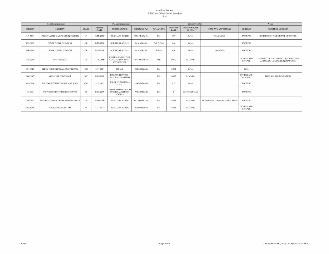
Auxiliary Boilers
RBLC and Other Permit Searches PM
RBLCID FACILITY STATEPERMIT
DATEPROCESS NAME THROUGHPUT POLLUTANT
EMISSION
RATE
EMISSION RATE
UNITSTIME AVG CONDITION METHOD CONTROL METHOD
Facility Information Process Information Emission Limits Notes
LA-0231 LAKE CHARLES GASIFICATION FACILITY LA 6/22/2009 AUXILIARY BOILER 938.3 MMBtu/hr PM 6.99 lb/hr MAXIMUM BACT-PSD GOOD DESIGN AND PROPER OPERATION
PM, TOT PRYOR PLANT CHEMICAL OK 2/23/2009 BOILERS #1 AND #2 80 MMBtu/hr PM, TOTAL 0.6 lb/hr BACT-PSD
OK-0135 PRYOR PLANT CHEMICAL OK 2/23/2009 BOILERS #1 AND #2 80 MMBtu/hr PM-10 0.5 lb/hr 24-HOUR BACT-PSD
NV-0050 MGM MIRAGE NV 11/30/2009
BOILERS - UNITS CC001,
CC002, AND CC003 AT
CITY CENTER
41.64 MMBtu/hr PM\ 0.0077 lb/MMBtuOTHER CASE-
BY-CASE
LIMITING THE FUEL TO NATURAL GAS ONLY
AND GOOD COMBUSTION PRACTICES
OH-0323 TITAN TIRE CORPORATION OF BRYAN OH 6/5/2008 BOILER 50.4 MMBtu/hr PM 0.094 lb/hr N/A
NV-0047 NELLIS AIR FORCE BASE NV 2/26/2008BOILERS/HEATERS -
NATURAL GAS-FIREDPM 0.0077 lb/MMBtu
OTHER CASE-
BY-CASEFLUE GAS RECIRCULATION
OH-0309 TOLEDO SUPPLIER PARK- PAINT SHOP OH 5/3/2007BOILER (2), NATURAL
GAS20.4 MMBtu/hr PM 0.15 lb/hr BACT-PSD
FL-0286 FPL WEST COUNTY ENERGY CENTER FL 1/10/2007
TWO 99.8 MMBtu/hr GAS-
FUELED AUXILIARY
BOILERS
99.8 MMBtu/hr PM 2 GS/100 SCF GAS BACT-PSD
*IA-0107 MARSHALLTOWN GENERATING STATION IA 4/14/2014 AUXILIARY BOILER 60.1 MMBtu/hrr PM 0.008 lb/MMBtu AVERAGE OF 3 ONE-HOUR TEST RUNS BACT-PSD
*PA-0288 SUNBURY GENERATION PA 4/1/2013 AUXILIARY BOILER 106 MMBtu/hr PM 0.008 lb/MMBtuOTHER CASE-
BY-CASE
ERM Page 3 of 3 Aux Boilers RBLC 2005-2015 (9-14-2015).xlsx

Auxiliary Boilers
RBLC and Other Permit Searches SOx
RBLCID FACILITY STATEPERMIT
DATEPROCESS NAME THROUGHPUT POLLUTANT
EMISSION
RATE
EMISSION RATE
UNITSTIME AVG CONDITION METHOD CONTROL METHOD
*MD-0042 WILDCAT POINT GENERATION FACILITY MD 4/8/2014 AUXILLARY BOILER 45 MMBtu/hr SO2 0.0006 lb/MMBtu 3-HOUR BLOCK AVERAGE BACT-PSDEXCLUSIVE USE OF PIPELINE QUALITY
NATURAL GAS
*PA-0296BERKS HOLLOW ENERGY ASSOC LLC/
ONTELAUNEEPA 12/17/2013 AUXILIARY BOILER 40 MMBtu/hr SOx 0.19 TPY BASED ON 12-MONTH ROLLING TOTAL
*PA-0291 HICKORY RUN ENERGY STATION PA 4/23/2013 AUXILIARY BOILER 40 MMBtu/hr SOx 0.0021 lb/MMBtuOTHER CASE-BY-
CASE
*PA-0288 SUNBURY GENERATION PA 4/1/2013 AUXILIARY BOILER 106 MMBtu/hr SO2 0.003 lb/MMBtuOTHER CASE-BY-
CASE
*VA-0321 BRUNSWICK COUNTY POWER VA 3/12/2013 AUXILIARY BOILER 66.7 MMBtu/hr SO2 0.0011 lb/MMBtu BACT-PSD
*IN-0158 ST. JOSEPH ENEGRY CENTER, LLC IN 12/3/2012TWO (2) NATURAL GAS
AUXILIARY BOILERS80 MMBtu/hr SO2 0.0022 lb/MMBtu 3 HOURS BACT-PSD FUEL SPECIFICATIONS
NJ-0080 HESS NEWARK ENERGY CENTER NJ 11/1/2012Boiler less than 100
MMBtu/hr51.9 MMscf/yr SO2 0.08 lb/hr N/A
Use of natural gas a clean fuel and a low sulfur
fuel
IA-0105 IOWA FERTILIZER COMPANY IA 10/26/2012 AUXILIARY BOILER 472.4 MMBtu/hr 0.162 lb/hr AVERAGE OF THREE TESTSOTHER CASE-BY-
CASE
FL-0335 SUWANNEE MILL FL 9/5/2012Four(4) Natural Gas Boilers -
46 MMBtu/hour46 MMBtu/hr SO2 2 GR OF S/100 SCF
OTHER CASE-BY-
CASE
NJ-0079 WOODBRIDGE ENERGY CENTER NJ 7/25/2012
Commercial/Institutional
size boilers less than 100
MMBtu/hr
2000 hours/year SO2 0.162 lb/hr AVERAGE OF THREE TESTSOTHER CASE-BY-
CASEUse of natural gas
NV-0050 MGM MIRAGE NV 11/30/2009
BOILERS - UNITS CC001,
CC002, AND CC003 AT
CITY CENTER
41.64 MMBtu/hr SO2 0.0007 lb/MMBtu BACT-PSDLIMITING THE FUEL TO NATURAL GAS
ONLY.
NV-0050 MGM MIRAGE NV 11/30/2009
BOILERS - UNITS CC004,
CC005, AND CC006 AT
CITY CENTER
4.2 MMBtu/hr SOx 0.0024 lb/MMBtu BACT-PSD FUEL IS LIMITED TO NATURAL GAS ONLY.
NV-0050 MGM MIRAGE NV 11/30/2009BOILER - UNIT MB090 AT
MANDALAY BAY4.3 MMBtu/hr SOx 0.0006 lb/MMBtu BACT-PSD
LIMITING THE FUEL TO NATURAL GAS
ONLY
NV-0050 MGM MIRAGE NV 11/30/2009
BOILERS - UNITS BE102
THRU BE105 AT
BELLAGIO
2 MMBtu/hr SOx 0.0006 lb/MMBtu BACT-PSDLIMITING THE FUEL TO NATURAL GAS
ONLY
NV-0050 MGM MIRAGE NV 11/30/2009BOILER - UNIT BE111 AT
BELLAGIO2.1 MMBtu/hr SOx 0.0048 lb/MMBtu BACT-PSD
LIMITING THE FUEL TO NATURAL GAS
ONLY AND GOOD COMBUSTION
PRACTICES
NV-0050 MGM MIRAGE NV 11/30/2009
BOILERS - UNITS CC026,
CC027 AND CC028 AT
CITY CENTER
44 MMBtu/hr SOx 0.0007 lb/MMBtu BACT-PSDLIMITING THE FUEL TO NATURAL GAS
ONLY
NV-0050 MGM MIRAGE NV 11/30/2009
BOILERS - UNITS NY42,
NY43, AND NY44 AT NEW
YORK - NEW YORK
2 MMBtu/hr SOx 0.005 lb/MMBtu BACT-PSDLIMITING THE FUEL TO NATURAL GAS
ONLY
OH-0310AMERICAN MUNICIPAL POWER
GENERATING STATIONOH 10/8/2009 AUXILIARY BOILER 150 MMBtu/hr SO2 0.037 lb/hr N/A OPERATING PERMIT
NV-0049 HARRAH'S OPERATING COMPANY, INC. NV 8/20/2009 BOILER - UNIT HA08 8.37 MMBtu/hr SO2 0.0006 lb/MMBtu BACT-PSD FUEL IS LIMITED TO NATURAL GAS.
NV-0049 HARRAH'S OPERATING COMPANY, INC. NV 8/20/2009 BOILER - UNIT FL01 14.34 MMBtu/hr SOx 0.0006 lb/MMBtu BACT-PSD FUEL IS LIMITED TO NATURAL GAS.
NV-0049 HARRAH'S OPERATING COMPANY, INC. NV 8/20/2009 BOILER - UNIT BA01 16.8 MMBtu/hr SOx 0.0042 lb/MMBtu BACT-PSD FUEL IS LIMITED TO NATURAL GAS.
Facility Information Process Information Emission Limits Notes
ERM Page 1 of 2 Aux Boilers RBLC 2005-2015 (9-14-2015).xlsx

Auxiliary Boilers
RBLC and Other Permit Searches SOx
RBLCID FACILITY STATEPERMIT
DATEPROCESS NAME THROUGHPUT POLLUTANT
EMISSION
RATE
EMISSION RATE
UNITSTIME AVG CONDITION METHOD CONTROL METHOD
Facility Information Process Information Emission Limits Notes
NV-0049 HARRAH'S OPERATING COMPANY, INC. NV 8/20/2009 BOILER - UNIT BA03 31.38 MMBtu/hr SOx 0.0006 lb/MMBtu BACT-PSD FUEL IS LIMITED TO NATURAL GAS.
NV-0049 HARRAH'S OPERATING COMPANY, INC. NV 8/20/2009 BOILER - UNIT CP01 35.4 MMBtu/hr SOx 0.0006 lb/MMBtu BACT-PSD FUEL IS LIMITED TO NATURAL GAS.
NV-0049 HARRAH'S OPERATING COMPANY, INC. NV 8/20/2009 BOILER - UNIT CP03 33.48 MMBtu/hr SOx 0.0006 lb/MMBtu BACT-PSD FUEL IS LIMITED TO NATURAL GAS.
NV-0049 HARRAH'S OPERATING COMPANY, INC. NV 8/20/2009 BOILER - UNIT CP26 24 MMBtu/hr SOx 0.0006 lb/MMBtu BACT-PSD FUEL IS LIMITED TO NATURAL GAS.
NV-0049 HARRAH'S OPERATING COMPANY, INC. NV 8/20/2009 BOILER - UNIT PA15 21 MMBtu/hr SOx 0.0006 lb/MMBtu BACT-PSD FUEL IS LIMITED TO NATURAL GAS.
NV-0049 HARRAH'S OPERATING COMPANY, INC. NV 8/20/2009 BOILER - UNIT IP04 16.7 MMBtu/hr SOx 0.0006 lb/MMBtu BACT-PSD FUEL IS LIMITED TO NATURAL GAS.
LA-0231 LAKE CHARLES GASIFICATION FACILITY LA 6/22/2009 AUXILIARY BOILER 938.3 MMBtu/hr SO2 0.28 lb/hr MAXIMUM BACT-PSDFUELED BY NATURAL GAS OR SUBSTITUTE
NATURAL GAS (SNG)
OK-0135 PRYOR PLANT CHEMICAL OK 2/23/2009 BOILERS #1 AND #2 80 MMBtu/hr SO2 0.2 lb/hr BACT-PSD
OK-0129 CHOUTEAU POWER PLANT OK 1/23/2009 AUXILIARY BOILER 33.5 MMBtu/hr SO2 0.03 lb/hr N/A LOW SULFUR FUEL
AR-0094 JOHN W. TURK JR. POWER PLANT AR 11/5/2008 AUXILIARY BOILER 555 MMBtu/hr SO2 0.0006 lb/MMBtu 3 HOUR AVERAGE BACT-PSD
NV-0047 NELLIS AIR FORCE BASE NV 2/26/2008BOILERS/HEATERS -
NATURAL GAS-FIREDSO2 0.0015 lb/MMBtu BACT-PSD USE OF PIPELINE-QUALITY NATURAL GAS
AL-0230THYSSENKRUPP STEEL AND STAINLESS USA,
LLCAL 8/17/2007
3 NATURAL GAS-FIRED
BOILERS WITH ULNB;
EGR (537-539)
64.9 MMBtu each SO2 0.0006 lb/MMBtu BACT-PSD
IA-0088 ADM CORN PROCESSING - CEDAR RAPIDS IA 6/29/2007NATURAL GAS BOILER
(292.5 MMBtu/hr)292.5 MMBtu/hr SO2 0.0006 lb/MMBtu 30-DAY ROLLING AVERAGE BACT-PSD
OH-0309 TOLEDO SUPPLIER PARK- PAINT SHOP OH 5/3/2007BOILER (2), NATURAL
GAS20.4 MMBtu/hr SO2 0.01 lb/hr BACT-PSD
FL-0286 FPL WEST COUNTY ENERGY CENTER FL 1/10/2007
TWO 99.8 MMBtu/hr GAS-
FUELED AUXILIARY
BOILERS
99.8 MMBtu/hr SO2 2 GS/100 SCF GAS BACT-PSD
NV-0044 HARRAH'S OPERATING COMPANY, INC. NV 1/4/2007COMMERCIAL/INSTITUTI
ONAL-SIZE BOILERS35.4 MMBtu/hr SO2 0.001 lb/MMBtu BACT-PSD USE OF NATURAL GAS AS THE ONLY FUEL
NV-0048 GOODSPRINGS COMPRESSOR STATION NV 5/16/2006
COMMERCIAL/INSTITUTI
ONAL-SIZE BOILER (100
MMBtu/hr)
3.85 MMBtu/hr SO2 0.0015 lb/MMBtu BACT-PSDLOW-SULFUR NATURAL GAS IS THE ONLY
FUEL USED BY THE UNIT.
NV-0046 GOODSPRINGS COMPRESSOR STATION NV 5/16/2006COMMERCIAL/INSTITUTI
ONAL BOILER3.85 MMBtu/hr SO2 0.0026 lb/MMBtu BACT-PSD
LOW-SULFUR NATURAL GAS IS THE ONLY
FUEL FOR THE PROCESS.
NY-0095 CAITHNES BELLPORT ENERGY CENTER NY 5/10/2006 AUXILIARY BOILER 29.4 MMBtu/hr SO2 0.0005 lb/MMBtu BACT-PSD LOW SULFUR FUEL
OH-0307 SOUTH POINT BIOMASS GENERATION OH 4/4/2006 AUXILIARY BOILER 247 MMBtu/hrR S02 0.15 lb/hr BACT-PSD
ERM Page 2 of 2 Aux Boilers RBLC 2005-2015 (9-14-2015).xlsx
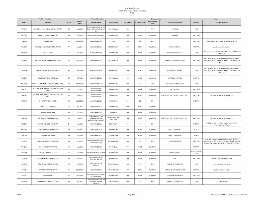
Auxiliary Boilers
RBLC and Other Permit Searches VOC
RBLCID FACILITY STATEPERMIT
DATEPROCESS NAME THROUGHPUT POLLUTANT EMISSION RATE
EMISSION RATE
UNITSTIME AVG CONDITION METHOD CONTROL METHOD
*TX-0751 EAGLE MOUNTAIN STEAM ELECTRIC STATION TX 6/18/2015
Commercial/Institutional Size
Boilers (100 MMBtu) natural
gas
73.3 MMBtu/hr VOC 4 PPM 1-HR AVG LAER
*AK-0083 KENAI NITROGEN OPERATIONS AK 1/6/2015 Five (5) Waste Heat Boilers 50 MMBtu/hr VOC 0.0054 lb/MMBtu 3-HR AVG BACT-PSD
*WV-0025 MOUNDSVILLE WV 11/21/2014 AUXILIARY BOILER 100 VOC 0.6 lb/hr BACT-PSD Use of Natural Gas & Good Combustion Practices
*WY-0075 CHEYENNE PRAIRIE GENERATING STATION WY 7/16/2014 AUXILIARY BOILER 25.06 MMBtu/h VOC 0.0017 lb/MMBtu 3 HOUR AVERAGE BACT-PSD good combustion practices
*MD-0041 CPV ST. CHARLES MD 4/23/2014 AUXILLARY BOILER 93 MMBtu/hr VOC 0.002 lb/MMBtu 3-HOUR AVERAGE BLOCK LAEREXCLUSIVE USE OF NATURAL GAS, AND GOOD COMBUSTION
PRACTICES
*IA-0107 MARSHALLTOWN GENERATING STATION IA 4/14/2014 AUXILIARY BOILER 60.1 MMBtu/hr VOC 0.005 lb/MMBtu AVERAGE OF 3 STACK TEST RUNS BACT-PSD
THE EXCLUSIVE USE OF PIPELINE QUALITY NATURAL GAS,
LIMITED HOURS OF OPERATION, AND GOOD COMBUSTION
PRACTICES
*MD-0042 WILDCAT POINT GENERATION FACILITY MD 4/8/2014 AUXILLARY BOILER 45 MMBtu/hr VOC 0.0033 lb/MMBtu 3-HOUR BLOCK AVERAGE LAER
THE EXCLUSIVE USE OF PIPELINE QUALITY NATURAL GAS,
LIMITED HOURS OF OPERATION, AND GOOD COMBUSTION
PRACTICES
*OR-0050 TROUTDALE ENERGY CENTER, LLC OR 3/5/2014 AUXILIARY BOILER 39.8 MMBtu/hr VOC 0.005 lb/MMBtu 3-HR BLOCK AVERAGE BACT-PSD
*PA-0296 BERKS HOLLOW ENERGY ASSOC LLC/ ONTELAUNEE PA 12/17/2013 AUXILIARY BOILER 40 MMBtu/hr VOC 0.14 TPY BASED ON A 12-MO AVERAGE NSPS
*MI-0412HOLLAND BOARD OF PUBLIC WORKS - EAST 5TH
STREETMI 12/4/2013
Auxiliary Boiler B
(EUAUXBOILERB)95 MMBtu/hr VOC 0.008 lb/MMBtu TEST METHOD BACT-PSD
*MI-0412HOLLAND BOARD OF PUBLIC WORKS - EAST 5TH
STREETMI 12/4/2013
Auxiliary Boiler A
(EUAUXBOILERA)55 MMBtu/hr VOC 0.008 lb/MMBtu HEAT INPUT; TEST PROTOCOL WILL SPECIFY BACT-PSD Efficient combustion; natural gas fuel.
*TX-0641 PINECREST ENERGY CENTER TX 11/21/2013 AUXILIARY BOILER 150 MMBtu/hr VOC 0.9 lb/hr BACT-PSD
CARROLL COUNTY ENERGY OH 11/5/2013 AUXILIARY BOILER 99 MMBtu/hr VOC 0.006 lb/MMBtu
RENAISSANCE POWER MI 11/1/2013 AUXILIARY BOILER 40 MMBtu VOC 0.005 lb/MMBtu
*MI-0410 THETFORD GENERATING STATION MI 7/25/2013
FGAUXBOILERS: Two
auxiliary boilers; 100
MMBtu/hr heat input each
100 MMBtu/hr heat
input eachVOC 0.008 lb/MMBtu HEAT INPUT; TEST PROTOCOL WILL SPECIFY BACT-PSD Efficient combustion; natural gas fuel.
*OH-0352 OREGON CLEAN ENERGY CENTER OH 6/18/2013 AUXILIARY BOILER 99 MMBtu/H VOC 0.59 lb/hr BACT-PSDGood combustion practices and using combustion
optimization technologies
*PA-0291 HICKORY RUN ENERGY STATION PA 4/23/2013 AUXILIARY BOILER 40 MMBtu/hr VOC 0.0015 lb/MMBtu OTHER CASE-BY-CASE OTHER
*PA-0296 SUNBURY GENERATION PA 4/1/2013 AUXILIARY BOILER 40 MMBtu/hrR VOC 0.005 lb/MMBtu OTHER CASE-BY-CASE OTHER
*LA-0272 AMMONIA PRODUCTION FACILITY LA 3/27/2013COMMISSIONING BOILERS 1;
2 (CB-1 & CB-2)217.5 MMBtu/hr VOC 1.41 lb/hr HOURLY MAXIMUM BACT-PSD
FLUE GAS RECIRCULATION AND GOOD COMBUSTION
PRACTICES (I.E., PROPER DESIGN OF BURNER AND FIREBOX
COMPONENTS; MAINTAINING THE PROPER AIR-TO-FUEL
*VA-0321 BRUNSWICK COUNTY POWER VA 3/12/2013 AUXILIARY BOILER 66.7 MMBtu/hr VOC 0.005 lb/MMBtu BACT-PSD
SC-0149 KLAUSNER HOLDING USA, INC SC 1/3/2013 NATURAL GAS BOILER EU004 46 MMBtu/hr VOC 0.003 lb/MMBtu 3-HOUR AVERAGEOTHER CASE-BY-
CASE
*IN-0158 ST. JOSEPH ENEGRY CENTER, LLC IN 12/3/2012TWO (2) NATURAL GAS
AUXILIARY BOILERS80 MMBtu/hr VOC 0.005 lb/MMBtu 3-HR BACT-PSD GOOD COMBUSTION PRACTICES
NJ-0080 HESS NEWARK ENERGY CENTER NJ 11/1/2012Boiler less than 100
MMBtu/hr51.9 MMscf/year VOC 0.27 lb/hr AVERAGE OF THREE TESTS LAER use of natural gas a clean fuel
IA-0105 IOWA FERTILIZER COMPANY IA 10/26/2012 AUXILIARY BOILER 472.4 MMBtu/hr VOC 0.0014 lb/MMBtu AVERAGE OF 3 STACK TEST RUNS BACT-PSD good combustion practices
FL-0335 SUWANNEE MILL FL 9/5/2012Four(4) Natural Gas Boilers -
46 MMBtu/hour46 MMBtu/hr VOC 0.003 lb/MMBtu Good Combustion Practice BACT-PSD
NJ-0079 WOODBRIDGE ENERGY CENTER NJ 7/25/2012
Commercial/Institutional size
boilers less than 100
MMBtu/hr
2000 hours/year VOC 0.14 lb/hr AVERAGE OF THREE TESTS LAER Use of Natural Gas
Facility Information Process Information Emission Limits Notes
ERM Page 1 of 3 Aux Boilers RBLC 2005-2015 (9-14-2015).xlsx

Auxiliary Boilers
RBLC and Other Permit Searches VOC
RBLCID FACILITY STATEPERMIT
DATEPROCESS NAME THROUGHPUT POLLUTANT EMISSION RATE
EMISSION RATE
UNITSTIME AVG CONDITION METHOD CONTROL METHOD
Facility Information Process Information Emission Limits Notes
*OH-0350 REPUBLIC STEEL OH 7/18/2012 Steam Boiler 65 MMBtu/hr VOC 0.35 lb/hr BACT-PSD Proper burner design and good combustion practices
LA-0254 NINEMILE POINT ELECTRIC GENERATING PLANT LA 8/16/2011 AUXILIARY BOILER 338 MMBtu/hrR VOC 5.5 lb/MMscf ANNUAL AVERAGE BACT-PSDUSE OF PIPELINE QUALITY NATURAL GAS AND GOOD
COMBUSTION PRACTICES
*MI-0393 RAY COMPRESSOR STATION MI 10/14/2010 AUXILIARY BOILER 12.25 MMBtu/hr VOC 0.05 lb/hr TEST METHOD BACT-PSD
PONDERA/ KING POWER STATION TX 8/5/2010 AUXILIARY BOILER 45 MMBtu/hr VOC 0.0055 lb/MMBtu
LA-0240 FLOPAM INC. LA 6/14/2010 Boilers 25.1 MMBtu/hr VOC 0.003 lb/MMBtu NATURAL GAS FIRED BACT-PSD Good equipment design and proper combustion techniques
NV-0050 MGM MIRAGE NV 11/30/2009
BOILERS - UNITS CC001,
CC002, AND CC003 AT CITY
CENTER
41.64 MMBtu/hr VOC 0.0024 lb/MMBtuOTHER CASE-BY-
CASE
LIMITING THE FUEL TO NATURAL GAS ONLY AND GOOD
COMBUSTION PRACTICES
NV-0050 MGM MIRAGE NV 11/30/2009
BOILERS - UNITS CC004,
CC005, AND CC006 AT CITY
CENTER
4.2 MMBtu/hr VOC 0.0048 lb/MMBtuOTHER CASE-BY-
CASE
LIMITING THE FUEL TO NATURAL GAS ONLY AND GOOD
COMBUSTION PRACTICES
NV-0050 MGM MIRAGE NV 11/30/2009BOILER - UNIT MB090 AT
MANDALAY BAY4.3 MMBtu/hr VOC 0.0054 lb/MMBtu
OTHER CASE-BY-
CASE
FLUE GAS RECIRCULATION AND GOOD COMBUSTION
PRACTICES
NV-0050 MGM MIRAGE NV 11/30/2009BOILERS - UNITS BE102 THRU
BE105 AT BELLAGIO2 MMBtu/hr VOC 0.0054 lb/MMBtu
OTHER CASE-BY-
CASE
LIMITING THE FUEL TO NATURAL GAS ONLY AND GOOD
COMBUSTION PRACTICES
NV-0050 MGM MIRAGE NV 11/30/2009BOILER - UNIT BE111 AT
BELLAGIO2.1 MMBtu/hr VOC 0.0048 lb/MMBtu
OTHER CASE-BY-
CASE
LIMITING THE FUEL TO NATURAL GAS ONLY AND GOOD
COMBUSTION PRACTICES
NV-0050 MGM MIRAGE NV 11/30/2009
BOILERS - UNITS CC026,
CC027 AND CC028 AT CITY
CENTER
44 MMBtu/hr VOC 0.0055 lb/MMBtuOTHER CASE-BY-
CASE
LIMITING THE FUEL TO NATURAL GAS ONLY AND GOOD
COMBUSTION PRACTICES
NV-0050 MGM MIRAGE NV 11/30/2009
BOILERS - UNITS NY42, NY43,
AND NY44 AT NEW YORK -
NEW YORK
2 MMBtu/hr VOC 0.005 lb/MMBtuOTHER CASE-BY-
CASEGOOD COMBUSTION PRACTICES
OH-0310AMERICAN MUNICIPAL POWER GENERATING
STATIONOH 10/8/2009 AUXILIARY BOILER 150 MMBtu/hr VOC 0.83 lb/hr
OTHER CASE-BY-
CASE
NV-0049 HARRAH'S OPERATING COMPANY, INC. NV 8/20/2009 BOILER - UNIT HA08 8.37 MMBtu/hr VOC 0.0054 lb/MMBtuOTHER CASE-BY-
CASE
OPERATING IN ACCORDANCE WITH THE MANUFACTURER'S
SPECIFICATION
NV-0049 HARRAH'S OPERATING COMPANY, INC. NV 8/20/2009 BOILER - UNIT FL01 14.34 MMBtu/hr VOC 0.0054 lb/MMBtuOTHER CASE-BY-
CASEFLUE GAS RECIRCULATION
NV-0049 HARRAH'S OPERATING COMPANY, INC. NV 8/20/2009 BOILER - UNIT BA01 16.8 MMBtu/hr VOC 0.0054 lb/MMBtuOTHER CASE-BY-
CASEFLUE GAS RECIRCULATION
NV-0049 HARRAH'S OPERATING COMPANY, INC. NV 8/20/2009 BOILER - UNIT BA03 31.38 MMBtu/hr VOC 0.0054 lb/MMBtuOTHER CASE-BY-
CASE
OPERATING IN ACCORDANCE WITH THE MANUFACTURER'S
SPECIFICATION
NV-0049 HARRAH'S OPERATING COMPANY, INC. NV 8/20/2009 BOILER - UNIT CP01 35.4 MMBtu/hr VOC 0.0054 lb/MMBtuOTHER CASE-BY-
CASE
FLUE GAS RECIRCULATION AND OPERATING IN
ACCORDANCE WITH THE MANUFACTURER'S SPECIFICATION
NV-0049 HARRAH'S OPERATING COMPANY, INC. NV 8/20/2009 BOILER - UNIT CP03 33.48 MMBtu/hr VOC 0.0054 lb/MMBtuOTHER CASE-BY-
CASE
OPERATING IN ACCORDANCE WITH THE MANUFACTURER'S
SPECIFICATION
NV-0049 HARRAH'S OPERATING COMPANY, INC. NV 8/20/2009 BOILER - UNIT CP26 24 MMBtu/hr VOC 0.0054 lb/MMBtuOTHER CASE-BY-
CASE
OPERATING IN ACCORDANCE WITH THE MANUFACTURER'S
SPECIFICATION
NV-0049 HARRAH'S OPERATING COMPANY, INC. NV 8/20/2009 BOILER - UNIT PA15 21 MMBtu/hr VOC 0.0053 lb/MMBtuOTHER CASE-BY-
CASE
OPERATING IN ACCORDANCE WITH THE MANUFACTURER'S
SPECIFICATION
ERM Page 2 of 3 Aux Boilers RBLC 2005-2015 (9-14-2015).xlsx

Auxiliary Boilers
RBLC and Other Permit Searches VOC
RBLCID FACILITY STATEPERMIT
DATEPROCESS NAME THROUGHPUT POLLUTANT EMISSION RATE
EMISSION RATE
UNITSTIME AVG CONDITION METHOD CONTROL METHOD
Facility Information Process Information Emission Limits Notes
NV-0049 HARRAH'S OPERATING COMPANY, INC. NV 8/20/2009 BOILER - UNIT IP04 16.7 MMBtu/hr VOC 0.0053 lb/MMBtuOTHER CASE-BY-
CASE
OPERATING IN ACCORDANCE WITH THE MANUFACTURER'S
SPECIFICATION
OK-0135 PRYOR PLANT CHEMICAL OK 2/23/2009 BOILERS #1 AND #2 80 MMBtu/hr VOC 0.5 lb/hr BACT-PSD
OK-0129 CHOUTEAU POWER PLANT OK 1/23/2009 AUXILIARY BOILER 33.5 MMBtu/hr VOC 0.54 lb/hr BACT-PSD GOOD COMBUSTION
AR-0094 JOHN W. TURK JR. POWER PLANT AR 11/5/2008 AUXILIARY BOILER 555 MMBtu/hr VOC 0.0055 lb/MMBtu 3-HR AVERAGE BACT-PSD
OH-0323 TITAN TIRE CORPORATION OF BRYAN OH 6/5/2008 BOILER 50.4 MMBtu/hr VOC 0.27 lb/hr BACT-PSD
NV-0047 NELLIS AIR FORCE BASE NV 2/26/2008BOILERS/HEATERS -
NATURAL GAS-FIREDVOC 0.0062 lb/MMBtu
OTHER CASE-BY-
CASEFLUE GAS RECIRCULATION
IA-0088 ADM CORN PROCESSING - CEDAR RAPIDS IA 6/29/2007NATURAL GAS BOILER (292.5
MMBtu/hr)292.5 MMBtu/hr VOC 0.0054 lb/MMBtu AVERAGE OF 3 TEST RUNS BACT-PSD GOOD COMBUSTION PRACTICES
OH-0309 TOLEDO SUPPLIER PARK- PAINT SHOP OH 5/3/2007 BOILER (2), NATURAL GAS 20.4 MMBtu/hr VOC 0.11 lb/hr LAER
FL-0285 PROGRESS BARTOW POWER PLANT FL 1/26/2007ONE GASEOUS-FUELED 99
MMBtu/hr AUXILIARY BOILER99 MMBtu/hr VOC 2 GRS/100 SCF BACT-PSD
FL-0286 FPL WEST COUNTY ENERGY CENTER FL 1/10/2007TWO 99.8 MMBtu/hr GAS-
FUELED AUXILIARY BOILERS99.8 MMBtu/hr VOC 2 GRS/100 SCF BACT-PSD
NV-0044 HARRAH'S OPERATING COMPANY, INC. NV 1/4/2007COMMERCIAL/INSTITUTIONA
L-SIZE BOILERS35.4 MMBtu/hr VOC 0.005 lb/MMBtu BACT-PSD GOOD COMBUSTION DESIGN
NV-0048 GOODSPRINGS COMPRESSOR STATION NV 5/16/2006
COMMERCIAL/INSTITUTIONA
L-SIZE BOILER (100
MMBtu/hr)
3.85 MMBtu/hr VOC 0.005 lb/MMBtuOTHER CASE-BY-
CASEGOOD COMBUSTION PRACTICE
NV-0046 GOODSPRINGS COMPRESSOR STATION NV 5/16/2006COMMERCIAL/INSTITUTIONA
L BOILER3.85 MMBtu/hr VOC 0.005 lb/MMBtu
OTHER CASE-BY-
CASEGOOD COMBUSTION PRACTICE
OH-0307 SOUTH POINT BIOMASS GENERATION OH 4/4/2006 AUXILIARY BOILER 247 MMBtu/hrR VOC 0.99 lb/hr BACT-PSD
OR-0046 TURNER ENERGY CENTER, LLC CALPINE OR 1/6/2005 AUXILIARY BOILER 417904 MMBtu/yr VOC 0.0044 lb/MMBtu 3-HR BLOCK AVERAGE BACT-PSD
ERM Page 3 of 3 Aux Boilers RBLC 2005-2015 (9-14-2015).xlsx
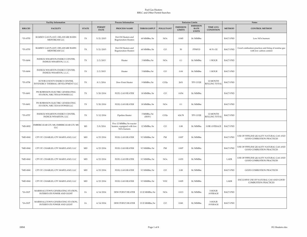
Fuel Gas Heaters
RBLC and Other Permit Searches
RBLCID FACILITY STATEPERMIT
DATEPROCESS NAME THROUGHPUT POLLUTANT
EMISSION
LIMITS
EMISSION
RATE
UNITS
TIME AVG
CONDITIONMETHOD CONTROL METHOD
*TX-0755RAMSEY GAS PLANT, DELAWARE BASIN
MIDSTREAM LLCTX 5/21/2015
Hot Oil Heaters and
Regeneration Heaters60 MMBtu/hr NOx 0.045 lb/MMBtu BACT-PSD Low NOx burners
*TX-0755RAMSEY GAS PLANT, DELAWARE BASIN
MIDSTREAM LLCTX 5/21/2015
Hot Oil Heaters and
Regeneration Heaters60 MMBtu/hr CO 50 PPMVD @ 3% O2 BACT-PSD
Good combustion practices and firing of residue gas
with low carbon content
*TX-0694INDECK WHARTON ENERGY CENTER,
INDECK WHARTON, L.L.C.TX 2/2/2015 Heater 3 MMBtu/hr NOx 0.1 lb/MMBtu 1 HOUR BACT-PSD
*TX-0694INDECK WHARTON ENERGY CENTER,
INDECK WHARTON, L.L.C.TX 2/2/2015 Heater 3 MMBtu/hr CO 0.04 lb/MMBtu 1 HOUR BACT-PSD
*TX-0758ECTOR COUNTY ENERGY CENTER,
INVENERGY THERMAL DEVELOPMENT LLCTX 8/1/2014 Dew-Point Heater 9 MMBtu/hr CO2e 2631 TPY CO2E
12-MONTH
ROLLING TOTALBACT-PSD
*TX-0691PH ROBINSON ELECTRIC GENERATING
STATION, NRG TEXAS POWER LLCTX 5/20/2014 FUEL GAS HEATER 18 MMBtu/hr CO 0.054 lb/MMBtu BACT-PSD
*TX-0691PH ROBINSON ELECTRIC GENERATING
STATION, NRG TEXAS POWER LLCTX 5/20/2014 FUEL GAS HEATER 18 MMBtu/hr NOx 0.1 lb/MMBtu BACT-PSD
*TX-0757INDECK WHARTON ENERGY CENTER,
INDECK WHARTON, LLCTX 5/12/2014 Pipeline Heater
3 MMBtu/hr
(HHV)CO2e 624.78 TPY CO2E
12-MONTH
ROLLING TOTALBACT-PSD
*MS-0092EMBERCLEAR GTL MS, EMBERCLEAR GTL MS
LLCMS 5/8/2014
Five 12 MMBtu/hr reactor
heaters, equipped with low-
NOx burners
12 MMBtu/hr CO 0.08 lb/MMBtu 3-HR AVERAGE BACT-PSD
*MD-0041 CPV ST. CHARLES, CPV MARYLAND, LLC MD 4/23/2014 FUEL GAS HEATER 9.5 MMBtu/hr PM 0.007 lb/MMBtu BACT-PSDUSE OF PIPELINE QUALITY NATURAL GAS AND
GOOD COMBUSTION PRACTICES
*MD-0041 CPV ST. CHARLES, CPV MARYLAND, LLC MD 4/23/2014 FUEL GAS HEATER 9.5 MMBtu/hr PM 0.007 lb/MMBtu BACT-PSDUSE OF PIPELINE QUALITY NATURAL GAS AND
GOOD COMBUSTION PRACTICES
*MD-0041 CPV ST. CHARLES, CPV MARYLAND, LLC MD 4/23/2014 FUEL GAS HEATER 9.5 MMBtu/hr NOx 0.035 lb/MMBtu LAERUSE OF PIPELINE QUALITY NATURAL GAS AND
GOOD COMBUSTION PRACTICES
*MD-0041 CPV ST. CHARLES, CPV MARYLAND, LLC MD 4/23/2014 FUEL GAS HEATER 9.5 MMBtu/hr CO 0.08 lb/MMBtu BACT-PSD GOOD COMBUSTION PRACTICES
*MD-0041 CPV ST. CHARLES, CPV MARYLAND, LLC MD 4/23/2014 FUEL GAS HEATER 9.5 MMBtu/hr VOC 0.005 lb/MMBtu LAEREXCLUSIVE USE OF NATURAL GAS AND GOOD
COMBUSTION PRACTICES
*IA-0107MARSHALLTOWN GENERATING STATION,
INTERSTATE POWER AND LIGHTIA 4/14/2014 DEW POINT HEATER 13.32 MMBtu/hr NOx 0.013 lb/MMBtu
3-HOUR
AVERAGEBACT-PSD
*IA-0107MARSHALLTOWN GENERATING STATION,
INTERSTATE POWER AND LIGHTIA 4/14/2014 DEW POINT HEATER 13.32 MMBtu/hr CO 0.041 lb/MMBtu
3-HOUR
AVERAGEBACT-PSD
Facility Information Process Information NotesEmission Limits
ERM Page 1 of 8 FG Heaters.xlsx
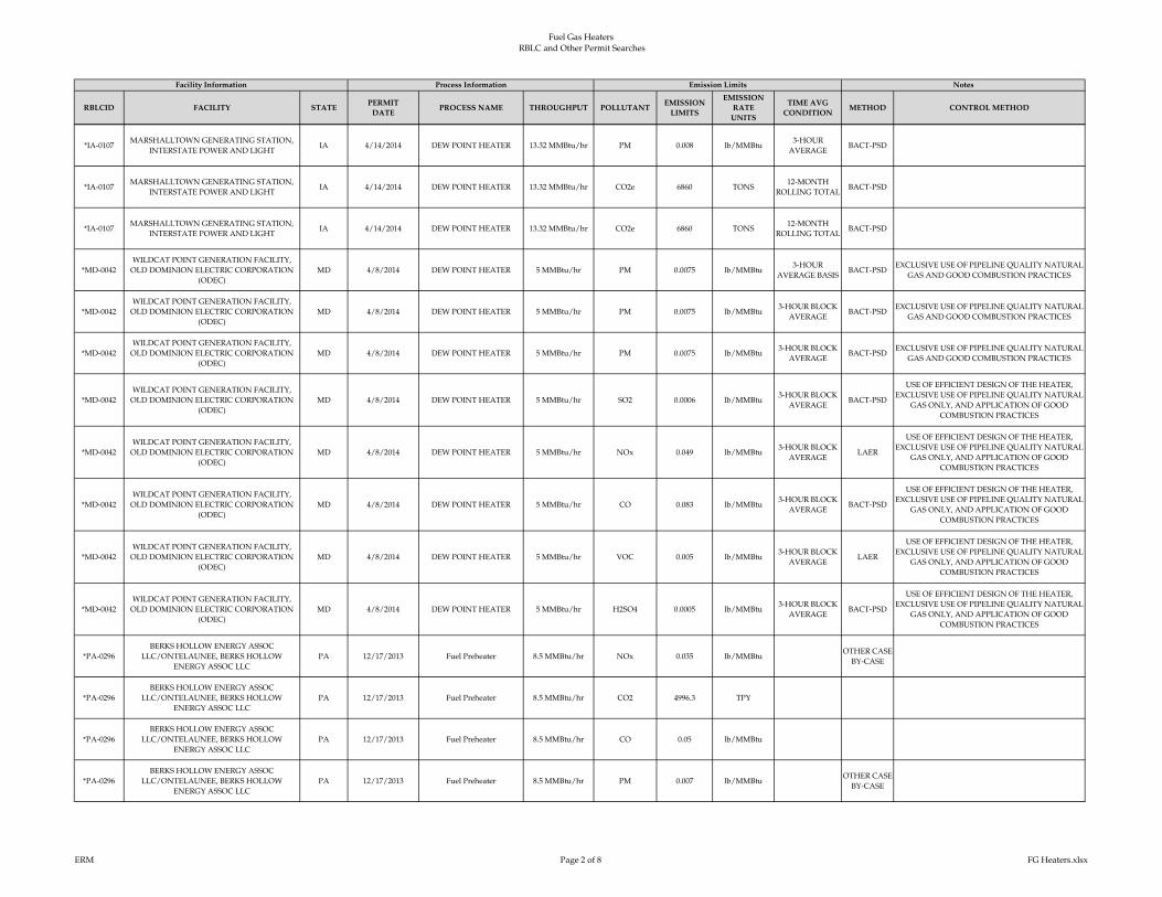
Fuel Gas Heaters
RBLC and Other Permit Searches
RBLCID FACILITY STATEPERMIT
DATEPROCESS NAME THROUGHPUT POLLUTANT
EMISSION
LIMITS
EMISSION
RATE
UNITS
TIME AVG
CONDITIONMETHOD CONTROL METHOD
Facility Information Process Information NotesEmission Limits
*IA-0107MARSHALLTOWN GENERATING STATION,
INTERSTATE POWER AND LIGHTIA 4/14/2014 DEW POINT HEATER 13.32 MMBtu/hr PM 0.008 lb/MMBtu
3-HOUR
AVERAGEBACT-PSD
*IA-0107MARSHALLTOWN GENERATING STATION,
INTERSTATE POWER AND LIGHTIA 4/14/2014 DEW POINT HEATER 13.32 MMBtu/hr CO2e 6860 TONS
12-MONTH
ROLLING TOTALBACT-PSD
*IA-0107MARSHALLTOWN GENERATING STATION,
INTERSTATE POWER AND LIGHTIA 4/14/2014 DEW POINT HEATER 13.32 MMBtu/hr CO2e 6860 TONS
12-MONTH
ROLLING TOTALBACT-PSD
*MD-0042
WILDCAT POINT GENERATION FACILITY,
OLD DOMINION ELECTRIC CORPORATION
(ODEC)
MD 4/8/2014 DEW POINT HEATER 5 MMBtu/hr PM 0.0075 lb/MMBtu3-HOUR
AVERAGE BASISBACT-PSD
EXCLUSIVE USE OF PIPELINE QUALITY NATURAL
GAS AND GOOD COMBUSTION PRACTICES
*MD-0042
WILDCAT POINT GENERATION FACILITY,
OLD DOMINION ELECTRIC CORPORATION
(ODEC)
MD 4/8/2014 DEW POINT HEATER 5 MMBtu/hr PM 0.0075 lb/MMBtu3-HOUR BLOCK
AVERAGEBACT-PSD
EXCLUSIVE USE OF PIPELINE QUALITY NATURAL
GAS AND GOOD COMBUSTION PRACTICES
*MD-0042
WILDCAT POINT GENERATION FACILITY,
OLD DOMINION ELECTRIC CORPORATION
(ODEC)
MD 4/8/2014 DEW POINT HEATER 5 MMBtu/hr PM 0.0075 lb/MMBtu3-HOUR BLOCK
AVERAGEBACT-PSD
EXCLUSIVE USE OF PIPELINE QUALITY NATURAL
GAS AND GOOD COMBUSTION PRACTICES
*MD-0042
WILDCAT POINT GENERATION FACILITY,
OLD DOMINION ELECTRIC CORPORATION
(ODEC)
MD 4/8/2014 DEW POINT HEATER 5 MMBtu/hr SO2 0.0006 lb/MMBtu3-HOUR BLOCK
AVERAGEBACT-PSD
USE OF EFFICIENT DESIGN OF THE HEATER,
EXCLUSIVE USE OF PIPELINE QUALITY NATURAL
GAS ONLY, AND APPLICATION OF GOOD
COMBUSTION PRACTICES
*MD-0042
WILDCAT POINT GENERATION FACILITY,
OLD DOMINION ELECTRIC CORPORATION
(ODEC)
MD 4/8/2014 DEW POINT HEATER 5 MMBtu/hr NOx 0.049 lb/MMBtu3-HOUR BLOCK
AVERAGELAER
USE OF EFFICIENT DESIGN OF THE HEATER,
EXCLUSIVE USE OF PIPELINE QUALITY NATURAL
GAS ONLY, AND APPLICATION OF GOOD
COMBUSTION PRACTICES
*MD-0042
WILDCAT POINT GENERATION FACILITY,
OLD DOMINION ELECTRIC CORPORATION
(ODEC)
MD 4/8/2014 DEW POINT HEATER 5 MMBtu/hr CO 0.083 lb/MMBtu3-HOUR BLOCK
AVERAGEBACT-PSD
USE OF EFFICIENT DESIGN OF THE HEATER,
EXCLUSIVE USE OF PIPELINE QUALITY NATURAL
GAS ONLY, AND APPLICATION OF GOOD
COMBUSTION PRACTICES
*MD-0042
WILDCAT POINT GENERATION FACILITY,
OLD DOMINION ELECTRIC CORPORATION
(ODEC)
MD 4/8/2014 DEW POINT HEATER 5 MMBtu/hr VOC 0.005 lb/MMBtu3-HOUR BLOCK
AVERAGELAER
USE OF EFFICIENT DESIGN OF THE HEATER,
EXCLUSIVE USE OF PIPELINE QUALITY NATURAL
GAS ONLY, AND APPLICATION OF GOOD
COMBUSTION PRACTICES
*MD-0042
WILDCAT POINT GENERATION FACILITY,
OLD DOMINION ELECTRIC CORPORATION
(ODEC)
MD 4/8/2014 DEW POINT HEATER 5 MMBtu/hr H2SO4 0.0005 lb/MMBtu3-HOUR BLOCK
AVERAGEBACT-PSD
USE OF EFFICIENT DESIGN OF THE HEATER,
EXCLUSIVE USE OF PIPELINE QUALITY NATURAL
GAS ONLY, AND APPLICATION OF GOOD
COMBUSTION PRACTICES
*PA-0296
BERKS HOLLOW ENERGY ASSOC
LLC/ONTELAUNEE, BERKS HOLLOW
ENERGY ASSOC LLC
PA 12/17/2013 Fuel Preheater 8.5 MMBtu/hr NOx 0.035 lb/MMBtuOTHER CASE-
BY-CASE
*PA-0296
BERKS HOLLOW ENERGY ASSOC
LLC/ONTELAUNEE, BERKS HOLLOW
ENERGY ASSOC LLC
PA 12/17/2013 Fuel Preheater 8.5 MMBtu/hr CO2 4996.3 TPY
*PA-0296
BERKS HOLLOW ENERGY ASSOC
LLC/ONTELAUNEE, BERKS HOLLOW
ENERGY ASSOC LLC
PA 12/17/2013 Fuel Preheater 8.5 MMBtu/hr CO 0.05 lb/MMBtu
*PA-0296
BERKS HOLLOW ENERGY ASSOC
LLC/ONTELAUNEE, BERKS HOLLOW
ENERGY ASSOC LLC
PA 12/17/2013 Fuel Preheater 8.5 MMBtu/hr PM 0.007 lb/MMBtuOTHER CASE-
BY-CASE
ERM Page 2 of 8 FG Heaters.xlsx
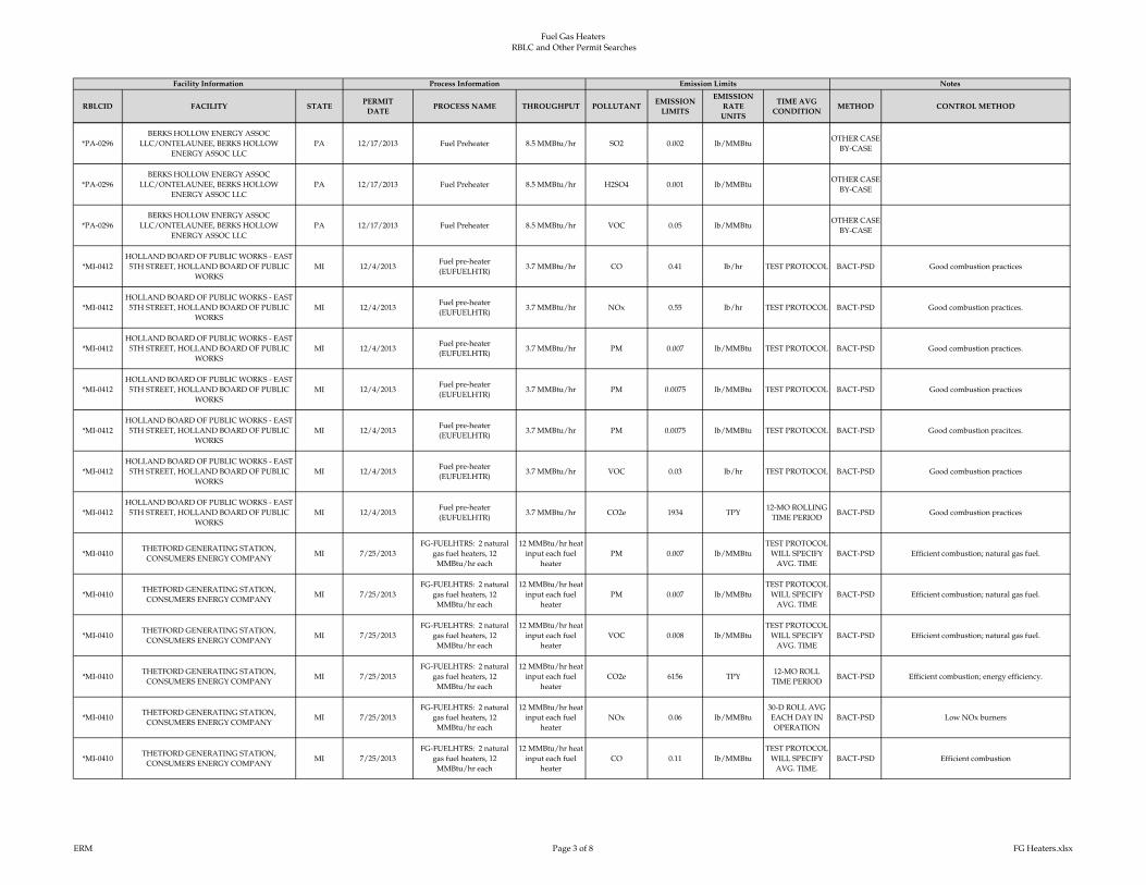
Fuel Gas Heaters
RBLC and Other Permit Searches
RBLCID FACILITY STATEPERMIT
DATEPROCESS NAME THROUGHPUT POLLUTANT
EMISSION
LIMITS
EMISSION
RATE
UNITS
TIME AVG
CONDITIONMETHOD CONTROL METHOD
Facility Information Process Information NotesEmission Limits
*PA-0296
BERKS HOLLOW ENERGY ASSOC
LLC/ONTELAUNEE, BERKS HOLLOW
ENERGY ASSOC LLC
PA 12/17/2013 Fuel Preheater 8.5 MMBtu/hr SO2 0.002 lb/MMBtuOTHER CASE-
BY-CASE
*PA-0296
BERKS HOLLOW ENERGY ASSOC
LLC/ONTELAUNEE, BERKS HOLLOW
ENERGY ASSOC LLC
PA 12/17/2013 Fuel Preheater 8.5 MMBtu/hr H2SO4 0.001 lb/MMBtuOTHER CASE-
BY-CASE
*PA-0296
BERKS HOLLOW ENERGY ASSOC
LLC/ONTELAUNEE, BERKS HOLLOW
ENERGY ASSOC LLC
PA 12/17/2013 Fuel Preheater 8.5 MMBtu/hr VOC 0.05 lb/MMBtuOTHER CASE-
BY-CASE
*MI-0412
HOLLAND BOARD OF PUBLIC WORKS - EAST
5TH STREET, HOLLAND BOARD OF PUBLIC
WORKS
MI 12/4/2013Fuel pre-heater
(EUFUELHTR)3.7 MMBtu/hr CO 0.41 lb/hr TEST PROTOCOL BACT-PSD Good combustion practices
*MI-0412
HOLLAND BOARD OF PUBLIC WORKS - EAST
5TH STREET, HOLLAND BOARD OF PUBLIC
WORKS
MI 12/4/2013Fuel pre-heater
(EUFUELHTR)3.7 MMBtu/hr NOx 0.55 lb/hr TEST PROTOCOL BACT-PSD Good combustion practices.
*MI-0412
HOLLAND BOARD OF PUBLIC WORKS - EAST
5TH STREET, HOLLAND BOARD OF PUBLIC
WORKS
MI 12/4/2013Fuel pre-heater
(EUFUELHTR)3.7 MMBtu/hr PM 0.007 lb/MMBtu TEST PROTOCOL BACT-PSD Good combustion practices.
*MI-0412
HOLLAND BOARD OF PUBLIC WORKS - EAST
5TH STREET, HOLLAND BOARD OF PUBLIC
WORKS
MI 12/4/2013Fuel pre-heater
(EUFUELHTR)3.7 MMBtu/hr PM 0.0075 lb/MMBtu TEST PROTOCOL BACT-PSD Good combustion practices
*MI-0412
HOLLAND BOARD OF PUBLIC WORKS - EAST
5TH STREET, HOLLAND BOARD OF PUBLIC
WORKS
MI 12/4/2013Fuel pre-heater
(EUFUELHTR)3.7 MMBtu/hr PM 0.0075 lb/MMBtu TEST PROTOCOL BACT-PSD Good combustion pracitces.
*MI-0412
HOLLAND BOARD OF PUBLIC WORKS - EAST
5TH STREET, HOLLAND BOARD OF PUBLIC
WORKS
MI 12/4/2013Fuel pre-heater
(EUFUELHTR)3.7 MMBtu/hr VOC 0.03 lb/hr TEST PROTOCOL BACT-PSD Good combustion practices
*MI-0412
HOLLAND BOARD OF PUBLIC WORKS - EAST
5TH STREET, HOLLAND BOARD OF PUBLIC
WORKS
MI 12/4/2013Fuel pre-heater
(EUFUELHTR)3.7 MMBtu/hr CO2e 1934 TPY
12-MO ROLLING
TIME PERIODBACT-PSD Good combustion practices
*MI-0410THETFORD GENERATING STATION,
CONSUMERS ENERGY COMPANYMI 7/25/2013
FG-FUELHTRS: 2 natural
gas fuel heaters, 12
MMBtu/hr each
12 MMBtu/hr heat
input each fuel
heater
PM 0.007 lb/MMBtu
TEST PROTOCOL
WILL SPECIFY
AVG. TIME
BACT-PSD Efficient combustion; natural gas fuel.
*MI-0410THETFORD GENERATING STATION,
CONSUMERS ENERGY COMPANYMI 7/25/2013
FG-FUELHTRS: 2 natural
gas fuel heaters, 12
MMBtu/hr each
12 MMBtu/hr heat
input each fuel
heater
PM 0.007 lb/MMBtu
TEST PROTOCOL
WILL SPECIFY
AVG. TIME
BACT-PSD Efficient combustion; natural gas fuel.
*MI-0410THETFORD GENERATING STATION,
CONSUMERS ENERGY COMPANYMI 7/25/2013
FG-FUELHTRS: 2 natural
gas fuel heaters, 12
MMBtu/hr each
12 MMBtu/hr heat
input each fuel
heater
VOC 0.008 lb/MMBtu
TEST PROTOCOL
WILL SPECIFY
AVG. TIME
BACT-PSD Efficient combustion; natural gas fuel.
*MI-0410THETFORD GENERATING STATION,
CONSUMERS ENERGY COMPANYMI 7/25/2013
FG-FUELHTRS: 2 natural
gas fuel heaters, 12
MMBtu/hr each
12 MMBtu/hr heat
input each fuel
heater
CO2e 6156 TPY12-MO ROLL
TIME PERIODBACT-PSD Efficient combustion; energy efficiency.
*MI-0410THETFORD GENERATING STATION,
CONSUMERS ENERGY COMPANYMI 7/25/2013
FG-FUELHTRS: 2 natural
gas fuel heaters, 12
MMBtu/hr each
12 MMBtu/hr heat
input each fuel
heater
NOx 0.06 lb/MMBtu
30-D ROLL AVG
EACH DAY IN
OPERATION
BACT-PSD Low NOx burners
*MI-0410THETFORD GENERATING STATION,
CONSUMERS ENERGY COMPANYMI 7/25/2013
FG-FUELHTRS: 2 natural
gas fuel heaters, 12
MMBtu/hr each
12 MMBtu/hr heat
input each fuel
heater
CO 0.11 lb/MMBtu
TEST PROTOCOL
WILL SPECIFY
AVG. TIME.
BACT-PSD Efficient combustion
ERM Page 3 of 8 FG Heaters.xlsx

Fuel Gas Heaters
RBLC and Other Permit Searches
RBLCID FACILITY STATEPERMIT
DATEPROCESS NAME THROUGHPUT POLLUTANT
EMISSION
LIMITS
EMISSION
RATE
UNITS
TIME AVG
CONDITIONMETHOD CONTROL METHOD
Facility Information Process Information NotesEmission Limits
*MI-0410THETFORD GENERATING STATION,
CONSUMERS ENERGY COMPANYMI 7/25/2013
FG-FUELHTRS: 2 natural
gas fuel heaters, 12
MMBtu/hr each
12 MMBtu/hr heat
input each fuel
heater
PM 0.0018 lb/MMBtu
TEST PROTOCOL
WILL SPECIFY
AVG. TIME.
BACT-PSD Efficient combustion; natural gas fuel.
*TX-0680SONORA GAS PLANT, WTG SONORA GAS
PLANT LLCTX 6/14/2013 Process Heater 10 MMBtu/hr NOx 0.01 lb/MMBtu BACT-PSD Low NOx burners
*TX-0680SONORA GAS PLANT, WTG SONORA GAS
PLANT LLCTX 6/14/2013 Heater 10 MMBtu/hr CO 100 PPMVD @3% O2 BACT-PSD
TX-0634LONE STAR NGL, MONT BELVIEU GAS
PLANT, ENERGY TRANSFER PARTNERS, LPTX 10/12/2012
FRAC I and II Hot Oil
Heaters270 MMBtu/hr CO2 137943 TPY
365-DAY TOTAL,
ROLLED DAILYBACT-PSD
TX-0634LONE STAR NGL, MONT BELVIEU GAS
PLANT, ENERGY TRANSFER PARTNERS, LPTX 10/12/2012
FRAC I and II Hot Oil
Heaters270 MMBtu/hr CO2e 138078 TPY
12-MONTH
ROLLING BASISBACT-PSD
*TX-0663JACKSON COUNTY GAS PLANT, ETC TEXAS
PIPELINE, LTD.TX 5/25/2012 Heaters 48 MMBtu/hr NOx 7.62 TON YEAR BACT-PSD Flue Gas Recirculation
*TX-0663JACKSON COUNTY GAS PLANT, ETC TEXAS
PIPELINE, LTD.TX 5/25/2012 Heaters 48 MMBtu/hr CO 17.39 TON YEAR BACT-PSD Best combustion practices
CA-1190PETROROCK- TUNNELL LEASE, PETROROCK-
TUNNELL LEASECA 1/24/2012 Heater 3 MMBtu/hr NOx 12 PPMVD
40 MINUTES @
3% O2
OTHER CASE-
BY-CASELow NOx burner
AK-0071INTERNATIONAL STATION POWER PLANT,
CHUGACH ELECTRIC ASSOCIATION, INC.AK 12/20/2010
Sigma Thermal Auxiliary
Heater (1)12.5 MMBtu/hr NOx 32 lb/MMscf
3-HOUR
AVERAGEBACT-PSD Low NOx Burners and Flue Gas Recirculation
AK-0071INTERNATIONAL STATION POWER PLANT,
CHUGACH ELECTRIC ASSOCIATION, INC.AK 12/20/2010
Sigma Thermal Auxiliary
Heater (1)12.5 MMBtu/hr PM 7.6 lb/MMscf
3-HOUR
AVERAGEBACT-PSD Good Combustion Practices
AK-0071INTERNATIONAL STATION POWER PLANT,
CHUGACH ELECTRIC ASSOCIATION, INC.AK 12/20/2010
Sigma Thermal Auxiliary
Heater (1)12.5 MMBtu/hr PM 7.6 lb/MMscf
3-HOUR
AVERAGEBACT-PSD Good Combustion Practices
AK-0071INTERNATIONAL STATION POWER PLANT,
CHUGACH ELECTRIC ASSOCIATION, INC.AK 12/20/2010
Sigma Thermal Auxiliary
Heater (1)12.5 MMBtu/hr PM 7.6 lb/MMscf
3-HOUR
AVERAGEBACT-PSD Good Combustion Practices
LA-0244LAKE CHARLES CHEMICAL COMPLEX - LAB
UNIT, SASOL NORTH AMERICA, INC.LA 11/29/2010
EQT0029 - Hot Oil Heater H-
601170 MMBtu/hr PM 1.71 lb/hr
HOURLY
MAXIMUMBACT-PSD No additional control
LA-0244LAKE CHARLES CHEMICAL COMPLEX - LAB
UNIT, SASOL NORTH AMERICA, INC.LA 11/29/2010
EQT0029 - Hot Oil Heater H-
601170 MMBtu/hr NOx 19.69 lb/hr
HOURLY
MAXIMUMBACT-PSD Low NOx burners
*MI-0393RAY COMPRESSOR STATION, CONSUMERS
ENERGYMI 10/14/2010 Pipeline heaters 18 MMBtu/hr NOx 0.9 lb/hr TEST METHOD BACT-PSD Low NOx burners
*MI-0393RAY COMPRESSOR STATION, CONSUMERS
ENERGYMI 10/14/2010 Pipeline heaters 18 MMBtu/hr VOC 0.9 lb/hr TEST METHOD BACT-PSD
ERM Page 4 of 8 FG Heaters.xlsx
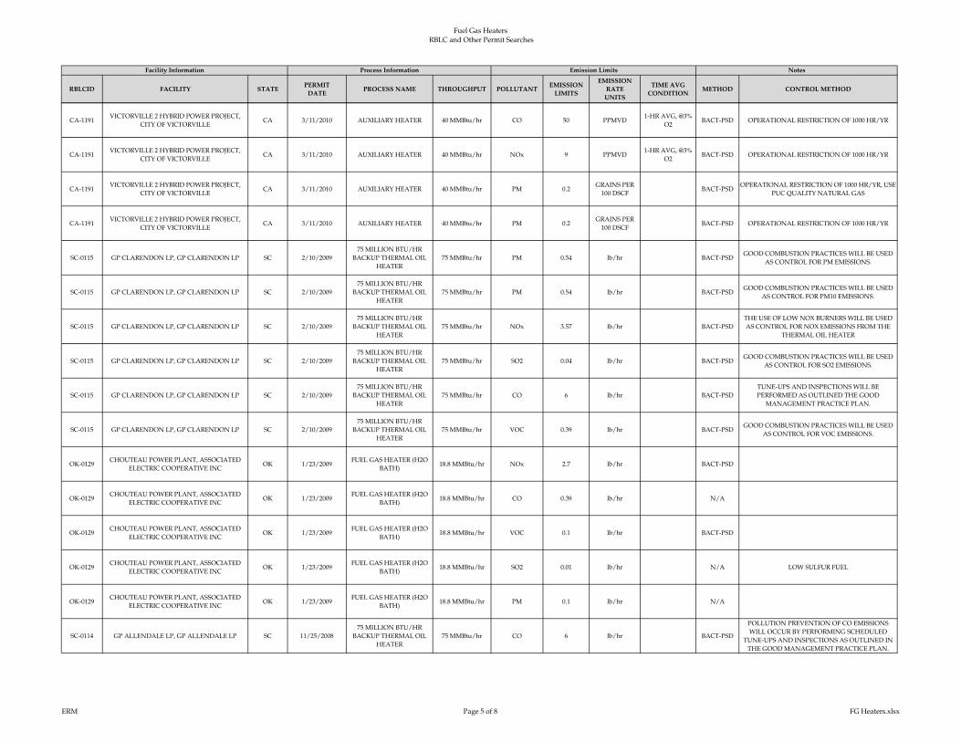
Fuel Gas Heaters
RBLC and Other Permit Searches
RBLCID FACILITY STATEPERMIT
DATEPROCESS NAME THROUGHPUT POLLUTANT
EMISSION
LIMITS
EMISSION
RATE
UNITS
TIME AVG
CONDITIONMETHOD CONTROL METHOD
Facility Information Process Information NotesEmission Limits
CA-1191VICTORVILLE 2 HYBRID POWER PROJECT,
CITY OF VICTORVILLECA 3/11/2010 AUXILIARY HEATER 40 MMBtu/hr CO 50 PPMVD
1-HR AVG, @3%
O2BACT-PSD OPERATIONAL RESTRICTION OF 1000 HR/YR
CA-1191VICTORVILLE 2 HYBRID POWER PROJECT,
CITY OF VICTORVILLECA 3/11/2010 AUXILIARY HEATER 40 MMBtu/hr NOx 9 PPMVD
1-HR AVG, @3%
O2BACT-PSD OPERATIONAL RESTRICTION OF 1000 HR/YR
CA-1191VICTORVILLE 2 HYBRID POWER PROJECT,
CITY OF VICTORVILLECA 3/11/2010 AUXILIARY HEATER 40 MMBtu/hr PM 0.2
GRAINS PER
100 DSCFBACT-PSD
OPERATIONAL RESTRICTION OF 1000 HR/YR, USE
PUC QUALITY NATURAL GAS
CA-1191VICTORVILLE 2 HYBRID POWER PROJECT,
CITY OF VICTORVILLECA 3/11/2010 AUXILIARY HEATER 40 MMBtu/hr PM 0.2
GRAINS PER
100 DSCFBACT-PSD OPERATIONAL RESTRICTION OF 1000 HR/YR
SC-0115 GP CLARENDON LP, GP CLARENDON LP SC 2/10/2009
75 MILLION BTU/HR
BACKUP THERMAL OIL
HEATER
75 MMBtu/hr PM 0.54 lb/hr BACT-PSDGOOD COMBUSTION PRACTICES WILL BE USED
AS CONTROL FOR PM EMISSIONS.
SC-0115 GP CLARENDON LP, GP CLARENDON LP SC 2/10/2009
75 MILLION BTU/HR
BACKUP THERMAL OIL
HEATER
75 MMBtu/hr PM 0.54 lb/hr BACT-PSDGOOD COMBUSTION PRACTICES WILL BE USED
AS CONTROL FOR PM10 EMISSIONS.
SC-0115 GP CLARENDON LP, GP CLARENDON LP SC 2/10/2009
75 MILLION BTU/HR
BACKUP THERMAL OIL
HEATER
75 MMBtu/hr NOx 3.57 lb/hr BACT-PSD
THE USE OF LOW NOX BURNERS WILL BE USED
AS CONTROL FOR NOX EMISSIONS FROM THE
THERMAL OIL HEATER
SC-0115 GP CLARENDON LP, GP CLARENDON LP SC 2/10/2009
75 MILLION BTU/HR
BACKUP THERMAL OIL
HEATER
75 MMBtu/hr SO2 0.04 lb/hr BACT-PSDGOOD COMBUSTION PRACTICES WILL BE USED
AS CONTROL FOR SO2 EMISSIONS.
SC-0115 GP CLARENDON LP, GP CLARENDON LP SC 2/10/2009
75 MILLION BTU/HR
BACKUP THERMAL OIL
HEATER
75 MMBtu/hr CO 6 lb/hr BACT-PSD
TUNE-UPS AND INSPECTIONS WILL BE
PERFORMED AS OUTLINED THE GOOD
MANAGEMENT PRACTICE PLAN.
SC-0115 GP CLARENDON LP, GP CLARENDON LP SC 2/10/2009
75 MILLION BTU/HR
BACKUP THERMAL OIL
HEATER
75 MMBtu/hr VOC 0.39 lb/hr BACT-PSDGOOD COMBUSTION PRACTICES WILL BE USED
AS CONTROL FOR VOC EMISSIONS.
OK-0129CHOUTEAU POWER PLANT, ASSOCIATED
ELECTRIC COOPERATIVE INCOK 1/23/2009
FUEL GAS HEATER (H2O
BATH)18.8 MMBtu/hr NOx 2.7 lb/hr BACT-PSD
OK-0129CHOUTEAU POWER PLANT, ASSOCIATED
ELECTRIC COOPERATIVE INCOK 1/23/2009
FUEL GAS HEATER (H2O
BATH)18.8 MMBtu/hr CO 0.39 lb/hr N/A
OK-0129CHOUTEAU POWER PLANT, ASSOCIATED
ELECTRIC COOPERATIVE INCOK 1/23/2009
FUEL GAS HEATER (H2O
BATH)18.8 MMBtu/hr VOC 0.1 lb/hr BACT-PSD
OK-0129CHOUTEAU POWER PLANT, ASSOCIATED
ELECTRIC COOPERATIVE INCOK 1/23/2009
FUEL GAS HEATER (H2O
BATH)18.8 MMBtu/hr SO2 0.01 lb/hr N/A LOW SULFUR FUEL
OK-0129CHOUTEAU POWER PLANT, ASSOCIATED
ELECTRIC COOPERATIVE INCOK 1/23/2009
FUEL GAS HEATER (H2O
BATH)18.8 MMBtu/hr PM 0.1 lb/hr N/A
SC-0114 GP ALLENDALE LP, GP ALLENDALE LP SC 11/25/2008
75 MILLION BTU/HR
BACKUP THERMAL OIL
HEATER
75 MMBtu/hr CO 6 lb/hr BACT-PSD
POLLUTION PREVENTION OF CO EMISSIONS
WILL OCCUR BY PERFORMING SCHEDULED
TUNE-UPS AND INSPECTIONS AS OUTLINED IN
THE GOOD MANAGEMENT PRACTICE PLAN.
ERM Page 5 of 8 FG Heaters.xlsx

Fuel Gas Heaters
RBLC and Other Permit Searches
RBLCID FACILITY STATEPERMIT
DATEPROCESS NAME THROUGHPUT POLLUTANT
EMISSION
LIMITS
EMISSION
RATE
UNITS
TIME AVG
CONDITIONMETHOD CONTROL METHOD
Facility Information Process Information NotesEmission Limits
SC-0114 GP ALLENDALE LP, GP ALLENDALE LP SC 11/25/2008
75 MILLION BTU/HR
BACKUP THERMAL OIL
HEATER
75 MMBtu/hr PM 0.54 lb/hr BACT-PSD
SC-0114 GP ALLENDALE LP, GP ALLENDALE LP SC 11/25/2008
75 MILLION BTU/HR
BACKUP THERMAL OIL
HEATER
75 MMBtu/hr PM 0.54 lb/hr BACT-PSD
SC-0114 GP ALLENDALE LP, GP ALLENDALE LP SC 11/25/2008
75 MILLION BTU/HR
BACKUP THERMAL OIL
HEATER
75 MMBtu/hr NOx 3.57 lb/hr BACT-PSDLOW NOX BURNERS WILL BE USED AS
CONTROLS FOR NOX EMISSIONS.
SC-0114 GP ALLENDALE LP, GP ALLENDALE LP SC 11/25/2008
75 MILLION BTU/HR
BACKUP THERMAL OIL
HEATER
75 MMBtu/hr SO2 0.04 lb/hr BACT-PSDGOOD COMBUSTION PRACTICES WILL BE USED
AS CONTROL FOR SO2 EMISSIONS.
SC-0114 GP ALLENDALE LP, GP ALLENDALE LP SC 11/25/2008
75 MILLION BTU/HR
BACKUP THERMAL OIL
HEATER
75 MMBtu/hr VOC 0.39 lb/hr BACT-PSDGOOD COMBUSTION PRACTICES WILL BE USED
AS CONTROL FOR VOC EMISSIONS
MD-0040CPV ST CHARLES, COMPETITIVE POWER
VENTURES, INC./CPV MARYLAND, LLCMD 11/12/2008 HEATER 1.7 MMBtu/hr PM 0.007 lb/MMBtu BACT-PSD
MD-0040CPV ST CHARLES, COMPETITIVE POWER
VENTURES, INC./CPV MARYLAND, LLCMD 11/12/2008 HEATER 1.7 MMBtu/hr PM 0.007 lb/MMBtu BACT-PSD
MD-0040CPV ST CHARLES, COMPETITIVE POWER
VENTURES, INC./CPV MARYLAND, LLCMD 11/12/2008 HEATER 1.7 MMBtu/hr CO 0.08 lb/MMBtu BACT-PSD
MD-0040CPV ST CHARLES, COMPETITIVE POWER
VENTURES, INC./CPV MARYLAND, LLCMD 11/12/2008 HEATER 1.7 MMBtu/hr NOx 0.1 lb/MMBtu BACT-PSD
MD-0040CPV ST CHARLES, COMPETITIVE POWER
VENTURES, INC./CPV MARYLAND, LLCMD 11/12/2008 HEATER 1.7 MMBtu/hr VOC 0.005 lb/MMBtu LAER
MD-0040CPV ST CHARLES, COMPETITIVE POWER
VENTURES, INC./CPV MARYLAND, LLCMD 11/12/2008 HEATER 1.7 MMBtu/hr PM 0.007 lb/MMBtu LAER
MN-0070 MINNESOTA STEEL INDUSTRIES, LLC, MN 9/7/2007 PROCESS HEATERS 606 MMBtu/hr PM 0.015 lb/MMBtu BACT-PSD
MN-0070 MINNESOTA STEEL INDUSTRIES, LLC, MN 9/7/2007 PROCESS HEATERS 606 MMBtu/hr SO2 0.0029 lb/T DRI PRODUCED BACT-PSD LIMITED TO NATURAL GAS
MN-0070 MINNESOTA STEEL INDUSTRIES, LLC, MN 9/7/2007 PROCESS HEATERS 606 MMBtu/hr NOx 0.04 lb/MMBtu
24 HOUR
ROLLING
AVERAGE
BACT-PSD
MN-0070 MINNESOTA STEEL INDUSTRIES, LLC, MN 9/7/2007 PROCESS HEATERS 606 MMBtu/hr CO 0.08 lb/MMBtu
1 HOUR
ROLLING
AVERAGE
BACT-PSD
MN-0070 MINNESOTA STEEL INDUSTRIES, LLC, MN 9/7/2007 PROCESS HEATERS 606 MMBtu/hr PM 0.015 lb/MMBtu BACT-PSD
ERM Page 6 of 8 FG Heaters.xlsx

Fuel Gas Heaters
RBLC and Other Permit Searches
RBLCID FACILITY STATEPERMIT
DATEPROCESS NAME THROUGHPUT POLLUTANT
EMISSION
LIMITS
EMISSION
RATE
UNITS
TIME AVG
CONDITIONMETHOD CONTROL METHOD
Facility Information Process Information NotesEmission Limits
FL-0285PROGRESS BARTOW POWER PLANT,
PROGRESS ENERGY FLORIDA (PEF)FL 1/26/2007
FIVE 3 MM BTU/HR
GASEOUS-FUELED
PROCESS HEATERS
3 MMBtu/hr VOC 2GR S/100 SCF
GASBACT-PSD
FL-0285PROGRESS BARTOW POWER PLANT,
PROGRESS ENERGY FLORIDA (PEF)FL 1/26/2007
FIVE 3 MM BTU/HR
GASEOUS-FUELED
PROCESS HEATERS
3 MMBtu/hr CO 0.08 lb/MMBtu BACT-PSD
FL-0286FPL WEST COUNTY ENERGY CENTER,
FLORIDA POWER AND LIGHT COMPANYFL 1/10/2007
TWO GAS-FUELED 10
MMBtu/hr PROCESS
HEATERS
10 MMBtu/hr NOx 0.095 lb/MMBtu BACT-PSD
FL-0286FPL WEST COUNTY ENERGY CENTER,
FLORIDA POWER AND LIGHT COMPANYFL 1/10/2007
TWO GAS-FUELED 10
MMBtu/hr PROCESS
HEATERS
10 MMBtu/hr CO 0.08 lb/MMBtu BACT-PSD
FL-0286FPL WEST COUNTY ENERGY CENTER,
FLORIDA POWER AND LIGHT COMPANYFL 1/10/2007
TWO GAS-FUELED 10
MMBtu/hr PROCESS
HEATERS
10 MMBtu/hr SO2 2GS/100 SCF
GASBACT-PSD
FL-0286FPL WEST COUNTY ENERGY CENTER,
FLORIDA POWER AND LIGHT COMPANYFL 1/10/2007
TWO GAS-FUELED 10
MMBtu/hr PROCESS
HEATERS
10 MMBtu/hr VOC 2GR S/100 SCF
GASBACT-PSD
FL-0286FPL WEST COUNTY ENERGY CENTER,
FLORIDA POWER AND LIGHT COMPANYFL 1/10/2007
TWO GAS-FUELED 10
MMBtu/hr PROCESS
HEATERS
10 MMBtu/hr PM 2GR S/100 SCF
GASBACT-PSD
TX-0501TEXSTAR GAS PROCESS FACILITY, TEXSTAR
FS LPTX 7/11/2006 BOTTOM HEATERS (2) 15 MMBtu/hr NOx 1.61 lb/hr BACT-PSD
TX-0501TEXSTAR GAS PROCESS FACILITY, TEXSTAR
FS LPTX 7/11/2006 BOTTOM HEATERS (2) 15 MMBtu/hr CO 1.35 lb/hr BACT-PSD
TX-0501TEXSTAR GAS PROCESS FACILITY, TEXSTAR
FS LPTX 7/11/2006 BOTTOM HEATERS (2) 15 MMBtu/hr SO2 0.01 lb/hr BACT-PSD
TX-0501TEXSTAR GAS PROCESS FACILITY, TEXSTAR
FS LPTX 7/11/2006 BOTTOM HEATERS (2) 15 MMBtu/hr PM 0.12 lb/hr BACT-PSD
TX-0501TEXSTAR GAS PROCESS FACILITY, TEXSTAR
FS LPTX 7/11/2006 BOTTOM HEATERS (2) 15 MMBtu/hr VOC 0.09 lb/hr BACT-PSD
MD-0036DOMINION, DOMINION COVE POINT LNG,
L.P.MD 3/10/2006
FUEL GAS PROCESS
HEATERPM 0.0074 lb/MMBtu
3-HOUR
AVERAGEBACT-PSD
USE OF LNG QUALITY, LOW SULFUR NATURAL
GAS
MD-0036DOMINION, DOMINION COVE POINT LNG,
L.P.MD 3/10/2006
FUEL GAS PROCESS
HEATERNOx 17 PPMVD
3-HOUR
AVERAGELAER GOOD COMBUSTION PRACTICES AND DRY LNB
MD-0036DOMINION, DOMINION COVE POINT LNG,
L.P.MD 3/10/2006
FUEL GAS PROCESS
HEATERVOC 143 PPMVD
3-HOUR
AVERAGELAER GOOD COMBUSTION PRACTICES
MD-0036DOMINION, DOMINION COVE POINT LNG,
L.P.MD 3/10/2006
FUEL GAS PROCESS
HEATERCO 143 PPMVD BACT-PSD GOOD COMBUSTION PRACTICES
ERM Page 7 of 8 FG Heaters.xlsx
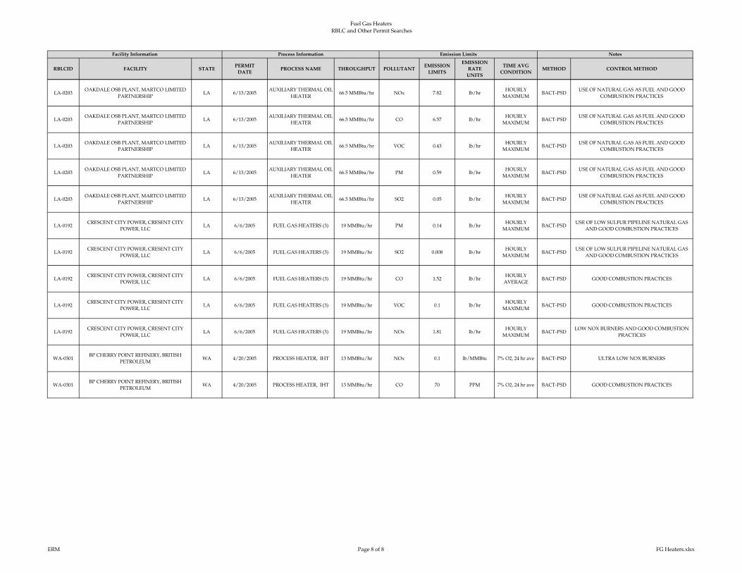
Fuel Gas Heaters
RBLC and Other Permit Searches
RBLCID FACILITY STATEPERMIT
DATEPROCESS NAME THROUGHPUT POLLUTANT
EMISSION
LIMITS
EMISSION
RATE
UNITS
TIME AVG
CONDITIONMETHOD CONTROL METHOD
Facility Information Process Information NotesEmission Limits
LA-0203OAKDALE OSB PLANT, MARTCO LIMITED
PARTNERSHIPLA 6/13/2005
AUXILIARY THERMAL OIL
HEATER66.5 MMBtu/hr NOx 7.82 lb/hr
HOURLY
MAXIMUMBACT-PSD
USE OF NATURAL GAS AS FUEL AND GOOD
COMBUSTION PRACTICES
LA-0203OAKDALE OSB PLANT, MARTCO LIMITED
PARTNERSHIPLA 6/13/2005
AUXILIARY THERMAL OIL
HEATER66.5 MMBtu/hr CO 6.57 lb/hr
HOURLY
MAXIMUMBACT-PSD
USE OF NATURAL GAS AS FUEL AND GOOD
COMBUSTION PRACTICES
LA-0203OAKDALE OSB PLANT, MARTCO LIMITED
PARTNERSHIPLA 6/13/2005
AUXILIARY THERMAL OIL
HEATER66.5 MMBtu/hr VOC 0.43 lb/hr
HOURLY
MAXIMUMBACT-PSD
USE OF NATURAL GAS AS FUEL AND GOOD
COMBUSTION PRACTICES
LA-0203OAKDALE OSB PLANT, MARTCO LIMITED
PARTNERSHIPLA 6/13/2005
AUXILIARY THERMAL OIL
HEATER66.5 MMBtu/hr PM 0.59 lb/hr
HOURLY
MAXIMUMBACT-PSD
USE OF NATURAL GAS AS FUEL AND GOOD
COMBUSTION PRACTICES
LA-0203OAKDALE OSB PLANT, MARTCO LIMITED
PARTNERSHIPLA 6/13/2005
AUXILIARY THERMAL OIL
HEATER66.5 MMBtu/hr SO2 0.05 lb/hr
HOURLY
MAXIMUMBACT-PSD
USE OF NATURAL GAS AS FUEL AND GOOD
COMBUSTION PRACTICES
LA-0192CRESCENT CITY POWER, CRESENT CITY
POWER, LLCLA 6/6/2005 FUEL GAS HEATERS (3) 19 MMBtu/hr PM 0.14 lb/hr
HOURLY
MAXIMUMBACT-PSD
USE OF LOW SULFUR PIPELINE NATURAL GAS
AND GOOD COMBUSTION PRACTICES
LA-0192CRESCENT CITY POWER, CRESENT CITY
POWER, LLCLA 6/6/2005 FUEL GAS HEATERS (3) 19 MMBtu/hr SO2 0.008 lb/hr
HOURLY
MAXIMUMBACT-PSD
USE OF LOW SULFUR PIPELINE NATURAL GAS
AND GOOD COMBUSTION PRACTICES
LA-0192CRESCENT CITY POWER, CRESENT CITY
POWER, LLCLA 6/6/2005 FUEL GAS HEATERS (3) 19 MMBtu/hr CO 1.52 lb/hr
HOURLY
AVERAGEBACT-PSD GOOD COMBUSTION PRACTICES
LA-0192CRESCENT CITY POWER, CRESENT CITY
POWER, LLCLA 6/6/2005 FUEL GAS HEATERS (3) 19 MMBtu/hr VOC 0.1 lb/hr
HOURLY
MAXIMUMBACT-PSD GOOD COMBUSTION PRACTICES
LA-0192CRESCENT CITY POWER, CRESENT CITY
POWER, LLCLA 6/6/2005 FUEL GAS HEATERS (3) 19 MMBtu/hr NOx 1.81 lb/hr
HOURLY
MAXIMUMBACT-PSD
LOW NOX BURNERS AND GOOD COMBUSTION
PRACTICES
WA-0301BP CHERRY POINT REFINERY, BRITISH
PETROLEUMWA 4/20/2005 PROCESS HEATER, IHT 13 MMBtu/hr NOx 0.1 lb/MMBtu 7% O2, 24 hr ave BACT-PSD ULTRA LOW NOX BURNERS
WA-0301BP CHERRY POINT REFINERY, BRITISH
PETROLEUMWA 4/20/2005 PROCESS HEATER, IHT 13 MMBtu/hr CO 70 PPM 7% O2, 24 hr ave BACT-PSD GOOD COMBUSTION PRACTICES
ERM Page 8 of 8 FG Heaters.xlsx

Emergency Generators and Fire Water Pumps RLBC and Other Permit Searches
RBLCID FACILITY STATEPERMIT
DATEPROCESS NAME THROUGHPUT POLLUTANT
EMISSION
LIMITS
EMISSION RATE
UNITSTIME AVG CONDITION METHOD CONTROL METHOD
*TX-0728PEONY CHEMICAL MANUFACTURING
FACILITY, BASFTX 4/1/2015 Emergency Diesel Generator 1500 hp VOC 0.7 lb/hr OTHER CASE-BY-CASE Minimized hours of operations Tier II engine
*TX-0728PEONY CHEMICAL MANUFACTURING
FACILITY, BASFTX 4/1/2015 Emergency Diesel Generator 1500 hp CO 0.0126 g/hp-hr OTHER CASE-BY-CASE Minimized hours of operations Tier II engine
*TX-0728PEONY CHEMICAL MANUFACTURING
FACILITY, BASFTX 4/1/2015 Emergency Diesel Generator 1500 hp NOx 0.0218 g/hp-hr LAER Minimized hours of operations Tier II engine
*TX-0728PEONY CHEMICAL MANUFACTURING
FACILITY, BASFTX 4/1/2015 Emergency Diesel Generator 1500 hp PM 0.15 lb/hr OTHER CASE-BY-CASE Minimized hours of operations Tier II engine
*TX-0728PEONY CHEMICAL MANUFACTURING
FACILITY, BASFTX 4/1/2015 Emergency Diesel Generator 1500 hp PM 0.15 lb/hr OTHER CASE-BY-CASE Minimized hours of operations Tier II engine
*TX-0728PEONY CHEMICAL MANUFACTURING
FACILITY, BASFTX 4/1/2015 Emergency Diesel Generator 1500 hp PM 0.15 lb/hr OTHER CASE-BY-CASE Minimized hours of operations Tier II engine
*TX-0728PEONY CHEMICAL MANUFACTURING
FACILITY, BASFTX 4/1/2015 Emergency Diesel Generator 1500 hp SO2 0.61 lb/hr OTHER CASE-BY-CASE Low sulfur fuel 15 ppmw
*AK-0082
POINT THOMSON PRODUCTION
FACILITY, EXXON MOBIL
CORPORATION
AK 1/23/2015 Emergency Camp Generators 2695 hp CO2e 2332 TPY COMBINED BACT-PSD
*AK-0082
POINT THOMSON PRODUCTION
FACILITY, EXXON MOBIL
CORPORATION
AK 1/23/2015 Emergency Camp Generators 2695 hp VOC 0.0007 lb/hp-hr BACT-PSD
*AK-0082
POINT THOMSON PRODUCTION
FACILITY, EXXON MOBIL
CORPORATION
AK 1/23/2015 Emergency Camp Generators 2695 hp PM 0.15 g/hp-hr BACT-PSD
*AK-0082
POINT THOMSON PRODUCTION
FACILITY, EXXON MOBIL
CORPORATION
AK 1/23/2015 Emergency Camp Generators 2695 hp PM 0.15 g/hp-hr BACT-PSD
*AK-0082
POINT THOMSON PRODUCTION
FACILITY, EXXON MOBIL
CORPORATION
AK 1/23/2015 Airstrip Generator Engine 490 hp CO2e 163 TPY BACT-PSD
*AK-0082
POINT THOMSON PRODUCTION
FACILITY, EXXON MOBIL
CORPORATION
AK 1/23/2015 Airstrip Generator Engine 490 hp VOC 0.0025 lb/hp-hr BACT-PSD
*AK-0082
POINT THOMSON PRODUCTION
FACILITY, EXXON MOBIL
CORPORATION
AK 1/23/2015 Airstrip Generator Engine 490 hp PM 0.15 g/hp-hr BACT-PSD
*AK-0082
POINT THOMSON PRODUCTION
FACILITY, EXXON MOBIL
CORPORATION
AK 1/23/2015 Airstrip Generator Engine 490 hp PM 0.15 g/hp-hr BACT-PSD
*AK-0082
POINT THOMSON PRODUCTION
FACILITY, EXXON MOBIL
CORPORATION
AK 1/23/2015 Agitator Generator Engine 98 hp CO2e 356 TPY BACT-PSD
*AK-0082
POINT THOMSON PRODUCTION
FACILITY, EXXON MOBIL
CORPORATION
AK 1/23/2015 Agitator Generator Engine 98 hp VOC 0.0025 lb/hp-hr BACT-PSD
*AK-0082
POINT THOMSON PRODUCTION
FACILITY, EXXON MOBIL
CORPORATION
AK 1/23/2015 Agitator Generator Engine 98 hp NOx 5.6 g/hp-hr BACT-PSD
*AK-0082
POINT THOMSON PRODUCTION
FACILITY, EXXON MOBIL
CORPORATION
AK 1/23/2015 Agitator Generator Engine 98 hp PM 0.3 g/hp-hr BACT-PSD
*AK-0082
POINT THOMSON PRODUCTION
FACILITY, EXXON MOBIL
CORPORATION
AK 1/23/2015 Agitator Generator Engine 98 hp PM 0.3 g/hp-hr BACT-PSD
*AK-0082
POINT THOMSON PRODUCTION
FACILITY, EXXON MOBIL
CORPORATION
AK 1/23/2015 Fine Water Pumps 610 hp CO2e 565 TPY COMBINED BACT-PSD
*AK-0082
POINT THOMSON PRODUCTION
FACILITY, EXXON MOBIL
CORPORATION
AK 1/23/2015 Fine Water Pumps 610 hp VOC 0.0007 lb/hp-hr BACT-PSD
Facility Information Process Information Emission Limits Notes
ERM Page 1 of 19 Engines BACT Table.xlsx
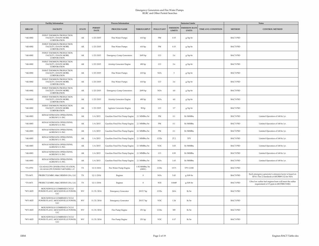
Emergency Generators and Fire Water Pumps RLBC and Other Permit Searches
RBLCID FACILITY STATEPERMIT
DATEPROCESS NAME THROUGHPUT POLLUTANT
EMISSION
LIMITS
EMISSION RATE
UNITSTIME AVG CONDITION METHOD CONTROL METHOD
Facility Information Process Information Emission Limits Notes
*AK-0082
POINT THOMSON PRODUCTION
FACILITY, EXXON MOBIL
CORPORATION
AK 1/23/2015 Fine Water Pumps 610 hp PM 0.15 g/hp-hr BACT-PSD
*AK-0082
POINT THOMSON PRODUCTION
FACILITY, EXXON MOBIL
CORPORATION
AK 1/23/2015 Fine Water Pumps 610 hp PM 0.15 g/hp-hr BACT-PSD
*AK-0082
POINT THOMSON PRODUCTION
FACILITY, EXXON MOBIL
CORPORATION
AK 1/23/2015 Emergency Camp Generators 2695 hp CO 2.6 g/hp-hr BACT-PSD
*AK-0082
POINT THOMSON PRODUCTION
FACILITY, EXXON MOBIL
CORPORATION
AK 1/23/2015 Airstrip Generator Engine 490 hp CO 2.6 g/hp-hr BACT-PSD
*AK-0082
POINT THOMSON PRODUCTION
FACILITY, EXXON MOBIL
CORPORATION
AK 1/23/2015 Fine Water Pumps 610 hp NOx 3 g/hp-hr BACT-PSD
*AK-0082
POINT THOMSON PRODUCTION
FACILITY, EXXON MOBIL
CORPORATION
AK 1/23/2015 Fine Water Pumps 610 hp CO 2.6 g/hp-hr BACT-PSD
*AK-0082
POINT THOMSON PRODUCTION
FACILITY, EXXON MOBIL
CORPORATION
AK 1/23/2015 Emergency Camp Generators 2695 hp NOx 4.8 g/hp-hr BACT-PSD
*AK-0082
POINT THOMSON PRODUCTION
FACILITY, EXXON MOBIL
CORPORATION
AK 1/23/2015 Airstrip Generator Engine 490 hp NOx 4.8 g/hp-hr BACT-PSD
*AK-0082
POINT THOMSON PRODUCTION
FACILITY, EXXON MOBIL
CORPORATION
AK 1/23/2015 Agitator Generator Engine 98 hp CO 3.7 g/hp-hr BACT-PSD
*AK-0083KENAI NITROGEN OPERATIONS,
AGRIUM U.S. INC.AK 1/6/2015 Gasoline Fired Fire Pump Engine 2.1 MMBtu/hr PM 0.1 lb/MMBtu BACT-PSD Limited Operation of 168 hr/yr.
*AK-0083KENAI NITROGEN OPERATIONS,
AGRIUM U.S. INC.AK 1/6/2015 Gasoline Fired Fire Pump Engine 2.1 MMBtu/hr PM 0.1 lb/MMBtu BACT-PSD Limited Operation of 168 hr/yr.
*AK-0083KENAI NITROGEN OPERATIONS,
AGRIUM U.S. INC.AK 1/6/2015 Gasoline Fired Fire Pump Engine 2.1 MMBtu/hr PM 0.1 lb/MMBtu BACT-PSD Limited Operation of 168 hr/yr.
*AK-0083KENAI NITROGEN OPERATIONS,
AGRIUM U.S. INC.AK 1/6/2015 Gasoline Fired Fire Pump Engine 2.1 MMBtu/hr CO2e 27.2 TPY BACT-PSD Limited Operation of 168 hr/yr.
*AK-0083KENAI NITROGEN OPERATIONS,
AGRIUM U.S. INC.AK 1/6/2015 Gasoline Fired Fire Pump Engine 2.1 MMBtu/hr VOC 3.03 lb/MMBtu BACT-PSD Limited Operation of 168 hr/yr.
*AK-0083KENAI NITROGEN OPERATIONS,
AGRIUM U.S. INC.AK 1/6/2015 Gasoline Fired Fire Pump Engine 2.1 MMBtu/hr CO 0.99 lb/MMBtu BACT-PSD Limited Operation of 168 hr/yr.
*AK-0083KENAI NITROGEN OPERATIONS,
AGRIUM U.S. INC.AK 1/6/2015 Gasoline Fired Fire Pump Engine 2.1 MMBtu/hr NOx 1.63 lb/MMBtu BACT-PSD Limited Operation of 168 hr/yr.
*TX-0753GUADALUPE GENERATING STATION,
GUADALUPE POWER PARTNERS, L.P.TX 12/2/2014 Fire Water Pump Engine
1.92 MMBtu/hr
(HHV)CO2e 15.71 TPY CO2E BACT-PSD
*TX-0671 PROJECT JUMBO, M&G RESINS USA, LLC TX 12/1/2014 Engines 0 NOx 5.43 g/kW-hr BACT-PSDEach emergency generator's emission factor is based on
EPA's Tier 2 standards at 40CFR89.112 for NOx
*TX-0671 PROJECT JUMBO, M&G RESINS USA, LLC TX 12/1/2014 Engines 0 SO2 0.0649 g/kW-hr BACT-PSDUltra low sulfur fuel engines burn will meet the sulfur
requirement of 15 ppm in 40CFR80.510(b)
*WV-0025
MOUNDSVILLE COMBINED CYCLE
POWER PLANT, MOUNDSVILLE POWER,
LLC
WV 11/21/2014 Emergency Generator 2015.7 hp CO2e 2416 lb/hr BACT-PSD
*WV-0025
MOUNDSVILLE COMBINED CYCLE
POWER PLANT, MOUNDSVILLE POWER,
LLC
WV 11/21/2014 Emergency Generator 2015.7 hp VOC 1.24 lb/hr BACT-PSD
*WV-0025
MOUNDSVILLE COMBINED CYCLE
POWER PLANT, MOUNDSVILLE POWER,
LLC
WV 11/21/2014 Fire Pump Engine 251 hp CO2e 309 lb/hr BACT-PSD
*WV-0025
MOUNDSVILLE COMBINED CYCLE
POWER PLANT, MOUNDSVILLE POWER,
LLC
WV 11/21/2014 Fire Pump Engine 251 hp VOC 0.17 lb/hr BACT-PSD
ERM Page 2 of 19 Engines BACT Table.xlsx
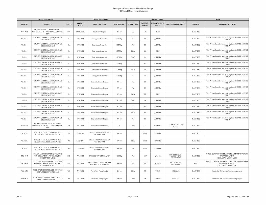
Emergency Generators and Fire Water Pumps RLBC and Other Permit Searches
RBLCID FACILITY STATEPERMIT
DATEPROCESS NAME THROUGHPUT POLLUTANT
EMISSION
LIMITS
EMISSION RATE
UNITSTIME AVG CONDITION METHOD CONTROL METHOD
Facility Information Process Information Emission Limits Notes
*WV-0025
MOUNDSVILLE COMBINED CYCLE
POWER PLANT, MOUNDSVILLE POWER,
LLC
WV 11/21/2014 Fire Pump Engine 251 hp CO 1.44 lb/hr BACT-PSD
*IL-0114CRONUS CHEMICALS, LLC, CRONUS
CHEMICALS, LLCIL 9/5/2014 Emergency Generator 3755 hp PM 0.1 g/kW-hr BACT-PSD
Tier IV standards for non-road engines at 40 CFR 1039.102,
Table 7.
*IL-0114CRONUS CHEMICALS, LLC, CRONUS
CHEMICALS, LLCIL 9/5/2014 Emergency Generator 3755 hp PM 0.1 g/kW-hr BACT-PSD
Tier IV standards for non-road engines at 40 CFR 1039.102,
Table 7.
*IL-0114CRONUS CHEMICALS, LLC, CRONUS
CHEMICALS, LLCIL 9/5/2014 Emergency Generator 3755 hp CO2e 432 TPY BACT-PSD
Tier IV standards for non-road engines at 40 CFR 1039.102,
Table 7.
*IL-0114CRONUS CHEMICALS, LLC, CRONUS
CHEMICALS, LLCIL 9/5/2014 Emergency Generator 3755 hp VOC 0.4 g/kW-hr BACT-PSD
Tier IV standards for non-road engines at 40 CFR 1039.102,
Table 7.
*IL-0114CRONUS CHEMICALS, LLC, CRONUS
CHEMICALS, LLCIL 9/5/2014 Emergency Generator 3755 hp CO 3.5 g/kW-hr BACT-PSD
Tier IV standards for non-road engines at 40 CFR 1039.102,
Table 7.
*IL-0114CRONUS CHEMICALS, LLC, CRONUS
CHEMICALS, LLCIL 9/5/2014 Emergency Generator 3755 hp NOx 0.67 g/kW-hr BACT-PSD
Tier IV standards for non-road engines at 40 CFR 1039.102,
Table 7.
*IL-0114CRONUS CHEMICALS, LLC, CRONUS
CHEMICALS, LLCIL 9/5/2014 Emergency Generator 3755 hp PM 0.1 g/kW-hr BACT-PSD
Tier IV standards for non-road engines at 40 CFR 1039.102,
Table 7.
*IL-0114CRONUS CHEMICALS, LLC, CRONUS
CHEMICALS, LLCIL 9/5/2014 Firewater Pump Engine 373 hp PM 0.1 g/kW-hr BACT-PSD
Tier IV standards for non-road engines at 40 CFR 1039.102,
Table 7.
*IL-0114CRONUS CHEMICALS, LLC, CRONUS
CHEMICALS, LLCIL 9/5/2014 Firewater Pump Engine 373 hp PM 0.1 g/kW-hr BACT-PSD
Tier IV standards for non-road engines at 40 CFR 1039.102,
Table 7.
*IL-0114CRONUS CHEMICALS, LLC, CRONUS
CHEMICALS, LLCIL 9/5/2014 Firewater Pump Engine 373 hp CO2e 72 TPY BACT-PSD
Tier IV standards for non-road engines at 40 CFR 1039.102,
Table 7.
*IL-0114CRONUS CHEMICALS, LLC, CRONUS
CHEMICALS, LLCIL 9/5/2014 Firewater Pump Engine 373 hp VOC 0.4 g/kW-hr BACT-PSD
Tier IV standards for non-road engines at 40 CFR 1039.102,
Table 7.
*IL-0114CRONUS CHEMICALS, LLC, CRONUS
CHEMICALS, LLCIL 9/5/2014 Firewater Pump Engine 373 hp CO 3.5 g/kW-hr BACT-PSD
Tier IV standards for non-road engines at 40 CFR 1039.102,
Table 7.
*IL-0114CRONUS CHEMICALS, LLC, CRONUS
CHEMICALS, LLCIL 9/5/2014 Firewater Pump Engine 373 hp NOx 3.5 g/kW-hr BACT-PSD
Tier IV standards for non-road engines at 40 CFR 1039.102,
Table 7.
*IL-0114CRONUS CHEMICALS, LLC, CRONUS
CHEMICALS, LLCIL 9/5/2014 Firewater Pump Engine 373 hp PM 0.1 g/kW-hr BACT-PSD
Tier IV standards for non-road engines at 40 CFR 1039.102,
Table 7.
*TX-0758
ECTOR COUNTY ENERGY CENTER,
INVENERGY THERMAL DEVELOPMENT
LLC
TX 8/1/2014 Firewater Pump Engine 0 CO2e 5 TPY CO2E12-MONTH ROLLING
TOTALBACT-PSD
*AL-0301NUCOR STEEL TUSCALOOSA, INC.,
NUCOR STEEL TUSCALOOSA, INC.AL 7/22/2014
DIESEL FIRED EMERGENCY
GENERATOR800 hp CO 0.0055 lb/hp-hr BACT-PSD
*AL-0301NUCOR STEEL TUSCALOOSA, INC.,
NUCOR STEEL TUSCALOOSA, INC.AL 7/22/2014
DIESEL FIRED EMERGENCY
GENERATOR800 hp NOx 0.015 lb/hp-hr BACT-PSD
*AL-0301NUCOR STEEL TUSCALOOSA, INC.,
NUCOR STEEL TUSCALOOSA, INC.AL 7/22/2014
DIESEL FIRED EMERGENCY
GENERATOR800 hp PM 0.0007 lb/hp-hr BACT-PSD
*MD-0043
PERRYMAN GENERATING STATION,
CONSTELLATION POWER SOURCE
GENERATION, INC.
MD 7/1/2014 EMERGENCY GENERATOR 1300 hp PM 0.17 g/hp-hrCONDENSIBLE +
FILTERABLEBACT-PSD
GOOD COMBUSTION PRACTICES, LIMITED HOURS OF
OPERATION, AND
EXCLUSIVE USE OF ULSD
*MD-0043
PERRYMAN GENERATING STATION,
CONSTELLATION POWER SOURCE
GENERATION, INC.
MD 7/1/2014EMERGENCY DIESEL ENGINE
FOR FIRE WATER PUMP350 hp PM 0.17 g/hp-hr
FILTERABLE +
CONDENSIBLEBART
GOOD COMBUSTION PRACTICES, LIMITED HOURS OF
OPERATION, AND
EXCLUSIVE USE OF ULSD
*WY-0076ROCK SPRINGS FERTILIZER COMPLEX,
SIMPLOT PHOSPHATES, LLCWY 7/1/2014 Fire Water Pump Engine 200 hp CO2e 58 TONS ANNUAL BACT-PSD limited to 500 hours of operation per year
*WY-0076ROCK SPRINGS FERTILIZER COMPLEX,
SIMPLOT PHOSPHATES, LLCWY 7/1/2014 Fire Water Pump Engine 200 hp CO2e 58 TONS ANNUAL BACT-PSD limited to 500 hours of operation per year
ERM Page 3 of 19 Engines BACT Table.xlsx
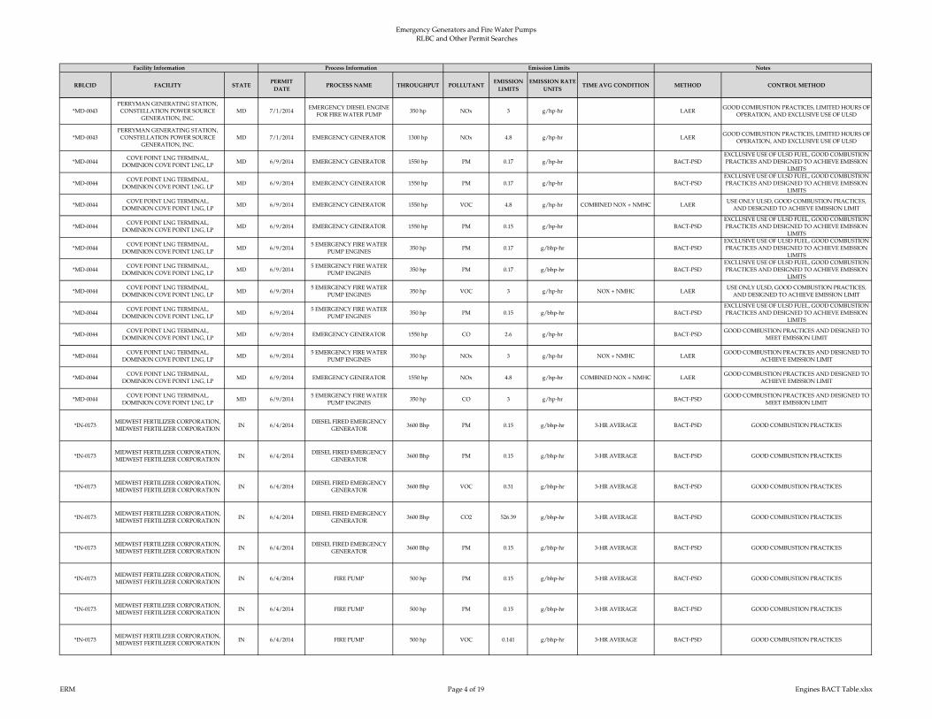
Emergency Generators and Fire Water Pumps RLBC and Other Permit Searches
RBLCID FACILITY STATEPERMIT
DATEPROCESS NAME THROUGHPUT POLLUTANT
EMISSION
LIMITS
EMISSION RATE
UNITSTIME AVG CONDITION METHOD CONTROL METHOD
Facility Information Process Information Emission Limits Notes
*MD-0043
PERRYMAN GENERATING STATION,
CONSTELLATION POWER SOURCE
GENERATION, INC.
MD 7/1/2014EMERGENCY DIESEL ENGINE
FOR FIRE WATER PUMP350 hp NOx 3 g/hp-hr LAER
GOOD COMBUSTION PRACTICES, LIMITED HOURS OF
OPERATION, AND EXCLUSIVE USE OF ULSD
*MD-0043
PERRYMAN GENERATING STATION,
CONSTELLATION POWER SOURCE
GENERATION, INC.
MD 7/1/2014 EMERGENCY GENERATOR 1300 hp NOx 4.8 g/hp-hr LAERGOOD COMBUSTION PRACTICES, LIMITED HOURS OF
OPERATION, AND EXCLUSIVE USE OF ULSD
*MD-0044COVE POINT LNG TERMINAL,
DOMINION COVE POINT LNG, LPMD 6/9/2014 EMERGENCY GENERATOR 1550 hp PM 0.17 g/hp-hr BACT-PSD
EXCLUSIVE USE OF ULSD FUEL, GOOD COMBUSTION
PRACTICES AND DESIGNED TO ACHIEVE EMISSION
LIMITS
*MD-0044COVE POINT LNG TERMINAL,
DOMINION COVE POINT LNG, LPMD 6/9/2014 EMERGENCY GENERATOR 1550 hp PM 0.17 g/hp-hr BACT-PSD
EXCLUSIVE USE OF ULSD FUEL, GOOD COMBUSTION
PRACTICES AND DESIGNED TO ACHIEVE EMISSION
LIMITS
*MD-0044COVE POINT LNG TERMINAL,
DOMINION COVE POINT LNG, LPMD 6/9/2014 EMERGENCY GENERATOR 1550 hp VOC 4.8 g/hp-hr COMBINED NOX + NMHC LAER
USE ONLY ULSD, GOOD COMBUSTION PRACTICES,
AND DESIGNED TO ACHIEVE EMISSION LIMIT
*MD-0044COVE POINT LNG TERMINAL,
DOMINION COVE POINT LNG, LPMD 6/9/2014 EMERGENCY GENERATOR 1550 hp PM 0.15 g/hp-hr BACT-PSD
EXCLUSIVE USE OF ULSD FUEL, GOOD COMBUSTION
PRACTICES AND DESIGNED TO ACHIEVE EMISSION
LIMITS
*MD-0044COVE POINT LNG TERMINAL,
DOMINION COVE POINT LNG, LPMD 6/9/2014
5 EMERGENCY FIRE WATER
PUMP ENGINES350 hp PM 0.17 g/bhp-hr BACT-PSD
EXCLUSIVE USE OF ULSD FUEL, GOOD COMBUSTION
PRACTICES AND DESIGNED TO ACHIEVE EMISSION
LIMITS
*MD-0044COVE POINT LNG TERMINAL,
DOMINION COVE POINT LNG, LPMD 6/9/2014
5 EMERGENCY FIRE WATER
PUMP ENGINES350 hp PM 0.17 g/bhp-hr BACT-PSD
EXCLUSIVE USE OF ULSD FUEL, GOOD COMBUSTION
PRACTICES AND DESIGNED TO ACHIEVE EMISSION
LIMITS
*MD-0044COVE POINT LNG TERMINAL,
DOMINION COVE POINT LNG, LPMD 6/9/2014
5 EMERGENCY FIRE WATER
PUMP ENGINES350 hp VOC 3 g/hp-hr NOX + NMHC LAER
USE ONLY ULSD, GOOD COMBUSTION PRACTICES,
AND DESIGNED TO ACHIEVE EMISSION LIMIT
*MD-0044COVE POINT LNG TERMINAL,
DOMINION COVE POINT LNG, LPMD 6/9/2014
5 EMERGENCY FIRE WATER
PUMP ENGINES350 hp PM 0.15 g/bhp-hr BACT-PSD
EXCLUSIVE USE OF ULSD FUEL, GOOD COMBUSTION
PRACTICES AND DESIGNED TO ACHIEVE EMISSION
LIMITS
*MD-0044COVE POINT LNG TERMINAL,
DOMINION COVE POINT LNG, LPMD 6/9/2014 EMERGENCY GENERATOR 1550 hp CO 2.6 g/hp-hr BACT-PSD
GOOD COMBUSTION PRACTICES AND DESIGNED TO
MEET EMISSION LIMIT
*MD-0044COVE POINT LNG TERMINAL,
DOMINION COVE POINT LNG, LPMD 6/9/2014
5 EMERGENCY FIRE WATER
PUMP ENGINES350 hp NOx 3 g/hp-hr NOX + NMHC LAER
GOOD COMBUSTION PRACTICES AND DESIGNED TO
ACHIEVE EMISSION LIMIT
*MD-0044COVE POINT LNG TERMINAL,
DOMINION COVE POINT LNG, LPMD 6/9/2014 EMERGENCY GENERATOR 1550 hp NOx 4.8 g/hp-hr COMBINED NOX + NMHC LAER
GOOD COMBUSTION PRACTICES AND DESIGNED TO
ACHIEVE EMISSION LIMIT
*MD-0044COVE POINT LNG TERMINAL,
DOMINION COVE POINT LNG, LPMD 6/9/2014
5 EMERGENCY FIRE WATER
PUMP ENGINES350 hp CO 3 g/hp-hr BACT-PSD
GOOD COMBUSTION PRACTICES AND DESIGNED TO
MEET EMISSION LIMIT
*IN-0173MIDWEST FERTILIZER CORPORATION,
MIDWEST FERTILIZER CORPORATIONIN 6/4/2014
DIESEL FIRED EMERGENCY
GENERATOR3600 Bhp PM 0.15 g/bhp-hr 3-HR AVERAGE BACT-PSD GOOD COMBUSTION PRACTICES
*IN-0173MIDWEST FERTILIZER CORPORATION,
MIDWEST FERTILIZER CORPORATIONIN 6/4/2014
DIESEL FIRED EMERGENCY
GENERATOR3600 Bhp PM 0.15 g/bhp-hr 3-HR AVERAGE BACT-PSD GOOD COMBUSTION PRACTICES
*IN-0173MIDWEST FERTILIZER CORPORATION,
MIDWEST FERTILIZER CORPORATIONIN 6/4/2014
DIESEL FIRED EMERGENCY
GENERATOR3600 Bhp VOC 0.31 g/bhp-hr 3-HR AVERAGE BACT-PSD GOOD COMBUSTION PRACTICES
*IN-0173MIDWEST FERTILIZER CORPORATION,
MIDWEST FERTILIZER CORPORATIONIN 6/4/2014
DIESEL FIRED EMERGENCY
GENERATOR3600 Bhp CO2 526.39 g/bhp-hr 3-HR AVERAGE BACT-PSD GOOD COMBUSTION PRACTICES
*IN-0173MIDWEST FERTILIZER CORPORATION,
MIDWEST FERTILIZER CORPORATIONIN 6/4/2014
DIESEL FIRED EMERGENCY
GENERATOR3600 Bhp PM 0.15 g/bhp-hr 3-HR AVERAGE BACT-PSD GOOD COMBUSTION PRACTICES
*IN-0173MIDWEST FERTILIZER CORPORATION,
MIDWEST FERTILIZER CORPORATIONIN 6/4/2014 FIRE PUMP 500 hp PM 0.15 g/bhp-hr 3-HR AVERAGE BACT-PSD GOOD COMBUSTION PRACTICES
*IN-0173MIDWEST FERTILIZER CORPORATION,
MIDWEST FERTILIZER CORPORATIONIN 6/4/2014 FIRE PUMP 500 hp PM 0.15 g/bhp-hr 3-HR AVERAGE BACT-PSD GOOD COMBUSTION PRACTICES
*IN-0173MIDWEST FERTILIZER CORPORATION,
MIDWEST FERTILIZER CORPORATIONIN 6/4/2014 FIRE PUMP 500 hp VOC 0.141 g/bhp-hr 3-HR AVERAGE BACT-PSD GOOD COMBUSTION PRACTICES
ERM Page 4 of 19 Engines BACT Table.xlsx
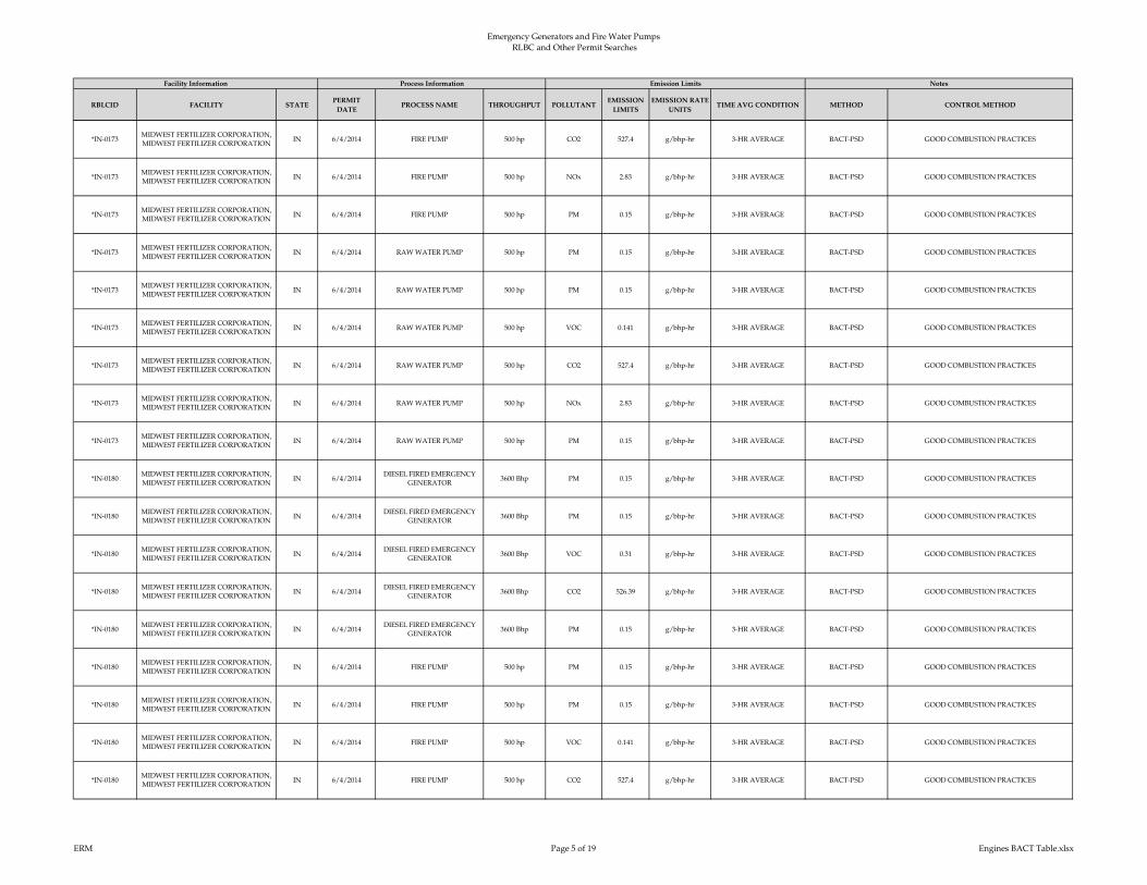
Emergency Generators and Fire Water Pumps RLBC and Other Permit Searches
RBLCID FACILITY STATEPERMIT
DATEPROCESS NAME THROUGHPUT POLLUTANT
EMISSION
LIMITS
EMISSION RATE
UNITSTIME AVG CONDITION METHOD CONTROL METHOD
Facility Information Process Information Emission Limits Notes
*IN-0173MIDWEST FERTILIZER CORPORATION,
MIDWEST FERTILIZER CORPORATIONIN 6/4/2014 FIRE PUMP 500 hp CO2 527.4 g/bhp-hr 3-HR AVERAGE BACT-PSD GOOD COMBUSTION PRACTICES
*IN-0173MIDWEST FERTILIZER CORPORATION,
MIDWEST FERTILIZER CORPORATIONIN 6/4/2014 FIRE PUMP 500 hp NOx 2.83 g/bhp-hr 3-HR AVERAGE BACT-PSD GOOD COMBUSTION PRACTICES
*IN-0173MIDWEST FERTILIZER CORPORATION,
MIDWEST FERTILIZER CORPORATIONIN 6/4/2014 FIRE PUMP 500 hp PM 0.15 g/bhp-hr 3-HR AVERAGE BACT-PSD GOOD COMBUSTION PRACTICES
*IN-0173MIDWEST FERTILIZER CORPORATION,
MIDWEST FERTILIZER CORPORATIONIN 6/4/2014 RAW WATER PUMP 500 hp PM 0.15 g/bhp-hr 3-HR AVERAGE BACT-PSD GOOD COMBUSTION PRACTICES
*IN-0173MIDWEST FERTILIZER CORPORATION,
MIDWEST FERTILIZER CORPORATIONIN 6/4/2014 RAW WATER PUMP 500 hp PM 0.15 g/bhp-hr 3-HR AVERAGE BACT-PSD GOOD COMBUSTION PRACTICES
*IN-0173MIDWEST FERTILIZER CORPORATION,
MIDWEST FERTILIZER CORPORATIONIN 6/4/2014 RAW WATER PUMP 500 hp VOC 0.141 g/bhp-hr 3-HR AVERAGE BACT-PSD GOOD COMBUSTION PRACTICES
*IN-0173MIDWEST FERTILIZER CORPORATION,
MIDWEST FERTILIZER CORPORATIONIN 6/4/2014 RAW WATER PUMP 500 hp CO2 527.4 g/bhp-hr 3-HR AVERAGE BACT-PSD GOOD COMBUSTION PRACTICES
*IN-0173MIDWEST FERTILIZER CORPORATION,
MIDWEST FERTILIZER CORPORATIONIN 6/4/2014 RAW WATER PUMP 500 hp NOx 2.83 g/bhp-hr 3-HR AVERAGE BACT-PSD GOOD COMBUSTION PRACTICES
*IN-0173MIDWEST FERTILIZER CORPORATION,
MIDWEST FERTILIZER CORPORATIONIN 6/4/2014 RAW WATER PUMP 500 hp PM 0.15 g/bhp-hr 3-HR AVERAGE BACT-PSD GOOD COMBUSTION PRACTICES
*IN-0180MIDWEST FERTILIZER CORPORATION,
MIDWEST FERTILIZER CORPORATIONIN 6/4/2014
DIESEL FIRED EMERGENCY
GENERATOR3600 Bhp PM 0.15 g/bhp-hr 3-HR AVERAGE BACT-PSD GOOD COMBUSTION PRACTICES
*IN-0180MIDWEST FERTILIZER CORPORATION,
MIDWEST FERTILIZER CORPORATIONIN 6/4/2014
DIESEL FIRED EMERGENCY
GENERATOR3600 Bhp PM 0.15 g/bhp-hr 3-HR AVERAGE BACT-PSD GOOD COMBUSTION PRACTICES
*IN-0180MIDWEST FERTILIZER CORPORATION,
MIDWEST FERTILIZER CORPORATIONIN 6/4/2014
DIESEL FIRED EMERGENCY
GENERATOR3600 Bhp VOC 0.31 g/bhp-hr 3-HR AVERAGE BACT-PSD GOOD COMBUSTION PRACTICES
*IN-0180MIDWEST FERTILIZER CORPORATION,
MIDWEST FERTILIZER CORPORATIONIN 6/4/2014
DIESEL FIRED EMERGENCY
GENERATOR3600 Bhp CO2 526.39 g/bhp-hr 3-HR AVERAGE BACT-PSD GOOD COMBUSTION PRACTICES
*IN-0180MIDWEST FERTILIZER CORPORATION,
MIDWEST FERTILIZER CORPORATIONIN 6/4/2014
DIESEL FIRED EMERGENCY
GENERATOR3600 Bhp PM 0.15 g/bhp-hr 3-HR AVERAGE BACT-PSD GOOD COMBUSTION PRACTICES
*IN-0180MIDWEST FERTILIZER CORPORATION,
MIDWEST FERTILIZER CORPORATIONIN 6/4/2014 FIRE PUMP 500 hp PM 0.15 g/bhp-hr 3-HR AVERAGE BACT-PSD GOOD COMBUSTION PRACTICES
*IN-0180MIDWEST FERTILIZER CORPORATION,
MIDWEST FERTILIZER CORPORATIONIN 6/4/2014 FIRE PUMP 500 hp PM 0.15 g/bhp-hr 3-HR AVERAGE BACT-PSD GOOD COMBUSTION PRACTICES
*IN-0180MIDWEST FERTILIZER CORPORATION,
MIDWEST FERTILIZER CORPORATIONIN 6/4/2014 FIRE PUMP 500 hp VOC 0.141 g/bhp-hr 3-HR AVERAGE BACT-PSD GOOD COMBUSTION PRACTICES
*IN-0180MIDWEST FERTILIZER CORPORATION,
MIDWEST FERTILIZER CORPORATIONIN 6/4/2014 FIRE PUMP 500 hp CO2 527.4 g/bhp-hr 3-HR AVERAGE BACT-PSD GOOD COMBUSTION PRACTICES
ERM Page 5 of 19 Engines BACT Table.xlsx

Emergency Generators and Fire Water Pumps RLBC and Other Permit Searches
RBLCID FACILITY STATEPERMIT
DATEPROCESS NAME THROUGHPUT POLLUTANT
EMISSION
LIMITS
EMISSION RATE
UNITSTIME AVG CONDITION METHOD CONTROL METHOD
Facility Information Process Information Emission Limits Notes
*IN-0180MIDWEST FERTILIZER CORPORATION,
MIDWEST FERTILIZER CORPORATIONIN 6/4/2014 FIRE PUMP 500 hp NOx 2.83 g/bhp-hr 3-HR AVERAGE BACT-PSD GOOD COMBUSTION PRACTICES
*IN-0180MIDWEST FERTILIZER CORPORATION,
MIDWEST FERTILIZER CORPORATIONIN 6/4/2014 FIRE PUMP 500 hp PM 0.15 g/bhp-hr 3-HR AVERAGE BACT-PSD GOOD COMBUSTION PRACTICES
*IN-0180MIDWEST FERTILIZER CORPORATION,
MIDWEST FERTILIZER CORPORATIONIN 6/4/2014 RAW WATER PUMP 500 hp PM 0.15 g/bhp-hr 3-HR AVERAGE BACT-PSD GOOD COMBUSTION PRACTICES
*IN-0180MIDWEST FERTILIZER CORPORATION,
MIDWEST FERTILIZER CORPORATIONIN 6/4/2014 RAW WATER PUMP 500 hp PM 0.15 g/bhp-hr 3-HR AVERAGE BACT-PSD GOOD COMBUSTION PRACTICES
*IN-0180MIDWEST FERTILIZER CORPORATION,
MIDWEST FERTILIZER CORPORATIONIN 6/4/2014 RAW WATER PUMP 500 hp VOC 0.141 g/bhp-hr 3-HR AVERAGE BACT-PSD GOOD COMBUSTION PRACTICES
*IN-0180MIDWEST FERTILIZER CORPORATION,
MIDWEST FERTILIZER CORPORATIONIN 6/4/2014 RAW WATER PUMP 500 hp CO2 527.4 g/bhp-hr 3-HR AVERAGE BACT-PSD GOOD COMBUSTION PRACTICES
*IN-0180MIDWEST FERTILIZER CORPORATION,
MIDWEST FERTILIZER CORPORATIONIN 6/4/2014 RAW WATER PUMP 500 hp NOx 2.83 g/bhp-hr 3-HR AVERAGE BACT-PSD GOOD COMBUSTION PRACTICES
*IN-0180MIDWEST FERTILIZER CORPORATION,
MIDWEST FERTILIZER CORPORATIONIN 6/4/2014 RAW WATER PUMP 500 hp PM 0.15 g/bhp-hr 3-HR AVERAGE BACT-PSD GOOD COMBUSTION PRACTICES
*IN-0173MIDWEST FERTILIZER CORPORATION,
MIDWEST FERTILIZER CORPORATIONIN 6/4/2014
DIESEL FIRED EMERGENCY
GENERATOR3600 Bhp NOx 4.46 g/bhp-hr 3-HR AVERAGE BACT-PSD GOOD COMBUSTION PRACTICES
*IN-0180MIDWEST FERTILIZER CORPORATION,
MIDWEST FERTILIZER CORPORATIONIN 6/4/2014
DIESEL FIRED EMERGENCY
GENERATOR3600 Bhp NOx 4.46 g/bhp-hr 3-HR AVERAGE BACT-PSD GOOD COMBUSTION PRACTICES
*IN-0173MIDWEST FERTILIZER CORPORATION,
MIDWEST FERTILIZER CORPORATIONIN 6/4/2014 RAW WATER PUMP 500 hp CO 2.6 g/bhp-hr 3-HR AVERAGE BACT-PSD GOOD COMBUSTION PRACTICES
*IN-0180MIDWEST FERTILIZER CORPORATION,
MIDWEST FERTILIZER CORPORATIONIN 6/4/2014 RAW WATER PUMP 500 hp CO 2.6 g/bhp-hr 3-HR AVERAGE BACT-PSD GOOD COMBUSTION PRACTICES
*IN-0173MIDWEST FERTILIZER CORPORATION,
MIDWEST FERTILIZER CORPORATIONIN 6/4/2014 FIRE PUMP 500 hp CO 2.6 g/bhp-hr 3-HR AVERAGE BACT-PSD GOOD COMBUSTION PRACTICES
*IN-0180MIDWEST FERTILIZER CORPORATION,
MIDWEST FERTILIZER CORPORATIONIN 6/4/2014 FIRE PUMP 500 hp CO 2.6 g/bhp-hr 3-HR AVERAGE BACT-PSD GOOD COMBUSTION PRACTICES
*IN-0173MIDWEST FERTILIZER CORPORATION,
MIDWEST FERTILIZER CORPORATIONIN 6/4/2014
DIESEL FIRED EMERGENCY
GENERATOR3600 Bhp CO 2.61 g/bhp-hr 3-HR AVERAGE BACT-PSD GOOD COMBUSTION PRACTICES
*IN-0180MIDWEST FERTILIZER CORPORATION,
MIDWEST FERTILIZER CORPORATIONIN 6/4/2014
DIESEL FIRED EMERGENCY
GENERATOR3600 Bhp CO 2.61 g/bhp-hr 3-HR AVERAGE BACT-PSD GOOD COMBUSTION PRACTICES
*TX-0757INDECK WHARTON ENERGY CENTER,
INDECK WHARTON, LLCTX 5/12/2014 Firewater Pump Engine 175 hp CO2e 5.34 TPY CO2E
12-MONTH ROLLING
TOTALBACT-PSD
*IN-0185 MAG PELLET LLC, MAG PELLET LLC IN 4/24/2014 EMERGENCY GENERATORS 620 hp CO2e 500 hr BACT-PSD
*IN-0185 MAG PELLET LLC, MAG PELLET LLC IN 4/24/2014 EMERGENCY GENERATORS 620 hp PM 0.2 g/kW-hr BACT-PSD
ERM Page 6 of 19 Engines BACT Table.xlsx
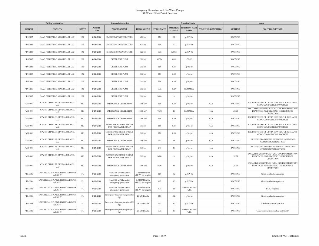
Emergency Generators and Fire Water Pumps RLBC and Other Permit Searches
RBLCID FACILITY STATEPERMIT
DATEPROCESS NAME THROUGHPUT POLLUTANT
EMISSION
LIMITS
EMISSION RATE
UNITSTIME AVG CONDITION METHOD CONTROL METHOD
Facility Information Process Information Emission Limits Notes
*IN-0185 MAG PELLET LLC, MAG PELLET LLC IN 4/24/2014 EMERGENCY GENERATORS 620 hp PM 0.2 g/kW-hr BACT-PSD
*IN-0185 MAG PELLET LLC, MAG PELLET LLC IN 4/24/2014 EMERGENCY GENERATORS 620 hp PM 0.2 g/kW-hr BACT-PSD
*IN-0185 MAG PELLET LLC, MAG PELLET LLC IN 4/24/2014 EMERGENCY GENERATORS 620 hp SO2 0.0015 g/kW-hr BACT-PSD
*IN-0185 MAG PELLET LLC, MAG PELLET LLC IN 4/24/2014 DIESEL FIRE PUMP 300 hp CO2e 31.11 CO2E BACT-PSD
*IN-0185 MAG PELLET LLC, MAG PELLET LLC IN 4/24/2014 DIESEL FIRE PUMP 300 hp PM 0.15 g/hp-hr BACT-PSD
*IN-0185 MAG PELLET LLC, MAG PELLET LLC IN 4/24/2014 DIESEL FIRE PUMP 300 hp PM 0.15 g/hp-hr BACT-PSD
*IN-0185 MAG PELLET LLC, MAG PELLET LLC IN 4/24/2014 DIESEL FIRE PUMP 300 hp PM 0.15 g/hp-hr BACT-PSD
*IN-0185 MAG PELLET LLC, MAG PELLET LLC IN 4/24/2014 DIESEL FIRE PUMP 300 hp SO2 0.29 lb/MMBtu BACT-PSD
*IN-0185 MAG PELLET LLC, MAG PELLET LLC IN 4/24/2014 DIESEL FIRE PUMP 300 hp NOx 3 g/hp-hr BACT-PSD
*MD-0041CPV ST. CHARLES, CPV MARYLAND,
LLCMD 4/23/2014 EMERGENCY GENERATOR 1500 kW PM 0.15 g/hp-hr N/A BACT-PSD
EXCLUSIVE USE OF ULTRA LOW SULFUR FUEL AND
GOOD COMBUSTION PRACTICES
*MD-0041CPV ST. CHARLES, CPV MARYLAND,
LLCMD 4/23/2014 EMERGENCY GENERATOR 1500 kW VOC 4.8 lb/MMBtu N/A LAER
EXCLUSIVE USE OF ULSD FUEL, GOOD COMBUSTION
PRACTICES, AND LIMITING THE HOURS OF
OPERATION
*MD-0041CPV ST. CHARLES, CPV MARYLAND,
LLCMD 4/23/2014 EMERGENCY GENERATOR 1500 kW PM 0.15 g/hp-hr N/A BACT-PSD
EXCLUSIVE USE OF ULTRA LOW SULFUR FUEL AND
GOOD COMBUSTION PRACTICES
*MD-0041CPV ST. CHARLES, CPV MARYLAND,
LLCMD 4/23/2014
EMERGENCY DIESEL ENGINE
FOR FIRE WATER PUMP300 hp PM 0.15 g/hp-hr N/A BACT-PSD
EXCLUSIVE USE OF ULTRA LOW SULFUR FUEL AND
GOOD COMBUSTION PRACTICES
*MD-0041CPV ST. CHARLES, CPV MARYLAND,
LLCMD 4/23/2014
EMERGENCY DIESEL ENGINE
FOR FIRE WATER PUMP300 hp PM 0.15 g/hp-hr N/A BACT-PSD
EXCLUSIVE USE OF ULTRA LOW SULFUR FUEL AND
GOOD COMBUSTION PRACTICES
*MD-0041CPV ST. CHARLES, CPV MARYLAND,
LLCMD 4/23/2014 EMERGENCY GENERATOR 1500 kW CO 2.6 g/hp-hr N/A BACT-PSD
USE OF ULTRA LOW SULFUR DIESEL AND GOOD
COMBUSTION PRACTICES
*MD-0041CPV ST. CHARLES, CPV MARYLAND,
LLCMD 4/23/2014
EMERGENCY DIESEL ENGINE
FOR FIRE WATER PUMP300 hp CO 2.6 g/hp-hr N/A BACT-PSD
USE OF ULTRA LOW SULFUR DIESEL AND GOOD
COMBUSTION PRACTICES
*MD-0041CPV ST. CHARLES, CPV MARYLAND,
LLCMD 4/23/2014
EMERGENCY DIESEL ENGINE
FOR FIRE WATER PUMP300 hp NOx 3 g/hp-hr N/A LAER
EXCLUSIVE USE OF ULSD FUEL, GOOD COMBUSTION
PRACTICES, AND LIMITING THE HOURS OF
OPERATION
*MD-0041CPV ST. CHARLES, CPV MARYLAND,
LLCMD 4/23/2014 EMERGENCY GENERATOR 1500 kW NOx 4.8 g/hp-hr N/A LAER
EXCLUSIVE USE OF ULSD FUEL, GOOD COMBUSTION
PRACTICES, AND LIMITING THE HOURS OF
OPERATION
*FL-0346LAUDERDALE PLANT, FLORIDA POWER
& LIGHTFL 4/22/2014
Four 3100 kW black start
emergency generators
2.32 MMBtu/hr
(HHV) per enginePM 0.2 g/kW-hr BACT-PSD Good combustion practice
*FL-0346LAUDERDALE PLANT, FLORIDA POWER
& LIGHTFL 4/22/2014
Four 3100 kW black start
emergency generators
2.32 MMBtu/hr
(HHV) per engineCO 3.5 g/kW-hr BACT-PSD Good combustion practice
*FL-0346LAUDERDALE PLANT, FLORIDA POWER
& LIGHTFL 4/22/2014
Four 3100 kW black start
emergency generators
2.32 MMBtu/hr
(HHV) per engineSO2 15
PPM SULFUR IN
FUELBACT-PSD ULSD required
*FL-0346LAUDERDALE PLANT, FLORIDA POWER
& LIGHTFL 4/22/2014
Emergency fire pump engine (300
hp)29 MMBtu/hr PM 0.2 g/hp-hr BACT-PSD Good combustion practice
*FL-0346LAUDERDALE PLANT, FLORIDA POWER
& LIGHTFL 4/22/2014
Emergency fire pump engine (300
hp)29 MMBtu/hr CO 3.5 g/kW-hr BACT-PSD Good combustion practice.
*FL-0346LAUDERDALE PLANT, FLORIDA POWER
& LIGHTFL 4/22/2014
Emergency fire pump engine (300
hp)29 MMBtu/hr SO2 15
PPM SULFUR IN
FUELBACT-PSD Good combustion practice and ULSD
ERM Page 7 of 19 Engines BACT Table.xlsx

Emergency Generators and Fire Water Pumps RLBC and Other Permit Searches
RBLCID FACILITY STATEPERMIT
DATEPROCESS NAME THROUGHPUT POLLUTANT
EMISSION
LIMITS
EMISSION RATE
UNITSTIME AVG CONDITION METHOD CONTROL METHOD
Facility Information Process Information Emission Limits Notes
*MD-0042
WILDCAT POINT GENERATION
FACILITY, OLD DOMINION ELECTRIC
CORPORATION (ODEC)
MD 4/8/2014 EMERGENCY GENERATOR 1 2250 kW PM 0.15 g/hp-hr BACT-PSD
EXCLUSIVE USE OF ULSD FUEL, GOOD COMBUSTION
PRACTICES, LIMITED HOURS OF OPERATION, AND
DESIGNED TO ACHIEVE EMISSION LIMITS
*MD-0042
WILDCAT POINT GENERATION
FACILITY, OLD DOMINION ELECTRIC
CORPORATION (ODEC)
MD 4/8/2014 EMERGENCY GENERATOR 1 2250 kW PM 0.15 g/hp-hr BACT-PSD
EXCLUSIVE USE OF ULSD FUEL, GOOD COMBUSTION
PRACTICES, LIMITED HOURS OF OPERATION, AND
DESIGNED TO ACHIEVE EMISSION LIMITS
*MD-0042
WILDCAT POINT GENERATION
FACILITY, OLD DOMINION ELECTRIC
CORPORATION (ODEC)
MD 4/8/2014 EMERGENCY GENERATOR 1 2250 kW H2SO4 0.006 g/hp-hr 3-HOUR BLOCK AVERAGE BACT-PSD
USE OF ULTRA-LOW DIESEL SULFUR FUEL, LIMITED
HOURS OF OPERATION AND DESIGNED TO MEET
SUBPART IIII LIMITS
*MD-0042
WILDCAT POINT GENERATION
FACILITY, OLD DOMINION ELECTRIC
CORPORATION (ODEC)
MD 4/8/2014 EMERGENCY GENERATOR 1 2250 kW PM 0.15 g/hp-hr BACT-PSD
EXCLUSIVE USE OF ULSD FUEL, GOOD COMBUSTION
PRACTICES, LIMITED HOURS OF OPERATION, AND
DESIGNED TO ACHIEVE EMISSION LIMITS
*MD-0042
WILDCAT POINT GENERATION
FACILITY, OLD DOMINION ELECTRIC
CORPORATION (ODEC)
MD 4/8/2014 EMERGENCY GENERATOR 1 2250 kW SO2 0.006 g/bhp-hr 3-HOUR BLOCK AVERAGE BACT-PSD
USE OF ULTRA-LOW DIESEL SULFUR FUEL, LIMITED
HOURS OF OPERATION AND DESIGNED TO MEET
NSPS SUBPART IIII LIMITS
*MD-0042
WILDCAT POINT GENERATION
FACILITY, OLD DOMINION ELECTRIC
CORPORATION (ODEC)
MD 4/8/2014EMERGENCY DIESEL ENGINE
FOR FIRE WATER PUMP477 hp PM 0.15 g/hp-hr BACT-PSD
EXCLUSIVE USE OF ULSD FUEL, GOOD COMBUSTION
PRACTICES, LIMITED HOURS OF OPERATION, AND
DESIGNED TO ACHIEVE EMISSION LIMITS
*MD-0042
WILDCAT POINT GENERATION
FACILITY, OLD DOMINION ELECTRIC
CORPORATION (ODEC)
MD 4/8/2014EMERGENCY DIESEL ENGINE
FOR FIRE WATER PUMP477 hp PM 0.15 g/hp-hr BACT-PSD
EXCLUSIVE USE OF ULSD FUEL, GOOD COMBUSTION
PRACTICES, LIMITED HOURS OF OPERATION, AND
DESIGNED TO ACHIEVE EMISSION LIMITS
*MD-0042
WILDCAT POINT GENERATION
FACILITY, OLD DOMINION ELECTRIC
CORPORATION (ODEC)
MD 4/8/2014EMERGENCY DIESEL ENGINE
FOR FIRE WATER PUMP477 hp H2SO4 0.0049 g/bhp-hr 3-HOUR BLOCK AVERAGE BACT-PSD
USE OF ULTRA-LOW DIESEL SULFUR FUEL, LIMITED
HOURS OF OPERATION AND DESIGNED TO MEET
SUBPART IIII LIMITS
*MD-0042
WILDCAT POINT GENERATION
FACILITY, OLD DOMINION ELECTRIC
CORPORATION (ODEC)
MD 4/8/2014EMERGENCY DIESEL ENGINE
FOR FIRE WATER PUMP477 hp PM 0.15 g/hp-hr BACT-PSD
EXCLUSIVE USE OF ULSD FUEL, GOOD COMBUSTION
PRACTICES, LIMITED HOURS OF OPERATION, AND
DESIGNED TO ACHIEVE EMISSION LIMITS
*MD-0042
WILDCAT POINT GENERATION
FACILITY, OLD DOMINION ELECTRIC
CORPORATION (ODEC)
MD 4/8/2014EMERGENCY DIESEL ENGINE
FOR FIRE WATER PUMP477 hp SO2 0.0049 g/bhp-hr 3-HOUR BLOCK AVERAGE BACT-PSD
USE OF ULTRA-LOW DIESEL SULFUR FUEL, LIMITED
HOURS OF OPERATION AND DESIGNED TO MEET
SUBPART IIII LIMITS
*MD-0042
WILDCAT POINT GENERATION
FACILITY, OLD DOMINION ELECTRIC
CORPORATION (ODEC)
MD 4/8/2014 EMERGENCY GENERATOR 1 2250 kW CO 2.6 g/hp-hr BACT-PSD
USE OF ULSD FUEL, GOOD COMBUSTION PRACTICES
AND HOURS OF OPERATION LIMITED TO 100 HOURS
PER YEAR
*MD-0042
WILDCAT POINT GENERATION
FACILITY, OLD DOMINION ELECTRIC
CORPORATION (ODEC)
MD 4/8/2014EMERGENCY DIESEL ENGINE
FOR FIRE WATER PUMP477 hp CO 2.6 g/hp-hr BACT-PSD
USE OF ULSD FUEL, GOOD COMBUSTION PRACTICES
AND HOURS OF OPERATION LIMITED TO 100 HOURS
PER YEAR
*MD-0042
WILDCAT POINT GENERATION
FACILITY, OLD DOMINION ELECTRIC
CORPORATION (ODEC)
MD 4/8/2014EMERGENCY DIESEL ENGINE
FOR FIRE WATER PUMP477 hp NOx 3 g/hp-hr LAER
LIMITED OPERATING HOURS, USE OF ULTRA- LOW
SULFUR FUEL AND GOOD COMBUSTION PRACTICES
*MD-0042
WILDCAT POINT GENERATION
FACILITY, OLD DOMINION ELECTRIC
CORPORATION (ODEC)
MD 4/8/2014 EMERGENCY GENERATOR 1 2250 kW NOx 4.8 g/hp-hr LAERLIMITED OPERATING HOURS, USE OF ULTRA- LOW
SULFUR FUEL AND GOOD COMBUSTION PRACTICES
*NJ-0081
PSEG FOSSIL LLC SEWAREN
GENERATING STATION, PSEG FOSSIL
LLC
NJ 3/7/2014 Emergency diesel fire pump 0 PM 0.15 g/bhp-hr BACT-PSD Use of ultra low sulfur distillate oil
*NJ-0081
PSEG FOSSIL LLC SEWAREN
GENERATING STATION, PSEG FOSSIL
LLC
NJ 3/7/2014 Emergency diesel fire pump 0 PM 0.15 g/bhp-hr OTHER CASE-BY-CASE Use of Ultra low sulfur distillate oil
*NJ-0081
PSEG FOSSIL LLC SEWAREN
GENERATING STATION, PSEG FOSSIL
LLC
NJ 3/7/2014 Emergency diesel fire pump 0 VOC 0.119 lb/hr LAER
ERM Page 8 of 19 Engines BACT Table.xlsx
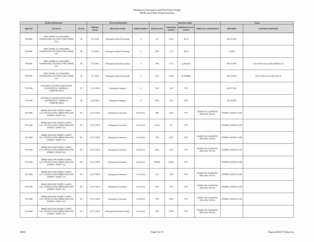
Emergency Generators and Fire Water Pumps RLBC and Other Permit Searches
RBLCID FACILITY STATEPERMIT
DATEPROCESS NAME THROUGHPUT POLLUTANT
EMISSION
LIMITS
EMISSION RATE
UNITSTIME AVG CONDITION METHOD CONTROL METHOD
Facility Information Process Information Emission Limits Notes
*NJ-0081
PSEG FOSSIL LLC SEWAREN
GENERATING STATION, PSEG FOSSIL
LLC
NJ 3/7/2014 Emergency diesel fire pump 0 CO 0.079 lb/hr BACT-PSD
*NJ-0081
PSEG FOSSIL LLC SEWAREN
GENERATING STATION, PSEG FOSSIL
LLC
NJ 3/7/2014 Emergency diesel fire pump 0 NOx 1.75 lb/hr LAER
*NJ-0081
PSEG FOSSIL LLC SEWAREN
GENERATING STATION, PSEG FOSSIL
LLC
NJ 3/7/2014 Emergency diesel fire pump 0 PM 0.15 g/bhp-hr BACT-PSD Use of Ultra low sulfur distillate oil
*NJ-0081
PSEG FOSSIL LLC SEWAREN
GENERATING STATION, PSEG FOSSIL
LLC
NJ 3/7/2014 Emergency diesel fire pump 0 SO2 0.002 lb/MMBtu BACT-PSD Use of Ultra low sulfur fuel oil
*TX-0706
NATURAL GAS FRACTIONATION,
OCCIDENTAL CHEMICAL
CORPORATION
TX 1/23/2014 Emergency Engines 0 VOC 0.03 TPY BACT-PSD
*TX-0706
NATURAL GAS FRACTIONATION,
OCCIDENTAL CHEMICAL
CORPORATION
TX 1/23/2014 Emergency Engines 0 NOx 0.33 TPY BACT-PSD
*PA-0296
BERKS HOLLOW ENERGY ASSOC
LLC/ONTELAUNEE, BERKS HOLLOW
ENERGY ASSOC LLC
PA 12/17/2013 Emergency Generator 60 Gal/hr PM 0.017 TPYBASED ON 12-MONTH
ROLLING TOTALOTHER CASE-BY-CASE
*PA-0296
BERKS HOLLOW ENERGY ASSOC
LLC/ONTELAUNEE, BERKS HOLLOW
ENERGY ASSOC LLC
PA 12/17/2013 Emergency Generator 60 Gal/hr CO2e 65 TPY OTHER CASE-BY-CASE
*PA-0296
BERKS HOLLOW ENERGY ASSOC
LLC/ONTELAUNEE, BERKS HOLLOW
ENERGY ASSOC LLC
PA 12/17/2013 Emergency Generator 60 Gal/hr PM 0.017 TPYBASED ON 12-MONTH
ROLLING TOTALOTHER CASE-BY-CASE
*PA-0296
BERKS HOLLOW ENERGY ASSOC
LLC/ONTELAUNEE, BERKS HOLLOW
ENERGY ASSOC LLC
PA 12/17/2013 Emergency Generator 60 Gal/hr VOC 0.03 TPYBASED ON 12-MONTH
ROLLING TOTALOTHER CASE-BY-CASE
*PA-0296
BERKS HOLLOW ENERGY ASSOC
LLC/ONTELAUNEE, BERKS HOLLOW
ENERGY ASSOC LLC
PA 12/17/2013 Emergency Generator 60 Gal/hr H2SO4 0.0001 TPY OTHER CASE-BY-CASE
*PA-0296
BERKS HOLLOW ENERGY ASSOC
LLC/ONTELAUNEE, BERKS HOLLOW
ENERGY ASSOC LLC
PA 12/17/2013 Emergency Generator 60 Gal/hr CO 0.29 TPYBASED ON 12-MONTH
ROLLING TOTALOTHER CASE-BY-CASE
*PA-0296
BERKS HOLLOW ENERGY ASSOC
LLC/ONTELAUNEE, BERKS HOLLOW
ENERGY ASSOC LLC
PA 12/17/2013 Emergency Generator 60 Gal/hr NOx 0.53 TPYBASED ON 12-MONTH
ROLLING TOTALOTHER CASE-BY-CASE
*PA-0296
BERKS HOLLOW ENERGY ASSOC
LLC/ONTELAUNEE, BERKS HOLLOW
ENERGY ASSOC LLC
PA 12/17/2013 Emergency Generator 60 Gal/hr PM 0.005 TPYBASED ON 12-MONTH
ROLLING TOTALOTHER CASE-BY-CASE
*PA-0296
BERKS HOLLOW ENERGY ASSOC
LLC/ONTELAUNEE, BERKS HOLLOW
ENERGY ASSOC LLC
PA 12/17/2013 Emergency Firewater Pump 16 Gal/hr PM 0.005 TPYBASED ON 12-MONTH
ROLLING TOTAL
ERM Page 9 of 19 Engines BACT Table.xlsx
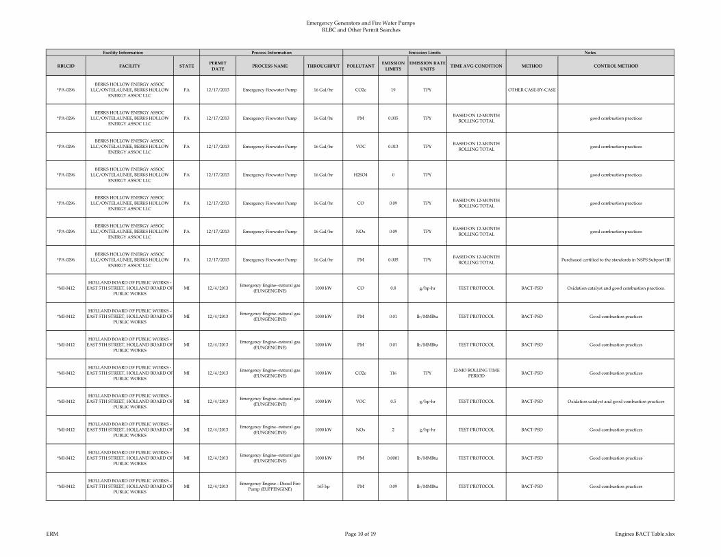
Emergency Generators and Fire Water Pumps RLBC and Other Permit Searches
RBLCID FACILITY STATEPERMIT
DATEPROCESS NAME THROUGHPUT POLLUTANT
EMISSION
LIMITS
EMISSION RATE
UNITSTIME AVG CONDITION METHOD CONTROL METHOD
Facility Information Process Information Emission Limits Notes
*PA-0296
BERKS HOLLOW ENERGY ASSOC
LLC/ONTELAUNEE, BERKS HOLLOW
ENERGY ASSOC LLC
PA 12/17/2013 Emergency Firewater Pump 16 Gal/hr CO2e 19 TPY OTHER CASE-BY-CASE
*PA-0296
BERKS HOLLOW ENERGY ASSOC
LLC/ONTELAUNEE, BERKS HOLLOW
ENERGY ASSOC LLC
PA 12/17/2013 Emergency Firewater Pump 16 Gal/hr PM 0.005 TPYBASED ON 12-MONTH
ROLLING TOTALgood combustion practices
*PA-0296
BERKS HOLLOW ENERGY ASSOC
LLC/ONTELAUNEE, BERKS HOLLOW
ENERGY ASSOC LLC
PA 12/17/2013 Emergency Firewater Pump 16 Gal/hr VOC 0.013 TPYBASED ON 12-MONTH
ROLLING TOTALgood combustion practices
*PA-0296
BERKS HOLLOW ENERGY ASSOC
LLC/ONTELAUNEE, BERKS HOLLOW
ENERGY ASSOC LLC
PA 12/17/2013 Emergency Firewater Pump 16 Gal/hr H2SO4 0 TPY good combustion practices
*PA-0296
BERKS HOLLOW ENERGY ASSOC
LLC/ONTELAUNEE, BERKS HOLLOW
ENERGY ASSOC LLC
PA 12/17/2013 Emergency Firewater Pump 16 Gal/hr CO 0.09 TPYBASED ON 12-MONTH
ROLLING TOTALgood combustion practices
*PA-0296
BERKS HOLLOW ENERGY ASSOC
LLC/ONTELAUNEE, BERKS HOLLOW
ENERGY ASSOC LLC
PA 12/17/2013 Emergency Firewater Pump 16 Gal/hr NOx 0.09 TPYBASED ON 12-MONTH
ROLLING TOTALgood combustion practices
*PA-0296
BERKS HOLLOW ENERGY ASSOC
LLC/ONTELAUNEE, BERKS HOLLOW
ENERGY ASSOC LLC
PA 12/17/2013 Emergency Firewater Pump 16 Gal/hr PM 0.005 TPYBASED ON 12-MONTH
ROLLING TOTALPurchased certified to the standards in NSPS Subpart IIII
*MI-0412
HOLLAND BOARD OF PUBLIC WORKS -
EAST 5TH STREET, HOLLAND BOARD OF
PUBLIC WORKS
MI 12/4/2013Emergency Engine--natural gas
(EUNGENGINE)1000 kW CO 0.8 g/hp-hr TEST PROTOCOL BACT-PSD Oxidation catalyst and good combustion practices.
*MI-0412
HOLLAND BOARD OF PUBLIC WORKS -
EAST 5TH STREET, HOLLAND BOARD OF
PUBLIC WORKS
MI 12/4/2013Emergency Engine--natural gas
(EUNGENGINE)1000 kW PM 0.01 lb/MMBtu TEST PROTOCOL BACT-PSD Good combustion practices
*MI-0412
HOLLAND BOARD OF PUBLIC WORKS -
EAST 5TH STREET, HOLLAND BOARD OF
PUBLIC WORKS
MI 12/4/2013Emergency Engine--natural gas
(EUNGENGINE)1000 kW PM 0.01 lb/MMBtu TEST PROTOCOL BACT-PSD Good combustion practices
*MI-0412
HOLLAND BOARD OF PUBLIC WORKS -
EAST 5TH STREET, HOLLAND BOARD OF
PUBLIC WORKS
MI 12/4/2013Emergency Engine--natural gas
(EUNGENGINE)1000 kW CO2e 116 TPY
12-MO ROLLING TIME
PERIODBACT-PSD Good combustion practices
*MI-0412
HOLLAND BOARD OF PUBLIC WORKS -
EAST 5TH STREET, HOLLAND BOARD OF
PUBLIC WORKS
MI 12/4/2013Emergency Engine--natural gas
(EUNGENGINE)1000 kW VOC 0.5 g/hp-hr TEST PROTOCOL BACT-PSD Oxidation catalyst and good combustion practices
*MI-0412
HOLLAND BOARD OF PUBLIC WORKS -
EAST 5TH STREET, HOLLAND BOARD OF
PUBLIC WORKS
MI 12/4/2013Emergency Engine--natural gas
(EUNGENGINE)1000 kW NOx 2 g/hp-hr TEST PROTOCOL BACT-PSD Good combustion practices
*MI-0412
HOLLAND BOARD OF PUBLIC WORKS -
EAST 5TH STREET, HOLLAND BOARD OF
PUBLIC WORKS
MI 12/4/2013Emergency Engine--natural gas
(EUNGENGINE)1000 kW PM 0.0001 lb/MMBtu TEST PROTOCOL BACT-PSD Good combustion practices
*MI-0412
HOLLAND BOARD OF PUBLIC WORKS -
EAST 5TH STREET, HOLLAND BOARD OF
PUBLIC WORKS
MI 12/4/2013Emergency Engine --Diesel Fire
Pump (EUFPENGINE)165 hp PM 0.09 lb/MMBtu TEST PROTOCOL BACT-PSD Good combustion practices
ERM Page 10 of 19 Engines BACT Table.xlsx
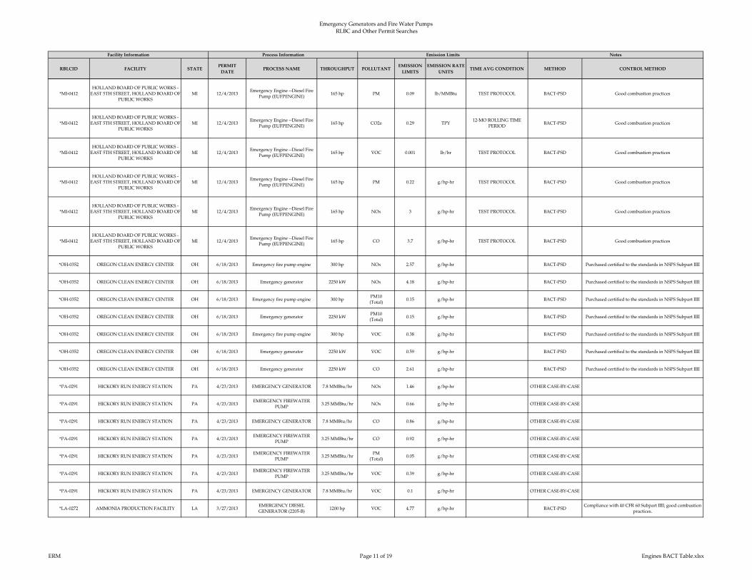
Emergency Generators and Fire Water Pumps RLBC and Other Permit Searches
RBLCID FACILITY STATEPERMIT
DATEPROCESS NAME THROUGHPUT POLLUTANT
EMISSION
LIMITS
EMISSION RATE
UNITSTIME AVG CONDITION METHOD CONTROL METHOD
Facility Information Process Information Emission Limits Notes
*MI-0412
HOLLAND BOARD OF PUBLIC WORKS -
EAST 5TH STREET, HOLLAND BOARD OF
PUBLIC WORKS
MI 12/4/2013Emergency Engine --Diesel Fire
Pump (EUFPENGINE)165 hp PM 0.09 lb/MMBtu TEST PROTOCOL BACT-PSD Good combustion practices
*MI-0412
HOLLAND BOARD OF PUBLIC WORKS -
EAST 5TH STREET, HOLLAND BOARD OF
PUBLIC WORKS
MI 12/4/2013Emergency Engine --Diesel Fire
Pump (EUFPENGINE)165 hp CO2e 0.29 TPY
12-MO ROLLING TIME
PERIODBACT-PSD Good combustion practices
*MI-0412
HOLLAND BOARD OF PUBLIC WORKS -
EAST 5TH STREET, HOLLAND BOARD OF
PUBLIC WORKS
MI 12/4/2013Emergency Engine --Diesel Fire
Pump (EUFPENGINE)165 hp VOC 0.001 lb/hr TEST PROTOCOL BACT-PSD Good combustion practices
*MI-0412
HOLLAND BOARD OF PUBLIC WORKS -
EAST 5TH STREET, HOLLAND BOARD OF
PUBLIC WORKS
MI 12/4/2013Emergency Engine --Diesel Fire
Pump (EUFPENGINE)165 hp PM 0.22 g/hp-hr TEST PROTOCOL BACT-PSD Good combustion practices
*MI-0412
HOLLAND BOARD OF PUBLIC WORKS -
EAST 5TH STREET, HOLLAND BOARD OF
PUBLIC WORKS
MI 12/4/2013Emergency Engine --Diesel Fire
Pump (EUFPENGINE)165 hp NOx 3 g/hp-hr TEST PROTOCOL BACT-PSD Good combustion practices
*MI-0412
HOLLAND BOARD OF PUBLIC WORKS -
EAST 5TH STREET, HOLLAND BOARD OF
PUBLIC WORKS
MI 12/4/2013Emergency Engine --Diesel Fire
Pump (EUFPENGINE)165 hp CO 3.7 g/hp-hr TEST PROTOCOL BACT-PSD Good combustion practices
*OH-0352 OREGON CLEAN ENERGY CENTER OH 6/18/2013 Emergency fire pump engine 300 hp NOx 2.57 g/hp-hr BACT-PSD Purchased certified to the standards in NSPS Subpart IIII
*OH-0352 OREGON CLEAN ENERGY CENTER OH 6/18/2013 Emergency generator 2250 kW NOx 4.18 g/hp-hr BACT-PSD Purchased certified to the standards in NSPS Subpart IIII
*OH-0352 OREGON CLEAN ENERGY CENTER OH 6/18/2013 Emergency fire pump engine 300 hpPM10
(Total)0.15 g/hp-hr BACT-PSD Purchased certified to the standards in NSPS Subpart IIII
*OH-0352 OREGON CLEAN ENERGY CENTER OH 6/18/2013 Emergency generator 2250 kWPM10
(Total)0.15 g/hp-hr BACT-PSD Purchased certified to the standards in NSPS Subpart IIII
*OH-0352 OREGON CLEAN ENERGY CENTER OH 6/18/2013 Emergency fire pump engine 300 hp VOC 0.38 g/hp-hr BACT-PSD Purchased certified to the standards in NSPS Subpart IIII
*OH-0352 OREGON CLEAN ENERGY CENTER OH 6/18/2013 Emergency generator 2250 kW VOC 0.59 g/hp-hr BACT-PSD Purchased certified to the standards in NSPS Subpart IIII
*OH-0352 OREGON CLEAN ENERGY CENTER OH 6/18/2013 Emergency generator 2250 kW CO 2.61 g/hp-hr BACT-PSD Purchased certified to the standards in NSPS Subpart IIII
*PA-0291 HICKORY RUN ENERGY STATION PA 4/23/2013 EMERGENCY GENERATOR 7.8 MMBtu/hr NOx 1.46 g/hp-hr OTHER CASE-BY-CASE
*PA-0291 HICKORY RUN ENERGY STATION PA 4/23/2013EMERGENCY FIREWATER
PUMP3.25 MMBtu/hr NOx 0.66 g/hp-hr OTHER CASE-BY-CASE
*PA-0291 HICKORY RUN ENERGY STATION PA 4/23/2013 EMERGENCY GENERATOR 7.8 MMBtu/hr CO 0.86 g/hp-hr OTHER CASE-BY-CASE
*PA-0291 HICKORY RUN ENERGY STATION PA 4/23/2013EMERGENCY FIREWATER
PUMP3.25 MMBtu/hr CO 0.92 g/hp-hr OTHER CASE-BY-CASE
*PA-0291 HICKORY RUN ENERGY STATION PA 4/23/2013EMERGENCY FIREWATER
PUMP3.25 MMBtu/hr
PM
(Total)0.05 g/hp-hr OTHER CASE-BY-CASE
*PA-0291 HICKORY RUN ENERGY STATION PA 4/23/2013EMERGENCY FIREWATER
PUMP3.25 MMBtu/hr VOC 0.39 g/hp-hr OTHER CASE-BY-CASE
*PA-0291 HICKORY RUN ENERGY STATION PA 4/23/2013 EMERGENCY GENERATOR 7.8 MMBtu/hr VOC 0.1 g/hp-hr OTHER CASE-BY-CASE
*LA-0272 AMMONIA PRODUCTION FACILITY LA 3/27/2013EMERGENCY DIESEL
GENERATOR (2205-B)1200 hp VOC 4.77 g/hp-hr BACT-PSD
Compliance with 40 CFR 60 Subpart IIII; good combustion
practices.
ERM Page 11 of 19 Engines BACT Table.xlsx

Emergency Generators and Fire Water Pumps RLBC and Other Permit Searches
RBLCID FACILITY STATEPERMIT
DATEPROCESS NAME THROUGHPUT POLLUTANT
EMISSION
LIMITS
EMISSION RATE
UNITSTIME AVG CONDITION METHOD CONTROL METHOD
Facility Information Process Information Emission Limits Notes
*LA-0272 AMMONIA PRODUCTION FACILITY LA 3/27/2013EMERGENCY DIESEL
GENERATOR (2205-B)1200 hp NOx 4.77 g/hp-hr BACT-PSD
Compliance with 40 CFR 60 Subpart IIII; good combustion
practices.
*IN-0158 ST. JOSEPH ENEGRY CENTER, LLC IN 12/3/2012EMERGENCY DIESEL
GENERATOR2012 hp
PM
(Filterable)0.15 g/hp-hr 3 HOUR BACT-PSD
COMBUSTION DESIGN CONTROLS AND USAGE
LIMITS
*IN-0158 ST. JOSEPH ENEGRY CENTER, LLC IN 12/3/2012EMERGENCY DIESEL
GENERATOR2012 hp
PM10
(Filterable)0.15 g/hp-hr 3 HOUR BACT-PSD
COMBUSTION DESIGN CONTROLS AND USAGE
LIMITS
*IN-0158 ST. JOSEPH ENEGRY CENTER, LLC IN 12/3/2012EMERGENCY DIESEL
GENERATOR2012 hp
PM2.5
(Filterable)0.15 g/hp-hr 3 HOUR BACT-PSD
COMBUSTION DESIGN CONTROLS AND USAGE
LIMITS
*IN-0158 ST. JOSEPH ENEGRY CENTER, LLC IN 12/3/2012EMERGENCY DIESEL
GENERATOR2012 hp VOC 0.23 g/hp-hr 3 HOUR BACT-PSD
COMBUSTION DESIGN CONTROLS AND USAGE
LIMITS
*IN-0158 ST. JOSEPH ENEGRY CENTER, LLC IN 12/3/2012EMERGENCY DIESEL
GENERATOR2012 hp CO 2.6 g/hp-hr 3 HOUR BACT-PSD
COMBUSTION DESIGN CONTROLS AND USAGE
LIMITS
*IN-0158 ST. JOSEPH ENEGRY CENTER, LLC IN 12/3/2012EMERGENCY DIESEL
GENERATOR2012 hp NOx 4.8 g/hp-hr 3 HOUR BACT-PSD
COMBUSTION DESIGN CONTROLS AND USAGE
LIMITS
*NJ-0080 HESS NEWARK ENERGY CENTER NJ 11/1/2012 Emergency Generator 200 HRS/YR CO 11.56 lb/hr BACT-PSD
*NJ-0080 HESS NEWARK ENERGY CENTER NJ 11/1/2012 Emergency Generator 200 HRS/YR NOx 18.53 lb/hr LAER use of ultra low sulfur diesel (ULSD) a clean fuel
*NJ-0080 HESS NEWARK ENERGY CENTER NJ 11/1/2012 Emergency Generator 200 HRS/YRPM
(Filterable)0.59 lb/hr use of ULSD, a low sulfur clean fuel
*NJ-0080 HESS NEWARK ENERGY CENTER NJ 11/1/2012 Emergency Generator 200 HRS/YRPM10
(Filterable)0.66 lb/hr BACT-PSD
*NJ-0080 HESS NEWARK ENERGY CENTER NJ 11/1/2012 Emergency Generator 200 HRS/YR VOC 2.62 lb/hr LAER use of ULSD, a low sulfur clean fuel
IA-0105 IOWA FERTILIZER COMPANY IA 10/26/2012 Fire Pump 14 GAL/HR NOx 2.8 g/hp-hrAVERAGE OF 3 STACK
TEST RUNSBACT-PSD good combustion practices
IA-0105 IOWA FERTILIZER COMPANY IA 10/26/2012 Emergency Generator 142 GAL/HR NOx 4.47 g/hp-hrAVERAGE OF 3 STACK
TEST RUNSBACT-PSD good combustion practices
IA-0105 IOWA FERTILIZER COMPANY IA 10/26/2012 Emergency Generator 142 GAL/HRPM
(Total)0.15 g/hp-hr
AVERAGE OF 3 STACK
TEST RUNSBACT-PSD good combustion practices
IA-0105 IOWA FERTILIZER COMPANY IA 10/26/2012 Fire Pump 14 GAL/HRPM
(Total)0.15 g/hp-hr
AVERAGE OF 3 STACK
TEST RUNSBACT-PSD good combustion practices
IA-0105 IOWA FERTILIZER COMPANY IA 10/26/2012 Emergency Generator 142 GAL/HRPM10
(Total)0.15 g/hp-hr
AVERAGE OF 3 STACK
TEST RUNSBACT-PSD good combustion practices
IA-0105 IOWA FERTILIZER COMPANY IA 10/26/2012 Fire Pump 14 GAL/HRPM10
(Total)0.15 g/hp-hr
AVERAGE OF 3 STACK
TEST RUNSBACT-PSD good combustion practices
IA-0105 IOWA FERTILIZER COMPANY IA 10/26/2012 Emergency Generator 142 GAL/HRPM2.5
(Total)0.15 g/hp-hr
AVERAGE OF 3 STACK
TEST RUNSBACT-PSD good combustion practices
IA-0105 IOWA FERTILIZER COMPANY IA 10/26/2012 Fire Pump 14 GAL/HRPM2.5
(Total)0.15 g/hp-hr
AVERAGE OF 3 STACK
TEST RUNSBACT-PSD good combustion practices
IA-0105 IOWA FERTILIZER COMPANY IA 10/26/2012 Emergency Generator 142 GAL/HR VOC 0.3 g/hp-hrAVERAGE OF 3 STACK
TEST RUNSBACT-PSD good combustion practices
IA-0105 IOWA FERTILIZER COMPANY IA 10/26/2012 Fire Pump 14 GAL/HR VOC 0.19 g/hp-hrAVERAGE OF 3 STACK
TEST RUNSBACT-PSD good combustion practices
IA-0105 IOWA FERTILIZER COMPANY IA 10/26/2012 Emergency Generator 142 GAL/HR CO 2.61 g/hp-hrAVERAGE OF 3 STACK
TEST RUNSBACT-PSD good combustion practices
IA-0105 IOWA FERTILIZER COMPANY IA 10/26/2012 Fire Pump 14 GAL/HR CO 2.61 g/hp-hrAVERAGE OF 3 STACK
TEST RUNSBACT-PSD good combustion practices
*NJ-0079 WOODBRIDGE ENERGY CENTER NJ 7/25/2012 Emergency Generator 100 HRS/YR CO 1.99 lb/hr BACT-PSD Use of ULSD oil
ERM Page 12 of 19 Engines BACT Table.xlsx

Emergency Generators and Fire Water Pumps RLBC and Other Permit Searches
RBLCID FACILITY STATEPERMIT
DATEPROCESS NAME THROUGHPUT POLLUTANT
EMISSION
LIMITS
EMISSION RATE
UNITSTIME AVG CONDITION METHOD CONTROL METHOD
Facility Information Process Information Emission Limits Notes
*NJ-0079 WOODBRIDGE ENERGY CENTER NJ 7/25/2012 Emergency Generator 100 HRS/YR NOx 21.16 lb/hr LAER Use of ULSD diesel oil
*NJ-0079 WOODBRIDGE ENERGY CENTER NJ 7/25/2012 Emergency Generator 100 HRS/YRPM10
(Total)0.13 lb/hr OTHER CASE-BY-CASE Use of ULSD oil
*NJ-0079 WOODBRIDGE ENERGY CENTER NJ 7/25/2012 Emergency Generator 100 HRS/YRPM2.5
(Total)0.13 lb/hr OTHER CASE-BY-CASE Use of ULSD oil
*NJ-0079 WOODBRIDGE ENERGY CENTER NJ 7/25/2012 Emergency Generator 100 HRS/YR VOC 0.49 lb/hr LAER Use of ULSD oil
*SC-0159 US10 FACILITY SC 7/9/2012EMERGENCY GENERATORS,
GEN1, GEN21000 kW VOC 4.77 g/hp-hr BACT-PSD
BACT HAS BEEN DETERMINED TO BE COMPLIANCE
WITH NSPS, SUBPART IIII, 40 CFR60.4202 AND 40
CFR60.4205.
*SC-0159 US10 FACILITY SC 7/9/2012FIRE PUMPS, FIRE1, FIRE2,
FIRE3211 kW VOC 2.98 g/hp-hr BACT-PSD
BACT HAS BEEN DETERMINED TO BE COMPLIANCE
WITH NSPS, SUBPART IIII, 40 CFR60.4202 AND 40
CFR60.4205.
SC-0113 PYRAMAX CERAMICS, LLC SC 2/8/2012EMERGENCY GENERATORS 1
THRU 8757 hp NOx 2.98 g/hp-hr BACT-PSD
ENGINES MUST BE CERTIFIED TO COMPLY WITH
NSPS, SUBPART IIII.
SC-0113 PYRAMAX CERAMICS, LLC SC 2/8/2012 FIRE PUMP 500 hp NOx 2.98 g/hp-hr BACT-PSDPURCHASE OF CERTIFIED ENGINE BASED ON NSPS,
SUBPART IIII.
SC-0113 PYRAMAX CERAMICS, LLC SC 2/8/2012EMERGENCY GENERATORS 1
THRU 8757 hp VOC 2.98 g/hp-hr BACT-PSD
PURCHASE ENGINES CERTIFIED TO COMPLY WITH
NSPS, SUBPART IIII.
SC-0113 PYRAMAX CERAMICS, LLC SC 2/8/2012 FIRE PUMP 500 hp VOC 2.98 g/hp-hr BACT-PSD
CERTIFIED ENGINES THAT COMPLY WITH NSPS,
SUBPART IIII. HOURS OF OPERATION LIMITED TO 100
HOURS PER YEAR FOR MAINTENANCE AND
TESTING.
SC-0113 PYRAMAX CERAMICS, LLC SC 2/8/2012EMERGENCY GENERATORS 1
THRU 8757 hp CO 2.61 g/hp-hr BACT-PSD
ENGINES MUST BE CERTIFIED TO COMPLY WITH
NSPS, SUBPART IIII.
SC-0113 PYRAMAX CERAMICS, LLC SC 2/8/2012 FIRE PUMP 500 hp CO 2.61 g/hp-hr BACT-PSD
ENGINES CERTIFIED TO MEET NSPS, SUBPART IIII.
HOURS OF OPERATION LIMITED TO 100 HOURS PER
YEAR FOR MAINTENANCE AND TESTING.
*MI-0402 SUMPTER POWER PLANT MI 11/17/2011Diesel fuel-fired combustion
engine (RICE)732 hp CO 0.31 g/hp-hr TEST BACT-PSD Good combustion practices
*MI-0402 SUMPTER POWER PLANT MI 11/17/2011Diesel fuel-fired combustion
engine (RICE)732 hp NOx 4.85 g/hp-hr TEST BACT-PSD Good combustion practices
*MI-0402 SUMPTER POWER PLANT MI 11/17/2011Diesel fuel-fired combustion
engine (RICE)732 hp
PM
(Filterable)0.05 g/hp-hr TEST BACT-PSD Good combustion practices
*MI-0402 SUMPTER POWER PLANT MI 11/17/2011Diesel fuel-fired combustion
engine (RICE)732 hp
PM10
(Total)0.06 lb/MMBtu TEST BACT-PSD Good combustion practices
*MI-0402 SUMPTER POWER PLANT MI 11/17/2011Diesel fuel-fired combustion
engine (RICE)732 hp
PM2.5
(Total)0.06 lb/MMBtu TEST BACT-PSD Good combustion practices
*CA-1212 PALMDALE HYBRID POWER PROJECT CA 10/18/2011 EMERGENCY IC ENGINE 182 hp NOx 2.98 g/hp-hr 3 HOUR BACT-PSD
*CA-1212 PALMDALE HYBRID POWER PROJECT CA 10/18/2011 EMERGENCY IC ENGINE 2683 hp NOx 4.77 g/hp-hr 3 HOUR BACT-PSD
*CA-1212 PALMDALE HYBRID POWER PROJECT CA 10/18/2011 EMERGENCY IC ENGINE 2683 hpPM
(Total)0.15 g/hp-hr BACT-PSD USE ULTRA LOW SULFUR FUEL
*CA-1212 PALMDALE HYBRID POWER PROJECT CA 10/18/2011 EMERGENCY IC ENGINE 182 hpPM
(Total)0.15 g/hp-hr BACT-PSD USE ULTRA LOW SULFUR FUEL
*CA-1212 PALMDALE HYBRID POWER PROJECT CA 10/18/2011 EMERGENCY IC ENGINE 2683 hpPM10
(Total)0.15 g/hp-hr BACT-PSD USE ULTRA LOW SULFUR FUEL
ERM Page 13 of 19 Engines BACT Table.xlsx

Emergency Generators and Fire Water Pumps RLBC and Other Permit Searches
RBLCID FACILITY STATEPERMIT
DATEPROCESS NAME THROUGHPUT POLLUTANT
EMISSION
LIMITS
EMISSION RATE
UNITSTIME AVG CONDITION METHOD CONTROL METHOD
Facility Information Process Information Emission Limits Notes
*CA-1212 PALMDALE HYBRID POWER PROJECT CA 10/18/2011 EMERGENCY IC ENGINE 182 hpPM10
(Total)0.15 g/hp-hr BACT-PSD USE ULTRA LOW SULFUR FUEL
*CA-1212 PALMDALE HYBRID POWER PROJECT CA 10/18/2011 EMERGENCY IC ENGINE 2683 hpPM2.5
(Total)0.15 g/hp-hr BACT-PSD USE ULTRA LOW SULFUR FUEL
*CA-1212 PALMDALE HYBRID POWER PROJECT CA 10/18/2011 EMERGENCY IC ENGINE 182 hpPM2.5
(Total)0.15 g/hp-hr BACT-PSD USE ULTRA LOW SULFUR FUEL
*CA-1212 PALMDALE HYBRID POWER PROJECT CA 10/18/2011 EMERGENCY IC ENGINE 2683 hp CO 2.61 g/hp-hr BACT-PSD
*CA-1212 PALMDALE HYBRID POWER PROJECT CA 10/18/2011 EMERGENCY IC ENGINE 182 hp CO 2.61 g/hp-hr BACT-PSD
LA-0254NINEMILE POINT ELECTRIC
GENERATING PLANTLA 8/16/2011
EMERGENCY DIESEL
GENERATOR1250 hp CO 2.6 g/hp-hr ANNUAL BACT-PSD
ULTRA LOW SULFUR DIESEL AND GOOD
COMBUSTION PRACTICES
LA-0254NINEMILE POINT ELECTRIC
GENERATING PLANTLA 8/16/2011 EMERGENCY FIRE PUMP 350 hp CO 2.6 g/hp-hr BACT-PSD
ULTRA LOW SULFUR DIESEL AND GOOD
COMBUSTION PRACTICES
LA-0254NINEMILE POINT ELECTRIC
GENERATING PLANTLA 8/16/2011
EMERGENCY DIESEL
GENERATOR1250 hp
PM10
(Total)0.15 g/hp-hr ANNUAL BACT-PSD
ULTRA LOW SULFUR DIESEL AND GOOD
COMBUSTION PRACTICES
LA-0254NINEMILE POINT ELECTRIC
GENERATING PLANTLA 8/16/2011 EMERGENCY FIRE PUMP 350 hp
PM10
(Total)0.15 g/hp-hr ANNUAL BACT-PSD
ULTRA LOW SULFUR DIESEL AND GOOD
COMBUSTION PRACTICES
LA-0254NINEMILE POINT ELECTRIC
GENERATING PLANTLA 8/16/2011
EMERGENCY DIESEL
GENERATOR1250 hp
PM2.5
(Total)0.15 g/hp-hr ANNUAL BACT-PSD
ULTRA LOW SULFUR DIESEL AND GOOD
COMBUSTION PRACTICES
LA-0254NINEMILE POINT ELECTRIC
GENERATING PLANTLA 8/16/2011 EMERGENCY FIRE PUMP 350 hp
PM2.5
(Total)0.15 g/hp-hr ANNUAL BACT-PSD
ULTRA LOW SULFUR DIESEL AND GOOD
COMBUSTION PRACTICES
LA-0254NINEMILE POINT ELECTRIC
GENERATING PLANTLA 8/16/2011
EMERGENCY DIESEL
GENERATOR1250 hp VOC 1 g/hp-hr ANNUAL BACT-PSD
ULTRA LOW SULFUR DIESEL AND GOOD
COMBUSTION PRACTICES
LA-0254NINEMILE POINT ELECTRIC
GENERATING PLANTLA 8/16/2011 EMERGENCY FIRE PUMP 350 hp VOC 1 g/hp-hr ANNUAL BACT-PSD
ULTRA LOW SULFUR DIESEL AND GOOD
COMBUSTION PRACTICES
LA-0251 FLOPAM INC. FACILITY LA 4/26/2011 Fire Pump Engines - 2 units 444 hp CO 0.66 g/hp-hr BACT-PSD good equipment design and proper combustion practices
LA-0251 FLOPAM INC. FACILITY LA 4/26/2011 Fire Pump Engines - 2 units 444 hpPM10
(Filterable)0.01 g/hp-hr BACT-PSD
LA-0251 FLOPAM INC. FACILITY LA 4/26/2011 Fire Pump Engines - 2 units 444 hp NOx 5.95 g/hp-hr BACT-PSD
AK-0071INTERNATIONAL STATION POWER
PLANTAK 12/20/2010
Caterpillar 3215C Black Start
Generator (1)1500 kW NOx 4.77 g/hp-hr INSTANTANEOUS BACT-PSD Turbocharger and Aftercooler
AK-0071INTERNATIONAL STATION POWER
PLANTAK 12/20/2010
Caterpillar 3215C Black Start
Generator (1)1500 kW
PM
(Total)0.03 g/hp-hr INSTANTANEOUS BACT-PSD Good Combustion Practices
AK-0071INTERNATIONAL STATION POWER
PLANTAK 12/20/2010
Caterpillar 3215C Black Start
Generator (1)1500 kW
PM10
(Total)0.03 g/hp-hr INSTANTANEOUS BACT-PSD Good Combustion Practices
AK-0071INTERNATIONAL STATION POWER
PLANTAK 12/20/2010
Caterpillar 3215C Black Start
Generator (1)1500 kW
PM2.5
(Total)0.03 g/hp-hr INSTANTANEOUS BACT-PSD Good Combustion Practices
ID-0018 LANGLEY GULCH POWER PLANT ID 6/25/2010 FIRE PUMP ENGINE 235 kW NOx 2.98 g/hp-hr BACT-PSDTIER 3 ENGINE-BASED GOOD COMBUSTION
PRACTICES (GCP)
ID-0018 LANGLEY GULCH POWER PLANT ID 6/25/2010EMERGENCY GENERATOR
ENGINE750 kW NOx 4.77 g/hp-hr BACT-PSD
TIER 2 ENGINE-BASED, GOOD COMBUSTION
PRACTICES (GCP)
ID-0018 LANGLEY GULCH POWER PLANT ID 6/25/2010EMERGENCY GENERATOR
ENGINE750 kW PM 0.15 g/hp-hr BACT-PSD
TIER 2 ENGINE-BASED, GOOD COMBUSTION
PRACTICES (GCP)
ID-0018 LANGLEY GULCH POWER PLANT ID 6/25/2010 FIRE PUMP ENGINE 235 kW PM 0.15 g/hp-hr BACT-PSDTIER 3 ENGINE-BASED, GOOD COMBUSTION
PRACTICES (GCP)
ID-0018 LANGLEY GULCH POWER PLANT ID 6/25/2010EMERGENCY GENERATOR
ENGINE750 kW VOC 4.77 g/hp-hr BACT-PSD
TIER 2 ENGINE-BASED, GOOD COMBUSTION
PRACTICES (GCP)
ERM Page 14 of 19 Engines BACT Table.xlsx

Emergency Generators and Fire Water Pumps RLBC and Other Permit Searches
RBLCID FACILITY STATEPERMIT
DATEPROCESS NAME THROUGHPUT POLLUTANT
EMISSION
LIMITS
EMISSION RATE
UNITSTIME AVG CONDITION METHOD CONTROL METHOD
Facility Information Process Information Emission Limits Notes
ID-0018 LANGLEY GULCH POWER PLANT ID 6/25/2010 FIRE PUMP ENGINE 235 kW VOC 2.98 g/hp-hr BACT-PSDTIER 3 ENGINE-BASED, GOOD COMBUSTION
PRACTICES (GCP)
ID-0018 LANGLEY GULCH POWER PLANT ID 6/25/2010EMERGENCY GENERATOR
ENGINE750 kW CO 2.61 g/hp-hr BACT-PSD
TIER 2 ENGINE-BASED, GOOD COMBUSTION
PRACTICES (GCP)
*CA-1191VICTORVILLE 2 HYBRID POWER
PROJECTCA 3/11/2010
EMERGENCY FIREWATER
PUMP ENGINE135 kW NOx 2.83 g/hp-hr BACT-PSD
OPERATIONAL RESTRICTION OF 50 HR/YR, OPERATE
AS REQUIRED FOR FIRE SAFETY TESTING
*CA-1191VICTORVILLE 2 HYBRID POWER
PROJECTCA 3/11/2010 EMERGENCY ENGINE 2000 kW NOx 4.47 g/hp-hr BACT-PSD OPERATIONAL RESTRICTION OF 50 HR/YR
*CA-1191VICTORVILLE 2 HYBRID POWER
PROJECTCA 3/11/2010 EMERGENCY ENGINE 2000 kW
PM
(Total)0.15 g/hp-hr BACT-PSD
OPERATIONAL RESTRICTION OF 50 HR/YR; USE OF
ULTRA LOW SULFUR FUEL NOT TO EXCEED 15
PPMVD FUEL SULFUR
*CA-1191VICTORVILLE 2 HYBRID POWER
PROJECTCA 3/11/2010
EMERGENCY FIREWATER
PUMP ENGINE135 kW
PM
(Total)0.15 g/hp-hr BACT-PSD
OPERATIONAL RESTRICTION OF 50 HR/YR, OPERATE
AS REQUIRED FOR FIRE SAFETY TESTING
*CA-1191VICTORVILLE 2 HYBRID POWER
PROJECTCA 3/11/2010 EMERGENCY ENGINE 2000 kW
PM2.5
(Total)0.15 g/hp-hr BACT-PSD
OPERATIONAL RESTRICTION OF 50 HR/YR; USE OF
ULTRA LOW SULFUR FUEL NOT TO EXCEED 15
PPMVD
*CA-1191VICTORVILLE 2 HYBRID POWER
PROJECTCA 3/11/2010
EMERGENCY FIREWATER
PUMP ENGINE135 kW
PM2.5
(Total)0.15 g/hp-hr BACT-PSD
OPERATIONAL RESTRICTION OF 50 HR/YR, OPERATE
AS REQUIRED FOR FIRE SAFETY TESTING
*CA-1191VICTORVILLE 2 HYBRID POWER
PROJECTCA 3/11/2010 EMERGENCY ENGINE 2000 kW CO 2.61 g/hp-hr BACT-PSD OPERATIONAL RESTRICTION OF 50 HR/YR
*CA-1191VICTORVILLE 2 HYBRID POWER
PROJECTCA 3/11/2010
EMERGENCY FIREWATER
PUMP ENGINE135 kW CO 2.61 g/hp-hr BACT-PSD
OPERATIONAL RESTRICTION OF 50 HR/YR, OPERATE
AS REQUIRED FOR FIRE SAFETY TESTING
MI-0389KARN WEADOCK GENERATING
COMPLEXMI 12/29/2009 FIRE PUMP 525 hp CO 2.6 g/hp-hr TEST BACT-PSD
ENGINE DESIGN AND OPERATION. 15 PPM SULFUR
FUEL
MI-0389KARN WEADOCK GENERATING
COMPLEXMI 12/29/2009 EMERGENCY GENERATOR 2000 kW
PM
(Total)0.15 g/hp-hr TEST BACT-PSD
ENGINE DESIGN AND OPERATION. 15 PPM SULFUR
FUEL.
MI-0389KARN WEADOCK GENERATING
COMPLEXMI 12/29/2009 FIRE PUMP 525 hp
PM
(Total)0.15 g/hp-hr TEST BACT-PSD
ENGINE DESIGN AND OPERATION. 15 PPM SULFUR
FUEL.
MI-0389KARN WEADOCK GENERATING
COMPLEXMI 12/29/2009 EMERGENCY GENERATOR 2000 kW
PM10
(Total)0.06 lb/MMBtu TEST BACT-PSD
ENGINE DESIGN AND OPERATION. 15 PPM SULFUR
FUEL.
MI-0389KARN WEADOCK GENERATING
COMPLEXMI 12/29/2009 FIRE PUMP 525 hp
PM10
(Total)0.31 lb/MMBtu TEST BACT-PSD
ENGINE DESIGN AND OPERATION. 15 PPM SULFUR
FUEL.
MI-0389KARN WEADOCK GENERATING
COMPLEXMI 12/29/2009 EMERGENCY GENERATOR 2000 kW CO 2.61 g/hp-hr TEST BACT-PSD
ENGINE DESIGN AND OPERATION. 15 PPM SULFUR
FUEL.
NV-0050 MGM MIRAGE NV 11/30/2009
DIESEL EMERGENCY
GENERATORS - UNITS CC009
THRU CC015 AT CITY CENTER
3622 hp CO 0.77 g/hp-hr LAERTURBOCHARGER AND GOOD COMBUSTION
PRACTICES
NV-0050 MGM MIRAGE NV 11/30/2009
EMERGENCY GENERATORS -
UNITS LX024 AND LX025 AT
LUXOR
2206 hp CO 0.82 g/hp-hr LAERTURBOCHARGER AND GOOD COMBUSTION
PRACTICES
NV-0050 MGM MIRAGE NV 11/30/2009
DIESEL EMERGENCY
GENERATORS - UNITS CC009
THRU CC015 AT CITY CENTER
3622 hp NOx 4.54 g/hp-hr Other Case-by-Case TURBOCHARGER AAND AFTER-COOLER
ERM Page 15 of 19 Engines BACT Table.xlsx

Emergency Generators and Fire Water Pumps RLBC and Other Permit Searches
RBLCID FACILITY STATEPERMIT
DATEPROCESS NAME THROUGHPUT POLLUTANT
EMISSION
LIMITS
EMISSION RATE
UNITSTIME AVG CONDITION METHOD CONTROL METHOD
Facility Information Process Information Emission Limits Notes
NV-0050 MGM MIRAGE NV 11/30/2009
EMERGENCY GENERATORS -
UNITS LX024 AND LX025 AT
LUXOR
2206 hp NOx 5.94 g/hp-hr Other Case-by-CaseTURBOCHARGING, AFTER-COOLING, AND LEAN-
BURN TECHNOLOGY
NV-0050 MGM MIRAGE NV 11/30/2009
DIESEL EMERGENCY
GENERATORS - UNITS CC009
THRU CC015 AT CITY CENTER
3622 hpPM10
(Filterable)0.05 g/hp-hr Other Case-by-Case
TURBOCHARGER AND GOOD COMBUSTION
PRACTICES
NV-0050 MGM MIRAGE NV 11/30/2009
EMERGENCY GENERATORS -
UNITS LX024 AND LX025 AT
LUXOR
2206 hpPM10
(Filterable)0.05 g/hp-hr Other Case-by-Case
TURBOCHARGER AND GOOD COMBUSTION
PRACTICES
NV-0050 MGM MIRAGE NV 11/30/2009
DIESEL EMERGENCY
GENERATORS - UNITS CC009
THRU CC015 AT CITY CENTER
3622 hp VOC 0.14 g/hp-hr Other Case-by-CaseTURBOCHARGER AND GOOD COMBUSTION
PRACTICES
NV-0050 MGM MIRAGE NV 11/30/2009
EMERGENCY GENERATORS -
UNITS LX024 AND LX025 AT
LUXOR
2206 hp VOC 0.14 g/hp-hr Other Case-by-CaseTURBOCHARGER AND GOOD COMBUSTION
PRACTICES
LA-0231LAKE CHARLES GASIFICATION
FACILITYLA 6/22/2009
EMERGENCY DIESEL POWER
GENERATOR ENGINES (2)1341 hp EACH CO 0.21 g/hp-hr MAXIMUN (EACH) BACT-PSD COMPLY WITH 40 CFR 60 SUBPART IIII
LA-0231LAKE CHARLES GASIFICATION
FACILITYLA 6/22/2009 FIRE WATER DIESEL PUMPS (3) 575 hp EACH CO 0.29 g/hp-hr MAXIMUM (EACH) BACT-PSD COMPLY WITH 40 CFR 60 SUBPART IIII
LA-0231LAKE CHARLES GASIFICATION
FACILITYLA 6/22/2009
EMERGENCY DIESEL POWER
GENERATOR ENGINES (2)1341 hp EACH NOx 5.78 g/hp-hr MAXIMUM (EACH) BACT-PSD COMPLY WITH 40 CFR 60 SUBPART IIII
LA-0231LAKE CHARLES GASIFICATION
FACILITYLA 6/22/2009 FIRE WATER DIESEL PUMPS (3) 575 hp EACH NOx 4.75 g/hp-hr MAXIMUM (EACH) BACT-PSD COMPLY WITH 40 CFR 60 SUBPART IIII
LA-0231LAKE CHARLES GASIFICATION
FACILITYLA 6/22/2009
EMERGENCY DIESEL POWER
GENERATOR ENGINES (2)1341 hp EACH
PM10
(Total)0.02 g/hp-hr MAXIMUM (EACH) BACT-PSD COMPLY WITH 40 CFR 60 SUBPART IIII
LA-0231LAKE CHARLES GASIFICATION
FACILITYLA 6/22/2009 FIRE WATER DIESEL PUMPS (3) 575 hp EACH
PM10
(Total)0.06 g/hp-hr MAXIMUM (EACH) BACT-PSD COMPLY WITH 40 CFR 60 SUBPART IIII
NH-0015 CONCORD STEAM CORPORATION NH 2/27/2009 EMERGENCY GENERATOR 2 11.6 MMBtu/hr NOx 1.98 lb/MMBtuAVERAGE OF 3 1-HOUR
TEST RUNSLAER
OPERATES LESS THAN 500 HOURS PER CONSECUTIVE
12 MONTH PERIOD.
NH-0015 CONCORD STEAM CORPORATION NH 2/27/2009 EMRGENCY GENERATOR 1 5.6 MMBtu/hr NOx 1.98 lb/MMBtuAVERAGE OF 3 1-HOUR
TEST RUNSLAER
LESS THAN 500 HOURS OF OPERATION PER
CONSECUTIVE 12 MONTH PERIOD
SC-0115 GP CLARENDON LP SC 2/10/2009DIESEL EMERGENCY
GENERATOR1400 hp NOx 3.7 g/hp-hr BACT-PSD
TUNE-UPS AND INSPECTIONS WILL BE PERFORMED
AS OUTLINED IN THE GOOD MANAGEMENT
PRACTICE PLAN.
SC-0115 GP CLARENDON LP SC 2/10/2009DIESEL EMERGENCY
GENERATOR1400 hp CO 0.98 g/hp-hr BACT-PSD
TUNE-UPS AND INSPECTIONS WILL BE PERFORMED
AS OUTLINED IN THE GOOD MANAGEMENT
PRACTICE PLAN.
SC-0115 GP CLARENDON LP SC 2/10/2009 FIRE WATER DIESEL PUMP 525 hp CO 1.1 g/hp-hr BACT-PSD
TUNE-UPS AND INSPECTIONS WILL BE PERFORMED
AS OUTLINED IN THE GOOD MANAGEMENT
PRACTICE PLAN.
SC-0115 GP CLARENDON LP SC 2/10/2009 FIRE WATER DIESEL PUMP 525 hp NOx 5.1 g/hp-hr BACT-PSD
TUNE-UPS AND INSPECTIONS WILL BE PERFORMED
AS OUTLINED IN THE GOOD MANAGEMENT
PRACTICE PLAN.
SC-0115 GP CLARENDON LP SC 2/10/2009DIESEL EMERGENCY
GENERATOR1400 hp
PM
(Total)0.08 g/hp-hr BACT-PSD
TUNE-UPS AND INSPECTIONS WILL BE PERFORMED
AS OUTLINED IN THE GOOD MANAGEMENT
PRACTICE PLAN.
SC-0115 GP CLARENDON LP SC 2/10/2009 FIRE WATER DIESEL PUMP 525 hpPM
(Total)0.35 g/hp-hr BACT-PSD
TUNE-UPS AND INSPECTIONS WILL BE PERFORMED
AS OUTLINED IN THE GOOD MANAGEMENT
PRACTICE PLAN.
SC-0115 GP CLARENDON LP SC 2/10/2009DIESEL EMERGENCY
GENERATOR1400 hp
PM10
(Filterable)0.06 g/hp-hr BACT-PSD
TUNE-UPS AND INSPECTIONS WILL BE PERFORMED
AS OUTLINED IN THE GOOD MANAGEMENT
PRACTICE PLAN.
ERM Page 16 of 19 Engines BACT Table.xlsx

Emergency Generators and Fire Water Pumps RLBC and Other Permit Searches
RBLCID FACILITY STATEPERMIT
DATEPROCESS NAME THROUGHPUT POLLUTANT
EMISSION
LIMITS
EMISSION RATE
UNITSTIME AVG CONDITION METHOD CONTROL METHOD
Facility Information Process Information Emission Limits Notes
SC-0115 GP CLARENDON LP SC 2/10/2009 FIRE WATER DIESEL PUMP 525 hpPM10
(Filterable)0.35 g/hp-hr BACT-PSD
TUNE-UPS AND INSPECTIONS WILL BE PERFORMED
AS OUTLINED IN THE GOOD MANAGEMENT
PRACTICE PLAN.
SC-0115 GP CLARENDON LP SC 2/10/2009DIESEL EMERGENCY
GENERATOR1400 hp VOC 0.1 g/hp-hr BACT-PSD
TUNE-UPS AND INSPECTIONS WILL BE PERFORMED
AS OUTLINED IN THE GOOD MANAGEMENT
PRACTICE PLAN.
SC-0115 GP CLARENDON LP SC 2/10/2009 FIRE WATER DIESEL PUMP 525 hp VOC 0.41 g/hp-hr BACT-PSD
TUNE-UPS AND INSPECTIONS WILL BE PERFORMED
AS OUTLINED IN THE GOOD MANAGEMENT
PRACTICE PLAN.
OK-0129 CHOUTEAU POWER PLANT OK 1/23/2009EMERGENCY DIESEL
GENERATOR (2200 hp)2200 hp NOx 4.77 g/hp-hr BACT-PSD
OK-0129 CHOUTEAU POWER PLANT OK 1/23/2009EMERGENCY FIRE PUMP (267-
hp DIESEL)267 hp CO 2.6 g/hp-hr BACT-PSD
OK-0129 CHOUTEAU POWER PLANT OK 1/23/2009EMERGENCY DIESEL
GENERATOR (2200 hp)2200 hp
PM10
(Total)0.15 g/hp-hr BACT-PSD
OK-0129 CHOUTEAU POWER PLANT OK 1/23/2009EMERGENCY FIRE PUMP (267-
hp DIESEL)267 hp
PM10
(Total)0.41 g/hp-hr BACT-PSD
OK-0129 CHOUTEAU POWER PLANT OK 1/23/2009EMERGENCY DIESEL
GENERATOR (2200 hp)2200 hp VOC 0.32 g/hp-hr BACT-PSD GOOD COMBUSTION
OK-0129 CHOUTEAU POWER PLANT OK 1/23/2009EMERGENCY FIRE PUMP (267-
hp DIESEL)267 hp VOC 1.12 g/hp-hr BACT-PSD GOOD COMBUSTION
OK-0129 CHOUTEAU POWER PLANT OK 1/23/2009EMERGENCY DIESEL
GENERATOR (2200 hp)2200 hp CO 2.61 g/hp-hr BACT-PSD
OK-0129 CHOUTEAU POWER PLANT OK 1/23/2009EMERGENCY FIRE PUMP (267-
hp DIESEL)267 hp NOx 7.8 g/hp-hr BACT-PSD
FL-0310 SHADY HILLS GENERATING STATION FL 1/12/20092.5 MW EMERGENCY
GENERATOR2.5 MW NOx 6.9 g/hp-hr 3 ONE HOUR TESTS BACT-PSD
PURCHASE MODEL IS AT LEAST AS STRINGENT AS
THE BACT VALUES, UNDER EPA CERTIFICATION.
FL-0310 SHADY HILLS GENERATING STATION FL 1/12/20092.5 MW EMERGENCY
GENERATOR2.5 MW
PM10
(Total)0.4 g/hp-hr NA /RECORDKEEPING BACT-PSD
FIRING ULSO WITH A MAXIMUM SULFUR CONTENT
OF 0.0015% BY WEIGHT AND A MAXIMUM HOURS OF
OPERATION OF 500 HOUR/YR.
FL-0310 SHADY HILLS GENERATING STATION FL 1/12/20092.5 MW EMERGENCY
GENERATOR2.5 MW
PM10
(Total)0.4 g/hp-hr NA /RECORDKEEPING BACT-PSD
FIRING ULSO WITH A MAXIMUM SULFUR CONTENT
OF 0.0015% BY WEIGHT AND A MAXIMUM HOURS OF
OPERATION OF 500 HOUR/YR.
FL-0310 SHADY HILLS GENERATING STATION FL 1/12/20092.5 MW EMERGENCY
GENERATOR2.5 MW CO 8.5 g/hp-hr 3 ONE HOUR TESTS BACT-PSD
PURCHASED MODEL IS AT LEAST AS STRINGENT AS
THE BACT VALUES UNDER EPA'S CERTIFICATION.
SC-0114 GP ALLENDALE LP SC 11/25/2008DIESEL EMERGENCY
GENERATOR1400 hp NOx 3.7 g/hp-hr BACT-PSD
SC-0114 GP ALLENDALE LP SC 11/25/2008DIESEL EMERGENCY
GENERATOR1400 hp CO 0.98 g/hp-hr BACT-PSD
SC-0114 GP ALLENDALE LP SC 11/25/2008 FIRE WATER DIESEL PUMP 525 hp CO 1.1 g/hp-hr BACT-PSD
TUNE-UPS AND INSPECTIONS WILL BE PERFORMED
AS OUTLINED IN THE GOOD MANAGEMENT
PRACTICE PLAN.
SC-0114 GP ALLENDALE LP SC 11/25/2008 FIRE WATER DIESEL PUMP 525 hp NOx 5.1 g/hp-hr BACT-PSD
TUNE-UPS AND INSPECTIONS WILL BE PERFORMED
AS OUTLINED IN THE GOOD MANAGEMENT
PRACTICE PLAN.
SC-0114 GP ALLENDALE LP SC 11/25/2008DIESEL EMERGENCY
GENERATOR1400 hp
PM
(Total)0.08 g/hp-hr BACT-PSD
SC-0114 GP ALLENDALE LP SC 11/25/2008 FIRE WATER DIESEL PUMP 525 hpPM
(Total)0.35 g/hp-hr BACT-PSD
TUNE-UPS AND INSPECTIONS WILL BE PERFORMED
AS OUTLINED IN THE GOOD MANAGEMENT
PRACTICE PLAN.
SC-0114 GP ALLENDALE LP SC 11/25/2008DIESEL EMERGENCY
GENERATOR1400 hp
PM10
(Filterable)0.06 g/hp-hr BACT-PSD
SC-0114 GP ALLENDALE LP SC 11/25/2008 FIRE WATER DIESEL PUMP 525 hpPM10
(Filterable)0.35 g/hp-hr BACT-PSD
TUNE-UPS AND INSPECTIONS WILL BE PERFORMED
AS OUTLINED IN THE GOOD MANAGEMENT
PRACTICE PLAN.
ERM Page 17 of 19 Engines BACT Table.xlsx
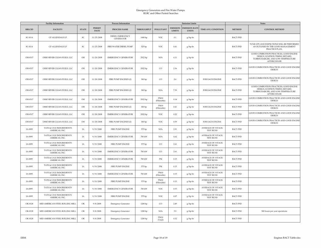
Emergency Generators and Fire Water Pumps RLBC and Other Permit Searches
RBLCID FACILITY STATEPERMIT
DATEPROCESS NAME THROUGHPUT POLLUTANT
EMISSION
LIMITS
EMISSION RATE
UNITSTIME AVG CONDITION METHOD CONTROL METHOD
Facility Information Process Information Emission Limits Notes
SC-0114 GP ALLENDALE LP SC 11/25/2008DIESEL EMERGENCY
GENERATOR1400 hp VOC 0.1 g/hp-hr BACT-PSD
SC-0114 GP ALLENDALE LP SC 11/25/2008 FIRE WATER DIESEL PUMP 525 hp VOC 0.41 g/hp-hr BACT-PSD
TUNE-UPS AND INSPECTIONS WILL BE PERFORMED
AS OUTLINED IN THE GOOD MANAGEMENT
PRACTICE PLAN.
OH-0317 OHIO RIVER CLEAN FUELS, LLC OH 11/20/2008 EMERGENCY GENERATOR 2922 hp NOx 4.11 g/hp-hr BACT-PSD
GOOD COMBUSTION PRACTICES, GOOD ENGINE
DESIGN, IGNITION TIMING RETARD,
TURBOCHARGER, AND LOW-TEMPERATURE
AFTERCOOLER
OH-0317 OHIO RIVER CLEAN FUELS, LLC OH 11/20/2008 EMERGENCY GENERATOR 2922 hp CO 2.36 g/hp-hr BACT-PSDGOOD COMBUSTION PRACTICES AND GOOD ENGINE
DESIGN
OH-0317 OHIO RIVER CLEAN FUELS, LLC OH 11/20/2008 FIRE PUMP ENGINES (2) 300 hp CO 2.6 g/hp-hr FOR EACH ENGINE BACT-PSDGOOD COMBUSTION PRACTICES AND GOOD ENGINE
DESIGN
OH-0317 OHIO RIVER CLEAN FUELS, LLC OH 11/20/2008 FIRE PUMP ENGINES (2) 300 hp NOx 7.39 g/hp-hr FOR EACH ENGINE BACT-PSD
GOOD COMBUSTION PRACTICES, GOOD ENGINE
DESIGN, IGNITION TIMING RETARD,
TURBOCHARGER, AND LOW-TEMPERATURE
AFTERCOOLER
OH-0317 OHIO RIVER CLEAN FUELS, LLC OH 11/20/2008 EMERGENCY GENERATOR 2922 hpPM10
(Filterable)0.14 g/hp-hr BACT-PSD
GOOD COMBUSTION PRACTICES AND GOOD ENGINE
DESIGN
OH-0317 OHIO RIVER CLEAN FUELS, LLC OH 11/20/2008 FIRE PUMP ENGINES (2) 300 hpPM10
(Filterable)0.41 g/hp-hr FOR EACH ENGINE BACT-PSD
GOOD COMBUSTION PRACTICES AND GOOD ENGINE
DESIGN
OH-0317 OHIO RIVER CLEAN FUELS, LLC OH 11/20/2008 EMERGENCY GENERATOR 2922 hp VOC 0.22 g/hp-hr BACT-PSDGOOD COMBUSTION PRACTICES AND GOOD ENGINE
DESIGN
OH-0317 OHIO RIVER CLEAN FUELS, LLC OH 11/20/2008 FIRE PUMP ENGINES (2) 300 hp VOC 0.39 g/hp-hr FOR EACH ENGINE BACT-PSDGOOD COMBUSTION PRACTICES AND GOOD ENGINE
DESIGN
IA-0095TATE & LYLE INDGREDIENTS
AMERICAS, INC.IA 9/19/2008 FIRE PUMP ENGINE 575 hp NOx 2.91 g/hp-hr
AVERAGE OF 3 STACK
TEST RUNSBACT-PSD
IA-0095TATE & LYLE INDGREDIENTS
AMERICAS, INC.IA 9/19/2008 EMERGENCY GENERATOR 700 kW NOx 4.62 g/hp-hr
AVERAGE OF 3 STACK
TEST RUNSBACT-PSD
IA-0095TATE & LYLE INDGREDIENTS
AMERICAS, INC.IA 9/19/2008 FIRE PUMP ENGINE 575 hp CO 2.61 g/hp-hr
AVERAGE OF 3 STACK
TEST RUNSBACT-PSD
IA-0095TATE & LYLE INDGREDIENTS
AMERICAS, INC.IA 9/19/2008 EMERGENCY GENERATOR 700 kW CO 2.61 g/hp-hr
AVERAGE OF 3 STACK
TEST RUNSBACT-PSD
IA-0095TATE & LYLE INDGREDIENTS
AMERICAS, INC.IA 9/19/2008 EMERGENCY GENERATOR 700 kW PM 0.15 g/hp-hr
AVERAGE OF 3 STACK
TEST RUNSBACT-PSD
IA-0095TATE & LYLE INDGREDIENTS
AMERICAS, INC.IA 9/19/2008 FIRE PUMP ENGINE 575 hp PM 0.15 g/hp-hr
AVERAGE OF 3 STACK
TEST RUNSBACT-PSD
IA-0095TATE & LYLE INDGREDIENTS
AMERICAS, INC.IA 9/19/2008 EMERGENCY GENERATOR 700 kW
PM10
(Filterable)0.15 g/hp-hr
AVERAGE OF 3 STACK
TEST RUNSBACT-PSD
IA-0095TATE & LYLE INDGREDIENTS
AMERICAS, INC.IA 9/19/2008 FIRE PUMP ENGINE 575 hp
PM10
(Filterable)0.15 g/hp-hr
AVERAGE OF 3 STACK
TEST RUNSBACT-PSD
IA-0095TATE & LYLE INDGREDIENTS
AMERICAS, INC.IA 9/19/2008 EMERGENCY GENERATOR 700 kW VOC 0.15 g/hp-hr
AVERAGE OF 3 STACK
TEST RUNSBACT-PSD
IA-0095TATE & LYLE INDGREDIENTS
AMERICAS, INC.IA 9/19/2008 FIRE PUMP ENGINE 575 hp VOC 0.07 g/hp-hr
AVERAGE OF 3 STACK
TEST RUNSBACT-PSD
OK-0128 MID AMERICAN STEEL ROLLING MILL OK 9/8/2008 Emergency Generator 1200 hp CO 2.49 g/hp-hr BACT-PSD
OK-0128 MID AMERICAN STEEL ROLLING MILL OK 9/8/2008 Emergency Generator 1200 hp NOx 5.9 g/hp-hr BACT-PSD 500 hours per year operations
OK-0128 MID AMERICAN STEEL ROLLING MILL OK 9/8/2008 Emergency Generator 1200 hpPM10
(Total)0.32 g/hp-hr BACT-PSD
ERM Page 18 of 19 Engines BACT Table.xlsx
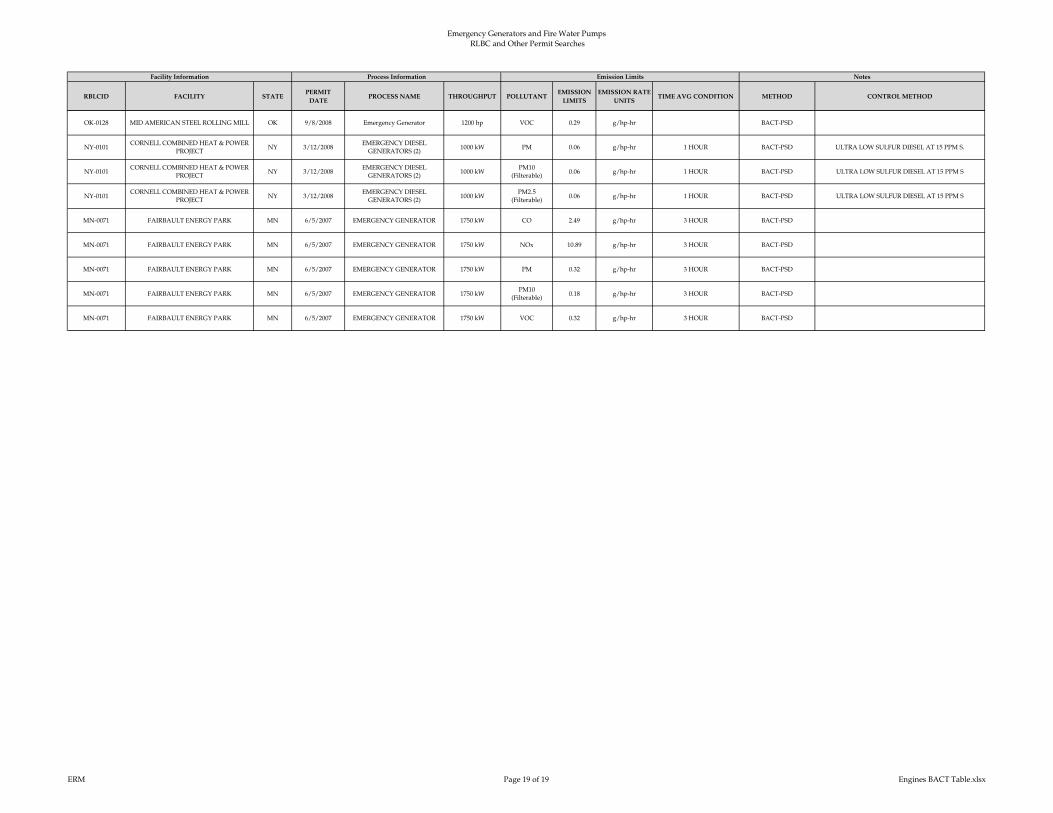
Emergency Generators and Fire Water Pumps RLBC and Other Permit Searches
RBLCID FACILITY STATEPERMIT
DATEPROCESS NAME THROUGHPUT POLLUTANT
EMISSION
LIMITS
EMISSION RATE
UNITSTIME AVG CONDITION METHOD CONTROL METHOD
Facility Information Process Information Emission Limits Notes
OK-0128 MID AMERICAN STEEL ROLLING MILL OK 9/8/2008 Emergency Generator 1200 hp VOC 0.29 g/hp-hr BACT-PSD
NY-0101CORNELL COMBINED HEAT & POWER
PROJECTNY 3/12/2008
EMERGENCY DIESEL
GENERATORS (2)1000 kW PM 0.06 g/hp-hr 1 HOUR BACT-PSD ULTRA LOW SULFUR DIESEL AT 15 PPM S.
NY-0101CORNELL COMBINED HEAT & POWER
PROJECTNY 3/12/2008
EMERGENCY DIESEL
GENERATORS (2)1000 kW
PM10
(Filterable)0.06 g/hp-hr 1 HOUR BACT-PSD ULTRA LOW SULFUR DIESEL AT 15 PPM S
NY-0101CORNELL COMBINED HEAT & POWER
PROJECTNY 3/12/2008
EMERGENCY DIESEL
GENERATORS (2)1000 kW
PM2.5
(Filterable)0.06 g/hp-hr 1 HOUR BACT-PSD ULTRA LOW SULFUR DIESEL AT 15 PPM S
MN-0071 FAIRBAULT ENERGY PARK MN 6/5/2007 EMERGENCY GENERATOR 1750 kW CO 2.49 g/hp-hr 3 HOUR BACT-PSD
MN-0071 FAIRBAULT ENERGY PARK MN 6/5/2007 EMERGENCY GENERATOR 1750 kW NOx 10.89 g/hp-hr 3 HOUR BACT-PSD
MN-0071 FAIRBAULT ENERGY PARK MN 6/5/2007 EMERGENCY GENERATOR 1750 kW PM 0.32 g/hp-hr 3 HOUR BACT-PSD
MN-0071 FAIRBAULT ENERGY PARK MN 6/5/2007 EMERGENCY GENERATOR 1750 kWPM10
(Filterable)0.18 g/hp-hr 3 HOUR BACT-PSD
MN-0071 FAIRBAULT ENERGY PARK MN 6/5/2007 EMERGENCY GENERATOR 1750 kW VOC 0.32 g/hp-hr 3 HOUR BACT-PSD
ERM Page 19 of 19 Engines BACT Table.xlsx

Appendix C – GHG BACT Supplement
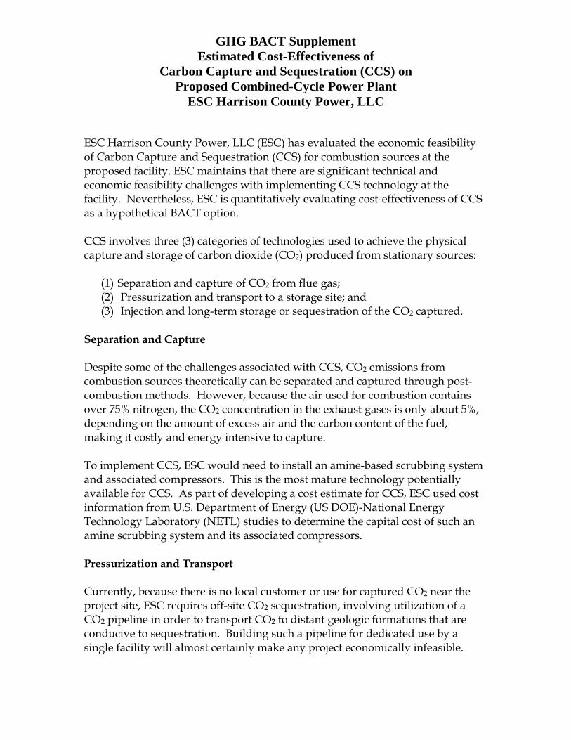
GHG BACT Supplement Estimated Cost-Effectiveness of
Carbon Capture and Sequestration (CCS) on Proposed Combined-Cycle Power Plant
ESC Harrison County Power, LLC
ESC Harrison County Power, LLC (ESC) has evaluated the economic feasibility of Carbon Capture and Sequestration (CCS) for combustion sources at the proposed facility. ESC maintains that there are significant technical and economic feasibility challenges with implementing CCS technology at the facility. Nevertheless, ESC is quantitatively evaluating cost-effectiveness of CCS as a hypothetical BACT option.
CCS involves three (3) categories of technologies used to achieve the physical capture and storage of carbon dioxide (CO2) produced from stationary sources:
(1) Separation and capture of CO2 from flue gas;(2) Pressurization and transport to a storage site; and(3) Injection and long-term storage or sequestration of the CO2 captured.
Separation and Capture
Despite some of the challenges associated with CCS, CO2 emissions from combustion sources theoretically can be separated and captured through post-combustion methods. However, because the air used for combustion contains over 75% nitrogen, the CO2 concentration in the exhaust gases is only about 5%, depending on the amount of excess air and the carbon content of the fuel, making it costly and energy intensive to capture.
To implement CCS, ESC would need to install an amine-based scrubbing system and associated compressors. This is the most mature technology potentially available for CCS. As part of developing a cost estimate for CCS, ESC used cost information from U.S. Department of Energy (US DOE)-National Energy Technology Laboratory (NETL) studies to determine the capital cost of such an amine scrubbing system and its associated compressors.
Pressurization and Transport
Currently, because there is no local customer or use for captured CO2 near the project site, ESC requires off-site CO2 sequestration, involving utilization of a CO2 pipeline in order to transport CO2 to distant geologic formations that are conducive to sequestration. Building such a pipeline for dedicated use by a single facility will almost certainly make any project economically infeasible.

ESC Harrison County Power, LLC GHG BACT Supplement
Page 2 However, such an option may be effective if adequate storage capacities exist, and if reasonable transportation prices can be arranged with a pipeline operator.
As shown in Figure 1 below, obtained from a June 2013 Eastern Interconnection States’ Planning Council (EISPC) report produced for the US DOE1, no CO2 pipelines for Enhanced Oil Recovery (EOR) exist in the eastern United States. The closest existing CO2 transport pipeline to ESC is located in Mississippi, roughly 950 miles from the project site. Although building an approximately 1,000 mile pipeline is a technically feasible option for CO2 transport, it would be cost prohibitive and would be expected to lead to increased CO2 emissions because of the additional compression required to transport the captured CO2 over such a large distance. Aside from the direct costs, such a pipeline project would likely face major permitting challenges. If permitting of such a line was even possible, it would take years to permit and construct.
Figure 1 Map of Existing CO2 Transport Pipelines (June 2013)
1 ICF Incorporated. Current State and Future Direction of Coal-fired Power in the Eastern Interconnection. Rep. N.p.: Eastern Interconnection States’ Planning Council, n.d.

ESC Harrison County Power, LLC GHG BACT Supplement
Page 3 Geological Sequestration
Dedicated geological sequestration of CO2 requires close proximity to a favorable geologic formation. ESC used the US DOE-NETL National Carbon Sequestration Database and Geographic Information System (NATCARB) to identify the nearest geologic carbon sequestration site that may be suitable for the project. Table 2 below shows the DOE-NETL estimates of CO2 storage resources from geological formations by State2.
Table 2 CO2 Storage Resource Estimates, Million Tons
State
Oil and Gas Reservoir Storage Resources
Unmineable Coal Storage Resource
Saline Formation Storage Resource
Total Storage Resource
Low Estimate
High Estimate
Low Estimate
High Estimate
Low Estimate
High Estimate
Low Estimate
High Estimate
KY 1,157 3,538 154 220 16,226 121,475 17,538 125,233
MD - - - - - - - - - - - - 2,050 2,127 2,050 2,127
OH 717 2,172 132 132 10,924 10,924 11,773 13,228
PA 882 2,701 298 298 19,114 19,114 20,294 22,112
VA 0 11 176 761 - - - - - - 507 3,208
WV 6,537 19,897 408 408 - - - - - - 19,279 32,639
United States 205,030 255,736 59,525 124,561 2,622,395 23,846,272 2,885,848 24,226,569
Table 2 shows that West Virginia and surrounding states have identified potentially viable CO2 geologic storage resources in oil and gas fields, deep coal seams (> 2,400 feet), and saline aquifers. Development of these sites is in its infancy. Additional significant research and testing would be required to develop and regulate these sites for large-scale use by a CO2 emitter such as ESC3. The nearest test site that is undergoing small-scale validation testing was identified as a coal seam in Russell County, Virginia. Costs to implement CCS include constructing a 12-inch diameter, 190-mile long pipeline to deliver the compressed CO2 to this potential site.
2 The North American Carbon Storage Atlas, 5th Edition, NETL, 2015. 3 West Virginia Carbon Capture and Storage Opportunities Associated with Potential Locations for Coal-to-Liquid Facilities. Carr et al., 2009.

ESC Harrison County Power, LLC GHG BACT Supplement
Page 4 A map of the DOE-NETL NATCARB4 carbon sequestration test sites is provided in Figure 2 below.
Figure 2 NATCARB CO2 Storage Projects
A 12-inch pipe is conservatively small and likely underestimates the costs for constructing the pipeline. Further, the cost-effectiveness estimate is conservatively low as the estimate does not include compressor stations which would likely be needed to transport the gases over this distance. Additionally, for this cost-effectiveness estimate, no allowance was provided for mitigation of the likely substantial ecological and social impacts of building a new pipeline over such a large distance.
Based on the analysis above and due to the fact that there are no suitable CO2 storage locations or existing transport pipelines close to the project site, the use of add-on controls for carbon sequestration is considered to be technically infeasible.
Cost-Effectiveness Analysis
For the cost-effectiveness analysis, the estimated costs for CCS were, again, divided into three (3) categories:
(1) Post-combustion capture and compression costs; (2) Pipeline costs; and
4 NATCARB, USDOE - NETL, http://www.netl.doe.gov/research/coal/carbon-storage/carbon-storage-natcarb. 04 Feb. 2014.

ESC Harrison County Power, LLC GHG BACT Supplement
Page 5
(3) Geological storage costs.
In a U.S. Environmental Protection Agency (EPA) Prevention of Significant Deterioration (PSD) permit proceeding for the City of Palmdale, (Palmdale)5, the U.S. Environmental Appeals Board (EAB) noted that, particularly in the context of CCS, when evaluating the economic impacts of greenhouse gas (GHG) control strategies, “it may be appropriate in some cases to assess the cost effectiveness of a control option in a less detailed quantitative (or even qualitative) manner.” Although the following analysis is quantitative in many respects, it does rely on certain assumptions. These assumptions are appropriate and conservative and certainly sufficient given the EAB guidance on these assessments.
Capital cost values for post-combustion capture and compression were taken from the US DOE Interagency Task Force report on CCS6, which were conservatively estimated at approximately $103 per ton of CO2 captured. Capital costs for post-combustion capture and compression ranged from $54 to $103 per ton of CO2 captured, where the higher value was associated with new natural gas-fired combined-cycle units. Annual operation and maintenance (O&M) and fuel costs for the post-combustion capture and compression system were adapted from costs derived for similar systems on electric generating units found in a US DOE report for Fossil Energy Plants7. For the capital and O&M costs related to the required pipeline and geologic storage of CO2, methodology developed by the NETL8 was used based on the estimated pipeline length, pipeline diameter, and sequestration formation depth. Additional details for the cost-effectiveness calculations are shown in Table 4.
EPA typically uses a dollar per ton removed ($/ton removed) basis when evaluating the cost-effectiveness of pollution control devices. ESC believes that, in addition to a per ton removed basis, it is appropriate to compare the cost to install CCS against the total project cost. In the Palmdale9 case, the Region argued that evaluating CCS using a “price comparison approach was consistent with” the GHG Permitting Guidance. The EAB upheld the Region’s
5 In re City of Palmdale, PSD Appeal No. 11-07, slip op. at 56-60 (EAB Sept. 17, 2012), 15 E.A.D. ___ (Palmdale Hybrid Power Project) 2) (citing EPA, EPA-457/B-11-001, PSD and Title V Permitting Guidance for Greenhouse Gases at 42 (Mar. 2011) (the “GHG Permitting Guidance”). 6 Report of the Interagency Task Force on Carbon Capture and Storage, US DOE, August 2010. 7 Cost and Performance Baseline For Fossil Energy Plants, Volume 1a: Bituminous and Natural Gas to
Electricity, DOE/2015/1723, Revision 3, July 2015. 8 Estimating Carbon Dioxide Transport and Storage Costs, DOE/NETL-2010/1447, March 2013. 9 In re: City of Palmdale (Palmdale Hybrid Power Project), PSD Appeal No. 11-07 (E.A.B. Sept. 17, 2012). Id. at 55.

ESC Harrison County Power, LLC GHG BACT Supplement
Page 6 determination that CCS was cost prohibitive because the “cost of CCS would be so high - twice the annual cost of the entire project.”
EOR was considered in the economic analysis of CCS, but no value was included in the economic analysis for CCS for the sale of CO2. Currently, there is not a significant market for CO2 for EOR in the region in which the proposed project is located. As such, it is ESC’s opinion that EOR in the region has no economic value. Further, it is beyond the scope of the business purpose for this project to become contractually obligated to provide CO2 for commercial purposes, including EOR.
ESC’s cost-effectiveness analysis does not account for tax credits associated with CCS. Since 2008, the IRS has provided a tax credit for two (2) types of CO2 sequestration. A credit of $20 per ton may be taken for CO2 sequestered in secure geological storage10. A $10 per ton credit is available for CO2 used as a tertiary injectant in a qualified EOR or natural gas recovery project11. This tax credit is capped and ceases to be available once credits have been claimed for sequestering 75,000,000 tons of CO212. As of September 26, 2016, credits have already been claimed for the sequestration of 44,590,130 tons of CO213. ESC expects that as new plants come on-line that will implement CCS, such as the planned integrated gasification combined cycle plants in the Southeast and Midwest, these tax credits will not be available, and thus are not considered in this cost analysis for CCS. It is extremely speculative to consider whether Congress will extend these tax credits in the future.
The results of the cost-effectiveness analysis for CCS are shown in Table 3 below. Additional details for the cost-effectiveness calculations are shown in Table 4.
10 26 U.S.C. 45Q(a)(1). Adjusted for inflation, the credit for calendar year 2016 is $22.14 per ton. 11 26 U.S.C. 45Q(a)(2). Adjusted for inflation, the credit for calendar year 2016 is $11.07 per ton. 12 26 U.S.C. 45Q(e); see also IRS Notice 2016-53 (“… the §45Q credit will apply with respect to qualified CO2
before the end of the calendar year in which the Secretary, in consultation with the EPA, certifies that 75,000,000 metric tons of qualified CO2 have been taken into account in accordance with § 45Q(a)”).
13 IRS Notice 2016-53.

ESC Harrison County Power, LLC GHG BACT Supplement
Page 7 Table 3 Carbon Capture and Sequestration Cost-Effectiveness
Parameter Cost Estimate (2013 US Dollars)
Capital Cost $445,560,623
Annual O&M Costs $73,948,232
Capital Recovery1 $42,057,770
Total Annualized Cost $116,006,002
Total CO2 Controlled (TPY)2 2,081,376
CO2 Cost-Effectiveness ($/ton removed) $56 1 Capital recovery based on economic life of 20 years for equipment and 7% interest rate. 2 Assumes 90% of CO2 emissions are captured and controlled from ESC’s proposed combustion
turbine/duct burners.
The above assessment would not be changed even in the unlikely event that CCS tax credits were available at the time of project implementation. Based on the conservatively estimated capital cost for CCS that approaches 75% of the estimated capital cost of the project14 as well as the calculated cost-effectiveness of $56/ton CO2 reduced, the use of CCS as an add-on control for GHG emissions is not considered cost-effective and therefore is not BACT.
14 The estimated capital cost of the project is $606 million, based on a nominal plant output of 640 MW, and an installed capital cost of $947/kW. The installed capital cost was obtained from a report called “Cost of New Entry Estimates for Combustion Turbine and Combined Cycle Plants in PJM” specifically, Table 1 “Cost of New Entry Estimates for Combustion Turbine and Combined Cycle Plants in PJM" lists $947/kW as the installed capital cost in the RTO region of PJM.

Potential CO2 Emissions from CT/DBs (tons/yr) Based on Harrison County Power air permit application, 2016 2,312,640Expected Capture Efficiency 90% 90%CO2 Captured (tons) 90% CO2 captured 2,081,376
Base Capital (1) $103.42/ton CO2 captured $249,699,847Annual O&M (2) $12.17/ton CO2 captured $29,382,293Annual Fuel (3), (4) 12.6% incremental fuel use at $2.59/MMBtu $12,857,176
L, Pipeline Length (miles) (6) 190D, Pipeline Diameter (inches) 12
Materials $64,632 + $1.85 x L x (330.5 x D2 + 686.7 x D + 26,960) $33,833,450Labor $341,627 + $1.85 x L x (343.2 x D2 + 2074 x D + 170,013) $100,018,138Miscellaneous $150,166 + $1.58 x L x (8,417 x D + 7,234) $37,866,915Right of Way $48,037 + $1.20 x L x (577 x D + 29,788) $9,765,516
CO2 Surge Tank Fixed ($1,150,636) $1,334,766Pipeline Control System Fixed ($110,632) $128,336
Fixed O&M ($/yr) $8,632 x L $1,902,532
Number of Injection Wells 2Well Depth (m) Depth of formation(7) 1,825
Site Screening and Evaluation Fixed ($4,738,488) $5,496,760Injection Wells $240,714 x e0.0008 x Well Depth $1,202,371Injection Equipment $94029 x (7,839/(280 x Number of Injection Wells))0.5 $408,099Liability Bond Fixed ($5,000,000) $5,000,000
Pore Space Acquisition $0.334/short ton CO2 $806,425
Normal Annual Expenses $11,566/day x Number Injection Wells x 365 day/yr $9,794,293Consumables $2,995/yr/ton CO2/day $19,811,690Surface Maintenance $23,478 x (7,839/(280 x Number of Injection Wells))0.5 $101,898Subsurface Maintenance $7.08/ft-depth x Number of Injection Wells $98,351
Post-Combustion CO2 Capture and Compression
Estimated Cost-Effectiveness of Carbon Capture and Sequestration (CCS)ESC Harrison County Power, LLC
Geologic Storage Costs (5)
Post-Combustion CO2 Capture and Compression
Pipeline Cost Breakdown (5)
Pipeline Costs
Other Capital
O&M
Table 4
Capital
Declining Capital Funds
O&M
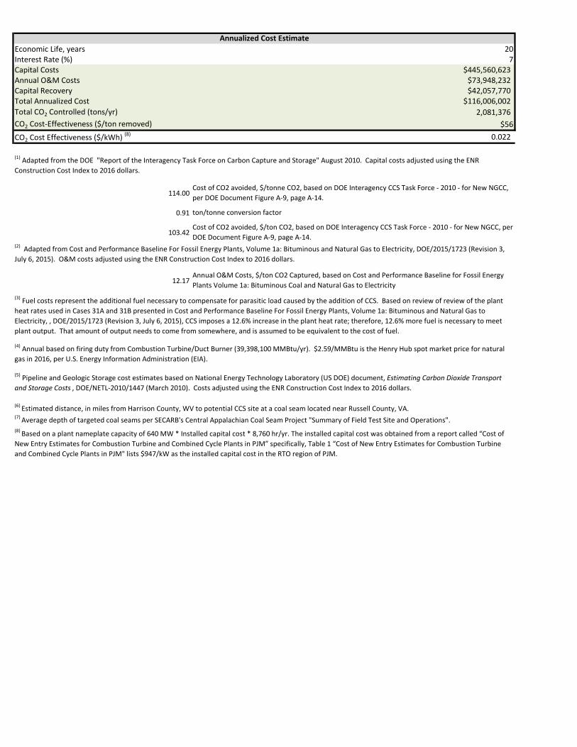
Economic Life, years 20Interest Rate (%) 7Capital Costs $445,560,623Annual O&M Costs $73,948,232Capital Recovery $42,057,770Total Annualized Cost $116,006,002Total CO2 Controlled (tons/yr) 2,081,376 CO2 Cost-Effectiveness ($/ton removed) $56CO2 Cost Effectiveness ($/kWh) (8) 0.022
114.00
0.91
103.42
12.17Annual O&M Costs, $/ton CO2 Captured, based on Cost and Performance Baseline for Fossil Energy Plants Volume 1a: Bituminous Coal and Natural Gas to Electricity
(8) Based on a plant nameplate capacity of 640 MW * Installed capital cost * 8,760 hr/yr. The installed capital cost was obtained from a report called “Cost of New Entry Estimates for Combustion Turbine and Combined Cycle Plants in PJM” specifically, Table 1 “Cost of New Entry Estimates for Combustion Turbine and Combined Cycle Plants in PJM" lists $947/kW as the installed capital cost in the RTO region of PJM.
(3) Fuel costs represent the additional fuel necessary to compensate for parasitic load caused by the addition of CCS. Based on review of review of the plant heat rates used in Cases 31A and 31B presented in Cost and Performance Baseline For Fossil Energy Plants, Volume 1a: Bituminous and Natural Gas to Electricity, , DOE/2015/1723 (Revision 3, July 6, 2015), CCS imposes a 12.6% increase in the plant heat rate; therefore, 12.6% more fuel is necessary to meet plant output. That amount of output needs to come from somewhere, and is assumed to be equivalent to the cost of fuel.
(5) Pipeline and Geologic Storage cost estimates based on National Energy Technology Laboratory (US DOE) document, Estimating Carbon Dioxide Transport and Storage Costs , DOE/NETL-2010/1447 (March 2010). Costs adjusted using the ENR Construction Cost Index to 2016 dollars.
(7) Average depth of targeted coal seams per SECARB's Central Appalachian Coal Seam Project "Summary of Field Test Site and Operations".
Annualized Cost Estimate
(1) Adapted from the DOE "Report of the Interagency Task Force on Carbon Capture and Storage" August 2010. Capital costs adjusted using the ENR Construction Cost Index to 2016 dollars.
(2) Adapted from Cost and Performance Baseline For Fossil Energy Plants, Volume 1a: Bituminous and Natural Gas to Electricity, DOE/2015/1723 (Revision 3, July 6, 2015). O&M costs adjusted using the ENR Construction Cost Index to 2016 dollars.
(4) Annual based on firing duty from Combustion Turbine/Duct Burner (39,398,100 MMBtu/yr). $2.59/MMBtu is the Henry Hub spot market price for natural gas in 2016, per U.S. Energy Information Administration (EIA).
(6) Estimated distance, in miles from Harrison County, WV to potential CCS site at a coal seam located near Russell County, VA.
Cost of CO2 avoided, $/ton CO2, based on DOE Interagency CCS Task Force - 2010 - for New NGCC, per DOE Document Figure A-9, page A-14.
ton/tonne conversion factor
Cost of CO2 avoided, $/tonne CO2, based on DOE Interagency CCS Task Force - 2010 - for New NGCC, per DOE Document Figure A-9, page A-14.

Appendix D – Comparison of GHG Emission Rates and Heat Rates for Combustion Turbines

Facility Location Type Size/Configuration GHG Emission Rate Heat Rate(Btu/kW-hr)
ESC Harrison County Power, LLC Harrison County, WV General Electric 7HA.02One combined-cycle combustion turbine, with a
nominal plant nominal gross electrical generating capacity of 640 MW.
802 lb CO2e/MW-hr, Gross, 53.6°F, NG Firing, Combined-Cycle, w/DF760 lb CO2e/MW-hr, Gross, 53.6°F, NG Firing, CC, w/o DF
6,832 Btu/kW-hr HHV, Gross, 53.6°F, NG Firing, Combined-Cycle, w/DF6,486 Btu/kW-hr HHV, Gross, 53.6oF, NG Firing, CC, w/o DF
40 CFR Part 60 (NSPS) Subpart TTTT Standards of Performance for Greenhouse
Gas Emissions from New Stationary Sources: Electric Utility Generating Units (as
adopted 8/3/2015)
New combined-cycle trains > 25 MW; existing units and simple-cycle trains are not affected
1,000 lb CO2/MW-hr(gross output, 12-operating month annual average, firing greater than 90% natural
gas)
ESC Brooke County Power, LLC Brooke County, WV General Electric 7HA.01Two combined-cycle combustion turbines, with
a nominal plant nominal gross electrical generating capacity of 750 MW.
735.66 lb CO2/MW-hr, Gross, 52.4°F, NG Firing, Combined-Cycle823.89 lb CO2e/MW-hr, Gross, 52.4°F, Ethane Firing, Combined-Cycle
6,450 Btu/kW-hr HHV, Gross, 52.4oF, NG Firing, Combined-Cycle6,476 Btu/kW-hr HHV, Gross, 52.4, Ethane Firing, Combined-Cycle
Moundsville Power LLC Moundsville, WV General Electric 7FA.04 188.5 MW, Gross, 59°F 792 lb CO2e/MW-hr, Gross, 59°F, NG Firing, Combined-Cycle 6,418 Btu/kW-hr HHV 59oF, NG Firing, Combined-Cycle
PSEG Fossil LLCSewaren Unit No. 7 Woodbridge, NJ General Electric 7HA.02
One combined-cycle combustion turbine, with a nominal plant nominal gross electrical
generating capacity of 585 MW. 888 lb CO2e/MW-hr 6,871 Btu/kW-hr HHV, Net, ISO conditions, w/o duct firing
Middlesex Energy Center Sayreville, NJ General Electric 7HA.02One combined-cycle combustion turbine, with a
nominal plant nominal gross electrical generating capacity of 633 MW.
888 lb CO2e/MW-hr 6,901 Btu/kW-hr HHV, Gross, ISO conditions, w/o duct firing
Woodbridge Energy Center Woodbridge, NJ General Electric 7FA.05Two combined-cycle combustion turbines, with
a nominal plant nominal gross electrical generating capacity of 725 MW.
925 lb CO2e/MW-hr, Gross 7,605 Btu/kW-hr, w/o duct firing
Lower Colorado River AuthorityThomas G. Ferguson Plant Llano, TX General Electric 7FA 195 MW each; 590 MW for 2-2-1 combined-cycle
configuration0.459 ton CO2 /net MW-hr (918 lb CO2/net MW-hr)
(365-day rolling average)7,720 Btu/kW-hr, without duct firing (365-day rolling average)
Three options Combined-cycle with 271 MW steam turbine in 2x2x1 configuration
General Electric 7FA 183 MW each
Siemens SGT6-5000F(4) 205 MW each
Siemens SGT6-5000F(5) 232 MW each
Calpine CorporationChannel Energy Center, LLC Pasadena, TX Siemens 501F (FD3) 180 MW combined-cycle with 475 MMBtu/hr
duct burner918.5 lb CO2/MW-hr 7,730 Btu/kW-hr, without duct firing
Calpine/Bechtel Joint Development
Russell City Energy CenterHayward, CA Siemens-Westinghouse 501FD3 2,038.6 MMBtu/hr each; 200 MMBtu/hr duct
burners; 2 combined-cycle trains119.0 lb CO2e/MMBtu 7,730 Btu/kW-hr, without duct firing
Palmdale Hybrid Power Project Palmdale, CA General Electric 7FA 154 MW each; 2x2x1 combined-cycle with 267 MW steam turbine
774 lb CO2 /net MW-hr (site-wide average) 117 lb CO2/MMBtu (30-day average for each turbine) 6,970 Btu/kW-hr
Cricket Valley Energy Center Dover, NY General Electric 7FA.05 Three combined-cycle units with 596.8 MMBtu/hr duct burners
3,576,943 tons CO2e maximum: emissions from 3 combined-cycle units (12-month rolling average)
7,605 Btu/kW-hr, without duct firing
Pioneer Valley Energy Center Westfield, MA Not specified 431 MW combined-cycle unit N/A 6,840 Btu/kW-hr, without duct firingPacifiCorp EnergyLake Side 2 Project UT Siemens 501F (FD3) 180 MW combined-cycle with 475 MMBtu/hr
duct burner950 lb CO2e per MW-hr
(12-month rolling average)N/A
Gateway Cogeneration 1, LLCSmart Water Project Prince George, VA N/A Combined-cycle N/A 8,983 Btu/kW-hr
Sevier Power CompanySevier Power Project UT
Two natural gas fired combined-cycle combustion turbines with heat recovery steam generators
580 MW (expected generating capacity)2,019,226 tons CO2e
(12-month rolling average)N/A
Newark Energy Center Project Newark, NJGE F class natural gas fired combined-cycle combustion
turbines655 MW (plant)
887 lb CO2 /MW-hr, Gross2,000,268 tons CO2 for 2 turbine/duct burners (12-month rolling average) 7,522 Btu/kW-hr HHV, Net, ISO conditions, without duct firing
Old Bridge Clean Energy Center Old Bridge, Middlesex County, NJ
700 MW natural gas-fired combined-cycle power plant N/A
950 lb CO2e/MW-hr (12-month rolling average)121.521 lb CO2e/MMBtu N/A
Christian County Generation LLC Taylorville, IL
F-class combustion turbine (either Siemens or GE); Two combined-cycle combustion turbines firing
either SNG or pipeline natural gas
Two combustion turbines and the plant have nominal gross electrical generating capacity of
716 MW; Nominal net electrical generating capacity of 602 MW
2,307,110 tons/yr CO2e (12-month rolling average) 1,201 lb CO2/MW-hr N/A
Other InformationTurbine InformationProject Information
ESC Harrison County Power, LLCComparison of GHG Emission Rates and Heat Rates for Combustion Turbines
Coronado VenturesLa Paloma Energy Center, LLC Harlingen, TX 918.5 lb CO2/MW-hr 7,720 Btu/kW-hr, without duct firing (365-day rolling average)
Adopted Regulations
Proposed Project (Combined-Cycle)
Projects with Combined-Cycle Combustion Turbines
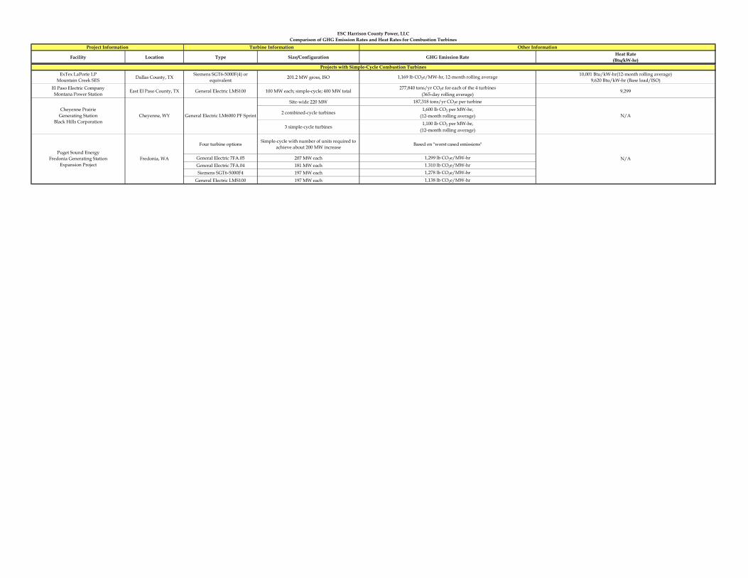
Facility Location Type Size/Configuration GHG Emission Rate Heat Rate(Btu/kW-hr)
Other InformationTurbine InformationProject Information
ESC Harrison County Power, LLCComparison of GHG Emission Rates and Heat Rates for Combustion Turbines
ExTex LaPorte LP
Mountain Creek SES Dallas County, TX Siemens SGT6-5000F(4) or equivalent 201.2 MW gross, ISO 1,169 lb CO2e/MW-hr, 12-month rolling average 10,001 Btu/kW-hr(12-month rolling average)
9,620 Btu/kW-hr (Base load/ISO)El Paso Electric CompanyMontana Power Station East El Paso County, TX General Electric LMS100 100 MW each; simple-cycle; 400 MW total
277,840 tons/yr CO2e for each of the 4 turbines(365-day rolling average)
9,299
Site-wide 220 MW 187,318 tons/yr CO2e per turbine
2 combined-cycle turbines1,600 lb CO2 per MW-hr,
(12-month rolling average)
3 simple-cycle turbines1,100 lb CO2 per MW-hr,
(12-month rolling average)
Four turbine options Simple-cycle with number of units required to achieve about 200 MW increase Based on "worst cased emissions"
General Electric 7FA.05 207 MW each 1,299 lb CO2e/MW-hrGeneral Electric 7FA.04 181 MW each 1.310 lb CO2e/MW-hrSiemens SGT6-5000F4 197 MW each 1,278 lb CO2e/MW-hr
General Electric LMS100 197 MW each 1,138 lb CO2e/MW-hr
Puget Sound EnergyFredonia Generating Station
Expansion ProjectFredonia, WA N/A
General Electric LM6000 PF SprintCheyenne, WYCheyenne Prairie
Generating StationBlack Hills Corporation
N/A
Projects with Simple-Cycle Combustion Turbines

Appendix E – Air Permit Application Forms

Table of Contents
APPLICATION FOR NSR PERMIT
ATTACHMENT A BUSINESS CERTIFICATE ATTACHMENT B LOCATION MAP ATTACHMENT C SCHEDULE OF CHANGES ATTACHMENT D REGULATORY DISCUSSION ATTACHMENT E PLOT PLAN ATTACHMENT F DETAILED PROCESS FLOW DIAGRAMS ATTACHMENT G PROCESS DESCRIPTION ATTACHMENT H MATERIAL SAFETY DATA SHEETS ATTACHMENT I EQUIPMENT UNITS TABLE ATTACHMENT J EMISSION POINTS DATA SUMMARY SHEET ATTACHMENT K FUGITIVE EMISSIONS DATA SUMMARY SHEET ATTACHMENT L EMISSIONS UNIT DATA SHEETS ATTACHMENT M AIR POLLUTION CONTROL DEVICE SHEETS ATTACHMENT N SUPPORTING EMISSIONS CALCULATIONS ATTACHMENT O MONITORING, REPORTING, & RECORDKEEPING PLANS ATTACHMENT P AIR QUALITY PERMIT NOTICE ATTACHMENT Q BUSINESS CONFIDENTIAL CLAIMS ATTACHMENT R AUTHORITY FORMS ATTACHMENT S TITLE V PERMIT

APPLICATION FOR NSR PERMIT
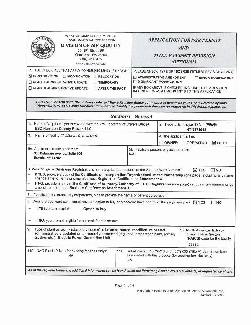
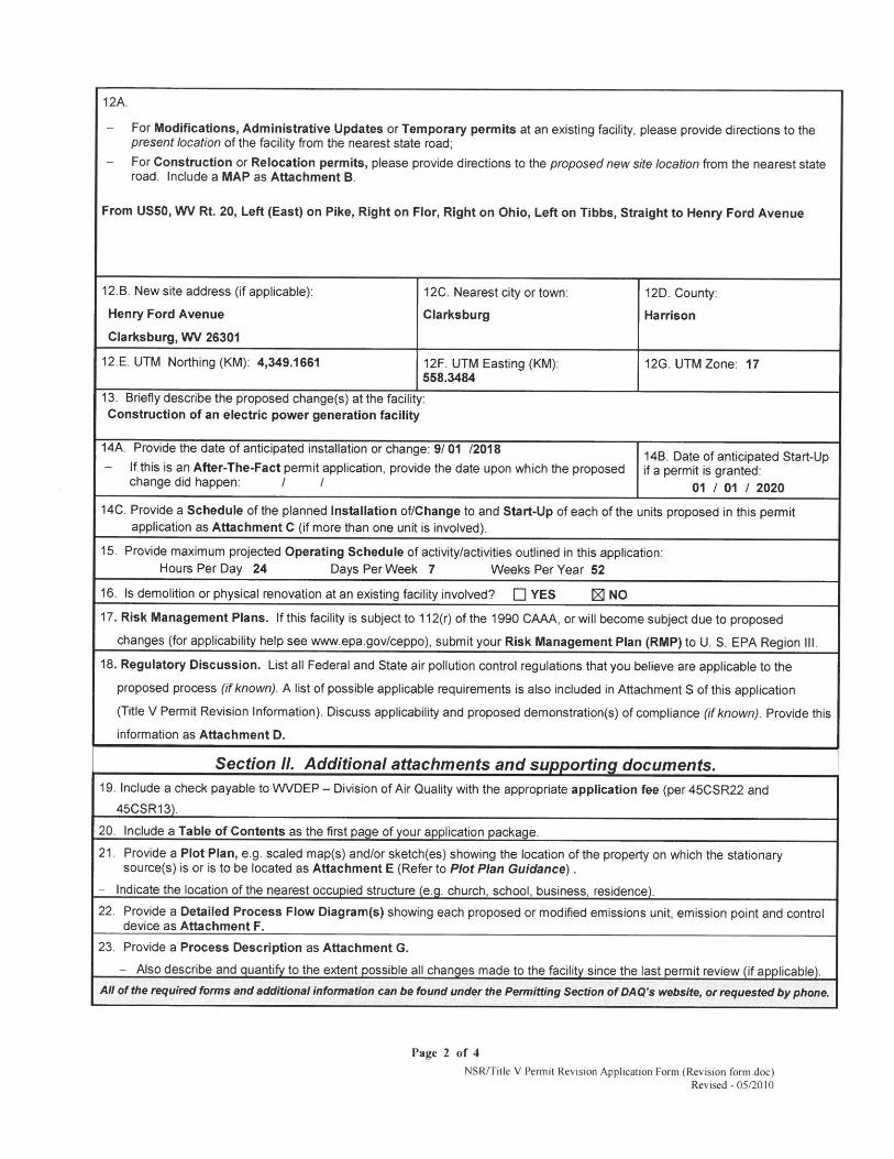


ATTACHMENT A BUSINESS CERTIFICATE


ATTACHMENT B LOCATION MAP

kristen.fisher
Rectangle
kristen.fisher
Typewritten Text
Energy
kristen.fisher
Typewritten Text
kristen.fisher
Typewritten Text
kristen.fisher
Typewritten Text
kristen.fisher
Typewritten Text
kristen.fisher
Typewritten Text
kristen.fisher
Typewritten Text

ATTACHMENT C SCHEDULE OF INSTALLATION AND START-UP
ESC Harrison County Power, LLC has tentatively scheduled to begin construction related activities during 2018. Final installation of equipment and start-up of the facility is tentatively scheduled for the first quarter of 2020. This schedule may vary depending on actual delivery of equipment, unforeseen construction delays, etc.

ATTACHMENT D REGULATORY DISCUSSION
The Plant will be designed and operated in accordance with applicable state and federal regulations. Regulations potentially impacting the proposed Plant are further discussed in the permit application package. Specifically, Section 3.4 provides a detailed applicability analysis of the federal Prevention of Significant Deterioration (PSD) and Best Available Control Technology (BACT) requirements; Section 3.6.1 addresses federal requirements including New Source Performance Standards (NSPS) and National Emissions Standards for Hazardous Air Pollutants (NESHAPs); and Section 3.6.2 contains the applicable West Virginia state requirements.

ATTACHMENT E PLOT PLAN


ATTACHMENT F DETAILED PROCESS FLOW DIAGRAM

Gas Turbine
HCCT-1
HCCT-1
Attachment F
Process Flow Diagram
Emission Point
Process Flow
Vent Streams
Electricity to
Grid
Dry Air
Cooled
Condenser
Unit 1 Heat Recovery Steam
Generator
Steam
Turbine
Steam
Condensate
Auxiliary
Boiler
AB-1
Natural GasSteam for
Plant Support
AB-1
Electric
Generator
EG-1
Firewater
Pump
FP-1
Diesel
Storage
Tank
ST-1
FP-1ST-1
Diesel
Storage
Tank
ST-2
ST-2
Fuel
Gas
Heater
FGH-1
FGH-1
<20% Aqueous NH3
Storage Tank
Tank 1
Natural Gas
Electricity to
Grid
EG-2EG-1

ATTACHMENT G
PROCESS DESCRIPTION

Page 1 of 2
Attachment G Process Description
The ESC Harrison County, LLC power plant has a proposed primary point of interconnection as a direct 138 kilovolt (kV) interconnection to the First Energy’s (Allegheny Power’s) existing Glen Falls 138 kV substation, about 2 miles north of the project site. Plant output will be sold into the Pennsylvania-New Jersey-Maryland Interconnection LLC (PJM) regional electric grid. Pipeline-quality natural gas used by the plant’s combustion turbine will be purchased from local suppliers, and will take advantage of the gas produced in nearby natural gas shale plays. Electricity will be generated using one (1) combined-cycle combustion turbine (HCCT-1) with a design heat input rating of 3,496.2 million Btu per hour (MMBtu/hr)1. Electricity generated by the combustion turbines will be routed through a local electrical substation and sold on the grid. To enhance the plant’s overall efficiency and increase the amount of electric generated by the plant, the hot exhaust gases from the combustion turbine are routed to a downstream Heat Recovery Steam Generator (HRSG). The HRSG contains a series of heat exchangers designed to recover the heat from the turbine’s exhaust gas and produce steam, as in a boiler. The Project includes the installation of duct burners to produce additional steam in the HRSG for additional power output from the steam turbine generator. The maximum duct firing level is expected to be 1,001.3 MMBtu/hr on a HHV basis. The fuel for the duct burners will be the same as for the combustion turbine: pipeline-quality natural gas. Cooled exhaust gas passing through the HRSG will be vented to the atmosphere through emission point HCCT-1. The Selective Catalytic Reduction (SCR) and Oxidation Catalyst control devices used to reduce NOx and CO emissions from the combustion turbines will be incorporated into the HRSG, at locations where the emission control reactions optimally occur.
1 Combustion turbine output and heat input vary by several factors, including ambient
temperature, relative humidity, fuel, load level, whether duct firing or evaporative cooling are in use, etc. 3,496.2 MMBtu/hr is the expected maximum heat input for the CT, which occurs at an operating case with an ambient temperature of -12.2 °F, 80% relative humidity, natural gas firing, base load, with 100% duct firing, and with evaporative cooling off.

Page 2 of 2
SCR involves the injection of aqueous ammonia (NH3) with a concentration of less than 20% by weight into the combustion turbine exhaust gas streams. Ammonia reacts with NOx in the exhaust gas stream, reducing it to elemental nitrogen (N2) and water vapor (H2O). The aqueous ammonia will be stored on-site in one (1) storage tank, with a capacity of 35,000 gallons. The aqueous ammonia storage tank will not normally vent to the atmosphere. It will be equipped with pressure relief valves that would only vent in the event of an emergency. The Oxidation Catalyst does not require the use of chemical reagents. Steam generated in the HRSG will be routed to a steam driven electric generator. This generator will produce additional electricity that will be sold on the grid. Electricity generated by the combustion turbine and the single steam generator represent the plant’s total electrical output. The Project will use a dry air cooled condenser (DACC) in lieu of a conventional wet cooling tower for steam turbine generator steam condensation. The steam produced in the HRSG will be used in the steam turbine to produce additional electrical power. Once the steam does its work in the steam turbine, it is exhausted and condensed at a vacuum in the DACC. The cycle is a closed loop system, and the condensate is reused as feed water to the HRSG. The DACC will minimize the use of water at the plant. The DACC will not generate particulate matter (PM) emissions typically associated with wet cooling tower drift losses. Therefore, the DACC is not considered an emissions source. Steam condensate from the steam generator will be routed back to the HRSG for reuse in the steam cycle. Support equipment will also be used by the plant to assist with facility operations. A 77.8 MMBtu/hr Auxiliary Boiler will be used to produce steam for plant support. A 5.5 MMBtu/hr Fuel Gas Heater will be used to preheat the gaseous fuel received by the plant. In addition, a 2,000 kW (approximately 2,682 hp) Emergency Generator (EG-1) will be used for emergency backup electric power, and a 315 hp Fire Water Pump (FP-1) will be used for plant fire protection. Both the Emergency Generator and the Fire Water Pump will run on ultra low sulfur diesel (USLD) fuel, and will be periodically operated for short periods per manufacturer’s maintenance instructions to ensure operational readiness in the event of an emergency. The ULSD fuel will be stored in two (2) small storage tanks; the 500 gallon Fire Water Pump Tank (ST-1), and the 3,000 gallon Emergency Generator Tank (ST-2).

ATTACHMENT H MSDS
For informational purposes, attached are typical Material Safety Data Sheets (MSDS) for natural gas. Chemical compositions included in these MSDS may vary depending on vendor supply, and were not used in determining maximum emission rates.
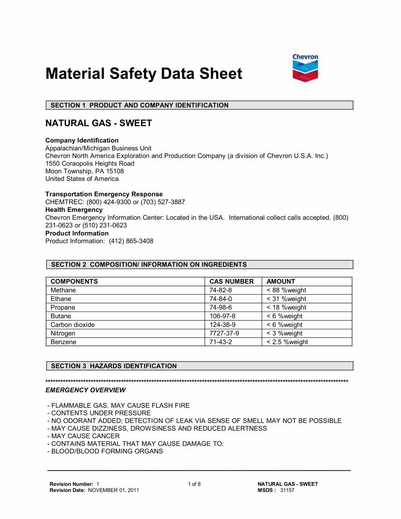
_____________________________________________________________________
Revision Number: 1 Revision Date: NOVEMBER 01, 2011
1 of 8 NATURAL GAS - SWEET MSDS : 31157
Material Safety Data Sheet
SECTION 1 PRODUCT AND COMPANY IDENTIFICATION
NATURAL GAS - SWEET
Company IdentificationAppalachian/Michigan Business UnitChevron North America Exploration and Production Company (a division of Chevron U.S.A. Inc.)1550 Coraopolis Heights RoadMoon Township, PA 15108United States of America
Transportation Emergency ResponseCHEMTREC: (800) 424-9300 or (703) 527-3887Health EmergencyChevron Emergency Information Center: Located in the USA. International collect calls accepted. (800)231-0623 or (510) 231-0623Product InformationProduct Information: (412) 865-3408
SECTION 2 COMPOSITION/ INFORMATION ON INGREDIENTS
COMPONENTS CAS NUMBER AMOUNT Methane 74-82-8 < 88 %weight Ethane 74-84-0 < 31 %weight Propane 74-98-6 < 18 %weight Butane 106-97-8 < 6 %weight Carbon dioxide 124-38-9 < 6 %weight Nitrogen 7727-37-9 < 3 %weight Benzene 71-43-2 < 2.5 %weight
SECTION 3 HAZARDS IDENTIFICATION
************************************************************************************************************************EMERGENCY OVERVIEW
- FLAMMABLE GAS. MAY CAUSE FLASH FIRE - CONTENTS UNDER PRESSURE - NO ODORANT ADDED; DETECTION OF LEAK VIA SENSE OF SMELL MAY NOT BE POSSIBLE - MAY CAUSE DIZZINESS, DROWSINESS AND REDUCED ALERTNESS - MAY CAUSE CANCER - CONTAINS MATERIAL THAT MAY CAUSE DAMAGE TO: - BLOOD/BLOOD FORMING ORGANS
_____________________________________________________________________
Revision Number: 1 Revision Date: NOVEMBER 01, 2011
2 of 8 NATURAL GAS - SWEET MSDS : 31157
- REDUCES OXYGEN AVAILABLE FOR BREATHING************************************************************************************************************************
IMMEDIATE HEALTH EFFECTSEye: Not expected to cause prolonged or significant eye irritation.Skin: Contact with the skin is not expected to cause prolonged or significant irritation. Contact with theskin is not expected to cause an allergic skin response. Not expected to be harmful to internal organs ifabsorbed through the skin.Ingestion: Material is a gas and cannot usually be swallowed.Inhalation: This material can act as a simple asphyxiant by displacement of air. Symptoms ofasphyxiation may include rapid breathing, incoordination, rapid fatigue, excessive salivation,disorientation, headache, nausea, and vomiting. Convulsions, loss of consciousness, coma, and/or deathmay occur if exposure to high concentrations continues. Excessive or prolonged breathing of this materialmay cause central nervous system effects. Central nervous system effects may include headache,dizziness, nausea, vomiting, weakness, loss of coordination, blurred vision, drowsiness, confusion, ordisorientation. At extreme exposures, central nervous system effects may include respiratory depression,tremors or convulsions, loss of consciousness, coma or death. If this material is heated, fumes may beunpleasant and produce nausea and irritation of the eye and upper respiratory tract.
DELAYED OR OTHER HEALTH EFFECTS:Reproduction and Birth Defects: This material is not expected to cause adverse reproductive effectsbased on animal data.This material is not expected to cause harm to the unborn child based on animaldata.Cancer: Prolonged or repeated exposure to this material may cause cancer. Contains benzene, whichhas been classified as a carcinogen by the National Toxicology Program (NTP) and a Group 1 carcinogen(carcinogenic to humans) by the International Agency for Research on Cancer (IARC).
Target Organs: Contains material that may cause damage to the following organ(s) following repeatedinhalation at concentrations above the recommended exposure limit: Blood/Blood Forming OrgansSee Section 11 for additional information. Risk depends on duration and level of exposure.
SECTION 4 FIRST AID MEASURES
Eye: No specific first aid measures are required. As a precaution, remove contact lenses, if worn, andflush eyes with water.Skin: No specific first aid measures are required. As a precaution, remove clothing and shoes ifcontaminated. To remove the material from skin, use soap and water. Discard contaminated clothing andshoes or thoroughly clean before reuse.Ingestion: No specific first aid measures are required because this material is a gas.Inhalation: During an emergency, wear an approved, positive pressure air-supplying respirator. Move theexposed person to fresh air. If not breathing, give artificial respiration. If breathing is difficult, giveoxygen. Get immediate medical attention.
SECTION 5 FIRE FIGHTING MEASURES
SPECIAL NOTES: In case of fire do not extinguish. Stop flow of fuel and allow fire to burn out.
FIRE CLASSIFICATION:OSHA Classification (29 CFR 1910.1200): Flammable gas.
NFPA RATINGS: Health: 1 Flammability: 4 Reactivity: 0
FLAMMABLE PROPERTIES:

_____________________________________________________________________
Revision Number: 1 Revision Date: NOVEMBER 01, 2011
3 of 8 NATURAL GAS - SWEET MSDS : 31157
Flashpoint: -162 °C (-260 °F) (Typical)Autoignition: 482 °C - 632 °C (900 °F - 1170 °F) Flammability (Explosive) Limits (% by volume in air): Lower: 3.8 Upper: 17
EXTINGUISHING MEDIA: Allow gas to burn if flow cannot be shut off safely. Apply water from a safedistance to cool container, surrounding equipment and structures. Container areas exposed to directflame contact should be cooled with large quantities of water (500 gallons water per minute flameimpingement exposure) to prevent weakening of container structure.
PROTECTION OF FIRE FIGHTERS:Fire Fighting Instructions: Do not extinguish. Stop flow of fuel and allow fire to burn out. If flames areaccidentally extinguished, explosive reignition may occur. Eliminate ignition sources. Keep people away.Isolate fire area and deny unnecessary entry. Immediately withdraw all personnel from area in case ofrising sound from venting safety device or discoloration of the container. For unignited vapor cloud, usewater spray to knock down and control dispersion of vapors. Use water spray to cool fire-exposedcontainers and fire-affected zone until fire is out and danger of reignition has passed. See Section 7 forproper handling and storage. For fires involving this material, do not enter any enclosed or confined firespace without proper protective equipment, including self-contained breathing apparatus.Combustion Products: Highly dependent on combustion conditions. A complex mixture of airbornesolids, liquids, and gases including carbon monoxide, carbon dioxide, and unidentified organic compoundswill be evolved when this material undergoes combustion.
SECTION 6 ACCIDENTAL RELEASE MEASURES
Protective Measures: Eliminate all sources of ignition in vicinity of released gas. If this material isreleased into the work area, evacuate the area immediately. Monitor area with combustible gas indicator. For large releases, warn public of downwind explosion hazard.Spill Management: Stop the source of the release if you can do it without risk. Observe precautions inExposure Controls/Personal Protection section of the MSDS. All equipment used when handling theproduct must be grounded. If possible, turn leaking containers so that gas escapes rather than liquid. Usewater spray to reduce vapors or divert vapor cloud drift. Do not direct water at spill or source of leak.Prevent spreading of vapors through sewers, ventilation systems and confined areas. Isolate area untilgas has dispersed.Reporting: Report spills to local authorities and/or the U.S. Coast Guard's National Response Center at(800) 424-8802 as appropriate or required.
SECTION 7 HANDLING AND STORAGE
Precautionary Measures: This material presents a fire hazard. Gas can catch fire and burn withexplosive force. Invisible gas spreads easily and can be set on fire by many sources such as pilot lights,welding equipment, and electrical motors and switches. Gases are heavier than air and may travel alongthe ground or into drains to possible distant ignition sources that may cause an explosive flashback. Donot breathe gas. Wash thoroughly after handling.Unusual Handling Hazards: This product does not contain an odorant. Detection of leak via sense ofsmell, therefore, may not be possible. Static Hazard: Electrostatic charge may accumulate and create a hazardous condition when handlingthis material. To minimize this hazard, bonding and grounding may be necessary but may not, bythemselves, be sufficient. Review all operations which have the potential of generating and accumulatingan electrostatic charge and/or a flammable atmosphere (including tank and container filling, splash filling,tank cleaning, sampling, gauging, switch loading, filtering, mixing, agitation, and vacuum truck operations)and use appropriate mitigating procedures. For more information, refer to OSHA Standard 29 CFR1910.106, 'Flammable and Combustible Liquids', National Fire Protection Association (NFPA 77,'Recommended Practice on Static Electricity', and/or the American Petroleum Institute (API)

_____________________________________________________________________
Revision Number: 1 Revision Date: NOVEMBER 01, 2011
4 of 8 NATURAL GAS - SWEET MSDS : 31157
Recommended Practice 2003, 'Protection Against Ignitions Arising Out of Static, Lightning, and StrayCurrents'.General Storage Information: DO NOT USE OR STORE near heat, sparks, flames, or hot surfaces .USE AND STORE ONLY IN WELL VENTILATED AREA. Keep container closed when not in use. Whenworking with this material, the minimal oxygen content should be 19.5% by volume under normalatmospheric pressure.
SECTION 8 EXPOSURE CONTROLS/PERSONAL PROTECTION
GENERAL CONSIDERATIONS:Consider the potential hazards of this material (see Section 3), applicable exposure limits, job activities,and other substances in the work place when designing engineering controls and selecting personalprotective equipment. If engineering controls or work practices are not adequate to prevent exposure toharmful levels of this material, the personal protective equipment listed below is recommended. The usershould read and understand all instructions and limitations supplied with the equipment since protection isusually provided for a limited time or under certain circumstances.
ENGINEERING CONTROLS:Use process enclosures, local exhaust ventilation, or other engineering controls to control airborne levelsbelow the recommended exposure limits. Use in a well-ventilated area. Use explosion-proof ventilationequipment.
PERSONAL PROTECTIVE EQUIPMENTEye/Face Protection: No special eye protection is normally required. Where splashing is possible, wearsafety glasses with side shields as a good safety practice.Skin Protection: No special protective clothing is normally required. Where splashing is possible, selectprotective clothing depending on operations conducted, physical requirements and other substances in theworkplace. Suggested materials for protective gloves include: Nitrile Rubber, Viton.Respiratory Protection: Determine if airborne concentrations are below the recommended occupationalexposure limits for jurisdiction of use. If airborne concentrations are above the acceptable limits, wear anapproved respirator that provides adequate protection from this material, such as: Supplied-AirRespirator, or Air-Purifying Respirator for Organic Vapors.Wear an approved positive pressure air-supplying respirator unless ventilation or other engineeringcontrols are adequate to maintain a minimal oxygen content of 19.5% by volume under normalatmospheric pressure.Use a positive pressure air-supplying respirator in circumstances where air-purifying respirators may notprovide adequate protection.
Occupational Exposure Limits:
Component Agency TWA STEL Ceiling Notation Benzene ACGIH .5 ppm
(weight) 2.5 ppm(weight)
-- Skin A1Skin
Benzene CVX 1 ppm(weight)
5 ppm(weight)
-- --
Benzene OSHA SRS 1 ppm(weight)
5 ppm(weight)
-- --
Benzene OSHA Z-2 10 ppm(weight)
-- 25 ppm(weight)
--
Butane ACGIH 1000 ppm(weight)
-- -- --
Carbon dioxide ACGIH 5000 ppm(weight)
30000 ppm(weight)
-- --
Carbon dioxide OSHA Z-1 9000 mg/m3 -- -- --

_____________________________________________________________________
Revision Number: 1 Revision Date: NOVEMBER 01, 2011
5 of 8 NATURAL GAS - SWEET MSDS : 31157
Ethane ACGIH 1000 ppm(weight)
-- -- --
Methane ACGIH 1000 ppm(weight)
-- -- --
Nitrogen ACGIH -- -- -- Simpleasphyxiant.
Propane ACGIH 1000 ppm(weight)
-- -- --
Propane OSHA Z-1 1800 mg/m3 -- -- -- Consult local authorities for appropriate values.
SECTION 9 PHYSICAL AND CHEMICAL PROPERTIES
Attention: the data below are typical values and do not constitute a specification.
Color: ColorlessPhysical State: GasOdor: OdorlesspH: Not ApplicableVapor Pressure: 760 mmHgVapor Density (Air = 1): No data available Boiling Point: -162°C (-259.6°F)Solubility: Insoluble in water.Freezing Point: No data availableMelting Point: -184°C (-299.2°F)Specific Gravity: 0.57Density: No data availableViscosity: No data available
SECTION 10 STABILITY AND REACTIVITY
Chemical Stability: This material is considered stable under normal ambient and anticipated storageand handling conditions of temperature and pressure.Incompatibility With Other Materials: May react with strong acids or strong oxidizing agents, such aschlorates, nitrates, peroxides, etc.Hazardous Decomposition Products: Carbon Dioxide (Elevated temperatures), Carbon Monoxide(Elevated temperatures)Hazardous Polymerization: Hazardous polymerization will not occur.
SECTION 11 TOXICOLOGICAL INFORMATION
IMMEDIATE HEALTH EFFECTSEye Irritation: The eye irritation hazard is based on evaluation of data for similar materials or productcomponents. Skin Irritation: The skin irritation hazard is based on evaluation of data for similar materials or productcomponents. Skin Sensitization: The skin sensitization hazard is based on evaluation of data for similar materials orproduct components. Acute Dermal Toxicity: The acute dermal toxicity hazard is based on evaluation of data for similarmaterials or product components.
Acute Oral Toxicity: The acute oral toxicity hazard is based on evaluation of data for similar materials orproduct components.

_____________________________________________________________________
Revision Number: 1 Revision Date: NOVEMBER 01, 2011
6 of 8 NATURAL GAS - SWEET MSDS : 31157
Acute Inhalation Toxicity: The acute inhalation toxicity hazard is based on evaluation of data for similarmaterials or product components.
ADDITIONAL TOXICOLOGY INFORMATION: This product contains butane. An atmospheric concentration of 100,000 ppm (10%) butane is notnoticeably irritating to the eyes, nose or respiratory tract, but will produce slight dizziness in a few minutesof exposure. No chronic systemic effect has been reported from occupational exposure.
This product contains benzene.GENETIC TOXICITY/CANCER: Repeated or prolonged breathing of benzene vapor has been associatedwith the development of chromosomal damage in experimental animals and various blood diseases inhumans ranging from aplastic anemia to leukemia (a form of cancer). All of these diseases can be fatal.In some individuals, benzene exposure can sensitize cardiac tissue to epinephrine which may precipitatefatal ventricular fibrillation.REPRODUCTIVE/DEVELOPMENTAL TOXICITY: No birth defects have been shown to occur in pregnantlaboratory animals exposed to doses not toxic to the mother. However, some evidence of fetal toxicitysuch as delayed physical development has been seen at such levels. The available information on theeffects of benzene on human pregnancies is inadequate but it has been established that benzene cancross the human placenta.OCCUPATIONAL: The OSHA Benzene Standard (29 CFR 1910.1028) contains detailed requirements fortraining, exposure monitoring, respiratory protection and medical surveillance triggered by the exposurelevel. Refer to the OSHA Standard before using this product.
This product may contain detectable but varying quantities of the naturally occurring radioactive substanceradon 222. The amount in the gas itself is not hazardous, but since radon rapidly decays (t1/2 = 3.82days)to form other radioactive elements including lead 210, polonium 210, and bismuth 210, equipment maycontain radioactivity. The radon decay products are solids and therefore may attach to dust particles orform films and sludges in equipment. Inhalation, ingestion or skin contact with radon decay products canlead to the deposit (or presence) of radioactive material in the respiratory tract, bone, blood formingorgans, intestinal tract, and kidney, which may lead to certain cancers. The International Agency forResearch on Cancer (IARC) has classified radon as a Group 1 carcinogen. Some studies of peopleoccupationally exposed to radiation indicate an increased incidence of chromosomal aberrations; theclinical significance of this increase is unknown. Risks can be minimized by following good industrial andpersonal hygiene practices noted in the section on storage and handling.
SECTION 12 ECOLOGICAL INFORMATION
ECOTOXICITYThis material is not expected to be harmful to aquatic organisms. The ecotoxicity hazard is based on anevaluation of data for the components or a similar material.
ENVIRONMENTAL FATEReady Biodegradability: This material is expected to be readily biodegradable. The biodegradability ofthis material is based on an evaluation of data for the components or a similar material.
SECTION 13 DISPOSAL CONSIDERATIONS
Use material for its intended purpose or recycle if possible. This material, if it must be discarded, maymeet the criteria of a hazardous waste as defined by US EPA under RCRA (40 CFR 261) or other State

_____________________________________________________________________
Revision Number: 1 Revision Date: NOVEMBER 01, 2011
7 of 8 NATURAL GAS - SWEET MSDS : 31157
and local regulations. Measurement of certain physical properties and analysis for regulated componentsmay be necessary to make a correct determination. If this material is classified as a hazardous waste,federal law requires disposal at a licensed hazardous waste disposal facility.
SECTION 14 TRANSPORT INFORMATION
The description shown may not apply to all shipping situations. Consult 49CFR, or appropriate DangerousGoods Regulations, for additional description requirements (e.g., technical name) and mode-specific orquantity-specific shipping requirements.
DOT Shipping Description: UN1971, NATURAL GAS, COMPRESSED, 2.1 ADDITIONALINFORMATION - RQ (BENZENE) FOR SINGLE PACKAGES CONTAINING GREATER THAN OREQUAL TO 10 LBS AND CONCENTRATION OF 200 PPM
IMO/IMDG Shipping Description: UN1971, NATURAL GAS, COMPRESSED, 2.1
ICAO/IATA Shipping Description: UN1971, NATURAL GAS, COMPRESSED, 2.1
SECTION 15 REGULATORY INFORMATION
EPCRA 311/312 CATEGORIES: 1. Immediate (Acute) Health Effects: YES 2. Delayed (Chronic) Health Effects: YES 3. Fire Hazard: YES 4. Sudden Release of Pressure Hazard: YES 5. Reactivity Hazard: NO
REGULATORY LISTS SEARCHED: 01-1=IARC Group 1 03=EPCRA 313 01-2A=IARC Group 2A 04=CA Proposition 65 01-2B=IARC Group 2B 05=MA RTK 02=NTP Carcinogen 06=NJ RTK
07=PA RTK
The following components of this material are found on the regulatory lists indicated. Benzene 01-1, 02, 04, 05, 06, 07 Butane 05, 06, 07 Carbon dioxide 05, 06, 07 Ethane 05, 06, 07 Methane 05, 06, 07 Nitrogen 05, 06, 07 Propane 05, 06, 07
CERCLA REPORTABLE QUANTITIES(RQ)/EPCRA 302 THRESHOLD PLANNING QUANTITIES(TPQ): Component Component RQ Component TPQ Product RQ
Benzene 10 lbs None 400 lbs
CHEMICAL INVENTORIES:All components comply with the following chemical inventory requirements: AICS (Australia), DSL(Canada), EINECS (European Union), IECSC (China), KECI (Korea), PICCS (Philippines), TSCA (UnitedStates).

_____________________________________________________________________
Revision Number: 1 Revision Date: NOVEMBER 01, 2011
8 of 8 NATURAL GAS - SWEET MSDS : 31157
SECTION 16 OTHER INFORMATION
NFPA RATINGS: Health: 1 Flammability: 4 Reactivity: 0
HMIS RATINGS: Health: 1* Flammability: 4 Reactivity: 0(0-Least, 1-Slight, 2-Moderate, 3-High, 4-Extreme, PPE:- Personal Protection Equipment Indexrecommendation, *- Chronic Effect Indicator). These values are obtained using the guidelines orpublished evaluations prepared by the National Fire Protection Association (NFPA) or the National Paintand Coating Association (for HMIS ratings).
REVISION STATEMENT: This revision updates the following sections of this Material Safety Data Sheet: 2, 3, 4, 5, 6, 7, 8, 12, 15Revision Date: NOVEMBER 01, 2011
ABBREVIATIONS THAT MAY HAVE BEEN USED IN THIS DOCUMENT: TLV - Threshold Limit Value TWA - Time Weighted Average STEL - Short-term Exposure Limit PEL - Permissible Exposure Limit
CAS - Chemical Abstract Service Number ACGIH - American Conference of GovernmentalIndustrial Hygienists
IMO/IMDG - International Maritime Dangerous GoodsCode
API - American Petroleum Institute MSDS - Material Safety Data Sheet CVX - Chevron NFPA - National Fire Protection Association (USA) DOT - Department of Transportation (USA) NTP - National Toxicology Program (USA) IARC - International Agency for Research onCancer
OSHA - Occupational Safety and HealthAdministration
Prepared according to the OSHA Hazard Communication Standard (29 CFR 1910.1200) and the ANSIMSDS Standard (Z400.1) by the Chevron Energy Technology Company, 100 Chevron Way,Richmond, California 94802.
The above information is based on the data of which we are aware and is believed to be correctas of the date hereof. Since this information may be applied under conditions beyond ourcontrol and with which we may be unfamiliar and since data made available subsequent to thedate hereof may suggest modifications of the information, we do not assume any responsibilityfor the results of its use. This information is furnished upon condition that the personreceiving it shall make his own determination of the suitability of the material for his particularpurpose.

ATTACHMENT I EMISSION UNITS TABLE
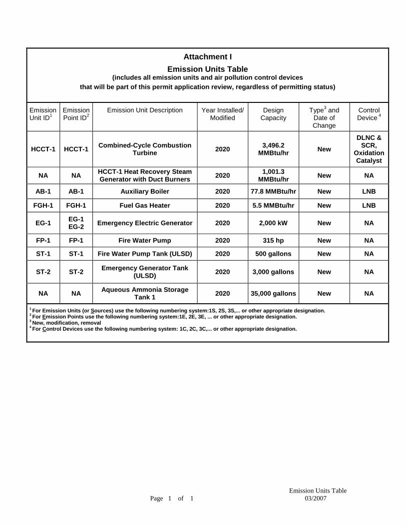
Attachment I Emission Units Table
(includes all emission units and air pollution control devices that will be part of this permit application review, regardless of permitting status)
Emission Unit ID1
Emission Point ID2
Emission Unit Description Year Installed/ Modified
Design Capacity
Type3 and Date of Change
Control Device 4
HCCT-1 HCCT-1 Combined-Cycle Combustion Turbine 2020 3,496.2
MMBtu/hr New DLNC &
SCR, Oxidation Catalyst
NA NA HCCT-1 Heat Recovery Steam Generator with Duct Burners 2020 1,001.3
MMBtu/hr New NA
AB-1 AB-1 Auxiliary Boiler 2020 77.8 MMBtu/hr New LNB
FGH-1 FGH-1 Fuel Gas Heater 2020 5.5 MMBtu/hr New LNB
EG-1 EG-1 EG-2 Emergency Electric Generator 2020 2,000 kW New NA
FP-1 FP-1 Fire Water Pump 2020 315 hp New NA
ST-1 ST-1 Fire Water Pump Tank (ULSD) 2020 500 gallons New NA
ST-2 ST-2 Emergency Generator Tank (ULSD) 2020 3,000 gallons New NA
NA NA Aqueous Ammonia Storage Tank 1 2020 35,000 gallons New NA
1 For Emission Units (or Sources) use the following numbering system:1S, 2S, 3S,... or other appropriate designation. 2 For Emission Points use the following numbering system:1E, 2E, 3E, ... or other appropriate designation. 3 New, modification, removal 4 For Control Devices use the following numbering system: 1C, 2C, 3C,... or other appropriate designation.
Emission Units Table Page 1 of 1 03/2007

ATTACHMENT J
EMISSION POINTS DATA SUMMARY SHEET
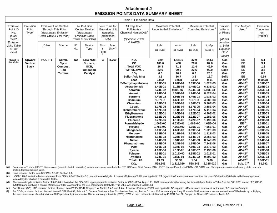
Attachment J EMISSION POINTS DATA SUMMARY SHEET
Page 1 of 6 WVDEP-DAQ Revision 2/11
Table 1: Emissions Data
Emission Point ID
No. (Must match
Emission Units Table
& Plot Plan)
Emission Point Type1
Emission Unit Vented Through This Point
(Must match Emission Units Table & Plot Plan)
Air Pollution Control Device (Must match
Emission Units Table & Plot Plan)
Vent Time for Emission Unit
(chemical processes
only)
All Regulated Pollutants -
Chemical Name/CAS3
(Speciate VOCs & HAPS)
Maximum Potential Uncontrolled Emissions 4
Maximum Potential Controlled Emissions 5
Emission Form
or Phase
(At exit conditions, Solid, Liquid or
Gas/ Vapor)
Est. Method Used 6
Emission Concentrati
on 7 (mg/m3)
ID No. Source ID No.
Device Type
Short
Term2
Max (hr/yr)
lb/hr (a), (c), (e)
ton/yr (a), (c), (e)
lb/hr (a), (c), (e)
ton/yr (a), (c), (e)
HCCT-1 (a), (c), (e)
Upward Vertical Stack
HCCT- 1
Comb. Cycle
Combust-ion
Turbine
NA Low NOx Burners,
SCR, Oxidation Catalyst
C 8,760 NOx CO
Total VOC PM/PM10/PM2.5
SO2 Sulfur Acid Mist
Lead 2-Methylnaphthalene
Acetaldehyde Acrolein Arsenic Benzene Cadmium Chromium
Cobalt Dichlorobenzene
Ethylbenzene Fluoranthene
Fluorene Formaldehyde
Hexane Manganese
Mercury Naphthalene
Nickel Phenanathrene
POM Pyrene Toluene
Xylenes Total HAP
CO2e
329 100.0 16.3 22.6 6.0 3.8
0.002 2.33E-05 1.40E-01 2.24E-02 1.94E-04 4.40E-02 1.07E-3 1.36E-03 8.17E-05 1.17E-03 1.12E-01 2.92E-06 2.72E-06 1.06E+00 1.75E+00 3.69E-04 2.53E-04 5.14E-03 2.04E-03 1.65E-05 7.69E-03 4.86E-06 4.58E-01 2.24E-01
13.33 528,543
1,441.0 438 71.3 99.0 26.1 16.7 0.008
1.02E-04 6.13E-01 9.80E-02 8.52E-04 1.93E-01 4.68E-03 5.96E-03 3.58E-04 5.11E-03 4.90E-01 1.28E-05 1.19E-05 4.63E+01 7.66E+00 1.62E-03 1.11E-03 2.25E-02 8.94E-03 7.24E-05 3.37E-02 2.13E-05 2.01E+00 9.80E-01
58.39 2,315,020
32.9 20.0 11.4 22.6 6.0 3.8
0.002 2.33E-06 1.40E-02 2.24E-03 1.94E-04 4.40E-03 1.07E-3 1.36E-03 8.17E-05 1.17E-04 1.12E-02 2.92E-07 2.72E-07 1.06E+00 1.75E-01 3.69E-04 2.53E-04 5.14E-04 2.04E-03 1.65E-06 7.69E-04 4.86E-07 4.58E-02 2.24E-02
1.34 528,543
144.1 87.6 49.9 99.0 26.1 16.7 0.01
1.02E-05 6.13E-02 9.80E-03 8.52E-04 1.93E-02 4.68E-03 5.96E-03 3.58E-04 5.11E-04 4.90E-02 1.28E-06 1.19E-06 4.63E+00 7.66E-01 1.62E-03 1.11E-03 2.25E-03 8.94E-03 7.24E-06 3.37E-03 2.13E-06 2.01E-01 9.80E-02
5.86 2,315,020
Gas Gas Gas
Solid Gas
Solid Solid Gas Gas Gas Gas Gas Gas Gas Gas Gas Gas Gas Gas Gas Gas Gas Gas Gas Gas Gas Gas Gas Gas Gas Gas Gas
EE EE EE EE EE EE
AP-42(b) AP-42(c) AP-42(c) AP-42(c) AP-42(c) AP-42(c) AP-42(c) AP-42(c) AP-42(c) AP-42(c) AP-42(c) AP-42(c) AP-42(c)
EE(d) AP-42(c) AP-42(c) AP-42(c) AP-42(c) AP-42(c) AP-42(c) AP-42(c) AP-42(c) AP-42(c) AP-42(c) AP-42(c)
Sub. C(f)
5.1 3.1 1.8 3.5 0.9 0.59
0.00031 3.59E-07 2.15E-03 3.45E-04 2.99E-05 6.78E-04 1.65E-04 2.10E-04 1.26E-05 1.80E-05 1.72E-03 4.49E-08 4.19E-08 1.63E-01 2.69E-02 5.69E-05 3.89E-05 7.91E-05 3.14E-04 2.54E-07 1.18E-04 7.49E-08 7.05E-03 3.45E-03 2.06E-01 81,392
(a) Combustion Turbine (HCCT-1) emissions (uncontrolled & controlled) include emissions from both the CT/HRSG and Duct Burner (DB). HCCT-1 annual “controlled” NOx, CO, VOC, and PM represents combined steady state, start-up, and shutdown emission rates.
(b) Lead emission factor from USEPA's AP-42, Section 1.4. (c) HCCT-1 HAP emission factors obtained from EPA's AP-42 Section 3.1, except formaldehyde. A control efficiency of 90% was applied to CT organic HAP emissions to account for the use of Oxidation Catalysts, with the exception of
formaldehyde, which is a controlled factor. (d) The formaldehyde emission factor of 3.0E-04 is based on the EPA 95th upper percentile emission factor for CTGs (EPA August 21, 2001 memorandum) by taking the formaldehyde factor in Table 3 of the 8/21/2001 memo of 2.92E-03
lb/MMBtu and applying a control efficiency of 90% to account for the use of Oxidation Catalysts. This value was rounded to 3.0E-04. (e) Duct Burner (DB) HAP emission factors obtained from EPA's AP-42 Chapter 1.4, Tables 1.4-3 and 1.4-4. A control efficiency of 90% was applied to DB organic HAP emissions to account for the use of Oxidation Catalysts. (f) For CO2e, emission factors obtained from 40 CFR Part 98, Subpart C: General Stationary Fuel Combustion Sources, Tables C-1 and C-2 for natural gas firing. For each GHG, emissions are normalized to a CO2e basis by multiplying
the mass emissions of each individual GHG pollutant by its respective Global warming potentials (GWP). GWP of each pollutant established by 40 CFR Part 98, Subpart A: General Provisions, Table A-1.
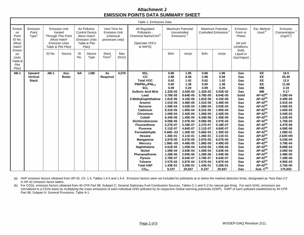
Attachment J EMISSION POINTS DATA SUMMARY SHEET
Page 2 of 6 WVDEP-DAQ Revision 2/11
Table 1: Emissions Data
Emission
Point ID No. (Must match Emissi
on Units
Table & Plot
Plan)
Emission Point Type1
Emission Unit Vented
Through This Point (Must match
Emission Units Table & Plot Plan)
Air Pollution Control Device (Must match
Emission Units Table & Plot
Plan)
Vent Time for Emission Unit
(chemical processes only)
All Regulated Pollutants -
Chemical Name/CAS3
(Speciate VOCs & HAPS)
Maximum Potential Uncontrolled Emissions 4
Maximum Potential Controlled Emissions 5
Emission Form or Phase
(At exit
conditions, Solid,
Liquid or Gas/Vapor)
Est. Method Used 6
Emission Concentration 7
(mg/m3)
ID No. Source ID No.
Device Type
Short Term2
Max (hr/yr)
lb/hr ton/yr lb/hr ton/yr
AB-1
Upward Vertical Stack
AB-1
Aux. Boiler
NA LNB As Required
4,576 NOx CO
Total VOC PM/PM10/PM2.5
SO2 Sulfuric Acid Mist
Lead 2-Methylnaphthalene
Arsenic Benzene Cadmium Chromium
Cobalt Dichlorobenzene
Fluoranthene Fluorene
Formaldehyde Hexane
Manganese Mercury
Naphthalene Nickel
Phenanathrene Pyrene Toluene
Total HAP CO2e
0.86 2.88 0.62 0.60 0.09
1.32E-02 3.78E-05 1.81E-06 1.51E-05 1.59E-04 8.31E-05 1.06E-04 6.34E-06 9.06E-05 2.27E-07 2.11E-07 5.66E--03 1.36E-01 2.87E-05 1.96E--05 4.61E-05 1.59E-04 1.28E-06 3.78E-07 2.57E-04 1.43E-01
9,107
1.96 6.58 1.42 1.38 0.20
3.02E-02 8.64E-05 4.15E-06 3.46E-05 3.63E-04 1.90E-04 2.42E-04 1.45E-05 2.07E-04 5.18E-07 4.84E-07 1.30E-02 3.11E-01 6.57E-05 4.49E-05 1.05E-04 3.63E-04 2.94E-06 8.64E-07 5.87E-04 3.26E-01 20,837
0.86 2.88 0.62 0.60 0.09
1.32E-02 3.78E-05 1.81E-06 1.51E-05 1.59E-04 8.31E-05 1.06E-04 6.34E-06 9.06E-05 2.27E-07 2.11E-07 5.66E-03 1.36E-01 2.87E-05 1.96E-05 4.61E-05 1.59E-04 1.28E-06 3.78E-07 2.57E-04 1.43E-01
9,107
1.96 6.58 1.42 1.38 0.20
3.02E-02 8.64E-05 4.15E-06 3.46E-05 3.63E-04 1.90E-04 2.42E-04 1.45E-05 2.07E-04 5.18E-07 4.84E-07 1.30E-02 3.11E-01 6.57E-05 4.49E-05 1.05E-04 3.63E-04 2.94E-06 8.64E-07 5.87E-04 3.26E-01 20,837
Gas Gas Gas Gas Gas Gas
Solid Gas Gas Gas Gas Gas Gas Gas Gas Gas Gas Gas Gas Gas Gas Gas Gas Gas Gas Gas Gas
EE EE EE EE MB MB
AP-42(a)
AP-42(a)
AP-42(a)
AP-42(a)
AP-42(a)
AP-42(a)
AP-42(a)
AP-42(a)
AP-42(a)
AP-42(a)
AP-42(a)
AP-42(a)
AP-42(a)
AP-42(a)
AP-42(a)
AP-42(a)
AP-42(a)
AP-42(a)
AP-42(a)
AP-42(a)
Sub. C(b)
16.5 55.49 12.0 11.66 2.19 0.17
7.28E-04 3.49E-05 2.91E-04 3.06E-03 1.60E-03 2.04E-03 1.22E-04 1.75E-03 4.37E-06 4.08E-06 1.09E-01 2.62E+00 5.53E-04 3.79E-04 8.88E-04 3.06E-03 2.48E-05 7.28E-06 4.95E-03 2.75E-00 175,602
(a) HAP emission factors obtained from AP-42, Ch. 1.4, Tables 1.4-3 and 1.4-4. Emission factors were not included for pollutants at or below the method detection limits, designated as "less than (<)"
in AP-42 emission factor tables. (b) For CO2e, emission factors obtained from 40 CFR Part 98, Subpart C: General Stationary Fuel Combustion Sources, Tables C-1 and C-2 for natural gas firing. For each GHG, emissions are
normalized to a CO2e basis by multiplying the mass emissions of each individual GHG pollutant by its respective Global warming potentials (GWP). GWP of each pollutant established by 40 CFR Part 98, Subpart A: General Provisions, Table A-1.

Attachment J EMISSION POINTS DATA SUMMARY SHEET
Page 3 of 6 WVDEP-DAQ Revision 2/11
Table 1: Emissions Data
Emission Point ID No. (Must match
Emission Units Table &
Plot Plan)
Emission Point Type1
Emission Unit Vented
Through This Point
(Must match Emission Units
Table & Plot Plan)
Air Pollution Control Device
(Must match Emission
Units Table & Plot Plan)
Vent Time for Emission Unit
(chemical processes only)
All Regulated Pollutants -
Chemical Name/CAS3
(Speciate VOCs & HAPS)
Maximum Potential Uncontrolled Emissions 4
Maximum Potential Controlled Emissions
5
Emission Form or Phase
(At exit
conditions, Solid,
Liquid or Gas/Vapor)
Est. Method Used 6
Emission Concentration
7 (mg/m3)
ID No. Source ID No.
Device
Type
Short Term2
Max (hr/yr)
lb/hr ton/yr lb/hr ton/yr
FGH-1 Exhaust FGH-1 Fuel Gas
Heater
NA LNB As required
8,760 NOx CO
Total VOC PM/PM10/ PM2.5
SO2 Lead
Sulfuric Acid Mist 2-Methylnaphthalene
Arsenic Benzene
Cadmium Chromium
Cobalt Dichlorobenzene
Fluoranthene Fluorene
Formaldehyde Hexane
Manganese Mercury
Naphthalene Nickel
Phenanathrene Pyrene Toluene
Total HAP CO2e
0.20 0.21 0.04 0.04 0.01
2.66E-06 9.29E-04 1.27E-07 1.06E-06 1.12E-05 5.84E-06 7.44E-06 4.46E-07 6.37E-06 1.59E-08 1.49E-08 3.98E-04 9.56E-03 2.02E-06 1.38E-06 3.24E-06 1.12E-05 9.03E-08 2.66E-08 1.81E-05 1.00E-02
641
0.86 0.93 0.17 0.19 0.03
1.16E-05 4.07E-03 5.58E-07 4.65E-06 4.88E-05 2.56E-05 3.26E-05 1.95E-06 2.79E-05 6.98E-08 6.51E-08 1.74E-03 4.19E-02 8.84E-06 6.05E-06 1.42E-05 4.88E-05 3.95E-07 1.16E-07 7.91E-05 4.39E-02
2,806
Gas Gas Gas Gas Gas
Solid Solid Gas Gas Gas Gas Gas Gas Gas Gas Gas Gas Gas Gas Gas Gas Gas Gas Gas Gas Gas Gas
EE EE EE EE MB
AP-42(a) MB
AP-42(a) AP-42(a) AP-42(a) AP-42(a) AP-42(a) AP-42(a) AP-42(a) AP-42(a) AP-42(a) AP-42(a) AP-42(a) AP-42(a) AP-42(a) AP-42(a) AP-42(a) AP-42(a) AP-42(a) AP-42(a) AP-42(a)
Sub. C(b)
3.8 4.1 10.5 0.8 0.1 0.1 0.01
3.50E-05 2.91E-04 3.06E-03 1.60E-03 2.04E-03 1.22E-04 1.75E-03 4.37E-06 4.08E-06 1.09E-01 2.62E+00 5.54E-04 3.79E-04 8.89E-04 3.06E-03 2.48E-05 7.29E-06 4.95E-03 2.75E-00 12,351
(a) HAP emission factors obtained from AP-42, Ch. 1.4, Tables 1.4-3 and 1.4-4. Emission factors were not included for pollutants at or below the method detection limits, designated as "less than (<)"
in AP-42 emission factor tables. (b) For CO2e, emission factors obtained from 40 CFR Part 98, Subpart C: General Stationary Fuel Combustion Sources, Tables C-1 and C-2 for natural gas firing. For each GHG, emissions are
normalized to a CO2e basis by multiplying the mass emissions of each individual GHG pollutant by its respective Global warming potentials (GWP). GWP of each pollutant established by 40 CFR Part 98, Subpart A: General Provisions, Table A-1.

Attachment J EMISSION POINTS DATA SUMMARY SHEET
Page 4 of 6 WVDEP-DAQ Revision 2/11
Table 1: Emissions Data
Emission Point ID
No. (Must match
Emission Units Table
& Plot Plan)
Emission Point Type1
Emission Unit Vented
Through This Point (Must match
Emission Units Table & Plot Plan)
Air Pollution Control Device (Must match
Emission Units Table & Plot
Plan)
Vent Time for Emission Unit
(chemical processes only)
All Regulated Pollutants - Chemical
Name/CAS3
(Speciate VOCs & HAPS)
Maximum Potential Uncontrolled Emissions 4
Maximum Potential Controlled Emissions
5
Emission Form or Phase (At exit
conditions, Solid, Liquid
or Gas/Vapor)
Est. Method Used 6
Emission Concentratio
n 7 (mg/m3)
ID No. Source ID No. Device Type
Short Term2
Max (hr/yr)
lb/hr ton/yr lb/hr ton/yr
EG-1
Exhaust EG-1
Emerg. Electric
Gen.
NA NA As Required
100 VOC NOx CO SO2
PM/PM10/PM2.5 Sulfuric Acid Mist
Acetaldehyde Acrolein Benzene
Formaldehyde Naphthalene
POM Toluene Xylenes
Total HAPS CO2e
0.65 32.22 1.77 0.03 0.15
3.58E-03 4.87E-04 1.52E-04 1.50E-02 1.52E-03 2.51E-03 4.10E-03 5.43E-03 3.73E-03 3.29E-02
3,161
0.03 1.61 0.09
0.001 0.01
1.79E-04 2.43E-05 7.61E-06 7.50E-04 7.62E-05 1.26E-04 2.05E-04 2.71E-04 1.86E-04 1.65E-03
158
0.65 32.22 1.77 0.03 0.15
3.58E-03 4.87E-04 1.52E-04 1.50E-02 1.52E-03 2.51E-03 4.10E-03 5.43E-03 3.73E-03 3.29E-02
3,161
0.03 1.61 0.09 0.001 0.01
1.79E-04 2.43E-05 7.61E-06 7.50E-04 7.62E-05 1.26E-04 2.05E-04 2.71E-04 1.86E-04 1.65E-03
158
Gas Gas Gas Gas Gas Gas Gas Gas Gas Gas Gas Gas Gas Gas Gas Gas
EE EE EE MB EE MB
AP-42(a) AP-42(a) AP-42(a) AP-42(a) AP-42(a) AP-42(a) AP-42(a) AP-42(a) AP-42(a) Sub. C(b)
22.71 1,124.0
61.9 1.02 5.2
0.12 1.70E-02 5.31E-03 5.23E-01 5.32E-02 8.77E-02 1.43E-01 1.90E-01 1.30E-01 1.15E+00 110,350
EG-1
Exhaust EG-2
Emerg. Electric
Gen.
NA NA As Required
100 VOC NOx CO SO2
PM/PM10/PM2.5 Sulfuric Acid Mist
Acetaldehyde Acrolein Benzene
Formaldehyde Naphthalene
POM Toluene Xylenes
Total HAPS CO2e
0.65 32.22 1.77 0.03 0.15
3.58E-03 4.87E-04 1.52E-04 1.50E-02 1.52E-03 2.51E-03 4.10E-03 5.43E-03 3.73E-03 3.29E-02
3,161
0.03 1.61 0.09
0.001 0.01
1.79E-04 2.43E-05 7.61E-06 7.50E-04 7.62E-05 1.26E-04 2.05E-04 2.71E-04 1.86E-04 1.65E-03
158
0.65 32.22 1.77 0.03 0.15
3.58E-03 4.87E-04 1.52E-04 1.50E-02 1.52E-03 2.51E-03 4.10E-03 5.43E-03 3.73E-03 3.29E-02
3,161
0.03 1.61 0.09 0.001 0.01
1.79E-04 2.43E-05 7.61E-06 7.50E-04 7.62E-05 1.26E-04 2.05E-04 2.71E-04 1.86E-04 1.65E-03
158
Gas Gas Gas Gas Gas Gas Gas Gas Gas Gas Gas Gas Gas Gas Gas Gas
EE EE EE MB EE MB
AP-42(a) AP-42(a) AP-42(a) AP-42(a) AP-42(a) AP-42(a) AP-42(a) AP-42(a) AP-42(a) Sub. C(b)
22.71 1,124.0
61.9 1.02 5.2
0.12 1.70E-02 5.31E-03 5.23E-01 5.32E-02 8.77E-02 1.43E-01 1.90E-01 1.30E-01 1.15E+00 110,350
(a) HAP emission factors obtained from AP-42, Ch. 3.4, Tables 3.4-3 and 3.4-4. Emission factors were not included for pollutants at or below the method detection limits, designated as "less than (<)"
in AP-42 emission factor tables. (b) For CO2e, emission factors obtained from 40 CFR Part 98, Subpart C: General Stationary Fuel Combustion Sources, Tables C-1 and C-2 for distillate fuel oil No. 2 firing. For each GHG, emissions
are normalized to a CO2e basis by multiplying the mass emissions of each individual GHG pollutant by its respective Global warming potentials (GWP). GWP of each pollutant established by 40 CFR Part 98, Subpart A: General Provisions, Table A-1.

Attachment J EMISSION POINTS DATA SUMMARY SHEET
Page 5 of 6 WVDEP-DAQ Revision 2/11
Table 1: Emissions Data
Emission Point ID
No. (Must match
Emission Units
Table & Plot Plan)
Emission Point Type1
Emission Unit Vented
Through This Point
(Must match Emission Units
Table & Plot Plan)
Air Pollution Control Device (Must match
Emission Units Table & Plot
Plan)
Vent Time for Emission Unit
(chemical processes only)
All Regulated Pollutants - Chemical
Name/CAS3
(Speciate VOCs & HAPS)
Maximum Potential Uncontrolled Emissions 4
Maximum Potential Controlled Emissions 5
Emission Form or Phase
(At exit
conditions, Solid, Liquid
or Gas/Vapor)
Est. Method Used 6
Emission Concentration
7 (mg/m3)
ID No. Source ID No. Device Type
Short Term2
Max (hr/yr)
lb/hr ton/yr lb/hr ton/yr
FP-1
Exhaust FP-1
Fire Water Pump
NA NA As Require
d
100 NOx CO
Total VOC PM/PM10/ PM2.5
SO2 Sulfuric Acid Mist
Acetaldehyde Acrolein Benzene
Formaldehyde Naphthalene
POM Toluene Xylenes
Total HAP CO2e
1.87 0.31 0.06 0.05
0.003 3.89E-04 1.61E-03 7.88E-04 1.96E-03 2.48E-03 1.78E-04 3.53E-04 8.59E-04 5.99E-04 8.82E-03
344
0.09 0.02
0.003 0.003
1.6E-04 1.94E-05 8.05E-05 1.18E-06 9.80E-05 1.24E-04 8.90E-06 1.76E-05 4.29E-05 2.99E-05 4.03E-04
17
1.87 0.31 0.06 0.05 0.003
3.89E-04 1.61E-03 7.88E-04 1.96E-03 2.48E-03 1.78E-04 3.53E-04 8.59E-04 5.99E-04 8.82E-03
344
0.09 0.02
0.003 0.003
1.6E-04 1.94E-05 8.05E-05 1.18E-06 9.80E-05 1.24E-04 8.90E-06 1.76E-05 4.29E-05 2.99E-05 4.03E-04
17
Gas Gas
Gas Gas Gas Gas Gas Gas Gas Gas Gas Gas Gas Gas Gas Gas
EE EE EE EE MB MB
AP-42(a) AP-42(a) AP-42(a) AP-42(a) AP-42(a) AP-42(a) AP-42(a) AP-42(a) AP-42(a) Sub. C(b)
10.99 356.24 58.27
6.0E-01 9.866 0.074
3.07E-01 3.74E-01 4.25E-02 4.73E-01 3.40E-02 6.73E-02 1.64E-01 1.14E-01 1.53E-00 65,521
ST-1
Upward Vertical Stack
ST-1
Diesel Storag
e Tank
NA NA C 8,760 Total VOC
X
X
X
X
Gas
EPA TANKS
NA
ST-2
Upward Vertical Stack
ST-2
Diesel Storag
e Tank
NA NA C 8,760 Total VOC
X
X
X
X
Gas
EPA TANKS
NA
The EMISSION POINTS DATA SUMMARY SHEET provides a summation of emissions by emission unit. Note that uncaptured process emission unit emissions are not typically considered to be fugitive and must be accounted for on the appropriate EMISSIONS UNIT DATA SHEET and on the EMISSION POINTS DATA SUMMARY SHEET. Please note that total emissions from the source are equal to all vented emissions, all fugitive emissions, plus all other emissions (e.g. uncaptured emissions). Please complete the FUGITIVE EMISSIONS DATA SUMMARY SHEET for fugitive emission activities. 1 Please add descriptors such as upward vertical stack, downward vertical stack, horizontal stack, relief vent, rain cap, etc. 2 Indicate by "C" if venting is continuous. Otherwise, specify the average short-term venting rate with units, for intermittent venting (ie., 15 min/hr). Indicate as many rates as needed to clarify frequency of venting (e.g., 5 min/day, 2 days/wk). 3 List all regulated air pollutants. Speciate VOCs, including all HAPs. Follow chemical name with Chemical Abstracts Service (CAS) number. LIST Acids, CO, CS2, VOCs, H2S, Inorganics, Lead,
Organics, O3, NO, NO2, SO2, SO3, all applicable Greenhouse Gases (including CO2 and methane), etc. DO NOT LIST H2, H2O, N2, O2, and Noble Gases. 4 Give maximum potential emission rate with no control equipment operating. If emissions occur for less than 1 hr, then record emissions per batch in minutes (e.g. 5 lb VOC/20 minute batch).
5 Give maximum potential emission rate with proposed control equipment operating. If emissions occur for less than 1 hr, then record emissions per batch in minutes (e.g. 5 lb VOC/20 minute batch). 6 Indicate method used to determine emission rate as follows:MB = material balance;ST = stack test (give date of test);EE = engineering estimate; O = other (specify).
7 Provide for all pollutant emissions. Typically, the units of parts per million by volume (ppmv) are used. If the emission is a mineral acid (sulfuric, nitric, hydrochloric or phosphoric) use units of milligram per dry cubic meter (mg/m3) at standard conditions (68 °F and 29.92 inches Hg) (see 45CSR7). If the pollutant is SO2, use units of ppmv (See 45CSR10).
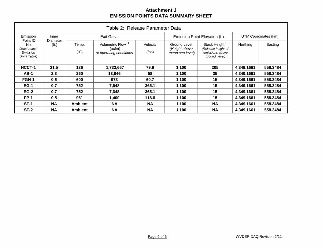
Attachment J EMISSION POINTS DATA SUMMARY SHEET
Page 6 of 6 WVDEP-DAQ Revision 2/11
Table 2: Release Parameter Data
Emission Point ID
No. (Must match
Emission Units Table)
Inner Diameter
(ft.)
Exit Gas Emission Point Elevation (ft) UTM Coordinates (km)
Temp.
(oF)
Volumetric Flow 1 (acfm)
at operating conditions
Velocity
(fps)
Ground Level (Height above
mean sea level)
Stack Height 2 (Release height of emissions above
ground level)
Northing Easting
HCCT-1 21.5 136 1,733,667 79.6 1,100 205 4,349.1661 558.3484 AB-1 2.3 260 13,846 58 1,100 35 4,349.1661 558.3484
FGH-1 0.6 600 973 60.7 1,100 15 4,349.1661 558.3484 EG-1 0.7 752 7,648 365.1 1,100 15 4,349.1661 558.3484 EG-2 0.7 752 7,648 365.1 1,100 15 4,349.1661 558.3484 FP-1 0.5 961 1,400 118.8 1,100 15 4,349.1661 558.3484 ST-1 NA Ambient NA NA 1,100 NA 4,349.1661 558.3484 ST-2 NA Ambient NA NA 1,100 NA 4,349.1661 558.3484

ATTACHMENT K FUGITIVE EMISSIONS DATA SUMMARY SHEET
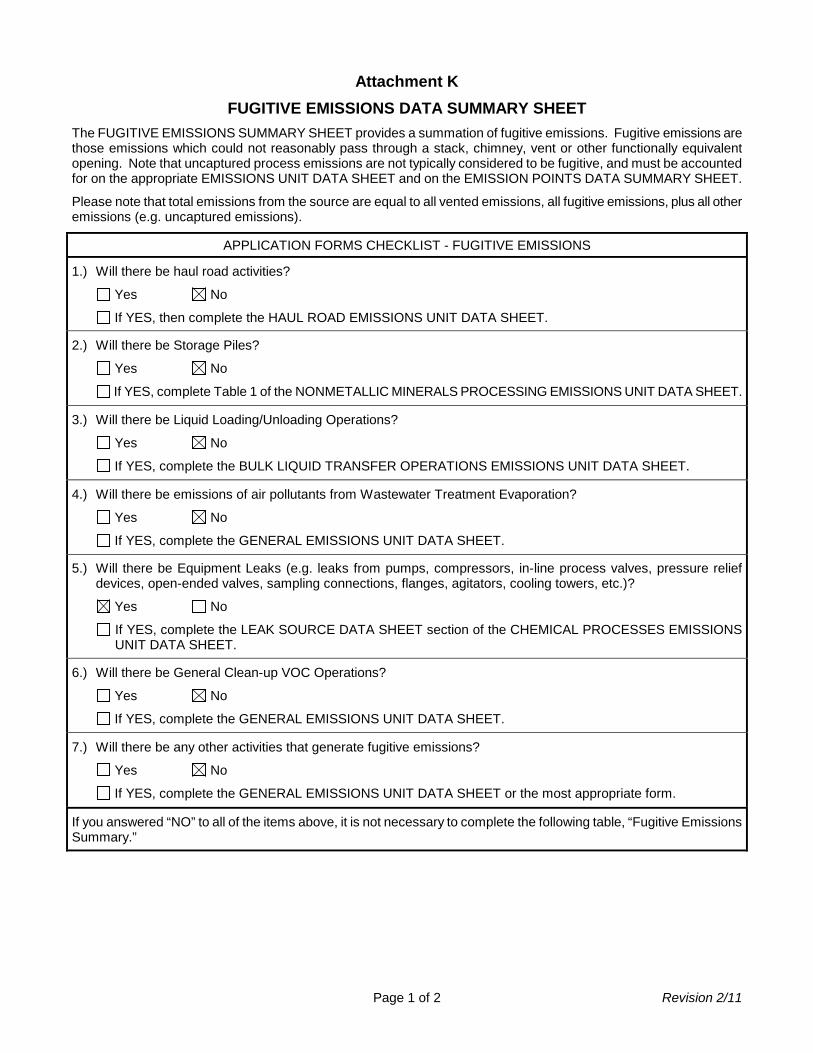
Page 1 of 2 Revision 2/11
Attachment K FUGITIVE EMISSIONS DATA SUMMARY SHEET
The FUGITIVE EMISSIONS SUMMARY SHEET provides a summation of fugitive emissions. Fugitive emissions are those emissions which could not reasonably pass through a stack, chimney, vent or other functionally equivalent opening. Note that uncaptured process emissions are not typically considered to be fugitive, and must be accounted for on the appropriate EMISSIONS UNIT DATA SHEET and on the EMISSION POINTS DATA SUMMARY SHEET.
Please note that total emissions from the source are equal to all vented emissions, all fugitive emissions, plus all other emissions (e.g. uncaptured emissions).
APPLICATION FORMS CHECKLIST - FUGITIVE EMISSIONS
1.) Will there be haul road activities?
Yes No
If YES, then complete the HAUL ROAD EMISSIONS UNIT DATA SHEET.
2.) Will there be Storage Piles?
Yes No
If YES, complete Table 1 of the NONMETALLIC MINERALS PROCESSING EMISSIONS UNIT DATA SHEET.
3.) Will there be Liquid Loading/Unloading Operations?
Yes No
If YES, complete the BULK LIQUID TRANSFER OPERATIONS EMISSIONS UNIT DATA SHEET.
4.) Will there be emissions of air pollutants from Wastewater Treatment Evaporation?
Yes No
If YES, complete the GENERAL EMISSIONS UNIT DATA SHEET.
5.) Will there be Equipment Leaks (e.g. leaks from pumps, compressors, in-line process valves, pressure relief devices, open-ended valves, sampling connections, flanges, agitators, cooling towers, etc.)?
Yes No
If YES, complete the LEAK SOURCE DATA SHEET section of the CHEMICAL PROCESSES EMISSIONS UNIT DATA SHEET.
6.) Will there be General Clean-up VOC Operations?
Yes No
If YES, complete the GENERAL EMISSIONS UNIT DATA SHEET.
7.) Will there be any other activities that generate fugitive emissions?
Yes No
If YES, complete the GENERAL EMISSIONS UNIT DATA SHEET or the most appropriate form.
If you answered “NO” to all of the items above, it is not necessary to complete the following table, “Fugitive Emissions Summary.”
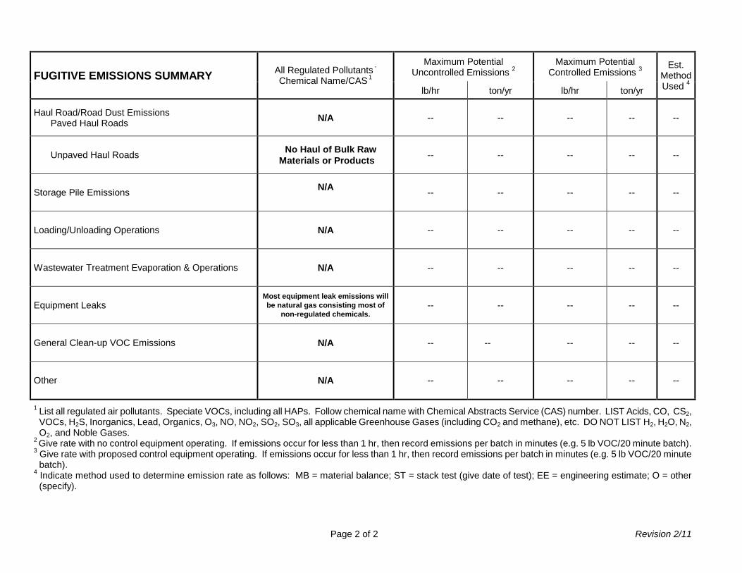
Page 2 of 2 Revision 2/11
FUGITIVE EMISSIONS SUMMARY All Regulated Pollutants -
Chemical Name/CAS 1
Maximum Potential Uncontrolled Emissions 2
Maximum Potential Controlled Emissions 3
Est. Method Used 4 lb/hr ton/yr lb/hr ton/yr
Haul Road/Road Dust Emissions Paved Haul Roads N/A -- -- -- -- --
Unpaved Haul Roads No Haul of Bulk Raw Materials or Products -- -- -- -- --
Storage Pile Emissions N/A -- -- -- -- --
Loading/Unloading Operations N/A -- -- -- -- --
Wastewater Treatment Evaporation & Operations N/A -- -- -- -- --
Equipment Leaks Most equipment leak emissions will be natural gas consisting most of
non-regulated chemicals. -- -- -- -- --
General Clean-up VOC Emissions N/A -- -- -- -- --
Other N/A -- -- -- -- --
1 List all regulated air pollutants. Speciate VOCs, including all HAPs. Follow chemical name with Chemical Abstracts Service (CAS) number. LIST Acids, CO, CS2, VOCs, H2S, Inorganics, Lead, Organics, O3, NO, NO2, SO2, SO3, all applicable Greenhouse Gases (including CO2 and methane), etc. DO NOT LIST H2, H2O, N2, O2, and Noble Gases.
2 Give rate with no control equipment operating. If emissions occur for less than 1 hr, then record emissions per batch in minutes (e.g. 5 lb VOC/20 minute batch). 3 Give rate with proposed control equipment operating. If emissions occur for less than 1 hr, then record emissions per batch in minutes (e.g. 5 lb VOC/20 minute
batch). 4 Indicate method used to determine emission rate as follows: MB = material balance; ST = stack test (give date of test); EE = engineering estimate; O = other
(specify).

ATTACHMENT L EMISSIONS UNIT DATA SHEETS

Combustion Turbine
Page 1 of 4 Revision 03/2007
Attachment L Emission Unit Data Sheet
(INDIRECT HEAT EXCHANGER)
Control Device ID No. (must match List Form): Equipment Information: Combined Cycle Gas Turbine HCCT-1
1. Manufacturer: General Electric 2. Model No. 7HA.02
Serial No. NA
3. Number of units: 1 4. Use – Electric Generation
5. Rated Boiler Horsepower: NA hp 6. Boiler Serial No.: NA
7. Date constructed: 2020 8. Date of last modification and explain: NA
9. Maximum design heat input per unit:
4,497.5 (CT + DB) ×106 BTU/hr
10. Peak heat input per unit:
4,497.5 (CT + DB) ×106 BTU/hr
11. Steam produced at maximum design output:
NA LB/hr
NA psig
12. Projected Operating Schedule:
Hours/Day 24
Days/Week 7
Weeks/Year 52
13. Type of firing equipment to be used: Pulverized coal Spreader stoker Oil burners Natural Gas Burner Others, specify
14. Proposed type of burners and orientation: Vertical Front Wall Opposed Tangential Others, specify Dry Low NOx Burners
15. Type of draft: Forced Induced 16. Percent of ash retained in furnace: NA %
17. Will flyash be reinjected? Yes No 18. Percent of carbon in flyash: NA %
Stack or Vent Data
19. Inside diameter or dimensions: 21.5 ft. 20. Gas exit temperature: 136 °F
21. Height: 205 ft. 22. Stack serves:
This equipment only
Other equipment also (submit type and rating of all other equipment exhausted through this stack or vent)
23. Gas flow rate: 1,733,667 actual ft3/min
24. Estimated percent of moisture: NA %

Combustion Turbine
Page 2 of 4 Revision 03/2007
Fuel Requirements 25.
Type Fuel Oil No. Natural Gas Gas (other, specify) Coal, Type: Other:
Quantity (at Design Output)
NA gph@60°F
4,366,505 ft3/hr
NA ft3/hr
NA TPH
Annually ×103 gal
38,251 ×106 ft3/yr ×106 ft3/yr
tons
Sulfur
Maximum: wt. %
Average: wt. %
0.4 ppmw gr/100 ft3
Maximum: wt. %
Ash (%) NA Maximum
BTU Content
BTU/Gal.
Lbs/Gal.@60°F
1,030 BTU/ft3 BTU/ft3
BTU/lb
Source Evaluating Suppliers
Supplier Evaluating Suppliers
Halogens (Yes/No) No
List and Identify Metals NA
26. Gas burner mode of control: Manual Automatic hi-low Automatic full modulation Automatic on-off
27. Gas burner manufacturer: GE
28. Oil burner manufacturer: NA
29. If fuel oil is used, how is it atomized? Oil Pressure Steam Pressure Compressed Air Rotary Cup Other, specify
30. Fuel oil preheated: Yes No 31. If yes, indicate temperature: °F 32. Specify the calculated theoretical air requirements for combustion of the fuel or mixture of fuels described
above actual cubic feet (ACF) per unit of fuel: NA @ NA °F, NA PSIA, NA % moisture
33. Emission rate at rated capacity: See Attachment J lb/hr
34. Percent excess air actually required for combustion of the fuel described: NA %
Coal Characteristics 35. Seams: NA
36. Proximate analysis (dry basis): % of Fixed Carbon: % of Sulfur: % of Moisture: % of Volatile Matter: % of Ash:

Combustion Turbine
Page 3 of 4 Revision 03/2007
Emissions Stream
37. What quantities of pollutants will be emitted from the boiler before controls?
Pollutant Pounds per Hour lb/hr grain/ACF @ °F PSIA
CO 100.0 NA NA NA
Hydrocarbons NA NA NA NA
NOx 329.0 NA NA NA
Pb 0.002 NA NA NA
PM/PM10/PM2.5 22.6 NA NA NA
SO2 6.0 NA NA NA
VOCs 16.3 NA NA NA
Total HAPs 13.33 NA NA NA
CO2e 528,543 NA NA NA
Sulfuric Acid Mist 3.8 NA NA NA
Emissions represent hourly steady state emission rates only.
38. What quantities of pollutants will be emitted from the boiler after controls?
Pollutant Pounds per Hour lb/hr grain/ACF @ °F PSIA
CO 20.0 NA NA NA
Hydrocarbons NA NA NA NA
NOx 32.9 NA NA NA
Pb 0.002 NA NA NA
PM/PM10/PM2.5 22.6 NA NA NA
SO2 6.0 NA NA NA
VOCs 11.4 NA NA NA
Total HAPs 1.34 NA NA NA
CO2e 528,543 NA NA NA
Sulfuric Acid Mist 3.8 NA NA NA
Emissions represent hourly steady state emission rates only.
39. How will waste material from the process and control equipment be disposed of? NA
40. Have you completed an Air Pollution Control Device Sheet(s) for the control(s) used on this Emission Unit.
41. Have you included the air pollution rates on the Emissions Points Data Summary Sheet?

Combustion Turbine
Page 4 of 4 Revision 03/2007
42. Proposed Monitoring, Recordkeeping, Reporting, and Testing Please propose monitoring, recordkeeping, and reporting in order to demonstrate compliance with the proposed operating parameters. Please propose testing in order to demonstrate compliance with the proposed emissions limits.
MONITORING PLAN: Please list (1) describe the process parameters and how they were chosen (2) the ranges and how they were established for monitoring to demonstrate compliance with the operation of this process equipment operation or air pollution control device. See Attachment O
TESTING PLAN: Please describe any proposed emissions testing for this process equipment or air pollution control device. See Attachment O
RECORDKEEPING: Please describe the proposed recordkeeping that will accompany the monitoring. See Attachment O
REPORTING: Please describe the proposed frequency of reporting of the recordkeeping. See Attachment O
43. Describe all operating ranges and maintenance procedures required by Manufacturer to maintain warranty. NA

Auxiliary Boiler
Page 1 of 4 Revision 03/2007
Attachment L Emission Unit Data Sheet
(INDIRECT HEAT EXCHANGER)
Control Device ID No. (must match List Form): AB-1 Equipment Information: Auxiliary Boiler
1. Manufacturer: TBD 2. Model No. NA
Serial No. NA
3. Number of units: 1 4. Use : Steam Production
5. Rated Boiler Horsepower: NA hp 6. Boiler Serial No.: NA
7. Date constructed: 2020 8. Date of last modification and explain: NA
9. Maximum design heat input per unit:
77.8 ×10⁶ BTU/hr
10. Peak heat input per unit:
77.8 ×10⁶ BTU/hr
11. Steam produced at maximum design output:
NA LB/hr
NA psig
12. Projected Operating Schedule:
Hours/Day 24
Days/Week 7
Weeks/Year 52 13. Type of firing equipment to be used:
Pulverized coal Spreader stoker Oil burners Natural Gas Burner Others, specify
14. Proposed type of burners and orientation: Vertical Front Wall Opposed Tangential Others, specify
15. Type of draft: Forced Induced 16. Percent of ash retained in furnace: NA %
17. Will flyash be reinjected? Yes No 18. Percent of carbon in flyash: NA %
Stack or Vent Data
19. Inside diameter or dimensions: 2.3 ft. 20. Gas exit temperature: 260 °F
21. Height: 35 ft. 22. Stack serves:
This equipment only
Other equipment also (submit type and rating of all other equipment exhausted through this stack or vent)
23. Gas flow rate: 13,846 ft3/min
24. Estimated percent of moisture: NA %
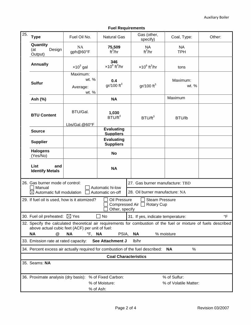
Auxiliary Boiler
Page 2 of 4 Revision 03/2007
Fuel Requirements 25. Type Fuel Oil No. Natural Gas Gas (other,
specify) Coal, Type: Other:
Quantity (at Design Output)
NA gph@60°F
75,509 ft3/hr
NA ft3/hr
NA TPH
Annually ×103 gal
346 ×106 ft3/hr
×106 ft3/hr
tons
Sulfur
Maximum: wt. %
Average: wt. %
0.4 gr/100 ft3
gr/100 ft3
Maximum: wt. %
Ash (%) NA Maximum
BTU Content
BTU/Gal.
Lbs/Gal.@60°F
1,030 BTU/ft3
BTU/ft3
BTU/lb
Source Evaluating Suppliers
Supplier Evaluating Suppliers
Halogens (Yes/No) No
List and Identify Metals NA
26. Gas burner mode of control: Manual Automatic hi-low Automatic full modulation Automatic on-off
27. Gas burner manufacture: TBD
28. Oil burner manufacture: NA
29. If fuel oil is used, how is it atomized? Oil Pressure Steam Pressure Compressed Air Rotary Cup Other, specify
30. Fuel oil preheated: Yes No 31. If yes, indicate temperature: °F 32. Specify the calculated theoretical air requirements for combustion of the fuel or mixture of fuels described
above actual cubic feet (ACF) per unit of fuel: NA @ NA °F, NA PSIA, NA % moisture
33. Emission rate at rated capacity: See Attachment J lb/hr
34. Percent excess air actually required for combustion of the fuel described: NA %
Coal Characteristics 35. Seams: NA
36. Proximate analysis (dry basis): % of Fixed Carbon: % of Sulfur: % of Moisture: % of Volatile Matter: % of Ash:
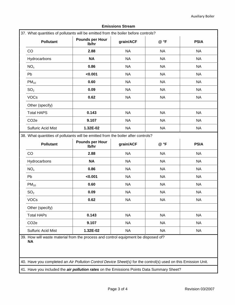
Auxiliary Boiler
Page 3 of 4 Revision 03/2007
Emissions Stream
37. What quantities of pollutants will be emitted from the boiler before controls?
Pollutant Pounds per Hour lb/hr grain/ACF @ °F PSIA
CO 2.88 NA NA NA
Hydrocarbons NA NA NA NA
NOx 0.86 NA NA NA
Pb <0.001 NA NA NA
PM10 0.60 NA NA NA
SO2 0.09 NA NA NA
VOCs 0.62 NA NA NA
Other (specify)
Total HAPS 0.143 NA NA NA
CO2e 9.107 NA NA NA
Sulfuric Acid Mist 1.32E-02 NA NA NA
38. What quantities of pollutants will be emitted from the boiler after controls?
Pollutant Pounds per Hour lb/hr grain/ACF @ °F PSIA
CO 2.88 NA NA NA
Hydrocarbons NA NA NA NA
NOx 0.86 NA NA NA
Pb <0.001 NA NA NA
PM10 0.60 NA NA NA
SO2 0.09 NA NA NA
VOCs 0.62 NA NA NA
Other (specify)
Total HAPs 0.143 NA NA NA
CO2e 9.107 NA NA NA
Sulfuric Acid Mist 1.32E-02 NA NA NA
39. How will waste material from the process and control equipment be disposed of? NA
40. Have you completed an Air Pollution Control Device Sheet(s) for the control(s) used on this Emission Unit.
41. Have you included the air pollution rates on the Emissions Points Data Summary Sheet?

Auxiliary Boiler
Page 4 of 4 Revision 03/2007
42. Proposed Monitoring, Recordkeeping, Reporting, and Testing Please propose monitoring, recordkeeping, and reporting in order to demonstrate compliance with the proposed operating parameters. Please propose testing in order to demonstrate compliance with the proposed emissions limits.
MONITORING PLAN: Please list (1) describe the process parameters and how they were chosen (2) the ranges and how they were established for monitoring to demonstrate compliance with the operation of this process equipment operation or air pollution control device. See Attachment O
TESTING PLAN: Please describe any proposed emissions testing for this process equipment or air pollution control device. See Attachment O
RECORDKEEPING: Please describe the proposed recordkeeping that will accompany the monitoring. See Attachment O
REPORTING: Please describe the proposed frequency of reporting of the recordkeeping. See Attachment O
43. Describe all operating ranges and maintenance procedures required by Manufacturer to maintain warranty. NA

Fuel Gas Heater
Page 1 of 4 Revision 03/2007
Attachment L Emission Unit Data Sheet
(INDIRECT HEAT EXCHANGER)
Control Device ID No. (must match List Form): FGH-1 Equipment Information: Fuel Gas Heater
1. Manufacturer: TBD 2. Model No. NA
Serial No. NA
3. Number of units: 1 4. Use : Steam Production
5. Rated Boiler Horsepower: NA hp 6. Boiler Serial No.: NA
7. Date constructed: 2020 8. Date of last modification and explain: NA
9. Maximum design heat input per unit:
5.5 ×10⁶ BTU/hr
10. Peak heat input per unit:
5.5 ×10⁶ BTU/hr
11. Steam produced at maximum design output:
NA LB/hr
NA psig
12. Projected Operating Schedule:
Hours/Day 24
Days/Week 7
Weeks/Year 52 13. Type of firing equipment to be used:
Pulverized coal Spreader stoker Oil burners Natural Gas Burner Others, specify
14. Proposed type of burners and orientation: Vertical Front Wall Opposed Tangential Others, specify
15. Type of draft: Forced Induced 16. Percent of ash retained in furnace: NA %
17. Will flyash be reinjected? Yes No 18. Percent of carbon in flyash: NA %
Stack or Vent Data
19. Inside diameter or dimensions: 0.6 ft. 20. Gas exit temperature: 600 °F
21. Height: 15 ft. 22. Stack serves:
This equipment only
Other equipment also (submit type and rating of all other equipment exhausted through this stack or vent)
23. Gas flow rate: 973 ft3/min
24. Estimated percent of moisture: NA %

Fuel Gas Heater
Page 2 of 4 Revision 03/2007
Fuel Requirements 25. Type Fuel Oil No. Natural Gas Gas (other,
specify) Coal, Type: Other:
Quantity (at Design Output)
NA gph@60°F
5,311 ft3/hr
NA ft3/hr
NA TPH
Annually ×103 gal
47 ×106 ft3/hr
×106 ft3/hr
tons
Sulfur
Maximum: wt. %
Average: wt. %
0.4 gr/100 ft3
gr/100 ft3
Maximum: wt. %
Ash (%) NA Maximum
BTU Content
BTU/Gal.
Lbs/Gal.@60°F
1,030 BTU/ft3
BTU/ft3
BTU/lb
Source Evaluating Suppliers
Supplier Evaluating Suppliers
Halogens (Yes/No) No
List and Identify Metals NA
26. Gas burner mode of control: Manual Automatic hi-low Automatic full modulation Automatic on-off
27. Gas burner manufacture: TBD
28. Oil burner manufacture: NA
29. If fuel oil is used, how is it atomized? Oil Pressure Steam Pressure Compressed Air Rotary Cup Other, specify
30. Fuel oil preheated: Yes No 31. If yes, indicate temperature: °F 32. Specify the calculated theoretical air requirements for combustion of the fuel or mixture of fuels described
above actual cubic feet (ACF) per unit of fuel: NA @ NA °F, NA PSIA, NA % moisture
33. Emission rate at rated capacity: See Attachment J lb/hr
34. Percent excess air actually required for combustion of the fuel described: NA %
Coal Characteristics 35. Seams: NA
36. Proximate analysis (dry basis): % of Fixed Carbon: % of Sulfur: % of Moisture: % of Volatile Matter: % of Ash:

Fuel Gas Heater
Page 3 of 4 Revision 03/2007
Emissions Stream
37. What quantities of pollutants will be emitted from the boiler before controls?
Pollutant Pounds per Hour lb/hr grain/ACF @ °F PSIA
CO 0.21 NA NA NA
Hydrocarbons NA NA NA NA
NOx 0.20 NA NA NA
Pb <0.001 NA NA NA
PM10 0.04 NA NA NA
SO2 0.01 NA NA NA
VOCs 0.04 NA NA NA
Other (specify)
Total HAPS 0.001 NA NA NA
CO2e 641 NA NA NA
Sulfuric Acid Mist 9.3E-04 NA NA NA
38. What quantities of pollutants will be emitted from the boiler after controls?
Pollutant Pounds per Hour lb/hr grain/ACF @ °F PSIA
CO 0.21 NA NA NA
Hydrocarbons NA NA NA NA
NOx 0.20 NA NA NA
Pb <0.001 NA NA NA
PM10 0.04 NA NA NA
SO2 0.01 NA NA NA
VOCs 0.04 NA NA NA
Other (specify)
Total HAPs 0.001 NA NA NA
CO2e 641 NA NA NA
Sulfuric Acid Mist 9.3E-04 NA NA NA
39. How will waste material from the process and control equipment be disposed of? NA
40. Have you completed an Air Pollution Control Device Sheet(s) for the control(s) used on this Emission Unit.
41. Have you included the air pollution rates on the Emissions Points Data Summary Sheet?

Fuel Gas Heater
Page 4 of 4 Revision 03/2007
42. Proposed Monitoring, Recordkeeping, Reporting, and Testing Please propose monitoring, recordkeeping, and reporting in order to demonstrate compliance with the proposed operating parameters. Please propose testing in order to demonstrate compliance with the proposed emissions limits.
MONITORING PLAN: Please list (1) describe the process parameters and how they were chosen (2) the ranges and how they were established for monitoring to demonstrate compliance with the operation of this process equipment operation or air pollution control device. See Attachment O
TESTING PLAN: Please describe any proposed emissions testing for this process equipment or air pollution control device. See Attachment O
RECORDKEEPING: Please describe the proposed recordkeeping that will accompany the monitoring. See Attachment O
REPORTING: Please describe the proposed frequency of reporting of the recordkeeping. See Attachment O
43. Describe all operating ranges and maintenance procedures required by Manufacturer to maintain warranty. NA

Emergency Generator
Page 1 of 4 Revision 03/2007
Attachment L EMISSIONS UNIT DATA SHEET
GENERAL
To be used for affected sources other than asphalt plants, foundries, incinerators, indirect heat exchangers, and quarries. Identification Number (as assigned on Equipment List Form): Emergency Generator EG-1
1. Name or type and model of proposed affected source:
Emergency Electric Generator – 2,000 kW (~2,682 hp)
2. On a separate sheet(s), furnish a sketch(es) of this affected source. If a modification is to be made to this source, clearly indicated the change(s). Provide a narrative description of all features of the affected source which may affect the production of air pollutants.
3. Name(s) and maximum amount of proposed process material(s) charged per hour:
N/A
4. Name(s) and maximum amount of proposed material(s) produced per hour:
N/A
5. Give chemical reactions, if applicable, that will be involved in the generation of air pollutants:
N/A
* The identification number which appears here must correspond to the air pollution control device identification number appearing on the List Form.
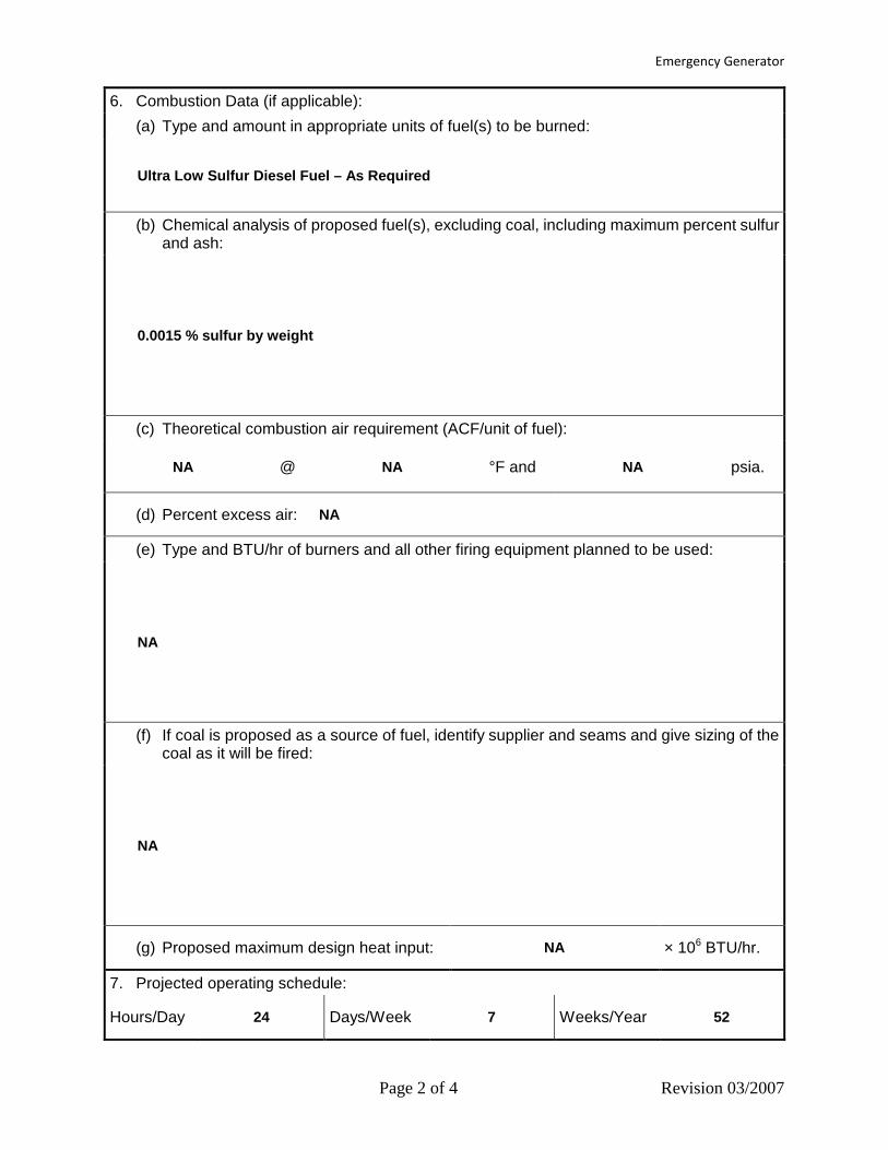
Emergency Generator
Page 2 of 4 Revision 03/2007
6. Combustion Data (if applicable): (a) Type and amount in appropriate units of fuel(s) to be burned:
Ultra Low Sulfur Diesel Fuel – As Required
(b) Chemical analysis of proposed fuel(s), excluding coal, including maximum percent sulfur and ash:
0.0015 % sulfur by weight
(c) Theoretical combustion air requirement (ACF/unit of fuel):
NA @ NA °F and NA psia.
(d) Percent excess air: NA
(e) Type and BTU/hr of burners and all other firing equipment planned to be used:
NA
(f) If coal is proposed as a source of fuel, identify supplier and seams and give sizing of the coal as it will be fired:
NA
(g) Proposed maximum design heat input: NA × 106 BTU/hr.
7. Projected operating schedule:
Hours/Day 24 Days/Week 7 Weeks/Year 52

Emergency Generator
Page 3 of 4 Revision 03/2007
8. Projected amount of pollutants that would be emitted from this affected source if no control devices were used:
@ NA °F and Ambient psia
a. NOX 32.22 lb/hr N/A grains/ACF
b. SO2 0.03 lb/hr N/A grains/ACF
c. CO 1.77 lb/hr N/A grains/ACF
d. PM/PM10/PM2.5 0.15 lb/hr N/A grains/ACF
e. Hydrocarbons N/A lb/hr N/A grains/ACF
f. VOCs 0.65 lb/hr N/A grains/ACF
g. Pb N/A lb/hr N/A grains/ACF
h. Specify other(s)
CO2e 3,161 lb/hr N/A grains/ACF
Total HAPs 3.29E-02 lb/hr N/A grains/ACF
Sulfuric Acid Mist 3.6E-03 lb/hr NA grains/ACF
lb/hr NA grains/ACF
NOTE: (1) An Air Pollution Control Device Sheet must be completed for any air pollution device(s) used to control emissions from this affected source.
(2) Complete the Emission Points Data Sheet.
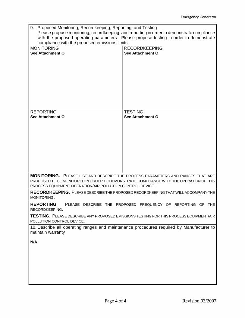
Emergency Generator
Page 4 of 4 Revision 03/2007
9. Proposed Monitoring, Recordkeeping, Reporting, and Testing Please propose monitoring, recordkeeping, and reporting in order to demonstrate compliance with the proposed operating parameters. Please propose testing in order to demonstrate compliance with the proposed emissions limits.
MONITORING See Attachment O
RECORDKEEPING See Attachment O
REPORTING See Attachment O
TESTING See Attachment O
MONITORING. PLEASE LIST AND DESCRIBE THE PROCESS PARAMETERS AND RANGES THAT ARE PROPOSED TO BE MONITORED IN ORDER TO DEMONSTRATE COMPLIANCE WITH THE OPERATION OF THIS PROCESS EQUIPMENT OPERATION/AIR POLLUTION CONTROL DEVICE. RECORDKEEPING. PLEASE DESCRIBE THE PROPOSED RECORDKEEPING THAT WILL ACCOMPANY THE MONITORING. REPORTING. PLEASE DESCRIBE THE PROPOSED FREQUENCY OF REPORTING OF THE RECORDKEEPING. TESTING. PLEASE DESCRIBE ANY PROPOSED EMISSIONS TESTING FOR THIS PROCESS EQUIPMENT/AIR POLLUTION CONTROL DEVICE. 10. Describe all operating ranges and maintenance procedures required by Manufacturer to maintain warranty N/A

Fire Water Pump
Page 1 of 4 Revision 03/2007
Attachment L EMISSIONS UNIT DATA SHEET
GENERAL
To be used for affected sources other than asphalt plants, foundries, incinerators, indirect heat exchangers, and quarries. Identification Number (as assigned on Equipment List Form): Fire Water Pump FP-1
1. Name or type and model of proposed affected source:
Fire Water Pump – 315 hp (235 kW)
2. On a separate sheet(s), furnish a sketch(es) of this affected source. If a modification is to be made to this source, clearly indicated the change(s). Provide a narrative description of all features of the affected source which may affect the production of air pollutants.
3. Name(s) and maximum amount of proposed process material(s) charged per hour:
Fire water – As Required
4. Name(s) and maximum amount of proposed material(s) produced per hour:
Fire water – As Required
5. Give chemical reactions, if applicable, that will be involved in the generation of air pollutants:
NA
* The identification number which appears here must correspond to the air pollution control device identification number appearing on the List Form.
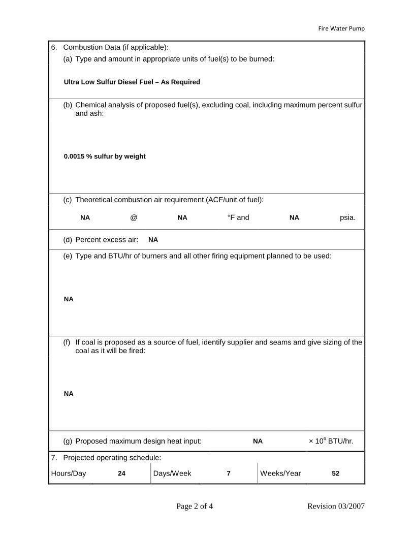
Fire Water Pump
Page 2 of 4 Revision 03/2007
6. Combustion Data (if applicable): (a) Type and amount in appropriate units of fuel(s) to be burned:
Ultra Low Sulfur Diesel Fuel – As Required
(b) Chemical analysis of proposed fuel(s), excluding coal, including maximum percent sulfur and ash:
0.0015 % sulfur by weight
(c) Theoretical combustion air requirement (ACF/unit of fuel):
NA @ NA °F and NA psia.
(d) Percent excess air: NA
(e) Type and BTU/hr of burners and all other firing equipment planned to be used:
NA
(f) If coal is proposed as a source of fuel, identify supplier and seams and give sizing of the coal as it will be fired:
NA
(g) Proposed maximum design heat input: NA × 106 BTU/hr.
7. Projected operating schedule:
Hours/Day 24 Days/Week 7 Weeks/Year 52
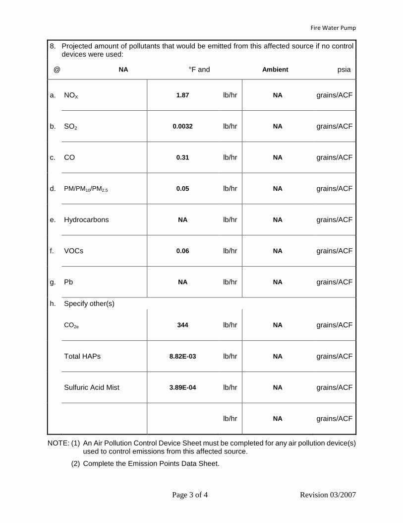
Fire Water Pump
Page 3 of 4 Revision 03/2007
8. Projected amount of pollutants that would be emitted from this affected source if no control devices were used:
@ NA °F and Ambient psia
a. NOX 1.87 lb/hr NA grains/ACF
b. SO2 0.0032 lb/hr NA grains/ACF
c. CO 0.31 lb/hr NA grains/ACF
d. PM/PM10/PM2.5 0.05 lb/hr NA grains/ACF
e. Hydrocarbons NA lb/hr NA grains/ACF
f. VOCs 0.06 lb/hr NA grains/ACF
g. Pb NA lb/hr NA grains/ACF
h. Specify other(s)
CO2e 344 lb/hr NA grains/ACF
Total HAPs 8.82E-03 lb/hr NA grains/ACF
Sulfuric Acid Mist 3.89E-04 lb/hr NA grains/ACF
lb/hr NA grains/ACF
NOTE: (1) An Air Pollution Control Device Sheet must be completed for any air pollution device(s) used to control emissions from this affected source.
(2) Complete the Emission Points Data Sheet.

Fire Water Pump
Page 4 of 4 Revision 03/2007
9. Proposed Monitoring, Recordkeeping, Reporting, and Testing Please propose monitoring, recordkeeping, and reporting in order to demonstrate compliance with the proposed operating parameters. Please propose testing in order to demonstrate compliance with the proposed emissions limits.
MONITORING See Attachment O
RECORDKEEPING See Attachment O
REPORTING See Attachment O
TESTING See Attachment O
MONITORING. PLEASE LIST AND DESCRIBE THE PROCESS PARAMETERS AND RANGES THAT ARE PROPOSED TO BE MONITORED IN ORDER TO DEMONSTRATE COMPLIANCE WITH THE OPERATION OF THIS PROCESS EQUIPMENT OPERATION/AIR POLLUTION CONTROL DEVICE. RECORDKEEPING. PLEASE DESCRIBE THE PROPOSED RECORDKEEPING THAT WILL ACCOMPANY THE MONITORING. REPORTING. PLEASE DESCRIBE THE PROPOSED FREQUENCY OF REPORTING OF THE RECORDKEEPING. TESTING. PLEASE DESCRIBE ANY PROPOSED EMISSIONS TESTING FOR THIS PROCESS EQUIPMENT/AIR POLLUTION CONTROL DEVICE. 10. Describe all operating ranges and maintenance procedures required by Manufacturer to maintain warranty NA
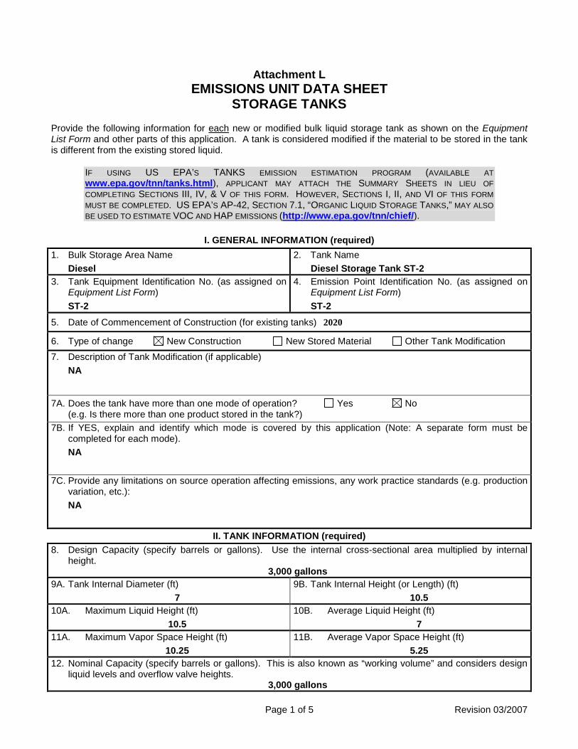
Page 1 of 5 Revision 03/2007
Attachment L EMISSIONS UNIT DATA SHEET
STORAGE TANKS Provide the following information for each new or modified bulk liquid storage tank as shown on the Equipment List Form and other parts of this application. A tank is considered modified if the material to be stored in the tank is different from the existing stored liquid.
IF USING US EPA’S TANKS EMISSION ESTIMATION PROGRAM (AVAILABLE AT www.epa.gov/tnn/tanks.html), APPLICANT MAY ATTACH THE SUMMARY SHEETS IN LIEU OF COMPLETING SECTIONS III, IV, & V OF THIS FORM. HOWEVER, SECTIONS I, II, AND VI OF THIS FORM MUST BE COMPLETED. US EPA’S AP-42, SECTION 7.1, “ORGANIC LIQUID STORAGE TANKS,” MAY ALSO BE USED TO ESTIMATE VOC AND HAP EMISSIONS (http://www.epa.gov/tnn/chief/).
I. GENERAL INFORMATION (required) 1. Bulk Storage Area Name
Diesel 2. Tank Name
Diesel Storage Tank ST-2 3. Tank Equipment Identification No. (as assigned on
Equipment List Form) ST-2
4. Emission Point Identification No. (as assigned on Equipment List Form) ST-2
5. Date of Commencement of Construction (for existing tanks) 2020
6. Type of change New Construction New Stored Material Other Tank Modification 7. Description of Tank Modification (if applicable)
NA
7A. Does the tank have more than one mode of operation? Yes No (e.g. Is there more than one product stored in the tank?)
7B. If YES, explain and identify which mode is covered by this application (Note: A separate form must be completed for each mode). NA
7C. Provide any limitations on source operation affecting emissions, any work practice standards (e.g. production variation, etc.): NA
II. TANK INFORMATION (required) 8. Design Capacity (specify barrels or gallons). Use the internal cross-sectional area multiplied by internal
height. 3,000 gallons
9A. Tank Internal Diameter (ft) 7
9B. Tank Internal Height (or Length) (ft) 10.5
10A. Maximum Liquid Height (ft) 10.5
10B. Average Liquid Height (ft) 7
11A. Maximum Vapor Space Height (ft) 10.25
11B. Average Vapor Space Height (ft) 5.25
12. Nominal Capacity (specify barrels or gallons). This is also known as “working volume” and considers design liquid levels and overflow valve heights.
3,000 gallons
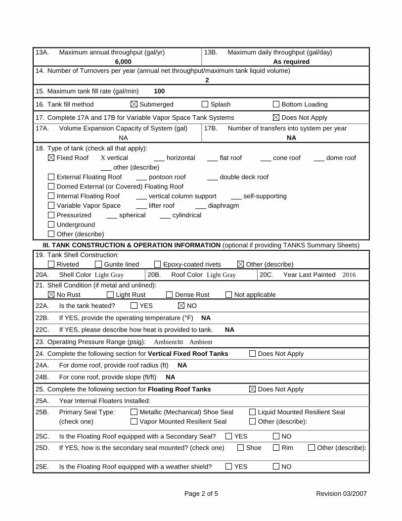
Page 2 of 5 Revision 03/2007
13A. Maximum annual throughput (gal/yr) 6,000
13B. Maximum daily throughput (gal/day) As required
14. Number of Turnovers per year (annual net throughput/maximum tank liquid volume) 2
15. Maximum tank fill rate (gal/min) 100
16. Tank fill method Submerged Splash Bottom Loading
17. Complete 17A and 17B for Variable Vapor Space Tank Systems Does Not Apply 17A. Volume Expansion Capacity of System (gal)
NA 17B. Number of transfers into system per year
NA 18. Type of tank (check all that apply):
Fixed Roof X vertical horizontal flat roof cone roof dome roof other (describe)
External Floating Roof pontoon roof double deck roof Domed External (or Covered) Floating Roof Internal Floating Roof vertical column support self-supporting Variable Vapor Space lifter roof diaphragm Pressurized spherical cylindrical Underground Other (describe)
III. TANK CONSTRUCTION & OPERATION INFORMATION (optional if providing TANKS Summary Sheets) 19. Tank Shell Construction:
Riveted Gunite lined Epoxy-coated rivets Other (describe) 20A. Shell Color Light Gray 20B. Roof Color Light Gray 20C. Year Last Painted 2016 21. Shell Condition (if metal and unlined):
No Rust Light Rust Dense Rust Not applicable
22A. Is the tank heated? YES NO
22B. If YES, provide the operating temperature (°F) NA
22C. If YES, please describe how heat is provided to tank. NA
23. Operating Pressure Range (psig): Ambient to Ambient
24. Complete the following section for Vertical Fixed Roof Tanks Does Not Apply
24A. For dome roof, provide roof radius (ft) NA
24B. For cone roof, provide slope (ft/ft) NA
25. Complete the following section for Floating Roof Tanks Does Not Apply
25A. Year Internal Floaters Installed:
25B. Primary Seal Type: Metallic (Mechanical) Shoe Seal Liquid Mounted Resilient Seal (check one) Vapor Mounted Resilient Seal Other (describe):
25C. Is the Floating Roof equipped with a Secondary Seal? YES NO
25D. If YES, how is the secondary seal mounted? (check one) Shoe Rim Other (describe):
25E. Is the Floating Roof equipped with a weather shield? YES NO

Page 3 of 5 Revision 03/2007
25F. Describe deck fittings; indicate the number of each type of fitting: ACCESS HATCH
BOLT COVER, GASKETED:
UNBOLTED COVER, GASKETED:
UNBOLTED COVER, UNGASKETED:
AUTOMATIC GAUGE FLOAT WELL BOLT COVER, GASKETED:
UNBOLTED COVER, GASKETED:
UNBOLTED COVER, UNGASKETED:
COLUMN WELL BUILT-UP COLUMN – SLIDING COVER, GASKETED:
BUILT-UP COLUMN – SLIDING COVER, UNGASKETED:
PIPE COLUMN – FLEXIBLE FABRIC SLEEVE SEAL:
LADDER WELL PIP COLUMN – SLIDING COVER, GASKETED:
PIPE COLUMN – SLIDING COVER, UNGASKETED:
GAUGE-HATCH/SAMPLE PORT SLIDING COVER, GASKETED:
SLIDING COVER, UNGASKETED:
ROOF LEG OR HANGER WELL WEIGHTED MECHANICAL ACTUATION, GASKETED:
WEIGHTED MECHANICAL ACTUATION, UNGASKETED:
SAMPLE WELL-SLIT FABRIC SEAL (10% OPEN AREA)
VACUUM BREAKER WEIGHTED MECHANICAL ACTUATION, GASKETED:
WEIGHTED MECHANICAL ACTUATION, UNGASKETED:
RIM VENT WEIGHTED MECHANICAL ACTUATION GASKETED:
WEIGHTED MECHANICAL ACTUATION, UNGASKETED:
DECK DRAIN (3-INCH DIAMETER) OPEN:
90% CLOSED:
STUB DRAIN 1-INCH DIAMETER:
OTHER (DESCRIBE, ATTACH ADDITIONAL PAGES IF NECESSARY)

Page 4 of 5 Revision 03/2007
26. Complete the following section for Internal Floating Roof Tanks Does Not Apply
26A. Deck Type: Bolted Welded 26B. For Bolted decks, provide deck construction:
26C. Deck seam: Continuous sheet construction 5 feet wide Continuous sheet construction 6 feet wide Continuous sheet construction 7 feet wide Continuous sheet construction 5 × 7.5 feet wide Continuous sheet construction 5 × 12 feet wide Other (describe)
26D. Deck seam length (ft) 26E. Area of deck (ft2) For column supported tanks: 26F. Number of columns:
26G. Diameter of each column:
IV. SITE INFORMANTION (optional if providing TANKS Summary Sheets) 27. Provide the city and state on which the data in this section are based.
See TANKS Summary Sheet 28. Daily Average Ambient Temperature (°F)
29. Annual Average Maximum Temperature (°F)
30. Annual Average Minimum Temperature (°F)
31. Average Wind Speed (miles/hr)
32. Annual Average Solar Insulation Factor (BTU/(ft2·day))
33. Atmospheric Pressure (psia)
V. LIQUID INFORMATION (optional if providing TANKS Summary Sheets)
34. Average daily temperature range of bulk liquid: See TANKS Summary Sheet
34A. Minimum (°F) 34B. Maximum (°F)
35. Average operating pressure range of tank:
35A. Minimum (psig) 35B. Maximum (psig)
36A. Minimum Liquid Surface Temperature (°F)
36B. Corresponding Vapor Pressure (psia)
37A. Average Liquid Surface Temperature (°F)
37B. Corresponding Vapor Pressure (psia)
38A. Maximum Liquid Surface Temperature (°F)
38B. Corresponding Vapor Pressure (psia)
39. Provide the following for each liquid or gas to be stored in tank. Add additional pages if necessary. 39A. Material Name or Composition
39B. CAS Number
39C. Liquid Density (lb/gal)
39D. Liquid Molecular Weight (lb/lb-mole)
39E. Vapor Molecular Weight (lb/lb-mole)
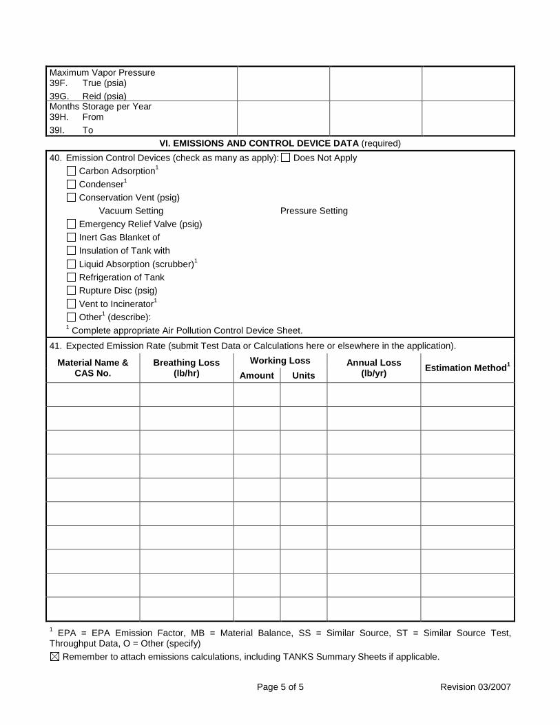
Page 5 of 5 Revision 03/2007
Maximum Vapor Pressure 39F. True (psia) 39G. Reid (psia)
Months Storage per Year 39H. From 39I. To
VI. EMISSIONS AND CONTROL DEVICE DATA (required) 40. Emission Control Devices (check as many as apply): Does Not Apply
Carbon Adsorption1 Condenser1 Conservation Vent (psig)
Vacuum Setting Pressure Setting Emergency Relief Valve (psig) Inert Gas Blanket of Insulation of Tank with Liquid Absorption (scrubber)1 Refrigeration of Tank Rupture Disc (psig) Vent to Incinerator1 Other1 (describe):
1 Complete appropriate Air Pollution Control Device Sheet.
41. Expected Emission Rate (submit Test Data or Calculations here or elsewhere in the application).
Material Name & CAS No.
Breathing Loss (lb/hr)
Working Loss Annual Loss (lb/yr) Estimation Method1
Amount Units
1 EPA = EPA Emission Factor, MB = Material Balance, SS = Similar Source, ST = Similar Source Test, Throughput Data, O = Other (specify)
Remember to attach emissions calculations, including TANKS Summary Sheets if applicable.

Page 1 of 5 Revision 03/2007
Attachment L EMISSIONS UNIT DATA SHEET
STORAGE TANKS Provide the following information for each new or modified bulk liquid storage tank as shown on the Equipment List Form and other parts of this application. A tank is considered modified if the material to be stored in the tank is different from the existing stored liquid.
IF USING US EPA’S TANKS EMISSION ESTIMATION PROGRAM (AVAILABLE AT www.epa.gov/tnn/tanks.html), APPLICANT MAY ATTACH THE SUMMARY SHEETS IN LIEU OF COMPLETING SECTIONS III, IV, & V OF THIS FORM. HOWEVER, SECTIONS I, II, AND VI OF THIS FORM MUST BE COMPLETED. US EPA’S AP-42, SECTION 7.1, “ORGANIC LIQUID STORAGE TANKS,” MAY ALSO BE USED TO ESTIMATE VOC AND HAP EMISSIONS (http://www.epa.gov/tnn/chief/).
I. GENERAL INFORMATION (required) 1. Bulk Storage Area Name
Diesel 2. Tank Name
Diesel Storage Tank ST-1 3. Tank Equipment Identification No. (as assigned on
Equipment List Form) ST-1
4. Emission Point Identification No. (as assigned on Equipment List Form) ST-1
5. Date of Commencement of Construction (for existing tanks) 2020
6. Type of change New Construction New Stored Material Other Tank Modification 7. Description of Tank Modification (if applicable)
NA
7A. Does the tank have more than one mode of operation? Yes No (e.g. Is there more than one product stored in the tank?)
7B. If YES, explain and identify which mode is covered by this application (Note: A separate form must be completed for each mode). NA
7C. Provide any limitations on source operation affecting emissions, any work practice standards (e.g. production variation, etc.): NA
II. TANK INFORMATION (required) 8. Design Capacity (specify barrels or gallons). Use the internal cross-sectional area multiplied by internal
height. 500 gallons
9A. Tank Internal Diameter (ft) 3.5
9B. Tank Internal Height (or Length) (ft) 7
10A. Maximum Liquid Height (ft) 7
10B. Average Liquid Height (ft) 3.5
11A. Maximum Vapor Space Height (ft) 6.25
11B. Average Vapor Space Height (ft) 3.5
12. Nominal Capacity (specify barrels or gallons). This is also known as “working volume” and considers design liquid levels and overflow valve heights.
500 gallons
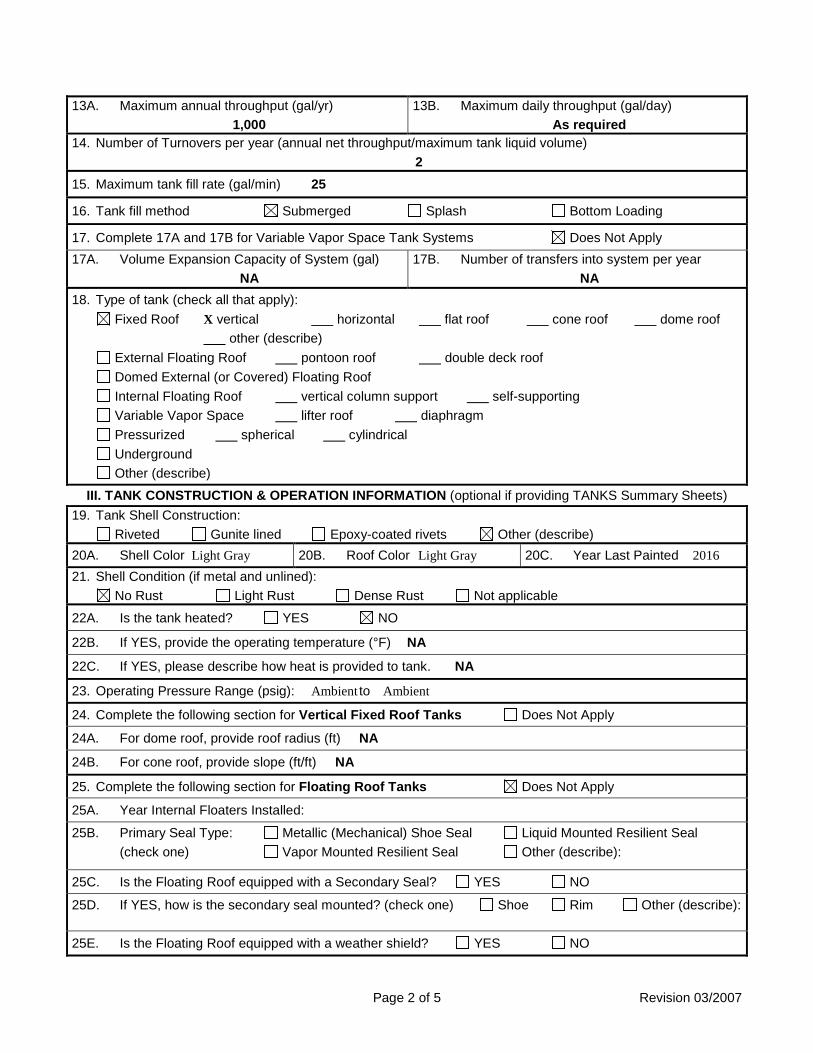
Page 2 of 5 Revision 03/2007
13A. Maximum annual throughput (gal/yr) 1,000
13B. Maximum daily throughput (gal/day) As required
14. Number of Turnovers per year (annual net throughput/maximum tank liquid volume) 2
15. Maximum tank fill rate (gal/min) 25
16. Tank fill method Submerged Splash Bottom Loading
17. Complete 17A and 17B for Variable Vapor Space Tank Systems Does Not Apply 17A. Volume Expansion Capacity of System (gal)
NA 17B. Number of transfers into system per year
NA 18. Type of tank (check all that apply):
Fixed Roof X vertical horizontal flat roof cone roof dome roof other (describe)
External Floating Roof pontoon roof double deck roof Domed External (or Covered) Floating Roof Internal Floating Roof vertical column support self-supporting Variable Vapor Space lifter roof diaphragm Pressurized spherical cylindrical Underground Other (describe)
III. TANK CONSTRUCTION & OPERATION INFORMATION (optional if providing TANKS Summary Sheets) 19. Tank Shell Construction:
Riveted Gunite lined Epoxy-coated rivets Other (describe) 20A. Shell Color Light Gray 20B. Roof Color Light Gray 20C. Year Last Painted 2016 21. Shell Condition (if metal and unlined):
No Rust Light Rust Dense Rust Not applicable
22A. Is the tank heated? YES NO
22B. If YES, provide the operating temperature (°F) NA
22C. If YES, please describe how heat is provided to tank. NA
23. Operating Pressure Range (psig): Ambient to Ambient
24. Complete the following section for Vertical Fixed Roof Tanks Does Not Apply
24A. For dome roof, provide roof radius (ft) NA
24B. For cone roof, provide slope (ft/ft) NA
25. Complete the following section for Floating Roof Tanks Does Not Apply
25A. Year Internal Floaters Installed:
25B. Primary Seal Type: Metallic (Mechanical) Shoe Seal Liquid Mounted Resilient Seal (check one) Vapor Mounted Resilient Seal Other (describe):
25C. Is the Floating Roof equipped with a Secondary Seal? YES NO
25D. If YES, how is the secondary seal mounted? (check one) Shoe Rim Other (describe):
25E. Is the Floating Roof equipped with a weather shield? YES NO

Page 3 of 5 Revision 03/2007
25F. Describe deck fittings; indicate the number of each type of fitting: ACCESS HATCH
BOLT COVER, GASKETED:
UNBOLTED COVER, GASKETED:
UNBOLTED COVER, UNGASKETED:
AUTOMATIC GAUGE FLOAT WELL BOLT COVER, GASKETED:
UNBOLTED COVER, GASKETED:
UNBOLTED COVER, UNGASKETED:
COLUMN WELL BUILT-UP COLUMN – SLIDING COVER, GASKETED:
BUILT-UP COLUMN – SLIDING COVER, UNGASKETED:
PIPE COLUMN – FLEXIBLE FABRIC SLEEVE SEAL:
LADDER WELL PIP COLUMN – SLIDING COVER, GASKETED:
PIPE COLUMN – SLIDING COVER, UNGASKETED:
GAUGE-HATCH/SAMPLE PORT SLIDING COVER, GASKETED:
SLIDING COVER, UNGASKETED:
ROOF LEG OR HANGER WELL WEIGHTED MECHANICAL ACTUATION, GASKETED:
WEIGHTED MECHANICAL ACTUATION, UNGASKETED:
SAMPLE WELL-SLIT FABRIC SEAL (10% OPEN AREA)
VACUUM BREAKER WEIGHTED MECHANICAL ACTUATION, GASKETED:
WEIGHTED MECHANICAL ACTUATION, UNGASKETED:
RIM VENT WEIGHTED MECHANICAL ACTUATION GASKETED:
WEIGHTED MECHANICAL ACTUATION, UNGASKETED:
DECK DRAIN (3-INCH DIAMETER) OPEN:
90% CLOSED:
STUB DRAIN 1-INCH DIAMETER:
OTHER (DESCRIBE, ATTACH ADDITIONAL PAGES IF NECESSARY)

Page 4 of 5 Revision 03/2007
26. Complete the following section for Internal Floating Roof Tanks Does Not Apply
26A. Deck Type: Bolted Welded 26B. For Bolted decks, provide deck construction:
26C. Deck seam: Continuous sheet construction 5 feet wide Continuous sheet construction 6 feet wide Continuous sheet construction 7 feet wide Continuous sheet construction 5 × 7.5 feet wide Continuous sheet construction 5 × 12 feet wide Other (describe)
26D. Deck seam length (ft) 26E. Area of deck (ft2) For column supported tanks: 26F. Number of columns:
26G. Diameter of each column:
IV. SITE INFORMANTION (optional if providing TANKS Summary Sheets) 27. Provide the city and state on which the data in this section are based.
See TANKS Summary Sheet 28. Daily Average Ambient Temperature (°F)
29. Annual Average Maximum Temperature (°F)
30. Annual Average Minimum Temperature (°F)
31. Average Wind Speed (miles/hr)
32. Annual Average Solar Insulation Factor (BTU/(ft2·day))
33. Atmospheric Pressure (psia)
V. LIQUID INFORMATION (optional if providing TANKS Summary Sheets)
34. Average daily temperature range of bulk liquid: See TANKS Summary Sheet
34A. Minimum (°F) 34B. Maximum (°F)
35. Average operating pressure range of tank:
35A. Minimum (psig) 35B. Maximum (psig)
36A. Minimum Liquid Surface Temperature (°F)
36B. Corresponding Vapor Pressure (psia)
37A. Average Liquid Surface Temperature (°F)
37B. Corresponding Vapor Pressure (psia)
38A. Maximum Liquid Surface Temperature (°F)
38B. Corresponding Vapor Pressure (psia)
39. Provide the following for each liquid or gas to be stored in tank. Add additional pages if necessary. 39A. Material Name or Composition
39B. CAS Number
39C. Liquid Density (lb/gal)
39D. Liquid Molecular Weight (lb/lb-mole)
39E. Vapor Molecular Weight (lb/lb-mole)

Page 5 of 5 Revision 03/2007
Maximum Vapor Pressure 39F. True (psia) 39G. Reid (psia)
Months Storage per Year 39H. From 39I. To
VI. EMISSIONS AND CONTROL DEVICE DATA (required) 40. Emission Control Devices (check as many as apply): Does Not Apply
Carbon Adsorption1 Condenser1 Conservation Vent (psig)
Vacuum Setting Pressure Setting Emergency Relief Valve (psig) Inert Gas Blanket of Insulation of Tank with Liquid Absorption (scrubber)1 Refrigeration of Tank Rupture Disc (psig) Vent to Incinerator1 Other1 (describe):
1 Complete appropriate Air Pollution Control Device Sheet.
41. Expected Emission Rate (submit Test Data or Calculations here or elsewhere in the application).
Material Name & CAS No.
Breathing Loss (lb/hr)
Working Loss Annual Loss (lb/yr) Estimation Method1
Amount Units
1 EPA = EPA Emission Factor, MB = Material Balance, SS = Similar Source, ST = Similar Source Test, Throughput Data, O = Other (specify)
Remember to attach emissions calculations, including TANKS Summary Sheets if applicable.

ATTACHMENT M
AIR POLLUTION CONTROL DEVICES The Combined-Cycle Combustion Turbines will be equipped with dry low-NOx combustors (DLNC). These combustion controls along with Selective Catalytic Reduction (SCR) systems will control emissions of nitrogen oxides (NOx). Oxidation catalysts will be used to control the turbines’ carbon monoxide (CO) and volatile organic compounds (VOC) emissions. The Auxiliary Boiler will be equipped with low-NOx burners (LNB) to control NOx emissions. The proposed emission control systems and association regulatory implications are further discussed in Section 3.4 – Prevention of Significant Deterioration (PSD) of this permit application package.

ATTACHMENT N SUPPORTING EMISSION CALCULATIONS
Potential emissions from the Project emission sources are estimated using various calculation methodologies including vendor data, emission factors from USEPA’s Compilation of Air Pollutant Emission Factors (AP-42) publication, material balances, New Source Performance Standards (NSPS) emission standards, USEPA’s Mandatory Greenhouse Gas Reporting Rule (40 CFR Part 98), and/or engineering calculations.
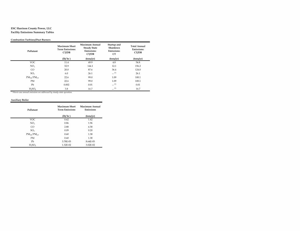
ESC Harrison County Power, LLCFacility Emissions Summary Tables
Combustion Turbines/Duct Burners
Maximum Short Term Emissions:
CT/DB
Maximum Annual Steady State Emissions:
CT/DB
Startup and Shutdown Emissions:
CT
Total Annual Emissions:
CT/DB
(lb/ hr ) (tons/yr) (tons/yr) (tons/yr)VOC 11.4 49.9 4.8 54.8NOx 32.9 144.1 12.1 156.2CO 20.0 87.6 36.4 124.0SO2 6.0 26.1 -- (1) 26.1
PM10/PM2.5 22.6 99.0 1.09 100.1PM 22.6 99.0 1.09 100.1Pb 0.002 0.01 -- (1) 0.01
H2SO4 3.8 16.7 -- (1) 16.7(1) Worst-case annual emissions are addressed by steady-state operation.
Auxiliary Boiler
Maximum Short Term Emissions
Maximum Annual Emissions
(lb/ hr ) (tons/yr)VOC 0.62 1.42NOx 0.86 1.96CO 2.88 6.58SO2 0.09 0.20
PM10/PM2.5 0.60 1.38PM 0.60 1.38Pb 3.78E-05 8.64E-05
H2SO4 1.32E-02 3.02E-02
Pollutant
Pollutant

ESC Harrison County Power, LLCFacility Emissions Summary TablesEmergency Generator and Fire Water Pump
Emergency Generator
Maximum Short Term Emissions
Emergency Generator
Maximum Annual Emissions
Fire Water Pump Maximum Short Term Emissions
Fire Water Pump Maximum Annual
Emissions
(lb/hr) (tons/yr) (lb/hr) (tons/yr)VOC 0.65 0.03 0.06 0.00NOx 32.22 1.61 1.87 0.09CO 1.77 0.09 0.31 0.02SO2 0.03 0.0015 0.0032 0.0002
PM10/PM2.5 0.15 0.01 0.05 0.00PM 0.15 0.01 0.05 0.00Pb -- -- -- --
H2SO4 1.85E-04 3.58E-03 3.89E-04 1.94E-05
Fuel Gas HeaterFuel Gas Heater Maximum Short Term Emissions
Fuel Gas Heater Maximum Annual
Emissions
(lb/hr) (tons/yr)VOC 0.04 0.17NOx 0.20 0.86CO 0.21 0.93SO2 6.07E-03 2.66E-02
PM10/PM2.5 0.04 0.19PM 0.04 0.19Pb -- --
H2SO4 9.29E-04 4.07E-03
Pollutant
Pollutant
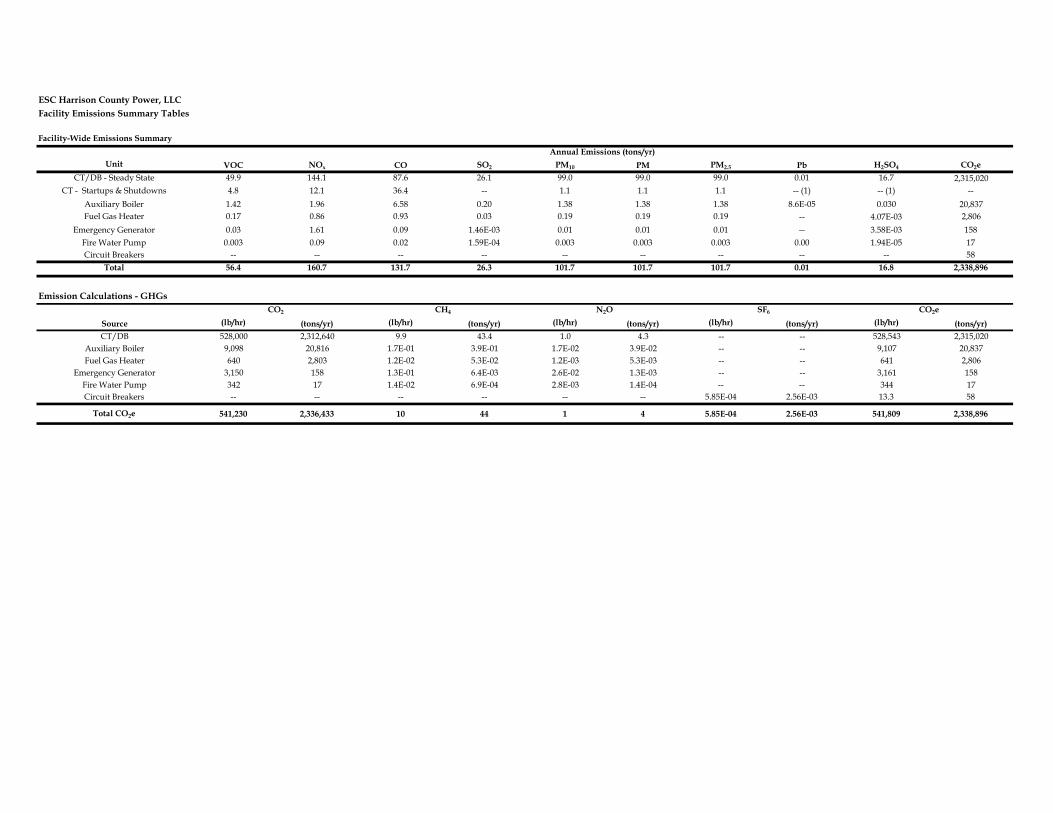
ESC Harrison County Power, LLCFacility Emissions Summary Tables
Unit VOC NOx CO SO2 PM10 PM PM2.5 Pb H2SO4 CO2eCT/DB - Steady State 49.9 144.1 87.6 26.1 99.0 99.0 99.0 0.01 16.7 2,315,020
CT - Startups & Shutdowns 4.8 12.1 36.4 -- 1.1 1.1 1.1 -- (1) -- (1) --Auxiliary Boiler 1.42 1.96 6.58 0.20 1.38 1.38 1.38 8.6E-05 0.030 20,837Fuel Gas Heater 0.17 0.86 0.93 0.03 0.19 0.19 0.19 -- 4.07E-03 2,806
Emergency Generator 0.03 1.61 0.09 1.46E-03 0.01 0.01 0.01 -- 3.58E-03 158Fire Water Pump 0.003 0.09 0.02 1.59E-04 0.003 0.003 0.003 0.00 1.94E-05 17Circuit Breakers -- -- -- -- -- -- -- -- -- 58
Total 56.4 160.7 131.7 26.3 101.7 101.7 101.7 0.01 16.8 2,338,896
Emission Calculations - GHGs
Source (lb/hr) (tons/yr) (lb/hr) (tons/yr) (lb/hr) (tons/yr) (lb/hr) (tons/yr) (lb/hr) (tons/yr)CT/DB 528,000 2,312,640 9.9 43.4 1.0 4.3 -- -- 528,543 2,315,020
Auxiliary Boiler 9,098 20,816 1.7E-01 3.9E-01 1.7E-02 3.9E-02 -- -- 9,107 20,837Fuel Gas Heater 640 2,803 1.2E-02 5.3E-02 1.2E-03 5.3E-03 -- -- 641 2,806
Emergency Generator 3,150 158 1.3E-01 6.4E-03 2.6E-02 1.3E-03 -- -- 3,161 158Fire Water Pump 342 17 1.4E-02 6.9E-04 2.8E-03 1.4E-04 -- -- 344 17Circuit Breakers -- -- -- -- -- -- 5.85E-04 2.56E-03 13.3 58
Total CO2e 541,230 2,336,433 10 44 1 4 5.85E-04 2.56E-03 541,809 2,338,896
CO2
Annual Emissions (tons/yr) Facility-Wide Emissions Summary
CO2eCH4 N2O SF6

ESC Harrison County Power, LLCFacility Emissions Summary Tables
Hazardous Air Pollutant (HAP) CT (lb/hr)
DB(lb/hr)
Auxiliary Boiler (lb/hr)
Fuel Gas Heater (lb/hr)
Emergency Generator (lb/hr)
Fire Water Pump (lb/hr)
Facility Total (tons/yr)
2-Methylnaphthalene NA 2.33E-06 1.81E-06 1.27E-07 NA NA 1.49E-05Acetaldehyde 1.40E-02 NA NA NA 4.87E-04 1.61E-03 6.14E-02
Acrolein 2.24E-03 NA NA NA 1.52E-04 7.88E-04 9.81E-03Arsenic NA 1.94E-04 1.51E-05 1.06E-06 NA NA 8.91E-04Benzene 4.20E-03 2.04E-04 1.59E-04 1.12E-05 1.50E-02 1.96E-03 2.05E-02
Cadmium NA 1.07E-03 8.31E-05 5.84E-06 NA NA 4.90E-03Chromium NA 1.36E-03 1.06E-04 7.44E-06 NA NA 6.24E-03
Cobalt NA 8.17E-05 6.34E-06 4.46E-07 NA NA 3.74E-04Dichlorobenzene NA 1.17E-04 9.06E-05 6.37E-06 NA NA 7.46E-04
Ethylbenzene 1.12E-02 NA NA NA NA NA 4.90E-02Fluoranthene NA 2.92E-07 2.27E-07 1.59E-08 NA NA 1.87E-06
Fluorene NA 2.72E-07 2.11E-07 1.49E-08 NA NA 1.74E-06Formaldehyde 1.05E+00 7.29E-03 5.66E-03 3.98E-04 1.52E-03 2.48E-03 4.64E+00
Hexane NA 1.75E-01 1.36E-01 9.56E-03 NA NA 1.12E+00Manganese NA 3.69E-04 2.87E-05 2.02E-06 NA NA 1.69E-03Mercury NA 2.53E-04 1.96E-05 1.38E-06 NA NA 1.16E-03
Naphthalene 4.55E-04 5.93E-05 4.61E-05 3.24E-06 2.51E-03 1.78E-04 2.50E-03Nickel NA 2.04E-03 1.59E-04 1.12E-05 NA NA 9.35E-03
Phenanathrene NA 1.65E-06 1.28E-06 9.03E-08 NA NA 1.06E-05POM 7.69E-04 NA NA NA 4.10E-03 3.53E-04 3.59E-03
Pyrene NA 4.86E-07 3.78E-07 2.66E-08 NA NA 3.11E-06Toluene 4.55E-02 3.31E-04 2.57E-04 1.81E-05 5.43E-03 8.59E-04 2.02E-01Xylenes 2.24E-02 NA NA NA 3.73E-03 5.99E-04 9.82E-02
4.646.23
NA = No Emission Factor Available.Total HAPs
Maximum Emissions (Single HAP)

ATTACHMENT O
MONITORING, RECORDKEEPING, REPORTING AND TESTING PLANS
ESC Harrison County Power, LLC suggests the following:
• Limit the annual gas consumption for the combined-cycle Combustion Turbine, Auxiliary Boiler, and Fuel Gas Heater as presented in this permit application.
• Record the amount of natural gas consumed in the combined-cycle Combustion
Turbine, Auxiliary Boiler, and Fuel Gas Heater on a daily, monthly, and 12-month rolling total.
• Operate and maintain SCR and Oxidation Catalyst for the combined-cycle
Combustion Turbine for NOx and CO control.
• Limit the sulfur content of the natural gas as required by regulation.
• Install, operate, calibrate, and maintain continuous emission monitoring systems (CEMS) on the combined-cycle Combustion Turbine as required and in accordance with applicability regulations.
• Conduct performance testing for each pollutant in accordance with the methods,
standards, and deadlines mandated by regulation.
• Combust only ultra low sulfur diesel (ULSD) fuel in the Emergency Generator and Fire Water Pump engines.
• Record the annual hours of operation for the Emergency Generator and Fire Water
Pump engines.
• Maintain required records for at least five (5) years.

ATTACHMENT P
AIR QUALITY PERMIT NOTICE

Attachment P AIR QUALITY PERMIT NOTICE
Notice of Application Notice is given that ESC Harrison County Power, LLC has applied to the West Virginia Department of Environmental Protection, Division of Air Quality, for a PSD permit application, for an electric power generation facility located on Henry Ford Avenue, North of US Route 50 in Harrison County, West Virginia. The latitude and longitude coordinates are: 39°17’15.28’’N and 80°19’21.42’’W. The applicant estimates the potential to discharge the following Regulated Air Pollutants will be 160.7 tons per year of nitrogen oxides, 131.7 tons per year of carbon monoxide, 2,338,896 tons per year of carbon dioxide equivalent emissions, 56.4 tons per year of volatile organic compounds, 101.7 tons per year of particulate matter, 26.3 tons per year of sulfur dioxide, 0.01 tons per year of lead, and 8.41 tons per year of hazardous air pollutants. Startup of operation is expected to occur in the 2nd quarter of 2020. Written comments will be received by the West Virginia Department of Environmental Protection, Division of Air Quality, 601 57th Street, SE, Charleston, WV 25304, for at least 30 calendar days from the date of publication of this notice. Any questions regarding this permit application should be directed to the DAQ at (304) 926-0499, extension 1250, during normal business hours. Dated this the (day) day of November, 2016. By: ESC Harrison County Power, LLC Andrew Dorn IV
Manager 360 Delaware Avenue, Suite 406 Buffalo, NY 14202

ATTACHMENT Q BUSINESS CONFIDENTIAL CLAIMS
This permit application does not contain business confidential information; therefore, this application is considered non-confidential.
ATTACHMENT R AUTHORITY FORMS
Since this application is signed by the “Responsible Official”, this section is not applicable.
ATTACHMENT S TITLE V PERMIT REVISION INFORMATION
Since the site does not currently possess a Title V Permit, Attachment S is not being provided with this permit application.

Appendix F – Check for Air Permitting Fees