ES10029 Optimizing Structural Analysis with...
56
Optimizing Structural Analysis with Dynamo 1 ES10029 Optimizing Structural Analysis with Dynamo Emmanuel Weyermann, Software Architect Autodesk Learning Objectives Learn how to use Dynamo to create models in Robot Structural Analysis Discover the results-feedback loop Learn how to recognize possibilities and limitations of the Robot Structural Analysis package Gain beginning knowledge of how to extend the package using a simple Python script Description With the new Structural Analysis package for Dynamo software, you may optimize your existing structural workflows or invent some way of doing things. This lab will teach participants how to create structural model inside Robot Structural Analysis software using Dynamo software workflows, and how to set up the calculations model using dedicated nodes and run the computation. To complete the process, you will also learn how to interpret results to build optimized structural systems. Your AU Experts Emmanuel is the author of the Structural Analysis for Dynamo package. He is Software Architect for Autodesk Simulation group since 2013. Before that, Emmanuel worked as a software engineer on client/server applications, led customized projects for large engineering firms, and trained users to Robot Structural Analysis API. Emmanuel has been the development lead for several initiatives at Autodesk, such as Revit Extensions, Code Checking, and the Falcon and Dalton projects for Revit. Emmanuel holds a Master’s Degree in Structural Engineering and a Master of Science in Software Design and Development.
Transcript of ES10029 Optimizing Structural Analysis with...

Optimizing Structural Analysis with Dynamo
1
ES10029
Optimizing Structural Analysis with Dynamo Emmanuel Weyermann, Software Architect
Autodesk
Learning Objectives
Learn how to use Dynamo to create models in Robot Structural Analysis
Discover the results-feedback loop
Learn how to recognize possibilities and limitations of the Robot Structural Analysis package
Gain beginning knowledge of how to extend the package using a simple Python script
Description
With the new Structural Analysis package for Dynamo software, you may optimize your existing structural workflows or invent some way of doing things. This lab will teach participants how to create structural model inside Robot Structural Analysis software using Dynamo software workflows, and how to set up the calculations model using dedicated nodes and run the computation. To complete the process, you will also learn how to interpret results to build optimized structural systems.
Your AU Experts
Emmanuel is the author of the Structural Analysis for Dynamo package.
He is Software Architect for Autodesk Simulation group since 2013.
Before that, Emmanuel worked as a software engineer on client/server applications, led customized projects for large engineering firms, and trained users to Robot Structural Analysis API.
Emmanuel has been the development lead for several initiatives at Autodesk, such as Revit Extensions, Code Checking, and the Falcon and Dalton projects for Revit.
Emmanuel holds a Master’s Degree in Structural Engineering and a Master of Science in Software Design and Development.

Optimizing Structural Analysis with Dynamo
2
Table of Contents Learning Objectives ................................................................................................................................... 1
Description ................................................................................................................................................ 1
Your AU Experts ........................................................................................................................................ 1
Introduction .............................................................................................................................................. 4
Autodesk Dynamo ................................................................................................................................. 4
Difference between Autodesk Dynamo and Dynamo Studio ............................................................... 4
Naming convention in this document ................................................................................................... 4
Get Started ................................................................................................................................................ 4
Example 1 - A 2D frame ............................................................................................................................ 7
Goals and objectives ............................................................................................................................. 7
Create the geometry ............................................................................................................................. 7
Create analytical bars .......................................................................................................................... 10
Assign sections to analytical bars........................................................................................................ 12
Assign supports to column base ......................................................................................................... 15
Create a live load................................................................................................................................. 17
Create a uniform member load .......................................................................................................... 19
Analyze the structure .......................................................................................................................... 21
Get reactions results ........................................................................................................................... 22
Get forces extreme results .................................................................................................................. 23
Example 2 - A concrete reservoir ............................................................................................................ 26
Goals and objectives ........................................................................................................................... 26
Create the geometry ........................................................................................................................... 26
Create panels ...................................................................................................................................... 30
Assign thickness to panels .................................................................................................................. 32
Example 3 - Python script to extend the Structural Analysis package .................................................... 34
Goals and objectives ........................................................................................................................... 34
Get Started .......................................................................................................................................... 34
Start coding ......................................................................................................................................... 35
Example 4 - A 3D frame .......................................................................................................................... 41
Goal and objectives ............................................................................................................................. 41
Expected output .................................................................................................................................. 41
Main graph .......................................................................................................................................... 42

Optimizing Structural Analysis with Dynamo
3
Get Started .......................................................................................................................................... 43
Sections and structure self-weight ..................................................................................................... 44
Assigning attributes ............................................................................................................................ 45
Loading conditions .............................................................................................................................. 48
Example 5 – Structural Analysis and Revit .............................................................................................. 50
Goals and objectives ........................................................................................................................... 50
Get Started .......................................................................................................................................... 50
Example 6 –Analytical Model and Mass Objects .................................................................................... 53
Goals and objectives ........................................................................................................................... 53
Mass objects and Dynamo .................................................................................................................. 53
Passing data to React Structures ........................................................................................................ 55

Optimizing Structural Analysis with Dynamo
4
Introduction
Autodesk Dynamo Autodesk gives an answer to this new challenge in our design world. This solution is called Autodesk®
Dynamo (open source) and Autodesk® Dynamo Studio (Desktop Subscription). Dynamo lets designers and engineers create visual logic to explore parametric designs and automate tasks. It helps you to solve challenges faster by designing workflows that drive the geometry and behavior of design models. With Dynamo you will extend your designs into interoperable workflows for documentation, fabrication, coordination, simulation, and analysis.
Difference between Autodesk Dynamo and Dynamo Studio
Difference between Autodesk Dynamo and Dynamo Studio Product
Open Source version available in products (i.e. Revit).
Standalone Polished version supported by Autodesk, working outside of Revit.
Key Value The open source technologies which represent Dynamo’s execution engine and graph UI built into Revit allowing better geometry. Allows you to add logic and behavior to Revit
All of the computational power and geometry tools of Dynamo Core. Aimed at the architect, engineer, or design professional who needs access to analysis linked with Dynamo.
Support No Support Basic Support
Documentation Available online Included
Availability Click here Click here
Pricing Freely Available in Product. A valid Revit license is needed.
New Desktop Subscription Offering
Naming convention in this document - Dynamo nodes names will be in Bold - Dynamo nodes fields will be in Bold Italic - Field values will be in Italic
Get Started
The main objective here is to setup properly your machine to use the Structural Analysis for Dynamo package. Here are first steps:
1. Start Dynamo and create a new project 2. Check if the Structural Analysis for Dynamo package version 0.2.2 is installed

Optimizing Structural Analysis with Dynamo
5
3. If not, open the package manager and download the package
4. Some new nodes should be now available on the library

Optimizing Structural Analysis with Dynamo
6
5. When done, open Robot Structural Analysis 2016 6. Start a Shell project 7. You are done

Optimizing Structural Analysis with Dynamo
7
Example 1 - A 2D frame
Goals and objectives The goal of this example is to learn how to create a simple structure in Robot Structural Analysis and access results inside Dynamo.
Dataset:
- 2DFrame\2DFrame_x.dyn
Create the geometry In this section are described all steps to follow for building the model geometry inside Dynamo.
1. Add two Number Slider nodes.
2. Rename sliders to Height and Width.

Optimizing Structural Analysis with Dynamo
8
3. Add a Point.Origin node. A point at (0,0,0) should be visible in Dynamo canvas.
4. Add three Point.ByCoordinates nodes.

Optimizing Structural Analysis with Dynamo
9
5. Change sliders values to Width = 5 and Height = 3 and connect your nodes to obtain four points at (0,0,0), (0,0,height), (0,width,height) and (0,width,0). Four points should be visible in Dynamo canvas.
6. Add three Line.ByStartPointEndPoint nodes.

Optimizing Structural Analysis with Dynamo
10
7. Connect Point.ByCoordinates nodes output to Line.ByStartPointEndPoint nodes to build three lines representing the frame. At this stage the initial model is ready.
Create analytical bars In this section are described steps to convert the geometry available in Dynamo into bars in Robot Structural Analysis.
1. Add three AnalyticalBar.ByLine nodes.

Optimizing Structural Analysis with Dynamo
11
2. Connect Line.ByStartPointEndPoint nodes outputs to newly created AnalyticalBar.ByLine
nodes.
3. If Dynamo execution option is set to automatic, the frame should be created in Robot Structural Analysis.
4. Else, click run in Dynamo to generate the model in Robot Structural Analysis.

Optimizing Structural Analysis with Dynamo
12
5. The structure maybe not visible. To fix this, make a right-click inside the canvas and call the contextual command “redraw“. The structure should be now visible.
Assign sections to analytical bars In this section are described steps to assign to Robot Structural Analysis bars a specific section containing needed mechanical characteristics for analysis.
1. Add three AnalyticalBar.SetSectionByName nodes.
2. Connect the AnalyticalBar.Byline nodes output to newly created nodes input ports.

Optimizing Structural Analysis with Dynamo
13
3. Find the Section UI nodes in the library under Model/Attributes/Bars. 4. Add it inside the canvas and connect it to the name port of the first.
AnalyticalBar.SetSectionByName node. 5. Note that Section node exposes only sections available inside the opened document.
6. Create a Code Block by a double click inside Dynamo canvas and write “W 16x40”;.
Optimizing Structural Analysis with Dynamo
14
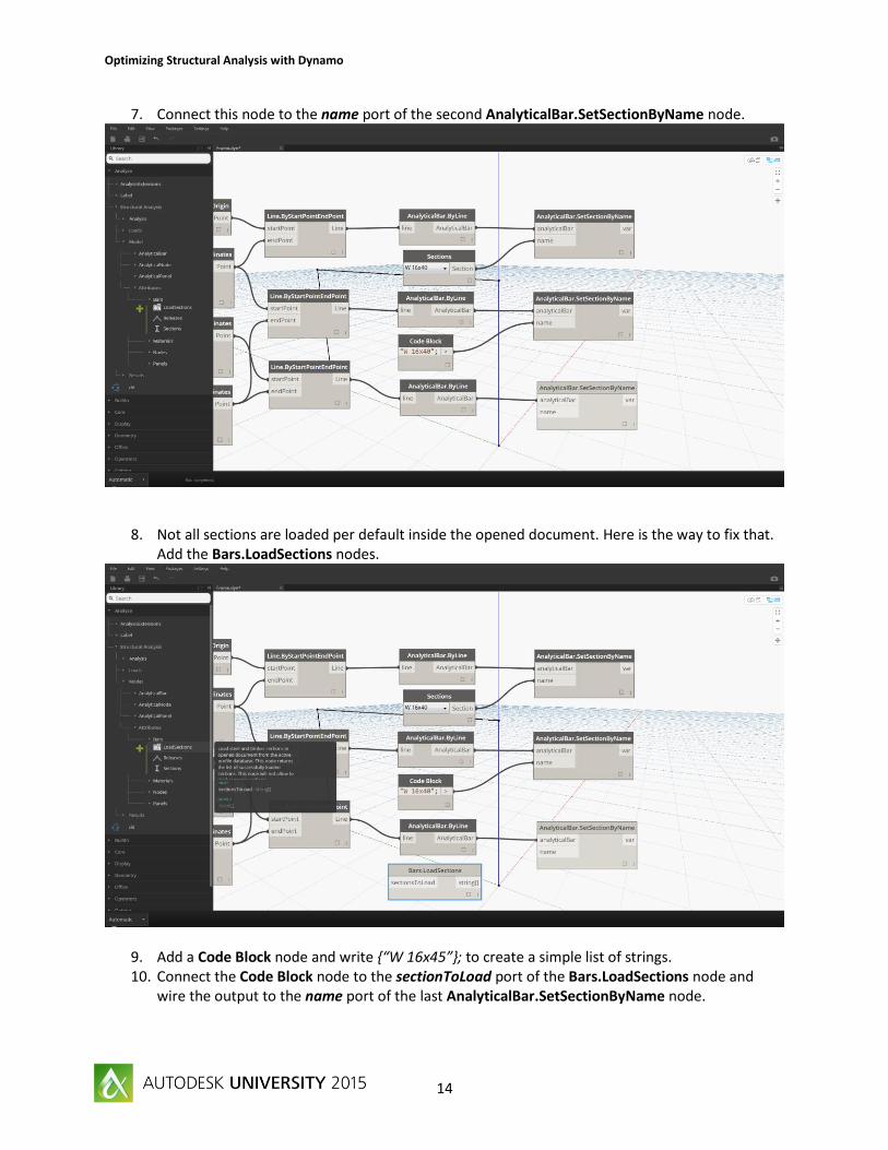
7. Connect this node to the name port of the second AnalyticalBar.SetSectionByName node.
8. Not all sections are loaded per default inside the opened document. Here is the way to fix that. Add the Bars.LoadSections nodes.
9. Add a Code Block node and write {“W 16x45”}; to create a simple list of strings. 10. Connect the Code Block node to the sectionToLoad port of the Bars.LoadSections node and
wire the output to the name port of the last AnalyticalBar.SetSectionByName node.

Optimizing Structural Analysis with Dynamo
15
11. Check the Robot Structural Analysis project, sections should be now assigned to elements.
12. If sections are not visible, make sure you turn on the section shape visibility option.
Assign supports to column base In this section are described steps to assign to Robot Structural Analysis nodes a specific support definition.
1. Add two AnalyticalBar.StartNode nodes and connect them to the outputs of the first and the last AnalyticalBar.SetSectionByName nodes.

Optimizing Structural Analysis with Dynamo
16
2. Add two AnalyticalNode.SetSupportByName nodes and connect them to the outputs of the AnalyticalBar.StartNode nodes.
3. Find the Support UI node in the library under Model/Attributes/Nodes. 4. Add it inside the canvas and connect it to the name port of AnalyticalNode.SetSupportByName
nodes.

Optimizing Structural Analysis with Dynamo
17
5. Check out your model in Robot Structural Analysis.
Create a live load In this section are described steps to create in Robot Structural Analysis nodes a live load case named AU2015.
1. Add a node LoadCase.ByNatureAndType.

Optimizing Structural Analysis with Dynamo
18
2. Add a CaseNature UI node and connect it to the caseNature input port of the LoadCase.ByNatureAndType node.
3. Select Live in the comboBox.
4. Add a CaseType UI node and connect it to the caseType input port of the LoadCase.ByNatureAndType node.
5. Select Simple in the comboBox.

Optimizing Structural Analysis with Dynamo
19
6. Add a Code Block (double click in Dynamo Canvas) and write “AU2015”; 7. Connect the Code Block to the caseName port of the LoadCase.ByNatureAndType node.
Create a uniform member load In this section are described steps to apply uniform member loads in Robot Structural Analysis. These loads will be part of the load case AU2015.

Optimizing Structural Analysis with Dynamo
20
1. Add a UniformMemberLoad.ByBars and connect the loadCase input port to the loadCase node output created previously.
2. Connect the node that provide the top beam as output to the AnalyticalBars input port.
3. Create a Code Block and write -10000; . This will represent a -10000 N magnitude force. 4. Connect the Code Block node to the fz input port of the uniformMemberLoad.ByBars nodes.

Optimizing Structural Analysis with Dynamo
21
Analyze the structure To properly prepare all data for analysis, a list containing all objects that represents the calculation model should be created.
1. Add a node List.Create and connect all bars, nodes, loads and load cases. 2. Add an Analysis.Calculate node.
Optimizing Structural Analysis with Dynamo
22
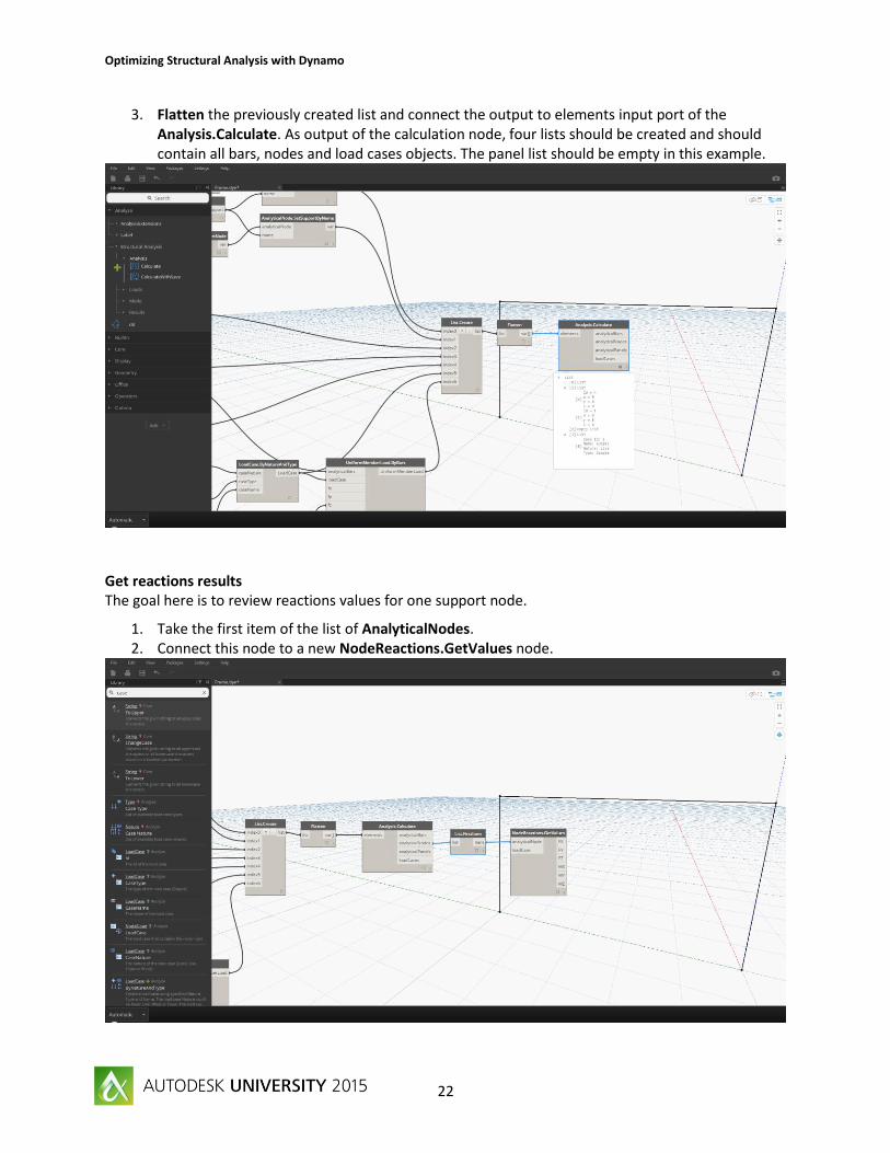
3. Flatten the previously created list and connect the output to elements input port of the Analysis.Calculate. As output of the calculation node, four lists should be created and should contain all bars, nodes and load cases objects. The panel list should be empty in this example.
Get reactions results The goal here is to review reactions values for one support node.
1. Take the first item of the list of AnalyticalNodes. 2. Connect this node to a new NodeReactions.GetValues node.

Optimizing Structural Analysis with Dynamo
23
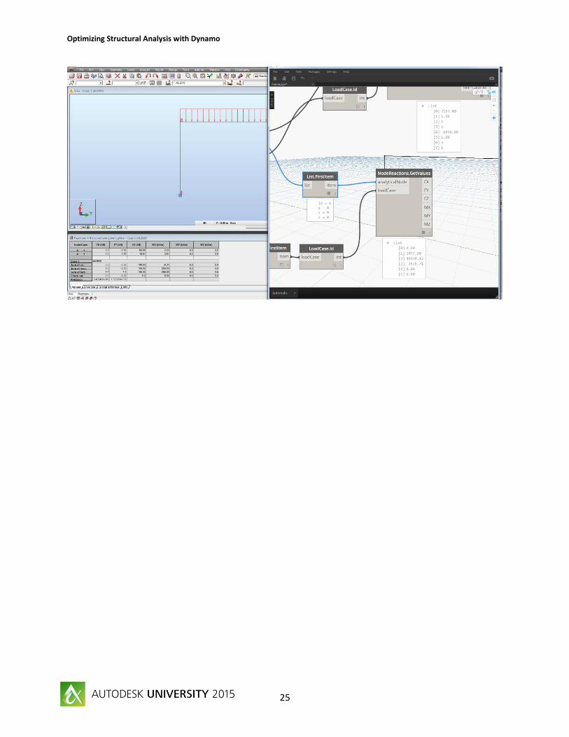
3. Take the first item of the LoadCases list. 4. Get Ids by adding a LoadCase.ID node. 5. Connect it to the loadCase input port.
Get forces extreme results The goal of this section is to review extreme forces results all bars part of the model. The result option will be specified using a Force UI Node.
1. Add a BarForces.GetExtremValuesAndPositionsByLists node. 2. Connect the list of AnalyticalBars output of the calculation node to the input of the BarForces
node. 3. Set load cases Ids to the result node by adding a LoadCase.Id node as proxy.

Optimizing Structural Analysis with Dynamo
24
4. Add a Forces results option UI nodes. 5. Select MY in the combo box. 6. Connect it to the name input port of the results node. 7. Review results.
8. Compare results with Robot Structural Analysis.
Optimizing Structural Analysis with Dynamo
25

Optimizing Structural Analysis with Dynamo
26
Example 2 - A concrete reservoir
Goals and objectives The goal of this example is to learn how to parameterize and create a concrete reservoir in Robot Structural Analysis.
Dataset:
- ConcreteReservoir\ ConcreteReservoir_x.dyn
Create the geometry The model will consist on a disc to model the bottom slabs and a cylinder. Following section will explain how to do that.
1. Add two Number Sliders called Radius and Height.
2. Create a Point.ByCoordinates and connect the z input to the Height slider. 3. Create a Point.Origin node. 4. Create a list with these 2 points.

Optimizing Structural Analysis with Dynamo
27
5. Add a Circle.ByCenterPointRadius node 6. Connect the radius input port to the Radius slider. 7. Connect the list of point to the centerPoint input port. 8. The output on these actions will be two circles.
9. Add a Curve.DivideEqually node, and use the circles list as input. 10. Add a Code Block with the value 2.

Optimizing Structural Analysis with Dynamo
28
11. Wire the Code Block to the divisions input port. When this is done the output of the newly created node should be a list of arcs. First item of the list should contain two arcs representing the first circle, the second item should contain two arcs representing the second circle.
12. Add a List.Transpose node to transpose (swap lines/columns) the arcs list.
13. Add a Code Block node with the value Radius+5; 14. Connect the Code Block to the Radius slider. 15. Add a Circle.ByCenterPointRadius node.
Optimizing Structural Analysis with Dynamo
29
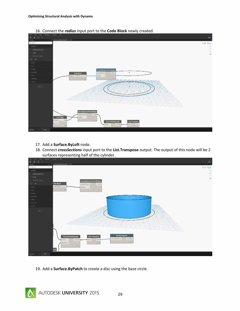
16. Connect the radius input port to the Code Block newly created.
17. Add a Surface.ByLoft node. 18. Connect crossSections input port to the List.Transpose output. The output of this node will be 2
surfaces representing half of the cylinder.
19. Add a Surface.ByPatch to create a disc using the base circle.

Optimizing Structural Analysis with Dynamo
30
Create panels At this stage, the Dynamo model contains three surfaces and the goal will be to create in Robot Structural Analysis three panels representing these surfaces.
1. Add a node AnalyticalPanel.Bysurface. 2. Connect this node to the Surface.ByPatch output.
3. Add a node AnalyticalPanel.Bysurface.

Optimizing Structural Analysis with Dynamo
31
4. Connect this node to the Surface.ByLoft output.
5. The model in Robot Structural Analysis will look like this. Here edges are discretized using 10 divisions as default value.
6. Add a Code Block with 25; as value. 7. Connect the Code Block to the divisions input ports of all AnalyticalPanel.BySurface nodes.

Optimizing Structural Analysis with Dynamo
32
8. Panels edges in Robot Structural Analysis should be smoother.
Assign thickness to panels 1. Add two nodes AnalyticalPanel.SetThicknessByName.

Optimizing Structural Analysis with Dynamo
33
2. Add a Thickness UI node. 3. Connect this node to AnalyticalPanel.SetThicknessByName nodes. 4. Connect AnalyticalPanel.BySurface output to AnalyticalPanel.SetThicknessByName nodes.
5. Now In Robot Structural Analysis panels will have a thickness assigned and the model is ready.

Optimizing Structural Analysis with Dynamo
34
Example 3 - Python script to extend the Structural Analysis package
Goals and objectives When using UI nodes (supports, releases, thickness…) only elements defined in Robot Structural Analysis opened document are available in combo boxes.
A first solution to add a new support definition is to create it using Robot Structural Analysis user interface. A second one is to create a python script inside Dynamo and leverage Robot Structural Analysis API.
The expected goal of this exercise is to create a support with following definition.
Dataset:
- Python\ CreateSupportDefinition.dyn
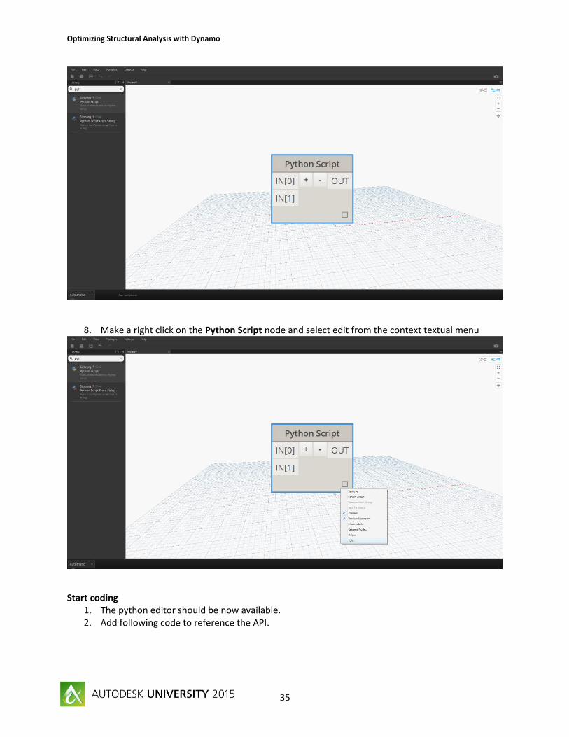
Get Started 1. Start Robot Structural Analysis. 2. Open or create a new document. 3. Create a new file in Dynamo. 4. Turn the execution mode to manual. 5. Search the Python Script node in the nodes library. 6. Add it into Dynamo canvas. 7. Add a new input port to it.
Optimizing Structural Analysis with Dynamo
35
8. Make a right click on the Python Script node and select edit from the context textual menu
Start coding 1. The python editor should be now available. 2. Add following code to reference the API.

Optimizing Structural Analysis with Dynamo
36
# add Robot Structural Analysis API reference from System import Environment #get the current user folder i.e C:\Users\<you>\AppData\Roaming user = Environment.GetFolderPath(Environment.SpecialFolder.ApplicationData) # add the reference to the interop file shipped with the package clr.AddReferenceToFileAndPath(user +r"\Dynamo\0.9\packages\Structural Analysis for
Dynamo\bin\RSA\interop.RobotOM.dll")
3. Add needed import to be able to use objects exposed by the API.
# add needed import to be able to use Robot Structural Analysis objects from RobotOM import * from System import Object
4. Assign your inputs to temporary variables.

Optimizing Structural Analysis with Dynamo
37
# get input data # the support name will go to the input[0] nodeSupportName = IN[0] # the support data will go to the input[1] nodeSupportData = IN[1]
5. Create needed objects for Robot Structural Analysis.
# Connect to the running instance of Robot Structural Analysis application = RobotApplicationClass() # Get a reference of the current project project = application.Project # Get a reference of the current model structure = project.Structure # Get a reference of the label server labels = structure.Labels
6. Create a new node support object.

Optimizing Structural Analysis with Dynamo
38
# create a new label of type support node with the name passed as parameter out = labels.Create(IRobotLabelType.I_LT_NODE_SUPPORT, nodeSupportName)
7. Assign values from the collection to the support object data.
# assign the node support definition to the Robot Structural Analysis object out.Data.UX = nodeSupportData[0] out.Data.UY = nodeSupportData[1] out.Data.UZ = nodeSupportData[2] out.Data.RX = nodeSupportData[3] out.Data.RY = nodeSupportData[4] out.Data.RZ = nodeSupportData[5]
8. Store the definition of the support in open document.
# store the new created label in the open document labels.Store(out)

Optimizing Structural Analysis with Dynamo
39
9. Return the name of the support as output of the python script. #Assign the name to the OUT variable OUT = out.Name
10. Accept all changes and the script is ready to be used. 11. Add a first Code Block with the name of the support “AU2015”; 12. Add a second Code Block with a collection of six true/false values (for example
{true,true,true,false,false,true};). “true” value means that the direction is blocked and “false” means the direction is free.

Optimizing Structural Analysis with Dynamo
40
13. Run the script and you should be done. A new support definition is now available in Robot Structural Analysis project
Optimizing Structural Analysis with Dynamo
41
Example 4 - A 3D frame
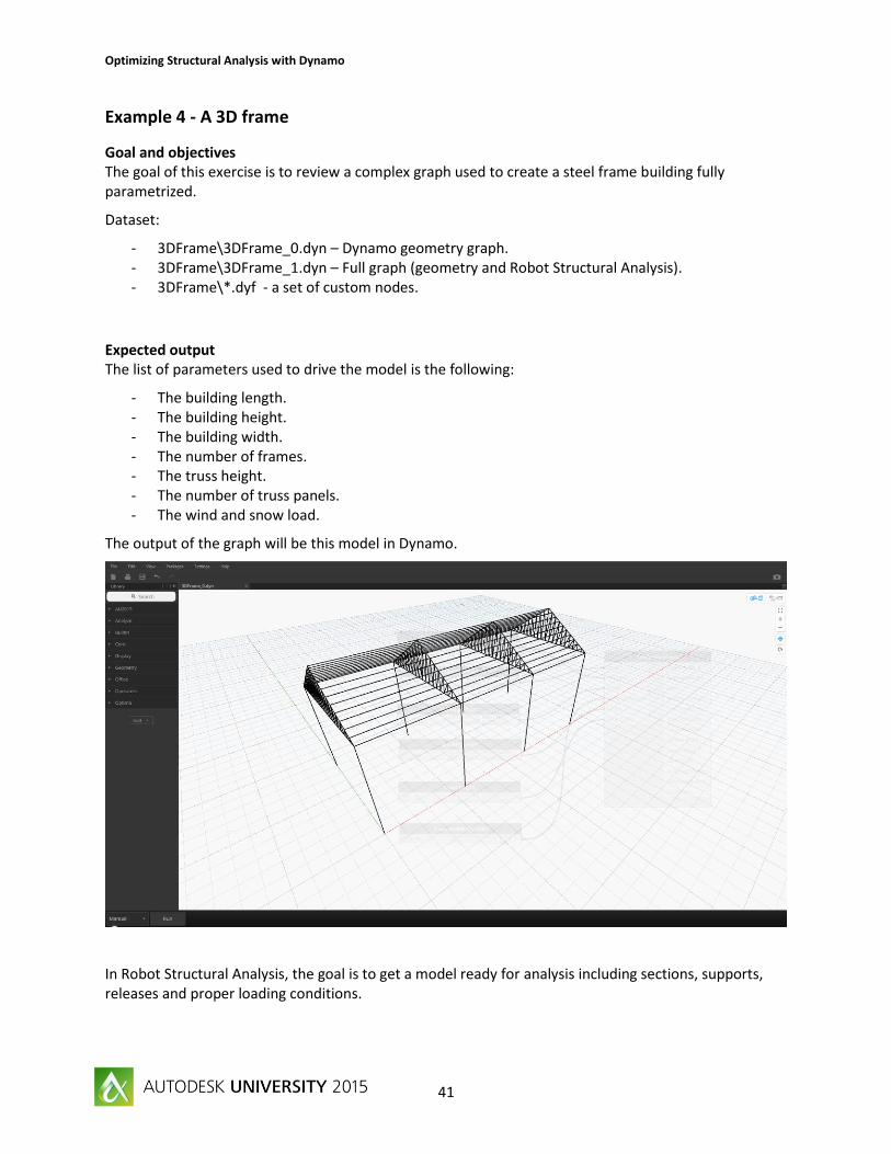
Goal and objectives The goal of this exercise is to review a complex graph used to create a steel frame building fully parametrized.
Dataset:
- 3DFrame\3DFrame_0.dyn – Dynamo geometry graph. - 3DFrame\3DFrame_1.dyn – Full graph (geometry and Robot Structural Analysis). - 3DFrame\*.dyf - a set of custom nodes.
Expected output The list of parameters used to drive the model is the following:
- The building length. - The building height. - The building width. - The number of frames. - The truss height. - The number of truss panels. - The wind and snow load.
The output of the graph will be this model in Dynamo.
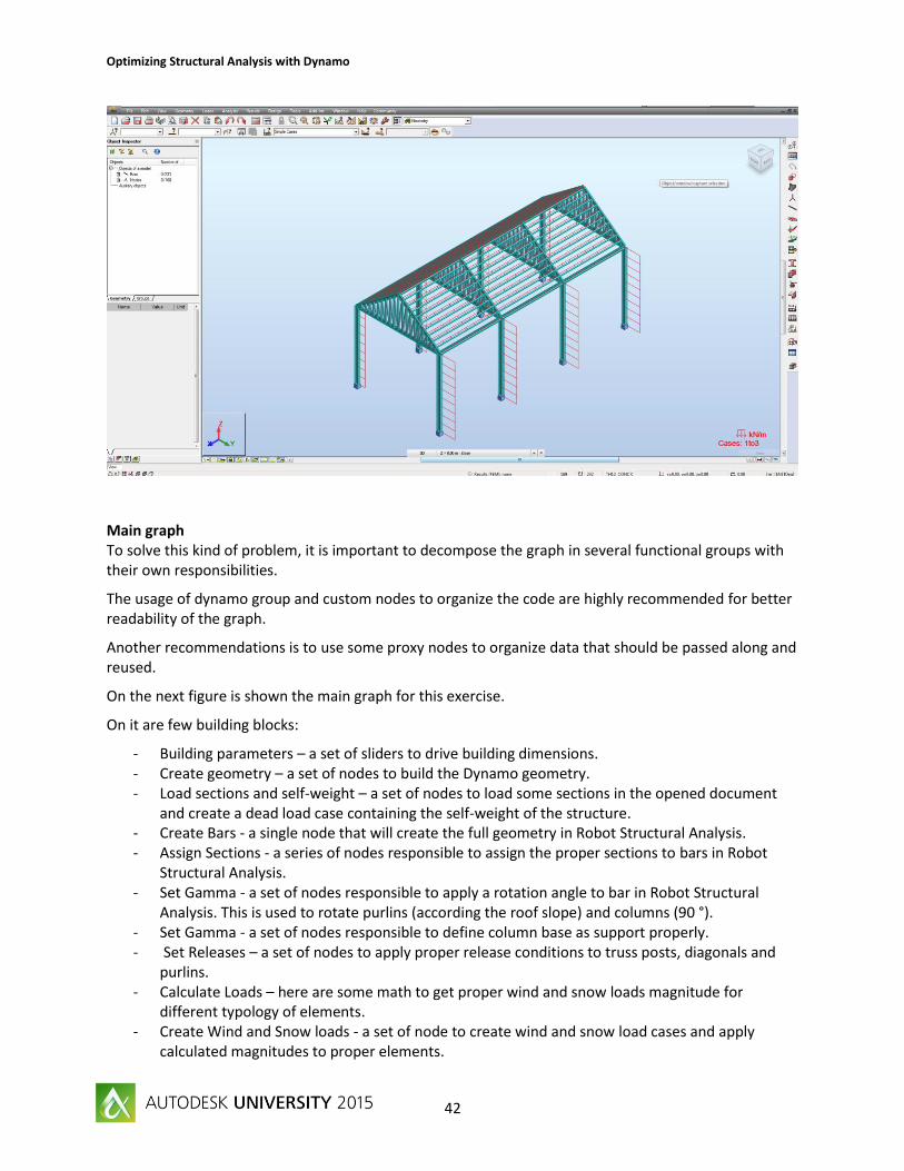
In Robot Structural Analysis, the goal is to get a model ready for analysis including sections, supports, releases and proper loading conditions.
Optimizing Structural Analysis with Dynamo
42
Main graph To solve this kind of problem, it is important to decompose the graph in several functional groups with their own responsibilities.
The usage of dynamo group and custom nodes to organize the code are highly recommended for better readability of the graph.
Another recommendations is to use some proxy nodes to organize data that should be passed along and reused.
On the next figure is shown the main graph for this exercise.
On it are few building blocks:
- Building parameters – a set of sliders to drive building dimensions. - Create geometry – a set of nodes to build the Dynamo geometry. - Load sections and self-weight – a set of nodes to load some sections in the opened document
and create a dead load case containing the self-weight of the structure. - Create Bars - a single node that will create the full geometry in Robot Structural Analysis. - Assign Sections - a series of nodes responsible to assign the proper sections to bars in Robot
Structural Analysis. - Set Gamma - a set of nodes responsible to apply a rotation angle to bar in Robot Structural
Analysis. This is used to rotate purlins (according the roof slope) and columns (90 °). - Set Gamma - a set of nodes responsible to define column base as support properly. - Set Releases – a set of nodes to apply proper release conditions to truss posts, diagonals and
purlins. - Calculate Loads – here are some math to get proper wind and snow loads magnitude for
different typology of elements. - Create Wind and Snow loads - a set of node to create wind and snow load cases and apply
calculated magnitudes to proper elements.

Optimizing Structural Analysis with Dynamo
43
Get Started The base model is as following. This part of the graph is will take input parameters, create the geometry in Dynamo and create bars in Robot Structural Analysis.
Behind the Create Geometry group is a custom node (Frame Geometry.dyf). The output of this custom node is a list of Line objects. This list is passed to a first proxy node that act an accumulation node. The

Optimizing Structural Analysis with Dynamo
44
main goal of the proxy node is to be sure that all requested sections are loaded in the project and self-weight load case created before moving forward.
The list of bars is next passed to an Analyticalbars.ByLines node that will create element in Robot Structural Analysis.
The output will be passed to a second proxy node that will organize Robot Structural Analysis bars by functional roles.
Note that the last item of this proxy node is a line. This data is passed here be able later to calculate the roof slope and the rotation angle to apply to purlins.
Sections and structure self-weight To be able to use specific sections in Robot Structural Analysis, sections should be available. To overcome when in Dynamo context, the node Bar.loadSections could be used.
This node take as input a list of strings representing steel profile names. During execution, this node will try to load all sections specified and return the list of section names that have been successfully loaded in current document.
Note that sections should be present inside the active database with same name, main operation behind the scene is a string comparison (W12X14 name should be W 12x14 and HSS sections are classified under HSRO in Robot Structural Analysis).
The structure self-weight to the whole structure is created using a LoadCase.ModelSelfWeight node that take as input a Dead and Simple LoadCase and a coefficient. The coefficient value is 1.0 per default and could be changed according needs.

Optimizing Structural Analysis with Dynamo
45
Assigning attributes Sections are assigned to proper elements using AnalyticalBar.SetSectionName node. Then objects are passed along through proxy nodes to perform a re-classification.
For purlins and columns, a rotation angle is applied using AnalyticalBar.SetGammaAngle node.
Optimizing Structural Analysis with Dynamo
46
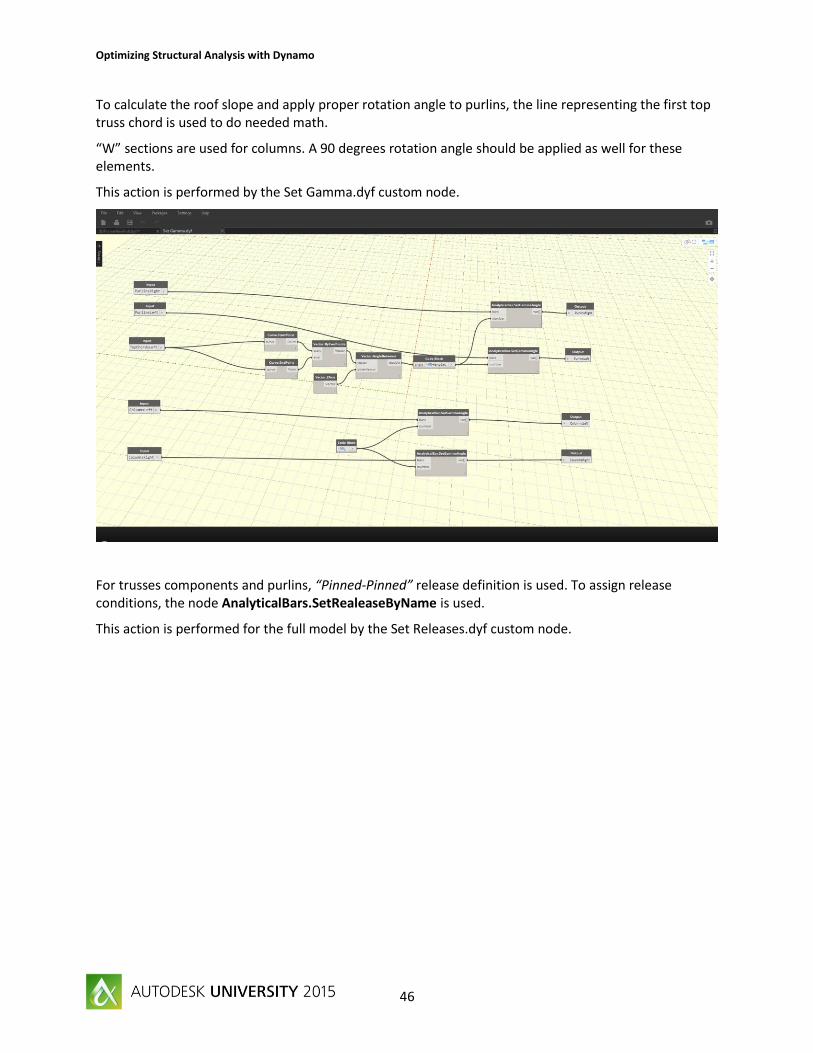
To calculate the roof slope and apply proper rotation angle to purlins, the line representing the first top truss chord is used to do needed math.
“W” sections are used for columns. A 90 degrees rotation angle should be applied as well for these elements.
This action is performed by the Set Gamma.dyf custom node.
For trusses components and purlins, “Pinned-Pinned” release definition is used. To assign release conditions, the node AnalyticalBars.SetRealeaseByName is used.
This action is performed for the full model by the Set Releases.dyf custom node.

Optimizing Structural Analysis with Dynamo
47
Column base should be defined as support and the “Fixed” support definition is used.
To assign support conditions to column, the start node of each columns is picked, and the node AnalyticalNode.SetSupportByName is used.
This action is performed for the full model by the Set Supports.dyf custom node.

Optimizing Structural Analysis with Dynamo
48
Loading conditions Using the dynamo geometry, a wind pressure and snow load, it is possible to parametrize loading conditions. On this example, it is assume that the wind is perpendicular to the Y axis.
A group of nodes is responsible to calculate the distribution of load on elements, then these values are passed to UniformMemberLoad.ByBars nodes.
The load Calculation.dyf file contains the calculation of loads for each type of elements using influence surfaces. As output will be a list of values for wind loads and a for snow loads that should be applied to specific elements.

Optimizing Structural Analysis with Dynamo
49
The load Wind Load.dyf file shows how uniform loads are created.
For each typology of bars, a load will be applied. Note that the Fz value is a list and load are apply in the Local system of coordinates.
The content of the Snow Load.dyf file is similar except for the coordinate system of the load which is set to GlobalProjected.

Optimizing Structural Analysis with Dynamo
50
Example 5 – Structural Analysis and Revit
Goals and objectives When moving data from Revit to any structural analysis software, we are facing two main issues:
- Keeping both models synchronized - Mapping the definition of a cross section from Revit (mainly from family type) into sections
provided by the simulation product.
This example is a boilerplate script that read analytical model from Revit stick elements, convert his representation to analytical bars, then read family type to get proper section and then assigned them to React Structures bar elements.
Dataset:
- Revit\Revit_frame_x.dyn - Revit\Revit_ frame.rvt
Get Started 1. Create a structure in Revit or open Revit_frame.rvt file. The model is a simple steel frame
composed of 9 columns, 10 beams and 4 beams system.
2. Start Dynamo 0.9 from Revit Addins Ribbon tab. 3. Be sure that the Structural Analysis package is available, if not download it. 4. Open React Structures and create a new project. 5. Open Revit_frame_0.dyn or create a script as described in the next image. 6. If you run this script in automatic, all family type used by family instance are loaded in React
Structures. 7. The model geometry should be visible into the Dynamo canvas.

Optimizing Structural Analysis with Dynamo
51
8. To create bars, few nodes are added to read Analytical model curves from the model. Note that only straight elements are supported here. Unfortunately each elements contain three curves and a bit of clean up should be done to get a single curve be element.
9. Connecting the start and end points of the filtered curved, bars could be easily created using AnalyticalBars.ByPoint node.
10. The next steps is to assign sections to bars using regular node.

Optimizing Structural Analysis with Dynamo
52
11. To achieve a customized mapping, some additional nodes not present here should be added between FamilyType.Name and nodes consuming this name as input (Bars.LoadSections and AnalyticalBar.SetSectionName).
12. The model is now generated into React Structure. 13. If Dynamo is running in Automatic, any changes in the Revit model will be applied to React
Structure model (location, dimensions, family types...).

Optimizing Structural Analysis with Dynamo
53
Example 6 –Analytical Model and Mass Objects
Goals and objectives Generally it is not possible to move in a generic way data from Revit to structural analysis software for elements that don’t host analytical model representation. The goal of this example is to learn how to create a simple graph to extract some data to Revit and pass them to React Structures.
Dataset:
- Revit\Revit_Massx.dyn - Revit\Revit_Mass.rvt
Mass objects and Dynamo 1. Create a Mass object in Revit or open Revit_Mass.rvt file.
2. Start Dynamo 0.9 from Revit Addins Ribbon tab. 3. Be sure that the Structural Analysis package is available, if not download it.

Optimizing Structural Analysis with Dynamo
54
4. Open Revit_Mass0.dyn or create a script as described in the next figure.
5. At this stage the Revit geometry is available in Dynamo and is ready to be shared. 6. Note that the last Dynamo node of this graph exposes a list of list of curves describing mass
object faces.

Optimizing Structural Analysis with Dynamo
55
Passing data to React Structures 1. Add a node AnalyticalPanel.ByCurves. 2. Connect it to the Surface.PerimeterCurves output port. 3. Specify the number of divisions that will be used to make surfaces smoother during generation. 4. Assigned thickness to newly created panels.
5. At this stage six panels should be created in React Structures with appropriate thickness.
Optimizing Structural Analysis with Dynamo
56
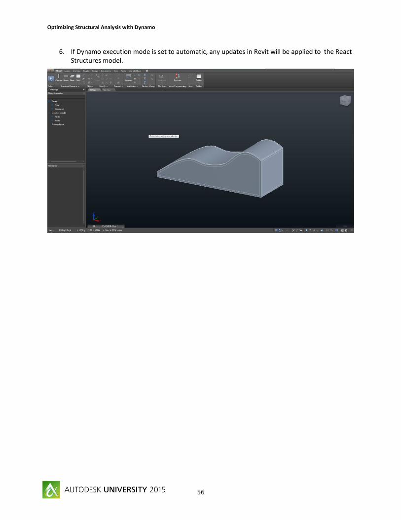
6. If Dynamo execution mode is set to automatic, any updates in Revit will be applied to the React Structures model.