
ERTMS/ETCS UNIT INTERFACES BETWEEN CONTROL-COMMAND AND ... · INTERFACES BETWEEN CONTROL-COMMAND...
25
EUROPEAN RAILWAY AGENCY ERTMS Unit File : ERA_ERTMS_033281 rev 1_2 draft.docERA_ERTMS_033281 PAGE 1 OF 25 ERTMS/ETCS UNIT INTERFACES BETWEEN CONTROL-COMMAND AND SIGNALLING TRACKSIDE AND OTHER SUBSYSTEMS Reference: ERA/ERTMS/033281 Document type: Version : 1.02 T Date : 08/06/201115/11/2012 Edited by Quality review Approved by Name Position Date & Signature
-
Upload
nguyenhanh -
Category
Documents
-
view
238 -
download
1
Transcript of ERTMS/ETCS UNIT INTERFACES BETWEEN CONTROL-COMMAND AND ... · INTERFACES BETWEEN CONTROL-COMMAND...
EUROPEAN RAILWAY AGENCY ERTMS Unit
File : ERA_ERTMS_033281 rev 1_2 draft.docERA_ERTMS_033281
PAGE 1 OF 25
ERTMS/ETCS UNIT
INTERFACES BETWEEN CONTROL-COMMAND AND SIGNALLING TRACKSIDE
AND OTHER SUBSYSTEMS
Reference: ERA/ERTMS/033281 Document type:
Version : 1.02 T
Date : 08/06/201115/11/2012
Edited by Quality review Approved by
Name
Position
Date
&
Signature
ERA ERTMS/ETCS UNIT
INTERFACES BETWEEN CONTROL-COMMAND AND SIGNALLING TRACKSIDE
AND OTHER SUBSYSTEMS
Version 1.0 PAGE 2 OF 25
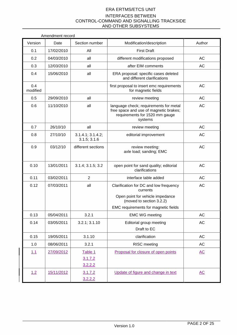
Amendment record
Version Date Section number Modification/description Author
0.1 17/02/2010 All First Draft
0.2 04/03/2010 all different modifications proposed AC
0.3 12/03/2010 all after EIM comments AC
0.4 15/06/2010 all ERA proposal: specific cases deleted and different clarifications
0.4 modified
first proposal to insert emc requirements for magnetic fields
AC
0.5 29/09/2010 all review meeting AC
0.6 11/10/2010 all language check; requirements for metal free space and use of magnetic brakes;
requirements for 1520 mm gauge systems
AC
0.7 26/10/10 all review meeting AC
0.8 27/10/10 3.1.4.1; 3.1.4.2; 3.1.5; 3.1.6
editorial improvement AC
0.9 03/12/10 different sections review meeting: axle load; sanding; EMC
AC
0.10 13/01/2011 3.1.4; 3.1.5; 3.2 open point for sand quality; editorial clarifications
AC
0.11 03/02/2011 2 interface table added AC
0.12 07/03/2011 all Clarification for DC and low frequency currents
Open point for vehicle impedance (moved to section 3.2.2)
EMC requirements for magnetic fields
AC
0.13 05/04/2011 3.2.1 EMC WG meeting AC
0.14 03/05/2011 3.2.1; 3.1.10 Editorial group meeting
Draft to EC
AC
0.15 19/05/2011 3.1.10 clarification AC
1.0 08/06/2011 3.2.1 RISC meeting AC
1.1 27/09/2012 Table 1
3.1.7.2
3.2.2.2
Proposal for closure of open points AC
1.2 15/11/2012 3.1.7.2
3.2.2.2
Update of figure and change in text AC
ERA ERTMS/ETCS UNIT
INTERFACES BETWEEN CONTROL-COMMAND AND SIGNALLING TRACKSIDE
AND OTHER SUBSYSTEMS
Version 1.0 PAGE 3 OF 25
Table of Content
1. INTRODUCTION 4
2. SCOPE 5
3. INTERFACE CHARACTERISTICS 8
3.1. Vehicle design and operation 8
3.1.1. Definitions 8 3.1.2. Axle distances 10 3.1.3. Wheel geometry 11 3.1.4. Use of sanding equipment 13 3.1.5. On-board flange lubrication 14 3.1.6. Use of composite brake blocks 14 3.1.7. Vehicle mass 14 3.1.8. Use of shunt assisting devices 16 3.1.9. Impedance between wheels 17 3.1.10. Combination of rolling stock characteristics influencing shunting impedance 17
3.2. Electromagnetic compatibility 18
3.2.1. Electromagnetic fields 18 3.2.2. Conducted interference 22 3.2.3. Use of magnetic / eddy current brakes 24
4. SPECIFIC CHARACTERISTICS FOR 1520/1524 MM GAUGE SYSTEMS 25
ERA ERTMS/ETCS UNIT
INTERFACES BETWEEN CONTROL-COMMAND AND SIGNALLING TRACKSIDE
AND OTHER SUBSYSTEMS
Version 1.0 PAGE 4 OF 25
1. INTRODUCTION This document defines the interoperability requirements that are applicable at the interface between the Control-Command and Signalling Track-side and other subsystems (mainly, but not exclusively, rolling stock). Since different types of trackside equipment originate different compatibility requirements, in this document traceability is provided, by mean of “justifications” explaining the source of each requirement.
ERA ERTMS/ETCS UNIT
INTERFACES BETWEEN CONTROL-COMMAND AND SIGNALLING TRACKSIDE
AND OTHER SUBSYSTEMS
Version 1.0 PAGE 5 OF 25
2. SCOPE This specification is limited to requirements related to compatibility of train detection systems with other subsystems. The possible effects of parameters on equipment other than train detection systems are not taken into account (e.g., rolling stock and operation are involved in respecting the requirement on maximum amount of sand, not to disturb track circuits operations, while the possible effects of sand on infrastructure elements like switches are not in the scope of this specification). The requirements specified in this document have been identified on the basis of compatibility requirements of train detection systems, by reference to the train detection systems intended for use in interoperable lines, i.e.,
1. Axle counters 2. Track circuits 3. Wheel detectors (e.g., for level crossing operations) 4. Vehicle detectors based on inductive loops
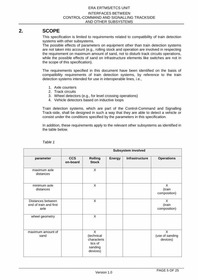
Train detection systems, which are part of the Control-Command and Signalling Track-side, shall be designed in such a way that they are able to detect a vehicle or consist under the conditions specified by the parameters in this specification. In addition, these requirements apply to the relevant other subsystems as identified in the table below. Table 1
Subsystem involved
parameter CCS on-board
Rolling Stock
Energy Infrastructure Operations
maximum axle distances
X
minimum axle distances
X X (train
composition)
Distances between end of train and first
axle
X X (train
composition)
wheel geometry
X
maximum amount of sand
X (technical
characteristics of
sanding devices)
X (use of sanding
devices)
ERA ERTMS/ETCS UNIT
INTERFACES BETWEEN CONTROL-COMMAND AND SIGNALLING TRACKSIDE
AND OTHER SUBSYSTEMS
Version 1.0 PAGE 6 OF 25
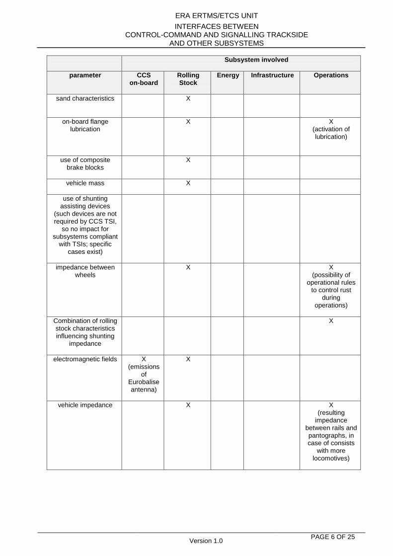
Subsystem involved
parameter CCS on-board
Rolling Stock
Energy Infrastructure Operations
sand characteristics
X
on-board flange lubrication
X X (activation of lubrication)
use of composite brake blocks
X
vehicle mass
X
use of shunting assisting devices
(such devices are not required by CCS TSI,
so no impact for subsystems compliant
with TSIs; specific cases exist)
impedance between wheels
X X (possibility of
operational rules to control rust
during operations)
Combination of rolling stock characteristics influencing shunting
impedance
X
electromagnetic fields
X (emissions
of Eurobalise antenna)
X
vehicle impedance
X X (resulting
impedance between rails and pantographs, in case of consists
with more locomotives)
ERA ERTMS/ETCS UNIT
INTERFACES BETWEEN CONTROL-COMMAND AND SIGNALLING TRACKSIDE
AND OTHER SUBSYSTEMS
Version 1.0 PAGE 7 OF 25
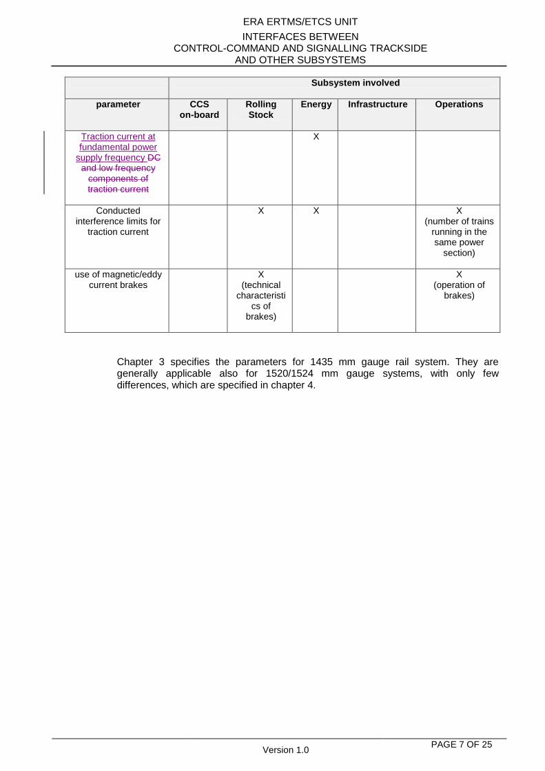
Subsystem involved
parameter CCS on-board
Rolling Stock
Energy Infrastructure Operations
Traction current at fundamental power
supply frequency DC and low frequency
components of traction current
X
Conducted interference limits for
traction current
X
X X (number of trains
running in the same power
section)
use of magnetic/eddy current brakes
X (technical
characteristics of
brakes)
X (operation of
brakes)
Chapter 3 specifies the parameters for 1435 mm gauge rail system. They are generally applicable also for 1520/1524 mm gauge systems, with only few differences, which are specified in chapter 4.
ERA ERTMS/ETCS UNIT
INTERFACES BETWEEN CONTROL-COMMAND AND SIGNALLING TRACKSIDE
AND OTHER SUBSYSTEMS
Version 1.0 PAGE 8 OF 25
3. INTERFACE CHARACTERISTICS
3.1. VEHICLE DESIGN AND OPERATION
3.1.1. Definitions
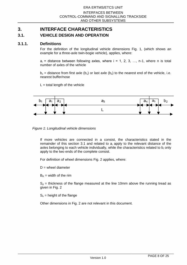
For the definition of the longitudinal vehicle dimensions Fig. 1, (which shows an example for a three-axle twin-bogie vehicle), applies, where: ai = distance between following axles, where i = 1, 2, 3, …, n-1, where n is total number of axles of the vehicle bx = distance from first axle (b1) or last axle (b2) to the nearest end of the vehicle, i.e. nearest buffer/nose L = total length of the vehicle
Figure 1: Longitudinal vehicle dimensions
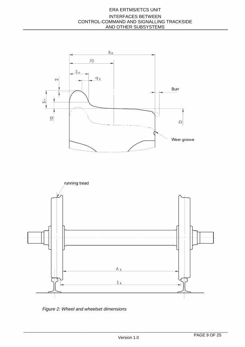
If more vehicles are connected in a consist, the characteristics stated in the remainder of this section 3.1 and related to ai apply to the relevant distance of the axles belonging to each vehicle individually, while the characteristics related to bi only apply to the two ends of the complete consist. For definition of wheel dimensions Fig. 2 applies, where: D = wheel diameter BR = width of the rim Sd = thickness of the flange measured at the line 10mm above the running tread as given in Fig. 2 Sh = height of the flange Other dimensions in Fig. 2 are not relevant in this document.
ERA ERTMS/ETCS UNIT
INTERFACES BETWEEN CONTROL-COMMAND AND SIGNALLING TRACKSIDE
AND OTHER SUBSYSTEMS
Version 1.0 PAGE 9 OF 25
Figure 2: Wheel and wheelset dimensions
ERA ERTMS/ETCS UNIT
INTERFACES BETWEEN CONTROL-COMMAND AND SIGNALLING TRACKSIDE
AND OTHER SUBSYSTEMS
Version 1.0 PAGE 10 OF 25
The values quoted in the following paragraphs are absolute limit values including any measurement tolerances. The term wheelset applies to any pair of opposite wheels, even those not connected by a common axle. Except where stated, wheelset assemblies are assumed to have continuous wheel centres and not have spoke wheels. Any references to wheel sets concern centre of wheels.
3.1.2. Axle distances
3.1.2.1. Maximum axle distance
Harmonised parameter: The distance ai (Fig. 1) does not exceed 20 000 mm. Justification: This requirement is related to the minimum length of a signalling section, so that a vehicle or consist does not bridge it, making the train detection system report it as “unoccupied”.
3.1.2.2. Minimum axle distance (1)
Harmonised parameter: For the maximum speed v lower or equal to 350 km/h: The distance ai (Fig.1) is ai ≥ v x 7,2 (where v is in km/h and distance ai is in mm) Justification: Axle counter systems have to be able to distinguish the detection of an axle by 2 subsequent counters with sufficient resolution; otherwise the result will be a count-error.
3.1.2.3. Minimum axle distance (2)
Harmonised parameter: For the maximum speed v higher than 350 km/h, the distance ai (Fig.1) is at least: [open point] Justification: Axle counter systems have to be able to distinguish the detection of an axle by 2 subsequent counters with sufficient resolution; otherwise the result will be a count-error.
3.1.2.4. Minimum axle distance (3)
Harmonised parameter: The distance between first and last axle L - (b1 + b2) (Fig.1) is at least 3 000 mm
Justification: The electrical joints between adjacent track circuits may have an area where the detection of an axle of a vehicle is not ensured.
3.1.2.5. Distances between end of train and first axle on new High Speed lines
Harmonised parameter: The distance bx (Fig. 1) does not exceed 5 000 mm.
ERA ERTMS/ETCS UNIT
INTERFACES BETWEEN CONTROL-COMMAND AND SIGNALLING TRACKSIDE
AND OTHER SUBSYSTEMS
Version 1.0 PAGE 11 OF 25
Justification: A train detection system shall be able to detect:
the first axle before the nose of the train reaches a danger point ahead
the last axle until the tail of the train has passed the danger point.
3.1.2.6. Distances between end of train and first axle on other lines
Harmonised parameter: The distance bx (Fig. 1) does not exceed 4 200 mm. Justification: A train detection system shall be able to detect:
the first axle before the nose of the train reaches a danger point ahead the last axle until the tail of the train has passed the danger point.
3.1.3. Wheel geometry
3.1.3.1. Minimum wheel rim width
Harmonised parameter: The dimension BR (Fig. 2) is at least 133 mm. Justification: The detection field of the axle counter is influenced by the wheel which passes. The rim width has to be big enough to influence the field sufficiently in order to ensure appropriate detection.
3.1.3.2. Minimum wheel diameter
Harmonised parameter: For the maximum speed v, the dimension D (Fig. 2) is at least
v [km/h] D [mm]
v ≤ 100 330
100 < v ≤ 250 150 + 1.8 x v
250 < v ≤ 350 50 + 2.2 x v
350 < v [open point]
For v ≤ 250 km/h in the case of spoke wheels (spoke wheels of the design existing when this specification enters in force only), D is at least 600 mm
Justification: The length of the influence of the detection field of the axle counter is related to the wheel diameter.
3.1.3.3. Minimum flange thickness
Harmonised parameter: The dimension Sd (Fig. 2) is at least: 1. 27.5 mm if the dimension D (Fig. 2) does not exceed 840 mm 2. 20.0 mm if the dimension D (Fig. 2) is more than 840 mm
ERA ERTMS/ETCS UNIT
INTERFACES BETWEEN CONTROL-COMMAND AND SIGNALLING TRACKSIDE
AND OTHER SUBSYSTEMS
Version 1.0 PAGE 12 OF 25
Justification: The detection field of the axle counter is influenced by the wheel which passes. The flange thickness has to be big enough to influence the field sufficiently to ensure appropriate detection
3.1.3.4. Flange height
Harmonised parameter: The range of the dimension Sh (Fig. 2) is 27.5 — 36 mm. Justification: The detection field of the axle counter is influenced by the wheel which passes. The flange height has to be big enough to influence the field sufficiently to ensure appropriate detection.
3.1.3.5. Metal and inductive components-free space between wheels
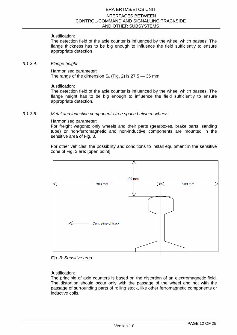
Harmonised parameter: For freight wagons: only wheels and their parts (gearboxes, brake parts, sanding tube) or non-ferromagnetic and non-inductive components are mounted in the sensitive area of Fig. 3. For other vehicles: the possibility and conditions to install equipment in the sensitive zone of Fig. 3 are: [open point]
Fig. 3: Sensitive area Justification: The principle of axle counters is based on the distortion of an electromagnetic field. The distortion should occur only with the passage of the wheel and not with the passage of surrounding parts of rolling stock, like other ferromagnetic components or inductive coils.
ERA ERTMS/ETCS UNIT
INTERFACES BETWEEN CONTROL-COMMAND AND SIGNALLING TRACKSIDE
AND OTHER SUBSYSTEMS
Version 1.0 PAGE 13 OF 25
Remark: The requirements of Fig. 3 can be respected by freight wagons; in case of locomotives it may be necessary to install equipment (e.g., brakes) in the area forbidden by Fig. 3.
3.1.3.6. Wheel material
Harmonised parameter: The wheels have ferromagnetic characteristics (μr > 300) and are electrically conducting. Justification: This characteristic is necessary to generate the distortion of the electromagnetic field of axle counters, to ensure appropriate detection.
3.1.4. Use of sanding equipment
3.1.4.1. Maximum amount of sand
Harmonised parameter: The allowed amount of sand per sanding device within 30 s is
1. For speed v < 140 km/h; 400 g + 100 g 2. For speed v > 140 km/h; 650 g + 150 g
The number of active sanding devices does not exceed the following
1. For multiple units with distributed sanding devices: first and last car and intermediate cars with a minimum of 7 intermediate axles, between two sanding devices that are not sanded. It is permissible to couple such multiple units and to operate all sanding devices at the coupled ends.
2. For loco-hauled trains
a. For emergency and full service braking: all available sanding devices b. In all other cases: a maximum of 4 sanding devices per rail
This parameter shall be taken into account jointly with 3.1.4.2 (Sand Characteristics). Justification: Sand is applied to the tracks to improve braking and traction performance. Sand can create an isolating layer between wheels and rails increasing the contact resistance, with risk of not detecting trains on tracks equipped with track circuits.
3.1.4.2. Sand characteristics
Harmonised parameter: The characteristics of sand applied to the tracks are: [open point]. This parameter shall be taken into account jointly with 3.1.4.1 (Maximum amount of sand). This parameter is to enable the margins related to contact resistance between wheels and rails to be taken into account for the use of track circuits. Justification: The composition of the sand which is used is relevant for the risk of not detecting trains on tracks equipped with track circuits.
ERA ERTMS/ETCS UNIT
INTERFACES BETWEEN CONTROL-COMMAND AND SIGNALLING TRACKSIDE
AND OTHER SUBSYSTEMS
Version 1.0 PAGE 14 OF 25
3.1.5. On-board flange lubrication
The use of flange lubrication (including switch off) is controlled by national rules1. Justification: Lubricant can create an isolating film between wheels and rails increasing the contact resistance, with risk of not detecting trains on tracks equipped with track circuits.
3.1.6. Use of composite brake blocks
Harmonised parameter: The vehicles use brake blocks assessed for the effects on the contact resistance between wheel and rail2. Justification: Composite brake blocks can create an isolating film between wheels and rails increasing the contact resistance, with risk of not detecting trains on tracks equipped with track circuits.
3.1.7. Vehicle mass
3.1.7.1. Axle load
Harmonised parameter: The axle load is
1. at least 5 t generally for vehicles with 2 axles and more, 2. at least 4 t for vehicles with 4 axles and brake blocks, 3. at least 3,5 t for vehicles with more than 4 axles and brake blocks.
Justification: A minimum axle load will activate pedals and treadles. Also, minimum axle load will have a beneficiary effect on the resistance between wheel and track, which is important for the operation of track circuits. Brake blocks acting on the surface of wheels contribute to keep them clean and limit the increase of contact resistance.
3.1.7.2. Vehicle metal mass
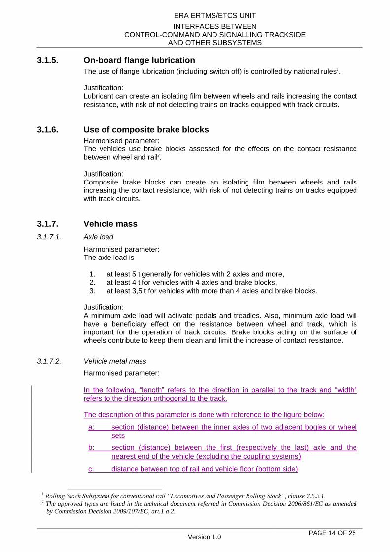
Harmonised parameter: In the following, “length” refers to the direction in parallel to the track and “width” refers to the direction orthogonal to the track. The description of this parameter is done with reference to the figure below:
a: section (distance) between the inner axles of two adjacent bogies or wheel sets
b: section (distance) between the first (respectively the last) axle and the
nearest end of the vehicle (excluding the coupling systems)
c: distance between top of rail and vehicle floor (bottom side)
1 Rolling Stock Subsystem for conventional rail “Locomotives and Passenger Rolling Stock”, clause 7.5.3.1.
2 The approved types are listed in the technical document referred in Commission Decision 2006/861/EC as amended
by Commission Decision 2009/107/EC, art.1 a 2.
ERA ERTMS/ETCS UNIT
INTERFACES BETWEEN CONTROL-COMMAND AND SIGNALLING TRACKSIDE
AND OTHER SUBSYSTEMS
Version 1.0 PAGE 15 OF 25
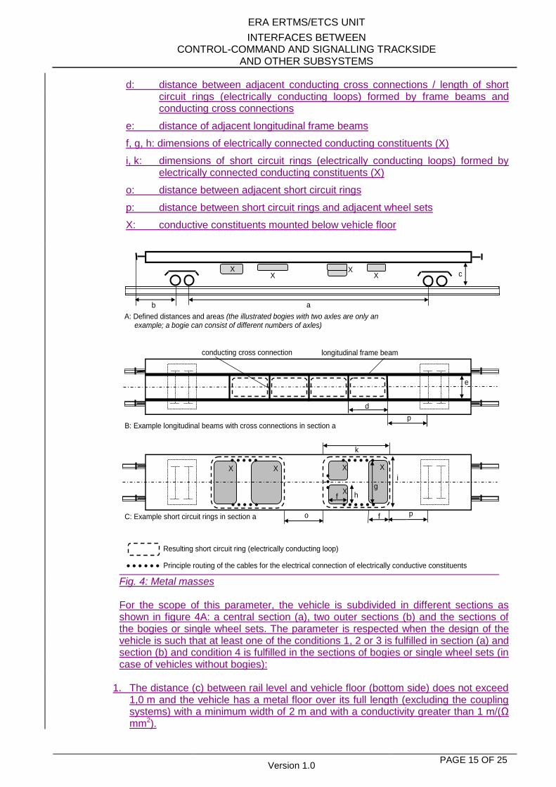
d: distance between adjacent conducting cross connections / length of short circuit rings (electrically conducting loops) formed by frame beams and conducting cross connections
e: distance of adjacent longitudinal frame beams
f, g, h: dimensions of electrically connected conducting constituents (X)
i, k: dimensions of short circuit rings (electrically conducting loops) formed by electrically connected conducting constituents (X)
o: distance between adjacent short circuit rings
p: distance between short circuit rings and adjacent wheel sets
X: conductive constituents mounted below vehicle floor
A: Defined distances and areas (the illustrated bogies with two axles are only an example; a bogie can consist of different numbers of axles)
B: Example longitudinal beams with cross connections in section a
C: Example short circuit rings in section a
e
h
f
longitudinal frame beam conducting cross connection
i
k
p
p o
d
X X
Principle routing of the cables for the electrical connection of electrically conductive constituents
Resulting short circuit ring (electrically conducting loop)
X f
X X
g
c X X X
X
b a
Fig. 4: Metal masses For the scope of this parameter, the vehicle is subdivided in different sections as shown in figure 4A: a central section (a), two outer sections (b) and the sections of the bogies or single wheel sets. The parameter is respected when the design of the vehicle is such that at least one of the conditions 1, 2 or 3 is fulfilled in section (a) and section (b) and condition 4 is fulfilled in the sections of bogies or single wheel sets (in case of vehicles without bogies):
1. The distance (c) between rail level and vehicle floor (bottom side) does not exceed
1,0 m and the vehicle has a metal floor over its full length (excluding the coupling systems) with a minimum width of 2 m and with a conductivity greater than 1 m/(Ω mm2).
ERA ERTMS/ETCS UNIT
INTERFACES BETWEEN CONTROL-COMMAND AND SIGNALLING TRACKSIDE
AND OTHER SUBSYSTEMS
Version 1.0 PAGE 16 OF 25
2. The vehicle has constructive structures at least inside section (a) and (b) consisting of longitudinal frame beams symmetrically on both sides with a minimum distance (e) of 1,0 m. These are electrically connected with conducting cross connections in a distance (d) less or equal than 3 m to form short circuit rings (electrically conducting loops) as illustrated in figure 4B, showing an example for section (a).
The electrical resistance of the resulting short circuit rings is lower than 0.1 Ω.
The distance (o) between adjacent short circuit rings does not exceed 3 m. The distance (p) between a short circuit ring and an adjacent wheel set of a bogie does not exceed 3 m, the distance to a single wheel set does not exceed 1.5 m.
The distance between rail level and short circuit rings on the bottom side of vehicle floor does not exceed 1,0 m.
3. The vehicle has electrically conducting constituents (X) mounted below the floor at least inside section (a) and (b). These are electrically connected to form short circuit rings (electrically conducting loops) as illustrated in figure 4C, showing an example for section (a). The dimensions of the constituents fulfil at least one of the following conditions:
a) minimum width (g) of 2 m and minimum longitudinal length (f) of 1 m, b) minimum width (h) of 1 m and minimum longitudinal length (f) of 1 m on
both long sides of the vehicle.
The electrical connection is done in a way that short circuit rings with a length (k) equal or more than 2.5 m but less or equal than 3 m and a minimum width (i) of 2 m result. Figure 4C illustrates the principle routing of the cabling.
The conductivity of the conducting constituents is greater than 1 m/(Ω mm2). The electrical resistance of the resulting short circuit rings is lower than 0.1 Ω.
The distance (o) between adjacent short circuit rings does not exceed 3 m. The distance (p) between a short circuit ring and an adjacent wheel set of a bogie does not exceed 3 m, the distance to a single wheel set does not exceed 1.5 m.
The distance between rail level and short circuit rings on the bottom side of vehicle floor does not exceed 1,0 m.
4. Bogies consist of metal parts with a conductivity greater than 1 m/(Ω mm2). Constructive supporting metal parts of a bogie frame are electrically connected with an electrical resistance lower than 0.1 Ω. The distance between rail level and the bottom side of the bogie frame does not exceed 1,0 m. If these requirements are not fulfilled at least condition 1, 2 or 3 is fulfilled in the section of the bogie alternatively.
Justification: This parameter specifies the minimum metal mass of a vehicle ensuring its detection by trackside inductive loops. Therefore it is necessary that each vehicle has constructive metallic parts to influence the loop sufficiently. Justification: The metal-mass influences loop detection systems.
3.1.8. Use of shunt assisting devices
Harmonised parameter: The use of shunting assisting devices is not required.
ERA ERTMS/ETCS UNIT
INTERFACES BETWEEN CONTROL-COMMAND AND SIGNALLING TRACKSIDE
AND OTHER SUBSYSTEMS
Version 1.0 PAGE 17 OF 25
Justification: Shunting assisting devices are not necessary for the operation of track circuits.
3.1.9. Impedance between wheels
Harmonised parameter: The electrical resistance between the running surfaces of the opposite wheels of a wheelset does not exceed 0.05 Ohm, measured by a voltage between 1.8 VDC and 2.0 VDC (open circuit). Justification: A track circuit is only able to detect rolling stock if the impedance between rails does not exceed a certain value, given by the impedance of the opposite wheels of the wheelsets and the contact resistance at the wheel-rail surface. The interface requirement given here is only related to the electrical resistance between the running surfaces of the opposite wheels of a wheelset. Remark: operational rules may apply to ensure that a sufficiently low value of the contact resistance is maintained during service: see 3.1.4 (Use of sanding equipment), 3.1.5 (On board flange lubrication) and 3.1.6 (Use of composite brake blocks)
3.1.10. Combination of rolling stock characteristics influencing shunting impedance
Harmonised parameter: The rules for combination of characteristics listed above (3.1.2 to 3.1.9) for vehicles or consists to ensure adequate operation with train detection systems are: [open point]. Remark: these are not additional conditions for the approval of rolling stock. These rules must be evaluated when checking the compatibility of a consist with the infrastructure, without the necessity of tests. Justification: These rules refer to possible conditions / limitations for the use of vehicles and consists on lines where track circuits are installed. Operation of track circuits relies on the contact resistance between wheels and rails that is influenced by the combination of several factors. The dynamic shunt behaviour differs from the static shunt behaviour. Even for vehicles or consists compliant with the single parameters defined in this specification, rules for the vehicles or consist may be necessary to cover this.
ERA ERTMS/ETCS UNIT
INTERFACES BETWEEN CONTROL-COMMAND AND SIGNALLING TRACKSIDE
AND OTHER SUBSYSTEMS
Version 1.0 PAGE 18 OF 25
3.2. ELECTROMAGNETIC COMPATIBILITY
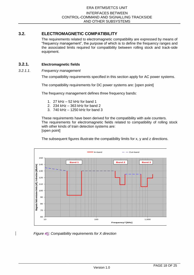
The requirements related to electromagnetic compatibility are expressed by means of “frequency management”, the purpose of which is to define the frequency ranges and the associated limits required for compatibility between rolling stock and track-side equipment.
3.2.1. Electromagnetic fields
3.2.1.1. Frequency management
The compatibility requirements specified in this section apply for AC power systems. The compatibility requirements for DC power systems are: [open point] The frequency management defines three frequency bands:
1. 27 kHz – 52 kHz for band 1 2. 234 kHz – 363 kHz for band 2 3. 740 kHz – 1250 kHz for band 3
These requirements have been derived for the compatibility with axle counters. The requirements for electromagnetic fields related to compatibility of rolling stock with other kinds of train detection systems are: [open point] The subsequent figures illustrate the compatibility limits for x, y and z directions.
Figure 45: Compatibility requirements for X direction
60
70
80
90
100
110
120
130
140
150
10 100 1,000 10,000
Frequency f [kHz]
Mag
netic
fiel
d em
issi
on li
mits
(eff)
, X-d
irect
ion
[dB
uA/m
]
In-band Out-band
Band 1 Band 2 Band 3
ERA ERTMS/ETCS UNIT
INTERFACES BETWEEN CONTROL-COMMAND AND SIGNALLING TRACKSIDE
AND OTHER SUBSYSTEMS
Version 1.0 PAGE 19 OF 25
60
70
80
90
100
110
120
130
140
150
10 100 1,000 10,000f [kHz]
Ma
gn
eti
c f
ield
em
iss
ion
lim
its
(R
MS
),
Y-d
ire
cti
on
[d
Bu
A/m
]In-band Out-band
Band 1 Band 2 Band 3
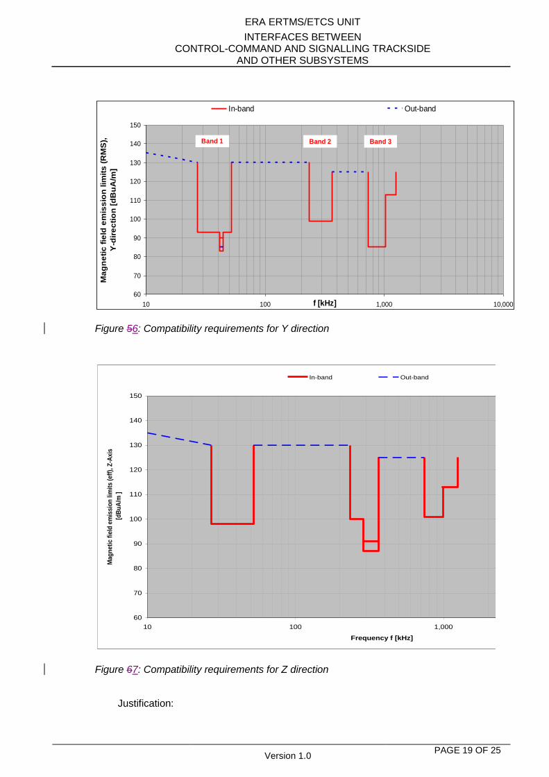
Figure 56: Compatibility requirements for Y direction
Figure 67: Compatibility requirements for Z direction
Justification:
60
70
80
90
100
110
120
130
140
150
10 100 1,000 10,000
Frequency f [kHz]
Mag
ne
tic
fie
ld e
mis
sio
n l
imit
s (
eff
), Z
-Ax
is
[d
Bu
A/m
]
In-band Out-band
ERA ERTMS/ETCS UNIT
INTERFACES BETWEEN CONTROL-COMMAND AND SIGNALLING TRACKSIDE
AND OTHER SUBSYSTEMS
Version 1.0 PAGE 20 OF 25
The magnetic fields generated by rolling stock can interfere with the operation of train detection systems.
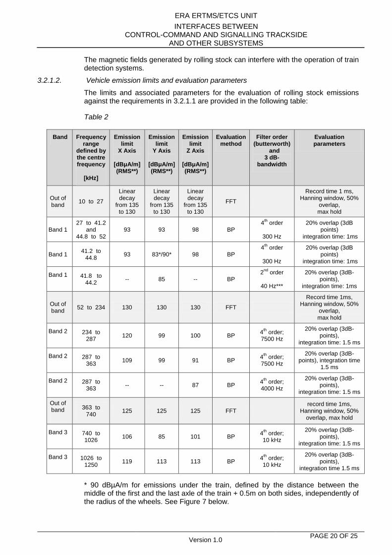
3.2.1.2. Vehicle emission limits and evaluation parameters
The limits and associated parameters for the evaluation of rolling stock emissions against the requirements in 3.2.1.1 are provided in the following table:
Table 2
Band Frequency range
defined by the centre frequency
[kHz]
Emission limit
X Axis
[dBμA/m] (RMS**)
Emission limit
Y Axis
[dBμA/m] (RMS**)
Emission limit
Z Axis
[dBμA/m] (RMS**)
Evaluation method
Filter order (butterworth)
and 3 dB-
bandwidth
Evaluation parameters
Out of band
10 to 27
Linear decay
from 135 to 130
Linear decay
from 135 to 130
Linear decay
from 135 to 130
FFT
Record time 1 ms, Hanning window, 50%
overlap, max hold
Band 1 27 to 41.2
and 44.8 to 52
93 93 98 BP 4
th order
300 Hz
20% overlap (3dB points)
integration time: 1ms
Band 1 41.2 to
44.8 93 83*/90* 98 BP
4th
order
300 Hz
20% overlap (3dB points)
integration time: 1ms
Band 1
41.8 to 44.2
-- 85 -- BP 2
nd order
40 Hz***
20% overlap (3dB-points),
integration time: 1ms
Out of band
52 to 234 130 130 130 FFT
Record time 1ms, Hanning window, 50%
overlap, max hold
Band 2
234 to 287
120 99 100 BP 4
th order;
7500 Hz
20% overlap (3dB-points),
integration time: 1.5 ms
Band 2
287 to 363
109 99 91 BP 4
th order;
7500 Hz
20% overlap (3dB-points), integration time
1.5 ms
Band 2
287 to 363
-- -- 87 BP 4
th order;
4000 Hz
20% overlap (3dB-points),
integration time: 1.5 ms
Out of band
363 to 740
125 125 125 FFT record time 1ms,
Hanning window, 50% overlap, max hold
Band 3
740 to 1026
106 85 101 BP 4
th order;
10 kHz
20% overlap (3dB-points),
integration time: 1.5 ms
Band 3
1026 to 1250
119 113 113 BP 4
th order;
10 kHz
20% overlap (3dB-points),
integration time 1.5 ms
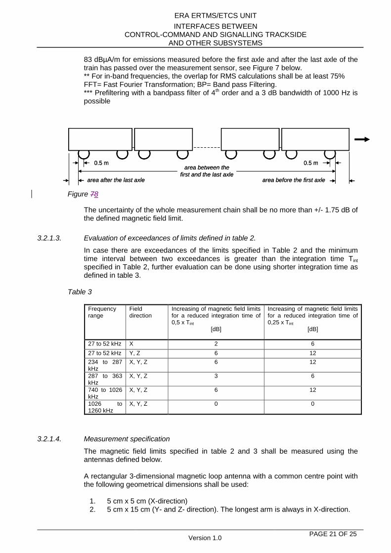
* 90 dBµA/m for emissions under the train, defined by the distance between the middle of the first and the last axle of the train + 0.5m on both sides, independently of the radius of the wheels. See Figure 7 below.
ERA ERTMS/ETCS UNIT
INTERFACES BETWEEN CONTROL-COMMAND AND SIGNALLING TRACKSIDE
AND OTHER SUBSYSTEMS
Version 1.0 PAGE 21 OF 25
83 dBµA/m for emissions measured before the first axle and after the last axle of the train has passed over the measurement sensor, see Figure 7 below. ** For in-band frequencies, the overlap for RMS calculations shall be at least 75% FFT= Fast Fourier Transformation; BP= Band pass Filtering. *** Prefiltering with a bandpass filter of 4th order and a 3 dB bandwidth of 1000 Hz is possible
Figure 78
The uncertainty of the whole measurement chain shall be no more than +/- 1.75 dB of the defined magnetic field limit.
3.2.1.3. Evaluation of exceedances of limits defined in table 2.
In case there are exceedances of the limits specified in Table 2 and the minimum time interval between two exceedances is greater than the integration time Tint specified in Table 2, further evaluation can be done using shorter integration time as defined in table 3.
Table 3
Frequency range
Field direction
Increasing of magnetic field limits for a reduced integration time of 0,5 x Tint
[dB]
Increasing of magnetic field limits for a reduced integration time of 0,25 x Tint
[dB]
27 to 52 kHz X 2 6
27 to 52 kHz Y, Z 6 12
234 to 287 kHz
X, Y, Z 6 12
287 to 363 kHz
X, Y, Z 3 6
740 to 1026 kHz
X, Y, Z 6 12
1026 to 1260 kHz
X, Y, Z 0 0
3.2.1.4. Measurement specification
The magnetic field limits specified in table 2 and 3 shall be measured using the antennas defined below. A rectangular 3-dimensional magnetic loop antenna with a common centre point with the following geometrical dimensions shall be used:
1. 5 cm x 5 cm (X-direction) 2. 5 cm x 15 cm (Y- and Z- direction). The longest arm is always in X-direction.
0.5 m 0.5 marea between the
first and the last axlearea after the last axle area before the first axle
0.5 m 0.5 marea between the
first and the last axlearea after the last axle area before the first axle
ERA ERTMS/ETCS UNIT
INTERFACES BETWEEN CONTROL-COMMAND AND SIGNALLING TRACKSIDE
AND OTHER SUBSYSTEMS
Version 1.0 PAGE 22 OF 25
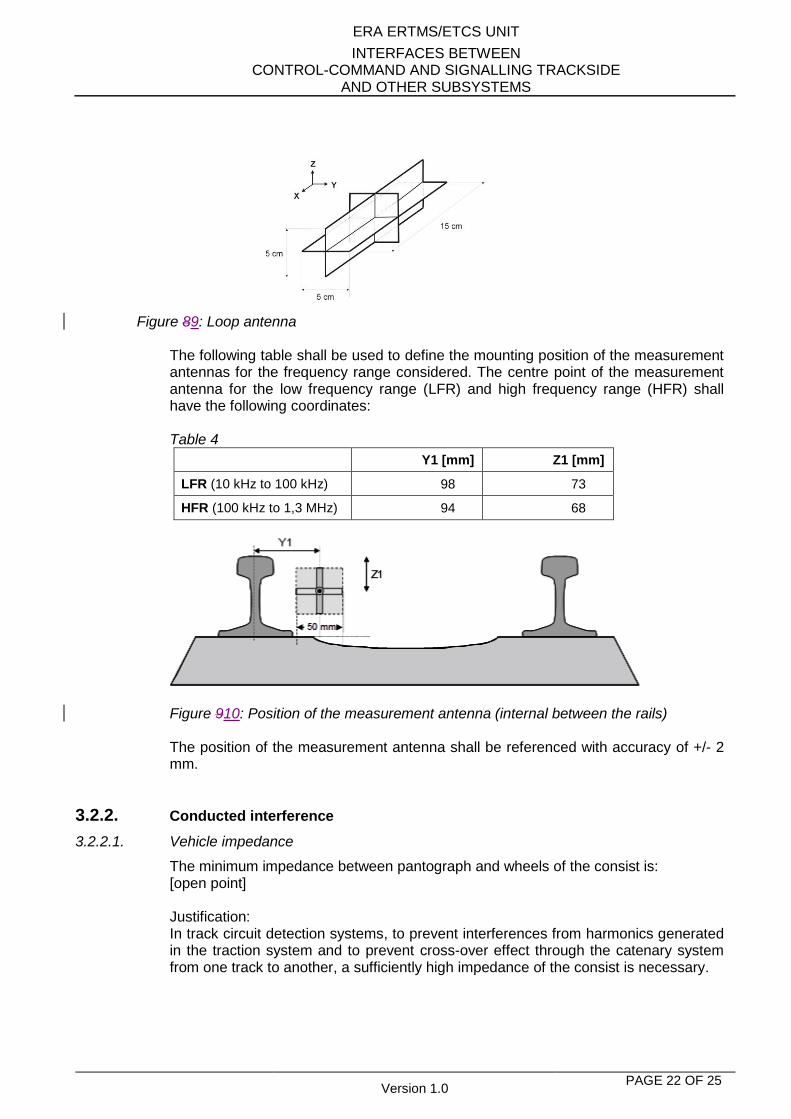
Figure 89: Loop antenna
The following table shall be used to define the mounting position of the measurement antennas for the frequency range considered. The centre point of the measurement antenna for the low frequency range (LFR) and high frequency range (HFR) shall have the following coordinates: Table 4
Y1 [mm] Z1 [mm]
LFR (10 kHz to 100 kHz) 98 73
HFR (100 kHz to 1,3 MHz) 94 68
Figure 910: Position of the measurement antenna (internal between the rails) The position of the measurement antenna shall be referenced with accuracy of +/- 2 mm.
3.2.2. Conducted interference
3.2.2.1. Vehicle impedance
The minimum impedance between pantograph and wheels of the consist is: [open point] Justification: In track circuit detection systems, to prevent interferences from harmonics generated in the traction system and to prevent cross-over effect through the catenary system from one track to another, a sufficiently high impedance of the consist is necessary.
ERA ERTMS/ETCS UNIT
INTERFACES BETWEEN CONTROL-COMMAND AND SIGNALLING TRACKSIDE
AND OTHER SUBSYSTEMS
Version 1.0 PAGE 23 OF 25
3.2.2.2. Traction current at fundamental power supply frequency
There is no requirement applicable to rolling stock for a maximum harmonised value of the traction current at the fundamental power supply frequency and its harmonics. Justification: The traction current in the rails can interfere with the operation of train detection systems. The upper limit of this parameter is linked to the short circuit current of the traction power supply. This is a design issue of trackside subsystems and it is not directly associated with requirements for rolling stock.
DC and low frequency components of traction current
The maximum harmonised value of the DC and low frequency components of the traction current is:
[open point]
Justification:
This parameter is the short circuit current of the traction power supply.
The DC and low frequency components of the current in the rails can interfere with the operation of train detection systems.
3.2.2.3. 25kV AC, 50Hz Electromagnetic interference limits for traction current
The electromagnetic interference limits are: [open point] Justification: the harmonics in the traction current in the rails can interfere with the operation of train detection systems.
3.2.2.4. 15kV AC, 16,7Hz Electromagnetic interference limits for traction current
The electromagnetic interference limits are: [open point] Justification: the harmonics in the traction current in the rails can interfere with the operation of train detection systems.
3.2.2.5. 3kV DC Electromagnetic interference limits for traction current
The electromagnetic interference limits are: [open point] Justification: the harmonics in the traction current in the rails can interfere with the operation of train detection systems.
3.2.2.6. 1,5kV DC Electromagnetic interference limits for traction current
The electromagnetic interference limits are:
ERA ERTMS/ETCS UNIT
INTERFACES BETWEEN CONTROL-COMMAND AND SIGNALLING TRACKSIDE
AND OTHER SUBSYSTEMS
Version 1.0 PAGE 24 OF 25
[open point] Justification: the harmonics in the traction current in the rails can interfere with the operation of train detection systems.
3.2.2.7. 750V DC Electromagnetic interference limits for traction current
The electromagnetic interference limits are: [open point] Justification: the harmonics in the traction current in the rails can interfere with the operation of train detection systems.
3.2.3. Use of magnetic / eddy current brakes
Harmonised parameter: The use of magnetic and/or eddy current brakes is: [open point]. Justification: The magnetic fields generated by those brakes may influence axle counters.
ERA ERTMS/ETCS UNIT
INTERFACES BETWEEN CONTROL-COMMAND AND SIGNALLING TRACKSIDE
AND OTHER SUBSYSTEMS
Version 1.0 PAGE 25 OF 25
4. SPECIFIC CHARACTERISTICS FOR 1520/1524 MM GAUGE SYSTEMS
For the 1520/1524 rail system the same values specified in chapter 3 apply, with only the following differences for the harmonised parameters
1. Maximum axle distance: the distance ai (Fig. 1) does not exceed 19 000 mm;
2. Minimum wheel rim width: the dimension BR (Fig. 2) is at least 130 mm;
3. Impedance between wheels: the impedance between the running surfaces of the opposite wheels of a wheelset does not exceed 0.06 Ohm.

![WiFi Command Reference - Nokia Networks · WiFi Command Reference ... — mgw-profile profile-name [create] ... — signalling-protocol protocol — no signalling-protocol](https://static.fdocuments.net/doc/165x107/5b0165527f8b9a54578e1eaa/wifi-command-reference-nokia-networks-command-reference-mgw-profile-profile-name.jpg)


![WiFi Command Reference - infoproducts.alcatel-lucent.com · — signalling-protocol protocol — no signalling-protocol ... — no ipv6-tcp-mss-adjust — mgw-map — address ip-prefix[/prefix-length]](https://static.fdocuments.net/doc/165x107/5b0165527f8b9a54578e1ea8/wifi-command-reference-signalling-protocol-protocol-no-signalling-protocol.jpg)


