
Ericsson Review Vol 67 1990 1
58
ERICSSON REVIEW AXE 10 Central Processors Service Script Interpreter, an Advanced Intelligent Network Platform New Ericsson Telecom Centre for Basic Technology A Service Management System for the Intelligent Network The Future of Cellular Telephony 1 1990
Transcript of Ericsson Review Vol 67 1990 1
ERICSSON REVIEW
AXE 10 Central Processors Service Script Interpreter, an Advanced Intelligent Network Platform New Ericsson Telecom Centre for Basic Technology A Service Management System for the Intelligent Network The Future of Cellular Telephony 1 1990

ERICSSON REVIEW Vol. 67,1990
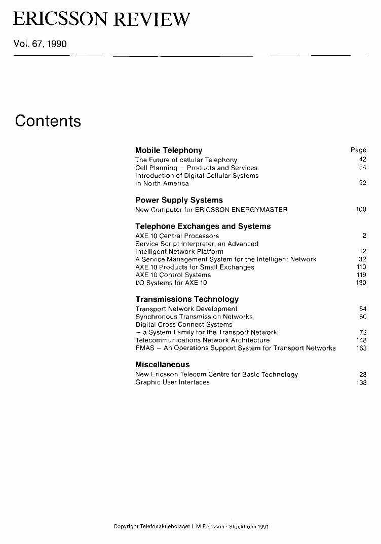
Contents
Mobile Telephony Page The Future of cellular Telephony 42 Cell Planning - Products and Services 84 Introduction of Digital Cellular Systems in North America 92
Power Supply Systems New Computer for ERICSSON ENERGYMASTER 100
Telephone Exchanges and Systems AXE 10 Central Processors 2 Service Script Interpreter, an Advanced Intelligent Network Platform 12 A Service Management System for the Intelligent Network 32 AXE 10 Products for Small Exchanges 110 AXE 10 Control Systems 119 I/O Systems for AXE 10 130
Transmissions Technology Transport Network Development 54 Synchronous Transmission Networks 60 Digital Cross Connect Systems - a System Family for the Transport Network 72 Telecommunications Network Architecture 148 FMAS - An Operations Support System for Transport Networks 163
Miscellaneous New Ericsson Telecom Centre for Basic Technology 23 Graphic User Interfaces 138
Copyright Telefonaktiebolaget L M Ericsson • Stockholm 1991


ERICSSON REVIEW Number 1 1990 Volume 67
Responsible publ isher Gosta Lindberg
Editor Goran Norrman
Editorial staff Martti Viitaniemi
Subscr ipt ion Peter Mayr
Subscr ipt ion one year $ 20
Address S-126 25 Stockho lm, Sweden
Published in Swedish, Engl ish, French and Spanish wi th four issues per year
Copyright Telefonakt iebolaget LM Ericsson
Contents 2
12
23
32
42
AXE 10 Central Processors
Service Script Interpreter, an Advanced Intelligent Network Platform
New Ericsson Telecom Centre for Basic Technology
A Service Management System for the Intelligent Network
The Future of Cellular Telephony
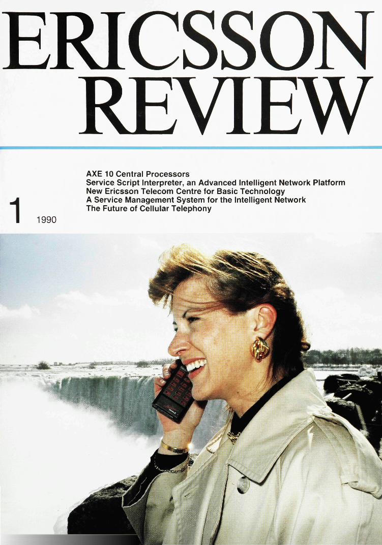
Cover Pocket telephones can be used in most situations. The extraordinary evolution of the cellular industry, how the progress in cellular technology helps reduce costs of new telephone networks, and the services likely to be offered in the future are described on page 42

AXE 10 Central Processors
Anthony Ash, Oleg Avsan and Orjan Eriksson
The control system of AXE 10 consists of a powerful, duplicated, parallel working, synchronized central processor, a number of regional processors and an operating system. This concept was first introduced in AXE 10 in 1977 and the control system was named APZ 210 03. Early in the 1990s, Ericsson will release the next central processor family, meeting the needs of AXE 10 control systems in this decade. The authors present the new central processors and describe how they fit into the control system strategy.
and cost-effective control systems. One of the new central processors is used in control system APZ 211 10 for low to middle size exchanges while the other is used in control system APZ 21210, which caters for very large applications. Compatibility between the processors makes it possible to upgrade an exchange in service with more control power without causing any significant interruption in traffic handling.
electronic switching system telephone exchanges telecommunication computer control
Fig. 1 APZ 21 evolution
The driving force behind the development of new central processors is the demand for an increased number of telecommunication services for the benefit of business as well as private subscribers. In AXE 10 this developement has been going on since the introduction of APZ 210 03 in 1977. APZ 210 was developed further and the latest version, APZ 210 06, was released in 1982. Development after APZ 210 was along two paths: APZ 211 with emphasis on small physical size and low manufacturing cost and APZ 212 emphasizing high processor capacity. Fig. 1 gives an overview of the main line of the APZ evolution.
The two new central processors that have been developed will add even better members to this family of powerful
The original and the following control systems are described in earlier issues of Ericsson Review.2, "•5
Control System Software The software for the AXE 10 telecommunication system comprises a very large number of programs which cover a wide range of market requirements. All these programs, which have been proved to perform well in present installations, are executable in APZ 21110 and APZ 212 10 as well. This means that service reliablity and compatibility with older telecom plants are guaranteed.
The structure of the APZ software is outlined in fig. 2, the lower part showing the hardware and the microprogram (MIP), which are unique to APZ 211 10 and APZ 212 10 respectively. A unique software part, the processor system shell,
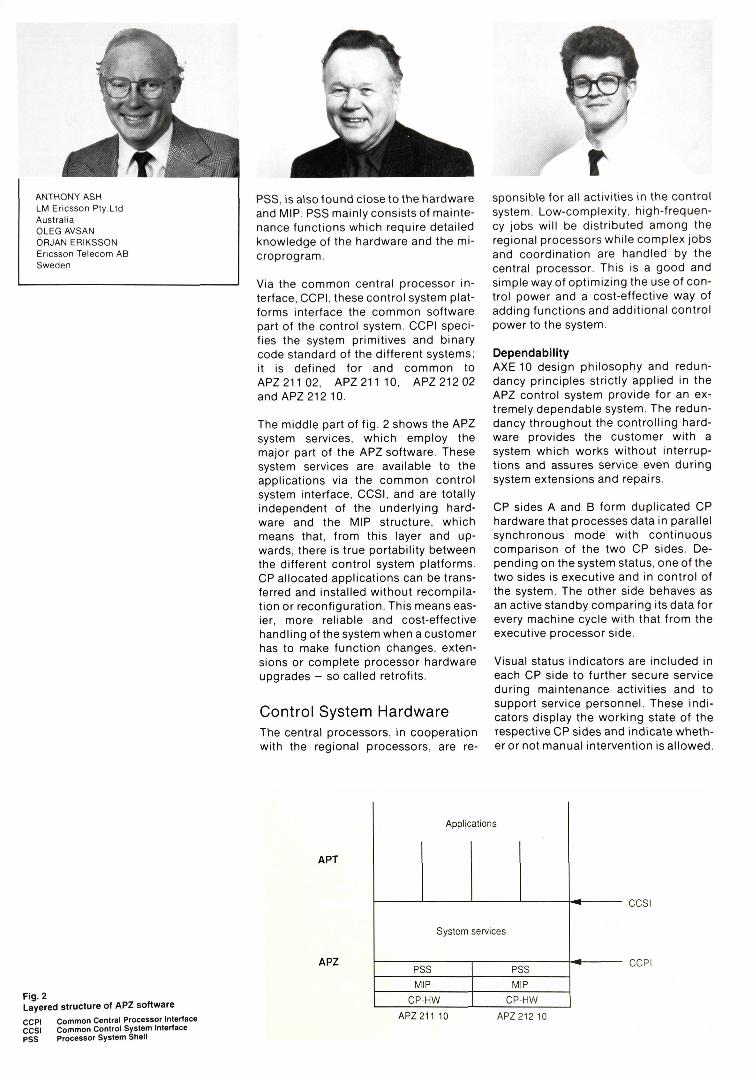
ANTHONY ASH LM Ericsson Pty.Ltd Australia OLEG AVSAN ORJAN ERIKSSON Ericsson Telecom AB Sweden
PSS, is also found close to the hardware and MIP. PSS mainly consists of maintenance functions which require detailed knowledge of the hardware and the microprogram.
Via the common central processor interface, CCPI, these control system platforms interface the common software part of the control system. CCPI specifies the system primitives and binary code standard of the different systems; it is defined for and common to APZ21102, APZ21110, APZ21202 and APZ212 10.
The middle part of fig. 2 shows the APZ system services, which employ the major part of the APZ software. These system services are available to the applications via the common control system interface, CCSI, and are totally independent of the underlying hardware and the MIP structure, which means that, from this layer and upwards, there is true portability between the different control system platforms. CP allocated applications can be transferred and installed without recompila-tion or reconfiguration. This means easier, more reliable and cost-effective handling of the system when a customer has to make function changes, extensions or complete processor hardware upgrades - so called retrofits.
Control System Hardware The central processors, in cooperation with the regional processors, are re
sponsible for all activities in the control system. Low-complexity, high-frequency jobs will be distributed among the regional processors while complex jobs and coordination are handled by the central processor. This is a good and simple way of optimizing the use of control power and a cost-effective way of adding functions and additional control power to the system.
Dependability AXE 10 design philosophy and redundancy principles strictly applied in the APZ control system provide for an extremely dependable system. The redundancy throughout the controlling hardware provides the customer with a system which works without interruptions and assures service even during system extensions and repairs.
CP sides A and B form duplicated CP hardware that processes data in parallel synchronous mode with continuous comparison of the two CP sides. Depending on the system status, one of the two sides is executive and in control of the system. The other side behaves as an active standby comparing its data for every machine cycle with that from the executive processor side.
Visual status indicators are included in each CP side to further secure service during maintenance activities and to support service personnel. These indicators display the working state of the respective CP sides and indicate whether or not manual intervention is allowed.
Fig. 2 Layered structure of APZ software CCPI Common Central Processor Interface CCSI Common Control System Interface PSS Processor System Shell
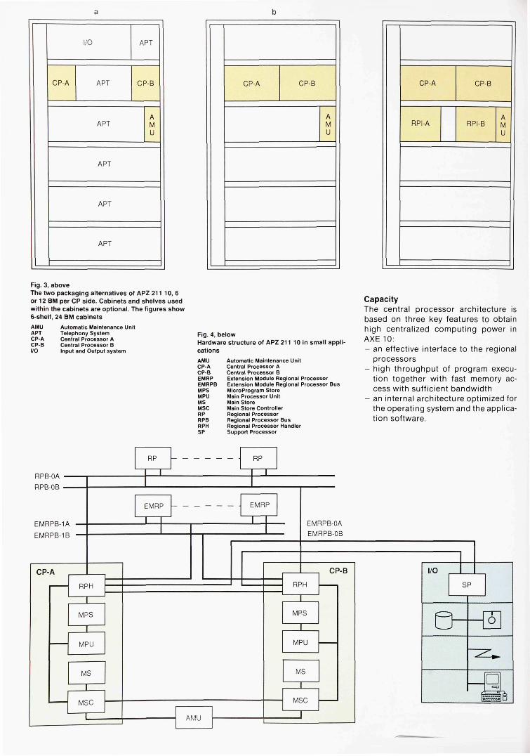
Fig. 3, above The two packaging alternatives of APZ 211 10, 6 or 12 BM per CP side. Cabinets and shelves used within the cabinets are optional. The figures show 6-shelf, 24 BM cabinets
AMU Automatic Maintenance Unit APT Telephony System CP-A Central Processor A CP-B Central Processor B I/O Input and Output system
Fig. 4, below Hardware structure of APZ 211 10 in small applications
AMU Automatic Maintenance Unit CP-A Central Processor A CP-B Central Processor B EMRP Extension Module Regional Processor EMRPB Extension Module Regional Processor Bus MPS Microprogram Store MPU Main Processor Unit MS Main Store MSC Main Store Controller RP Regional Processor RPB Regional Processor Bus RPH Regional Processor Handler SP Support Processor
Capacity The central processor architecture is based on three key features to obtain high centralized computing power in AXE 10: - an effective interface to the regional
processors - high throughput of program execu
tion together with fast memory access with sufficient bandwidth
- an internal architecture optimized for the operating system and the application software.
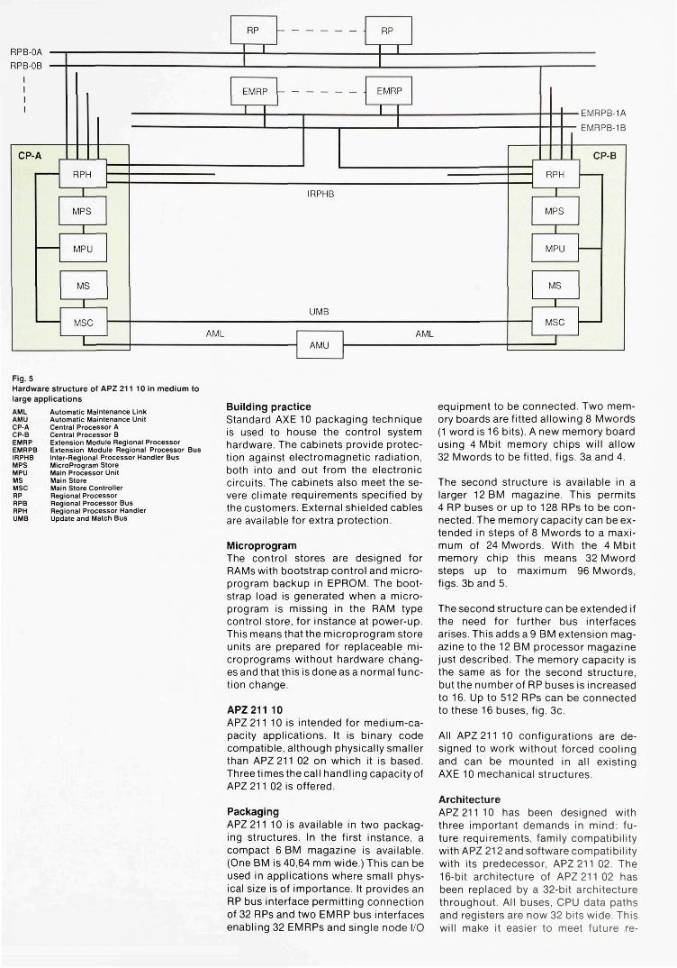
Fig. 5 Hardware structure of APZ 211 10 in medium to large applications
AML Automatic Maintenance Link AMU Automatic Maintenance Unit CP-A Central Processor A CP-B Central Processor B EMRP Extension Module Regional Processor EMRPB Extension Module Regional Processor Bus IRPHB Inter-Regional Processor Handler Bus MPS Microprogram Store MPU Main Processor Unit MS Main Store MSC Main Store Controller RP Regional Processor RPB Regional Processor Bus RPH Regional Processor Handler UMB Update and Match Bus
Building practice Standard AXE 10 packaging technique is used to house the control system hardware. The cabinets provide protection against electromagnetic radiation, both into and out from the electronic circuits. The cabinets also meet the severe climate requirements specified by the customers. External shielded cables are available for extra protection.
Microprogram The control stores are designed for RAMs with bootstrap control and microprogram backup in EPROM. The bootstrap load is generated when a microprogram is missing in the RAM type control store, for instance at power-up. This means that the microprogram store units are prepared for replaceable microprograms without hardware changes and that this is done as a normal function change.
APZ 211 10 APZ 211 10 is intended for medium-capacity applications. It is binary code compatible, although physically smaller than APZ 211 02 on which it is based. Three times the call handling capacity of APZ 211 02 is offered.
Packaging APZ 211 10 is available in two packaging structures. In the first instance, a compact 6 BM magazine is available. (One BM is 40,64 mm wide.) This can be used in applications where small physical size is of importance. It provides an RP bus interface permitting connection of 32 RPs and two EMRP bus interfaces enabling 32 EMRPs and single node I/O
equipment to be connected. Two memory boards are fitted allowing 8 Mwords (1 word is 16 bits). A new memory board using 4 Mbit memory chips will allow 32 Mwords to be fitted, figs. 3a and 4.
The second structure is available in a larger 12 BM magazine. This permits 4 RP buses or up to 128 RPs to be connected. The memory capacity can be extended in steps of 8 Mwords to a maximum of 24 Mwords. With the 4 Mbit memory chip this means 32 Mword steps up to maximum 96 Mwords, figs. 3b and 5.
The second structure can be extended if the need for further bus interfaces arises. This adds a 9 BM extension magazine to the 12 BM processor magazine just described. The memory capacity is the same as for the second structure, but the number of RP buses is increased to 16. Up to 512 RPs can be connected to these 16 buses, fig. 3c.
All APZ 211 10 configurations are designed to work without forced cooling and can be mounted in all existing AXE 10 mechanical structures.
Architecture APZ 21110 has been designed with three important demands in mind: future requirements, family compatibility with APZ 212 and software compatibility with its predecessor, APZ 211 02. The 16-bit architecture of APZ 211 02 has been replaced by a 32-bit architecture throughout. All buses, CPU data paths and registers are now 32 bits wide. This will make it easier to meet future re-
6
quirements, which may involve very large data stores, but does not exclude the 16-bit data structure and operation of APZ211 02. Compatibility in all respects is maintained, fig. 6.
Memory areas have necessarily been expanded too, using the largest memory components commercially available. The main store as mentioned above can be as large as 96 Mwords. Although it is accessible as 16-bit words for compatibility reasons, the actual store is 32 bits wide (plus 6 error correcting bits). This is in accordance with the 32-bit processor architecture and allows for future development.
The microprogram is executed from RAM loaded from PROM. This is done in order to prepare the system for microprograms loadable from an external source.
The register memory, RM, and base address store, BAS, now share an area which is 64 K x 32 bits wide (plus four parity bits). This permits a large 60 K x 32 bit BAS, required for efficient variable addressing. BAS is a very fast memory of cache type. By autonomous measurement functions in the system it keeps track of and holds in separate, easily accessable memory locations, the most used variable addresses.
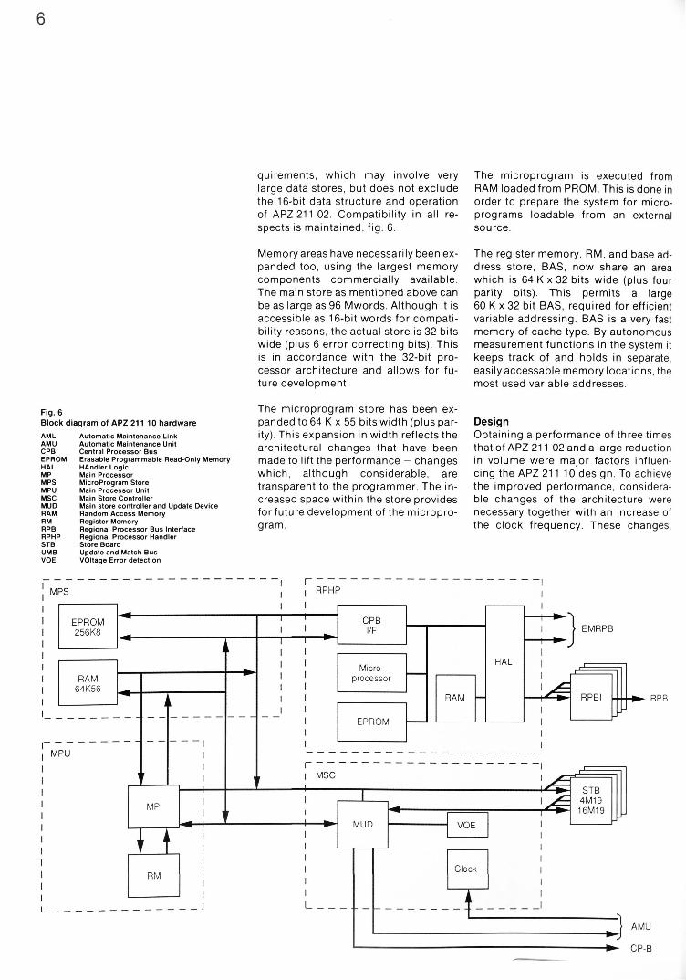
Fig. 6 Block diagram of APZ 211 10 hardware
AML Automatic Maintenance Link AMU Automatic Maintenance Unit CPB Central Processor Bus EPROM Erasable Programmable Read-only Memory HAL HAndler Logic MP Main Processor MPS Microprogram Store MPU Main Processor Unit MSC Main Store Controller MUD Main store controller and Update Device RAM Random Access Memory RM Register Memory RPBI Regional Processor Bus Interface RPHP Regional Processor Handler STB Store Board UMB Update and Match Bus VOE VOItage Error detection
The microprogram store has been expanded to 64 K x 55 bits width (plus parity). This expansion in width reflects the architectural changes that have been made to lift the performance - changes which, although considerable, are transparent to the programmer. The increased space within the store provides for future development of the microprogram.
Design Obtaining a performance of three times that of APZ 211 02 and a large reduction in volume were major factors influencing the APZ 211 10 design. To achieve the improved performance, considerable changes of the architecture were necessary together with an increase of the clock frequency. These changes,
7
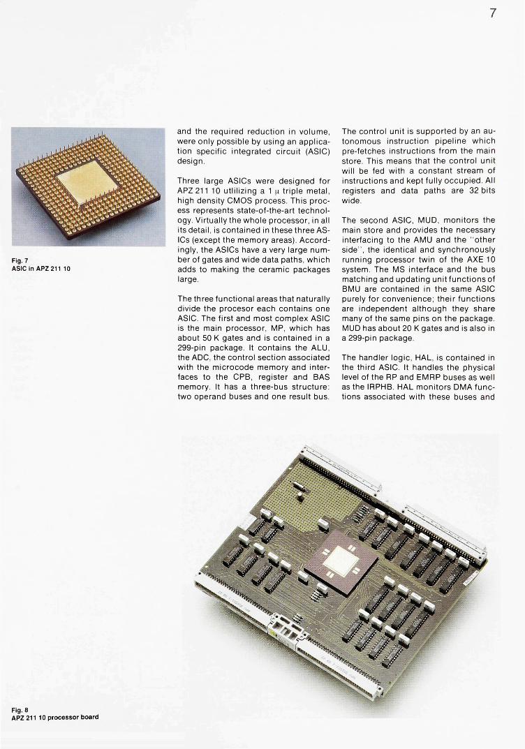
and the required reduction in volume, were only possible by using an application specific integrated circuit (ASIC) design.
Three large ASICs were designed for APZ 211 10 utiilizing a 1 LI triple metal, high density CMOS process. This process represents state-of-the-art technology. Virtually the whole processor, in all its detail, is contained in these three ASICs (except the memory areas). Accordingly, the ASICs have a very large number of gates and wide data paths, which adds to making the ceramic packages large.
The three functional areas that naturally divide the procesor each contains one ASIC. The first and most complex ASIC is the main processor, MP, which has about 50 K gates and is contained in a 299-pin package. It contains the ALU, the ADC, the control section associated with the microcode memory and interfaces to the CPB, register and BAS memory. It has a three-bus structure: two operand buses and one result bus.
The control unit is supported by an autonomous instruction pipeline which pre-fetches instructions from the main store. This means that the control unit will be fed with a constant stream of instructions and kept fully occupied. All registers and data paths are 32 bits wide.
The second ASIC, MUD, monitors the main store and provides the necessary interfacing to the AMU and the "other side", the identical and synchronously running processor twin of the AXE 10 system. The MS interface and the bus matching and updating unitfunctionsof BMU are contained in the same ASIC purely for convenience; their functions are independent although they share many of the same pins on the package. MUD has about 20 K gates and is also in a 299-pin package.
The handler logic, HAL, is contained in the third ASIC. It handles the physical level of the RP and EMRP buses as well as the IRPHB. HAL monitors DMA functions associated with these buses and
Fig. 7 ASIC in APZ 211 10
Fig. 8 APZ 211 10 processor board

8
Fig. 9 APZ 212 10 cabinet layout. The figure shows two five-shelf, 24 BM cabinets CP-A Central Processor A CP-B Central Processor B CPUM Central Processor Unit Magazine DSPSM Data Store Program Store Magazine MAUM MAintenance Unit Magazine POWCM Power and Control Magazine RPIM Regional Processor Interface Magazine
Fig. 10 Hardware sturcture of APZ 212 10
CP-A Central Processor A CP-B Central Processor B DSU Data Store Unit IPU Instruction Processing Unit MAU MAintenance Unit PSU Program Store Unit RP Regional Processor RPA Regional Processor bus Adaptor RPB Regional Processor Bus RPI Regional Processor Interlace RSU Reference Store Unit SP Support Processor SPU Signal Processing Unit
supports the interface to the CPB and a powerful microprocessor. HAL has about 15 K gates and is in a 181-pin package.
To be able to design these large ASICs, one CAD system was used throughout the process: for layout, logic simulation, verification, and generation of hardware production documents. The CAD system allowed the design to be simulated from the lowest levels up to subsystem level with the computer "models" of the blocks and, finally, with the detailed design.
APZ 212 10 APZ 212 10, the most powerful control system for AXE 10, is intended for very large applications. Its call handling capacity is two times that of APZ 212 01/ 02.
Packaging APZ 212 10 only requires the floor space of two cabinets, fig. 9. One five-shelf cabinet per CP side contains all the associated hardware, processor, memory and RP-bus interfaces. The CP-B cabinet also holds the maintenance unit, MAU.

Fig. 11 Detailed block diagram of the APZ 212 10 CPU hardware
ALU Arithmetic and Logical Unit CLU CLock Unit CPU Central Processor Unit DAU Data Access Unit DSH Data Store Handler DSU Data Store Unit IPI Instruction Processing Interface IPU Instruction Processing Unit JBU Job Buffer Unit LTU Link and Trace Unit MAI MAintenance unit Interface MAU MAintenance Unit MCU Microprogram Control Unit PCU Priority Control Unit PSH Program Store Handler PSU Program Store Unit RPB Regional Processor Bus RPCU Regional Processor Controller Unit RPHI Regional Processor Handler Interface RPI Regional Processor Interface RPIO Regional Processor Input/Output RPIRS Regional Processor Interface Receive/Send RS Reference Store RSH Reference Store Handler SPI Signal Processor Interface SPU Signal Processing Unit STU STore Unit UMU Update and Match Unit
Architecture Just as for APZ 211 10, APZ 212 10 isde-signed to meet three important demands: capacity, compatibility with APZ 212 02 and software compatibility with the APZ 211 family.
One crucial decision was to keep the APZ 212 architecture by designing it with commonly available components. The new 1 u. CMOS process was used for the critical data circuits in the central processor.
As a result, the traditional central processing unit, CPU, is divided into two parallel working processor units: a signal processsor unit, SPU, that handles signals and job control of the second part, which is the instruction processor, IPU, entirely dedicated to program execution, fig. 10.
The CPU design comprises four gate arrays, ASICs. The number of utilized cells for the ASICs ranges from 3 K to 8 K. Ceramic 209-pin grid arrays (PGA) are used.
Design The central processing unit, CPU, containing the two internal processors SPU and IPU, is optimized for high performance, fig. 11. IPU executes programs very fast memory access and with its supporting micro architecture which provides the high capacity throughput.
SPU constantly supplies IPU with jobs and sees to it that signals initiated by the programs are forwarded to the regional processors via RPH.
A common synchronized 10 MHz clock supplies the timing pulses to control the 100 ns machine cycle operation.
SPU SPU handles signalling and job administration tasks. It is a specially designed 16-bit processor unit adapted to control its own activities entirely by a microprogram, without access to the system memories.
The central arithmetic and logical unit (ALU) functions and parts of the microprogram controller functions are integrated in one gate array, SAC, containing 7 K cells.
IPU IPU is a 32-bit processor unit based on register oriented processing. A dual-port RAM contains the four levels of general and special purpose registers. Each program interrupt level has its own register set.
The functions that are capable of increasing the processing speed have

been integrated in the three gate arrays in IPU as follows: - Central ALU functions in one gate ar
ray of 8 K cells, LAC - The error correction function for DS
and PS in one gate array of 5 K cells, EDC
- The address calculation function for PS in one gate array of 3 K cells, ADC
Microprogram control The microprogram of the CP units, SPU and IPU and to some extent RPH, is a flexible and powerful tool which makes for unique system characteristics.
In order to ensure high performance, especially in the IPU, the micro architecture strongly supports parallel micro activities forming so-called horizontal microprogramming, i.e. a few microprogram steps containing extremely wide micro instructions.
Besides fulfilling the demand for high performance, the microprogram supports the operational software in the maintenance of the system, routine tests and built-in hardware tests for production and installation.
The IPU micro instruction format comprises 104 bits, capable of addressing three operands. The corresponding format of the SPU is 80 bits.
APZ Source Systems The APZ source system strategy is to make use of the very high compatibility between the different central processors. Annually, new revisions of the source system, common to the APZ 211 and APZ 212 family, are released with new and improved functions and features. By maintaining common software
for the hardware control systems, design efforts can be made more efficient and product maintenance costs can be reduced.
Together with the annual issue of the source system, methods and procedures for updating systems in operation are also released. They are based on function changes and can be implemented without any significant service interrupt.
APZ 211 10 and APZ 212 10 are just as suitable for new installations as for retrofits of existing central processors when there is a need for more processor capacity.
Applications For small autonomous exchanges APZ 211 10 is best suited. By adapting the main store and the bus connections to suit a smaller application, APZ 211 10 can be configured to only need the physical space of 15 BM for a complete system Fig. 3a shows an example of a configuration capable of handling 256 subscribers.
In the other end of the size range are the large exchanges, for which the APZ 212 10 processor is the obvious choice. Even though it is the most powerful processor it still only requires the floor space of one square meter (10 square feet). The processing capacity, memory size and number of bus connections in this machine is fully adapted to the various applications and signalling systems that form part of very large exchanges. A powerful I/O system - especially designed to handle these large applications - is included for the interface to various operation support systems.
10
Fig. 12 APZ 212 10 processor board
Fig. 13 ASIC in APZ 212 10

Technical data Central processor for
Call handling capacity
CP clock frequency Maximum number of RPs Memory capacity, 1 Mb/4 Mb OS (16 bit words) 1 Mb/4 Mb PS (16 bit words) 1 Mb/4 Mb RS (40 bit words) 256 kb/1 Mb Per board assembly, 1 Mb/4 Mb Power consumption:
Basic configuration Fully equipped
Fan cooled cabinets Mean Time Between System Failures, MTBSF Mean Time To Restoration, MTTR Printed circuit boards
Board size K2 (mm) Board size K3 (mm) Components:
Logic
Memories
Microprogram
APZ211 10
3 times APZ 211 02
12 MHz 512 24 MW/96 MW
4MW/16MW
150 W 350 W
> 1000 years 100 h Glass epoxy 6 layers h222, d 178
TTL 74F, ALS, High density 1 n CMOS gate arrays, triple metal DRAM 1 Mb, 4 Mb SRAM 6 4 k x 4 b i t s EPROM 128 k x 8 bits SRAM,EPROM
APZ 212 10
2 times APZ 212 01/02 10 times APZ 211 02 10 MHz 1 024
48 MW/192 MW 16MW/32 MW 256 kW/1 MW 4MW/16MW
1 300 W 1 750 W h 1 795, w 1 200, d 400
> 1000 years 4h Glass epoxy 2-6 layers h222, d 178 h344, d 178
TTL 74F, ALS 1 n CMOS Gate arrays
DRAM 1 Mb, 4Mb SRAM 256 kb, 1 Mb
SRAM,EPROM
References
For the majority of exchanges, in the range between those described above, the APZ 211 10 control system is best suited. Its processor memory size and bus handling capacity makes it a cost-effective alternative for exchanges of medium size.
A new concept has been introduced to facilitate the handling and maintenance of application systems and to fully benefit from the high compatibility between the different control systems. This means that all application system activities presently oriented towards the AXE 10 level are moved to the APZ and APT levels respectively. Both APZ 211 10 and APZ 212 10 can be used together with the same APT application system which makes capacity and function upgrades even easier. It is made possible by the common interface towards applications offered by these new processors not only at the software level but also for operation and maintenance as well as general system handling. The true benefit to be derived from this con
cept is the considerable reduction of the cost of handling application systems.
Summary With the release of APZ 211 10 and APZ 212 10, Ericsson can offer control systems suitable for all kinds of applications - those available today and those of tomorrow. This is equally true of small autonomous exchanges with only a hundred ordinary telephone subscribers, very large cellular mobile telephone exchanges and international transit exchanges with ISDN and IN capabilities.
The solutions offered facilitate functional growth as well as the addition of subscribers in a very cost-effective way. If an exchange requires more capacity than what is provided by its present control system, there are well proven and simple procedures for updating it to a larger machine thanks to the outstanding compatibility of the new control systems APZ 211 10 and APZ 212 10.
Eklund, M., Larsson, C. G. and Sorme, K.-.AXE 10-System Description. Ericsson Review 53(1976):2, pp. 70-89. Nilsson, B. A. and Sorme, K.: AXE 10-A Review. Ericsson Review 57 (1980):4, pp. 138-148. Andersson, T. och Ljungfeldt, O.: Digital Transit Exchanges AXE 10. Ericsson Review 58 (1981):2, pp. 56-67. Jonsson, I.: Control System for AXE 10. Ericsson Review 61 (1984):4, pp. 146-155. Fletcher, C, Heinonen, E. and Jonsson, A..AXE 10 for Small Exchange Applications. Ericsson Review 63 (1986):4, pp. 140-148.
Service Script Interpreter, an Advanced Intelligent Network Platform
Paul van Hal, Jan van der Meer, Nael Salah
Ericsson's products for Advanced Intelligent Networks enable network service providers to structure and program a wide range of advanced network services. The products, based on the AXE 10 system and the new Telecommunication Management and Operations Support system (TMOS), are capable of supplying the need for services to all subscribers in the telecom network. It is the Service Script Interpreter in AXE 10 that creates these new opportunities. The authors describe the Service Script Interpreter, its applications and characteristics.
intel l igent networks te lecommunicat ion network management electronic swi tch ing systems
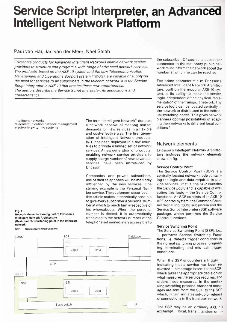
Fig. 1 Network elements forming part of Ericsson's Intelligent Network Architecture (Basic switch:) Switching point in the transport network
SSF Service Switching Functions
The term "Intelligent Network" denotes a network capable of meeting market demands for new services in a flexible and cost-effective way. The first generation of Intelligent Network products, IN/1, has been deployed in a few countries to provide a limited set of network services. A new generation of products, enabling network service providers to supply a large number of new advanced services, have been introduced by Ericsson.
Companies' and private subscribers' use of their telephones will be markedly influenced by the new services. One striking example is the Personal Number service. The equipment described in this article makes it technically possible to give every subscriber a personal number at which to reach him irrespective of his whereabouts. When the personal number is dialled, it is automatically translated to the network number of the telephone set immediately accessible to
the subscriber. Of course, a subscriber connected to the stationary public network must inform the network about the number at which he can be reached.
The prime characteristic of Ericsson's Advanced Intelligent Network Architecture, built on the modular AXE 10 system, is its ability to make the service logic independent of the physical implementation of the transport network. The service logic can be located centrally in the network or distributed to the individual switching nodes. This gives network planners optimal possibilities of adapting their networks to different local conditions.1
Network elements Ericsson's Intelligent Network Architecture includes the network elements shown in fig. 1.
Service Control Point The Service Control Point (SCP) is a centrally located network node containing the logic and data required to provide services. That is, the SCP contains the Service Logic and is capable of executing this logic - the Service Control functions. An SCP consists of an AXE 10 APZ control system, the Common Channel Signalling (CCS) subsystem and the Service Script Interpreter (SSI) software package, which performs the Service Control functions.
Service Switching Point The Service Switching Point (SSP), box 1, performs Service Switching Functions, i.e. detects trigger conditions in the normal switching process: originating, terminating and mid call trigger conditions.
When the SSP encounters a trigger -indicating that a service has been requested - a message is sent to the SCP, which takes the appropriate decision on what measures the service requires, and orders these measures. In the continuing switching process, standard messages are sent from the SCP to the SSP which, in turn, initiates set-up or release of connections in the transport network.
The SSP may be an ordinary AXE 10 exchange - local, transit, tandem or in-

PAUL VAN HAL JAN VAN DER MEER Ericsson Telecomminicatie B.V. Netherlands NAEL SALAH Ericsson Telecom AB
Box 1 SERVICE SWITCHING POINT (SSP) The SSP includes functions for - detection of triggering conditions; that is,
identification of network signals related to services, and the handling of these signals
- transfer of calls to the SCP function - reception of responses from the SCP func
tion - check (at the request of the SCP) of whether
specific conditions arise and, if so, transmission of the corresponding messages to the SCP
- ordering of set-up and release of connections in the transport network
- handling of the interworking with the IP equipment, including activation of this equipment, and digit reception
Box 2 FREEPHONE SERVICE The Freephone service allows a multi-site company, for example, to advertise a single charge-free number for its customers to call. The company - by definition a Service Customer - pays the charge of all received calls to the advertised number which, when dialled, is translated by the SCP to the network number of one of the company's answering positions. The translation may be determined by one or more branching parameters, such as time of day, day of the week, and the origin of the call.
ternational - supplemented with Service Switching functions.
The communication between the service logic in the SCP and the access and switching functions in the SSP is based on the OSI protocol Transaction Capability Application Part (TCAP) in CCS 7.2
In the first applications, this communication is based on messages - on the North American market called Query, Collect digits. User digits, Response and Termination notification.
Service Switching and Control Point A Service Switching and Control Point (SSCP) combines in one node the functions of the SCP and SSP; that is, the SSCP handles both Service Control and Service Switching functions. The advantage of the SSCP node is, firstly, that signalling between the SSP and SCP requires no CCS network capacity and, secondly, that the service logic can be distributed in the network. Thus, the service logic can be brought closer to the Service Customers than in the case of SCP nodes.
Signal Transfer Point In Networks with many SSPs and SCPs, Signal Transfer Points (STP) can be incorporated to make more efficient use of the signalling network. An STP node may consist of an AXE 10 APZ control system and the CCS subsystem.
External databases The SCP and SSCP have access ta external, dedicated databases through the CCS network - a facility made use of in credit card validation, for example. The information needed for this service is stored in databases owned by credit card companies independent of the network operator. Another reason for the existence of separate databases is that the administration of them is sometimes best located outside of the SCP/SSCP.
Intelligent Peripherals Intelligent Peripherals (IP) is a collection of versatile and cost-effective equipment allowing communication between the Intelligent Network and its subscribers. IP can send a number of different announcements to subscribers and receive digits from Dual Tone Multi Frequency (DTMF) telephones. The announcements may be of a fixed
format or with a variable part, and they can be sent once only or several times. The Intelligent Peripheral is normally integrated in the AXE 10 system, forming part of the SSP, but can be provided as a separate node accessible by several Service Switching Points. IP is activated by the SCP via the SSP.
Service Management System The Service Management Application System (SMAS) is used for service programming and administration. It includes functions for communication with all SCPs and SSCPs in the network and has a user-friendly operator interface. SMAS has been developed as an application based on Ericsson's Telecommunication Management and Operations Support system (TMOS).3
TMOS is based on open industry standards, such as the X/Open Common Application Environment, which includes OSI communication protocols2 and the Structured Query Language (SQL). It has a modular structure, both with respect to size and functions, to allow adaptation to different applications.
Service Script Interpreter The Service Script Interpreter is a service-independent platform on which a number of "modules" are stored. Each module, when activated, performs a defined function. A module is the smallest building block in SSI.
The modules can be combined into Service Scripts, which, by definition, are capable of performing more complex functions than the modules. A script can describe in detail the logic and data required to implement a complete service. It may be convenient, however, to divide the service into several parts, using one script for each of these parts and linking the different scripts together.
The concept of the SSI architecture is the result of successful efforts to meet the demands of sophisticated services, such as the Freephone service, box 2. The required functions are divided into a number of parts, called modules. When the functions related to one module have been executed, a new module is activated, and so forth until the service is effected. The modules used for
14
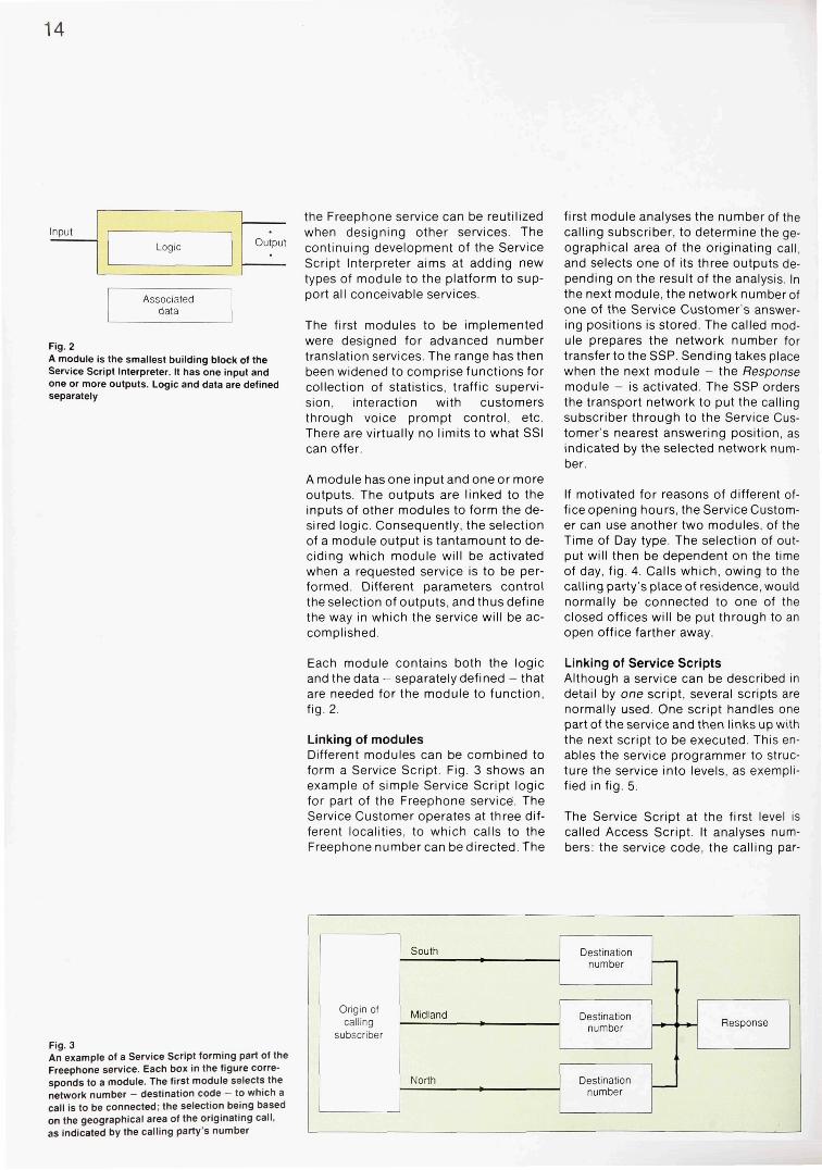
Fig. 2 A module is the smallest building block of the Service Script Interpreter. It has one input and one or more outputs. Logic and data are defined separately
the Freephone service can be reutilized when designing other services. The continuing development of the Service Script Interpreter aims at adding new types of module to the platform to support all conceivable services.
The first modules to be implemented were designed for advanced number translation services. The range has then been widened to comprise functions for collection of statistics, traffic supervision, interaction with customers through voice prompt control, etc. There are virtually no limits to what SSI can offer.
A module has one in put and one or more outputs. The outputs are linked to the inputs of other modules to form the desired logic. Consequently, the selection of a module output is tantamount to deciding which module will be activated when a requested service is to be performed. Different parameters control the selection of outputs, and thus define the way in which the service will be accomplished.
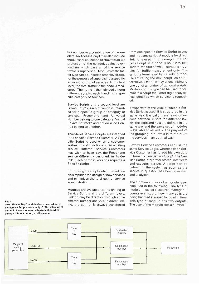
first module analyses the number of the calling subscriber, to determine the geographical area of the originating call, and selects one of its three outputs depending on the result of the analysis. In the next module, the network numberof one of the Service Customer's answering positions is stored. The called module prepares the network number for transfer to the SSP. Sending takes place when the next module - the Response module - is activated. The SSP orders the transport network to put the calling subscriber through to the Service Customer's nearest answering position, as indicated by the selected network number.
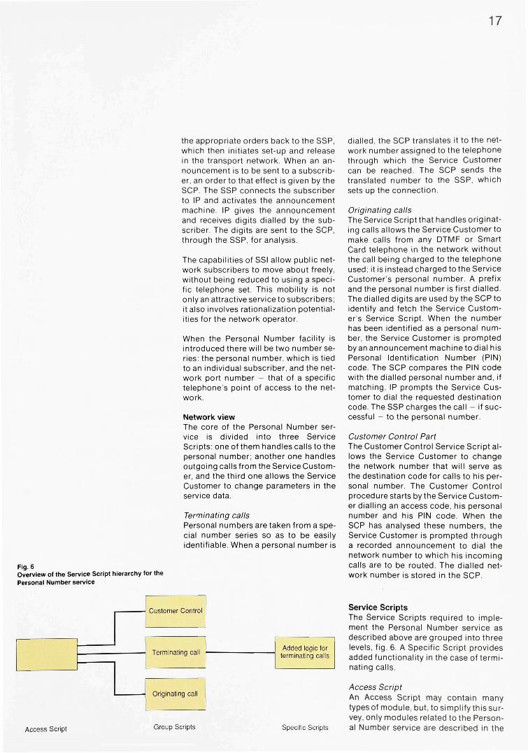
If motivated for reasons of different office opening hours, the Service Customer can use another two modules, of the Time of Day type. The selection of output will then be dependent on the time of day, fig. 4. Calls which, owing to the calling party's place of residence, would normally be connected to one of the closed offices will be put through to an open office farther away
Each module contains both the logic and the data - separately defined - that are needed for the module to function, fig. 2.
Linking of modules Different modules can be combined to form a Service Script. Fig. 3 shows an example of simple Service Script logic for part of the Freephone service. The Service Customer operates at three different localities, to which calls to the Freephone number can be directed. The
Linking of Service Scripts Although a service can be described in detail by one script, several scripts are normally used. One script handles one part of the service and then links up with the next script to be executed. This enables the service programmer to structure the service into levels, as exemplified in fig. 5.
The Service Script at the first level is called Access Script. It analyses numbers: the service code, the calling par-
Fig. 3 An example of a Service Script forming part of the Freephone service. Each box in the figure corresponds to a module. The first module selects the network number - destination code - to which a call is to be connected; the selection being based on the geographical area of the originating call, as indicated by the calling party's number
15
Fig. 4 Two "Time of Day" modules have been added to the Service Script shown in fig. 3. The selection of output in these modules is dependent on when, during a 24-hour period, a call is made
ty's number or a combination of parameters. An Access Script may also include modules for collection of statistics or for protection of the network against overload (in which case all of the service traffic is supervised). Modules of the latter type can be linked to other levels too, for the purpose of supervising a specific service or group of services. At the first level, the total traffic to the node is measured. The traffic is then divided among different scripts, each handling a specific category of services.
Service Scripts at the second level are Group Scripts, each of which is intended for a specific group or category of services. Freephone and Universal Number belong to one category; Virtual Private Networks and nation-wide Cen-trex belong to another.
Third-level Service Scripts are intended for a specific Service Customer. A Specific Script is used when a customer wishes to add functions to an existing service. Different Service Customers may wish to have, say, the Freephone service differently designed, in its details. Each of these versions requires a Specific Script.
Structuring the scripts into different levels simplifies the design of new services and minimizes the total cost of service administration.
Modules are available for the linking of Service Scripts at the different levels. Linking may be direct or through some external number analysis. In direct linking, the control is always transferred
from one specific Service Script to one and the same script. A module for direct linking is used if, for example, the Access Script in a node is split into two scripts, the first of which contains modules for traffic measurement only. The script is terminated by its linking module activating the next script. As an alternative, a module may effect linking to one out of a number of optional scripts. Modules of this type can be used to terminate a script that, after digit analysis, has identified which service is requested.
Irrespective of the level at which a Service Script is used, it is structured in the same way. Basically there is no difference between scripts for different levels; the logic and data are defined in the same way and the same set of modules is available to all levels. The purpose of the grouping into levels is to structure the services in an optimal way.
Several Service Customers can use the same Service Logic, whereas each Service Customer has to add his own data to form his own Service Script. The Service Script Interpreter stores, interprets and executes scripts. A script can be defined in the system as soon as the service in question has been specified and analysed.
The function and use of a module is exemplified in the following. One type of module - called Resource manager -counts events, e.g. how many calls are being handled at a specific point in time. This type of module has two outputs. The user of the module sets a number -

16
Fig. 5 Service Scripts are linked to each other in a hierarchic manner. Each script handles one specific part of a service
e.g. 10 - in the data field. If 10 or fewer calls are handled, the module selects one of its two outputs. If there are more than 10 terminating calls, the other output is selected.
The following general conclusions can be drawn from the example: - What is counted depends on the mod
ule's location in the service logic - All calls to a network node can be
counted - the module is the first one in the Access Script
- All calls to a specific service can be counted - the module is located after the Access Script, but before all other modules in the script that handles the service in question
- What will happen when the module has selected one of its outputs depends on which modules have been connected after the module. This is determined by the service programmer. For example, calls to the normal output may continue to be handled. When the other output is selected, a recorded announcement can inform the calling subscriber that the service is blocked
- The number of events resulting in the alternative output being selected can be determined by the Service Customer, who will specify the number in the module's data field.
The AXE 10 Man-Machine language can be used to define logic and data for Service Scripts, but the Service Management System SMAS provides a more user-friendly interface based on graphical and/or textual presentation. Definition of scripts is an easy process. Functions for support of validation and testing are provided both in SMAS and SSI.
Service Logic Modularity Even at its introduction, the Service Script Interpreter included some sixty
different types of module. Some of them are described in box 3, so as to give a clear picture of the creation of services and to demonstrate the versatility of the functions that can be achieved on the platform.
Examples of network services Service Customers can be offered a wide range of services. Some of these services are owned by the network operator and are accessible to all Service Customers; others are specially designed for an individual Service Customer.
Which services can be implemented depends on the modules included in the relevant issue of SSI, and on the SCP/ SSP interface and the functional content of the SSP. SMAS is used to create and distribute the services.
Network services supported by Ericsson's Service Script Interpreter are exemplified below. - Advanced Freephone - Automatic call distribution - Universal number - Call forwarding services - Virtual network services - Nation-wide Centrex - Credit card services - Personal number - Call back when busy/no answer - Queueing - Do not disturb - Hot line - Access verification services - Information services - Televoting.
PERSONAL NUMBER To concretize the process of designing a service by means of a hierarchy of modules and Service Scripts, a description of the Personal Number service is given in the following. Details about the signal processing units active in different phases have been omitted, for the sake of lucidity. The following applies throughout, unless otherwise stated:
Signals related to services are detected by the SSP, which invokes the SCP. The latter processes input data and sends
17
the appropriate orders back to the SSP, which then initiates set-up and release in the transport network. When an announcement is to be sent to a subscriber, an order to that effect is given by the SCP. The SSP connects the subscriber to IP and activates the announcement machine. IP gives the announcement and receives digits dialled by the subscriber. The digits are sent to the SCP, through the SSP, for analysis.
The capabilities of SSI allow public network subscribers to move about freely, without being reduced to using a specific telephone set. This mobility is not only an attractive service to subscribers; it also involves rationalization potentialities for the network operator.
When the Personal Number facility is introduced there will be two number series: the personal number, which is tied to an individual subscriber, and the network port number - that of a specific telephone's point of access to the network.
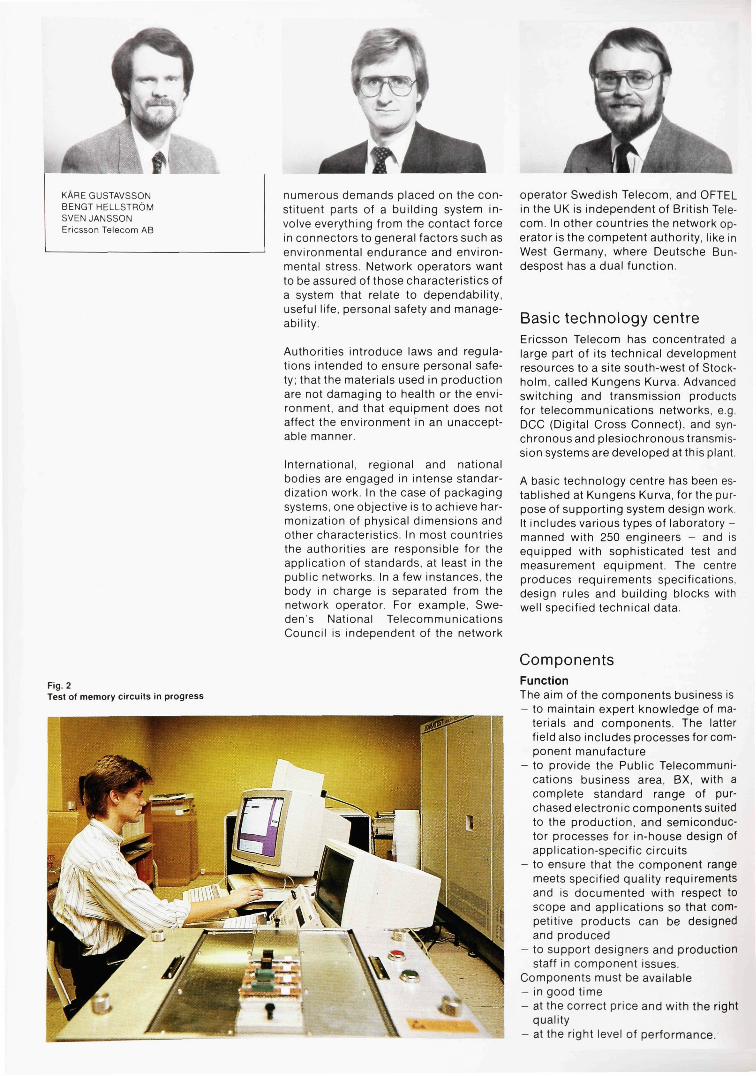
Network view The core of the Personal Number service is divided into three Service Scripts: one of them handles calls to the personal number; another one handles outgoing calls from the Service Customer, and the third one allows the Service Customer to change parameters in the service data.
Terminating calls Personal numbers are taken from a special number series so as to be easily identifiable. When a personal number is
Fig. 6 Overview of the Service Script hierarchy for the Personal Number service
dialled, the SCP translates it to the network number assigned to the telephone through which the Service Customer can be reached. The SCP sends the translated number to the SSP, which sets up the connection.
Originating calls The Service Script that handles originating calls allows the Service Customer to make calls from any DTMF or Smart Card telephone in the network without the call being charged to the telephone used; it is instead charged to the Service Customer's personal number. A prefix and the personal number is first dialled. The dialled digits are used by the SCP to identify and fetch the Service Customer's Service Script. When the number has been identified as a personal number, the Service Customer is prompted by an announcement machine to dial his Personal Identification Number (PIN) code. The SCP compares the PIN code with the dialled personal number and, if matching, IP prompts the Service Customer to dial the requested destination code. The SSP charges the call - if successful - to the personal number.
Customer Control Part The Customer Control Service Script allows the Service Customer to change the network number that will serve as the destination code for calls to his personal number. The Customer Control procedure starts by the Service Customer dialling an access code, his personal number and his PIN code. When the SCP has analysed these numbers, the Service Customer is prompted through a recorded announcement to dial the network number to which his incoming calls are to be routed. The dialled network number is stored in the SCP.
Service Scripts The Service Scripts required to implement the Personal Number service as described above are grouped into three levels, fig. 6. A Specific Script provides added functionality in the case of terminating calls.
Access Script An Access Script may contain many types of module, but, to simplify this survey, only modules related to the Personal Number service are described in the

18
Fig. 7 The Access Script analyses the dialled digits to determine the type of service requested. The result of this analysis may lead to the calling party receiving a recorded announcement, or to a jump to another script
Fig. 8 An outgoing Group Script analyses the digits dialled by a Service Customer and determines whether or not the call is allowed to be set up
following. Each box in figs. 7 sponds to a module.
11 corre-
The script contains a module capable of analysing the prefixes related to the service. The module has several outputs, each of them indicating one possible traffic situation. Analysis of the dialled digits may result in the selection of one of the following outputs: - The number is blocked - The number is not present in the Que
ry message received - The number cannot be identified in
the analysis table.
Selection of one of these outputs results in the appropriate message being stored and sent to the Service Customer.
If the dialled digits are recognized, the module selects one of the following three outputs: - Terminating call - Originating call - Customer Control.
Selection of any one of these outputs results in a jump to one of the Group Scripts at the second level.

19
Fig. 9 The Service Customer's incoming Group Script, after digit analysis, links in his Specific Script
Fig. 10 An incoming Specific Script adds extra functionality to the basic service. In the case shown here, the selection of destination code is dependent on when, during a 24-hour period, the call is made
Outgoing Group Script An outgoing Group Script is invoked when the Service Customer wants to make a call, fig. 8. The script contains an enhanced number analysis module for analysis of personal numbers. The module checks the dialled digits and selects an output. The appropriate recorded announcement is stored and sent as a standard message to the SSP, if the number is blocked, not present in the Query message or can not be identified in the analysis table.
If the dialled digits are recognized, the Service Customer is prompted through an announcement, initiated by the Voice Prompt PIN module, to dial his PIN code. When this PIN code has been checked, the Service Customer receives another announcement, initiated by the Voice Prompt module, to dial the destination code. These digits are received and included in a standard message to the SSP, which sets up the call.
In the case of PIN code and personal number mismatch, the Service Customer may be prompted to re-dial his PIN code. When the comparison has resulted in acceptance, the procedure contin-
ues as described above. Data for call charging is stored by the Charge module and then included in a Response message to the SSP.
Incoming Group Script An incoming Group Script is invoked when a call is made to the Service Customer. The script includes a module that analyses the personal number dialled, fig. 9. A recorded announcement is sent, if the number is blocked, not present in the Query message or can not be identified in the analysis table.
If the number is recognized as a personal number, it is translated to the network number and included in a Response message to the SSP. After analysis and acceptance, the SSP orders the call to be set up. If the called Service Customer has a Specific Script for terminating calls, the analysis module selects an output that causes a jump to this script.
Incoming Specific Script The incoming Specific Script adds extra functionality to the basic service, and the choice of modules is fairly optional. For example, a module in which the selection of outputs is determined by time parameters can be added, fig. 10. Different destination codes can then be chosen depending on when, during a 24-hour period, the call is made.
Customer Control Service Script A Customer Control Service Script, fig. 11, is invoked when the Service Customer wishes to change the network num-berto which his incoming calls are to be routed. The Service Customer dials an access code followed by his personal number. The script includes an enhanced number analysis module for analysis of dialled digits. A recorded announcement is stored and included in a Response message to the SSP, if the number is blocked, not present in the Query message or can not be identified in the analysis table.
If the access code and the personal number are defined in the script's analysis table, the Service Customer is prompted through an announcement, initiated by the Voice Prompt PIN module, to dial his PIN code. If erroneous, a prompt to re-dial the PIN code may be given. When the correct PIN code has

Fig. 11 The Customer Control Service Script analyses the Service Customer's number and the associated PIN code before he is allowed to change the network number to which his incoming calls are to be routed
been received, the Service Customer is prompted through an announcement, initiated by the Customer Control module, to dial the new network number. The module informs the Service Management System (SMAS) about the requested change and awaits an acceptance. Then the module starts a process that changes the network number in the incoming Group Script. The change is recorded in SMAS.
Conclusion With Ericsson's Service Script Interpreter, a platform for Advanced Intelligent Networks has been introduced. Thanks to the wide range of reusable modules, SSI and SMAS together provide the means for rapid, broad-based introduction of advanced services.
The Service Script Interpreter enables Network Operators to design and write programs that define new services. The programming procedures are similar to those used to define data in the AXE 10 system A new product, the Service
Management System, supports the definition, distribution and maintenance of services.
Service Customers can change data in their Service Scripts by means of an ordinary DTMF telephone. Major changes - related to complex private networks or a Freephone service, for example -are made from terminals supported by SMAS. The Service Customer can make use of these possibilities to activate a service or change his service data.
The modularity of the AXE 10 system allows Service Scripts to be located in nodes where maximal benefit can be obtained from them. In addition to the independent SCP node, there are nodes in which the SCP function has been combined with local, tandem, transit and international exchanges or Signal Transfer Points. Combining several functions in one node means a substantial reduction of costs and improved quality of the services.
The Service Script Interpreter is being further developed to meet the most sophisticated market demands.

21
Box 3 MODULES - SOME EXAMPLES Time modules Some modules base their selection of output on the result of a comparison between user-specific data and data from the system clock and calendar. Branching parameters are - time of day - day of the week - date.
Three different types of module relate to the time-dependent selections mentioned: Time Of Day (TOD), Date Of Week (DOW) and Date. When the modules are designed, a maximum number of outputs is allocated for each of them. For example, it has been decided that TOD type modules can have a maximum of eight outputs. The Service Customer decides on the number of outputs actually needed and, in the module's data field, states the time intervals that will result in the respective outputs being selected. The equivalent applies to DOW and Date. DOW can have a maximum of seven outputs and Date a maximum of 24.
Number analysis modules Input data to the module - a number - is compared with data stored on the platform. - Analysis of dialled digits
If this type of module is part of an Access Script it may find, for example, that the access code of the Freephone service has been dialled. The Group Script of that service will then be activated. If the module is instead part of the Group Script of the Freephone service, it will analyse the digits dialled after the service access code. The module will then invoke a Specific Script that selects the network number to which the call is to be routed.
- Calling number analysis This type of module has been introduced, since identification of the calling party's number is required in several services. In the Freephone service, this information is used for selection of the network number to which a call is to be routed. It also determines the Virtual Network Group a subscriber belongs to, or his PIN code. Subscribers belonging to a Virtual Network Group can call each other through abbreviated numbers. These numbers are translated to complete network numbers by other modules, and that is why the calling party's number must be known.
- Route origin The origin of an incoming route is analysed to determine the geographical area the calling subscriber belongs to. This - approximative - analysis is made when the calling party's number is not available.
Branching functions - Branching on a digit of a number
An indicated digit of the calling or called party's number, or of the number received after a prompt, is compared with a predefined digit in the service data. The result of this comparison determines the selection of module output
- Number screening on a list The calling or called party's number, or the number received after a prompt, is compared with a list of predefined numbers. The selec
tion of an output in the module is dependent on whether or not the number is included on the list. If the number is not included, the selected output can cause a recorded announcement to be sent to the subscriber.
Network automatic call distributor Protective modules are available: to protect the network against call bursts and for maximization of the rate of successful calls and optimal utilization of network resources. Protective type modules are often included by the network operator. - Call gapping
The Call gapping module has a counter with two outputs. The traffic through the module is measured for a given period of time. If a preset calling rate limit is exceeded, the alternative output will be selected. This type of module can be used to inform the calling subscriber that the service is blocked
- Call distributor Calls passing the Call distributor module are distributed among the available outputs in accordance with the calling rate defined for the respective outputs. A module with two outputs can direct two out of tree calls to one of its outputs and one out of three calls to the other
- Resource manager The Resource manager module keeps track of the portion of a predefined number of resource units that are still idle. The module is incremented each time it is called and decremented at the end of the call. A Termination notification message informs the module about the ending of a call
The module has two outputs. When the number of calls being handled exceeds the limit set in the module's data field, the alternative utput is selected - which, if so arranged, results in the calling party receiving a recorded announcement of blocking.
- Uniform load distributor A combination of the Call distributor and Resource manager functions ensures a predefined distribution of traffic to the module's outputs and prevents the traffic volume from exceeding available traffic handling resources.
User interactions Modules for user interactions are capable of establishing communication with subscribers. Activation of this type of module in a script results in a recorded announcement to the calling subscriber. The module sends a Collect digits message to the SSP. The equipment (IP) that gives the recorded announcement can also receive the digits it has requested - provided they are sent from a DTMF telephone. IP sends the received digits, through the SSP and the User digits message, to the module for analysis or check. - Direct prompt
A recorded announcement is given and the received digits are sent to the module, where they are checked against the Service Customer's service data
- Prompt with retries This type of prompt is similar to the direct prompt except that, if the check shows mis
match, the procedure will be repeated a predefined number of times - including recorded announcement and digit reception.
Response handling - Information loading
This type of module is used for loading information into the Response messages to be sent to the SSP when a Service Script has been executed. A range of information variables can be loaded, such as destination code, announcement identity, charging data, gapping data or service code
- Response initiation The module sends the Response message to the SSP when a script has been executed.
Statistics Modules used for collection of statistics are treated in exactly the same way as other modules. This means that the generation of statistical information can be adapted to the demands of each specific service. Several types of statistics module are available. - Call attempt meter
The passings of the Call attempt meter during script execution are counted. The result can be used to indicate the interest in a specific service or group of services
- Termination information meter When a call is disconnected, this type of module increments a counter for each of the following events that has occurred: passing of the module, called party answer, no answer, called party busy, blocking, calling party abandon, and the time interval in speech position. The module is informed about the ending of a call attempt by the message Termination notification
- Call data collector When this type of module is passed, specific call data can be collected. For example, the number of the calling party and the destination code are recorded for study purposes. The information available when a call is terminated can also be recorded.
Two types of module order reading of the information collected by the three preceding modules: - Sampling
A Sampling module orders reading when a statistics module has been passed a predefined number of times
- Periodic meter reader A Periodic meter reader module orders reading periodically at preset intervals, ranging from once every 10 seconds to once per week.
Enhanced number analysis The analysis functions provided on the platform are extended as regards capacity and facilities. - Number analysis range
The capacity of the platform has been extended to handle greater number sets. The number of digits allowed in a set is also extended. This means that a larger number of Service Customers can be served
continued

continued
- Number comparison Any number occurring as an input parameter can be compared with a number stored in the module's data field
- Extended PIN code checking A large number of PIN codes of different length can be handled. They can be changed by the Service Customer
- Virtual Network number analysis This type of module authorizes the calling party and identifies the Private Network he belongs to. Subsequent modules analyse dialled digits and other parameters and translate them to the route numbers and network numbers used to set up the call.
Customer control A Service Customer can use the Customer Control module to change his service data. Functions are provided for definition of the data he is allowed to change, and the extent to which this data can be changed is also defined.
To change data in a Service Script, the Service Customer accesses this script by dialling an access code. When the code has been checked, he receives a recorded announcement, for example: "If you want to change time of day, dial 1; if you want to change day of week, dial 2", etc. When the Service Customer has dialled the appropriate digits, the procedure continues under
voice prompt control until all allowed changes have been made.
Enhanced network automatic call distribution The Network Automatic Call Distribution features are enhanced through the addition of a Queue module, which can be remotely controlled via the generic Customer Control capabilities previously described. - Network queueing
A Network queueing module monitors the number of calls passing through to a specific destination. If the number of terminating calls exceeds the defined call handling capacity, the queueing function will be activated. The function places calls in a queue until a call previously set up is disconnected. A queued call is then fetched from the queue and set up to its destination. A recorded annonunce-ment may be given to the queueing subscribers
- Queue control The Queue control function, together with the User interactions function, allows the customer to change handling limit values, fetch calls from the queue, etc
Enhanced Platform Capabilities The platform is further enhanced through the introduction of the following capabilities: - The execution of a specified sequence of
modules can be repeated within a Service Script
- A Service Script can be invoked by another script and executed as a subroutine
- Any variables available to a process can be used as branching parameters
- Any variables available to a process can be modified as defined in the Service Script data
- Charging information, e.g. number of pulses, is accumulated for each Service Customer for a specified period of time (one week or less). If the number exceeds a limit defined in the Service Customer's script, call attempts will be rejected for the rest of the period
- The Multiple Call Dialling module is a type of module intended for credit card calls, for example. When applied, a Service Customer does not have to dial his account code and PIN code repeatedly when making several calls to be charged to the same card
- The Subscriber Category Comparison module is used for Virtual Network Services. A check of calling party data and destination data is made
- One type of module provides access -through the Common Channel Signalling transaction capability - to data stored outside the platform
- Voice prompt announcement with variable parts is intended for use in Customer Control Service Scripts. Announcements containing variable digits can be stored; for example, "This call costs x USD". When an announcement is given, the x is replaced by the actual figure.
References 1 Soderberg, L. Architecture for Intelli
gent Networks. Er icsson Review 66 (1989):1,s 1 3 - 2 2 .
2 Abramowicz, H. and L indberg, A.: OSI for Telecommunications Applications. Ericsson Review 66 (1989):1, s 2 - 1 2 .
3 L jungblom, F.: SMAS... Er icsson Review 67 (1990):1, s 3 2 - 4 1 .

New Ericsson Telecom Centre for Basic Technology
Kare Gustavsson, Bengt Hellstrom and Sven Jansson
The market demands new and better functions in the telecommunications networks. Ericsson continuously employs new technology - new components, for example - to meet these demands. The components are characterized by growing complexity, an increased number of l/Os, and higher singnal processing speed. This means that more stringent requirements are imposed on packaging systems in terms of their heat removal capabilities, and that transmission characteristics must be carefully checked. Components, materials and mechanical construction must be chosen so that requirements for performance, dependability and life of the equipment are met.
The authors give some examples of the knowledge and physical resources available in the field of basic technology within Ericsson Telecom AB; how these resources are used in design work and what measures are taken to ensure that the designed products are up to expectations.
packaging envi ronmental test ing standardisat ion quali ty cont ro l
Fig. 1 Packaging systems, which can be divided into five levels, must comply with stipulated requirements as regards environmental endurance and manageability. Increasingly stringent demands are being made on the systems in terms of packing density, heat removal capability and operating frequency
For designers to be able to design new efficient and dependable systems, they must have at their disposal a set of "building blocks" and documents that describe how these blocks are to be used. An example of such a set is the packaging system, which can be divided into five levels, fig. 1. If one of the levels - the component level, forexample - is changed radically, other levels of the packaging system must also be modified. The packaging system needs updating; the prime cause being technological development or demands from the market-place or the authorities.
The basic technology platform needed for system design also includes engineering data. The design rules cover a wide range of fields. Experts in basic technology provide directions in various types of document and start collaborating with system designers at an early stage of product development projects.
A number of computerized design tools are used: CAD (Computer Aided Design), CAE (Computer Aided Engineering), CAM (Computer Aided Manufacturing) and CAP (Computer Aided Publishing).
Technology trends The purpose of introducing a new packaging system is to use it not only when an immediate need has arisen but also in future applications: it is given the technical potential to meet the development expected in the next five-year period. Advance design for longer periods is hardly possible. Experience has shown that innovations in the component field radically, and often unfore-seeably, change the conditions for design work. One such change is the current increase in the use of optical interconnect within systems.
Market trends New market requirements force changes in the packaging system. For example, modern network engineering exploits all possibilities of building very compact equipment. Switching and transmission equipment, such as multiplexers and concentrators, are increasingly being installed away from telephone exchanges with their controlled environment. Obviously, such applications mean new and stringent environmental requirements for packaging systems.
Standardization; demands from network operators and authorities Over the years, network operators have been placing increasingly stringent and detailed demands on products as regards their physical characteristics. The
KARE GUSTAVSSON BENGTHELLSTROM SVENJANSSON Ericsson Telecom AB
Fig. 2 Test of memory circuits in progress
numerous demands placed on the constituent parts of a building system involve everything from the contact force in connectors to general factors such as environmental endurance and environmental stress. Network operators want to be assured of those characteristics of a system that relate to dependability, useful life, personal safety and manageability.
Authorities introduce laws and regulations intended to ensure personal safety; that the materials used in production are not damaging to health or the environment, and that equipment does not affect the environment in an unacceptable manner.
International, regional and national bodies are engaged in intense standardization work. In the case of packaging systems, one objective is to achieve harmonization of physical dimensions and other characteristics. In most countries the authorities are responsible for the application of standards, at least in the public networks. In a few instances, the body in charge is separated from the network operator. For example, Sweden's National Telecommunications Council is independent of the network
operator Swedish Telecom, and OFTEL in the UK is independent of British Telecom. In other countries the network operator is the competent authority, like in West Germany, where Deutsche Bun-despost has a dual function.
Basic technology centre Ericsson Telecom has concentrated a large part of its technical development resources to a site south-west of Stockholm, called Kungens Kurva. Advanced switching and transmission products for telecommunications networks, e.g. DCC (Digital Cross Connect), and synchronous and plesiochronous transmission systems are developed at this plant
A basic technology centre has been established at Kungens Kurva, for the purpose of supporting system design work. It includes various types of laboratory -manned with 250 engineers - and is equipped with sophisticated test and measurement equipment. The centre produces requirements specifications, design rules and building blocks with well specified technical data.
Components Function The aim of the components business is - to maintain expert knowledge of ma
terials and components. The latter field also includes processes for component manufacture
- to provide the Public Telecommunications business area, BX, with a complete standard range of purchased electronic components suited to the production, and semiconductor processes for in-house design of application-specific circuits
- to ensure that the component range meets specified quality requirements and is documented with respect to scope and applications so that competitive products can be designed and produced
- to support designers and production staff in component issues.
Components must be available - in good time - at the correct price and with the right
quality - at the right level of performance.

25
All components are purchased to Ericsson's specifications. Availability and short time of delivery are important factors in the selection of components and suppliers.
Area of responsibility The technology centre assumes full responsibility for components throughout business area BX. This involves ensuring that all equipments from Ericsson Telecom AB, wherever designed and produced, fulfil the same stringent requirements for quality and dependability.
Operations include everything from the selection of components and suppliers to the monitoring of component quality during manufacture and operation.
Resources The technology centre has expert knowledge in - the component market - component technology and engi
neering - test program development - testing and test systems - dependability - quality systems - analysis of materials and faults.
Fig. 3 A Scanning Electron Microscope is used for detailed analysis of semiconductors
The main part of BX activities in the component field, requiring some 100 engineers, is carried out at Kungens Kurva. There are also close-to-production units for support and test program development. Some of Ericsson's local companies outside Sweden also have resources for work in the component field.
The laboratory is equipped with a complete set of sophisticated test systems and instruments for VLSI testing and for testing of passive and active discrete electronic components, fig. 2.
The centre has measurement rooms with instruments for studying active optical components - lasers, LEDs and detectors - and for investigating passive optical components such as connectors, couplers and fibres. Equipment for measuring crystals and high-stability oscillators, e.g. caesium clocks, is also available. The measurement equipment is computer-controlled throughout.
Clean rooms for analysis of faults, materials and design are equipped with sophisticated devices: a SAM (Scanning Auger Microscope) with a SIMS (Secondary Ion Mass-Spectroscope) option for surface analysis, and SEM (Scanning Electron Microscope) equipment for microscopy, fig. 3.
Packages can be opened by means of plasma etching. In design analysisof mi-crocircuits, the SEM equipment is used not only for three-dimensional micrography but also for analysis of static and dynamic voltage contrasts and for EBIC (Electron Beam Induced Current) analysis in studies of diffusion areas. Other equipment includes instruments for X-ray microscopy, residual gas analysis and hot spot detection.
Long-term test rooms and measurement rooms meet international requirements as regards temperature and humidity. The long-term test rooms allow testing with moisture, cold, heat and temperature cycling.
Quality and dependability assurance The quality of system products is actively influenced by verification and qualification of components against documented requirements. In addition,

quality audits in accordance with ISO 9000 are carried out on suppliers' premises.
Receiving inspection ensures that purchased components meet stipulated requirements. It is based on documented directives from the department responsible for the components. Strategic components are tested lot by lot and are requalified periodically. These procedures, together with in-process and field monitoring, provide experience that facilitate prediction of the reliability of new components and products. Fault and materials analyses provide data for corrective actions so that the quality of system products is continually being improved.
Component process The component activities support the development of system products from design to production.
then carefully evaluated, technically and commercially, before final acceptance is given. Then the design - a printed board assembly, for example - is released with respect to its componentry and thus ready for volume production.
The main activities are - qualification - design support - production support - standardization.
Qualification of components includes assessment of performance, quality and long-term characteristics.
Design support consists of advice to designers concerning selection of components and guidance to their use. Engineering data specify the maximum component values allowed for high reliability and long useful life to be guaranteed.
Fig. 4, below left Chips being mounted in a multichip module
Fig. 5, below right Detail reproduction of fig. 4. The chips are being bonded
At the start of the design stage the components department is informed about the need for new components. Components which at a preliminary review are considered suitable for use are given preliminary authorization, so that the design work can proceed. Both the components and the manufacturer are
Production support comprises control of the production units' receiving inspections and assistance in the solving of problems. The production units feed back quality statistics to the components department, which collaborates actively with the component suppliers for the purpose of improving quality.

27
Assembly techniques The centre contains a class 10 000 clean room, in which the useful life of new types of package and various methods of mounting chips on carriers are studied. Hitherto the carriers have usually been "normal" printed boards. The work includes development of new package carrier techniques that permit very high packing density, figs. 4 and 51.
The work has already resulted in surface-mounted chip components - resistors and capacitors - being used in transmission equipment. Extensive studies have shown that plastic packages can also be used in applications which require very long life and high dependability; PLCC (Plastic Leaded Chip Carrier) may be mentioned as an example. A study of the useful life of non-hermetically encapsulated large chips is being made, for the purpose of determining the mechanical stress these chips are exposed to.
Another project is the study of the life of TAB (Tape Automated Bonding) circuits mounted on different types of substrate. A multichip module for processor applications containing 42 chips has been manufactured for the study. The chip surface is protected by an epoxy glob-top.
Packaging system engineering The objective of packaging system engineering is to provide a competitive, producible packaging system for electronic equipment. It must offer designers favourable technical solutions and at the same time come up to customers' expectations as regards different characteristics.2
Ericsson develops some of the products included in a packaging system while others are purchased. This method is in tune with Ericsson's business concept: to provide advanced systems, products and services. For products that do not represent the core of the corporate business concept and for which the cost of in-house development would be very high, e.g. packages for semiconductor circuits, the strategy stipulates cooper
ation. Naturally, Ericsson assumes responsibility for the overall properties of the packaging system.
A high level of competence is a prerequisite for the preparation of requirements specifications and assessment of suppliers and partners. Ericsson has the required competence, partly as a result of extensive activities in the relevant fields.
Product and technology plans are prepared each year. The plans give the production units early notice of contemplated technological changes. This early information and the resultant advance planning greatly contribute to the high product quality and facilitate scheduled changeover from one product to another.
Packaging system engineering covers a wide range, from interconnections on a chip to finished containers for complete telephone exchanges. The 140 engineers prepare technology and product plans for and supply the requisite range of packaging systems. Here too, Ericsson demands the same characteristics of a product - in quality terms and otherwise - irrespective of where it has been produced.
Design tools Computer-based tools, CAD (Computer Aided Design), are used in the design work to continually increase productivity and reduce lead times. The tools work with three spatial dimensions. This means that the fit of different parts of a complicated design can be checked on the screen before manufacture.
Some thirty workstations are available. They are connected to an internal Ericsson network which permits rapid transfer of engineering data to the production units, which also use computerized tools, CAM (Computer Aided Manufacturing). CAM is also used in the manufacture of tools and packaging system elements.
The use of CAD/CAM systems saves time and improves quality, since information for preparation/manufacture can be transmitted directly to the manufacturing equipment.
Fig. 6 Measuring of signal transmission characteristics in a printed board by means of a network analyzer
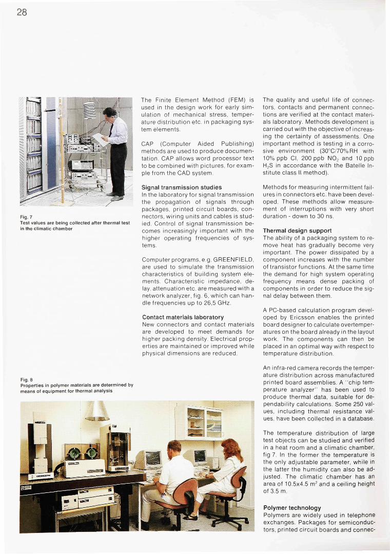
28
Fig. 7 Test values are being collected after thermal test in the climatic chamber
The Finite Element Method (FEM) is used in the design work for early simulation of mechanical stress, temperature distribution etc. in packaging system elements.
CAP (Computer Aided Publishing) methods are used to produce documentation. CAP allows word processor text to be combined with pictures, for example from the CAD system.
Signal transmission studies In the laboratory for signal transmission the propagation of signals through packages, printed circuit boards, connectors, wiring units and cables is studied. Control of signal transmission becomes increasingly important with the higher operating frequencies of systems.
Computer programs, e.g. GREENFIELD, are used to simulate the transmission characteristics of building system elements. Characteristic impedance, delay, attenuation etc. are measured with a network analyzer, fig. 6, which can handle frequencies up to 26,5 GHz.
Contact materials laboratory New connectors and contact materials are developed to meet demands for higher packing density. Electrical properties are maintained or improved while physical dimensions are reduced.
The quality and useful life of connectors, contacts and permanent connections are verified at the contact materials laboratory. Methods development is carried out with the objective of increasing the certainty of assessments. One important method is testing in a corrosive environment (30°C/70%RH with 10% ppb CI, 200 ppb N02 and 10 ppb H2S in accordance with the Batelle Institute class II method).
Methods for measuring intermittent failures in connectors etc. have been developed. These methods allow measurement of interruptions with very short duration - down to 30 ns.
Thermal design support The ability of a packaging system to remove heat has gradually become very important. The power dissipated by a component increases with the number of transistor functions. At the same time the demand for high system operating frequency means dense packing of components in order to reduce the signal delay between them.
A PC-based calculation program developed by Ericsson enables the printed board designer to calculate overtemper-atures on the board already in the layout work The components can then be placed in an optimal way with respect to temperature distribution.
Fig. 8 Properties in polymer materials are determined by means of equipment for thermal analysis
An infra-red camera records the temperature distribution across manufactured printed board assemblies. A "chip temperature analyzer" has been used to produce thermal data, suitable for dependability calculations. Some 250 values, including thermal resistance values, have been collected in a database.
The temperature distribution of large test objects can be studied and verified in a heat room and a climatic chamber, fig 7. In the former the temperature is the only adjustable parameter, while in the latter the humidity can also be adjusted. The climatic chamber has an area of 10.5x4.5 m2 and a ceiling height of 3.5 m.
Polymer technology Polymers are widely used in telephone exchanges. Packages for semiconductors, printed circuit boards and connec-
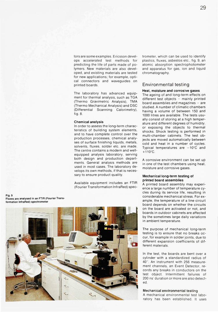
29
tors are some examples. Ericsson develops accelerated test methods for predicting the life of parts made of polymers. New materials are also developed, and existing materials are tested for new applications; for example, optical connectors and waveguides on printed boards.
The laboratory has advanced equipment for thermal analysis, such as TGA (Thermo Gravimetric Analysis), TMA (Thermo Mechanical Analysis) and DSC (Differential Scanning Calorimetry), fig-8.
Chemical analysis In order to assess the long-term characteristics of building system elements, and to have complete control over the production processes, chemical analyses of surface finishing liquids, metals, solvents, fluxes, solder etc. are made. The centre contains a modern and well-equipped analysis laboratory, serving both design and production departments. General analysis methods are used in most cases. The laboratory develops its own methods, if that is necessary to ensure product quality.
Available equipment includes an FTIR (Fourier Transformation InfraRed) spec-
Fig. 9 Fluxes are analysed in an FTIR (Fourier Transformation InfraRed) spectrometer
trometer, which can be used to identify plastics, fluxes, asbestos etc., fig. 9, an atomic absorption spectrophotometer and apparatus for gas, ion and liquid chromatography.
Environmental testing Heat, moisture and corrosive gases The ageing of and long-term effects on different test objects - mainly printed board assemblies and magazines - are studied. A number of climatic chambers having a volume of between 150 and 1000 litres are available. The tests usually consist of storing at a high temperature and different degrees of humidity, or exposing the objects to thermal shocks. Shock testing is performed in multi-chamber cabinets. The test objects are moved automatically between cold and heat in a number of cycles. Typical temperatures are -10°C and + 110°C.
A corrosive environment can be set up in one of the test chambers using heat, moisture and corrosive gases.
Mechanical long-term testing of printed board assemblies A printed board assembly may experience a large number of temperature cycles during its service life, resulting in considerable mechanical stress. For example, the temperature of a line circuit board depends on whether the circuits on the board are activated or not, and boards in outdoor cabinets are affected by the sometimes large daily variations in ambient temperature.
The purpose of mechanical long-term testing is to ensure that no breaks occur, for example in solder joints, due to different expansion coefficients of different materials.
In the test, the boards are bent over a cylinder with a standardized radius of 40". An instrument with 256 measurement channels, an Event Detector, records any breaks in conductors on the test object. Intermittent failures of 200 ns' duration or more are also detected.
Mechanical environmental testing A mechanical environmental test laboratory has been established. It uses
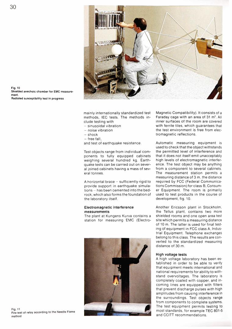
30
Fig. 10 Shielded anechoic chamber for EMC measurement. Radiated susceptibility test in progress
mainly internationally standardized test methods, IEC tests. The methods include testing with - sinusoidal vibration - noise vibration - shock - free fall, and test of earthquake resistance.
Test objects range from individual components to fully equipped cabinets weighing several hundred kg. Earthquake tests can be carried out on several joined cabinets having a mass of several tonnes.
A horizontal brace - sufficiently rigid to provide support in earthquake simulations - has been cemented into the bedrock, which also forms the foundation of the laboratory itself.
Electromagnetic interference measurements The plant at Kungens Kurva contains a station for measuring EMC (Electro-
Fig. 11 Fire test of relay according to the Needle Flame method
Magnetic Compatibility). It consists of a Faraday cage with an area of 31 m2. All inner surfaces of the room are covered with ferrite tiles, which guarantees that the test environment is free from electromagnetic reflections.
Automatic measuring equipment is used to check that the object withstands the permitted level of interference and that it does not itself emit unacceptably high levels of electromagnetic interference. The test object may be anything from a component to several cabinets. The measurement station permits a measuring distance of 3 m, the distance required by FCC (Federal Communications Commission) for class B, Consumer Equipment. The room is primarily used to test products in the course of development, fig. 10.
Another Ericsson plant in Stockholm, the Tellus plant, contains two more shielded rooms and one open area test site which permits a measuring distance of 10 m. The latter is used for final testing of equipment in FCC class A, Industrial Equipment. Telephone exchanges belong to this class. The results are converted to the standardized measuring distance of 30 m.
High voltage tests A high voltage laboratory has been established in order to be able to verify that equipment meets international and national requirements for ability to withstand overvoltages. The laboratory is completely coated with copper, and incoming lines are equipped with filters that prevent discharge pulses with high amplitudes from causing interference in the surroundings. Test objects range from components to complete systems. The test equipment permits testing to most standards, for example TEC 801-5 and CCITT recommendations.

Fig. 12 Fire test of plastic material according to the Oxygen Index method
Fire tests All materials, components and cables must meet international fire resistance requirements.
Components - unmounted or mounted on printed boards - are tested using the Needle Flame method, IEC 695-2-2. The test object is ignited with a gas flame. The ignition time is dependent on the size of the test object. When the flame is removed the fire must go out within 30 seconds, fig. 11.
At present, printed boards and materials are tested using two different methods: - Underwriters' test, UL 94
The lower end of a test rod of standard size is ignited with a defined flame. The material is classified according to its after-burning time. Classifications of Ericsson equipment correspond to after-burning times shorter than 10 and 30 s respectively. Drops or other loose, burning particles must not occur
- Oxygen index test Special apparatus is used to determine the Oxygen Index (Ol) of materials. The lower end of a test rod, taken from the material to be tested, is ignited in a mixture of oxygen and nitrogen. The Ol is defined as the lowest concentration of oxygen at which the rod continues to burn three minutes after the igniting flame has been removed. Materials used by Ericsson Telecom must have an Oxygen Index of at least 28, fig. 12.
Other activities Activities in the field of basic technology at Ericsson Telecom AB also involve units responsible for the supply of computerized tools (CAD) and for supporting the use of these tools in the production of VLSI circuits, printed board assemblies and test programs.
References 1 Liljestrand, L-G: The Development of
Packaging Technology. Ericsson Review 64 (1987):4, pp. 189-197
2 Ernmark, D. and Hellstrom, B.: Cabinet Practice for Electronic Systems. Ericsson Review 63 (1986):2, pp. 42-48

A Service Management System for the Intelligent Network
Fredrik Ljungblom
A comprehensive Service Management system is a necessary component for the success of the Intelligent Network concept. Ericsson's Service Management Application System is one of several applications in the Ericsson TELECOMMUNICATIONS MANAGEMENT AND OPERATIONS SUPPORT (TMOS) family which supports the design, provisioning and management of network services. The author describes the Service Management Application System and points out its advantages.
intelligent networks telecommunication network management
The Service Management Application System (SMAS) forms an integral part of Ericsson's Intelligent Network. Other nodes in the network are Service Control Points (SCP), Service Switching Points (SSP), Service Switching and Control Points (SSCP) and Signalling Transfer Points (STP).1
SMAS supports "traditional" IN services such as Freephone, Universal Number, and Credit Card Calling More importantly, it is designed as a service-independent support system from the very beginning, fully exploiting the flexibility of the Service Script Interpreter (SSI) in
AXE 10 and providing vital support of the programming and rapid introduction of new services. Thus, the Network Service Provider and his Service Customers can take full advantage of all the new possibilities offered by the Intelligent Network concept. To sum up, SMAS offers: - SERVICE DESIGN (Service Logic De
sign, Creation, Programming, Definition) capability to allow the Network Service Provider to independently take full responsibility for the Service Design Activity in order to timely and effectively design new Service Logic, as standard revenue-generating service offerings or tailored services in direct response to individual customer needs
- SERVICE MANAGEMENT capability to manage the Service Logic, Service Data and Service Scripts, which define the Network Services for customers. User interfaces are made available to the Service Management staff as well as direct Customer Control interfaces for change of Customer Data and reporting of Service Statistics
- SERVICE PROVISIONING capability to initiate the activation or change of the Service Scripts or Service Data in
Fig. 1 From concept to network service
1 Customer Contracts 1 Customer specific network service installed in network
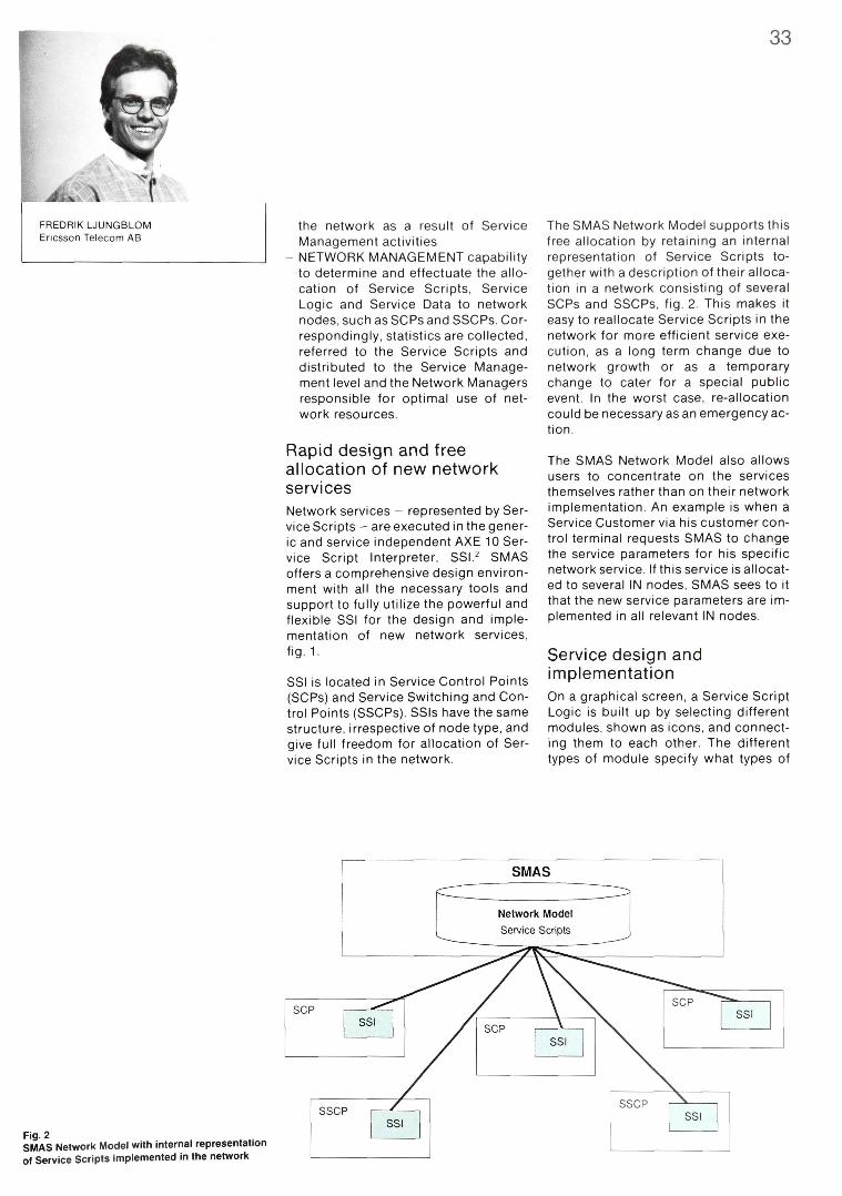
33
FREDRIKLJUNGBLOM Ericsson Telecom AB
the network as a result of Service Management activities
- NETWORK MANAGEMENT capability to determine and effectuate the allocation of Service Scripts, Service Logic and Service Data to network nodes, such as SCPs and SSCPs. Correspondingly, statistics are collected, referred to the Service Scripts and distributed to the Service Management level and the Network Managers responsible for optimal use of network resources.
Rapid design and free allocation of new network services Network services - represented by Service Scripts - are executed in the generic and service independent AXE 10 Service Script Interpreter, SSI.2 SMAS offers a comprehensive design environment with all the necessary tools and support to fully utilize the powerful and flexible SSI for the design and implementation of new network services, fig. 1.
SSI is located in Service Control Points (SCPs) and Service Switching and Control Points (SSCPs). SSIs have the same structure, irrespective of node type, and give full freedom for allocation of Service Scripts in the network.
The SMAS Network Model supports this free allocation by retaining an internal representation of Service Scripts together with a description of their allocation in a network consisting of several SCPs and SSCPs, fig. 2. This makes it easy to reallocate Service Scripts in the network for more efficient service execution, as a long term change due to network growth or as a temporary change to cater for a special public event. In the worst case, re-allocation could be necessary as an emergency action.
The SMAS Network Model also allows users to concentrate on the services themselves rather than on their network implementation. An example is when a Service Customer via his customer control terminal requests SMAS to change the service parameters for his specific network service. If this service is allocated to several IN nodes, SMAS sees to it that the new service parameters are implemented in all relevant IN nodes.
Service design and implementation On a graphical screen, a Service Script Logic is built up by selecting different modules, shown as icons, and connecting them to each other. The different types of module specify what types of
Fig. 2 SMAS Network Model with internal representation of Service Scripts implemented in the network
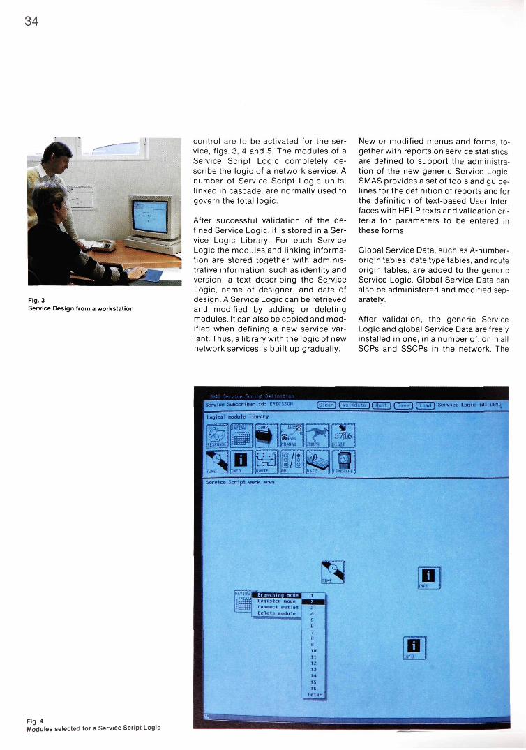
control are to be activated for the service, figs. 3, 4 and 5. The modules of a Service Script Logic completely describe the logic of a network service. A number of Service Script Logic units, linked in cascade, are normally used to govern the total logic.
After successful validation of the defined Service Logic, it is stored in a Service Logic Library. For each Service Logic the modules and linking information are stored together with administrative information, such as identity and version, a text describing the Service Logic, name of designer, and date of design. A Service Logic can be retrieved and modified by adding or deleting modules. It can also be copied and modified when defining a new service variant. Thus, a library with the logic of new network services is built up gradually.
New or modified menus and forms, together with reports on service statistics, are defined to support the administration of the new generic Service Logic. SMAS provides a set of tools and guidelines for the definition of reports and for the definition of text-based User Interfaces with HELP texts and validation criteria for parameters to be entered in these forms.
Global Service Data, such as A-number-origin tables, date type tables, and route origin tables, are added to the generic Service Logic. Global Service Data can also be administered and modified separately.
After validation, the generic Service Logic and global Service Data are freely installed in one, in a number of, or in all SCPs and SSCPs in the network. The
Fig. 3 Service Design from a workstation
Fig. 4 Modules selected for a Service Script Logic
34

35
SMAS Network Service Configuration Database shows the allocation of the generic network services in the network.
After installation, certain test functions can be initiated. The basic principle isto use the designed and installed generic network service as a simulating object and to simulate the introduced network service.
The introduction of completely new network services may require updating of the triggering tables in the SSPs and SSCPs. These triggering tables can be updated, modified and copied. When they have been installed in the SSPs and SSCPs, the SMAS Network Service Configuration Database is updated as well. When an installed network service is activated, it is also registered in this database.
Service provisioning
Customer administrative and commercial information data (name, address etc.) are specified and stored in the Customer Database, which can also be updated from an external customer database.
Customer-specific Service Data are defined and administered via the User Interface, defined during Service Design. Requests to change customer-specific Service Data can also be received from external support systems.
Once new or revised customer-specific Service Data have been defined and successfully validated, they are considered eligible for introduction in the network. Management of pending customer data updates involves maintaining a
Fig. 5 Completed Service Script Logic
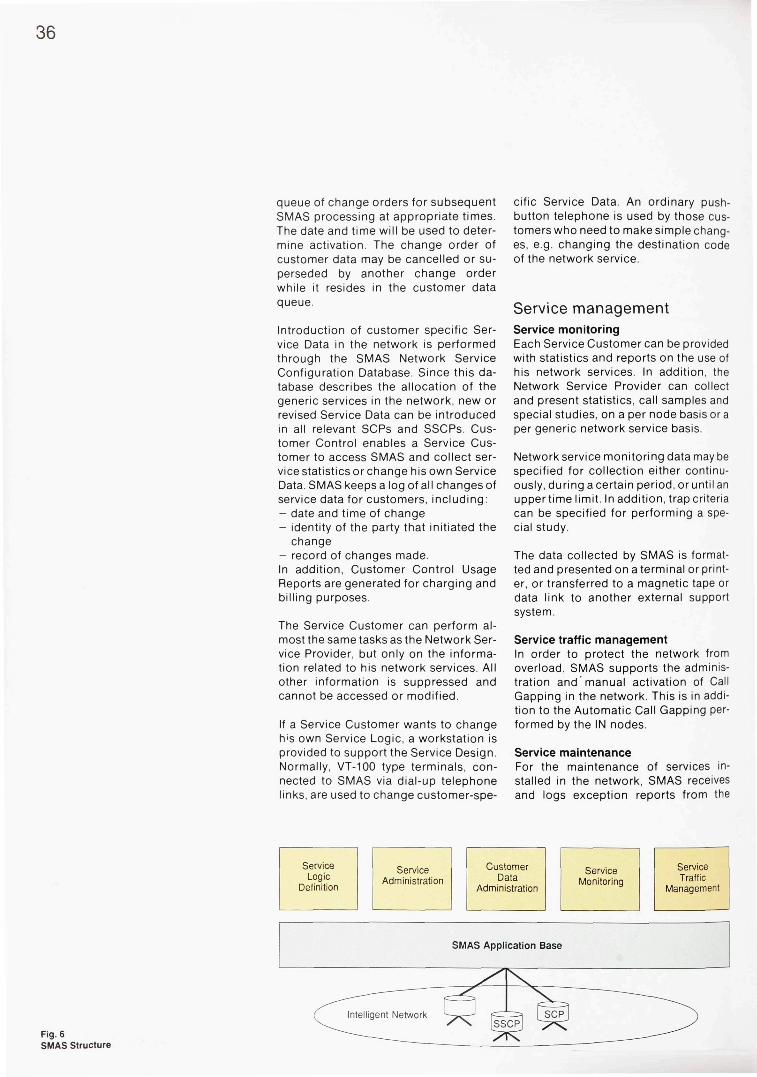
queue of change orders for subsequent SMAS processing at appropriate times. The date and time will be used to determine activation. The change order of customer data may be cancelled or superseded by another change order while it resides in the customer data queue.
Introduction of customer specific Service Data in the network is performed through the SMAS Network Service Configuration Database. Since this database describes the allocation of the generic services in the network, new or revised Service Data can be introduced in all relevant SCPs and SSCPs. Customer Control enables a Service Customer to access SMAS and collect service statistics or change his own Service Data. SMAS keeps a log of all changes of service data for customers, including: - date and time of change - identity of the party that initiated the
change - record of changes made. In addition, Customer Control Usage Reports are generated for charging and billing purposes.
The Service Customer can perform almost the same tasks as the Network Service Provider, but only on the information related to his network services. All other information is suppressed and cannot be accessed or modified.
If a Service Customer wants to change h's own Service Logic, a workstation is provided to support the Service Design. Normally, VT-100 type terminals, connected to SMAS via dial-up telephone links, are used to change customer-spe
cific Service Data. An ordinary pushbutton telephone is used by those customers who need to make simple changes, e.g. changing the destination code of the network service.
Service management Service monitoring Each Service Customer can be provided with statistics and reports on the use of his network services. In addition, the Network Service Provider can collect and present statistics, call samples and special studies, on a per node basis or a per generic network service basis.
Network service monitoring data may be specified for collection either continuously, during a certain period, or until an upper time limit. In addition, trap criteria can be specified for performing a special study.
The data collected by SMAS is formatted and presented on a terminal or printer, or transferred to a magnetic tape or data link to another external support system.
Service traffic management In order to protect the network from overload, SMAS supports the administration and manual activation of Call Gapping in the network. This is in addition to the Automatic Call Gapping performed by the IN nodes.
Service maintenance For the maintenance of services installed in the network, SMAS receives and logs exception reports from the
Fig. 6 SMAS Structure
36
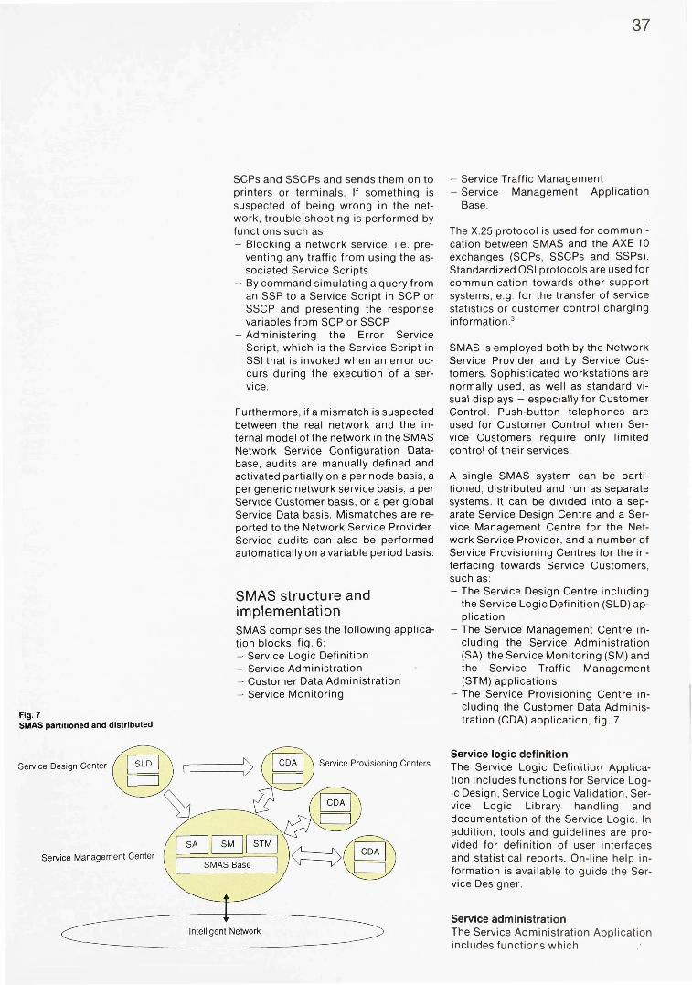
37
Fig. 7 SMAS partitioned and distributed
SCPs and SSCPs and sends them on to printers or terminals. If something is suspected of being wrong in the network, trouble-shooting is performed by functions such as: - Blocking a network service, i.e. pre
venting any traffic from using the associated Service Scripts
- By command simulating a query from an SSP to a Service Script in SCP or SSCP and presenting the response variables from SCP or SSCP
- Administering the Error Service Script, which is the Service Script in SSI that is invoked when an error occurs during the execution of a service.
Furthermore, if a mismatch is suspected between the real network and the internal model of the network in the SMAS Network Service Configuration Database, audits are manually defined and activated partially on a per node basis, a per generic network service basis, a per Service Customer basis, or a per global Service Data basis. Mismatches are reported to the Network Service Provider. Service audits can also be performed automatically on a variable period basis.
SMAS structure and implementation SMAS comprises the following application blocks, fig. 6: - Service Logic Definition - Service Administration - Customer Data Administration - Service Monitoring
- Service Traffic Management - Service Management Application
Base.
The X.25 protocol is used for communication between SMAS and the AXE 10 exchanges (SCPs, SSCPs and SSPs). Standardized OSI protocols are used for communication towards other support systems, e.g. for the transfer of service statistics or customer control charging information.3
SMAS is employed both by the Network Service Provider and by Service Customers. Sophisticated workstations are normally used, as well as standard visual displays - especially for Customer Control. Push-button telephones are used for Customer Control when Service Customers require only limited control of their services.
A single SMAS system can be partitioned, distributed and run as separate systems. It can be divided into a separate Service Design Centre and a Service Management Centre for the Network Service Provider, and a number of Service Provisioning Centres for the interfacing towards Service Customers, such as: - The Service Design Centre including
the Service Logic Definition (SLD) application
- The Service Management Centre including the Service Administration (SA), the Service Monitoring (SM) and the Service Traffic Management (STM) applications
- The Service Provisioning Centre including the Customer Data Administration (CDA) application, fig. 7.
Service logic definition The Service Logic Definition Application includes functions for Service Logic Design, Service Logic Validation, Service Logic Library handling and documentation of the Service Logic. In addition, tools and guidelines are provided for definition of user interfaces and statistical reports. On-line help information is available to guide the Service Designer.
Service administration The Service Administration Application includes functions which

38
Definitions Service Script: The description of the network service performed. The Service Script has two parts: a service logic part and a service data part. The service logic part is composed of modules. One service logic part can be used by a number of Service Customers
Module: The smallest building block of the service logic. Modules have different functions, such as: information, selection, network protection, voice prompting, statistics, interwork-ing, response, and screening.
Network Service Provider: The telephone company that provides and maintains the network which includes the SCPs and SSCPs.
Service Customer: A customer to the Network Service paying for the service, for example Freephone.
Service User: A user of network services. For example, a Service User can dial a Freephone number of a certain Service Customer.
- administer global Service Data for the generic Service Logic
- install Service Logic and global Service Data in the target SCPs and SSCPs
- test the installed generic network service
- make the generic network service available for subscription
- perform Service Maintenance on installed services.
On-line help is available to guide the Service Administrator.
Customer data administration The Customer Data Administration Application includes functions for the administration of network services for individual Service Customers, such as: - Definition of customer administrative
information - Definition of customer specific Ser
vice Data - Validation of customer specific Ser
vice Data - Management of pending data up
dates - Installation and activation of Service
Data in the SCPs and SSCPs.
On-line help information is available to guide the Customer Data Administrator.
In addition, this application supports the distribution of service statistics to individual Service Customers and changes of service parameters, initiated by the Service Customers, either directly (through a Customer terminal) or indirectly, by asking the Network Service Provider to make the changes.
Service monitoring The Service Monitoring Application supports the submitting of requests and the collection and presentation of monitoring data that qualify or quantify the usage of network services. Requests and collection of statistics, call sampling and special studies are done on a per node basis, a per generic network service basis, a per Service Customer basis, or freely specified.
When the Service Logic is designed, statistical modules are introduced where sampling is required. The Service Mon
itoring application activates and deactivates these statistical modules. For call sampling, parameters such as sample identity, sampling rate and sampling period are specified. For special studies, special identities, upper time limits, trap limits and trap criteria are specified. When the statistical modules are activated in the SCPs and SSCPs, data is generated which is collected by SMAS and stored in a database. A report generator is provided for the definition of tailored reports.
Service traffic management The Service Traffic Management Application supports the administration and manual activation of Call Gapping in the network. This activation, called SMAS Originated Code Control (SOCC), is done flexibly, e.g. on a per Service Customer basis, a per node basis or a per generic network service basis.
Service management system application base The Service Management System Application Base supports other SMAS applications by including the different SMAS databases and handling communication with the AXE 10 SCPs and SSCPs, including other basic SMAS functions.
SSI platform capabilities representation There is an internal representation of all the modules of SSI that can be combined into Service Logic, i.e. an internal representation of the generic SSI capabilities. Several versions of SSI can be supported.
Service logic library database All defined Service Logic building blocks are stored in the Service Logic Library database. For each Service Logic, information about the modules used - and their linking - is stored together with administrative information such as identity, version, text describing the Service Logic, name of designer, and date of design.
Network service configuration database The Network Service Configuration Database describes the implementation of Service Scripts in the network. The stored information covers the representation of Service Logic and its linkage
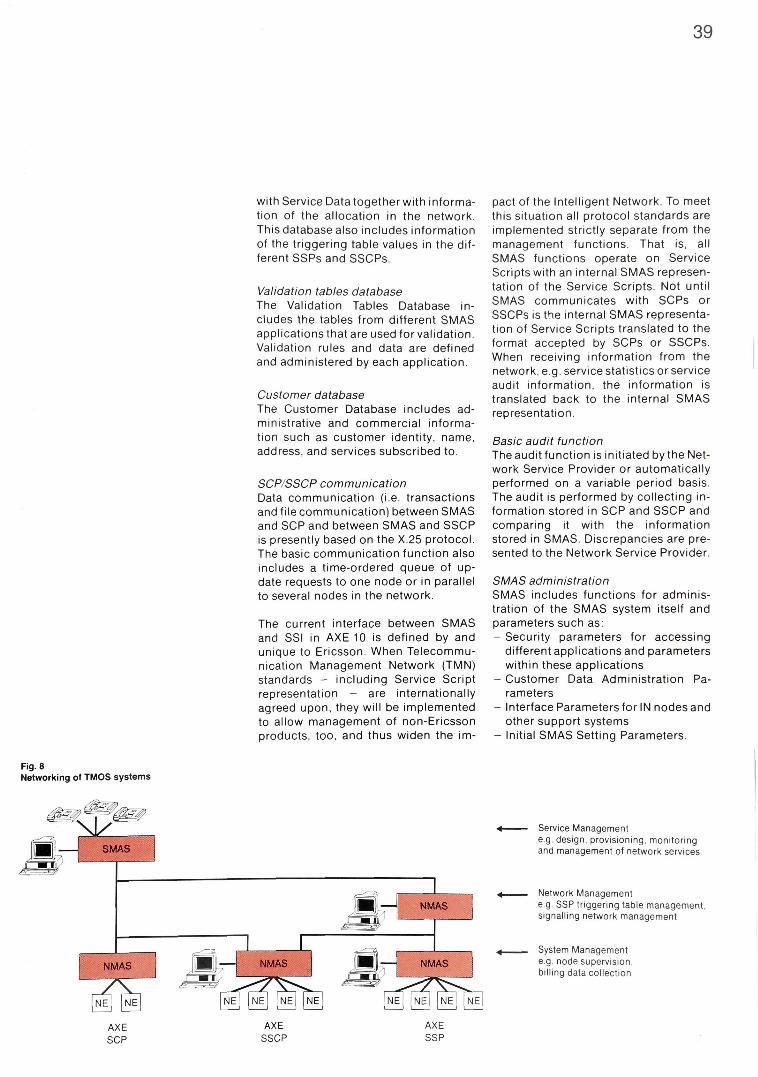
39
Fig. 8 Networking of TMOS systems
with Service Data together with information of the allocation in the network. This database also includes information of the triggering table values in the different SSPs and SSCPs.
Validation tables database The Validation Tables Database includes the tables from different SMAS applications that are used for validation. Validation rules and data are defined and administered by each application.
Customer database The Customer Database includes administrative and commercial information such as customer identity, name, address, and services subscribed to.
SCP/SSCP communication Data communication (i.e. transactions and file communication) between SMAS and SCP and between SMAS and SSCP is presently based on the X.25 protocol. The basic communication function also includes a time-ordered queue of update requests to one node or in parallel to several nodes in the network.
The current interface between SMAS and SSI in AXE 10 is defined by and unique to Ericsson. When Telecommunication Management Network (TMN) standards - including Service Script representation - are internationally agreed upon, they will be implemented to allow management of non-Ericsson products, too, and thus widen the im
pact of the Intelligent Network. To meet this situation all protocol standards are implemented strictly separate from the management functions. That is, all SMAS functions operate on Service Scripts with an internal SMAS representation of the Service Scripts. Not until SMAS communicates with SCPs or SSCPs is the internal SMAS representation of Service Scripts translated to the format accepted by SCPs or SSCPs. When receiving information from the network, e.g. service statistics or service audit information, the information is translated back to the internal SMAS representation.
Basic audit function The audit function is initiated by the Network Service Provider or automatically performed on a variable period basis. The audit is performed by collecting information stored in SCP and SSCP and comparing it with the information stored in SMAS. Discrepancies are presented to the Network Service Provider.
SMAS administration SMAS includes functions for administration of the SMAS system itself and parameters such as: - Security parameters for accessing
different applications and parameters within these applications
- Customer Data Administration Parameters
- Interface Parameters for IN nodes and other support systems
- Initial SMAS Setting Parameters.

40
Fig. 9 Example of SMAS Hardware Configuration
References 1 Soderberg, L : Architecture for Intelli
gent Networks. Ericsson Review 66 (1989):1, pp. 1 3 - 2 2 .
2 Van Hal, P., van de Meer, J. and Salah, N.: The Service Script Interpreter, an Advanced Intelligent Network Platform. Ericsson Review 67(1990) :1, pp. 1 2 - 2 2 .
3 Abramowicz, H. and L indberg, A.: OSI for Telecommunications Applications. Ericsson Review 66(1989):1, pp. 2 - 1 2 .
Total intelligent network management SMAS is one member of the Ericsson TELECOMMUNICATIONS MANAGEMENT AND OPERATIONS SUPPORT (TMOS) family. TMOS addresses every aspect of the management of the Intelligent Network, box 1.
The open system characteristics of TMOS, and the associated design system, allow for application development under full Network Operator control in order to integrate SMAS and other TMOS applications in its unique operations support environment. The modularity and layered structure of TMOS facilitates the conf iguraton of TMOS applications according to the Network Operator's needs. TMOS applications can be combined and run on the same hardware configuration, or networked as shown in fig. 8.
The hardware modularity of TMOS makes it possible to configure an SMAS from very small systems on laptopcom-
puters up to large systems on fault tolerant high capacity hardware; there are virtually no system limitations in the number of connected exchanges or users. As the network grows, more SMAS processing capacity can be added. Fig. 9 shows a typical hardware configuration on which SMAS is based. This figure is an example only and is neither a maximum nor a minimum configuration.
Conclusions TMOS provides a single, integrated solution to all management operations of the Intelligent Network. The TMOS application SMAS provides a striking example of the flexibility of the AXE 10 IN platform, SSI, and gives the Network Service Provider the necessary support to rapidly design network services for his own customers and introduce these services in the network. Thus, TMOS in general and SMAS in particular are the means to meet the demands for service provisioning in a competitive environment.
Box 1 - T M O S
TMOS (TELECOMMUNICATIONS MANAGEMENT AND OPERATIONS SUPPORT) is a family of systems for computerized management and operations support of public telecommunication networks. TMOS will provide Telecom Administrations with single, integrated solutions to all management operations in fixed and mobile networks.
To date there are five application systems in TMOS, each aimed at a specific area of the telecommunications infrastructure: NMAS Network Management System for the
switched network FMAS Facility Management System for the
transport network
SMAS Service Management System for the Intelligent Network
CMAS Cellular Management System for the mobile telecom networks
BMAS Business Management System for Cen-trex and Virtual Private Networks
The TMOS concept means that any of the five individual systems can be used as a stand-alone system. Furthermore, each individual system is constructed in a modular way, to allow for any useful combination.
However, TMOS also allows for a combination of the different systems, which will provide an integrated management platform for the total network service offering. By combining different applications, customized operations support systems can be created.
The systems have been designed to conform to the emerging ANSI/CCITT Telecommunication Management Network (TMN) standards for operations support systems, to enable them to be used to control equipment in multi-vendor networks as well as to cooperate with non-Ericsson support systems, fig. A.
They also conform to the X/Open Common Applications Environment (CAE), which lays down standards for software portability across different computer systems. This will allow customers to chose the hardware on which to run TMOS applications from a wide variety of manufacturers, and to dimension systems according to their needs. The systems are run in a UNIX environment, assuring access to development support - as does the use of the C++ programming language in critical portions of the systems.
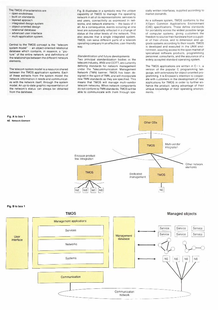
TheTMOS characteristics are - open-endedness - built on standards - layered appoach - integrated design system - object-oriented design - relational database - advanced user interface - multi-application system.
Central to the TMOS concept is the "telecom system model" - an object-oriented relational database which contains, in essence, a "picture" of the entire network, and definitions of the relationships between the different network elements.
The telecom system model is a resource shared between the TMOS application systems. Each of these extracts from the system model the network information it needs and communicates with the network itself, through the system model. An up-to-date graphic representation of the network's status can always be obtained from the database.
Fig. B illustrates in a symbolic way the unique capability of TMOS to manage the operating network in all of its representations: services to end users, connectivity as expressed in networks, and network elements - the basis of it all. As a consequence, events occuring at one level are automatically reflected in a change of status at the other levels of the network. This also assures that a single integrated system, TMOS, can serve different parts of a telecom operating company in an effective, user-friendly way.
Standardization and future developments Two principal standardization bodies in the telecom industry, ANSI and CCITT, are currently defining standards for network management under the Telecommunication Management Network (TMN) banner. TMOS has been designed in the spirit of TMN, and will incorporate new TMN standards as they are specified. This means that TMOS will manage multi-vendor telecom networks. When network components do not conform to TMN standards, TMOS will be able to communicate with them through spe
cially written interfaces, supplied according to market demands.
As a software system, TMOS conforms to the X/Open Common Applications Environment (CAE) specifications. These define standards for portability across the widest possible range of computer systems, giving customers the freedom to source their hardware from a supplier of their choice, and to dimension and upgrade systems according to their needs. TMOS is developed and executed in the UNIX environment, assuring access to the open market of specialized software products, programming personnel, consultants, and the assurance of a widely accepted standard operating system.
The TMOS applications are written in C + + , a version of the popular C programming language, with extensions for object-oriented programming. It is Ericsson's intention to cooperate with customers in the development of new applications for TMOS in order to further enhance the product, taking advantage of their unique knowledge of their operating environments.
Fig. A to box 1
NE Network Element
Fig. B to box 1
Managed objects
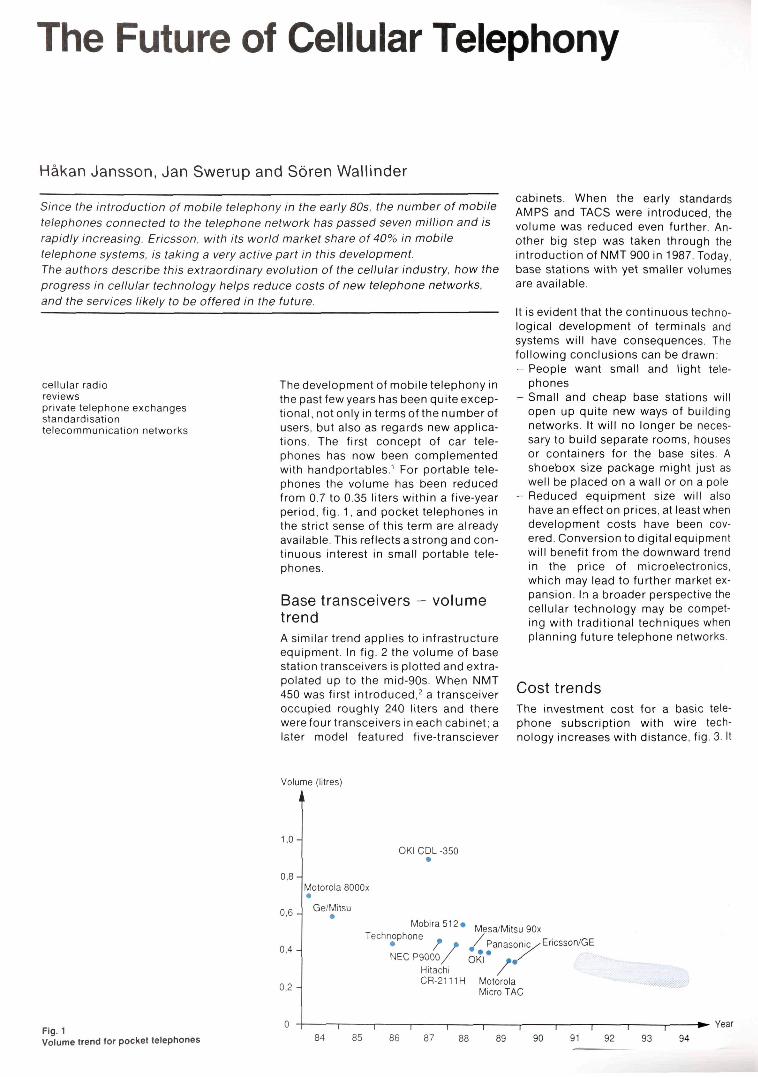
The Future of Cellular Telephony
Hakan Jansson, Jan Swerup and Soren Wallinder
Since the introduction of mobile telephony in the early 80s, the number of mobile telephones connected to the telephone network has passed seven million and is rapidly increasing. Ericsson, with its world market share of 40% in mobile telephone systems, is taking a very active part in this development. The authors describe this extraordinary evolution of the cellular industry, how the progress in cellular technology helps reduce costs of new telephone networks, and the services likely to be offered in the future.
cellular radio reviews private te lephone exchanges standardisat ion te lecommunica t ion networks
The development of mobile telephony in the past few years has been quite exceptional, not only in terms of the number of users, but also as regards new applications. The first concept of car telephones has now been complemented with handportables.1 For portable telephones the volume has been reduced from 0.7 to 0.35 liters within a five-year period, fig. 1, and pocket telephones in the strict sense of this term are already available. This reflects a strong and continuous interest in small portable telephones.
Base transceivers - volume trend A similar trend applies to infrastructure equipment. In fig. 2 the volume of base station transceivers is plotted and extrapolated up to the mid-90s When NMT 450 was first introduced,2 a transceiver occupied roughly 240 liters and there were four transceivers in each cabinet; a later model featured five-transciever
cabinets. When the early standards AMPS and TACS were introduced, the volume was reduced even further. Another big step was taken through the introduction of NMT 900 in 1987. Today, base stations with yet smaller volumes are available.
It is evident that the continuous technological development of terminals and systems will have consequences. The following conclusions can be drawn: - People want small and light tele
phones - Small and cheap base stations will
open up quite new ways of building networks. It will no longer be necessary to build separate rooms, houses or containers for the base sites. A shoebox size package might just as well be placed on a wall or on a pole
- Reduced equipment size will also have an effect on prices, at least when development costs have been covered. Conversion to digital equipment will benefit from the downward trend in the price of microelectronics, which may lead to further market expansion. In a broader perspective the cellular technology may be competing with traditional techniques when planning future telephone networks.
Cost trends The investment cost for a basic telephone subscription with wire technology increases with distance, fig. 3. It
Fig. 1 Volume trend for pocket telephones

SOREN WALLINDER Swedish Telecommunications Administration HAKAN JANSSON JANSWERUP Ericsson Radio Systems AB
also increases with time, as labour costs are going up. The cost reduction through development is not large enough to outbalance the rising costs of labour.
In the case of radio equipment, capital investments start at a higher level - with the setting up of a base station. This cost is effective up to the cell border, where extra investments have to be made; either in the form of a new base station or some kind of repeater.
Since radio technology is not yet fully exploited, the cost decreases quite rapidly with time. As has been mentioned already, this is particularly true of cellular equipment because it represents an area of great interest. The break-even point where radio becomes cheaper than wire is rapidly shifting towards shorter distance. This means that cellular technology can be used not only in remote Malaysian villages3, box 1, but also in more densely populated areas like suburbs, and even in the cities.
Fig. 2 Volume trend for radio base transceivers
Fig. 3 Cost versus distance trend for wire and radio Radio is becoming economically attractive for shorter distances

SEKx 1000 per subscriber
Box 1 RADIO IN THE LOCAL LOOP The attractiveness of radio in the local loop will, in the long run, be determined by the relationship between investment costs for wire and those for radio. Investment costs for a cellular radio network were analyzed by Banque Paribas8 in 1988, fig. A.
The Swedish wire telephone network covers the whole country. Considering the actual costs involved, not all subscriptions are sufficiently revenue-generating to break even. With the intention of reducing the necessary rural subsidies, Swedish Telecommunications Administration has made an investigation into the economy in different parts of the existing network, fig. B.
New technological possibilities of reducing costs were explored. Studies involved tests of cellular telephones, powered from the normal mains and using roof antennas. Subscribers paid normal rates and were given normal numbers, as if they were connected to the wire network. The possibility of data communication was also included as an option. The results were favourable and showed that radio will play an important role in the future.
Fig. A to box 1 Investment per subscriber for GSM cellular radio network, including terminal, infrastructure and mobile switch Source: Banque Paribas
It thus seems possible to build complete telephone networks at a lower price with cellular technology than with wire, and the digital radio technology further accentuates this shift in cost structure. The reason why networks are not already built in this way is twofold: - People are not yet aware of the trends
and of the new possibilities - More frequency spectrum must be al
located in order to take full advantage of the new technology. The UK is allocating additional spectrum in the 1800 MHz band for a GSM-based PCN service.
So far only investment costs have been taken into account. If maintenance is also considered, cellular radio offers further advantages. Network equipment is concentrated to a limited number of locations. Instead of helicoptering over the countryside to inspect for broken wires or cables, a visit to a base station will suffice to clear a fault.
The personal telephone There is every reason to believe that people want to use pocket telephones in the future, instead of wire telephones. That would mark the event of the "personal telephone", which will become a reality when the following three main requirements have been met: - The telephone must be small and light
enough to be carried comfortably in a shirt pocket
- It must provide coverage and facilities with such a quality that no other telephone is needed
- It must be cheap (prime cost and charges).
When these characteristics have been achieved, people will no longer dial to reach a home telephone, or an office desk telephone which is seldom answered. If they want to get in touch with a person, they just call a personal telephone. People want to call people; they don't want to call places.
Personal telephone numbers in traditional telephony have been discussed for many years. Modern telephone exchanges and PABXs include the diversion (Follow Me) facility, which could be used to make calls follow a person. It demands rerouting commands from the user, even if simplified procedures can be introduced with smart cards. A cellular telephone performs these functions automatically and is always within reach. It may well be that the cellular technology and the personal telephone will speed up the introduction of personal telephone numbers. The called person might want to know whether an incoming call concerns his work, his private life or even some particular function he may have in society. A personal number for each function would make it possible to distinguish between different types of call.
Cellular technology already meets the three requirements specified above: small size, wide area coverage and good economy, at least in some countries. Also, the number of a cellular telephone can be regarded as a personal number.
In the following, a number of applications of radio telephony in different market segments will be discussed, fig. 4.
Fig. B to box 1 Investment per subscriber in the present Swedish wire network, including terminal, local loop and local exchange Source: Swedish Telecommunications Administration
44

45
Market segments The office The wireless PABX is geared to serve the office segment. It has the obvious advantage of enabling people to make and receive calls at any place in the office, and it saves the company administrative costs. When reorganizing and moving staff from one office to another, no cables have to be rearranged and no data changed. People just take their telephones along and can use them directly, without having to wait for someone else to make wire or program changes. Today, companies have to bear great expenses for the rearrangement of equipment, and for the resulting loss of production.
The mobility of telephones under the wireless PABX can be extended by arranging extra coverage outside the office area. This could be done by locating base stations or telepoints in strategic places, providing a pattern of discontinuous coverage. If the users want especially good coverage, it may be a good idea for a number of companies to join forces and build a common system. In this way they can share the costs of coverage, and perhaps even take over some part of the public service.
The business userwill use histelephone for speech and for simple data applica
tions, such as displaying the number of the calling party. A laptop PC would of course benefit from an attached pocket phone for electronic mail or file transfer,4 even if the transmission speed would be some ten thousand bits per second. Communication of larger amounts of data will be through a desktop PC or a terminal with broadband fibre connection.
The telephone will be served by company owned picocells connecting the user to the PABX and through it onwards to the PSTN/ISDN. All features of the PABX will be directly accessible. A three-dimensional structure can be arranged with one or more cells on each floor. An indoor system requires very low power levels, both at the base station and at the telephone. This means low battery drain and the corresponding increase of the operating time.
A wireless PABX has been used as an example, but communication service for the office could also be offered by one of the cellular operators in a cen-trex-like service: "cellular centrex". In conventional centrex applications, a company's extensions are wired to the local telephone exchange, where they are switched and supplied with extra features used in the office. In a cellular application, traffic will first pass
Fig. 4 Market segments for personal telephones
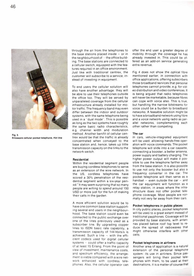
through the air from the telephones to the base stations placed inside - or in the neighbourhood of - the office building. The base stations are connected to a cellular switch, equipped with the features required in an office environment. Just like with traditional centrex, the customer will subscribe to a service, instead of investing in equipment.
To end users the cellular solution will also have another advantage: they will be able to use their telephones outside the office too. They will be served by unparalleled coverage from the cellular infrastructure already installed for motor traffic. The frequency band may even differ between the indoor and outdoor systems, with the same telephone being used in a "dual mode". This is possible as long as the two systems have roughly the same basic radio characteristics, e.g. channel width and modulation method. Another benifit of cellular centrex would be that the traffic is already concentrated when conveyed to the base station and, hence, takes up little transmission capacity on the links to the network switch.
Residential Within the residential segment people are buying cordless telephones to serve as an extension of the wire network. In the US, cordless telephones have scored a 30% penetration of the residential segment within a six-year period.7 It may seem surprising that so many people are willing to spend around 150 USD or more just for the fun of making their calls in the garden.
A more efficient solution would be to have one common base station supporting several end users in the neighbourhood. The base station could even be connected to the public exchange over one of the lines previously used as a subscriber line. By upgrading copper lines to ISDN basic rate capability, a transmission capacity of 144 kbits/s is achieved. Such a line - with the efficient codecs used for digital cellular systems - could offer a traffic capacity of at least 15 Erlang. From the point of view of investment, maintenance costs, and spectrum efficiency, the arrangement is viable compared with a wire network enhanced with cordless telephones. Also, the cellular operator can
offer the end user a greater degree of mobility through the coverage he has already invested in. This could be offered as an add-on service generating extra revenue.
Fig. 4 does not show the optical fibre mentioned earlier, in connection with office applications, offering subscribers those broadband services that personal telephones cannot provide; e.g. for video distribution and video conferences. It is being argued that radio telephones will never be marketable, because fibres can cope with voice also. This is true, but handling the narrow bitstreams for voice could be a burden to broadband networks. A feasable solution might be to have a broadband network using fibre and a voice network using radio as parallel networks, complementing each other rather than competing.
The car In cars, vehicle-integrated equipment will be used, allowing hands-free operation with voice commands. The pocket telephone will slide into a car cassette, connecting a booster, a better antenna, power supply and battery charging. The higher power output will make it possible to use the telephone farther away from the base station. It is also possible to use not only the booster but also a frequency converter in the car. The pocket telephone will then serve as a handset - even outside the car - and the car equipment will function as a relay station, in areas where the infrastructure does not offer pocket telephone coverage. Most people are normally not very far away from their cars.
Pocket telephones in public places In city public places, pocket telephones will be used to a great extent instead of traditional payphones. Coverage will be provided by base stations, with antennas placed below roof top level to reduce the spread of radiowaves that might otherwise interfere with other cells.
Pocket telephones in airliners Another area of application is a natural extension of the personal telephone system: its use in airliners. Since passengers will bring their pocket telephones with them, to be used at their destinations, it is a matter of course that
Fig. 5 Ericssons cellular pocket telephone, Hot line

47
this facility should be utilized on the journey too. It will require equipment that consumes less power than today's products, to avoid interference with ground cellular systems or with the airliner's control and communication systems. The user may also find data or text communication more attractive than voice service, since space in the cabin is normally so limited that he cannot prevent other passengers from listening to his telephone conversation.
The link to car electronics Another worthwhile application of cellular telephony is in the vehicle industry. A communication channel between new electronic systems in cars and central information sources would improve efficiency and safety. Queues could be reduced by informing drivers or their navigation systems about congestions in the traffic. Safety could be increased by informing the cars' speed control systems about slippery roads or accidents ahead. Important steps in this area are being taken through the EC-backed Prometheus project. In at least some of these new applications, cellular telephony would be economically viable, since most cars would be equipped with a mobile telephone anyway.
The war of standards The initial standard (for analog cordless telephones) in the residential segment was followed by the UK/CT2 standard. CT2 was the first standard to be introduced for digital radio transmission. It is based on frequency division multiple access, FDMA. CT2 also includes an invention called telepoint, which allows end users to use their telephones in certain public places. However, incoming calls can so far only be received in the area covered by the subscriber's "personal" base station located in his home or office.
The European DECT standard focuses on the office segment. It uses a wideband time division (TDMA) scheme, which means that one base station can provide high capacity at a low cost. Even if the pocket telephones themselves are slightly more expensive than traditional telephones, the principle applied optimizes the total cost of an office application. DECT also uses an adaptive channel allocation concept in order to minimize the spectrum needed and to make frequency planning unnecessary. For a PABX, cell and frequency coordination would otherwise become a heavy burden.
Fig. 6 Pocket telephones can be used in most situations
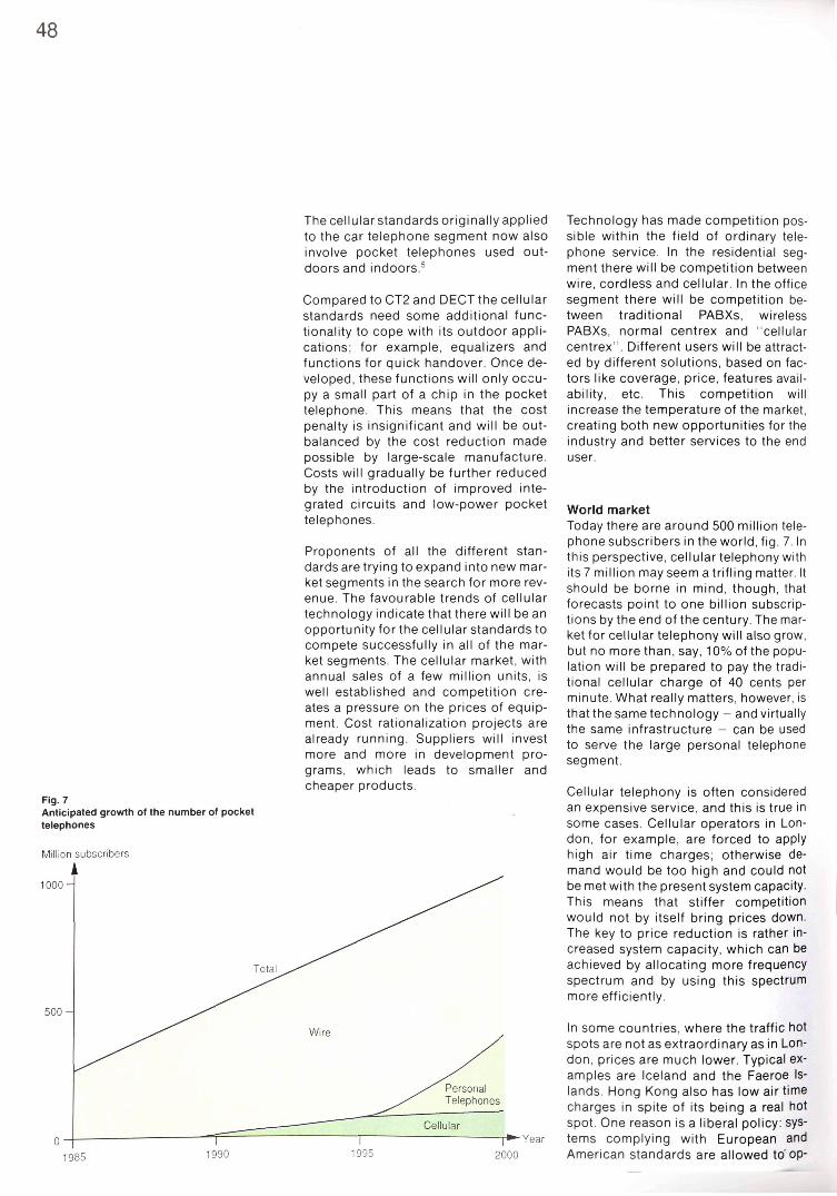
48
Fig. 7 Anticipated growth of the number of pocket telephones
The cellular standards originally applied to the car telephone segment now also involve pocket telephones used outdoors and indoors.5
Compared to CT2 and DECT the cellular standards need some additional functionality to cope with its outdoor applications; for example, equalizers and functions for quick handover. Once developed, these functions will only occupy a small part of a chip in the pocket telephone. This means that the cost penalty is insignificant and will be outbalanced by the cost reduction made possible by large-scale manufacture. Costs will gradually be further reduced by the introduction of improved integrated circuits and low-power pocket telephones.
Proponents of all the different standards are trying to expand into new market segments in the search for more revenue. The favourable trends of cellular technology indicate that there will be an opportunity for the cellular standards to compete successfully in all of the market segments. The cellular market, with annual sales of a few million units, is well established and competition creates a pressure on the prices of equipment. Cost rationalization projects are already running. Suppliers will invest more and more in development programs, which leads to smaller and cheaper products.
Technology has made competition possible within the field of ordinary telephone service. In the residential segment there will be competition between wire, cordless and cellular. In the office segment there will be competition between traditional PABXs, wireless PABXs, normal centrex and "cellular centrex". Different users will be attracted by different solutions, based on factors like coverage, price, features availability, etc. This competition will increase the temperature of the market, creating both new opportunities for the industry and better services to the end user.
World market Today there are around 500 million telephone subscribers in the world, fig. 7. In this perspective, cellular telephony with its 7 million may seem a trifling matter. It should be borne in mind, though, that forecasts point to one billion subscriptions by the end of the century. The market for cellular telephony will also grow, but no more than, say, 10% of the population will be prepared to pay the traditional cellular charge of 40 cents per minute. What really matters, however, is that the sametechnology - and virtually the same infrastructure - can be used to serve the large personal telephone segment.
Cellular telephony is often considered an expensive service, and this is true in some cases. Cellular operators in London, for example, are forced to apply high air time charges; otherwise demand would be too high and could not be met with the present system capacity. This means that stiffer competition would not by itself bring prices down. The key to price reduction is rather increased system capacity, which can be achieved by allocating more frequency spectrum and by using this spectrum more efficiently.
In some countries, where the traffic hot spots are not as extraordinary as in London, prices are much lower. Typical examples are Iceland and the Faeroe Islands. Hong Kong also has low air time charges in spite of its being a real hot spot. One reason is a liberal policy: systems complying with European and American standards are allowed to'op-

49
erate side by side. Hong Kong has allocated more frequency spectrum for cellular telephony than any other market in the world, and the air-time charge is about 16 cents (US) a minute.
So, cellular service in itself need not be expensive, provided that frequency spectrum is allocated in proportion to the need in heavy traffic areas. Today's price and rate floor is around 1000 USD for a pocket phone and 16 cents a minute. It is difficult to foretell the future price development, but the afore-mentioned technological trends indicate 50% reduction every 5 years. Such price levels would certainly attract a large number of users - those who would normally buy a wire telephone, a private mobile radio, a cordless, or even a pager.
Such a large market, as indicated in fig. 7, requires a more flexible and cost-based pricing strategy. In his home, the user might not be charged a higher fee than today's fee for a wire telephone. When he uses his pocket telephone downtown he utilizes more valuable resources - since the demand for frequency spectrum is greater - and might therefore pay more for this service. Making or receiving calls in a car could entail yet higher charges, since it means utilizing more resources in the form of frequency spectrum and real-time processing.
Fig. 8 The future cellular network will include different layers of cells
Another pricing issue will arise in the office application, where corporate rates have to be applied to place cellular telephony on a level with competing alternatives.
It is thus possible for network operators to adopt a pricing strategy that maintains higher profits in the traditional cellular segment, while at the same time entering another more price-sensitive market segment. This is important, since a network operator that profitably covers traditional cellular telephony would like to retain favourable prices in that market segment, when entering a new one. In some cases the revenues from profitable segments may be used for investments in less profitable ones. An example of this is the way PTTs can use cellular telephony to provide basic telephone service in remote areas.
Future cell structure A difficulty which system designers frequently encounter is that of coping with changing traffic needs.6 Most cities are crowded in the daytime, and the only thing drivers stuck in traffic jams can do is make telephone calls. The traffic pattern is characterized by high volume and slowly moving telephones, in cars or on the pavement. At night, when the jams are dissolved, the traffic volume is lower and the cars are moving fast. The problem is how to serve these two types of traffic efficiently.
One simple way would be to have two different systems, one for slowly moving pocket telephones and another for car telephones. But this will not solve the problem, since even with cars both types of traffic pattern occur. A better idea would be to employ one system, but split it up into two different tiers of cells: large umbrella cells for fast moving telephones and microcells for those moving slowly. In order to achieve optimal frequency spectrum efficiency, frequencies could be dynamically allocated to the two tiers as determined by the traffic situation.
Special attention will have to be paid to the arrangement of street cells. When a car turns round a corner, the signal strength from the street cell behind will decrease very quickly, while that from

50
Fig. 9 The future cellular network will include separate layers of network intelligence and switching nodes
the "oncoming" street cell will rapidly increase. Enough time must be allocated for the system to measure and evaluate the signal strength in order to decide to which base station the call should be handed over. Fortunately, the nature of drivers is to some extent friendly to the system: cars normally slow down before turning.
In some cases a long cell covering the street is the best solution. If the street crossing is arranged for high speed even when cars are turning, the best arrangement may be a cloverleaf antenna illuminating all the four directions of the intersection. If a car is moving too fast to allow successful handover, it will have to be allocated a channel from the more precious umbrella cell. This cell must not be as large as today's umbrella cells of 50 kilometers radius or more; it should rather be built up of small cells with up to one or a few km radius.
The two tiers of outdoor cells have to work in complementary mode, since
they serve basically the same traffic needs. This arrangement is similar to gradings in traditional telephone systems, where the overflows from several direct routes are switched over a common route via a transit node. Indoors, picocells serve traffic originating from slowly moving pocket telephones. Charging will most probably be much lower when end users are indoors and use the office system, compared with their utilizing the more advanced outdoor base stations. They should therefore be given the possibility of deciding whether they wish to make phone calls at a cheap rate or with the best possible service.
The network of the future When mobile telephones represent a substantial portion of the total number of telephones a quite new situation arises. There will be a dramatic increase

51
in the number of switching points capable of handling mobile communication. It will eventually lead to a network as big as today's telephone network.
The regulatory environments in different countries determine what the new networks are called: cellular networks, or Personal Communications Networks (PCN), for example. Sometimes they are PSTNs using radio as a transmission medium. However, the basic principles for building the networks remain the same, fig. 9.
Access to PSTN What we are witnessing today is the gradual changeover from wire to radio telephones, base stations providing the new access technique, replacing old line cards. Network structure and network integration will be even more important than in today's cellular networks. The network will most likely be based on the same principles as large-scale wire networks, with several levels of switches in a hierarchical structure. These levels can have nodes of different types, such as transit nodes and access nodes. The specific network design and dimensioning will be based on the services demanded, and on the traffic handling capacity.
Nodes for specific functions - not necessarily for voice communication - may be used: STP nodes, Signalling Transfer Points for Signalling System No. 7, and nodes to which telephone-operator positions are connected.
Charging principles To allow end users to inform themselves of the charging of their calls is a matter of prime importance. There should be clear indications of whether they are making "short distance" or "long distance" calls. An appropriate numbering plan must therefore be designed - for the PSTN and for the mobile networks.
The numbering plan may not provide an adequate information base for determining the charge for a call. If the person called has left for another country, or is actually in the airliner, the call will probably be more expensive than what can be deduced from the number
dialled. Either the calling party must have the correct charging information or the excess charge must be paid by the called party, who has caused the extra cost.
Subscriber data bases For incoming calls it is necessary to keep track of an end user's whereabouts. The cellular network needs databases and advanced signalling systems for this purpose. It pays to adhere to the old concept "signalling before switching". The cost of switching will be lower if the originating exchange first finds out where to get in touch with the called party; the call will then be switched to that exchange. This is an element of the Intelligent Network approach: the network service can be improved with new features by upgrading a few nodes containing databases or feature intelligence.
The centralized Home Location Register, HLR, is an example of a separate network database, where "separate" means that it may be used as a standalone unit, with communication on data links to other network nodes. Database information can be provided in different ways: - A sufficient number of different data
bases are installed by each network operator
- Two or more network operators share nodes and databases, by common use of an HLR, for example. If the database serves an area that is large enough, it might be of interest from a security point of view to use duplicated units in a loadsharing mode
- Several network operators together use databases run by another operator. An example of this arrangement is AT&T's running of databases for the 800 service for several Regional Bell Operating Companies.
The European CEPT/GSM standard will lead to the use of specialized network nodes related to the mobility of end users. HLR, Home Location Register, is an example of such a node. What GSM actually provides is a structured way of describing a cellular radio network. This is similar to the way OSI describes data network communication protocols. Today GSM is the most advanced specifi-

52
Easier implementation More attractive
cation in the wor ld, as far as mobile network definit ions are concerned.
adaptation to changing situations as networks evolve.
References 1 Jismalm, G. and Rydbeck, N.: Ericsson
Telephones for Cellular Systems. Ericsson Review 64 (1987):3, pp. 141-150.
2 Sdderholm, G., Widmark, J. and Orn-ulf, E.: Ericsson Cellular Mobile Telephone Systems. Ericsson Review 64 (1987):B, pp. 42-49.
3 KhirBinHarun.M.andOmholt, R Malaysia Cellular System - Pioneer in Asia. Ericsson Review 64 (1987):3, pp. 151-159.
4 Beddoes, E. and Pinches, M.: Cellular Radio Telephony - the Racal-VODA-FONE Network in Great Brittain. Ericsson Review 64 (1987):3, pp. 120-140.
5 Lindell, F., Swerup, J. and Uddenfeldt, J.: Digital Cellular Radio for the Future. Ericsson Review 64 (1987):3, pp. 160-168.
6 Lejdal, J.-O. and Lindqvist, H.: Cellular Network Planning is Maximizing System Economy. Ericsson Review 64 (1987):3, pp. 122-129.
7 Arthur D. Little: The Market Requirements up to the Year 2000 for Cordless Telephone Products in Europe and the Means to Satisfy these Market Needs. January 1989.
8 Banque Paribas Capital Markets, The European Market for Mobile Communications. August 1988.
Demand for efficient operation The cellular market will keep growing. The larger supply of system capacity wil l lead to lower air t ime cost per call. This in turn will lead to a demand for more efficient operat ion. In the early days of cel lulartelephony unsuff icient attention was paid to operating costs. The main thing for an operator was to get started quickly, and then to expand and adapt to the traffic growth. In the future much more attention wil l be paid to operation and maintenance costs.
A way to cut operation and maintenance costs is to build up an organizat ion opt i mized for the geographic layout of the network. The maintenance system should be such as to allow - operation of the network f rom region
al offices - closing down some operational cen
tres at night and shift ing the supervision of those regions to other centres
- operation of a wire network, a cellular network and data networks f rom the same regional centre
The development of cellular technology The capacity of the infrastructure grows with each base station added. The cells are becoming smaller. More users will gradually have a base station within closer range, and power levels can be lowered. This in turn will lead to smaller and cheaper equipment. Smaller base stations wil l make network implementation easier, and smaller telephones will lead to better user acceptance. The larger market will need more capacity, which again calls for even smaller cells, and so on.
The mobile telephone business has a dazzling future. Users will benefit from personal telephones. For network operators and suppliers it is a matter of seizing the great opportunit ies that lie ahead. But, most importantly, to capitalize on the possibil it ies inherent in cellular technology, companies will have to exploit their combined knowledge of radio and telephony.


ERICSSON