ER-40&50 Evo features - Electron retracts · 2 Retracts installation,operation, and maintenance...
33
Transcript of ER-40&50 Evo features - Electron retracts · 2 Retracts installation,operation, and maintenance...


1
Dear customer, congratulations on the purchase of your new electric retracts system. Electron are dedicated to design and production of electric retracts to the highest standards of quality and reliability to bring you the customer the very latest next generation designs.
ER-40&50 Evo features
Size Retract
Retraction
angle (degree)
Trunion hole
Weight one retract
Max
plane weight
Cicle time
Garantee
stall torque
ER-40 70,80, 85, 90, 100
5,6,8,10,11,12, 12.7mm (1/2”), 13mm
140gr 17kg About 4.5sec
25kgxcm
ER-50 90, 100
6,8,10,11,12,12.7mm (1/2”), 13, 14, 15, 16mm
260gr 30kg About 6sec
45kgxcm

2
Retracts installation,operation, and maintenance
Installation:
Installation is simple. The Retracts have a standar clamping, and its installation is similar to any
standard retract. An advantage of the electric retract, is that installations of complex valves and
air circuits are unnecessary. The Retracts are supplied with 1m long cable which is directly
connected to the control unit. If the cable is not long enough, it can be extended with the correct
polarity. Is advisable prolong just the necessary length to avoid voltage drops.
Operation:
The operation of retracts, is the best quality of electric retracts. You will notice the advantage of
not having to compress air before each flight, and you will forget the leaks…
Retracts must be operated always through Electron Control units. Never operate the retracts with
direct battery or with other brands control units. Electron Retracts only warrants their retracts
with Electron controllers.

3
Wiring diagram

4
The battery recommended to power the retracts is a 2S (7.4V) LiPo. With 500-900mAh battery
you will have power enough for all flying day. If you choose another battery, you must keep in
mind that the battery must have between 7-10V. Electron recommends don´t sharing the receiver
battery, to avoid problems in the receiver system. Use always a single small battery only for
retracts system.
If you need move one retract for mount your model, you will can connect the battery (2S LiPo)
few seconds direct to the retract. You will can invert the polarity to move it in two sense.
ATTENTION!!: after reaching the end of the cycle does not leave the battery connected! you will
burn the motor.
Electron retracts control units, detect the finals of cycles by the increase of current. All eVo
retracts are equipped with internal absorbers for compensate this high current and torque, to
save the gear boxes. Is important to keep the absorbers in good conditions. Special software in
our control units, help to keep all absorption power of the absorbers.You will can hear a small
noise at finals of cycles. Don´t worry, it is a small unload, to liberate the absorbers and maintain it
free by long time periods, for proper conservation.

5
Maintenance:
Like any mechanical system, it requires minimal maintenance to ensure long product life.
Below is the recommended maintenance, and repair procedure if the retract was suffers damages
after hard landings or any incident.
Electron retracts has designed very compact systems for need a low maintenance. The spindle
system are made in auto lubricate materials, and all “delicate” parts are very protected by the
high strength 7075 aluminium black main body.
Is advisable keep the spindle clean and lubed, specially if your plane flies on unpaved runways.
Electron grease is a special grease for spindles, easy to apply. After clean, apply 2 drops of grease
in both sides of slider.

6
Retracts Trouble shooting
Problems
Solutions
The retract make noise, but doesn´t move -Disassembled the gear motor and check the gear boxes. Probably any gear have broken tooth. Change it. Page(7)
The retract don´t move, and don´t make any noise -Sure it is properly connected and battery charged - Disassembled the gear motor, and test it, maybe has an internal damaged. Change it Page(7)
My retract loss torque and have not power enough to lift up my strut
-Please clean the spindle, bearings, and lube it
After a hard landing, my retract don´t runs well -sure that the spindle and high strength carbon steel cart are not twisted. Change it if necessary. Page (8)
After a hard landing, my retract have play or trunion breaks
-Guide bushings and trunion have damages. Change it Page(9)
Retract don´t reach 90º when it lifting -Check the trunion screws, if it is unscrewed can colliding with the main body.
Different sense retraction between retracts -Please check the correct polarity connection
Rudder servo runs when nose retract is up -Check the correct polarity connection

7
Procedure to disassemble and change parts:
Pic1 shows how disassemble the gear motor to change it. Are three steps:
Step1: Remove electron labels
Step2: Remove M2.5 screws, located on the sides of gear motor
Step3: Remove M2 screws, located in the front of gear motor

8
Pic2 shows how remove the spindle system.
Once disassembled the engine (Pic1), you can unscrew the spindle, and remove it with axial
bearings and absorbers. The spindle cart can remove by a side of main body once the spindle is
removed as shows the pic2.
Be careful not to change the order of bearing races. The bearing races, have different diameters,
to allow the correct rotation of spindle. The smaller outer diameter (9.8mm) must be located in
the ring absorber sides as shows the Pic2.

9
Pic 3 shows how remove the trunion and bushings. First, you need remove the trunion axle. You
can extract it, gently tapping. Never hot the system!. After remove the trunion, you will can take
off the bushings pushing them from the main body sides.

10

11
Electromagnetic brakes Manual
Electron magnetic brakes have gone a long development process to achieve a high quality
product. Electron have used high-tech materials, to achieve a proportionate effect and low
current consumption.
Brake features (single Wheel)
Weight
(complete Wheel)
Electric current
consumption at full brake with 2S liPo (8V)
Electric current
consumption at full brake with 3S liPo
(12V)
Maximum braking torque at 8V, 2S
LiPo
Maximum braking torque at 12V, 3S
LiPo
Solenoid impedance
190Gr
1A
1.45A
11kg.cm
18kg.cm
7.8 ohmios

12
Installation:
Installation is simple. The brake disk must be guided by five pins inside wheel. 5 pins must insert
into the holes of the disc. Rubber segments on the disc must be on the electromagnet side.
Electromagnet is guided by the wheel axle, and normally this is fixed in the leg by radial screw.
If your leg have a screw instead of axle with radial screw, please be careful. If the screw is very
tightened, the bearings can suffer irreversible damages.

13
RB45 and RS200 Control units:
The brakes must be connect in the brakes pins in the corner of control unit, how it is showed in
the photo. The polarity can be reversed without affecting the operation of the system. Central
terminals are not used. Only the sides terminals. The RB45 is ready to operate 2 main brakes with
proportional control. RS-200 include two options: brake limiter, and ABS mode, with adjustable
pulse ratio. The channel selected to control the brakes, must be connect in “brake input”. Please,
follow the control unit manual, to get a correct brake calibration.
E-brakes controller
This control unit operate only 2 brakes, this is not valid for control the retracts also. This control
unit include the ABS mode with 5 diferent pulse ratios. Please, follow the E-brakes manual to
achieve the correct brakes calibration.

14
Operation and Maintenance:
Electron brakes have big advantages over pneumatic brakes. Thanks to a long period of
development, the team electron, have achieved a very smooth, high braking torque and low
current consumption. Now, you can stop your model easily and accurately without worrying
pressurize your tank before each flight.
If you determine share the elevator channel to apply brakes after land, is advisable program the
braking travel in the last third - fourth of the travel stick (pitch down). In this way we will save
energy in the aproach.
Neutral posittion fourth travel begin to brake Full stick down full brakes
System performance increases as the disc wears. There comes a time that the red color of the
surface is deleted (metal to metal friction). At this time, is advisable to change the brake disk to
keep the electromagnet in good conditions.

15
Brakes trouble shooting
Problems
solutions
When down the retracts, the brake activates and deactivates after few seconds
-Reprogram the control unit
One brake don´t runs -check the correct connection to the control unit
braking power is different between two wheels
-Change the brake discs between wheels, if the high braking torque change also, mean that the brake discs are worn, change it in both wheels
Braking power is insufficient -Repeat the calibration procedure, ensuring that the maximum point is properly calibrated
Lost braking torque -Dismount the brake disc, and clean the friction surfaces

16
RB-45 users guide

17
Programming method
1. Hold the LED/Button while switch on the RX. 2. releasing the LED/Button pressed after several seconds, and LED will give one flash per second (Start of programming). 3. Put the radio in the gear up position, pressing then the LED/Button. The LED give 2 flashes. 4. Put the radio in the gear down position, and press the LED/Button. The LED will give 3 flashes (start configuration brakes). 5. Put the radio on brake 0% position, and press the LED/Button. The LED will give 4 flashes. 6. Put the radio on 100% brake position and press the LED/Button. The LED will give 5 flashes (Configuration of the rudder servo position). 7. Finally, put the rudder servo in the retracted position where you want to record, and press the LED/Button to save and end the programming. Note: If you do not have brakes, just press the button trice until the LED gives 5 flashes, in order to set the centered position of the rudder servo. The RB-45 disconnects the rudder servo and brake, when the retracts goes “UP” to avoid unnecessary movements or accidental energy consumption. This means that the steering servo and brakes only will work when the retracts are down.

18
RS-200 users guide
Features: -Direct control of 3 motors in bidirectional and regulated mode up to 2,5A -Control of electric brake, full proportional, lineal and adjustable pulsed mode. -3 servo outputs for the control of the doors, endpoints programmable -Steering servo processor. Programmable position in retracted mode, programmable center, sense and gain on extended mode. -Single or dual channel mode. -Programmable delay for extension and retraction of all gears independently. -Easy programming trough a LCD display. -Small (same dimensions as RB45) size and lightweight.
19
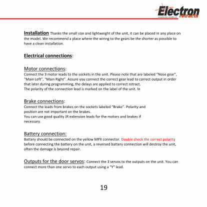
Installation Thanks the small size and lightweight of the unit, it can be placed in any place on
the model. We recommend a place where the wiring to the gears be the shorter as possible to have a clean installation.
Electrical connections: Motor connections: Connect the 3 motor leads to the sockets in the unit. Please note that are labeled “Nose gear”, “Main Left”, “Main Right”. Assure you connect the correct gear lead to correct output in order that later during programming, the delays are applied to correct retract. The polarity of the connection lead is marked on the label of the unit. In
Brake connections: Connect the leads from brakes on the sockets labeled “Brake”. Polarity and position are not important on the brakes. You can use good quality JR extension leads for the motors and brakes if necessary.
Battery connection: Battery should be connected on the yellow MPX connector. Double check the correct polarity before connecting the battery on the unit, a reversed battery connection will destroy the unit, often the damage is beyond repair.
Outputs for the door servos: Connect the 3 servos to the outputs on the unit. You can
connect more than one servo to each output using a “Y” lead.

20
Output to the steering servo: Connect the steering servo here if used.
Radio inputs: You can choose to use a single channel to control the gear and brake, or
separated channels. Gear input channel should be always connected for operation, brake channel and steering input channel are optional. Power supply considerations: PLEASE READ! This controller can receive up to 3 different power sources. In order to prevent malfunctions in your system you should know that: -The main battery should be between 6,6 to 9,9V. Recommended battery is a Lipo of 7,4V. Double check the polarity. This battery power the motors and the brakes. The controller have a internal switch operated by the Gear Input. It is not necessary to disconnect this battery between uses, but it is recommended to disconnect it after the flying session. There is a minimal power drawn from this battery when the unit is switched off that can drain a battery in 2 month.
In the case you use battery regulators: -The steering servo is powered by same supply as on the steering input. So, for example, if the steering input come from a battery regulator (powerBox, etc) at 6V and the gear channel comes directly from the receiver powered at 5V, the steering servo will be powered at 6V. -The outputs to the servos for the doors are powered from the gear input. If you connect directly the gear input to a low power source (for example, directly to the receiver when the receiver is powered by a low power, 5V regulator) the current draw by the servos of the doors could be excessive, causing the receiver to switch off.

21
-The power input pin of the Gear and Brake inputs are internally connected together. This could cause a malfunction by connecting different voltages together. For example, if you connect the Gear Input directly to the receiver that is powered at 5V and the brake input to a battery regulator that supply 6V, then the 6V supply will flow trough the unit to the receiver, being no longer powered at 5V by a independent regulator. In this case, it is necessary to cut the central wire (red) on the lead to the receiver. Unit and door servos will be powered by the power coming on the brake input. -All negative connections are connected together inside the unit. Always fully disconnect the batteries (both poles) from the installation before charging, as current can flow trough the unit from one battery to the other during charge, damaging the installation. Please contact to Electron Retracts for advice on particular installations.
SETUP: Once you have installed the controller in your model, you can adjust the radio, outputs, delays and steering servo. Setup can be done trough a data terminal or trough a pushbutton and LED light. Full functions are only available if programmed trough the data terminal. In both cases, first you should decide if you will use one or two channels for control and to setup your transmitter accordingly. -Double channel operation. The Gear In input control the retract operation and the Brake input control the brake.
operation: The Gear In input control both the gear and the brake. Operation similar to a turbine engine operation where raising the trim enable the engine to run and the stick throw regulate the engine power. For example, you can setup a channel that from –100% to –75% activate the gear and from –75% to +100% regulate the brake power.

22
The following setup procedure assume the use of a ElectronProgrammer, or Xicoy data terminal. Simple setup procedure by LED/button, is the same as RB45. Please jump to the “RB45 Setup” section for the pushbutton and Led setup procedure.
Setup using Electron Programmer: Connect the data terminal (Same model as used by Xicoy V10 turbine ecus) on the socket at left side of Gear In input. You can navigate trough the different menus by the buttons on the left side of the box, and values are changed using the + and – buttons on the right side. First screen displayed show the status (gear up, gear down, etc), the battery voltage, power of the brake, and, during motor operation, the amperage to each of the motors. Second screen display the RC signals measured from the receiver. Youcan check that the RX connection is working and the measured values change when the transmitter controls are operated. Standard RC signal go from 1000 to 2000uS, 1000us typically is displayed on RC transmitters as –100% 1500uS 0% and 2000uS as +100%. Due at display space the numbers are divided by 10, so a measured signal of 1400uS is displayed as “140”. On third screen you can scroll trough the different programming sections. Select the area you want to program by pressing the “+” button.

23
Manual Mode: With this mode, you will can independently run one retract, in any direction, stoping, and reasume in any position. This is very usefull for retracts installing.
Radio Setup: On this section you can program the following radio inputs and setup the brake power. First screen is the Gear Up position: Set the transmitter switch or slider of the gear channel in the position you wish that the gear be in retracted position. Current reading is displayed on the right side of the screen. Once the TX set, press the “+” button. The controller will store the current signal received as “gear up” command. Next screen is the Gear Down position: Set the transmitter switch or slider of the gear channel in the position you wish that the gear be in extended position. Once the TX set, press the “+” button. The controller will store the current signal received as “gear down” command.

24
Next screen is the Brake OFF position: Set the transmitter switch or slider of the brake channel (or on the gear channel if you use the single channel option) in the position you wish that the brake be unpowered. Press the “+” button. The controller will store the current signal received as “Brake OFF” command. Note that if in this step the controller does not detect a valid signal in the brake input, then it will assume a single channel operation mode, To enable double channel, this step should be repeated once the brake channel is active. Last radio screen is the Brake Maximum position: Set the transmitter switch or slider of the brake channel (or on the gear channel if you use the single channel option) in the position you wish that the brake be at maximum power. Press the “+” button. The controller will store the current signal received as “Brake 100%” command. This complete the radio setup for the gear and brake channels. But two more adjust options are offered in this section: Brake limiter: The limiter usually is set at 100% and the brake power is adjusted trough the TX, but in the case that you need to limit the maxim brake power, you can decrease this setting to reduce the power applied to brakes. Brake pulse ratio: The power to the brakes could be pulsed in order to produce a “ABS like” operation, brake power is pulsed to avoid to create “flats” on the tires on hard braking. It is possible to adjust the brake pulses in different values to change the ratio between the “high power” and “low power” pulse depending on wheel diameter and model weight.

25
Servo sequencer setup: The unit provide 3 independent outputs to control the servo operated doors. All 3 outputs are the same, so the setup of one output is described It is possible to define 3 different positions for each output: Gear Up position: The position you wish that the servo be driven when the gear is retracted. Typically a closed door. Gear Down position: The position you wish that the servo be driven when the gear is retracted. Depending on model type, could be open or closed door. Motor ON position: The position of the doors when the retracts are moving, typically open. The setup of the position is easily done by the help of the steering input channel. In the case you don’t use this channel on your installation, you should temporarily connect a RC signal from the rx or from a servo tester in order to operate the servo manually to the desired position. It is recommended to connect only the servo being adjusted to avoid the other servos to move uncontrolled during the setup.
First screen is the “Servo 1 Gear Up position”. When this screen is displayed, the servo1 out will receive the same signal as arriving to the Steering input, so that you can move the servo directly trough your TX. Set the servo at the position you want that it to be when the gear is retracted, and press the “+” button. The current position will be stored in the permanent memory of the controller. In the case you don’t want to modify this position, simply change of screen by the menu buttons, settings are only changed on the memory when the “+” button is pressed. Next screen is the “Servo 1 Gear Down position”. Operate the servo trough the TX to the position you want that it to be when the gear is extended, and press the “+” button. The position could be the same as the “gear up” position if you wish a CLOSED-OPENED-CLOSED sequence.

26
Last screen is the “Servo 1 Motor On position”. Again, operate the servo trough the TX to the position you want that it to be when the gear is in movement, and press the “+” button to store the setting. Usually is the same position as the “gear down” position in the OPENED-CLOSED sequence, but also it allow to program a overtravel, the door opens more during gear operation to give extra clearance to the wheel and legs, but return to “scale” position when the gear is fully extended. Servo 2 and Servo 3 are programmed same way. Last screen is the “Servo switch off time:” To prevent the possibility of a servo to be overloaded and burned due at being jammed, a protection function is added that allow to release the servo force after some seconds (programmable by this parameter). Servo signal is switched off, that cause the servo to act as “unpowered”. The servo position is refreshed each 15 seconds to compensate the small movement of the servo (if any) during these 15s to keep in to commanded position, assuming that there is no force acting on the servo during the switch off period. In the case you want that the servo be active all the time, set this parameter to zero. Correct operation of this feature imply a servo that become “soft” when no signal received. All analog servos act like this, but some digital servos hold the position when no signal is received. If you plan to use digital servos on the doors and the switch off feature, check first if your servo is compatible, or use a analog servo. The Hitech and Multiplex digital servos we have tested are not suitable, but JR 8511 are.

27
When our gear doors are operated by servos, is advisable adjust the servo arm to maintain the transmisión collineal with the servo arm axle when the doors are closed. In this way we will avoid that gear doors can be opened during the flight due to G forces or pressure in the fuselaje You can see this in the next drawing
28
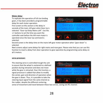
Motor delay: To replicate the operation of full size landing gears, it has been provided a programmable delay for each motor operation. First screen on this section is the delay in seconds of the main, left gear when Gear Up is selected. “Gear Up Delay Mains Left”. Use the +/- buttons to set the time you want the controller wait before the left main motor is operated since the Gear Up command is selected. Second screen is the delay time on the mains left gear motor operation when “gear down” is selected. Next screens adjust same delays for right mains and nose gear. Please note that you can use this function to insert a delay from door operation to gear operation by programming same delay on all 3 motors.
servo processor: The steering servo is controlled trough the unit to assure that the wheel is centered to a defined position during retraction and does not move while the gear is retracted. Over this function, a signal processor is added that allow to modify the center, gain and direction of operation when the gear is down. Thus, it is possible to take the steering input signal from the same channel as the rudder, despite the different centering, sense of movement and travel between these two servos, saving one RC channel.

29
Setup: Connect the Steering input to the desired RX channel for the steering (or trough a “Y” lead on the rudder channel). If you use same signal as the rudder, first setup the rudder centering and travel. Once you are satisfied with the rudder operation, connect the steering servo and proceed to adjustment. First adjustment is the position of the steering servo retracted position. Using the rudder channel of your TX, set the servo to the position you want it when the gear is being retracted and stored, then press the “+” button to store the setting. For nose retracts with steering system This position must be as centered as possible to allow the correct linkage between the brass pin in nose leg and servo arm. Next adjustment is the centering of the servo in deployed position. Double check that the rudder is centered, and then using the + and – buttons center the steering servo. Finally, check the steering travel and sense. A range of adjustment from –200% to +200% is provided. Positive numbers mean same direction as rudder, negative numbers mean reverse operation. A 100% setting give same travel and direction as the rudder servo, -100% give same travel but reverse operation, 200% travel mean double travel than rudder, 50% give half movement. Once you set the travel and sense, it is possible that the centering need a new adjust, just go back to previous adjustment by the menu buttons.
30
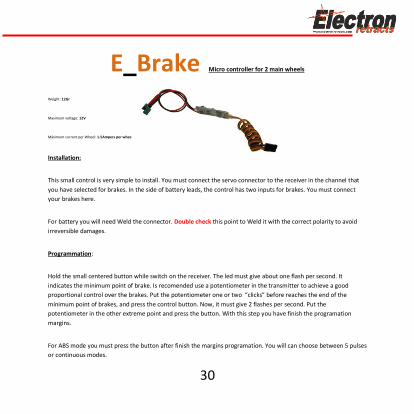
E_Brake Micro controller for 2 main wheels
Weight: 12Gr
Maximum voltage: 12V
Máximum current per Wheel: 1.5Ampers per whee
Installation:
This small control is very simple to install. You must connect the servo connector to the receiver in the channel that
you have selected for brakes. In the side of battery leads, the control has two inputs for brakes. You must connect
your brakes here.
For battery you will need Weld the connector. Double check this point to Weld it with the correct polarity to avoid
irreversible damages.
Programmation:
Hold the small centered button while switch on the receiver. The led must give about one flash per second. It
indicates the minimum point of brake. Is recomended use a potentiometer in the transmitter to achieve a good
proportional control over the brakes. Put the potentiometer one or two “clicks” before reaches the end of the
mínimum point of brakes, and press the control button. Now, it must give 2 flashes per second. Put the
potentiometer in the other extreme point and press the button. With this step you have finish the programation
margins.
For ABS mode you must press the button after finish the margins programation. You will can choose between 5 pulses
or continuous modes.

31
Warranty:
Electron Retracts warrants this product against, design defects,
manufacturing , or materials for 2 years.
Please, give us the serial
number to claim.
Note: The warranty excludes damage from misuse of systems, or damage caused
by reasons outside the manufacturing.

Turbinas y Compresores JetsXoel, S.L.
Poligono industrial AGranxa, Rúa D, Paralela3, Edificio CIE, Nave 9
36400 O Porriño, Spain
www.electron-retracts.com