Equipment Site Description - Earthquake Country
5
Equipment Site Description Current United States research in earthquake engineering is lacking the capability to conduct real time shake table testing of full or large-scale structural systems including soil-foundation-structure interaction (SFSI). Also, experimental capabilities are required to simulate near source ground motions with large velocity and displacement pulses. Existing shake table systems in the U.S. are limited by payload capacity (base shear and/or overturning moment), pumping capacity, stroke, and overhead room to construct and test tall structural systems. The University of California, San Diego (UCSD) is providing the earthquake engineering community with a Large High Performance Outdoor Shake Table (LHPOST) within the George E. Brown, Jr. Network for Earthquake Engineering Simulation (NEES) collaboratory. This LHPOST, built as part of the Charles Lee Powell Structural Research Laboratories at UCSD, incorporates performance characteristics that allow the accurate reproduction of near source ground motions for the seismic testing of very large structural and SFSI systems. The LHPOST is a 7.6m wide by 12.2m long single degree of freedom (DOF) system with the capability of upgrading to 6-DOF. The current specifications consist of a stroke of ±0.75m, a peak horizontal velocity of 1.8 m/s, a horizontal force capacity of 6.8MN, an overturning moment capacity of 35MN-m (bare table) and 50MN-m (400 ton specimen), and a vertical payload capacity of 20MN. The testing frequency range is 0-20 Hz. Further specifications can be found at structures.ucsd.edu/NEES/. Figure 1 provides a schematic rendering showing the key components of the LHPOST facility. Component 1 in Figure D.9-1 shows the steel platen, which consists of a 12.2 m long by 7.6 m wide structural steel box of variable depth up to 2.4m. Hold down connections will be provided at 610 mm on center for connecting test specimens to the platen. The reaction mass (component 2) consists of a ring structure using reinforced and mass concrete with hold down connections spaced at 610 mm on center for fastening loading frames, connecting temporary construction rigs and connecting actuators for testing in the adjacent soil pit. MTS Systems designed the hydraulic and mechanical systems for the LHPOST such as the two horizontal actuators (component 3), six vertical pressure balance bearings (component 4) with a force capacity of 8 MN each to react the vertical forces, two vertical tension cylinders (hold-down struts) for the overturning moment restraint system (component 5), and the components required for yaw restraint to prevent the platen from undesirable out-of-plane motions in the uniaxial configuration (component 6). A weatherproofing system (component 7) consisting of permanent and retractable prestressed concrete planks and pressurized with filtered, conditioned air running continuously will ensure that the environmentally sensitive parts of the hydraulic system will be protected from the elements by housing them in an essentially indoor environment. Detailed descriptions of the components are described in subsequent paragraphs. Figure D.9-1: Key Components of LHPOST The equipment will be operational by October 2004 and will be managed as a national shared-use NEES equipment site, with tele-observation and limited tele-operation capabilities. The facilities at Camp Elliott will be used to conduct large- and full-scale testing to investigate structural and geotechnical performance issues related to the area of Critical Infrastructure Protection (CIP) that cannot readily be extrapolated from testing at smaller scale, or under quasi-static or pseudo-dynamic conditions. Potential research that could be carried out include (a) the effects of passive and semi-active energy dissipating systems on building response, (b) large-scale testing of kinematic soil- foundation-structure interaction, (c) seismic response of nuclear waste dry storage casks, including the soil-structure interaction and the kinematic interaction between casks, (d) loss estimation of buildings, including the interaction between their components, (e) seismic response of full-scale wood-frame construction including school buildings (f) response of building diaphragms, where the presence of a distributed mass constrains the testing to be performed solely under dynamic conditions, (g) assessment of liquefaction mitigation mechanisms, (g) optimization of shallow foundations to maximize kinematic soil-foundation interaction, h) the study of the complex interaction between Page 1 of 5
Transcript of Equipment Site Description - Earthquake Country
Equipment Site Description
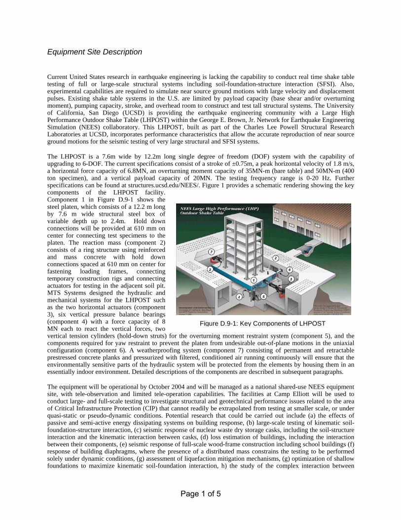
Current United States research in earthquake engineering is lacking the capability to conduct real time shake table testing of full or large-scale structural systems including soil-foundation-structure interaction (SFSI). Also, experimental capabilities are required to simulate near source ground motions with large velocity and displacement pulses. Existing shake table systems in the U.S. are limited by payload capacity (base shear and/or overturning moment), pumping capacity, stroke, and overhead room to construct and test tall structural systems. The University of California, San Diego (UCSD) is providing the earthquake engineering community with a Large High Performance Outdoor Shake Table (LHPOST) within the George E. Brown, Jr. Network for Earthquake Engineering Simulation (NEES) collaboratory. This LHPOST, built as part of the Charles Lee Powell Structural Research Laboratories at UCSD, incorporates performance characteristics that allow the accurate reproduction of near source ground motions for the seismic testing of very large structural and SFSI systems. The LHPOST is a 7.6m wide by 12.2m long single degree of freedom (DOF) system with the capability of upgrading to 6-DOF. The current specifications consist of a stroke of ±0.75m, a peak horizontal velocity of 1.8 m/s, a horizontal force capacity of 6.8MN, an overturning moment capacity of 35MN-m (bare table) and 50MN-m (400 ton specimen), and a vertical payload capacity of 20MN. The testing frequency range is 0-20 Hz. Further specifications can be found at structures.ucsd.edu/NEES/. Figure 1 provides a schematic rendering showing the key components of the LHPOST facility. Component 1 in Figure D.9-1 shows the steel platen, which consists of a 12.2 m long by 7.6 m wide structural steel box of variable depth up to 2.4m. Hold down connections will be provided at 610 mm on center for connecting test specimens to the platen. The reaction mass (component 2) consists of a ring structure using reinforced and mass concrete with hold down connections spaced at 610 mm on center for fastening loading frames, connecting temporary construction rigs and connecting actuators for testing in the adjacent soil pit. MTS Systems designed the hydraulic and mechanical systems for the LHPOST such as the two horizontal actuators (component 3), six vertical pressure balance bearings (component 4) with a force capacity of 8 MN each to react the vertical forces, two vertical tension cylinders (hold-down struts) for the overturning moment restraint system (component 5), and the components required for yaw restraint to prevent the platen from undesirable out-of-plane motions in the uniaxial configuration (component 6). A weatherproofing system (component 7) consisting of permanent and retractable prestressed concrete planks and pressurized with filtered, conditioned air running continuously will ensure that the environmentally sensitive parts of the hydraulic system will be protected from the elements by housing them in an essentially indoor environment. Detailed descriptions of the components are described in subsequent paragraphs.
Figure D.9-1: Key Components of LHPOST
The equipment will be operational by October 2004 and will be managed as a national shared-use NEES equipment site, with tele-observation and limited tele-operation capabilities. The facilities at Camp Elliott will be used to conduct large- and full-scale testing to investigate structural and geotechnical performance issues related to the area of Critical Infrastructure Protection (CIP) that cannot readily be extrapolated from testing at smaller scale, or under quasi-static or pseudo-dynamic conditions. Potential research that could be carried out include (a) the effects of passive and semi-active energy dissipating systems on building response, (b) large-scale testing of kinematic soil-foundation-structure interaction, (c) seismic response of nuclear waste dry storage casks, including the soil-structure interaction and the kinematic interaction between casks, (d) loss estimation of buildings, including the interaction between their components, (e) seismic response of full-scale wood-frame construction including school buildings (f) response of building diaphragms, where the presence of a distributed mass constrains the testing to be performed solely under dynamic conditions, (g) assessment of liquefaction mitigation mechanisms, (g) optimization of shallow foundations to maximize kinematic soil-foundation interaction, h) the study of the complex interaction between
Page 1 of 5

interconnected components of electrical substations, such as high-voltage transformer-bushing systems, and i) response of structural members to blast loading. Such experiments present unique opportunities to develop, calibrate, and validate computational tools. Description of Physical Facility The UCSD LHPOST was developed at the Field Station at Camp Elliott, a site located 15km away from the main UCSD campus (see Figure D.9-2). The shake table, acting in combination with a Soil-Foundation-Structure
Interaction (SFSI) facility, funded by the California Department of Transportation (Caltrans) and an Explosive Loading Laboratory (ELL), funded by the Technical Support Working Group (TSWG), will result in one-of-a-kind worldwide real-time testing of structural components, assemblies, and systems such as nuclear casks, building structures, bridge abutments, and embankments and foundations that will be subjected to real-time earthquake or blast loading. UCSD is convinced that the LHPOST in conjunction with the field laboratory site adds unique testing capabilities to NEES and consolidates the leadership of the NEES collaboratory as the predominant earthquake testing consortium in the world. Camp Elliott is situated on the corner of Miramar/Pomerado Rd. and Interstate 15. It is on University property that currently houses an animal facility for the UCSD School of Medicine and a storage facility for
Scripps Institute of Oceanography. Camp Elliott has restricted access and is a gated facility. The Structural Engineering field station is currently located on a 2-acre site on the Northwest corner of the University property. Hotel and dining services are within 1 mile of the site.
Figure D.9-2: Field Station at Camp Elliott
LHPOST System and Component Specifications The design criteria and main specifications of the shake table system were dictated by consideration of a number of target research application examples consisting of large or full-scale shake table experiments. Design criteria and expected performance parameters of the shake table are summarized in Table D.9-1. Performance parameters consist of specifications for actuator stroke, velocity and force capacities, and frequency bandwidth of the earthquake simulator. Specifications for the various components of the LHPOST in its uniaxial configuration can be found on the project website (currently hosted at http://structures.ucsd.edu/NEES/). These components include the horizontal actuators, the vertical bearings, hold-down struts, and the hydraulic power supply. Detailed descriptions of the various components are provided in the following sections.
Table D.9-1: NEES LHPOST Specifications
Size 7.6 m × 12.2 mPeak velocity 1.8 m/s Stroke ±0.75 m Maximum gravity (vertical) payload 20 MN Force capacity of actuators 6.8 MN Maximum overturning moment (bare table, 400 ton specimen)
35 MN-m, 50 MN-m
Frequency bandwidth 0 - 20 Hz
Reaction Mass Extensive 2-D and 3-D finite element modeling of the reaction mass taking into consideration the surrounding soil properties that were based on the results from geotechnical investigations performed at Camp Elliott were conducted
Page 2 of 5
and led to a reaction mass design consisting of a ring structure using reinforced and mass concrete. Lumped mass concrete corners are connected with reinforced concrete tubes. The tubes are designed with potential hold down connections spaced at 610 mm on center for fastening loading frames, connecting temporary construction rigs and connecting actuators for testing in the adjacent soil pit (see component 2 in Figure D.9-1). Openings in the tubes were required for distributing the hydraulic lines and for access to the main pit below the platen and to the tunnel that leads to the pump/accumulator house. The reaction mass was designed to transfer mainly by bending and shear, the forces resulting from the horizontal actuators acting along the longitudinal axis in the 1-DOF configuration. To maintain a constant flexural and shear stiffness, the beam was proportioned so that the maximum tensile stresses at maximum thrust were below the tensile strength of concrete. A thick slab was proportioned in the transverse tubes to act as a reaction element to the horizontal actuators. A massive concrete member was cast below the platen. This member was required for stiffness and to transfer the reasonably large forces developed from the combination of the prestressing action of the discrete vertical tension struts and those generated by the maximum overturning moment in the transverse and longitudinal direction of loading. The final design of the reaction mass removed portions of the corner concrete elements to reduce the overall amount of concrete and minimize costs. The reaction block was built using 25 MPa strength concrete. The lower parts of the reaction mass will be covered with an epoxy resin to contain any oil leakages that might occur and special pockets were provided to pump oil and water out when required.
Actuators and Servo-valves In the current 1-DOF configuration, two horizontal actuators equipped with high flow servo-valves will power the shake table. These are single ended actuators ported to allow flows over 20,000 liter/min each. Dual 10,000 liter/min servo-valves (MTS Model 256.27) are mounted to each actuator. The technical specifications for the actuator are provided in Table D.9-2. For the servo-valvMPa servo-valve pressure drop. At the intermediate stage, pressure drop, the null leakage is less than 15 liter/min, and specifications for the servo-valves are provided on the projec
Platen Sliding System: Hydrostatic Pressure BalanThe LHPOST uses a set of 6 pressure balance bearings wiforces imposed on the table by the platen (approximately 2.force (9.4 MN), additional gravity loads, and the overturningvery large LHPOST forces and consequently the high flow rwhich have a number of inherent features that can be used high-pressure capability, which allows for minimum size,required for flow, self-aligning capabilities up to 2 degreesstrokes, uses servo-control, which allows height adjustmenactuator. In the pressure balance actuator, force applied transmitted to the bearing face. The pressure supports mocoefficient. UCSD has operation experience with these be(SRMD) system.
Overturning Moment Restraint System: Discrete TA shake table for physically reproducing the effects of earthqall of the forces imposed by the test specimen on the table.vertical force components that must be reacted, and generallactuator construction. The LHPOST uses a tension cylin
Page 3
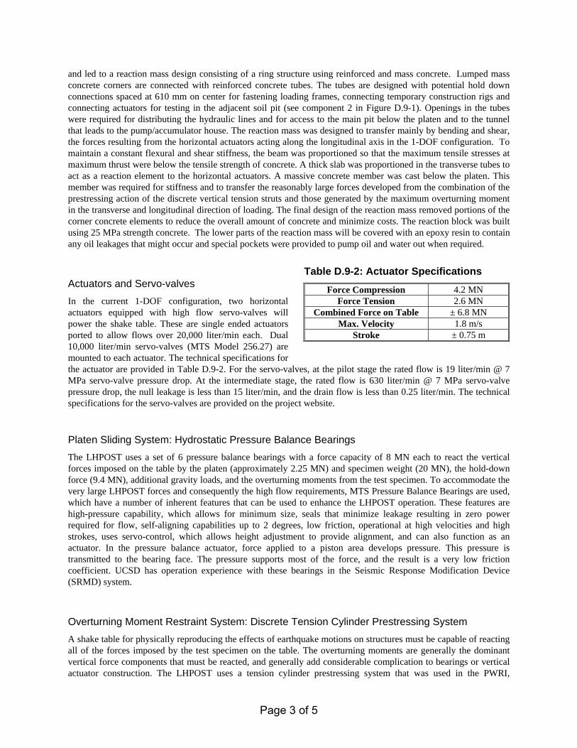
Table D.9-2: Actuator Specifications
Force Compression 4.2 MN Force Tension 2.6 MN
Combined Force on Table ± 6.8 MN Max. Velocity 1.8 m/s
Stroke ± 0.75 m
es, at the pilot stage the rated flow is 19 liter/min @ 7 the rated flow is 630 liter/min @ 7 MPa servo-valve the drain flow is less than 0.25 liter/min. The technical t website.
ce Bearings th a force capacity of 8 MN each to react the vertical 25 MN) and specimen weight (20 MN), the hold-down moments from the test specimen. To accommodate the equirements, MTS Pressure Balance Bearings are used, to enhance the LHPOST operation. These features are seals that minimize leakage resulting in zero power , low friction, operational at high velocities and high t to provide alignment, and can also function as an
to a piston area develops pressure. This pressure is st of the force, and the result is a very low friction arings in the Seismic Response Modification Device
ension Cylinder Prestressing System uake motions on structures must be capable of reacting The overturning moments are generally the dominant y add considerable complication to bearings or vertical der prestressing system that was used in the PWRI,
of 5

Japanese Ministry of Construction (MOC) shake table designed by MTS in Japan and similar to the static tare weight compression passive actuators used on many MTS earthquake simulation shaking tables. In the 1DOF configuration, the table sits on six hydrostatic bearings and two vertical tension cylinders (hold-down struts). The downward or compressive movement of the table is taken by the hydrostatic bearings, while the tension-only struts resist any upward movement. The use of the discrete tension cylinder prestressing system allows for the bearings to be expanded to actuator-bearings for future upgrade to 6-DOF.
Platen The UCSD-NEES project team has worked closely with MTS Systems on the design of the turnkey steel platen system. The platen is being fabricated in three pieces and will be assembled on-site using field welding and bolting. Figure D.9-3 shows a schematic of the platen, including attachments for the yaw-restraint and horizontal actuators. The platen consists of a 12.2 m long by 7.6 m wide structural steel box of variable depth up to 2.4m. Hold down connections will be provided at 610 mm on center for connecting test specimens to the platen. This array of hold down connections is identical to that used in the Powell Laboratories at UCSD making it compatible with existing
hardware and loading frames. The design weight of the platen is less than 1.5 MN. The stiffness requirements consist of ensuring a fundamental mode of vibration (lowest natural vibration frequency) greater than 65 Hz. For strength requirements, elastic response is expected throughout the entire operation with only localized yielding permitted upon impact of a collapsing body, and extensive yielding allowed upon unanticipated loss of control of the shake table. The latter requirement is to protect the reaction mass from irreparable damage. The stability requirements for the platen consist of providing a factor of safety against wall stability of 3.0, even for the case when a specimen that extends across the entire width of the table is post-tensioned to the table at 890 kN/tie-down. Detailed manufacturing specifications and to
3 Piece Assembly
Yaw-Restraint Bearing Attachment
Horizontal ActuatorAttachment
Figure D.9-3: Schematic of Steel Platen Design
Hydraulic Power System The LHPOST hydraulic power supply design is very similar to the existing power supply at UCSD for the SRMD facility. It consists of two pumps, a blow-down system, a cooling system, accumulator banks, and a surge tank. The hydraulic power is supplied to the actuators by an accumulator bank through a blow-down valve. The accumulator bank provides the high flow needed to simulate an earthquake, and the blaccumulators to constant 21 MPa pressure for controlliprovided to pump oil into the accumulator bank. Returnpump has a charging flow of 431 liter/min and is responThe second pump’s function is for direct pumping and hwhen supplemented with the two hydraulic power units21 MPa or above in order to simulate the design earthqcharge the accumulator banks is 6 min and the flodisplacement on the table of 7.5 m. The power system future upgrade to a 6-DOF system. The technical speciTable D.9-3.
Page
lerances were established for the platen.
Table D.9-3: Hydraulic Power Supply Specifications
Component Specifications Accumulator bank Volume of 9,500 liters and pressure at 35MPa Blow-down valve(s) Peak flow of 38,000 liter/min
Hydraulic power units (2)
One pump flow of 718 liter/min for pilot pressure at 21MPa and blow down assist, and one pump flow of 431 liter/min for accumulator charge at 35 MPa: power at 450 kVA each
Surge Tank Volume of 10,000 liter
ow-down valve converts the high-pressure oil from the ng the actuators. MTS Hydraulic Power Units (HPUs) are flow is directed to an auxiliary reservoir or surge tank. One sible for charging the 9,500 liters of oil in the accumulators. as a charging flow of 718 liter/min. The accumulator bank,
, satisfies the design requirement of providing 2,720 liter at uake records. With this configuration, the expected time to w from the accumulator banks could produce a swept construction will allow for increasing flow for the targeted fications for the hydraulic power supply are summarized in
4 of 5
Weatherproofing System A feature of the shake table system is that it is located outside so that normal construction techniques can be used in building and mounting specimens on the table. San Diego is an ideal location since it has one of the most temperate climates in the world. Since a significant number of components within the hydraulic system are sensitive to the environment, particularly UV radiation, dust, debris and moisture, in order to have the system operate reliably outdoors, various techniques must be used to prevent the elements from affecting the system. The LHPOST weatherproofing system ensures that all accessible portions of the LHPOST will be covered and pressurized with filtered, conditioned air running continuously (see component 7 in Figure D.9-1). The cover consists of enclosing the space between the platen and the surrounding reaction block with permanent and retractable prestressed concrete planks that can support the weight of equipment and foot traffic necessary to construct the specimen. During operation of the table, the planks are retracted and bellows will be attached to protect components from dust and debris. Therefore, the environmentally sensitive parts of the hydraulic system will be protected from the elements by housing them in an essentially indoor environment. Additionally, all electrical control cables that connect to the valves of the actuators will be high quality weather rated connections.
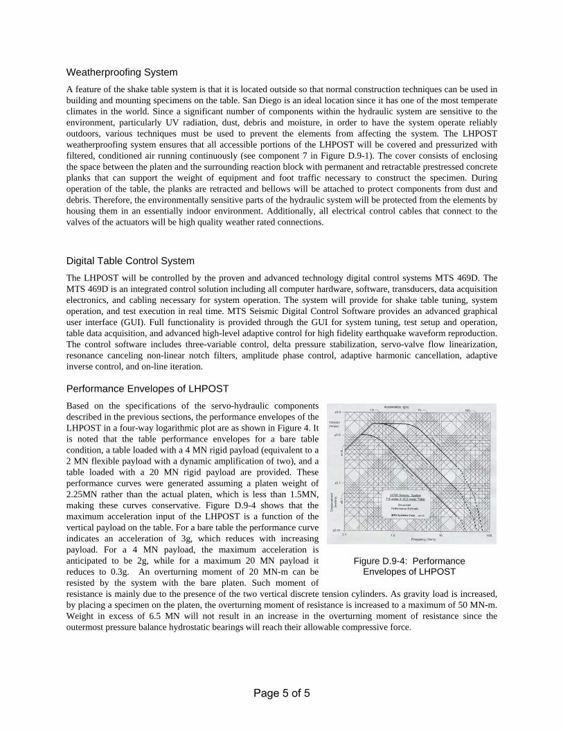
Digital Table Control System The LHPOST will be controlled by the proven and advanced technology digital control systems MTS 469D. The MTS 469D is an integrated control solution including all computer hardware, software, transducers, data acquisition electronics, and cabling necessary for system operation. The system will provide for shake table tuning, system operation, and test execution in real time. MTS Seismic Digital Control Software provides an advanced graphical user interface (GUI). Full functionality is provided through the GUI for system tuning, test setup and operation, table data acquisition, and advanced high-level adaptive control for high fidelity earthquake waveform reproduction. The control software includes three-variable control, delta pressure stabilization, servo-valve flow linearization, resonance canceling non-linear notch filters, amplitude phase control, adaptive harmonic cancellation, adaptive inverse control, and on-line iteration. Performance Envelopes of LHPOST Based on the specifications of the servo-hydraulic components described in the previous sections, the performance envelopes of the LHPOST in a four-way logarithmic plot are as shown in Figure 4. It is noted that the table performance envelopes for a bare table condition, a table loaded with a 4 MN rigid payload (equivalent to a 2 MN flexible payload with a dynamic amplification of two), and a table loaded with a 20 MN rigid payload are provided. These performance curves were generated assuming a platen weight of 2.25MN rather than the actual platen, which is less than 1.5MN, making these curves conservative. Figure D.9-4 shows that the maximum acceleration input of the LHPOST is a function of the vertical payload on the table. For a bare table the performance curve indicates an acceleration of 3g, which reduces with increasing payload. For a 4 MN payload, the maximum acceleration is anticipated to be 2g, while for a maximum 20 MN payload it reduces to 0.3g. An overturning moment of 20 MN-m can be resisted by the system with the bare platen. Such moment of resistance is mainly due to the presence of the two vertical discrete tension cylinders. As gravity load is increased, by placing a specimen on the platen, the overturning moment of resistance is increased to a maximum of 50 MN-m. Weight in excess of 6.5 MN will not result in an increase in the overturning moment of resistance since the outermost pressure balance hydrostatic bearings will reach their allowable compressive force.
Figure D.9-4: Performance Envelopes of LHPOST
Page 5 of 5