LCEC.com - Used Chemical Equipment & Complete Process Plants
0
Equipment of Ceramic Plants
Study Support
Dalibor Jančar
Ostrava 2015
VYSOKÁ ŠKOLA BÁŇSKÁ – TECHNICKÁ UNIVERZITA OSTRAVA
FAKULTA METALURGIE A MATERIÁLOVÉHO INŽENÝRSTVÍ
1
Title: Equipment of Ceramic Plants
Code: 635-3006/01
Author: Ing. Dalibor Jančar, Ph.D.
Edition: first, 2015
Number of pages: 54
Academic materials for the Metallurgical Engineering study programme at the Faculty of
Metallurgy and Materials Engineering.
Proofreading has not been performed.
Execution: VŠB - Technical University of Ostrava
1
TABLE OF CONTENTS
TABLE OF CONTENTS ............ CHYBA! ZÁLOŽKA NENÍ DEFINOVÁNA.
1 INTRODUCTION .......................................................................................... 5
2 RAW MATERIAL EXTRACTION ............................................................. 7
2.1 Excavators ........................................................................................................... 7
2.1.2 Bucket chain excavator ........................................................................................... 7
2.2 Loaders ................................................................................................................ 8
3 RAW MATERIAL TRANSPORT ............................................................. 10
3.1 Conveyors .......................................................................................................... 10
3.1.1 Belt conveyors ....................................................................................................... 11
3.1.1.1 Cable belt conveyor ........................................................................................ 11
3.1.1.2 Steep belt conveyor ........................................................................................ 11
3.1.2 Bucket elevator ...................................................................................................... 11
3.1.3 Threaded conveyor ................................................................................................ 11
3.1.4 Rollway ................................................................................................................. 11
3.1.4.1 Driven ............................................................................................................ 12
3.1.4.2 Gravity roller .................................................................................................. 12
3.1.5 Transport slides and chutes ................................................................................... 12
3.1.6 Suspended bench conveyors.................................................................................. 12
3.2 Pneumatic transport equipment ........................................................................ 13
3.2.1 High-pressure pneumatic transport ....................................................................... 14
3.2.1.2 Cell feeders ..................................................................................................... 14
3.2.2 Pneumatic transport of (medium-pressure) mixers ............................................... 15
3.2.3 Pneumatic transport of aerating chutes ................................................................. 15
3.3 Inter-object transport ........................................................................................ 15
3.3.1 Rail and automobile transport ............................................................................... 15
3.3.2 Interoperational transport ...................................................................................... 15
3.4 Liquid transport equipment (dredge) ................................................................ 16
3.4.1 Single-acting piston pump ..................................................................................... 17
3.4.2 Rotary pump .......................................................................................................... 17
3.4.5 Dredge pump ......................................................................................................... 17
4 BATCHERS, FEEDERS ............................................................................. 19
4.1 Belt feeder ......................................................................................................... 20
4.2 Apron feeder ...................................................................................................... 20
2
4.3 Roll feeder ......................................................................................................... 20
4.4 Vibration feeder................................................................................................. 20
4.5 Disc feeder ......................................................................................................... 20
4.6 Rotary-gate (flight) feeder ................................................................................. 21
4.7 Chain (screen) feeder ........................................................................................ 21
4.8 Feeding screw feeder ........................................................................................ 21
5 SIZE REDUCTION ..................................................................................... 22
5.1 Jaw breaker ....................................................................................................... 23
5.2 Cone crusher ..................................................................................................... 23
5.3 Roll crusher and breaker .................................................................................. 24
5.4 Antifriction crusher and breaker ....................................................................... 24
5.4.1 Weight crusher and breaker................................................................................... 24
5.4.2 Centrifugal breakers .............................................................................................. 24
5.5 Rotory crushers and breakers ........................................................................... 25
5.5.1 Rotory crushers and breakers with swinging mixing devices ............................... 25
5.5.2 Rotory crushers and breakers with fixed mixing devices ..................................... 25
5.6 Gravity roller breakers ..................................................................................... 28
5.6.1 Ball breakers .......................................................................................................... 28
5.7 Bar breakers ...................................................................................................... 29
5.8 Autogenousbreakers .......................................................................................... 30
5.9 Centrifugal(planetary) breakers ....................................................................... 30
5.10 Vibration breakers........................................................................................... 30
5.11 Míxer breakers (attritors) ............................................................................... 31
5.12 Colloid breakers .............................................................................................. 32
5.13 Jet spray breakers ........................................................................................... 33
6 SEPARATION .............................................................................................. 35
6.1 Sorting ............................................................................................................... 36
6.1.1 Mechanical sorting ................................................................................................ 36
6.1.2 Water (hydraulic) sorting ...................................................................................... 36
6.1.3 Air separation sorting ........................................................................................... 37
6.2 Separating ......................................................................................................... 38
7 MIXING AND HOMOGENIZATION ...................................................... 40
7.1 Prehomogenisation............................................................................................ 41
7.2 Míxers ................................................................................................................ 41

3
8 FORMING .................................................................................................... 43
8.1 Pressing ............................................................................................................. 44
8.1.1 Dry and semi-dry pressing .................................................................................... 45
8.1.1.1 Granulation ..................................................................................................... 45
8.1.1.2 Single-action compression ............................................................................. 46
8.1.1.3 Double-action compression ............................................................................ 46
8.1.1.4 Isostatic pressing ............................................................................................ 47
8.2 Plastic forming .................................................................................................. 48
8.2.1 Drawing ................................................................................................................. 49
8.2.1.1 Drawing worm presses ................................................................................... 49
8.2.2 Thowing ................................................................................................................ 50
8.3 Casting .............................................................................................................. 51
9 RECOMMENDED LITERATURE ........................................................... 54
4
STUDY INSTRUCTIONS
Ceramic works equipment
You have obtained study material for the part-time study of the second semester subject Gas
Engineering from the study branch Thermal Equipment and Ceramic Materials.
Prerequisites
The subject doesn´t have any prerequisites.
Subject objective and learning results
The objective of the subject is to be made acquainted with the technological flow of ceramic
material production from the extraction of basic raw materials up to the resultant forming of
final shapes.
After studying the subject a student should have:
knowledge results
Knowledge of equipment for mining, loading, transporting, processing and treating raw
materials
Knowledge of the machines presently used for forming ceramic products.
skills results
The capability of independently choosing certain equipment (machines) for an individual
technology, kinds of materials and the final properties of products.
When studying each chapter we recommend the following procedure:
To read chapter categorization.
To study a chapter through to understand the principle of given technological equipment.
The method how to communicate with the teacher:
It is possible to communicate with a teacher using the email address: [email protected]
or telephone number: 597 321 537.
Subject guarantor: Ing. Dalibor Jančar Ph.D.
Lecturer: Ing. Dalibor Jančar Ph.D.
5
1 INTRODUCTION
Chapter sections:
equipment selection and design for ceramic works;
technological procedures of ceramic works production;
raw material extraction - excavators;
loading raw materials - loading machines.
Study time: 30 minut
Objective: After studying through these chapters
you will know the technological operation of ceramic works from
deposit exploration to the final product;
you will be acquainted with basic extractions and loading machines;
Lecture
When selecting and designing equipment for ceramic works it is necessary to
proceed mostly from the raw material basics, which we have available. This means that the
selection of various types of equipment is subordinated to the method of processing extracted
raw materials and their properties (fragility, adhesiveness, etc.). It is necessary to take into
consideration that raw materials can sometimes change their own character, and that is why it
is necessary to carry out a proper survey of deposits.
Technological procedure for ceramic works production:
raw material extraction (excavators, loaders),
raw material transport (conveyor belts, ropeways, automobile transport and
other ways),
feeders

6
reduction equiment (crushers, breakers),
raw material separation (meshes, grills, sorters),
blending and homogenisation (mixers, smoothing),
forming
It is necessary to be aware that the limiting element of a ceramic works is its
oven. It is the most expensive equipment, it is difficult to exchange, and creates the final
product. That is why in selecting individual equipment before final processing, we always
have to have a capacity reserve for individal equipment. During such a procedure we cannot
then have an interruption of production for the individual sections of continuous raw material
processing.
7
2 RAW MATERIAL EXTRACTION
In this area there is found equipment for the mining and loading of raw materials
which are known as excavators and equipment for loading raw materials by equipment known
as loaders.
2.1 EXCAVATORS
An excavator is mechanical equipment, which is used for separating lightly
disconnected rock (soil, gravel, sand, brick clay) and for loading heavy disconnected rock,
which has already been broken up and is found in landfills or directly in a quarry. The
performance of this equipment is recorded in [m3/hour] or in [t/hour].
2.1.1 Single-bucket excavators
They are used for mining rocks of various hardness, of dry and plastic, lumpy rocks
broken up by blasting. The basic part is the bucket, according to which it they can be divided
into buckets with the upper or lower bucket.
Excavators with upper buckets are used for loading broken-up rock (limestone) for
earth work above the terrain level or for mining gravel, sand and clay rock.
Excavators with lower buckets are used when deepening pits of smaller dimensions, in
building constructions and for the mining of soil under the water surface level, for treating
terrain, etc.
The operational performance of single-bucket excavators depends mostly on the bucket
dimension (m3), the loosening-up of soil co-efficients, the soil density (t.m
-3), the working
cycle (s).
A forward shovel (bucket) has a tilted bottom, through which it is emptied and
produces a volume of 0,15 m3 to 4 m
3, even exceptionally more.
There are used most often with belt or bucket-wheel undercarriages, rarely with rail
undercarriages or walking undercarriages.
2.1.2 Bucket-ladder excavators
They are used for excavating lightly disconnected materials (gravel sand, clays, brick
clay), for terrain treatment, for excavating sand from the bottom of the water surface, at the
level at the bottom of the river, for material handling at landfills, for raw material
homogenization, and other areas. They have a high output, as their operation is uninterrupted.
The working parts are wheel buckets. They are hollow vessels with a content of 25 to
150 l, and with a big excavator up to 250 l. The wheel buckets are fastened to a linked chain
which circulates in the bucket ladder. Guiding pulleys guide the linked chain. An excavator
has a self-propelling undercarriage, for which it is necessary to construct a rail track. Before
activating the machine it is necessary to treat the terrain for excavation.
8
The operational output of bucket-ladder excavators depends mostly on the dimension
of the bucket wheel (m3), the bucket wheel spacing (m), the chain speed (m.s
-1), and the co-
efficient of the loosened-up soil.
The biggest excavators are over 200 meters long and have a height of 100 meters.
Bucket-ladder excavators can deepen a pit the length of a football pitch at a depth of
over 25 meters in one day. At top speed they can travel along a highway at one kilometer per
hour, of course it lasts a while.
2.2 LOADERS
Loaders are machines which scoop up soft, broken-up rock, and also other granular
material and load them onto a transport container. They are simple structurally and lighter in
operation than excavators.
Loader categoriation:
1. Cyclically working with buckets - front-loader
- overhead
- rotating
- tunnel maker
2. Continually working a) bucket-wheel - with rotating conveyor belt
b) worm (screw) - stroking
c) bucket
d) plate
e) scraper loader
Summary concept:
After studying this chapter through the following concepts should be clear
for you:
selection of ceramic works design;
the selection of suitable technology for excavating and loading raw
materials according to the type of raw material
Questions:
1. What is necessary to occur during selecting and designing equipment for
ceramic works ?

9
2. What is the general technological procedure for ceramic works
production? What is the limiting factor in ceramic works?
3. What do we select suitable technological equipment for mining and
loading according to?
4.
What are the most known types of equipment for excavating and loading
raw materials?
5. What does the operational output of wheel bucket and bucket ladder
excavators mostly depend on?
10
3 RAW MATERIAL TRANSPORT
Chapter sections:
basic raw material transport categorization:
conveyor belt categorization;
loose and lumpy raw material transport.
Study time: 35 minutes
Objective: After studying through this chapter
you will know the basic types of mechanical conveyor belts.
Lecture
Transport and material handling only passively share in the production process.
because it does not directly influence their own technological activity.
Categories:
Fluent (conveyor belts, chutes, pneumatic and hydraulic transport, etc).
Interrupted (ropeways, cranes, lifts, ships, rail and non-rail vehicles, etc.)
3.1 CONVEYOR BELTS
Conveyor belt categories:
1. Mechanical with a drawing component
2. Mechanical without a drawing component
3. Hydraulic (using rollerways)
4. Pneumatic
11
3.1.1 Belt conveyors
Belt transport is one of the most economical and efficient means of transport for short
and middle distances. It is possible to divide belt transport into:
Transport for short distances (4 - 20 m).
Transport for large distances (100 - 5000 m)
It is used for the transport of powder, loose and non-adhesive granular materials. The
conveyor belt slope angle determines the material angle of discharge, which is the root angle
of the straight surface line of the discharge taper of loosely poured non-coherent material. The
smaller the angle of discharge, the more material caving in from the belt. It can be up to 24°.
The drawing component of the conveyor belt is a belt. It can be made of textile, rubber, or be
reinforced or with steel. It is placed on load-bearing rollers.
3.1.1.1 Cable belt conveyor
It is used for distant transport. A rubber belt with a profiled edge bears a pair of non-
metallic cables, which are also drawing cables. The suspended belt conveyor removes the
resistance of the rubber belt when shifting to load-bearing rollers (the rubber belt is not
burdened by the force of traction), which enables it to be used even for several kilometers of
long transport.
3.1.1.2 Steep conveyor
It is determined for transporting material in a soft state and adhesive, partially pre-
crushed earth under a slope of 80°. It consists of a load-bearing belt conveyor and a forced-
down belt, which copies the shape of the load-bearing conveyor. The drawing profile of the
load-bearing belt is partially trough-shaped. The material on the load-bearing belt is loaded by
a hopper, where it is caught after its release by a forced-down belt. The transport speed of
both belts is the same, so that material is carried away almost vertically towards a drive pulley
and it proceeds on for further technological treatment. It saves using a built-up area.
3.1.2 Bucket elevator
It is used for the vertical transport of loose, lightly-granular and non-adhesive
materials. It continuously works and solves spatial problems.
3.1.3 Threaded conveyor
Material is transported in a steel chute along a helix.
The transport chute is closed with a cover against dust and it is possible to empty the
chute in any location. It can also have reserve functioning. It is used for loose materials. The
maximum temperature of transported material is up to 70 °C, for conveyors produced from
special alloys they can reach a temperature up to 300 °C.
It must not be used for sharp or adhesive material!
3.1.4 Rollerway
12
It is used for lumpy products (bricks, linings, panels, glass, cases, boards, etc).
Categories: 1 Driven - by cogwheels, by chains, towing
2. Gravity roller (an inclination from 5 to 15°).
3.1.4.1 Driven
Lumpy material is transported along rollers driven most often by an electrical motor.
For the roller drive there is used tapered cogwheels or a roller chain. The spacing of rollers is
selected so that a transported piece lies on at least three rollers at the same time.
3.1.4.2 Gravity roller
Material moves along small rollers. It is used for short distances. It has an inclination
of 5 to 15°. It sometimes can be horizontal, and then the transported material has to be pushed
manually.
3.1.5 Transport slides and chutes
It is used for granular and non-adhesive materials. It uses gravitation (the chute
inclination has to be greater than the material angle of discharge) + shedding.
3.1.6 Suspended bench conveyors
It basically concerns a chair lift cableway closed in a circuit. It is used for transporting
pressings, slabs, dry bricks and other products in ceramic works. It can go through an oven, in
which enamelled products are placed. It then has to be made of high-grade, creep-resistant
steel.
Concept summary:
After studying through this chapter the following concepts should be clear to
you:
the selection of a suitable conveyor for loose and lumpy materials
according to the kind of material and transport location.
Questions:
1. What is the angle of discharge and how is it determined?
2. What is the maximum angle of discharge of transported material for
transport using a belt conveyor?
3. What suitable belt conveyor adjustment is used to overcome transport
13
steepness?
4. From what material do we select a belt conveyor belt for sharp-edged
materials and materials with high temperatures?
5. What conveyor is most suitable for vertical transport?
6. What kinds of rollerways can we encounter?
3.2 PNEUMATIC TRANSPORT EQUIPMENT
Chapter sections:
powder raw material transport - pnuematic transport;
pneumatic transport categories;
high-pressure pneumatic transport;
medium-pressure pneumatic transport;
pneumatic transport using aeration channels;
interobject transport.
Study time: 45 minutes
Objective: After studying through this chapter
you will know the basic types of pneumatic transport for transporting
powder raw materials.
you will know the basic types of interobject transport
Lecture

14
In plants for the production of building materials on the basis of the silicate transport
of powder materials compressed air is being used more and more. Especially in the transport
of non-adhesive powder or lightly-granular materials, for example cement, ash, limestone,
koalin, foundry sand, and similar materials. As a complementary part of separating air
equipment systems, they are used to shift captured solid particles for the storage and
depositing of waste, or for the transport of separated products for further treatment. We can
divide pneumatic transport into mobile and stationary transport. Among mobile pneumatic
transport we can count loose materials of the most various mobile media - containers, crates,
trailers. Stationary pneumatic transport is thought of as solidly built-in equipment in a certain
location. Material is transported through a tube to distances from 1000 m up to a height of 40
m [1].
Stationary pneumatic transport categories:
Low-pressure
Medium-pressure
High- pressure
Transport using pneumatic chutes
3.2.1 High-pressure pneumatic transport
It is mostly used to fill in cement reservoirs and to empty them. Compressed air is
used for transport with a pressure 0,23 up to 0,8 MPa. The trasport pipeline is a seamless steel
tube with diameters 70, 80, 100, 125, 150 up to 200 mm. For the transport of solid abrasive
materials there is used a steel pipeline lined with basalt. A cyclone and hose filter is used for
separating the transported material from the load-bearing air. The most important part of the
pneumetic system is the equipment for supplying powder material and for mixing with load-
bearing air, that is feeding equipment (Fuller pump, chamber feeder).
3.2.1.1 Fuller pump
The principle of a cantilevered Fuller pump is maybe this: The pump is made of two
chambers (pressure and mixing) separated by a valve. Powder material in measured dosages is
fed into the mixing chamber. If the pressure of the powder material grows to a prescribed
level, the valve opens and the material falls into the mouthpiece spaces, which are in the
lower parts of the mixing chamber. A helix is used for pushing the air out of the powder
material, and to prevent it from going into the mixing chamber.
3.2.1.2 Chamber feeders
Differing from the Fuller cantilever pump, it work interruptedly. And it is in two
phases. In the first phase there is the filling of pressure vessels with the powder material and
their closing. In the second phase there is the joint opening of the valve for supplying
compressed air and the emptying of the opening into the pipeline.
If we want to have a continuous supply, we use two pumps. Thus always in the first
phase there is the filling of one pump and in the other the emptying, and in the second phase
the opposite.
15
3.2.2 Pneumatic mixing transport (medium-pressure)
The pneumatic material transport sysyem using a mixer is suitable for dry, loose, non-
adhesive materials continually transported in smaller amounts for further production or
storage, for example for the transport of separated ash in boiler houses.
The separated material falls from the discharge chute to the rotating feeder, under
which a mixer is placed, ensuring the mixing of air with the material. The source of the
pressure air is a ventilator or blower. Aerating the operational (storage) resevoir is carried out
using filtering equipment located on the resevoir. Its regeneration is ensured by the blow of
pressure air [2].
3.2.3 Pneumatic transport using aeration chutes
In some cases it is suitable to use transport using pneumatic transport chutes instead of
high-pressure pneumatic transport. Especially when transporting short distances, where
favourable conditions are created for it, and where a space is available for the necessary
inclination of pneumatic transport chutes. In this case transport equipment is composed of the
source of pressure air (most often a ventilator station), the intake of pressure air with a
regulating body, the transport chutes themselves including material inlets, branches,
ventilation valves, discharges and aeration. It basically can be said that the only fundamental
difference is that this transport doesn´t have a mixer.
3.3 INTEROBJECT TRANSPORT
It is used for transporting building materials (quarry stone, clays, gypsum, brick clay,
flour, crushed stone, final products). It is necessary to transport this material into the
production process and shift it using an individual production operation. And after treatment
to move it to shipping and to transport it to the place of consumption.
3.3.1 Rail and automotive transport
Rail transport moves mainly raw materials and fuel and takes final products away.
Automotive transport in industry for the production of building materials and fire-resistant
materials transports up to 60 % of the volume of all materials. Lorries are the most wide-
spread means of transport in the silicate industry for shorter and longer distances when
transporting raw materials.
3.3.2 Interoperational transport
It is used for the transport of pressings into drying rooms, the transport of dried
products to ovens and final products from ovens to the storage of goods. For example, there is
a deck-convoy vehicle, which moves along rails, furthermore electric car traversers and
various kinds of convoy lorries. Deck-convoy lorries are used for the mechanized transport of
ceramic products between convoy lorries and drying room chambers. Car traversers are rail
transport machines with low platforms for transporting convoy vehicles or oven vehicles on
permanent tracks.

16
Concept summary:
After studying this chapter through the following concepts should be clear to
you:
pneumatic transport;
what a Fuller pump is;
what chamber feeders are used for;
which types of transport fall under interobject transport.
Questions:
1. What are the most important parts of high-pressure pneumatic transport?
2. What are chamber feeders used for?
3. Where is it possible to use raw material transport using aeration channels?
3.4 EQUIPMENT FOR FLUID TRANSPORT ( DREDGE)
Chapter sections:
dredge transport - kinds of pumps:
pump output;
Necessary study time: 10 minutes
Objective: After studying through this chapter
you will know the basic types of pumps used for dredge transport
Lecture

17
At cermaic works plants it is sometimes necessary to transport the dredge from
separation into gypsum forms to higher locations than those which this dredge was prepared
in. For these purposes there are used:
3.4.1 Single-acting piston pump
A liquid is transported through them using pressure brought about by the piston
motion in a cylinder.
A crank mechanism introduces it into activity. A liquid enters into a cylinder using the
suction opening, on which the suction pipeline is fixed. The liquid leaves the cylinder through
the outlet opening, onto which the discharge pipe is fixed.
Regulation:
by changing the rotation
using a water accumulator
The piston pump does not have a large transport output, but reaches high pressure up
to 40 MPa.
3.4.2 Rotary centrifugal pump
For transporting liquids and dredge with a large output a rotary pump is used. This
deals with a high-speed machine of relatively small dimensions, which favourable is shown in
its mass and price. The most important parts of the pump are the rotor made of a shaft with a
rotor wheel and the pump case.
Regulation:
by changing rotation
by throttling the discharge pipe
Total efficiency: 85 – 88%.
3.4.5 Dredge pump
It is used for transporting water with rough mixtures (dredge, etc.). It has a large
clearance and reaches low pressures.
Concept summary:
After studying this chapter through the following concepts should be clear
to you:
what kinds of pumps are possible to use for transporting dredge;
what the efficiencies of individual pumps are;

18
Questions:
1. What kinds of pumps are possible to use for dredge transport?
2. Can you explain the principle of the piston pump?
38
19
4 BATCHERS, FEEDERS
Chapter sections:
supplying raw materials - batchers, feeders;
Time necessary for study: 20 minutes
Objective: After studying through this chapter
you will know the basic kinds of equipment for the uniform supply of
materials,
Lecture
They are used for supplying exactly measured amounts of loose, granular and non-
adhensive elements into mixing equipment or for the uniform supply of various materials into
crushers and breakers not to lead to their clogging up.
Categories:
For dry granular material: 1. Movable a) belt
b) apron
c) vibration
d) chain
e) roll
f) disc
g) rotary gate
2. Rotary
For adhesive material 1. roll
2. cased
3. roll with a feeding thread
For opening material 1. helixical

20
4.1 BELT FEEDER
A belt feeder is used for feeding dry, powder and granular non-adhesive material
(max. to the grain dimension of 100 mm). If a rubber belt is used, the temperature of the feed
material must not exceed 80 °C.
Regulation
using a closing slide (a change in flow profile)
a speed change in the fed material
4.2 APRON FEEDER
It precisely is concerned with a form of a belt feeder. Instead of a belt there is a chain,
which enables the transport of material under an angle up to 20°. It is used in the civil
engieering and ceramic industries for loose and rough-grained materials.
4.3 ROLL FEEDER
It is used for feeding light and lumpy materials (max. granulity of 150 mm). The main
part is a rotating cylinder, which can be cylindrical or multi-edged. With the turning of the
cylinder, material is brought out to the surface by friction. The amount of fed material is
regulated by a closing slide or by speedily rotating the cylinder.
4.4 VIBRATION FEEDER
The working part of the machine is a suitably formed chute, produced from a steel
sheet. An electrical magnetic vibrator is connected to the chute and material begins to be fed
along the chute through vibration. A form of transport slide.
.
If the feeder has to sort as well, it has to have two meshes. It is used for dry, non-
adhesive materials up to a size of 150 mm and a maximum temperature up to 70 °C. It has
small energy consumption, simple service and minimal wear of its functional surface.
4.5 DISC FEEDER
Disc feeders are derived from disc batchers. Material falls in them through a vertical
mouthpiece onto a coaxial plate, which is screwed onto the flange of a threaded wheel placed
in the housing of the drive mechanism coming from a drive screw. It is possible to regulate
the height of their layer of material either by a telescopic membrance under the disc (that is a
collector) or by regulating the size of its diameter at a dimension 630 up to 250 mm, or if need
be by the height of the filling cylinder (using a screw) In regards to requirements to constantly
regulate the peripheral speed on the disc diameters, the number of rotations is to the extent of
0,33 až 0,85 s-1
In its basic technical perimeters the disc feeder reaches a transport efficiency
of 0,033 do 0,825 m3.s
-1 The given technical design enables the feeding of all loose and
granular materials with various speeds up to a granule size of 200 mm (for example, sand,

21
crushed stone material, gypsum and cement. The working part is a horizontal disk. Material
is collected from the disk by an adjustable colletor.
4.6 ROTARY GATE (FLIGHT) FEEDER - ROLL
They are made up of a bladed wheel which rotates in a roller with inlet (upper) and
outlet (lower) openings. In the state of rest the wheel blades prevent the flow of material.
When the wheel turns material pours into the upper chamber, which slightly turns to the lower
position enabling its emptying out. The working part is then a gate (rotor) which has 6 to 12
blades. The size of the gate gives the grain size of the supplied material, which can be 12 - 50
mm. The amount is regulated by changing the rotation of the closing slide or gate. It is
suitable only for dry materials with small granulity.
4.7 CHAIN (SCREEN) FEEDER
Chain (screen) feeders consist of sets of linked chains, which are loosely suspended on
a roll beside each other. In a state of rest hanging linked chains prevent material from falling
out of the reservoir. After putting the chain into operation in the arrow direction in a
changeable number of rotations at a dimension 0,25 - 0,5 s-1
the material is passed on for
further transport.
4.8 FEEDING SCREW FEEDER
Feeding screw feeders, working on the principle of worm conveyors, are mentioned in
the chapter about plastic forming.
Concept summary:
After studying through this chapter the following concepts should be clear
to you:
for what reasons feeders are used;
what kinds of feeders are used in ceramic works;
Questions:
1. What kinds of feeders are used in ceramic works?
2. With what is it possible to regulate the amount of fed material for a roll
feeder? What materials are suitable for rotary gate feeders?
3. What is the biggest advantage of a disc feeder?
4. What is a chain (screen) feeder used for?

22
5 SIZE REDUCTION
Chapter sections:
the purpose of size reduction;
granular system characteristics;
size reduction machine categories;
crushers and breakers with directly driven mechanisms.
Necessary study time: 120 minutes
Objective: After studying these chapters
you will know the concepts of specific surface, the milling curve;
you will know basic kinds of crushers and breakers;
you will know the difference between a crusher and a breaker.
Lecture
Is it one of the main operations. It deals with reducing, which is carried out for the
purpose of:
1. separating valuable minerals
2. it is assigned for products of a certain size
3. it is assigned for products with larger surfaces- fine
It deals with very energy demanding operations.
An important numerical characteristic of a granular system is special surface S (or also
surface density Sv), which is the parameter of the average (mean) values of the roughness of
the entire granular system. When the same mass of the solid phase system grows, the surface
size, reducing the size of the particles hyperbolically, that is the specific surface, is the
indirectly specific size of the particles.
23
WITH SIZE REDUCTION DEVICES
I. Crushers and breakers directly driven by devices
5.1 JAW BREAKERS
They are used for crushing large pieces of raw materials.
They are made up of two jaws, one moveable and the other fixed. It concerns a
pendulum with the moveable jaw, driven by an eccentric shaft. For a single-toggle crusher the
sense of rotation is important for the pulling-in of material into the groove between the jaws.
.A single-toggle crusher is used as a secondary crusher for example for the production
of gravel into concrete.
A double-toggle crusher is used as a primary crusher for crushing quartz, limestone,
magnesite, burnt clay, shale, glass cullets, fire clay fragments and for crushing various rocks
in the gravel industry
The advantage of jaw breakers is that they have little dust nuisance, of course in
comparison with impact crushers (viz Chapter 5.5.2). They have a lower reduction ratio,
meaning input material contains less fine particles.
5.2 CONE CRUSHERS
They are similar to jaw breakers, but their wedge-shaped mouth is round. It is again
used for hard, fragile and non-lubricated materials. As opposed to jaw breakers, the advantage
is their fluent running with shaking, smaller energy consumption and greater production
capacity.
Categories: a) acute-angle
b) obtusangular
c) with a fixed shaft
Acute-angle cone crushers have an apex angle of an acute crusher cone cca 20°. The
shaft axis is slanted (an inclination of 1 – 2°) as opposed to a notional cone axis, whose cone
copies the conical surface and there is crushing between the cone and fixed jaws. The
crushing cone is solidly set on the axis. It is used for rough crushing.
The principle an obtusangular cone crusher is the same as an acute-angular one, the
precise apex angle of the crusher cone is obtuse (cca 100°). It is used for light crushing.
Cone crusher with a fixed shaft (that is a gyratory crusher) has a fixed axis
eccentrically set by the driving body, which bears the crusher cone. The axis is parallel with
the slope axis - it copies the roll surface.
A.
24
5.3 ROLL CRUSHERS AND BREAKERS
Size reduction is carried out by reducing the pressure between two parallel rolls
turning against each other. The size of the output granule determines the goove between the
rollers. One of the rollers is pressed towards the second roller using a spiral spring or
hydraulically. They are used for medium-size and light crushing, or is need be grinding hard,
fragile material, such as quartz, feldspar, fireclay and magnesium scar. The peripheral speed
of both rolls is mostly the same, only for the reduction and spread of plastic components, is a
more economic diffterental speed of rolls, that is the roll differencial. The same effect is
reached when there is the same rotation with various roller diameters.
For soft and medium-size hard materials (chalk, limestone, magnesite) a toothed-roll
is used. In processing soft materials (brick clays) there knife rolls are used, which are slotted
or toothed type, or of a "hedge-hog" and "wolf" type.
5.4 ANTIFRICTION CRUSHERS AND BREAKERS
Reduction machines fall into this group, which is equipment on which material is
forced between two joint rolling surfaces: a grinding body, that is a cylindrical or conical
tread ( tread breakers) or balls (circulating crushers) and a grinding path, which is ringed (ring
crushers) and it is either even, dish-like, conical or cylindrical.
5.4.1 Weight crushers and breakers
Among the most know types of weight crushers and breakers there are Edge crushers,
which are either for wet grinding (extrusion) or for dry grinding (screening).
Treads on the wet-grinding crushers rotate and material is pushed through across a
static bowl. Central moistening is located on the main shaft. It is used for the wet processing
of brick clays.
Conversely, for dry-grinding crushers the bowls rotate and the treads stand. It is used
for the continuous grinding of dry mixtures in fire protection industries. The entire crusher is
closed and connected to a dust exhaust.
5.4.2 Centrifugal breakers
These breakers have a fixed ring grinding track and circulating grinding bodies, treads
or balls, pressed onto a ground stock by a centrifugal force. The crushers are high-speed,
working from 100 to 200 rotations per minute. The main group are Pendulum crushers, less
often there are Circulation crushers.
Pendulum breakers are machines with a vertically driven shaft connected by a frame,
on which a pendulum hangs, carrying a rotationally set tread, that are pulleys. During rotation
pendulums space out and press treads with centrifugal force on the vertical ringed mixing
tracks.
25
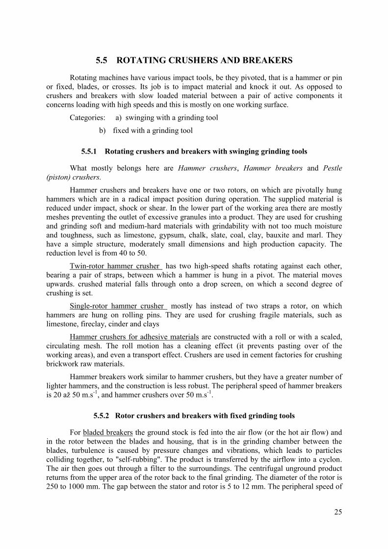
5.5 ROTATING CRUSHERS AND BREAKERS
Rotating machines have various impact tools, be they pivoted, that is a hammer or pin
or fixed, blades, or crosses. Its job is to impact material and knock it out. As opposed to
crushers and breakers with slow loaded material between a pair of active components it
concerns loading with high speeds and this is mostly on one working surface.
Categories: a) swinging with a grinding tool
b) fixed with a grinding tool
5.5.1 Rotating crushers and breakers with swinging grinding tools
What mostly belongs here are Hammer crushers, Hammer breakers and Pestle
(piston) crushers.
Hammer crushers and breakers have one or two rotors, on which are pivotally hung
hammers which are in a radical impact position during operation. The supplied material is
reduced under impact, shock or shear. In the lower part of the working area there are mostly
meshes preventing the outlet of excessive granules into a product. They are used for crushing
and grinding soft and medium-hard materials with grindability with not too much moisture
and toughness, such as limestone, gypsum, chalk, slate, coal, clay, bauxite and marl. They
have a simple structure, moderately small dimensions and high production capacity. The
reduction level is from 40 to 50.
Twin-rotor hammer crusher has two high-speed shafts rotating against each other,
bearing a pair of straps, between which a hammer is hung in a pivot. The material moves
upwards. crushed material falls through onto a drop screen, on which a second degree of
crushing is set.
Single-rotor hammer crusher mostly has instead of two straps a rotor, on which
hammers are hung on rolling pins. They are used for crushing fragile materials, such as
limestone, fireclay, cinder and clays
Hammer crushers for adhesive materials are constructed with a roll or with a scaled,
circulating mesh. The roll motion has a cleaning effect (it prevents pasting over of the
working areas), and even a transport effect. Crushers are used in cement factories for crushing
brickwork raw materials.
Hammer breakers work similar to hammer crushers, but they have a greater number of
lighter hammers, and the construction is less robust. The peripheral speed of hammer breakers
is 20 až 50 m.s-1
, and hammer crushers over 50 m.s-1
.
5.5.2 Rotor crushers and breakers with fixed grinding tools
For bladed breakers the ground stock is fed into the air flow (or the hot air flow) and
in the rotor between the blades and housing, that is in the grinding chamber between the
blades, turbulence is caused by pressure changes and vibrations, which leads to particles
colliding together, to "self-rubbing". The product is transferred by the airflow into a cyclon.
The air then goes out through a filter to the surroundings. The centrifugal unground product
returns from the upper area of the rotor back to the final grinding. The diameter of the rotor is
250 to 1000 mm. The gap between the stator and rotor is 5 to 12 mm. The peripheral speed of

26
the blade is 60 to 100 m.s-1
. It is used for grinding fireproof and ceramic clays, kaolin,
bergmeal, bauxite and talc. It grinds at a medium fineness 300 m or at a big fineness 50 m.
Bolt breakers are also called basket or cage breakers or disintegrators, and they have
peg bolts caught on one side on a circular panel, that is a stator or rotor, and on the other side
along the individual circular rows in ringed flanges of a semi-cicular shape, so that they create
a cage or basket. The material is reduced by impacts between the bolts by two rotating rotors
moving in a counterdirection (with a peripheral speed of 20 to 40 m.s-1
). They are used for
light crushing or rough grinding of soft and fragile materials with small abrasivity, for
grinding chalk, gypsum, coal and dry clays (with moisture less than 11 %). The imput granule
is up to a size 20 to 40 mm. The output product has a max.granule of 4 mm.
Peg breakers - impact breakers with loose-ended tools. have on the rotor either on one
or both sides a tool sticking out in the shape of a peg, a nib or a cross. They are also often
called attritors (the same name is used even for mixer breakers, Chap 5.11). They are used for
the light grinding of soft up to medium-hard materials (limestone, talc, chalk, graphite). It is
possible to control product granulity by rotation selection and by the number of pegs.
Impact crushers and breakers reduce material not only by impact in a rotor with a
solidly anchored blade, but also by the sudden impact of cast off pieces on the impact amour
plates or grills. They are able to process big boulders and give a good isometric shape to a
product. They have one or two cylindrical rotors, provided with 2,3 or 4 interchangeable
blades, which knock material out, and cast it off against the armour plate or grill impact walls.
Pieces are sorted on it and fragments or whole pieces are regularly taken away along the
arising cracks and fly back against the rotor. New material is thrown against it, it crashes into
it - causing autogenous crushing. Some impacted pieces are again involved and cast off by the
blades again against the impact walls. A series of such impacts continues as long as there is a
sufficiently light product, on which a lesser centrifugal force works. It finds a gap between the
impact wall and the rotor or the impact grill. The size of the output product granule is 40 mm
It is possible to control the granulity to a certain measure by revolution. They are used for
grinding limestone, cement sintered clay, fireclay, ore, coal, coke, basalt, granite and gravel to
concrete. They can even process pieces over 1 m in diameter!
For mechanical sweeping crushers and breakers material is cast off using the
centrifugal force of radical blades axially sticking out from a horizontal sweeping disk - the
rotor against the peripheral armour plate ring, where it shatters. The crusher can be a single-
rotor or dual-level with two disks. It is suitable for the selective crushing of brittle and
abrasive materials, limestone, cement sinter clay. Max. granulity of the output granule is
100 mm. In breakers of this type of air resistance plays a role on light particles. That is why
special vacuum sweeping breakers were developed.
Pneumatic swepping breakers which give the material speed by air flow from jets. The
material falls into the space betwen the mouth of the air jets (400 m.s-1
) and cast-off tubes,
which are channeled on the impact wall, with which it shatters. A product is carried out by the
air into the separator, In this way SiC can be processed.
Concept summary:
After studying this chapter the following concepts should be clear to you:
27
specific surface;
grinding cruve;
the purpose of size reduction;
the difference between a crusher and a breaker;
the selection of suitable reduction tools for certain kinds of
materials.
Questions:
1. What is the purpose of size reduction?
2. Can you explain the concept specific surface?
3. What are basic size reduction machine categories?
4. What´s the difference between a crusher and a breaker?
5. What is a single-toggle crusher used for?
6. Can you explain the diffrence between a conical crusher with a
swinging axis and with a fixed axis.
7. What types of cylinders exist for cylindrical crushers and for what
materials are the individual types used for?
8. Can you explain the principle of an impact crusher?
II. Crushers and breakers indirectly driven by tools
Chapter sessions:
the principle of crushers and breakers indirectly driven by tools;
crushers and mixers indirectly driven by tools;
gravity roller breakers, principles, kinds;
gravity roller breakers, filled with ground stock and grinding bodies
- equations;
centrifugal, vibration and mixer breakers

28
Necessary time for study: 120 minutes
Objective: After studying this chapter
you will know the most important breakers used in the ceramic
industry;
you will know the equation to calculate the filling of a ball breaker
with ground stock and by grinding bodies
Lecture
In the second group there are breakers with size reduction grinding tools, and these
breakers with grinding tools do not move on tracks of a precisely determined structure, but are
usually made up of a great number of "tools" ((balls, bars, rolls, flints – pebbles, rough grain
ground stock) called grinding bodies and they loosely move in a closed grinding area. These
are called breakers indirectly driven by tools or also breakers with loose grinding bodies.
Grinding in these breakers takes place by the impact of bodies on the ground
stock or the friction between the grinding bodies, and even joint friction and impact
between particles
The frequency and intensity of impact and friction depends on the number of rotations
or oscillations per time unit, but it is the same for the number of grinding bodies, on their size
and mass (the density of material from which they are created).
5.6 GRAVITY ROLLER BREAKERS
Size reduction is carried out by the impact, pressure and friction of falling and the
effect of gravity of the loose grinding bodies. Most examples of gravitational breakers are ball
breakers.
5.6.1 Ball breakers
It concerns one of the most often used breakers in traditional light ceramics and in
cement production
29
Ball breakers are basically hollow barrels or cylinders. They turn around a horizontal
axis and they are partially filled inside with loose grinding bodies - most often iron or ceramic
balls. During breaker rotation the grinding bodies create a centrifugal force which is carried
upwards and falls after reaching a certain height. The material is falling and bodies are rolling
over, and are ground by hits (impacts) pressure and rubbing. In the cement industry ground
raw materials are consequently stored in homogenious strengths.
Roll breaker in ceramics is used most often for wet grinding. It can also be to mix raw
materials, but they do not have too different grindabilities. The filling and emptying takes
place through an opening with a closing and releasing (with a stopcock) lid. That is why they
have is an "aerating" opening. Emptying can occur with overpresure up to 0,3 MPa.
Single-chamber tube breakers have a length 3 to 8 times greater than their diameter.
They grind a passage in it. Ground stock enters into the breaker by a hollow pin and the
product is tightened by the outlet pin. They are used mainly in the cement industry for the dry
grinding of sintered clay and the wet grinding of raw materials.
Multi-chamber breakers. that is combined breakers, have individual chambers filled
with various big grinding balls
Tube breakers with a external separation between chambers that is multi-level
breakers, are divided with inaccessible barriers at 2 separate chambers, with every intake of
material from outside and through the peripheral output of a product.
For these types of breakers we grind in an opened or closed cycle.
Opened cycle: Ground stock is ground in one chamber, its product enters into an elevator and
it is carried into a sorter. The rough part from the sorter goes for final
grinding into the second chamber of the breaker. Its product is connected
to the fine fraction, then it is taken with it from the sorter
Closed cycle: Ground stock is ground in one chamber, its product enters into an elevator and
it is carried into a sorter. . The rough part from the sorter goes for final
grinding into the second chamber of the breaker. Its product enters again
into the sorter and all sorts of output leaves the sorter.
The difference is then only in that in the closed cycle the product ground from the
second chamber is also sorted
Grinding body material: steel, flint, porcelain, steatite, korund, etc..
Breaker brickwork material: silex, porcelain, steatite, corundum, rubber
5.7 BAR BREAKERS
The grinding bodies are cylindral bars with a diameter 35 to 125 mm, a length of 25 to
50 mm (shorter than the length of the internal breaker area). l:D = 1,5 to 2,5. It is used for wet
or dry flow reduction on the interface between fine crushing and rough grinding.
Filling degree f = 35 až 45 %,
Maximal entry grain -25 mm (with greater granules a bigger bar spacing)

30
Size of product granule - 1 to 3 mm,
Rotations 55 to 65 % of ball breakers
They grind hard and brittle material (only a few fine parts arise, which make
treatment more difficult, they give a more regular granule)
5.8 AUTOGENUOUS BREAKERS
They are distinguished in that they have no (or only very few) grinding bodies. Rough
pieces grind material more finely. They grind in a short roll with a large size (4 to 9 m), so
that to impact energy is sufficient. Material enters and exits through a hollow pin. For
example, it is used for grinding limestone.
5.9 CENTIFUGAL (PLANETARY) BREAKERS
In addition to gravitational acceleration, these breakers also use centifugal
acceleration, which is made in high frequencies for intensive size reduction.
They are used mainly for very fine grinding and the mechanical activation of hard
materials. They grind a mixture of big grinding bodies. Fine grinding is carried out wet.
Laboratory breakers work with a speed up to 10 g, which means a considerable shortening of
grinding time.
Grinding corundum: Ball breaker 150 hours
Planetary breaker 1 hour
5.10 VIBRATION BREAKERS
Vibration breakers grind using grinding bodies introduced into the vibration motion of
grinding vessels. The vessels consist of elastic or rubber blocks.
The oscillation amplitude is very small, only several millimeters. Grinding vessels
have a circular oscillation at a frequency 1500 or 3000 cycles a minute, which is the
frequency of a network(50 Hz) or half of it.
The grinding bodies are usually balls with a diameter 10 to 30 mm, for big breakers
even 60 mm. Bars or rolls can be used as well (the production waste from antifriction
bearings) suitable for grinding using friction. They can grind wet as well as dry.
Filling degree - f = 70 až 80 %,
Maximal input granule - 5 mm,
Product granule size - 0,1 to 0,04 mm,
Production rate - 1000 to 2000 kg.h-1
,
They can grind medium-hard up to hard materials, not too abrasive
31
5.11 MIXER BREAKERS (ATTRITORS)
. The principle of mixer breakers is grinding using the impact and friction of loose
grinding bodies introduced into motion by a míxer. It grinds in the dredge! The mixer can be
in the form of a frame, a peg, a ring, or a disk and screw. Such grinding bodies use sand (sand
breakers), glass balls (pearly breakers) or steel or ceramic balls with a diameter of several
tenths to several millimeters. The peripheral speed is 8 to 12 m.s-1
(high-speed breakers), 0,5
up to 3 m.s-1
(slow-speed breakers). Circulation for big breakers helps by using a valveless
pump (p), which sucks at the bottom through a special divided valve (v) and by a lid forcing
the dredge back into the dish.
A sand breaker uses a sand grain with a diameter 0,5 to 0,9 mm and a mixer with 1700
to 2000 rot.min-1
. The breakers are used in oxidic ceramics, the grinding of porcelain matter,
and in glazure grinding. It is important to observe the viscosity of the dredge, which
considerably increases product fineness.
Concept summary:
After studying the chapter through the following concepts should be clear
to you:
grinding bodies;
ground stock;
breaker filling;
opened and closed cycle.
Questions:
1. Can you explain the principle of breakers with loose grinding bodies?
2. Can you name the basic types of breakers with loose grinding bodies?
3. How do we categorize ball breakers according to grinding environment?
4. Can you explain the principle of the opened and closed cycle?
5. What material is the whole brickwork of a ball breaker from?
6. What are the most common shapes of the grinding bodies of ball
breakers?
7. From what materials are grinding bodies for ball breakers?
8. What does autogenous grinding mean?
9. What grinding bodies do we use for vibration and planetary breakers?

32
WITHOUT REDUCTION GRINDING TOOLS
Chapter sections:
the principle of breakers without reduction tools;
basic categories;
non-mechanical methods of size reduction.
Necessary study time: 90 minutes
Objective: After studying these chapters
you will know special kinds of breakers for very fine grinding;
you will know non-traditional methods of size reduction.
Lecture
This deals with a group of breakers without size reduction tools. They are mostly
used for very fine grinding, founded on the principle of particles colliding together, which are
loaded with a high gradient speed in a fluid or liquid environment.
Categories:
1. Fall breakers (autogenous)
2. Colloid breakers
3. Jet spray breakers (pneumatic)
4. Sweeping breakers
5.12 COLLOID BREAKERS
. Very fine grinding in dredge in high-speed rotary equipment is called colloid
grinding. For size reduction it takes place in a narrow gap between the stator and rotor
B.
33
causing skid tension in the load-bearing media with a high drop speed, they disperse, emulsify
and homogenize together. The dredge is forced in under pressure. The gap between the stator
and rotor is setable. On the surface of the stator and rotar various strong adhesive layers arise,
according to the viscosity of the environment, between which there takes places during high
speeds then the formation of thin whirling layers. For micometric particles such quick rotation
can take place so that a certain tension leading to their interruption arises.
Size of grain product - up to 0,5 m.
A grooved colloid breaker with a rotor conically embedded into a stator can be built
with toothing. The rotor has 3000 rot.min-1
. The gap is adjustable.
The grinding bodies are from single-grain corundum disks.
Vibroactive breaker has cavational hollows made between the stator and rotor.
Note.: Cavitation is the formation of a cavity in liquids when the local temperature
drops, following their implosion (by collapsing). The pressure drop can be a consequence of a
local increase in speed (called hydrodynamic cavitation), or the passage of intensive acoustic
waves in period dilutions (acoustic cavitation). Cavitation is initially filled in by a vacuum,
later a gas from the surrounding liquids can diffuse into it.. When underpressure vanishes,
which creates cavitation, its bubbles collapse during the foundation of impact waves,by the
destructive effects of the surrounding material. Cavitation arises for example on the blades of
ship screws, turbines, on pumps and other equipment, which move at great speeds in liquids.
Cavitation causes noise, reduces the efficiency of machines and can cause their mechanical
damage as well.
Cavitation takes place, if there is a drop of underpressure under water steam pressure.
It leads to the tearing off of small water layers from the rotor´s walls, to the release of
absorbed air, to hydraulic impacts and shaking - an intensive pulsation of high frequencies. In
25 cavities with 3000 rot.min-1
the impact frequency is 75 000 min-1
. Equipment works in a
closed cycle with the use of rotor suction effects. It grinds or disperses less solid materials,
such as MgO, CaCO3, graphite, bergmeal, kaolin, benonite and other elements.
5.13 JET SPRAY BREAKERS
The intensive whirling and joint collision of particles in a gaseous environment, that is
a dry one, is possible to bring about with a jet system. It is possible to reach a flow speed of
500 to 1200 m . s-1
. The internal space is arranged so that it works together as a centrifugal
pneumatic sorter, so that particles gradually grind together in internal multiple cycles.
Jet spray crusher with a flat chamber (micronizer – spiral jet breaker) has a cylindrical
surface chamber into which 6 to 20 jets are tilted in the mouth along the periphery in a
tangential chamber at an angle 30 to 75°.
Compressed air with a pressure 0,5 to 1,5 MPa (or smoked gases) is lead into the
separation ring of the surrounding grinding chamber, which is forced in by the feeding ground
stock injector. The particle path and pressure media cross inside the chamber and particles
with speeds from 100 to 150 m.s-1
(in air), 200 to 250 m.s-1
(in steam) meet in the arising
whirl below acute angles and grind together. The centrifugal force presses the biggest

34
particles in the direction of the periphery of the grinding chamber, particles circulate as long
as they are not so fine that they are transported by the wider tubes in the chambers bottom
into cyclon parts where the separation of air takes place and its consequent dedusting in a
filter. Ground stock remains in the working chamber for about 10 to 20 s, and load-bearing
medium is only a hundreth of this value. The equipment iteslf is small, but appropriate for a
compressor station.
Grinding degree - up to 6000 (colloid breakers: 600, ball
breakers: 60),
Grain product size - 0,1 up to 6 m,
Production rate - 5000 kg.h-1
,
For the very fine grinding of talc, graphite, barite, Al2O3.
Counterflow jet breakers work on the principle of two jets lying against each other,
leading to a frontal collision of particles.
Fluid counterflow jet breakers have 3 to 6 Laval jets with supersonic speed media,
which introduces ground stock into a fluid state. Size reduction takes place by particles
crashing together and through friction. The material practically doesn´t come into contact
with the jets nor with the walls of the grinding area and that is why there is not abrasion
purification. The breaker is suitable for reducing strongly abrasive materials such as SiC,
wolfram, Al2O3, ZrO2, corundum, quartz, but also for materials of a foliated character, such
as mica, graphite and talc.
Summary concept:
After studying this chaper through the following concepts should be clear
to you:
the principle of cavitation;
jet spray breakers;
Questions:
1. For what is grinding without reduction tools used?
2. Can you explain the principle of a breaker with a flat chamber?
3. Can you name other kinds of breakers and their principles?

35
6 SEPARATION
Chapter sections:
kinds of dressing;
mechanical sorting;
water sorting;
air sorting;
separating- according to density, magnetic separation
Necessary study time: 110 minutes
Objective: After studying these chapters
you will know the principle of mechanical sorting using meshes and
grills;
you will know the principle of water sorting on the basis of gravitation
and centrifugal speed and the kinds of sorters;
you will know the principle of air sorting on the basis of graviation and
centrifugal speed and the kinds of sorters
you will know the principle of magnetic separation.
Lecture
Dressing with separation is understood as a series of operations carried out with
particle systems, which is possible to divide into three basic groups:
1. Sorting that is separation according to particle size into two or more groups,
classes, fractions or categories. For example, sand fractionation.

36
2. Separating that is particle separation according to kind, which is supported by
various material properties, such as density, physical properties (mechanical,
eletrical, chemical, etc.)
3. Parting or segregation, that is separation according to grouping. Solid particles
are segregated from a liquid (filtration) or gaseous environment (dedusting)
6.1 SORTING
In these operations the sorting symbols are the geometric dimensions of particles. It is
carried out on various types of mesh grills and other sorters in various types of environments
(water, air), using the gravitational and sedimentary speed of particles.
6.1.1 Mechanical sorting
It is carried out on standardized meshes or grills for both wet and dry conditions.
The screens are perforated or meshed. Laboratory meshes of a size in the order of
micrometers are produced electrolically. Operational meshes from wire or man-made fibre
have hole sizes 0,1 up to 100 mm. Grills are systems of uniform bars of various profiles
oriented and titlted in the direction of material progress. They can be solid or moveable.
Material is screened through a mesh or grill and the result is a rough (overmeshed) and
fine (undermeshed) product. Sorting is never carried out perfectly, both products contain
defective grains. In rough products a defective undermesh that is the non-separation of
fine components and in fine products defective overmeshing, that is the non-separation
of a rough component.
It can be generally said that the success of technical sorting, whether it be through
screening or non-meshed sorting depends on these factors:
The granular composition, density or moisture of a sorted material,
Method of sorting (dry or wet)
The sorters parameters (rotations, amplitude) and the sorting parameters
(period, volume concentration)
6.1.2 Water (hydraulic) sorting
A sediment tank or settling tank works either periodically or in combination, when
fine dredge constantly flows through and sediment sometimes collects as at the sediment
channels.
Taken from: Hanykýř, V., Kutzendörfer, J. Technologie keramiky. Hradec Králové: Vega,
2002. 287 s. ISBN 80-900860-6-3.
Funnels are created by a series of pyramids, groutings by a series of cones with a
closed internal cone. They work continually as settling cones.
Mechanical sorters have a space for sediment made from inclined channels, from
whose bottom the sediment is continuously dug out, while fine fraction flow across a fire
bridge.
37
The sorting limit is 50 to 500 m. It is used in the grinding circuit. The digging out is
carried out by a system of rakes and a transport worm.
Among centrifugal sorters there is mostly hydrocyclons used also for densifying and
separating.
The dredge rotation is achieved through its being put under a pressure from 30 to 400
kPa in a tangental direction to the cylindrical parts. It is achieved so that the peripheral speed,
even several 10ths m.s-1, of the centrifual force is many times more than the gravitational
one. The rough and heavy fractions settle in the lower end parts and densely flow out the
lower outlet jet. The sorting limit can be in a range of 2 to 250 m, exceptionally up to 500
m. For a narrow sorting limits there is used higher pressures, narrow cones with acute apex
angles, (10 up to 15° instead of 20°), more diluted dredge and a smaller outlet jet.
For a big capacity with small hydocyclones they gather together in a multicyclone.
For example for a sorting limit under 10 m there is used 72 hydrocyclones with a diameter
15 mm.
For reducing abrasion there is used lining rubber (for washing koalin) or abrasion-
proof plastics. They are built in the same way as tri-product hydrocyclones with two coaxial
tribitory tubes carrying the finest and roughest fractions. Turbocyclones are also constructed
(centricyclones), in which the dredge is accelerated by a blade wheel placed in the lower part
of the cylindrical area (it is used in the grinding of cement raw material sludge).
6.1.3 Air (wind) sorting
Air sorting is mainly suitable for separating fine fractions. It is best to sort by particle
systems with a 10 % to 30 % of fine parts.. Surface moisture cannot be more than 6%.
The sediment speed in the air is much greater than in water (about 65 times). The
acuity of sorting depends considerably on the time, during which the sorting is carried out,
that is the length of the particle track. It should be the greatest, that is why it is introduced in
sorting houses which have a spiral track of air
The sorting limits are from hundreds of m to 3 mm for them.
Sorting in a zig-zag sorter mainly takes place in the fractures of canals - the number of
fractures corresponds to the degree of sorting, in which repeated resorting takes place. The
sorting limit is from 0,1 to 10 mm.
In the first case it concerns an inclined vibrating mesh with a high frequency of air
being blown through, in the second case about a non-moveable mesh with air pulses being
blown through, brought about by rotating valves. This sorter is suitable for dedusting dry
roughly granular materials.
Among the most common sorters is a circuit sorter with an internal circulation of air
and with a rotating sweeping plate, on which material arrives.
Closely related to air sorting is the separation of dust from the air flow, by which dust
is understood the majority of specks from 0,1 m up to 1 mm. This is in the sedimentary
particle in the gravitational field (of the dust chamber) in the centrifugal field (cyclones) or in
the electrostatic field (that is the electrofilters) A good separation is achieved even in the
filters (dry or wet).
38
6.2 SEPARATION
The task of separation or the enriching of the particle system according to
mineralogical composition, which is carried out on the basis of various material properties,
firstly according to various physical properties, such as density, magnetic and electric
properties, surface absorption properties, elasticity modules, colour, but also according to
chemical behaviour, for example cyanide infusion, amalgamation (connecting metal with
mercury).
The oldest method is wet separation according to density. Among basic equipment for
this method of mechanical separation there are separators. Separation is carried out in the
conditions of disturbed settlement on the basis of stratifying the loosening system. Grains
with greater densities create a lower layer - it reduces the system´s area of gravity, the
potential energy drops, so that separation is carried out as well on equal-falling grains.
Separators are usually made up of 2 connected dishes, in one is the mesh with material, in the
other a piston (with a quick movement downwards and slow movement upwards), which
loosens the grain system in the water. Stratification takes place in the mesh, the heavy parts
(with greater density) gather below , the lighter parts above - under the mesh is water in the
base and heavy particles are distributed, for example by a groove at a certain depth under the
surface, they lightly flow across.
Separation on the basis of magnetic properties which is carried out exclusively by
electromagnets, is often connected to enriching raw materials on the basis of electrical
properties under the joint name of electrical separation. These separators are mostly of a
barrel shape. Material comes to the rotating barrel and the magnetic components are peeled
off by the barrel and they fall from it later than non-magnetic components.
Separation on the basis of electric properties. A non-conductive grain in an electrical
field is polarized, an opposite charge arises in it, before it is in the supporting electrode. The
polarization force depends on the strength of the electrical field and on the permitivity of the
material. How quickly a body charges depends on its surface conductivity (for example in
separating limestone and quartz).
Separation on the basis of surface force - foam decantation. Material dredge, after a
small feeding of the flotation of chemical agents, which cling to small, wetable particles,
whirl through the air. In the phasal interface a whole series of possible physical-chemical
processes are carried out. On the surface there arises foam with a mineral compound, which
constantly fades away, the rest of the compounds stay in the dredge.
Concept summary:
After studying this chapter the following concepts should be clear to you:
basic sorting groups;
mesh sorting;
water sorting;
air sorting;
magnetic separation.

39
Questions:
1. What is sorting used for?
2. Can you explain the concepts of overmeshed and undermeshed?
3. Can you explain the principle of sediment tanks and mechanical
sorters?
4. Can you explain the principle of hydrocyclones and what they are used
for?
5. What is the technological procedure for washing kaolin?
6. What is the principle of a gravitational sorter?
7. What is the principle of magnetic separation?
40
7 MIXING AND HOMOGENIZATION
Chapter sections:
the purpose of blending and homogenization;
pre-homogenization;
separating dumps;
mixers - gravitional, mechanical, pneumatic and static
Necessary study time: 25 minutes
Objective: After studying through this chapter
you will know the types of homogenization;
you will you the types of mixers
Lecture
Mixing or mixing and homogenization is a process in which the local distribution of
components changes during the reduction of concentrated gradients inside a system. It is very
often an original process carried out together with a main process, as for example during
grinding. It is covered in all production coming from at least 2 components.
Mixing particle matter takes place by moving individual particles or their groups into
different areas. They are distinguished into:
1. Conventional mixing – it takes place with the transfer of groups of adjacent particles
from one place in a system to another. It is done by the work
of shearing force in certain areas of a material, for example, an
2. intervening mixer, through macromixing
3. Diffuse mixing – it takes place by moving individual particles, usually by small
individual motions caused by random forces, which arise

41
secondarily caused by shear, tension or pressure stress. It takes
place in micromixing.
7.1 PREHOMOGENIZATION
Prehomogenization is mostly used in cement works and in the production of rough
ceramics. In cement works it is in such a way only the main raw material is prepared, that is
limestone. It is reasonable in such a way also to prepare blast furnace slag.
The procedure requires raw material at a maximal grain size of about 25 mm.
The quality of the mixing bed depends on the kind of method of pouring. Storage is
usually carried out in the form of longitudinal dumps drawing crosswise. If there is not
enough room, there is ringed filling, which is more expensive.
Categories of dumps:
1.Perpendicular dumps
a) Roofed dumps that is the Chevron method which is the most wide-spead method, in
which material is dispersed in individual layers along the entire length of a dump on its
ridge.
b) Line dumps according to the Winrow method, in which material is layered in
longitudinal strips beside each other and between each other. The previous method
disadvantageously prevents the mixing of rough parts at the periphery of the
embankment, that is at the bottom of the dump.
2. Ringed dumps are built in circular halls, in which the centre acts as a rotating
storage transporter and taking away scrapper.
Dump collection is carried out most often by an excavating excavator (scrapper).
Dumps are taken away from the front side in sliced layers. Every batch taken away
corresponds to an average composition.
The dump height at a given width depends on the poured coal material. The length
ratio to the width has to be at the biggest, at least 5:1. In fluent production the conical end of
the landfill is usually not taken away, so that it is possible to avoid fluctuation of the required
raw material composition.
7.2 MIXERS
The course of mixing in a mixer does not depend only on its structure, but very
fundamentally on the mixing composition. A mixer does not have any dead spots, in which
material could stay without movement and the course of mixing from the point of view of
mixers is influenced mostly by the speed of a mixer, its filling level and its dimensions and
shape.
Mixer clasification:
1. Gravitational – they have rotating dishes of a barrel or other various shape.
2. Mechanical – they have rotating mixing tools
42
a) Worm mixers have a worm as a mixing tool, used together for transport
b) Paddle and gate mixers. have a paddle or worm shape on a blade shaft
c) Disk mixers – for these mixers mixing in a flat dish (a plate or bowl) takes place,
usually rotating around a vertical axis. They are used in the preparation of working
mixtures forming using a dry or semi-dry method, for example for preparing a tiles
mixture, in the production of fire-resistant materials for mixing fireclay, etc.
d) Circular mixer – it is in the form of a circular breaker and it is also used for grinding
3. Pneumatic– mixing is reached by auxilary medium (through air)
4. Static– mixing is reached by solid in-building, which suitably regulates material
flow. It is usually used for mixing gases and liquids.
Concept summary
After studying this chapter through the following concept should be clear:
conventional and diffuse mixing;
prehomogenization;
dumps;
gravitational and mechanical mixers, pneumatic and static mixers.
Questions
1. Can you explain the concepts conventional and diffuse mixing?
2. Can you explain the concept prehomogenization?
3. What are the main advantages of line dumps?
4. Can you explain the principle of a circular mixer?

43
8 FORMING
Chapter sections:
individual kinds of forming according to water content;
pressing;
dry and semi-dry pressing;
granulation;
isostatic pressing.
Necessary study time: 225 minutes
After studying this chapter:
you should know all kinds of forming;
the principle of granulation;
the concept of a spray drier;
the principle of single-action and double-action compression;
the backfill mixture for pressing;
pressing at a constant height and constant pressure;
isostatic pressing.
Lecture
Forming is a production operation given by working material, working mixture and a
systematically given geometry.
We can divide material for forming into:
Dredge - forming by casting (little viscosity and a low flow limit) (thixotropy)
Pastes - shaping, plastic forming

44
Mixtures - they have no bonding agent
It is possible to divide forming according to water content:
Pressing – water content 0 to 25 %
Plastic forming – water content 15 to 25 %
Casting – water content 26 to 40 %
The methods of pressing, plastic forming and casting are methods which work on
material in the long-term: Among the methods of short-term forming using acting forces there
are:
Ramming and press-ramming
Vibration and vibration pressing
Forming using pressure waves
By working with forces we can rank these methods in the short-term into pressing
techniques
8.1 LISOVÁNÍ PRESSING
Pressing in ceramics is understood as the forming and thickening of particle systems,
power and granular systems, crumblings and granulates up to plastic paste by working with
external forces (pressure) Moisture moves at about 0 to 25 % and pressing pressures are from
3 to 200 MPa, exceptionally up to 500 MPa.
The main advantages of pressing:
The dimensional accuracy of pressings effected by small amounts of shinkage
Energy savings during drying
Very good thickening
A small amount of waste during production
The possibility of automation
A suitable content of water for a given pressing pressure is such, during which the
pressing has the smallest shrinkage, that is the content of water in the pressing is only such to
fill in gaps between grains. The entire volume of these gaps and pores determines the critical
moisture. It depends on the granulity (the distribution of particle sizes and particle shape and
their layout, shrinkage, which is dependent on the pressing method). Critical moisture drops
with increasing pressing pressure. A higher content of moisture than critical moisture
increases the pressing volume, which is shown in its higher porosity.
The content of water determines the pressing pressure and dimentional tolerance of
pressings. In moisture up to 40 it usually presses a pressure 20 to 200 MPa (a dimensional
45
tolerance of 1 %). For 10 to 15 % water there is selected a pressing pressure of 20 MPa (a
dimensional tolerance 2 %) and the total shrinkage is 12 to 15 %.
8.1.1 Dry and semi-dry pressing
It is used for thickening powder and granular systems with moisture up to 8%,
pressure 20 to 200 Mpa, and sometimes 500 MPa.
8.1.1.1 Granulace Granulation
The direct pressing of fine, soft powders is unsuitable, because air is pressed as well,
which leads to the cracking of pressings. That is why at first there is only prepared granulates
of a grain size 0,2 to 1 mm, which have a good pressability. Granulation is carried out using
these various methods:
Prepressing, that is rough pressings (by briquetting, by pelleting), which is crushed,
the crushed material is screened, a suitable fraction is mixed for the pressing mixture
in order to achieve a big pouring mass. A granulate is angular and sometimes it is
badly running.
Pelletization on a plate (conical or barrel) granulator, where fed powder scrapes, it
piles up into little water drops or dredge - it carries out piling-up granulation. The
granulate is a round grain of approxiately the same size.
Mixing granulation in granulation mixers with raking mixing bodies. They are fed
towards an agglomeration of a certain powder into a vertical cylindrical chamber with
a vertical shaft (1000 to 3000 rot/min) with a resetable blade upwards and it sprays an
agglomeration liquid. In high turbulent flow, particles are moistened and wrapped into
the growing agglomerate, which drops spirally and exits the bottom of the cylinder.
the granulate is circular.
Spray drying the dredge in the flow of hot drying media (air, combustibles). Drying
takes place is several seconds, it is cheap, thermally efficient and has little working
force need. The size and granulity and the granulate are setable, The spraying is
carried out in pressure jets or by a spraying disk. The temperature of hot air on entry is
cca 240 °C, on exiting cca 90 °C, according to operation.
o The drying room with a pressure jet has a high drying tower of a moderately
small diameter. The hot air is transferred overarm, the mixture upwards
(counterflow) , the final drying is concurrent. The product is gathered in the
lower part where like in the cyclone moist air is led out
o Drying rooms with spray disks work on the principle of centrifugal spraying.
They have a drying tower with a greater diameter and a moderately small
height. Dying is concurrent.
Factors influencing granulate quality:
the size of the jet outlet opening,
the outlet speed of dredge flow from a jet
the physical properties of the spraying dredge (mostly viscoscity, furthermore volume
mass and surface tension)
46
jet rotation
size of the drying room chamber
8.1.1.2 Single-action compression
Pressing is carried out using a stamping tool only from one side (from above). It is
suitable only for pressings of low shapes - the compactness of the pressings drops with the
distance from the stamping tool press
After pressing there is the problem of pressing out the pressing from a mould.
Pressing is either with a contant pressure, when a constant pressing compactness is
achieved, of course the height can drop ( suitable for products, which are still machined
before burning) or with a constant height (the punch enters the mould with the same depth) -
the compactness for the pressing fluctuates according to filling, but the height is constant (it is
necessary to maintain the amount of filling and it properties (moisture, ´). From the above
mentioned it consequently follows that the dosage and filling of pressing tools which after all
is valid for all kinds of pressing:
Volume the dosage of a supposed homogenous well-filled pressing
mixture with a constant moisture, it is used in pressing tiles
and slabs, it is quick and suitable for automation
Mass it is more precise and for pressing fire resistant building
materials, because it is possible to keep exact dimensions even
for big products
8.1.1.3 Double-action compression
For more even pressing it is neccesary to carry out pressing from two sides. we have
these kinds of two-sided pressings:
Simultaneous
Non-simultaneous
With a spring-loaded mattress
Simultaneous pressing is just double-sided pressing, that is working with the same
force at the same time, the same speed from both sides. It is possible only on special hydraulic
presses.
Non-simultaneous pressing – there is pressing first from one side and then the other
during the use of suvný coating and setable impact screws, which are upper stamping tools
along the sides
Pressing with a spring loaded mattress.– the spring-loading is prestressed by springs or
hydraulics across a relief valve
In pressing complicated shapes with different pressing heights there has to be a multi-
part stamping tool
47
The moulds are made from tool steel or alloyed carbides
8.1.1.4 Isostatic pressing
It is a forming method in which a liquid is used for pressure transfer (less often than
gas). For pressing there is used granulates of a moisture 5 to 10 %. Pressure works on the
pressing closed in an elastomeric (rubber) mattress uniformly in all directions.
The advantages of isostatic pressing
The possibility to evenly gain pressings of a moderately large
dimension regardless of the size/diameter ratio and without a great
amount of plastifiers
For obtaining the same volume mass a pressure 2-3x smaller is enough
A greater strength due to homogenous pressing
The possiblity of pressing crucibles, tubes and other complicated
shapes.
Concept summary:
Aft:er stuying through this chapter the following concepts should be clear
to you
mixture, paste, dredge;
pressing, plastic forming, casting;
critical moisture;
granulation;
spray drying room;
simultaneous and non-simultaneous pressing;
isostatic pressing.
Questions:
1. Can you explain the main difference between pressing, plastic forming
and casting?
2. What is granulation?
3. What is the principle of spray drying rooms and what are they used for?
4. What are the main advantages of pressing?
5. Can you explain the principle of single-action compression?
6. Can you explain the principle of double-action compression?
7. Can you explain the difference between pressing at a constant pressure

48
and at a constant height?
8. What is dosage mixture?
9. What is the principle of isostatic pressing?
10. What are the advantages of isostatic pressing?
8.2 PLASTIC FORMING
Chapter sections:
paste forming - drawing, throwing
the presence of air in paste
clipping paste
Necessary study time: 45 minutes
Objective: After studying this chapter
you will know the principle of drawing, - horizontal, vertical, with a
vacuum and without one.
you will know the principle of throwing - manual and mechanical
using a template.
Lecture
Plastic forming is the oldest method of forming. It processes a heterogenous multi-
phase mixture of a pastelike consistency with a moisture usually15 up to 25%. It is used in the
technology of building ceramics (bricks, gravel) and fire-resistant materials (fireclay), and in
fine ceramic technology (porcelain)
Categories:
1. Drawing
worm
49
piston
cylinder
2. Rotating
loose
mechanical
8.2.1 Drawing
Drawing, more correctly extrusion, is forming by drawing a pastelike mixture through
a profiled aperture. Individual formings (bricks, bars, tubes) are cut off from it, and if
necessary further shaped. A continuous flow of material comes out of it. The working
pressure for a usual press is perhaps up to 3MPa. A zone is cut off into:
a) Handled pieces indicated as blooms, loaves, packages. In this form the material is
left to mature for further processing (plates, cups) or it is burnt (opening material)
b) Semi-products for pre-pressing (steel casting tubes, vents) or for hardening for
machining.
c) Final products - bricks, beams, tiles, tubes
8.2.1.1 Drawing worm presses
The main part of a worm press is a worm, which homogenizes a mixture, and also
transports and presses it. It rotates in a cylindrical chamber and a paste is pressed out through
the aperture. It is categorized according to position.:
Horizontal
Vertical
Both mentioned types can further be:
Usual (without a vacuum)
With a vacuum
The presence of air in the paste worsens it formability, it shows itself as
opening material:
1) It reduces plasticity
2) It reduces cohesiveness, binding propoerties and strength
3) It reduces cubic mass (´)
4) It causes the expansion of paste coming out of the press, which is shown in
elasticity and elastic recovery
.Aeration causes an improvement of the forming properties of the paste, increasing its
plasticity, increasing its continuity and by it the moveability of liquid phases by disturbing the
50
hydrophobia and by facilitating particle hydration. Of course, it increases the entire energy
consumption.
Reducing worm rotations can increase aeration!
Underpressure is 70 to 90% čli 30 to 50 kPa. Vacuuming is carried out most often by
a water air pump, that is by a vacuum rotation pump.
If the length and mass zone do not safely allow drawing horizontally, a vertical press.
is used.
8.2.2 Throwing
Throwing is a traditional method of forming ceramics, in which plastic paste is in a
rotating direction and it is done manually or with a tool of a rotating shape.
Free turning (with a free hand) happens without the use of a plaster mould on a
potter´s wheel (man-made pottery)
Mechanical turning is carried out most often using a plastic mould and a flat, most
often today, rotating roller template. In forming flat products (plates, saucers, etc.) it forms a
mould in the internal surface and a template externally – that is throwing out or throwing in.
In forming hollow products (cups, etc.) the mould gives a more external shape, the template
forms a cavity - – that is throwing out or in
Concept summery:
After studying the chapter through the following concepts should be clear
for you:
drawing
throwing
a worm press
a piston press
throwing in and throwing out
Questions:
1. How mich water does paste contain for plastic forming?
2. What is the principle of a worm press?
3. What causes the presence of air in the paste and how is it possible to
reduce its presence?
4. How is it possible to draw products too long?
5. What is used to cut off paste?
6. Can you explain the concepts of throwing out and throwing in?
51
8.3 CASTING
Chapter sections:
the principle of casting
lití na střep; casting for body
lití na jádro. casting for the core
Necessary study time: 35 minutes
Objective: After studying this chapter
the principle of casting
the requirements for dredge casting
what liquification is
the formation of plastic moulds and their lifetime
Lecture
Casting is a ceramic method of forming for current drainage from fluid dredge, in
which a body is formed in a cut absorbent, most often a plastic mould.
Categories:
1. Casting for body
2. Casting for core
In casting for body a dredge mould is filled usually from a distribution pipeline,
where it is led to a circulation pump. During mould filling, it is useful to rotate and to
gradually uncouple the jet from the bottom upwards. The casted dedge is left to sit before a
testing time in a mould, so that the required strength of a body is created. Many times it is
necessary to completely pour the dredge to completely fill the mould. And then emptying it

52
by roatating the mould, it pours out, excess dedge flows back to the tank, a casted body stays
on the walls of the mould. This sits for a certain time, hardens, it strengthens by other water
drainage it drys, its contraction is carried out and it is separated from the mould.
In casting for a core a plastic core (J) is inserted into a mould. The dredge is poured
into the gap between the core and a mould determining the body strength, which is created in
the mould and in the core. The dredge has to be completely poured until the time both bodies
are connected. In this way, massive products are casted, for example some sanitary ceramics,
big isolators, glass pots, etc.
Complicated shapes, which are spilled out of the form, have a two-part shape.
Requirements for casting dredge:
1. If possible a low content of water, it shortens the downtime in body formation
and in drying.
2. A high speed in body formation and thickening, time and space savings
3. Low and constant viscosity, minimal flow limit. Tixothropy facilitates the
casting out of excessive dredge, in forming a casting is easily deformed
4. A low content of liquidification and its corrosive effects
5. Easy separation from the mould and sufficient casting strength
Water in the dredge is partially replaced by liquidifications (water glass, Na2CO3,
Na3PO4), which increase the electro-kinetic potential of dispersed particles and cause an
apparent reduction of dredge viscosity. This leads to quicker body formation.
The mass casting of oval bowls, lids, handles column casting is used. that is, battery casting.
Moulds are placed next to each other, the lower side of a mould (for example, for bowls)
creates the interior surface, the upper side the exterior surface.. It is casted for a full body. The
handle is casted in the same way.
Concept summary:
After studying this chapter the following concepts should be clear to you:
casting for body and casting for core
what liquidifications are
the production of plaster moulds
the formation of complicated products by casting
Questions:
1. What is the difference in casting for a body and for a core?
2. What are the requirements for casting dredge?
3. What are liquidifications and which materials belong among them

53
4. Can you explain the concept of electro-kinetic potential?
5. Can you explain the concept of dredge viscosity?

54
9 RECOMMENDED LITERATURE
[1] KUNEŠ, K., ŠPIČÁK, K. Procesy a zařízení v keramice I; II, Částičové soustavy I,
Tvarování II.
[2] PROKEŠ, J. Stroje zařízení – Průmyslová výroba hrubé keramiky. Brno: VUT.
[3] PROKEŠ, J. Strojní zařízení: průmyslová výroba maltovin a hrubé keramiky.