Equipment & Machines
40
Foundation Isolation Solutions for Equipment & Machines Foundation Isolation Solutions for Equipment & Machines
Transcript of Equipment & Machines
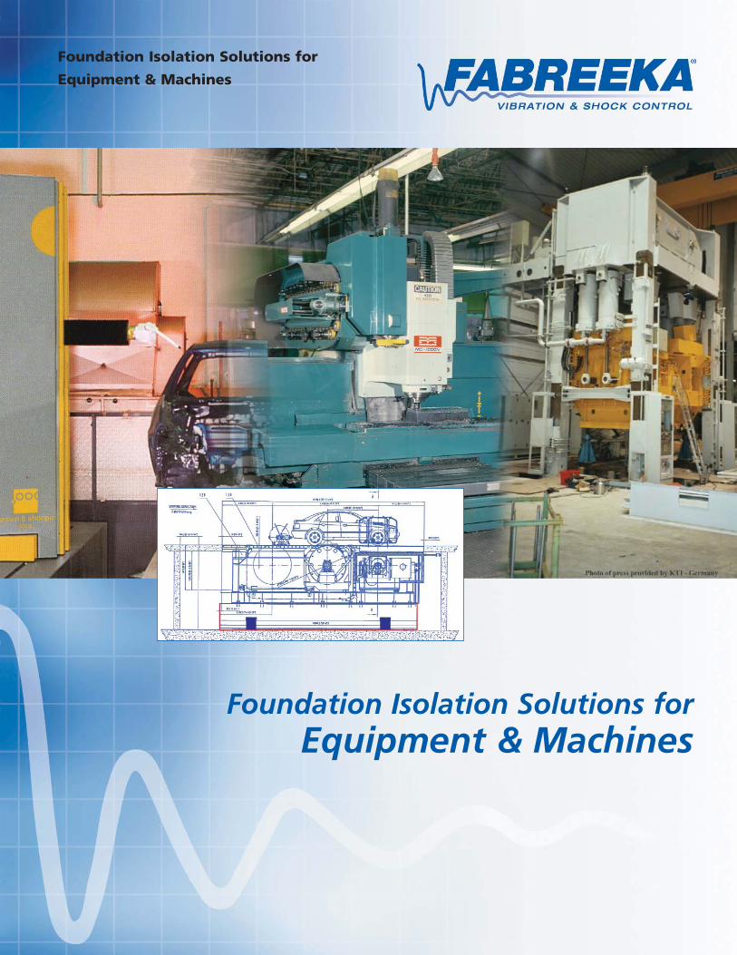
Foundation Isolation Solutions for
Equipment & Machines
Foundation Isolation Solutions forEquipment & Machines
2
GlobalThinking
Fabreeka® International, Inc.Corporate Headquarters - Stoughton, MA, USA
Fabreeka-Canada Ltd.
Fabreeka United Kingdom
Fabreeka Deutschland GmbH
Fabreeka b.v. Holland
Fabreeka® International has been a leader
in the field of shock and vibration control
since 1936. Our company provides state-
of-the-art vibration isolation and shock
control solutions for industries worldwide.
Sound engineering principles and tested per-
formance support all of our isolation systems.
Fabreeka® is more than a manufacturer of iso-
lators. We engineer solutions for your vibration
and shock problems.
Service
Solutions
Products
Contact us at any one of our worldwide facili-
ties, listed on the back page, for assistance.

3
IntroductionThe purpose of isolation is to control unwanted vibration sothat its adverse effects are kept within acceptable limits.
BackgroundWhen is a foundation (inertia block, reaction mass) required?In certain applications, it is not desirable or feasible to mount amachine directly on vibration isolators. An integral part of manymachine tool and equipment installations is a properly designedand isolated foundation.
Design ServicesOur Engineering group will assist you with design solutions foryour machinery or equipment foundation including; structuraldesign and dynamic analysis, finite element modeling andmodal analysis, if required.
Vibration IsolatorsA brief discussion regarding isolator natural frequency, staticand dynamic spring rate, damping and transmissibility, includ-ing types of isolators and isolator performance.
FABSORBTM
Fabsorb™ isolation material is an economical approach tofoundation isolation where high frequency vibration control isrequired.
FAB-EPM and INFABTM
These vibration isolation materials provide low frequency isola-tion, ease of installation and design flexibility to meet a widerange of applications.
Pneumatic Isolators and Air BagsPneumatic isolators provide exceptional low frequency andshock isolation for sensitive machines and equipment. Air bagisolators allow for large displacements (stroke) where solutionsrequire the same.
Coil Spring IsolatorsHeavy duty, large capacity spring isolators are used as a solu-tion when low frequency isolation and large dynamic deflec-tions must co-exist.
Vibration Measurement & AnalysisFabreeka provides Vibration Measurement & Analysis servicesprior to and after installation to determine and/or verify theresultant amplitude and frequency of vibration at your facility.
12
36
8
5
15
19
38
37
4
38
4
15
37
36
8
32
4
IntroductionVibrating, rotating, reciprocating and impacting equipment create machine-induced vibration and/orshock, which is transmitted into their support systems. Rotating machines and equipment that arenot properly balanced produce centrifugal forces creating steady state and random vibration.Machines generating pulses or impacts, such as forging presses, injection molding, impact testers,hammers, centrifugal pumps and compressors are the most predominate sources of vibration andshock.
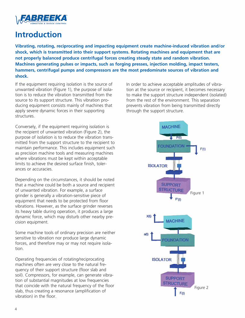
If the equipment requiring isolation is the source ofunwanted vibration (Figure 1), the purpose of isola-tion is to reduce the vibration transmitted from thesource to its support structure. This vibration pro-ducing equipment consists mainly of machines thatapply severe dynamic forces in their supportingstructures.
Conversely, if the equipment requiring isolation isthe recipient of unwanted vibration (Figure 2), thepurpose of isolation is to reduce the vibration trans-mitted from the support structure to the recipient tomaintain performance. This includes equipment suchas precision machine tools and measuring machineswhere vibrations must be kept within acceptablelimits to achieve the desired surface finish, toler-ances or accuracies.
Depending on the circumstances, it should be notedthat a machine could be both a source and recipientof unwanted vibration. For example, a surfacegrinder is generally a vibration-sensitive piece ofequipment that needs to be protected from floorvibrations. However, as the surface grinder reversesits heavy table during operation, it produces a largedynamic force, which may disturb other nearby pre-cision equipment.
Some machine tools of ordinary precision are neithersensitive to vibration nor produce large dynamicforces, and therefore may or may not require isola-tion.
Operating frequencies of rotating/reciprocatingmachines often are very close to the natural fre-quency of their support structure (floor slab andsoil). Compressors, for example, can generate vibra-tion of substantial magnitudes at low frequenciesthat coincide with the natural frequency of the floorslab, thus creating a resonance (amplification ofvibration) in the floor.
Figure 1
Figure 2
In order to achieve acceptable amplitudes of vibra-tion at the source or recipient, it becomes necessaryto make the support structure independent (isolated)from the rest of the environment. This separationprevents vibration from being transmitted directlythrough the support structure.
5
BackgroundThe separation method of cutting the existing floorslab or even creating trenches around machines toreduce the vibration being transmitted by the soilbeneath the floor slab is experimental at best andoften not a practical solution. A thorough under-standing of the machine, the support structure(floor) and the soil is required. The effectiveness ofthis approach relies heavily on the soil mechanics,magnitude and frequency of the vibration ampli-tudes to be reduced. To be an effective solution,trenches and slab cuts can be up to 6 feet deep and10 inches wide, which requires the soil to beextremely stable and can also cause safety issues.
Soil Mechanics
When installing machinery or equipment on a sup-port foundation that rests directly on soil as themeans of providing isolation, the soil conditionsmust be taken into account. Poorly designed andinstalled foundations may amplify vibration orworse, may settle unevenly and sink. Interactionbetween the soil and the foundation is equally asimportant as the interaction between the machineand the foundation.
Any static and dynamic forces exerted on the foun-dation also are exerted on the soil, and the load-bearing capacity of the soil is a key factor in deter-mining the size of the foundation.
If soil alone is to be used as the means of isolation,it is necessary to know the characteristics of theenergy dissipative properties of the soil. Establishingthese properties depends not only on the type ofsoil, but also on the physical design of the founda-tion; in particular, the depth, the ratio betweenlength and width and the material and density ofthe backfill.
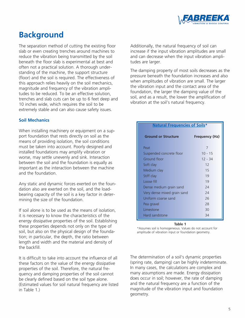
It is difficult to take into account the influence of allthese factors on the value of the energy dissipativeproperties of the soil. Therefore, the natural fre-quency and damping properties of the soil cannotbe clearly defined based on the soil type alone.(Estimated values for soil natural frequency are listedin Table 1.)
Natural Frequencies of Soils*
Ground or Structure Frequency (Hz)
Peat 7
Suspended concrete floor 10 - 15
Ground floor 12 - 34
Soft clay 12
Medium clay 15
Stiff clay 19
Loose fill 19
Dense medium grain sand 24
Very dense mixed grain sand 24
Uniform coarse sand 26
Pea gravel 28
Limestone 30
Hard sandstone 34
Table 1*Assumes soil is homogeneous. Values do not account foramplitude of vibration input or foundation geometry.
Additionally, the natural frequency of soil canincrease if the input vibration amplitudes are smalland can decrease when the input vibration ampli-tudes are larger.
The damping property of most soils decreases as thepressure beneath the foundation increases and alsowhen amplitudes of vibration are small. The largerthe vibration input and the contact area of thefoundation, the larger the damping value of thesoil, and as a result, the lower the amplification ofvibration at the soil's natural frequency.
The determination of a soil's dynamic properties(spring rate, damping) can be highly indeterminate.In many cases, the calculations are complex andmany assumptions are made. Energy dissipationdoes occur in soil; however, the rate of dampingand the natural frequency are a function of themagnitude of the vibration input and foundationgeometry.
6
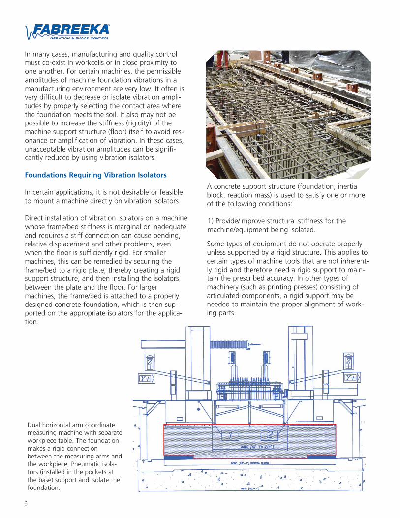
In many cases, manufacturing and quality controlmust co-exist in workcells or in close proximity toone another. For certain machines, the permissibleamplitudes of machine foundation vibrations in amanufacturing environment are very low. It often isvery difficult to decrease or isolate vibration ampli-tudes by properly selecting the contact area wherethe foundation meets the soil. It also may not bepossible to increase the stiffness (rigidity) of themachine support structure (floor) itself to avoid res-onance or amplification of vibration. In these cases,unacceptable vibration amplitudes can be signifi-cantly reduced by using vibration isolators.
Foundations Requiring Vibration Isolators
In certain applications, it is not desirable or feasibleto mount a machine directly on vibration isolators.
Direct installation of vibration isolators on a machinewhose frame/bed stiffness is marginal or inadequateand requires a stiff connection can cause bending,relative displacement and other problems, evenwhen the floor is sufficiently rigid. For smallermachines, this can be remedied by securing theframe/bed to a rigid plate, thereby creating a rigidsupport structure, and then installing the isolatorsbetween the plate and the floor. For largermachines, the frame/bed is attached to a properlydesigned concrete foundation, which is then sup-ported on the appropriate isolators for the applica-tion.
A concrete support structure (foundation, inertiablock, reaction mass) is used to satisfy one or moreof the following conditions:
1) Provide/improve structural stiffness for themachine/equipment being isolated.
Some types of equipment do not operate properlyunless supported by a rigid structure. This applies tocertain types of machine tools that are not inherent-ly rigid and therefore need a rigid support to main-tain the prescribed accuracy. In other types ofmachinery (such as printing presses) consisting ofarticulated components, a rigid support may beneeded to maintain the proper alignment of work-ing parts.
Dual horizontal arm coordinatemeasuring machine with separateworkpiece table. The foundationmakes a rigid connectionbetween the measuring arms andthe workpiece. Pneumatic isola-tors (installed in the pockets atthe base) support and isolate thefoundation.
7
3) Isolate the equipment/machine from the environ-ment when installing isolators directly beneath theunit would compromise the conditions above.
In applications in which the frequency of excitationis low, the natural frequency of the isolation systemmust be very low to provide low transmissibility andtherefore good vibration isolation. A problem oftenarises with a machine intended to be mounted onlyat its base, because a low-stiffness base-mountedsystem tends to be unstable and will allow excessivemotion to take over.
Effective isolation may therefore be difficult toachieve. A mounting arrangement where the isola-tors are relocated may be used to move the isolationsystem's elastic center closer to the center of gravityof the machine. This will reduce the effect of "rock-ing," improve the vibration isolation and reducemotion on the isolators. In most applications, it ismore feasible to attach the machine rigidly to afoundation (to lower the center of gravity of themachine and foundation together) and to suspendthe foundation on isolators located in the same hor-izontal plane as the center of gravity.
A foundation or mass designed to meet the require-ments outlined previously may be installed eitherabove floor level or in a pit below floor level.Isolators used to support the foundation may bemade of rubber, mat material, steel springs, airsprings or other suitable, resilient material. Therequired size of the foundation depends on the rea-son for its use, the type and size of equipment andthe type of isolation required.
The desired natural frequency (stiffness) and damp-ing for the isolation system is usually established bythe operating characteristics of the mounted equip-ment (source) and/or the isolation required (recipi-ent). The design basis for the support foundationnatural frequency assumes that the foundation is arigid body with a stiffness much greater than theisolators. Similarly, the pit base also should be stifferthan the soil supporting it.
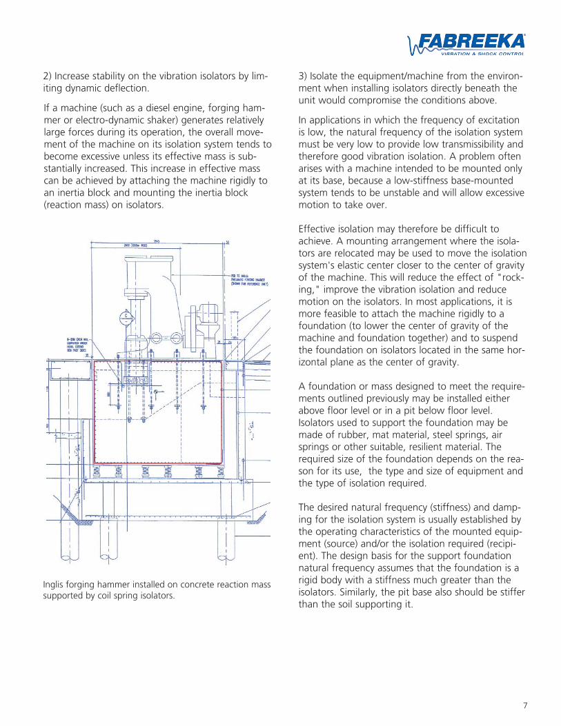
Inglis forging hammer installed on concrete reaction masssupported by coil spring isolators.
2) Increase stability on the vibration isolators by lim-iting dynamic deflection.
If a machine (such as a diesel engine, forging ham-mer or electro-dynamic shaker) generates relativelylarge forces during its operation, the overall move-ment of the machine on its isolation system tends tobecome excessive unless its effective mass is sub-stantially increased. This increase in effective masscan be achieved by attaching the machine rigidly toan inertia block and mounting the inertia block(reaction mass) on isolators.
8
Design ServicesFoundation Design
The function of a foundation is not only to supportthe weight of the machine/equipment, but also tokeep the vibration levels and dynamic displacementof the isolation system within acceptable limits.
Designing foundations supporting machines that canproduce static and dynamic loads requires soundengineering procedures for a reliable result. Anincorrectly designed foundation is extremely difficultto correct once installed.
Engineering disciplines involved in the proper designprocedures for isolated support foundations includetheory of vibrations, geotechnical engineering (soilcharacteristics), structural analysis, and in someapplications, dynamic analysis.
The design conditions and requirements can be clas-sified into three groups: machine properties, includ-ing unbalanced forces, operating speeds; weight,center of gravity and allowable deflection; soilparameters, including load bearing capacity, andenvironmental requirements - What degree of isola-tion is required and at what frequencies?
Soil
The machine/equipment, foundation, isolators andpit ultimately all are supported by the soil beneaththem. Geotechnical recommendations and evalua-tion of the soil (soils analysis) should be made andmust be part of the design. This analysis includes soilcharacteristics, including load-bearing capacity, shearmodulus, density, soil type and the composition ofthe soil at various depths. In the structural design ofthe support foundation, piles may be requireddepending on the load bearing capacity of the soil,high water table or generally poor soil conditionsthat indicate unacceptable permanent settling of thefoundation will occur.
Settling, if any, should be uniform and kept to aminimum, especially when designing support foun-dations for equipment providing large dynamicloads/forces. If the foundation supported by isolatorsis used to enhance the machine frame/bed stiffnessor is used as an integral part of the structural sup-
port of the machine (i.e. gantry CMM, turbine, rollgrinder), then the dimensions of the foundation aredefined by the machine geometry. The weight andtype of machine along with a preliminary foundationsize will give an indication of the soil's supportrequirements.
The traditional rules observed in the past of makingthe foundation 3 to 5 or even 10 to 12 times theweight of the equipment/machine it supports areapplicable only when the foundation will be isolatedby the soil and where the soil dynamic propertiesare known.
Structural Design and Stiffness
To be acceptable, the proposed design of a founda-tion or any support structure must provide a reliablestructural configuration that also meets the staticand dynamic criteria for the structure. Deflections inthe foundation caused by static loads or by dynamicforces/inputs should be within acceptable limits. Thisdesign approach sometimes requires modeling ofthe foundation, so that the real structure behavior ispredetermined and errors are minimized.
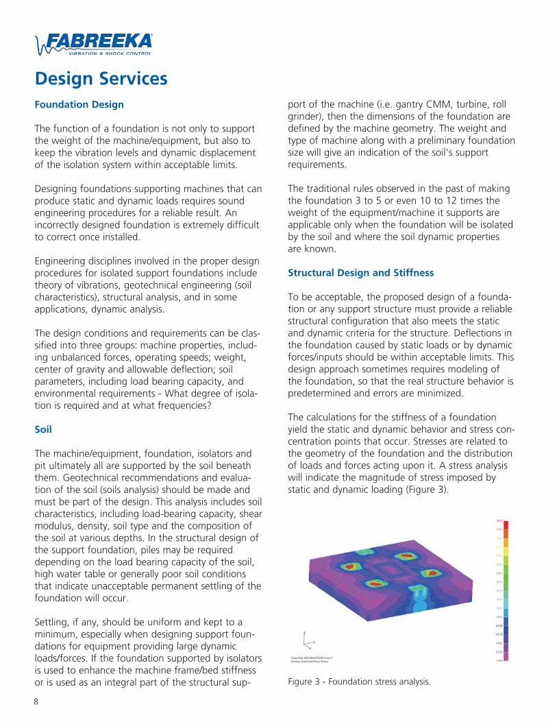
The calculations for the stiffness of a foundationyield the static and dynamic behavior and stress con-centration points that occur. Stresses are related tothe geometry of the foundation and the distributionof loads and forces acting upon it. A stress analysiswill indicate the magnitude of stress imposed bystatic and dynamic loading (Figure 3).
Figure 3 - Foundation stress analysis.
9
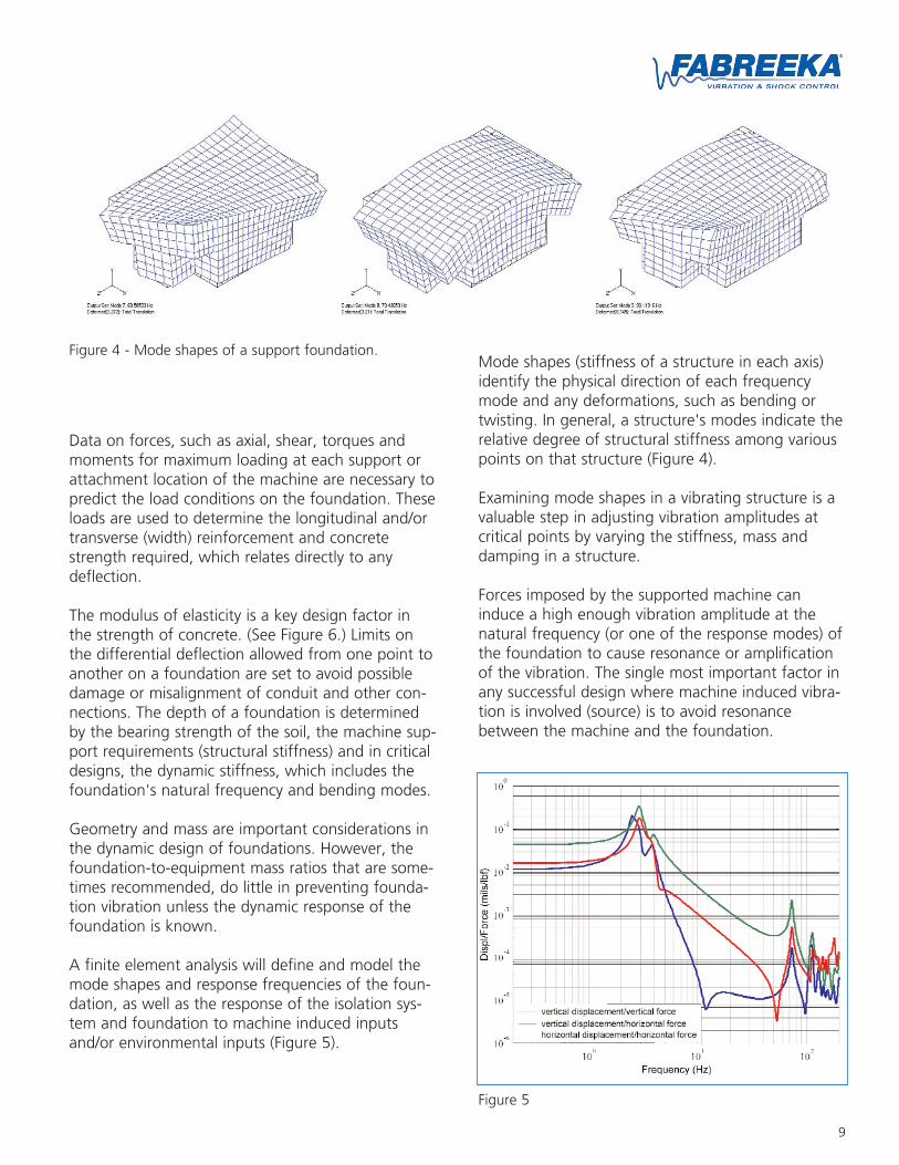
Figure 4 - Mode shapes of a support foundation.
Data on forces, such as axial, shear, torques andmoments for maximum loading at each support orattachment location of the machine are necessary topredict the load conditions on the foundation. Theseloads are used to determine the longitudinal and/ortransverse (width) reinforcement and concretestrength required, which relates directly to anydeflection.
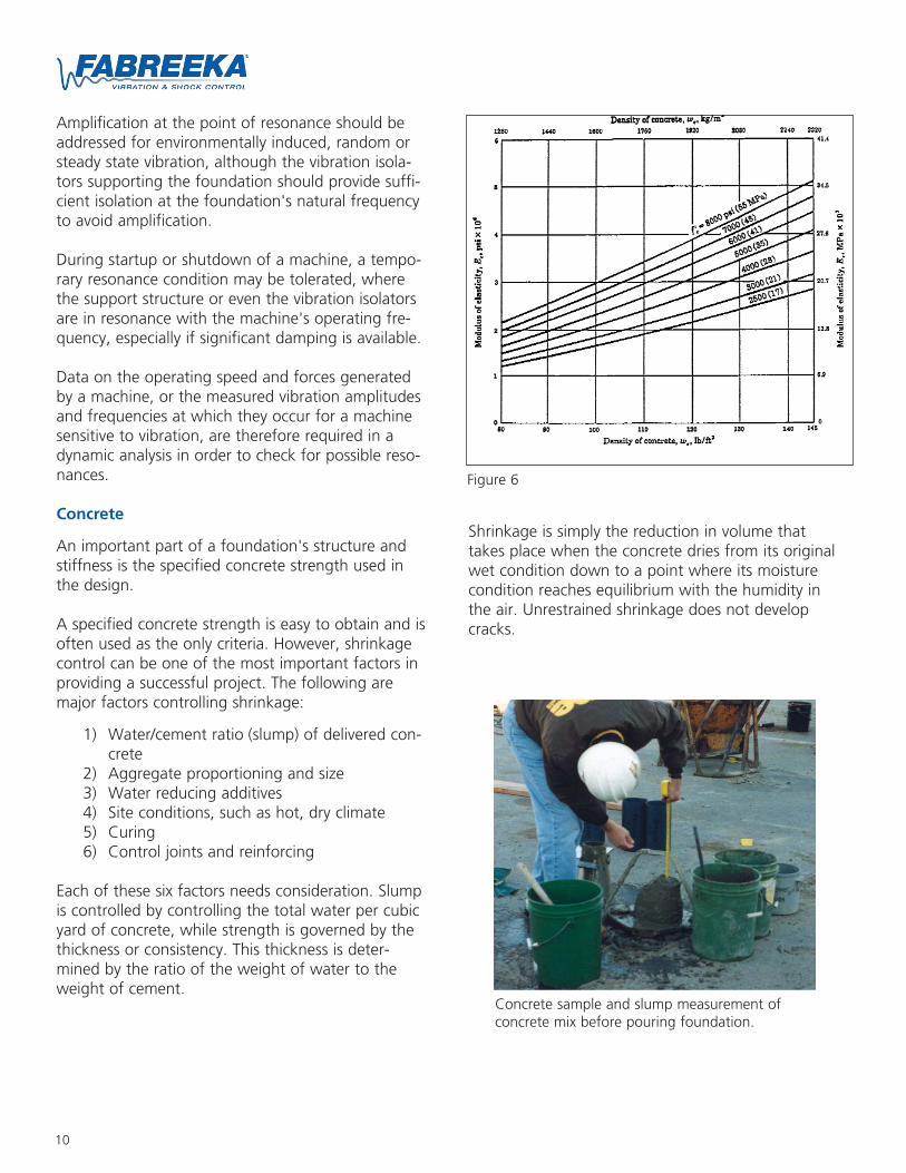
The modulus of elasticity is a key design factor inthe strength of concrete. (See Figure 6.) Limits onthe differential deflection allowed from one point toanother on a foundation are set to avoid possibledamage or misalignment of conduit and other con-nections. The depth of a foundation is determinedby the bearing strength of the soil, the machine sup-port requirements (structural stiffness) and in criticaldesigns, the dynamic stiffness, which includes thefoundation's natural frequency and bending modes.
Geometry and mass are important considerations inthe dynamic design of foundations. However, thefoundation-to-equipment mass ratios that are some-times recommended, do little in preventing founda-tion vibration unless the dynamic response of thefoundation is known.
A finite element analysis will define and model themode shapes and response frequencies of the foun-dation, as well as the response of the isolation sys-tem and foundation to machine induced inputsand/or environmental inputs (Figure 5).
Mode shapes (stiffness of a structure in each axis)identify the physical direction of each frequencymode and any deformations, such as bending ortwisting. In general, a structure's modes indicate therelative degree of structural stiffness among variouspoints on that structure (Figure 4).
Examining mode shapes in a vibrating structure is avaluable step in adjusting vibration amplitudes atcritical points by varying the stiffness, mass anddamping in a structure.
Forces imposed by the supported machine caninduce a high enough vibration amplitude at thenatural frequency (or one of the response modes) ofthe foundation to cause resonance or amplificationof the vibration. The single most important factor inany successful design where machine induced vibra-tion is involved (source) is to avoid resonancebetween the machine and the foundation.
Figure 5
10
Amplification at the point of resonance should beaddressed for environmentally induced, random orsteady state vibration, although the vibration isola-tors supporting the foundation should provide suffi-cient isolation at the foundation's natural frequencyto avoid amplification.
During startup or shutdown of a machine, a tempo-rary resonance condition may be tolerated, wherethe support structure or even the vibration isolatorsare in resonance with the machine's operating fre-quency, especially if significant damping is available.
Data on the operating speed and forces generatedby a machine, or the measured vibration amplitudesand frequencies at which they occur for a machinesensitive to vibration, are therefore required in adynamic analysis in order to check for possible reso-nances.
Concrete
An important part of a foundation's structure andstiffness is the specified concrete strength used inthe design.
A specified concrete strength is easy to obtain and isoften used as the only criteria. However, shrinkagecontrol can be one of the most important factors inproviding a successful project. The following aremajor factors controlling shrinkage:
1) Water/cement ratio (slump) of delivered con-crete
2) Aggregate proportioning and size3) Water reducing additives4) Site conditions, such as hot, dry climate5) Curing6) Control joints and reinforcing
Each of these six factors needs consideration. Slumpis controlled by controlling the total water per cubicyard of concrete, while strength is governed by thethickness or consistency. This thickness is deter-mined by the ratio of the weight of water to theweight of cement.
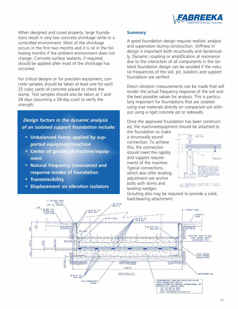
Shrinkage is simply the reduction in volume thattakes place when the concrete dries from its originalwet condition down to a point where its moisturecondition reaches equilibrium with the humidity inthe air. Unrestrained shrinkage does not developcracks.
Figure 6
Concrete sample and slump measurement ofconcrete mix before pouring foundation.
11
When designed and cured properly, large founda-tions result in very low concrete shrinkage while in acontrolled environment. Most of the shrinkageoccurs in the first two months and it is nil in the fol-lowing months if the ambient environment does notchange. Concrete surface sealants, if required,should be applied after most of the shrinkage hasoccurred.
For critical designs or for precision equipment, con-crete samples should be taken at least one for each25 cubic yards of concrete placed to check theslump. Test samples should also be taken at 7 and28 days (assuming a 28-day cure) to verify thestrength.
Design factors in the dynamic analysis
of an isolated support foundation include:
Unbalanced forces applied by sup-
ported equipment/machine
Center of gravity of machine/equip-
ment
Natural frequency (resonance) and
response modes of foundation
Transmissibility
Displacement on vibration isolators
Summary
A good foundation design requires realistic analysisand supervision during construction. Stiffness indesign is important both structurally and dynamical-ly. Dynamic coupling or amplification at resonancedue to the interaction of all components in the iso-lated foundation design can be avoided if the natu-ral frequencies of the soil, pit, isolators and supportfoundation are verified.
Direct vibration measurements can be made that willrender the actual frequency response of the soil andthe best possible values for analysis. This is particu-larly important for foundations that are isolatedusing mat materials directly on compacted soil with-out using a rigid concrete pit or sidewalls.
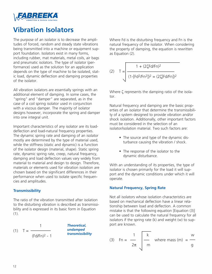
Once the approved foundation has been construct-ed, the machine/equipment should be attached tothe foundation to makea structurally soundconnection. To achievethis, the connectionshould meet the rigidityand support require-ments of the machine.Typical connections,which also offer levelingadjustment are anchorbolts with shims andleveling wedges.Grouting also may be required to provide a solid,load-bearing attachment.
12
Vibration IsolatorsWhere Fd is the disturbing frequency and Fn is thenatural frequency of the isolator. When consideringthe property of damping, the equation is rewrittenas Equation (2).
Where ζ represents the damping ratio of the isola-tor.
Natural frequency and damping are the basic prop-erties of an isolator that determine the transmissibili-ty of a system designed to provide vibration and/orshock isolation. Additionally, other important factorsmust be considered in the selection of anisolator/isolation material. Two such factors are:
The source and type of the dynamic dis-turbance causing the vibration / shock.
The response of the isolator to thedynamic disturbance.
With an understanding of its properties, the type ofisolator is chosen primarily for the load it will sup-port and the dynamic conditions under which it willoperate.
Natural Frequency, Spring Rate
Not all isolators whose isolation characteristics arebased on mechanical deflection have a linear rela-tionship between load and deflection. A commonmistake is that the following equation [Equation (3)]can be used to calculate the natural frequency for allisolators if the spring rate (k) and weight (w) to sup-port are known.
1 + (2ζFd/Fn)2
(2) T =(1-[Fd2/Fn2])2 = (2ζ[Fd/Fn])2
1 k w(3) Fn = where mass (m) =
2π m g
The purpose of an isolator is to decrease the ampli-tudes of forced, random and steady state vibrationsbeing transmitted into a machine or equipment sup-port foundation. Isolators exist in many forms,including rubber, mat materials, metal coils, air bagsand pneumatic isolators. The type of isolator (per-formance) used as the solution for an applicationdepends on the type of machine to be isolated, stat-ic load, dynamic deflection and damping propertiesof the isolator.
All vibration isolators are essentially springs with anadditional element of damping. In some cases, the"spring" and "damper" are separated, as in thecase of a coil spring isolator used in conjunctionwith a viscous damper. The majority of isolatordesigns however, incorporate the spring and damperinto one integral unit.
Important characteristics of any isolator are its load-deflection and load-natural frequency properties.The dynamic spring rate and damping of an isolatormostly are determined by the type of material used,while the stiffness (static and dynamic) is a functionof the isolator design (material, shape). Static springrate, dynamic spring rate, creep, natural frequency,damping and load deflection values vary widely frommaterial to material and design to design. Therefore,materials or elements used for vibration isolation arechosen based on the significant differences in theirperformance when used to isolate specific frequen-cies and amplitudes.
Transmissibility
The ratio of the vibration transmitted after isolationto the disturbing vibration is described as transmissi-bility and is expressed in its basic form in Equation(1).
1(1) T =
(Fd/Fn)2 - 1
Theoretical,undampedtransmissibility
13
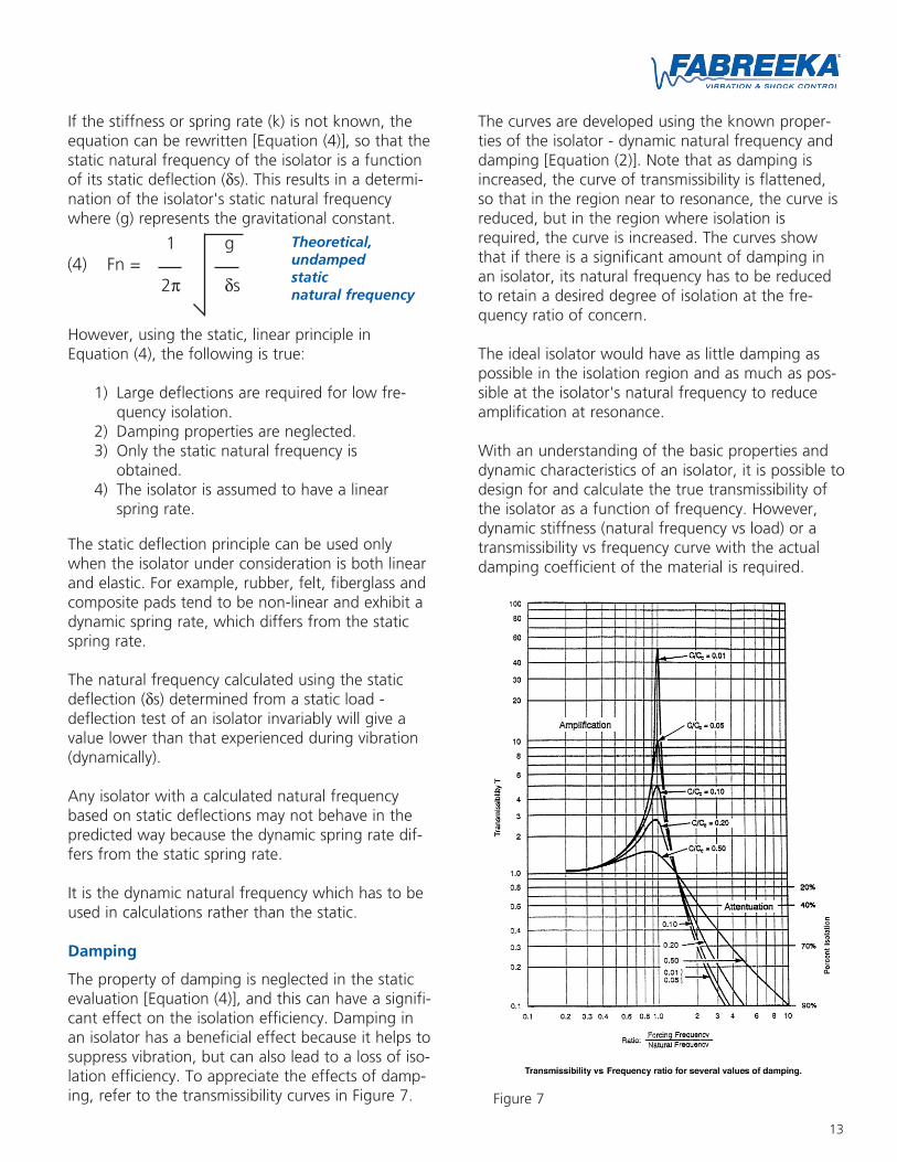
The curves are developed using the known proper-ties of the isolator - dynamic natural frequency anddamping [Equation (2)]. Note that as damping isincreased, the curve of transmissibility is flattened,so that in the region near to resonance, the curve isreduced, but in the region where isolation isrequired, the curve is increased. The curves showthat if there is a significant amount of damping inan isolator, its natural frequency has to be reducedto retain a desired degree of isolation at the fre-quency ratio of concern.
The ideal isolator would have as little damping aspossible in the isolation region and as much as pos-sible at the isolator's natural frequency to reduceamplification at resonance.
With an understanding of the basic properties anddynamic characteristics of an isolator, it is possible todesign for and calculate the true transmissibility ofthe isolator as a function of frequency. However,dynamic stiffness (natural frequency vs load) or atransmissibility vs frequency curve with the actualdamping coefficient of the material is required.
Figure 7
If the stiffness or spring rate (k) is not known, theequation can be rewritten [Equation (4)], so that thestatic natural frequency of the isolator is a functionof its static deflection (δs). This results in a determi-nation of the isolator's static natural frequencywhere (g) represents the gravitational constant.
However, using the static, linear principle inEquation (4), the following is true:
1) Large deflections are required for low fre-quency isolation.
2) Damping properties are neglected.3) Only the static natural frequency is
obtained.4) The isolator is assumed to have a linear
spring rate.
The static deflection principle can be used onlywhen the isolator under consideration is both linearand elastic. For example, rubber, felt, fiberglass andcomposite pads tend to be non-linear and exhibit adynamic spring rate, which differs from the staticspring rate.
The natural frequency calculated using the staticdeflection (δs) determined from a static load -deflection test of an isolator invariably will give avalue lower than that experienced during vibration(dynamically).
Any isolator with a calculated natural frequencybased on static deflections may not behave in thepredicted way because the dynamic spring rate dif-fers from the static spring rate.
It is the dynamic natural frequency which has to beused in calculations rather than the static.
Damping
The property of damping is neglected in the staticevaluation [Equation (4)], and this can have a signifi-cant effect on the isolation efficiency. Damping inan isolator has a beneficial effect because it helps tosuppress vibration, but can also lead to a loss of iso-lation efficiency. To appreciate the effects of damp-ing, refer to the transmissibility curves in Figure 7.
1 g(4) Fn =
2π δs
Theoretical,undampedstaticnatural frequency
14
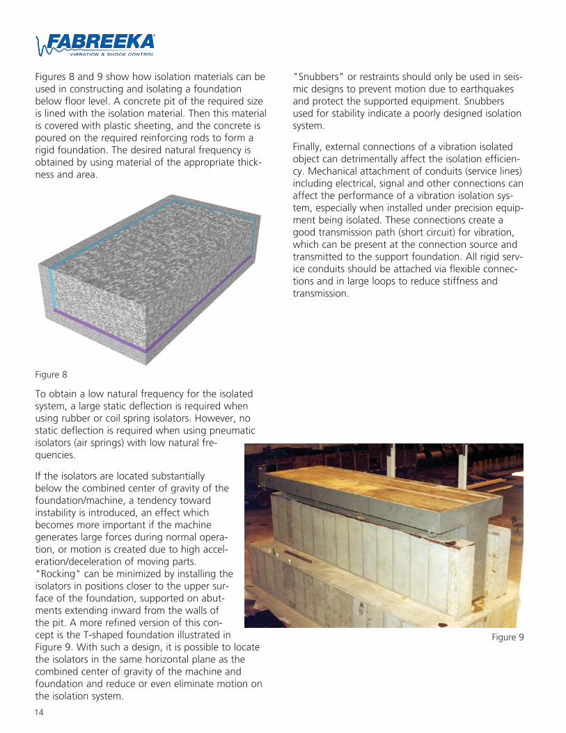
Figures 8 and 9 show how isolation materials can beused in constructing and isolating a foundationbelow floor level. A concrete pit of the required sizeis lined with the isolation material. Then this materialis covered with plastic sheeting, and the concrete ispoured on the required reinforcing rods to form arigid foundation. The desired natural frequency isobtained by using material of the appropriate thick-ness and area.
To obtain a low natural frequency for the isolatedsystem, a large static deflection is required whenusing rubber or coil spring isolators. However, nostatic deflection is required when using pneumaticisolators (air springs) with low natural fre-quencies.
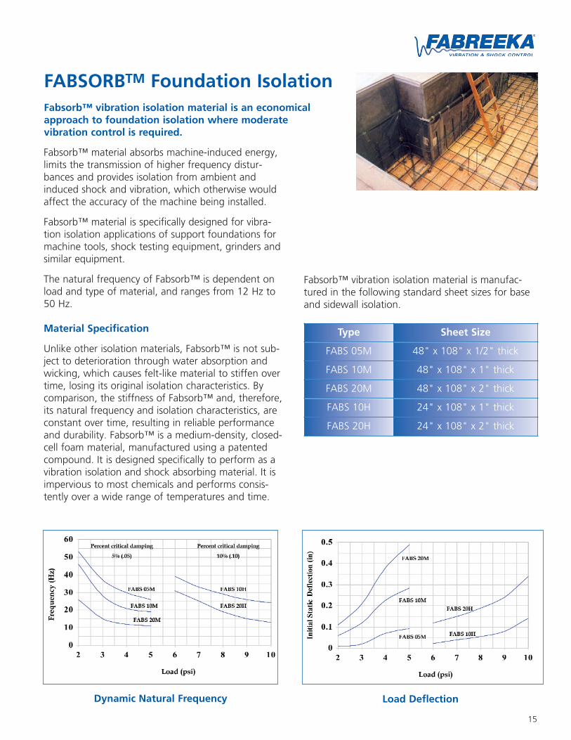
If the isolators are located substantiallybelow the combined center of gravity of thefoundation/machine, a tendency towardinstability is introduced, an effect whichbecomes more important if the machinegenerates large forces during normal opera-tion, or motion is created due to high accel-eration/deceleration of moving parts."Rocking" can be minimized by installing theisolators in positions closer to the upper sur-face of the foundation, supported on abut-ments extending inward from the walls ofthe pit. A more refined version of this con-cept is the T-shaped foundation illustrated inFigure 9. With such a design, it is possible to locatethe isolators in the same horizontal plane as thecombined center of gravity of the machine andfoundation and reduce or even eliminate motion onthe isolation system.
"Snubbers" or restraints should only be used in seis-mic designs to prevent motion due to earthquakesand protect the supported equipment. Snubbersused for stability indicate a poorly designed isolationsystem.
Finally, external connections of a vibration isolatedobject can detrimentally affect the isolation efficien-cy. Mechanical attachment of conduits (service lines)including electrical, signal and other connections canaffect the performance of a vibration isolation sys-tem, especially when installed under precision equip-ment being isolated. These connections create agood transmission path (short circuit) for vibration,which can be present at the connection source andtransmitted to the support foundation. All rigid serv-ice conduits should be attached via flexible connec-tions and in large loops to reduce stiffness andtransmission.
Figure 9
Figure 8
15
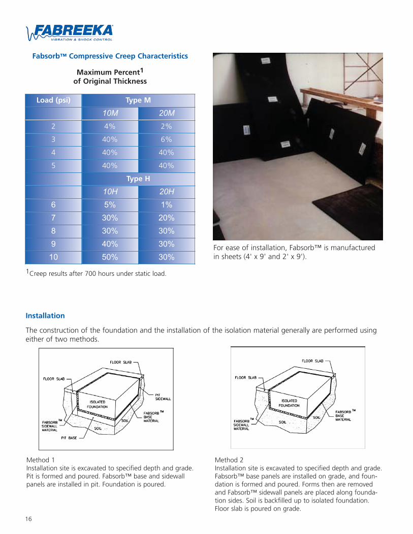
FABSORBTM Foundation IsolationFabsorb™ vibration isolation material is an economicalapproach to foundation isolation where moderatevibration control is required.
Fabsorb™ material absorbs machine-induced energy,limits the transmission of higher frequency distur-bances and provides isolation from ambient andinduced shock and vibration, which otherwise wouldaffect the accuracy of the machine being installed.
Fabsorb™ material is specifically designed for vibra-tion isolation applications of support foundations formachine tools, shock testing equipment, grinders andsimilar equipment.
The natural frequency of Fabsorb™ is dependent onload and type of material, and ranges from 12 Hz to50 Hz.
Material Specification
Unlike other isolation materials, Fabsorb™ is not sub-ject to deterioration through water absorption andwicking, which causes felt-like material to stiffen overtime, losing its original isolation characteristics. Bycomparison, the stiffness of Fabsorb™ and, therefore,its natural frequency and isolation characteristics, areconstant over time, resulting in reliable performanceand durability. Fabsorb™ is a medium-density, closed-cell foam material, manufactured using a patentedcompound. It is designed specifically to perform as avibration isolation and shock absorbing material. It isimpervious to most chemicals and performs consis-tently over a wide range of temperatures and time.
Fabsorb™ vibration isolation material is manufac-tured in the following standard sheet sizes for baseand sidewall isolation.
Load DeflectionDynamic Natural Frequency
Type Sheet Size
FABS 05M 48" x 108" x 1/2" thick
FABS 10M 48" x 108" x 1" thick
FABS 20M 48" x 108" x 2" thick
FABS 10H 24" x 108" x 1" thick
FABS 20H 24" x 108" x 2" thick
16
Installation
The construction of the foundation and the installation of the isolation material generally are performed usingeither of two methods.
For ease of installation, Fabsorb™ is manufacturedin sheets (4' x 9' and 2' x 9').
Fabsorb™ Compressive Creep Characteristics
Maximum Percent1
of Original Thickness
Load (psi) Type M
10M 20M2 4% 2%
3 40% 6%
4 40% 40%
5 40% 40%
Type H
10H 20H6 5% 1%7 30% 20%8 30% 30%9 40% 30%10 50% 30%
1Creep results after 700 hours under static load.
Method 1Installation site is excavated to specified depth and grade.Pit is formed and poured. Fabsorb™ base and sidewallpanels are installed in pit. Foundation is poured.
Method 2Installation site is excavated to specified depth and grade.Fabsorb™ base panels are installed on grade, and foun-dation is formed and poured. Forms then are removedand Fabsorb™ sidewall panels are placed along founda-tion sides. Soil is backfilled up to isolated foundation.Floor slab is poured on grade.

17
Installation Procedure (Method 1)
Following the layout drawings provided by Fabreeka,install the Fabsorb™ panels on the sidewalls of the pit.Sidewall panels should rest on pit floor.
Sidewall panels can be secured to the pit walls by con-struction adhesive or by 3" duct tape (lower right).Additionally, all vertical seams also should be taped toprevent concrete from creeping into any gaps.
Install Fabsorb™ base isolation panels. Base panelsshould not contact pit sidewalls - only sidewall isola-tion panels. Tape all seams.
Lay polyethylene sheeting over Fabsorb™ material onbase and sidewalls. Tape all seams to prevent concreteseepage into the material.
Place reinforcement rod per structural design drawingsusing shim material to keep rod elevated and to preventpuncturing or tearing the sheeting and material.
Pour concrete, and trim polyethylene sheeting at floorlevel after fully cured.
A proven mastic sealer, Sika Type 125L or equivalent,should be used to seal the isolation material at gradebetween the floor and the foundation at the exposededge.
Installation Procedure (Method 2)
Following the layout drawings provided by Fabreeka,install the Fabsorb™ panels on grade. Allowable soilloading should be verified by soils survey / report. Allseams should be taped using 3" wide duct tape.
Lay polyethylene sheeting over Fabsorb™ base material,and construct forming for foundation around base isola-tion panels.
Place reinforcement rod per structural design drawingsusing shim material to keep rod elevated and to preventpuncturing or tearing the sheeting and material.
Pour concrete for foundation and allow for proper curetime. Remove forming and secure Fabsorb™ sidewallisolation panels to sides of foundation using construc-tion adhesive or duct tape.
Backfill soil against sidewall isolation panels.
Pour floor slab on grade.
A proven mastic sealer, Sika Type 125L or equivalent,should be used to seal the isolation material at gradebetween the floor and the foundation at the exposededge.
Fabsorb™ can be supplied cut to size, marked and fur-nished with detailed layout drawings for installation bycontractors. Supplied in standard sheet sizes, it can beeasily cut with a utility knife when the foundationdimensions vary.
18
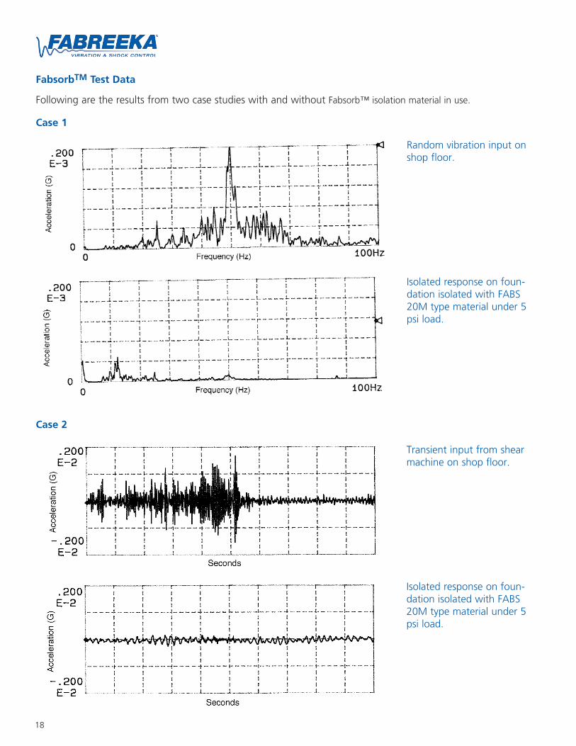
FabsorbTM Test Data
Following are the results from two case studies with and without Fabsorb™ isolation material in use.
Case 1
Case 2
Random vibration input onshop floor.
Isolated response on foun-dation isolated with FABS20M type material under 5psi load.
Transient input from shearmachine on shop floor.
Isolated response on foun-dation isolated with FABS20M type material under 5psi load.
19
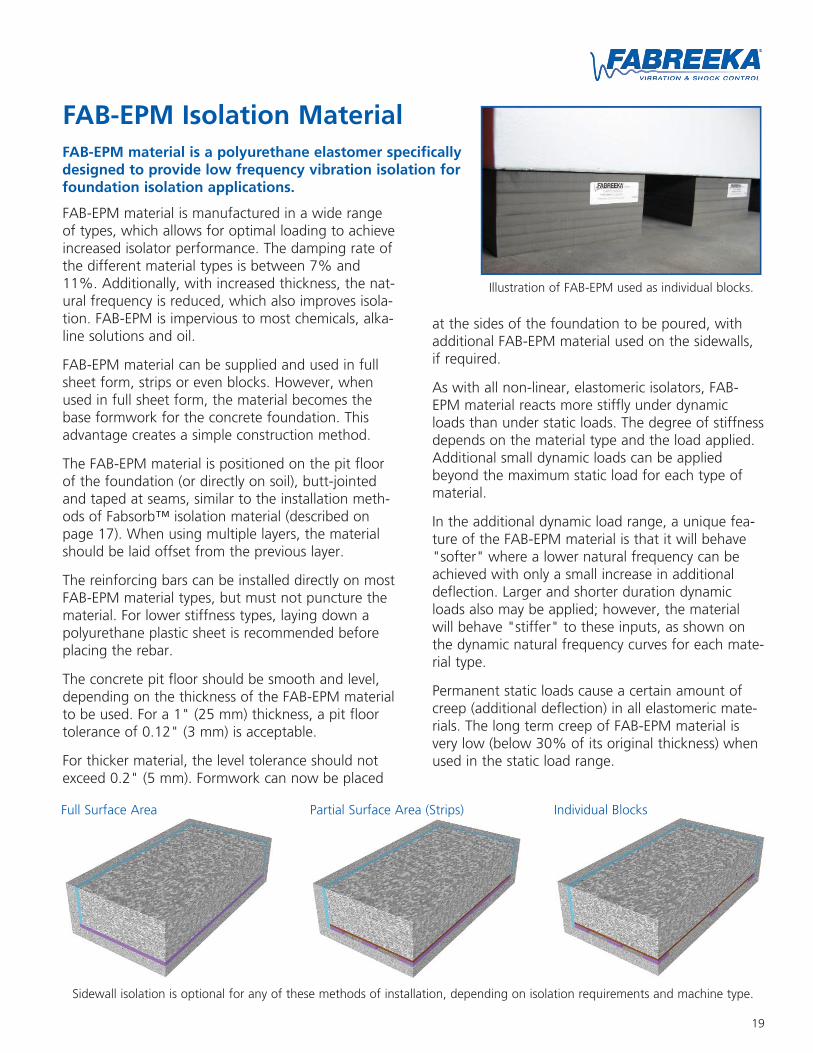
FAB-EPM Isolation MaterialFAB-EPM material is a polyurethane elastomer specificallydesigned to provide low frequency vibration isolation forfoundation isolation applications.
FAB-EPM material is manufactured in a wide rangeof types, which allows for optimal loading to achieveincreased isolator performance. The damping rate ofthe different material types is between 7% and11%. Additionally, with increased thickness, the nat-ural frequency is reduced, which also improves isola-tion. FAB-EPM is impervious to most chemicals, alka-line solutions and oil.
FAB-EPM material can be supplied and used in fullsheet form, strips or even blocks. However, whenused in full sheet form, the material becomes thebase formwork for the concrete foundation. Thisadvantage creates a simple construction method.
The FAB-EPM material is positioned on the pit floorof the foundation (or directly on soil), butt-jointedand taped at seams, similar to the installation meth-ods of Fabsorb™ isolation material (described onpage 17). When using multiple layers, the materialshould be laid offset from the previous layer.
The reinforcing bars can be installed directly on mostFAB-EPM material types, but must not puncture thematerial. For lower stiffness types, laying down apolyurethane plastic sheet is recommended beforeplacing the rebar.
The concrete pit floor should be smooth and level,depending on the thickness of the FAB-EPM materialto be used. For a 1" (25 mm) thickness, a pit floortolerance of 0.12" (3 mm) is acceptable.
For thicker material, the level tolerance should notexceed 0.2" (5 mm). Formwork can now be placed
at the sides of the foundation to be poured, withadditional FAB-EPM material used on the sidewalls,if required.
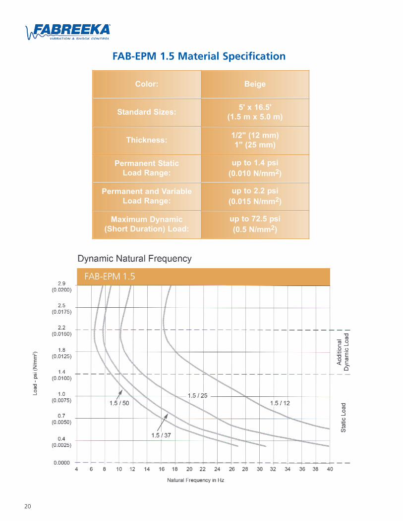
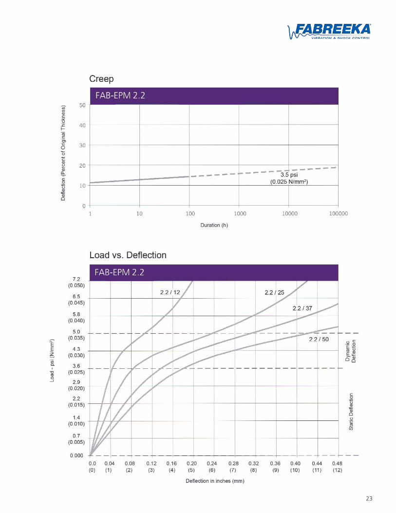
As with all non-linear, elastomeric isolators, FAB-EPM material reacts more stiffly under dynamicloads than under static loads. The degree of stiffnessdepends on the material type and the load applied.Additional small dynamic loads can be appliedbeyond the maximum static load for each type ofmaterial.
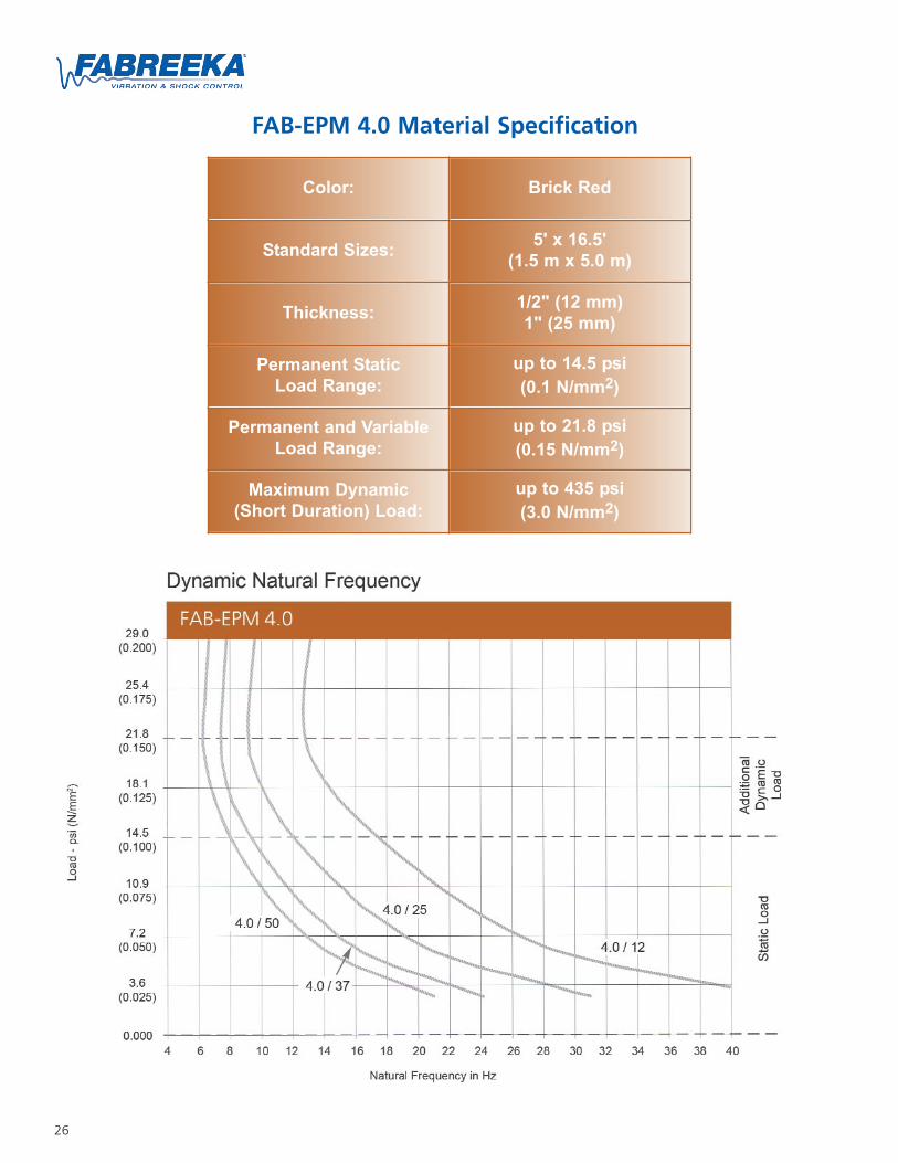
In the additional dynamic load range, a unique fea-ture of the FAB-EPM material is that it will behave"softer" where a lower natural frequency can beachieved with only a small increase in additionaldeflection. Larger and shorter duration dynamicloads also may be applied; however, the materialwill behave "stiffer" to these inputs, as shown onthe dynamic natural frequency curves for each mate-rial type.
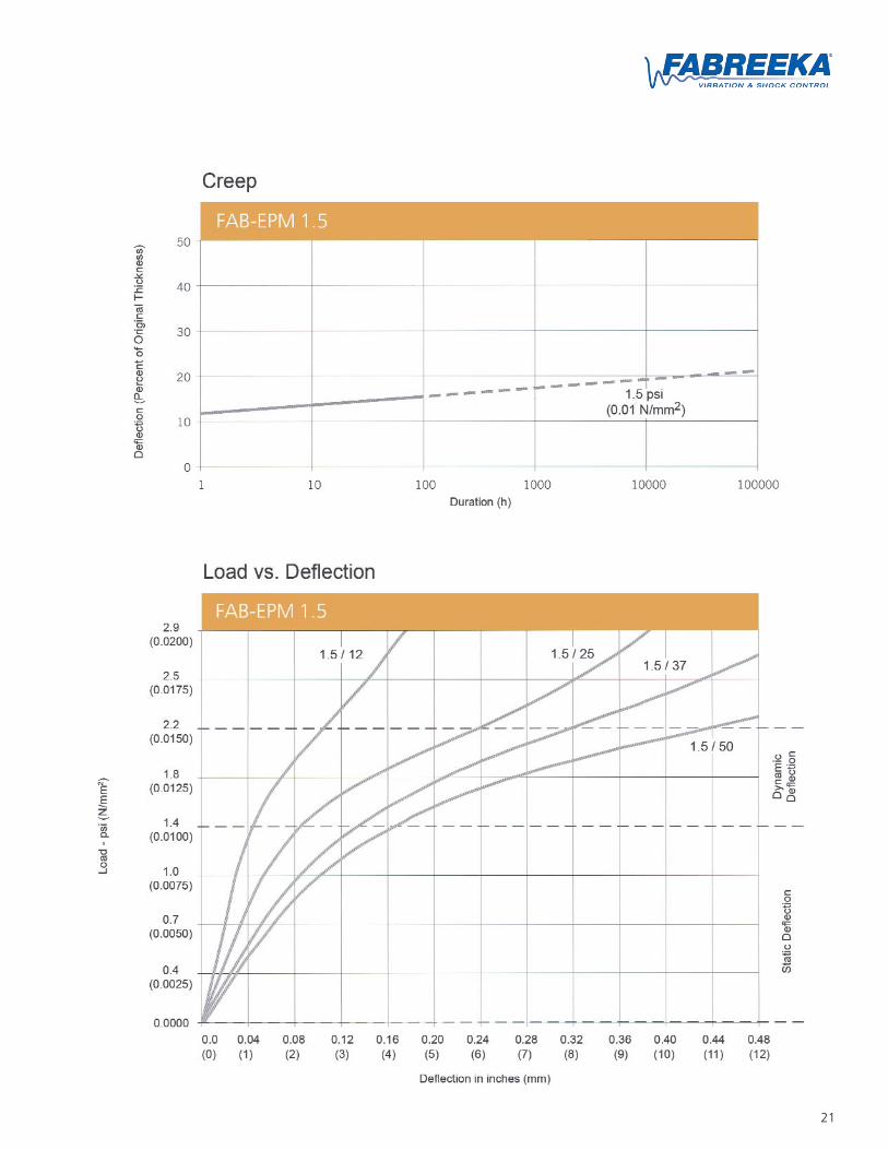
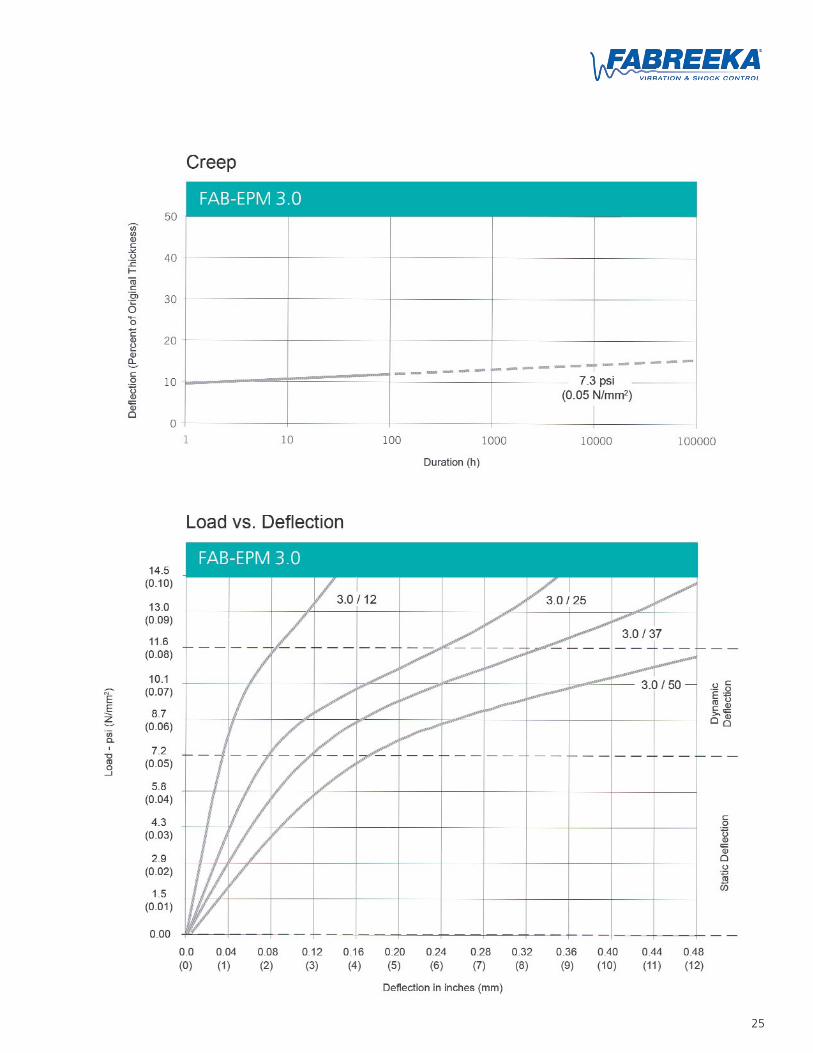
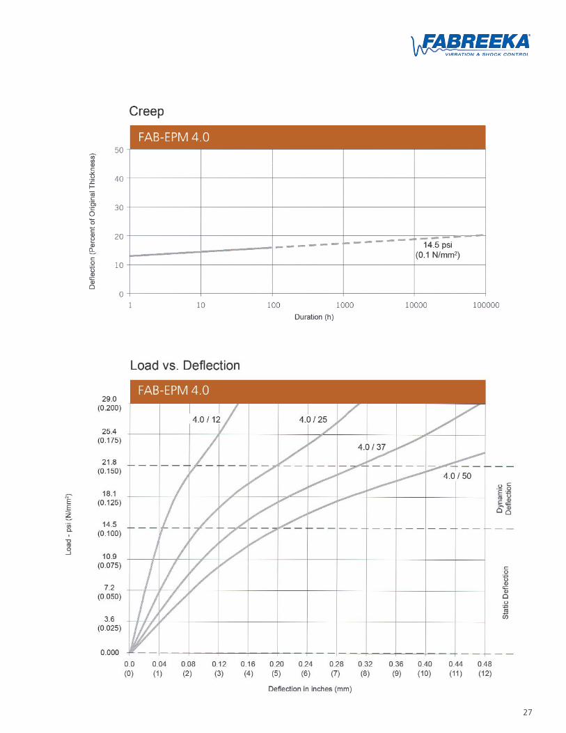
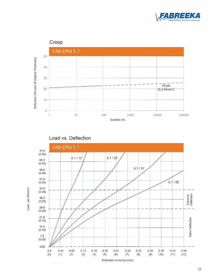
Permanent static loads cause a certain amount ofcreep (additional deflection) in all elastomeric mate-rials. The long term creep of FAB-EPM material isvery low (below 30% of its original thickness) whenused in the static load range.
Sidewall isolation is optional for any of these methods of installation, depending on isolation requirements and machine type.
Full Surface Area Individual BlocksPartial Surface Area (Strips)
Illustration of FAB-EPM used as individual blocks.
20
FAB-EPM 1.5 Material Specification
Color: Beige
Standard Sizes: 5' x 16.5'(1.5 m x 5.0 m)
Thickness: 1/2" (12 mm)1" (25 mm)
Permanent StaticLoad Range:
up to 1.4 psi(0.010 N/mm2)
Permanent and VariableLoad Range:
up to 2.2 psi(0.015 N/mm2)
Maximum Dynamic(Short Duration) Load:
up to 72.5 psi(0.5 N/mm2)
21
22
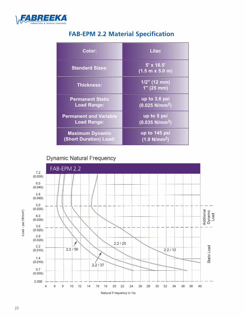
FAB-EPM 2.2 Material Specification
Color: Lilac
Standard Sizes: 5' x 16.5'(1.5 m x 5.0 m)
Thickness: 1/2" (12 mm)1" (25 mm)
Permanent StaticLoad Range:
up to 3.6 psi(0.025 N/mm2)
Permanent and VariableLoad Range:
up to 5 psi(0.035 N/mm2)
Maximum Dynamic(Short Duration) Load:
up to 145 psi(1.0 N/mm2)
23

24
FAB-EPM 3.0 Material Specification
Color: Turquoise
Standard Sizes: 5' x 16.5'(1.5 m x 5.0 m)
Thickness: 1/2" (12 mm)1" (25 mm)
Permanent StaticLoad Range:
up to 7.2 psi(0.05 N/mm2)
Permanent and VariableLoad Range:
up to 11.6 psi(0.08 N/mm2)
Maximum Dynamic(Short Duration) Load:
up to 290 psi(2.0 N/mm2)
25
26
FAB-EPM 4.0 Material Specification
Color: Brick Red
Standard Sizes: 5' x 16.5'(1.5 m x 5.0 m)
Thickness: 1/2" (12 mm)1" (25 mm)
Permanent StaticLoad Range:
up to 14.5 psi(0.1 N/mm2)
Permanent and VariableLoad Range:
up to 21.8 psi(0.15 N/mm2)
Maximum Dynamic(Short Duration) Load:
up to 435 psi(3.0 N/mm2)
27
28
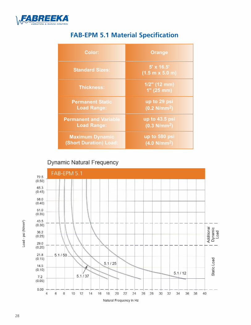
FAB-EPM 5.1 Material Specification
Color: Orange
Standard Sizes: 5' x 16.5'(1.5 m x 5.0 m)
Thickness: 1/2" (12 mm)1" (25 mm)
Permanent StaticLoad Range:
up to 29 psi(0.2 N/mm2)
Permanent and VariableLoad Range:
up to 43.5 psi(0.3 N/mm2)
Maximum Dynamic(Short Duration) Load:
up to 580 psi(4.0 N/mm2)
29
30
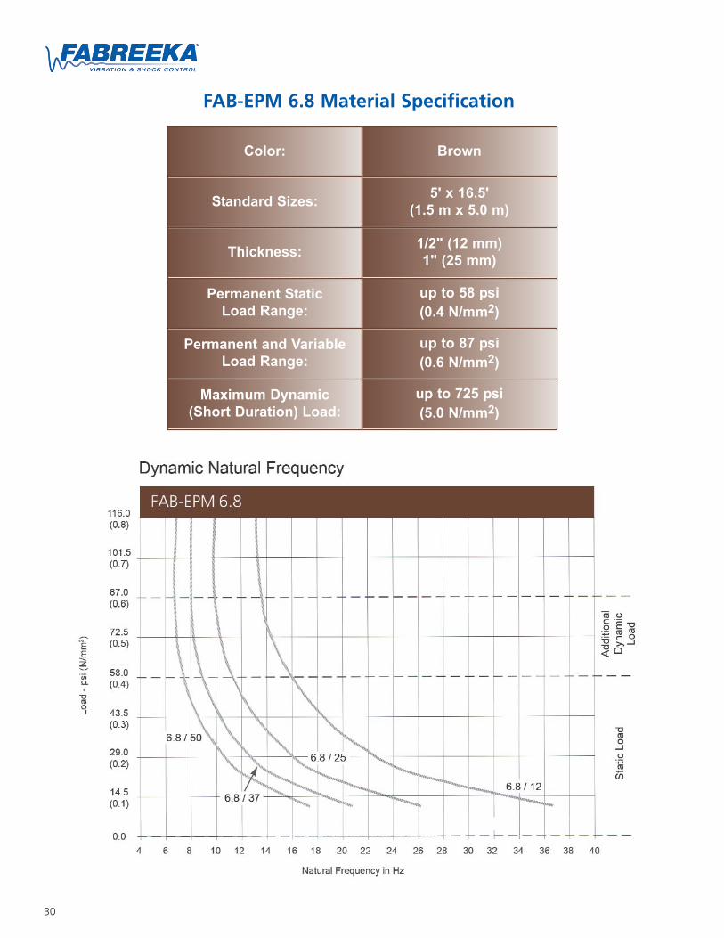
FAB-EPM 6.8 Material Specification
Color: Brown
Standard Sizes: 5' x 16.5'(1.5 m x 5.0 m)
Thickness: 1/2" (12 mm)1" (25 mm)
Permanent StaticLoad Range:
up to 58 psi(0.4 N/mm2)
Permanent and VariableLoad Range:
up to 87 psi(0.6 N/mm2)
Maximum Dynamic(Short Duration) Load:
up to 725 psi(5.0 N/mm2)

31
32
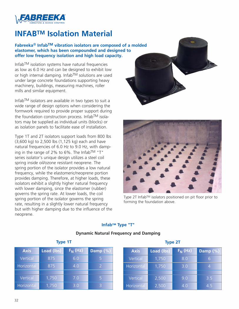
INFABTM Isolation MaterialFabreeka® InfabTM vibration isolators are composed of a moldedelastomer, which has been compounded and designed tooffer low frequency isolation and high load capacity.
InfabTM isolation systems have natural frequenciesas low as 6.0 Hz and can be designed to exhibit lowor high internal damping. InfabTM solutions are usedunder large concrete foundations supporting heavymachinery, buildings, measuring machines, rollermills and similar equipment.
InfabTM isolators are available in two types to suit awide range of design options when considering theformwork required to provide proper support duringthe foundation construction process. InfabTM isola-tors may be supplied as individual units (blocks) oras isolation panels to facilitate ease of installation.
Type 1T and 2T isolators support loads from 800 lbs(3,600 kg) to 2,500 lbs (1,125 kg) each and havenatural frequencies of 6.0 Hz to 9.0 Hz, with damp-ing in the range of 2% to 6%. The InfabTM "T"series isolator's unique design utilizes a steel coilspring inside oil/ozone resistant neoprene. Thespring portion of the isolator provides a low naturalfrequency, while the elastomeric/neoprene portionprovides damping. Therefore, at higher loads, theseisolators exhibit a slightly higher natural frequencywith lower damping, since the elastomer (rubber)governs the spring rate. At lower loads, the coilspring portion of the isolator governs the springrate, resulting in a slightly lower natural frequencybut with higher damping due to the influence of theneoprene.
Type 2T InfabTM isolators positioned on pit floor prior toforming the foundation above.
Infab™ Type "T"
Dynamic Natural Frequency and Damping
Axis Load (lbs) FN (Hz) Damp (%)
Vertical 875 6.0 5
Horizontal 875 4.0 2
Vertical 1,750 7.0 5
Horizontal 1,750 3.0 3
Type 1T
Axis Load (lbs) FN (Hz) Damp (%)
Vertical 1,750 8.0 6
Horizontal 1,750 3.0 4
Vertical 2,500 9.0 3.5
Horizontal 2,500 4.0 4.5
Type 2T
33
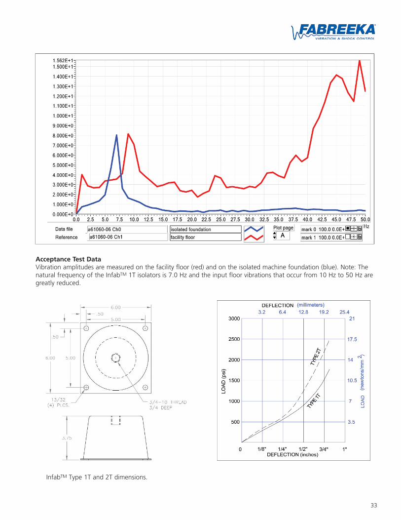
Acceptance Test DataVibration amplitudes are measured on the facility floor (red) and on the isolated machine foundation (blue). Note: Thenatural frequency of the InfabTM 1T isolators is 7.0 Hz and the input floor vibrations that occur from 10 Hz to 50 Hz aregreatly reduced.
InfabTM Type 1T and 2T dimensions.
34
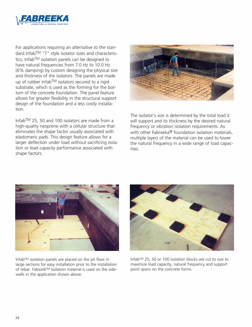
For applications requiring an alternative to the stan-dard InfabTM "T" style isolator sizes and characteris-tics, InfabTM isolation panels can be designed tohave natural frequencies from 7.0 Hz to 10.0 Hz(6% damping) by custom designing the physical sizeand thickness of the isolators. The panels are madeup of rubber InfabTM isolators secured to a rigidsubstrate, which is used as the forming for the bot-tom of the concrete foundation. The panel featureallows for greater flexibility in the structural supportdesign of the foundation and a less costly installa-tion.
InfabTM 25, 50 and 100 isolators are made from ahigh-quality neoprene with a cellular structure thateliminates the shape factor usually associated withelastomeric pads. This design feature allows for alarger deflection under load without sacrificing isola-tion or load capacity performance associated withshape factors.
InfabTM isolation panels are placed on the pit floor inlarge sections for easy installation prior to the installationof rebar. FabsorbTM isolation material is used on the side-walls in the application shown above.
The isolator's size is determined by the total load itwill support and its thickness by the desired naturalfrequency or vibration isolation requirements. Aswith other Fabreeka® foundation isolation materials,multiple layers of the material can be used to lowerthe natural frequency in a wide range of load capac-ities.
InfabTM 25, 50 or 100 isolation blocks are cut to size tomaximize load capacity, natural frequency and supportpoint spans on the concrete forms.
35
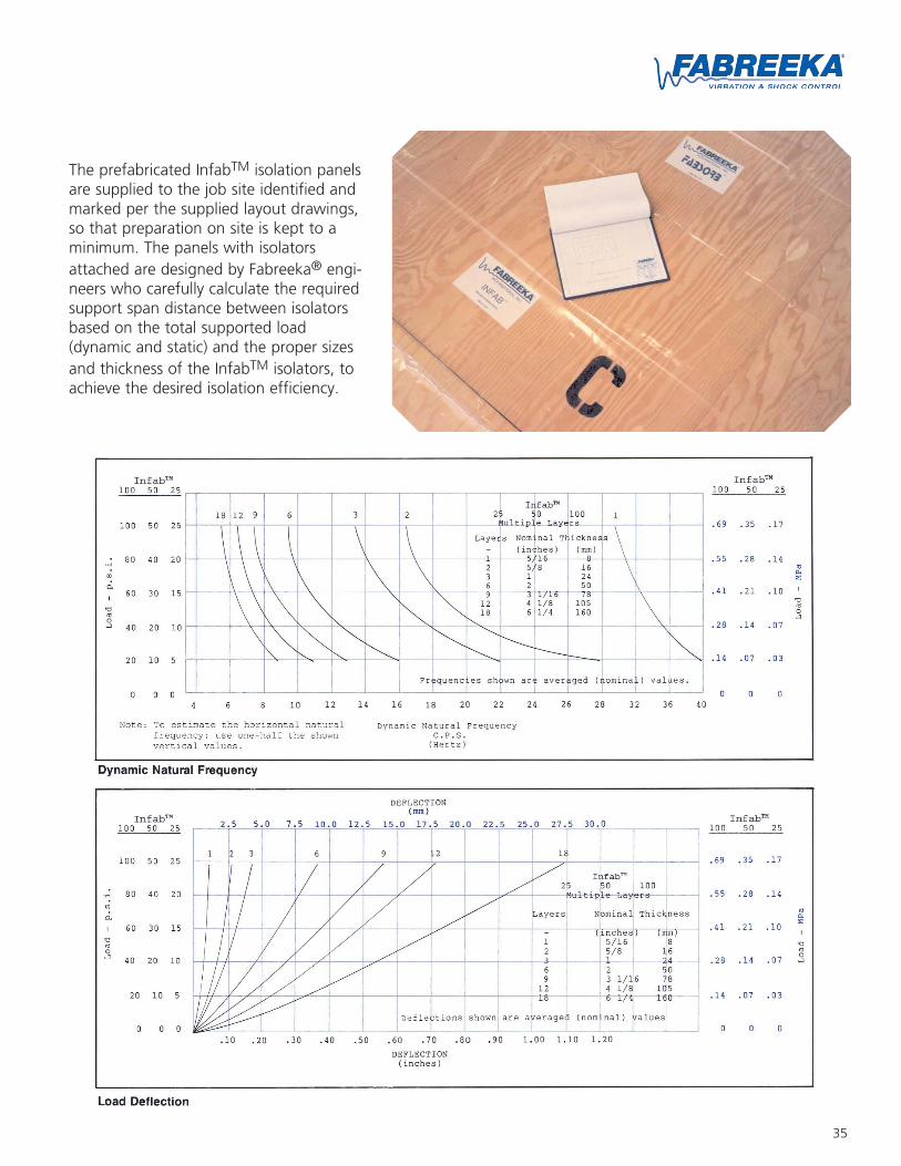
The prefabricated InfabTM isolation panelsare supplied to the job site identified andmarked per the supplied layout drawings,so that preparation on site is kept to aminimum. The panels with isolatorsattached are designed by Fabreeka® engi-neers who carefully calculate the requiredsupport span distance between isolatorsbased on the total supported load(dynamic and static) and the proper sizesand thickness of the InfabTM isolators, toachieve the desired isolation efficiency.
36
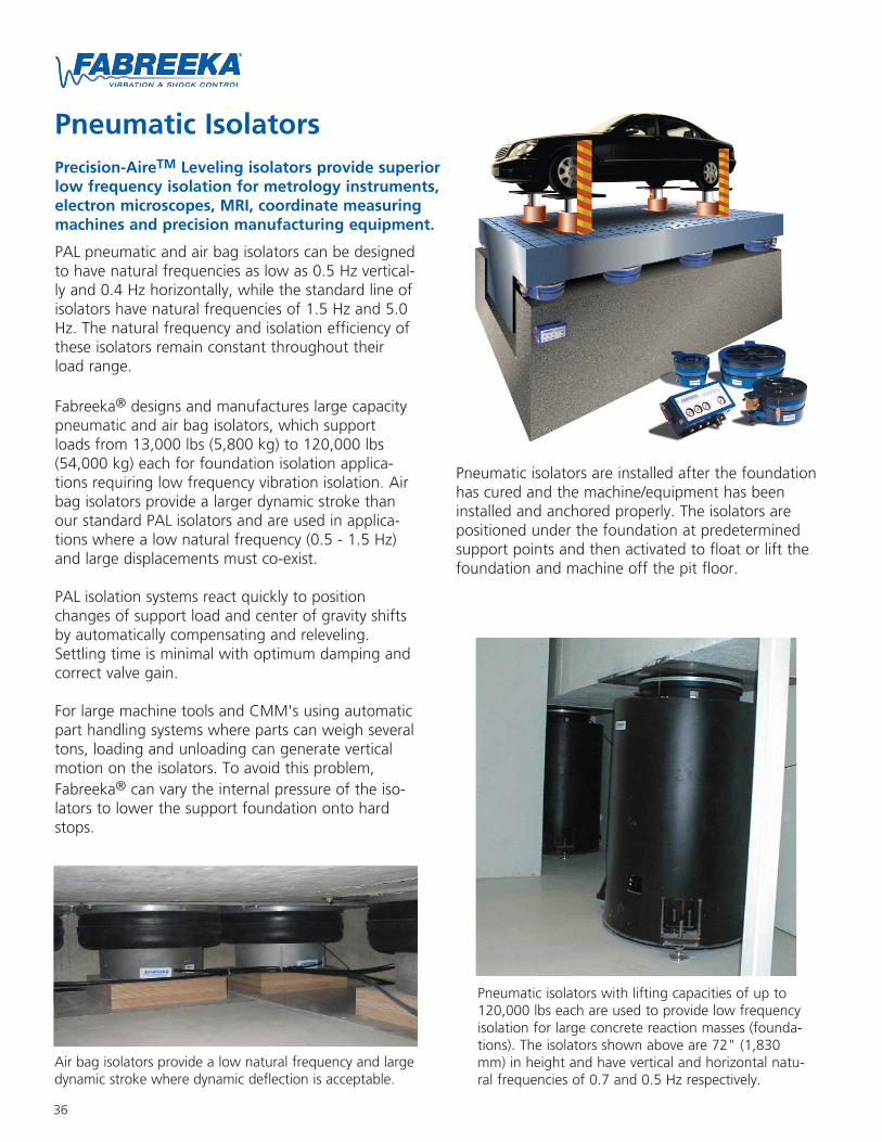
Pneumatic IsolatorsPrecision-AireTM Leveling isolators provide superiorlow frequency isolation for metrology instruments,electron microscopes, MRI, coordinate measuringmachines and precision manufacturing equipment.
PAL pneumatic and air bag isolators can be designedto have natural frequencies as low as 0.5 Hz vertical-ly and 0.4 Hz horizontally, while the standard line ofisolators have natural frequencies of 1.5 Hz and 5.0Hz. The natural frequency and isolation efficiency ofthese isolators remain constant throughout theirload range.
Fabreeka® designs and manufactures large capacitypneumatic and air bag isolators, which supportloads from 13,000 lbs (5,800 kg) to 120,000 lbs(54,000 kg) each for foundation isolation applica-tions requiring low frequency vibration isolation. Airbag isolators provide a larger dynamic stroke thanour standard PAL isolators and are used in applica-tions where a low natural frequency (0.5 - 1.5 Hz)and large displacements must co-exist.
PAL isolation systems react quickly to positionchanges of support load and center of gravity shiftsby automatically compensating and releveling.Settling time is minimal with optimum damping andcorrect valve gain.
For large machine tools and CMM's using automaticpart handling systems where parts can weigh severaltons, loading and unloading can generate verticalmotion on the isolators. To avoid this problem,Fabreeka® can vary the internal pressure of the iso-lators to lower the support foundation onto hardstops.
Pneumatic isolators are installed after the foundationhas cured and the machine/equipment has beeninstalled and anchored properly. The isolators arepositioned under the foundation at predeterminedsupport points and then activated to float or lift thefoundation and machine off the pit floor.
Pneumatic isolators with lifting capacities of up to120,000 lbs each are used to provide low frequencyisolation for large concrete reaction masses (founda-tions). The isolators shown above are 72" (1,830mm) in height and have vertical and horizontal natu-ral frequencies of 0.7 and 0.5 Hz respectively.
Air bag isolators provide a low natural frequency and largedynamic stroke where dynamic deflection is acceptable.
37
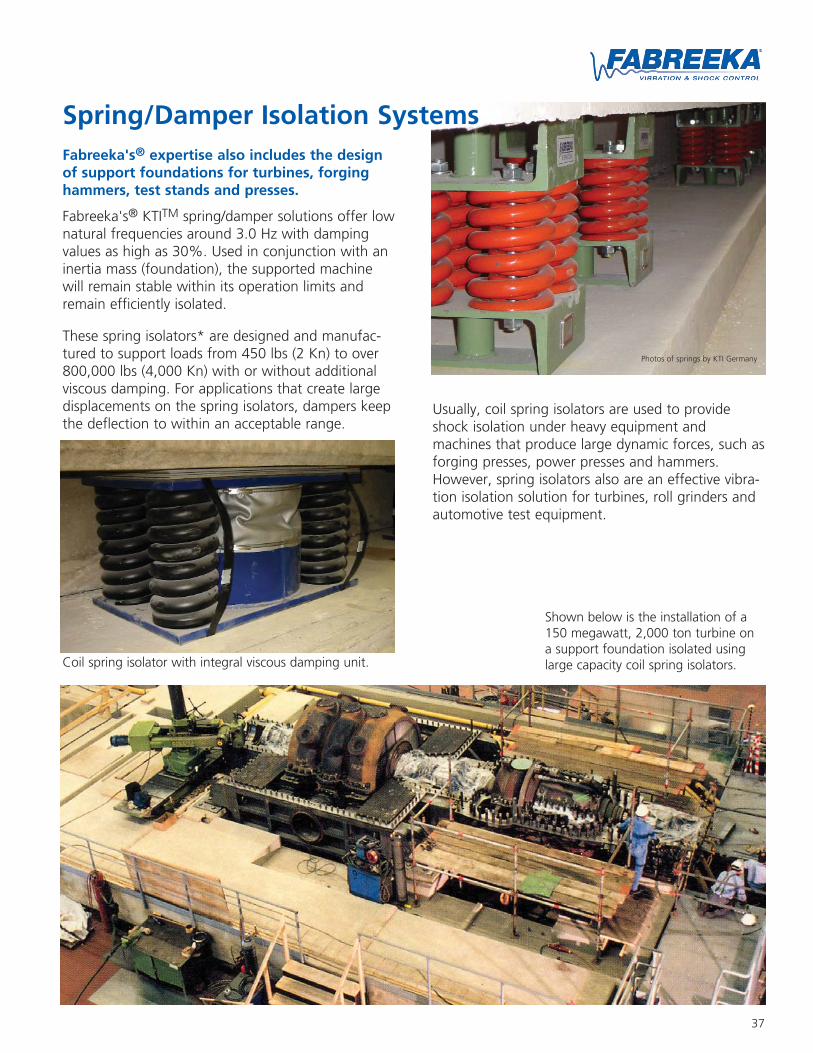
Photos of springs by KTI Germany
Spring/Damper Isolation SystemsFabreeka's® expertise also includes the designof support foundations for turbines, forginghammers, test stands and presses.
Fabreeka's® KTITM spring/damper solutions offer lownatural frequencies around 3.0 Hz with dampingvalues as high as 30%. Used in conjunction with aninertia mass (foundation), the supported machinewill remain stable within its operation limits andremain efficiently isolated.
These spring isolators* are designed and manufac-tured to support loads from 450 lbs (2 Kn) to over800,000 lbs (4,000 Kn) with or without additionalviscous damping. For applications that create largedisplacements on the spring isolators, dampers keepthe deflection to within an acceptable range.
Usually, coil spring isolators are used to provideshock isolation under heavy equipment andmachines that produce large dynamic forces, such asforging presses, power presses and hammers.However, spring isolators also are an effective vibra-tion isolation solution for turbines, roll grinders andautomotive test equipment.
Coil spring isolator with integral viscous damping unit.
Shown below is the installation of a150 megawatt, 2,000 ton turbine ona support foundation isolated usinglarge capacity coil spring isolators.

38
Most precision machine tool and measuring machine manufacturers haveestablished allowable vibration specifications for their machines. Fabreeka®
utilizes highly accurate instrumentation to quantify the amplitude and fre-quency of vibration to make proper vibration control recommendations.
Fabreeka® engineers also conduct acceptance test measurements afterinstallation. Acceptance test measurements provide the resultant vibrationamplitudes after isolation is installed.
Consultation & Project ManagementFabreeka® provides complete, detailed design drawings and specifications for your construction or fabrication.
Our engineers can supervise critical phases of construction and provide oversight for the design, installationand testing of installed isolation systems. Design review meetings are held with customers as part of overallproject management. Design, service, installation and expertise since 1936.
Vibration Measurement & Analysis Services
Fabreeka® can provide vibrationmeasurement services from any ofour worldwide facilities.
Foundation Isolation Applicationsboring mills multi-section machining centers vertical
turning lathes long bed lathes roll grindersresearch labs broaching machines looms auto
testing equipment horizontal arm coordinate measuringmachines compressors mri equipment electro-
dynamic shakers printing presses pumps engine-generator sets injection molding machines diesel
engines centrifugal pumps turbines rolling roadmachines forging hammers road simulators
forging presses vibration testing equipment multi-axis machining centers dynamometers research labs
gantry coordinate measuring machines precisionmachine tools centrifugal pumps multi-section
machining centers pumps long bed lathes rollgrinders vibration testing equipment broaching
machines looms horizontal arm coordinate measuringmachines boring mills mri equipment electro-
dynamic shakers printing presses engine-generatorsets vertical turning lathes injection molding
machines diesel engines turbines forging hammersroad simulators rolling road machines forging pressesdynamometers gantry coordinate measuring machines
research labs precision machine tools multi-axismachining centers compressors auto testing equipment
United States
PO Box 2101023 Turnpike StreetStoughton, MA 02072Tel: (781) 341-3655or: 1-800-322-7352
Fax: (781) [email protected]
Canada
2907 Portland DriveOakville, ON L6H 5S4Tel: 1-800-322-7352Fax: (781) 341-3983
United Kingdom
8 to 12 Jubilee WayThackley Old RoadShipley, West YorkshireBD18 1QGTel: 44-1274-531333Fax: [email protected]
Germany
Hessenring 13 (D-64572)Postfach 103D-64570 , ButtelbornTel: 49-6152-9597-0Fax: 49-6152-9597-40
The Netherlands
Molenwerf 12 (1911 DB)Postbus 1331910 AC UitgeestTel: 31-2513-20305Fax: 31-2513-12830
www.fabreeka.comFAB 3000-050 08/04
*Fabreeka is a registered trademark of Fabreeka International, Inc.KTI is a registered trademark of KTI GmbH.