Equipment for Cryogenic Service - Princeton CryoTech · Cylinder Filling System 14 Argon Maximizer...
24
Packaged Gases Product Catalog www.chartindustries.com PACKAGED GASES SOLUTIONS | SYSTEM DESIGN | MANUFACTURING | TRAINING | SERVICE Packaged Gases Equipment for Cryogenic Service
Transcript of Equipment for Cryogenic Service - Princeton CryoTech · Cylinder Filling System 14 Argon Maximizer...

Packaged Gases Product Catalog
www.chartindustries.com
PACKAGED GASES SOLUTIONS | SYSTEM DESIGN | MANUFACTURING | TRAINING | SERVICE
Packaged GasesEquipment for Cryogenic Service

2
TABLE OF CONTENTS
About Chart Packaged Gases 3
Where does Packaged Gases fit? 4-5
Dura-Cyl® Selection Guide 6-7
Laser-Cyl™ Liquid Cylinders 8
VGL™ Series Liquid Cylinders 9
Cryo-Cyl™ Liquid Cylinders 10
Mega-Cyl™ Liquid Cylinders 11
Ultra-Helium Dewar™ 12
Liquid Cylinder Cutaway 13
Lo-Loss™ Cylinder Filling System 14
Argon Maximizer™ 15
Pro V8™ Manifold 16
ADF105™ Filling Station 17
CGA Fitting Restraints 18
Liquid Cylinder Accessories 19
Cylinder Repair 20
Online Resources 21
Notes 22
Conversion Data 23

3
Innovative Design, Technology & Reliability
A B O U T C H A R T P A C K A G E D G A S E S
Across Chart, we pride ourselves on designing innovative products with advanced technology and high reliability to enhance customer value. Our understanding of our customer's business needs and end- use applications has helped us achieve a wide product portfolio of solutions. We provide the right product for the application − driving a competitive advantage for our customer and our company.
Innovative DesignOur packaged gases equipment designs are based on a system that incorporates patented and proven innovative technologies. Every component is designed, built and tested to create the safest and most reliable packaged gases equipment available today.
Quality Manufacturing
Our experiences and code compliant ISO 9001 and 14000 ensures our liquid cylinders are manufactured to high quality standards and on time.
PerformanceThe patented Dura-Cyl® design is the perfect blend of plumbing controls, rugged durability and thermal efficiency − giving you the highest performance liquid cylinder package on the market today.
Sales & Marketing Services
Our sales process doesn’t stop with the equipment supply. We offer electronic sales tools, customized literature, marketing assistance and sales training to make our authorized partners positioned for growth in the liquid cylinder market.
When you choose Chart, you get single-source accountability from initial quality through after the sale service support.

4
W H E R E D O E S P A C K A G E D G A S E S F I T ?
Packaged Gases ApplicationsMetal Fabrication Welding − GMAW/MIG, GTAW/TIG and Laser Beam WeldingMetal fabrication uses many different welding processes for the wide range of materials, thickness and product applications. Many of these unique and specialized welding processes use inert shielding gas or the combination of gases to obtain the maximum weld quality and optimized productivity. Liquid cylinders offer the flexibility to easily alter the gas supply to match the manufacturing process changes.
Cutting − Laser, Oxy Fuel and PlasmaAll thermal cutting techniques utilize gases to assist in the cutting process. High-pressure nitrogen and oxygen are used as an assist gas to rapidly remove the molten metal from the cut zone or burn it away during the laser cutting process. To maintain maximum laser uptime and achieve the best cut quality, it is critical that the gas supply be uninterrupted and the required pressures and flows for the material and thickness being cut are maintained. Oxy Fuel and Plasma cutting processes have similar requirements. Laser-Cyl™ liquid cylinders manifolded together are an economical solution to providing an uninterrupted gas supply.
Analytical / Laboratory
ICP/ICP-MS − Inductively Coupled Plasma/Mass SpectrometryGC − Gas ChromatographA continuous flow of high purity argon gas is required for ICP/ICP-MS systems to repeatedly process material samples trouble-free. Dura-Cyl® liquid cylinders manifolded together meet this requirement. In addition, liquid cylinders are compact so they take up a minimal amount of valuable lab space.
Biological Storage and ResearchA sufficient supply of high-quality liquid nitrogen is needed to keep valuable biological samples stored indefinitely. Any interruption in supply can result in the loss of many years of research. With dedicated Dura-Cyl liquid cylinders connected to your equipment, you can be assured of your liquid supply to keep your samples safe. For applications that require the greatest amount of liquid in a tight space, the Dura-Cyl 265 with casters is an excellent choice.
Metal Processing
Heat Treating, Cryotempering, Thermal Spray CoatingHeat treating and cryotempering processes are dependent on the quality of the nitrogen gas and liquid supply to maintain production at peak performance. With the Dura-Cyl liquid cylinder located at the point of use, the operator has complete control over their gas supply for optimum operation. In the thermal spray coating process, oxygen and argon are used at high pressure and at high flow rates. Manifolding Dura-Cyl tanks together is an economical solution for this application.

5
W H E R E D O E S P A C K A G E D G A S E S F I T ?
Medical
Oxygen Therapy and CryotherapyMedical applications have some of the most stringent gas requirements and the Dura-Cyl liquid cylinder meets these requirements with NF grade availability. Dura-Cyl tanks manifolded together for respiratory therapy assures a continuous gas supply and lowers distribution costs over high-pressure cylinders. An isolated hyperbaric chamber with intermittent use of oxygen is also a good application for Dura-Cyl tanks.
CryotherapyNF grade nitrogen can be supplied for gas applications to operate pneumatic surgical tools and supply liquid for medical uses such as cryotherapy. Working with the equipment manufacturers, we understand the stringent requirements for safe liquid supply. Our Dura-Cylliquid cylinders can be ordered with the proper controls to ensure proper operation for this application.
MRI − Magnetic Resonance Imaging (Helium)Superconducting magnets bathed in liquid helium are the most commonly used magnets in an MRI machine. The low temperature reduces the internal resistance to zero, which reduces the electrical requirement for the system dramatically and making it much more economical to operate. Chart's Ultra-Helium Dewar™ tanks are designed and built for reliable helium transport. They are thermally efficient, lightweight and maneuverable − making them the dewar of choice of lab personnel.
General Processing
Purging and BlanketingInert purging and blanketing with nitrogen or argon gas is a common processing step in many manufacturing applications. These range from pharmaceutical to chemical to the wine industry, and they require a secure supply of gas for optimum processing results. Other unique applications like keeping fiber optic and telephone wire lines dry with nitrogen throughout the city make the Dura-Cyl tank an excellent choice of inert gas supply.
Electronic Manufacturing and TestingElectronic grade manufacturing can use liquid or gaseous nitrogen or argon during the manufacturing process. Dura-Cyl liquid cylinders offer a compact package where the pressure and source is near the operation for convenience and customization of the gas supply. In a related business, printed circuit board testing performed in liquid nitrogen- powered environmental test chambers require quality liquid at the point of use. For intermittent uses or small chambers, the Dura-Cyl tank is an economical and convenient liquid supply.

6
D U R A - C Y L ® S E L E C T I O N G U I D E
Dura-Cyl® Premium Liquid Cylinders
MCR models have a combination pressure control regulator with our exclusive calibrated micrometer adjusting screw. (MP & HP models only)
The Dura-Cyl® series is a premium transportable liquid cylinder for cryogenic service. The patented internal support system design and quality construction makes the Dura-Cyl series the most efficient yet rugged cylinder on the market today. Along with the patented Liquid Cylinder Control Manifold and our wide choice of caster base options, the Dura-Cyl Series is also the most user-friendly cylinder available. Adding our industry-leading 7-year vacuum warranty, the Dura-Cyl provides the lowest cost of ownership – making it the preferred choice in transportable liquid cylinders.
MODEL 160 L 160 L 180 L 180 L 180 L 200L 200 L 200 L Pressure MP HP LP MP HP LP MP HPLCCM Part Number 10508748 10508756 — 10508764 10496433 — 10508772 10496417MCR Part Number 10783424 10783467 — 10783491 10783539 — 10783598 10783619None(1) Part Number — — 10648450 — — 13277869 — — CAPACITY(2)(3) Liquid (Gross) (liters) 176 176 196 196 196 209 209 209 Liquid (Net) (liters) 165 165 185 185 185 196 196 196Gas (N
2) ft3 / Nm3 3,685 / 97 3,464 / 91 — 4,099 / 108 3,864 / 102 — 4,375 / 115 4,072 / 108
Gas (O2) ft3 / Nm3 4,577 / 120 4,348 / 114 — 5,096 / 134 4,843 / 127 — 5,435 / 143 5,048 / 133
Gas (Ar) ft3 / Nm3 4,448 / 117 4,226 / 111 — 4,961 / 130 4,709 / 124 — 5,290 / 139 4,932 / 130Gas (CO
2) ft3 / Nm3 — 3,382 / 89 — — 3,766 / 99 — — 4,011 / 105
Gas (N2O) ft3 / Nm3 — 3,207 / 84 — --- 3,574 / 94 — — 3,810 / 100
PERFORMANCENER (N
2) % per day 2.0 2.0 1.5 1.9 1.9 1.85 1.85 1.85
NER (O2 - Ar) % per day 1.4 1.4 1.0 1.3 1.3 1.2 1.2 1.2
NER (CO2 - N
2O) % per day — 0.5 — — 0.5 — — 0.5
Gas Flow (N2, O
2, Ar) SCFH/Nm3/hr 350 / 9.2 350 / 9.2 — 350 / 9.2 350 / 9.2 — 400 / 10.5 400 / 10.5
Gas Flow (CO2, N
2O) SCFH/Nm3/hr — 110 / 2.9 — — 110 / 2.9 — — 110 / 2.9
DIMENSIONS & PRESSURE RATINGS Relief Valve Setting psig / barg 230 / 16 350 / 24 22 / 1.5 230 / 16 350 / 24 22 / 1.5 230 / 16 350 / 24 DOT/CTC Rating 4L200 4L292 4L100 4L200 4L292 4L100 4L200 4L292Diameter in / cm 20 / 50.8 20 / 50.8 20 / 50.8 20 / 50.8 20 / 50.8 20 / 50.8 20 / 50.8 20 / 50.8Height(4) in / cm 59.8 / 151.9 59.8 / 151.9 64.3 / 163.3 64.3 / 163.3 64.3 / 163.3 66.6 / 169.2 66.6 / 169.2 66.6 / 169.2 Tare Weight lb / kg 250 / 113.4 280 / 126.9 210 / 95.2 260 / 117.9 300 / 136.1 210 / 95.2 280 / 126.9 320 / 145.1 Full Weight (N
2) lb / kg 517 / 234 531 / 241 540 / 245 557 / 253 580 / 263 559 / 253.5 597 / 271 618 / 280
(O2) lb / kg 629 / 285 640 / 290 676 / 307 682 / 309 701 / 318 706 / 320.2 730 / 331 747 / 339
(Ar) lb / kg 710 / 322 717 / 325 778 / 354 773 / 351 787 / 357 821 / 372.4 827 / 375 839 / 380 (CO
2) lb / kg — 667 / 303 — --- 731 / 331 — — 779 / 353
(1) Pressure building regulator optional on LP models. (2) Gas capacities at DOT4L limits. See manual P/N 10642912 for details. NER = Nominal Evaporation Rate
(3) Most of the Dura-Cyl models are available with permanently installed CGA fittings for medical applications. Contact Customer Service for details.
(4) All dimensions are mea sured fro m the floor to the top of the sight gauge protector.
Footring Caster Base
The Roto-Tel™ Liquid Level Gauge offers improved accuracy and expanded gauge ranges for better resolution.
LCCM models have an integral mounted combi-nation pressure control regulator, isolation valve and a calibrated dome control knob. (MP & HP models only)

7
D U R A - C Y L ® S E L E C T I O N G U I D E
Dura-Cyl® Advantages
Ideal for liquid nitrogen, oxygen, argon, CO2 or nitrous oxide Different sizes, pressures, and features to meet your needs Stainless steel bottle construction Thick, dent-resistant outer shell Durable inner-vessel support system Heavy-duty footring and large diameter handling ring with four supports Optional Micrometer Controlled Regulator (MCR) or Liquid Cylinder Control
Manifold (LCCM) Roto-Tel™ Liquid Level Gauge System 7-year vacuum warranty
120 L RB 230 L RB 230 L RB 230 L RB 230 L SB 230 L SB 230 L SB 265 L RB 265 L RB 265 L SB 265 L SB LP LP MP HP LP MP HP MP HP MP HP — — — 10616546 — 10496468 10496492 — — 10510039 10512561 — — 10783635 10783651 — 10810779 10794027 10783678 10783694 — — 10648396 10648599 — — 10648556 — — — — — —
120 240 240 240 240 240 240 276 276 276 276 110 230 230 230 230 230 230 265 265 265 265 — — 5,024 / 132 4,734 / 124 — 5,024 / 132 4,734 / 124 5,769 / 152 5,438 / 143 5,769 / 152 5,438 / 143 — — 6,244 / 164 5,930 / 156 — 6,244 / 164 5,930 / 156 7,186 / 189 6,811 / 179 7,186 / 189 6,811 / 179 — — 6,073 / 160 5,763 / 151 — 6,073 / 160 5,763 / 151 6,982 / 183 6,634 / 174 6,982 / 183 6,634 / 174 — — — 4,614 / 121 — — 4,614 / 121 — 5,305 / 139 — 5,305 / 139 — — — 4,378 / 115 — — 4,378 / 115 — 5,034 / 132 — 5,034 / 132
2.0 1.5 1.8 1.8 1.5 1.8 1.8 2 2 2 2 1.4 1.0 1.2 1.2 1.0 1.2 1.2 1.4 1.4 1.4 1.4 — — — 0.5 — — 0.5 — 0.5 — 0.5 — — 400 / 10.5 400 / 10.5 — 400 / 10.5 400 / 10.5 400 / 10.5 400 / 10.5 400 / 10.5 400 / 10.5 — — — 110 / 2.9 — — 110 / 2.9 — 110 / 2.9 — 110 / 2.9
22 / 1.5 22 / 1.5 230 / 16 350 / 24 22 / 1.5 230 / 16 350 / 24 230 / 16 350 / 24 230 / 16 350 / 24 4L100(5) 4L100 4L200 4L292 4L100 4L200 4L292 4L200 4L292 4L200 4L292 20 / 50.8 26 / 66.0 26 / 66.0 26 / 66.0 26 / 66.0 26 / 66.0 26 / 66.0 26 / 66.0 26 / 66.0 26 / 66.0 26 / 66.0 51 / 129.5 57.2 / 145.3 57.2 / 145.3 57.2 / 145.3 56.8 / 144.3 56.8 / 144.3 56.8 / 144.3 59.9 / 152.2 59.9 / 152.2 59.5 / 151.1 59.5 / 151.1 177 / 80.3 296 / 134.3 311 / 141.1 367 / 166.5 325 / 147.4 340 / 154.2 395 / 179.2 330 / 149.7 390 / 176.9 360 / 163.3 418 / 189.6 377 / 171 697 / 316.2 675 / 306.1 710 / 322 726 / 329.3 704 / 319.3 738 / 334.7 748 / 339.2 784 / 355.6 778 / 352.8 812 / 368.3 462 / 209.5 866 / 392.8 828 / 375.5 858 / 389.1 895 / 406 857 / 388.7 886 / 401.8 925 / 419.5 954 / 432.7 955 / 433.1 982 / 445.4 528 / 239.5 998 / 452.7 939 / 425.9 963 / 436.8 1,027 / 465.8 968 / 439 991 / 449.5 1,052 / 477.1 1,076 / 488 1,082 / 490.7 1,104 / 500.7 — — — 895 / 405.9 — — 923 / 418.6 — 997 / 452.2 — 1,025 / 464.9
RB = Round Base SB = Square Base Note: All caster base models are available with stainless steel casters.
(5) Dura-Cyl 120LP is not TC approved.
Footring Caster Base
The Dura-Cyl LP models feature the "sight gauge" liquid level indicator and a liquid globe valve with an extended stem for less ice build-up on the handle for easier operation.
Two pull handles are standard on the round base design.
Some models available with either round or square stainless steel caster bases for safe and easy mobility.
Specifications������S��� ���� ���� ���� ���� ���� ����� ������������������ ������������������
Pressure MP HP MP HP MP HP MP HP MP HP
LCCM Part Number 10508748 10508756 10508764 10496433 10508772 10496417 10602822 10616546 -- --
MCR Part Number 10783424 10783467 10783491 10783539 10783598 10783619 10783635 10783651 10783678 10783694
��������Liquid (Gross) (liters) 176 176 196 196 209 209 240 240 276 276
Liquid (Net) (liters) 165 165 185 185 196 196 230 230 265 265
Gas (N2)* ft3 / Nm3 3685 / 97 3464 / 91 4099 / 108 3864 / 102 4375 / 115 4072 / 108 5024 / 132 4734 / 124 5769 / 152 5438 / 143
Gas (O2)* ft3 / Nm3 4577 / 120 4348 / 114 5096 / 134 4843 / 127 5435 / 143 5048 / 133 6244 / 164 5930 / 156 7186 / 189 6811 / 179
Gas (Ar)* ft3 / Nm3 4448 / 117 4226 / 111 4961 / 130 4709 / 124 5290 / 139 4932 / 130 6073 / 160 5763 / 151 6982 / 183 6634 / 174
Gas (CO2)* ft3 / Nm3 -- 3382 / 89 -- 3766 / 99 -- 4011 / 105 -- 4614 / 121 -- 5305 / 139
Gas (N2O)* ft3 / Nm3 -- 3207 / 84 -- 3574 / 94 -- 3810 / 100 -- 4378 / 115 -- 5034 / 132
�����������NER (N2) per day 2 2 1.9 1.9 1.85 1.85 1.8 1.8 2 2
NER (O2 - Ar) %
%
per day 1.4 1.4 1.3 1.3 1.2 1.2 1.2 1.2 1.4 1.4
NER (CO2 - N2O) % per day -- 0.5 -- 0.5 -- 0.5 -- 0.5 -- 0.5
Gas Flow (N2, O2, Ar) ft3/hr / Nm3 /hr 350 / 9.2 350 / 9.2 350 / 9.2 350 / 9.2 400 / 10.5 400 / 10.5 400 / 10.5 400 / 10.5 400 / 10.5 400 / 10.5
Gas Flow (CO2, N2O) ft3/hr / Nm3 /hr -- 110 / 2.9 -- 110 / 2.9 -- 110 / 2.9 -- 110 / 2.9 -- 110 / 2.9
�����S���S������SS����������SRelief Valve Setting psig / barg 230 / 16 350 / 24 230 / 16 350 / 24 230 / 16 350 / 24 230 / 16 350 / 24 230 / 16 350 / 24
DOT/CTC Rating 4L200 4L292 4L200 4L292 4L200 4L292 4L200 4L292 4L200 4L292
Diameter 20 /50.8 20 /50.8 20 /50.8 20 /50.8 20 /50.8 20 /50.8 26 /66.0 26 /66.0 26 /66.0 26 /66.0
Height 59.8 / 151.9 59.8 / 151.9 64.3 / 163.3 64.3 / 163.3 66.6 / 169.2 66.6 / 169.2 57.2 / 145.3 57.2 / 145.3 59.9 / 152.2 59.9 / 152.2
Empty Weight 250 / 113.4 280 / 126.9 260 / 117.9 300 / 136.1 280 / 126.9 320 / 145.1 300 / 136.1 340 / 154.2 340 / 154.2 360 / 163.6
Full Weight (N2) 517 / 234 531 / 241 557 / 253 580 / 263 597 / 271 618 / 280 664 / 301 683 / 310 758 / 344 754 / 343
(O2) 629 / 285 640 / 290 682 / 309 701/ 318 730 / 331 747 /339 817 / 370 831 / 377 935 / 424 924 / 420
(Ar) 710 / 322 717 / 325 773 / 351 787 / 357 827 / 375 839 / 380 928 / 421 936 / 424 1062 / 481 1046 / 475
(CO2) -- 667 / 303 -- 731 / 331 -- 779 / 353 -- 868 / 393 -- 967 / 439
�o�enc�at��e2
3
85, 6, 7
4
1
PressureBuilding
Coil
lb / kg
lb / kgin / ��in / ��
lb / kglb / kglb / kg
�����������������������g���������������������� ���������������������
����������������������������������������������������������������������g���g��g������������
����������������������������������������������������������������������g���g��g������������
�����S���������S����MP HP
10496468 10496492
10810779 10794027
240 240
230 230
5024 / 132 4734 / 124
6244 / 164 5930 / 156
6073 / 160 5763 / 151
-- 4614 / 121
-- 4378 / 115
1.8 .8
1.2 .2
- .5
400 / 10.5 400 / 10.5
- 10 / 2.9
230 / 16 350 / 24
4L200 4L292
26 /66.0 26 /66.0
56.8 / 144.3 56.8 / 144.3
300 / 136.1 340 / 154.2
664 / 301 683 / 310
817 / 370 831 / 377
928 / 421 936 / 424
-- 868 / 393
�����S���������S����MP HP
10510039 10512561
-- --
276 276
265 265
5769 / 152 5438 / 143
7186 / 189 6811 / 179
6982 / 183 6634 / 174
-- 5305 / 139
- 5034 / 132
2 2
1.4 .4
-- 0.5
400 / 10.5 400 / 10.5
-- 10 / 2.9
230 / 16 350 / 24
4L200 4L292
26 /66.0 26 /66.0
59.5 / 151.1 59.5 / 151.1
340 / 154.2 360 / 163.6
758 / 344 754 / 343
935 / 424 924 / 420
1062 / 481 1046 / 475
-- 967 / 439
�������������������������������������������������������������������������������g�����������������������������������������������������������������
DURA–CYL®
PREMIUM LIQUID CYLINDERS
1. Fill / Liquid Valve.2. Pressure Control Valve.3. Vent Valve.4. Pressure Control Regulator (optional).5. Pressure Gauge.6. Pressure Relief Valve.7. Rupture Disk.8. Liquid Level Gauge.
Model: LP
Specifications������S��� ���� ���� ���� ���� ���� ����� ������������������ ������������������
Pressure MP HP MP HP MP HP MP HP MP HP
LCCM Part Number 10508748 10508756 10508764 10496433 10508772 10496417 10602822 10616546 -- --
MCR Part Number 10783424 10783467 10783491 10783539 10783598 10783619 10783635 10783651 10783678 10783694
��������Liquid (Gross) (liters) 176 176 196 196 209 209 240 240 276 276
Liquid (Net) (liters) 165 165 185 185 196 196 230 230 265 265
Gas (N2)* ft3 / Nm3 3685 / 97 3464 / 91 4099 / 108 3864 / 102 4375 / 115 4072 / 108 5024 / 132 4734 / 124 5769 / 152 5438 / 143
Gas (O2)* ft3 / Nm3 4577 / 120 4348 / 114 5096 / 134 4843 / 127 5435 / 143 5048 / 133 6244 / 164 5930 / 156 7186 / 189 6811 / 179
Gas (Ar)* ft3 / Nm3 4448 / 117 4226 / 111 4961 / 130 4709 / 124 5290 / 139 4932 / 130 6073 / 160 5763 / 151 6982 / 183 6634 / 174
Gas (CO2)* ft3 / Nm3 -- 3382 / 89 -- 3766 / 99 -- 4011 / 105 -- 4614 / 121 -- 5305 / 139
Gas (N2O)* ft3 / Nm3 -- 3207 / 84 -- 3574 / 94 -- 3810 / 100 -- 4378 / 115 -- 5034 / 132
�����������NER (N2) per day 2 2 1.9 1.9 1.85 1.85 1.8 1.8 2 2
NER (O2 - Ar) %
%
per day 1.4 1.4 1.3 1.3 1.2 1.2 1.2 1.2 1.4 1.4
NER (CO2 - N2O) % per day -- 0.5 -- 0.5 -- 0.5 -- 0.5 -- 0.5
Gas Flow (N2, O2, Ar) ft3/hr / Nm3 /hr 350 / 9.2 350 / 9.2 350 / 9.2 350 / 9.2 400 / 10.5 400 / 10.5 400 / 10.5 400 / 10.5 400 / 10.5 400 / 10.5
Gas Flow (CO2, N2O) ft3/hr / Nm3 /hr -- 110 / 2.9 -- 110 / 2.9 -- 110 / 2.9 -- 110 / 2.9 -- 110 / 2.9
�����S���S������SS����������SRelief Valve Setting psig / barg 230 / 16 350 / 24 230 / 16 350 / 24 230 / 16 350 / 24 230 / 16 350 / 24 230 / 16 350 / 24
DOT/CTC Rating 4L200 4L292 4L200 4L292 4L200 4L292 4L200 4L292 4L200 4L292
Diameter 20 /50.8 20 /50.8 20 /50.8 20 /50.8 20 /50.8 20 /50.8 26 /66.0 26 /66.0 26 /66.0 26 /66.0
Height 59.8 / 151.9 59.8 / 151.9 64.3 / 163.3 64.3 / 163.3 66.6 / 169.2 66.6 / 169.2 57.2 / 145.3 57.2 / 145.3 59.9 / 152.2 59.9 / 152.2
Empty Weight 250 / 113.4 280 / 126.9 260 / 117.9 300 / 136.1 280 / 126.9 320 / 145.1 300 / 136.1 340 / 154.2 340 / 154.2 360 / 163.6
Full Weight (N2) 517 / 234 531 / 241 557 / 253 580 / 263 597 / 271 618 / 280 664 / 301 683 / 310 758 / 344 754 / 343
(O2) 629 / 285 640 / 290 682 / 309 701/ 318 730 / 331 747 /339 817 / 370 831 / 377 935 / 424 924 / 420
(Ar) 710 / 322 717 / 325 773 / 351 787 / 357 827 / 375 839 / 380 928 / 421 936 / 424 1062 / 481 1046 / 475
(CO2) -- 667 / 303 -- 731 / 331 -- 779 / 353 -- 868 / 393 -- 967 / 439
�o�enc�at��e1
3
4
96, 7, 8
5
2
Vaporizer
PressureBuilding
Coil
lb / kg
lb / kgin / ��in / ��
lb / kglb / kglb / kg
�����������������������g���������������������� ���������������������
����������������������������������������������������������������������g���g��g������������
����������������������������������������������������������������������g���g��g������������
�����S���������S����MP HP
10496468 10496492
10810779 10794027
240 240
230 230
5024 / 132 4734 / 124
6244 / 164 5930 / 156
6073 / 160 5763 / 151
-- 4614 / 121
-- 4378 / 115
1.8 .8
1.2 .2
- .5
400 / 10.5 400 / 10.5
- 10 / 2.9
230 / 16 350 / 24
4L200 4L292
26 /66.0 26 /66.0
56.8 / 144.3 56.8 / 144.3
300 / 136.1 340 / 154.2
664 / 301 683 / 310
817 / 370 831 / 377
928 / 421 936 / 424
-- 868 / 393
�����S���������S����MP HP
10510039 10512561
-- --
276 276
265 265
5769 / 152 5438 / 143
7186 / 189 6811 / 179
6982 / 183 6634 / 174
-- 5305 / 139
- 5034 / 132
2 2
1.4 .4
-- 0.5
400 / 10.5 400 / 10.5
-- 10 / 2.9
230 / 16 350 / 24
4L200 4L292
26 /66.0 26 /66.0
59.5 / 151.1 59.5 / 151.1
340 / 154.2 360 / 163.6
758 / 344 754 / 343
935 / 424 924 / 420
1062 / 481 1046 / 475
-- 967 / 439
�������������������������������������������������������������������������������g�����������������������������������������������������������������
DURA–CYL®
PREMIUM LIQUID CYLINDERS
1. Gas Use Valve.2. Fill / Liquid Valve.3. Pressure Control Valve.4. Vent Valve.5. Combination Pressure Control Regulator.6. Pressure Gauge.7. Pressure Relief Valve.8. Rupture Disk.9. Liquid Level Gauge.
Models: MP & HP
Nomenclature
Nomenclature

8
L A S E R - C Y L ™ L I Q U I D C Y L I N D E R S
Laser-Cyl is designed specifically for laser applications, as a high performance option to expensive high pressure cylinder tanks. The Laser-Cyl delivers optimal pressure up to 500 psig (34.5 bar) and continuous flow rates up to 575 SCFH (15.1 Nm3/hr).
Product Advantages
Durable inner vessel support system (200 VHP only)
Built-in vaporizer coils supply constant pressure gas at continuous flow rates up to 575 SCFH (15.1 Nm3/hr)
Piping controls located on top for easy operation and maintenance
Differential pressure liquid level gauge accurately displays product level (450 only)
Insulation system provides low NER for longer holding time
Available in 200 and 450 liter sizes with an optional pallet frame
7-year vacuum warranty
Laser-Cyl™ High Pressure Liquid Cylinders
MODEL 200 450 Pressure VHP VHP Part Number 10619771 10619659 CAPACITY(1) Liquid (Gross) (liters) 200 450 Liquid (Net) (liters) 196 428Gas (N
2) ft3 / Nm3 3,521 / 93 7,922 / 208
Gas (O2) ft3 / Nm3 4,674 / 123 10,519 / 276
Gas (Ar) ft3 / Nm3 4,552 / 120 10,241 / 269Gas (CO
2) ft3 / Nm3 3,537 / 93 7,960 / 209
Gas (N2O) ft3 / Nm3 3,333 / 88 7,516 / 197
PERFORMANCENER (N) % per day 2.0 2.0 NER (O
2 - Ar) % per day 1.4 1.4
NER (CO2 - N
2O) % per day 0.5 0.5
Gas Flow (N2, O
2, Ar) SCFH/Nm3/hr 350 / 9.2 575 / 15.1
Gas Flow (CO2, N
2O) SCFH/Nm3/hr 110 / 2.9 180 / 4.7
DIMENSIONS & PRESSURE RATINGS Relief Valve Setting psig / barg 500 / 34.5 500 / 34.5 DOT/CTC Rating 4L412 4L412 Diameter (cylinder) in / cm 20 / 50.8 30 / 76.2 Height (cylinder)(2) in / cm 65.8 / 167.1 61.3 / 155.7 Base Width (frame) in / cm — 34 / 86.4 Base Depth (frame) in / cm — 34 / 86.4 Base Height (frame) in / cm — 73.8 / 187.5 Tare Weight(3) lb / kg 375 / 170 1,265 / 574 Full Weight (N
2) lb / kg 630 / 286 1,839 / 836
(O2) lb / kg 762 / 346 2,136 / 971
(Ar) lb / kg 846 / 384 2,324 / 1,056 (CO
2) lb / kg 791 / 360 2,202 / 1,001
(1) Net gas capacities at DOT 4L limits. (2) All dimensions are mea sured fro m the floor to the top of the sight gauge protector. (3) Weights are approximate and vary with pallet design.
Specifications
Specifications������S��� ���� ���� ���� ���� ���� ����� ������������������ ������������������
Pressure MP HP MP HP MP HP MP HP MP HP
LCCM Part Number 10508748 10508756 10508764 10496433 10508772 10496417 10602822 10616546 -- --
MCR Part Number 10783424 10783467 10783491 10783539 10783598 10783619 10783635 10783651 10783678 10783694
��������Liquid (Gross) (liters) 176 176 196 196 209 209 240 240 276 276
Liquid (Net) (liters) 165 165 185 185 196 196 230 230 265 265
Gas (N2)* ft3 / Nm3 3685 / 97 3464 / 91 4099 / 108 3864 / 102 4375 / 115 4072 / 108 5024 / 132 4734 / 124 5769 / 152 5438 / 143
Gas (O2)* ft3 / Nm3 4577 / 120 4348 / 114 5096 / 134 4843 / 127 5435 / 143 5048 / 133 6244 / 164 5930 / 156 7186 / 189 6811 / 179
Gas (Ar)* ft3 / Nm3 4448 / 117 4226 / 111 4961 / 130 4709 / 124 5290 / 139 4932 / 130 6073 / 160 5763 / 151 6982 / 183 6634 / 174
Gas (CO2)* ft3 / Nm3 -- 3382 / 89 -- 3766 / 99 -- 4011 / 105 -- 4614 / 121 -- 5305 / 139
Gas (N2O)* ft3 / Nm3 -- 3207 / 84 -- 3574 / 94 -- 3810 / 100 -- 4378 / 115 -- 5034 / 132
�����������NER (N2) per day 2 2 1.9 1.9 1.85 1.85 1.8 1.8 2 2
NER (O2 - Ar) %
%
per day 1.4 1.4 1.3 1.3 1.2 1.2 1.2 1.2 1.4 1.4
NER (CO2 - N2O) % per day -- 0.5 -- 0.5 -- 0.5 -- 0.5 -- 0.5
Gas Flow (N2, O2, Ar) ft3/hr / Nm3 /hr 350 / 9.2 350 / 9.2 350 / 9.2 350 / 9.2 400 / 10.5 400 / 10.5 400 / 10.5 400 / 10.5 400 / 10.5 400 / 10.5
Gas Flow (CO2, N2O) ft3/hr / Nm3 /hr -- 110 / 2.9 -- 110 / 2.9 -- 110 / 2.9 -- 110 / 2.9 -- 110 / 2.9
�����S���S������SS����������SRelief Valve Setting psig / barg 230 / 16 350 / 24 230 / 16 350 / 24 230 / 16 350 / 24 230 / 16 350 / 24 230 / 16 350 / 24
DOT/CTC Rating 4L200 4L292 4L200 4L292 4L200 4L292 4L200 4L292 4L200 4L292
Diameter 20 /50.8 20 /50.8 20 /50.8 20 /50.8 20 /50.8 20 /50.8 26 /66.0 26 /66.0 26 /66.0 26 /66.0
Height 59.8 / 151.9 59.8 / 151.9 64.3 / 163.3 64.3 / 163.3 66.6 / 169.2 66.6 / 169.2 57.2 / 145.3 57.2 / 145.3 59.9 / 152.2 59.9 / 152.2
Empty Weight 250 / 113.4 280 / 126.9 260 / 117.9 300 / 136.1 280 / 126.9 320 / 145.1 300 / 136.1 340 / 154.2 340 / 154.2 360 / 163.6
Full Weight (N2) 517 / 234 531 / 241 557 / 253 580 / 263 597 / 271 618 / 280 664 / 301 683 / 310 758 / 344 754 / 343
(O2) 629 / 285 640 / 290 682 / 309 701/ 318 730 / 331 747 /339 817 / 370 831 / 377 935 / 424 924 / 420
(Ar) 710 / 322 717 / 325 773 / 351 787 / 357 827 / 375 839 / 380 928 / 421 936 / 424 1062 / 481 1046 / 475
(CO2) -- 667 / 303 -- 731 / 331 -- 779 / 353 -- 868 / 393 -- 967 / 439
�o�enc�at��e1
3
4
96, 7, 8
5b5a
2
Vaporizer
PressureBuilding
Coil
lb / kg
lb / kgin / ��in / ��
lb / kglb / kglb / kg
�����������������������g���������������������� ���������������������
����������������������������������������������������������������������g���g��g������������
����������������������������������������������������������������������g���g��g������������
�����S���������S����MP HP
10496468 10496492
10810779 10794027
240 240
230 230
5024 / 132 4734 / 124
6244 / 164 5930 / 156
6073 / 160 5763 / 151
-- 4614 / 121
-- 4378 / 115
1.8 .8
1.2 .2
- .5
400 / 10.5 400 / 10.5
- 10 / 2.9
230 / 16 350 / 24
4L200 4L292
26 /66.0 26 /66.0
56.8 / 144.3 56.8 / 144.3
300 / 136.1 340 / 154.2
664 / 301 683 / 310
817 / 370 831 / 377
928 / 421 936 / 424
-- 868 / 393
�����S���������S����MP HP
10510039 10512561
-- --
276 276
265 265
5769 / 152 5438 / 143
7186 / 189 6811 / 179
6982 / 183 6634 / 174
-- 5305 / 139
- 5034 / 132
2 2
1.4 .4
-- 0.5
400 / 10.5 400 / 10.5
-- 10 / 2.9
230 / 16 350 / 24
4L200 4L292
26 /66.0 26 /66.0
59.5 / 151.1 59.5 / 151.1
340 / 154.2 360 / 163.6
758 / 344 754 / 343
935 / 424 924 / 420
1062 / 481 1046 / 475
-- 967 / 439
�������������������������������������������������������������������������������g�����������������������������������������������������������������
DURA–CYL®
PREMIUM LIQUID CYLINDERS
1. Gas Use Valve.2. Fill / Liquid Valve.3. Pressure Control Valve.4. Vent Valve.5a.Pressure Control Regulator.5b.Economizer Regulator6. Pressure Gauge.7. Pressure Relief Valve.8. Rupture Disk.9. Liquid Level Gauge.
Model: 200
Nomenclature

9
V G L ™ S E R I E S
The VGL™ Series is back. Since its first introduction by Minnesota Valley Engineering (MVE) in 1970, the VGL liquid cylinder built its reputation on reliability and innovation. It was the first liquid cylinder to offer a stainless steel outer jacket, an all-metal shock absorbing footring, and color-coded valve handles. Now, the VGL Series is available with updated components and the latest in field-proven vacuum insulation technology. The most popular models have been streamlined − making them the preferred choice in economical transportable liquid cylinders.
VGL™ Vertical Gas Liquid Cylinders
Product Advantages Ideal for liquid nitrogen, oxygen, argon, CO2 or nitrous oxide Stainless steel inner and outer cylinder construction Thick, dent-resistant outer shell Four handling ring supports with large one-inch pipe size ring 4" galvanized casters on 230 models Integrated pull handle on 230 square base model Color-coded valve handles and name tags for easy identification
of the plumbing functions Roto-Tel™ Liquid Level Gauge System 5-year vacuum warranty
MODEL 180 200 230 RB 230 SB Pressure HP HP HP HPPBER Part Number 14880547 14880555 14880563 14880571 CAPACITY (1) (2)
Liquid (Gross) (liters) 196 209 240 240 Liquid (Net) (liters) 185 196 230 230Gas (N
2) ft3 / Nm3 3,864/102 4,072/108 4,734/124 4,734/124
Gas (O2) ft3 / Nm3 4,843/127 5,048/133 5,930/156 5,930/156
Gas (Ar) ft3 / Nm3 4,709/124 4,932/130 5,763/151 5,763/151 Gas (CO
2) ft3 / Nm3 3,766/99 4,011/105 4,614/121 4,614/121
Gas (N2O) ft3 / Nm3 3,574/94 3,810/100 4,378/115 4,378/115
PERFORMANCE (3)
NER (N2) % per day 1.9 1.85 1.8 1.8
NER (O2 - Ar) % per day 1.3 1.2 1.2 1.2
NER (CO2 - N
2O) % per day 0.5 0.5 0.5 0.5
Gas Flow (N2, O
2, Ar) SCFH/Nm3/hr 350/9.2 400/10.5 400/10.5 400/10.5
Gas Flow (CO2) SCFH/Nm3/hr 110/2.9 110/2.9 110/2.9 110/2.9
DIMENSIONS & PRESSURE RATINGS Relief Valve Setting psig / barg 350 / 24 350 / 24 350 / 24 350 / 24 DOT Rating 4L292 4L292 4L292 4L292 Diameter in / cm 20 / 50.8 20 / 50.8 26 / 66.0 26 / 66.0Height(4) in / cm 64.3/163.3 66.6/169.2 57.2/145.3 56.8/144.3 Tare Weight lb / kg 288/130 305/138 360/163 393/178 Full Weight (N
2) lb / kg 568/257 603/273 703/318 736/333
(O2) lb / kg 689/312 732/332 851/386 884/400
(Ar) lb / kg 775/351 824/373 956/433 989/448 (CO
2) lb / kg 719/326 764/346 888/402 921/417
(1) Gas capacities at DOT4L limits. See manual for details. (2) All VGL models are available with permanently installed CGA fittings for medical applications. Contact Customer Service for details. (3) Ambient conditions: 68°F/20°C and 50% relative humidity(4) Dimensions are mea sured fro m the floor to the top of the sight gauge protector. Note: All caster base models are available with galvanized casters. RB = Round Base SB = Square Base NER=Nominal Evaporation Rate
Specifications Footring | Caster Base
1. Gas Use Valve 2. Fill / Liquid Valve 3. Pressure Building Valve 4. Vent Valve 5. Combination Pressure Building Regulator 6. Pressure Gauge 7. Pressure Relief Valve 8. Rupture Disk 9. Liquid Level Gauge
Nomenclature

10
C R Y O - C Y L ™ L I Q U I D C Y L I N D E R S
Like the Dura-Cyl models, the Cryo-Cyl™ 80HP liquid cylinder model is designed and built to meet the rugged demands of the liquid cylinder market. However, in contrast, this model is designed specifically for liquid and low to medium gas flow applications. By specifically targeting these applications, we are able to offer this model at an economical value over our premium Dura-Cyl Series.
Cryo-Cyl™ Liquid Cylinders
Product Advantages Ideal for liquid nitrogen, oxygen, argon, CO2 or nitrous oxide Stainless steel construction Thick, dent-resistant outer shell Durable, inner-vessel support system Heavy-duty footring and large diameter handling ring with two supports Roto-Tel™ Liquid Level Gauge System 7-year vacuum warranty
MODEL 80 L Pressure HP Part Number 10648610 CAPACITY(1)(2) Liquid (Gross) (liters) 85 Liquid (Net) (liters) 80Gas (N
2) ft3 / Nm3 1,680 / 44
Gas (O2) ft3 / Nm3 2,108 / 55
Gas (Ar) ft3 / Nm3 2,049 / 54Gas (CO
2) ft3 / Nm3 1,640 / 43
Gas (N2O) ft3 / Nm3 1,555 / 41
PERFORMANCENER (N
2) % per day 3.0
NER (O2 - Ar) % per day 2.0
NER (CO2 - N
2O) % per day 0.8
Gas Flow (N2, O
2, Ar)(3) SCFH/Nm3/hr 100 / 2.6
Gas Flow (CO2, N
2O) SCFH/Nm3/hr 35 / 0.9
DIMENSIONS & PRESSURE RATINGS Relief Valve Setting psig / barg 350 / 24 Operating Pressure(4) psig / barg 125 / 8.6 DOT/CTC Rating 4L292Diameter in / cm 20 / 50.8Height(5) in / cm 39.5 / 100.3 Tare Weight lb / kg 165 / 74.8 Full Weight (N
2) lb / kg 287 / 130
(O2) lb / kg 340 / 155
(Ar) lb / kg 377 / 171 (CO
2) lb / kg 353 / 161
(1) Net gas capacities at DOT 4L limits. (2) The Cryo-Cyl model is available with permanently installed CGA fittings for medical applications. Contact Customer Service for details. (3) Gas flows of twice the continuous flow rate can be achieved for one hr. over an eight hr. period. (4) Pressure building regulator range (50-175 psi). (5) Height dimensions are mea sured fro m the floor to the top of the sight gauge protector.
Specifications
Standard on all of our liquid cylin-ders are color-coded model labels, protectors and two safety devices.
Protector Color Pressure
Yellow LPBlue MPOrange HPRed VHP
Specifications������S��� ���� ���� ���� ���� ���� ����� ������������������ ������������������
Pressure MP HP MP HP MP HP MP HP MP HP
LCCM Part Number 10508748 10508756 10508764 10496433 10508772 10496417 10602822 10616546 -- --
MCR Part Number 10783424 10783467 10783491 10783539 10783598 10783619 10783635 10783651 10783678 10783694
��������Liquid (Gross) (liters) 176 176 196 196 209 209 240 240 276 276
Liquid (Net) (liters) 165 165 185 185 196 196 230 230 265 265
Gas (N2)* ft3 / Nm3 3685 / 97 3464 / 91 4099 / 108 3864 / 102 4375 / 115 4072 / 108 5024 / 132 4734 / 124 5769 / 152 5438 / 143
Gas (O2)* ft3 / Nm3 4577 / 120 4348 / 114 5096 / 134 4843 / 127 5435 / 143 5048 / 133 6244 / 164 5930 / 156 7186 / 189 6811 / 179
Gas (Ar)* ft3 / Nm3 4448 / 117 4226 / 111 4961 / 130 4709 / 124 5290 / 139 4932 / 130 6073 / 160 5763 / 151 6982 / 183 6634 / 174
Gas (CO2)* ft3 / Nm3 -- 3382 / 89 -- 3766 / 99 -- 4011 / 105 -- 4614 / 121 -- 5305 / 139
Gas (N2O)* ft3 / Nm3 -- 3207 / 84 -- 3574 / 94 -- 3810 / 100 -- 4378 / 115 -- 5034 / 132
�����������NER (N2) per day 2 2 1.9 1.9 1.85 1.85 1.8 1.8 2 2
NER (O2 - Ar) %
%
per day 1.4 1.4 1.3 1.3 1.2 1.2 1.2 1.2 1.4 1.4
NER (CO2 - N2O) % per day -- 0.5 -- 0.5 -- 0.5 -- 0.5 -- 0.5
Gas Flow (N2, O2, Ar) ft3/hr / Nm3 /hr 350 / 9.2 350 / 9.2 350 / 9.2 350 / 9.2 400 / 10.5 400 / 10.5 400 / 10.5 400 / 10.5 400 / 10.5 400 / 10.5
Gas Flow (CO2, N2O) ft3/hr / Nm3 /hr -- 110 / 2.9 -- 110 / 2.9 -- 110 / 2.9 -- 110 / 2.9 -- 110 / 2.9
�����S���S������SS����������SRelief Valve Setting psig / barg 230 / 16 350 / 24 230 / 16 350 / 24 230 / 16 350 / 24 230 / 16 350 / 24 230 / 16 350 / 24
DOT/CTC Rating 4L200 4L292 4L200 4L292 4L200 4L292 4L200 4L292 4L200 4L292
Diameter 20 /50.8 20 /50.8 20 /50.8 20 /50.8 20 /50.8 20 /50.8 26 /66.0 26 /66.0 26 /66.0 26 /66.0
Height 59.8 / 151.9 59.8 / 151.9 64.3 / 163.3 64.3 / 163.3 66.6 / 169.2 66.6 / 169.2 57.2 / 145.3 57.2 / 145.3 59.9 / 152.2 59.9 / 152.2
Empty Weight 250 / 113.4 280 / 126.9 260 / 117.9 300 / 136.1 280 / 126.9 320 / 145.1 300 / 136.1 340 / 154.2 340 / 154.2 360 / 163.6
Full Weight (N2) 517 / 234 531 / 241 557 / 253 580 / 263 597 / 271 618 / 280 664 / 301 683 / 310 758 / 344 754 / 343
(O2) 629 / 285 640 / 290 682 / 309 701/ 318 730 / 331 747 /339 817 / 370 831 / 377 935 / 424 924 / 420
(Ar) 710 / 322 717 / 325 773 / 351 787 / 357 827 / 375 839 / 380 928 / 421 936 / 424 1062 / 481 1046 / 475
(CO2) -- 667 / 303 -- 731 / 331 -- 779 / 353 -- 868 / 393 -- 967 / 439
�o�enc�at��e1
385, 6, 7
4
2
Vaporizer
PressureBuilding
Coil
lb / kg
lb / kgin / ��in / ��
lb / kglb / kglb / kg
�����������������������g���������������������� ���������������������
����������������������������������������������������������������������g���g��g������������
����������������������������������������������������������������������g���g��g������������
�����S���������S����MP HP
10496468 10496492
10810779 10794027
240 240
230 230
5024 / 132 4734 / 124
6244 / 164 5930 / 156
6073 / 160 5763 / 151
-- 4614 / 121
-- 4378 / 115
1.8 .8
1.2 .2
- .5
400 / 10.5 400 / 10.5
- 10 / 2.9
230 / 16 350 / 24
4L200 4L292
26 /66.0 26 /66.0
56.8 / 144.3 56.8 / 144.3
300 / 136.1 340 / 154.2
664 / 301 683 / 310
817 / 370 831 / 377
928 / 421 936 / 424
-- 868 / 393
�����S���������S����MP HP
10510039 10512561
-- --
276 276
265 265
5769 / 152 5438 / 143
7186 / 189 6811 / 179
6982 / 183 6634 / 174
-- 5305 / 139
- 5034 / 132
2 2
1.4 .4
-- 0.5
400 / 10.5 400 / 10.5
-- 10 / 2.9
230 / 16 350 / 24
4L200 4L292
26 /66.0 26 /66.0
59.5 / 151.1 59.5 / 151.1
340 / 154.2 360 / 163.6
758 / 344 754 / 343
935 / 424 924 / 420
1062 / 481 1046 / 475
-- 967 / 439
�������������������������������������������������������������������������������g�����������������������������������������������������������������
DURA–CYL®
PREMIUM LIQUID CYLINDERS
1. Gas Use/Vent Valve.2. Fill / Liquid Valve.3. Pressure Control Valve.4. Pressure Control Regulator.5. Pressure Gauge.6. Pressure Relief Valve.7. Rupture Disk.8. Liquid Level Gauge.
Nomenclature

11
M E G A - C Y L ™ L I Q U I D C Y L I N D E R S
The Mega-Cyl series is Chart’s line of palletized cylinders designed for easy transport with capacities from 450 to 1000 liters. Engineered with the volume user in mind, it’s ideal for construction sites, remote purging operations and back-up systems. Mega-Cyl cylinders are available in all services at 350 psig (24 barg) and are specifically designed to optimize distribution costs.
Mega-Cyl™ Palletized Liquid Cylinders
Product Advantages Tough, durable stainless steel construction High-performance Super Insulation Easily accessible valves and gauges Spray header for pump filling on vent tube Accurate differential pressure contents gauge (non-electric) Galvanized steel pallet frames available for all models 7-year vacuum warranty
MODEL 450 800 1000 Pressure HP HP HP Part Number 10588979 10671262 10752281 CAPACITY Liquid (Gross) (liters) 450 880 1056 Liquid (Net)(1) (liters) 428 800 950Gas (N
2) ft3 / Nm3 8,875 / 233.2 19,672 / 517 23,363 / 614
Gas (O2) ft3 / Nm3 11,111 / 292 24,320 / 639.1 28,843 / 758
Gas (Ar) ft3 / Nm3 10,812 / 284.1 23,767 / 624.6 28,234 / 742Gas (CO
2) ft3 / Nm3 8,652 / 227.4 16,255 / 427.2 18,580 / 488.3
PERFORMANCENER (N
2) % per day 2.1 1.8 1.3
NER (O2 - Ar) % per day 1.4 1.2 0.9
NER (CO2 - N
2O) % per day 0.6 0.5 0.3
Gas Flow (N2, O
2, Ar) SCFH/Nm3/hr 575 / 15.1 880 / 23.1 960 / 25.2
Gas Flow (CO2) SCFH/Nm3/hr 195 / 5.1 280 / 7.4 300 / 7.9
DIMENSIONS & PRESSURE RATINGS Relief Valve Setting psig / barg 350 / 24 350 / 24 350 / 24 DOT/CTC/ASME Rating 4L292 ASME Sec 8/Div1 ASME Sec 8/Div1 Diameter (cylinder) in / cm 30 / 76.2 42 / 106.7 42 / 106.7 Height (cylinder) in / cm 62 / 158 67 / 171 76 / 191 Base Width (frame)(2) in / cm 34 / 86.4 45 / 114 45 / 114 Base Depth (frame)(2) in / cm 34 / 86.4 45 / 114 45 / 114 Height (frame)(2) in / cm 74 / 188 95 / 241 95 / 241 Tare Wt. (cyl + frame)(3) lb / kg 1,275 / 580 2,500 / 1,136 2,650 / 1,205 Full Weight (N
2) lb / kg 1,918 / 872 3,926 / 1,784 4,343 / 1,974
(O2) lb / kg 2,195 / 998 4,514 / 2,052 5,038 / 2,290
(Ar) lb / kg 2,393 / 1,088 4,958 / 2,253 5,569 / 2,532 (CO
2) lb / kg 2,265 / 1,029 4,666 / 2,120 5,218 / 2,372
(1) CO
2 values and 450 liter models based on DOT4L fill density. N
2, O
2 and Ar values based on net volume at 0 psig.
(2) Customized pallets are available upon request. (3) Weights are approximate and vary with pallet design.
Specifications
Mechanical differential pressure gauge standard
for contents indication.
Specifications������S��� ���� ���� ���� ���� ���� ����� ������������������ ������������������
Pressure MP HP MP HP MP HP MP HP MP HP
LCCM Part Number 10508748 10508756 10508764 10496433 10508772 10496417 10602822 10616546 -- --
MCR Part Number 10783424 10783467 10783491 10783539 10783598 10783619 10783635 10783651 10783678 10783694
��������Liquid (Gross) (liters) 176 176 196 196 209 209 240 240 276 276
Liquid (Net) (liters) 165 165 185 185 196 196 230 230 265 265
Gas (N2)* ft3 / Nm3 3685 / 97 3464 / 91 4099 / 108 3864 / 102 4375 / 115 4072 / 108 5024 / 132 4734 / 124 5769 / 152 5438 / 143
Gas (O2)* ft3 / Nm3 4577 / 120 4348 / 114 5096 / 134 4843 / 127 5435 / 143 5048 / 133 6244 / 164 5930 / 156 7186 / 189 6811 / 179
Gas (Ar)* ft3 / Nm3 4448 / 117 4226 / 111 4961 / 130 4709 / 124 5290 / 139 4932 / 130 6073 / 160 5763 / 151 6982 / 183 6634 / 174
Gas (CO2)* ft3 / Nm3 -- 3382 / 89 -- 3766 / 99 -- 4011 / 105 -- 4614 / 121 -- 5305 / 139
Gas (N2O)* ft3 / Nm3 -- 3207 / 84 -- 3574 / 94 -- 3810 / 100 -- 4378 / 115 -- 5034 / 132
�����������NER (N2) per day 2 2 1.9 1.9 1.85 1.85 1.8 1.8 2 2
NER (O2 - Ar) %
%
per day 1.4 1.4 1.3 1.3 1.2 1.2 1.2 1.2 1.4 1.4
NER (CO2 - N2O) % per day -- 0.5 -- 0.5 -- 0.5 -- 0.5 -- 0.5
Gas Flow (N2, O2, Ar) ft3/hr / Nm3 /hr 350 / 9.2 350 / 9.2 350 / 9.2 350 / 9.2 400 / 10.5 400 / 10.5 400 / 10.5 400 / 10.5 400 / 10.5 400 / 10.5
Gas Flow (CO2, N2O) ft3/hr / Nm3 /hr -- 110 / 2.9 -- 110 / 2.9 -- 110 / 2.9 -- 110 / 2.9 -- 110 / 2.9
�����S���S������SS����������SRelief Valve Setting psig / barg 230 / 16 350 / 24 230 / 16 350 / 24 230 / 16 350 / 24 230 / 16 350 / 24 230 / 16 350 / 24
DOT/CTC Rating 4L200 4L292 4L200 4L292 4L200 4L292 4L200 4L292 4L200 4L292
Diameter 20 /50.8 20 /50.8 20 /50.8 20 /50.8 20 /50.8 20 /50.8 26 /66.0 26 /66.0 26 /66.0 26 /66.0
Height 59.8 / 151.9 59.8 / 151.9 64.3 / 163.3 64.3 / 163.3 66.6 / 169.2 66.6 / 169.2 57.2 / 145.3 57.2 / 145.3 59.9 / 152.2 59.9 / 152.2
Empty Weight 250 / 113.4 280 / 126.9 260 / 117.9 300 / 136.1 280 / 126.9 320 / 145.1 300 / 136.1 340 / 154.2 340 / 154.2 360 / 163.6
Full Weight (N2) 517 / 234 531 / 241 557 / 253 580 / 263 597 / 271 618 / 280 664 / 301 683 / 310 758 / 344 754 / 343
(O2) 629 / 285 640 / 290 682 / 309 701/ 318 730 / 331 747 /339 817 / 370 831 / 377 935 / 424 924 / 420
(Ar) 710 / 322 717 / 325 773 / 351 787 / 357 827 / 375 839 / 380 928 / 421 936 / 424 1062 / 481 1046 / 475
(CO2) -- 667 / 303 -- 731 / 331 -- 779 / 353 -- 868 / 393 -- 967 / 439
�o�enc�at��e1
3
4
9
6, 7, 85b
5a
2
Vaporizer
PressureBuilding
Coil
lb / kg
lb / kgin / ��in / ��
lb / kglb / kglb / kg
�����������������������g���������������������� ���������������������
����������������������������������������������������������������������g���g��g������������
����������������������������������������������������������������������g���g��g������������
�����S���������S����MP HP
10496468 10496492
10810779 10794027
240 240
230 230
5024 / 132 4734 / 124
6244 / 164 5930 / 156
6073 / 160 5763 / 151
-- 4614 / 121
-- 4378 / 115
1.8 .8
1.2 .2
- .5
400 / 10.5 400 / 10.5
- 10 / 2.9
230 / 16 350 / 24
4L200 4L292
26 /66.0 26 /66.0
56.8 / 144.3 56.8 / 144.3
300 / 136.1 340 / 154.2
664 / 301 683 / 310
817 / 370 831 / 377
928 / 421 936 / 424
-- 868 / 393
�����S���������S����MP HP
10510039 10512561
-- --
276 276
265 265
5769 / 152 5438 / 143
7186 / 189 6811 / 179
6982 / 183 6634 / 174
-- 5305 / 139
- 5034 / 132
2 2
1.4 .4
-- 0.5
400 / 10.5 400 / 10.5
-- 10 / 2.9
230 / 16 350 / 24
4L200 4L292
26 /66.0 26 /66.0
59.5 / 151.1 59.5 / 151.1
340 / 154.2 360 / 163.6
758 / 344 754 / 343
935 / 424 924 / 420
1062 / 481 1046 / 475
-- 967 / 439
�������������������������������������������������������������������������������g�����������������������������������������������������������������
DURA–CYL®
PREMIUM LIQUID CYLINDERS
1. Gas Use Valve.2. Fill / Liquid Valve.3. Pressure Control Valve.4. Vent Valve.5a.Pressure Control Regulator.5b.Economizer Regulator6. Pressure Gauge.7. Pressure Relief Valve.8. Rupture Disk.9. Liquid Level Gauge.
Nomenclature

12
U L T R A - H E L I U M D E W A R ™
The Ultra-Helium Dewar™ Cryogenic Tanks are designed and built for reliable transport. They are light, maneuverable and durable, while providing superior thermal performance. The unique neck tube design provides proven support during transportation. The outboard caster base provides maximum stability in a compact design.
Available in sizes ranging from 60 to 500 liters. The Ultra Helium Dewars are suitable for air transport (IATA conforming) with the optional absolute pressure relief valve. All models are 100% non-magnetic for Magnetic Resonance Imagery (MRI) service.
Ultra-Helium Dewar™ Helium Transport
Product Advantages Maximum durability and lightweight Outstanding thermal performance Large ball valves for up to 3/4" (19 mm)
transfer lines
MODEL 60 100 250 500 Part Number 10533409 10533417 9923629 11202581 CAPACITY (1)
Liquid (Gross) (liters) 66 110 275 550 Liquid (Net) (liters) 60 100 250 500 PERFORMANCENER (2) % per day 1.75 1.25 1.0 1.0MAWP psig / barg 10.0 / 0.7 10.0 / 0.7 10.0 / 0.7 10.0 / 0.7
DIMENSIONS & PRESSURE RATINGS Relief Valve Setting psig / barg 10.0 / 0.7 10.0 / 0.7 10.0 / 0.7 10.0 / 0.7Secondary Relief Valve psig / barg 12.0 / 0.8 12.0 / 0.8 12.0 / 0.8 12.0 / 0.8Diameter in / cm 26 / 66 26 / 66 32.0 / 81.3 42.0 / 106.7Height in / cm 49.5 / 125.7 56.5 / 143.5 67.4 / 171.1 67.25 / 170.8 Dip Tube Length (1) in / cm 32.5 / 82.6 39.5 / 100.3 54.4 / 138.2 51.5 / 98.1Tare Weight lb / kg 184 / 83 212 / 96 348 / 158 470 / 213.2
(1) The dip tube length is measured from the tank flange to the bottom of the inner vessel.(2) Based on gross capacity.Contact Customer Service for details.
Specifications

13
L I Q U I D C Y L I N D E R C U T A W A Y
How We Build the Best Liquid CylinderSimply stated, innovation is the foundation of Chart's legendary performance, lowest lifecyle cost, safety, and user-friendliness. Each of Chart's world-leading liquid cylinders has been developed with a commitment to quality, precision engineering and technical excellence.
Handling Ring Large diameter heavy-gauge
stainless steel rolled ring supported with four brackets for additional strength. Plumbing, gauges and control valves are well protected
when exposed to rough handling.
Neck TubeOur rugged neck tube is a key
component to our patented Dura-Series support system design. It is a perfect balance of low heat loss and
durability in event of a tip-over.
Outer ShellOur high-strength high-polish
stainless steel outer shell is a full 12-gauge thickness for maximum
dent resistance for a longer life quality appearance.
Bottom SupportAnother key component to our patented Dura-Series support
system. The bottom support not only supports the inner vessel in the
event of a tip-over, but this unique design prevents the outer top head
from caving if the cylinder is dropped vertically.
FootringOur footring is made of thick
7-gauge stainless steel and welded 100% to the bottom head. This all
metal, boltless design helps absorb vertical shock, promotes cylinder
stability and eliminates maintenance over the cylinder’s life.
LCCMThe patented Liquid Cylinder Control Manifold (LCCM) reduces plumbing connections by combining the Economizer and Pressure Builder (PB) regulator along with the PB isolation valve. The set pressure can easily be adjusted by hand with the calibrated dome control knob.
Load RingThe load ring is another key component to our patented Dura-Series support system design. In the event of a tip-over, the shock is distributed from the outer shell to the inner vessel through the load ring. This helps prevent failure of the neck tube and gives protection in all directions.
Vacuum & InsulationReducing heat transfer from the inner vessel has always been our top priority. That’s why we integrate a proprietary spiral wrap super insulation system with our vacuum maintenance system. This durable proven package will give you years of trouble-free service for maximum NER performance.
Inner VesselEvery step in design, engineering, fabrication and inspection is directed toward meeting DOT 4L, TC4LM and other pressure vessel codes and specifications.
VaporizerWe optimize our vaporizer designs with the available area of the outer shell to yield the highest gas withdrawal rates attainable. During the manufacturing process, we solder the copper coils to the inside of the outer shell with custom robotic machines to maximize the solder content and control the bonding strength to achieve our high performance specifications.
Dura-Cyl®

14
L O - L O S S ™ C Y L I N D E R F I L L I N G S Y S T E M
Lo-Loss™ is an automated filling system that dramatically reduces depressurization (flash) losses during liquid cylinder filling. By maintaining an optimal pressure difference between the bulk tank and liquid cylinder, losses are kept at a minimum without increasing fill times.
Lo-Loss™ Liquid Cylinder Filling System
Product Advantages Designed for pressure transfer filling in
argon, oxygen and nitrogen* service Automatic liquid cylinder pressure
regulation throughout the fill cycle Modular design allows integration into
existing systems Automatic shutoff improves labor
utilization by allowing unattended filling Promotes DOT-compliant filling and
eliminates wasted product associated with vent filling * Each product requires a separate pressure control unit
40
35
30
25
20
15
10
5
0
Depressurization (flash) Losses
Loss
(%)
Bulk Tank Pressure (psig)0 40 80 120 160 200 240
Argon Oxygen Nitrogen
The Lo-Loss System reduces flash losses during liquid cylinder filling to 3-5% without compromising fill times. For example, flash losses of up to 23%* (1,217 SCF) will occur when filling a 200 liter liquid cylinder in argon service from a bulk tank at 150 psig (see graph). By maintaining the liquid cylinder vent pressure at 30 psig lower than the bulk tank pressure, Lo-Loss reduces flash losses in this example to 3%* (160 SCF).
* An additional 2-4% of product based on gross volume will be lost due to transfer and cool-down losses.

15
A R G O N M A X I M I Z E R ™
The Argon Maximizer™ is an efficient cryogenic heat exchanger designed to reduce filling losses in argon liquid cylinders. It operates with a simple heat transfer principle that consumes inexpensive liquid nitrogen to subcool the argon during the liquid cylinder filling process. The results are lower liquid cylinder filling losses and colder liquid for longer holding times — giving you better handling logistics at your fill plant and at your customer’s site. The Argon Maximizer can also be used with Lo-Loss to further optimize the filling process.
Argon Maximizer™ Liquid Cylinder Automated Filling System
Product Advantages Reduce argon liquid cylinder filling costs by as much as 75%* Increase customer satisfaction with longer hold times (40 hours on average) Reduce liquid cylinder fill time labor by 25%* Eliminate just-in-time liquid cylinder filling
* See case study #7, P/N 14661205.
Cyl
ind
er P
ress
ure
(P
SIG
)
Hold Time (Hours)
12 Hour Hold Time 52 Hour Hold Time230
100
50
0 12 32 52
DOT Full Liquid Cylinder Pressure Rise Comparison to Relief Valve with Argon
Filled with Argon Maximizer
Filled without
Argon Maximizer
Note: Argon bulk tank saturated at 130 psig, and cylinders filled with the Lo-Loss system.
Argon Maximizer Schematic

16
P R O V 8 ™ M A N I F O L D
The Pro V8™ Manifold is a high-performance liquid cylinder solution for a consistent gas supply in permanent or temporary applications requiring delivery pressures up to 450 psig and flow rates up to 2200 SCFH. What makes the Pro V8 manifold unique from other manifolds is that it draws liquid from up to a total of 8 liquid cylinders into an on-board vaporizer for minimum pressure drop in high flow gas applications, like laser assist gas.
The Pro V8 manifold provides a constant gas flow by switching between the reserve and primary bank of liquid cylinders until the main supply is finally exhausted. This design minimizes residual losses as it alternates between the reserve and primary banks until the primary bank can no longer supply the required minimum pressure to the application. This patented feature is driven by a PLC with pressure transducer inputs for high reliability and user-friendliness. The Pro V8 allows for empty cylinders to be switched out with no gas supply downtime and at the user’s convenience. Built using a painted steel chassis on large pneumatic casters, the Pro V8 is easily transported and can go anywhere a gas supply is needed − indoors or outdoors. Works with all pressure ranges of liquid cylinders in gas service, providing they are of all the same service pressure.
Pro V8™ Manifold Programmable Liquid Cylinder Manifold System
Product Advantages Performance Gas Flow*
- 1000 SCFH w/3 Liquid Cylinders - 2200 SCFH w/3 Liquid Cylinders + 1 Pusher Liquid Cylinder - Pressure Drop: 5 psi @ 1000 SCFH, 10 psi @ 2200 SCFH**
Capacity - 6 Liquid Cylinders + 2 Pusher LCs (4 per bank) - Compatibility Models: MP, HP or Laser-CylTM
Integrated high-performance vaporizer with drip pan keeps a majority of the water off the floor and allows for drainage pipe-away
Control Panel for easy set up, cylinder type selection (all must be same type) & operator switchover PLC and pressure monitoring drives switching between banks, ensuring maximum product usage Standard final line regulator with valve manifold Optional manually open override solenoid valves Optional flex hose kits for vent and liquid cylinder connections include 90 degree style for easy cylinder
connection (available for all services) Rugged steel compact frame design for easy delivery and set up for temporary applications Fits through standard 34” door, straps down easily in standard pickup truck and includes lifting lug for
overhead crane Large 6" diameter casters for outdoor installations
* Measured at 70˚F and 50% relative humidity with nitrogen.**Measured between liquid cylinder top head and ambient vaporizer output.
17
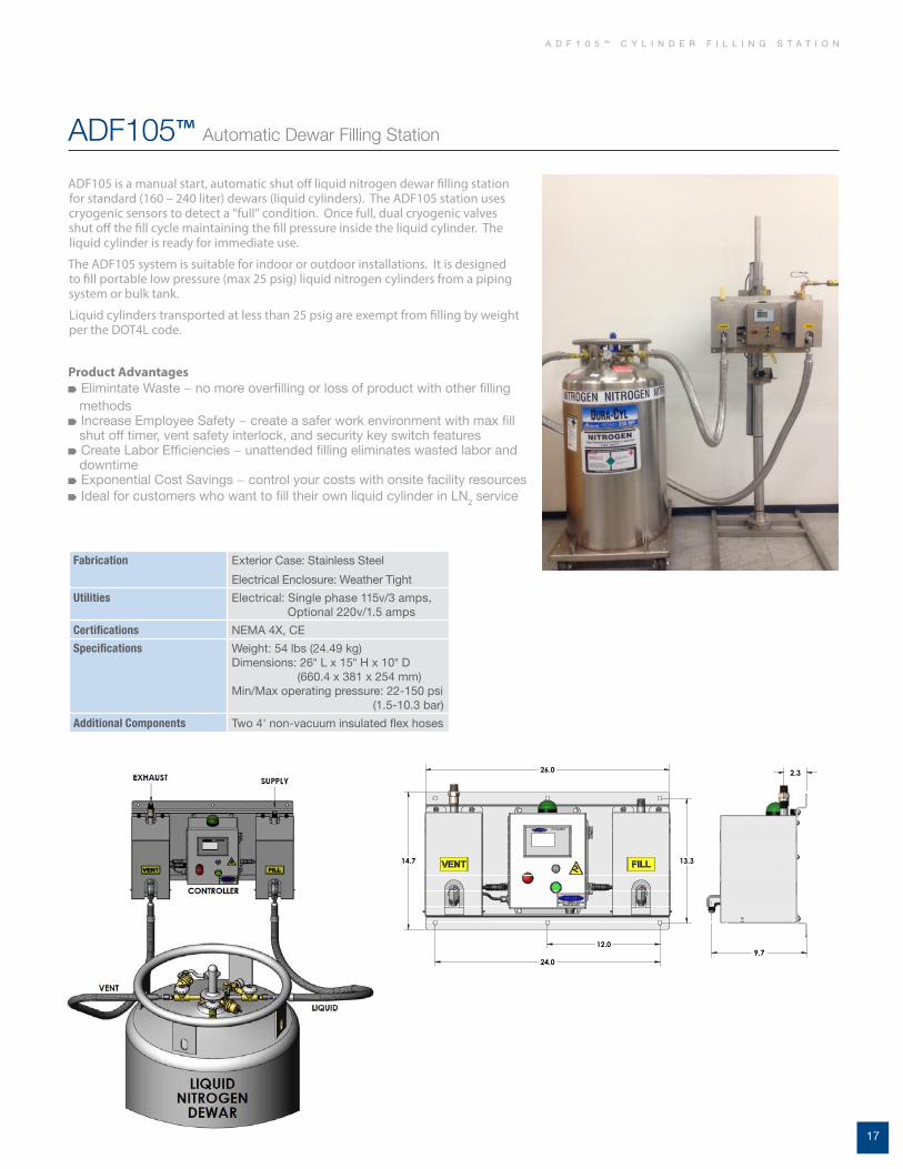
A D F 1 0 5 ™ C Y L I N D E R F I L L I N G S T A T I O N
ADF105 is a manual start, automatic shut off liquid nitrogen dewar filling station for standard (160 – 240 liter) dewars (liquid cylinders). The ADF105 station uses cryogenic sensors to detect a "full" condition. Once full, dual cryogenic valves shut off the fill cycle maintaining the fill pressure inside the liquid cylinder. The liquid cylinder is ready for immediate use.
The ADF105 system is suitable for indoor or outdoor installations. It is designed to fill portable low pressure (max 25 psig) liquid nitrogen cylinders from a piping system or bulk tank.
Liquid cylinders transported at less than 25 psig are exempt from filling by weight per the DOT4L code.
ADF105™ Automatic Dewar Filling Station
Product Advantages Elimintate Waste − no more overfilling or loss of product with other filling
methods Increase Employee Safety − create a safer work environment with max fill
shut off timer, vent safety interlock, and security key switch features Create Labor Efficiencies − unattended filling eliminates wasted labor and
downtime Exponential Cost Savings − control your costs with onsite facility resources Ideal for customers who want to fill their own liquid cylinder in LN2 service
Fabrication Exterior Case: Stainless Steel
Electrical Enclosure: Weather Tight
Utilities Electrical: Single phase 115v/3 amps, Optional 220v/1.5 amps
Certifications NEMA 4X, CE
Specifications Weight: 54 lbs (24.49 kg) Dimensions: 26" L x 15" H x 10" D (660.4 x 381 x 254 mm) Min/Max operating pressure: 22-150 psi (1.5-10.3 bar)
Additional Components Two 4' non-vacuum insulated flex hoses
26.0
14.7 13.3
12.0
24.0
9.7
2.3 26.0
14.7 13.3
12.0
24.0
9.7
2.3

18
Maintaining control of product service is of the utmost importance when using liquid cylinders. Chart offers CGA Fitting Restraints that provide a clear visual indication before any attempt is made to remove or change use-fittings. Installing and inspecting these restraints ensures that cylinders are filled with the correct product each and every time. Designs comply with CGA bulletin #SB-26.
CGA Fitting Restraints For Liquid Cylinders
WARNING!DO NOT REMOVE ANY FITTINGS UNLESS
CYLINDER IS BEING SERVICED BY
AUTHORIZED PERSONNEL. DO NOT USE
CYLINDER IF WIRE SEAL IS MISSING,
DAMAGED OR HAS BEEN TAMPERED WITH
OR IF THERE IS ANY DOUBT AS TO THE
CONTENTS CONTAINED IN THIS CYLINDER.
FAILURE TO FOLLOW ANY OF THESE
INSTRUCTIONS MAY RESULT IN DEATH,
SEVERE PERSONAL INJURY AND/OR
PROPERTY DAMAGE.
A B
SDCSDC (Single Direction Clutch, GENERANT). Also available with internal check valve.
Warning Label (4½" x 3½") P/N 10998521
Type A & B restraints are standard on all DOT cylinders.
Brazed CGA fitting into valve body
C G A F I T T I N G R E S T R A I N T S

19
Warning Label (4½" x 3½") P/N 10998521
L I Q U I D C Y L I N D E R A C C E S S O R I E S
A variety of handling carts and accessories are available to make the transportation of liquid cylinders safe and easy. They optimize fast and safe deliveries by decreasing back injuries, along with lowering Worker’s Compensation costs.
The four-wheeled carriage cart permanently attaches to the lower section of any 20 inch (508 mm) diameter liquid cylinder. The front pull handle is attached to the dual swivel wheels for easy mobility. Rear wheels are stationary so the carriage cart with liquid cylinder can be backed into a tight location. Ideal for lab users with dedicated liquid cylinders.
With dual relief valves one cylinder can be used for both liquid (low pressure) or gas (medium pressure) accounts, which maximizes the flexibility of your liquid cylinders.
Stainless-steel transfer hoses that remain flexible during liquid transfer can be coupled with a bronze phase separator. Ideal for safe discharge of LN2 into open dewars.
The M45 manifold is a convenient, automatic way of increasing the gas delivery rate to any application. The unique change-over valve allows easy manual selection of the primary bank of cylinders. An indicator light shows when the system automatically switches to the reserve bank so replacement cylinders can be ordered.
Options and Accessories engineered to enhance system installations in any application.
The vent muffler can be attached to the vent connection of the liquid cylinder to reduce the venting noise during the fill. Plastic for inert service and brass for oxygen service.

20
C Y L I N D E R R E P A I R
Chart's aftermarket support is world-class, offering installation, repair and OEM replacement parts for every product we manufacture and more. Our repair facilities are integrated with our manufacturing sites so the latest updates in equipment design and manufacturing processes are always built into your repairs. Liquid cylinder repair locations in Ball Ground, GA and McCarran, NV.
Liquid Cylinder Repair World Class Facilities
Benefits Complete cosmetic, revac and rebuild services No hassle shipping with pick-up and delivery at your door Free freight available Cylinder inspection with estimate prior to work Component replacement with stock OEM parts DOT/TC and ASME coded facility Three/Five year vacuum warranty Lowest life-cycle cost Service on all makes and models Guaranteed 100% satisfaction Quickest turn-around time in the industry
Eastern Repair Facility − Ball Ground, GA
Beverage, Liquid Cylinder, MicroBulk & Trifecta Repair
Quality service and 100% satisfaction is what you'll get when you have your beverage and liquid cylinders repaired by Chart, the same team that builds them. Our staff is dedicated to repairing your cylinders to the same reliable standards on which they were built.
Western Repair Facility − McCarran, NV
Bulk, Mobiles, Beverage, Liquid Cylinder, MicroBulk & Trifecta Repair
This repair location strategically services our Western region accounts on over 15 acres with 43,000 square feet ready to service all your equipment. This is our newest state-of-the-art facility.

21
O N L I N E R E S O U R C E S
Chart Online Marketing Services
3 Easy Steps To Getting Onto Our Website To Order Marketing Materials!
1. Go to http://literature.chart-ind.com.
2. Enter your User ID and Password. Click Log In, or click on Sign Up to create an account.
3. Choose a category that you are interested in.
As Chart Inc. continues to provide distributors and customers with the best products and services in the industry, we would like to introduce you to an innovative marketing support tool designed to assist you in growing your business faster! Chart Online Marketing Services is like having your very own 24/7 marketing department providing you the marketing materials needed to drive customers to you. But this is much more than just a site to download product photos, you now have the ability to truly customize brochures, spec sheets and posters with your local contact information and company logo.
Chart Parts Website
It’s Easy to Use!Check out the Benefits• Personalized account information• Order history & shipment tracking• Shopping cart stores your parts before you buy• Parts available for all makes and models• 24/7 ordering and order tracking• Same-day shipment on all stock parts
For All Your Parts Needs...www.chartparts.com
Chart Tank Sizing App
Correctly sizing your cryogenic equipment supply is easy when you know how – or know who to ask. For decades, Chart has helped gas distributors select the optimal cryogenic storage products for their customers. But now, Chart has developed a new Tank Sizing App that can advance your mode-change sales process faster and more accurately. No matter the challenge, Chart will provide the tools you need to succeed. Download the app today for free at your app store and start learning from our experience.
App

22
Notes
N O T E S

23
C O N V E R S I O N D A T A
Pressurepsig
Argon Nitrogen Oxygen CO2
Pressurepsig
Argon Nitrogen Oxygen CO2
0 29.69 24.60 30.36 225 23.58 18.35 24.24 20.34
25 28.24 23.17 28.89 250 23.17 17.89 23.83 20.07
50 27.32 22.26 27.97 275 22.77 17.43 23.43 19.82
75 26.60 21.53 27.25 22.40 300 22.37 16.96 23.03 19.58
100 25.98 20.89 26.63 21.96 325 21.98 16.47 22.64 19.34
125 25.43 20.33 26.09 21.57 350 21.43 15.96 22.25 19.11
150 24.93 19.80 25.59 21.23 375 21.19 15.42 21.86 18.88
175 24.46 19.30 25.12 20.91 400 20.79 14.80 21.47 18.66
200 24.01 18.82 24.67 20.61 425 20.39 14.07 21.08 18.44
SCF of GAS / Liter of LIQUID
ARGON Weight Gas Liquid
Pounds(Lb)
Kilograms(Kg)
Cubic Feet(SCF)
Cubic Meters(Nm3)
Gallons(Gal)
Liters(L)
1 Pound 1.0 0.4536 9.671 0.2543 0.08600 0.3255
1 Kilogram 2.205 1.0 21.32 0.5605 0.18957 0.7176
1 SCF Gas 0.1034 0.04690 1.0 0.02628 0.008893 0.03366
1 Nm3 Gas 3.933 1.7840 38.04 1.0 0.3382 1.2802
1 Gal Liquid 11.630 5.276 112.5 2.957 1.0 3.785
1 L Liquid 3.072 1.3936 29.71 0.7812 0.2642 1.0
NITROGEN Pounds(Lb)
Kilograms(Kg)
Cubic Feet(SCF)
Cubic Meters(Nm3)
Gallons(Gal)
Liters(L)
1 Pound 1.0 0.4536 13.803 0.3627 0.1481 0.5606
1 Kilogram 2.205 1.0 30.42 0.7996 0.3262 1.2349
1 SCF Gas 0.07245 0.03286 1.0 0.02628 0.01074 0.04065
1 Nm3 Gas 2.757 1.2506 38.04 1.0 0.4080 1.5443
1 Gal Liquid 6.745 3.060 93.11 2.447 1.0 3.785
OXYGEN Pounds(Lb)
Kilograms(Kg)
Cubic Feet(SCF)
Cubic Meters(Nm3)
Gallons(Gal)
Liters(L)
1 Pound 1.0 0.4536 12.076 0.3174 0.1050 0.3977
1 Kilogram 2.205 1.0 26.62 0.6998 0.2316 0.8767
1 SCF Gas 0.08281 0.03756 1.0 0.02628 0.008691 0.0329
1 Nm3 Gas 3.151 1.4291 38.04 1.0 0.3310 1.2528
1 Gal Liquid 9.527 4.322 115.1 3.025 1.0 3.785
1 L Liquid 2.517 1.1417 30.38 0.7983 0.2642 1.0
SCF (Standard Cubic Foot) gas measured at 1 atmosphere and 70°F. Liquid measured at 1 atmosphere and boiling temperature.
CARBON DIOXIDE
Weight Gas Liquid Solid
Pounds(Lb)
Tons(T)
Kilograms(Kg)
Cubic Feet(SCF)
Cubic Meters(Nm3)
Gallons(Gal)
Liters(L)
Cubic Feet(Cu Ft)
1 Pound 1.0 0.0005 0.4536 8.741 0.2294 0.11806 0.4469 0.010246
1 Ton 2000.0 1.0 907.2 17,483.0 458.8 236.1 893.9 20.49
1 Kilogram 2.205 0.0011023 1.0 19.253 0.5058 0.2603 0.9860 0.2260
1 SCF Gas 0.1144 — 0.05189 1.0 0.02628 0.013506 0.05113 0.0011723
1 Nm3 Gas 4.359 0.002180 1.9772 38.04 1.0 0.5146 1.9480 0.04468
1 Gal Liquid 8.470 0.004235 3.842 74.04 1.9431 1.0 3.785 0.08678
1 L Liquid 2.238 0.0011185 1.0151 19.562 0.5134 0.2642 1.0 0.02293
1 Cu Ft Solid 97.56 0.04880 44.25 852.8 22.38 11.518 43.60 1.0
SCF (Standard Cubic Foot) gas measured at 1 atmosphere and 70°F. Nm3 (normal cubic meter) gas measured at 1 atmosphere and 0°C.Liquid measured at 21.42 atmospheres and 1.7°F. All values rounded to nearest 4/5 significant numbers.
Gas D
ensities at Liquid PressuresConversion D
ata

Chart Inc.www.chartindustries.com
407 7th Street NW, New Prague, MN 56071Phone 800.400.4683Fax 952.758.8275 Worldwide 952.758.4484
©2015 Chart Inc. P/N 13962022