Equilibrium: The disturbing force F can be determined by...
121
1038 © 2010 Pearson Education, Inc., Upper Saddle River, NJ. All rights reserved. This material is protected under all copyright laws as they currently exist. No portion of this material may be reproduced, in any form or by any means, without permission in writing from the publisher. Equilibrium: The disturbing force F can be determined by summing moments about point A. a Spring Formula: The restoring spring force F 1 can be determine using spring formula . Critical Buckling Load: For the mechanism to be on the verge of buckling, the disturbing force F must be equal to the restoring spring force F 1 . Ans. P cr = kL 4 2P cr u = kLu 2 F s = k a L 2 u b = kLu 2 F s = kx F = 2Pu +©M A = 0; P(Lu) - F a L 2 b = 0 •13–1. Determine the critical buckling load for the column. The material can be assumed rigid. P k A L 2 L 2 13 Solutions 46060 6/11/10 11:56 AM Page 1038
Transcript of Equilibrium: The disturbing force F can be determined by...

1038
© 2010 Pearson Education, Inc., Upper Saddle River, NJ. All rights reserved. This material is protected under all copyright laws as they currentlyexist. No portion of this material may be reproduced, in any form or by any means, without permission in writing from the publisher.
Equilibrium: The disturbing force F can be determined by summing momentsabout point A.
a
Spring Formula: The restoring spring force F1 can be determine using springformula .
Critical Buckling Load: For the mechanism to be on the verge of buckling, thedisturbing force F must be equal to the restoring spring force F1.
Ans. Pcr =
kL
4
2Pcr u =
kLu
2
Fs = kaL
2 ub =
kLu
2
Fs = kx
F = 2Pu
+ ©MA = 0; P(Lu) - FaL
2b = 0
•13–1. Determine the critical buckling load for the column.The material can be assumed rigid.
P
k
A
L2
L2
13 Solutions 46060 6/11/10 11:56 AM Page 1038

1039
© 2010 Pearson Education, Inc., Upper Saddle River, NJ. All rights reserved. This material is protected under all copyright laws as they currentlyexist. No portion of this material may be reproduced, in any form or by any means, without permission in writing from the publisher.
Equilibrium: The disturbing forces F1 and F2 can be related to P by writing themoment equation of equlibrium about point A. Using small angle ananlysis, where
and ,
1
(1)
Spring Force. The restoring spring force and can be determined usingthe spring formula,
, where and , Fig. b. Thus,x2 =
13
Lux1 =
23
LuFsp = kx
AFsp B2AFsp B1F2 + 2F1 = 3Pu
+ ©MA = 0; F2aL
3b + F1a2
3 Lb - PLu = 0
sin u = ucos u � 1
13–2. Determine the critical load for the rigid bar andspring system. Each spring has a stiffness k.
Pcr
k
k
P
L3
L3
L3
A
AFsp B1 = kx1 = ka23
Lub =
23
kLu AFsp B2 = kx2 = ka13
Lub =
13
kLu
Critical Buckling Load. When the mechanism is on the verge of buckling thedisturbing force F must be equal to the restoring force of the spring Fsp. Thus,
Substituting this result into Eq. (1),
Ans.Pcr =
59
kL
13
kLu + 2a23
kLub = 3Pcr u
F1 = AFsp B1 =
23
kLu F2 = AFsp B2 =
13
kLu
13 Solutions 46060 6/11/10 11:56 AM Page 1039
1040
© 2010 Pearson Education, Inc., Upper Saddle River, NJ. All rights reserved. This material is protected under all copyright laws as they currentlyexist. No portion of this material may be reproduced, in any form or by any means, without permission in writing from the publisher.
a
Require:
Ans.Pcr =
4 kL
+ ©MA = 0; -P(u)aL
2b + 2 k u = 0
13–3. The leg in (a) acts as a column and can be modeled(b) by the two pin-connected members that are attached to atorsional spring having a stiffness k (torque�rad). Determinethe critical buckling load. Assume the bone material is rigid.
L—2
L—2
P
(b)(a)
k
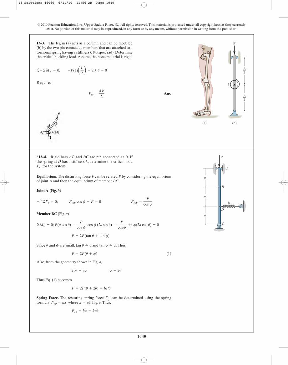
Equilibrium. The disturbing force F can be related P by considering the equilibriumof joint A and then the equilibrium of member BC,
Joint A (Fig. b)
Member BC (Fig. c)
Since and are small, and . Thus,
(1)
Also, from the geometry shown in Fig. a,
Thus Eq. (1) becomes
Spring Force. The restoring spring force Fsp can be determined using the springformula, , where , Fig. a. Thus,
Fsp = kx = kau
x = auFsp = kx
F = 2P(u + 2u) = 6Pu
2au = af f = 2u
F = 2P(u + f)
tan f � ftan u � ufu
F = 2P(tan u + tan f)
©MC = 0; F(a cos u) -
P
cos f cos f (2a sin u) -
P
cos f sin f(2a cos u) = 0
+ c ©Fy = 0; FAB cos f - P = 0 FAB =
P
cos f
*13–4. Rigid bars AB and BC are pin connected at B. Ifthe spring at D has a stiffness k, determine the critical load
for the system.Pcr
k
A
B
D
a
C
P
a
a
13 Solutions 46060 6/11/10 11:56 AM Page 1040

1041
© 2010 Pearson Education, Inc., Upper Saddle River, NJ. All rights reserved. This material is protected under all copyright laws as they currentlyexist. No portion of this material may be reproduced, in any form or by any means, without permission in writing from the publisher.
13–4. Continued
Critical Buckling Load. When the mechanism is on the verge of buckling thedisturbing force F must be equal to the restoring spring force Fsp.
Ans.Pcr =
ka
6
6Pcru = kau
F = Fsp
13 Solutions 46060 6/11/10 11:56 AM Page 1041

1042
Section Properties:
Critical Buckling Load: for pin supported ends column. Applying Euler’sformula,
Ans.
Critical Stress: Euler’s formula is only valid if .
O.K.scr =
Pcr
A=
22720.651.10(10- 3)
= 20.66 MPa 6 sg = 250 MPa
scr 6 sg
= 22720.65 N = 22.7 kN
=
p2 (200)(109)(0.184167)(10- 6)
[1(4)]2
Pcr =
p2EI
(KL)2
K = 1
Ix = Iy =
112
(0.01) A0.063 B +
112
(0.05) A0.013 B = 0.184167 A10- 6 B m4
A = 0.01(0.06) + 0..05(0.01) = 1.10 A10- 3 B m2
•13–5. An A-36 steel column has a length of 4 m and ispinned at both ends. If the cross sectional area has thedimensions shown, determine the critical load.
© 2010 Pearson Education, Inc., Upper Saddle River, NJ. All rights reserved. This material is protected under all copyright laws as they currentlyexist. No portion of this material may be reproduced, in any form or by any means, without permission in writing from the publisher.
25 mm
10 mm
10 mm
25 mm
25 mm
25 mm
Section Properties:
Critical Buckling Load: for one end fixed and the other end pinnedcolumn. Applying Euler’s formula,
Ans.
Critical Stress: Euler’s formula is only valid if .
O.K.scr =
Pcr
A=
46368.681.10(10- 3)
= 42.15 MPa 6 sg = 250 MPa
scr 6 sg
= 46368.68 N = 46.4 kN
=
p2 (200)(109)(0.184167)(10- 6)
[0.7(4)]2
Pcr =
p2 EI
(EL)2
K = 0.7
Ix = Iy =
112
(0.01) A0.063 B +
112
(0.05) A0.013 B = 0.184167 A10- 6 B m4
A = 0.01(0.06) + 0.05(0.01) = 1.10 A10- 3 B m2
13–6. Solve Prob. 13–5 if the column is fixed at its bottomand pinned at its top.
25 mm
10 mm
10 mm
25 mm
25 mm
25 mm
13 Solutions 46060 6/11/10 11:56 AM Page 1042

1043
© 2010 Pearson Education, Inc., Upper Saddle River, NJ. All rights reserved. This material is protected under all copyright laws as they currentlyexist. No portion of this material may be reproduced, in any form or by any means, without permission in writing from the publisher.
The cross sectional area and moment of inertia of the square tube is
The column is pinned at both of its end, . For A36 steel, and(table in appendix). Applying Euler’s formula,
Ans.
Critical Stress. Euler’s formula is valid only if .
O.K.scr =
Pcr
A=
157.745.75
= 27.4 ksi 6 sg = 36 ksi
scr 6 sg
= 157.74 kip = 158
Pcr =
p2EI
(KL)2 =
p2 C29.0(103) D(31.74)
C1(20)(12) D2sg = 36 ksi
E = 29.0(103) ksik = 1
I =
112
(6)(63) -
112
(5.5)(5.53) = 31.74 in4
A = 6(6) - 5.5(5.5) = 5.75 in2
13–7. A column is made of A-36 steel, has a length of 20 ft,and is pinned at both ends. If the cross-sectional area hasthe dimensions shown, determine the critical load.
6 in.
0.25 in.
0.25 in.
0.25 in. 0.25 in.
5.5 in.
The cross-sectional area and moment of inertia of the square tube is
The column is fixed at one end, . For 2014–76 aluminium,and (table in appendix). Applying Euler’s formula,
Ans.
Critical Stress. Euler’s formula is valid only if .
O.K.scr =
Pcr
A=
52.35.75
= 9.10 ksi 6 sg = 60 ksi
scr 6 sg
= 52.29 kip = 52.3 kip
Pcr =
p2EI
(KL)2 =
p2 C10.6(103) D(31.74)
C0.7(30)(12) D2sg = 60 ksi
E = 10.6(103) ksiK = 0.7
I =
112
(6)(63) -
112
(5.5)(5.53) = 31.74 in4
A = 6(6) - 5.5(5.5) = 5.75 in2
*13–8. A column is made of 2014-T6 aluminum, has alength of 30 ft, and is fixed at its bottom and pinned at itstop. If the cross-sectional area has the dimensions shown,determine the critical load.
6 in.
0.25 in.
0.25 in.
0.25 in. 0.25 in.
5.5 in.
13 Solutions 46060 6/11/10 11:56 AM Page 1043

1044
© 2010 Pearson Education, Inc., Upper Saddle River, NJ. All rights reserved. This material is protected under all copyright laws as they currentlyexist. No portion of this material may be reproduced, in any form or by any means, without permission in writing from the publisher.
From the table in appendix, the cross-sectional area and moment of inertia aboutweak axis (y-axis) for are
The column is fixed at its base and free at top, . Here, the column will buckleabout the weak axis (y axis). For A36 steel, and .Applying Euler’s formula,
Thus, the factor of safety with respect to buckling is
Ans.
The Euler’s formula is valid only if .
O.K.scr =
Pcr
A=
33.1711.2
= 2.96 ksi 6 sg = 36 ksi
scr 6 sg
F.S =
Pcr
P=
33.1715
= 2.21
Pcr =
p2EIy
(KL)2 =
p2 C29.0(103) D(26.7)
C2 (20)(12) D2 = 33.17 kip
sy = 36 ksiE = 29.0(103) ksik = 2
A = 11.2 in2 Iy = 26.7 in4
W14 * 38
•13–9. The column is made of A-36 steel and isfixed supported at its base. If it is subjected to an axial loadof determine the factor of safety with respect tobuckling.
P = 15 kip,
W14 * 38
20 ft
P
From the table in appendix, the cross-sectional area and moment of inertia aboutweak axis (y-axis) for are
The column is fixed at its base and free at top about strong axis. Thus, . ForA36 steel, and .
The column is fixed at its base and pinned at top about weak axis. Thus, .
Ans.
The Euler’s formula is valid only if .
O.K.scr =
Pcr
A=
270.7611.2
= 24.17 ksi 6 sg = 36 ksi
scr 6 sg
= 270.76 kip = 271 kip (Control)
Pcr =
p2EIy
(KyLy)2 =
p2 C29.0(103) D(26.7)
C0.7(20)(12) D2ky = 0.7
Pcr =
p2EIx
(KxLx)2 =
p2 C29.0(103) D(385)
C2 (20)(12) D2 = 478.28 kip
sg = 36 ksiE = 29.0(103) ksikx = 2
A = 11.2 in2 Ix = 385 in4 Iy = 26.7 in4
W14 * 38
13–10. The column is made of A-36 steel.Determine the critical load if its bottom end is fixedsupported and its top is free to move about the strong axisand is pinned about the weak axis.
W14 * 38
20 ft
P
13 Solutions 46060 6/11/10 11:56 AM Page 1044
1045
© 2010 Pearson Education, Inc., Upper Saddle River, NJ. All rights reserved. This material is protected under all copyright laws as they currentlyexist. No portion of this material may be reproduced, in any form or by any means, without permission in writing from the publisher.
The least radius of gyration:
O.K.
Ans.Pcr = scr A = 8.243 (2.48) = 20.4 kip
=
p2 (29)(103)
C1.0 (120)0.644 D2 = 8.243 ksi 6 sg
scr =
p2E
AKLr B2 ; K = 1.0
r2 = 0.644 in. controls.
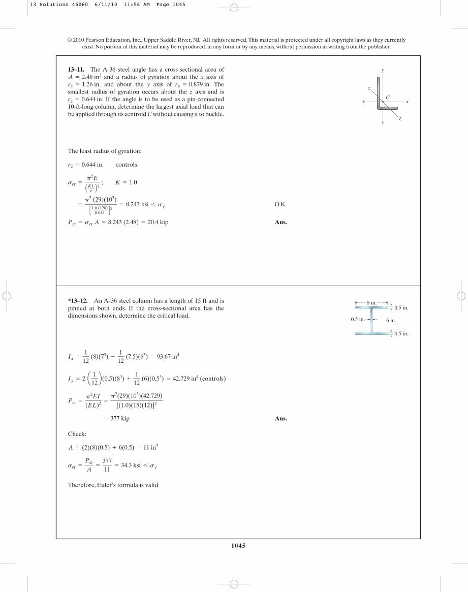
13–11. The A-36 steel angle has a cross-sectional area ofand a radius of gyration about the x axis ofand about the y axis of The
smallest radius of gyration occurs about the z axis and isIf the angle is to be used as a pin-connected
10-ft-long column, determine the largest axial load that canbe applied through its centroid C without causing it to buckle.
rz = 0.644 in.
ry = 0.879 in.rx = 1.26 in.A = 2.48 in2
x x
y
y
z
z
C
Ans.
Check:
Therefore, Euler’s formula is valid
scr =
Pcr
A=
37711
= 34.3 ksi 6 sg
A = (2)(8)(0.5) + 6(0.5) = 11 in2
= 377 kip
Pcr =
p2EI
(EL)2 =
p2(29)(103)(42.729)
[(1.0)(15)(12)]2
Iy = 2 a 112b(0.5)(83) +
112
(6)(0.53) = 42.729 in4 (controls)
Ix =
112
(8)(73) -
112
(7.5)(63) = 93.67 in4
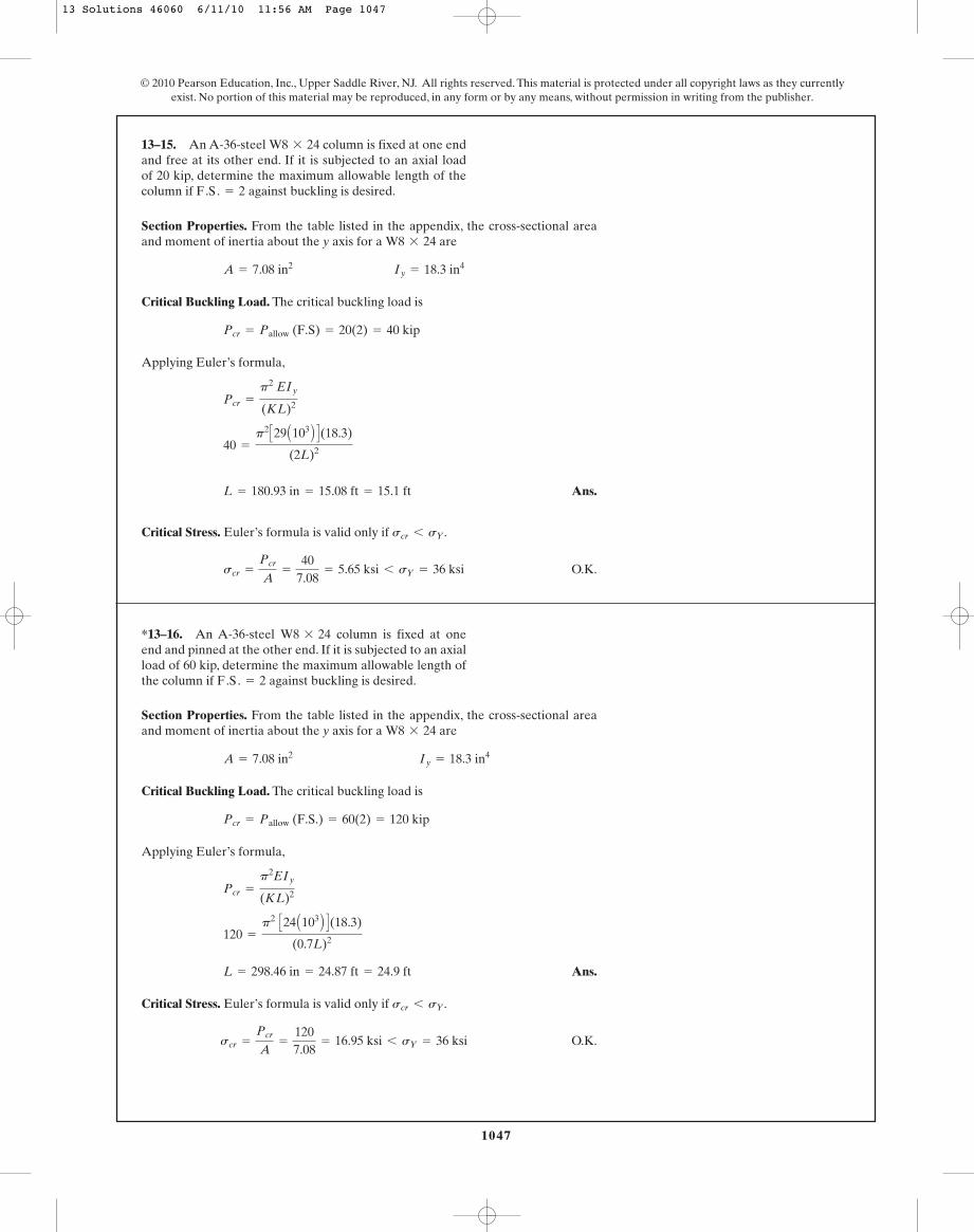
*13–12. An A-36 steel column has a length of 15 ft and ispinned at both ends. If the cross-sectional area has thedimensions shown, determine the critical load.
8 in.
0.5 in. 6 in.
0.5 in.
0.5 in.
13 Solutions 46060 6/11/10 11:56 AM Page 1045

1046
© 2010 Pearson Education, Inc., Upper Saddle River, NJ. All rights reserved. This material is protected under all copyright laws as they currentlyexist. No portion of this material may be reproduced, in any form or by any means, without permission in writing from the publisher.
Ans.
Therefore, Euler’s formula is valid.
=
272 1382.6 (10- 3)
= 105 MPa 6 sg
scr =
Pcr
A ; A = (0.1)(0.05) - (0.08)(0.03) = 2.6(10- 3) m2
= 272 kN
= 272 138 N
Pcr =
p2EI
(KL)2 =
p2(200)(109)(0.86167)(10- 6)
[(0.5)(5)]2
I =
112
(0.1)(0.053) -
112
(0.08)(0.033) = 0.86167 (10- 6) m4
•13–13. An A-36 steel column has a length of 5 m and isfixed at both ends. If the cross-sectional area has thedimensions shown, determine the critical load.
10 mm50 mm
10 mm
100 mm
In order for the column to buckle about and at the same time, Iy mustbe equal to Ix
Ans.
Check:
O.K.
Ans.
Check stress:
Therefore, Euler’s formula is valid.
scr =
Pcr
A=
2452(3.10)
= 39.5 ksi 6 sg
= 245 kip
Pcr =
p2 EI
(KL)2 =
p2 (29)(103)(110.8)
[1.0(360)]2
d 7 2(1.231) = 2.462 in.
d = 8.43 in.
0.764 + 1.55 d2= 110.8
Iy = Ix
y - yx - x
Iy = 2(0.382) + 2 (3.10)ad
2b2
= 0.764 + 1.55 d2
Ix = 2(55.4) = 110.8 in.4
13–14. The two steel channels are to be laced togetherto form a 30-ft-long bridge column assumed to be pinconnected at its ends. Each channel has a cross-sectionalarea of and moments of inertia
The centroid C of its area is located inthe figure. Determine the proper distance d between thecentroids of the channels so that buckling occurs about thex–x and axes due to the same load. What is the valueof this critical load? Neglect the effect of the lacing.
sY = 50 ksi.Est = 2911032 ksi,
y¿ –y¿
Iy = 0.382 in4.Ix = 55.4 in4,A = 3.10 in2
1.231 in.0.269 in.
d
y y¿
C C
y y¿
x x
13 Solutions 46060 6/11/10 11:56 AM Page 1046
1047
© 2010 Pearson Education, Inc., Upper Saddle River, NJ. All rights reserved. This material is protected under all copyright laws as they currentlyexist. No portion of this material may be reproduced, in any form or by any means, without permission in writing from the publisher.
Section Properties. From the table listed in the appendix, the cross-sectional areaand moment of inertia about the y axis for a are
Critical Buckling Load. The critical buckling load is
Applying Euler’s formula,
Ans.
Critical Stress. Euler’s formula is valid only if .
O.K.scr =
Pcr
A=
407.08
= 5.65 ksi 6 sY = 36 ksi
scr 6 sY
L = 180.93 in = 15.08 ft = 15.1 ft
40 =
p2 C29 A103 B D(18.3)
(2L)2
Pcr =
p2 EIy
(KL)2
Pcr = Pallow (F.S) = 20(2) = 40 kip
A = 7.08 in2 Iy = 18.3 in4
W8 * 24
13–15. An A-36-steel column is fixed at one endand free at its other end. If it is subjected to an axial loadof 20 kip, determine the maximum allowable length of thecolumn if against buckling is desired.F.S. = 2
W8 * 24
Section Properties. From the table listed in the appendix, the cross-sectional areaand moment of inertia about the y axis for a are
Critical Buckling Load. The critical buckling load is
Applying Euler’s formula,
Ans.
Critical Stress. Euler’s formula is valid only if .
O.K.scr =
Pcr
A=
1207.08
= 16.95 ksi 6 sY = 36 ksi
scr 6 sY
L = 298.46 in = 24.87 ft = 24.9 ft
120 =
p2 C24 A103 B D(18.3)
(0.7L)2
Pcr =
p2EIy
(KL)2
Pcr = Pallow (F.S.) = 60(2) = 120 kip
A = 7.08 in2 Iy = 18.3 in4
W8 * 24
*13–16. An A-36-steel column is fixed at oneend and pinned at the other end. If it is subjected to an axialload of 60 kip, determine the maximum allowable length ofthe column if against buckling is desired.F.S. = 2
W8 * 24
13 Solutions 46060 6/11/10 11:56 AM Page 1047

1048
© 2010 Pearson Education, Inc., Upper Saddle River, NJ. All rights reserved. This material is protected under all copyright laws as they currentlyexist. No portion of this material may be reproduced, in any form or by any means, without permission in writing from the publisher.
Section Properties:
Critical Buckling Load: for pin supported ends column. Applying Euler’sformula,.
Ans.
Critical Stress: Euler’s formula is only valid if .
O.K.scr =
Pcr
A=
2.9248.00
= 0.3655 ksi 6 sg = 5 ksi
scr 6 sg
= 2.924 kip = 2.92 kip
=
p2(1.6)(103)(2.6667)
[1(10)(12)]2
Pcr =
p2EI
(KL)2
K = 1
Iy =
112
(4) A23 B = 2.6667 in4 (Controls !)
Ix =
112
(2) A43 B = 10.667 in4
A = 4(2) = 8.00 in2
•13–17. The 10-ft wooden rectangular column has thedimensions shown. Determine the critical load if the endsare assumed to be pin connected.sY = 5 ksi.
Ew = 1.611032 ksi,
10 ft
4 in.
2 in.
13–18. The 10-ft column has the dimensions shown.Determine the critical load if the bottom is fixed and thetop is pinned. sY = 5 ksi.Ew = 1.611032 ksi,
10 ft
4 in.
2 in.
Section Properties:
Critical Buckling Load: for column with one end fixed and the other endpinned. Applying Euler’s formula.
Ans.
Critical Stress: Euler’s formula is only valid if .
O.K.scr =
Pcr
A=
5.9688.00
= 0.7460 ksi 6 sg = 5 ksi
scr 6 sg
= 5.968 kip = 5.97 kip
=
p2 (1.6)(103)(2.6667)
[0.7(10)(12)]2
Pcr =
p2EI
(KL)2
K = 0.7
Iy =
112
(4) A23 B = 2.6667 in4 (Controls!)
Ix =
112
(2) A43 B = 10.667 in4
A = 4(2) = 8.00 in2
13 Solutions 46060 6/11/10 11:56 AM Page 1048
1049
© 2010 Pearson Education, Inc., Upper Saddle River, NJ. All rights reserved. This material is protected under all copyright laws as they currentlyexist. No portion of this material may be reproduced, in any form or by any means, without permission in writing from the publisher.
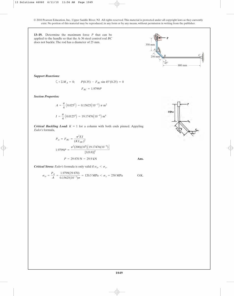
Support Reactions:
a
Section Properties:
Critical Buckling Load: for a column with both ends pinned. AppylingEuler’s formula,
Ans.
Critical Stress: Euler’s formula is only valid if .
O.K.scr =
Pcr
A=
1.9799(29 870)
0.15625(10- 3)p= 120.5 MPa 6 sg = 250 MPa
scr 6 sg
P = 29 870 N = 29.9 kN
1.9799P =
p2(200)(109) C19.17476(10- 9) D[1(0.8)]2
Pcr = FBC =
p2EI
(KLBC)2
K = 1
I =
p
4 A0.01254 B = 19.17476 A10- 9 B m4
A =
p
4 A0.0252 B = 0.15625 A10- 3 B p m2
FBC = 1.9799P
+ ©MA = 0; P(0.35) - FBC sin 45°(0.25) = 0
13–19. Determine the maximum force P that can be applied to the handle so that the A-36 steel control rod BCdoes not buckle. The rod has a diameter of 25 mm.
P
C
350 mm
800 mm45�
250 mm
A
B
13 Solutions 46060 6/11/10 11:56 AM Page 1049
1050
© 2010 Pearson Education, Inc., Upper Saddle River, NJ. All rights reserved. This material is protected under all copyright laws as they currentlyexist. No portion of this material may be reproduced, in any form or by any means, without permission in writing from the publisher.
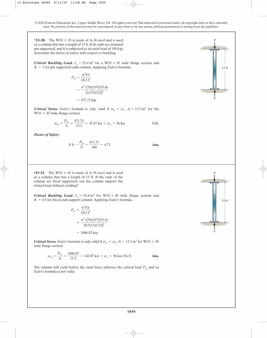
Critical Buckling Load: for a wide flange section andfor pin supported ends column. Applying Euler’s formula,
Critical Stress: Euler’s formula is only valid if . for thewide-flange section.
O.K.
Factor of Safety:
Ans.F.S =
Pcr
P=
471.73100
= 4.72
scr =
Pcr
A=
471.7313.3
= 35.47 ksi 6 sg = 36 ksi
W10 * 45A = 13.3 in2scr 6 sg
= 471.73 kip
=
p2 (29)(103)(53.4)
[1(15)(12)]2
Pcr =
p2EI
(KL)2
K = 1W10 * 45Iy = 53.4 in4
*13–20. The is made of A-36 steel and is usedas a column that has a length of 15 ft. If its ends are assumedpin supported, and it is subjected to an axial load of 100 kip,determine the factor of safety with respect to buckling.
W10 * 45
15 ft
P
P
Critical Buckling Load: for wide flange section andfor fixed ends support column. Applying Euler’s formula,
Critical Stress: Euler’s formula is only valid if . for wide flange section.
Ans.
The column will yield before the axial force achieves the critical load Pcr and soEuler’s formula is not valid.
scr =
Pcr
A=
1886.9213.3
= 141.87 ksi 7 sg = 36 ksi (No!)
W10 * 45A = 13.3 in2scr 6 sg
= 1886.92 kip
=
p2 (29)(103)(53.4)
[0.5(15)(12)]2
Pcr =
p2EI
(KL)2
K = 0.5W10 * 45Iy = 53.4 in4
•13–21. The is made of A-36 steel and is usedas a column that has a length of 15 ft. If the ends of thecolumn are fixed supported, can the column support thecritical load without yielding?
W10 * 45
15 ft
P
P
13 Solutions 46060 6/11/10 11:56 AM Page 1050
1051
© 2010 Pearson Education, Inc., Upper Saddle River, NJ. All rights reserved. This material is protected under all copyright laws as they currentlyexist. No portion of this material may be reproduced, in any form or by any means, without permission in writing from the publisher.
Ans.
Check:
O.K. =
831.6325.6
= 32.5 ksi 6 sg
scr =
Pcr
A
F.S. =
Pcr
P=
831.63380
= 2.19
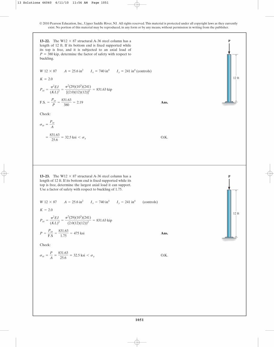
Pcr =
p2EI
(KL)2 =
p2(29)(103)(241)
[(2.0)(12)(12)]2 = 831.63 kip
K = 2.0
W 12 * 87 A = 25.6 in2 Ix = 740 in4 Iy = 241 in4 (controls)
13–22. The structural A-36 steel column has alength of 12 ft. If its bottom end is fixed supported whileits top is free, and it is subjected to an axial load of
determine the factor of safety with respect tobuckling.P = 380 kip,
W12 * 87
12 ft
P
Ans.
Check:
O.K.scr =
P
A=
831.6325.6
= 32.5 ksi 6 sg
P =
Pcr
F.S=
831.631.75
= 475 ksi
Pcr =
p2EI
(KL)2 =
p2(29)(103)(241)
(2.0(12)(12))2 = 831.63 kip
K = 2.0
W 12 * 87 A = 25.6 in2 Ix = 740 in4 Iy = 241 in4 (controls)
13–23. The structural A-36 steel column has alength of 12 ft. If its bottom end is fixed supported while itstop is free, determine the largest axial load it can support.Use a factor of safety with respect to buckling of 1.75.
W12 * 87
12 ft
P
13 Solutions 46060 6/11/10 11:56 AM Page 1051
1052
© 2010 Pearson Education, Inc., Upper Saddle River, NJ. All rights reserved. This material is protected under all copyright laws as they currentlyexist. No portion of this material may be reproduced, in any form or by any means, without permission in writing from the publisher.
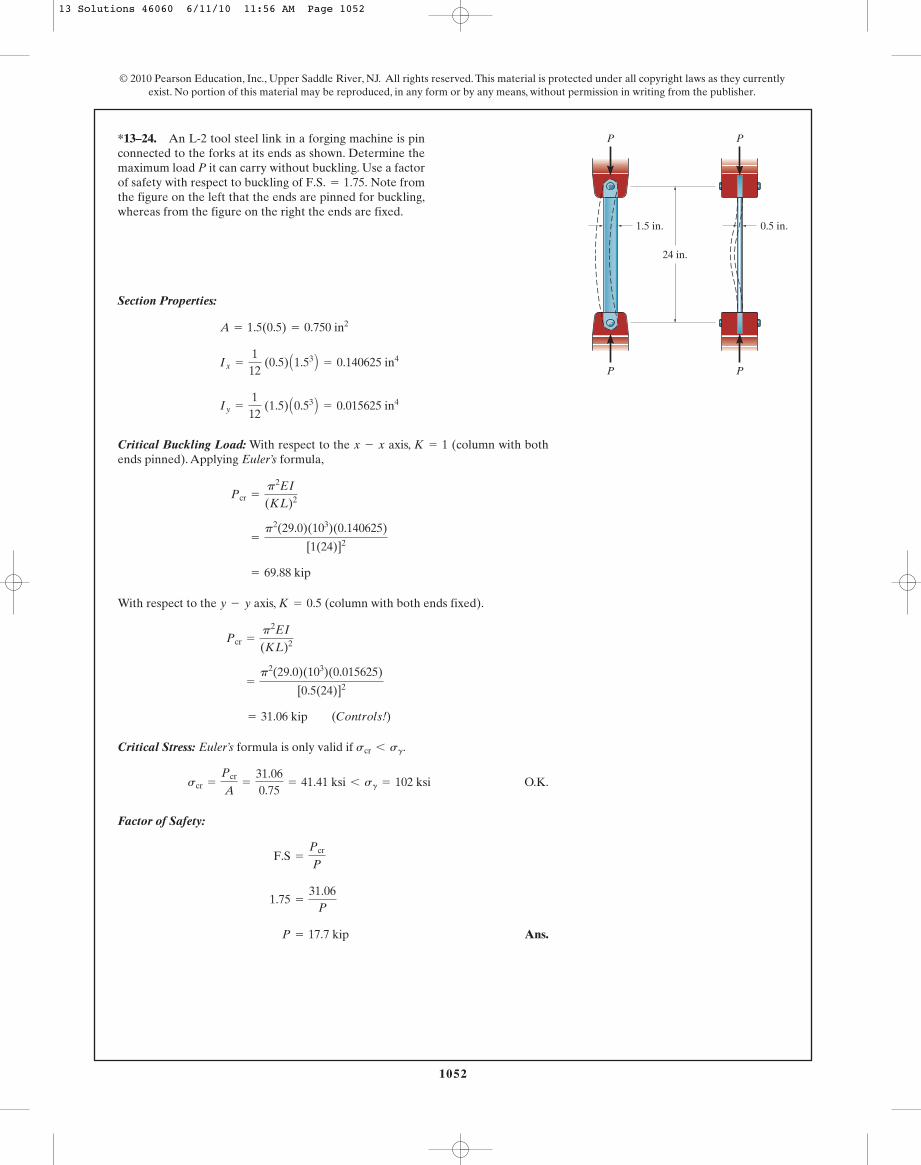
Section Properties:
Critical Buckling Load: With respect to the axis, (column with bothends pinned). Applying Euler’s formula,
With respect to the axis, (column with both ends fixed).
Critical Stress: Euler’s formula is only valid if .
O.K.
Factor of Safety:
Ans. P = 17.7 kip
1.75 =
31.06P
F.S =
Pcr
P
scr =
Pcr
A=
31.060.75
= 41.41 ksi 6 sg = 102 ksi
scr 6 sg
= 31.06 kip (Controls!)
=
p2(29.0)(103)(0.015625)
[0.5(24)]2
Pcr =
p2EI
(KL)2
K = 0.5y - y
= 69.88 kip
=
p2(29.0)(103)(0.140625)
[1(24)]2
Pcr =
p2EI
(KL)2
K = 1x - x
Iy =
112
(1.5) A0.53 B = 0.015625 in4
Ix =
112
(0.5) A1.53 B = 0.140625 in4
A = 1.5(0.5) = 0.750 in2
*13–24. An L-2 tool steel link in a forging machine is pinconnected to the forks at its ends as shown. Determine themaximum load P it can carry without buckling. Use a factorof safety with respect to buckling of Note fromthe figure on the left that the ends are pinned for buckling,whereas from the figure on the right the ends are fixed.
F.S. = 1.75.
PP
P P
24 in.
1.5 in. 0.5 in.
13 Solutions 46060 6/11/10 11:56 AM Page 1052

1053
© 2010 Pearson Education, Inc., Upper Saddle River, NJ. All rights reserved. This material is protected under all copyright laws as they currentlyexist. No portion of this material may be reproduced, in any form or by any means, without permission in writing from the publisher.
From the table in appendix, the cross-sectional area and the moment of inertiaabout weak axis (y-axis) for are
Critical Buckling Load: Since the column is pinned at its base and top, . ForA36 steel, and . Here, the buckling occurs about theweak axis (y-axis).
Ans.
Euler’s formula is valid only if .
O.K.scr =
Pcr
A=
62.338.85
= 7.04 ksi 6 sg = 36 ksi
scr 6 sg
= 62.33 kip = 62.3 kip
P = Pcr =
p2EIy
(KL)2 =
p2 C29.0(103) D(19.6)
C1(25)(12) D2
sg = 36 ksiE = 29.0(103) ksiK = 1
A = 8.85 in2 Iy = 19.6 in4
W14 * 30
•13–25. The is used as a structural A-36 steelcolumn that can be assumed pinned at both of its ends.Determine the largest axial force P that can be appliedwithout causing it to buckle.
W14 * 30
25 ft
P
a
Buckling load:
Ans.
Check:
O.K.scr =
Pcr
A=
8.381.5 (1.5)
= 3.72 ksi 6 sg
Pcr = FA(F.S.) = 1.732(2.42)(2) = 8.38 kip
P = 2.42 kip
3.464 P =
p2 (29)(103)(0.421875)
[(1.0)(120)]2
Pcr =
p2 EI
(KL)2
I =
112
(1.5)(1.5)3= 0.421875 in4
L = 10(12) = 120 in.
Pcr = FA(F.S.) = 1.732 P(2) = 3.464 P
FA = 1.732 P
:+ ©Fx = 0; FA - 2P cos 30° = 0
FBC = 2 P
+ ©MA = 0; FBC sin 30°(10) - P(10) = 0
13–26. The A-36 steel bar AB has a square cross section.If it is pin connected at its ends, determine the maximumallowable load P that can be applied to the frame. Use afactor of safety with respect to buckling of 2.
10 ft 1.5 in.
BA1.5 in.
1.5 in. 30�
C
P
13 Solutions 46060 6/11/10 11:56 AM Page 1053
1054
© 2010 Pearson Education, Inc., Upper Saddle River, NJ. All rights reserved. This material is protected under all copyright laws as they currentlyexist. No portion of this material may be reproduced, in any form or by any means, without permission in writing from the publisher.
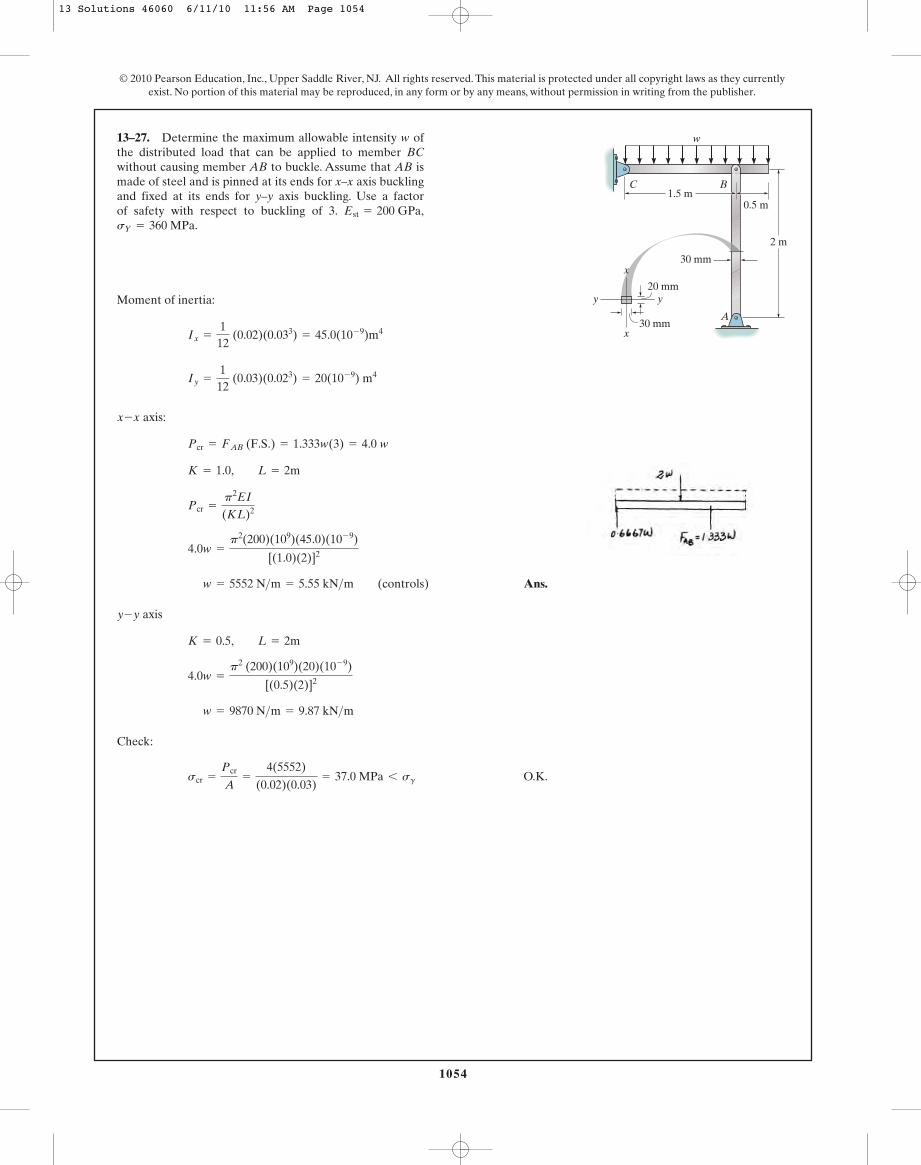
Moment of inertia:
axis:
Ans.
axis
Check:
O.K.scr =
Pcr
A=
4(5552)
(0.02)(0.03)= 37.0 MPa 6 sg
w = 9870 N>m = 9.87 kN>m 4.0w =
p2 (200)(109)(20)(10- 9)
[(0.5)(2)]2
K = 0.5, L = 2m
y-y
w = 5552 N>m = 5.55 kN>m (controls)
4.0w =
p2(200)(109)(45.0)(10- 9)
[(1.0)(2)]2
Pcr =
p2EI
(KL)2
K = 1.0, L = 2m
Pcr = FAB (F.S.) = 1.333w(3) = 4.0 w
x-x
Iy =
112
(0.03)(0.023) = 20(10- 9) m4
Ix =
112
(0.02)(0.033) = 45.0(10- 9)m4
13–27. Determine the maximum allowable intensity w ofthe distributed load that can be applied to member BCwithout causing member AB to buckle. Assume that AB ismade of steel and is pinned at its ends for x–x axis bucklingand fixed at its ends for y–y axis buckling. Use a factorof safety with respect to buckling of 3.sY = 360 MPa.
Est = 200 GPa,1.5 m
2 m
w
B
A
0.5 m
C
30 mm
x
x
y y20 mm
30 mm
13 Solutions 46060 6/11/10 11:56 AM Page 1054
1055
© 2010 Pearson Education, Inc., Upper Saddle River, NJ. All rights reserved. This material is protected under all copyright laws as they currentlyexist. No portion of this material may be reproduced, in any form or by any means, without permission in writing from the publisher.
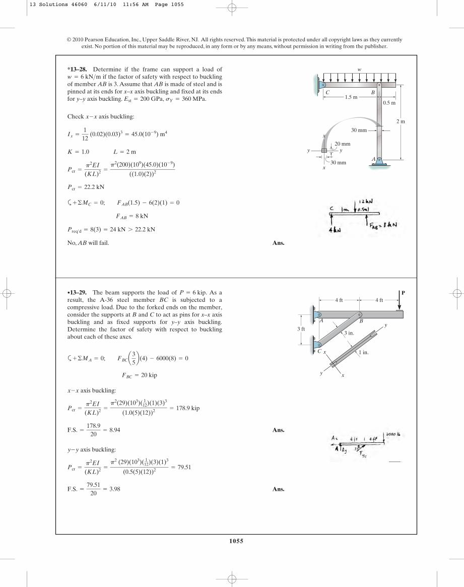
Check axis buckling:
a
No, AB will fail. Ans.
Preq’d = 8(3) = 24 kN 7 22.2 kN
FAB = 8 kN
+ ©MC = 0; FAB(1.5) - 6(2)(1) = 0
Pcr = 22.2 kN
Pcr =
p2EI
(KL)2 =
p2(200)(109)(45.0)(10- 9)
((1.0)(2))2
K = 1.0 L = 2 m
Ix =
112
(0.02)(0.03)3= 45.0(10- 9) m4
x-x
*13–28. Determine if the frame can support a load ofif the factor of safety with respect to buckling
of member AB is 3. Assume that AB is made of steel and ispinned at its ends for x–x axis buckling and fixed at its endsfor y–y axis buckling. sY = 360 MPa.Est = 200 GPa,
w = 6 kN>m
1.5 m
2 m
w
B
A
0.5 m
C
30 mm
x
x
y y20 mm
30 mm
a
axis buckling:
Ans.
axis buckling:
Ans.F.S. =
79.5120
= 3.98
Pcr =
p2EI
(KL)2 =
p2 (29)(103)( 112)(3)(1)3
(0.5(5)(12))2 = 79.51
y-y
F.S. =
178.920
= 8.94
Pcr =
p2EI
(KL)2 =
p2(29)(103)( 112)(1)(3)3
(1.0(5)(12))2 = 178.9 kip
x-x
FBC = 20 kip
+ ©MA = 0; FBCa35b(4) - 6000(8) = 0
•13–29. The beam supports the load of As aresult, the A-36 steel member BC is subjected to acompressive load. Due to the forked ends on the member,consider the supports at B and C to act as pins for x–x axisbuckling and as fixed supports for y–y axis buckling.Determine the factor of safety with respect to bucklingabout each of these axes.
P = 6 kip. P4 ft
A B
C
4 ft
3 ft3 in.
1 in.x
xy
y
13 Solutions 46060 6/11/10 11:56 AM Page 1055
1056
© 2010 Pearson Education, Inc., Upper Saddle River, NJ. All rights reserved. This material is protected under all copyright laws as they currentlyexist. No portion of this material may be reproduced, in any form or by any means, without permission in writing from the publisher.
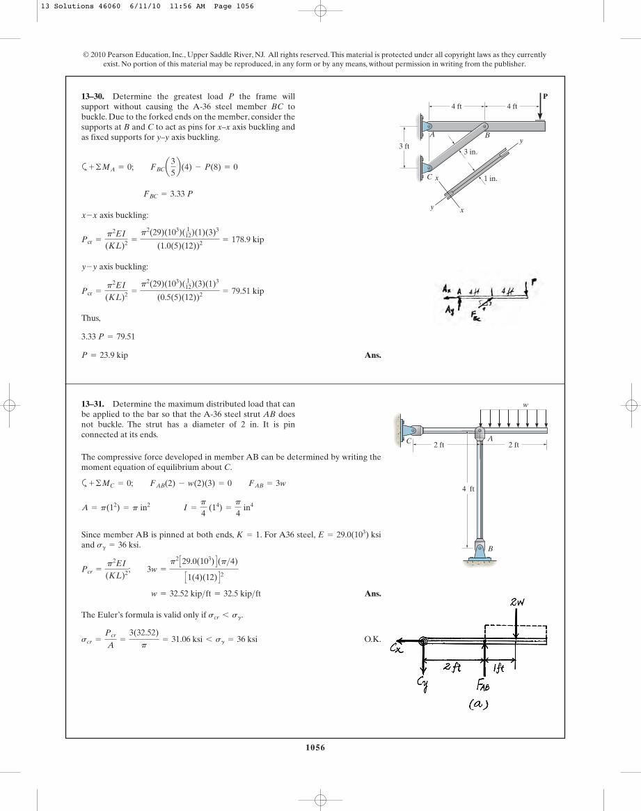
a
axis buckling:
axis buckling:
Thus,
Ans.P = 23.9 kip
3.33 P = 79.51
Pcr =
p2EI
(KL)2 =
p2(29)(103)( 112)(3)(1)3
(0.5(5)(12))2 = 79.51 kip
y-y
Pcr =
p2EI
(KL)2 =
p2(29)(103)( 112)(1)(3)3
(1.0(5)(12))2 = 178.9 kip
x-x
FBC = 3.33 P
+ ©MA = 0; FBCa35b(4) - P(8) = 0
13–30. Determine the greatest load P the frame willsupport without causing the A-36 steel member BC tobuckle. Due to the forked ends on the member, consider thesupports at B and C to act as pins for x–x axis buckling andas fixed supports for y–y axis buckling.
P4 ft
A B
C
4 ft
3 ft3 in.
1 in.x
xy
y
13–31. Determine the maximum distributed load that canbe applied to the bar so that the A-36 steel strut AB doesnot buckle. The strut has a diameter of 2 in. It is pinconnected at its ends.
2 ft 2 ft
4 ft
B
A
w
C
The compressive force developed in member AB can be determined by writing themoment equation of equilibrium about C.
a
Since member AB is pinned at both ends, . For A36 steel,and .
Ans.
The Euler’s formula is valid only if .
O.K.scr =
Pcr
A=
3(32.52)
p= 31.06 ksi 6 sg = 36 ksi
scr 6 sg
w = 32.52 kip>ft = 32.5 kip>ft Pcr =
p2EI
(KL)2; 3w =
p2 C29.0(103) D(p>4)
C1(4)(12) D2sg = 36 ksi
E = 29.0(103) ksiK = 1
A = p(12) = p in2 I =
p
4 (14) =
p
4 in4
+ ©MC = 0; FAB(2) - w(2)(3) = 0 FAB = 3w
13 Solutions 46060 6/11/10 11:56 AM Page 1056

1057
© 2010 Pearson Education, Inc., Upper Saddle River, NJ. All rights reserved. This material is protected under all copyright laws as they currentlyexist. No portion of this material may be reproduced, in any form or by any means, without permission in writing from the publisher.
Section the truss through , the FBD of the top cut segment is shown in Fig. a.Thecompressive force developed in member AC can be determined directly by writingthe force equation of equilibrium along x axis.
Since both ends of member AC are pinned, . For A-36 steel,
and . The length of member AC is .
Ans.
Euler’s formula is valid only if .
O.K.scr =
Pcr
A=
53
(37.47)
p= 19.88 ksi 6 sg = 36 ksi
scr 6 sg
P = 37.47 kip = 37.5 kip
Pcr =
p2EI
(KL)2 ; 53
P =
p2 C29.0(103) D(p>4)
C1(5)(12) D2LAC = 232
+ 42= 5 ftsg = 36 ksi
E = 29.0(103) ksiK = 1
A = p(12) = p in2 I =
p
4 (14) =
p
4 in4
:+ ©Fx = 0; FAC a35b - P = 0 FAC =
53
P (C)
a-a
*13–32. The members of the truss are assumed to be pinconnected. If member AC is an A-36 steel rod of 2 in.diameter, determine the maximum load P that can besupported by the truss without causing the member to buckle.
D
CB
P
3 ft
A
4 ft
13 Solutions 46060 6/11/10 11:56 AM Page 1057

The force with reference to the FBD shown in Fig. a.
a
The length of member AB is . Here, buckling will occur aboutthe weak axis, (y-axis). Since both ends of the member are pinned, .
Euler’s formula is valid only if .
O.K.
Thus, the factor of safety against buckling is
Ans.F.S =
Pcr
FAB=
33.6915
= 2.25
scr =
Pcr
A=
33.69(103)
3.2(10- 3)= 10.53(106)Pa = 10.53 MPa 6 sg = 360 MPa
scr 6 sg
Pcr =
p2EIy
(KyLy)2 =
p2 C200(109) D C0.4267(10- 6) DC1.0(5) D2 = 33.69 kN
Ky = 1L = 232
+ 42= 5m
A = 0.04(0.08) = 3.2(10- 3) m2 Iy =
112
(0.08)(0.043) = 0.4267(10- 6)m4
+ ©MC = 0; 3(6)(3) - FAB a35b(6) = 0 FAB = 15 kN
•13–33. The steel bar AB of the frame is assumed to be pinconnected at its ends for y–y axis buckling. If determine the factor of safety with respect to buckling aboutthe y–y axis due to the applied loading.sY = 360 MPa.
Est = 200 GPa,
w = 3 kN>m,
1058
© 2010 Pearson Education, Inc., Upper Saddle River, NJ. All rights reserved. This material is protected under all copyright laws as they currentlyexist. No portion of this material may be reproduced, in any form or by any means, without permission in writing from the publisher.
6 m
3 m
4 m
y x40 mm
40 mmC
B
A
40 mm
w
13 Solutions 46060 6/11/10 11:56 AM Page 1058
1059
© 2010 Pearson Education, Inc., Upper Saddle River, NJ. All rights reserved. This material is protected under all copyright laws as they currentlyexist. No portion of this material may be reproduced, in any form or by any means, without permission in writing from the publisher.
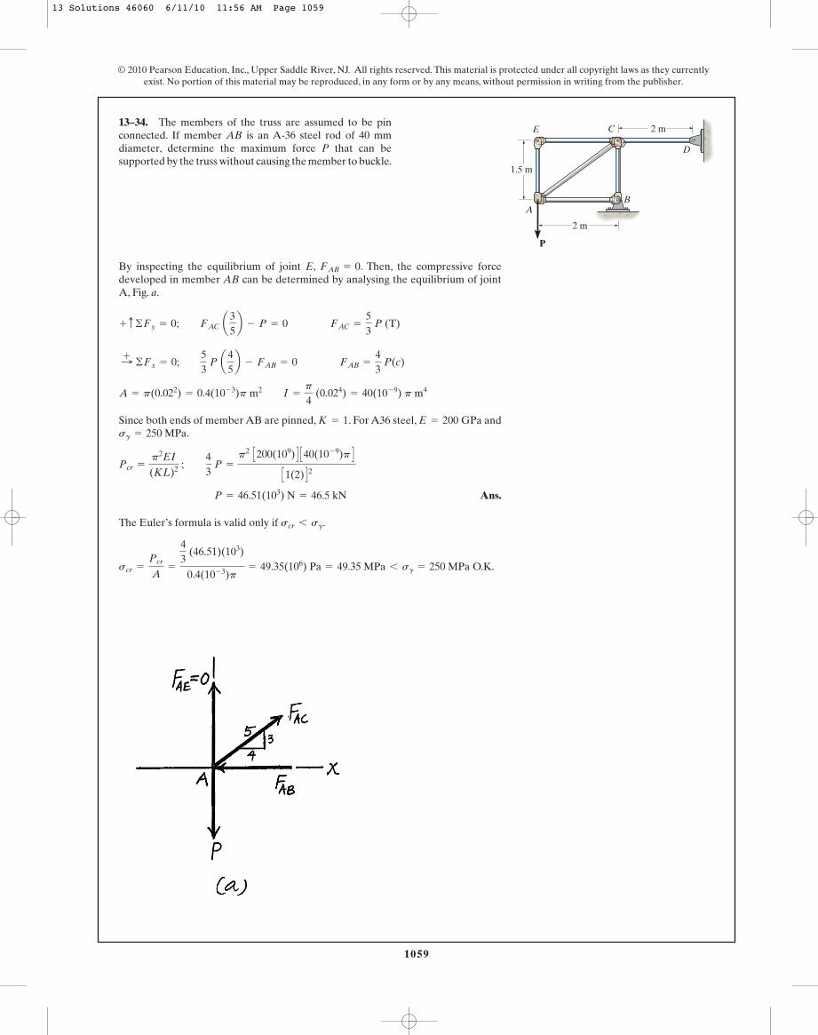
By inspecting the equilibrium of joint E, . Then, the compressive forcedeveloped in member AB can be determined by analysing the equilibrium of jointA, Fig. a.
Since both ends of member AB are pinned, . For A36 steel, and.
Ans.
The Euler’s formula is valid only if .scr 6 sg
P = 46.51(103) N = 46.5 kN
Pcr =
p2EI
(KL)2 ; 43
P =
p2 C200(109) D C40(10- 9)p DC1(2) D2
sg = 250 MPaE = 200 GPaK = 1
A = p(0.022) = 0.4(10- 3)p m2 I =
p
4 (0.024) = 40(10- 9) p m4
:+ ©Fx = 0; 53
P a45b - FAB = 0 FAB =
43
P(c)
+ c ©Fy = 0; FAC a35b - P = 0 FAC =
53
P (T)
FAB = 0
13–34. The members of the truss are assumed to be pinconnected. If member AB is an A-36 steel rod of 40 mmdiameter, determine the maximum force P that can besupported by the truss without causing the member to buckle.
AB
D
CE 2 m
2 m
1.5 m
P
O.K.scr =
Pcr
A=
43
(46.51)(103)
0.4(10- 3)p= 49.35(106) Pa = 49.35 MPa 6 sg = 250 MPa
13 Solutions 46060 6/11/10 11:56 AM Page 1059
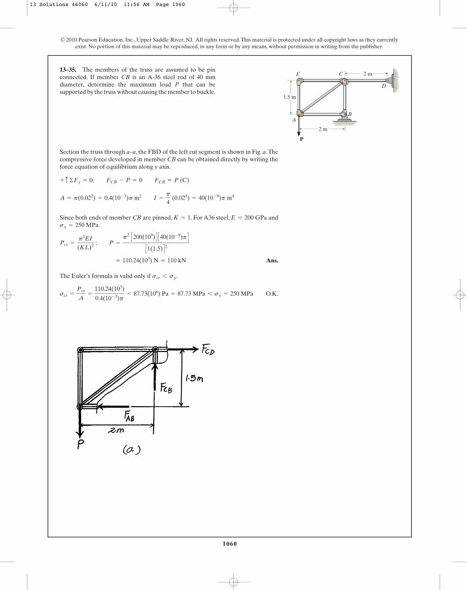
Section the truss through a–a, the FBD of the left cut segment is shown in Fig. a.Thecompressive force developed in member CB can be obtained directly by writing theforce equation of equilibrium along y axis.
Since both ends of member CB are pinned, . For A36 steel, and.
Ans.
The Euler’s formula is valid only if .
O.K.scr =
Pcr
A=
110.24(103)
0.4(10- 3)p= 87.73(106) Pa = 87.73 MPa 6 sg = 250 MPa
scr 6 sg
= 110.24(103) N = 110 kN
Pcr =
p2EI
(KL)2 ; P =
p2 C200(109) D C40(10- 9)p DC1(1.5) D2
sg = 250 MPaE = 200 GPaK = 1
A = p(0.022) = 0.4(10- 3)p m2 I =
p
4 (0.024) = 40(10- 9)p m4
+ c ©Fy = 0; FCB - P = 0 FCB = P (C)
13–35. The members of the truss are assumed to be pinconnected. If member CB is an A-36 steel rod of 40 mmdiameter, determine the maximum load P that can besupported by the truss without causing the member to buckle.
1060
© 2010 Pearson Education, Inc., Upper Saddle River, NJ. All rights reserved. This material is protected under all copyright laws as they currentlyexist. No portion of this material may be reproduced, in any form or by any means, without permission in writing from the publisher.
AB
D
CE 2 m
2 m
1.5 m
P
13 Solutions 46060 6/11/10 11:56 AM Page 1060
1061
© 2010 Pearson Education, Inc., Upper Saddle River, NJ. All rights reserved. This material is protected under all copyright laws as they currentlyexist. No portion of this material may be reproduced, in any form or by any means, without permission in writing from the publisher.
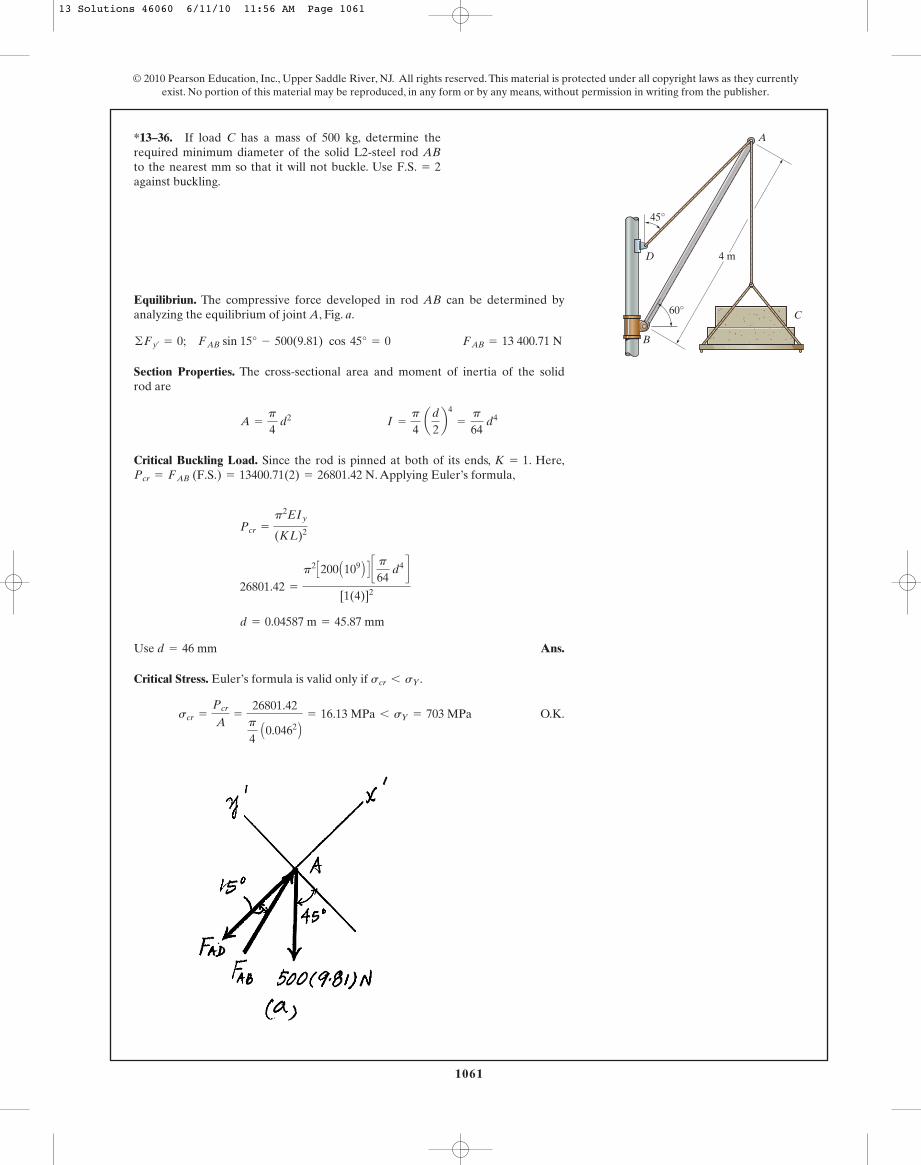
Equilibriun. The compressive force developed in rod AB can be determined byanalyzing the equilibrium of joint A, Fig. a.
Section Properties. The cross-sectional area and moment of inertia of the solid rod are
Critical Buckling Load. Since the rod is pinned at both of its ends, . Here,. Applying Euler’s formula,
Ans.
Critical Stress. Euler’s formula is valid only if .
O.K.scr =
Pcr
A=
26801.42p
4 A0.0462 B = 16.13 MPa 6 sY = 703 MPa
scr 6 sY
Use d = 46 mm
d = 0.04587 m = 45.87 mm
26801.42 =
p2 C200 A109 B D c p64
d4 d[1(4)]2
Pcr =
p2EIy
(KL)2
Pcr = FAB (F.S.) = 13400.71(2) = 26801.42 NK = 1
A =
p
4 d2 I =
p
4 ad
2b4
=
p
64 d4
©Fy¿= 0; FAB sin 15° - 500(9.81) cos 45° = 0 FAB = 13 400.71 N
*13–36. If load C has a mass of 500 kg, determine therequired minimum diameter of the solid L2-steel rod ABto the nearest mm so that it will not buckle. Use against buckling.
F.S. = 2
B
C
D
45°
A
60°
4 m
13 Solutions 46060 6/11/10 11:56 AM Page 1061
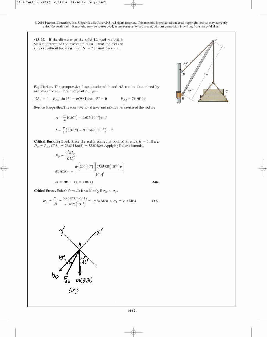
Equilibrium. The compressive force developed in rod AB can be determined byanalyzing the equilibrium of joint A, Fig. a.
Section Properties. The cross-sectional area and moment of inertia of the rod are
Critical Buckling Load. Since the rod is pinned at both of its ends, . Here,. Applying Euler’s formula,
Ans.
Critical Stress. Euler’s formula is valid only if .
O.K.scr =
Pcr
A=
53.6028(706.11)
p 0.625 A10- 3 B = 19.28 MPa 6 sY = 703 MPa
scr 6 sY
m = 706.11 kg = 7.06 kg
53.6028m =
p2 c200 A109 B d c97.65625 A10- 9 Bp d[1(4)]2
Pcr =
p2EIy
(KL)2
Pcr = FAB (F.S.) = 26.8014m(2) = 53.6028mK = 1
I =
p
4 A0.0254 B = 97.65625 A10- 9 Bpm4
A =
p
4 A0.052 B = 0.625 A10- 3 Bpm2
©Fy¿= 0; FAB sin 15° - m(9.81) cos 45° = 0 FAB = 26.8014m
•13–37. If the diameter of the solid L2-steel rod AB is50 mm, determine the maximum mass C that the rod cansupport without buckling. Use against buckling.F.S. = 2
1062
© 2010 Pearson Education, Inc., Upper Saddle River, NJ. All rights reserved. This material is protected under all copyright laws as they currentlyexist. No portion of this material may be reproduced, in any form or by any means, without permission in writing from the publisher.
B
C
D
45°
A
60°
4 m
13 Solutions 46060 6/11/10 11:56 AM Page 1062
1063
© 2010 Pearson Education, Inc., Upper Saddle River, NJ. All rights reserved. This material is protected under all copyright laws as they currentlyexist. No portion of this material may be reproduced, in any form or by any means, without permission in writing from the publisher.
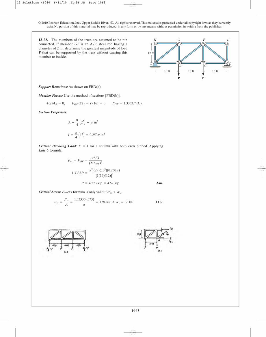
Support Reactions: As shown on FBD(a).
Member Forces: Use the method of sections [FBD(b)].
Section Properties:
Critical Buckling Load: for a column with both ends pinned. ApplyingEuler’s formula,
Ans.
Critical Stress: Euler’s formula is only valid if .
O.K.scr =
Pcr
A=
1.3333(4.573)
p= 1.94 ksi 6 sg = 36 ksi
scr 6 sg
P = 4.573 kip = 4.57 kip
1.3333P =
p2 (29)(103)(0.250p)
[1(16)(12)]2
Pcr = FGF =
p2EI
(KLGF)2
K = 1
I =
p
4 A14 B = 0.250p in4
A =
p
4 A22 B = p in2
+ ©MB = 0; FGF (12) - P(16) = 0 FGF = 1.3333P (C)
13–38. The members of the truss are assumed to be pinconnected. If member GF is an A-36 steel rod having adiameter of 2 in., determine the greatest magnitude of loadP that can be supported by the truss without causing thismember to buckle.
G
A BD
C
F
P
16 ft 16 ft
12 ft
P
16 ft
EH
13 Solutions 46060 6/11/10 11:56 AM Page 1063
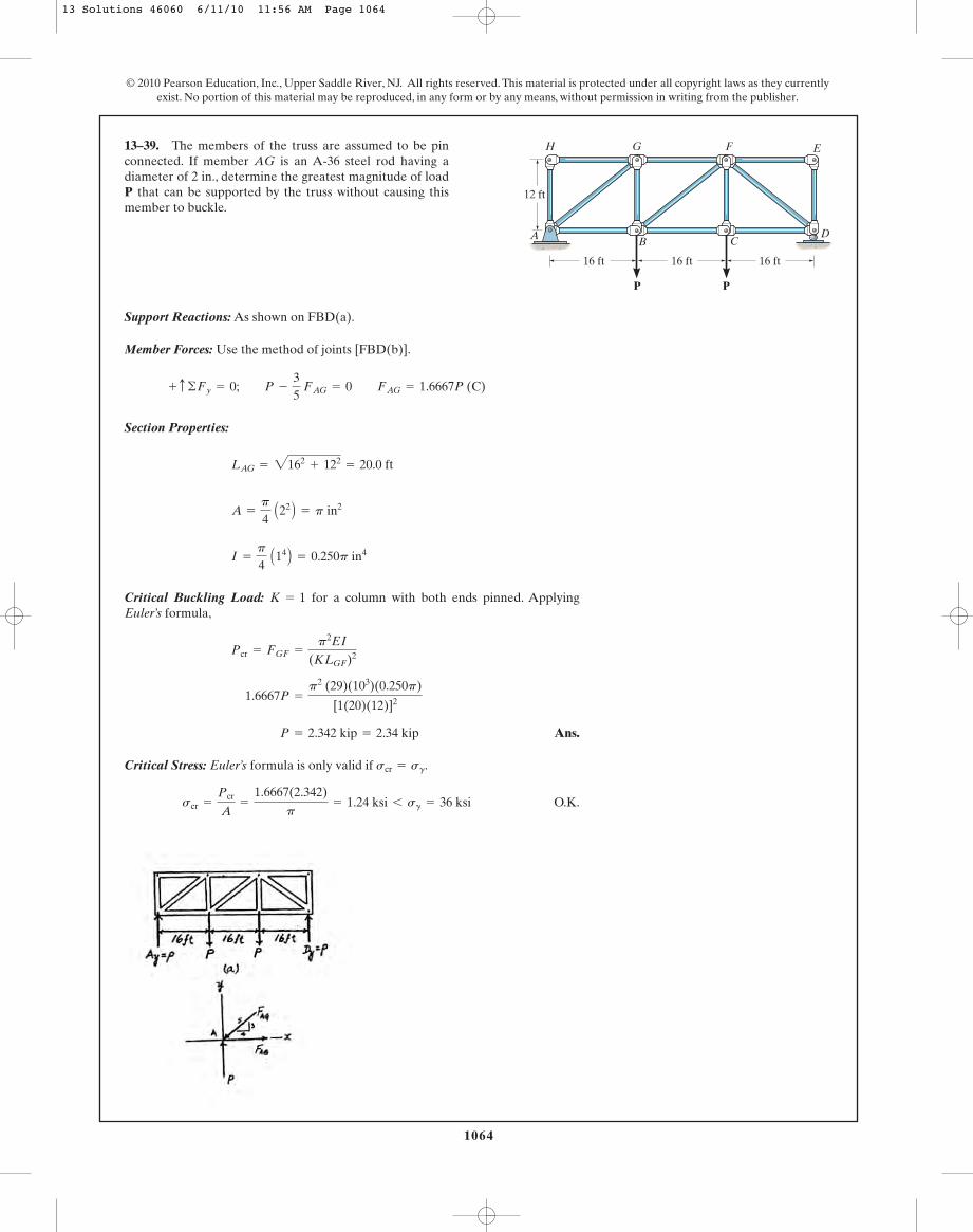
Support Reactions: As shown on FBD(a).
Member Forces: Use the method of joints [FBD(b)].
Section Properties:
Critical Buckling Load: for a column with both ends pinned. ApplyingEuler’s formula,
Ans.
Critical Stress: Euler’s formula is only valid if .
O.K.scr =
Pcr
A=
1.6667(2.342)
p= 1.24 ksi 6 sg = 36 ksi
scr = sg
P = 2.342 kip = 2.34 kip
1.6667P =
p2 (29)(103)(0.250p)
[1(20)(12)]2
Pcr = FGF =
p2EI
(KLGF)2
K = 1
I =
p
4 A14 B = 0.250p in4
A =
p
4 A22 B = p in2
LAG = 2162+ 122
= 20.0 ft
+ c ©Fy = 0; P -
35
FAG = 0 FAG = 1.6667P (C)
13–39. The members of the truss are assumed to be pinconnected. If member AG is an A-36 steel rod having adiameter of 2 in., determine the greatest magnitude of loadP that can be supported by the truss without causing thismember to buckle.
1064
© 2010 Pearson Education, Inc., Upper Saddle River, NJ. All rights reserved. This material is protected under all copyright laws as they currentlyexist. No portion of this material may be reproduced, in any form or by any means, without permission in writing from the publisher.
G
A BD
C
F
P
16 ft 16 ft
12 ft
P
16 ft
EH
13 Solutions 46060 6/11/10 11:56 AM Page 1064
1065
© 2010 Pearson Education, Inc., Upper Saddle River, NJ. All rights reserved. This material is protected under all copyright laws as they currentlyexist. No portion of this material may be reproduced, in any form or by any means, without permission in writing from the publisher.
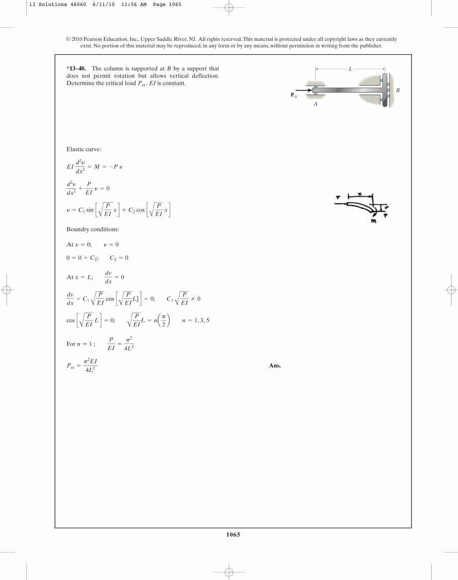
Elastic curve:
Boundry conditions:
At
At
For
Ans.Pcr =
p2EI
4L2
n = 1 ; P
EI=
p2
4L2
cos cA
P
EI L d = 0;
A
P
EIL = nap
2b n = 1, 3, 5
dvdx
= C1 AP
EI cos c
A
P
EIL] d = 0; C1 A
P
EIZ 0
x = L; dvdx
= 0
0 = 0 + C2; C2 = 0
x = 0; y = 0
y = C1 sin cA
P
EI x d + C2 cos c
A
P
EI x d
d2y
dx2 +
P
EI y = 0
EI d2y
dx2 = M = -P y
*13–40. The column is supported at B by a support thatdoes not permit rotation but allows vertical deflection.Determine the critical load EI is constant.Pcr .
L
Pcr
A
B
13 Solutions 46060 6/11/10 11:56 AM Page 1065

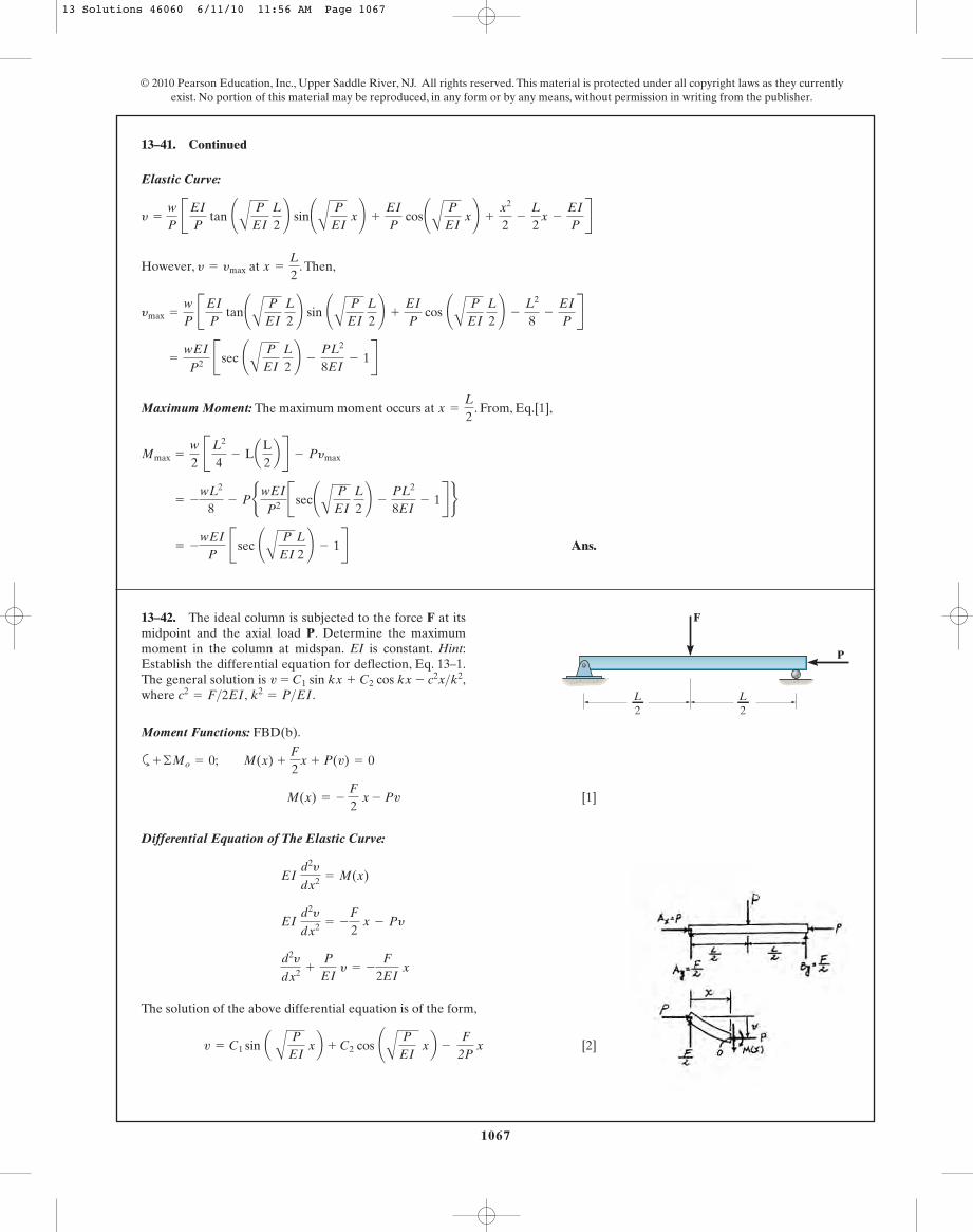
Moment Functions: FBD(b).
a
[1]
Differential Equation of The Elastic Curve:
The solution of the above differential equation is of the form
[2]
and
[3]
The integration constants can be determined from the boundary conditions.
Boundary Condition:
At , . From Eq. [2],
At , . From Eq.[3],
C1 =
wEI
P2 tan ¢A
P
EI L
2≤
0 = C1 AP
EI cos ¢
A
P
EI L
2≤ -
wEI
P2 A
P
EI sin ¢
A
P
EI L
2≤ +
wP
aL
2b -
wL
2P
dy
dx= 0x =
L
2
0 = C2 -
wEI
P2 C2 =
wEI
P2
y = 0x = 0
dv
dx= C1 A
P
EI cos ¢
A
P
EI x≤ - C2 A
P
EI sin ¢
A
P
EIx≤ +
wP
x - wL
2P
v = C1 sin a A
P
EI xb + C2 cos ¢
A
P
EI x b +
w2P
x2 - wL
2P x -
wEI
P2
d2y
dx2 +
P
EI y =
w2EI
Ax2- Lx B
EI d2y
dx2 =
w2
Ax2- Lx B - Py
EI d2y
dx2 = M(x)
M(x) =
w
2 Ax2
- Lx B - Pv
+ ©Mo = 0; wx ax
2b - M(x) - awL
2bx - Pv = 0
•13–41. The ideal column has a weight (force�length)and rests in the horizontal position when it is subjected to theaxial load P.Determine the maximum moment in the columnat midspan. EI is constant. Hint: Establish the differentialequation for deflection, Eq. 13–1, with the origin at the midspan. The general solution is
where k2= P>EI.1w>12P22x2
- 1wL>12P22x - 1wEI>P22v = C1 sin kx + C2 cos kx +
w
1066
© 2010 Pearson Education, Inc., Upper Saddle River, NJ. All rights reserved. This material is protected under all copyright laws as they currentlyexist. No portion of this material may be reproduced, in any form or by any means, without permission in writing from the publisher.
L
P
w
13 Solutions 46060 6/11/10 11:56 AM Page 1066
1067
© 2010 Pearson Education, Inc., Upper Saddle River, NJ. All rights reserved. This material is protected under all copyright laws as they currentlyexist. No portion of this material may be reproduced, in any form or by any means, without permission in writing from the publisher.
Elastic Curve:
However, at . Then,
Maximum Moment: The maximum moment occurs at . From, Eq.[1],
Ans. = -
wEI
P Bsec ¢
A
P
EI
L
2≤ - 1R
= -
wL2
8- PbwEI
P2 Bsec¢A
P
EI L
2≤ -
PL2
8EI- 1R r
Mmax =
w2
BL2
4- LaL
2b R - Pymax
x =
L
2
=
wEI
P2 Bsec ¢A
P
EI L
2≤ -
PL2
8EI- 1R
ymax =
wP
BEI
P tan¢
A
P
EI L
2≤ sin ¢
A
P
EI L
2≤ +
EI
P cos ¢
A
P
EI L
2≤ -
L2
8-
EI
PR
x =
L
2y = ymax
y =
wP
BEI
P tan ¢
A
P
EI L
2≤ sin¢
A
P
EI x≤ +
EI
P cos¢
A
P
EI x≤ +
x2
2-
L
2x -
EI
PR
13–41. Continued
Moment Functions: FBD(b).
a
[1]
Differential Equation of The Elastic Curve:
The solution of the above differential equation is of the form,
[2] v = C1 sin a A
P
EI xb + C2 cos ¢
A
P
EI xb -
F2P
x
d2y
dx2 +
P
EI y = -
F
2EI x
EI d2y
dx2 = -
F
2 x - Py
EI d2y
dx2 = M(x)
M(x) = - F
2 x
- Pv
+ ©Mo = 0; M(x) + F
2x + P(v) = 0
13–42. The ideal column is subjected to the force F at itsmidpoint and the axial load P. Determine the maximummoment in the column at midspan. EI is constant. Hint:Establish the differential equation for deflection, Eq. 13–1.The general solution is where k2
= P>EI.c2= F>2EI,
v = C1 sin kx + C2 cos kx - c2x>k2,
P
F
L2
L2
13 Solutions 46060 6/11/10 11:56 AM Page 1067
1068
and
[3]
The integration constants can be determined from the boundary conditions.
Boundary Conditions:
At , . From Eq.[2],
At , . From Eq.[3],
Elastic Curve:
However, at . Then,
Maximum Moment: The maximum moment occurs at . From Eq.[1],
Ans. = -
F
2 A
EI
P tan¢
A
P
EI L
2≤
= -
FL
4- Pb F
2P BA
EI
Ptan¢
A
P
EI L
2≤ -
L
2R r
Mmax = -
F
2 aL
2b - Pymax
x =
L
2
=
F
2P BA
EI
P tan¢
A
P
EI L
2≤ -
L
2R
ymax =
F
2P BA
EI
P sec¢
A
P
EI L
2≤ sin¢
A
P
EI L
2≤ -
L
2R
x =
L
2y = ymax
=
F
2P BA
EI
P sec¢
A
P
EI L
2≤ sin¢
A
P
EI x≤ - xR
y =
F
2P A
EI
P sec¢
A
P
EI L
2≤ sin¢
A
P
EI x≤ -
F
2P x
C1 =
F
2P A
EI
P sec¢
A
P
EI L
2≤
0 = C1 AP
EI cos¢
A
P
EI L
2≤ -
F
2P
dy
dx= 0x =
L
2
C2 = 0y = 0x = 0
dv
dx= C1 A
P
EI cos ¢
A
P
EI x≤ - C2 A
P
EI sin ¢
A
P
EIx≤ -
F2P
© 2010 Pearson Education, Inc., Upper Saddle River, NJ. All rights reserved. This material is protected under all copyright laws as they currentlyexist. No portion of this material may be reproduced, in any form or by any means, without permission in writing from the publisher.
13–42. Continued
13 Solutions 46060 6/11/10 11:56 AM Page 1068
1069
© 2010 Pearson Education, Inc., Upper Saddle River, NJ. All rights reserved. This material is protected under all copyright laws as they currentlyexist. No portion of this material may be reproduced, in any form or by any means, without permission in writing from the publisher.
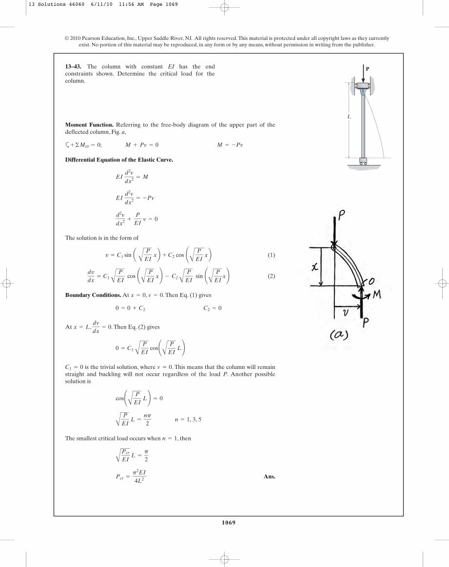
Moment Function. Referring to the free-body diagram of the upper part of thedeflected column, Fig. a,
a
Differential Equation of the Elastic Curve.
The solution is in the form of
(1)
(2)
Boundary Conditions. At , . Then Eq. (1) gives
At , . Then Eq. (2) gives
is the trivial solution, where . This means that the column will remainstraight and buckling will not occur regardless of the load P. Another possiblesolution is
The smallest critical load occurs when , then
Ans.Pcr =
p2EI
4L2
APcr
EI L =
p
2
n = 1
A
P
EI L =
np
2 n = 1, 3, 5
cos¢A
P
EI L≤ = 0
v = 0C1 = 0
0 = C1 AP
EI cos¢
A
P
EI L≤
dvdx
= 0x = L
0 = 0 + C2 C2 = 0
v = 0x = 0
dv
dx= C1 A
P
EI cos ¢
A
P
EI x≤ - C2 A
P
EI sin ¢
A
P
EIx≤
v = C1 sin a A
P
EI xb + C2 cos ¢
A
P
EI xb
d2v
dx2 +
P
EI v = 0
EI d2v
dx2 = -Pv
EI d2v
dx2 = M
+ ©MO = 0; M + Pv = 0 M = -Pv
13–43. The column with constant EI has the endconstraints shown. Determine the critical load for thecolumn.
L
P
13 Solutions 46060 6/11/10 11:56 AM Page 1069
1070
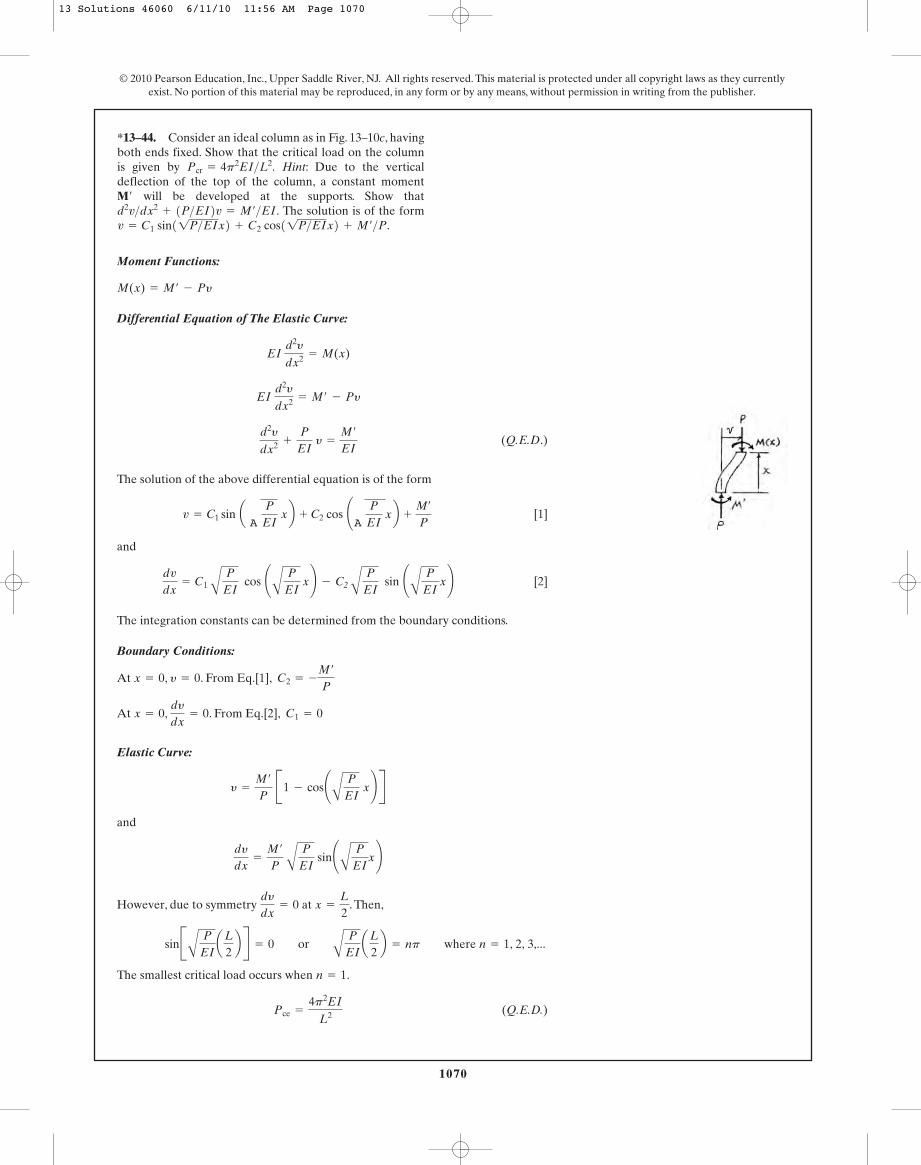
Moment Functions:
Differential Equation of The Elastic Curve:
(Q.E.D.)
The solution of the above differential equation is of the form
[1]
and
[2]
The integration constants can be determined from the boundary conditions.
Boundary Conditions:
At , . From Eq.[1],
At , . From Eq.[2],
Elastic Curve:
and
However, due to symmetry at . Then,
The smallest critical load occurs when .
(Q.E.D.)Pce =
4p2EI
L2
n = 1
sinBA
P
EIaL
2b R = 0 or
A
P
EIaL
2b = np where n = 1, 2, 3,...
x =
L
2dy
dx= 0
dy
dx=
M¿
P A
P
EI sin¢
A
P
EIx≤
y =
M¿
P B1 - cos¢
A
P
EI x≤ R
C1 = 0dy
dx= 0x = 0
C2 = -
M¿
Py = 0x = 0
dv
dx= C1 A
P
EI cos ¢
A
P
EI x≤ - C2 A
P
EI sin ¢
A
P
EIx≤
v = C1 sin a A
P
EI xb + C2 cos ¢
A
P
EI xb +
M¿
P
d2y
dx2 +
P
EI y =
M¿
EI
EI d2y
dx2 = M¿ - Py
EI d2y
dx2 = M(x)
M(x) = M¿ - Py
© 2010 Pearson Education, Inc., Upper Saddle River, NJ. All rights reserved. This material is protected under all copyright laws as they currentlyexist. No portion of this material may be reproduced, in any form or by any means, without permission in writing from the publisher.
*13–44. Consider an ideal column as in Fig. 13–10c, havingboth ends fixed. Show that the critical load on the columnis given by Hint: Due to the verticaldeflection of the top of the column, a constant moment
will be developed at the supports. Show thatThe solution is of the form
C2 cos11P>EIx2 + M¿>P.v = C1 sin11P>EIx2 +
M¿>EI.d2v>dx2+ 1P>EI2v =
M¿
Pcr = 4p2EI>L2.
13 Solutions 46060 6/11/10 11:56 AM Page 1070

1071
© 2010 Pearson Education, Inc., Upper Saddle River, NJ. All rights reserved. This material is protected under all copyright laws as they currentlyexist. No portion of this material may be reproduced, in any form or by any means, without permission in writing from the publisher.
Equilibrium. FBD(a).
Moment Functions: FBD(b).
Differential Equation of The Elastic Curve:
(Q.E.D.)
The solution of the above differential equation is of the form
[1]
and
[2]
The integration constants can be determined from the boundary conditions.
Boundary Conditions:
At , . From Eq.[1],
At , . From Eq.[2],
Elastic Curve:
=
R¿
P BA
EI
P sin¢
A
P
EIx≤ - L cos¢
A
P
EI x≤ + (Lx)R
y =
R¿
P A
EI
P sin¢
A
P
EI x≤ -
R¿L
P cos¢
A
P
EIx≤ +
R¿
P (L - x)
C1 =
R¿
P A
EI
P
dy
dx= 0x = 0
C2 = -
R¿L
Py = 0x = 0
dv
dx= C1 A
P
EI cos ¢
A
P
EI x≤ - C2 A
P
EI sin ¢
A
P
EIx≤ -
R¿
P
v = C1 sin aA
P
EI xb + C2 cos ¢
A
P
EI xb +
R¿
P (L - x)
d2y
dx2 +
P
EI y =
R¿
EI (L - x)
EI d2y
dx2 = R¿(L - x) - Py
EI d2y
dx2 = M(x)
M(x) = R¿(L - x) - Py
•13–45. Consider an ideal column as in Fig. 13–10d, havingone end fixed and the other pinned.Show that the critical loadon the column is given by Hint:Due to thevertical deflection at the top of the column,a constant moment
will be developed at the fixed support and horizontalreactive forces will be developed at both supports. Showthat The solutionis of the form
After application of the boundary conditionsshow that Solve by trial anderror for the smallest nonzero root.
1P>EI L.tan 11P>EIL2 =
1R¿>P21L - x2.C2 cos 11P>EIx2 +v = C1 sin 11P>EIx2 +
1R¿>EI21L - x2.d2v>dx2+ 1P>EI2v =
R¿
M¿
Pcr = 20.19EI>L2.
13 Solutions 46060 6/11/10 11:56 AM Page 1071

1072
However, at . Then,
(Q.E.D.)
By trial and error and choosing the smallest root, we have
Then,
(Q.E.D.)Pcr =
20.19EI
L2
A
P
EI L = 4.49341
tan¢A
P
EI L≤ =
A
P
EI L
0 =
A
EI
P sin¢
A
P
EI L≤ - L cos¢
A
P
EI L≤
x = Ly = 0
© 2010 Pearson Education, Inc., Upper Saddle River, NJ. All rights reserved. This material is protected under all copyright laws as they currentlyexist. No portion of this material may be reproduced, in any form or by any means, without permission in writing from the publisher.
13–45. Continued
Section properties for :
Buckling about axis:
Ans.
Check: O.K.
Check yielding about axis:
O.K.smax = 5.963[1 + 0.37463 sec (0.4184)] = 8.41 ksi 6 sg = 36 ksi
KL
2r A
P
EA=
2.0(96)
2(3.29) A
26.529(103)(4.44)
= 0.4184
ec
r2 =
(1) A8.112 B
(3.29)2 = 0.37463
P
A=
26.54.44
= 5.963 ksi
smax =
P
A c1 +
ec
r2 sec aKL
2r A
P
EAb d
x-x
scr =
Pcr
A=
26.54.44
= 5.96 ksi 6 sg
P = Pcr =
p2EIy
(KL)2 =
p2(29)(103)(3.41)
[(2.0)(96)]2 = 26.5 kip (controls)
K = 2.0 L = 8(12) = 96 in.
y-y
rx = 3.29 in. d = 8.11 in.
A = 4.44 in2 Ix = 48.0 in4 Iy = 3.41 in4
W8 * 15
13–46. Determine the load P required to cause the A-36steel column to fail either by buckling or byyielding. The column is fixed at its base and free at its top.
W8 * 15
8 ft
1 in.P
13 Solutions 46060 6/11/10 11:56 AM Page 1072
1073
© 2010 Pearson Education, Inc., Upper Saddle River, NJ. All rights reserved. This material is protected under all copyright laws as they currentlyexist. No portion of this material may be reproduced, in any form or by any means, without permission in writing from the publisher.
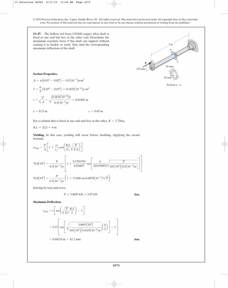
Section Properties.
For a column that is fixed at one end and free at the other, . Thus,
Yielding. In this case, yielding will occur before buckling. Applying the secantformula,
smax =
P
A B1 +
ec
rx 2 sec¢KL
2rx A
P
EA≤ R
KL = 2(2) = 4 m
K = 2
e = 0.15 m c = 0.03 m
r =
A
I
A=
C
0.1625 A10- 6 Bp0.5 A10- 3 Bp = 0.01803 m
I =
p
4 A0.034
- 0.024 B = 0.1625 A10- 6 Bp m4
A = p A0.032- 0.022 B = 0.5 A10- 3 Bp m2
13–47. The hollow red brass C83400 copper alloy shaft isfixed at one end but free at the other end. Determine themaximum eccentric force P the shaft can support withoutcausing it to buckle or yield. Also, find the correspondingmaximum deflection of the shaft.
P
a
a
150 mm
2 m
30 mm
20 mm
Section a – a
70.0 A106 B =
P
0.5 A10- 3 Bp D1 +
0.15(0.03)
0.018032 secC 42(0.01803)A
P
101 A109 B C0.5 A10- 3 Bp D S T
Solving by trial and error,
Ans.
Maximum Deflection.
Ans. = 0.04210 m = 42.1 mm
= 0.15DsecCC
5.8697 A103 B101 A109 B C0.1625 A10- 6 Bp D a
42b S - 1T
vmax = eBsec¢A
P
EI KL
2≤ - 1R
P = 5.8697 kN = 5.87 kN
70.0 A106 B =
P
0.5 A10- 3 Bp a1 + 13.846 sec 8.8078 A10- 3 B2Pb
13 Solutions 46060 6/11/10 11:56 AM Page 1073
1074
© 2010 Pearson Education, Inc., Upper Saddle River, NJ. All rights reserved. This material is protected under all copyright laws as they currentlyexist. No portion of this material may be reproduced, in any form or by any means, without permission in writing from the publisher.
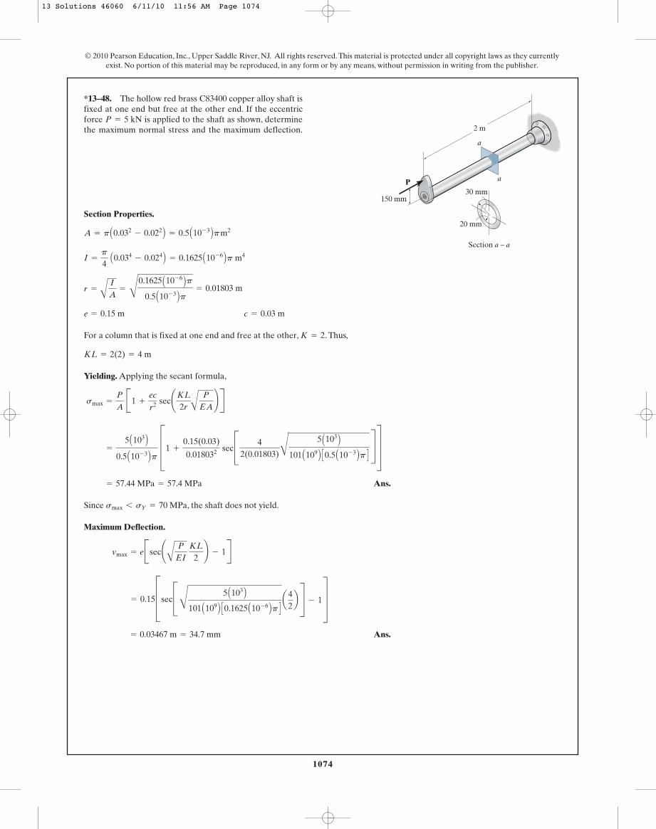
Section Properties.
For a column that is fixed at one end and free at the other, . Thus,
Yielding. Applying the secant formula,
Ans.
Since , the shaft does not yield.
Maximum Deflection.
Ans. = 0.03467 m = 34.7 mm
= 0.15DsecCC
5 A103 B101 A109 B C0.1625 A10- 6 Bp D a
42b S - 1T
vmax = eBsec¢A
P
EI KL
2≤ - 1R
smax 6 sY = 70 MPa
= 57.44 MPa = 57.4 MPa
=
5 A103 B0.5 A10- 3 Bp D1 +
0.15(0.03)
0.018032 secC 42(0.01803)C
5 A103 B101 A109 B C0.5 A10- 3 Bp D S T
smax =
P
A B1 +
ec
r2 sec¢KL
2r A
P
EA≤ R
KL = 2(2) = 4 m
K = 2
e = 0.15 m c = 0.03 m
r =
A
I
A=
C
0.1625 A10- 6 Bp0.5 A10- 3 Bp = 0.01803 m
I =
p
4 A0.034
- 0.024 B = 0.1625 A10- 6 Bp m4
A = p A0.032- 0.022 B = 0.5 A10- 3 Bp m2
*13–48. The hollow red brass C83400 copper alloy shaft isfixed at one end but free at the other end. If the eccentricforce is applied to the shaft as shown, determinethe maximum normal stress and the maximum deflection.
P = 5 kN
P
a
a
150 mm
2 m
30 mm
20 mm
Section a – a
13 Solutions 46060 6/11/10 11:56 AM Page 1074
1075
© 2010 Pearson Education, Inc., Upper Saddle River, NJ. All rights reserved. This material is protected under all copyright laws as they currentlyexist. No portion of this material may be reproduced, in any form or by any means, without permission in writing from the publisher.
Section Properties:
For a column pinned at both ends, . Then .
Buckling: Applying Euler’s formula,
Critical Stress: Euler’s formula is only valid if .
O.K.
Yielding: Applying the secant formula,
smax =
Pmax
A B1 +
ec
r2 sec¢ (KL)
2r A
Pmax
EA≤ R
scr =
Pcr
A=
18983.70.61575(10- 3)
= 30.83 MPa 6 sg = 750 MPa
scr 6 sg
Pmax = Pcr =
p2EI
(KL)2 =
p2 (120)(109) C64.1152(10- 9) D
22 = 18983.7 N = 18.98 kN
KL = 1(2) = 2 mK = 1
r =
A
I
A=
A64.1152(10- 9)0.61575(10- 3)
= 0.010204 m
I =
p
4 (0.01754
- 0.01054) = 64.1152(10- 9) m4
A =
p
4 (0.0352
- 0.0212) = 0.61575(10- 3) m2
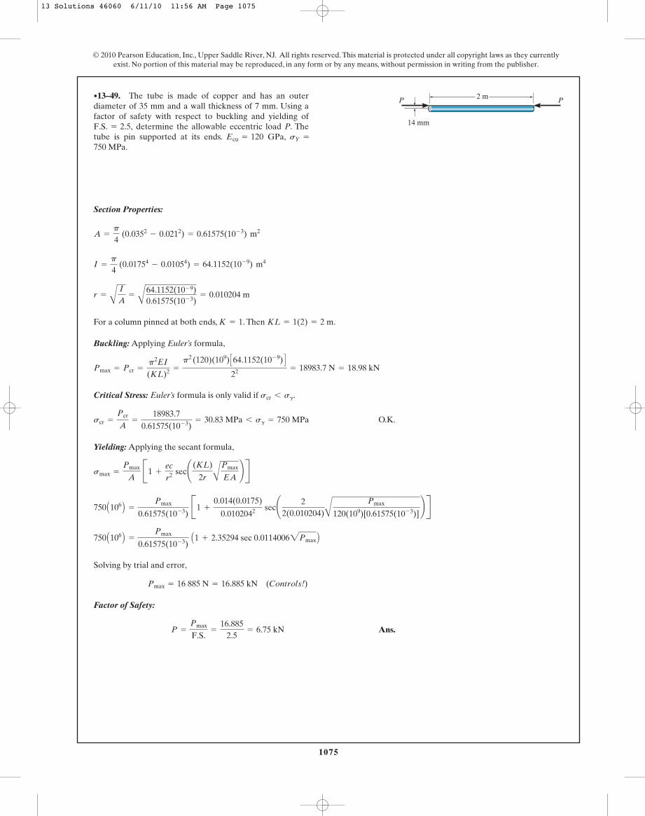
•13–49. The tube is made of copper and has an outerdiameter of 35 mm and a wall thickness of 7 mm. Using afactor of safety with respect to buckling and yielding of
determine the allowable eccentric load P. Thetube is pin supported at its ends. GPa,750 MPa.
sY =Ecu = 120F.S. = 2.5,
2 m
14 mm
P P
Solving by trial and error,
Factor of Safety:
Ans.P =
Pmax
F.S.=
16.8852.5
= 6.75 kN
Pmax = 16 885 N = 16.885 kN (Controls!)
750 A106 B =
Pmax
0.61575(10- 3) A1 + 2.35294 sec 0.01140062Pmax B
750 A106 B =
Pmax
0.61575(10- 3) B1 +
0.014(0.0175)
0.0102042 sec¢ 22(0.010204)A
Pmax
120(109)[0.61575(10- 3)]≤ R
13 Solutions 46060 6/11/10 11:56 AM Page 1075
1076
Section Properties:
s
For a column fixed at both ends, . Then .
Buckling: Applying Euler’s formula,
Critical Stress: Euler’s formula is only valid if .
O. K.
Yielding: Applying the secant formula,
smax =
Pmax
A B1 +
ec
r 2 sec¢ (KL)
2r A
Pmax
EA≤ R
scr =
Pcr
A=
75 935.00.61575(10- 3)
= 123.3 MPa 6 sg = 750 MPa
scr 6 sg
Pmax = Pcr =
p2EI
(KL)2 =
p2(120)(109) C64.1152(10- 9) D12 = 75 935.0 N = 75.93 kN
KL = 0.5(2) = 1 mK = 0.5
r =
A
I
A=
A
64.1152(10- 9)0.61575(10- 3)
= 0.010204 m
I =
p
4 A0.01754
- 0.01054 B = 64.1152 A10- 9 B m4
A =
p
4 A0.0352
- 0.0212 B = 0.61575 A10- 3 B m2
© 2010 Pearson Education, Inc., Upper Saddle River, NJ. All rights reserved. This material is protected under all copyright laws as they currentlyexist. No portion of this material may be reproduced, in any form or by any means, without permission in writing from the publisher.
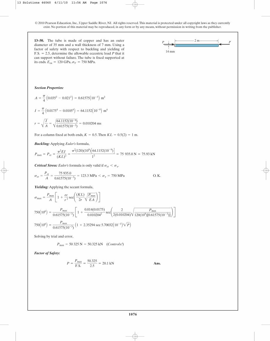
13–50. The tube is made of copper and has an outerdiameter of 35 mm and a wall thickness of 7 mm. Using afactor of safety with respect to buckling and yielding of
determine the allowable eccentric load P that itcan support without failure. The tube is fixed supported atits ends. GPa, MPa.sY = 750Ecu = 120
F.S. = 2.5,
2 m
14 mm
P P
Solving by trial and error,
Factor of Safety:
Ans.P =
Pmax
F.S.=
50.3252.5
= 20.1 kN
Pmax = 50 325 N = 50.325 kN (Controls!)
750 A106 B =
Pmax
0.61575(10- 3) A1 + 2.35294 sec 5.70032 A10- 3 B2P B
750 A106 B =
Pmax
0.61575(10- 3) B1 +
0.014(0.0175)
0.0102042 sec¢ 22(0.010204)A
Pmax
120(109)[0.61575(10- 3)]≤ R
13 Solutions 46060 6/11/10 11:56 AM Page 1076

1077
© 2010 Pearson Education, Inc., Upper Saddle River, NJ. All rights reserved. This material is protected under all copyright laws as they currentlyexist. No portion of this material may be reproduced, in any form or by any means, without permission in writing from the publisher.
Section Properties:
A = 10(4) = 40 in2 Iy =
112
(4)(103) = 333.33 in4 Ix =
112
(10)(43) = 53.33 in4
13–51. The wood column is fixed at its base and can beassumed pin connected at its top. Determine the maximumeccentric load P that can be applied without causing thecolumn to buckle or yield. sY = 8 ksi.Ew = 1.811032 ksi,
P
10 ft
10 in.
4 in.x
y
P
x
y
Buckling about axis:
Check: O.K.
Yielding about axis:
By trial and error:
Ans.P = 73.5 kip (controls)
8(40) = P[1 + 3.0 sec (0.0542212P)]
aKL
2rbA
P
EA=
0.7(10)(12)
2(2.8868) A
P
1.8(103)(40)= 0.0542212P
ec
r2 =
5(5)
2.88682 = 3.0
smax =
P
A a1 +
ec
r2 secaKL
2rbA
P
EAb
y-y
scr =
Pcr
A=
13440
= 3.36 ksi 6 sg
P = Pcr =
p2EI
(KL)2 =
p2(1.8)(103)(53.33)
[(0.7)(10)(12)]2 = 134 kip
x-x
ry =
A
Ix
A=
A
333.3340
= 2.8868 in.
13 Solutions 46060 6/11/10 11:56 AM Page 1077

1078
© 2010 Pearson Education, Inc., Upper Saddle River, NJ. All rights reserved. This material is protected under all copyright laws as they currentlyexist. No portion of this material may be reproduced, in any form or by any means, without permission in writing from the publisher.
Section Properties:
Buckling about axis:
Check: O.K.
Yielding about axis:
By trial and error:
Ans.P = 76.5 kip (controls)
8(40) = P[1 + 3.0 sec (0.0387292P)]
aKL
2rbA
P
EA=
0.5(10)(12)
2(2.8868) A
P
1.8(103)(40)= 0.0387292P
ec
r2 =
5(5)
2.88682 = 3.0
smax =
P
A a1 +
ec
r2 secaKL
2r A
P
EAb b
y-y
scr =
Pcr
A=
26340
= 6.58 ksi 6 sg
P = Pcr =
p2EI
(KL)2 =
p2(1.8)(103)(53.33)
[(0.5)(10)(12)]2 = 263 kip
x-x
ry =
A
Iy
A=
A
333.3340
= 2.8868 in.
A = 10(4) = 40 in2 Iy =
112
(4)(103) = 333.33 in4 Ix =
112
(10)(43) = 53.33 in4
*13–52. The wood column is fixed at its base and canbe assumed fixed connected at its top. Determine themaximum eccentric load P that can be applied withoutcausing the column to buckle or yield.sY = 8 ksi.
Ew = 1.811032 ksi,
P
10 ft
10 in.
4 in.x
y
P
x
y
13 Solutions 46060 6/11/10 11:56 AM Page 1078
1079
© 2010 Pearson Education, Inc., Upper Saddle River, NJ. All rights reserved. This material is protected under all copyright laws as they currentlyexist. No portion of this material may be reproduced, in any form or by any means, without permission in writing from the publisher.
Section Properties. From the table listed in the appendix, the necessary sectionproperties for a are
Buckling About the Strong Axis. Since the column is fixed at the base and free atthe top, . Applying Euler’s formula,
Euler’s formula is valid if .
O.K.
Then,
Yielding About Weak Axis. Since the support provided by the bracing can beconsidered a pin connection, the upper portion of the column is pinned at both of itsends. Then and . Applying the secant formula,
Solving by trial and error,
Then,
Ans.Pallow =
Pmax
1.5=
39.3761.5
= 26.3 kN (controls)
Pmax = 39.376 kN
250 A106 B =
Pmax
2.86 A10- 3 B c1 + 10.2556 sec 4.6875 A10- 3 B2Pmax d
250 A106 B =
Pmax
2.86 A10- 3 B D1 +
0.1(0.051)
0.02232 secC 1(5)
2(0.0223)APmax
200 A109 B C2.86 A10- 3 B D S T
smax =
Pmax
A C1 +
ec
ry 2 secB AKL By
2ry A
Pmax
EAR S
L = 5 mKy = 1
Pallow =
Pcr
F.S.=
98.702
= 49.35 kN
scr =
Pcr
A=
98.70 A103 B2.86 A10- 3 B = 34.51 MPa 6 sY = 250MPa
scr 6 sY
Pcr =
p2EIx
(KL)x 2 =
p2 c200 A109 B d c20.0 A10- 6 B d[2(10)]2 = 98.70kN
Kx = 2
e = 0.1m
Ix = 20.0 A106 B mm4= 20.0 A10- 6 Bm4 c =
bf
2=
1022
= 51 mm = 0.051 m
A = 2860 mm2= 2.86 A10- 3 B m2 ry = 22.3 mm = 0.0223 m
W200 * 22
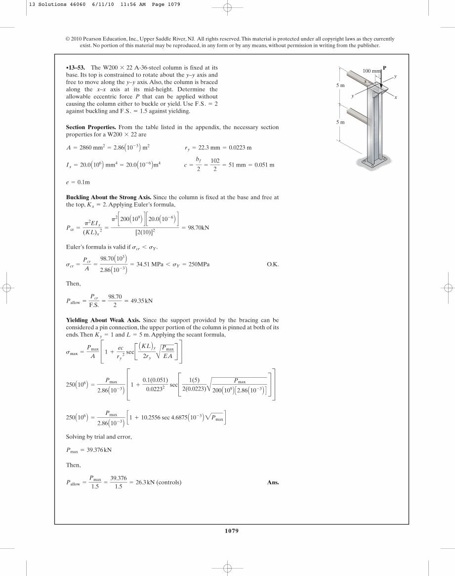
•13–53. The A-36-steel column is fixed at itsbase. Its top is constrained to rotate about the y–y axis andfree to move along the y–y axis. Also, the column is bracedalong the x–x axis at its mid-height. Determine theallowable eccentric force P that can be applied withoutcausing the column either to buckle or yield. Use against buckling and against yielding.F.S. = 1.5
F.S. = 2
W200 * 22
x
xy
y
P
5 m
5 m
100 mm
13 Solutions 46060 6/11/10 11:56 AM Page 1079

1080
© 2010 Pearson Education, Inc., Upper Saddle River, NJ. All rights reserved. This material is protected under all copyright laws as they currentlyexist. No portion of this material may be reproduced, in any form or by any means, without permission in writing from the publisher.
Section Properties. From the table listed in the appendix, necessary sectionproperties for a are
Buckling About the Strong Axis. Since the column is fixed at the base and free atthe top, . Applying Euler’s formula,
Euler’s formula is valid only if .
O.K.
Since , the column does not buckle.
Yielding About Weak Axis. Since the support provided by the bracing can beconsidered a pin connection, the upper portion of the column is pinned at both of itsends. Then and . Applying the secant formula,
Ans.
Since , the column does not yield.smax 6 sY = 250 MPa
= 130.26 MPa = 130 MPa
=
2.5 A103 B2.86 A10- 3 B D1 +
0.1(0.051)
0.02232 secC 1(5)
2(0.0223)C
25 A103 B200 A109 B C2.86 A10- 3 B D S T
smax =
P
A C1 +
ec
ry 2 secB (KL)
2ry A
P
EAR S
L = 5 mKy = 1
P = 25 kN 6 Pcr
scr =
Pcr
A=
98.70 A103 B2.86 A10- 3 B = 34.51 MPa 6 sY = 250 MPa
scr 6 sY
Pcr =
p2EIx
(KL)x 2 =
p2 c200 A109 B d c20.0 A10- 6 B d[2(10)]2 = 98.70kN
Kx = 2
e = 0.1m
Ix = 20.0 A106 B mm4= 20.0 A10- 6 Bm4 c =
bf
2=
1022
= 51 mm = 0.051 m
A = 2860 mm2= 2.86 A10- 3 B m2 ry = 22.3 mm = 0.0223 m
W200 * 22
13–54. The A-36-steel column is fixed at itsbase. Its top is constrained to rotate about the y–y axis andfree to move along the y–y axis. Also, the column is bracedalong the x–x axis at its mid-height. If determine the maximum normal stress developed in thecolumn.
P = 25 kN,
W200 * 22
x
xy
y
P
5 m
5 m
100 mm
13 Solutions 46060 6/11/10 11:56 AM Page 1080

1081
© 2010 Pearson Education, Inc., Upper Saddle River, NJ. All rights reserved. This material is protected under all copyright laws as they currentlyexist. No portion of this material may be reproduced, in any form or by any means, without permission in writing from the publisher.
Section Properties.
For a column that is fixed at one end and pinned at the other . Then,
Buckling About the Weak Axis. Applying Euler’s formula,
Euler’s formula is valid if .
O.K.
Since , the column will not buckle.
Yielding About Strong Axis. Applying the secant formula.
Since , the column will not yield. Ans.smax 6 sY = 15 MPa
= 10.29 MPa
=
10 A103 B7.5 A10- 3 B D1 +
0.15(0.075)
0.043302 secC 3.52(0.04330)
C
10 A103 B10 A109 B C7.5 A10- 3 B D S T
smax =
P
A C1 +
ec
rx 2 secB (KL)x
2rx A
P
EAR S
Pcr 7 P = 10 kN
scr =
Pcr
A=
12.59 A103 B7.5 A10- 3 B = 1.68 MPa 6 sY = 15 MPa
scr 6 sY
Pcr =
p2EIy
(KL)y 2 =
p2 C10 A109 B D C1.5625 A10- 6 B D3.52 = 12.59 kN
(KL)x = (KL)y = 0.7(5) = 3.5 m
K = 0.7
e = 0.15 m c = 0.075 m
Iy =
112
(0.15) A0.053 B = 1.5625 A10- 6 Bm4
rx =
A
Ix
A=
C
14.0625 A10- 6 B7.5 A10- 3 B = 0.04330 m
Ix =
112
(0.05) A0.153 B = 14.0625 A10- 6 B m4
A = 0.05(0.15) = 7.5 A10- 3 B m2
13–55. The wood column is fixed at its base, and its topcan be considered pinned. If the eccentric force is applied to the column, investigate whether the columnis adequate to support this loading without buckling oryielding. Take and sY = 15 MPa.E = 10 GPa
P = 10 kNP
5 m
150 mmx
75 mm 75 mm
25 mm
25 mmxy
13 Solutions 46060 6/11/10 11:56 AM Page 1081

1082
Section Properties.
For a column that is fixed at one end and pinned at the other . Then,
Buckling About the Weak Axis. Applying Euler’s formula,
Ans.
Euler’s formula is valid if .
O.K.
Yielding About Strong Axis. Applying the secant formula with ,
O.K. = 13.31 MPa 6 sY = 15 MPa
=
12.59 A103 B7.5 A10- 3 B D1 +
0.15(0.075)
0.043302 secC 3.52(0.04330)
C
12.59 A103 B B10 A109 B C7.5 A10- 3 B D S T
smax =
P
A C B1 +
ec
rx 2 secB (KL)x
2rx A
P
EAR S
P = Pcr = 12.59 kN
scr =
Pcr
A=
12.59 A103 B7.5 A10- 3 B = 1.68 MPa 6 sY = 15 MPa
scr 6 sY
Pcr =
p2EIy
(KL)y 2 =
p2 C10 A109 B D C1.5625 A10- 6 B D3.52 = 12.59 kN = 12.6 kN
(KL)x = (KL)y = 0.7(5) = 3.5 m
K = 0.7
e = 0.15 m c = 0.075 m
Iy =
112
(0.15) A0.053 B = 1.5625 A10- 6 Bm4
rx =
AIx
A= C
14.0625 A10- 6 B7.5 A10- 3 B = 0.04330 m
Ix =
112
(0.05) A0.153 B = 14.0625 A10- 6 B m4
A = 0.05(0.15) = 7.5 A10- 3 B m2
© 2010 Pearson Education, Inc., Upper Saddle River, NJ. All rights reserved. This material is protected under all copyright laws as they currentlyexist. No portion of this material may be reproduced, in any form or by any means, without permission in writing from the publisher.
*13–56. The wood column is fixed at its base, and itstop can be considered pinned. Determine the maximumeccentric force P the column can support without causing it to either buckle or yield. Take and sY = 15 MPa.
E = 10 GPa
P
5 m
150 mmx
75 mm 75 mm
25 mm
25 mmxy
13 Solutions 46060 6/11/10 11:56 AM Page 1082

1083
© 2010 Pearson Education, Inc., Upper Saddle River, NJ. All rights reserved. This material is protected under all copyright laws as they currentlyexist. No portion of this material may be reproduced, in any form or by any means, without permission in writing from the publisher.
Section Properties. From the table listed in the appendix, necessary sectionproperties for a are
Buckling About the Strong Axis. Since the column is fixed at the base and pinned atthe top, . Applying Euler’s formula,
Euler’s formula is valid only if .
O.K.
Thus,
Yielding About Strong Axis. Since the column is fixed at its base and free at its top,. Applying the secant formula,
Solving by trial and error,
Then,
Ans.Pallow =
Pmax
1.5=
133.451.5
= 88.97 kN = 89.0 kN (controls)
Pmax = 133.45 kN
250 A106 B =
Pmax
3.62 A10- 3 B A1 + 4.1270 sec (0.0021237)2Pmax B
250 A106 B =
Pmax
3.62 A10- 3 B D1 +
0.35(0.13)
0.1052 secC 2(6)
2(0.105)A
Pmax
200 A109 B C3.62 A10- 3 B D S T
smax =
Pmax
A C1 +
ec
rx 2 secB (KL)x
2rx A
Pmax
EAR S
Kx = 2
Pallow =
Pcr
F.S.=
199.182
= 99.59 kN
scr =
Pcr
A=
199.18 A103 B3.62 A10- 3 B = 55.02 MPa 6 sY = 250 MPa
scr 6 sY
Pcr =
p2EIy
(KL)y 2 =
p2 C200 A109 B D C1.78 A10- 6 B D[0.7(6)]2 = 199.18 kN
Kx = 0.7
e = 0.35 m
Iy = 1.78 A106 Bmm4= 1.78 A10- 6 Bm4 c =
d
2=
2602
= 130 mm = 0.13 m
A = 3620 mm2= 3.62 A10- 3 B m2 rx = 105 mm = 0.105 m
W250 * 28
•13–57. The A-36-steel column is fixed at itsbase. Its top is constrained to rotate about the y–y axis andfree to move along the y–y axis. If determinethe allowable eccentric force P that can be applied withoutcausing the column either to buckle or yield. Use against buckling and against yielding.F.S. = 1.5
F.S. = 2
e = 350 mm,
W250 * 28
x
xy
y
P
6 m
e
13 Solutions 46060 6/11/10 11:56 AM Page 1083
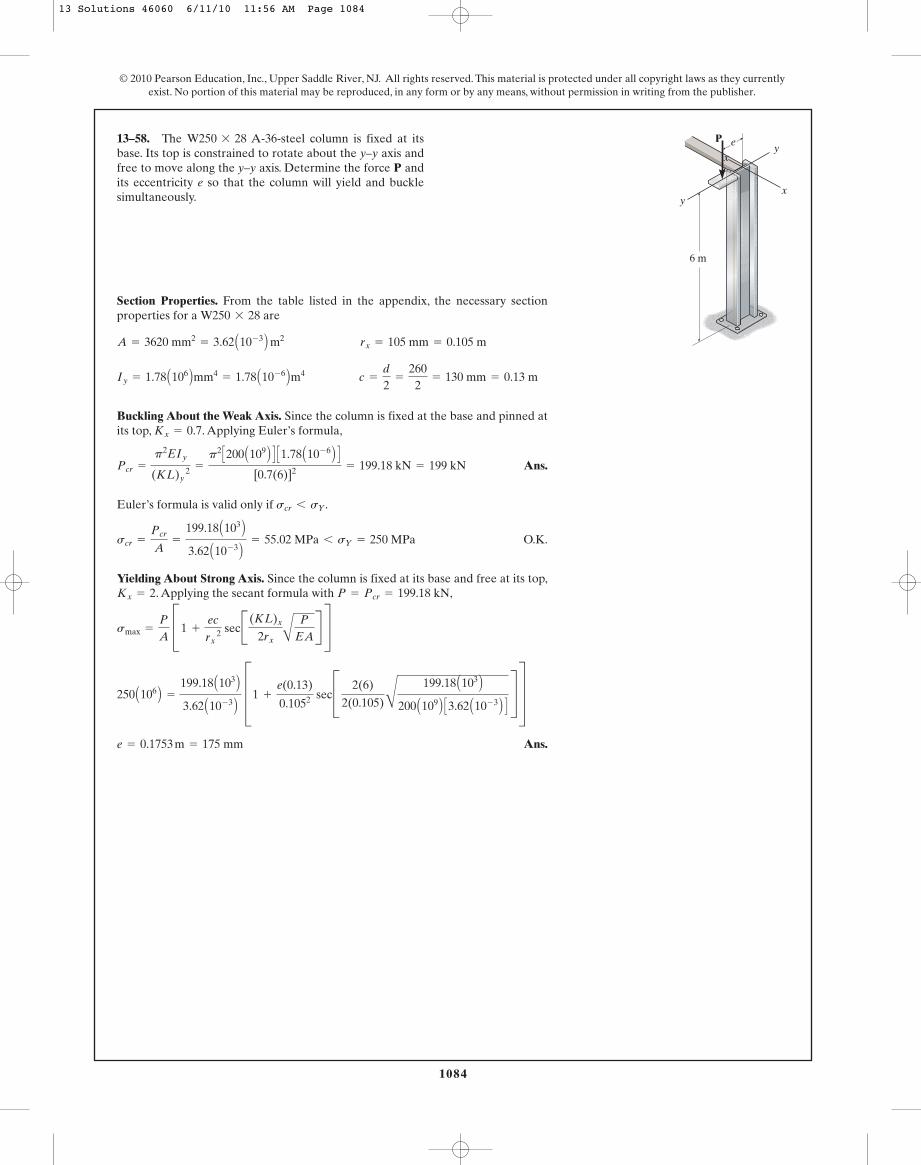
1084
© 2010 Pearson Education, Inc., Upper Saddle River, NJ. All rights reserved. This material is protected under all copyright laws as they currentlyexist. No portion of this material may be reproduced, in any form or by any means, without permission in writing from the publisher.
Section Properties. From the table listed in the appendix, the necessary sectionproperties for a are
Buckling About the Weak Axis. Since the column is fixed at the base and pinned atits top, . Applying Euler’s formula,
Ans.
Euler’s formula is valid only if .
O.K.
Yielding About Strong Axis. Since the column is fixed at its base and free at its top,. Applying the secant formula with ,
Ans.e = 0.1753 m = 175 mm
250 A106 B =
199.18 A103 B3.62 A10- 3 B D1 +
e(0.13)
0.1052 secC 2(6)
2(0.105)C
199.18 A103 B200 A109 B C3.62 A10- 3 B D S T
smax =
P
A C1 +
ec
rx 2 secB (KL)x
2rx A
P
EAR S
P = Pcr = 199.18 kNKx = 2
scr =
Pcr
A=
199.18 A103 B3.62 A10- 3 B = 55.02 MPa 6 sY = 250 MPa
scr 6 sY
Pcr =
p2EIy
(KL)y 2 =
p2 C200 A109 B D C1.78 A10- 6 B D[0.7(6)]2 = 199.18 kN = 199 kN
Kx = 0.7
Iy = 1.78 A106 Bmm4= 1.78 A10- 6 Bm4 c =
d
2=
2602
= 130 mm = 0.13 m
A = 3620 mm2= 3.62 A10- 3 B m2 rx = 105 mm = 0.105 m
W250 * 28
13–58. The A-36-steel column is fixed at itsbase. Its top is constrained to rotate about the y–y axis andfree to move along the y–y axis. Determine the force P andits eccentricity e so that the column will yield and bucklesimultaneously.
W250 * 28
x
xy
y
P
6 m
e
13 Solutions 46060 6/11/10 11:56 AM Page 1084
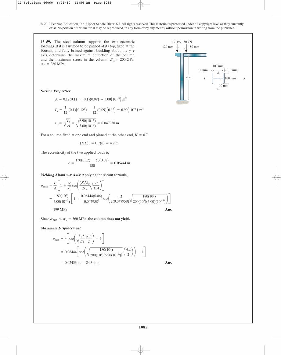
1085
© 2010 Pearson Education, Inc., Upper Saddle River, NJ. All rights reserved. This material is protected under all copyright laws as they currentlyexist. No portion of this material may be reproduced, in any form or by any means, without permission in writing from the publisher.
Section Properties:
For a column fixed at one end and pinned at the other end, .
The eccentricity of the two applied loads is,
Yielding About x–x Axis: Applying the secant formula,
Ans.
Since , the column does not yield.
Maximum Displacement:
Ans. = 0.02433 m = 24.3 mm
= 0.06444Bsec¢A
180(103)
200(109)[6.90(10- 6)] a4.2
2b ≤ - 1R
ymax = eBsec¢A
P
EI KL
2≤ - 1R
smax 6 sg = 360 MPa
= 199 MPa
=
180(103)
3.00(10- 3) B1 +
0.06444(0.06)
0.0479582 sec¢ 4.22(0.047958)A
180(103)200(109)(3.00)(10- 3)
≤ R
smax =
P
A B1 +
ec
rx2 sec¢ (KL)x
2rx A
P
EA≤ R
e =
130(0.12) - 50(0.08)
180= 0.06444 m
(KL)x = 0.7(6) = 4.2 m
K = 0.7
rx =
AIx
A=
A6.90(10- 6)3.00(10- 3)
= 0.047958 m
Ix =
112
(0.1) A0.123 B -
112
(0.09) A0.13 B = 6.90 A10- 6 B m4
A = 0.12(0.1) - (0.1)(0.09) = 3.00 A10- 3 B m2
13–59. The steel column supports the two eccentricloadings. If it is assumed to be pinned at its top, fixed at thebottom, and fully braced against buckling about the y–yaxis, determine the maximum deflection of the columnand the maximum stress in the column.sY = 360 MPa.
Est = 200 GPa,
50 kN
80 mm
6 m
120 mm130 kN
100 mm
10 mm
10 mm10 mm100 mm
y y
x
x
13 Solutions 46060 6/11/10 11:56 AM Page 1085
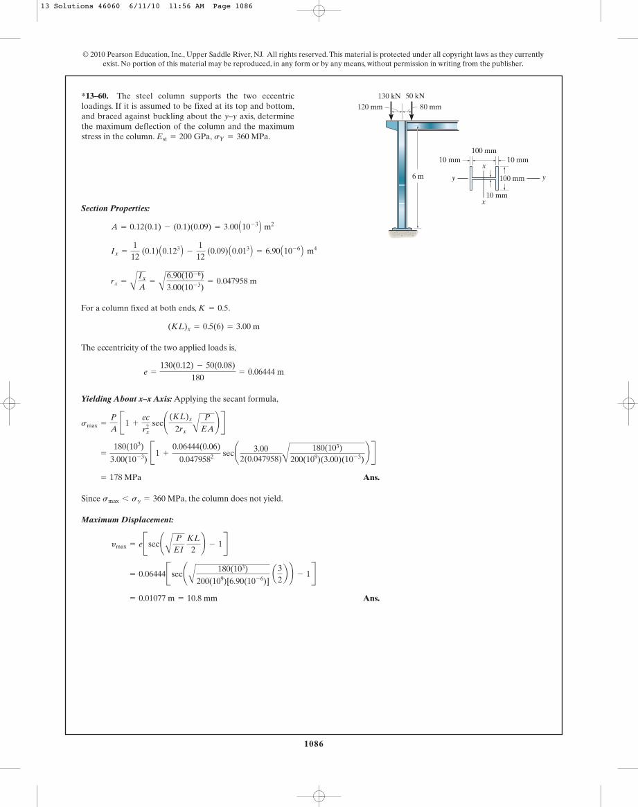
1086
© 2010 Pearson Education, Inc., Upper Saddle River, NJ. All rights reserved. This material is protected under all copyright laws as they currentlyexist. No portion of this material may be reproduced, in any form or by any means, without permission in writing from the publisher.
Section Properties:
For a column fixed at both ends, .
The eccentricity of the two applied loads is,
Yielding About x–x Axis: Applying the secant formula,
Ans.
Since , the column does not yield.
Maximum Displacement:
Ans. = 0.01077 m = 10.8 mm
= 0.06444Bsec¢A
180(103)
200(109)[6.90(10- 6)] a3
2b ≤ - 1R
ymax = eBsec¢A
P
EI KL
2≤ - 1R
smax 6 sg = 360 MPa
= 178 MPa
=
180(103)
3.00(10- 3) B1 +
0.06444(0.06)
0.0479582 sec¢ 3.002(0.047958)A
180(103)200(109)(3.00)(10- 3)
≤ R
smax =
P
A B1 +
ec
rx2 sec¢ (KL)x
2rx A
P
EA≤ R
e =
130(0.12) - 50(0.08)
180= 0.06444 m
(KL)x = 0.5(6) = 3.00 m
K = 0.5
rx =
AIx
A=
A
6.90(10- 6)3.00(10- 3)
= 0.047958 m
Ix =
112
(0.1) A0.123 B -
112
(0.09) A0.013 B = 6.90 A10- 6 B m4
A = 0.12(0.1) - (0.1)(0.09) = 3.00 A10- 3 B m2
*13–60. The steel column supports the two eccentricloadings. If it is assumed to be fixed at its top and bottom,and braced against buckling about the y–y axis, determinethe maximum deflection of the column and the maximumstress in the column. sY = 360 MPa.Est = 200 GPa,
50 kN
80 mm
6 m
120 mm130 kN
100 mm
10 mm
10 mm10 mm100 mm
y y
x
x
13 Solutions 46060 6/11/10 11:56 AM Page 1086

1087
© 2010 Pearson Education, Inc., Upper Saddle River, NJ. All rights reserved. This material is protected under all copyright laws as they currentlyexist. No portion of this material may be reproduced, in any form or by any means, without permission in writing from the publisher.
Section Properties. From the table listed in the appendix, the necessary sectionproperties for a are
The eccentricity of the equivalent force is
Buckling About the Weak Axis. The column is braced along the weak axis atmidheight and the support provided by the bracing can be considered as a pin. Thetop portion of the column is critical is since the top is pinned so and
Applying Euler’s formula,
Euler’s equation is valid only if .
O.K.
Then,
Since , the column does not buckle.
Yielding About Strong Axis. Since the column is fixed at its base and pinned at itstop, and . Applying the secant formula with
Since , the column does not yield.smax 6 sY = 250 MPa
= 231.84 MPa
=
468.75 A103 B5.70 A10- 3 B C1 +
0.15(0.133)
0.1122 secB 0.7(8)
2(0.112)C468.75 A103 B
200 A109 B C5.70 A10- 3 B D R S
smax =
Pmaxœ
AC1 +
ec
rx 2secB (KL)x
2rx A
Pmaxœ
EAR S
Pmaxœ
= P¿(F.S.) = 312.5(1.5) = 468.75 kNL = 8 mKx = 0.7
Pœ
allow 7 P¿
Pallowœ
=
Pcr
F.S.=
867.292
= 433.65 kN
scr =
Pcr
A=
867.29 A103 B5.70 A10- 3 B = 152.16 MPa 6 sY = 250 MPa
scr 6 sY
Pcr =
p2EIy
(KL)y 2 =
p2 C200 A109 B D C7.03 A10- 6 B D[1(4)]2 = 867.29 kN
L = 4 mKy = 1
e =
250(0.25) -
2504
(0.25)
250 +
2504
= 0.15 m
P¿ = 250 +
2504
= 312.5 kN
Iy = 7.03 A106 Bmm4= 7.03 A10- 6 Bm4 c =
d
2=
2662
= 133 mm = 0.133 m
A = 5700 mm2= 5.70 A10- 3 B m2 rx = 112 mm = 0.112 m
W250 * 45
13–61. The A-36-steel column is pinned at itstop and fixed at its base. Also, the column is braced alongits weak axis at mid-height. If investigatewhether the column is adequate to support this loading.Use against buckling and againstyielding.
F.S. = 1.5F.S. = 2
P = 250 kN,
W250 * 45
4 m
250 mm 250 mm
4 m
PP4
13 Solutions 46060 6/11/10 11:56 AM Page 1087
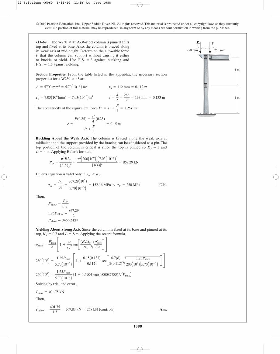
1088
Section Properties. From the table listed in the appendix, the necessary sectionproperties for a are
The eccentricity of the equivalent force is
Buckling About the Weak Axis. The column is braced along the weak axis atmidheight and the support provided by the bracing can be considered as a pin. Thetop portion of the column is critical is since the top is pinned so and
. Applying Euler’s formula,
Euler’s equation is valid only if .
O.K.
Then,
Yielding About Strong Axis. Since the column is fixed at its base and pinned at itstop, and . Applying the secant formula,
Solving by trial and error,
Then,
Ans.Pallow =
401.751.5
= 267.83 kN = 268 kN (controls)
Pmax = 401.75 kN
250 A106 B =
1.25Pmax
5.70 A10- 3 B A1 + 1.5904 sec (0.00082783)2Pmax B
250 A106 B =
1.25Pmax
5.70 A10- 3 B C1 +
0.15(0.133)
0.1122 sec B 0.7(8)
2(0.112)A1.25Pmax
200 A109 B C5.70 A10- 3 B D R S
smax =
Pmaxœ
A C1 +
ec
rx 2 secB (KL)x
2rx APmax
œ
EAR S
L = 8 mKx = 0.7
Pallow = 346.92 kN
1.25Pallow =
867.292
Pallowœ
=
Pcr
F.S.
scr =
Pcr
A=
867.29 A103 B5.70 A10- 3 B = 152.16 MPa 6 sY = 250 MPa
scr 6 sY
Pcr =
p2EIy
(KL)y 2 =
p2 C200 A109 B D C7.03 A10- 6 B D[1(4)]2 = 867.29 kN
L = 4 mKy = 1
e =
P(0.25) -
P
4 (0.25)
P +
P
4
= 0.15 m
P¿ = P +
P
4= 1.25P
Iy = 7.03 A106 Bmm4= 7.03 A10- 6 Bm4 c =
d
2=
2662
= 133 mm = 0.133 m
A = 5700 mm2= 5.70 A10- 3 B m2 rx = 112 mm = 0.112 m
W250 * 45
© 2010 Pearson Education, Inc., Upper Saddle River, NJ. All rights reserved. This material is protected under all copyright laws as they currentlyexist. No portion of this material may be reproduced, in any form or by any means, without permission in writing from the publisher.
•13–62. The A-36-steel column is pinned at itstop and fixed at its base. Also, the column is braced alongits weak axis at mid-height. Determine the allowable forceP that the column can support without causing it eitherto buckle or yield. Use against buckling and
against yielding.F.S. = 1.5F.S. = 2
W250 * 45
4 m
250 mm 250 mm
4 m
PP4
13 Solutions 46060 6/11/10 11:56 AM Page 1088
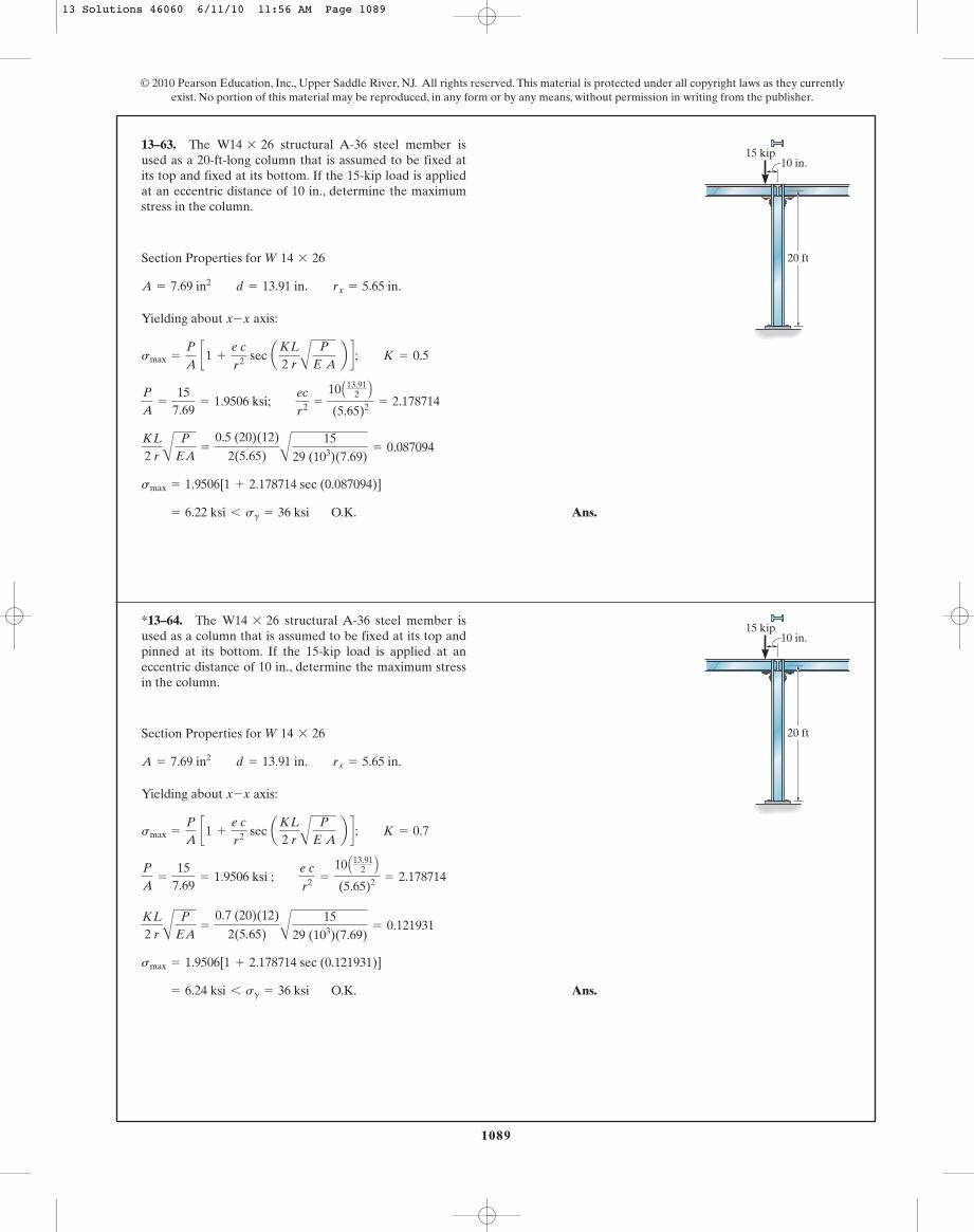
1089
© 2010 Pearson Education, Inc., Upper Saddle River, NJ. All rights reserved. This material is protected under all copyright laws as they currentlyexist. No portion of this material may be reproduced, in any form or by any means, without permission in writing from the publisher.
Section Properties for
Yielding about axis:
O.K. Ans. = 6.22 ksi 6 sg = 36 ksi
smax = 1.9506[1 + 2.178714 sec (0.087094)]
KL
2 r AP
EA=
0.5 (20)(12)
2(5.65) A
1529 (103)(7.69)
= 0.087094
P
A=
157.69
= 1.9506 ksi; ec
r2 =
10 A13.912 B
(5.65)2 = 2.178714
smax =
P
A c1 +
e cr2 sec aKL
2 r AP
E A b d ; K = 0.5
x-x
A = 7.69 in2 d = 13.91 in. rx = 5.65 in.
W 14 * 26
13–63. The structural A-36 steel member isused as a 20-ft-long column that is assumed to be fixed atits top and fixed at its bottom. If the 15-kip load is appliedat an eccentric distance of 10 in., determine the maximumstress in the column.
W14 * 2615 kip
10 in.
20 ft
Section Properties for
Yielding about axis:
O.K. Ans. = 6.24 ksi 6 sg = 36 ksi
smax = 1.9506[1 + 2.178714 sec (0.121931)]
KL
2 r AP
EA=
0.7 (20)(12)
2(5.65) A
1529 (103)(7.69)
= 0.121931
P
A=
157.69
= 1.9506 ksi ; e cr2 =
10 A13.912 B
(5.65)2 = 2.178714
smax =
P
A c1 +
e cr2 sec aKL
2 r AP
E A b d ; K = 0.7
x-x
A = 7.69 in2 d = 13.91 in. rx = 5.65 in.
W 14 * 26
*13–64. The structural A-36 steel member isused as a column that is assumed to be fixed at its top andpinned at its bottom. If the 15-kip load is applied at aneccentric distance of 10 in., determine the maximum stressin the column.
W14 * 2615 kip
10 in.
20 ft
13 Solutions 46060 6/11/10 11:56 AM Page 1089

1090
© 2010 Pearson Education, Inc., Upper Saddle River, NJ. All rights reserved. This material is protected under all copyright laws as they currentlyexist. No portion of this material may be reproduced, in any form or by any means, without permission in writing from the publisher.
Section Properties. The necessary section properties are
For a column that is pinned at both of its ends . Thus,
Buckling About the Weak Axis. Applying Euler’s formula,
Ans.
Critical Stress: Euler’s formula is valid only if .
O.K.
Yielding About Strong Axis. Applying the secant formula,
O.K. = 229.27 MPa 6 sY = 414 MPa
=
83.50 A103 B5 A10- 3 B D1 +
0.15(0.05)
0.028872 secC 32(0.02887)
C
83.50 A103 B73.1 A109 B C5 A10- 3 B D S T
smax =
P
A C1 +
ec
rx 2 secB (KL)x
2rx A
P
EAR S
scr =
Pcr
A=
83.50 A103 B5 A10- 3 B = 16.70 MPa 6 sY = 414 MPa
scr 6 sY
Pcr =
p2EIy
(KL)y 2 =
p2 C73.1 A109 B D C1.04167 A10- 6 B D32 = 83.50 kN = 83.5 kN
(KL)x = (KL)y = 1(3) = 3 m
K = 1
rx =
AIx
A= C
4.1667 A10- 6 B5 A10- 3 B = 0.02887 m
Iy =
112
(0.1) A0.053 B = 1.04167 A10- 6 B m4
A = 0.05(0.1) = 5 A10- 3 Bm2
•13–65. Determine the maximum eccentric load P the2014-T6-aluminum-alloy strut can support without causingit either to buckle or yield. The ends of the strut are pin-connected.
3 m
100 mm
150 mm
100 mm
50 mm
150 mma
a
P P
Section a – a
13 Solutions 46060 6/11/10 11:56 AM Page 1090

1091
© 2010 Pearson Education, Inc., Upper Saddle River, NJ. All rights reserved. This material is protected under all copyright laws as they currentlyexist. No portion of this material may be reproduced, in any form or by any means, without permission in writing from the publisher.
Section Properties: For a wide flange section ,
For a column fixed at one end and free at the other and, .
Buckling About y–y Axis: Applying Euler’s formula,
Critical Stress: Euler’s formula is only valid if .
O. K.
Yielding About x–x Axis: Applying the secant formula,
Solving by trial and error,
Factor of Safety:
Ans.F.S. =
Pmax
P=
117.075
= 1.56
Pmax = 117.0 kip (Controls!)
36(14.1) = Pmax A1 + 2.608943 sec 0.06238022Pmax B 36 =
Pmax
14.1 B1 +
8 A1.502 B
3.612 sec¢ 2882(3.61)A
Pmax
29.0(103)(14.1)≤ R
smax =
Pmax
A B1 +
ec
rx2 sec¢ (KL)x
2rx A
Pmax
EA≤ R
scr =
Pcr
A=
210.1514.1
= 14.90 ksi 6 sg = 36 ksi
scr 6 sg
= 210.15 kip
=
p2 (29.0)(103)(60.9)
2882
P = Pcr =
p2EIy
(KL)y2
(KL)y = (KL)x = 2(12)(12) = 288 in.
K = 2
A = 14.1 in2 rx = 3.61 in. Iy = 60.9 in4 d = 8.50 in.
W8 * 48
13–66. The structural A-36 steel column is fixedat its bottom and free at its top. If it is subjected to theeccentric load of 75 kip, determine the factor of safety withrespect to either the initiation of buckling or yielding.
W8 * 48
12 ft
8 in.y
y x
75 kip
13 Solutions 46060 6/11/10 11:56 AM Page 1091
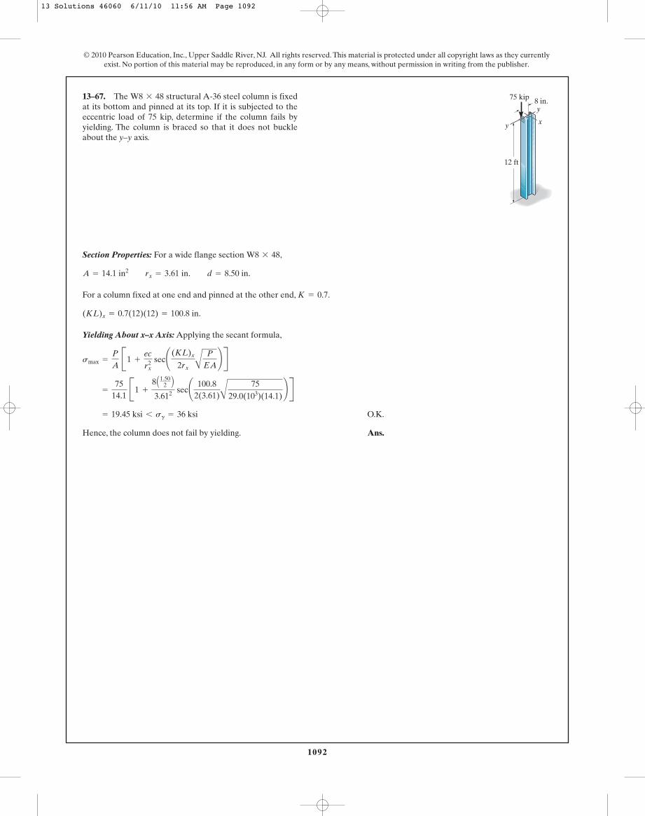
Section Properties: For a wide flange section ,
For a column fixed at one end and pinned at the other end, .
Yielding About x–x Axis: Applying the secant formula,
O.K.
Hence, the column does not fail by yielding. Ans.
= 19.45 ksi 6 sg = 36 ksi
=
7514.1
B1 +
8 A1.502 B
3.612 sec¢ 100.82(3.61)A
7529.0(103)(14.1)
≤ R
smax =
P
A B1 +
ec
rx2 sec¢ (KL)x
2rx A
P
EA≤ R
(KL)x = 0.7(12)(12) = 100.8 in.
K = 0.7
A = 14.1 in2 rx = 3.61 in. d = 8.50 in.
W8 * 48
13–67. The structural A-36 steel column is fixedat its bottom and pinned at its top. If it is subjected to theeccentric load of 75 kip, determine if the column fails byyielding. The column is braced so that it does not buckleabout the y–y axis.
W8 * 48
1092
© 2010 Pearson Education, Inc., Upper Saddle River, NJ. All rights reserved. This material is protected under all copyright laws as they currentlyexist. No portion of this material may be reproduced, in any form or by any means, without permission in writing from the publisher.
12 ft
8 in.y
y x
75 kip
13 Solutions 46060 6/11/10 11:56 AM Page 1092
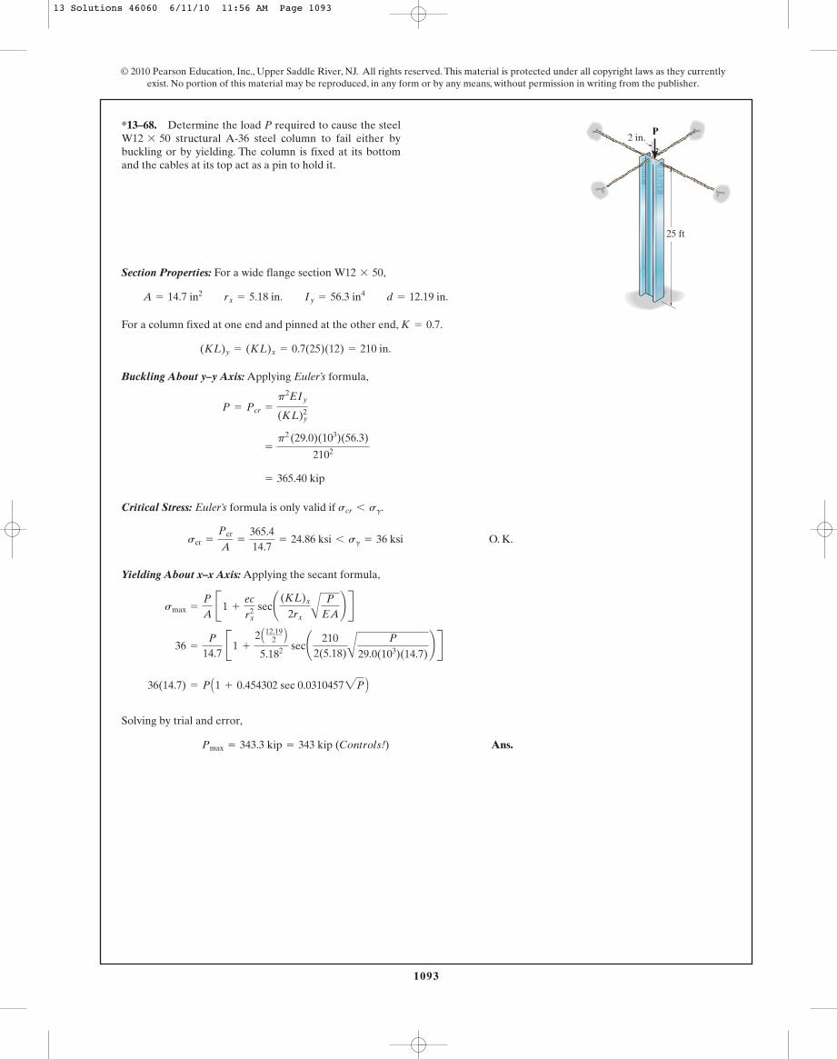
1093
© 2010 Pearson Education, Inc., Upper Saddle River, NJ. All rights reserved. This material is protected under all copyright laws as they currentlyexist. No portion of this material may be reproduced, in any form or by any means, without permission in writing from the publisher.
Section Properties: For a wide flange section ,
For a column fixed at one end and pinned at the other end, .
Buckling About y–y Axis: Applying Euler’s formula,
Critical Stress: Euler’s formula is only valid if .
O. K.
Yielding About x–x Axis: Applying the secant formula,
Solving by trial and error,
Ans.Pmax = 343.3 kip = 343 kip (Controls!)
36(14.7) = P A1 + 0.454302 sec 0.03104572P B
36 =
P
14.7 B1 +
2 A12.192 B
5.182 sec¢ 2102(5.18)A
P
29.0(103)(14.7)≤ R
smax =
P
A B1 +
ec
rx2 sec¢ (KL)x
2rx A
P
EA≤ R
scr =
Pcr
A=
365.414.7
= 24.86 ksi 6 sg = 36 ksi
scr 6 sg
= 365.40 kip
=
p2 (29.0)(103)(56.3)
2102
P = Pcr =
p2EIy
(KL)y2
(KL)y = (KL)x = 0.7(25)(12) = 210 in.
K = 0.7
A = 14.7 in2 rx = 5.18 in. Iy = 56.3 in4 d = 12.19 in.
W12 * 50
*13–68. Determine the load P required to cause the steelstructural A-36 steel column to fail either by
buckling or by yielding. The column is fixed at its bottomand the cables at its top act as a pin to hold it.
W12 * 50
25 ft
2 in.P
13 Solutions 46060 6/11/10 11:56 AM Page 1093
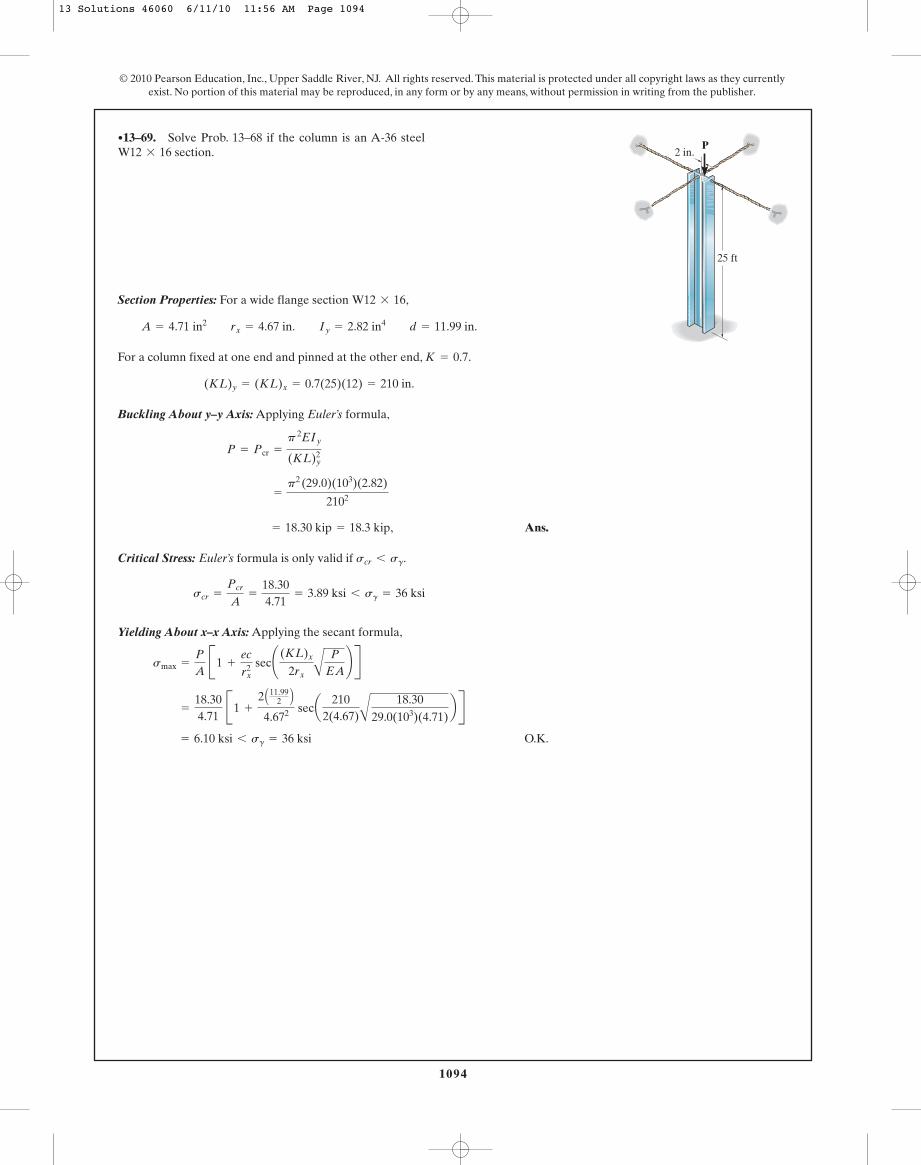
Section Properties: For a wide flange section ,
For a column fixed at one end and pinned at the other end, .
Buckling About y–y Axis: Applying Euler’s formula,
‚ Ans.
Critical Stress: Euler’s formula is only valid if .
Yielding About x–x Axis: Applying the secant formula,
O.K. = 6.10 ksi 6 sg = 36 ksi
=
18.304.71
B1 +
2 A11.992 B
4.672 seca 2102(4.67)A
18.3029.0(103)(4.71)
b R
smax =
P
A B1 +
ec
rx2 sec¢ (KL)x
2rx A
P
EA≤ R
scr =
Pcr
A=
18.304.71
= 3.89 ksi 6 sg = 36 ksi
scr 6 sg
= 18.30 kip = 18.3 kip
=
p2 (29.0)(103)(2.82)
2102
P = Pcr =
p 2EIy
(KL)y2
(KL)y = (KL)x = 0.7(25)(12) = 210 in.
K = 0.7
A = 4.71 in2 rx = 4.67 in. Iy = 2.82 in4 d = 11.99 in.
W12 * 16
•13–69. Solve Prob. 13–68 if the column is an A-36 steelsection.W12 * 16
1094
© 2010 Pearson Education, Inc., Upper Saddle River, NJ. All rights reserved. This material is protected under all copyright laws as they currentlyexist. No portion of this material may be reproduced, in any form or by any means, without permission in writing from the publisher.
25 ft
2 in.P
13 Solutions 46060 6/11/10 11:56 AM Page 1094

1095
© 2010 Pearson Education, Inc., Upper Saddle River, NJ. All rights reserved. This material is protected under all copyright laws as they currentlyexist. No portion of this material may be reproduced, in any form or by any means, without permission in writing from the publisher.
‚ AnsEt = 14590 ksi = 14.6 (103) ksi
40 =
p2 Et
(60)2
scr =
p2 Et
AK Lr B2 ; aKL
rb = 60
13–70. A column of intermediate length buckles when thecompressive stress is 40 ksi. If the slenderness ratio is 60,determine the tangent modulus.
Section Properties: The neccessary section properties are
For the column pinned at both of its ends, . Thus,
Critical Stress. Applying Engesser’s equation,
(1)
From the stress - strain diagram, the tangent moduli are
Substituting into Eq. (1),
Since , elastic buckling occurs. Thus,
‚ Ans.Pcr = scr A = 19.92(5.5) = 109.57 kip = 110 kip
scr 6 sY = 25 ksi
scr = 0.7969 A10- 3 B c25 A103 B d = 19.92 ksi
(Et)1 = 25 A103 B(Et)2 =
(55 - 25) ksi
0.004 - 0.001= 10 A103 B (ksi) 25ksi 6 s … 40 ksi
(Et)1 =
25 ksi0.001
= 25 A103 Bksi 0 … s 6 25 ksi
scr =
p2Et
aKL
rb
=
p2Et
111.292 = 0.7969 A10- 3 BEt
KLry
=
1(6)(12)
0.6470= 111.29
K = 1
ry =
AIy
A=
A
2.30215.5
= 0.6470 in.
I = 2B 112
(0.5) A33 B R +
112
(5) A0.53 B = 2.3021 in4
A = 2[0.5(3)] + 5(0.5) = 5.5 in2
13–71. The 6-ft-long column has the cross section shownand is made of material which has a stress-strain diagramthat can be approximated as shown. If the column ispinned at both ends, determine the critical load for thecolumn.
Pcr
(ksi)
P (in./in.)
55
25
0.001 0.004
3 in.
5 in.0.5 in.
0.5 in.
0.5 in.
s
13 Solutions 46060 6/11/10 11:56 AM Page 1095
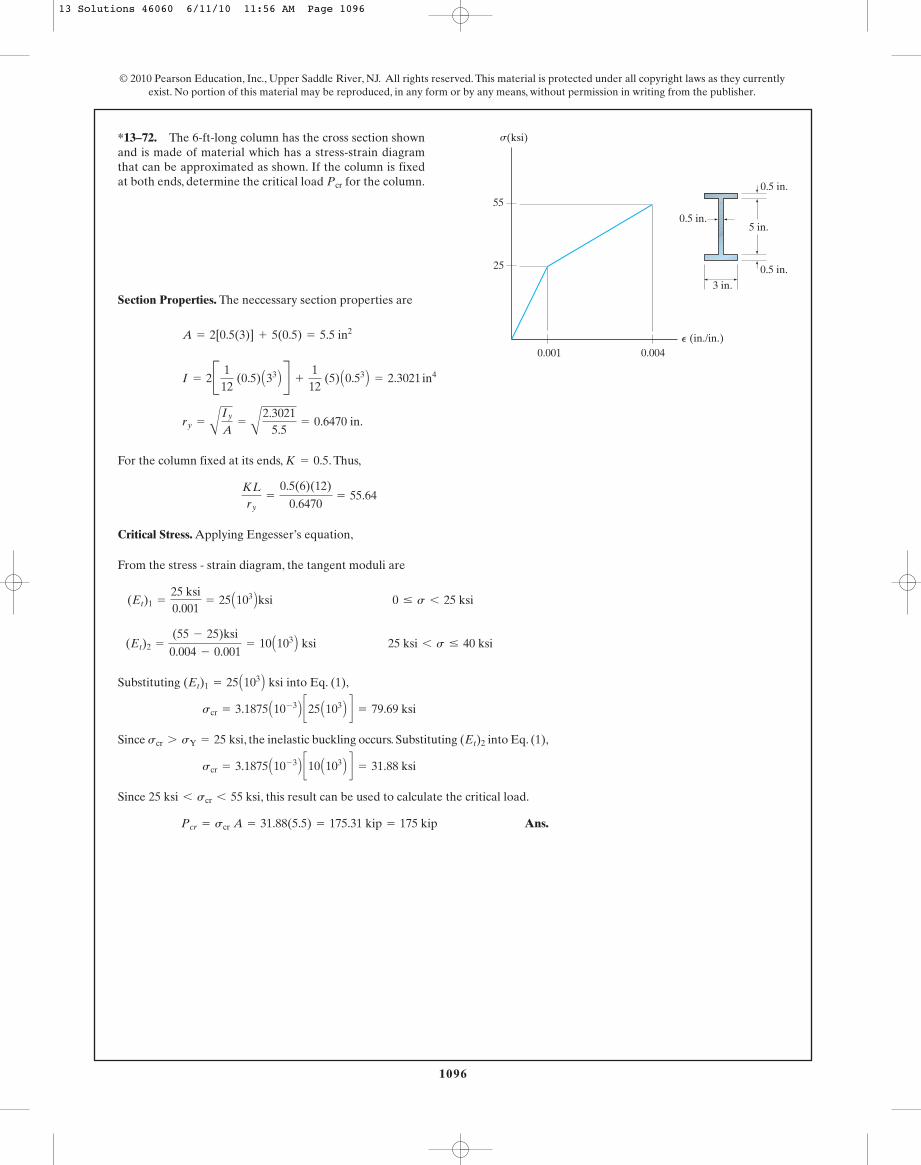
1096
© 2010 Pearson Education, Inc., Upper Saddle River, NJ. All rights reserved. This material is protected under all copyright laws as they currentlyexist. No portion of this material may be reproduced, in any form or by any means, without permission in writing from the publisher.
Section Properties. The neccessary section properties are
For the column fixed at its ends, . Thus,
Critical Stress. Applying Engesser’s equation,
From the stress - strain diagram, the tangent moduli are
Substituting into Eq. (1),
Since , the inelastic buckling occurs. Substituting into Eq. (1),
Since , this result can be used to calculate the critical load.
Ans.Pcr = scr A = 31.88(5.5) = 175.31 kip = 175 kip
25 ksi 6 scr 6 55 ksi
scr = 3.1875 A10- 3 B c10 A103 B d = 31.88 ksi
(Et)2scr 7 sY = 25 ksi
scr = 3.1875 A10- 3 B c25 A103 B d = 79.69 ksi
(Et)1 = 25 A103 B ksi
(Et)2 =
(55 - 25)ksi
0.004 - 0.001= 10 A103 B ksi 25 ksi 6 s … 40 ksi
(Et)1 =
25 ksi0.001
= 25 A103 Bksi 0 … s 6 25 ksi
KLry
=
0.5(6)(12)
0.6470= 55.64
K = 0.5
ry =
A
Iy
A=
A
2.30215.5
= 0.6470 in.
I = 2B 112
(0.5) A33 B R +
112
(5) A0.53 B = 2.3021 in4
A = 2[0.5(3)] + 5(0.5) = 5.5 in2
*13–72. The 6-ft-long column has the cross section shownand is made of material which has a stress-strain diagramthat can be approximated as shown. If the column is fixedat both ends, determine the critical load for the column.Pcr
(ksi)
P (in./in.)
55
25
0.001 0.004
3 in.
5 in.0.5 in.
0.5 in.
0.5 in.
s
13 Solutions 46060 6/11/10 11:56 AM Page 1096

1097
© 2010 Pearson Education, Inc., Upper Saddle River, NJ. All rights reserved. This material is protected under all copyright laws as they currentlyexist. No portion of this material may be reproduced, in any form or by any means, without permission in writing from the publisher.
•13–73. The stress-strain diagram of the material of acolumn can be approximated as shown. Plot P�A vs. KL�rfor the column.
P (in./in.)
200
350
0.0010 0.004
s (MPa)
Tangent Moduli. From the stress - strain diagram,
Critical Stress. Applying Engesser’s equation,
(1)
If , Eq. (1) becomes
when , this equation becomes
If , Eq. (1) becomes
when , this
equation gives
Using these results, the graphs of is shown in Fig. a can be plotted.P
A vs.
KLr
KLr
= 49.67 = 49.7
200 A106 B =
p2 C50 A109 B DaKL
rb2
scr =
P
A= sY = 200 MPa
P
A=
p2 c50 A109 B d¢KL
r≤2
=
0.4935 A106 B¢KL
r≤2
MPa
Et = (Et)2 = 50 GPa
KLr
= 99.346 = 99.3
200 A106 B =
p2 C200 A109 B DaKL
rb2
scr =
P
A= sY = 200 MPa
P
A=
p2 C200 A109 B DaKL
rb2 =
1.974 A106 BaKL
rb2 MPa
Et = (Et)1 = 200 GPa
scr P
A=
p2Et
aKLrb2
(Et)2 =
(350 - 200) A106 B0.004 - 0.001
= 50 GPa 200MPa 6 s … 350 MPa
(Et)1 =
200 A106 B0.001
= 200 GPa 0 … s 6 200MPa
13 Solutions 46060 6/11/10 11:56 AM Page 1097

1098
© 2010 Pearson Education, Inc., Upper Saddle River, NJ. All rights reserved. This material is protected under all copyright laws as they currentlyexist. No portion of this material may be reproduced, in any form or by any means, without permission in writing from the publisher.
Tangent modulus: From the stress–strain diagram,
Critical Stress: Applying Engesser’s equation,
[1]
Substituting into Eq. [1], we have
When ,
Substitute into Eq. [1], we have
When ,Lr
= 53.1P
A= 140 MPa
P
A=
0.395(106)
ALr B2 MPa
P
A=
p2 C40(109) DALr B2
(Et)2 = 40 GPa
Lr
= 99.3P
A= 140 MPa
P
A=
1.38(106)
ALr B2 MPa
P
A=
p2 C140(109) DALr B2
(Et)1 = 140 GPa
scr P
A=
p2Et
aLrb2
(Et)2 =
(260 - 140)(106)
0.004 - 0.001= 40 GPa
(Et)1 =
140(106)
0.001= 140 GPa
13–74. Construct the buckling curve, P�A versus L�r,for a column that has a bilinear stress–strain curve incompression as shown. The column is pinned at its ends.
0.001 0.004
140
260
s (MPa)
P (mm/mm)
13 Solutions 46060 6/11/10 11:56 AM Page 1098
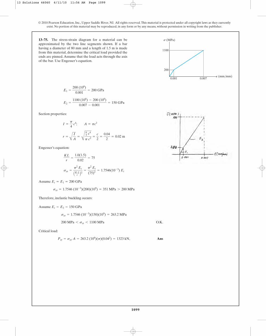
1099
© 2010 Pearson Education, Inc., Upper Saddle River, NJ. All rights reserved. This material is protected under all copyright laws as they currentlyexist. No portion of this material may be reproduced, in any form or by any means, without permission in writing from the publisher.
Section properties:
Engesser’s equation:
Assume
Therefore, inelastic buckling occurs:
Assume
O.K.
Critical load:
‚ AnsPcr = scr A = 263.2 (106)(p)(0.042) = 1323 kN
200 MPa 6 scr 6 1100 MPa
scr = 1.7546 (10- 3)(150)(109) = 263.2 MPa
Et = E2 = 150 GPa
scr = 1.7546 (10- 3)(200)(109) = 351 MPa 7 200 MPa
Et = E1 = 200 GPa
scr =
p2 Et
AK Lr B2 =
p2 Et
(75)2 = 1.7546(10- 3) Et
KLr
=
1.0(1.5)
0.02= 75
r =
A
I
A=
C
p4 c4
p c2 =
c
2=
0.042
= 0.02 m
I =
p
4 c4; A = pc2
E2 =
1100 (106) - 200 (106)
0.007 - 0.001= 150 GPa
E1 =
200 (106)
0.001= 200 GPa
13–75. The stress-strain diagram for a material can beapproximated by the two line segments shown. If a barhaving a diameter of 80 mm and a length of 1.5 m is madefrom this material, determine the critical load provided theends are pinned. Assume that the load acts through the axisof the bar. Use Engesser’s equation.
1100
200
0.001 0.007P (mm/mm)
s (MPa)
13 Solutions 46060 6/11/10 11:56 AM Page 1099

1100
© 2010 Pearson Education, Inc., Upper Saddle River, NJ. All rights reserved. This material is protected under all copyright laws as they currentlyexist. No portion of this material may be reproduced, in any form or by any means, without permission in writing from the publisher.
Section properties:
Engesser’s equation:
Assume
NG
Assume
O.K.
Critical load:
Ans.Pcr = scr A = 1052.8 (106)(p)(0.042) = 5292 kN
200 MPa 6 scr 6 1100 MPa
scr = 7.018385 (10- 3)(150)(109) = 1052.8 MPa
Et = E2 = 150 GPa
scr = 7.018385 (10- 3)(200)(109) = 1403.7 MPa 7 200 MPa
Et = E1 = 200 GPa
scr =
p2 Et
AK Lr B2 =
p2 Et
(37.5)2 = 7.018385(10- 3) Et
KLr
=
0.5 (1.5)
0.02= 37.5
r =
A
I
A=
C
p4 c4
p c2 =
c
2=
0.042
= 0.02 m
I =
p
4 c4; A = pc2
E2 =
1100 (106) - 200 (106)
0.007 - 0.001= 150 GPa
E1 =
200 (106)
0.001= 200 GPa
*13–76. The stress-strain diagram for a material can beapproximated by the two line segments shown. If a barhaving a diameter of 80 mm and a length of 1.5 m is madefrom this material, determine the critical load provided theends are fixed.Assume that the load acts through the axis ofthe bar. Use Engesser’s equation.
1100
200
0.001 0.007P (mm/mm)
s (MPa)
13 Solutions 46060 6/11/10 11:56 AM Page 1100
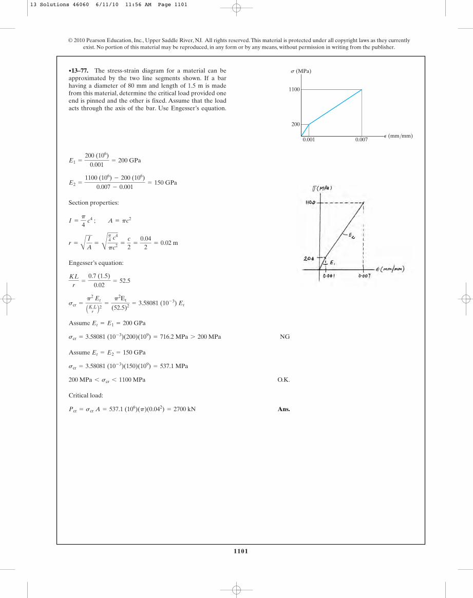
1101
© 2010 Pearson Education, Inc., Upper Saddle River, NJ. All rights reserved. This material is protected under all copyright laws as they currentlyexist. No portion of this material may be reproduced, in any form or by any means, without permission in writing from the publisher.
Section properties:
Engesser’s equation:
Assume
NG
Assume
O.K.
Critical load:
Ans.Pcr = scr A = 537.1 (106)(p)(0.042) = 2700 kN
200 MPa 6 scr 6 1100 MPa
scr = 3.58081 (10- 3)(150)(109) = 537.1 MPa
Et = E2 = 150 GPa
scr = 3.58081 (10- 3)(200)(109) = 716.2 MPa 7 200 MPa
Et = E1 = 200 GPa
scr =
p2 Et
AK Lr B2 =
p2Et
(52.5)2 = 3.58081 (10- 3) Et
KLr
=
0.7 (1.5)
0.02= 52.5
r =
A
I
A=
C
p4 c4
pc2 =
c
2=
0.042
= 0.02 m
I =
p
4 c4 ; A = pc2
E2 =
1100 (106) - 200 (106)
0.007 - 0.001= 150 GPa
E1 =
200 (106)
0.001= 200 GPa
•13–77. The stress-strain diagram for a material can beapproximated by the two line segments shown. If a barhaving a diameter of 80 mm and length of 1.5 m is madefrom this material, determine the critical load provided oneend is pinned and the other is fixed. Assume that the loadacts through the axis of the bar. Use Engesser’s equation.
1100
200
0.001 0.007P (mm/mm)
s (MPa)
13 Solutions 46060 6/11/10 11:56 AM Page 1101
1102
© 2010 Pearson Education, Inc., Upper Saddle River, NJ. All rights reserved. This material is protected under all copyright laws as they currentlyexist. No portion of this material may be reproduced, in any form or by any means, without permission in writing from the publisher.
Section Properties:
Slenderness Ratio: For a column fixed at both ends, . Thus,
AISC Column Formula: Assume a long column.
Here, and for A–36 steel,
. Since , the assumption is correct.
Thus,
Ans.L = 3.56 m
aKLrb
e…
KLr
… 200=
A
2p2[200(109)]
250(106)= 125.7
aKLrb
e=
A
2p2Esg
KLr
= 40.0(3.555) = 142.2
L = 3.555 m
100(103)
0.625(10- 3)p=
12p2 C200(109) D23(40.0L)3
sallow =
12p2E
23 AKLr B2
KLr
=
0.5L
0.0125= 40.0L
K = 0.5
r =
AIA
=
A
97.65625(10- 9)p0.625(10- 3)p
= 0.0125 m
I =
p
4 A0.0254 B = 97.65625 A10- 9 B p m4
A = p A0.0252 B = 0.625 A10- 3 B p m2
13–78. Determine the largest length of a structural A-36steel rod if it is fixed supported and subjected to an axialload of 100 kN. The rod has a diameter of 50 mm. Use theAISC equations.
13 Solutions 46060 6/11/10 11:56 AM Page 1102

1103
© 2010 Pearson Education, Inc., Upper Saddle River, NJ. All rights reserved. This material is protected under all copyright laws as they currentlyexist. No portion of this material may be reproduced, in any form or by any means, without permission in writing from the publisher.
Section Properties: For a wide flange section,
Slenderness Ratio: For a column pinned at both ends, . Thus,
AISC Column Formula: Assume a long column,
Here, and for grade 50 steel,
. Since , the assumption is not correct.
Thus, the column is an intermediate column.
Applying Eq. 13–23,
Solving by trial and error,
Ans.L = 131.12 in. = 10.9 ft
0 = 12.565658 A10- 9 B L3- 24.788132 A10- 6 B L2
- 1.743638 A10- 3 B L + 0.626437
29013.3
=
B1 -
(0.49751L)2
2(107.02)R(50)
53
+
3(0.49751L)
8(107.0)-
(0.49751L)3
8(107.03)
sallow =
B1 -
(KL>r)2
2(KL>r)2cRsg
53
+
3(KL>r)
8(KL>r)c-
(KL>r)3
8(KL>r)3c
KLr
6 aKLrb
c=
A
2p2[29(103)]50
= 107.0
aKLrb
c=
A2p2Esg
KLr
= 0.49751 (166.3) = 82.76
L = 166.3 in.
29013.3
=
12p2 C29(103) D23(0.49751L)2
sallow =
12p2E
23 AKLr B2
aKLrb
y=
1(L)
2.01= 0.49751L
K = 1
A = 13.3 in2 ry = 2.01 in
W10 * 45
13–79. Determine the largest length of a structural steel column if it is pin supported and subjectedto an axial load of 290 kip. .Use the AISC equations.
sY = 50 ksiEst = 29(103) ksi,
W10 * 45
13 Solutions 46060 6/11/10 11:56 AM Page 1103
1104
© 2010 Pearson Education, Inc., Upper Saddle River, NJ. All rights reserved. This material is protected under all copyright laws as they currentlyexist. No portion of this material may be reproduced, in any form or by any means, without permission in writing from the publisher.
For a
Assume a long column:
Long column.
Ans.= 8.99 ft
L = 137.4¢ r
K≤ = 137.4¢0.785
1≤ = 107.86 in.
KLr
= 137.4
aKLrb
c=
A2p2Esg
=
A
2p2(29)(103)36
= 126.1, KLr
7 aKLrb
c
aKLrb =
A12p2E23sallow
=
A
12p2(29)(103)23(7.91)
= 137.4
sallow =
12p2E
23(KL>r)2
s =
P
A=
283.54
= 7.91 ksi
W 10 * 12, ry = 0.785 in. A = 3.54 in2
*13–80. Determine the largest length of a structural A-36 steel section if it is pin supported and issubjected to an axial load of 28 kip. Use the AISC equations.
W10 * 12
Try,
Long column
O.K.
Ans.Use W6 * 15
= 11.28(4.43) = 50.0 kip 7 40 kip
Pallow = sallowA
sallow =
12 p2E
23(KL>r)2 =
12p2(29)(103)
23(115.1)2 = 11.28 ksi
aKLryb =
(1.0)(14)(12)
1.46= 115.1, aKL
ryb 7 aKL
rb
c
aKLrb
c=
A2p2EsY
=
A
2p2(29)(103)50
= 107
W6 * 15 (A = 4.43 in2 ry = 1.46 in.)
•13–81. Using the AISC equations, select from Appendix Bthe lightest-weight structural A-36 steel column that is 14 ftlong and supports an axial load of 40 kip.The ends are pinned.Take sY = 50 ksi.
13 Solutions 46060 6/11/10 11:56 AM Page 1104

1105
© 2010 Pearson Education, Inc., Upper Saddle River, NJ. All rights reserved. This material is protected under all copyright laws as they currentlyexist. No portion of this material may be reproduced, in any form or by any means, without permission in writing from the publisher.
Try
Intermediate column
O.K.
Ans.Use W6 * 9
= 41.3 kip 7 40 kip
= 15.40(2.68)
Pallow = sallowA
sallow =
C1 -12 A KL>r
(KL>r)c B2 DsgC53 +
38 A KL>r
(KL>r)c B -18 A KL>r
(KL>r)c B3 D =
C1 -12 A79.56
126.1 B2 D36 ksi
C53 +38 A79.56
126.1 B - 18 A79.5612.61 B3 D = 15.40 ksi
KLry
6 aKLrb
c
KLry
=
0.5(12)(12)
0.905= 79.56
aKLrb
c=
A2p2EsY
=
A
2p2(29)(103)50
= 107
W6 * 9 A = 2.68 in2 ry = 0.905 in.
13–82. Using the AISC equations, select from Appendix Bthe lightest-weight structural A-36 steel column that is 12 ftlong and supports an axial load of 40 kip.The ends are fixed.Take sY = 50 ksi.
13 Solutions 46060 6/11/10 11:56 AM Page 1105
1106
© 2010 Pearson Education, Inc., Upper Saddle River, NJ. All rights reserved. This material is protected under all copyright laws as they currentlyexist. No portion of this material may be reproduced, in any form or by any means, without permission in writing from the publisher.
Section Properties: Try a wide flange section,
Slenderness Ratio: For a column fixed at both ends, . Thus,
AISC Column Formula: For A–36 steel,
. Since , the column is an intermediate
column. Applying Eq. 13–23,
The allowable load is
O.K.
Thus, Ans.Use W8 * 24
= 101 kip 7 P = 100 kip
= 14.271(7.08)
Pallow = sallowA
= 14.271 ksi
=
B1 -
(89.442)
2(126.12)R(36)
53
+
3(89.44)
8(126.1)-
(89.443)
8(126.13)
sallow =
B1 -
(KL>r)2
2(KL>r)2cRsg
53
+
3(KL>r)
8(KL>r)c-
(KL>r)3
8(KL>r)3c
KLr
6 aKLrb
c=
A
2p2[29(103)]36
= 126.1
aKLrb
c=
A2p2Esg
aKLrb
y=
0.5(24)(12)
1.61= 89.44
K = 0.5
A = 7.08 in2 ry = 1.61 in
W8 * 24
13–83. Using the AISC equations, select from Appendix Bthe lightest-weight structural A-36 steel column that is 24 ftlong and supports an axial load of 100 kip.The ends are fixed.
13 Solutions 46060 6/11/10 11:56 AM Page 1106
1107
© 2010 Pearson Education, Inc., Upper Saddle River, NJ. All rights reserved. This material is protected under all copyright laws as they currentlyexist. No portion of this material may be reproduced, in any form or by any means, without permission in writing from the publisher.
Try
intermediate column.
O.K.
Ans.Use W 8 * 48
Pallow = sallow A = 14.611 (14.1) = 206 kip 7 P = 200 kip
=
e1 -12 C 86.54
126.1 D2 f36
e 53 +
38 C 86.54
126.1 D -18 C86.54
126.1 D3 f= 14.611 ksi
sallow =
b1 -12B
KLr
AKLr B cR
2 r sg
b 53 +
38B
KLr
AKLr B cR -
18B
KLr
AKLr B c R3 r
aKLryb 6 aKL
rb
c
KLry
=
0.5 (30)(12)
2.08= 86.54
aKLrb
c=
A2 p2Esg
=
A
2 p2 (29)(103)36
= 126.1
W8 * 48 ry = 2.08 in. A = 14.1 in2
*13–84. Using the AISC equations, select from Appendix Bthe lightest-weight structural A-36 steel column that is 30 ftlong and supports an axial load of 200 kip.The ends are fixed.
13 Solutions 46060 6/11/10 11:56 AM Page 1107

1108
© 2010 Pearson Education, Inc., Upper Saddle River, NJ. All rights reserved. This material is protected under all copyright laws as they currentlyexist. No portion of this material may be reproduced, in any form or by any means, without permission in writing from the publisher.
Section Properties. From the table listed in the appendix, the necessary sectionproperties for a are
Slenderness Ratio. For a column pinned at both of its ends, . Here,and Thus,
AISC Column Formulas. For A-36 steel
. Since , the column is an
intermediate column.
Thus, the allowable force is
Ans.Pallow = sallowA = 11.428(7.08) = 80.91 kip = 80.9 kip
= 11.428 ksi
=
C1 -
111.802
2 A126.102 B S(36)
53
+
3(111.80)
8(126.10)-
111.803
8 A126.103 B
sallow =
B1 -
(KL>r)2
2(KL>r)c 2RsY
53
+
3(KL>r)
8(KL>r)c-
(KL>r)3
8(KL>r)c 3
¢KLr≤
y6 ¢KL
r≤
c=
C
2p2 C29 A103 B D36
= 126.10
¢KLr≤
c=
A2p2EsY
¢KLr≤
y=
1(180)
1.61= 111.80 (controls)
¢KLr≤
x=
1(360)
3.42= 105.26
Ly = 15(12) = 180 in.Lx = 30(12) = 360 in.K = 1
A = 7.08 in2 rx = 3.42 in. ry = 1.61 in.
W8 * 24
•13–85. A A-36-steel column of 30-ft length ispinned at both ends and braced against its weak axis at mid-height. Determine the allowable axial force P that can besafely supported by the column. Use the AISC columndesign formulas.
W8 * 24
13 Solutions 46060 6/11/10 11:56 AM Page 1108
1109
© 2010 Pearson Education, Inc., Upper Saddle River, NJ. All rights reserved. This material is protected under all copyright laws as they currentlyexist. No portion of this material may be reproduced, in any form or by any means, without permission in writing from the publisher.
Section Properties. From the table listed in the appendix, the necessary sectionproperties for a are
Slenderness Ratio. For a column pinned at both of its ends, . Here,and Thus,
AISC Column Formulas. For A-36 steel
. Since , the column is an
intermediate column.
Thus, the allowable force is
O.K.
Thus, a column is adequate.W10 * 39
Pallow = sallowA = 22.614(11.5) = 260.06 kip 7 P = 250 kip
= 22.614 ksi
=
C1 -
60.6062
2 A107.002 B S(50)
53
+
3(60.606)
8(107.00)-
60.6063
8 A107.003 B
sallow =
B1 -
(KL>r)2
2(KL>r)c 2RsY
53
+
3(KL>r)
8(KL>r)c-
(KL>r)3
8(KL>r)c 3
¢KLr≤
y6 ¢KL
r≤
c=
S
2p2 c29 A103 B d50
= 107.00
¢KLr≤
c=
A2p2EsY
¢KLr≤
y=
1(120)
1.98= 60.606 (controls)
¢KLr≤
x=
1(240)
4.27= 56.21
Ly = 10(12) = 120 in.Lx = 20(12) = 240 in.K = 1
A = 11.5 in2 rx = 4.27 in. ry = 1.98 in.
W10 * 39
13–86. Check if a column can safely support anaxial force of The column is 20 ft long and ispinned at both ends and braced against its weak axis atmid-height. It is made of steel having and
Use the AISC column design formulas.sY = 50 ksi.E = 29(103) ksi
P = 250 kip.W10 * 39
13 Solutions 46060 6/11/10 11:56 AM Page 1109
1110
© 2010 Pearson Education, Inc., Upper Saddle River, NJ. All rights reserved. This material is protected under all copyright laws as they currentlyexist. No portion of this material may be reproduced, in any form or by any means, without permission in writing from the publisher.
Section properties:
Assume long column:
Ans.
O.K.K L
r=
2401.42
= 169 7 55
d = 1.42 in.
sallow =
54 000
AK Lr B2 ; 3.820
d2 =
54000
C240d D2
KLr
=
1.0 (5)(12)d4
=
240d
sallow =
P
A=
3p4 d2 =
3.820d2
r =
A
I
A=
C
pd4
64p4 d2 =
d
4
A =
p
4 d2 ; I =
p
4 ad
2b4
=
pd4
64
13–87. A 5-ft-long rod is used in a machine to transmitan axial compressive load of 3 kip. Determine its smallestdiameter if it is pin connected at its ends and is made of a2014-T6 aluminum alloy.
13 Solutions 46060 6/11/10 11:56 AM Page 1110
1111
© 2010 Pearson Education, Inc., Upper Saddle River, NJ. All rights reserved. This material is protected under all copyright laws as they currentlyexist. No portion of this material may be reproduced, in any form or by any means, without permission in writing from the publisher.
Section Properties. Try . From the table listed in the appendix, thenecessary section properties are
Slenderness Ratio. For a column pinned at both of its ends, . Thus,
AISC Column Formulas. Here, .
Since , the
column is an intermediate column.
Thus, the allowable force is
O.K.
Thus,
Ans.A W10 * 45 can be used
Pallow = sallowA = 17.034(13.3) = 226.55 kip 7 P = 200 kip
= 17.034 ksi
=
C1 -
89.5522
2 A107.002 B S(50)
53
+
3(89.552)
8(107.00)-
89.5523
8 A107.003 B
sallow =
B1 -
(KL>r)2
2(KL>r)c 2RsY
53
+
3(KL>r)
8(KL>r)c-
(KL>r)3
8(KL>r)c 3
aKLrb
y6 aKL
rb
c
aKLrb
c=
A2p2EsY
=
S
2p2 c29 A103 B d50
= 107.00
aKLrb
y=
1(15)(12)
2.01= 89.552
K = 1
A = 13.3 in2 ry = 2.01 in.
W10 * 45
*13–88. Check if a column can safely supportan axial force of The column is 15 ft long andis pinned at both of its ends. It is made of steel having
and Use the AISC columndesign formulas.
sY = 50 ksi.E = 29(103) ksi
P = 200 kip.W10 * 45
13 Solutions 46060 6/11/10 11:56 AM Page 1111

1112
© 2010 Pearson Education, Inc., Upper Saddle River, NJ. All rights reserved. This material is protected under all copyright laws as they currentlyexist. No portion of this material may be reproduced, in any form or by any means, without permission in writing from the publisher.
Section Properties:
Slenderness Ratio: For a column pinned at both ends, . Thus,
AISC Column Formula: For A–36 steel,
. Since , the column is an intermediate
column. Applying Eq. 13–23,
The allowable load is
O.K.
Thus, the column is adequate. Ans.
= 1906 kN 7 P = 1500 kN
= 126.2 A106 B (0.0151)
Pallow = sallowA
= 126.2 MPa
=
B1 -
(51.802)
2(125.72)R(250)(106)
53
+
3(51.80)
8(125.7)-
(51.803)
8(125.73)
sallow =
B1 -
(KL>r)2
2(KL>r)c2Rsg
53
+
3(KL>r)
8(KL>r)c-
(KL>r)3
8(KL>r)c3
KLr
6 aKLrb
c=
A
2p2[200(109)]
250(106)= 125.7
aKLrb
c=
A2p2Esg
aKLrb
y=
1(4)
0.077214= 51.80
K = 1
ry =
A
Iy
A=
A90.02583(10- 6)
0.0151= 0.077214 m
Iy =
112
(0.04) A0.33 B +
112
(0.31) A0.013 B = 90.025833 A10- 6 B m4
A = 0.3(0.35) - 0.29(0.31) = 0.0151 m2
•13–89. Using the AISC equations, check if a columnhaving the cross section shown can support an axial force of1500 kN.The column has a length of 4 m, is made from A-36steel, and its ends are pinned.
350 mm
10 mm
300 mm
20 mm20 mm
13 Solutions 46060 6/11/10 11:56 AM Page 1112

1113
© 2010 Pearson Education, Inc., Upper Saddle River, NJ. All rights reserved. This material is protected under all copyright laws as they currentlyexist. No portion of this material may be reproduced, in any form or by any means, without permission in writing from the publisher.
Section Properties.
Slenderness Ratio. For a column pinned at both of its ends, . Thus,
AISC Column Formulas.
Ans.
Here, . For A-36 steel
. Since , the assumption of a
long column is correct.
aKLrb
c6
KLr
6 200=
C
2p2 C200 A109 B D250 A106 B = 125.66
aKLrb
c=
A2p2EsY
KLr
= 31.23(4.4607) = 139.33
L = 4.4607 m = 4.46 m
150 A103 B.9 A10- 3 Bp =
12p2 C200 A109 B D23(31.23L)2
sallow =
12p2E
23(KL>r)2
KLr
=
1(L)
0.03202= 31.23L
K = 1
r =
A
I
A=
C
0.9225 A10- 6 Bp0.9 A10- 3 Bp = 0.03202 m
I =
p
4 A0.054
- 0.044 B = 0.9225 A10- 6 Bp m4
A = p A0.052- 0.042 B = 0.9 A10- 3 Bp m2
13–90. The A-36-steel tube is pinned at both ends. If itis subjected to an axial force of 150 kN, determine themaximum length that the tube can safely support using theAISC column design formulas.
100 mm
80 mm
13 Solutions 46060 6/11/10 11:56 AM Page 1113

1114
© 2010 Pearson Education, Inc., Upper Saddle River, NJ. All rights reserved. This material is protected under all copyright laws as they currentlyexist. No portion of this material may be reproduced, in any form or by any means, without permission in writing from the publisher.
Section Properties:
Slenderness Ratio: For a column pinned at both ends, . Thus,
Aluminum (2014 - T6 alloy) Column Formulas: Assume a long column and applyEq. 13–26.
Here, . Since , the assumption is correct. Thus,
Ans.b = 0.704 in.
KLr
7 55KL
r=
332.550.7041
= 472.3
b = 0.7041 in.
0.6005b2 =
54 000
A332.55b B2
sallow =
54 000(KL>r)2
aKLrb
y=
1(8)(12)236 b
=
332.55b
K = 1
ry =
A
Iy
A=
C
512b4
5b2 =
236
b
Iy =
112
(5b) Ab3 B =
512
b4
A = b(5b) = 5b2
13–91. The bar is made of a 2014-T6 aluminum alloy.Determine its smallest thickness b if its width is 5b. Assumethat it is pin connected at its ends.
5bb
8 ft
600 lb
600 lb
13 Solutions 46060 6/11/10 11:56 AM Page 1114
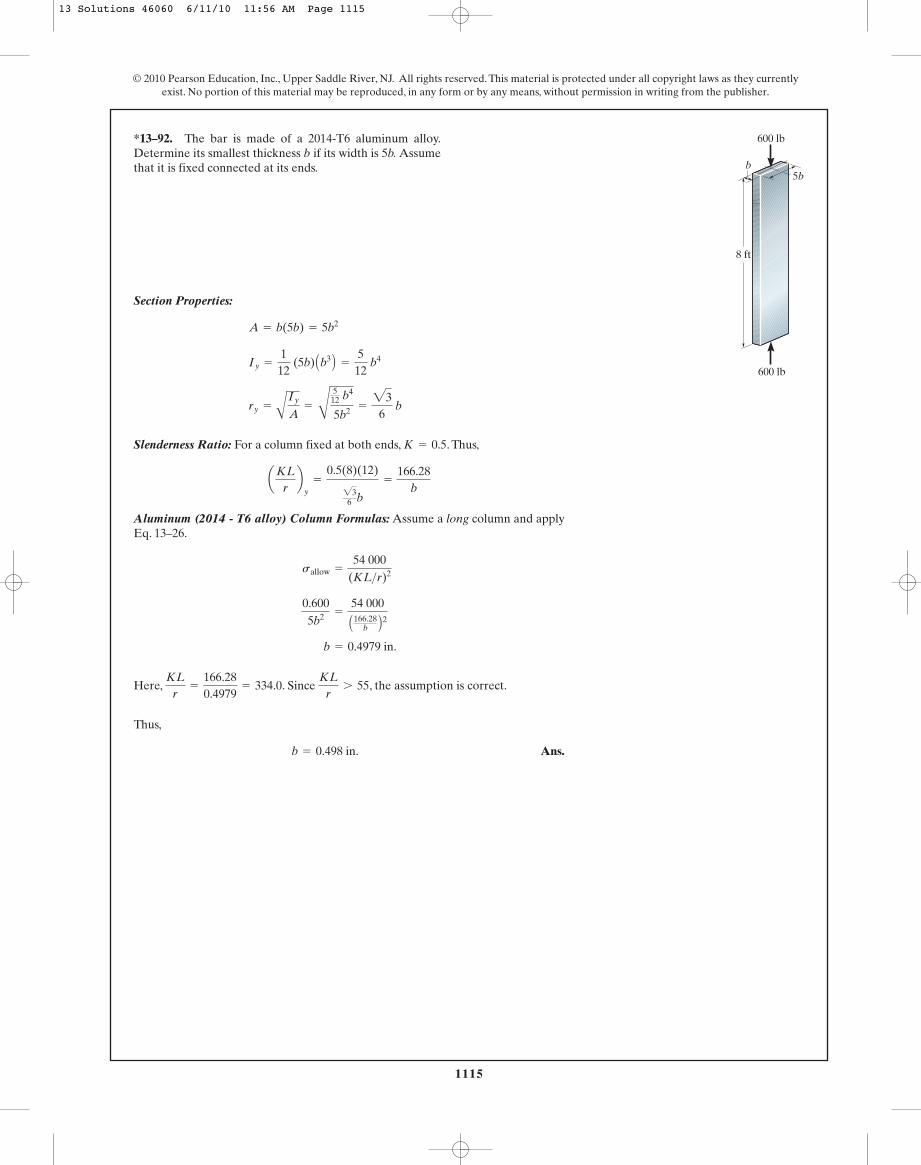
1115
© 2010 Pearson Education, Inc., Upper Saddle River, NJ. All rights reserved. This material is protected under all copyright laws as they currentlyexist. No portion of this material may be reproduced, in any form or by any means, without permission in writing from the publisher.
Section Properties:
Slenderness Ratio: For a column fixed at both ends, . Thus,
Aluminum (2014 - T6 alloy) Column Formulas: Assume a long column and applyEq. 13–26.
Here, . Since , the assumption is correct.
Thus,
Ans.b = 0.498 in.
KLr
7 55KL
r=
166.280.4979
= 334.0
b = 0.4979 in.
0.6005b2 =
54 000
A166.28b B2
sallow =
54 000(KL>r)2
aKLrb
y=
0.5(8)(12)
236 b
=
166.28b
K = 0.5
ry =
A
Iy
A=
C
512 b4
5b2 =
236
b
Iy =
112
(5b) Ab3 B =
512
b4
A = b(5b) = 5b2
*13–92. The bar is made of a 2014-T6 aluminum alloy.Determine its smallest thickness b if its width is 5b. Assumethat it is fixed connected at its ends.
5bb
8 ft
600 lb
600 lb
13 Solutions 46060 6/11/10 11:56 AM Page 1115
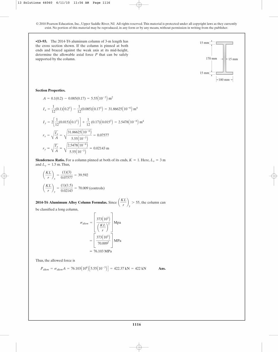
1116
© 2010 Pearson Education, Inc., Upper Saddle River, NJ. All rights reserved. This material is protected under all copyright laws as they currentlyexist. No portion of this material may be reproduced, in any form or by any means, without permission in writing from the publisher.
Section Properties.
Slenderness Ratio. For a column pinned at both of its ends, . Here,and . Thus,
2014-T6 Alumimum Alloy Column Formulas. Since , the column can
be classified a long column,
Thus, the allowed force is
Ans.Pallow = sallowA = 76.103 A106 B C5.55 A10- 3 B D = 422.37 kN = 422 kN
= 76.103 MPa
= C 373 A103 B70.0092 S MPa
sallow = D373 A103 BaKL
rb2 T Mpa
aKLrb
y7 55
aKLrb
y=
(1)(1.5)
0.02143= 70.009 (controls)
aKLrb
x=
(1)(3)
0.07577= 39.592
Ly = 1.5 mLx = 3 mK = 1
ry =
A
Iy
A=
C
2.5478 A10- 6 B5.55 A10- 3 B = 0.02143 m
rx =
AIx
A=
C
31.86625 A10- 6 B5.55 A10- 3 B = 0.07577
Iy = 2 c 112
(0.015) A0.13 B d +
112
(0.17) A0.0153 B = 2.5478 A10- 6 B m4
Ix =
112
(0.1) A0.23 B -
112
(0.085) A0.173 B = 31.86625 A10- 6 B m4
A = 0.1(0.2) - 0.085(0.17) = 5.55 A10- 3 B m2
•13–93. The 2014-T6 aluminum column of 3-m length hasthe cross section shown. If the column is pinned at bothends and braced against the weak axis at its mid-height,determine the allowable axial force P that can be safelysupported by the column.
100 mm
15 mm170 mm
15 mm
15 mm
13 Solutions 46060 6/11/10 11:56 AM Page 1116

1117
© 2010 Pearson Education, Inc., Upper Saddle River, NJ. All rights reserved. This material is protected under all copyright laws as they currentlyexist. No portion of this material may be reproduced, in any form or by any means, without permission in writing from the publisher.
Section Properties.
Slenderness Ratio. For a column pinned at both of its ends, . Then,
2014-T6 Alumimum Alloy Column Formulas. Assuming a long column,
Ans.
Since , the assumption is correct.aKLrb
y= 46.6727(3.083) = 143.88 7 55
L = 3.083 m = 3.08 m
100 A103 B5.55 A10- 3 B = C 373 A103 B
(46.672L)2 S A106 B Pa
sallow = D373 A103 BaKL
rb2 T MPa
aKLrb
y=
1(L)
0.02143= 46.6727L
K = 1
ry =
A
Iy
A=
C
2.5478 A10- 6 B5.55 A10- 3 B = 0.02143 m
Iy = 2 c 112
(0.015) A0.13 B d +
112
(0.17) A0.0153 B = 2.5478 A10- 6 B m4
A = 0.1(0.2) - 0.085(0.17) = 5.55 A10- 3 B m2
13–94. The 2014-T6 aluminum column has the crosssection shown. If the column is pinned at both ends andsubjected to an axial force determine themaximum length the column can have to safely support theloading.
P = 100 kN,
100 mm
15 mm170 mm
15 mm
15 mm
13 Solutions 46060 6/11/10 11:56 AM Page 1117
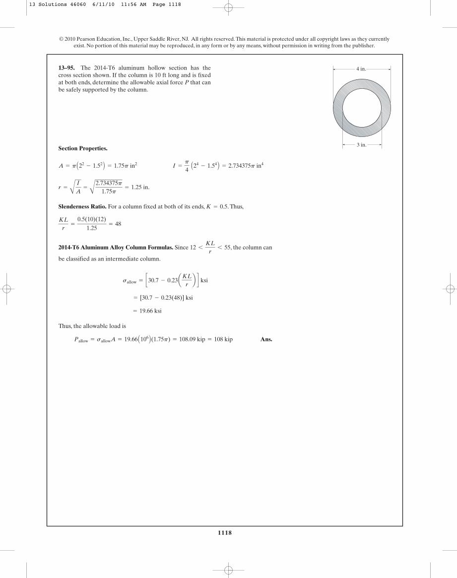
1118
© 2010 Pearson Education, Inc., Upper Saddle River, NJ. All rights reserved. This material is protected under all copyright laws as they currentlyexist. No portion of this material may be reproduced, in any form or by any means, without permission in writing from the publisher.
Section Properties.
Slenderness Ratio. For a column fixed at both of its ends, . Thus,
2014-T6 Aluminum Alloy Column Formulas. Since , the column can
be classified as an intermediate column.
Thus, the allowable load is
Ans.Pallow = sallowA = 19.66 A106 B(1.75p) = 108.09 kip = 108 kip
= 19.66 ksi
= [30.7 - 0.23(48)] ksi
sallow = c30.7 - 0.23aKLrb d ksi
12 6
KLr
6 55
KLr
=
0.5(10)(12)
1.25= 48
K = 0.5
r =
A
I
A=
A
2.734375p1.75p
= 1.25 in.
A = p A22- 1.52 B = 1.75p in2 I =
p
4 A24
- 1.54 B = 2.734375p in4
13–95. The 2014-T6 aluminum hollow section has thecross section shown. If the column is 10 ft long and is fixedat both ends, determine the allowable axial force P that canbe safely supported by the column.
4 in.
3 in.
13 Solutions 46060 6/11/10 11:56 AM Page 1118

1119
© 2010 Pearson Education, Inc., Upper Saddle River, NJ. All rights reserved. This material is protected under all copyright laws as they currentlyexist. No portion of this material may be reproduced, in any form or by any means, without permission in writing from the publisher.
Section Properties.
Slenderness Ratio. For a column fixed at its base and pinned at its top, .Thus,
2014-T6 Aluminum Alloy Column Formulas. Assuming an intermediate column,
Ans.
Since , the assumption of an intermediate column
is correct.
KLr
= 0.56(97.13) = 54.39 6 55
L = 97.13 in. = 8.09 ft
1001.75p
= 30.7 - 0.23(0.56L)
sallow = c30.7 - 0.23aKLrb d ksi
KLr
=
0.7(L)
1.25= 0.56L
K = 0.7
r =
A
I
A=
A
2.734375p1.75p
= 1.25 in.
A = p A22- 1.52 B = 1.75p in2 I =
p
4 A24
- 1.54 B = 2.734375p in4
*13–96. The 2014-T6 aluminum hollow section has thecross section shown. If the column is fixed at its base andpinned at its top, and is subjected to the axial force
determine the maximum length of the columnfor it to safely support the load.P = 100 kip,
4 in.
3 in.
13 Solutions 46060 6/11/10 11:56 AM Page 1119
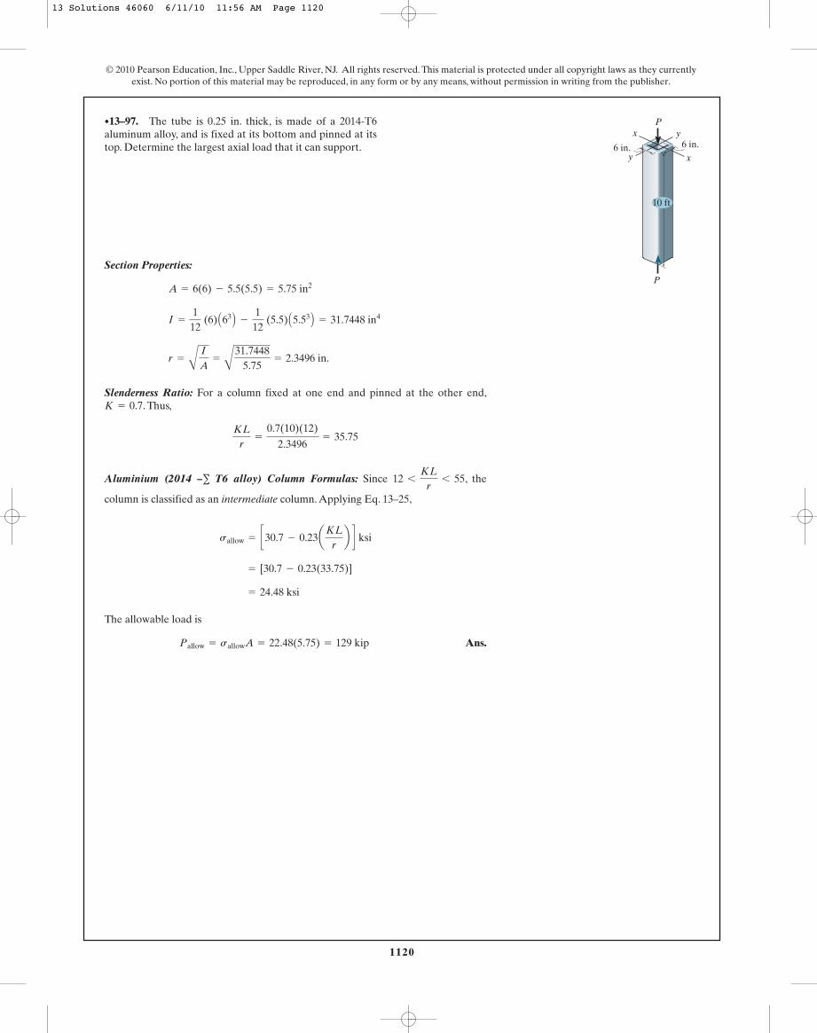
1120
© 2010 Pearson Education, Inc., Upper Saddle River, NJ. All rights reserved. This material is protected under all copyright laws as they currentlyexist. No portion of this material may be reproduced, in any form or by any means, without permission in writing from the publisher.
Section Properties:
Slenderness Ratio: For a column fixed at one end and pinned at the other end,. Thus,
Aluminium (2014 –∑ T6 alloy) Column Formulas: Since , the
column is classified as an intermediate column. Applying Eq. 13–25,
The allowable load is
Ans.Pallow = sallowA = 22.48(5.75) = 129 kip
= 24.48 ksi
= [30.7 - 0.23(33.75)]
sallow = c30.7 - 0.23aKLrb d ksi
12 6
KLr
6 55
KLr
=
0.7(10)(12)
2.3496= 35.75
K = 0.7
r =
A
I
A=
A
31.74485.75
= 2.3496 in.
I =
112
(6) A63 B -
112
(5.5) A5.53 B = 31.7448 in4
A = 6(6) - 5.5(5.5) = 5.75 in2
•13–97. The tube is 0.25 in. thick, is made of a 2014-T6aluminum alloy, and is fixed at its bottom and pinned at itstop. Determine the largest axial load that it can support.
P
6 in.yx
y x6 in.
P
10 ft
13 Solutions 46060 6/11/10 11:56 AM Page 1120

1121
© 2010 Pearson Education, Inc., Upper Saddle River, NJ. All rights reserved. This material is protected under all copyright laws as they currentlyexist. No portion of this material may be reproduced, in any form or by any means, without permission in writing from the publisher.
Section Properties:
Slenderness Ratio: For column fixed at both ends, . Thus,
Aluminium (2014 – T6 alloy) Column Formulas: Since , the
column is classified as an intermediate column. Applying Eq. 13–25,
The allowable load is
Ans.Pallow = sallowA = 24.83(5.75) = 143 kip
= 24.83 ksi
= [30.7 - 0.23(25.54)]
sallow = c30.7 - 0.23aKLrb d ksi
12 6
KLr
6 55
KLr
=
0.5(10)(12)
2.3496= 25.54
K = 0.5
r =
A
I
A=
A
31.74485.75
= 2.3496 in.
I =
112
(6) A63 B -
112
(5.5) A5.53 B = 31.7448 in4
A = 6(6) - 5.5(5.5) = 5.75 in2
13–98. The tube is 0.25 in. thick, is made of a 2014-T6aluminum alloy, and is fixed connected at its ends.Determine the largest axial load that it can support.
P
6 in.yx
y x6 in.
P
10 ft
13 Solutions 46060 6/11/10 11:56 AM Page 1121

1122
© 2010 Pearson Education, Inc., Upper Saddle River, NJ. All rights reserved. This material is protected under all copyright laws as they currentlyexist. No portion of this material may be reproduced, in any form or by any means, without permission in writing from the publisher.
Section Properties:
Slenderness Ratio: For a column pinned as both ends, . Thus,
Aluminum (2014 – T6 alloy) Column Formulas: Since , the
column is classified as an intermediate column. Applying Eq. 13–25,
The allowable load is
Ans.Pallow = sallowA = 18.95(5.75) = 109 kip
= 18.95 ksi
= [30.7 - 0.23(51.07)]
sallow = c30.7 - 0.23aKLrb d ksi
12 6
KLr
6 55
KLr
=
1(10)(12)
2.3496= 51.07
K = 1
r =
A
I
A=
A
31.74485.75
= 2.3496 in.
I =
112
(6) A63 B -
112
(5.5) A5.53 B = 31.7448 in4
A = 6(6) - 5.5(5.5) = 5.75 in2
13–99. The tube is 0.25 in. thick, is made of 2014-T6aluminum alloy and is pin connected at its ends. Determinethe largest axial load it can support.
P
6 in.yx
y x6 in.
P
10 ft
Slenderness Ratio. For a column pinned at both of its ends, . Then,
NFPA Timber Column Formula. Assuming an intermediate column,
Ans.
. Since , the assumption is correct.11 6
KL
d6 26
KL
d=
723
= 24
Use a = 3 in.
a = 2.968 in.
152a(a)
= 1.20 c1 -
13
a72>a26.0b2 d
sallow = 1.20 c1 -
13
aKL>d26.0
b2 d ksi
KL
d=
(1)(6)(12)
a=
72a
K = 1
*13–100. A rectangular wooden column has the crosssection shown. If the column is 6 ft long and subjected to anaxial force of determine the required minimumdimension a of its cross-sectional area to the nearest so that the column can safely support the loading. Thecolumn is pinned at both ends.
116 in.
P = 15 kip,
2a
a
13 Solutions 46060 6/11/10 11:56 AM Page 1122

1123
© 2010 Pearson Education, Inc., Upper Saddle River, NJ. All rights reserved. This material is protected under all copyright laws as they currentlyexist. No portion of this material may be reproduced, in any form or by any means, without permission in writing from the publisher.
Slenderness Ratio. For a column fixed at its base and pinned at its top .Then,
NFPA Timer Column Formula. Since , the column can be classified
as a long column.
The allowable force is
Ans.Pallow = sallowA = 0.4783(3)(6) = 8.61 kip
sallow =
540 ksi(KL>d)2 =
54033.62 = 0.4783 ksi
26 6
KL
d6 50
KL
d=
0.7(12)(12)
3= 33.6
K = 0.7
•13–101. A rectangular wooden column has the crosssection shown. If and the column is 12 ft long,determine the allowable axial force P that can be safelysupported by the column if it is pinned at its top and fixed atits base.
a = 3 in.
2a
a
Slenderness Ratio. For a column fixed at its base and pinned at its top, .Then,
NFPA Timber Column Formula. Assuming an intermediate column,
Ans.
Here, . Since , the assumption is
correct.
11 6
KL
d6 26
KL
d= 0.2333(106.68) = 24.89
L = 106.68 in. = 8.89 ft
153(6)
= 1.20 c1 -
13a0.2333L
26.0b2 d
sallow = 1.20 c1 -
13aKL>d
26.0b2 d ksi
KL
d=
0.7L
3= 0.2333L
K = 0.7
13–102. A rectangular wooden column has the crosssection shown. If and the column is subjected toan axial force of determine the maximumlength the column can have to safely support the load. Thecolumn is pinned at its top and fixed at its base.
P = 15 kip,a = 3 in.
2a
a
13 Solutions 46060 6/11/10 11:56 AM Page 1123

1124
© 2010 Pearson Education, Inc., Upper Saddle River, NJ. All rights reserved. This material is protected under all copyright laws as they currentlyexist. No portion of this material may be reproduced, in any form or by any means, without permission in writing from the publisher.
Section properties:
Assume long column:
Assumption NG
Assume intermediate column:
, Assumption O.K.
Ans.Use a = 712
in.
11 6
KL
d6 26
KL
d=
1.0(14)(12)
7.46= 22.53
a = 7.46 in.
50a2 = 1.20B1 -
13
a1.0(14)(12)
a
26.0b2R
sallow = 1.20B1 -
13
aKL>d26.0
b2R
KL
d=
(1.0)(14)(12)
7.15= 23.5,
KL
d6 26
a = 7.15 in.
50a2 =
540
C (1.0)(14)(12)a
D 2
sallow =
540
AKLd B2
A = a2 sallow = s =
P
A=
50a2
13–103. The timber column has a square cross section andis assumed to be pin connected at its top and bottom. If itsupports an axial load of 50 kip, determine its smallest sidedimension a to the nearest Use the NFPA formulas.1
2 in.
14 ft
a
13 Solutions 46060 6/11/10 11:56 AM Page 1124
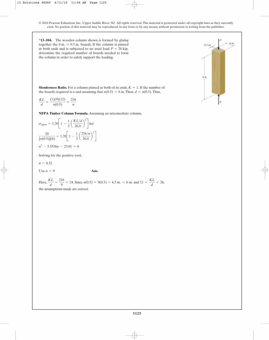
1125
© 2010 Pearson Education, Inc., Upper Saddle River, NJ. All rights reserved. This material is protected under all copyright laws as they currentlyexist. No portion of this material may be reproduced, in any form or by any means, without permission in writing from the publisher.
Slenderness Ratio. For a column pinned at both of its ends, . If the number ofthe boards required is n and assuming that . Then, . Thus,
NFPA Timber Column Formula. Assuming an intermediate column,
Solving for the positive root,
Ans.
Here, . Since and ,
the assumptions made are correct.
11 6
KL
d6 26n(0.5) = 9(0.5) = 4.5 in. 6 6 in.
KL
d=
2169
= 24
Use n = 9
n = 8.32
n2- 5.5556n - 23.01 = 0
20[n(0.5)](6)
= 1.20B1 -
13
a216>n26.0
b2R
sallow = 1.20B1 -
13
aKL>d26.0
b2R ksi
KL
d=
(1)(9)(12)
n(0.5)=
216n
d = n(0.5)n(0.5) 6 6 inK = 1
*13–104. The wooden column shown is formed by gluingtogether the boards. If the column is pinnedat both ends and is subjected to an axial load determine the required number of boards needed to formthe column in order to safely support the loading.
P = 20 kip,6 in. * 0.5 in.
9 ft
6 in.0.5 in.
P
P
13 Solutions 46060 6/11/10 11:56 AM Page 1125

1126
© 2010 Pearson Education, Inc., Upper Saddle River, NJ. All rights reserved. This material is protected under all copyright laws as they currentlyexist. No portion of this material may be reproduced, in any form or by any means, without permission in writing from the publisher.
Slenderness Ratio: For a column fixed at one end and free at the other end, .Thus,
NFPA Timber Column Formulas: Assume a long column. Apply Eq. 13–29,
Here, . Since , the assumption is correct.
Thus,
Ans.L = 46.48 in. = 3.87 ft
26 6
KL
d6 50
KL
d= 1.00(46.48) = 46.48
L = 46.48 in
2
2(4)=
540(1.00L)2
sallow =
540(KL>d)2 ksi
KL
d=
2(L)
2= 1.00L
K = 2
•13–105. The column is made of wood. It is fixed at itsbottom and free at its top. Use the NFPA formulas todetermine its greatest allowable length if it supports anaxial load of P = 2 kip.
P
L
4 in.
2 in.x
x
y
y
Slenderness Ratio: For a column fixed at one end and free at the other end, .Thus,
NFPA Timber Column Formulas: Since , it is a long column. Apply
Eq. 13–29,
The allowable axial force is
Ans.Pallow = sallowA = 0.234375[2(4)] = 1.875 kip
= 0.234375 ksi
=
54048.02
sallow =
540(KL>d)2 ksi
26 6
KL
d6 50
KL
d=
2(4)(12)
2= 48.0
K = 2
13–106. The column is made of wood. It is fixed at itsbottom and free at its top. Use the NFPA formulas todetermine the largest allowable axial load P that it cansupport if it has a length L = 4 ft.
P
L
4 in.
2 in.x
x
y
y
13 Solutions 46060 6/11/10 11:56 AM Page 1126
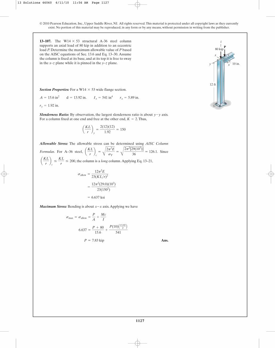
1127
© 2010 Pearson Education, Inc., Upper Saddle River, NJ. All rights reserved. This material is protected under all copyright laws as they currentlyexist. No portion of this material may be reproduced, in any form or by any means, without permission in writing from the publisher.
Section Properties: For a wide flange section.
Slenderness Ratio: By observation, the largest slenderness ratio is about axis.For a column fixed at one end and free at the other end, . Thus,
Allowable Stress: The allowable stress can be determined using AISC Column
Formulas. For A–36 steel, . Since
, the column is a long column. Applying Eq. 13–21,
Maximum Stress: Bending is about axis. Applying we have
Ans. P = 7.83 kip
6.637 =
P + 8015.6
+
P(10) A13.922 B
541
smax = sallow =
P
A+
Mc
I
x-x
= 6.637 ksi
=
12p2(29.0)(103)
23(1502)
sallow =
12p2E
23(KL>r)2
aKLrb
c…
KLr
… 200
aKLrb
c=
B
2p2EsY
=
B
2p2[29(103)]
36= 126.1
aKLrb
y=
2(12)(12)
1.92= 150
K = 2y-y
ry = 1.92 in.
A = 15.6 in2 d = 13.92 in. Ix = 541 in4 rx = 5.89 in.
W14 * 53
13–107. The structural A-36 steel columnsupports an axial load of 80 kip in addition to an eccentricload P. Determine the maximum allowable value of P basedon the AISC equations of Sec. 13.6 and Eq. 13–30. Assumethe column is fixed at its base, and at its top it is free to swayin the x–z plane while it is pinned in the y–z plane.
W14 * 53
12 ft
80 kip
y
y
x
x
10 in.
P
z
13 Solutions 46060 6/11/10 11:56 AM Page 1127
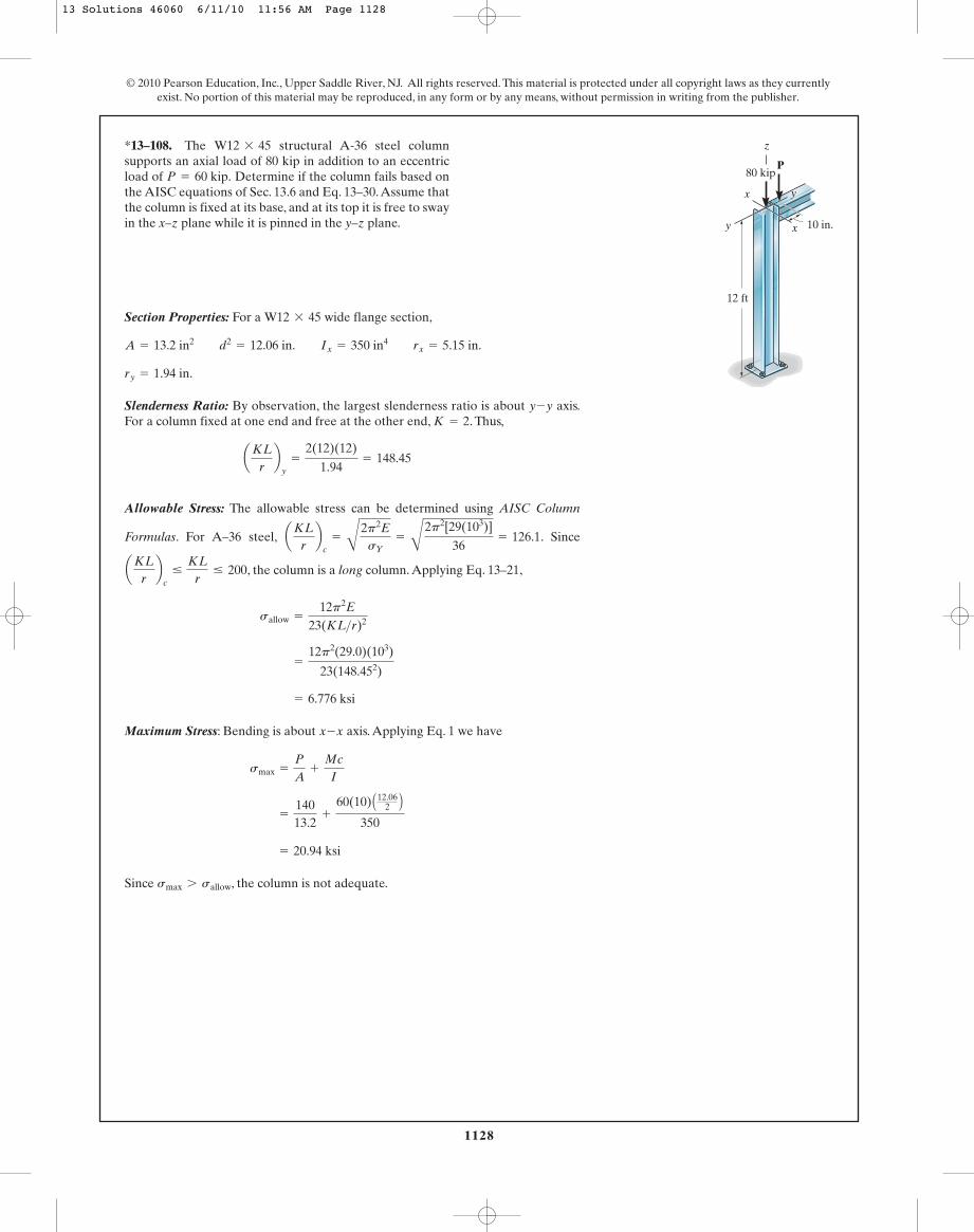
1128
© 2010 Pearson Education, Inc., Upper Saddle River, NJ. All rights reserved. This material is protected under all copyright laws as they currentlyexist. No portion of this material may be reproduced, in any form or by any means, without permission in writing from the publisher.
Section Properties: For a wide flange section,
Slenderness Ratio: By observation, the largest slenderness ratio is about axis.For a column fixed at one end and free at the other end, . Thus,
Allowable Stress: The allowable stress can be determined using AISC Column
Formulas. For A–36 steel, . Since
, the column is a long column. Applying Eq. 13–21,
Maximum Stress: Bending is about axis. Applying Eq. 1 we have
Since , the column is not adequate.smax 7 sallow
= 20.94 ksi
=
14013.2
+
60(10) A12.062 B
350
smax =
P
A+
Mc
I
x-x
= 6.776 ksi
=
12p2(29.0)(103)
23(148.452)
sallow =
12p2E
23(KL>r)2
aKLrb
c…
KLr
… 200
aKLrb
c=
B
2p2EsY
=
B
2p2[29(103)]
36= 126.1
aKLrb
y=
2(12)(12)
1.94= 148.45
K = 2y-y
ry = 1.94 in.
A = 13.2 in2 d2= 12.06 in. Ix = 350 in4 rx = 5.15 in.
W12 * 45
*13–108. The structural A-36 steel columnsupports an axial load of 80 kip in addition to an eccentricload of Determine if the column fails based onthe AISC equations of Sec. 13.6 and Eq. 13–30.Assume thatthe column is fixed at its base, and at its top it is free to swayin the x–z plane while it is pinned in the y–z plane.
P = 60 kip.
W12 * 45
12 ft
80 kip
y
y
x
x
10 in.
P
z
13 Solutions 46060 6/11/10 11:56 AM Page 1128
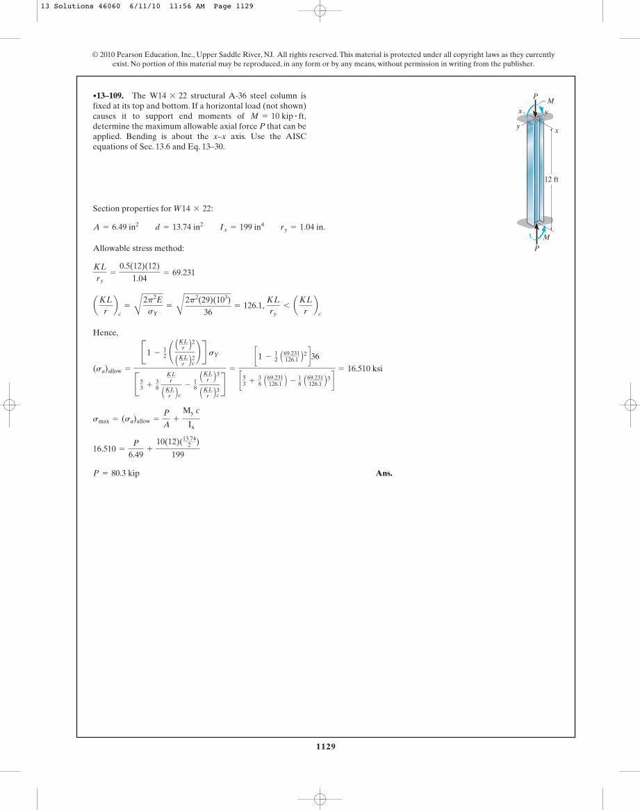
1129
© 2010 Pearson Education, Inc., Upper Saddle River, NJ. All rights reserved. This material is protected under all copyright laws as they currentlyexist. No portion of this material may be reproduced, in any form or by any means, without permission in writing from the publisher.
Section properties for :
Allowable stress method:
,
Hence,
Ans.P = 80.3 kip
16.510 =
P
6.49+
10(12)(13.742 )
199
smax = (sa)allow =
P
A+
My c
Ix
(sa)allow =
B1 -12 ¢ A
KLr B2AKL
r B2c ≤ R sY
B53 +
38
KLr
AKLr B c -
18 AKL
r B3AKL
r B3c R=
c1 -12 A69.231
126.1 B2 d36
c53 +38 A69.231
126.1 B - 18 A69.231126.1 B3 d
= 16.510 ksi
KLry
6 aKLrb
caKL
rb
c=
B
2p2EsY
=
B
2p2(29)(103)
36= 126.1
KLry
=
0.5(12)(12)
1.04= 69.231
A = 6.49 in2 d = 13.74 in2 Ix = 199 in4 ry = 1.04 in.
W14 * 22
•13–109. The structural A-36 steel column isfixed at its top and bottom. If a horizontal load (not shown)causes it to support end moments of determine the maximum allowable axial force P that can beapplied. Bending is about the x–x axis. Use the AISCequations of Sec. 13.6 and Eq. 13–30.
M = 10 kip # ft,
W14 * 22
12 ft
yx
yx
P
P
M
M
13 Solutions 46060 6/11/10 11:56 AM Page 1129
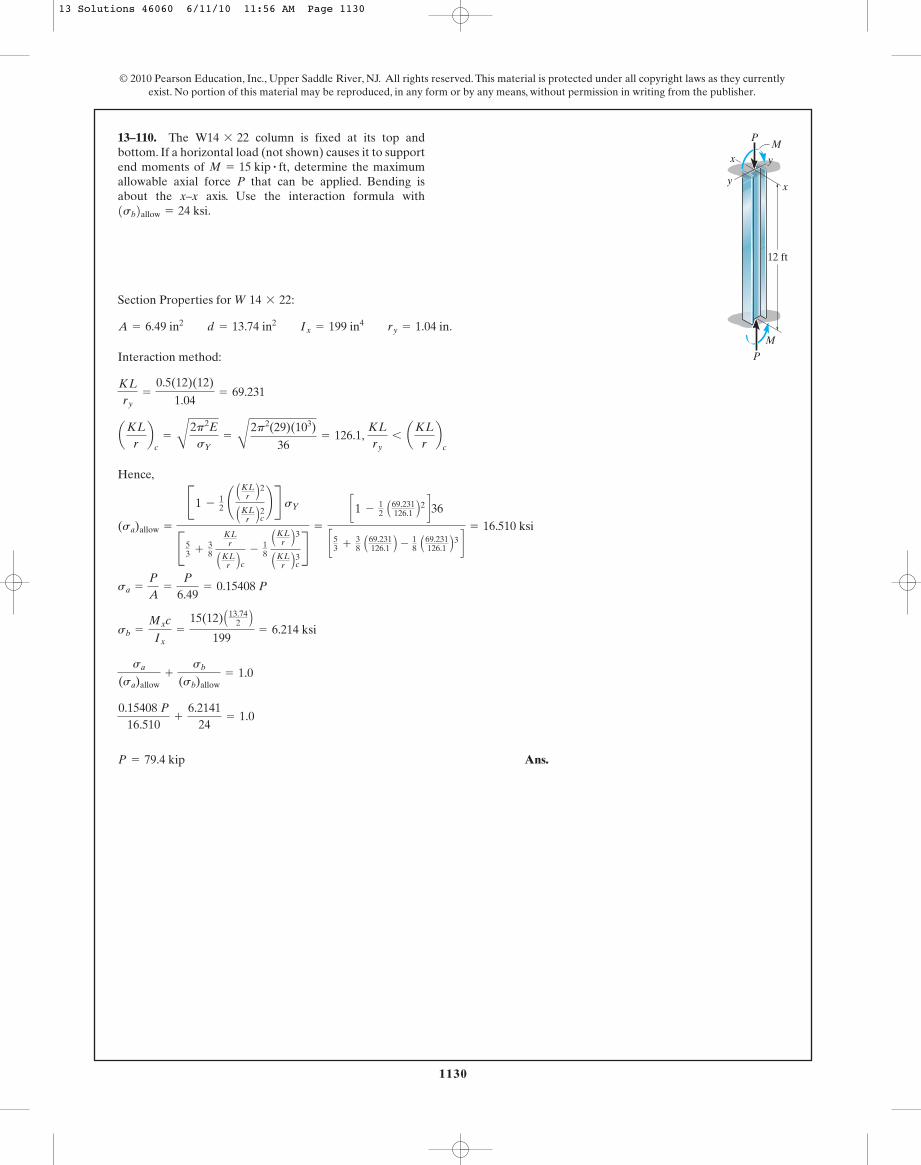
1130
© 2010 Pearson Education, Inc., Upper Saddle River, NJ. All rights reserved. This material is protected under all copyright laws as they currentlyexist. No portion of this material may be reproduced, in any form or by any means, without permission in writing from the publisher.
Section Properties for :
Interaction method:
Hence,
Ans.P = 79.4 kip
0.15408 P16.510
+
6.214124
= 1.0
sa
(sa)allow+
sb
(sb)allow= 1.0
sb =
Mxc
Ix=
15(12) A13.742 B
199= 6.214 ksi
sa =
P
A=
P
6.49= 0.15408 P
(sa)allow =
B1 -12 ¢ A
KLr B2AKL
r B2c ≤ R sY
B53 +
38
KLr
AKLr B c -
18 AKL
r B3AKL
r B3c R=
c1 -12 A69.231
126.1 B2 d36
c53 +38 A69.231
126.1 B - 18 A69.231126.1 B3 d
= 16.510 ksi
aKLrb
c=
B
2p2EsY
=
B
2p2(29)(103)
36= 126.1,
KLry
6 aKLrb
c
KLry
=
0.5(12)(12)
1.04= 69.231
A = 6.49 in2 d = 13.74 in2 Ix = 199 in4 ry = 1.04 in.
W 14 * 22
13–110. The column is fixed at its top andbottom. If a horizontal load (not shown) causes it to supportend moments of determine the maximumallowable axial force P that can be applied. Bending isabout the x–x axis. Use the interaction formula with1sb2allow = 24 ksi.
M = 15 kip # ft,
W14 * 22
12 ft
yx
yx
P
P
M
M
13 Solutions 46060 6/11/10 11:56 AM Page 1130

1131
© 2010 Pearson Education, Inc., Upper Saddle River, NJ. All rights reserved. This material is protected under all copyright laws as they currentlyexist. No portion of this material may be reproduced, in any form or by any means, without permission in writing from the publisher.
Section properties for :
Allowable stress method:
Ans.P = 4.07 kip
9.26 =
P + 4012.6
+
P(16) A7.995A B
45.2
smax = (sa)allow =
P
A+
My c
Iy
(sa)allow =
12p2E
23(KL>r)2 =
12p2(29)(103)
23(126.98)2 = 9.26 ksi
aKLrb
c=
B
2p2EsY
=
B
2p2 (29)(103)36
= 126.1, 200 7
KLry
7 aKLrb
c
KLry
=
2(10)(12)
1.89= 126.98
b = 7.995
Iy = 45.2 in4 ry = 1.89 in.
A = 12.6 in2 d = 13.66 in.
W14 * 43
13–111. The structural A-36 steel columnis fixed at its bottom and free at its top. Determine thegreatest eccentric load P that can be applied usingEq. 13–30 and the AISC equations of Sec. 13.6.
W14 * 43P
10 ft
40 kip
16 in.
13 Solutions 46060 6/11/10 11:56 AM Page 1131
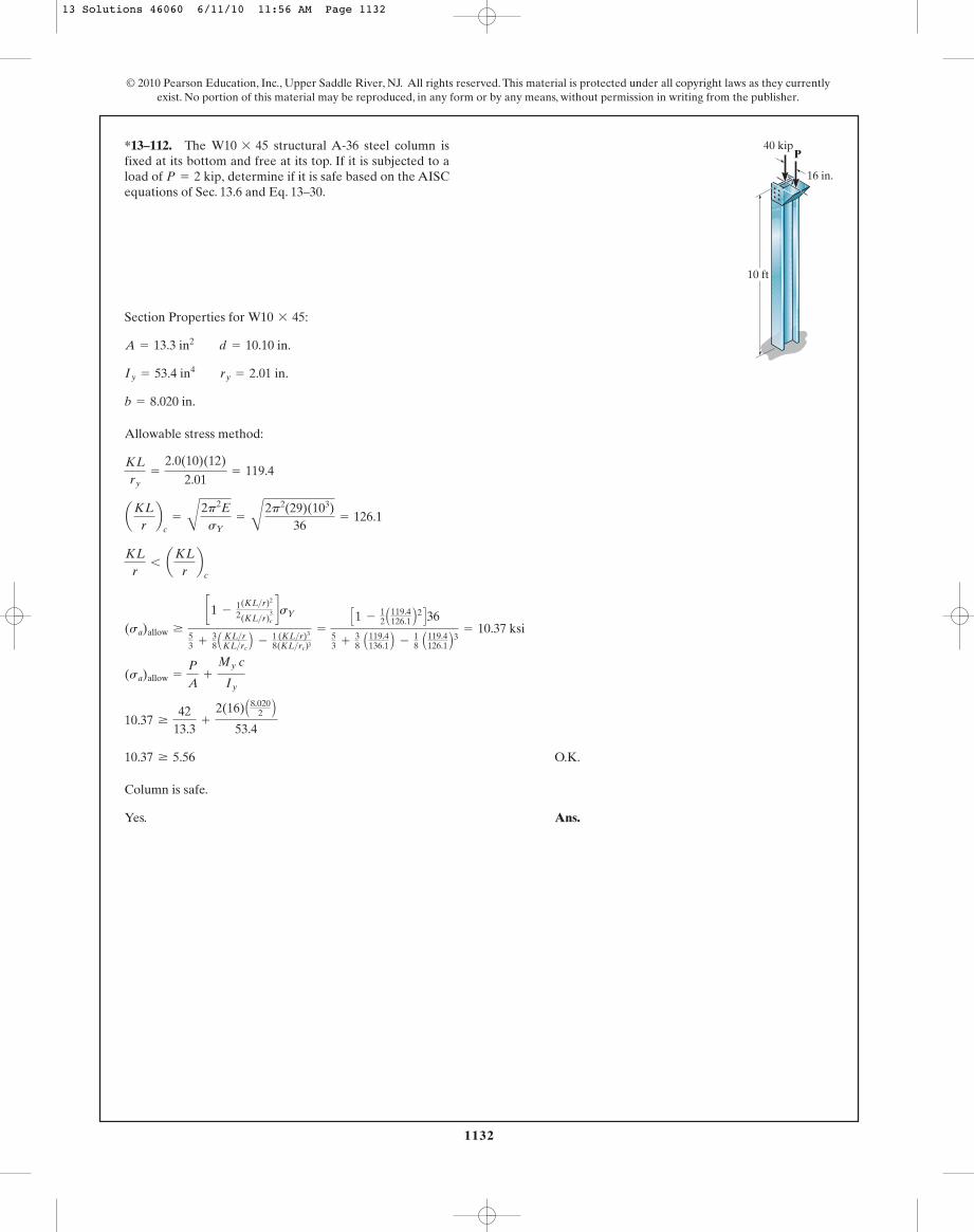
1132
© 2010 Pearson Education, Inc., Upper Saddle River, NJ. All rights reserved. This material is protected under all copyright laws as they currentlyexist. No portion of this material may be reproduced, in any form or by any means, without permission in writing from the publisher.
Section Properties for :
Allowable stress method:
O.K.
Column is safe.
Yes. Ans.
10.37 Ú 5.56
10.37 Ú
4213.3
+
2(16) A8.0202 B
53.4
(sa)allow =
P
A+
My c
Iy
(sa)allow Ú
c1 -12
(KL>r)2
(KL>r)3c
dsY
53 +
38 A KL>r
KL>rcB -
18
(KL>r)3
(KL>rc)3
=
C1 -12 A119.4
126.1 B2 D3653 +
38 A119.4
136.1 B -18 A119.4
126.1 B3 = 10.37 ksi
KLr
6 aKLrb
c
aKLrb
c=
B
2p2EsY
=
B
2p2(29)(103)36
= 126.1
KLry
=
2.0(10)(12)
2.01= 119.4
b = 8.020 in.
Iy = 53.4 in4 ry = 2.01 in.
A = 13.3 in2 d = 10.10 in.
W10 * 45
*13–112. The structural A-36 steel column isfixed at its bottom and free at its top. If it is subjected to aload of determine if it is safe based on the AISCequations of Sec. 13.6 and Eq. 13–30.
P = 2 kip,
W10 * 45P
10 ft
40 kip
16 in.
13 Solutions 46060 6/11/10 11:56 AM Page 1132

1133
© 2010 Pearson Education, Inc., Upper Saddle River, NJ. All rights reserved. This material is protected under all copyright laws as they currentlyexist. No portion of this material may be reproduced, in any form or by any means, without permission in writing from the publisher.
Section Properties. From the table listed in the appendix, the section properties fora are
Slenderness Ratio. Here, . and for a column fixed at its baseand free at its top, . Thus,
Since the column is fixed at its base and pinned at its top, and. Then,
Allowable Stress. The allowable stress will be determined using the AISC columnformulas. For A-36 steel,
. Since ,
the column is classified as a long column.
Maximum Stress. Bending is about the weak axis. Since and
,
Ans.P = 8.604 kip = 8.60 kip
8.400 =
P
13.3+
[P(12)](4.01)
53.4
sallow =
P
A+
Mc
I
c =
bf
2=
8.022
= 4.01 in
M = P(12)
=
12p2 C29 A103 B D23(133.332)
= 8.400 ksi
sallow =
12p2E
23(KL>r)2
aKLrb
c6 aKL
rb
x6 200aKL
rb
c=
B
2p2EsY
=
C
2p2 C29 A103 B D36
= 126.10
aKLrb
y=
0.7(288)
2.01= 100.30
Ly = 24(12) = 288 inKy = 0.7
aKLrb
x=
2(288)
4.32= 133.33 (controls)
Kx = 2Lx = 24(12) = 288 in
A = 13.3 in2 bf = 8.02 in. rx = 4.32 in. Iy = 53.4 in4 ry = 2.01 in.
W10 * 45
•13–113. The A-36-steel column is fixed at itsbase. Its top is constrained to move along the x–x axis butfree to rotate about and move along the y–y axis. Determinethe maximum eccentric force P that can be safely supportedby the column using the allowable stress method.
W10 * 45
x
xy
y
P
24 ft
12 in.
13 Solutions 46060 6/11/10 11:56 AM Page 1133
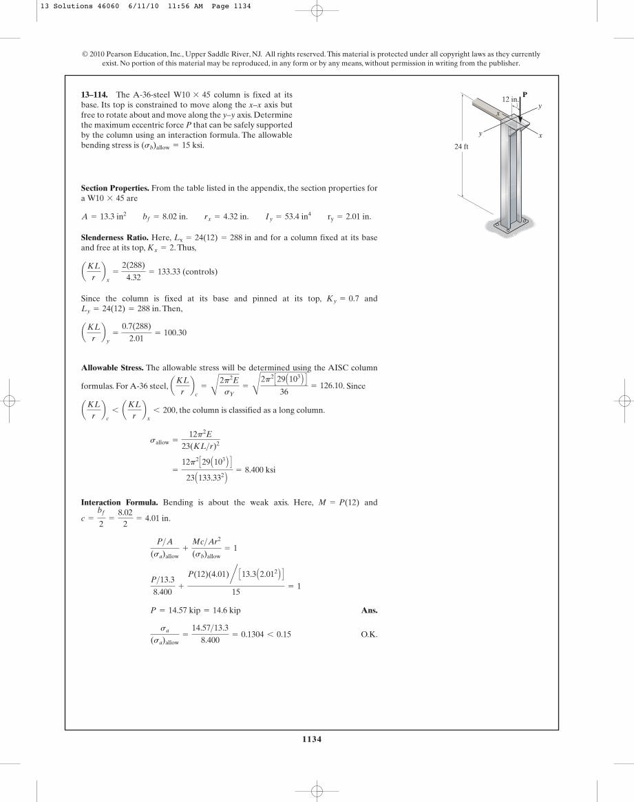
1134
© 2010 Pearson Education, Inc., Upper Saddle River, NJ. All rights reserved. This material is protected under all copyright laws as they currentlyexist. No portion of this material may be reproduced, in any form or by any means, without permission in writing from the publisher.
Section Properties. From the table listed in the appendix, the section properties fora are
Slenderness Ratio. Here, and for a column fixed at its baseand free at its top, . Thus,
Since the column is fixed at its base and pinned at its top, and. Then,
Allowable Stress. The allowable stress will be determined using the AISC column
formulas. For A-36 steel, . Since
, the column is classified as a long column.
Interaction Formula. Bending is about the weak axis. Here, and
.
Ans.
O.K.sa
(sa)allow=
14.57>13.3
8.400= 0.1304 6 0.15
P = 14.57 kip = 14.6 kip
P>13.3
8.400+
P(12)(4.01)n C13.3 A2.012 B D15
= 1
P>A(sa)allow
+
Mc>Ar2
(sb)allow= 1
c =
bf
2=
8.022
= 4.01 in
M = P(12)
=
12p2 C29 A103 B D23 A133.332 B = 8.400 ksi
sallow =
12p2E
23(KL>r)2
aKLrb
c6 aKL
rb
x6 200
aKLrb
c=
B
2p2EsY
=
C
2p2 C29 A103 B D36
= 126.10
aKLrb
y=
0.7(288)
2.01= 100.30
Ly = 24(12) = 288 inKy = 0.7
aKLrb
x=
2(288)
4.32= 133.33 (controls)
Kx = 2Lx = 24(12) = 288 in
A = 13.3 in2 bf = 8.02 in. rx = 4.32 in. Iy = 53.4 in4 ry = 2.01 in.
W10 * 45
13–114. The A-36-steel column is fixed at itsbase. Its top is constrained to move along the x–x axis butfree to rotate about and move along the y–y axis. Determinethe maximum eccentric force P that can be safely supportedby the column using an interaction formula. The allowablebending stress is (sb)allow = 15 ksi.
W10 * 45
x
xy
y
P
24 ft
12 in.
13 Solutions 46060 6/11/10 11:56 AM Page 1134
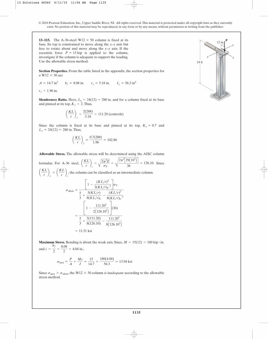
1135
© 2010 Pearson Education, Inc., Upper Saddle River, NJ. All rights reserved. This material is protected under all copyright laws as they currentlyexist. No portion of this material may be reproduced, in any form or by any means, without permission in writing from the publisher.
Section Properties. From the table listed in the appendix, the section properties fora are
Slenderness Ratio. Here, . and for a column fixed at its baseand pinned at its top, . Thus,
Since the column is fixed at its base and pinned at its top, and. Thus,
Allowable Stress. The allowable stress will be determined using the AISC column
formulas. For A-36 steel, . Since
, the column can be classified as an intermediate column.
Maximum Stress. Bending is about the weak axis. Since, .
and .,
Since , the column is inadequate according to the allowablestress method.
W12 * 50smax 7 sallow
smax =
P
A+
Mc
I=
1514.7
+
180(4.04)
56.3= 13.94 ksi
c =
bf
2=
8.082
= 4.04 in
M = 15(12) = 180 kip # in
= 11.51 ksi
=
C1 -
111.202
2 A126.102 B S(36)
53
+
3(111.20)
8(126.10)-
111.203
8 A126.103 B
sallow =
B1 -
(KL>r)2
2(KL>r)C 2RsY
53
+
3(KL>r)
8(KL>r)C-
(KL>r)3
8(KL>r)C 3
aKLrb
x6 aKL
rb
c
aKLrb
c=
A2p2EsY
=
C
2p2 C29 A103 B D36
= 126.10
aKLrb
y=
0.7(288)
1.96= 102.86
Ly = 24(12) = 288 inKy = 0.7
aKLrb
x=
2(288)
5.18= 111.20 (controls)
Kx = 2Lx = 24(12) = 288 in
ry = 1.96 in.
A = 14.7 in2 bf = 8.08 in. rx = 5.18 in. Iy = 56.3 in4
W12 * 50
13–115. The A-36-steel column is fixed at itsbase. Its top is constrained to move along the x–x axis butfree to rotate about and move along the y–y axis. If theeccentric force is applied to the column,investigate if the column is adequate to support the loading.Use the allowable stress method.
P = 15 kip
W12 * 50
x
xy
y
P
24 ft
12 in.
13 Solutions 46060 6/11/10 11:56 AM Page 1135

1136
© 2010 Pearson Education, Inc., Upper Saddle River, NJ. All rights reserved. This material is protected under all copyright laws as they currentlyexist. No portion of this material may be reproduced, in any form or by any means, without permission in writing from the publisher.
Section Properties. From the table listed in the appendix, the section properties fora are
Slenderness Ratio. Here, and for a column fixed at its baseand pinned at its top, . Thus,
Since the column is fixed at its base and pinned at its top, and. Then,
Allowable Axial Stress. For A-36 steel,
. Since , the column can be
classified as an intermediate column.
Interaction Formula. Bending is about the weak axis. Here,
. and
Ans.
O.K.
Thus, a column is adequate according to the interaction formula.W12 * 50
sa
(sa)allow=
15>14.7
11.51= 0.089 6 0.15
P = 14.57 kip = 14.6 kip
P>A(sa)allow
+
Mc>Ar2
(sb)allow=
15>14.7
11.51+
180(4.04)n C14.7 A1.962 B D15
= 0.9471 6 1
c =
bf
2=
8.082
= 4.04 in.= 180 kip # in
M = 15(12)
= 11.51 ksi
=
C1 -
111.202
2 A126.102 B S(36)
53
+
3(111.20)
8(126.10)-
111.203
8 A126.103 B
sallow =
C1 -
(KL>r)2
2(KL>r)c 2 SsY
53
+
3(KL>r)
8(KL>r)c-
(KL>r)3
8(KL>r)c 3
aKLrb
x6 aKL
rb
c=
C
2p2 C29 A103 B D36
= 126.10
aKLrb
c=
A2p2EsY
aKLrb
y=
0.7(288)
1.96= 102.86
Ly = 24(12) = 288 inKy = 0.7
aKLrb
x=
2(288)
5.18= 111.20 (controls)
Kx = 2Lx = 24(12) = 288 in
A = 14.7 in2 bf = 8.08 in. rx = 5.18 in. ry = 1.96 in.
W12 * 50
*13–116. The A-36-steel column is fixed at itsbase. Its top is constrained to move along the x–x axis butfree to rotate about and move along the y–y axis. If theeccentric force is applied to the column,investigate if the column is adequate to support the loading.Use the interaction formula.The allowable bending stress is(sb)allow = 15 ksi.
P = 15 kip
W12 * 50
x
xy
y
P
24 ft
12 in.
13 Solutions 46060 6/11/10 11:56 AM Page 1136
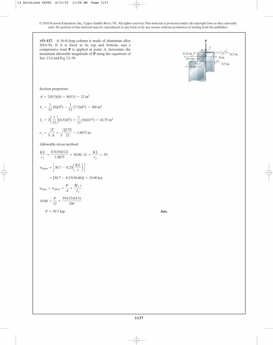
1137
© 2010 Pearson Education, Inc., Upper Saddle River, NJ. All rights reserved. This material is protected under all copyright laws as they currentlyexist. No portion of this material may be reproduced, in any form or by any means, without permission in writing from the publisher.
Section properties:
Allowable stress method:
Ans.P = 95.7 kip
19.00 =
P
12+
P(4.25)(4.5)
166
smax = sallow =
P
A+
Mx c
Ix
= [30.7 - 0.23(50.86)] = 19.00 ksi
sallow = c30.7 - 0.23aKLrb d
KLry
=
0.5(16)(12)
1.8875= 50.86, 12 6
KLry
6 55
ry =
A
Iy
A=
A
42.7512
= 1.8875 in.
Iy = 2a 112b(0.5)(83) +
112
(8)(0.53) = 42.75 in4
Ix =
112
(8)(93) -
112
(7.5)(83) = 166 in4
A = 2(0.5)(8) + 8(0.5) = 12 in2
•13–117. A 16-ft-long column is made of aluminum alloy2014-T6. If it is fixed at its top and bottom, and acompressive load P is applied at point A, determine themaximum allowable magnitude of P using the equations ofSec. 13.6 and Eq. 13–30. 8 in.
0.5 in.
0.5 in.
4.25 in.
y
x x
8 in.y
P
A0.5 in.
13 Solutions 46060 6/11/10 11:56 AM Page 1137

1138
© 2010 Pearson Education, Inc., Upper Saddle River, NJ. All rights reserved. This material is protected under all copyright laws as they currentlyexist. No portion of this material may be reproduced, in any form or by any means, without permission in writing from the publisher.
Section Properties:
Interaction method:
Ans.P = 98.6 kip
0.08333P
19.00+
0.1152P
20= 1
sa
(sa)allow+
sb
(sb)allow= 1.0
sb =
Mc
Ix=
P(4.25)(4.50)
166= 0.1152P
sa =
P
A=
P
12= 0.08333P
= 19.00 ksi
= [30.7 - 0.23(50.86)]
sallow = c30.7 - 0.23aKLrb d
KLry
=
0.5(16)(12)
1.8875= 50.86, 12 6
KLry
6 55
ry =
A
Iy
A=
A
42.7512
= 1.8875 in.
Iy = 2a 112b(0.5)(83) +
112
(8)(0.53) = 42.75 in4
Ix =
112
(8)(93) -
112
(7.5)(83) = 166 in4
A = 2(0.5)(8) + 8(0.5) = 12 in2
13–118. A 16-ft-long column is made of aluminum alloy2014-T6. If it is fixed at its top and bottom, and acompressive load P is applied at point A, determine themaximum allowable magnitude of P using the equations ofSec. 13.6 and the interaction formula with 1sb2allow = 20 ksi. 8 in.
0.5 in.
0.5 in.
4.25 in.
y
x x
8 in.y
P
A0.5 in.
13 Solutions 46060 6/11/10 11:56 AM Page 1138
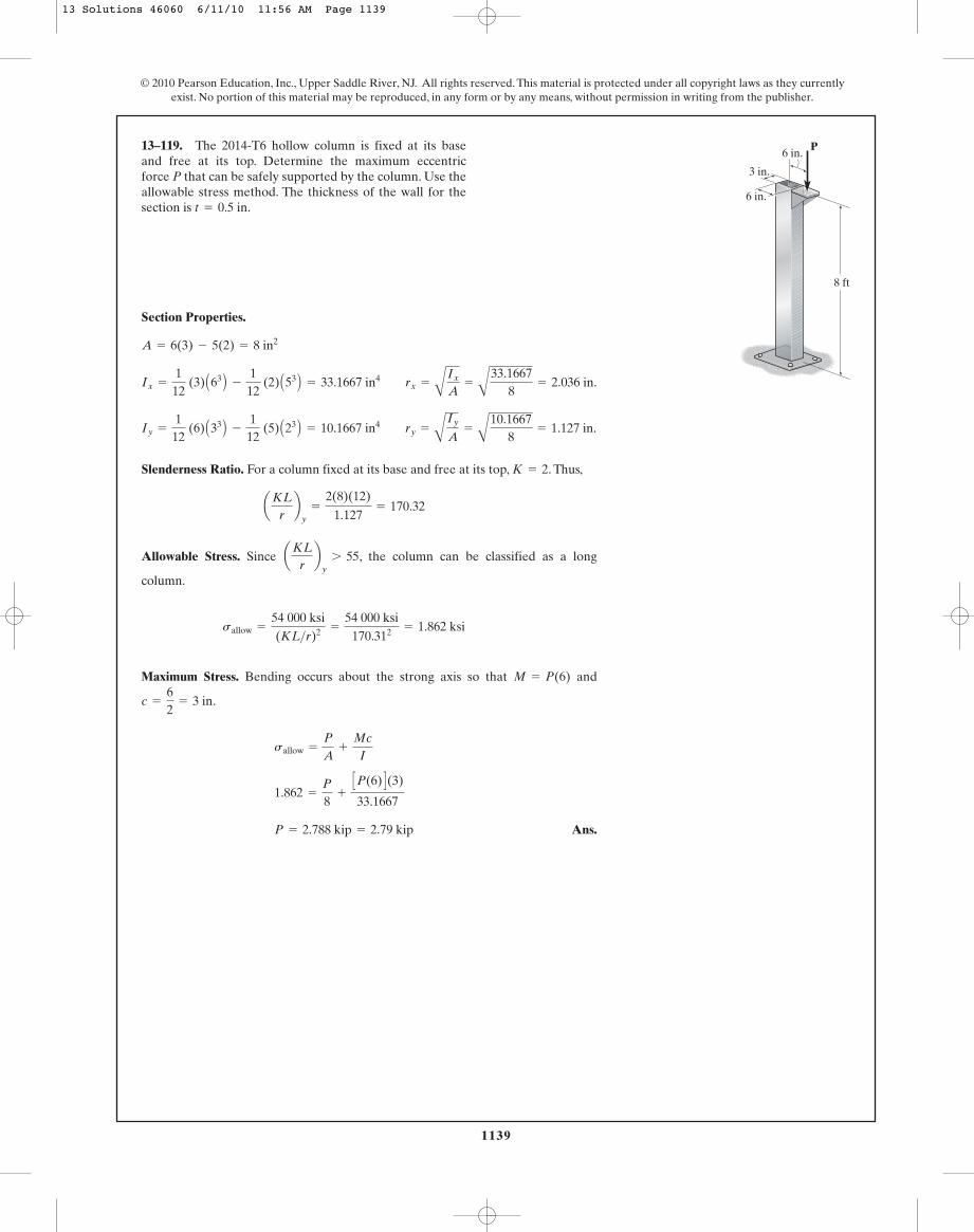
1139
© 2010 Pearson Education, Inc., Upper Saddle River, NJ. All rights reserved. This material is protected under all copyright laws as they currentlyexist. No portion of this material may be reproduced, in any form or by any means, without permission in writing from the publisher.
Section Properties.
Slenderness Ratio. For a column fixed at its base and free at its top, . Thus,
Allowable Stress. Since , the column can be classified as a long
column.
Maximum Stress. Bending occurs about the strong axis so that and
.
Ans.P = 2.788 kip = 2.79 kip
1.862 =
P
8+
CP(6) D(3)
33.1667
sallow =
P
A+
Mc
I
c =
62
= 3 in
M = P(6)
sallow =
54 000 ksi(KL>r)2 =
54 000 ksi170.312 = 1.862 ksi
aKLrb
y7 55
aKLrb
y=
2(8)(12)
1.127= 170.32
K = 2
Iy =
112
(6) A33 B -
112
(5) A23 B = 10.1667 in4 ry =
A
Iy
A=
A
10.16678
= 1.127 in.
Ix =
112
(3) A63 B -
112
(2) A53 B = 33.1667 in4 rx =
AIx
A=
A
33.16678
= 2.036 in.
A = 6(3) - 5(2) = 8 in2
13–119. The 2014-T6 hollow column is fixed at its baseand free at its top. Determine the maximum eccentricforce P that can be safely supported by the column. Use theallowable stress method. The thickness of the wall for thesection is t = 0.5 in.
P6 in.
6 in.
3 in.
8 ft
13 Solutions 46060 6/11/10 11:56 AM Page 1139
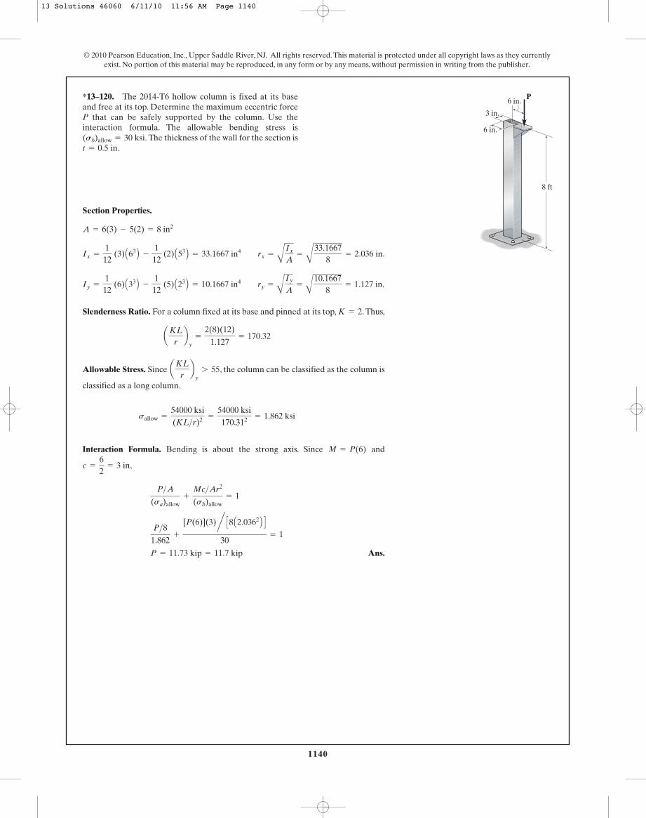
1140
© 2010 Pearson Education, Inc., Upper Saddle River, NJ. All rights reserved. This material is protected under all copyright laws as they currentlyexist. No portion of this material may be reproduced, in any form or by any means, without permission in writing from the publisher.
Section Properties.
Slenderness Ratio. For a column fixed at its base and pinned at its top, . Thus,
Allowable Stress. Since , the column can be classified as the column is
classified as a long column.
Interaction Formula. Bending is about the strong axis. Since and
,
Ans.P = 11.73 kip = 11.7 kip
P>81.862
+
[P(6)](3)n C8 A2.0362 B D30
= 1
P>A(sa)allow
+
Mc>Ar2
(sb)allow= 1
c =
62
= 3 in
M = P(6)
sallow =
54000 ksi(KL>r)2 =
54000 ksi170.312 = 1.862 ksi
aKLrb
y7 55
aKLrb
y=
2(8)(12)
1.127= 170.32
K = 2
Iy =
112
(6) A33 B -
112
(5) A23 B = 10.1667 in4 ry =
A
Iy
A=
A
10.16678
= 1.127 in.
Ix =
112
(3) A63 B -
112
(2) A53 B = 33.1667 in4 rx =
AIx
A=
A
33.16678
= 2.036 in.
A = 6(3) - 5(2) = 8 in2
*13–120. The 2014-T6 hollow column is fixed at its baseand free at its top. Determine the maximum eccentric forceP that can be safely supported by the column. Use theinteraction formula. The allowable bending stress is
The thickness of the wall for the section ist = 0.5 in.(sb)allow = 30 ksi.
P6 in.
6 in.
3 in.
8 ft
13 Solutions 46060 6/11/10 11:56 AM Page 1140
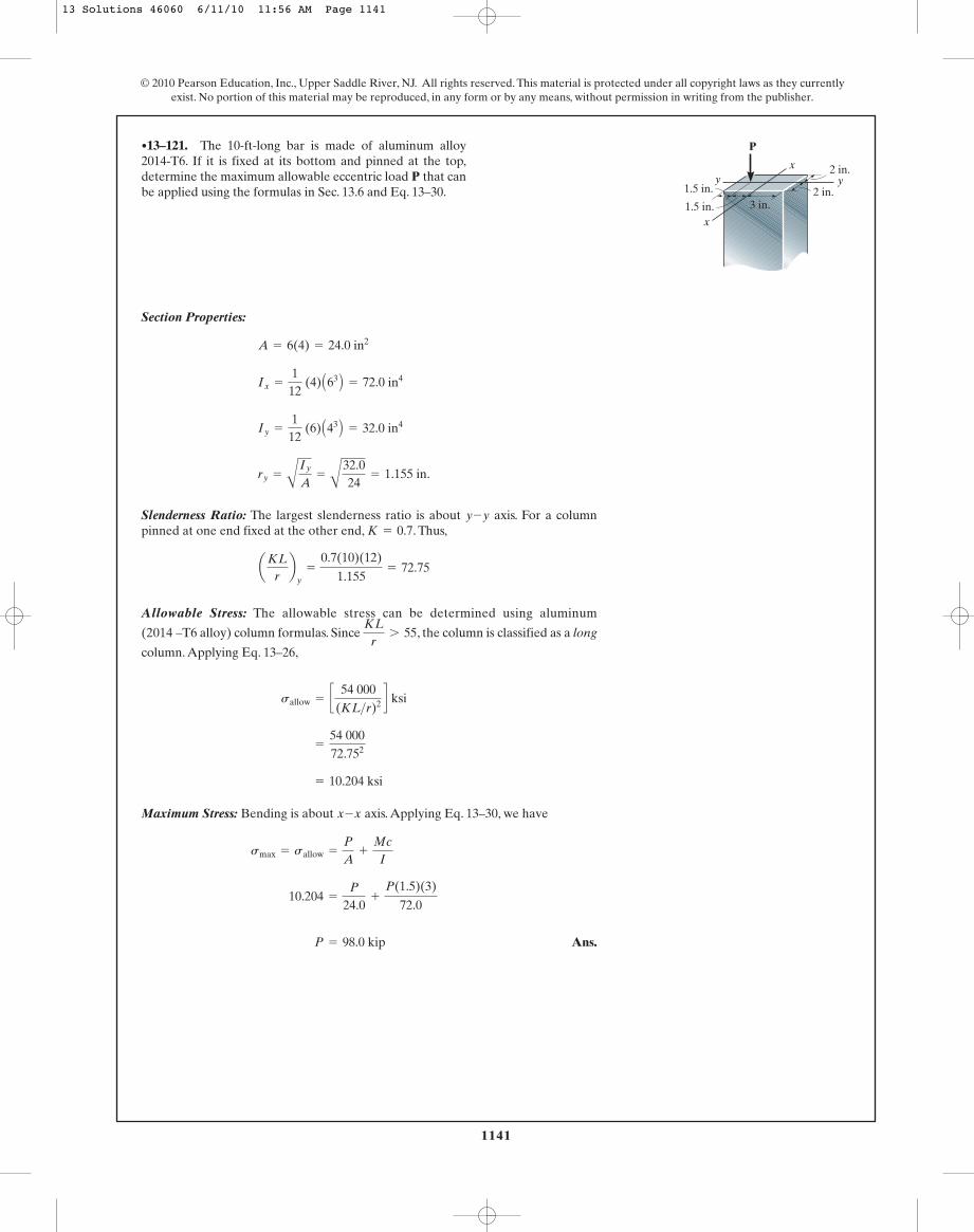
1141
© 2010 Pearson Education, Inc., Upper Saddle River, NJ. All rights reserved. This material is protected under all copyright laws as they currentlyexist. No portion of this material may be reproduced, in any form or by any means, without permission in writing from the publisher.
Section Properties:
Slenderness Ratio: The largest slenderness ratio is about axis. For a columnpinned at one end fixed at the other end, . Thus,
Allowable Stress: The allowable stress can be determined using aluminum
(2014 –T6 alloy) column formulas. Since , the column is classified as a long
column. Applying Eq. 13–26,
Maximum Stress: Bending is about axis. Applying Eq. 13–30, we have
Ans. P = 98.0 kip
10.204 =
P
24.0+
P(1.5)(3)
72.0
smax = sallow =
P
A+
Mc
I
x-x
= 10.204 ksi
=
54 00072.752
sallow = c 54 000(KL>r)2 d ksi
KLr
7 55
aKLrb
y=
0.7(10)(12)
1.155= 72.75
K = 0.7y-y
ry =
A
Iy
A=
A
32.024
= 1.155 in.
Iy =
112
(6) A43 B = 32.0 in4
Ix =
112
(4) A63 B = 72.0 in4
A = 6(4) = 24.0 in2
•13–121. The 10-ft-long bar is made of aluminum alloy2014-T6. If it is fixed at its bottom and pinned at the top,determine the maximum allowable eccentric load P that canbe applied using the formulas in Sec. 13.6 and Eq. 13–30.
3 in.1.5 in.
1.5 in.
x
xy y
2 in.
2 in.
P
13 Solutions 46060 6/11/10 11:56 AM Page 1141
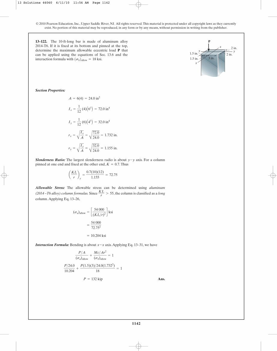
1142
© 2010 Pearson Education, Inc., Upper Saddle River, NJ. All rights reserved. This material is protected under all copyright laws as they currentlyexist. No portion of this material may be reproduced, in any form or by any means, without permission in writing from the publisher.
Section Properties:
Slenderness Ratio: The largest slenderness radio is about axis. For a columnpinned at one end and fixed at the other end, . Thus
Allowable Stress: The allowable stress can be determined using aluminum
(2014 –T6 alloy) column formulas. Since , the column is classified as a long
column. Applying Eq. 13–26,
Interaction Formula: Bending is about axis. Applying Eq. 13–31, we have
Ans.P = 132 kip
P>24.0
10.204+
P(1.5)(3)>24.0(1.7322)
18= 1
P>A
(sa)allow+
Mc>Ar2
(sb)allow= 1
x-x
= 10.204 ksi
=
54 00072.752
(sa)allow = c 54 000(KL>r)2 d ksi
KLr 7 55
aKLrb
y=
0.7(10)(12)
1.155= 72.75
K = 0.7y-y
ry =
A
Iy
A=
A
32.024.0
= 1.155 in.
rx =
A
Ix
A=
A
72.024.0
= 1.732 in.
Iy =
112
(6) A43 B = 32.0 in4
Ix =
112
(4) A63 B = 72.0 in4
A = 6(4) = 24.0 in2
13–122. The 10-ft-long bar is made of aluminum alloy2014-T6. If it is fixed at its bottom and pinned at the top,determine the maximum allowable eccentric load P thatcan be applied using the equations of Sec. 13.6 and theinteraction formula with 1sb2allow = 18 ksi. 3 in.1.5 in.
1.5 in.
x
xy y
2 in.
2 in.
P
13 Solutions 46060 6/11/10 11:56 AM Page 1142
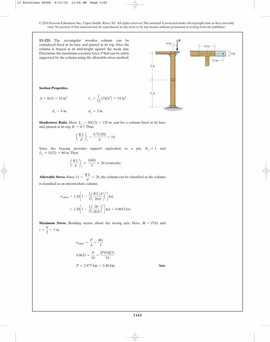
1143
© 2010 Pearson Education, Inc., Upper Saddle River, NJ. All rights reserved. This material is protected under all copyright laws as they currentlyexist. No portion of this material may be reproduced, in any form or by any means, without permission in writing from the publisher.
13–123. The rectangular wooden column can beconsidered fixed at its base and pinned at its top. Also, thecolumn is braced at its mid-height against the weak axis.Determine the maximum eccentric force P that can be safelysupported by the column using the allowable stress method.
Section Properties.
Slenderness Ratio. Here, . and for a column fixed at its baseand pinned at its top, . Thus,
Since the bracing provides support equivalent to a pin, and. Then
Allowable Stress. Since , the column can be classified as the column
is classified as an intermediate column.
Maximum Stress. Bending occurs about the strong axis. Here, and
.
Ans.P = 2.477 kip = 2.48 kip
0.9633 =
P
18+
[P(6)](3)
54
sallow =
P
A+
Mc
I
c =
62
= 3 in
M = P(6)
= 1.20 c1 -
13a 20
26.0b2 d ksi = 0.9633 ksi
sallow = 1.20 c1 -
13aKL>d
26.0b2 d ksi
11 6
KL
d6 26
aKL
db
y=
1(60)
3= 20 (controls)
Ly = 5(12) = 60 inKy = 1
aKL
db
x=
0.7(120)
6= 14
K = 0.7Lx = 10(12) = 120 in
dx = 6 in. dy = 3 in.
A = 6(3) = 18 in2 Ix =
112
(3) A63 B = 54 in4
5 ft
5 ft
P6 in.
6 in.
6 in.
3 in.
13 Solutions 46060 6/11/10 11:56 AM Page 1143

1144
© 2010 Pearson Education, Inc., Upper Saddle River, NJ. All rights reserved. This material is protected under all copyright laws as they currentlyexist. No portion of this material may be reproduced, in any form or by any means, without permission in writing from the publisher.
*13–124. The rectangular wooden column can beconsidered fixed at its base and pinned at its top. Also, thecolumn is braced at its mid-height against the weak axis.Determine the maximum eccentric force P that can besafely supported by the column using the interactionformula. The allowable bending stress is (sb)allow = 1.5 ksi.
Section Properties.
Slenderness Ratio. Here, . and for a column fixed at its basepinned at its top, . Thus,
Since the bracing provides support equivalent to a pin, and. Then
Allowable Axial Stress. Since , the column can be classified as the
column is classified as an intermediate column.
Interaction Formula. Bending occurs about the strong axis. Since and
.
Ans.P = 3.573 kip = 3.57 kip
P>18
0.9633+
[P(6)](3)n C18 A1.7322 B D1.5
= 1
P>A(sa)allow
+
Mc>Ar2
(sb)allow= 1
c =
62
= 3 in
M = P(6)
= 1.20 c1 -
13a 20
26.0b2 d ksi = 0.9633 ksi
sallow = 1.20 c1 -
13
aKL>d26.0
b2 d ksi
11 6
KL
d6 26
aKL
db
y=
1(60)
3= 20 (controls)
Ly = 5(12) = 60 inKy = 1
aKL
db
x=
0.7(120)
6= 14
K = 0.7Lx = 10(12) = 120 in
rx =
A
Ix
A=
A
5418
= 1.732 in. dx = 6 in. dy = 3 in.
A = 6(3) = 18 in2 Ix =
112
(3) A63 B = 54 in4
5 ft
5 ft
P6 in.
6 in.
6 in.
3 in.
13 Solutions 46060 6/11/10 11:56 AM Page 1144
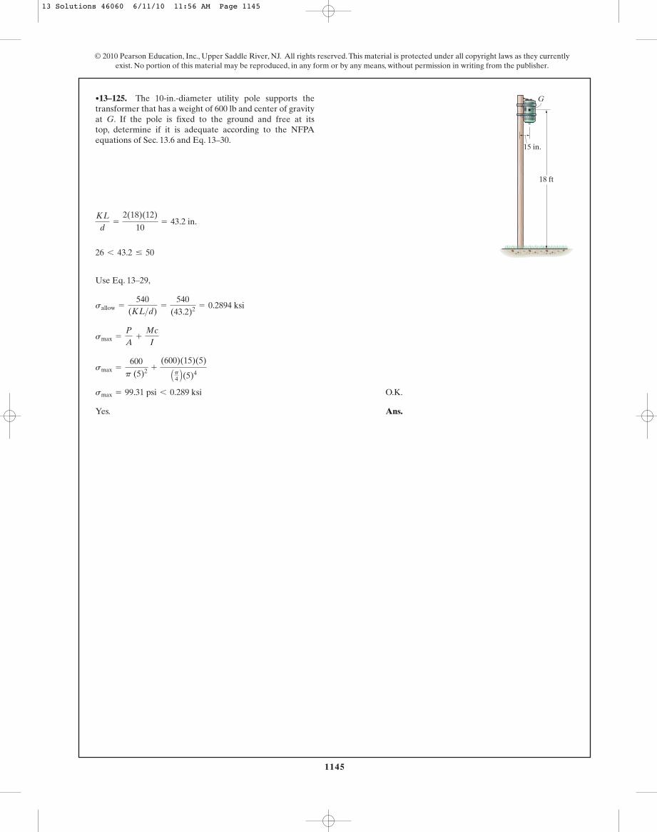
1145
© 2010 Pearson Education, Inc., Upper Saddle River, NJ. All rights reserved. This material is protected under all copyright laws as they currentlyexist. No portion of this material may be reproduced, in any form or by any means, without permission in writing from the publisher.
Use Eq. 13–29,
O.K.
Yes. Ans.
smax = 99.31 psi 6 0.289 ksi
smax =
600p (5)2 +
(600)(15)(5)
Ap4 B(5)4
smax =
P
A+
Mc
I
sallow =
540(KL>d)
=
540(43.2)2 = 0.2894 ksi
26 6 43.2 … 50
KL
d=
2(18)(12)
10= 43.2 in.
•13–125. The 10-in.-diameter utility pole supports thetransformer that has a weight of 600 lb and center of gravityat G. If the pole is fixed to the ground and free at itstop, determine if it is adequate according to the NFPAequations of Sec. 13.6 and Eq. 13–30.
G
18 ft
15 in.
13 Solutions 46060 6/11/10 11:56 AM Page 1145

1146
© 2010 Pearson Education, Inc., Upper Saddle River, NJ. All rights reserved. This material is protected under all copyright laws as they currentlyexist. No portion of this material may be reproduced, in any form or by any means, without permission in writing from the publisher.
Section Properties:
Slenderness Ratio: For a column pinned at both ends, . Thus,
Allowable Stress: The allowable stress can be determined using NFPA timber
column formulas. Since , it is a long column. Applying Eq. 13–29,
Maximum Stress: Bending is about axis. Applying Eq. 13–30, we have
Ans. P = 1.69 kip
0.234375 =
P
18.0+
P(0.75)(1.5)
13.5
smax = sallow =
P
A+
Mc
I
y-y
=
54048.02 = 0.234375 ksi
sallow =
540(KL>d)2 ksi
26 6
KL
d6 50
aKL
db
y=
1.0(12)(12)
3= 48.0
K = 1.0
Iy =
112
(6) A33 B = 13.5 in4
A = 6(3) = 18.0 in2
13–126. Using the NFPA equations of Sec. 13.6 andEq. 13–30, determine the maximum allowable eccentricload P that can be applied to the wood column.Assume thatthe column is pinned at both its top and bottom.
6 in.
12 ft
P0.75 in.
3 in.
13 Solutions 46060 6/11/10 11:56 AM Page 1146
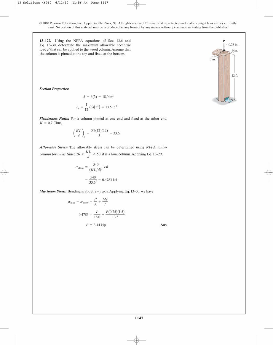
1147
© 2010 Pearson Education, Inc., Upper Saddle River, NJ. All rights reserved. This material is protected under all copyright laws as they currentlyexist. No portion of this material may be reproduced, in any form or by any means, without permission in writing from the publisher.
Section Properties:
Slenderness Ratio: For a column pinned at one end and fixed at the other end,. Thus,
Allowable Stress: The allowable stress can be determined using NFPA timber
column formulas. Since , it is a long column. Applying Eq. 13–29,
Maximum Stress: Bending is about axis. Applying Eq. 13–30, we have
Ans. P = 3.44 kip
0.4783 =
P
18.0+
P(0.75)(1.5)
13.5
smax = sallow =
P
A+
Mc
I
y-y
=
54033.62 = 0.4783 ksi
sallow =
540(KL>d)2 ksi
26 6
KL
d6 50
aKL
db
y=
0.7(12)(12)
3= 33.6
K = 0.7
Iy =
112
(6) A33 B = 13.5 in4
A = 6(3) = 18.0 in2
13–127. Using the NFPA equations of Sec. 13.6 andEq. 13–30, determine the maximum allowable eccentricload P that can be applied to the wood column.Assume thatthe column is pinned at the top and fixed at the bottom.
6 in.
12 ft
P0.75 in.
3 in.
13 Solutions 46060 6/11/10 11:56 AM Page 1147
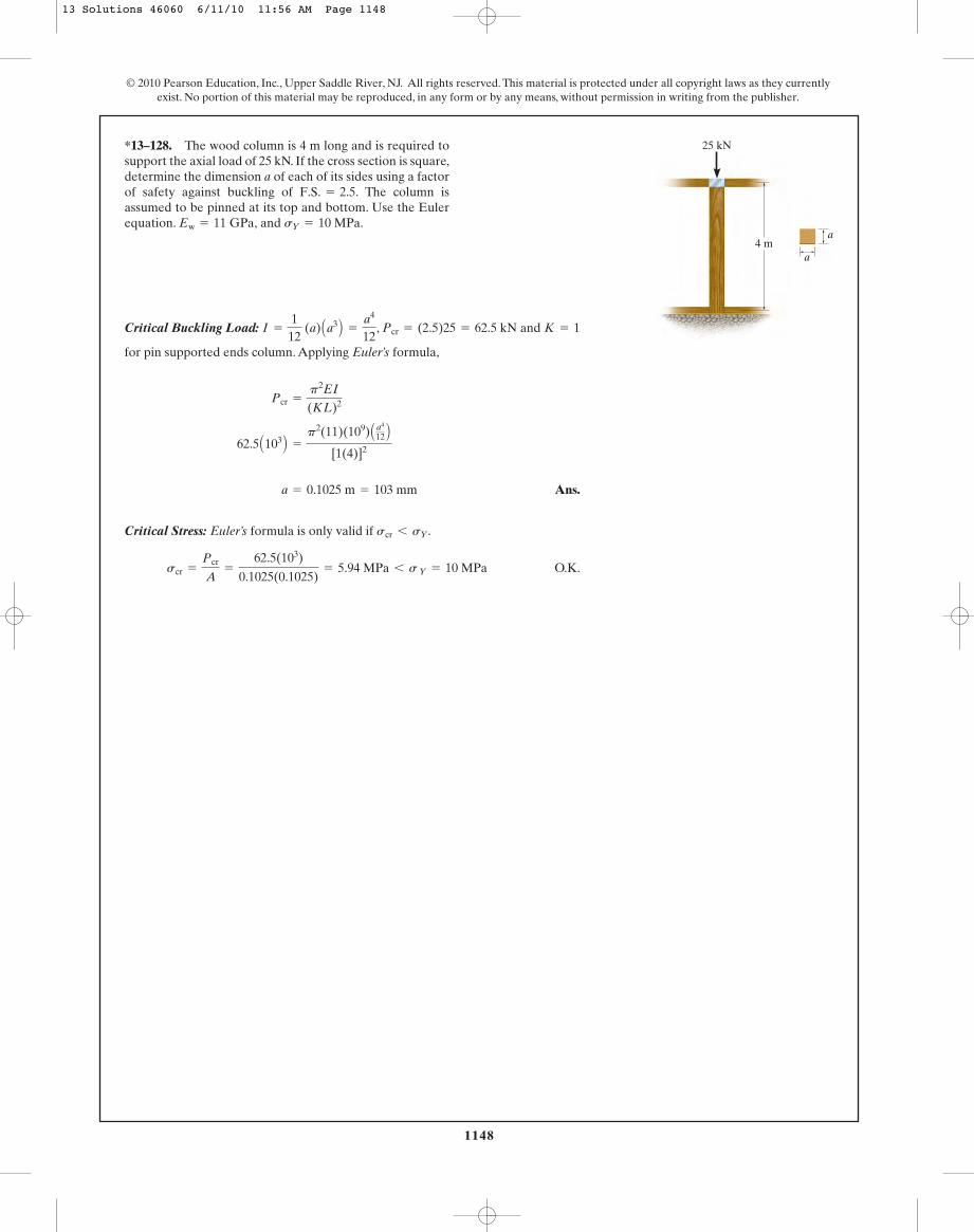
1148
© 2010 Pearson Education, Inc., Upper Saddle River, NJ. All rights reserved. This material is protected under all copyright laws as they currentlyexist. No portion of this material may be reproduced, in any form or by any means, without permission in writing from the publisher.
Critical Buckling Load: , and
for pin supported ends column. Applying Euler’s formula,
Ans.
Critical Stress: Euler’s formula is only valid if .
O.K.scr =
Pcr
A=
62.5(103)
0.1025(0.1025)= 5.94 MPa 6 s Y = 10 MPa
scr 6 sY
a = 0.1025 m = 103 mm
62.5 A103 B =
p2(11)(109) A a4
12 B[1(4)]2
Pcr =
p2EI
(KL)2
K = 1Pcr = (2.5)25 = 62.5 kNI =
112
(a) Aa3 B =
a4
12
*13–128. The wood column is 4 m long and is required tosupport the axial load of 25 kN. If the cross section is square,determine the dimension a of each of its sides using a factorof safety against buckling of The column isassumed to be pinned at its top and bottom. Use the Eulerequation. and sY = 10 MPa.Ew = 11 GPa,
F.S. = 2.5.
25 kN
4 ma
a
13 Solutions 46060 6/11/10 11:56 AM Page 1148

1149
© 2010 Pearson Education, Inc., Upper Saddle River, NJ. All rights reserved. This material is protected under all copyright laws as they currentlyexist. No portion of this material may be reproduced, in any form or by any means, without permission in writing from the publisher.
Equilibrium. When the system is given a slight lateral disturbance, the configurationshown in Fig. a is formed. The couple moment M can be related to P by consideringthe equilibrium of members AB and BC.
Member AB
(1)
a (2)
Member BC
a (3)
Solving Eqs. (1), (2), and (3), we obtain
Since is very small, the small angle analysis gives . Thus,
(4)
Torslonal Spring Moment. The restoring couple moment Msp can be determinedusing the torsional spring formula, . Thus,
Critical Buckling Load. When the mechanism is on the verge of bucklling M mustequal Msp.
Ans.Pcr =
2k
L
Pcr L
2 u = ku
M = Msp
Msp = ku
M = ku
M =
PL
2 u
sin u � uu
Bx = 0 By =
2M
L sin u M =
PL
2 sin u
+ ©MC = 0; -ByaL
2 sin ub + BxaL
2 cos ub + M = 0
+ ©MA = 0; ByaL
2 sin ub + BxaL
2 cos ub - M = 0
+ c ©Fy = 0; By - P = 0
•13–129. If the torsional springs attached to ends A andC of the rigid members AB and BC have a stiffness k,determine the critical load Pcr.
P
k
k
B
A
C
L2
L2
13 Solutions 46060 6/11/10 11:56 AM Page 1149

1150
© 2010 Pearson Education, Inc., Upper Saddle River, NJ. All rights reserved. This material is protected under all copyright laws as they currentlyexist. No portion of this material may be reproduced, in any form or by any means, without permission in writing from the publisher.
13–129. Continued
13 Solutions 46060 6/11/10 11:56 AM Page 1150

1151
© 2010 Pearson Education, Inc., Upper Saddle River, NJ. All rights reserved. This material is protected under all copyright laws as they currentlyexist. No portion of this material may be reproduced, in any form or by any means, without permission in writing from the publisher.
13–130. Determine the maximum intensity w of theuniform distributed load that can be applied on the beamwithout causing the compressive members of the supportingtruss to buckle. The members of the truss are made from A-36-steel rods having a 60-mm diameter. Use F.S. = 2against buckling.
2 m 3.6 m
1.5 m
B
C
A
D
w
Equilibrium. The force developed in member BC can be determined by consideringthe equilibrium of the free-body diagram of the beam AB, Fig. a.
a
The Force developed in member CD can be obtained by analyzing the equilibriumof joint C, Fig. b,
Section Properties. The cross-sectional area and moment of inertia of the solidcircular rod CD are
Critical Buckling Load. Since both ends of member CD are pinned, . Thecritical buckling load is
Applying Euler’s formula,
Ans.
Critical Stress: Euler’s formula is valid only if .
O.K.scr =
Pcr
A=
20.907(4634.63)
0.9 A10- 3 Bp = 34.27 MPa 6 sY = 250 MPa
scr 6 sY
w = 4634.63 N>m = 4.63 kN>m
20.9067w =
p2 C200 A109 B D C0.2025 A10- 6 Bp D[1(3.6)]2
Pcr =
p2EI
(KL)2
Pcr = FCD (F.S.) = 10.4533w(2) = 20.9067w
K = 1
A = p A0.032 B = 0.9 A10- 3 Bp m2 I =
p
4A0.034 B = 0.2025 A10- 6 Bp m4
:+ ©Fx = 0; 4.6667wa45b + 7.28a12
13b w-FCD = 0 FCD = 10.4533w (C)
+ c ©Fy = 0; FACa 513b - 4.6667wa 3
5b = 0 FAC = 7.28w (T)
+ ©MA = 0; w(5.6)(2.8) - FBCa35b(5.6) = 0 FBC = 4.6667w
13 Solutions 46060 6/11/10 11:56 AM Page 1151
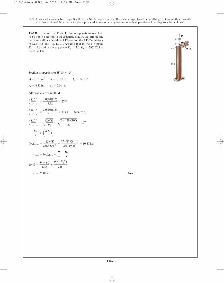
1152
© 2010 Pearson Education, Inc., Upper Saddle River, NJ. All rights reserved. This material is protected under all copyright laws as they currentlyexist. No portion of this material may be reproduced, in any form or by any means, without permission in writing from the publisher.
Section properties for :
Allowable stress method:
Ans. P = 25.0 kip
10.47 =
P + 6013.3
+
P(8) A10.102 B
248
smax = (sa)allow =
P
A+
Mc
I
(sa)allow =
12p2E
23(KL>r)2 =
12p2(29)(103)
23(119.4)4 = 10.47 ksi
KL
r7 aKL
rb
c
aKLrb
c=
B
2p2Esg
=
B
2p2(29)(103)
50= 107
aKLrb
y=
2.0(10)(12)
2.01= 119.4 (controls)
aKLrb
x=
1.0(10)(12)
4.32= 27.8
rx = 4.32 in. ry = 2.01 in.
A = 13.3 in2 d = 10.10 in. Ix = 248 in4
W 10 * 45
13–131. The steel column supports an axial loadof 60 kip in addition to an eccentric load P. Determine themaximum allowable value of P based on the AISC equationsof Sec. 13.6 and Eq. 13–30. Assume that in the x–z plane
and in the y–z plane sY = 50 ksi.
Est = 2911032 ksi,Ky = 2.0.Kx = 1.0
W10 * 45
10 ft
60 kip
y x
yx
8 in.
Pz
13 Solutions 46060 6/11/10 11:56 AM Page 1152
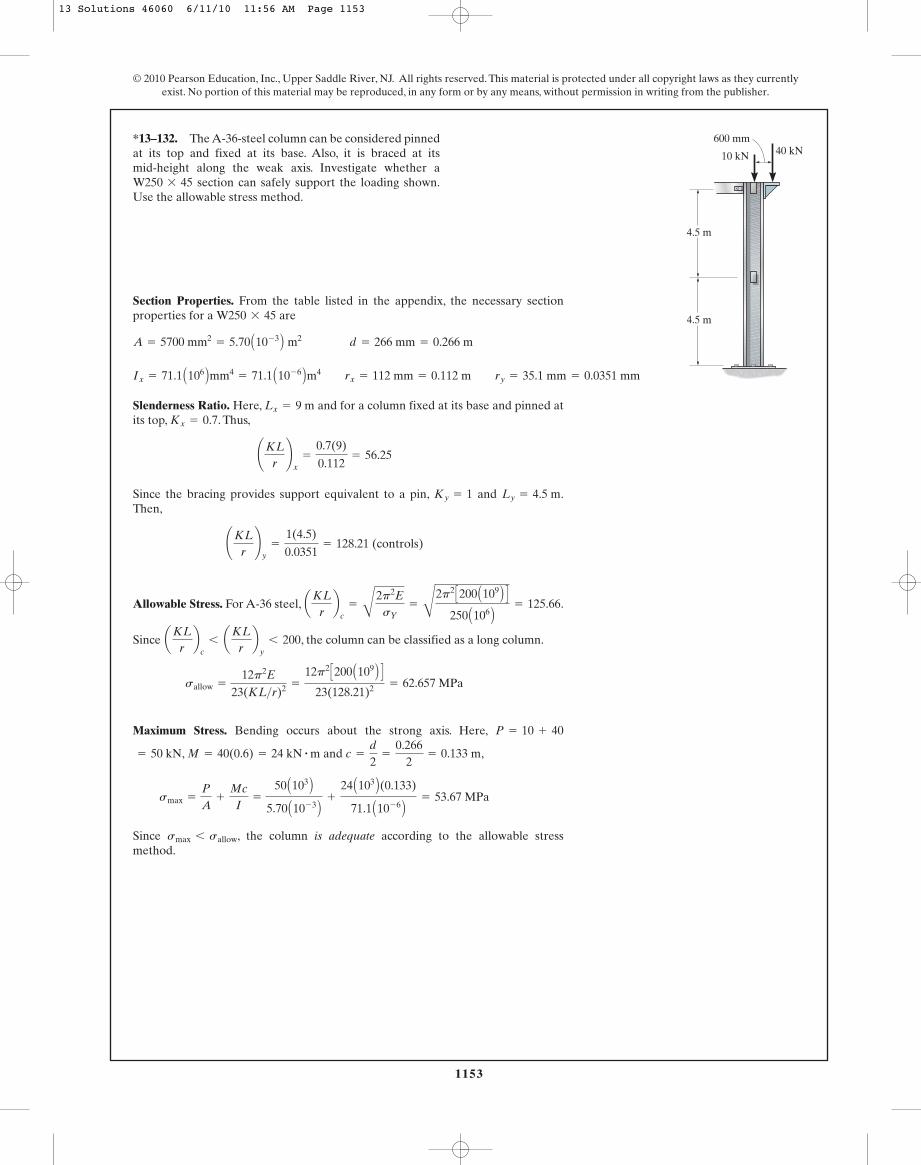
1153
© 2010 Pearson Education, Inc., Upper Saddle River, NJ. All rights reserved. This material is protected under all copyright laws as they currentlyexist. No portion of this material may be reproduced, in any form or by any means, without permission in writing from the publisher.
Section Properties. From the table listed in the appendix, the necessary sectionproperties for a are
A = 5700 mm2= 5.70 A10- 3 B m2 d = 266 mm = 0.266 m
W250 * 45
*13–132. The A-36-steel column can be considered pinnedat its top and fixed at its base. Also, it is braced at itsmid-height along the weak axis. Investigate whether a
section can safely support the loading shown.Use the allowable stress method.W250 * 45
4.5 m
4.5 m
600 mm40 kN10 kN
Slenderness Ratio. Here, and for a column fixed at its base and pinned atits top, . Thus,
Since the bracing provides support equivalent to a pin, and .Then,
Allowable Stress. For A-36 steel, .
Since , the column can be classified as a long column.
Maximum Stress. Bending occurs about the strong axis. Here,
, and ,
Since , the column is adequate according to the allowable stressmethod.
smax 6 sallow
smax =
P
A+
Mc
I=
50 A103 B5.70 A10- 3 B +
24 A103 B(0.133)
71.1 A10- 6 B = 53.67 MPa
c =
d
2=
0.2662
= 0.133 mM = 40(0.6) = 24 kN # m= 50 kN
P = 10 + 40
sallow =
12p2E
23(KL>r)2 =
12p2 C200 A109 B D23(128.21)2 = 62.657 MPa
aKLrb
c6 aKL
rb
y6 200
aKLrb
c=
B
2p2EsY
=
C
2p2 C200 A109 B D250 A106 B = 125.66
¢KLr≤
y=
1(4.5)
0.0351= 128.21 (controls)
Ly = 4.5 mKy = 1
¢KLr≤
x=
0.7(9)
0.112= 56.25
Kx = 0.7Lx = 9 m
Ix = 71.1 A106 Bmm4= 71.1 A10- 6 Bm4 rx = 112 mm = 0.112 m ry = 35.1 mm = 0.0351 mm
13 Solutions 46060 6/11/10 11:56 AM Page 1153
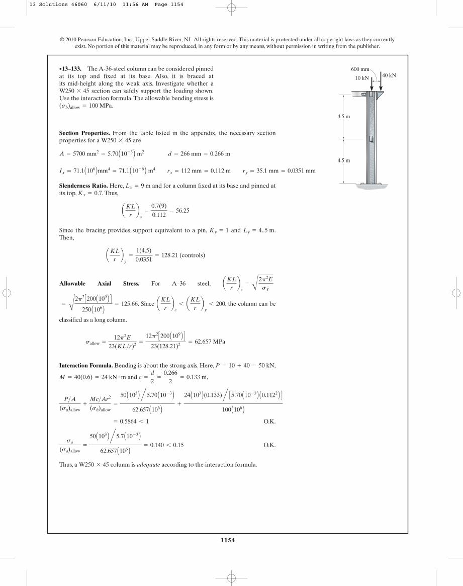
1154
© 2010 Pearson Education, Inc., Upper Saddle River, NJ. All rights reserved. This material is protected under all copyright laws as they currentlyexist. No portion of this material may be reproduced, in any form or by any means, without permission in writing from the publisher.
Section Properties. From the table listed in the appendix, the necessary sectionproperties for a are
A = 5700 mm2= 5.70 A10- 3 B m2 d = 266 mm = 0.266 m
W250 * 45
•13–133. The A-36-steel column can be considered pinnedat its top and fixed at its base. Also, it is braced atits mid-height along the weak axis. Investigate whether a
section can safely support the loading shown.Use the interaction formula.The allowable bending stress is(sb)allow = 100 MPa.
W250 * 45
4.5 m
4.5 m
600 mm40 kN10 kN
Slenderness Ratio. Here, and for a column fixed at its base and pinned atits top, . Thus,
Since the bracing provides support equivalent to a pin, and .Then,
Allowable Axial Stress. For A–36 steel,
. Since , the column can be
classified as a long column.
Interaction Formula. Bending is about the strong axis. Here, ,
and ,c =
d
2=
0.2662
= 0.133 mM = 40(0.6) = 24 kN # m
P = 10 + 40 = 50 kN
sallow =
12p2E
23(KL>r)2 =
12p2 C200 A109 B D23(128.21)2 = 62.657 MPa
aKLrb
c6 aKL
rb
y6 200=
C
2p2 C200 A109 B D250 A106 B = 125.66
aKLrb
c=
B
2p2EsY
aKLrb
y=
1(4.5)
0.0351= 128.21 (controls)
Ly = 4..5 mKy = 1
aKLrb
x=
0.7(9)
0.112= 56.25
Kx = 0.7Lx = 9 m
Ix = 71.1 A106 Bmm4= 71.1 A10- 6 B m4 rx = 112 mm = 0.112 m ry = 35.1 mm = 0.0351 mm
O.K.
O.K.
Thus, a column is adequate according to the interaction formula.W250 * 45
sa
(sa)allow=
50 A103 B n5.7 A10- 3 B62.657 A106 B = 0.140 6 0.15
= 0.5864 6 1
P>A
(sa)allow+
Mc>Ar2
(sb)allow=
50 A103 B n5.70 A10- 3 B62.657 A106 B +
24 A103 B(0.133)n C5.70 A10- 3 B A0.1122 B D100 A106 B
13 Solutions 46060 6/11/10 11:56 AM Page 1154
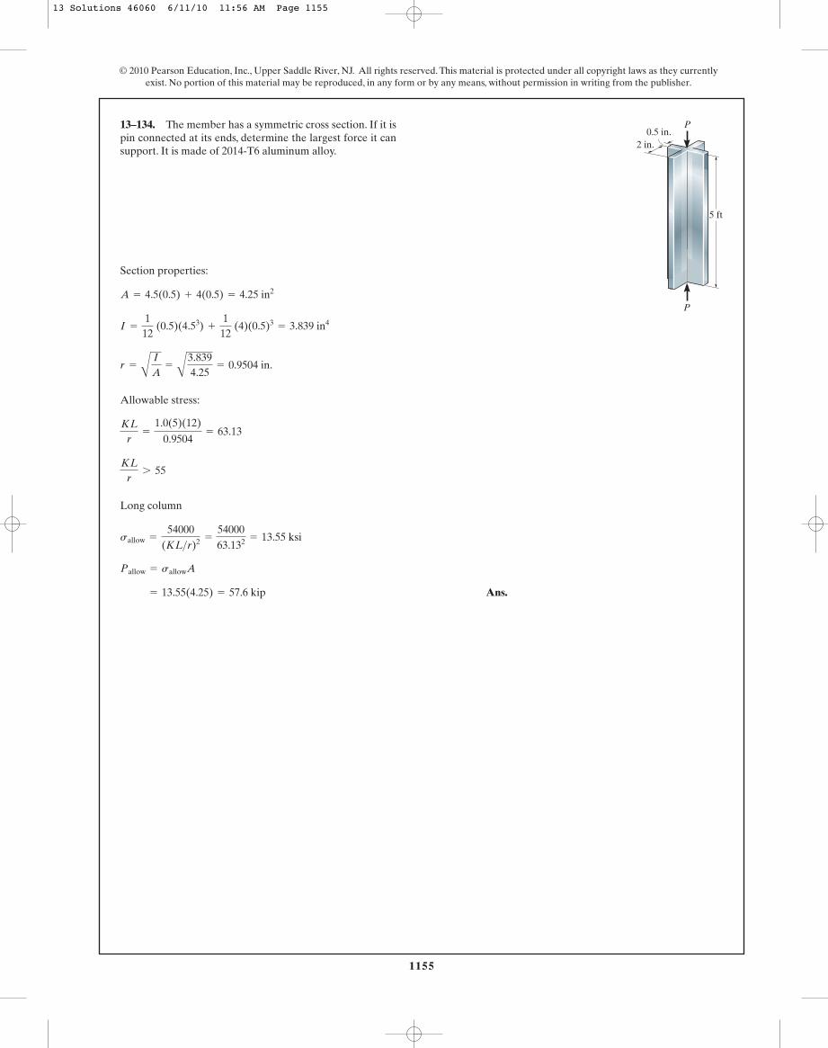
1155
© 2010 Pearson Education, Inc., Upper Saddle River, NJ. All rights reserved. This material is protected under all copyright laws as they currentlyexist. No portion of this material may be reproduced, in any form or by any means, without permission in writing from the publisher.
Section properties:
Allowable stress:
Long column
Ans. = 13.55(4.25) = 57.6 kip
Pallow = sallowA
sallow =
54000(KL>r)2 =
5400063.132 = 13.55 ksi
KLr
7 55
KLr
=
1.0(5)(12)
0.9504= 63.13
r =
A
I
A=
A
3.8394.25
= 0.9504 in.
I =
112
(0.5)(4.53) +
112
(4)(0.5)3= 3.839 in4
A = 4.5(0.5) + 4(0.5) = 4.25 in2
13–134. The member has a symmetric cross section. If it ispin connected at its ends, determine the largest force it cansupport. It is made of 2014-T6 aluminum alloy.
P
P
5 ft
2 in.0.5 in.
13 Solutions 46060 6/11/10 11:56 AM Page 1155

1156
© 2010 Pearson Education, Inc., Upper Saddle River, NJ. All rights reserved. This material is protected under all copyright laws as they currentlyexist. No portion of this material may be reproduced, in any form or by any means, without permission in writing from the publisher.
Section Properties. From the table listed in the appendix, the section properties fora are
Critical Buckling Load. For buckling about the strong axis, and .Since the column is fixed at its base and pinned at its top,
For buckling about the weak axis, and since the bracing providesa support equivalent to a pin. Applying Euler’s formula,
Ly = 6 mKy = 1
Pcr =
p2EIx
(KL)x 2 =
p2 c200 A109 B d c45.5 A10- 6 B d[0.7(12)]2 = 1.273 A106 BN = 1.27 MN
Lx = 12 mKx = 0.7
Iy = 15.3 A106 B mm4= 15.3 A10- 6 Bm4
A = 5890 mm2= 5.89 A10- 3 B m2 Ix = 45.5 A106 B mm4
= 45.5 A10- 6 Bm4
W200 * 46
13–135. The A-36-steel column can beconsidered pinned at its top and fixed at its base. Also, thecolumn is braced at its mid-height against the weak axis.Determine the maximum axial load the column can supportwithout causing it to buckle.
W200 * 46
6 m
6 m
Ans.
Critical Stress. Euler’s formula is valid only if .
O.K.scr =
Pcr
A=
838.92 A103 B5.89 A10- 3 B = 142.43 MPa 6 sY = 250 MPa
scr 6 sY
Pcr =
p2EIy
(KL)y 2 =
p2 c200 A109 B d c15.3 A10- 6 B d[1(6)]2 = 838.92 kN = 839 kN (controls)
13 Solutions 46060 6/11/10 11:56 AM Page 1156
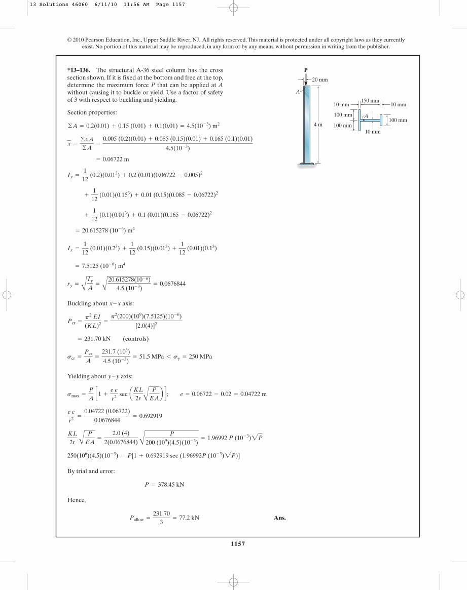
1157
© 2010 Pearson Education, Inc., Upper Saddle River, NJ. All rights reserved. This material is protected under all copyright laws as they currentlyexist. No portion of this material may be reproduced, in any form or by any means, without permission in writing from the publisher.
Section properties:
Buckling about axis:
Yielding about axis:
By trial and error:
Hence,
Ans.Pallow =
231.703
= 77.2 kN
P = 378.45 kN
250(106)(4.5)(10- 3) = P[1 + 0.692919 sec (1.96992P (10- 3)2P)]
KL
2r A
P
EA=
2.0 (4)
2(0.0676844) A
P
200 (109)(4.5)(10- 3)= 1.96992 P (10- 3)2P
e cr2 =
0.04722 (0.06722)
0.0676844= 0.692919
smax =
P
A c1 +
e cr2 sec aKL
2r A
P
EAb d ; e = 0.06722 - 0.02 = 0.04722 m
y-y
scr =
Pcr
A=
231.7 (103)
4.5 (10- 3)= 51.5 MPa 6 sg = 250 MPa
= 231.70 kN (controls)
Pcr =
p2 EI
(KL)2 =
p2(200)(109)(7.5125)(10- 6)
[2.0(4)]2
x-x
ry =
A
Iy
A=
A
20.615278(10- 6)4.5 (10- 3)
= 0.0676844
= 7.5125 (10- 6) m4
Ix =
112
(0.01)(0.23) +
112
(0.15)(0.013) +
112
(0.01)(0.13)
= 20.615278 (10- 6) m4
+
112
(0.1)(0.013) + 0.1 (0.01)(0.165 - 0.06722)2
+
112
(0.01)(0.153) + 0.01 (0.15)(0.085 - 0.06722)2
Iy =
112
(0.2)(0.013) + 0.2 (0.01)(0.06722 - 0.005)2
= 0.06722 m
x =
©xA
©A=
0.005 (0.2)(0.01) + 0.085 (0.15)(0.01) + 0.165 (0.1)(0.01)
4.5(10- 3)
©A = 0.2(0.01) + 0.15 (0.01) + 0.1(0.01) = 4.5(10- 3) m2
*13–136. The structural A-36 steel column has the crosssection shown. If it is fixed at the bottom and free at the top,determine the maximum force P that can be applied at Awithout causing it to buckle or yield. Use a factor of safetyof 3 with respect to buckling and yielding.
20 mm
4 m
P
A
10 mm
100 mm
100 mm
10 mm150 mm
A100 mm
10 mm
13 Solutions 46060 6/11/10 11:56 AM Page 1157

1158
© 2010 Pearson Education, Inc., Upper Saddle River, NJ. All rights reserved. This material is protected under all copyright laws as they currentlyexist. No portion of this material may be reproduced, in any form or by any means, without permission in writing from the publisher.
Section properties:
Buckling about axis:
O.K.
Hence the column does not buckle.
Yielding about axis:
Hence the column does not yield!
No. Ans.
smax = 0.7407 [1 + 0.692919 sec (0.1134788)] = 1.25 MPa 6 sg = 250 MPa
K L2 r
A
P
E A=
2.0 (4)
2(0.06783648) A
3.333 (103)200 (109)(4.5)(10- 3)
= 0.1134788
e cr2 =
0.04722 (0.06722)
(0.067844)= 0.689815
P
A=
3.333 (103)
4.5 (10- 3)= 0.7407 MPa
P =
103
= 3.333 kN
smax =
P
A c1 +
e cr2 sec aKL
2r A
P
EA b d e = 0.06722 - 0.02 = 0.04722 m
y-y
Pallow =
Pcr
FS=
231.73
= 77.2 kN 7 P = 10 kN
scr =
Pcr
A=
231.7 (103)
4.5 (10- 3)= 51.5 MPa 6 sg = 250 MPa
Pcr =
p2 EI
(KL)2 =
p2(200)(109)(7.5125)(10- 6)
[2.0(4)]2 = 231.70 kN
x-x
ry =
B
Iy
A=
B
20.615278 (10- 6)
4.5 (10- 3)= 0.067843648 m
Ix =
112
(0.01)(0.23) +
112
(0.15)(0.013) +
112
(0.01)(0.13) = 7.5125 (10- 6) m4
+
112
(0.1)(0.013) + 0.1 (0.01)(0.165 - 0.06722)2= 20.615278 (10- 6) m4
+
112
(0.01)(0.153) + 0.01 (0.15)(0.085 - 0.06722)2
Iy =
112
(0.2)(0.013) + 0.2 (0.01)(0.06722 - 0.005)2
x =
©xA
©A=
0.005 (0.2)(0.01) + 0.085 (0.15)(0.01) + 0.165 (0.1)(0.01)
4.5 (10- 3)= 0.06722 m
©A = 0.2 (0.01) + 0.15 (0.01) + 0.1 (0.01) = 4.5 (10- 3) m2
•13–137. The structural A-36 steel column has the crosssection shown. If it is fixed at the bottom and free at the top,determine if the column will buckle or yield when the load
Use a factor of safety of 3 with respect tobuckling and yielding.P = 10 kN.
20 mm
4 m
P
A
10 mm
100 mm
100 mm
10 mm150 mm
A100 mm
10 mm
13 Solutions 46060 6/11/10 11:56 AM Page 1158