EPT-30-MASTER SERVICE MANUAL - g-ec2.images...
144
1 VESTIL MFG. 2999 N. WAYNE ST. PO BOX 507 ANGOLA, INDIANA 46703 PH # 800-348-0868 FX # 800-526-3133 MADE IN P.R.C. EPT - 30- SERIES MASTER SERVICE AND PARTS MANUAL BW-REV-06-12-2007
Transcript of EPT-30-MASTER SERVICE MANUAL - g-ec2.images...

1
VESTIL MFG. 2999 N. WAYNE ST. PO BOX 507 ANGOLA, INDIANA 46703PH # 800-348-0868 FX # 800-526-3133 MADE IN P.R.C.
EPT - 30- SERIES MASTER SERVICE AND PARTS
MANUAL
BW-REV-06-12-2007
2
INDEX
Motor Controller......................................................... 3-71 Ept-****-30 change out instructions for
Battery ....................................................................72 - 77Charger ..................................................................78 - 85Charger Conversion to Soneil Brand...................86 - 97Cylinder ................................................................98 - 113Belly Switch Troubleshooting ...........................114 - 130Program Values ..........................................................131Troubleshooting Guide ......................................132 - 136Warranty .....................................................................137EPT-30-SERIES PARTS ...................................138 - 143

3
MANUAL
© 1999 CURTIS INSTRUMENTS, INC.
DESIGN OF CURTIS PMC 1200 SERIESCONTROLLERS PROTECTED BY U.S.PATENT NO. 4626750.
1207&1207A
MultiMode™MOTOR CONTROLLERS
1207 / 1207A Manualp/n 16081, Rev. D: August 1999
CURTIS PMC
235 East Airway BoulevardLivermore, California 94568 USATel: 925-961-1088Fax: 925-961-1099www.curtisinst.com

4
1207 / 1207A Manualp/n 16081, Rev. D: August 1999
© 1999 CURTIS INSTRUMENTS, INC.
This electronic version of the 1207/1207A manual is offered as a convenience to ourcustomers. You may download any or all of it.
If you would like a hard copy of the published manual, please order it by part number fromthe Curtis office nearest you.
The electronic version of the manual is identical to the printed version published in August1999 and revised March 2000. The revisions are in Figures 4, 4A, and 9A (on pages 8, 24,and 28).
Bookmarks have been added to the electronic version to speed the process of goingdirectly to a particular part of the document.
CURTIS INSTRUMENTS, INC.200 KISCO AVENUEMOUNT KISCO, NEW YORK 10549 USA☎ 914-666-2971 FAX 914-666-2188
■ CURTIS PMC235 EAST AIRWAY BOULEVARDLIVERMORE, CALIFORNIA 94550 USA☎ 925-961-1088 FAX 925-961-1099
■ ADDITIONAL OFFICES located inBulgaria, China, England, France, Germany,India, Italy, Japan, Netherlands, Puerto Rico,Russia, Sweden, and Switzerland

5
Curtis PMC 1207/1207A Manual iii
1234567890112345678901123456789011234567890112345678901123456789011234567890112345678901123456789011234567890112345678901123456789011234567890112345678901123456789011234567890112345678901123456789011234567890112345678901123456789011234567890112345678901123456789011234567890112345678901123456789011234567890112345678901123456789011234567890112345678901123456789011234567890112345678901123456789011234567890112345678901123456789011234567890112345678901123456789011234567890112345678901123456789011234567890112345678901123456789011234567890112345678901123456789011234567890112345678901123456789011234567890112345678901123456789011234567890112345678901123456789011234567890112345678901123456789011234567890112345678901123456789011234567890112345678901123456789011234567890112345678901123456789011234567890112345678901123456789011234567890112345678901123456789011234567890112345678901123456789011234567890112345678901123456789011234567890112345678901123456789011234567890112345678901123456789011234567890112345678901123456789011234567890112345678901123456789011234567890112345678901123456789011234567890112345678901123456789011234567890112345678901123456789011234567890112345678901123456789011234567890112345678901123456789011234567890112345678901123456789011234567890112345678901123456789011234567890112345678901123456789011234567890112345678901123456789011234567890112345678901123456789011234567890112345678901
CONTENTS
1. OVERVIEW .............................................................................. 1
2. INSTALLATION AND WIRING: 1207 controllers ................ 31207 Mounting ................................................................... 31207 Connections: Low Current ........................................ 41207 Connections: High Current ....................................... 51207 Adjustment Panel ....................................................... 51207 Wiring: Standard Configuration (Series Motor) ......... 6
Power wiring for series motor ...................................... 7Control wiring for series motor .................................... 7
1207 Wiring: Compound Motor Configuration ................. 8Power wiring for compound motor .............................. 9Control wiring for compound motor ........................... 9
1207 Wiring: Throttle ...................................................... 105kΩ–0 throttle (“Type 1”) ......................................... 100–5V, 0–10V, 3-wire potentiometer, and
electronic throttles (“Type 2”) ................................ 110–5kΩ throttle (“Type 3”) ......................................... 15
1207 Wiring: Emergency Reverse Check .......................... 151207 Switches and Other Hardware ................................. 16
Keyswitch ................................................................... 16Main contactor .......................................................... 16Forward/reverse contactors ......................................... 16F/R and emergency reverse switches ........................... 16Circuitry protection devices ....................................... 16
1207 Installation Checkout ............................................... 17
2A. INSTALLATION AND WIRING: 1207A controllers ............ 191207A Mounting .............................................................. 191207A Connections: Low Current .................................... 201207A Connections: High Current ................................... 211207A Wiring: Standard Configuration (Series Motor) .... 22
Power wiring for series motor .................................... 23Control wiring for series motor .................................. 23
CONTENTS
6
Curtis PMC 1207/1207A Manual v
FIGURES
FIG. 1: Curtis PMC 1207 and 1207A motor controllersand handheld programmer ...........................................1
FIG. 2: Mounting dimensions,Curtis PMC 1207 controller ........................................3
FIG. 3: Standard wiring diagram (series motors),Curtis PMC 1207 controller ........................................6
FIG. 4: Compound motor wiring diagram,Curtis PMC 1207 controller ........................................8
FIG. 5: Wiring for 5kΩ–0 throttle (1207 controller) ..............10
FIG. 6: Wiring for 20kΩ potentiometerused as a wigwag-style throttle (1207 controller) ........10
FIG. 7: Wiring for 0–5V throttle (1207 controller) ................11
FIG. 8: Wiring for 0–10V throttle (1207 controller) ..............12
FIG. 9: Wiring for 3-wire pot throttle (1207 controller) .........13
FIG. 10: Wiring for Curtis ET-XXX electronic throttle(1207 controller) ........................................................14
FIG. 11: Wiring for 0–5kΩ throttle (1207 controller) ..............15
FIG. 2A: Mounting dimensions,Curtis PMC 1207A controller ....................................19
FIG. 3A: Standard wiring diagram (series motors),Curtis PMC 1207A controller ....................................21
FIG. 4A: Compound motor wiring diagram,Curtis PMC 1207A controller ....................................24
FIG. 5A: Wiring for 5kΩ–0 throttle (1207A controller) ...........26
FIGURES

7
Curtis PMC 1207/1207A Manual vi
FIG. 6A: Wiring for 20kΩ potentiometerused as a wigwag-style throttle (1207A controller) ......26
FIG. 7A: Wiring for 0–5V throttle (1207A controller) .............27
FIG. 8A: Wiring for 3-wire pot throttle (1207A controller) ......28
FIG. 9A: Wiring for Curtis ET-XXX electronic throttle(1207A controller) ......................................................28
FIG. 10A: Wiring for 0–5kΩ throttle (1207A controller) ...........29
FIG. 11A: Alternative wiring for emergency reverse check(1207A controller) ......................................................29
TABLES
TABLE 1: LED codes ..................................................................37
TABLE 2: Troubleshooting chart ................................................39
FIGURES/TABLES

8
Curtis PMC 1207/1207A Manual 1
11 — OVERVIEW
OVERVIEW
Curtis PMC 1207/1207A programmable motor speed controllers provide effi-cient, cost-effective, and simple-to-install control for a variety of small electricvehicles. Typical applications include walkie fork/pallet trucks, mini personnelcarriers, and sweepers. The microprocessor-based logic section combined with aproven MOSFET power section gives the 1207/1207A controllers high powerand advanced features in a simple, compact package. The optional handheldprogrammer enables the user to set parameters, conduct tests, and obtain diag-nostic information quickly and easily.
Fig. 1 Curtis PMC1207 and 1207Aelectronic motor controllersand handheld programmer.
Like all Curtis PMC motor controllers, the 1207 and 1207A models offersuperior operator control of the vehicle’s motor drive speed. Features include:
✓ Power MOSFET design, providing• infinitely variable drive and plug brake control• silent high-frequency operation• high efficiency (for reduced motor and battery losses)
✓ Compact size
✓ Overvoltage and undervoltage protection
✓ Thermal protection and compensation circuitry provides undertemperaturecutback, constant current limit, and linear rollback in overtemperature—thus preventing sudden power loss regardless of thermal conditions
☞More Features

9
Curtis PMC 1207/1207A Manual 2
✓ Intelligent handheld programmer (optional) provides a full set of parameterand function settings
✓ Diagnostic and test information for the controller—and other system com-ponents—readily available both on-board and through the programmer
✓ On-board potentiometers allow direct manual adjustment of accelerationrate, creep speed, maximum speed, plug current, and main current limit(1207 single-mode models only)
✓ Circuitry and software detects faults in the throttle circuit, MOSFET drivecircuit, MOSFET transistors, contactor drivers, and contactors—ensuringthat the controller meets EEC fault detect requirements
✓ Input sequencing options include neutral start and static return to off (SRO)
✓ Microprocessor-controlled contactor sequencing provides true arclesscontactor switching
✓ Smooth, controlled plug braking—with either variable (throttle-dependent)or fixed plug current limit
✓ Neutral braking option provides automatic plug braking in neutral
✓ MultiMode™ input selects between two different operating modes, thusallowing optimization of vehicle characteristics for different driving condi-tions
✓ Emergency reverse (belly button switch) with a single input
✓ Ramp-start feature provides full power for starting on ramps
✓ Simple contactor and switch wiring, with coil drivers monitored for faults—thus ensuring fail-safe operation
✓ Flexible throttle circuitry accommodates a variety of throttle types
✓ Programmable “ramp shape” (static throttle map) provides flexibility inselecting throttle response feel
✓ Connections made by solid copper power busses with a polarized Molexconnector for control signals
✓ Solid, well-protected construction—with an aluminum mounting plate andinjection-molded cover.
Familiarity with your Curtis PMC controller will help you install and operate itproperly. We encourage you to read this manual carefully. If you have questions,please contact the Curtis office nearest you.
1 — OVERVIEW

10
Curtis PMC 1207/1207A Manual 3
INSTALLATION AND WIRING: 1207
MOUNTING
The 1207 controller can be oriented in any position, but the location should becarefully chosen to keep the controller as clean and dry as possible. If a cleanmounting location cannot be found, a cover must be used to shield thecontroller from water and contaminants.
To ensure full rated output power, the controller should be fastened to aclean, flat metal surface with three screws. The case outline and mounting holedimensions are shown in Figure 2. The controller should be mounted withsufficient clearance to allow the sliding cover to be opened, providing access to
22 — INSTALLATION & WIRING: 1207 Controller
66 (2.60)
28 (1.10)
122(4.80)
152 (6.00)
165 (6.50)
127 (5.00)
SLIDINGCOVER
6.5 (0.25)
22 (0.85)
60(2.35)
4.8 (0.19)
21 × 16 × 1.5(0.83 × 0.63 × 0.06);
8.4 (0.33) dia. hole thru
6.6 (0.26) dia.,3 plcs
Dimensions in millimeters and (inches)
CL
Fig. 2 Mountingdimensions,Curtis PMC 1207controller.

11
Curtis PMC 1207/1207A Manual 4
the user-adjustable potentiometers. Access is also needed to plug the programmerinto the connector beneath the sliding cover, and to view the Status LED.
Although not usually necessary, a thermal joint compound can be used toimprove heat conduction from the case to the mounting surface.
CONNECTIONS: Low Current
An integrated 16-pin low power connector molded into the front of the control-ler provides the low power logic control connections (see pin list below). Themating connector is Molex Mini-Fit Jr., part number (5557) 39-01-2165.Contact Molex regarding compatible pins for various wire sizes.
2 — INSTALLATION & WIRING: 1207 Controller
Pin 1 shunt field driver output; n/c for series motorsPin 2 reverse contactor driver outputPin 3 forward contactor driver outputPin 4 main contactor driver outputPin 5 throttle: 3-wire pot highPin 6 throttle: 3-wire pot wiper or 0–5VPin 7 throttle: pot lowPin 8 throttle: 2-wire 5kΩ–0 or 0–5kΩ input
Pin 9 throttle: 0–10VPin 10 emergency reverse (BB) check output [optional]Pin 11 reverse inputPin 12 forward inputPin 13 emergency reverse inputPin 14 mode selection inputPin 15 brake inputPin 16 keyswitch input (KSI)
16 15 14 13 12 11 10 9
8 7 6 5 4 3 2 1

12
Curtis PMC 1207/1207A Manual 5
CONNECTIONS: High Current
Four tin-plated copper bus bars are provided for the high current connections tothe battery and motor:
M- output to motor armatureB- negative connection to batteryB+ positive connection to battery/fieldA2 plug diode to motor armature
Cables are fastened to the bus bars by M8 (5⁄16") bolts.When tightening the bolts, two opposing wrenchesshould be used to prevent bending the bus bars andputting undue strain on the internal connections.
2 — INSTALLATION & WIRING: 1207 Controller
ADJUSTMENT PANEL
The adjustment panel is located on top of the 1207 controller, under a slidingprotective cover. The panel provides access to a set of adjustable potentiometers,and also contains the Status LED and a connector for the handheld programmer.
Manually Adjustable Potentiometers
Five screwdriver-adjustable potentiometers (“trimpots”) allow manualadjustment of the main and plug current limits, acceleration rate,maximum creep speed, and maximum speed (labeled “LOW”), as de-scribed in Section 3. The trimpots can be enabled or disabled at thefactory; if they are enabled, MultiMode™ operation is not available.NOTE: To adjust any of these parameters electronically with the pro-grammer, its potentiometer must be set to “OFF.”
Programmer Connector
An RJ11 modular connector is provided for the handheld programmer.The mating cable is supplied with the programmer.
Status LED
The LED displays flashing codes to indicate controller status; the codesare listed in Section 5.
STATUSA C C E L . L O WC R E E PP L U GM A I N
4OFF
1 230
4OFF
1 230
4OFF
1 230
4OFF
1 230
4OFF
1 230
L I M I TSPEEDL I M I TCURRENT
M- A2B+B-

13
Curtis PMC 1207/1207A Manual 6
WIRING: Standard Configuration (Series Motor)
The basic wiring for series motors with field reversing is shown in Figure 3.
2 — INSTALLATION & WIRING: 1207 Controller
Fig. 3 Standardwiring diagram(series motor),Curtis PMC 1207controller.
MULTIMODE
EMERGENCYREVERSE
A2A1
REVERSECONTACTORPRECHARGE RESISTOR
(250 Ω, 5 W)
BRAKE FORWARD
CONTACTORS
MAINREVERSE
SWITCHES
CO
NT
RO
LF
US
E
M- A2B+B-
FORWARDCONTACTOR
POWERFUSE
KEYSWITCH
POLARITYPROTECTION
DIODE
S1S2
THROTTLE5kΩ–0 (TYPICAL)
MAINCONTACTOR
B-
B+
FORWARD REVERSE
A
The configuration shown in Figure 3 is a typical arrangement for a series motor.Curtis PMC controllers are designed for use in a wide range of applications, andaccordingly can be installed in a variety of ways to best meet customer needs.
NOTE: The emergency reverse check feature (wiring shown by dashed line) is afactory option.

14
Curtis PMC 1207/1207A Manual 7
Power Wiring for Series Motor
In every wiring configuration, it is imperative that the field be wired between thecontroller’s B+ and A2 terminals and that the armature be wired between the M-
and A2 terminals. The internal plug diode used in the 1207 is connected betweenM- and A2. Therefore, the armature and field positions cannot be interchanged.Reversing contactors can be used to switch either the armature or the field.
Control Wiring for Series Motor
Wiring for the input switches and contactors is shown in Figure 3 (see detailbelow). The main contactor, if one is used, is normally connected directly to thecontroller. Optionally, the main contactor can be switched directly by thekeyswitch or brake, leaving Pin 4 unconnected.
The throttle shown in Figure 3 is a 5kΩ–0 type. Various other throttles can alsobe accommodated, and are discussed in the throttle wiring section.
2 — INSTALLATION & WIRING: 1207 Controller
16-pin detail (see Fig. 3):
BRAKE
MULTIMODE
EMERGENCYREVERSE
FORWARD
REVERSE
KEYSWITCH
EMERGENCYREVERSE
CHECKOUTPUT
MAINCONTACTOR
FORWARDCONTACTOR
REVERSECONTACTOR
2-WIRE POT(5 kΩ)
POTLOW
8 7 6 5 4 3 2 1
16 15 14 13 12 11 10 9

15
Curtis PMC 1207/1207A Manual 8
WIRING: Compound Motor Configuration
A specially configured controller is available for compound motor applications.The wiring for a compound wound motor with armature reversing is shown inFigure 4.
2 — INSTALLATION & WIRING: 1207 Controller
Fig. 4 Compoundmotor wiring diagram,Curtis PMC 1207controller.
The configuration shown in Figure 4 requires the use of a compound woundmotor. Pure shunt motors cannot be used with 1207 controllers. Althoughthe configuration shown is typical, various other configurations are possible.
NOTE: The emergency reverse check feature (wiring shown by dashed line) is afactory option.
MULTIMODE
EMERGENCYREVERSE
A2A1
RE
VE
RS
EC
ON
TAC
TORPRECHARGE RESISTOR
(250 Ω, 5 W)
BRAKE FWD
CONTACTORS
MAINREV
SWITCHES
CO
NT
RO
LF
US
E
M- A2B+B-
FORWARDCONTACTOR
POWERFUSE
KEYSWITCH
POLARITYPROTECTION
DIODE
S1
S2
MAINCONTACTOR
B-
B+
FORWARD REVERSE SHUNT
THROTTLE5kΩ–0 (TYPICAL)
A
3/
28
/0
0

16
Curtis PMC 1207/1207A Manual 9
Power Wiring for Compound Motor
The field must be wired between B+ and A2 and the armature between M- and A2.The internal plug diode in the 1207 is connected between M- and A2; therefore,the armature and field positions cannot be interchanged.
If the shunt is rated for under 2 amperes, it can be connected directly to thecontroller as shown in Figure 4. If the shunt is rated for higher than 2 amperes,a contactor must be used to control the shunt field.
Control Wiring for Compound Motor
Control wiring for the compound motor application is like that for the standard(series motor) wiring. The main contactor, if one is used, is normally connecteddirectly to the controller. Optionally, the main contactor can be switched directlyby the keyswitch or brake, leaving pig Pin 4 unconnected.
The throttle shown in Figure 4 is a 5kΩ–0 type. Various other throttles can alsobe accommodated, and are discussed in the throttle wiring section.
Polarity protection diodes and control fuses must be sized appropriately tohandle the increased current from the shunt field.
2 — INSTALLATION & WIRING: 1207 Controller
16-pin detail (see Fig. 4):
BRAKE
MULTIMODE
EMERGENCYREVERSE
FORWARD
REVERSE
KEYSWITCH
EMERGENCYREVERSE
CHECKOUTPUT
MAINCONTACTOR
FORWARDCONTACTOR
REVERSECONTACTOR
2-WIRE POT(5 kΩ)
POTLOW
8 7 6 5 4 3 2 1
16 15 14 13 12 11 10 9
SHUNT
17
Curtis PMC 1207/1207A Manual 10
WIRING: Throttle
Wiring for various throttles is described below. They are characterized as Type 1,Type 2, and Type 3 throttles in the programming menu of the handheldprogrammer. NOTE: In the text, throttles are identified by their nominal range andnot by their actual active range.
If the throttle you are planning to use is not covered, please contact theCurtis office nearest you.
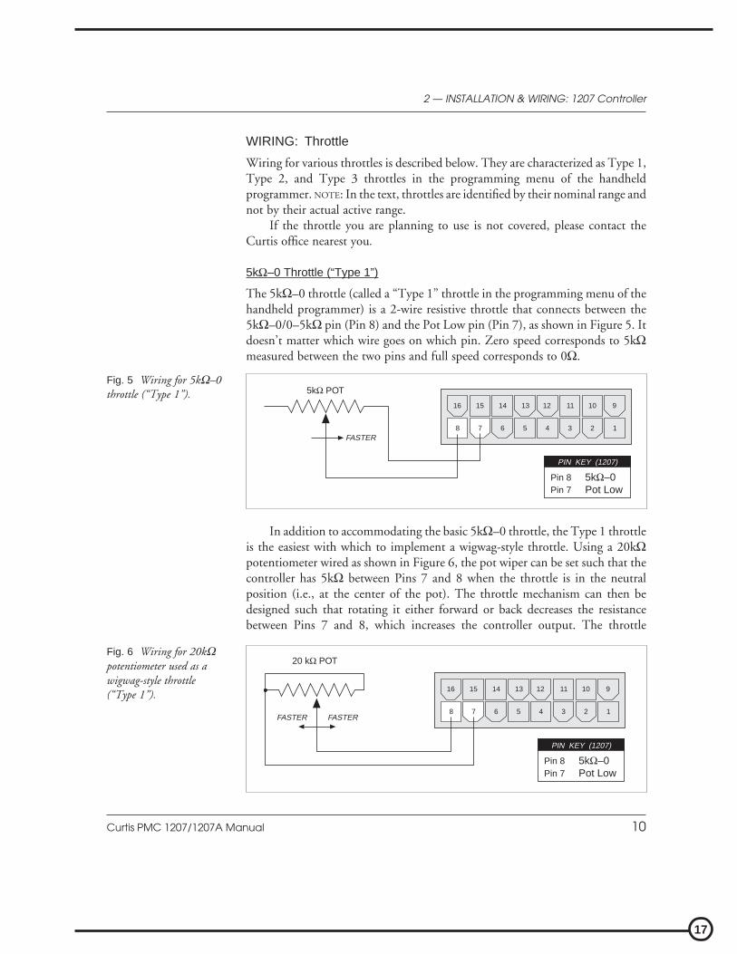
5kΩ–0 Throttle (“Type 1”)
The 5kΩ–0 throttle (called a “Type 1” throttle in the programming menu of thehandheld programmer) is a 2-wire resistive throttle that connects between the5kΩ–0/0–5kΩ pin (Pin 8) and the Pot Low pin (Pin 7), as shown in Figure 5. Itdoesn’t matter which wire goes on which pin. Zero speed corresponds to 5kΩmeasured between the two pins and full speed corresponds to 0Ω.
2 — INSTALLATION & WIRING: 1207 Controller
In addition to accommodating the basic 5kΩ–0 throttle, the Type 1 throttleis the easiest with which to implement a wigwag-style throttle. Using a 20kΩpotentiometer wired as shown in Figure 6, the pot wiper can be set such that thecontroller has 5kΩ between Pins 7 and 8 when the throttle is in the neutralposition (i.e., at the center of the pot). The throttle mechanism can then bedesigned such that rotating it either forward or back decreases the resistancebetween Pins 7 and 8, which increases the controller output. The throttle
Fig. 6 Wiring for 20kΩpotentiometer used as awigwag-style throttle(“Type 1”).
Fig. 5 Wiring for 5kΩ–0throttle (“Type 1”).
8 7 6 5 4 3 2 1FASTER
16 15 14 13 12 11 10 9
5kΩ POT
Pin 8Pin 7
5kΩ–0Pot Low
PIN KEY (1207)
8 7 6 5 4 3 2 1FASTERFASTER
16 15 14 13 12 11 10 9
20 kΩ POT
Pin 8Pin 7
5kΩ–0Pot Low
PIN KEY (1207)

18
Curtis PMC 1207/1207A Manual 11
mechanism must provide signals to the controller’s forward and reverse inputsindependent of the throttle pot resistance. The controller will not sense directionfrom the pot resistance.
Broken wire protection for Type 1 throttles is provided by the controllersensing the current flow from the 5kΩ–0 input through the pot and into the PotLow pin. If the Pot Low input current falls below 0.1 mA, a throttle fault isgenerated and the controller is disabled. NOTE: The Pot Low pin (Pin 7) must notbe tied to ground.
0–5V, 0–10V, 3-Wire Potentiometer, and Electronic Throttles (“Type 2”)
With these throttles (“Type 2” in the programming menu), the controller looksfor a voltage signal at either the pot wiper/0–5V input of the controller (Pin 6) orthe 0–10V input (Pin 9). Zero speed corresponds to 0V and full speed corre-sponds to either 5V or 10V, measured relative to B-. Pot Low is the current returnpath for all Type 2 throttles.
A voltage source, 3-wire pot, or electronic throttle can be used with thisthrottle type. The wiring for each is slightly different and each has varying levelsof throttle fault detection associated with it.
0–5V Throttle
Two ways of wiring the 0–5V throttle are shown in Figure 7. Broken wireprotection is provided by the controller looking for a minimum current into the
(b) Ground-referenced0–5V throttle
(a) 0–5V throttle sensorFig. 7 Wiring for 0–5Vthrottle (“Type 2”).
2 — INSTALLATION & WIRING: 1207 Controller
8 7 6 5 4 3 2 1
8 7 6 5 4 3 2 1
16 15 14 13 12 11 10 9
+
-
+
B-
16 15 14 13 12 11 10 9
4.7 kΩ
(Shunt impedance 150 kΩ to ground)
Pin 7Pin 6Pin 5
Pot Low0–5V InputPot High
PIN KEY (1207)
Pin 7Pin 6
Pot Low0–5V Input
PIN KEY (1207)
SENSOR GROUND
SENSOR OUTPUT0–5V
SENSOR

19
Curtis PMC 1207/1207A Manual 12
Pot Low pin. If the Pot Low input current falls below 0.1 mA, a throttle fault isgenerated and controller shuts down. If a throttle sensor is used, the sensor’sground return current must be less than 10 mA. If the 0–5V throttle input(Pin 7) exceeds 8 volts, controller output will shut down. NOTE: In Figure 7(b),the throttle’s voltage input signal is in reference to Pot Low.
0–10V Throttle
Two ways of wiring the 0–10V throttle are shown in Figure 8. Broken wireprotection is provided by the controller looking for a minimum current into thePot Low pin. If the Pot Low input current falls below 0.1 mA, a throttle fault isgenerated and the controller shuts down. If a throttle sensor is used, the sensor’sground return current must be less than 10 mA. If the 0–10V throttle input(Pin 9) exceeds 16 volts, the controller will shut down. NOTE: In Figure 8(b), thethrottle’s voltage input signal is in reference to Pot Low.
2 — INSTALLATION & WIRING: 1207 Controller
(b) Ground-referenced0–10V throttle
(a) 0–10V throttle sensorFig. 8 Wiring for 0–10Vthrottle (“Type 2”).
8 7 6 5 4 3 2 1
16 15 14 13 12 11 10 9
8 7 6 5 4 3 2 1
16 15 14 13 12 11 10 9
+
-
+
B-
Pin 9Pin 7Pin 5
0–10V InputPot LowPot High
PIN KEY (1207)
Pin 9Pin 7
0–10V InputPot Low
PIN KEY (1207)
0–10VSENSOR
(Shunt impedance 150 kΩ to ground)
SENSOR GROUND
SENSOR OUTPUT
4.7 kΩ
20
Curtis PMC 1207/1207A Manual 13
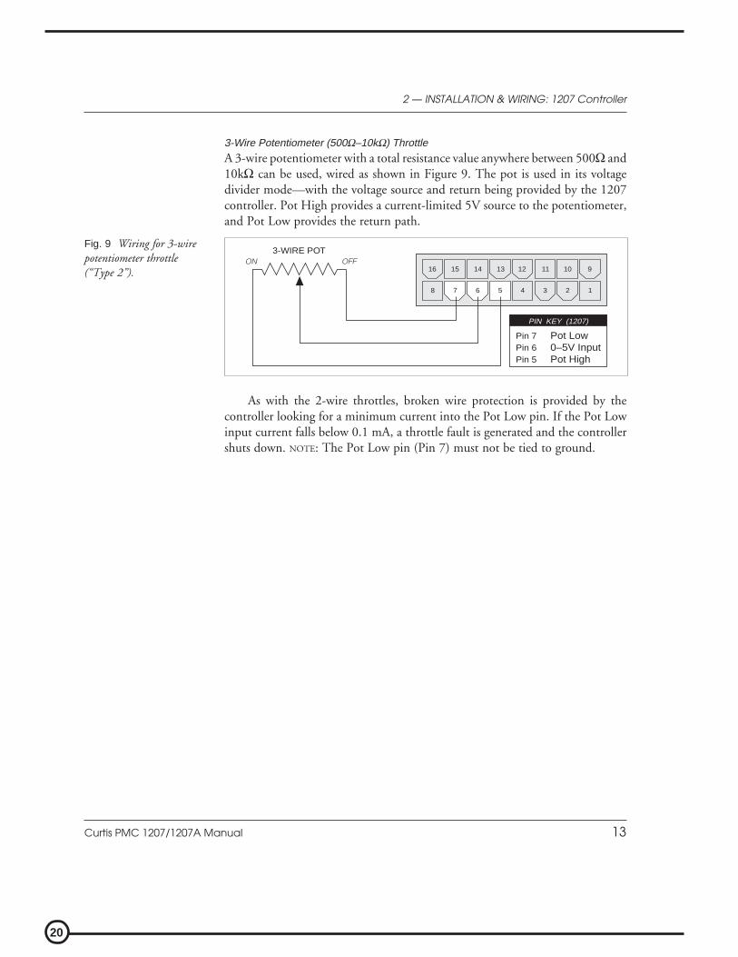
As with the 2-wire throttles, broken wire protection is provided by thecontroller looking for a minimum current into the Pot Low pin. If the Pot Lowinput current falls below 0.1 mA, a throttle fault is generated and the controllershuts down. NOTE: The Pot Low pin (Pin 7) must not be tied to ground.
2 — INSTALLATION & WIRING: 1207 Controller
Fig. 9 Wiring for 3-wirepotentiometer throttle(“Type 2”).
8 7 6 5 4 3 2 1
16 15 14 13 12 11 10 9OFFON
3-WIRE POT
Pin 7Pin 6Pin 5
Pot Low0–5V InputPot High
PIN KEY (1207)
3-Wire Potentiometer (500Ω–10kΩ) Throttle
A 3-wire potentiometer with a total resistance value anywhere between 500Ω and10kΩ can be used, wired as shown in Figure 9. The pot is used in its voltagedivider mode—with the voltage source and return being provided by the 1207controller. Pot High provides a current-limited 5V source to the potentiometer,and Pot Low provides the return path.

21
Curtis PMC 1207/1207A Manual 14
Curtis ET-XXX Electronic Throttle
The Curtis ET-XXX provides throttle and forward/reverse inputs to the 1207.Wiring for the Curtis ET-XXX is shown in Figure 10.
2 — INSTALLATION & WIRING: 1207 Controller
There is no fault detection built into the ET-XXX, and the controller willdetect only open wiper faults. It is the responsibility of the vehicle manufacturerto provide any additional throttle fault detection necessary for the application.
The ET-XXX can be integrated into a control head to provide wigwag-stylethrottle control. Alternatively, a complete control head assembly is available fromCurtis. This control head assembly—the CH series—combines the ET-XXXthrottle with a variety of standard control head switch functions for use in walkieand lift truck applications.
Fig. 10 Wiring for CurtisET-XXX electronic throttle(“Type 2”).
8 7 6 5 4 3 2 1
16 15 14 13 12 11 10 9
ET-XXX
B-
B+
GREEN
ORANGE
BLACK
BLACK/WHITE
WHITE
WHT/BRN
Pin 16Pin 12Pin 11
Pin 7Pin 6
KSI InputForwardReverse
Pot Low0–5V Input
PIN KEY (1207)
KEYSWITCH
WHT/GRN

22
Curtis PMC 1207/1207A Manual 15
2 — INSTALLATION & WIRING: 1207 Controller
0–5kΩ Throttle (“Type 3”)
The 0–5kΩ throttle (“Type 3” in the programming menu) is a 2-wire resistivethrottle that connects between the 5kΩ–0/0–5kΩ pin (Pin 8) and the Pot Lowpin (Pin 7), as shown in Figure 11. It doesn’t matter which wire goes on whichpin. For Type 3 throttles, zero speed corresponds to 0Ω and full speed corre-sponds to 5kΩ.
Fig. 11 Wiring for 0–5Ωthrottle (“Type 3”).
8 7 6 5 4 3 2 1FASTER
16 15 14 13 12 11 10 9
5kΩ POT
Pin 8Pin 7
5kΩ–0Pot Low
PIN KEY (1207)
Broken wire protection is provided by the controller sensing the current flowfrom the 0–5kΩ input through the pot and into the Pot Low pin. If the Pot Lowinput current falls below 0.1 mA, a throttle fault is generated and the controllershuts down. NOTE: The Pot Low pin (Pin 7) must not be tied to ground.
WIRING: Emergency Reverse Check
An optional wire connected directly to the emergency reverse (belly button)switch provides for broken wire detection when that option is enabled at thefactory. The emergency reverse check output wire periodically pulses the emer-gency reverse circuit to check for continuity. If there is no continuity in thecircuit, the controller shuts down and a fault code is indicated.
This feature must be enabled at Curtis PMC. If the option is selected and thecheck wire is not connected, the vehicle will not operate. If the option is notselected and the check wire is connected, no harm will occur—but continuity willnot be checked.
The emergency reverse check output wire is connected to Pin 10, as shownby the dashed lines in the two basic wiring diagrams (Figures 3 and 4).

23
Curtis PMC 1207/1207A Manual 16
2 — INSTALLATION & WIRING: 1207 Controller
SWITCHES AND OTHER HARDWARE
Keyswitch
The vehicle should have a master on/off switch to turn the system off when notin use. The keyswitch provides logic power for the 1207 controller, coil currentfor the contactors, and shunt current (in compound motor applications). Thekeyswitch must be capable of carrying these currents.
Main Contactor
A main contactor allows the 1207 controller to be disconnected from the battery.In 24V applications a main contactor is optional, but in 36V applications amain contactor is required. A heavy-duty single-pole, single-throw (SPST)contactor with silver-alloy contacts is recommended, such as an Albright SW80or SW180 (available from Curtis).
After initial closing of the contacts, inrush currents flow as the controller’sinternal filter capacitors are charged. A 250Ω, 5W resistor (such as Curtis PMCp/n MP-2) can be used across the contactor to precharge the capacitors andreduce the inrush current through the contacts.
Forward/Reverse Contactors
For forward/reverse, a paired single-pole, double-throw (2×SPDT) contactor isrecommended, such as an Albright DC88 or DC182 (available from Curtis).With 4-terminal split field motors, two single-pole, single-throw (SPST) contac-tors are typically used. The coil voltage should match the vehicle voltage. Themaximum allowed coil current is 1 ampere.
Forward/Reverse, Emergency Reverse, and Mode Switches
The direction input switches can be any type of single-pole, single-throw (SPST)switch capable of switching the battery voltage at 10 mA.
Circuitry Protection Devices
For reverse polarity protection, a diode should be added to the control circuit. Itmust be sized appropriately for the maximum contactor coil currents (and shuntcurrent, in compound motor applications). To protect the control wiring fromaccidental shorts, a low current fuse (appropriate for the maximum current draw)should be connected in series with the battery feed. These devices are both shownin the wiring diagrams.

24
Curtis PMC 1207/1207A Manual 17
1207 INSTALLATION CHECKOUT
Before operating the vehicle, carefully complete the following checkout proce-dure. If you find a problem during the checkout, refer to the diagnostics andtroubleshooting section (Section 5) for further information.
The installation checkout can be conducted with or without the handheldprogrammer. The checkout procedure is easier with a programmer. Otherwise,observe the Status LED for codes.
Put the vehicle up on blocks to get the drive wheel(s) offthe ground before beginning these tests.
Turn the keyswitch off and make sure that the brake isapplied (brake switch open), the throttle is in neutral,and the forward/reverse switches are open.
Do not stand, or allow anyone else to stand, directly infront of or behind the vehicle during the tests.
1. Slide open the cover on the top of the controller. The cover is notremovable; be careful not to force it. If a programmer is available,connect it to the programmer connector.
2. Turn the keyswitch on. The programmer should “power up” with aninitial display, and the controller’s Status LED should begin steadilyblinking a single flash. If neither happens, check for continuity in thekeyswitch circuit and controller ground.
3. If you are using a programmer, put it into the diagnostic mode bypressing the DIAGNOSTICS key. The display should indicate “No FaultsFound.”
Release the brake (close the brake switch). To do this on a walkie,pull the tiller down to the operating position. The LED should con-tinue blinking a single flash and the programmer should continue toindicate no faults. If there is a problem, the LED will flash a diagnosticcode and the programmer will display a diagnostic message. If you areconducting the checkout without a programmer, look up the LEDdiagnostic code in Section 5: Diagnostics and Troubleshooting.
When the problem has been corrected, it may be necessary to cyclethe brake in order to clear the fault code.
2 — INSTALLATION & WIRING: 1207 Controller
☞C A U T I O N

25
Curtis PMC 1207/1207A Manual 18
4. With the brake released, select a direction and operate the throttle. Themotor should begin to turn in the selected direction. If it does not,verify the wiring to the forward/reverse switches, forward/reverse con-tactors, and motor. The motor should run proportionally faster withincreasing throttle. If not, refer to Section 5.
5. If you are using a programmer, put it into the test mode by pressingthe TEST key. Scroll down to observe the status of the forward, reverse,brake, emergency reverse, and mode switches. Cycle each switch inturn, observing the programmer. Each input should show the correctstate on the programmer.
6. Specific material handling directives, such as prEN1175, require testingof the controller’s fault detection circuitry. This can be done as follows:
a) Disconnect the battery and make sure the keyswitch is off.b) Using an inline fuse holder fitted with a 10-amp fuse and
alligator clips, connect the controller’s M- and B- terminals.c) Turn the keyswitch on, release the brake, and apply the throttle.
The motor should not operate, and the direction contactorsshould not pull in.
d) Leave the keyswitch on and remove the inline fuse wire. Thevehicle status should continue to remain off.
e) Cycle the keyswitch off and on, release the brake, and apply thethrottle. The vehicle should now operate normally.
7. Take the vehicle off the blocks and drive it in a clear area. It should havesmooth acceleration and good top speed.
8. Test the plug braking of the vehicle. Verify that the plug braking optionis as desired (variable or fixed).
9. Verify that all options, such as high pedal disable (HPD), static returnto off (SRO), and anti-tiedown, are as desired.
10. Check to see whether the emergency reverse (belly button) feature isworking correctly. If you have the optional emergency reverse checkwiring, verify that the circuit is operational by momentarily disconnect-ing one of the emergency reverse wires. The vehicle should be disabledand a fault indicated.
11. When you have completed the checkout procedure, be sure to close theprotective sliding cover.
2 — INSTALLATION & WIRING: 1207 Controller
26
Curtis PMC 1207/1207A Manual 19
INSTALLATION AND WIRING: 1207A
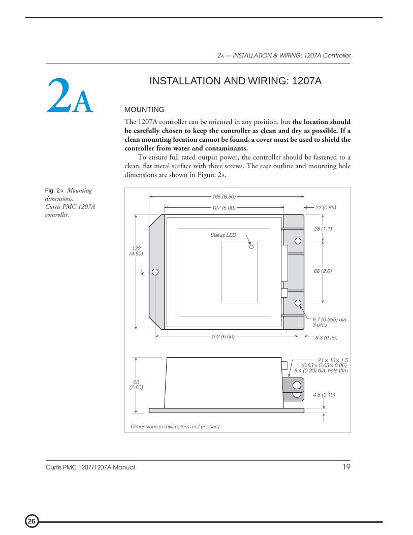
MOUNTING
The 1207A controller can be oriented in any position, but the location shouldbe carefully chosen to keep the controller as clean and dry as possible. If aclean mounting location cannot be found, a cover must be used to shield thecontroller from water and contaminants.
To ensure full rated output power, the controller should be fastened to aclean, flat metal surface with three screws. The case outline and mounting holedimensions are shown in Figure 2A.
2A — INSTALLATION & WIRING: 1207A Controller
2A
Fig. 2A Mountingdimensions,Curtis PMC 1207Acontroller.
66 (2.6)
28 (1.1)
122(4.80)
152 (6.00) 6.3 (0.25)
22 (0.85)
66(2.60)
4.8 (0.19)
21 × 16 × 1.5(0.83 × 0.63 × 0.06);
8.4 (0.33) dia. hole thru
6.7 (0.265) dia.,3 plcs
Dimensions in millimeters and (inches)
Status LED
CL
165 (6.50)
127 (5.00)

27
Curtis PMC 1207/1207A Manual 20
2A — INSTALLATION & WIRING: 1207A Controller
Although not usually necessary, a thermal joint compound can be used toimprove heat conduction from the case to the mounting surface.
CONNECTIONS: Low Current
An integrated 16-pin low power connector molded into the front of the control-ler provides the low power logic control connections (see pin list below). Themating connector is Molex Mini-Fit Jr., part number (5557) 39-01-2165.Contact Molex regarding compatible pins for various wire sizes.
Pin 1 shunt field driver output; n/c for series motorsPin 2 reverse contactor driver outputPin 3 forward contactor driver outputPin 4 main contactor driver outputPin 5 throttle: 3-wire pot highPin 6 throttle: 3-wire pot wiper or 0–5VPin 7 throttle: pot lowPin 8 throttle: 2-wire 5kΩ–0 or 0–5kΩ input
Pin 9 n/cPin 10 emergency reverse (BB) check output [optional]Pin 11 reverse inputPin 12 forward inputPin 13 emergency reverse inputPin 14 mode selection inputPin 15 brake inputPin 16 keyswitch input (KSI)
16 15 14 13 12 11 10 9
8 7 6 5 4 3 2 1

28
Curtis PMC 1207/1207A Manual 21
2A — INSTALLATION & WIRING: 1207A Controller
CONNECTIONS: High Current
Four tin-plated copper bus bars are provided for the high current connections tothe battery and motor:
M- output to motor armatureB- negative connection to batteryB+ positive connection to battery/fieldA2 plug diode to motor armature
Cables are fastened to the bus bars by M8 (5⁄16") bolts.When tightening the bolts, two opposing wrenchesshould be used to prevent bending the bus bars andputting undue strain on the internal connections.
M- A2B+B-
Programmer Connector
A 4-pin Molex connector is provided for the handheld programmer. The matingcable is supplied with the programmer.
Status LED
The Status LED, located on top of the controller, displays flashing codes toindicate controller status; the codes are listed in Section 5.

29
Curtis PMC 1207/1207A Manual 22
WIRING: Standard Configuration (Series Motor)
The basic wiring for series motors with field reversing is shown in Figure 3A.
2A — INSTALLATION & WIRING: 1207A Controller
Fig. 3A Standardwiring diagram(series motor),Curtis PMC 1207Acontroller.
MULTIMODE
EMERGENCYREVERSE
A2A1
REVERSECONTACTORPRECHARGE RESISTOR
(250 Ω, 5 W)
BRAKE FORWARD
CONTACTORS
MAINREVERSE
SWITCHES
CO
NT
RO
LF
US
E
M- A2B+B-
FORWARDCONTACTOR
POWERFUSE
KEYSWITCH
POLARITYPROTECTION
DIODE
S1S2
MAINCONTACTOR
B-
B+
FORWARD REVERSE
THROTTLE5kΩ–0 (TYPICAL)
A
The configuration shown in Figure 3A is a typical arrangement for a series motor.Curtis PMC controllers are designed for use in a wide range of applications, andaccordingly can be installed in a variety of ways to best meet customer needs.
NOTE: The emergency reverse check feature (wiring shown by dashed line) is afactory option.

30
Curtis PMC 1207/1207A Manual 23
Power Wiring for Series Motor
In every wiring configuration, it is imperative that the field be wired between thecontroller’s B+ and A2 terminals and that the armature be wired between the M-
and A2 terminals. The internal plug diode used in the 1207A is connectedbetween M- and A2. Therefore, the armature and field positions cannot beinterchanged. Reversing contactors can be used to switch either the armature orthe field.
Control Wiring for Series Motor
Wiring for the input switches and contactors is shown in Figure 3A (see detailbelow). The main contactor, if one is used, is normally connected directly to thecontroller. Optionally, the main contactor can be switched directly by thekeyswitch or brake, leaving Pin 4 unconnected.
The throttle shown in Figure 3A is a 5kΩ–0 type. Various other throttles can alsobe accommodated, and are discussed in the throttle wiring section.
2A — INSTALLATION & WIRING: 1207A Controller
16-pin detail (see Fig. 3A):
BRAKE
MULTIMODE
EMERGENCYREVERSE
FORWARD
REVERSE
KEYSWITCH
EMERGENCYREVERSE
CHECKOUTPUT
MAINCONTACTOR
FORWARDCONTACTOR
REVERSECONTACTOR
2-WIRE POT(5 kΩ)
POTLOW
8 7 6 5 4 3 2 1
16 15 14 13 12 11 10 9

31
Curtis PMC 1207/1207A Manual 24
WIRING: Compound Motor Configuration
A specially configured controller is available for compound motor applications.In this controller, the MOSFET output driver is used to drive the shunt field.The wiring for a compound wound motor with armature reversing is shown inFigure 4A.
2A — INSTALLATION & WIRING: 1207A Controller
Fig. 4A Compoundmotor wiring diagram,Curtis PMC 1207Acontroller.
The configuration shown in Figure 4A requires the use of a compound woundmotor. Pure shunt motors cannot be used with 1207A controllers. Althoughthe configuration shown is typical, various other configurations are possible.
NOTE: The emergency reverse check feature (wiring shown by dashed line) is afactory option.
MULTIMODE
EMERGENCYREVERSE
A2A1
RE
VE
RS
EC
ON
TAC
TO
RPRECHARGE RESISTOR(250 Ω, 5 W)
BRAKE FWD
CONTACTORS
MAINREV
SWITCHESC
ON
TR
OL
FU
SE
M- A2B+B-
FORWARDCONTACTOR
POWERFUSE
KEYSWITCH
POLARITYPROTECTION
DIODE
S1
S2
MAINCONTACTOR
B-
B+
FORWARD REVERSE SHUNT
THROTTLE5kΩ–0 (TYPICAL)
A
B-
3/
28
/0
0

32
Curtis PMC 1207/1207A Manual 25
Power Wiring for Compound Motor
The field must be wired between B+ and A2 and the armature between M- and A2.The internal plug diode in the 1207A is connected between M- and A2; therefore,the armature and field positions cannot be interchanged.
If the shunt is rated for under 2 amperes, it can be connected directly to thecontroller as shown in Figure 4A. If the shunt is rated for higher than 2 amperes,a contactor must be used to control the shunt field.
Control Wiring for Compound Motor
Control wiring for the compound motor application is like that for the standard(series motor) wiring. The main contactor, if one is used, is normally connecteddirectly to B-.
The throttle shown in Figure 4A is a 5kΩ–0 type. Various other throttles can alsobe accommodated, and are discussed in the throttle wiring section.
Polarity protection diodes and control fuses must be sized appropriately tohandle the increased current from the shunt field.
2A — INSTALLATION & WIRING: 1207A Controller
16-pin detail (see Fig. 4A):
BRAKE
MULTIMODE
EMERGENCYREVERSE
FORWARD
REVERSE
KEYSWITCH
EMERGENCYREVERSE
CHECKOUTPUT
FORWARDCONTACTOR
REVERSECONTACTOR
2-WIRE POT(5 kΩ)
POTLOW
8 7 6 5 4 3 2 1
16 15 14 13 12 11 10 9
SHUNT
33
Curtis PMC 1207/1207A Manual 26
WIRING: Throttle
Wiring for various throttles is described below. They are characterized as Type 1,Type 2, and Type 3 throttles in the programming menu of the handheldprogrammer. NOTE: In the text, throttles are identified by their nominal range andnot by their actual active range.
If the throttle you are planning to use is not covered, please contact theCurtis office nearest you.
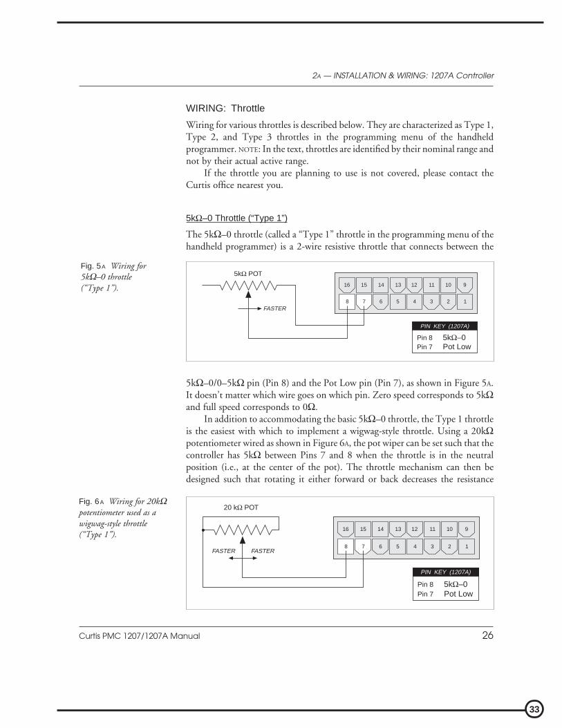
5kΩ–0 Throttle (“Type 1”)
The 5kΩ–0 throttle (called a “Type 1” throttle in the programming menu of thehandheld programmer) is a 2-wire resistive throttle that connects between the
2A — INSTALLATION & WIRING: 1207A Controller
Fig. 5A Wiring for5kΩ–0 throttle(“Type 1”).
8 7 6 5 4 3 2 1FASTER
16 15 14 13 12 11 10 9
5kΩ POT
Pin 8Pin 7
5kΩ–0Pot Low
PIN KEY (1207A)
5kΩ–0/0–5kΩ pin (Pin 8) and the Pot Low pin (Pin 7), as shown in Figure 5A.It doesn’t matter which wire goes on which pin. Zero speed corresponds to 5kΩand full speed corresponds to 0Ω.
In addition to accommodating the basic 5kΩ–0 throttle, the Type 1 throttleis the easiest with which to implement a wigwag-style throttle. Using a 20kΩpotentiometer wired as shown in Figure 6A, the pot wiper can be set such that thecontroller has 5kΩ between Pins 7 and 8 when the throttle is in the neutralposition (i.e., at the center of the pot). The throttle mechanism can then bedesigned such that rotating it either forward or back decreases the resistance
Fig. 6A Wiring for 20kΩpotentiometer used as awigwag-style throttle(“Type 1”).
8 7 6 5 4 3 2 1FASTERFASTER
16 15 14 13 12 11 10 9
20 kΩ POT
Pin 8Pin 7
5kΩ–0Pot Low
PIN KEY (1207A)

34
Curtis PMC 1207/1207A Manual 27
2A — INSTALLATION & WIRING: 1207A Controller
(b) Ground-referenced0–5V throttle
(a) 0–5V throttle sensor
Fig. 7A Wiring for 0–5Vthrottle (“Type 2”).
8 7 6 5 4 3 2 1
8 7 6 5 4 3 2 1
16 15 14 13 12 11 10 9
+
-
+
B-
16 15 14 13 12 11 10 9
4.7 kΩ
(Shunt impedance 150 kΩ to ground)
Pin 7Pin 6Pin 5
Pot Low0–5V InputPot High
PIN KEY (1207A)
Pin 7Pin 6
Pot Low0–5V Input
PIN KEY (1207A)
SENSOR GROUND
SENSOR OUTPUT0–5V
SENSOR
between Pins 7 and 8, which increases the controller output. The throttlemechanism must provide signals to the controller’s forward and reverse inputsindependent of the throttle pot resistance. The controller will not sense directionfrom the pot resistance.
0–5V, 3-Wire Potentiometer, and Electronic Throttles (“Type 2”)
With these throttles (“Type 2” in the programming menu), the controller looksfor a voltage signal at the pot wiper/0–5V input of the controller (Pin 6). Zerospeed corresponds to 0V and full speed corresponds to 5V. Pot Low is the currentreturn path for all Type 2 throttles.
0–5V Throttle
Two ways of wiring the 0–5V throttle are shown in Figure 7A. If a throttle sensoris used, the sensor’s ground return current must be less than 10 mA. If the 0–5Vthrottle input (Pin 6) exceeds 8 volts, the controller will shut down.

35
Curtis PMC 1207/1207A Manual 28
2A — INSTALLATION & WIRING: 1207A Controller
3-Wire Potentiometer (500Ω–10kΩ) Throttle
The 3-wire potentiometer is used in its voltage divider mode—with the voltagesource and return being provided by the 1207A controller. Pot High provides acurrent-limited 5V source to the potentiometer, and Pot Low provides the returnpath. Wiring is shown in Figure 8A.
Fig. 8A Wiring for 3-wirepotentiometer throttle(“Type 2”).
8 7 6 5 4 3 2 1
16 15 14 13 12 11 10 9OFFON
3-WIRE POT
Pin 7Pin 6Pin 5
Pot Low0–5V InputPot High
PIN KEY (1207A)
Fig. 9A Wiring forCurtis ET-XXX electronicthrottle (“Type 2”).
Curtis ET-XXX Electronic Throttle
The Curtis ET-XXX (manufactured by Hardellet) provides throttle and forward/reverse inputs to the 1207A controller. Wiring for the Curtis ET-XXX is shownin Figure 9A.
8 7 6 5 4 3 2 1
16 15 14 13 12 11 10 9
ET-XXX
B-
B+
B-
GREEN
ORANGE
BLACK
BLACK/WHITE
WHITE
WHT/BRN
Pin 16Pin 12Pin 11
Pin 6
KSI InputForwardReverse
0–5V Input
PIN KEY (1207A)
KEYSWITCH
WHT/GRN
3/
28
/0
0
36
Curtis PMC 1207/1207A Manual 29
2A — INSTALLATION & WIRING: 1207A Controller
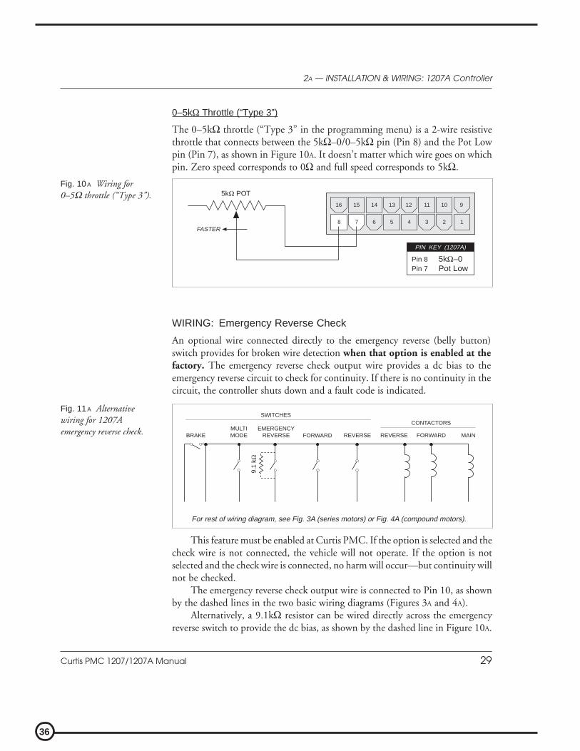
0–5kΩ Throttle (“Type 3”)
The 0–5kΩ throttle (“Type 3” in the programming menu) is a 2-wire resistivethrottle that connects between the 5kΩ–0/0–5kΩ pin (Pin 8) and the Pot Lowpin (Pin 7), as shown in Figure 10A. It doesn’t matter which wire goes on whichpin. Zero speed corresponds to 0Ω and full speed corresponds to 5kΩ.
Fig. 11A Alternativewiring for 1207Aemergency reverse check. MULTI
MODEEMERGENCY
REVERSE
For rest of wiring diagram, see Fig. 3A (series motors) or Fig. 4A (compound motors).
BRAKE FORWARD
CONTACTORS
MAINREVERSE
SWITCHES
FORWARD REVERSE
9.1
kΩ
This feature must be enabled at Curtis PMC. If the option is selected and thecheck wire is not connected, the vehicle will not operate. If the option is notselected and the check wire is connected, no harm will occur—but continuity willnot be checked.
The emergency reverse check output wire is connected to Pin 10, as shownby the dashed lines in the two basic wiring diagrams (Figures 3A and 4A).
Alternatively, a 9.1kΩ resistor can be wired directly across the emergencyreverse switch to provide the dc bias, as shown by the dashed line in Figure 10A.
Fig. 10A Wiring for0–5Ω throttle (“Type 3”).
8 7 6 5 4 3 2 1FASTER
16 15 14 13 12 11 10 9
5kΩ POT
Pin 8Pin 7
5kΩ–0Pot Low
PIN KEY (1207A)
WIRING: Emergency Reverse Check
An optional wire connected directly to the emergency reverse (belly button)switch provides for broken wire detection when that option is enabled at thefactory. The emergency reverse check output wire provides a dc bias to theemergency reverse circuit to check for continuity. If there is no continuity in thecircuit, the controller shuts down and a fault code is indicated.
37
Curtis PMC 1207/1207A Manual 30
2A — INSTALLATION & WIRING: 1207A Controller
SWITCHES AND OTHER HARDWARE
Keyswitch
The vehicle should have a master on/off switch to turn the system off when notin use. The keyswitch provides logic power for the 1207A controller, coil currentfor the contactors, and shunt current (in compound motor applications). Thekeyswitch must be capable of carrying these currents.
Main Contactor
A main contactor allows the 1207A controller to be disconnected from thebattery. A heavy-duty single-pole, single-throw (SPST) contactor with silver-alloy contacts is recommended, such as an Albright SW80 or SW180 (availablefrom Curtis).
After initial closing of the contacts, inrush currents flow as the controller’sinternal filter capacitors are charged. A 250Ω, 5W resistor (such as Curtis PMCp/n MP-2) can be used across the contactor to precharge the capacitors andreduce the inrush current through the contacts.
In compound motor applications, the main contactor driver is used to drivethe shunt field. The main contactor—if one is used—is normally connecteddirectly to B- in this configuration.
Forward/Reverse Contactors
For forward/reverse, a paired single-pole, double-throw (2×SPDT) contactor isrecommended, such as an Albright DC88 or DC182 (available from Curtis).With 4-terminal split field motors, two single-pole, single-throw (SPST) contac-tors are typically used. The coil voltage should match the vehicle voltage. Themaximum allowed coil current is 1 ampere.
Forward/Reverse, Emergency Reverse, and Mode Switches
The direction input switches can be any type of single-pole, single-throw (SPST)switch capable of switching the battery voltage at 10 mA.
Circuitry Protection Devices
For reverse polarity protection, a diode should be added to the control circuit. Itmust be sized appropriately for the maximum contactor coil currents (and shuntcurrent, in compound motor applications). To protect the control wiring fromaccidental shorts, a low current fuse (appropriate for the maximum current draw)should be connected in series with the battery feed. These devices are both shownin the wiring diagrams.

38
Curtis PMC 1207/1207A Manual 31
2A — INSTALLATION & WIRING: 1207A Controller
1207A INSTALLATION CHECKOUT
Before operating the vehicle, carefully complete the following checkout proce-dure. If you find a problem during the checkout, refer to the diagnostics andtroubleshooting section (Section 5) for further information.
The installation checkout can be conducted with or without the handheldprogrammer. The checkout procedure is easier with a programmer. Otherwise,observe the Status LED for codes.
Put the vehicle up on blocks to get the drive wheel(s) offthe ground before beginning these tests.
Turn the keyswitch off and make sure that the brake isapplied (brake switch open), the throttle is in neutral,and the forward/reverse switches are open.
Do not stand, or allow anyone else to stand, directly infront of or behind the vehicle during the tests.
1. If a programmer is available, connect it to the programmer connector.
2. Turn the keyswitch on. The programmer should “power up” with aninitial display, and the controller’s Status LED should begin steadilyblinking a single flash. If neither happens, check for continuity in thekeyswitch circuit and controller ground.
3. If you are using a programmer, put it into the diagnostic mode bypressing the DIAGNOSTICS key. The display should indicate “No FaultsFound.”
Release the brake (close the brake switch). To do this on a walkie,pull the tiller down to the operating position. The LED should con-tinue blinking a single flash and the programmer should continue toindicate no faults. If there is a problem, the LED will flash a diagnosticcode and the programmer will display a diagnostic message. If you areconducting the checkout without a programmer, look up the LEDdiagnostic code in Section 5: Diagnostics and Troubleshooting.
When the problem has been corrected, it may be necessary to cyclethe brake in order to clear the fault code.
4. With the brake released, select a direction and operate the throttle. Themotor should begin to turn in the selected direction. If it does not,
☞C A U T I O N
39
Curtis PMC 1207/1207A Manual 32
2A — INSTALLATION & WIRING: 1207A Controller
verify the wiring to the forward/reverse switches, forward/reverse con-tactors, and motor. The motor should run proportionally faster withincreasing throttle. If not, refer to Section 5.
5. If you are using a programmer, put it into the test mode by pressingthe TEST key. Scroll down to observe the status of the forward, reverse,brake, emergency reverse, and mode switches. Cycle each switch inturn, observing the programmer. Each input should show the correctstate on the programmer.
6. Specific material handling directives, such as prEN1175, require testingof the controller’s fault detection circuitry. This can be done as follows:
a) Disconnect the battery and make sure the keyswitch is off.b) Using an inline fuse holder fitted with a 10-amp fuse and
alligator clips, connect the controller’s M- and B- terminals.c) Turn the keyswitch on, release the brake, and apply the throttle.
The motor should not operate, and the direction contactorsshould not pull in.
d) Leave the keyswitch on and remove the inline fuse wire. Thevehicle status should continue to remain off.
e) Cycle the keyswitch off and on, release the brake, and apply thethrottle. The vehicle should now operate normally.
7. Take the vehicle off the blocks and drive it in a clear area. It should havesmooth acceleration and good top speed.
8. Test the plug braking of the vehicle. Verify that the plug braking optionis as desired (variable or fixed).
9. Verify that all options, such as high pedal disable (HPD), static returnto off (SRO), and anti-tiedown, are as desired.
10. Check to see whether the emergency reverse (belly button) feature isworking correctly. If you have the optional emergency reverse checkwiring, verify that the circuit is operational by momentarily disconnect-ing one of the emergency reverse wires. The vehicle should be disabledand a fault indicated.

40
Curtis PMC 1207/1207A Manual 33
33 — ADJUSTMENT OF PARAMETERS
ADJUSTMENT OF PARAMETERS
A number of controller parameters can be adjusted electronically via theoptional handheld programmer; for a complete list of the adjustments thatcan be made, see Section 6: Programmer Operation. On some 1207models, it is also possible to adjust the main current limit, plug currentlimit, acceleration rate, maximum creep speed, and maximum speed me-chanically, by means of the built-in screwdriver-adjustable potentiometers.
ADJUSTMENT VIA THE PROGRAMMER
To change a parameter using the programmer, press the PROGRAM key, andscroll down the Program Menu until the desired parameter is the top lineof the display. Press the appropriate CHANGE VALUE key (“up” or “down”)until the desired number is reached. The parameter is now set at the desiredvalue. All programming occurs in real time. That is, the parameters can bechanged while the vehicle is in operation.
The upper and lower limits of parameters are set at the factory. Someparameters have dependencies on other parameters. When the program-mer is being used to adjust a parameter and a limit is reached, the displaywill stop changing. To see why the display has stopped changing, press theMORE INFO key. If the limit is related to another parameter, that informationwill be displayed; changing the value of the related parameter may allow theoriginal parameter to be adjusted further. Otherwise, the display simplysays “Max Limit” or “Min Limit.”
Use of the programmer is described more fully in Section 6.
1207 single-mode controllers only
If a programmer is connected when a parameter is adjusted mechani-cally (see next page), the effect of the change can be seen in theprogrammer display. To adjust one of these five parameters with theprogrammer, its potentiometer must be set to the “OFF” position onthe adjustment panel. If you attempt to use the programmer toadjust a parameter whose potentiometer is not set to the “OFF”position, its value will not change. You will also note that the LEDsin the corners of both the CHANGE VALUE keys do not light up—another indication the parameter cannot be adjusted electronically.If you press the MORE INFO key, the programmer will display thefollowing message: “Protected by controller, can’t program.”

41
Curtis PMC 1207/1207A Manual 34
3 — ADJUSTMENT OF PARAMETERS
MECHANICAL ADJUSTMENT [1207 single-mode controllers only]
Five screwdriver-adjustable potentiometers (“trimpots”) allow mechanical ad-justment of the main current limit, plug current limit, acceleration rate, maxi-mum creep speed, and maximum speed (labeled “LOW”). The five trimpots areaccessed through holes on the adjustment panel, located under the slidingprotective cover on top of the controller. Adjustments are made with a smallinsulated screwdriver.
The trimpot’s relative position indicates the approximate value over theallowable range. For example: if the main current limit range is 20–250 amps,position “0” corresponds to 20 amps, and position “4” to 250 amps. Setting thepot halfway (at position “2”) corresponds to approximately 135 amps.
If you wish to adjust any of these parameters electronically, using theprogrammer, its trimpot must be set to “OFF.”
NOTE: On 1207 controllers with the MultiMode™ feature, the trimpots aredisabled at the factory.
STATUSA C C E L . L O WC R E E PP L U GM A I N
4OFF
1 230
4OFF
1 230
4OFF
1 230
4OFF
1 230
4OFF
1 230
L I M I TSPEEDL I M I TCURRENT

42
Curtis PMC 1207/1207A Manual 35
44 — MAINTENANCE
MAINTENANCE
There are no user-serviceable parts inside Curtis PMC 1207 and 1207A control-lers. No attempt should be made to open the controller. Opening thecontroller may damage it and will void the warranty.
However, it is recommended that the controller exterior be cleaned periodi-cally, and—if a handheld programmer is available—this periodic cleaning pro-vides a good opportunity to check the controller’s diagnostic history file. It is alsorecommended that the controller’s fault detection circuitry be checked wheneverthe vehicle is serviced.
The 1207/1207A controller is inherently a high power device.When working around any battery powered vehicle, propersafety precautions should be taken. These include, but arenot limited to: proper training, wearing eye protection, avoid-ing loose clothing and jewelry, and using insulated wrenches.
CLEANING
Although the 1207/1207A controller requires virtually no maintenance if prop-erly installed, the following minor maintenance is recommended in certainapplications.
1. Remove power by disconnecting the battery.
2. Discharge the capacitors in the controller by connecting a load (such asa contactor coil or a horn) across the controller’s B+ and B- terminals.
3. Remove and dirt or corrosion from the bus bar area. The controllershould be wiped clean with a moist rag. Allow it to dry before recon-necting the battery.
4. Make sure the connections to the bus bars are tight. Use two wellinsulated wrenches for this task in order to avoid stressing the bus bars.
DIAGNOSTIC HISTORY
The handheld programmer can be used to access the controller’s diagnostichistory file. Connect the programmer, press the MORE INFO key, and then—while
☞C A U T I O N

43
Curtis PMC 1207/1207A Manual 36
4 — MAINTENANCE
continuing to hold the MORE INFO key—press the DIAGNOSTICS key. The program-mer will read out all the faults that the controller has experienced since the lasttime the diagnostic history file was cleared. The faults may be intermittent faults,faults caused by loose wires, or faults caused by operator errors. Faults such ascontactor faults may be the result of loose wires; contactor wiring should becarefully checked out. Faults such as HPD or overtemperature may be caused byoperator habits or by overloading.
After a problem has been diagnosed and corrected, clearing the diagnostic historyfile is advisable. This allows the controller to accumulate a new file of faults. Bychecking the new diagnostic history file at a later date, you can readily determinewhether the problem was indeed completely fixed.
To clear the diagnostic history file, go to the Special Program Menu (bypressing and holding the MORE INFO key, and then pressing the PROGRAM key),scroll through the menu until “Clear Diagnostic History” is the top line in thedisplay, and then press MORE INFO again. The programmer will prompt you toacknowledge or cancel. See Section 6 of this manual for more detail on program-mer operation.
TESTING THE FAULT DETECTION CIRCUITRY
Specific material handling directives, such as prEN1175, require periodic testingof the controller’s fault detection circuitry. It is recommended that each time thevehicle is serviced, the M- fault detection circuitry be checked as follows:
1. Put the vehicle up on blocks to get the drive wheel(s) off the ground,disconnect the battery, and make sure the keyswitch is off.
2. Using an inline fuse holder fitted with a 10-amp fuse and alligatorclips, connect the controller’s M- and B- terminals.
3. Turn the keyswitch on, release the brake, and apply the throttle. Themotor should not operate, and the direction contactors should notpull in.
4. Leave the keyswitch on and remove the inline fuse wire. The vehiclestatus should continue to remain off.
5. Cycle the keyswitch off and on, release the brake, and apply thethrottle. The vehicle should now operate normally.

44
Curtis PMC 1207/1207A Manual 37
55 — DIAGNOSTICS & TROUBLESHOOTING
DIAGNOSTICS AND TROUBLESHOOTING
The 1207/1207A controllers provide diagnostics information to assist techni-cians in troubleshooting drive system problems. The diagnostics information canbe obtained in two ways: reading the appropriate display on the programmer orobserving the fault codes issued by the Status LED. The Status LED is located ontop of the controller. On 1207 models, it is under the sliding protective cover.
LED DIAGNOSTICS
During normal operation, with no faults present, the Status LED flashes a singleflash at approximately 1 flash/second. If the controller detects a fault, a 2-digitfault identification code is flashed continuously until the fault is corrected. Forexample, code “3,2”—welded direction contactor—appears as:
¤ ¤ ¤ ¤ ¤ ¤ ¤ ¤ ¤ ¤ ¤ ¤ ¤ ¤ ¤( 3 , 2 ) ( 3 , 2 ) ( 3 , 2 )
The codes are listed in Table 1. For suggestions about possible causes of thevarious faults, refer to the troubleshooting chart (Table 2).
Table 1 LED CODESLED CODE EXPLANATION
LED off no power or defective controllersolid on defective controller
single flash ¤ controller operational; no faults
1,2 ¤ ¤¤ hardware fail-safe error1,3 ¤ ¤¤¤ M- fault or motor output short1,4 ¤ ¤¤¤¤ sequencing fault (SRO)
2,1 ¤¤ ¤ 5kΩ–0 or throttle wiper input fault2,2 ¤¤ ¤¤ emerg. rev. circuit check fault (BB wiring)2,3 ¤¤ ¤¤¤ high-pedal-disable fault (HPD)2,4 ¤¤ ¤¤¤¤ throttle pot low open or shorted to B+ or B-
3,1 ¤¤¤ ¤ contactor or shunt driver overcurrent3,2 ¤¤¤ ¤¤ welded direction contactor3,3 ¤¤¤ ¤¤¤ [reserved for future use]3,4 ¤¤¤ ¤¤¤¤ missing contactor or shunt4,1 ¤¤¤¤ ¤ low battery voltage4,2 ¤¤¤¤ ¤¤ overvoltage4,3 ¤¤¤¤ ¤¤¤ thermal cutback4,4 ¤¤¤¤ ¤¤¤¤ [reserved for future use]
NOTE: Only one fault is indicated at a time, and faults are not queued up.

45
Curtis PMC 1207/1207A Manual 38
5 — DIAGNOSTICS & TROUBLESHOOTING
Operational faults—such as overtemperature—are cleared as soon as operation isbrought within range. Non-operational faults—such as a throttle fault—usuallyrequire the brake or keyswitch to be cycled after the problem is remedied.
PROGRAMMER DIAGNOSTICS
With a programmer, diagnostics and troubleshooting is more direct than with theLED alone. The programmer presents complete diagnostic information in plainlanguage—no codes to decipher. Faults are displayed in the Diagnostic Menu,and the status of the controller inputs/outputs is displayed in the Test Menu.
The following 4-step process is generally used for diagnosing and troubleshootingan inoperative vehicle: (1) visually inspect the vehicle for obvious problems;(2) diagnose the problem, using the programmer; (3) test the circuitry with theprogrammer; and (4) correct the problem. Repeat the last three steps as necessaryuntil the vehicle is operational.
Example: A vehicle that does not operate in “forward” isbrought in for repair.
STEP 1: Examine the vehicle and its wiring for any obviousproblems, such as broken wires or loose connections.
STEP 2: Connect the programmer, put it in diagnostic mode,and read the displayed fault information. In this example, thedisplay shows “No Faults Present,” indicating that the control-ler has not detected anything out of the norm.
STEP 3: Put the programmer in test mode, and observe thestatus of the inputs and outputs in the forward direction. Inthis example, the display shows that the forward switch did notclose when “forward” was selected, which means the problemis either in the forward switch or the switch wiring.
STEP 4: Check or replace the forward switch and wiring andrepeat the test. If the programmer shows the forward switchclosing and the vehicle now drives normally, the problem hasbeen corrected.
Refer to the troubleshooting chart (Table 2) for suggestions covering a wide rangeof possible faults.

46
Curtis PMC 1207/1207A Manual 39
5 — DIAGNOSTICS & TROUBLESHOOTING
Table 2 TROUBLESHOOTING CHARTLED PROGRAMMER
CODE LCD DISPLAYEXPLANATION POSSIBLE CAUSE
1,2 HW F A I L SA F E hardware fail-safe error 1. Controller defective.
1,3 M - SHORT ED M- output shorted 1. M- output shorted to ground.2. Direction contactor not closing.3. Direction contactor not closing fast enough.4. Internal motor short to ground.
1,4 SRO SRO fault 1. Improper sequence of KSI, brake, anddirection inputs.
2. Wrong SRO type selected.3. Brake or direction switch circuit open.4. Sequencing delay too short.
2,1 THROT T L E F AUL T 1 5kΩ–0 or wiper fault 1. Throttle input wire open.2. Throttle input wire shorted to ground or B+.3. Throttle pot defective.4. Wrong throttle type selected.
2,2 BB W I R I NG CHECK emerg. reverse wiring fault 1. BB wire open.2. BB check wire open.
2,3 HPD HPD sequencing fault 1. Improper seq. of KSI, brake, throttle inputs.2. Wrong HPD type selected.3. Misadjusted throttle pot.
2,4 THROT T L E F AUL T 2 Pot Low broken or shorted 1. Pot Low wire open.2. Pot Low wire shorted.3. Wrong throttle type selected.
3,1 CONT DRVR OC driver output overcurrent 1. Direction contactor coil shorted.2. Shunt field shorted.
3,2 D I R CONT WE LDED welded direction contactor 1. Direction contactor stuck closed.
3,4 M I SS I NG CONT ACTOR missing contactor or shunt 1. Direction contactor coil open.2. Direction contactor missing.3. Shunt field open.4. Wire to shunt or direction contactor open.
4,1 LOW BA T T ERY VOL T AGE low battery voltage 1. Battery voltage <16 volts.2. Corroded battery terminal.3. Loose battery or controller terminal.
4,2 OVERVOL T AGE overvoltage 1. Battery voltage >48V (1207); >33V (1207A).2. Vehicle operating with charger attached.
4,3 THERMA L CUT BACK over-/under-temp. cutback 1. Temperature >85°C or <-25°C.2. Excessive load on vehicle.3. Improper mounting of controller.4. Operation in extreme environments.

47
Curtis PMC 1207/1207A Manual 40
66 — PROGRAMMER OPERATION
PROGRAMMER OPERATION
The universal Curtis PMC handheld programmer (optional) allows you toprogram, test, and diagnose Curtis PMC programmable controllers. The pro-grammer is powered by the host controller, via an RJ11 modular connectorlocated in the adjustment panel on top of the controller (1207 models) or via a4-pin Molex connector on the front panel (1207A models).
When the programmer is first plugged into the controller, it displays thecontroller’s model number, date of manufacture, and software revision code.Following this initial display, the programmer displays a prompt for furtherinstructions.
C U R T I S P M C
+ + + + + + + + + + + + + + + + + + + ++++
A DIVISION OF CURTIS INSTRUMENTS INC.
SCROLLDISPLAY
CHANGEVALUE
PROGRAM DIAGNOSTICS
MORE INFO
TEST
+++
Change the selecteditem’s value (up or down)with these two keys
Choose the Program, Test,or Diagnostics Mode withone of these three keys
The LED in the corner ofthe key lights up to identifythe mode of operation
Get more informationabout selected items withthis key. Also, use thiskey in combination withother keys to put theprogrammer in Specialmodes.
Scroll the 4-linedisplay (up and down)with these two keys
A 4-line LCD display ispresented in this window

48
Curtis PMC 1207/1207A Manual 41
6 — PROGRAMMER OPERATION
The programmer is operated via an 8-key keypad. Three keys select operatingmodes (Program, Test, Diagnostics), two scroll the display up and down, and twochange the values of selected parameters. The eighth key, the MORE INFO key, isused to display further information about selected items within any of the threestandard modes. In addition, when pressed together with the PROGRAM orthe DIAGNOSTICS key, the MORE INFO key selects the Special Program mode or theSpecial Diagnostics mode.
The display window presents a 4-line LCD display. The display is visible even inbright sunlight. You can adjust the display contrast in the Special Program mode.
When one of the menu keys is pressed, the LED at the corner of the key lights up,identifying the mode of programmer operation. For example, if the TEST key ispressed, the LED at the corner of the key indicates that the programmer is nowin the Test mode, and the Test Menu is displayed.
Four lines of a menu are displayed at a time. The item at the top of the displaywindow is the selected item. To select an item, scroll within the menu until thedesired item is positioned at the top of the display window. The selected item isalways the top line. (In the Program mode, the selected item is highlighted by aflashing arrow.) To modify a parameter or obtain more information about it, itmust be scrolled to the top position in the display window.
To scroll up and down within a menu, use the two SCROLL DISPLAY arrow keys.The SCROLL DISPLAY arrow keys can be pressed repeatedly or be held down. Whena key is held down, the scrolling speed increases the longer the key is held.
A small scroll bar at the left of the display window provides a rough indication ofthe position of the four displayed items within the entire menu. That is, when thebar is at the top of the window, the top of the menu is displayed. As you scrollthrough the menu, the bar moves downward. When the bar is at the very bottomof the window, you have reached the end of the menu. This sample display isfrom the Program Menu:
SCROLLDISPLAY
M1 MA I N C / L > 2 5 0M1 P LUG C / L 7 0M1 RAMP C / L 2 5 0M1 ACCE L RA T E 1 . 0
selected itemscroll bar

49
Curtis PMC 1207/1207A Manual 42
6 — PROGRAMMER OPERATION
The two CHANGE VALUE arrow keys are used to increase or decrease the value of aselected menu item. Like the SCROLL DISPLAY arrow keys, the CHANGE VALUE arrowkeys can be pressed repeatedly or be held down. The longer a key is held, the fasterthe parameter changes. This allows rapid changing of any parameter.
An LED on each CHANGE VALUE arrow key indicates whether the key is activeand whether change is permissable. When the value of a parameter is beingincreased, the LED on the “up” CHANGE VALUE key is on until you reach themaximum value for that parameter. When the LED goes off, you cannot increasethe value.
The MORE INFO key has three functions: (1) to display more information aboutthe selected item, (2) to access the Special Program and Special Diagnosticsmodes (when used together with the PROGRAM and DIAGNOSTICS keys), and (3)to initiate certain commands (such as the Self Test).
“More information” is available in all of the programmer operating modes.After using the MORE INFO key to display additional information about theselected item, press the MORE INFO key again to return to the original list.
OPERATING MODES:PROGRAM, TEST, DIAGNOSTICS, SPECIAL PROGRAM, SPECIAL DIAGNOSTICS
In the Program mode, accessed by pressing the PROGRAM key, all the adjustableparameters and features of the controller are displayed (four at a time), along withtheir present settings. The setting of the selected item—the item at the top of thedisplay, with the flashing arrow—can be changed, using the two CHANGE VALUE
keys.The LEDs on these keys indicate whether there is still room for change. That
is, when the upper limit of a parameter’s range is reached, the LED on the “up”key no longer lights up, indicating that the present value cannot be increased;when the lower limit is reached, the LED on the “down” key no longer lights up.
The MORE INFO key, when used in the Program mode, displays a bar graphalong with the minimum and maximum values possible for the selected param-eter. Parameters can be changed either from the main Program Menu or afterthe MORE INFO key has been pressed and the additional information is beingdisplayed (see example below).
CHANGEVALUE
set valueselected parameter
bar graph
minimum value
MODE 1 ACCE L ERA T I ONRA T E , SECS
M I N 0 . 2 MAX 3 . 01.3
maximum value
units
PROGRAM

50
Curtis PMC 1207/1207A Manual 43
6 — PROGRAMMER OPERATION
Some parameters on some controllers have dependencies on other param-eters. This means that the available settings for one parameter may be dependenton the limits of another parameter. If you attempt to set a parameter (A) outsidethe limits imposed by another parameter (B), a message will be displayedindicating that parameter A is dependent on parameter B.
The Program Menu is presented at the end of this section. NOTE: Some itemsmay not be available on all models.
In the Test mode, accessed by pressing the TEST key, real-time information isdisplayed about the status of the inputs, outputs, and controller temperature. Forexample, when the status of the forward switch is displayed, it should read“On/Off/On/Off/On/Off” as the switch is repeatedly turned on and off. In theTest mode, the item of interest does not need to be the top item on the list; it onlyneeds to be among the four items visible in the window. The Test mode is usefulfor checking out the operation of the controller during initial installation, andalso for troubleshooting should problems occur.
The MORE INFO key, when used in the Test mode, causes additional informa-tion to be displayed about the selected item (top line in the window).
The Test Menu is presented at the end of this section. NOTE: Some items maynot be available on all models.
In the Diagnostics mode, accessed by pressing the DIAGNOSTICS key, currentlyactive faults detected by the controller are displayed.
The MORE INFO key, when used in the Diagnostics mode, causes additionalinformation to be displayed about the selected item.
A list of the abbreviations used in the Diagnostics display is included at theend of this section.
The Special Program mode allows you to perform a variety of tasks, most ofwhich are self-explanatory. Through the Special Program Menu, you can revertto earlier settings, save controller settings into the programmer memory, load thecontroller settings from the programmer into a controller, clear the controller’sdiagnostic history, adjust the contrast of the programmer’s LCD display, selectthe language to be displayed by the programmer, and display basic information(model number, etc.) about the controller and the programmer.
To access the Special Program mode, first press the MORE INFO key. Then,while continuing to hold the MORE INFO key, press the PROGRAM key. The LEDon the PROGRAM key will light, just as when the programmer is in Program mode.
PROGRAMMORE INFO
*
DIAGNOSTICS
TEST

51
Curtis PMC 1207/1207A Manual 44
6 — PROGRAMMER OPERATION
DIAGNOSTICSMORE INFO
*
To distinguish between the Program and Special Program modes, look at themenu items in the display.
CONTROLLER CLONING
Two of the Special Program Menu items—“Save ControllerSettings in Programmer” and “Load Programmer Settingsinto Controller”—allow you to “clone” controllers. To dothis, simply program one controller to the desired settings,save these settings in the programmer, and then load theminto other similar (same model number) controllers, thuscreating a family of controllers with identical settings.
The MORE INFO key is used initially to access the Special Program mode, and onceyou are within the Special Program mode, it is used to perform the desired tasks.To adjust the contrast in the display window, for example, select “ContrastAdjustment” by scrolling until this item is at the top of the screen, and thenpress MORE INFO to find out how to make the adjustment.
The Special Program Menu is presented at the end of this section.
In the Special Diagnostics mode, the controller’s diagnostic history file isdisplayed. This file includes a list of all faults observed and recorded by thecontroller since the history was last cleared. (NOTE: The maximum and minimumtemperatures recorded by the controller are included in the Test Menu.) Eachfault is listed in the diagnostic history file only once, regardless of the number oftimes it occurred.
To access Special Diagnostics, first press the MORE INFO key. Then, whilecontinuing to hold the MORE INFO key, press the DIAGNOSTICS key. The LED onthe DIAGNOSTICS key will light, just as when the programmer is in Diagnosticsmode.
The MORE INFO key, when used within the Special Diagnostics mode, causesadditional information to be displayed about the selected item.
To clear the diagnostic history file, put the programmer into the SpecialProgram mode, select “Clear Diagnostic History,” and press the MORE INFO keyfor instructions. Clearing the diagnostic history file also resets the maximum/minimum temperatures in the Test Menu.
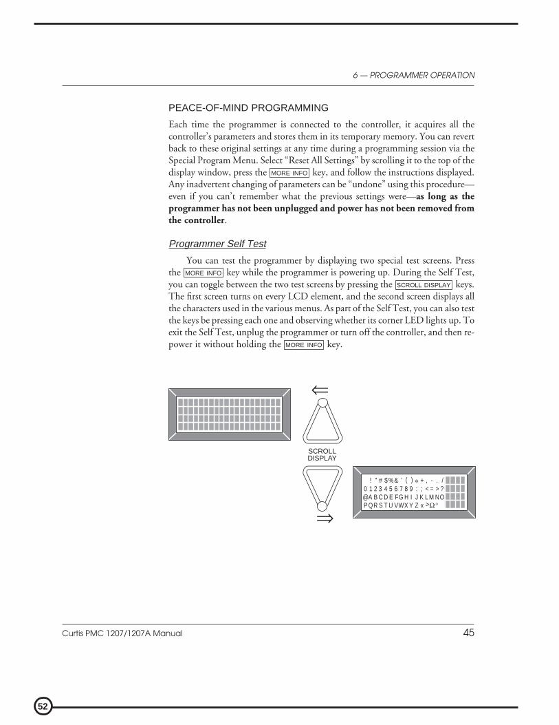
52
Curtis PMC 1207/1207A Manual 45
6 — PROGRAMMER OPERATION
PEACE-OF-MIND PROGRAMMING
Each time the programmer is connected to the controller, it acquires all thecontroller’s parameters and stores them in its temporary memory. You can revertback to these original settings at any time during a programming session via theSpecial Program Menu. Select “Reset All Settings” by scrolling it to the top of thedisplay window, press the MORE INFO key, and follow the instructions displayed.Any inadvertent changing of parameters can be “undone” using this procedure—even if you can’t remember what the previous settings were—as long as theprogrammer has not been unplugged and power has not been removed fromthe controller.
Programmer Self Test
You can test the programmer by displaying two special test screens. Pressthe MORE INFO key while the programmer is powering up. During the Self Test,you can toggle between the two test screens by pressing the SCROLL DISPLAY keys.The first screen turns on every LCD element, and the second screen displays allthe characters used in the various menus. As part of the Self Test, you can also testthe keys be pressing each one and observing whether its corner LED lights up. Toexit the Self Test, unplug the programmer or turn off the controller, and then re-power it without holding the MORE INFO key.
⇒
SCROLLDISPLAY
⇐
@A B C D E FG H I J K L M NOQP R S T U VWX Y Z x Ω°
0 1 2 3 4 5 6 7 8 9 : ; < = > ?! " # $ %& ' ( ) * + , - . /
>

53
Curtis PMC 1207/1207A Manual 46
PROGRAMMER MENUS
Items are listed for each menu in the order they appear in the actual menusdisplayed by the handheld programmer.
Program Menu (not all items available on all controllers)
E M R R E V C / L Emergency reverse current limitT H R O T T L E T Y P E Throttle type*R A M P S H A P E Throttle mapC R E E P S P E E D Creep speed, as percent PWM duty cycleE M R R E V S P E E D Emerg. reverse speed, as % PWM duty cycleS E Q U E N C I N G D L Y Sequencing delay, in secondsV A R I A B L E P L U G Throttle-variable plug braking: on or offH I G H P E D A L D I S High pedal disable (HPD): type†S R O Static return to off (SRO): type‡A N T I - T I E D O W N Anti-tiedown: on or offQ U I C K S T A R T Quick-start throttle factorM 1 M A I N C / L Mode 1 main current limitM 1 P L U G C / L Mode 1 plug current limitM 1 R A M P C / L Mode 1 ramp start current limitM 1 A C C E L R A T E Mode 1 acceleration rate, in secondsM 1 M A X S P E E D Mode 1 maximum speed, as % PWM outputM 2 M A I N C / L Mode 2 main current limitM 2 P L U G C / L Mode 2 plug current limitM 2 R A M P C / L Mode 2 ramp start current limitM 2 A C C E L R A T E Mode 2 acceleration rate, in secondsM 2 M A X S P E E D Mode 2 maximum speed, as % PWM outputN E U T B R A K E C / L Neutral brake current limitN E U T R A L B R A K E Neutral brake: on or off
(Notes are on the next page.)
6 — PROGRAMMER OPERATION

54
Curtis PMC 1207/1207A Manual 47
Program Menu Notes
(For more detail on these options, see Appendix A: Glossary of Features and Functions.)
* Throttle typesType 1: 5kΩ–0Type 2: 0–5V, 0–10V, 3-wire pot, and electronic throttlesType 3: 0–5kΩ throttles
† HPD typesType 0: no HPDType 1: HPD on brake inputType 2: HPD on KSI
‡ SRO typesType 0: no SROType 1: SRO on brake inputType 2: SRO on KSI plus brake input plus a direction inputType 3: SRO on KSI plus brake input plus forward input
Test Menu (not all items available on all controllers)
T H R O T T L E % Throttle reading, as percent of fullB A T T V O L T A G E Battery voltageH E A T S I N K ° C Heatsink temperatureM A X T E M P ° C Maximum temperature seen *M I N T E M P ° C Minimum temperature seen *B R A K E I N P U T Brake switch: on/offS P E E D I N Mode switch: on (Mode 1) / off (Mode 2)E M R R E V I N P U T Emergency reverse switch: on/offF O R W A R D I N P U T Forward switch: on/offR E V E R S E I N P U T Reverse switch: on/offM A I N C O N T A C T O R Main contactor: on/offF W D C O N T Forward contactor: on/offR E V C O N T Reverse contactor: on/off
6 — PROGRAMMER OPERATION
* Maximum/minimum temperatures recordedsince Diagnostic History was last cleared.

55
Curtis PMC 1207/1207A Manual 48
6 — PROGRAMMER OPERATION
Special Program Menu
R E S E T A L L S E T T I N G S Revert to original settingsC O N T S E T T I N G S > P R O G Save controller settings in programmerP R O G S E T T I N G S > C O N T Load programmer settings in controllerC L E A R D I A G H I S T O R Y Clear diagnostic history memoryC O N T R A S T A D J U S T M E N T Adjust display contrastL A N G U A G E S E L E C T I O N Select displayed languageP R O G R A M M E R I N F O Display programmer informationC O N T R O L L E R I N F O Display controller information
Diagnostics and Special Diagnostics “ Menu”
This is not a menu as such, but simply a list of the possible messages you may seedisplayed when the programmer is operating in either of the Diagnostics modes.The messages are listed in alphabetical order for easy reference.
B B W I R I N G C H E C K BB wiring check failedC O N T D R V R O C Contactor driver overcurrentD I R C O N T W E L D E D Direction contactor weldedH P D High-pedal-disable (HPD) activatedH W F A I L S A F E Hardware failsafe activatedL O W B A T T E R Y V O L T A G E Low battery voltage (<16V)M - S H O R T E D M- output faultM I S S I N G C O N T A C T O R Missing contactorN O K N O W N F A U L T S No known faultsO V E R V O L T A G E Overvoltage (1207: >48V; 1207A: >33V)S R O Static-return-to-off (SRO) activatedT H E R M A L C U T B A C K Cutback, due to over/under tempT H R O T T L E F A U L T 1 Throttle input faultT H R O T T L E F A U L T 2 Throttle low input fault

56
Curtis PMC 1207/1207A Manual A-1
APPENDIX A: GLOSSARY
APPENDIX A
GLOSSARY OF FEATURES AND FUNCTIONS
Acceleration/deceleration rate
The acceleration rate is the time required for the controller to increase from 0%to 100% duty factor. The shape of the acceleration curve is controlled by thedynamic throttle response, which is linear.
If you have a MultiMode™ controller, the acceleration rates in Mode 1 andin Mode 2 are independently adjustable via the handheld programmer. If youhave a 1207 controller with the MultiMode™ feature disabled (i.e., a single-mode controller), you can adjust the acceleration rate mechanically via theappropriate trimpot located on top of the controller.
Anti-tiedown
Before enabling Mode 1 operation, the anti-tiedown function checks that themode selection switch has been released after the last cycling of the brake switch.This feature discourages operators from taping or otherwise “tying down” themode switch. If Mode 1 is already selected before the brake is released, thecontroller remains in Mode 2 until the mode switch is released and pressed again.
Arcless contactor switching
The controller output duty factor is quickly reduced to zero any time a directionis de-selected, so that the controller current will be reduced to zero before thedirection contactor drops out.
BB (= Belly Button; see Emergency reverse)
Brake
The brake must be released (brake input “high”) for the controller to operate.This is a safety interlock used on most material handling vehicles.
Cycling the brake or KSI clears most faults and enables operation.
57
Curtis PMC 1207/1207A Manual A-2
APPENDIX A: GLOSSARY
Contactor drivers and circuits
These controllers can accommodate up to four external contactors: forward,reverse, main, and shunt. Some vehicles may have no main contactor, or the maincontactor may be wired directly to the KSI or brake signal, bypassing thecontroller.
Various protections provided for the contactor drivers ensure that thecontactors operate correctly; see Fault detection.
The shunt winding of a compound motor can be wired directly to the shuntdriver, provided that the maximum current does not exceed the driver’s currentrating.
Creep speed at first throttle
Creep speed is activated when a direction is first selected. The output maintainscreep speed until the throttle is rotated out of the throttle deadband (typically10% of throttle). Creep speed is adjustable from 0 to 25% of the controller dutyfactor; the adjustment can be made mechanically (via the appropriate trimpot ontop of the 1207 controller) or electronically (via the handheld programmer).
Current limiting
Curtis PMC controllers limit the motor current to a preset maximum. Thisfeature protects the controller from damage that might result if the current werelimited only by motor demand. PWM output to the power section is reducedsmoothly until the motor current falls below the set limit level.
In addition to protecting the controller, the current limit feature alsoprotects the rest of the system. By eliminating high current surges during vehicleacceleration, stress on the motor and batteries is reduced and their efficiencyenhanced. Similarly, there is less wear and tear on the vehicle drivetrain, as wellas on the ground on which the vehicle rides (an important consideration with golfcourses and tennis courts, for example).
If you have a MultiMode™ controller, the main current limit, plug currentlimit, and ramp start current limit in Mode 1 and in Mode 2 are independentlyadjustable via the handheld programmer. If you have a 1207 controller with theMultiMode™ feature disabled (i.e., a single-mode controller), you can adjust themain and plug current limits mechanically via the appropriate trimpots locatedon top of the controller.
In addition, the emergency reverse current limit can be set via the handheldprogrammer.
58
Curtis PMC 1207/1207A Manual A-3
APPENDIX A: GLOSSARY
Current multiplication
During acceleration and during reduced speed operation, the Curtis PMCcontroller allows more current to flow into the motor than flows out of thebattery. The controller acts like a dc transformer, taking in low current and highvoltage (the full battery voltage) and putting out high current and low voltage.The battery needs to supply only a fraction of the current that would be requiredby a conventional controller (in which the battery current and motor current arealways equal). The current multiplication feature gives vehicles using CurtisPMC controllers dramatically greater driving range per battery charge.
Deceleration rate
The deceleration rate is the time required for the controller to decrease from100% duty factor to zero. The deceleration rate is fixed, and cannot be adjusted.The shape of the deceleration curve is controlled by the dynamic throttleresponse, which is linear.
Emergency reverse
Emergency reverse is activated when the brake is released, KSI is activated, andthe emergency reverse switch (the BB, or “belly button” switch) is pressed. Afterthe BB switch is released, normal controller operation is not resumed untilneutral (no direction) is selected or until the brake is cycled (brake, then brakerelease). However, repeatedly pressing the BB switch will reactivate the emer-gency reverse function each time.
Because emergency reverse immediately powers the reverse contactor, somearcing may occur.
Fault detection
An internal microcontroller automatically maintains surveillance over the func-tioning of the controller. When a fault is detected, the appropriate fault code issignalled via the LED, externally visible on top of the controller. The diagnosticcodes flashed by the LED are listed in Section 5, Troubleshooting.
If the fault is critical, the controller is disabled. More typically, the fault is aremediable condition and temporary—for example, an undervoltage fault iscleared when the condition is removed.

59
Curtis PMC 1207/1207A Manual A-4
APPENDIX A: GLOSSARY
The automatic fault detection system includes:
contactor coil open / shorted driver (F/R and shunt contactors)contactor driver overcurrent / contactor coil shortcontactor weldedemergency reverse circuit checkM- output faultmemory checks upon start-upovervoltage cutoffpower supply out of range (internal)throttle faultundervoltage cutbackwatchdog (external and internal)watchdog (internal)
Fault recording
Fault events are recorded in the controller’s memory. Multiple occurrences of thesame fault are recorded as one occurrence.
The fault event list can be loaded into the programmer for readout. TheSpecial Diagnostics mode provides access to the controller’s diagnostic historyfile—the entire fault event list created since the diagnostic history file was lastcleared. The Diagnostics mode, on the other hand, provides information aboutonly the currently active faults.
Fault recovery (including recovery from disable)
Almost all faults require a cycling of the KSI or brake input to reset the controllerand enable operation.
The only exceptions are these:
FAULT RECOVERY
anti-tiedown release and re-select Mode 1contactor overcurrent when condition clearsemergency reverse BB re-applied or brake cycledHPD lower throttle to below HPD thresholdovervoltage when battery voltage drops below overvoltageSRO when proper sequence is followedthermal cutback when temperature comes within rangethrottle fault clears when condition goneundervoltage when battery voltage rises above undervoltage

60
Curtis PMC 1207/1207A Manual A-5
APPENDIX A: GLOSSARY
High-pedal-disable (HPD)
The HPD feature prevents the vehicle from being started while the throttle isapplied. The controller can be programmed to have HPD based on either brakeinput or KSI.
Brake-type HPD
To start the vehicle, the controller must receive a brake input (brake released)before receiving a throttle input. Controller operation will be disabled immedi-ately if pedal demand (throttle input) is greater than 25% duty factor at the timethe brake is released (brake input “high”). Normal controller operation is re-gained by reducing the throttle demand to less than 25%.
Sequencing delay, which can be set with the handheld programmer, providesa variable delay before disabling the controller. If the brake is applied while thethrottle is above the HPD threshold (25%), HPD is not activated if the brake isthen released before the delay time elapses.
KSI-type HPD
The HPD feature can be activated by KSI input instead of brake input, ifpreferred. To start the vehicle, the controller must receive a KSI input beforereceiving a throttle input.
KSI
KSI (Key Switch Input) provides power to the logic board, and initializes andstarts diagnostics. In combination with the brake input, KSI enables all logicfunctions.
Some vehicles may have no keyswitch (KSI simply tied to B+) or may havethe key permanently turned on.
LED
A Status LED located on top of the controller flashes a fault identification codeif a fault is detected by the controller. The fault codes are listed in Table 1. Thecode will continue to flash until the fault condition has been cleared during activefault detection. This will typically happen after cycling KSI for power-up faultconditions, and cycling the brake for faults detected during operation. NOTE: In1207 models, the Status LED is on the adjustment panel under the slidingprotective cover.
61
Curtis PMC 1207/1207A Manual A-6
APPENDIX A: GLOSSARY
MOSFET
A MOSFET (Metal Oxide Semiconductor Field Effect Transistor) is a type oftransistor characterized by its fast switching speeds and very low losses.
MultiMode ™
The MultiMode™ feature of these controllers allows the vehicle to be operatedwith two distinct sets of characteristics. The two modes can be programmed to besuitable for operation under different conditions, such as slow precise maneuver-ing in Mode 2 and faster, long distance travel in Mode 1. The followingparameters can be set independently in the two modes:
— main current limit— plug current limit— ramp start current limit— acceleration rate— maximum speed
The operating mode is selected by means of the mode selection switch. IfMode 1 is not selected, the controller operates by default in Mode 2. When thecontroller returns to Mode 2 from Mode 1, it automatically changes the maincurrent limit, the plug current limit, the ramp start current limit, the accelerationrate, and the maximum speed to their Mode 2 values.
If the anti-tiedown feature is active, Mode 1 must be re-selected each timethe brake is released.
Neutral brake
The optional neutral brake feature provides automatic plug braking in neutral. Ifthis option is not selected, the vehicle is free to coast in neutral. The neutral brakeplug current limit is programmable.
Overtemperature
At overtemperature (from 85°C to 95°C), the drive current limit is linearlydecreased from full set current down to zero. (Plug current, however, is notreduced—in order to provide full vehicle braking under all thermal conditions.)The operating PWM frequency is shifted to 1.5 kHz when the controller isoperating in the overtemperature range.
Overvoltage protection
Overvoltage resets the microprocessor, inhibits PWM, and opens the contactors,thereby shutting down the controller. Overvoltage can result during batterycharging or from an improperly wired controller. Controller operation resumes

62
Curtis PMC 1207/1207A Manual A-7
APPENDIX A: GLOSSARY
when the voltage is brought within the acceptable range. The cutoff voltage andre-enable voltage are percentages of the battery voltage, and are set at the factory.
Plug braking
Plug braking takes place when a series motor is driven electrically in a directionopposite from the direction it is turning. The 1207/1207A controls the fieldcurrent to obtain smooth and controlled plug braking torque. During plugbraking, the maximum current limit is automatically changed to the plug currentlimit, and the PWM frequency is changed to 1.5 kHz. NOTE: Plug current limiton the 1207/1207A controls the field current. The armature current in plugmode will be higher than the field current.
There are two types of plug braking control — fixed and variable. The fixedplug current limit is set to a fixed level. The variable plug current limit varies thecurrent limit to correspond to the throttle position.
If you have a MultiMode™ controller, the plug current limits in Mode 1and in Mode 2 are independently adjustable via the handheld programmer. If youhave a 1207 controller with the MultiMode™ feature disabled (i.e., a single-mode controller), you can adjust the plug current limit mechanically via theappropriate trimpot located on top of the controller.
PWM
Pulse width modulation (PWM), also called “chopping,” is a technique thatswitches battery voltage to the motor on and off very quickly, thereby controllingthe speed of the motor. Curtis PMC 1200 series controllers use high frequencyPWM—15 kHz—which permits silent, efficient operation.
Quick-start
Upon receiving a quick throttle demand from neutral, the controller will exceednormal acceleration momentarily in order to overcome inertia. The “quick-start”algorithm is applied each time the vehicle passes through neutral and is not inplug mode. If the vehicle is in plug, the quick-start function is disabled, allowingnormal plug braking to occur.
The quick-start throttle factor is adjustable via the handheld programmer.
Ramp shape (throttle map)
“Ramp shape” is a programmable parameter that determines the static throttlemap of the 1207/1207A controller. Eleven preprogrammed ramp shapes areavailable, in 5% steps between 20% and 70% (20, 25, 30, 35, 40, 45, 50, 55, 60,
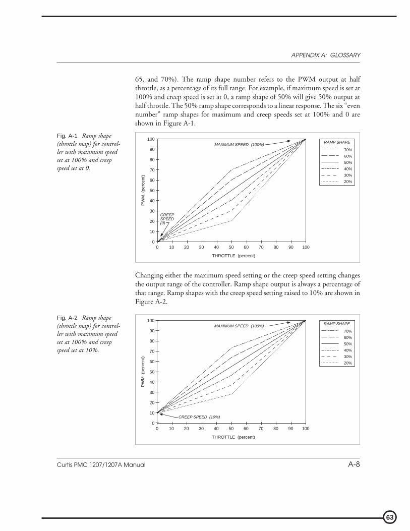
63
Curtis PMC 1207/1207A Manual A-8
APPENDIX A: GLOSSARY
65, and 70%). The ramp shape number refers to the PWM output at halfthrottle, as a percentage of its full range. For example, if maximum speed is set at100% and creep speed is set at 0, a ramp shape of 50% will give 50% output athalf throttle. The 50% ramp shape corresponds to a linear response. The six “evennumber” ramp shapes for maximum and creep speeds set at 100% and 0 areshown in Figure A-1.
Fig. A-2 Ramp shape(throttle map) for control-ler with maximum speedset at 100% and creepspeed set at 10%.
THROTTLE (percent)
PW
M (
perc
ent)
70%
60%
50%
40%
30%
20%
RAMP SHAPE100
90
80
70
60
50
40
30
20
10
0100908070605040302010 0
CREEP SPEED (10%)
MAXIMUM SPEED (100%)
Fig. A-1 Ramp shape(throttle map) for control-ler with maximum speedset at 100% and creepspeed set at 0.
THROTTLE (percent)
PW
M (
perc
ent)
70%
60%
50%
40%
30%
20%
RAMP SHAPE100
90
80
70
60
50
40
30
20
10
0100908070605040302010 0
CREEPSPEED(0)
MAXIMUM SPEED (100%)
Changing either the maximum speed setting or the creep speed setting changesthe output range of the controller. Ramp shape output is always a percentage ofthat range. Ramp shapes with the creep speed setting raised to 10% are shown inFigure A-2.

64
Curtis PMC 1207/1207A Manual A-9
APPENDIX A: GLOSSARY
In Figure A-3, the creep speed is kept at 10% and the maximum speed settingdropped to 60%.
In all cases, the ramp shape number is the PWM output at half throttle, as apercentage of its full range. So, for example, in Figure A-3, a 50% ramp shapegives 35% PWM output at half throttle (halfway between 10% and 60%). A 30%ramp shape gives 25% PWM at half throttle (30% of the range {which is 50%,from 10% to 60%}, starting at 10% output, or {[.30 x 50%] + 10%} = 25%).
Ramp start
The ramp start feature allows the vehicle to be started with a higher plug currentlimit to prevent rolling downhill. Ramp start increases the plug current limit forthe selected direction only. When the opposite direction is selected, ramp startwill be canceled and a 3-step sequence must be followed to re-activate it:
STEP 1. select a direction for more than 1 second,STEP 2. return to neutral, andSTEP 3. re-select the same direction.
Once the vehicle is operating in ramp start mode, it will continue to do so untilthe opposite direction is selected for more than one second.
When the brake is first released, the ramp start current limit level will beobtained when either direction is selected in plug braking mode. In ramp startmode, either direction selected will allow the ramp start current limit level. Thiscondition remains until the other direction is selected for more than one second.The new direction then becomes the decision direction, and the 3-step ramp startsequence is required to regain the ramp start current limit level in plug.
Fig. A-3 Ramp shape(throttle map) for control-ler with maximum speedset at 60% and creep speedset at 10%.
THROTTLE (percent)
PW
M (
perc
ent)
70%
60%
50%
40%
30%
20%
RAMP SHAPE100
90
80
70
60
50
40
30
20
10
0100908070605040302010 0
CREEP SPEED(10%)
MAXIMUM SPEED(60%)
65
Curtis PMC 1207/1207A Manual A-10
APPENDIX A: GLOSSARY
The ramp start current limit is adjustable via the handheld programmer. TheMode 1 and Mode 2 ramp start current limits can be set independently.
Reset
Almost all faults require a cycling of the KSI or brake input to reset the controllerand enable operation; see Fault recovery for exceptions.
Sequencing delay
Sequencing delay allows the brake to be cycled within a set time (the sequencingdelay), in order to prevent inadvertent activation of HPD or SRO. This featureis useful in applications where the brake switch may bounce or be momentarilycycled during operation. The delay can be set with the handheld programmerfrom 0 to 3 seconds, where 0 corresponds to no delay.
Shunt field control
The shunt field of a compound motor can be directly controlled by using theshunt winding driver (if the current requirement meets the contactor driverspecifications). The shunt is activated while a direction is selected, as long as thecontroller is not in plug braking mode. A programmable delay is available for theshunt drive. This delays the shunt turn-on until some time after the reversingcontactors have shuttled. The delay can be set with the handheld programmerfrom 0 to 0.5 seconds, where 0 corresponds to no delay.
Smooth, stepless operation
Like all Curtis PMC 1200 Series controllers, the 1207 and 1207A models allowsuperior operator control of the vehicle’s drive motor speed. The amount ofcurrent delivered to the motor is set by varying the “on” time (duty cycle) of thecontroller’s power MOSFET transistors. This technique—pulse width modula-tion (PWM)—permits silent, stepless operation.
Speed settings
The maximum speed setting defines the upper-limit speed as a percentage ofPWM output at full throttle. If you have a MultiMode™ controller, themaximum speed settings in Mode 1 and in Mode 2 are independently adjustablevia the handheld programmer. If you have a 1207 controller with the MultiMode™

66
Curtis PMC 1207/1207A Manual A-11
APPENDIX A: GLOSSARY
feature disabled (i.e., a single-mode controller), you can adjust the maximumspeed mechanically via the trimpot labeled “LOW” on top of the controller.
The maximum creep speed setting is also adjustable via these two methods;see Creep speed. The maximum emergency reverse speed is adjustable only via theprogrammer.
Static-return-to-off (SRO)
The SRO feature prevents the vehicle from being started when “in gear.” SROchecks the sequencing of brake input—or of KSI and brake input—relative to adirection input. The brake input must come on before a direction is selected. Ifa direction is selected before or simultaneously (within 50 msec) with the brakeinput, the controller is disabled. There are three types of SRO: SRO relative tobrake input alone (Type “1” in the programming menu); SRO relative to bothKSI and brake input (Type “2”); and SRO relative to KSI, brake, and forwardinputs (Type “3”). The handheld programmer can be used to set the controller tooperate with any of these types of SRO, or with no SRO (SRO Type “0”).
If your controller is programmed so that both KSI and brake input arerequired (SRO Type “2”), the following sequence must be followed to enable thecontroller: STEP 1, KSI on; STEP 2, brake released (brake input “high”); and STEP 3,direction selected. The interval between steps 1 and 2 is the same as between steps2 and 3; that is, KSI input must precede brake input by at least 50 msec. Oncethe controller is operational, turning off either KSI or the brake causes thecontroller to turn off; re-enabling the controller requires the 3-step sequence.
Similarly, if your controller is programmed so that KSI, brake, and forwardinputs are all required (SRO Type “3”), they must be provided in that sequencein order to enable the controller. Note, however, that operation is allowed if areverse input precedes the brake input; this can be useful when operating a walkieon ramps.
Sequencing delay, which can be set with the handheld programmer, providesa variable delay before disabling the controller. If the brake is applied whiledirection is selected, SRO is not activated if the brake is then released before thedelay time elapses.
Temperature compensation for current limits
Full temperature compensation provides constant current limits throughout thenormal operating range (heatsink temperatures of -25°C to +85°C). The tem-perature sensor is also used to calculate and display the heatsink temperature onthe handheld programmer.

67
Curtis PMC 1207/1207A Manual A-12
APPENDIX A: GLOSSARY
Temperature extreme current-limit cutback (see Overtemperature,Undertemperature)
Temperature extreme data storage
The maximum and minimum temperatures read at the heatsink at any timeduring powering of the controller are stored in the controller’s memory. Thesevalues (which can be accessed via the programmer’s Test Menu) are cleared eachtime the controller’s diagnostic history file is cleared.
Throttle map
The throttle map (duty factor as a function of throttle position) is adjustable, sothat you can provide the proper feel for the many types of vehicles that use the1207 controller. The throttle map parameter is called “ramp shape”; see Rampshape for more information.
Throttle response
The dynamic throttle response (duty factor as a function of time) is shaped by theacceleration rate setting. Dynamic throttle response is linear. The newest throttleinput is mapped to the throttle map, and the controller then automaticallyaccelerates (or decelerates) through a straight line until the new throttle demandis obtained.
Throttle types
The 1207 and 1207A controllers accept a variety of throttle inputs, throughvarious combinations of their four throttle input pins. The most commonly usedthrottles can all be hooked up directly: 5kΩ–0 and 0–5kΩ 2-wire rheostats,3-wire pots, 0–5V throttles, 0–10V throttles (1207 only), and the CurtisET-XXX electronic throttle.
Throttle full range produces 0–100% duty factor at the controller output(unless limited by other conditions). Throttle fault detect is performed on thethrottle input signals and virtually eliminates the possibility of runaway opera-tion. Adjustments and settings are independent of throttle type. However,throttle fault conditions will vary by throttle type.

68
Curtis PMC 1207/1207A Manual A-13
APPENDIX A: GLOSSARY
Undertemperature
When the controller is operating at less than -25°C, the current limit is cut backto approximately one-half of the set current. The operating PWM frequency isshifted to 1.5 kHz when the controller is operating at undertemperature.
Undervoltage protection
Undervoltage protection automatically disables the controller output if batteryvoltage is detected below the undervoltage point at start-up, or when the batteryvoltage is pulled below the undervoltage point by an external load. The undervoltagecutback point is set in ROM, and is not adjustable.
During normal operation, the controller duty factor will be reduced whenthe batteries discharge down to less than the undervoltage level. If the motorcurrent is such that the batteries are being pulled below the minimum point, theduty factor will be reduced until the battery voltage recovers to the minimumlevel. In this way the controller “servos” the duty factor around the point whichmaintains the minimum allowed battery voltage.
If the voltage continues to drop below the undervoltage level to a severeundervoltage condition (due to battery drain or external load), the controllercontinues to behave in a predictable fashion, with its output disabled.
Watchdog (external, internal)
The external watchdog timer guards against a complete failure of the micropro-cessor, which would incapacitate the internal watchdog timer. This independentsystem check on the microprocessor meets the EEC’s requirement for backupfault detection.
The external watchdog timer safety circuit shuts down the controller (andthe microprocessor) if the software fails to generate a periodic external pulse train.This pulse train can only be created if the microprocessor is operating. If notperiodically reset, the watchdog timer times out after 150 msec and turns off thecontroller. The external watchdog also directly disengages all contactors anddirectly shuts down the PWM drive to the MOSFETs. It can only be reset bycycling KSI.
The internal watchdog timer must be reset periodically by correct sequentialexecution of the software. If not reset, the internal timer times out and themicroprocessor is “warm booted.” This causes the microprocessor to shut downits outputs (thus shutting down the controller) and attempt to restart.

69
Curtis PMC 1207/1207A Manual A-14
APPENDIX A: GLOSSARY
APPENDIX BSPECIFICATIONS
Table B-1 SPECIFICATIONS: 1207 CONTROLLERS
Nominal input voltage range 24 – 36 VMaximum operating voltage 45 VOvervoltage point 48 VMinimum operating voltage 16 V (= undervoltage point)Electrical isolation to heatsink 500 V ac (minimum)PWM operating frequency 15 kHz
Output current* 1207-11XX 1207-21XX250 amps for 1 minute 300 amps for 30 seconds200 amps for 2 minutes 210 amps for 2 minutes150 amps for 5 minutes 160 amps for 5 minutes100 amps for 1 hour 110 amps for 1 hour
Contactor voltage = battery voltageContactor current (maximum) 1 amp (current limit at 2 amps)Contactor coil spike protection internal diode to brake; internal diode from brake to KSIShunt driver current (maximum) 2 ampsShunt driver spike protection active clamp at 47 V
KSI input voltage 16–45 VKSI input current (typical) 80 mA without programmer; 130 mA with programmerLogic input current (typical) 10 mA at 24 VLogic input threshold 8 V
Ambient operating temperature range -25°C to 50°CHeatsink overtemperature cutback 85°CHeatsink undertemperature cutback -25°C
Package splash resistantWeight 1.1 kg (2.5 lbs)Dimensions 122 × 165 × 60 mm (4.8" × 6.5" × 2.35")
* Output current rating test conditions:1. Controller cover installed2. Controller mounted to 230 × 305 × 3.2 mm (9" × 12" × 0.125") aluminum plate heatsink3. Airflow at 4.8 km/h (3 mph) perpendicular to bottom of aluminum plate4. Duty factor held at 60%5. Initial heatsink temperature at 20°C6. Ambient temperature at 20°C7. Current held at tested rating for 120% of time before thermal cutback
B-1
APPENDIX B: SPECIFICATIONS

70
Curtis PMC 1207/1207A Manual A-15
APPENDIX A: GLOSSARY
Table B-2 SPECIFICATIONS: 1207A CONTROLLERS
Nominal input voltage 24 VMaximum operating voltage 30 VOvervoltage point 33 VMinimum operating voltage 16 V (= undervoltage point)Electrical isolation to heatsink 500 V ac (minimum)PWM operating frequency 15 kHz
Output current* 1207A-41XX 1207A-51XX250 amps for 1 minute 300 amps for 30 seconds200 amps for 2 minutes 210 amps for 2 minutes150 amps for 5 minutes 160 amps for 5 minutes100 amps for 1 hour 110 amps for 1 hour
Contactor voltage 24 VContactor current (maximum) 1 amp (current limit at 2 amps)Contactor coil spike protection internal diode to brake; internal diode from brake to KSIShunt driver current (maximum) 2 ampsShunt driver spike protection active clamp at 47 V
KSI input voltage 16–30 VKSI input current (typical) 80 mA without programmer; 130 mA with programmerLogic input current (typical) 10 mA at 24 VLogic input threshold 8 V
Ambient operating temperature range -25°C to 50°CHeatsink overtemperature cutback 85°CHeatsink undertemperature cutback -25°C
Package splash resistantWeight 1.1 kg (2.5 lbs)Dimensions 122 × 165 × 66 mm (4.8" × 6.5" × 2.6")
* Output current rating test conditions:1. Controller cover installed2. Controller mounted to 230 × 305 × 3.2 mm (9" × 12" × 0.125") aluminum plate heatsink3. Airflow at 4.8 km/h (3 mph) perpendicular to bottom of aluminum plate4. Duty factor held at 60%5. Initial heatsink temperature at 20°C6. Ambient temperature at 20°C7. Current held at tested rating for 120% of time before thermal cutback
B-2
APPENDIX B: SPECIFICATIONS

71
Curtis PMC 1207/1207A Manual A-16
APPENDIX A: GLOSSARY
B-3
APPENDIX B: SPECIFICATIONS
1207/1207A AUXILIARY PANELS
Auxiliary panels are available for the 1207 and 1207A controllers, consisting of arange of contactor and fuse assemblies mounted on small aluminum panels.These auxiliary panels are designed to let you install your controller in theminimum time, at minimum cost. The panels, manufactured by Curtis Instru-ments (UK) Ltd., are available through all Curtis offices.
All panels are flush rear mounting. Please contact the Curtis office nearestyou for further configuration details.
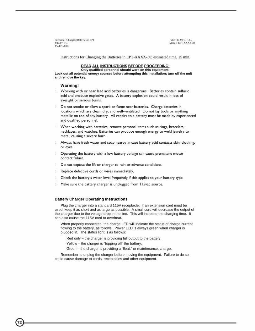
72
Filename: Changing Batteries in EPT VESTIL MFG. CO. 4/17/07 TG Model: EPT-XXXX-30 15-126-010
Instructions for Changing the Batteries in EPT-XXXX-30; estimated time, 15 min.
READ ALL INSTRUCTIONS BEFORE PROCEEDING! Only qualified personnel should work on this equipment!
Lock out all potential energy sources before attempting this installation; turn off the unit
and remove the key.
Warning!
! Working with or near lead acid batteries is dangerous. Batteries contain sulfuric acid and produce explosive gases. A battery explosion could result in loss of eyesight or serious burns.
! Do not smoke or allow a spark or flame near batteries. Charge batteries in locations which are clean, dry, and well-ventilated. Do not lay tools or anything metallic on top of any battery. All repairs to a battery must be made by experienced and qualified personnel.
! When working with batteries, remove personal items such as rings, bracelets, necklaces, and watches. Batteries can produce enough energy to weld jewelry to metal, causing a severe burn.
! Always have fresh water and soap nearby in case battery acid contacts skin, clothing, or eyes.
! Operating the battery with a low battery voltage can cause premature motor contact failure.
! Do not expose the lift or charger to rain or adverse conditions.
! Replace defective cords or wires immediately.
! Check the battery’s water level frequently if this applies to your battery type.
! Make sure the battery charger is unplugged from 115vac source.
Battery Charger Operating Instructions
Plug the charger into a standard 115V receptacle. If an extension cord must be used, keep it as short and as large as possible. A small cord will decrease the output of the charger due to the voltage drop in the line. This will increase the charging time. It can also cause the 115V cord to overheat.
When properly connected, the charge LED will indicate the status of charge current flowing to the battery, as follows: Power LED is always green when charger is plugged in. The status light is as follows:
Red only – the charger is providing full output to the battery. Yellow – the charger is “topping off” the battery. Green – the charger is providing a “float,” or maintenance, charge.
Remember to unplug the charger before moving the equipment. Failure to do so could cause damage to cords, receptacles and other equipment.

73
Filename: Changing Batteries in EPT VESTIL MFG. CO. 4/17/07 TG Model: EPT-XXXX-30 15-126-010
Troubleshooting:
If the unit does not operate, check all of the wiring connections to make sure they’re both mechanically and electrically sound – specifically at the battery, and the motor.
A fully-charged lead acid battery in good condition at room temperature should read 12.65 volts. At 11.9 volts it is considered to be fully discharged and in need of charging. When checking battery voltage, wait at least 1\2 hour after the charger has been turned off before checking the battery’s voltage.
If the batteries aren’t being charged by the charger, check the output charger fuse. Verify fuse is good with an ohmmeter, or close visual (ohm meter best). Fuse is a 10Amp 250 Volt; GBD 10A. If it is good, check the battery’s state of charge with a voltmeter. The charger must be connected to the battery in order to read the output voltage of the battery charger. Depending on the state of charge of the batteries, the voltage should be somewhere around 27 to 28 volts dc. If it is determined the batteries are dead, and need replaced, continue with the following procedure. Tools Required: 14mm wrench, or crescent wrench Regular flat bladed screw driver

74
Filename: Changing Batteries in EPT VESTIL MFG. CO. 4/17/07 TG Model: EPT-XXXX-30 15-126-010
Changing Batteries in EPT-XXXX-30; estimated time 15 minutes.
Remove the black plastic cover, it will lift out.
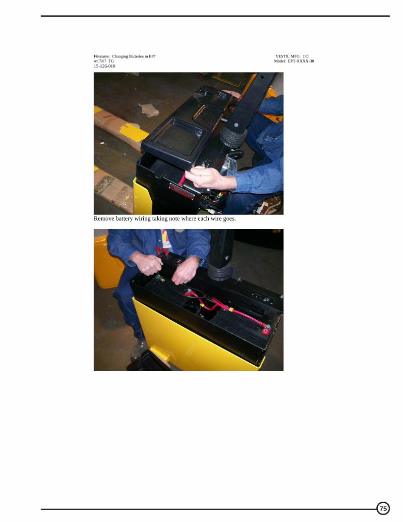
75
Filename: Changing Batteries in EPT VESTIL MFG. CO. 4/17/07 TG Model: EPT-XXXX-30 15-126-010
Remove battery wiring taking note where each wire goes.

76
Filename: Changing Batteries in EPT VESTIL MFG. CO. 4/17/07 TG Model: EPT-XXXX-30 15-126-010
Batteries need to be lifted straight up. Tie wraps can aid in this process as shown here, or two small piece of nylon rope. Caution: do not use metal and short the battery terminals together!
Once the batteries are removed, they can be exchanged for the new ones. Reverse the process, and reconnect the wiring.
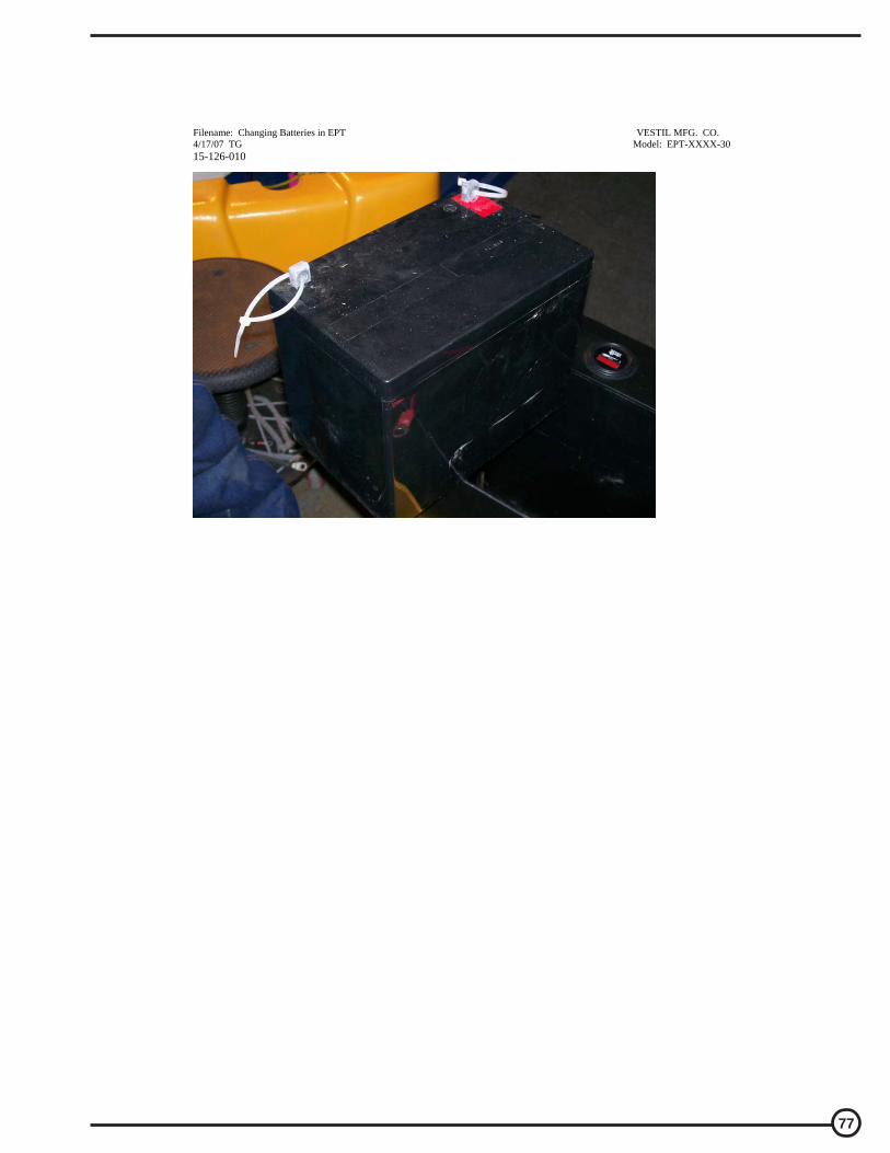
77
Filename: Changing Batteries in EPT VESTIL MFG. CO. 4/17/07 TG Model: EPT-XXXX-30 15-126-010
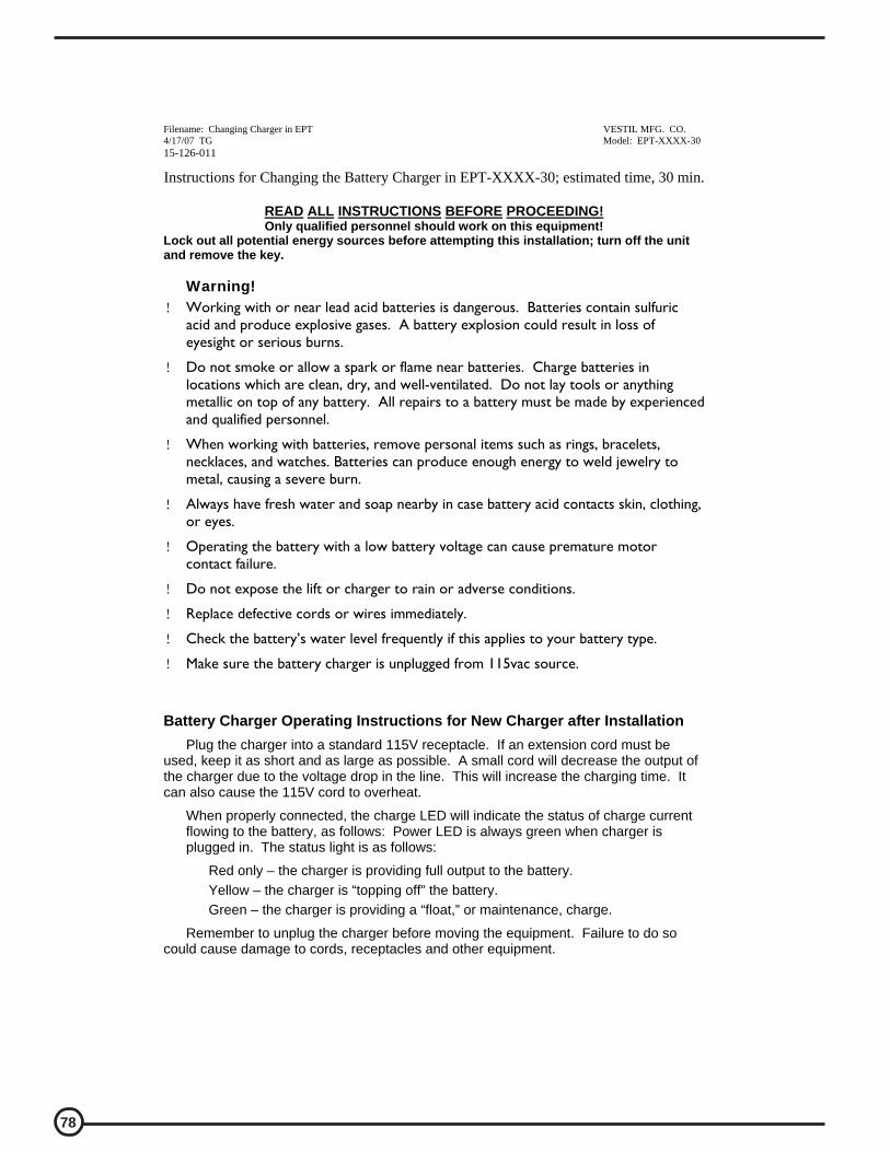
78
Filename: Changing Charger in EPT VESTIL MFG. CO. 4/17/07 TG Model: EPT-XXXX-30 15-126-011
Instructions for Changing the Battery Charger in EPT-XXXX-30; estimated time, 30 min.
READ ALL INSTRUCTIONS BEFORE PROCEEDING! Only qualified personnel should work on this equipment!
Lock out all potential energy sources before attempting this installation; turn off the unit
and remove the key.
Warning!
! Working with or near lead acid batteries is dangerous. Batteries contain sulfuric acid and produce explosive gases. A battery explosion could result in loss of eyesight or serious burns.
! Do not smoke or allow a spark or flame near batteries. Charge batteries in locations which are clean, dry, and well-ventilated. Do not lay tools or anything metallic on top of any battery. All repairs to a battery must be made by experienced and qualified personnel.
! When working with batteries, remove personal items such as rings, bracelets, necklaces, and watches. Batteries can produce enough energy to weld jewelry to metal, causing a severe burn.
! Always have fresh water and soap nearby in case battery acid contacts skin, clothing, or eyes.
! Operating the battery with a low battery voltage can cause premature motor contact failure.
! Do not expose the lift or charger to rain or adverse conditions.
! Replace defective cords or wires immediately.
! Check the battery’s water level frequently if this applies to your battery type.
! Make sure the battery charger is unplugged from 115vac source.
Battery Charger Operating Instructions for New Charger after Installation
Plug the charger into a standard 115V receptacle. If an extension cord must be used, keep it as short and as large as possible. A small cord will decrease the output of the charger due to the voltage drop in the line. This will increase the charging time. It can also cause the 115V cord to overheat.
When properly connected, the charge LED will indicate the status of charge current flowing to the battery, as follows: Power LED is always green when charger is plugged in. The status light is as follows:
Red only – the charger is providing full output to the battery. Yellow – the charger is “topping off” the battery. Green – the charger is providing a “float,” or maintenance, charge.
Remember to unplug the charger before moving the equipment. Failure to do so could cause damage to cords, receptacles and other equipment.

79
Filename: Changing Charger in EPT VESTIL MFG. CO. 4/17/07 TG Model: EPT-XXXX-30 15-126-011
Troubleshooting:
If the unit does not operate, check all of the wiring connections to make sure they’re both mechanically and electrically sound – specifically at the battery, and the motor.
A fully-charged lead acid battery in good condition at room temperature should read 12.65 volts. At 11.9 volts it is considered to be fully discharged and in need of charging. When checking battery voltage, wait at least 1\2 hour after the charger has been turned off before checking the battery’s voltage.
If the batteries aren’t being charged by the charger, check the output charger fuse. Verify fuse is good with an ohmmeter, or close visual (ohm meter best). Fuse is a 10Amp 250 Volt; GBD 10A. If it is good, check the battery’s state of charge with a voltmeter. The charger must be connected to the battery in order to read the output voltage of the battery charger. Depending on the state of charge of the batteries, the voltage should be somewhere around 27 to 28 volts dc. If it is determined the battery charger is dead, and needs replaced, continue with the following procedure. Tools Required: 10mm deep socket, or small wrench 14mm wrench, or crescent wrench Regular flat bladed screw driver

80
Filename: Changing Charger in EPT VESTIL MFG. CO. 4/17/07 TG Model: EPT-XXXX-30 15-126-011
Model: EPT-XXXX-30
Remove the two screws shown below and take off the yellow cover.
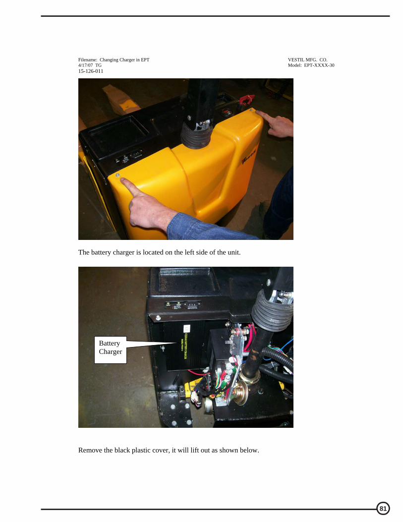
81
Filename: Changing Charger in EPT VESTIL MFG. CO. 4/17/07 TG Model: EPT-XXXX-30 15-126-011
The battery charger is located on the left side of the unit. Remove the black plastic cover, it will lift out as shown below.
Battery Charger

82
Filename: Changing Charger in EPT VESTIL MFG. CO. 4/17/07 TG Model: EPT-XXXX-30 15-126-011
Remove battery wiring from the negative post as shown with 13mm wrench. There will be one large black wire, and one smaller black wire. The smaller black wire is connected to the battery charger. Caution; do not short out battery terminals with tools!
Do the same for the red post as shown here; remove 2 Red wires.
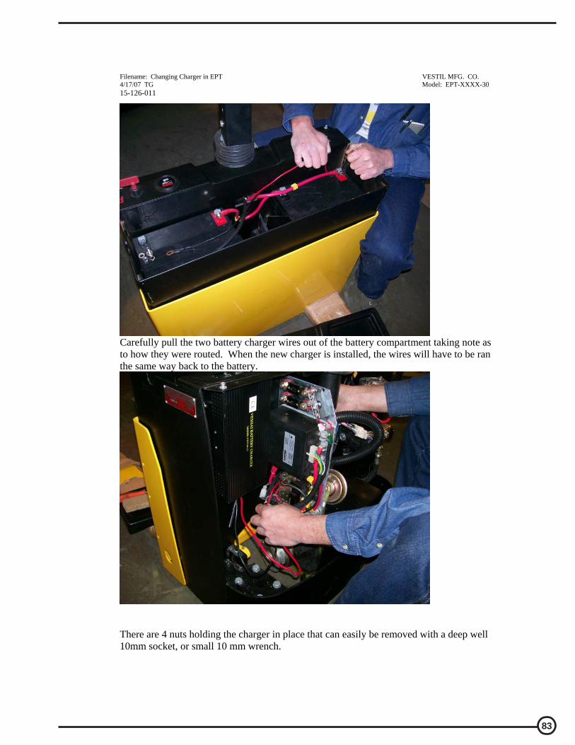
83
Filename: Changing Charger in EPT VESTIL MFG. CO. 4/17/07 TG Model: EPT-XXXX-30 15-126-011
Carefully pull the two battery charger wires out of the battery compartment taking note as to how they were routed. When the new charger is installed, the wires will have to be ran the same way back to the battery.
There are 4 nuts holding the charger in place that can easily be removed with a deep well 10mm socket, or small 10 mm wrench.

84
Filename: Changing Charger in EPT VESTIL MFG. CO. 4/17/07 TG Model: EPT-XXXX-30 15-126-011
Remove the 4 nuts.
4 10mm nuts
Remove nuts

85
Filename: Changing Charger in EPT VESTIL MFG. CO. 4/17/07 TG Model: EPT-XXXX-30 15-126-011
Once the battery charger is removed, it can be exchanged for the new one. Reverse the process, and reconnect the wiring.

86
Filename: Changing Charger in EPT to Soneil VESTIL MFG. CO. 5/16/07 TG Model: EPT-XXXX-30 15-126-015
Instructions for Changing the Battery Charger in EPT-XXXX-30; estimated time, 30 min.
READ ALL INSTRUCTIONS BEFORE PROCEEDING! Only qualified personnel should work on this equipment!
Lock out all potential energy sources before attempting this installation; turn off the unit
and remove the key.
Warning!
! Working with or near lead acid batteries is dangerous. Batteries contain sulfuric acid and produce explosive gases. A battery explosion could result in loss of eyesight or serious burns.
! Do not smoke or allow a spark or flame near batteries. Charge batteries in locations which are clean, dry, and well-ventilated. Do not lay tools or anything metallic on top of any battery. All repairs to a battery must be made by experienced and qualified personnel.
! When working with batteries, remove personal items such as rings, bracelets, necklaces, and watches. Batteries can produce enough energy to weld jewelry to metal, causing a severe burn.
! Always have fresh water and soap nearby in case battery acid contacts skin, clothing, or eyes.
! Operating the battery with a low battery voltage can cause premature motor contact failure.
! Do not expose the lift or charger to rain or adverse conditions.
! Replace defective cords or wires immediately.
! Check the battery’s water level frequently if this applies to your battery type.
! Make sure the battery charger is unplugged from 115vac source.
Battery Charger Operating Instructions for New Charger after Installation
Plug the charger into a standard 115V receptacle. If an extension cord must be used, keep it as short and as large as possible. A small cord will decrease the output of the charger due to the voltage drop in the line. This will increase the charging time. It can also cause the 115V cord to overheat.
Remember to unplug the charger before moving the equipment. Failure to do so
could cause damage to cords, receptacles and other equipment. The following procedure will explain how to replace the existing charger with a Soneil charger. Tools Required: 10mm deep socket, or small wrench 14mm wrench, or crescent wrench Regular flat bladed screw driver

87
Filename: Changing Charger in EPT to Soneil VESTIL MFG. CO. 5/16/07 TG Model: EPT-XXXX-30 15-126-015
Model: EPT-XXXX-30
Remove the two screws shown below and take off the yellow cover.

88
Filename: Changing Charger in EPT to Soneil VESTIL MFG. CO. 5/16/07 TG Model: EPT-XXXX-30 15-126-015
The battery charger is located on the left side of the unit. Remove the black plastic cover, it will lift out as shown below.
Battery Charger

89
Filename: Changing Charger in EPT to Soneil VESTIL MFG. CO. 5/16/07 TG Model: EPT-XXXX-30 15-126-015
Remove battery wiring from the negative post as shown with 13mm wrench. There will be one large black wire, and one smaller black wire. The smaller black wire is connected to the battery charger. Caution; do not short out battery terminals with tools!
Do the same for the red post as shown here; remove 2 Red wires.

90
Filename: Changing Charger in EPT to Soneil VESTIL MFG. CO. 5/16/07 TG Model: EPT-XXXX-30 15-126-015
Carefully pull the two battery charger wires out of the battery compartment taking note as to how they were routed. When the new charger is installed, the wires will have to be ran the same way back to the battery.
There are 4 nuts holding the charger in place that can easily be removed with a deep well 10mm socket, or small 10 mm wrench.
4 10mm nuts
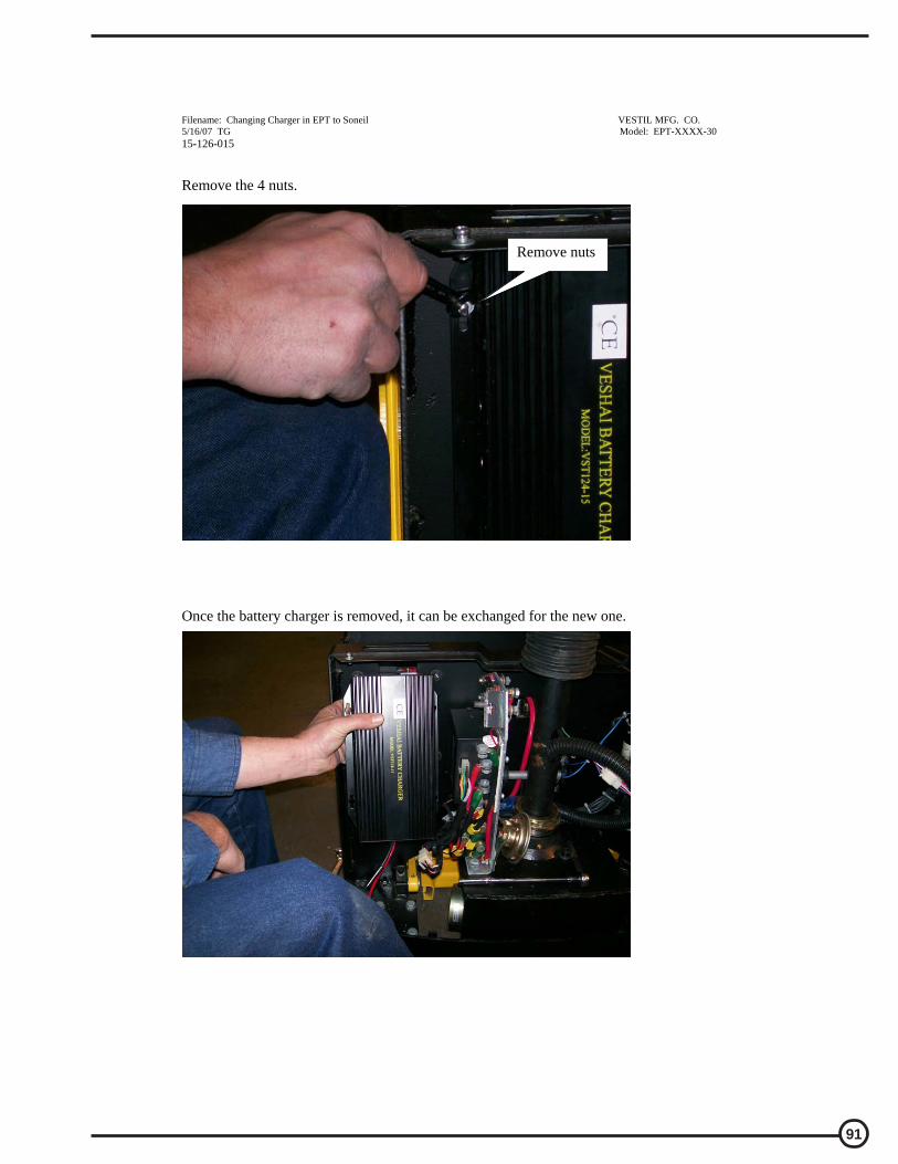
91
Filename: Changing Charger in EPT to Soneil VESTIL MFG. CO. 5/16/07 TG Model: EPT-XXXX-30 15-126-015
Remove the 4 nuts. Once the battery charger is removed, it can be exchanged for the new one.
Remove nuts

92
Filename: Changing Charger in EPT to Soneil VESTIL MFG. CO. 5/16/07 TG Model: EPT-XXXX-30 15-126-015
There are two “hook and loop” strips on the back of the charger. Remove the adhesive backing from the 2 strips.
2 strips
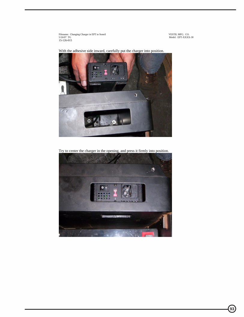
93
Filename: Changing Charger in EPT to Soneil VESTIL MFG. CO. 5/16/07 TG Model: EPT-XXXX-30 15-126-015
With the adhesive side inward, carefully put the charger into position. Try to center the charger in the opening, and press it firmly into position.
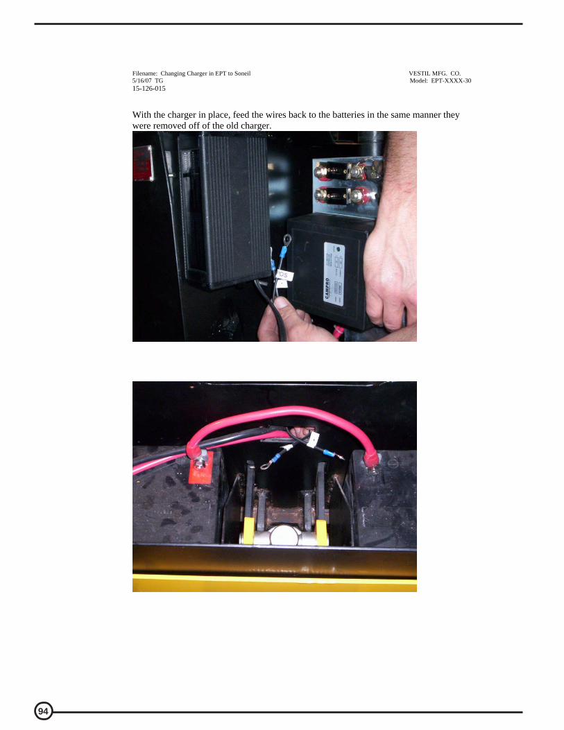
94
Filename: Changing Charger in EPT to Soneil VESTIL MFG. CO. 5/16/07 TG Model: EPT-XXXX-30 15-126-015
With the charger in place, feed the wires back to the batteries in the same manner they were removed off of the old charger.
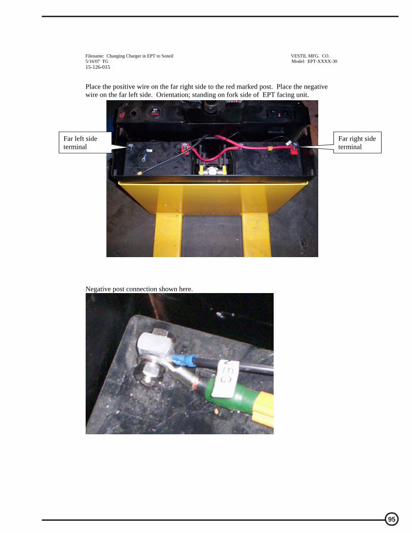
95
Filename: Changing Charger in EPT to Soneil VESTIL MFG. CO. 5/16/07 TG Model: EPT-XXXX-30 15-126-015
Place the positive wire on the far right side to the red marked post. Place the negative wire on the far left side. Orientation; standing on fork side of EPT facing unit. Negative post connection shown here.
Far right side terminal
Far left side terminal

96
Filename: Changing Charger in EPT to Soneil VESTIL MFG. CO. 5/16/07 TG Model: EPT-XXXX-30 15-126-015
Plug in the charger and make sure the on/off switch is on; shown here as on. Plug this end into a standard 115 volt outlet and charger batteries for at least 8 hours or overnight. The charger will not overcharge the batteries, so leaving the unit plugged in over a weekend is ok. The charger should only be used in doors!
On/Off switch

97
Filename: Changing Charger in EPT to Soneil VESTIL MFG. CO. 5/16/07 TG Model: EPT-XXXX-30 15-126-015
Troubleshooting:
If the unit does not operate, check all of the wiring connections to make sure they’re both mechanically and electrically sound – specifically at the battery, and the motor.
Charge the unit overnight.
A fully-charged lead acid battery in good condition at room temperature should read 12.65 volts. At 11.9 volts it is considered to be fully discharged and in need of charging. When checking battery voltage, wait at least 1\2 hour after the charger has been turned off before checking the battery’s voltage.
If the batteries aren’t being charged by the charger, check the output charger fuse. First, remove the yellow cover, 2 screws on top. The fuse is on the bottom of the charger. Verify the fuse is good with an ohmmeter, or close visual (ohm meter best). Fuse is a 10Amp 250 Volt; GDA 10A. If it is good, plug the charger in and check the lights next to the fuse. Red: Power On Yellow: Charging Green: Full Charge Green Flashing: Batteries are not connected to charger Verify the on off switch is set to on. With the charger connected to the battery read the output voltage of the battery charger. Depending on the state of charge of the batteries, the voltage should be somewhere around 26 to 29 volts dc typically. If the charger is functioning properly, install the black tray over the batteries and the yellow shroud over the back.

98
Filename: Changing Cylinder in EPT VESTIL MFG. CO. 5/09/07 TG Model: EPT-XXXX-30 15-126-014
Instructions for Changing the Cylinder in EPT-XXXX-30; estimated time, 45 min.
READ ALL INSTRUCTIONS BEFORE PROCEEDING! Only qualified personnel should work on this equipment!
Lock out all potential energy sources before attempting this installation. Make sure the
forks are fully lowered; turn off the unit and remove the key.
Warning!
! Working with or near lead acid batteries is dangerous. Batteries contain sulfuric acid and produce explosive gases. A battery explosion could result in loss of eyesight or serious burns.
! Do not smoke or allow a spark or flame near batteries. Charge batteries in locations which are clean, dry, and well-ventilated. Do not lay tools or anything metallic on top of any battery. All repairs to a battery must be made by experienced and qualified personnel.
! When working with batteries, remove personal items such as rings, bracelets, necklaces, and watches. Batteries can produce enough energy to weld jewelry to metal, causing a severe burn.
! Always have fresh water and soap nearby in case battery acid contacts skin, clothing, or eyes.
! Operating the battery with a low battery voltage can cause premature motor contact failure.
! Do not expose the lift or charger to rain or adverse conditions.
! Replace defective cords or wires immediately.
! Check the battery’s water level frequently if this applies to your battery type.
! Make sure the battery charger is unplugged from 115vac source.
Troubleshooting:
If the cylinder is leaking, and needs replaced or seals replaced; continue with the following procedure.
Tools Required: 14mm wrench, 16mm wrench, or crescent wrench Regular flat bladed screw driver “Dental Pick” for o-rings
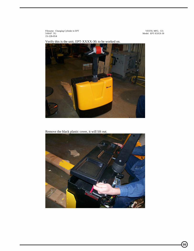
99
Filename: Changing Cylinder in EPT VESTIL MFG. CO. 5/09/07 TG Model: EPT-XXXX-30 15-126-014
Verify this is the unit, EPT-XXXX-30; to be worked on.
Remove the black plastic cover, it will lift out.

100
Filename: Changing Cylinder in EPT VESTIL MFG. CO. 5/09/07 TG Model: EPT-XXXX-30 15-126-014
Remove battery wiring taking note where each wire goes.

101
Filename: Changing Cylinder in EPT VESTIL MFG. CO. 5/09/07 TG Model: EPT-XXXX-30 15-126-014
Batteries need to be lifted straight up. Tie wraps can aid in this process as shown here, or two small piece of nylon rope. Caution: do not use metal and short the battery terminals together!
Once the batteries are removed, set them aside.
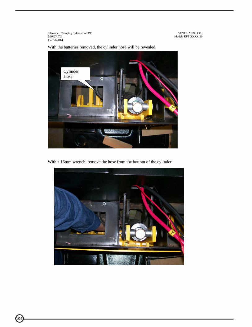
102
Filename: Changing Cylinder in EPT VESTIL MFG. CO. 5/09/07 TG Model: EPT-XXXX-30 15-126-014
With the batteries removed, the cylinder hose will be revealed. With a 16mm wrench, remove the hose from the bottom of the cylinder.
Cylinder Hose

103
Filename: Changing Cylinder in EPT VESTIL MFG. CO. 5/09/07 TG Model: EPT-XXXX-30 15-126-014
The cylinder hose can be placed here to help prevent oil leakage.
Remove snap ring from pin on bottom of cylinder using a tool similar to this.
Place hose hear

104
Filename: Changing Cylinder in EPT VESTIL MFG. CO. 5/09/07 TG Model: EPT-XXXX-30 15-126-014
Once the snap ring is removed, take the pin out that holds the bottom of the cylinder in place.
Remove the snap ring from the pin on top of the cylinder.
Remove lower pin

105
Filename: Changing Cylinder in EPT VESTIL MFG. CO. 5/09/07 TG Model: EPT-XXXX-30 15-126-014
Using a flat punch and hammer if required, remove the top cylinder pin.
Take note of the location of the two bushings that keep the cylinder centered.

106
Filename: Changing Cylinder in EPT VESTIL MFG. CO. 5/09/07 TG Model: EPT-XXXX-30 15-126-014
The cylinder can now be removed.
If a cylinder is being replaced, this procedure can be reversed to install the new one. If the seals are being replaced, follow the next steps.

107
Filename: Changing Cylinder in EPT VESTIL MFG. CO. 5/09/07 TG Model: EPT-XXXX-30 15-126-014
To replace the seals, the rod end of the cylinder must be unscrewed. Place the cylinder in a vice, and with a flat punch and hammer, tap the end loose counterclockwise.

108
Filename: Changing Cylinder in EPT VESTIL MFG. CO. 5/09/07 TG Model: EPT-XXXX-30 15-126-014
The rod assembly should pull out once the end is unscrewed.
With a small screwdriver remove the bottom seal.

109
Filename: Changing Cylinder in EPT VESTIL MFG. CO. 5/09/07 TG Model: EPT-XXXX-30 15-126-014

110
Filename: Changing Cylinder in EPT VESTIL MFG. CO. 5/09/07 TG Model: EPT-XXXX-30 15-126-014
Remove the other O-ring seal in a similar fashion.
Remove bushings from the top of the cylinder rod.
Two bushings on each side
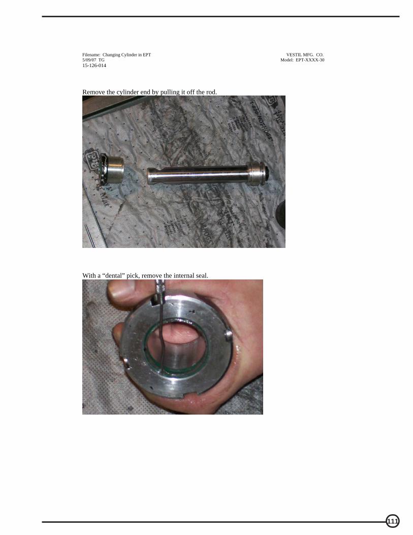
111
Filename: Changing Cylinder in EPT VESTIL MFG. CO. 5/09/07 TG Model: EPT-XXXX-30 15-126-014
Remove the cylinder end by pulling it off the rod.
With a “dental” pick, remove the internal seal.

112
Filename: Changing Cylinder in EPT VESTIL MFG. CO. 5/09/07 TG Model: EPT-XXXX-30 15-126-014
This shows the all the cylinder parts disassembled. Replace the seals and reverse the process to re-assemble the cylinder and place it back in the pallet truck. Take caution not to damage the new seals when installing.

113
Filename: EPT Belly Switch trouble shoot VESTIL MFG. CO. 4/24/07 TG Model: EPT-XXXX-30
Instructions for Changing the Tiller Assembly; EPT-XXXX-30; estimated time, 30 min.
READ ALL INSTRUCTIONS BEFORE PROCEEDING! Only qualified personnel should work on this equipment!
Lock out all potential energy sources before attempting this installation; turn off the unit and remove the key.
Warning!
! Working with or near lead acid batteries is dangerous. Batteries contain sulfuric acid and produce explosive gases. A battery explosion could result in loss of eyesight or serious burns.
! Do not smoke or allow a spark or flame near batteries. Charge batteries in locations which are clean, dry, and well-ventilated. Do not lay tools or anything metallic on top of any battery. All repairs to a battery must be made by experienced and qualified personnel.
! When working with batteries, remove personal items such as rings, bracelets, necklaces, and watches. Batteries can produce enough energy to weld jewelry to metal, causing a severe burn.
! Always have fresh water and soap nearby in case battery acid contacts skin, clothing, or eyes.
! Operating the battery with a low battery voltage can cause premature motor contact failure.
! Do not expose the lift or charger to rain or adverse conditions.
! Replace defective cords or wires immediately.
! Check the battery’s water level frequently if this applies to your battery type.
! Make sure the battery charger is unplugged from 115vac source.

114
Filename: EPT Belly Switch trouble shoot VESTIL MFG. CO. 4/24/07 TG Model: EPT-XXXX-30
Troubleshooting:
If the unit does not operate, check all of the wiring connections to make sure they’re both mechanically and electrically sound – specifically at the battery, and the motor.
A fully-charged lead acid battery in good condition at room temperature should read 12.65 volts. At 11.9 volts it is considered to be fully discharged and in need of charging. When checking battery voltage, wait at least 1\2 hour after the charger has been turned off before checking the battery’s voltage.
If the batteries aren’t being charged by the charger, check the output charger
fuse. Verify fuse is good with an ohmmeter, or close visual (ohm meter best). Fuse is a 10Amp 250 Volt; GBD 10A. If it is good, check the battery’s state of charge with a voltmeter. The charger must be connected to the battery in order to read the output voltage of the battery charger. Depending on the state of charge of the batteries, the voltage should be somewhere around 27 to 28 volts dc. If the batteries are fully charged, and the units belly switch is not functioning the following procedure will show how to…
A) Replace the tiller assembly which contains the belly switch and throttle controls.
B) Troubleshoot belly switch mechanism itself. The following tools will be required: 5mm allen wrench Philips bladed screw driver Small Regular flat bladed screw driver
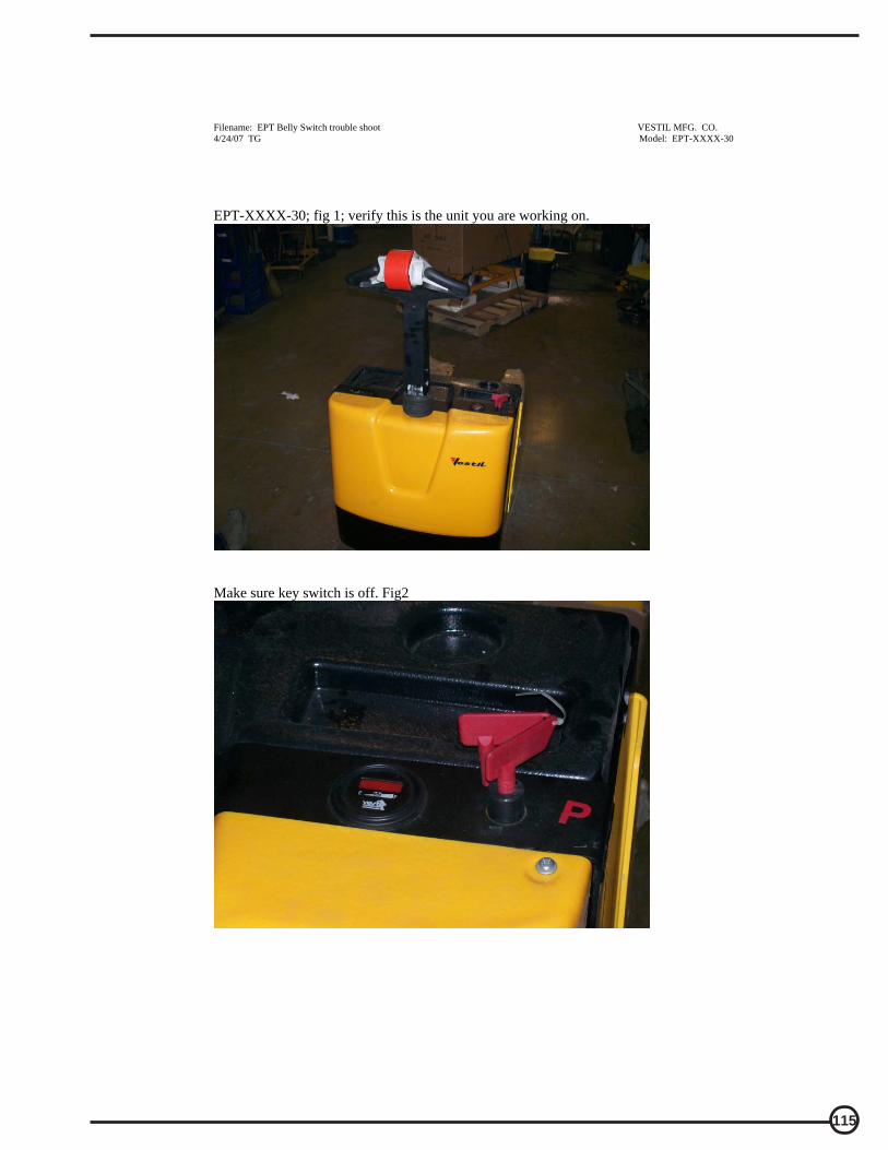
115
Filename: EPT Belly Switch trouble shoot VESTIL MFG. CO. 4/24/07 TG Model: EPT-XXXX-30
EPT-XXXX-30; fig 1; verify this is the unit you are working on.
Make sure key switch is off. Fig2
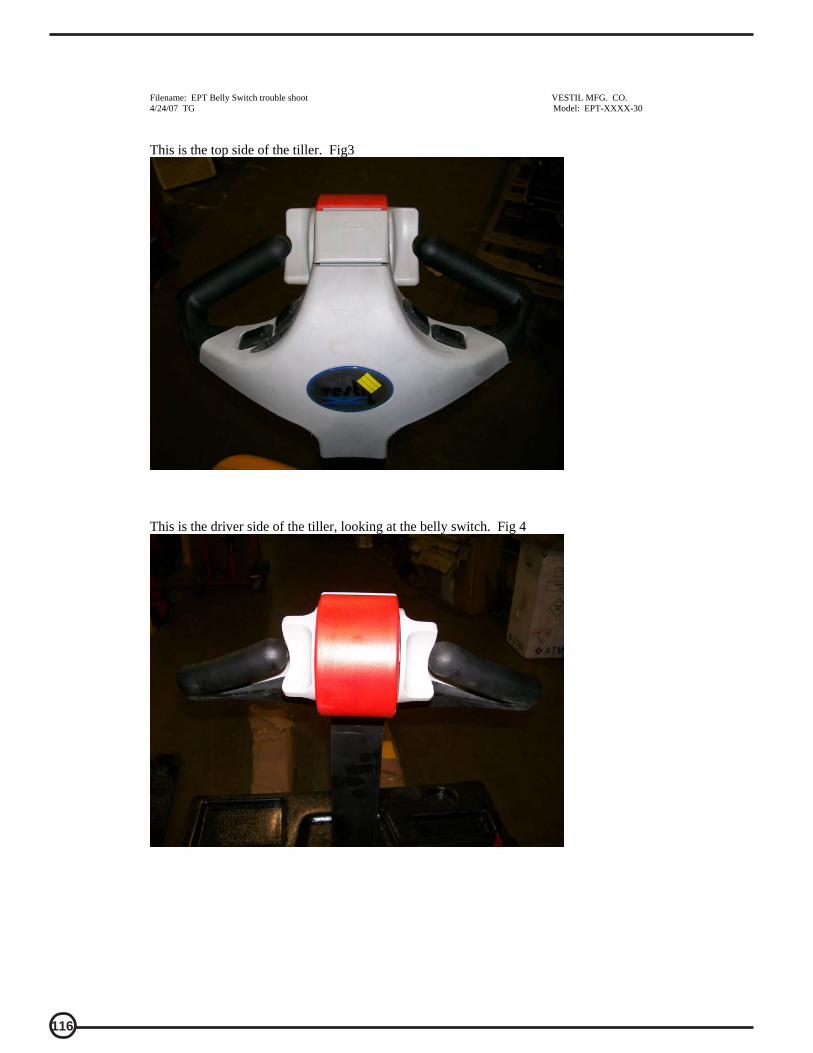
116
Filename: EPT Belly Switch trouble shoot VESTIL MFG. CO. 4/24/07 TG Model: EPT-XXXX-30
This is the top side of the tiller. Fig3
This is the driver side of the tiller, looking at the belly switch. Fig 4

117
Filename: EPT Belly Switch trouble shoot VESTIL MFG. CO. 4/24/07 TG Model: EPT-XXXX-30
This is the bottom side of the tiller handle. 3 allen head screws need to be removed. Fig5
5mm allen screws; 3 places

118
Filename: EPT Belly Switch trouble shoot VESTIL MFG. CO. 4/24/07 TG Model: EPT-XXXX-30
Lift the front top edge of the tiller cover up. Fig8
Carefully pull the belly switch back off of the tiller while tipping the front up. Fig 9

119
Filename: EPT Belly Switch trouble shoot VESTIL MFG. CO. 4/24/07 TG Model: EPT-XXXX-30
The tiller assembly cover should come off, just be careful not to drop it and rip out the wiring from the connectors. At this point, the tiller throttle assembly can be replaced with a new one by just unplugging the two connectors. Or, if the problem appears to be in the belly switch itself, further breakdown of the assembly can continue to search for the problem. Fig 10
Unplug the two connectors from the tiller throttle assembly. Fig11

120
Filename: EPT Belly Switch trouble shoot VESTIL MFG. CO. 4/24/07 TG Model: EPT-XXXX-30
Remove Philips screw on throttle. Fig12
Throttle wheel will then pull off. Take note of the orientation of the wheel on the shaft. Correct orientation is shown here. Fig 13

121
Filename: EPT Belly Switch trouble shoot VESTIL MFG. CO. 4/24/07 TG Model: EPT-XXXX-30
Do the same on the other side, taking note of the orientation of the two plastic bushings. If the throttle wheel had a tendency to stick, contact Vestil Manufacturing for replacement bushings. Fig 14
The front of the red cover should be connected via the gray tab. Fig 15

122
Filename: EPT Belly Switch trouble shoot VESTIL MFG. CO. 4/24/07 TG Model: EPT-XXXX-30
To remove the red cover, use a small screwdriver and carefully lift the plastic up over the gray tab. Fig 16
Do the same on the other side, and remove. Fig 17
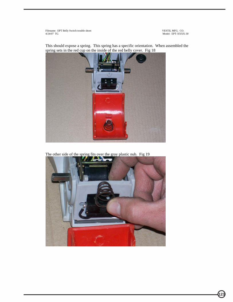
123
Filename: EPT Belly Switch trouble shoot VESTIL MFG. CO. 4/24/07 TG Model: EPT-XXXX-30
This should expose a spring. This spring has a specific orientation. When assembled the spring sets in the red cup on the inside of the red belly cover. Fig 18
The other side of the spring fits over the gray plastic nub. Fig 19

124
Filename: EPT Belly Switch trouble shoot VESTIL MFG. CO. 4/24/07 TG Model: EPT-XXXX-30
Another picture of the nub, spring not shown. At this point, verify the solder joints are in tact and the two wires are attached to the switch as shown below. Also verify the belly switch is not stuck in. You should be able to push on the switch and the actuator will move freely in and out, you should here a click as you do this. If the switch is stuck in contact Vestil Manufacturing for replacement options. Fig20 Replace any broken/missing components. To assemble, press the red belly switch cover back on the tiller head seating the red holes over the gray tabs. Basically the opposite of the procedure in Fig. 17, but without a screwdriver. Fig 21
Nub
Bell Switch actuator
Solder connection
Solder connection

125
Filename: EPT Belly Switch trouble shoot VESTIL MFG. CO. 4/24/07 TG Model: EPT-XXXX-30
The spring can be pushed into position. Fig. 22
This is the spring is shown not seated completely. Push the spring into the pocket, and over the gray plastic nub. Fig23

126
Filename: EPT Belly Switch trouble shoot VESTIL MFG. CO. 4/24/07 TG Model: EPT-XXXX-30
Install bushings. Fig24
Put thumb throttle wheels back on. Fig25
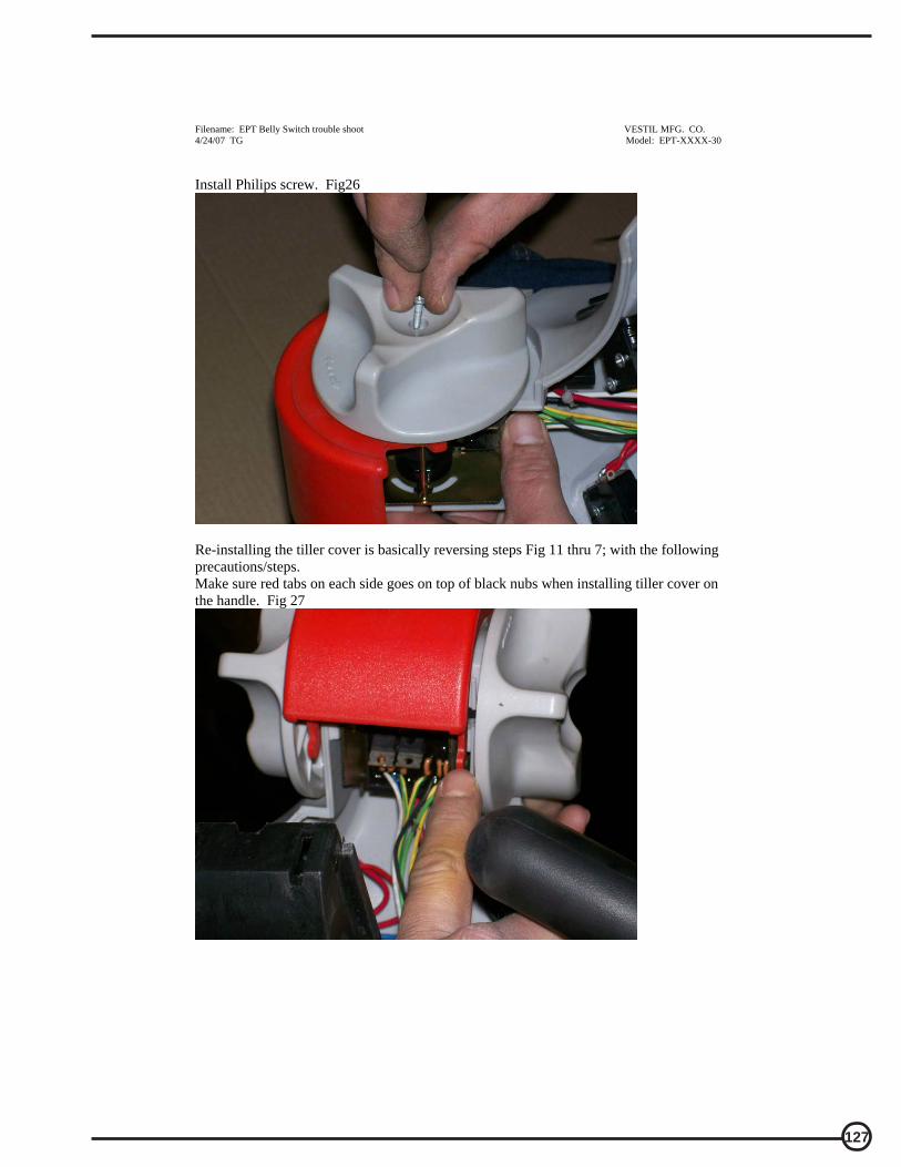
127
Filename: EPT Belly Switch trouble shoot VESTIL MFG. CO. 4/24/07 TG Model: EPT-XXXX-30
Install Philips screw. Fig26
Re-installing the tiller cover is basically reversing steps Fig 11 thru 7; with the following precautions/steps. Make sure red tabs on each side goes on top of black nubs when installing tiller cover on the handle. Fig 27

128
Filename: EPT Belly Switch trouble shoot VESTIL MFG. CO. 4/24/07 TG Model: EPT-XXXX-30
Black nub for right side shown here and the next photo fig 28
red tab slides over the top of this when installing the top assembly back on the handle. Fig 29

129
Filename: EPT Belly Switch trouble shoot VESTIL MFG. CO. 4/24/07 TG Model: EPT-XXXX-30
This is the top front where the two connectors are. Make sure they are on each side of the stand offs so the wires do not get pinched. Fig30
This shows sliding the red tabs over the black nub. Fig31 this is basically the reverse of Fig9.

130
Filename: EPT Belly Switch trouble shoot VESTIL MFG. CO. 4/24/07 TG Model: EPT-XXXX-30

131
filename: EPTdefaultvalues
Program Menu Values for the EPT (electric pallet truck)1207A controllerThese are the desired parameters for the EPT.
EPT-XXXX-30 Rev. 05-01-07; TG
Option ProgramDisplay Parameters
EMR-REV C/L 60 ATHROTTLE TYPE 2RAMP SHAPE 30CREEP SPEED 1%EMR REV SPEED 25%SEQUENCING DLY 0 sVARIABLE PLUG OnHIGH PEDAL DIS 0SRO 2ANTI-TIEDOWN OffBB CHECK OffQUICK START 0M1 MAIN C/L 250 AM1 PLUG C/L 250 AM1 RAMP C/L 250 AM1 ACCEL RATE 2.0 sM1 MAX SPEED 85%M2 MAIN C/L 250 AM2 PLUG C/L 100 AM2 RAMP C/L 250 AM2 ACCEL RATE 2 sM2 MAX SPEED 85%NEUT BRAKE C/L 35 ANEUTRAL BRAKE Off

132
04/26/07 15-126-013
VESTIL MFG. CO. 1
TROUBLESHOOTING GUIDE -- ______ Warning: Before performing any task, always block drive wheel off of the ground. Consult the factory for problems at time of installation, or for any problems not addressed below.
Problem: Possible cause(s): Action:
Unit doesn’t move when controls are used.
Battery voltage low (<17) Problem with motor controller (check for LED flash code on side of controller) Fuse blown
Charge batteries. Consult diagnostics page/factory Remove back shroud and check fuses (3 fuses).
Unit will not charge
Charger malfunction Bad batteries
Verify output voltage on charger, will only get a reading when connected to batteries; should be approximately 28 volts.
Load test batteries
Unit will not go forward; reverse works; belly switch just kills unit (does not go forward and time out)
Broken wire, or loose connection Contactor bad, motor controller bad
Locate Pin 2 on Molex connector at motor controller. Trace wiring to contactor and verify connection.
When forward is depressed, there
should be 24 volts on this wire from Molex connector to the contactor, if not, the motor controller may be bad; consult diagnostics page/factory. If 24 volts is present at contactor, verify ground connection. If ground is good, remove both wires and check with ohm meter; resistance should be approximately 38 ohms. If it’s open or zero, the contactor should be replaced.
Unit will not go reverse; belly
switch works (i.e. when the handle is in operating range and rotating throttle in reverse and the belly switch is hit, the unit moves forward and times out)
Broken wire, or loose connection, contactor bad, motor controller bad
Same as above; except locate Pin 3 on Molex connector on motor controller…and follow procedure.
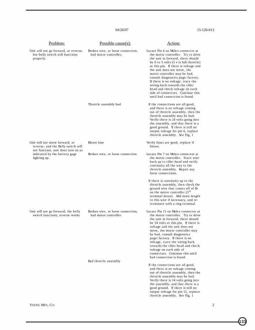
133
04/26/07 15-126-013
VESTIL MFG. CO. 2
Problem: Possible cause(s): Action:
Unit will not go forward, or reverse, but belly switch still functions properly.
Broken wire, or loose connection, bad motor controller,
Throttle assembly bad
Locate Pin 6 on Molex connector at the motor controller. Try to drive the unit in forward, there should be 0 to 5 volts (5 v is full throttle) at this pin. If there is voltage and the unit does not move, the motor controller may be bad, consult diagnostics page/factory. If there is no voltage, trace the wiring back towards the tiller head and check voltage on each side of connectors. Continue this until bad connection is found.
If the connections are all good,
and there is no voltage coming out of throttle assembly, then the throttle assembly may be bad. Verify there is 24 volts going into the assembly, and that there is a good ground. If there is still no output voltage for pin 6, replace throttle assembly. See Fig. 1
Unit will not move forward, or
reverse, and the Belly switch will not function, unit does turn on as indicated by the battery gage lighting up.
Blown fuse Broken wire, or loose connection
Verify fuses are good, replace if blown.
Locate Pin 7 on Molex connector at
the motor controller. Trace wire back up to tiller head and verify continuity all the way to the throttle assembly. Repair any loose connections.
If there is continuity up to the
throttle assembly, then check the ground wire that comes off of B- on the motor controller (3rd terminal down). Add more length to this wire if necessary, and re-terminate with a ring terminal.
Unit will not go forward; the belly
switch functions; reverse works.
Broken wire, or loose connection, bad motor controller
Bad throttle assembly
Locate Pin 11 on Molex connector at the motor controller. Try to drive the unit in forward, there should be 24 volts at this pin. If there is voltage and the unit does not move, the motor controller may be bad, consult diagnostics page/factory. If there is no voltage, trace the wiring back towards the tiller head and check voltage on each side of connectors. Continue this until bad connection is found.
If the connections are all good,
and there is no voltage coming out of throttle assembly, then the throttle assembly may be bad. Verify there is 24 volts going into the assembly, and that there is a good ground. If there is still no output voltage for pin 11, replace throttle assembly. See Fig. 1

134
04/26/07 15-126-013
VESTIL MFG. CO. 3
Problem: Possible cause(s): Action: Unit will not reverse; belly switch
does not function; forward ok Broken wire, or loose connection,
bad motor controller Bad throttle assembly
Locate Pin 12 on Molex connector at the motor controller. Try to drive the unit in reverse, there should be 24 volts at this pin. If there is voltage and the unit does not move, the motor controller may be bad, consult diagnostics page/factory. If there is no voltage, trace the wiring back towards the tiller head and check voltage on each side of connectors. Continue this until bad connection is found.
If the connections are all good,
and there is no voltage coming out of throttle assembly, then the throttle assembly may be bad. Verify there is 24 volts going into the assembly, and that there is a good ground. If there is still no output voltage for pin 12, replace throttle assembly. See Fig. 1
Belly switch does not function;
forward ok; reverse ok Broken wire, or loose connection,
bad motor controller Bad belly switch
Locate Pin 13 on Molex connector at the motor controller. Try to drive the unit in reverse, and hit the belly switch… there should be 24 volts at this pin. If there is voltage and the unit does not move, the motor controller may be bad, consult diagnostics page/factory. If there is no voltage, trace the wiring back towards the tiller head and check voltage, or continuity on each side of connectors. Continue this until bad connection is found.
If the connections are all good,
and there is no voltage, then the switch may be bad. Verify there is 24 volts going into the switch. If there is still no output voltage for pin 13, replace the switch.
Unit will not reverse. The unit only
goes forward for about 1 second and dies when the handle is pulled down. When the handle is re-set and pulled down the unit will move forward again then die.
Stuck Switch
The belly switch is stuck on. Tap the orange assembly to see if the switch can be freed. If this doesn’t work, disassemble the tiller head by removing 3 screws from bottom. Slightly loosen up the two scews that hold the switch in place, this may free the switch. If it is still stuck, contact the factory for a replacement switch.

135
04/26/07 15-126-013
VESTIL MFG. CO. 4
Problem: Possible cause(s): Action:
Unit will not raise; motor does not run
Loose wire Bad solenoid Upper limit switch out of
adjustment
Verify 24 volts at coil when raise is pushed, if no voltage, trace wiring back to till her head looking for voltage on each side of the connectors until the bad connection is found.
If voltage is present at the solenoid
and the unit does not raise, remove the two wires to the coil and measure the coil resistance. It should be around 19 ohms. If it’s open, or shorted replace the solenoid.
Bypass upper limit switch and see if
the unit raises…DO NOT TAKE IT ALL THE WAY UP… If it does raise, verify the limit switch is normally closed and will open when activated. If the limit switch is ok, try to adjust the switch accordingly so that the units raise height is approximately 7 to 8”
Unit will not raise; motor runs Lower solenoid stuck on Check to see if the lowering switch
is stuck on. If it is, remove the tiller head via 3 screws on bottom and replace switch, or tap on switch to see if it can be freed up.
Unit will not lower
Loose wire; bad coil
Verify 24 volts at coil when lower is pushed, if no voltage, trace wiring back to tiller head looking for voltage on each side of the connectors until the bad connection is found.
If voltage is present at the coil and
the unit does not lower, remove the connector to the coil and measure the coil resistance. It should be around 39 ohms. If it’s open, or shorted replace the coil.
Unit keeps blowing fuses when the
raise button is pressed
Shorted solenoid for motor raise Remove the wire to the solenoid coil on the pump motor. Measure the resistance, it should be around 19 ohms. If it is nearly zero ohms replace the solenoid.

136
04/26/07 15-126-013
VESTIL MFG. CO. 5
Problem: Possible cause(s): Action: Unit will not reverse; belly switch
does not function; forward ok Broken wire, or loose connection,
bad throttle assembly, bad motor controller.
Locate Pin 12 on Molex connector at the motor controller. Try to drive the unit in reverse, there should be 24 volts at this pin. If there is voltage and the unit does not move, the motor controller may be bad, consult factory. If there is no voltage, trace the wiring back towards the tiller head and check voltage on each side of connectors. Continue this until bad connection is found. If the connections are all good, and there is no voltage coming out of throttle assembly, then the throttle assembly may be bad. Verify there is 24 volts going into the assembly, and that there is a good ground. If there is still no output voltage for pin 12, replace throttle assembly.
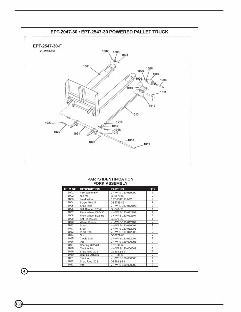
138
4
EPT-2047-30 • EPT-2547-30 POWERED PALLET TRUCK
PARTS IDENTIFICATIONFORK ASSEMBLY
PART NO.VH-WPS-130-010000GB6170-86EPT-2547-30-NWGB5785-86VH-WPS-130-012103GB278-82VH-WPS-130-012102VH-WPS-130-012104GB879-86VH-WPS-130-012101VH-WPS-130-010001VH-WPS-130-012001VH-WPS-130-012003GB6171-86VH-WPS-130-012004VH-WPS-130-000001EPT-30-17VH-WPS-130-000002GB894.1-86EPT-30-20VH-WPS-130-030000GB894.1-86VH-WPS-130-000003
ITEM NO.10011002100310041005100610071008100910101011101210131014101510161017101810191020102110221023
QTY12222422622222222122122
DESCRIPTIONFork AssemblyNut M6Load WheelScrew M6x45Snap RingBall Bearing 6204ZFront Wheel Ø80x90Front Wheel BearingSet Pin Ø5x30Wheel FrameShaftShaftPush RodNutClevis EndPinBearing Ø22x20Trunion RodSnap Ring Ø16Bearing Ø16x16TrunionSnap Ring Ø22Pin

139
5
EPT-2047-30 • EPT-2547-30 POWERED PALLET TRUCK
PARTS IDENTIFICATION • TAIL BOX ASSEMBLY
DESCRIPTIONMachine CoverBattery CoverBatteryBattery ChargerSpring Washer Ø6Nut M6Battery IndicatorDisconnect Switch KEYDisconnect SwitchFlat Washer Ø6Bolt M6x25PinPivot ArmBushing Ø16x10Snap Ring Ø16Main BodySnap Ring Ø20Bushing Ø20x20ShaftShaftSnap Ring Ø22Washer Ø10BoltBoltBearing SetWheel 76x36Nut M12Wheel FrameShaftBushingBearing PlateBearing 30205Bearing PlateWasherBearing 6205Nut M10Washer Ø8Fixed RingLink RodBoltFixed PlateWasher Ø8Bolt
ITEM NO.2001200220032004200520062007200820092010201120122013201420152016201720182019202020212022202320242025202620272028202920302031203220332034203520362037203820392040204120422043
QTY112114411224244112111222422224222222222212
PART NO.VH-WPS-130-000011VH-WPS-130-0000102X12V / 70AHVST224-15GB859-87EPT-30-2006DC24VEPT-30-2008EPT-30-2009GB895-85GB/T823-1988VH-WPS-130-000005VH-WPS-130-000006EPT-30-2014EPT-30-2015VH-WPS-130-020000EPT-30-2017EPT-30-2018VH-WPS-130-000007VH-WPS-130-000004GB894.1-86GB859-87GB70-85GB5785-86VH-WPS-130-040008VH-WPS-130-040009GB6170-86VH-WPS-130-041000VH-WPS-130-040007VH-WPS-130-040006VH-WPS-130-040003GB/T297VH-WPS-130-040002GB278-82GB894.1-86GB6170-86GB859-87VH-WPS-130-040005VH-WPS-130-040004GB/T2673-1986VH-WPS-130-020013GB859-87GB70-85

140
6
EPT-2047-30 • EPT-2547-30 POWERED PALLET TRUCK
PARTS IDENTIFICATION
HANDLE ASSEMBLY
DESCRIPTION
Screw M6x12Handle CoverFront ButtonElectrical Outlet (big)Electrical Outlet (small)Left Handle CoverFace PlateSpringHorn ButtonButton GroupRight Handle CoverBolt M3x10BushingSwitch CoverThrottle SwitchHandleBoltWasher Ø8Pneumatic SpringSnap RIng Ø20ShaftBushing 16x20CouplerBoltWasher Ø8Rubber CoverNut M56x1.5Washer 56WasherBoltWasherGrease ZerkWheel SetBearing 8112Bearing 80113ShaftBolt M10x30Washer Ø10Drive Wheel SystemControl Handle
ITEM NO.
310131023103310431053106310731083109311031113112311331143115311631173118311932013202320332043205320632073208320932103211321232133214321532163217321832193300
QTY
3111111211122111111212111111144111114411
PART NO.
GB70-85CH-2-000001CH-2-010000CH-2-000002CH-2-000003CH-4-000004CH-2-000005CH-2-000006CH-2-000007CH-2-020000CH-2-000008GB818-85CH-2-000009CH-2-000010CH-2-000011VH-WPS-130-062000GB 70-85GB859-87PWS-100/25-030001GB894.1-86PWS-100/25-030002EPT-30-3203PWS-100/25-030003GB70-85GB859-87PWS-100/25-030004VH-WP-200B-060004GB858-88VH-WPS-130-060003GB70-85GB859-87GB1152-89VH-WPS-130-060002GB-T297GB278-82VH-WPS-130-061000GB5785-86GB95-85DC24V/700KWVHS-CH2 3100
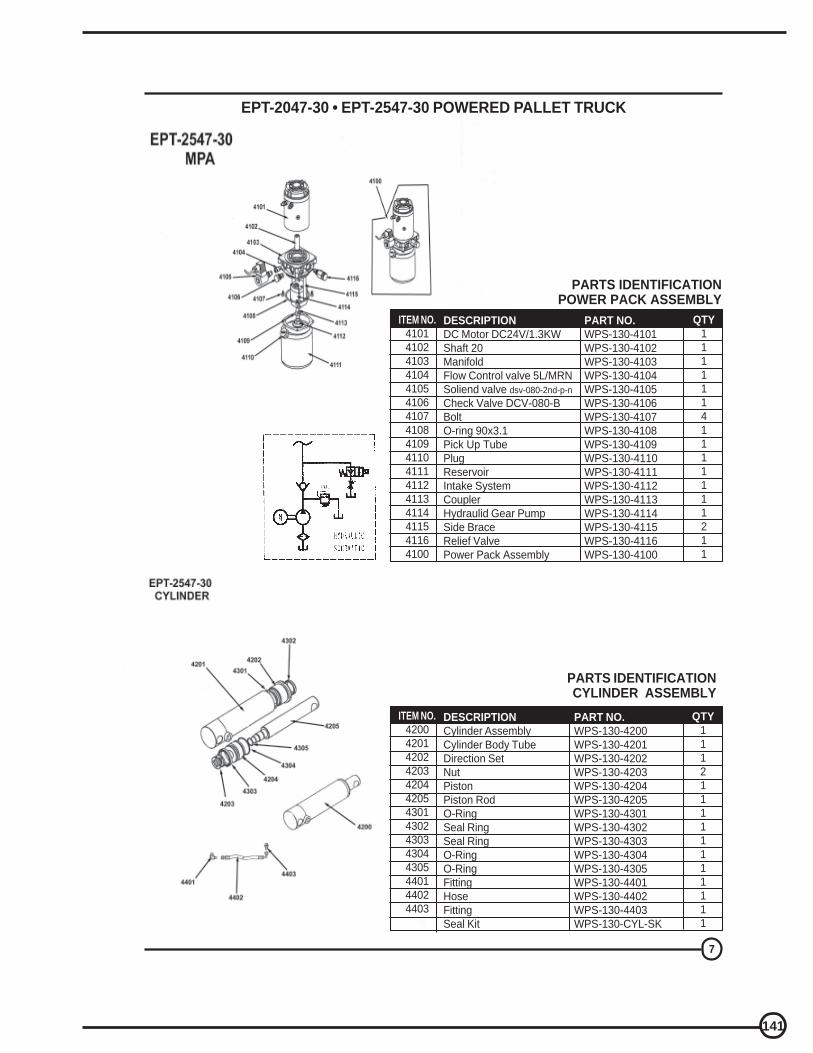
141
7
EPT-2047-30 • EPT-2547-30 POWERED PALLET TRUCK
PARTS IDENTIFICATIONPOWER PACK ASSEMBLY
PART NO.
WPS-130-4101WPS-130-4102WPS-130-4103WPS-130-4104WPS-130-4105WPS-130-4106WPS-130-4107WPS-130-4108WPS-130-4109WPS-130-4110WPS-130-4111WPS-130-4112WPS-130-4113WPS-130-4114WPS-130-4115WPS-130-4116WPS-130-4100
ITEM NO.
41014102410341044105410641074108410941104111411241134114411541164100
QTY
11111141111111211
DESCRIPTION
DC Motor DC24V/1.3KWShaft 20ManifoldFlow Control valve 5L/MRNSoliend valve dsv-080-2nd-p-n
Check Valve DCV-080-BBoltO-ring 90x3.1Pick Up TubePlugReservoirIntake SystemCouplerHydraulid Gear PumpSide BraceRelief ValvePower Pack Assembly
PART NO.
WPS-130-4200WPS-130-4201WPS-130-4202WPS-130-4203WPS-130-4204WPS-130-4205WPS-130-4301WPS-130-4302WPS-130-4303WPS-130-4304WPS-130-4305WPS-130-4401WPS-130-4402WPS-130-4403WPS-130-CYL-SK
ITEM NO.
42004201420242034204420543014302430343044305440144024403
QTY
111211111111111
DESCRIPTION
Cylinder AssemblyCylinder Body TubeDirection SetNutPistonPiston RodO-RingSeal RingSeal RingO-RingO-RingFittingHoseFittingSeal Kit
PARTS IDENTIFICATIONCYLINDER ASSEMBLY
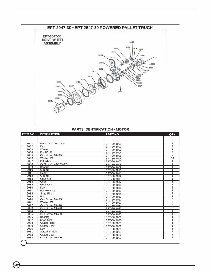
142
8
EPT-2047-30 • EPT-2547-30 POWERED PALLET TRUCK
PARTS IDENTIFICATION • MOTOR
DESCRIPTION
Motor DC 700W 24VKeyWasherPin Ø5x16Cap Screw M6x15Washer Ø6PU WheelOil Seal Ø140x180x12BearingO-RingGearO-RingGear BoxGearGear AxleKeyBall BearingSnap RingPlugCap Screw M6x15Washer Ø6Cap Screw M6x20Cap Screw M6x20GearCap Screw M6x60BearingSnap RingClutch PlateClutch GearKeyScraping PlateClutch GearCap Screw M6x20
ITEM NO.
300130023003300430053006300730083009301030113012301330143015301630173018301930203021302230233024302530263027302830293030303130323033
QTY
12127
13111111111121133331111111113
PART NO.
EPT-30-3001EPT-30-3002EPT-30-3003EPT-30-3004EPT-30-3005EPT-30-3006EPT-30-3007EPT-30-3008EPT-30-3009EPT-30-3010EPT-30-3011EPT-30-3012EPT-30-3013EPT-30-3014EPT-30-3015EPT-30-3016EPT-30-3017EPT-30-3018EPT-30-3019EPT-30-3020EPT-30-3021EPT-30-3022EPT-30-3023EPT-30-3024EPT-30-3025EPT-30-3026EPT-30-3027EPT-30-3028EPT-30-3029EPT-30-3030EPT-30-3031EPT-30-3032EPT-30-3033

143
9
EPT-2047-30 • EPT-2547-30 POWERED PALLET TRUCK
PARTS IDENTIFICATIONWIRING DIAGRAM
NO.
123456789
10111214
QTY
1111112111111
DESCRIPTION
MOTOR ControllerContactor F/RPump MotorHydraulic ContactorBellly SwitchBattery MeterFuse 150AFuse 5AKEY SWITCH ASSYHornDrive MotorControl BottonsBATTERY 12V/70AH


Serial No. __________________
Model: ____________________ LIMITED WARRANTY
Vestil Manufacturing Corporation (Vestil) warrants each EPT model electric pallet truck, and Stacker models SE/HP, S-CB, S-62, to be free of defects in material and workmanship during the warranty period. Our warranty obligation is to provide a replacement for a defective original part (a part used to make the product as shipped to the warrantee) after we receive a proper request for warranty service. “Proper request” means that we must receive: 1) a photocopy of your Customer Invoice that displays the shipping date; AND 2) a written request for warranty service that includes your name and phone number. Send requests by any of the following methods:
Mail Fax Email Vestil Manufacturing Corporation (260) 665-1339 [email protected] 2999 North Wayne Street, PO Box 507 Phone Angola, IN 46703 (260) 665-7586 In the written request, list the parts you believe are defective and include the address where replacements should be delivered. After Vestil receives your request, an authorized representative will contact you to determine whether your claim is covered by the warranty (also see “If a defective part is covered…” below). Before providing warranty service, Vestil may require you to send the entire product or the defective part or parts to its facility in Angola, Indiana. Who may request service? Only the warrantee may request service. You are a warrantee if you purchased the product from Vestil or from an authorized distributor AND Vestil has been fully paid. What is covered under the warranty? The warranty covers the following original drive and lift components: drive motors and lift motors, hydraulic pumps, electronic controllers, switches and cylinders. It also covers original parts that wear under normal usage conditions (“wearing parts”): bearings, hoses, wheels, seals, brushes, batteries, and the battery charger. The warranty period for drive and lift components is 1 year. For wearing parts, the warranty period is 90 days. Both warranty periods begin on the date when Vestil ships the product to the warrantee. If you purchased the product from an authorized distributor, the periods begin when the distributor ships the product, which extends the warranty by up to an additional 30 days. If a defective part is covered by the warranty, what will Vestil do to correct the problem? Vestil will provide an appropriate replacement for any covered part. An authorized representative of Vestil will contact you to discuss your claim. What is not covered by the warranty?
1. Labor costs or Freight; 2. Any of the following automatically void the warranty:
• Product misuse; • Negligent operation or repair; • Corrosion or use in corrosive conditions; • Inadequate or improper maintenance; • Failure to exercise good judgment; • Damage sustained during shipping; • Accidents involving the product; • Unauthorized modifications: Do NOT modify the product IN ANY WAY without first receiving
written authorization from Vestil. Modifications may render the pallet truck or stacker unsafe to use or might cause excessive and/or abnormal wear.
Do any other warranties apply to the product? Vestil Manufacturing Corp. makes no other express warranties. Any warranty implied-by-law is limited in duration to the warranty period.