EPP Eagle V2 - · PDF fileEPP Eagle V2 The EPP eagle is a graceful bird and truly a ... choose...
13
EPP Eagle V2 The EPP eagle is a graceful bird and truly a pleasure to behold. People could even mistake it for a real eagle at a distance – until you pull off some loops and aileron rolls. The EPP eagle can be a docile soaring bird or fully aerobatic predator! It comes with 4 servos so you can choose to set it up as a v-tail configuration, or you can cut ailerons into the wings and install the additional servos to make a 4 channel setup. Our EPP Eagle comes as an ARF kit with servos, leads, ESC, Motor, Propeller and connectors. All you need to supply is your receiver and battery. Aircraft parameters Wingspan 120cm Maximum chord length 270mm Empty Weight 200 grams Takeoff Weight 460-520 grams Motor: 2205 1650Kv Battery 2150mah 2S (recommended) COG: 60mm from leading edge NOTE: The supplied motor is suitable for 2S battery packs only. Running it with a 3S battery pack will damage the motor. Kit Inclusions Motor: 22085KV1650 2S Prop Saver: To fit motor Propeller: SF 8038 ESC: Emax 20 AMP Simon Series 4 Servos: Emax ES08AII 9 Gram 1 V-Tail Mixer 1 Servo reverser 2 x Servo Splitter leads Control Linkages and Pushrods Rubber bands Airframe and all accessories.
Transcript of EPP Eagle V2 - · PDF fileEPP Eagle V2 The EPP eagle is a graceful bird and truly a ... choose...

EPP Eagle V2
The EPP eagle is a graceful bird and truly a pleasure to behold. People could even mistake it for a real eagle at a distance – until you pull off
some loops and aileron rolls. The EPP eagle can be a docile soaring bird or fully aerobatic
predator! It comes with 4 servos so you can choose to set it up as a v-tail configuration, or you can cut ailerons into the wings and install
the additional servos to make a 4 channel setup. Our EPP Eagle comes as an ARF kit with servos,
leads, ESC, Motor, Propeller and connectors. All you need to supply is your receiver and battery.
Aircraft parameters Wingspan 120cm
Maximum chord length 270mm Empty Weight 200 grams Takeoff Weight 460-520 grams
Motor: 2205 1650Kv Battery 2150mah 2S (recommended)
COG: 60mm from leading edge NOTE: The supplied motor is suitable for 2S
battery packs only. Running it with a 3S battery pack will damage the motor.
Kit Inclusions Motor: 22085KV1650 2S Prop Saver: To fit motor
Propeller: SF 8038 ESC: Emax 20 AMP Simon Series 4 Servos: Emax ES08AII 9 Gram
1 V-Tail Mixer 1 Servo reverser
2 x Servo Splitter leads Control Linkages and Pushrods
Rubber bands Airframe and all accessories.

Two pieces of strengthening wood are provided to be glued inside the beak area at the front.
Glue the glass fibre wing supports in place and insert the two rods for attaching the rubber bands.
The image below shows how the bottom panel is attached. Glue it in place with both the sides.

Glue the two motor mount boards together leaving an even gap around the edges. Then mark out and drill your motor mount holes.
Trim the part of the bottom sheet that overlaps to make it level with the sides.
Glue in your motor mount. The U shaped hole for the wires goes to the bottom and the recess around the motor mount goes to the front to fit neatly with the two pieces of board already
attached to the inside of the fuselage. Pin the bottom part under the beak while drying to ensure it doesn’t come away from the curved surface.
Glue the two additional pieces of EPP foam firmly up against the rear of the motor mount.
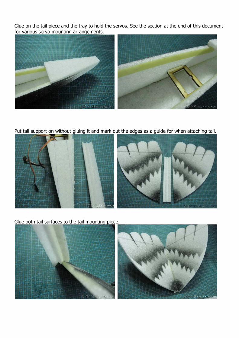
Glue on the tail piece and the tray to hold the servos. See the section at the end of this document for various servo mounting arrangements.
Put tail support on without gluing it and mark out the edges as a guide for when attaching tail.
Glue both tail surfaces to the tail mounting piece.
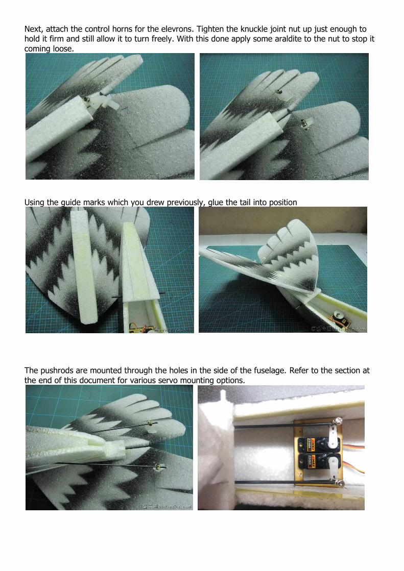
Next, attach the control horns for the elevrons. Tighten the knuckle joint nut up just enough to hold it firm and still allow it to turn freely. With this done apply some araldite to the nut to stop it
coming loose.
Using the guide marks which you drew previously, glue the tail into position
The pushrods are mounted through the holes in the side of the fuselage. Refer to the section at
the end of this document for various servo mounting options.
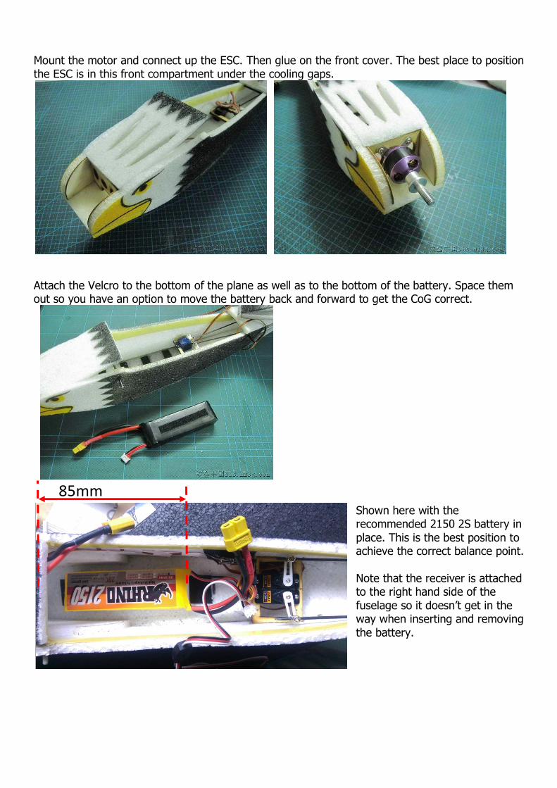
Mount the motor and connect up the ESC. Then glue on the front cover. The best place to position the ESC is in this front compartment under the cooling gaps.
Attach the Velcro to the bottom of the plane as well as to the bottom of the battery. Space them out so you have an option to move the battery back and forward to get the CoG correct.
Shown here with the recommended 2150 2S battery in
place. This is the best position to achieve the correct balance point.
Note that the receiver is attached to the right hand side of the
fuselage so it doesn’t get in the way when inserting and removing
the battery.
85mm
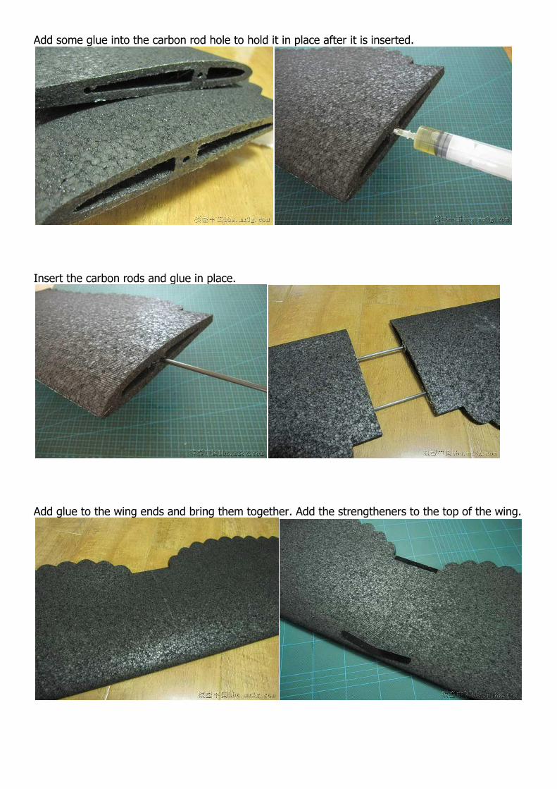
Add some glue into the carbon rod hole to hold it in place after it is inserted.
Insert the carbon rods and glue in place.
Add glue to the wing ends and bring them together. Add the strengtheners to the top of the wing.

Glue on the wing tips. (black wingtip version shown here). Use a black felt pen to colour in glue.
Trim the wingtips underneath to make them flush with the lower surface of the wing. Finished product shown (white wingtip version shown on right).
Building is complete.

Use the copper wire pushrods for the ailerons. Servo holes in the wings are
large enough to allow servos to be mounted either way. Check the direction
of travel of your servos and adjust as needed before gluing the servos in.
Cover the servos with black electrical tape or clear Blenderm tape.
CoG Location is 60mm back from the leading edge of the wing.

Setting up your electronics. This will depend on how you want to fly your bird. We’ve included all the components you may possibly need such as servo Y splitter leads , servo reverser and v-tail mixer. Depending on your chosen setup you may not need to use all these parts. See the examples below which give you detailed instructions for each
setup, and choose the best setup for your needs.
Setup 1 V-tail controlled with rudder and elevator sticks – ailerons separate (Programmable Transmitter Required) For this setup you will need a transmitter with V-Tail mixing and servo reversing functionality. The rear fins act as a V-Tail setup. One servo is connected to each fin control surface and rudder and elevator inputs are mixed. Turning can be achieved using the rudder stick on the transmitter and elevators function as normal. Additionally, the ailerons can be used for banking. This setup gives you the best of both worlds allowing you to use rudder for smooth gentle realistic turns, while bringing in the ailerons for more aircraft like manoeuvres . Use the exact setup as shown below and take note of the direction the servos are mounted as well as where each servo is connected. Also use a Y splitter cable to connect your aileron servos In the wings to the aileron plug on the receiver.
Run the ESC battery plug wired over the top of this shaft to keep the ESC in position in the front compartment.

Set V-Tail mixing to be active Set rudder to be reversed
Setup 2 V-Tail set up for dual elevator control – ailerons separate (Programmable Transmitter not required) For this setup you will use the supplied servo reverser and a Y splitter cable. In this configuration both the servos mounted inside the body will be working in unison as elevator servos. So the plane will have ailerons for roll and bank as well as elevator – no rudder. There is no mixing and both the tail surfaces act only as elevators. This configuration gives you maximum manoeuvrability for bank and yank turns, slow rolls and loops. Use the exact setup as shown below and take note of the direction the servos are mounted as well as where each servo is connected. Also use a Y splitter cable to connect your aileron servos In the wings to the aileron plug on the receiver.

Setup 3 V-tail controlled with rudder and aileron sticks (Programmable Transmitter not required) This setup is used when you want to fly the plane using a V-Tail setup but instead of turning with the rudder, you use the aileron stick to turn. So the two tail surfaces mix the aileron and elevator inputs from the transmitter. You can’t use ailerons in the wings when you have the plane set up in this configuration. Use this configuration for smooth, gentle flight for pilots who are accustomed to flying with ailerons instead of rudder. Use the exact setup as shown below and take note of the direction the servos are mounted as well as where each servo is connected. You only need the two servos in the body – aileron servos in the wings are not needed.
Note: Servos must be mounted on the outsides with the servo arms protruding inward. To do this you will also need to trim the last hole off the servo arms and move the control linkage knuckle to the nes hole in. This is to give clearance so the two servo arms don’t touch as they move past each other.

Motor and Prop
We supply two spacers for the motor mounts. These spacers need to be placed on the top two motor mounts. This gives the motor the required amount of down thrust to prevent the plane pitching up under full throttle. Attach and tighten the prop saver to the motor shaft and attach the propeller as shown here with the retaining o-ring.
Congratulations, you’re ready to fly!
RCFoamFly – www.rcfoamfly.com ©All rights reserved – For personal use only. No unauthorised copying or distributing.