
EPOS4 Communication Guide · maxon motor ag Brünigstrasse 220 P.O.Box 263 CH-6072 Sachseln Phone...
42
maxon motor ag Brünigstrasse 220 P.O.Box 263 CH-6072 Sachseln Phone +41 41 666 15 00 Fax +41 41 666 16 50 www.maxonmotor.com Edition November 2017 EPOS4 Positioning Controllers Communication Guide maxon motor control Positioning Controllers Communication Guide Document ID: rel7290
Transcript of EPOS4 Communication Guide · maxon motor ag Brünigstrasse 220 P.O.Box 263 CH-6072 Sachseln Phone...
maxon motor ag Brünigstrasse 220 P.O.Box 263 CH-6072 Sachseln Phone +41 41 666 15 00 Fax +41 41 666 16 50 www.maxonmotor.com
Edition November 2017
EPOS4 Positioning Controllers
Communication Guide
maxon motor control
Positioning Controllers
Communication Guide
Document ID: rel7290
maxon motor controlA-2 Document ID: rel7290 EPOS4 Positioning Controllers
Edition: November 2017 EPOS4 Communication Guide© 2017 maxon motor. Subject to change without prior notice.
1 About this Document 3
2 USB & RS232 Communication 72.1 EPOS4 USB & RS232 Command Reference . . . . . . . . . . . . . . . . . . . . . . . . . 72.2 Data Link Layer . . . . . . . . . . . . . . . . . . . . . . . . . . . . . . . . . . . . . . . . . . . . . . . 102.3 Physical Layer . . . . . . . . . . . . . . . . . . . . . . . . . . . . . . . . . . . . . . . . . . . . . . . . 16
3 CAN Communication 173.1 General Information . . . . . . . . . . . . . . . . . . . . . . . . . . . . . . . . . . . . . . . . . . . . 173.2 CANopen Basics . . . . . . . . . . . . . . . . . . . . . . . . . . . . . . . . . . . . . . . . . . . . . . 193.3 CANopen Application Layer . . . . . . . . . . . . . . . . . . . . . . . . . . . . . . . . . . . . . . 213.4 Identifier Allocation Scheme. . . . . . . . . . . . . . . . . . . . . . . . . . . . . . . . . . . . . . 29
4 EtherCAT Communication 314.1 Communication Specifications . . . . . . . . . . . . . . . . . . . . . . . . . . . . . . . . . . . . 324.2 EtherCAT State Machine (ESM) . . . . . . . . . . . . . . . . . . . . . . . . . . . . . . . . . . 324.3 Integration of ESI Files . . . . . . . . . . . . . . . . . . . . . . . . . . . . . . . . . . . . . . . . . . 344.4 Error Code Definition . . . . . . . . . . . . . . . . . . . . . . . . . . . . . . . . . . . . . . . . . . . 34
5 Gateway Communication (USB or RS232 to CAN) 35
6 Communication Error Code Definition 37
TABLE OF CONTENTS
READ THIS FIRSTThese instructions are intended for qualified technical personnel. Prior commencing with any activities…• you must carefully read and understand this manual and• you must follow the instructions given therein.
EPOS4 positioning controllers are considered as partly completed machinery according to EU Directive 2006/42/EC, Article2, Clause (g) and are intended to be incorporated into or assembled with other machinery or other partly completedmachinery or equipment.Therefore, you must not put the device into service,…• unless you have made completely sure that the other machinery fully complies with the EU directive’s requirements!• unless the other machinery fulfills all relevant health and safety aspects!• unless all respective interfaces have been established and fulfill the herein stated requirements!
About this Document
© 2017 maxon motor. Subject to change without prior notice.
maxon motor controlEPOS4 Positioning Controllers Document ID: rel7290 1-3EPOS4 Communication Guide Edition: November 2017
1 About this DocumentThe present document provides you with information on the EPOS4 communication interfaces.
Find the latest edition of the present document as well as additional documentation and software for EPOS4 positioning controllers also on the Internet: http://epos.maxonmotor.com.
1.1 Intended PurposeThe purpose of the present document is to familiarize you with the described equipment and the tasks on safe and adequate installation and/or commissioning. Follow the described instructions …
• to avoid dangerous situations,• to keep installation and/or commissioning time at a minimum,• to increase reliability and service life of the described equipment.
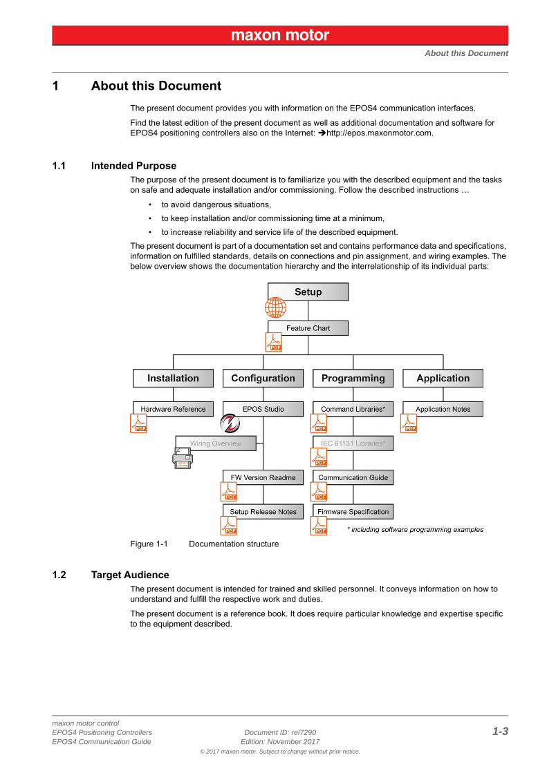
The present document is part of a documentation set and contains performance data and specifications, information on fulfilled standards, details on connections and pin assignment, and wiring examples. The below overview shows the documentation hierarchy and the interrelationship of its individual parts:
Figure 1-1 Documentation structure
1.2 Target AudienceThe present document is intended for trained and skilled personnel. It conveys information on how to understand and fulfill the respective work and duties.
The present document is a reference book. It does require particular knowledge and expertise specific to the equipment described.
About this Document
© 2017 maxon motor. Subject to change without prior notice.
maxon motor control1-4 Document ID: rel7290 EPOS4 Positioning Controllers
Edition: November 2017 EPOS4 Communication Guide
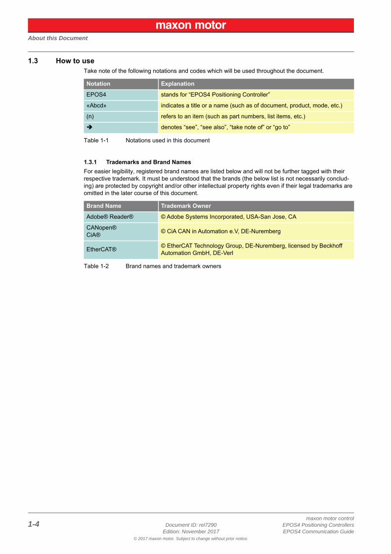
1.3 How to useTake note of the following notations and codes which will be used throughout the document.
Table 1-1 Notations used in this document
1.3.1 Trademarks and Brand NamesFor easier legibility, registered brand names are listed below and will not be further tagged with their respective trademark. It must be understood that the brands (the below list is not necessarily conclud-ing) are protected by copyright and/or other intellectual property rights even if their legal trademarks are omitted in the later course of this document.
Table 1-2 Brand names and trademark owners
Notation Explanation
EPOS4 stands for “EPOS4 Positioning Controller”
«Abcd» indicates a title or a name (such as of document, product, mode, etc.)
(n) refers to an item (such as part numbers, list items, etc.)
denotes “see”, “see also”, “take note of” or “go to”
Brand Name Trademark Owner
Adobe® Reader® © Adobe Systems Incorporated, USA-San Jose, CA
CANopen®CiA® © CiA CAN in Automation e.V, DE-Nuremberg
EtherCAT® © EtherCAT Technology Group, DE-Nuremberg, licensed by Beckhoff Automation GmbH, DE-Verl
About this Document
© 2017 maxon motor. Subject to change without prior notice.
maxon motor controlEPOS4 Positioning Controllers Document ID: rel7290 1-5EPOS4 Communication Guide Edition: November 2017
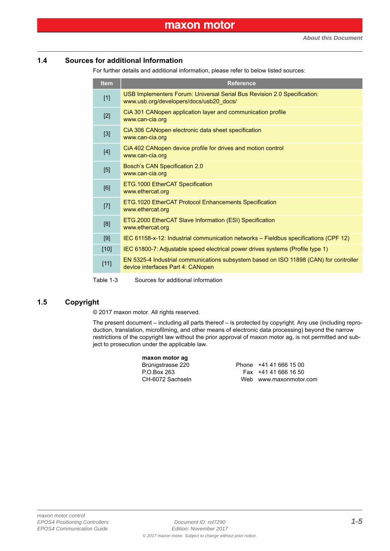
1.4 Sources for additional InformationFor further details and additional information, please refer to below listed sources:
Table 1-3 Sources for additional information
1.5 Copyright© 2017 maxon motor. All rights reserved.
The present document – including all parts thereof – is protected by copyright. Any use (including repro-duction, translation, microfilming, and other means of electronic data processing) beyond the narrow restrictions of the copyright law without the prior approval of maxon motor ag, is not permitted and sub-ject to prosecution under the applicable law.
Item Reference
[1] USB Implementers Forum: Universal Serial Bus Revision 2.0 Specification:www.usb.org/developers/docs/usb20_docs/
[2] CiA 301 CANopen application layer and communication profilewww.can-cia.org
[3] CiA 306 CANopen electronic data sheet specificationwww.can-cia.org
[4] CiA 402 CANopen device profile for drives and motion controlwww.can-cia.org
[5] Bosch’s CAN Specification 2.0www.can-cia.org
[6] ETG.1000 EtherCAT Specificationwww.ethercat.org
[7] ETG.1020 EtherCAT Protocol Enhancements Specificationwww.ethercat.org
[8] ETG.2000 EtherCAT Slave Information (ESI) Specificationwww.ethercat.org
[9] IEC 61158-x-12: Industrial communication networks – Fieldbus specifications (CPF 12)
[10] IEC 61800-7: Adjustable speed electrical power drives systems (Profile type 1)
[11] EN 5325-4 Industrial communications subsystem based on ISO 11898 (CAN) for controller device interfaces Part 4: CANopen
maxon motor agBrünigstrasse 220P.O.Box 263CH-6072 Sachseln
PhoneFax
Web
+41 41 666 15 00+41 41 666 16 50www.maxonmotor.com

About this Document
© 2017 maxon motor. Subject to change without prior notice.
maxon motor control1-6 Document ID: rel7290 EPOS4 Positioning Controllers
Edition: November 2017 EPOS4 Communication Guide
• • p a g e i n t e n t i o n a l l y l e f t b l a n k • •
USB & RS232 CommunicationEPOS4 USB & RS232 Command Reference
© 2017 maxon motor. Subject to change without prior notice.
maxon motor controlEPOS4 Positioning Controllers Document ID: rel7290 2-7EPOS4 Communication Guide Edition: November 2017
2 USB & RS232 Communication
2.1 EPOS4 USB & RS232 Command Reference
2.1.1 Read Functions
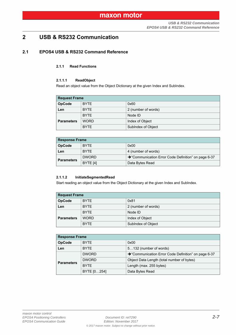
2.1.1.1 ReadObjectRead an object value from the Object Dictionary at the given Index and SubIndex.
2.1.1.2 InitiateSegmentedReadStart reading an object value from the Object Dictionary at the given Index and SubIndex.
Request FrameOpCode BYTE 0x60Len BYTE 2 (number of words)
ParametersBYTE Node IDWORD Index of ObjectBYTE SubIndex of Object
Response FrameOpCode BYTE 0x00Len BYTE 4 (number of words)
ParametersDWORD “Communication Error Code Definition” on page 6-37BYTE [4] Data Bytes Read
Request FrameOpCode BYTE 0x81Len BYTE 2 (number of words)
ParametersBYTE Node IDWORD Index of ObjectBYTE SubIndex of Object
Response FrameOpCode BYTE 0x00Len BYTE 5…132 (number of words)
Parameters
DWORD “Communication Error Code Definition” on page 6-37DWORD Object Data Length (total number of bytes)BYTE Length (max. 255 bytes)BYTE [0…254] Data Bytes Read
USB & RS232 CommunicationEPOS4 USB & RS232 Command Reference
© 2017 maxon motor. Subject to change without prior notice.
maxon motor control2-8 Document ID: rel7290 EPOS4 Positioning Controllers
Edition: November 2017 EPOS4 Communication Guide
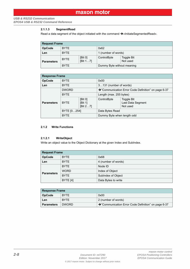
2.1.1.3 SegmentReadRead a data segment of the object initiated with the command «InitiateSegmentedRead».
2.1.2 Write Functions
2.1.2.1 WriteObjectWrite an object value to the Object Dictionary at the given Index and SubIndex.
Request FrameOpCode BYTE 0x62Len BYTE 1 (number of words)
ParametersBYTE [Bit 0]
[Bit 1…7]ControlByte Toggle Bit
Not usedBYTE Dummy Byte without meaning
Response FrameOpCode BYTE 0x00Len BYTE 3…131 (number of words)
Parameters
DWORD “Communication Error Code Definition” on page 6-37BYTE Length (max. 255 bytes)
BYTE[Bit 0][Bit 1][Bit 2…7]
ControlByte Toggle BitLast Data SegmentNot used
BYTE [0…254] Data Bytes ReadBYTE Dummy Byte when length odd
Request FrameOpCode BYTE 0x68Len BYTE 4 (number of words)
Parameters
BYTE Node IDWORD Index of ObjectBYTE SubIndex of ObjectBYTE [4] Data Bytes to write
Response FrameOpCode BYTE 0x00Len BYTE 2 (number of words)Parameters DWORD “Communication Error Code Definition” on page 6-37
USB & RS232 CommunicationEPOS4 USB & RS232 Command Reference
© 2017 maxon motor. Subject to change without prior notice.
maxon motor controlEPOS4 Positioning Controllers Document ID: rel7290 2-9EPOS4 Communication Guide Edition: November 2017
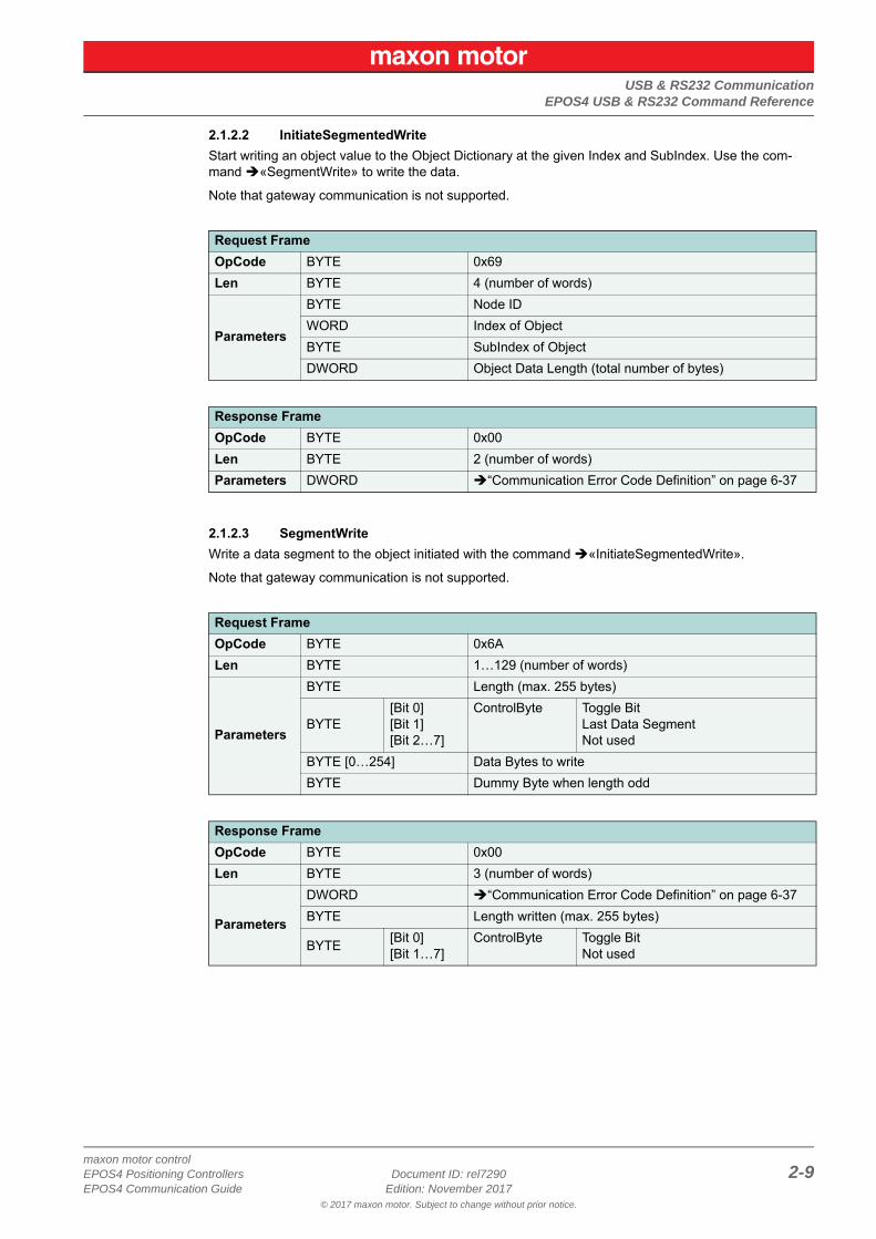
2.1.2.2 InitiateSegmentedWriteStart writing an object value to the Object Dictionary at the given Index and SubIndex. Use the com-mand «SegmentWrite» to write the data.
Note that gateway communication is not supported.
2.1.2.3 SegmentWriteWrite a data segment to the object initiated with the command «InitiateSegmentedWrite».
Note that gateway communication is not supported.
Request FrameOpCode BYTE 0x69Len BYTE 4 (number of words)
Parameters
BYTE Node IDWORD Index of ObjectBYTE SubIndex of ObjectDWORD Object Data Length (total number of bytes)
Response FrameOpCode BYTE 0x00Len BYTE 2 (number of words)Parameters DWORD “Communication Error Code Definition” on page 6-37
Request FrameOpCode BYTE 0x6ALen BYTE 1…129 (number of words)
Parameters
BYTE Length (max. 255 bytes)
BYTE[Bit 0][Bit 1][Bit 2…7]
ControlByte Toggle BitLast Data SegmentNot used
BYTE [0…254] Data Bytes to writeBYTE Dummy Byte when length odd
Response FrameOpCode BYTE 0x00Len BYTE 3 (number of words)
Parameters
DWORD “Communication Error Code Definition” on page 6-37BYTE Length written (max. 255 bytes)
BYTE [Bit 0][Bit 1…7]
ControlByte Toggle BitNot used
USB & RS232 CommunicationData Link Layer
© 2017 maxon motor. Subject to change without prior notice.
maxon motor control2-10 Document ID: rel7290 EPOS4 Positioning Controllers
Edition: November 2017 EPOS4 Communication Guide
2.2 Data Link Layer
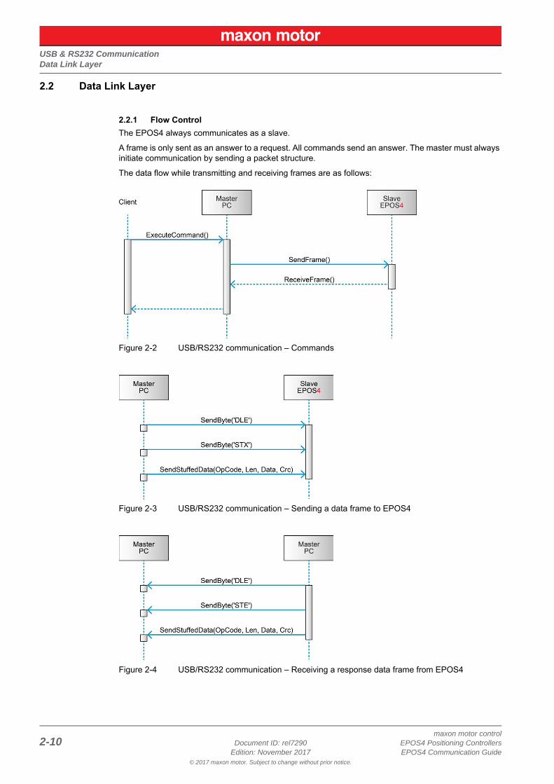
2.2.1 Flow ControlThe EPOS4 always communicates as a slave.
A frame is only sent as an answer to a request. All commands send an answer. The master must always initiate communication by sending a packet structure.
The data flow while transmitting and receiving frames are as follows:
Figure 2-2 USB/RS232 communication – Commands
Figure 2-3 USB/RS232 communication – Sending a data frame to EPOS4
Figure 2-4 USB/RS232 communication – Receiving a response data frame from EPOS4
USB & RS232 CommunicationData Link Layer
© 2017 maxon motor. Subject to change without prior notice.
maxon motor controlEPOS4 Positioning Controllers Document ID: rel7290 2-11EPOS4 Communication Guide Edition: November 2017
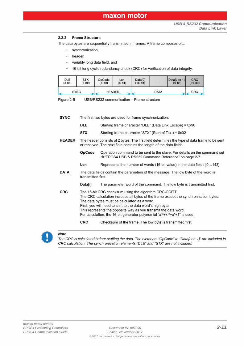
2.2.2 Frame StructureThe data bytes are sequentially transmitted in frames. A frame composes of…
• synchronization,• header,• variably long data field, and• 16-bit long cyclic redundancy check (CRC) for verification of data integrity.
Figure 2-5 USB/RS232 communication – Frame structure
NoteThe CRC is calculated before stuffing the data. The elements “OpCode” to “Data[Len-1]” are included in CRC calculation. The synchronization elements “DLE” and “STX” are not included.
SYNC The first two bytes are used for frame synchronization.
DLE Starting frame character “DLE” (Data Link Escape) = 0x90
STX Starting frame character “STX” (Start of Text) = 0x02
HEADER The header consists of 2 bytes. The first field determines the type of data frame to be sent or received. The next field contains the length of the data fields.
OpCode Operation command to be sent to the slave. For details on the command set “EPOS4 USB & RS232 Command Reference” on page 2-7.
Len Represents the number of words (16-bit value) in the data fields [0…143].
DATA The data fields contain the parameters of the message. The low byte of the word is transmitted first.
Data[i] The parameter word of the command. The low byte is transmitted first.
CRC The 16-bit CRC checksum using the algorithm CRC-CCITT. The CRC calculation includes all bytes of the frame except the synchronization bytes. The data bytes must be calculated as a word. First, you will need to shift to the data word’s high byte.This represents the opposite way as you transmit the data word.For calculation, the 16-bit generator polynomial “x16+x12+x5+1” is used.
CRC Checksum of the frame. The low byte is transmitted first.
USB & RS232 CommunicationData Link Layer
© 2017 maxon motor. Subject to change without prior notice.
maxon motor control2-12 Document ID: rel7290 EPOS4 Positioning Controllers
Edition: November 2017 EPOS4 Communication Guide
2.2.3 Error Control
2.2.3.1 AcknowledgeAs a reaction to a bad OpCode or CRC value, the slave sends a frame containing the corresponding error code.
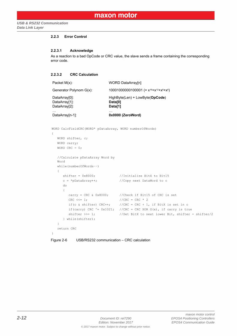
2.2.3.2 CRC Calculation
Figure 2-6 USB/RS232 communication – CRC calculation
Packet M(x): WORD DataArray[n]
Generator Polynom G(x): 10001000000100001 (= x16+x12+x5+x0)
DataArray[0]:DataArray[1]:DataArray[2]:…DataArray[n-1]:
HighByte(Len) + LowByte(OpCode)Data[0]Data[1]…0x0000 (ZeroWord)
WORD CalcFieldCRC(WORD* pDataArray, WORD numberOfWords){
WORD shifter, c;WORD carry;WORD CRC = 0;
//Calculate pDataArray Word by Wordwhile(numberOfWords−−){
shifter = 0x8000;c = *pDataArray++;do{
//Initialize BitX to Bit15//Copy next DataWord to c
carry = CRC & 0x8000;CRC <<= 1;if(c & shifter) CRC++;if(carry) CRC ^= 0x1021;shifter >>= 1;
//Check if Bit15 of CRC is set//CRC = CRC * 2//CRC = CRC + 1, if BitX is set in c//CRC = CRC XOR G(x), if carry is true//Set BitX to next lower Bit, shifter = shifter/2
} while(shifter);}return CRC
}
USB & RS232 CommunicationData Link Layer
© 2017 maxon motor. Subject to change without prior notice.
maxon motor controlEPOS4 Positioning Controllers Document ID: rel7290 2-13EPOS4 Communication Guide Edition: November 2017
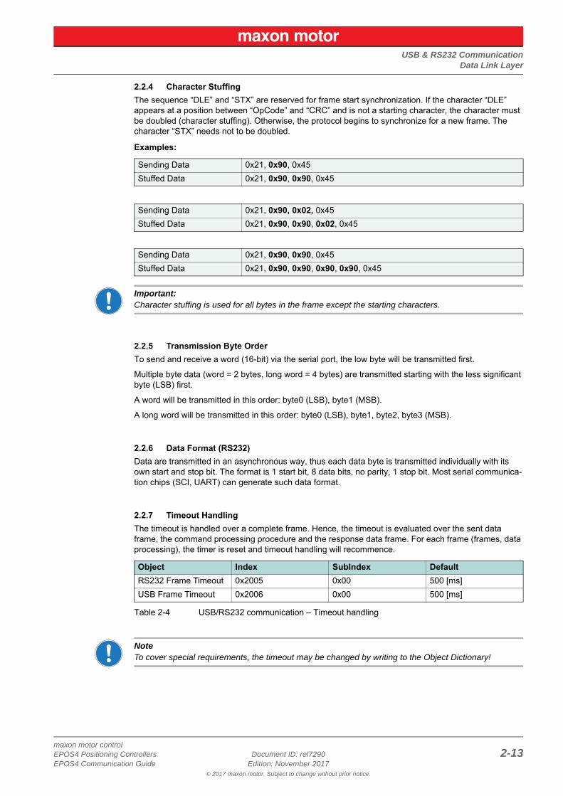
2.2.4 Character StuffingThe sequence “DLE” and “STX” are reserved for frame start synchronization. If the character “DLE” appears at a position between “OpCode” and “CRC” and is not a starting character, the character must be doubled (character stuffing). Otherwise, the protocol begins to synchronize for a new frame. The character “STX” needs not to be doubled.
Examples:
Important:Character stuffing is used for all bytes in the frame except the starting characters.
2.2.5 Transmission Byte OrderTo send and receive a word (16-bit) via the serial port, the low byte will be transmitted first.
Multiple byte data (word = 2 bytes, long word = 4 bytes) are transmitted starting with the less significant byte (LSB) first.
A word will be transmitted in this order: byte0 (LSB), byte1 (MSB).
A long word will be transmitted in this order: byte0 (LSB), byte1, byte2, byte3 (MSB).
2.2.6 Data Format (RS232)Data are transmitted in an asynchronous way, thus each data byte is transmitted individually with its own start and stop bit. The format is 1 start bit, 8 data bits, no parity, 1 stop bit. Most serial communica-tion chips (SCI, UART) can generate such data format.
2.2.7 Timeout HandlingThe timeout is handled over a complete frame. Hence, the timeout is evaluated over the sent data frame, the command processing procedure and the response data frame. For each frame (frames, data processing), the timer is reset and timeout handling will recommence.
Table 2-4 USB/RS232 communication – Timeout handling
NoteTo cover special requirements, the timeout may be changed by writing to the Object Dictionary!
Sending Data 0x21, 0x90, 0x45Stuffed Data 0x21, 0x90, 0x90, 0x45
Sending Data 0x21, 0x90, 0x02, 0x45Stuffed Data 0x21, 0x90, 0x90, 0x02, 0x45
Sending Data 0x21, 0x90, 0x90, 0x45Stuffed Data 0x21, 0x90, 0x90, 0x90, 0x90, 0x45
Object Index SubIndex DefaultRS232 Frame Timeout 0x2005 0x00 500 [ms]USB Frame Timeout 0x2006 0x00 500 [ms]
USB & RS232 CommunicationData Link Layer
© 2017 maxon motor. Subject to change without prior notice.
maxon motor control2-14 Document ID: rel7290 EPOS4 Positioning Controllers
Edition: November 2017 EPOS4 Communication Guide
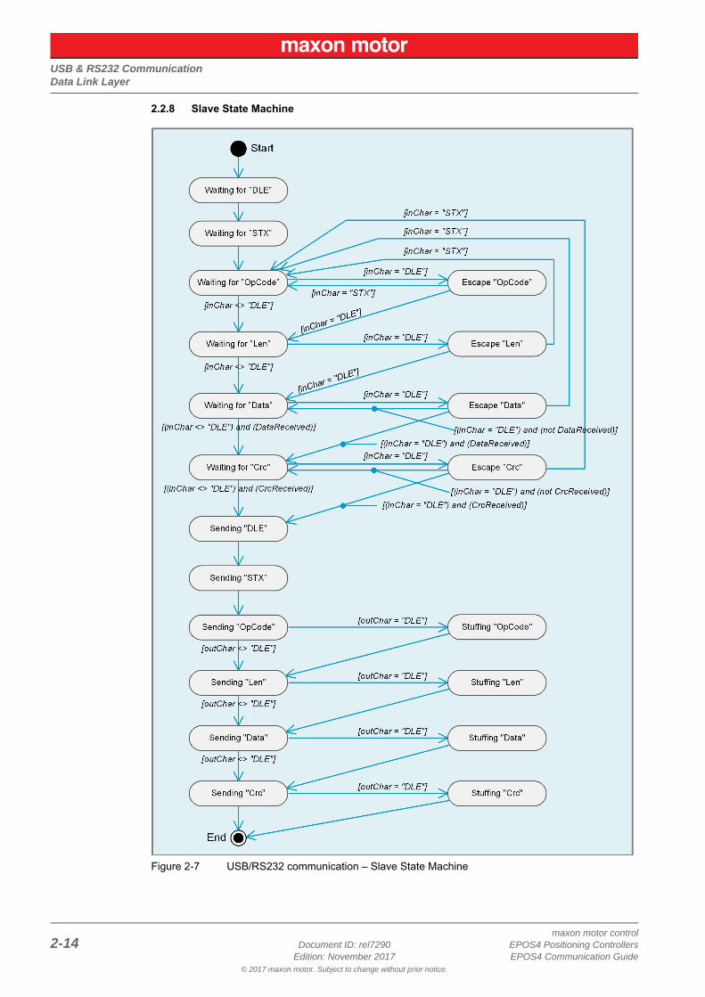
2.2.8 Slave State Machine
Figure 2-7 USB/RS232 communication – Slave State Machine
USB & RS232 CommunicationData Link Layer
© 2017 maxon motor. Subject to change without prior notice.
maxon motor controlEPOS4 Positioning Controllers Document ID: rel7290 2-15EPOS4 Communication Guide Edition: November 2017
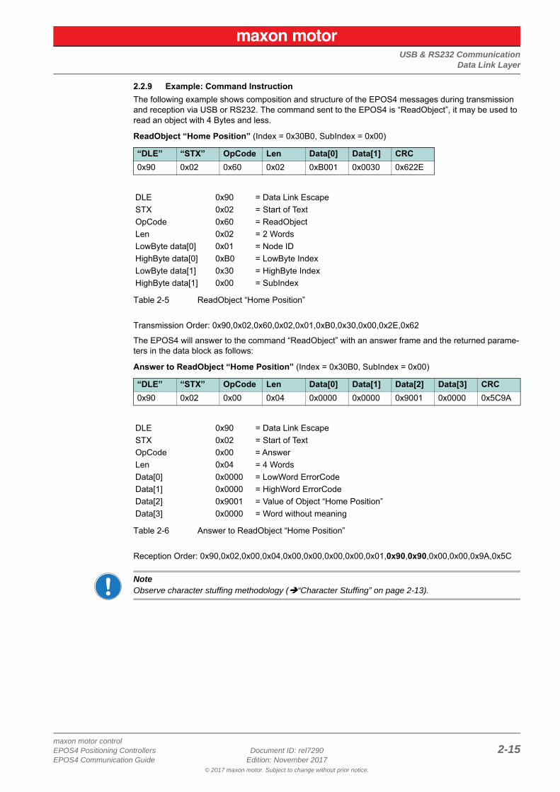
2.2.9 Example: Command InstructionThe following example shows composition and structure of the EPOS4 messages during transmission and reception via USB or RS232. The command sent to the EPOS4 is “ReadObject”, it may be used to read an object with 4 Bytes and less.
ReadObject “Home Position” (Index = 0x30B0, SubIndex = 0x00)
Table 2-5 ReadObject “Home Position”
Transmission Order: 0x90,0x02,0x60,0x02,0x01,0xB0,0x30,0x00,0x2E,0x62
The EPOS4 will answer to the command “ReadObject” with an answer frame and the returned parame-ters in the data block as follows:
Answer to ReadObject “Home Position” (Index = 0x30B0, SubIndex = 0x00)
Table 2-6 Answer to ReadObject “Home Position”
Reception Order: 0x90,0x02,0x00,0x04,0x00,0x00,0x00,0x00,0x01,0x90,0x90,0x00,0x00,0x9A,0x5C
NoteObserve character stuffing methodology (“Character Stuffing” on page 2-13).
“DLE” “STX” OpCode Len Data[0] Data[1] CRC0x90 0x02 0x60 0x02 0xB001 0x0030 0x622E
DLE 0x90 = Data Link EscapeSTX 0x02 = Start of TextOpCode 0x60 = ReadObjectLen 0x02 = 2 WordsLowByte data[0] 0x01 = Node IDHighByte data[0] 0xB0 = LowByte IndexLowByte data[1] 0x30 = HighByte IndexHighByte data[1] 0x00 = SubIndex
“DLE” “STX” OpCode Len Data[0] Data[1] Data[2] Data[3] CRC0x90 0x02 0x00 0x04 0x0000 0x0000 0x9001 0x0000 0x5C9A
DLE 0x90 = Data Link EscapeSTX 0x02 = Start of TextOpCode 0x00 = AnswerLen 0x04 = 4 WordsData[0] 0x0000 = LowWord ErrorCodeData[1] 0x0000 = HighWord ErrorCodeData[2] 0x9001 = Value of Object “Home Position”Data[3] 0x0000 = Word without meaning
USB & RS232 CommunicationPhysical Layer
© 2017 maxon motor. Subject to change without prior notice.
maxon motor control2-16 Document ID: rel7290 EPOS4 Positioning Controllers
Edition: November 2017 EPOS4 Communication Guide
2.3 Physical Layer
2.3.1 USB
Electrical StandardThe EPOS4’s USB interface follows the «Universal Serial Bus Specification Revision 2.0». You may wish to download the file from the Internet (for URL “Sources for additional Information” on page 1-5), full details are described in chapter “7.3 Physical Layer”.
2.3.2 RS232
Electrical StandardThe EPOS4’s communication protocol uses the RS232 standard to transmit data over a 3-wire cable (signals TxD, RxD, and GND).
The RS232 standard can only be used for point-to-point communication between a master and a single EPOS4 slave. It uses negative, bipolar logic with a negative voltage signal representing a logic “1”, and positive voltage representing a logic “0”. Voltages of -3…-25 V with respect to signal ground (GND) are considered logic “1”, whereas voltages of +3…25 V are considered logic “0”.
MediumFor the physical connection, a 3-wire cable will be required. We recommend to install a shielded and twisted pair cable in order to achieve good performance, even in an electrically noisy environment. Depending on the bit rate used, the cable length can range from 3…15 meters. However, we do not rec-ommend to use RS232 cables longer than 5 meters.
CAN CommunicationGeneral Information
© 2017 maxon motor. Subject to change without prior notice.
maxon motor controlEPOS4 Positioning Controllers Document ID: rel7290 3-17EPOS4 Communication Guide Edition: November 2017
3 CAN Communication
3.1 General Informationmaxon EPOS4 drives’ CAN interface follows the CiA CANopen specifications…
• CiA 301 V4.2; CANopen application layer and communication profile ([2])corresponds with the international standard EN 5325-4; Industrial communications subsystem based on ISO 11898 (CAN) ([11])
• CiA 306 V1.3; CANopen electronic data sheet specification ([3])• CiA 402 V4.0; CANopen drives and motion control device profile ([4])
corresponds with international standard IEC 61800-7 Ed 2.0; Generic interface and use of pro-files for power drive systems – profile type 1([10])
3.1.1 DocumentationFor further information on CAN/CANopen as well as respective specifications listed references in chapter “1.4 Sources for additional Information” on page 1-5.
3.1.2 Notations, Abbreviations and Terms used
Table 3-7 CAN communication – Notations
Notation Description Format
nnnnb Numbers followed by “b”. binary
nnnnh Numbers followed by “h”. hexadecimal
nnnn All other numbers. decimal
Abbreviation Description
CAN CAN Application Layer
CMS CAN Message Specification
COB Communication Object (CAN Message) – a unit of transportation in a CAN message network. Data must be sent across a network inside a COB.
COB-ID COB Identifier – identifies a COB uniquely in a network and determines the priority of that COB in the MAC sublayer.
EDS Electronic Data Sheet – a standard form of all CAN objects supported by a device. Used by external CAN configurators.
ID Identifier – the name by which a CAN device is addressed.
MAC Medium Access Control – one of the sublayers of the Data Link Layer in the CAN Reference Model. Controls the medium permitted to send a message.
OD Object Dictionary – the full set of objects supported by the node. Represents the interface between application and communication (term “Object” on page 3-18).
PDO Process Data Object – object for data exchange between several devices.
PLC Programmable Controller – can serve as a CAN Master for the EPOS4.
RO Read Only
RW Read Write
Continued on next page.
CAN CommunicationGeneral Information
© 2017 maxon motor. Subject to change without prior notice.
maxon motor control3-18 Document ID: rel7290 EPOS4 Positioning Controllers
Edition: November 2017 EPOS4 Communication Guide
Table 3-8 CAN communication – Abbreviations
Table 3-9 CAN communication – Terms
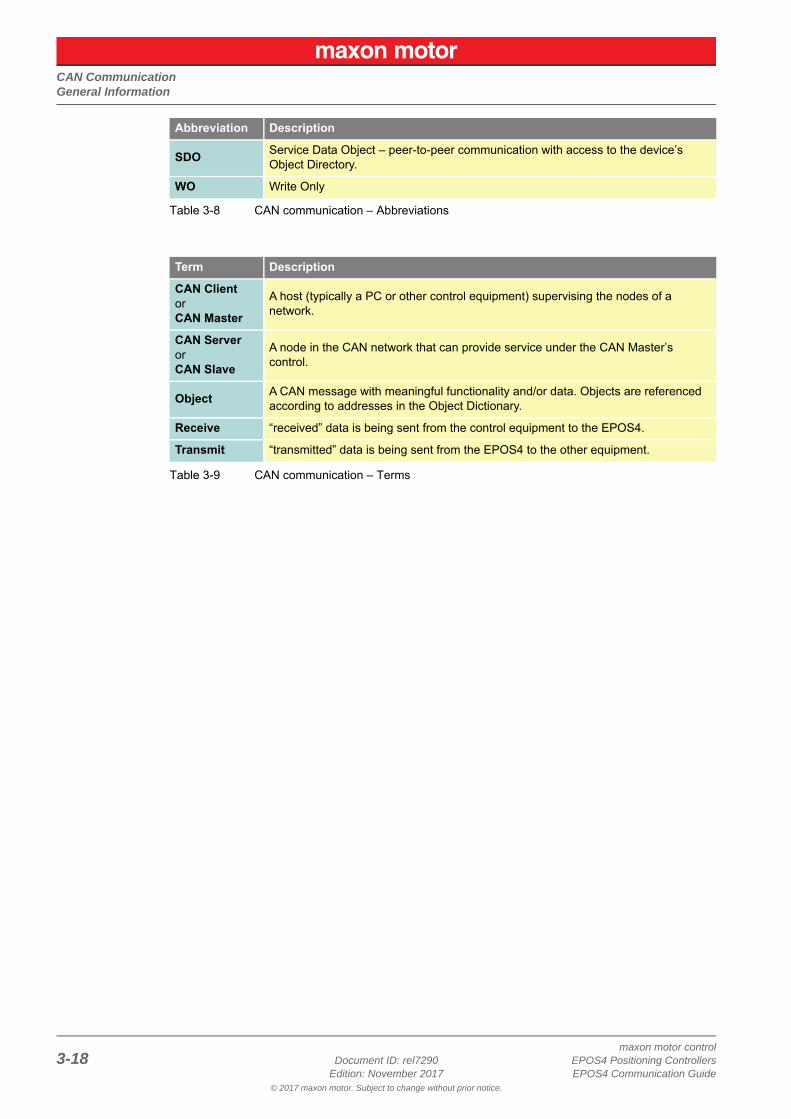
SDO Service Data Object – peer-to-peer communication with access to the device’s Object Directory.
WO Write Only
Term Description
CAN ClientorCAN Master
A host (typically a PC or other control equipment) supervising the nodes of a network.
CAN ServerorCAN Slave
A node in the CAN network that can provide service under the CAN Master’s control.
Object A CAN message with meaningful functionality and/or data. Objects are referenced according to addresses in the Object Dictionary.
Receive “received” data is being sent from the control equipment to the EPOS4.
Transmit “transmitted” data is being sent from the EPOS4 to the other equipment.
Abbreviation Description
CAN CommunicationCANopen Basics
© 2017 maxon motor. Subject to change without prior notice.
maxon motor controlEPOS4 Positioning Controllers Document ID: rel7290 3-19EPOS4 Communication Guide Edition: November 2017
3.2 CANopen BasicsSubsequently described are the CANopen communication features most relevant to the maxon motor’s EPOS4 Positioning Controllerss. For more detailed information consult above mentioned CANopen doc-umentation.
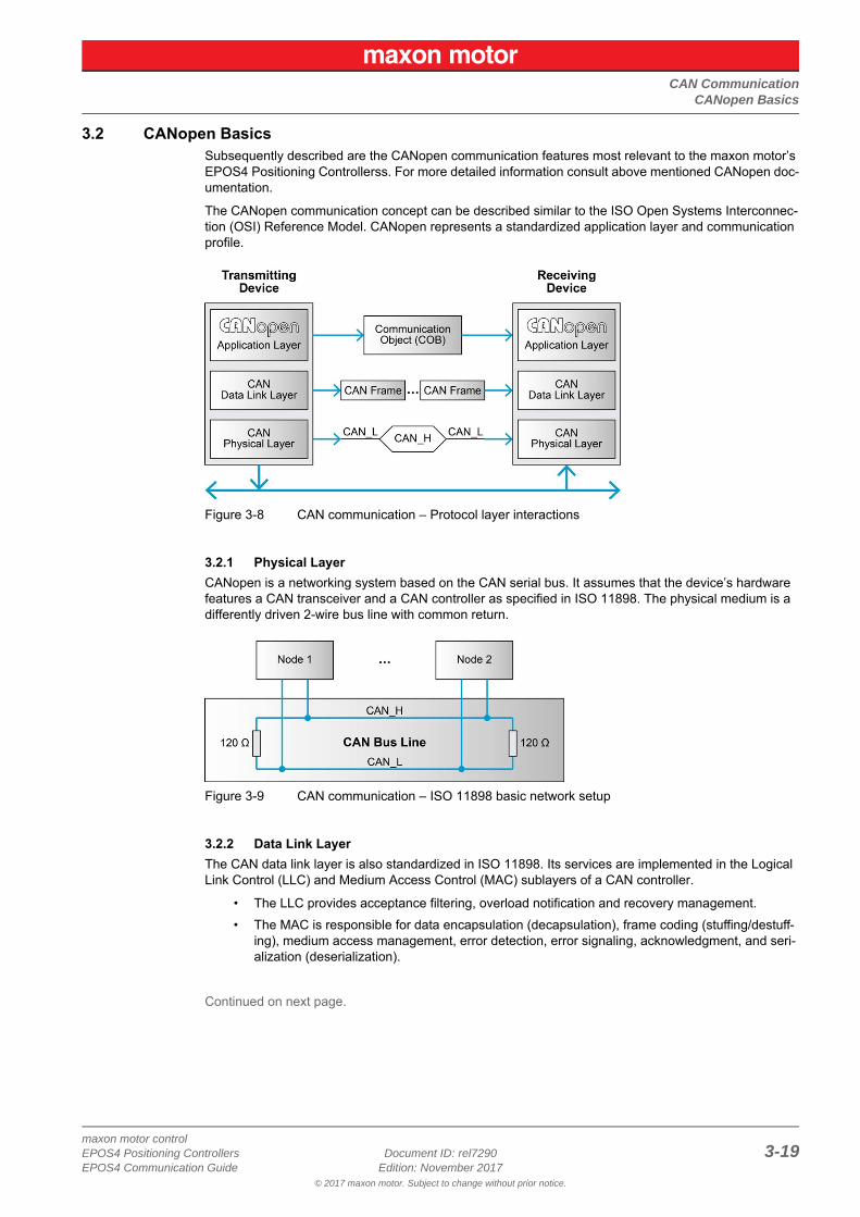
The CANopen communication concept can be described similar to the ISO Open Systems Interconnec-tion (OSI) Reference Model. CANopen represents a standardized application layer and communication profile.
Figure 3-8 CAN communication – Protocol layer interactions
3.2.1 Physical LayerCANopen is a networking system based on the CAN serial bus. It assumes that the device’s hardware features a CAN transceiver and a CAN controller as specified in ISO 11898. The physical medium is a differently driven 2-wire bus line with common return.
Figure 3-9 CAN communication – ISO 11898 basic network setup
3.2.2 Data Link LayerThe CAN data link layer is also standardized in ISO 11898. Its services are implemented in the Logical Link Control (LLC) and Medium Access Control (MAC) sublayers of a CAN controller.
• The LLC provides acceptance filtering, overload notification and recovery management.• The MAC is responsible for data encapsulation (decapsulation), frame coding (stuffing/destuff-
ing), medium access management, error detection, error signaling, acknowledgment, and seri-alization (deserialization).
Continued on next page.
CAN CommunicationCANopen Basics
© 2017 maxon motor. Subject to change without prior notice.
maxon motor control3-20 Document ID: rel7290 EPOS4 Positioning Controllers
Edition: November 2017 EPOS4 Communication Guide
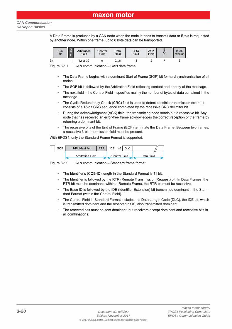
A Data Frame is produced by a CAN node when the node intends to transmit data or if this is requested by another node. Within one frame, up to 8 byte data can be transported.
Figure 3-10 CAN communication – CAN data frame
• The Data Frame begins with a dominant Start of Frame (SOF) bit for hard synchronization of all nodes.
• The SOF bit is followed by the Arbitration Field reflecting content and priority of the message.• The next field – the Control Field – specifies mainly the number of bytes of data contained in the
message.• The Cyclic Redundancy Check (CRC) field is used to detect possible transmission errors. It
consists of a 15-bit CRC sequence completed by the recessive CRC delimiter bit.• During the Acknowledgment (ACK) field, the transmitting node sends out a recessive bit. Any
node that has received an error-free frame acknowledges the correct reception of the frame by returning a dominant bit.
• The recessive bits of the End of Frame (EOF) terminate the Data Frame. Between two frames, a recessive 3-bit Intermission field must be present.
With EPOS4, only the Standard Frame Format is supported.
Figure 3-11 CAN communication – Standard frame format
• The Identifier’s (COB-ID) length in the Standard Format is 11 bit.• The Identifier is followed by the RTR (Remote Transmission Request) bit. In Data Frames, the
RTR bit must be dominant, within a Remote Frame, the RTR bit must be recessive.• The Base ID is followed by the IDE (Identifier Extension) bit transmitted dominant in the Stan-
dard Format (within the Control Field).• The Control Field in Standard Format includes the Data Length Code (DLC), the IDE bit, which
is transmitted dominant and the reserved bit r0, also transmitted dominant.• The reserved bits must be sent dominant, but receivers accept dominant and recessive bits in
all combinations.
CAN CommunicationCANopen Application Layer
© 2017 maxon motor. Subject to change without prior notice.
maxon motor controlEPOS4 Positioning Controllers Document ID: rel7290 3-21EPOS4 Communication Guide Edition: November 2017
3.3 CANopen Application Layer
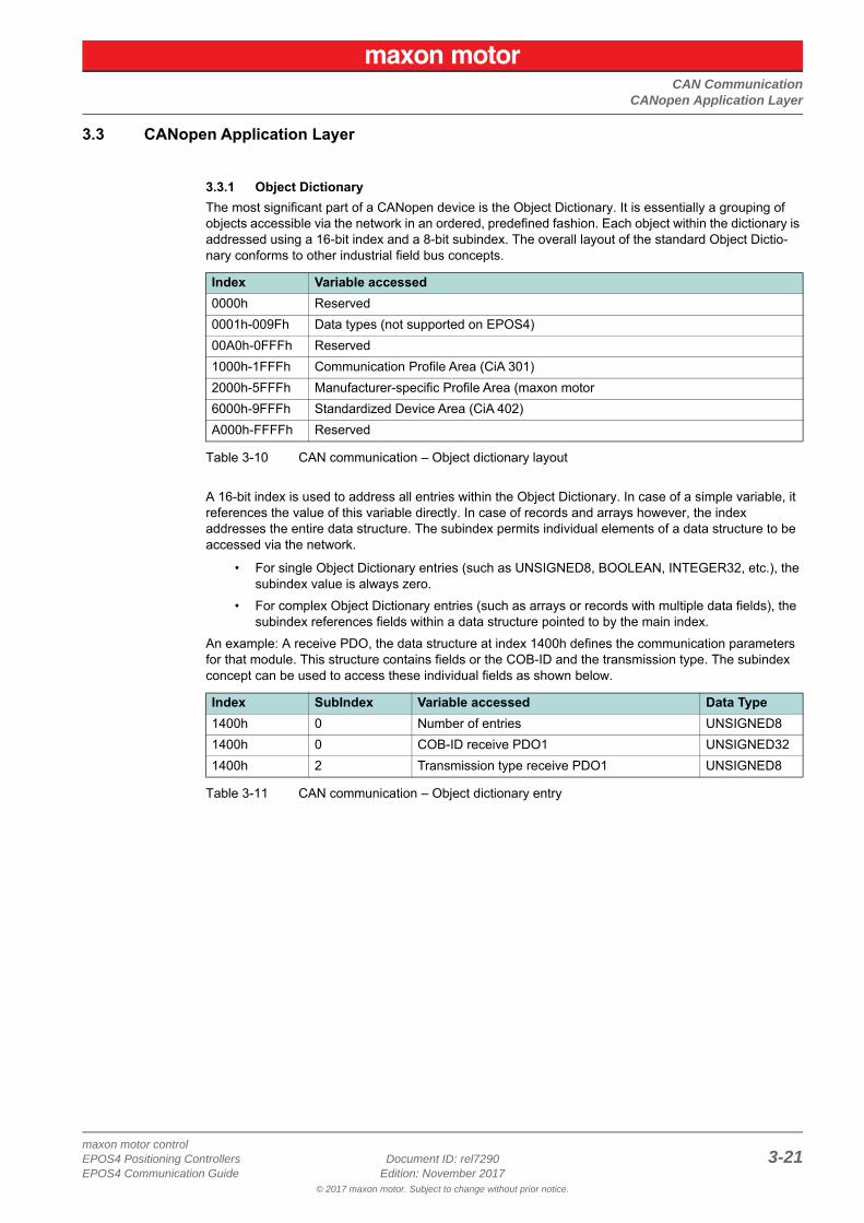
3.3.1 Object DictionaryThe most significant part of a CANopen device is the Object Dictionary. It is essentially a grouping of objects accessible via the network in an ordered, predefined fashion. Each object within the dictionary is addressed using a 16-bit index and a 8-bit subindex. The overall layout of the standard Object Dictio-nary conforms to other industrial field bus concepts.
Table 3-10 CAN communication – Object dictionary layout
A 16-bit index is used to address all entries within the Object Dictionary. In case of a simple variable, it references the value of this variable directly. In case of records and arrays however, the index addresses the entire data structure. The subindex permits individual elements of a data structure to be accessed via the network.
• For single Object Dictionary entries (such as UNSIGNED8, BOOLEAN, INTEGER32, etc.), the subindex value is always zero.
• For complex Object Dictionary entries (such as arrays or records with multiple data fields), the subindex references fields within a data structure pointed to by the main index.
An example: A receive PDO, the data structure at index 1400h defines the communication parameters for that module. This structure contains fields or the COB-ID and the transmission type. The subindex concept can be used to access these individual fields as shown below.
Table 3-11 CAN communication – Object dictionary entry
Index Variable accessed0000h Reserved0001h-009Fh Data types (not supported on EPOS4)00A0h-0FFFh Reserved1000h-1FFFh Communication Profile Area (CiA 301)2000h-5FFFh Manufacturer-specific Profile Area (maxon motor6000h-9FFFh Standardized Device Area (CiA 402)A000h-FFFFh Reserved
Index SubIndex Variable accessed Data Type1400h 0 Number of entries UNSIGNED81400h 0 COB-ID receive PDO1 UNSIGNED321400h 2 Transmission type receive PDO1 UNSIGNED8
CAN CommunicationCANopen Application Layer
© 2017 maxon motor. Subject to change without prior notice.
maxon motor control3-22 Document ID: rel7290 EPOS4 Positioning Controllers
Edition: November 2017 EPOS4 Communication Guide
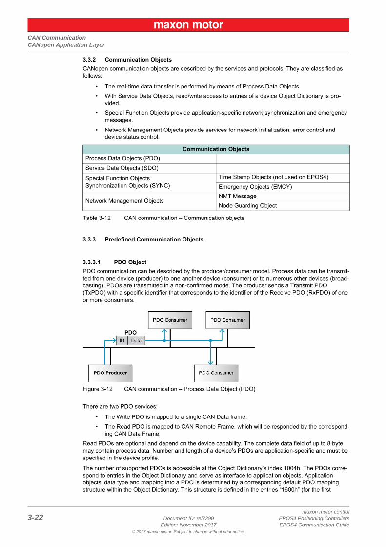
3.3.2 Communication ObjectsCANopen communication objects are described by the services and protocols. They are classified as follows:
• The real-time data transfer is performed by means of Process Data Objects.• With Service Data Objects, read/write access to entries of a device Object Dictionary is pro-
vided.• Special Function Objects provide application-specific network synchronization and emergency
messages.• Network Management Objects provide services for network initialization, error control and
device status control.
Table 3-12 CAN communication – Communication objects
3.3.3 Predefined Communication Objects
3.3.3.1 PDO ObjectPDO communication can be described by the producer/consumer model. Process data can be transmit-ted from one device (producer) to one another device (consumer) or to numerous other devices (broad-casting). PDOs are transmitted in a non-confirmed mode. The producer sends a Transmit PDO (TxPDO) with a specific identifier that corresponds to the identifier of the Receive PDO (RxPDO) of one or more consumers.
Figure 3-12 CAN communication – Process Data Object (PDO)
There are two PDO services:
• The Write PDO is mapped to a single CAN Data frame.• The Read PDO is mapped to CAN Remote Frame, which will be responded by the correspond-
ing CAN Data Frame.Read PDOs are optional and depend on the device capability. The complete data field of up to 8 byte may contain process data. Number and length of a device’s PDOs are application-specific and must be specified in the device profile.
The number of supported PDOs is accessible at the Object Dictionary’s index 1004h. The PDOs corre-spond to entries in the Object Dictionary and serve as interface to application objects. Application objects’ data type and mapping into a PDO is determined by a corresponding default PDO mapping structure within the Object Dictionary. This structure is defined in the entries “1600h” (for the first
Communication ObjectsProcess Data Objects (PDO)Service Data Objects (SDO)
Special Function ObjectsSynchronization Objects (SYNC)
Time Stamp Objects (not used on EPOS4)Emergency Objects (EMCY)
Network Management ObjectsNMT MessageNode Guarding Object
CAN CommunicationCANopen Application Layer
© 2017 maxon motor. Subject to change without prior notice.
maxon motor controlEPOS4 Positioning Controllers Document ID: rel7290 3-23EPOS4 Communication Guide Edition: November 2017
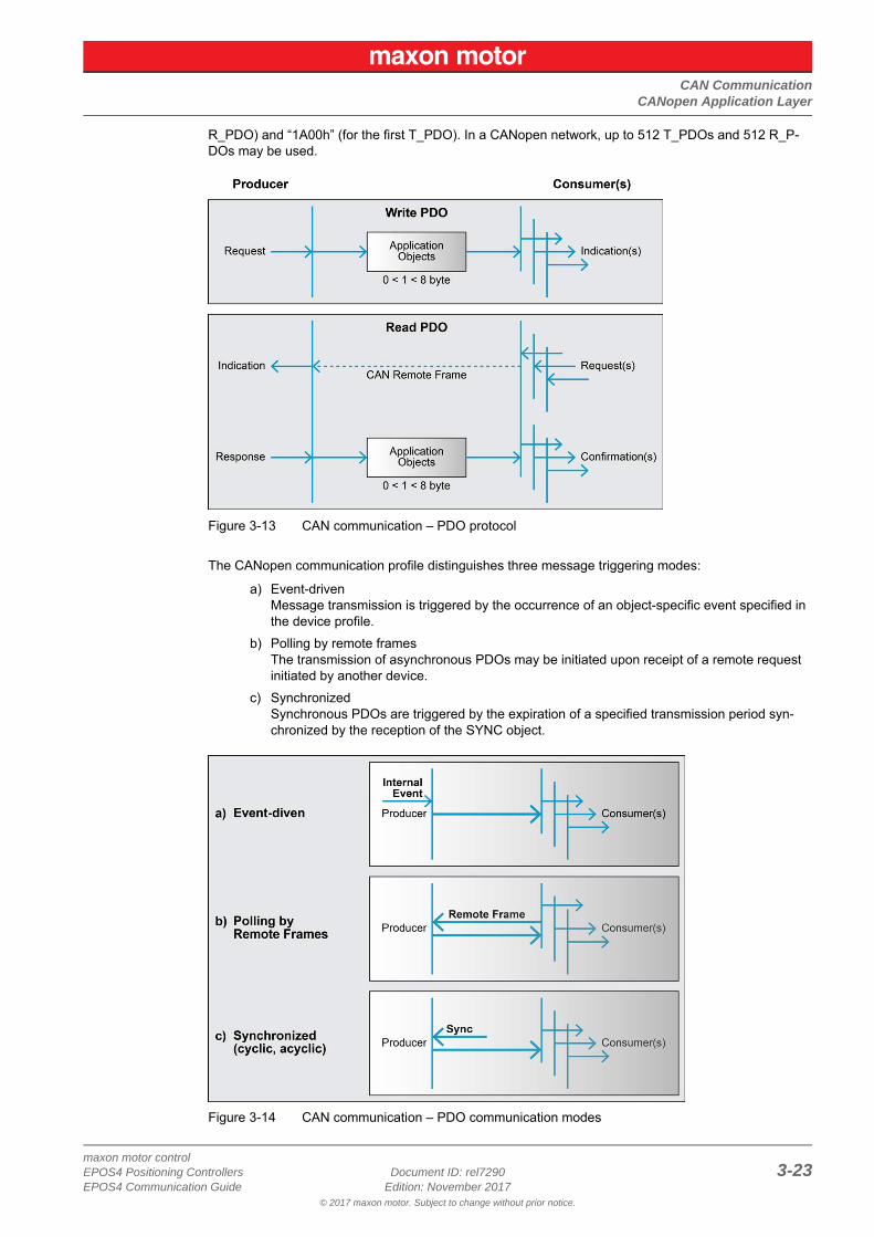
R_PDO) and “1A00h” (for the first T_PDO). In a CANopen network, up to 512 T_PDOs and 512 R_P-DOs may be used.
Figure 3-13 CAN communication – PDO protocol
The CANopen communication profile distinguishes three message triggering modes:
a) Event-drivenMessage transmission is triggered by the occurrence of an object-specific event specified in the device profile.
b) Polling by remote framesThe transmission of asynchronous PDOs may be initiated upon receipt of a remote request initiated by another device.
c) SynchronizedSynchronous PDOs are triggered by the expiration of a specified transmission period syn-chronized by the reception of the SYNC object.
Figure 3-14 CAN communication – PDO communication modes
CAN CommunicationCANopen Application Layer
© 2017 maxon motor. Subject to change without prior notice.
maxon motor control3-24 Document ID: rel7290 EPOS4 Positioning Controllers
Edition: November 2017 EPOS4 Communication Guide
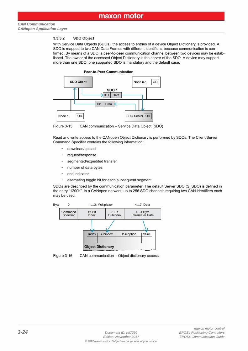
3.3.3.2 SDO ObjectWith Service Data Objects (SDOs), the access to entries of a device Object Dictionary is provided. A SDO is mapped to two CAN Data Frames with different identifiers, because communication is con-firmed. By means of a SDO, a peer-to-peer communication channel between two devices may be estab-lished. The owner of the accessed Object Dictionary is the server of the SDO. A device may support more than one SDO, one supported SDO is mandatory and the default case.
Figure 3-15 CAN communication – Service Data Object (SDO)
Read and write access to the CANopen Object Dictionary is performed by SDOs. The Client/Server Command Specifier contains the following information:
• download/upload• request/response• segmented/expedited transfer• number of data bytes• end indicator• alternating toggle bit for each subsequent segment
SDOs are described by the communication parameter. The default Server SDO (S_SDO) is defined in the entry “1200h”. In a CANopen network, up to 256 SDO channels requiring two CAN identifiers each may be used.
Figure 3-16 CAN communication – Object dictionary access
CAN CommunicationCANopen Application Layer
© 2017 maxon motor. Subject to change without prior notice.
maxon motor controlEPOS4 Positioning Controllers Document ID: rel7290 3-25EPOS4 Communication Guide Edition: November 2017
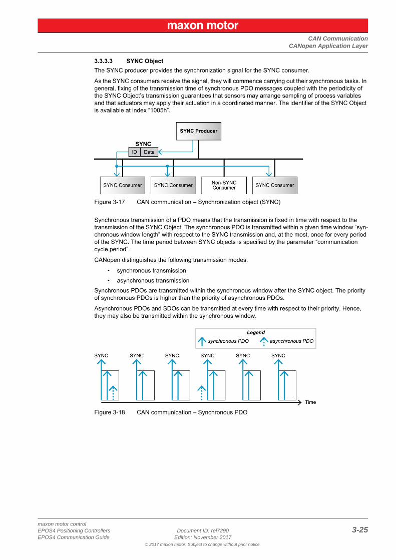
3.3.3.3 SYNC ObjectThe SYNC producer provides the synchronization signal for the SYNC consumer.
As the SYNC consumers receive the signal, they will commence carrying out their synchronous tasks. In general, fixing of the transmission time of synchronous PDO messages coupled with the periodicity of the SYNC Object’s transmission guarantees that sensors may arrange sampling of process variables and that actuators may apply their actuation in a coordinated manner. The identifier of the SYNC Object is available at index “1005h”.
Figure 3-17 CAN communication – Synchronization object (SYNC)
Synchronous transmission of a PDO means that the transmission is fixed in time with respect to the transmission of the SYNC Object. The synchronous PDO is transmitted within a given time window “syn-chronous window length” with respect to the SYNC transmission and, at the most, once for every period of the SYNC. The time period between SYNC objects is specified by the parameter “communication cycle period”.
CANopen distinguishes the following transmission modes:
• synchronous transmission• asynchronous transmission
Synchronous PDOs are transmitted within the synchronous window after the SYNC object. The priority of synchronous PDOs is higher than the priority of asynchronous PDOs.
Asynchronous PDOs and SDOs can be transmitted at every time with respect to their priority. Hence, they may also be transmitted within the synchronous window.
Figure 3-18 CAN communication – Synchronous PDO
CAN CommunicationCANopen Application Layer
© 2017 maxon motor. Subject to change without prior notice.
maxon motor control3-26 Document ID: rel7290 EPOS4 Positioning Controllers
Edition: November 2017 EPOS4 Communication Guide
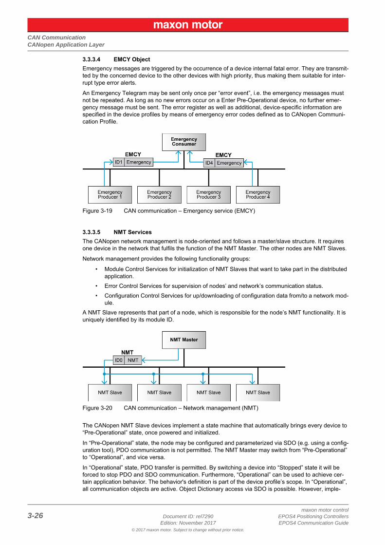
3.3.3.4 EMCY ObjectEmergency messages are triggered by the occurrence of a device internal fatal error. They are transmit-ted by the concerned device to the other devices with high priority, thus making them suitable for inter-rupt type error alerts.
An Emergency Telegram may be sent only once per “error event”, i.e. the emergency messages must not be repeated. As long as no new errors occur on a Enter Pre-Operational device, no further emer-gency message must be sent. The error register as well as additional, device-specific information are specified in the device profiles by means of emergency error codes defined as to CANopen Communi-cation Profile.
Figure 3-19 CAN communication – Emergency service (EMCY)
3.3.3.5 NMT ServicesThe CANopen network management is node-oriented and follows a master/slave structure. It requires one device in the network that fulfils the function of the NMT Master. The other nodes are NMT Slaves.
Network management provides the following functionality groups:
• Module Control Services for initialization of NMT Slaves that want to take part in the distributed application.
• Error Control Services for supervision of nodes’ and network’s communication status.• Configuration Control Services for up/downloading of configuration data from/to a network mod-
ule.A NMT Slave represents that part of a node, which is responsible for the node’s NMT functionality. It is uniquely identified by its module ID.
Figure 3-20 CAN communication – Network management (NMT)
The CANopen NMT Slave devices implement a state machine that automatically brings every device to “Pre-Operational” state, once powered and initialized.
In “Pre-Operational” state, the node may be configured and parameterized via SDO (e.g. using a config-uration tool), PDO communication is not permitted. The NMT Master may switch from “Pre-Operational” to “Operational”, and vice versa.
In “Operational” state, PDO transfer is permitted. By switching a device into “Stopped” state it will be forced to stop PDO and SDO communication. Furthermore, “Operational” can be used to achieve cer-tain application behavior. The behavior's definition is part of the device profile’s scope. In “Operational”, all communication objects are active. Object Dictionary access via SDO is possible. However, imple-

CAN CommunicationCANopen Application Layer
© 2017 maxon motor. Subject to change without prior notice.
maxon motor controlEPOS4 Positioning Controllers Document ID: rel7290 3-27EPOS4 Communication Guide Edition: November 2017
mentation aspects or the application state machine may require to switching off or to read only certain application objects while being operational (e.g. an object may contain the application program, which cannot be changed during execution).
Figure 3-21 CAN communication – NMT slave states
CANopen Network Management provides the following services, which can be distinguished by the Command Specifier (CS).
Table 3-13 CAN communication – NMT slave (commands, transitions, and states)
Service*1
Transi-tion
NMT State after Command
Remote*3
Functionality
–*2 0 Pre-Operational FALSE Communication:• Service Data Objects (SDO) Protocol• Emergency Objects• Network Management (NMT) Protocol
EnterPre-Operational 3, 6 Pre-Operational FALSE
ResetCommunication 1, 8, 9 Initialization
(Pre-Operational) FALSE
Calculates SDO COB-IDs.Setup Dynamic PDO-Mapping and calculates PDO COB-IDs.Communication:• While initialization is active, no communication is supported.• Upon completion, a boot-up message will be sent to the
CAN Bus.
Reset Node 1, 8, 9 Initialization(Pre-Operational) FALSE
Generates a general reset of EPOS4 software having same effect as turning off and on the supply voltage. Not saved parameters will be overwritten with values saved to the EEPROM using «Save all Parameters».
Start Remote Node 2, 5 Operational TRUE
Communication:• Service Data Objects (SDO) Protocol• Process Data Objects (PDO) Protocol• Emergency Objects• Network Management (NMT) Protocol
Stop Remote Node 4, 7 Stopped FALSE
Communication:• Network Management (NMT) Protocol• Layer setting services (LSS)• Lifeguarding (Heartbeating)
*1) The command may be sent with Network Management (NMT) protocol.*2) The EPOS4 automatically generates the transition after initialization is completed. A Boot-Up message is being sent.*3) Remote flag Bit 9 of the Statusword.
CAN CommunicationCANopen Application Layer
© 2017 maxon motor. Subject to change without prior notice.
maxon motor control3-28 Document ID: rel7290 EPOS4 Positioning Controllers
Edition: November 2017 EPOS4 Communication Guide
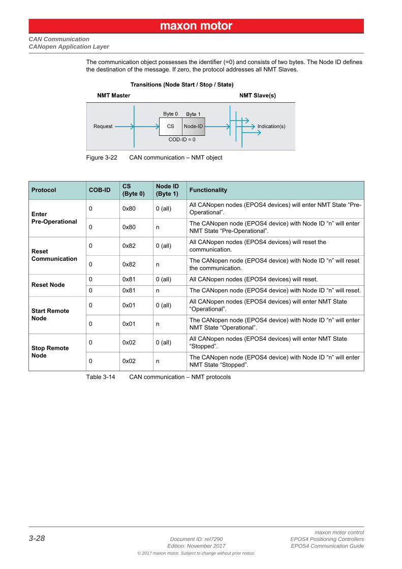
The communication object possesses the identifier (=0) and consists of two bytes. The Node ID defines the destination of the message. If zero, the protocol addresses all NMT Slaves.
Figure 3-22 CAN communication – NMT object
Table 3-14 CAN communication – NMT protocols
Protocol COB-ID CS(Byte 0)
Node ID(Byte 1) Functionality
EnterPre-Operational
0 0x80 0 (all) All CANopen nodes (EPOS4 devices) will enter NMT State “Pre-Operational”.
0 0x80 n The CANopen node (EPOS4 device) with Node ID “n” will enter NMT State “Pre-Operational”.
ResetCommunication
0 0x82 0 (all) All CANopen nodes (EPOS4 devices) will reset the communication.
0 0x82 n The CANopen node (EPOS4 device) with Node ID “n” will reset the communication.
Reset Node0 0x81 0 (all) All CANopen nodes (EPOS4 devices) will reset.
0 0x81 n The CANopen node (EPOS4 device) with Node ID “n” will reset.
Start Remote Node
0 0x01 0 (all) All CANopen nodes (EPOS4 devices) will enter NMT State “Operational”.
0 0x01 n The CANopen node (EPOS4 device) with Node ID “n” will enter NMT State “Operational”.
Stop Remote Node
0 0x02 0 (all) All CANopen nodes (EPOS4 devices) will enter NMT State “Stopped”.
0 0x02 n The CANopen node (EPOS4 device) with Node ID “n” will enter NMT State “Stopped”.
CAN CommunicationIdentifier Allocation Scheme
© 2017 maxon motor. Subject to change without prior notice.
maxon motor controlEPOS4 Positioning Controllers Document ID: rel7290 3-29EPOS4 Communication Guide Edition: November 2017
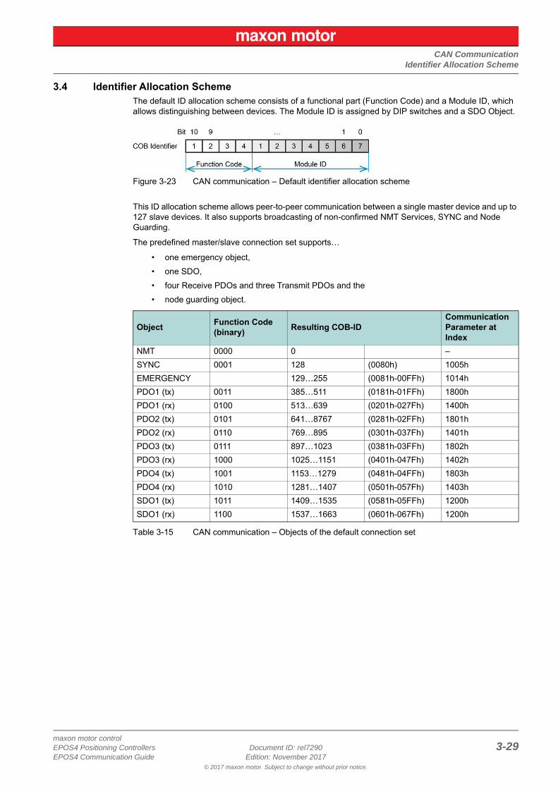
3.4 Identifier Allocation SchemeThe default ID allocation scheme consists of a functional part (Function Code) and a Module ID, which allows distinguishing between devices. The Module ID is assigned by DIP switches and a SDO Object.
Figure 3-23 CAN communication – Default identifier allocation scheme
This ID allocation scheme allows peer-to-peer communication between a single master device and up to 127 slave devices. It also supports broadcasting of non-confirmed NMT Services, SYNC and Node Guarding.
The predefined master/slave connection set supports…
• one emergency object,• one SDO,• four Receive PDOs and three Transmit PDOs and the• node guarding object.
Table 3-15 CAN communication – Objects of the default connection set
Object Function Code(binary) Resulting COB-ID
CommunicationParameter at Index
NMT 0000 0 –SYNC 0001 128 (0080h) 1005hEMERGENCY 129…255 (0081h-00FFh) 1014hPDO1 (tx) 0011 385…511 (0181h-01FFh) 1800hPDO1 (rx) 0100 513…639 (0201h-027Fh) 1400hPDO2 (tx) 0101 641…8767 (0281h-02FFh) 1801hPDO2 (rx) 0110 769…895 (0301h-037Fh) 1401hPDO3 (tx) 0111 897…1023 (0381h-03FFh) 1802hPDO3 (rx) 1000 1025…1151 (0401h-047Fh) 1402hPDO4 (tx) 1001 1153…1279 (0481h-04FFh) 1803hPDO4 (rx) 1010 1281…1407 (0501h-057Fh) 1403hSDO1 (tx) 1011 1409…1535 (0581h-05FFh) 1200hSDO1 (rx) 1100 1537…1663 (0601h-067Fh) 1200h

CAN CommunicationIdentifier Allocation Scheme
© 2017 maxon motor. Subject to change without prior notice.
maxon motor control3-30 Document ID: rel7290 EPOS4 Positioning Controllers
Edition: November 2017 EPOS4 Communication Guide
• • p a g e i n t e n t i o n a l l y l e f t b l a n k • •
EtherCAT Communication
© 2017 maxon motor. Subject to change without prior notice.
maxon motor controlEPOS4 Positioning Controllers Document ID: rel7290 4-31EPOS4 Communication Guide Edition: November 2017
4 EtherCAT CommunicationThe functionality of the EPOS4 can be extended with an EtherCAT communication by using an Ether-CAT Card in extension slot 1 or a Connector Board with EtherCAT functionality.
• ETG.1000 V1.0.4; EtherCAT Specification ([6])corresponds with the international standard IEC 61158-x-12 Industrial communication networks – Fieldbus specifications (CPF 12: EtherCAT) ([9])
• ETG.1020 V1.2.0; EtherCAT Protocol Enhancements Specification ([7])• ETG.2000 V1.0.9; EtherCAT Slave Information (ESI) Specification ([8])• CiA 402 V4.0; CANopen drives and motion control device profile ([4])
corresponds with international standard IEC 61800-7 Ed 2.0; Generic interface and use of pro-files for power drive systems – profile type 1 ([10])
ReferenceYou may access all relevant data and the free-for-download documentation from the EtherCAT website at http://ethercat.org/. Navigate to the downloads section and search for the document “EtherCAT Technology Introduction”.The document “EtherCAT_Introduction_xxxx.pdf” will serve well as an introduction to EtherCAT and does include information on the technology, implementation, and possible applications.
For EPOS4 firmware and hardware, consult maxon motor's comprehensive documentation set avail- able at http://epos.maxonmotor.com. Among others, you will find the following documents:
EPOS4 Firmware Specification• Operating modes• Communication and error handling• Object dictionary• etc.
EPOS4 Hardware Reference• Technical data• Wiring diagrams and connection overview• etc

EtherCAT CommunicationCommunication Specifications
© 2017 maxon motor. Subject to change without prior notice.
maxon motor control4-32 Document ID: rel7290 EPOS4 Positioning Controllers
Edition: November 2017 EPOS4 Communication Guide
4.1 Communication Specifications
Table 4-16 EtherCAT communication – Communication specifications
4.2 EtherCAT State Machine (ESM)The EtherCAT State Machine coordinates both Master and Slave during startup and operation. Their interaction (Master Slave) results in changes of states being related to writes to the Application Layer Controlword: AL Ctrl (0x0120).
Upon initialization of Data Layer and Application Layer, the ESM enters “Init” state which defines the Application Layer's root of the communication relationship between Master and Slave. In the Application Layer, no direct communication between Master and Slave is possible. The Master uses “Init” state…
• to initialize a configuration register set and• to configure the Sync Manager.
Operation of the connected EPOS4 (the Slave) requires its prior initialization by the Master via the ESM. Within the ESM, transitions between certain states must follow a given scheme and will be initiated by the Master. The Slave itself must not execute any transition.
For an overview of the EtherCAT State Machine Figure 4-24, for further descriptions as from Table 4-17.
Figure 4-24 EtherCAT communication – ESM scheme
Topic DescriptionPhysical layer IEEE 802.3 100 Base T (100 Mbit/s, full duplex)
Fieldbus connection X14 (RJ45): EtherCAT Signal INX15 (RJ45): EtherCAT Signal OUT
SyncManager
SM0: Mailbox outputSM1: Mailbox inputSM2: Process data outputsSM3: Process data inputs
FMMUFMMU0: Mapped to process data output (RxPDO) areaFMMU1: Mapped to process data input (TxPDO) areaFMMU2: Mapped to mailbox status
Process data Variable PDO mappingMailbox (CoE) SDO Request, SDO Response, SDO Complete AccessSynchronization SM-synchron, DC-synchron
LED indicators NET status (green LED / red LED)NET port activity (green LED)
EtherCAT CommunicationEtherCAT State Machine (ESM)
© 2017 maxon motor. Subject to change without prior notice.
maxon motor controlEPOS4 Positioning Controllers Document ID: rel7290 4-33EPOS4 Communication Guide Edition: November 2017
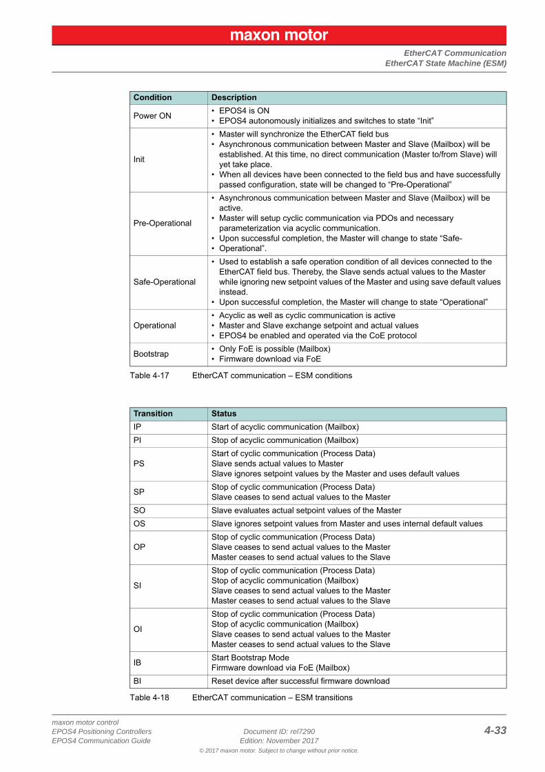
Table 4-17 EtherCAT communication – ESM conditions
Table 4-18 EtherCAT communication – ESM transitions
Condition Description
Power ON • EPOS4 is ON• EPOS4 autonomously initializes and switches to state “Init”
Init
• Master will synchronize the EtherCAT field bus• Asynchronous communication between Master and Slave (Mailbox) will be
established. At this time, no direct communication (Master to/from Slave) will yet take place.
• When all devices have been connected to the field bus and have successfully passed configuration, state will be changed to “Pre-Operational”
Pre-Operational
• Asynchronous communication between Master and Slave (Mailbox) will be active.
• Master will setup cyclic communication via PDOs and necessary parameterization via acyclic communication.
• Upon successful completion, the Master will change to state “Safe-• Operational”.
Safe-Operational
• Used to establish a safe operation condition of all devices connected to the EtherCAT field bus. Thereby, the Slave sends actual values to the Master while ignoring new setpoint values of the Master and using save default values instead.
• Upon successful completion, the Master will change to state “Operational”
Operational• Acyclic as well as cyclic communication is active• Master and Slave exchange setpoint and actual values• EPOS4 be enabled and operated via the CoE protocol
Bootstrap • Only FoE is possible (Mailbox)• Firmware download via FoE
Transition StatusIP Start of acyclic communication (Mailbox)PI Stop of acyclic communication (Mailbox)
PSStart of cyclic communication (Process Data)Slave sends actual values to MasterSlave ignores setpoint values by the Master and uses default values
SP Stop of cyclic communication (Process Data) Slave ceases to send actual values to the Master
SO Slave evaluates actual setpoint values of the MasterOS Slave ignores setpoint values from Master and uses internal default values
OPStop of cyclic communication (Process Data)Slave ceases to send actual values to the MasterMaster ceases to send actual values to the Slave
SI
Stop of cyclic communication (Process Data)Stop of acyclic communication (Mailbox)Slave ceases to send actual values to the MasterMaster ceases to send actual values to the Slave
OI
Stop of cyclic communication (Process Data)Stop of acyclic communication (Mailbox)Slave ceases to send actual values to the MasterMaster ceases to send actual values to the Slave
IB Start Bootstrap ModeFirmware download via FoE (Mailbox)
BI Reset device after successful firmware download
EtherCAT CommunicationIntegration of ESI Files
© 2017 maxon motor. Subject to change without prior notice.
maxon motor control4-34 Document ID: rel7290 EPOS4 Positioning Controllers
Edition: November 2017 EPOS4 Communication Guide
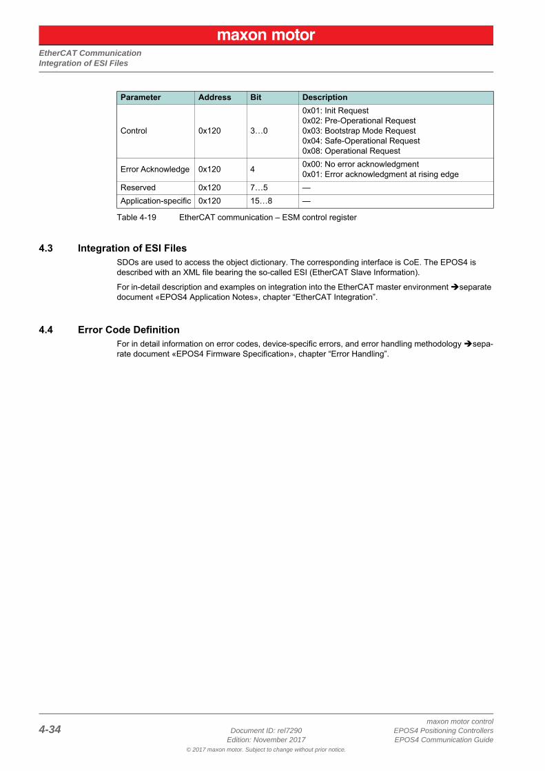
Table 4-19 EtherCAT communication – ESM control register
4.3 Integration of ESI FilesSDOs are used to access the object dictionary. The corresponding interface is CoE. The EPOS4 is described with an XML file bearing the so-called ESI (EtherCAT Slave Information).
For in-detail description and examples on integration into the EtherCAT master environment separate document «EPOS4 Application Notes», chapter “EtherCAT Integration”.
4.4 Error Code DefinitionFor in detail information on error codes, device-specific errors, and error handling methodology sepa-rate document «EPOS4 Firmware Specification», chapter “Error Handling”.
Parameter Address Bit Description
Control 0x120 3…0
0x01: Init Request0x02: Pre-Operational Request0x03: Bootstrap Mode Request0x04: Safe-Operational Request0x08: Operational Request
Error Acknowledge 0x120 4 0x00: No error acknowledgment0x01: Error acknowledgment at rising edge
Reserved 0x120 7…5 —Application-specific 0x120 15…8 —
Gateway Communication (USB or RS232 to CAN)
© 2017 maxon motor. Subject to change without prior notice.
maxon motor controlEPOS4 Positioning Controllers Document ID: rel7290 5-35EPOS4 Communication Guide Edition: November 2017
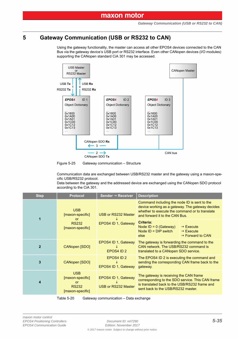
5 Gateway Communication (USB or RS232 to CAN)Using the gateway functionality, the master can access all other EPOS4 devices connected to the CAN Bus via the gateway device’s USB port or RS232 interface. Even other CANopen devices (I/O modules) supporting the CANopen standard CiA 301 may be accessed.
Figure 5-25 Gateway communication – Structure
Communication data are exchanged between USB/RS232 master and the gateway using a maxon-spe-cific USB/RS232 protocol.Data between the gateway and the addressed device are exchanged using the CANopen SDO protocol according to the CiA 301.
Table 5-20 Gateway communication – Data exchange
Step Protocol Sender Receiver Description
1
USB[maxon-specific]
orRS232
[maxon-specific]
USB or RS232 Master
EPOS4 ID 1, Gateway
Command including the node ID is sent to the device working as a gateway. The gateway decides whether to execute the command or to translate and forward it to the CAN Bus.
Criteria:Node ID = 0 (Gateway)Node ID = DIP switchelse
Execute Execute Forward to CAN
2 CANopen [SDO]EPOS4 ID 1, Gateway
EPOS4 ID 2
The gateway is forwarding the command to the CAN network. The USB/RS232 command is translated to a CANopen SDO service.
3 CANopen [SDO]EPOS4 ID 2
EPOS4 ID 1, Gateway
The EPOS4 ID 2 is executing the command and sending the corresponding CAN frame back to the gateway.
4
USB[maxon-specific]
orRS232
[maxon-specific]
EPOS4 ID 1, Gateway
USB or RS232 Master
The gateway is receiving the CAN frame corresponding to the SDO service. This CAN frame is translated back to the USB/RS232 frame and sent back to the USB/RS232 master.

Gateway Communication (USB or RS232 to CAN)
© 2017 maxon motor. Subject to change without prior notice.
maxon motor control5-36 Document ID: rel7290 EPOS4 Positioning Controllers
Edition: November 2017 EPOS4 Communication Guide
• • p a g e i n t e n t i o n a l l y l e f t b l a n k • •
Communication Error Code Definition
© 2017 maxon motor. Subject to change without prior notice.
maxon motor controlEPOS4 Positioning Controllers Document ID: rel7290 6-37EPOS4 Communication Guide Edition: November 2017
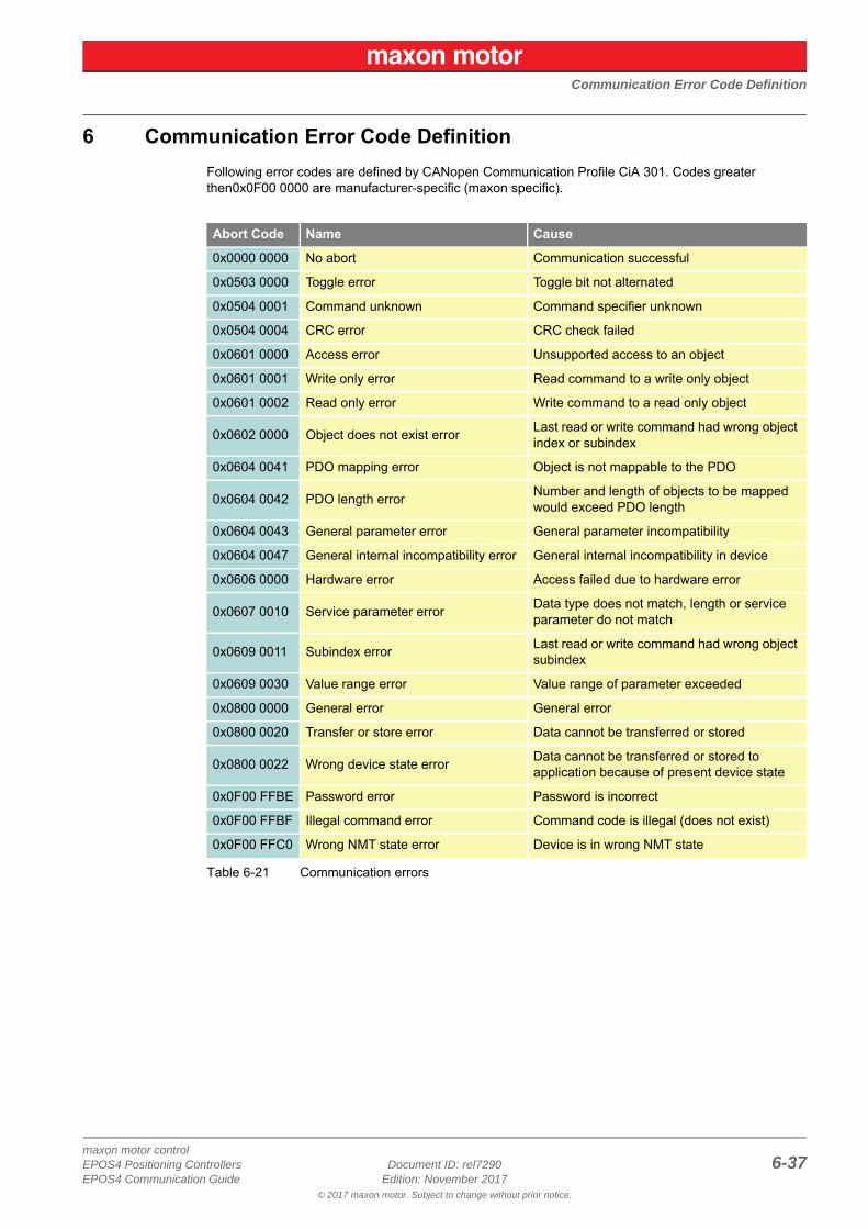
6 Communication Error Code DefinitionFollowing error codes are defined by CANopen Communication Profile CiA 301. Codes greater then0x0F00 0000 are manufacturer-specific (maxon specific).
Table 6-21 Communication errors
Abort Code Name Cause
0x0000 0000 No abort Communication successful
0x0503 0000 Toggle error Toggle bit not alternated
0x0504 0001 Command unknown Command specifier unknown
0x0504 0004 CRC error CRC check failed
0x0601 0000 Access error Unsupported access to an object
0x0601 0001 Write only error Read command to a write only object
0x0601 0002 Read only error Write command to a read only object
0x0602 0000 Object does not exist error Last read or write command had wrong object index or subindex
0x0604 0041 PDO mapping error Object is not mappable to the PDO
0x0604 0042 PDO length error Number and length of objects to be mapped would exceed PDO length
0x0604 0043 General parameter error General parameter incompatibility
0x0604 0047 General internal incompatibility error General internal incompatibility in device
0x0606 0000 Hardware error Access failed due to hardware error
0x0607 0010 Service parameter error Data type does not match, length or service parameter do not match
0x0609 0011 Subindex error Last read or write command had wrong object subindex
0x0609 0030 Value range error Value range of parameter exceeded
0x0800 0000 General error General error
0x0800 0020 Transfer or store error Data cannot be transferred or stored
0x0800 0022 Wrong device state error Data cannot be transferred or stored to application because of present device state
0x0F00 FFBE Password error Password is incorrect
0x0F00 FFBF Illegal command error Command code is illegal (does not exist)
0x0F00 FFC0 Wrong NMT state error Device is in wrong NMT state

Communication Error Code Definition
© 2017 maxon motor. Subject to change without prior notice.
maxon motor control6-38 Document ID: rel7290 EPOS4 Positioning Controllers
Edition: November 2017 EPOS4 Communication Guide
• • p a g e i n t e n t i o n a l l y l e f t b l a n k • •
maxon motor controlEPOS4 Positioning Controllers Document ID: rel7290 Z-39EPOS4 Communication Guide Edition: November 2017
© 2017 maxon motor. Subject to change without prior notice.
Figure 1-1 Documentation structure. . . . . . . . . . . . . . . . . . . . . . . . . . . . . . . . . . . . . . . . . . . . . . . . . . . . . . . . . . . . . . . . . .3Figure 2-2 USB/RS232 communication – Commands. . . . . . . . . . . . . . . . . . . . . . . . . . . . . . . . . . . . . . . . . . . . . . . . . . .10Figure 2-3 USB/RS232 communication – Sending a data frame to EPOS4 . . . . . . . . . . . . . . . . . . . . . . . . . . . . . . . . . .10Figure 2-4 USB/RS232 communication – Receiving a response data frame from EPOS4 . . . . . . . . . . . . . . . . . . . . . . .10Figure 2-5 USB/RS232 communication – Frame structure . . . . . . . . . . . . . . . . . . . . . . . . . . . . . . . . . . . . . . . . . . . . . . .11Figure 2-6 USB/RS232 communication – CRC calculation . . . . . . . . . . . . . . . . . . . . . . . . . . . . . . . . . . . . . . . . . . . . . . .12Figure 2-7 USB/RS232 communication – Slave State Machine . . . . . . . . . . . . . . . . . . . . . . . . . . . . . . . . . . . . . . . . . . .14Figure 3-8 CAN communication – Protocol layer interactions . . . . . . . . . . . . . . . . . . . . . . . . . . . . . . . . . . . . . . . . . . . . .19Figure 3-9 CAN communication – ISO 11898 basic network setup . . . . . . . . . . . . . . . . . . . . . . . . . . . . . . . . . . . . . . . . .19Figure 3-10 CAN communication – CAN data frame . . . . . . . . . . . . . . . . . . . . . . . . . . . . . . . . . . . . . . . . . . . . . . . . . . . . .20Figure 3-11 CAN communication – Standard frame format . . . . . . . . . . . . . . . . . . . . . . . . . . . . . . . . . . . . . . . . . . . . . . . .20Figure 3-12 CAN communication – Process Data Object (PDO). . . . . . . . . . . . . . . . . . . . . . . . . . . . . . . . . . . . . . . . . . . .22Figure 3-13 CAN communication – PDO protocol . . . . . . . . . . . . . . . . . . . . . . . . . . . . . . . . . . . . . . . . . . . . . . . . . . . . . . .23Figure 3-14 CAN communication – PDO communication modes . . . . . . . . . . . . . . . . . . . . . . . . . . . . . . . . . . . . . . . . . . .23Figure 3-15 CAN communication – Service Data Object (SDO) . . . . . . . . . . . . . . . . . . . . . . . . . . . . . . . . . . . . . . . . . . . .24Figure 3-16 CAN communication – Object dictionary access . . . . . . . . . . . . . . . . . . . . . . . . . . . . . . . . . . . . . . . . . . . . . .24Figure 3-17 CAN communication – Synchronization object (SYNC) . . . . . . . . . . . . . . . . . . . . . . . . . . . . . . . . . . . . . . . . .25Figure 3-18 CAN communication – Synchronous PDO . . . . . . . . . . . . . . . . . . . . . . . . . . . . . . . . . . . . . . . . . . . . . . . . . . .25Figure 3-19 CAN communication – Emergency service (EMCY). . . . . . . . . . . . . . . . . . . . . . . . . . . . . . . . . . . . . . . . . . . .26Figure 3-20 CAN communication – Network management (NMT). . . . . . . . . . . . . . . . . . . . . . . . . . . . . . . . . . . . . . . . . . .26Figure 3-21 CAN communication – NMT slave states . . . . . . . . . . . . . . . . . . . . . . . . . . . . . . . . . . . . . . . . . . . . . . . . . . . .27Figure 3-22 CAN communication – NMT object. . . . . . . . . . . . . . . . . . . . . . . . . . . . . . . . . . . . . . . . . . . . . . . . . . . . . . . . .28Figure 3-23 CAN communication – Default identifier allocation scheme . . . . . . . . . . . . . . . . . . . . . . . . . . . . . . . . . . . . . .29Figure 4-24 EtherCAT communication – ESM scheme . . . . . . . . . . . . . . . . . . . . . . . . . . . . . . . . . . . . . . . . . . . . . . . . . . .32Figure 5-25 Gateway communication – Structure . . . . . . . . . . . . . . . . . . . . . . . . . . . . . . . . . . . . . . . . . . . . . . . . . . . . . . .35
LIST OF FIGURES
maxon motor controlZ-40 Document ID: rel7290 EPOS4 Positioning Controllers
Edition: November 2017 EPOS4 Communication Guide© 2017 maxon motor. Subject to change without prior notice.
Table 1-1 Notations used in this document . . . . . . . . . . . . . . . . . . . . . . . . . . . . . . . . . . . . . . . . . . . . . . . . . . . . . . . . . . . 4Table 1-2 Brand names and trademark owners . . . . . . . . . . . . . . . . . . . . . . . . . . . . . . . . . . . . . . . . . . . . . . . . . . . . . . . . 4Table 1-3 Sources for additional information . . . . . . . . . . . . . . . . . . . . . . . . . . . . . . . . . . . . . . . . . . . . . . . . . . . . . . . . . . 5Table 2-4 USB/RS232 communication – Timeout handling . . . . . . . . . . . . . . . . . . . . . . . . . . . . . . . . . . . . . . . . . . . . . . 13Table 2-5 ReadObject “Home Position” . . . . . . . . . . . . . . . . . . . . . . . . . . . . . . . . . . . . . . . . . . . . . . . . . . . . . . . . . . . . . 15Table 2-6 Answer to ReadObject “Home Position”. . . . . . . . . . . . . . . . . . . . . . . . . . . . . . . . . . . . . . . . . . . . . . . . . . . . . 15Table 3-7 CAN communication – Notations . . . . . . . . . . . . . . . . . . . . . . . . . . . . . . . . . . . . . . . . . . . . . . . . . . . . . . . . . . 17Table 3-8 CAN communication – Abbreviations. . . . . . . . . . . . . . . . . . . . . . . . . . . . . . . . . . . . . . . . . . . . . . . . . . . . . . . 18Table 3-9 CAN communication – Terms . . . . . . . . . . . . . . . . . . . . . . . . . . . . . . . . . . . . . . . . . . . . . . . . . . . . . . . . . . . . 18Table 3-10 CAN communication – Object dictionary layout . . . . . . . . . . . . . . . . . . . . . . . . . . . . . . . . . . . . . . . . . . . . . . . 21Table 3-11 CAN communication – Object dictionary entry. . . . . . . . . . . . . . . . . . . . . . . . . . . . . . . . . . . . . . . . . . . . . . . . 21Table 3-12 CAN communication – Communication objects . . . . . . . . . . . . . . . . . . . . . . . . . . . . . . . . . . . . . . . . . . . . . . . 22Table 3-13 CAN communication – NMT slave (commands, transitions, and states) . . . . . . . . . . . . . . . . . . . . . . . . . . . . 27Table 3-14 CAN communication – NMT protocols . . . . . . . . . . . . . . . . . . . . . . . . . . . . . . . . . . . . . . . . . . . . . . . . . . . . . . 28Table 3-15 CAN communication – Objects of the default connection set . . . . . . . . . . . . . . . . . . . . . . . . . . . . . . . . . . . . 29Table 4-16 EtherCAT communication – Communication specifications. . . . . . . . . . . . . . . . . . . . . . . . . . . . . . . . . . . . . . 32Table 4-17 EtherCAT communication – ESM conditions . . . . . . . . . . . . . . . . . . . . . . . . . . . . . . . . . . . . . . . . . . . . . . . . . 33Table 4-18 EtherCAT communication – ESM transitions . . . . . . . . . . . . . . . . . . . . . . . . . . . . . . . . . . . . . . . . . . . . . . . . . 33Table 4-19 EtherCAT communication – ESM control register . . . . . . . . . . . . . . . . . . . . . . . . . . . . . . . . . . . . . . . . . . . . . 34Table 5-20 Gateway communication – Data exchange . . . . . . . . . . . . . . . . . . . . . . . . . . . . . . . . . . . . . . . . . . . . . . . . . . 35Table 6-21 Communication errors . . . . . . . . . . . . . . . . . . . . . . . . . . . . . . . . . . . . . . . . . . . . . . . . . . . . . . . . . . . . . . . . . . 37
LIST OF TABLES
maxon motor controlEPOS4 Positioning Controllers Document ID: rel7290 Z-41EPOS4 Communication Guide Edition: November 2017
© 2017 maxon motor. Subject to change without prior notice.
AAccess error 37access to CAN bus via USB or RS232 35
CCAN
communication 17error codes 37gateway 35
CAN Client, Master, Server, Slave (definition) 18CMS (definition) 17COB, COB-ID (definition) 17codes (used in this document) 4Command unknown 37communication via gateway 35CRC error 37
EEDS (definition) 17error codes 37ESI file 34ESM (EtherCAT State Machine) 32
Ffunctions
read 7write 8
GGeneral error 37General internal incompatibility error 37General parameter error 37
HHardware error 37
IID (definition) 17Illegal command error 37InitiateSegmentedRead (function) 7InitiateSegmentedWrite (function) 9
MMAC (definition) 17
NNo abort 37notations (used in this document) 4
OObject (definition) 18Object does not exist error 37OD (definition) 17OSI Reference Model 19
PPassword error 37PDO (definition) 17PDO length error 37PDO mapping error 37PLC (definition) 17purpose of this document 3
RRead only error 37ReadObject (function) 7Receive (definition) 18RO, RW, WO (definition) 17RS232
communication 7data format 13gateway 35physical layer 16
SSDO (definition) 18SegmentedWrite (function) 9SegmentRead (function) 8Service parameter error 37Subindex error 37
TToggle error 37Transfer or store error 37Transmit (definition) 18
UUSB
communication 7gateway 35physical layer 16
VValue range error 37
WWrite only error 37WriteObject (function) 8Wrong device state error 37Wrong NMT state error 37
INDEX
maxon motor controlZ-42 Document ID: rel7290 EPOS4 Positioning Controllers
Edition: November 2017 EPOS4 Communication Guide© 2017 maxon motor. Subject to change without prior notice.
EtherCAT® is a registered trademark and patented technology, licensed by Beckhoff Automation GmbH, Germany
© 2017 maxon motor. All rights reserved.
The present document – including all parts thereof – is protected by copyright. Any use (including reproduction, translation, microfilming and other means of electronic data processing) beyond the narrow restrictions of the copyright law without the prior approval of maxon motor ag, is not permitted and subject to persecution under the applicable law.
maxon motor agBrünigstrasse 220P.O.Box 263CH-6072 SachselnSwitzerland
Phone +41 41 666 15 00Fax +41 41 666 16 50
www.maxonmotor.com