Mr.G.Thirupugal II M.Sc., Microbial Gene Technology Department of Microbial Technology
R
Ms
Ma
b
a
ARRAA
KBHBBM
C
h0
Enzyme and Microbial Technology 96 (2017) 1–13
Contents lists available at ScienceDirect
Enzyme and Microbial Technology
j o ur na l ho mepage: www.elsev ier .com/ locate /emt
eview
icrobial bioelectrosynthesis of hydrogen: Current challenges andcale-up
ichael Kitching a, Robin Butler a, Enrico Marsili b,∗
School of Biotechnology, Dublin City University, Dublin 9, IrelandSingapore Centre for Environmental Life Sciences Engineering (SCELSE), Nanyang Technological University, 637551, Singapore, Singapore
r t i c l e i n f o
rticle history:eceived 3 February 2016eceived in revised form 31 August 2016ccepted 8 September 2016vailable online 9 September 2016
a b s t r a c t
Sustainable energy supplies are needed to supplement and eventually replace fossil fuels. Molecularhydrogen H2 is a clean burning, high-energy fuel that is also used as reducing gas in industrial processes.H2 is mainly synthesized by steam reforming of natural gas, a non-renewable fuel. There are biosyn-thetic strategies for H2 production; however, they are associated with poor yield and have high cost. Theapplication of an electrochemical driving force in a microbial electrolysis cell (MEC) improves the yield
eywords:ioelectrosynthesisydrogenioelectroreactorsiofilms
of biological reactions. The performance of the MEC is influenced by experimental parameters such asthe electrode material, reactor design, microbial consortia and the substrate. In this review, factors thataffect the performance of MECs are discussed and critically analysed. The potential for scale-up of H2
bioelectrosynthesis is also discussed.© 2016 Elsevier Inc. All rights reserved.
icrobial electrolysis cells
ontents
1. Introduction . . . . . . . . . . . . . . . . . . . . . . . . . . . . . . . . . . . . . . . . . . . . . . . . . . . . . . . . . . . . . . . . . . . . . . . . . . . . . . . . . . . . . . . . . . . . . . . . . . . . . . . . . . . . . . . . . . . . . . . . . . . . . . . . . . . . . . . . . . . . . . 21.1. Alternative energy sources . . . . . . . . . . . . . . . . . . . . . . . . . . . . . . . . . . . . . . . . . . . . . . . . . . . . . . . . . . . . . . . . . . . . . . . . . . . . . . . . . . . . . . . . . . . . . . . . . . . . . . . . . . . . . . . . . . . . . . . 21.2. Hydrogen . . . . . . . . . . . . . . . . . . . . . . . . . . . . . . . . . . . . . . . . . . . . . . . . . . . . . . . . . . . . . . . . . . . . . . . . . . . . . . . . . . . . . . . . . . . . . . . . . . . . . . . . . . . . . . . . . . . . . . . . . . . . . . . . . . . . . . . . . 2
2. Pathway for H2 biosynthesis . . . . . . . . . . . . . . . . . . . . . . . . . . . . . . . . . . . . . . . . . . . . . . . . . . . . . . . . . . . . . . . . . . . . . . . . . . . . . . . . . . . . . . . . . . . . . . . . . . . . . . . . . . . . . . . . . . . . . . . . . . . . . 22.1. Dark fermentation . . . . . . . . . . . . . . . . . . . . . . . . . . . . . . . . . . . . . . . . . . . . . . . . . . . . . . . . . . . . . . . . . . . . . . . . . . . . . . . . . . . . . . . . . . . . . . . . . . . . . . . . . . . . . . . . . . . . . . . . . . . . . . . . 22.2. Biophotolysis/Indirect biophotolysis . . . . . . . . . . . . . . . . . . . . . . . . . . . . . . . . . . . . . . . . . . . . . . . . . . . . . . . . . . . . . . . . . . . . . . . . . . . . . . . . . . . . . . . . . . . . . . . . . . . . . . . . . . . . . 32.3. Photofermentation . . . . . . . . . . . . . . . . . . . . . . . . . . . . . . . . . . . . . . . . . . . . . . . . . . . . . . . . . . . . . . . . . . . . . . . . . . . . . . . . . . . . . . . . . . . . . . . . . . . . . . . . . . . . . . . . . . . . . . . . . . . . . . . 5
3. Microbial fuel cells (MFCs) and microbial electrolysis cells (MECs) . . . . . . . . . . . . . . . . . . . . . . . . . . . . . . . . . . . . . . . . . . . . . . . . . . . . . . . . . . . . . . . . . . . . . . . . . . . . . . . . . . . . . 54. H2 bioelectrosynthesis . . . . . . . . . . . . . . . . . . . . . . . . . . . . . . . . . . . . . . . . . . . . . . . . . . . . . . . . . . . . . . . . . . . . . . . . . . . . . . . . . . . . . . . . . . . . . . . . . . . . . . . . . . . . . . . . . . . . . . . . . . . . . . . . . . . 5
4.1. MEC current and H2 bioelectrosynthesis . . . . . . . . . . . . . . . . . . . . . . . . . . . . . . . . . . . . . . . . . . . . . . . . . . . . . . . . . . . . . . . . . . . . . . . . . . . . . . . . . . . . . . . . . . . . . . . . . . . . . . . . . 64.2. Electrode material and pre-treatment . . . . . . . . . . . . . . . . . . . . . . . . . . . . . . . . . . . . . . . . . . . . . . . . . . . . . . . . . . . . . . . . . . . . . . . . . . . . . . . . . . . . . . . . . . . . . . . . . . . . . . . . . . . 6
4.2.1. Anodic material . . . . . . . . . . . . . . . . . . . . . . . . . . . . . . . . . . . . . . . . . . . . . . . . . . . . . . . . . . . . . . . . . . . . . . . . . . . . . . . . . . . . . . . . . . . . . . . . . . . . . . . . . . . . . . . . . . . . . . . . . 64.2.2. Cathode material . . . . . . . . . . . . . . . . . . . . . . . . . . . . . . . . . . . . . . . . . . . . . . . . . . . . . . . . . . . . . . . . . . . . . . . . . . . . . . . . . . . . . . . . . . . . . . . . . . . . . . . . . . . . . . . . . . . . . . . . 64.2.3. Electrode pretreatment . . . . . . . . . . . . . . . . . . . . . . . . . . . . . . . . . . . . . . . . . . . . . . . . . . . . . . . . . . . . . . . . . . . . . . . . . . . . . . . . . . . . . . . . . . . . . . . . . . . . . . . . . . . . . . . . . 6
4.3. Reactor design and operating conditions for H2 bioelectrosynthesis . . . . . . . . . . . . . . . . . . . . . . . . . . . . . . . . . . . . . . . . . . . . . . . . . . . . . . . . . . . . . . . . . . . . . . . . . . . .74.3.1. Laboratory scale reactor design. . . . . . . . . . . . . . . . . . . . . . . . . . . . . . . . . . . . . . . . . . . . . . . . . . . . . . . . . . . . . . . . . . . . . . . . . . . . . . . . . . . . . . . . . . . . . . . . . . . . . . . . .74.3.2. Pilot scale design . . . . . . . . . . . . . . . . . . . . . . . . . . . . . . . . . . . . . . . . . . . . . . . . . . . . . . . . . . . . . . . . . . . . . . . . . . . . . . . . . . . . . . . . . . . . . . . . . . . . . . . . . . . . . . . . . . . . . . . . 7
4.4. Bioelectrosynthesis of H2 using mixed microbial consortia . . . . . . . . . . . . . . . . . . . . . . . . . . . . . . . . . . . . . . . . . . . . . . . . . . . . . . . . . . . . . . . . . . . . . . . . . . . . . . . . . . . . . 84.4.1. Mixed vs single species consortia . . . . . . . . . . . . . . . . . . . . . . . . . . . . . . . . . . . . . . . . . . . . . . . . . . . . . . . . . . . . . . . . . . . . . . . . . . . . . . . . . . . . . . . . . . . . . . . . . . . . . . 84.4.2. Enrichment. . . . . . . . . . . . . . . . . . . . . . . . . . . . . . . . . . . . . . . . . . . . . . . . . . . . . . . . . . . . . . . . . . . . . . . . . . . . . . . . . . . . . . . . . . . . . . . . . . . . . . . . . . . . . . . . . . . . . . . . . . . . . .8
4.5. Choice of substrate in BES for H2 bioelectrosynthesis . . . . . . . . . . . . .
4.6. Presence of exogenous redox mediators . . . . . . . . . . . . . . . . . . . . . . . . . . .
4.7. In situ bioelectrochemical production of H2 for specific applicatio
∗ Corresponding author.E-mail address: [email protected] (E. Marsili).
ttp://dx.doi.org/10.1016/j.enzmictec.2016.09.002141-0229/© 2016 Elsevier Inc. All rights reserved.
. . . . . . . . . . . . . . . . . . . . . . . . . . . . . . . . . . . . . . . . . . . . . . . . . . . . . . . . . . . . . . . . . . . . . . . . . . . . . . 9
. . . . . . . . . . . . . . . . . . . . . . . . . . . . . . . . . . . . . . . . . . . . . . . . . . . . . . . . . . . . . . . . . . . . . . . . . . . . . . 9ns. . . . . . . . . . . . . . . . . . . . . . . . . . . . . . . . . . . . . . . . . . . . . . . . . . . . . . . . . . . . . . . . . . . . . . . . . .10
2 M. Kitching et al. / Enzyme and Microbial Technology 96 (2017) 1–13
4.8. Comparison with other bio-hydrogen production processes . . . . . . . . . . . . . . . . . . . . . . . . . . . . . . . . . . . . . . . . . . . . . . . . . . . . . . . . . . . . . . . . . . . . . . . . . . . . . . . . . . 105. Challenges and outlook . . . . . . . . . . . . . . . . . . . . . . . . . . . . . . . . . . . . . . . . . . . . . . . . . . . . . . . . . . . . . . . . . . . . . . . . . . . . . . . . . . . . . . . . . . . . . . . . . . . . . . . . . . . . . . . . . . . . . . . . . . . . . . . . . 106. Conclusions . . . . . . . . . . . . . . . . . . . . . . . . . . . . . . . . . . . . . . . . . . . . . . . . . . . . . . . . . . . . . . . . . . . . . . . . . . . . . . . . . . . . . . . . . . . . . . . . . . . . . . . . . . . . . . . . . . . . . . . . . . . . . . . . . . . . . . . . . . . . . 10
Acknowledgement . . . . . . . . . . . . . . . . . . . . . . . . . . . . . . . . . . . . . . . . . . . . . . . . . . . . . . . . . . . . . . . . . . . . . . . . . . . . . . . . . . . . . . . . . . . . . . . . . . . . . . . . . . . . . . . . . . . . . . . . . . . . . . . . . . . . . . 10 . . . . . .
1
1
tunhAfsslcagmap
wgwcsstrrh
1
abhwtagMAeata
n1tet
C
C
References . . . . . . . . . . . . . . . . . . . . . . . . . . . . . . . . . . . . . . . . . . . . . . . . . . . . . . . . . . . .
. Introduction
.1. Alternative energy sources
While the recent exploitation of the shale gas might provideemporary relief [1], the increasing global energy demand putsnder stress the fossil fuels reserves, which are needed also foron-energy industrial use. Fossil fuel combustion produces green-ouse gasses such as CO2, which contribute to climate change.s part of sustainable energy production, transportation and use
ramework, there is a need for energy recovery technologies toupplement the renewable energy produced through establishedolar and wind technology. To be suitable for investment andarge-scale implementation, energy recovery technology should beost-competitive with existing energy sources in few years’ timend have low environmental impact, as calculated in a cradle-to-rave life cycle assessment [2,3]. Energy recovery technology fromarginal resources (e.g., solid waste and wastewater) should be
pplicable to existing infrastructure (i.e., by retrofitting existinglants) with minimal implementation cost.
Energy recovery from wastewater and food/agricultural solidaste is achieved through production of biofuels, including hydro-
en and n-butanol [4–6], although direct energy recovery fromastewater in the form of electrical power through microbial fuel
ells (MFC) has been repeatedly proposed, even in recent pilot scaletudies [7,8]. Current MFC research focuses rather on poweringmall devices in remote areas [9,10]. We refer the interested readero two recent publications for a comprehensive review of energyecovery through MFC [11,12]. In the following, we will reviewecent research for the bioelectrochemical synthesis of molecularydrogen H2.
.2. Hydrogen
Molecular hydrogen is a clean burning, high-energy fuel, withn energy content of 121 MJ kg−1 [13]. H2 is used as fuel in tur-ines, internal combustion engines, fuel cells as well as ovens andeaters [14]. H2 has the lowest flashpoint of most common fuels,hich allows for simpler starting and ignition equipment. Devices
hat use H2 can perform well even at low temperature [14]. H2 islso a reagent for the Haber process to produce ammonia, the sin-le most important compound produced at industrial scale (144T worldwide), which is the main intermediate for fertilizers [15].
mong other industrial uses, H2 is needed to convert heavy oil tongine fuels and as a reducing gas in industrial processes. While H2s fuel poses higher risk than methane, as its flames are invisibleo the naked eye and is an odourless gas and odorants cannot bedded, it might be added to natural gas to lower CO2 emissions [16].
H2 is mainly produced by steam reforming of natural gas, aon-renewable fuel whose extraction would likely peak in the next5–20 years [17,18]. Natural gas steam reforming also requires highemperature (970–1100 K) and pressures up to 3.5 MPa in the pres-nce of a Ni catalyst. Furthermore, CO2 is released as a by-product,hus increasing the overall environmental impact (Eqs. (1)–(2)) [7].
nHm + nH2O− > nCO + (n + m/2)H2 (1)
O + H2O − > CO2 + H2 (2)
. . . . . . . . . . . . . . . . . . . . . . . . . . . . . . . . . . . . . . . . . . . . . . . . . . . . . . . . . . . . . . . . . . . . . . . . . . . . 10
Partial oxidation of the hydrocarbons with O2 and steam allowsthe use of numerous gaseous and liquid fuels as feedstock, includinghigh boiling point and high sulphur heavy oil or petroleum refineryoil. However, the partial oxidation process produces CO as well asCO2 as a by-product [19].
Currently, 4% of global H2 production is accounted by water elec-trolysis, which relies on the burning of fossils fuels to generatethe electrical power needed for the water splitting process [19].An alternate process for water electrolysis involves photocatalysts,which catalyses the oxidation of water to form O2 [20]. However,sacrificial reagents are needed due to the difficulty in O2 releasefrom the catalyst surface and low quantum efficiency in the visiblerange. Photocatalysts are prepared with rare and expensive mate-rial and have limited stability [21]. Renewable energy sources (e.g.,photovoltaic cells, wind and hydropower) can be used to producethe electrical energy needed for the water electrolysis process [19].This approach is feasible in countries with existing solar and windenergy infrastructure, such as Ireland and China [22].
However, there is still need for low-cost H2 production withlow environmental impact. Following a brief introduction on H2biosynthesis in microorganisms (Section 2) and to bioelectrochem-ical systems (BES, Section 3), we will review the current methods forH2 bioelectrosynthesis, outlining their strengths and weaknessesand future perspectives for scale-up and commercial applications.
2. Pathway for H2 biosynthesis
H2 biosynthesis in microorganisms occurs either through sun-light driven biochemical reactions by photosynthetic algae orcyanobacteria, or sunlight independent biochemical reactions(dark fermentation) [23]. Dark fermentation can be exploited toproduce H2 from low-cost feed such as molasses or industrialwastes such as dairy, palm oil or glycerol waste [24,25]. Sunlightdriven reactions such as biophotolysis/photofermentation produceH2 from water or organic compounds, respectively, using photo-synthetic microorganisms. Key advantages and disadvantages ofeach process are summarized in Table 1.
2.1. Dark fermentation
As dark fermentation occurs under anoxic or anaerobic condi-tions, bacteria reduce protons via hydrogenases to recycle theirelectron shuttles, such as NADH. This process can occur either viaglycolysis (Eqs. (3)–(5)) or pyruvate processing to release formicacid, which is then degraded to H2 and CO2 by formic hydrogenase(Eqs. (6)–(7)) [16].
C6H12O6 + 2NAD+ → 2CH3COCOOH + 2NADH + 2H+ (3)
NADH + H+ + 2Fd2+ → 2H+ + NAD+ + 2Fd+ (4)
2Fd+ + 2H+ → 2Fd2+ + H2 (5)
CH3COCOOH + HCoA → CH3CO-CoA + HCOOH (6)
HCOOH → H2 + CO2 (7)
Where NAD and Fd+ are nicotinamide adenine dinucleotide andferredoxin, respectively. Dark fermentation is suitable for degra-dation of food and industrial waste. Currently, dark fermentation
M. Kitching et al. / Enzyme and Microbial Technology 96 (2017) 1–13 3
Table 1Current H2 biosynthesis processes.
Process Advantages Disadvantages
Dark Low environmental impact Methanogens consume H2,Fermentation [107,111,112] Can be coupled with the degradation of low value waste H2 partial pressure inhibits process
No oxygen limitation High temperatures (55 ◦C)Simple processHigher H2 production rate
Direct biophotolysis [23,109] Only water and CO2 required Large bioreactor surface per unit of productN2 fixing ability O2 production inhibits H2 synthesis
Formation of explosive H2-O2 mixtureLow volumetric synthesis rate
Indirect No explosive gas mixture Low volumetric synthesis rateBiophotolysis [23,109] No O2 inhibition of hydrogenases
Smaller reactor than for direct biophotolysisPhotofermentation [23,96,111,115] Higher yield than dark fermentation Low volumetric synthesis rate
Various organic wastes as substrateWide spectra of energy can be used
F lectroT les, th
ocptmhamalfitadahsl
2
gtteu
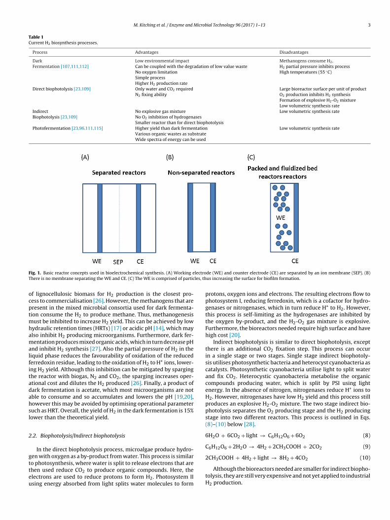
ig. 1. Basic reactor concepts used in bioelectrochemical synthesis. (A) Working ehere is no membrane separating the WE and CE. (C) The WE is comprised of partic
f lignocellulosic biomass for H2 production is the closest pro-ess to commercialisation [26]. However, the methanogens that areresent in the mixed microbial consortia used for dark fermenta-ion consume the H2 to produce methane. Thus, methanogenesis
ust be inhibited to increase H2 yield. This can be achieved by lowydraulic retention times (HRTs) [17] or acidic pH [14], which maylso inhibit H2 producing microorganisms. Furthermore, dark fer-entation produces mixed organic acids, which in turn decrease pH
nd inhibit H2 synthesis [27]. Also the partial pressure of H2 in theiquid phase reduces the favourability of oxidation of the reducederredoxin residue, leading to the oxidation of H2 to H+ ions, lower-ng H2 yield. Although this inhibition can be mitigated by sparginghe reactor with biogas, N2 and CO2, the sparging increases oper-tional cost and dilutes the H2 produced [26]. Finally, a product ofark fermentation is acetate, which most microorganisms are notble to consume and so accumulates and lowers the pH [19,20],owever this may be avoided by optimising operational parameteruch as HRT. Overall, the yield of H2 in the dark fermentation is 15%ower than the theoretical yield.
.2. Biophotolysis/Indirect biophotolysis
In the direct biophotolysis process, microalgae produce hydro-en with oxygen as a by-product from water. This process is similar
o photosynthesis, where water is split to release electrons that arehen used reduce CO2 to produce organic compounds. Here, thelectrons are used to reduce protons to form H2. Photosystem IIsing energy absorbed from light splits water molecules to formde (WE) and counter electrode (CE) are separated by an ion membrane (SEP). (B)us increasing the surface for biofilm formation.
protons, oxygen ions and electrons. The resulting electrons flow tophotosystem I, reducing ferredoxin, which is a cofactor for hydro-genases or nitrogenases, which in turn reduce H+ to H2. However,this process is self-limiting as the hydrogenases are inhibited bythe oxygen by-product, and the H2-O2 gas mixture is explosive.Furthermore, the bioreactors needed require high surface and havehigh cost [20].
Indirect biophotolysis is similar to direct biophotolysis, exceptthere is an additional CO2 fixation step. This process can occurin a single stage or two stages. Single stage indirect biophotoly-sis utilises photosynthetic bacteria and heterocyst cyanobacteria ascatalysts. Photosynthetic cyanobacteria utilise light to split waterand fix CO2. Heterocystic cyanobacteria metabolise the organiccompounds producing water, which is split by PSI using lightenergy. In the absence of nitrogen, nitrogenases reduce H+ ions toH2. However, nitrogenases have low H2 yield and this process stillproduces an explosive H2-O2 mixture. The two stage indirect bio-photolysis separates the O2 producing stage and the H2 producingstage into two different reactors. This process is outlined in Eqs.(8)–(10) below [28].
6H2O + 6CO2 + light → C6H12O6 + 6O2 (8)
C6H12O6 + 2H2O → 4H2 + 2CH3COOH + 2CO2 (9)
2CH COOH + 4H + light → 8H + 4CO (10)
3 2 2 2Although the bioreactors needed are smaller for indirect biopho-tolysis, they are still very expensive and not yet applied to industrialH2 production.

4
M.
Kitching
et al.
/ Enzym
e and
Microbial
Technology 96
(2017) 1–13
Table 2A selection of substrate utilisation used in MEC experiments and the H2 production rates normalised to the reactor volume (m3 m−3 day−1) and cathode surface area (m3 m−2 day−1).
Substrate(mg L−1)
Inoculum H2 Productionrate(m3 m−3 day−1)
H2 Productionrate(m3 m−2 day−1)
Cathode E vs.Ag/AgCl/V
T (◦C) Mode ofoperation
MECconfiguration
Biocathode/cathode
Cathode Anode Refs.
Acetate (60) Mixed(enriched)
2.2 0.010 −0.7 30 Continuous(0.01 h)
Dual chamberwith cationexchangemembrane
Biocathode Graphite paper Graphite [62]
Acetate (300) G.Sulfurreducens
0.31 0.005 −0.8 33–35 Continuous(0.04 h)
Single chamber Biocathode NanoporousGraphite
Nanoporous Graphite [66]
Acetate (600) Mixed(enriched)
2.4 0.024 −0.9 RT Continuous(0.64 h)
Dual chamberwith cationexchangemembrane
Biocathode Graphite felt Graphite felt [63]
Acetate (1000) Mixed(adapted tocold temp)
0.23 ± 0.03 0.011 ± 0.001 0.6a 4 Semi batch(mediareplaced 2–3days)
Single chamber Cathode Graphite fibre(platinumcoated)
Carbon cloth [79]
Acetate (1000) Mixed(enriched)
1.90 ± 0.08 0.087 ±0.004 0.8a 25 Semi batch(mediareplaced 2–3days)
Single chamber Cathode Graphite fibre(platinumcoated)
Carbon cloth [79]
Acetate (100) Mixed(enriched)
0.02 0.002 0.5 30 Batch Dual Chamberwith cationexchangemembrane
Cathode Titanium meshdisk
Graphite felt disc [49]
Acetate (2720) Mixed(enriched fromprior MEC)
50 50 1 30 Continuous(0.003 h)
Dual chamberwith anionexchangemembrane
Cathode Ni foam Graphite felt [119]
Ammonia (510) Mixed(enriched)
0.01 0.001 0.6 28 Batch Dual chamberwith anionexchangemembrane
Cathode Carbon felt Carbon felt [81]
Lactate (910) S. oneidensisMR-1
0.25 3.068 0.6 30 Batch Aerated H typereactor withanion exchangemembrane
Cathode Graphite(modified with5% Pt inactivatedcarbonpowder)
Carbon fibre fabric [93]
Methanol(1600)
Mixed(enriched MFCculture)
0.1 0.004 0.8 37 Batch Dual chamberreactor withanion exchangemembrane
Cathode Graphite fibrecloth (Coatedwith Pt)
Graphite fibre brush [94]
Sodiumbicarbonate(2500)
Mixed(enriched)
45.27 Surface areanot reported
−0.8 (vs SHE) 30 Batch Dual chamberwith cationexchangemembrane
Biocathode Graphitegranules
Graphite granules [64]
SodiumBicarbonate(500) + CO2
sparging
Mixed 8.9 × 10⁻⁷ 0.0092 ± 1.3∼ −0.75 V(vsSHE)
24 Batch Dual Chamberwith cationexchangemembrane
Biocathode Graphite plates Graphite plates [95]
SodiumBicarbonate(5000)
Mixed(enriched)
1.15 Surface areanot reported
−0.85 (vs. SHE). 24 Batch Dual Chamberwith cationexchangemembrane
Biocathode Vitreouscarbon (dopedwith CNT)
Graphite plates [65]
Hydrogen rates normalised to electrode surface area were calculated using the projected surface area or the working electrode. ∼Based on total surface area.a No reference electrode reported.

Microb
2
sp
2
aarpc
3c
Spbspt
BeosaciaditMtof[eTvdfl[ifmc
rnsadtmpiMuae
M. Kitching et al. / Enzyme and
.3. Photofermentation
Photosynthetic bacteria such as purple non-sulphur or greenulphur bacteria decompose small organic molecules to H2 in theresence of light as in Eq. (11).
CH3COOH + 4H2O → 8H2 + 4CO2 (11)
This process differs from biophotolysis where organic moleculesre used as the hydrogen carrier rather than water. This process has
greater H2 yield than dark fermentation and can utilise a widerange of substrates than biophotolysis. However, the volumetric H2roduction rates are lower than dark fermentation and too slow forommercial application [21].
. Microbial fuel cells (MFCs) and microbial electrolysisells (MECs)
Electroactive microorganisms (EAM) such as Geobacter sp. andhewanella sp. can respire solid state electrodes poised at oxidativeotential via extracellular electron transfer (EET), in lack of solu-le electron acceptors, to produce an anodic (oxidation) current. Aimilar EET process occurs when the electrode is poised at reducingotential and cathodic (reduction) current flows from the electrodeo the EAMs.
MFC and MEC are examples of recent biotechnology known asES that combine biological and electrochemical processes to gen-rate electricity, hydrogen or other useful chemicals. BESs consistf an anode, a cathode and, typically, an ion-selective membraneeparating the two electrodes (Fig. 1). An oxidation process occurst the anode (e.g., acetate oxidation), whereas a reduction pro-ess occurs at the cathode (e.g., H2 evolution). The electrodes aremmersed in an aqueous electrolyte that contains the reactantsnd products. BESs can be operated in MFC mode, in which theyeliver electrical power, or in MEC mode, in which external power
s invested to increase the kinetics of chemical reactions and/oro drive thermodynamically unfavourable reactions [29]. EET in
FCs and MECs is achieved mainly by two mechanisms. Elec-ron transfer between the cell surface and the solid-state electrodeccurs either through direct electron transfer (DET) via cell sur-ace proteins such as c-type cytochromes [30] or hydrogenases31]. When electron transfer is mostly achieved through solublelectron shuttles, it is termed mediated electron transfer (MET).hese electron shuttles may exogenous (e.g., thionine [32], methyliologen [33], hydroxyl naphthoquinones [34]) or microbially pro-uced redox mediators (e.g., phenazines from Pseudomonas sp. [35],avins from Shewanella sp. [36] and quinones from Escherichia coli
37]). The relative contribution of DET and MET to the overall EETs dependent on the electroactive species and the electrode sur-ace physical/chemical properties [36]. However, the details of EET
echanism are often unknown, particularly for mixed microbialonsortia.
MFC technology has been tested in laboratory for biosensing,ecalcitrant contaminant removal and desalination [38]. However,one of these proposed applications is intended for industrialcale production of electrical power. The most promising MFC/MECpplication is in wastewater treatment, where chemical oxygenemand (COD) removal is coupled to the production of small elec-rical power [7,39]. However, there are many unresolved problems,
ainly the low buffer capacity of wastewater, which results in lowH in the anodic compartment [40] and the need for efficient chem-
cal or biological catalysts at the cathode, which limits the overall
FC/MEC power output. Currently, MFCs have not yet been scaled-p successfully to generate enough electrical power for commercialpplication [41]. MEC allow combining biocatalysis with externalnergy input, thus increasing the potential applications. Current
ial Technology 96 (2017) 1–13 5
MFC/MEC research aims to couple COD removal and energy recov-ery from waste with chemical synthesis (e.g., methane, ethanol,formic acid, H2O2, acetate and H2 [38]). This process, termed bio-electrosynthesis or electrically assisted biosynthesis has a betterenergy efficiency than MFC alone and show promise for scale-up topractical applications [42]. In this review, we will analyse the mostrecent literature on MEC for H2 production and the key improve-ments needed for large-scale implementation.
4. H2 bioelectrosynthesis
The main limitation in H2 biosynthesis is the poor yield becauseof the process inhibition due to the production of organic acids andpartial H2 inhibition of ferredoxin and undirected metabolism ofthe microbial community. The addition of a driving force (i.e., elec-trochemical potential or current) improves the volumetric yield ofthe biological reaction, for example volumetric H2 increased by afactor of 1.7 for an Enterococcus aerogenes culture degrading glyc-erol waste discharged from a biodiesel plant [43].
The potential applied to MEC affects the metabolism of themicrobial consortia. Call and Logan demonstrated that H2 pro-duction rate increased as the applied voltage decreased (i.e., it ismoved to more negative value). It should be noted that the appliedpotential was altered by changing the mediums conductivity. Theincrease in H2 production may have been due to the lowered resis-tance of the MEC or the inhibition of methanogens[44]. Sasakiet al. showed that high anode potential (1.61 V vs. Ag/AgCl) inhibitsmethanogen activity [45–47]. In their work, low methanogenicactivity was due to the removal of methanogens from the reactoras copy numbers of the methanogen 16 s RNA gene decreased from48 ± 5 × 10⁷ to under the limit of detection for RT-PCR (−0.14 V)[48]. This effect of potential was also suggested by other researchers[49].
Bioelectrochemical synthesis of H2 is similar to conventionalwater electrolysis. Water electrolysis, due to the high potentialrequired (E0′
= 1.23 V) require high energy (5.6 kW m−3 H2), andtypical H2 electrolyser have efficiency between 56 and 73% [48].Microbial metabolism of organic compounds in BES generates CO2,H+ and electrons at the anode from dissolved organic moleculessuch as acetate (Eq. 12). The electrons travel through the electricalcircuit where they recombine with the H+ ions at the cathode (Eq.13), which diffuse from the anode to the cathode, usually throughcation exchange membrane to form H2 [50]. Reduction of the H+
ions may occur directly at the electrode surface or through hydroge-nases or outer membrane cytochromes by EAM on the biocathode.The overall reaction is conventionally separated into two half reac-tions, for each compartment, as in Eq. 12 (anode) and 13 (cathode),where acetate is used as a model non-fermentable organic sub-strate. The additional potential at standard conditions (pH 7, acetateconcentration 1 M, P 1 bar) is −0.14 V, thus additional energy isneeded to support the overall reaction.
C2H4O2 + 2H2O → 2CO2 + 8e− + 8H+(E0′ = −0.28 Vvs, SHE) (12)
8H+ + 8e− → 4H2(E0′ = −0.42 Vvs, SHE) (13)
In MEC, the potential required for H2 synthesis is much lower,as the microbial consortia produce the required protons as aby-product of their metabolism. Under standard conditions, thereversible potential of H+/H2 (vs. SHE) is −414 mV, while the typicalequilibrium anode potential generated from the bacterial oxidationof organic compounds is around −300 mV. Therefore, the minimum
additional potential required for H2 synthesis is around 114 mV,much lower than the potential needed for the abiotic water elec-trolysis [51]. Under practical conditions, a potential higher than theminimum theoretical potential is needed due to the overpotentials
6 Microb
am
4
dtba
armotscbosat
4
hape[Ibh
4
cwclcch
4
dAaaunw[te
ccsa(ab
M. Kitching et al. / Enzyme and
nd the consumption of the electrons in catabolic side reactions byicroorganisms.
.1. MEC current and H2 bioelectrosynthesis
At a given externally imposed potential, MEC current productionepends on EAM concentration and activity, their localization inhe biofilms, diffusional limitations for substrate and H2 transport,iofilm conductivity [52,53]. H2 production is usually measured as
function of the cathodic (reduction) current output.Current output can be recorded easily and continuously on
potentiostat or a data logger, while monitoring H2 productionequires additional instruments and longer time. Therefore, opti-
ization of current production can be used instead of optimizationf H2 production, at least in preliminary laboratory studies. Reportshat calculate H2 production rate from both current and H2 analysistate that the actual H2 production rate is higher than the cal-ulated theoretical rate from the current. This additional H2 maye produced by dark fermentation of organic compounds, whichccur also under electroactive conditions [47]. Given the relation-hip with current density, we will also include reports that focuslso on current optimisation in BES systems as well as H2 bioelec-rosynthesis.
.2. Electrode material and pre-treatment
In light of large-scale application, H2 bioelectrosynthesis mustave a cost comparable with catalytic reforming of hydrocarbonsnd other oil-related production processes. A cost analysis of H2roduction via steam reforming of petroleum was prepared Cruzt al., which calculated the H2 production cost at 1.18 US $ kg−1
54]. Electrodes are a major cost in the bioelectrosynthesis process.deal electrode material should have high porosity for maximumiomass attachment [55], low cost for cost effective scale-up andigh conductivity for low overpotential.
.2.1. Anodic materialCarbon materials are preferred for anodes, because of their low
ost and the high biocompatibility. Carbon based electrodes coatedith carbon nanotubes (CNTs) offer the best performance, but the
ost depends on the amount of CNT used and might be too high forarge-scale implementation [56]. Graphene sponge, although lessonductive is much cheaper and feasible if attached to a currentollector [57]. Carbon felt due to its large surface area producesigh current densities in MEC [37].
.2.2. Cathode materialThe cathodic reaction combines e− and H+ formed from the
egradation of the organic compounds at the anode to form H2.lthough conventional MEC/MFCs utilise expensive catalysts suchs Pt [37,58] or Ni [59] based electrodes as cathodes. Carbon basednodes doped with expensivc catalysts such as CNTs have beentilised [60,65]. Huang et al. demonstrated that less-expensive Pdanoparticles doped carbon paper cathodes can perform in MECith the same coulombic efficiency (CE) and H2 production rate
61]. A comprehensive review on cathodic material for MEC showshat SS and Ni alloys are a good compromise between cost andfficiency [58].
A cheaper alternative for expensive abiotic transition metals inathodes are inexpensive electrode materials supporting an effi-ient EAM consortia. The cathodes with EAM consortia on theirurface are termed biocathodes and are superior to abiotic cathodes
s H2 is produced at a similar rate while utilising cheaper materialsTable 2). For example, Jeremiasse et al. were able to produce H2 atrate of 2.2 m3 m−2 day−1 at −0.7 V (vs. SHE), using a mixed micro-ial consortia established on a graphite paper cathode [62]. Croese
ial Technology 96 (2017) 1–13
et al. produced H2 gas at a rate of 2.4 m3 m−3 day−1 with a mixedmicrobial consortium established on graphite felt cathodes, andacetate as a substrate [63]. LaBelle et al. (2013) examined the yieldand production rate of H2 bioelectrochemical synthesis of a mixedmicrobial consortia incubated in an electrochemical cell fitted withgraphite rod electrodes in a graphite granule bed cathode. The threereactors had a high variation in the amount of H2 produced, which isdue to unequal microbial colonisation of the graphite rod biocath-odes. However, there was significant production of H2 when thebiocathodes were poised at −0.6 V (vs. SHE) for two of the threereactors (45.27 and 44.28 m3 m−2 day−1, respectively) [64].
As we will discuss later in 4.4.2, electrode surface area does notinfluence the microbial population, or at most to a minor extend.However Jourdin et al. demonstrated that the microbial consortiamay influence the physicochemical surface properties of the cath-ode. Their study using a mixed inoculum poised at −0.85 V (vs SHE)multi walled CNT doped vitreous carbon cathodes showed that themicrobial consortia functionalised the surface of the cathode withbiologically generated copper nanoparticles [65].
The choice of biocathode material can influence biogas compo-sition and production rate, therefore consideration of the cathodematerial should not be overlooked. For example, Selembo et al.showed that various cathode materials, such as stainless steel (SS)and Ni alloys along with platinum influence the production rateof the H2 gas and the COD removal rate for single chamber MECsinoculated with an enriched MFC culture. They found that SS A286produced the largest amounts of H2 gas, which was improved fur-ther by the electrodeposition of a Ni oxide layer [49].
Inversion of bioanode at the end of biofilm development tobiocathode for MEC operation has been suggested to improveH2 production. Geelhoeld et al., when examing H2 production,developed a Geobacter sulfurreducens biofilm on the surface of ananoporus graphite anode. During the operation of the MEC, thebioanode was inverted to a biocathode (−1.0 V vs. Ag/AgCl) in astep-wise manner. The MEC produced 0.31 m3 m−3 day−1, which iswithin the range of other reports in the literature (see Table 2) [66].
4.2.3. Electrode pretreatmentThe effect of electrode surface morphology and chemistry on
current production in MEC is not straightforward. Among variousfactors that affect attachment, specific surface [37] and materialhydrophilicity plays a major role, as recently confirmed for She-wanella biofilms [55]. Pre-treatment of anodes to alter electrodesurface physical chemistry has been examined to increase the cur-rent output in MFCs. Current literature examines mainly anodepretreatment, however Zhang et al. compared graphite felt, car-bon paper and SS mesh materials as bio-cathodes in MFCs andsuggested that the higher surface area of the cathode increasesmaximum current density, COD removal and columbic efficiencydue to increased biomass attachment. This suggests that success-ful anode pre-treatments may be worth considering also for thecathode material [67].
Plasma treatment influences the physicochemical properties ofthe material surfaces such as charge and hydrophobicity. The mate-rial of interest is placed in a chamber along with a carrier gasat low pressure. The gas is ionised to form plasma by the appli-cation of an electric field, which then reacts with the surface ofthe material. Plasma pre-treatment has been studied to increasecell attachment to inorganic surfaces [68,69], and is a cheap, fastand safe technique. Flexer et al. compared nitrogen, oxygen andargon pre-treatment of graphite anodes and found that nitro-
gen pre-treatment yields the greatest current output for a mixedmicrobial biofilm, followed closely by oxygen pre-treatment. Theyalso found that plasma pre-treatment increases initial cell attach-ment rate and attached biomass on the electrode [70]. Recently,
Microb
obotem
Wsat3em
Bltptt1fd
bcHnovrp[ebgtitm
4b
4
fdtnaesttrsitHicw
M. Kitching et al. / Enzyme and
ur group found that atmospheric air plasma treatment of car-on felt anode significantly raised the maximum current outputf a S. loihica biofilm during the initial stage (up to 24 h), due tohe increased hydrophilicity that favoured cell attachment, how-ver the CE decreased by 60% [37]. Guo et al. electrochemicallyodified anode surface charge and hydrophobicity, depositingCH3, OH, SO3
− and N(CH3)3I onto glassy carbon electrodes.hen using mixed microbial consortia in a BES, the hydrophilic
urfaces ( N(CH3)3I and SO3−) had a shorter start up time of
pproximate 25 days and current stabilised within 38 days, whilehe start-up time of the hydrophobic surface ( CH3) was around4 days and a stable current was not reached by the end of thexperiment (53 days). The N(CH3)3I functionalization attained theaximum current density of 0.210 ± 0.003 mA cm−2, followed byOH (0.142 ± 0.012 mA cm−2) and SO3
− (0.117 ± 0.004 mA cm−2).iofilm formation for the CH3 functionalised electrode showed
arge attached bacterial flocs, while the more hydrophilic elec-rodes showed thinner biofilms with greater coverage and biomassresence [71]. Cheng and Logan demonstrated that ammonia pre-reatment of carbon cloth reduced the acclimatization time ofhe reactor from ∼150 to 60 h and increased power density from640 to 1970 mW m−2. The authors state that increased anode per-ormance was due to the increased surface charge, which theyemonstrated to increase by a factor of 10 at pH 7 [72].
The effect of cathode modification on H2 production in MEC haseen scarcely reported. High surface cathodes increase cathodicurrent, thus eliminating the need for expensive Pt catalyst [73,74].owever, these works refer to abiotic cathodes. In another work, Nianowires were coated on the graphite surface of a MEC biocath-de, increasing bioreduction rate 2.3 time-fold [75]. Reticulateditreous carbon cathodes modified with CNTs show higher cur-ent because of their high surface area but the nanostructure itselflays a role, somewhat enhancing the electron transfer process60]. Further research is needed to clarify the role of nanostructuredlectrodes in MEC biocathodes. A different approach was reportedy Yan et al. (2015), where the biocathode was added with conju-ated oligoelectrolytes (COE) that intercalate bacterial membranes,hus enhancing electron transfer rate between cathode and dissim-latory metal-reducing bacteria S. oneidensis MR-1 [76]. However,he long-term feasibility of COE is not well-demonstrated, as they
ight damage the microorganisms on the electrode[77].
.3. Reactor design and operating conditions for H2ioelectrosynthesis
.3.1. Laboratory scale reactor design
Currently, there is no consensus about the optimal MEC designor laboratory-scale H2 bioelectrosynthesis. In many cases, theesign chosen depends on previous experience with MFC or is dic-ated by simplicity and cost reasons. Small reactors are certainlyeeded to test novel electrode materials or microbial consortia,nd high-throughput systems, such as microfluidic flow cells, arexcellent tools for laboratory screening. However, scale-up requiresimple and robust design, which can withstand the changes inhe feedstock and long operating time needed for the growth ofhe mixed EAM community. The concepts for bioelectrochemicaleactors have been recently reviewed [78]. For bioelectrosynthe-is process, a single anodic chamber is both simple and efficient,n combination with multiple cathodes to avoid cathodic limita-ions. There is no specific requirement for H2 bioelectrosynthesis;
2 collection should be included, before it reacts with other speciesn the BES. The high specific surface can be sought by using complexhamber design, such as serpentine, spiral, or other tortuous path,hich increase residence time. As the fluid path becomes longer in
ial Technology 96 (2017) 1–13 7
the reactor, the latter behave as a plug flow reactor (PFR) rather thana continuously stirred tank reactor (CSTR) and multiple feed mightbe considered, to increase overall efficiency. Operation of MEC atlow temperature decrease biomass activity, thus current output.However, it also minimizes consumption of H2 by methanogenicbacteria, as demonstrated in both lab scale [79,80] and pilot-scaleMEC [81]. The standard dual chamber electrochemical cell is usedprimarily in these experiments under anaerobic conditions to pre-vent the H+ ions reacting with O2 to produce H2O [44,64,82].
In certain cases, membranes can be eliminated, to simplify thedesign and to reduce costs. Saski et al. demonstrated that themembrane-less H-type dual chamber electrochemical reactor pro-duces biogas with similar H2 content to the anode compartmentof a H-type dual chamber cell with a proton exchange membrane(54.4 ± 9.5 vs. 42.6 ± 4.5% v/v, respectively) when the workingelectrode was poised at −0.9 V (vs. Ag/AgCl) [44]. Although thispotential seems too high to be practical, methanogens which oxi-dise H2, were demonstrated to be inhibited.
A single chamber is a simpler design for scale-up, and showedsimilar performance for H2 production as the H-type dual cham-ber (H2 production rate of 2.2 L−1 day−1 single chamber vs.2.4 L−1 day−1 for the H type dual chamber cell) [83]. The electrodeswere only 2 cm distant in the single chamber MEC, thus resulting inhigher current and H2 production. This relationship between elec-trode spacing and H2 production was also demonstrated by Chenget al., using single chamber MECs, fitted with either graphite fibreanodes or carbon cloth anodes [84]. Small distance between elec-trodes should be taken in consideration for MEC design, due to thedecrease in ohmic resistance and the resulting increase in current.
Villano’ s study using trichloroethene dechlorinating culturessuggest that at cathode potentials below −0.75 V (vs. SHE), the rel-ative amount of H2 formed from abiotic water electrolysis starts toincrease [51].
4.3.2. Pilot scale designAt least one company, Cambrian Innovation, produces an indus-
trial scale BES for wastewater treatment based on MFC technology(EcoVoltTM). Emefcy, is also currently advertising their own BESfor wastewater treatment (Electrogenic Bio Reactors, www.emefcy.com, not yet commercially available), however pilot-scale bioelec-trosynthesis of H2 needs still to be proved. Recent literature showssignificant progresses, particularly when H2 bioelectrosynthesis isassociated with COD degradation and coupled to wastewater treat-ment. For example, Heidrich et al. set-up a 100 L MEC equipped withcarbon felt anodes and SS wire wool cathodes. The MEC was fedwith raw domestic wastewater at outdoor temperature and oper-ated for twelve months with an average of 49% electrical energyrecovery and 41% CE. These results suggest that scale-up is fea-sible and no pre-treatment of domestic wastewater is needed.However, the large overpotential, likely due to accumulation ofnon-electrochemically active biomass on the electrode and the con-sequent low energy recovery, needs to be addressed [81].
In a much larger pilot-scale trial, Cusick et al. set-up a 1000 Lcontinuous MEC fed with organic carbon-rich winery wastewaterat 31 ◦C. The MEC was equipped with graphite brush anodes andSS 304 cathodes. Following establishment of efficient EAM, CODremoval >60% was measured. The maximum H2 production ratewas measured at 0.19 ± 0.04 m3 m−3 day−1, however most of theH2 was converted into methane (86 ± 6%), the electrical energy effi-ciency was >100%, calculated on standard energy recovery from
the overall biogas. Hydrogen removal for MEC and amendment ofthe wastewater are needed to increase hydrogen conversion andefficiency of electrochemically active biomass [85]. While high tem-perature increases microbial respiration and current output, it also
8 Microb
i[
umflct
atfarcwatpwiwrH
temrtatts
wtcc
to0gisum
4
ssabtipittmaT
M. Kitching et al. / Enzyme and
ncreases activity of methanogens, responsible for H2 consumption86].
Carrera et al. (2012) coupled COD removal and H2 synthesissing a 10 L flat plate MEC, which was with fed raw refrigeratedunicipal wastewater. COD removal reached 75.8% at the fastest
ow rate with a HRT of 10 h. H2 production rate at this HRT and theoulombic efficiency were low, 0.06L L−1 day−1 and 23%, respec-ively [87].
Escapa et al. (2015) used a membrane-less dual chamber (3 Lnode and cathode) MECs in batch and continuous operations, withwo layers of 5 mm thick graphite as the anode and Ni based-gas dif-usion electrode as the cathode, which was poised at +0.7 V using andjustable DC power supply. The MECs attained high levels of CODemoval (72 ± 2%) under closed circuit operation, while in openircuit COD removal dropped to 33 ± 2%, indicating COD removalas a bioelectrochemical aided process. Current density decreased
fter 24 hours to roughly 0.1 A m−2. H2 production increases forhe first 3 days before levelling off. The increase in production isrevented due to the decrease in cathodic conversion efficiencies,hich drop in both MECs. Continuous operation system resulted
n poor COD removal, with low COD containing waste; however,hen the waste COD increased from 70 to 114 mg L−1 and the COD
emoval increased from 33 to 45%. The high CE (209–460%) suggests2 recycling by the EAB, which lowers H2 yield [88].
A possible oversight in these pilot scale reactors is the ratio ofhe volume of the reactor to the electrode surface area. Farhangit al. suggested that, although the current density was high (Niesh cathode, 4.15 A m−2) the corresponding low H2 production
ate (0.28 ± 0.01 m3 m−2day−1) was influenced by the large reac-or volume compared to the electrode surface, and suggested that
smaller volume may increase the production rate. assuming thathe decreasing the volume does not significantly affect other reac-or parameters such as mass transfer and mixing and that there isufficient volume of electrolyte to sustain the reaction [88].
In a more recent study, the use of biological cathodes colonizedith mixed biomass enable H2 biosynthesis at a cost lower than
he H2 market value. However, the comparison with H2 productionost is not reported, and the capital costs are not included in thealculation [89].
The cost of H2 production in MEC associated with wastewa-er treatment has been previously discussed. Assuming a currentutput of 5 A m−2 of anode and an energy consumption of.9 kWh kg COD−1 (kilowatt-hour per kg of removed chemical oxy-en demand (COD)), a cost of Euro 1220 per m3 of anodic materials the requirement for the breakeven in 7 years. However, thistudy did not compare this result with the cost of H2 productionsing other technologies, and did not verify whether the currentaterials used in MEC can meet these costs [90].
.4. Bioelectrosynthesis of H2 using mixed microbial consortia
Mixed microbial consortia offer higher flexibility than singlepecies in terms of substrate utilization for H2 bioelectrosynthe-is and do not require sterile or clean feed. Since H2 might serves electron donor for numerous species, the as-produced H2 muste removed from the reactor to avoid its further oxidation. Fur-hermore, mediated EET in mixed consortia is more efficient thann single species, as redox mediators produced by a species (e.g.,irroloquinoline quinone, riboflavin) can be used by other species
n the community, thus increasing the overall electrode reduc-ion/oxidation rate [35] and consequently the degradation rate of
he feedstock [91]. BES for H2 synthesis are usually inoculated withixed food or paper waste or sludge from biogas plants that contain mix of fermentative, acetogenic, and anaerobic microorganisms.he low cost and large availability of the feedstock is a positive fac-
ial Technology 96 (2017) 1–13
tor for scale-up of H2 bioelectrosynthesis. However, there are stillconstraints and limitations that need to be addressed.
4.4.1. Mixed vs single species consortiaRaghavulu et al. reported that a MEC inoculated with Shewanella
haliotis increased current generation from 25.5 to 32.7 �A cm−2
when augmented with an anaerobic sludge culture. COD removalefficiency also increased from 36.9 to 55.1%; however, this wasonly a marginal increase from the original anaerobic sludge culture(54.7%). The authors suggest that the higher energy generation bedue to the increased substrate utilisation capacity of the mixed cul-ture. Cyclic voltammetry showed a syntrophic mechanism betweenthe S. haliotis culture and the anaerobic sludge culture in avoidingelectron losses prior to reaching the working electrode [92].
Mixed cultures that are suitable for waste degradation containscompeting metabolic pathways that consume H2. EAMs may bemore versatile to organic degradation, increase yield further, how-ever reports on single species EAM cultures are lacking. At the timeof writing, only one report examining Shewanella oneidensis MR-1has been published for BES synthesis of H2. The authors used anaerated S. oneidensis culture, due to greater current generation andbiomass yield. They observed O2 as a competing electron acceptor,which lowered the H2 yield to 15% of the theoretical maximum. It islikely that start-up of the culture under aerobic conditions and thenswitching to anaerobic conditions would allow for high biomassgrowth and greater H2 yield [93].
4.4.2. EnrichmentPrevious reports describing long-term experiments showed that
the population of the microbial consortia shifts to adapt to theconditions of the bioelectroreactor. EAM are enriched during thebioelectrosynthesis process, as commonly observed in other bio-electrochemical reactors (e.g., MFC). For example, 16 s RNA genesequencing and/or TLRF analysis of the microbial consortia of MECsrevealed enrichment of EAMs such as Geobacter [79,96] and Desul-fovibrio [79,94,96].
Microbial enrichment is influenced by substrate. Zhan et al., util-ising an adapted mixed microbial community for H2 synthesis fromammonia alone did demonstrate the presence of the ammonia-oxidising bacteria with anode reducing capability (Nitrosomonaseuropaea) on the anode, together with ammonia assimilating bacte-ria (Stentrophomonas sp.) that compete with the ammonia oxidisingbacteria, lowering H2 yield and CE. The authors suggest that theremay be a possible syntrophic mechanism for ammonia oxidation byNitrosomonas, Comamomas and Paracoccus [82]82F. A recent studyshowed that autotrophic consortia might thrive with the cathodeas sole electron donor and CO2 as a sole electron acceptor, produc-ing H2 without significant loss from other metabolic pathways [95].A mixed microbial consortium comprising EAM and fermentativebacteria did not produce net H2 in a single chamber MEC, as theelectrons released from the oxidation of the substrate (methanol)were recycled by homoacetogenic bacteria. However, use of a dou-ble chamber MEC avoided electron recycling and resulted in net H2production, although at low CE [94]. In the large scale 1000L trialusing organic rich winery wastewater most of the H2 was convertedinto methane (86 ± 6%).
A relatively minor influence of electrode size (22 vs. 100 cm2
graphite cathode) was observed by Croese et al. due to availabil-ity of electrode surface area, which favoured initial attachmentof microbes present at the start of the experiment rather thanattachment of microbes that are enriched during the experiment.Differences of flow path of nutrients may affect anode population,
due to differences in mixing, mass transfer and shear forces in thesystem [63].Acetate-fed MECs inoculated from UASB reactors enrich mem-bers of both the Bacteroidetes and Proteobacteria phyla [65].

Microb
PapeMdrscsgo(sr
4
tstaidiw[a[tss
dpoas
mrbsoAbda
b[72atcttwhrhnt
M. Kitching et al. / Enzyme and
roteobacteria do contain electroactive bacteria such as Shewanelland Geobacter, while there are no members of the Bacteroideteshylum that have been demonstrated to be EAM to date. How-ver, this phylum has been enriched in multiple reports for bothFCs and MECs, suggesting a possible symbiotic relationship could
evelop under electrogenic conditions [64,96]. Such a syntrophicelationship of EAMs and complex substrate metabolisers has beenuggested in other MEC experiments. Pyrosequencing of the anodeompartment of a MEC, inoculated with anaerobic digester sludgehowed that fermenters such as Kosmotoga sp. and homoaceto-ens Treponema sp. were abundant in the spent medium, whilen the anode the dominant organisms were pionate fermentersKosmotoga, and Syntrophobacter spp.), homoacetogens (Treponemap.), and EAMs such as Geobacter spp. and Dysgonomonas sp. CODemoval in the MEC was high at 96% [97].
.5. Choice of substrate in BES for H2 bioelectrosynthesis
Organic substrates influence the electroactivity and composi-ion of the microbial consortia in MECs [64]. Table 2 lists theubstrates used in prior MEC reports and the resulting H2 produc-ion rate. While it is possible to optimize the substrate compositionnd concentration in laboratory experiments, this is obviouslympossible in real-world application for energy recovery fromomestic wastewater. Therefore, the effect of organic substrates
s studied through artificial wastewater of different compositions,hose organic concentration can be easily compared through COD
43–47]. Acetate is the most common substrate in MEC [79,98,99]s it cannot be directly converted to H2 through dark fermentation48,49,83,98,99] and promotes growth of efficient EAM. We referhe reader to a recent review by Pandey et al., which summariesimple, defined and undefined media that have been utilised in BEStudies [100].
A MEC inoculated with sewage sludge and fed with acetate pro-uced the highest H2 yield at low cathodic pH and high cathodicotential. However, strong competition from methanogens wasbserved after prolonged operation [101]. Thermodynamic modelsnd experimental evidence suggested that acetate decreases thetart-up time of MECs [63].
Although the breakdown of lactate to acetate and H2 is ther-odynamically favourable, a +0.11 V activation overpotential is
equired, possibly due to O2 inhibition of the fermentation [86]. H2ioelectrosynthesis from complex substrates (milk, glycerol, andtarch) produces exceptionally high current that might lower theverall energy requirement [99]. Interestingly, non EAM such ascetobacterium might contribute to the productivity of the micro-ial consortia via DET, although it is not possible at present toiscern DET-mediated synthesis from acetogenesis, due to the highmount of concomitantly produced H2 [96].
Ammonia as a hydrogen carrier for BES experiments has noteen examined in much detail, as the reported CE is very low (0.34%91] and 1.1% [99]). However, ammonia-adapted cultures achieved8 and 53% CE after 5 days with an initial concentration of 10 and0–30 mM ammonia, respectively [82]. It has been suggested thatmmonia inhibits the microbial consortia during waste degrada-ion [102]. It is possible that MECs harbouring an ammonia adaptedulture could avail of the ammonia produced from protein degrada-ion, which in turn is a substrate for N2 and H2 production, assuminghat the additional organic carbon does not interfere significantlyith the process. Methanol is a by-product of biodiesel industry and
as been used as carbon source in MFC [103], however it does not
esult in appreciable current production compared to other alco-ols such as ethanol [104]. Methanol is a simple substrate that doesot require pre-treatment. When fed to a two chamber, mixed cul-ured MEC, H2 production rate was measured at 0.8 m3 m−3 day−94.ial Technology 96 (2017) 1–13 9
The chemical properties of the synthesis buffer also affect themetabolic activity of the microbial community. The addition ofsodium bromomethanesulfonate (NaBES) to both anode and cath-ode does not affect the H2 synthesis of an enriched electrosyntheticbiome but inhibits methanogenesis at the biocathode. Interestingly,when NaBES was removed by medium exchange, methanogene-sis did not occur for 2 of the 3 reactors tested, which is due tothe acidic pH of the medium and partial H2 pressure. Further,the removal of NaBES also increased acetogenesis from 5 ± 1.8to 9.7 ± 1.5 mM day−1. When the bicarbonate buffer was replacedby a higher conductive potassium phosphate buffer and spargedwith CO2 to lower the electrolyte resistance, it did not significantlyaffect H2 synthesis. When the cathode pH was lowered to belowpH 5, H2 synthesis increased from 25 to 300–400 mM day−1 whileacetate synthesis ceased. NaOH titration partially restored acetateproduction and slowed H2 synthesis [96]. After multiple mediaexchanges and exposure of the biocathode to acidic pH, H2 biosyn-thesis remained relatively high even at near neutral pH, whichsuggests the microbiome adapted to produce H2 regardless of pH, aslong as the microbiome is exposed to an acidic pH during its devel-opment [96]. 0.5 gL−1 of bromoethanesulfonic acid (BESA) has alsobeen successfully utilised to inhibit methanogens in the bioelectro-chemical synthesis of acetate by an enriched acetogenic consortia[105].
The majority of the papers examining H2 bioelectrochemicalsynthesis utilise the application of an electrochemical potentialto enhance breakdown of organic compounds to generate H+ thatcombine at the cathode to form H2. However, there are reportsthat utilise CO2 as a carbon source [65,95] which has been usedas a substrate in H2 synthesis experiments prior. For example,LaBelle et al. using graphite granules as cathode and anode pro-duce 45.27 m3.m−3.day−1 of hydrogen using sodium bicarbonateas a carbon source [64].
4.6. Presence of exogenous redox mediators
With the exception of EAM, most microorganisms in mixed elec-troactive consortia cannot directly use the electrode as an externalelectron donor or acceptor as part of their respiration process.While redox mediators produced by certain EAM can be used byother microorganisms in the consortium [106], practical applica-tion are limited by the low concentration of microbial producedmediators, around 10–20 �M [107]. Therefore, exogenous redoxmediators have been used to increase current output and H2 pro-duction in mixed consortia. For example, the addition of 2 mMthionine increased H2 production in Enterobacter aerogenes pureculture by 70%. The H2 production was limited by the charge trans-fer rate at the electrode and not by the metabolic rate, as the glycerol(substrate) consumption rate did not increase as increasing concen-tration of thionine was added. Although the addition of thioninedid not increase the glycerol consumption rate, it did increase thetotal amount glycerol consumed, from 59.7 to 92.9 mM. The timecourse data suggests that without thionine, there was a build-up ofinhibitory by-products, which interfere with glycerol consumptionat 12 h. However, with the addition of thionine and glycerol, thisinhibition did not occur and glycerol consumption continues up to50 h. Interestingly, the redox mediator did not affect the growthrate of the biomass [43].
Villano et al. demonstrated that the addition of methyl viologenup to 1–2 mM to a trichloroethene (TCE) and a cis-DCE dechlo-rinating culture in a MEC increased the H2 production rate fromapproximately 0 to 6.02 ± 0.3 and 5.95 ± 0.3 �mol mg VSS−1d−1,
respectively. The data showed fitted to a Michaelis-Menten modelcurve for both the TCE and cis-DCE [51].Although not examined in MEC, the redox mediator flavin issecreted by members of the Shewanella genus. Flavins mediated

1 Microb
ai
cbrr
eeib
4a
dodsdwtdab
i5btbHiC(Cpasot
tb[
4
ptadoiasbt
wsvt
0 M. Kitching et al. / Enzyme and
nodic electron transfer [108], thus increasing current generationn single species and mixed consortia BESs [37].
In addition to these well-known redox mediators, recent a studylaims that cell-produced enzymes might be responsible for EET inioelectrosynthesis in mixed microbial consortia [109]. The specificelevance of this charge transfer mechanism to bioelectrosynthesisequires further investigation.
Chemicals other than redox mediators might be also used tonhance current production in bioelectrosynthesis system. Forxample, Yan et al., 2015, used conjugated oligoelectrolytes tomprove electron transfer across bacterial membranes to produceoth anodic and cathodic current [110].
.7. In situ bioelectrochemical production of H2 for specificpplications
Bioelectrosynthesis of H2 increases as the applied potentialecreases. However, the cost of applied potential offsets the valuef the H2 as product. As H2 is an efficient electron donor, the pro-uction of H2 in MECs in situ has been utilised to increase theynthesis of other high value products. For example, butanol pro-uction increases by 60.3% for a Clostridium beijerinckii IB4 culture,hen 0.1 mM of the electron carrier neutral red was introduced,
hus decreasing the accumulation of H2 in favour of butanol pro-uction [111]. Bioelectrochemically produced H2 was reported as
likely electron donor in the reduction of acetate to caproate,utyrate, and smaller fractions of caprylate [112].
Jourdin et al. (2016) demonstrated when CO2 was spargedn the cathode chamber containing the enriched biocathode and00 mg L−1 sodium bicarbonate, the majority of the H2 producedy the consortia was utilised to produce acetate. This conflicts withhe results of LaBelle et al., who demonstrated that using sodiumicarbonate produces a high volumetric H2 production rate [96].owever these differences may arise from the sparging of CO2
n the cathode and suggests that the concentration of dissolvedO2 may influence acteogenic acitivity. The results of Jourdin et al.2015) seem to support this idea. In the study, the aurthors spargedO2 through the cathode containing a mixed consortia on graphitelate cathodes while also containing 500 mg L−1 sodium bicarbon-te while poised at −0.75 V (vs. SHE). The authors report a poor H2ynthesis rate or 8.9 × 10⁻⁷ m3 m−3 day−1, however the presencef acetogens was not detected on the electrode surface, suggestinghat the acetate producers may be present as planktonic cells [95].
It is possible to produce in situ catalyst that increase H2 produc-ion. For example, the BES proposed by Wang et al. couple cathodicioreduction of Co(II) to Co(0) to catalytic bioelectrosynthesis of H2113].
.8. Comparison with other bio-hydrogen production processes
Currently, there is no established process for bio-hydrogenroduction. An early review highlighted the unclear prospect ofhese processes already in 2004 [23]. A more recent review (2013)nalysed an impressive number of research on bio-hydrogen pro-uction. Choice of feedstock and reactor optimisation were singledut as the most important factors of the process, but no feasibil-
ty conclusion was made [114]. Similar conclusions were made in 2012 review on dark fermentation [115]. A through pilot-scaletudy on bio-hydrogen production by allothermal gasification ofiomass reported a cost of few 6.5–9.1 D kg−1 of H2 and suggestedhat this process is feasible on the short to medium term [116].
We refer the reader to a recent review by Rahman et al. (2015)
here examples of H2 synthesis rate of other competing biologicalynthesis strategies are summarised. The synthesis rate of H2 canary widely between synthesis strategies from 0.03 m3 m−3 day−1
o 43.2 m3 m−3 day−1. Dark fermentation has the highest H2 pro-
ial Technology 96 (2017) 1–13
duction rate that varies between 1.72–43.2 m3 m−3 day−1 [28].Another review by Kapdan et al. (2006) reported that H2 synthesisrate by dark fermentation can vary between 0.1–20.4 m3 m−3 day−1
[27]. Data summarized in Table 2 shows that the H2 synthesis ratefor dark fermentation and MECs are similar.
Bioelectrochemical synthesis of H2 has been investigated since10 years. With respect to electrical energy production (MFC), bio-electrosynthesis of H2 results in a higher value product, thus itspotential for large-scale application is higher. However, H2 biosyn-thesis can be attained in simpler biological processes, such as darkfermentation, provided that methanogens, which metabolise H2 toform methane, are inhibited, which can be achieved using low HRTs[117] or acidic pH [118] or low temperature [81].
5. Challenges and outlook
Although promising, bioelectrochemical synthesis of H2 in MECsstill suffers from poor synthesis rate. Further improvements to cur-rent MEC technology should focus on increasing active electrodesurface and current density per unit of geometric surface. Poroustridimensional electrode materials, such as carbon felt, eventuallypre-treated or functionalized to improve biocompatibility, increasethe available surface area for microbial cell attachment and subse-quent electroactive biofilm formation.
Competition for the H+ precursor by other microbes, such asmethanogens, is still a concern for scale-up. Use of a defined mixedinoculum and/or the optimisation of operational parameters suchas reactor temperature, pH, methanogen inhibitor concentration,HRT and electrochemical potential applied to the working electrodewill improve the yield, and should be considered throughout allstages of MEC development, from laboratory to full-scale studies.
MEC and dark fermentation technologies for H2 production aresimilar in terms of the volumetric synthesis rate. However, con-centration of viable cells in MEC biofilms can largely exceed theconcentration of planktonic cells in fermentors. As H2 productionis a function of the abundance of the microbial catalyst, MEC mayoutperform dark fermentation technology in full-scale bioreactors.
6. Conclusions
At laboratory scale, bioelectrochemical production of H2 in MEChas shown lower environmental impact than conventional coal ornatural gas steam reforming. When poised at negative potential,biocathodes populated with mixed microbial consortia producehigher current than single species, thus increasing H2 productionrate. However, metabolic pathways from other microorganismsconsume H2, thereby requiring selective inhibition, shorter resi-dence time or other design measures. Bio-augmented EAM cultures,along with waste pre-treatment may increase the efficiency ofthe H2 bioelectrosynthesis. Critical assessment of the few scale-up studies already published show that further optimization ofelectrode material and morphology, possibly including surface pre-treatment, might improve EAM attachment, thereby boosting H2production to rates that are competitive with existing H2 biosyn-thesis technologies.
Acknowledgement
Michael Kitching was funded by Irish Research Council (Ireland),Project ID RS/2012/276.
References
[1] Q. Wang, X. Chen, A.N. Jha, H. Rogers, Natural gas from shale formation—theevolution, evidences and challenges of shale gas revolution in United States,Renewable Sustainable Energy Rev. 30 (2014) 1–18.

Microb
M. Kitching et al. / Enzyme and[2] D. Pant, A. Singh, G. Van Bogaert, Y.A. Gallego, L. Diels, K. Vanbroekhoven, Anintroduction to the life cycle assessment (LCA) of bioelectrochemicalsystems (BES) for sustainable energy and product generation: relevance andkey aspects, Renewable Sustainable Energy Rev. 15 (2011) 1305–1313.
[3] J. Foley, R. Rozendal, C. Hertle, P. Lant, K. Rabaey, Life cycle assessment ofhigh-rate anaerobic treatment, microbial fuel cells, and microbialelectrolysis cells, Environ. Sci. Technol. 44 (2010) 3629–3637.
[4] C. Lu, J. Zhao, S.-T. Yang, D. Wei, Fed-batch fermentation for n-butanolproduction from cassava bagasse hydrolysate in a fibrous bed bioreactorwith continuous gas stripping, Bioresour. Technol. 104 (2011) 380–387.
[5] C. Barca, A. Soric, D. Ranava, M.-T. Giudici-Orticoni, J.-H. Ferrasse, Anaerobicbiofilm reactors for dark fermentative hydrogen production fromwastewater: a review, Bioresour. Technol. 185 (2015) 386–398.
[6] A. ElMekawy, S. Srikanth, S. Bajracharya, H.M. Hegabd, P.S. Nigam, A. Singh,S. Mohanh, D. Pant, Food and agricultural wastes as substrates forbioelectrochemical system (BES): the synchronized recovery of sustainableenergy and waste treatment, Food Res. Int. 73 (2015) 213–225.
[7] G. Zheng, W. Liao, F. Zhang, Z. He, Energy extraction from a large-scalemicrobial fuel cell system treating municipal wastewater, J. Power Sources300 (2015) 260–264.
[8] Y. Dong, Y. Qu, W. He, Y. Du, J. Liu, X. Han, Y.A. Feng, 90-liter stackablebaffled microbial fuel cell for brewery wastewater treatment based onenergy self-sufficient mode, Bioresour. Technol. 195 (2016) 66–72.
[9] X.A. Walter, A. Stinchcombe, J. Greenman, I. Ieropoulos, Urine transductionto usable energy: a modular MFC approach for smartphone and remotesystem charging, Appl. Energy (2016) (in press).
[10] C. Donovan, A. Dewan, D. Heo, Z. Lewandowski, H. Beyenal, Sedimentmicrobial fuel cell powering a submersible ultrasonic receiver: newapproach to remote monitoring, J. Power Sources 233 (2013) 79–85.
[11] Z. Du, H. Li, T. Gu, A state of the art review on microbial fuel cells: apromising technology for wastewater treatment and bioenergy, Biotechnol.Adv. 25 (2007) 464–482.
[12] H. Wang, J.-D. Park, Z. Ren, Practical energy harvesting for microbial fuelcells: a review, Environ. Sci. Technol. 49 (2015) 3267–3277.
[13] A. Haryanto, S. Fernando, N. Murali, S. Adhikari, Current status of hydrogenproduction techniques by steam reforming of ethanol: a review, EnergyFuels 19 (2005) 2098–2106.
[14] K. Mazloomi, C. Gomes, Hydrogen as an energy carrier: prospects andchallenges, Renewable Sustainable Energy Rev. 16 (2012) 3024–3033.
[15] N. Cherkasov, A. Ibhadon, P. Fitzpatrick, A review of the existing andalternative methods for greener nitrogen fixation, Chem. Eng. Process. 90(2015) 24–33.
[16] P. Dodds, I. Staffell, A.D. Hawkes, F. Li, P. Grünewal, W. McDowall, Hydrogenand fuel cell technologies for heating: a review, Int. J. Hydrogen Energy 40(2015).
[17] R. Bentley, Y. Bentley, Explaining the price of oil 1971–2014: the need to usereliable data on oil discovery and to account for ‘mid-point’ peak, EnergyPolicy 86 (2015) 880–890.
[18] Maggio, Cacciola, When will oil, natural gas, and coal peak? Fuel 98 (2012)111–123.
[19] R. Kothari, D. Buddhi, R. Sawhney, Comparison of environmental andeconomic aspects of various hydrogen production methods, RenewableSustainable Energy Rev. 12 (2008) 553–563.
[20] F. Meng, J. Li, S.K. Cushing, J. Bright, M. Zhi, J.D. Rowley, Z. Hong, A.Manivannan, A.D. Bristow, N. Wu, Photocatalytic Water oxidation byhematite/reduced graphene oxide composites, ACS Catal. 3 (2013) 746–751.
[21] J. Liu, Y. Liu, N. Liu, Y. Han, X. Zhang, H. Huang, Y. Lifshitz, S.T. Lee, J. Zhong, Z.Kang, Metal-free efficient photocatalyst for stable visible water splitting viaa two-electron pathway, Science 347 (2015) 970–974.
[22] J. Carton, A. Olabi, Wind/hydrogen hybrid systems: opportunity for Ireland’swind resource to provide consistent sustainable energy supply, Energy 35(2010) 4536–4544.
[23] Levin Biohydrogen production: prospects and limitations to practicalapplication. Int. J. Hydrogen Energy 29, 173–185 (2004).
[24] R. RenNanqi, G. GuoWanqian, L. LiuBingfeng, C. CaoGuangli, D. DingJie,Biological hydrogen production by dark fermentation: challenges andprospects towards scaled-up production, Curr. Opin. Biotechnol. 22 (2011)365–370.
[25] M.-L. Chong, V. Sabaratnam, Y. Shirai, M. Hassan, Biohydrogen productionfrom biomass and industrial wastes by dark fermentation, Int. J. HydrogenEnergy 34 (2009) 3277–3287.
[26] A. Singh, S. Sevda, I.M. Abu Reesh, K. Vanbroekhoven, D. Rathore, D. Pant,Biohydrogen production from lignocellulosic biomass: technology andsustainability, Energies 8 (2015) 13062–13080.
[27] I. Kapdan, F. Kargi, Bio-hydrogen production from waste materials, EnzymeMicrob. Technol. 38 (2006) 569–582.
[28] S.N.A. Rahman, M.S. Masdar, M.I. Rosli, E.H. Majlan, T. Husalani, Overview ofbiohydrogen production technologies and application in fuel cell, Am. J.Chem. 5 (2015) 12–23.
[29] K. Rabaey, R. Rozendal, Microbial electrosynthesis—revisiting the electricalroute for microbial production, Nat. Rev. Microbiol. 8 (2010) 706–716.
[30] L. Shi, D.J. Richardson, Z. Wang, S.N. Kerisit, K.M. Rosso, J.M. Zachara, J.K.Fredrickson, The roles of outer membrane cytochromes of Shewanella andGeobacter in extracellular electron transfer, Environ. Microbiol. Rep. 1(2009) 220–227.
ial Technology 96 (2017) 1–13 11
[31] T. Kihara, X.Y. Liu, C. Nakamura, K.M. Park, S.W. Ha, D.J. Qian, K. Kawasaki,N.A. Zorin, S. Yasuda, K. Hata, T. Wakayama, J. Miyakea, Direct electrontransfer to hydrogenase for catalytic hydrogen production using asingle-walled carbon nanotube forest, Int. J. Hydrogen Energy 36 (2011)7523–7529.
[32] M. Rahimnejad, G.D. Najafpour, A.A. Ghoreyshi, F. Talebnia, G.C. Premier, G.Bakeri, J.R. Kim, S.E. Oh, Thionine increases electricity generation frommicrobial fuel cell using Saccharomyces cerevisiae and exoelectrogenicmixed culture, J. Microbiol. 50 (2012) 575–580.
[33] F. Aulenta, A. Catervi, M. Majone, S. Panero, P. Reale, S. Rossetti, Electrontransfer from a solid-state electrode assisted by methyl viologen sustainsefficient microbial reductive dechlorination of TCE, Environ. Sci. Technol. 41(2007) 2554–2559.
[34] D. Park, J. Zeikus, Electricity generation in microbial fuel cells using neutralred as an electronophore, Appl. Environ. Microbiol. 66 (2000) 1292–1297.
[35] S. Freguia, S. Tsujimura, K. Kano, Electron transfer pathways in microbialoxygen biocathodes, Electrochim. Acta 55 (2010) 813–818.
[36] M. Epifanio, S. Inguva, M. Kitching, J.-P. Mosnier, E. Marsili, Effects ofatmospheric air plasma treatment of graphite and carbon felt electrodes onthe anodic current from Shewanella attached cells, Bioelectrochemistry 106(2015) 186–193.
[37] Y. Qiao, C. Li, S.-J. Bao, Z. Lu, Y. Hong, Direct electrochemistry andelectrocatalytic mechanism of evolved Escherichia coli cells in microbial fuelcells, Chem. Commun. 0 (2008) 1290–1292.
[38] Y. Zhang, I. Angelidaki, Microbial electrolysis cells turning to be versatiletechnology: recent advances and future challenges, Water Res. 56 (2014)11–25.
[39] L. Huang, S. Cheng, F. Rezaei, B. Logan, Reducing organic loads in wastewatereffluents from paper recycling plants using microbial fuel cells, Environ.Technol. 30 (2009) 499–504.
[40] Q. Wen, Y. Wu, L. Zhao, Q. Sun, F. Kong, Electricity generation and brewerywastewater treatment from sequential anode-cathode microbial fuel cell, J.Zhejiang Univ. Sci. B 11 (2010) 87–93.
[41] H.-L. Song, Y. Zhu, J. Li, Electron transfer mechanisms, characteristics andapplications of biological cathode microbial fuel cells—a mini review,Arabian J. Chem. (2015), http://dx.doi.org/10.1016/j.arabjc.2015.01.008.
[42] S. Patil, S. Gildemyn, D. Pant, K. Zengler, B.E. Logane, Y. Rabaey, A logical datarepresentation framework for electricity-driven bioproduction processes,Biotechnol. Adv. 33 (2015) 736–744.
[43] S. Sakai, T. Yagishita, Microbial production of hydrogen and ethanol fromglycerol-containing wastes discharged from a biodiesel fuel productionplant in a bioelectrochemical reactor with thionine, Biotechnol. Bioeng. 98(2007) 340–348.
[44] D. Call, B.E. Logan, Hydrogen production in a single chamber microbialelectrolysis cell lacking a membrane, Environ. Sci. Technol. 42 (9) (2008)3401–3406.
[45] K. Sasaki, M. Morita, D. Sasaki, N. Ohmura, Y. Igarashi, The membranelessbioelectrochemical reactor stimulates hydrogen fermentation by inhibitingmethanogenic archaea, Appl. Microbiol. Biotechnol. 97 (2012) 7005–7013.
[46] K. Sasaki, M. Morita, N. Matsumoto, D. Sasaki, S. Hirano, N. Ohmura, Y.Igarashi, Construction of hydrogen fermentation from garbage slurry usingthe membrane free bioelectrochemical system, J. Biosci. Bioeng. 114 (2012)64–69.
[47] K. Sasaki, M. Morita, D. Sasaki, Y. Igarashi, Single-chamberbioelectrochemical hydrogen fermentation from garbage slurry, Biochem.Eng. J. 68 (2012) 104–108.
[48] B. Logan, D. Call, S. Cheng, H.M.V. Hamelers, T.H.J.A. Sleutels, A.W.Jeremiasse, R.A. Rozendal, Microbial electrolysis cells for high yieldhydrogen gas production from organic matter, Environ. Sci. Technol. 42(2008) 8630–8640.
[49] P. Selembo, M. Merrill, B. Logan, The use of stainless steel and nickel alloysas low-cost cathodes in microbial electrolysis cells, J. Power Sources 190(2009) 271–278.
[50] R.A. Rozendal, H.V.M. Hamelers, G.J.W. Euverink, S.J. Metz, C.J.N. Buisman,Principle and perspectives of hydrogen production through biocatalyzedelectrolysis, Int. J. Hydrogen Energy 31 (2006) 1632–1640.
[51] M. Villano, L. Bonis, S. Rossetti, F. Aulenta, M. Majone, Bioelectrochemicalhydrogen production with hydrogenophilic dechlorinating bacteria aselectrocatalytic agents, Bioresour. Technol. 102 (2011) 3193–3199.
[52] C. Picioreanu, M. Loosdrecht, K. Katuri, K. Scott, I. Head, Mathematical modelfor microbial fuel cells with anodic biofilms and anaerobic digestion, WaterSci. Technol. 57 (2008) 965.
[53] K. Fischer, D. Batstone, M. Loosdrecht, C. Picioreanu, A mathematical modelfor electrochemically active filamentous sulfide-oxidising bacteria,Bioelectrochemistry 102 (2015) 1020.
[54] F.E. Cruz, S. de O. Junior, Petroleum refinery hydrogen production unit:exergy and production cost evaluation, Int. J. Thermodyn. 11 (2008)187–193.
[55] C. Santoro, M. Guilizzoni, J.P.C. Baena, U. Pasaogullari, A. Casalegno, B. Lia, S.Babanova, K. Artyushkova, P. Atanassov, The effects of carbon electrodesurface properties on bacteria attachment and start up time of microbial
fuel cells, Carbon 67 (2014) 128–139.[56] H.Y. Tsaia, C.C. Wub, C.Y. Leec, E.P. Shiha, Microbial fuel cell performance ofmultiwall carbon nanotubes on carbon cloth as electrodes, J. Power Sources194 (1) (2009) 199–205.
1 Microb
2 M. Kitching et al. / Enzyme and[57] J. Desloover, J.B. Arends, T. Hennebel, K. Rabaey, Operational and technicalconsiderations for microbial electrosynthesis, Biochem. Soc. Trans. 40(2012) 1233–1238.
[58] A. Kundu, J. Sahu, G. Redzwan, M. Hashim, An overview of cathode materialand catalysts suitable for generating hydrogen in microbial electrolysis cell,Int. J. Hydrogen Energy 38 (2013) 1745–1757.
[59] A. Escapa, M.I. San-Martín, R. Mateos, A. Morán, Scaling-up of membranelessmicrobial electrolysis cells (MECs) for domestic wastewater treatment:bottlenecks and limitations, Bioresour. Technol. 180 (2015) 72–78.
[60] L. Jourdin, S. Freguia, B.C. Donose, J. Chen, G.C. Wallace, J. Kellera, V. Flexer, Anovel carbon nanotube modified scaffold as an efficient biocathode materialfor improved microbial electrosynthesis, J. Mater. Chem. A 2 (2014)13093–13102.
[61] Y.-X. Huang, X.W. Liu, X.F. Sun, G.P. Sheng, Y.Y. Zhang, G.M. Yan, S.G. Wang,A.W. Xu, H.Q. Yu, A new cathodic electrode deposit with palladiumnanoparticles for cost-effective hydrogen production in a microbialelectrolysis cell, Int. J. Hydrogen Energy 36 (2011) 2773–2776.
[62] A. Jeremiasse, H. Hamelers, E. Croese, C. Buisman, Acetate enhances startupof a H2-producing microbial biocathode, Biotechnol. Bioeng. 109 (2012)657–664.
[63] E. Croese, A.W. Jeremiasse, I.P.G. Marshall, A.M. Spormann, G.J.W. Euverink,J.S. Geelhoeda, A.J.M. Stams, C.M. Plugge, Influence of setup and carbonsource on the bacterial community of biocathodes in microbial electrolysiscells, Enzyme Microb. Technol. 61–62 (2014) 67–75.
[64] E. LaBelle, C. Marshall, J. Gilbert, H. May, Influence of acidic pH on hydrogenand acetate production by an electrosynthetic microbiome, PLoS One 9(2014).
[65] L. Jourdin, Y. Lu, V. Flexer, J. Keller, S. Frequia, Biologically induced hydrogenproduction drives high rate/high efficiency microbial electrosynthesis ofacetate from carbon dioxide, ChemElectroChem 3 (2016) 581–591.
[66] J. Geelhoed, A. Stams, Electricity-assisted biological hydrogen productionfrom acetate by Geobacter sulfurreducens, Environ. Sci. Technol. 45 (2011)815–820.
[67] Y. Zhang, J. Sun, Y. Hu, S. Li, Q. Xu, Bio-cathode materials evaluation inmicrobial fuel cells: a comparison of graphite felt, carbon paper and stainlesssteel mesh materials, Int. J. Hydrogen Energy 37 (2012) 16935–16942.
[68] Poncin-Epaillard, Legeay, Surface engineering of biomaterials with plasmatechniques, J. Biomater. Sci. Polym. Ed. 14 (2003) 1005–1028.
[69] P. Chu, Plasma-surface modification of biomaterials, Mater. Sci. Eng.: R: Rep.36 (2002) 143–206.
[70] V. Flexer, M. Marque, B. Donose, B. Virdis, J. Keller, Plasma treatment ofelectrodes significantly enhances the development of anodicelectrochemically active biofilms, Electrochim. Acta 108 (2013) 566–574.
[71] K. Guo, S. Freguia, P.G. Dennis, X. Chen, B.C. Donose, J. Keller, J.J. Goodin, K.Rabaey, Effects of surface charge and hydrophobicity on anodic biofilmformation, community composition, and current generation inbioelectrochemical systems, Environ. Sci. Technol. 47 (2013) 7563–7570.
[72] S. Cheng, B.E. Logan, Ammonia treatment of carbon cloth anodes to enhancepower generation of microbial fuel cells tissue, Electrochem. Commun. 9(2007) 492–496.
[73] Q. Yang, Y. Jiang, Y. Xu, Y. Qiu, Y. Chen, S. Zhu, S. Shen, Hydrogen productionwith polyaniline/multi-walled carbon nanotube cathode catalysts inmicrobial electrolysis cells, J. Chem. Technol. Biotechnol. 90 (7) (2015)1263–1269.
[74] W. Cai, W. Liu, J. Han, A. Wang, Enhanced hydrogen production in microbialelectrolysis cell with 3D self-assembly nickel foam-graphene cathode,Biosens. Bioelectron. 80 (2016) 118–122.
[75] H. Nie, T. Zhang, M. Cui, H. Lu, D.R. Lovley, T.P. Russell, Improved cathode forhigh efficient microbial-catalyzed reduction in microbial electrosynthesiscells, Phys. Chem. Chem. Phys. 15 (2013) 14290–14294.
[76] H. Yan, C. Catania, G.C. Bazan, Membrane-intercalating conjugatedoligoelectrolytes: impact on bioelectrochemical systems, Adv. Mater. 27(2015) 2958–2973.
[77] V.B. Wang, N.D. Kirchhofer, X. Chen, M.Y.L. Tan, K. Sivakumar, B. Cao, Q.Zhang, S. Kjelleberg, G.C. Bazan, S.C.J. Loo, E. Marsili, Comparison of flavinsand a conjugated oligoelectrolyte in stimulating extracellular electrontransport from Shewanella oneidensis MR-1, Electrochem. Commun. 41(2014) 55–58.
[78] T. Krieg, A. Sydow, U. Schröder, J. Schrader, D. Holtmann, Reactor conceptsfor bioelectrochemical syntheses and energy conversion, Trends Biotechnol.32 (2014) 645–655.
[79] L. Lu, N. Ren, X. Zhao, H. Wang, D. Wua, D. Xing, Hydrogen production,methanogen inhibition and microbial community structures inpsychrophilic single-chamber microbial electrolysis cells, Energy Environ.Sci. 4 (2011) 1329–1336.
[80] L. Lu, D. Xing, N. Ren, B. Logan, Syntrophic interactions drive the hydrogenproduction from glucose at low temperature in microbial electrolysis cells,Bioresour. Technol. 124 (2012) 6876.
[81] E. Heidrich, J. Dolfing, K. Scott, S.R. Edwards, C. Jones, T.P. Curtis, Productionof hydrogen from domestic wastewater in a pilot-scale microbialelectrolysis cell, Appl. Microbiol. Biotechnol. 97 (2012) 6979–6989.
[82] G. Zhan, D. Li, Y. Tao, X. Zhu, L. Zhang, Y. Wanga, X. He, Ammonia ascarbon-free substrate for hydrogen production in bioelectrochemicalsystems, Int. J. Hydrogen Energy 39 (2014) 11854–11859.
ial Technology 96 (2017) 1–13
[83] K. Saski, M. Morita, Sasaki, D. Igarashi, Single-chamber bioelectrochemicalhydrogen fermentation from garbage slurry, Biochem. Eng. J. 68 (2012)104–108.
[84] S. Cheng, B. Logan, High hydrogen production rate of microbial electrolysiscell (MEC) with reduced electrode spacing, Bioresour. Technol. 102 (2011)3571–3574.
[85] R. Cusick, B. Bryan, D.S. Parker, M.D. Merrill, M. Mehanna, P.D. Kiely, G. Liu,B.E. Logan, Performance of a pilot-scale continuous flow microbialelectrolysis cell fed winery wastewater, Appl. Microbiol. Biotechnol. 89(2011) 2053–2063.
[86] S.H. Zinder, T. Anguish, S.C. Cardwell, Effects of temperature onmethanogenesis in a thermophilic (58 (C) anaerobic digestor, Appl. Environ.Microbiol. (1984) 808–813.
[87] L. Gil-Carrera, A. Escapa, P. Mehta, G. Santoyo, S.R. Guiot, A. Morán, B.Tartakovsky, Microbial electrolysis cell scale-up for combined wastewatertreatment and hydrogen production, Bioresour. Technol. 130 (2012)584–591.
[88] S. Farhangi, S. Ebrahimi, M. Niasar, Commercial materials as cathode forhydrogen production in microbial electrolysis cell, Biotechnol. Lett. 36(2014) 1987–1992.
[89] P. Batlle-Vilanova, S. Puiga, R. Gonzalez-Olmosa, A. Vilajeliu-Ponsa, L.Banerasb, M.D. Balaguera, J. Colprima, Assessment of biotic and abioticgraphite cathodes for hydrogen production in microbial electrolysis cells,Int. J. Hydrogen Energy 39 (2014) 1297–1305.
[90] A. Escapa, X. Gómez, B. Tartakovsky, A. Morán, Estimating microbialelectrolysis cell (MEC) investment costs in wastewater treatment plants:case study, Int. J. Hydrogen Energy 37 (2012) 18641–18653.
[91] V. Watson, B. Logan, Power production in MFCs inoculated with Shewanellaoneidensis MR-1 or mixed cultures, Biotechnol. Bioeng. 105 (2010) 489–498.
[92] S. Raghavulu, P.S. Babu, R.K. Goud, G.V. Subhash, S. Srikanth, S.V. Mohan,Bioaugmentation of an electrochemically active strain to enhance theelectron discharge of mixed culture: process evaluation throughelectro-kinetic analysis, RSC Adv. 2 (2011) 677–688.
[93] M. Rosenbaum, M. Cotta, L. Angenent, Aerated Shewanella oneidensis incontinuously fed bioelectrochemical systems for power and hydrogenproduction, Biotechnol. Bioeng. 105 (2010) 880–888.
[94] S. Pasupuleti, S. Srikanth, S. Mohan, D. Pant, Development of exoelectrogenicbioanode and study on feasibility of hydrogen production using abioticVITO-CoRETM and VITO-CASETM electrodes in a single chamber microbialelectrolysis cell (MEC) at low current densities, Bioresour. Technol. 195(2015) 131–138.
[95] N. Montpart, E. Ribot-Llobet, V.K. Garlapati, L. Rago, J.A. Baeza, A. Guisasola,Methanol opportunities for electricity and hydrogen production inbioelectrochemical systems, Int. J. Hydrogen Energy 39 (2014) 770–777.
[96] L. Jourdin, S. Freguia, B. Donose, J. Keller, Autotrophic hydrogen-producingbiofilm growth sustained by a cathode as the sole electron and energysource, Bioelectrochemistry 102 (2015) 5663.
[97] Y. Gao, H. Ryu, J. Domingo, H.-S. Lee, Syntrophic interactions betweenH2-scavenging and anode-respiring bacteria can improve current density inmicrobial electrochemical cells, Bioresour. Technol. 153 (2013) 245–253.
[98] M. Sun, G.P. Sheng, Z.X. Mu, X.W. Liu, Y.Z. Chen, H.L. Wang, H.Q. Yu,Manipulating the hydrogen production from acetate in a microbialelectrolysis cell-microbial fuel cell-coupled system, J. Power Sources 191(2009) 338–343.
[99] H. Liu, S. Grot, B.E. Logan, Electrochemically assisted microbial production ofhydrogen from acetate, Environ. Sci. Technol. 39 (2005) 4317–4320.
[100] S. Kalathil, J. Lee, M. Cho, Electrochemically active biofilm-mediatedsynthesis of silver nanoparticles in water, Green Chem. 13 (2011) 1482.
[101] P. Pandey, V.N. Shinde, R.L. Deopurkar, S.P. Kale, S.A. Patil, D. Pant, Recentadvances in the use of different substrates in microbial fuel cells towardwastewater treatment and simultaneous energy recovery, Appl. Energy 168(2016) 706–723.
[102] F. Kuok, H. Mimoto, K. Nakasaki, Reduction of ammonia inhibition of organicmatter degradation by turning during a laboratory-scale swine manurecomposting, Int. J. Waste Resour. 3 (2015).
[103] B. Liu, B. Li, Single chamber microbial fuel cells (SCMFCs) treatingwastewater containing methanol, Int. J. Hydrogen Energy 39 (2014)2340–2344.
[104] J. Kim, S. Jung, J. Regan, B. Logan, Electricity generation and microbialcommunity analysis of alcohol powered microbial fuel cells, Bioresour.Technol. 98 (2007) 2568–2577.
[105] G. Mohanakrishna, J. Seelam, K. Vanbroekhoven, D. Pant, An enrichedelectroactive homoacetogenic biocathode for the microbial electrosynthesisof acetate through carbon dioxide reduction, Faraday Discuss. 183 (2015)445–462.
[106] K. Rabaey, N. Boon, M. Höfte, W. Verstraete, Microbial phenazine productionenhances electron transfer in biofuel cells, Environ. Sci. Technol. 39 (2005)3401–3408.
[107] V. Wang, S.L. Chua, B. Cao, T. Seviour, V.J. Nesatyy, E. Marsili, S. Kjelleberg, M.Givskov, T. Tolker-Nielsen, H. Song, J.S.C. Loo, L. andYang, Engineering PQSbiosynthesis pathway for enhancement of bioelectricity production in
pseudomonas aeruginosa microbial fuel cells, PLoS One 8 (2013) e63129.[108] E. Marsili, D.B. Baron, I.D. Shikhare, D. Coursolle, J.A. Gralnica, D.R. Bond,Shewanella secretes flavins that mediate extracellular electron transfer,Proc. Nat. Acad. Sci. U. S. A. 105 (2008) 3968–3973.

Microb
[
[
[
[
[
M. Kitching et al. / Enzyme and
109] J. Deutzmann, M. Sahin, A. Spormann, Extracellular enzymes facilitateelectron uptake in biocorrosion and bioelectrosynthesis, mBio 6 (2015)e00496–15.
110] H. Yan, C. Catania, G. Bazan, Membrane-intercalating conjugatedoligoelectrolytes: impact on bioelectrochemical systems, Adv. Mater. 27(2015) 2958–2973.
111] A.-Y. He, C.Y. Yin, H. Xu, X.P. Kong, J.W. Xue, J. Zhu, M. Jiang, H. Wu,Enhanced butanol production in a microbial electrolysis cell by Clostridiumbeijerinckii IB4, Bioprocess Biosyst. Eng. 39 (2016) 245–254.
112] M. Eerten-Jansen, V. Eerten-Jansen, A.T. Heijne, T.I.M. Grootscholten, K.J.J.Steinbusch, T.H.J.A. Sleutels, H.V.M. Hamelers, C.J.N. Buisman,Bioelectrochemical production of caproate and caprylate from acetate by
mixed cultures, ACS Sustainable Chem. Eng. 1 (2016) 513–518.113] Q. Wang, H. Yu, X. Quan, Y. Li, G. Fan, L. Li, Assessment of five differentcathode materials for Co(II) reduction with simultaneous hydrogenevolution in microbial electrolysis cells, Int. J. Hydrogen Energy 40 (2015)184196.
ial Technology 96 (2017) 1–13 13
[114] O. Elsharnouby, H. Hafez, G. Nakhla, M. Naggar, A critical literature reviewon biohydrogen production by pure cultures, Int. J. Hydrogen Energy 38(2013) 4945–4966.
[115] S. Rittmann, C. Herwig, A comprehensive and quantitative review of darkfermentative biohydrogen production, Microb. Cell Fact. 11 (2012) 115.
[116] K. Zech, K. Oehmichen, E. Grasemann, J. Michaelis, S. Funke, M. Seiffert,Technical, economic and environmental assessment of technologies for theproduction of biohydrogen and its distribution, Int. J. Hydrogen Energy 40(2015) 5487–5495.
[117] H. Hafez, E. Elbeshbishy, G. Nakhla, M. Naggar, Simulating the impact ofsuppression of methanogenesis in continuous flow biohydrogen reactors,Int. J. Hydrogen Energy 36 (2011) 5885–5894.
[118] I. Kim, Effect of low pH on the activity of hydrogen utilizing methanogen inbio-hydrogen process, Int. J. Hydrogen Energy 29 (11) (2004) 1133–1140.
[119] A.W. Jeremiasse, H.V. Hamelers, M. Saakes, C.J. Buisman, Ni foam cathodeenables high volumetric H 2 production in a microbial electrolysis cell, Int. J.Hydrogen Energy 35 (2010) 12716–12723.