Envoy-S Installation and Operation ManualEnvoy-S Installation and Operation 8 2016 Enphase Energy...
49
INSTALLATION AND OPERATION MANUAL 141-00031, Rev 01 Enphase Envoy-S
Transcript of Envoy-S Installation and Operation ManualEnvoy-S Installation and Operation 8 2016 Enphase Energy...
INSTALLATION AND OPERATION MANUAL
141-00031, Rev 01
Enphase Envoy-S
Envoy-S Installation and Operation
2016 Enphase Energy Inc. 141-00031 Rev 01 2
Corporate Headquarters Contact Information
Enphase Energy Inc. 1420 N. McDowell Blvd. Petaluma, CA 94954
enphase.com
enphase.com/global/support-request
Environmental Protection
Waste electrical products should not be disposed of with household waste. Please recycle where facilities exist. Check your Local Authority or retailer for recycling advice.
Other Information For third-party license information, refer to enphase.com/licenses. For Enphase patent information, refer to enphase.com/company/patents/. Product information is subject to change without notice. All trademarks are recognised as the property of their respective owners. For warranty text, refer to enphase.com/warranty. User documentation is updated frequently; Check the Enphase website (enphase.com/support) for the latest information.
Copyright © 2016 Enphase Energy Inc. All rights reserved.
Audience
This manual is intended for use by professional installation and maintenance personnel.
Envoy-S Installation and Operation
2016 Enphase Energy Inc. 141-00031 Rev 01 3
Table of Contents
SAFETY ..................................................................................................................................... 5 Read this First .................................................................................................................................. 5 Safety Instructions ........................................................................................................................... 5
The Enphase Envoy-S ............................................................................................................... 6 How the Enphase Microinverter System Works .............................................................................. 6
Installation Planning and Preparation ......................................................................................... 7 Pre-installation Checks .................................................................................................................... 7
Select the Envoy-S Type to Install ............................................................................................... 7 Download the Installer Toolkit App .............................................................................................. 8 Box Contents ............................................................................................................................... 8 Plan the Power Connection ......................................................................................................... 8 Use a Phase Coupler for a Three-Phase Site ............................................................................. 8 Plan the Internet Connection ....................................................................................................... 9 Metering Considerations .............................................................................................................. 9 Required Items............................................................................................................................. 9 Optional Items .............................................................................................................................. 9 System Metering Options .......................................................................................................... 10 Create the Map and Install the PV Modules and Microinverters ............................................... 10
Installation Sequence .................................................................................................................... 11
Installing the Envoy-S ............................................................................................................... 12 1. Choose a Location for the Envoy-S ........................................................................................... 13 2. Provide a Power Connection ..................................................................................................... 13
Provide Power for the Envoy-S Standard (ENV-S-WB-230-F, -G, and -I) ................................ 13 Provide Power for the Envoy-S Metered (ENV-S-WM1-230) .................................................... 15
3. Install CTs for Metering (Model ENV-S-WM1-230 only) ............................................................ 16 Install the CT for Production Metering ....................................................................................... 16 Install the CT for Consumption Metering (optional) ................................................................... 17 Extend Consumption CT Leads, If Needed ............................................................................... 17
4. Energise the Envoy-S ................................................................................................................ 17 5. Detect the Microinverters ........................................................................................................... 18
Method A: Provision Microinverters with Installer Toolkit .......................................................... 18 Method B: Discover Microinverters with Installer Toolkit ........................................................... 18 Method C: Discover Microinverters with the Envoy-S ............................................................... 18 With All Methods ........................................................................................................................ 18
6. Verify System Configuration ...................................................................................................... 19 7. Connect to Enlighten ................................................................................................................. 19
Method A: Integrated Wi-Fi ........................................................................................................ 19 Method B: Enphase Mobile Connect Modem ............................................................................ 20 Method C: Ethernet Cable ......................................................................................................... 20 Method D: Power Line Communication Bridges ........................................................................ 21 If the Internet Connection Fails .................................................................................................. 21
8. Send System Summary Report ................................................................................................. 21
Activate Monitoring ................................................................................................................... 22 Method A: If the Envoy-S is Associated with a System in Installer Toolkit ................................ 22 Method B: If the Envoy-S is NOT associated with a System in Installer Toolkit ....................... 22 View System Performance in Enlighten .................................................................................... 22
Envoy-S Operation ................................................................................................................... 23 Envoy-S Displays and Controls ..................................................................................................... 23 Envoy-S LED States ...................................................................................................................... 23 LED Behaviour at Initial Start Up ................................................................................................... 24
Initial Communications Check ................................................................................................... 24 More about Microinverter Communications States.................................................................... 24
Initiate a New Scan for Microinverters ........................................................................................... 24
Connecting to Envoy-S ............................................................................................................. 25 Connect Using the Installer Toolkit App ........................................................................................ 25

Envoy-S Installation and Operation
2016 Enphase Energy Inc. 141-00031 Rev 01 4
Method A: Use the Site’s Wireless Router to Connect to the Envoy-S ..................................... 25 Method B: Create a Wireless Access Point ............................................................................... 25 Complete the Connection to Envoy-S with Installer Toolkit ....................................................... 26
Connect Remotely Using Enlighten ............................................................................................... 28 Connect Using the Envoy-S Local Interface .................................................................................. 29
View Production Readings ......................................................................................................... 29 View or Change Monitoring Settings ......................................................................................... 29 View Microinverter Information .................................................................................................. 33 View Envoy Information ............................................................................................................. 33 Open a Connection for Enphase Troubleshooting .................................................................... 33
Troubleshooting ....................................................................................................................... 34 Microinverter Detection Issues ...................................................................................................... 34
Issue: Installer Toolkit Shows “Cross Domain Traffic Reported” ............................................... 34 Issue: Microinverter Communications LED is Solid Amber ....................................................... 34 Issue: Installer Toolkit Detects Fewer Microinverters than Expected ........................................ 34 Issue: No Microinverters are Reporting ..................................................................................... 35 Issue: Installer Toolkit Indicates that Scanning is Inhibited ....................................................... 35
Power Production Issues ............................................................................................................... 35 Issue: Power Production LED is solid amber ............................................................................ 35
Internet Connection Issues ............................................................................................................ 36 Issue: Network Communications LED is Amber or Off .............................................................. 36 Issue: Wi-Fi Problems ................................................................................................................ 37 Issue: Cellular Connection Status “Not Connected” .................................................................. 37 Issue: Envoy-S is not Connecting with a New Router ............................................................... 37
Local Networking Considerations .................................................................................................. 37 DHCP versus Static IP Addressing ........................................................................................... 37 MAC Filtering ............................................................................................................................. 38 Firewall Settings......................................................................................................................... 38
Replacing an Envoy-S ................................................................................................................... 39 Replacing an Envoy-S Standard (non-hardwired) ..................................................................... 39 Replacing an Hardwired Envoy-S .............................................................................................. 40
Event Messages ............................................................................................................................ 42
Technical Data ......................................................................................................................... 48
Envoy-S Installation and Operation
2016 Enphase Energy Inc. 141-00031 Rev 01 5
SAFETY
Read this First Follow the instructions in this manual. These instructions are key to the installation and maintenance of the Enphase Envoy-S Standard™ and the Enphase Envoy-S Metered™.
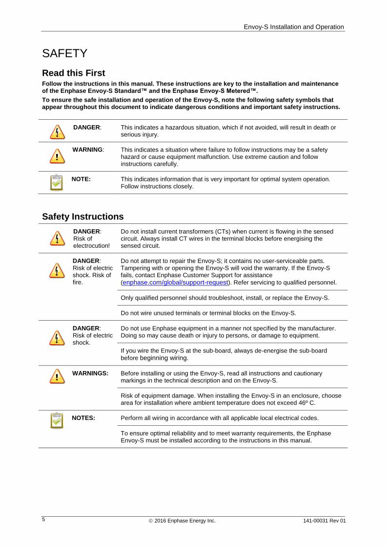
To ensure the safe installation and operation of the Envoy-S, note the following safety symbols that appear throughout this document to indicate dangerous conditions and important safety instructions.
DANGER: This indicates a hazardous situation, which if not avoided, will result in death or serious injury.
WARNING: This indicates a situation where failure to follow instructions may be a safety hazard or cause equipment malfunction. Use extreme caution and follow instructions carefully.
NOTE: This indicates information that is very important for optimal system operation. Follow instructions closely.
Safety Instructions
DANGER: Risk of electrocution!
Do not install current transformers (CTs) when current is flowing in the sensed circuit. Always install CT wires in the terminal blocks before energising the sensed circuit.
DANGER: Risk of electric shock. Risk of fire.
Do not attempt to repair the Envoy-S; it contains no user-serviceable parts. Tampering with or opening the Envoy-S will void the warranty. If the Envoy-S fails, contact Enphase Customer Support for assistance
(enphase.com/global/support-request). Refer servicing to qualified personnel.
Only qualified personnel should troubleshoot, install, or replace the Envoy-S.
Do not wire unused terminals or terminal blocks on the Envoy-S.
DANGER: Risk of electric shock.
Do not use Enphase equipment in a manner not specified by the manufacturer. Doing so may cause death or injury to persons, or damage to equipment.
If you wire the Envoy-S at the sub-board, always de-energise the sub-board
before beginning wiring.
WARNINGS: Before installing or using the Envoy-S, read all instructions and cautionary markings in the technical description and on the Envoy-S.
Risk of equipment damage. When installing the Envoy-S in an enclosure, choose area for installation where ambient temperature does not exceed 46º C.
NOTES: Perform all wiring in accordance with all applicable local electrical codes.
To ensure optimal reliability and to meet warranty requirements, the Enphase Envoy-S must be installed according to the instructions in this manual.
Envoy-S Installation and Operation
2016 Enphase Energy Inc. 141-00031 Rev 01 6
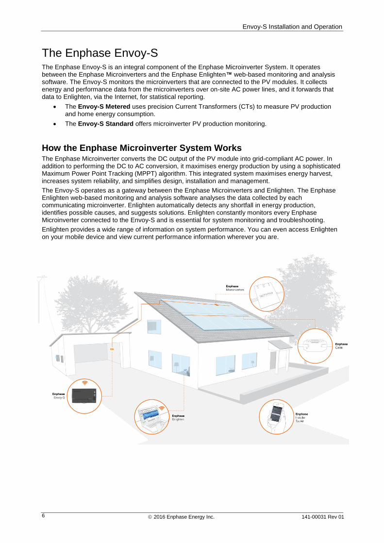
The Enphase Envoy-S The Enphase Envoy-S is an integral component of the Enphase Microinverter System. It operates between the Enphase Microinverters and the Enphase Enlighten™ web-based monitoring and analysis software. The Envoy-S monitors the microinverters that are connected to the PV modules. It collects energy and performance data from the microinverters over on-site AC power lines, and it forwards that data to Enlighten, via the Internet, for statistical reporting.
The Envoy-S Metered uses precision Current Transformers (CTs) to measure PV production and home energy consumption.
The Envoy-S Standard offers microinverter PV production monitoring.
How the Enphase Microinverter System Works The Enphase Microinverter converts the DC output of the PV module into grid-compliant AC power. In addition to performing the DC to AC conversion, it maximises energy production by using a sophisticated Maximum Power Point Tracking (MPPT) algorithm. This integrated system maximises energy harvest, increases system reliability, and simplifies design, installation and management.
The Envoy-S operates as a gateway between the Enphase Microinverters and Enlighten. The Enphase Enlighten web-based monitoring and analysis software analyses the data collected by each communicating microinverter. Enlighten automatically detects any shortfall in energy production, identifies possible causes, and suggests solutions. Enlighten constantly monitors every Enphase Microinverter connected to the Envoy-S and is essential for system monitoring and troubleshooting.
Enlighten provides a wide range of information on system performance. You can even access Enlighten on your mobile device and view current performance information wherever you are.
Envoy-S Installation and Operation
2016 Enphase Energy Inc. 141-00031 Rev 01 7
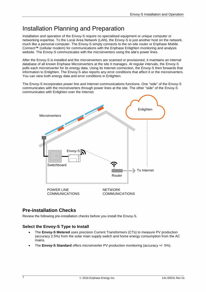
Installation Planning and Preparation Installation and operation of the Envoy-S require no specialised equipment or unique computer or networking expertise. To the Local Area Network (LAN), the Envoy-S is just another host on the network, much like a personal computer. The Envoy-S simply connects to the on-site router or Enphase Mobile Connect™ (cellular modem) for communications with the Enphase Enlighten monitoring and analysis website. The Envoy-S communicates with the microinverters using the site’s power lines. After the Envoy-S is installed and the microinverters are scanned or provisioned, it maintains an internal database of all known Enphase Microinverters at the site it manages. At regular intervals, the Envoy-S polls each microinverter for its energy data. Using its Internet connection, the Envoy-S then forwards that information to Enlighten. The Envoy-S also reports any error conditions that affect it or the microinverters. You can view both energy data and error conditions in Enlighten. The Envoy-S incorporates power line and Internet communications functions. One "side" of the Envoy-S communicates with the microinverters through power lines at the site. The other "side" of the Envoy-S communicates with Enlighten over the Internet.
Pre-installation Checks Review the following pre-installation checks before you install the Envoy-S.
Select the Envoy-S Type to Install
The Envoy-S Metered uses precision Current Transformers (CTs) to measure PV production (accuracy 2.5%) from the solar main supply switch and home energy consumption from the AC mains.
The Envoy-S Standard offers microinverter PV production monitoring (accuracy +/- 5%).
Enlighten
Microinverters
Router
Envoy-S
POWER LINE COMMUNICATIONS
NETWORK COMMUNICATIONS
To Internet
Switchboard
Envoy-S Installation and Operation
2016 Enphase Energy Inc. 141-00031 Rev 01 8
Download the Installer Toolkit App
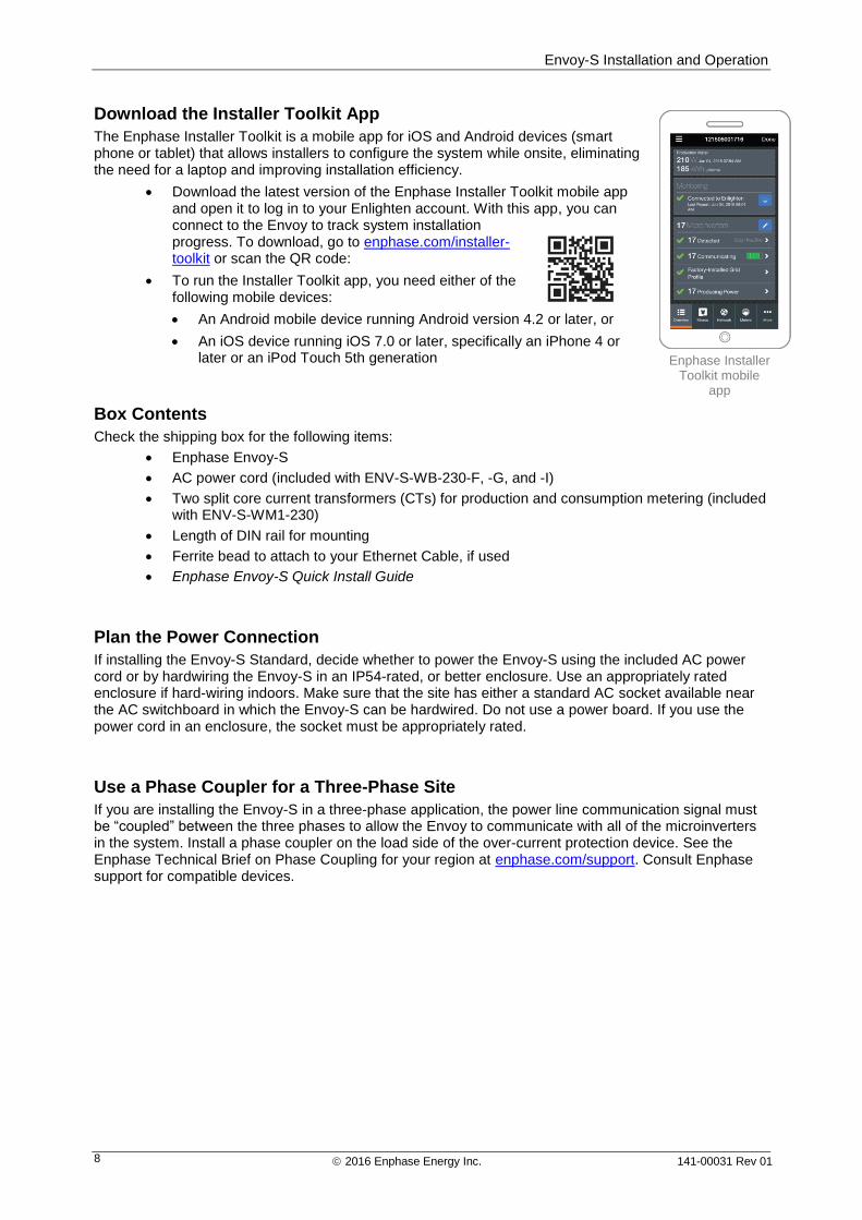
The Enphase Installer Toolkit is a mobile app for iOS and Android devices (smart phone or tablet) that allows installers to configure the system while onsite, eliminating the need for a laptop and improving installation efficiency.
Download the latest version of the Enphase Installer Toolkit mobile app and open it to log in to your Enlighten account. With this app, you can connect to the Envoy to track system installation progress. To download, go to enphase.com/installer-toolkit or scan the QR code:
To run the Installer Toolkit app, you need either of the following mobile devices:
An Android mobile device running Android version 4.2 or later, or
An iOS device running iOS 7.0 or later, specifically an iPhone 4 or later or an iPod Touch 5th generation
Box Contents
Check the shipping box for the following items:
Enphase Envoy-S
AC power cord (included with ENV-S-WB-230-F, -G, and -I)
Two split core current transformers (CTs) for production and consumption metering (included with ENV-S-WM1-230)
Length of DIN rail for mounting
Ferrite bead to attach to your Ethernet Cable, if used
Enphase Envoy-S Quick Install Guide
Plan the Power Connection
If installing the Envoy-S Standard, decide whether to power the Envoy-S using the included AC power cord or by hardwiring the Envoy-S in an IP54-rated, or better enclosure. Use an appropriately rated enclosure if hard-wiring indoors. Make sure that the site has either a standard AC socket available near the AC switchboard in which the Envoy-S can be hardwired. Do not use a power board. If you use the power cord in an enclosure, the socket must be appropriately rated.
Use a Phase Coupler for a Three-Phase Site
If you are installing the Envoy-S in a three-phase application, the power line communication signal must be “coupled” between the three phases to allow the Envoy to communicate with all of the microinverters in the system. Install a phase coupler on the load side of the over-current protection device. See the Enphase Technical Brief on Phase Coupling for your region at enphase.com/support. Consult Enphase support for compatible devices.
Enphase Installer Toolkit mobile
app
Envoy-S Installation and Operation
2016 Enphase Energy Inc. 141-00031 Rev 01 9
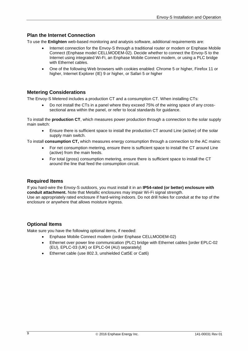
Plan the Internet Connection
To use the Enlighten web-based monitoring and analysis software, additional requirements are:
Internet connection for the Envoy-S through a traditional router or modem or Enphase Mobile Connect (Enphase model CELLMODEM-02). Decide whether to connect the Envoy-S to the Internet using integrated Wi-Fi, an Enphase Mobile Connect modem, or using a PLC bridge with Ethernet cables.
One of the following Web browsers with cookies enabled: Chrome 5 or higher, Firefox 11 or higher, Internet Explorer (IE) 9 or higher, or Safari 5 or higher
Metering Considerations
The Envoy-S Metered includes a production CT and a consumption CT. When installing CTs:
Do not install the CTs in a panel where they exceed 75% of the wiring space of any cross-sectional area within the panel, or refer to local standards for guidance.
To install the production CT, which measures power production through a connection to the solar supply main switch:
Ensure there is sufficient space to install the production CT around Line (active) of the solar supply main switch.
To install consumption CT, which measures energy consumption through a connection to the AC mains:
For net consumption metering, ensure there is sufficient space to install the CT around Line (active) from the main feeds.
For total (gross) consumption metering, ensure there is sufficient space to install the CT around the line that feed the consumption circuit.
Required Items
If you hard-wire the Envoy-S outdoors, you must install it in an IP54-rated (or better) enclosure with conduit attachment. Note that Metallic enclosures may impair Wi-Fi signal strength. Use an appropriately rated enclosure if hard-wiring indoors. Do not drill holes for conduit at the top of the enclosure or anywhere that allows moisture ingress.
Optional Items
Make sure you have the following optional items, if needed:
Enphase Mobile Connect modem (order Enphase CELLMODEM-02)
Ethernet over power line communication (PLC) bridge with Ethernet cables [order EPLC-02 (EU), EPLC-03 (UK) or EPLC-04 (AU) separately]
Ethernet cable (use 802.3, unshielded Cat5E or Cat6)
Envoy-S Installation and Operation
2016 Enphase Energy Inc. 141-00031 Rev 01 10
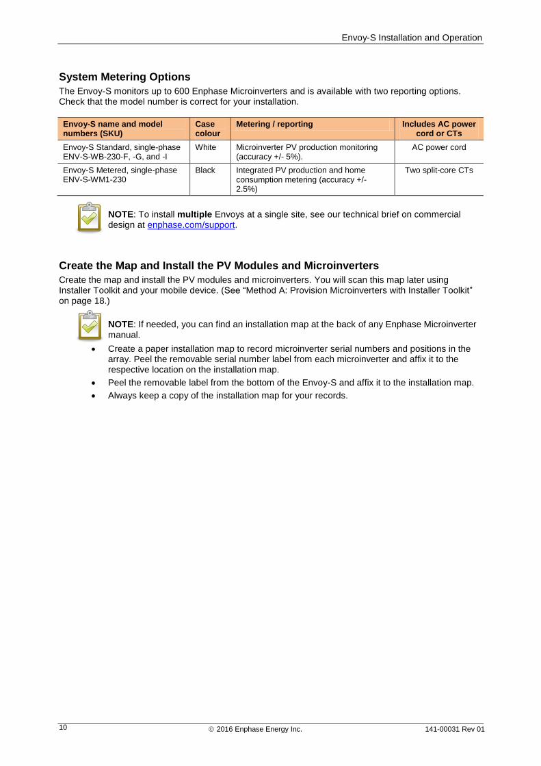
System Metering Options
The Envoy-S monitors up to 600 Enphase Microinverters and is available with two reporting options. Check that the model number is correct for your installation.
Envoy-S name and model numbers (SKU)
Case colour
Metering / reporting Includes AC power cord or CTs
Envoy-S Standard, single-phase ENV-S-WB-230-F, -G, and -I
White Microinverter PV production monitoring (accuracy +/- 5%).
AC power cord
Envoy-S Metered, single-phase ENV-S-WM1-230
Black Integrated PV production and home consumption metering (accuracy +/- 2.5%)
Two split-core CTs
NOTE: To install multiple Envoys at a single site, see our technical brief on commercial design at enphase.com/support.
Create the Map and Install the PV Modules and Microinverters
Create the map and install the PV modules and microinverters. You will scan this map later using Installer Toolkit and your mobile device. (See “Method A: Provision Microinverters with Installer Toolkit” on page 18.)
NOTE: If needed, you can find an installation map at the back of any Enphase Microinverter manual.
Create a paper installation map to record microinverter serial numbers and positions in the array. Peel the removable serial number label from each microinverter and affix it to the respective location on the installation map.
Peel the removable label from the bottom of the Envoy-S and affix it to the installation map.
Always keep a copy of the installation map for your records.
Envoy-S Installation and Operation
2016 Enphase Energy Inc. 141-00031 Rev 01 11
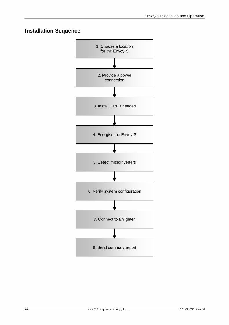
Installation Sequence
1. Choose a location for the Envoy-S
2. Provide a power connection
4. Energise the Envoy-S
7. Connect to Enlighten
8. Send summary report
6. Verify system configuration
5. Detect microinverters
3. Install CTs, if needed
Envoy-S Installation and Operation
2016 Enphase Energy Inc. 141-00031 Rev 01 12
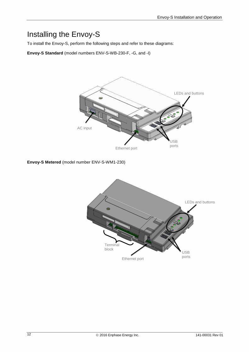
Installing the Envoy-S To install the Envoy-S, perform the following steps and refer to these diagrams: Envoy-S Standard (model numbers ENV-S-WB-230-F, -G, and -I)
Envoy-S Metered (model number ENV-S-WM1-230)
USB ports
LEDs and buttons
AC input
Ethernet port
Terminal block
USB ports
LEDs and buttons
Ethernet port
Envoy-S Installation and Operation
2016 Enphase Energy Inc. 141-00031 Rev 01 13
1. Choose a Location for the Envoy-S a. Install the Envoy-S near the switchboard. This ensures that the Envoy-S receives the strongest
possible communications signal from each microinverter.
b. If you are installing the Envoy-S in a three-phase application, the power line communication signal must be “coupled” between the three phases to allow the Envoy to communicate with all of the microinverters in the system. Install a phase coupler on the load side of the over-current protection device. See the Enphase Technical Brief on Phase Coupling for your region at enphase.com/support.
c. Install the Envoy-S in a protected dry space (such as a garage, attic, basement, or other cool, dry location) and, if the Envoy-S is hard-wired outdoors, you must also install it inside an IP54-rated, or better enclosure with conduit attachment. Use an appropriately rated enclosure if hard-wiring indoors.
NOTE: Metallic enclosures may impair Wi-Fi signal strength.
d. Mount the Envoy horizontally using the included DIN rail.
WARNING: Risk of equipment damage. When installing the Envoy-S in an enclosure, choose area for installation where ambient temperature does not exceed 46º C.
e. To wall-mount use two appropriately sized screws and a screwdriver. Mount the DIN rail first, and then clip the Envoy-S to the DIN rail.
2. Provide a Power Connection The Envoy-S is available in two configurations.
The Envoy-S Standard (ENV-S-WB-230-F, -G, and -I) includes an AC power cord.
The Envoy-S Metered (ENV-S-WM1-230) does not include an AC power cord, and you must hard-wire it.
The following sections provide separate instructions for the two configurations.
Provide Power for the Envoy-S Standard (ENV-S-WB-230-F, -G, and -I)
Use one of the following methods to provide power to the Envoy-S Standard.
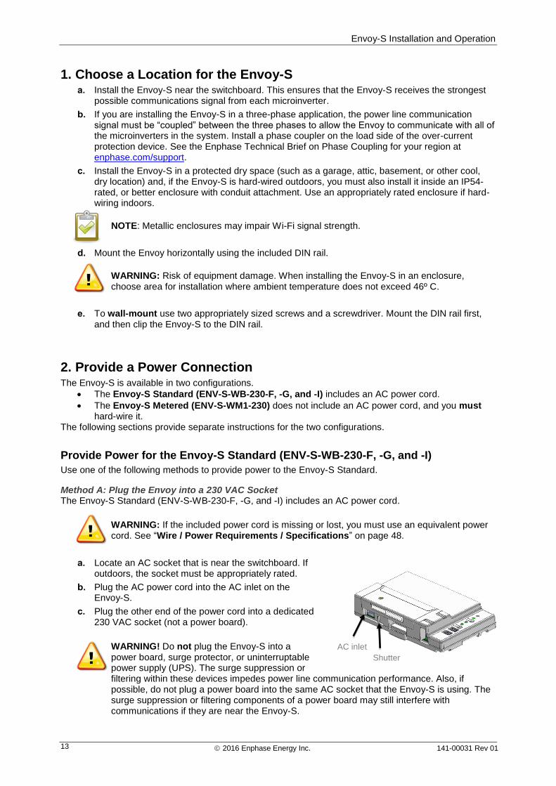
Method A: Plug the Envoy into a 230 VAC Socket The Envoy-S Standard (ENV-S-WB-230-F, -G, and -I) includes an AC power cord.
WARNING: If the included power cord is missing or lost, you must use an equivalent power cord. See “Wire / Power Requirements / Specifications” on page 48.
a. Locate an AC socket that is near the switchboard. If outdoors, the socket must be appropriately rated.
b. Plug the AC power cord into the AC inlet on the Envoy-S.
c. Plug the other end of the power cord into a dedicated 230 VAC socket (not a power board).
WARNING! Do not plug the Envoy-S into a power board, surge protector, or uninterruptable power supply (UPS). The surge suppression or filtering within these devices impedes power line communication performance. Also, if possible, do not plug a power board into the same AC socket that the Envoy-S is using. The surge suppression or filtering components of a power board may still interfere with communications if they are near the Envoy-S.
AC inlet
Shutter
Envoy-S Installation and Operation
2016 Enphase Energy Inc. 141-00031 Rev 01 14
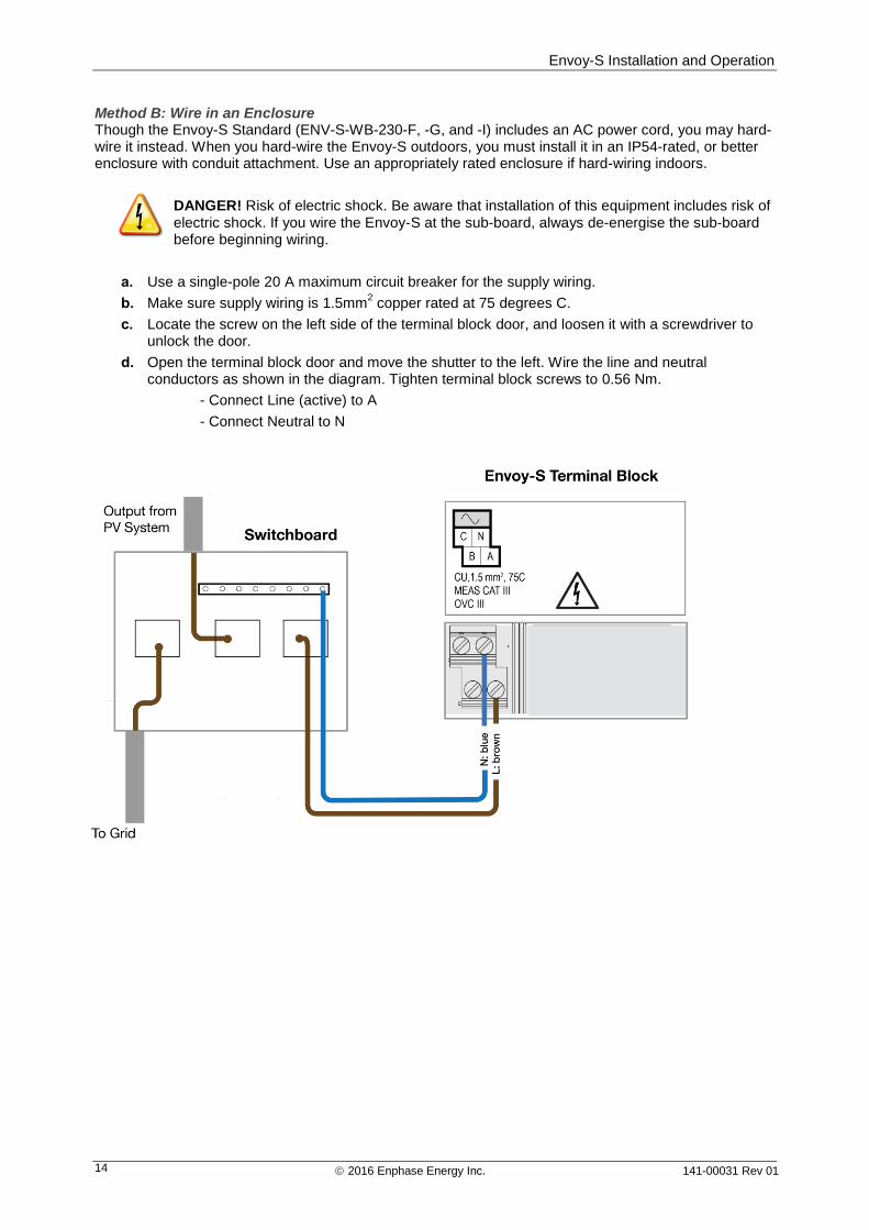
Method B: Wire in an Enclosure Though the Envoy-S Standard (ENV-S-WB-230-F, -G, and -I) includes an AC power cord, you may hard-wire it instead. When you hard-wire the Envoy-S outdoors, you must install it in an IP54-rated, or better enclosure with conduit attachment. Use an appropriately rated enclosure if hard-wiring indoors.
DANGER! Risk of electric shock. Be aware that installation of this equipment includes risk of electric shock. If you wire the Envoy-S at the sub-board, always de-energise the sub-board before beginning wiring.
a. Use a single-pole 20 A maximum circuit breaker for the supply wiring.
b. Make sure supply wiring is 1.5mm2 copper rated at 75 degrees C.
c. Locate the screw on the left side of the terminal block door, and loosen it with a screwdriver to unlock the door.
d. Open the terminal block door and move the shutter to the left. Wire the line and neutral conductors as shown in the diagram. Tighten terminal block screws to 0.56 Nm.
- Connect Line (active) to A
- Connect Neutral to N
Envoy-S Installation and Operation
2016 Enphase Energy Inc. 141-00031 Rev 01 15
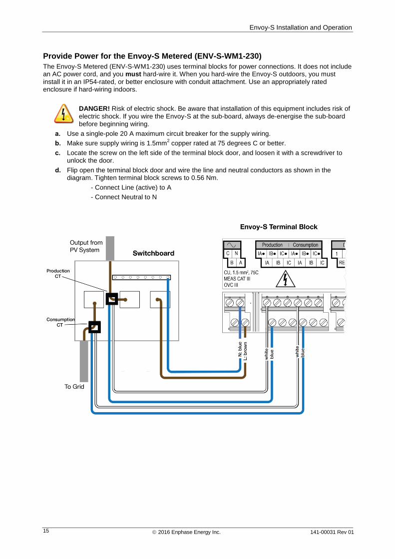
Provide Power for the Envoy-S Metered (ENV-S-WM1-230)
The Envoy-S Metered (ENV-S-WM1-230) uses terminal blocks for power connections. It does not include an AC power cord, and you must hard-wire it. When you hard-wire the Envoy-S outdoors, you must install it in an IP54-rated, or better enclosure with conduit attachment. Use an appropriately rated enclosure if hard-wiring indoors.
DANGER! Risk of electric shock. Be aware that installation of this equipment includes risk of electric shock. If you wire the Envoy-S at the sub-board, always de-energise the sub-board before beginning wiring.
a. Use a single-pole 20 A maximum circuit breaker for the supply wiring.
b. Make sure supply wiring is 1.5mm2 copper rated at 75 degrees C or better.
c. Locate the screw on the left side of the terminal block door, and loosen it with a screwdriver to unlock the door.
d. Flip open the terminal block door and wire the line and neutral conductors as shown in the diagram. Tighten terminal block screws to 0.56 Nm.
- Connect Line (active) to A
- Connect Neutral to N
Envoy-S Installation and Operation
2016 Enphase Energy Inc. 141-00031 Rev 0116
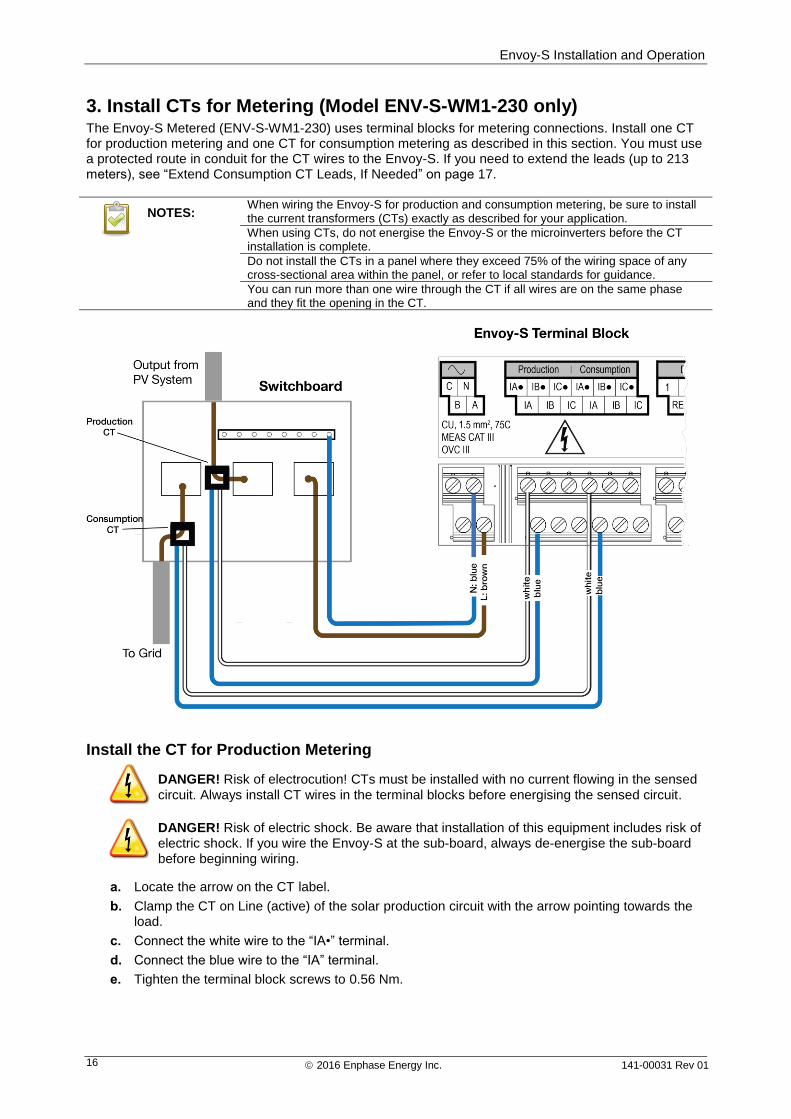
3. Install CTs for Metering (Model ENV-S-WM1-230 only)The Envoy-S Metered (ENV-S-WM1-230) uses terminal blocks for metering connections. Install one CT for production metering and one CT for consumption metering as described in this section. You must use a protected route in conduit for the CT wires to the Envoy-S. If you need to extend the leads (up to 213 meters), see “Extend Consumption CT Leads, If Needed” on page 17.
NOTES: When wiring the Envoy-S for production and consumption metering, be sure to install the current transformers (CTs) exactly as described for your application.
When using CTs, do not energise the Envoy-S or the microinverters before the CT installation is complete.
Do not install the CTs in a panel where they exceed 75% of the wiring space of any cross-sectional area within the panel, or refer to local standards for guidance.
You can run more than one wire through the CT if all wires are on the same phase and they fit the opening in the CT.
Install the CT for Production Metering
DANGER! Risk of electrocution! CTs must be installed with no current flowing in the sensed
circuit. Always install CT wires in the terminal blocks before energising the sensed circuit.
DANGER! Risk of electric shock. Be aware that installation of this equipment includes risk of electric shock. If you wire the Envoy-S at the sub-board, always de-energise the sub-board before beginning wiring.
a. Locate the arrow on the CT label.
b. Clamp the CT on Line (active) of the solar production circuit with the arrow pointing towards the load.
c. Connect the white wire to the “IA•” terminal.
d. Connect the blue wire to the “IA” terminal.
e. Tighten the terminal block screws to 0.56 Nm.
Envoy-S Installation and Operation
2016 Enphase Energy Inc. 141-00031 Rev 01 17
Install the CT for Consumption Metering (optional)
Install one split-core CT to provide consumption metering. Create a protected route with conduit for the CT wires to the Envoy-S.
DANGER! Risk of electrocution! CTs must be installed with no current flowing in the sensed circuit. Always install CT wires in the terminal blocks before energising the sensed circuit.
DANGER! Risk of electric shock. Be aware that installation of this equipment includes risk of electric shock. If you wire the Envoy-S at the sub-board, always de-energise the sub-board before beginning wiring. If it cannot be de-energised, a qualified electrician may safely install the CT as directed, making sure to connect the leads and then place the CT around the wire and latch.
WARNING! Do not install the CT in a panel where they exceed 75% of the wiring space of any cross-sectional area within the panel, or refer to local standards for guidance.
a. Make sure that the AC mains wire(s) are de-energised until you have secured the CT wires in the terminal blocks.
b. Connect the white wire to “IA•” and the blue wire to “IA”.
c. Clamp the CT on the solar supply Line (active). When the consumption CT is on the line (active) conductor, the arrow should point toward the load. Unlatch the CT and place Line (active) in through the opening. Latch the CT and listen for the click as it closes.
NOTE: Only run active conductors through the CT. The CT can monitor multiple active conductors.
d. Tighten the terminal block screws to 0.56 Nm.
Extend Consumption CT Leads, If Needed
If needed, an electrician may extend the leads of the consumption CT using the following guidance:
WARNING! To extend the CT leads, the electrician must use appropriately rated, 0.75mm2
to 1.5mm2, twisted pair wire and install it in accordance with all applicable electrical codes.
The electrician may add as much as three ohms round trip resistance to the consumption CT or up to 1.5 ohms per wire. For reference, the following maximum lengths at 75° C by gauge are:
64 meters of 0.75 mm2 7-strand Cu = 1.5 ohms
85 meters of 1 mm2 7-strand Cu = 1.5 ohms
128 meters of 1.5 mm2 7-strand Cu = 1.5 ohms
213 meters of 2.5 mm2 7-strand Cu = 1.5 ohms
Resistance figures may not be appropriate for all geographies or installation conditions. A qualified electrician must determine the wire gauge and type to obtain a maximum round trip resistance of three ohms.
Select wire that is code type and rated for voltage and temperature for the specific application. Mechanically protect the wires in a code type conduit or raceway. Use certified connectors for splices and insulated splices from one another and from the raceway, conduit, or junction box, if metallic.
Buried wires must be certified for direct burial and follow the code for installation. Do not bury splices unless in a certified junction box rated for the application, and use a certified moisture resistant connection method.
4. Energise the Envoy-S a. Close the terminal block door, and secure it with the screw.
b. Turn on the circuit feeding the Envoy-S.
c. All four LEDs flash amber during boot up. This typically takes 2 to 3 minutes. When boot up is
complete, the Microinverter Communications LED flashes amber indicating that that microinverters are not yet detected.
Envoy-S Installation and Operation
2016 Enphase Energy Inc. 141-00031 Rev 01 18
5. Detect the Microinverters Use one of the following methods to detect microinverters.
Method A: Provision Microinverters with Installer Toolkit
Use the Installer Toolkit mobile app to configure the Envoy-S with the serial numbers of the installed microinverters.
a. Launch Installer Toolkit and tap View Systems.
b. Select the system you are working with, or tap [+] to add a system.
c. Connect to the Envoy-S with your mobile device as described in the side note.
d. Return to Installer Toolkit. If the serial number for the Envoy-S you are installing is not displayed on the System Overview screen, tap the [+] next to the word “Envoys”. When the app displays the serial number of the Envoy-S, tap it to add it to the system.
e. Create the arrays and scan the serial numbers from the installation map as instructed by the Installer Toolkit Operation Manual at enphase.com/support.
f. Tap the Connect button. This provisions the scanned microinverters on the Envoy-S.
g. When prompted, confirm the number of microinverters that you installed.
h. The Microinverter Communications LED lights solid green if all of the provisioned devices are communicating or solid amber if any devices are not communicating.
Method B: Discover Microinverters with Installer Toolkit
a. Use the Installer Toolkit mobile app to set the number of microinverters the Envoy-S should search for on the power line. For more information, see the Installer Toolkit Operation Manual at enphase.com/support.
b. Connect to the Envoy-S with your mobile device as described in the side note.
c. Launch Installer Toolkit and tap Connect to an Envoy.
d. When prompted, enter the number of microinverters that you installed.
e. When prompted to start a device scan, tap OK.
The Microinverter Communications LED flashes green while scanning. It lights solid green when all of the microinverters you installed are communicating or solid amber if any devices are not communicating.
Method C: Discover Microinverters with the Envoy-S
If you are not using the Installer Toolkit app, press the Device Scan button on the Envoy-S. With this method, the Envoy searches the power line for 15 minutes, but does not know how many microinverters it should discover.
The Microinverter Communications LED flashes green for 15 minutes while scanning. At the end of the scan, it lights solid green if at least one microinverter was discovered or solid amber if no microinverters were discovered (or if any discovered microinverter stops communicating).
With All Methods
If the Microinverter Communications LED remains solid, see “Microinverter Detection Issues” on page
34.
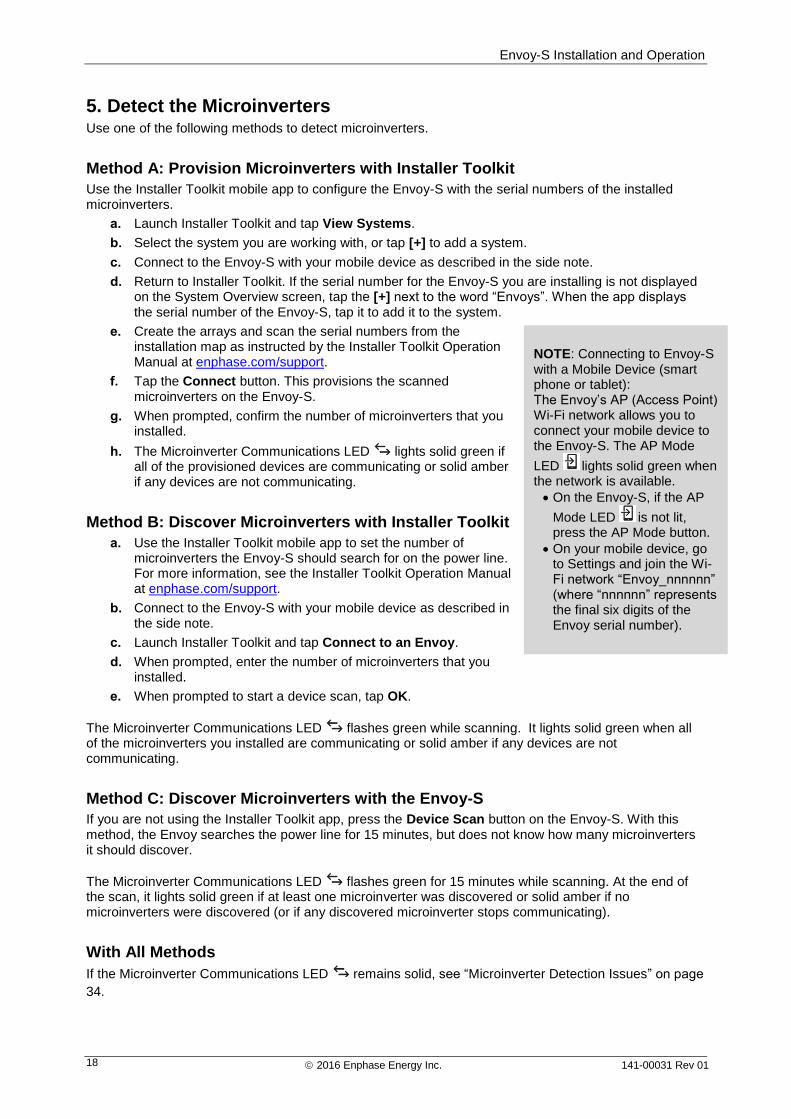
NOTE: Connecting to Envoy-S with a Mobile Device (smart phone or tablet): The Envoy’s AP (Access Point) Wi-Fi network allows you to connect your mobile device to the Envoy-S. The AP Mode
LED lights solid green when the network is available.
On the Envoy-S, if the AP
Mode LED is not lit, press the AP Mode button.
On your mobile device, go to Settings and join the Wi-Fi network “Envoy_nnnnnn” (where “nnnnnn” represents the final six digits of the Envoy serial number).
Envoy-S Installation and Operation
2016 Enphase Energy Inc. 141-00031 Rev 01 19
6. Verify System Configuration While still connected to Envoy-S with Installer Toolkit, check the Overview screen for the following:
a. Confirm that the expected number of devices are discovered and communicating.
b. Tap the Grid Profile row on the Overview screen to select and apply a grid profile to the microinverters. On the Overview screen, check that the new profile is set on all the microinverters. This may take up to 5 minutes.
c. Set up metering for the Envoy-S Metered (model ENV-S-WM1-230 only):
Tap the Meters button and check that Production Metering is enabled .
If you installed consumption metering CTs, tap the > to the right of Consumption Meter.
If the circuit that passes through the consumption CTs includes load with solar production, leave the type set to Net.
If the circuit that passes through the consumption CTs includes load only, change the type to Total (Gross).
Tap Enable Consumption Meter.
Return to the Overview screen and verify the meter reading(s).
WARNING! If using consumption metering, be sure to set the meter type correctly. You cannot change this setting once the meter is enabled.
NOTES:
Net metering considers the generation of the PV system and the household’s consumption and calculates the net outcome.
Total or gross metering measures the entire output of your system separate from your electricity consumption.
If you used Installer Toolkit to detect microinverters, the Power Production LED lights solid green when all expected microinverters are producing power. If you did not use Installer Toolkit, it lights solid green if all communicating microinverters are producing power. It flashes green when microinverters are
upgrading. Check Installer Toolkit for production status details. If the Power Production LED remains solid amber, see “Issue: Installer Toolkit Indicates that Scanning is Inhibited ” on page 35.
7. Connect to Enlighten The Envoy-S requires a connection to the Internet for reporting to Enlighten. You can provide this connection through an existing broadband router, other Wi-Fi access point at the installation site, or by using the Enphase Mobile Connect cellular modem.
WARNING! Risk of Equipment Damage. Do not remove power from the Envoy-S if the LEDs are flashing green. This indicates that a software upgrade is in progress.
Connect to a broadband router using one of these methods, described in the following sections:
Method A: Integrated Wi-Fi
Method B: Enphase Mobile Connect (order CELLMODEM-02 separately)
Method C: Ethernet cable (not included, installer must provide). This method requires that you use the ferrite bead included with the Envoy-S.
Method D: Power Line Communication Bridges [order EPLC-02 (EU), EPLC-03 (UK) or EPLC-04 (AU) separately]. This method requires that you use the ferrite bead included with the Envoy-S.
Method A: Integrated Wi-Fi
The Envoy-S integrated Wi-Fi operates at both 2.4GHz and 5GHz and supports several wireless security protocols in addition to Wi-Fi WPS. These include WEP Open System, WEP Shared Key, WPA-PSK, WPA2-PSK, WPA-EAP, and WPA2-EAP.
Envoy-S Installation and Operation
2016 Enphase Energy Inc. 141-00031 Rev 01 20
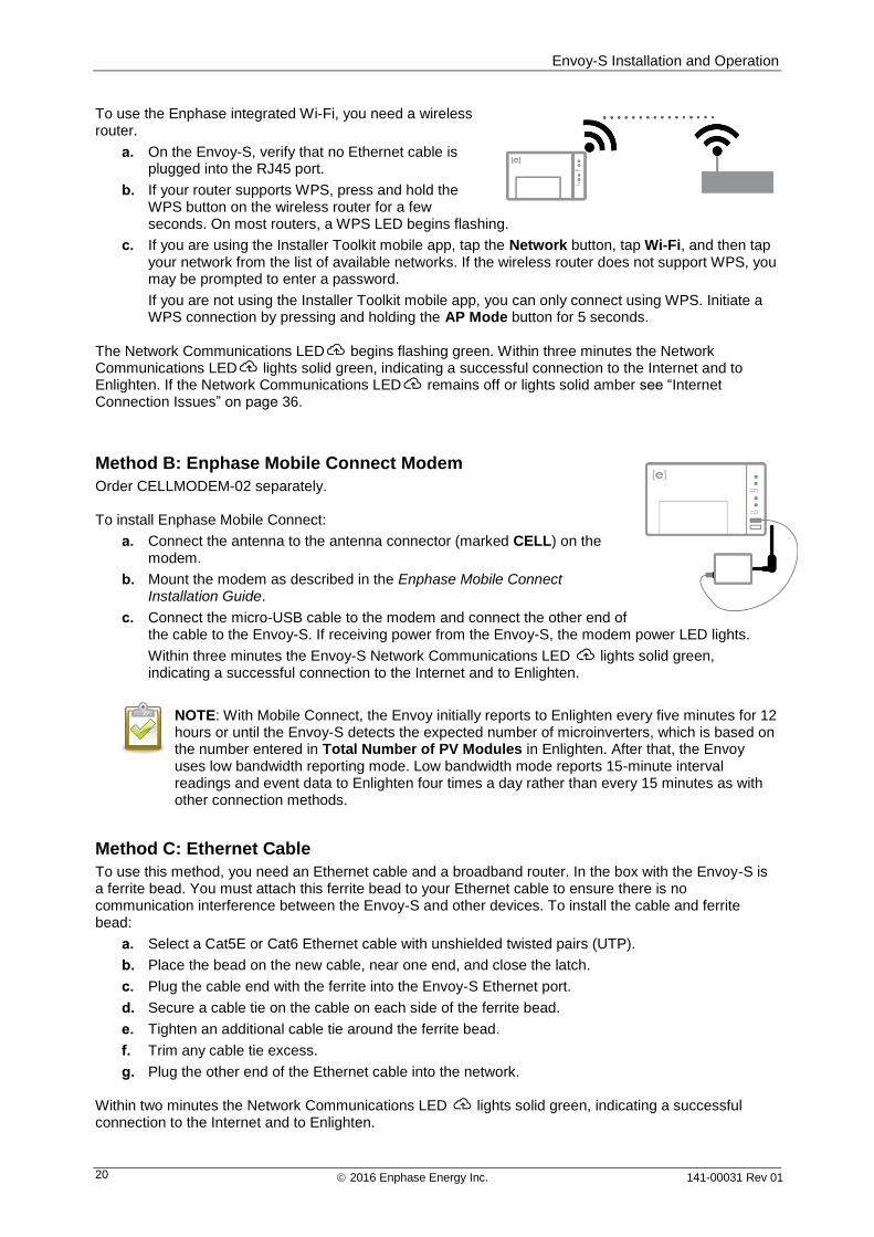
To use the Enphase integrated Wi-Fi, you need a wireless router.
a. On the Envoy-S, verify that no Ethernet cable is plugged into the RJ45 port.
b. If your router supports WPS, press and hold the WPS button on the wireless router for a few seconds. On most routers, a WPS LED begins flashing.
c. If you are using the Installer Toolkit mobile app, tap the Network button, tap Wi-Fi, and then tap your network from the list of available networks. If the wireless router does not support WPS, you may be prompted to enter a password.
If you are not using the Installer Toolkit mobile app, you can only connect using WPS. Initiate a WPS connection by pressing and holding the AP Mode button for 5 seconds.
The Network Communications LED begins flashing green. Within three minutes the Network Communications LED lights solid green, indicating a successful connection to the Internet and to Enlighten. If the Network Communications LED remains off or lights solid amber see “Internet Connection Issues” on page 36.
Method B: Enphase Mobile Connect Modem
Order CELLMODEM-02 separately. To install Enphase Mobile Connect:
a. Connect the antenna to the antenna connector (marked CELL) on the modem.
b. Mount the modem as described in the Enphase Mobile Connect Installation Guide.
c. Connect the micro-USB cable to the modem and connect the other end of the cable to the Envoy-S. If receiving power from the Envoy-S, the modem power LED lights.
Within three minutes the Envoy-S Network Communications LED lights solid green, indicating a successful connection to the Internet and to Enlighten.
NOTE: With Mobile Connect, the Envoy initially reports to Enlighten every five minutes for 12 hours or until the Envoy-S detects the expected number of microinverters, which is based on the number entered in Total Number of PV Modules in Enlighten. After that, the Envoy uses low bandwidth reporting mode. Low bandwidth mode reports 15-minute interval readings and event data to Enlighten four times a day rather than every 15 minutes as with other connection methods.
Method C: Ethernet Cable
To use this method, you need an Ethernet cable and a broadband router. In the box with the Envoy-S is a ferrite bead. You must attach this ferrite bead to your Ethernet cable to ensure there is no communication interference between the Envoy-S and other devices. To install the cable and ferrite bead:
a. Select a Cat5E or Cat6 Ethernet cable with unshielded twisted pairs (UTP).
b. Place the bead on the new cable, near one end, and close the latch.
c. Plug the cable end with the ferrite into the Envoy-S Ethernet port.
d. Secure a cable tie on the cable on each side of the ferrite bead.
e. Tighten an additional cable tie around the ferrite bead.
f. Trim any cable tie excess.
g. Plug the other end of the Ethernet cable into the network. Within two minutes the Network Communications LED lights solid green, indicating a successful connection to the Internet and to Enlighten.
Envoy-S Installation and Operation
2016 Enphase Energy Inc. 141-00031 Rev 01 21
When you use Ethernet cable, two small LEDs on the Ethernet port indicate Ethernet link and activity. The link LED is solid green when the cable is connected correctly, and the activity LED flashes green or yellow when data is sent or received.
Method D: Power Line Communication Bridges
Order EPLC-02 (EU), EPLC-03 (UK) or EPLC-04 (AU) separately. If you need to locate the Envoy-S away from the router, at a distance where an Ethernet cable is not practical or the wireless signal does not reach, use power line communication bridges with the Envoy-S. Bridges allow the Envoy-S to communicate with the broadband router over the site’s power lines. To install power line communication bridges:
h. Plug one of the bridges into the same AC socket that the Envoy-S is using.
i. Place the bead on the cable, near one end, and close the latch.
j. Plug the cable end with the ferrite into the Envoy-S Ethernet port.
k. Secure a tie wrap on the cable on each side of the ferrite bead.
l. Tighten an additional tie wrap around the ferrite bead.
m. Trim any tie wrap excess.
n. Plug the other end of the Ethernet cable into the bridge.
o. Plug the other bridge into an AC socket near the broadband router.
p. Connect one end of a second Ethernet cable to the second bridge, and connect the other end of the Ethernet cable into the broadband router.
Within two minutes the Network Communications LED lights solid green, indicating a successful connection to the Internet and to Enlighten.
If the Internet Connection Fails
After using any of these connection methods, if the Envoy-S does not connect to the Internet within five to ten minutes after you attempt a connection, see “Internet Connection Issues” on page 36.
8. Send System Summary Report When you have completed your system setup, you can generate and email a summary report.
a. From Installer Toolkit, tap Done in the upper-right corner of the screen to disconnect from the Envoy. Installer Toolkit will ask if you want to view a summary report.
b. Tap View Report. The report displays Envoy and system information with a list of microinverter serial numbers, their last power reports, and information about the grid profile applied to the microinverters.
c. Tap to email the report as needed as a record of successful system installation and for evidence of grid profile settings.
NOTE: If your mobile device is connected to the Envoy using AP mode, the email stays in the email outbox to be sent when the mobile device reconnects to the Internet. To disconnect from the Envoy network, go to Settings on your mobile device and disconnect from the Envoy-S Wi-Fi network “Envoy_nnnnnn” (where “nnnnnn” represents the final six digits of the Envoy serial number).
NOTE: If you connect to an Envoy after associating it to a system, the report includes a system name and address. For more information, refer to the Enphase Installer Toolkit Operation Manual at: enphase.com/support.
Envoy-S Installation and Operation
2016 Enphase Energy Inc. 141-00031 Rev 01 22
Activate Monitoring Register the Envoy-S for monitoring of the Enphase Microinverters in Enlighten at enlighten.enphaseenergy.com. Once you have registered the system and successfully installed the Envoy-S, Enlighten sets up an account for the site owner. When you complete the registration and installation, Enphase sends account information to the site owner so that they can log in to the Enlighten website and view system performance.
Method A: If the Envoy-S is Associated with a System in Installer Toolkit
a. On your mobile device, go to your Wi-Fi settings and disconnect from the Envoy’s AP network. This should restore Internet connectivity to your device.
b. Return to the Installer Toolkit app and tap the Sync button on the System Overview screen.
c. Log in to Enlighten and click on the system activation’s name from the installer dashboard.
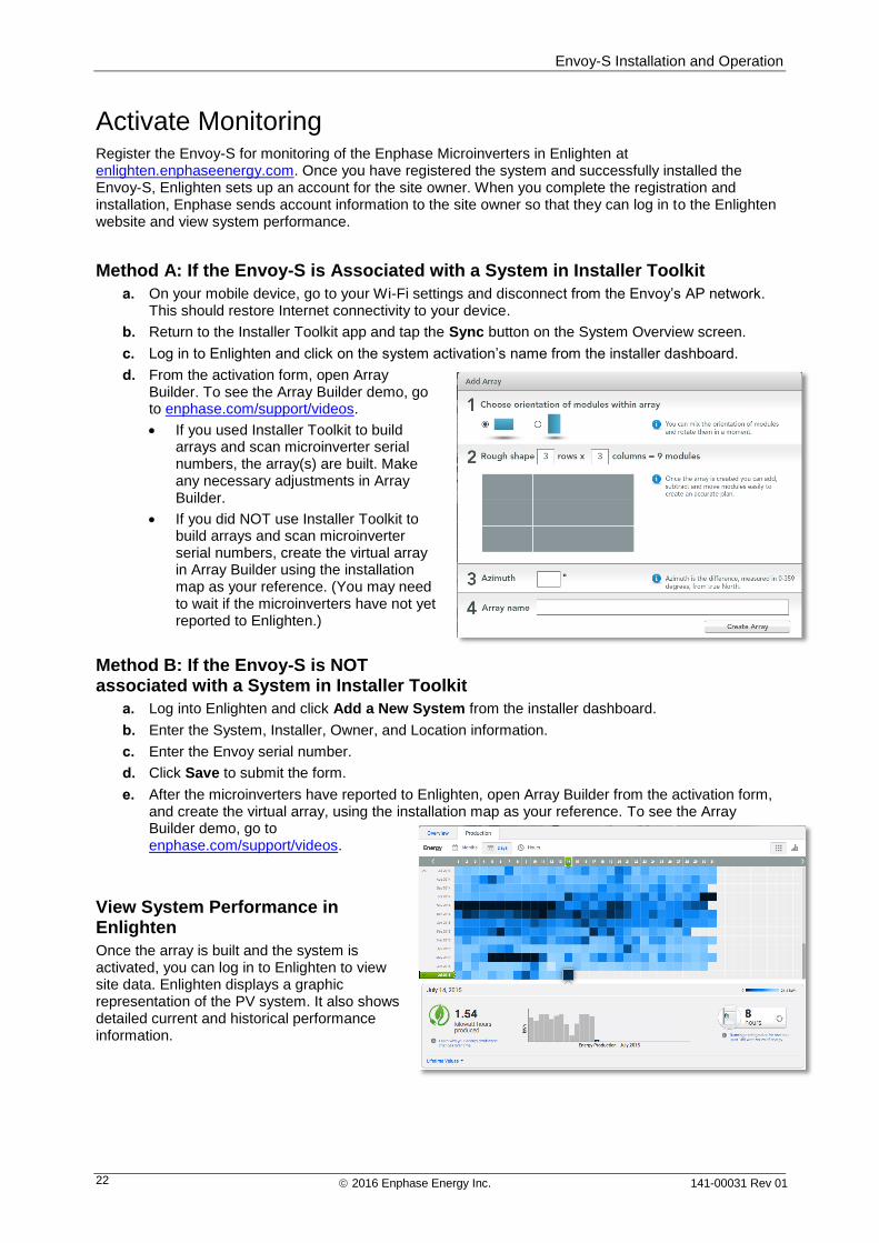
d. From the activation form, open Array Builder. To see the Array Builder demo, go to enphase.com/support/videos.
If you used Installer Toolkit to build arrays and scan microinverter serial numbers, the array(s) are built. Make any necessary adjustments in Array Builder.
If you did NOT use Installer Toolkit to build arrays and scan microinverter serial numbers, create the virtual array in Array Builder using the installation map as your reference. (You may need to wait if the microinverters have not yet reported to Enlighten.)
Method B: If the Envoy-S is NOT associated with a System in Installer Toolkit
a. Log into Enlighten and click Add a New System from the installer dashboard.
b. Enter the System, Installer, Owner, and Location information.
c. Enter the Envoy serial number.
d. Click Save to submit the form.
e. After the microinverters have reported to Enlighten, open Array Builder from the activation form, and create the virtual array, using the installation map as your reference. To see the Array Builder demo, go to enphase.com/support/videos.
View System Performance in Enlighten
Once the array is built and the system is activated, you can log in to Enlighten to view site data. Enlighten displays a graphic representation of the PV system. It also shows detailed current and historical performance information.
Envoy-S Installation and Operation
2016 Enphase Energy Inc. 141-00031 Rev 01 23
Envoy-S Operation
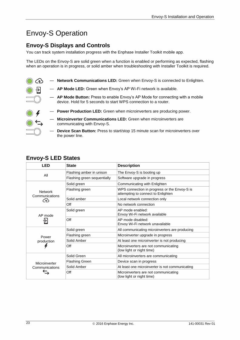
Envoy-S Displays and Controls You can track system installation progress with the Enphase Installer Toolkit mobile app. The LEDs on the Envoy-S are solid green when a function is enabled or performing as expected, flashing when an operation is in progress, or solid amber when troubleshooting with Installer Toolkit is required.
Envoy-S LED States
LED State Description
All Flashing amber in unison The Envoy-S is booting up
Flashing green sequentially Software upgrade in progress
Network
Communications
Solid green Communicating with Enlighten
Flashing green WPS connection in progress or the Envoy-S is attempting to connect to Enlighten
Solid amber Local network connection only
Off No network connection
AP mode
Solid green AP mode enabled: Envoy Wi-Fi network available
Off AP mode disabled: Envoy Wi-Fi network unavailable
Power
production
Solid green All communicating microinverters are producing
Flashing green Microinverter upgrade in progress
Solid Amber At least one microinverter is not producing
Off Microinverters are not communicating (low light or night time)
Microinverter
Communications
Solid Green All microinverters are communicating
Flashing Green Device scan in progress
Solid Amber At least one microinverter is not communicating
Off Microinverters are not communicating (low light or night time)
— Network Communications LED: Green when Envoy-S is connected to Enlighten.
— AP Mode LED: Green when Envoy’s AP Wi-Fi network is available.
— AP Mode Button: Press to enable Envoy’s AP Mode for connecting with a mobile
device. Hold for 5 seconds to start WPS connection to a router.
— Power Production LED: Green when microinverters are producing power.
— Microinverter Communications LED: Green when microinverters are
communicating with Envoy-S.
— Device Scan Button: Press to start/stop 15 minute scan for microinverters over
the power line.
Envoy-S Installation and Operation
2016 Enphase Energy Inc. 141-00031 Rev 01 24
LED Behaviour at Initial Start Up
When the Envoy-S starts up for the first time, it goes through the initial boot sequence. During this initial boot sequence, all the Envoy-S LEDs are flashing amber. If the Envoy-S retrieves a software update soon after connecting to the Internet, the LEDs flash green sequentially during the upgrade.
WARNING! Risk of Equipment Damage. Do not remove power from the Envoy-S if the LEDs are flashing green sequentially. This indicates that a software upgrade is in progress.
Initial Communications Check
The Envoy-S normally indicates no Internet connection for two to three minutes after the first start up. It then sends the first report to Enlighten. When Enlighten responds, the Network Communications LED lights solid green, indicating an Internet connection to Enlighten.
More about Microinverter Communications States
A detected microinverter is one that has been discovered via the Envoy’s device scan or provisioned via Installer Toolkit or Enlighten.
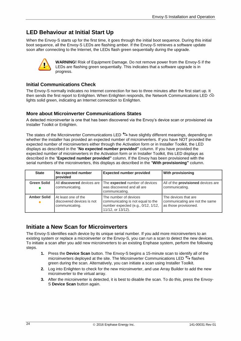
The states of the Microinverter Communications LED have slightly different meanings, depending on whether the installer has provided an expected number of microinverters. If you have NOT provided the expected number of microinverters either through the Activation form or in Installer Toolkit, the LED displays as described in the “No expected number provided” column. If you have provided the expected number of microinverters in the Activation form or in Installer Toolkit, this LED displays as described in the “Expected number provided” column. If the Envoy has been provisioned with the serial numbers of the microinverters, this displays as described in the “With provisioning” column.
State No expected number provided
Expected number provided With provisioning
Green Solid
All discovered devices are
communicating.
The expected number of devices
was discovered and all are communicating.
All of the provisioned devices are
communicating.
Amber Solid
At least one of the discovered devices is not communicating.
The number of devices communicating is not equal to the number expected (e.g., 0/12, 1/12, 11/12, or 13/12).
The devices that are communicating are not the same as those provisioned.
Initiate a New Scan for Microinverters The Envoy-S identifies each device by its unique serial number. If you add more microinverters to an existing system or replace a microinverter or the Envoy-S, you can run a scan to detect the new devices. To initiate a scan after you add new microinverters to an existing Enphase system, perform the following steps.
1. Press the Device Scan button. The Envoy-S begins a 15-minute scan to identify all of the
microinverters deployed at the site. The Microinverter Communications LED flashes green during the scan. Alternatively, you can initiate a scan using Installer Toolkit.
2. Log into Enlighten to check for the new microinverter, and use Array Builder to add the new microinverter to the virtual array.
3. After the microinverter is detected, it is best to disable the scan. To do this, press the Envoy-S Device Scan button again.
Envoy-S Installation and Operation
2016 Enphase Energy Inc. 141-00031 Rev 01 25
Connecting to Envoy-S There are several ways to connect with the Envoy-S to check status or do configuration tasks:
Connect wirelessly using Installer Toolkit
Connect remotely using Enlighten
Connect using a computer or mobile device with the Envoy-S local interface
Connect Using the Installer Toolkit App The Enphase Installer Toolkit is a mobile app that provides installers with onsite system configuration capabilities.
Options for establishing a connection between the Installer Toolkit app and the Envoy-S are:
Connect the mobile device to the same LAN as the Envoy-S using the site’s wireless router.
Use the Envoy-S to create a wireless Access Point (AP).
Method A: Use the Site’s Wireless Router to Connect to the Envoy-S
To use the site’s wireless router, select Settings on your mobile device and then select Wi-Fi. Tap the network you want to join from the list of available networks.
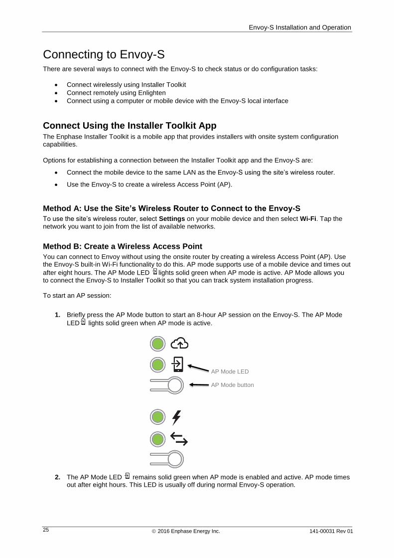
Method B: Create a Wireless Access Point
You can connect to Envoy without using the onsite router by creating a wireless Access Point (AP). Use the Envoy-S built-in Wi-Fi functionality to do this. AP mode supports use of a mobile device and times out
after eight hours. The AP Mode LED lights solid green when AP mode is active. AP Mode allows you to connect the Envoy-S to Installer Toolkit so that you can track system installation progress. To start an AP session:
1. Briefly press the AP Mode button to start an 8-hour AP session on the Envoy-S. The AP Mode
LED lights solid green when AP mode is active.
2. The AP Mode LED remains solid green when AP mode is enabled and active. AP mode times out after eight hours. This LED is usually off during normal Envoy-S operation.
AP Mode LED
AP Mode button
Envoy-S Installation and Operation
2016 Enphase Energy Inc. 141-00031 Rev 01 26
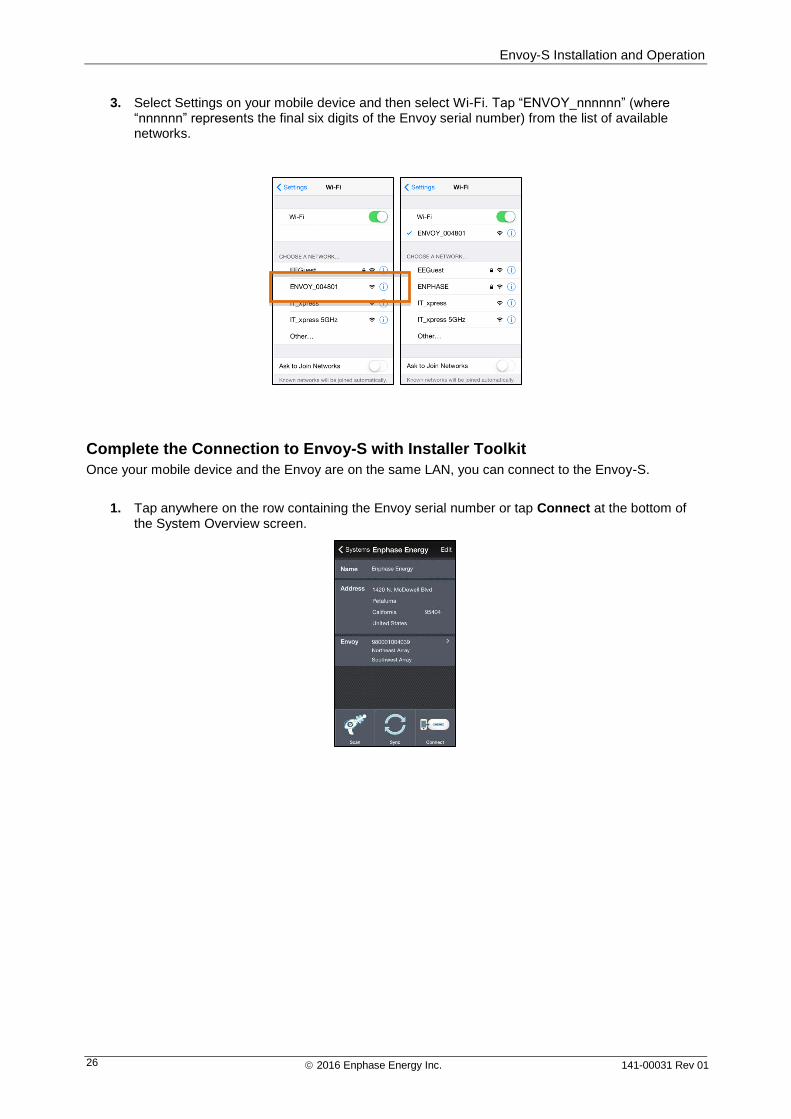
3. Select Settings on your mobile device and then select Wi-Fi. Tap “ENVOY_nnnnnn” (where “nnnnnn” represents the final six digits of the Envoy serial number) from the list of available networks.
Complete the Connection to Envoy-S with Installer Toolkit
Once your mobile device and the Envoy are on the same LAN, you can connect to the Envoy-S.
1. Tap anywhere on the row containing the Envoy serial number or tap Connect at the bottom of the System Overview screen.
Envoy-S Installation and Operation
2016 Enphase Energy Inc. 141-00031 Rev 01 27
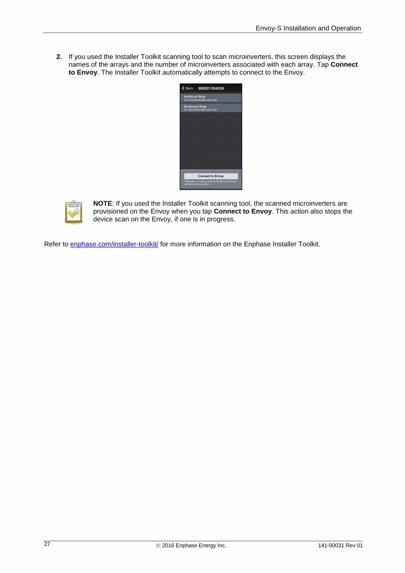
2. If you used the Installer Toolkit scanning tool to scan microinverters, this screen displays the names of the arrays and the number of microinverters associated with each array. Tap Connect to Envoy. The Installer Toolkit automatically attempts to connect to the Envoy.
NOTE: If you used the Installer Toolkit scanning tool, the scanned microinverters are provisioned on the Envoy when you tap Connect to Envoy. This action also stops the device scan on the Envoy, if one is in progress.
Refer to enphase.com/installer-toolkit/ for more information on the Enphase Installer Toolkit.
Envoy-S Installation and Operation
2016 Enphase Energy Inc. 141-00031 Rev 01 28
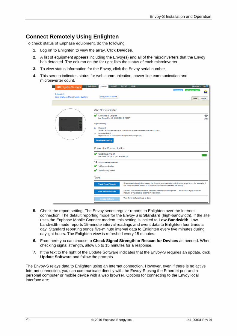
Connect Remotely Using Enlighten To check status of Enphase equipment, do the following:
1. Log on to Enlighten to view the array. Click Devices.
2. A list of equipment appears including the Envoy(s) and all of the microinverters that the Envoy has detected. The column on the far right lists the status of each microinverter.
3. To view status information for the Envoy, click the Envoy serial number.
4. This screen indicates status for web communication, power line communication and microinverter count.
5. Check the report setting. The Envoy sends regular reports to Enlighten over the Internet connection. The default reporting mode for the Envoy-S is Standard (high-bandwidth). If the site uses the Enphase Mobile Connect modem, this setting is locked to Low-Bandwidth. Low bandwidth mode reports 15-minute interval readings and event data to Enlighten four times a day. Standard reporting sends five-minute interval data to Enlighten every five minutes during daylight hours. The Enlighten view is refreshed every 15 minutes.
6. From here you can choose to Check Signal Strength or Rescan for Devices as needed. When checking signal strength, allow up to 15 minutes for a response.
7. If the text to the right of the Update Software indicates that the Envoy-S requires an update, click Update Software and follow the prompts.
The Envoy-S relays data to Enlighten using an Internet connection. However, even if there is no active Internet connection, you can communicate directly with the Envoy-S using the Ethernet port and a personal computer or mobile device with a web browser. Options for connecting to the Envoy local interface are:
Envoy-S Installation and Operation
2016 Enphase Energy Inc. 141-00031 Rev 01 29
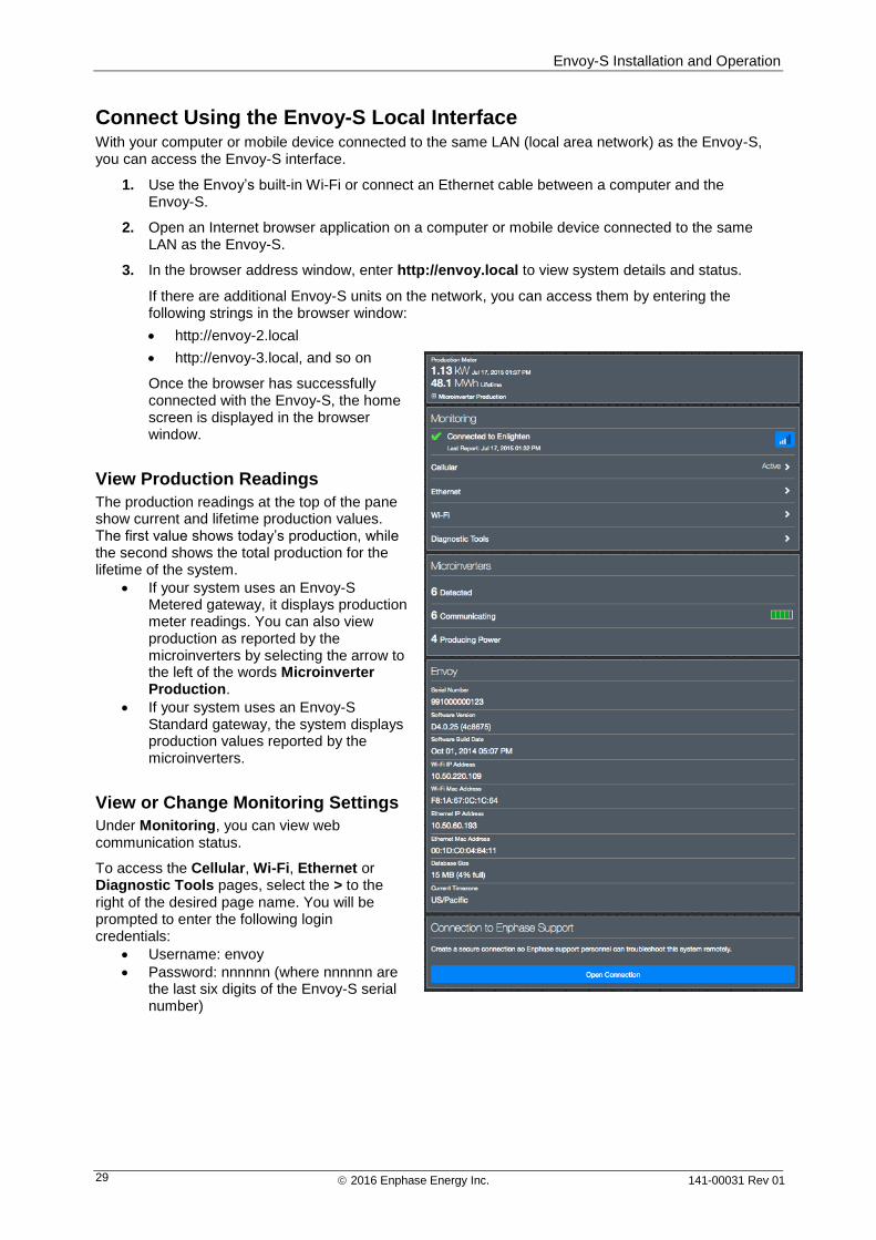
Connect Using the Envoy-S Local Interface With your computer or mobile device connected to the same LAN (local area network) as the Envoy-S, you can access the Envoy-S interface.
1. Use the Envoy’s built-in Wi-Fi or connect an Ethernet cable between a computer and the Envoy-S.
2. Open an Internet browser application on a computer or mobile device connected to the same LAN as the Envoy-S.
3. In the browser address window, enter http://envoy.local to view system details and status.
If there are additional Envoy-S units on the network, you can access them by entering the following strings in the browser window:
http://envoy-2.local
http://envoy-3.local, and so on
Once the browser has successfully connected with the Envoy-S, the home screen is displayed in the browser window.
View Production Readings
The production readings at the top of the pane show current and lifetime production values. The first value shows today’s production, while the second shows the total production for the lifetime of the system.
If your system uses an Envoy-S Metered gateway, it displays production meter readings. You can also view production as reported by the microinverters by selecting the arrow to the left of the words Microinverter Production.
If your system uses an Envoy-S Standard gateway, the system displays production values reported by the microinverters.
View or Change Monitoring Settings
Under Monitoring, you can view web communication status.
To access the Cellular, Wi-Fi, Ethernet or Diagnostic Tools pages, select the > to the right of the desired page name. You will be prompted to enter the following login credentials:
Username: envoy
Password: nnnnnn (where nnnnnn are the last six digits of the Envoy-S serial number)
Envoy-S Installation and Operation
2016 Enphase Energy Inc. 141-00031 Rev 01 30
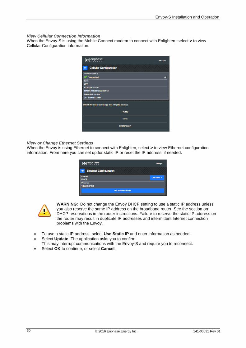
View Cellular Connection Information When the Envoy-S is using the Mobile Connect modem to connect with Enlighten, select > to view Cellular Configuration information.
View or Change Ethernet Settings When the Envoy is using Ethernet to connect with Enlighten, select > to view Ethernet configuration information. From here you can set up for static IP or reset the IP address, if needed.
WARNING: Do not change the Envoy DHCP setting to use a static IP address unless you also reserve the same IP address on the broadband router. See the section on DHCP reservations in the router instructions. Failure to reserve the static IP address on the router may result in duplicate IP addresses and intermittent Internet connection problems with the Envoy.
To use a static IP address, select Use Static IP and enter information as needed.
Select Update. The application asks you to confirm: This may interrupt communications with the Envoy-S and require you to reconnect.
Select OK to continue, or select Cancel.
Envoy-S Installation and Operation
2016 Enphase Energy Inc. 141-00031 Rev 01 31
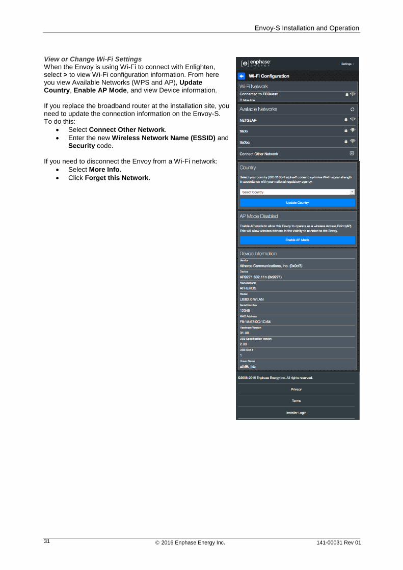
View or Change Wi-Fi Settings When the Envoy is using Wi-Fi to connect with Enlighten, select > to view Wi-Fi configuration information. From here you view Available Networks (WPS and AP), Update Country, Enable AP Mode, and view Device information. If you replace the broadband router at the installation site, you need to update the connection information on the Envoy-S. To do this:
Select Connect Other Network.
Enter the new Wireless Network Name (ESSID) and Security code.
If you need to disconnect the Envoy from a Wi-Fi network:
Select More Info.
Click Forget this Network.
Envoy-S Installation and Operation
2016 Enphase Energy Inc. 141-00031 Rev 01 32
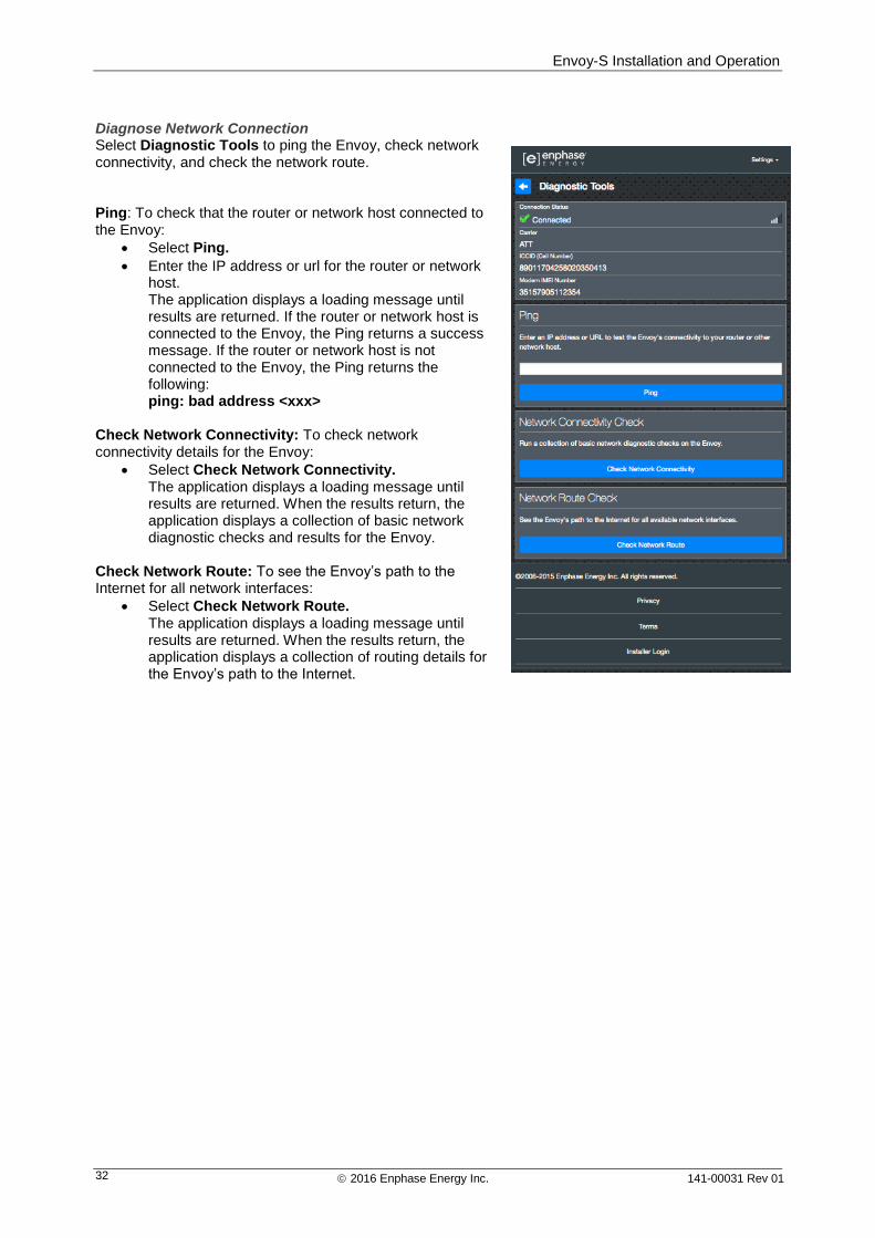
Diagnose Network Connection Select Diagnostic Tools to ping the Envoy, check network connectivity, and check the network route. Ping: To check that the router or network host connected to the Envoy:
Select Ping.
Enter the IP address or url for the router or network host. The application displays a loading message until results are returned. If the router or network host is connected to the Envoy, the Ping returns a success message. If the router or network host is not connected to the Envoy, the Ping returns the following: ping: bad address <xxx>
Check Network Connectivity: To check network connectivity details for the Envoy:
Select Check Network Connectivity. The application displays a loading message until results are returned. When the results return, the application displays a collection of basic network diagnostic checks and results for the Envoy.
Check Network Route: To see the Envoy’s path to the Internet for all network interfaces:
Select Check Network Route. The application displays a loading message until results are returned. When the results return, the application displays a collection of routing details for the Envoy’s path to the Internet.
Envoy-S Installation and Operation
2016 Enphase Energy Inc. 141-00031 Rev 01 33
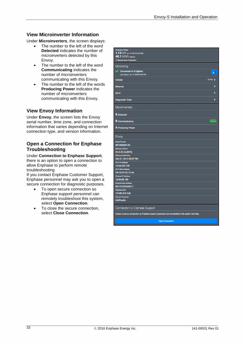
View Microinverter Information
Under Microinverters, the screen displays:
The number to the left of the word Detected indicates the number of microinverters detected by this Envoy.
The number to the left of the word Communicating indicates the number of microinverters communicating with this Envoy.
The number to the left of the words Producing Power indicates the number of microinverters communicating with this Envoy.
View Envoy Information
Under Envoy, the screen lists the Envoy serial number, time zone, and connection information that varies depending on Internet connection type, and version information.
Open a Connection for Enphase Troubleshooting
Under Connection to Enphase Support, there is an option to open a connection to allow Enphase to perform remote troubleshooting If you contact Enphase Customer Support, Enphase personnel may ask you to open a secure connection for diagnostic purposes.
To open secure connection so Enphase support personnel can remotely troubleshoot this system, select Open Connection.
To close the secure connection, select Close Connection.
Envoy-S Installation and Operation
2016 Enphase Energy Inc. 141-00031 Rev 01 34
Troubleshooting The following sections describe possible problems and solutions.
WARNING: Risk of electric shock. Risk of fire. Do not attempt to repair the Envoy-S; it contains no user-serviceable parts. Tampering with or opening the Envoy-S will void the warranty. If the Envoy-S fails, contact Enphase Customer Support for assistance (enphase.com/global/support-request). Warranty void if cover removed. Refer servicing to qualified personnel.
Microinverter Detection Issues Troubleshoot power line communication issues as follows.
Issue: Installer Toolkit Shows “Cross Domain Traffic Reported”
This means that communications from other Envoy(s) have been detected. To prevent this issue:
When multiple Envoy-S units exist on a common switchboard or transformer, commission only one system at a time at installation.
When multiple Envoy-S units on a common switchboard, use power line filters and separate the conduits and wires by at least 32 cm (12 inches).
If this alert persists or if the Installer Toolkit Microinverters screen (or Enlighten) shows more microinverters than expected, contact Enphase Customer support at enphase.com/global/support-request.
Issue: Microinverter Communications LED is Solid Amber
If the Microinverter Communications LED lights solid amber, it may be a result of low light levels. If there is not enough sunlight to power up the microinverters, they cannot communicate with the Envoy. If there is sufficient daylight for the microinverters to power up, the issue may be that the Envoy is having difficulty communicating over the power lines. To troubleshoot this issue:
Check the Installer Toolkit mobile app to see which microinverters are not communicating.
Check that the circuit breaker(s) for the PV array are in the “ON” position.
Verify that the PV modules are connected to the microinverters.
Verify the PV module DC voltage is within the allowable range for the microinverter.
Issue: Installer Toolkit Detects Fewer Microinverters than Expected
The Microinverters detected count shown in Installer Toolkit is an indication of the number of online microinverters producing power, reporting in to the Envoy, and not having any error conditions. If this number is lower than expected, it may indicate that the Envoy is not done scanning/discovering the entire array. Alternatively, it may indicate that the Envoy is having difficulty communicating over the power lines. It could also be a result of low light levels or that the PV module voltage is too low for the microinverter to power up. To troubleshoot the issue:
Check Enlighten or use the Installer Toolkit to connect to the Envoy to see if any microinverters are not reporting in to the Envoy or having any error conditions.
If installing the Envoy-S Standard, be sure that the Envoy is plugged directly into the wall and not into a power board or surge protector. Unplug any other device that is sharing the AC socket with the Envoy. Or, as an alternative, plug the Envoy into a circuit that supports fewer electronic appliances. Appliances sharing a power receptacle with the Envoy may interfere with power line communication.
Relocate your Envoy as close to the switchboard as possible. This ensures that the Envoy receives the strongest possible signal from each microinverter.
If this problem occurs when light levels are low, try again during daylight hours.
Envoy-S Installation and Operation
2016 Enphase Energy Inc. 141-00031 Rev 01 35
Issue: No Microinverters are Reporting
Check for the following conditions.
Has a device scan been run while the array was active? A device scan may have been run while the array was not connected to the grid or when the array was not powered by sunlight.
Run another scan during daylight hours.
Check that the circuit breaker(s) for the PV array are in the “ON” position. For the Envoy to communicate with the microinverters, the PV circuit breakers must be in the “ON” position at the switchboard.
Verify that the PV modules are connected to the microinverters.
Is the Envoy well located? The Envoy must be near the primary switchboard or the array's downstream sub-board. If installing the Envoy-S Standard:
Make sure the Envoy is not plugged into an AC socket strip or surge protector.
Plug the Envoy into an AC socket closer to the switch or sub-board.
Unplug other devices from the AC socket used for the Envoy.
As an alternative if signal strength is poor, power the Envoy from the solar production circuit (where local electrical code allows for monitoring equipment on the same circuit). This provides the best possible power line communications. The Envoy must be located indoors (a garage, attic, basement, or other cool, dry location) or in an IP54-rated enclosure. Remember that the Envoy must also have an Internet connection.
Is the system energised? PV modules power microinverters, PV modules provide power only during daylight hours, and microinverters communicate only when powered.
Run another scan during daylight hours.
Check that the circuit breaker(s) for the PV array are in the “ON” position. For the Envoy to communicate with the microinverters, the PV circuit breakers must be in the “ON” position at the Switchboard.
Verify that the PV modules are connected to the microinverters.
Is there a phase imbalance?
Ask the electrician to measure the conductors and neutral line to verify that the phases are balanced. If the phases are not balanced, electricians must recheck the wiring.
Is the Envoy-S plugged into a circuit on the primary switchboard while the PV circuit breakers are on a downstream sub-board? The primary switchboard is full and doesn’t have additional capacity to add circuit breakers.
Add a sub-board with a small subset of circuit breakers
Hard wire the Envoy-S into that sub-board, so that it can be close to the PV circuit breaker.
Issue: Installer Toolkit Indicates that Scanning is Inhibited
It is best to leave the Envoy in this condition for normal operation. However, if you need to re-enable scanning (for example, if you replace a microinverter) contact Enphase Customer Support (enphase.com/global/support-request).
Power Production Issues
Issue: Power Production LED is solid amber
The Power Production LED is solid green when all microinverters are producing, flashes green when a microinverter upgrade is in progress, flashes amber when microinverters are not yet detected, or becomes solid amber when any microinverter that is expected to produce is not. Check in Installer Toolkit to see which microinverters are affected.
Envoy-S Installation and Operation
2016 Enphase Energy Inc. 141-00031 Rev 01 36
If none of the microinverters are producing power, there may be a grid or wiring issue. First, verify that there is proper input voltage and frequency from the grid. Next, check the breaker and wiring, starting at the Switchboard.
If all of the non-productive microinverters are on the same branch, check the breaker and wiring starting at the junction box for the affected branch.
If only one or scattered microinverters are not producing power, first check to see that the AC connectors are fully seated in the Engage Cable connectors. Next, check that each module is meeting the required start-up voltage for the microinverter (usually 22 V). A PV module that is failing or that is undersized may not generate enough power for AC conversion.
Refer also to “Microinverter Detection Issues” on page 34 because the microinverters will not report production if they are not communicating with the Envoy-S.
Internet Connection Issues To the Local Area Network (LAN), the Envoy is just another host on the network, much like a personal computer. Enphase offers technical support at enphase.com/global/support-request for Envoy issues, but Enphase's Support responsibility does not extend to the premises network or LAN.
The Envoy must obtain a DHCP (Dynamic Host Configuration Protocol) IP address and have a route to the Internet. The Envoy will request this IP address from the broadband router during the power-up sequence. Two small green LEDs on the Ethernet port indicate Internet link and activity. One LED will be solid green, and the other will blink every few seconds.
Issue: Network Communications LED is Amber or Off
When the Envoy first boots up, it is configured to perform a DHCP broadcast, requesting an IP address from a DHCP source. This source can be a server/computer, but almost all consumer-grade broadband routers also provide DHCP services as well. This is the usual source of IP addresses for network hosts (computers, laptops, and the Envoy). When the Network Communications LED is solid amber, the Envoy-S has a local network connection only and failed to connect to Enlighten after its scheduled reporting time (five minutes). When the LED is off, there is no network connection. If you are using the Enphase Mobile Connect modem and the Network Communications LED remains off or lights solid amber, see Troubleshooting in the Enphase Mobile Connect Installation Guide. For any connection method, you can troubleshoot network issues with the Installer Toolkit mobile app by tapping the Network button, then Diagnostic Tools.
Allow 10 minutes after initial installation. If the Envoy has recently received a valid IP address, the LED will likely turn green momentarily.
Check network connectivity to the router or other DHCP server. You may also wish to contact your Internet Service Provider or refer to your router documentation for help.
Check that you are using a broadband router and not a switch or a hub. Many hubs and switches cannot provide a DHCP lease and may not allow the Envoy to connect to the web.
Use the Installer Toolkit to “Get New IP Address”, and then allow 30 to 60 seconds for the Network Communications LED to show solid green.
When using the Ethernet cable, two small LEDs on the Ethernet port indicate Internet link and activity. One LED will be solid green, and the other will blink green or yellow every few seconds. If the LEDs are not both on or blinking, try using a new Ethernet (CAT5) cable in place of the existing cable.
Power down all units in the chain, applying power again in this order: 1) modem, 2) router, and 3) Envoy. Allow a few minutes for the IP address to be reassigned.
If you replace the broadband router, configure the Envoy Wi-Fi settings for the new Wireless Network Name (SSID) and password.
Envoy-S Installation and Operation
2016 Enphase Energy Inc. 141-00031 Rev 01 37
Issue: Wi-Fi Problems
If the Network Communications LED remains off:
If the Envoy is installed in an enclosure, is the enclosure metallic? Metal enclosures impede wireless communication.
Stucco and plaster wall construction may contain metal mesh, which can affect wireless range. If you cannot see your router or access point in the list on the Envoy, or cannot maintain a connection, relocate the Envoy to be closer to your router or access point.
The WPS connection window may have timed out. Retry the connection steps.
Make sure that the broadband router is operational by checking that other devices at the site can access the network.
If you cannot see your router or access point in the list on the Envoy, or cannot maintain a connection, it may be necessary to add a wireless repeater to extend the network range.
If the Network Communications LED lights solid amber:
Power down all units in the chain, applying power again in this order: 1) broadband modem, 2) router or Wi-Fi base station, and 3) Envoy.
Make sure that the broadband router is connected to the Internet by checking that other devices at the site can access the Internet. If the other devices are not connected to the Internet, contact your ISP for assistance.
Issue: Cellular Connection Status “Not Connected”
If the Envoy-S Network Communications LED is solid amber for longer than 12 hours and the Installer Toolkit displays a Connection Status of Not Connected:
Unplug the modem USB cable.
Power cycle the Envoy-S, and wait until Envoy-S completely restarts.
Re-connect the cellular modem USB cable.
Allow two minutes between any extraction and insertion of the modem cable in the USB port of the cellular modem.
Issue: Envoy-S is not Connecting with a New Router
If you replace the wireless access point at the installation, you need to update the connection information on the Envoy-S. To do this:
Connect to the Envoy-S local interface as described on page 29.
Select Wi-Fi.
Select Connect Other Network.
Enter the new Wireless Network Name (ESSID) and Security code.
Local Networking Considerations
DHCP versus Static IP Addressing
If the site owner prefers not to use DHCP, you can set up the Envoy to use a static IP address. Use the Installer Toolkit to configure the static IP. Refer to enphase.com/installer-toolkit/ for more information on the Enphase Installer Toolkit.
Tap the Network Connectivity menu item. This allows you to see if the Envoy is using DHCP or Static-IP, and it allows you to change this setting if needed.
Tap Check Network Connectivity to view the Envoy connections.
WARNING: Do not change the Envoy DHCP setting to use a static IP address unless you also reserve the same IP address on the broadband router. See the section on DHCP reservations in the router instructions. Failure to reserve the static IP address on the router may result in duplicate IP addresses and intermittent Internet connection problems with the Envoy-S.
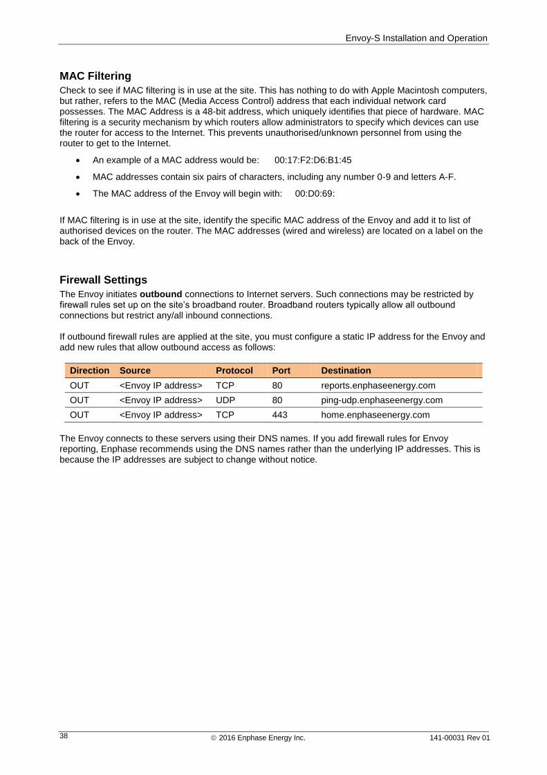
Envoy-S Installation and Operation
2016 Enphase Energy Inc. 141-00031 Rev 01 38
MAC Filtering
Check to see if MAC filtering is in use at the site. This has nothing to do with Apple Macintosh computers, but rather, refers to the MAC (Media Access Control) address that each individual network card possesses. The MAC Address is a 48-bit address, which uniquely identifies that piece of hardware. MAC filtering is a security mechanism by which routers allow administrators to specify which devices can use the router for access to the Internet. This prevents unauthorised/unknown personnel from using the router to get to the Internet.
An example of a MAC address would be: 00:17:F2:D6:B1:45
MAC addresses contain six pairs of characters, including any number 0-9 and letters A-F.
The MAC address of the Envoy will begin with: 00:D0:69:
If MAC filtering is in use at the site, identify the specific MAC address of the Envoy and add it to list of authorised devices on the router. The MAC addresses (wired and wireless) are located on a label on the back of the Envoy.
Firewall Settings
The Envoy initiates outbound connections to Internet servers. Such connections may be restricted by firewall rules set up on the site’s broadband router. Broadband routers typically allow all outbound connections but restrict any/all inbound connections. If outbound firewall rules are applied at the site, you must configure a static IP address for the Envoy and add new rules that allow outbound access as follows:
Direction Source Protocol Port Destination
OUT <Envoy IP address> TCP 80 reports.enphaseenergy.com
OUT <Envoy IP address> UDP 80 ping-udp.enphaseenergy.com
OUT <Envoy IP address> TCP 443 home.enphaseenergy.com
The Envoy connects to these servers using their DNS names. If you add firewall rules for Envoy reporting, Enphase recommends using the DNS names rather than the underlying IP addresses. This is because the IP addresses are subject to change without notice.
Envoy-S Installation and Operation
2016 Enphase Energy Inc. 141-00031 Rev 01 39
Replacing an Envoy-S If problems remain after following the troubleshooting steps above, contact Enphase at enphase.com/global/support-request.
DANGER! Risk of electric shock. Risk of fire. Do not attempt to repair the Envoy-S; it contains no user-serviceable parts. Tampering with or opening the Envoy-S will void the warranty. If the Envoy-S fails, contact Enphase Customer Support for assistance (enphase.com/global/support-request).
Warranty void if cover removed.
Refer servicing to qualified personnel. If Enphase Customer Support authorises an Envoy-S replacement (RMA), perform the following steps.
DANGER! Risk of electrocution! When replacing the Envoy-S Metered, CTs must be installed with no current flowing in the sensed circuit. Always install CT wires in the terminal blocks before energising the sensed circuit. Always de-energise the sensed circuit before disconnecting the CT leads from the terminal block.
DANGER! Risk of electric shock. Be aware that installation of this equipment includes risk of electric shock. Always de-energise circuits before wiring for power and CTs.
DANGER! Risk of electric shock. Risk of fire. If the Envoy-S is wired for metering, only qualified personnel should install or replace the Enphase Envoy-S.
WARNING! When replacing the Envoy-S Metered, you must install a new production CT to maintain metering accuracy. A new production CT is included with the replacement Envoy-S.
WARNING! If the Envoy-S you are replacing uses an Enphase cellular modem (Enphase Mobile Connect), do NOT move the cellular modem to another installation site. This de-activates the modem.
Replacing an Envoy-S Standard (non-hardwired)
If Enphase Customer Support authorises replacement (RMA) of an Envoy-S Standard (Model ENV-S-WB-230-F, -G, or -I), perform the following steps.
1. Disconnect the Ethernet cable (if used) and power cord from the old Envoy-S.
2. When the replacement Envoy-S arrives, power it as described in “2. Provide a Power Connection” on page 13.
WARNING: If the included power cord is missing or lost, you must use an equivalent power cord. See “Wire / Power Requirements / Specifications” on page 48.

Envoy-S Installation and Operation
2016 Enphase Energy Inc. 141-00031 Rev 01 40
3. Verify that the new Envoy-S powers up.
BEST PRACTICE: When powered up and connected for the first time, the Envoy-S may retrieve an automatic upgrade from Enphase. This upgrade may take up to 15 minutes. During upgrade the Envoy-S LEDs flash green sequentially.
WARNING! Risk of Equipment Damage. Do not remove power from the Envoy-S if the Envoy-S LEDs are flashing green sequentially. This indicates that a software upgrade is in progress.
4. Connect the Envoy-S to Enlighten as described in “7. Connect to Enlighten” on page 19.
5. Verify that the new Envoy-S Network Communications LED lights green within five minutes. If not, follow the network troubleshooting steps on page 36.
6. If possible, log in to Enlighten and add the Envoy-S to the Activation for this system by clicking “Add Another Envoy” under the “Envoy” section.
7. Verify that the new Envoy-S starts discovering microinverters within 20 minutes of starting up. If necessary, use the Enlighten or Device Scan button to start a new device scan during daylight hours. (See “Initiate a New Scan for Microinverters” on page 24.)
NOTE: If the old Envoy-S has communicated to the microinverters on the same day that the new replacement Envoy-S is installed, the new Envoy-S will be unable to discover the microinverters. Contact Enphase at enphase.com/global/support-request for assistance in this situation.
8. Assess the power line communications by running a Communication Check from Enlighten or the Installer Toolkit. If the communication check shows poor power line communications, relocate the Envoy-S closer to the Switchboard.
9. Contact Enphase Support at enphase.com/global/support-request to have the new Envoy-S added to your system and to retire the replaced Envoy-S.
10. Ship the old Envoy-S to Enphase using the supplied RMA shipping label.
Replacing an Hardwired Envoy-S
If Enphase Customer Support authorises an Envoy-S replacement (RMA), perform the following steps.
DANGER! Risk of electrocution! CTs must be installed with no current flowing in the sensed circuit. Always install CT wires in the terminal blocks before energising the sensed circuit. Do not disconnect the CT leads from the terminal block while the sensed circuit is energised.
DANGER! Risk of electric shock. Be aware that installation of this equipment includes risk of electric shock. If you wire the Envoy-S at the sub-board, always de-energise the sub-board before servicing.
WARNING! When replacing an Envoy-S that uses a production CT (model ENV-S-WM1-230), you must install the new production CT included with the replacement Envoy-S.
1. Turn off the circuit breaker supplying Envoy-S.
2. Disconnect the L1 and Neutral wires from the old Envoy.
3. Disconnect the Ethernet cable (if used).
4. Turn off the circuit breaker supplying the microinverters.
Envoy-S Installation and Operation
2016 Enphase Energy Inc. 141-00031 Rev 01 41
5. Unlatch the split-core of the production CT (if used) before disconnecting. Once the CT is unlatched, remove it from the sensed wires.
6. Unlatch the split-core of the consumption CT (if used) before disconnecting. Once the CT is unlatched, remove it from the sensed wires.
7. When the replacement Envoy-S arrives, install the Envoy-S and provide power as described in “2. Provide a Power Connection” on page 13.
8. Install the new production CT and consumption CT (if used) as described in “3. Install CTs for Metering (Model ENV-S-WM1-230 only)” on page 16.
9. Verify that the new Envoy-S powers up.
BEST PRACTICE: When powered up and connected for the first time, the Envoy-S may retrieve an automatic upgrade from Enphase. This upgrade may take up to 15 minutes. During upgrade the Envoy-S LEDs flash green sequentially.
WARNING! Risk of Equipment Damage. Do not remove power from the Envoy-S if the Envoy-S LEDs are flashing green sequentially. This indicates that a software upgrade is in progress.
10. Connect the Envoy-S to Enlighten as described in “7. Connect to Enlighten” on page 19.
11. Verify that the new Envoy-S Network Communications LED lights green within five minutes. If not, follow the network troubleshooting steps on page 36.
12. If possible, log in to Enlighten and add the Envoy-S to the Activation for this system by clicking “Add Another Envoy” under the “Envoy” section.
13. Verify that the new Envoy-S starts discovering microinverters within 20 minutes of starting up. If necessary, use the Enlighten or Device Scan button to start a new device scan during daylight hours. (See “Initiate a New Scan for Microinverters” on page 24.)
NOTE: If the old Envoy-S has communicated to the microinverters on the same day that the new replacement Envoy-S is installed, the new Envoy-S will be unable to discover the microinverters. Contact Enphase at enphase.com/global/support-request for assistance in this situation.
14. Assess the power line communications by running a Communication Check from Enlighten or the Installer Toolkit. If the communication check shows poor power line communications, relocate the Envoy-S closer to the Switchboard.
15. Contact Enphase Support at enphase.com/global/support-request to have the new Envoy-S added to your system and to retire the replaced Envoy-S.
16. Ship the old Envoy-S to Enphase using the supplied RMA shipping label.
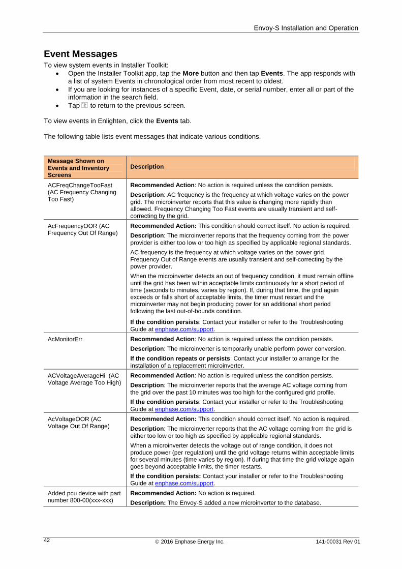
Envoy-S Installation and Operation
2016 Enphase Energy Inc. 141-00031 Rev 01 42
Event Messages To view system events in Installer Toolkit:
Open the Installer Toolkit app, tap the More button and then tap Events. The app responds with a list of system Events in chronological order from most recent to oldest.
If you are looking for instances of a specific Event, date, or serial number, enter all or part of the information in the search field.
Tap to return to the previous screen. To view events in Enlighten, click the Events tab. The following table lists event messages that indicate various conditions.
Message Shown on Events and Inventory Screens
Description
ACFreqChangeTooFast (AC Frequency Changing Too Fast)
Recommended Action: No action is required unless the condition persists.
Description: AC frequency is the frequency at which voltage varies on the power
grid. The microinverter reports that this value is changing more rapidly than allowed. Frequency Changing Too Fast events are usually transient and self-correcting by the grid.
AcFrequencyOOR (AC Frequency Out Of Range)
Recommended Action: This condition should correct itself. No action is required.
Description: The microinverter reports that the frequency coming from the power
provider is either too low or too high as specified by applicable regional standards.
AC frequency is the frequency at which voltage varies on the power grid. Frequency Out of Range events are usually transient and self-correcting by the power provider.
When the microinverter detects an out of frequency condition, it must remain offline until the grid has been within acceptable limits continuously for a short period of time (seconds to minutes, varies by region). If, during that time, the grid again exceeds or falls short of acceptable limits, the timer must restart and the microinverter may not begin producing power for an additional short period following the last out-of-bounds condition.
If the condition persists: Contact your installer or refer to the Troubleshooting
Guide at enphase.com/support.
AcMonitorErr Recommended Action: No action is required unless the condition persists.
Description: The microinverter is temporarily unable perform power conversion.
If the condition repeats or persists: Contact your installer to arrange for the
installation of a replacement microinverter.
ACVoltageAverageHi (AC Voltage Average Too High)
Recommended Action: No action is required unless the condition persists.
Description: The microinverter reports that the average AC voltage coming from
the grid over the past 10 minutes was too high for the configured grid profile.
If the condition persists: Contact your installer or refer to the Troubleshooting
Guide at enphase.com/support.
AcVoltageOOR (AC Voltage Out Of Range)
Recommended Action: This condition should correct itself. No action is required.
Description: The microinverter reports that the AC voltage coming from the grid is
either too low or too high as specified by applicable regional standards.
When a microinverter detects the voltage out of range condition, it does not produce power (per regulation) until the grid voltage returns within acceptable limits for several minutes (time varies by region). If during that time the grid voltage again goes beyond acceptable limits, the timer restarts.
If the condition persists: Contact your installer or refer to the Troubleshooting
Guide at enphase.com/support.
Added pcu device with part number 800-00(xxx-xxx)
Recommended Action: No action is required.
Description: The Envoy-S added a new microinverter to the database.
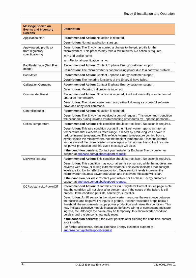
Envoy-S Installation and Operation
2016 Enphase Energy Inc. 141-00031 Rev 01 43
Message Shown on Events and Inventory Screens
Description
Application start Recommended Action: No action is required.
Description: Normal application start up.
Applying grid profile xx from regulatory specification yy
Description: The Envoy has started a change to the grid profile for the
microinverters. This process may take a few minutes. No action is required.
xx = grid profile name
yy = Regional specification name.
BadFlashImage (Bad Flash Image)
Recommended Action: Contact Enphase Energy customer support.
Description: The microinverter is not producing power due to a software problem.
Bad Meter Recommended Action: Contact Enphase Energy customer support.
Description: The metering functions of the Envoy-S have failed.
Calibration Corrupted Recommended Action: Contact Enphase Energy customer support.
Description: Metering calibration is incorrect.
CommandedReset Recommended Action: No action is required; it will automatically resume normal
operation momentarily.
Description: The microinverter was reset, either following a successful software
download or by user command.
ControlRequest Recommended Action: No action is required.
Description: The Envoy has received a control request. This uncommon condition
will occur only during isolated troubleshooting procedures by Enphase personnel.
CriticalTemperature Recommended Action: This condition should correct itself. No action is required.
Description: This rare condition occurs if the microinverter reports an internal
temperature that exceeds its rated range. It reacts by producing less power to reduce internal temperature. This reflects internal temperature coming from a sensor inside the microinverter, not the ambient temperature. Once the internal temperature of the microinverter is once again within normal limits, it will resume full power production and this event message will clear.
If the condition persists: Contact your installer or Enphase Energy customer
support at enphase.com/global/support-request.
DcPowerTooLow Recommended Action: This condition should correct itself. No action is required.
Description: This condition may occur at sunrise or sunset, while the modules are
covered with snow, or during extreme weather. This event indicates that sunlight levels are too low for effective production. Once sunlight levels increase, the microinverter resumes power production and this event message will clear.
If the condition persists: Contact your installer or Enphase Energy customer
support at enphase.com/global/support-request.
DCResistanceLoPowerOff Recommended Action: Clear this error via Enlighten’s Current Issues page. Note
that the condition will not clear after sensor reset if the cause of the failure is still present. If the condition persists, contact your installer.
Description: An IR sensor in the microinverter measures the resistance between
the positive and negative PV inputs to ground. If either resistance drops below a threshold, the microinverter stops power production and raises this condition. This may indicate defective module insulation, defective wiring or connectors, moisture ingress, etc. Although the cause may be temporary, this microinverter condition persists until the sensor is manually reset.
If the condition persists: If the event persists after clearing the condition, contact
your installer.
For further assistance, contact Enphase Energy customer support at enphase.com/global/support-request.
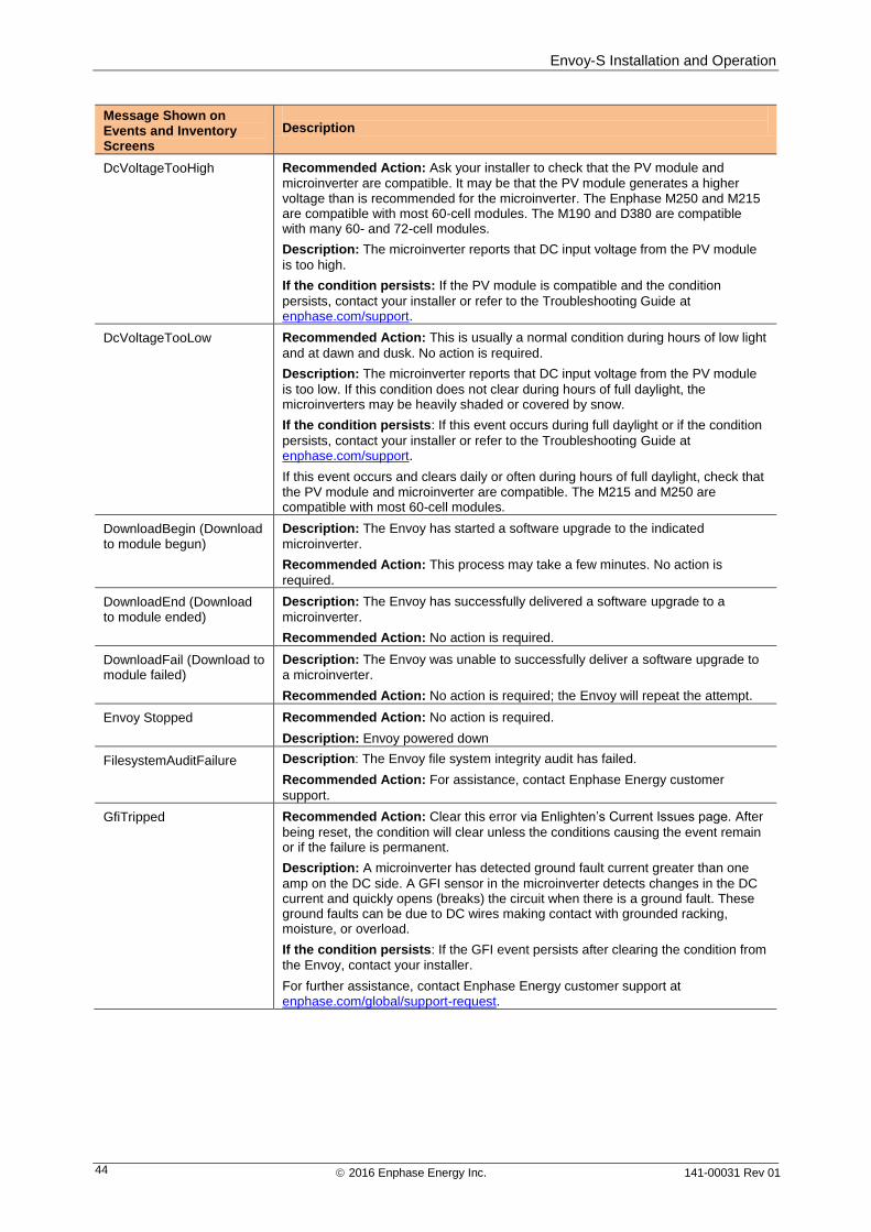
Envoy-S Installation and Operation
2016 Enphase Energy Inc. 141-00031 Rev 01 44
Message Shown on Events and Inventory Screens
Description
DcVoltageTooHigh Recommended Action: Ask your installer to check that the PV module and
microinverter are compatible. It may be that the PV module generates a higher voltage than is recommended for the microinverter. The Enphase M250 and M215 are compatible with most 60-cell modules. The M190 and D380 are compatible with many 60- and 72-cell modules.
Description: The microinverter reports that DC input voltage from the PV module
is too high.
If the condition persists: If the PV module is compatible and the condition
persists, contact your installer or refer to the Troubleshooting Guide at enphase.com/support.
DcVoltageTooLow Recommended Action: This is usually a normal condition during hours of low light
and at dawn and dusk. No action is required.
Description: The microinverter reports that DC input voltage from the PV module
is too low. If this condition does not clear during hours of full daylight, the microinverters may be heavily shaded or covered by snow.
If the condition persists: If this event occurs during full daylight or if the condition
persists, contact your installer or refer to the Troubleshooting Guide at enphase.com/support.
If this event occurs and clears daily or often during hours of full daylight, check that the PV module and microinverter are compatible. The M215 and M250 are compatible with most 60-cell modules.
DownloadBegin (Download to module begun)
Description: The Envoy has started a software upgrade to the indicated
microinverter.
Recommended Action: This process may take a few minutes. No action is
required.
DownloadEnd (Download to module ended)
Description: The Envoy has successfully delivered a software upgrade to a
microinverter.
Recommended Action: No action is required.
DownloadFail (Download to module failed)
Description: The Envoy was unable to successfully deliver a software upgrade to
a microinverter.
Recommended Action: No action is required; the Envoy will repeat the attempt.
Envoy Stopped Recommended Action: No action is required.
Description: Envoy powered down
FilesystemAuditFailure Description: The Envoy file system integrity audit has failed.
Recommended Action: For assistance, contact Enphase Energy customer
support.
GfiTripped Recommended Action: Clear this error via Enlighten’s Current Issues page. After
being reset, the condition will clear unless the conditions causing the event remain or if the failure is permanent.
Description: A microinverter has detected ground fault current greater than one
amp on the DC side. A GFI sensor in the microinverter detects changes in the DC current and quickly opens (breaks) the circuit when there is a ground fault. These ground faults can be due to DC wires making contact with grounded racking, moisture, or overload.
If the condition persists: If the GFI event persists after clearing the condition from
the Envoy, contact your installer.
For further assistance, contact Enphase Energy customer support at enphase.com/global/support-request.
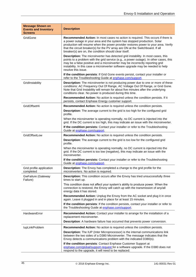
Envoy-S Installation and Operation
2016 Enphase Energy Inc. 141-00031 Rev 01 45
Message Shown on Events and Inventory Screens
Description
GridGone Recommended Action: In most cases no action is required. This occurs if there is
a power outage in your area and the system has stopped production. Solar production will resume when the power provider restores power to your area. Verify that the circuit breaker(s) for the PV array are ON at the Switchboard. If all breaker(s) are on, the condition should clear itself.
Description: The microinverter has detected grid instability. In most cases, this
points to a problem with the grid service (e.g., a power outage). In other cases, this may be a false positive and a microinverter may be incorrectly reporting grid instability. In this case a microinverter software upgrade may be needed to help resolve this issue.
If the condition persists: If Grid Gone events persist, contact your installer or
refer to the Troubleshooting Guide at enphase.com/support.
GridInstability Description: The microinverter is not producing power due to one or more of these
conditions: AC Frequency Out Of Range, AC Voltage Out Of Range, or Grid Gone. Note that Grid Instability will remain for about five minutes after the underlying conditions clear. No power is produced during this time.
Recommended Action: No action is required unless the condition persists. If it
persists, contact Enphase Energy customer support.
GridOffsetHi Recommended Action: No action is required unless the condition persists.
Description: The average current to the grid is too high for the configured grid
profile.
When the microinverter is operating normally, no DC current is injected into the grid. If the DC current is too high, this may indicate an issue with the microinverter.
If the condition persists: Contact your installer or refer to the Troubleshooting
Guide at enphase.com/support.
GridOffsetLow Recommended Action: No action is required unless the condition persists.
Description: The average current to the grid is too low for the configured grid
profile.
When the microinverter is operating normally, no DC current is injected into the grid. If the DC current is too low (negative), this may indicate an issue with the microinverter.
If the condition persists: Contact your installer or refer to the Troubleshooting
Guide at enphase.com/support.
Grid profile application completed
Description: The Envoy has completed a change to the grid profile for the
microinverters. No action is required.
GwFailure (Gateway Failure)
Description: This condition occurs after the Envoy has tried unsuccessfully three
times to start up.
This condition does not affect your system’s ability to produce power. When the connection is restored, the Envoy will catch up with the transmission of any/all energy data it has stored.
Recommended Action: Unplug the Envoy from the AC socket and plug it in once
again. Leave it plugged in and in place for at least 15 minutes.
If the condition persists: If the condition persists, contact your installer or refer to
the Troubleshooting Guide at enphase.com/support.
HardwareError Recommended Action: Contact your installer to arrange for the installation of a
replacement microinverter.
Description: A hardware failure has occurred that prevents power conversion.
IupLinkProblem Recommended Action: No action is required unless the condition persists.
Description: The IUP (Inter Microprocessor) is the internal communications link
between the two sides of a D380 Microinverter. The message indicates that the Envoy detects a communications problem with the indicated D380(s).
If the condition persists: Contact Enphase Customer Support at
enphase.com/global/support-request for a software upgrade. If the D380 does not respond to the upgrade, it will need to be replaced.
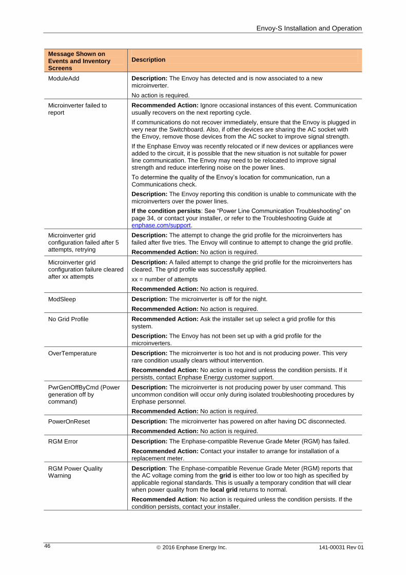
Envoy-S Installation and Operation
2016 Enphase Energy Inc. 141-00031 Rev 01 46
Message Shown on Events and Inventory Screens
Description
ModuleAdd Description: The Envoy has detected and is now associated to a new
microinverter.
No action is required.
Microinverter failed to report
Recommended Action: Ignore occasional instances of this event. Communication
usually recovers on the next reporting cycle.
If communications do not recover immediately, ensure that the Envoy is plugged in very near the Switchboard. Also, if other devices are sharing the AC socket with the Envoy, remove those devices from the AC socket to improve signal strength.
If the Enphase Envoy was recently relocated or if new devices or appliances were added to the circuit, it is possible that the new situation is not suitable for power line communication. The Envoy may need to be relocated to improve signal strength and reduce interfering noise on the power lines.
To determine the quality of the Envoy’s location for communication, run a Communications check.
Description: The Envoy reporting this condition is unable to communicate with the
microinverters over the power lines.
If the condition persists: See “Power Line Communication Troubleshooting” on
page 34, or contact your installer, or refer to the Troubleshooting Guide at enphase.com/support.
Microinverter grid configuration failed after 5 attempts, retrying
Description: The attempt to change the grid profile for the microinverters has
failed after five tries. The Envoy will continue to attempt to change the grid profile.
Recommended Action: No action is required.
Microinverter grid configuration failure cleared after xx attempts
Description: A failed attempt to change the grid profile for the microinverters has
cleared. The grid profile was successfully applied.
xx = number of attempts
Recommended Action: No action is required.
ModSleep Description: The microinverter is off for the night.
Recommended Action: No action is required.
No Grid Profile Recommended Action: Ask the installer set up select a grid profile for this
system.
Description: The Envoy has not been set up with a grid profile for the
microinverters.
OverTemperature Description: The microinverter is too hot and is not producing power. This very
rare condition usually clears without intervention.
Recommended Action: No action is required unless the condition persists. If it
persists, contact Enphase Energy customer support.
PwrGenOffByCmd (Power generation off by command)
Description: The microinverter is not producing power by user command. This
uncommon condition will occur only during isolated troubleshooting procedures by Enphase personnel.
Recommended Action: No action is required.
PowerOnReset Description: The microinverter has powered on after having DC disconnected.
Recommended Action: No action is required.
RGM Error Description: The Enphase-compatible Revenue Grade Meter (RGM) has failed.
Recommended Action: Contact your installer to arrange for installation of a
replacement meter.
RGM Power Quality Warning
Description: The Enphase-compatible Revenue Grade Meter (RGM) reports that the AC voltage coming from the grid is either too low or too high as specified by
applicable regional standards. This is usually a temporary condition that will clear when power quality from the local grid returns to normal.
Recommended Action: No action is required unless the condition persists. If the
condition persists, contact your installer.
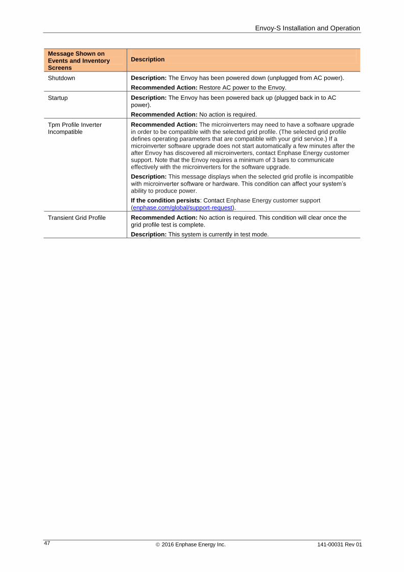
Envoy-S Installation and Operation
2016 Enphase Energy Inc. 141-00031 Rev 01 47
Message Shown on Events and Inventory Screens
Description
Shutdown Description: The Envoy has been powered down (unplugged from AC power).
Recommended Action: Restore AC power to the Envoy.
Startup Description: The Envoy has been powered back up (plugged back in to AC
power).
Recommended Action: No action is required.
Tpm Profile Inverter Incompatible
Recommended Action: The microinverters may need to have a software upgrade
in order to be compatible with the selected grid profile. (The selected grid profile defines operating parameters that are compatible with your grid service.) If a microinverter software upgrade does not start automatically a few minutes after the after Envoy has discovered all microinverters, contact Enphase Energy customer support. Note that the Envoy requires a minimum of 3 bars to communicate effectively with the microinverters for the software upgrade.
Description: This message displays when the selected grid profile is incompatible
with microinverter software or hardware. This condition can affect your system’s ability to produce power.
If the condition persists: Contact Enphase Energy customer support
(enphase.com/global/support-request).
Transient Grid Profile
Recommended Action: No action is required. This condition will clear once the
grid profile test is complete.
Description: This system is currently in test mode.
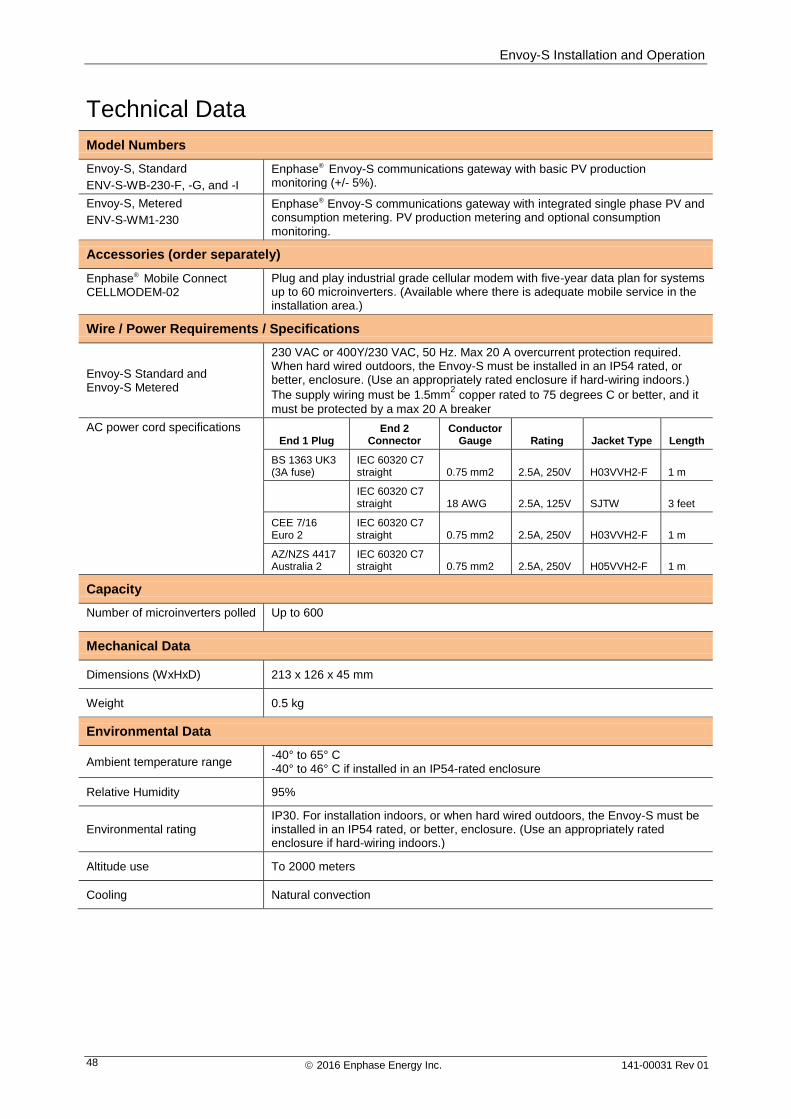
Envoy-S Installation and Operation
2016 Enphase Energy Inc. 141-00031 Rev 01 48
Technical Data
Model Numbers
Envoy-S, Standard
ENV-S-WB-230-F, -G, and -I
Enphase® Envoy-S communications gateway with basic PV production monitoring (+/- 5%).
Envoy-S, Metered
ENV-S-WM1-230
Enphase® Envoy-S communications gateway with integrated single phase PV and consumption metering. PV production metering and optional consumption monitoring.
Accessories (order separately)
Enphase® Mobile Connect CELLMODEM-02
Plug and play industrial grade cellular modem with five-year data plan for systems up to 60 microinverters. (Available where there is adequate mobile service in the installation area.)
Wire / Power Requirements / Specifications
Envoy-S Standard and Envoy-S Metered
230 VAC or 400Y/230 VAC, 50 Hz. Max 20 A overcurrent protection required. When hard wired outdoors, the Envoy-S must be installed in an IP54 rated, or better, enclosure. (Use an appropriately rated enclosure if hard-wiring indoors.)
The supply wiring must be 1.5mm2 copper rated to 75 degrees C or better, and it
must be protected by a max 20 A breaker
AC power cord specifications End 1 Plug
End 2 Connector
Conductor Gauge Rating Jacket Type Length
BS 1363 UK3 (3A fuse)
IEC 60320 C7 straight 0.75 mm2 2.5A, 250V H03VVH2-F 1 m
IEC 60320 C7 straight 18 AWG 2.5A, 125V SJTW 3 feet
CEE 7/16 Euro 2
IEC 60320 C7 straight 0.75 mm2 2.5A, 250V H03VVH2-F 1 m
AZ/NZS 4417 Australia 2
IEC 60320 C7 straight 0.75 mm2 2.5A, 250V H05VVH2-F 1 m
Capacity
Number of microinverters polled Up to 600
Mechanical Data
Dimensions (WxHxD) 213 x 126 x 45 mm
Weight 0.5 kg
Environmental Data
Ambient temperature range -40° to 65° C -40° to 46° C if installed in an IP54-rated enclosure
Relative Humidity 95%
Environmental rating IP30. For installation indoors, or when hard wired outdoors, the Envoy-S must be installed in an IP54 rated, or better, enclosure. (Use an appropriately rated enclosure if hard-wiring indoors.)
Altitude use To 2000 meters
Cooling Natural convection
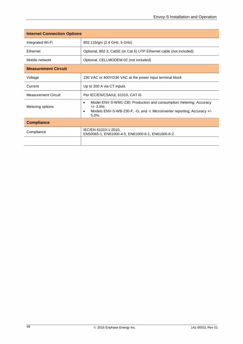
Envoy-S Installation and Operation
2016 Enphase Energy Inc. 141-00031 Rev 01 49
Internet Connection Options
Integrated Wi-Fi 802.11b/g/n (2.4 GHz, 5 GHz)
Ethernet Optional, 802.3, Cat5E (or Cat 6) UTP Ethernet cable (not included)
Mobile network Optional, CELLMODEM-02 (not included)
Measurement Circuit
Voltage 230 VAC or 400Y/230 VAC at the power input terminal block
Current Up to 200 A via CT inputs
Measurement Circuit Per IEC/EN/CSA/UL 61010, CAT III
Metering options
Model ENV-S-WM1-230: Production and consumption metering; Accuracy +/- 2.5%.
Models ENV-S-WB-230-F, -G, and -I: Microinverter reporting; Accuracy +/- 5.0%.
Compliance
Compliance IEC/EN 61010-1:2010, EN50065-1, EN61000-4-5, EN61000-6-1, EN61000-6-2