
Environmental Impact Assessment for Salalah Methanol Project ...
263
Salalah Methanol Company LLC c/o Oman Oil Company S.A.O.C. P.O. Box 261, PC 118, Muscat, Sultanate of Oman Environmental Impact Assessment for Salalah Methanol Project Project No. HMR/2064 April 2006 HMR Environmental Engineering Consultants P.O. Box: 1295, CPO Seeb Postal Code: 111 Sultanate of Oman Tel: (968) 24497506 Fax: (968) 24492616 email: [email protected] www.hmrenv.com
Transcript of Environmental Impact Assessment for Salalah Methanol Project ...

Salalah Methanol Company LLC c/o Oman Oil Company S.A.O.C. P.O. Box 261, PC 118, Muscat, Sultanate of Oman
Environmental Impact Assessment for Salalah Methanol Project Project No. HMR/2064 April 2006 HMR Environmental Engineering Consultants P.O. Box: 1295, CPO Seeb Postal Code: 111 Sultanate of Oman Tel: (968) 24497506 Fax: (968) 24492616 email: [email protected] www.hmrenv.com

Environmental Impact Assessment Salalah Methanol Company LLC Salalah Methanol Project
HMR Environmental Engineering Consultants HMR/2064 Sultanate of Oman April 2006
Environmental Impact Assessment for Salalah Methanol Project Project No. HMR/2064 April 2006
Issue and Revision
HMR SMC Revision Date
Prepared Checked Approved Approved Remarks
R1 12.03.2006 KRS BK SK Draft EMP (Ch 9)
R2 27.03.2006 KRS BK SK Draft report (Ch 1-3)
R3 04.04.2006 KRS BK SK Final draft report
R4
30.04.2006
KRS
BK
SK
Final report
This document has been prepared for the above titled project and it should not be relied upon or used for any other project without the prior written authority of HMR Consultants. HMR Consultants accepts no responsibility or liability for this document to any party other than the client for whom it was commissioned

Environmental Impact Assessment Salalah Methanol Company LLC Salalah Methanol Project
HMR Environmental Engineering Consultants HMR/2064 Sultanate of Oman i April 2006
EXECUTIVE SUMMARY
Background
Salalah Methanol Company LLC (SMC) is planning to establish a 3000 MTPD Greenfield methanol production facility in Salalah. The plant will be located near Salalah Port area, in the proposed Salalah Free Zone (SFZ). Methanol will be produced from natural gas supplied to the facility through a pipeline operated by Oman Gas Company (OGC). In addition to the main production units for methanol, the facility will include utilities such as steam turbine units, desalination plant, DM plant, nitrogen plant, ETP, STP, etc. The existing berth facilities at Salalah Port will be utilized for export of methanol product.
Regulatory Requirements
Planning and execution of the proposed project will be in compliance with Omani laws and regulations on environmental protection and pollution prevention. An Environmental Impact Assessment (EIA) study is to be conducted as per the “Guidelines on Environmental Impact Assessment” issued by Directorate General of Environmental Affairs (DGEA), Ministry of Regional Municipalities, Environment and Water Resources (MRME&WR). The present study is conducted as per the above guidelines. Further, various environmental regulations promulgated under Royal Decrees (RDs) and Ministerial Decisions (MDs) are considered in this study, which include regulations on air emissions, liquid effluent disposal, marine disposal, workplace and ambient noise, ground water, storage, handling and disposal of hazardous and non hazardous wastes, storage and handling of hazardous materials, etc.
Project Description
The main process units in the methanol plant include mercury removal and inlet compression, natural gas desulphurisation, reforming, make gas cooling, make gas compression and circulation, methanol synthesis, distillation, steam system and hot water circulation. The utilities and offsite facilities include product storage and export, seawater intake and distribution, seawater return, secondary cooling system, desalination plant, DM plant, auxiliary boiler, steam turbine based power generation, nitrogen plant, plant and instrument air, flare, ETP, STP, etc.
The primary raw material for production of methanol is natural gas received through a 24” high-pressure pipeline operated by OGC. Natural gas will be received at the battery limits of the facility from a pressure reducing terminal (PRT), located at

Environmental Impact Assessment Salalah Methanol Company LLC Salalah Methanol Project
HMR Environmental Engineering Consultants HMR/2064 Sultanate of Oman ii April 2006
Raysut industrial area outside the proposed SFZ (~ 3 km from the site, operated by OGC) and subsequently passed through a gas metering station (operated by OGC). The metering station will be located inside the SMC plant boundaries and will be integrated with SMC’s control and safety systems.
Refined methanol product from the storage tanks within the plant fence lines will be pumped through methanol product pipeline to the existing Berth # 31 at Salalah Port. The pipeline will run ~ 1.2 km in a northerly and north-easterly direction towards the port. Product methanol will be exported by sea vessels ranging from 10,000 to 50,000 DWT. The loading will be done by means of three loading arms, at Berth # 31, which is a multi-user berth.
Facility location
The project site is located at the proposed SFZ area, close to Salalah Port, about 15 km from Salalah city. All the main production units in the methanol plant and most of the utilities are located within the plant fence lines. However, facilities such as the raw material and product export pipelines, product loading, seawater intake and seawater return systems are located outside the facility fence lines.
Manpower and construction camps
The Engineering Procurement and Construction (EPC) contractor for the project is yet to be finalised. Most of the workers will be subcontractor staff engaged by the EPC contractor for executing civil, mechanical and electrical works. The manpower requirement during peak construction periods is expected to be about 800 - 1,000 workers. The peak manpower required during normal operation of the facility is envisaged to be about 90 to 100 and about 400 during plant turnarounds.
The locations of construction labour camps and project offices are not finalised yet and will be potentially determined by the EPC contractor in consultation with the Municipality and the Free Zone Company. It is likely that some of the work force will be engaged through local sub contractors and will mostly utilise their permanent accommodation facilities in Salalah. Some of the project staffs are likely to be accommodated in local apartments. Additional labour camps, if required, are likely to be established near the project site. The selection of location will comply with the applicable regulations and will avoid areas of high environmental sensitivities. Only project offices will be required to be developed at site. The permanent plant staff will be housed in the city of Salalah. SMC does not intend to build staff housing.

Environmental Impact Assessment Salalah Methanol Company LLC Salalah Methanol Project
HMR Environmental Engineering Consultants HMR/2064 Sultanate of Oman iii April 2006
Project timelines
The proposed timelines of the project are presented below:
Project Component Schedule FEED Completed by Jacobs Consultancy Environmental Impact Assessment April, 2006 Award of EPC Contracts November, 2006 Construction October 2007 Commercial operations October 2009
Environmental Baseline
Site characteristics
The project site is located west of Salalah Port facilities and to the northeast of the cattle feed factory and is about 15 km southwest of Salalah. The project site area is ~ 481155 m2 adjacent to the port authority office.
The site is situated adjacent to the alluvial plains of a Wadi Adawnib and is gently sloping towards the north east. The site is bisected by a minor wadi with an irregular bed profile. This minor wadi joins Wadi Adawnib at a point adjacent to the port facilities forming a small lagoon. The surface materials at the site are mixed and comprise mostly gravels, with sand, cobbles and boulder size rocks. There are two access roads adjacent to the eastern and southern boundaries of the project site. General elevation of the site is about 22 m above the mean sea level. The nearest dwellings to the site are the port accommodation area at ~1.5 km south-east from the site and Al Mughsayl village located ~ 2.4 km from the site.
Structural remains are observed at the site, which indicate that previous building works have been undertaken. This is likely to be in association with the port development. No surface contamination is observed at the site. Soil and groundwater samples were collected as a part of this EIA study for assessing the soil and groundwater quality at the site area.
The Wadi tributary passing through the centre of the site supports considerable scrub vegetation. The bed of this site Wadi features rounded gravel and cobbles but does not indicate any clear canalized flow route. The general direction of water flow is towards the east across the site, which subsequently joins Wadi Adawnib. There is no recorded flow data for the both the minor wadi and wadi Adawnib. However, data available with Ministry indicates a surveyed discharge rate of 729 m3/s (flood flow) for Wadi Adawnib.

Environmental Impact Assessment Salalah Methanol Company LLC Salalah Methanol Project
HMR Environmental Engineering Consultants HMR/2064 Sultanate of Oman iv April 2006
Topography
The site is an undeveloped open area with a slope towards northeast. The port authority office building delimits the plot on the eastern corner, while smaller rock out crops and relief borders the plot on the south-western side. The general ground elevation increases toward the north-western direction, reaching up to 800-1000 m elevation above the mean sea level at 20 km distance of the project site. Most of the land area within 10 km distance from the project site is classified as stony plain.
Geology
The study area is situated in alluvial plains belonging to the Nar Formation (Fars Group), which is Miocene to Pliocene in age and characterised by wadi alluvium deposits, underlain with cemented sands and conglomerate. The Nar Formation is underlain by shallow marine limestone and conglomerate (Adawnib Formation). This is further underlain by Mughsail Formation. The Fars Group is followed by the Dhofar Group, underlain by Hadhramaut Group, which is subdivided into four Formations, which include Umm er Radhuma (UeR), Rus, Dammam, and Aydim Formations.
Soil conditions
The soil within the region varies considerably with the undulating topography of the area. The soils surrounding the project site are typically calcareous (calcium-rich) and are described as gravely loams. The gravel content in the soil increases with increasing slope and elevation of the area. Soil samples were collected from the proposed site and analysed as a part of the present study in order to obtain baseline soil quality at the project site. The results indicate that the concentrations of metals and hydrocarbons in the soil are within comparable limits.
Hydrogeology and groundwater
The main source of water in the project area is the ground water aquifer lying underneath the Salalah plain between the UeR limestone and alluvial deposits. The ground water for the entire Salalah region is extracted mainly from two well fields namely Salalah Well Field and Sa'ada Well Field. The Salalah Well Field consists of eleven wells and is located north of Salalah Airport. The Sa'ada Well Field comprises three wells and is located east of Thumrait road, at the base of the jebels. In addition, there are many private wells extracting water for agricultural/institutional uses. Studies indicate that the area faces a deficit in aquifer recharge and it is required to implement appropriate management plans in order to ensure sustainability of
Environmental Impact Assessment Salalah Methanol Company LLC Salalah Methanol Project
HMR Environmental Engineering Consultants HMR/2064 Sultanate of Oman v April 2006
groundwater resources in the area. Over abstraction from the aquifers has resulted in saline water intrusion in addition to the decline of groundwater resources in the area.
Groundwater samples were collected and analysed as part of the present study in order to determine the groundwater quality at site. The results show that the quality of groundwater in the project area is not conforming to Omani drinking water standards / WHO standards. The exceeedance of limits may primarily be attributed to saline water intrusion. Floating hydrocarbon was not detected during sampling from the bore holes.
Climate
Dhofar region experiences three climatic seasons, winter (October - February), summer (March - June) and monsoon (Khareef, July - September). The mean maximum temperature of 33°C occurs throughout the summer months whilst the lowest temperature occurs in December and January, with a mean minimum of 16 to 17°C. A strong southwest monsoon brings some heavy rainfall to the area during the months of July - September, with a mean temperature of about 24°C. The humidity ranges from 96 – 98%. The average annual rainfall varies from as low as 50 mm in the plains to 300 mm in the mountains. The mean wind speed ranges from 5 to 13 km/h. High wind speeds are mostly encountered during the winter months. The prevailing wind direction in the interior and at the coast is variable throughout the year. During the monsoon season, the prevailing wind direction is from the south and south-west in Salalah area.
Ambient air quality
The ambient air quality in the area can be potentially affected by gaseous emissions from the industrial activities in the area such as port operations, power plant operations (Dhofar Power Company), operational activities of industries located near the port area and in Raysut industrial area. An ambient air quality survey was conducted as part of the present EIA study to assess the levels of critical pollutants in the area. The results show that Ground Level Concentrations (GLCs) of SO2, NOX, O3, VOCs and the ambient dust levels are within applicable standards. The maximum ambient noise levels in the area is ~ 54.5 dB(A), which is also within applicable standards.
Terrestrial ecology
The vegetation of Dhofar is largely tropical African. Endemism is high with Dhofar being classified as one of the centres of biological diversity in the Arabian Peninsula. A terrestrial ecological survey conducted as part of this EIA study to identify

Environmental Impact Assessment Salalah Methanol Company LLC Salalah Methanol Project
HMR Environmental Engineering Consultants HMR/2064 Sultanate of Oman vi April 2006
significant habitats and ecological sensitivities at the project site. The significant habitats are Wadi channels, open land and rocky outcrops. Vegetation is mostly significant at the Wadi channels. Acacia tortilis is the most dominant type present in all the habitats and is naturally grown in Oman. A regionally endemic species, Caralluma flava is observed within the proposed site. However, this is commonly found in Dhofar and is listed as ‘not a category of threat’.
A large number of bird species are present in Dhofar and many breed in the region, most of which are migratory. A large number of birds occur over the cool up welling areas of Dhofar and most breed from late June to September. A variety of small mammals and reptilian species are expected to be present in the vicinity of the project area. However, there are no threatened species observed in the project area.
Marine environment
The coastline of Salalah is directly under the influence of a yearly shift in wind direction and strength driven by climatic changes at the basin level. During the southwest monsoon (June-September), strong south-westerly winds blow along the coastline of Dhofar, generating a rapid polar-wise water combined with a coastal up-welling. The maximum sea surface temperature in the area is around 29-30ºC (May-June) and minimum around 23-24ºC (July-August). Salinity level in the area is found to be in the range of 36.1 to 36.7 ppt.
A marine survey was conducted during the course of this EIA study in order o assess the marine ecology in the area along with seawater and sediment sampling and analysis The analysis results show that there is no significant contamination of the marine environment in the area.
Four distinct habitats are observed near the project site, three in front of the intake and one at the proposed outfall location. The marine ecology at the intake location includes certain sensitive marine fauna. This includes unusual species of sea anemones, unusual burrowing eel, etc. The corals here do not form reefs. Several species of corals are observed and although none appear rare, some are endemic and unusual. Some of the coral species are recorded either first time in Oman or are rarely observed. The existence of seaweed communities (usually associated with temperate or cold water environment) and coral communities (usually associated with tropical water) is very unusual. It is only known from a few places in South Africa and Western Australia. ‘Ghost crabs’, that build conical mound, were relatively abundant at the intertidal beach area at the intake location indicating a few human disturbances in the area.

Environmental Impact Assessment Salalah Methanol Company LLC Salalah Methanol Project
HMR Environmental Engineering Consultants HMR/2064 Sultanate of Oman vii April 2006
The proposed outfall is located in a partially inundated wadi under the influence of tidal movement. The south shore of the wadi is completely transformed by the north retaining wall of Salalah Port facility. The wadi mouth consists of a triangular expense of fine sand and clay with little living organisms in it. Besides numerous birds, the fauna consist mostly of mud crabs. The bank of the wadi consists of a mixture of rounded stones and concrete suggesting either artificial embankment or disposal of construction concrete during the construction phase of the harbour. There were no mangrove trees or freshwater vegetation as in other khawrs of the region.
Occupation and employment
According to 1993 census data, public administration accounts for 27% of the total employment in the Salalah town. This is followed by construction (16%), trading (16%), manufacturing (9%) and agriculture (4%). Fisheries account for less than 0.3% of total employment.
Archaeological and cultural setting
Salalah, being a historical town, possesses many archaeologically important structures scattered around the region. Some of these include remains of the coastal city of Al Baleed, ancient buildings at Raysut, remains of fort at Ayn Hamraan, and several old mud houses in Awqdayn, Salalah, and Al Haffa. Dhofar Governorate has number of archaeological sites, which shed light upon the cultural and socio-economic development and the patterns of land-use.
Land use
The data on current land use as obtained from the Ministry of Housing, Dhofar Governorate indicate a total developed area of 14,215 ha and vacant land area of 48,885 ha. The future land use (2015) is expected to have a total developed area of 33,865 ha and vacant land area of 26,243.1 ha.
Environmental Releases
Construction phase
Various releases to the environment during construction phase include air emissions, liquid effluents, solid wastes, hazardous wastes, accidental releases and noise. Adequate measures will be taken for minimising the generation of wastes, handling, storage, transportation and treatment / disposal of such wastes.
The sources of air emissions during construction phase include various construction equipment, Diesel Generator (DG) units, and vehicles. Major pollutants released from
Environmental Impact Assessment Salalah Methanol Company LLC Salalah Methanol Project
HMR Environmental Engineering Consultants HMR/2064 Sultanate of Oman viii April 2006
such sources include NOX, SO2, CO, Particulate Matter (PM) and unburned hydrocarbons (HC). The liquid effluent streams include construction machinery/vehicle washing, spent hydro-test water, sanitary wastewater and surface run offs. Solid wastes will comprise construction debris, excavated soil, dredged material, packaging materials, scrap metal from construction and equipment fabrication and vehicle/equipment maintenance wastes. Solid and liquid hazardous wastes will include maintenance wastes, cleaning solvents, waste oil, oily sludge, paints, batteries, containers of hazardous materials, floor sweepings from material storage areas, contaminated soils from spills etc.
The marine construction work for the seawater intake pipeline can result in an increase in the suspended sediment concentration in the surrounding seawater column due to trenching/excavation work.
Accidental releases at construction sites may result mostly from any spills during loading/unloading, transportation and use of hazardous materials. The cleanup of such spills generates oil-contaminated sands, oil-soaked rags and floor sweepings. In instances where compressed gas cylinders or welding gases are used, there is a likelihood of accidental leaks during storage and handling.
Major sources of noise during construction activities are construction machinery / equipment such as DG units, compressors, engines, drillers, cement/concrete mixers, compactors etc., and activities such as excavation, bull dozing, and piling. The vehicles used for the transport of materials and men to the site will also generate noise along the access road.
Operational phase
During the operational phase, air emissions are mainly from the stationary point sources and fugitive emission sources. The point sources include reformer, auxiliary boilers and flare. Fugitive emission sources include storage tanks, valves, flanges and pipe fittings. Mobile sources include the vehicles used for transportation of men and materials. Major pollutants released from such sources include NOX, SO2, CO, PM, HC and Volatile Organic Compounds (VOCs).
Various process effluents are collected and treated in appropriate ETP units and the treated water from ETP is mostly recycled to the desalination plant. The liquid effluents that are disposed off from the facility include cooling water return, neutralized rejects from desalination plant and boiler blow down, treated water from STP and storm water (from storm water pond). The above effluents are discharged at the marine outfall.

Environmental Impact Assessment Salalah Methanol Company LLC Salalah Methanol Project
HMR Environmental Engineering Consultants HMR/2064 Sultanate of Oman ix April 2006
Solid wastes include domestic and office waste, packing materials, used electrical fittings, metal scrap, used spare parts, tyres and containers of non-hazardous materials. The solid hazardous wastes mainly include spent catalysts, used cotton waste, spent batteries, etc. Liquid hazardous waste mainly includes waste oil. Appropriate waste management methods will be implemented for collection, storage, handling, transportation, recycling and disposal of various waste materials.
Accidental releases from the facility mainly include release of materials such as natural gas and methanol. In addition, release of nitrogen from the liquid nitrogen storage or nitrogen handling pipelines can potentially lead to hazardous consequences.
Equipment such as compressors, blowers, turbines, flare, pumps, etc., will generate noise during the operation of the plant. The vehicle movements for transportation of men and materials will also lead to generation of noise at site as well as along their route to the facility.
Environmental Impacts
Construction phase
Significant potential environmental impacts during the construction phase of the project and proposed control and mitigation measures are summarised below.
Project activity Environmental Aspect Potential Impacts Mitigation / Remarks Landscape changes due to site preparation, excavation, etc.
Pump house at the seawater intake location will potentially pose visual impact on the cove and provide restrictions to the public from accessing the beach Damage to terrestrial habitats
• Site is located within a proposed industrial free zone and construction activities will have minimal footprint outside the industrial area.
• The pump house at the intake location will be designed to minimise visual impact
Air pollution due to increase in ambient dust concentration
• Dust suppression measures to be employed
Site construction activities involving grading, excavation, trenching, etc.
• Air emissions from internal combustion engine run construction machinery and vehicles
• Suspension of dust due to construction activity and vehicle movements
• Increase in noise levels
• Increase in vehicular traffic
Safety and health risk to workers and public using the existing roads and areas near the site
• Providing signboards indicating hazardous areas at all the construction locations
• Secured fencing of the construction areas to prevent unauthorised access to public
• Managing the traffic on the roads in such a way to minimise stress on other road users
• Providing adequate safety instructions and PPE to workers

Environmental Impact Assessment Salalah Methanol Company LLC Salalah Methanol Project
HMR Environmental Engineering Consultants HMR/2064 Sultanate of Oman x April 2006
Project activity Environmental Aspect Potential Impacts Mitigation / Remarks Increase in ambient noise levels • Proper maintenance of
equipment and vehicles • High noise activities
restricted to daytime • Use of noise barriers as
appropriate. • Minimising simultaneous
operation of various high noise equipment
Damage to terrestrial habitats along the pipeline routes
• Planning of pipeline routes in such a way to minimise areas of significant terrestrial habitats and vegetation
• Managing the pipeline construction activities to minimise impacts on areas outside pipeline corridors
Landscape changes • Restricting the pipeline construction activities within the pipeline corridors
• Pipeline and associated structures to be buried and therefore will not have any visual impacts
Air pollution due to increase in ambient dust concentrations
• Dust suppression measures to be employed
• Methanol export pipeline from the storage area in the plant to loading berth at Port Salalah
• Seawater intake pipeline
• Seawater outfall pipeline
• Air emissions from internal combustion engine run construction machinery and vehicles
• Dust generation during excavation and trenching activities and vehicle movements
• Increased noise levels• Open pipeline
trenches
Safety risk to workers and neaby population from open pipeline trenches
• Temporary fencing of the pipeline trenches
• Hazard indicating sign boards along pipeline route
Damage to coral communities and other marine habitats
• Planning construction methods in such way to minimise release / flushing of sediments
Marine construction of intake and out fall facilities involving dredging, pipeline installations, anchoring etc
• Flushing of sediments and increased turbidity
• Discharge of ballast water, bilge water and sewage to marine environment from barges / boats used for construction
• Discharge of domestic refuse to marine environment
Increase in TSS in seawater around the dredging sites and sediment transport
• Use of closed clamshell buckets and/or excavators with minimum sediment loss into the surrounding water
• Monitoring of TSS, turbidity and DO in seawater during the construction of the pipelines in the vicinity of the dredging area and the dredged material disposal area.

Environmental Impact Assessment Salalah Methanol Company LLC Salalah Methanol Project
HMR Environmental Engineering Consultants HMR/2064 Sultanate of Oman xi April 2006
Project activity Environmental Aspect Potential Impacts Mitigation / Remarks Degradation of marine environment and impact on marine flora and fauna
• Managing the disposal of waste water and other wastes in accordance with the procedures and facilities at the port
• Alternatively, providing waste collection, storage and disposal facilities for wastes generated in the construction barges, preventing the disposal of such wastes into the marine environment
Off-site impacts from quarrying for rocks and aggregates
• Utilizing approved quarries and transporters
Procurement of construction materials
Consumption of resources
Depletion of natural resources [fuels, wood, metal, etc.]
• Optimizing material consumption
Water abstraction for construction
Consumption of water from nearby sources
Stress on groundwater aquifers • Proper sourcing and optimizing use of water
Increase in ambient concentrations of NOX, SO2, CO, VOCs and dust
Air emissions - Operation of various construction equipment, DGs and vehicles at construction sites
Release of air pollutants including dust from site activity.
Disturbances to local residents due to air pollution
• Use of standard construction equipment, machineries and vehicles
• Proper O&M plans for construction equipment, DGs and vehicles
• Dust suppression measures • Monitoring of air emissions
and ambient levels of pollutants to ensure compliance with regulatory standards.
Increase in workplace and ambient noise levels
• Proper O&M plans for construction equipment, DGs and vehicles
• Use of suitable noise barriers as appropriate
• Minimising simultaneous operation of various high noise equipment
• Noise monitoring programs • Use of suitable ear protection
devices • Signboards indicating high
noise areas.
Noise - Operation of various construction equipment, DGs and vehicles at construction sites
Generation of noise and vibration
Disturbances to nearby population due to increased noise levels
• Planning and orientation of high noise generating construction equipment so as to ensure fence line noise level less than 70 dB(A)
• Schedule construction activities involving high noise generation for day time

Environmental Impact Assessment Salalah Methanol Company LLC Salalah Methanol Project
HMR Environmental Engineering Consultants HMR/2064 Sultanate of Oman xii April 2006
Project activity Environmental Aspect Potential Impacts Mitigation / Remarks Soil, groundwater and marine pollution
Liquid effluents - Collection, handling, storage and disposal of equipment and vehicle wash water, disposal of hydro-test water; sewage and contaminated surface run-offs
Improper handling / storage / treatment / discharge of wastewater streams into land / sea
Health risks to workers from infectious diseases
• Proper collection and treatment facilities for liquid effluents
• Vehicle maintenance and washing to be carried out at centralised workshop facilities of contracting companies outside the construction site or to have proper collection and treatment systems onsite, sewage collected in holding tanks and routed to onsite STP or other municipal STP for treatment and disposal
• Collection facilities for contaminated runoffs.
• Hydro-test water to be disposed off after analysis for potential contaminants for compliance applicable standards
• Periodic analysis of wastewater streams and monitoring of collection and treatment facilities
Soil, groundwater and marine pollution
Solid wastes - Collection, handling, storage and disposal of solid wastes from various construction activities
Improper handling / storage / treatment / disposal of solid wastes
House keeping issue
• Waste management plan to address proper collection, segregated storage and recycle / re-use / disposal of wastes at approved waste storage facility
• Periodic audits of waste management systems
Soil, groundwater and marine pollution
Hazardous wastes - Collection, handling, storage and disposal of hazardous wastes from various construction activities
Improper handling and disposal of hazardous wastes.
Public safety and health risk.
• Waste management plan to address proper collection, segregated storage / recycle of wastes to authorised recycling facilities
• Periodic audits of waste management systems
Storage & handling of hazardous substances like welding gases, fuels, lube oils, chemicals, radioactive substances, etc., handling of other construction materials and
• Improper storage / handling of hazardous substances,
• Failures of storage containers
• Improper storage and handling of other construction materials and equipment
Accidental release of hazardous substances causing soil, groundwater and marine pollution
• Adequate storage and handling facilities for hazardous substances as per the requirements of respective MSDS and in compliance with applicable regulations
• Periodic inspection / audits and integrity checks for storage facilities
Environmental Impact Assessment Salalah Methanol Company LLC Salalah Methanol Project
HMR Environmental Engineering Consultants HMR/2064 Sultanate of Oman xiii April 2006
Project activity Environmental Aspect Potential Impacts Mitigation / Remarks Fire, explosion and health risk to workers and community
• Spill containment facilities • Onsite and offsite emergency
plans • Appropriate training for
personnel handling hazardous materials with regard to handling methods, emergency measures, etc.
Risk from electrical failures and falling objects to workers
• Suitable PPEs to be issued to workers
• Signboards to indicate hazard operation/activity in the area
equipment
Exposure to radiation, safety and health risk
• Storage and handling of radioactive material to be in compliance with MD 249/97
• Providing adequate PPE and training to personnel handling radioactive materials
• Isolation of the relevant work areas
Stress on road traffic
Land, groundwater and marine contamination due to spillages Fire and safety risk to public
Accidents due to unsafe driving
• Developing and establishing Traffic Management Plan including transport procedures Vehicle fitness requirements
• Defensive driving procedures• Emergency response plan
• Transportation of materials and workers,
• Transportation of heavy plant machinery and equipment through road and sea
• Increased traffic due to
• Equipment and machinery transport,
• Unsafe driving, • Accidental spillages
of fuels, chemicals, solvents, etc. while transportation
Stress on marine traffic • EPC contractor to co-ordinate with Salalah Port for scheduling berthing requirements.
• Salalah Port to manage the ship traffic
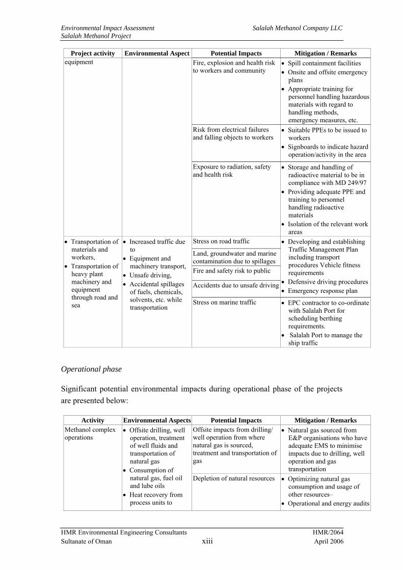
Operational phase
Significant potential environmental impacts during operational phase of the projects are presented below:
Activity Environmental Aspects Potential Impacts Mitigation / Remarks Offsite impacts from drilling/ well operation from where natural gas is sourced, treatment and transportation of gas
• Natural gas sourced from E&P organisations who have adequate EMS to minimise impacts due to drilling, well operation and gas transportation
Methanol complex operations
• Offsite drilling, well operation, treatment of well fluids and transportation of natural gas
• Consumption of natural gas, fuel oil and lube oils
• Heat recovery from process units to
Depletion of natural resources • Optimizing natural gas consumption and usage of other resources–
• Operational and energy audits

Environmental Impact Assessment Salalah Methanol Company LLC Salalah Methanol Project
HMR Environmental Engineering Consultants HMR/2064 Sultanate of Oman xiv April 2006
Activity Environmental Aspects Potential Impacts Mitigation / Remarks generate steam and power
Heat recovery from process units to produce steam and power
Not Applicable
Seawater intake Inappropriate intake of seawater
Damage to marine habitats • Design and sizing of intake structure in such a way to control intake flow and to prevent intake of marine life
Exceedance of emissions from regulatory limits for source emissions and increase in GLCs of hazardous pollutants,
Air emissions - Operation of Reformer, auxiliary boilers and flare Bulk handling and storage of methanol product
• NOx, SO2, VOCs and PM emissions from continuously operating sources
• Hydrocarbons and other hazardous air pollutants from fugitive sources
• Emissions during upset conditions especially flaring
Potential health impacts due to emissions of hazardous air pollutants
• Low NOx burners for combustion sources
• Stack heights to comply with MD 118/2004 and GEP stack heights;
• Internal floaters for all product storage tanks along with submerged loading facilities and vapour recovery systems as appropriate for minimising fugitive emissions
• Adequate O&M for combustion sources and emission control equipment to ensure efficient operations
• Continuous emission monitoring for all major emission sources
• Periodic ambient air monitoring to ensure regulatory compliance
• Preparation and enforcement of EMS
Exceedance of workplace noise levels
Noise- • Operation of
noise generating equipment like steam turbines blowers, pumps, compressors and flare
• Fleet movements and operation mobile equipment at the loading berth
• Noise emissions from continuously and intermittently operating sources,
• Noise emissions due to equipment faults, damage to equipment supports, fixtures, etc.
Exceedance of ambient noise levels at / outside fence line
• Noise levels to be maintained at ≤85 dB(A) at design for the plant equipment;
• Application of adequate noise enclosures to reduce the source noise levels
• O&M programs for noisy equipment;
• Periodic workplace and ambient noise level monitoring.

Environmental Impact Assessment Salalah Methanol Company LLC Salalah Methanol Project
HMR Environmental Engineering Consultants HMR/2064 Sultanate of Oman xv April 2006
Activity Environmental Aspects Potential Impacts Mitigation / Remarks Liquid Effluents - Collection, storage, treatment and disposal of process effluents, wash water and deluge water from plant and other areas, sanitary wastewater, return seawater, rejects from desalination plant and storm water
• Contaminants in the treated effluents discharged to sea above regulatory limits due to improper treatment
• Thermal and salinity effects due to discharge of cooling water and brine rejects into sea
• Contaminants in storm water discharged to sea
• Shock loads, upsets or peak discharge due to improper handling / treatment / disposal of liquid effluents.
• Accidental releases to land/surface drains
Soil, groundwater and marine pollution and potential damage to marine habitats
• Adequate treatment facilities at ETP for treating process effluents to meet regulatory requirements for marine discharge
• Proper collection and treatment of sanitary wastewater in the STP to marine discharge standards
• Proper O&M of effluent collection systems, ETP, STP and cooling water systems to ensure proper and efficient operation
• Periodic monitoring / sampling programs for treated effluents / marine discharges and seawater.
• Preparation and enforcement of EMS
Soil, groundwater and marine pollution
Solid Wastes - Collection, storage and disposal of solid wastes
Improper collection, handling / disposal of non hazardous industrial and domestic solid wastes
House keeping issue leading to unsafe and unhygienic conditions
• Onsite waste management centre for storage of wastes;
• Recycling materials such as metal and wood scrap to potential buyers;
• Waste management plan addressing proper collection segregated storage and disposal of wastes in compliance with MD 17/93
Land, groundwater and marine contamination and potential damage to marine habitats due to hazardous constituents such as hydrocarbons and heavy metals,
Hazardous Wastes - Collection, storage and disposal of hazardous wastes
Improper collection, handling, recycle / storage hazardous wastes
Inflammability / toxicity posing human and ecological risks
• Waste management plan for proper collection and segregated storage of wastes at the onsite hazardous waste storage area in compliance with MD 18/93 and applicable hazardous waste permit;
• Recycle of spent catalysts to catalyst suppliers for regeneration / recycling
• Recycling of wastes such as lube oil, batteries, etc., to authorised recycling facilities;
• Offsite disposal of wastes to authorised waste disposal facilities when such facilities become available in Oman
Storage, handling and transport of raw materials, intermediates and
Accidental releases of materials from storage vessels from leaks due to failure of
Injuries/fatalities, property damage, business interruption and environmental contamination,
• Detailed risk assessment studies to evaluate safeguarding mechanisms

Environmental Impact Assessment Salalah Methanol Company LLC Salalah Methanol Project
HMR Environmental Engineering Consultants HMR/2064 Sultanate of Oman xvi April 2006
Activity Environmental Aspects Potential Impacts Mitigation / Remarks Exposure risks from fire, explosion, toxic releases and spills
products that are flammable and / or toxic,
safeguarding mechanisms, corrosion and other causes Asphyxiation due to liquid
nitrogen leakage
and their adequacy • Implementing leak detection
systems and safe distances philosophy
• Restricted access to hazardous areas, establishing onsite and offsite emergency response plans, job safety plans, periodic audits, MSDS, PPE, permit to work systems, etc.
• Strict enforcement of inspection programs
Pipe line transport of natural gas and methanol
Accidental release of materials / hazards due to pipeline over pressurization, corrosion or external impacts leading to leaks / spills
Injuries / fatalities, property damage, business interruption environmental contamination and fire and explosion risks
As above
Methanol loading at the loading berth at the Port
Spillages during loading activities
Contamination of loading area and marine environment
• Providing facilities to prevent spillage runoffs to the sea during product loading
• Systems for periodic inspection and maintenance of the loading systems, inspections prior to each loading, testing of loading facilities, etc., as appropriate
• Facilities for containing and removing any spillages on land. Spillage collection sump at the berth area for collecting spillages and contaminated methanol, which will be returned to the plant.
Stress on road traffic
Accident hazards resulting in spillages, contamination, fire and toxicity risks
Road transport of hazardous materials
Increased road traffic, improper transportation, use of unauthorised / unfit vehicles, unsafe driving, accidental spillages Accidental spillages due to
leaks and environmental contamination
• Traffic management plan including transport procedures, vehicle fitness requirements, defensive driving requirements, emergency response procedures
• Training to concerned personnel on hazardous materials handled and respective MSDS
Export of product methanol
Increased movement of sea vessels at the port area
Stress on marine traffic • SMC to co-ordinate with Salalah Port for scheduling berthing requirements.
• Salalah Port to manage the ship traffic

Environmental Impact Assessment Salalah Methanol Company LLC Salalah Methanol Project
HMR Environmental Engineering Consultants HMR/2064 Sultanate of Oman xvii April 2006
Quantitative assessments of impacts are made for air quality, noise and marine discharges at the seawater outfall. The predicted impacts are found to be within acceptable levels.
Cumulative impacts
As explained earlier, the project site is located within the proposed SFZ area, where many industrial units are expected to be established in future. Salalah Port is close to the project site. In addition, Raysut industrial area is about 5 km from the project site, which also includes many currently operating industrial units. The environmental impacts from the existing industrial activities in the area are reflected in the prevailing environmental quality. The base line environmental studies carried out as part of this EIA study indicate that levels of major air pollutants, noise levels, soil and groundwater quality, marine environmental quality, etc., are well within acceptable standards. However, there are impacts on the environment near the proposed outfall area due to dredging and other construction activities at the port.
Under the current practice of environmental permitting, each industry is required to conduct an EIA study to assess the environmental impacts due to its construction and operation, based on the prevailing baseline status and the estimated pollution loads from the industry as well as any other concurrent developments within the area. Though there are other industrial projects being planned around the proposed project site at Salalah, it is unlikely that the construction periods of the same will coincide/overlap with that of the proposed methanol plant. Therefore cumulative impacts during the construction phase are not expected. The details of other projects proposed to be developed in the area are not presently available. It is expected that the assessment of potential environmental impacts from other industries in SFZ will be conducted through EIA studies for the respective industries as part of the permitting process and appropriate mitigation measures will be implemented to minimise the impacts.
Impacts of Hazardous Releases
The impacts of various accidental releases are likely to be within the facility, except for the product methanol pipeline. It is to be noted that the probability of occurrence of worst case scenarios such as catastrophic rupture of storage tanks and full bore rupture of pipelines are typically low. Also, the liquid pools will be contained within the containment areas and are not likely to spread to outside areas. Scheduled and periodic inspection and maintenance of various plant units and pipelines will be conducted to ensure that potential failure causes are eliminated and leaks are prevented.

Environmental Impact Assessment Salalah Methanol Company LLC Salalah Methanol Project
HMR Environmental Engineering Consultants HMR/2064 Sultanate of Oman xviii April 2006
Environmental Management Plan
An Environmental management Plan (EMP) has been proposed for the construction and operational phases of the project so as to reduce the impacts to as low as reasonably practicable levels. The proposed EMP follows the ‘Plan-Do-Check-Act system in line with the ISO 14001 Environmental Management System (EMS) Guidelines and includes the organization structure, resources, responsibilities, control and mitigation measures, monitoring / auditing programs, systems for review and implementation of corrective actions.
Conclusions
The residual impacts after effective implementation of the proposed EMP will be minimal and are unlikely to cause any significant, long term and irreversible impacts on the environment. The project will not cause any significant deterioration of the environmental quality and will in fact generate revenues, employment and invigorate the economy. Therefore, the proposed project is considered to be acceptable from an environmental standpoint within the context of local and internationally comparable environmental standards.

Environmental Impact Assessment Salalah Methanol Company LLC Salalah Methanol Project
HMR Environmental Engineering Consultants HMR/2064 Sultanate of Oman xix April 2006
ABBREVIATIONS
°C Degrees Centigrade µg micro-gram µm micro-meter µS micro-siemens ALARP As Low As Reasonably Practicable ASME American Society of Mechanical Engineering ASTM American Society for Testing and Materials bar Pressure unit equivalent to 101.3 kPascal BOD Biochemical oxygen demand CH3OH Methanol CO Carbon monoxide CO2 Carbon dioxide COD Chemical oxygen demand Cr Chromium Cu Copper dB Decibel DGEA Directorate General of Environmental Affairs DO Dissolved oxygen DPC Dofar Power Company EC Electrical conductivity EH&S Environment, Health and Safety EIA Environmental impact assessment EMP Environmental management plan EMS Environmental Management System EPC Engineering, procurement and construction ESD Emergency Shut Down ETP effluent treatment plant GDP Gross Domestic Product h hour H2 Hydrogen H2O Water HMR Consultants HMR Environmental Engineering Consultants, Oman HSE Health, safety and environment ISO International Organization for Standardization kg kilo-gram kVA kilo-volt-ampere kW kilo-Watt L litre Leq Equivalent noise level m meter m2 square meter m3 cubic meter max Maximum MD Ministerial decision mg milli-gram mL milli-litre mm milli-meter MNHC Ministry of National Heritage and Culture

Environmental Impact Assessment Salalah Methanol Company LLC Salalah Methanol Project
HMR Environmental Engineering Consultants HMR/2064 Sultanate of Oman xx April 2006
MOG Ministry of Oil & Gas MRME&WR Ministry of Regional municipalities, Environment and Water Resources MSDS Material safety data sheet MTPD Metric Tons Per Day MW mega-Watt NAAQS National ambient air quality standards NHWMC National Hazardous Waste Management Center Nm3 cubic meter at normal conditions (0oC and 1 atm pressure) NO Nitrogen oxide NO2 Nitrogen dioxide NOx Oxides of nitrogen O&G Oil and grease O&M Operation and maintenance O3 Ozone OGC Oman Gas Company PM Particulate matter PM10 Particulate matter less than 10 µm size PM2.5 Particulate matter less than 2.5 µm size ppm Parts per million ppmv Parts per million, volume based ppt Parts per thousand RCC Raysut Cement Company RD Royal Decree RO Reverse Osmosis ROP Royal Oman Police SFZ Salalah Free Zone SFZC Salalah Free Zone Company SMC Salalah Methanol Company SO2 Sulphur dioxide SPS Salalah Port Services SS Suspended solids STP Sewage treatment plant TDS Total dissolved solids tpd Tonnes per day UPS Uninterruptible Power supply USEPA United States (of America) Environmental Protection Agency UTM Universal transverse merkator

Environmental Impact Assessment Salalah Methanol Company LLC Salalah Methanol Project
HMR Environmental Engineering Consultants HMR/2064 Sultanate of Oman xxi April 2006
TABLE OF CONTENTS
1. INTRODUCTION ...................................................................................1-1
1.1 Project background ..................................................................................... 1-1
1.2 Objectives and scope of the EIA study....................................................... 1-1
1.3 Method of study............................................................................................ 1-2 1.3.1 Overview................................................................................................ 1-2 1.3.2 Document review................................................................................... 1-2 1.3.3 Environmental data gathering ................................................................ 1-3 1.3.4 Environmental impact assessment ......................................................... 1-3 1.3.5 Environmental management plan .......................................................... 1-3
1.4 Structure of the report................................................................................. 1-3
2. ENVIRONMENTAL REGULATORY FRAMEWORK ............................2-1
2.1 General.......................................................................................................... 2-1
2.2 Environmental legislations in Oman.......................................................... 2-1 2.2.1 Overview................................................................................................ 2-1 2.2.2 Wastewater reuse and discharge ............................................................ 2-2 2.2.3 Disposal of liquid effluents into marine environment ........................... 2-5 2.2.4 Air emissions from stationary sources................................................... 2-7 2.2.5 Environmental permitting .................................................................... 2-10 2.2.6 Regulation for crushers, quarries and transport of sand from coasts, beaches and wadis................................................................................................ 2-10 2.2.7 Management of radioactive materials.................................................. 2-11 2.2.8 Noise .................................................................................................... 2-11 2.2.9 Hazardous wastes................................................................................. 2-12 2.2.10 Solid non-hazardous waste .................................................................. 2-12 2.2.11 Ambient air quality .............................................................................. 2-13
3. PROJECT DESCRIPTION ....................................................................3-1
3.1 General.......................................................................................................... 3-1
3.2 Process flow .................................................................................................. 3-2
3.3 Description of methanol production plant................................................. 3-2
3.4 Plant utilities................................................................................................. 3-5
3.5 Offsite facilities............................................................................................. 3-8 3.5.1 Raw materials and product pipelines ..................................................... 3-8 3.5.2 Product export and loading .................................................................... 3-8 3.5.3 Seawater intake ...................................................................................... 3-9 3.5.4 Seawater return system .......................................................................... 3-9

Environmental Impact Assessment Salalah Methanol Company LLC Salalah Methanol Project
HMR Environmental Engineering Consultants HMR/2064 Sultanate of Oman xxii April 2006
3.6 Project location and land take .................................................................. 3-10
3.7 Manpower and construction camps ......................................................... 3-11
3.8 Project development and scheduling........................................................ 3-11
3.9 Project construction................................................................................... 3-12 3.9.1 Description of construction methods ................................................... 3-12 3.9.2 Sourcing of construction materials ...................................................... 3-14
3.10 Engineering codes and standards ............................................................. 3-15
4. DESCRIPTION OF THE ENVIRONMENT.............................................4-1
4.1 Overview ....................................................................................................... 4-1
4.2 Site characteristics ....................................................................................... 4-1
4.3 Topography .................................................................................................. 4-6
4.4 Geological setting ......................................................................................... 4-6
4.5 Regional soil conditions ............................................................................... 4-8
4.6 Hydrogeology and groundwater................................................................. 4-9
4.7 Climate ........................................................................................................ 4-14
4.8 Ambient air quality.................................................................................... 4-15 4.8.1 Background.......................................................................................... 4-15 4.8.2 Measurement of gaseous pollutants ..................................................... 4-15 4.8.3 Measurement of dust concentrations ................................................... 4-18
4.9 Noise ............................................................................................................ 4-19
4.10 Terrestrial Flora......................................................................................... 4-19 4.10.1 Regional ............................................................................................... 4-19 4.10.2 Site specific.......................................................................................... 4-20
4.11 Terrestrial Fauna....................................................................................... 4-21
4.12 Marine Environment ................................................................................. 4-26 4.12.1 Overview.............................................................................................. 4-26 4.12.2 Methodology........................................................................................ 4-26 4.12.3 Seawater temperature........................................................................... 4-27 4.12.4 Salinity ................................................................................................. 4-28 4.12.5 Marine habitats..................................................................................... 4-28 4.12.6 Intake.................................................................................................... 4-30 4.12.7 Shallow water community ................................................................... 4-31 4.12.8 Intertidal environment.......................................................................... 4-36 4.12.9 Outfall .................................................................................................. 4-39 4.12.10 Seawater Quality.............................................................................. 4-42

Environmental Impact Assessment Salalah Methanol Company LLC Salalah Methanol Project
HMR Environmental Engineering Consultants HMR/2064 Sultanate of Oman xxiii April 2006
4.12.11 Sediment quality .............................................................................. 4-42
4.13 Demography ............................................................................................... 4-43
4.14 Occupation and employment .................................................................... 4-44
4.15 Industrial environment.............................................................................. 4-44
4.16 Archaeological, cultural and recreational resources .............................. 4-45
4.17 Land use...................................................................................................... 4-46 4.17.1 Current land use ................................................................................... 4-46 4.17.2 Future land use..................................................................................... 4-46
5. ENVIRONMENTAL RELEASES ...........................................................5-1
5.1 General.......................................................................................................... 5-1
5.2 Waste classification...................................................................................... 5-1
5.3 Releases during construction phase ........................................................... 5-2 5.3.1 Overview................................................................................................ 5-2 5.3.2 Characterisation of releases ................................................................... 5-2 5.3.3 Air emissions ......................................................................................... 5-6 5.3.4 Liquid effluents...................................................................................... 5-7 5.3.5 Non-hazardous solid wastes................................................................... 5-8 5.3.6 Hazardous wastes................................................................................... 5-8 5.3.7 Noise ...................................................................................................... 5-9 5.3.8 Releases to marine environment .......................................................... 5-10 5.3.9 Accidental releases............................................................................... 5-11
5.4 Releases during operation phase .............................................................. 5-11 5.4.1 Air emissions ....................................................................................... 5-15 5.4.2 Liquid effluents.................................................................................... 5-17 5.4.3 Non-hazardous solid waste .................................................................. 5-19 5.4.4 Hazardous waste .................................................................................. 5-19 5.4.5 Noise .................................................................................................... 5-20 5.4.6 Marine releases .................................................................................... 5-20 5.4.7 Accidental releases............................................................................... 5-21
6. ANALYSIS OF ALTERNATIVES ..........................................................6-1
6.1 General.......................................................................................................... 6-1
6.2 Need for the project ..................................................................................... 6-1
6.3 Selection of project site................................................................................ 6-3
6.4 Selection of process and technology ........................................................... 6-4 6.4.1 Overview................................................................................................ 6-4 6.4.2 Conventional steam reforming............................................................... 6-5

Environmental Impact Assessment Salalah Methanol Company LLC Salalah Methanol Project
HMR Environmental Engineering Consultants HMR/2064 Sultanate of Oman xxiv April 2006
6.4.3 Combined reforming.............................................................................. 6-5 6.4.4 Auto-thermal reforming ......................................................................... 6-6 6.4.5 Gas heated reforming............................................................................. 6-6 6.4.6 Selected technology ............................................................................... 6-7
6.5 Sourcing of water and treatment technology ............................................ 6-7 6.5.1 Water sourcing ....................................................................................... 6-7 6.5.2 Comparison of water treatment technologies ........................................ 6-7 6.5.3 Selected option....................................................................................... 6-8
6.6 Power and steam Generation and power plant technology ..................... 6-9 6.6.1 Overview................................................................................................ 6-9 6.6.2 External sourcing of power and internal generation of steam ............... 6-9 6.6.3 Cogeneration of Power and Steam......................................................... 6-9 6.6.4 Power plant alternatives....................................................................... 6-10 6.6.5 Selected Option.................................................................................... 6-10
6.7 Wastewater treatment ............................................................................... 6-11 6.7.1 Overview.............................................................................................. 6-11 6.7.2 Without ETP ........................................................................................ 6-11 6.7.3 With ETP ............................................................................................. 6-12
6.8 Seawater intake .......................................................................................... 6-14
6.9 Seawater outfall.......................................................................................... 6-17
6.10 Sourcing of construction materials........................................................... 6-18
6.11 Sourcing of fuels and other utilities during construction phase ............ 6-18 6.11.1 Power ................................................................................................... 6-18 6.11.2 Water.................................................................................................... 6-19 6.11.3 Fuels..................................................................................................... 6-19
7. ENVIRONMENTAL IMPACT ASSESSMENT .......................................7-1
7.1 General.......................................................................................................... 7-1
7.2 Methodology ................................................................................................. 7-1
7.3 Impacts during construction phase .......................................................... 7-16 7.3.1 Air quality ............................................................................................ 7-16 7.3.2 Noise .................................................................................................... 7-16 7.3.3 Groundwater ........................................................................................ 7-17 7.3.4 Land and terrestrial ecology................................................................. 7-18 7.3.5 Marine environment............................................................................. 7-18 7.3.6 Socio economic environment............................................................... 7-19
7.4 Impacts during operational phase............................................................ 7-21 7.4.1 Air quality ............................................................................................ 7-21 7.4.2 Noise .................................................................................................... 7-25 7.4.3 Marine environment............................................................................. 7-26

Environmental Impact Assessment Salalah Methanol Company LLC Salalah Methanol Project
HMR Environmental Engineering Consultants HMR/2064 Sultanate of Oman xxv April 2006
7.4.4 Groundwater ........................................................................................ 7-34 7.4.5 Land ..................................................................................................... 7-34 7.4.6 Socio-economic environment .............................................................. 7-34
7.5 Cumulative impacts ................................................................................... 7-35
8. CONSEQUENCE ASSESSMENT .........................................................8-1
8.1 General.......................................................................................................... 8-1
8.2 Method of Consequence Assessment.......................................................... 8-1
8.3 Model used.................................................................................................... 8-2
8.4 Data sources.................................................................................................. 8-2
8.5 Materials and Process elements.................................................................. 8-2
8.6 Hazard identification................................................................................... 8-3 8.6.1 Failure scenarios .................................................................................... 8-3 8.6.2 Failure causes......................................................................................... 8-3 8.6.3 Failure types........................................................................................... 8-4
8.7 Consequence assessment ............................................................................. 8-4 8.7.1 Modelling inputs .................................................................................... 8-4 8.7.2 Chemical composition of materials ....................................................... 8-5 8.7.3 Meteorological conditions ..................................................................... 8-5 8.7.4 Consequences of failures ....................................................................... 8-6
8.8 Results ........................................................................................................... 8-8
9. ENVIRONMENTAL MANAGEMENT PLAN..........................................9-1
9.1 Overview ....................................................................................................... 9-1
9.2 Construction phase environmental management ..................................... 9-1 9.2.1 Selection of EPC contractor................................................................... 9-1 9.2.2 Organisation and responsibilities........................................................... 9-2 9.2.3 Site security and safety .......................................................................... 9-3 9.2.4 Environmental permitting for construction of the facility ..................... 9-4 9.2.5 Site preparation ...................................................................................... 9-4 9.2.6 Sourcing of construction materials and utilities..................................... 9-5 9.2.7 Air quality .............................................................................................. 9-6 9.2.8 Noise ...................................................................................................... 9-7 9.2.9 Wastewater............................................................................................. 9-8 9.2.10 Solid wastes ........................................................................................... 9-9 9.2.11 Solid hazardous wastes ........................................................................ 9-10 9.2.12 Liquid hazardous waste........................................................................ 9-11 9.2.13 Storage and handling of hazardous materials ...................................... 9-12 9.2.14 Seawater intake pipeline ...................................................................... 9-13 9.2.15 Marine outfall....................................................................................... 9-14

Environmental Impact Assessment Salalah Methanol Company LLC Salalah Methanol Project
HMR Environmental Engineering Consultants HMR/2064 Sultanate of Oman xxvi April 2006
9.2.16 Auditing ............................................................................................... 9-15 9.2.17 Review and implementation of corrective actions............................... 9-15 9.2.18 Environmental monitoring and auditing .............................................. 9-15
9.3 Operational phase environmental management ..................................... 9-16 9.3.1 Organisation and responsibility ........................................................... 9-16 9.3.2 Site handover from EPC contractor ..................................................... 9-16 9.3.3 Environmental Permitting for Plant Operation .................................... 9-17 9.3.4 Air Quality ........................................................................................... 9-17 9.3.5 Noise .................................................................................................... 9-19 9.3.6 Wastewater Treatment and Discharge ................................................. 9-20 9.3.7 Impacts on marine environment........................................................... 9-21 9.3.8 Solid Wastes......................................................................................... 9-22 9.3.9 Solid Hazardous Waste ........................................................................ 9-23 9.3.10 Liquid Hazardous Waste...................................................................... 9-24 9.3.11 Storage and Handling of Hazardous Materials .................................... 9-25 9.3.12 Environmental Monitoring Programme............................................... 9-26
9.4 Decommissioning........................................................................................ 9-27 9.4.1 Site restoration ..................................................................................... 9-28 9.4.2 Post-closure Monitoring....................................................................... 9-28
9.5 Emergency response plan.......................................................................... 9-28 9.5.1 Overview.............................................................................................. 9-28
10. CONCLUSIONS...............................................................................10-1
Appendix A Organisation responsible for EIA preparation ...........................A-1 Appendix B Plant and Utility Description......................................................B-1 Appendix C Plant and Site Layout Maps........................................................C-1 Appendix D Material Safety Data Sheets .......................................................D-1 Appendix E Meteorological data .................................................................... E-1 Appendix F List of plant species observed at the project site......................... F-1 Appendix G Definition of Terms Used in Impact Assessment Matrix...........G-1 Appendix H Air and noise dispersion contours ..............................................H-1 Appendix I Input data for temperature and salinity dispersion modeling ....... I-1 Appendix J Graphical representation of impact distances............................... J-1
List of Tables Table 2-1 : Applicable Omani environmental regulations......................................... 2-2 Table 2-2: Wastewater discharge and re-use standards - Categories......................... 2-3 Table 2-3: Wastewater discharge and re-use standards ............................................. 2-3 Table 2-4: Sewage sludge re-use standards ............................................................... 2-4 Table 2-5: Marine disposal standards ........................................................................ 2-6 Table 2-6 : Emission standards as per MD 118/2004 ................................................ 2-8 Table 2-7: Ambient noise standards ........................................................................ 2-11 Table 2-8 : Ambient air quality standards................................................................ 2-13 Table 3-1 : Details of process units in methanol plant............................................... 3-4

Environmental Impact Assessment Salalah Methanol Company LLC Salalah Methanol Project
HMR Environmental Engineering Consultants HMR/2064 Sultanate of Oman xxvii April 2006
Table 3-2: Details of utilities ..................................................................................... 3-5 Table 3-3: Raw materials, chemicals and catalysts ................................................... 3-7 Table 3-4: UTM coordinates of the project site....................................................... 3-10 Table 3-5: Tentative project timelines ..................................................................... 3-12 Table 3-6: Sourcing of construction materials......................................................... 3-14 Table 4-1: Regional stratigraphy ............................................................................... 4-8 Table 4-2: Analysis of soil samples ........................................................................... 4-9 Table 4-3: Groundwater quality at the proposed site............................................... 4-13 Table 4-4: Ambient air quality monitoring locations .............................................. 4-17 Table 4-5: Ambient air quality results (SO2, NOx O3 and benzene)........................ 4-17 Table 4-6: Ambient dust concentration.................................................................... 4-18 Table 4-7: Ambient noise levels .............................................................................. 4-19 Table 4-8: Scleractinian corals found in the shallow community............................ 4-32 Table 4-9: Seawater sampling locations .................................................................. 4-41 Table 4-10: Seabed sediments sampling locations .................................................. 4-41 Table 4-11: Seawater analysis ................................................................................. 4-42 Table 4-12: Sediment analysis ................................................................................. 4-43 Table 4-13: Distribution of economic activity in the Wilayat of Salalah ................ 4-44 Table 4-14: Current land use pattern at Salalah....................................................... 4-46 Table 5-1: Releases during construction phase.......................................................... 5-3 Table 5-2: Noise levels from construction equipment............................................. 5-10 Table 5-3: Releases during operation phase ............................................................ 5-11 Table 5-4: Stationary air emissions from the plant facilities ................................... 5-16 Table 5-5: Liquid effluent streams from the facility................................................ 5-18 Table 5-6: Typical source noise levels of plant equipment ..................................... 5-20 Table 7-1: Impacts during Construction Phase.......................................................... 7-4 Table 7-2: Environmental Impacts during Operation Phase.................................... 7-11 Table 7-3: Stationary point sources considered for modelling ................................ 7-21 Table 7-4: Inputs for air dispersion modeling.......................................................... 7-22 Table 7-5: Input data for prediction modeling......................................................... 7-23 Table 7-6: Predicted GLC of pollutants................................................................... 7-24 Table 7-7: Typical noise levels ................................................................................ 7-25 Table 7-8: NFR Characteristics (temperature)......................................................... 7-28 Table 7-9: RMZ Characteristics (temperature)........................................................ 7-30 Table 7-10: NFR characteristics (salinity)............................................................... 7-31 Table 7-11: RMZ characteristics (salinity) .............................................................. 7-32 Table 8-1: Hazardous material storage and handling ................................................ 8-2 Table 8-2: Failure types ............................................................................................. 8-4 Table 8-3: Chemical composition of materials for modelling ................................... 8-5 Table 8-4: Release scenarios considered for modelling ............................................ 8-6 Table 8-5: Impact distances for various release scenarios......................................... 8-8 Table 8-6: Pool characteristics................................................................................... 8-9 Table 9-1: Environmental and Auditing Plan for Construction Phase .................... 9-15 Table 9-2: Environmental Monitoring during Operational Phase ........................... 9-27 List of Figures Figure 3-1: Process Flow Diagram ............................................................................ 3-3 Figure 4-1: Electrical conductivity of pumped groundwater in Salalah .................. 4-11 Figure 4-2: Environmental survey locations............................................................ 4-12

Environmental Impact Assessment Salalah Methanol Company LLC Salalah Methanol Project
HMR Environmental Engineering Consultants HMR/2064 Sultanate of Oman xxviii April 2006
Figure 4-3: Windrose for Mina Salalah (2003)........................................................ 4-16 Figure 4-4: SST estimates from the Hadley Database in offshore Salalah.............. 4-27 Figure 4-5: Future land use at Wilayat of Salalah ................................................... 4-47 Figure 6-1: Wastewater Treatment Scheme without ETP ....................................... 6-13 Figure 6-2: Wastewater treatment scheme with ETP .............................................. 6-13 Figure 7-1: Impact Assessment Matrix...................................................................... 7-2 Figure 7-2: 3-D view of flow from marine flow (temperature dispersion).............. 7-29 Figure 7-3: Temperature – downstream distance profile at NFR ............................ 7-29 Figure 7-4: Temperature – downstream distance profile in RMZ ........................... 7-30 Figure 7-5: Salinity – downstream distance profile at NFR .................................... 7-31 Figure 7-6: Salinity – downstream distance profile at RMZ ................................... 7-32 Figure 7-7: 3-D view of salinity dispersion within RMZ ........................................ 7-33 Figure 9-1: Proposed HSE organisation structure for construction phase................. 9-3 List of Plates Plate 4-1: Intersection point of minor wadi with Wadi Adawnib.............................. 4-2 Plate 4-2: Lagoon formed at the intersection of wadis to the west of port ................ 4-2 Plate 4-3: Remains of a building structure................................................................. 4-3 Plate 4-4: Excavated pit used as collection tank for sewage ..................................... 4-4 Plate 4-5: Trucks transporting quarried material to port............................................ 4-4 Plate 4-6: Dumping of quarried material on site........................................................ 4-5 Plate 4-7: Abandoned fishing boat............................................................................. 4-5 Plate 4-8: Caralluma flava found near the north western boundary of the site....... 4-22 Plate 4-9: Acacia tortilis .......................................................................................... 4-22 Plate 4-10: Calotropis procera ................................................................................ 4-23 Plate 4-11: Aerva javanica....................................................................................... 4-23 Plate 4-12: Polypogon monspeliensis ...................................................................... 4-24 Plate 4-13: Vernonia arabica................................................................................... 4-24 Plate 4-14: Salsola spp............................................................................................. 4-25 Plate 4-15: Heliotropium fartakense ........................................................................ 4-25 Plate 4-16: Deep sandy habitat (22m) about 350m from shore. .............................. 4-28 Plate 4-17: Coral (Coscinarea sp.) from the observed community between 3 to15m
depth at the proposed intake area..................................................................... 4-29 Plate 4-18: Intertidal rocky community located near the planned intake ................ 4-29 Plate 4-19: Degraded sandy intertidal area at the proposed outfall location ........... 4-30 Plate 4-20: Two species of anemone (Edwardsia spp.) ........................................... 4-31 Plate 4-21: Head of a burrowing moray eel (possibly Gymnothorax megaspilus) .. 4-31 Plate 4-22: A few of the coral species observed on site. A: Favites pentagona,
B:Goniastrea pectinata, C: Hydnophora sp., D: Leptoria phrygia, E: Stylophora danae, F: Turbinaria peltata............................................................................ 4-33
Plate 4-23: A rich and diverse algal turf covers most of the shallow water hard substrate. At least 6 species are visible on this 5x7 cm frame......................... 4-34
Plate 4-24: Some macrophytes (here probably Nizmodinia sp.) were still visible in January suggesting that in the summer, most of the site must be covered with luxuriant macro algae communities. This cohabitation between algal communities and coral communities is nearly unique in the world................. 4-35
Plate 4-25: Unidentified sponge species. Many more were observed ..................... 4-36 Plate 4-26: Typical colors of the sea urchin Asthenosoma varium. ......................... 4-36 Plate 4-27: Conical reproductive mounds of Ocypode rotundata ........................... 4-37

Environmental Impact Assessment Salalah Methanol Company LLC Salalah Methanol Project
HMR Environmental Engineering Consultants HMR/2064 Sultanate of Oman xxix April 2006
Plate 4-28: Even a low swell on a very calm day, because of the rapid decrease of the depth near shore, result in strong rolling waves on the exposed rocky platform. 4-38
Plate 4-29: Left: Upper intertidal zone dominated by Tetraclita sp. barnacles. Right. Slightly lower level in the intertidal zone dominated by the oyster Saccostrea sp........................................................................................................................... 4-38
Plate 4-30: Left: Cellana rota. Right: Siphonaria sp. Both species are specialized in shallow (intertidal) environments where they graze on small incrusting algae... 4-39
Plate 4-31: Left: Chiton (Acanthopleura vaillantii) common in the lower intertidal. Right. Small colony of Perna viridis (green mussel). ..................................... 4-39
Plate 4-32: South shore of the wadi showing the retaining wall.............................. 4-40 Plate 4-33: General view of the development activity near the proposed outfall. ... 4-41 Plate 6-1: Panoramic view of the proposed intake location..................................... 6-16 Plate 6-2: View showing outfall location................................................................. 6-18

Environmental Impact Assessment Salalah Methanol Company LLC Salalah Methanol Project
HMR Environmental Engineering Consultants 1-1 HMR/2064 Sultanate of Oman April 2006
1. INTRODUCTION
1.1 Project background
Salalah Methanol Company LLC (SMC) proposes to develop a 3,000 metric tons per day (MTPD) methanol production facility at Salalah. The methanol complex will be sited adjacent to the existing Salalah Port facilities and is within the proposed Salalah Free Zone area. The total land allotted will provide for future expansion projects of the facility. The methanol production facility will be designed to be an independent complex and will include all the utilities and offsite units required for continuous reliable operation of the plant. The project will include power generation, seawater intake, water desalination unit, nitrogen plant, wastewater treatment plant and natural gas import facilities as a part of the onsite utilities. SMC will utilise an existing ship-loading berth (Berth # 31) at Salalah Port for the export of finished product to international market.
SMC contracted HMR Environmental Engineering Consultants (HMR) conducted this Environmental Impact Assessment (EIA) study for the above project in order to address the environmental impacts from various projects components and to obtain the environmental permit from Ministry of Regional Municipalities, Environment & Water Resources (MRME&WR) for the development of the project into construction, and operation .
1.2 Objectives and scope of the EIA study
The objective of this EIA study is to identify and assess all potential impacts from the project on the environment. The EIA focuses on developing appropriate management plans for the mitigation of significant environmental impacts. The impact assessment will typically cover all phases of the project viz. construction, operation, maintenance, and decommissioning. However, impacts during the decommissioning phase are considered to be similar to that of the construction phase and therefore are discussed in brief.
The scope of this EIA was developed in line with Omani Regulatory requirements, as specified in the “Guideline on Environmental Impact Assessment” issued by the Directorate General of Environmental Affairs (DGEA), MRME&WR. Accordingly, the scope of the EIA study is as listed below:
− Environmental review of the project for characterisation and quantification of wastes generated from the project during its construction, operation & maintenance and decommissioning;

Environmental Impact Assessment Salalah Methanol Company LLC Salalah Methanol Project
HMR Environmental Engineering Consultants 1-2 HMR/2064 Sultanate of Oman April 2006
− Desktop reviews and field studies for describing the current status of the environment at the project site;
− Collation of secondary data from various sources to establish the socio-cultural and socio-economic baseline in the area and thereby to access the impacts due to the project development;
− Identification of potential environmental impacts from the project activities during its construction, operation & maintenance and decommissioning;
− Environmental analysis of alternatives for the processes, technologies and approaches associated with the project development;
− Assessment of significant environmental impacts from the project;
− Development of suitable environmental management plans including mitigation measures and monitoring programmes; and
− Preparation of the EIA report for review by DGEA.
1.3 Method of study
1.3.1 Overview
The EIA study was conducted during the period January 2006 – April 2006. The overall methodology was based on the principles contained in MRME&WR’s “Guideline on Environmental Impact Assessment” published in the year 2000. In addition, guidance was taken from the World Bank Group guidelines on “Environmental Analysis and Review of Projects”. The overall study was carried out in phases as described in the following sections.
1.3.2 Document review
The Front End Engineering Design (FEED) documents for the project components and other related technical reports provided by SMC were reviewed. Technical details of the project components were collected and various environmental releases from the project during the construction and operational activities were assessed. Environmental baseline reports of previous studies in the vicinity of the proposed project location were reviewed to plan acquisition of primary data during successive site visits and field studies. Field studies focussed on validating and augmenting data, wherever required, on potential areas of concern with regard to environmental impacts due to the project development.
The raw materials, chemicals, fuels, etc., used in the process and their storage and handling philosophy were studied to identify potential environmental aspects. The proposed control and treatment schemes for air emissions, wastewaters, solid wastes,
Environmental Impact Assessment Salalah Methanol Company LLC Salalah Methanol Project
HMR Environmental Engineering Consultants 1-3 HMR/2064 Sultanate of Oman April 2006
hazardous wastes and noise were also reviewed. Consultations were held with SMC project team throughout the review process for better understanding of plant operation and environment safeguarding philosophy.
1.3.3 Environmental data gathering
Environmental data gathering included primary data collection during field visits and review of secondary data from previous study reports and published documents. Field investigations were carried out to augment and validate the available baseline data and to determine the current environmental quality in and around the project site. Field studies were conducted for specific components such as air quality, noise, terrestrial ecology, marine environment, and groundwater quality, while baseline information on topography, meteorology, geology, hydrogeology, socio-cultural and socio-economic environments were obtained from various previous study reports and other published reports for the project location. Information was also sourced from government departments and non-governmental agencies.
1.3.4 Environmental impact assessment
Based on the above, the environmental aspects and impacts from the proposed project activities are identified using checklists and matrices. Various predictive techniques, both qualitative and quantitative, are used to determine the magnitude of these impacts. The significance of each impact is determined based on the nature of impact and the current environmental quality.
1.3.5 Environmental management plan
Environmental Management Plan (EMP) is developed to mitigate all significant adverse environmental impacts to acceptable levels. The EMP addresses primarily the construction and operational phases of the project. For the decommissioning phase (including site restoration), which is envisaged to be after ~ 30 years of plant operation, a generic consideration is provided due to lack of detailed information. Also, the impacts during the decommissioning phase are considered to be similar to that of the construction phase. Environmental monitoring systems are identified and monitoring programmes are developed based on review of feasible alternatives. An environmental management system structure is proposed for effective implementation of the management plan.
1.4 Structure of the report
This EIA report is divided into ten chapters. Following this introductory chapter, applicable Omani Environmental Regulatory Requirements and the engineering and
Environmental Impact Assessment Salalah Methanol Company LLC Salalah Methanol Project
HMR Environmental Engineering Consultants 1-4 HMR/2064 Sultanate of Oman April 2006
construction standards used for the project are presented in Chapter 2. A detailed description of the project components, its activities and the project management during the construction and the operational phases are given in Chapter 3. The description of the existing environmental conditions at the project site, based on primary and secondary data analysis is provided in Chapter 4. Various releases to the environment (gaseous, liquid, solid, noise, etc.), waste generation areas and handling, treatment and disposal methods during the construction and operational phases of the project are detailed in Chapter 5. In Chapter 6, an environmental analysis of alternatives for the critical processes, technologies and approaches associated with the project development is presented.
Various environmental aspects and the potential impacts to the environment from the project activities are discussed in Chapter 7. The assessment of consequences due to storage and handling of hazardous and toxic chemicals as part of the project activities are presented in Chapter 8. The EMP is presented in Chapter 9 and the conclusions of the study are presented in Chapter 10.
An executive summary of the EIA is presented ahead of the main report. All other relevant information that is not included in the main sections is presented in appendices. The organisation and the individuals responsible for the preparation of this report are presented in Appendix A. Appendix B provides detailed description of the process units, utilities and offsite facilities. The layout plans for the project are included in Appendix C. Material Safety Data Sheets (MSDS) of major hazardous chemicals / materials used at the facility as part of the project activities are presented in Appendix D. A summary of the meteorological data used for the modelling of air and noise dispersion is presented in Appendix E. The list of plant species at the project area, collected as part of the terrestrial ecological survey at the site is presented in Appendix F. The definitions of terms used in Impact Assessment Matrix are presented in Appendix G. The contour maps of dispersion of air pollutants and noise propagation are presented in Appendix H. The input data for salinity and temperature dispersion modelling for the marine outfall are presented in Appendix I and Appendix J includes the graphical presentation of consequences of hazardous releases from the new projects.
Environmental Impact Assessment Salalah Methanol Company LLC Salalah Methanol Project
HMR Environmental Engineering Consultants 2-1 HMR/2064 Sultanate of Oman April 2006
2. ENVIRONMENTAL REGULATORY FRAMEWORK
2.1 General
Increasingly at country level, new environmental policies are being introduced including environmental action plans and sustainable development plans. Such policies are supported by legislations in the form of Royal Decrees (RD) and Ministerial Decisions (MD). Government policies in areas such as air, water, land distribution, waste generation and handling, pollution prevention and disposal of liquid and solid wastes are highly significant for any industrial development. It is within the scope of this EIA to highlight such legislations and detail their governance over the proposed methanol project.
The planning and development of the facility will be in full compliance with Omani laws and regulations on environment protection and pollution prevention. For areas where Omani regulations are not available, comparison is made with potentially applicable international regulations, such as those contained in the environmental directives of World Bank to demonstrate that the technology, equipment and operations selected for the proposed project is capable of meeting international standards. The project will also follow the requirements of engineering standards and codes specifically applicable for the project as per contractual agreement with the technology providers for the project.
2.2 Environmental legislations in Oman
2.2.1 Overview
The Omani regulations on environmental protection, control and management are covered under two basic laws viz., the "Law for the Conservation of the Environment and Prevention of Pollution" first promulgated in 1982 as RD 10/82 and superseded in November 2001 as RD 114/2001 and the "Law on Protection of Sources of Potable Water from Pollution" promulgated in November 2001 as RD 115/2001. MRME&WR has recently promulgated a revision to the environmental standards for stationary emission sources under MD 118/2004 and regulations for marine discharges under MD 159/2005, which have also been considered in this study.
The responsibility for the implementation of these laws rests with MRME&WR, which issues regulations, standards and guidelines through MDs. Within MRME&WR, DGEA is the authority responsible for environmental permitting, inspection and control in the Sultanate of Oman. The Omani Regulations relating to ambient air quality, noise, aqueous effluents, waste management, flora and fauna, etc. that govern the proposed project development and operation are listed in Table 2-1.

Environmental Impact Assessment Salalah Methanol Company LLC Salalah Methanol Project
HMR Environmental Engineering Consultants 2-2 HMR/2064 Sultanate of Oman April 2006
Table 2-1 : Applicable Omani environmental regulations
Reference Number Description Applicability RD 114/2001 (superseding RD 10/82)
Law for the conservation of the environment and prevention of pollution
Basic law governing the environmental protection in Oman
RD 115/2001 Law on protection of potable water sources from pollution
Domestic and industrial wastewater management (especially during construction)
RD 46/95 Law on handling and use of chemicals
Raw materials, chemicals and fuels storage, handling and transportation during construction and operation
MD 159/2005 superseding MD 7/84
Regulation for the discharge of liquid effluent into the marine environment
Discharge of primary cooling water and other effluents into sea
MD 118/2004 (superseding 5/86)
Regulations for air pollution control from stationary sources
Emissions from various stacks
MD 187/2001 (Superseding MD 300/93)
Issuing regulations for organizing obtaining environmental approvals and final environmental permit
Environmental approval of the projects
MD 200/2000 Issuing regulations for Crushers, Quarries & transport of sand from Coasts, Beaches and Wadis
Training of Wadi running across the site
MD 249/97 Regulations for control and management of radioactive materials substances
Management of radioactive substances during construction phase
MD 248/97 Regulations for the handling of toxic substances
Chemicals management during construction and operation
MD 80/94 Regulations for noise pollution in working environment
Workplace noise level control during construction and operation of the project
MD 79/94 Regulations for noise pollution in public environment
Ambient noise control during construction and operational phases of the project
MD 18/93 Regulation for the management of hazardous wastes
Hazardous waste management during construction and operation
MD 17/93 Regulations for the management of the solid non-hazardous wastes
Non-hazardous waste management during construction and operation
OS 8/98 (superseding OS 8/78)
Omani standard for drinking water (Issued by the Directorate General of Specifications and Measures, Ministry of Commerce and Industry)
Ground water quality at project area
The significant environmental regulations from the above, applicable for the project during the construction and operation phases are detailed in the following sections.
2.2.2 Wastewater reuse and discharge
The Omani standards for wastewater discharge and re-use on land are issued under MD 145/93. These are re-enforced under RD 115/2001. There are two types of standards, based on the crops grown on the land where the wastewater is applied, as described below in Table 2-2.

Environmental Impact Assessment Salalah Methanol Company LLC Salalah Methanol Project
HMR Environmental Engineering Consultants 2-3 HMR/2064 Sultanate of Oman April 2006
Table 2-2: Wastewater discharge and re-use standards - Categories
Specification Standard A-1 Standard A-2 Crops Vegetables likely to be eaten raw
Fruit likely to be eaten raw and within 2 weeks of any irrigation
Vegetables to be cooked or processed Fruit if no irrigation within 2 weeks of cropping Fodder, cereal and seed crops
Grass and ornamental areas
Public parks, hotel lawns recreational areas Areas with public access Lakes with public contact (except place which may be used for praying and hand washing)
Pastures Areas with no public access
The maximum permissible concentrations of various pollutants in the treated wastewater are as presented in Table 2-3.
Table 2-3: Wastewater discharge and re-use standards
Parameter Units Standard A-1 Standard A-2 Biochemical oxygen demand (BOD)- after 5 days @ 200C
mg/L 15 20
Chemical oxygen demand (COD) mg/L 150 200 Suspended solids (SS) mg/L 15 30 Total dissolved solids (TDS) mg/L 1500 2000 Electrical conductivity (EC) µS/cm 2000 2700 Sodium absorption ratio (SAR) - 10 10 pH - 6 - 9 6 -9 Aluminium (as Al) mg/L 5 5 Arsenic (as As) mg/L 0.100 0.100 Barium (as Ba) mg/L 1 2 Beryllium (as Be) mg/L 0.100 0.300 Boron (as B) mg/L 0.500 1.000 Cadmium (as Cd) mg/L 0.010 0.010 Chloride (as Cl) mg/L 650 650 Chromium (total as Cr) mg/L 0.050 0.050 Cobalt (as Co) mg/L 0.050 0.050 Copper (as Cu) mg/L 0.500 1.000 Cyanide (total as CN) mg/L 0.050 0.100 Fluoride (as F) mg/L 1 2 Iron (total as Fe) mg/L 1 5 Lead (as Pb) mg/L 0.100 0.200 Lithium (as Li) mg/L 0.070 0.070 Magnesium (as Mg) mg/L 150 150 Manganese (as Mn) mg/L 0.100 0.500 Mercury (as Hg) mg/L 0.001 0.001 Molybdenum (as Mo) mg/L 0.010 0.050 Nickel (as Ni) mg/L 0.100 0.100 Nitrogen: Ammoniacal (as N) mg/L 5 10

Environmental Impact Assessment Salalah Methanol Company LLC Salalah Methanol Project
HMR Environmental Engineering Consultants 2-4 HMR/2064 Sultanate of Oman April 2006
Parameter Units Standard A-1 Standard A-2 : Nitrate (as NO3) : Organic (Kjeldahl as N)
50 5
50 10
Oil and grease (total extractable) mg/L 0.500 0.500 Phenols (total) mg/L 0.001 0.002 Phosphorus (total as P) mg/L 30 30 Selenium (as Se) mg/L 0.020 0.020 Silver (as Ag) mg/L 0.010 0.010 Sodium (as Na) mg/L 200 300 Sulphate (as SO4) mg/L 400 400 Sulphide (total as S) mg/L 0.100 0.100 Vanadium (as V) mg/L 0.100 0.100 Zinc (as Zn) mg/L 5 5 Faecal coliform bacteria Number per
100 mL 200 1000
Viable nematode ova Number per L <1 <1
The following are Omani standards for re-use or disposal of sludge resulting from sewage treatment. The sludge generated from wastewater treatment may be applied on land for agricultural use, subject to the conditions described in Table 2-4.
Table 2-4: Sewage sludge re-use standards
Metal Maximum Permissible Concentration (mg/kg dry solid)
Maximum Application Rate (kg/ha/yr)
Maximum Permissible Concentration in Soil (mg/kg dry solid)
Cadmium 20 0.150 3 Chromium 1000 10 400 Copper 1000 10 150 Lead 1000 15 30 Mercury 10 0.100 1 Molybdenum 20 0.100 3 Nickel 300 3 75 Selenium 50 0.150 5 Zinc 3000 15 300
After spreading the sludge, there must be at least a three-week period before any grazing or harvesting of forage crops. Sludge application on land is prohibited in the following cases:
− On soils while fruits or vegetable crops are growing or being harvested;
− For six months preceding the harvesting of fruit or vegetables that are normally eaten raw, and grown in contact with the soil; and
− On soils with pH less than 7.

Environmental Impact Assessment Salalah Methanol Company LLC Salalah Methanol Project
HMR Environmental Engineering Consultants 2-5 HMR/2064 Sultanate of Oman April 2006
Any sludge containing metal concentrations above the prescribed limits shall be disposed in sanitary landfills or to other facilities with MRME&WR's approval.
2.2.3 Disposal of liquid effluents into marine environment
Omani Regulations for the disposal of liquid effluents into the marine environment were issued under MD 7/84, which has now been revised and superseded by MD 159/2005. The general provisions of the legislation and applicable standards are presented below.
a. The discharge of liquid effluent into the marine environment either directly or indirectly is prohibited without a permit to discharge from the Ministry;
b. Suitable treatment shall be provided to the effluents prior to discharge in order to destruct the hazardous constituents or methods such as re-use or recycle of the effluents shall be used. The Ministry has the right to reject the application of the permit if there is a possibility of reusing, recycling or treating the discharge without any risk to human or the ecosystem;
c. A detailed description and characterization of the effluent is an essential precondition for the consideration of the issuance of the permit to discharge. If the effluent is poorly characterized that proper assessment cannot be made of its potential impact on human health or the environment, such effluent may not be discharged to the marine environment;
d. The discharge end of the effluent discharge pipe must be sited a minimum of 1m below the lowest low tide level at the proposed discharge site;
e. At the discharge point, the effluent temperature shall not exceed 10 °C above the ambient intake seawater temperature;
f. The discharge point of the liquid effluent should be sited in such a way that it doesn’t reach coral reefs, algal beds and sea grass at the seabed;
g. The facilities and the equipments have to be maintained by taking seawater and liquid effluent samples according to regulation of the Ministry;
h. A 300 m radius from the point of effluent discharge is set as the initial zone of dilution. At the periphery of the initial zone of dilution, the following conditions shall be met:
− Increase in the ambient water temperature shall not exceed 1°C as weekly average;
− Depression of dissolved oxygen shall not exceed 10% of the ambient values (weekly average);
− Change in the pH shall not exceed 0.2 units of the ambient values; and

Environmental Impact Assessment Salalah Methanol Company LLC Salalah Methanol Project
HMR Environmental Engineering Consultants 2-6 HMR/2064 Sultanate of Oman April 2006
− Change in the salinity shall not exceed 2 parts per thousand from the ambient values (daily average).
The liquid effluents discharged into the marine environment shall comply with the stipulations contained in MD 159/2005 as presented in Table 2-5. A comparison of the applicable limits in MD 159/2005 with MD 7/84 is also included for reference.
Table 2-5: Marine disposal standards
Permissible Limits Parameter Units
MD 7/84 MD 159/2005 pH - 6-9 - Temperature °C - Not greater than 10°C
above the ambient receiving seawater temperature
Turbidity JTU Not greater than 75 - Suspended solids mg/L Not greater than 30 Not greater than 30 Oil and grease mg/L Not greater than 5 Not greater than 15 Total chlorine mg/L Not greater than 2.5 Not greater than 0.4 Nitrogen: Total (as N) mg/L Not greater than 40 Not greater than 15 Nitrogen: Organic mg/L - Not greater than 5 Ammonia mg/L - Not greater than 1.0 Nitrate mg/L - Not greater than 15 Phosphates mg/L Not greater than 0.1 - Sulphide mg/L Not greater than 0.1 Not greater than 0.1 Phenols (total) mg/L Not greater than 0.1 Not greater than 0.002 Cyanide as CN mg/L Not greater than 0.1 Not greater than 0.1 Iron (total as Fe) mg/L Not greater than 2 Not greater than 1.5 Copper (as Cu) mg/L Not greater than 0.5 Not greater than 0.2 Chromium (total as Cr) mg/L Not greater than 0.5 Not greater than 0.05 Lead (as Pb) mg/L Not greater than 0.1 - Zinc (as Zn) mg/L Not greater than 0.1 Not greater than 1.0 Nickel (as Ni) mg/L Not greater than 0.1 Not greater than 0.1 Cadmium (as Cd) mg/L Not greater than 0.05 Not greater than 0.01 Arsenic (as As) mg/L Not greater than 0.05 Not greater than 0.1 Selenium (as Se) mg/L Not greater than 0.02 Not greater than 0.02 Silver (as Ag) mg/L Not greater than 0.005 Not greater than 0.01 Mercury (as Hg) mg/L Not greater than 0.001 Not greater than 0.001 Aluminium (as Al) mg/L - Not greater than 5 Barium (as Ba) mg/L - Not greater than 2 Beryllium (Be) mg/L - Not greater than 0.3 Boron (as B) mg/L - Not greater than 1.0 Cobalt (as Co) mg/L - Not greater than 0.05 Fluorine (as F) mg/L - Not greater than 2 Palladium (as Pd) mg/L - Not greater than 0.08 Lithium (as Li) mg/L - Not greater than 0.07 Molybdenum (as Mo) mg/L - Not greater than 0.05

Environmental Impact Assessment Salalah Methanol Company LLC Salalah Methanol Project
HMR Environmental Engineering Consultants 2-7 HMR/2064 Sultanate of Oman April 2006
Permissible Limits Parameter Units
MD 7/84 MD 159/2005 Phosphorous (total as P) mg/L - Not greater than 2 Vanadium mg/L - Not greater than 0.1 Biochemical oxygen demand (5 days @ 200C)
mg/L Not greater than 30 Not greater than 20
Chemical Oxygen Demand
mg/L - Not greater than 200
Faecal coliforms counts Not greater than 100 in 100 ml
Not greater than 1000 per liter
Faecal streptococci Counts/100mL Not greater than 100 - Salmonella Counts / Litre Nil - Viable Nematode Ova Counts / Litre - Not greater than 1 Organo-Halogen mg/L - Not greater than 0.001 Pesticides or their by-Products
mg/L - Not greater than 0.001
Organo-silicon compounds
mg/L - Not greater than 0.001
Organio-copper compounds
mg/L - Not greater than 0.001
Organotion compounds mg/L - Not greater than 0.00002
2.2.4 Air emissions from stationary sources
Omani standards for air emissions from stationary sources are specified under MD 118/2004, which supersedes the earlier standards issued under MD 5/86. Applicable limits for emissions from stationary point sources at the facility are presented in Table 2-6. The key provisions of this regulation as they apply to the proposed project are presented below:
Article (2) – Emission controls have to be provided to all emission sources from the facility in order to prevent noxious or offensive emissions;
Article (3) – Monitoring of emissions from stacks have to be conducted and reported to the Ministry. The Ministry has the right to request to improve the monitoring method and equipment used in such monitoring;
Article (4) – Necessary action shall be taken by the operator of the facility to eliminate any harmful effects to public health, nuisance or emission of noxious odours arising from the work area;
Article (5) – Dark smoke shall not be emitted from chimneys unless specially permitted by the Ministry for specific reasons and periods. The smoke shall not be darker than shade one on the Ringlemann scale (20% opacity);

Environmental Impact Assessment Salalah Methanol Company LLC Salalah Methanol Project
HMR Environmental Engineering Consultants 2-8 HMR/2064 Sultanate of Oman April 2006
Article (6) – The facility shall submit an application for an environmental permit and shall not commission or operate the plant unless the height of the chimney serving the plant has been approved by the Ministry that it is sufficient enough to prevent the smoke, grit, dust and toxic gases from becoming prejudicial to health or nuisance. The minimum stack heights from ground level shall be as follows:
Power plants (Natural gas fired) - 26 m
Power plants (Diesel fired) - 35 m
Boilers (Natural gas based) - 15 m
Boilers (Diesel based) - 20 m
In other cases, the chimney height shall be calculated as “2.5 times multiplied by the height of the highest building (in meters) in the concerned establishment complex”;
Article (7) – The permit to operate shall be issued for a period of three years, renewable for a same period within one month from the date of expiry;
Article (8) – Concerned inspectors from the Ministry may enter the facility to inspect any processes causing emission of any noxious or offensive substances, to ensure efficiency of emission controls and to ascertain the quantity and quality of emissions and suggest requirements for further controls or measurements;
Article (9) – The facility shall provide access and assistance to the concerned environmental inspectors from the Ministry to perform their duties for inspection and monitoring of the sources at the facility;
Article (10) – Any change of ownership or production process of the facility shall be communicated to DGEA; and
Article (11) – Failure to comply with any provisions of this regulation will result in penalties and the Ministry may close down the establishment if there is prejudice harm to the public health or environmental damage.
Table 2-6 : Emission standards as per MD 118/2004
Pollutant Maximum Permissible limits Flaring in refinery and petroleum fields Carbon monoxide Sulphur dioxide Nitrogen dioxide Carbon dioxide Unburned Hydrocarbons matters
0.050g/m3
0.035 g/m3
0.150 g/m3
5 g/m3
0.010 g/m3

Environmental Impact Assessment Salalah Methanol Company LLC Salalah Methanol Project
HMR Environmental Engineering Consultants 2-9 HMR/2064 Sultanate of Oman April 2006
Pollutant Maximum Permissible limits Particulates 0.100 g/m3 Power plants – Natural gas fired Nitrogen dioxide Particulates Unburned Hydrocarbons matters Carbon dioxide
0.150 g/m3
0.050 g/m3
0.010 g/m3
5 g/m3 Power plants – diesel fired (<0.5% Sulphur) Sulphur dioxide Carbon monoxide Nitrogen dioxide Particulates Unburned Hydrocarbons matters
0.035 g/m3
0.050 g/m3
0.150 g/m3
0.100 g/m3
0.010 g/m3 Combustion sources - Diesel oil fired (Industrial boilers, furnaces, industrial ovens) Carbon monoxide Sulphur dioxide Nitrogen dioxide Particulates Unburned Hydrocarbons matters
0.050 g/m3
0.035 g/m3
0.150 g/m3
0.1 g/m3
0.010 g/m3 Combustion sources - Natural gas fired (Industrial boilers, furnaces, industrial ovens) Nitrogen dioxide Particulates Unburned Hydrocarbons Carbon dioxide
0.150 g/m3
0.050 g/m3 0.010 g/m3 5 g/m3
Desalination Plants Chlorine (Fugitive emission) 0.005 g/m3 Petrochemical Works Hydrocarbons Nitrogen oxides Carbon monoxide Total particulates Carbon disulphide
0 .010 g/m3
0.150 g/m3
0.050 g/m3
0.100 g/m3
0.035g/m3 Diesel or gas fired furnaces Total particulates Carbon monoxide Fluorine Sulphur dioxide Nitrogen oxides Hydrocarbons
0.1 g/m3
0.050 g/m3 0.003 g/m3 0.035 g/m3 0.150 g/m3 0.010 g/m3
During the project construction, it is expected that a number of construction equipment based on internal combustion and diesel generators will be used, which release emissions into air. Furthermore, fugitive dust emissions are expected from construction activities such as trench work, handling of aggregates, concrete mixing, vehicular movement on unpaved surfaces etc. All these emissions shall be controlled such that both workplace and ambient air standards are complied with.

Environmental Impact Assessment Salalah Methanol Company LLC Salalah Methanol Project
HMR Environmental Engineering Consultants 2-10 HMR/2064 Sultanate of Oman April 2006
2.2.5 Environmental permitting
MD 187/2001 specifies the requirement of any establishment to apply for and obtain environmental approvals/permits prior to commencing the developmental work for the project. The relevant articles promulgated under this regulation with regard to the proposed methanol project are listed below:
Article (3) – The owner of an establishment shall apply to MRME&WR on the form approved by the Ministry and in addition enclose an environmental impact study prepared by a consulting office approved by the Sultanate, if required by the Ministry;
Article (5) – The owner of the establishment shall be bound to implement the required conditions and shall inform the Ministry of the same after ensuring that all the conditions are implemented prior to issuance of environmental approval or environmental permit;
Article (7) – The establishments, if the nature of their activities so require as evaluated by the Ministry shall be bound to conduct an Environmental Audit (EA) by specialised companies approved by the Sultanate according to the requirements of ISO 14000 series of environmental management system, every two years from the date of receiving their final environmental permit; and
Article (8) – Without prejudice to penalties stipulated by the mentioned law on Conservation of the Environment and Prevention of Pollution, the Ministry may close down the establishment if it practiced its activity without environmental approval or final environmental permit or after their expiry dates.
2.2.6 Regulation for crushers, quarries and transport of sand from coasts, beaches and wadis
MD 200/2000 provides regulations for crushing and quarrying works at coasts, beaches and wadis. The relevant articles promulgated under this regulation with regard to the proposed methanol plant are listed below:
Article (8) – It is not permitted to make any excavations or remove sand from coasts, beaches or wadis other than places determined by MRME&WR. In addition, it is not permitted to excavate any part of a hill without obtaining the necessary permit issued by the concerned authority;
Article (10) – Everyone permitted to excavate or transport sand from coast, beaches and wadis shall:

Environmental Impact Assessment Salalah Methanol Company LLC Salalah Methanol Project
HMR Environmental Engineering Consultants 2-11 HMR/2064 Sultanate of Oman April 2006
a. Not change wadis and gorge’s courses and not to deepen excavation other than the depth stated in the permit; and
b. Not to cut down trees and maintain a distance of not less than five meters around trees within excavation area.
2.2.7 Management of radioactive materials
MD 249/97 provides regulations for the control and management of radioactive materials. The relevant articles promulgated under this regulation with regard to the methanol plant are listed below:
Article (2) – Any organisation intending to import, transport, store or use radioactive materials or equipment containing radioactive material must apply to the Ministry for a permit; and
Article (3) – The organisation shall, after obtaining approval from the Ministry, provide qualified personnel to monitor and control radioactive material and ensure that the provisions of this regulation are complied with.
2.2.8 Noise
The ambient noise standards issued under MD 79/84 are summarised in Table 2-7.
Table 2-7: Ambient noise standards
Maximum Permissible Noise Level [as Leq in dB (A)] Type of District Day Time (7AM -6PM): Workdays
Evening Time (6AM -11PM):
Workdays
Night Time (11PM- 7AM) on Workdays
and All Times on Holidays
Rural, residential, recreational
45 40 35
Suburban residential 50 45 40 Urban residential 55 50 45 Urban residential with some workshops or business
60 55 50
Industrial and commercial 70 70 70
MD 80/94 specifies the regulations for noise pollution control in working environment. These regulations state that no employee shall be exposed to noise levels exceeding 85 dB(A). If the workplace noise level exceeds 85 dB(A), suitable ear protection devices shall be provided. The attenuation of such protection devices shall reduce the noise level to 80 dB(A) or lower.
Environmental Impact Assessment Salalah Methanol Company LLC Salalah Methanol Project
HMR Environmental Engineering Consultants 2-12 HMR/2064 Sultanate of Oman April 2006
2.2.9 Hazardous wastes
MD 18/93 specifies the Omani regulations on hazardous waste management. Hazardous waste is defined as “any liquid or solid waste, which because of its quantity, physical, chemical or infectious characteristics can result in hazards to human health or the environment when improperly handled, stored, transported, treated or disposed off”. Some of the major requirements specified with respect to handling, storage, transport and disposal of hazardous wastes are listed below.
− License shall be obtained from MRME&WR for handling, storage, transport and disposal of hazardous wastes;
− No hazardous waste shall be mixed with any other type of waste;
− All hazardous waste shall be appropriately packed, labelled and shall have a waste consignment note when transported;
− Hazardous waste shall be transported through MRME&WR licensed transporters only; and
− Hazardous waste shall be disposed off at MRME&WR licensed treatment or disposal sites only.
It is important to note that the National Hazardous waste Management Centre (NHWMC), which is proposed to be installed as a centralised facility for treatment and disposal of hazardous wastes is still in planning stage. Until this facility is commissioned, Ministry has advised all hazardous waste generating industries to store such wastes in properly designed and secluded areas within the industry fence line. The storage areas should be designed with impervious flooring and contained within dike walls to mitigate any leaching of contaminants to soil and groundwater.
2.2.10 Solid non-hazardous waste
MD 17/93 specifies the Omani regulations on non-hazardous solid waste management. The relevant articles in the regulation are listed below:
Article (2) – Occupants of the premises shall store and dispose off solid non-hazardous waste in accordance with the provisions of these regulations and decision of the concerned authorities to this effect, such that there is no nuisance or hazard to the public health;
Article (5) – The occupant of the premises shall collect these wastes and transport it in a safe manner to a site designated by the concerned authority; and
Article (13) – No solid non-hazardous waste should be mixed with any category of hazardous waste at any time.

Environmental Impact Assessment Salalah Methanol Company LLC Salalah Methanol Project
HMR Environmental Engineering Consultants 2-13 HMR/2064 Sultanate of Oman April 2006
2.2.11 Ambient air quality
Presently, there are no Omani standards for ambient air quality. Therefore, MRME&WR recommends the use of USEPA's national ambient air quality (NAAQ) standards. The NAAQ standards are presented in Table 2-8.
Table 2-8 : Ambient air quality standards
Pollutant Averaging Period Maximum Permissible Limit (Adopted from USEPA NAAQ Standards)
24-hour average 150 µg/m3 Particulates (PM10) Annual arithmetic mean 50 µg/m3
24-hour average 65 µg/m3 Particulates (PM2.5) Annual arithmetic mean 15 µg/m3
3-hour average 1300 µg/m3 24-hour average 365 µg/m3 Sulphur dioxide (SO2) Annual arithmetic mean 80 µg/m3 24-hour average None
Nitrogen oxides (as NO2) Annual arithmetic mean 100 µg/m3 1-hour average 40,000 µg/m3
Carbon monoxide (CO) 8-hour average 10,000 µg/m3 1-hour average 235 µg/m3
Ozone (O3) 8-hour average 157 µg/m3 3-month average 1.5 µg/m3
Lead (Pb) Annual arithmetic mean None

Environmental Impact Assessment Salalah Methanol Company LLC Salalah Methanol Project
HMR Environmental Engineering Consultants 3-1 HMR/2064 Sultanate of Oman April 2006
3. PROJECT DESCRIPTION
This chapter provides a description of the design, engineering, construction, commissioning, operation and maintenance of various facilities for the methanol production plant. The project schedule and resource requirements, method of sourcing, transportation to site and storage are also detailed in the following sections.
3.1 General
The proposed methanol plant (3,000 MTPD) comprises the following sections/units
− Mercury Removal and inlet compression;
− Natural gas desulphurisation;
− Reforming;
− Make gas cooling;
− Make gas compression and circulation;
− Methanol synthesis;
− Distillation;
− Steam system; and
− Hot water circulation.
The facility will be operated on standalone basis with all support facilities being included in the project. The plant utilities/offsite facilities will include the following:
− Product storage and export;
− Seawater intake and distribution;
− Desalination plant;
− Demineralisation (Mix Bed and Condensate Polishing) plant;
− Secondary cooling;
− Auxiliary boiler;
− Gas metering;
− Power generation;
− Nitrogen plant;
− Plant and instrument air;
− Wastewater treatment, including domestic sewage treatment;
− Seawater return;
− Flare;

Environmental Impact Assessment Salalah Methanol Company LLC Salalah Methanol Project
HMR Environmental Engineering Consultants 3-2 HMR/2064 Sultanate of Oman April 2006
− Firewater system; and
− All maintenance workshops, warehouses, admin and industrial buildings and training facilities.
The above elements are detailed in the following sections.
3.2 Process flow
The primary raw material for production of methanol is natural gas received through a high-pressure pipeline operated by Oman Gas Company (OGC). Natural gas will be received at the battery limits of the facility from a pressure reducing terminal (PRT) and subsequently passed through a gas metering station at a pressure of 33 bar (a). The delivery point (i.e. SMC responsibility point) is the downstream of the metering station. The PRT will be located at the industrial area outside the free zone area and will be operated and maintained by OGC. The metering station, however, will be located inside the SMC plant boundaries and its operation and safety systems will be integrated with SMC’s safety system.
The feed gas will first be treated for mercury removal in the mercury absorber. Treated feed gas will then split into three streams viz. the reformer feedstock, reformer fuel, and utilities fuel. The feedstock stream is combined with the hydrogen rich recycled synthesis gas and then desulphurised by hydrogenation for converting the organic sulphur compounds in the feedstock to form H2S by a nickel molybdenum catalyst and subsequent absorption of H2S by zinc oxide in the feed gas desulphuriser. Treated and desulphurised gas is fed along with steam to the reformer. The make gas from the reformer is cooled by a train of heat exchangers and the heat is utilised to produce high-pressure steam. Cooled make gas is routed via the syngas knock out (KO) drum and compressed in a staged compressor/circulator. The syngas is then added to the methanol converter containing proprietary catalyst and the product is stored in the crude methanol tanks. The crude product is further refined in a two column distillation train. Methanol product conforming to the specifications is drawn off as a side stream and sent for storage and export. A schematic diagram of the process flow is presented in Figure 3-1.
3.3 Description of methanol production plant
The detailed information on the processes and operations employed at the proposed methanol production facility along with basis of design (sourced from the FEED documents) is presented in Appendix B. A brief description of the main processes, feed steams, intermediate and final product steams and the list of major equipment in each section is presented in. Table 3-1.

Environmental Impact Assessment Salalah Methanol Company LLC Salalah Methanol Project
HMR Environmental Engineering Consultants 3-3 HMR/2064 Sultanate of Oman April 2006
Figure 3-1: Process Flow Diagram

Environmental Impact Assessment Salalah Methanol Company LLC Salalah Methanol Project
HMR Environmental Engineering Consultants 3-4 HMR/2064 Sultanate of Oman April 2006
Table 3-1 : Details of process units in methanol plant
Process Unit Description Feed and products /intermediates
Associated equipment
Desulphurisation Unit
• Preheating natural gas
• Addition of H2 rich gas to produce feedstock gas
• Hydrogenation of sulphur compounds to form H2S
• Desulphurisation by absorption of H2S by zinc oxide
Feed - natural gas and H2 rich recycled synthesis gas Product - desulphurised feedstock
• Feed gas heater • Feed gas interchanger • Desulphuriser feed heater • Feed gas hydrogenator • Feed gas desulphuriser
Reformer Section
• Addition of steam to feed
• Steam reforming
Feed – feedstock gas stream Product – reformed gas/make gas
• Feed gas saturator • Reactants pre-heater • Steam reformer • Steam super heaters • Combustion air fan • Flue gas fan • Flue gas stack
Make gas cooling
Series of coolers, heat exchangers and condenser
Feed – make gas Product – Syngas
• Make gas boilers • Make gas desaturator • Desaturator heaters • Desaturator coolers • Desaturator circulation
pumps Make gas compression and circulation
Compression of make gas
Feed: Syngas Product – compressed syngas
• Syngas KO drum • HP steam syngas compressor
turbine • Loop circulator • Compressor air cooler • Compressor water cooler
Methanol Synthesis
Conversion of syngas to methanol in a converter containing Johnson Matthey Catalysts proprietary catalyst.
Feed – syngas Product – crude methanol
• Loop interchangers • Methanol converter • Saturator water heater • Methanol recovery condenser • Methanol recovery trim
cooler • Methanol recovery catchpot • Methanol • Flash drum • Methanol filters • Crude methanol tanks
Distillation Methanol refining by two column distilling
Feed – crude methanol Product – Product methanol
• Heavy ends column • Light ends column • Interchangers/heat
exchangers • Re-boilers • Condensers • Reflux drums

Environmental Impact Assessment Salalah Methanol Company LLC Salalah Methanol Project
HMR Environmental Engineering Consultants 3-5 HMR/2064 Sultanate of Oman April 2006
Process Unit Description Feed and products /intermediates
Associated equipment
• Heavy distillate tank • Product methanol check
tanks • Methanol vent scrubber • Off-Spec and re-cycled waste
methanol (slops) tank Steam system Steam generation Feed – boiler feed water
Product – HP Steam • Deaerator • Auxiliary boiler • Make gas boiler steam drum • Steam super heaters • Continuous blow down drum
3.4 Plant utilities
The utilities along with the offsite facilities provide all the services that are required by the methanol plant. The utilities section includes various facilities listed under Section 3.1. The quantities of generation and consumption of the above utilities are presented in Table 3-2. Further details of the above units are presented in Appendix B along with their specifications and operational details.
Table 3-2: Details of utilities
Utility units Description Quantities Associated equipment Product Storage Storage tanks for
refined methanol product
Three storage tanks each with a working volume of 50000 m3
• Storage tanks • Methanol export pumps • Temporary scraper
launcher • Methanol drain tank
Desalination plant Production of desalinated water for both industrial and domestic users
Single unit • Thermo compression multiple effect type desalination units
• Remineralisation unit Demineralisation plant
Treatment of process and steam condensates for recycling in polishing unit regeneration, desalination and chemical tanks
Ion exchange units. • Ion exchange polishing unit
• Demineralised water storage tanks
• Demineralised water pumps
Primary cooling water
Process cooling requirements
8,600 m3/hr • Seawater intake facilities • Intake pipeline • Outfall pipeline • Other outfall facilities
Secondary cooling system
Closed loop cooling water circuit for process cooling requirements
Plate heat exchangers. • Secondary cooling water pumps
• Secondary cooling water surge tank
• Secondary water coolers • Chemical dosing unit

Environmental Impact Assessment Salalah Methanol Company LLC Salalah Methanol Project
HMR Environmental Engineering Consultants 3-6 HMR/2064 Sultanate of Oman April 2006
Utility units Description Quantities Associated equipment Auxiliary boiler Supplementing steam
header with HP steam. In the event of reformer trip the boilers will ramp up to supply the entire plant demand.
Supplementary steam. • Auxiliary boiler package • Continuous blow down
drum • Common intermittent blow
down drum • Chemical dosing package
Gas metering system1
Measuring the quantifies of gas supplied to the plant
One unit with parallel trains
• Primary gas metering system
• Secondary flow meter • Motorised shut off valve
Power generation unit
Generation of electrical power for the plant, utilities and offsite facilities
Steam turbine driven generators, and Two Emergency DGs.
• Steam turbine and generator units and associated facilities
• Step-up transformers • Emergency diesel
generators • Diesel storage tank and
pumps • UPS system
Nitrogen plant For Nitrogen blanketing requirements of the plant, utilities and offsite facilities
Package unit – capacity will be finalised during final design
• Air separation unit • Liquid nitrogen storage
tank • Vaporiser
Plant and instrument air generation
For the plant and instrument air requirements of the plant, utilities and offsite facilities
Package unit – capacity will be finalised during final design
• Air compressors • Air dryers • Compressed air receiver • Instrument air receiver
Wastewater system Collection and treatment of effluents generated by the process and utility operations to regulatory disposal standards
ETP – capacity will be finalised during final design Storm water drains designed to capture the first flush from plant and utilities area.
• ETP • Organics ETP • Ammonia ETP • STP • Effluent collection drains
and sewers • Neutralisation basin • Storm water drains • Storm water pond
Flare system For emergency relief gases from the plant and utilities
Smoke-free • Flare stack • Pilot gas and ignition
facilities • Knock out drum • Knock out drum pumps
Firewater system For fire fighting requirements during emergency situations
Designed to supply fire water to all areas of the site
• Fire water pond sized to provide 4 hours supply at peak demand.
• Electrical fire water pumps • Jockey pump • Diesel driven fire water
pump
1 The operation of the pressure reducing terminal and the gas metering station will be by OGC.

Environmental Impact Assessment Salalah Methanol Company LLC Salalah Methanol Project
HMR Environmental Engineering Consultants 3-7 HMR/2064 Sultanate of Oman April 2006
Detailed list of raw materials and chemicals used within the facility, their handling and storage philosophy is presented in Table 3-3. MSDS for some of the major chemicals / catalysts are presented in Appendix D.
Table 3-3: Raw materials, chemicals and catalysts
Material Purpose Quantity Source of supply Storage Natural gas Feedstock and
fuel 4 million m3/day Existing OGC
pipeline No storage
KATALCO 32-4, 32-4G, 32-5
H2S removal Quantity to be finalised during detailed design
Imported 1 charge only,
KATALCO 51-9 Methanol synthesis catalyst
No warehouse inventory Imported No storage
KATALCO 61-1, 61-1A, 61-1T
Steam reforming
No warehouse inventory Imported No storage
N,N-Diethyl hydroxylamine
Steam Treatment
Quantity to be finalised during detailed design
Import Tote-drums
Hydrochloric acid Water Treatment
Quantity to be finalised during detailed design
Locally sourced (from Rusail Industrial Estate)
Storage tank
STEAMATE NA0240E
Steam Treatment (Corrosion control)
Quantity to be finalised during detailed design
Import Tote-drums
CORTROL OS5601 Steam Treatment (Corrosion control)
Quantity to be finalised during detailed design
Import Tote-drums
Sodium hydroxide Water Treatment
Quantity to be finalised during detailed design
Locally sourced (from Rusail Industrial Estate)
Storage tank
Sodium hypochlorite
Bio-control for seawater system
Generated as required at seawater pump-house area by electro-chlorination package.
Onsite generation No storage
Potassium hydroxide Water Treatment
Quantity to be finalised during detailed design
Locally sourced Tote-drums
Desalination plant dosing chemicals (sodium bisulphate)
Water Treatment
Quantity to be finalised during detailed design
Locally sourced To be finalised during detailed design
Scale Inhibitor Water Treatment
Quantity to be finalised during detailed design
Locally sourced To be finalised during detailed design
Anti-foam dosing Water Treatment
Quantity to be finalised during detailed design
Locally sourced To be finalised during detailed design
off-line cleaning chemicals
Water Treatment
Quantity to be finalised during detailed design
Locally sourced To be finalised during detailed design
OPTISPERSE HP5497
Boiler Feed water
Quantity to be finalised during detailed design
Import Tote-drums

Environmental Impact Assessment Salalah Methanol Company LLC Salalah Methanol Project
HMR Environmental Engineering Consultants 3-8 HMR/2064 Sultanate of Oman April 2006
3.5 Offsite facilities
The offsite facilities consist of product loading at the jetty, raw material and product pipelines, seawater intake and seawater return. These are described below.
3.5.1 Raw materials and product pipelines
Natural gas for the methanol plant is sourced from a currently operating high pressure 24” OGC pipeline. The gas first passes through a pressure reducing terminal located approximately 3 km from the site, at the Raysut Industrial Area. The gas then arrives on the northwest side of the site and enters the gas metering system. The feed gas flow is measured in the metering system and is then distributed to various users in the plant.
All catalysts and adsorbents are proposed to be imported from various suppliers. The frequency of catalyst turnover is envisaged to be once in four years. There will be no inventory of the catalysts in the facility, reserved for replacement, other than 1 load of ZnO, and insignificant surplus quantities left over from the catalyst loading.
Refined methanol product from the storage tanks within the plant boundary lines is pumped through methanol product pipeline to the existing Berth # 31 at Salalah Port. The pipeline runs approximately 1.2 km in a northerly and north-easterly direction towards the port. The pipeline is proposed to be installed in a pipeline corridor within the port facility.
3.5.2 Product export and loading
Product methanol is proposed to be exported by sea vessels ranging from 10,000 to 50,000 DWT. The loading will be done at Berth # 31 which is a multi-user, multipurpose berth. Prior to loading, the product flow is quantified through a metering station. Methanol is loaded on to ships by means of of 3 loading arms at the rate of 1000 tons per hour each, totalling to 3000 t/h.
A methanol berth drain tank (Slops tank), is used to collect the methanol that is drained from the loading arms after the loading is complete. The slops tank is emptied to the slops tank in the plant and the waste methanol is fed to the distillation section for recovery. Spillages and contaminated methanol will be contained in a sump at the berth area, which will be emptied as required by hand pump into the slops tanks and pumped back to the plant as mentioned.

Environmental Impact Assessment Salalah Methanol Company LLC Salalah Methanol Project
HMR Environmental Engineering Consultants 3-9 HMR/2064 Sultanate of Oman April 2006
3.5.3 Seawater intake
The methanol plant requires large quantities of seawater for cooling and make up to the desalination plant. The total demand is about 9,000 t/h and will be supplied through a buried pipeline to the plant. Seawater design temperature is taken as 28 °C from a depth of ~7 m below the sea surface.
The design of the intake facility is currently under review. Three alternatives are being considered for the intake location and pipeline configuration.
− Option 1 consists of a rock causeway extending out from the coast. A pump house, sized to accommodate four seawater screening and pumping trains, will be located approximately 350 m offshore protected from rough sea conditions by the causeway;
− Option 2 includes construction of the pump station and a wet well (pumping sump) at the beach. Sea water will be drawn through a sub sea pipeline and intake structures placed on the sea bed approximately 120 m offshore; and
− Option 3 involves re-locating the pump station to within the port complex to take water from the harbour side of the new breakwater. Seawater will then be drawn through pipeline of approximatly 3.2km routed through the Port area to the plant site.
Analysis of environmental impacts due to each of the above alternatives has been discussed in Chapter 6. The best available alternative will be finalised during the detailed design for the project, however presently the shore line pump-house and intake head (option 2) seems to be the best option.
Within the site boundary the seawater flow will be distributed to four users:
− Seawater-fresh water interchanger;
− Condensers of the steam turbines on syngas/circulator compressors and the turbo-alternator coolers; and
− Desalination plant.
3.5.4 Seawater return system
The seawater return will comprise two streams viz. return primary cooling water (~6,200 t/h at a maximum temperature of 38°C) and treated water from utilities, which includes treated desalination plant rejects, regeneration water from polishing unit and boiler blow down and treated water from STP. The design of the outfall facility is currently under review. Three alternatives are being considered for the outfall location and configuration.

Environmental Impact Assessment Salalah Methanol Company LLC Salalah Methanol Project
HMR Environmental Engineering Consultants 3-10 HMR/2064 Sultanate of Oman April 2006
− Option 1 consists of construction of the outfall system as a pipeline that discharges the effluent stream at the mouth of the wadi approximately 1.6 km northeast from the site;
− Option 2 includes the same scheme as option 1 but with a covered semicircular channel for discharge instead of a pipeline; and
− Option 3 involves relocating the discharge location of the seawater return to approximately 120m offshore so that the effluent will be discharged at least 1m below the lowest low-tide level.
Analysis of environmental impacts due to each of the above alternatives has been discussed in detail in Chapter 6. The best available alternative for seawater outfall seems to be option 3 which will be finalised during the detailed design for the project.
3.6 Project location and land take
As detailed in Section 3.3, all the units in the methanol production plant and most of the utilities are located within the plant fence lines. However, facilities such as the raw material and product export pipelines, product loading, seawater intake and seawater return systems are located outside the facility boundary limits. The UTM coordinates of the project site are as presented below
Table 3-4: UTM coordinates of the project site
Facility Location Easting Northing Corner Point – A 818210.6 1875727.0 Corner Point – E 817709.0 1875357.7 Corner Point – F 817797.5 1875274.7 Corner Point – G 817947.8 1874589.8 Corner Point – H 818206.2 1874415.8 Corner Point – I 818460.6 1874588.3 Corner Point – J 818611.8 1874699.9 Corner Point – K 818488.8 1874857.7 Corner Point – L 818826.7 1874985.3 Corner Point – M 818501.3 1875087.0 Corner Point – N 818406.5 1875167.2 Corner Point – O 818319.0 1875231.1
Methanol Plant and utilities
Corner Point – OO 818286.3 1875378.9 Seawater intake pipeline 350 m offshore 818968.0 1873379.0 Seawater outfall pipeline Wadi Mouth 818859.0 1875577.0 Feed gas pipeline Tie-in Point 817727.5 1875400.5
Start-At Tank Farm 818376.9 1875160.1 Product export pipeline
End-At Jetty 819564.2 1875346.3 Jetty Berth 31 819567.2 1875408.2
The project site layout maps are presented in Appendix C.

Environmental Impact Assessment Salalah Methanol Company LLC Salalah Methanol Project
HMR Environmental Engineering Consultants 3-11 HMR/2064 Sultanate of Oman April 2006
3.7 Manpower and construction camps
The construction of various project components for the methanol production facility is proposed to be between 3Q 2007 and 4Q 2008/1Q 2009 The Engineering, Procurement and Construction (EPC) contractor for the development is yet to be finalised. Moreover, the actual manpower requirement for various project components is not known at present. The EPC contractor will typically engage various subcontractors for construction of various project components. Most of the workers will be subcontractor staff engaged by the EPC contractor for executing civil, mechanical and electrical works. The manpower requirement during peak construction periods is expected to be about 800 - 1,000 workers. The peak manpower required during normal operation of the methanol complex is envisaged to be about 90 to 100 and about 400 during plant turnarounds. The plant operations are mostly controlled by Distributed Control System (DCS) and therefore will not require frequent manual interventions on the field for control of the plant operations. The control room will be typically manned for monitoring plant operations and for necessary operational control. In addition, inspection and maintenance personnel will be required for periodic inspection and maintenance operations in the plant.
The permanent plant staff will be housed in the city of Salalah. SMC does not intend to build staff housing. The locations of construction labour camps and project offices are not finalised yet and will be potentially determined by the EPC contractor in consultation with the Municipality and the Free Zone Company. It is likely that some of the work force will be engaged through local sub contractors and will potentially utilise their permanent accommodation facilities in Salalah. Some of the project staffs are likely to be accommodated in local apartments. Additional labour camps, if required, are likely to be established near the project site. The selection of location will comply with applicable regulations and will avoid areas of high environmental sensitivities. Only project offices will be required to be developed at site.
Since the project facility locations are within or nearby the existing port facilities, new access roads will not be required. However, a new access road is required to for the maintenance and operations of the seawater pump-house.
3.8 Project development and scheduling
Various project components, such as design, engineering, procurement, construction, commissioning and operation, will be executed by SMC, in co-ordination with technical consultants, technology providers and contractors. EPC contractors will typically engage sub-contractors, some of who will be local (Omani) companies. Currently the time schedule presented in Table 3-5 is envisaged for project execution.

Environmental Impact Assessment Salalah Methanol Company LLC Salalah Methanol Project
HMR Environmental Engineering Consultants 3-12 HMR/2064 Sultanate of Oman April 2006
Table 3-5: Tentative project timelines
Project Component Schedule FEED Completed by Jacobs Consultancy Environmental Impact Assessment April, 2006 Award of EPC Contracts November, 2006 Construction October 2007 Commercial operations October 2009
3.9 Project construction
Project construction activities of the facilities, as listed in Section 3.1 will mostly include terrestrial construction. However, the seawater intake and outfall facilities will involve marine construction activities. The berth facilities for product loading onto ships are already available at the port. The product export pipeline, product loading arms and product drain tank at the berth will be constructed as part of the project. The site marked for development of the facility is within the proposed Salalah Free Zone area, which is envisaged for establishing various industrial facilities in future. The construction activities will mainly include site preparation, soil excavation, laying internal roads, laying foundations for the plant and equipment, building structures and installation of equipment and piping.
3.9.1 Description of construction methods
The site is already levelled to a certain extent, however, the final grading will still have to be conducted. During this activity, the site will be cleared off all shrubs, vegetation, buried timber/roots and other objectionable material. The site will be further levelled and graded as necessary and will be secured by fencing. Excavation of soil will be required for laying foundations for various structures for plant, equipment, pipelines and buildings. The excavated soil will be stored in a dedicated storage area and will be used for backfilling, wherever possible. The excess quantity, if any, will be used for landscaping or alternatively disposed off in solid waste dumpsites with the approval from concerned authorities. Foundations for structures will be backfilled after compacting with pneumatic or mechanical compactors. New soil, if required for backfilling, will be sourced from approved borrow pits and it will be ensured that such soil is not contaminated with potential hydrocarbon or other contaminants.
Significant concrete work will be involved for the construction of plant and equipment foundations and buildings. Asphalting work will be required for the access roads and facility internal roads. The equipment used for construction work will typically include excavators, shovels, dumpers, tippers, vibrators, compactors, mobile cranes, water tankers, trailers etc. Most of these equipment will be operated during daytime only.

Environmental Impact Assessment Salalah Methanol Company LLC Salalah Methanol Project
HMR Environmental Engineering Consultants 3-13 HMR/2064 Sultanate of Oman April 2006
Different concrete mixes may be used for elements of differing durability requirements. Aggregate sources will be investigated by the contractor in order to ensure that aggregates of required quality are used for the works. The aggregates and water required will be obtained from approved sources so as to negate any significant impact/stress on existing environment. The EPC contractor will consider the possibility of obtaining ready mix concrete and bitumen as opposed to engaging concrete mixers and bitumen mixers onsite so as to minimise air emissions.
All the piping, of required sizes, for the facility will be procured from outside sources and brought to site and will be placed in the identified pipeline routes. Welding work will be performed for joining of the pipe lengths at site. Trenching and excavation work will be required for the seawater intake (onshore section), product export and natural gas supply pipelines. The product pipelines will be mostly direct buried or laid in utility trenches. However, at the supply and receiving ends, the pipelines will be installed above ground. Within the plant limits, the pipelines will be installed aboveground and in pipeline corridors. Suitable depths, as required, will be provided at Wadi and road crossings. Adequate safe depths and distances will be provided from other pipelines and utilities. Suitable padding at the bottom and top of the pipelines within the trench and adequate soil cover will be provided for the pipelines in order to ensure adequate protection. The above ground sections will be installed using suitable pipe supports. The pipeline construction will involve levelling and grading of the right of way (ROW) of suitable width, trenching using excavators/trenching equipment, pipeline stringing, welding, surface coatings, pipeline lowering, padding and backfilling. The trenched material will be partly used for backfilling and the balance will be typically arranged as a windrow over the trench, marking the location of the pipeline along the route. Gaps provided in the windrow at suitable distances as required to allow crossing.
For fabrication of the storage tanks, suitable fabrication materials such as sheet metals of appropriate gage and grade will be brought to the site. The fabrication works will involve cutting to required dimensions and shapes by shearing, cropping, gas or machine cutting, de-rusting / degreasing by chemical cleaning / blasting to remove rust, scales, oil and grease, etc., welding of various sections and fixing of the fabricated structures to the foundations.
Mechanical and electrical works will be typical of any industrial plant construction. Explosives may be employed only for the construction of the seawater pump-house and the access way to the pump house. Use of any radioactive materials will be limited to radiographic testing of process equipment and storage tanks using sealed radioactive sources.

Environmental Impact Assessment Salalah Methanol Company LLC Salalah Methanol Project
HMR Environmental Engineering Consultants 3-14 HMR/2064 Sultanate of Oman April 2006
The marine construction activities will include the installation of the new seawater intake pipeline. Based on the design configuration available at the time of this study, three options are being considered:
a. The intake pipeline and the pump house installed on a causeway, approximately 350 m offshore. The construction of the causeway will involve dumping of rocks (boulders) in the sea for building the causeway along the pipeline route and construction of access road on the causeway. The above construction activities are not expected to involve any offshore trenching / blasting.
b. The intake pipe is to be installed directly on the sea bottom without the causeway: This will involve dredging/ trenching the pipe bed. In such case, the trench excavation will be conducted typically by using either ‘excavators’. As the sea bottom at the proposed intake location is found to be hard and rocky, blasting may be required if this option of pipeline installation is selected for the intake pipeline. Any such blasting will have to be conducted under strictly controlled conditions in order to minimise impacts to surrounding sensitive marine environment. The excavated material will be discharged at specified locations at the shore and disposed off to approved dumpsites.
c. Relocating the pump station to within the port complex to take water from the harbour side of the new breakwater. Seawater will then be drawn through pipeline of approximately 3.2km routed through the Port area to the plant site
3.9.2 Sourcing of construction materials
The list of general materials required for project construction, their sources of supply, mode of transport and on-site storage facilities are presented below.
Table 3-6: Sourcing of construction materials
Construction Material
Supply source and mode of transport
Storage facility
Freshwater
From existing local groundwater resources by road tankers or from the municipality
Tanks for minimum storage quantity
Fill materials and aggregates Local quarries by road trucks Dedicated storage area at site Cements
Local sources by road Dedicated and sheltered storage area at site
Metal and wood Local sources by road Dedicated storage area at site Paints and other surface coating materials
Local sources by road Enclosed and designated storage area with required safety measures
Compressed gases (Oxygen, acetylene, LPG etc.)
Local resources by road Enclosed and designated storage area with required safety measures

Environmental Impact Assessment Salalah Methanol Company LLC Salalah Methanol Project
HMR Environmental Engineering Consultants 3-15 HMR/2064 Sultanate of Oman April 2006
Construction Material
Supply source and mode of transport
Storage facility
Diesel oil Local sources Storage tank, with necessary safety protection or through diesel dispensing tankers
Lubricating oils and greases
Local sources by road Enclosed and designated storage area with required safety measures
Chemicals
Local sources by road trucks Enclosed and designated storage area with required safety measures
Equipment spares, mechanical and electrical tools and spares
Will be provided by the EPC contractor sourced from local and external suppliers
Enclosed storage facility at site for environmentally sensitive equipment; others in lay down areas.
Electrical power From diesel generators / local grid
To be made available onsite during construction
3.10 Engineering codes and standards
The, design, engineering, construction, materials of construction, fabrication, inspection, testing and commissioning will conform to the applicable codes and standards as presented below:
− ASTM International (formerly) American Society for Testing and Materials;
− API – American Petroleum Institute;
− ASSHTO – American Association of State Highway and Transportation Officials;
− AWS – American Welding Society;
− ACO – American Concrete Institute;
− AISC – American Institute of Steel Construction;
− ASCE – American Society of Civil Engineers;
− BSI – British Standards Institution; and
− NFPA – National Fire Protection Association.
Civil and structural design will be in accordance with international design codes and standards published by the above organisations. Ancillary codes and standards will be those referenced in the specific main codes and used for design as selected from those given below:
− AISC – LRFD Manual of Steel Construction (Metric);
− ASCE 7-05 – Minimum Design loads for Buildings and other structures;
− ACI 318M – Building Code Requirements for Structural Concrete;
− API650 – Welded Steel Tanks for Oil Storage;

Environmental Impact Assessment Salalah Methanol Company LLC Salalah Methanol Project
HMR Environmental Engineering Consultants 3-16 HMR/2064 Sultanate of Oman April 2006
− BS5950 – Structural use of steelwork in building;
− BS6399 – Loading for buildings; and
− BS8110 – Structural use of concrete.
Design of marine and offshore works will be undertaken using appropriate internationally recognised standards and guides including, but not limited to:
− BS6349 – Maritime structures;
− US Army Corps of Engineers – Coastal Engineering Manual;
− EAU 1996 – Recommendations of the Committee for Waterfront Structures;
− Harbours and Waterways;
− CIRIA Special Publication 83/CUR Report 154: Manual on the Use of Rock in Coastal and Shoreline Engineering.

Environmental Impact Assessment Salalah Methanol Company LLC Salalah Methanol Project
HMR Environmental Engineering Consultants 4-1 HMR/2064 Sultanate of Oman April 2006
4. DESCRIPTION OF THE ENVIRONMENT
4.1 Overview
This chapter describes the current status of environment in and around the project site. A number of environmental studies have been conducted in the past for Salalah Port and the surrounding area. Consequently, a good amount of environmental baseline data is available with regard to physical, biological and social environment in the area. These include the Environmental Impact Assessment for Salalah Port conducted by Consulting Engineering Services (CES), April 2005 and Environmental Impact Assessment for Salalah Power System Privatisation Project for Dhofar Power Company S.A.O.C (DPC) by HMR, April 2001. For the present EIA study, the secondary data obtained from these sources were validated and augmented by site specific surveys during February-March 2006. The site surveys included accessing the existing ambient air quality, noise levels, groundwater and soil quality. A brief terrestrial ecological survey at the plant and offsite areas was also conducted. In addition, a marine survey was conducted at locations of the proposed seawater intake (Option 1 described in Section 3.5.3) and marine outfall (Section 3.5.4) to assess the marine environmental sensitivities of these locations. The above studies formed the basis of identifying and assessing potential impacts to the environment due to the project development and determining control measures for mitigating significant environmental impacts.
4.2 Site characteristics
The proposed SMC site is located west of Salalah Port facilities and to the northeast of existing cattle feed factory and is approximately 15km southwest of Salalah. The methanol production plant will be developed in a site of area 481155.1 m2 adjacent to the port authority office. The site is accessible by a 12m asphalted road, which runs from Raysut to the port accommodation area. The geographical (UTM) coordinates of the site corner points are presented in Table 3-4. A plot plan of the complex is presented in Appendix C.
The site is situated adjacent to the alluvial plains of a Wadi Adawnib. The project site is gently sloping towards the north east and is bisected by a minor wadi with an irregular bed profile. This minor wadi joins Wadi Adawnib at a point adjacent to the port facilities forming a small lagoon (Plate 4-1 and Plate 4-2). The surface materials at the site are mixed and comprise mostly gravels, with sand, cobbles and boulder size rocks. There are two access roads adjacent to the eastern and southern boundaries of the project site.

Environmental Impact Assessment Salalah Methanol Company LLC Salalah Methanol Project
HMR Environmental Engineering Consultants 4-2 HMR/2064 Sultanate of Oman April 2006
Plate 4-1: Intersection point of minor wadi with Wadi Adawnib
Plate 4-2: Lagoon formed at the intersection of wadis to the west of port
The general elevation of the site is about 22m above the mean sea level. The nearest dwellings to the site are the port accommodation area at about 1.5 km south-east from the site boundary and Al Mughsayl village located 2.4 km from the site.
Evidence of human activity was found during the brief site reconnaissance and successive field surveys. It is likely that the site terrain has been modified by historic

Environmental Impact Assessment Salalah Methanol Company LLC Salalah Methanol Project
HMR Environmental Engineering Consultants 4-3 HMR/2064 Sultanate of Oman April 2006
workings. The structural remains at the site, as observed during the site walkthrough, indicate that previous building works have been undertaken on this site (Plate 4-3 and Plate 4-4). Reportedly, this may have been in association with the port development. The nature of any remaining foundations is unknown. No evidence was observed on site to suspect any significant contamination of the site. Soil and groundwater samples were collected as a part of this EIA study for evaluating any contamination due to previous land use.
A temporary access road has been constructed across the site to facilitate transport of quarried material to the port. Further, dumping of material at the site was also observed during the site visit (Plate 4-5 and Plate 4-6). A few old boats were noticed abandoned on the site (Plate 4-7). The origin or owners of these boats, which are assumed to be fishing boats, are not known. These do not however show any archaeological or cultural importance.
Plate 4-3: Remains of a building structure

Environmental Impact Assessment Salalah Methanol Company LLC Salalah Methanol Project
HMR Environmental Engineering Consultants 4-4 HMR/2064 Sultanate of Oman April 2006
Plate 4-4: Excavated pit used as collection tank for sewage
Plate 4-5: Trucks transporting quarried material to port

Environmental Impact Assessment Salalah Methanol Company LLC Salalah Methanol Project
HMR Environmental Engineering Consultants 4-5 HMR/2064 Sultanate of Oman April 2006
Plate 4-6: Dumping of quarried material on site
Plate 4-7: Abandoned fishing boat

Environmental Impact Assessment Salalah Methanol Company LLC Salalah Methanol Project
HMR Environmental Engineering Consultants 4-6 HMR/2064 Sultanate of Oman April 2006
The Wadi tributary passing through the centre of the site supports considerable scrub vegetation. The general direction of water flow is towards the east across the site and then turning north till it joins the larger Wadi Adawnib located north of the port. There is no recorded flow data for the both the minor wadi and wadi Adawnib. However, a discharge measurement from wadi Adawnib was conducted on 14th April 1980 following a storm event. Information regarding this survey from the Ministry of Water Resources indicated a surveyed discharge rate of 729m3/s. The bed of this site Wadi features rounded gravel and cobbles but does not indicate any clear canalized flow route. A gravel mound was observed towards the south west of the site. No evidence was noted on site to support this being a natural feature.
The site margins are generally at the same level as that of the surrounding land. A 6m wide haul road runs along the south of the proposed project site and currently serves the Dhofar Cattle Feed Company and a quarry. The east and north of the site is bounded by a curving road connecting the port area and main road leading to Salalah. To the west and northwest the site boundary is less well defined as the plot is continuous with the remainder of the Salalah Free Zone area.
4.3 Topography
The site is an undeveloped open area with a slope towards northeast. The port authority office building delimits the plot on the eastern corner, while smaller rock out crops and relief borders the plot on the south-western side. The general ground elevation increases toward the north-western direction, reaching up to 800-1000m elevation above the mean sea level at 20 km distance of the project site. Most of the land area within 10 km distance from the project site is classified as stony plain.
The site is divided into two parts by a Wadi flowing in the east-west direction and diverting towards north at the western end of the site. Due to presence of the Wadi, a depression (elevation varying from 2.75 m to 6.0 m MSL) is formed along the route sloping gently towards western side of the site. There are several heaps of gravel dumped on the banks of the Wadi. In the south-western part of the site, there is a gravel hill (possibly made ground), covering approximately 200 square meters.
4.4 Geological setting
The study area is situated in alluvial plains belonging to the Nar Formation (Fars Group), which is Miocene to Pliocene in age and characterised by wadi alluvium deposits, underlain with cemented sands and conglomerate. The Nar Formation is underlain by shallow marine limestone and conglomerate (Adawnib Formation). This is further underlain by Mughsail Formation.

Environmental Impact Assessment Salalah Methanol Company LLC Salalah Methanol Project
HMR Environmental Engineering Consultants 4-7 HMR/2064 Sultanate of Oman April 2006
The Fars Group is followed by the Dhofar Group which consists of the Zalumah, Ashwaq and the lower part of Mughsail Formations. The Dhofar Group is underlain by Hadhramaut Group, which is subdivided into four Formations. These include (from older to younger) Umm er Radhuma (UeR), Rus, Dammam, and Aydim Formations. Aydim Formation is made of limestone and is underlain by Dammam Formation, which is made up of limestone, shale and marl rocks. Rus Formation is made of shale, limestone/dolomite and evaporates. The Rus formation is underlain by limestone and dolomite belonging to UeR formation. Hadhramaut is Eocene in age and is underlain by the Cretaceous/Tertiary unconformity. The stratigraphy of the area is summarised in Table 4-1 below.
The lithological units in the site area can be divided into four main units from youngest to the oldest.
Recent to present alluvial deposits - comprises unconsolidated sandy gravel formation with fluvial cobbles and boulders. These deposits are observed to fill the wadi in the central part of the site.
Khabra deposits - fine-grained deposits consisting of sandy silt and clay located just inland from recent shore bar, north-eastern part of the site.
Coastal deposits - consists of coarse, white bioclastic calcarenite (beach rock) containing abundant marine fossils with pebble bands.
The Tertiary deposits - the Tertiary deposits, which blanket most of the Dhofar region, were predominantly laid down during the Palaeocene to mid-Eocene periods. However, more recent Oligocene and Miocene deposits occupy some isolated areas within coastal regions, where deposition occurred locally within coastal embayment. Published geological references suggest that the Ras Raysut area is underlain by carbonate deposits of the Shihr Group. The major Tertiary formations of the region are defined as follows:
Shihr Group (Oligocene to Miocene) - predominantly limestone, locally dolomitise: with thick series of clastic, conglomerate, calcirudite, sandstones, marl and gypsum.
Habshiya Formation (Mid Eocene) - yellow and variegated shale and marl with interbedded chalky, fossiliferous and dolomitic limestone.

Environmental Impact Assessment Salalah Methanol Company LLC Salalah Methanol Project
HMR Environmental Engineering Consultants 4-8 HMR/2064 Sultanate of Oman April 2006
Rus and Jeza Formations (Lower Eocene) - chalky to crystalline limestone, with occasional silicified chert beds and nodules; some gypsiferous and massive gypsum beds, particularly within the Rus.
UeR formation (Palaeocena) - massive, hard, re-crystalline limestone, locally dolomitise with scattered chert nodules.
Table 4-1: Regional stratigraphy
Period Epoch Group Formation Formations Rock Types Quaternary Recent - - Recent wadi alluvium
Pliocene Nar Conglomerate
Adawnib Limestone and conglomerate Miocene Fars
Mugsail White turbiditic rocks
Ashwaq Limestone
Neo
gene
Oligocene Dhofar Zalumah Laccusstrine limestone Aydim Limestone and Dolomite Dammam Limestone, yellow marl and clastics Eocene Rus Chalky Limestone with shale, marls
and evaporites
Terti
ary
Pale
ogen
e
Paleocene
Had
hram
ut
Umm Er Radhuma Marl and Limestone
Cretaceous Upper Cretaceous Aruma Shammar Shale
4.5 Regional soil conditions
The soil within the region varies considerably, with the undulating topography of the area. The soils surrounding the project site are typically calcareous (calcium-rich) and are described as gravely loams. The gravel content in the soil increases with increasing topographical slope and general elevation of the area.
Regional soil salinity varies between non-saline and saline, however soils found closer to the coast are expected to have increased salt content. These coastal soils can extend from coastal dunes and marine flats some considerable distance inland influencing soil quality around the project site.
The soils surrounding the site are generally designated as unsuitable for irrigated farming due to high gravel content, shallow depth to bedrock and topographical slopes.
Soil samples were collected as a part of this EIA study in order to obtain a baseline of the soil quality within the project site. Samples were collected from within the proposed site at a depth of 1m with the help of hand held augers. The collected

Environmental Impact Assessment Salalah Methanol Company LLC Salalah Methanol Project
HMR Environmental Engineering Consultants 4-9 HMR/2064 Sultanate of Oman April 2006
samples were placed in polythene bags, labelled and submitted to laboratory for analysis. The sampling locations are presented in Figure 4-2.
In lieu of absence of applicable Omani standards and limits for soil quality, the results of laboratory analysis of soil were compared with the Preliminary Remediation Goals (PRG) listed in the USEPA Site Notification Standards for “Industrial Soil”. The comparison is presented in Table 4-2.
Table 4-2: Analysis of soil samples
Parameter Unit USEPA Standards
SS – 01 SS – 02 SS – 03 SS – 04
Coordinates - - E 818113 N 1875078
E 818171 N 1874982
E 817937 N 1874873
E 818386 N 1874821
Depth m - 1.0 m 1.0 m 1.0 m 1.0 m Cadmium mg/kg 810 0.364 0.303 0.501 0.52 Chromium mg/kg 450 72.6 60.3 80.6 30.1 Copper mg/kg 7.6 × 10⁴ 9.43 11.1 12.0 14.2 Nickel mg/kg 4.1 × 10⁴ 37.8 39.2 39.8 23.7 Lead mg/kg 750 2.38 1.66 7.92 11.4 Manganese mg/kg 3.2 × 10⁴ 310 257 305 - Barium mg/kg 1.0 × 10⁵ - - - 1628 Zinc mg/kg 1.0 × 10⁵ 21.1 20.2 58.3 68.3 Mercury mg/kg 610 - - - <0.1 Arsenic mg/kg 2.7 - - - 1.02 Cobalt mg/kg 1.0 × 10⁵ 2.82 3.31 2.49 4.2 Molybdenum mg/kg 1.0 × 10⁴ - - - 0.21 Antimony mg/kg 820 - - - <0.7 Vanadium mg/kg 1.4 × 10⁴ 45.6 43.7 42.9 23.7 Gasoline range hydrocarbons (C5-C10)
μg/L - - - - <10
Diesel range hydrocarbons (C11-C28)
mg/L - - - - <0.05
Heavy fraction (C29-C40)
mg/L - - - - <0.05
The results presented above indicate that the background concentrations of metals and hydrocarbons in the soil within the proposed site are well within comparable limits.
4.6 Hydrogeology and groundwater
The main source of water in the project area is the ground water aquifer lying underneath the Salalah plain between the UeR limestone and alluvial deposits. The ground water for the entire Salalah region is extracted mainly from two well fields namely Salalah Well Field and Sa'ada Well Field. The Salalah Well Field consists of

Environmental Impact Assessment Salalah Methanol Company LLC Salalah Methanol Project
HMR Environmental Engineering Consultants 4-10 HMR/2064 Sultanate of Oman April 2006
eleven wells and is located north of Salalah Airport. The Sa'ada Well Field comprises three wells and is located east of Thumrait road, at the base of the jebels. In addition, there are many private wells extracting water for agricultural/institutional uses.
The Directorate General of Water Supply & Transport (DGWST) has estimated (1995) the total aquifer reserves at 50.3 million m3. The annual recharge is estimated at 40 million cubic meters2. About 94% of this comes from the mountains. The rest is primarily due to infiltration of rain water directly falling over the Salalah plain and infiltration of surface water from natural springs. Average annual discharge is estimated at 44 million m3. Agriculture consumes about 87% of the total extraction. From these estimates, it can be noted that the area faces a deficit in aquifer recharge and it is required to implement appropriate management plans in order to ensure sustainability of groundwater resources in the area.
Over abstraction from the aquifers has resulted in saline water intrusion in addition to decline of groundwater resources. Several studies have been conducted in the past to assess the availability and quality of groundwater in the area. Such studies indicate an increasing trend of salinity in groundwater as presented in Figure 4-1. The figure graphically presents the Electrical Conductivity (EC) of pumped groundwater in 1983 and 1991 (Dames and Moore, 1992).
However, the saline water intrusion does not appear to have significant effect on the EC profile in the main freshwater zone, which has an EC of about 1900 – 4500 µS/cm (based on data obtained from Ministry during the EIA study for DPC). The water supply wells located near the project site are shown in Figure 4-2. The analysis of water samples conducted during the EIA study for DPC indicated TDS in the range of 2200-2500 mg/L, hardness in the range of 600-700 mg/L, nitrate in the range of 9-18 mg/L and iron in the range of 0.1-0.2 mg/L.
2 Mahad Baawain and Jamal Abu Ashour, 2002-Çanakkale. Sustainability of Groundwater in Salalah Catchment Area, Department of Civil Engineering, Sultan Qaboos University, Sultanate of Oman.

Environmental Impact Assessment Salalah Methanol Company LLC Salalah Methanol Project
HMR Environmental Engineering Consultants 4-11 HMR/2064 Sultanate of Oman April 2006
Figure 4-1: Electrical conductivity of pumped groundwater in Salalah
Bore wells have been drilled at the site as a part of the geotechnical survey for SMC project. Piezometers were installed in four of these bore wells and cased for the use of groundwater monitoring. The monitoring wells are located in such a way as to obtain representative samples from up-gradient, down-gradient and cross-gradient locations of the proposed site. A control point has also been located outside the fence line of the proposed site. Samples were collected on 12th March 2006 and analysed in order to determine the present groundwater quality and to provide a baseline against which future monitoring results may be compared so as to identify any change in groundwater quality. The locations of the sampled boreholes are presented in Figure 4-2. Samples were analyzed for various parameters to assess compliance with Omani standards. The results are presented in Table 4-3.

Environmental Impact Assessment Salalah Methanol Company LLC Salalah Methanol Project
HMR Environmental Engineering Consultants 4-12 HMR/2064 Sultanate of Oman April 2006
BH-01
BH-06
BH-14
BH-18
SS-01
SS-02SS-03
SS-04
AAQS-1
AAQS-2
AAQS-3
AAQS-4
AAQS-5
AAQS-6
AAQS-7
AAQS-8
Figure 4-2: Environmental survey locations

Environmental Impact Assessment Salalah Methanol Company LLC Salalah Methanol Project
HMR Environmental Engineering Consultants 4-13 HMR/2064 Sultanate of Oman April 2006
Table 4-3: Groundwater quality at the proposed site
Omani drinking water standards (OS 8/1998) Measured Concentrations
Parameter Unit Levels of Quality3
Maximum Levels BH-01 BH-06 BH-14 BH-18
pH - 6.5-8.0 9.0 7.1 7.58 7.14 7.5 Salinity - - - - - 1431 EC μS/cm 31360 22140 13190 - BOD mg/L - - 2.78 4.42 3.08 <2 Ammonia mg/L - 1.5 - - - 0.11 Sulphate (SO4) mg/L ≤250 400 1776 1238 618 167 Chloride mg/L ≤250 600 11786 8143 4144 792 TDS mg/L <800 1500 22408 15546 7981 1524 NO3 mg/L - 50 10 22.9 13.2 - Total hardness as CaCO3 mg/L <200 500 4061 2874 1735 767 Magnesium mg/L <30 – 1504 - 798 578 315 - Mercury mg/L - 0.001 <0.001 <0.001 <0.001 <0.001 Arsenic mg/L - 0.01 - - - <0.001 Zinc mg/L <3 5 0.006 0.005 0.001 0.029 Cadmium mg/L - 0.003 <0.003 <0.003 <0.003 <0.0003 Chromium mg/L - 0.05 <0.02 <0.02 <0.02 <0.004 Copper mg/L <1.0 1.5 <0.01 <0.01 <0.01 <0.013 Nickel mg/L - 0.02 0.006 0.004 0.006 <0.005 Barium mg/L - 0.7 - - - 0.027 Cobalt mg/L <0.002 0.003 <0.002 0.008 Iron mg/L <0.3 1.0 0.162 0.102 0.038 0.083 Lead mg/L - 0.01 0.084 0.014 0.015 0.008 Molybdenum mg/L - 0.07 - - - 0.03 Vanadium mg/L - - 0.013 0.015 0.006 0.006 Sodium mg/L <200 400 7372 5098 2520 3937 Potassium mg/L - - 249.9 175.7 79.1 146 Calcium mg/L 75* 200* 307 195 174 - TPH mg/L - - 0.136 0.042 0.106 - GRH (C5 – C10) μg/L - - - <10 DRH (C11 – C28) mg/L - - - - - <0.05 Heavy fraction (C29–C40) mg/L - - - - - <0.05
Faecal Coliforms Counts /100ml
- - - - - Absent
Depth to groundwater m - - 4.4 3.9 11.5 9.0
3 The levels of quality indicate the “desirable limits” and the maximum levels indicate the “maximum acceptable limits if no alternative source for drinking water exists” 4 Note more than 30 mg/L if the amount of sulphates is equal to or greater than 250 mg/L. Less than 150 mg/L if the amount of sulphates is less than 250 mg/L * WHO Standards

Environmental Impact Assessment Salalah Methanol Company LLC Salalah Methanol Project
HMR Environmental Engineering Consultants 4-14 HMR/2064 Sultanate of Oman April 2006
The depth to groundwater was measured using interface meter in all of the above boreholes as presented in the above table. No floating hydrocarbon was detected in the above boreholes.
It can be noted from the above results that the levels of sulphates, chlorides, TDS, sodium, lead, magnesium and total hardness in the groundwater samples are above the limits applicable for drinking water. However, the hydrocarbon levels are relatively low. The above exceedances are most likely due to saline water intrusion at the coastal area.
Based on the results of analysis, it can be noted that the groundwater quality in the project area is not in full compliance with Omani drinking water standards / WHO standards. However, it is to be noted that the groundwater in the project area will not be potentially used directly for drinking water requirements and will be treated prior to any industrial or domestic usage. To further assess the groundwater quality in the area, periodic sampling and analysis of groundwater needs to be conducted from various monitoring bore holes in the area.
4.7 Climate
Unlike in the rest of Oman, the Dhofar region experiences three climatic seasons, winter (October - February), summer (March - June) and monsoon (Khareef, July -September). The mean maximum temperature of 33°C occurs throughout the summer months whilst the lowest temperature occurs in December and January, with a mean minimum of 16 to 17°C. A strong southwest monsoon brings some heavy rainfall to the area during the months of July-September, with a mean temperature of about 24°C. The humidity ranges from 96 – 98%. The maximum air temperature reported at Salalah is 44.7°C (in year 1994) and the minimum air temperature reported is 10.8°C (in year 1983). The average barometric pressure encountered is recorded as 97.7 to 98.9 kPa (a).
The average annual rainfall varies from as low as 50 mm in the plains to 300 mm in the mountains. The mean wind speed ranges from 5 to 13 km/h. High wind speeds are mostly encountered during the winter months. The prevailing wind direction in the interior and at the coast is variable throughout the year, but winds from the north-east are minimal. During the monsoon season, the prevailing wind direction is from the south and south-west in Salalah area. A windrose developed based on the meteorological data for Mina Salalah for the year 2003 is presented in Figure 4-3.
A summary of Salalah monthly maximum, mean & minimum air temperatures, relative humidity, wind speed, wind direction and rainfall during year 1983 to 2003
Environmental Impact Assessment Salalah Methanol Company LLC Salalah Methanol Project
HMR Environmental Engineering Consultants 4-15 HMR/2064 Sultanate of Oman April 2006
obtained from Ministry of Communications, Directorate General of Civil Aviation and Meteorology, Department of Meteorology is summarised in Appendix E.
4.8 Ambient air quality
4.8.1 Background
The ambient air quality in the area can be potentially affected by gaseous emissions from the industrial activities in the area such as port operations, storage and handling of oil products by BP, DPC and industries located near the port area such as the Dofar Cattle Feed Factory (DCF). As part of the present EIA study, an assessment of ambient air quality was conducted during February-March, 2006. The survey included the following components:
− Measurement of gaseous pollutants viz. SO2, NOX, O3 and Hydrocarbons (–Volatile Organic Compounds - VOCs); and
− Measurement of ambient dust concentrations.
The above measurements were conducted as explained below:
4.8.2 Measurement of gaseous pollutants
Eight locations around the project area were selected based on predominant wind direction, locations of sensitive receptor and potential emission sources at the proposed facility. Monitoring stations were established at each of the locations for measuring the concentrations of SO2, NOX, O3 and VOC using passive diffusion tubes. For each parameter, the tubes were exposed for a period of about 3 weeks (between 14th February and 7th March 2006) for diffusion of respective pollutants.

Environmental Impact Assessment Salalah Methanol Company LLC Salalah Methanol Project
HMR Environmental Engineering Consultants 4-16 HMR/2064 Sultanate of Oman April 2006
Figure 4-3: Windrose for Mina Salalah (2003)
After exposure, the concentrations were determined by analysis in the laboratory. At each location, the diffusion tubes for each parameter were fixed in duplicate. That is, a total of 8 tubes were fixed at each monitoring location (for four parameters x 2 tubes each). The tubes were fixed at each location using fixtures and exposed to ambient air for diffusion of the pollutants. Diffusion tubes for SO2 NOX and O3 are acrylic tubes of approximately 10 cm long and about 15 mm diameter and the VOC tubes are metallic tubes of approximately 10 cm long and 5 mm diameter. The tubes contain chemicals for absorption of respective pollutants. The sensitivity of the tubes is about

Environmental Impact Assessment Salalah Methanol Company LLC Salalah Methanol Project
HMR Environmental Engineering Consultants 4-17 HMR/2064 Sultanate of Oman April 2006
0.1µg/m3. The tubes are used one time only and do not require any calibration. Sampling locations are presented in Table 4-4.
Table 4-4: Ambient air quality monitoring locations
Location Code
Location UTM Coordinates
Distance and Direction from
Project Site
Location Significance
AQ1 Site centre E 818454 N 1874968
Site centre At the site
AQ2 Near MOD facility E 818474 N 1876017
1.2 Km northeast of proposed site
Receptor location, downwind
AQ3 Nearest residential area towards northeast
E 180495 N 1878444
3.6 km northeast of site
Receptor location, downwind
AQ4 Royal court affairs and Royal Yatch Squadron officers accommodation
E 819256 N 1874367
1.4 km southeast of proposed site
Receptor location, crosswind
AQ5 Auqad village E 821728 N 1881293
7.2 km northeast of site
Receptor location, downwind
AQ6 Near Cattle Feed Factory
E 817169 N 1874571
1.1 km southwest of proposed site
Upwind location
AQ7 Near GTO E 817591 N 1875339
0.5 km northwest of proposed site
Near cattle feed factory
AQ8 Al Mughsayl village E 816111 N 1876378
2.4 km northwest of proposed site
Nearest residential area towards northwest
These locations are marked on the site map in Figure 4-2. The concentrations of pollutants obtained are presented in Table 4-5.
Table 4-5: Ambient air quality results (SO2, NOx O3 and benzene)
SO2 (μg/m3) NOX (μg/m3) O3 (μg/m3) Benzene (ppb) Location
Measured Limit5 Measured Limit6 Measured Limit7 Measured8 Limit9 AQ1 4.29 9.82 48.66 0.305 AQ2 5.48 13 49.16 0.09 AQ3 3.22 14.87 38.47 0.22 AQ4 5.24 10.78 50.30 0.095 AQ5 7.29 12 40.82 0.13 AQ6 4.32 6.35 54.59 0.1 AQ7 1.91 8.13 52.62 0.115 AQ8 1.91
80
6.3
100
51.35
157
0.085
1.54
5 USEPA NAAQ Standards, Annual arithmetic mean 6 USEPA NAAQ Standards, Annual arithmetic mean 7 USEPA NAAQ Standards, 8 hour average 8 Measurements are conducted for top 10VOCs. However, comparable standards are available only for benzene. 9 UK Ambient Air Quality Standards, Annual mean

Environmental Impact Assessment Salalah Methanol Company LLC Salalah Methanol Project
HMR Environmental Engineering Consultants 4-18 HMR/2064 Sultanate of Oman April 2006
The results are compared with annual average limits, as the sampling periods are more than 24-hours. It is appropriate to compare the results with annual average limits as these limits are for a longer averaging period than the measurement period and will be more stringent limits. The results show that the concentrations of pollutants are within applicable limits and there is no considerable deterioration of the ambient air quality of the area with regard to the critical pollutants monitored.
4.8.3 Measurement of dust concentrations
The ambient dust levels were measured at the same locations where measurements of gaseous pollutants were conducted, as listed in Table 4-4. Ambient dust measurements were conducted using direct reading particulate matter (PM10) monitor, Personnel Data Ram (pDR) 1000-AN manufactured by Monitoring Instruments for the Environment (MIE) Inc., USA. The instrument is a handheld dust monitor and draws air passively through the sensor, which works on the relationship between the particulate concentration and attenuation of light transmittance. The instrument covers a measurement range of 0.001 mg/m3 to 400 mg/m3.
Measurements were conducted on 7th of March 2006, for about 15 minutes at each location. Weather conditions were normal and there was no excess wind / dust storms during the measurements. The measured values were logged into the instrument memory, which was subsequently downloaded. Dust concentrations measured at each location are presented in Table 4-6.
Table 4-6: Ambient dust concentration
PM10 concentration (μg/m3) Location Measured NAAQS (annual arithmetic mean)
AQ1 22 AQ2 16 AQ3 9 AQ4 12 AQ5 11 AQ6 18 AQ7 7 AQ8 7
150
The dust concentrations presented above show that the ambient dust levels are within the applicable standards.

Environmental Impact Assessment Salalah Methanol Company LLC Salalah Methanol Project
HMR Environmental Engineering Consultants 4-19 HMR/2064 Sultanate of Oman April 2006
4.9 Noise
The ambient noise levels at the surroundings of the proposed project site were recorded as a part of the field studies on 13th February.2006. The noise level measurements were conducted using Integrating and Logging Sound Level Meter (SLM), Quest Model 2900 UL (intrinsically safe). The Quest 2900 UL is a Type 2 Integrating Data logging Sound Level Meter, which enables measurement of 'A', 'C', or linear weighted sound levels. The instrument has capabilities to measure equivalent continuous noise levels (Leq) with standard measurement settings conforming to regulatory requirements. Noise levels were measured on 13th February.2006, at the same locations as that of the ambient air quality measurements, for about 10-15 minutes at each location, during daytime. Weather conditions were normal and there was no excess wind during the measurements. Wind speeds were measured using a hand-held anemometer simultaneously with noise measurements to ensure that the wind speeds were less than 3 m/s, as high wind speeds would lead to errors in the measured noise levels. The ambient noise levels are presented in Table 4-7.
Table 4-7: Ambient noise levels
Location Omani Standard (MD 79/94)
Leq dB(A)
L5 dB(A)
L10 dB(A)
L50 dB(A)
L90 dB(A)
Wind speed (m/s)
1 50.2 52.7 52.0 49.9 47.6 1-2 2 51.5 54.1 53.3 51.1 49.6 1-2 3 48.8 53.1 50.5 47.6 44.0 0-1 4 49.7 55.5 53.2 46.2 43.5 1-2 5 51.5 54.5 53.2 49.9 48.4 1-2 6 54.5 58.9 57.8 52.7 49.2 0-1 7 45.8 49.1 46.4 42.8 40.9 0-1 8
7010
51.6 54.4 53.7 51.2 49.1 0-1
The results show that the ambient noise levels are within applicable limits.
4.10 Terrestrial Flora
4.10.1 Regional
The vegetation of Dhofar is largely tropical African. Endemism is high with Dhofar being classified as one of the centres of endemism and biological diversity in the Arabian Peninsula. The dominant vegetation of the coastal plains consists of scattered trees of Acacia tortilis. On rocky outcrops xerophytic shrubs such as Cadaba spp. Caesalpinia erianthera and Commiphora spp. are present in association with 10 Ambient noise limits for industrial area is considered as the proposed site is located in a designated industrial area.

Environmental Impact Assessment Salalah Methanol Company LLC Salalah Methanol Project
HMR Environmental Engineering Consultants 4-20 HMR/2064 Sultanate of Oman April 2006
Adenium obesum, Caralluma flava, Sansevieria ehrengergii, Kleinia odora, Euphorbia cactus and Aloe spp. On the soft coastal soils, species of Salsola, Suaeda, Euphorbia hardamautica, Vernonia arabica, Heliotropium fartakense, Limoniun axillare and the creeper Ipomoea pes-caprae occur. Much of the vegetation of coastal plains has been destroyed by anthropogenic influences and over-grazing. However, after rains, a cover of ephemeral herbs and grasses cover the plains, providing feed to grazing livestock. At the foot of the escarpment mountains, species of Commipohor, Jatropha dhofarica, Croton confertus, and the common succulent creeper Cissus quadrangularis are present.
4.10.2 Site specific
Site specific flora survey was conducted on 23nd March 2006, the findings of which are presented bellow. There are three distinct habitats on the proposed site.
− Open land with well compacted sand,
− Rocky outcrops and
− Wadi channels and edges.
The dominant vegetation of the open lands consists of sparsely distributed trees of Acacia tortilis and a few young Acacia ehrenbergiana. Trees are the main characteristic of a vegetation type. In addition, all of Acacia species which belongs to Acacia genus are naturally grown in Oman. These plants are in association with Calotropis procera, Aerva javanica, Rumex vesicarius, Heliotropium fartakense, Euphorbia hadramautica, Sida urens, Vernonia arabica, Polypogon monspeliensis, Cynodon dactylon, Chloris virgata, Aristidia adscensionis, Ipomoe pes-caprae, Solanum incanum, Solanum nigrum, Senra incana, Salsola, Suadea, Fagonia spp., and Caralluma flava. Much of the vegetation of the open land has been destroyed by ongoing activities such as construction of a temporary road across the site and dumping of quarried material on site (Section 4.2) and over-grazing.
Rocky outrcrops have very sparse vegetation with only a few species as was observed at the proposed seawater intake pipeline route. These are Acacia tortilis, Aerva javanica, Polypogon monspeliensis, Capparis spinosa and Capparis cartilaginea.
On the wadi channel and edges, that traverses through the site and along the proposed seawater outfall route, Acacia tortilis is the dominant species and is in association with Calotropis procera, Aerva javanica, Heliotropium fartakense, Vernonia arabica, Fagonia spp, Polypogon monspeliensis, Cynodon dactylon, Chloris virgata, Salsola spp., and Vitis spp.

Environmental Impact Assessment Salalah Methanol Company LLC Salalah Methanol Project
HMR Environmental Engineering Consultants 4-21 HMR/2064 Sultanate of Oman April 2006
Even though the proposed site is relatively disturbed, a regionally endemic species, Caralluma flava (Plate 4-8), is observed within the proposed site. Among the Caralluma species, Caralluma flava is commonly found in Dhofar and is listed under IUCN World Red Data List category as LR(nt) [LR (nt) is not a category of threat] as well as under Oman Red Data List Category. Caralluma flava was observed at the western border of the proposed site. Construction activities and vehicle movements on this part of the proposed site should be minimized in order to avoid the impacts on this species.
The species which are found on the proposed site are Acacia tortilis (Plate 4-9) Calotropis procera (Plate 4-10), Aerva javanica (Plate 4-11), Polypogon monspeliensis (Plate 4-12), Vernonia arabica (Plate 4-13), Salsola spp. (Plate 4-14), Heliotropium fartakense (Plate 4-15) and Cynodon dactylon. The detailed list of floral species that are found on the proposed site is presented in Appendix F.
4.11 Terrestrial Fauna
A large number of bird species are present in Dhofar and many breed in the region. Most of the species are migratory and pass regularly through Oman during the spring and autumn months. A large number of birds occur over the cool up welling areas off Dhofar and most breed from late June to September.
A variety of small mammals and reptilian species are expected to be present in the vicinity of the project area. There are no mammals in the project area that are listed in the IUCN Red List of threatened animals or in the Oman Red List, which qualify for protection.

Environmental Impact Assessment Salalah Methanol Company LLC Salalah Methanol Project
HMR Environmental Engineering Consultants 4-22 HMR/2064 Sultanate of Oman April 2006
Plate 4-8: Caralluma flava found near the north western boundary of the site
Plate 4-9: Acacia tortilis

Environmental Impact Assessment Salalah Methanol Company LLC Salalah Methanol Project
HMR Environmental Engineering Consultants 4-23 HMR/2064 Sultanate of Oman April 2006
Plate 4-10: Calotropis procera
Plate 4-11: Aerva javanica

Environmental Impact Assessment Salalah Methanol Company LLC Salalah Methanol Project
HMR Environmental Engineering Consultants 4-24 HMR/2064 Sultanate of Oman April 2006
Plate 4-12: Polypogon monspeliensis
Plate 4-13: Vernonia arabica

Environmental Impact Assessment Salalah Methanol Company LLC Salalah Methanol Project
HMR Environmental Engineering Consultants 4-25 HMR/2064 Sultanate of Oman April 2006
Plate 4-14: Salsola spp
Plate 4-15: Heliotropium fartakense

Environmental Impact Assessment Salalah Methanol Company LLC Salalah Methanol Project
HMR Environmental Engineering Consultants 4-26 HMR/2064 Sultanate of Oman April 2006
4.12 Marine Environment
4.12.1 Overview
The coast of Oman can be divided into three zones: the Arabian Gulf, the Gulf of Oman and the Arabian Sea. The coastline of Salalah under the Arabian Sea is directly under the influence of a yearly shift in wind direction and strength driven by climatic changes at the basin level. During the southwest monsoon (June-September), strong southwesterly winds blow along the coastline of Dhofar, generating a rapid polar-wise water combined with a coastal up-welling. During the northeast monsoon, the water mass of the Northern Indian Ocean cools down and experiences a dramatic increase of the mixed layer depth.
The proposed project site is located in the middle of this monsoon driven area and is affected by changes in water temperature, primary production and wave regime. The proposed intake (detailed in Section 3.5.3) faces east and is located in a short and narrow pocket beach limited by carbonate cliffs on both north and south border and a shallow rocky platform on the sea side (Plate 6-1). The outfall is proposed to be located in a small Khwar at the mouth of a wadi (Wadi Adawnib), near the northern wall of Salalah Harbour (Plate 4-2 and Plate 6-2).
As part of the present EIA study a marine survey was conducted, which included an assessment of marine ecology at the proposed intake and outfall locations and sampling and analysis of seawater and sediments from the above locations for assessment of contaminant levels. The following sections present the details and findings of the marine survey.
4.12.2 Methodology
• Intertidal surveys
Intertidal surveys were conducted at the proposed intake and outfall locations. Two survey quadrats (7 m x 10 m) were laid on either side of the planned outfall path (Option 3, Section 3.5.4). A series of 3 quadrats (5 m x 10 m) were laid along the bottom of the wadi at depths of approximately 1.5 m70 cm, and 30 cm at low tide (Option 1 and 2, Section 3.5.4). All encountered organisms were identified and population density estimated from digital images.
• Subtidal surveys
Three stations located at 8 m, 14 m and 22 m in depth were surveyed along the path of the proposed intake location (Option 1 and 2, Section 3.5.3). An approximate area of

Environmental Impact Assessment Salalah Methanol Company LLC Salalah Methanol Project
HMR Environmental Engineering Consultants 4-27 HMR/2064 Sultanate of Oman April 2006
200 m2 was sampled at each station and all encountered organisms were identified. Density was estimated from number of observations in 200 m2.
• Oceanography and water quality
Secondary historical data were used to evaluate the oceanography and water quality of the site. In addition, as mentioned above, seawater and sediment samples were collected from both intake and outfall locations for analysis of potential contaminants.
4.12.3 Seawater temperature
No direct long-term measurements of sea surface temperature (SST) are available for this region. However, records from the Hadley database show a clear annual pattern with maximum temperature reached before summer (May-June: 29-30ºC) and minimum SST recorded in summer (July-August 23-24ºC). A SST profile sourced from Hadley database for the Arabian Sea in offshore Salalah is presented in Figure 4-4. It is to be noted that these values were measured by remote sensing about 20 km offshore to avoid land generated errors. Temperature near shore can be several degrees lower.
Figure 4-4: SST estimates from the Hadley Database in offshore Salalah.
The maximum peaks in the above figure indicate the temperatures during summer (May-June). The temperatures subsequently reduce to the minimum during monsoon (July-August) and then increase to the subsequent peaks in winter months (November-December). The minimum summer average temperature is strongly under the influence of the monsoon up-welling (Khareef). Satellite images show clearly the extent and amplitude of this temperature drop. Deeper water (5-20 m), or water located closer to shore, would have even lower temperatures of approximately 17°C.

Environmental Impact Assessment Salalah Methanol Company LLC Salalah Methanol Project
HMR Environmental Engineering Consultants 4-28 HMR/2064 Sultanate of Oman April 2006
4.12.4 Salinity
Salinity (as measured by conductivity) does not fluctuate very much. Although Dohfar is under the influence of significant rain, the area affected by the monsoon rain in Oman is quite small in comparison to the large flow of water generated by the southwesterly winds and global changes in salinity are thus small. Previous studies conducted for the expansion project of container terminal of Salalah port (April 2005) indicate the salinity levels in the area to be in the range of 36.1 to 36.7 ppt.
4.12.5 Marine habitats
Four distinct habitats were observed near the project sites, three in front of the intake and one at the proposed outfall location as listed below:
− A large sandy/silty area located below 15 m in depth in front of the intake (Plate 4-16).
− A shallow water coral community dominated in the winter by corals and likely abundant seaweed in the summer situated between 3-15 m in depth in front of the intake (Plate 4-17).
− A intertidal carbonate community located in front of the intake (Plate 4-18).
− An extensive degraded sandy area located in front of the proposed outfall location in a wadi bed (Plate 4-19).
Plate 4-16: Deep sandy habitat (22m) about 350m from shore.

Environmental Impact Assessment Salalah Methanol Company LLC Salalah Methanol Project
HMR Environmental Engineering Consultants 4-29 HMR/2064 Sultanate of Oman April 2006
Plate 4-17: Coral (Coscinarea sp.) from the observed community between 3 to15m depth at the proposed intake area.
Plate 4-18: Intertidal rocky community located near the planned intake

Environmental Impact Assessment Salalah Methanol Company LLC Salalah Methanol Project
HMR Environmental Engineering Consultants 4-30 HMR/2064 Sultanate of Oman April 2006
Plate 4-19: Degraded sandy intertidal area at the proposed outfall location
4.12.6 Intake
The proposed intake (Options 1 and 2) is located in the northern end of a large bay fringed by high cliffs with a small pocket beach in the northern section. The central part of the bay is filled with fine sediment (mixture of find sand and silt). As the depth decreases, at around 13m in depth, the sandy bottom is progressively replaced by a mixture of sandy trenches filled with rough sands surrounded by rounded, eroded boulders from 50 cm to several meters in diameter. In shallower water, the rocky substrate become dominant with only narrow trenches filled with sediment and distinct ripple-marks suggesting strong currents. In even shallower water, all permanent sediments disappear but in small deep pockets between large boulders.
The deepest part of the bay is covered with a sandy bottom (fine sands with silt) and a rich endofauna. Several species of polychaetes worm were observed as well as two species of unusual Edwardsia sea anemone (two of each species, Plate 4-20 photographed at the bay at 22 m depth). Several small gastropods were also observed. The benthic ichtyofauna is relatively typical of sandy bottom, flat fish near the bottom but also a very unusual burrowing eel, possibly the rare Omani eel Gymnothorax megaspilus, Böhlke and Randall 1995 (refer Plate 4-21. In the small window, a typical polychaete burrow with the tentacles of the worm extended).

Environmental Impact Assessment Salalah Methanol Company LLC Salalah Methanol Project
HMR Environmental Engineering Consultants 4-31 HMR/2064 Sultanate of Oman April 2006
Plate 4-20: Two species of anemone (Edwardsia spp.)
Plate 4-21: Head of a burrowing moray eel (possibly Gymnothorax megaspilus)
4.12.7 Shallow water community
The shallow water community is dominated (in the winter) by a diverse coral community. Corals here do not form reefs and the shape of the colonies (mostly

Environmental Impact Assessment Salalah Methanol Company LLC Salalah Methanol Project
HMR Environmental Engineering Consultants 4-32 HMR/2064 Sultanate of Oman April 2006
massive, flattened or with very sturdy branches) suggests a community under the influence of both strong wave action and sedimentation. Coral covers observed on an average do not exceed 20% but reaches nearly 70% on some particularly rich boulders between 7-10m in depth. Several species were observed and although none appear rare, some are endemic and unusual. The list of coral species observed during the survey are presented in Table 4-8. A few photographs of the coral species observed during the survey are presented in Plate 4-22.
Table 4-8: Scleractinian corals found in the shallow community
Scleractinian coral Relative abundance Acroporidae
Acropora sp.1 Rare, only 2-3 colonies observed Montipora sp1 Unusual. Possibly a new species. Also observed in Bar Al-Hikman Montipora cf danae Small colonies only, encrusting
Faviidae Favites sinensis Common Favites pentagona Common Favites micropentagona Unusual Favites sp.1 Common. Large calices, very angular Plesiastrea versipora Unusual Goniastrea cf. pectinata Rare, first record for Oman Platygyra cf. lamellosa Unusual Leptoria phrygia Rare, limited to Dhofar in Oman
Siderastreidae Anomastrea irregularis Common Coscinarea Common Pseudosiderastrea tayami Common
Mussidae Acanthastrea maxima Regional endemic, rare Acanthastrea echinata Common Micromussa amakuensis Rare. Second record in Oman
Pocilloporidae Stylophora danae Second record out of the Red Sea
Dendrophylliidae Turbinaria peltata Common elsewhere Turbinaria reniformis Common elsewhere
Merulinidae Hydnophora cf. pilosa This is possibly a new species with long valleys and extended polyps
Poritidae Porites cf. harissoni Unusual here. Common elsewhere Goniopora sp Probably G. columna Porites lutea Only small colonies

Environmental Impact Assessment Salalah Methanol Company LLC Salalah Methanol Project
HMR Environmental Engineering Consultants 4-33 HMR/2064 Sultanate of Oman April 2006
Plate 4-22: A few of the coral species observed on site. A: Favites pentagona, B:Goniastrea pectinata, C: Hydnophora sp., D: Leptoria phrygia, E: Stylophora
danae, F: Turbinaria peltata.
Most of the hard substrate not covered with corals was covered with a very dense algal turf (Plate 4-23) and support abundances of grazing fishes (Parrot fishes: and Surgeon fish in the shallowest sections). Remnants of a few large macrophytes suggest that during the summer, the site is rich in algae growing under the influence of the nutrient rich up-welled water (Plate 4-24). The existence of seaweed communities (usually associated with temperate or cold water environment) and coral

Environmental Impact Assessment Salalah Methanol Company LLC Salalah Methanol Project
HMR Environmental Engineering Consultants 4-34 HMR/2064 Sultanate of Oman April 2006
communities (usually associated with tropical water) is very unusual. It is only known from a few places in South Africa and Western Australia.
The rest of the fauna consist of organisms typical of shallow hard substrate communities. In comparison to northern Oman, sponges were particularly abundant and sea cucumber particularly under represented (Plate 4-25). This might be explained by the extreme dynamic environment these organisms have to withstand during the summer with waves often exceeding several meters and thus very strong surge currents. Slow moving organisms (such as sea cucumber) which requires calm sediment to feed on are thus absent whereas water filtering organisms such as sponges and other filter feeders (bivalves, feather stars) are abundant.
Among the echinoderms, usually abundant in coral communities, only one species of echinoid (sea urchin: Asthenosoma varium, Plate 4-26) and one species of Crinoids (Decametra mollis) were observed.
Plate 4-23: A rich and diverse algal turf covers most of the shallow water hard substrate. At least 6 species are visible on this 5x7 cm frame.

Environmental Impact Assessment Salalah Methanol Company LLC Salalah Methanol Project
HMR Environmental Engineering Consultants 4-35 HMR/2064 Sultanate of Oman April 2006
Plate 4-24: Some macrophytes (here probably Nizmodinia sp.) were still visible in January suggesting that in the summer, most of the site must be covered
with luxuriant macro algae communities. This cohabitation between algal communities and coral communities is nearly unique in the world.

Environmental Impact Assessment Salalah Methanol Company LLC Salalah Methanol Project
HMR Environmental Engineering Consultants 4-36 HMR/2064 Sultanate of Oman April 2006
Plate 4-25: Unidentified sponge species. Many more were observed
Plate 4-26: Typical colors of the sea urchin Asthenosoma varium.
During the two-day marine survey, numerous fishing boats were observed operating in the area and the presence of several fishing buoys suggests that the bay is the area of regular fishing activities (both with nets and lines).
4.12.8 Intertidal environment
The intertidal area surrounding the proposed intake pipeline route consists of two ecosystems - a small pocket beach with ghost crabs (species unidentified, probably

Environmental Impact Assessment Salalah Methanol Company LLC Salalah Methanol Project
HMR Environmental Engineering Consultants 4-37 HMR/2064 Sultanate of Oman April 2006
Ocypode rotundata) that build conical mound, and a relatively wide, exposed rocky outcrop (Plate 4-27). Even during the survey in February, although the sea was exceptionally calm, the swell crashed on this area with great force (Plate 4-28).The relative abundance of ghost crabs (20 per 100 m of beach) suggests a beach subjected to few human disturbances and could provide a good indicator of future impact.
The hard substrate is made of limestone and sandstone. The upper level is typical of intertidal tropical areas dominated by barnacles (Tetraclita sp.) and oysters (Saccostrea sp.). Numerous gastropods (Nerita spp., Siphonaria spp., Cellana rota) and Polyplacophoran (Chitons: Acanthopleura vaillantii) were also abundant in the rocky intertidal zone (Plate 4-29, Plate 4-30 and Plate 4-31).
The lower part of the intertidal area is dominated by Perna viridis (green mussel). The bivalve is very abundant and probably the main diet of many predators given their abundance as empty shells on the beach.
Since the survey was carried out in March, the abundant seaweed growth triggered by the southwest monsoon was not visible. Most of the hard substrate appeared barren. In July-August, the site would reveal a very different picture with all of the intertidal rocks covered with abundances of kelp (mostly Nizmodinia). Other traces of green algae (intertidal) were visible but however were too small to be identified.
Plate 4-27: Conical reproductive mounds of Ocypode rotundata
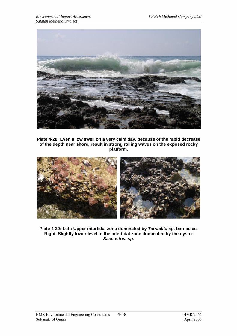
Environmental Impact Assessment Salalah Methanol Company LLC Salalah Methanol Project
HMR Environmental Engineering Consultants 4-38 HMR/2064 Sultanate of Oman April 2006
Plate 4-28: Even a low swell on a very calm day, because of the rapid decrease of the depth near shore, result in strong rolling waves on the exposed rocky
platform.
Plate 4-29: Left: Upper intertidal zone dominated by Tetraclita sp. barnacles. Right. Slightly lower level in the intertidal zone dominated by the oyster
Saccostrea sp.

Environmental Impact Assessment Salalah Methanol Company LLC Salalah Methanol Project
HMR Environmental Engineering Consultants 4-39 HMR/2064 Sultanate of Oman April 2006
Plate 4-30: Left: Cellana rota. Right: Siphonaria sp. Both species are specialized in shallow (intertidal) environments where they graze on small
incrusting algae.
Plate 4-31: Left: Chiton (Acanthopleura vaillantii) common in the lower intertidal. Right. Small colony of Perna viridis (green mussel).
4.12.9 Outfall
The proposed outfall is located in a partially inundated wadi under the influence of tidal movement. The south shore of the wadi is completely transformed by the north retaining wall of Salalah Port facility (Plate 4-32). Construction of additional facilities (dredging, additional retaining walls) is continuing considerably modifying the environment (Plate 4-33). The habitat appeared strongly disturbed and had no visibility for any photographic documentation.
The wadi mouth consists of a triangular expense of fine sand and clay with little living organisms in it. There were numerous fish in the water (Mullets mostly) and a small stingray in the very shallow water of the upper bay was observed.
The sediment was layered with a fine layer of silt over a large gravel-rubble layer above a very fine silt-clay layer. The anoxic layer (black clay) was only about 1 to 2

Environmental Impact Assessment Salalah Methanol Company LLC Salalah Methanol Project
HMR Environmental Engineering Consultants 4-40 HMR/2064 Sultanate of Oman April 2006
cm from the surface of the sediment. The only organisms found were crabs of the genus Uca sp. (fiddler crabs) at densities varying from 20-150 animals m-2.
Along the upper wadi, upstream of the retaining wall, the substrate consists of fine sediment mixed with large pebbles and small rubble of eroded stones. The sediment is anoxic at very shallow depth and smells strongly of sulphur dioxide. Beside numerous birds (counted - 14 large Grey heron and 6 small white egrets), the fauna consist mostly of mud crabs (Uca. sp). The bank of the wadi consists of a mixture of rounded stones and concrete suggesting either artificial embankment or disposal of construction concrete during the construction phase of the harbour.
Little was found in terms of biodiversity. There were no mangrove trees or freshwater vegetation as in other khawrs of the region.
Plate 4-32: South shore of the wadi showing the retaining wall

Environmental Impact Assessment Salalah Methanol Company LLC Salalah Methanol Project
HMR Environmental Engineering Consultants 4-41 HMR/2064 Sultanate of Oman April 2006
Plate 4-33: General view of the development activity near the proposed outfall
As mentioned in Section 4.12.1, seawater and subtidal/intertidal sediment samples were collected from the proposed intake and outfall locations for determining the current marine quality. The locations were selected considering the potential sensitive areas within the bay, corridor of impact around the intake and outfall locations. The sampling locations are listed in Table 4-10 and Table 4-9 and presented in Figure 4-2.
Table 4-9: Seawater sampling locations
Location # Description Easting Northing 1 Seawater from proposed intake 818968 1873379 2 Seawater from proposed intake 818835 1873866 3 Seawater from proposed intake 818821 1874011 4 Seawater from proposed outfall 819178 1875711 5 Seawater from proposed outfall 819482 1876175 6 Seawater from proposed outfall 810589 1876673
Table 4-10: Seabed sediments sampling locations
Location # Description Easting Northing 1 Subtidal sediment at proposed intake 818968 1873379 2 Subtidal sediment at proposed intake 818835 1873866 3 Subtidal sediment at proposed intake 818821 1874011 4 Subtidal sediment at proposed outfall 819178 1875711 5 Subtidal sediment at proposed outfall 819475 1876122

Environmental Impact Assessment Salalah Methanol Company LLC Salalah Methanol Project
HMR Environmental Engineering Consultants 4-42 HMR/2064 Sultanate of Oman April 2006
Location # Description Easting Northing 6 Intertidal sediment at proposed outfall 818859 1875577 7 Intertidal sediment at proposed outfall 818753 1875599
4.12.10 Seawater Quality
The samples were analysed for physical parameters such as pH, salinity, etc., heavy metals and hydrocarbons. The results are presented in Table 4-11.
Table 4-11: Seawater analysis
Locations Parameters Unit
1 2 3 4 5 6 UK EQS Limit11
Depth (m) m 20 11 1 2 2 0.4 - Electrical conductivity (EC) μS/m 59700 53600 53600 55300 55300 54100 -
TDS ppt 29.6 29.5 29.5 30.4 39.84 29.8 - Total Suspended Sediments (TSS) mg/L 69.5 139 136 136 <1 77 -
Chlorides mg/L - - - - 21546 - - Iron (Fe) mg/L 0.023 0.016 0.046 0.042 0.009 0.186 1,000 Cadmium (Cd) mg/L <0.003 <0.003 <0.003 <0.003 <0.0003 <0.003 2.5 Manganese (Mn) mg/L <0.001 <0.001 0.006 0.008 0.0019 0.002 - Copper (Cu) mg/L 0.017 0.013 0.016 0.011 0.0049 <0.01 5 Nickel (Ni) mg/L 0.154 0.068 0.037 0.017 <0.001 0.009 30 Lead (Pb) mg/L 0.004 <0.001 <0.001 <0.001 <0.007 <0.001 25 TPH12 mg/L 0.015 0.016 0.010 0.008 - 0.010 - GRH (C5 – C10) μg/L - - - - <10 - - DRH (C11 – C28) mg/L - - - - <0.05 - - Heavy fraction (C29 – C40)
mg/L - - - - <0.05 - -
In the absence of applicable Omani standards for seawater quality, the results have been compared with UK EQS standards for seawater. The results presented above indicate that there is no contamination of seawater in the area.
4.12.11 Sediment quality
Marine sediments function as a sink for pollution and will potentially entrap large amounts of contaminants. Sediment metal concentrations may often exceed those in overlying water layers. Subtidal/intertidal sediment samples were collected from 7 locations presented in Table 4-10 in order to assess the contamination level within the bay. Usually the contaminant concentrations in marine sediments are thought to increase with decreasing sediment grain size due to higher surface area available for 11 As contained in UK Environmental Quality Standards (EQS) 12 Samples from all locations barring location 5 have been analysed for TPH. Location 5 has been analysed to obtain the hydrocarbon fractional range.

Environmental Impact Assessment Salalah Methanol Company LLC Salalah Methanol Project
HMR Environmental Engineering Consultants 4-43 HMR/2064 Sultanate of Oman April 2006
adsorption. The Regional Organisation for Protection of Marine Environment (ROPME)13 recommends a standardised procedure of sieving the sediment sample and the <63 mm fraction be analysed for contaminants. However, due to insufficient quantity of the recommended fraction, a larger grain size was used i.e. 125 mm. The sediment samples collected were sent to MRME&WR laboratory for sieving and analysis. Samples were first freeze dried and sieved to obtain a grain size of <125 mm prior to being analysed for heavy metals and hydrocarbon contamination. Atomic absorption spectroscopy was used to determine the heavy metal concentrations and gas chromatography method was used to analyse hydrocarbons in the samples. The results of analysis are presented in Table 4-12.
Table 4-12: Sediment analysis
Locations Parameters Unit 1 2 3 4 5 6
UK Action levels14
Canadian limits15
Zinc (Zn) mg/kg 2.0 2.6 4.1 3.3 5.3 3.1 - 271 Chromium (Cr) mg/kg 12.1 16.0 14.5 15.1 12.8 11.6 - 160 Copper (Cu) mg/kg 19.0 17.4 21.4 17.5 2.1 27.2 40 108 Nickel (Ni) mg/kg 37.3 40.1 30.5 40.8 4.0 52.0 - 42.8 Lead (Pb) mg/kg 40.2 44.1 47.3 41.9 <0.6 55.5 40 112 Arsenic (As) mg/kg - - - - 0.2 - - 41.6 GRH (C5 – C10) μg/L - - - - <10 - - - DRH (C11 – C28) mg/L - - - - <0.05 - - - Heavy fraction (C29 – C40)
mg/L - - - - <0.05 - - -
Analytical results presented in the table above indicate that all the metals and hydrocarbon concentrations are well below comparable limits, except nickel in the intertidal sediment at the proposed outfall location, which is typically naturally present due to leaching from rocks.
4.13 Demography
The proposed site lies within the Wilayat of Salalah in the Dhofar Governorate. The total population in the Wilayat is 156,53016, out of which the male population is 92,489 and the female population is 64,401. According to 2003 census results, 72.5%
13 Regional Organization for the Protection of the Marine Environment, 1989, Manual of Oceanographic Observations and Pollutant Analysis Methods, ROPME, Kuwait, 2nd Edition. 14 UK Ministry of Agriculture, Fisheries and Food action levels are considered as the comparison standards for heavy metal in marine sediments 15 Based on Sediment Quality Guidelines, developed by Canadian Council of Ministers of the Environment (CCME). The limits represent the probable effect level (PEL) and Interim Marine Sediment QualityGuidelines (ISQG), above which adverse biological effects are usually observed 16 Based on the 2003 census report published by the Ministry of National Economy

Environmental Impact Assessment Salalah Methanol Company LLC Salalah Methanol Project
HMR Environmental Engineering Consultants 4-44 HMR/2064 Sultanate of Oman April 2006
of the total population in Dofar region is from the Wilayat of Salalah. There are a total of 21,258 households in 29,188 housing units within the Wilayat. According to previous census data, there are 64 schools within the Wilayat of Salalah with a total enrollment of 29734 students. There are 31 health institutions (hospitals, health centers and private clinics) with 538 beds in the Dhofar Governorate.
4.14 Occupation and employment
According to 1993 census data, public administration accounts for 27% of the total employment in the Salalah town. This is followed by construction (16%), trading (16%), manufacturing (9%) and agriculture (4%). Fisheries account for less than 0.3% of total employment. The details are presented in Table 4-13.
Table 4-13: Distribution of economic activity in the Wilayat of Salalah
Economic Activity Number of Employees % of Total Agriculture 1,897 3.8 Fishing 158 0.3 Mining & Quarrying 60 0.1 Manufacturing 4,323 8.6 Electricity, Gas & Water supply 373 0.7 Construction 8,061 16.0 Whole sale and retail trade etc. 7,834 15.6 Hotels, Restaurants 1,241 2.5 Transport, Storage & Communications 2,022 4.0 Financial Institutions 375 0.7 Real Estate, renting, etc. 918 1.8 Public Administration 13,661 27.2 Education 2,120 4.2 Health & Social Work 854 1.7 Other 6,389 12.8 Total 50,286 100.0
4.15 Industrial environment
The proposed site is located in a designated industrial area, which includes the Salalah Port facilities, the Raysut Industrial Area, and the new industrial area proposed in the Salalah Free Zone. The area around the port has also been reserved for future industrial and commercial developments. The port is located adjacent to the proposed project site and is separated by an asphalted road. The Raysut Industrial Estate is the biggest industrial area in the Dhofar Governorate and is located about 4.5 km to the north of the project area. The industries within the industrial area include food processing plants, tanneries and engineering units.

Environmental Impact Assessment Salalah Methanol Company LLC Salalah Methanol Project
HMR Environmental Engineering Consultants 4-45 HMR/2064 Sultanate of Oman April 2006
4.16 Archaeological, cultural and recreational resources
Salalah, being a historical town, possesses many archaeologically important structures scattered around the region. Some of these include remains of the coastal city of Al Baleed, ancient buildings at Raysut, remains of fort at Ayn Hamraan, and several old mud houses in Awqdayn, Salalah, and Al Haffa.
The Dhofar Governorate has number of archaeological sites, which shed light upon the cultural and socio-economic development and the patterns of land-use. Some of these areas have regional and national significance such as remains of the ancient city of Dhofar at Khawr Baleed, which was a flourishing city during the 13th century and served as a port for the export of frankincense. Remains of buildings cover the tip of Ra’s Raysut (Raysut headland). Megalithic Bronze Age remains of stone circles and houses have been preserved albeit heavily reused in the Iron Age. These remains are more observed on the lagoons, the lower terraces, the higher upland terraces, and the foothills. Earlier archaeological surveys have briefly covered this area and interpreted the findings as Iron Age homestead sites.
Religious and cultural resources refer to mosques, graveyards, prayer grounds and Sharia Court. In Salalah, there are 42 Juma mosques and 83 local mosques. Their spatial distribution is considered fairly wide serving the whole community adequately. There is a Sharia (Islamic law) Court located in Salalah. For religious education, there is a Quran School and the Sultan Qaboos Institute for Islamic Studies in Salalah.
There are many old graveyards spread throughout Salalah, several areas within the region are thought to be significant culturally. The Ministry of National Heritage and Culture (MNHC) is responsible for the maintenance of museums and other cultural facilities. There is currently one museum located in New Salalah attached to the regional office of MNHC covering regional and national history. There is also a concert hall within the complex.
Dhofar is a unique region in the Sultanate of Oman. It is a land of majestic mountains with lavish green landscape and serene coastline. This region has a unique temperate climate, which is markedly different from that of the rest of Oman. The culture of Dhofar is also somewhat different from that of northern Oman.
Salalah is a popular tourist destination in Oman as well as in the Gulf Region. It is estimated that more than 75% of the tourists arrive during the Khareef season (July-September), and during that time, more than 50% of the tourists arrive from outside Oman. The Al Khareef Festival is an annual event, held during the month of July - August. Unique in nature, the festival attracts visitors, musicians, folk art performers and traders. The products unique to Dhofar region include frankincense, incense
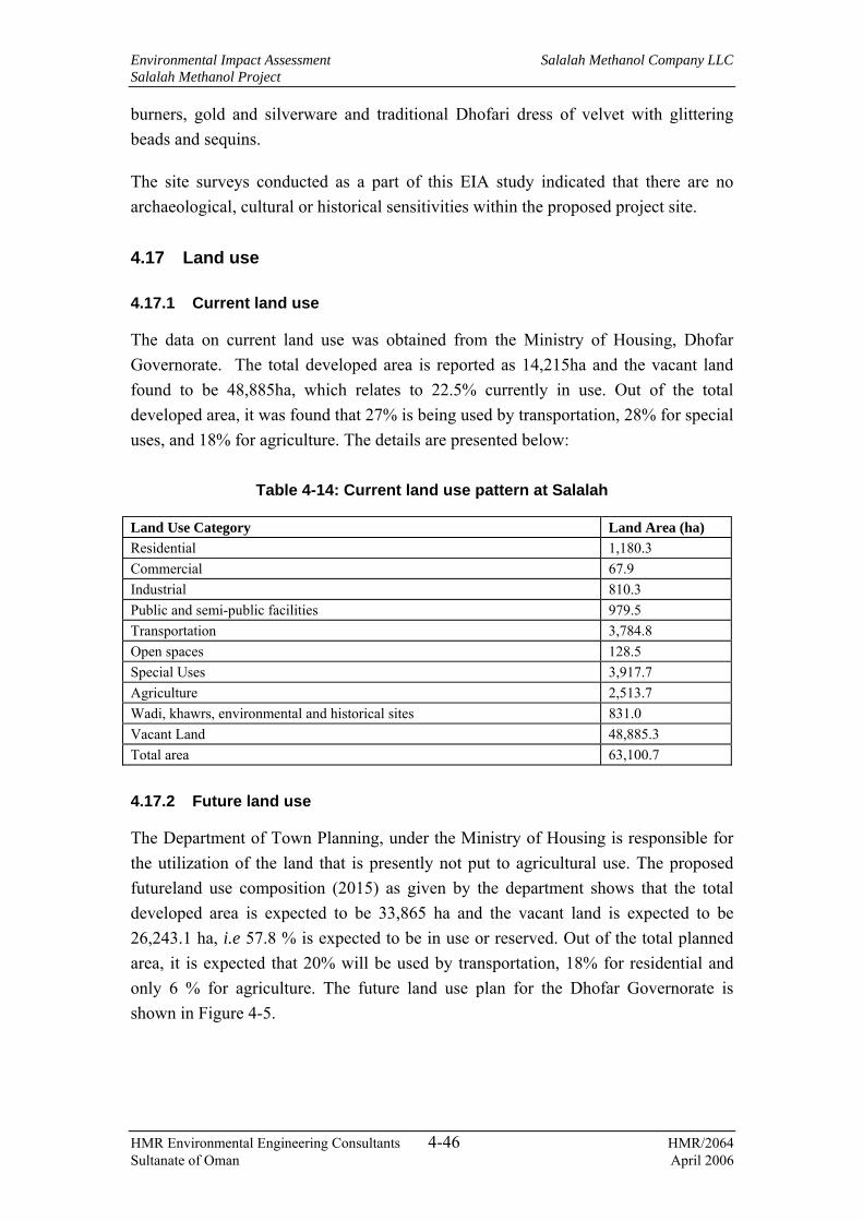
Environmental Impact Assessment Salalah Methanol Company LLC Salalah Methanol Project
HMR Environmental Engineering Consultants 4-46 HMR/2064 Sultanate of Oman April 2006
burners, gold and silverware and traditional Dhofari dress of velvet with glittering beads and sequins.
The site surveys conducted as a part of this EIA study indicated that there are no archaeological, cultural or historical sensitivities within the proposed project site.
4.17 Land use
4.17.1 Current land use
The data on current land use was obtained from the Ministry of Housing, Dhofar Governorate. The total developed area is reported as 14,215ha and the vacant land found to be 48,885ha, which relates to 22.5% currently in use. Out of the total developed area, it was found that 27% is being used by transportation, 28% for special uses, and 18% for agriculture. The details are presented below:
Table 4-14: Current land use pattern at Salalah
Land Use Category Land Area (ha) Residential 1,180.3 Commercial 67.9 Industrial 810.3 Public and semi-public facilities 979.5 Transportation 3,784.8 Open spaces 128.5 Special Uses 3,917.7 Agriculture 2,513.7 Wadi, khawrs, environmental and historical sites 831.0 Vacant Land 48,885.3 Total area 63,100.7
4.17.2 Future land use
The Department of Town Planning, under the Ministry of Housing is responsible for the utilization of the land that is presently not put to agricultural use. The proposed futureland use composition (2015) as given by the department shows that the total developed area is expected to be 33,865 ha and the vacant land is expected to be 26,243.1 ha, i.e 57.8 % is expected to be in use or reserved. Out of the total planned area, it is expected that 20% will be used by transportation, 18% for residential and only 6 % for agriculture. The future land use plan for the Dhofar Governorate is shown in Figure 4-5.

Environmental Impact Assessment Salalah Methanol Company LLC Salalah Methanol Project
HMR Environmental Engineering Consultants 4-47 HMR/2064 Sultanate of Oman April 2006
Figure 4-5: Future land use at Wilayat of Salalah

Environmental Impact Assessment Salalah Methanol Company LLC Salalah Methanol Project
HMR Environmental Engineering Consultants 5-1 HMR/2064 Sultanate of Oman April 2006
5. ENVIRONMENTAL RELEASES
5.1 General
The project interaction with the environment is primarily by way of consumption of resources, release of various waste streams and accidental releases/spills of hazardous materials. In the following sections, potential releases to the environment during construction and operational phases of the project are presented. Releases during the decommissioning phase will be similar to that of the construction phase but for a shorter duration.
5.2 Waste classification
The wastes streams in general are classified as below:
− Air emissions;
− Liquid effluents;
− Solid wastes;
− Hazardous wastes;
− Noise; and
− Accidental releases.
Air emissions are further classified into the following sub-groups:
− Stationary source emissions;
− Fugitive emissions; and
− Mobile source emissions.
Liquid effluents are classified into the following sub-groups:
− Process / industrial wastewater;
− Sanitary wastewater (sewage); and
− Surface runoffs.
Solid wastes are classified into the following sub-groups:
− Non-hazardous industrial wastes; and
− Domestic wastes.
Hazardous wastes are classified as below:
− Solid hazardous wastes; and

Environmental Impact Assessment Salalah Methanol Company LLC Salalah Methanol Project
HMR Environmental Engineering Consultants 5-2 HMR/2064 Sultanate of Oman April 2006
− Liquid hazardous wastes.
Accidental releases are classified as below:
− Gaseous releases into atmosphere; and
− Liquid spills and leaks onto land.
Most of the data presented in this chapter are derived from the FEED document for the project. Detailed information is currently not available for some of the waste streams arising from the project especially from the construction phase activities. However, an attempt has been made to estimate the quantities and characteristics using material balances, technical evaluations and from previous experience. The proposed control, treatment and disposal methods for various waste streams are also discussed in this chapter. Both construction and operational phases of the project are discussed with regard to waste generation, handling, storage, treatment and disposal. The waste management plan including monitoring programmes is further discussed in Chapter 9.
5.3 Releases during construction phase
5.3.1 Overview
The releases during construction phase will depend upon the type of construction activities, construction methods, construction equipment, chemicals / materials used, source / amount of utilities and duration of site work. It is important to note that detailed information on the above were not available during preparation of this report., Releases and related impacts are assessed based on available information, the construction methodology presented in Section 3.9 and technical assessments.
5.3.2 Characterisation of releases
Releases during construction of the proposed projects are identified in Table 5-1. It is difficult to provide accurate quantities of releases during construction, at this stage. Typical characteristics and proposed treatment and disposal methods are also summarized.

Environmental Impact Assessment Salalah Methanol Company LLC Salalah Methanol Project
HMR Environmental Engineering Consultants 5-3 HMR/2064 Sultanate of Oman April 2006
Table 5-1: Releases during construction phase
# Description of release and Source
Nature of release Proposed control, treatment & disposal methods
Air emissions
1 Stationary emission sources - Emissions from diesel generators
Continuous release during construction activities - Combustion products - NOX, CO, SO2, unburnt HC and Particulate Matter (PM)
• Use of standard DG units in proper operating and maintenance conditions
• Periodic maintenance schedules • Provision of standard exhaust
pipes
2 Mobile sources – Construction machinery, equipment and vehicles run by internal combustion engines
Intermittent release during construction activities - Combustion products (NOX, CO, SO2 , unburnt HC and PM)
• Use of standard construction equipment and vehicles
• Proper maintenance of equipment and vehicles including engine tuning, filter cleaning, etc.
• Providing standard exhaust pipes.
3 Area emission sources – HC emission from fuel storage tanks
Fugitive emission of vapours generated during storage and tank utilisation – Mainly HC
• Periodic inspection/maintenance of tanks and fittings to eliminate leaks
4 Fugitive emission sources - Dust emissions from earth work , vehicular traffic on unpaved roads, welding and metal cutting fumes, emissions from surface polishing and coating activities in fabrication areas
Intermittent release during construction activities, vehicle movements and fabrication activities - Airborne dust (PM), VOCs and metallic fumes
• Water spraying to reduce dust emissions
• Enclosed painting booths and dedicated fabrication areas
Liquid effluents
5 Wash water from equipment / vehicle washing at site
Intermittent - May contain suspended solids and oil & grease
• Collection and on-site treatment in settling tanks for separating oil & grease and TSS
• The primary treated effluent will be sent to an onsite STP or a municipal STP for further treatment.
6 Wastewater from hydro-testing of storage tanks, pipelines and other process equipment
One time discharge – Unlikely to be contaminated, however, may contain traces of rust , oil and corrosion inhibitor chemicals
• Will be reused to the extent possible
• Adequately designed holding pond will be provided for storage of spent hydro-test water. The water that is not evaporated will be routed to ETP for treatment once the plant is operational
7 Chemical cleaning solutions for cleaning of machineries and process vessels prior to commissioning
Intermittent – Wash water potentially contaminated with acids/alkalis/solvents, detergents, corrosion products, SS and oil & grease
• Will be sent to onsite STP or municipal STP after settling for separation of SS and oil & grease and neutralisation, if required, for further treatment and disposal

Environmental Impact Assessment Salalah Methanol Company LLC Salalah Methanol Project
HMR Environmental Engineering Consultants 5-4 HMR/2064 Sultanate of Oman April 2006
# Description of release and Source
Nature of release Proposed control, treatment & disposal methods
8 Sanitary wastewater from project site offices and labour camps
Continuous - Biodegradable organics and SS
• Will be collected in collection pits and sent to onsite/other nearby municipal STP for treatment
9 Surface runoffs - Drainage of rain water from within the project site
Rare occurrence – No pollutants expected unless drained from accidentally contaminated areas
• Holding pits to hold any runoffs from contaminated areas
• Uncontaminated water will be drained through surface drains
Non-hazardous solid waste
10 Excavated soil - Excavation for foundations, roads and other infrastructure and dredged material from marine construction
Continuous during excavation / dredging activities – Normally uncontaminated
• Excavated soil will be stockpiled in dedicated storage areas at site
• Will be reused for backfilling wherever possible and the rest disposed off to the nearest approved landfill site.
• If contaminated, will be collected and stored in dedicated bunded storage areas (Refer Item # 17). Dredged material will be normally uncontaminated and will be disposed at offshore locations close to pipeline trench (Refer Item # 22)
11 Domestic waste, office wastes from project offices and kitchen wastes from dining facilities, etc.
Intermittent – Non-recyclable, biodegradable waste
• Collected in waste skips and disposed off to the nearest approved landfill site / municipal waste disposal site
12 Miscellaneous wastes such as waste tyres, insulation material, waste cables, light fittings, etc.
Intermittent – Non-recyclable, non-biodegradable waste
• Stored in dedicated areas / skips and disposed to the nearest approved municipal waste disposal site
13 Metal scrap and empty metal drums of non-hazardous materials - Metal work and packaging materials
Intermittent – recyclable, non-biodegradable.
• Stored in segregated and dedicated storage area at site and sold to scrap metal dealers
14 Paper and wood scrap - Packaging materials
Intermittent – Recyclable, biodegradable
• Stored in segregated and dedicated storage area at site and sold to scrap buyers, if possible, and rest disposed to approved waste disposal sites.
15 Empty plastic containers of non-hazardous materials - Packaging materials
Intermittent – Recyclable, non-biodegradable.
• Stored in segregated and dedicated storage area at site and sold to approved recyclers to the extent possible. Rest disposed off to approved waste disposal sites.
Hazardous waste
16 Containers of hazardous materials (oil drums, paint drums, chemical drums etc.)
Intermittent - Empty containers contaminated with hydrocarbons and chemicals
• Stored on site in segregated and enclosed area and recycled as feasible

Environmental Impact Assessment Salalah Methanol Company LLC Salalah Methanol Project
HMR Environmental Engineering Consultants 5-5 HMR/2064 Sultanate of Oman April 2006
# Description of release and Source
Nature of release Proposed control, treatment & disposal methods
• Decontaminated for disposal as non-hazardous waste or disposed off in compliance with MD 18/93 and as directed by MRME&WR
17 Contaminated soils due to accidental spills and leaks of oils and liquid chemicals, settled solids/sediments collected from oil-water separation pits, hydro-testing of equipment, etc.
Intermittent - Contaminated soil
• Stored on site in a enclosed and bunded area with impervious flooring or in drums
• Disposed at approved land farm facility and/or as directed by MRME&WR
18 Unused and off-spec chemicals, paints, coatings etc.
Intermittent – Waste chemicals
• Stored on site in segregated and enclosed area, recycled wherever feasible
• Sent back to the supplier if feasible
• Non-reusable/recyclable material will be disposed off in compliance with MD 18/93 and/or as directed by MRME&WR
19 Waste oil and oil sludge - Fuel oil storage and maintenance workshops
Intermittent – hazardous waste
• Stored on site in segregated and enclosed area
• Sold to approved waste oil recyclers
20 Miscellaneous wastes such as spent batteries, used/soiled cotton wastes etc.
Intermittent – hazardous waste
• Stored on site in segregated and enclosed area and recycled wherever feasible
• Non-reusable/recyclable material will be disposed off in compliance with MD 18/93 and/or as directed by MRME&WR
Noise
21 Noise from construction equipment and vehicles
Continuous during construction activities –engine noise, noise from excavation, rock breaking, grading, bulldozing, etc.
• Proper maintenance of equipment and vehicles
• High noise activities to be restricted to day time only
• Providing ear protectors to workers in high noise areas
Marine releases
22 Sediment transport due to dredging for seawater intake pipeline and disposal of dredged material at offshore locations close to the pipeline trench
Continuous during dredging activities – re-suspension of sea bottom sediments and associated contaminants, if any, such as HC and heavy metals
• Periodic monitoring of seawater for TSS during the pipeline construction period
• Selection of dredging methods and equipment in order to minimise sediment loss into the surrounding water column
• Selection of appropriate locations for offshore disposal of dredged materials
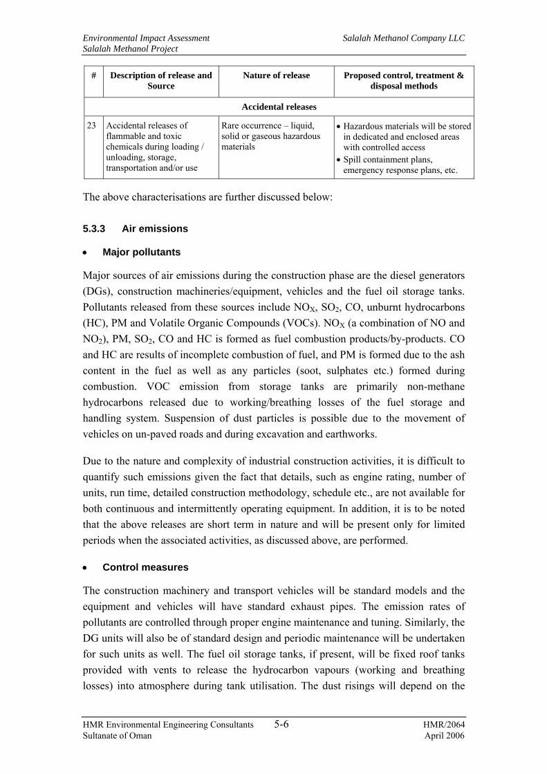
Environmental Impact Assessment Salalah Methanol Company LLC Salalah Methanol Project
HMR Environmental Engineering Consultants 5-6 HMR/2064 Sultanate of Oman April 2006
# Description of release and Source
Nature of release Proposed control, treatment & disposal methods
Accidental releases
23 Accidental releases of flammable and toxic chemicals during loading / unloading, storage, transportation and/or use
Rare occurrence – liquid, solid or gaseous hazardous materials
• Hazardous materials will be stored in dedicated and enclosed areas with controlled access
• Spill containment plans, emergency response plans, etc.
The above characterisations are further discussed below:
5.3.3 Air emissions
• Major pollutants
Major sources of air emissions during the construction phase are the diesel generators (DGs), construction machineries/equipment, vehicles and the fuel oil storage tanks. Pollutants released from these sources include NOX, SO2, CO, unburnt hydrocarbons (HC), PM and Volatile Organic Compounds (VOCs). NOX (a combination of NO and NO2), PM, SO2, CO and HC is formed as fuel combustion products/by-products. CO and HC are results of incomplete combustion of fuel, and PM is formed due to the ash content in the fuel as well as any particles (soot, sulphates etc.) formed during combustion. VOC emission from storage tanks are primarily non-methane hydrocarbons released due to working/breathing losses of the fuel storage and handling system. Suspension of dust particles is possible due to the movement of vehicles on un-paved roads and during excavation and earthworks.
Due to the nature and complexity of industrial construction activities, it is difficult to quantify such emissions given the fact that details, such as engine rating, number of units, run time, detailed construction methodology, schedule etc., are not available for both continuous and intermittently operating equipment. In addition, it is to be noted that the above releases are short term in nature and will be present only for limited periods when the associated activities, as discussed above, are performed.
• Control measures
The construction machinery and transport vehicles will be standard models and the equipment and vehicles will have standard exhaust pipes. The emission rates of pollutants are controlled through proper engine maintenance and tuning. Similarly, the DG units will also be of standard design and periodic maintenance will be undertaken for such units as well. The fuel oil storage tanks, if present, will be fixed roof tanks provided with vents to release the hydrocarbon vapours (working and breathing losses) into atmosphere during tank utilisation. The dust risings will depend on the

Environmental Impact Assessment Salalah Methanol Company LLC Salalah Methanol Project
HMR Environmental Engineering Consultants 5-7 HMR/2064 Sultanate of Oman April 2006
nature of the surface and the weather conditions. Water spraying will be done to reduce dust emissions.
5.3.4 Liquid effluents
• Major pollutants
The liquid effluent sources, nature and typical characteristics for the construction phase are presented in Table 5-1. With regard to the characteristics of the effluents, it is difficult to estimate the chemical composition of the various effluent streams. Therefore, first order approximations for the characteristics of these effluent streams (before any treatment) are also presented in the table.
• Control measures
For the segregation, treatment and disposal of the various liquid effluent streams generated during the construction period, the following measures are proposed. Construction machinery will be water washed periodically to remove any accumulated dirt. No detergents are envisaged to be used. Washing will be done in a designated area (washing ramp) and the washings will be collected into a settling tank in order to separate TSS and oil & grease. The clarified effluent will be sent to the STP along with sewage. The separated oil will be skimmed off or removed using soaking pads and the collected oil will be disposed as hazardous waste. The settled solids from the bottom of the tank will be removed periodically by the EPC contractor and disposed off in accordance with the regulations.
Hydro-testing will be carried out for storage tanks and piping. The spent hydro-test water will be virtually free of any contaminants, except for small amounts of corrosion products, oil and corrosion inhibitor chemicals (if used). Adequately designed holding pond/basin will be constructed for storage of spent hydro-test water. Water that is not evaporated will be routed to the ETP for treatment once the plant is operational.
Sewage generated from the various toilets, kitchens and washrooms at the project site, project offices and labour camps (if any) will be collected through underground pipes into holding tanks. The sewage from the holding tanks will be removed periodically by vacuum trucks and transferred to the onsite STP/nearest municipal STP for treatment and disposal. Storm water is expected mainly during the Khareef season, however will be a rare occurrence during other months due to scarcity of rainfall. The storm water from non-contaminated areas will be routed to surface drains in the area. Storage areas of hazardous wastes / hazardous materials will be enclosed to protect from rains and storm water. If storm water is suspected to be contaminated, it will be

Environmental Impact Assessment Salalah Methanol Company LLC Salalah Methanol Project
HMR Environmental Engineering Consultants 5-8 HMR/2064 Sultanate of Oman April 2006
collected in collection pits and prevented from entering surface drains. Normally run-offs from areas where hazardous substances (oils and chemicals) are stored will not occur. If there are any accidental spillages of hazardous substances on the soil, such areas will be immediately remediated to avoid the run-off being contaminated.
5.3.5 Non-hazardous solid wastes
• Major pollutants
Due to the nature and complexity of the construction activities, it is not practical to quantify the solid wastes as the details on construction activities, quantities of chemicals and materials, excavation and scrap generation rates, etc., are not available. The types of wastes typically generated during the construction and their method of handling and disposal are presented in Table 5-1.
• Control measures
Various wastes will be segregated and collected in appropriate skips, drums, etc. Non-hazardous wastes will be prevented from mixing with hazardous waste materials. The storage skips / areas for each type of waste will be clearly identified and marked. The collected wastes will be periodically disposed off to local recyclers. Any non-recyclable waste will be sent to municipal waste disposal sites in the vicinity of the proposed site.
Excavated soil will be stockpiled and reused for backfilling onsite, wherever possible. The excess quantity will be disposed in an approved landfill site / waste disposal site, if uncontaminated. The possibility of recycling of materials such as scrap metal, wooden and paper packing materials, metal and plastic drums etc., generated from construction activities will be assessed and will be recycled to the extent possible or offered to the local contractors for re-use. Non-recyclable wastes will be segregated, properly stored and disposed off in an approved waste disposal site along with other construction wastes.
5.3.6 Hazardous wastes
• Major pollutants
The quantities of hazardous waste streams cannot be estimated at present as the quantities of hazardous materials such as cleaning solvents, paints, fuels, oil, etc., which will be used for the construction activities are not available at present. Typically, the pollutants will be hydrocarbons / petrochemical compounds. The EPC contractors will include adequate provisions (as per MSDS) for the safe handling, storage, transportation and disposal of such wastes.

Environmental Impact Assessment Salalah Methanol Company LLC Salalah Methanol Project
HMR Environmental Engineering Consultants 5-9 HMR/2064 Sultanate of Oman April 2006
• Control measures
Various hazardous waste materials will be segregated and stored in appropriate protected and enclosed areas. Wastes will be segregated in such a way that those, which are explosive, flammable, reactive, corrosive, toxic, etc., will be separately stored in closed containers. To the extent possible, such wastes will be stored on concrete floored and bunded, enclosed and covered areas in order to protect from rains and prevent runoffs as the project site receives significant rainfall during the monsoon period of June to September.
Contaminated soils generated due to accidental spillage/leakage of oils, liquid chemicals, solvents and paints will be stored in bunded areas to prevent runoff and on impervious flooring to prevent leaching of hazardous materials and contamination of land and water. Waste, unused and offspec paints, chemicals and miscellaneous materials such as batteries will be considered for returning to supplier, recycling or reuse either onsite or offsite. Any non-recyclable material will be stored in a dedicated area. Waste oils and contaminated containers/packaging material such as oil drums, paint drums and chemical packaging materials will be sent to authorised recyclers.
Non-recyclable hazardous wastes cannot be disposed off-site since there are no authorized facilities for accepting or treating/disposing such wastes in the Sultanate of Oman.
The stored material, at the end of construction activity, will be transferred to the central storage yard of the EPC contractor for storage or disposed off with the guidance from MRME&WR. All storage areas, drums, containers, etc that is used for storing hazardous chemicals will be clearly identified using whether- proof permanent labels.
5.3.7 Noise
• Nature of pollution
It is difficult to quantify construction noise emissions as the details of the number and type of potential noise sources such as construction equipment, DG units, compressors, vehicles, etc., that will be used at site are not available at present. Also, the details of construction methods are also not available. However, the source noise levels of construction equipment will be maintained in such a way as to comply with applicable regulatory requirements. Typical noise levels from various construction equipment and activities and the duration of operation are presented in Table 5-2.

Environmental Impact Assessment Salalah Methanol Company LLC Salalah Methanol Project
HMR Environmental Engineering Consultants 5-10 HMR/2064 Sultanate of Oman April 2006
Table 5-2: Noise levels from construction equipment
Source of Noise Duration of Operation Noise Level at 1m from Source (dB[A])
Excavators, shovels, dumpers etc. Day time only 70-80 Compactors Day time only 75-80 Concrete mixers Day time only 70-80 Motors and compressors Day time only 65-75 DG Units 24 hours 75-85 Trucks Day time only 75-80
• Control measures
Noise levels of 70 dB (A) will be maintained at the fence lines of the construction site in compliance with MD 79/94. Workers on site will be provided with adequate Personal Protective Equipment (PPE) so as to alleviate noise levels to below 80 dB (A) as required by MD 80/94. Construction equipment/machineries will be provided with suitable noise dampening devices such as mufflers, silencers, etc., to minimise noise at source. Also, the construction activities will be scheduled / planned in such a way as to prevent high noise activities during night times and simultaneous operation of multiple high noise equipment will be avoided to the extent feasible.
5.3.8 Releases to marine environment
• Major pollutants
The release of sediments occurs while carrying out trenching for the intake pipeline (based on the option selected for the pipeline) using excavators (~ 5% loss of sediments into surrounding water column) and clamshell equipment operation (~ 7% sediment loss). However, based on the review of seabed core samples, it is found that seabed is predominantly gravely sand mixed with shells overlaying calcarenite, which has a tendency to settle fast as opposed to remain in suspension. It is expected that the sediments released during the trenching is likely to settle close to the trenched area.
• Control measures
Dredging work for the seawater intake pipeline will be done using clamshell buckets for the loose top seabed sediments comprising mainly of shelly sand. Excavators may be used in some locations where hard calcarenite is encountered. For trenching using clamshell, the excavated material will be placed adjacent to the trench itself. Appropriate locations will be selected for offshore disposal of dredged material.

Environmental Impact Assessment Salalah Methanol Company LLC Salalah Methanol Project
HMR Environmental Engineering Consultants 5-11 HMR/2064 Sultanate of Oman April 2006
5.3.9 Accidental releases
• Major pollutants
Leakage and spills of hazardous materials on to land and water may occur through failure of containers, spills during handling, transportation and use. However it is not practical to quantify the release due to lack of information on quantities of materials used and construction activities. The released materials will be mostly hydrocarbon based liquids or gases.
• Control measures
The hazardous materials will be stored in segregated, enclosed and protected areas in such a way as to store materials, which are explosives, flammables, corrosives, toxic, etc., separately. Such materials will be stored in enclosed and roofed storage areas to the extent feasible in order to protect from rains and prevent runoffs from storage areas. Appropriate spill containment plans and remediation plans will be established. In addition, standard procedures will be followed for receiving shipments from roll-on/roll-off containers and trucks, and maintain proper practices for storage, handling and use of the materials. The storage of hazardous chemicals and gases will be in accordance with the requirements in the respective MSDS.
5.4 Releases during operation phase
The assessment of environmental releases during operational phase of the project addresses the various waste streams generated due to the operation of the production plant units, utilities and offsite facilities. The waste streams are classified according to their physical and chemical nature. The facilities are still at the design stage and hence a few waste streams could not be quantified during the course of this study. However, for the purpose of identifying the impacts during worst case scenarios, relevant emission factors and assumptions have been used and are presented in the following sections.
Table 5-3: Releases during operation phase
# Description of release and Source
Nature of release Proposed control, treatment & disposal methods
Air emissions
1 Stationary point sources – reformer, auxiliary boilers, emergency power generators and flare
Continuous – Combustion products mainly SOx, NOx, CO, CO2, unburnt HC, PM
• Low NOx burners • Optimum air-fuel ratio • Burners designed and operated
for high combustion efficiency • Use of sweet natural gas as
primary fuel

Environmental Impact Assessment Salalah Methanol Company LLC Salalah Methanol Project
HMR Environmental Engineering Consultants 5-12 HMR/2064 Sultanate of Oman April 2006
# Description of release and Source
Nature of release Proposed control, treatment & disposal methods
• Pilot ignition systems at the flare to eliminate cold venting
2 Stationary point sources – uncondensed gasses from light ends column overhead condenser
Continuous – uncondensed gases comprising mainly CO2
• Appropriate operation of the light ends column and condensers to optimise the release of uncondensed gases from the column
3 Mobile sources – men and material transport vehicles and cargo ships
Intermittent – Combustion products mainly SOx, NOx, CO, CO2, unburnt HC, PM
• Proper tuning of vehicles engines • Appropriate schedules for
periodic maintenance
4 Fugitive emission sources –emission from storage tanks, piping connections, seals, and during product loading operations
Continuous – HC vapours. The final exit gas will contain 0.035 g/m3 of methanol
• Storage tanks are internal floating roof tanks to minimize vapours.
• Appropriate tank designs to reduce HC losses during tank utilisation
• Vent condenser for product recovery from storage tanks
• Vapour return lines at the loading facilities to enhance product recovery during loading operations
• Fugitive emission surveys regularly, as part of plant operations
Wastewater
5 Boiler blow down Continuous blow down – Typically contaminated with boiler feed chemicals and high TDS
• Routed to ETP for treatment to marine discharge standards prior to marine disposal through the discharge lagoon and outfall
6 Brine rejects from desalination plant
Continuous – Typical TDS increase of 38.9 ppt from the intake water quality
• Routed through saline effluent sump to discharge lagoon and final disposal through marine outfall
7 Ion exchange resins regeneration effluent
Intermittent – Typically contains high TDS and chemical residues
• Routed to ETP for treatment to marine discharge standards prior to marine disposal through the discharge lagoon and marine outfall
8 Primary cooling water return from coolers and heat exchangers
Continuous – Return seawater with temperature increase of 10oC
• Routed to discharge lagoon and further marine disposal, quality to comply with MD 159/2005
9 Plant sewage Continuous – Wastewater characterised with high biodegradable organic content and SS; typically BOD: 250 to 300 mg/L and SS: 100 to 200 mg/L
• Segregated and collected from various generation points and routed to STP. Treated water discharged through marine outfall

Environmental Impact Assessment Salalah Methanol Company LLC Salalah Methanol Project
HMR Environmental Engineering Consultants 5-13 HMR/2064 Sultanate of Oman April 2006
# Description of release and Source
Nature of release Proposed control, treatment & disposal methods
10 Storm water Rare occurrence – possibly contaminated with SS and HC, oil if run off from process areas
• Water from paved areas is routed to storm water pond and analysed for methanol contamination
• Contaminated water will be sent to the rerun tank for reprocessing
• Uncontaminated water will be routed to ETP for treatment and reuse / disposal
Solid non-hazardous waste
11 Plant domestic waste Continuous – Biodegradable and non-biodegradable solid waste from administration building, offices and kitchen
• Appropriate waste collection and storage facilities
• Segregated and stored in a secluded area
• Recycled and reused wherever possible
• Non-recyclable waste disposed to municipal waste disposal facilities / landfills
12 Used spare parts, electrical and mechanical units, metal scrap from workshop, tyres, etc.
Continuous – non-biodegradable solid waste
• Segregated and stored in a secluded area
• Recycled and reused wherever possible or sold to scrap dealers
• Non-recyclable waste disposed to municipal waste disposal sites
• Certain retired equipment will be cleaned and donated to technical schools, if appropriate.
13 Cleanouts from seawater intake screen
Continuous – Biodegradable and non-biodegradable solid wastes
• Segregated and stored in a secluded area
• Disposed to municipal waste disposal sites
14 Spent air filters and decontaminated methanol filters
Intermittent – Non-biodegradable solid waste
• Segregated and stored in a secluded area
• Disposed to municipal waste disposal sites
15 Spent ion exchange resins Intermittent – Non-biodegradable solid waste
• Neutralised to remove traces of chemicals
• Disposed to municipal landfills in the vicinity of the site.
16 STP sludge Continuous – biodegradable solids
• Appropriate sludge drying beds and methods will be used;
• STP sludge will be treated to land application standards as per RD 115/2001 and used for soil enrichment within the facility and / or SFZ

Environmental Impact Assessment Salalah Methanol Company LLC Salalah Methanol Project
HMR Environmental Engineering Consultants 5-14 HMR/2064 Sultanate of Oman April 2006
# Description of release and Source
Nature of release Proposed control, treatment & disposal methods
Hazardous waste
17 Mercury saturated adsorbent Intermittent (once in 15to 20 years) – Inorganic solid waste contaminated with mercury and HC.
• Returned to supplier
18 Waste zinc oxide from desulphuriser
Intermittent (once in 2 years) – Inorganic solid contaminated with HC and H2S
• Returned to supplier
19 Spent catalyst from feed gas hydrogenator
Intermittent (once in 4 to 6 years) – Hazardous due to presence of heavy metals and HC
• Returned to supplier
20 Spent catalyst from reformer section
Intermittent (once in 4 to 6 years) – Hazardous due to presence of heavy metals and HC
• Returned to supplier
21 Spent catalyst from methanol converter
Intermittent (once in 4 to 6 years) – Hazardous due to presence of heavy metals, methanol and other HC
• Returned to supplier
22 Empty containers of hazardous materials (oils and chemicals)
Intermittent – Hazardous due to presence of HC and chemical residues
• Decontaminated at site, if possible, and disposed as non-hazardous waste
• Will be stored on site, if decontamination not possible, in secluded and sheltered area according to the requirements of MSDS, MD 18/93 and guidance from ministry
Noise
23 Noise from plant, utilities and offsite units operations [flare, compressors, pumps, turbines, furnace, boiler]
Continuous – 85 dB(A) at 1 m from source
• Design source noise levels will be ≤85 dB(A)
• Noise enclosures as appropriate • Areas with noise levels higher
than 85 dB(A) will be classified as high noise areas. Access to such areas will be restricted and use of ear protective equipment will be made mandatory.
Marine releases
24 Spillages during product loading at the loading berth
Rare occurrence – methanol product
• Design provisions to capture any spill.
• Captured spills will be recycled back to the processing plant.
• Spill containment plan • Emergency response plan
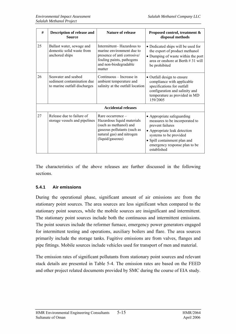
Environmental Impact Assessment Salalah Methanol Company LLC Salalah Methanol Project
HMR Environmental Engineering Consultants 5-15 HMR/2064 Sultanate of Oman April 2006
# Description of release and Source
Nature of release Proposed control, treatment & disposal methods
25 Ballast water, sewage and domestic solid waste from anchored ships
Intermittent– Hazardous to marine environment due to presence of anti corrosive/ fouling paints, pathogens and non-biodegradable matter
• Dedicated ships will be used for the export of product methanol
• Dumping of waste within the port area or onshore at Berth # 31 will be prohibited
26 Seawater and seabed sediment contamination due to marine outfall discharges
Continuous – Increase in ambient temperature and salinity at the outfall location
• Outfall design to ensure compliance with applicable specifications for outfall configuration and salinity and temperature as provided in MD 159/2005
Accidental releases
27 Release due to failure of storage vessels and pipelines
Rare occurrence – Hazardous liquid materials (such as methanol) and gaseous pollutants (such as natural gas) and nitrogen (liquid/gaseous)
• Appropriate safeguarding measures to be incorporated to prevent failures
• Appropriate leak detection systems to be provided
• Spill containment plan and emergency response plan to be established
The characteristics of the above releases are further discussed in the following sections.
5.4.1 Air emissions
During the operational phase, significant amount of air emissions are from the stationary point sources. The area sources are less significant when compared to the stationary point sources, while the mobile sources are insignificant and intermittent. The stationary point sources include both the continuous and intermittent emissions. The point sources include the reformer furnace, emergency power generators engaged for intermittent testing and operations, auxiliary boilers and flare. The area sources primarily include the storage tanks. Fugitive emissions are from valves, flanges and pipe fittings. Mobile sources include vehicles used for transport of men and material.
The emission rates of significant pollutants from stationary point sources and relevant stack details are presented in Table 5-4. The emission rates are based on the FEED and other project related documents provided by SMC during the course of EIA study.

Environmental Impact Assessment Salalah Methanol Company LLC Salalah Methanol Project
HMR Environmental Engineering Consultants 5-16 HMR/2064 Sultanate of Oman April 2006
Table 5-4: Stationary air emissions from the plant facilities
In order to minimise the air emissions, a number of state-of-the-art technologies is proposed to be integrated into the process. The flare has a pilot ignition system to ensure that no cold venting occurs. All the tanks will be provided with vent condensers/vapour return lines, submerged loading facilities and the large product storage tanks will be equipped with internal floating roofs, etc., as required. The emission rates of pollutants such as NOX, SO2, PM, CO and VOCs will comply with Omani regulations. Some of the air pollution control measures are detailed below.
• CO2 emission control
CO2 emissions are of environmental concern due to the global warming potential. In the proposed SMC plant, CO2 will be generated from the combustion of fuel gas in reformer furnace, auxiliary boiler, flare and emergency DGs. However, the GLC of CO2 is virtually unaffected due to atmospheric dilution. Currently, the best practice for minimising CO2 emission is through source reduction, which includes selection of fuel that contains less carbon content per unit energy and improving the conversion efficiency. These two methods of CO2 reduction will be considered in the design of combustion systems used in the plant. These are highlighted below:
− Use of natural gas as primary fuel, which has lower CO2 emission rate compared to liquid fuels;
− Use of high efficiency combustion systems to optimise fuel consumption; and
− Recovery of waste heat from reformer unit by generation of steam for energy conservation.
• CO and HC emission control
CO and unburnt HC result from incomplete combustion of the fuel. Since incomplete combustion results in increased fuel consumption and thus high operating costs, the combustion systems will be designed to achieve high combustion efficiency. While high combustion temperature and high air-fuel ratio help to minimise CO and unburnt HC emissions, such conditions have adverse effects on NOX generation and overall
Pollutant Emission Rate
(g/s) # Source Source ID Stack height
(m)
Stack dia (m)
Exhaust temp (K)
Stack gas
velocity (m/s)
Flow rate
(Nm3/s) SO2 NOx 1 Reformer stack 10-ST1201 50 2.0 459 117.46 219.5 3.63 309.6 2 Auxiliary boiler 20-SE2501A 20 1.5 453 13.63 14.5 1.01 97.2 3 Auxiliary boiler 20-SE2501B 20 1.5 453 13.63 14.5 1.01 97.2 6 Flare 20-FL3301 60 0.6 623 - 0.2 0.0027 -

Environmental Impact Assessment Salalah Methanol Company LLC Salalah Methanol Project
HMR Environmental Engineering Consultants 5-17 HMR/2064 Sultanate of Oman April 2006
energy recovery. Therefore, through optimal mixing of fuel and combustion air and controlling the combustion temperature, CO and unburnt HC emissions are minimised while ensuring NOX emissions and overall energy efficiency are not affected.
• NOX emission control
Low NOX burners will be used for NOX emission control. As mentioned above, care will be taken to ensure that the controls for NOX reduction do not lead to increased CO and unburnt HC emissions. The alternatives available to control NOX emissions include water / steam injection systems and DLN burners. These systems work on the principle of reducing the flame temperature to minimise thermal NOX. The above will be appropriately provided for all proposed combustion systems.
• PM and SO2 emission control
The feed gas to the combustion systems will contain no particulate matter. Further the fuel air ratio will be maintained in such a way to optimise the combustion efficiency thereby reducing the possibility of particulate matter/soot generation. The combustion systems will be designed to minimise visible smoke emissions throughout the anticipated load range.
SO2 concentration in exhaust gases will depend on the sulphur content in the fuel used. The H2S concentration in fuel gas is 2 – 5 ppm (max). Fuels used are sweet and are virtually free of sulphur. Therefore SO2 concentrations in flue gases from all major combustion units will be insignificant.
5.4.2 Liquid effluents
The treatment and disposal of the wastewater streams will be as presented in Table 5-3. All the industrial effluents will be treated in an ETP consisting of oil separators, neutralisation units and bio-treatment units as required by the respective effluent streams. The treatment methods and ETP block diagram are presented in Chapter 6 (Section 6.7). The treated water that is to be disposed at the marine outfall (desalination plant rejects, boiler blow down and regeneration effluents from polishing unit) will conform to the marine discharge standards specified in MD 159/2005. All other process water streams will be treated and recycled back. The sanitary wastewater will be treated in an STP and the treated water will be routed to the marine outfall. Return seawater with a temperature rise of ~ 9ºC and increase in TDS concentration of 560 mg/L from the intake seawater quality will be routed to marine outfall. The quantities and qualities of various liquid effluent streams are presented in Table 5-5.
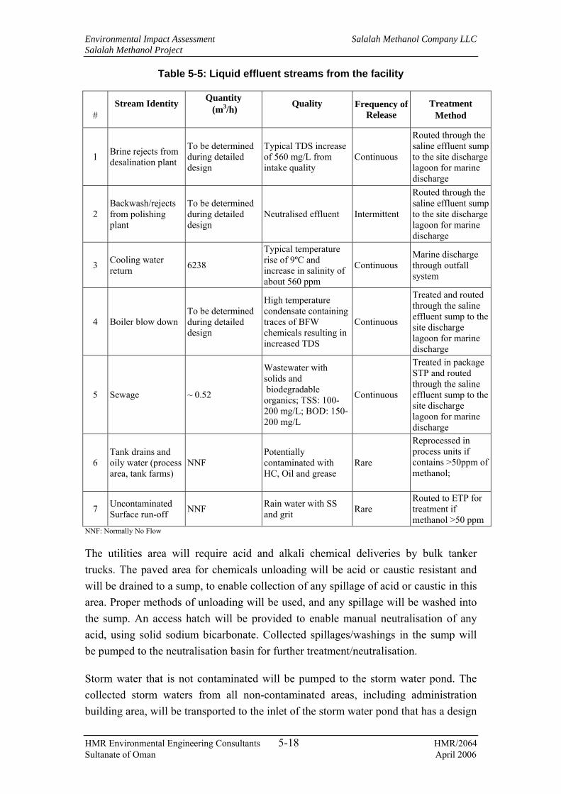
Environmental Impact Assessment Salalah Methanol Company LLC Salalah Methanol Project
HMR Environmental Engineering Consultants 5-18 HMR/2064 Sultanate of Oman April 2006
Table 5-5: Liquid effluent streams from the facility
#
Stream Identity
Quantity (m3/h)
Quality
Frequency of Release
Treatment Method
1 Brine rejects from desalination plant
To be determined during detailed design
Typical TDS increase of 560 mg/L from intake quality
Continuous
Routed through the saline effluent sump to the site discharge lagoon for marine discharge
2 Backwash/rejects from polishing plant
To be determined during detailed design
Neutralised effluent Intermittent
Routed through the saline effluent sump to the site discharge lagoon for marine discharge
3 Cooling water return 6238
Typical temperature rise of 9ºC and increase in salinity of about 560 ppm
Continuous Marine discharge through outfall system
4 Boiler blow down To be determined during detailed design
High temperature condensate containing traces of BFW chemicals resulting in increased TDS
Continuous
Treated and routed through the saline effluent sump to the site discharge lagoon for marine discharge
5 Sewage ~ 0.52
Wastewater with solids and biodegradable organics; TSS: 100-200 mg/L; BOD: 150-200 mg/L
Continuous
Treated in package STP and routed through the saline effluent sump to the site discharge lagoon for marine discharge
6 Tank drains and oily water (process area, tank farms)
NNF Potentially contaminated with HC, Oil and grease
Rare
Reprocessed in process units if contains >50ppm of methanol;
7 Uncontaminated Surface run-off NNF Rain water with SS
and grit Rare Routed to ETP for treatment if methanol >50 ppm
NNF: Normally No Flow
The utilities area will require acid and alkali chemical deliveries by bulk tanker trucks. The paved area for chemicals unloading will be acid or caustic resistant and will be drained to a sump, to enable collection of any spillage of acid or caustic in this area. Proper methods of unloading will be used, and any spillage will be washed into the sump. An access hatch will be provided to enable manual neutralisation of any acid, using solid sodium bicarbonate. Collected spillages/washings in the sump will be pumped to the neutralisation basin for further treatment/neutralisation.
Storm water that is not contaminated will be pumped to the storm water pond. The collected storm waters from all non-contaminated areas, including administration building area, will be transported to the inlet of the storm water pond that has a design

Environmental Impact Assessment Salalah Methanol Company LLC Salalah Methanol Project
HMR Environmental Engineering Consultants 5-19 HMR/2064 Sultanate of Oman April 2006
capacity to hold storm water run off from a peak 30 minute flow. Such a storm event is not anticipated to persist for several days/weeks. The collected storm water will be routed slowly through an oil interceptor to the ETP.
The design basis for a major storm event at Salalah is set as 75 mm of rainfall in 30 minutes with a return frequency no greater than once every 36 hours and no more than 12 such events per annum. The volume of this flow upon paved areas is held within the local sumps provided to allow for sufficient time (16 hours) for sampling and analysis in the site laboratory for methanol content in water. If the methanol concentration is high (defined as that which would overload the ETP), the contaminated storm water is sent to the re-run tank for reprocessing. If the methanol concentration is low or not detectable, the storm water is sent to the ETP feed tank. This tank will hold 1300 m³ designed adequately to hold the rain fall on all the paved areas and tank bunds in the storm event described above.
The ETP will be designed to treat a steady flow of 30 m³/h when the methanol plant is operating or 65 m³/h for 36 hours after a storm event. During and after a fire in the product storage tanks the plant would be shut down and the total 65 m³/h capacity becomes available to treat non-saline fire water.
5.4.3 Non-hazardous solid waste
The waste generation in the plant during normal operation will not be significant. The nature, frequency of generation and disposal methods for the various solid wastes generated in the plant is summarized in Table 5-3. Solid wastes include domestic and office waste from various sources within the facility, metal and wooden packaging materials, used electrical fittings, metal scrap, cans, drums and containers of non-hazardous materials and cleanouts from the seawater intake screen, that are primarily non hazardous in nature. These wastes are stored at a designated waste storage area within the facility and finally disposed off at approved waste disposal sites or sold for recycling (eg. packaging materials and metal scrap).
5.4.4 Hazardous waste
Hazardous wastes include solid and liquid wastes. Solid hazardous wastes include spent catalysts, oily sludge, used cotton waste, spent batteries, waste chemicals, containers of hazardous materials, etc. Liquid hazardous wastes include waste oil/paints/solvents and chemicals. The spent catalysts, waste oils, batteries and paints/solvents will be returned to the suppliers or to the approved recyclers.

Environmental Impact Assessment Salalah Methanol Company LLC Salalah Methanol Project
HMR Environmental Engineering Consultants 5-20 HMR/2064 Sultanate of Oman April 2006
5.4.5 Noise
Equipment such as steam turbine units, boilers, compressors, pumps, blowers, flare, etc., will generate noise during the operation of the plant. The vehicle movements for transportation of men and materials will also lead to generation of noise at site as well as along their route to the facility. Specific information on noise levels of all equipment is not available at present and will be available after detailed design. Typical noise levels of significant noise sources at the facility are presented below.
Table 5-6: Typical source noise levels of plant equipment
Source Duration of Operation
Source noise level
Typical noise control and attenuation measures
Flare – normal operation Continuous 85 dB (A) Flares – upset condition Rare 115 dB (A) Air compressor Continuous 85 dB (A) Steam turbines, generators, boilers, heaters, etc.
Continuous
85 dB (A)
Cooling water pumps, material transfer pumps
Continuous 85 dB (A)
• Source noise levels will be maintained as ≤85 dB (A)
• Noise enclosures provided wherever appropriate
• EPC contractor will ensure at the time of commissioning of the equipment that the noise levels are within the stipulated limits.
The plant equipment will have inherent noise control mechanisms. Source noise levels at design will be maintained at ≤85 dB (A) and noise enclosures, silencers, etc., will be provided wherever applicable. EPC contractor will ensure at the time of commissioning of the equipment that the noise levels are within the stipulated limits. All areas where high noise levels are expected will be marked and the workers will be provided with and directed to use suitable PPE before entering these areas.
5.4.6 Marine releases
Contaminant releases to marine environment will mainly occur from spillages and run-off of spillages during product loading into ships. Methanol is highly miscible in water and forms a homogenous solution. Since the product loading berth, i.e., Berth # 31 is located within the existing port breakwater, there is a possibility of increase of methanol concentration within the breakwater, in case of a spillage. Methanol is highly toxic material that can impact the marine environment. Moreover, it is almost impossible to recover methanol once it forms a solution with water. Due to the above conditions, facilities will be provided to prevent spillage runoffs to the sea during product loading. Systems for periodic inspection and maintenance of the loading systems, inspections prior to each loading, testing of loading facilities, etc., as appropriate will be established. Any spillages on land will be immediately contained and removed. A spillage collection sump will be provided at the berth area for

Environmental Impact Assessment Salalah Methanol Company LLC Salalah Methanol Project
HMR Environmental Engineering Consultants 5-21 HMR/2064 Sultanate of Oman April 2006
collecting spillages and contaminated methanol, which will be pumped periodically to the plant for recycling.
Dedicated ships will be used for the export of product methanol from the facility. Ballast water, sewage and domestic solid waste from ships will neither be allowed to be discharged at the berth area nor within the port area.
Discharge of return cooling water along with treated wastewater through the proposed marine outfall may result in increase of temperature and salinity at the immediate discharge area if the above streams are not properly treated / controlled. Improper treatment of wastewater will result in increase of pollutant concentrations in the outfall. However, the waste water treatment systems as explained in the previous sections and the marine outfall configuration will ensure adequate treatment of wastewater streams, control of pollutant concentrations and adequate dispersion of temperature and salinity as required by applicable regulations.
5.4.7 Accidental releases
Accidental releases from the facility during operation include gaseous or liquid product / material leaks from storage tanks, pipelines and process vessels due to corrosion, failures from overpressure situations, or external damage. The significance of the above leaks depends on the quantities (inventory) of material contained, type of leak (small / medium leak or rupture), operating conditions and the location of leak. An assessment of consequences of such releases and the control measures for such incidents are discussed further in Chapter 8.

Environmental Impact Assessment Salalah Methanol Company LLC Salalah Methanol Project
HMR Environmental Engineering Consultants 6-1 HMR/2064 Sultanate of Oman April 2006
6. ANALYSIS OF ALTERNATIVES
6.1 General
The development, design and construction of the proposed project involves several major management and technical decisions, some of which will have significant influence on the environmental impacts of the project. In this chapter, the environmentally critical alternatives selected for the project are identified and the justification for their selection is discussed. The following key elements are considered, which will have significant impacts on the environment, with regard to development, construction and operation of the project:
− Need for the project;
− Selection of project site;
− Selection of process and technology;
− Sourcing of water and treatment technology;
− Power and steam generation and power plant technology;
− Wastewater treatment;
− Seawater intake; and
− Seawater outfall.
The following are discussed specifically with regard to the construction phase:
− Sourcing of construction materials; and
− Sourcing of fuels and other utilities.
6.2 Need for the project
Methanol is a commercial and important multipurpose base chemical, made from many sources, predominantly from natural gas. It is a globally traded commodity, an intermediary chemical feedstock, used in the manufacture of other chemicals and end-products. Traditionally, methanol is mainly used to produce formaldehyde, methyl tertiary butyl ether (MTBE) and acetic acid contributing to about 72% of total methanol demand. Other uses of methanol are as general solvent, fuel and for manufacturing of other chemicals such as chloromethanes, methyl methacrylate, methylamines, glycol methyl ethers, dimethyl terephthalate and antifreeze. Formaldehyde is used in dyestuff, coatings, plastics and various glues used in wood-chips/particle board manufacture. MTBE is blended into gasoline as an oxygenate to facilitate better burning and thus reducing air pollution from vehicle exhaust gases. Acetic acid is used in production of many plastics and textile materials.

Environmental Impact Assessment Salalah Methanol Company LLC Salalah Methanol Project
HMR Environmental Engineering Consultants 6-2 HMR/2064 Sultanate of Oman April 2006
One of the growing and potential markets for methanol use is energy generation. Methanol can be used as direct fuel for turbines and it can be converted to di-methyl ether (DME) (DME use is similar to LPG uses). The fuel cells technology is also a promising area for Methanol use. Another potential use of methanol is in the production of olefins.
World demand for methanol is around 33 million tonnes per year and increasing modestly by about 2 to 3% per year but with significant changes in the profile of industry. Since the early 1980s, less-efficient small facilities are being replaced by larger plants using new efficient low-pressure technologies. Proved reserves of natural gas in the Middle East exceed 71 trillion cubic meters equivalent to a 41% share of the total world gas reserves with Iran and Qatar having the largest potential sources i.e. about 30%. Continuing exploration in Oman has raised proven natural gas reserves from only 12.3 trillion cubic feet in 1992 to 29 trillion cubic feet in 2004. In addition to increasing reserves and production, Oman has recently enhanced its existing pipeline capacities by installation of two pipelines to connect the reserves in the central part of the country to the coast i.e one pipeline connects Sohar and the other connects Salalah.
The Sultanate of Oman offers investment-friendly conditions, which are attracting national and foreign investors. Priority is being given particularly to large gas-based projects. Moreover, considering the gas reserves, methanol is a real option to convert natural gas or associated gas to a value-added product. Monetizing the abundant natural gas in stranded gas reserves, where the main end-user markets are geographically remote, is very attractive. Methanol production using natural gas as the feedstock serves as an excellent opportunity towards utilising the gas reserves due to the following reasons.
− Methanol is a diversely used natural gas product at a higher value.
− Methanol has excellent characteristics for easy transportation in comparison with gas.
− Methanol production cost in the range of US$ 50 per ton opens up the opoortunities for further downstream derivatives like formaldehyde, propylene or other applications.
As explained in Chapter 3, the product methanol from the proposed facility will be exported mainly to the markets in Asia.

Environmental Impact Assessment Salalah Methanol Company LLC Salalah Methanol Project
HMR Environmental Engineering Consultants 6-3 HMR/2064 Sultanate of Oman April 2006
6.3 Selection of project site
Two sites were considered for development of the proposed methanol production facility. The industrial area at Sohar presented a good initial feasibility result due to the availability of common facilities such as seawater intake, seawater return outfall, power, wastewater treatment plant, bulk liquid storage facility and export promotion zone at Sohar port. The second site considered was at the proposed industrial free zone adjacent to Port Salalah.
After a detailed assessment of both sites, SMC has selected the second option of locating the methanol production plant and its associated facilities near Port Salalah. The main reasons for the selection are as detailed below.
Oman Methanol Company LLC (OMC) (a company owned by the Omzest Group, Methanol Holding Trinidad and Germany’s Ferrostaal) is developing a methanol production plant at Sohar Industrial Area and the project is already under construction. OMC’s plant will mainly target the local market. The formaldehyde production plant being developed in Sohar by Oman Formaldehyde Chemical Company LLC will also receive methanol from OMC as its primary raw material. SMC proposes to export the entire product quantity during the first phase of the project.
As mentioned in the above section, the main raw material, which is dry sweet natural gas, is available near the proposed site in Salalah. The gas is supplied by OGC through a 24″ pipeline that is already operational. This pipeline currently feeds the DPC, Raysut Cement Company (RCC) and other minor users in the area. The feed gas to the facility will be through a tapping, pressure reducing terminal and a gas metering station.
All the proposed development lies within the Salalah Free Zone Company (SFZC) controlled area. Government of Oman plans to establish a free zone at Salalah adjacent to the port and have the potential to make Salalah a major air-sea cargo hub and centre for industrial development. In June 1999, Oman government announced plans to launch an industrial free zone at Port Salalah, under the management of SFZC It is expected that the proposed site for the methanol complex will be located in the planned Salalah Free Zone (SFZ). This free trade zone is expected to attract various industrial establishments. The land proposed for development of the methanol production facility will lie among allocated land in the Phase I development program of the free zone.
Port Salalah (known formerly as Port Raysut) is located in southern Oman about 1000 km from Muscat, and just 150 km from major East-West shipping lanes. Port Salalah

Environmental Impact Assessment Salalah Methanol Company LLC Salalah Methanol Project
HMR Environmental Engineering Consultants 6-4 HMR/2064 Sultanate of Oman April 2006
is located adjacent to the proposed SFZ and will facilitate import of raw materials and export of intermediates and products from industries developed within SFZ. As explained in Chapter 3, area at the port quay side for methanol loading facilities and a loading berth (Berth # 31) has already been allotted to SMC. The berth can handle ships of 10,000 to 50,000 DWT.
6.4 Selection of process and technology
6.4.1 Overview
The two major processes currently employed for methanol production use either high pressure or low pressure technology. Each process uses pressurized synthesis gas (a mixture of carbon monoxide, carbon dioxide, and hydrogen) that is usually produced by steam reforming of natural gas.
− In the high pressure process, the reaction of the components occurs at pressures of about 300 atm.
− In the low pressure process, the reaction is catalysed with a highly selective copper‑based compound at pressures of only 50‑100 atm.
The low pressure process has replaced the higher pressure route due to lower natural gas feedstock requirements and significantly lower operating costs.
Naphtha and residual fuel oil can also be feed stocks, but neither is currently as economical to operate as natural gas based methanol plants. Although residual fuel oil is relatively inexpensive, plant capital costs are much higher.
Methanol production from natural gas is typically carried out in two steps. The first step is to convert the feedstock natural gas into a synthesis gas stream consisting of CO, CO2 and hydrogen. The second step is the catalytic synthesis of methanol from the synthesis gas. Each of these steps can be carried out in a number of ways, and various technologies offer a spectrum of possibilities to suit most desired applications. At the front end, all processes contain a gas purification section to remove impurities, primarily sulphur, which could poison the catalysts. Similarly, all processes include a distillation section - two or three stage - at the back end to remove impurities from the crude methanol produced in the synthesis section. Process alternatives exist mainly in the reforming section and the most widely used/available technologies are described below
Environmental Impact Assessment Salalah Methanol Company LLC Salalah Methanol Project
HMR Environmental Engineering Consultants 6-5 HMR/2064 Sultanate of Oman April 2006
6.4.2 Conventional steam reforming
The conventional process employs a steam reformer with catalyst packed in tubes that are heated externally by burners using natural gas or other fuels. The feedstock to the reformer is a mixture of desulphurized natural gas and steam (typically up to 3:1 steam to carbon ratio).
2 CH4 + 3 H2O -> CO + CO2 + 7 H2 (Synthesis Gas)
CO + CO2 + 7 H2 -> 2 CH3OH + 2 H2 + H2O
This process results in a considerable H2 surplus, as can be seen in the formula above. If an external source of CO2 is available, the excess H2 can be consumed and converted to additional methanol. The most favourable gasification processes are those in which the surplus H2 is converted to water, during which steam reforming is accomplished through the following partial oxidation reaction:
CH4 + ½O2 -> CO + 2 H2 -> CH3OH
CH4 + O2 -> CO2 + 2 H2
The CO2 and H2 produced in the last equation would then react with an additional H2 from the top set of reactions to produce additional methanol. This gives the highest efficiency, but may be at additional capital cost. Unlike the reforming process, the synthesis of methanol is highly exothermic, taking place over a catalyst bed at moderate temperatures. Most plant designs make use of this extra energy to generate electricity needed in the process. By utilisation of its by-products as explained above, this production process proves more efficient compared to using other fossil fuels as raw material.
The synthesis gas is compressed and passed to the converter, where methanol is produced. If a quench-type converter is used, part of the synthesis gas is injected at various positions to moderate the temperature. The unconverted syngas is re-circulated to the converter by a compressor. The level of once-through conversion in the converter affects the size of the recycle and total flow to the converter.
6.4.3 Combined reforming
In the combined reformer or two-step reforming process, the tubular reformer is combined in series with a secondary reformer to which oxygen is added. Part of the natural gas feedstock may be diverted to the secondary (auto-thermal) reformer. Energy is provided by the heat of reaction of the partial oxidation process, considerably offloading the primary reformer. Synthesis gas from an oxygen-blown

Environmental Impact Assessment Salalah Methanol Company LLC Salalah Methanol Project
HMR Environmental Engineering Consultants 6-6 HMR/2064 Sultanate of Oman April 2006
reformer is deficient in hydrogen compared to the ideal molar ratio, so the two reformers together can produce the ideal ratio.
Compared to the conventional process, the combined reformer process requires additional capital in terms of an air separation unit and the secondary reformer, plus associated equipment. However, capital cost advantages are gained from a relatively small sized primary reformer, syngas system and syngas compressor.
6.4.4 Auto-thermal reforming
A system with a single stage auto-thermal reformer based on oxygen addition is also available. The syngas is deficient in hydrogen compared to the ideal molar ratio. This can be remedied if hydrogen is available, such as from an existing conventional reformer system.
The advantages for a single autothermal reformer include reduced capital cost due to relatively simple reformer system compared to combined reformer process. In addition, the reactor may be operated at high pressures, removing load from the main syngas compressor. The steam to carbon ratio can be lower than with the conventional steam reformer. The advantages and disadvantages of auto-thermal reformer system are similar to the combined reformer system apart from the ability of the latter to balance the syngas composition.
6.4.5 Gas heated reforming
The gas heated reformer system eliminates the requirement of a fired primary reformer. Instead, the hot gases from the oxygen-blown secondary reformer are used to provide indirect heat to an unfired primary reformer. The advantages are claimed to include the benefits of combined reforming, plus improved thermal efficiency resulting from direct use of hot gases rather than by conversion to steam.
The synthesis reactor, or converter, may be of several forms. One of the differentiating factors is the method of moderating the reaction. One technique is the injection of shots of syngas at various positions (the quench system). In another type of converter steam is raised, often from a shell and tube configuration and is usually used as process steam for the reformer. Two stage converter systems are available and are particularly useful in reducing equipment sizes at very large capacities. Another differentiating factor is axial versus radial flow through the catalyst beds.
All designs address the provision of process steam for reforming, recovery of heat from reforming and drives for the equipment such as syngas main and loop

Environmental Impact Assessment Salalah Methanol Company LLC Salalah Methanol Project
HMR Environmental Engineering Consultants 6-7 HMR/2064 Sultanate of Oman April 2006
compressors. The configuration differs between technologies with some processes producing significant quantities of export steam.
6.4.6 Selected technology
The proposed facility is being designed based on natural gas as feed stock and conventional steam reforming technology. However, slight modification in the process is made so as to use the excess H2 in the desulphurisation unit. The heat from the convection zone of the reformer and heat generated from the exothermic methanol synthesis reaction is used to produce steam. Conservation of fossil fuel is achieved by utilising the high pressure steam in steam turbines to generate power required for plant operation. The successful plant operations at or above the design capacity and reliability are two major criteria for the selection of the current technology and the plant configuration.
6.5 Sourcing of water and treatment technology
6.5.1 Water sourcing
The peak fresh water requirement during normal operating conditions is estimated about 160 m3/h. As indicated in Section 4.6, the groundwater resources in the area are very limited and hence cannot meet the requirements of the plant. SMC proposes to install a water treatment plant (Section 3.4) to produce desalinated water for plant and domestic use during the operational phase of the project.
6.5.2 Comparison of water treatment technologies
Membrane separation and distillation are the two processes that are suitable for commercial scale desalination of seawater. In the membrane separation process, a semi-permeable synthetic membrane is used to separate the salt ions from the seawater to produce fresh water. The membrane separation processes for desalination of seawater include reverse osmosis (RO) and electro-dialysis. Semi permeable and ion specific membranes can be used for desalination. Membrane processes are based on separation rather than distillation.
RO membranes primarily let water pass through them but reject the passage of salt ions. Practically a small percentage (about 1%) of sea salts may pass through the membranes or leak around seals. For potable water this leakage may be acceptable but for certain industrial purposes it may require further treatment. The operational pressure of reverse osmosis systems is a function of the salinity of the feed water. The salinity results in a colligative property known as Osmotic Pressure. Since this directly relates to working pressure and hence energy consumption, RO has an

Environmental Impact Assessment Salalah Methanol Company LLC Salalah Methanol Project
HMR Environmental Engineering Consultants 6-8 HMR/2064 Sultanate of Oman April 2006
advantage over thermal processes (where the latent heat of evaporation is constant irrespective of TDS), for relatively low salinity such as groundwater.
Electro-dialysis reversal (EDR) makes use of ion specific membranes which are arrayed between anodes and cathodes to drive salt ions in controlled migrations to the electrodes. While not as widespread as RO it is still in common use. RO is by far the most widely used separation process and has tremendous energy advantages when 1% salt passage can be tolerated, when steam is not available, and when good quality seawater is available.
In the evaporation process, thermal energy is supplied to evaporate water from seawater. The most common ways to desalt seawater involve some form of boiling and evaporation. In a simple still, seawater can be boiled releasing steam which, when condensed, forms pure water. Many stills can be connected together making the process more efficient. To achieve this however each still, or effect, must be at different pressures. At sea level pure water boils at 100°C. In a vacuum it can boil at much lower temperatures. Multiple Effect Distillation (MED) makes use of this principle.
Water flashes into steam when heated to 100°C but held under pressure until it is released into a vacuum chamber. Multi-Stage Flash desalination (MSF) engages connecting multiple stages of such vacuum chambers at successively lower pressures.
Other thermal processes include a variation of the simple still known as vapour compression (VC). Vapour compression desalination is a method of evaporating seawater whereby the energy efficiency is enhanced by compression and recycled to evaporate additional seawater. Vapour compression can be done using mechanical (MVC) or thermal (TVC) compressors. MVC uses centrifugal fans or blowers to compress and thereby heat steam making it suitable for driving a desalination process. TVC uses moderately pressured steam to drive a steam jet thermo-compressor. The desalination process results in a brine effluent with a dissolved solids concentration about twice the ambient seawater concentration, regardless of the process rate.
6.5.3 Selected option
With reference to environmental aspects, both membrane and thermal processes generate concentrated brine as reject water, which needs to be treated if required, and disposed back into the sea. In membrane processes, the reject stream will be at ambient temperature while in thermal processes the brine will be heated. In terms of fuel consumption (direct and indirect) per unit produced water, membrane processes (which use electrical energy) consume more compared to thermal processes for high salinity feed water, thus circuitously resulting in more environmental releases.

Environmental Impact Assessment Salalah Methanol Company LLC Salalah Methanol Project
HMR Environmental Engineering Consultants 6-9 HMR/2064 Sultanate of Oman April 2006
For the present project, SMC proposes to install a desalination plant of the thermo-compression multiple effect type. The desalinated product water flow is 160t/h max. 365 days per annum. To maintain reliability and a four year turn around frequency, there is one desalination plant with water storage tanks that allows bundle cleaning as required. One reason for selection of thermal unit is the excess steam available from the process in the plant.
6.6 Power and steam Generation and power plant technology
6.6.1 Overview
In order to meet the power and steam demand of the facility the following alternatives can be considered:
− External sourcing of power and internal generation of steam;
− Generation of power and steam internally but independently (no cogeneration);
− Cogeneration of power and steam internally; and
− Steam generation by heat recovery and power generation through steam turbine-generator.(also termed as cogeneration); and
− Use of a turbo-generator if there is excess steam available.
The above alternatives are analysed for technical, logistic and environmental aspects as below.
6.6.2 External sourcing of power and internal generation of steam
The power requirement for the methanol complex can be sourced from national/local grid. However, in order to ensure consistent availability of power to meet plant requirements, it is required to build adequate internal capacity to generate power. Sourcing of steam from external sources in not practical for the proposed development as there are no such potential suppliers for steam in the area. Natural gas fired boilers can internally generate the entire steam requirement. This will however involve significant consumption of natural resources and result in air emissions.
6.6.3 Cogeneration of Power and Steam
The cogeneration system is where power and steam is produced concurrently with part, or all, of the steam going to process units. Thus, cogeneration typically includes Gas Turbine (GT) power generators with Heat Recovery Steam Generator (HRSG) units. Fired boilers/heat recovery steam generators and steam turbine-generator units with part of the steam going to process are also termed cogeneration units. A

Environmental Impact Assessment Salalah Methanol Company LLC Salalah Methanol Project
HMR Environmental Engineering Consultants 6-10 HMR/2064 Sultanate of Oman April 2006
combined cycle power plant is where power is generated by a GT and steam is produced from the exhaust heat of the GT unit. The steam so produced is utilised in a steam turbine to generate additional power. The steam is typically condensed at the back end of the steam turbine. A combined cycle power plant where part of the steam is utilised in the process is referred to as a combined cycle cogeneration plant. A combined cycle cogeneration plant typically provides the most efficient cycle. However, the steam and power demands should match in order to have their generation coupled together, to be cost effective and efficient.
6.6.4 Power plant alternatives
Power plant alternatives available that are technically feasible for SMC are based on steam turbines, gas turbines and diesel generators. Among the feasible alternatives, diesel generators are not suitable since they are more appropriate for relatively low generation capacities. Besides, air emission levels from diesel engines are relatively high. Between the steam turbine and gas turbine, the latter is more energy efficient, while the emissions levels are comparatively low. While the fired boilers that generate steam for the steam turbines can use a variety of gas and liquid fuels, gas turbines can typically use only gaseous or light liquid fuels.
The heat from the convection zone of the reformer and the exothermic heat of methanol synthesis reaction can be utilised to produce high pressure steam. Part of the steam is utilised in the process, the excess steam that is generated may be used to generate power using a steam turbine power generator. The FEED and feasibility studies indicate that sufficient steam can be generated and used in the turbines to supply the entire power requirement of the facility.
6.6.5 Selected Option
Based on the above analysis, steam generation by heat recovery from the process units and power generation from steam turbine generator is selected as the best option. Two numbers of auxiliary boilers will be provided, one operating at much reduced rate and the second unit as hot standby. The auxiliary boilers serve two purposes. Under normal operation they supplement the HP steam header and in the event of a reformer trip the boilers ramp up to supply steam to cool the reformer and safely shutdown the system. An emergency power generating section is also used to provide enough electrical power to have the offsites and utilities in operation and put the steam turbine unit online during the cold startups. This section consists of a diesel storage tank, two fuel pumps and two diesel generators. An uninterruptible power supply unit (UPS) will also be provided. The UPS will be designed to provide enough

Environmental Impact Assessment Salalah Methanol Company LLC Salalah Methanol Project
HMR Environmental Engineering Consultants 6-11 HMR/2064 Sultanate of Oman April 2006
power to run the computer systems, ESD and control systems for a predetermined length of time in the event of total plant power failure.
6.7 Wastewater treatment
6.7.1 Overview
Wastewater streams emanating from the various process and utility units of the methanol complex will be segregated and treated if required to land disposal or marine discharge standards and will be disposed off accordingly. Wastewater streams such as return seawater and storm water that do not have a potential to be contaminated and are large in quantity will be disposed to the sea. These effluent streams will be analysed for hydrocarbons and heavy metals to ensure that the streams conform to the limits specified under marine discharge standards.
6.7.2 Without ETP
All plant areas that have a potential to be contaminated by methanol or lube oils will be provided with holding sumps for the collection of rainwater, wash water, and deluge water. Drains from areas subject to potential lube-oil contamination will be directed to an oil separator tank, where the oil will be skimmed and drummed for disposal. Residual water will be discharged to the storm water pond once oil has been manually removed. Drains from process areas subject to potential methanol contamination will be analysed before discharge. If a sump contains significant methanol (> 50 ppm wt) it will be recycled to the rerun tank and reprocessed to recover the methanol in the distillation section. If found uncontaminated it will be routed to the storm water pond. Drains from roadways and other clean areas of the site will be collected in various civil sumps and pumped to the storm water pond. From the storm water pond, the water stream is passed through an oil interceptor before being lifted in to the site discharge lagoon.
Process effluents will be treated in the treatment plant in order to recover as much water as possible for re-use. The process condensate will be passed through a cation unit to remove ammonia. The cation effluent will be mixed with stripped heavy distillate, dosed with caustic to free the ammonia and steam stripped. The condensed ammonia liquor from the top of the stripper will be sent to the convection zone of the reformer for incineration. The treated condensate from the cation unit will be then combined with steam condensates and treated in a mixed bed polishing unit which removes formates and other salts. The mixed bed effluent will be neutralised together with boiler blow down and sent to the saline effluent sump. The effluent from the stream stripper passes to the saline effluent sump and will be mixed with desalination

Environmental Impact Assessment Salalah Methanol Company LLC Salalah Methanol Project
HMR Environmental Engineering Consultants 6-12 HMR/2064 Sultanate of Oman April 2006
plant brine and neutralised mixed bed effluent. The combined stream from saline effluent sump will be pumped to the site discharge lagoon
Sanitary wastewater from the facility will be treated in an STP and the treated effluent (approximately containing 12 g BOD and 19 g TSS) will be sent to the site discharge lagoon. The combined stream from the site discharge lagoon along with seawater return will be discharged at the marine outfall. It will be ensured that the quality of the combined stream at the outlet of the site discharge lagoon and the seawater return complies with the marine discharge standards.
6.7.3 With ETP
This option will engage the same collection system as envisaged above. However, instead of the storm water pond discharging to sea it will be routed to the ETP holding tank before being slowly fed to an ETP. The outfall from the oily water separator will also be routed to the ETP holding tank, together with stripped heavy distillate. An anion unit will be added to the water treatment plant to specifically remove the formate from process condensate, which will then be directed to the ETP holding tank. The ammoniacal effluent from the cation unit will be treated in the ammonia ETP, instead of the steam stripper as in the previous scheme. The ETP comprises of two bio-disk units, one for ammoniacal waste and one for methanol and other organics so as to balance the C:N:P ratios in the feeds. The ETP will be capable of producing a normal quantity of around 30 m3/h of fresh water. This treated water can be ultra filtered and returned to the desalination units (to be finalised).
Boiler blow down is routed through a neutralisation basin along with mixed bed effluent and sent to the saline effluent sump. Desalination plant brine will be directed to the saline effluent sump from where the combined stream is sent to the site discharge lagoon. The treated domestic waste water will also be routed to the site discharge lagoon. The combined stream from the site discharge lagoon along with seawater return will be discharged at the marine outfall. It will be ensured that the quality of the combined stream at the outlet of the site discharge lagoon and the seawater return complies with the marine discharge standards.
The flow schemes for the above wastewater treatment alternatives are presented in Figures 6-1 and 6-2.

Environmental Impact Assessment Salalah Methanol Company LLC Salalah Methanol Project
HMR Environmental Engineering Consultants 6-13 HMR/2064 Sultanate of Oman April 2006
Figure 6-1: Wastewater Treatment Scheme without ETP
Figure 6-2: Wastewater treatment scheme with ETP
OILINTERCEPTOR
STORM WATER LIFT PUMP
SUMP
STORMWATER
POND
OILYWATER
SEPARATOR
SALINEEFFLUENT
SUMP
SEWAGETREATMENT
PLANT
SITE DISCHARGE
LAGOONTO SEA
DOMESTICWASTE
SEA WATERFROM COOLERS
PROCESSCONDENSATE
STEAMCONDENSATES
DESAL PLANTBRINE
LUBE OIL AREASUMPS
ROAD AND GENERALAREA DRAINS
METHANOL AREASUMPS
METHANOLRERUNTANK
OIL DRUMS
CATIONUNIT
MIXED BEDUNITRE-USED WATER
REPROCESSING
NH3
STRIPPEDHVY DIST
NEUTRALISN
BASIN
FORMATE
BOILERBLOWDOWN
METHANOLTANKS SUMPS
ANIONUNIT
ETP HOLDING
TANK
ORGANICSETP
AMMONIAETP
TREATED WATER
Methanol, water, Phosphate,& Trace Nutrients
OILINTERCEPTOR
STORM WATER LIFT PUMP
SUMP
STORMWATER
POND
OILYWATER
SEPARATOR
SALINEEFFLUENT
SUMP
SEWAGETREATMENT
PLANT
SITE DISCHARGE
LAGOONTO SEA
DOMESTICWASTE
SEA WATERFROM COOLERS
PROCESSCONDENSATE
STEAMCONDENSATES
DESAL PLANTBRINE
LUBE OIL AREASUMPS
ROAD AND GENERALAREA DRAINS
METHANOL AREASUMPS
METHANOLRERUNTANK
OIL DRUMS
CATIONUNIT
MIXED BEDUNIT
RE-USED WATER
REPROCESSING
STEAMSTRIPPER
NH3
STRIPPEDHVY DIST
NEUTRALISN
BASIN
FORMATE
BOILERBLOWDOWN
METHANOLTANKS SUMPS
CONZONE

Environmental Impact Assessment Salalah Methanol Company LLC Salalah Methanol Project
HMR Environmental Engineering Consultants 6-14 HMR/2064 Sultanate of Oman April 2006
The option with ETP is considered to be the preferred scheme as it will result in water that can be reused as a feed to the desalination plant. This is a major achievement towards resource conservation and will indirectly result in minimising fuel/energy consumption. The treated water that is disposed off at the marine outfall will comply with the limits specified in MD 159/2005.
6.8 Seawater intake
The methanol plant requires large quantities of seawater for cooling and make up to the desalination plant. The total demand is estimated to be about 8,600 t/h for the first phase of the project. Seawater design temperature is taken as 28°C from a depth of ~7 m below the sea surface. The design of the intake facility is currently under review. Three alternatives are being considered for the intake location and pipeline configuration.
− Option 1 consists of a rock causeway extending out from the coast. A pump house, sized to accommodate four seawater screening and pumping trains, will be located approximately 350 m offshore protected from rough sea conditions by the causeway;
− Option 2 includes construction of the pump station and a wet well (pumping sump) at the beach. Sea water will be drawn through a sub sea pipeline and intake structures placed on the sea bed approximately 120 m offshore; and
− Option 3 involves re-locating the pump station to within the port complex to take water from the harbour side of the new breakwater. Seawater will then be drawn through pipeline of approximately 3.2km routed through the Port area to the plant site.
As detailed above for Option 3, during initial discussions with Salalah Port Services (SPS), the possibility of locating the intake within the harbour area was explored. It transpired that SPS could agree in principle to two locations, viz.
a. At the seaward end of the new South Breakwater.
b. At the seaward edge of future Berth 6.
Construction of intake facility at location 2 is not considered favourable due to technical constraints. Possibility of considerable sediment entering the intake during future stages of berth construction will affect the reliability of seawater intake facility. In addition, construction of an intake at this location cannot be started until Berths 5 and 6 are substantially complete and hence will not suit the schedule of the Methanol Plant. Subject to further investigation, it appeared feasible to route the intake pipeline from site 1 along the inside of the new breakwater through the port area and thence to

Environmental Impact Assessment Salalah Methanol Company LLC Salalah Methanol Project
HMR Environmental Engineering Consultants 6-15 HMR/2064 Sultanate of Oman April 2006
the proposed project site. Vehicular access to the proposed intake location would potentially be along a reclaimed strip of land on the lee side of the breakwater. However, the inclusion of this reclaimed strip has not been finalised by the Ministry of Transport & Communications. Once constructed, however, there would be easy, secure road access to the pump house and intake pipeline. This location has major advantages in terms of ease and certainty of construction, lesser environmental impacts, lower cost and greater security. Moreover, as the site lies inside an area already dominated by several large container gantry cranes it would have very limited visual impact. However, the contract for the construction of the new port breakwater is already in place and it is unlikely that a design could be developed at this point to include the works which will facilitate siting of the seawater intake at this location.
The first option for seawater intake concept design consists of a new breakwater causeway with a rounded head forming a small harbour in which a concrete structure containing the seawater intake screens and pumps will be located. Vehicular access to the intake will be provided through a cutting in the coastal hillside and along the crest of the causeway. The seawater pipelines will be routed along the causeway and through the cutting below ground. Further the causeway and pump station will be designed to accommodate the seawater intake facilities for the future expansion projects. Construction of the breakwater will essentially involve dumping of locally quarried rock/pre-cast concrete blocks on to the sea bed. A marine survey conducted at the area as a part of this EIA study suggests that the proposed intake location serves as a habitat for a diversified marine ecology. Construction of the causeway and associated activities threatens the destruction of such susceptible environment.
This option further indicates a possibility of impacting the tidal regime in the proposed location. The impacts during the construction phase, however may be anticipated as insignificant and the tidal movements will remain largely as at present. The majority of the impacts are likely to influence currents once the causeway is built. During the operation of the seawater intake facility, there is a potential significant impacts on the tidal levels, movement, wave heights, local increases in currents and changes in circulation to occur immediately adjacent to the causeway structure.
Dredging and breakwater construction activities tend to effect the sediment movements in the immediate vicinity of the construction area. It is possible that there may be a locally moderate increase in sediment deposition in the immediate downstream vicinity of the construction area. Increase in sediment concentration and consequential deposition of sediments poses a threat to the existing marine ecology in the area. Moreover, water quality effects as a result of dredging and breakwater construction may be negligible. Re-suspension of sediments can be essentially restricted to the local area by implementing suitable control measures and thereby

Environmental Impact Assessment Salalah Methanol Company LLC Salalah Methanol Project
HMR Environmental Engineering Consultants 6-16 HMR/2064 Sultanate of Oman April 2006
ensuring no significant reduction in dissolved oxygen at the surrounding water column. However, long term impacts on regional sediment patterns may not be likely. Due to the limited magnitude of the causeway, a dynamic equilibrium may be established, once enhanced erosion immediately adjacent to the structure has established a new channel form.
Offshore discharges waste generated in the construction barges/boats and increased marine traffic in the area may also contribute to the environmental impacts during the construction phase. Significant alteration to existing site features and the character of the area during the construction and operational phase is likely to have major impacts on the landscape, setting and views of the site.
The second option consists of a sub-sea pipeline that would extend approximately 120m offshore. The seawater intake and filters will be placed on the sea bed so as to facilitate suction of water from at least 2 m above the seabed and about 7 m below the lowest chart datum level. The pump station will be placed on the beach along with pump well that will require excavation upto 7m below the chart datum. This design alternative for the seawater intake facility will potentially pose the minimal destruction of marine ecology as the area required for installation is less compared to option 2. However, this option will include substantial amount of dredging and seabed excavation activity resulting in re-suspension of sediments and contaminant transport through the water column. Sediment transport can be minimised using control techniques such as sediment screens and selection of dredging equipment that has the minimum sediment loss factor. The impact on the local tidal regime may be insignificant during both the construction and operation phase of the facility.
Based on the above discussions SMC has presently selected the shore line pump-house and intake head (option 2) as the best available option. The proposed pipeline route would be across the rocky outcrop and the pipeline will be a buried pipeline to reduce the visual impact. Two pipelines each of 1.3m diameter will be constructed for this phase of the development. A photograph of the proposed location for option 1 and 2 is presented in Plate 6-1.
Plate 6-1: Panoramic view of the proposed intake location

Environmental Impact Assessment Salalah Methanol Company LLC Salalah Methanol Project
HMR Environmental Engineering Consultants 6-17 HMR/2064 Sultanate of Oman April 2006
6.9 Seawater outfall
The seawater return will comprise of two streams viz return secondary cooling water from the heat exchangers (~6,200 t/h at a maximum temperature of 38 °C) and treated water from plant and utilities (~ 2,000m3/h), which includes treated process and domestic effluents and brine rejects. The treated process water will be recycled back into the system as a feed to the desalination plant.
The design of the outfall facility is currently under review. Three alternatives are being considered for the outfall location and configuration.
− Option 1 consists of construction of the outfall system as a pipeline that discharges the effluent stream at the mouth of the wadi approximately 1.6 km northeast from the site;
− Option 2 includes the same scheme as option 1 but with a covered semicircular channel for discharge instead of a pipeline; and
− Option 3 involves relocating the discharge location of the seawater return to approximately 120m offshore so that the effluent will be discharged at least 1m below the lowest tide level.
The best available alternate for seawater return outfall seems to be option 3, which will be finalised during the detailed design for the project. A view of the proposed outfall location is presented in Plate 6-2. MD 159/2005 requires the discharge end of the effluent discharge pipe to be sited a minimum of 1 m below the lowest low-tide level. The third option hence will be the most preferable option in view of regulatory compliance. Temperature and salinity modelling is conducted based on this option and is described in Section 7.4.3. However, it is being proposed to further extend/modify the existing breakwater facilities of port Salalah. The options for outfall pipeline will be discussed with concerned authorities during the final design and the most environment friendly alternative will be selected, also taking into account the technical and economic feasibilities.

Environmental Impact Assessment Salalah Methanol Company LLC Salalah Methanol Project
HMR Environmental Engineering Consultants 6-18 HMR/2064 Sultanate of Oman April 2006
Plate 6-2: View showing outfall location
6.10 Sourcing of construction materials
The construction materials used in project construction include aggregates, sand, cement, steel, wood, surface coating materials etc. All such materials can be sourced from local market. Since the project is near to Port Salalah and Raysut Industrial Area, the supply and transport of materials can be done through existing vendors and transporters. The site is accessible through the asphalted road connecting Raysut and Port Salalah. Major plant equipment and components, which are to be sourced from suppliers outside Oman, could be imported through sea and the existing port in Salalah will be potentially used for the purpose. This avoids the need for long distance road transportation of heavy plant equipment. However, equipment/components, which are supplied from vendors in Oman, will have to be transported on road to the site.
6.11 Sourcing of fuels and other utilities during construction phase
6.11.1 Power
The alternatives considered are sourcing from national grid and use of onsite DG units. Employing DGs to generate the entire power requirement during the construction phase will involve consumption of significant quantities of fuel and will result in air emissions from DG units. Moreover, storage of fuel within the site will cause fugitive emissions and accidental releases that may pose safety hazards. The
Environmental Impact Assessment Salalah Methanol Company LLC Salalah Methanol Project
HMR Environmental Engineering Consultants 6-19 HMR/2064 Sultanate of Oman April 2006
possibility of tapping power from the local grid, availability and reliability during the construction period is to be further explored. Portable diesel generators may be required to supply power to some parts of the site or construction activities. A suitable option will be selected based on the site logistics and power availability from grid at a later stage of the project development.
6.11.2 Water
The alternatives available to meet water requirements for the construction activities are to source from local groundwater resources, to install onsite desalination units or to obtain water from external sources. As explained earlier, the local groundwater resources are limited and are not suitable for direct use. Onsite desalination plant can be installed for producing potable water for construction and domestic uses. This will however result in generation of reject water having high TDS approximately double that of the intake seawater. Another alternative is to obtain water for construction and domestic uses from external sources using tankers. A suitable option will be selected based on the total quantity of water required at site and labour camps during the detailed design of the project.
6.11.3 Fuels
The fuels required for the construction equipment and vehicles can be stored onsite or can be met by using fuel-dispensing tankers. The option of using diesel-dispensing tankers for supply of fuel will be more suitable option for the present project. Such tankers can be supplied and maintained by the central facilities of the contracting companies. This avoids the need for onsite fuel storage and related safety protection systems. The EPC contractor will explore the possibility of engaging the nearest gas station to the site and not store any fuel on site. However, there will be a fuel tanker supplying fuel for all the stationary equipment, such as cranes and other heavy off road construction machineries.

Environmental Impact Assessment Salalah Methanol Company LLC Salalah Methanol Project
HMR Environmental Engineering Consultants 7-1 HMR/2064 Sultanate of Oman April 2006
7. ENVIRONMENTAL IMPACT ASSESSMENT
7.1 General
This section outlines the identification and assessment of potential environmental impacts from various components of project development. The assessment covers the construction and operational phases of the project. Based on similar considerations in the discussions on environmental releases in Chapter 5, the impacts associated with the project decommissioning (at the end of the project lifecycle of approximately 30 years) are considered to be similar to the construction phase and therefore, are not discussed separately.
Further to the discussions on the assessment of impacts, this section presents discussion on the residual impacts from the projects taking into account various control/mitigation measures incorporated (through design, procurement, construction, operation, maintenance and monitoring) during the construction and operation of the facilities and the cumulative environmental impacts from the project activities.
7.2 Methodology
The identification and assessment of environmental impacts is based on the guidelines provided in ISO 14001 series of standards and includes the following steps:
− Identification of major activities during the construction and operational phases of the project based on the discussions on project details provided in Chapter 3;
− Identification of potential environmental aspects from the project activities (identified in the above step) based on discussions in Chapters 3 and 5;
− Identification of potential impacts from the project considering the environmental aspects identified above and various environmental elements / sensitivities (receptors) which are likely to be impacted due to the project based on discussions presented in Chapter 4; and
− Assessment of environmental impacts considering the severity of impact and the likelihood of its occurrence.
Based on the above, as the first step, each major activity of the project during the construction and operation are identified. The associated environmental aspects are identified based on the project description (presented in Chapter 3) and various releases into the environment (presented in Chapter 5). The resulting impacts are identified by combining the above information with the environmental elements / sensitivities (environmental settings of the project site presented in Chapter 4).
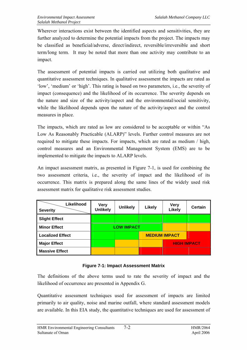
Environmental Impact Assessment Salalah Methanol Company LLC Salalah Methanol Project
HMR Environmental Engineering Consultants 7-2 HMR/2064 Sultanate of Oman April 2006
Wherever interactions exist between the identified aspects and sensitivities, they are further analyzed to determine the potential impacts from the project. The impacts may be classified as beneficial/adverse, direct/indirect, reversible/irreversible and short term/long term. It may be noted that more than one activity may contribute to an impact.
The assessment of potential impacts is carried out utilizing both qualitative and quantitative assessment techniques. In qualitative assessment the impacts are rated as ‘low’, ‘medium’ or ‘high’. This rating is based on two parameters, i.e., the severity of impact (consequence) and the likelihood of its occurrence. The severity depends on the nature and size of the activity/aspect and the environmental/social sensitivity, while the likelihood depends upon the nature of the activity/aspect and the control measures in place.
The impacts, which are rated as low are considered to be acceptable or within “As Low As Reasonably Practicable (ALARP)” levels. Further control measures are not required to mitigate these impacts. For impacts, which are rated as medium / high, control measures and an Environmental Management System (EMS) are to be implemented to mitigate the impacts to ALARP levels.
An impact assessment matrix, as presented in Figure 7-1, is used for combining the two assessment criteria, i.e., the severity of impact and the likelihood of its occurrence. This matrix is prepared along the same lines of the widely used risk assessment matrix for qualitative risk assessment studies.
Figure 7-1: Impact Assessment Matrix
The definitions of the above terms used to rate the severity of impact and the likelihood of occurrence are presented in Appendix G.
Quantitative assessment techniques used for assessment of impacts are limited primarily to air quality, noise and marine outfall, where standard assessment models are available. In this EIA study, the quantitative techniques are used for assessment of
Likelihood Severity
Very Unlikely Unlikely Likely Very
Likely Certain
Slight Effect
Minor Effect LOW IMPACT
Localized Effect MEDIUM IMPACT
Major Effect HIGH IMPACT
Massive Effect

Environmental Impact Assessment Salalah Methanol Company LLC Salalah Methanol Project
HMR Environmental Engineering Consultants 7-3 HMR/2064 Sultanate of Oman April 2006
impacts during the operational phase of the project, with regard to the above environmental aspects and are as presented below:
− Prediction of ground level concentration of SO2 and NO2;
− Prediction of ambient noise levels; and
− Prediction of salinity and temperature levels at the marine outfall.
In addition to the above, quantitative methods are used for assessing the consequences of accidental releases of hazardous materials used in the new facility, which is presented in Chapter 8.
In reviewing the impact/mitigation tables, it is to be noted that the project activities, related environmental aspects and associated impacts are enumerated alongside to facilitate subsequent rating. These ratings relate to the severity of the impact (slight / minor / localized / major / massive) and likelihood of its occurrence (very unlikely / unlikely / likely /very likely / certain), which are based on qualitative assessment of the situation and its interaction with the environmental elements. The identification and assessment of potential environmental impacts due to the construction activities and methanol complex operations are presented in Tables 7-1 and 7-2 respectively. The mitigation measures proposed to reduce the impacts are also presented in the tables. These are discussed further in detail in Chapter 9.

Environmental Impact Assessment Salalah Methanol Company LLC Salalah Methanol Project
HMR Environmental Engineering Consultants 7-4 HMR/2064 Sultanate of Oman April 2006
Table 7-1: Impacts during Construction Phase
Project activity Environmental Aspect Potential Impacts Severity Likelihood Impact
level Mitigation / Remarks
Terrestrial construction Landscape changes due to site preparation, excavation, etc.
Slight effect Likely Low
Pump house at the seawater intake location will potentially pose visual impact on the cove and provide restrictions to the public from accessing the beach
Slight effect Likely Low
• Site is located within a proposed industrial free zone and construction activities will have minimal footprint outside the industrial area.
• The pump house at the intake location will be designed to minimise visual impact
Damage to terrestrial habitats Slight effect Likely Low
Air pollution due to increase in ambient dust concentration
Minor effect Very likely Medium • Dust suppression measures to be employed
Site construction activities involving grading, excavation, trenching, etc.
• Air emissions from internal combustion engine run construction machinery and vehicles
• Suspension of dust due to construction activity and vehicle movements
• Increase in noise levels
• Increase in vehicular traffic
Safety and health risk to workers and public using the existing roads and areas near the site
Minor effect Very likely Medium • Providing signboards indicating hazardous areas at all the construction locations
• Secured fencing of the construction areas to prevent unauthorised access to public
• Managing the traffic on the roads in such a way to minimise stress on other road users
• Providing adequate safety instructions and PPE to workers

Environmental Impact Assessment Salalah Methanol Company LLC Salalah Methanol Project
HMR Environmental Engineering Consultants 7-5 HMR/2064 Sultanate of Oman April 2006
Project activity Environmental Aspect Potential Impacts Severity Likelihood Impact
level Mitigation / Remarks
Increase in ambient noise levels Minor effect Very likely Medium • Proper maintenance of equipment and vehicles
• High noise activities restricted to daytime
• Use of noise barriers as appropriate.
• Minimising simultaneous operation of various high noise equipment
Terrestrial construction of pipelines
Damage to terrestrial habitats along the pipeline routes
Localized effect Likely Medium • Planning of pipeline routes in such a way to minimise areas of significant terrestrial habitats and vegetation
• Managing the pipeline construction activities to minimise impacts on areas outside pipeline corridors
Landscape changes Minor effect Very likely Medium • Restricting the pipeline construction activities within the pipeline corridors
• Pipeline and associated structures to be buried and therefore will not have any visual impacts
Air pollution due to increase in ambient dust concentrations
Minor effect Very likely Medium • Dust suppression measures to be employed
• Methanol export pipeline from the storage area in the plant to loading berth at Port Salalah
• Seawater intake pipeline
• Seawater outfall pipeline
• Air emissions from internal combustion engine run construction machinery and vehicles
• Dust generation during excavation and trenching activities and vehicle movements
• Increased noise levels
• Open pipeline trenches
Safety risk to workers and neaby population from open pipeline trenches
Localized effect Likely Medium • Temporary fencing of the pipeline trenches
• Hazard indicating sign boards along pipeline route

Environmental Impact Assessment Salalah Methanol Company LLC Salalah Methanol Project
HMR Environmental Engineering Consultants 7-6 HMR/2064 Sultanate of Oman April 2006
Project activity Environmental Aspect Potential Impacts Severity Likelihood Impact
level Mitigation / Remarks
Marine construction Damage to coral communities and other marine habitats
Major effect Very likely High • Planning construction methods in such way to minimise release / flushing of sediments
Increase in TSS in seawater around the dredging sites and sediment transport
Localized effect Likely Medium • Use of closed clamshell buckets and/or excavators with minimum sediment loss into the surrounding water
• Monitoring of TSS, turbidity and DO in seawater during the construction of the pipelines in the vicinity of the dredging area and the dredged material disposal area.
Marine construction of intake and out fall facilities involving dredging, pipeline installations, anchoring etc
• Flushing of sediments and increased turbidity
• Discharge of ballast water, bilge water and sewage to marine environment from barges / boats used for construction
• Discharge of domestic refuse to marine environment
Degradation of marine environment and impact on marine flora and fauna
Major effect Very likely High • Managing the disposal of waste water and other wastes in accordance with the procedures and facilities at the port
• Alternatively, providing waste collection, storage and disposal facilities for wastes generated in the construction barges, preventing the disposal of such wastes into the marine environment
Resource use Off-site impacts from quarrying for rocks and aggregates
Localized effect Likely Medium • Utilizing approved quarries and transporters
Procurement of construction materials
Consumption of resources
Depletion of natural resources [fuels, wood, metal, etc.]
Localized effect Likely Medium • Optimizing material consumption
Water abstraction for construction
Consumption of water from nearby sources
Stress on groundwater aquifers Localized effect Likely Medium • Proper sourcing and optimizing use of water
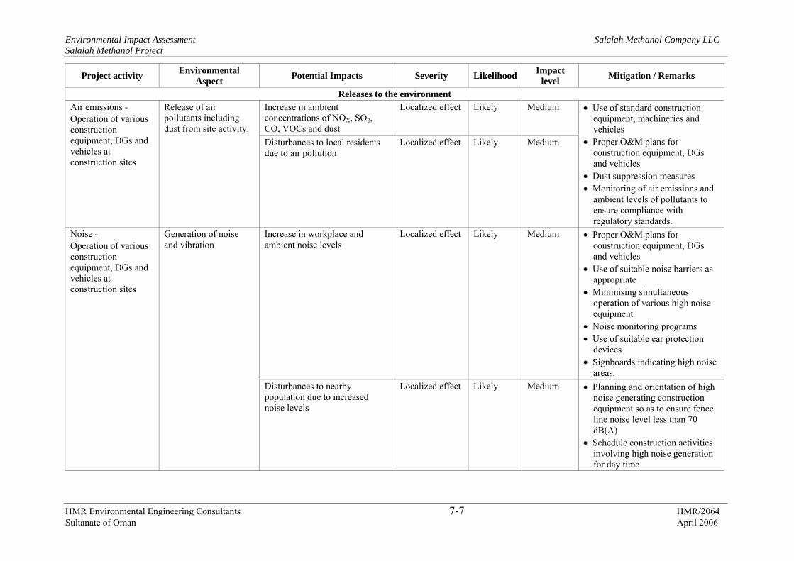
Environmental Impact Assessment Salalah Methanol Company LLC Salalah Methanol Project
HMR Environmental Engineering Consultants 7-7 HMR/2064 Sultanate of Oman April 2006
Project activity Environmental Aspect Potential Impacts Severity Likelihood Impact
level Mitigation / Remarks
Releases to the environment Increase in ambient concentrations of NOX, SO2, CO, VOCs and dust
Localized effect Likely Medium Air emissions - Operation of various construction equipment, DGs and vehicles at construction sites
Release of air pollutants including dust from site activity.
Disturbances to local residents due to air pollution
Localized effect Likely Medium
• Use of standard construction equipment, machineries and vehicles
• Proper O&M plans for construction equipment, DGs and vehicles
• Dust suppression measures • Monitoring of air emissions and
ambient levels of pollutants to ensure compliance with regulatory standards.
Increase in workplace and ambient noise levels
Localized effect Likely Medium • Proper O&M plans for construction equipment, DGs and vehicles
• Use of suitable noise barriers as appropriate
• Minimising simultaneous operation of various high noise equipment
• Noise monitoring programs • Use of suitable ear protection
devices • Signboards indicating high noise
areas.
Noise - Operation of various construction equipment, DGs and vehicles at construction sites
Generation of noise and vibration
Disturbances to nearby population due to increased noise levels
Localized effect Likely Medium • Planning and orientation of high noise generating construction equipment so as to ensure fence line noise level less than 70 dB(A)
• Schedule construction activities involving high noise generation for day time

Environmental Impact Assessment Salalah Methanol Company LLC Salalah Methanol Project
HMR Environmental Engineering Consultants 7-8 HMR/2064 Sultanate of Oman April 2006
Project activity Environmental Aspect Potential Impacts Severity Likelihood Impact
level Mitigation / Remarks
Liquid effluents Soil, groundwater and marine pollution
Localized effect Likely Medium Liquid effluents - Collection, handling, storage and disposal of equipment and vehicle wash water, disposal of hydro-test water; sewage and contaminated surface run-offs
Improper handling / storage / treatment / discharge of wastewater streams onto land / sea Health risks to workers from
infectious diseases Slight effect Likely Low
• Proper collection and treatment facilities for liquid effluents
• Vehicle maintenance and washing to be carried out at centralised workshop facilities of contracting companies outside the construction site or to have proper collection and treatment systems onsite, sewage collected in holding tanks and routed to onsite STP or other municipal STP for treatment and disposal
• Collection facilities for contaminated runoffs.
• Hydro-test water to be collected in suitably designed holding ponds and subsequently to be treated in the ETP
• Periodic analysis of wastewater streams and monitoring of collection and treatment facilities
Soil, groundwater and marine pollution
Localized effect Likely Medium Solid wastes - Collection, handling, storage and disposal of solid wastes from various construction activities
Improper handling / storage / treatment / disposal of solid wastes
House keeping issue Minor effect Very likely Medium
• Waste management plan to address proper collection, segregated storage and recycle / re-use / disposal of wastes at approved waste storage facility
• Periodic audits of waste management systems
Hazardous wastes - Collection, handling, storage and disposal
Improper handling and disposal of hazardous wastes.
Soil, groundwater and marine pollution
Localized effect Likely Medium • Waste management plan to address proper collection, segregated storage / recycle of
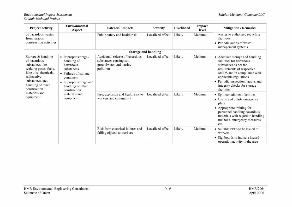
Environmental Impact Assessment Salalah Methanol Company LLC Salalah Methanol Project
HMR Environmental Engineering Consultants 7-9 HMR/2064 Sultanate of Oman April 2006
Project activity Environmental Aspect Potential Impacts Severity Likelihood Impact
level Mitigation / Remarks
of hazardous wastes from various construction activities
Public safety and health risk. Localized effect Likely Medium wastes to authorised recycling facilities
• Periodic audits of waste management systems
Storage and handling Accidental release of hazardous substances causing soil, groundwater and marine pollution
Localized effect Likely Medium • Adequate storage and handling facilities for hazardous substances as per the requirements of respective MSDS and in compliance with applicable regulations
• Periodic inspection / audits and integrity checks for storage facilities
Fire, explosion and health risk to workers and community
Localized effect Likely Medium • Spill containment facilities • Onsite and offsite emergency
plans • Appropriate training for
personnel handling hazardous materials with regard to handling methods, emergency measures, etc.
Storage & handling of hazardous substances like welding gases, fuels, lube oils, chemicals, radioactive substances, etc., handling of other construction materials and equipment
• Improper storage / handling of hazardous substances,
• Failures of storage containers
• Improper storage and handling of other construction materials and equipment
Risk from electrical failures and falling objects to workers
Localized effect Likely Medium • Suitable PPEs to be issued to workers
• Signboards to indicate hazard operation/activity in the area

Environmental Impact Assessment Salalah Methanol Company LLC Salalah Methanol Project
HMR Environmental Engineering Consultants 7-10 HMR/2064 Sultanate of Oman April 2006
Project activity Environmental Aspect Potential Impacts Severity Likelihood Impact
level Mitigation / Remarks
Exposure to radiation, safety and health risk
Localized effect Likely Medium • Storage and handling of radioactive material to be in compliance with MD 249/97
• Providing adequate PPE and training to personnel handling radioactive materials
• Isolation of the relevant work areas
Transportation Stress on road traffic Localized effect Likely Medium
Land, groundwater and marine contamination due to spillages
Localized effect Likely Medium
Fire and safety risk to public Localized effect Likely Medium
Accidents due to unsafe driving Localized effect Likely Medium
• Developing and establishing Traffic Management Plan including transport procedures Vehicle fitness requirements
• Defensive driving procedures • Emergency response plan
• Transportation of materials and workers,
• Transportation of heavy plant machinery and equipment through road and sea
• Increased traffic due to
• Equipment and machinery transport,
• Unsafe driving, • Accidental spillages
of fuels, chemicals, solvents, etc. while transportation
Stress on marine traffic Localized effect Likely Medium • EPC contractor to co-ordinate with Salalah Port for scheduling berthing requirements.
• Salalah Port to manage the ship traffic

Environmental Impact Assessment Salalah Methanol Company LLC Salalah Methanol Project
HMR Environmental Engineering Consultants 7-11 HMR/2064 Sultanate of Oman April 2006
Table 7-2: Environmental Impacts during Operation Phase
Activity Environmental
Aspects Potential Impacts Severity Likelihood Impact
level Mitigation / Remarks
Resource Use Offsite impacts from drilling/ well operation from where natural gas is sourced, treatment and transportation of gas
Minor effect Likely Low • Natural gas sourced from E&P organisations who have adequate EMS to minimise impacts due to drilling, well operation and gas transportation
Depletion of natural resources Localized effect Likely Medium • Optimizing natural gas consumption and usage of other resources–
• Operational and energy audits
Methanol complex operations
• Offsite drilling, well operation, treatment of well fluids and transportation of natural gas
• Consumption of natural gas, fuel oil and lube oils
• Heat recovery from process units to generate steam and power
Heat recovery from process units to produce steam and power
Positive effect - - Not Applicable
Seawater intake Inappropriate intake of seawater
Damage to marine habitats Localised effect Likely Medium • Design and sizing of intake structure in such a way to control intake flow and to prevent intake of marine life
Releases to the environment
Air emissions17 - • Operation of
Reformer, auxiliary boilers
• NOx, SO2, VOCs and PM emissions from continuously operating sources
Exceedance of emissions from regulatory limits for source emissions and increase in GLCs of hazardous pollutants,
Localized effect Likely Medium • Low NOx burners for combustion sources
• Stack heights to comply with MD 118/2004 and GEP stack heights;
17 Air dispersion modelling is conducted to determine the maximum ground level concentrations and the results are presented in subsequent sections

Environmental Impact Assessment Salalah Methanol Company LLC Salalah Methanol Project
HMR Environmental Engineering Consultants 7-12 HMR/2064 Sultanate of Oman April 2006
Activity Environmental Aspects
Potential Impacts Severity Likelihood Impact level
Mitigation / Remarks
and flare • Bulk handling and
storage of methanol product
• Hydrocarbons and other hazardous air pollutants from fugitive sources
• Emissions during upset conditions especially flaring
Potential health impacts due to emissions of hazardous air pollutants
Localized effect Likely Medium • Internal floaters for all product storage tanks along with submerged loading facilities and vapour recovery systems as appropriate for minimising fugitive emissions
• Adequate O&M for combustion sources and emission control equipment to ensure efficient operations
• Continuous emission monitoring for all major emission sources
• Periodic ambient air monitoring to ensure compliance with regulatory standards
• Preparation and enforcement of EMS
Exceedance of workplace noise levels
Localized effect Likely Medium Noise18- • Operation of noise
generating equipment like steam turbines blowers, pumps, compressors and flare
• Fleet movements and operation of other mobile equipment at the loading berth
• Noise emissions from continuously and intermittently operating sources,
• Noise emissions due to equipment faults, damage to equipment supports, fixtures, etc.
Exceedance of ambient noise levels at / outside fence line
Localized effect Likely Medium
• Noise levels to be maintained at ≤85 dB(A) at design for the plant equipment;
• Application of adequate noise enclosures to reduce the source noise levels
• O&M programs for noisy equipment;
• Periodic workplace and ambient noise level monitoring.
18 Noise modelling is conducted to determine the noise levels and the results are presented in the subsequent sections

Environmental Impact Assessment Salalah Methanol Company LLC Salalah Methanol Project
HMR Environmental Engineering Consultants 7-13 HMR/2064 Sultanate of Oman April 2006
Activity Environmental Aspects
Potential Impacts Severity Likelihood Impact level
Mitigation / Remarks
Liquid Effluents - Collection, storage, treatment and recycle / disposal of process effluents, wash water and deluge water from plant and other areas, sanitary wastewater, return seawater, rejects from desalination plant, polishing unit, boiler blow down and storm water
• Contaminants in the treated effluents discharged to sea above regulatory limits due to improper treatment
• Thermal and salinity effects due to discharge of cooling water and brine rejects into sea
• Shock loads, upsets or peak discharge due to improper handling / treatment / disposal of liquid effluents.
• Accidental releases to land / surface drains
Soil, groundwater and marine pollution and potential damage to marine habitats
Localized effect Likely Medium • Adequate treatment facilities at ETP for treating process effluents to meet regulatory requirements for marine discharge
• Proper collection and treatment of sanitary wastewater in the STP to marine discharge standards
• Proper O&M of effluent collection systems, ETP, STP and cooling water systems to ensure proper and efficient operation
• Periodic monitoring / sampling programs for treated effluents / marine discharges and seawater.
• Preparation and implementation of EMS
Soil, groundwater and marine pollution
Localized effect
Likely Medium Solid Wastes - Collection, storage and disposal of solid wastes
Improper collection, handling / disposal of non hazardous industrial and domestic solid wastes
House keeping issue leading to unsafe and unhygienic conditions
Localized effect
Likely Medium
• Onsite waste management centre for storage of wastes;
• Recycling materials such as metal and wood scrap to potential buyers;
• Waste management plan addressing proper collection segregated storage and disposal of wastes in compliance with MD 17/93

Environmental Impact Assessment Salalah Methanol Company LLC Salalah Methanol Project
HMR Environmental Engineering Consultants 7-14 HMR/2064 Sultanate of Oman April 2006
Activity Environmental Aspects
Potential Impacts Severity Likelihood Impact level
Mitigation / Remarks
Land, groundwater and marine contamination and potential damage to marine habitats due to hazardous constituents such as hydrocarbons and heavy metals,
Localized effect Likely Medium Hazardous Wastes - Collection, storage and disposal of hazardous wastes
Improper collection, handling, recycle / storage hazardous wastes
Inflammability / toxicity posing human and ecological risks
Localized effect Likely Medium
• Waste management plan for proper collection and segregated storage of wastes at the onsite hazardous waste storage area in compliance with MD 18/93 and applicable hazardous waste permit;
• Recycle of spent catalysts to catalyst suppliers for regeneration / recycling
• Recycling of wastes such as lube oil, batteries, etc., to authorised recycling facilities;
• Offsite disposal of wastes to authorised waste disposal facilities when such facilities become available in Oman
Hazardous materials management Injuries/fatalities, property damage, business interruption and environmental contamination,
Localized effect Likely Medium
Exposure risks from fire, explosion, toxic releases and spills
Localized effect Likely Medium
Storage, handling and transport of raw materials, intermediates and products that are flammable and / or toxic,
Accidental releases of materials from storage vessels from leaks due to failure of safeguarding mechanisms, corrosion and other causes Asphyxiation due to liquid
nitrogen leakage Localized effect Likely Medium
• Detailed risk assessment studies to evaluate safeguarding mechanisms and their adequacy
• Implementing leak detection systems and safe distances philosophy
• Restricted access to hazardous areas, establishing onsite and offsite emergency response plans, job safety plans, periodic audits, MSDS, PPE, permit to work systems, etc.
• Strict enforcement of inspection programs

Environmental Impact Assessment Salalah Methanol Company LLC Salalah Methanol Project
HMR Environmental Engineering Consultants 7-15 HMR/2064 Sultanate of Oman April 2006
Activity Environmental Aspects
Potential Impacts Severity Likelihood Impact level
Mitigation / Remarks
Pipe line transport of natural gas and methanol
Accidental release of materials / hazards due to pipeline over pressurization, corrosion or external impacts leading to leaks / spills
Injuries / fatalities, property damage, business interruption environmental contamination and fire and explosion risks
Localized effect Likely Medium As above
Methanol loading at the loading berth at the Port
Spillages during loading activities
Contamination of loading area and marine environment
Localized effect Likely Medium • Providing facilities to prevent spillage runoffs to the sea during product loading
• Systems for periodic inspection and maintenance of the loading systems, inspections prior to each loading, testing of loading facilities, etc., as appropriate
• Facilities for containing and removing any spillages on land. Spillage collection sump at the berth area for collecting spillages and contaminated methanol, which will be returned to the plant.
Stress on road traffic Localized effect Likely Medium
Accident hazards resulting in spillages, contamination, fire and toxicity risks
Localized effect Likely Medium
Road transport of hazardous materials
Increased road traffic, improper transportation, use of unauthorised / unfit vehicles, unsafe driving, accidental spillages
Accidental spillages due to leaks and environmental contamination
Localized effect Likely Medium
• Traffic management plan including transport procedures, vehicle fitness requirements, defensive driving requirements, emergency response procedures
• Training to concerned personnel on hazardous materials handled and respective MSDS
Export of product methanol
Increased movement of sea vessels at the port area
Stress on marine traffic Localized effect Likely Medium • SMC to co-ordinate with Salalah Port for scheduling berthing requirements.
• Salalah Port to manage the ship traffic

Environmental Impact Assessment Salalah Methanol Company LLC Salalah Methanol Project
HMR Environmental Engineering Consultants 7-16 HMR/2064 Sultanate of Oman April 2006
Tables 7-1 and 7-2 present potential environmental impacts during construction and operational phases of the project respectively and potential mitigation measures to minimise these impacts to ALARP levels. It can be noted from the above tables that each project activity will have impacts on various environmental elements. Similarly, several activities can have impacts on any one single environmental element. These are further discussed in the following sections.
7.3 Impacts during construction phase
7.3.1 Air quality
Major sources of potential impacts on air quality during construction phase of the projects are as below:
− Generation of dust due to site preparation, earthwork, excavation, movement of vehicles and trenching work for pipelines;
− Release of SO2, NOX, VOCs and PM from diesel engines of construction machineries, DG units and vehicles;
− Release of welding fumes and VOCs from fabrication of storage tanks, columns and pipelines involving welding/metal cutting work, surface cleaning and painting; and
− Fugitive emissions from storage of fuels, lube oils and other chemicals releasing VOC’s.
The fumes generated during welding and metal cutting activities and hazardous air pollutants entrained during spray-painting can cause health hazard to workers. The dust risings from earthwork and vehicle movements could be significant on the site particularly during dry weather conditions. With regard to exhaust emissions from construction equipment, DGs and vehicles, it is difficult at this stage to estimate these emissions and give quantitative predictions of their effect on the air quality. It is reasonable to qualitatively judge that any adverse impacts will be localised and is unlikely to impact the surrounding residential areas/receptors. The necessary mitigation measures to be implemented in order to minimise the adverse impacts on air quality are discussed in Chapter 9.
7.3.2 Noise
The heavy equipment used in the construction work, DGs used for on-site power generation, fabrication activities and the road vehicles used for transportation of material and men to site will have an adverse impact on the noise levels in the

Environmental Impact Assessment Salalah Methanol Company LLC Salalah Methanol Project
HMR Environmental Engineering Consultants 7-17 HMR/2064 Sultanate of Oman April 2006
workplace as well as the ambient. In the absence of specific information on the type, number, location and duration of operation of the major noise generating sources at the construction site (this will be finalised during further project development and detailed design and will be planned by the EPC contractor), it is difficult to make any quantitative predictions. It is likely that at certain locations close to the noise sources within the work site, the noise levels will be in excess of 85dB(A) requiring the personnel on-site to wear ear protection devices.
With respect to the ambient noise levels, since noise is attenuated by distance (typically noise levels drop by about 40 dB(A) at 100m distance from source), the activities on-site are unlikely to adversely affect the ambient noise levels. However, during night times when the ambient noise levels are low, the level of perception to noise may be more acute. Noise from transport vehicles will be only transient for a given location and can be considered as a nuisance during night time through the route which it passes. The mitigation measures presented in Table 7-1 and Chapter 9 are expected to minimise the noise impact to ALARP levels.
7.3.3 Groundwater
Sourcing of water for construction activities from water wells with low yield can adversely affect other competing users in the area. Therefore, it is important to select sustainable water wells for sourcing water for construction.
Potential causes of groundwater contamination are surface discharge of liquid effluents such as equipment and vehicle washings and sanitary wastewater, spillage of hazardous wastes on land, leaching of pollutants from onsite waste storage areas, accidental leakage/spillage of hazardous materials such as fuel, lubricating oil, chemicals, etc., and disposal of contaminated hydro-test water onto land.
No untreated / contaminated effluents will be discharged onto land. Equipment and vehicle washings will be conducted at designated areas and the washing will be collected and treated for separation of oil and & grease and suspended solids and will be discharged to onsite STP / nearby STP. Alternatively, such washing activities will be undertaken at the central workshop facilities of contracting companies, offsite, as available. The sanitary wastewater will be collected in collection pits and will be treated in the onsite STP or alternatively be transported to a nearby STP using vacuum tanker. Spent hydro-test water will be typically free of any contaminants except for traces of corrosion chemicals, rust and oil and will be disposed to sea after analysis for potential contaminants to ensure compliance with applicable discharge standards.
There will be dedicated waste storage areas at site for hazardous and non-hazardous wastes. All hazardous and non-hazardous wastes will be properly collected,

Environmental Impact Assessment Salalah Methanol Company LLC Salalah Methanol Project
HMR Environmental Engineering Consultants 7-18 HMR/2064 Sultanate of Oman April 2006
segregated and stored in appropriate storage areas. Hazardous wastes will be collected and recycled as possible. Remaining wastes will be shifted to approved hazardous waste storage facilities. Recyclable non-hazardous wastes such as metal and wood scrap will be sold to scrap buyers, as feasible. Other non-hazardous wastes will be disposed off to an approved dumpsite. Hazardous materials such as chemicals, paints, lube oil, etc., will be stored at dedicated and protected storage areas at site and appropriate spill containment systems will be established.
Potential for land and groundwater contamination at offsite locations exist during transportation of hazardous materials and hazardous wastes. Appropriate transportation and handling procedures for hazardous materials and hazardous wastes will be established to mitigate such impacts. It can be noted from the above that potential impacts due to discharge of liquid effluents and handling of solid/hazardous wastes will be minimised by implementation of measures as above, which are further explained in Chapter 9.
7.3.4 Land and terrestrial ecology
Potential impacts on land are due to changes in the landscape and damage to vegetation due to earthwork, excavation, trenching, etc., as part of the construction activities and due to the discharge of liquid effluents, solid and hazardous wastes and accidental spillage of hazardous materials. Various effluent streams, causes of contamination (including offsite impacts) and the mitigation measures are as discussed above (for groundwater) and in turn are expected to minimise the resulting impacts.
As explained earlier, most of the construction activities are within existing industrial area footprints and therefore, the impacts on landscape changes and terrestrial ecology (as highlighted in Chapter 4) are not considered to be significant. Also, there are no cultural or archaeological resources within the project site.
7.3.5 Marine environment
The construction of seawater intake and outfall pipelines / facilities will involve dredging and pipeline installation activities. This will potentially result in increase in seawater sediment concentrations and disturbance to corals and other marine life. Appropriate dredging equipment and methodology will be used so as to minimise the release of sediments into the surrounding water column. As discussed in Section 4.12.9, the proposed outfall location is devoid of significant ecological sensitivities. It is unlikely that the construction of the planned outfall will considerably modify the already damaged ecosystem. It is suggested that the outfall pipe be extended to a

Environmental Impact Assessment Salalah Methanol Company LLC Salalah Methanol Project
HMR Environmental Engineering Consultants 7-19 HMR/2064 Sultanate of Oman April 2006
depth 1m below the lowest low-tide level, as required by applicable regulations, in order to ensure proper dispersion.
The area proposed for the intake is rich, although, probably not richer than many surrounding areas. In particular, several species of unusual corals were observed in shallow water. The beach is particularly beautiful and would constitute and ideal recreational area (particularly in the winter).
Offshore discharge of ballast water, bilge water, sewage, domestic refuse from the construction barges poses threat to marine flora and fauna. Disposal of such wastes will be done in accordance with the existing facilities and procedures of the port.
7.3.6 Socio economic environment
The likely impacts on socio-economic environment will be due to generation of employment opportunities, land use, utilisation of public infrastructure and influx of expatriate construction workers, experience and skills transfer to local community, as well as certain contract work. Direct socio-economic benefits occur from the project construction by way of short-term employment generation and contracting opportunities for the local businesses. The project construction activities will provide direct employment up to a peak of about 1000 persons during the construction period of about 18 months. It is expected that the contracting companies will utilise their existing/permanent employees for construction activities. However, it is typical that a number of opportunities are generated for skilled and unskilled employees for various construction activities, which will potentially benefit local people. Further, SMC facility being the first sizable industry in the Salalah Free Zone, will be instrumental in attracting new industries into the Free Zone and enhancing industrial development in the region.
As explained in earlier sections, the proposed facility will be established in the SFZ area, which is identified for future development of various industrial facilities. In addition, the proposed site is close the Salalah Port area and is not currently used for any activities such as agriculture, grazing, etc. and therefore, there are no potential impacts on land uses from the proposed methanol production facility.
The locations of construction labour camps are not finalised yet and will be potentially determined by the EPC contractor in consultation with SMC personnel. It is likely that some of the work force will be engaged through local sub contractors and will potentially utilise their permanent accommodation facilities in Salalah. Some of the project staffs may be accommodated in local apartments. Additional labour camps, if required, are likely to be established near the project site.

Environmental Impact Assessment Salalah Methanol Company LLC Salalah Methanol Project
HMR Environmental Engineering Consultants 7-20 HMR/2064 Sultanate of Oman April 2006
In addition, infrastructure such as power supply, water supply, sanitation, hospitals, etc., will also receive minor impacts. However since various project developments are envisaged to be completed within a period of 18 months above impacts will not be significant.
The increased road traffic due to the transport of construction materials and construction staff to the site can potentially place stress on road traffic. However, since almost all equipment will arrive at the Salalah Port, the stress on existing roads during the construction phase will be limited. The number and details of construction vehicles are not available at present. The current traffic on the access road to the site is not relatively high and hence it can be considered that the construction activities will not pose significant stress on road traffic.
The expatriate construction workers in the area may interact with the local people and can have potential impacts on local life style, culture and public health and safety. In addition, the expectations of local people with regard to employment opportunities and other supports from the project development may pose stress on the socioeconomic front. Employment of immigrant workers for construction can pose some health risk to local people. The expatriate workers constitute a significant number of the total construction work force. It is expected that majority of the expatriate construction workers will be from established contracting companies, and therefore most of them are expected to be long-term residents of Oman. As per the Omani labour law, all immigrant workers will be medically screened for any infectious diseases.
The duration of construction activities are expected to be about two years. In addition, as discussed above, the construction activities will potentially offer employment opportunities for the local people in the area. Appropriate measures will be taken to manage the interaction of construction workers with the local people and the expectations of the local community. It is also to be noted that the project development is within an industrial area, identified for future developments under SFZ. Suitable measures for socioeconomic management will be implemented in association with SFZ.
Other sources of potential impacts on public safety and health during construction phase are storage and transport of hazardous substances, disposal of hazardous wastes, off-site quarrying/excavation and increased road traffic. Except for the fuel oils and welding gasses, none of the substances used during construction pose any significant hazards to safety and health. Fuel oil will be transported in dedicated oil tankers driven by certified drivers. The fuel oil storage tanks, if any, will be provided with the necessary safety and leak containment facilities. Welding gasses will be

Environmental Impact Assessment Salalah Methanol Company LLC Salalah Methanol Project
HMR Environmental Engineering Consultants 7-21 HMR/2064 Sultanate of Oman April 2006
sourced locally in cylinders and stored on site in a protected and secluded storage area. The quantities of hazardous wastes are not expected to be significant during construction. Such wastes will be stored, handled and disposed off in accordance to MD 18/93 and good engineering practice to minimise any safety and health hazards.
Rocks and aggregates required for the construction work will be sourced from approved local quarries. EPC contractors are not likely to directly undertake quarrying. Instead, they will select approved sub-contractors to supply rocks and aggregates. However, in order to ensure that the public are not exposed to any unacceptable safety or health risk, EPC contractors will ensure that the quarry operators have the necessary permits to operate.
7.4 Impacts during operational phase
7.4.1 Air quality
As discussed earlier in this chapter, quantitative techniques are used to assess the impacts of air emissions during the operational phase, for which computer simulation models are used. Industrial Source Complex Short Term (ISCST)-3 and SCREEN-3 models (USEPA Models) are used for conducting air dispersion modelling. ISCST-3 model is capable of calculating maximum GLC of each pollutant from multiple sources. However, ISCST-3 does not include provisions for modelling flare emissions. Therefore SCREEN-3 is initially used to model the emission from the flare, in order to determine the effective release height, which is subsequently used in ISCST-3 along with other stacks.
Reformer, auxiliary boilers and the flare constitute the stationary emission sources in the methanol complex. The scenario considered for modelling is operation of all the major air polluting stationary point sources at normal conditions as described in the following sections. The DG used for the black start is not considered for modelling as this is not in continuous operation.
The emission sources considered for the modelling are presented in Table 7-3.
Table 7-3: Stationary point sources considered for modelling
# Stack ID Source Source ID 1 SMCH1 Reformer 10-ST1201 2 SMCAB1 Auxiliary Boiler 1 20-SE2501A 3 SMCAB2 Auxiliary Boiler 2 20-SE2501B 4 SMCFL1 Flare 20-FL3301

Environmental Impact Assessment Salalah Methanol Company LLC Salalah Methanol Project
HMR Environmental Engineering Consultants 7-22 HMR/2064 Sultanate of Oman April 2006
ISCST-3 model is used for estimating GLCs of NOX and SO2 from all sources except flare. Flare is modelled as equivalent “point source”, since ISCST-3 cannot handle “flares” as such. Conversion of flare to an equivalent point source is based on the procedures in ISCST-3 guidelines. It order to ensure that the equivalent point source of a flare is truly represented, calibration runs are performed using SCREEN-3 model, which predicts GLCs for only a single source at a time.
Dispersion modelling using ISCST-3 requires hourly meteorological data. Such data recorded in meteorological station at Mina Salalah for the year 2003 is used for conducting the modelling. Simulation modelling is performed to estimate GLCs of two pollutants of significance in this case, viz., NOX and SO2.
The emission load of pollutants from the facility will be 26.91 g/s of NOX and 0.31 g/s of SO2. The model set up configurations are presented in
Table 7-4: Inputs for air dispersion modeling
Model used ISCST3 Topography for dispersion Rural Averaging time 1 hour, 24 hours and annual Terrain heights Flat terrain Source type Point source Source group All Building downwash option Disabled (Not considered plausible) Domain 10km radius Coordinate system Cartesian Gridding Uniform grid size of 250m Receptor height 0 (at ground level) Anemometer height 10 m Surface meteorological data Data recorded at Mina Salalah Station
(One full year hourly data - 2003) Upper air data None used Mixing height data Estimated values using CSIRO Mixing Height Model
As explained earlier, the flare needs to be modelled as an equivalent point source. The flare is converted as an equivalent point source. Simulations are performed using SCREEN-3 model (which provides hourly average concentrations) for identical cases in order to check whether the equivalent point source yields identical output as that of the flare. The modelling input for ICST3 is as presented in Table 7-4. The GLCs for SO2 and NOX along with distance to maximum GLC is presented in Table 7.6.

Environmental Impact Assessment Salalah Methanol Company LLC Salalah Methanol Project
HMR Environmental Engineering Consultants 7-23 HMR/2064 Sultanate of Oman April 2006
Table 7-5: Input data for prediction modeling
Locations Emission Rates (g/s) Source
X (m) Y (m)
Release Height
(m)
Stack Internal Diameter
(m)
Stack Exit
Temp (K)
Stack Gas
Velocity (m/s) NOX SO2
SMCH1 818383 1874747 50.0 2.0 459.0 117.46 23.91 0.28
SMCAB1 818475 1874678 20.0 1.5 453.0 13.63 1.50 0.02 SMCAB2 818480 1874660 20.0 1.5 453.0 13.63 1.50 0.02 SMCFL 817956 1874893 60.0 0.6 1293 0.60 - 0.0002
The contour maps of dispersion of pollutants are presented in Appendix H. From the results presented in Table 7-6, it can be noted that the predicted GLCs of NOX and SO2 for the input scenario are well below both USEPA NAAQ and WHO-EU standards. As discussed in Section 4.8, the maximum SO2 and NOX concentration observed at and around the project site are 7.29µg/m3 and 14.87µg/m3, respectively. Hence after adding the background SO2 level, the maximum annual average ground level SO2 concentration during the operational phase of the methanol plant will be 7.32µg/m3. Similarly the maximum annual average ground level NOx concentration will be 17.17µg/m3. It can be concluded that the predicted concentrations complies well with the Omani/US EPA NAAQ standards.

Environmental Impact Assessment Salalah Methanol Company LLC Salalah Methanol Project
HMR Environmental Engineering Consultants 7-24 HMR/2064 Sultanate of Oman April 2006
Table 7-6: Predicted GLC of pollutants
Max 1-Hour Average GLC
Location of Max GLC
Distance to Max GLC
Max 24-Hour Average GLC
Location of Max GLC
Distance to Max GLC
Max Annual Average GLC
Location of Max GLC
Distance to Max GLC Pollutant Modelling Scenario
µg/m3 m m µg/m3 m m µg/m3 m m
Alternate A 23.3 819200 E; 1873890 N 1570 7.9
817700 E; 1874890 N 380 2.3
818700 E; 1875390 N 750
Maximum Permissible Limit (Omani / USEPA NAAQ Standards)
None - - None - - 100 - - NOx
Guideline Limit (WHO-EU standards) 200 - - None - - 40 - -
Alternate A 0.28 819200 E; 1873890 N 1570 0.11
817700 E; 1874890 N 380 0.03
818700 E; 1875390 N 750
Maximum Permissible Limit (Omani / USEPA NAAQ Standards)
1300 (3-h average)
- - 365 - - 80 - - SO2
Guideline Limit (WHO-EU standards)
500 (10-min average)
- - 125 - - 50 - -

Environmental Impact Assessment Salalah Methanol Company LLC Salalah Methanol Project
HMR Environmental Engineering Consultants 7-25 HMR/2064 Sultanate of Oman April 2006
7.4.2 Noise
The methanol complex includes a number of noise generating sources, which will have potential adverse impacts on the workplace and ambient noise levels. Some of these sources are continuous and some are intermittent. In order to determine the impact of noise sources at the plant, noise modelling was conducted.
ENM software tool, developed by RTA Technology Pty Ltd, Australia was used for prediction of impacts on the ambient noise levels from the noise sources at the plant. As discussed earlier, the source noise levels of various plant equipment was not available during this EIA. However, SMC will ensure that the source noise levels of all equipment are maintained at a maximum of 85 dB(A) by design. For predicting impacts due to noise sources at the facility, 2 scenarios are considered as below:
Scenario 1: Noise levels for all sources at 85 dB(A) except flare, which is considered at 115 dB(A); and
Scenario 2: Noise levels for all sources at 85 dB(A), including flare.
The noise sources considered for modelling are presented in Table 7-7.
Table 7-7: Typical noise levels
Source No
Source Easting Northing
1 Flare 817956.524 1874891.447 2 Plant air 818163.632 1874591.617 3 Nitrogen plant 818098.089 1874591.664 4 Steam turbine 818366.229 1874588.412 5 Secondary cooling water system 818434.017 1874591.639 6 Reformer 818338.908 1874714.215 7 ETP pumps and blowers 818179.521 1874826.975 8 Transfer pumps 818219.416 1874693.663 9 Compressor house 818261.242 1874667.566
ENM is a Microsoft Windows based software tool, which can accept up to 1000 stationary noise sources and can cover a maximum area of 64 km2. The noise sources are modelled as point source, line, plane, surface, etc. Each noise source is entered into the model with the source noise level and location within the plant. The model calculates the sound pressure level at specified intervals taking into account the distance, barrier, ground effect and temperature gradient. In the present study the following inputs are used:

Environmental Impact Assessment Salalah Methanol Company LLC Salalah Methanol Project
HMR Environmental Engineering Consultants 7-26 HMR/2064 Sultanate of Oman April 2006
− 9 sources have been considered for the plant units as presented above;
− The sources considered are the steam turbines, auxiliary boilers, reformer, utility units, process and utility pumps, air blowers, compressors and flare; and
− Flat terrain is considered. Wind from southwest at 3 m/s, relative humidity 85% and average ambient temperature of 35 oC are also considered.
The locations of the sources were sourced from the facility plot plan as presented in Appendix C. The noise levels were modelled using the above inputs and the noise contour map indicating the predicted noise levels was developed. The contour map is presented in Appendix H. The predicted average noise level outside the plant fence line and within the plant area due to the noise sources is combined with the prevailing average ambient noise levels at the site and the cumulative noise level is calculated using the equation Leq = 10 log [Σ10 0.1x Lpi], where Leq is cumulative equivalent continuous noise level at the given location and Lpi is the predicted noise level/average ambient/workplace noise level at the site. Noise levels were measured at receptor locations during the baseline assessment for this EIA study. The maximum ambient noise level obtained during the above surveys is 54.5 dB(A).
The maximum fence line noise level predicted is 60 dB(A) for scenario 1 and 50 dB(A) for scenario 2. The predicted noise levels are added to the background noise level using the above equation to obtain cumulative noise levels of 61.08 dB(A) for scenario 1 and 55.82 dB(A) for scenario 2. Therefore, it can be concluded that if the source noise levels are maintained as discussed above, the fence line noise levels will be within applicable limits of 70dB(A) for industrial area. The predicted noise levels at the plant and receptor locations are presented in the noise contour maps included in Appendix H. The measures for noise control associated with the facility operation are discussed in Chapter 9.
7.4.3 Marine environment
The discharge of treated effluents and return cooling water into the sea during the operation of the plant may have potential impacts on the seawater and sediment quality. The temperature increase of 8-10ºC at the seawater outfall (Option 1, Chapter 3) is likely to impact areas at the mouth of the wadi. In addition, this could interact with the effects of any dredging in the area. A warm layer at the surface would further limit oxygen exchange with the water surface and enhance the hypoxia observed in the sediments as described in Chapter 4.
The characteristics of the various streams along with the cooling water return in the marine outfall are presented in Chapter 5. Omani marine discharge standards (MD

Environmental Impact Assessment Salalah Methanol Company LLC Salalah Methanol Project
HMR Environmental Engineering Consultants 7-27 HMR/2064 Sultanate of Oman April 2006
159/2004), as presented in Chapter 2, stipulates limits for increases in temperature, salinity, etc., at 300 m radius from the discharge point. In light of the above, it is advisable that periodic monitoring be conducted at the outfall location to establish the above conditions (as explained in Chapter 9). To assess the impacts of salinity and temperature at the marine outfall, salinity and temperature dispersion modelling is conducted considering the normal operating scenario as presented in the following paragraphs.
Modelling is conducted using The Cornell Mixing Zone Expert System -GI v 4.3 (CORMIX). CORMIX is a software for the analysis, prediction, and design of aqueous toxic or conventional pollutant discharges into diverse water bodies. It predicts the dilution and trajectory of a submerged single port, multi-port or surface discharge of varying densities into a stratified or uniform density ambient environment, bounded or unbounded. CORMIX correctly predicts highly complex discharge situations involving boundary interactions, dynamic bottom attachments, internal layer formation, and buoyant intrusions. Extensive comparison with field and laboratory data has shown that the CORMIX predictions on dilutions and concentrations (with associated plume geometries) are reliable for majority of cases.
The input data for the modelling is sourced from primary data collected during the course of this EIA study and previous study reports for the area and is presented in Appendix I. It is to be noted that the present modelling study has been conducted considering the marine outfall discharge at 120 m offshore, 3 m below the sea surface. This is considered due to the fact that MD 159/2005 requires that the outfall port be sited a minimum 1 m below the lowest low tide level. The results of modelling are presented in the following sections.
• Hydrodynamic classification
This flow configuration applies to a layer corresponding to the full water depth at the discharge site. The hydrodynamics is classified as flow class H4-90A4 and the regimes shown are as described below.
A submerged buoyant effluent issues horizontally or near- horizontally from the discharge port. The discharge configuration is hydro-dynamically stable, that is the discharge strength (measured by its momentum flux) is weak in relation to the layer depth and in relation to the stabilizing effect of the discharge buoyancy (measured by its buoyancy flux). The buoyancy effect is very strong in the present case. The following flow zones exist:
a. Momentum-dominated near-field jet: The flow is initially dominated by the effluent momentum (jet-like) and is weakly advected by the ambient current.

Environmental Impact Assessment Salalah Methanol Company LLC Salalah Methanol Project
HMR Environmental Engineering Consultants 7-28 HMR/2064 Sultanate of Oman April 2006
b. Buoyancy-dominated near-field plume: After a short distance the discharge buoyancy becomes the dominating factor (plume-like). The plume rises upward while the advection by the ambient current is still weak.
c. Layer boundary impingement/upstream spreading: The weakly bent jet/plume impinges on the layer boundary (water surface) at a near-vertical angle. After impingement the flow spreads more or less radially along the layer boundary. In particular, the flow spreads some distance upstream against the ambient flow, and laterally across the ambient flow. This spreading is dominated by the strong buoyancy of the discharge.
d. Buoyant spreading at layer boundary: The plume spreads laterally along the layer boundary (surface) while it is being advected by the ambient current. The plume thickness may decrease during this phase. The mixing rate is relatively small. The plume may interact with a nearby bank or shoreline.
e. Passive ambient mixing: After some distance the background turbulence in the ambient shear flow becomes the dominating mixing mechanism. The passive plume is growing in depth and in width. The plume may interact with the channel bottom and/or banks.
The flow zones listed as 'a' through 'c' constitute the hydrodynamic mixing zone in which strong initial mixing takes place. Predictions will be terminated in zone 'd' or 'e' depending on the definitions of the boundary limits specified as the regulatory mixing zone (300m) or the region of interest (500m). A figure showing the 3-dimensional flow characteristics is presented in Figure 7-2
• Results of temperature dispersion modelling
Near field mixing
The applicable water layer depth at the point of discharge is 3.7 m. The near field region (NFR) is the zone of strong initial mixing. It has no regulatory implication. However, this information may be required for the design of the outfall port since the mixing in the NFR is usually sensitive to the discharge design conditions. The following results are predicted at the NFR boundary.
Table 7-8: NFR Characteristics (temperature)
Temperature at the edge of NFR 1.0636°C above ambient Dilution at the edge of NFR 8.5 NFR location centreline co-ordinates X – 37.47m, Y – 17.62m, Z – 3.7m NFR plume dimensions Half width – 13.93m, Thickness – 3.7m Cumulative travel time 76.62sec
The temperature-downstream distance profile in the NFR is depicted in Figure 7-3.

Environmental Impact Assessment Salalah Methanol Company LLC Salalah Methanol Project
HMR Environmental Engineering Consultants 7-29 HMR/2064 Sultanate of Oman April 2006
Figure 7-2: 3-D view of flow from marine flow (temperature dispersion)
Figure 7-3: Temperature – downstream distance profile at NFR

Environmental Impact Assessment Salalah Methanol Company LLC Salalah Methanol Project
HMR Environmental Engineering Consultants 7-30 HMR/2064 Sultanate of Oman April 2006
The effluent density is less than the surrounding ambient water density at the discharge level. Therefore, the effluent is positively buoyant and will tend to rise towards the surface. The ambient density stratification is weak relative to the discharge conditions and therefore, the discharge will behave as if the ambient was un-stratified.
Far field mixing
The discharge plume becomes vertically fully mixed within near field at 0.0m downstream but re-stratifies later. Plume in unbounded section will not contact bank. The plume conditions at the boundary of the specified Regulatory Mixing Zone (RMZ) are as presented in Table 7-9. The temperature-downstream distance profile in the RMZ is depicted in Figure 7-4.
Table 7-9: RMZ Characteristics (temperature)
Temperature at the edge of RMZ 0.581263°C above ambient Dilution at the edge of RMZ 15.5 RMZ location centreline co-ordinates X - 300 m, Y – 17.62 m, Z – 3.7 m RMZ plume dimensions Half width – 69.21m, Thickness – 1.36m Cumulative travel time 1269.94 sec
Figure 7-4: Temperature – downstream distance profile in RMZ

Environmental Impact Assessment Salalah Methanol Company LLC Salalah Methanol Project
HMR Environmental Engineering Consultants 7-31 HMR/2064 Sultanate of Oman April 2006
• Results of salinity dispersion modelling
The discharge flow characteristics are as explained for temperature dispersion modelling. The temperature at the edge of NFR is 0.066 ppt above ambient. Other NFR characteristics are as presented in Table 7-10. The temperature-downstream distance profile in the NFR is depicted in Figure 7-5.
Table 7-10: NFR characteristics (salinity)
Salinity at the edge of NFR 66.18 ppm above ambient Dilution at the edge of NFR 8.5 NFR location centreline co-ordinates X – 37.47m, Y – 17.62m, Z – 3.7m NFR plume dimensions Half width – 13.93m, Thickness – 3.7m Cumulative travel time 76.62sec
Figure 7-5: Salinity – downstream distance profile at NFR

Environmental Impact Assessment Salalah Methanol Company LLC Salalah Methanol Project
HMR Environmental Engineering Consultants 7-32 HMR/2064 Sultanate of Oman April 2006
The characteristics in RMZ are as explained for temperature dispersion. The salinity at the edge of RMZ is 0.036 ppt. Other RMZ characteristics are as presented in Table 7-11.
Table 7-11: RMZ characteristics (salinity)
Salinity at the edge of RMZ 36.25 ppm above ambient Dilution at the edge of RMZ 15.5 RMZ location centreline co-ordinates X - 300 m, Y – 17.62 m, Z – 3.7 m RMZ plume dimensions Half width – 69.25m, Thickness – 1.36m Cumulative travel time 1269.94sec
The temperature-downstream distance profile in the RMZ is depicted in Figure 7-6.
Figure 7-6: Salinity – downstream distance profile at RMZ

Environmental Impact Assessment Salalah Methanol Company LLC Salalah Methanol Project
HMR Environmental Engineering Consultants 7-33 HMR/2064 Sultanate of Oman April 2006
The 3-dimensional representation of the dispersion of salinity within the mixing region is provided in Figure 7-7. The concentrations are given in colour grades.
Figure 7-7: 3-D view of salinity dispersion within RMZ
From the above discussions it can be noted that the salinity and temperature levels at the edge of the mixing zone i.e., 300 m from the point of discharge are well within applicable regulatory limits.
In addition to the above, impacts of seawater outfall as per configurations in Option 1 and 2, discussed in Section 6.9, was also assessed using predictive modelling. The unfavourable conditions at the discharge locations for Options 1 and 2 are very low ambient current (calm at the lagoon formed at the intersection of the Wadis, Plate 4-2, and ~0.1m/s at the mouth of the Wadi), bounded configuration of the discharge locations, shallow depth, etc. The results indicated that the temperature and salinity dispersions were not effective. In addition, it will be required to generate significant velocities to ensure smooth flow of the discharged effluents into the sea. This may result in considerable flooding of the Wadi, affecting the vegetation in the area. In addition, this will also affect natural flow of water through the Wadi during rains and in turn will pose adverse impacts on groundwater recharge.

Environmental Impact Assessment Salalah Methanol Company LLC Salalah Methanol Project
HMR Environmental Engineering Consultants 7-34 HMR/2064 Sultanate of Oman April 2006
Based on the above, the design of the outfall system is to be carried out considering the associated environmental impacts, techno-economic feasibility and future industrial development in the area, in consultation with concerned authorities such as MRME&WR, Free Zone Company and SPS.
7.4.4 Groundwater
As explained in Section 3, the water requirement during operational phase of the project will be met by a desalination plant and hence, there will be no impacts due to abstraction of groundwater. All hazardous materials and chemicals stored in the facility will be contained in proper vessels/storage facilities in compliance with MD 248/97 and as per the requirements of the respective MSDS. The storage and handling facilities will be provided with adequately designed containments to prevent any releases or spills on to land and subsequently leaching to groundwater. Appropriate methods of handling and transportation will be established for hazardous materials. All wastes (hazardous and non-hazardous) will be handled and stored in compliance with applicable regulations and will be recycled/reused or disposed off at MRME&WR approved facility as appropriate.
All process and sanitary wastewater streams will be segregated and routed to the ETP and STP respectively for treatment and disposal. Wastewater will not be discharged onto land prior to or after treatment. Hence groundwater contamination due to infiltration of the waste effluent streams will not occur. In view of the secondary containment and other spill management systems, the probability of spills and leaks on open land is very low and therefore, potential adverse impacts on groundwater quality at project site are minimised.
7.4.5 Land
Potential for land contamination may exist at the project site during handling, storage and transportation of products and hazardous materials/wastes. The proposed practices on storage and handling of hazardous materials, discharge of liquid effluents and disposal of hazardous wastes are discussed in previous sections and these will ensure to minimise the resulting impacts.
7.4.6 Socio-economic environment
As explained in Chapter 6, Methanol is a commercial and important multipurpose base chemical. It is a globally traded commodity and is an intermediary chemical feedstock used in the manufacture of various other chemicals such as formaldehyde. The proposed methanol production facility in Salalah is expected to completely export its product, which will earn substantial income and foreign exchange for the country’s

Environmental Impact Assessment Salalah Methanol Company LLC Salalah Methanol Project
HMR Environmental Engineering Consultants 7-35 HMR/2064 Sultanate of Oman April 2006
growing economy. Presently Oman is in the process of establishing and developing various petrochemical and other industries in various industrial estates in the country. The development of SFZ is part of such development. In addition to the proposed methanol production facility, various other industrial facilities are expected to be established in the proposed SFZ area. These developments will provide significant employment opportunities for local population in Salalah as well as other parts of Oman thus resulting in positive impacts on the socio-economic environment.
The potential adverse impacts on public safety and health are due to accidental releases during storage, handling and transportation of hazardous materials such as natural gas, methanol, fuel oils, etc. and various wastes at the facility. Consequence assessment has been conducted to determine impacts of potential accidental failure scenarios with regard to the storage and transportation of significant hazardous materials resulting in fire and explosion. The details and results of this are presented in Chapter 8. As explained in earlier sections, proper storage, handling and transportation facilities and procedures will be established for safe handling of hazardous materials and wastes, which will potentially minimise resulting impacts.
7.5 Cumulative impacts
As explained earlier, the project site is located within the proposed SFZ area, where many industrial units are expected to be established in future. Salalah Port is close to the project site. In addition, Raysut industrial area is about 5 km from the project site, which also includes many currently operating industrial units. The environmental impacts from the existing industrial activities in the area are reflected in the prevailing environmental quality. The base line environmental studies carried out as part of this EIA study indicate that levels of major air pollutants, noise levels, soil and groundwater quality, marine environmental quality, etc., are well within acceptable standards. However, there are impacts on the environment near the proposed outfall area due to dredging and other construction activities at the port.
Under the current practice of environmental permitting, each industry is required to conduct an EIA study to assess the environmental impacts due to its construction and operation, based on the prevailing baseline status and estimated pollution loads from the industry as well as any other concurrent developments within the area. Though there are other industrial projects being planned around the proposed project site at Salalah, it is unlikely that the construction periods of the same will coincide/overlap with that of the proposed methanol plant. Therefore cumulative impacts during the construction phase are not expected. The details of other projects proposed to be developed in the area are not presently available. It is expected that the assessment of potential environmental impacts from other industries in SFZ will be conducted

Environmental Impact Assessment Salalah Methanol Company LLC Salalah Methanol Project
HMR Environmental Engineering Consultants 7-36 HMR/2064 Sultanate of Oman April 2006
through EIA studies for the respective industries as part of the permitting process and appropriate mitigation measures will be implemented to minimise the impacts.

Environmental Impact Assessment Salalah Methanol Company LLC Salalah Methanol Project
HMR Environmental Engineering Consultants 8-1 HMR/2064 Sultanate of Oman April 2006
8. CONSEQUENCE ASSESSMENT
8.1 General
This chapter discusses the impacts due to potential hazardous incidents from the operation phase of the project and is presented as a Consequence Assessment (CA) study. The CA study is conducted in order to assess the level of impacts associated with storage and handling of significant hazardous materials (raw materials and products/by-products) during the operation of the plant and the requirements to mitigate such impacts.
The raw material used in the process and the product and intermediates are flammable and toxic. Areas within the facility where such materials are stored / handled are potentially hazardous areas. However, the production process is completely automated, which reduces the human intervention in handling of such materials and in turn reduces hazardous process/work elements.
This chapter addresses potential flammable and toxic hazards resulting from storage, handling and transportation of flammable and toxic substances. Materials and process elements that pose significant hazards during handling and storage are identified considering the hazardous properties of materials and nature of operations. The details of this assessment are presented in the following sections.
8.2 Method of Consequence Assessment
− Identification of major raw materials and products stored and handled and identification of major process;
− Identification of various hazards from storage, handling and transportation of the above materials and major process elements considering the properties of materials and nature of operations;
− Determination of credible hazard scenarios; and
− Assessment of consequences of such scenarios.
Each of the above elements is discussed in later sections. It is to be noted that detailed assessment of risks associated with hazardous materials and operations considering the frequencies of failures are not included here. Such have to be undertaken as a separate Quantitative Risk Assessment (QRA) study.
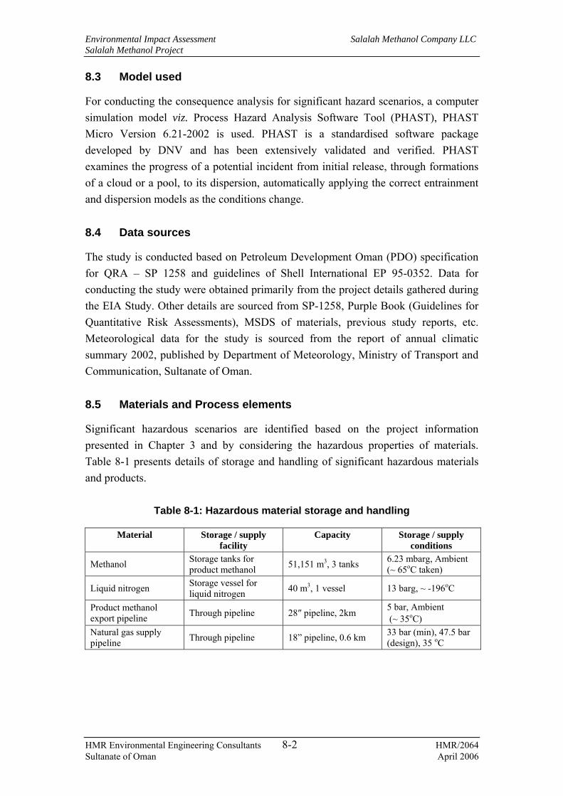
Environmental Impact Assessment Salalah Methanol Company LLC Salalah Methanol Project
HMR Environmental Engineering Consultants 8-2 HMR/2064 Sultanate of Oman April 2006
8.3 Model used
For conducting the consequence analysis for significant hazard scenarios, a computer simulation model viz. Process Hazard Analysis Software Tool (PHAST), PHAST Micro Version 6.21-2002 is used. PHAST is a standardised software package developed by DNV and has been extensively validated and verified. PHAST examines the progress of a potential incident from initial release, through formations of a cloud or a pool, to its dispersion, automatically applying the correct entrainment and dispersion models as the conditions change.
8.4 Data sources
The study is conducted based on Petroleum Development Oman (PDO) specification for QRA – SP 1258 and guidelines of Shell International EP 95-0352. Data for conducting the study were obtained primarily from the project details gathered during the EIA Study. Other details are sourced from SP-1258, Purple Book (Guidelines for Quantitative Risk Assessments), MSDS of materials, previous study reports, etc. Meteorological data for the study is sourced from the report of annual climatic summary 2002, published by Department of Meteorology, Ministry of Transport and Communication, Sultanate of Oman.
8.5 Materials and Process elements
Significant hazardous scenarios are identified based on the project information presented in Chapter 3 and by considering the hazardous properties of materials. Table 8-1 presents details of storage and handling of significant hazardous materials and products.
Table 8-1: Hazardous material storage and handling
Material Storage / supply facility
Capacity Storage / supply conditions
Methanol Storage tanks for product methanol 51,151 m3, 3 tanks 6.23 mbarg, Ambient
(~ 65oC taken)
Liquid nitrogen Storage vessel for liquid nitrogen 40 m3, 1 vessel 13 barg, ~ -196oC
Product methanol export pipeline Through pipeline 28″ pipeline, 2km 5 bar, Ambient
(~ 35oC) Natural gas supply pipeline Through pipeline 18” pipeline, 0.6 km 33 bar (min), 47.5 bar
(design), 35 oC

Environmental Impact Assessment Salalah Methanol Company LLC Salalah Methanol Project
HMR Environmental Engineering Consultants 8-3 HMR/2064 Sultanate of Oman April 2006
8.6 Hazard identification
8.6.1 Failure scenarios
Potential hazards due to the storage and handling of materials as identified in Table 8-1 are associated mainly with the failures of the storage vessels and pipelines during normal operation or during abnormal conditions. The failure scenarios can be assessed based on the causes of failures and the types of failures as discussed below.
8.6.2 Failure causes
Based on information provided by SP-1258, the causes of failures can be categorised as below:
− Failure due to external interferences;
− Operational / mechanical failure; and
− Corrosion and other failures.
These are explained below.
• External interference
This includes excavation, digging, piling, entry into incorrect pipeline, equipment, storage vessel, etc. Impacts from excavating machinery are a major cause of leaks from buried pipelines and are likely to result in large releases while exposing the workers involved in the excavation activity to the resulting consequences. For the aboveground equipment, pipeline, storage installations, etc., impacts from vehicles or from nearby construction and maintenance works are important hazards. The natural gas pipeline from the PRT in Raysut industrial area to SMC plant and the metering station at SMC site will be operated and maintained by OGC. However, the metering station will be integrated into SMC's fire and gas detection system.
• Operational / mechanical failures
Operational/mechanical failures include failures due to over-pressurisation, inappropriate selection of material, construction and operational defects and corrosion. Corrosion related leak could be either external or internal. Galvanic, pitting and stress corrosion are the main types of corrosion.
• Other failures
Other failure causes include, flooding, washout, ground movement or even sabotage.

Environmental Impact Assessment Salalah Methanol Company LLC Salalah Methanol Project
HMR Environmental Engineering Consultants 8-4 HMR/2064 Sultanate of Oman April 2006
Considering the facility details presented in Chapter 3, potential causes of failures at the facility could be failures due to over-pressurisation or due to external interferences, despite the continuous monitoring, control and relief systems. Failure due to corrosion will not typically result as the facilities will be new and given the fact that SMC will implement a comprehensive inspection program, the chances for corrosion failures are remote. However corrosion failures are possible at later stage as the plant becomes old. Also, inappropriate material selection or construction defects are not potential causes of failures as the design, material selection and construction activities are tried and proven many times in the region as well as the thorough quality assurance procedures expected to be applied.
8.6.3 Failure types
Failures due to the above causes can result in a pinhole leak, medium-hole leak or complete rupture of the equipment, storage tank or pipeline. The failures due to over-pressurisation or corrosion can typically result in a pinhole or medium size leak while the failures due to external interference can potentially lead to full rupture. However, the failures due to over-pressurisation can sometimes result in full rupture of the storage tank or pipeline as well. For the present case, pinhole leak (10 mm leak) and instantaneous release of complete inventory from the storage tank (catastrophic rupture) and pinhole leak and full bore rupture of the pipeline are considered to represent the minimum (most credible) and worst-case scenarios as presented below:
Table 8-2: Failure types
Component Failure types Storage tanks for product methanol
Storage vessel for liquid nitrogen
10 mm (pinhole) leak; and Instantaneous release of the complete inventory (catastrophic rupture)
Product methanol export pipeline Natural gas supply pipeline
10 mm leak (pinhole leak); and Full bore rupture
8.7 Consequence assessment
8.7.1 Modelling inputs
Consequence modelling is conducted for the failure scenarios explained above. As described in Section 8.3, the modelling is conducted using PHAST. The following inputs are required to run the model.
− Chemical composition of substance released (Table 8-3);

Environmental Impact Assessment Salalah Methanol Company LLC Salalah Methanol Project
HMR Environmental Engineering Consultants 8-5 HMR/2064 Sultanate of Oman April 2006
− Inventory of the substance available for release (calculated based on information provided in Table 8-1);
− Operating pressure and temperature (Table 8-1);
− Type of release (Table 8-2); and
− Atmospheric conditions, viz., ambient temperature, humidity, wind speed and atmospheric stability sourced from metereological data for Mina Salalah.
The above inputs for the present case are described below.
8.7.2 Chemical composition of materials
The materials and their compositions considered for the modelling are presented in Table 8-3
Table 8-3: Chemical composition of materials for modelling
Material Composition Product methanol 99.85% (assay provided in the FEED document – Basis of
design, Document No. 60.8579.00/P.02a/0001) Liquid Nitrogen 100 % pure Natural Gas Natural gas composition as provided in the FEED document
– Basis of design, Document No. 60.8579.00/P.02a/0001
8.7.3 Meteorological conditions
The dispersion of flammable/toxic vapour released into the atmosphere is controlled by wind speed and atmospheric stability. Atmospheric stability is dependent on the wind speed and incoming solar radiation (insulation). Atmospheric stability varies from extremely unstable (class A) to moderately stable (class F) condition. Generally, class A to D occurs during day time and class D to F during nighttime. Class D represents neutral stability, which may occur during daytime or nighttime if overcast conditions prevail. The predominant wind speed at the location (based on meteorological data for Mina Salalah) is 1 – 3 m/s. Considering strong solar insolation during daytime and clear/thinly overcast sky during nighttime, the following wind speed and stability classes are considered for modelling.
− 1/A - class A with a wind speed of 1m/s;
− 2/F - class F with a wind speed of 2 m/s; and
− 3/D - class D with a wind speed of 3 m/s.
The stability conditions are determined based on Pasquill’s Stability classes.

Environmental Impact Assessment Salalah Methanol Company LLC Salalah Methanol Project
HMR Environmental Engineering Consultants 8-6 HMR/2064 Sultanate of Oman April 2006
8.7.4 Consequences of failures
As explained earlier, the hazardous substances are stored in storage tanks, with secondary containment in the form of dikes. In case of a pinhole leak from the storage tank, the contents will be released as a jet. The liquid pool will be collected inside the dyke wall, within the containment area. The liquid will vapourise forming a vapour cloud, which will disperse in the downwind direction due to natural mixing and wind. In case of large leaks from the storage tanks as during catastrophic rupture, large liquid pools will be formed in the dyke area and will take longer time for the pool to evaporate. As the dyke area is designed to contain complete contents of one tank, it is unlikely that the pool will spread to out side the containment area. The release orientation from the storage tanks will be typically horizontal direction and is considered for modelling. For buried pipelines, the release will potentially impinge on the soil cover. For a vertical release, due to high momentum of the released jet, the sand cover will be potentially displaced after which the jet will act as a free jet, which is considered for modelling. For above ground pipelines, a horizontal release is considered for modelling to depict the worst case impact distances.
The release scenarios are summarised in Table 8-4.
Table 8-4: Release scenarios considered for modelling
Facility Leak size Release orientation Storage tanks 10 mm leak
Catastrophic rupture Horizontal release
Natural gas pipeline (above ground)
10 mm leak Full bore rupture
Horizontal release
Methanol pipeline 10 mm leak Full bore rupture
Vertical release
The release will continue until the tank/pipeline is isolated and the material contained is released into the atmosphere. The release of material can cause the following consequences:
− Pool fire, if there is an ignition source nearby. For the storage tanks, the released liquid will be contained in the dyke area and is not likely to spread outside the dike area;
− Jet fire, if there is an immediate source of ignition. The liquid and/or vapour jet from the pinhole may get ignited;
− Vapour cloud explosion if there is a delayed source of ignition (such as a vehicle passing by or the flare within the facility) and the vapour quantity in

Environmental Impact Assessment Salalah Methanol Company LLC Salalah Methanol Project
HMR Environmental Engineering Consultants 8-7 HMR/2064 Sultanate of Oman April 2006
the vapour cloud due to evaporation of the liquid or the gas cloud (for natural gas releases) is sufficient to explode;
− Flash fire if there is delayed source of ignition and the vapour concentration is within the flammable limits; and
− Otherwise the liquid vapour cloud will disperse into the atmosphere. For natural gas, since the vapours are not toxic, there are no toxicity hazards. However, for methanol vapours toxic hazards are considered within the exposure concentration limits.
The major hazard from the liquid nitrogen release is due to asphyxiation and due to cold burns at the vicinity of release. Since nitrogen is inert, non-toxic and non-flammable there are no flammability or toxicity hazards from the release.
Asphyxiation occurs due to reduced concentration of oxygen in the breathing air. Liquid nitrogen rapidly evaporates giving nitrogen gas. One litre of liquid produces approximately 700 litres of gas at ambient temperature and atmospheric pressure, displacing significant quantities of air. This effect is compounded by nitrogen's tendency to accumulate at low levels where it is less easily dispersed. Even an apparently small spillage could lead to low oxygen levels, presenting hazards to personnel working in the area.
The normal oxygen level in the atmosphere is 20.9%. Physical and intellectual performance may be inhibited if levels fall below 17% and at levels just a few per cent lower, symptoms of asphyxia such as gasping, vomiting or collapse, will set in. Victims may not be aware of their condition, especially if the oxygen level falls rapidly and a major leak or spillage could lead to unconsciousness. When the oxygen content of air is reduced to around 10%, unconsciousness can be immediate. Death is possible at concentrations below 10%. For the present case, conservatively a concentration of 10% or below is considered to be fatal.
After release, the gas cloud will mix with air and the concentration level within the cloud will reduce. As air contains about 78% nitrogen, a concentration level of 12% within the cloud will result in cumulative concentration level of 90% nitrogen, which will potentially result in less than 10% of oxygen within the plume. Therefore, conservatively a concentration level of 12% nitrogen in the plume is considered to determine the impact distances. Also, the temperature in the immediate vicinity of release will be very low and this may result in condensation of oxygen [the boiling point of liquid oxygen (-183 oC) is lower than that of liquid nitrogen (-196 oC) at atmospheric pressure] in the surrounding air and this may also lead to reduced concentration of oxygen.

Environmental Impact Assessment Salalah Methanol Company LLC Salalah Methanol Project
HMR Environmental Engineering Consultants 8-8 HMR/2064 Sultanate of Oman April 2006
Cold burns or frostbite can result from direct contact with the liquid. Evaporation of large volumes of liquid could lower the local temperature low enough to cause frostbite or hypothermia.
For methanol vapours the concentration limits provided as Immediate Danger to Life and Death (IDLH) is considered for calculating toxicity impact distances. IDLH is a condition that poses a threat of exposure to airborne contaminants when that exposure is likely to cause death or immediate or delayed permanent adverse health effects or prevent escape from such an environment. For methanol the limit is 6000 ppm.
8.8 Results
Considering the above, the releases of hazardous materials from storage tanks and pipelines were modelled using the inputs presented in 8.7.1 and the considerations presented in Section 8.7.4. The results are presented as impact distances in Table 8-5 and Table 8-6. Impact distances include thermal radiation hazards from jet fire, flash fire and vapour cloud explosion. The thermal radiation hazards are presented as distances (m) to different radiation levels (kW/m2). For jet fire radiation hazards, a level of 37.5 kW/m2 is considered to be fatal. For flash fire, the probability of fatality is considered to be 10% within flame front, i.e., within LFL. Graphical representation of impact distances and the cloud footprints are presented in Appendix J.
Table 8-5: Impact distances for various release scenarios
Impact distance (m) to
Jet fire radiation Impact distance (m) to
IDLH19 Storage
tank Leak type Weather class
UFL LFL 4 kW/m2
12.5 kW/m2
37.5 kW/m2
m
1/A - - 7.64 6.50 5.59 51.82 2/F - - 7.82 6.64 5.72 43.56 10 mm 3/D - - 7.85 6.66 5.75 43.13 1/A 61.34 89.20 - - - 138.88 2/F 61.13 96.49 - - - 142.12
Product methanol storage tank
Full bore rupture
3/D 62.90 84.99 - - - 136.16 1/A - - - - - - 2/F - - - - - - 10 mm 3/D - - - - - - 1/A - - - - - 18.45 2/F - - - - - 14.71
Liquid nitrogen storage tank
Full bore rupture
3/D - - - - - 6.25 1/A - - 13.22 4.70 - 10.23 2/F - - 14.14 6.48 - -
Product methanol export
10 mm 3/D - - 14.63 7.75 - -
19 IDLH – Immediate Danger to Life and Health, as defined by NIOSH, considering an exposure time of 30 minutes. For methanol the limit is 6000 ppm

Environmental Impact Assessment Salalah Methanol Company LLC Salalah Methanol Project
HMR Environmental Engineering Consultants 8-9 HMR/2064 Sultanate of Oman April 2006
Impact distance (m) to
Jet fire radiation Impact distance (m) to
IDLH19 Storage
tank Leak type Weather class
UFL LFL 4 kW/m2
12.5 kW/m2
37.5 kW/m2
m
1/A - 165.22 247.69 118.01 19.85 - 2/F - 321.41 305.89 168.93 28.69 -
pipeline Full bore rupture
3/D - 169.16 351.42 213.77 38.13 - 1/A - - 11.37 10.26 9.09 - 2/F - - 11.37 10.26 9.09 - 10 mm 3/D - - 11.37 10.26 9.09 - 1/A 73.80 377.29 424.99 393.48 387.65 - 2/F 81.35 410.79 424.99 393.48 387.65 -
Natural gas supply pipeline
Full bore rupture
3/D 75.04 408.88 424.99 393.48 387.65 -
Table 8-6: Pool characteristics
Late pool fire radiation impact distance (m) to Storage
tank Leak type Weather class
Pool vaporisation rate (kg/s)
Pool radius
(m) 4
kW/m2 12.5
kW/m2 37.5
kW/m2 1/A 0.297 7.10 45.25 29.81 19.99 2/F 0.291 7.10 44.92 30.48 21.34 10 mm 3/D 0.341 6.84 43.05 29.88 21.56 1/A 0.199 105.55 364.76 238.89 160.00 2/F 4.34 105.55 369.70 246.13 169.65
Product methanol storage tank
Full bore rupture
3/D 0.042 105.55 369.47 248.63 173.57 1/A 0.034 1.643 18.47 14.41 11.49 2/F 0.018 1.167 21.11 18.60 16.48 10 mm 3/D - - - - - 1/A 25.66 69.62 260.81 168.73 111.60 2/F 16.28 69.13 267.53 178.52 123.08
Product methanol export pipeline
Full bore rupture
3/D 17.89 68.59 263.33 177.79 124.28
From the above results, it can be noted that the radiation impact distances for various release scenarios are likely to be within the facility, except for product methanol export pipeline. However, it is to be noted that the probability of occurrence of worst case scenarios such as catastrophic rupture of storage tanks and full bore rupture of pipelines are typically low. Also, the liquid pools will be contained within the containment areas and are not likely to spread to outside areas. The impact distances to 12% nitrogen in case of catastrophic rupture of liquid nitrogen storage tank is only 18.45m and hence will not extend to the outside of battery limits. In addition, the failure incidents will be reduced due to the following:
− The storage tanks as well as the pipelines will be well maintained and corrosion protected through suitable material selection, surface coatings, etc.

Environmental Impact Assessment Salalah Methanol Company LLC Salalah Methanol Project
HMR Environmental Engineering Consultants 8-10 HMR/2064 Sultanate of Oman April 2006
− The tanks are provided with secondary containment in order to contain the released material so as to prevent spreading to outside the containment area;
− Operators will be aware of potential hazards from the storage and handling of hazardous materials and operations. Also the hazardous areas will be clearly marked and access to these locations will be strictly restricted; and
− Work permit systems will be implemented for entire facility in order to control the maintenance activities, which will potentially involve replacement of pipeline sections, valves, fittings at the storage tanks / pipelines, welding, excavation, etc., at hazardous areas at the facility.
However, to address the likely consequences arising out of the hazardous incidents at the facility, an onsite and offsite emergency preparedness plan is to be developed and implemented, a framework for which is presented in Chapter 9.
It is considered that the risk analysis will continue as the detailed design progresses. Therefore, upon completion of the detailed design, a further assessment considering failure frequencies of each failure incident such as immediate or delayed ignitions, explosions, etc., is recommended as a detailed QRA study.

Environmental Impact Assessment Salalah Methanol Company LLC Salalah Methanol Project
HMR Environmental Engineering Consultants 9-1 HMR/2064 Sultanate of Oman April 2006
9. ENVIRONMENTAL MANAGEMENT PLAN
9.1 Overview
This chapter describes various measures that are to be implemented so as to mitigate the environmental impacts rated as medium/high from the construction and operational phases of the project to ALARP levels. The references made to potential mitigation measures included in Chapters 5, 7 and 8 of this EIA Report have been discussed in detail in the following sections along with monitoring plans and management systems to implement the mitigation measures. The decommissioning phase, at the end of the project lifecycle, will be approximately after 20-30 years. The activities involved will be similar to the construction phase and is therefore not addressed in detail separately. However, a few management strategies and approaches with regards to the site restoration to the requirements of the future land user are provided.
The EMP for the construction and operational phases of the project follows the ‘Plan-Do-Check-Act system in line with the ISO 14001 Environmental Management System EMS guidelines and includes the organization structure, resources, responsibilities, control and mitigation measures, monitoring/auditing programs, systems for review and implementation of corrective actions.
The ultimate responsibility for environmental management during all phases of the project rests with SMC. However the EPC contractor will also bear the responsibility for developing and implementing the EMP during construction phase of the project. The responsibility for implementing the EMP during the operational phase will be entirely with SMC. Periodic environmental audits will be conducted by SMC/EPC contractor or an independent consultant during the construction phase to ensure effective implementation of the management plan. Appropriate corrective actions will be implemented with due correspondence and consensus with Ministry of Regional Municipalities, Environment & Water Resources (MRME&WR) for any deviations.
9.2 Construction phase environmental management
9.2.1 Selection of EPC contractor
As mentioned in preceding sections, project components were in the design stage during the course of this EIA study. The EPC contractors for the project development have not yet been identified for the detailed engineering and construction of the plant facilities, procurement and installation of equipment, and subsequent commissioning and handing over of the facility to SMC for commercial operation. The selection of

Environmental Impact Assessment Salalah Methanol Company LLC Salalah Methanol Project
HMR Environmental Engineering Consultants 9-2 HMR/2064 Sultanate of Oman April 2006
the EPC contractor will take into consideration the contractor’s competency in managing environmental issues during construction and adhering to the control measures included in this management plan. In addition to the mitigation measures presented in the EMP, the EPC contractors will also be responsible for implementation of additional control measures suggested by MRME&WR based on the EIA study and as included in the initial environmental permit.
9.2.2 Organisation and responsibilities
The EPC contractors and their subcontractors will be required to establish an organizational structure for environmental management including health and safety issues to ensure effective implementation of the mitigation measures and to review the environmental management process. An indicative organization structure is presented in Figure 9-1.
As project developer, SMC will ensure, through its onsite project Manager (PM) that the EPC contractors develop and implement an effective Health, Safety, and Environmental Management System (HSEMS) for the project construction phase. The HSEMS will comply with the control measures and environmental management requirements outlined in this EMP and any additional conditions provided by the regulators. The EPC contractors will be responsible for ensuring that their subcontractors also establish an HSEMS to effectively implement the requirements of this EMP. The HSEMS documents will include the objectives and targets, organization structure, responsibilities, resources, control measures, monitoring and auditing plans, review systems, provisions for implementing corrective actions for deviations and training systems.
Since the project developer will have the ultimate responsibility for HSE management during construction of the facility, SMC, through its PM will ensure that the EPC contractors operate in accordance with all the HSE requirements throughout the period of construction.
The HSE manager of EPC contactors reporting to the PM will be responsible for day-to-day HSE management on site. The HSE Manager will maintain constant interactions with line managers and other staff throughout the construction period. The EPC contractor will assist in periodic audits of the EMS including monitoring programs to ensure effective implementation of the control and mitigation measures and implementation of corrective actions for any deviations.

Environmental Impact Assessment Salalah Methanol Company LLC Salalah Methanol Project
HMR Environmental Engineering Consultants 9-3 HMR/2064 Sultanate of Oman April 2006
Figure 9-1: Proposed HSE organisation structure for construction phase
9.2.3 Site security and safety
The project site will be fenced on all sides and access to the site will be through gates that will be manned during 7 days a week including holidays. The security personnel will carry out regular foot patrols and walkthrough inspections, however, it is incumbent upon every person at site, including visitors, to report any unsafe conditions. The HSE Manager or persons designated by him will conduct periodic walkthrough inspections and will identify any emergency situations, spills, housekeeping and other environmental and safety related issues. The access to site will be restricted to employees, authorised sub-contractors and visitors. All workers at the site will be given either a uniform or an identity badge, as a mark of authorisation to work on the site. All entrances to the site will have a notice indicating the work being carried out, the names of companies present and the people responsible for the site.
The pipeline trenches will be fenced/caution-taped at full length and barricaded at possible pedestrian or vehicle crossing points as required to minimise safety risks. The HSE Manager will co-ordinate with the line managers to ensure that safe work
SMC CEO
Project Manager (SMC)
Project Manager (EPC Contractor)
Line Managers (EPC/Sub-contractor)
HSE Manager (EPC Contractor)
Supporting Staff
Third party Consultant
Indicates Command Indicates Interaction
Environmental Impact Assessment Salalah Methanol Company LLC Salalah Methanol Project
HMR Environmental Engineering Consultants 9-4 HMR/2064 Sultanate of Oman April 2006
practices are followed with regard to working at height, confined space entry, use of adequate PPE, work permit procedures, etc.
9.2.4 Environmental permitting for construction of the facility
The EPC contractors will be responsible for obtaining the requisite permits (on their names) during construction from MRME&WR and other relevant authorities. These permits typically include the following.
− Permit for wastewater discharge;
− Permits for handling, storage, treatment/disposal of hazardous waste;
− Permit for handling and storage of radioactive material;
− Chemicals permit for handling, storage and transportation of hazardous chemicals; and
− Approval for excavation of Wadis/cutting of hills/removal and/or transportation of sand from wadis/ changing wadis and gorge’s courses.
The HSE Manager of the EPC contractor will primarily be responsible for maintaining compliance with the above permit conditions, obtaining additional approvals and coordinating with the regulatory agencies.
9.2.5 Site preparation
As discussed in the preceding sections, the site contains small trees and shrubs. A wadi with considerable amount of vegetation runs across the site in east-west direction. Levelling and grading of the site prior to the civil construction will involve removal of such vegetation. Approval has to be obtained from MRME&WR and concerned authorities prior to any excavation planned at the wadis and cutting of hills. Care should be taken not to disturb any vegetation existing outside the site fence lines during the mobilization and demobilization of construction equipment. Care should be taken during the site preparation to minimise damage to vegetation, which are identified as significant as presented in Section 4.10.2.
Any subsurface contamination that is suspected or discovered during the construction activities will be further assessed and remediated if required. Grading and soil compaction will be involved as a part of site preparation. If any dust risings are expected particularly during the dry weather conditions, water will be sprayed for dust suppression.
The excavated soil will be stored at appropriate locations within the project site. The soil will be used for backfilling and grading, wherever possible. The excess soil will

Environmental Impact Assessment Salalah Methanol Company LLC Salalah Methanol Project
HMR Environmental Engineering Consultants 9-5 HMR/2064 Sultanate of Oman April 2006
be disposed off in approved municipal dumpsites. All the construction equipment and machinery used will be of standard design and in good operating condition so as to achieve good fuel efficiency and thereby reduce air emissions.
9.2.6 Sourcing of construction materials and utilities
Rocks and aggregates for foundation and concrete works will be obtained from quarries through licensed and registered sub-contractors. It will be ensured that the sub-contractors obtain (have valid permits if they are current quarry operators) necessary permits from MRME&WR and Royal Oman Police (ROP) for operations at the quarry sites to ensure that the public is not exposed to any safety or health risk. The EPC contractor will document a copy of the sub-contractors permit to quarry and will produce copies of the document to MRME&WR whenever required.
Freshwater required for construction and domestic use at site will be most likely sourced from permitted groundwater wells in the area through sub-contractors. It is to be ensured that abstraction of groundwater from the supply wells in the area can meet the project water demand without causing stress to the current usage pattern. If it is found that water abstraction is likely to cause any stress, then water for the entire project construction will be obtained through other sources such as supply wells from nearby Wilayats or installing an onsite desalination plant. Efforts will be made to minimize water consumption through conservation measures. Treated wastewater will be used for spraying purposes for dust suppression.
Civil construction and internal road works will require cements and bitumen and will possibly engage mixers on site. Cement and bitumen mixers are major contributors towards fugitive emissions of dust, cement particulates and hazardous air pollutants. The EPC contractor will explore the possibility of importing ready mix cements for civil and road works so as to minimise the above said releases to the environment.
In addition to the above, the mitigation measures for management of various environmental releases and storage and handling of hazardous materials during the construction phase are categorised as below:
− Mitigation measures by planning;
− Mitigation measures by controls during site work; and
− Mitigation measures by monitoring.
Mitigation measures with regard to each of the environmental releases and storage and handling of hazardous materials are discussed in the following sections.

Environmental Impact Assessment Salalah Methanol Company LLC Salalah Methanol Project
HMR Environmental Engineering Consultants 9-6 HMR/2064 Sultanate of Oman April 2006
9.2.7 Air quality
The following mitigation measures are presented for minimising impacts on air quality during construction activities.
• Planning
− Standard construction equipment, DGs and vehicles to be used to ensure that the release of air pollutants is minimised. EPC contractors will be encouraged to source power required during construction phase from DPC or the local power grid.
• Controls during site work
− EPC contractor to plan and schedule for periodic maintenance and tuning of DG units, vehicles and other construction equipment;
− Water to be sprayed on dust prone graded roads and work sites. Treated water used for dust suppression will be sourced from the onsite STP or sourced from outside as feasible;
− Adequately sized construction yard and lay down areas to be provided for storage of construction materials, equipment, tools, earthmoving equipment, etc;
− On-site vehicle speeds to be controlled to reduce dust generation;
− Onsite fuel storage to be according to applicable regulations and as per respective MSDS. Onsite fuel storage tanks, if any, to be provided with submerged loading facilities as feasible to minimise fugitive emissions. Welding gas cylinders to be stored in a secluded and protected area;
− Fabrication activities such as welding, gas cutting, grit blasting and surface coating/painting to be done in a designated area / coating booths; and
− Construction staffs to be properly trained as appropriate in order to follow suitable measures to minimise emissions.
• Monitoring
− Periodic audits to be conducted to assess implementation of the control measures and results of audits to be reviewed and corrective actions to be taken;
− Periodic monitoring of emissions for critical pollutants such as CO, NOx and SO2 to be conducted at emission sources as appropriate; and
− Periodic monitoring of ambient air quality to be conducted for critical pollutants at various locations around the construction site (considering the

Environmental Impact Assessment Salalah Methanol Company LLC Salalah Methanol Project
HMR Environmental Engineering Consultants 9-7 HMR/2064 Sultanate of Oman April 2006
location of various activities, wind direction and location of receptors). The reports of such monitoring to be submitted to MRME&WR, as required, to provide status of compliance with applicable regulations.
9.2.8 Noise
The following mitigation measures are presented for minimising impacts from noise during construction activities.
• Planning
− Major construction equipment used at site to be planned in such a way as to maintain source noise levels at 85 dB (A).
• Controls during site work
− Construction equipment to be oriented away from sensitive receptors as feasible;
− Noise attenuation such as shrouding, insulation and vibration dampers to be used as appropriate for high noise generating equipments;
− Workers exposed to noise levels above 85 dB (A) are to be provided with adequate ear protection devices;
− High noise activities to be scheduled in such a way so as to minimise such activities at night times;
− Periodic maintenance such as engine tuning, lubrication, filter cleaning / replacement, oil changes, replacement of required spares etc., of noise generating equipment such as DG units, air compressors and other construction equipment to be conducted so as to optimize the equipment noise levels, reduce emissions and maintain efficiencies;
− Simultaneous operation of multiple high noise sources to be minimised to reduce cumulative noise level impacts;
− Equipment and vehicles that may be in use only intermittently to be shut down during idling periods or throttled down to a minimum; and
− Signboards indicating high noise areas to be displayed as appropriate and access to such areas to be controlled.
• Monitoring
− Periodic audits to be conducted to assess implementation of the control measures and results of audits to be reviewed and corrective actions to be taken; and

Environmental Impact Assessment Salalah Methanol Company LLC Salalah Methanol Project
HMR Environmental Engineering Consultants 9-8 HMR/2064 Sultanate of Oman April 2006
− Periodic monitoring of workplace and ambient noise levels to be conducted to assess compliance with applicable standards. The noise monitoring results to be submitted to MRME&WR to establish compliance with applicable regulations.
9.2.9 Wastewater
The following mitigation measures are presented for minimising impacts from wastewater handling and disposal during construction activities.
• Planning
− EPC contractor to establish facilities to segregate wastewater streams according to characteristics as presented in Section 5.3.4 and Table 5-1 and route it to adequately sized wastewater treatment plants or transporting it to off-site treatment plants for treatment and disposal;
− Adequately designed holding pond to be provided for the storage of spent hydro-test water; and
− Facilities to be provided at the site to segregate the storm water run-offs from contaminated areas.
• Controls at site work
− Construction equipment and vehicle washing to be carried out at designated areas provided with wash water collection systems. Alternatively, equipment and vehicle washing may be carried out at off-site locations (such as work shops of contracting companies), where adequate facilities are available;
− Adequately sized construction yard and lay down area to be provided for storage of construction machinery, material, equipment, tools and vehicles. Appropriate spill control measures and handling procedures to be provided at such areas;
− Sewage generated on-site to be collected through underground pipes into holding tanks, from where the sewage will be routed to onsite STP or alternatively transported periodically by vacuum trucks and transferred to an approved STP close to the site for treatment and disposal;
− The hydro-test water needs to be collected in the lined pond and the water evaporated. The water that is not evaporated will be routed to the ETP for treatment after the plant is operational;
− Accidental spillages of hazardous substances to be immediately remediated to prevent contaminated runoffs and potential contamination of soil and groundwater; and
Environmental Impact Assessment Salalah Methanol Company LLC Salalah Methanol Project
HMR Environmental Engineering Consultants 9-9 HMR/2064 Sultanate of Oman April 2006
− Waste consignment notes to be prepared and documented for transportation of wastewater (sanitary and other wastewater), if any, to offsite treatment facilities. The quantities of wastewater generated and transported for offsite disposal/treatment to be recorded for future verification.
• Monitoring
− Periodic audits to be conducted to assess implementation of the control measures and results of audits to be reviewed and corrective actions to be taken for any deviations.
9.2.10 Solid wastes
The following mitigation measures are presented for minimising impacts from storage and handling of solid wastes during construction activities.
• Planning
− Waste management plan to be prepared to address proper collection, segregated storage and recycle/disposal of wastes at approved wastes disposal sites; and
− Suitable storage area (adequately designed to protect from rains during the monsoon and to prevent any run offs) and collection skips to be provided for solid wastes for segregated collection of wastes. The sizing of such areas and skips to be in accordance with the expected waste quantities and the frequency of disposal. The waste skips/containers holding the waste material to be suitably labelled for easy identification of material.
• Controls at site work
− Excavated soil to be stockpiled at an appropriate location at site. Adequate enclosures and curbs to be provided to avoid blowing away by wind and run off with storm water. The soil to be reused for backfilling and grading as feasible. Any excess soil to be disposed off in approved dumpsites;
− Concrete waste, other construction wastes, domestic refuse, etc., to be collected, segregated and disposed off to approved dumpsites;
− Metal scrap, wood scrap, empty containers of non-hazardous materials, packing materials, etc. to be collected, segregated and recycled to scrap dealers as feasible and the non-recyclable waste to be disposed off to approved dumpsites; and
− Waste consignment notes to be prepared and documented for transporting wastes from the site identifying the type of waste, quantity, disposal site, etc.

Environmental Impact Assessment Salalah Methanol Company LLC Salalah Methanol Project
HMR Environmental Engineering Consultants 9-10 HMR/2064 Sultanate of Oman April 2006
The delivery receipts obtained from municipal dumpsites are to be documented. The quantities of various categories of wastes generated, stored and transported for offsite disposal to be recorded for future verification.
• Monitoring
− Periodic audits to be conducted to assess implementation of the control measures and results of audits to be reviewed and corrective actions to be taken for deviations.
9.2.11 Solid hazardous wastes
The following mitigation measures are presented for minimising impacts from solid hazardous wastes during construction activities.
• Planning
− Waste management plan to address proper collection, segregated storage/recycle of hazardous wastes; and
− Suitable storage area (adequately designed to protect from rains during the monsoon and to prevent any run offs) with impervious flooring, bunds, roof and spill collection facilities as appropriate, to be established for collection and segregated storage and collection methods to be established for solid hazardous wastes. The sizing of such areas to be in accordance with the expected waste quantities and the frequency of recycling/disposal. The waste skips/containers holding the waste material to be properly labelled indicating the material, hazardous nature, etc.
• Controls at site work
− Contaminated soil generated due to remediation of accidental spills to be stored in a bunded and sheltered area with impervious flooring to minimise blowing away by wind, run off with storm water and infiltration;
− All other solid hazardous wastes such as waste chemicals, empty containers of hazardous materials, waste batteries, etc., to be properly collected, segregated and stored in enclosed and secluded area in compliance with requirements of MD 18/93 and respective MSDS;
− Potential opportunities for recycle/reuse to be considered for all wastes as feasible. Potential for returning to the suppliers to be explored for wastes such as unused chemicals, empty containers of hazardous materials, etc;
− As there are no centralised hazardous waste management facilities that are currently operating in Oman, non recyclable hazardous wastes are to be

Environmental Impact Assessment Salalah Methanol Company LLC Salalah Methanol Project
HMR Environmental Engineering Consultants 9-11 HMR/2064 Sultanate of Oman April 2006
stored on site and subsequently to be transferred to central hazardous waste management facilities of EPC contractors;
− Suitable PPE to be used by workers handling hazardous wastes; and
− Waste consignment notes to be prepared and documented for transporting wastes from the site identifying the type of waste, hazardous nature, quantity, disposal/recycle location, etc. Quantities of hazardous wastes generated, stored and transported for recycle/offsite storage to be recorded for future verification. Approved transporters to be used for transportation of hazardous waste materials.
• Monitoring
− Periodic audits to be conducted to assess implementation of the control measures and results of audits to be reviewed and corrective actions to be taken for deviations
9.2.12 Liquid hazardous waste
The following mitigation measures are presented for minimising impacts from liquid hazardous wastes during construction activities.
• Planning
− Waste management plan to address proper collection, segregated storage/ recycle of liquid hazardous wastes; and
− Suitable storage area (adequately designed to protect from rains during the monsoon and to prevent any run offs) with impervious flooring, bunds, covers/roof and spill collection facilities as appropriate to be established for collection and segregated storage of liquid hazardous wastes. The sizing of such areas to be in accordance with the expected waste quantities and the frequency of recycling/disposal. The containers holding the waste materials to be properly labelled indicating the material, hazardous nature, etc.
• Controls at site work
− Any spills/leaks from the waste containers onto land to be immediately remediated to minimise the potential to soil and groundwater contamination;
− Potential opportunities for recycle/reuse to be considered for all wastes as feasible. Potential for returning to the suppliers to be explored for wastes such as unused chemicals, cleaning solvents, paints, etc. Waste oil to be recycled to approved recyclers;

Environmental Impact Assessment Salalah Methanol Company LLC Salalah Methanol Project
HMR Environmental Engineering Consultants 9-12 HMR/2064 Sultanate of Oman April 2006
− As there are no centralised hazardous waste management facilities that are currently operating in Oman, non recyclable hazardous wastes are to be stored on site and subsequently to be transferred to central hazardous waste management facilities of EPC contractors or handed over to SMC after completion of the project construction;
− Suitable PPE to be used by workers handling the hazardous wastes; and
− Waste consignment notes to be prepared and documented for transporting wastes from the site identifying the type of waste, hazardous nature, quantity, disposal/recycle location, etc. Quantities of hazardous wastes generated, stored and transported for recycle/offsite storage to be recorded for future verification. Approved transporters to be used for transportation of hazardous waste materials.
• Monitoring
− Periodic audits to be conducted to assess implementation of the control measures and results of audits to be reviewed and corrective actions to be taken for deviations.
9.2.13 Storage and handling of hazardous materials
The following mitigation measures are presented for minimising impacts from storage and handling of hazardous materials during construction activities.
• Planning
− EPC contractor to obtain permits (in their name) from concerned regulatory authorities for storage and handling of chemicals and fuels to be used at construction site;
− Enclosed and secluded storage area (adequately designed to protect from rains during the monsoon and to prevent any run offs) along with spill collection and safety facilities to be provided for storage of hazardous materials such as lube oils, toxic and flammable chemicals, cleaning solvents, paints, fuels, etc., according to applicable regulations and MSDS. Onsite fuel storage tanks, if any, to be provided with secondary containment and spill collection facilities. Properly lined areas with spill collection facilities to be provided for loading/unloading of hazardous materials;
− Roofed and ventilated are with adequate safety protection to be provided for storage of gas cylinders; and

Environmental Impact Assessment Salalah Methanol Company LLC Salalah Methanol Project
HMR Environmental Engineering Consultants 9-13 HMR/2064 Sultanate of Oman April 2006
− Onsite and offsite emergency response plans to be established for handling any potential emergency situations due to accidental release of hazardous materials.
• Controls at site work
− All hazardous materials to be stored and handled at designated storage areas as mentioned above in compliance applicable regulations and MSDS;
− The storage areas and vessels/containers to be properly labelled indicating the material, hazardous nature, quantity, safety measures to be followed, etc. Appropriate MSDS information to be displayed at areas of storage and use;
− Appropriate handling methods and facilities to be established for hazardous materials. Any spills/leaks to be immediately remediated to minimise contamination of soil and groundwater;
− The use of radioactive sources is envisaged for radiographic testing of storage tanks, pipelines etc. Any radioactive sources stored on site to be kept in secured and designated areas under the custody of authorised personnel;
− Personnel handling hazardous materials to be provided with appropriate training on the hazardous nature of the materials, methods for handling and storage, exposure controls required, emergency procedures, etc. Appropriate PPE to be used by personnel handling hazardous materials; and
− Approved transporters to be used for transportation of hazardous materials.
• Monitoring
− Periodic audits to be conducted to assess implementation of the control measures and results of audits to be reviewed and corrective actions to be taken for deviations.
− Inventory of the hazardous materials including the type of material, hazardous nature, quantity stored and consumed, etc., to prepared and documented by the EPC contractor/subcontractors; and
− EPC contractor to document all the relevant chemical permits and to be made available to the Ministry for inspections as required.
9.2.14 Seawater intake pipeline
The construction work for the intake pipeline is expected to involve limited amount of dredge work. The mitigation measures to minimise impacts due to the construction of intake pipeline are presented below.

Environmental Impact Assessment Salalah Methanol Company LLC Salalah Methanol Project
HMR Environmental Engineering Consultants 9-14 HMR/2064 Sultanate of Oman April 2006
• Planning
− Suitable trenching/dredging and other construction equipment and methods to be used to minimise the loss of sediments to the surrounding water column and cause minimum disturbance to the marine ecology of the area. It is to be noted that (as explained in Section 4.12) the intertidal and subtidal areas at the proposed seawater intake location have significant marine ecological sensitivities, which vary in abundance during the monsoon, winter and other months. In addition, at a depth of approximately 13 m, boulders and sandy trenches are encountered, which form significant habitats. Further, the beach at the proposed intake location is observed to be subjected to minimum human disturbances as evidenced by the abundant presence of ghost crabs. The construction activities have to be scheduled and planned in such a way to minimise the impacts to such habitats. In addition, alternative locations for the intake, presented in Section 6.8, may be adequately reviewed prior to finalising the present location for installation of the intake facilities. It is also suggested to review the feasibility of establishing common seawater intake and outfall facilities potentially required for future industrial establishments in the area in consultation with SFZ and Salalah Port authorities.
• Controls at site work
− Trenching activities to be controlled according to the tidal movements and sediment concentrations in the area;
− The dredging to be conducted to the minimum possible, along the proposed pipeline route;
− The dredged material (if quantities are minimum) to be disposed off safely, adjacent to the trench, which will get back filled in the trench after installation of the pipeline;
• Monitoring
− Monitoring of TSS concentration in seawater at various locations in and around the construction site during the construction period in order to assess sediment transport and the resultant impacts; and
− Waste consignment notes to be prepared and documented for the disposal of dredged/excavated material.
9.2.15 Marine outfall
− Mitigation measures as suggested for the intake line are to be considered in case of construction of offshore outfall pipeline. As presented in Chapter 4,

Environmental Impact Assessment Salalah Methanol Company LLC Salalah Methanol Project
HMR Environmental Engineering Consultants 9-15 HMR/2064 Sultanate of Oman April 2006
the proposed location of the outfall has already been subjected to considrable environmental disturbances due to the activities at the port and therefore significant ecological sensitivites are not encountered in this area. However, it is suggested to implement appropriate mitigation measures as explained above in order to ensure that further impacts are minimised. In case of construction of the outfall channel, mitigation measures identified for onshore construction in the above sections are to be adopted.
9.2.16 Auditing
The HSEMS of the EPC contractor and the sub-contractors are to include systems for scheduling, organizing and conducting periodic audits of the HSEMS implementation during the construction phase. The audits are to be scheduled in such a way as to cover all significant activities of the construction and including necessary environmental monitoring programs as presented in previous sections. Various environmental monitoring proposed during the construction phase are presented in Table 9-1. The monitoring data are to be compiled and documented. The reports of such audits/monitoring are to be provided to the Ministry as required. Corrective actions are to be implemented for any deviations from compliance requirements.
9.2.17 Review and implementation of corrective actions
The findings and recommendations of periodic audits and related monitoring along with recommendations for corrective actions and improvements are to be periodically reviewed by EPC contractor/SMC. Adequate resources are to be provided by SMC/EPC contractor and sub-contractors for implementation of such recommendations and corrective actions for improving the effectiveness of the HSEMS.
9.2.18 Environmental monitoring and auditing
The proposed monitoring and auditing plan for the construction phase is presented in Table 9-1.
Table 9-1: Environmental and Auditing Plan for Construction Phase
Environmental Aspect
Scope of Monitoring / Auditing Method Frequency of Monitoring /
Auditing
Air quality
PM10 concentrations at various locations within and around construction sites and nearby receptors
Using portable dust monitor Monthly
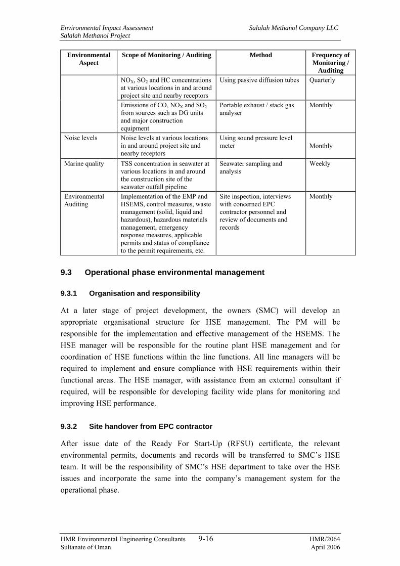
Environmental Impact Assessment Salalah Methanol Company LLC Salalah Methanol Project
HMR Environmental Engineering Consultants 9-16 HMR/2064 Sultanate of Oman April 2006
Environmental Aspect
Scope of Monitoring / Auditing Method Frequency of Monitoring /
Auditing NOX, SO2 and HC concentrations at various locations in and around project site and nearby receptors
Using passive diffusion tubes Quarterly
Emissions of CO, NOX and SO2 from sources such as DG units and major construction equipment
Portable exhaust / stack gas analyser
Monthly
Noise levels Noise levels at various locations in and around project site and nearby receptors
Using sound pressure level meter
Monthly
Marine quality TSS concentration in seawater at various locations in and around the construction site of the seawater outfall pipeline
Seawater sampling and analysis
Weekly
Environmental Auditing
Implementation of the EMP and HSEMS, control measures, waste management (solid, liquid and hazardous), hazardous materials management, emergency response measures, applicable permits and status of compliance to the permit requirements, etc.
Site inspection, interviews with concerned EPC contractor personnel and review of documents and records
Monthly
9.3 Operational phase environmental management
9.3.1 Organisation and responsibility
At a later stage of project development, the owners (SMC) will develop an appropriate organisational structure for HSE management. The PM will be responsible for the implementation and effective management of the HSEMS. The HSE manager will be responsible for the routine plant HSE management and for coordination of HSE functions within the line functions. All line managers will be required to implement and ensure compliance with HSE requirements within their functional areas. The HSE manager, with assistance from an external consultant if required, will be responsible for developing facility wide plans for monitoring and improving HSE performance.
9.3.2 Site handover from EPC contractor
After issue date of the Ready For Start-Up (RFSU) certificate, the relevant environmental permits, documents and records will be transferred to SMC’s HSE team. It will be the responsibility of SMC’s HSE department to take over the HSE issues and incorporate the same into the company’s management system for the operational phase.

Environmental Impact Assessment Salalah Methanol Company LLC Salalah Methanol Project
HMR Environmental Engineering Consultants 9-17 HMR/2064 Sultanate of Oman April 2006
9.3.3 Environmental Permitting for Plant Operation
SMC will be responsible for obtaining the requisite permits for the operational phase of the facility from MRME&WR and other relevant authorities. These permits primarily include the following.
− Environmental Permit for operation of the methanol production plant and associated facilities;
− Environmental permit to operate the stationary point sources within the plant fence line;
− Wastewater / Marine discharge permit;
− Hazardous waste permit; and
− Chemicals permit.
Any planned changes from the normal operating conditions of the facility that may potentially lead to significant increase in various environmental releases for a considerable duration is to be communicated to the ministry along with a predicted quantification of changes.
The mitigation measures for the operational phase are categorised into the following components:
− Mitigation measures by design;
− Mitigation measures by Operation & Maintenance (O&M) control; and
− Mitigation measures by monitoring.
The above are discussed in the following sections.
9.3.4 Air Quality
The mitigation measures to minimise impacts on air quality due to the operation of the project facilities are presented below:
• Design
− NOX reduction measures such as low NOX burners, steam injection or water injection to be provided for reformer unit and auxiliary boilers for reduction of NOX emissions;
− Continuous Emission Monitors (CEMs) to be provided at the reformer stack for obtaining online emission rates of pollutants;

Environmental Impact Assessment Salalah Methanol Company LLC Salalah Methanol Project
HMR Environmental Engineering Consultants 9-18 HMR/2064 Sultanate of Oman April 2006
− Adequate stack heights to be provided according to requirements of MD 118/2004 and good engineering practices for the proposed stationary point sources so as to ensure effective dispersion of the pollutants;
− Adequate sampling ports, platforms and facilities required for flue gas sampling are to be provided at all the stacks;
− A suitable leak detection system to be provided to enable immediate response to accidental releases of flammable and toxic gases/vapours. Detection of gases in excess of acceptable levels by the gas and methanol detectors can be immediately followed by fault repair/ maintenance programmes; and
− Submerged loading facilities to be provided for bulk loading of product. Conservation vents with pressure and vacuum settings and internal floaters for storage tanks and loading racks in order to reduce fugitive emissions.
• O&M control
− Periodic maintenance of the combustion units of stationary point sources need to be planned and scheduled in order to ensure efficient operation and to reduce emission levels;
− Periodic inspection, maintenance and calibration of the CEMs at stacks to be planned and scheduled in order to obtain accurate concentration levels of pollutants;
− The operating parameters critical to ensuring efficient combustion such as air to fuel ratio, temperature, etc., of reformer unit and boilers are to be constantly monitored in order to ensure efficient operation and to reduce emission levels of pollutants; and
− Periodic inspection, integrity checks and maintenance of major piping, equipment, fittings such as valves, flanges, etc., storage tanks (rim seals, tank shell and roof) and vapour recovery systems is to be planned and scheduled to ensure reliability and to minimise leaks and fugitive emissions;
• Monitoring
− Periodic monitoring of emissions using portable stack monitoring instrument to be conducted at all major stacks in order to validate the monitoring data from CEMs. Such monitoring data to be compared with applicable standards and reported to Ministry as required. The frequency and method of such monitoring will be determined with consensus from the Ministry ;
− Flare emissions due to the flaring of natural gas during normal operating condition and upset conditions is to be estimated. The emissions due to

Environmental Impact Assessment Salalah Methanol Company LLC Salalah Methanol Project
HMR Environmental Engineering Consultants 9-19 HMR/2064 Sultanate of Oman April 2006
flaring during upset conditions is to be estimated, recorded and reported to the Ministry when the permit conditions are exceeded;
− Continuous Ambient Air Quality Monitoring station is to be installed at an appropriate location considering the locations of emission sources, wind direction and locations of receptors, for monitoring of ambient air concentrations of significant air pollutants such as NOX, SO2, HC, CO, O3, PM, etc. Alternatively, periodic monitoring of ambient air quality is to be conducted at appropriate locations around the plant, using passive diffusion tubes or portable instruments. The results of monitoring to be compared with applicable standards and submitted to the Ministry as required; and
− Monitoring of fugitive emissions (using portable instruments) from pipes, equipment, fittings, flanges, etc., handling hazardous / toxic materials is to be conducted periodically, which is to be followed by appropriate repair programmes to eliminate such emissions.
9.3.5 Noise
The mitigation measures to minimise impacts from noise due to the operation of the project facilities are presented below:
• Design
− The source noise levels of all noise generating plant equipment to be maintained at 85 dB(A) by design (refer Section 7.4.2); and
− As appropriate, noise barriers / attenuation to be employed to ensure that the maximum noise level at 1m distance from a single source will not exceed 85 dB(A).
• O&M control
− Periodic inspection of noise generating equipment to be carried out to assess equipment conditions and operating practices and corrective measures to be implemented for any deviations from recommended conditions or operating practices;
− Stabilised and smooth operation of noise generating equipment to be ensured;
− Periodic maintenance such as tuning, lubrication, oil changes, alignment and balancing of rotating parts to be planned and scheduled for noise generating plant equipment in order to minimise noise levels; and
− Areas with noise levels above 85 dB (A) to be designated and sign boards to be displayed indicating high noise areas. Entry to such areas to be restricted; and

Environmental Impact Assessment Salalah Methanol Company LLC Salalah Methanol Project
HMR Environmental Engineering Consultants 9-20 HMR/2064 Sultanate of Oman April 2006
− Personnel working in high noise areas to be provided with adequate ear protectors to minimise noise exposure.
• Monitoring
− Periodic monitoring of work place and ambient noise levels to be conducted to assess compliance with applicable standards. Such monitoring will be required as there can be variations in the noise levels of equipment due to wear and tear, changes in alignments, damage of rotating components, change in operating practices, etc. The results of monitoring to be compared with applicable standards and reported to the Ministry as required; and
− Noise exposure survey to be conducted to assess personnel exposure levels. Such survey to be periodically repeated as there can be changes in work locations, work patterns, noise levels of equipment, etc.
9.3.6 Wastewater Treatment and Discharge
The mitigation measures to minimise impacts from wastewater due to the operation of the project facilities are presented below:
• Design
− By design, the increase in temperature of outfall water at the discharge point, not to exceed 10°C compared to the inlet seawater;
− The outfall system to be designed in such a way as to meet the requirements of marine discharge standards; and
− All the process effluents to be segregated and treated in the ETP prior to disposal at the common outfall.
• O&M control
− Effluent sewers to be periodically cleaned and inspected for integrity in order to ensure effective transport of effluents to ETP and prevent overflows and leakages and infiltration;
− Sanitary wastewater from all sections of the facility to be collected and routed to STP for treatment and disposal; and
− All run off from the process area and storage tanks area to be routed to ETP for treatment prior to disposal.

Environmental Impact Assessment Salalah Methanol Company LLC Salalah Methanol Project
HMR Environmental Engineering Consultants 9-21 HMR/2064 Sultanate of Oman April 2006
• Monitoring
− Periodic analysis of marine outfall water (separately for return cooling water and other effluent streams) to be carried out for all applicable elements, as provided by marine discharge standards, to assess compliance; and
− The reports of such analysis to be submitted to the Ministry as required.
9.3.7 Impacts on marine environment
The mitigation measures for impacts on marine environment are as presented below
• Design
− Installation of a new outfall pipeline adjacent to the existing port facilities to ensure discharge at a safe distance from the shore and as required by MD so as to have efficient dispersion of pollutants (refer Section 7.4.3)
• O&M control
− Periodic inspection and maintenance of the outfall pipeline to ensure integrity and appropriate discharge of outfall water.
• Monitoring
− Periodic monitoring of parameters such as temperature, salinity and pH to be carried out at the mixing zone and inlet seawater;
− Daily/periodic analysis of marine discharge stream to be conducted as discussed under Section 9.3.6 and Table 9-2; and
− Periodic sampling and analysis to be planned and scheduled in co-ordination with SPS and / or Free Zone Company for sediments (heavy metals and hydrocarbons) and seawater (physical parameters, heavy metals and hydrocarbons) including biological sampling, at various locations in and around the outfall area (including mixing zone). The changes in the results of succesive analysis are to be noted and compared with the baseline obtained during this EIA in order to assess any impacts on the marine environmental quality from the plant operations and other industrial activities in the area.
Since the project involves export of methanol by sea vessels, there arises a likely event of spill/leak of product into the marine environment. SPS is responsible for the sea traffic management and spill control and hence SMC has no direct control of such activities.

Environmental Impact Assessment Salalah Methanol Company LLC Salalah Methanol Project
HMR Environmental Engineering Consultants 9-22 HMR/2064 Sultanate of Oman April 2006
SMC will prepare a detailed marine spill contingency plan to provide information on the spill/emergency response organisation, in-house inventory of resources for spill control, procedures for reporting and responding to chemical spill accidents associated with cargo transfer operations in its marine facilities so as to comply with the guidelines issued under Law on marine pollution control RD34/74. Such plan is to be prepared in co-ordination with SPS and any other concerned authorities responsible for marine spill management at Salalah Port and should take into account the requirements of the National Marine Spill Contingency Plan. The marine spill contingency plan is to be audited and updated every year in accordance with applicable regulations.
In the event of a spill, there will be an urgent need to obtain data on the spilled product, its chemical properties, physical state, safety considerations and associated environmental impact. SMC will maintain a database of such information on its product handled at the terminal and contingency plan for all probable incidents due to the facility operation.
9.3.8 Solid Wastes
The mitigation measures to minimise impacts from solid wastes due to the operation of the project facilities are presented below:
• Design
− Waste management plan to be prepared to address proper collection, segregated storage and recycle/disposal of wastes at approved waste disposal sites;
− Suitable waste collection skips to be provided for segregated collection of solid waste streams. The sizing of such skips to be based on the expected waste quantities and the frequency of disposal. The waste skips/containers holding the waste material to be suitably labelled for easy identification of material; and
− Appropriate storage area to be earmarked for segregated storage of general and office wastes and other domestic refuse.
• O&M control
− All wastes to be collected, segregated and stored at designated storage areas;
− Metal scrap, wood scrap, uncontaminated and used spare parts, empty containers of non-hazardous materials, packing materials, etc., to be collected and recycled to scrap dealers as feasible. The rest along with general wastes and domestic refuse to be disposed off to approved dumpsites;

Environmental Impact Assessment Salalah Methanol Company LLC Salalah Methanol Project
HMR Environmental Engineering Consultants 9-23 HMR/2064 Sultanate of Oman April 2006
− Potential opportunities for recycle / reuse to be considered for all wastes as feasible; and
− Waste consignment notes to be prepared and documented for transporting wastes from the site identifying the type of waste, quantity, disposal site, etc. The delivery receipts obtained from municipal dumpsites also to be documented. The quantities of various categories of wastes generated, stored and transported for offsite disposal to be recorded for future verification and to be reported to the Ministry as required.
• Monitoring
− Periodic audits to be conducted to assess implementation of the control measures and results of audits to be reviewed and corrective actions to be taken.
9.3.9 Solid Hazardous Waste
The mitigation measures to minimise impacts from solid hazardous wastes due to the operation of the project facilities are presented below:
• By design
− Waste management plan to address proper collection, segregated storage/ recycle of hazardous wastes; and
− Suitable waste skips to be provided as appropriate based on the anticipated waste generation, for segregation of recyclable and non-recyclable hazardous wastes. Waste skips/containers holding the waste material to be properly labelled indicating the material, hazardous nature, etc.
• O&M control
− Contaminated soil generated due to remediation of accidental spills to be stored as hazardous waste in appropriate containers. If large quantities of soil to be stored, such may by stored as pile, in designated enclosed and bunded area with impervious floor in order to prevent infiltration and runoffs. The storage containers/area to be appropriately labelled.
− Equipment/piping replaced due to failures/damage to be treated as hazardous waste and to be decontaminated as feasible and reused/recycled;
− All other solid hazardous wastes such as waste chemicals, empty containers of hazardous materials, waste batteries, etc., to be properly collected, segregated and stored in a dedicated hazardous waste storage area and/or

Environmental Impact Assessment Salalah Methanol Company LLC Salalah Methanol Project
HMR Environmental Engineering Consultants 9-24 HMR/2064 Sultanate of Oman April 2006
recycled to approved buyers. Catalysts and adsorbents are to be sent back to suppliers for regeneration/recovery as feasible;
− Potential opportunities for recycle/reuse to be considered for all wastes as feasible. Potential for returning to the suppliers to be explored for wastes such as unused chemicals, empty containers of hazardous materials, etc;
− Non-recyclable hazardous waste to be stored in the hazardous waste storage area till a hazardous waste management facility becomes operational in Oman. The quantities of wastes stored to be recorded; and
− Waste consignment notes to be prepared and documented for transporting wastes from the site identifying the type of waste, hazardous nature, quantity, disposal/recycle location, etc. Quantities of hazardous wastes generated, stored and transported for recycle/offsite storage to be recorded for future verification. Approved transporters to be used for transportation of hazardous waste materials.
• Monitoring
− Periodic audits to be conducted to assess implementation of the control measures and results of audits to be reviewed and corrective actions to be taken; and
− Suitable PPE to be used by workers handling the hazardous wastes.
9.3.10 Liquid Hazardous Waste
The mitigation measures to minimise impacts from liquid hazardous wastes due to the operation of the project facilities are presented below:
• By design
− Waste management plan to address proper collection, segregated storage/ recycle of liquid hazardous wastes.
• By O&M control
− Any spills/leaks from the waste containers onto land to be immediately remediated to minimise the potential to soil and groundwater contamination;
− Liquid hazardous wastes such as waste oil, waste chemicals, cleaning solvents, paints, hydrocarbons and other hazardous materials drained from equipment and pipelines during maintenance activities in the plant to be properly collected, segregated and stored in enclosed and secluded area in compliance with applicable regulations and respective MSDS;

Environmental Impact Assessment Salalah Methanol Company LLC Salalah Methanol Project
HMR Environmental Engineering Consultants 9-25 HMR/2064 Sultanate of Oman April 2006
− Potential opportunities for recycle/reuse to be considered for all wastes. Potential for returning to the suppliers to be explored for wastes such as unused chemicals, cleaning solvents, paints, etc. Waste oil to be recycled to approved recyclers.
− Suitable PPE to be used by workers handling the hazardous wastes;
− Non-recyclable hazardous waste to be stored in the hazardous waste storage area till a hazardous waste management facility becomes operational in Oman. The quantities of wastes stored to be recorded;
− The storage containers holding the waste materials to be properly labelled indicating the material, hazardous nature, source of generation, date of generation and quantity stored; and
− Waste consignment notes to be prepared and documented for transporting wastes from the facility identifying the type of waste, hazardous nature, quantity, disposal/recycle location, etc. Quantities of hazardous wastes generated, stored and transported for recycle/offsite storage to be recorded for future verification. Approved transporters to be used for transportation of hazardous waste materials.
• By monitoring
− Periodic audits to be conducted to assess implementation of the control measures and results of audits to be reviewed and corrective actions to be taken; and
− Quantities of each hazardous wastes generated, recycled, stored onsite, etc., to be periodically reported to the Ministry as required.
9.3.11 Storage and Handling of Hazardous Materials
The mitigation measures for impacts due to storage and handling of hazardous materials are as below.
• By design
− Enclosed and secluded storage area along with spill collection and safety facilities to be provided for storage of hazardous materials such as lube oils, toxic and flammable chemicals, cleaning solvents, paints, fuels, etc., according to applicable regulations and MSDS;
− Secondary containment to be provided for all the storage tanks in order to contain any accidental leaks; and
− Roofed and ventilated area with adequate safety protection to be provided for storage of flammable and toxic gas cylinders.

Environmental Impact Assessment Salalah Methanol Company LLC Salalah Methanol Project
HMR Environmental Engineering Consultants 9-26 HMR/2064 Sultanate of Oman April 2006
• By O&M control
− All hazardous materials to be stored and handled at designated storage areas as mentioned above in compliance with applicable regulations and MSDS;
− The storage areas and vessels/containers to be properly labelled indicating the material, hazardous nature, quantity, safety measures to be followed, etc. Appropriate MSDS information to be displayed at areas of storage and use. If hazardous chemicals are to be stored at points of use in the plant, enclosed and bunded areas to be provided for storage in order to contain spillages and leaks;
− Appropriate handling methods and facilities to be established for hazardous materials. Any spills/leaks to be immediately remediated to minimise contamination of soil and groundwater;
− Personnel handling hazardous materials to be provided with appropriate training on the hazardous nature of the materials, methods for handling and storage, exposure controls required, emergency procedures, etc. Appropriate PPE to be used by personnel handling hazardous materials;
− Emergency response measures to be established for hazardous materials storage and handling; and
− Approved transporters to be used for transportation of hazardous materials.
• By monitoring
− Periodic audits to be conducted to assess implementation of the control measures and results of audits to be reviewed and corrective actions to be taken; and
− Inventory of the hazardous materials including the type of material, hazardous nature, quantity stored and consumed, etc., to documented and periodically updated.
9.3.12 Environmental Monitoring Programme
Based on the discussions above, an environmental monitoring programme as summarised below is proposed for the operational phase.

Environmental Impact Assessment Salalah Methanol Company LLC Salalah Methanol Project
HMR Environmental Engineering Consultants 9-27 HMR/2064 Sultanate of Oman April 2006
Table 9-2: Environmental Monitoring during Operational Phase
Environmental Aspect
Scope of Monitoring / Auditing Method Frequency of Monitoring
Point Source Emissions
Emission monitoring for SO2, NOX, CO, CO2 and HC at major stacks
On-line CEMs and / or portable instrument
Continuous (for CEM) and quarterly (for portable instrument)
Flare stack emissions
Estimating emissions from the flare Predictive emission monitoring
Continuous
Fugitive emissions
Comprehensive leak detection and repair survey for all the pipes, fittings and equipment handling toxic / hazardous substances
Surveys using portable instruments
Annual
pH, temperature, salinity/TDS, TSS and oil & grease
Laboratory analysis Daily Marine outfall
Applicable elements as per MD 159/2005
Laboratory analysis Quarterly
At the mixing zone
Temperature, salinity, pH and DO Laboratory analysis Quarterly
Temperature, salinity, pH and DO Laboratory analysis Quarterly Seawater and sediments at various locations at discharge
HC and heavy metals Laboratory analysis Annual
Sanitary wastewater
Flow volume Online flow meter Continuous
Ambient air quality
Monitoring of critical pollutants such as NOX, SO2 and hydrocarbons at various locations around the plant
Continuous Ambient Air Quality Monitoring Station at an appropriate location in consensus with MRME&WR and / or diffusion tubes or portable instrument
Continuous (for AAQM) Once in 6 months (for diffusion tubes or portable instrument)
Workplace and ambient noise levels Using sound pressure level meter
Quarterly Noise levels
Noise exposure survey for plant personnel
Using sound pressure level meter and dosimeter
Quarterly
Solid Waste Quantity of each category of waste disposed from site
Weight or volume measurement
Monthly
Hazardous wastes
Quantity of each category of waste stored at site
Weight or volume measurement
Monthly
9.4 Decommissioning
At the end of life cycle of the facility, all the assets in the site will be decommissioned and the site will be restored to the extent possible, to its original condition. Remediation of any contaminated soils will be carried out. All efforts will be made to restore the site to a level such that it can be put to useful purposes like industrial, housing or recreational use. To demonstrate the fitness of the land for the intended

Environmental Impact Assessment Salalah Methanol Company LLC Salalah Methanol Project
HMR Environmental Engineering Consultants 9-28 HMR/2064 Sultanate of Oman April 2006
future use, post-closure monitoring will be carried out before transferring the land to the next landowner.
Decommissioning activities, which involves dismantling of equipment and structures will be more or less similar to the construction phase activities. Consequently, similar environmental impacts are expected and a similar environmental management plan will be applicable. However, the duration of decommissioning will be much shorter compared to the duration of construction activities.
The decommissioned equipment and the waste materials generated will be recycled to the extent possible, and the non-recyclable wastes will be disposed according to the waste management plan. The decommissioning will be contracted to a qualified contractor, who will be responsible for environmental management.
9.4.1 Site restoration
After removal of structures and equipment from the site, all above ground metalwork and concrete will be entirely removed from the site. Foundations will be excavated to completely remove structures and back-filled with compacted fill or other suitable material according to the type of ground. Waste materials generated during site restoration will be disposed according to the waste management plan. The site will be levelled off prior to transfer to the next landlord.
Any soil found to be contaminated with hydrocarbons or any other chemicals would be removed from the site, and replaced with virgin soil. The contaminated soil will be treated or disposed off according to internationally accepted practices. Vegetation will be grown on the restored site for soil stabilisation.
9.4.2 Post-closure Monitoring
Post-closure monitoring will be carried out before transferring the land to the next landowner, to demonstrate the fitness of the land for the intended future use. The monitoring will potentially include soil and groundwater analysis.
9.5 Emergency response plan
9.5.1 Overview
It is required to develop an onsite and offsite emergency response plan in order to address the impacts from accidental releases of hazardous materials. The framework for the same is provided below. Emergency preparedness plan refers to the detailed management plan on how to respond, control, recover and mitigate in the event of emergencies. In order to develop this plan, a detailed risk analysis needs to be

Environmental Impact Assessment Salalah Methanol Company LLC Salalah Methanol Project
HMR Environmental Engineering Consultants 9-29 HMR/2064 Sultanate of Oman April 2006
conducted, identifying and evaluating various process safety risks associated with the proposed facility operation, which can be conducted after detailed design of the facility. However, an approach for emergency preparedness plan is presented in this section.
The emergency preparedness planning can be divided into three components viz. on site emergency planning, off site emergency planning, and transit emergency planning. Onsite emergency planning includes the following elements:
− Preventive and predictive systems;
− Protective systems;
− Personnel protective equipment;
− Mock drill and simulation exercises;
− Mutual aid scheme;
− Communication;
− Medical facilities;
− Reporting to external agencies; and
− Training to persons on emergency response plan and first-aid.
Off-site emergency planning includes the following elements:
− Educating the people around the site about the potential hazards and response;
− Mock drills;
− Communication;
− Transport;
− Medical Facilities;
− Coordination;
− Evacuation;
− Mutual aid scheme; and
− Training to persons on emergency response plan and first-aid.
Transit emergency planning includes the following elements:
− Information dissemination policies including proper signage;
− Vehicle fitness procedure;
− Communication policy in the event of emergencies;
− Medical Facilities;
− Mutual aid scheme; and

Environmental Impact Assessment Salalah Methanol Company LLC Salalah Methanol Project
HMR Environmental Engineering Consultants 9-30 HMR/2064 Sultanate of Oman April 2006
− Training to persons on emergency response plan and first-aid.
• Preventive, Predictive and Protective Systems
The preventive, predictive and protective systems for fire safety may include the following:
− Fail-safe design of equipment
− Fire hazard area classification
− Fire warning signs such as no smoking, no open flame etc
− Leak control and containment systems
− Gas, smoke and fire detectors/alarms
− Safety auditing
− Hydrant system
− High and medium velocity water spray systems
− Fixed foam systems
− Portable fire extinguishers
• Personnel Protection, First Aid and Medical Attention
Appropriate and adequate facilities will be provided for the personal safety of the workers and the visitors to the plant as per industrial best practices. A team of plant personnel will be trained in first-aid.
• Emergency Communication and Response
For effective emergency preparedness, an emergency communication system and an emergency response team will be developed.
Emergency Communication System
Communication is an important factor in handling an emergency. Therefore, an emergency communication system will be designed in order to allow the earliest possible action to be taken to control the situation. An adequate number of points will be identified from which the alarm can be raised either directly by activating an audible warning, or indirectly, such as a signal or message to a permanently manned location viz. the Central Control room of the facility.
The alarm will also alert the incident controller, who assesses the situation and initiates suitable action. A reliable system for informing the emergency services when the alarm is raised, may also be designed.
Environmental Impact Assessment Salalah Methanol Company LLC Salalah Methanol Project
HMR Environmental Engineering Consultants 9-31 HMR/2064 Sultanate of Oman April 2006
Emergency Response Team
Effective emergency plans require that in the event of an accident, nominated officials be given specific duties, often separate from their day-to day activities. This team consists of several experienced plant personnel who are actively involved in the operation, administration, safety and security of the plant. Two principal members of the emergency response team are the plant manager (main controller) and HSE manager (incident controller).
The HSE manager will be the person in-charge of the plant at the time of incident and the typical responsibilities are to assess the scale of the incident; to initiate emergency procedures to secure the employees; reduce damage to plant and property, and to minimize loss of the material; to direct rescue and other necessary procedures until backup forces arrive; to co-ordinate with outside services such as fire and police departments; to assume the responsibilities of the plant manager pending his arrival; and to provide advice and information as requested by the emergency services.
The plant manager is the most senior management representative at the plant and will have the overall responsibilities of directing operations after relieving the HSE manager of the responsibility of the overall control. The typical responsibilities are to exercise direct operational control of the installation, to continually review and assess possible developments to determine the most probable course of events, to direct the shutting down of the plant and evacuation in consultation with the site incident controller and other key personnel, to control traffic movement within the installation, and to co-ordinate with all outside services such as fire and police. The communication facilities for co-ordination with fire and police departments will be located in the Central Control Room.
• Training, Publicity and Mock Drills
All the plant personnel will be adequately informed and trained in safety and emergency matters. The safety and emergency procedures will be widely published through posters, manuals, workers education classes and video presentations. Quarterly mock drills will be conducted to judge the effectiveness of the emergency procedures. An annual mock drill and audit effectiveness of the emergency response system will be conducted by an external certified agency.
• Public Information and Interaction with External Agencies
This becomes critical in the event of off-site emergencies. The off-site emergency plan is required to be prepared in consultation with and the approval of the local government authorities and the port authorities. Such a plan will be developed only at the final stage of the project execution.

Environmental Impact Assessment Salalah Methanol Company LLC Salalah Methanol Project
HMR Environmental Engineering Consultants 10-1 HMR/2064 Sultanate of Oman April 2006
10. CONCLUSIONS
The project will involve development of 3,000 MTPD methanol production facility. It will also include utilities and offsite units such as power generators, nitrogen plant, plant and instrument air system, desalination plant, ETP and STP, seawater intake and return systems. The project utilises state-of-the-art process technology and follows an iterative approach in the design of the facility. With specific reference to pollution prevention and abatement, some of the key elements incorporated into process and plant design are presented below:
− Low energy consumption per tonne of methanol produced is achieved through recovery of waste heat from reformer flue gases and the use of high efficiency reformer, in turn also reducing emissions to the air;
− Fugitive hydrocarbon emissions are minimized by using internal floaters and conservation vents on the major storage tanks;
− Fresh water consumption is minimized by a number of recycle and reuse measures including recycle of treated process effluents from the ETP to desalination plant;
− Fuel consumption is significantly reduced by employing steam turbines for power generation (as against gas or oil fired turbines) using the excess steam generated from heat recovery of reformer flue gas. This in turn reduces air emissions;
− CO2, CO, HC, NOX and SO2 emission loads are minimized by using energy efficient combustion systems, burning sweet natural gas (by employing desulphurisation unit) and incorporating low NOX burners;
− Venting of hydrocarbons into the atmosphere is eliminated by burning all hydrocarbons (during trip/shutdown situations) through flare;
− Hazardous waste management includes reduction at source, reuse and recycle, of wastes there by minimising onsite storage and further disposal requirements; and
− A mercury removal unit is incorporated in the process so as to eliminate traces of mercury in the waste streams from the plant.
It can be noted that all potential adverse impacts on the environment are minimized to the extent possible by process design and control and effective mitigation measures to minimize residual impacts. The project will fully comply with all Omani environmental laws and regulations and industrial best practices for environmental protection.

Environmental Impact Assessment Salalah Methanol Company LLC Salalah Methanol Project
HMR Environmental Engineering Consultants 10-2 HMR/2064 Sultanate of Oman April 2006
As explained in earlier chapters, the facility requires to install seawater intake and outfall systems. In light of the proposed free zone development in the area, it is likely that many industries will require to source seawater for their process and other requirements and discharge treated effluents into the sea. Therefore, it will be appropriate to assess the feasibility of providing a common seawater intake and outfall for all the industries in SFZ, at suitable locations considering the associated environmental impacts, as against installing individual intake and outfall systems, which will result in more impacts to the environment. It is suggested that the above requirement be reviewed by concerned authorities and suitable measures be implemented in co-ordination with the project proponents in the area.
The proposed project will significantly contribute to the ongoing industrial development in Oman, in order to invigorate economic growth of the country. The project is expected to provide direct employment up to 1,000 persons during the construction phase and up to 100 persons during the operational phase.
Based on discussions in various chapters in the report, it can be noted that the residual impacts after effective implementation of the proposed EMP are minimal. The project is unlikely to cause any significant, long term and irreversible impacts on the environment. Therefore, the proposed project is considered to be acceptable from an environmental standpoint within the context of local and internationally comparable environmental standards.

Environmental Impact Assessment Salalah Methanol Company LLC Salalah Methanol Project
HMR Environmental Engineering Consultants A-1 HMR/2064 Sultanate of Oman April 2006
Appendix A Organisation responsible for EIA preparation
HMR Environmental Engineering Consultants (HMR) is responsible for the preparation of this report of EIA study for SMC. HMR is a leading environmental engineering consultancy in the Sultanate of Oman, specialized in the fields of environmental assessment and management, risk assessment, water resources management, environmental auditing, environmental monitoring, pollution control and environmental training. HMR is registered with the World Bank, Ministry of Regional Municipalities and Environment and is a Class-1 registered consulting firm with the tender board of the Sultanate of Oman. The following staffs of HMR are responsible for the preparation of this report.
Name of EIA Team Member
Position in EIA Team Role in Project Execution
Sanjeev Kulkarni Team Leader Overall project co-ordination, resource allocation and report review
Babu Krishnan Project Manager Project management, data collection, impact assessment and report preparation
Rohith Saralaya EIA Expert data collection, information review, impact assessment and report preparation
Vinod Gopinath Environmental monitoring and modelling expert
Data collection, baseline study, air dispersion modelling and noise modelling
Shubha Shrinivas CAD Specialist Map preparations
On behalf of SMC, the following individuals have associated with the study and reviewed EIA report at various stages of the study.
Name Position Role in Project Execution Mr. Yusuf Oncu Project Manager Focal point for the EIA
Report review and guidance for the study Mr. Awadh Al Shanfari HRD Manager Report review and coordination for field visits

Environmental Impact Assessment Salalah Methanol Company LLC Salalah Methanol Project
HMR Environmental Engineering Consultants B-1 HMR/2064 Sultanate of Oman April 2006
Appendix B Plant and Utility Description
Natural Gas Desulphurisation and Preheat Section
Natural is received from the metering station provided near the north-west fenceline of the facility. The gas is treated for removal of mercury in the mercury absorber. Treated gas is then split into three streams i.e. reformer feed (feedstock), reformer fuel, and fuel for offsite units.
The feedstock stream is preheated by employing low pressure (LP) steam in the feed gas heater. Hydrogen-rich recycled synthesis gas is added to the feedstock gas stream so as to produce a combined stream. The combined stream is preheated in the feed gas interchanger and the desulphuriser feed heater .
Organic sulphur compounds present in the feedstock natural gas are hydrogenated by nickel molybdenum catalyst in the feed gas hydrogenator to form hydrogen sulphide. The hydrogen sulphide originally present in the feedstock and the produced hydrogen sulphide are absorbed by zinc oxide in the feed gas desulphuriser. There are two desulphuriser vessels so as to allow either one to be taken off line and recharged with fresh zinc oxide without having to interrupt plant operation.
Reformer Section
The desulphurised gas is cooled in the feed gas interchanger thereby transferring heat to feedstock gas stream. The gas stream then passes through the feed gas saturator in which it contacts hot circulating condensate in a counter current fashion. Some of the condensate evaporates into the feedstock gas to provide part of the steam required for natural gas reforming. Part of this saturated gas is used to strip methanol and other alcohols from the heavy distillate side stream produced in the distillation section. The remaining gas bypasses the stripper. The recombined stream is mixed with more steam in order to give the required molar steam to carbon ratio. It is then in the reactants pre-heaters, located in the convection zone of the reformer.
The mixture of steam and feedstock gas is then fed to the tubes of the steam reformer. The vertical tubes in the reformer are packed with beds of catalyst. The steam reformer is fired with flash gas, gas purged from the methanol loop and supplemented by natural gas.
Heat exchanger coils are located in the convection section of the reformer for heating the feedstock natural gas/steam stream in the reactants pre-heaters, superheating steam in the steam superheaters, pre-heating desulphuriser feed gas in desulphuriser feed heater, and heating combustion air in combustion air heater.

Environmental Impact Assessment Salalah Methanol Company LLC Salalah Methanol Project
HMR Environmental Engineering Consultants B-2 HMR/2064 Sultanate of Oman April 2006
Combustion air is forced into the reformer using the combustion air fan. Flue gas is extracted from the convection zone by the flue gas fan, and sent to the flue gas stack.
Make Gas Cooling System
Heat is recovered from the make gas leaving the steam reformer firstly by raising high pressure steam in the make gas boilers, then by pre-heating boiler feed water (BFW) in the make gas BFW heaters, and finally in the make gas desaturator.
The make gas passes through the make gas boilers and is cooled by raising saturated steam. The make gas is further cooled in the hot make gas BFW heater and then the cold make gas BFW heater. The un-reacted steam that is condensed in the make gas desaturator. The make gas desaturator is a direct contact condenser having a circulating stream of process condensate that is a part of the water circuit. The make gas desaturator is kept in heat balance by circulating a stream of process condensate cooled by heat transfer to boiler feed water in desaturator BFW heater, heating demineralised water in desaturator DMW heater, air cooling in desaturator water cooler, and finally by cooling water in desaturator water trim cooler.
Make Gas Compression and Circulation System
Make gas leaves the make gas desaturator and flows via syngas KO drum to the syngas compressor/circulator which is driven by a high pressure (HP) steam turbine. The make gas is compressed in stages, and is combined with the syngas loop recycle stream. This mixture then enters the re-circulator stage of cooler which acts as the loop circulator. Heat generated by make gas compression is removed between compression stages by cooling firstly against air and then by cooling water.
Methanol Synthesis
The syngas from the circulator is heated in the methanol loop cold interchanger. A small proportion of this gas is then further heated in the methanol loop hot interchanger before it enters the top bed of the methanol converter. The remaining gas is added to the converter as quench gas. The combined reacted gas flow leaves the bottom of the methanol converter
The converter contains five beds of Johnson Matthey Catalysts proprietary catalyst. The hot gas leaving the converter splits into two streams. The smaller stream is used to heat the feed to the converter’s first bed of catalyst in the methanol loop hot interchanger. The larger stream is used to heat circulating hot process condensate from the water circuit in the saturator water heater. The two gas streams are then recombined before entering the methanol loop cold interchanger. After this exchanger

Environmental Impact Assessment Salalah Methanol Company LLC Salalah Methanol Project
HMR Environmental Engineering Consultants B-3 HMR/2064 Sultanate of Oman April 2006
the total stream is cooled first by air in the methanol recovery condenser and then by cooling water in the methanol recovery trim cooler to condense methanol and water. These are separated from the unreacted gas in the methanol recovery catchpot.
A purge gas stream is taken from the gas leaving the catchpot to prevent a build up of excess hydrogen and inerts. It is released under pressure control and used as fuel and hydrogen recycle for natural gas desulphurisation. The remaining gas is mixed with make up gas (MUG) to be re-circulated around the methanol synthesis loop.
The crude methanol from methanol recovery catchpot contains water and organic by-products. The pressure of the crude methanol is reduced and it flashes into the methanol flash drum. The flashed gas separates and is washed with water bottoms from heavy ends column to recover methanol, before being used as part of the fuel in the steam reformer.
Methanol filters, situated between the methanol recovery catchpot and the methanol flash drum, filter the crude methanol to remove any traces of wax. The crude methanol liquid then passes to the crude methanol tank.
Distillation
Refined methanol is produced by two-column distillation. A portion of the water bottoms from the heavy ends column is added to the crude methanol to provide sufficient water for extractive distillation in the light ends column. A small quantity of aqueous sodium hydroxide is added from the caustic dosing unit to prevent corrosion of carbon steel equipment in the distillation section.
The crude methanol from the crude methanol tank, is pumped by crude methanol pump and then pre-heated in the crude methanol/recycle water interchanger by the water flow from the base of the heavy ends column, before being passed into the light ends column. The light ends column removes the light ends by water extractive distillation, the reboil being provided by heat exchange with circulating condensate in the light ends column hot water reboiler. Overhead condensing is first effected by air cooling in light ends condenser, followed by secondary methanol being condensed out of the exit vapour by cooling water in the light ends vent condenser. Provision is made for purging this secondary methanol from the light ends reflux drum using the secondary methanol pump, in the rare events when unusually large quantities of light ends are present. This purge is pumped to the heavy distillate tank for recycling to the saturator. The final gases from light ends condenser consist mainly of carbon dioxide.
The heavy ends column produces methanol as a near top product and water containing traces of methanol as the bottom product. Other high boiling point compounds are

Environmental Impact Assessment Salalah Methanol Company LLC Salalah Methanol Project
HMR Environmental Engineering Consultants B-4 HMR/2064 Sultanate of Oman April 2006
removed in the heavy distillate side stream and sent to heavy distillate tank. This small heavy distillate stream is pumped by via heavy distillate stripper exchanger to the top of the heavy distillate stripper where hydrocarbons are recovered. The stripped heavy distillate is cooled in and sent to a steam stripper in the offsites area for final treatment before disposal.
A significant amount of the reboil heat for the heavy ends column is provided by circulating hot process condensate, both by providing direct reboil in heavy ends hot water reboiler and partially vaporising the heavy ends column feed in heavy ends feed pre-heater. The main reboil heat is supplied by condensing LP steam in the heavy ends column steam reboiler. The heavy ends column overheads are condensed in the air cooled heavy ends condenser and totally returned to the heavy ends column as reflux.
Product methanol is drawn off as a side draw near the top of the heavy ends column to allow any light ends which have passed through the light ends column to be purged, or leave as vapour, from the heavy ends reflux drum. The product is cooled in methanol product cooler and sent to one of the product methanol check tanks. When one tank is full, flow is diverted to the other tank while the contents of the first tank are checked for purity and specification. If the product is complying with the specifications, it is then pumped to the offsites area methanol storage tanks to await loading onto ships. Any off-spec material is pumped to rerun tank from where it can be blended in to the distillation unit feed at the crude methanol tank for reprocessing.
Some of the heavy ends column water bottoms are used as irrigation in the packed section of the methanol flash drum, and similarly in the tank’s crude methanol vent scrubber. This scrubber is used to recover fugitive methanol vapours from tank breathing into the rerun tank. To ensure that volatile Organic compound (VOC) limits of 0.035g/m³ of methanol are met, the scrubber is provided with a pump around cooler. The remainder of the water bottoms stream is sent to the circulating condensate stream at the top of the desaturator for re-use.
Steam System
Demineralised water (DMW) is pumped to the methanol plant from the offsites demineralisation plant. The DMW is heated in desaturator DMW heater and then flows to the top of the deaerator where it is steam stripped to remove its dissolved gases. It is then pumped to high pressure by BFW Pumps. A portion is sent to the auxiliary boiler and the rest to the make gas boiler steam drum via the desaturator BFW heater and make gas BFW heaters. The steam drum feeds the natural circulation make gas boilers, which are heated by the make gas leaving the reformer.

Environmental Impact Assessment Salalah Methanol Company LLC Salalah Methanol Project
HMR Environmental Engineering Consultants B-5 HMR/2064 Sultanate of Oman April 2006
HP steam from the auxiliary boilers supplements the HP steam from the reformer. Most of the HP superheated steam is expanded through the syngas compressor /circulator’s turbine to at which pressure level superheated medium pressure (MP) steam is extracted from the turbine for process and offsite users. The balance of power required for syngas compressor/circulator’s turbine is provided by the air-cooled condensing section of the turbine. The steam turbine condensate is sent via, the steam condensate pumps, to condensate polishing.
MP Steam is used to drive a number of users passing out LP steam. The remainder is sent to the offsites generator turbines. These pass out sufficient LP Steam to maintain the LP steam balance. The remaining steam is condensed in seawater condensers and the condensate returned to polishing.
LP steam is used to preheat natural gas in the feed gas heater and reboil heat in the heavy ends column heavy ends reboiler. Their condensate is recycled back to the deaerator. Continuous blowdown from the steam drum and the auxiliary boilers is flashed to LP steam in the continuous blowdown drum and the residual water sent to effluent treatment.
Hot Water Circuit
The hot water circuit utilises process condensate to carry heat generated by the reforming section and the synthesis section around the plant. Excess heat from reforming is removed in the make gas desaturator into hot condensate, which flows out of the bottom of the column and is split into two parts. The smaller part is pumped by desaturator circulation pumps through the desaturator BFW heater, the desaturator DMW heater, the air cooled desaturator water cooler, and the desaturator water trim cooler back to the top of the desaturator.
Distillation water bottoms are added to this stream downstream of desaturator water cooler. In the top of the desaturator the cold water cools the make gas so as to reduce the power required to compress it into the loop. In the lower part of the desaturator, heat is recovered by cooling and condensing out the unreacted steam present in the reformer make gas stream after heat exchange in the waste heat boiler and its associated BFW heaters. This heat is recovered by directly contacting the make gas stream with a stream of condensate which mainly enters the mid point of the desaturator and joins up with the condensate flowing down from the top of the desaturator.
The flow of condensate that enters the mid point of the desaturator has its own circuit. This stream comprises the larger part of the condensate leaving the bottom of the desaturator and is pumped by saturator feed pumps to two points: firstly to the

Environmental Impact Assessment Salalah Methanol Company LLC Salalah Methanol Project
HMR Environmental Engineering Consultants B-6 HMR/2064 Sultanate of Oman April 2006
saturator water heater which effectively picks up the heat generated during methanol synthesis and secondly to the distillation section where the heat is released as reboil. Condensate leaving the saturator water heater is again split, some going to the saturator to saturate the feedstock natural gas, whilst the remainder flows to heavy ends hot water reboiler. To prevent the build-up of water and dissolved gases such as ammonia in the condensate circuit a purge stream is taken at this point. The purge is flashed into the reformer fuel main in purge flash drum to remove dissolved gases. The remaining liquid is air cooled in purge cooler before passing to the offsites area for treatment and recovery.
The remainder of the condensate leaving the saturator and the heavy ends hot water reboiler, along with the second part of the split of condensate out of the desaturator all join up and then flow to the heavy ends feed pre-heater. The condensate then flows to the light ends hot water reboiler and from there completes the circuit by flowing back to the mid point of the desaturator. A saturator condensate bypass is used to allow easy start up and balancing of the hot water circuit.
Description of Utilities and Offsite Facilities
The utilities and offsites (U&O) provide all the services that are required by the methanol plant. The complex is standalone and is not dependent on any outside facilities. Seawater is used for cooling and feed for a desalination plant. A mixed bed and cation exchange polishing plant provides boiler feed water and treats process condensates. An auxiliary boiler generates steam for the methanol plant and for the power generation. There is also a seawater intake, nitrogen plant, instrument and utility air plant, sewerage treatment plant, flare system, product methanol storage and ship loading system. The above mentioned facilities are detailed in the following sections.
Product Storage and Export
The methanol storage consists of three storage tanks, two pumps (one working and one standby) for pumping the product for ship loading. Prior to loading the methanol is metered through a metering station to monitor the quantity of methanol exported.
The methanol storage tanks are internal floating roof tanks, with 50 000 m3 volume The capacity of each methanol transfer pump is 4000 m3/h. A temporary scraper launcher is provided for cleaning the methanol line during pre-commissioning. For draining the dead volume in storage tanks and other process drains in the methanol storage area a methanol drain tank is provided which is kept under nitrogen blanketing. The methanol drain tank is provided with vertical sump pump that pumps the methanol (or methanol+water mixture) to the rerun tank in the methanol plant.

Environmental Impact Assessment Salalah Methanol Company LLC Salalah Methanol Project
HMR Environmental Engineering Consultants B-7 HMR/2064 Sultanate of Oman April 2006
A dewatering ejector is provided for draining the containment in which the methanol drain tank rests. At the port the methanol is loaded on to ships by means of loading arms. A temporary scraper receiver is provided to collect the scraper from the launcher during pre-commissioning.
A methanol berth drain tank kept under nitrogen blanketing is provided at the berth to collect the methanol that will be drained from the loading arms after the loading is complete. Methanol Re-injection pumps are provided for pumping the methanol collected in the methanol berth drain tank back to the ships during the next transfer of methanol to ships.
Spillages and contaminated methanol are contained in a sump at the jetty area, which is emptied as required by vacuum tanker and returned to the methanol plant rerun tank for reprocessing.
Desalination and Remineralisation Plant
The plant will be of the thermo-compression multiple effect type. The required secure desalinated product water flow is 160t/h max 365 days per annum. To maintain reliability and a four year turn around frequency, there is 1 x 100% desalination plant and a large water storage tank. The desalinated water is mainly used to provide water for the polishing plant at 125 t/h.
The remaining 35 t/h can be fed to the remineralisation plant where it is dosed to potable and utility water standards. In normal operation up to 0.7t/hr will be consumed as make up to the closed circuit cooling water system, 0.75 t/h is fed to the potable water tank and further 0.75 t/h is fed to the utility water tank.

Environmental Impact Assessment Salalah Methanol Company LLC Salalah Methanol Project
HMR Environmental Engineering Consultants B-8 HMR/2064 Sultanate of Oman April 2006
A constant make up will also be available to replace evaporation losses from the fire water pond if required. If a large amount of fresh water is required, the remineralisation plants are sized to remineralise the combined design output of desalination plant.
Demineralisation (Mix Bed and Condensate Polishing) Unit
The purpose of the ion exchange polishing plant is to treat process and steam condensates, so that they can be returned. This consists of the mixed bed and condensate polishing unit (CPU), the wastewater steam stripping system and demineralised water storage.
Process condensate and steam condensate are fed to the CPU. The combined stream contains ammonia, dissolved natural gas, dissolved synthesis gas and methanol distillation bottoms from CPU. The streams are degassed, passed through a cation unit, degassed again to remove released CO2 made up with desalinated water and polished before recycled to the demineralised water storage tanks.
The cation unit has a guard bed containing non regenerated resin, which is cleaned periodically by a hot water backwash. The majority of the demin water is directed by the demin water pumps to the deaerator on the methanol plant. Demin water is required by the mixed bed and condensate polishing unit for regeneration, chemical tanks in the desalination and remineralisation plants, and lastly for auxiliary boiler dosing unit.

Environmental Impact Assessment Salalah Methanol Company LLC Salalah Methanol Project
HMR Environmental Engineering Consultants B-9 HMR/2064 Sultanate of Oman April 2006
The mixed bed and polishing unit has two effluent streams. The first, neutralised mixed bed effluent, is fed directly to the saline effluent sump from where it joins the seawater return stream. The second, cation effluent, contains the removed ammonia as ammonium chloride in an excess of hydrochloric acid. This is sent to the stripper feed tank where it is joined by the stripped fuel oil from the saturator. In order to steam strip ammonia from ammonium chloride the pH is raised to above 8.5 by continuous caustic soda dosing. The effluent is first heated in the wastewater stripper interchanger. It then enters the top of the wastewater stripper where ammonia and methanol are stripped by the LP steam injected at the base of the packed column.
The column bottoms contain a strong hot salt solution. This is first cooled in the wastewater stripper interchanger and further by addition of sea water up-stream of the inline mixer/cooler. It is routed to the sea water discharge lagoon by gravity flow.
Secondary Cooling System
This system provides a closed loop cooling water circuit to remove heat from the methanol plant. The heat is then removed from the cooling water itself using fresh sea water or by air cooling. There are two cooling water circuits; the main circuit provides cooling to the users within the methanol plant whereas the emergency circuit provides cooling to the users essential for start-up and shutdown. Under normal operation the secondary cooling water pumps take warm water at 45°C from the secondary cooling water surge tank and pump it to the sea water coolers. It is in these plate exchangers that the water is cooled to 35°C using sea water. The seawater is pumped at 28°C from the sea water intake pumps and exits the exchangers at 38°C. The cooling water is then pumped underground to the methanol plant where it is used to remove heat from the process. The return streams are collected in a header and piped back underground to the secondary cooling water surge tank. The emergency cooling water pump takes warm water at 45°C from the secondary cooling water surge tank and pumps it through to the emergency cooling water exchanger where it is air cooled. The air cooler cannot cool the water down to the normal operating condition of 35°C but it will prevent the heat in the system accumulating should the emergency cooling water circuit be running for a long period of time. From here the cooling water flows above ground to the plant equipment essential for start–up and shutdown. These are the auxiliary boilers, nitrogen plant, instrument air plant, utility water cooler, potable water cooler, and the utility generator. The cooling water then returns to the secondary cooling water surge tank. During normal operation the emergency cooler and pump are not running and the emergency cooling water circuit is fed from the main cooling water circuit.

Environmental Impact Assessment Salalah Methanol Company LLC Salalah Methanol Project
HMR Environmental Engineering Consultants B-10 HMR/2064 Sultanate of Oman April 2006
The secondary cooling water surge tank is kept under nitrogen blanket to prevent any oxygen getting into the water system. It also has a make-up water supply which operates under level control and a tank overflow to drainage. The secondary cooling water dosing unit is used occasionally to add make up corrosion inhibitor to the loop to protect the pipework.
Auxiliary Boiler
The auxiliary boiler plants serve two purposes. Under normal operation they supplement the HP steam header with 30 to 40 t/h of steam at 105 bar(g) and 520°C. In the event of a reformer trip the boilers ramp up to supply 200 t/h of HP steam at 105 bar(g) and 500°C. This steam is required to keep the reformer warm and safely shutdown the system. BFW is pumped to the auxiliary boiler packages from the deaerator by BFW pumps, deaerator is common to the methanol and offsite boiler feed systems. Within the package it is heated, vaporised and superheated before it joins the HP steam header. Continuous blowdown from the steam drum flows to a common continuous blowdown drum while an intermittent blowdown from the boilers is connected to a common intermittent blowdown drum.
The auxiliary boilers are fired using natural gas from letdown valve. It also has the option to run on heavy distillate for which atomising steam is provided. The boiler dosing unit provides dosing chemicals for all three boilers (main and two auxiliary) within the methanol plant. It provides Phosphates to all three steam drums and carbohydrazide and morpholine to the BFW pumps suction line.
Gas Metering
The natural gas feedstock for the methanol plant is delivered to Salalah via a high pressure pipeline. The gas supply first goes through a pressure reduction terminal located approximately 3km out from the site. The pipeline then arrives on the north-west side of the plot and enters the gas metering system. This item is the fiscal metering system that quantifies the amount of gas entering the site. Both the pressure reduction terminal and the gas metering system are out with the scope of this project; however it is envisaged that the gas metering system will have a relief line that will tie in to the site flare header.
Motorised shut off valve immediately inside the plot can be operated via the distributed control system (DCS) to shutoff the gas supply in an emergency. There is also a second flow meter connected to the DCS to verify the fiscal reading in gas metering system. Feed gas KO drum catches any liquid that may inadvertently carry over into the plot and directs it to heavy distillate tank.
Environmental Impact Assessment Salalah Methanol Company LLC Salalah Methanol Project
HMR Environmental Engineering Consultants B-11 HMR/2064 Sultanate of Oman April 2006
The vapour outlet from the KO drum connects to the feed gas mercury absorber where any mercury in the feed is removed. This vessel has a bypass facility to allow online replacement of the catalyst. Feed gas filter is located downstream of mercury absorber to catch any carbon dust that may contaminate the gas stream, the filter also has a bypass facility. From here the natural gas is distributed to all the individual users on the plant. It is used on the methanol plant as a reformer fuel and reactant and is also let down in pressure for use as fuel for the flame front generator on the flare, fuel for the auxiliary boiler packages, purge gas for the flare header and fuel for domestic use in the administration buildings.
Power Generation
All electrical power consumed within the methanol plant will be generated within the facility fenceline. The units have steam driven alternators to generate the electricity and transformers to step up the voltage for distribution around the site. MP steam is used to drive each unit, there is an LP pass out stream while the remaining vapour is pulled down to a vacuum at the back end of the turbine to remove as much energy as possible from the steam. The exhaust steam is then condensed fully using sea water and then pumped back to the mixed bed and condensate polishing unit. The steam turbine and alternator will be lube oil cooled.
An emergency power generating section is also used to provide enough electrical power to get the offsites and utilities running and to get a position where the utility generator can be brought online. This section consists of a diesel storage tank, two fuel pumps and two diesel generators. An uninterruptible power supply unit (UPS) will also be provided. The UPS will be designed to provide enough power to run the computer systems, ESD and control systems for a predetermined length of time in the event of a plant power failure.
Nitrogen Plant
The nitrogen plant consists of an air separation unit, a liquid nitrogen storage tank and a vaporiser to vaporise the stored liquid nitrogen. The air separation unit is capable of generating a continuous supply of gaseous nitrogen and simultaneous but intermittent supply of liquid nitrogen as and when required. The vaporiser is used to vaporise the stored liquid nitrogen and thus serves as a back-up when there is no power or the nitrogen generating unit is shut down. The liquid nitrogen storage tank will have a provision to import liquid nitrogen during initial start-up when there is no power and as such liquid nitrogen cannot be generated.

Environmental Impact Assessment Salalah Methanol Company LLC Salalah Methanol Project
HMR Environmental Engineering Consultants B-12 HMR/2064 Sultanate of Oman April 2006
Plant and Instrument Air
The compressed air and instrument air system consists of three compressors, two dryer packages, compressed air receiver and instrument air receiver. Out of the three compressors two are working and one is a standby. One compressor is diesel driven and the other two are electric driven.
Out of the two dryer packages one is in operation mode and the other is stand-by. From the compressor discharge header the wet air is taken to the wet air receiver. From the wet air receiver a tap off is taken for plant air distribution and the other tap off goes to the dryers and from the dryers to the instrument air receiver.
Flare
The flare stack system consists of a flare stack, knock out drum, flare knock out drum pump and a flare stack KO drum pump. The flare headers feed in to the Flare KO drum located on the northern edge of the methanol plant. Here any condensed or carried over liquids are separated from the flammable gas stream to the flare. The stream can supplemented with natural gas from the gas supply to the plant.
The KO drum at the base of the flare is intended to separate small amounts of liquids mainly steam condensate, that may be in the header. The liquid accumulated in the drum is pumped out to storm water pond. The flare stack is designed to achieve a smokeless flare. LP fuel gas is purged into the flare header to prevent flash back. Purge reduction seals are used to reduce the consumption of the purged fuel gas. Nitrogen is used as a back up purge medium in the event of loss of natural gas supply.
Firewater System
The fire water system is designed to provide fire water to all areas of the site. The sea water pump house is provided with dry fire fighting equipment consistent with the electrical nature of the fire hazards there. The methanol loading area in the port has its own firewater system, provided by the port authority which also has a fire fighting tug vessel on standby. A foam skid is provided by this project at the jetty for connection to the port area firewater system.
The site’s fire water supply is stored in a pond which is 62 x 65 metres and 4 metres deep with sloping walls, and is kept full of fresh water. The water is re-mineralised desalinated water. In normal operation, 10 t/h of water is available to replenish firewater losses due to evaporation or leaks. Should a draw be made on the firewater pond, the remineralisation plant can divert its full capacity of 160 m3/h.

Environmental Impact Assessment Salalah Methanol Company LLC Salalah Methanol Project
HMR Environmental Engineering Consultants B-13 HMR/2064 Sultanate of Oman April 2006
The fire water pond is sized to provide a minimum of 4 hours supply at peak demand of 3550m3/h. The seawater return line can be diverted wholly or in part to the firewater pond to provide extra fire water if required. The fire water main is kept pressurised to 7 bars by a continuously operated jockey pump that has a 100% standby. The pump achieves this by a balance spill back line set to its minimum flow. In the event of firewater draw, the 2 x 50% fire water motor driven pumps start in sequence to satisfy the demand, and are capable of delivering 12 bar(g) at max flow. Should they fail for any reason, or not satisfy the demand, then the 1x 100% diesel driven fire water pump starts.

Environmental Impact Assessment Salalah Methanol Company LLC Salalah Methanol Project
HMR Environmental Engineering Consultants C-1 HMR/2064 Sultanate of Oman April 2006
Appendix C Plant and Site Layout Maps

Environmental Impact Assessment Salalah Methanol Company LLC Salalah Methanol Project
HMR Environmental Engineering Consultants D-1 HMR/2064 Sultanate of Oman April 2006
Appendix D Material Safety Data Sheets

Environmental Impact Assessment Salalah Methanol Company LLC Salalah Methanol Project
HMR Environmental Engineering Consultants E-1 HMR/2064 Sultanate of Oman April 2006
Appendix E Meteorological data
Historical Meteorological Data at Salalah Port
Air Temperature (°C)
Relative Humidity (%)
Wind Speed (km/h)
Dominant Wind Direction (degrees)
Total Rainfall (mm) Month
Mean Max Min Mean Max Min Mean Mean Total January 24.3 30.0 17.0 60.0 96 19 - - 0.0 February 25.1 32.0 18.0 61.0 97.0 3.0 - - 0.0 March 26.0 33.0 19.0 62.0 100 10.0 - 0.0 April 27.3 31.8 19.6 77.0 97.0 25.0 9.25 210 0.0 May 28.4 32.5 26.2 80.0 96.0 56.0 9.25 210 0.0 June 28.3 32.4 25.4 83.0 94.0 19.9 11.1 180 1.6 July 24.3 28.8 22.1 89.0 96.0 72.0 5.55 180 11.0 August 24.0 27.6 21.5 92.0 96.0 79.0 5.55 180 25.4 September 23.9 29.4 21.3 88.0 96.0 66.0 5.55 180 15.6 October 27.5 34.4 20.0 70.0 100 22.0 7.4 270 0.0 November 26.5 33.0 19.0 67.0 100 14.0 11.1 270 0.3 December 25.2 31.4 16.6 58.0 100 17.0 12.95 030 4.6 Meteorological Data for year 2002
Air Temperature (°C)
Relative Humidity (%)
Wind Speed (km/h)
Dominant Wind Direction (degrees)
Total Rainfall (mm) Month
Mean Max Min Mean Max Min Mean Mean Total January 23.9 30.7 16.9 53.0 85.0 13.0 12.96 360 0.0 February 23.6 31.3 16.2 54.0 86.0 11.0 11.11 360 0.0 March 25.7 33.8 17.5 71.0 91.0 20.0 7.41 180 0.0 April 27.7 38.8 21.6 71.0 90.0 11.0 7.41 210 14.4 May 28.0 34.3 23.4 80.0 94.0 31.0 9.26 180 73.0 June 27.0 31.2 24.1 87.0 94.0 67.0 9.26 180 7.6 July 24.3 26.9 22.3 91.0 96.0 78.0 7.41 180 28.0 August 23.0 26.4 21.5 94.0 98.0 80.0 5.56 180 36.0 September 25.5 30.3 21.9 86.0 97.0 56.0 7.41 210 1.2 October 26.3 32.4 20.2 75.0 97.0 29.0 5.56 180 0.0 November 26.7 32.7 19.3 56.0 88.0 15.0 11.11 300 6.2 December 24.9 28.9 18.8 63.0 83.0 17.0 9.26 90 14.2

Environmental Impact Assessment Salalah Methanol Company LLC Salalah Methanol Project
HMR Environmental Engineering Consultants F-1 HMR/2064 Sultanate of Oman April 2006
Appendix F List of plant species observed at the project site Taxon Endemism IUCN World Red
Data List Category Oman (Red Data List Category)
Acacia tortilis None None None Acacia ehrenbergiana None None None Aerva javanica None None None Aristidia adscensionis None None None Calotropis procera None None None Capparis cartilagenia None None None Capparis spinosa None None None
Caralluma flava Regionally Endemic LR (nt) LR (nt); Low Risk. Not a
category of threat Chloris virgata None None None Cynodon dactylon None None None Euphorbia hadramautica None None None Fagonia spp. None None None Heliotropium farkatense None None None Ipomoe pes-caprae None None None Polypogon monspeliensis None None None Rumex vesicarius None None None Salsola spp. None None None Senra incana None None None Solanum incanum None None None Solanum nigrum None None None Suaeda spp. None None None Vernonia arabica None None None

Environmental Impact Assessment Salalah Methanol Company LLC Salalah Methanol Project
HMR Environmental Engineering Consultants G-1 HMR/2064 Sultanate of Oman April 2006
Appendix G Definition of Terms Used in Impact Assessment Matrix
Severity of consequences
Severity Definition
Persistent severe environmental damage or severe nuisance extending over a large area; Constant, high exceedance of statutory or prescribed limits (representing a threat to human health in both the long and short term); and In terms of commercial or recreational use or nature conservancy, a major economic loss for the company.
Massive Effect
Potential Consequence Causing widespread nuisance both on and off site; Significant, widespread and permanent loss of resource; and Major contribution to a known global environmental problem with demonstrable effects. Severe environmental damage; Extended surpassing of statutory or prescribed limits; and The company is required to take extensive measures to restore the contaminated environment to its original state.
Major Effect
Potential Consequence Highly noticeable effects on the environment, difficult to reverse. Widespread degradation of resources restricting potential for further usage; Significant contribution to a known global environmental problem when compared with oil and gas industry world-wide; Statutory or prescribed guidelines approaching occupational exposure limits; Periodic widespread nuisance both on and off site.
Release of quantifiable discharges of known toxicity; Repeated exceedance of statutory or prescribed limit; Causing localized nuisance both on and off site;
Localized Effect
Potential Consequence Noticeable effects on the environment, reversible over the long term; Localized degradation of resources restricting potential for usage; Elevated contribution to global air pollution problem partly due to preventable releases. Contamination; Damage sufficiently large to attack the environment; No permanent effects to the environment; Single exceedance of statutory or prescribed criterion; Single complaint.
Minor Effect
Potential Consequence Noticeable effects on the environment, but returning to original condition in the medium term without specific mitigation measures; Slight local degradation of resources, but not jeopardizing further usage; Small contribution to global air problem through unavoidable releases; Elevation in ambient pollutant levels greater than 50% of statutory or prescribed guidelines; Infrequent localized nuisance.
Slight Effect Local environmental damage Within the fence and within systems Negligible financial consequences

Environmental Impact Assessment Salalah Methanol Company LLC Salalah Methanol Project
HMR Environmental Engineering Consultants G-2 HMR/2064 Sultanate of Oman April 2006
Severity Definition
Potential Consequence No noticeable or limited local effect upon the environment, rapidly returning to original state by natural action Unlikely to effect resources to noticeable degree No significant contribution to global air pollution problem Minor elevation in ambient pollutant levels, but well below statutory or prescribed guidelines No reported nuisance effects
Positive Effect Activity has a net-positive and beneficial affect resulting in sustainable Environmental improvement (such as ecosystem health) Increase in magnitude or quality of habitat for those species known to naturally occur in the area; Growth in ‘naturally occurring’ populations of flora and fauna; positive feedback from stakeholders; potential financial gains
Likelihood of occurrence
Likelihood Definition Certain Will occur under normal operating conditions. Very likely Very likely to occur under normal operational conditions. Likely Likely to occur at some time under normal operating conditions. Unlikely Unlikely, but may occur at some time under normal operating conditions.
Very unlikely Very unlikely to occur under normal operating conditions but may occur in exceptional circumstances.

Environmental Impact Assessment Salalah Methanol Company LLC Salalah Methanol Project
HMR Environmental Engineering Consultants H-1 HMR/2064 Sultanate of Oman April 2006
Appendix H Air and noise dispersion contours
Maximum 1-hour Average GLC Contours for NOx (Max Value: 23.3 µg/m3 at 1570 m)
808000 810000 812000 814000 816000 818000 820000 822000 824000 826000
1866000
1868000
1870000
1872000
1874000
1876000
1878000
1880000
1882000
1884000
NO
RTH
IING
IN M
ETE
RS
EASTING IN METERS

Environmental Impact Assessment Salalah Methanol Company LLC Salalah Methanol Project
HMR Environmental Engineering Consultants H-2 HMR/2064 Sultanate of Oman April 2006
Maximum 24-hour Average GLC Contours for NOx
(Max Value: 7.9 µg/m3 at 380 m)
808000 810000 812000 814000 816000 818000 820000 822000 824000 826000
1866000
1868000
1870000
1872000
1874000
1876000
1878000
1880000
1882000
1884000
NO
RTH
ING
IN M
ETE
RS
EASTING IN METERS

Environmental Impact Assessment Salalah Methanol Company LLC Salalah Methanol Project
HMR Environmental Engineering Consultants H-3 HMR/2064 Sultanate of Oman April 2006
Annual Average GLC Contours for NOx
(Max Value: 2.3 µg/m3 at 750 m)
808000 810000 812000 814000 816000 818000 820000 822000 824000 826000
1866000
1868000
1870000
1872000
1874000
1876000
1878000
1880000
1882000
1884000
NO
RTH
ING
IN M
ETE
RS
EASTING IN METERS

Environmental Impact Assessment Salalah Methanol Company LLC Salalah Methanol Project
HMR Environmental Engineering Consultants H-4 HMR/2064 Sultanate of Oman April 2006
Maximum 1-Hour Average GLC Contours for SO2
(Max Value: 0.28 µg/m3 at 1750 m)
808000 810000 812000 814000 816000 818000 820000 822000 824000 826000
1866000
1868000
1870000
1872000
1874000
1876000
1878000
1880000
1882000
1884000
NO
RTH
ING
IN M
ETE
RS
EASTING IN METERS
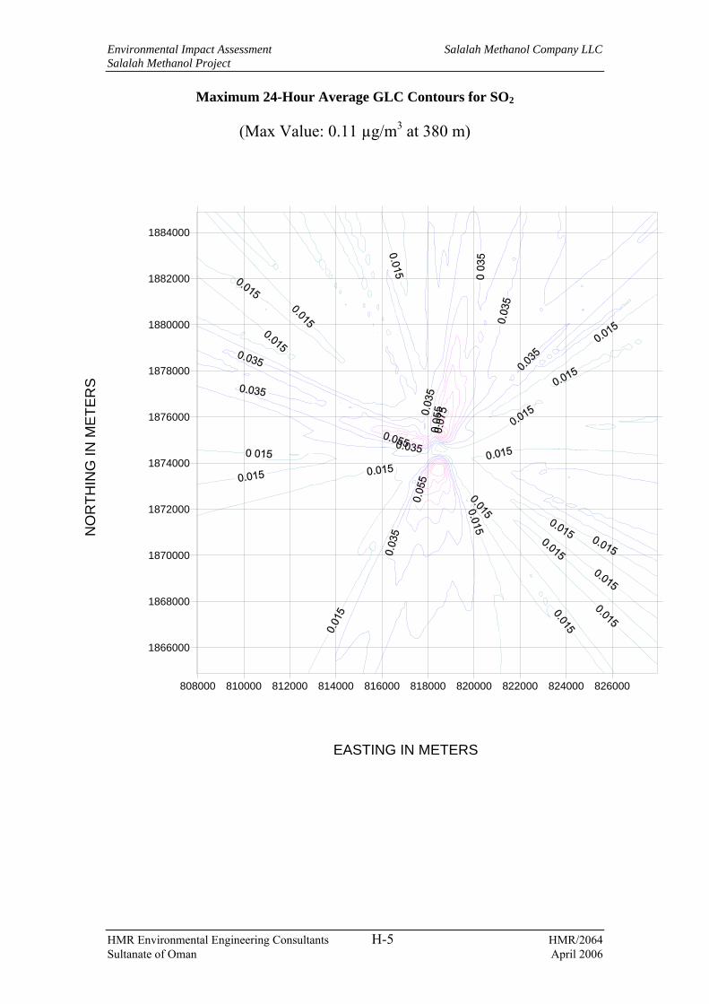
Environmental Impact Assessment Salalah Methanol Company LLC Salalah Methanol Project
HMR Environmental Engineering Consultants H-5 HMR/2064 Sultanate of Oman April 2006
Maximum 24-Hour Average GLC Contours for SO2
(Max Value: 0.11 µg/m3 at 380 m)
808000 810000 812000 814000 816000 818000 820000 822000 824000 826000
1866000
1868000
1870000
1872000
1874000
1876000
1878000
1880000
1882000
1884000
NO
RTH
ING
IN M
ETE
RS
EASTING IN METERS

Environmental Impact Assessment Salalah Methanol Company LLC Salalah Methanol Project
HMR Environmental Engineering Consultants H-6 HMR/2064 Sultanate of Oman April 2006
Annual Average GLC Contours for SO2
(Max Value: 0.03 µg/m3 at 750 m)
808000 810000 812000 814000 816000 818000 820000 822000 824000 826000
1866000
1868000
1870000
1872000
1874000
1876000
1878000
1880000
1882000
1884000
NO
RTH
ING
IN M
ETE
RS
EASTING IN METERS

Environmental Impact Assessment Salalah Methanol Company LLC Salalah Methanol Project
HMR Environmental Engineering Consultants H-7 HMR/2064 Sultanate of Oman April 2006
31
9
1011 12
22
ONE STOP SHOP
AREA = 10.62 Ha
LOB,
AREA = 4.2 Ha
23
SFZ ADMIN BUILDG.
17
13 1415
16
CIVIL DEFENCE
&
HEALTH BUILDG.
MOSQUESECURITY
18
1920 21
PORT AUTHORITY
200
METRESSCALE 1:400
0 100
GAS
METERING
WH
METHANOL
STORAGE
GH
300 400
SEAWATER
INTAKE
PIPELINE
500
AMMONIAFUTURE
METHANOLFUTURE

Environmental Impact Assessment Salalah Methanol Company LLC Salalah Methanol Project
HMR Environmental Engineering Consultants H-8 HMR/2064 Sultanate of Oman April 2006
31
9
1011 12
22
ONE STOP SHOP
AREA = 10.62 Ha
LOB,
AREA = 4.2 Ha
23
SFZ ADMIN BUILDG.
17
13 1415
16
CIVIL DEFENCE
&
HEALTH BUILDG.
MOSQUESECURITY
18
1920 21
PORT AUTHORITY
200
METRESSCALE 1:400
0 100
GAS
METERING
WH
METHANOL
STORAGE
GH
300 400
SEAWATER
INTAKE
PIPELINE
500
AMMONIAFUTURE
METHANOLFUTURE

Environmental Impact Assessment Salalah Methanol Company LLC Salalah Methanol Project
HMR Environmental Engineering Consultants H-9 HMR/2064 Sultanate of Oman April 2006
31
9
1011 12
22
ONE STOP SHOP
AREA = 10.62 Ha
LOB, AREA = 4.2 Ha
23
SFZ ADMIN BUILDG.
17
13 14 1516
CIVIL DEFENCE
&
HEALTH BUILDG.
MOSQUESECURITY
18
1920 21
PORT AUTHORITY
200
METRESSCALE 1:400
0 100
GAS
METERING
WH
METHANOL
STORAGE
GH
300 400
SEAWATER
INTAKE
PIPELINE
500
AMMONIAFUTURE
METHANOLFUTURE

Environmental Impact Assessment Salalah Methanol Company LLC Salalah Methanol Project
HMR Environmental Engineering Consultants H-10 HMR/2064 Sultanate of Oman April 2006
31
9
1011 12
22
ONE STOP SHOP
AREA = 10.62 Ha
LOB,
AREA = 4.2 Ha
23
SFZ ADMIN BUILDG.
17
13 1415
16
CIVIL DEFENCE
&
HEALTH BUILDG.
MOSQUESECURITY
18
1920 21
PORT AUTHORITY
200
METRESSCALE 1:400
0 100
GAS
METERING
WH
METHANOL
STORAGE
GH
300 400
SEAWATER
INTAKE
PIPELINE
500
AMMONIAFUTURE
METHANOLFUTURE

Environmental Impact Assessment Salalah Methanol Company LLC Salalah Methanol Project
HMR Environmental Engineering Consultants I-1 HMR/2064 Sultanate of Oman April 2006
Appendix I Input data for temperature and salinity dispersion modelling
The input data for salinity and temperature dispersion modelling are presented below.
Parameter Value Cross-section Unbounded Average depth 4 m Depth at discharge 3.7 m Ambient velocity 0.22 m/s Darcy-Weisbach friction factor 0.0340 Calculated from Manning's 0.03 Wind velocity 3 m/s Stratification Type unstratified Seawater density at point of discharge 1025 kg/m3 Nearest bank left Distance to bank 120 m Port diameter 1.22 m Port cross-sectional area 1.169 m2 Discharge velocity 2.29 m/s Discharge flow rate 2.68 m3/s20 Discharge port height 0.1 m Vertical discharge angle 0 deg Horizontal discharge angle 45 deg Discharge density 1022 kg/m3 Density difference -3 kg/m3 Buoyant acceleration 0.0287 m/s2 Discharge concentration 9oC (Temperature)
560 mg/L (Salinity) Toxic discharge No Water quality standard specified Yes Regulatory mixing zone Yes Regulatory mixing zone specification Distance Regulatory mixing zone value 300 m Region of interest 500 m
20 Calculated based on the effluent flow rates provided by SMC

Environmental Impact Assessment Salalah Methanol Company LLC Salalah Methanol Project
HMR Environmental Engineering Consultants J-1 HMR/2064 Sultanate of Oman April 2006
Appendix J Graphical representation of impact distances

Environmental Impact Assessment Salalah Methanol Company LLC Salalah Methanol Project
HMR Environmental Engineering Consultants J-2 HMR/2064 Sultanate of Oman April 2006