Environmental, Health and Safety Manual - Skanska EHS Manual Rev.0.204 6 Introduction Environmental,...
422
Environmental, Health and Safety Manual LGA CTB REPLACEMENT - SKB 1213126-000
Transcript of Environmental, Health and Safety Manual - Skanska EHS Manual Rev.0.204 6 Introduction Environmental,...
Environmental, Health and Safety
Manual
LGA CTB REPLACEMENT - SKB
1213126-000

Table of Contents
Introduction 6
Injury-Free Environment® 8
Environmental, Health and Safety Policy Statement 10
SHEMS 12
SHEMS Program 12
Identification and Management of EHS Impacts 15
Determining Legal and Other Requirements 21
Training 23
Communication 33
Incident Investigation 37
Audits 38
Nonconformance, Corrective Actions and Preventative Action 40
Emergency Preparedness 42
Management Review 44
Document / Record Control 47
Policies 50
Accountability Policy 50
Cell Phone/Tablets/Smart Device User Policy 53
Vehicle Policy 55
Fit For Duty Policy 60
Personal Protection Equipment (PPE) Policy 61

Stop Work Authority 64
EHS Policies Specific to Subcontractors 65
Substance Abuse Policy 72
Safety 76
Aerial Work Platforms 76
Concrete and Masonry 78
Confined and Enclosed Spaces 86
Cranes and Crane Rigging 95
Demolition 204
Dropped Object Protection 208
Electrical 210
Excavation and Trenching 216
Fall Prevention and Protection 223
Fire Prevention and Protection 230
Housekeeping 238
Illumination – Project Lighting 241
Lockout/Tagout 246
Maintenance and Protection of Traffic (Vehicular and Pedestrian) 256
Material Handling and Storage 265
Motor Vehicles and Mechanized Equipment 280
Pile Driving 285
Rigging 290

Scaffolds 295
Signs, Signals and Barricades 301
Stairways and Ladders 303
Steel Erection 312
Temporary Works 316
Tools – Hand and Power 319
Welding and Cutting (Hot Work) 324
Environmental 330
Potential and Unforeseen Upset Conditions (e.g., Spills/Leaks) 330
Archaeological, Cultural and Historic 334
Community Impacts: Transportation, Traffic Circulation and Economic 337
Community Impacts: Utilities 340
Flora, Fauna, Wetlands, and Habitat Areas 343
Hazardous Materials and Waste Management 346
Indoor Air Quality 350
Materials and Waste Management 352
Noise and/or Vibration 354
Outdoor Air Quality 357
Water Impacts 360
Health 364
Asbestos, Inclusive of Naturally Occurring Asbestos 364
First Aid/Emergency Services/Bloodborne Pathogens 369

Hazard Communication 374
Heat and Cold Related Illness 377
Heavy Metals (Lead, Arsenic, Cadmium, Hexavalent Chromium) 380
Noise Exposure 391
Polychlorinated Biphenyls (PCBs) 394
Radiation 400
Respiratory Protection 404
Sanitation 414
Silica 418

Project EHS Manual Rev.0.204 6
Introduction
Environmental, health and safety (EHS) are core values for Skanska, and are the foundations
for all policies, procedures, training programs, reporting requirements and incident response
plans. These are designed to ensure the health and safety of all site personnel and minimize
impacts on the surrounding community. Contractor’s senior management fully supports all
EHS initiatives and the enforcement of the policies set forth in this EHS Manual.
Skanska’s Safety, Health and Environmental Management System (SHEMS) ) provides the
format to conduct work on projects managed by Contractor in the context of increasingly
stringent legislation, the development of economic policies and other measures that foster both
safety and environmental protection. The program has been developed and is based on
continual improvement associated with increased concern expressed by interested stakeholders
regarding environmental matters and sustainable development.
The scope of Skanska’s Safety Health and Environmental Management System applies to all
sizes and types of projects where SkanskaMaintains operational and financial control.
The basis of Skanska’s approach depends on the commitment from all levels and functions of the
organization. A system of this kind enables an organization to:
Develop a safety, health and environmental policy that establishes objectives, targets and
processes to achieve the policy commitments
Take action as needed to improve its performance and demonstrate the conformity of the
system to the requirements of OHSAS 18001 and ISO 14001
The overall aim of this program is to promote safety, health and environmental protection, the
prevention of pollution and to address the socio-economic needs of the affected community.
Skanska’s EHS Manual will reflect all applicable legal and client requirements. The project
management will ensure that all members of the project team adhere to our SHEMS and all EHS
Manual requirements. Project management will have full access to Skanska’s national and
regional corporate environmental, health and safety staff in support of this program.
Our EHS professionals are trained in their field and will guide the project team in establishing
Skanska’s SHEMS, which is inclusive of measuring our environmental, health and safety
performance. Similar to production planning, the entire Skanska team will be involved in the

Project EHS Manual Rev.0.204 7
planning and implementation of Skanska’s SHEMS to ensure the project’s overall
environmental, health and safety success.
The entire Skanska team has extensive experience establishing and implementing Skanska’s
program on complex building and infrastructure projects in diverse geographical areas ranging
from urban areas to extremely rural areas. Adherence to Skanska’s standards for all employees
throughout all projects is integral to our success.
EHS POLICIES
These EHS policies address Skanska’s expectations to protect the environment and the health
and safety of everyone at or nearby Contractor project sites. To the extent these EHS policies
relate to Skanska employees, Skanska has direct responsibility for enforcing these policies.1 To
the extent the policies relate to subcontractors and their employees, workers or other personnel
on a site at the behest of a subcontractor, the subcontractors are responsible for ensuring that
their workers comply with these expectations.2
Skanska further reserves the right to supplement, modify or alter these policies at any time.
EHS Manual Definitions
The term “employee is defined as a person employed by Skanska, and, in the case of a joint
venture includes all individuals employed by the joint venture or working at a project on behalf
of the joint venture while remaining in the employ of a joint venture partner.
The term “subcontractor” is defined as a business or person of any tier below Skanska that
performs any part of the labor or material requirements of a contract for construction, alteration
or repair on the project.
1 As to Skanska employees, as stated in the applicable Employee Handbook, employment with Skanska is
employment at will. This means that employment may be terminated for any or no reason, with or without cause or
notice, at any time by an employee or by the Company. Nothing in this EHS Manual or in any other document or
oral statement shall limit the right to terminate at will. This employment at will policy is the sole and entire
agreement between any Skanska employee and Skanska, as to the duration of employment and the circumstances
under which employment may be terminated. 2 Nothing in the EHS Manual is intended to or should be deemed to give Skanska the right to control any site
personnel that are not Skanska employees. This EHS Manual does not create any joint employment relationship,
either direct or implied, between Skanska and any subcontractor worker.
Project EHS Manual Rev.0.204 8
The term “subcontractor employee” is defined as a person employed by a subcontractor. The
definition of project “subcontractor employee” shall apply to every tier of subcontractor, its
employees, independent contractors, agents, suppliers, and all workers who enter the project and
perform a portion of the contract involving labor.
The terms “site personnel” and “worker” are defined to include employees of Skanska as well as
subcontractor employees performing work at the project site. Subcontractors maintain all
responsibility for managing, controlling and setting the terms and conditions of work for
subcontractor personnel. To the extent that a subcontractor of any tier performs any part of the
contract scope of work, it assumes responsibility for complying with the applicable provisions of
this EHS Manual.
Injury-Free Environment®
In 2003, Skanska implemented an Injury-Free Environment (IFE®) initiative on all our projects.
IFE is the shared corporate and individual belief that safety is a value, not compromised by cost
or schedule. The program is designed to create for all workers a mindset intolerant of any
frequency or severity of injury or incident.
In our IFE, everyone involved on projects, from craft workers to our client partners, has
ownership of the safety program and is held accountable for its implementation. The core
principles of our IFE philosophies include:
All incidents and injuries are preventable
Injury-free operations are possible in construction
Safety awareness is personalized every day
Each worker is empowered and accountable to stop any unsafe act or condition on the
jobsite
We manage our IFE through training and participation. All subcontractors and workers entering
our jobsites are encouraged to attend IFE training, which focuses on workers’ personal
relationship to safety and three skills:
Assigning injury-free work
Recognizing and reinforcing safe work
Constructively correcting at-risk work

Project EHS Manual Rev.0.204 9
Prior to any work activity starting, a Construction Work Plan (CWP) will be completed to
identify specific hazards and controls related to the task.
Daily jobsite IFE activities begin with Stretch & Flex, a 10-minute stretching and calisthenics
program for all workers. Begun in 2004, Stretch & Flex is an energetic way for the entire team to
start the day and is followed by announcements or relevant toolbox talks. Crews then gather for a
Daily Hazard Analysis (DHA), a 10-15 minute documented conversation about the day’s
activities, associated hazards and plans to abate the hazards. Skanska superintendents and EHS
professionals perform daily worksite inspections to confirm DHAs and CWPs are completed and
implemented appropriately.
The effectiveness of our IFE program is measured through both leading and lagging indicators.
Lagging indicators, such as incident rates and lost time accident rates, capture industry-standard
safety statistics. Leading indicators, however, are more consistent with our IFE culture and
include measuring participation in Stretch & Flex, the number of people who have been trained
in IFE and the number of Executive Site Visits performed by Skanska leadership.

Project EHS Manual Rev.0.204 10
Environmental, Health and Safety Policy Statement
Skanska is attuned to the potential safety, health and environmental impacts of its operations and
activities. In keeping with Skanska AB policies, which are incorporated here by reference,
Skanska’s management has established, implemented and maintains a safety, health and
environmental management system to address these potential impacts and to carry out operations
and activities in a manner that is protective of human health and the environment. This
management system is designed to make safety, health and environmental care an integral part of
all projects and a responsibility of all employees and any persons working for, or on behalf of,
Skanska. It allocates appropriate resources and provides the training necessary to ensure the
attainment of safety, health and environmental objectives and targets.
Senior Skanska management is committed to keeping this system effective for its intended
purpose and to continually improving it as a framework to achieve the following results:
Regulatory Compliance
We will evaluate and comply with all applicable federal, state and local laws and regulations and
any other requirements at each location where we conduct business.
Prevention of Accidents
We will strive to identify and assess risk in all our activities and take actions to mitigate any
high-risk conditions.
Prevention of Pollution
We will seek first to cost-effectively avoid the creation of pollution and waste from our projects
and operations, and second, to manage remaining waste through safe and responsible methods.
Conservation
We will strive to reduce our consumption of natural resources through cost-effective use of
recycled and reused materials and conservation of energy and water.
Emissions and Effluents
Project EHS Manual Rev.0.204 11
We will work to diminish our emissions and effluents by employing cost-effective operational
controls, by diligently monitoring operational indicators and by implementing corrective and
preventive actions where necessary.
Ecology and Habitat
We will protect habitats, wetlands and other sensitive ecological resources in accordance with
applicable regulations and local ordinances.
Hazardous and Toxic Substances
We will exercise caution when using hazardous materials and not use toxic substances if we
cannot assess their human, ecological or environmental risks.
Communication
We will communicate this policy to all employees, make it available to the public and establish
procedures to receive and respond to inquiries from external interested parties. We will also alert
potentially affected individuals and authorities of any safety, health or environmental incidents in
a timely and effective manner. Thorough investigations will be conducted and corrective and
preventive actions implemented and monitored. Senior management at Skanska believes that
how we care for people and the environment today affects both current and future generations.
We accept our responsibility for doing our best to maintain awareness and to minimize adverse
safety, health and environmental impacts from our operations.
Sincerely,
Richard Cavallaro
EVP Skanska AB / President & CEO Skanska USA
January 1, 2015

Project EHS Manual Rev.0.204 12
SHEMS
SHEMS Program
Corporate Organization Structure
The overall structure for Skanska USA Inc. SHEMS management is shown below. The
organizational structure for each region will be carried out to the individual project level and
maintained throughout the life of the project.
Prior to the commencement of work on every project, a project-specific organization
structure/chart will be created. This document will be updated by the project team throughout the
life of the project.

Project EHS Manual Rev.0.204 13
Corporate Organization Chart

Project EHS Manual Rev.0.204 14
Richard Cavallaro
EVP Skanska AB
President/CEO Skanska USA
Paul Haining
Chief EHS Officer
Skanska USA
Paul Haining
Chief EHS Officer
Skanska USA
Scott MacLeod,
Co-COO, USB
FL,PR,NC,VA,SC,GA,SIS
VP EHS
SHEMS Coordinator
USA Buildings
Project SHEMS Coordinator
Rich Kennedy
Co-COO, USB
NY,NJ
VP EHS
SHEMS Coordinator
USA Buildings
Project SHEMS Coordinator
Paul Hewins
Co-COO, USB
PA,DE,TN,OH,IL
VP EHS
SHEMS Coordinator
USA Buildings
Project SHEMS Coordinator
Mats Johansson
Co-COO, USB
DC,MA,CT
VP EHS
SHEMS Coordinator
USA Buildings
Project SHEMS Coordinator
Dave Schmidt
Co-COO, USB
AZ,OR,WA,TX
VP EHS
SHEMS Coordinator
USA Buildings
Project SHEMS Coordinator
Len Vetrone
Co-COO, USB
CA
VP EHS
SHEMS Coordinator
USA Buildings
Project SHEMS Coordinator
Christian Deater
USA Building
SHEMS Coordinator
Clark Peterson
VP EHS
Skanska USA Civil
Mike Aparicio, EVP
Brian Stieritz, EVP
USAC - West
EHS Director
SHEMS Coordinator
Project SHEMS Coordinator
Denny Quinn, EVP
USAC - Midwest
EHS Director
SHEMS Coordinator
Project SHEMS Coordinator
Sal Taddeo, EVP (acting)
USAC - Southeast
EHS Director
SHEMS Coordinator
Project SHEMS Coordinator
Mike Viggiano, EVP
USAC - NE/Koch
EHS Director
SHEMS Coordinator
Project SHEMS Coordinator
Nick Bishop
USA Civil SHEMS Coordinator
Carol Whelan
USA Civil Systems Manager
Skanska USA EHS Executive Coordinator
William Flemming
President/CEO
Skanska USA Building
Mike Cobelli
President/CEO
Skanska USA Civil
Don Fusco
COO-West
Skanska USA Civil
Sal Taddeo
COO-East
Skanska USA Civil

Project EHS Manual Rev.0.204 15
Identification and Management of EHS Impacts
Objective
The objective is to identify the EHS impacts of Skanska’s activities, products and services and to
develop operational controls, indicators, measureable objectives and targets as defined in the
EHS Manual. This assessment will take into account our operations, subcontractor operations,
visitors and vendor activities. EHS impacts will be identified before the start of work and
updated as needed.
ISO/OHSAS References
ISO 4.3.1 Environmental aspects
ISO 4.3.3 Objectives, targets and programs
ISO 4.4.1 Resources, roles, responsibility and authority
ISO 4.4.6 Operational controls
OHSAS 4.3.1 Hazard identification, risk assessment and determining controls
OHSAS 4.3.3 Objectives and programs
OHSAS 4.4.1 Resources, roles, responsibility, accountability and authority
OHSAS 4.4.6 Operational controls
Procedure
Identifying EHS Impacts and Determining Significance
Prior to beginning work, project teams will identify and assess all potential EHS aspects and
impacts utilizing the PlanIt Tool. The following criteria establish the EHS aspects and impacts as
significant:
Any EHS impact with a regulatory requirement
An impact deemed significant by a client
Potential human exposure to a hazard

Project EHS Manual Rev.0.204 16
A solid waste stream that can be profitably recycled or reused related to a Skanska green
strategic indicator or initiative
Any situation that could result in adverse publicity or negative public opinion
The EHS Manual identifies the minimum requirements for all significant environmental aspects
and Health and Safety Hazards. For each EHS aspect and hazard identified, the project team will
customize the project EHS Manual and ensure the following items are included:
Significant Environmental Aspects Objectives
Quantifiable Environmental Targets (where practical)
Health and Safety Objectives
Operational controls
Performance indicators
Legal and other requirements
Roles and responsibilities
Documents and records
Training
Emergency response
Each project uses an integrated approach to manage the environmental, health and safety risks
associated with the project and the individuals below have been assigned specific responsibilities
associated with the management of the program.
Tasks Person Responsible Documents/Records/Performance
Indicators
Manage risk and mitigate
impacts associated with this
program
Project Manager,
Superintendent, Project
Engineer, EHS Professional
Management review results
Identify legal and other
requirements
Project Manager,
Superintendent, Project
Engineer, EHS Professional
Management review results
Identify and develop
applicable plans
Project Manager,
Superintendent, Project
Engineer, EHS Professional
Management review results
Identify employee training
needs
Project Manager,
Superintendent, Project
Training records

Project EHS Manual Rev.0.204 17
Tasks Person Responsible Documents/Records/Performance
Indicators
Engineer, EHS Professional
Facilitate training
Project Manager,
Superintendent, Project
Engineer, EHS Professional
Training attendance records
Implementation of programs
Project Manager,
Superintendent, Project
Engineer, EHS Professional
Management review results
Prepare Construction Work
Plan
Project Manager,
Superintendent, Project
Engineer, EHS Professional
Construction Work Plans
Review and approve
Construction Work Plan
Project Manager,
Superintendent, Project
Engineer, EHS Professional
Construction Work Plan sign-
offs
Conduct crew reviews
Project Manager,
Superintendent, Project
Engineer, EHS Professional
Crew review results
Required inspections
Project Manager,
Superintendent, Project
Engineer, EHS Professional
Inspection findings
Compliance audits
Project Manager,
Superintendent, Project
Engineer, EHS Professional
Audit findings
Subcontractor EHS Kick-off
Meeting Project Manager,
Superintendent, Project
Engineer, EHS Professional
Meeting minutes and attendance
records
For each individual construction activity (e.g., framing doors, installing fixtures, etc.), each
contractor will be provided Skanska’s electronic tool to develop a Construction Work Plan
(CWP) to mitigate EHS risks and impacts.
The Construction Work Plan will include:
A narrative description of each activity that details all elements of the task in a
sequential order inclusive of means and methods
Initial and residual risk
Triggers which include the task environment, equipment, materials and tools associated
a with the activity and controls to be implemented for risk mitigation
Project EHS Manual Rev.0.204 18
Identification of competent person(s)
Training requirements (documentation to be provided prior to work commencing)
All equipment, materials, small tools and safety equipment
Emergency action plan, including, but not limited to, fall protection rescue, confined
space rescue, SCBA standby, HazMat team, etc.
Additional information as required (drawings, SDS sheets, cut sheets, etc.)
The following hierarchy should be followed, in the prescribed order, when determining controls
for each trigger:
Elimination
Substitution (i.e., substitution of a product that is less hazardous, or using the same
product but in a different form)
Engineering Controls (i.e., fitting mufflers to equipment to reduce noise at source, use of
local exhaust ventilation systems, etc.)
Administrative Controls (e.g., utilizing enclosures, shift rotation, signage, barriers, etc.)
Personal Protective Equipment (PPE)
The CWP will determine the highest remaining risk level for each task, which will be
documented on the acknowledgement sheet that is attached to the Risk Assessment and Control
Worksheet. The risk levels will be classified as extremely high risk, high risk, moderate risk or
low risk.
Upon completion of the CWP, the risk assessment must be approved by an appropriate member
of the management team. Subcontractor management will approve their CWPs and submit to
Skanska project management for review prior to starting work. As the risk associated with the
task increases the authorization for the activity advances through the organizational structure:
Extremely high risk operation – never authorized
High risk operation – company officer (President or VP)
Moderate risk operation– Project Manager, Superintendent, and EHS
Low risk operation – Superintendent
Following the sign-off of the CWP, and before any activity begins, all crew members must be
given training on the plan requirements, and are to sign the acknowledgement sheet. A change in
conditions requires the plan to be updated and all crew members to be retrained.
Ongoing Risk Assessment

Project EHS Manual Rev.0.204 19
A Daily Hazard Analysis will:
Begin with a pre-shift meeting in the area where work is to be performed
Include communications from project management to crew from the morning’s/pre-shift
meeting
Should include a 360 degree look around
Be conducted by the foreman at the activity’s location to communicate the risks, hazards
and environmental aspects associated with the CWP
Discuss the required controls to ensure safe performance and mitigate any negative
impact to the environment
Address changing conditions including simultaneous operations or adjacent work
activities
Provide an opportunity for craft employees to provide feedback or concerns to project
management
Be turned in to the project superintendent, or their designee, at the end of each shift
Project management team will review the DHA, provide feedback at the next pre-shift meeting,
and address all EHS concerns.
Crew Reviews
Every two weeks the project team members are required to evaluate all foremen/crews as a
means to engage the whole team in EHS planning activities. The reviews should occur at the
beginning of the shift and should include the foremen and all of their crew members. Each
project shall create a rotating schedule to ensure that all project team members are involved in
assessing all crews. The crew review shall be documented and ensure that the CWPs are:
Current to the ongoing task
Taking into account any changing conditions (i.e., the triggers noted on the original plan
are still applicable)
Reviewed in the field and revisions provided prior to the next shift
Maintained in the project’s EHS files
Project management will address all EHS concerns, discuss findings, and provide revised CWPs
to crews as necessary.

Project EHS Manual Rev.0.204 20

Project EHS Manual Rev.0.204 21
Determining Legal and Other Requirements
Objective
The objective of this procedure is to provide projects with appropriate and relevant knowledge of
federal, state and local safety, health and environmental regulations that are applicable to the
hazards and environmental aspects of the activities and operations at their respective worksites.
ISO/OHSAS References
ISO 4.3.2 Legal and other requirements
OHSAS 4.3.2 Legal and other requirements
Procedure
Authority and Responsibility
In this project EHS Manual the project manager will assign roles and responsibilities to Skanska
personnel to ensure legal compliance on the project.
The project manager and designated SHEMS coordinator are responsible for maintaining
operations in compliance with all applicable legal requirements with the assistance of the EHS
Director.
The project manager/superintendent will ensure all personnel who perform work on our behalf
are adequately trained in the risks they are exposed. Likewise, subcontractors shall ensure that
their employees are adequately trained in the risks to which they are exposed.
During the management review process, if a change of activities or operations creates a new EHS
aspect or impact, the project manager will be responsible for identifying and enforcing all
applicable legal requirements.
Information on legal requirements can be obtained from multiple sources, including but not
limited to:
Construction Industry Compliance Assistance Center www.cicacenter.org
Environmental Law Net www.lawvianet.com
Environmental Protection Agency www.epa.gov

Project EHS Manual Rev.0.204 22
BLR Solutions for Skanska Safety and Environmental www.blr.com
American National Standards Institute www.ansi.org
Occupational Safety and Health Administration www.osha.gov
Skanska can also receive input on local ordinances and other requirements through legal
publications, bulletins, notices and person-to-person contact with local government agencies and
municipal officials. Skanska is responsible for identifying, processing and responding
appropriately to applicable municipal requirements.
If regulatory requirements change Skanska’s EHS programs will be updated accordingly. The
EHS Department transmits all new programs and requirements to the project manager, or his/her
alternate, who will initiate appropriate responses to ensure program implementation and
compliance. A log must be maintained to document all applicable legal requirement
updates/changes.
The EHS Department may prepare management instructions, handbooks, interpretive statements
and maintenance manuals to assist with legal compliance.

Project EHS Manual Rev.0.204 23
Training
Objective
EHS training will be conducted to ensure that employees understand how to execute their tasks
safely while also protecting the environment.
ISO/OHSAS References
ISO 4.4.2 Competence, training, and awareness
OHSAS 4.4.2 Competence, training, and awareness
Procedure
These are minimum training requirements and are not intended to be all-encompassing. Training
requirements are also referenced in the individual EHS aspects, CWPs and other EHS
documents.
Prior to engaging in work, all employees will be trained on the EHS impacts of the tasks being
performed. Likewise, all Subcontractors shall cause all workers to be trained on applicable EHS
impacts of the tasks performed by those workers.
Project Orientation Training
All site personnel will receive project-specific orientation upon arrival at the project site.
IFE Trainings
IFE training is required for all individuals working on Skanska projects
Consult the regional EHS Director for current IFE training requirements
Awareness Training
The objective of awareness training is to enable employees to recognize potential EHS impacts
and to understand Skanska’s policies as defined in this EHS Manual. Workers roles and
responsibilities will be communicated during awareness training conducted by Skanska or the
subcontractor, as applicable.

Project EHS Manual Rev.0.204 24
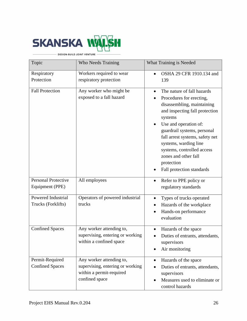
A baseline training matrix has been developed (see below) to determine minimum training
requirements within the organization. The training identified in the matrix is not intended to be
all-inclusive. Specific awareness training will be identified at the operating unit level.

Project EHS Manual Rev.0.204 25
Training Matrix
Topic Who Needs Training What Training is Needed
Project Specific EHS
Orientation
All project management,
supervision, and workers
entering the project
At a minimum the training must
cover following Skanska’s Corporate
Policies:
IFE
SHEMS Awareness
Accountability
Anti-harassment
Environmental aspects
Expectations for Stretch and
Flex and
Code of conduct
Ethics
Site specific information may
include:
Site Emergency Action Plan,
Site Specific and Owner
Requirements,
OSHA 10/30hr Construction
Outreach Training
requirements
Fall Protection General
Awareness Training
Hazard
Communication
All workers entering the project Hazard Communication Basic
Training
Hazardous Chemical
or Substance
Workers exposed to hazardous
chemicals or substances such as
paints, solvents, lead, silica and
asbestos.
Specific Hazard Training
Project EHS Manual Rev.0.204 26
Topic Who Needs Training What Training is Needed
Respiratory
Protection
Workers required to wear
respiratory protection
OSHA 29 CFR 1910.134 and
139
Fall Protection Any worker who might be
exposed to a fall hazard
The nature of fall hazards
Procedures for erecting,
disassembling, maintaining
and inspecting fall protection
systems
Use and operation of:
guardrail systems, personal
fall arrest systems, safety net
systems, warding line
systems, controlled access
zones and other fall
protection
Fall protection standards
Personal Protective
Equipment (PPE)
All employees Refer to PPE policy or
regulatory standards
Powered Industrial
Trucks (Forklifts)
Operators of powered industrial
trucks
Types of trucks operated
Hazards of the workplace
Hands-on performance
evaluation
Confined Spaces Any worker attending to,
supervising, entering or working
within a confined space
Hazards of the space
Duties of entrants, attendants,
supervisors
Air monitoring
Permit-Required
Confined Spaces
Any worker attending to,
supervising, entering or working
within a permit-required
confined space
Hazards of the space
Duties of entrants, attendants,
supervisors
Measures used to eliminate or
control hazards

Project EHS Manual Rev.0.204 27
Topic Who Needs Training What Training is Needed
Air monitoring requirements
Emergency procedures/rescue
equipment
Communications
Permitting procedure
PPE
Excavations/Trenches Workers entering or working
within an excavation/trench
Hazards of the space (slides,
cave-ins, water accumulation,
etc.)
Safe means of access/egress
Proper support system
procedures (erection,
maintenance, disassembly
and inspection)
Lockout/Tagout Workers affected by hazardous
energy sources
Nature of known hazardous
energy sources
Project-specific
Lockout/Tagout procedures
Gas/Arc Welding &
Cutting
Workers conducting welding
and/or cutting
Procedures for unattended
machines and electrode
holders
Operations around water
Shielding arc welding
The safe use of fuel gas
Respiratory training
Occupational exposure
training (i.e. lead, welding
fumes, hexavalent
chromium)
Hot Work Workers conducting hot work Hazards of the area

Project EHS Manual Rev.0.204 28
Topic Who Needs Training What Training is Needed
activities Permits
Duties of fire watch
How to use a fire
extinguisher
Scaffolding Workers working from
scaffolding
The nature of any known
hazards
Proper erection, maintenance
and disassembly of fall
protection systems
Falling object protection
Material/equipment handling
from scaffold
Maximum load-carrying
capacity
Scaffold tagging system
Access and egress
Crane Suspended
Personnel Baskets
Workers working from crane
baskets
Safety work rules
100% fall protection
Lift plans contents
Emergency procedures
Shipyards and Vessel
maintenance
Workers performing
maintenance of vessel, to
include floating cranes, whether
at our site or at a shipyard
Requirements of OSHA 29
CFR 1915 and 1926
Marine Operations Employee working on or in the
immediate vicinity of barges
and other marine equipment
Marine operations
Man-overboard procedures
Vessel access
Safety equipment (life buoy,
PFD, safety skiff)
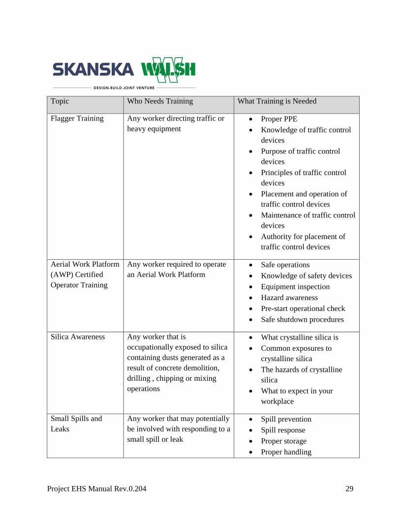
Project EHS Manual Rev.0.204 29
Topic Who Needs Training What Training is Needed
Flagger Training Any worker directing traffic or
heavy equipment
Proper PPE
Knowledge of traffic control
devices
Purpose of traffic control
devices
Principles of traffic control
devices
Placement and operation of
traffic control devices
Maintenance of traffic control
devices
Authority for placement of
traffic control devices
Aerial Work Platform
(AWP) Certified
Operator Training
Any worker required to operate
an Aerial Work Platform
Safe operations
Knowledge of safety devices
Equipment inspection
Hazard awareness
Pre-start operational check
Safe shutdown procedures
Silica Awareness Any worker that is
occupationally exposed to silica
containing dusts generated as a
result of concrete demolition,
drilling , chipping or mixing
operations
What crystalline silica is
Common exposures to
crystalline silica
The hazards of crystalline
silica
What to expect in your
workplace
Small Spills and
Leaks
Any worker that may potentially
be involved with responding to a
small spill or leak
Spill prevention
Spill response
Proper storage
Proper handling

Project EHS Manual Rev.0.204 30
Topic Who Needs Training What Training is Needed
Hazard identification
Rigging Any worker involved with
standard, major or critical lifts
Rigging plans
Load characteristics
Equipment requirements
Environmental factors
Inspections
Lift preparation
Role of the rigger
Types of slings, shackles
Communication systems
Hand/Voice
Signaling
Any worker involved with
communicating with heavy
equipment operators to facilitate
the movement of materials or
equipment
Rigging awareness
Equipment
capabilities/limitations
Hand signals
Voice commands
Accident
Investigations
Anyone participating in
accident/incident investigations
How to respond to different
types of accidents
Conducting an investigation
Techniques to get accurate
results when interviewing
witnesses
Documenting findings and
corrective actions
Assessing accuracy of
findings and effectiveness of
corrective actions
Implementing improvements
Competency Training
Project EHS Manual Rev.0.204 31
Competency training is not the same as an OSHA competent person. Competency training is the
minimum training that each employee must complete before beginning an assigned task or
function.
CWPs will be used as the basis for competency training. Any further training will be identified
as part of the CWP process. Skanska and Subcontractors will ensure employees have received
training prior to commencing an activity, and likewise subcontractor training will be subject to
verification by Skanska at its discretion.
All site personnel will be trained on:
The scope of work for the activity
Associated hazards
Environmental aspects
Engineering and/or administrative controls
Specific PPE requirements
Emergency action plan
Additional Training Requirements
All Skanska salaried personnel with field operation responsibilities must complete one web-
based safety training module each month. Each module is valid for five years.
All Skanska employees identified as competent persons on the Construction Work Plan are
required to complete all associated web-based training modules or an equivalent program,
approved by the local EHS Director. All training must be renewed every five years.
All Skanska salaried personnel with field operation responsibilities must complete OSHA 30
training. After initial OSHA 30 training, OSHA 10 training must be completed every five years.
Enter project-specific training requirements
Documentation
All training will be documented
Training records will be maintained for the length of the job and thereafter will be stored
with the project files and/or at regional EHS office
Subcontractor employee training records will be subject to verification by Skanska at its
discretion throughout the duration of the project

Project EHS Manual Rev.0.204 32

Project EHS Manual Rev.0.204 33
Communication
Objective
The objective of this procedure is to communicate our concern for the safety of all personnel, the
environment, and our desire to conduct business operations in a safe and environmentally sound
manner to all employees, owners, suppliers and contractors.
An additional objective is to communicate specific procedures and requirements to those owners,
suppliers and subcontractors that provide goods and services associated with significant
environmental aspects or known hazards.
All written, external input regarding safety, health and environmental performance will be
considered as being from an interested party. All such input will be processed in accordance with
this procedure.
ISO/OHSAS References
ISO 4.4.3 Communication
ISO 4.5.2 Evaluation of Compliance
OHSAS 4.4.3 Communication, Participation and Consultation
OHSAS 4.5.2 Evaluation of Compliance
Procedure
Internal Communication
Skanska will communicate the following to employees:
Skanska’s Environmental, Health and Safety (EHS) policy and relevant sections of the
SHEMS will initially be communicated through SHEMS awareness training
Any changes to the SHEMS will be communicated to employees as needed by senior
management
Each Skanska region will create a Corporate EHS Leadership Team that meets on a monthly
basis to set goals, policies, and programs. Meetings may be held via teleconference; however the
team must meet in person at least once a quarter.
Project EHS Manual Rev.0.204 34
Meetings shall be led by a member of the senior executive management team responsible for the
region (e.g., Executive Vice President, Chief Operating Officer or General Manager) and shall
include Contractor EHS Directors, Project Executives, Account Managers and Superintendents,
as applicable.
All projects will also establish a Project EHS Leadership Team, inclusive of all levels of project
management and craft for both Skanska and subcontractors. The team shall meet monthly and
will:
Review all incidents
Discuss job environmental, health, and safety performance
Conduct a site inspection - all potential hazards/risk identified must be addressed at the
time of the inspection and document closure if possible
Assess committee’s site inspection to the EHS Monthly Compliance Audit to evaluate
potential trends and repetitive items.
Hold special meetings when warranted and after all lost-time incidents
Utilize Project SHEMS Leadership Team agenda and maintain meeting minutes
Report program status to the regional office management team
External Communication
Skanska will communicate the following information to external parties:
Our concerns about EHS issues and desires to conduct business operations in a safe and
environmentally sound manner
That we have an EHS Management System that is based on ISO-14001/OHSAS-18001
and that has been registered with an accredited ISO-14001/OHSAS-18001 Registrar
That we encourage our owners, suppliers and contractors to provide, at the same quality
and price, products and services that have safe working conditions and the least
environmental consequence of all available options
Relevant sections of the SHEMS will be communicated to subcontractors during the contract
award process, orientation training and SHEMS Awareness Training.
Skanska will communicate the following to suppliers:

Project EHS Manual Rev.0.204 35
Where a supplier’s product is creating a significant EHS hazard, Skanska will
communicate to that supplier that, where possible, they should select the available option
that minimizes the potential environmental impact or safety hazard of that product
Where an owner, supplier or contractor is supplying goods or services associated with
EHS aspects, the project will work with procurement to inform that supplier or
contractor of applicable requirements to mitigate, minimize, or otherwise control the
potential EHS impacts
Communications with owners, suppliers, and contractors form part of the subcontract agreement.
All written, external inquiries concerning EHS performance will be directed to the corporate
EHS Department and, when appropriate, to the Communications Department, which will:
Coordinate with the Operating Unit/Region’s most senior EHS representative to evaluate
the substance of the external communication
The Operating Unit/Region’s most senior EHS representative will make a determination
of whether the communication pertains to an existing significant aspect or hazard, or to
one that may need to be added into the SHEMS
Following this evaluation, the EHS department, or designee, will respond appropriately
to the external interested party
The response will be timely
All external communications will be kept for consideration when establishing and
reviewing safety and environmental objectives and targets for the SHEMS and will
initiate any necessary changes to the SHEMS
Documentation
Corporate EHS Leadership Team meeting documentation will be maintained at the regional
office.
Project EHS Leadership Team meeting documentation will be maintained with the project
records.
The EHS Department will document the contents of the external communication, the evaluation
of its content, the decision taken on any changes to the SHEMS and the contents of the reply to
the external interested party. Records pertaining to these communications will be kept in the
EHS Department.

Project EHS Manual Rev.0.204 36

Project EHS Manual Rev.0.204 37
Incident Investigation
Objective
Skanska will conduct an incident investigation following all EHS incidents that occur on a
project in order to identify root causes, develop corrective and preventive actions and
communicate lessons learned to prevent future occurrences.
ISO/OHSAS References
ISO 4.5.3 Nonconformity, Corrective Action and Preventive Action
OHSAS 4.5.3 Nonconformity, Corrective Action and Preventive Action
Procedure
Following an incident of any severity level, including near miss, project management and/or a
Skanska EHS representative will investigate the incident. The investigation will:
Provide a specific description of the incident, including any underlying deficiencies, root
causes and other factors that may have caused or contributed to the incident
Identify the need for corrective action and preventative action
Identify opportunities for continual improvement
Communicate preventative actions and lessons learned
All serious accidents, near misses, lost time accidents, potential fatalities, and serious
environmental breaches must be followed by a Flash Report
EHS Directors will review preventative actions to determine effectiveness and initiate policy
changes when necessary.
If the incident investigation identifies a process or procedural failure, it will be addressed in
accordance with the nonconformance, corrective action and preventive action section.
Documentation
All incident investigation documentation will be maintained in Skanska’s web-based reporting
database.
Project EHS Manual Rev.0.204 38
Audits
Objective
The objective of this procedure is to provide guidance for conducting SHEMS audits at our
jobsites, which determine proper implementation and maintenance of both the ISO 14001 &
OHSAS 18001 standards as well Skanska policies and procedures.
ISO/OHSAS References
ISO 4.5.5 Internal Audit
OHSAS 4.5.5 Internal Audit
Procedure
Internal audits will be conducted annually on all projects that are three months or greater in
duration. An audit checklist will be utilized to assess conformance to the standards. Findings
identified during the assessment will be documented in accordance with the Non-Conformance,
Corrective Action and Preventative Action process.
Auditors will rely on records for information related to the functioning of the SHEMS and its
objectives and targets. Auditors will also rely on employee interviews, observations of operating
conditions to gauge EHS status and conditions on a site.
Responsibilities
EHS
Maintain a list of projects that qualify for audits
Maintain a schedule of audits
Select the auditor/audit team to ensure objectivity
Maintain documentation of auditor training
Be the point of contact for all communications with the registrar inclusive of scheduling
the external audits
Coordinate external audit closing meeting (in person or via teleconference) with the
respective Business Unit (BU) Senior Management Team and the project teams

Project EHS Manual Rev.0.204 39
Communicate all external audit reports to respective BU’s inclusive of any potential
non-conformances and corrective actions required to be taken by the affected BU
Ensure all findings are documented and closed out
Maintain audits
Auditor/Audit Team
Auditors will receive auditor training and will have relevant work experience of at least five
years in EHS management. The audit may be conducted by a sole auditor or by a team. If
conducted by a team, a lead auditor will be designated. The auditor/audit team is responsible for
issuing/distributing a formal audit report within five working days to the following:
The project team (inclusive of all who attended either the opening or closing meeting,
Vice President/Project Executive, Project Manager, General Superintendent)
Regional EHS leads
Corporate EHS
Documentation
All audit records will be maintained in Skanska’s web-based reporting database.

Project EHS Manual Rev.0.204 40
Nonconformance, Corrective Actions and Preventative Action
Objective
Following any deviations from established procedures and programs related to the SHEMS or
whenever a non-conformance in the SHEMS is detected, a corrective and preventive action
report will be completed.
ISO/OHSAS References
ISO 4.5.3 Nonconformity, Corrective Action and Preventive Action
OHSAS 4.5.3 Nonconformity, Corrective Action and Preventive Action
Classifications for Nonconformance
Major Nonconformance Classification
Report any systemic failure in the implementation of the SHEMS. For example:
Environmental aspects and hazard identification is not taking place
Required documents not maintained
Construction planning, monitoring and measuring are not being implemented or partially
being implemented at site
Training/management review/EHS meetings not being conducted as per procedure
Several similar minor nonconformance in documentation and/or implementation in a
specific procedure or element of the ISO/OHSAS Standards
Minor Nonconformance Classification
A single observed nonconformance to the SHEMS that is not considered to be a breakdown. For
example:
Obsolete versions of policy are observed at the site
Gaps in documented evidence of conformance
Obsolete versions of SHEMS and its controlled documents are being utilized
Orientation not being conducted timely and consistently
Roles and responsibilities have not been defined/communicated

Project EHS Manual Rev.0.204 41
Opportunity for Improvement (OFI) Classification
A finding not determined to be a nonconformance but that could be an enhancement of EHS
programs.
Event
This is an unanticipated occurrence onsite that has the potential to become a nonconformity if
not addressed.
Procedure
The project team is responsible for responding to a nonconformance
Nonconformance will be addressed at monthly SHEMS management review meetings
The auditor/audit team is responsible for issuing/distributing a formal audit report within
five working days to the following:
- The project team (inclusive of all who attended either the opening or closing
meeting, Vice President/Project Executive, Project Manager, General
Superintendent)
- Regional EHS leads
- Corporate EHS
Within five days of the auditor’s findings being reported, the project team will complete
and submit for approval a corrective action report (CAR), which includes a root cause
analysis and corrective and preventive actions required to mitigate the nonconformance
The project team is responsible to ensure that the correction is completed
Any corrective action taken to eliminate the cause of nonconformance will be
appropriate to the magnitude of the finding
When additional time is required to complete the investigation and to identify corrective
and preventive actions, the project team will notify their EHS Director who will
determine the timeline for completion of the CAR
Preventative and corrective actions will be reviewed at the management review meetings
to assess implementation and effectiveness with revisions made as needed

Project EHS Manual Rev.0.204 42
Emergency Preparedness
Objective
Skanska will implement procedures to identify and respond to an EHS emergency in order to
minimize the potential negative impact. Each project will be responsible for coordinating its
emergency response procedures.
ISO/OHSAS References
ISO 4.4.7 Emergency Preparedness and Response
OHSAS 4.4.7 Emergency Preparedness and Response
Procedure
Each project team will:
Consider all activities and hazards when developing the project-specific Emergency
Action Plans (EAP) and Environmental Compliance Plans (ECP)
Identify a local environmental response contractor
Provide the necessary resources and equipment available to manage minor EHS
incidents (first aid kits, spills kits, properly trained personnel, etc.)
Post emergency phone numbers in visible locations on site
Communicate the plan to all site personnel
The EAP will include:
Emergency escape routes
Emergency signals
Assembly points
Spill kit locations
Designated lines of authority
The plan will be tested at least every six months. Following any emergency response or drill, a
debrief will be conducted to determine if EAP is effective.

Project EHS Manual Rev.0.204 43
Documentation
All EAP training, the critique of all emergency drills, and incident reports will be recorded and
maintained with the project records.

Project EHS Manual Rev.0.204 44
Management Review
Objective
This procedure specifies senior management review of the Safety, Health and Environmental
Management System (SHEMS) at planned intervals to ensure its continuing effectiveness,
suitability and adequacy, and provides for its continual improvement at the corporate and project
level.
ISO/OHSAS References
ISO 4.5.1 Monitoring and Measurement
ISO 4.5.2 Evaluation of Compliance
ISO 4.6 Management Review
OHSAS 4.5.1 Monitoring and Measurement
OHSAS 4.5.2 Evaluation of Compliance
OHSAS 4.6 Management Review
Procedure
Skanska USA Senior Leadership Team, together with members of the USA EHS
Leadership Team, will conduct a Business Unit Annual Management Review at internals
not to exceed twelve months.
The EHS Leadership Team will conduct a Regional/Operating Unit Management
Review at internals not to exceed twelve months.
Each Project Team will conduct a Monthly Management Review
Skanska will establish annual engagement targets will generally be set at this meeting
All non-project based executives and above will attend a minimum of four project Monthly
Management Review Meetings per year
Project based executives are required to attend their own project’s Monthly Management Review
Meeting in addition the executives are required to attend to 4 peer project’s Monthly
Management Review Meeting’s

Project EHS Manual Rev.0.204 45
Records will be kept of each management review utilizing designated agendas. The respective
EHS Director or designee will prepare the necessary content to be considered in the regional
review and will give recommendations for improvement.
The following items will be addressed at each SHEMS Management Review Meeting:
Review of monthly or annual goals
- This is to include discussion as to whether monthly or annual objectives and targets
are being met. Where issues are detected, alternative solutions should be discussed
with a goal of improving performance
Open items from previous management review
- Previous minutes are to be reviewed. All outstanding action items are to be
discussed and documented with status updates
SHEMS audit results
- Discussion shall include results of previous internal/external audits, review and
update of any corrective and preventive actions that were implemented as a result of
previous audits and date for next audits
Review of SHEMS procedures
- Ensure all aspects of the management system are in place and effective. EHS
risks/aspects identified in the project specific EHS Manual are to be reviewed to
ensure that they are current and up-to-date. Where changes are needed, these
documents are to be updated in the PlanIt tool.
Monitoring and measurement of EHS indicators
- A minimum of 4 aspects/hazards identified in the project’s EH&S Manual specific
to existing or upcoming work are to be reviewed.
- The project team will review the leading and lagging indicators to determine if
controls are effective and objectives and targets are being met.. Where indicators are
found to be ineffective, a plan will be implemented to improve performance. Action
items, responsibilities and dates should be noted in the review minutes
- The project team will review the previous months EHS compliance audit to ensure
legal compliance
- The project team will review and ensure that all monitoring equipment used at the
project site is calibrated per manufacturer’s requirements. Records are to be
maintained at the project site
Correction and prevention of nonconformance
Project EHS Manual Rev.0.204 46
- Management will review corrective and preventive actions and address CARs with
open items
- Management will review corrective and preventive actions to determine
effectiveness and noted in the meeting minutes. Where corrective and preventive
actions are found to be ineffective, a plan will be implemented to improve
performance. Action items, responsibilities and dates should be noted in the review
minutes
- Confirm project review of other locations' Flash Reports and determine if applicable
to project; if so, develop a plan to implement, monitor and measure.
Consider and recommend opportunities for improvement, changes to policies and any
other relevant information regarding the SHEMS
o Ensure recommendations are communicated to the Operating Unit/Region EHS
Leads for consideration for changes to the Skanska SHEMS.
Discuss any relevant communication from external interested parties, including
complaints for the previous month
o This includes inquiries from owners, clients, unions or surrounding community.

Project EHS Manual Rev.0.204 47
Document / Record Control
Objective
The purpose of this procedure is to ensure that only authorized and current documents are used to
implement the requirements and that records are properly prepared, maintained, retained and
disposed.
ISO/OHSAS References
ISO 4.4.5 Control of documents
ISO 4.5.4 Control of records
OHSAS 4.4.5 Control of documents
OHSAS 4.5.4 Control of records
Procedure
The following is to outline protocols that apply to potential changes that may be needed to
effectively implement the EHS Manual at all levels.
The EHS Manual and all associated documents will be controlled at the corporate level
All projects will implement the most current version of the EHS Manual
Skanska will maintain a national library for all current documents that are applicable to
the implementation of the EHS Manual. The library will be managed by the EHS
Leadership team.
EHS related documents will be reviewed periodically and revised as needed by the EHS
Leadership team
Updated documents will be communicated by the EHS Leadership Team to project
teams
Regional specific addenda to the EHS Manual will be identified as such and maintained
at the regional level by the EHS Director
Project-specific documents will be identified and maintained at the project level
Documentation
All documents and records will be legible, identifiable and easily retrieved for review

Project EHS Manual Rev.0.204 48
Documents and records will be maintained at all projects through a combination of hard
copies and electronic copies
All documents and records will be retained through the life of the project or otherwise as
required by law or by contract.
ISO 14001/OSHAS 18001 Standards SHEMS Procedures Correlation Table
ISO 14001-2004 Elements BS OHSAS 18001-2007 Elements SHEMS Section
4.1 General requirements Stated
4.2 Environmental Health & Safety Policy Statement Stated
4.3 Planning
4.3.1 Environmental aspects 4.3.1 Hazard identification, risk assessment and determining controls
Identification and Management of EHS Impacts
4.3.2 Legal and other requirements 4.3.2 Legal and other requirements Determining Legal and Other Requirements
4.3.3 Objectives, targets and programs
4.3.3 Objectives and programs Identification and Management of EHS Impacts
4.4 Implementation and operation
4.4.1 Resources, roles, responsibility and authority
4.4.1 Resources, roles, responsibility, accountability and authority
Identification and Management of EHS Impacts
4.4.2 Competence, training and awareness
4.4.2 Competence, training and awareness
Training
4.4.3 Communication 4.4.3 Communication, participation and consultation
Communication
4.4.4 Documentation 4.4.4 Documentation Applicable documentation defined in specific procedure
4.4.5 Control of documents 4.4.5 Control of documents Document/Record Control
4.4.6 Operational control 4.4.6 Operational control Identification and Management of EHS Impacts
4.4.7 Emergency preparedness and response
4.4.7 Emergency preparedness and response
Emergency Preparedness
4.5 Checking

Project EHS Manual Rev.0.204 49
4.5.1 Monitoring and measurement 4.5.1 Monitoring and measurement Management Review
4.5.2 Evaluation of compliance 4.5.2 Evaluation of compliance Communication,
Management Review
4.5.3 Nonconformity, corrective action and preventive action
4.5.3 Incident investigation, nonconformity, corrective action and preventive action
Incident Investigation,
Nonconformance, Corrective Actions and Preventative Action
4.5.4 Control of records 4.5.4 Control of records Document/Record Control
4.5.5 Internal audit 4.5.5 Internal audit Audits
4.6 Management review Management Review

Project EHS Manual Rev.0.204 50
Policies
Accountability Policy
Objective
This Accountability Policy details the minimum standards all personnel (located at the site or
otherwise) are required to observe regarding EHS issues. Regional policies may exceed the
minimum requirements as the region deems necessary.
Adherence to EHS Policies Regarding Dangers
That ARE Immediately Dangerous to Life and Health
All personnel shall adhere to all EHS policies that protect against immediate dangers to life and
health. Examples of such policies include, but are not limited to, those regarding fall protection,
exposure to electricity, caught in-between hazards, struck by hazards, lockout/tag out hazards,
exposure to unsafe trench excavation, failure to locate utilities pre-excavation, use of ear buds
and confined space hazards. While Contractor does not generally follow a progressive
disciplinary practice, Contractor employees are, except as otherwise agreed in an applicable
Collective Bargaining Agreement (CBA) or Project Labor Agreement (PLA), subject to the
following disciplinary actions for violations of any EHS policy designed to protect against
immediate dangers to life and health
1st Offense: Three (3) -day suspension without pay
2nd Offense: Twenty (20) day suspension without pay
3rd Offense: Termination
Contractor may impose more serious penalties upon its offending employees if it deems such
action to be appropriate for violations covered by this provision.
Subcontractors are likewise responsible for disciplining subcontractor workers who fail to adhere
to applicable EHS policies and rules set forth in this EHS Manual, provided that Contractor may
take actions necessary to address imminent threats to life and health and, if a subcontractor fails
to take timely or appropriate corrective action, Contractor may, consistent with the terms of the
Project EHS Manual Rev.0.204 51
applicable subcontract, bar from the project site any such subcontractor worker who poses a
safety risk to the project.
Adherence to EHS Policies Regarding Activity
NOT Immediately Dangerous to Life and Health
AllSite personnel shall adhere to all EHS policies, including, but not limited to PPE
requirements, equipment/tool inspections, use of tools, rebar caps, and housekeeping.
While Contractor does not generally follow a progressive disciplinary practice, Contractor
employees are, except as otherwise agreed in an applicable CBA or PLA, subject to the
following disciplinary actions for violations of any EHS policy that is not designed to protect
against immediate dangers to life and health:
1st Offense: Written reprimand
2nd Offense: One (1) day suspension without pay
3rd Offense: Three (3) day suspension without pay
Contractor may impose more serious penalties upon its offending employees if it deems such
action to be appropriate for violations covered by this provision.
Subcontractors are likewise responsible for disciplining subcontractor workers who fail to adhere
to applicable EHS policies and rules set forth in this EHS Manual, provided that Contractor may
take actions necessary to address imminent threats to life and health and, if a subcontractor fails
to take timely or appropriate corrective action, Contractor may, consistent with the terms of the
applicable subcontract, bar from the project site any such subcontractor worker who poses a
safety risk to the project.
Imposition of Discipline on Contractor Employees
The level of offense will be considered over a rolling one (1) year period looking back from the
date of each offense.
The foregoing discipline policy shall be applicable to all supervisory personnel in
relation to their respective obligation to properly and adequately manage their workforce
so that it conducts itself in a safe manner and in accordance with this EHS policy.
Accordingly, should employees under the management of supervisory personnel commit
multiple (i.e. more than one (1)) IDLH or non-IDLH offense as stated above during a

Project EHS Manual Rev.0.204 52
given one (1) year period, said multiple offenses may be construed as a violation of the
workplace rule requiring supervisors to properly manage and maintain a safe working
environment in accordance with this EHS policy and may result in the supervisor being
subject to discipline as set forth herein.
With respect to supervisory personnel being indirectly associated with any single EHS
policy violation constituting a danger that is either an IDLH or non-IDLH by employees
under his or her direct or indirect supervision and management, the supervisor may be
disciplined by way of no less than a five (5) day suspension without pay. However,
shorter suspension periods without pay for the supervisor may be considered in such
situations after consultation with the Human Resources and Legal Departments.
The above is the minimum guideline. All offenses will be reviewed and more
severe discipline may be implemented when conditions warrant.
Prior to any discipline being implemented, the proposed disciplinary action
should be discussed with Human Resources and approved at or above the Project
Executive level. The level of discipline imposed should then be documented for
the employee file.
All disciplinary actions resulting in a suspension are to be reviewed and approved
by the Senior Leadership Team (SLT) and the local HR representative (in
consultation with the Legal Department).
Contractor employees that are terminated for EHS non-compliance will not be
deemed eligible for rehire for a minimum of six (6) months. The rehire of
employees terminated for failure to comply with EHS policies requires Contractor
approval at the senior management level and such decision shall be made in
consultation with HR.
If in the judgment of the Contractor’s project team, the extenuating circumstances of an
individual incident warrant not adhering to the guidelines above, the team can petition an
appropriate member of Contractor’s senior management for relief from the guidelines. Only a
Project EHS Manual Rev.0.204 53
member of Contractor’s senior management, in consultation with Contractor’s Legal Department
and HR, can authorize deviations from these guidelines, except as expressly provided above.
Cell Phone/Tablets/Smart Device User Policy
Objective
When site personnel use communication technology on project sites, they are expected to utilize
it in a safe, prudent manner that in no way jeopardizes the safety of themselves or others or puts
equipment, facilities or other materials at risk.3
Legal and Other Requirements
All site personnel shall comply with all applicable federal, state and local laws and regulations
regarding the use of cell phones/smart device usage while driving.
3 In the event this Policy is inconsistent with any information in any Skanska Employee Handbook and/or any
applicable joint venture employee handbooks (together, the “Handbooks”), the more stringent safety requirement
shall govern as to Skanska employees to the extent necessary to remove the conflict or inconsistency.

Project EHS Manual Rev.0.204 54
Skanska Management
Members of Skanska’s project management team may purchase appropriate hands-free
smart devices for use by Skanska employees with the approval of the project executive
for that site
Members of Skanska management shall ensure Skanska employee awareness of, and
enforce compliance with this Policy and the related policy contained in any Handbooks
Project Management shall ensure that cell phone/tablets/smart devices are being used in
a safe manner when they must be utilized as part of the work. Project Management shall
ensure that signage shall be posted where cell phones/smart device use is prohibited, and
identify tasks that are not to be performed while using those devices, such as texting or
emailing while driving, to the extent those activities are not already address by this
Policy or in Handbooks.
In no event shall the use of wired or wireless earpieces (earbuds, Bluetooth, etc.) in
connection with cell phones, smart devices or music players be permitted.
Only where specifically permitted in writing as part of a CWP, cell phones/tablets/smart
devices maybe used in connection with work operations where such usage is required to
carry out the work but then only in strict accordance with the guidelines set forth for
such usage in the CWP.
Enter project-specific responsibilities
EHS
Members of Skanska’s EHS staff may provide additional recommendations to site
personnel for safe usage of cell phones, tablets and smart devices.
Enter project-specific responsibilities
Sub-Contractor
Sub-Contractor shall ensure that sub-Contractor employees are aware of this Policy, and
shall ensure compliance with the Policy
Procedure
All site personnel, while operating a company fleet vehicle, whether company owned or
rented, shall utilize a cell phone “Hands Free” product, whether portable or permanently
installed in a vehicle or piece of equipment.
Project EHS Manual Rev.0.204 55
Use of cell phones/smart devices in vehicles while on site is only permitted when the
vehicle is parked (e.g., a cell phone/smart device may not be used when temporarily
stopped at a traffic light)
Any person requiring the use of a cell phone/tablet/smart device as a tool for their work
can only use them in a stationary position at a location in which the use of the device
would not create a hazard to themselves or other employees.
Cell phones/tablets/smart devices may never be used when operating heavy machinery.
The use of personal cell phones/tablets/smart devices and/or personal audio devices is
subject to the same restrictions as Skanska- issued cell phones/tablets/smart devices
Personal cell phones/tablets/smart devices and/or personal audio devices may never be
used when operating any equipment or machinery on an active project site
The use of personal cell phones/tablets/smart devices and/or personal audio devices may
be entirely prohibited, in Skanska management’s discretion, while on a project worksite
if such use creates a safety risk
The use of personal cell phones by Skanska employees shall be limited to designated
breaks and lunch periods
Regardless of whether personal cell use is permitted on break or in designated areas, in
no event shall the use of earbuds or headphones of any type be permitted on the project
worksite. The use of earbuds or headphones shall be considered an IDLH condition and
the requirements of the accountability policy shall apply.
In the event of an emergency requiring the use of communication equipment, comply with the
project’s emergency response plan and communication protocol.
Vehicle Policy
Objective
The purpose of this policy is to establish rules and regulations for safe operation of motor
vehicles when used on a project site.
Legal and Other Requirements
Federal, State, Local Regulations
All site personnel shall comply with all applicable federal, state and local laws and
Project EHS Manual Rev.0.204 56
regulations regarding the safe operation of equipment and motor vehicles
Enter project-specific regulations
Rights and Responsibilities
Project management will identify who will fulfill the responsibilities of monitoring and
measuring the operational controls listed below. Site personnel will be responsible for
complying with any imposed project- specific requirements by the Client or Skanska.
Project Management
Members of management shall enforce the policies and rules set forth in this EHS
Manual
Ensure that proper access, egress and safe parking areas are available at the project site
Verify that daily walk-around inspections are being performed
EHS Staff
Members of the EHS Staff shall:
Audit the inspection and maintenance records of company-owned vehicles
Recommend the appropriate safety accessories for company-owned vehicles when
required (e.g., flashing beacons, whip flags, fire extinguisher size, etc.)
Enforce the rules set forth in this EHS Manual
Subcontractors
Subcontractors shall:
Ensure that their subcontractor employees operating a motor vehicle on an active project
site are properly licensed and qualified to drive a motor vehicle
Ensure that vehicles utilized on an active project site meet the project safety
requirements
Ensure that all subcontractor employees operating a vehicle on an active project site
comply with the applicable policies and rules set forth in this EHS Manual
Coordinate with project vehicle routes, conflicts in parking, and access and egress
Project EHS Manual Rev.0.204 57
logistics
In the event this Policy conflicts with or is inconsistent with any information in any Contractor
Handbook, the more stringent requirement shall apply.
Operational Controls/Documents
The following documents should be maintained as part of the project files. To the extent these
documents are within the control of subcontractors, subcontractors shall maintain them and make
them available for inspection by Contractor’s EHS staff at the project site:
Manufacturer’s operating manual
Driver’s License
Construction Work Plan
Maintenance of Traffic (MOT)
Traffic Control Program(TCP)
Maintenance and Protection of Traffic(MPT)
Vehicle equipment and maintenance records
Enter project-specific operational controls/documents
Performance Indicators/Records
Performance indicators are the means by which projects monitor and measure their compliance
with operational controls and the status of achieving objectives and targets. . Accordingly, the
following records should be maintained as part of the project files:
Daily vehicle inspections (when applicable)
Maintenance records
Incident reports involving vehicles
Enter project-specific indicators/records
Procedure and Rules
The following procedures and rules apply to all vehicles, whether owned by the company or
covered by a company auto allowance, used during the construction process, (e.g., material
delivery and transport, hauling of debris, service and maintenance vehicles) or for related
business purposes:
Rules for Safe Operation of Vehicles

Project EHS Manual Rev.0.204 58
Every vehicle shall have a seatbelt for every occupant being transported
Every vehicle over one ton in hauling capacity shall have a fire extinguisher and first aid
kit
Parked equipment 1 ton or greater in capacity shall have a wheel chocked and parking
brake set
Every vehicle entering an active work zone must be equipped with an audible reverse
signal alarm, and in urban areas, a “white noise” alarm is recommended.
A spotter shall be used whenever a heavy duty vehicle is put in reverse.
A spotter shall be used whenever a light duty vehicle (e.g., pickup truck) is put in reverse
and conditions surrounding such use present a significant risk to person or property.
If a vehicle has an obstructed view to the rear, a trained spotter shall be used to direct the
backing operations.
The spotter can only be removed if a Construction Work Plan detailing the controls for
safely backing without a spotter has been reviewed and approved by project management.
A worker shall not serve as a spotter unless properly trained and qualified to do so.
It is the responsibility of each vehicle operator to perform a daily walk-around and
vehicle inspection. Drivers are responsible for checking the mechanical condition of the
vehicle, fire extinguishers or any other mandated equipment and keeping company-
owned vehicles clean
All tools and equipment must be secured prior to being transported
All site personnel are required to know and comply with local, state and federal traffic
laws for the locations in which they will operate their vehicles
Any Contractor employee must notify his/her supervisor immediately if he/she is issued a
citation while operating a vehicle during the construction process or for project-related
purposes, whether the vehicle is Contractor-owned or covered by an auto allowance.
Continued violations of these rules by Contractor employees could result in the loss of a
Contractor vehicle or auto allowance or potential further disciplinary action up to and
including termination
Neither Contractor vehicles nor private vehicles used for Contractor purposes under auto
allowances may be operated when the Contractor employee is under the influence of
alcohol or drugs
Contractor employees are subject to disciplinary action if they are involved in an accident
for which they are charged with a traffic violation or crime, or found liable for in a civil
lawsuit, including but not limited to drug or alcohol use, unacceptable driving record or
evidence of any unsafe conditions or circumstances. All charges of traffic violations

Project EHS Manual Rev.0.204 59
involving Contractor vehicles or private vehicles while used for Contractor purposes
under auto allowances are to be immediately reported to a member of the project
management team. Accidents must be reported in accordance with established
Contractor’s corporate policies and procedures
Except in an emergency, only authorized drivers may operate a vehicle
Decals and unit-assigned numbers are not to be removed from Contractor-owned vehicles
under any circumstance without written authorization of a Contractor equipment manager
All Contractor employee drivers are expected to conduct themselves appropriately,
professionally and in a safe manner when operating a Contractor vehicle or private
vehicle used for Contractor’s purposes. Contractor employees found in violation of any
of these rules will be subject to disciplinary action, up to and including dismissal.
Subcontractors are likewise responsible for disciplining subcontractor workers who fail to
adhere to applicable EHS policies and rules set forth in this EHS Manual, provided that
Contractor may take actions necessary to address imminent threats to life and health and,
if a subcontractor fails to take timely or appropriate corrective action, Contractor may,
consistent with the terms of the applicable subcontract, bar from the project site any such
subcontractor worker who poses a safety risk to the project
Job Vehicles/Trucks
All company vehicle assignments will be made to the jobs as required. As with any other
equipment, the project manager will request vehicle job assignments when the job is
mobilized. The equipment manager will assign vehicles to the jobs. Job vehicles will be
used on the job by qualified drivers and will remain on the job overnight
Applicable Training
Enter project-specific training

Project EHS Manual Rev.0.204 60
Fit For Duty Policy
Objective
Skanska employees and subcontractor employees are expected to report to work fit for duty,
which means able to perform their job duties safely, appropriately and effectively, free from the
adverse effects of physical, mental, emotional and personal problems.
Procedure
Skanska will implement our fit for duty process for all projects. Project management will be
responsible for ensuring that employees are fit for duty. Anyone on a Skanska project must be
capable of carrying out the assigned task(s).
Foremen will be responsible for the following:
Foremen will assign each worker tasks for which they are physically fit and mentally
capable
Foremen will ensure that each employee reporting to work is not under the influence of
drugs or alcohol
During Stretch and Flex and the Daily Hazard Analysis (DHA), all foremen will observe their
crew members to assure they are capable of performing each stretch and are not in
distress. Employees are responsible for maintaining their own individual level of fitness required
to conduct his/her daily work.
Project EHS Manual Rev.0.204 61
Personal Protection Equipment (PPE) Policy
Objective
All site personnel shall, at a minimum, wear the following personal protective equipment while
on the project site (except inside the jobsite office and designated safe zones).
Requirements
Head Protection
Hardhats will be worn at all times on this project, in accordance with the following:
Hardhats will be worn according to manufacturer requirements
Company name and personal name (first and last) will be displayed on the hardhat
Hardhats more than five years old, as determined by manufacture date, will not be worn
Hardhat meets ANSI Z89.1 requirements
Eye and Face Protection
Eye and face protection safety glasses with side-shields that meet ANSI Z87 criteria are
to be worn at all times. Prescription glasses must meet ANSI Z87 requirements, or
employees will be required to wear over the glasses (OTG) safety eyewear.
In addition, the following eye/face protective equipment, at a minimum, must be used
when performing the following work activities:
Activity Safety Equipment
Welding Welding hood and safety glasses
Burning Burning goggles with face shield
Abrasive grinding or
cutting
Safety glasses and face shield
Drilling Goggles or safety glasses and face
shield

Project EHS Manual Rev.0.204 62
Reaming Face shield and safety glasses
Chemical handling Goggles and face shield
Concrete pouring Safety glasses and face shield
Foot Protection
Safety-toed work boots with a minimum of six inch ankle support must be worn on all
jobsites. Shoes must be puncture resistant. Sturdy work boots that are in good condition
must be worn (heel and sole will not show excessive wear). Tennis shoes or other street
shoes are not allowed, even if they have safety toes
High-Visibility Attire
All persons on the project site must wear a high visibility orange or high visibility green
vest or shirt that has reflective striping consistent with Class II requirements
ANSI Class III reflectivity requirements must be met when working in traffic and/or at
night
Work Attire
Shirts will have a minimum sleeve length of three (3) inches. Tank tops and cut-off
shirts are not permitted. Long pants that fit properly around the waist and ankles and that
are not excessively worn are required. Pants that are worn low on the hips or thigh are
not allowed. The length of the pants will be such as to not present a tripping hazard.
Shorts are not permitted
Hand Protection
All personnel on the project shall wear gloves at all times. All gloves shall be a
minimum of ANSI cut level III. Each task shall be analyzed to determine the appropriate
cut level of glove that is required. Specialty gloves may be required ANSI cut level III
for handling sharp materials, chemicals, electrical work, etc.
Specific tasks requiring high dexterity are not exempt from this requirement.
This requirement applies to all craft workers, supervisors, managers, visitors, vendors or
any other individual onsite

Project EHS Manual Rev.0.204 63
Additional Protections
Respiratory protection and hearing protection are covered in this manual
Contractor may, taking into consideration the hazards associated with a particular project or task,
require site personnel to wear additional personal protective equipment to reduce the likelihood
of a work-related injury or illness.
Project EHS Manual Rev.0.204 64
Stop Work Authority
Employees have been given the authority, without fear of reprimand or retaliation, to
immediately:
Stop any work activity that presents a danger to any employees, the public, or the
environment
Get involved, question and rectify any situation that is identified as not being in
compliance with our environmental, health, and safety policies
Report any unsafe conditions or potential negative environmental impacts
Question any work activity that involves violation of established environmental, health,
and safety policies
Project EHS Manual Rev.0.204 65
EHS Policies Specific to Subcontractors
Rights and Responsibilities
.Each subcontractor shall participate in and enforce the project-specific environmental, health,
and safety programs that shall cover all work performed by it and its sub-subcontractors.
Subcontractors shall comply with all applicable federal, state and local EHS requirements
Project Management
Inform subcontractors of the policies and rules contained in this EHS Manual
Ensure subcontractors have met Business Unit prequalification criteria prior to being allowed
to work on a project
Review the subcontractor’s written CWP, with the understanding that Contractor may reject
any CWP that does not comply with the requirements of this EHS Manual
Provide subcontractors with Contractor’s CWP
Conduct a preconstruction EHS meeting utilizing the Subcontractor Kick-Off Meeting
Agenda Form with all tier subcontractors to inform them of the project-specific program.
Owners and union business agents, may also need to be invited, pending approval of site
management and the EHS Director.
Conduct subcontractor EHS meetings as they deem necessary
Conduct inspections of subcontractor operations to encourage compliance with applicable
regulations and policies
Request that subcontractors attend Project SHEMS Leadership Team meetings
Enter project-specific information
Subcontractor shall
Attend the preconstruction EHS meeting held by Skanska project management
Provide a copy of their Construction Work Plans (CWPs) utilizing the template
furnished by Skanska, to include task-specific activities and associated competent
persons
Submit all CWPs to Skanska project management for review one week prior to the
commencement of each activity

Project EHS Manual Rev.0.204 66
Warrant that subcontractor employees and workers have all necessary training for the
assigned tasks.
Submit applicable employee training records to Skanska prior to work commencing
All subcontractor employees and tier subcontractor employees will attend a Skanska
jobsite orientation at the commencement of employment
Prepare Daily Hazard Analysis (DHA) prior to the commencement of each activity
Provide all required PPE to their employees, instruct employees on proper use, and
ensure use/implementation at all times
Provide adequate safety measures against occupational exposures such as gases, fumes,
vapors, dusts, chemicals and noise levels, including potential exposures to individuals in
the vicinity of the work being performed
Provide all applicable occupational monitoring documentation, including but not
restricted to, exposure assessments, employee blood levels, and proof of respirator fit
tests (including tier subcontractors)
Maintain documentation that verifies that its EHS program is in compliance with
applicable federal, state, local and project safety requirements. Documentation shall be
made available upon request by Skanska
Conduct periodic safety observations and take corrective actions for recognized hazards.
Report unsafe conditions outside their scope of work to Skanska personnel
Implement immediate corrective action to eliminate unsafe practices and conditions
when they are observed or reported, in accordance with Skanska’s Accountability Policy
Subcontractors are required to utilize Skanska’s Employee Reprimand Notice Forms for
each employee violation and submit copies to Skanska’s on-site management
immediately
Comply with project emergency action plan
Investigate all incidents resulting in a near miss, personal injury, general liability,
negative environmental impact, and third-party claims
Submit in writing to Contractor within 24 hours of any incident all findings, including
root cause, corrective action, and preventative action, shall be submitted to Contractor in
writing within 24 hours of the event, and such written report shall be on the form
designated by Skanska
Job foremen will conduct weekly toolbox safety meetings for all site employees under
their supervision with sign off and submit to Skanska project team

Project EHS Manual Rev.0.204 67
Attend contractor’s Project SHEMS Leadership Team meeting on monthly basis with the
representatives of the various trades employed to ensure that all employees understand
and comply with the safety programs.
Subcontractors will submit:
- Monthly safety performance report by the 5th of every month, to include hours
worked and all incidents, or
- Day Facts Online Reporting or paper copies of Contractors Daily Report (where
available)
Designate an EHS representative prior to mobilization
Provide a full-time onsite EHS professional upon mobilization of the subcontractor’s
first worker if the subcontractor plans to have thirty (30) or more workers (including
workers of lower tier subcontractors) on the project, provided that if the subcontractor’s
staffing exceeds 150 workers or the subcontractor will perform activities deemed high
risk by Contractor, additional EHS personnel may be required. In the event this policy
conflicts with or is inconsistent with the applicable subcontract, the more stringent
requirement shall govern to the extent necessary to remove the conflict or inconsistency.
Submit the resume of their proposed EHS professional or representative to be reviewed
by Contractor. Contractor will have the right to object to the use of the proposed EHS
professional or representative if he/she does not have the training and experience
required for this project. The subcontractor’s designated EHS professional or
representative will have the authority and responsibility to ensure the proper
implementation of this policies and rules in this EHS Manual.
Subcontractor full time onsite EHS professionals shall have the following minimum
qualifications:
- Three years construction safety experience
- Onsite full time and have no other responsibilities other than environmental, health
and safety
- Specialized training relevant to scope of work
- Minimum of OSHA 30-hour construction safety awareness course
- Working knowledge of EHS regulations and hazard control methods
- Demonstrated ability to conduct EHS training
Each subcontractor expected to have less than 30 workers onsite will designate an EHS
representative prior to mobilization. This onsite EHS representative will be a competent
worker who has completed at least 10 hours of OSHA awareness training and who may
have other onsite duties.

Project EHS Manual Rev.0.204 68
Enter project-specific information
Designated Subcontractor EHS Professional or Representative
Designated EHS professionals and representatives will have the authority to stop any work they
deem unsafe.
Skanska reserves the right to object to designated subcontractor safety professionals and
representatives if they do not strictly adhere to and enforce the requirements of this EHS
Manual, including, without limitation, if they fail to:
- Investigate any incident or near miss and report the findings to Skanska
- Attend EHS meetings as required by Skanska
- Conduct regular EHS meetings with workers to instruct them on project EHS
practices and requirements
- Conduct written daily EHS inspections of their work activities and make available
to Skanska for review to ensure compliance with safe work practices and this EHS
Management Program
Subcontractor EHS Submittals
Prior to beginning work, each subcontractor shall submit to Contractor the following (in the
event this policy conflicts with or is inconsistent with the applicable subcontract, the most
stringent requirement shall govern to the extent necessary to remove the conflict or
inconsistency):
Subcontractor-prepared Construction Work (CWP), at least one week prior to
mobilization
Name(s) of designated EHS representative or professional and a statement of his/her
qualifications
Emergency contacts and telephone numbers for their senior operations person and
company EHS representative who are available at all times
Verification of training completed by designated competent persons as required by the
scope of work
Verification of training completed by qualified equipment operators as required by the
scope of work for cranes, forklifts, aerial lifts, heavy equipment, etc.

Project EHS Manual Rev.0.204 69
Verification that subcontractor workers designated as first responders have completed
first aid and CPR training
Verification of required training completed by subcontractor workers responding to
environmental incidents
Verification that current annual crane inspections by a third-party crane inspection firm
have been completed for all cranes brought onto the project
Project-specific Master Chemical and Substance Inventory Sheet and Safety Data Sheets
for all hazardous chemicals and materials to be used or stored on the project
Verification that OSHA or other project required training, as applicable, has been
completed. Examples of OSHA or project required training may include:
- Fall Protection
- Confined Space
- Respiratory Protection
- Excavations and Trenches
- Scaffolding
- Crane Signals
- Annual Hazard Communication Training
- Ladders
Permits or Plans as Required
Prior to commencing work on the project, each Subcontractor will submit to Contractor for
review all work permits or plans pertinent to its scope of work, including, as applicable, the
following:
Confined Space Entry
Hot Work
Excavation and Trenching
Crane Lift Permit
Fall Protection Plan
Lockout/Tagout Checklist
Other work plans and permits as deemed necessary
Maintain While Working on the Project
Throughout the course of the project, each subcontractor will maintain the following records or
documents on-site and submit electronically to Skanska weekly:
Project EHS Manual Rev.0.204 70
OSHA documentation related to injuries
Subcontractor Work Site Safety Inspection
Scaffold, Trench, Crane and Forklift Inspections
Skanska permits or forms, or their approved equivalent, such as:
- Confined space entry
- Hot work
- Excavation and trenching
- Crane lift permit
- Fall protection plan
- Lockout/tagout checklist
- Other work plans and permits as deemed necessary
Subcontractor Pre-Mobilization Meeting
Prior to mobilization, each subcontractor shall attend a pre-mobilization meeting to discuss site
specific environmental, health and safety concerns. The meeting will address the following:
Review subcontractor contract responsibilities
Skanska policy includes that personal protective equipment (PPE) shall be provided, at
no expense to the employee, by the subcontractor. The subcontractor shall enforce the
use of PPE
Review Subcontractor Data Compliance Log, (Includes a written EHS Program, written
Hazard Communication Program, lockout/tagout program as required, SDS sheets,
OSHA 300A Summary Form, project-specific fall plan if required, competent person
sign off, and written verification of fall protection training)
Review of subcontractor’s method of weekly jobsite inspection
Review required OSHA trainings with respect to scope of work, paying special attention
to Fall Protection training
Other trainings as required by the scope of work may include ladders, scaffolding,
confined space, excavations, respiratory protection, rigging and hand signals, tools, etc.
Task-specific preplanning meetings required for all high risk activities
Review competent and qualified person sign off
PPE Review: hard hats, safety glasses, hearing protection, face shields for grinding
operations, welding and cutting shields, goggles, dust masks for nuisance dust, or a full
respiratory protection program for respirator use for protection from hazard atmospheric
conditions, gloves, etc. Other items may be required depending on the task.
Project EHS Manual Rev.0.204 71
Review project-specific fall protection requirements, which may exceed the Skanska six-
foot rule
Review the use of the Guardrail Disruption Permit and its appropriate application. If
guardrails are removed without permission, Skanska will assume that your firm is
responsible for reinstalling the guardrails, and will charge your account accordingly.
Review Skanska Fire Protection/ Prevention requirements: subcontractor must provide a
fire extinguisher and fire watch in accordance with Skanska’s Hot Work permit
requirements.
Review Skanska project-specific emergency plan and site evacuation plan
All medical emergencies and accidents must be reported to Skanska immediately
Skanska will coordinate 911 responses. Subcontractors are required to submit injury
report, insurance accident report forms and hospital release forms in a timely manner.
All property damage incidents must be reported to Skanska immediately
Skanska’s three-strike rule for environmental, health and safety violations
Subcontractors shall take corrective action to abate unsafe conditions immediately.
Weekly Tool Box Talks must be submitted with employee sign-off
Each subcontractor is responsible to provide drinking water for its own employees
Each subcontractor is responsible to provide its own first aid kit, as well as current
trained First Aid/ CPR designated person(s)
Subcontractors are responsible to protect their own workers
All workers must attend project orientation, sign in and receive a Skanska hardhat
sticker
Enter project-specific EHS policies and procedures

Project EHS Manual Rev.0.204 72
Substance Abuse Policy
Objective
Skanska has a drug-free workplace program to ensure that our business is functioning safely,
efficiently and cost-effectively. Skanska will require all employees and job applicants to
participate in, consent to and comply with the dictates of this program as a condition of
employment and continued employment. For those who refuse to cooperate fully with the terms
and conditions of this program, Skanska will take appropriate measures to address the situation
promptly and will not tolerate substance abuse. This policy applies to all Skanska, subcontractors
at any tier, vendor and other third-party employees, including management working on or
visiting the project.
Responsibilities
Project Management
Address employee questions or requests for information relative to Skanska’s substance
abuse policy
Document any reasonable suspicion of prohibited drug and/or alcohol use by employees
or subcontractors that requires a drug/alcohol test
Provide copy of positive/negative result to employee
Enter project-specific information here
Subcontractor
Comply with this policy. Each subcontractor will promote a Drug Free Workplace with
their employees and will communicate what constitutes prohibited activities
Ensure all workers involved in an incident have a post incident drug/alcohol test within
three hours of the incident and report the results to Skanska. At a minimum, the drug test
will follow current Substance Abuse Mental Health Services Administration (SAMHSA)
five panel guidelines; the alcohol test will follow Department of Transportation (DOT)
guidelines
Enter project-specific information here
Procedure
Jobsite Requirements

Project EHS Manual Rev.0.204 73
Whenever employees are working, operating Skanska vehicles or equipment, present on
Skanska premises or present in any other location performing services for Skanska, they
are prohibited from:
- Using, possessing, buying, selling, manufacturing, distributing, dispensing or
transferring illegal drugs or controlled substances
- Being under the influence of controlled substances
Workers are expected to follow the medical advice given with prescribed medication
Violation of this requirement will result in termination
Testing
Skanska reserves the right to request drug and alcohol screenings from job applicants
and employees
Skanska will conduct drug and alcohol testing within the parameters of any applicable
state and federal laws and will use scientifically valid methods and procedures
Skanska reserves the right to use onsite testing procedures per direction of the project for
both employees and subcontractors
Applicants for all positions will be notified that they may be required, once offered a
position, to successfully pass a drug test as a condition of being hired.
Applicants will be required to sign a consent form and present a valid photo
identification card (driver’s license)
A positive drug test or refusal to participate in a drug test, or any effort to tamper with a
sample or to alter a test result, will disqualify an applicant from employment
This provision will apply to all former employees who are eligible to reapply for
employment with Skanska after six months
Reasonable Suspicion Testing
Employees and subcontractors will be required to submit to a drug and/or alcohol test
when a supervisor and/or manager have reasonable suspicion of prohibited drug and/or
alcohol use. Reasonable suspicion will be documented and will not be based on rumor,
speculation or unsubstantiated information.
Post-Accident Testing

Project EHS Manual Rev.0.204 74
All employees and subcontractors who may have caused or contributed to an incident or
injury during work time or while on Skanska business or on Skanska property will be
subject to drug and alcohol testing
A post-accident drug and alcohol test must take place within three (3) hours of the time
of the accident. Any worker who fails to report a work-related accident is in violation of
this program and is subject to disciplinary action, up to and including termination.
Organizational Response to Policy Violation
An employee or job applicant who receives a confirmed positive test result may contest
or explain the result to the medical review officer within five working days after
receiving written notification of the test result. If an employee’s or job applicant’s
explanation or challenge is unsatisfactory to the medical review officer, the medical
review officer shall report a positive test result back to Skanska.
In the event of a positive test result, after appeal, the employee shall be removed from
the project and subject to termination, pending review by Human Resources.
Right to Search
Employees and their property, including but not limited to lunch boxes and toolboxes,
are subject to search while on Skanska premises. Searches may be conducted without
prior warning and may include entire work groups or specific individuals, if
management has reason to suspect the employee is in violation of this program. Trained
narcotic dogs may be used in searches. Searches of employees and their clothing will be
by a person of the same gender.
Employees who refuse to cooperate will not be forcibly detained or searched, but failure
to cooperate will result in disciplinary action up to and including termination
Confidentiality
All information, interviews, reports, statements, memoranda, documentation, and drug
and alcohol test results, written or otherwise, are confidential. Skanska and any of its
agents associated with drug and alcohol testing who receive or have access to
information concerning test results shall keep all information confidential. No such
information shall be released without the written consent of the employee unless the
release is on a need-to-know basis, is required by law, and is relevant to a legal claim
asserted by the employee, or as otherwise provided by law.
Project EHS Manual Rev.0.204 75
In the event of a positive drug test, the reason for termination shall be referred to as
“employee failed to comply with company program”
Skanska workers’ compensation carrier may be notified of results of post-accident tests
that may affect Skanska insurance program as provided for by state laws
Reservation of Rights
Skanska reserves the rights to administer, interpret, change or rescind the program in
whole or in part, with or without notice or consideration. In addition, changes to
applicable state and federal laws or regulations may require Skanska to modify or
supplement the program.
The program does not create an employment contract and should not be interpreted or
considered as such
This program does not, in any way, change the nature of the at-will employment
relationship on the part of the employee or Skanska

Project EHS Manual Rev.0.204 76
Safety
Aerial Work Platforms
Objective
The purpose of this program is to establish safe working practices for all employees working on
or around aerial work platforms (AWPs).
Legal and Other Requirements
Federal, state, local regulations
OSHA 29 CFR 1926.453
OSHA 29 CFR 1926.502
OSHA 29 CFR 1926.952
ANSI A92
Port Authority of NY/NJ
Skanska/Client requirements
Enter project-specific requirements
Procedure
Aerial work platforms including telescoping boom platforms, articulating boom platforms,
scissor lifts, and vertical towers/lifts are covered by this program.
Effective January 1, 2016, all boom lifts will be fitted with appropriate primary or secondary
guarding devices in an effort to eliminate operator crushing incidents. A primary guarding device
is a physical structure that prevents the operator from being crushed. A secondary guarding
device is an alarm and/or sensor bar that alerts ground personnel when the operator is in a
potential crush hazard.
During operation of the equipment, an individual trained on emergency ground control processes
will be in reasonable proximity to ground controls to respond to an emergency.

Project EHS Manual Rev.0.204 77
Only qualified operators will operate lifts
Prior to use, employees will perform an inspection on the lift and fill out the inspection
form
Employees will wear a full body harness and be tied off with a self-retracting lifeline
(SRL) to the manufacturer’s designated anchorage point at all times while operating the
lift
Decelerating lanyards are not permitted
Tying off to an adjacent structure or equipment (unless designed for purpose or
appropriate engineering design checks have been conducted) while working from a lift
will not be permitted
Designated operators will be held accountable for the safe operation of the lift to which
they are assigned. If the lift is operated in an unsafe manner, the operator will be subject
to disciplinary action up to, and including, termination
Employees will always stand firmly on the platform of the lift. An employee will never
stand, sit or climb on the edge of the platform, or use any type of ladder, plank or other
device as a work positioning system
The gates of lifts will be properly engaged whenever the lift is in use
Boom or basket load limits will not be exceeded for any reason.
Lifts will not be used as material hoists unless the load is contained within the basket
and meets the lift’s rated capacity. The lift will not be modified for hoisting, lifting or
positioning of material unless the manufacturer approves it in writing.
A lift will not be moved when the boom is extended in a working position and
employees are in the platform, unless the equipment has been specifically designed for
this purpose
The insulating components of a lift will not be altered or integrity compromised in any
way to reduce its insulating value
In the event that a lift is stuck, the operator must immediately shut down the lift and
summon help. The employee will be rescued from the lift by other means and the lift
will be operated from the ground controls to free it once initial operator has been
extracted from basket
Operational lifts must maintain a minimum of 10 feet clearance from power lines plus
additional clearance from OHSA 1926 subpart K
Enter project-specific procedure

Project EHS Manual Rev.0.204 78
Responsibilities
Tasks/Operational controls Person responsible Documents/Records/Performance
indicators
Required inspections
Qualified Operators,
assigned competent
persons
Aerial Work Platform Inspections
General Safety Hazard
Inspections/safety observations
Enter project-specific roles
and responsibilities
Enter project-specific
roles and responsibilities Enter project specific
Document/Records/Performance
indicators
Applicable Training
Operator training meeting ANSI standards
All AWP training should include practical review of emergency retrieval process using
ground controls
Enter project-specific training
Potential Related Safety, Health and/or Environmental Aspects
Enter project-specific potential health and/or environmental impacts
Concrete and Masonry
Objective
The purpose of this program is to develop, implement, maintain and enforce safe work practices
when working with concrete and masonry products.
Legal and Other Requirements
Federal, State, Local Regulations
OSHA 29 CFR 1926.700

Project EHS Manual Rev.0.204 79
OSHA 29 CFR 1926.701
OSHA 29 CFR 1926.702
OSHA 29 CFR 1926.703
OSHA 29 CFR 1926.704
OSHA 29 CFR 1926.705
OSHA 29 CFR 1926.706
Enter project-specific regulations
Skanska/Client Requirements
Washout in approved concrete wash out areas/containers (Skip pans lined with poly)
Have available onsite – barrier cream and Nuetralite to protect against concrete burns.
Procedure
General Requirements
No construction load will be placed on a concrete structure until it has been determined
that it can support the load
All impalement hazards will be identified and guarded to eliminate the hazard
No employee, other than those essential to the work, will be permitted behind the jack
during post-tensioning operation; signs and barriers will be erected to limit employee
access
No employee will be allowed to ride on a concrete bucket
Elevated concrete buckets will be routed so that no employees are exposed to hazards
associated with falling concrete and/or buckets
No employee will be permitted to work under concrete buckets while buckets are being
elevated or lowered
Walkways will be setup for safe access/egress
Taglines will be used to control the bucket as well as to activate release of the bucket
Air horns will signal when the bucket is being flown overhead
Task-specific personal protective equipment (PPE) to be worn will be determined based
on the level of risk of dermal contact associated with each activity
For any mixing, chipping, grinding, or other dust-producing activities related to concrete
or mortar, refer to the silica and/or respiratory protection sections of this manual
Port Authority NY/NJ requirements

Project EHS Manual Rev.0.204 80
Equipment and Tools
Concrete mixers with one cubic yard or larger loading skips will be equipped with a
mechanical device to clear the skip of materials with guardrails installed on each side of
the skip
Powered and rotating concrete troweling machines that are manually guided will be
equipped with a control switch (a.k.a. “dead man” switch) that will automatically shut
off the power whenever the hands of the operator are removed from the equipment
handles
Slick line/distribution systems will be secured to prevent the release of stored energy
Slick line/distribution systems will be cleared of any residual concrete upon completion
of work or during extended periods of idle time
Slick line/distribution systems shall utilize thrust blocks during vertical operations or
operations that include changes in direction based on engineering calculations
Concrete buggy handles will not extend beyond the wheels on either side of the buggy
Concrete pumping systems using discharge pipes will be provided with pipe supports
designed for 100 percent overload
Concrete buckets equipped with hydraulic or pneumatic gates will have positive safety
latches
Concrete buckets will be designed to prevent concrete from hanging up on top and the
sides
Equip buckets with a discharge device that an employee can operate without being
exposed to the load. and with safety devices to prevent premature or accidental dumping
and ensure that the release is self-closing
Follow safe rigging practices when handling concrete buckets
Sections of tremies and similar concrete conveyances will be secured with wire rope (or
equivalent materials) in addition to the regular couplings or connections
Ensure that all concrete and masonry tools are inspected prior to use
Bull float handles will be constructed of nonconductive material or insulated with a
nonconductive sheath
When using bull floats, inspect the area to ensure there is no energized equipment or
power lines nearby that the handles could touch
Finishers will wear kneepads and impervious gloves when hand-finishing concrete

Project EHS Manual Rev.0.204 81
Masonry saws will be guarded with a semicircular enclosure over the blade. A method
for retaining blade fragments will be incorporated in the design of the semicircular
enclosure
No employee will be permitted to perform maintenance or repair on equipment unless all
potentially hazardous energy sources have been locked out and tagged in accordance
with Skanska’s lockout/tagout policy
Employees, who operate vibrators, pump nozzles, and concrete buckets will wear
appropriate eye and foot protection based on risk assessment. It is highly recommended
that long sleeve shirts be worn to protect against exposure of concrete to the bare skin
and the possibility of concrete burn and contact dermatitis
Cast‐In‐Place Concrete
General Requirements
Drawings or plans, including all revisions for the jack layout, formwork (including
shoring equipment), working decks and scaffolds will be available at the jobsite
All shoring equipment (including equipment used in re-shoring operations) will be
inspected prior to erection
Erection shoring equipment will be inspected immediately prior to, during and after
concrete placement. If it is found damaged, it will be immediately reinforced
The decking under concrete placement area will be sectioned off with “Do Not Enter”
signage
The sills for shoring will be sound, rigid and capable of carrying the maximum intended
load
All base plates, shore heads, extension devices and adjustment screws will be in firm
contact and secured when necessary with the foundation and the form
Eccentric loads on shore heads and similar members will be prohibited unless these
members have been designed for such loading
Whenever single post shores are used on top of another (tiered):
- A qualified designer will prepare the design of the shoring, and an engineer
qualified in structural design will inspect the erected shoring

Project EHS Manual Rev.0.204 82
- The single post shores will be vertically aligned, spliced to prevent misalignment
and adequately braced in two mutually perpendicular directions at the splice level.
Each tier will also be diagonally braced in the same two directions
Adjustments of single post shores to raise formwork will not be made after the
placement of concrete
Re-shoring will be erected, as the original forms and shores are removed, whenever the
concrete is required to support loads in excess of its capacity
Walkways along form walls will be constructed in accordance with OSHA scaffold and
fall protection standards
Vertical Slip Forms
Formwork will be designed, fabricated, erected, supported, braced and maintained so
that it will be capable of supporting, without failure, all vertical and lateral loads
anticipated to be applied to the formwork
The steel rods or pipes on which jacks climb, or by which the forms are lifted, will be
specifically designed for that purpose and adequately braced where not encased in
concrete
Forms will be designed to prevent excessive distortion of the structure during the jacking
operation
All vertical slip forms will be provided with scaffolds or work platforms where
employees are required to work or pass
Jacks and vertical supports will be positioned in such a manner that the loads do not
exceed the rated capacity of the jacks
The jacks or other lifting devices will be provided with mechanical dogs or other
automatic holding devices to support the slip forms whenever failure of the power
supply or lifting mechanism occurs
The form structure will be maintained with all design tolerances specified for plumb
during the jacking operation
The predetermined safe rate of lift will not be exceeded
Reinforcing Steel

Project EHS Manual Rev.0.204 83
Reinforcing steel for walls, piers, columns and similar vertical structures will be
adequately supported to prevent overturning and to prevent collapse
Measures will be taken to prevent unrolled wire mesh from recoiling
All vertical and horizontal rebar, form stakes, metal and/or plastic conduit and/or small
pipe stub-ups will be protected with approved caps or other industry accepted and tested
alternatives to protect against impalement and injury
Ensure that reinforcing steel and forms for walls, piers, columns, stairs and similar
vertical structures are adequately supported to prevent overturning and collapse and are
designed and installed under the supervision of a qualified person
Removal of Formwork
Forms and shores (except those used for slabs on grade and slip forms) will not be
removed until it has been determined that the concrete has gained sufficient strength to
support its weight and superimposed loads
Re-shoring will not be removed until the concrete being supported has attained adequate
strength to support its weight and all loads in place upon it
Implement the red bolt policy to ensure the last bolt holding the form in place is not
removed until it is positively rigged to a piece of equipment or crane.
Precast Concrete Erection
General Requirements
Precast concrete wall units, structural framing and tilt-up wall panels will be adequately
supported to prevent overturning and to prevent collapse until permanent connections are
completed
Lifting inserts that are embedded or otherwise attached to tilt-up precast concrete
members will be capable of supporting at least two times the maximum intended load
applied or transmitted to them
Lifting inserts that are embedded or otherwise attached to precast concrete members,
other than the tilt-up members, will be capable of supporting at least four times the
maximum intended load applied or transmitted to them

Project EHS Manual Rev.0.204 84
Lifting hardware will be capable of supporting at least five times the maximum intended
load applied or transmitted to the lifting hardware
Proper lifting devices, such as lifting lugs, will be used for precast. A lifting plan will be
prepared and made part of the Construction Work Plan (CWP).
No employee will be permitted under precast concrete members being lifted or tilted into
position except those employees required for the erection of those members
Enter project-specific procedure
Lift Slab
All lift slab operations will be designed by a Registered Professional Engineer with
experience in this field
Enter project-specific procedure
Masonry Construction
A limited access zone will be established whenever a masonry wall is being constructed
The limited access zone will:
- Be established prior to the start of construction of the wall
- Be equal to the height of the wall to be constructed plus four feet and will run the
entire length of the wall
- Be established on the side of the wall that does not have a scaffold
- Be restricted to entry by employees actively engaged in constructing the wall
- Remain in place until the wall is adequately supported
All masonry walls over eight (8) feet in height will be adequately braced to prevent
overturning and to prevent collapse unless the wall is adequately supported so that it will
not overturn or collapse. The bracing will remain in place until permanent supporting
elements of the structure are in place
Establish requirements for supporting masonry walls during construction. Limited access
zone will encompass both the front and rear of the work area
No material lean on or be stacked against the wall until fully supported

Project EHS Manual Rev.0.204 85
Responsibilities
Tasks/Operational Controls Person Responsible Documents/Records/Performance
Indicators
Required inspections
Foreman/assigned
competent person(s)
Inspection forms
Ensure formwork system is
constructed as per the design
Project Managers,
superintendents,
engineers, QC
Inspection Records verifying built
per the design documents.
Ensure fall protection
program is followed
EHS and Assigned
competent person(s)
Compliance audit/Inspection
Verify supplier equipment
has been properly inspected
prior to commencing work
Assigned competent
person(s)
Equipment Inspection reports
Click here to enter text. Enter project-specific
roles and responsibilities
Enter project-specific operational
controls/documents
Applicable Training
Installation of Formwork
Rigging
Fall protection
Housekeeping
Potential Related Safety, Health and/or Environmental Aspect
Potential and unforeseen Upset Conditions
Community Impacts Transportation

Project EHS Manual Rev.0.204 86
Confined and Enclosed Spaces
Objective
The purpose of this program is to protect workers from the hazards associated with permit-
required and non-permit required confined spaces on our jobsites. Projects will take the
necessary steps to correctly evaluate confined spaces in order to safely enter and perform our
work.
All workers taking part in an entry will be trained in accordance with the requirements of this
program.
Legal and Other Requirements
Federal, State, Local Regulations
OSHA 29 CFR 1926.21
OSHA 29 CFR 1926 Subpart AA
Notification to Port Authority by 10 AM the day prior to entry. Send PA Confined Space
Notification to REO’s office and fill out PA and SWJV Confined Space Entry Permits.
Skanska/Client Requirements
Notification to Port Authority by 10 AM the day prior to entry. Send PA Confined Space
Notification to REO’s office and fill out PA and SWJV Confined Space Entry Permits.
Sign out atmospheric meters at the start of each shift/ Turn back in and sign out at the
end of the shift.
Procedure
Entry Procedure
Pre-Entry Procedure
Isolate the space and implement the measures necessary to prevent unauthorized entry
Properly calibrate air monitoring equipment and maintain records of calibration

Project EHS Manual Rev.0.204 87
Evaluate the space to determine if it fits the definition of a permit–required confined
space. Regardless of type of confined space, an air-monitoring log is to be filled out and
maintained at the jobsite for inspection
Implement the means, procedures, and practices necessary for safe entry operations
including, but not limited to the following:
- Test the space for atmospheric hazards in this order: oxygen content, combustible
gases, vapors and dusts and then for toxic gases and vapors.
- Specify acceptable entry condition
- Isolate the confined space
- Purge, flush or ventilate the space as necessary to eliminate or control atmospheric
hazard (purging to be done for at least 30 minutes prior to retesting air quality).
No employee will be allowed to enter a confined space with an oxygen deficient or
potentially toxic/explosive atmosphere until Construction Work Plan is approved by
Skanska project management
Identification of work tasks to be performed in the space and their potential hazards.
Implement Lock-Out/Tag-Out as necessary
Identification of appropriate controls if hot work is to be performed in the space
Selection of rescue and retrieval methods (if these functions will be performed by site
personnel) or notification of proper emergency services that may be required to respond
Selection of communication method based on configuration of space and work task to be
performed
In an explosive environment, all mechanical equipment and lighting must be explosion-
proof (Class 1 Div 1)
Provide the following equipment to employees, maintain the equipment properly, and
ensure that employees use the equipment properly:
- Testing and monitoring equipment
- Ventilation equipment needed to obtain acceptable entry conditions
- Any necessary communications equipment
- Personal protective equipment when feasible engineering and work practice controls
do not adequately protect employees
- Lighting equipment needed to enable employees to see well enough to work safely
and to exit the space quickly in an emergency
- Non-sparking hand tools
- Barriers and shields as required

Project EHS Manual Rev.0.204 88
- Rescue and emergency equipment needed to comply with this program, except to
the extent that the equipment is provided by rescue services
- Communication means or equipment
- Any other equipment necessary for safe entry into and rescue from space
- Fill out pre-entry checklist and entry permit
- Post entry permit at entrance to space (permit must be authorized by the supervisor
before entry may begin)
- Ensure space attendant is at his/her post outside the space opening
Enter project-specific procedure
During Entry
Ensure continuous communication between attendant(s) and entrant(s) to monitor
entrant(s) status
Attendant must remain outside the space for the duration of the entry unless relieved by
another authorized attendant
Test or monitor the space continuously to determine if acceptable entry conditions are
being maintained. Document readings every 15 minutes.
Ensure all rescue controls are in place
Evacuate the space immediately when:
- A prohibited condition is detected inside or outside the space
- Entrant(s) exhibit signs of exposure to a hazard
- When the order to evacuate is given
- When work in the space is concluded and occupation of the space is no longer
necessary
Enter project-specific procedure
Post Entry
Remove all entrants and equipment from space
Cancel the permit and file it for program review
Replace the cover, hatch, door, etc., in space to prevent unauthorized entry
Enter project-specific procedure
Authorized Entrants
Only authorized personnel shall enter confined spaces

Project EHS Manual Rev.0.204 89
Follow all entry procedures including but not limited to:
- Verification of acceptable entry conditions
- Continuous air monitoring
- Implementation of forced air ventilation if necessary
- Proper use of equipment required
- Communication with attendant and other entrants
- Any other procedures deemed necessary for safe operations
Alert attendant when:
- You recognize any warning sign or symptom of exposure to a hazard
- You detect a prohibited condition
Exit the permit space immediately when:
- An order to evacuate is given by the attendant or the entry supervisor
- You recognize any warning sign or symptom of exposure to a hazard
- You recognize a prohibited condition
- An evacuation alarm is sounded
Enter project-specific procedure
Authorized attendant(s) will follow all entry procedures including, but not limited to:
Verification of acceptable entry conditions
Continuous air monitoring
Implementation of forced air ventilation if necessary
Communication with entrants
Any other procedures deemed necessary for safe operations
Continuously maintaining an accurate count of authorized entrants in the confined space
and noting time of entry and exit
Taking the following actions when unauthorized persons approach or enter a confined
space while entry is in progress:
- Warn the unauthorized person(s) that they must stay away from the confined space
- Advise the unauthorized persons that they must exit immediately if they have
entered the confined space
- Inform the authorized entrants and the entry supervisor if an unauthorized person(s)
has entered the confined space
Monitoring activities inside and outside the space to determine if it is safe for entrants to
remain in the space and order the authorized entrants to evacuate the confined space
immediately under any of the following conditions:
Project EHS Manual Rev.0.204 90
- If the attendant detects a prohibited condition
- If the attendant detects the behavioral effects of hazard exposure in an authorized
entrant
- If the attendant detects a situation outside the space that could endanger the
authorized entrants
- If the attendant cannot effectively and safely perform all the required duties
Conducting air monitoring and enter the results on the air-monitoring log throughout the
duration of the entry
Remaining outside the confined space during entry operations until reviewed by another
approved attendant
Summoning rescue and other emergency services as soon as it is determined that
authorized entrants may need assistance to escape from space hazards
Performing non-entry rescues with retrieval equipment
Enter project-specific procedure
The entry supervisor will coordinate the entry and establish entry procedure including, but not
limited to:
Evaluating the confined space to determine known and potential hazards
Identifying acceptable entry conditions
Selecting appropriate equipment (retrieval, personal protective equipment, air monitors,
etc.) based on hazards in the confined space
Verifying that rescue services are available and the means for summoning them are
operable
Assigning qualified and trained individuals as authorized entrants and attendants
Verifying that the appropriate entries have been made on the permit, that all tests
specified by the permit have been conducted and that all procedures and equipment
specified by the permit are in place before endorsing the permit and allowing entry to
begin
Terminating the entry and canceling the permit when:
- A prohibited condition is detected
- A condition that is not allowed under the entry permit criteria arises inside or near
the confined space
- Operations covered by the entry permit have been completed

Project EHS Manual Rev.0.204 91
Ensuring all Safety Data Sheets (SDS) for hazardous chemicals involved with entry are
kept available for emergency personnel in the event an employee must receive treatment
for overexposure to a substance
Provide pedestrian, vehicle or other barriers as necessary to protect entrants from
external hazards
Provide lighting equipment needed to enable employees to see well enough to work
safely and to exit the space quickly in an emergency
Provide equipment, such as ladders, needed for safe ingress and egress by authorized
entrants
Remove unauthorized persons who enter or who attempt to enter the confined space
during entry operations
Determine when responsibility for a confined space entry operation is transferred, at
intervals dictated by the hazards and operations performed within the space, when entry
operations remain consistent with the terms of the entry permit and acceptable entry
conditions are maintained
Enter project-specific procedure
Rescue Services
Follow all procedures identified for safe entry according to this program
Notify REO’s office prior to entry
Permit System
Before entry is authorized, the supervisor must complete the entry permit. The entry
supervisor whose name appears on the permit must sign the entry permit to authorize
entry.
The completed permit must be posted at the entry portal or by any other equally effective
means so that the entrants can confirm that pre-entry preparations have been completed
The duration of the permit may not exceed the time required to complete the assigned
task or job identified on the permit. Permits will be valid for a period of eight hours or
less.
The entry supervisor must terminate entry and cancel the entry permit when:
- The entry operations covered by the entry permit have been completed
- A condition that is not allowed under the entry permit arises in or near the confined
space

Project EHS Manual Rev.0.204 92
The supervisor must give the safety department each completed entry permit, which will
be maintained for one year to facilitate a review of the confined space program. If any
problems are encountered during an entry operation, they must be noted on the permit so
appropriate revisions can be made to the confined space program.
Enter project-specific procedure
Non Entry Rescue
Application
To facilitate non-entry rescue, retrieval systems or methods must be used whenever an
authorized entrant enters a confined space
The only circumstance retrieval equipment is not required is when its use would increase
the overall risk of entry or would not contribute to the rescue of the entrant such as with
confined spaces with side openings. Side openings in a confined space are those within
3-½ feet of the bottom.
Enter project-specific procedure
Retrieval systems must meet the following requirements:
Each authorized entrant must use a chest or full body harness with the retrieval line
attached at the center of the entrant’s back near shoulder level, or above the entrant’s
head. Wristlets may be used in lieu of the chest or full body harness if the use of a full
body harness is infeasible or creates a greater hazard. The wristlets must be the safest
and most effective alternative in this case.
The other end of the retrieval line must be attached to a mechanical device or fixed point
outside the permit space in such a manner that rescue can begin as soon as the rescuer
becomes aware that rescue is necessary. A mechanical device must be available to
retrieve personnel from vertical-type permit spaces more than five feet deep.
Enter project-specific procedure
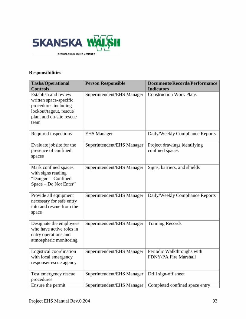
Project EHS Manual Rev.0.204 93
Responsibilities
Tasks/Operational
Controls
Person Responsible Documents/Records/Performance
Indicators
Establish and review
written space-specific
procedures including
lockout/tagout, rescue
plan, and on-site rescue
team
Superintendent/EHS Manager Construction Work Plans
Required inspections
EHS Manager Daily/Weekly Compliance Reports
Evaluate jobsite for the
presence of confined
spaces
Superintendent/EHS Manager
Project drawings identifying
confined spaces
Mark confined spaces
with signs reading
“Danger – Confined
Space – Do Not Enter”
Superintendent/EHS Manager Signs, barriers, and shields
Provide all equipment
necessary for safe entry
into and rescue from the
space
Superintendent/EHS Manager Daily/Weekly Compliance Reports
Designate the employees
who have active roles in
entry operations and
atmospheric monitoring
Superintendent/EHS Manager
Training Records
Logistical coordination
with local emergency
response/rescue agency
Superintendent/EHS Manager
Periodic Walkthroughs with
FDNY/PA Fire Marshall
Test emergency rescue
procedures
Superintendent/EHS Manager
Drill sign-off sheet
Ensure the permit Superintendent/EHS Manager Completed confined space entry

Project EHS Manual Rev.0.204 94
process is being
implemented
permits
Entry logs
Atmospheric monitoring Foreman/Superintendent/EHS
Manager
Enter project-specific roles
and responsibilities
Atmospheric monitoring data
Calibration records
Enter project-specific
information here
Enter project-specific roles
and responsibilities
Enter project specific
Document/Records/Performance
Indicators
Applicable Training
Emergency response
Confined space entrant, attendant, supervisor, and rescuer training
Atmospheric testing
Lockout/tagout
Enter project-specific training
Potential Health and/or Environmental Impacts
Enter project-specific potential health and/or environmental impact

Project EHS Manual Rev.0.204 95
Cranes and Crane Rigging
11.1 General Policy 100
11.1.1 Scope of Applicable Equipment 100
11.1.2 Applicable Regulations 100
11.1.3 Definitions 101
11.1.4 Regional/Project-Specific Requirements 110
11.2 Site Prep 111
11.2.1 Required Documentation 111
11.2.2 Owner Notification/Requirements 111
11.2.3 Geotechnical and Crane Location Plan (CLP) Requirements 111
11.2.4 Subcontractors 112
11.2.5 Monthly Project Crane Meeting 112
11.2.6 Annual Project Crane Meeting 112
11.2.7 Regional/Project-Specific Requirements 113
11.3 Operations 114
11.3.1 Authority to Stop Operation/Emergency Stop 114
11.3.2 Proper Operation Required 114
11.3.3 Notifications 114
11.3.4 Safety Devices 114
11.3.5 Assembly/Disassembly 115
11.3.6 Assembly/Disassembly General Requirements 115

Project EHS Manual Rev.0.204 96
11.3.7 Knowledge of Procedures 115
11.3.8 Review of Procedures 116
11.3.9 Assembly/Disassembly Crew Responsibilities 116
11.3.10 Crane Moves 121
11.3.11 Updates to Crane Location Plan 121
11.3.12 Cell Phones or Other Devices 121
11.3.13 Grounding 121
11.3.14 Leaving the Equipment Unattended 121
11.3.15 Keeping Clear of the Load 122
11.3.16 Receiving a Load 122
11.3.17 Free Fall and Controlled Load Lowering 123
11.3.18 Compliance with Rated Capacity 124
11.3.19 Load Weight 124
11.3.20 Use of Load Chart 125
11.3.21 Work Area Control 125
11.3.22 Verification of Approved Location 126
11.3.23 Pre‐Operational / Pre-Lift Meeting 126
11.3.24 Lift and Carry 127
11.3.25 Operator Requirements and Responsibilities 127
11.3.26 Fall Protection 127
11.3.27 Regional/Project-Specific Requirements 127
11.4 Lift Planning 128
Project EHS Manual Rev.0.204 97
11.4.1 Lift Classification 128
11.4.2 Planned Personnel Lifts 128
11.4.3 Critical Lift 143
11.4.4 Major Lift 144
11.4.5 Standard Lift 144
11.4.6 Repetitive/Similar Lifts 144
11.4.7 Multiple Crane Lifts 145
11.4.8 Regional/Project-Specific Requirements 145
11.5 Left Intentionally Blank for Review Purposes 145
11.6 Maintenance and Inspection 145
11.6.1 Inspection and Oversight Requirements 145
11.6.2 On‐Hire/Off‐Hire Inspections 146
11.6.3 Inspection Requirements 146
11.6.4 Tagout 151
11.6.5 Wire Rope Inspection 151
11.6.6 Regional/Project-Specific Requirements 157
11.7 Electrical 157
11.7.1 Power Line Safety – Assembly and Disassembly 158
11.7.2 Power Line Safety ‐Equipment Operations 160
11.7.3 Regional/Project-Specific Requirements 171
11.8 Weather 172
11.8.1 Wind 172

Project EHS Manual Rev.0.204 98
11.8.2 Lightning 172
11.8.3 Winter Months 172
11.8.4 Regional/Project-Specific Requirements 172
11.9 Training Requirements 172
11.9.1 Signal Training‐General Requirements 173
11.9.2 Electrical Training 177
11.9.3 Dedicated Spotter 178
11.9.4 Rigging Training 178
11.9.5 Regional/Project-Specific Requirements 178
11.10 Unconventional Cranes 178
11.10.1 Tower Cranes 178
11.10.2 Derricks 186
11.10.3 Floating Cranes, Derricks and Land Cranes, Derricks on Barges 193
11.10.4 Overhead & Gantry Cranes 201
11.10.5 Regional/Project-Specific Requirements 202
11.11 Program Management 203
11.11.1 Crane Management System 203
11.11.2 Regional- and Project-Specific Requirement Approvals and Storage 203
11.11.3 Document Storage 203
11.11.4 Program Evaluation and Improvement 203

Project EHS Manual Rev.0.204 99

Project EHS Manual Rev.0.204 100
11.1 General Policy
The following standards, definitions and procedures support the acquisition, erection, operation
and maintenance of all cranes under Skanska control on Skanska projects. This document is
designed to be included as part of the EHS Manual It includes basic requirements for the
operation of cranes in all regions. Project and regional-specific requirements can be added at the
end of each major section.
This document is intended to standardize the efforts and actions required by project teams to
safely and properly plan and manage the crane operations on each site. Therefore, this document,
together with applicable project or agency specifications and OSHA regulations, will guide all
project teams on the safe operation of and the administrative requirements for cranes.
On joint-venture projects where Skanska is not the lead managing partner, the lead managing
partner’s crane policy will take precedence; however, when not the lead managing partner,
Skanska employees will make every effort to comply with Skanska’s practices.
11.1.1 Scope of Applicable Equipment
This standard applies to all cranes, defined as a piece of equipment designed to hoist, lower and
horizontally move a suspended load. It is intended to assist in the use of mobile cranes, truck
cranes, rough terrain cranes, crawler cranes, pile drivers, tower cranes and gantry cranes, but is
not intended to provide guidelines for mobile equipment for which the hoisting of loads is a
secondary purpose (e.g., an excavator equipped with a hook on the bucket).
11.1.2 Applicable Regulations
ASME B30.5.2011 OSHA 29 CFR 1926.1412 OSHA 29 CFR 1926.1426
OSHA 29 CFR 1910.179 OSHA 29 CFR 1926.1413 OSHA 29 CFR 1926.1427
OSHA 29 CFR 1926.106 OSHA 29 CFR 1926.1414 OSHA 29 CFR 1926.1430
OSHA 29 CFR 1926.1400 OSHA 29 CFR 1926.1415 OSHA 29 CFR 1926.1431
OSHA 29 CFR 1926.1401 OSHA 29 CFR 1926.1416 OSHA 29 CFR 1926.1434
OSHA 29 CFR 1926.1402 OSHA 29 CFR 1926.1417 OSHA 29 CFR 1926.1435
OSHA 29 CFR 1926.1403 OSHA 29 CFR 1926.1418 OSHA 29 CFR 1926.1436
OSHA 29 CFR 1926.1404 OSHA 29 CFR 1926.1419 OSHA 29 CFR 1926.1437
OSHA 29 CFR 1926.1406 OSHA 29 CFR 1926.1420 OSHA 29 CFR 1926.1441
OSHA 29 CFR 1926.1407 OSHA 29 CFR 1926.1421 OSHA 29 CFR 1926.1501
OSHA 29 CFR 1926.1408 OSHA 29 CFR 1926.1422 OSHA 29 CFR 1926.20

Project EHS Manual Rev.0.204 101
OSHA 29 CFR 1926.1409 OSHA 29 CFR 1926.1423 OSHA 29 CFR 1926.251
OSHA 29 CFR 1926.1410 OSHA 29 CFR 1926.1424 OSHA 29 CFR 1926.502
OSHA 29 CFR 1926.1411 OSHA 29 CFR 1926.1425 OSHA 29 CFR 1926.550
11.1.3 Definitions
A/D director (Assembly/disassembly director): Individual who meets this policy’s
requirements for an A/D director, irrespective of the person’s formal job title or whether the
person is non‐management or management personnel
Anti-collision system: An electronic device used to help the operator avoid swing collisions with
other cranes and set swing boundaries and zones for safe operation
Articulating crane: A crane whose boom consists of a series of folding, pin-connected structural
members, typically manipulated to extend or retract using power from hydraulic cylinders
Assembly/disassembly: The assembly and/or disassembly of equipment covered under this
policy. With regard to tower cranes, ‘‘erecting and climbing’’ replaces the term ‘‘assembly’’ and
‘‘dismantling’’ replaces the term ‘‘disassembly”. Regardless of whether the crane is initially
erected to its full height or is climbed in stages, the process of increasing the height of the crane is
an erection process.
Assist crane: A crane used to assist in assembling or disassembling a crane
Attachments: Any device(s) that expand(s) the range of tasks that can be done by the equipment.
Examples include, but are not limited to, augers, drills, magnets, pile‐drivers and boom‐attached
personnel platforms.
Audible signal: A signal made by a distinct sound or series of sounds. Examples include, but are
not limited to, sounds made by bells, horns or whistles.
Blocking (also referred to as ‘‘cribbing’’): Wood or other material used to support equipment
or a component and distribute loads to the ground. It is typically used to support lattice boom
sections during assembly/disassembly and under outrigger and stabilizer floats.
Boatswain’s chair: A single-point, adjustable suspension scaffold consisting of a seat or sling
(which may be incorporated into a full body harness) designed to support one employee in a
sitting position
Bogie: See ‘‘travel bogie” below

Project EHS Manual Rev.0.204 102
Boom (equipment other than tower crane): An inclined spar, strut or other long structural
member that supports the upper hoisting tackle on a crane or derrick. Typically, the length and
vertical angle of the boom can be varied to achieve increased height, or height and reach, when
lifting loads. Booms can usually be grouped into general categories of hydraulically extendible,
cantilevered type, latticed section, cable-supported type or articulating type.
Boom (tower cranes): On tower cranes, if the ‘‘boom’’ (i.e., principal horizontal structure) is
fixed, it is referred to as a jib; if it is moveable up and down, it is referred to as a boom
Boom angle indicator: Device that measures the angle of the boom relative to horizontal
Boom hoist limiting device: Includes boom hoist disengaging device, boom hoist shut‐off, boom
hoist disconnect, boom hoist hydraulic relief, boom hoist kick‐outs, automatic boom stop device
or derricking limiter. This type of device disengages boom hoist power when the boom reaches a
predetermined operating angle. It also sets brakes or closes valves to prevent the boom from
lowering after power is disengaged.
Boom length indicator: Indicates the length of the permanent part of the boom (such as ruled
markings on the boom) or, as in some computerized systems, the length of the boom with
extensions/attachments
Boom stop: Includes boom stops (belly straps with struts/standoff), telescoping boom stops,
attachment boom stops and backstops. These devices restrict the boom from moving above a
certain maximum angle and toppling over backward.
Boom suspension system: System of pendants, running ropes, sheaves and other hardware that
supports the boom tip and controls the boom angle
Center of gravity: Point in an object around which its weight is evenly distributed. If you could
put a support under that point, you could balance the object on the support.
Certified welder: Welder who meets nationally recognized certification requirements applicable
to the task being performed
Climbing: Process in which a tower crane is raised to a new working height either by adding
tower sections to the top of the crane (top climbing) or by a system in which the entire crane is
raised inside the structure (inside climbing)

Project EHS Manual Rev.0.204 103
Come‐a‐long: A mechanical device typically consisting of a chain or cable attached at each end
that is used to facilitate movement of materials through leverage
Competent person: One who is capable of identifying existing and predictable hazards in the
surroundings or working conditions that are unsanitary, hazardous or dangerous to employees and
who has authorization to take prompt corrective measures to eliminate them. Training records are
maintained and available.
Competent Rigging Person: Typically, the foreman of the crew performing the lift, but may be
anyone who oversees the lift from rigging to landing the load. The individual must possess
training and experience and meet the other competent person criteria to be considered competent
in rigging.
Controlled load lowering: Lowering a hoisted load with maximum control using the gear train
or hydraulic components of a hoist mechanism. Controlled load lowering requires the use of the
hoist drive motor, rather than the load hoist brake, to lower the load.
Controlling entity: Prime contractor, general contractor, construction manager or any other legal
entity that has the overall responsibility for the construction of the project, including its planning,
quality and completion
Counterweight: A weight used to supplement the weight of equipment in providing stability for
lifting loads by counterbalancing those loads
Crane location plan (CLP): A drawing specific to a jobsite that identifies known hazards for
underground and overhead crane operations. It specifies an individual area’s ability to support
the ground pressure produced by operating a crane. The drawing provides a visual representation
of where specific cranes are approved to and are not approved to operate. The drawing is adjusted
routinely to account for changes in site conditions and other factors that affect the safe operation
of a crane on the site. The CLP must be approved by a qualified person.
If Skanska is the controlling entity on a jobsite, Skanska must also make the location of
underground hazards in the set‐up area (e.g., voids, tanks, utilities) available to the user and the
operator of all cranes on the jobsite. If hazards are identified in documents (e.g., site drawings, as‐
built drawings and soil analyses) that are in the possession of Skanska (whether at the site or
offsite) or are hazards that are otherwise known to Skanska.
Note: this does not relieve each respective user and operator of cranes on the jobsite (e.g.,
subcontractors) from their responsibility to meet the requirements as stated above.

Project EHS Manual Rev.0.204 104
Crawler crane: Equipment with base mounting that incorporates a continuous belt of sprocket-
driven track
Crossover points: Locations on a wire rope spooled on a drum where one layer of rope climbs
up on and crosses over the previous layer. This takes place at each flange of the drum as the rope
is spooled onto the drum, reaches the flange and begins to wrap back in the opposite direction.
Dedicated channel: Line of communication assigned by the employer who controls the
communication system to only one signal person and crane/derrick or to a coordinated group of
cranes/derricks/signal person(s)
Dedicated pile‐driver: A machine designed to function exclusively as a pile‐driver. These
machines typically have the ability to both hoist and pile‐drive the material.
Dedicated spotter (power lines): To be considered a dedicated spotter, the requirements of a
signal person must be met. The dedicated spotter’s sole responsibility is to watch the separation
between the power line and the equipment, load line and load, including rigging and lifting
accessories. They also ensure, through communication with the operator, that the applicable
minimum approach distance is not breached
Directly under the load: When a part or all of an employee is directly beneath the load
Dismantling: Includes partial dismantling (i.e., dismantling to shorten a boom or substitute a
different component)
Drum rotation indicator: A device on a crane or hoist that indicates in which direction and at
what relative speed a particular hoist drum is turning.
Electrical contact: Occurs when a person, object or equipment makes contact or comes in close
proximity with an energized conductor or equipment that allows the passage of current
Encroachment: Where any part of the crane, load line or load (including rigging and lifting
accessories) breaches the minimum clearance distance required to be maintained from a power
line
Fall protection equipment: Guardrail systems, safety net systems, personal fall arrest systems,
positioning device systems or fall restraint systems
Fall restraint system: A fall protection system that prevents the user from falling any distance

Project EHS Manual Rev.0.204 105
Floating cranes/derricks: Equipment designed by the manufacturer (or employer) for marine
use by and is permanently attachment to a barge, pontoons, vessel or other means of flotation
Free fall (of the load line): When only the brake is used to regulate the descent of the load line
(i.e., the drive mechanism is not used to drive the load down faster or retard its lowering)
Free surface effect: The uncontrolled transverse movement of liquids in compartments which
reduces a vessel’s transverse stability
Hoist: A mechanical device for lifting and lowering loads by winding a line onto or off a drum
Hoisting: The act of raising, lowering or otherwise moving a load in the air with equipment. As
used in this policy, ‘‘hoisting’’ can be done by means other than wire rope/hoist drum equipment.
Insulating link/device: An insulating device listed, labeled or accepted by a nationally
recognized testing laboratory
Jib (tower cranes): On tower cranes, if the ‘‘boom’’ (i.e., principal horizontal structure) is fixed,
it is referred to as a jib; if it is moveable up and down, it is referred to as a boom
Jib stop (also jib backstop): The same type of device as a boom stop but for a fixed or luffing
jib
Lift director: Directly oversees the work being performed by a crane and the associated rigging
crew. The lift director is someone appointed on the jobsite and can be in the capacity of a project
manager, project superintendent, foreman or project crane coordinator (PCC).
Lift plan: A construction plan that outlines the step‐by‐step aspects of a particular lift in detail.
It includes a rigging plan and a signal plan.
List: The angle of inclination about the longitudinal axis of a barge, pontoon, vessel or other
means of floatation
Load: Object(s) being hoisted and/or the weight of the object(s); both uses refer to the object(s)
and the load‐attaching equipment (e.g., the load block, ropes, slings, shackles and any other
ancillary attachment)
Load moment (or rated capacity) limiter: A system that aids the equipment operator by
sensing (directly or indirectly) the overturning moment on the equipment (i.e., load multiplied by
radius). It compares this lifting condition to the equipment’s rated capacity and when the rated

Project EHS Manual Rev.0.204 106
capacity is reached, shuts off power to those equipment functions that can increase the severity of
loading on the equipment (e.g., hoisting, telescoping out or luffing out). Typically, those
functions that decrease the severity of loading on the equipment remain operational (e.g.,
lowering, telescoping in or luffing in).
Locomotive crane: A crane mounted on a base or car equipped for travel on a railroad track
Luffing jib limiting device: Similar to a boom hoist limiting device except that it limits the
movement of the luffing jib
Marine hoisted personnel transfer device: A device, such as a ‘‘transfer net’’, that is designed
to protect the employees being hoisted during a marine transfer and to facilitate rapid entry into
and exit from the device. Such devices do not include boatswain’s chairs when hoisted by
equipment covered in this document.
Marine worksite: A construction worksite located in, on or above the water
Mobile crane: A lifting device incorporating a cable-suspended latticed boom or hydraulic
telescopic boom designed to be moved between operating locations by transport over the road
Multi‐purpose machine: A machine designed to be configured in various ways, at least one of
which allows it to hoist (by means of a winch or hook) and horizontally move a suspended load.
For example, a machine that can rotate and can be configured with removable forks/tongs (for
use as a forklift).
Nonconductive: An object that, because of the nature and condition of the materials used and the
conditions of use (including environmental conditions and condition of the material), has the
property of not becoming energized (i.e., it has high dielectric properties offering a high
resistance to the passage of current under the conditions of use)
Operational controls: Levers, switches, pedals and other devices for controlling equipment
Operator: A person who is operating the equipment or a winch pack, jib (with a hook at the end)
or jib used in conjunction with a winch
Operational aids: are devices that assist the operator in the safe operation of the crane by
providing information or automatically taking control of a crane function

Project EHS Manual Rev.0.204 107
Overhead and Gantry cranes: includes overhead/bridge cranes, semi‐gantry, cantilever gantry,
wall cranes, storage bridge cranes, launching gantry cranes and similar equipment irrespective of
whether it travels on tracks, wheels or other means
Pendants: Includes both wire and bar types. Wire type: A fixed length of wire rope with
mechanical fittings at both ends for pinning segments of wire rope together. Bar type: Instead of
wire rope, a bar is used. Pendants are typically used in a latticed boom crane system to easily
change the length of the boom suspension system without completely changing the rope on the
drum when the boom length is increased or decreased.
Personal fall arrest system: A system used to arrest an employee in a fall from a working level.
It consists of an anchorage, connectors and a body harness and may include a lanyard,
deceleration device, lifeline or suitable combination of these.
Portal crane: A type of crane consisting of a rotating upper structure, hoist machinery and boom
mounted on top of a structural gantry which may be fixed in one location or have travel
capability. The gantry legs or columns usually have portal openings in between to allow passage
of traffic beneath the gantry.
Power lines: Electric transmission and distribution lines
Project crane coordinator (PCC): The PCC is typically not a full-time position, but rather a
multipurpose member of the project staff who serves in the capacity of a field engineer tasked
with crane management for the jobsite. Some of the PCC’s duties include verification of
completion of daily periodic inspections, verification of operator’s licensing and qualification,
and completion of routine tasks maintaining the project’s compliance with this document.
Proximity alarm: Device that provides a warning of proximity to a power line
Qualified evaluator (not a third party): Person employed by the signal person’s employer who
has demonstrated that he/she is competent in accurately assessing whether individuals meet the
qualification requirements in this policy for a signal person
Qualified evaluator (third party): An entity that, due to its independence and expertise, has
demonstrated that it is competent in accurately assessing whether individuals meet the
qualification requirements in this policy for a signal person

Project EHS Manual Rev.0.204 108
Qualified person: Person who, by possession of a recognized degree, certificate or professional
standing, or who by extensive knowledge, training and experience, successfully demonstrates the
ability to solve/resolve problems relating to the subject matter, the work or the project
Qualified rigger: Rigger who meets the criteria for a qualified person
Range control limit device: Device that can be set by an equipment operator to limit movement
of the boom or jib tip to a plane or multiple planes
Range control warning device: Device that can be set by an equipment operator to warn that the
boom or jib tip is at a plane or multiple planes
Rated capacity: The maximum working load permitted by the manufacturer under specified
working conditions. Such working conditions typically include a specific combination of factors
such as equipment configuration, radii, boom length and other parameters of use.
Rated capacity indicator: An indicator that tells the operator what percent of capacity they are
at. Refer to indicator on the crane.
Rated capacity limiter: See load moment limiter
Regional crane coordinator (RCC): The regional crane coordinator may be a full-time position
with duties that include oversight and planning of all monthly and annual crane inspections and
the overall regional compliance with this document. The RCC utilizes a CGC to track the
location and status of all cranes and their inspections. Each region will have an RCC.
Repetitive lift-up points: When operating on a short cycle operation, the rope used on a single
layer and spooled repetitively over a short portion of the drum
Rigging plan: Portion of the lift plan related to the method and materials used to rig a load. It
specifically details all rigging to be used in the lift.
Running wire rope: A wire rope that moves over sheaves or drums
Runway: A firm, level surface designed, prepared and designated as a path of travel for the
weight and configuration of the crane being used to lift and travel with the crane-suspended load.
An existing surface may be used as long as it meets these criteria.

Project EHS Manual Rev.0.204 109
Side boom crane: Track‐type or wheel‐type tractor with a boom mounted on the side used for
lifting, lowering or transporting a load suspended on the load hook. The boom or hook can be
lifted or lowered in a vertical direction only.
Signal person: The individual who gives signals to the crane operator. Must be trained as a
competent person in signaling.
Signal plan: The portion of the lift plan related to signaling throughout the duration of the lift;
outlines all signal-related details for the lift
Special hazard warnings: Warnings of site‐specific hazards (e.g., proximity of power lines)
Subcontractor: Any individual or entity contracted and working under Skanska on Skanska’s
contract
Tagline: A rope (usually fiber) attached to a lifted load for purposes of controlling load spinning
and pendular motions or used to stabilize a bucket or magnet during material handling operations
Tender: Individual responsible for monitoring and communicating with a diver
Third-party inspector: Certified crane inspector contracted for a specific purpose, such as the
oversight of the erection of a tower crane, monthly and annual inspections on rubber tire, crawler,
or bridge cranes and Magnetic Particle Testing (Magnaflux)
Tilt up or tilt down operation/tripping: Raising/lowering a load from the horizontal to vertical
or vertical to horizontal position while using one or more lines or using more than one piece of
equipment (e.g., cranes, excavators, loaders, dozers)
Tower crane: Type of lifting structure that uses a vertical mast or tower to support a working
boom (jib) in an elevated position. Loads are suspended from the working boom.
Travel bogie (tower cranes): An assembly of two or more axles arranged to permit vertical
wheel displacement and equalize the loading on the wheels
Trim: Angle of inclination about the transverse axis of a barge, pontoon, vessel or other means of
floatation
Two blocking: A condition in which a component that is uppermost on the hoist line, such as the
load block, hook block, overhaul ball or similar component, comes in contact with the boom tip,

Project EHS Manual Rev.0.204 110
fixed upper block or similar component. This binds the system and continued application of
power can cause failure of the hoist rope or other component.
Unavailable procedures: Procedures that are no longer available from the manufacturer or have
never been available from the manufacturer
Upper works: The revolving frame of equipment on which the operating machinery (and i n
many cases the engine) is mounted, along with the operator’s cab. The counterweight is typically
supported on the rear of the upper structure and the boom or other front end attachment is
mounted on the front.
Wire rope: A flexible rope constructed by laying steel wires into various patterns of multi‐wired
strands around a core system to produce a helically wound rope
11.1.4 Regional/Project-Specific Requirements
DOB 32-hour Rigging Supervisors course and DOB 16- hour Rigging Worker course required.

Project EHS Manual Rev.0.204 111
11.2 Site Prep
11.2.1 Required Documentation
The following documentation must be present inside the cab before the crane may be placed into
service:
Current Monthly Inspection
Manufacturer’s Load Chart
Manufacturer’s Operating Manual
It is the responsibility of project management, the operator and craft personnel involved with the
crane operation to ensure this documentation is present in the cab of the crane for the duration of
the crane’s presence on a Skanska project. If this documentation is not present, it should be
reported to the project crane coordinator immediately.
11.2.2 Owner Notification/Requirements
Some owners or agencies may require the contractor to follow a specific procedure to notify
them of the intent to bring a crane onto their jobsite. All project teams should consult project
specifications for notification requirements specific to their projects. In general, project teams
should:
Notify the owner or authority prior to mobilization of any crane
Obtain and comply with owner or authority requirements for project crane operations
Verify owner or authority requirements regarding crane capacity
Notify the Skanska Insurance Department if rented cranes are being used
11.2.3 Geotechnical and Crane Location Plan (CLP) Requirements
The CLP is created at the beginning of the project, revisited during the monthly crane program
meeting and routinely adjusted to reflect current site conditions. Each time a crane is moved and
set up onsite, a checklist is completed that displays that the site conditions have been examined
and are adequate to support the crane. All ground improvements (leveling, stone, matting, etc.)
must be noted on the CLP.
The CLP must include crane locations and a description of the crane to which it corresponds, as
well as a classification of the crane and pictures of the existing ground conditions in each
proposed set-up location. Include the geotechnical report(s), if available, along with any soil

Project EHS Manual Rev.0.204 112
borings or test pits within the proposed crane locations. A jobsite visit may be scheduled to
perform an evaluation of the ground conditions and overhead conditions at each proposed set up
location at the discretion of the qualified person reviewing the submittal.
Cranes without the ability to level themselves (crawler cranes) require ground improvement, at a
minimum, to level the area. This will most often be achieved with the construction of a stone
crane pad. Crawler cranes with 250 tons or greater capacity must be set on crane mats, at a
minimum. Poor ground conditions could also necessitate matting for cranes of smaller capacity.
If the project team can provide calculations showing that the existing ground conditions are
adequate to support a crane with 250 tons or greater capacity, they may request a dispensation
from the regional crane coordinator (RCC) and Skanska engineering as well as acquire sign-off
from the assigned project vice president or designee. For cranes not owned or operated by
Skanska a third-party engineer and subcontractor senior executive may fulfill this requirement
and submit to Skanska for review and approval.
All outrigger-supported cranes need appropriate dunnage under the outriggers. Where possible,
100 percent outriggers should be used. Partial outriggers may only be used if a manufacturer’s
load chart is issued for that configuration. If partial outriggers are used, the partial load chart
must be used in all lift classification calculations. The project crane coordinator (PCC) must verify
that the crane is set up in an appropriate configuration.
11.2.4 Subcontractors
All subcontractors working under Skanska contract will abide by the Skanska Crane Policy.
11.2.5 Monthly Project Crane Meeting
The project team will hold a meeting chaired by the PCC to discuss crane- and rigging-related
issues once every month. Examples of topics to be discussed with the project team include
training; any reoccurring repairs or issues identified with cranes or rigging that may indicate
improper use or maintenance; recent or future changes to the project site that will impact the
CLP; and any other issues related to cranes or rigging on the project. This meeting should be
documented with the Crane Meeting Agenda Form.
11.2.6 Annual Project Crane Meeting
Once per year, the RCC will attend a monthly project crane meeting for each project. This will
provide the project team an opportunity to ask questions about the evolving crane policy as well
as give input and suggestions for improvement. At the same time, it will allow the RCC to

Project EHS Manual Rev.0.204 113
evaluate how the company‐wide crane policies are being implemented at the project level. This
meeting should be documented with the Crane Meeting Agenda Form.
11.2.7 Regional/Project-Specific Requirements
Enter project-specific requirements

Project EHS Manual Rev.0.204 114
11.3 Operations
11.3.1 Authority to Stop Operation/Emergency Stop
Whenever there is a safety concern, every employee has the authority to stop work and refuse to
handle loads until the issue has been corrected. Every employee has the right to give an
emergency stop signal.
11.3.2 Proper Operation Required
Operations must not begin unless all of the devices listed in this section are in proper working
order. If a device stops working properly during operations, the operator must safely stop
operations. If any of the devices listed in this section are not in proper working order, the
equipment must be taken out of service and operations must not resume until the device is again
working properly. Alternative measures are not permitted.
11.3.3 Notifications
The minimum notice for a project team to provide notice to the regional crane coordinator (RCC)
for the intended use of a crane is eight weeks. The RCC will consult the equipment manager and
determine, based on the type of crane and duration required, whether to rent, purchase or utilize a
Skanska-owned crane. If a project crane coordinator (PCC) is not already designated on the
jobsite, the RCC and project team will designate one at this time.
11.3.4 Safety Devices
The following safety devices are required on all company-owned and rented equipment, unless
otherwise specified:
Boom angle indicator
Crane level indicator: Equipment must have a crane level indicator that is either built into
the equipment or available on the equipment. If a built‐in crane level indicator is not
working properly, it must be tagged‐out or removed and replaced. If a removable crane
level indicator is not working properly, it must be removed. This requirement does not
apply to portal cranes, derricks, floating cranes/derricks and land cranes/derricks on
barges, pontoons, vessels or other means of flotation.
Boom stops, except for derricks and hydraulic booms
Jib stops (if a jib is attached), except for derricks
Locks on equipment with foot pedal brakes

Project EHS Manual Rev.0.204 115
Integral holding device/check valve on hydraulic outrigger jacks and hydraulic stabilizer
jacks
Rail clamps and rail stops on equipment on rails, except for portal cranes
Horn: Equipment must have a horn that is both built in or on the equipment and
immediately available to the operator. If a built‐in horn is not working properly, it must
be tagged‐out or removed and replaced. If a removable horn is not working properly, it
must be removed. In either case, the horn must be replaced or repaired.
11.3.5 Assembly/Disassembly
Selection of Skanska or Manufacturer Procedures
When assembling or disassembling equipment (or attachments), Skanska/crane user must
comply with all applicable manufacturer prohibitions and with either the manufacturer’s
procedures applicable to assembly/disassembly (A/D) or an approved Skanska A/D plan
Synthetic slings may only be used for A/D rigging when specifically approved or
directed by the manufacturer
Skanska procedures must be developed by a qualified person
An A/D director will be identified in the construction plan
Prevent unintended dangerous movement and prevent collapse of any part of the
equipment
Provide adequate support and stability of all parts of the equipment
Position employees involved in the A/D operation so that their exposure to unintended
movement or collapse of part or all of the equipment is minimized
11.3.6 Assembly/Disassembly General Requirements
For all cranes working on a Skanska-controlled site, including rented, owned and subcontractor
supplied, the A/D must be directed by a person who meets the criteria for both a competent
person and a qualified person, or by a competent person who is assisted by one or more qualified
persons (A/D director). Where the A/D is being performed by only one person, that person must
meet the criteria for both a competent person and a qualified person.
11.3.7 Knowledge of Procedures
The A/D director must clearly understand the applicable A/D procedures.

Project EHS Manual Rev.0.204 116
11.3.8 Review of Procedures
The A/D director must review the applicable assembly/disassembly procedures immediately
before beginning assembly/disassembly, unless the A/D director understands the procedures and
has applied them to the same type and configuration of equipment (including accessories, if any).
11.3.9 Assembly/Disassembly Crew Responsibilities
The crew is required to review and sign off on the construction plan, the A/D plan and any
applicable manufacturer’s requirements.
Before commencing A/D operations, the A/D director must ensure that the crew members
understand all of the following:
Their tasks
The hazards associated with their tasks
The hazardous positions/locations that they need to avoid
During A/D operations, before a crew member takes on a different task, or when adding new
personnel during the operations, the construction plan must be reviewed and updated as necessary
by said personnel.
11.3.9.1 Protecting Assembly/Disassembly Crew Members out of Operator View
Before a crew member goes to a location that is out of view of the operator and is either in, on,
under the equipment or near the equipment (or load) where the crew member could be injured by
movement of the equipment (or load), the crew member must inform the operator that he/she is
going to that location. When the operator knows that a crew member went to a location out of
view, the operator must not move any part of the equipment (or load) until the operator is
informed in accordance with a prearranged system of communication that the crew member is in
a safe position.
11.3.9.2 Working under the Boom, Jib or Other Components
When pins (or similar devices) are being removed, employees must not be under the boom, jib or
other components.
Exception: If the employer demonstrates that site constraints require one or more employees to be
under the boom, jib or other components when pins (or similar devices) are being removed, the
A/D director must implement procedures that minimize the risk of unintended dangerous

Project EHS Manual Rev.0.204 117
movement and minimize the duration and extent of exposure under the boom. At a minimum, the
components must be adequately blocked and, when possible, supported by an assist crane. A
documented Construction Work Plan must be developed.
11.3.9.3 Capacity Limits
During all phases of A/D, rated capacity limits for loads imposed on the equipment, equipment
components (including rigging), lifting lugs and equipment accessories must not be exceeded for
the equipment being assembled/disassembled.
11.3.9.4 Addressing Specific Hazards
The A/D director supervising the A/D operation must address the hazards associated with the
operation, which will be identified in the Construction Work Plan.
11.3.9.5 Site and Ground Bearing Conditions
Site and ground conditions must be adequate for safe A/D operations and to support the
equipment during assembly/disassembly.
11.3.9.6 Blocking Material
The size, amount, condition and method of stacking the blocking must be sufficient to sustain the
loads and maintain stability.
11.3.9.7 Proper Location of Blocking
When used to support lattice booms or components, blocking must be appropriately placed to:
Protect the structural integrity of the equipment
Prevent dangerous movement and collapse
11.3.9.8 Verifying Assist Crane Loads
When using an assist crane, the loads that will be imposed on the assist crane during the A/D
process must be verified by a Construction Work Plan and with the corresponding lift plan.
11.3.9.9 Boom and Jib Lift Points
The point(s) of attachment of rigging to a boom (or boom sections or jib or jib sections) must be
suitable for preventing structural damage and facilitating safe handling of these components.
Project EHS Manual Rev.0.204 118
11.3.9.10 Center of Gravity
The center of gravity of the load must be identified if it is integral to maintaining stability.
Where there is insufficient information to accurately identify the center of gravity, measures
designed to prevent unintended dangerous movement resulting from an inaccurate identification
of the center of gravity must be used.
11.3.9.11 Stability upon Pin Removal
The boom sections, boom suspension systems (such as gantry A‐frames and jib struts) and
components must be rigged or supported to maintain stability upon the removal of the pins.
11.3.9.12 Snagging
Suspension ropes and pendants must not be allowed to catch on the boom or jib connection pins
or cotter pins (including keepers and locking pins).
11.3.9.13 Struck By Counterweights
Rigging and blocking must be sufficient to minimize the potential for unintended movement from
inadequately supported counterweights and from hoisting counterweights.
11.3.9.14 Boom Hoist Brake Failure
Each time the boom hoist brake is being relied on to prevent boom movement during A/D; the
brake must first be tested. If the brake proves insufficient, a boom hoist pawl, other locking
device/back‐up braking device or another method of preventing dangerous movement of the
boom (such as blocking or an assist crane) and a boom hoist brake failure must be used.
11.3.9.15 Loss of Backward Stability
Backward stability must be ensured before swinging the upper works, travel and when attaching
or removing equipment components.
11.3.9.16 Wind Speed and Weather
The effect of wind speed and weather on the equipment (refer to manufacturer’s procedures) must
be considered.
11.3.9.17 Cantilevered Boom Sections
Manufacturer limitations on the maximum amount of boom supported only by cantilevering must
not be exceeded. If the manufacturer’s limitations are not available, a registered professional

Project EHS Manual Rev.0.204 119
engineer familiar with the type of equipment involved must determine this limitation and provide
it in writing. The limitation must not be exceeded.
11.3.9.18 Weight of Components
The weight of each of the components must be readily available and known to the riggers or
suitable qualified competent person.
11.3.9.19 Components and Configuration
The selection of components and configuration of the equipment that affect the capacity or safe
operation of the equipment must be in accordance with manufacturer instructions, prohibitions,
limitations and specifications. If these are unavailable, a registered professional engineer familiar
with the type of equipment involved must approve, in writing, the selection and configuration of
components. Upon completion of assembly, the equipment must be inspected by a qualified
inspector.
11.3.9.20 Shipping Pins
Reusable shipping pins, straps, links and similar equipment must be removed. Once removed,
they must either be stowed or otherwise stored so they do not present a falling object hazard.
11.3.9.21 Pile Driving
Equipment used for pile driving must not have a jib attached during pile driving operations.
11.3.9.22 Outriggers and Stabilizers
When the load to be handled and the operating radius require the use of outriggers or stabilizers
or at any time when outriggers or stabilizers are used, all of the following requirements must be
met (except as otherwise indicated):
The outriggers or stabilizers must be either fully extended or, if the manufacturer’s
procedures permit, deployed as specified in the load chart
The outriggers must be set to remove the equipment weight from the wheels, except for
locomotive cranes. This provision does not apply to stabilizers.
When outrigger floats are used, they must be attached to the outriggers. When stabilizer
floats are used, they must be attached to the stabilizers.

Project EHS Manual Rev.0.204 120
Each outrigger or stabilizer must be visible to the operator or to a signal person during
extension and setting
11.3.9.23 Outrigger and Stabilizer Material
Outrigger and stabilizer blocking must:
Be placed only under the outrigger or stabilizer float/pad of the jack or, where the
outrigger or stabilizer is designed without a jack, under the outer bearing surface of the
extended outrigger or stabilizer beam
Be a minimum 4” solid oak or the equivalent and be sized such that individual pad
blocking covers an area equal to three times the overall pad dimension. All blocking will
be tightly spaced and in contact with the outrigger pad (cross blocking may be required)
or be suitably engineered to carry anticipated loads with a given soil capacity.
Follow manufacturer’s procedures when using locomotive cranes. When lifting loads
without using outriggers or stabilizers, the manufacturer’s procedures must be met
regarding truck wedges or screws.
11.3.9.24 Rigging
When rigging is used for A/D, Skanska must ensure that:
The rigging work is done by a qualified rigger
Synthetic slings are protected from abrasive, sharp or acute edges, and configurations
that could cause a reduction of the sling’s rated capacity, such as distortion or localized
compression. “Sling Saver” rigging attachments are recommended.
When synthetic slings are used, the synthetic sling manufacturer’s instructions,
limitations, specifications and recommendations are followed
11.3.9.25 Operation
Skanska will comply with all manufacturer procedures applicable to the operational functions of
equipment, including its use with attachments. Before starting the engine, the operator will verify
that all controls are in the proper starting position and that all personnel are in the clear. The
operator must be familiar with the equipment and its proper operation. If adjustments or repairs
are necessary, the operator will promptly inform the person designated by Skanska to receive
such information and, where there are successive shifts, the next operator. Safety devices and
operational aids will not be used as a substitute for the exercise of professional judgment by the
operator.

Project EHS Manual Rev.0.204 121
11.3.10 Crane Moves
Whenever a mobile crane is to be moved onsite, a spotter must be present to supplement the
operator’s visibility and clear all personnel from the area. The PCC will consult the crane
location plan (CLP) and the crane move checklist to approve the activity. Prior to the move, the
starting point, the end point and the route of the move must be reviewed with the operator and the
spotter. If the crane must travel or set up in an area not specified on the CLP, a project
superintendent or project manager must sign off.
11.3.11 Updates to Crane Location Plan
Any time any portion of the jobsite that is indicated as an approved area for a crane to set up on
the CLP undergoes a significant change that could impact the area’s ability to support that crane,
the CLP must be updated. Examples of such changes include excavation, construction or
demolition of sheeting or piles, any change in support of excavation, demolition of structures and
any change in ground conditions that could impact the ability of the ground conditions to support
a crane. The crane user’s updated CLP must be submitted to Skanska Engineering with a
description of the changes and photographs, where applicable. At the discretion of Skanska
Engineering, a jobsite visit may be scheduled to evaluate the impact of the changes. At a
minimum, the CLP must be updated annually regardless of the changes to the ground conditions.
11.3.12 Cell Phones or Other Devices
The operator and crew will not engage in any practice that diverts his/her attention while actually
engaged in operating the crane, such as the use of cell phones or other attention‐diverting
activities.
11.3.13 Grounding
While working in close proximity to sources of electrical discharge, cranes on Skanska sites are
to be operated in compliance with OSHA 1926.1501 (a)(15)(vii) to ensure work crew safety.
Additionally, all sites must have materials necessary to properly ground cranes and loads as is
specified in OSHA 1926.1501 (a) (15) (vii) readily available.
11.3.14 Leaving the Equipment Unattended
At any time on any Skanska project the operator, including subcontractors, is not permitted to
leave the controls while the load is suspended.

Project EHS Manual Rev.0.204 122
11.3.15 Keeping Clear of the Load
Where available, hoisting routes that minimize the exposure of employees to hoisted loads must
be used, to the extent consistent with public safety. While the operator is not moving a suspended
load, no employee must be within the fall zone, except for employees:
Engaged in hooking, unhooking or guiding a load
Engaged in the initial attachment of the load to a component or structure
Operating a concrete hopper or concrete bucket
When employees are engaged in hooking, unhooking, guiding the load or in the initial connection
of a load to a component or structure and are within the fall zone, all of the following criteria
must be met:
The materials being hoisted must be rigged to prevent unintentional displacement
Hooks with self‐closing latches or their equivalent must be used
The materials must be rigged by a qualified rigger
11.3.16 Receiving a Load
Only those employees needed to receive a load are permitted to be within the fall zone when a
load is being landed. These employees must be on the construction plan.
During a tilt‐up or tilt‐down operation:
No employee can be directly under the load. Only employees essential to the operation
are permitted in the fall zone (but not directly under the load).
An employee is essential to the operation if the employee is conducting one of the following
operations and the employer can demonstrate it is infeasible for the employee to perform that
operation from outside the fall zone:
Physically guiding the load
Closely monitoring and giving instructions regarding the load’s movement
Either detaching it from or initially attaching it to another component or structure (such
as, but not limited to, making an initial connection or installing bracing)
Note: Boom free fall is prohibited when an employee is in the fall zone of the boom or load and
load line free fall is prohibited when an employee is directly under the load.

Project EHS Manual Rev.0.204 123
11.3.17 Free Fall and Controlled Load Lowering
11.3.17.1 Boom Free Fall Prohibitions
The use of equipment in which the boom is designed to free fall (live boom) is prohibited in each
of the following circumstances:
An employee is in the fall zone of the boom or load
An employee is being hoisted
The load or boom is directly over a power line, or over any part of the area extending the
Table A clearance distance to each side of the power line
The load is over a shaft or a cofferdam, except where there are no employees in the fall
zone
11.3.17.2 Preventing Boom Free Fall
Where the use of equipment with a boom that is designed to free fall (live boom) is prohibited,
the boom hoist will have a secondary mechanism or device designed to prevent the boom from
falling in the event the primary system used to hold or regulate the boom hoist fails, as follows:
Friction drums will have:
- A friction clutch and, in addition, a braking device to allow for controlled boom
lowering
- A secondary braking or locking device that is manually or automatically engaged to
back up the primary brake while the boom is held (such as a secondary friction
brake or a ratchet and pawl device)
Hydraulic drums will have an integrally mounted holding device or internal static brake
to prevent boom hoist movement in the event of hydraulic failure
Neither clutches nor hydraulic motors will be considered brake or locking devices for
purposes of this document
Hydraulic boom cylinders will have an integrally mounted holding device
11.3.17.3 Preventing Uncontrolled Retraction
Hydraulic telescoping booms will have an integrally mounted holding device to prevent the boom
from retracting in the event of hydraulic failure.
11.3.17.4 Load Line Free Fall

Project EHS Manual Rev.0.204 124
In each of the following circumstances, controlled load lowering is required and free fall of the
load line hoist is prohibited:
An employee is directly under the load
An employee is being hoisted
The load is directly over a power line or over any part of the area extending the Table A
clearance distance to each side of the power line (refer to section 11.7.2.1)
The load is over a shaft or cofferdam where people may be present
11.3.18 Compliance with Rated Capacity
The equipment will not be operated in excess of its rated capacity.
11.3.19 Load Weight
The weight of the load will be determined from a reliable source (such as the manufacturer of the
contents of the load), by a reliable calculation method (such as calculating a steel beam from
measured dimensions and a known per foot weight) or by other equally reliable means. All load
information will be provided to the operator via the Skanska lift plan/Construction Work Plan
prior to the lift. The operator will verify that the load is within the rated capacity of the
equipment by slowly beginning to hoist the load to determine its weight, using a load weighing
device, load moment indicator, rated capacity indicator or rated capacity limiter. Additionally:
The boom or other parts of the equipment will not contact any obstruction
The equipment will not be used to drag or pull loads sideways
The operator will test the brakes each time a load that is 90 percent or more of the
maximum line pull is handled by lifting the load a few inches and applying the brakes. In
duty cycle and repetitive lifts where each lift is 90 percent or more of the maximum line
pull, this requirement applies to the first lift but not to successive lifts.
Neither the load nor the boom will be lowered below the point where less than two full
wraps of rope remain on their respective drums
A tag or restraint line will be used if necessary to prevent rotation of the load that would
be hazardous
The brakes will be adjusted in accordance with manufacturer procedures to prevent
unintended movement
The operator will obey a stop (or emergency stop) signal, irrespective of who gives it

Project EHS Manual Rev.0.204 125
11.3.20 Use of Load Chart
The competent personnel involved in designing and executing a lift, including the operator, must
know how to use a load chart. This includes understanding:
The terminology necessary to interpret load charts
How to ensure that the load chart is the appropriate chart for the equipment in its
particular configuration and application
The operational limitations of load charts and footnotes
How to relate the chart to the configuration of the crane, crawlers, outriggers/stabilizers
extended or retracted, jib erected or offset and various counterweight configurations
The difference between structural capacity and capacity limited by stability
What is included in capacity ratings
The range diagram and its relationship to the load chart
The work area chart and its relationship to the load chart
Where to find and how to use the “parts‐of‐line” information
How to use the load chart together with the load indicators and/or load moment devices
11.3.21 Work Area Control
The following requirements apply where there are accessible areas in which the equipment’s
swing radius or rotating superstructure (whether permanently or temporarily mounted) poses a
reasonably foreseeable risk of:
Striking and injuring an employee
Pinching/crushing an employee against another part of the equipment or another object
11.3.21.1 To Prevent Employees from Entering These Hazard Areas
Skanska/crane user must inform each employee assigned to work on or near the equipment
(‘‘authorized personnel’’) of how to recognize struck‐by and pinch/crush hazard areas posed by
the rotating superstructure. Control lines, warning lines, railings or similar barriers to mark the
boundaries of the hazard areas will be erected and maintained.
Exception: When Skanska/crane user can demonstrate that it is neither feasible to erect such
barriers on the ground nor on the equipment, the hazard areas must be clearly marked by a
combination of warning signs (such as ‘‘Danger — Swing/Crush Zone’’) and high visibility

Project EHS Manual Rev.0.204 126
markings on the equipment that identify the hazard areas. In addition, Skanska/crane user must
train each employee to understand what these markings signify.
11.3.21.2 Protecting Employees in the Hazard Area
Before an employee enters a location in the hazard area that is out of view of the operator, the
employee (or someone instructed by the employee) must ensure that the operator is informed that
he/she is going to that location. Where the operator knows that an employee went to a location
covered by this section, the operator must not rotate the superstructure until the operator is
informed in accordance with a prearranged system of communication that the employee is in a
safe position. Where any part of a crane/derrick is within the working radius of another
crane/derrick, the controlling entity must institute a system to coordinate operations. If there is no
controlling entity, the employer (if there is only one employer operating the multiple pieces of
equipment), or employers, must institute such a system.
W here any part of a crane/derrick is within the working radius of another crane/derrick, the
controlling entity will institute a system to coordinate operations. If there is no controlling entity,
the employers will institute such a system.
11.3.22 Verification of Approved Location
The crane must be properly set up in a pre‐approved location. The project crane coordinator is
required keep a current CLP of approved set-up locations for all cranes on the job. When any
crane is set up to make a lift, the PCC is required to consult the CLP specific to that crane and
verify that the crane is setting up in an approved location. The PCC must verify that the location
each time a crane is broken down and set up in a new location, is within the original limits of that
crane’s CLP. All assist cranes required for the mobilization of project cranes will follow the
same guidelines listed throughout this document.
11.3.23 Pre‐Operational / Pre-Lift Meeting
For any operation requiring the use of a crane, a pre‐operational meeting is required to review the
appropriate lift plan prior to making any lifts. The meeting should include the operator, signal
person and all crew members involved in rigging and handling the load. During the meeting, a
lift director will be appointed. The lift director’s responsibility will be to directly oversee the
work being performed by the crane and the associated rigging crew. This meeting will be used to
make sure everyone involved in the lift is well versed on all details, including what rigging will
be used, how the load will be rigged, the exact lift path of the load, who will be giving signals, the

Project EHS Manual Rev.0.204 127
method of signaling, where the signaler will be located, etc. It should never be assumed that any
member of the crew is aware of any single aspect of the lift and therefore all aspects should be
reviewed at the pre‐operational/pre‐lift meeting.
11.3.24 Lift and Carry
A lift and carry is always treated as a critical lift and must be approved by the appropriate
management personnel. A competent person must supervise the operation, determine if it is
necessary to reduce rated capacity and make determinations regarding load position, boom
location, ground support, travel route, overhead obstructions and speed of movement necessary
to ensure safety. For equipment with tires, tire pressure and the load location specified by the
manufacturer must be maintained. The rotational speed of the equipment must be controlled that
the load does not swing out beyond the radius at which it can be controlled.
11.3.25 Operator Requirements and Responsibilities
Operators are required to hold a valid National Commission for the Certification of Crane
Operators (NCCCO) certification and provide to the PCC satisfactory evidence (experience) to
establish their qualification to operate the specific equipment. The operator is responsible for the
safe operation of the crane and successful execution of lifts. It should be noted that whenever
there is a concern toward safety, anyone has the right to stop and refuse to handle the load until a
qualified person has determined that safety has been assured.
11.3.26 Fall Protection
Skanska’s Fall Protection Policy states that at all times when exposed to a fall hazard over 6 feet
you must be properly equipped with fall protection system.
11.3.27 Regional/Project-Specific Requirements
Enter project-specific requirements

Project EHS Manual Rev.0.204 128
11.4 Lift Planning
For any operation that requires the use of a crane, the section within the Construction Work Plan
entitled “Lift Information” must be completed. This document assists the project team in
developing the proper lift plan for a specific operation by asking a series of questions. Upon
answering these questions, a detailed lift plan will be generated for use during the pre-operational
meeting, especially in regards to planned personnel, critical and major lifts. It is the
responsibility of the project team to develop this plan with the assistance of the project crane
coordinator. A copy of the planned personnel and critical lift will be forwarded to the regional
crane coordinator (RCC) for review. If at any time any revisions need to be made to the lift plan,
the operation must stop, the current lift plan must be updated and the project crane coordinator
(PCC) must be notified prior to any further action taking place. As with the original plan, the
entire crew and operator must be briefed on the amended plan prior to the lift taking place.
11.4.1 Lift Classification
A classification of the lift must be determined after evaluating the weight of the object, capacity
of the crane and the radius throughout the lift. It is important to note that “capacity” refers to the
capacity listed on the load chart posted in the cab of the crane.
11.4.2 Planned Personnel Lifts
The use of a crane to hoist employees on a personnel platform or man-basket will be prohibited,
except when the erection, dismantling and use of conventional means of reaching a jobsite, such
as ladder, stairway, aerial lift, scaffold or elevating platform would be more hazardous or is not
possible because of jobsite conditions. In such cases, the project team must request a
dispensation for the use of personnel platforms and man baskets by the Skanska EHS Department
and RCC; the personnel platform or man basket must be designed and stamped by Skanska
Engineering or a third party PE and approval from a Skanska officer or designee must be
acquired.
Hoisting personnel is prohibited without appropriate planning and protection.
The requirements of this section apply when one or more employees are hoisted. A Skanska
Construction Work Plan or planned personnel lift must be completed and notification and
signatures are required from a Skanska officer or delegate, Corporate EHS Department, RCC,
PCC, project manager and site EHS manager. Depending on the site location, some local
governing agencies require notification prior to the lifting of any personnel.

Project EHS Manual Rev.0.204 129
The use of equipment to hoist employees is prohibited except when Skanska/crane user can
demonstrate that the erection, use and dismantling of conventional means of reaching the work
area, such as a personnel hoist, ladder, stairway, aerial lift, elevating work platform, or scaffold,
would be more hazardous, or is not possible because of the project’s structural design or jobsite
conditions. This paragraph does not apply to work covered by steel erection.
11.4.2.1 Use of Personnel Platform
When using equipment to hoist employee(s), the employee(s) must be in a personnel platform
that meets the requirements specified in this document. An exception is drill shafts (refer to
section 11.4.2.13 for information).
11.4.2.2 Equipment Set Up
The equipment must be uniformly level, within one percent of level grade and located on footing
that a qualified person has determined to be sufficiently firm and stable. Any outriggers or
stabilizers must all be extended and locked. The amount of extension must be the same for all
outriggers and stabilizers and in accordance with manufacturer’s procedures and load charts.
11.4.2.3 Equipment Criteria
Use of suspended personnel platforms
The total load (with the platform loaded, including the hook, load line and rigging) must not
exceed 50 percent of the rated capacity for the radius and configuration of the equipment, except
during proof testing. Check the lift plan section of the Construction Work Plan to reduce lifting
capacity to 50.
Use of boom‐attached personnel platforms
The total weight of the loaded personnel platform must not exceed 50 percent of the rated
capacity for the radius and configuration of the equipment (except during proof testing).
Hoisting personnel without a personnel platform
When hoisting personnel without a personnel platform as outlined in this document, the total
load (including the hook, load line, rigging and any other equipment that imposes a load) must
not exceed 50 percent of the rated capacity for the radius and configuration of the equipment,
except during proof testing.

Project EHS Manual Rev.0.204 130
When the occupied personnel platform is in a stationary working position, the load and boom
hoist brakes, swing brakes and operator-actuated secondary braking and locking features (such as
pawls or dogs) or automatic secondary brakes must be engaged.
11.4.2.4 Devices
Equipment (except for derricks and articulating cranes) with a variable angle boom must be
equipped with all of the following:
A boom angle indicator, readily visible to the operator
A boom hoist limiting device
Articulating cranes must be equipped with a properly functioning automatic overload protection
device.
Equipment with a luffing jib must be equipped with:
A jib angle indicator, readily visible to the operator
A jib hoist limiting device
Equipment with telescoping booms must be equipped with a device to indicate the boom’s
extended length clearly to the operator or must have measuring marks on the boom.
Anti two‐block
A device that automatically prevents damage and load failure from contact between the load
block, overhaul ball or similar component and the boom tip (or fixed upper block or similar
component) must be used. The device(s) must prevent such damage/failure at all points where
two‐blocking could occur.
Exception: This device is not required when hoisting personnel in pile driving operations; rather it
specifies how to prevent two‐blocking during such operations.
Controlled load lowering
The load line hoist drum must have a system, other than the load line hoist brake, that regulates
the lowering rate of speed of the hoist mechanism. This system or device must be used when
hoisting personnel.

Project EHS Manual Rev.0.204 131
Free fall of the load line hoist is prohibited. The use of equipment in which the boom hoist
mechanism can free fall is also prohibited.
Personnel hoisting operations must not begin unless the devices listed in this section are in proper
working order. If a device stops working properly during such operations, the operator must
safely stop operations. Personnel hoisting operations must not resume until the device is again
working properly. Alternative measures are not permitted.
Direct attachment of a personnel platform to a luffing jib is prohibited.
11.4.2.5 Personnel Platform Criteria
A qualified person familiar with structural design must design the personnel platform and
attachment/suspension system used for hoisting personnel.
The system used to connect the personnel platform to the equipment must allow the platform to
remain within 10 degrees of level, regardless of boom angle.
The suspension system must be designed to minimize tipping of the platform due to movement of
employees occupying the platform.
The personnel platform itself (excluding the guardrail system and personal fall arrest system
anchorages) must be capable of supporting, without failure, its own weight and at least five times
the maximum intended load.
All welding of the personnel platform and its components must be performed by a certified
welder familiar with the weld grades, types and material specified in the platform design.
The personnel platform must be equipped with a guardrail system that meets the requirements of
OSHA 1926 Subpart M, and must be enclosed at least from the toe board to mid‐rail with either
solid construction material or expanded metal having openings no greater than 1⁄2 inch (1.27
cm).
Points to which personal fall arrest systems are attached must meet the anchorage requirements in
OSHA 1926.502. A grab rail must be installed inside the entire perimeter of the personnel
platform except for access gates/doors.
If installed, access gates/doors of all types (including swinging, sliding, folding or other types)
must:

Project EHS Manual Rev.0.204 132
Not swing outward. If, due to the size of the personnel platform, such as a one‐person
platform, it is not feasible for the door to swing inward and allow safe entry for the
platform occupant, then the access gate/door may swing outward
Be equipped with a device that prevents accidental opening
Have headroom sufficient to allow employees to stand upright in the platform
In addition to the use of hard hats, employees must be protected by overhead protection on the
personnel platform when employees are exposed to falling objects.
The platform overhead protection must not obscure the view of the operator or platform
occupants (such as wire mesh that has up to 1⁄2” openings), unless full protection is necessary.
All edges exposed to employee contact must be smooth enough to prevent injury.
The weight of the platform and its rated capacity must be conspicuously posted on the platform
with a plate or other permanent marking.
11.4.2.6 Personnel Platform Loading
The personnel platform must not be loaded in excess of its rated capacity. Personnel platforms
must be used only for employees, their tools and the materials necessary to do their work.
Platforms must not be used to hoist materials or tools when not hoisting personnel.
Exception: Materials and tools to be used during the lift, if secured and distributed in accordance
with paragraph (8.1.6) (c) of OSHA 1926, may be in the platform for trial lifts.
Materials and tools must be:
Secured to prevent displacement
Evenly distributed within the confines of the platform while it is suspended
The number of employees occupying the personnel platform must not exceed the maximum
number the platform was designed to hold or the number required to perform the work,
whichever is less.
11.4.2.7 Attachment and Rigging
Hooks and other detachable devices:
Project EHS Manual Rev.0.204 133
Hooks used in the connection between the hoist line and the personnel platform (including
hooks on overhaul ball assemblies, lower load blocks, bridle legs or other attachment
assemblies or components) must be:
- Of a type that can be closed and locked, eliminating the throat opening
- Closed and locked when attached
Shackles used in place of hooks must be of the alloy anchor type, with either a bolt, nut
and retaining pin in place or of the screw type with the screw pin secured preventing
accidental removal
Where other detachable devices are used, they must be of the type that can be closed and
locked to the same extent as the devices addressed in the beginning of this section. Such
devices must be closed and locked when attached.
When a rope bridle is used to suspend the personnel platform, each bridle leg must be
connected to a master link or shackle in a manner that ensures that the load is evenly
divided among the bridle legs
Rigging hardware (including wire rope, shackles, rings, master links and other rigging
hardware) and hooks must be capable of supporting, without failure, at least five times the
maximum intended load applied or transmitted to that component. Where rotation-
resistant rope is used, the slings must be capable of supporting without failure at least ten
times the maximum intended load.
Eyes in wire rope slings must be fabricated with thimbles
Bridles and associated rigging for suspending the personnel platform must be used only
for the platform and the necessary employees, their tools and materials necessary to do
their work.
The bridles and associated rigging must not have been used for any purpose other than
hoisting personnel
11.4.2.8 Trial Lift and Inspection
A trial lift with the unoccupied personnel platform loaded at least to the anticipated lift weight
must be made from ground level or from any other location where employees will enter the
platform, to each location at which the platform will be hoisted and positioned. Where there is
more than one location to be reached from a single set‐up position, either individual trial lifts for
each location or a single trial lift, in which the platform is moved sequentially to each location,
must be performed. The method selected must be the same as the method that will be used to
hoist the personnel. The trial lift must be performed immediately prior to each shift in which

Project EHS Manual Rev.0.204 134
personnel will be hoisted. In addition, the trial lift must be repeated prior to hoisting employees
in each of the following circumstances:
The equipment has been moved and set up in a new location or returned to a previously
used location
The lift route has changed, unless the competent person determines that the new route
presents no new factors affecting safety
The competent person must determine that:
Safety devices and operational aids required by this section are activated and functioning
properly
Nothing interferes with the equipment or the personnel platform in the course of the trial
lift
The lift will not exceed 50 percent of the equipment’s rated capacity at any time during
the lift
The load radius to be used during the lift has been accurately determined
Immediately after the trial lift, the competent person must:
Conduct a visual inspection of the equipment, base support or ground and personnel
platform to determine whether the trial lift has exposed any defect or problem or
produced any adverse effect
Confirm that, upon the completion of the trial lift process, the test weight has been
removed
Immediately prior to each lift:
The platform must be hoisted a few inches with the personnel and materials/tools on
board and inspected by a competent person to ensure that it is secure and properly
balanced
The following conditions must be determined by a competent person to exist before the lift of
personnel proceeds:
Hoist ropes must be free of deficiencies
Multiple part lines must not be twisted around each other

Project EHS Manual Rev.0.204 135
The primary attachment must be centered over the platform; if the load rope is slack, the
hoisting system must be inspected to ensure that all ropes are properly seated on drums
and in sheaves
Any condition found during the trial lift and subsequent inspections that fails to meet a
requirement of this policy or otherwise creates a safety hazard must be corrected before hoisting
personnel.
11.4.2.9 Proof Testing
At each jobsite prior to hoisting employees on the personnel platform and after any repair or
modification, the platform and rigging must be proof tested to 125 percent of the platform’s rated
capacity. The proof test may be done concurrently with the trial lift.
The platform must be lowered by controlled load lowering then braked and held in a suspended
position for a minimum of five minutes with the test load evenly distributed on the platform.
After proof testing, a competent person must inspect the platform and rigging to determine if the
test has been passed. If any deficiencies are found that pose a safety hazard, the platform and
rigging must not be used to hoist personnel unless the deficiencies are corrected, the test is
repeated and a competent person determines that the test has been passed.
Personnel hoisting must not be conducted until the competent person determines that the platform
and rigging have successfully passed the proof test.
11.4.2.10 Work Practices
Hoisting of the personnel platform must be performed in a slow, controlled, cautious manner with
no sudden movements of the equipment or the platform.
Platform occupants must:
Keep all parts of the body inside the platform during raising, lowering and horizontal
movement. This provision does not apply to an occupant of the platform when necessary
to position the platform or while performing the duties of a signal person
Refrain from standing, sitting on or working from the top or intermediate rail or toe board
or use any other means/device to raise their working height
Refrain from pulling the platform out of plumb in relation to the hoisting equipment

Project EHS Manual Rev.0.204 136
Secure the platform to the structure where work is to be performed before exiting or
entering a hoisted personnel platform that is not landed, unless Skanska/crane user can
demonstrate that securing to the structure would create a greater hazard
If the platform is tied to the structure, the operator must not move the platform until he/she
receives confirmation that it is freely suspended.
Tag lines must be used when necessary to control the platform.
Platforms without controls
Where the platform is not equipped with controls, the equipment operator must remain at the
equipment controls, onsite and in view of the equipment at all times while the platform is
occupied.
Platforms with controls
Where the platform is equipped with controls, all of the following must be met at all times while
the platform is occupied:
The occupant using the controls in the platform must be a qualified person with respect to
their use, including the safe limitations of the equipment and hazards associated with its
operation
The equipment operator must be at a set of equipment controls that include boom and
swing functions of the equipment and must be onsite and in view of the equipment
The platform operating manual must be in the platform or on the equipment
Wind
When wind speed (sustained or gusts) exceeds 20 mph at the personnel platform, a qualified
person must determine if, in light of the wind conditions, it is safe to lift personnel. If it is not,
the lifting operation must not begin (or, if already in progress, must be terminated).
Other Weather and Environmental Conditions
A qualified person must determine if, in light of indications of dangerous weather conditions, or
other impending or existing danger, it is safe to lift personnel. If it is not, the lifting operation
must not begin (or if already in progress must be terminated). Employees being hoisted must
remain in direct communication with the signal person, where used, or the operator.

Project EHS Manual Rev.0.204 137
Fall Protection
Except over water, employees occupying the personnel platform must be provided and use a
personal fall arrest system. The system must be attached to a structural member within the
personnel platform. When working over or near water, the requirements of OSHA 1926.106
apply. The fall arrest system, including the attachment point (anchorage), must meet the
requirements in OSHA 1926.502.
Other Load Lines
No lifts will be made on any other of the equipment’s load lines while personnel are being
hoisted, except in pile driving operations.
Factory‐Produced Boom‐Mounted Personnel Platforms that Incorporate a Winch as Original
Equipment
Loads are permitted to be hoisted by such a winch while employees occupy the personnel
platform only where the load on the winch line does not exceed 500 pounds and does not exceed
the rated capacity of the winch and platform.
Traveling—Equipment other than Derricks
Hoisting of employees while the equipment is traveling is prohibited, except for:
Equipment that travels on fixed rails
Where the employer demonstrates that there is no less hazardous way to perform the
work. This exception does not apply to rubber‐tired equipment
Where employees are hoisted while the equipment is traveling, all of the following criteria must
be met:
Equipment travel must be restricted to a fixed track or runway
W here a runway is used, it must be a firm, level surface designed, prepared and
designated as a path of travel for the weight and configuration of the equipment being
used to lift and travel with the personnel platform. An existing surface may be used as
long as it meets these criteria.
Equipment travel must be limited to boom length
The boom must be parallel to the direction of travel, except where it is safer to do
otherwise
Project EHS Manual Rev.0.204 138
A complete trial run must be performed to test the route of travel before employees are
allowed to occupy the platform. This trial run can be performed at the same time as the
trial lift which tests the lift route
Traveling—derricks
Derricks are prohibited from traveling while personnel are hoisted.
11.4.2.11 Pre‐Lift Meeting
A pre‐lift meeting must be held to review the applicable requirements of this section and the
procedures that will be followed. It will be attended by the equipment operator, signal person (if
used for the lift), employee(s) to be hoisted and the person responsible for the task to be
performed. The pre‐lift meeting will be held prior to the trial lift at each new work location and
must be repeated for any employees newly assigned to the operation.
11.4.2.12 Hoisting Personnel near Power Lines
Hoisting personnel within 25 feet of a power line that is up to 350 kV and hoisting personnel
within 50 feet of a power line that is over 350 kV is prohibited, except for work covered by
Section 11.7.2.9 Power Transmission and Distribution.
11.4.2.13 Hoisting Personnel in Drill Shafts
When hoisting employees into and out of drill shafts that are up to and including 8 feet in
diameter, all of the following requirements must be met:
The employee must be in either a personnel platform or on a boatswain’s chair
If using a personnel platform, paragraphs (a) through (n) of 1926.1400 apply
If using a boatswain’s chair the following paragraphs of OSHA 1926.1400 apply: (a), (c),
(d)(1), (d)(3), (d)(4), (e)(1), (e)(2), (e)(3), (f)(1), (f)(2)(i), (f)(3)(i), (g), (h), (k)(1), (k)(6),
(k)(8),(k)(9), (k)(11)(i), (m), (n). Where the terms ‘‘personnel platform’’ or ‘‘platform’’
are used in these paragraphs, substitute them with ‘‘boatswain’s chair.’’
A signal person must be stationed at the shaft opening
The employee must be hoisted in a slow, controlled descent and ascent
The employee must use personal fall protection equipment, including a full body harness,
attached independent of the crane/derrick
The fall protection equipment must meet the applicable requirements in OSHA 1926.502

Project EHS Manual Rev.0.204 139
The boatswain’s chair itself (excluding the personal fall arrest system anchorages) must
be capable of supporting, without failure, its own weight and at least five times the
maximum intended load
No more than one person must be hoisted at a time
11.4.2.14 Hoisting Personnel for Pile Driving Operations
When hoisting an employee in pile driving operations, the following requirements must be met:
The employee must be in a personnel platform or boatswain’s chair
For lattice boom cranes, clearly mark the cable (so that it can easily be seen by the
operator) at a point that will give the operator sufficient time to stop the hoist to prevent
two‐blocking or use a spotter who is in direct communication with the operator to inform
the operator when this point is reached
For telescopic boom cranes, clearly mark the cable (so that it can be easily seen by the
operator) at a point that will give the operator sufficient time to stop the hoist to prevent
two blocking and use a spotter who is in direct communication with the operator to
inform the operator when this point is reached
If using a personnel platform, paragraphs OSHA 1926.1400 (b) through (n) of this section
apply
If using a boatswain’s chair the following paragraphs of OSHA 1926.1400 apply: (a), (c),
(d)(1), (d)(3), (d)(4), (e)(1), (e)(2), (e)(3), (f)(1), (f)(2)(i), (f)(3)(i), (g), (h), (j), (k)(1),
(k)(6), (k)(8), (k)(9), (k)(11)(i), (m), and (n). Where the terms ‘‘personnel platform’’ or
‘‘platform’’ are used in these paragraphs, substitute them with ‘‘boatswains chair”.
The employee must be hoisted in a slow, controlled descent and ascent
The employee must use personal fall protection equipment, including a full body harness,
independently attached to the lower load block or overhaul ball
The fall protection equipment must meet the applicable requirements in OSHA 1926.502
The boatswain’s chair itself (excluding the personal fall arrest system anchorages) must
be capable of supporting, without failure, its own weight and at least five times the
maximum intended load
No more than one person may be hoisted at a time
11.4.2.15 Operational Aids
The devices listed as operational aids are required on all equipment covered under Skanska’s
crane policy, unless otherwise specified.
Project EHS Manual Rev.0.204 140
Operations will not begin unless the listed operational aids are in proper working order, except
where Skanska/crane user meets the specified temporary alternative measures. More protective
alternative measures specified by the crane/derrick manufacturer, if any, shall be followed.
If a listed operational aid stops working properly during operations, the operator will safely stop
operations until the temporary alternative measures are implemented or the device is again
working properly. If a replacement part is no longer available, the use of a substitute device that
performs the same type of function is permitted and is not considered a modification under
OSHA 1926.1434 ‐ Category I operational aids and alternative measures.
Operational aids that are not working properly will be repaired no later than seven days after the
deficiency occurs.
Exception: If the employer documents that it has ordered the necessary parts within seven days
of the occurrence of the deficiency, the repair will be completed within seven days of receipt of
the parts.
11.4.2.16 Boom Hoist Limiting Device
For equipment manufactured after December 16, 1969, a boom hoist limiting device is required.
Temporary alternative measures (use at least one) are as follows:
Use a boom angle indicator
Clearly mark the boom hoist cable (so that it can easily be seen by the operator) at a point
that will give the operator sufficient time to stop the hoist to keep the boom within the
minimum allowable radius. In addition, install mirrors or remote video cameras and
displays if necessary for the operator to see the mark.
Clearly mark the boom hoist cable (so that it can easily be seen by a spotter) at a point
that will give the spotter sufficient time to signal the operator and have the operator stop
the hoist to keep the boom within the minimum allowable radius
If the equipment was manufactured on or before December 16, 1969 and was not
originally equipped with a boom hoist limiting device, at least one of the measures in
paragraphs (d)(1)(i)(A) through (C) of OSHA 1926.1400 shall be used on a permanent
basis
11.4.2.17 Luffing Jib Limiting Device

Project EHS Manual Rev.0.204 141
Equipment with a luffing jib will have a luffing jib limiting device. Temporary alternative
measures are the same as in paragraph (d) (1) (i) of OSHA 1926.1400, except to limit the
movement of the luffing jib.
11.4.2.18 Anti Two‐Blocking Device
Telescopic boom cranes
Telescopic boom cranes manufactured after February 28, 1992, will be equipped with a
device that automatically prevents damage from contact between the load block,
overhaul ball or similar component and the boom tip (or fixed upper block or similar
component). The device(s) must prevent such damage at all points where two‐blocking
could occur.
Temporary alternative measures: Clearly mark the cable (so that it can easily be seen by the
operator) at a point that will give the operator sufficient time to stop the hoist to prevent two‐
blocking, and use a spotter when extending the boom.
Lattice boom cranes
Lattice boom cranes manufactured after Feb 28, 1992, will be equipped with a device that
either automatically prevents damage and load failure from contact between the load
block, overhaul ball or similar component and the boom tip (or fixed upper block or
similar component) or warns the operator in time for the operator to prevent two‐
blocking. The device(s) must prevent such damage/failure or provide adequate warning
for all points where two‐blocking could occur.
Lattice boom cranes and derricks manufactured one year after the effective date of this
standard will be equipped with a device that automatically prevents damage and load
failure from contact between the load block, overhaul ball, or similar component and the
boom tip (or fixed upper block or similar component). The device(s) must prevent such
damage/failure at all points where two‐blocking could occur.
Exception: The requirements of this section do not apply to such lattice boom equipment when
used for dragline, clamshell (grapple), magnet, drop ball, container handling, concrete bucket and
marine operations that do not involve hoisting personnel and pile driving work.
Temporary alternative measures: Clearly mark the cable (so that it can easily be seen by the
operator) at a point that will give the operator sufficient time to stop the hoist to prevent two
blocking or use a spotter.

Project EHS Manual Rev.0.204 142
Category II operational aids and alternative measures
Operational aids that are not working properly will be repaired no later than 30 days after the
deficiency occurs.
Exception: If the employer can document that it has ordered the necessary parts within seven
days of the occurrence of the deficiency and the part is not received in time to complete the repair
in 30 days, the repair will be completed within seven days of receipt of the parts.
Boom Angle or Radius Indicator
The equipment will have a boom angle or radius indicator readable from the operator’s station.
Temporary alternative measures: Radii or boom angle will be determined by measuring the radii
or boom angle with a measuring device.
Jib Angle Indicator (if the equipment has a luffing jib)
Temporary alternative measures: Radii or jib angle will be determined by ascertaining the main
boom angle and then measuring the radii or jib angle with a measuring device.
Boom Length Indicator
When the equipment is equipped with a telescopic boom, except where the rated capacity is
independent of the boom length, one of the following methods will be used:
Mark the boom with measured marks to calculate boom length
Calculate boom length from boom angle and radius measurements
Measure the boom with a measuring device
Load weighing and similar devices
Equipment (other than derricks) manufactured after March 29, 2003 with a rated capacity over
6,000 pounds will have at least one of the following:
Load weighing device
Load moment (or rated capacity) indicator
Load moment (or rated capacity) limiter
Temporary alternative measures: The weight of the load will be determined from a reliable
source (e.g., the load’s manufacturer), by a reliable calculation method (i.e., calculating a steel
Project EHS Manual Rev.0.204 143
beam from measured dimensions and a known per foot weight) or by other equally reliable
means. This information will be provided to the operator prior to the lift.
The following devices are required on equipment manufactured after January 1, 2008:
Outrigger position (horizontal beam extension) sensor/monitor. If the equipment has
outriggers the operator will verify that the position of the outriggers is correct (in
accordance with manufacturer procedures) before beginning operations requiring
outrigger deployment.
Hoist drum rotation indicator. If the drum is not visible from the operator’s station mark
the drum. In addition, install mirrors or remote video cameras and displays if necessary
for the operator to see the mark.
11.4.3 Critical Lift
A lift is a critical lift when:
More than 75 percent of the crane’s load chart as configured is being utilized during the
lift
The lift requires more than one crane
The load on the crane cannot be accurately determined including pulling or side loading
Equipment that contains an operator’s cabin is being lifted
Lift and Carry: The lift is considered a critical lift and the critical lift checklist must be
completed.
Sign-offs must be obtained from the RCC, PCC, project manager and EHS manager before
the lift is made. Refer to 11.3.24 Lift and Carry
Plan Development
Before beginning a crane operation in which more than one crane will be supporting the load, the
operation must be planned. The planning must meet the following requirements:
The plan must be developed by a qualified person
Where the qualified person determines that engineering expertise is needed for the
planning, Skanska must ensure that it is provided
Plan Implementation
Project EHS Manual Rev.0.204 144
The multiple‐crane lift must be supervised by a person who meets the criteria for both a
competent person and a qualified person, or by a competent person who is assisted by
one or more qualified persons
The supervisor must review the plan with all workers who will be involved with the
operation
Some local governing agencies may require notification before a multiple crane lift
11.4.4 Major Lift
A lift is a major lift when:
The item lifted has a significant impact to the project schedule or budget
The item has a lead time greater than 12 months
The item is valued at more than $100,000
The crane is on a barge, regardless of weight of load or capacity of crane
The major lift checklist must be completed, and sign-offs must be obtained by the PCC, project
manager and safety engineer before the lift is made.
Depending on the weight of the object and the capacity of the crane, a lift could be classified as
both a critical and major lift, in which case the critical lift checklist and approvals are solely
required.
11.4.5 Standard Lift
If the weight of the object and its radius throughout the duration of the lift are such that it is less
than 75 percent capacity of the crane’s capacity and none of the major or critical lift items are
present, it is a standard lift. A Construction Work P lan and lift plan must still be completed.
11.4.6 Repetitive/Similar Lifts
If a crew makes the same lift throughout the day, they need only go through the standard lift
process once at the beginning of the day. For example, if the task is to remove spoils from an
area with a 45-ton cherry lifter and a skip pan, then the weight of the skip pan and radius needs to
be evaluated once. A pre‐operational meeting must take place before the first lift, and the crew
can continue to work at the same operation with the same plan and no additional pre-operational
meetings are required, with the exception that all rigging must be visually inspected prior to
every lift. However, if any significant aspect of the operation changes (a larger skip pan is

Project EHS Manual Rev.0.204 145
substituted for the one in the plan, the spoils need to be placed in a location that requires a longer
boom and larger radius, the nature of the spoils change and therefore the weight of the load
changes, or any change is made to any single detail of the operation), the pre‐operational meeting
should take place again.
11.4.7 Multiple Crane Lifts
Plan Development
Before beginning a crane operation in which more than one crane will be supporting the load, the
operation must be planned. The planning must meet the following requirements:
The plan must be developed by a qualified person
Where the qualified person determines that engineering expertise is needed for the
planning, Skanska must ensure that it is provided
Plan Implementation
The multiple‐crane lift must be supervised by a person who meets the criteria for both a
competent person and a qualified person or by a competent person who is assisted by one
or more qualified persons
The supervisor must review the plan with all workers who will be involved with the
operation
Some local governing agencies may require notification before a multiple crane lift
11.4.8 Regional/Project-Specific Requirements
Enter project-specific requirements
11.5 Left Intentionally Blank for Review Purposes
This section has been left intentionally blank for annual changes from the regional crane
committees and EHS senior leadership.
11.6 Maintenance and Inspection
11.6.1 Inspection and Oversight Requirements
Prior to any crane being placed in service, each crane must have an up-to-date monthly and
annual inspection. The project crane coordinator (PCC) is responsible for ensuring that at the
Project EHS Manual Rev.0.204 146
time of the crane’s arrival at the jobsite, these inspections are up-to-date and present in the cab. If
they are not, the PCC is required to notify the regional crane coordinator (RCC) who will arrange
for the inspections to be completed as soon as possible. The crane will not be operated until these
inspections are completed or documentation is provided. Upon expiration of initial inspections,
Skanska/crane user is required to provide for subsequent inspections.
11.6.2 On‐Hire/Off‐Hire Inspections
When a crane arrives on the jobsite, whether company-owned or rented, an on‐hire inspection
must be performed. It is the responsibility of the PCC to ensure this activity is performed. This
inspection is separate from a safety inspection and is intended to document incidental damage to
the crane body, condition of cab, etc., to protect Skanska/crane user from claims for alleged
damage to the equipment. The condition of the crane should be documented with photographic
evidence especially with regard to any pre‐existing damage. When a crane is leaving the jobsite,
an off‐hire inspection must be performed by the PCC or a member of the project team to
document the condition of the crane with new photographs showing all previously existing
damage as well as any new damage. Both reports will be included in the crane file maintained by
the RCC.
11.6.3 Inspection Requirements
If a company-owned or rented crane arrives on any site and it does not have a current monthly
inspection, the RCC will determine whether the crane will need to have a monthly inspection
completed on that crane. The on‐hire inspection should be completed as soon as the crane is
assembled and prior to going to work. A full monthly inspection will be completed on rentals
longer than five consecutive days. If a rental is less than five consecutive days, then daily
inspections should be performed by the appropriate parties. Current, comprehensive inspections
are essential to ensure safe operation of all cranes.
The following mandatory inspections apply to all cranes on Skanska USA projects:
11.6.3.1 Daily/Pre Shift Inspections
Daily and pre-shift inspections must be conducted by the operator assigned to each crane.
Regardless of whether the operator agrees to sign the inspection form, it is the responsibility of
the PCC to confirm with the operator that the inspection has been completed each day. The
inspection should be a visual “walk-around” inspection and function test covering:
Control mechanisms for maladjustments interfering with proper operations

Project EHS Manual Rev.0.204 147
Control and drive mechanisms for apparent excessive wear of components and
contamination by lubricants, water or other foreign matter
Air, hydraulic and other pressurized lines for deterioration or leakage, particularly those
which flex in normal operation
Hydraulic system for proper fluid level
Hooks and latches for deformation, cracks, excessive wear or damage such as from
chemicals or heat
Wire rope reeving for compliance with the manufacturer’s specifications
Electrical apparatus for malfunctioning, signs of apparent excessive deterioration, dirt or
moisture accumulation
Tires (when in use) for proper inflation and condition
Ground conditions around the equipment for proper support, including ground settling
Under and around outriggers/stabilizers and supporting foundations, ground water
accumulation, or similar conditions
The equipment for level position within the tolerances specified by the equipment
manufacturer’s recommendations, both before each shift and after each move and setup
Operator cab windows for significant cracks, breaks or other deficiencies that would
hamper the operator’s view
Safety devices and operational aids required for proper operation. Any deficiencies
identified during the inspection must be communicated to the PCC, who is required to
provide documentation describing the deficiency as well as the corrective action taken to
remedy it.
All deficiencies found must be reported to the RCC immediately. Deficiencies that are related to
safety will result in the immediate removal of the crane from service until the deficiencies are
corrected. Non‐safety related deficiencies will be repaired as soon as deemed practical. A copy
of the completed daily inspection form should be left in the cab of the crane or filed and made
available at the jobsite.
11.6.3.2 Monthly Inspections
Monthly inspections must be conducted by a qualified inspector or an approved third-party
inspection company. Inspections are to be scheduled by the RCC, who is responsible for keeping
a current database of cranes on all projects and identifying when inspections are required and
completed. Any deficiencies identified during the inspection must be communicated to the PCC,
who is required to provide documentation describing the deficiency as well as the corrective

Project EHS Manual Rev.0.204 148
action taken to remedy it. All deficiencies found must be reported to the RCC immediately.
Deficiencies that are safety related will result in the immediate removal of the crane from service
until the deficiencies are corrected. Non‐safety related deficiencies will be repaired as soon as
deemed practical. A copy of the completed inspection form should be left in the cab of the crane
or at the jobsite. A copy of the inspection will be available on the Skanska crane and rigging
website.
11.6.3.3 Annual Inspections/Annual Magnetic Particle Testing
Annual inspections must be conducted by a qualified inspector or an approved third-party
inspection company. As with monthly inspections, annual inspections are scheduled by the RCC.
Any deficiencies identified during the inspection must be communicated to the PCC, who is
required to provide documentation describing the deficiency as well as the corrective action
taken to remedy it. All deficiencies found must be reported to the RCC immediately. Deficiencies
that are safety related will result in the immediate removal of the crane from service until the
deficiencies are corrected. Non‐safety related deficiencies will be repaired as soon as deemed
practical.
A non-destructive testing method must be completed at least once a year on all lattice boom
cranes, hydraulic cranes and pile drivers. This test may include magnetic particle, ultrasound, x‐
ray or other means necessary to establish the structural integrity of boom and members. This test
is to be performed by a qualified individual. On lattice boom cranes, when intending to increase
the boom length, the section of boom to be installed must be tested before it is inserted. Once the
section is inserted, a qualified inspector or an independent qualified company will conduct a
complete inspection.
When crane operations or the crane environment may increase the “wear and tear” on the crane
(e.g., pile driving, pulling sheets, barge-mounted mobile cranes), additional or more frequent
inspections may be required, as determined by the RCC in conjunction with the project team
responsible for that crane during the monthly crane program meeting.
If any unusual incident or accident occurs on any project involving a crane, which may affect the
strength, stability or potentially may have damaged loadbearing components, the crane will be
removed from service until the satisfactory completion of an inspection by a qualified person or
third-party inspection team.
11.6.3.4 Modified Equipment Inspection

Project EHS Manual Rev.0.204 149
No modifications will be made to any crane without the manufacturer’s approval or written
approval from a professional engineer.
11.6.3.5 Repaired/Adjusted Equipment
Equipment that has had a repair or adjustment that relates to safe operation (e.g., a repair or
adjustment to a safety device or operator aid, or to a critical part of a control system, power plant,
braking system, load‐sustaining structural components, load hook, or in-use operating
mechanism) must be inspected by a qualified person after such a repair or adjustment has been
completed, prior to initial use. The inspection must meet all of the following requirements:
The qualified person must determine if the repair/adjustment meets manufacturer
equipment criteria (where applicable and available)
Where manufacturer equipment criteria are unavailable or inapplicable, the qualified
person must:
- Include functional testing of the repaired/adjusted parts and other components that
may be affected by the repair/ adjustment
- Determine if a registered professional engineer (RPE) is needed to develop criteria
for the repair/adjustment. If an RPE is not needed, Skanska must ensure that the
criteria are developed by the qualified person. If an RPE is needed, Skanska must
ensure that they are developed by an RPE.
- Determine if the repair/adjustment meets the criteria developed in accordance with
OSHA 1926.1400 (b)(i)(c)
The inspection must include functional testing of the repaired/adjusted parts and other
components that may be affected by the repair/adjustment
11.6.3.6 Post‐Assembly Inspection
Upon completion of assembly, the equipment must be inspected by a qualified person to assure
that it is configured in accordance with manufacturer equipment criteria. Where manufacturer
equipment criteria are unavailable, a qualified person must determine if an RPE familiar with the
type of equipment involved is needed to develop criteria for the equipment configuration. If an
RPE is not needed, Skanska must ensure that the criteria are developed by the qualified person. If
an RPE is needed, Skanska must ensure that they are developed by an RPE.
Equipment must not be used until an inspection and function test are complete and the equipment
is configured in accordance with the applicable criteria.
11.6.3.7 Equipment Modifications

Project EHS Manual Rev.0.204 150
Modifications or additions that affect the capacity or safe operation of the equipment are
prohibited, except where the requirements of this section are met.
11.6.3.8 Manufacturer Review and Approval
The manufacturer approves the modifications/additions in writing.
The load charts, procedures, instruction manuals and instruction plates/tags/decals will be
modified as necessary to accord with the modification/addition. The original safety factor of the
equipment is not reduced.
11.6.3.9 Manufacturer Refusal to Review Request
If the manufacturer is provided a detailed description of the proposed modification/addition and
is asked to approve the modification/addition but declines to review the technical merits of the
proposal or fails to acknowledge the requestor within 30 days of the review, then an RPE who is
a qualified person with respect to the equipment involved must:
Approve the modification/addition and specify the equipment configurations to which that
approval applies and modify the load charts, procedures, instruction manuals and instruction
plates/tags/decals as necessary to align with the modification/addition, without reducing the
original safety factor of the equipment.
11.6.3.10 Unavailable Manufacturer
Modifications or additions that affect the capacity or safe operation of the equipment are
prohibited where the manufacturer, after a review of the technical safety merits of the proposed
modification/addition, rejects the proposal and explains the reasons for the rejection in a written
response. If the manufacturer rejects the proposal but does not explain the reasons for the
rejection in writing, the employer may treat this as a manufacturer refusal to review the request
under paragraph 11.6.3.9 of this policy.
11.6.3.11 Severe Service
Where the severity of use/conditions is such that there is a reasonable probability of damage or
excessive wear (e.g., loading that may have exceeded rated capacity, shock loading that may
have exceeded rated capacity, prolonged exposure to a corrosive atmosphere), Skanska/crane
user must stop using the equipment and a qualified person must inspect the equipment for
structural damage to determine if the equipment can continue to be used safely.

Project EHS Manual Rev.0.204 151
If a deficiency is found and it is deemed unsafe, Skanska/crane user must stop crane operation
until the deficiency is repaired and re‐inspected.
11.6.3.12 Equipment not in Regular Use
Equipment that has been idle for three months or more will be inspected by a qualified inspector
or third-party inspector. Prior to use, a monthly inspection will be performed.
11.6.4 Tagout
11.6.4.1 Tagging Out of Service Equipment/Functions
When Skanska/crane user has taken the equipment out of service, a tag will be placed in the cab
stating that the equipment is out of service and is not to be used. When Skanska/crane user has
taken a function(s) out of service, a tag will be placed in a conspicuous position stating that the
function is out of service and is not to be used.
11.6.4.2 Response to “Do Not Operate”/Tagout Signs
If there is a warning (tag‐out or maintenance/do not operate) sign on the equipment or starting
control, the operator will not activate the switch or start the equipment until the sign has been
removed by a person authorized to remove it.
11.6.4.3 Maintenance and Repair Employees
Maintenance, inspection and repair personnel without NCCCO Operators certification are
permitted to operate the equipment only where the following requirements are met:
The operation is limited to those functions necessary to perform maintenance, inspect
or verify the performance of the equipment
The personnel are familiar with the operation, safe limitations, characteristics and
hazards associated with the type of equipment
Maintenance and repair personnel meet the definition of a qualified person with respect
to the equipment and maintenance/repair tasks performed
11.6.5 Wire Rope Inspection
11.6.5.1 Shift inspection
A competent person must begin a visual inspection prior to each shift the equipment is used,
which must be completed before or during that shift. The inspection must consist of observation

Project EHS Manual Rev.0.204 152
of wire ropes (running and standing) that are likely to be in use during the shift for apparent
deficiencies, including those listed below. Untwisting (opening) of wire rope or booming down is
not required as part of this inspection.
Apparent Deficiencies
Category I
Apparent deficiencies in this category include significant corrosion, electric arc damage (from a
source other than power lines) or heat damage, improperly applied end connections or
significantly corroded, cracked, bent or worn end connections (such as from severe service).
Category II
Apparent deficiencies in this category are visible, broken wires, as follows:
In running wire ropes: Six randomly distributed broken wires in one rope lay or three
broken wires in one strand in one rope lay, where a rope lay is the length along the rope
in which one strand makes a complete revolution around the rope
In rotation resistant ropes: Two randomly distributed broken wires in six rope diameters
or four randomly distributed broken wires in 30 rope diameters
In pendants or standing wire ropes: More than two broken wires in one rope lay located
in rope beyond end connections and/or more than one broken wire in a rope lay located
at an end connection
A diameter reduction of more than five percent from nominal diameter.
Category III
Apparent deficiencies in this category include rotation-resistant wire rope core protrusion or any
other distortion indicating core failure, and prior electrical contact with a power line.
11.6.5.2 A Broken Strand
Critical Review Items
The competent person must give particular attention to all of the following:
Rotation-resistant wire rope in use
Wire rope being used for boom hoists and luffing hoists, particularly at reverse bends
Wire rope at flange points, crossover points and repetitive lift-up points on drums

Project EHS Manual Rev.0.204 153
Wire rope at or near terminal ends
Wire rope in contact with saddles, equalizer sheaves or other sheaves where rope travel is
limited
11.6.5.3 Removal from Service
If a deficiency in Category I is identified, an immediate determination must be made by the
competent person as to whether the deficiency constitutes a safety hazard. If the deficiency is
determined to constitute a safety hazard, operations involving use of the wire rope in question
must be prohibited until the wire rope is replaced.
If the deficiency is localized, the problem is corrected by severing the wire rope in two; the
undamaged portion may continue to be used. Joining lengths of wire rope by splicing is
prohibited. If a rope is shortened, Skanska must ensure that the drum will still have two wraps of
wire when the load and/or boom are in its lowest position.
If a deficiency in Category II is identified, operations involving use of the wire rope in question
must be prohibited until Skanska/crane user complies with the wire rope manufacturer’s
established criterion for removal from service or a different criterion that the wire rope
manufacturer has approved in writing for that specific wire rope, or until the wire rope is
replaced. If the deficiency is localized, the problem is corrected by severing the wire rope in two;
the undamaged portion may continue to be used. Joining lengths of wire rope by splicing is
prohibited. If a rope is shortened, Skanska must ensure that the drum will still have two wraps of
wire when the load and/or boom are in its lowest position.
Significant distortion of the wire rope structure such as kinking, crushing, unstranding, bird
caging, signs of core failure or steel core protrusion between the outer strands is grounds for
removal from service.
If a deficiency in Category III is identified, operations involving use of the wire rope in question
must be prohibited until the wire rope is replaced. If the deficiency (other than power line
contact) is localized and the problem is corrected by severing the wire rope in two, the
undamaged portion may continue to be used. Joining lengths of wire rope by splicing is
prohibited. Repair of wire rope that contacted an energized power line is also prohibited. If a
rope is shortened, Skanska must ensure that the drum will still have two wraps of wire when the
load and/or boom are in its lowest position.

Project EHS Manual Rev.0.204 154
Where a wire rope is required to be removed from service per this section, either the equipment
(as a whole) or the hoist with that wire rope must be tagged‐out, until the wire rope is repaired or
replaced.
11.6.5.4 Monthly Inspection
Each month an inspection must be conducted in accordance with section 11.6.5.1 (shift
inspection) of this policy. The inspection must include any deficiencies that the qualified person
who conducts the annual inspection determines under section 11.6.5.2 must be monitored.
Wire ropes on equipment must not be used until an inspection demonstrates that no
corrective action under section 11.6.5.3 is required
The inspection must be documented
11.6.5.5 Annual/Comprehensive
At least every 12 months, wire ropes in use on equipment must be inspected by a qualified person
as defined in this policy. The inspection must identify deficiencies of the types listed below. The
inspection must be complete and thorough, covering the surface of the entire length of the wire
ropes, with particular attention given to all of the following:
Critical review items
Those sections that are normally hidden during shift and monthly inspections
Wire rope subject to reverse bends
Wire rope passing over sheaves
Exception: In the event an inspection is not feasible due to existing set‐up and configuration of
the equipment (such as where an assist crane is needed) or due to site conditions (such as a dense
urban setting), such inspections must be conducted as soon as it becomes feasible but no longer
than an additional 6 months for running ropes and for standing ropes at the time of disassembly.
If a deficiency is identified, an immediate determination must be made by the qualified person as
to whether the deficiency constitutes a safety hazard. If the deficiency is determined to constitute
a safety hazard, operations involving use of the wire rope in question must be prohibited until the
wire rope is replaced. If the deficiency is localized, the problem is corrected by severing the wire
rope in two; the undamaged portion may continue to be used. Joining lengths of wire rope by
splicing is prohibited. If a rope is shortened, Skanska must ensure that the drum will still have
two wraps of wire when the load and/or boom are in its lowest position. If the qualified person
determines that, though not presently a safety hazard, the deficiency needs to be monitored, the
Project EHS Manual Rev.0.204 155
employer must ensure that the deficiency is checked in the monthly inspections. The inspection
must be documented.
11.6.5.6 Rope Lubricants
Lubricants that hinder inspection must not be used. All documents produced under this section
must be available, during the applicable document retention period, to all persons who conduct
inspections under this section.
11.6.5.7 Wire Rope Selection and Installation Criteria
Original equipment wire rope and replacement wire rope must be selected and installed in
accordance with the requirements of this section. Selection of replacement wire rope must be in
accordance with the recommendations of the wire rope manufacturer, the equipment
manufacturer or a qualified person.
Wire Rope Design Criteria
Wire rope (other than rotation-resistant rope) must comply with either Option (1) or Option (2) of
this section, as follows:
Option (1): Wire rope must comply with section 5–1.7.1 of ASME B30.5– 2004
(incorporated by reference, see OSHA 1926.6) except that section’s paragraph (c) must
not apply
Option (2): Wire rope must be designed to have, in relation to the equipment’s rated
capacity, a sufficient minimum breaking force and design factor so that compliance with
the applicable inspection provisions in OSHA 1926.1413 will be an effective means of
preventing sudden rope failure
Wire rope must be compatible with the safe functioning of the equipment.
Boom Hoist Reeving
Fiber core ropes must not be used for boom hoist reeving, except for derricks.
Rotation-resistant ropes must be used for boom hoist reeving only where the requirements of this
section are met.
11.6.5.8 Rotation-Resistant Ropes
Definitions
Project EHS Manual Rev.0.204 156
Type I rotation-resistant wire rope (‘‘Type I’’): Type I rotation-resistant rope is stranded rope
constructed to have little or no tendency to rotate or, if guided, transmits little or no torque. It has
at least 15 outer strands and comprises an assembly of at least three layers of strands laid
helically over a center in two operations. The direction of lay of the outer strands is opposite to
that of the underlying layer.
Type II rotation-resistant wire rope (‘‘Type II’’): Type II rotation-resistant rope is stranded
rope constructed to have significant resistance to rotation. It has at least 10 outer strands and
comprises an assembly of two or more layers of strands laid helically over a center in two or
three operations. The direction of lay of the outer strands is opposite to that of the underlying
layer.
Type III rotation resistant wire rope (‘‘Type III’’): Type III rotation-resistant rope is stranded
rope constructed to have limited resistance to rotation. It has no more than nine outer strands and
comprises an assembly of two layers of strands laid helically over a center in two operations. The
direction of lay of the outer strands is opposite to that of the underlying layer.
11.6.5.9 Requirements
Types II and III with an operating design factor of less than 5 must not be used for duty cycle or
repetitive lifts. Rotation-resistant ropes (including Types I, II and III) must have an operating
design factor of no less than 3.5. Type I must have an operating design factor of no less than 5,
except where the wire rope manufacturer and the equipment manufacturer approves the design
factor, in writing. Types II and III must have an operating design factor of no less than 5, except
where the requirements of paragraph OSHA 1926.1414(e)(3) are met. When Types II and III with
an operating design factor of less than 5 are used (for non‐duty cycle, non‐repetitive lifts), the
following requirements must be met for each lifting operation:
A qualified person must inspect the rope. The rope must be used only if the qualified
person determines that there are no deficiencies constituting a hazard. In making this
determination, more than one broken wire in any one rope lay must be considered a
hazard.
Operations must be conducted in such a manner and at such speeds as to minimize
dynamic effects
Each lift made under OSHA 1926.1414(e) (3) must be recorded in the monthly and annual
inspection documents. Such prior uses must be considered by the qualified person in
determining whether to use the rope again.
Project EHS Manual Rev.0.204 157
Additional requirements for rotation resistant ropes for boom hoist reeving
Rotation-resistant ropes must not be used for boom hoist reeving, except where the
requirements of this section are met
Rotation-resistant ropes may be used as boom hoist reeving when load hoists are used as
boom hoists for attachments such as luffing attachments or boom and mast attachment
systems. Under these conditions, all of the following requirements must be met:
- The drum must provide a first layer rope pitch diameter of not less than 18 times the
nominal diameter of the rope used
- The requirements in OSHA 1926.1426(a) (irrespective of the date of manufacture of
the equipment) and OSHA 1926.1426(b)
- All sheaves used in the boom hoist reeving system must have a rope pitch diameter
of not less than 18 times the nominal diameter of the rope used
- The operating design factor for the boom hoist reeving system must be not less than
five
- The operating design factor for these ropes must be the total minimum breaking
force of all parts of rope in the system divided by the load imposed on the rope
system when supporting the static weights of the structure and the load within the
equipment’s rated capacity
- When provided, a power controlled lowering system must be capable of handling
rated capacities and speeds as specified by the manufacturer
- Wire rope clips used in conjunction with wedge sockets must be attached to the
unloaded dead end of the rope only, except that the use of devices specifically
designed for dead‐ending rope in a wedge socket is permitted
- Socketing must be done in the manner specified by the manufacturer of the wire rope
or fitting
- Prior to cutting a wire rope, seizing must be placed on each side of the point to be
cut. The length and number of seizing must be in accordance with the wire rope
manufacturer’s instructions.
11.6.6 Regional/Project-Specific Requirements
Enter project-specific requirements
11.7 Electrical

Project EHS Manual Rev.0.204 158
11.7.1 Power Line Safety – Assembly and Disassembly
Regarding assembly and/or disassembly, all Table A clearances apply.
Before beginning equipment A/D, Skanska/crane user must have a Construction Work Plan
identifying the electrical hazards associated with the work. Identify the work zone by either:
- Demarcating boundaries (such as with flags, or a device such as a range limit device or
range control warning device) and prohibiting the operator from operating the equipment
past those boundaries
- Defining the work zone as the area 360 degrees around the equipment, up to the
equipment’s maximum working radius
For power lines < 350kV, determine if any part of the equipment, load line or load (including
rigging and lifting accessories), if operated up to the equipment’s maximum working radius in
the work zone, could get closer than 20 feet to a power line. If so, Skanska/crane user must meet
the following requirements in Option (1), Option (2), or Option (3) of this section, as follows.
For power Lines > 350kV – Option (3) only.
Option (1): De‐energize and ground
Confirm from the utility owner/ operator that the power line has been de‐energized and
visibly grounded at the jobsite.
Option (2): 20 foot clearance
Ensure that no part of the equipment, load line or load (including rigging and lifting
accessories) gets closer than 20 feet to the power line by implementing the measures
specified in paragraph 11.7.2.2, Titled Preventing encroachment/electrocution.
Option (3): Table A clearance
TABLE A—MINIMUM CLEARANCE DISTANCES
Note: The value that follows ‘‘to’’ is up to and includes that value. For example, “up to 200”
means up to and including 200kV.
Voltage (nominal, kV, alternating current) Minimum clearance distance (feet)
< 50 …..……….. 10
Over 50 up to 200 …..……….. 15
Over 200 to 350 …..……….. 20

Project EHS Manual Rev.0.204 159
Over 350 to 500 …..……….. 25
Over 500 to 750 …..……….. 35
Over 750 to 1,000 …..……….. 45
Over 1,000 …..……….. as established by the utility owner/operator
or registered professional engineer who is a
qualified person with respect to electrical
power transmission and distribution)
11.7.1.1 Preventing Encroachment Electrocution
Where encroachment precautions are required under Option (2) or Option (3) of this section, all
of the following requirements must be met:
Conduct a planning meeting with the assembly/disassembly (A/D) director, operator,
A/D crew and the other workers who will be in the A/D area to review the location of the
power line(s) and the steps that will be implemented to prevent
encroachment/electrocution
Tag lines must be non‐conductive
At least one of the following additional measures must be in place. The measure selected
from this list must be effective in preventing encroachment. The additional measures are:
- Use a dedicated spotter who is in continuous contact with the equipment operator.
The dedicated spotter must:
- Be equipped with a visual aid to assist in identifying the minimum
clearance distance. Examples of a visual aid include, but are not
limited to, clearly visible line painted on the ground, a clearly visible
line of stanchions a set of clearly visible line-of‐sight landmarks (e.g., a
fence post behind the dedicated spotter and a building corner ahead of
the dedicated spotter).
- Be positioned to effectively gauge the clearance distance
- Where necessary, use equipment that enables the dedicated spotter to
communicate directly with the operator
- Give timely information to the operator so that the required clearance
distance can be maintained
- A proximity alarm set to give the operator sufficient warning to prevent
encroachment
- A device that automatically warns the operator when to stop
movement, such as a range control warning device. Such a device must
be set to give the operator sufficient warning to prevent encroachment.

Project EHS Manual Rev.0.204 160
- A device that automatically limits range of movement, set to prevent
encroachment
- An elevated warning line, barricade or line of signs in view of the
operator, equipped with flags or similar high‐visibility markings
11.7.1.2 Assembly/Disassembly below Power Lines Prohibited
During A/D, no part of a crane/derrick, load line or load (including rigging and lifting
accessories), whether partially or fully assembled, is allowed below a power line unless Skanska
has confirmed that the utility owner/operator has de‐energized and (at the jobsite) visibly
grounded the power line.
11.7.1.3 Assembly/Disassembly inside “Table A” Clearance Prohibited
During A/D, no part of a crane/derrick, load line or load (including rigging and lifting
accessories), whether partially or fully assembled, is allowed closer than the minimum approach
distance under Table A (see below) to a power line unless the employer has confirmed that the
utility owner/operator has de‐energized and (at the jobsite) visibly grounded the power line.
11.7.1.4 Voltage Information
Where Option 3, section 11.7.2.1 is used, the utility owner/operator of the power lines must
provide the requested voltage information within two working days of the employer’s request.
11.7.1.5 Power Lines Presumed Energized
Skanska/crane user must assume that all power lines are energized unless the utility
owner/operator confirms that the power line has been and continues to be de‐energized and
visibly grounded at the jobsite.
11.7.1.6 Posting of Electrocution Warnings
There must be at least one electrocution hazard warning conspicuously posted in the cab so that it
is in view of the operator and, except for overhead gantry and tower cranes, at least two on the
outside of the equipment.
11.7.2 Power Line Safety ‐Equipment Operations
11.7.2.1 Hazard Assessments and Precautions inside the Work Zone

Project EHS Manual Rev.0.204 161
Before beginning equipment operations, Skanska/crane user must have a Construction Work Plan
identifying the electrical hazards associated with the work. Identify the work zone by either:
Demarcating boundaries (e.g., with flags or a device such as a range limit device or range
control warning device) and prohibiting the operator from operating the equipment past
those boundaries
Defining the work zone as the area 360 degrees around the equipment, up to the
equipment’s maximum working radius
For power lines < 350kV: D etermine if any part of the equipment, load line or load (including
rigging and lifting accessories), if operated up to the equipment’s maximum working radius in
the work zone, could get closer than 20 feet to a power line. If so, Skanska/crane user must meet
the following requirements in Option (1), Option (2) or Option (3) of this section, as follows.
For power Lines > 350kV: Option (3) only.
Option (1): De‐energize and ground
Confirm from the utility owner/ operator that the power line has been de‐energized and
visibly grounded at the jobsite.
Option (2): 20 foot clearance
Ensure that no part of the equipment, load line or load (including rigging and lifting
accessories) gets closer than 20 feet to the power line by implementing the measures
specified in paragraph 11.7.2.2, Titled Preventing encroachment/electrocution.
Option (3): Table A clearance
TABLE A—Minimum Clearance Distances
Note: The value that follows ‘‘to’’ is up to and includes that value. For example, “up to 200”
means up to and including 200kV.
Voltage (nominal, kV, alternating current) Minimum clearance distance (feet)
< 50 …..……….. 10
Over 50 up to 200 …..……….. 15
Over 200 to 350 …..……….. 20
Over 350 to 500 …..……….. 25
Over 500 to 750 …..……….. 35
Over 750 to 1,000 …..……….. 45
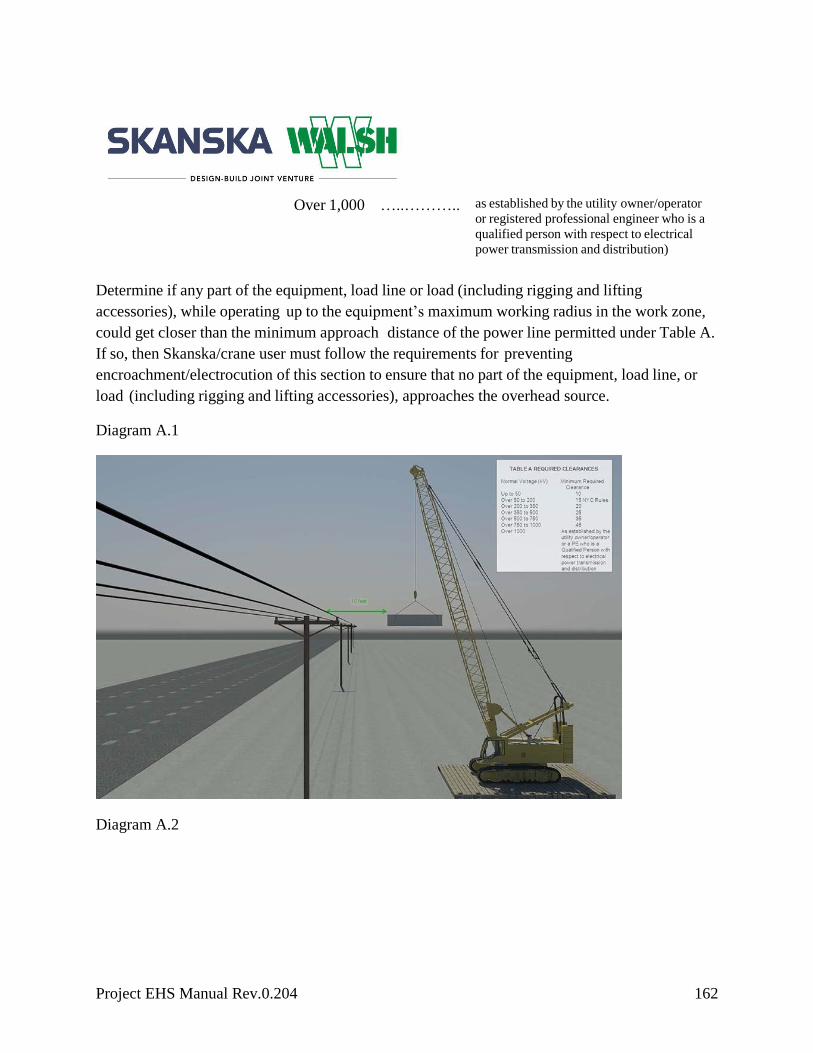
Project EHS Manual Rev.0.204 162
Over 1,000 …..……….. as established by the utility owner/operator
or registered professional engineer who is a
qualified person with respect to electrical
power transmission and distribution)
Determine if any part of the equipment, load line or load (including rigging and lifting
accessories), while operating up to the equipment’s maximum working radius in the work zone,
could get closer than the minimum approach distance of the power line permitted under Table A.
If so, then Skanska/crane user must follow the requirements for preventing
encroachment/electrocution of this section to ensure that no part of the equipment, load line, or
load (including rigging and lifting accessories), approaches the overhead source.
Diagram A.1
Diagram A.2

Project EHS Manual Rev.0.204 163
Diagram A.3

Project EHS Manual Rev.0.204 164
Diagram A.1-A.3 are examples of Table A – Minimum clearance while operating
11.7.2.2 Preventing Encroachment/Electrocution Equipment Operations
Where encroachment precautions are required under Option (2) or Option (3) of this section, all
of the following requirements must be met:
Conduct a planning meeting reviewing the construction plan with the operator and the
other workers who will be in the area of the equipment or load to review the location of
the power line(s) and the steps that will be implemented to prevent encroachment/
electrocution
Tag lines must be non‐conductive
Erect and maintain an elevated warning line, barricade or line of signs, in view of the
operator, equipped with flags or similar high‐visibility markings at 20’ from the power
line (if using Option (2) of this section) or at the minimum approach distance under Table
A, above (if using Option (3) of this section).
Implement at least one the following measures:

Project EHS Manual Rev.0.204 165
- A proximity alarm, set to give the operator sufficient warning to prevent
encroachment
- A dedicated spotter who is in continuous contact with the operator. Where this
measure is selected, the dedicated spotter must:
Be equipped with a visual aid to assist in identifying the minimum clearance
distance. Examples of a visual aid include, but are not limited to, a clearly
visible line painted on the ground, a clearly visible line of stanchions or a set of
clearly visible line-of-sight landmarks (e.g., a fence post behind the dedicated
spotter and a building corner ahead of the dedicated spotter).
Be positioned to effectively gauge the clearance distance. Where necessary, use
equipment that enables the dedicated spotter to communicate directly with the
operator. Give timely information to the operator so that the required clearance
distance can be maintained.
A device that automatically warns the operator when to stop movement, such as a range
control warning device. Such a device must be set to give the operator sufficient warning
to prevent encroachment.
A device that automatically limits range of movement, set to prevent encroachment.
An insulating link/device installed at a point between the end of the load line (or below)
and the load.
11.7.2.3 Voltage Information
Where Option (3) of this section is used, the utility owner/operator of the power lines must
provide the requested voltage information within two working days of the employer’s request.
11.7.2.4 Operations below Power Lines
No part of the equipment, load line or load (including rigging and lifting accessories) is allowed
below a power line; unless Skanska has confirmed that the utility owner/operator has de‐
energized and (at the jobsite) visibly grounded the power line.
Exceptions:
For equipment with non‐extensible booms: The uppermost part of the equipment, with
the boom at true vertical, would be more than 25’ below the plane of the power line and
more than the minimum clearance distance below the plane of the power line, as
established in Table A.

Project EHS Manual Rev.0.204 166
For equipment with articulating or extensible booms: The uppermost part of the
equipment, with the boom in the fully extended position, at true vertical, would be more
than 25’ below the plane of the power line or more than the minimum clearance distance
below the plane of the power line, as established in Table A of this section.
11.7.2.5 Power Lines Presumed Energized
Skanska/crane user must assume that all power lines are energized unless the utility
owner/operator confirms that the power line has been and continues to be de‐energized and
visibly grounded at the jobsite.
When working near transmitter/communication towers where the equipment is close enough for
an electrical charge to be induced in the equipment or materials being handled, the transmitter
must be de‐energized or the following precautions must be taken:
The equipment must be provided with an electrical ground
Tag lines must be non‐conductive
11.7.2.6 Training
To be prepared in the event of electrical contact with a power line, Skanska/crane user must
ensure each operator and crew member assigned to work with the equipment are trained on all of
the following:
Information regarding the danger of electrocution from the operator simultaneously
touching the equipment and the ground
The importance to the operator’s safety of remaining inside the cab except where there is
an imminent danger of fire, explosion or other emergency that necessitates leaving the
cab
The safest means of evacuating from equipment that may be energized
The danger of the potentially energized zone around the equipment (step potential)
The need for crew in the area to avoid approaching or touching the equipment and the
load
Safe clearance distance from power lines
The limitations of an insulating link/device, proximity alarm and range control (and
similar) device, if used
The procedures to be followed to properly ground equipment and the limitations of
grounding

Project EHS Manual Rev.0.204 167
Power lines are presumed to be energized unless the utility owner/operator confirms that the
power line has been and continue to be de-energized and visibly grounded at the jobsite.
Power lines are presumed to be uninsulated unless the utility owner/operator or a registered
engineer who is a qualified person with respect to electrical power transmission and distribution
confirms that a line is insulated.
Employees working as dedicated spotters must be trained to effectively perform their task,
including training on the applicable requirements of this section. Devices originally designed by
the manufacturer for use as a safety device, operational aid or a means to prevent power line
contact or electrocution when used to comply with this section, must meet the manufacturer’s
procedures for use and conditions of use.
Skanska must determine that it is not feasible to do the work without breaching the minimum
approach distance under Table A
The employer may determine that, after consultation with the utility owner/operator, it is
infeasible to de-energize and ground the power line or relocate the power line.
11.7.2.7 Power Line with Unknown Voltage
Refer to Option 1 in section 11.7.2.2.
11.7.2.8 Power Line Safety (All Voltages)—Equipment Operations Closer than the “Table A” Zone
Equipment operations in which any part of the equipment, load line or load (including rigging and
lifting accessories) is closer than the minimum approach distance under Table A to an energized
power line is prohibited, except where Skanska demonstrates that the following requirements are
met:
Hazards are identified in the Construction Work Plan
Minimum clearance distance is identified
The power line owner/operator or registered professional engineer who is a qualified
person with respect to electrical power transmission and distribution determines the
minimum clearance distance that must be maintained to prevent electrical contact in light
of the onsite conditions. The factors that must be considered in making this
determination include, but are not limited to, conditions affecting atmospheric
conductivity, time necessary to bring the equipment, load line and load (including rigging
and lifting accessories) to a complete stop, wind conditions, degree of sway in the power

Project EHS Manual Rev.0.204 168
line lighting conditions and other conditions affecting the ability to prevent electrical
contact.
A planning meeting with the employer and utility owner/operator (or registered
professional engineer who is a qualified person with respect to electrical power
transmission and distribution) is held to determine the procedures that will be followed to
prevent electrical contact and electrocution. At a minimum these procedures must
include:
- If the power line is equipped with a device that automatically reenergizes the circuit
in the event of a power line contact, the automatic reclosing feature of the circuit
interrupting device must be made inoperative if the design of the device permits
before the work begins
- The dedicated spotter must be equipped with a visual aid to assist in identifying the
minimum clearance distance. Examples of a visual aid include, but are not limited
to, a line painted on the ground; a clearly visible line of stanchions; a set of clearly
visible line‐of‐sight landmarks (such as a fence post behind the dedicated spotter
and a building corner ahead of the dedicated spotter) positioned to effectively gauge
the clearance distance. Where necessary, use equipment that enables the dedicated
spotter to communicate directly with the operator. Give timely information to the
operator so that the required clearance distance can be maintained.
- An elevated warning line or barricade (not attached to the crane) is in view of the
operator (either directly or through video equipment) equipped with flags or similar
high‐visibility markings to prevent electrical contact
- An insulating link/device is installed at a point between the end of the load line (or
below) and the load
- All employees, excluding equipment operators located on the equipment, who may
come in contact with the equipment, the load line, or the load are insulated or
guarded from the equipment, the load line, and the load through an additional means
other than an insulating link device. Insulating gloves rated for the voltage involved
are adequate additional means of protection for the purposes of this paragraph.
- Nonconductive rigging is used if the rigging is within the Table A distance during the
operation
- The equipment is equipped with a device that automatically limits range of
movement and that is set to prevent any part of the equipment, load line or load
(including rigging and lifting accessories) from breaching the minimum approach
distance established in Table A
- Tag lines are of the nonconductive type

Project EHS Manual Rev.0.204 169
- Barricades forming a perimeter at least 10’ away from the equipment are used to
prevent unauthorized personnel from entering the work area. In areas where
obstacles prevent the barricade from being at least 10’ away, the barricade must be
as far from the equipment as feasible.
- Workers other than the operator are prohibited from touching the load line above the
insulating link/ device and crane. Operators remotely operating the equipment from
the ground must use either wireless controls that isolate the operator from the
equipment or insulating mats that insulate the operator from the ground.
- Only personnel essential to the operation are permitted to be in the area of the crane
and load
- The equipment is properly grounded
- Insulating line hose or cover‐up is installed by the utility owner/operator except
where such devices are unavailable for the line voltages involved
- The procedures developed comply with this section and are documented and
immediately available onsite
- The equipment user and utility owner/operator (or RPE) meets with the equipment
operator and the other workers who will be in the area of the equipment or load to
review the procedures that will be implemented to prevent breaching the minimum
approach distance established in Table A of this section and prevent electrocution.
- The procedures developed to comply with this section are implemented
- The utility owner/operator (or RPE) and all employers of employees involved in the
work identify one person who will direct the implementation of the procedures. The
person identified in accordance with this paragraph must direct the implementation
of the procedures and must have the authority to stop work at any time to ensure
safety.
- If a problem occurs implementing these procedures or indicating that those
procedures are inadequate to prevent electrocution, the employer must safely stop
operations and either develop new procedures to comply with this section or have
the utility owner/ operator de‐energize and visibly ground or relocate the power line
before resuming work
- Devices originally designed by the manufacturer for use as a safety device
operational aid or a means to prevent power line contact or electrocution, when used
to comply with this section, must comply with the manufacturer’s procedures for use
and conditions of use
11.7.2.9 Safety while Traveling Under or Near Power Lines with No Load
Project EHS Manual Rev.0.204 170
Skanska will ensure that:
The power lines are identified on the crane location plan
The boom/mast and boom/mast support system are lowered sufficiently to meet the
requirements of this paragraph
The clearances specified in Table T (see below) of this section are maintained
The effects of speed and terrain on equipment movement (including movement of the
boom/mast) are considered so that those effects do not cause the minimum clearance
distances specified in Diagram B of this section to be breached
There is a dedicated spotter. If any part of the equipment while traveling will get closer
than 15’ to the power line, Skanska must ensure that a dedicated spotter who is in
continuous contact with the driver/operator is used. The dedicated spotter must be
positioned to effectively gauge the clearance distance. Where necessary, use equipment
that enables the dedicated spotter to communicate directly with the operator. Give timely
information to the operator so that the required clearance distance can be maintained.
Additional precautions for traveling in poor visibility:
When traveling at night or in conditions of poor visibility, in addition to the measures
previously specified in this section, Skanska will ensure that the power lines are
illuminated or another means of identifying the location of the lines is used and a safe
path of travel is identified and used
TABLE T —Minimum Clearance Distances While Traveling with No Load
Voltage(nominal, kV, alternating
current) while traveling
Minimum clearance distance (feet)
up to 0.75 …..……….. 4
over .75 to 50 …..……….. 6
over 50 to 345 …..……….. 10
over 345 to 750 …..……….. 16
Over 750 to 1,000 …..……….. 20
Over 1,000 …..……….. as established by the utility owner/operator
or registered professional engineer who is a
qualified person with respect to electrical
power transmission and distribution

Project EHS Manual Rev.0.204 171
Diagram B – Examples of Table T – Required clearances while traveling
11.7.2.10 Unavailable Operation Procedures
Where the manufacturer’s procedures are unavailable, Skanska will ensure compliance with all
procedures necessary for the safe operation of the equipment and attachments. Procedures for the
operational controls must be developed by a qualified person.
11.7.2.11 Accessibility of Procedures
The procedures applicable to the operation of the equipment, including rated capacities (load
charts), recommended operating speeds, special hazard warnings, instructions and operator’s
manual will be readily available in the cab at all times for use by the operator. Where rated
capacities are available in the cab only in electronic form and in the event of a failure that makes
the rated capacities inaccessible, the operator must immediately cease operations or follow safe
shut‐down procedures until the rated capacities (in electronic or other form) are available.
11.7.3 Regional/Project-Specific Requirements
Enter project-specific requirements
Project EHS Manual Rev.0.204 172
11.8 Weather
When a local storm warning has been issued, the competent person will determine whether it is
necessary to implement manufacturer recommendations for securing the equipment.
11.8.1 Wind
If wind conditions are such that the operator determines the lift is unsafe, the operation must be
stopped. The U.S. Weather Bureau data from the nearest reporting station may be used for the
determination of wind speed. Check the manufacturer’s wind recommendations prior to use.
Objects with large surface areas, such as formwork, may require a lower threshold in order to be
safely lifted. Any condition that may affect the permissible limits for safe lifts should be
identified in the lift plan.
11.8.2 Lightning
The use of a crane during lightning storms and events will be up to the sole discretion of the
project team and/or work crews. Whenever there is a concern toward safety, the operator has the
authority to stop and refuse to handle the load until a qualified person has determined the
conditions are safe.
11.8.3 Winter Months
When using cranes during the winter months, it is important to check the boom and head sheaves
for ice at the start of the shift. If at all possible, lower the boom to inspect for ice. If you cannot
lower the boom, make sure the crew and surrounding work crews are aware of the possible
danger of ice falling and do not stand under the boom when the crane is in use. Also, make sure
that all personnel working with the crane stand in front of the crane beyond the hook or headache
ball. In some operations, such as cranes on barges, ice may form more frequently. In these cases,
be aware of slips and do not walk under the booms.
11.8.4 Regional/Project-Specific Requirements
Enter project-specific requirements
11.9 Training Requirements
Project EHS Manual Rev.0.204 173
11.9.1 Signal Training‐General Requirements
Any person who will signal a crane must have passed the Skanska hand signal training class or
possess a nationally recognized certificate from an accredited organization. A qualified signal
person will display a recognizable visual marking on his/her hardhat while working on any site
where owner requirements do not prohibit such displays. The signal person(s) for each specific
lift are to be clearly identifiable by the operator. The preferred identification method is the display
of a unique visual identifier (such as a green hardhat, vest and gloves) by the signal person(s)
during the lift. This unique identifier is designated on a project-specific basis, depending on the
owner and site conditions.
During operations requiring signals, the ability to transmit signals between the operator and signal
person will be maintained. If that ability is interrupted at any time, the operator will safely stop
operations requiring signals until the signal is reestablished and a proper signal is given and
understood. If the operator becomes aware of a safety problem and needs to communicate with
the signal person, the operator must safely stop operations. Operations will not resume until the
operator and signal person agree that the problem has been resolved. Only one person gives
signals to a crane/derrick at a time, except in circumstances where the operator cannot see the
assigned signal person; in this case, a second signal person can relay signals to the operator from
the signal person who is out of view. The Construction Work Plan must be amended at this time.
Anyone who becomes aware of a safety problem must alert the operator or signal person by
giving the stop or emergency stop signal. All directions given to the operator by the signal person
will be given from the operator’s direction perspective.
A signal person must be provided for any working or traveling crane on site.
Signals to operators must be by hand or dedicated two-way communication. When using hand
signals, the standard method must be used (see Appendix B).
Exception: where use of the standard method for hand signals is infeasible, or where an operation
or use of an attachment is not covered in the standard method, non‐standard hand signals may be
used.
Non‐Standard Hand Signals
When using non‐standard hand signals, the signal person, operator and lift supervisor (where
there is one) will contact each other prior to the operation and agree on the non‐standard hand
signals that will be used.

Project EHS Manual Rev.0.204 174
New Signals
Signals other than hand, voice or audible signals may be used where the employer on any
Skanska project, demonstrates that:
The new signals provide communication at least equally effective as voice, audible or
standard method hand signals, and are suitable
The signals used (e.g., hand, voice, audible or new) and means of transmitting the signals
to the operator (e.g., direct line of sight, video, radio, etc.) must be appropriate for the
site conditions
Prior to beginning operations, the operator, signal person and lift supervisor (if there is one), will
contact each other and agree on the voice signals that will be used. Once the voice signals are
agreed upon, these workers do not need to meet again to discuss voice signals, unless another
worker is substituted, there is confusion about the voice signals or a voice signal is to be changed.
Each voice signal will contain the following three elements, given in the following order:
function (e.g., hoist, boom, etc.), direction distance and/or speed function, stop command.
The operator, signal person and lift supervisor, if there is one, must be able to effectively
communicate in the language used.
When using any electronic device for voice/audible signals, back-up batteries must be with the
signal person prior to operation. A proactive plan for device failure must be discussed and
documented.
Communication with Multiple Cranes/Derricks
Where a signal person(s) is in communication with more than one crane/derrick, a system for
identifying which crane/derrick each signal is for must be established.
Radio or Other Electronic Transmission of Signals
The device(s) used to transmit signals will be tested onsite before beginning operations to ensure
that the signal transmission is clear and reliable. Signals must be transmitted through a dedicated
channel.
Exception: Multiple cranes/derricks and one or more signal persons may share a dedicated
channel for the purpose of coordinating operations. The operator’s reception of signals must be
by a hands‐free system

Project EHS Manual Rev.0.204 175
Signals
Hand signal charts must be both posted on the equipment and readily available at the site.
Upon completion of the Skanska hand signal training course or if the signalman possesses a
nationally recognized certificate from an accredited organization, each individual will be issued
the appropriate project- specific signalman visual identifier. See images below.

Project EHS Manual Rev.0.204 176
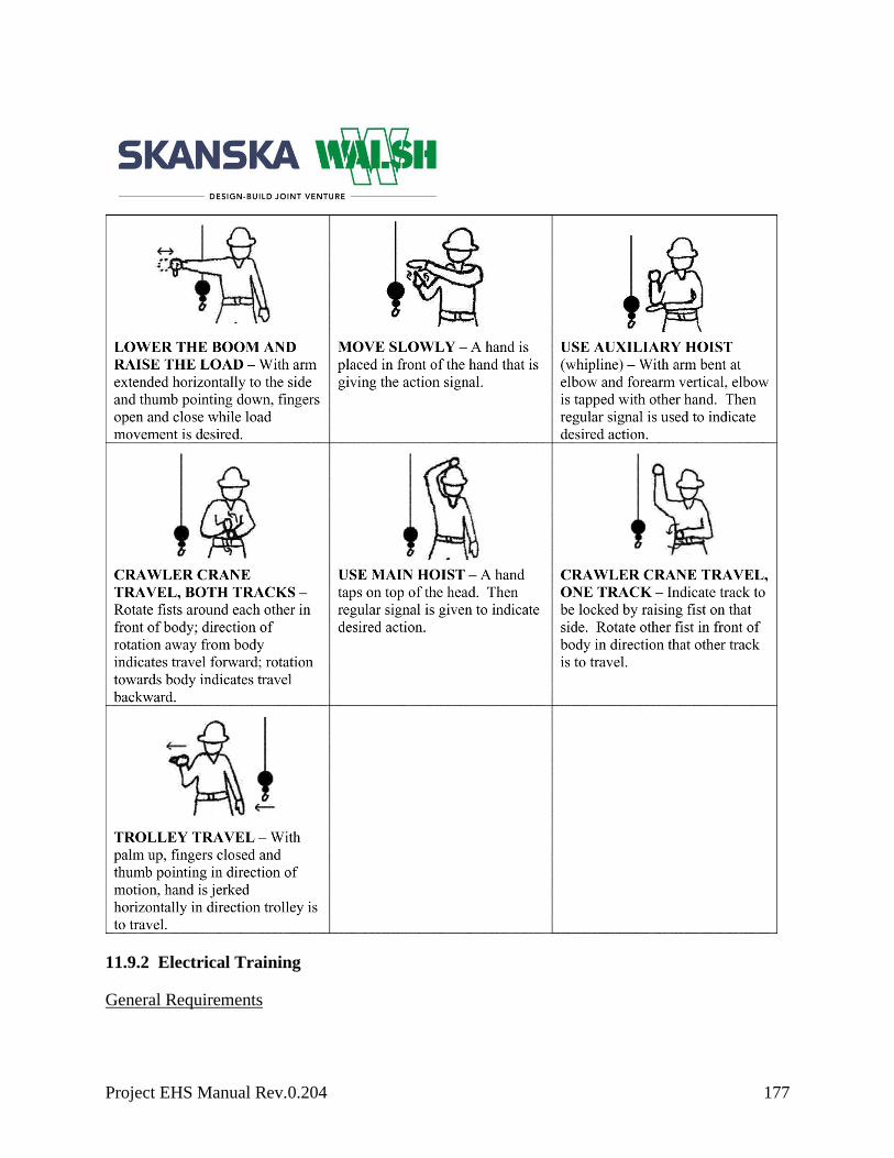
Project EHS Manual Rev.0.204 177
11.9.2 Electrical Training
General Requirements

Project EHS Manual Rev.0.204 178
Each crew member working with a crane must have completed the electrical training defined in
Electrical 11.7.2.6.
11.9.3 Dedicated Spotter
General Requirements
A person working as a dedicated spotter around electrical hazards must be trained to fit the
definition of signal person.
11.9.4 Rigging Training
General Requirements
All rigging personnel must meet the definition of a qualified rigger.
11.9.5 Regional/Project-Specific Requirements
Enter project-specific requirements
11.10 Unconventional Cranes
11.10.1 Tower Cranes
This section contains supplemental requirements for tower cranes. All sections apply to tower
cranes unless specified otherwise.
11.10.1.1 Erecting, Climbing and Dismantling
The following sections apply to tower cranes (except as otherwise noted), except that the term
assembly/disassembly (A/D) is replaced by “erecting, climbing and dismantling,” and the term
“disassembly” is replaced by “dismantling”:
Assembly/Disassembly — Selection of manufacturer or employer procedures
Assembly/Disassembly — General requirements (applies to all assembly and disassembly
operations)
Disassembly – Additional requirements for dismantling of booms and jibs (applies to both the use
of manufacturer procedures and employer procedures)
11.10.1.2 Dangerous Areas (Self‐Erecting Tower Cranes)

Project EHS Manual Rev.0.204 179
In addition to the requirements for self‐erecting tower cranes, the following applies:
Employees will not be in or under the tower, jib or rotating portion of the crane during
erecting, climbing and dismantling operations until the crane is secured in a locked
position and the competent person in charge indicates it is safe to enter this area, unless
the manufacturer’s instructions direct otherwise and only the necessary personnel are
permitted in this area
In some jurisdictions, a master rigger and proper notification to local governing agencies are
required. This is the responsibility of the jobsite.
11.10.1.3 Foundations and Structural Supports
Tower crane foundations and structural supports will be designed by the manufacturer or a
registered professional engineer (RPE).
11.10.1.4 Addressing Specific Hazards
In addition to assembly/disassembly requirements, the A/D supervisor will address the following:
Foundations and structural supports: The A/D supervisor will verify that the tower crane
foundations and structural supports are installed in accordance with their design.
Loss of backward stability: Backward stability must be considered before swinging self-
erecting cranes or cranes on traveling or static undercarriages.
Wind speed: Wind must not exceed the speed recommended by the manufacturer or
where the manufacturer does not specify this information, the speed determined by a
qualified person.
11.10.1.5 Plumb Tolerance
Towers will be erected plumb to the manufacturer’s tolerance and verified by a qualified person.
Where the manufacturer does not specify plumb tolerance, the crane tower will be plumb to a
tolerance of at least 1:500 (approximately 1” in 40’).
11.10.1.6 Multiple Tower Crane Jobsites
On jobsites where more than one fixed jib (hammerhead) tower crane is installed, the cranes will
be located so no crane will come in contact with the structure of another crane. Cranes are
permitted to pass over one another.
11.10.1.7 Climbing Procedures
Project EHS Manual Rev.0.204 180
Prior to, and during, all climbing procedures (including inside climbing and top climbing), the
employer will:
Comply with all manufacturer prohibitions
Have an RPE verify that the host structure is strong enough to sustain the forces imposed
through the braces
Brace anchorages and supporting floors
Ensure that no part of the climbing procedure takes place when wind exceeds the speed
recommended by the manufacturer or, where the manufacturer does not specify this
information, the speed determined by a qualified person. Some local governing agencies
require 48-hour notifications.
11.10.1.8 Counterweight/Ballast
Equipment will not be erected, dismantled or operated without the amount and position of
counterweight and/or ballast in place as specified by the manufacturer or an RPE familiar with
the equipment. The maximum counterweight and/or ballast specified by the manufacturer or an
RPE familiar with the equipment will not be exceeded.
11.10.1.9 Signs
The size and location of signs installed on tower cranes must be in accordance with manufacturer
specifications. Where these are unavailable, an RPE familiar with the type of equipment involved
must approve in writing the size and location of any signs.
11.10.1.10 Safety Devices
The following safety devices are required on all tower cranes unless otherwise specified:
Boom stops on luffing boom type tower cranes
Jib stops on luffing boom type tower cranes if equipped with a jib attachment
Travel rail end stops at both ends of travel rail
Travel rail clamps on all travel bogies
Integrally mounted check valves on all load-supporting hydraulic cylinders
Hydraulic system pressure limiting device
The following brakes, which automatically set in the event of pressure loss or power
failure:
Project EHS Manual Rev.0.204 181
- A hoist brake on all hoists
- Swing brake
- Trolley brake
- Rail travel brake
Dead man control or forced neutral return control (hand) levers
Emergency stop switch at the operator’s station
Trolley end stops at both ends of travel of the trolley
Proper operation required
Operations will not begin unless the devices listed in this section are in proper working order. If a
device stops working properly during operations, the operator will safely stop operations.
Operations will not resume until the device is again working properly. Alternative measures are
not permitted to be used.
11.10.1.11 Operational Aids
The devices listed in the following sections (“operational aids”) are required on all tower cranes,
unless otherwise specified.
Operations will not begin unless the operational aids are in proper working order, except where
Skanska/crane user meets the specified temporary alternative measures. More protective
alternative measures specified by the tower crane manufacturer, if any, will be followed.
If an operational aid stops working properly during operations, the operator will safely stop
operations until the temporary alternative measures are implemented or the device is again
working properly. If a replacement part is no longer available, the use of a substitute device that
performs the same type of function is permitted and is not considered a modification.
11.10.1.12 Category I Operational Aids and Alternative Measures
Operational aids listed in this below that are not working properly will be repaired no later than
seven days after the deficiency occurs.
Exception: If the employer documents that it has ordered the necessary parts within seven days of
the occurrence of the deficiency, the repair will be completed within seven days of receipt of the
parts.
Trolley Travel Limiting Device
Project EHS Manual Rev.0.204 182
The travel of the trolley will be restricted at both ends of the jib by a trolley-travel limiting device
to prevent the trolley from running into the trolley end stops.
Temporary alternative measures:
Option A: The trolley rope will be marked (so it can be seen by the operator) at a point
that gives the operator sufficient time to stop the trolley prior to the end stops
Option B: A spotter will be used when operations are conducted within 10’ of the outer
or inner trolley end stops
Boom Hoist Limiting Device
The range of the boom will be limited at the minimum and maximum radius.
Temporary alternative measures: Clearly mark the cable (so it can be seen by the operator) at a
point that gives the operator sufficient time to stop the boom hoist within the minimum and
maximum boom radius or use a spotter.
Anti Two‐Blocking Device
The tower crane will be equipped with a device that automatically prevents damage from contact
between the load block, overhaul ball or similar component and the boom tip (or fixed upper
block or similar component). The device(s) must prevent such damage at all points where two‐
blocking could occur.
Temporary alternative measures: Clearly mark the cable (so it can be seen by the operator) at a
point that will give the operator sufficient time to stop the hoist to prevent two‐blocking or use a
spotter.
Hoist Drum Lower Limiting Device
Tower cranes manufactured more than one year after January 1st, 2011 must be equipped with a
device that prevents the last three wraps of hoist cable from being spooled off the drum.
Temporary alternative measures: Mark the cable (so it can be seen by the operator) at a point that
will give the operator sufficient time to stop the hoist prior to the last three wraps of hoist cable
being spooled off the drum or use a spotter.
Load Moment Limiting Device

Project EHS Manual Rev.0.204 183
The tower crane must have a device that prevents moment overloading
Temporary alternative measures: A radius-indicating device will be used (if the tower crane is
not equipped with a radius indicating device, the radius will be measured to ensure the load is
within the rated capacity of the crane). In addition, the weight of the load will be determined from
a reliable source (e.g., the load’s manufacturer), by a reliable calculation method (i.e., calculating
a steel beam from measured dimensions and a known per foot weight) or by other equally reliable
means. This information will be provided to the operator prior to the lift.
Hoist Line Pull Limiting Device
The capacity of the hoist will be limited to prevent overloading including each individual gear
ratio if equipped with a multiple-speed hoist transmission.
Temporary alternative measures: The operator will ensure that the weight of the load does not
exceed the capacity of the hoist (including for each individual gear ratio if equipped with a
multiple speed hoist transmission).
Rail Travel Limiting Device
The travel distance in each direction will be limited to prevent the travel bogies from running into
the end stops or buffers.
Temporary alternative measures: A spotter will be used when operations are conducted within
10’ of either end of the travel rail end stops.
Boom Hoist Drum Positive Locking Device
The boom hoist drum will be equipped with a device to positively lock the boom hoist drum.
Temporary alternative measures: The device will be manually set when required if an electric,
hydraulic or automatic type is not functioning.
11.10.1.13 Category II Operational Aids and Alternative Measures
Operational aids listed in below that are not working properly will be repaired no later than 30
days after the deficiency occurs.
Exception: If the employer can document that it has ordered the necessary parts within seven days
of the occurrence of the deficiency, and the part is not received in time to complete the repair in
30 days, the repair will be completed within seven days of receipt of the parts.

Project EHS Manual Rev.0.204 184
11.10.1.14 Boom Angle or Hook Radius Indicator
Luffing boom tower cranes will have a boom angle indicator readable from the operator’s station.
Hammerhead tower cranes will have a hook radius indicator readable from the operator’s station.
If either of the above criteria is not met, the following temporary alternative measures may be
implemented:
Temporary alternative measures:
Hook radii or boom angle will be determined by measuring the hook radii or boom angle
Trolley travel deceleration device: the trolley speed will be automatically reduced prior
to the trolley reaching the end limit in both directions
Temporary alternative measures:
The operator will reduce the trolley speed when approaching the trolley end limits
Boom hoist deceleration device: the boom speed will be automatically reduced prior to
the boom reaching the minimum or maximum radius limit
Temporary alternative measures:
The operator will reduce the boom speed when approaching the boom maximum or
minimum end limits
Load hoist deceleration device: the load speed will be automatically reduced prior to the
hoist reaching the upper limit
Temporary alternative measures:
The operator will reduce the hoist speed when approaching the upper limit
Wind speed indicator: a device will be provided to display the wind speed and mounted
above the upper rotating structure on tower cranes. On self-erecting cranes, it will be
mounted at or above the jib level.
Temporary alternative measures:
Use of wind speed information from a properly functioning indicating device on another
tower crane on the same site or a qualified person estimates the wind speed

Project EHS Manual Rev.0.204 185
Load indicating device: Cranes manufactured after 2012 will have a device that displays the
magnitude of the load on the hook. Displays that are part of load-moment limiting devices
that display the load on the hook meet this requirement.
Temporary alternative measures:
The weight of the load will be determined from a reliable source (e.g., the load’s
manufacturer), by a reliable calculation method (i.e., calculating a steel beam from
measured dimensions and a known per foot weight) or by other equally reliable means.
This information will be provided to the operator prior to the lift.
11.10.1.15 Pre‐Erection Inspections
Before each crane component is erected
It must be inspected by a qualified person for damage or excessive wear. The qualified
person must pay particular attention to components that will be difficult to inspect
thoroughly during shift inspections.
If the qualified person determines that a component is damaged or worn to the extent that
it would create a safety hazard if used on the crane, that component must not be erected on
the crane unless it is repaired and, upon re‐inspection by the qualified person, found to no
longer create a safety hazard.
If the qualified person determines that, though not presently a safety hazard, the
component needs to be monitored, the employer must ensure that the component is
checked in the monthly inspections. Any such determination must be documented and the
documentation must be available to any individual who conducts a monthly inspection.
11.10.1.16 Post‐Erection Inspection
The following requirements will be met:
A load test using certified weights or scaled weights using a certified scale with a current
certificate of calibration will be conducted after each erection. The load test will be
conducted in accordance with the manufacturer’s instructions. Where these instructions
are will develop written load-test procedures.
11.10.1.17 Monthly
The following additional items will be included:

Project EHS Manual Rev.0.204 186
Tower (mast) bolts and other structural bolts (for loose or dislodged condition) from the
base of the tower crane up or, if the crane is tied to or braced by the structure, those
above the upper‐most brace support
The uppermost tie‐in, braces, floor supports and floor wedges where the tower crane is
supported by the structure, shall be inspected for loose or dislodged components
11.10.1.18 Annual
In addition to the items that must be inspected, all turntable and tower bolts must be inspected for
proper condition and torque.
11.10.2 Derricks
This section contains supplemental requirements for derricks. Whether temporarily or
permanently mounted, all sections of this subpart apply to derricks unless specified otherwise. A
derrick is powered equipment consisting of a mast or equivalent member that is held at or near
the end by guys or braces, with or without a boom and its hoisting mechanism. The
mast/equivalent member and/or the load is moved by the hoisting mechanism (typically base‐
mounted) and operating ropes. Derricks include: A‐frame, basket, breast, Chicago boom, gin pole
(except gin poles used for erection of communication towers), guy, shearleg, stiffleg and
variations of such equipment.
11.10.2.1 Operation – Procedures
Section OSHA 1926.1417 (Operation) applies except for OSHA 1926.1417(c) Accessibility of
procedures.
Load Chart Contents
Load charts will contain at least:
Rated capacity at corresponding ranges of boom angle or operating radii
Specific lengths of components to which the rated capacities apply
Required parts for hoist reeving
Size and construction of rope
Load chart location
Permanent Installations

Project EHS Manual Rev.0.204 187
For permanently installed derricks with fixed lengths of boom, guy and mast, a load chart will be
posted where it is visible to personnel responsible for the operation of the equipment.
Non‐Permanent Installations
For derricks that are not permanently installed, the load chart will be readily available at the job
site to personnel responsible for the operation of the equipment.
11.10.2.2 Construction and Anchoring
General Requirements
Derricks will be constructed to meet all stresses imposed on members and components
when installed and operated in accordance with the manufacturer’s procedures and
within its rated capacity
Welding of load-sustaining members will conform to recommended practices in
ANSI/AWS D14.3 ‐94 or D1.1‐2
11.10.2.3 Guy Derricks
The minimum number of guys is six, with equal spacing, except where a qualified person or
derrick manufacturer approves variations from these requirements and revises the rated capacity
to compensate for such variations. Guy derricks will not be used unless the employer has the
following guy information:
The number of guys
The spacing around the mast
The size, grade and construction of rope to be used for each guy
The anchorage and guying will be designed to withstand maximum horizontal and vertical forces
encountered when operating within rated capacity with the particular guy slope and spacing
specified for the application.
For guy derricks manufactured after December 18, 1970, in addition to the information required
in this section, the employer will have the following guy information:
The amount of initial sag or tension
The amount of tension in guy line rope at anchor

Project EHS Manual Rev.0.204 188
The mast base will permit the mast to rotate freely with allowance for slight tilting of the mast
caused by guy slack.
The mast cap will:
Permit the mast to rotate freely
Withstand tilting and cramping caused by the guy loads
Be secured to the mast to prevent disengagement during erection
Be provided with means for attaching guy ropes
11.10.2.4 Stiffleg Derricks
The mast will be supported in the vertical position by at least two stifflegs. One end of each will
be connected to the top of the mast and the other end securely anchored. The stifflegs will be
capable of withstanding the loads imposed at any point of operation within the load chart range,
and the mast base will:
Permit the mast to rotate freely (when necessary)
Permit deflection of the mast without binding
Be prevented from lifting out of its socket when the mast is in tension
Be anchored
Be designed to withstand maximum horizontal and vertical forces encountered when
operating within rated capacity with the particular stiffleg spacing and slope specified for
the application
The stiffleg connecting member at the top of the mast will:
Permit the mast to rotate freely (when necessary)
Withstand the loads imposed by the action of the stifflegs
Be secured so as to oppose separating forces
Be anchored
Be designed to withstand maximum horizontal and vertical forces encountered when
operating within rated capacity with the particular stiffleg spacing and slope specified for
the application
11.10.2.5 Gin Pole Derrick
Guy lines will be sized and spaced to stabilize the gin pole in both boomed and vertical positions.

Project EHS Manual Rev.0.204 189
Exceptions:
Where the size and/or spacing of guy lines do not result in the gin pole being stable in
both boomed and vertical positions, the employer will ensure that the derrick is not used
in an unstable position
The base of the gin pole will permit movement of the pole (when necessary). The gin
pole shall be anchored at the base against horizontal forces (when such forces are
present)
11.10.2.6 Chicago Boom Derrick
The fittings for stepping the boom and for attaching the topping lift will be arranged to:
Permit the derrick to swing at all permitted operating radii and mounting heights
between fittings
Accommodate attachment to the upright member of the host structure
Withstand the forces applied when configured and operated in accordance with the
manufacturer’s procedures and within its rated capacity
Prevent the boom or topping lift from lifting out under tensile forces
11.10.2.7 Swingers and Hoists
The boom, swinger mechanisms and hoists will be suitable for the derrick work intended and will
be anchored to prevent displacement from the imposed loads. Base‐mounted drum hoists will
meet the requirements in the following sections of ASME B30.7–2001:
Sections 7‐1.1 (Load ratings and markings)
Section 7‐1.2 (Construction), except: 7‐1.2.13 (Operator’s cab) 7‐1.2.15 (Fire
extinguishers)
Section 7‐1.3 (Installation)
Applicable terms in section 7‐0.2 (Definitions)
11.10.2.8 Load Tests for New Hoists
The employer will ensure that new hoists are load tested to a minimum of 110 percent of rated
capacity, but not more than 125 percent of rated capacity, unless otherwise recommended by the
manufacturer. This requirement is met where the manufacturer has conducted this testing.
11.10.2.9 Repaired or Modified Hoists

Project EHS Manual Rev.0.204 190
Hoists that have had repairs, modifications or additions affecting their capacity or safe operation
will be evaluated by a qualified person to determine if a load test is necessary. If it is, load testing
will be conducted in accordance with this policy and manufacturer requirements.
11.10.2.10 Load Test Procedure
Load tests required by this policy will be conducted as follows:
The test load will be hoisted a vertical distance to assure that the load is supported by the
hoist and held by the hoist brake(s)
The test load will be lowered, stopped and held with the brake(s)
The hoist will not be used unless a competent person determines that the test has been
passed
11.10.2.11 Operational Aids
Section OSHA 1926.1416 (Operational aids) applies, except for OSHA 1926.1416 (d)(1) Boom
hoist limiting device and OSHA 1926.1416(e)(1) Boom angle or radius indicator and OSHA
1926.1416(e)(4) Load weighing and similar devices.
Boom Angle Aid
The employer will ensure that either:
The boom hoist cable is marked with caution and stop marks. The stop marks will
correspond to maximum and minimum allowable boom angles. The caution and stop
marks will be in view of the operator or a spotter who is in direct communication with
the operator.
An electronic or other device that signals the operator in time to prevent the boom from
moving past its maximum and minimum angles, or automatically prevents such
movement, is used
Load Weight/Capacity Devices
Derricks manufactured after 2012 with a maximum rated capacity over 6,000 pounds will have at
least one of the following: load weighing device, load moment indicator, rated capacity indicator
or rated capacity limiter.
Temporary alternative measures: The weight of the load will be determined by a reliable source
(e.g., the load’s manufacturer), by a reliable calculation method (i.e., calculating a steel beam

Project EHS Manual Rev.0.204 191
from measured dimensions and a known per foot weight) or by other equally reliable means. This
information will be provided to the operator prior to the lift.
11.10.2.12 Post‐Assembly Approval and Testing – New or Reinstalled Derricks
11.10.2.13 Functional Test
Prior to initial use, new or reinstalled derricks will be tested with no hook load by a competent
person to verify proper operation. This test will include:
Lifting and lowering the hook(s) through the full range of hook travel
Raising and lowering the boom through the full range of boom travel
Swinging in each direction through the full range of swing
Actuating the anti two‐block and boom hoist limit devices (if provided)
Actuating the locking, limiting and indicating devices (if provided)
11.10.2.14 Load Test
Prior to initial use, new or reinstalled derricks will be load tested by a competent person.
The test load will meet the following requirements:
Test loads will be at least 100 percent and no more than 110 percent of the rated capacity
unless otherwise recommended by the manufacturer or qualified person but in no event
will the test load be less than the maximum anticipated load
The test will consist of:
Hoisting the test load a few inches and holding to verify that the load is supported by the
derrick and held by the hoist brake(s)
Swinging the derrick, if applicable, the full range of its swing, at the maximum allowable
working radius for the test load
Booming the derrick up and down within the allowable working radius for the test load
Lowering, stopping and holding the load with the brake(s).
The derrick will not be used unless the competent person determines that the test has been
passed.
Documentation

Project EHS Manual Rev.0.204 192
Tests conducted under this section will be documented. The document will contain the date, test
results and the name of the tester. The document will be retained until the derrick is re-tested or
dismantled, whichever occurs first.
11.10.2.15 Load Testing Repaired or Modified Derricks
Derricks that have had repairs, modifications or additions affecting the derrick’s capacity or safe
operation will be evaluated by a qualified person to determine if a load test is necessary. If a load
test is necessary, it will be conducted and documented in accordance with this policy.
11.10.2.16 Power Failure Procedures
If power fails during operations, the derrick operator will safely stop operations. This includes
setting all brakes or locking devices and moving all clutch and other power controls to the off
position.
11.10.2.17 Use of Winch Heads
Ropes will not be handled on a winch head without the knowledge of the operator. While a
winch head is being used, the operator will be within reach of the power unit control lever.
11.10.2.18 Securing the Boom
When the boom is being held in a fixed position, dogs, pawls or other positive holding
mechanisms on the boom hoist will be engaged. When taken out of service for 30 days or more,
the boom will be secured by one of the following methods:
Laid down
Secured to a stationary member, as nearly under the head as possible, by attachment of a
sling to the load block for guy derricks, lifted to a vertical position and secured to the
mast for stiffleg derricks, secured against the stiffleg
The process of jumping the derrick will be supervised by the A/D supervisor.
Derrick operations will be supervised by a competent person.
Inspections
In addition to the requirements in OSHA 1926.1412, the following additional items will be
included in the inspections:
Project EHS Manual Rev.0.204 193
Daily: Guys for proper tension
Annual: Gudgeon pin for cracks, wear and distortion
Foundation supports for continued ability to sustain the imposed loads. OSHA
1926.1427 Operator qualification and certification does not apply.
11.10.3 Floating Cranes, Derricks and Land Cranes, Derricks on Barges
This section contains supplemental requirements for floating cranes/derricks and land
cranes/derricks on barges, pontoons, vessels or other means of flotation (vessel/flotation device).
All sections of this subpart apply to floating cranes/derricks and land cranes/derricks on barges,
pontoons, vessels or other means of flotation, unless specified otherwise. The requirements of
this section do not apply when using jacked barges when the jacks are deployed to the
river/lake/sea bed and the barge is fully supported by the jacks
11.10.3.1 General Requirements
The requirements in paragraphs (c) through (k) of this section apply to both floating
cranes/derricks and land cranes/derricks on barges, pontoons, vessels or other means of flotation
11.10.3.2 Work Area Control
The requirements of OSHA 1926.1424 Work area control apply, except for OSHA 1926.1416 (a)
(2) (ii). The employer will either:
Erect and maintain control lines, warning lines, railings or similar barriers to mark the
boundaries of the hazard areas
Clearly mark the hazard areas using a combination of warning signs (such as “Danger —
Swing/Crush Zone”) and high visibility markings on the equipment that identify the
hazard areas. In addition, the employer will train the employees to understand what these
markings signify.
11.10.3.3 Keeping Clear of the Load
OSHA 1926.1425 does not apply.
11.10.3.4 Additional Safety Devices
In addition to the safety devices listed in OSHA 1926.1415, the following safety devices are
required:
Project EHS Manual Rev.0.204 194
Barge, pontoon, vessel or other means of flotation list and trim device, located in the cab
or, where there is no cab, at the operator’s station
Horn
Positive equipment house lock
Wind speed and direction indicator: A competent person will determine if wind is a
factor that needs to be considered. If it needs to be considered, a wind speed and
direction indicator will be used
11.10.3.5 Operational Aids
An anti two‐block device is required only when hoisting personnel or hoisting over an occupied
cofferdam or shaft
OSHA 1926.1416(e)(4) Load weighing and similar devices does not apply to dragline, clamshell
(grapple), magnet, drop ball, container handling, concrete bucket and pile driving work.
11.10.3.6 Accessibility of Procedures Applicable to Equipment Operation
If the crane/derrick has a cab, the requirements of OSHA 1926.1417(c) apply. If the crane/derrick
does not have a cab, rated capacities (load charts) will be posted at the operator’s station. If the
operator’s station is moveable (such as with pendant‐controlled equipment), the load charts will
be posted on the equipment
Procedures applicable to the operation of the equipment (other than load charts), recommended
operating speeds, special hazard warnings, instructions and operators manual, will be readily
available on board.
11.10.3.7 Inspections
In addition to meeting the requirements of OSHA 1926.1412 for inspecting the crane/derrick, the
employer will ensure that the barge, pontoons, vessel or other means of flotation used to support
a floating crane/derrick or land crane/derrick is inspected as follows:
Shift Inspections
The means used to secure/attach the equipment to the vessel/flotation device will be inspected for
proper condition, including wear, corrosion, loose or missing fasteners, defective welds and
(where applicable) insufficient tension.
Monthly Inspections

Project EHS Manual Rev.0.204 195
The vessel/flotation device used will be inspected for the following:
The means used to secure/attach the equipment to the vessel/flotation device will be
inspected for proper condition, including wear, corrosion and (where applicable)
insufficient tension
Taking on water
Deck load for proper securing
Chain lockers, storage, fuel compartments and battening of hatches for serviceability as a
water‐tight appliance
Firefighting and lifesaving equipment in place and functional
The shift and monthly inspections will be conducted by a competent person. If any deficiency is
identified, an immediate determination will be made by a qualified person as to whether the
deficiency constitutes a hazard. If the deficiency is determined to constitute a hazard, the
vessel/flotation device will be removed from service until it has been corrected.
Annual
External vessel/flotation device inspection
The external portion of the barge, pontoons, vessel or other means of flotation used will be
inspected annually by a qualified person who has expertise with respect to vessels/flotation
devices. The inspection will include the items identified above as Shift and Monthly of this
section.
In addition, cleats, bitts, chocks, fenders, capstans, ladders and stanchions will be inspected for
significant:
Corrosion, wear, deterioration and deformation
External evidence of leaks and structural damage
Four‐corner draft readings checked
Firefighting equipment for serviceability
Rescue skiffs, lifelines, work vests, life preservers and buoys for condition
If any deficiency is identified, an immediate determination will be made by the qualified person
as to whether the deficiency constitutes a hazard or, though not yet a hazard, needs to be
monitored in the monthly inspections. If the deficiency is determined to constitute a hazard, the
vessel/flotation device will be removed from service until it has been corrected. If the qualified
Project EHS Manual Rev.0.204 196
person determines that, though not presently a hazard, the deficiency needs to be monitored, the
employer will ensure that the deficiency is checked in the monthly inspections.
Quadrennial
Internal vessel/flotation device inspection
The internal portion of the barge, pontoons, vessel or other means of flotation used will be
surveyed once every four years by a marine engineer, marine architect, licensed surveyor or
other qualified person who has expertise with respect to vessels/flotation devices.
If any deficiency is identified, an immediate determination will be made by the surveyor as to
whether the deficiency constitutes a hazard or, though not yet a hazard, needs to be monitored in
the monthly or annual inspections, as appropriate. If the deficiency is determined to constitute a
hazard, the vessel/flotation device will be removed from service until it has been corrected. If the
surveyor determines that, though not presently a hazard, the deficiency needs to be monitored,
the employer will ensure that the deficiency is checked in the monthly or annual inspections, as
appropriate.
Documentation
The monthly and annual inspections required in this section (above) will be documented in
accordance with OSHA 1926.1412 (e) (3) and 1926.1412(f)(7), respectively. The quadrennial
inspection required in paragraph (h) (5) of this section will be documented in accordance with
OSHA 1926.1412(f) (7), except that the documentation for that inspection will be retained for a
minimum of four years.
11.10.3.8 Working with a Diver
The following additional requirements apply when working with a diver in the water:
If a crane/derrick is used to get a diver into and out of the water, it will not be used for
any other purpose until the diver is back on board. When used for more than one diver, it
will not be used for any other purpose until all divers are back on board.
The operator will remain at the controls of the crane/derrick at all times. In addition to
the requirements in OSHA 1926.1419 through 1422 Signals, either:
- A clear line of sight will be maintained between the operator and tender
- The signals between the operator and tender will be transmitted electronically

Project EHS Manual Rev.0.204 197
The means used to secure the crane/derrick to the vessel/flotation device will not allow
any amount of shifting in any direction.
The employer will ensure that the manufacturer’s specifications and limitations with
respect to environmental, operational and in‐transit loads for the barge, pontoons, vessel
or other means of flotation are not exceeded or violated
11.10.3.9 Load Charts
The manufacturer load charts applicable to operations on water will not be exceeded. When using
these charts, the employer will comply with all parameters and limitations (such as
dynamic/environmental parameters) applicable to the use of the charts. The load charts will take
into consideration a minimum wind speed of 40 miles per hour. The requirements for maximum
allowable list and maximum allowable trim as specified in Table M1 of this section will be met.
Reference OSHA 1926.1437(m) (1) ‐ (m) (4)
TABLE M1 – Maximum Allowable List and Trim
Rated Capacity Maximum
Allowable
List
Maximum
Allowable
Trim Equipment designed for marine use by permanent attachment
(other than derricks):
25 tons or less 5 degrees 5 degrees
Over 25 tons 7 degrees 7 degrees
Derricks designed for marine use by permanent attachment: 10 degrees 10degrees
The equipment will be stable under the conditions specified in Tables M2 and M3 of this section.
Anything less than minimum freeboard list needs to be approved by an RPE.
TABLE M2: Equipment freeboard stability requirements
Operated at Wind speed Minimum freeboard
Rated capacity 60 mph 2 ft.
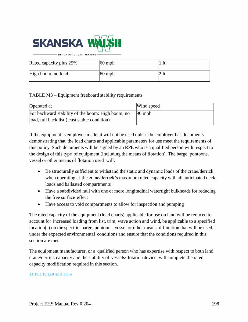
Project EHS Manual Rev.0.204 198
TABLE M3 – Equipment freeboard stability requirements
Operated at Wind speed
For backward stability of the boom: High boom, no
load, full back list (least stable condition)
90 mph
If the equipment is employer‐made, it will not be used unless the employer has documents
demonstrating that the load charts and applicable parameters for use meet the requirements of
this policy. Such documents will be signed by an RPE who is a qualified person with respect to
the design of this type of equipment (including the means of flotation). The barge, pontoons,
vessel or other means of flotation used will:
Be structurally sufficient to withstand the static and dynamic loads of the crane/derrick
when operating at the crane/derrick’s maximum rated capacity with all anticipated deck
loads and ballasted compartments
Have a subdivided hull with one or more longitudinal watertight bulkheads for reducing
the free surface effect
Have access to void compartments to allow for inspection and pumping
The rated capacity of the equipment (load charts) applicable for use on land will be reduced to
account for increased loading from list, trim, wave action and wind, be applicable to a specified
location(s) on the specific barge, pontoons, vessel or other means of flotation that will be used,
under the expected environmental conditions and ensure that the conditions required in this
section are met.
The equipment manufacturer, or a qualified person who has expertise with respect to both land
crane/derrick capacity and the stability of vessels/flotation device, will complete the rated
capacity modification required in this section.
11.10.3.10 List and Trim
Rated capacity plus 25% 60 mph 1 ft.
High boom, no load 60 mph 2 ft.

Project EHS Manual Rev.0.204 199
The maximum allowable list and the maximum allowable trim for the barge, pontoon, vessel or
other means of flotation will not exceed the amount necessary to ensure that the conditions in
Table M2 of this section are met. In addition, the maximum allowable list and the maximum
allowable trim will not exceed the least of the following:
Five degrees
The amount specified by the crane/derrick manufacturer
The amount specified by the qualified person, when an amount is not specified by the
manufacturer
The maximum allowable list and the maximum allowable trim for the land crane/derrick will not
exceed the amount specified by the crane/derrick manufacturer or, where an amount is not so
specified, the amount specified by the qualified person.
The following conditions will be met:
All deck surfaces of the barge, pontoons, vessel or other means of flotation used will be
above water
The entire bottom area of the barge, pontoons, vessel or other means of flotation used will
be submerged
11.10.3.11 Physical Attachment, Corralling, Rails System and Centerline Cable System
The employer will meet the requirements in Option (1), Option (2), Option (3) or Option (4) of
this section. Whichever option is used, the requirements of paragraph (11.57.12…4) must also be
met.
Option (1)
Physical attachment
The crane/derrick will be physically attached to the barge, pontoons, vessel or other means of
flotation. Methods of physical attachment include crossed‐cable systems attached to the
crane/derrick and vessel/flotation device (this type of system allows the crane/derrick to lift up
slightly from the surface of the vessel/means of flotation), bolting or welding the crane/derrick to
the vessel/flotation device, strapping the crane/derrick to the vessel/flotation device with chains
or other methods of physical attachment.
Option (2)

Project EHS Manual Rev.0.204 200
Corralling
The crane/derrick will be prevented from shifting by installing barricade restraints (a corralling
system). Corralling systems will not allow any amount of shifting in any direction by the
equipment.
Option (3)
Rails
The crane/derrick will be mounted on a rail system to prevent shifting. Rail clamps and rail stops
are required unless the system is designed to prevent movement during operation by other means.
Option (4)
Centerline cable system
The crane/derrick will be mounted to a wire rope system to prevent shifting. The wire rope
system will meet the following requirements:
The wire rope and attachments will be of sufficient size/strength to support the side load
of crane/derrick
The wire rope will be physically attached to the vessel/flotation device
The wire rope will be attached to the crane/derrick by appropriate attachment methods
(such as shackles or sheaves) on the undercarriage, which will allow the crew to secure
the crane/derrick from movement during operation and to move the crane/derrick
longitudinally along the vessel/flotation device for repositioning
Means shall be installed to prevent the crane/derrick from passing the forward or aft end
of the wire rope attachments
The crane/derrick will be secured from movement during operation
The systems/means used to comply with Option (1), Option (2), Option (3) or Option (4) of this
section will be designed by a marine engineer, an RPE familiar with floating crane/derrick design,
or a qualified person familiar with floating crane/derrick design.
Exception: For mobile auxiliary cranes used on the deck of a floating crane/derrick, the
requirement to use Option (1), Option (2), Option (3) or Option (4) of this section does not apply
where the employer demonstrates implementation of a plan and procedures that meet the
following requirements:

Project EHS Manual Rev.0.204 201
A marine engineer or RPE familiar with floating crane/derrick design develops and signs
a written plan for the use of the mobile auxiliary crane
The plan will be designed so that the applicable requirements of this section are met
despite the position, travel, operation and lack of physical attachment (or corralling, use
of rails or cable system) of the mobile auxiliary crane
The plan will specify the areas of the deck where the mobile auxiliary crane is permitted
to be positioned, travel and operate and the parameters/limitations of such movements and
operation.
The deck will be marked to identify the permitted areas for positioning, travel and
operation. The plan will specify the dynamic/environmental conditions that must be
present for use of the plan.
If the dynamic/environmental conditions are exceeded, the mobile auxiliary crane will be
physically attached or corralled in accordance with Option (1), Option (2) or Option (4) of this
section.
The barge, pontoons, vessel or other means of flotation used will:
Be structurally sufficient to withstand the static and dynamic loads of the crane/derrick
when operating at the crane/derrick’s maximum rated capacity with all anticipated deck
loads and ballasted compartments
Have a subdivided hull with one or more longitudinal watertight bulkheads for reducing
the free surface effect
Have access to void compartments to allow for inspection and pumping
11.10.4 Overhead & Gantry Cranes
Permanently Installed Overhead and Gantry Cranes
This paragraph applies to the following equipment when used in construction and permanently
installed in a facility: overhead and gantry cranes, including semi gantry, cantilever gantry, wall
cranes, storage bridge cranes, and others having the same fundamental characteristics.
The requirements of OSHA 1910.179, except for OSHA 1910.179(b) (1), apply to the equipment
identified in paragraph above of this section.
Overhead and Gantry Cranes that are Not Permanently Installed in a Facility

Project EHS Manual Rev.0.204 202
This section applies to the following equipment when used in construction and not permanently
installed in a facility: overhead and gantry cranes, overhead/bridge cranes, semi gantry,
cantilever gantry, wall cranes, storage bridge cranes, launching gantry cranes and similar
equipment, irrespective of whether it travels on tracks, wheels, or other means.
The following requirements apply to equipment identified in the paragraph directly above in this
section:
OSHA 1926.1400 through 1414; OSHA 1926.1417 through 1425; OSHA 1926.1426(d),
OSHA 1926.1427 through 1434; OSHA 1926.1437, OSHA 1926.1439, and OSHA
1926.1441
The following portions of OSHA 1910.179:
Paragraphs (b)(5),(6),(7); (e)(1),(3),(5),(6); (f)(1),(4); (g); (h)(1),(3); (k); and (n) of
OSHA 1910.179
The definitions in OSHA 1910.179 (a) except for “hoist” and “load.” For those words,
the definitions in OSHA 1926.1401 apply
OSHA 1910.179 (b)(2) applies only to equipment identified in paragraph (b)(1) of this
section manufactured before September 19, 2001
For equipment manufactured on or after September 19, 2001, the following sections of
ASME B.30.2–2011 apply: 2-1.3.1; 2-1.3.2; 2-1.4.1; 2-1.6; 2-1.7.2; 2-1.8.2; 2-1.9.1; 2-
1.9.2; 2-1.11; 2-1.12.2; 2-1.13.7; 2-1.14.2; 2-1.14.3; 2-1.14.5; 2-1.15.; 2-2.2.2; 2-3.2.1.1.
In addition, 2-3.5 applies, except in 2-3.5.1 (b), “29CFR 1910.147” is substituted for
“ANSI Z244.1”
11.10.5 Regional/Project-Specific Requirements
Enter project-specific requirements

Project EHS Manual Rev.0.204 203
11.11 Program Management
11.11.1 Crane Management System
The regional crane coordinator (RCC) is responsible for reporting and tracking through
Skanska’s database (Intelex). The database will include all information related to each crane
currently on a Skanska USA project. It will include size, capacity, make, model, location, status
of inspections, certification number, historical maintenance data and all other applicable
information related to each crane. This database will alert the RCC to upcoming expiring
monthly, annual and periodic inspections. The RCC will then schedule those inspections with the
project crane coordinator (PCC) on each project. If at any time a PCC is not available on a jobsite
and an action needs to take place, the following hierarchy of authority governs:
Superintendent
Project manager
Project executive
If a PCC is removed from the jobsite, there will be a transition period of one month while a new
PCC is selected and trained.
11.11.2 Regional- and Project-Specific Requirement Approvals and Storage
Each region and project may require amendments to this minimum policy for a specific owner
and/or regional variations. Regional and project-specific requirements need to be supplied to and
approved by the EHS and Equipment Departments.
Enter project-specific requirements
11.11.3 Document Storage
Monthly and periodic inspections will be stored in multiple locations. Hard copies of the most
recent inspection must be stored in the crane and in the equipment file. These documents will be
available upon request at the site of operation.
11.11.4 Program Evaluation and Improvement
The Skanska Crane Policy will be evaluated and revised routinely in conjunction with Skanska’s
EHS manual.
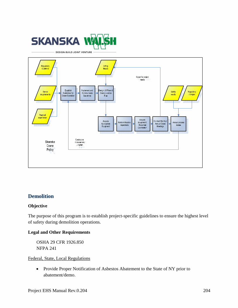
Project EHS Manual Rev.0.204 204
Demolition
Objective
The purpose of this program is to establish project-specific guidelines to ensure the highest level
of safety during demolition operations.
Legal and Other Requirements
OSHA 29 CFR 1926.850
NFPA 241
Federal, State, Local Regulations
Provide Proper Notification of Asbestos Abatement to the State of NY prior to
abatement/demo.

Project EHS Manual Rev.0.204 205
Skanska/Client Requirements
Construction work plans, engineering survey, utility identification, hazardous chemical
location report and drawings, demolition plan, competent person certification and
training, demolition inspections by competent person.
Procedure
Demolition plan
Prior to demolition activities, a hazardous material survey must be accomplished to
identify all hazardous materials (e.g. asbestos, lead, PCB’s mercury, etc.)
Before starting any demolition activities, each job must develop a project-specific
demolition plan
The demolition plan must indicate the phases of work by method. Risk assessment is a
critical component when selecting the final method
The plan should include (if they are applicable):
- Engineering survey report
- Hazardous materials survey
- Abatement plans for each hazardous material
- Demolition method plan
- Utility protection plan
- Shoring or bracing plan
- Fall protection plan
- Worker access plan
- Maintenance of Traffic (MOT) plans
- Dust control plan
- Waste/debris disposal plan
- Pest and rodent control (vector control)
- Noise and vibration assessment based on demolition means and methods
- Permits
Enter project-specific procedure
Engineering survey
Prior to demolition operations, an engineering survey report will be made, by a
competent person, of the structure per OSHA 29 CFR 1926.850, Subpart T, Demolition
The completed engineering survey report form must be kept onsite during all operations

Project EHS Manual Rev.0.204 206
Enter project-specific procedure
Hazardous materials survey and abatement plan
Prior to the disturbance/removal of any identified or suspect hazardous materials, take
the necessary precautions to ensure worker and community safety
Enter project-specific procedure
Utility protection plan
All known or suspected utilities must be clearly identified (using Call Before you Dig or
other utility locate service) and marked before demolition work begins
The demolition plan must list each known or suspected utility and indicate the following:
- Is the utility scheduled to remain or will it be removed before demolition begins?
- If the utility remains, is protection required including any bracing or shoring?
- Project management must decide if demolition work can safely proceed if high-risk
utilities are suspected in the demolition area
- Testing and purging of pipes, tanks, or other equipment containing hazardous,
flammable, or explosive substances must be considered and highlighted in the
demolition plan
Shoring or bracing plan
The demolition plan must identify the structures impacted by demolition, including
internal walls, flooring or bracing and external structures, particularly party walls that
may rely on or be impacted by the demolished structures
Enter project-specific procedure
Dust control plan
The demolition plan must state if permitting requires dust control, the type of dust
suppressant used (i.e., water, chemical or both), the source (i.e., fire hydrant, ponded
water, or tanker) and what equipment is needed to spray the water (i.e., type of pump,
length of hose, nozzles, etc.)
Enter project-specific procedure
Disposal plan

Project EHS Manual Rev.0.204 207
The demolition plan must list the type of debris requiring disposal and must state where
each waste is being disposed and how it will be removed from the structure
Manifests must be filled out anytime a truck leaves the site for disposal of debris.
Pest and rodent control plan
The demolition plan must state if permitting requires a pest and rodent control plan and
the procedures that will be taken
Enter project-specific procedure
Noise and vibration assessment
The demolition plan must assess noise and vibration impacts and appropriate controls
Enter project-specific procedure
Responsibilities
Tasks/Operational Controls Person Responsible Documents/Records/Performance
Indicators
Develop and maintain a
project-specific demolition
plan
Project team Demolition plan
Review and approve the
project-specific demolition
plan
Project team/Engineer Demolition plan
Required inspections
Superintendent/EHS
Manager
Enter project specific
document/Records/Performance
indicators
Identify all hazardous
materials (i.e., lead, asbestos,
mercury, PCBs, etc.)
EHS Manager/ PB Hazardous materials survey
Waste manifests
Develop and maintain solid
waste management plan
Enter project-specific
roles and responsibilities
Vendor recycling reports
Ensure all permits and legal
requirements are in place
Enter project-specific
roles and responsibilities
Enter project specific
document/Records/Performance
indicators
Identify all utilities affected Superintendent As-builts/contract drawings
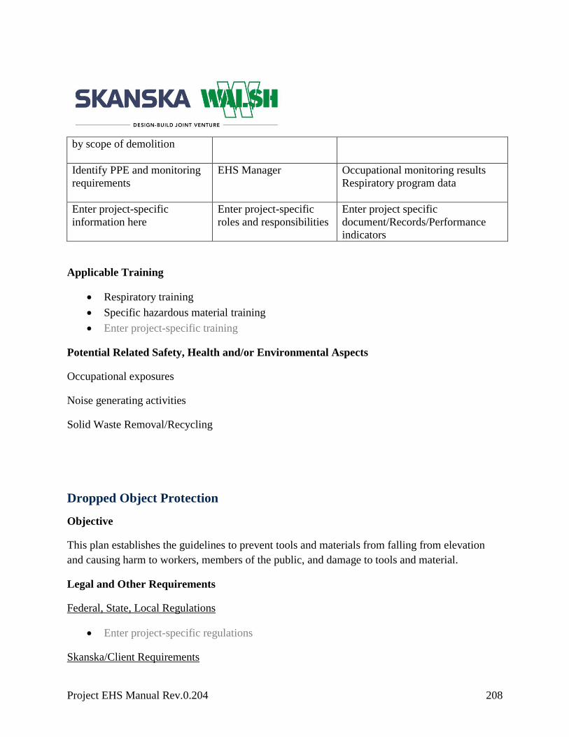
Project EHS Manual Rev.0.204 208
by scope of demolition
Identify PPE and monitoring
requirements
EHS Manager Occupational monitoring results
Respiratory program data
Enter project-specific
information here
Enter project-specific
roles and responsibilities
Enter project specific
document/Records/Performance
indicators
Applicable Training
Respiratory training
Specific hazardous material training
Enter project-specific training
Potential Related Safety, Health and/or Environmental Aspects
Occupational exposures
Noise generating activities
Solid Waste Removal/Recycling
Dropped Object Protection
Objective
This plan establishes the guidelines to prevent tools and materials from falling from elevation
and causing harm to workers, members of the public, and damage to tools and material.
Legal and Other Requirements
Federal, State, Local Regulations
Enter project-specific regulations
Skanska/Client Requirements

Project EHS Manual Rev.0.204 209
Enter project-specific requirements
Procedure
General Requirements
Those working above others will protect personnel below through an active plan that
may include the use of tool lanyards, debris netting, and/or barricades
Workers will communicate to any affected personnel of overhead hazards associated
with their work tasks
Enter project-specific procedure
Tool and Material Storage
Equipment or materials stored inside a building under construction will not be placed
within six feet of any hoist way or inside floor openings, nor within 10 feet of an exterior
wall that does not extend above the top of the material stored
Materials will not be stacked above or against the guardrails
All tools, equipment and materials used throughout the course of a shift that may pose a
hazard of falling from an overhead work area (aerial lifts, scaffolds, permanent
platforms, etc.) will be removed and properly stored whenever feasible and at the end of
shift
Communications devices, such as two-way radios, cell phones, etc., will be secured to
prevent from dropping to a lower elevation
All materials, equipment, and tools that are not in use while aloft will be secured against
accidental displacement
Enter project-specific procedure
The plan may include provisions for:
Canvas bags (bolt bags)
Barricades
Safety watches
Scaffolding
Canopies
Grating
Rope and well wheels

Project EHS Manual Rev.0.204 210
Hot work
Tool lanyards
Debris netting
Hidden material
Enter project-specific procedure
Responsibilities
Tasks/Operational Controls Person Responsible Documents/Records/Performance
Indicators
Required inspections
EHS Professional, trade
foreman and/or
superitnedent.
General worksite Safety
inspections.
Dropped object plan training EHS Department
Training Records
Applicable Training
Project-specific dropped object plan training
Enter project-specific training
Potential Related Safety, Health and/or Environmental Aspects
Enter project-specific potential health and/or environmental impacts
Electrical
Objective
The purpose of this program is to protect against the hazards associated with electricity. Our
safeguards against electrical hazards will include a quarterly inspection program, lockout/tagout
(LOTO) procedures, and general requirements for work involving any type of electricity or
electric tool.
Legal and Other Requirements
Federal, State, Local Regulations
OSHA 29 CFR 1926 Subpart K

Project EHS Manual Rev.0.204 211
OSHA 29 CFR 1926 Subpart V
NFPA 70 and 70E
NEC
Enter project-specific regulations
Skanska/Client Requirements
Use Control of Hazardous Energies forms to verify LOTO procedures.
Procedure
General Requirements
All cord sets will be elevated above the work surface when practical
Wire, nails, or other conductive material will not be used to hang or attach cord sets or
welding leads
Cord sets that cross roadways will be protected from damage by vehicle and equipment
traffic by devices such as hose bridges
Nationally Recognized Testing Laboratories (NRTL) approved (e.g. UL) covers are
required on all panels, load centers, pull boxes, etc. prior to energizing. Necessary steps
will be taken to prevent unauthorized or unqualified workers access to energized
electrical parts or equipment
No work will be performed on any energized electrical circuit, busbars, equipment, or
panels unless an approved written work plan is developed in accordance with Chapter 1
of NFPA 70E and submitted to Skanska for review prior to performance of work
Electrical equipment and tools used on this project will be inspected by a competent
person to prevent any worker from receiving an accidental electrical shock. This rule
will apply to all cord sets, portable electrical equipment, tools and appliances not part of
any permanent building or structural electrical systems.
All temporary cords will be three wire, 16 gauge or heavier, with a hard or extra-hard
duty rating
o Electrical tape cannot be used to repair electrical cords.
o Any repair must be accomplished by a designated competent person and be done
in accordance with manufacturer’s specifications
o Daily visual inspections of all cords must be completed
Once permanent power is energized all exposed live conductors must be covered (e.g.,
outlet covers)

Project EHS Manual Rev.0.204 212
Enter project-specific procedure
Assured Grounding
All portable electric tools, drop cords, extension cords, and similar items will be visually
inspected before being put to use at the start of each shift
Any items showing signs of possible damage will not be used until repaired as indicated
and tested
All portable electric tools, extension and drop cords, fixed temporary wiring and
receptacles will be tested quarterly for continuity of the conductors and for the
connection to the exposed frame in the case of tools
All cord fittings and receptacles will be tested to make certain the conductors are
connected to the proper terminals
Any items inspected and tested during the periods listed below shall be marked with tape
in the color assigned to that period as follows
Time Period Color
January, February, March White
April, May, June Green
July, August, September Red
October, November, December Orange
Color coded electrical tape at the male end of the cord shall be used to mark each item
after it passes the above tests/inspections
Placing a piece of the appropriate colored tape on the cover of the receptacle box will
mark fixed temporary wiring
Other items will be marked in a similar manner with the color-coded tape being attached
in the manner and location that provides maximum protection
Enter project-specific procedure
Ground Fault Circuit Interrupters (GFCI)
All cord sets and cord-plug electrical equipment, tools or appliances that are 120 volts
will be connected to a GFCI. Office equipment and appliances in site offices do not
require GFCI devices.
Project EHS Manual Rev.0.204 213
Each worker, after plugging in his/her tool and/or extension cord, will test and reset the
GFCI device being used to ensure it is working properly with each use. If the GFCI
device is not functioning properly they will repeat the process until a properly working
GFCI device is found. They will report the defective GFCI device to their supervisor.
Enter project-specific procedure
Double-Insulated Tools
All tools must have a grounding conductor or be double-insulated
Tools where this label has been removed, painted over, or is otherwise not readable must
be removed from service
Enter project-specific procedure
Electrical Systems
Electrical systems will be inspected and maintained on a regular basis
All equipment will have positive indication of “ON” (energized) and “OFF” (de-
energized) clearly labeled on the device/equipment
Electrical equipment will not be opened, adjusted, repaired, or otherwise handled until it
is de-energized and locked-out according to the lockout program
De-energized equipment will be tested before performing any work on the equipment
If live electrical work is required during commissioning, troubleshooting and/or
maintenance, work must be performed under an energized electrical permit and the
requirements of NFPA 70E
All metal panels, boxes, covers, conduit, etc., that are part of the electrical system will be
grounded
All electrical equipment exposed to flammable gases or vapors, combustible dust, or
ignitable fibers must be explosion-proof
Circuit breakers will be labeled to show what they control
All circuit breaker panels will be labeled to show what voltage, phase, and feeder source
they contain and will be marked in accordance with ANSI standards and National
Electric Code (NEC)
Panel covers will be kept in place whenever the panel is energized
All cables exiting metal panels or boxes will be secured with stress relieving clamps
Waterproof clamps will be used as necessary

Project EHS Manual Rev.0.204 214
All splices and repairs will be made inside an approved box or sealed with epoxy or
vulcanizing kits; tape alone is not acceptable
All panels will be equipped with a lockable door so that power can be turned off and
locked out for repairs. Adequate space is needed to open the door at least 90 degrees
Clearance will be according to the table below:
Nominal voltage to
ground
Minimum clear distance for conditions1
(A) (B) (C)
Feet2 Feet2 Feet2
0-15 3 3 3
151-600 3 3 1/2 4
1Conditions (A), (B), (C) are as follows: (A) Exposed live parts on one side and no live or grounded parts on the other side
of the working space, or exposed live parts on both sides effectively guarded by insulating material. Insulated wire or
insulated busbars operating at no more than 300 volts are note considered live parts. (B) Exposed live parts on one side
and grounded parts on the other side. (C) Exposed live parts on both sides of the workplace [not guarded as provided in
condition (A)] with the operator between.
2For all international systems of unites (SI): one foot = 0.3048 meters
Enter project-specific procedure
Responsibilities
Tasks/Operational
Controls
Person Responsible Documents/Records/Performance
Indicators
Develop and maintain a
project-specific
temporary electrical plan
Superintendent/Engineer/EHS
Manager
Sub-contractor electrical
plans/drawings
Required inspections
EHS Manager Tool inspections
Project EHS Manual Rev.0.204 215
Ensure electrical
systems, tools, cords and
lights meet the
requirements of this
program
Superintendent/EHS Manager
Compliance audits
Implement the Assured
Grounding Program
Enter project-specific roles
and responsibilities
Compliance audits and findings
Quarterly inspections
Ensure that ground fault
circuit interrupters
(GFCIs) are used
Enter project-specific roles
and responsibilities
Compliance audits and findings
Develop and submit
energized electrical work
plan, as necessary
Electrical subcontractor Energized electrical work plan
Designate LOTO
administrator
TBD Enter project specific
document/Records/Performance
indicators
Enter project-specific
information here
Enter project-specific roles
and responsibilities
Enter project specific
document/Records/Performance
indicators
Applicable Training
General Awareness electrical safety
Competent Person electrical safety
Potential Related Safety, Health and/or Environmental Aspects
Failure to comply with the requirements of this program can result in potential electrical shock
and or power outages.

Project EHS Manual Rev.0.204 216
Excavation and Trenching
Objective
The purpose of this program is to protect against the hazards associated with trenching and
excavation operations.
Legal and Other Requirements
Federal, State, Local Regulations
OSHA 29 CFR 1926.650
OSHA 29 CFR 1926.651
OSHA 29 CFR 1926.652
OSHA Technical Manual (OTM) Section V: Chapter 2
Enter project-specific regulations
Skanska/Client Requirements
One Call must be called prior to any ground instrusive work. A dig permit must also be
completed with all appropriate signatures prior to work.
Procedure
General Requirements
A competent person must supervise all trenching and excavations and be onsite at all
times during trenching and excavation operations
All surface encumbrances such as signs, poles, and foundations that create a hazard will
be removed or supported to safeguard employees
Review drawings; contact “one call” or other entities to determine which utilities are
expected to be encountered during excavation work
If any damage occurs to any line, work will be terminated and the utility owner will be
contacted
Work may only proceed after the utility company gives authorization
When approaching the estimated location of the underground installation, hand digging
or alternative safe method will be used
Project EHS Manual Rev.0.204 217
While the excavation is open, underground installations will be protected, supported, or
removed as necessary to safeguard employees and the utility
A stairway, ladder, or ramp will be provided in all trench excavations four feet or more
in depth. Employees must not have to travel more than 25 feet to obtain access.
If a ramp is selected, the employee must be able to exit the excavation in an upright
posture without having to scale the slope
If structural ramps are used by employees, the competent person must design the ramp,
or, if for vehicle use, the competent person must be qualified in structural design
All structural members of ramps and runways will be of uniform thickness
Employees will not be under any loads handled by equipment
Employees will be required to stand away from any vehicle being loaded or unloaded to
avoid being struck by spillage or falling materials
Where oxygen deficiency (atmospheres containing less than 19.5 percent oxygen) or a
hazardous atmosphere exists or could reasonably be expected to exist, such as in
excavations in landfill areas or areas where hazardous substances are stored nearby, the
atmospheres in the excavation will be tested before employees enter excavations greater
than four feet in depth
A ventilation system will be utilized and monitored by the competent person if
hazardous atmospheres are encountered
Emergency rescue equipment will be available where hazardous atmospheric conditions
exist or may reasonably be expected to develop
Employees will not work in excavations in which there is accumulated water or in
excavations in which water is accumulating
Employees may re-enter the excavation after the water has been removed and the
excavation is inspected and approved by a competent person
All adjacent structures such as buildings, sidewalks, pavement, etc. will be shored,
braced or underpinned as required
Excavations below footings or foundations are not permitted unless an appropriate
shoring system designed by a professional engineer is applied
All excavations will be scaled to remove loose material that could pose a hazard by
falling or rolling into the excavation
All spoil piles will be kept in a minimum of two feet from the edge of the excavation, or
by the use of a sufficient retaining device or by both

Project EHS Manual Rev.0.204 218
The competent person will inspect all excavations daily and when conditions of the
excavation have changed, in accordance with Skanska’s trenching and excavation
checklist
No employee will be allowed to work in any excavation that the competent person
deems unsafe
Walkways over excavations will have proper guardrails
Adequate barriers will be provided around the perimeter of all excavations
Enter project-specific procedure
Soil
All soil will be considered Type C until otherwise determined by a competent person
The classification of the deposits will be made on the results of at least one visual and
one manual analysis
A visual test must be performed and include observing the soil during excavation
specifically looking for cohesiveness, cracks, layered systems, surface water, vibration,
other existing underground structures, etc., which can affect the stability of the
excavation
One of the following tests will be performed along with the visual test:
Plasticity – mold a moist or wet sample of soil into a ball and attempt to roll it into
threads as thin as 1/8-inch in diameter. Cohesive material can be successfully rolled into
threads without crumbling. For example, if at least a two-inch length of 1/8-inch thread
can be held on one end without tearing, the soil is cohesive
Dry Strength – if the soil is dry and crumbles on its own or with moderate pressure into
individual grains of fine powder, it is granular. If the soil is dry and falls into clumps that
break up into smaller clumps, but the smaller clumps can only be broken up with
difficulty, it may be clay in any combination with gravel, sand or silt. If the dry soil
breaks into clumps that do not break up into smaller clumps and can only be broken with
difficulty and there is no visual indication the soil is fissured, the soil may be considered
un-fissured
Thumb penetration – the thumb penetration test can be used to estimate the unconfined
compressive strength of 1.5 tons per square foot (tsf), which can be readily indented by
the thumb. However, they can be penetrated by the thumb only with very great effort.
Type C soils with an unconfined compressive strength of 0.5 tsf can be easily penetrated
several inches by the thumb and can be molded by light finger pressure. This test should

Project EHS Manual Rev.0.204 219
be conducted on an undisturbed soil sample, such as a large clump of soil, as soon as
practicable after excavation to keep to a minimum the effects of exposure to drying
influences
Pocket penetrometer – this device will provide the compressive strengths of soils
After performing a visual and manual test you can then determine the soil classification
including:
- Stable rock – natural solid mineral matter that can be excavated with vertical sides
remaining intact while exposed
- Type A – cohesive soil with an unconfined compressive strength of 1.5 tons per
square foot (tsf) or greater. This soil is highly cohesive and generally contains
significant clay content or is a cemented soil
- Type B – cohesive soil with an unconfined compressive strength greater than 0.5 tsf,
but less than 1.5 tsf. This soil is less cohesive than Type A and can include certain
angular gravel as well as previously disturbed soils that are well compacted
- Type C – cohesive soil with an unconfined compressive strength of 0.5 tsf or less.
This soil is the least stable, having little or no cohesive properties and includes most
granular soil
Enter project-specific procedure
Protective Systems
All employees will be protected while working in an excavation by the use of a
protective system unless deemed unnecessary by a competent person or engineer
At a minimum, trenches five feet or greater must have a protective system or be properly
sloped or benched in accordance with the table below
Trenches less than five feet in depth may require protective systems, sloping, or
benching depending on soil conditions and/or activities
All protective systems will either be designed by a registered professional engineer or
will be a commercially available system used per manufacturer’s instructions
Sloped or benched trenches and excavations will be consistent with the following table:
Maximum Allowable Slopes
Stable Rock Vertical 90 Degrees

Project EHS Manual Rev.0.204 220
Type A ¾ h : 1 v 53 Degrees
Type B 1 h : 1 v 45 Degrees
Type C 1 ½ h : 1 v 34 Degrees
Timber Shoring and Aluminum Shoring
When using timber or aluminum shoring, it will be built in accordance with
specifications and manufacturer’s recommendations. Any deviation will only be allowed
with the manufacturer’s approval
All manufacturer’s data must be kept at the jobsite during construction
Enter project-specific procedure
Designs by a Registered Professional Engineer
Designs will be in written form and include sizes, types and configurations of the
materials to be used
The design must be properly stamped and at least one copy kept at the jobsite during
construction
Enter project-specific procedure
Materials and Equipment
Material used for the protective systems must be free from damage that may impair their
function
Manufactured material will be used per their recommendations
The competent person will examine material that has been damaged and evaluate if it
can be used. If not sure, a professional engineer must be utilized
Installation and Removal of Support Systems
Members of support systems will be securely connected together to prevent sliding,
falling, kick-outs or other predictable failure
Support systems will be installed and removed in a manner that protects employees

Project EHS Manual Rev.0.204 221
Individual members of support systems will not be subjected to loads exceeding what
they were designed to withstand
Before temporary removal of individual members begins, additional precautions will be
taken to ensure the safety of employees, such as installing other structural members to
carry the loads imposed on the support system
Removal will begin at, and progress from, the bottom of the excavation
Backfilling will progress together with the removal of support systems from excavations
Do not excavate more than two feet below the bottom member of a support system
unless it is so designed
Enter project-specific procedure
Shield System/Trench Box
Shield systems will not be subjected to loads exceeding those that the system was
designed to withstand
Shields will be installed in a manner to restrict lateral or other hazardous movement of
the shield in the event of the application of sudden lateral loads
Employees will be protected from the hazard of cave-ins when entering or exiting the
areas protected by shields
Employees will not be allowed in shields when shields are being installed, removed or
moved vertically
Do not excavate more than two feet below the bottom of a shield unless it is so designed
The manufacturer’s data sheet for all trench boxes will be kept onsite during their use.
Enter project-specific procedure
Responsibilities
Tasks/Operational Controls Person Responsible Documents/Records/Performance
Indicators
Required inspections
EHS Manager Compliance Audits
Verify utility locations Superintendent As-built drawings
Utility strikes
Ensure protection systems
engineered data is available
Engineer Engineered design data
Ensure dewatering equipment
is available
Superintendent Enter project specific
Document/Records/Performance

Project EHS Manual Rev.0.204 222
Indicators
Soil classification Competent person Soil Classification documentation
reports
Conduct atmospheric
monitoring
Competent person Air monitoring data
Calibration records
Installation of positive
perimeter protection
Superintendent Compliance audits and findings
Engineered design data
Enter project-specific
information here
Enter project-specific
roles and responsibilities
Enter project specific
Document/Records/Performance
Indicators
Applicable Training
General Awarenss Trenching and Shoring
Competent Person Trenching and Shoring
Potential Related Safety, Health and/or Environmental Aspects
Trenching and excavation, dewatering.

Project EHS Manual Rev.0.204 223
Fall Prevention and Protection
Objective
The purpose of this program is to develop, implement, enforce, and maintain 100 percent
continuous fall protection for employees that are exposed to potential fall hazards, based on risk
assessment.
Legal and Other Requirements
Federal, State, Local Regulations
OSHA 29 CFR 1926.500
OSHA 29 CFR 1926.501
OSHA 29 CFR 1926.502
OSHA 29 CFR 1926.503
Skanska/Client Requirements
SWJV will enforce fall protection at 6 feet and greater to a lower level. There will be
times when SWJV enforces fall protection or perimeter protection when there is an
exposure of less the 6 feet. SWJV will look at the risk and not the rule.
Procedure
All employees will be 100 percent protected while working six feet or higher off the ground or
when hazards below six feet dictate enforcement at a lesser height. This policy will apply to all
trades, even when OSHA allows for exceptions. In the event where local statutes require fall
protection at less than six feet the more stringent standard will apply, (e.g., WA State
requirements begin at four feet).
Guardrail systems
Standard rail will consist of:
- Top rail – 42 inches, plus or minus three (3) inches. When wire rope is selected it
will be at least one-quarter inch diameter and will be flagged at six (6) foot intervals
with high visibility material such as “Caution” ribbon or equivalent
Project EHS Manual Rev.0.204 224
- Mid-rails – must be installed half way between top edge of guardrail and the
walking/working surface
Toe-board – must be minimum one of three-and-a-half inches
A maximum allowable deflection in the system will not exceed three (3) inches
When pipe railings are used, posts, top rails and intermediate railings will be at least one
and a half inches nominal diameter (schedule 40 pipe) with posts spaced not more than
eight (8) feet apart on center
When structural steel railings are utilized, posts, top rails and intermediate rails will be at
least two (2) inches x two (2) inches x three-eighths inch angles, with posts spaced not
more than 8 feet apart on center
Guardrail systems will be capable of withstanding, without failure, a force of at least 200
pounds for the top rail, and 150 pounds for the mid-rail, applied within two (2) inches of
the top edge, in any outward or downward direction, at any point along the top edge
Guardrail systems will be surfaced to prevent injury to an employee from punctures or
lacerations and to prevent snagging of clothing
Duplex nails are not allowed in the construction of guardrails
When guardrail systems are used at access ways and hoisting areas, a chain, gate or
removable guardrail section will be installed
When guardrail systems are used around holes that are used as points of access (such as
ladder ways), they will be provided with a gate, or be offset so that a person cannot walk
directly into the hole
Guardrail systems used on ramps and runways will be erected along each unprotected
side or edge
When guardrail systems are used around holes used for the passage of materials, the hole
will have not more than two sides provided with removable guardrail sections to allow
the passage of materials. When the hole is not in use, it will be closed over with a cover,
or a guardrail system will be provided along all unprotected sides or edges.
When guardrail systems are used at holes, they will be erected on all unprotected sides
or edges of the hole
If a component of guardrail system must be removed, the competent person must
complete a Skanska Guardrail Removal Permit. The competent person is responsible for
immediately replacing and restoring the protective system upon completion of the task.

Project EHS Manual Rev.0.204 225
Safety Nets
Safety nets will never be relied upon as a sole form of fall protection
Nets are designed to provide fall arrest under or around an elevated surface such as a
bridge or steel structure
The following criteria must be met when using nets:
- Place nets as close to the work as possible, and not more than 30 feet below the
work surface
- Install nets so an item’s weight does not come into contact with any lower surface
when dropped
- Extend the net outward from the outermost projection of the work surface as
follows:
Distance Below Work Surface Projection Distance
Up to 5 feet 8 feet
5 to 10 feet 10 feet
Over 10 feet 13 feet
Mesh openings will not exceed six (6) feet by six (6) feet
All scrap material that may have fallen into the net will be removed as soon as possible
to help ensure a fallen employee’s protection
Nets will be drop-tested, using a 400 pound bag of sand dropped from 42 inches above
the highest working surface that employees would be exposed to a fall, on the following
occasions:
- Immediately after installation
- Prior to beginning work in the area
- After relocation
- Following any repairs
- At six month intervals if left in one place
A copy of the test results will be maintained at the jobsite
If it is unreasonable to perform a test drop, a competent person may certify its
compliance with the standards
The compliance certificate must include the identification of the net and its installation,
date it achieved compliance and the signature of the competent person. This certification
must be located at the jobsite.

Project EHS Manual Rev.0.204 226
All defective nets will be immediately removed from service
A border rope for webbing capable of withstanding a minimum breaking strength of
5,000 pounds must be used
Connections will be as strong as the integral net components and not spaced greater than
six inches apart
All nets will be inspected on a weekly basis for wear, damage or other deterioration, and
after any occurrence that could affect the integrity of the net
Warning Line System
When a guardrail system is not feasible, a warning line system can be used for working
on elevated slabs or roof with approval from the Skanska EHS Director and Project
Executive
Warning lines should be set up around the work and be a minimum of fifteen (15) feet
back from any unprotected or leading edge
Lines should be 36 inches high and flagged every six feet to ensure visibility. They
should withstand a minimal side load to avoid tipping over
Signage must be posted in the area notifying of the unprotected edge
Access will be a path formed by two warning lines leading to the work area
Enter project-specific procedure
Safety Monitoring System
A safety monitor system is not approved at any Skanska project.
Covers
All holes two inches or greater in the least dimension in a floor, roof, or other
walking/working surface must be covered
Covers will be placed and labeled “Hole” or “Hole Cover” on holes in walking/working
or road surfaces that present fall hazards and will be secured by nails or a chocking
device
Covers will be capable of supporting, without failure, at least twice the maximum weight
of employees, materials and equipment

Project EHS Manual Rev.0.204 227
Holes in roadways will be capable of supporting, without failure, at least twice the
maximum axle load of the largest vehicle expected to cross over the cover based on an
engineered design
Personal Fall Arrest Systems
General Requirements
All personal fall arrest equipment will be inspected prior to use
Any damaged, defective, or worn equipment must be removed from service
Personal fall arrest systems and components subjected to impact loading will be
immediately removed from service
The project must provide prompt rescue of employees in the event of a fall or will ensure
that employees are able to rescue themselves
Full Body Harness/Self-Retracting Lifelines or “Connectors”
Approved full body harnesses are to be used when a personal fall arrest system must be
used. The only exception is for lineman performing power transmission work (refer to
OSHA 1926.959 for specific requirements).
All connectors must be self-retracting lifelines with a locking snap hook that has a gate
rated for 3,600 pounds.
Self-retracting lifelines will be inspected prior to use by the user
Decelerating lanyards will not be permitted
The anchorage point must be able to withstand a minimum load of 5,000 pounds
The anchorage point should ideally be located above the user’s head in order to prevent
“swing” type falls
The D-ring of the body harness will be located in the center of the wearer’s back
Horizontal/Vertical Lifelines
Lifelines will be designed, installed, and used under the supervision of a qualified person
and maintain a safety factor of at least two
Lifeline systems will be engineered either by the manufacturer or a qualified engineer
prior to use and should consider at a minimum:
Project EHS Manual Rev.0.204 228
- The number of personnel tied to the lifeline
- The size of wire rope to be used. It will be a minimum seven inches (7) by 19 and
three-eighths inch galvanized aircraft cable. One shock absorber must be connected
from the anchorage point (stanchion) to the wire rope. This must provide adequate
protection for two people using self-retracting lifelines (deceleration) devices
- Distance between anchorage points (slack)
- Obstructions, permanent material, etc., which may cause injury should a person fall
Synthetic rope may only be used for vertical applications (unless an engineered system is
approved for horizontal use).
Synthetic rope should be stored to protect against exposures to UV rays, extreme
weather, and abrasion activities. Certain types of work may also degrade the integrity of
synthetic rope systems (e.g. hot work)
Ladder climbing safety devices and rope grabs that require hand manipulation are
unacceptable
- Where a self-retracting lanyard is incorporated in the system, the device must
always be located overhead to limit fall distance
Positioning Devices
At no time will a positioning device be used without fall protection via full-body
harness, lanyard, and anchorage point
Positioning devices will be rigged such that an employee cannot free fall more than two
(2) feet
Positioning devices will be secured to an anchorage capable of supporting at least twice
the potential impact load of an employee's fall or 3,000 pounds (13.3 kN), whichever is
greater
Connectors will be drop forged, pressed or formed steel or made of equivalent materials
Fall Protection Plan
The fall protection work plan shall:
Identify all fall hazards in the work area
Describe the method of fall arrest or fall restraint to be provided

Project EHS Manual Rev.0.204 229
Describe the proper procedures for the assembly, maintenance, inspection, and
disassembly of the fall protection system to be used
Describe the proper procedures for the handling, storage, and securing of tools and
materials
Describe the method of providing overhead protection for workers who may be in, or
pass through, the area below the work site
Describe the method for prompt, safe removal of injured workers
Be available on the job site for inspection by the department.
Enter project-specific procedure
Responsibilities
Tasks/Operational Controls Person Responsible Documents/Records/Performance
Indicators
Prepare and implement fall
protection plan
Superintendent
Enter project specific
document/Records/Performance
indicators
Provide appropriate fall
protection equipment
Superintendent
Enter project specific
document/Records/Performance
indicators
Inspect fall protection
equipment
User/Competent Person
Inspection records
Engineering data for fall
protection systems
Superintendent Engineering data
Applicable Training
General awareness for fall protection will be provided during our sitewide orientation to
all new hires. There will be a designated competent person in each crew for fall
protection.
Potential Related Safety, Health and/or Environmental Aspects
Steel erection, excavations and aerial lifts will relate to the fall protection aspect.

Project EHS Manual Rev.0.204 230
Fire Prevention and Protection
Objective
The purpose of this program is to establish procedures for jobsite fire protection and prevention
measures. Skanska will take all necessary measures to protect employees from fire hazards and
the hazards associated with flammable liquid storage, temporary heating devices, liquid propane
(LP) gas, and propane.
Legal and Other Requirements
Federal, State, Local Regulations
OSHA 29 CFR 1926.150
OSHA 29 CFR 1926.151
OSHA 29 CFR 1926.152
OSHA 29 CFR 1926.153
OSHA 29 CFR 1926.154
OSHA 29 CFR 1926.155
Standard methods of Fire Tests of Building Construction and Materials, NFPA 251-1995
Skanska/Client Requirements
The Port Authority of NY/NJ requires the contractor to maintain the provisions under the FDNY
Fire Safety Manager Fire Code.
The Port Authority of NY/NJ requires the contractor to file a hotwork permit and keep in the
field in close proximity to the operation.
SWJV requires a daily hot work permit be filled out prior to hot work commencing.
Procedure
Fire Extinguishers
All fire extinguishers will be ABC cartridge-type, except for the two and a half point
extinguishers kept in project vehicles such as pick-up trucks which will be type BC
Project EHS Manual Rev.0.204 231
Extinguishers will be inspected monthly for damage, leakage, discharge, and block
accessibility; metal tags or equivalent will be used to signify proof of inspection
At least one portable fire extinguisher will be located not less than 25 feet, nor more than
75 feet, from any flammable liquid storage area located outside
Fire extinguishers will be mounted, labeled, and displayed in planned locations of
building projects (e.g., stair cases, ingress and egress points, etc.)
A 20 pound ABC cartridge-type extinguisher will be installed on all heavy equipment,
trucks (other than pick-ups), connex boxes, welders, compressors, and asphalt/batch
plants.
Additional fire extinguishers will be kept readily available during any hot work
operation
Mount two extinguishers to all fuel and lube trucks according to the following
guidelines:
- Do not mount the fire extinguishers so close together that both could be made
inaccessible by a localized fire
- Mount them in locations where they will not be knocked off or clogged with mud
and ice in the winter
- If an extinguisher is mounted inside a cabinet, be sure that it will not become
blocked by loose equipment. Put a sign on the cabinet to indicate that a fire
extinguisher is located inside
Flammable Liquid Storage
Flammable liquids or other hazardous materials should be stored outdoors or in small detached
structures
General Requirements
Smoking is not permitted in any flammable liquid storage areas
An inventory must be kept for all flammable or combustible storage areas
Only approved containers and portable tanks will be used for storage and handling of
flammable and combustible liquids
Flammable or combustible liquids will not be stored in areas used for exits, stairways, or
normally used for the safe passage of people

Project EHS Manual Rev.0.204 232
Waste containers must be accumulated on a firm working base, such as asphalt or
concrete. The base must be impervious and have a minimum thickness of four inches.
There will be a berm of at least six inches around the base or allocation enclosed by
walls.
The storage structure must have a containment and collection system that is capable of
holding in excess of 20 percent of the total capacity of all containers or 110 percent of
the capacity of the largest container or tank, whichever is greater
Indoor Storage
Design specifications for inside storage rooms are stated in the standard methods of Fire
Tests of Building Construction and Materials, NFPA 251-1995
An inside storage room must be designed in a manner that renders it liquid tight and
provides adequate fire resistance to adjoining building areas
The boundary between the walls and floor must be sealed so that liquid cannot leak
through
Openings to other rooms must be non-combustible, liquid tight raised sill or ramps that
are at least six (6) inches in height
An allowable alternative is to make the floor in the storage area six (6) inches lower than
the floors in the adjoining rooms. The floor must be constructed of a liquid-tight
material.
All transfers of flammable chemicals performed inside a building must be done in the
flammable chemical storage area. If there is another room in the building that is
separated from other operations in the building, or that is protected by walls with
adequate fire resistance, and that is provided with adequate ventilation, then flammable
chemical transfers can also be performed in that area.
The quantity of flammable and combustible chemicals stored outside of the flammable
chemical storage cabinet and inside a building must be limited. The following limits are
set by OSHA:
- 25 gallons of Class 1A liquid in containers
- 120 gallons of Class 1B, 1C, II or III liquids in containers
- 660 gallons of class 1B, 1C, II OR III liquids in single portable tank
OSHA also limits the quantity of flammable chemicals that can be stored in a flammable
chemicals storage cabinet. The following limits are set by OSHA: no more than 60
gallons of Class I or Class II liquid or more than 120 gallons of a Class III liquid inside a

Project EHS Manual Rev.0.204 233
storage cabinet. When cabinets are used, these will be vented to an outside area free
from external hazards
Classes of Flammable and Combustible Liquids
as Defined by 29 CFR 1910.106
Indoor storage includes building, shops, and ventilated connex boxes
Cabinets should be labeled “Flammable – Keep Fire Away”
At least one portable 20 pound ABC extinguisher will be located outside of, but not
more than 10 feet from, the door opening into any room used for flammable or
combustible liquid storage
Lighting fixtures will be an explosion proof type and general storage areas will be
ventilated
Outdoor Storage
Storage of containers (not more than 60 gallons each) will not exceed 1,100 gallons in
any one area
Storage areas will be separated by a buffer zone of five (5) feet
Storage areas will not be within 20 feet to a building. Minimum distance will also be
maintained between the storage area, property lines, streets, alleys, or public ways. For
Class I liquids, a minimum distance of 20 feet will be maintained between the flammable
chemical storage area and the property line. At least 10 feet of distance must be
maintained between the storage area and any street, alley or public way.

Project EHS Manual Rev.0.204 234
There will be a 12-foot wide access way to permit approach of fire control apparatus
within 200 feet of each storage area
The storage area will be graded in a manner to divert possible spills away from buildings
or other exposures or will be surrounded by a curb at least six (6) inches high. When
curbs or dikes are used, provisions will be made for draining off accumulations of
ground or rainwater or spills of flammable or combustible liquids. Drains will terminate
at a safe location and will be accessible to operation under fire conditions.
An outside storage building that is located 50 feet or less from another building or
adjoining property line must have a two hour rated fire wall
Storage areas must be secured against tampering by trespassers
Keep weeds, debris, and other combustible materials 25 feet from the storage area.
It is advisable to provide a covering over all containers.
Lighting fixtures used in outdoor flammable chemical storage areas should be at least
eight (8) feet above the containers. If the fixtures are less than eight feet above the
containers an explosion proof lighting and electrical system must be used.
Outdoor Portable Tank Storage
Portable tanks shall not be stored within 20 feet of any building
Portable tanks with a combined capacity of 2,200 gallons shall have a minimum five-
foot clearance between them
A single portable tank exceeding 1,100 gallons shall have a minimum five-foot clearance
around it
There will be a 12-foot wide access way to permit approach of fire control apparatus
within 200 feet of each storage area
Storage areas should be kept free of weeds, debris, or other combustible materials within
25 feet of the storage area.
At least one portable fire extinguisher will be located no less than 25 feet, and than 75
feet, from any flammable liquid storage area located outside
Each tank will be labeled: “(Contents of Tank) – Flammable, No Smoking”
Temporary Heating Devices
General Requirements

Project EHS Manual Rev.0.204 235
Combustible materials must be kept at least 10 feet away from heating devices.
Fire barrels are not allowed on any project
Do not allow clothes, gloves, shoes, etc., to be placed on, overhead or immediately next
to a heater
Never store compressed gas (acetylene, propane, etc.), gasoline, diesel fuel, paint thinner
or any flammable liquid in a trailer or room where a temporary heating device is in use
Do not allow paint or thinner to be sprayed in areas where a heater may ignite the
explosive
Make sure there is an easy escape route in case a heater malfunctions
Keep fire extinguishers readily available and fully charged. Employees need to be
trained on proper use of the fire extinguishers.
Inspect the entire heating unit frequently for any defects, leaks or worn parts. Make
repairs immediately.
Combustion Heaters
Read manufacturer’s instructions before lighting a heater
Adequate ventilation must be provided and area must be monitored for oxygen and
carbon monoxide levels
Each unit shall be equipped with an automatic shut-off valve to stop the flow of gas or
oil any time the flame goes out
Refueling will be done only after the heater has been turned off and has had time to
become cool to the touch
Safety cans are required for all flammable liquids (including diesel fuel) and will be used
along with funnels or spouts to prevent spills
Electric Heaters
All electric heaters must be properly grounded and used in a dry area to prevent electric
shock
An automatic shut-off device must be built into the unit to prevent fire in the event the
unit is tipped over
Care must be taken to keep electric cords out of mud, snow, ice, and water.

Project EHS Manual Rev.0.204 236
LP Gas and Propane Requirements
Each system will have containers, valves, manifolds, assemblies, and regulators of an
approved type and in good repair
Valves and fittings connected directly to the container will have a rated working pressure
of at least 250 PSI
Every container and vaporizer will be provided with one or more approved safety relief
valves or devices. These valves will be arranged to afford free vent to the outer air
Cylinder connectors will be provided with an excess flow valve to minimize the flow of
gas in the event the fuel lines become ruptured
Storage
Containers will be stored in cages upright on firm foundations or otherwise firmly
secured
Storage of propane cylinders within buildings or connex boxes is prohibited
Propane storage locations will be provided with at least an approved portable 20 pound
ABC fire extinguisher
Propane will not be stored within 25 feet of the nearest building
Storage areas/cages will be labeled with “Flammable Gas—No Open Flames” sign
clearly mounted
Use
Containers, regulating equipment, manifolds, pipe, tubing, and hose will be located to
minimize exposure to high temperatures or physical damage
For temporary heating, heaters will be located six (6) feet from any LP gas container.
Blower and radiant type heaters will not be directed toward any LP gas container within
20 feet
Valves in the assembly of multiple container systems will be arranged so that
replacement of containers can be made without shutting off the flow of gas in the system
The minimum separation between propane and ignition sources such as compressors,
light plants, etc. will be 25 feet.
Combustible material such as weeds and long dry grass will be removed within 10 feet
of the container.

Project EHS Manual Rev.0.204 237
Use a soap and water solution to detect leaks. Leaks should be corrected immediately
No welding on containers or tanks
Responsibilities
Tasks/Operational Controls Person Responsible Documents/Records/Performance
Indicators
Required inspections
EH&S Professional
Monthly fire extinguisher
inspections
Daily storage area inspections Identify potential fire hazards
and applicable legal
requirements
EH&S Professional Superintendent
Enter project specific
document/Records/Performance
indicators
Hot work permit approval
Superintendent Hot work permit
Include fire
protection/response
procedures in emergency
action plan
EH&S Professional
Emergency action plan
Correctly store flammable
liquids, LP gas, and propane
EH&S Professional
Compliance audits and findings
Applicable Training
Fire extinguisher training
FDNY Certiciate of Fitness F60 + G60
Potential Related Safety, Health and/or Environmental Aspects
Welding and Cutting is related to the Fire Protection and Prevention Aspect.

Project EHS Manual Rev.0.204 238
Housekeeping
Objective
The purpose of this program is to establish guidelines to protect employees from the hazards
associated with poor housekeeping. This program details general housekeeping and the handling
of waste and debris.
Legal and Other Requirements
Federal, State, Local Regulations
OSHA 29 CFR 1926.25
OSHA 29 CFR 1926.252
Skanska/Client Requirements
SWJV will maintain workzones to prevent incidents related to the above aspect. SWJV will have
designated roll-off containers set up for specific types of waste in an effort to maintain our
recycling requirements.
SWJV will maintain housekeeping throughout our workzones in an effort to uphold the
apprearance of the airport while undergoing construction.
Procedure
General Housekeeping
Work areas will be kept in an orderly manner at all times and all waste will be removed
by the end of the shift
Trash receptacles will be provided throughout each jobsite with safe means to facilitate
removal and will be emptied regularly to prevent overflow
Any extra materials from activities will be returned to storage facilities at the end of each
shift
Oily rags will be kept and disposed of separately in metal containers with tops
All scrap lumber, forms, and crates will be kept cleared from work areas, passageways,
stairs, in and around buildings or other structures

Project EHS Manual Rev.0.204 239
All nails will be removed from lumber or other material
Receptacles will have self-closing or securable lids to prevent pest and rodent infestation
A trash receptacle will be placed in all designated break areas
All trailers and office space will be kept clean at all times
Crews will focus on housekeeping throughout their shift and maintain as needed.
Trash Chute
When materials must be dropped more than 20 feet to any point lying outside the exterior
walls of a structure, an enclosed chute of wood or equivalent material will be used as a
ramp
When debris is dropped through holes or openings in the floor without the use of a chute,
the area onto which the material is dropped will be completely enclosed with barricades
Enclosure requirements
- Barricades must be at least 42 inches high and at least six (6) feet back from the
projected edge of the opening above
- Wind velocity and its potential for carrying materials should be calculated into the
disposal plan
- Signs warning of the hazard of falling materials should be posted at each level
- A spotter may be posted at the area of retrieval to keep area clear of unnecessary
traffic
- Debris will not be removed from the disposal site until all handling ceases from
above
A dumpster or truck will be maintained at the bottom of the chute at all times.
A physical barrier will be maintained around the trash receptacle at the bottom of the
chute
“Caution” signs will be posted on the barrier to warn employees of potential hazards
Responsibilities
Tasks/Operational Controls Person Responsible Documents/Records/Performance
Indicators
Required inspections
EH&S Professional
Enter project specific
document/Records/Performance
indicators
Project EHS Manual Rev.0.204 240
Applicable Training
Sitewide orientation will cover maintaining housekeeping throughout the job as well as
periodic toolbox talks on the subject.
Potential Related Safety, Health and/or Environmental Aspects
Housekeeping relates to all aspects in our EHS manual, it is everyone’s responsibility to take
part in maintaining a clean jobsite.
Project EHS Manual Rev.0.204 241
Illumination – Project Lighting
Objective
The purpose of this program is to ensure that adequate lighting is provided at all locations and
during all work operations. In addition to providing necessary illumination for our workers, we
must ensure that adequate lighting is provided for pedestrian traffic that may be passing around
our sites.
Legal and Other Requirements
OSHA 29 CFR 1926.56
Federal, State, Local Regulations
5 Foot Candles for General construction area lighting.
3 Foot Candles for General construction areas, concrete placement,excavation and waste areas,
access ways, active storage areas, loading platforms, refueling, and field maintenance areas.
5 Foot Candles for Indoors: warehouses, corridors, hallways, and exitways.
10 Foot Candles for General construction plant and shops (e.g., batch plants, screening plants,
mechanical and electrical equipment rooms, carpenter shops, rigging lofts and active store
rooms, mess halls, and indoor toilets and workrooms.)
30 Foot Canles for First aid stations, infirmaries, and offices.
Skanska/Client Requirements
SWJV will comply with the above Federal, State and Local Regulations.
Procedure
Fixtures
Fixtures are to be rated for the project environment and/or classification.
Fixtures are recommended to be made out of metal or high-strength plastics with suitable
diffusers.
Fixture guards are required to reduce breakage.

Project EHS Manual Rev.0.204 242
Fixtures are to be fastened to a solid surface or suspended with proper cable or hangers
to support the weight of the fixture, wire and environmental conditions (e.g., ice load).
All fixtures are to be UL listed for the application.
Streamers are discouraged and may only be used when allowed by local jurisdiction.
Any streamers used are to have shielded compact fluorescent lamps (CFL) and required
guards/cages of either plastic or metal.
The use of multi-tap 175W, 250W or 400W metal halide fixtures for temporary lighting
must be pulse start with wire guards
Power Source
When required by local jurisdiction, all connections to fixtures will be made from
individual branch circuits, specifically designated for lighting
Egress signs will be on a separate circuit from general lighting
A minimum of two circuits will be required in a work area/floor
No “Laundry Drops” or connections for small tools will be permitted
All circuits will be clearly labeled to indicate that they are served at the source panel.
Fixtures connected to 277/480VAC circuits will have a separate label indicating voltage
Minimum wire gauge is #12AWG for lighting
Branch circuits for lighting will be supported so they do not interfere with construction
activities and not rest on the floor or interfere with potential walking/equipment
movement
Task Lighting
Task lighting may be achieved for work activities utilizing commercially available
fixtures/tripods for that purpose.
All task lighting fixtures are to be UL listed for the application.
The use of halogen lamps for task lighting is acceptable, providing the fixture has
tempered glass and a wire shield.
Lighting Levels
Project EHS Manual Rev.0.204 243
The minimum lighting levels will be in accordance with OSHA 1926.56 – Illumination.
Measurements will be made from a calibrated light meter either new out of box or
calibrated per the manufacturer’s requirements
General Requirements
Construction areas, ramps, runways, corridors, offices, shops, and storage areas will be
illuminated to the intensities listed in the table below while any work is in progress
Lighting plans will include additional requirements when walls and interior elements
have been constructed
Lighting in stairways and hallways must be maintained at all times
Illumination Requirements
Foot-Candles Area Of Operation
5 General construction area lighting.
3 Concrete placement, excavation and waste areas, access ways, active storage areas,
loading platforms, refueling, and field maintenance areas.
5 Indoors: warehouses, corridors, hallways, and exits.
5
Tunnels, shafts, and general underground work areas. (Exception: minimum of 10-
foot candles is required at tunnel and shaft heading during drilling, mucking, and
scaling. Bureau of Mines approved cap lights will be acceptable for use in the tunnel
heading).
Project EHS Manual Rev.0.204 244
10
General Construction Work Plant and shops (e.g., batch plants, screening plants,
mechanical and electrical equipment rooms, carpenter shops, rigging lofts and active
store rooms, barracks or living quarters, locker or dressing rooms, mess halls, and
indoor toilets and work rooms).
30 First aid stations, infirmaries, and offices.
For areas or operations not covered above, refer to the American National Standard
A11.1-1965, R1970, Practice for Industrial Lighting, for recommended values of
illumination
Responsibilities
Tasks/Operational Controls Person Responsible Documents/Records/Performance
Indicators
Prepare project-specific
lighting plan
Superintendent Enter project specific
document/Records/Performance
indicators
Required inspections
EH&S Professional
Enter project specific
document/Records/Performance
indicators
Measure light levels EH&S Professional
Light readings
Calibration of light meter EH&S Professional
Calibration records
Applicable Training
Training will consist of reviewing the construction work plan related to the work being
performed requiring SWJV to comply with the above lighting standards.
Potential Related Safety, Health and/or Environmental Aspects
Maintaining adequate illumination is critical to achieving the objective to this aspect.

Project EHS Manual Rev.0.204 245
Project EHS Manual Rev.0.204 246
Lockout/Tagout
Objective
This procedure establishes a lockout/tagout procedure to ensure that workers are not exposed to
the hazards from moving machinery or equipment and those hazards posed by an energized
source (pneumatic, steam, hydraulic, electrical, chemical).
Legal and Other Requirements
OSHA 29 CFR 1910.147
OSHA 29 CFR 1926.417
Federal, State, Local Regulations
OSHA 29 CFR 1910.147
OSHA 29 CFR 1926.417
Skanska/Client Requirements
All personnel performing lock out tagout must be trained as per the above standards.
Prior to LOTO taking place the Lock out Tag out Conrol of Hazardous Energies forms must be
filled out and completed. 1.)Lock out Tag out Evaluation Form 2.) Shut Down Equipment Form
Procedure
Procedure for Lockout/Tagout
The project superintendent or designated qualified person will authorize the shutdown of
the equipment after it has been established that:
- The qualified person requesting the shutdown has a complete understanding of the
equipment or system to be cleared
- The qualified person has knowledge of the type and magnitude of the energy, the
hazards of the energy to be controlled and the method to control the energy
- A survey was made to locate and identify all isolating devices to be sure which
breaker, valve, switch or other energy isolating devices are required to lockout the
equipment or system. All items to be isolated will be listed on the clearance form
under “devices to be isolated”

Project EHS Manual Rev.0.204 247
Enter project-specific procedure
Shutdown
After preparation for shutdown requirements have been satisfied, the qualified person
will review the lockout/tagout identification form for completeness and accuracy
Isolation
To isolate the equipment or system from its energy source, the following actions will be taken in
sequence:
The qualified person lists all devices that must be locked out on the clearance form
The qualified person will self-perform or assign another qualified person to physically
operate all necessary devices to isolate the equipment or system (e.g., de-energizes,
drain, vent, close valves, etc.)
Lockout
To lockout the equipment, the following actions will be taken in sequence:
The qualified person will attach a locking device with a lock and “Do Not Operate” tag.
All affected craft supervisors will verify the locks and tags have been hung.
The qualified person and supervisor will initial the clearance form to verify the isolation
is complete and that the key(s) will be maintained in or near the lockout office
The key lock boxes or rods for the isolation lock(s) will be maintained in a
predetermined, secure location. The qualified person will drop their key into the lock
box. The clearance holder (craft supervisor) will add their lock to the lock box.
Each trained employee will be provided one lock for each piece of equipment being
locked out and will have only one key for each. Each employee must lockout at the
disconnect switch and/or valve themselves.
If more than one person is working on the same piece of equipment at the same time,
each person is to have a personal lock on the lockout device. If the primary device will
not accommodate each person’s lock, multiple locking devices are to be used
When multiple locking devices are required, the shank of the devices must immobilize
the equipment and must not merely be attached to the shank of another lock

Project EHS Manual Rev.0.204 248
It may be necessary to lockout/tagout energy caused by gravity
Where a keyed switch controls the ignition, the key will be placed in the “off” position,
removed, and the switch tagged with a “Do Not Start” tag
If standard lockout switches are not available to immobilize the machinery, fuses should
be pulled, terminals disconnected or other standard safety procedures applicable to the
individual piece of equipment should be followed. “Do not start” tags will be placed at
the starter button or switch
In the event that tagging and removing the ignition key are not considered adequate
protection, the battery cable that is connected to the starter will be removed at the battery
end and tagged with a “Do Not Start” tag
All other necessary precautions, such as opening or closing valves, changing valves,
tagging and locking valves, installing blind flanges, etc., will be performed prior to
starting the job
No employee will remove another person’s lock, lockout device or “Do Not Start” tag.
Before leaving the job for another assignment, at shift end or upon completion of that job,
each employee will personally remove their own lock.
If an employee fails to remove a lock, that employee will be required to return to remove
it in person. If the individual is not available, the lock will not be removed until the
foreman in charge has made a thorough check of the equipment. The foreman will verify
and make certain the equipment is safe to operate.
Verification of Isolation
Before starting work on the equipment or system, the following actions will be taken in the
following sequence:
After ensuring that no personnel are exposed and having checked on all disconnected
energy sources, start the equipment or system
Return all controls to the “off” position after the test
The qualified person will notify the clearance holder that the lockout procedure is
complete. The clearance holder and affected employee(s) will then discuss the specific
equipment or system to be worked on and understand all the system boundaries (i.e.,
location of all locks and tags)
The qualified person and clearance holder return to the control room to sign a Shutdown
Equipment Form, signifying that the system is safe to work and isolation is complete

Project EHS Manual Rev.0.204 249
The supervisor informs the affected employee(s) the system has been locked out and
verified. The clearance holder drops their key in a separate lock box, all affected
employee(s) lock back onto the box.
Work can now begin
Release from Lockout (Return to Service)
Before lockout devices are removed and energy is restored to the equipment or system,
the following procedures will be followed and actions taken by the qualified person
using a Release from Lockout Form
After work on the equipment or system is complete, the area will be inspected to ensure
nonessential items have been removed and equipment or system components are intact
The work area will be checked to be sure that all employees have been safely positioned
or removed
All affected employee(s) will be notified that the lockout devices are to be removed
The qualified person will use the identification form as a guide to ensure that all
isolation devices listed in the identification form are properly accounted for. The
following sequence is to occur:
- The clearance holder verifies that all affected persons on the clearance form have
signed the lockout form and show evidence of notification
- All craft supervisors who are listed on the clearance form will return to the lockout
station and sign and date the log book
- The qualified person will remove all locks
Should it become necessary to have a clearance released when the clearance holder (craft
supervisor) is off duty, the procedure will be as follows:
- The qualified person will contact the clearance holder and request a release of the
clearance. If unable to do so, the clearance holder’s supervisor will be notified
- The supervisor will check the work prior to authorizing the release. They will then
sign the clearance holder’s name and their own name on the appropriate line of the
identification form.
Testing
The following steps will be taken to test equipment or systems under the clearance procedures:

Project EHS Manual Rev.0.204 250
Notify all craft supervisors on the clearance form that the system and/or isolated
components are to be tested
The qualified person along with the craft supervision will “walk down” the system to
verify that component isolation/activation will not compromise the safety of personnel
working in this area
Each supervisor and the qualified person will sign the test release on the clearance form
Affected employee(s) (listed on the identification form) in the immediate area of the
isolated test will be notified by verbal warning, barricades, warning tape, etc., or by
other appropriate means
Locks will be removed on the isolated component by the qualified person and the test
will be completed
If no further work is required, the craft supervisor will initial the clearance form,
returning the device into service
If further work needs to be done on the component, the isolation devices (locks, blind,
etc.) will be reattached and this policy will resume from the beginning
Medium and High Voltage Lockout Procedures (600 + volts)
Work on high voltage lines or equipment requires safety precautions in addition to the standard
lockout program and procedures.
High Voltage Rooms and Collector Ring Compartments
Whenever any high voltage rooms or areas such as collector ring compartments are
unlocked and de-energized, the following must happen:
- All personnel working in or near these areas will place their lock and tag on the
junction box that is disconnected or at the gate on the appropriate substation or
disconnect box
- Multiple lockouts will be used so that each employee has a lock and tag in position
High Voltage Lines and Equipment
When a high voltage line is to be worked on, it must not be considered de-energized until a
qualified person determines that the high voltage line has been de-energized and grounded.
Project EHS Manual Rev.0.204 251
Qualified persons will visually observe to:
Determine that the disconnecting devices on the high voltage circuit are in the open
position
Ensure that each ungrounded conductor of the high voltage circuit, upon which work is
to be done, is properly connected to the system ground medium
Ground the ungrounded conductor, which will be on the source side of the circuit on
which work is to be performed. Grounding jumpers connected to the ground bus will be
provided for this purpose. Grounding will be accomplished by the following procedure:
- Verifying that the feeder disconnect is open and locked out
- Using a ground stick, ground each ungrounded phase to bleed off any residual
electrical charge on the circuit
- Attaching grounding jumpers to each ungrounded phase of the circuit on which
work is to be performed
High voltage circuits will not be energized until:
All work on the high voltage circuit is completed and inspected
All personnel have been cleared from the high voltage area and notified that the circuit
will be energized
All protective grounding installed has been removed from ungrounded conductors
The high voltage area has been secured and locked
Lockout – General Requirements
All energy sources of power-driven equipment will be locked and/or tagged in the off-
position when maintenance is being performed
Energy sources that must be locked out include but are not limited to electrical,
mechanical, chemical, steam, hydraulic, and pneumatic
It is the responsibility of the qualified person to ensure that the proper lockout/tagout
procedures are followed
It is the responsibility of the qualified person and the clearance holder performing the
maintenance to ensure that all equipment is properly locked and tagged out before
starting any maintenance work

Project EHS Manual Rev.0.204 252
Both the qualified person and the clearance holder must check the equipment before
restarting it to make sure it is safe to operate
Skanska requires that both lockout and tagout devices be used during equipment
maintenance
All lockout devices must be:
- Durable, to withstand wear
- Substantial, so they will not detach
- Capable of identifying the person who applied it
- Designed for a single use application
Available lockout devices include:
- A disconnect switch, circuit breaker, valve or other energy isolating mechanism that
is placed in the safe on or off position
- A device placed over the energy isolating mechanism to hold it in the safe position
- A lock attached to the ‘on’ switch to ensure equipment cannot be energized without
removal of the lock
Tagout–General Requirements
Tagout refers to a sign or tag posted on a switch that physically cannot be locked out
Once the switch has been placed in the off-position, the tag is placed over the switch and
warns other employees that the equipment is under maintenance and should not be
started
This tag must also identify the person who applied it. In a tagout, the energy-isolating
device is placed in the safe position and a written warning is attached to it
All tagout materials must be:
- Durable, to withstand wear
- Substantial, so they will not detach
- Capable of identifying the person who applied it
- Designed for a single use application
A lockout or tagout is applied whenever maintenance is performed around any machine
where injury could occur from:
- Unexpected startup of the equipment
- Release of stored energy

Project EHS Manual Rev.0.204 253
Responsibilities
Tasks/Operational Controls Person Responsible Documents/Records/Performance
Indicators
Verify implementation of
lockout/tagout program
EH&S Professional
Daily/Weekly Compliance audits
Required inspections
EH&S Professional
Daily/Weely Compliance audits
Lockout/tagout coordinator(s)
Superintendent EH&S Professional
Construction Work Plans
Lockout/tagout clearance
(return to service)
Superintendent
Lock out Tag out Conrol of Hazardous Energies forms
Communication with
process/system owner
Superintendent
Lock out Tag out Conrol of Hazardous Energies forms
Subcontractor EHS Kick-off
Meeting
EH&S Professional
Meeting agenda
Agenda sign in sheets
Enter project-specific
information here
Enter project-specific
roles and responsibilities
Enter project specific
document/Records/Performance
indicators
Applicable Training
Management training and communications
Employee will be properly trained to ensure that all affected employee(s) understand the purpose
and function of the lockout/tagout policy. The training will include the following:
Communications
Each qualified person will receive training in the recognition of applicable hazardous
energy sources, the type and magnitude of the energy available in the workplace and the
methods and means necessary for energy isolation and control
Each supervisor of the affected employee(s) will be instructed in the purpose and use of
clearance procedure

Project EHS Manual Rev.0.204 254
All other employees who work in construction or startup operations and may be in an
area where energy control procedures may be utilized will be instructed about the
procedure and about preventing any attempt to restart or re-energize equipment or
systems that are locked out
Employee Retraining
Retraining will be provided for all clearance holders, qualified persons and affected
employee(s) whenever there is a change in their job assignments, equipment, or
processes that present a new hazard or when there is a change in the safety clearance
procedure
Additional retraining will also be conducted wherever a periodic inspection of the
section reveals or whenever management has reason to believe that there are deviations
from or inadequacies in the employee’s knowledge or use of the energy control
procedures
Management will verify that employee training has been accomplished and is being kept
up to date. The verification will contain each employee’s name, dates of training, and
who conducted the training
Lockout/Tagout
Employees performing any service or maintenance work must be made aware of the
lockout and tagout program (this also applies to any vendors or subcontractors doing
work on company jobsites)
Employees will be taught the purpose and function of performing the lockout/tagout
Employees will receive periodic training to ensure they are up-to-date and
knowledgeable on the lockout/tagout program and procedure
Potential Related Safety, Health and/or Environmental Aspects
Electrical Safety, Confined Space, Demolition, Motor Vehicles and Mechanized Equipment,
Community Impacts Utilities and Water Impacts are all related Aspects.

Project EHS Manual Rev.0.204 255

Project EHS Manual Rev.0.204 256
Maintenance and Protection of Traffic (Vehicular and Pedestrian)
Objective
The purpose of the Maintenance and Protection of Traffic (MPT) program is to protect our
employees and the public when our projects directly impact traffic. This program will be project-
specific according to the environment and needs of the site.
Legal and Other Requirements
Federal, State, Local Regulations
OSHA 29 CFR 1926.200
OSHA 29 CFR 1926.201
Manual on Uniform Traffic Control Devices (MUTCD) http://mutcd.fhwa.dot.gov/
American Traffic Safety Services Association (ATSSA)
Skanska/Client Requirements
Procedure
When it becomes necessary to temporarily close a public street or alley, a written traffic control
plan is required to show how the closure will occur. The plan must be submitted to Skanska for
review.
Maintenance of Traffic (MOT) plan shall include:
Copy of current specifications
Barricade log
Duration of plan
Traffic survey identifying conditions (volume, speed, etc.)
Existing traffic control measures
Photos and/or video of existing conditions along with periodic photos as the plan
changes

Project EHS Manual Rev.0.204 257
Applicable permits
Specialized vehicles
Projects that require extensive traffic control may set up specific traffic control vehicles with
flashing/rotating lights or beacons, sign racks, cone racks, worker platforms, protective railing
and impact absorption capabilities, (attenuator trucks).
The cone truck should be a one-ton flatbed outfitted with two warning beacons visible
from all directions and a Type II flashing arrow sign controlled from within the cab
There should be two platforms on the truck for employees to stand while setting out the
cone pattern, one on each side built into the bed frame. These can be a stand-in type
cages so that the employee can stand upright while placing or removing the cones. This
design will help to ensure the safety of the worker while reducing the possibility of an
injury due to excessive bending.
Fall protection equipment must be provided to the employees if required
The crash truck should be a five-ton flatbed, outfitted with the same warning devices as
the cone truck. Check with local authorities for your area as some require Type I arrow
signs on crash trucks
There will be an approved truck-mounted attenuator attached to the rear of the truck for
added protection against vehicle impacts
There will be two-way communication between all vehicles and the superintendent in
charge of traffic control
Flagger Control
Flaggers are required when:
- Workers or equipment intermittently block a traffic lane
- Plans call for one lane to be used for two directions of traffic with a flagger at each
end
- EHS and/or project staff determines there is a need
- Required by the owner
Flaggers will be trained in the techniques of flagging traffic (i.e., ATSSA and/or state
equivalent) before performing this duty

Project EHS Manual Rev.0.204 258
They must be far enough away from the work to slow or stop traffic before it enters the
work zone
During daylight hours, all flaggers must wear a reflectorized garment (ANSI/ISEA 107-
240 Class II).
At night all flaggers must wear a reflectorized garment (ANSI/ISEA 107-240 Class III).
It is recommended that they also wear reflectorized gloves.
From sunset to sunrise, flagger stations must be illuminated so the flagger is clearly
visible to approaching traffic
When communicating through radios, a spare battery pack should be readily available
If communication breaks down between the flaggers, the operation is to be shut down
immediately until the situation is remedied
Documentation
One person should be responsible for documenting traffic control
The same individual should carry out routine inspections of the traffic control
installation
A traffic control inspection report should be completed and signed every day by the
designated traffic control person and included in the documentation
Further documentation will include a camera for recording any accidents or incidents.
These pictures will be in a successive series from advance warning, all the way up to and
including termination of the traffic pattern
Documentation records should include:
- Starting and ending times of work
- Location of work
- Names of crew members
- Types of equipment used
- Changes in temporary or permanent regulatory devices
- Installation, change, and removal of traffic control devices
- Drawing of working closure to include all devices
When an inspection requires correction to include maintenance, the documentation
should include:
- A description of the corrections needed, when it was noted and by whom
- Corrections made or deferred and why
- Replacements made or deferred and why

Project EHS Manual Rev.0.204 259
- Any other needed actions
Control Warning and Guidance Devices
Effective warning and guidance devices are planned out in advance and should be uniformly
placed and well maintained. There are six (6) categories of devices:
Signs
Barricades
Delineators
High-level warning devices
Warning lights/illumination
Flashing arrow/message boards
Utilization of Halo has been determined to be a best practice and is recommended for
Skanska projects. All signage and traffic control shall comply with the Federal Manual on
Uniform Traffic Control Devices (MUTCD) and can be viewed and downloaded at:
http://mutcd.fhwa.dot.gov/
Traffic Signs for Functional Groups
Construction signs are used only for construction or maintenance work on or adjacent to
the roadway
Warning signs generally apply to a permanent situation but may have some applications
on temporary construction sites
Regulatory signs are used for posting speed limits, are enforced by local law
enforcement agencies, and are maintained by the contractor when placed within or
adjacent to the work area
Sign location depends on alignment, grade, location of street intersections and posted
speed limits. The signs must face and be visible to oncoming traffic and be mounted to
resist displacement
Advance warning signs are located on the right-hand side of traffic lanes
On divided highways, supplemental advance warning signs will be placed on the divider
Messages conveyed during hours of darkness must be on reflectorized or illuminated
signs

Project EHS Manual Rev.0.204 260
Signs will be installed before work begins and will be removed or covered immediately
after work has been completed
If at any time a sign is not required, it will remain covered or be removed
Barricades
Barricades will be used to mark or block off specific hazard or to channel traffic. They
may not be placed in a moving lane of traffic without advance warning, such as high
level warning devices (e.g., flashing arrow signs) and appropriate delineators
When closing off a street, barricades should be placed to prevent vehicles from passing
through, except where access is necessary for local traffic or emergency vehicles
Marking barricade rails is done by alternating orange and white stripes on a downward
slant at 45 degrees. The entire area of white and orange must be reflectorized for night
time use. The width of the stripes depends on the size of the rails. Rails less than three
feet require four inch wide stripes; all other rails require six inch stripes.
Barricades will have a minimum of 270 square inches of retro-reflective area facing
traffic when used on freeways, expressways and other high-speed highways.
Barricades with stripes that begin in the upper right side and slope downwardly to the
lower left are designated right barricades. Barricades with stripes that begin in the upper
left side and slope downwardly to the lower right are designated left barricades.
Barricades should slope with the direction of traffic.
On highways or in situations where barricades are susceptible to overturning in the wind,
sandbags should provide ballasting. Sandbags may be placed on lower parts of the frame
or stays to provide the required ballast but will not be placed on top of any striped rail.
Delineators
Delineators will be used to aid a driver in determining the location and alignment of the
traffic lane
During daylight hours, maximize delineator effectiveness by evaluating position,
spacing, form, texture, size and color
During night time, maximize effectiveness by evaluating position and visibility
All delineators used at night must be adequately reflectorized
Delineators are used for the following instances:

Project EHS Manual Rev.0.204 261
- To channel and divert traffic in advance of work zones
- To define traffic lanes through work zones
- To define a change in the position of the existing lane around work zones
- To define curves and edges of the roadway on detours
- Delineators will be constructed to withstand impact without appreciable damage to
the device, the striking vehicle or passing traffic, including damage from
knockdown by wind or turbulence from passing vehicles
Minimum Recommended Delineator and Sign Placement
Traffic Speed Taper Length
(Each Lane)
Delineator
(Taper)
Spacing
(Tangent)
Sign Spacing
(Advance of Taper
& Between Signs)
25 MPH
30 MPH
35 MPH
40 MPH
45 MPH
50 MPH
150 Feet
200 Feet
250 Feet
350 Feet
550 Feet
600 Feet
25 Feet
30 Feet
35 Feet
40 Feet
45 Feet
50 Feet
50 Feet
60 Feet
70 Feet
80 Feet
90 Feet
100 Feet
150 Feet
200 Feet
250 Feet
350 Feet
550 Feet
600 Feet
55+MPH 1000 Feet 50 Feet 100 Feet 1000 Feet
Warning Lights/Illumination
Lights should be used on top of channelizing devices for intermediate and long-term
closures especially at tapers, shifts, and turnarounds
Illumination should be provided in lane closures at night
Flashing Arrow/Message Signs
Panels with a matrix of electric lights, capable of sequential arrows displays or messages
are intended to supplement, not replace, other work area traffic control devices by

Project EHS Manual Rev.0.204 262
providing additional, high level, advance warning of lane closures. They are effective for
all lane closures and should be considered for all high-speed situations
Flashing arrow/message signs will be repaired immediately or taken out of service if:
- Any of the lamps are out
- The panel is not dimming properly
- Lamps are out of alignment
Day Closures
Devices should be installed in the direction of traffic in the following order:
- First advance warning sign
- Advance warning zone
- Transition zone
- Buffer zone
- Work zone
- Termination zone
When signs and channelizing devices are installed and removed several times during an
operation, a spot should be painted or marked where each sign or device is located to
minimize time required to reset the signs or devices
Flashing vehicle lights should be used to warn the drivers of the presence of workers.
All aspects of the closure should provide clear, concise direction to all drivers. Be sure
of positioning and visibility of all signs, flashing arrow/message signs, barricades and
delineators
Any part of the pattern that has been disturbed should be reset as soon and as quickly as
possible
Night Closures
During night operations, a back-up, shadow or protection vehicle should be used and
should be positioned 100 feet or more behind the cone truck as the first signs are placed.
This process is to be followed for set-up and teardown.

Project EHS Manual Rev.0.204 263
All crews working in or around the closure need to be outfitted with personal protective
equipment, including bright clothes conforming to ANSI standards, hard hats, safety
glasses, gloves and Class III reflectorized vests
All employees should be visible at a distance of 1,000 feet
If working together, should wear the same clothing to prevent confusing approaching
motorists.
Other applicable accessories may include retro reflective striping on hard-hats
Before making night-time closures, all materials and equipment must be inspected and in
good working order
- All message boards and flashing arrow signs will be tested to ensure all lights and
switches are functioning properly and that the equipment is fueled and fully
charged
- All inspections and maintenance procedures will be documented daily and/or
nightly
Devices maintained in project inventory will be kept clean, stored properly to avoid
marring, and organized to verify that all items are in stock and readily retrievable
Devices will be inspected when they are returned to inventory
Any devices that are non-standard or in poor condition will be retired, modified or
repaired
Responsibilities
Tasks/Operational Controls Person Responsible Documents/Records/Performance
Indicators
Prepare Maintenance of
Traffic (MOT) plan Superintendent
Maintenance of Traffic (MOT) plan
Implement MOT plan Superintendent
Compliance audits and findings
Review of relevant incidents
Required inspections
EH&S Professional Barricade log
Project MPT coordinator
Superintendent
Enter project specific
Document/Records/Performance
Indicators
Subcontractor EHS Kick-off
Meeting EH&S Professional
Meeting agenda
Agenda sign in sheets

Project EHS Manual Rev.0.204 264
Applicable Training
ATSSA supervision training
ATSSA technical training
ATSSA flagger training
Potential Related Safety, Health and/or Environmental Aspects

Project EHS Manual Rev.0.204 265
Material Handling and Storage
Objective
The purpose of this program is to establish safe procedures for material loading/unloading,
storage, use, and disposal. By properly handling materials with mechanical means, safe work
practices, and correct storage methods, the risk of injury and illness is reduced.
Legal and Other Requirements
Federal, State, Local Regulations
OSHA 29 CFR 1926.250
OSHA 29 CFR 1926.251
OSHA 29 CFR 1926.1501
OSHA 29 CFR 1910.178
DOT 49 CFR Parts 393.100-136
Federal Motor Carrier Safety Administration 40 CFR 112.7(h)(2) & (3)
Federal Highway Administration
Skanska/Client Requirements
The Port Authority of NY/NJ Requirements
Procedure
Loading and Unloading
All employees involved with the loading or unloading of materials will be trained in accordance
with the requirements of this program. Exceptions to this program must be approved by the
Skanska regional EHS Director.
Implement measures necessary to prevent unauthorized or unsupervised material
handling for loading/unloading operations by competent person
Designate roles in loading/unloading operations, such as escort, spotter, operator, and
competent person who will be involved in any activity involving loading/unloading

Project EHS Manual Rev.0.204 266
Ensure procedures are reviewed regularly to verify if adequate and adhered to
Ensure deficiencies in procedures are corrected before subsequent loading/unloading
operations are authorized to continue
Examples of circumstances requiring the review of the loading/unloading program are:
- Any observed unsafe acts that are against this policy or any other company policy
- Any observance of an unescorted delivery
- Any observance of an unsupervised loading/unloading activity
- The lack of visual devices required as part of the loading/unloading process
- The occurrence of an injury or near-miss during loading/unloading
- Employee complaints about the effectiveness of the program
The decals below shall be applied to all Skanska-owned vehicles involved in loading or
unloading on jobsites.
Escorting Procedure
Pre-Loading/Unload Procedure

Project EHS Manual Rev.0.204 267
All deliveries must be scheduled in advance of the anticipated delivery date and time
A crewmember shall meet and greet delivery driver at project entrance
Inspect load for movement/shifting during transit prior to accepting delivery
Any loads that exhibit signs of shifting or movement during transit will not be accepted
Use a flagger to spot vehicles in designated unloading area
Loads must remain strapped/chained until in the designated unloading area
Ensure that the truck or trailer does not move during loading or unloading with any piece
of equipment by:
- Engaging parking brake
- Chocking the wheels
- Engaging locking mechanism built onto the dock
Designated loading and unloading areas shall be:
- Clear of other traffic, pedestrians and people not involved in loading or unloading of
materials
- Clear of overhead electrical hazards/obstructions
- Firm level ground
Loading the Truck and Trailer: Before the Tie-Downs Are Applied
The gross vehicle weight rating (GVWR) of a truck and trailer stipulates the maximum cargo
weight that the unit may carry. Exceeding the GVWR is dangerous: brakes work less
efficiently, tires loose air pressure, and springs may be stressed to the limit.
Proper placement of materials must always be pre-planned. Placing a load too far back on a
long trailer may cause fishtailing; placing it too far forward on a trailer can overload the
tongue, making steering difficult.
Considerations:
Vehicles must never be overloaded
Loading should allow for safe unloading
Two essential requirements must be satisfied when loading vehicles. The load must be
distributed so that:
- The maximum permitted gross vehicle weight and axle weights are not exceeded
- The load center of gravity is kept as low as possible to achieve maximum stability
when the vehicle is braked, or accelerated or changes direction
Unauthorized individuals will not be permitted into the loading area

Project EHS Manual Rev.0.204 268
The designated competent person shall be in place to observe all loading activities
Ensure the designated loading area is clear of all obstructions
Ensure vehicle and trailer brakes applied and all stabilizers, wheel chocks and interlocks
are in engaged prior to the commencement of loading activities
Drivers shall not remain in their cabs during loading activities unless required and
authorized by project management
Ensure all vehicle floors and/or decking areas are inspected for debris, broken boarding,
etc. prior to the placement of any loads
Spotter should be in place when opposite side of load is not visible and maintain
visual/audible communication with the operator
Proper personal fall protection equipment shall be in place for all employees who are
required to work from heights while loading materials onto trucks
Proper dunnage/cribbing must be in place prior to landing/placing the materials on the
trailer
Ensure lift plan is developed in the construction work plan
Taglines are required if load is being moved overhead
Rope hooks shall not be used to anchor loads
The material being loaded shall be done so to ensure proper securement of all materials.
Secure load in place with two straps at a minimum
Prior to the movement of the loaded vehicle, all applied vehicle and trailer brakes,
stabilizers, wheel chocks, and interlocks must be disengaged
Material handling form used for logging in materials being loaded and unloaded

Project EHS Manual Rev.0.204 269
Unloading
Unauthorized individuals will not be permitted into the unloading area.
The designated competent person shall be in place to inspect the load for stability and
any shifting that may have taken place during transit and to observe all unloading
activities
Ensure the designated unloading area is clear of all obstructions
Ensure vehicle and trailer brakes are applied and all stabilizers, wheel chocks and
interlocks are in engaged prior to the commencement of unloading operations.
Drivers shall not remain in their cabs during unloading operations unless required and
authorized by project management.
Spotter should be in place when opposite side of load is not visible and maintain
visual/audible communication with the operator.
Proper personal fall protection equipment shall be in place for all employees who are
required to work from heights while unloading materials
Proper dunnage/cribbing must be in place prior to landing/placing the materials in the
designated storage area
Ensure lift plan is developed in the construction work plan
Taglines are required if load is being moved overhead
Rope hooks should not be used to anchor loads. Rope hooks are not subject to
construction standards, and so they vary in strength, size and material content and are
rarely designed to withstand forces
The delivered material shall be in a condition to ensure safe unloading
Fixed jacks may be necessary to support a semitrailer and prevent upending during the
loading or unloading when the trailer is not coupled to a tractor
Hazardous material loading/unloading
Identify and communicate special handling and storage requirements for all hazardous
materials prior to loading and unloading
Pocket Guide for Unloading / Loading Trucks

Project EHS Manual Rev.0.204 270
Dunnage Do’s and Don’ts

Project EHS Manual Rev.0.204 271
Load Distribution on Trailers
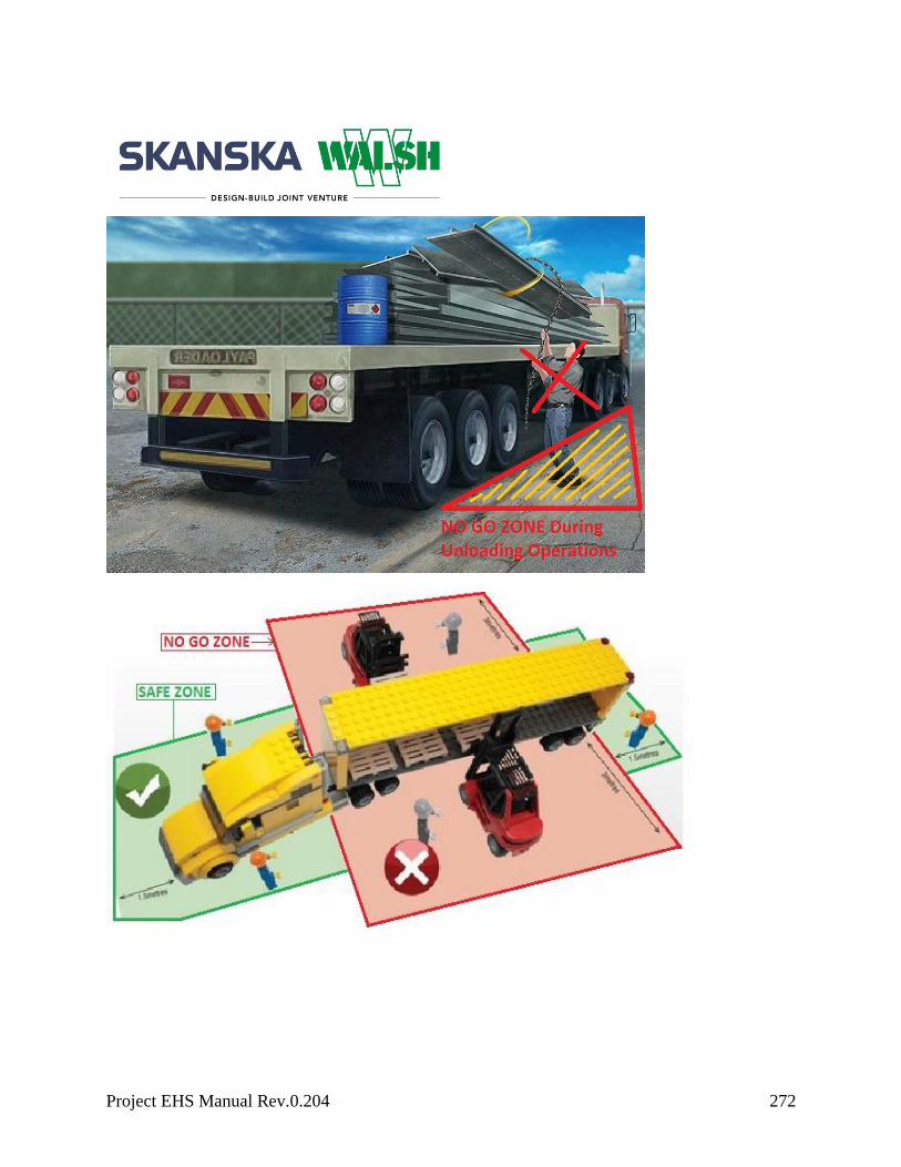
Project EHS Manual Rev.0.204 272
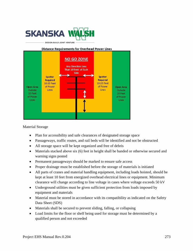
Project EHS Manual Rev.0.204 273
Material Storage
Plan for accessibility and safe clearances of designated storage space
Passageways, traffic routes, and rail beds will be identified and not be obstructed
All storage space will be kept organized and free of debris
Materials stacked above six (6) feet in height shall be banded or otherwise secured and
warning signs posted
Permanent passageways should be marked to ensure safe access
Proper drainage must be established before the storage of materials is initiated
All parts of cranes and material handling equipment, including loads hoisted, should be
kept at least 10 feet from energized overhead electrical lines or equipment. Minimum
clearance will change according to line voltage in cases where voltage exceeds 50 kV
Underground utilities must be given sufficient protection from loads imposed by
equipment and materials
Material must be stored in accordance with its compatibility as indicated on the Safety
Data Sheet (SDS)
Materials shall be secured to prevent sliding, falling, or collapsing
Load limits for the floor or shelf being used for storage must be determined by a
qualified person and not exceeded

Project EHS Manual Rev.0.204 274
Equipment or materials stored inside a building under construction will not be placed
within six (6) feet of any hoist way or inside floor openings, nor within 10 feet of an
exterior wall that does not extend above the top of the material stored
Materials will not be stacked above or against the guardrails
Stacking of materials should be based on the frequency of need. Special bins should be
used for odd shapes or fragile material and height limitations should be determined when
planning storage space
Lumber cannot be stacked more than 16 feet high if moved by hand or more than 20 feet
high if moved by forklift
All nails must be removed from used lumber before stacking. Lumber must be stacked
and leveled on solid supports and the stacks must be stable and self-supporting
Stacks of loose bricks cannot be greater than seven (7) feet high. At four (4) feet, the
stack will be tapered back two (2) inches for every foot above four (4) feet. At six (6)
feet, the stack will be tapered back one-half block for each tier above six (6) feet
Bags and bundles must be stacked in interlocking rows to remain secure
Bagged material must be stacked by stepping back the layers and cross-keying the bags
at least every 10 layers
Boxed materials must be banded or held in place with cross-ties or shrink wrap plastic
fiber
Drums, barrels, and kegs must be stacked symmetrical. When stored on their sides,
bottom tiers must be blocked to prevent rolling
If stacking material two (2) or more tiers high, the bottom tier must be choked to prevent
shifting in either direction
When stacked on end, planks or sheets of plywood or pallets must be placed between
each tier to provide a flat, firm surface
Cylindrical materials, bar stock, and structural steel must be blocked or stored in racks
Racks will not face main aisles or traffic lanes nor create hazards to passersby when
supplies are being removed. When racks are not available, material will be stacked and
blocked to prevent spreading or tilting
Large structural steel beams will be placed on solid level ground. They should be braced,
especially when the height exceeds the width, to prevent accidental tipping over
Banding

Project EHS Manual Rev.0.204 275
Hazards associated with steel strapping include shifting or moving loads, loose ends,
whipping, improper use of banding as handholds, tripping over banding and cuts from
sharp edges
Banding shall be removed with caution because loads may have shifted during transport
and can tumble when tension is released
When tension is released from removal of banding or breaks caused by incorrect
strapping, loose ends will whip away from the package with enough force to cause
serious injury. Always use caution when working around bundles strapped under
pressure
Banding is not to be used as a handhold to access the load
Steel straps shall be disposed of as soon as possible to avoid tripping or cutting hazards
Banding machines must be kept in good condition and employees using the machine will
be properly trained
When applying or removing banding, leather palm gloves that extend to the wrist are
recommended
Loose fitting clothes are not permitted when working around strapping machines
Safe removal of banding from bound material will be with tools designed to cut steel
banding.
Claw hammer, crowbar, chisel or anything that applies leverage is prohibited when
removing banding
Employees and/or machinery must be clear of the work area when removing banding
Two-hand operated strap cutters are recommended because they are designed to cut the
strap and absorb the energy released when the strap is cut
If duck billed shears must be used, place a gloved hand on the strap and make the cut so
the un-grasped end is too short to reach the worker. Then, if the strap springs, it will fly
away from the cutter’s face and body, which should be positioned out of direct line of
the strap
Straps should be cut square and not at an angle
Manually Moving Materials
Inspect materials for slivers that could splinter off rough or sharp edges
Determine the weight of the load before applying force to move it
Identify and walk the intended pathway and ensure it is clear of any hazards

Project EHS Manual Rev.0.204 276
Use gloves and forearm protection when handling sharp-edge materials
Get assistance for large and/or heavy loads
Get assistance when visibility is imposed due to load size
Use dunnage blocks under raised loads that require manual placement
Attach handles and holders to loads when possible to reduce pinching or smashing
fingers
Manually Operated Mechanisms
Wheel wells with safety hooks, jibs or other lifting mechanisms should be used when
manually lifting material overhead
Equipment is to be installed as per manufacturer’s recommendations
Lifts are to be reviewed by competent person
Hoist all loads with tag lines
When lifting loose materials overhead a boot should be used to prevent materials from
slipping out of rigging
Moving Long and/or Bulky Materials
When carrying more than one long load, materials should be tied together in several
places before being carried
Any material that may carry a wind load requires two or more employees to handle
Mechanically Moving Materials
Barrels must always be picked with a proper lifting device. Cutting lifting eyes into
barrels to move is not acceptable
Weight, size, and shape of the material must be determined when selecting equipment to
move it
Consult the equipment’s rated load chart to determine maximum weight and condition
capacity. Rating charts should be posted on the equipment and not exceeded
Ensure that loads are centered and stable against shifting and induced dynamic loading
Keep the load in the lowest position possible on the equipment for traveling

Project EHS Manual Rev.0.204 277
Stacked loads on pallets shall be correctly piled and cross-tiered and secured with
banding if necessary
The water line and weight capacity of scale boxes and skip buckets must be clearly
identified
Scale boxes or skip buckets used for moving material or debris must be permanently
rigged with a bolt and pin shackle and may not be loaded above their water line or
exceed weight capacity
Lifting boxes must be proof tested by a qualified person to 125% capacity
Daily visual inspections must be performed on all lifting boxes
Conveyors
General Requirements
Employees must never ride on material handling conveyors
Where the conveyor passes over work areas or aisles, guards must be provided to keep
employees from being struck by falling objects
Crossovers must be guarded to protect employees and either marked with a warning sign
or painted a highly visible color
Screw conveyors must be completely covered except at loading and discharge points
Guards and Emergency Stops
Guards must be provided at loading and discharge points to protect employees from
contacting the moving screw
Guards are moveable and must be interlocked to prevent conveyor movement when not
in place
Emergency buttons or pull cords designed to stop the conveyor must be installed at the
employee workstation or the station must be adequately guarded to positively prevent all
injury exposure
Access points on the conveyor should have an emergency stop cable that extends the
entire length of exposed belt or be guarded
The emergency stop switch must be designed to be reset before the conveyor can be
restarted

Project EHS Manual Rev.0.204 278
Disposal of Waste Material
General Requirements
When materials must be dropped more than 20 feet to any point lying outside the
exterior walls of a structure, an enclosed chute of wood or equivalent material will be
used as a ramp
When debris is dropped through holes or openings in the floor without the use of a chute,
the area onto which the material is dropped will be completely enclosed with barricades
Enclosure requirements
- Barricades must be at least 42 inches high and at least six feet back from the
projected edge of the opening above
- Wind velocity and its potential for carrying materials should be calculated into the
disposal plan
- Signs warning of the hazard of falling materials should be posted at each level
- A spotter may be posted at the area of retrieval to keep area clear of unnecessary
traffic
- Debris will not be removed from the disposal site until all handling ceases from
above
All scrap lumber, waste material and rubbish should be removed from the immediate
work area as the work progresses
All solvent waste, oily rags, and flammable liquids should be kept in fire resistant
covered containers until removed from the jobsite
Used oil will be recycled
Responsibilities
Tasks/Operational Controls Person Responsible Documents/Records/Performance
Indicators
Required inspections
EH&S Professional
Enter project specific
Document/Records/Performance
Indicators
Proof testing for lifting boxes Superintendent
Documentation of proof test
Daily visual rigging
inspections with monthly
documentation
User/Assigned Competent Person
Documentation of rigging
inspections

Project EHS Manual Rev.0.204 279
Develop waste management
plan
EH&S Professional
Waste management plan
Maintain hoisting equipment
register to record and track all
lifting components requiring
certification
EH&S Professional
Enter project specific
Document/Records/Performance
Indicators
Develop and implement an
incoming and outgoing
delivery system
Superintendent
Delivery schedules
Loading/unloading schedules
Identify designated
loading/unloading areas Superintendent
Project drawings
Identify communication
systems Superintendent
Enter project specific
Document/Records/Performance
Indicators
Equipment inspections EH&S Professional
Enter project specific
Document/Records/Performance
Indicators
Installation of signs, barriers
and shields Superintendent Enter project specific
Document/Records/Performance
Indicators
Applicable Training
Potential Related Safety, Health and /or Environmental Aspects

Project EHS Manual Rev.0.204 280
Motor Vehicles and Mechanized Equipment
Objective
The purpose of this program is to establish rules and regulations for safe operation of motor
vehicles and mechanized equipment.
Legal and Other Requirements
Federal, State, Local Regulations
OSHA 29 CFR 1910.178
OSHA 29 CFR 1926.20
OSHA 29 CFR 1926.600
Skanska/Client Requirements
The Port Authority of NY/NJ Requirements
Procedure
General Requirements
Employees must have appropriate license and/or training to operate vehicles and
equipment
Parked equipment 1 ton or greater in capacity shall have a wheel chocked and parking
brake set
No modifications that affect the capacity of safe operation of equipment will be made
Daily visual inspections and all applicable checklists must be completed prior to use and
submitted to supervisor daily
All safety defects will be corrected before the equipment is used or other controls must be
implemented with the approval of supervision
All equipment with roll over protective structures (ROPS) must have a seat belt that is
worn at all times
Seat belts must be worn in all vehicles

Project EHS Manual Rev.0.204 281
Construction vehicles greater than a pickup truck must be equipped with an audible
reverse signal alarm. In urban areas, a “white noise” alarm may be required
Equipment left unattended at night next to a highway or active construction area must
have lights or reflectors to identify the location of the equipment
Construction vehicles and equipment that are not equipped with a reverse-signal alarm by
the manufacturer are required to be retrofitted with an alarm prior to mobilization and use
on site.
o Where immediate correction is not feasible, these vehicles and/or equipment shall
either be removed from service immediately until the reverse signal alarm is
repaired or a designated spotter shall be assigned
All haulage vehicles, loaders, cranes, shovels etc., must have a cab shield and/or canopy
All rubber-tired equipment will be equipped with fenders when provided by manufacturer
Tools and equipment must be secured when transported in employee compartment
Never short across the starter terminals or across the batteries, as this could bypass the
engine neutral-start system as well as damage the electrical system
Prior to starting the engine or beginning to move the equipment, a walk around inspection
is required
Mount and dismount the equipment only where steps and/or handholds are provided
Passengers are not permitted in equipment cabs unless additional seat, seat belt, and
ROPS or falling object protective structure (FOPS) are provided
Riding in the bed of pick-up trucks is prohibited
Do not operate equipment above posted speed limits
Pushing equipment with vehicles or other equipment is strictly prohibited
Backing and Spotters
All backing operations shall be controlled
Designated Spotters shall be used where the vehicle or equipment has an obstructed view
to the rear
Only a Construction Work Plan specifically identifying the approved controls shall be
used in lieu of a spotter.
Project EHS Manual Rev.0.204 282
A spotter must be used when workers on foot are potentially exposed to backing
operations
If the operator loses visual contact with the spotter, the vehicle shall immediately be
brought to a full stop until visual contact with the spotter is reestablished
Spotters shall be trained and designated prior to being allowed to be a spotter
Spotters shall be issued a hard hat sticker that shall be placed on the left hand side of their
hard hat indicating that they have been trained.
Designated spotters shall be readily identifiable, such as with a specific color hard hat,
vest, etc.
Designated spotters will be personnel assigned to reverse signaling activities. The
designated spotter shall:
Daytime designated spotter PPE – must have a minimum ANSI approved Class 2 safety
vest with retro-reflective material and spotter gloves.
o Nighttime designated spotter PPE – must have a minimum ANSI Class 3 safety vest
with retro-reflective material, and two lighted red traffic wands.
o During Day or Night operations the designated spotter shall be visible at a minimum
distance of 1,000 feet.
Not engage in any activities that could pose a distraction, other than those related to the
vehicle or equipment being signaled
Always maintain visual contact with the operator of the vehicle or equipment and do not
cross behind in close proximity while it is operating in reverse
Maintain a safe working distance from the vehicle or equipment
Light duty vehicles, which Do NOT have a reverse signal alarm and Do NOT have an
obstructed view to the rear, are required to do the following.
o Make every attempt to back the vehicle into a parking space when you arrive, or
pull through to eliminate the need to back out of a parking space or work area.
o If backing is necessary, perform a 360 degree walk around inspection and sound
the horn with 2 short blasts; then wait two seconds before proceeding in reverse
Construction equipment, heavy and light duty vehicles equipped with video or proximity
sensor technology are NOT exempt from the use of a spotter if they have an obstructed
view to the rear.
Maintenance
Project EHS Manual Rev.0.204 283
Implement an equipment maintenance program
Heavy equipment that is suspended or held aloft by use of slings, hoists, or jacks will be
substantially blocked or cribbed to prevent falling and shifting. Safety tire rack cage or
equivalent protection will be provided and used when changing tires with split rims or
rims equipped with locking rings
Trucks with dump bodies will be equipped with permanent positive protection capable
of being locked to prevent accidental lowering of the body when maintenance or
inspection work is done
All equipment is required to be locked and tagged out prior to maintenance operations
Replace all damaged or worn parts prior to use
Responsibilities
Tasks/Operational Controls Person Responsible Documents/Records/Performance
Indicators
Review and approve
Construction Work Plan
Project Manager,
Superintendent, EHS
Professional
Signed Construction Work Plans
Conduct crew reviews
Superintendent Crew reviews
Required inspections
User/Assigned Competent Person
Enter project specific
Document/Records/Performance
Indicators
Verification of
training/license
EH&S Professional Training records
Routine maintenance
Superintendent Maintenance records
Waste storage/disposal from
maintenance operations
Superintendent Enter project specific
Document/Records/Performance
Indicators

Project EHS Manual Rev.0.204 284
Applicable Training
Potential Related Safety, Health and/or Environmental Aspects

Project EHS Manual Rev.0.204 285
Pile Driving
Objective
The purpose of this program is to establish a safe operating procedure for the use of pile drivers
and pile driving equipment.
Legal and Other Requirements
Federal, State, Local Regulations
OSHA 29 CFR 1926.603
American Society of Mechanical Engineers, Pressure Vessels Codes Section VIII
Skanska/Client Requirements
The Port Authority of NY/NJ Requirements
Procedure
General Requirements
Identify potential risks pertaining to driving and cutting piles of any type (overhead
power lines, underground utility vaults, unstable ground, existing utilities, etc.)
No pile driving work will occur until it is verified that no underground utilities exist
where piles will be driven or existing underground utility locations have been verified by
hand or vacuum excavation
Ensure adequate manpower is provided allowing for safe execution of all pile driving
activities including pile cutting
Ensure that the geologic bearing strata profiles are identified prior to executing pile
driving activities
Ensure the appropriate pile lengths have been procured and placed in relation to the
geologic bearing profiles limiting need to cut excessive pile lengths above grade
Loading and offloading of piles or sheets from trucks with beds over six (6) feet high
requires fall protection
Project EHS Manual Rev.0.204 286
All employees conducting pile operations above six feet will use 100 percent fall
protection, including while in aerial work platforms (AWP)
All employees will be kept clear when piling is being hoisted into the leads
Outriggers and rubber-tired equipment must be in position to provide maximum stability
when in use
In cuts, fills or other areas where soil may be unstable, mats and substantial cribbing
should be used for supports
Mechanical pile-threaders and remote release shackles that are operated from the ground
are the first choice when planning operations
Steam or air supply lines must have shut off valves within easy reach of operators
When piles are being driven in an excavated pit, appropriate support of excavation
(SOE) will be used
When steel pipe piles are being “blown out” employees will be kept well beyond the
range of falling materials
A tag line will be attached to the blow pipe for steadying during operations
Precautions will be taken to prevent exposure to items falling from above such as
cushion blocks, auger spoils, pile chips, and steel debris
No personnel involved with the pile driving operation will stand in front of the leads
while driving piles
When the top worker is guiding a pile into position in the leads, they should be cautioned
against putting their arms or hands between the pile and the inside guide, or on top of the
pile
Blocking will be provided on top of booms to prevent damage to lacings from hoist line
whipping
A strong ladder, securely fastened, should extend the height of the rig, and should be
maintained in good condition at all times
Stop-blocks will be provided for the leads to prevent the hammer from being raised
against the head-block
A blocking device, capable of safely supporting the weight of the hammer, will be
provided for placement in the leads under the hammer while employees are working
under the hammer
Guards will be provided across the top of the head-block to prevent the cable from
jumping out of the sheaves
When the leads must be inclined in the driving of batter piles, provisions will be made to
stabilize the leads

Project EHS Manual Rev.0.204 287
Fixed leads will be provided with a ladder and adequate rings and a ladder safety
climbing device
If the leads are provided with platforms, they will be protected by standard guardrails
Hoisting of all piling will be done by use of a closed shackle or other positive means of
attachment that will prevent accidental disengagement
Riding the ball, hook, or loads is prohibited
A boatswain’s chair is not allowed during any pile driving activity
If piling cannot be pulled without exceeding the load rating of equipment, a pile
extractor will be used
Dogs on pile driver hoist drums that automatically disengage either by relieving the load
or rotating the drum will be prohibited
Pile hammers will be lowered to the bottom of leads while pile driver is being moved
Safe access to the top of the crane and any attached power units will be provided
All signaling will be performed by a certified and/or qualified signal person
Access into a pile driving area will require coordination with the pile driving foreman
Hose connections will be secured by at least one and a quarter inch diameter chain or
equivalent wire rope to prevent whipping
Stirrups will be provided on sheet piling to aid in guiding the pile in place
For pile other than sheet piles, a driving head or bonnet is required to bell the head
Stop blocks are required for the leads to prevent the hammer from striking the head
block
Pits or excavations that piles are being driven into will be properly braced, sheet-piled or
sloped, and barricades will be provided
When driving jacked piles, the pits will be provided with access ladders and curbs to
prevent material from falling into the pit
Engineered design solutions specific to the pile type/dimensions including support tab
patterns allowing for safe removal of pile sections must be followed
Review plumb of pile prior to cutting determining potential for eccentric loading risk
Pile sections more than five feet above grade must be secured and removed by
appropriate mechanical means (e.g., loader, excavator, pile driving rig, crane, etc.). The
cut pile section should then be lowered by mechanical means
Pile sections less than five feet may be manually displaced using tab utilization process
in conjunction with safe working practices detailed in Construction Work Plan
When pile tops are cut, a controlled access zone shall be established two and a half times
the length of the longest pile that is to be cut
Project EHS Manual Rev.0.204 288
Ensure that no pile driving activity is taking place within the controlled access zone
Personal Protective Equipment (PPE)
Adequate hearing protection must be provided based on occupational noise monitoring
Use caution if driving creosoted wood piles, as the hammer impact may spray creosote,
injuring the eyes, skin, and lungs. Double eye protection, Tyvek® suits, and respiratory
protection may be required
Inspection and Maintenance of Pile Driving Equipment
The use of metal-armored hoses is recommended to be used when possible
Air hammer, steam or air hoses will be securely fastened to the hammer with an
adequate length of at least one and a quarter inch diameter chain or cable to prevent
whipping or spraying of steam or air
Defective air or steam hoses shall be replaced or repaired in accordance with the
manufacturer’s recommendations before reuse
All moving parts in the lead must be lubricated in accordance with manufacturer’s
recommendations
Whip checks, or equivalent means, must be provided for each hose connection to prevent
the line from thrashing around in case the coupling becomes disconnected
Hooks, slings, leads and all other connections must be checked for damage and cracking
prior to mobilization and periodically during use
When shutting down rigs, all pressure must be relieved from lines
When not in use, hammer must be lowered to the base of the leads and blocked
All equipment is required to be locked and tagged out prior to maintenance operations.
Consider steam and/or air pressure
Responsibilities
Tasks/Operational Controls Person Responsible Documents/Records/Performance
Indicators
Develop pile driving location
plan
Superintendent
Enter project specific
Document/Records/Performance
Indicators

Project EHS Manual Rev.0.204 289
Equipment inspections
User/Assigned Competent Person
Inspection records
Compliance audits
EH&S Professional Compliance audits and findings
Evaluate ground conditions,
including geologic data
Superintendent Enter project specific
Document/Records/Performance
Indicators
Identify existing utilities (Call
before you dig)
Superintendent Enter project specific
Document/Records/Performance
Indicators
Implement maintenance
program Superintendent
Enter project specific
Document/Records/Performance
Indicators
Develop lifting plan Superintendent Enter project specific
Document/Records/Performance
Indicators
Occupational noise
monitoring EH&S Professional
Enter project specific
Document/Records/Performance
Indicators
Noise and vibration
monitoring
EH&S Professional
Enter project specific
Document/Records/Performance
Indicators
Applicable Training
Potential Related Safety, Health and/or Environmental Aspects

Project EHS Manual Rev.0.204 290
Rigging
Objective
The following policy and procedures support the safe use, maintenance, and inspection of
rigging equipment and associated gear on all projects.
Legal and Other Requirements
Federal, State, Local Regulations
OSHA 29 CFR 1926.32
Skanska/Client Requirements
The Port Authority of NY/NJ Requirements
Procedure
Rigging Plan
A detailed rigging plan must be attached to the construction work plan (CWP) for all categories
of lifts. The rigging plan must be completed by a qualified person and documented on the rigging
plan form.
General Requirements
A designated person shall inspect all new rigging equipment before it is placed into
service
Visual inspection for damage will be performed by the user or other designated person
prior to each use. Written records are not required for these inspections.
A documented monthly inspection of all rigging must be completed by a designated
person. RFID technology may be used to document monthly inspections.
Chains will not be used for rigging purposes
Enter project-specific procedure
Lifting Devices

Project EHS Manual Rev.0.204 291
Any purchased lifting device must be stamped with the maximum working load limit,
date of manufacture, and manufacturer’s name
A lifting device may be engineered by a qualified person and fabricated. Before use, the
lifting device must be sent out to a professional testing service and the lifting device
must be tested to five times the intended lifting load weight
The lifting device must be tagged with the date of test and the working load limit
All testing documentation must be kept on file at the jobsite
Storage
All rigging must be properly stored at the end of each shift
Rigging will not be stored in the immediate work area
All rigging will be stored in an area where it will not be subjected to mechanical
damage, corrosive action, moisture, direct sunlight, extreme temperatures, or kinking
When possible a storage box will be supplied and designated for rigging storage
Synthetic, Round, and Wire Rope Slings
Proper use:
Synthetic slings will not be shortened with knots, bolts, or other makeshift devices
Sling legs will not be kinked
Slings will not be loaded in excess of their rated capacities
Slings used in a basket hitch will have the loads balanced to prevent slippage
Slings will be securely attached to their loads
Slings will be padded or protected from the sharp edges of their loads
Shock loading is prohibited
All loads will be placed on dunnage so the load is not resting on the sling
A competent person will inspect slings and attachments before and after each lift.
All damaged equipment will be taken out of service and destroyed to prevent future use
Removal criteria for synthetic web/round slings:
Acid or caustic burns

Project EHS Manual Rev.0.204 292
Melting or charring of any part of the sling surface
Snags, punctures, tears or cuts
Broken or worn stitches or distortion of fittings
Missing or illegible identification tags
Holes, tears, cuts, abrasive wear, or snags that expose the core yarns
Discoloration, brittle, or stiff areas on any part of the sling that may indicate damage
Other conditions that cause doubt as to the continued use of the sling
Removal criteria for wire rope sling:
Ten randomly distributed broken wires in one rope lay, or five broken wires in one
strand in one rope lay
Wear or scraping of one-third the original diameter of outside individual wires
Kinking, crushing, bird caging or any other damage resulting in distortion of the wire
rope structure
Evidence of heat damage
Missing or illegible identification tags
Hardware
Proper Use:
Only American-made hardware that is incompliance with ANSI requirements (Crosby
shackles) will be permitted
For long-term installations, bolt type shackles will be used; if screw pin type shackles
are used, the pin will be secured from rotation or loosening
The screw pin will be fully engaged and in contact with the shackle body
If a shackle is designed for a cotter pin, it will be used and maintained in good working
condition
The load applied to the shackle will be centered in the bow of the shackle to prevent side
loading
Multiple sling legs will not be applied to the shackle pin
Multiple slings in the body of a shackle will not exceed 120 degrees in angle

Project EHS Manual Rev.0.204 293
If the shackle is to be side loaded, the rated load will be reduced according to the
recommendations of the manufacturer or a qualified person
The screw pin shackle will not be rigged in a manner that would cause the pin to
unscrew
When a shackle is used in a choker hitch, the pin will be connected to the choking eye of
the sling
Hardware Removal Criteria
Missing or illegible manufacturer’s name or trademark and/or rated load identification
(or size as required)
A 10 percent or more reduction of the original dimension
Bent, twisted, distorted, stretched, elongated, cracked or broken load bearing
components, excessive nicks, gouges, pitting and corrosion
Indications of heat damage including weld spatter or arc strikes
Loose or missing nuts, bolts, cotter pins, snap rings or other fasteners and retaining
devices
Use of unauthorized replacement components
Other visible conditions that cause doubt as to the continued use of the hardware
Responsibilities
Tasks/Operational Controls Person Responsible Documents/Records/Performance
Indicators
Develop rigging plan
Superintendent Rigging plan
Rigging inspections
EH&S Professional
Inspection records
Engineering and proof testing
Superintendent
Engineered drawings
Proof testing results
Identify rigging storage
locations
Superintendent
Enter project specific
Document/Records/Performance
Indicators

Project EHS Manual Rev.0.204 294
Applicable Training
Rigging training
Potential Related Safety, Health and/or Environmental Aspects
Project EHS Manual Rev.0.204 295
Scaffolds
Objective
The purpose of this program is to establish guidelines for working on or around scaffolding. This
program will inform employees about the hazards of working with scaffolding, the proper
terminology, different types of scaffolds and tagging systems.
Legal and Other Requirements
Federal, State, Local Regulations
OSHA 29 CFR 1910.145
OSHA 29 CFR 1926.200
OSHA 29 CFR 1926.450 Subpart L
OSHA 29 CFR 1926.451
OSHA 29 CFR 1926.454
American Lumber Standards
Skanska/Client Requirements
PA NY/NJ
Procedure
General Requirements
Workers who use and construct scaffolding will be trained in the following:
- Types of scaffolding hazards: electrical, fall and falling objects
- Correct procedures for erecting and maintaining scaffolding
- Maximum intended load and intended use of the scaffold
Scaffolds will be securely anchored, set plumb, and capable of carrying the maximum
intended load without settling or displacement
Identify and label the maximum working load for each scaffold
Project EHS Manual Rev.0.204 296
- The maximum intended load is the total load of all persons, equipment, tools,
materials, transmitted loads and other anticipated loads to be applied to a scaffold or
scaffold component at any one time
All scaffolds must be capable of supporting at least four times the maximum intended
load
Unstable objects, such as barrels, boxes, loose brick or concrete blocks, may not be used
to support scaffolds or planks
The use of shore or lean-to scaffolding is prohibited
No scaffold may be erected, dismantled, or altered except under the supervision of
competent persons
Any scaffold component, including braces, brackets, trusses, screw legs, ladders, etc.,
that has been damaged or weakened in any way must be immediately repaired or
replaced
An access ladder or equivalent safe access to the scaffold must be provided
Diagonal bracing and scaffold rungs are not to be used to access the scaffold unless their
design incorporates an approved ladder
When employees must work underneath a scaffold, an 18-gauge screen, a half inch wire
mesh or equivalent protection must be placed between the toe board and the guardrail
All wooden load-carrying components of scaffold framing must be a minimum of 1,500
fiber construction grade lumber
All dimensions are nominal sizes as provided in the American Lumber Standards
Scaffold tagging procedures must be followed at all times
- Scaffolding will be tagged appropriately during erecting, use, and dismantling
- All scaffolds will have a daily documented inspection by job superintendent or
designated competent person before use
- Tags will be located at each access point and kept current
Scaffolding Tag Identification Code
Red Tag = DO NOT USE
- Prohibits use of scaffolding
Yellow Tag = NOT ERECTED TO CODE
- Indicates restriction or special use conditions of scaffold, i.e. a requirement for fall
protection
Green Tag = APPROVED FOR USE

Project EHS Manual Rev.0.204 297
- Indicates scaffold is erected to all safety standards and company policies and is
ready for use
Planking
All planking will be two (2) inches by 10 inches scaffold-grade or equivalent, as
recognized by approved grading rules for species of wood used
Laminated planking that provides the equivalent strength of scaffold grade planking is
also permitted
The maximum permissible span for two (2) inches by 10 inches or wider planks of full
thickness undressed lumber is:
- 10 feet with a working load of 25 per square foot (psf)
- 8 feet with a working load of 50 psf
- 6 feet with a working load of 75 psf
The maximum permissible spans for two (2) inches by 10 inches or wider planks of
nominal thickness lumber (not recommended for heavy use) are:
- 8 feet with a working load of 25 psf
- 6 feet with a working load of 50 psf
All planking must overlap by a minimum of 12 inches, or be secured from movement
Scaffold planks must extend over their end supports at least six inches but no more than
twelve inches (unless cleated to prevent slipping)
All working levels on scaffolds will be fully planked
Guardrails and Toe boards
Guardrails and toe boards must be installed on all open sides and ends of platforms more
than six feet above the ground or floor, except needle beam scaffolds and float scaffolds
Guardrails must be 42 inches high with a three (3) inch tolerance and a mid-rail.
Supports must be at intervals not to exceed eight (8) feet
Toe boards must be at least one (1) inch by four (4) inches lumber or equivalent
Tubular Welded Frame Scaffolds
Cross bracing and/or diagonal bracing is required to secure vertical members laterally

Project EHS Manual Rev.0.204 298
Cross bracing must square and align vertical member to keep scaffolding plumb at all
times
All bracing connections must be secure
Legs must be set on adjustable bases, mud sills, or other foundations adequate to support
the maximum load
Frames will be placed on top of another using coupling or stacking pins for vertical
alignment
Panels will be locked together vertically by pins or other equivalent suitable means to
prevent uplifting
Scaffolding will be secured to a structure at intervals no greater than 30 feet horizontally
or 26 feet vertically
Drawings and specifications for all frame scaffolds over 125 feet above the base plates
must be designed by a registered professional engineer
Upon receipt of shipment of tubular scaffolds, always inspect all components
Manually Propelled Ladder Stands and Scaffolds
The design and construction of mobile work platforms (ladder stands) and rolling (mobile)
scaffolds (towers) will conform to the following:
The designed working load of ladder stands must be calculated on the basis of one or
more individuals weighing 200 pounds with 50 pounds of equipment per person
Light duty scaffolds must be designed and constructed to carry a working load of 25
pounds per square foot
Medium duty scaffolds must be designed and constructed to carry a working load of 50
pounds per square foot
Heavy duty scaffolds must be designed and constructed to carry a working load of 75
pounds per square foot
All ladder stands and scaffolds must be capable of supporting at least four times the
designed working load
The height of rolling scaffolds will not exceed four times the minimum base dimension
The material selected must be strong enough to meet test requirements and must be
protected against corrosion and deterioration
Project EHS Manual Rev.0.204 299
The materials used must meet manufacturer’s standards, including strength, dimension
and weight specifications, and they must safely support the working load
Nails, bolts and other fasteners used in the construction of ladders, scaffolds and towers
must be of adequate size and in sufficient number to develop the designed strength of the
unit
Nails must be driven full length
Steps must be fabricated from slip-resistant treads
Leveling of elevated work platforms, screw jacks or other suitable means for adjusting
the height must be provided in the base section of each unit
No one will ride rolling scaffolds when they are being moved
Rolling scaffolds will only be used on level surfaces
Caster brakes must be locked when the scaffold is in use or not in motion
Loose material and equipment will be secured or removed before moving scaffold
Any exposed surface must be free of sharp edges, burrs, or other hazards
Suspended Scaffolds (Swing Stage Scaffold)
Suspended scaffolds will not be less than 20 inches nor more than 36 inches wide
Wire, synthetic or fiber rope used for scaffold suspension must support at least six times
the maximum intended load
Non-conducting, insulated material will be placed over scaffold suspension cables if
there is any chance of contact with an electrical arc
Employees working from a two-point suspended scaffold must wear a full body harness
and be tied off to an independent lifeline
Multi-stage scaffolds require additional safety suspension lines and fall protection
devices
Ropes will be protected from burning or welding operations
Responsibilities
Tasks/Operational Controls Person Responsible Documents/Records/Performance
Indicators
Daily inspections
User/assigned competent person
Inspection records
Scaffold tags

Project EHS Manual Rev.0.204 300
Ensure that there is a
competent person onsite at all
times when scaffolding is
being used
EH&S Professional
Enter project specific
Document/Records/Performance
Indicators
Supervise the erection and
use of scaffolding systems
Superintendent Scaffold erection permit
Scaffold design Project Engineer
Engineered drawings and
calculations
Scaffold maximum working load
Enter project-specific
information here
Enter project-specific
roles and responsibilities
Enter project specific
Document/Records/Performance
Indicators
Applicable Training
Scaffold user training
Scaffold erector training
4 Hour user cards
32 hour scaffold erector/dismantled card
Potential Related Safety, Health and/or Environmental Aspects

Project EHS Manual Rev.0.204 301
Signs, Signals and Barricades
Objective
The purpose of this program is to establish safe working guidelines for using signs, signals and
barricades as part of a hazard warning system.
Legal and Other Requirements
OSHA 29CFR 1926.200
ANSI D6.1-1971
ANSI Z53.1-1967
Federal, State, Local Regulations
Skanska Requirements/Client Requirements
PA NY/NJ requirements
Procedure
General Requirements
The project shall have a consistent means of identifying local or general hazards. A
Hazard Warning System must be understandable by all employees, subcontractors and
visitors.
When signs are used on the project, they must be consistently the same throughout the
project
Signs/Signals
Signs when required shall be visible at all times when work is being performed, and shall
be removed promptly when the purpose for them no longer exist.
Danger signs shall be used only where an immediate hazard exists and have red as the
predominating color for the upper panel; black out line on the borders; and a white lower
panel for additional sign wording.
Project EHS Manual Rev.0.204 302
Caution signs shall be used only to warn against potential hazards and have yellow as the
predominate color; black upper panel and borders; yellow lettering of “caution” on the
black panel; and the lower yellow panel for additional sign wording. Black lettering shall
be used for additional wording.
Exit signs, when required, shall be lettered in legible red letters, not less than six (6)
inches high, on a white field and the principal stroke of the letters shall be at least three-
fourths inch in width.
Safety instruction signs, shall be white with green upper panel with white letters to
convey the principal message. Any additional wording on the sign shall be black letters
on the white background.
Directional signs, other than automotive traffic signs, shall be white with a black panel
and a white directional symbol. Any additional wording on the sign shall be black letters
on the white background.
Construction areas shall be posted with legible traffic signs at points of hazard.
All traffic control signs or signals shall be normal highway signs or signals.
Accident prevention tags shall be used as a temporary means of warning employees of an
existing hazard, such as defective tools, equipment etc. They shall not be used in place
of, or as a substitute for, accident prevention signs.
Barricades
Barricades shall be visible at all times when work is being performed, and shall be
removed promptly when the hazard no longer exist.
Yellow and red chain/rope shall be the preferred material in lieu of tape.
Barricade tape, when used, shall be a minimum of two (2) inches wide and be colored red
and black for “danger” and yellow and black for “caution”. If timber barricade is used it
should be painted with the same colors as barricade tape or the appropriate tape should be
affixed to it.
Red and black barricade tape shall be used to designate an area of danger. Only the
individual(s) who establishes a “danger area” may allow employees to enter. All others
shall go around.
Yellow and black barricade tape shall be used to designate an area of caution.
If barricade tape is to be used, it shall only be “re-enforced” barricade tape.
All barricades shall be signed designating the hazard that the barricade is protecting
Employees shall be allowed to move through an area marked with the caution tape but
only with knowledge of why the area is marked.
Employees are not allowed to enter a red barricaded area without permission from the
supervisor responsible for the hazard in that area.

Project EHS Manual Rev.0.204 303
Signs shall be placed with the barricade tape to identify the hazards and the person
identifying the hazard.
Responsibilities
Tasks/Operational Controls Person Responsible Documents/Records/Performance
Indicators
Evaluate work area for the
need to use
signs/signals/barricades
Superintendent
Enter project specific
Document/Records/Performance
Indicators
Required inspections
EH&S Professional
Enter project specific
Document/Records/Performance
Indicators
Applicable Training
Potential Related Safety, Health and/or Environmental Aspects
Stairways and Ladders
Objective
The purpose of this program is to establish rules regarding the proper design and the safe use of
stairways and ladders on our projects.
Legal and Other Requirements
Federal, State, Local Regulations
OSHA 29 CFR 1926.1050
OSHA 29 CFR 1926.1051

Project EHS Manual Rev.0.204 304
OSHA 29 CFR 1926.1052
OSHA 29 CFR 1926.1053
OSHA 29 CFR 1926.1060
Skanska/Client Requirements
PA NY/NJ requirements
Ladders Last
Prior to beginning work, the crew will evaluate all tasks that require individuals to work at
elevated heights. It is the expectation that these tasks will be performed using methods other than
a ladder. Use of portable scaffold devices, scissor lifts, scaffold towers, podium/platform ladders
(acceptable only with the top rail at least 30 inches above the platform), lift pods, etc. will be the
preferred method to perform work at heights.
Ladder use will be allowed only when it has been determined by the crew in conjunction with
Skanska project management that it is not feasible to use all other options to complete the task.
If it is determined that a ladder must be used the need will be documented and acknowledged in
the Construction Work Plan:
Procedure
General Requirements
When there is only one point of access between levels, it must be kept clear to permit
free passage by workers
Where there is a break in access elevation of 19 inches or more a stair/step must be
installed
Workers must maintain three points of contact at all times when climbing or descending
from a ladder
When feet are at or above the sixth rung from the bottom, 100 percent fall protection is
required
A double-cleated ladder or two or more ladders must be provided when ladders are the
only means of access for 25 or more employees, or when a ladder serves simultaneous
two-way traffic
Manufactured ladders are not to be modified without manufacturer’s consent

Project EHS Manual Rev.0.204 305
Ladder rungs, cleats, and steps must be parallel, level and uniformly spaced
Ladders must not be tied or fastened together to create longer sections unless they are
specifically designed for such use. If splicing is necessary, a competent person will
design the splice
During pit excavations, a job-built ladder will be built to accommodate the adding of
additional rungs as the depth of the excavation increases
Two or more separate ladders used to reach an elevated work area must be offset with a
platform or landing between the ladders
Wooden ladders will not be painted, except for identification or warning labels placed
only on one face of a side rail
Metal ladders are prohibited on all job sites
Ladders will not be used in a horizontal position for use as platforms, runways, or
scaffolds
The minimum clear distance between side rails for all portable ladders is 11 and a half
inches
All stepladders must have a metal spreader or locking device
Stepladders may not be used in any configuration other than completely open, locked in
place and sitting on firm, level ground
Where access is required for elevation difference of 30 feet or greater ladders are not
permitted
All ladders must be used per the manufacturer’s requirements
Self-supporting portable ladders and non-supporting portable ladders must be capable of
supporting at least four times the maximum intended load, except Type 1A (Extra Heavy
Duty), which must sustain 3.3 times the maximum intended load
Ladder Safety Practices
Set‐up and Use
When ladders are used to access an upper landing, the side rails must extend at least
three feet above the upper landing so an employee can walk through the ladder by
gripping the side rails while stepping onto the landing
When an extension is not possible, the ladder must be secured at the top to a rigid
support that will not deflect and a grasping device, such as a grab rail, will be provided
to assist employees in accessing the ladder
Project EHS Manual Rev.0.204 306
The grasping device must be close enough for an employee to reach without stooping or
stretching
Under no circumstance may the extension cause the ladder to deflect under a load or slip
off its support
Non self-supporting ladders must be angled so that the horizontal distance from the top
support to the toe of the ladder is approximately one-quarter the working length of the
ladder
Ladders must be maintained free of oil, grease and other slipping hazards
Ladders must not be loaded beyond the maximum intended load or beyond the
manufacturer’s rated capacity
Ladders must be used only for the purpose for which they were designed
Ladders must be used only on stable and level surfaces unless secured to prevent
accidental displacement
They must not be used on slippery surfaces unless secured or provided with slip-resistant
feet to prevent accidental displacement
Slip-resistant feet must not be used as a substitute for care in placing, lashing or holding
a ladder that is used upon slippery surfaces including, but not limited to, flat metal or
concrete surfaces that may become slippery
Ladders placed in passageways, doorways or driveways, must be barricaded to keep the
activities or traffic away from the ladder
The area around the top and bottom of ladders must be kept clear of debris and
obstructions that would present a tripping hazard or otherwise obstruct employees
ascending or descending the ladder
The top of a non-self-supporting ladder must be placed with the two rails supported
equally unless it is equipped with a single support attachment
Ladders must not be moved, shifted or extended while occupied
The top or top step of a stepladder must not be used as a work platform
Cross-bracing on the rear section of stepladders must not be used for climbing unless the
ladders are designed for and provided with steps for climbing on both front and rear
sections
Single-rail ladders must not be used
Ladders will be tied, blocked or otherwise secured to prevent displacement

Project EHS Manual Rev.0.204 307
Housekeeping
Electrical cords, air hoses, welding leads and other obstructions will not impede access
at the top or bottom of access
Should the ladder be located in an area susceptible to mud, water or snow, it will be
inspected prior to use and relocated as needed
In areas where muddy conditions are present, crushed stone and/or grating will be
located at the bottom to prevent slipping while climbing
Ladder Inspection and Repair
A competent person will inspect ladders each shift for visible defects and after any
situation that may have affected their safe use
Portable and fixed ladders with structural defects, such as, but not limited to, broken or
missing rungs, cleats or steps, broken or split rails, corroded components or other faulty
or defective components, must be withdrawn from service by either immediately
marking the ladder in a manner that readily identifies it as defective, or tagging it with
“Do Not Use” or similar notices
A ladder can also be removed from service by blocking it with plywood or other
attachment that spans several rungs
A system to label ladders that verify inspections will be used for all ladders. Inspections
must be documented on tags a minimum of once per week
Job Made Ladders
A competent person who has been designated by the job superintendent will build job-
made ladders
Job-built ladder repairs must restore the ladder to a condition meeting its original design
criteria before the ladder is returned to service
Single cleat ladders, for use by 24 or fewer employees, will not exceed 30 feet in length
- Width will be 15 to 20 inches at the top, side rails will be parallel or flared top to
bottom not more than ¼ inch for each two feet of length

Project EHS Manual Rev.0.204 308
- Two (2) inch by four (4) inch lumber will be used for side rails up to 16 feet long;
two (2) inch by six (6) inch lumber will be used for ladders 16 to 30 feet long
Double cleat ladders, for use by 25 or more employees or for two-way traffic; will not
exceed 24 feet in length
- Side and middle rails will be two (2) inch by four (4) inch lumber up to 12 feet in
length; two (2) inch by six (6) inch lumber from 12 to 24 feet in length
Cleats will:
- Be set into the edges of the side rails half-inch, or have filler blocks placed between
them
- Be secured with three 10d common wire nails (or equivalent). Double headed nails
will not be used
- Be spaced 12 inches top to top
- When using three-quarter inch thick cleats, the width will be determined by the
length of the cleat as shown below:
Length of Cleat (inches) Width (inches)
Up to and including 20 inches Three and an half
Over 10 inches and up to and
including 30 inches
Three and three-quarters
Wood materials acceptable for three-quarter inch thick cleats
Oregon Ash
Pumpkin Ash
White Ash
Beach
Birch
Rock Elm
Soft Elm
Hackberry
Hickory
Holly
Western Larch
Locust
Hard Maple
Red Maple
Red Oak
White Oak
Pecan
Persimmon
Southern Yellow Pine
Tamarack

Project EHS Manual Rev.0.204 309
Enter project-specific procedure
Fixed Ladder Requirements
Fixed ladders are those placed at 90 degree angle (vertically). Typical applications are
utility towers, stacks, and buildings
There will be a seven (7) inch clearance between the ladder rung and any obstruction
behind the ladder to allow for proper footing
There will be 30 inch of clearance between the centerline of the fixed ladder and any
obstruction on the climbing side of the ladder. If an obstruction is encountered the
tolerance can be reduced to 24 inches, provided that a deflection device is installed to
guide employees around the obstruction.
When stepping from a fixed ladder onto a ladder, the step-across distance will be
between seven (7) to 12 inches. If the distance is greater than 12 inches, a platform must
be installed to provide safe access.
Fixed ladders will be provided with cages, wells, ladder safety devices or self-retracting
lifeline where the length of climb is less than 24 feet but the top of the ladder is at a
distance greater than 24 feet above lower levels
Fixed ladders must support at least 500 pounds between any two connection points
- Each rung will be capable of supporting a single concentrated load of 250 pounds
applied in the middle of the rung
Ladder Safety Devices
Where the total length of the climb equals or exceeds 24 feet, fixed ladders will be equipped with
one of the following:
Self-retracting lifelines (SRLs) and rest platforms at intervals not to exceed 150 feet
A cage or well, and multiple ladder sections not to exceed 50 feet in length
Ladder sections will be offset from adjacent sections and landing platforms will be
provided at maximum intervals of 50 feet
Cages will be clean of projections on the inside of the cage
The bottom of a cage will be at a level seven (7) to eight (8) feet above the point of
access or landing
The top of the cage will be a minimum of 42 inches above the top of the platform

Project EHS Manual Rev.0.204 310
Ladder safety climb devices will be capable of withstanding an 18 foot drop of a 500
pound weight
When ascending or descending a fixed ladder, a hands-free climbing device is required
Ladder safety climb devices will be activated within two feet after a fall occurs. The
connection between the ladder safety climb device and the point of attachment to the
harness will not exceed nine (9) inches in length
A qualified person will inspect all existing fixed ladders provided by the owner prior to
use
Stairways
Design, Construction and Maintenance
Stairways that will not be a permanent part of the structure on which construction work
is being performed must have landings at every 12 feet or less of vertical rise
Each landing must measure at least 30 inches long by 22 inches wide
Stairs must be installed at an angle between 30 degrees and 50 degrees from horizontal
Riser height and tread depth must be uniform within each flight of stairs, including any
foundation structure used as one or more treads of the stair. In any stairway system,
variations in riser height or tread depth must not be more than one and a quarter inch.
All parts of stairways must be free of hazardous objects, such as protruding nails and
slippery conditions on stairways must be eliminated
Metal pan stairs shall not be used until the pans are filled to prevent a tripping hazard
Stair Rails and Handrails
Stairways having four or more risers or rising more than 30 inches, whichever is less,
will be equipped with at least one handrail and one stair rail along each unprotected side
or edge
Design and construction specification will be as follows:
- Stair rails must be at least 36 inches high; handrails will be between 30 and 37
inches
- When the top edge of a stair rail also serves as a handrail, its height cannot be more
than 37 inches nor less than 36 inches

Project EHS Manual Rev.0.204 311
- For all such height provisions, measure from the support surface of the stair rail to
the surface of the tread in line with the face of the riser at the forward edge of the
tread
- Stair rails must include mid-rails, screens, mesh, intermediate vertical members or
equivalent intermediate structural members between the top rail and the stair steps
- Mid-rails must be located halfway between the top edge of the stair rail and the stair
steps. Screens or mesh must be extended from the top rail to the stair step and along
the entire opening between top rail supports. Intermediate vertical members and
other equivalent structural members must be not more than 19 inches apart.
- Handrails and the top stair rail must withstand a force of at least 200 pounds applied
within two inches of the top edge, in any downward or outward direction
- Handrails that will not be a permanent part of a structure must have a minimum
clearance of three inches between the handrail and walls, stair rail and other objects
- Handrails and stair rails must be smooth surfaced to prevent injury from punctures
or lacerations and from snagging clothes.
- No duplex nails permitted in stairway construction.
Responsibilities
Tasks/Operational Controls Person Responsible Documents/Records/Performance
Indicators
Review requirements of
Ladders Last program
EH&S Professional
Ladder Authorization Permits
Ladder Authorization Log
Required inspections
User/assigned competent person
Inspection records/Tags on ladders
Applicable Training
Competent person training
General awareness training

Project EHS Manual Rev.0.204 312
Potential Related Safety, Health and/or Environmental Aspects
Steel Erection
Objective
The purpose of this program is to establish safe working practices for all employees associated
with steel erection activities.
Legal and Other Requirements
OSHA 29 CFR 1926 Subpart R
OSHA 29 CFR 1926 Subpart M
ANSI Z359-1-2007
Federal, State, Local Regulations
Skanska/Client Requirements
PA NY/NJ requirements
Procedure
General Requirements
A written steel erection plan must be developed and approved and Skanska’s Notice to
Commence Steel Erection form must be completed prior to work commencing
All steel deliveries will be coordinated with the Skanska project team to ensure
pedestrian/vehicular traffic around the project is controlled.
No deliveries shall be unbound until inspected and deemed secure by a qualified person.
Check loads to make sure there are no sharp edges that will cut into lifting slings. Use
softeners where applicable

Project EHS Manual Rev.0.204 313
Workers engaged in steel erection activities, including but not limited to connecting,
decking, and bolt up, are not exempt from Skanska’s 100 percent fall protection
requirements when working from heights of six feet or greater (except where local
requirements are more stringent, for example, the four foot requirement in Washington
state)
Establish controlled access zones when necessary
Safety signs will be posted where necessary to keep people out of danger areas (i.e.,
Workers Overhead)
Projecting or protruding reinforcing rods that create tripping or falling hazards will be
bent or covered
Commercially available rebar caps or job-built protection devices significant enough to
provide impalement protection will be used
Before cutting any large or heavy structural steel member, the member will be secured or
supported by ropes, cables or other means to prevent dropping or uncontrolled swinging
A tag line will be attached to all loads
All openings in floors, temporary or permanent, will be securely planked over or
guarded
Keep working area in orderly condition with necessary equipment and materials safely
arranged. Unused material should be properly stored at all times
Lateral lines for perimeter guarding and anchorage for personal fall arrest systems
should be installed on the ground, before the lift.
A safety railing of five-sixteenths of an inch wire rope or equal will be installed,
approximately 42 inches high (not less than 39 inches nor more than 45 inches), around
the perimeter of all temporary-planked or temporary metal-decked floors during
structural steel assembly.
Bright colored flagging should be tied to the railing at not more that 6-foot intervals to
increase visibility.
Steel Assembly
Power sources will be secured and hose lines will be bled off before disconnecting tools
or hose sections
Whip checks and positive protection shall be installed on all airline hose
connections/fittings
Project EHS Manual Rev.0.204 314
When plumbing-up a building, related equipment shall be placed so that connection
points are accessible
Equipment used in plumbing-up shall be properly secured at all times
Turn buckles shall be secured to prevent unwinding under stress
During the placement of any solid web structural members, the load will not be released
from the hoisting line until the members are secured with no less than two bolts, or the
equivalent at each connection and drawn up wrench tight
Containers will be provided for storing or carrying bolts, nuts and drift pins, and secured
against accidental displacement when aloft
When bolts or drift pins are being knocked out, means will be provided to keep them
from falling
Impact wrenches will be provided with a locking device for retaining the socket
Responsibilities
Tasks/Operational Controls Person Responsible Documents/Records/Performance
Indicators
Develop/review steel erection
plan
Project Manager
Steel erection plan
Engineered drawings
Lift and rigging plans
Bolt-up and plumb-up plans
Required inspections
EH&S Professional
Enter project specific
Document/Records/Performance
Indicators
Complete Notice to
Commence Steel Erection
form
Superintendent
Enter project specific
Document/Records/Performance
Indicators
Applicable Training

Project EHS Manual Rev.0.204 315
Potential Related Safety, Health and/or Environmental Aspects

Project EHS Manual Rev.0.204 316
Temporary Works
Objective
The purpose of this program is to ensure that all “temporary works” or “false works,” such as
temporary shoring, platforms, walkways, or scaffolds, required for the construction of the
“permanent works” are identified and the appropriate criteria are executed.
Legal and Other Requirements
Federal, State, Local Regulations
OSHA 1926 Subpart L
OSHA 1926 Subpart P
OSHA 1926 Subpart Q
Skanska/Client Requirements
PA NY/NJ requirements
Procedure
Operations shall take steps to ensure that all temporary works are adequately deployed
and maintained for their intended use
Fit for purpose review must take place prior to installing temporary works systems
Review must include the application requirements with design engineers for task-
specific design and review of manufacturer’s specifications for proprietary systems
The documented design of the temporary works by a competent engineer or
manufacturer including working drawings and specifications must be maintained on site
and available for review
Temporary works shall be identified on project schedules as part of the project look-
ahead and risk assessment process
Temporary works shall be assembled by qualified persons per the engineer’s or
manufacturer’s designed criteria
Temporary works shall be inspected daily by a competent person prior to use and tagged
at all access points

Project EHS Manual Rev.0.204 317
Responsibilities
Tasks/Operational Controls Person Responsible Documents/Records/Performance
Indicators
Inspections of temporary
works and installation of
inspection tags
User/assigned competent person
Completed inspection tags
Inspection records
Identify temporary works on
project
EH&S Professional
Risk analysis of proposed
systems and alternate solution
review
Superintendent Enter project specific
Document/Records/Performance
Indicators
Temporary works are
engineered
Project Engineer
Engineering data/manufacturer’s
requirements
Adequate resources are
allocated for design review
prior to installation
Project Manager
Enter project specific
Document/Records/Performance
Indicators
Working drawings and
specifications are available
onsite
Superintendent Drawings and specifications
Subcontractor EHS Kick-off
Meeting
EH&S Professional
Meeting agenda
Agenda sign in sheets
Applicable Training
Temporary works general awareness
Qualified persons training
Manufacturer recommended training

Project EHS Manual Rev.0.204 318
Potential Related Safety, Health, and/or Environmental Aspects

Project EHS Manual Rev.0.204 319
Tools – Hand and Power
Objective
The purpose of this program is to establish safe work practices for the proper use and
maintenance of hand and power tools.
Legal and Other Requirements
Federal, State, Local Regulations
OSHA 29 CFR 1910.242
OSHA 29 CFR 1910.243
OSHA 29 CFR 1926.300
Skanska/Client Requirements
PA NY/NJ requirements
Procedure
General Requirements
Maintain all hand and power tools in a safe condition
Power tools equipped with belts, gears, shafts, pulleys, sprockets, spindles, drums, fly
wheels, chains or other reciprocating, rotating or moving parts of equipment will be
properly guarded
Impact tools, such as drift pins, wedges, and chisels will be kept free of mushroomed
heads
The wooden handles of tools will be kept free of splinters or cracks and will be kept tight
in the tool
All tools should be visually inspected prior to use
Power Operated Hand Tools
Project EHS Manual Rev.0.204 320
Refer to the manufacturer’s instruction manual prior to using all power operated tools
Electric power operated tools will either be the approved double-insulated type or
grounded
Comply with assured grounding program/ground fault circuit interrupter (GFCI) use
Electric power operated tools will have free-spinning clutches designed to protect
against wrist injuries.
Do not use a power tool with broken or defective insulation on the cord, defective plugs,
or loose or broken switches.
The use of electric cords for hoisting or lowering tools is not permitted
Power tools with secondary handles must be used according to the manufacturer’s
requirements
All components on the tool must be compatible per the manufacturer’s requirements
Before changing out wheels/blades or bits, disconnect the power cords or remove the
battery power pack
If using a gas powered tool considerations should be made for exhaust in enclosed
working spaces
Powder Actuated Tools
Loading
Tools will not be loaded until just prior to the intended firing time
The tool will be tested each day before loading to see that the safety devices are in
proper working condition. The method of testing will be in accordance with the
manufacturer’s recommended procedure.
Use
Only trained individuals are permitted to use powder actuated tools and proof of training
must be carried on the individual at all times
The lowest velocity on the tool shall be used at all times
Any tool found not in proper working order, or that develops a defect during use, will be
immediately removed from service, tagged out and not used until properly repaired or
replaced
Neither loaded nor empty tools are to be pointed at any employees
Project EHS Manual Rev.0.204 321
Keep hands clear of the open barrel end
Loaded powder actuated tools shall never be left unattended
Fasteners will not be driven into very hard or brittle materials including, but not limited
to, cast iron, glazed tile, surface-hardened steel, glass block, face brick or hollow tile
Sufficient backing must be in place to prevent the pin or fastener from passing
completely through the surface
No fastener will be driven into a spalled area
The operator will never fasten closer than three inches from the edge of masonry work
Ensure that the masonry work be at least three times as thick as the fastener penetration
Tools will not be used in an explosive or flammable atmosphere
All tools will be used with the correct shield, guard or attachment recommended by the
manufacturer
Safety glasses and face shields are required when using powder actuated tools
Charge Storage
Live loads/cartridges must be stored in an approved, locked storage cabinet
Unfired loads shall be disposed of per manufacturer’s recommendations
Explosive charges shall not be disposed of in trash containers or left unattended
Pneumatic/Hydraulic Tools
Ensure that all couplings are installed properly.
All hose-connections shall be inspected before each use and periodically throughout the
operation
All hoses shall be inspected prior to each use by looking for bends, kinks, or swelled
areas.
Worn out hoses shall be removed from service. Duct tape is not to be used for repairs.
Hoses under pressure must be a reinforced wire braided type.
Couplings under pressure shall not be disconnected unless specifically designed
Hoses that are not in service shall be stored properly
Hoses will not be placed in access ways or across ladder passage. Where this is
unavoidable, lines should be rerouted, blocked over, or otherwise protected

Project EHS Manual Rev.0.204 322
Hoses placed across vehicle roadways will be protected by means of modular hose
protectors, manmade jobsite ramps, protection boards such as wood blocking (two (2)
inches by four (4) inches, four (4) inches by four (4) inches) engineered to withstand a
minimum of 10 tons per wheel
Whip checks will be used on all hoses and tools to prevent against the hazards when
uncoupling occurs.
Whip checks will be properly positioned on the hose based on the maximum working
pressure not exceeding 200 pounds per square inch (PSI)
- Hoses up to one and a half inches in diameter require a three-sixteenths whip check
- Hoses up to three inches in diameter require a one-quarter inch whip check
- Hoses four inches in diameter require a three-eighths inch whip check
If the hose diameter is larger than four inches or the pressure is greater than 200 PSI,
consult the manufacturer and/or jobsite engineering department for proper protection.
All hose clamps must be crimped into place. Double band clamps can be used per the
manufacturer’s recommendations.
Hoses with worn gear clamps shall be tagged and taken out of service
Ensure safety clips or other wire–type retainers are used at the fittings and the flanges
are lined up properly.
Responsibilities
Tasks/Operational Controls Person Responsible Documents/Records/Performance
Indicators
Tool inspections
User/assigned competent person
Visual inspections
Implement assured grounding
program/GFCI use
EH&S Professional Weekly Compliance Sheets
Applicable Training
Powder-actuated tool training

Project EHS Manual Rev.0.204 323
Potential Related Safety, Health and/or Environmental Aspects

Project EHS Manual Rev.0.204 324
Welding and Cutting (Hot Work)
Objective
The purpose of this program is to establish guidelines to protect employees from the hazards of
welding and cutting and the compressed gases used in these operations.
Legal and Other Requirements
Federal, State, Local Regulations
OSHA 29 CFR 1910.251
OSHA 29 CFR 1926.252
OSHA 29 CFR 1926.134
OSHA 29 CFR 1926.350 Subpart J
FDNY Rules and Regualtions
Skanska/Client Requirements
PA NY/NJ requirements
Procedure
Compressed Gas Cylinders Handling, Storage and Use
Keep valve protection cap in place at all times when a cylinder is not in use
Cylinders will be moved by tilting and rolling them on their bottom edges. They will not
be intentionally dropped, struck, or permitted to strike each other violently
Valve protection caps will not be used for lifting cylinders from one vertical position to
another. Bars will not be used under valves or valve protection caps to pry cylinders
loose when frozen.
Secure cylinders in an upright position, use carriers or carts and isolate them from
welding and cutting operations
Cylinders, when transported by vehicle, will be transported in an upright position
When hoisting cylinders, they will be secured on a basket or specific means to ensure
they are fully secure. They will not be hoisted or transported by means of magnets or
choker slings.

Project EHS Manual Rev.0.204 325
Do not hoist individual cylinders with a chain or a choker sling
Compressed gas cylinders must be stored at a minimum of 20 feet from fuel gases or
separated by a noncombustible barrier wall at least five feet high with a half hour,
noncombustible rating (one-quarter inch steel plate minimum). Storage must be in a
well-ventilated area with a minimum distance of five feet from other materials.
Inside of buildings, cylinders will be stored in a well-protected, well-ventilated, dry
location, at least 20 feet (6.1 m) from highly combustible materials such as oil
Cylinders should be stored in designated areas away from elevators, stairs or gangways
Storage areas will be located where cylinders will not be knocked over or damaged by
unauthorized persons
Cylinders will not be kept in unventilated enclosures
Storage of propane inside a building is prohibited
Gas hose will not be stored in an unventilated Connex or Knack® box
Carts will have half-hour fire-resistant wall between cylinders
Fuel gas and oxygen manifolds must be located in well-ventilated areas
Do not take oxygen, acetylene or other gas cylinders into a confined space
Reverse flow check valves will be installed at the torch end
Flashback arrestors will be installed at both the torch end and the regulator (most are
manufactured this way)
Inspect hoses and fittings daily and replace damaged hoses to prevent leaking gases
- When the fuel gas cylinder is opened and a leak is found the valve will be closed
and the gland nut tightened
- If this action does not stop the leak, the use of the cylinder will be discontinued and
it will be properly tagged and removed from the work area
- If a regulator attached to a cylinder valve will effectively stop a leak through the
valve seat, the cylinder need not be removed from the work area
Keep hoses, cables and other equipment clear of passageways, ladders, and stairs
Place cylinders away from the work, so that sparks, hot slag, or flame cannot reach them
Use only approved regulators, gauges, and torches
Use only friction lighters, “strikers,” to ignite torches
“Crack” (open and close quickly) all cylinder valves to remove any dirt or dust, prior to
connecting a regulator
Keep all hose, regulators, cylinders, valve protection caps, couplings, apparatus and
torch connections free of grease and oil
Do not weld or cut on any containers that have contained toxic or flammable materials

Project EHS Manual Rev.0.204 326
Do not place anything on or near a manifold or cylinder top that may interfere with
prompt shutoff in case of an emergency
When shutting down a system make sure to shut off regulators and bleed lines
Do not use oxygen for cleaning off surfaces, ventilation, or blowing dust from clothing
Arc Welding and Cutting Safe Practices and Procedures
A welding hood must be properly attached to a hard hat and in place before striking an
arc and during welding
Wear safety glasses under the hood or shield
When leaving electrode holders unattended, remove the electrode and place the holder in
a place so that the electrical contact will not occur
The welding machine should be shut off when not in use or if it is being moved
Use noncombustible or flameproof screens to protect employees and others from arc
flash whenever practical
Rod stubs shall be placed in a container
Do not use cables with repairs or splices within 10 feet of the holder unless the
insulation is valued equivalent to the original
Do not weld on any drum or container that has contained gasoline, oils or other
flammable liquids
Use appropriate earmuffs or earplugs when performing plasma arc welding or cutting
Ventilation
Ventilation must be sufficient to supply respirable air to the welder and to passersby
Mechanical ventilation must be provided when welding or cutting on metals in a space
less than 10,000 cubic feet per welder, in a room having a ceiling height less than 16
feet, or in a confined space
Such ventilation will be a minimum of 2,000 cubic feet per minute per welder, except
where local exhaust hoods, booths, or airline respirators are provided
Natural ventilation is considered sufficient when the above restrictions are not present
Respiratory Protection

Project EHS Manual Rev.0.204 327
Welding and gas cutting generate carbon monoxide, carbon dioxide and nitrous gases.
When these potentially hazardous materials are present in amounts that exceed OSHA’s
personal exposure limits, and engineering controls are not sufficient to eliminate the
hazard, respirators will be provided.
Respiratory protection procedures will correspond to their section in this EHS Manual
The safety data sheet (SDS) must be consulted on the material being welded, the welding
rods being used or the flux required to determine what toxic materials the process may
emit
Eye Protection
Welders and their helpers shall wear filter lenses to protect their eyes against infrared
and ultraviolet light.
Unless a welding arc is behind a screen or barrier, not only the welder but also
employees within 30 feet will need eye protection
The guide below shows shade numbers of filter lenses and their application:
Welding Operation Shade Number
Shielded metal-arc welding 1/16, 3/32, 1/8, 5/32 inch
diameter electrodes
10
Gas-shielded arc welding (non-ferrous) 1/16, 3/32, 1/8,
5/32-inch diameter electrodes
11
Gas-shielded arc welding (ferrous) 1/16, 3/32, 1/8, 5/32-inch
diameter electrodes
12
Shielded metal-arc welding 3/16, 7/32, ¼ inch diameter
electrodes
12
5/16, 3/8-inch diameter electrodes 14
Atomic hydrogen welding 10-14

Project EHS Manual Rev.0.204 328
Carbon arc welding 14
Soldering 14
Torch brazing 3 or 4
Light cutting, up to one inch 3 or 4
Medium cutting, 1 inch to 6 inches 4 or 5
Heavy cutting, over 6 inches 5 or 6
Gas welding (light), up to 1/8 inch 4 or 5
Gas welding (medium), 1/8 inch to ½ inch 5 or 6
Gas welding (heavy), over ½ inch 6 or 8
Fire Protection
Prior to commencing any welding operation, workers must thoroughly inspect area to
make sure that there are no combustible materials nearby. Clear and maintain a 25 foot
radius
Institute a hot work permit
Workers will keep a fire extinguisher within 30 feet of their work area
A thorough visual inspection of the work area should be made after each shift (one half
hour) to make sure that combustible material is not smoldering and that all equipment
has been shut down and properly secured
A fire watch will be assigned and stationed with a fire extinguisher
Responsibilities
Tasks/Operational Controls Person Responsible Documents/Records/Performance
Indicators
Required inspections User/assigned competent Fill out daily hot work permit for

Project EHS Manual Rev.0.204 329
person
all spark creating tools.
Identify/maintain gas cylinder
storage locations
EH&S Professional
Enter project specific
Document/Records/Performance
Indicators
Maintain Safety Data Sheets
(SDS)
EH&S Professional
SDS records
SiteHawk®
Fill out PA hot work permit
24 hours prior to the start of
any welding or burning
operations.
Superintendent PA hot work permit for burning
and cutting operations
Applicable Training
COF Fire Guard
COF Torch/Welding use
Potential Related Safety, Health and/or Environmental Aspects

Project EHS Manual Rev.0.204 330
Environmental
Potential and Unforeseen Upset Conditions (e.g., Spills/Leaks)
Objective
To exercise caution when utilizing hazardous and non-hazardous material substances in our
operations which has the potential to cause a negative environmental impact when released on
land, into the atmosphere or in the water.
Target
To have zero environmental impacts related to our construction operations.
.
Legal and Other Requirements
Federal, State, Local Regulations
Section 311(j)(l)(c) Clean Water Act
Oil Pollution Act
40 CFR 112 – SPCC Regulations
CERCLA
RCRA
SARA Title III
Hazardous Waste Operations and Emergency Response Standard
(HAZWOPER)1910.120(a)(l)(i-v) and 1926.65(a)(l)(i-v)
http://www.cicacenter.org/swift.html
Enter Project-specific requirements
Skanska/Client Requirements
Environmental Compliance Program
Emergency Action Plan

Project EHS Manual Rev.0.204 331
Equipment Maintenance Program
Skanska AB Spill Reporting Protocol
Enter project-specific requirements
Procedure
Each project team shall develop project-specific environmental programs related to potential
spills and leaks, to include, at a minimum:
Daily/weekly/quarterly inspections
Equipment maintenance reports/repairs
Waste storage inspections
Waste disposal /manifesting reports
Training requirements
Spill kits and fire extinguishers
Environmental incident reports
Corrective and preventive action plans and closure reports
Method to monitor and measure the adequacy of controls
Actions to be taken if controls are found to be inadequate
Enter project-specific performance indicators/records
Responsibilities
Tasks/Operational Controls Person Responsible Documents/Records/Performance
Indicators
Identify and develop required
plans
Enter project-specific
roles and responsibilities
Emergency action plan
Environmental compliance plan
Spill prevention countermeasures
and controls
Equipment maintenance plan
Communication with all
impacted stakeholders
Enter project-specific
roles and responsibilities
Community meetings
Newsletters
Implementation of programs
Enter project-specific
roles and responsibilities
Emergency action plan
Environmental compliance plan
Spill prevention countermeasures
and controls

Project EHS Manual Rev.0.204 332
Equipment maintenance plan
Incident reports
Compliance audits and results
Permit identification and
procurement
Enter project-specific
roles and responsibilities
Permit requirements
Signage and barricades
Required
daily/weekly/quarterly
inspections
Enter project-specific
roles and responsibilities
Enter project specific
Document/Records/Performance
Indicators
Provide appropriate spill kits
Enter project-specific
roles and responsibilities
Enter project specific
Document/Records/Performance
Indicators
Emergency response plan
and scheduled drills
Enter project-specific
roles and responsibilities
Emergency response plan
Documentation of drills
Storage area selection and
construction
Enter project-specific
roles and responsibilities
Enter project specific
Document/Records/Performance
Indicators
Certified storage area
inspector for RCRA
hazardous waste
Enter project-specific
roles and responsibilities
Enter project specific
Document/Records/Performance
Indicators
Environmental compliance
audits
Enter project-specific
roles and responsibilities
Compliance audits and findings
Waste disposal tracking Enter project-specific
roles and responsibilities
Waste manifests
Enter project-specific
information here
Enter project-specific
roles and responsibilities
Enter project specific
Document/Records/Performance
Indicators
Applicable Training
Spill response training
Fueling procedures training
Equipment Inspection training

Project EHS Manual Rev.0.204 333
Potential Related Safety, Health and/or Environmental Aspects
Excavation and Trenching, motor vehicles and mechanized equipment.

Project EHS Manual Rev.0.204 334
Archaeological, Cultural and Historic
Objective
To prevent any negative impacts to and preserve all significant archaeological, cultural, and
historical sensitive areas on our projects while conducting construction-related activities.
Target
To have zero impacts involving all existing archaeological, cultural and historical aspects
of the project.
Legal and Other Requirements
Federal, State, Local Regulations
30 CFR Part 800 – Protection of Historic Properties
National Historic Preservation Act (NHPA) of 1996
Archaeology and Historic Preservation Act of 1974
Archaeology Resource Protection Act of 1979
Enter project-specific regulations
Skanska/Client Requirements
NY/NJ Port Authority Requirements
Procedure
Each project team shall develop project-specific environmental programs related to the potential
impact of archeological, cultural and historical sites or elements associated with the scope of
work.
Review project specifications and drawings to determine if there are any archaeological,
cultural and historically sensitive operations.
Perform preconstruction surveys of archeological, cultural and historical sites associated
with the project inclusive of engineering controls and site logistics

Project EHS Manual Rev.0.204 335
Ensure pre-construction photographic documentation of sensitive areas have been
conducted
Assess permit requirements and procure as necessary
Communicate archaeological, cultural and historically sensitive areas and requirements
to stakeholders
Ensure all elements of the project archaeological, cultural and historical work plan are
implemented, monitored and documented
Enter project-specific performance indicators/records
Responsibilities
Tasks/Operational Controls Person Responsible Documents/Records/Performance
Indicators
Preconstruction surveys
Enter project-specific
roles and responsibilities
Enter project specific
Document/Records/Performance
Indicators
Stakeholder communication
Enter project-specific
roles and responsibilities
Enter project specific
Document/Records/Performance
Indicators
Implementation of
archaeological, cultural and
historical work plan
Enter project-specific
roles and responsibilities
Enter project specific
Document/Records/Performance
Indicators
Required
daily/weekly/quarterly
inspections
Enter project-specific
roles and responsibilities
Enter project specific
Document/Records/Performance
Indicators
Environmental compliance
audits
Enter project-specific
roles and responsibilities
Compliance audits and findings
Enter project-specific
information here
Enter project-specific
roles and responsibilities
Enter project specific
Document/Records/Performance
Indicators
Applicable Training
Regulatory training

Project EHS Manual Rev.0.204 336
General Awareness training regarding Archaelogical Sensistive areas and requirements
Potential Related Safety, Health and/or Environmental Aspects
Demolition

Project EHS Manual Rev.0.204 337
Community Impacts: Transportation, Traffic Circulation and Economic
Objective
The project team will perform the necessary evaluation of construction-related activities in order
to develop programs that will mitigate negative impacts to the local transportation systems,
traffic patterns and the economic viability of the communities where we build.
Target
To have zero vehicle/equipment/pedestrian incidents as a result of our MPT throughout
Port Authority airport property and the surrounding community streets.
Legal and Other Requirements
Federal, State, Local Regulations
National Environmental Policy Act (NEPA)
Environmental Impact Statement (EIS)
Environmental Permits
Preconstruction Traffic Studies
Department of Transportation Permits
Skanska/Client Requirements
Environmental Compliance Program
NY/NJ Port Authority Requirements
Procedure
Each project team shall develop project-specific environmental programs to mitigate potential
impacts on the community associated with transportation, traffic circulation and the economy as
it relates to the scope of work.
Review project specifications and drawings to determine if there are any operations that
will impact the transportation, traffic circulation or economy of the surrounding area
Project EHS Manual Rev.0.204 338
Conduct preconstruction traffic surveys
Ensure that all impacts on transportation, traffic circulation or economy of the
surrounding areas are communicated to project stakeholders
Ensure required traffic and environmental plans are developed, implemented and
maintained
Procure required regulatory permits
Periodically review the effectiveness of plans and programs
Enter project-specific performance indicators/records
Responsibilities
Tasks/Operational Controls Person Responsible Documents/Records/Performance
Indicators
Review/conduct preconstruction
traffic surveys
Enter project-specific
roles and
responsibilities
Enter project specific
Document/Records/Performance
Indicators
Identify and develop required
plans
Enter project-specific
roles and
responsibilities
Traffic Control Plan
Parking and Mass Transit access
relocation Plans
Communication with all
impacted stakeholders
Enter project-specific
roles and
responsibilities
Community meetings
Newsletters
Implementation of
transportation, traffic circulation
work plan
Enter project-specific
roles and
responsibilities
Incident reports
Community complaints
Compliance audits and results
Permit identification and
procurement
Enter project-specific
roles and
responsibilities
Permit requirements
Signage and barricades
Required daily/weekly/quarterly
inspections
Enter project-specific
roles and
responsibilities
Enter project specific
Document/Records/Performance
Indicators
Click here to enter text. Enter project-specific
roles and
responsibilities
Enter project-specific operational
controls/documents

Project EHS Manual Rev.0.204 339
Applicable Training
Regulatory inspection requirements
Task-specific EHS training
General awareness regarding this significant aspect
Potential Related Safety, Health and/or Environmental Aspects
MPT, Motor Vehicles and mechanized equipment

Project EHS Manual Rev.0.204 340
Community Impacts: Utilities
Objective
To ensure that we perform the necessary evaluation of construction-related activities in order to
develop programs that will mitigate negative impacts to utility services, (e.g., water, power,
sewage and fiber optics) and disruptions to the community throughout the duration of the project.
Target
To have zero impacts involving utilities related to our construction activities.
Legal and Other Requirements
Federal, State, Local Regulations
Department of Transportation permits
Utility locates/Call before you dig
Enter project-specific regulations
Skanska/Client Requirements
Community Action Plan
Preconstruction survey
Emergency Action Plan
NY/NJ Port Authority Requirements
Procedure
Each project team shall develop project-specific environmental programs to mitigate potential
impacts on the community associated with the disruption of vital utilities and services associated
with gas, water, steam and sewer as it relates to the scope of work.
Review project specifications and drawings to determine if there are any operations that
potentially impact the utilities of the surrounding area
Conduct preconstruction utility surveys
Project EHS Manual Rev.0.204 341
Ensure that all potential impacts on utilities of the surrounding areas are communicated
to project stakeholders
Ensure required plans are developed and implemented and maintained
Identify and procure required regulatory permits
Periodically review the effectiveness of plans and programs
Enter project-specific performance indicators/records
Responsibilities
Tasks/Operational Controls Person Responsible Documents/Records/Performance
Indicators
Conduct preconstruction
utility surveys
Enter project-specific
roles and responsibilities
Enter project specific
Document/Records/Performance
Indicators
Identify and develop required
plans
Enter project-specific
roles and responsibilities
Utility relocation plans
Permit identification and
procurement
Enter project-specific
roles and responsibilities
Permit requirements
Signage and barricades
Company community liaison Enter project-specific
roles and responsibilities
Community meetings
Newsletters
Communication with all
impacted stakeholders
Enter project-specific
roles and responsibilities
Community meetings
Newsletters
Utility locates/Call before you
dig
Enter project-specific
roles and responsibilities
Enter project specific
Document/Records/Performance
Indicators
Implementation of plans and
programs
Enter project-specific
roles and responsibilities
Incident reports
Community complaints
Compliance audits and results
Required
daily/weekly/quarterly
inspections
Enter project-specific
roles and responsibilities
Enter project specific
Document/Records/Performance
Indicators
Enter project-specific
information here
Enter project-specific
roles and responsibilities
Enter project specific
Document/Records/Performance

Project EHS Manual Rev.0.204 342
Indicators
Click here to enter text. Enter project-specific
roles and responsibilities
Enter project-specific operational
controls/documents
Applicable Training
Gneral Awareness Training specific to this significant aspect
Potential Related Safety, Health and/or Environmental Aspects
Excavation and Trenching

Project EHS Manual Rev.0.204 343
Flora, Fauna, Wetlands, and Habitat Areas
Objective
Ensure that we perform the necessary evaluation of construction-related activities that have the
potential to negatively impact wetland areas, plant and animal species and the habitats in which
they exist on our projects.
Target
To have zero negative impacts on animal/plant life or wetlands related to our construction
operations.
Legal and Other Requirements
Federal, State, Local Regulations
Clean Water Act –Section 404
33 CFR Ch. II (7–1–13 Edition)
National Environmental Policy Act
Environmental Impact Statement (EIS)
Environmental Assessment (EA)
Endangered Species Act
National Historic Preservation Act
Enter project-specific regulations
Skanska/Client Requirements
Project specifications
Green strategic indicators
NY/NJ Port Authority Requirements
Project EHS Manual Rev.0.204 344
Procedure
Each project team shall develop project-specific environmental programs to mitigate potential
negative impacts to flora, fauna, wetlands and the associated habitats as it relates to the scope of
work.
Review project specifications and drawings to determine if there are any operations that
may impact flora, fauna, wetlands and their associated habitats
Conduct preconstruction surveys
Ensure that all potential impacts associated with flora, fauna, wetlands and the
associated habitats are properly identified and protected
Ensure required plans are developed, implemented and maintained
Identify and procure required regulatory permits
Perform any necessary sampling as defined in permit
Periodically review the effectiveness of plans and programs
Ensure all monitoring equipment is properly calibrated and maintained
Enter in additional project requirements
Responsibilities
Tasks/Operational Controls Person Responsible Documents/Records/Performance
Indicators
Identify protected flora, fauna
and habitat areas (wetlands)
Enter project-specific
roles and responsibilities
Enter project specific
Document/Records/Performance
Indicators
Identify and develop required
plans
Enter project-specific
roles and responsibilities
Storm Water Pollution Prevention
Plan (CWPPP)
Spill Prevention Countermeasures
Control Plans (SPCC)
Soil Erosion and Sediment Control
Plan (SESC)
Required daily/weekly/quarterly
inspections
Wetland Disturbance Programs
Engineered drawings
Environmental Compliance plan
Permit identification and
procurement
Enter project-specific
roles and responsibilities
Permit requirements
§404 permit,– Discharge of
Dredged Materials
Project EHS Manual Rev.0.204 345
Company community liaison Enter project-specific
roles and responsibilities
Community meetings
Newsletters
Communication with all
impacted stakeholders
Enter project-specific
roles and responsibilities
Community meetings
Newsletters
Required
daily/weekly/quarterly
inspections
Enter project-specific
roles and responsibilities
Enter project specific
Document/Records/Performance
Indicators
Water quality management -
Periodic Sampling
Enter project-specific
roles and responsibilities
Analytical results
Sampling/monitoring
equipment calibration
Enter project-specific
roles and responsibilities
Calibration records
Enter project-specific
roles and responsibilities
Enter project-specific operational
controls/documents
Applicable Training
Regulatory inspection requirements (CWPPP, RCRA, etc.)
General Awareness training specific to this significant aspect
Potential Related Safety, Health and/or Environmental Aspects
Enter project-specific health and environmental impacts

Project EHS Manual Rev.0.204 346
Hazardous Materials and Waste Management
Objective
Ensure that we perform the necessary assessment of construction-related activities and institute
work practices that minimizes the amount of hazardous materials used or hazardous waste
generated on our projects. This includes specific programs that address the proper storage,
handling and disposing of materials/waste that when not addressed may negatively impact the
environment.
Target
To Reduce the amount of hazardous waste generated on our projects by 5% annually and to
properly store hazardous chemicals in double containment, to properly clean up spills and to
manage resultant waste as per regulatory guidelines.
Legal and Other Requirements
Federal, State, Local Regulations
SARA Title 3 – Right to know
RCRA
CERCLA
29 CFT 1910.120/1926.65
Hazardous Waste Operations and Emergency Response Standard
(HAZWOPER)1910.120(a)(l)(i-v) and 1926.65 (a)(l)(i-v)
49 CFR 172
USDOT HM 126F/181
Enter project-specific regulations
Skanska/Client Requirements
Environmental Compliance Program
Emergency Action Plan
Material Specific Management/Abatement Programs (i.e. Heavy Metal, PCB’S,
VOC/Semi-VOC HASP’s, Hazardous Chemical Plan)

Project EHS Manual Rev.0.204 347
Waste Reports
Enter project-specific requirements
Procedure
Each project team shall develop project-specific environmental programs to mitigate potential
positive and negative impacts associated with hazardous waste and materials as it relates to the
scope of work.
Review project specifications and drawings to determine if there are any operations that
may generate hazardous waste or utilize hazardous materials
Conduct preconstruction surveys
Ensure that all potential impacts associated with hazardous waste or hazardous materials
are properly identified and managed
Ensure required plans are developed, implemented and maintained
Identify and procure required regulatory permits
Perform any necessary sampling as defined in any permit
Periodically review the effectiveness of plans and programs
Ensure all monitoring equipment is properly calibrated and maintained
Educate the employees via monthly toolbox talks regarding hazardous waste and waste
management on the project site
Enter project-specific performance indicators/records
Responsibilities
Tasks/Operational Controls Person Responsible Documents/Records/Performance
Indicators
Identify operations associated
with hazardous waste or
hazardous materials
Enter project-specific
roles and responsibilities
Enter project specific
Document/Records/Performance
Indicators
Identify waste minimization
programs
Enter project-specific
roles and responsibilities
Hazardous waste minimization
program
Potential on-site treatment systems
Identify and develop required
plans
Enter project-specific
roles and responsibilities
Emergency Action Plan
Spill Prevention Countermeasures

Project EHS Manual Rev.0.204 348
Control Plans (SPCC)
Environmental Compliance plan
Permit identification and
procurement
Enter project-specific
roles and responsibilities
Permit requirements
Company community liaison Enter project-specific
roles and responsibilities
Community meetings
Owner Progress Meetings
Newsletters
Communication with all
impacted stakeholders
Enter project-specific
roles and responsibilities
Community meetings
Newsletters
Required
daily/weekly/quarterly
inspections
Enter project-specific
roles and responsibilities
Enter project specific
Document/Records/Performance
Indicators
Management of hazardous
waste disposal program
Enter project-specific
roles and responsibilities
Environmental Compliance Plan
Waste disposal logs
Area/personal occupational
exposure monitoring/associated
reports/confirmation of employee
communication
Emergency response
drills/activities
Enter project-specific
roles and responsibilities
Emergency Action Plan
Response Drill Evaluations
Coordinate site
familiarization tours with
local authorities and or
Emergency Responders
Enter project-specific
roles and responsibilities
Enter project specific
Document/Records/Performance
Indicators
Characterize waste and
coordinate disposal
Enter project-specific
roles and responsibilities
Enter project specific
Document/Records/Performance
Indicators
Management of
waste/material storage areas
Enter project-specific
roles and responsibilities
Environmental Compliance Plan
Storage area inspections
Inventory lists for each storage area
Waste disposal logs
Maintain SDS/Right to know
station – SiteHawk® project
Enter project-specific
roles and responsibilities
Enter project specific
Document/Records/Performance

Project EHS Manual Rev.0.204 349
online SDS program
Indicators
Subcontractor’s EHS
meetings
Enter project-specific
roles and responsibilities
Enter project specific
Document/Records/Performance
Indicators
Sampling/monitoring
equipment calibration
Enter project-specific
roles and responsibilities
Calibration records
Click here to enter text. Enter project-specific
roles and responsibilities
Enter project-specific operational
controls/documents
Applicable Training
Regulatory inspection requirements (e.g. RCRA waste management)
HAZWOPER response/technician/supervisor
Spill response training
General awareness training specific to this environmental aspect
Potential Related Safety, Health and/or Environmental Aspects
Housekeeping, material handling and storage, Heavy metals, PCB’s

Project EHS Manual Rev.0.204 350
Indoor Air Quality
Objective
Perform the necessary assessment of construction-related activities and ensure that measures are
implemented to preserve indoor environmental air quality during construction and into
occupancy phase. Measures will be of proper magnitude to ensure that workers, adjacent
contractors, and members of the public are not exposed to airborne contaminants as a result of
construction.
Target
Establish a construction IAQ monitoring schedule for construction operations which have the
ability to impact indoor air quality. Verify conformance to the IAQ monitoring schedule.
Legal and Other Requirements
Federal, State, Local Regulations
Enter project-specific requirements
Skanska/Client Requirements
Green Strategic indicators/LEED
Envision
Port Authority NY/NJ requirements
Procedure
Each project team shall develop project-specific environmental programs to mitigate potential
negative impacts associated with indoor air quality as it relates to the scope of work.
Review project specifications and drawings to determine if there are any operations that
may impact indoor air quality
Identify and comply with client/project requirements, such as infection control programs
Ensure required plans are developed and implemented and maintained
Project EHS Manual Rev.0.204 351
Perform any necessary sampling as defined in the plan
Ensure all monitoring equipment is properly calibrated and maintained
Periodically review the effectiveness of plans and programs
Educate the employees via monthly toolbox talks regarding indoor air quality program
requirements
Enter project-specific performance indicators/records
Responsibilities
Tasks/Operational Controls Person Responsible Documents/Records/Performance
Indicators
Identify and develop indoor
air quality plans
Enter project-specific
roles and responsibilities
Indoor air quality plan
Communication with all
impacted stakeholders
Enter project-specific
roles and responsibilities
Enter project-specific operational
controls/documents
Conduct air monitoring Enter project-specific
roles and responsibilities
Enter project specific
Document/Records/Performance
Indicators
Required
daily/weekly/quarterly
inspections
Enter project-specific
roles and responsibilities
Enter project specific
Document/Records/Performance
Indicators
Click here to enter text. Enter project-specific
roles and responsibilities
Enter project-specific operational
controls/documents
Applicable Training
General awareness training specific to this environmental aspect.
Potential Health and/or Environmental Impacts
Housekeeping, Material handling and storage, concrete and masonry, welding and
cutting.
Project EHS Manual Rev.0.204 352
Materials and Waste Management
Objective
Construction-related activities will be assessed by the project team for the potential to reduce the
upfront demand on materials placed into our projects and minimize the amount of solid waste
generated on site through our activities. The reuse of materials will be evaluated and where reuse
is not feasible it is intended that all waste materials that can be diverted from landfills will be.
Target
Achieve greater than 98% waste diverswion from landfills. Skanska
Legal and Other Requirements
Federal, State, Local Regulations
Enter project-specific regulations
Skanska/Client Requirements
Project specifications
Construction Waste Management Plan
LEED/Envision
Green Strategic indicator – materials
Port Authority NY/NJ requiremetns
Procedure
Each project team shall develop project-specific waste management programs to ensure effective
materials management and promote the diversion of recyclable materials from landfills as it
relates to the scope of work.
Review project specifications and drawings to determine if there are any operations that
may present opportunities to reduce, reuse or recycle materials

Project EHS Manual Rev.0.204 353
Identify and comply with client/project requirements, such as material reuse and
substitution
Ensure required plans are developed and implemented and maintained
Periodically review the effectiveness of plans and programs
Educate the employees via monthly toolbox talks regarding materials and waste
management
Responsibilities
Tasks/Operational Controls Person Responsible Documents/Records/Performance
Indicators
Implement waste
management plan
Enter project-specific
roles and responsibilities
Waste logs
Communication of plan
requirements
Enter project-specific
roles and responsibilities
Toolbox talks
Document required waste
tracking
Enter project-specific
roles and responsibilities
Skanska monthly/quarterly reports
Storage area inspections Enter project-specific
roles and responsibilities
Enter project specific
Document/Records/Performance
Indicators
Click here to enter text. Enter project-specific
roles and responsibilities
Enter project-specific operational
controls/documents
Applicable Training
Environmental Managemet Plan training
Potential Related Safety, Health and/or Environmental Aspects
Material handling and storage, Housekeeping.

Project EHS Manual Rev.0.204 354
Noise and/or Vibration
Objective
To ensure all construction-related activities that have the potential to generate noise or vibration
are properly planned for and controls are implemented to mitigate any negative impacts to
surrounding communities.
Target
Track and investigate each community complaint related to noise and/or vibration.
Legal and Other Requirements
Federal, State, Local Regulations
Local noise ordinances
Work hour restrictions
Skanska/Client Requirements
Project specifications
Work hour restrictions
PA NY/NJ requirements
Procedure
Each project team shall develop project-specific noise and vibration programs to mitigate
negative impacts as it relates to the scope of work.
Review project specifications and drawings to determine if there are any operations that
may create any noise or vibration risk
Conduct preconstruction ambient noise and vibration monitoring
Identify and comply with client/project requirements, such as truck routes and work hour
restrictions
Ensure required plans are developed, implemented and maintained

Project EHS Manual Rev.0.204 355
Periodically review the effectiveness of plans and programs
Responsibilities
Tasks/Operational Controls Person Responsible Documents/Records/Performance
Indicators
Conduct preconstruction
noise and vibration
assessments
EH&S Professional Noise and vibration surveys
Identification of alternative
construction means and
methods to mitigate impacts
Superintendent Alternative noise and vibration
generating equipment.
Alternative project material
delivery and haul routes
Installation of noise meters EH&S Professional
Quantitative noise monitoring
results
Installation of vibration
monitoring equipment
EH&S Professional
Quantitative vibration monitoring
results
Company community liaison Project Manager
Community meetings
Communication with all
impacted stakeholders
Project Manager
Community meeting minutes
Community complaints
Noise requirements
Conduct crew reviews
EH&S Professional
Executed Crew reviews
Noise and vibration
monitoring
EH&S Professional
Noise and vibration monitoring
results
Sampling/monitoring
equipment calibration
EH&S Professional
Calibration records

Project EHS Manual Rev.0.204 356
Applicable Training
Environmental Management Plan training
Potential Related Safety, Health and/or Environmental Aspects
Demolition, Pile Driving

Project EHS Manual Rev.0.204 357
Outdoor Air Quality
Objective
The goal of this program is to ensure our construction activities do not negatively affect the air
quality in the communities surrounding our project sites.
Target
Track 100% of non-road diesel powered equipment to ensure equipment is equipped with best
available technology (BAT) for controlling air emissions .
Legal and Other Requirements
Federal, State, Local Regulations
National Ambient Air Quality Standards (NAAQS)
Clean Air Act
National Emission Standards for Hazardous Air Pollutants (NESHAP)
40CFR part 63, Subpart C- List of Hazardous Air Pollutants
Skanska/Client Requirements
LEED
Envision
Project specifications
Material/equipment specific management programs
PA NY/NJ requirements
Procedure
Each project team shall develop project-specific environmental programs to mitigate potential
negative impacts associated with outdoor air quality as it relates to the scope of work.
Review project specifications and drawings to determine if there are any operations that
may contribute to negative outdoor air quality
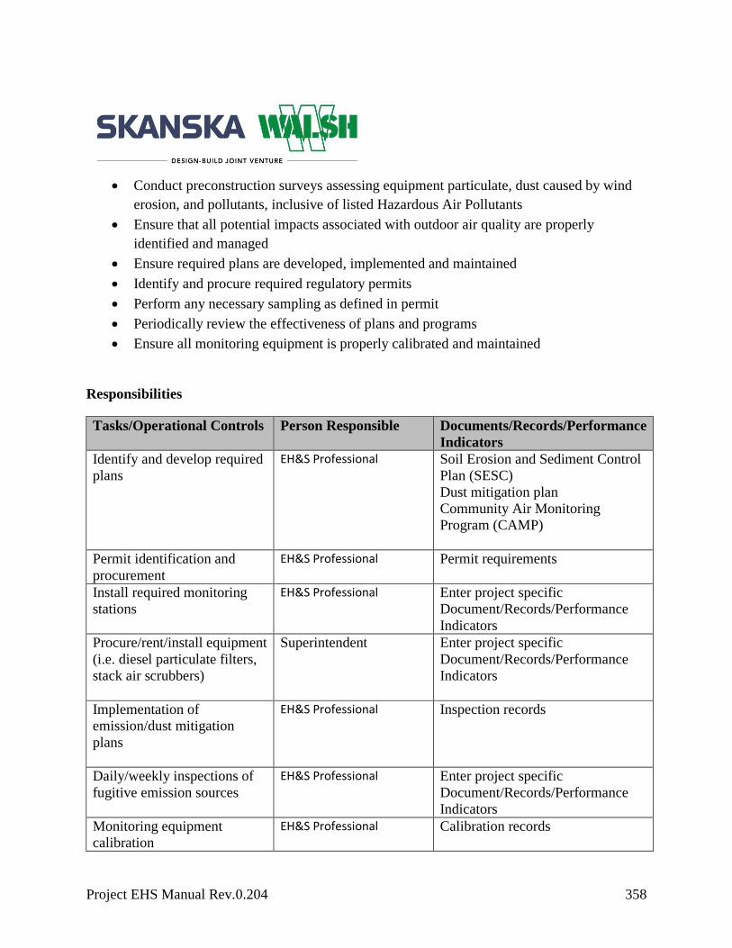
Project EHS Manual Rev.0.204 358
Conduct preconstruction surveys assessing equipment particulate, dust caused by wind
erosion, and pollutants, inclusive of listed Hazardous Air Pollutants
Ensure that all potential impacts associated with outdoor air quality are properly
identified and managed
Ensure required plans are developed, implemented and maintained
Identify and procure required regulatory permits
Perform any necessary sampling as defined in permit
Periodically review the effectiveness of plans and programs
Ensure all monitoring equipment is properly calibrated and maintained
Responsibilities
Tasks/Operational Controls Person Responsible Documents/Records/Performance
Indicators
Identify and develop required
plans
EH&S Professional
Soil Erosion and Sediment Control
Plan (SESC)
Dust mitigation plan
Community Air Monitoring
Program (CAMP)
Permit identification and
procurement
EH&S Professional
Permit requirements
Install required monitoring
stations
EH&S Professional
Enter project specific
Document/Records/Performance
Indicators
Procure/rent/install equipment
(i.e. diesel particulate filters,
stack air scrubbers)
Superintendent Enter project specific
Document/Records/Performance
Indicators
Implementation of
emission/dust mitigation
plans
EH&S Professional
Inspection records
Daily/weekly inspections of
fugitive emission sources
EH&S Professional
Enter project specific
Document/Records/Performance
Indicators
Monitoring equipment
calibration
EH&S Professional
Calibration records

Project EHS Manual Rev.0.204 359
Applicable Training
Monitoring equipment use and calibration training
Potential Health and/or Environmental Impacts

Project EHS Manual Rev.0.204 360
Water Impacts
Objective
Perform the necessary evaluation of construction-related activities and identify where effluent
from operations such as dewatering can be utilized for site dust control or where contaminated
water/surface runoff could potentially leave the site and negatively impact the environment.
Target
Discharge water within the required limits as specified on our dewatering permit.
Legal and Other Requirements
Federal, State, Local
Clean Water Act
33 CFR Ch. II(7-1-13 Edition)
National Pollution Discharge Elimination System (NPDES)
National Environmental Policy Act (NEPA)
Enter project-specific regulations
Skanska/Client Requirements
Green strategic indicators– Consumption of Potable Water
Environmental compliance plan
Port Authority of NY/NJ requirements
Procedure
Each project team shall develop project-specific environmental programs to mitigate potential
negative impacts on the environment as it relates to the scope of work. The project team will
assess the reuse of effluent in operations where potable water is not required during construction
(i.e., dust control).
Review project specifications and drawings to determine if there are any operations that
require dewatering.

Project EHS Manual Rev.0.204 361
Assess the opportunities to utilize effluent generated from dewatering to reduce potable
water consumption
Conduct preconstruction surveys
Ensure that all potential impacts to water bodies are properly identified
Ensure required plans are developed and implemented and maintained
Identify and procure required regulatory permits
Perform necessary effluent sampling as defined in permit
Periodically review the effectiveness of plans and programs
Responsibilities
Tasks/Operational Controls Person Responsible Documents/Records/Performance
Indicators
Management of geotechnical
and environmental boring
program
EH&S Professional
Geotechnical and environmental
borings reports
Identify potential reuse
opportunities
EH&S Professional
Reuse logs
Design and procure
dewatering system
Superintendent Engineered drawings and
calculations
Surveys, designs, utility drawings
(retention/detention basins,
well/treatment system design and
discharge connections)
Develop dewatering system
location plan
Superintendent
Enter project specific
Document/Records/Performance
Indicators
Permit identification and
procurement
EH&S Professional
NPDES
Combined stormwater and sanitary
discharge permit
Well permits
Identify and develop required
plans
EH&S Professional
Storm Water Pollution Prevention
Plan (CWPPP)
Spill Prevention Countermeasures

Project EHS Manual Rev.0.204 362
Control Plans (SPCC)
Soil Erosion and Sediment Control
Plan (SESC)
Required daily/weekly/quarterly
inspections
Wetland Disturbance Programs
Environmental compliance
Program (ECP)
Company community liaison Project Manager
Community meetings
Newsletters
Coordinate meetings with
regulatory agencies as needed
Project Manager
Company community
liaison
Meeting agendas and sign-in sheets
Call Before You Dig
Superintendent
Call sheet record acknowledging
call took place.
Implementation of
Dewatering Plans
EH&S Professional
Required Best Management
Practices inspections
Dewatering logs, including
sediment monitoring, piezometer
readings, TSS readings and site
treatment methods
Conduct crew reviews
EH&S Professional
Executed Crew reviews
Water quality management -
Periodic sampling of effluent
discharge
EH&S Professional
Analytical results
Sampling/monitoring
equipment calibration
EH&S Professional
Calibration records
Click here to enter text. Enter project-specific
roles and responsibilities
Enter project-specific operational
controls/documents
Applicable Training
Regulatory inspection requirements

Project EHS Manual Rev.0.204 363
Environmental Management Plan training.
Potential Related Safety, Health and/or Environmental Aspects

Project EHS Manual Rev.0.204 364
Health
Asbestos, Inclusive of Naturally Occurring Asbestos
Objective
The purpose of this program is to ensure that all employees are safeguarded from the
occupational health and safety risks associated with asbestos.
Legal and Other Requirements
Federal, State, Local Regulations
NESHAPS 40 CFR Part 61
EPA 600/4-80-005
OSHA 29 CFR 1926.1101
OSHA 29 CFR 1910.134
EPA 40 CFR 260-265
OSHA 29 CFR 1910.1001
Enter project-specific requirements
Skanska/Client Requirements
Port Authority of NY/NJ Requirements
Procedure
General Requirements:
Prior to commencing work, a survey of existing conditions must occur to identify
naturally occurring asbestos (NOA) and asbestos-containing building materials that may
be disturbed by project activities.
Communicate the location of asbestos to all employees whose work activities may
contact asbestos containing material (ACM), presumed asbestos containing material
(PACM), or NOA

Project EHS Manual Rev.0.204 365
Only properly certified employees and licensed contractors are permitted to disturb ACM
or PACM
Area monitoring and/or personal exposure monitoring will be reviewed and used to
communicate to employees working in adjacent areas that they are free from any
potential occupational exposure to asbestos.
Communicate the locations of and authorized entrant requirements pertaining to regulated
areas.
Ensure that signs and labels (see below for sample) identify all ACM and/or PACM that
may be disturbed during construction
Enter project-specific performance indicators/records
Identification/Disturbance of Naturally Occurring Asbestos:
Prior to engaging in any geo-technical or sub-surface investigative work (e.g., drilling,
pile driving, test pitting, mechanical breaking of rock, etc.) refer to the project’s geo-
technical survey. If the project has not conducted a survey and it is possible to collect a
sample of the rock, the rock is to be analyzed by a certified laboratory to determine the
presence of NOA.
In lieu of documented confirmation the project shall consult the U.S. Geological Survey
(USGS) to locate NOA areas in your region. The project team may also contact a
certified state geologist until a sample can be collected.
If NOA exists on the project and will be disturbed, the project team must create,
implement, and maintain an Asbestos Control Plan detailing the approach to mitigate
inhalation exposures and reduce/limit the amount of fibers from the rock being released
into the atmosphere. The topics of the plan may include the following;
- Introduction/scope of work
- Associated construction work plan
- Dust control plan

Project EHS Manual Rev.0.204 366
- Employee exposure plan
Worksite specific respiratory plan
Administrative controls (limit dust generating activities, design change,
equipment change)
Engineering controls (cover, capping, surfactants, suppressants)
- Material handling
- Personal protective equipment
- Personal hygiene
- Waste management
- Analytical results
- Logistics map/contract documents or drawings
Enter project-specific performance indicators/records
Asbestos-Containing Building Materials:
Prior to any renovation or demolition activities, an asbestos survey must be completed for
all potentially impacted materials
The asbestos survey must be completed by a certified building inspector
The asbestos survey report must be shared with all personnel on site and a copy must be
kept on site for reference
Materials not sampled shall be assumed to be asbestos-containing until proven otherwise
If additional suspect materials are identified during the project all work must stop
immediately and the materials must be sampled for asbestos by a certified inspector
Only a licensed contractor will remove, repair, or clean up asbestos-containing building
materials
An emergency response plan must be prepared in the event that ACM is disturbed by
anyone other than a licensed contractor
Responsibilities
Tasks/Operational Controls Person Responsible Documents/Records/Performance
Indicators
Identify all operations that
may impact asbestos
DJV Abatement designer
and EHS
Construction and Demolition
specifications
Conduct asbestos survey DJV Asbestos project Asbestos survey report

Project EHS Manual Rev.0.204 367
designer Geological surveys
Asbestos awareness training
EHS Department Training records
Ensure applicable permits are
in place
SWJV Project
Management and
abatement contractor
EPA and NYSDOL Notification
letters.
Ensure proper identification
and labeling of ACM and
PACM
EHS and DJV Hazardous Materials survey
If required, identify and
facilitate occupational
exposure monitoring
3rd Party Asbestos
monitoring company and
EHS
Air monitoring results
Calibration records
Applicable daily/weekly
inspections of asbestos work
areas
3rd Party Asbestos
monitoring company and
EHS
Asbestos abatement logs
If required, development of
Asbestos Control Programs
DJV and EHS Asbestos Control Program
Conduct area monitoring
3rd Party Asbestos
monitoring company and
EHS
Air monitoring results
Calibration records
Prepare emergency response
plan to address accidental
asbestos disturbances
EHS Emergency response plan
Click here to enter text. Enter project-specific
roles and responsibilities
Enter project-specific operational
controls/documents
Applicable Training
Asbestos awareness training
Abatement worker
Abatement supervisor
Abatement project designer
Certified building inspector

Project EHS Manual Rev.0.204 368
Potential Related Safety, Health and/or Environmental Aspects
Hazardous Materials and Asbestos

Project EHS Manual Rev.0.204 369
First Aid/Emergency Services/Bloodborne Pathogens
Objective
The purpose of this program is to ensure that all employees are safeguarded from the
occupational health and safety risks associated with bloodborne pathogens and provided proper
medical treatment.
Legal and Other Requirements
Federal, State, Local Regulations
OSHA 29 CFR 1910 1030
OSHA 29 CFR 1910.1020
OSHA 29 CFR 1910.1904
Enter project-specific requirements
Skanska/Client Requirements
Emergency Action Plan
Bloodborne Pathogen Control Plan
Procedure
First Aid Attendant Requirements:
Skanska and each sub-contractor shall have, at all times, a minimum of one employee
per shift trained in first aid/CPR/AED and bloodborne pathogens
Employees shall not be considered as first aid providers until they have completed and
received certification for the required programs pursuant to 29 CFR 1926.50(c)
At the commencement of each project, provisions shall be made in the Emergency
Action Plan (EAP) for prompt medical attention in case of injury or illness. This shall
include, but not be limited to:
- Contact details and maps to the nearest clinic or hospital
- Communication systems in the event of a first aid emergency

Project EHS Manual Rev.0.204 370
- Telephone numbers shall be posted on all sites for physicians, hospitals or
ambulances
First Aid Station:
Eating, drinking, smoking, applying cosmetics or lip balm, and handling contact lenses is
prohibited at the First Aid Station.
A fully stocked first aid kit in accordance with ANSI-Z308.1-1978 must include:
- An eye-wash station capable of at least a 15-minute flush
- Running water, hot (if feasible) and cold
- CPR resuscitation masks and non-latex gloves as PPE for first aid providers
First Aid Supplies:
Each site shall have at least one first aid kit. An evaluation of the workplace shall take
place to determine the need for further kits according to location, size, number of
employees, etc. This evaluation should also determine any additional types and
quantities of first aid equipment and supplies in the first aid kits
Contents of the first aid kit shall be checked prior to initial use and thereafter on a
weekly basis to ensure that any expended items are replaced
The contents of the first aid kit shall be placed in a weatherproof container with
individual sealed packages for each type of item
Each site will have access to an AED
Enter additional project requirements
Bloodborne Pathogens:
Consuming food or drink, smoking, handling contact lenses or applying cosmetics inside the
affected area is prohibited.
Employees who work at job sites that have the following conditions have the potential for
exposure to bloodborne pathogens:
Effluent waste in Waste Water Pollution Control Plants
Effluent drained on ground when plumbers hook up to sewer systems.

Project EHS Manual Rev.0.204 371
Contaminants in restrooms when plumbers complete hook ups.
Exposure to contaminants in portable toilets.
Exposures to following as a result of an injury:
- Human blood components
- Body fluid visibly contaminated with blood
- Any unfixed tissue or organ (other than intact skin)
Enter additional project requirements
Bloodborne Pathogen Control Plan:
The exposure control plan shall be maintained on the project site. The plan consists of
four parts:
- Exposure determination - identification and documentation of all job classifications
with occupational exposure, without regard to the use of personal protective
equipment
- The procedure for evaluation of circumstances surrounding an exposure incident
- The process for disinfecting of manageable contaminated surface areas: no more
than 4 square feet
- Larger contaminated areas requiring decontamination will be contracted out to a
firm specializing in such matters
Site Preparation and Engineering Controls
All employees involved in the decontamination procedures must receive training
according to 29 CFR 1910.1030
Warning signs posted – Highly visible warning signs should be posted at the entrance of
the contaminated area
Work control practices – Personal protective equipment should be donned at all times
within the contaminated work area
- Eye protection, such as splash goggles, safety glasses with solid side shields, or full-
face shields,
- Rubber utility gloves (preferred) or disposable gloves (single use),
- Rubber boots or boot covers,
- Protective outer clothing, such as impervious coveralls, bibs or aprons,
- Respiratory protection

Project EHS Manual Rev.0.204 372
Personnel decontamination – Clean up personnel should wash hands with soap and
running water after removing personal protective equipment. Antiseptic hand wipes or
gels may be used in the absence of hand washing facilities or water
Cross-contamination control –All infectious waste materials should be sealed in double-
bagged, heavy-duty trash bags and tagged or marked as hazardous materials prior to
removal from the contaminated area
Hard Surface Cleaning and Disinfection
Remove excessive contamination—Liquid blood or fluids should be removed by blotting
with absorbent pads, paper towels, or absorbent materials, such as kitty litter or
diatomaceous earth powder
Thoroughly clean – Affected areas should be thoroughly cleaned with a disinfectant
solution
Disinfect – Apply enough disinfectant to the pre-cleaned surface to allow it to remain
wet for at least 10 minutes, followed by wiping dry or air-drying
Refuse decontamination –All infectious materials, including cleaning supplies or
materials contaminated with blood or body fluids should be decontaminated by wetting
thoroughly with disinfectant prior to being placed in biohazard bags for disposal
Regulated Waste Disposal
Materials soiled with blood or bodily fluids, such as paper towels, cloths, sponges, and
mop heads, should be placed in double-bagged trash bags, sealed with tape, labeled and
disposed of as hazardous materials in accordance with local and state regulations
Enter project-specific procedure
Responsibilities
Tasks/Operational Controls Person Responsible Documents/Records/Performance
Indicators
Identify operations that may
include exposures to
bloodborne pathogens
EHS and Project
operations
Construction Work Plans
Manage bloodborne pathogen
control program development
EHS and Onsite Medial
Team
Written Bloodborne Pathogen
Control Program

Project EHS Manual Rev.0.204 373
Ensure the development of
emergency action plan
EHS Emergency Action Plan
Ensure adequate first aid
supplies are available
EHS, Onsite Medical
Team
Inventory of Medical and first aid
supplies and equipment
Project site coordination tours
with First Responders
EHS Attendence sheets, Meeting
minutes
Conduct incident
investigations and maintain
all records associated with
exposures to bloodborne
pathogens
EHS Incident Investigation reports
Management of infectious
waste disposal
EHS Medical Waste manifests
Click here to enter text. Enter project-specific
roles and responsibilities
Applicable Training
First aid/CPR/AED Training
Enter project-specific training
Potential Related Safety, Health and/or Environmental Aspects
Port Authority of NY/NJ Requirements

Project EHS Manual Rev.0.204 374
Hazard Communication
Objective
The purpose of this program is to communicate the hazards associated with chemicals on the
jobsite to all affected employees.
Legal and Other Requirements
Federal, State, Local Regulations
OSHA 29 CFR 1926.59
OSHA 29 CFR 1910.1200
Skanska/Client Requirements
Port Authority of NY/NJ Requirements
Procedure
All employees must be trained on the proper use, storage, labeling, and disposal of
chemicals in the work place
All chemicals must be properly labeled
All information contained on labels must comply with Federal, State and local laws
and/or regulations and include the identity of the chemical products or substances in the
container, hazard warnings and names and addresses of the manufacturer or the
responsible parties
All containers of chemical products, including laboratory bottles, solvent cans, and
dispensers will be labeled. Container labels will not be removed and will be replaced if
illegible
Only those chemicals that can be classified “For Immediate Use” (this means the
chemicals are under the control of and used only by the person who transfers it from the
labeled container and only for the duration of the shift during which it is transferred) are
exempted from the stated labeling procedures

Project EHS Manual Rev.0.204 375
In storage areas where similar chemical products are stored, signs or placards to identify
the material may be posted in lieu of container labels
If any hazardous materials are transferred from a storage tank or container through a
pipeline, labels with the required information will be affixed to the line at the discharge
point (valve)
If a chemical product other than that specified on the container label is placed in a
container, the container will be re-labeled to accurately reflect the hazards of the current
contents
All employees must have access to safety data sheets (SDS) for chemicals in the work
place
All contractors must maintain a master chemical inventory list for chemicals brought on
site
Responsibilities
Tasks/Operational
Controls
Person Responsible Documents/Records/Performance
Indicators
Evaluate chemicals before
purchase and explore the
use of less hazardous
substitutes
Procurement/Sustainability Project data sheets, Purchasing
records, DS
Conduct Hazard
Communication training, at
least annually
EHS Training records
Ensure that an SDS has
been obtained for all
hazardous chemicals
Project operations, EHS Subcontractor submittals
Keep an inventory of all
hazardous chemicals and
make available to all
employees
EHS SiteHawk®
Review SDS, as part of the
Construction Plan
EHS, Project Operations
Construction Work Plans
Ensure all chemical
containers are properly
labeled
EHS Inspection reports
Click here to enter text. Enter project-specific roles
and responsibilities
Enter project specific
Document/Records/Performance

Project EHS Manual Rev.0.204 376
Indicators
Applicable Training
Hazard Communication training, at least annually
Site Specific SDS Training
Potential Related Safety, Health and/or Environmental Aspects
Hazardous Materials, Hazard Communication

Project EHS Manual Rev.0.204 377
Heat and Cold Related Illness
Objective
The purpose of this program is to establish safe working guidelines when employees are working
in hot or cold weather that could result in an injury or illness.
Legal and Other Requirements
Federal, State, Local Regulations
OSHA 29 CFR 1910.132(d)
OSHA 29 CFR 1915.152
OSHA 29 CFR 1917.95
OSHA 29 CFR 1926.28
OSHA 29 CFR 1904.7(b)(5)
OSHA 29 CFR 1910.141
OSHA 29 CFR 1926.50
OSHA 29 CFR 1926.21
Enter project-specific regulations
Skanska/Client Requirements
Port Authority of NY/NJ Requirements
Procedure
General Requirements
Weather conditions shall be evaluated to identify exposure to hot or cold conditions
All employees shall be acclimatized to the ambient temperatures prior to working a full
40hr per week work schedule
Employees shall be trained in the recognition of a heat/cold related illness and have
means to initiate emergency response
Potable water shall be accessible to all employees
Winter hard hat liners/gloves shall be provided during times of cold weather

Project EHS Manual Rev.0.204 378
When temperatures reach 95 degrees or above, employees shall take a minimum ten
minute net preventative cool-down rest period every two hours
Employees must be reminded to drink plenty of water throughout the work shift
Enter project-specific procedure
Hot Weather
Shade shall be present when the outdoor temperature exceeds 85 degrees Fahrenheit
Shades should be accessible for employees in their work area
Structures such as bridges, false work, etc. can be utilized as shaded areas
All employees shall be closely observed by a supervisor or designee during a heat wave.
For purposes of this section only, “heat wave” means any day in which the predicted
high temperature for the day will be at least 85 degrees Fahrenheit and at least ten
degrees Fahrenheit higher than the average high daily temperature in the preceding five
days
An employee who has been newly assigned to a high heat area shall be closely observed
by a supervisor or designee for the first 14 days of the employee's employment
Enter project-specific procedure
Cold Weather
Employees shall wear layered clothing
Areas where employees can warm up shall be established
Employees shall be closely observed to identify signs of frost bite and or hypothermia
Employees shall wear insulated gloves (water resistant if necessary) to protect the hands
Project teams shall monitor the weather conditions during a winter storm and have a
reliable means of communicating with workers and being able to stop work or evacuate
when necessary
Enter project-specific procedure
Responsibilities
Tasks/Operational Controls Person Responsible Documents/Records/Performance
Indicators
Evaluate weather conditions
EHS/ Superintendents Construction Work Plans
Evaluate workers for signs of
heat or cold related illness
EHS, On site Medical
Team
Medic notes, EHS reports

Project EHS Manual Rev.0.204 379
Identify ambient temperatures
are being monitored and
communicated
Superintendents, Daily Reports
Ensure that shaded areas are
available in high heat
Project operations team
Construction work plan operational
controls
Ensure that employees can
warm up if needed
Project operations Construction Work Plans
operational controls
Provide potable water
Foreman EHS inspections
Prepare emergency response
plan
EHS Emergency Action Plan
Click here to enter text. Enter project-specific
roles and responsibilities
Enter project-specific operational
controls/documents
Applicable Training
Heat and cold illness awareness training
Project EHS Orientation
Potential Related Safety, Health and/or Environmental Aspects
Heat and Cold Illness

Project EHS Manual Rev.0.204 380
Heavy Metals (Lead, Arsenic, Cadmium, Hexavalent Chromium)
Objective
This program is to prevent employee, public and community exposures to heavy metals produced
by and associated with construction activities. This program is designed to minimize the risk of
exposure to heavy metals and subsequent impact to the environment
Legal and Other Requirements
Federal, State, Local Regulations
OSHA 29 CFR 1926.62 - Lead
OSHA 29 CFR 1910.1025 - Lead.
OSHA 29 CFR 1926.1118 – Inorganic Arsenic
OSHA 29 CFR 1910.1018– Inorganic Arsenic
OSHA 29 CFR 1926.1127 - Cadmium
OSHA 29 CFR 1910.1027- Cadmium
OSHA 29 CFR 1926.1126 Chromium (VI)
OSHA 29 CFR 1910.1026 - Chromium (VI)
OSHA 29 CFR 1910.134 - Respiratory Protection
Skanska/Client Requirements
Port Authority of NY/NJ Requirements
Procedure
Exposure Assessment
Initial Determination
Before work begins, each project will determine whether there is any risk of employee
exposure to heavy metals

Project EHS Manual Rev.0.204 381
Owner specifications will be reviewed to determine if heavy metals are present on the
project. If necessary, a survey will be completed to identify additional sources of heavy
metals
If the initial determination for heavy metals or materials suspected of containing metals
is positive, the project team may collect bulk samples and send them to a laboratory for
determination of the content
Sources of heavy metals which produce potential exposures:
- Excavation of soils that are contaminated with heavy metals
- Demolition or salvage of structures where heavy metals are present
- Removal or encapsulation of materials containing heavy metals
- New construction, alteration, excavation, repair or renovation of structures,
substrates, or portions that contain heavy metals
- Certain welding activities
- Installation of products containing heavy metals
- Heavy metals contamination/emergency cleanup
- Transportation, disposal, storage of materials contaminated with heavy metals on
the site
- Maintenance operations associated with any of the above
Enter in additional project requirements
Exposure Monitoring
If the presence of heavy metals has been identified or is suspected, the competent person will
collect personal air samples to establish baseline readings for all workers with potential
exposures. Samples will be representative of a full shift including at least one sample for each
job classification in each work area for either each shift, or, preferably the shift with the highest
potential exposure level. These samples must be representative of the monitored employee’s
regular daily exposure to heavy metals.
Follow-up air monitoring shall be performed as listed below:
- If baseline sampling results demonstrate that the employee is below the action level
further air monitoring is not required. If a change of equipment, process, control,
personnel or a new task has been initiated that may result in exposure to heavy
metals at or above the action level, then additional monitoring will be conducted
- If baseline sampling results demonstrate exposure is above the action level and
below the PEL, then two samples, taken at least seven days apart, will be required at
Project EHS Manual Rev.0.204 382
least every six months until two consecutive samples demonstrate the exposure is
below the action level
- If baseline sampling results demonstrate exposure is at or above the PEL, then two
samples, taken at least seven days apart, will be required at least every three months
until two consecutive samples demonstrate the exposure is below the PEL.
Consideration will be taken to the levels of the two consecutive samples. If results
are below the PEL, but above the action level, sampling will resume as per the
paragraph above. If results are below the action level, then sampling will be
conducted as per the first paragraph
Follow-up air monitoring shall also be performed whenever an employee exhibits
symptoms that may be caused by exposure to heavy metals.
All employees being monitored or in the area must be outfitted with the appropriate
respiratory protection.
Recordkeeping and Notification Requirements
Baseline and additional sampling results will be recorded and stored at the jobsite and at
the B.U. / Regional EHS Department
Air sampling worksheets will be kept with all sampling results as per the respiratory
program
Within five days of receipt of sample results, employees will be notified by letter of the
results of the exposure monitoring. These letters will either be given to the employee by
hand, if at the jobsite, or by certified letter delivery. If the employee receives the letter by
hand, he/she will be required to sign off on the air monitoring results to show that they
received the notification
Permissible Exposure Limit (PEL)
No one shall be exposed to heavy metals concentrations greater than the PEL, averaged
over an eight-hour day, without proper protection:
- Lead PEL = 50 µg/m3 8hr TWA
- Arsenic PEL = 10 µg/m3 8hr TWA
- Cadmium PEL = 5 µg/m3 8hr TWA
- Hexavalent Chromium PEL = 5 µg/m3 8hr TWA
If exposure to heavy metals exceeds eight hours per day, then the maximum time
weighted average (TWA) exposure limit in µg/m3of air is divided by hours of exposure
during that day

Project EHS Manual Rev.0.204 383
Engineering and Work-Practice Controls
Engineering and work practice controls, including administrative controls, shall be used
to reduce and maintain employee exposure to less than the PEL
Where engineering and work practice controls are not able to reduce the exposure to
below 50 percent of the applicable OSHA PEL, respiratory protection shall be worn to
supplement the engineering and work practice controls
Engineering controls shall include, but not be limited to:
- HEPA (High Efficiency Particulate Air) vacuum shrouded scalers and grinders
- HEPA vacuum blasters
- Chemical paint stripping
- Dust collection/ventilation
- Removal of paint before burning or welding;
- Cleaning with HEPA filter vacuums
- Utilizing wet methods to reduce dust
- Use of long cutting torches to keep workers further away from fumes
- Use of mechanical ventilation to move fumes and dust away from employees
- Dust control
- Positioning workers upwind or otherwise outside of visible fume or dust clouds
Heavy Metals Program
This written program shall be considered the governing compliance program. This will be
further supplemented by site-specific programs, such as the Worksite Specific Respiratory
Program for heavy metals, which details overall site controls for heavy metals.
Where work involving heavy metals is subcontracted out, the subcontractor will be
responsible for providing a Site Specific Compliance Program. This program shall be
approved by the regional EHS department lead, prior to the commencing work
Protective clothing will be provided for all employees exposed to heavy metals in excess
of 50 percent of the PEL in air
Protective clothing may include coveralls, disposable suits, gloves, hats, shoe coverlets,
face shields or goggles

Project EHS Manual Rev.0.204 384
This clothing shall be replaced daily unless the exposure to heavy metals is minimal,
such as when exposed to heavy metals less than 15 minutes per day or when welding on
“pre-cleaned” steel
Damaged protective clothing shall be replaced as needed to maintain effectiveness
Contaminated protective clothing shall be removed at the completion of a work shift
only in the designated change areas. Employees are not permitted to move to other work
areas, offices, trailers etc. without removing affected clothing
Commercial laundries that launder protective clothing or equipment shall be notified, in
writing, of the potentially harmful effects of exposure to the specific metals involved
Contaminated clothing that is to be cleaned or disposed of shall be kept in a closed
container, such as a heavy-duty plastic trash bag
Seal each bag with a tie when it becomes full. All trash cans and bags that contain
contaminated clothing shall be marked with this warning – “Caution – Clothing
contaminated with heavy metals. Do not remove contaminants by blowing or shaking.
Dispose of contaminated wash water in accordance with local, state and federal
regulations”
Heavy metals must not be removed from protective clothing or equipment by blowing,
shaking or any other means that could disperse contaminants into the air
Work boots shall be vacuumed or cleaned with water before being worn off the project
site
Respirators/Respirator Selection
Respirators shall be used and worn in accordance with the Respiratory Protection section
of this EHS manual
- Respiratory protection will be instituted at 50 percent of OSHA’s PEL
- Each subsequent upgrade in respirator use will be done so when personal
monitoring indicates a potential for 50 percent of the maximum use concentration
for each.
Dust masks and or filtering face pieces are not allowed on Skanska projects at any time.
Respirators are not considered an engineering control – they are used to provide
protection while engineering controls are being implemented; and

Project EHS Manual Rev.0.204 385
Respirators shall be worn at the commencement of the operation, and thereafter until air
monitoring results demonstrate that engineering and administrative controls are
sufficient in the control of exposure to heavy metals.
Fit testing must be conducted per the established Respiratory Program in this manual
Respiratory Protection for Heavy Metals
Airborne Concentration
of Heavy Metals or
Condition of Use
Required Respirator * Activity Initial Respiratory
Requirements
50% of PEL < 5 times the
PEL
½ half or Full-Face Air-Purifying
Respirator (APR) equipped with
HEPA filters. **
Manual scraping,
Manual sanding,
Manual demolition of
structures (e.g., dry wall),
Chemical Paint Removal
Earthwork/excavation/dust
control
All other activities require
baseline exposure monitoring
to be conducted to determine
if a ½ face respirator can be
used.
>5 times the PEL to < than
25 times the PEL
Full-face Air-Purifying Respirator
equipped with HEPA filters.
or
Power Air Purifying Respirator
(PAPR) equipped with HEPA
filters.
Heat gun applications, and
Power tool cleaning with
dust collection systems
Abrasive blasting
Welding

Project EHS Manual Rev.0.204 386
Brazing
Lancing
Cutting
Grinding
Torch burning.
> 25 times the PEL to <
500 times the PEL
Power Air Purifying Respirator
(PAPR) equipped with HEPA
filters.
or
Any supplied air respirator operated
in a continuous flow, pressure-
demand or other positive-pressure
mode.
Activities determined by
baseline exposure monitoring
> 500 times the PEL or
when concentrations are
unknown in an emergency
response situation.
Any self-contained breathing
apparatus that has a full face piece
and is a pressure-demand or other
positive-pressure mode.
* Respirators specified for high concentrations can be used at lower concentrations of heavy
metals
** A HEPA filter is at least 99.97 percent efficient against particles that are 0.3 micron in
diameter
Training and Respiratory Usage
All employees who will potentially be exposed to heavy metals shall be properly trained
before that exposure begins.
Training shall be repeated annually and will cover the following items:
- The content of applicable state and federal regulations
- A list of specific operations (burning, welding, etc.) that can result in exposure

Project EHS Manual Rev.0.204 387
- The purpose, proper selection, fitting, use and limitations of respirators;
- The purpose and a description of the medical surveillance and medical removal
protection programs
- Information on the health problems associated with excessive heavy metals
exposure. Particular emphasis should be placed on topics such as reproductive
problems that heavy metals can cause in both men and women
- Engineering controls and work practices that will be used to control heavy metals
exposure
Skanska or subcontractor will also provide a copy of the regulations pertaining to heavy
metals to all affected employees
The project’s designated Respiratory Coordinator will ensure that when respirators are
chosen that require fit testing, all employees have been properly fit-tested per the
established Respiratory Program and all controls are implemented
Employee representatives should be notified that facial hair may prevent a proper fit;
Whenever a filter respirator is selected, the employee will be permitted to change the
filter elements when an increase in breathing resistance is detected. Filters do not have
an expiration date or mechanical detector for signifying expiration. The only adequate
means of assessing filter life is breathing resistance
Employees wearing respirators will be allowed to leave work areas to wash their face
and respirator when necessary to prevent skin irritation
Housekeeping
All surfaces shall be kept as free as practical of heavy metal accumulations;
Compressed air shall not be used for cleaning
Vacuuming is the preferred choice for cleaning, however, wet methods such as washing,
wet sweeping, wet shoveling, and wet brushing may be used when vacuuming is not
practical
Vacuums will be equipped with HEPA filters and shall be emptied in a manner that
minimizes the release of heavy metals into the air
Hygiene Facilities and Practices
Change Areas

Project EHS Manual Rev.0.204 388
Clean change areas to remove contaminated clothing will be provided for employees
exposed above the PEL and as protection during initial monitoring
Change areas will be equipped with separate storage facilities for protective work
clothing and equipment and for street clothes to prevent cross-contamination
Employees will not be allowed to leave the job wearing any protective clothing or
equipment
Showers
The project will provide shower facilities, where feasible, for use by employees whose
airborne exposure to heavy metals is above the PEL
If a project does provide shower facilities, use will be mandatory at the end of the work
shift. Cleaning agents and towels will be provided
Eating Facilities
Lunchroom facilities will be provided for employees exposed over the PEL
This facility will be as free as practicable from heavy metal contamination
Before using the facilities, employees will wash their hands and face
Employees should not enter the facility with their protective clothing unless the surface
dust has been removed by vacuuming or similar means
Periodic wipe testing should be considered to prove the effectiveness of the program
Hand Washing Facilities
The project will provide adequate hand washing facilities for use by employees exposed
to heavy metals
When showers are not provided, the project will assure all employees wash their hands
and face at each break and the end of the work shift
Portable hand wash facilities with filtration devices should be considered
Warning Signs
The following warning signs shall be posted in each work area with potential exposures
above the PEL:
WARNING – HAZARD

Project EHS Manual Rev.0.204 389
<Enter Specific Contaminant> WORK AREA
AUTHORIZED EMPLOYEES ONLY BEYOND THIS POINT
NO SMOKING, EATING OR DRINKING
Responsibilities
Tasks/Operational Controls Person Responsible Documents/Records/Performance
Indicators
Identify operations that may
be impacted by heavy metals
Project Operations and
EHS
Soil sampling results, hazardous
materials surveys
Obtain applicable permits
Project Operations,
Subcontractors
Hazardous materials abatement
notification
Identify potential
environmental impacts
associated with heavy metals
Project Operations, EHS
Construction Work Plans
Establish and maintain
authorized work zones
Project operations Logistic plans
Establish and maintain waste
storage areas
EHS Site maps
Conduct occupational
exposure monitoring
EHS Sampling results
If required, facilitate
biological
monitoring/medical
surveillance programs
EHS Monitoring results
Communicate results of
occupational exposure
monitoring to affected
employees
EHS Exposure notification
If required, development of
heavy metal specific control
programs
EHS, Subcontractor
management
Written exposure control programs

Project EHS Manual Rev.0.204 390
Manage monitoring
equipment, calibration,
recordkeeping
EHS Calibration records
Click here to enter text. Enter project-specific
roles and responsibilities
Enter project-specific operational
controls/documents
Applicable Training
Hazard Communication Training
HAZWOPER Training
Respiratory Protection
Potential Related Safety, Health and/or Environmental Aspects
Hazardous Materials

Project EHS Manual Rev.0.204 391
Noise Exposure
Objective
The purpose of this program is to ensure that all employees are safeguarded from the
occupational health and safety risks associated with noise.
Legal and Other Requirements
Federal, State, Local Regulations
OSHA 29 CFR 1926.52
OSHA 29 CFR 1926.101
ANSI S3.19
NYCDEP Noise Mitigation Requirements
Skanska/Client Requirements
Port Authority of NY/NJ Requirements
Procedure
General
Workplace noise levels shall be identified and monitored using a calibrated sound level
meter in the course of day-to-day work, and whenever there is a change in production
processes, equipment, or controls
Determine if employees in specific areas have exposure to noise that exceeds OSHA
regulations (table below)
It is Skanska USA Inc. policy that all employees exposed to sound levels greater than
85dBA/8-Hour Time Weighted Average (TWA) shall use hearing protection complying
with ANSI S3.19
Controlling noise at the source utilizing engineering controls must be considered first
before any other measures are implemented
Warning signs will be posted in conspicuous locations at worksites near the high noise
level areas to notify employees if hearing protection is required

Project EHS Manual Rev.0.204 392
When the following tasks are being performed, hearing protection is mandatory and
exposure to impulsive or impact noise should not exceed 140 dB peak sound pressure
level:
- Pile driving
- Jack hammering
- Chipping concrete or steel with power tools
- Operating gasoline chain or cut-off saws
- Arc gouging
- Hoe ram operating
OSHA Permissible Noise Exposure (A-scale readings on sound level meter at slow
response)
Duration per Day (Hours) Sound Level dBA Slow
Response
8 90
6 92
4 95
3 97
2 100
1.5 102
1 105
.5 110
.25 or less 115
Enter in additional project requirements
Hearing Protection
The project shall provide a variety of adequate hearing protection devices for employees.
All employees subject to work in high noise areas must be provided with appropriate
hearing protection devices as determined by a competent person
Employees are required to wear company-provided hearing protection and at no time may
an employee tamper with or modify any hearing protection equipment
Damaged or defective equipment must be discarded and replaced immediately
Failure to follow hearing conservation program and rules set forth by the company may
result in disciplinary action up to and including retraining and/or termination
Enter in additional project requirements

Project EHS Manual Rev.0.204 393
Responsibilities
Tasks/Operational Controls Person Responsible Documents/Records/Performance
Indicators
Ensure applicable noise
mitigation plans are in place
Project Operations and
EHS
Noise Mitigation Plans
Establish and maintain
authorized work zones
Project Operations Logistic Plans
Perform area sound level
and/or dosimetry monitoring
EHS Monitoring data
Calibration records
If required, development of
Hearing Conservation
Program
EHS, Subcontractor
competent person
Written hearing conservation
program, noise dosimeter readings,
audiometric testing
Click here to enter text. Enter project-specific
roles and responsibilities
Enter project-specific operational
controls/documents
Applicable Training
Environmental Management Plan training
Hearing Conservation training
Potential Health and/or Environmental Impacts
Noise and Vibration

Project EHS Manual Rev.0.204 394
Polychlorinated Biphenyls (PCBs)
Objective
The purpose of this program is to ensure that all employees are safeguarded from the
occupational health and safety risks associated with exposures to polychlorinated biphenyls
(PCBs)
Legal and Other Requirements
Federal, State, Local Regulations
OSHA 29 CFR 1910.1000 Table Z-1.
OSHA 29 CFR 1910.120
OSHA 29 CFR 1910.134
EPA TSCA
Skanska/Client Requirements
Port Authority Of NY/NJ Requirements
Procedure
General Requirements
Develop Worksite Specific Respiratory Plan as defined in the Respiratory Protection
section of this manual
Provide training to employees who are potentially exposed to PCB hazards
Implement all feasible engineering controls to reduce PCB exposures. When engineering
controls are exhausted implement administrative/work practice controls
Respirators will only be used when the above mentioned controls fail to reduce exposure
levels below the 8-hour time weighted average (TWA) permissible exposure limit
(PEL):
- 100µg/m³ for Aroclor 1242
- 50µg/m³ for Aroclor 1254
Develop project-specific PCB Management Program

Project EHS Manual Rev.0.204 395
Enter project-specific performance indicators/records
Activities that may result in PCB exposure
Work on electrical installations and/or equipment where PCBs may have been used as an
insulator or coolant, including demolition or salvage
Work on pipes or equipment painted with PCB containing coatings
Removal/handling of PCB contaminated soils
Initial Determination/ Exposure Assessment
Each project shall determine whether the potential for PCB exposure exists prior to the
start of work
- Potential sources of PCB exposure may be identified in the owner specification or
related documents.
- If the initial determination establishes that PCBs may be present in coatings or
paints, paint chip samples shall be collected and forwarded to an accredited
laboratory for analysis
- If detectable levels of PCBs are identified exposure monitoring must be performed
Prior to work commencing, all PCB sources must be identified in the work area
An ongoing assessment must be conducted as surfaces or equipment not visible at the
start of a project may become apparent as work progresses
Enter in additional project requirements
Controls
If occupational monitoring identifies potential PCB exposures, engineering and
administrative controls shall be used.
Engineering controls include, but are not limited to:
- Chemical/mechanical paint stripping
- Removal of paint before burning
- Use of long cutting torches
- Use of local exhaust ventilation equipped with HEPA filtration at the point of fume
generation
- Use of mechanical ventilation
Project EHS Manual Rev.0.204 396
- Positioning employees upwind or otherwise outside of visible fume or dust clouds
Enter additional project requirements
Administrative controls include, but are not limited to:
- Signs and barricades will be placed allowing only authorized employees to enter an
area where operations are taking place that may create exposure to PCBs. The sign
shall read:
WARNING
HAZARD
PCB WORK AREA
AUTHORIZED EMPLOYEES ONLY BEYOND THIS POINT
NO SMOKING, EATING OR DRINKING ALLOWED BEYOND THIS
POINT
Enter additional project requirements
Respiratory Protection
Respiratory protection shall be used as the last line of defense in the protection against
exposure to PCBs and shall never be used as the sole means of limiting employee exposure.
Respiratory protection shall be required at the beginning of each identified activity until
air sampling results demonstrate that the exposure is below the action level
Respirators will be selected based on the criteria identified in the Respiratory Protection
section of this manual and according to the Worksite Specific Respiratory Plan
Personal Hygiene
Food and drink is not permitted to be present or consumed in the work area
Tobacco products are not permitted to be present or consumed in the work area
A wash station will be available for employees to use as they exit the work area
Protective Work Clothing and Equipment
If there is a potential for an employee to come into physical contact with PCBs they
must wear employer-provided protective equipment/clothing

Project EHS Manual Rev.0.204 397
Enter additional project requirements
Medical Surveillance
Employers shall make medical surveillance available at no cost to the employee and at a
reasonable time and place, where employees:
Are or may be exposed to PCBs at or above the permissible exposure limit for 30 days or
more in a calendar year
Wear a respirator for 30 days or more a calendar year or as required by 29 CFR
1910.134
Are experiencing signs or symptoms of adverse health effects associated with PCB
exposure; or are exposed in an emergency
Frequency of Medical Surveillance
Within 30 days of initial assignment, unless the employee has received a PCB-related
medical exam within the past 12 months
Within 30 days after a licensed healthcare provider provides a written medical opinion
recommending an additional examination
Whenever an employee shows signs or symptoms of adverse health effects associated
with PCB exposure
Within 30 days after exposure during an emergency which results in an uncontrolled
release of PCB
At the termination of employment, unless the last examination that meets the
requirement of the standard was less than 6 months prior to the date of termination
Contents of Examination
Medical and work history emphasizing:
- Past, present and anticipated future exposure to PCBs
- Any history of respiratory dysfunction
- Any history of asthma, dermatitis, skin ulceration or nasal septum perforation
- Smoking status and history
- A physical examination of the skin and respiratory tract; and
- Any tests deemed necessary by the examining healthcare provider
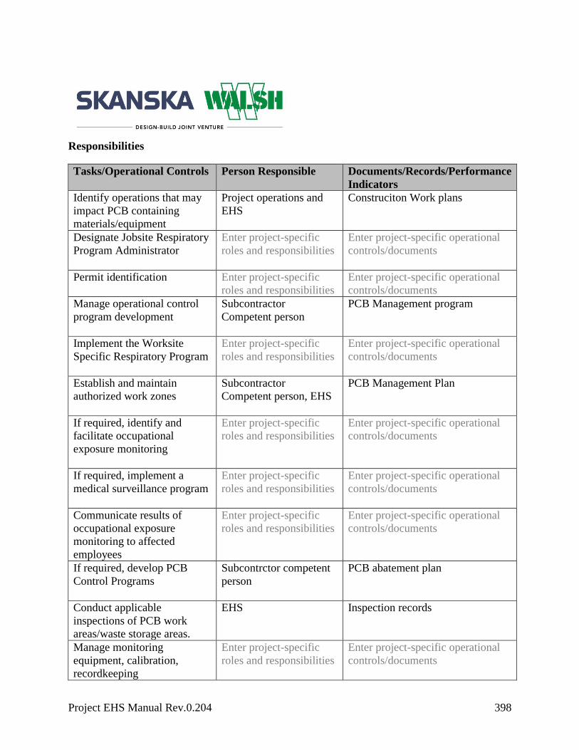
Project EHS Manual Rev.0.204 398
Responsibilities
Tasks/Operational Controls Person Responsible Documents/Records/Performance
Indicators
Identify operations that may
impact PCB containing
materials/equipment
Project operations and
EHS
Construciton Work plans
Designate Jobsite Respiratory
Program Administrator
Enter project-specific
roles and responsibilities
Enter project-specific operational
controls/documents
Permit identification
Enter project-specific
roles and responsibilities
Enter project-specific operational
controls/documents
Manage operational control
program development
Subcontractor
Competent person
PCB Management program
Implement the Worksite
Specific Respiratory Program
Enter project-specific
roles and responsibilities
Enter project-specific operational
controls/documents
Establish and maintain
authorized work zones
Subcontractor
Competent person, EHS
PCB Management Plan
If required, identify and
facilitate occupational
exposure monitoring
Enter project-specific
roles and responsibilities
Enter project-specific operational
controls/documents
If required, implement a
medical surveillance program
Enter project-specific
roles and responsibilities
Enter project-specific operational
controls/documents
Communicate results of
occupational exposure
monitoring to affected
employees
Enter project-specific
roles and responsibilities
Enter project-specific operational
controls/documents
If required, develop PCB
Control Programs
Subcontrctor competent
person
PCB abatement plan
Conduct applicable
inspections of PCB work
areas/waste storage areas.
EHS Inspection records
Manage monitoring
equipment, calibration,
recordkeeping
Enter project-specific
roles and responsibilities
Enter project-specific operational
controls/documents

Project EHS Manual Rev.0.204 399
Click here to enter text. Enter project-specific
roles and responsibilities
Enter project-specific operational
controls/documents
Applicable Training
PCB Awareness Training
Potential Related Safety, Health and/or Environmental Aspects
Enter project-specific health and environmental impacts

Project EHS Manual Rev.0.204 400
Radiation
Objective
The purpose of this program is to ensure that all employees are safeguarded from the
occupational health and safety risks associated with ionizing and non-ionizing radiation
produced by x-rays, lasers, and naturally occurring radioactive material.
Legal and Other Requirements
Federal, State, Local Regulations
OSHA 29 CFR 1926.53
OSHA 29 CFR 1926.54
OSHA 29 CFR 1910.1096
OSHA 29 CFR 1910.97 (a)(3)
Skanska/Client Requirements
Port Authority of NY/NJ requirements
Procedure
General Requirements:
Perform an evaluation of the radiation hazards specific to the production, use, release,
disposal, or presence of radioactive materials or other sources of radiation
When appropriate, such evaluation shall include a physical survey of the location of
materials and equipment and measurements of radiation levels or concentrations of
radioactive material present
Emergency signals shall be defined in the project’s Emergency Action Plan
All employees shall be made familiar with the actual sound of the signal
Ionizing Radiation:

Project EHS Manual Rev.0.204 401
Employer shall supply appropriate personnel monitoring equipment, such as film
badges, pocket chambers, pocket dosimeters, film rings, etc. for the following:
- Each employee who enters a restricted area under such circumstances that employee
receives, or is likely to receive a dose in any calendar quarter in excess of 25 percent
of the applicable value specified in Table G-18 located in OSHA 29 CFR 1910.1096
- Each employee under 18 years of age who enters a restricted area under such
circumstances that the employee receives, or is likely to receive, a dose in any
calendar quarter in excess of 5 percent of the applicable value specified in Table G-
18
- Each employee who enters a high radiation area (which means any area, accessible
to personnel, in which there exists radiation at such levels that a major portion of the
body could receive in any one hour a dose in excess of 100 millirem)
Signage shall be posted using the conventional radiation caution colors (magenta or
purple on yellow background) and shall be conspicuously posted. The symbol shall be
the conventional three-bladed design and shall include the words: “CAUTION –
RADIATION AREA”
Non-Ionizing Radiation
Precautions will be taken to ensure all workers that use lasers are trained in proper use
and the hazards associated with lasers

Project EHS Manual Rev.0.204 402
No worker will install, adjust, or operate any laser equipment without a valid
qualification card, which the worker must have on their person
Standard laser warning signs will be placed around the perimeter of the area where the
laser is being used
No laser equipment will be used that does not contain a label indicating make, maximum
output, and beam spread
Whenever a laser is not in use, shutters or caps will be used and the laser turned off
When performing internal alignment, lasers will only be guided by mechanical or
electronic means
No laser beam will be directed at any worker
When environmental conditions exist such as rain, fog, snow, or extremely dusty
conditions, use of lasers will not be permitted.
Workers using lasers will use appropriate eye protection.
Responsibilities
Tasks/Operational Controls Person Responsible Documents/Records/Performance
Indicators
Identify operations that may
be impacted by radiation
Superintendent Construction Work plans
Manage operational control
program development
Superintendent Construction Work plans
Establish and maintain
authorized work zones
EH&S Professional
Inspections
If required, develop Radiation
Control Programs
EH&S Professional
Construction Work plans, training
records, Radiation Safety program
If required, identify and
facilitate occupational
exposure monitoring
EH&S Professional
Occupational exposure monitoring
records, Leak testing reports on
equipment
Communicate results of
occupational exposure
monitoring to affected
EH&S Professional
Records from Contractors
Project EHS Manual Rev.0.204 403
employees
Manage monitoring
equipment, calibration,
recordkeeping
EH&S Professional
Enter project-specific operational
controls/documents
Applicable Training
Radiation Safety Training
Potential Related Safety, Health and/or Environmental Aspects
Hazardous Materials

Project EHS Manual Rev.0.204 404
Respiratory Protection
Objective
The purpose of this program is to establish, implement and maintain an appropriate respiratory
protection program to protect employees from respiratory hazards on our jobsites.
Legal and Other Requirements
Federal, State, Local Regulations
OSHA 29 CFR 1910.134
OSHA 29 CFR 1926.103
Skanska/Client Requirements
Port Authority of NY/NJ Requirements
Procedure
Medical Evaluation:
Persons shall not be assigned to tasks requiring the use of respirators unless it has been
determined that they are physically able to perform the work and use the equipment
Prior to respirator use, each employee shall complete a Medical Evaluation
Questionnaire (MEQ) in accordance with CFR 1910.134, which shall be sent to a
licensed healthcare provider for approval
The licensed healthcare provider will evaluate the MEQ and certify clearance for
respirator use
This clearance will be forwarded to the employer for processing and recordkeeping.
Additional medical evaluations shall be provided when:
- An employee has any change in medical status
- An employee reports medical signs or symptoms that are related to ability to use a
respirator
- The licensed healthcare provider states that the employee needs to be re-evaluated

Project EHS Manual Rev.0.204 405
Fit Test Procedure:
Full-face respirators require quantitative fit tests to achieve OSHA protection factors
A qualitative fit test may be used for half face air purifying respirators
Fit tests will be done:
- Before using the respirator in the field
- At least annually
- When a different type or brand of respirator is worn
- When there is a significant physical difference in the employee such as body weight
changes, facial scarring, or dentures
Fit testing shall not be conducted if there is any hair growth between the skin and the
face piece seal surface
If an employee exhibits difficulty in breathing during the tests, she or he shall be referred
to a licensed healthcare provider
If the employee does not pass a fit test, they will be provided with another make, model
or size of the required respirator and a fit test will be performed immediately
A summary of all fit test results shall be maintained for three years. The summary shall,
at a minimum, include:
- The name of the individual tested
- The date of the test
- The name of the individual who administered the test
- The fit factors obtained from quantitative tests, if performed
- The manufacturer, model, and size of respirator
Selection of Respirators
Filtering face pieces/dust masks are not permitted for use on any project under any
circumstances
The respirator furnished shall provide adequate respiratory protection against the
particular hazard for which it is designed
Respirators shall be chosen according to an assigned protection factor (APF)
Skanska requires the use of a respirator at 50 percent of the permissible exposure limit
To determine which respirator is adequate to protect against the contaminant, the
following calculation shall be used:

Project EHS Manual Rev.0.204 406
- OSHA PEL* or NIOSH REL** x APF = Maximum Use Concentration/2***
* PEL = Permissible Exposure Limit
**REL = Recommended Exposure Limit
***Skanska’s safety factor of two
Once the Maximum Use Concentration is known, utilize the following table to select the
proper respirator for the operation:
Type of Respirator Assigned Protection Factor2
Half Face Full Face Helmet /
Hood
Loose-
Fitting Face
piece
Air Purifying Respirator (APR) 10 50 - -
Powered Air-Purifying Respirator
(PAPR) 50 1,000 25 / 1,0001 25
Supplied-Air Respirator (SAR) or
Airline Respirator
Demand Mode 10 50 - -
Continuous Flow Mode 50 1,000 25 / 1,0001 25
Pressure-demand or other
positive pressure mode 50 1,000 - -
Self-Contained Breathing
Apparatus (SCBA)
Demand Mode 10 50 50 -
Pressure-Demand or other
positive-pressure mode (e.g.,
open/closed circuit)
- 10,000 10,000 -
1 Evidence must be provided by the respirator manufacturer that testing of these respirators demonstrates performance
at a level of protection of 1,000 or greater to receive an APF of 1,000. Absence of such testing, all other PAPRs and
SARs with helmets/hoods are to be treated as loose-fitting face piece respirators, and receive an APF of 25. 2 These APFs do not apply to respirators used solely for escape. Escape respirators for other IDLH atmospheres are
specified by 29 CFR 1910.134 (d) (2) (ii).
Respirators will be selected based on the specific hazard involved and shall be selected
in accordance with the manufacturer’s instructions or other related requirements (OSHA,
ANSI, NIOSH, etc.). The criteria specified in the following table shall be used:

Project EHS Manual Rev.0.204 407
Hazard Respirator*
Oxygen Deficiency Self-contained breathing apparatus.
Combination airline respirator with auxiliary self-contained air
supply or an air-storage receiver with alarm.
Gas & Vapor
(Contaminants immediately
dangerous to life and health)
Self-contained breathing apparatus.
Air purifying full-face piece respirator with chemical canister
(gas mask).
Combination airline respirator with auxiliary self-contained air
supply or an air-storage receiver with alarm.
Gas & Vapor
(Contaminants NOT immediately
dangerous to life and health)
Airline respirator.
Air purifying half-face respirator with chemical cartridge.
Particulate Contaminants
(Contaminants immediately
dangerous to life and health)
Self-contained breathing apparatus.
Air purifying full-face piece respirator with chemical canister
(gas mask).
Combination airline respirator with auxiliary self-contained air
supply or an air-storage receiver with alarm.
Particulate Contaminants
(Contaminants NOT immediately
dangerous to life and health)
Air-purifying half- with filter pad or cartridge.
Airline respirator.
Combination Gas, Vapor &
Particulate
(Contaminants immediately
dangerous to life and health)
Self-contained breathing apparatus.
Air purifying full-face piece respirator with chemical canister
(gas mask with filter).
Combination airline respirator with auxiliary self-contained air
supply or an air-storage receiver with alarm.
Combination Gas, Vapor &
Particulate (Contaminants NOT
immediately dangerous to life and
health)
Airline respirator.
Air purifying half-face respirator with chemical cartridge and
appropriate filter.
Use of Respirators
The correct respirator shall be specified in the Construction Work Plan
Each employee will be assigned his or her own respirator. Sharing respirators is not
permitted
Prior to the use of any negative pressure air-purifying respirators a fit check will be
performed by the wearer

Project EHS Manual Rev.0.204 408
When a self-contained breathing apparatus (SCBA) is used in atmospheres immediately
dangerous to life or health (IDLH), standby personnel must be present with suitable
rescue equipment
Any work performed in an IDLH situation will require the buddy system
Respirators shall not be removed while inside a work area that requires respiratory
protection
Employees shall be permitted to leave the work area to maintain, clean, change filters,
replace parts, or to inspect their respirator if it is impeding their ability to work or if the
respirator stops functioning as intended
Employees shall notify supervisor of when leaving the work area
The competent person shall monitor work area conditions to assure continuing respirator
effectiveness
If hair growth or apparel interferes with a profit fit, they must be removed to eliminate
interference (clean-shaven)
Employees requiring corrective vision for full-face respirators will be provided with
manufacturer approved optical inserts
Optical inserts shall be fitted by qualified individuals
Contact lenses shall not be used with full-face respirators
Filter/Cartridge Selection
Each cartridge is color coded as indicated in the table below

Project EHS Manual Rev.0.204 409
ATMOSPHERIC
CONTAMINANT(S)
ASSIGNED COLOR(S)
Acid gases WHITE
Hydrocyanic acid gas WHITE with a 1/2 inch GREEN stripe completely around the canister near the
bottom
Chlorine gas WHITE with a 1/2 inch YELLOW stripe completely around the canister near the
bottom
Organic vapors BLACK
Ammonia gas GREEN
Acid gases and ammonia gas GREEN with 1/2 inch WHITE stripe completely around the canister near the
bottom
Carbon monoxide BLUE
Acid gases and organic vapors YELLOW
Hydrocyanic acid gas and
chloropicrin vapor
YELLOW with 1/2 inch BLUE strip completely around the canister near the
bottom
Acid gases, organic vapors,
and ammonia gases
BROWN
Particulates (dusts, fumes,
mists, fogs, or smokes)
Radioactive materials, (except
tritium and noble gases)
PURPLE (Magenta) – High Efficiency Particulate Filter (HEPA)*
Particulates (dusts, fumes,
mists, fogs, or smokes) in
combination with any of the
gases or vapors
Canister color for contaminant as designated above, with 1/2 inch GRAY stripe
completely around the canister near the top
All of the above atmospheric
contaminants
RED with 1/2 inch GRAY stripe completely around the canister near the top
* Only P-100 Series HEPA filters are permitted
Air Quality/Requirements for In-Line Respiratory Systems

Project EHS Manual Rev.0.204 410
Cylinders of purchased breathing air shall meet at least the requirements of the
specification for Type 1 – Grade D breathing air as described in Compressed Gas
Association Commodity Specifications G-7.1-1989
Breathing air may be supplied to respirators from cylinders or air compressors
Cylinders of purchased breathing air should have certificate of analysis from the supplier
that the breathing air meets the requirements of Type 1 – Grade D air
Supplied air compressors shall be equipped with the necessary safety and standby
devices
Compressors shall be situated to prevent contaminated air from entering the system and
suitable inline air purifying absorbent beds and filters installed to further assure
breathing air quality
All filter panels must have a tag indicating the last absorbent bed and filter change out
signed by the authorized person
An emergency escape bottle of sufficient capacity to enable the employee to evacuate
the contaminated atmosphere in the event of compressor failure
Equipment must have alarms to indicate compressor failure and overheating;
If an oil lubricated compressor is used, it shall have a high-temperature and carbon
monoxide alarm
Carbon monoxide levels must be maintained below 10 ppm
Respirator hose length shall not exceed 300 linear feet
Cleaning and Disinfecting
Respirators shall be cleaned and disinfected daily
Respirator wipes are intended for the cleaning/sanitizing prior to each use throughout the
shift and shall not be used in lieu of the daily cleaning requirements
The following procedure is recommended for cleaning and disinfecting respirators:
- Remove filters, cartridges or canisters
- Wash face piece in cleaner-disinfectant or detergent solution (see following
paragraphs). Use a hand brush to facilitate removal of dirt
- Rinse completely in clean, warm water
- Air dry in a clean area
- Clean other respirator parts as recommended by manufacturer
- Inspect valves, head straps and other parts, replace with new parts if defective
- Insert new filters, cartridges or canisters, make sure seal is tight

Project EHS Manual Rev.0.204 411
Storage
After inspection, cleaning and necessary repair, respirators shall be stored to protect
against dust, sunlight, heat, extreme cold, excessive moisture or damaging chemicals
Respirators shall be stored in a plastic bag or other container in a sanitary location
Respirators should not be stored in such places as lockers or toolboxes unless they are in
carrying cases or cartons
Emergency use respirators will be placed at stations and work areas as required.
Emergency use respirators shall be immediately accessible at all times
Emergency use respirators shall be stored in clearly marked compartments built for the
purpose and in accordance with the manufacturer’s recommendations
Instructions for the use and storage of emergency use respirators must be mounted inside
the carrying case lid.
Inspections
When in use, employees must document the daily inspection of their respirator
Emergency use respirators shall be inspected after each use, monthly, and per the
manufacturer’s recommendations
A record shall be kept of inspection dates and findings for emergency use respirators
Rubber or elastomeric parts shall be inspected for pliability and signs of deterioration
Only designated individuals with NIOSH approved parts designed for the respirator shall
perform repairs
- No attempt shall be made to replace components or make adjustments or repairs
beyond the manufacturer’s recommendations
Reducing or admission valves or regulators shall be returned to the manufacturer or to a
trained technician for adjustment or repair
Respirators that have failed inspection will be taken out of service.
Self-contained breathing apparatuses (SCBAs) shall be inspected monthly
- Cylinders shall be fully charged according to the manufacturer’s instructions
- Regulator and warning devices shall function properly
- Respirator inspection shall include a check of the tightness of connections and the
condition of the face piece, headband, valves, connecting tube and canisters
SCBA tanks shall be inspected annually

Project EHS Manual Rev.0.204 412
Air Sampling Procedure:
Personal air sampling shall be the only method to determine actual employee exposure.
Area monitoring shall be used to supplement personal air sampling but shall not be the
only method of determining exposure
Baseline occupational monitoring shall be performed at the beginning of each activity
that has been identified as a potential airborne exposure. Each task associated with the
activity shall be monitored separately
Historical data from similar operations can be used as baseline to determine initial PPE
and engineering controls to be used
Air sampling will be representative of daily exposures
An air monitoring worksheet shall be completed for each sample taken. If several
different samples are taken on the same day then one air monitoring worksheet can be
filled out providing the conditions for each employee are the same, otherwise a separate
worksheet is required
A chain of custody will be completed for each batch of samples that are to be sent to the
laboratory for analysis, along with the air monitoring worksheet. Both these documents
are to remain with analysis received back from the laboratory
Air Sampling Frequency
Results below the action level, monitoring shall:
- Continue until sampling shows no exposure on at least three consecutive
measurements taken at least seven days apart
Results above the action level, but below the permissible exposure limit, monitoring
shall:
- Be repeated at least every six months
- Continue until at least two consecutive measurements, taken at least seven days
apart, are below the action level, at which time the monitoring for that employee or
operation may be discontinued
Results above the permissible exposure limit, monitoring shall:
- Be repeated quarterly
- Continue until at least two consecutive measurements, taken at least seven days
apart, are below the permissible exposure level, at which time the monitoring for
that employee or operation may be discontinued
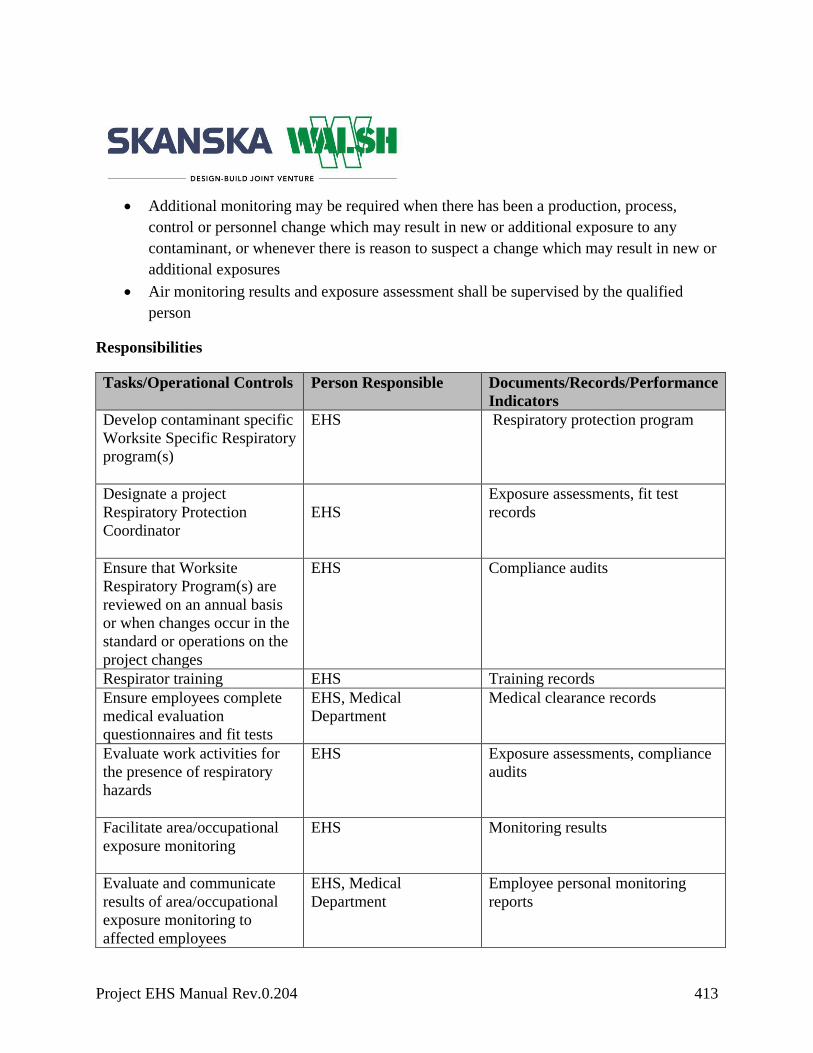
Project EHS Manual Rev.0.204 413
Additional monitoring may be required when there has been a production, process,
control or personnel change which may result in new or additional exposure to any
contaminant, or whenever there is reason to suspect a change which may result in new or
additional exposures
Air monitoring results and exposure assessment shall be supervised by the qualified
person
Responsibilities
Tasks/Operational Controls Person Responsible Documents/Records/Performance
Indicators
Develop contaminant specific
Worksite Specific Respiratory
program(s)
EHS Respiratory protection program
Designate a project
Respiratory Protection
Coordinator
EHS
Exposure assessments, fit test
records
Ensure that Worksite
Respiratory Program(s) are
reviewed on an annual basis
or when changes occur in the
standard or operations on the
project changes
EHS Compliance audits
Respirator training EHS Training records
Ensure employees complete
medical evaluation
questionnaires and fit tests
EHS, Medical
Department
Medical clearance records
Evaluate work activities for
the presence of respiratory
hazards
EHS Exposure assessments, compliance
audits
Facilitate area/occupational
exposure monitoring
EHS Monitoring results
Evaluate and communicate
results of area/occupational
exposure monitoring to
affected employees
EHS, Medical
Department
Employee personal monitoring
reports

Project EHS Manual Rev.0.204 414
Manage monitoring
equipment, calibration,
recordkeeping
EHS Calibration records
Ensure daily respirator
inspections are being
performed
Foreman Compliance audits
Click here to enter text. Enter project-specific
roles and responsibilities
Enter project-specific operational
controls/documents
Applicable Training
Respiratory protection training
Hazard Specific training
HAZWOPER Training
Potential Related Safety, Health and/or Environmental Aspects
Indoor Air Quality
Outdoor Air Quality
Hazardous Materials
Sanitation
Objective
The purpose of this program is to ensure all workers are provided with a sanitary work
environment inclusive of drinking water, adequate facilities, and an area free of vermin.
Legal and Other Requirements
Federal, State, Local Regulations
OSHA 29 CFR 1926.51
Enter project-specific regulations

Project EHS Manual Rev.0.204 415
Skanska/Client Requirements
Port Authority of NY/NJ Requirements
Procedure
Drinking Water
Clean drinking water shall be available at all times
Containers used to dispense drinking water shall be cleaned daily using soap and water,
clearly marked, and equipped with a tap and tight fitting lid
Water shall not be dipped and/or scooped from containers
Use of a drinking cup by more than one person is not acceptable
A ready supply of drinking cups shall be provided at water stations
A sanitary container for unused cups and a trash can for used cups shall be provided
Water containers and outlets that are not suitable for drinking shall be clearly marked
Non-potable water shall be so labeled
Toilets
Toilets shall be available at the worksite. This does not apply to mobile crews that have
transportation available to nearby toilet facilities
Separate locked toilets shall be provided for females and keys or combinations given to
females
Toilets shall be serviced and cleaned as often as necessary to maintain sanitary
conditions
Toilets in poor repair shall be removed or repaired as soon as possible
The minimum amount of toilets that shall be provided at each jobsite will be as follows:
Number of Employees Minimum Facilities
Less than 20 1 toilet seat
20 or more 1 toilet seat and 1 urinal for each 40 workers
200 or more 1 toilet seat and 1 urinal for each 50 workers

Project EHS Manual Rev.0.204 416
Washing Facilities
Washing facilities shall be provided near the worksite. Cleaning agents and towels or
similar products shall be provided. Hand wipers are an alternative that can be
considered
Change Rooms
Change rooms complete with storage for street clothes and separate storage for
protective clothing shall be provided when employees must wear protective clothing to
handle toxic materials
Eating and Drinking
Eating and drinking shall not be allowed in areas exposed to toxic materials
Vermin Control
Enclosed workplaces, buildings, storage trailers, etc., shall be constructed, maintained,
cleaned and organized to prevent the entrance and harborage of rats, mice, insects and
other vermin. Extermination measures shall be used when their presence is detected
Insect Control
Establish operational controls to protect animal life and prevent vermin infestation
Reduce areas of standing water to prevent mosquitoes breeding. Where standing water
cannot be removed treat with larvicides as per the manufacturer’s instructions. If these
controls are ineffective an industrial-style pesticide will be used as per EPA guidelines.
Insect repellant containing DEET ® (N,N-Diethyl-meta-toluamide) will be provided for
employees
Minimize mosquito breeding grounds to prevent nuisance and reduce the risk of
communicable diseases
Make sure wheelbarrows, buckets, and other containers are turned upside down when
not in use so they do not collect standing water
Responsibilities

Project EHS Manual Rev.0.204 417
Tasks/Operational Controls Person Responsible Documents/Records/Performance
Indicators
Ensure adequate Sanitation
facilities and drinking water
throughout project site.
Foreman,
Superintendents
Construction Work plans,
Compliance audits
Applicable Training
Enter project-specific training
Potential Related Safety, Health and/or Environmental Aspects
Sanitation
Project EHS Manual Rev.0.204 418
Silica
Objective
The purpose of this program is to ensure that all employees are safeguarded from the
occupational health and safety risks associated with exposures to silica.
Legal and Other Requirements
Federal, State, Local Regulations
OSHA 29 CFR 1910.1020
OSHA 29 CFR 1926.20
OSHA 29 CFR 1926.21
OSHA 29 CFR 1926.55
OSHA 29 CFR 1926.57, Appendix A
OSHA 29 CFR 1926.59
OSHA 29 CFR 1926.103
OSHA 29 CFR 1910.134
OSHA 26 CFR 1926.1153 New Silica Standard
Skanska/Client Requirements
The Port Authority of NY/NJ Requirements
Procedure
A Worksite Specific Respiratory Plan shall be created for all activities that may potentially
disturb crystalline silica.
Baseline occupational monitoring and area sampling shall commence at the beginning of each
operation which is identified as potentially involving silica exposure. Historical data from
similar operations that has been collected within the past 12 months can be used as baseline to
establish PPE and engineering controls.

Project EHS Manual Rev.0.204 419
Activities that may disturb crystalline silica-containing materials include, but are not
limited to:
- Jack hammering and chipping
- Grinding concrete
- Tunneling
- Sandblasting
- Dry sweeping or blowing concrete debris, sand or rock dust
- Demolition of concrete/masonry structures
- Drilling rock or concrete
- Crushing, loading, dumping rock or concrete
- Saw cutting concrete or rock
Controls
In operations where there is a potential for silica exposure, engineering controls shall be used
as the first line of defense. These may include, but are not limited to:
- Use of dust collection systems
- Wetting down surfaces with a fine mist sprayer
- During saw cutting, use equipment that provides water to the blade
- During rock drilling, use water through the drill stem to reduce the amount of dust
in the air
- During abrasive blasting use abrasives with a low silica or no silica content
- Use local exhaust ventilation to prevent dust from being released into the air
Where engineering controls cannot be utilized, or are not effective to sufficiently reduce
exposure to respirable silica, administrative controls will be used to reduce the time of
exposure for employees. These may include, but are not limited to:
- Job rotation
- Activity rescheduling to off hours
- Shift change
- Reassignment to a work area away from silica generating activities
Where exposure limits are at or above the action level, respirators and protective
clothing shall be given to each affected employee.

Project EHS Manual Rev.0.204 420
Where protective clothing is provided, trash bins will be available at the exit to each area
to allow employees to discard such items.
Signs and barricades will be placed allowing for only authorized employees entering an
area where operations are taking place that may create exposure to crystalline silica. The
sign shall read:
Warning
Hazard
Silica work area
Authorized employees only beyond this point
No smoking, eating or drinking allowed beyond this point
Respiratory Protection
Respiratory protection shall be used as the last line of defense in the protection against
exposure to silica
Respirators will be selected based on the criteria identified in the Respiratory Protection
section of this manual and according to the Worksite Specific Respiratory Plan
Personal Hygiene
Food and drink are not permitted to be present or consumed in the work area
Tobacco products are not permitted to be present or consumed in the work area
A wash station will be available for employees to use so that they can wash up following
work in designated silica work areas
Responsibilities
Tasks/Operational Controls Person Responsible Documents/Records/Performance
Indicators
Identify operations that may
potentially expose employees
to silica
Superintendent
Construction Work Plans
Designate jobsite Respiratory
Program Administrator;
EH&S Professional or assigned competent person
Respiratory Protection Program
Facilitate area/occupational EH&S Professional Air sampling logs, worksheets

Project EHS Manual Rev.0.204 421
exposure monitoring
Implement the Worksite
Specific Respiratory Work
Plan
Superintendent
Construction work plans, crew
reviews, compliance inspections
Establish and maintain
authorized work zones
Superintendent
Inspection logs, project photos
Evaluate and communicate
results of area/occupational
exposure monitoring to
affected employees
EH&S Professional
Air monitoring reports
Manage monitoring
equipment, calibration,
recordkeeping
EH&S Professional
Calibration logs
Ensure daily respirator
inspections are being
performed
User/Competent Person
Compliance audits
Applicable Training
Respiratory protection training
Hazard specific training
HAZWOPER Training
Potential Related Safety, Health and/or Environmental Aspects

Project EHS Manual Rev.0.204 422


![EHS Manual - Skanska · Project EHS Manual Rev.[Version Number] 8 Skanska is attuned to the potential safety, health and environmental impacts of its operations and](https://static.fdocuments.net/doc/165x107/5be42bba09d3f2d7048c6045/ehs-manual-skanska-project-ehs-manual-revversion-number-8-skanska-is-attuned.jpg)