Environmental, Health, and Safety Guidelines for Thermal ...€¦ · Thermal Power Plants The...
27
EUROMOT The European Association of Internal Combustion Engine Manufacturers President: Dr Manlio Mattei General Manager: Dr Peter Scherm Lyoner Strasse 18, ZIP 60528 Frankfurt/M., Germany fon 0049 69 6603-1354 fax 0049 69 6603-2354 eMail [email protected] web www.euromot.org ENGINES IN SOCIETY Office registered in Frankfurt/M., No.VR4278 Environmental, Health, and Safety Guidelines for Thermal Power Plants The Euromot Position as of 9 May 2008
Transcript of Environmental, Health, and Safety Guidelines for Thermal ...€¦ · Thermal Power Plants The...

EUROMOT The European Association of Internal Combustion Engine Manufacturers
President: Dr Manlio Mattei General Manager: Dr Peter Scherm
Lyoner Strasse 18, ZIP 60528 Frankfurt/M., Germany fon 0049 69 6603-1354 fax 0049 69 6603-2354 eMail [email protected] web www.euromot.org
ENGINES IN SOCIETY Office registered in Frankfurt/M., No.VR4278
Environmental, Health, and Safety Guidelines for Thermal Power Plants The Euromot Position as of 9 May 2008
2 page of 27
EUROMOT is the European Association of Internal Combustion Engine Manufacturers. It is committed to promoting the central role of the IC engine in modern society, reflects the importance of advanced technologies to sustain economic growth without endangering the global environment and communicates the assets of ICE power to regulators worldwide. For almost 20 years it has supported its members, consisting of national associations and companies from all over Europe and abroad, by providing expertise and up-to-date information and by campaigning on their behalf for internationally aligned legislation. For further information about the Association, please visit our website: http://www.Euromot.org – your bookmark for engine power worldwide Our members are: CASE NEW HOLLAND
CATERPILLAR POWER SYSTEMS
CUMMINS
DAIMLER
DEUTZ
DEUTZ POWER SYSTEMS
FIAT POWERTRAIN TECHNOLOGIES
GE JENBACHER
HATZ
JCB POWER SYSTEMS
JOHN DEERE
KAWASAKI EUROPE
KOMATSU ENGINES
LIEBHERR
LOMBARDINI
MAN
MTU FRIEDRICHSHAFEN
ROLLS-ROYCE
SAME DEUTZ-FAHR
SCANIA
SISU DIESEL
STEYR MOTORS
VOLKSWAGEN INDUSTRIAL ENGINES
VOLVO CONSTRUCTION EQUIPMENT
VOLVO PENTA
WÄRTSILÄ
WAUKESHA ENGINES
YANMAR INTERNATIONAL EUROPE
SSIE GROUP (SMALL SI ENGINE MANUFACTURERS)
BRIGGS & STRATTON
DOLMAR
EMAK
GGP (ALPINA)
HONDA EUROPE
HUSQVARNA
KIORITZ (ECHO)
KOHLER ENGINES
McCULLOCH EUROPE
Status: 2008-01-01
MHI EQUIPMENT EUROPE
ROBIN EUROPE
SHINDAIWA
STIHL
TECUMSEH
TORO EUROPE
WACKER CONSTRUCTION EQUIPMENT
ZENOAH EUROPE

3 page of 27
1. Introduction On 11 March 2008 the International Finance Corporation (IFC) / World Bank (WB) published the first draft on the Environmental, Health, and Safety Guidelines for Thermal power Plants /1/ for public comments. This are the last Guidelines to be finalized of a totally 63 Guidelines package.
Thermal Power Guidelines are intended for combustion facilities with a total rated heat input capacity above 50 Megawatt thermal input (MWth) on the Higher Heating Value (HHV) basis. The Thermal Power Guideline is also referring to other industrial Guidelines in context of emissions from combustion sources and will thus used jointly in many cases in context with these other Guidelines.
The Guidelines are said to be based on Good International Industry Practise (GIIP) reflecting amongst all varying levels of environmental assimilative capacity as well as varying levels of financial and technical feasibility. The performance levels are said to be achievable in new facilities by existing technology at reasonable costs. For existing facilities it is said that establishment of site-specific targets with an appropriate timetable might be needed. Use of BAT (Best Available Technique) which are technical, financial and operative feasible is the target. The applicability of specific recommendations should be based on the professional opinion of qualified and experienced persons (on basis of the results of an Environmental assessment (EA) in which host country context, assimilative capacity of the environment and other project factors are considered). It is said that the EA process may recommend alternative (higher or lower) levels or measures (than those provided in the Guidelines), which if acceptable to IFC become project- or site-specific requirements. This justification should demonstrate that the choice for any alternative performance levels are protective of human health and the environment. The IPPC (Integrated Pollution Prevention and Control) principle taking the whole environmental picture into consideration is the basis.
The draft Thermal Power Guidelines however does not enough consider the differences in the infrastructure around the world. The “justification mechanism” (should be a part of the site-specific Environmental Assessment (EA)) is only briefly mentioned in the document as an option for projects where less stringent levels (e.g. due to existing fuel infrastructure, etc.) than those presented in the Guidelines are appropriate.
In this document we have presented our main concerns (see below chapter) on the draft Guidelines. We have also made some counterproposals on above aspects based on GIIP, IPPC and BAT principles.
2. Summary of the main concerns and Euromot proposals The current draft version of the Guidelines does for example not take into account how to tackle cases where the local fuel infrastructure is in a big transition process e.g. a gas pipe line is under construction and a new power plant should therefore only for a few years time operate on a high sulphur oil before change to gas mode is made. For these kinds of plants a relaxation or flexibility mechanism is needed in order to avoid excessive investment costs in “short-term” abatement techniques which will not be later on used when operating on gas.
In order to make the “justification mechanism” workable, at least some examples of some past executed projects where this alternative has been applied should be included in the appendix of the document. Otherwise there is a big risk that external parties (other than IFC) will in practise never use this “justification option”, but apply the guideline levels (for emissions, effluents, etc.) as stiff fixed limits. In the current Guidelines from 1998 the “variance mechanism” is mentioned and the engine industry have now and then got questions from customers how to implement it (e.g. due to commercially available fuel sulphur contents), without being able to give any proper answer. Thus the inbuilt “flexibility” mechanism of the Guidelines needs to be described in order to make it workable otherwise it will be lost leading to expensive and unpractical solutions not according to GIIP/BAT.

4 page of 27
The proposed increment levels, the monitoring of ambient air quality (tables 1 and 8) and the control room noise levels (see chapter 1.2, Occupational Health and Safety) in the draft Thermal Power Guidelines are beyond BAT and not according to GIIP. Some emission values (table 7) are set too strict and not considering the existing fuel infrastructure around the world and the current technical development status of the stationary engines.
The implementation timing of the Guidelines needs some flexibility in order to avoid excessive problems. In the following we have briefly illustrated our concerns on these issues.
A. Ambient Air Quality (AAQ)
The proposal /1/ uses a level corresponding to (equal or above) 25% of the relevant short term ambient standard as a “threshold” for mandatory CEMS (Continuous Emission Monitoring System) and plant emission decrease modifications:
- The “threshold” for CEMS is set too low and much lower than national praxis around the world. E.g. in Jamaica /10/ air quality monitoring is required if 75% of NAAQS is exceeded. See chapter 4.B.1 below for further information.
- We assume that the increment 25% “threshold” level is derived from the US EPA NAAQS (National Ambient Air Quality Standard) (e.g. 24-h SO2 values). Please note that US EPA has defined PSD (Prevention of Significant Deterioration) increments in microgram/m3 and NOT in percentages (%). Many ambient air quality standards do not have any defined increment limit at all (as it is the case e.g. in EU). By introducing an universal 25% increment (“of relevant short-tem ambient standard”) “threshold” a new very strict ambient air quality ruling is created, which would become much stricter than original national standards referred to. Therefore in our opinion the 25 % “threshold” should be replaced with the “original” federal US EPA NAAQS PSD increment figures in the draft Guidelines /1/, if “thresholds” are to be included. Please see further information in chapter 4.B.2.
- In our opinion the WHO AAQ Guidelines should be removed as a reference (see chapter 4.B.3 below). The AAQ threshold item needs also to be corrected in the final General EHS Guidelines /11/.
B. Control Room Noise
The control room noise level is set to 60 dBA in the draft /1/. However this value is very low compared to limit values seen e.g. in Europe where levels up to 70 dBA are allowed.
We propose the control room limit to be set at 65 .. 70 dBA. For further discussions see chapter 5 below. This noise item needs also to be corrected in the final General EHS Guidelines.
C.Emissions (non-degraded airshed)
Proposed emission limits in table 7 /1/ are in general reflecting the engine development status quite well. Each gas engine type has its’ technique specific limits and liquid fired engines have emission limits depending on the engine size (bore).
However the category of spark ignition engines should include all different pure gas engine types (ignited with spark plugs or other devices). Dual fuel engine (DF) in liquid fuel mode aspects need also to be added. The DF engine type has different emissions in diesel mode compared to a “modern diesel engine” due to the engine optimization (this needs also to be corrected in the final General EHS Guidelines /11/).
Use of “sustainable fuels” are promoted by granting a progressive NOx-emission bonus for these fuels.
BUT following aspects should still need modifications:
- Introduction of a new “< 50 MWe (about 50…120 MWth)” size span with own emission levels in order to take into the account the stationary engine plant group now being transferred from small to the big plant category when replacing the current Thermal Power Guideline 1998

5 page of 27
/2/ by the proposed new Thermal Guideline /1/. We discussed this issue also in our Washington meeting in January 2007. Reasons:
- SO2 and particulate are fuel related emissions. Due to the existing infrastructure in many countries around the world, the needed liquid fuel qualities are not commercially available and the only option in order to fulfil the proposed emission levels is then use of a secondary FGD (Flue Gas Desulphurization) equipment becomes a must (generating secondary pollutions such as solid/liquid wastes and consuming scarce resources such as water). This is not according to the IPPC/GIIP/BAT principles. The “justification” mechanism for making deviations from emission levels in site-specific cases (mentioned on page 1 /1/) needs some further description (e.g. an example of a real done project in the annex to the Guidelines) in order to make it to a real working option.
- Note also emission limit values (NOx) for dual fuel engines (DF) in liquid mode (discussed above)..
- In the General EHS Guidelines a progressive NOx-emission bonus based on efficiency is granted to the liquid fired stationary diesel engine plant (bore < 400 mm). The same bonus should also be applied in the Thermal Power Plants Guidelines /1/ and further extended. See chapter 3.E.1 below and annex 2 for further information.
- Liquid fired reciprocating engine plants 120 .. 300 MWth - An emission NOx-bonus for the <400 mm bore liquid fired diesel engine category is needed
to be introduced, see discussion in chapter 3.E.2 and annex 2.
- Note also emission limit values (NOx) for dual fuel engines (DF) in liquid mode and “justification mechanism” aspects discussed above.
- Liquid fired reciprocating engine plants > 300 MWth - The proposed NOx level is in practise leading to a mandatory use of SCR (not
technical/economical feasible in many places around the world). Advanced “wet methods” still need a lot of development before these can be introduced on a commercial scale. The proposed emission level is thus beyond BAT and GIIP. Performed EIAs for big plants done in the past indicate that the US EPA PSD incremental AAQ values (see table 3 below) are fulfilled with today´s prescribed WB /2/ NOx-level, for SO2 the imission increment has also been fulfilled in much bigger plants (>>300MWth, operating on fuels fulfilling the S-limit of the 1998 Guideline /2/). Therefore the emission limits should be higher than proposed levels and “threshold” modified. We propose a “mix” to raise the emission levels and ditto for the plant size “threshold”. In paragraph 3.E.3 below this is further discussed.
The specified sulphur limit of the liquid fuel is in practise leading to a usage of a FGD in many countries around the world (low sulfur fuel often not commercially available).Note also emission limit values (NOx) for dual fuel engines (DF) in liquid mode and “justification mechanism” aspects discussed above .
D. Emissions in degraded areas
The proposed NOx-limit in practice restricts the technology choice to only SCR (not feasible in many places around the world). An alternative NOx-emission level enabling use of some alternative abatement method is needed for all types of stationary engine plants (gaseous/liquid fired engines).
Also the particulate limit needs to be changed in order to reflect the performance of available abatement technologies. See paragraph 3.E.4 for more information.
E. CEMS for plants >300 MWth
For plants > 300 MWth CEMS is proposed to be mandatory for NOx, (and in liquid mode additionally) particulate and in some case for SO2 (in case of Flue Gas Desulphurization application) emissions. In chapter 4.A. and annex 1 we have shown that CEMS is not according to GIIP in a general sense in a reciprocating plant due to technical challenges and infrastructure reasons. We propose use of the effective practical “surrogate” parameter sampling in periods

6 page of 27
between the annual intermittent measurements (an option in the current “Thermal Power Guideline /2/”).
F. Implementation time
Delivery times of projects are today long due to the fact that the engines are sold out for the coming years. Thus many already sold stationary engine power projects will be delivered and commissioned in year 2011 or later. Engine development takes a long time and sufficient lead-time is needed before introducing new solutions on the markets. Existing plants should be grandfathered. Therefore some clarification of the implementation timing of the Guidelines is needed. See item 6.A. for more information.
G. Euromot recommendations for emission limit values for new plants: - In below table 1 is a summary with our proposal for stack emissions. We consider the below
emission limits for fossil liquid fuel fired engines to be based on GIIP/BAT/IPPC in a non-degraded airshed. “Justification mechanism” will anyway be needed in some projects and needs a further description how to use it.
- For degraded airsheds (all fuel and engine types (except of spark ignited gas engine)) we propose a NOx-value of 750 mg/Nm3 (15 % O2) in order to keep the SCR O&M costs at a reasonable level and enable development of alternative abatement techniques (SCR is besides cost aspects not technical feasible in some applications). The particulate limit should be raised to 50 mg/Nm3 (15 % O2) in order to reflect the performance of available technology.
Table 1: Euromot proposal for stack emission limits for new liquid fired reciprocating engine plants (in mg/Nm3 (15 % O2) if otherwise not stated) in a non-degraded zone. Note ISO 9096 or principal similar other measurement methods for particulate. Engine at steady state load conditions at 85 – 100 % MCR load.
Fuel input [MWth] Engine type NOx (as NO2) [mg/Nm3] *,**
max. S-content [%] in fuel or equivalent SO2 *
[mg/Nm3]
Particulate [mg/Nm3] *
1460-1600 (<400 mm bore)1850 (≥ 400 mm bore)
Dual fuel engine (DF) 20001460-1600 (<400 mm bore)
1850 (≥ 400 mm bore)Dual fuel engine (DF) 2000 75
Diesel engine (CI)1600
from 1 July 2015: 1000-1300***Dual fuel engine (DF) 1850
>600
50
1,5% or 880 50
Diesel engine (CI) 2% or 1170120-600
Diesel engine (CI) 2,5% or 1470 7550-120
*Emission bonuses should be given for all emissions, see Annex 2 for bonus proposals. ** An allowance should be given to derogate from the obligation to comply with the emission limits in cases where a plant which normally uses gaseous fuels and which would otherwise need to be equipped with an waste gas purification facility has to resort exceptionally and for a period not exceeding 10 days except where there is an overriding need to maintain energy supplies to the use of other fuels because of a sudden interruption in the supply of gas. *** Depending on technical development status, to be checked in year 2012
Existing installations should be grandfathered. Application of new technical solutions is not always applicable on older stationary reciprocating engine generation. If an existing installation is expanded or rebuilt the new Guidelines shall apply only to the new part (see section 6A for more information for implementation time proposal) of the installation. 3. Stack emission levels In table 7 at page 18 /1/ technique specific emission limits are given for stationary reciprocating engines, combustion turbines and boiler plants. In the text below the proposed limits are further discussed and counter proposals are given.

7 page of 27
A. HHV base to be changed to LHV Proposed emissions levels for reciprocating engines are dependent on the used fuel (natural gas, liquid or liquid/gas bio-fuel), engine type (SG, DF, GD or diesel) and power plant size.
Power plant size is defined by MWth=fuel thermal input based on HHV (Higher Heat Value). On page 1 is stated “.. with a total rated heat input capacity above 50 Megawatt thermal input (MWth) on higher Heating Value (HHV) basis”. In the EU LCP BREF /14/ the plant size threshold is however based on LHV (Lower Heating Value) of the fuel. According to UK statistical data /15/ the typical ratio between HHV and LHV are:
HHV LHV Ratio - Natural gas*: 39.8 35.8 1.11 - HFO 43.3 41.2 1.05 - Gas oil 45.6 43.4 1.05
*Please, note that the heat value of natural gas depends on the gas composition.
Recommendation: In our opinion the MWth-“thresholds” shall be based on LHV and not HHV as is the case in Europe. B. Plant size clarification In the General notes of the table 7 /1/ is stated:
“ .. MWth category is to apply to the entire facility consisting of multiple units that are reasonable considered to be emitted from a common stack except for PM and NOx limits for combustion turbines and boilers”.
The meaning of above sentence is not clear and is not according to the text on page 1 (“ …with a total rated heat input capacity above 50 Megawatt”). E.g. each reciprocating engine unit in a power plant usually has its own stack pipe due to design requirements (in order to avoid turbocharger damages, etc.) but should anyway be treated differently compared to gas turbine and boiler plants?
Recommendation: In our opinion all prime movers shall be treated in the same way and therefore the above sentence (in table 7) should be removed. C. Emission bonus In table 7 an emission bonus for the NOx-value has been given for the use of sustainable fuels. This progressive approach should be extended also to high efficiency single cycles, combined heat and power (CHP) plants and special applications such as mechanical drives, etc. In annex 2 we have listed our proposal for emission bonuses. In e.g. Turkey /7/ (note for all emission compounds!) and UK /18/ efficiency bonuses are granted to efficient processes. D. 300 MWth threshold For liquid fired reciprocating plants >300 MWth has been set as an threshold for the “big” plant and emission limits and measurement requirements for the plant are restricted considerably when exceeding this threshold.
For boiler plants the “big plant” threshold is however set to 600 MWth. We assume that some ground level concentration modelling has been used as the base for above threshold levels.
Recommendation: In past performed GLC modelling for plants (up to about 600 MWth) the imission increments from bigger HFO-fired diesel plants without secondary flue gas cleaning were below the primary US federal EPA set PSD increment values and therefore proposed emission levels and plant size threshold should be modified. See discussions in chapter 3 and 4.

8 page of 27
E. Euromot proposals for emission levels in the Thermal Power Guidelines Reciprocating engines have emission levels division based on the used fuel and the engine type. In general the given emission levels in the Guidelines /1/ reflect quite well the engine technology development status with some exceptions explained below.
SO2 and particulate are fuel related emissions. The proposed emission levels for SO2 and particulate are rather tight when considering existing fuel infrastructure around the world. A “justification example” (in order to deviate from the set level(s)) based on a real done case is to be added to the annex of the Guidelines document in order to show how to work out the procedure in a correct way. This is important for all plant sizes.
E.1 Liquid fired reciprocating plants in the range 50 MWth … 120 MWth (about 50 MWe) in
non-degraded airshed. When comparing to the current “Thermal power – Guidelines for New Plants” 1998 /2/ version can be noted that the emission levels have been considerably reduced. E.g.:
a. Particulate level from 100 … 150 mg/Nm3 (15 % O2) 50 mg/Nm3 (15 % O2).
b. SO2 level from 2000 mg/Nm3 (15 % O2) about 1170 mg/Nm3 (15 % O2) (= 2 % S in HFO (heavy fuel oil))
c. NOx (as NO2) level from 2000 mg/Nm3 (15 % O2) 1460 mg/Nm3 (15 % O2) , bore <400 mm or 1850 mg/Nm3 (15 % O2) , bore > 400 mm
Particulate and SO2 are fuel related emissions and the new proposed levels do not reflect the existing fuel infrastructure in many countries around the world. In Euromot position paper /3/ the fuel infrastructure and SO2 limits has been handled in chapter 4.3. In this document it was concluded that average world sulphur content of the heavy fuel oil was 2.67 wt-% S in 2001 and 2.69 wt-% in 2005 and the trend has been towards higher sulphur contents during the late years. If the only liquid fuels commercially available have sulphur contents > 2 wt-% the only option to fulfil the new proposed level /1/ is to install a flue gas desulphurization (FGD) unit.
In source /3/ on pages 14 – 15 typical investment costs and operation & maintenance (O&M) costs of the FGD are presented. It can be concluded from the graphs that the investment cost increases considerably for plants < 120 MWth (about 50 MWe), additionally a large amount of clean water (typically about 1.1 m3/MWhe of water is needed, i.e. for a 120 MWth plant about 50 m3/h water is needed). The outlet flue gas temperature from a FGD (of a wet scrubber type) is without stack reheat in the range 55 .. 60 degree C only and might as a consequence considerably increase the GLCs in the power plant surrounding. A stack reheat should not much help up the situation as typical used wet scrubber flue gas reheat temperatures are in order of 85 … 100 degree C.
A stack reheat system might dependent on used configuration have a very high investment cost (corrosion resistant materials need, special components used in order to avoid fouling, etc.) and need a huge heat amount (recovered from the flue gases or an additional heat source is needed). In areas with scarce water resources this is definitely not according to GIIP nor IPPC principle. On top of this the disposal of the generated FDG end product should be handled in an environmental acceptable way in order not to generate secondary pollutions (dust, etc.) and this sets certain minimum requirements on the surrounding existing infrastructure.
A reciprocating engine plant operating on a high sulphur fuel will also emit particulate in excess of the stipulated emission level and a secondary abatement equipment should be needed such as an ESP (Electrostatic Precipitator). Please note that according to the EU BREF document /14/ secondary abatement techniques for particulate is not recommended due to very few existing references around the world. In source /4/ in annex 1 it can be seen that the investment cost for an ESP increases tremendously for plants < 120 MWth (about 50 MWe). Below some particulate emission limits around the world are listed:
9 page of 27
- Japanese /5/ “all area” particulate limit is analogous to: 75 mg/Nm3 (15 % O2) - Philippine /6/ “particulate limits for fuel burning equipment” are:
“urban and industrial areas”: 150 mg/Nm3 “”other area”; 200 mg/Nm3
- Turkish /7/ particulate limit (for diesel engines): 75 mg/Nm3 (15 % O2) - Ecuadorian /8/ particulate
limit ((“para motores de combustio’ n interna”): 150 mg/Nm3 (15 % O2) - Indian /9/: particulate limit:
HFO (Heavy Fuel Oil): 100 mg/Nm3 (15 % O2) LFO (Light Fuel Oil): 75 mg/Nm3 (15 % O2)
Euromot proposal: Insert a new power plant size range 50 .. 120 MWth with own emission limits in order to take worldwide existing infrastructure and technique development status into consideration and avoid excessive investment costs:
− particulate: max. 75 mg/Nm3 (15 % O2). − S wt-%: max. 2.5 wt-% (this should be close to the “worldwide average” S-% content
of HFOs and is by accident same as the limit in e.g. Ecuador /8/) − For NOx-level for diesel and dual fuel engines. See item 2 below.
“Justification mechanism” possibility will be important. E.2 Liquid fired reciprocating plants in the range 120 MWth (about 50 MWe)… 300 MWth in
non-degraded airshed. Comparison to current “Thermal Power – Guidelines for New Plants” 1998:
NOx (as NO2): Proposed NOx-levels: i. 1460 mg/Nm3 (15 % O2) , bore < 400 mm ii. 1850 mg/Nm3 (15 % O2) , bore > 400 mm
versus the old single limit of 2000 mg/Nm3 (15 % O2). NOx: The proposed NOx values represent quite well the technical development status of the diesel engines (but not for the DF engine, see below) at the moment but for engines with <400mm bore the proposed limit will increase the fuel consumption and thus the CO2 emissions (see /3/ page 12).
The NOx-emission from a reciprocating engine is also affected by the intake air (“burning air”) humidity, i.e. in dry ambient conditions the NOx emissions will be higher. In “dry ambient conditions” e.g. the <400 mm bore diesel engine will have difficulties to maintain the 1460 mg/Nm3 (15 % O2) NOx-level without introduction of some “water addition” (humidification, etc.) method with a considerably increased water consumption of the plant as the consequence. In order to maintain the high efficiency of the diesel engine plant and the low make-up water consumption a similar approach (to introduce a NOx-span) as done in the General EHS Guideline /11/ is recommended.
The dual fuel engine (DF) type has in diesel mode different emissions compared to a “modern diesel engine” due to the optimization to be able to operate in two fuel modes therefore an own specific NOx- and particulate emission levels are to be added.
Below some NOx emission levels around the world are listed: - Philippines /6/ “diesel-powered electricity generators”: 2000 mg/Nm3 - Ecuadorian /8/ (“para motores de combustio’ n interna”): 2000 mg/Nm3 (15 % O2) Euromot proposal:
- Insert a NOx emission span as done in the General EHS Guidelines /11/ for the liquid fired diesel engine < 400 mm bore category, i.e. 1460 .. 1600 mg/Nm3 (15 % O2) in order to show the support of the “Kyoto spirit” (emphasize importance of fuel efficiency). This should also be according to the IPPC spirit, keeping all emissions (NOx, CO2, SO2) and
10 page of 27
fuel, water consumptions) in a balanced way at an (lowest) optimum level and not focusing on a single emission such as NOx and increasing others.
- Insert for dual fuel engines (DF): o NOx: 2000 mg/Nm3 (15 % O2). o Particulate: 75 mg/Nm3 (15 % O2).
- See also annex 2 for additional emission bonus proposals. Work out text for the “justification option”.
E.3 Liquid fired reciprocating plants >300 MWth in non-degraded airshed The comparison to current “Thermal Power – Guidelines for New Plants” 1998 shows:
- NOx (as NO2): Proposed NOx-level: 740 mg/Nm3 (15 % O2) (“contingent upon water availability for injection”) versus the old limit of 2000 mg/Nm3 (15 % O2).
- SO2 level from 0.2 tpd/MWe (for a big efficient stationary engine about 1.9 % S in oil) about 590 mg/Nm3 (15 % O2) (= maximum 1 % S in HFO).
The proposed NOx-level is very low (just below the federal Italian /12/ limit and the Finnish “special area” Guideline level /13/ and can either only be fulfilled by an advanced “water method” (with a huge clean water consumption, e.g. for a 100 MWe plant an additional about 350000 tonnes/year clean water should be needed for NOx-reduction) but in most cases in practise achievable only by application of SCR (Selective Catalytic Reaction).
The advanced water methods are still under development stage (“prototypes”) and the first references are so far mainly in ships where the engines are used very differently compared to in a stationary plant. With a “water method” special attention should also be paid to the purity of the used water otherwise fouling and corrosion will occur on the engine components which will affect heavily the reliability and availability of the stationary reciprocation plant. In many parts around the world water is a scarce resource and should therefore preferably be used for agriculture, personal hygiene and other community needs and therefore “dry” inbuilt abatement methods are preferred and according to the GIIP-principle.
A SCR is an efficient but sensitive method, (see EU LCP BREF /14/ page 360): - A minimum flue gas temperature at inlet of the SCR-reactor is needed (fuel S-%
dependent) in order to avoid salt formation on the SCR elements. - Some trace metals (such as Na, K, Ca, Mg, As, Se, P, etc.) which might be present in the
liquid fuel act as “catalyst poisons” and deactivate the catalyst. - A soot blowing system is needed in the reactor containing the catalyst elements. - An existing infrastructure is needed: reagent supply (ammonia-water, urea-water), spare
part availability, etc.. Note urea is to be of high quality (see /4/ annex 1) ! - SCR has high capital and operating costs (see typical costs at e.g. annex 1 /4/). Operating
cost depends on the amount of reagent needed and the frequency at which the catalytic elements need to be replaced or newly added in order to maintain the design efficiency of the SCR. The used catalytic elements need to be properly disposed off.
- SCR is recommended to be subjected to regular planned maintenance or inspection, e.g. annually in order to prevent ammonia “slip”. For instance, with high ammonia “slips” harmful salt deposits can occur on the internal surfaces of the components sited after the reactor affecting detrimentally performance, such as a boiler. Ammonia emission is also contributing to the acidification of the environment and should therefore be kept as low as possible.
According to EU LCP BREF /14/ (page 406) “ .. SCR is an applied technique for diesel engines, but can not be seen as BAT for engines with frequent load variation, including frequent start up and shut down periods due to technical constraints. A SCR unit would not function effectively, when the operating conditions and the consequent catalyst temperature are fluctuating frequently outside the necessary effective temperature window….”
Therefore neither a “water addition”-method nor SCR can be considered to be GIIP for many locations around the world.

11 page of 27
Above has been shown the stipulated NOx-emission standards for stationary reciprocating plants in the Philippines and Ecuador. Some past GLC simulations for big stationary engine plant projects have been well below the US EPA NAAQS PSD incremental (see table 3) value for NO2 with the WB 1998 /2/ set NOx emission level. Therefore in our opinion the plant size “threshold” 300 MWth is set on a too low level and dito for the proposed NOx emission level.
The proposed sulphur limit of the fuel does not reflect the existing fuel infrastructure in many countries around the world (see discussion above) and in practise a FGD should be needed in these countries. As above stated clean water consumption of a reciprocating plant equipped with a FGD is huge and an existing infrastructure for the needed reagent, spare parts and end-product disposal are to exist besides trained O&M personnel. As a consequence “deviations” in these project circumstances will have to be made in many cases and the “justification mechanism” as a part of the site-specific environmental assessment used. But in the Guideline is not given any description of the “way to proceed” for the “justification”. In order to help up the dilemma the S wt-% should be raised to 1.5 wt-%, based on old GLC calculations. This should be a good compromise. In past GLC simulations in some big HFO (with the WB 1998 /2/ set SO2 emission level) projects (>> 300 MWth) SO2 has been below the US EPA NAAQS PSD incremental values. Therefore in our opinion the plant size “threshold” 300 MWth is set on a too low level and ditto for the proposed fuel S-% level.
Euromot Proposal: - The plant size threshold should be raised from 300 MWth to the same level 600 MWrh as
for the boiler plant.
- The NOx-emission limit should be adjusted to reflect the development status of the liquid fired reciprocating engines. SCR is not GIIP/BAT for many locations around the world and an advanced “water addition” methods need still further development before reaching proposed NOx-limit on a commercial scale. The “water addition” methods need a huge clean water amount and the availability of this water will be questionable in some parts around the word. Dry methods in combination with some water addition method for moderate NOx reductions (such as humidification, water fuel-emulsion, etc.) are representing better the IPPC principle. We therefore propose following NOx-limits:
- NOx (as NO2):
o Diesel engine: Step I: 1600 mg/Nm3 (15% O2) Step II: from 1 July 2015: NOx-limit 1000 … 1300 mg/Nm3 (15 % O2)
(depending on technical development status, to be checked in year 2012) in order to give the industry time to further develop the (“extreme) Miller” concept (a “dry method”)
o Dual fuel (DF) engine: 1850 mg/Nm3 (15% O2)
- Fuel sulphur content: The “justification mechanism” will be needed in many cases, see
above for further information. As discussed above usage of a FGD might increase the GLC imission values in the plant surrounding, etc. and is therefore in many cases not according to IPPC principle. We propose to raise the S to 1.5 wt-% in order to help up the situation. See also efficiency bonus for emissions discussion in annex 2.
E.4 Degraded areas: The proposed NOx-emission levels will cause in practise for all liquid fired and some gas fired reciprocating engines types that a SCR is a must. As above said the SCR is sensitive to certain fuel impurities, e.g. liquid bio-fuels contain one of the most critical ones namely P, a strong well-known catalyst deactivator. Quality and composition of bio fuels might vary greatly, in field conditions (in a liquid bio-fuel fired plant) it has been experienced that the deactivation of the SCR during the first year was 5 times faster compared to deactivation when operating on fuel oils. The catalyst change has a big impact on the O&M cost of the plant.

12 page of 27
The proposed particulate level will be difficult to fulfil in case of a plant operating on e.g. a residual fuel oil (such as HFO) and equipped with a dry ESP and FGD. A FGD scrubber generates also particulate material and a secondary abatement method for particulate should therefore be needed to be situated after the FGD such as a wet ESP. A wet ESP has a very huge investment cost and is therefore not economical feasible (and not technically proven) for a stationary diesel engine plant. Therefore the particulate limit should be raised to 50 mg/Nm3 (15% O2), which is also the BAT level according to /14/ for HFO fuel. Note measurement standard ISO 9096 or principally similar other methods.
Euromot proposal:
- In degraded areas the NOx-level should be raised for all stationary engine plant types to 750 mg/Nm3 from 400 mg/Nm3 (15% O2) in order to keep the SCR O&M costs at a reasonable level and “room” for other reduction methods under development (SCR not technical feasible in many locations around the world).
- The particulate limit should be raised to 50 mg/Nm3 (15% O2). Note measurement standard
ISO 9096 or principally similar other methods. 4. Monitoring On page 19 in table 8 in the Guideline draft /1/ monitoring requirements of stack emissions, imissions and noise in the surrounding of the power plant (outside plant boundary) are presented.
A. Stack monitoring/frequency (emissions)
A.1 For a power plant size range of 50 .. 300 MWth it is proposed that the stack measurement can either be on an intermittent (we assume term ”indicative” to be identical to “surrogate performance monitoring described in current 1998 Guidelines. A clearer definition of “indicative” is needed) “surrogate performance monitoring (based on initial calibration” used between stack measurements) or on a continuous basis. Emission components to be measured are particulate, nitrogen oxides (NOx) and if a FGD is used also sulfur dioxide (SO2) in case of fossil liquid fuels, in case of liquid/gaseous bio-fuels (=biomass ? to be clarified) SO2 is left out and in case of natural gas only NOx is listed. “Surrogate” performance monitoring is a cost effective preferred practical method especially in places where due to the existing infrastructure maintenance (lack of spare parts, skilled people) and calibration (lack of calibration gases) of the measurement equipment can not be ensured. Stack emission testing/frequency is proposed to be on an annual basis.
A.2 For the liquid fired power plant size equal or exceeding 300 MWth continuous emission
monitoring systems (CEMS) are required for NOx, particulate and SO2 (in case of no FGD in the power plant fuel S-% content monitoring is enough). In case of gas as fuel NOx measurement only is required. We consider the requirements not to be according to the GIIP and BAT principles, please see below for more information:
In CIMAC document /19/ appendix 4 (“Some aspects of the use of continuous emission monitoring (CEM)”) is written: - “.. The current type of reciprocating engine can be considered a stable process. .. This means that discrete measurements … of emissions will give a good indication of the emissions also between the measurements. A stable process has a low monitoring frequency need and measurements can be done on a discontinuous basis ..“. - “… many technical challenges still have to be resolved before CEM systems for engine applications can be considered a feasible way of collecting reliable measurement data … Experience has however shown that especially if the engine is running on HFO, the sampling system may be prone to problems, such as clogging and corrosion …”.
- Please also note statement regarding particulate measurement in the CIMAC document: “ .. Therefore, monitoring parameters such as exhaust gas opacity can in the case of diesel engines not be seen as a means of monitoring the “mass-related” particle emissions …”.
13 page of 27
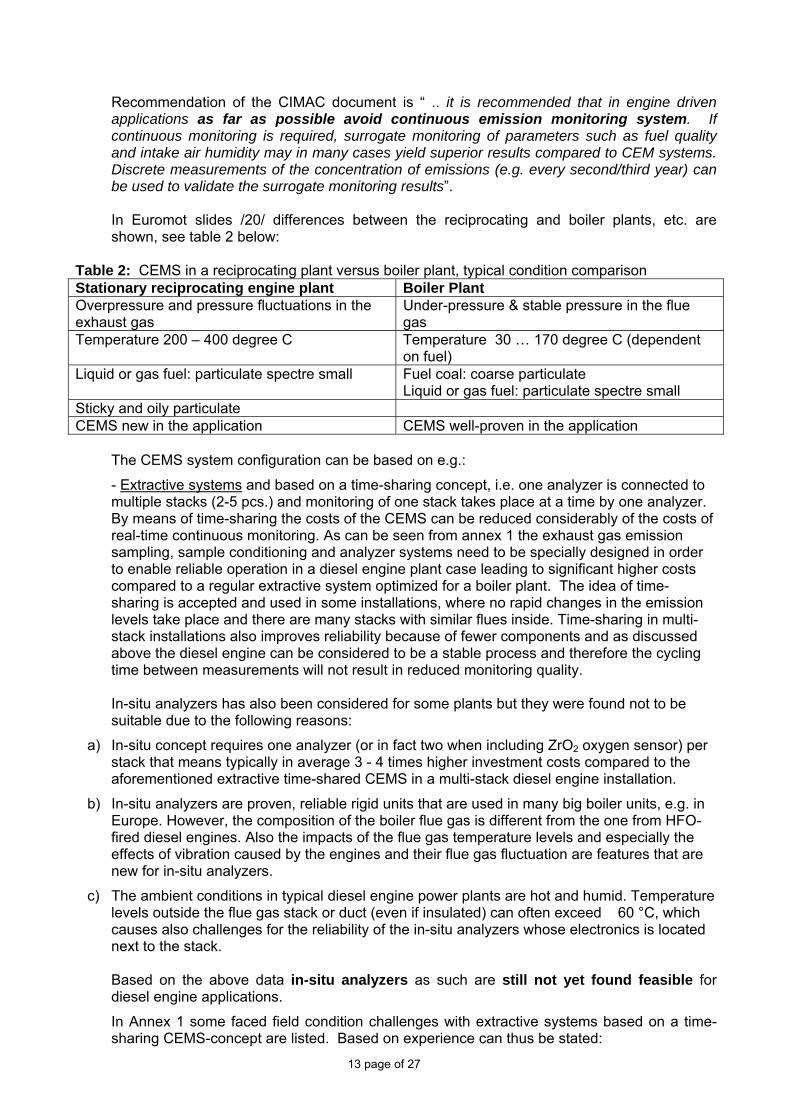
Recommendation of the CIMAC document is “ .. it is recommended that in engine driven applications as far as possible avoid continuous emission monitoring system. If continuous monitoring is required, surrogate monitoring of parameters such as fuel quality and intake air humidity may in many cases yield superior results compared to CEM systems. Discrete measurements of the concentration of emissions (e.g. every second/third year) can be used to validate the surrogate monitoring results”. In Euromot slides /20/ differences between the reciprocating and boiler plants, etc. are shown, see table 2 below:
Table 2: CEMS in a reciprocating plant versus boiler plant, typical condition comparison Stationary reciprocating engine plant Boiler Plant Overpressure and pressure fluctuations in the exhaust gas
Under-pressure & stable pressure in the flue gas
Temperature 200 – 400 degree C Temperature 30 … 170 degree C (dependent on fuel)
Liquid or gas fuel: particulate spectre small Fuel coal: coarse particulate Liquid or gas fuel: particulate spectre small
Sticky and oily particulate CEMS new in the application CEMS well-proven in the application
The CEMS system configuration can be based on e.g.:
- Extractive systems and based on a time-sharing concept, i.e. one analyzer is connected to multiple stacks (2-5 pcs.) and monitoring of one stack takes place at a time by one analyzer. By means of time-sharing the costs of the CEMS can be reduced considerably of the costs of real-time continuous monitoring. As can be seen from annex 1 the exhaust gas emission sampling, sample conditioning and analyzer systems need to be specially designed in order to enable reliable operation in a diesel engine plant case leading to significant higher costs compared to a regular extractive system optimized for a boiler plant. The idea of time-sharing is accepted and used in some installations, where no rapid changes in the emission levels take place and there are many stacks with similar flues inside. Time-sharing in multi-stack installations also improves reliability because of fewer components and as discussed above the diesel engine can be considered to be a stable process and therefore the cycling time between measurements will not result in reduced monitoring quality. In-situ analyzers has also been considered for some plants but they were found not to be suitable due to the following reasons:
a) In-situ concept requires one analyzer (or in fact two when including ZrO2 oxygen sensor) per stack that means typically in average 3 - 4 times higher investment costs compared to the aforementioned extractive time-shared CEMS in a multi-stack diesel engine installation.
b) In-situ analyzers are proven, reliable rigid units that are used in many big boiler units, e.g. in Europe. However, the composition of the boiler flue gas is different from the one from HFO-fired diesel engines. Also the impacts of the flue gas temperature levels and especially the effects of vibration caused by the engines and their flue gas fluctuation are features that are new for in-situ analyzers.
c) The ambient conditions in typical diesel engine power plants are hot and humid. Temperature levels outside the flue gas stack or duct (even if insulated) can often exceed 60 °C, which causes also challenges for the reliability of the in-situ analyzers whose electronics is located next to the stack.
Based on the above data in-situ analyzers as such are still not yet found feasible for diesel engine applications.
In Annex 1 some faced field condition challenges with extractive systems based on a time-sharing CEMS-concept are listed. Based on experience can thus be stated:
14 page of 27
Measurement techniques proven appropriate in a boiler plant are therefore not necessary suitable without modifications in a stationary reciprocating engine plant.
In EU LCP BREF / 14/ on page 405 discontinuous particulate monitoring (once every 6 month) is recommended. Note also stated emission measurement span “Steady state 85 to 100 % load of the engine”. If an ESP (Electrostatic Precipitator) is used the electric power supply and in case of a bag filter the minimum pressure drop over the filter are suitable “surrogate” parameters.
For the ≥300 MWth liquid fuel fired power plant is also stipulated to measure heavy metals on an annual basis. In our opinion this requirement should be removed, the emission can be estimated by analysing the used liquid fuels in case of no secondary abatement equipment.
Euromot proposal: For the > 300 MWth reciprocating plant:
Above has been shown that CEMS is a rather new application in the stationary reciprocating engine plant configuration and experience and big care are needed in the design/operation of the system (which is hard to achieve and maintain in many locations around the world). We therefore propose following: (in line with CIMAC /19/) in order to have a practical cost-effective overall balance:
- Continuous particulate measurement demand for the liquid fuel fired reciprocating plant should be omitted, reasons: existing CEM-systems are made with the boiler plant in focus and are thus not reliable in the reciprocating engine plant. The EU LCP BREF document is instead of CEMS proposing discontinuous measurements for the engine plant.
- NOx should be measured on a continuous base (e.g. with a time shared CEMS) only in degraded air-sheds (where emissions are critical). In non-degraded air-sheds a more frequent monitoring e.g. 2 times/year instead of use of CEMS is recommended.
Stack emission measurements in general:
- Corrective actions are to be taken if maximum emission levels are exceeded for more than 5% of the operating time or the occasion of a plant audit. The objective is to ensure continuing compliance with the emission limits based on sound maintenance and operation.
- Stack emissions should be monitored at steady state 90 .. 100 % MCR-loading of the stationary bigger reciprocating power plant as is the case in USA.
- Start-ups, shut-downs and emergency operation conditions of the power plant should be excluded as is the praxis worldwide.
B. Ambient Air Quality (Imissions)
The 25% increment “threshold” stipulated is in our opinion not logical and will be discussed further on below. It will lead to introduction of a new “own” ambient air quality standard/guideline stricter than existing national standards. B.1 GLC measurements:
In cases where the Environmental Assessment calculations predict the GLC to be above or equal to 25% of the relevant short term ambient standard or plant equal to or bigger than 1200 MWth continuous ambient air quality is demanded in the proposal /1/. This is a very strict approach, e.g.:
- In EU Directive /21/ regarding imission monitoring is stated:
“Upper assessment threshold” means a specified level, below which a combination of measurements and modelling techniques may be used to assess prescribed ambient air quality.
- “Lower assessment threshold” means a specified level below which modelling or objective-estimation techniques alone may be used to assess prescribed ambient-air quality.”

15 page of 27
The “upper assessment thresholds” for particulate, SO2 and NO2 (human health) in EU are: - SO2: 60 % of the 24-hour limit value (not be exceeded more than 3 times a year).
- NO2: 70 % of the 1-hour limit value (not to be exceeded more than 18 times a year) and 80 % of the annual limit value - Particulate: 60 % of the 24-hour limit value (not to be exceeded more than 7 times a year)
The “lower assessment thresholds” for particulate, SO2 and NO2 (human health) in EU are: - SO2: 40 % of the 24-hour limit value (not be exceeded more than 3 times a year).
- NO2: 50 % of the 1-hour limit value (not to be exceeded more than 18 times a year) and 65 % of the annual limit value - Particulate: 40 % of the 24-hour limit value (not to be exceeded more than 7 times a year)
If the “upper assessment threshold” is exceeded CEMS is required in EU. In Jamaica /10/ (see page 5-4) in a case for a major source where the maximum ground level ambient concentration plus the background concentration predicted by a screening model is greater than 75% of the applicable National Ambient Air Quality standard (for a criteria pollutant) “… the owner shall conduct stack tests as appropriate .. and conduct detailed modelling ..” Page 4-2; “ .. Post-construction or post-operational ambient air quality monitoring is generally required for a period up to one year after the source commences operation, unless the results of the air quality monitoring and dispersion modelling demonstrate that the source does not exceed 75% of any ambient air quality standard.” The Ambient Air Quality Standards of Jamaica are close to the US EPA primary NAAQS.
As it can be seen from above the approach in e.g. Jamaica seems to be close to the EU procedures. The proposal /1/ in table 8 is thus much stricter than the EU and approaches in other countries around the world. Even in zones (below the “lower assessment thresholds”) where according to the EU Directive modelling alone should be sufficient the draft Guideline proposal is demanding CEMS, which is neither practical nor cost-effective.
In the proposal /1/ the importance of percentiles use (for unusual meteorological events), macro-scale testing (sampling point to be representative for a bigger area not only for e.g. a local small hill) and effect of natural sources on background levels leading to exceedance justifications (see page 7 in /3/) explanations are missing. Euromot proposal: The measurement GLC procedure and thresholds given in table 8 need to be updated e.g. according to international procedures (e.g. Jamaica) for measurements. Otherwise costly (in source /23/ cost figures up to 400000 USD is estimated for a years data of gaseous pollutants) and unnecessary monitoring of imissions will be required in most cases. In source /23/ is estimated that a modeling study to typically take 3 to 4 months versus 15 months or more for a monitoring study. Thus modeling studies only are preferred (cost-effective and practical), if possible. B.2 25 % increment “threshold” level discussion:
- In the Guideline proposal /1/ on page 3 is stated “ …Modify emission levels, if needed, to ensure that incremental impacts are small (e.g. 25 % of relevant ambient air quality standard levels) and that the airshed will not become degraded”.
- On page 19 in table 8 the “threshold” for different GLC “actions” is also set to 25 %. We have in
previous feedback /24/ shown that the interpretation of this threshold might lead to much stricter appliances of the referred standards (see page 7 /24/ US EPA NAAQS and EU AQG comparison example) than what has been the intention. We have also highlighted that in most standards no general increment limit rules are stipulated as the case is in EU. In UK /22/ a procedure for screening out insignificant emissions to air adopting a “precaution approach” (overestimating the impact) has been developed. The H1 /22/ method is a simplified calculation method for

16 page of 27
estimating both long term and short term process contributions. On page 26 /22/ is stated “.. Detailed assessment of short-term effects is often complex. … The error in estimating short-term releases can also be a factor of 4 to 5. Therefore a pragmatic approach is suggested that unless the short-term PC exceeds 30 % of the short term EAL then …detailed modelling may not be needed”. In other words, if 30 % of the short-term GLC level is exceeded then detailed modelling is to be done.
- Below in table 3 are gathered the federal US EPA PSD increments for a Class II area which we
assume to be the base for the draft Guideline IFC increment figure (e.g: SO2 91/365 25%). Table 3: Federal primary US EPA NAAQS and PSD Increments, m3 at 25 degree C and 760 mm Hg. Pollutant Averaging period Concentration
microgram/m3 PSD Increment microgram/m3
PM10 24-hour* 150 30 PM2.5 Annual** 15 N/A 24-hour*** 35 N/A SO2 Annual**** 80 20 24-hour***** 365 91 NO2 Annual**** 100 25 *Not to be exceeded more than 3 times in 3 consecutive years **Annual arithmetic mean from single or multiple monitors, averaged over 3 years ***98th percentile of concentrations in a given year, averaged over 3 years ****Annual Arithmetic Mean ***** Not to be exceeded more than once per calendar year Euromot Proposal: In our opinion in order to avoid misinterpretations (too strict implementation of national standards) the increment proposal of 25 % in the draft Guidelines should be deleted. Otherwise the measurement/compliance requirements will be become excessive as seen from text above (much stricter than praxis worldwide) and beyond existing national ambient air quality standards requirements. US EPA NAAQS is not stipulating increment limits in % but in unit microgram/m3 and if increments are used in the Guidelines /1/ the real original US EPA figures shall be used not calculated conclusions. Include table 3 above in the document as an increment example allowed for a single source in USA. For consistency the same correction should also be made in the final General EHS Guidelines. B.3 Applicable Ambient Air Quality (AAQ) Standards/Guidelines
On page 17 in the draft proposal /1/ is written: “ .. An airshed should be considered as being degraded (or having poor air quality) if ambient baseline levels exceed nationally legislated air quality standards or, in their absence, if WHO Air Quality Guidelines are significantly exceeded”. Above sentence might result in that WHO Guidelines will be applied in countries (such as in Africa, etc.) where national AAQ standards are absent with stricter demands compared to cases in e.g USA and Europe as the consequence. In document /24/ we also highlighted that in WHO documentation is written: “… National standards will vary according to the approach adopted for balancing health risks, technological feasibility, economic considerations and various other political and social factors …The guideline values recommended by WHO acknowledge this heterogeneity and, in particular, recognize .. governments should consider their own local circumstances carefully before adopting the guidelines directly as legally based standards…”. The sentence in proposal /1/ needs a correction in order to be reasonable. Euromot proposal in the following corrected sentence: “.. An airshed should be considered as being degraded (or having poor air quality) if ambient baseline levels exceed nationally legislated air quality standards or, in their absence, if some other internationally recognized sources (such as federal US EPA Primary NAAQS) are significantly

17 page of 27
exceeded”. For consistency reasons the final General EHS Guidelines should also be corrected (“WHO deleted”), subheader 14 on page 5 corrected, etc. 5. Control room noise level On page 14 in the draft Guidelines /1/ is stated “ .. Provisions of sound-insulated control rooms with noise levels below 60 dBA ..”
As in the case of previous EHS guidelines discussion /24/, we interpret this as a target level to guarantee very good speech communication environment in the control room. The possible occupational health risks considering hearing loss are clearly not evident in the control room.
It is the position of industry, that this is an overly idealistic value. This is because:
• The current legislation imposes limit values of 65…70 dB(A) for rooms of similar purpose of use,
• The evidence presented in research literature is not unanimous regarding the adverse effects of low frequency noise interference with speech communication,
• The current status in large power plants of simple construction, as e.g. in warm, humid ambient conditions utilising large amounts of large internal combustion engines or coal power plants is 65…75 dB(A) /24/.
• There is no previous limit value for control room noise set in IFC EHS guidelines.
Euromot proposal: Our recommendation for noise level in the control room of a large thermal power plant is 65…70 dB(A) (in line with German VDI 2058 Blatt 3 page 10). We regard this as an improvement with reference to the current situation. By setting the limit value to 65…70 dB(A) the following aspects are sufficiently taken into account:
• Improvement of current situation, • No imposed prohibitive civil construction costs due to separate control room buildings or
unnecessarily heavy structures hindering the development of new power plant projects, • The non-existing risk of occupational hearing loss risk due to noise level of 65…70 dB(A). • The sufficient speech communication environment in the control room.
6. Others A. Implementation date of the Guidelines
In the the General EHS Guidelines /1/ it was informed: “As of April 30, 2007, new versions of the World Bank Group Environmental, Health, and Safety Guidelines .. are now in use. They replace those documents previously published”.
NO implementation time period was given before introduction of the new Guidelines. It is thus not clear how to handle projects sold before said date but not yet commissioned or projects in a late sales stage (some sales projects take a long time). We have earlier pointed out this dilemma in our paper /24/ sent to IFC in June 2007.
Delivery times of projects are today long due to the fact that the engines are sold out for the coming years. Thus many already sold stationary engine power projects will be delivered and commissioned in 2011 or later. To be noted is that reciprocating engines in stationary applications are very similar to those engines used on sea-going vessels. IMO is expected to enforce the next step for more stringent emission requirements on January 1 2011 (keel laying of the vessel), which correlates with an engine delivery close to about in July 2011. The IFC/World Bank updated Guidelines are thus ahead of IMO. Engine development takes a long time (especially the proposed NOx-limit for > 300 MWth is very tough). Therefore some clarification of the implementation timing of the Guidelines is needed.

18 page of 27
In order to make the situation clearer for implementation we propose following wording for the Thermal Power Guidelines:
“For ongoing sales contracts signed latest July 01 2009 or one year after enforcement of the new “Thermal Power Guidelines” provided that the power plant is commissioned latest December 31 2011 or three years after enforcement of the new “Thermal Guidelines” the ”IFC/World Bank ”Thermal power – Guidelines for New Plants” 1998 shall apply otherwise the new Guidelines”. Existing installations should be “grandfathered”. If an existing installation is expanded or rebuilt the new Guidelines shall apply only to the new part (note the implementation timing of guidelines above).
B. Miscellaneous Page 4 second column first paragraph: “ .. use of higher energy-efficient systems, such as combined cycle gas turbine system for natural gas and oil-fired units, ..” “ .. use of higher energy-efficient systems, such as combined cycle gas turbine or stationary reciprocating engine system for natural gas and oil-fired units, ..” Page 5 /1/, table 2:
- Wet Limestone FGD o “Gypsum as a saleable by-product” is very difficult to achieve in oil burning due to
the colour demand of the gypsum ! Therefore should be added other options such as:
Filling material in cement manufacturing (dependent on composition) Disposal on landfill
o Make up water quality issue is vital, it will stipulate which materials can be used in the scrubber construction. If chloride content., etc. is too high special very (corrosion resistive materials) expensive materials are needed.
o Can also be operated in an almost no waste water mode (sufficient bleed-off of waste water is needed in order to maintain the chloride balance)..
o To be noted that investment cost very dependent on plant size
- Dry Lime FGD: o ”use less electricity than wet FGD” ? A big fan is needed to compensate for the big
pressure drop in the bag filters and therefore in many cases the electrical consumption will be higher with the dry FGD system !
o End product consists mainly of CaCO3 and needs therefore to be stabilized (with e.g. fly-ash from a coal fired plant or cement) in order to be more stabilized before disposal..
o Can be e.g. used as road-filling material or in special cases as a “reagent” in a wet scrubber process (done in Denmark).
o To be noted that investment cost very dependent on plant size
- Seawater FGD: o ”Simple process no wastewater” This is not true ! The discharged water is to be
treated in a “seawater treatment plant”, where e.g. sulphite is oxidized to sulphate (in order to raise the pH) before discharged back to the sea. The sea water flow is huge !
o Good pre-cleaning of the flue gas is needed before the FGD unit with efficient e.g. ESP:s in order to decrease the particulate content.
- What does “Optimization of operational parameters for existing reciprocating engines
burning natural gas to reduce NOx emission” mean ? We propose instead sentence: “Rebuild the liquid fired diesel to a lean burn gas engine”.

19 page of 27
- Subheader 7:”Water injection may not be practical for industrial combustion turbines in all cases ..” :”Water injection may not be practical for industrial combustion turbines and stationary reciprocating engines in all cases ..”
Page 6, table 3: - SCR:
o Lifetime for SCR seems to be too optimistic. Feedback: A typical guarantee from a subsupplier is “maximum 16000 operating hours,
however maximum three years starting from the day the exhaust gas is passed through the units for the first time”. The ammonia slip will of course also start to increase with time and will also set requirements on the “lifetime” of the catalyst element. Typically (for a oil fuel case) it is proposed to start to change the first layer after 4 years operation in order to maintain the reduction rate and low NH3-slips and afterwards one layer per every second year (usually a reactor contains 2 .. 3 layers). Therefore the stated very long lifetimes in the table should be checked.
For a bio-oil fired plant the SCR element lifetime might be much shorter due to P (“strong catalyst deactivator”) in the fuel !
Plant capital cost increase: “20 – 30 % (reciprocating engines)” “5 – 10 % (reciprocating engines)”
- NSCR: o Add high ammonia slip !
-Page 7, table 4: - ESP:
- Reduction rate given is too optimistic. For oil fired engines only a particulate reduction rate of 60 .. 70 % particulate reduction has been achieved in tests. This can also be seen in the US CI NSPS /16/ ruling where an alternative particulate reduction of 60 % is given as an alternative to the low emission limit (which is beyond BAT !).
- Fabric Filter: - Removal efficiency is dependent on the formed filter cake thickness on the filter surface. In oil firing a much lower reduction rate than stated in table have been seen, please correct. In oil firing the ash emission is low compared to coal as fuel and thus the formed cake will be thin. A protection agent such as CaO might be needed in order to protect the filter against the sticky oil ash particulate.
- Wet scrubber: o We assume this is of a venturi scrubber type, because spray scrubbers have a very
low reduction rate on oil particulate ! Please state scrubber type. Table 5:
- Table needs some checking: o , e.g. “36 – 40 (Simple Cycle GT)” has CO2 emission of 505-561 (net) ? A lower
efficiency higher CO2 not as now shown. o Oil engine has lower CO2 than the gas engine ? Please check. o CCGT 54 -58 efficiency ? In real site conditions typical efficiencies are in order of
45 -55 %, so presented values feels high. Please check. o An example with a stationary recip. engine plant with a combined cycle should be
added. Today e.g. in some countries (combined cycle) steam turbines are popular in stationary engine plants.
- Annex A:
o For the diesel engine should be added: Diesel engines are fuel flexible and can use fuels such as diesel oil, heavy
fuel oil, natural gas, crude oil, bio-fuels (such as palm oil, etc.) and emulsified fuels (such as Orimulsion, etc.).

20 page of 27
Typical electrical efficiencies in single mode are typically ranging from 40 % for the medium speed engines up to about 50 % for large engines and even higher efficiencies in combined cycle mode. Total efficiency in CHP (Combined and Heat Production) is typically in liquid operation up to 60 - 80 % and in gas mode even higher dependent on the application. The heat to power ratio is typically 0.5 to 1.3 in CHP-applications., dependent on the application. See picture 1 below for more information.
Picture 1: Combined Heat and Power (CHP) options for a stationary reciprocating plant
o Description of SG and DF engine types are missing. Should be added, e.g.: Lean Burn Gas Engines
Typical electrical efficiencies for bigger stationar medium speed engines in single mode are typically 40 – 47 % and up to close to 50 % in combined cycle mode. Total efficiency in CHP (Combined and Heat Production) is typically up to 90 % dependent on the application. The heat to power ratios are typically 0.5 to 1.3 in CHP-applications, dependent on the application.. See picture 1 above for more information
Spark Ignition (SG) Often a spark ignited gas-otto engine is working according to the lean burn concept. The expression “lean burn” is emanating from the ratio of combustion air and fuel in the cylinder, which is a lean mixture, i.e. there is much more air present in the cylinder than needed for the combustion. In order to stabilize the ignition and combustion of the lean mixture, in bigger engine types a prechamber with a richer air/fuel mixture is used. The ignition is initiated with a spark plug or some other device located in the prechamber, resulting in a high-energy ignition source for the main fuel charge in the cylinder. The burning mixture of fuel and air expands, pushing the piston. Finally the products of combustion are removed from the cylinder, completing the cycle. The energy released from the combustion of fuel is via the moving piston transferred to the engine flywheel. An alternator is connected to the rotating engine flywheel and produces electricity. The engine type is designed for low pressure gas as fuel.
The most important parameter governing the rate of NOx formation in internal combustion engines is the combustion temperature; the higher the temperature the higher the NOx content of the
Energyconsumption
Energydistribution
Energyconversion
Primaryenergy Fuel
Alternator Engine
Exhaust gases Cooling circuits
Hot waterSteam
Secondaryelectricityproduction
Electricityconsumer
Processes Processes- drying- heating- after burning- etc.
Heating- process heating- district heating- drying- desalination- etc.
Cooling- absorption chiller
Electricity Heat

21 page of 27
exhaust gases. One method is to lower the fuel/air ratio, the same specific heat quantity released by the combustion of the fuel is then used to heat up a larger mass of exhaust gases, resulting in a lower maximum combustion temperature. This metod low fuel/air ratio is called lean burn and it reduces NOx effectively. The spark-ignited lean-burn engine has therefore low NOx emissions. This is a pure gas engine, it operates only on gaseous fuels.
Dual fuel engines (DF)
Some DF engine types are fuel versatile, these can be run on low pressure natural gas or liquid fuels such as diesel oil (as back-up fuel, etc.), heavy fuel oil, etc. This engine type can operate at full load in both fuel modes. Dual Fuel (DF) engines can also be designed to work in gas mode only with a pilot liquid fuel used for ignition of the gas. In gas mode, the engine is operated according to the lean-burn principle, i.e. there is about twice as much air in the cylinder compared to the minimum needed for complete combustion of gas. This allows a controlled combustion and a high specific cylinder output without immediate risk of knocking or self-ignition when the process is well controlled. In gas engines the compression of the air/gas mixture with the piston does not heat the gas enough to start the combustion process, some additional energy needs to be added and this is arranged by injecting a small pilot fuel stream (for instance diesel oil). Diesel fuel has a lower self-ignition temperature than gas and the heat in the cylinder close to the top position is enough to ignite the diesel fuel which, in turn creates enough heat to cause the air/gas mixture to burn. The amount of pilot fuel is typically below one to two percent of the total fuel consumption at full load. The engine works according to the diesel process in liquid fuel mode and the otto process principle in gas mode.
The burning mixture of fuel and air expands, pushing the piston. Finally the products of combustion are removed from the cylinder, completing the cycle. The energy released from the combustion of fuel is via the moving piston transferred to the engine flywheel. An alternator is connected to the rotating engine flywheel and produces electricity.
The lean burn concept means that the engine has low NOx emission in gas mode. The dual fuel engine has a lower compression ratio than a modern diesel engine and therefore the NOx-emissions in diesel mode are different compared to a “pure” diesel engine.
7. Conclusions In this document the draft Thermal EHS Guidelines aspects have been discussed and counterproposals given in order to get a balance between environmental/cost-aspects (cost-effectiveness) and practical Guideline levels based on GIIP, BAT and IPPC principles.
The proposed AAQ standard “threshold” for CEMS and modification need of emissions are much beyond general practise around the world.
- If increments are used the same figure values and units connected to the related national
standard from where these are taken should be applied, otherwise a new very strict AAQs is created as will be the case now. In our opinion also references to WHO AAQ should be erased, because national standards are very seldom (in fact never) applying this Guideline directly. Importance of percentiles, macro-scale testing, etc. should be stressed out in the draft in order to get reasonable standards (and not a “never to exceed approach”). See discussion in chapter 4.B.
- Regarding stack measurements we have concluded that the cost-effective and practical
“surrogate” monitoring between the intermittent annual measurements should prevail as an alternative also in big plants due to infrastructure reasons. Emission measurements should be conducted at steady state load conditions, 90 – 100 % MCR (Maximum Continuous Rating) of engine unit. Start-ups, shut-downs and emergency operation conditions of the stationary reciprocating engine plant should be excluded. See chapter 4.A for more information.

22 page of 27
In general the proposed emission levels reflect quite well the technical development of the stationary reciprocating engine. But additional emission bonus factors/levels, specific DF engine emissions in liquid mode (needs also to be corrected in the final General EHS Guidelines /11/), a new plant size range needs to be introduced and some limits and plant size threshold modified (especially for the proposed big plant > 300 MWth). The existing infrastructure around the world has not been taken sufficiently into account and therefore proposals for changing the fuel S-% of liquid fuels and introduction of a “lower end” (reflecting the “new” range 50 .. 120 MWth (about 20 …50 MWe) span now included in the “Thermal Power” Guidelines compared to current version) plant size range has been done (e.g. see above table 1). The emission limits proposed for “degraded” areas need some modifications in order to reflect the performance of available technologies. The “justification mechanism” enabling different emission levels in a specific project needs to be described with some example in order to make it to a working option. See chapter 3 for more information.
The noise level in the control room has been improved compared to the General EHS Guideline stipulated level, but is still lower compared to Western standards. This needs still to be corrected (see chapter 5 for more information).
Implementation timing of the Guidelines should be worked out in order to avoid big application problems, for a certain transition period the levels in the “old Thermal Power guidelines” 1998 should still be accepted (see chapter 6A for discussion). Existing installations should be “grandfathered”. If an existing installation is expanded or rebuilt the new Guidelines shall apply only to the new part.
8. Sources /1/ IFC Environmental, Health and safety Guidelines for Thermal Power Plants – Draft, March 11, 2008. Available at http://www.ifc.org/ifcext/policyreview.nsf/AttachmentsByTitle/EHS_Draft_ThermalPowerPlants/$FILE/Draft+-+THERMAL+POWER+PLANTS+March_11_08.pdf /2/ Thermal Power: Guidelines for New Plants, World Bank Group July 1998. Available at http://www.ifc.org/ifcext/enviro.nsf/AttachmentsByTitle/gui_thermnew_WB/$FILE/thermnew_PPAH.pdf /3/ Euromot Position: Worldbank – International Finance Corporation General Environmental, Health and Safety Guidelines, Position paper – November 2006, available at http://www.euromot.org/download/news/positions/stationary_engines/WB_EHS_guidelines_euromot_position_141106.pdf /4/ Euromot Position Paper: “Emissions to air from engine driven power plants”, Euromot 2002, available at internet http://www.euromot.org/download/news/positions/stationary_engines/EIPPCB_BREF_euromot_comment_may_02.pdf /5/ “Nationwide general limits” for diesel engines, Japan /6/ RA 8479 Philippine Clean Air Act of 1999 Implementing Rules and Regulations (IRR) , available at http://www.geocities.com/afdb/8749irr.htm /7/ Turkish Official Gazette 25606 dated October 7 2004 /8/ “Norma de Emisiones al aire desde Fuentes Fijas de Combustion”, Version Final Agosto 2002 (Minesterio del ambiente), Ecuador
23 page of 27
/9/ India: “Emission Standards for Diesel Engines (Engine Rating more than 0.8 MW (800 kW) for Power Plant, GeneratorSet Applications and other Requirements”, http://www.envfor.nic.in/legis/eia/epr_amd_489.html /10/ Natural Resources Conservation Authority Ambient Air Quality Guideline Document; November 2006, Jamaica at http://www.nepa.gov.jm/regulations/air-ambient-guideline-2006.pdf /11/ IFC: Environmental, Health and Safety (EHS) Guidelines, General EHS Guidelines, April 30 2007. Available at http://www.ifc.org/ifcext/enviro.nsf/AttachmentsByTitle/gui_EHSGuidelines2007_GeneralEHS/$FILE/Final+-+General+EHS+Guidelines.pdf /12/ Italy: Decreto Ministeriale del 12/07/1990 pubblicato/a su: Gazz. Uff. Suppl. Ordin. No 176 del 30/07/1990: ”Linee guida per il contenimento delle emissioni degli impianti industriali e la fissazione dei valori minimi di emissione” /13/ Best Available Techniques (BAT) in Small 5-50 MW Combustion Plants in Finland, at http://www.ymparisto.fi/download.asp?contentid=3708 , see page 102 for emission limits in English /14/ Integrated Pollution Prevention and Control (IPPC) Reference Document on Best Available Techniques for large Combustion Plants , July 2006, available at http://www.jrc.es/pub/english.cgi/d1254325/19%20Reference%20Document%20on%20Best%20Available%20Techniques%20for%20Large%20Combustion%20Plants%20%28adopted%20July%202006%29%20-%2022%20Mb /15/ DUKES 2007: Digest of UK Energy Statistics 2007 published by BERR, available at http://stats.berr.gov.uk/energystats/dukesa_1-a_3.xls /16/ 40 CFR Parts 60, 85 et al. Standards for Performance for Stationary Compression Ignition Internal Combustion Engines; Final rule, at http://www.epa.gov/ttn/atw/nsps/cinsps/fr11jy06.pdf /17/ Stationary Engine Emission Legislation – Diesel and Gas, The Euromot Position, November 2004 at http://www.euromot.org/download/news/positions/stationary_engines/Future_stationary_engine_emission_legislation_Nov04.pdf /18/ The Environment Protection Act 1990, part 1 (1995 Revision), (PG1/5(95): Secretary of State´s Guidance-Compression Ignition Engines, 20-50 MW Net Rated Thermal Input. /19/ CIMAC paper Number 23: Standards and Methods for Sampling and Analysing Emission Components in Non-Automotive Diesel and Gas Engine Exhaust Gases – Marine and Land based Power Plant Sources, February 2005. can be ordered at http://www.cimac.com/services/Index1-techpaperdatabase.htm /20/ Euromot slides: “ Continuous Emission Monitoring (CEMS) .., 2003 at http://www.euromot.org/download/news/positions/stationary_engines/EIPPCB_BREF_backup_document_CEMS_jun03.pdf /21/ Council Directive 1999/30/EC of 22 April 1999 relating to limit values for sulphur dioxide, nitrogen dioxide and oxides of nitrogen, particulate matter and lead in ambient air /22/ Integrated Pollution and Control (IPPC) Environmental Assessment and Appraisal of BAT; IPPC H1 (ISBN 0 11 3101082), 2002 /23/ “Prevention of Significant Deterioration (PSD) Requirements for Ne or Modified Sources, August 7 1980 Trinity Consultants Inc.

24 page of 27
/24/ WorldBank – International Finance Corporation General Concerns and recommendations to the final version of the General Environmental, Health and Safety Guidelines (April 20, 2007), Euromot Position paper dated June 29, 2007. Available at http://www.euromot.org/download/news/positions/stationary_engines/WB_EHS_guidelines_euromot_position_background_paper_290607.pdf

25 page of 27
ANNEX 1 Summary of experience on CEMS at some big HFO-fired diesel engine plants Extractive systems and based on a time-sharing CEMS-concept: The sulphur content in fuel oils used in the example plants typically varied between 1-1.5 wt-% and the ash content normally between 0.02 and 0.04 wt-%. The CEMS concepts varied somewhat from one plant to another depending on the supplier but generally the observations of the problems were pretty similar but the magnitude of a specific problem differed from one plant to another.
1. Acid droplet formation in the analyzers: Even though gas drying systems allowing water dew point temperatures of about -30 °C was used, the formation of acidic components after the drying system was not been able to be eliminated totally. Acid droplets (sulphuric acid) condensate inside the tubes, sensors and valves, and caused gradual deterioration of the components. The deterioration rate was often unacceptable and caused high maintenance costs as well as competence and resource requirements. After more than two years optimization in two plants the CEM system was managed to get into condition that the client accepted the extent of this droplet formation. In diesel flue gas there is some components or a mixture of components that promote this kind of boosted formation of acids that is observed in other type of installations only with exceptionally high sulphur fuels.
2. Filter fouling: Diesel PM (Particulate Matter) was found to be a problematic component for the fine filters (hot and cold filters) and there was a need to remove dust from the sample gas before it entered into the gas conditioning system and analyzer(s). Diesel PM was so fine-graded that it entered into the pores of the filters and started to plug them. Even though in many boiler applications the dust amounts are much higher than those from diesel engines, due to the size and nature of the dust from diesel engines, diesel PM is difficult to be removed with automatic blow-back units or similar. The only remedy was to replace filters e.g. in the probes often enough. Even though the removed filters could be manually cleaned with solvent and pressurized air a couple of times and reused, a lot of new filters were need.
3. Maintenance need / lack of competence: Maintenance is an essential part of many components at power plants; it is vital with CEMS. The operators and maintenance personnel of diesel power plants in South and Central America as well as in Asia are used to service normal power plant units with components in size an order of magnitude bigger than those in the CEMS. A lot of guarantee issues were handled, in which small parts had been broken by accident or mistreatment during service because the maintenance, cleaning or replacement the small components required totally different care than the rigid big components in other units.
4. Operation / lack of competence: In order to achieve continuous monitoring and storage of emission data, the system must run reliably and also provide accurate enough emission data. There are critical items, such as calibration procedures, scheduled maintenance and tracking of faults and fixing of them. It was found out that operators, even after been specifically trained at site and after a couple of months operation, did not yet understand the operation and maintenance principles of the CEMS. This was mainly due to the lack of the education.
5. Electrical problems: The quality of electricity at many of the power plants either caused failures in the electronics of the analyzers or errors in the data. Voltage stabilizers were normally required, even though e.g. in Europe any such problems with electricity have very seldom faced with such equipment.
6. Probe filter cracking problem: The vibration caused by the engine and flue gas caused a lot of maintenance in one installation. The normally used ceramic filters cracked at the plant in a far too short time.
7. Complicated system – a lot of components (even in time-shared unit): This feature mixed with the items described above catalyzes the sensitivity of the CEMS units for the faults and stoppages of monitoring.

26 page of 27
8. Other minor challenges: Such problems, such as jamming of data acquisition system, might sound minor but one have to remember that a CEMS is as reliable as its weakest link. If there are interruptions in the data transfer and storage, the data of that downtime period might be totally lost.
It is important to notice that when increasing the size of the plant, the amount of the engines and stacks normally tends to increase and hence more probes, sample lines, channels and maybe gas conditioning units and analyzers are required. And the more small (and sensitive in a certain meaning) components are installed the more probable are also failures in the system.

27 page of 27
ANNEX 2
Efficiency bonuses
To promote high fuel efficiency and low CO2 emissions emission bonuses on NOx, SO2 and particulate should be introduced. In e.g. the Turkish /7/ and UK /18/ standards emission bonuses are granted to reciprocating engine plants. Engines in mechanical drive applications are often loaded differently from stationary applications, often mechanical drives are used at varying loadings and engine speeds (rpm:s).(“harsh conditions”).
o High efficient (single cycle) stationary diesel and gas engine plants: Plant size below 600 MWth:
• Diesel engine (liquid fuel mode): o Emission limit 1600 mg/Nm3 (15 % O2) < 400 mm bore size
diameter engine category o Emission limit 1900 mg/Nm3 (15 % O2) > 400 mm bore size
diameter engine category o Reference shaft efficiency is 35 % for engines < 5 MWth and
40 % for bigger units. Engine shaft efficiency calculation according to ISO 3046-1:2002 (E)
• Dual fuel (DF) in gas/liquid mode and gas mode SG and GD engines see below.
Diesel engine plant size > 600 MWth, dual fuel (DF), SG and GD (gas mode)
• Corrected emission limit [mg/Nm3] = emission limit [mg/Nm3]*engine shaft efficiency/reference efficiency
• Reference shaft efficiency is 40 % . Engine shaft efficiency calculation according to ISO 3046-1:2002 (E)
o Combined cycle processes**:
Corrected emission limit [mg/Nm3] = emission limit [mg/Nm3]*combined cycle process efficiency/45
Combined cycle process efficiency = engine + steam turbine shaft/alternator gross outputs
o High efficient combined heat and power systems (CHP)**:
Total CHP efficiency = (electricity MWe, gross) + 2/3 heat recovery (MWheat,
gross)/C > 65 % C = primary enery consumed (input) calculated on the lower heat value of
the fuel Corrected emission limit [mg/Nm3] = emission limit [mg/Nm3]*1.3
o Sustainable fuels (liquid/gaseous biofuels):
Corrected emission limit [mg/Nm3] = emission limit [mg/Nm3]*1.3
o Engine driven plants in mechanical drive applications: Corrected emission limit [mg/Nm3] = emission limit [mg/Nm3]*1.3
** High efficient (single cycle) stationary engine plant bonus can be used as an alternative. Frankfurt/Main, 9 May 2008 Johan Boij Panagiotis Daskalopoulos Chairman Stationary Engines WG Euromot Technical Manager