![Performance and Durability Evaluation of Bamboo Reinforced ... · ... bamboo reinforced beam [4]. Bamboo reinforced concrete design is similar to steel reinforced concrete design](https://static.fdocuments.net/doc/165x107/5b573ef17f8b9adf7d8d8ed2/performance-and-durability-evaluation-of-bamboo-reinforced-bamboo-reinforced.jpg)
Environmental degradation of composites for marine...
18
1 Please note that this is an author-produced PDF of an article accepted for publication following peer review. The definitive publisher-authenticated version is available on the publisher Web site. Philosophical Transactions of the Royal Society A: Mathematical, Physical and Engineering Sciences July 2016, Volume 374, Issue 2071, Pages 20150272 (1-13) http://dx.doi.org/10.1098/rsta.2015.0272 http://archimer.ifremer.fr/doc/00340/45167/ © 2016 The Author(s) Published by the Royal Society. All rights reserved Achimer http://archimer.ifremer.fr Environmental degradation of composites for marine structures: new materials and new applications Davies Peter 1, * 1 IFREMER Centre Bretagne, Marine Structures Laboratory, Plouzané 29280, France * Corresponding author : Peter Davies, email address : [email protected] Abstract : This paper describes the influence of seawater ageing on composites used in a range of marine structures, from boats to tidal turbines. Accounting for environmental degradation is an essential element in the multi-scale modelling of composite materials but it requires reliable test data input. The traditional approach to account for ageing effects, based on testing samples after immersion for different periods, is evolving towards coupled studies involving strong interactions between water diffusion and mechanical loading. These can provide a more realistic estimation of long-term behaviour but still require some form of acceleration if useful data, for 20 year lifetimes or more, are to be obtained in a reasonable time. In order to validate extrapolations from short to long times, it is essential to understand the degradation mechanisms, so both physico-chemical and mechanical test data are required. Examples of results from some current studies on more environmentally friendly materials including bio- sourced composites will be described first. Then a case study for renewable marine energy applications will be discussed. In both cases, studies were performed first on coupons at the material level, then during structural testing and analysis of large components, in order to evaluate their long-term behaviour. This article is part of the themed issue ‘Multiscale modelling of the structural integrity of composite materials’. Keywords : seawater ; immersion ; durability ; damage ; coupling
Transcript of Environmental degradation of composites for marine...

1
Please note that this is an author-produced PDF of an article accepted for publication following peer review. The definitive publisher-authenticated version is available on the publisher Web site.
Philosophical Transactions of the Royal Society A: Mathematical, Physical and Engineering Sciences July 2016, Volume 374, Issue 2071, Pages 20150272 (1-13) http://dx.doi.org/10.1098/rsta.2015.0272 http://archimer.ifremer.fr/doc/00340/45167/ © 2016 The Author(s) Published by the Royal Society. All rights reserved
Achimer http://archimer.ifremer.fr
Environmental degradation of composites for marine structures: new materials and new applications
Davies Peter 1, *
1 IFREMER Centre Bretagne, Marine Structures Laboratory, Plouzané 29280, France
* Corresponding author : Peter Davies, email address : [email protected]
Abstract : This paper describes the influence of seawater ageing on composites used in a range of marine structures, from boats to tidal turbines. Accounting for environmental degradation is an essential element in the multi-scale modelling of composite materials but it requires reliable test data input. The traditional approach to account for ageing effects, based on testing samples after immersion for different periods, is evolving towards coupled studies involving strong interactions between water diffusion and mechanical loading. These can provide a more realistic estimation of long-term behaviour but still require some form of acceleration if useful data, for 20 year lifetimes or more, are to be obtained in a reasonable time. In order to validate extrapolations from short to long times, it is essential to understand the degradation mechanisms, so both physico-chemical and mechanical test data are required. Examples of results from some current studies on more environmentally friendly materials including bio-sourced composites will be described first. Then a case study for renewable marine energy applications will be discussed. In both cases, studies were performed first on coupons at the material level, then during structural testing and analysis of large components, in order to evaluate their long-term behaviour. This article is part of the themed issue ‘Multiscale modelling of the structural integrity of composite materials’. Keywords : seawater ; immersion ; durability ; damage ; coupling

2
Please note that this is an author-produced PDF of an article accepted for publication following peer review. The definitive publisher-authenticated version is available on the publisher Web site.
1. Introduction
Composite materials have been used extensively in marine structures, from small boats to submarines. Various authors have reviewed these applications [1-5], which include very large structures produced in a range of composite materials. Over recent years there have been some significant changes in both the materials and their applications. For example, increasing concern about environmental impact has favoured a move towards bio-sourced and recyclable matrix polymers. In some cases these are reinforced by natural fibres such as flax. The resistance to the marine environment of such materials will be discussed below. In parallel there has been a developing interest in marine renewable energies, and composite components such as tidal turbine blades are playing a key role in this emerging industry. The very high cyclic loads and long term immersion are pushing marine composites into a new area of performance and the requirements for composites in such structures will also be discussed below. The choice of composites for marine structures over metals is usually justified by three main arguments, although specific properties (e.g. non-magnetic for mine-hunter hulls, or acoustic properties for sonar domes) may be more important in certain cases. The advantages cited are low weight, the possibility to manufacture complex shapes without expensive tooling, and good long term properties (no corrosion). In this paper the focus is on the latter. Although in-service experience has often been very good, with pleasure boats and some military craft continuing to navigate for more than 20 years, these vessels are dimensioned with large safety factors. In order to really benefit from weight gains in highly loaded applications it is essential to understand the factors leading to environmental degradation. Durability, and fluidcomposite interactions are therefore attracting considerable attention [6,7]. This paper will first describe some recent developments, and then discuss in more general terms the challenges in developing lifetime predictions for these materials, with an overview of available stress-diffusion models.
For Review O
nly
2
Phil. Trans. R. Soc. A.
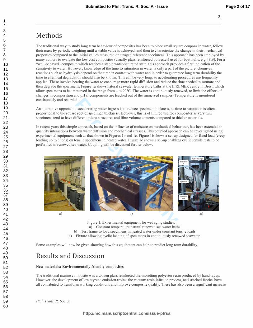
Methods
The traditional way to study long term behaviour of composites has been to place small square coupons in water, follow
their mass by periodic weighing until a stable value is achieved, and then to characterize the change in their mechanical
properties compared to the initial values measured on unaged reference specimens. This approach has been employed by
many authors to evaluate the low cost composites (usually glass reinforced polyester) used for boat hulls, e.g. [8,9]. For a
“well-behaved” composite which reaches a stable water-saturated state, this approach provides a first indication of the
sensitivity to water. However, knowledge of the time to saturation in water is only a part of the picture, chemivcal
reactions such as hydrolysis depend on the time in contact with water and in order to guarantee long term durability the
time to chemical degradation should also be known. This can be very long, so accelerating procedures are frequently
applied. These involve heating the water to encourage more rapid diffusion and reduce the time needed to saturate and
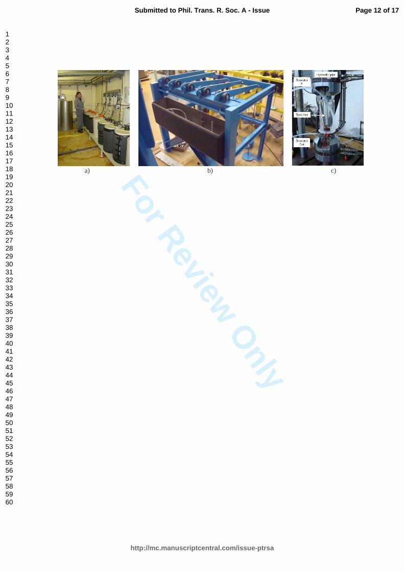
then degrade the specimens. Figure 1a shows natural seawater temperature baths at the IFREMER centre in Brest, which
allow specimens to be immersed in the range from 4 to 90°C. The water is continuously renewed, to limit the effects of
changes in composition and pH if components are leached out of the immersed samples. Temperature is monitored
continuously and recorded.
An alternative approach to accelerating water ingress is to reduce specimen thickness, as time to saturation is often
proportional to the square root of specimen thickness. However, this is of limited use for composites as very thin
specimens tend to have different micro-structures and fibre volume contents compared to thicker materials.
In recent years this simple approach, based on the influence of moisture on mechanical behaviour, has been extended to
quantify interactions between water diffusion and mechanical stresses. This coupled approach can be investigated using
experimental equipment such as that shown in Figures 1b and 1c. Figure 1b shows a set-up designed for fixed load (creep
loading up to 3 tons) on tensile specimens in heated water. Figure 1c shows a set-up enabling cyclic tensile tests to be
performed in renewed sea water. Coupling will be discussed further below.
a) b) c)
Figure 1. Experimental equipment for wet aging studies.
a) Constant temperature natural renewed sea water baths
b) Test frame to load specimens in heated water under constant tensile loads
c) Fixture allowing cyclic loading of specimens in continuously renewed seawater.
Some examples will now be given showing how this equipment can help to predict long term durability.
Results and Discussion
New materials: Environmentally friendly composites
The traditional marine composite was a woven glass reinforced thermosetting polyester resin produced by hand layup.
However, the development of low styrene emission resins, the vacuum resin infusion process, and stitched fabrics have
all contributed to transform working conditions and improve composite quality. There has also been a significant increase
Page 2 of 17
http://mc.manuscriptcentral.com/issue-ptrsa
Submitted to Phil. Trans. R. Soc. A - Issue
123456789101112131415161718192021222324252627282930313233343536373839404142434445464748495051525354555657585960

For Review O
nly
3
Phil. Trans. R. Soc. A.
in awareness in recent years of the importance of including life cycle analysis in the design process. Energy consumption
during manufacturing and end-of-life disposal are two aspects which influence this.
There are a number of ways of reducing the environmental impact of marine composites. The first is to replace the
petrochemical based thermosetting polyester by a thermoplastic such as polypropylene or polyamide, which can be
recycled after service to produce new components. An improved option is to use a bio-sourced thermoplastic. There are
various materials available, see for example [10]. A common choice is PLA (poly lactic acid), obtained from corn. Aging
studies have been performed on this polymer and underline the paradox of such materials [11]. They degrade quite
quickly, particularly at moderate temperatures, which is essential for a biodegradable polymer, but we also want them to
show good durability in water under service conditions. Another disadvantage of such thermoplastic polymers for marine
applications is the large change in manufacturing technology which they impose, requiring high temperatures (200°C or
more) and costly tooling. Most boatyards use either hand lay-up or vacuum infusion and they are not equipped for high
temperature manufacturing.
A new set of materials developed recently appear to overcome these problems. The Elium™ range of acrylic resins from
Arkema can be infused like polyester or vinyl ester but then react to form thermoplastics, which can subsequently be
recycled [12]. This is a revolution for small boatyards, providing access to recyclable materials with existing
manufacturing technology. However, due to their very recent introduction, although mechanical properties are starting to
appear [13] very few data are available to assess the long term durability of these materials in seawater. This is
fundamental to their adoption in marine structures, so an aging study was initiated in 2014. Unreinforced resin and carbon
fibre reinforced acrylic samples were immersed in seawater at different temperatures. The first results from this study,
after aging for one year, will be given here. Table 1 shows the materials tested.
Material Reinforcement Thickness
mm
Density
Vf
%
Tg
°C
Number of
specimens
Acrylic polymer None 2.7 1.187 - 116 34
Carbon fibre reinforced acrylic 90/0/45/-45/0/90°
±45° stitched
1.5 1.515 54 97 36
36
Table 1. Materials tested, based on thermoplastic acrylic matrix polymer
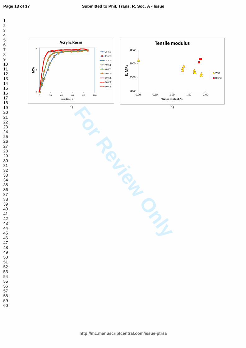
First, examples of weight gain plots from immersion of the matrix polymer in sea water at three different temperatures for
one year are shown in Figure 2. For the 2.7 mm thick unreinforced resin samples the plots appear to be Fickian to a first
approximation, with a saturation moisture content of around 1.8%.
a) b)
Figure 2. Aging of unreinforced acrylic matrix resin
a) Weight gains of after immersion in sea water at different temperatures,
b) Matrix resin tensile strength after aging, in wet and dry state.
The unreinforced samples were saturated at all temperatures after about two months. Tensile test results showed a small
drop in modulus and strength after one year in seawater at 60°C, but both were recovered after drying at 60°C, Figure 2b.
This suggests that only reversible plasticization occurs under these conditions. The accelerating effect of temperature
indicates that, compared to 25°C, diffusion is around 3 times faster at 40°C and 9 times faster at 60°C.
0
1
2
0 20 40 60 80 100
M%
root time, h
Acrylic Resin
25°C1
25°C2
25°C3
40°C 1
40°C2
40°C3
60°C 1
60°C 2
60°C 3
2000
2500
3000
3500
0,00 0,50 1,00 1,50 2,00
E,
MP
a
Water content, %
Tensile modulus
Wet
Dried
Page 3 of 17
http://mc.manuscriptcentral.com/issue-ptrsa
Submitted to Phil. Trans. R. Soc. A - Issue
123456789101112131415161718192021222324252627282930313233343536373839404142434445464748495051525354555657585960
For Review O
nly
4
Phil. Trans. R. Soc. A.
For the composites the weight gain plots were more scattered. For the carbon reinforced composites the weight gain at
saturation (around 1%) is roughly what would be expected based on the unreinforced resin saturation value and the fibre
volume fraction.
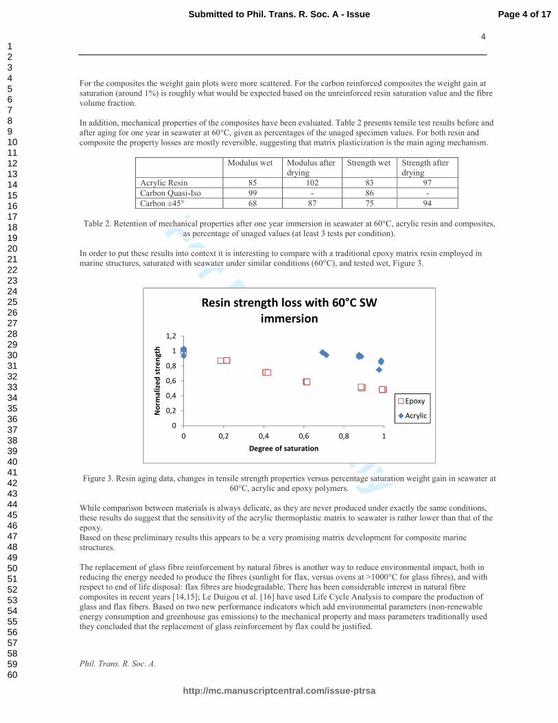
In addition, mechanical properties of the composites have been evaluated. Table 2 presents tensile test results before and
after aging for one year in seawater at 60°C, given as percentages of the unaged specimen values. For both resin and
composite the property losses are mostly reversible, suggesting that matrix plasticization is the main aging mechanism.
Modulus wet Modulus after
drying
Strength wet Strength after
drying
Acrylic Resin 85 102 83 97
Carbon Quasi-Iso 99 - 86 -
Carbon ±45° 68 87 75 94
Table 2. Retention of mechanical properties after one year immersion in seawater at 60°C, acrylic resin and composites,
as percentage of unaged values (at least 3 tests per condition).
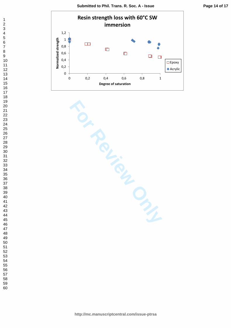
In order to put these results into context it is interesting to compare with a traditional epoxy matrix resin employed in
marine structures, saturated with seawater under similar conditions (60°C), and tested wet, Figure 3.
Figure 3. Resin aging data, changes in tensile strength properties versus percentage saturation weight gain in seawater at
60°C, acrylic and epoxy polymers.
While comparison between materials is always delicate, as they are never produced under exactly the same conditions,
these results do suggest that the sensitivity of the acrylic thermoplastic matrix to seawater is rather lower than that of the
epoxy.
Based on these preliminary results this appears to be a very promising matrix development for composite marine
structures.
The replacement of glass fibre reinforcement by natural fibres is another way to reduce environmental impact, both in
reducing the energy needed to produce the fibres (sunlight for flax, versus ovens at >1000°C for glass fibres), and with
respect to end of life disposal: flax fibres are biodegradable. There has been considerable interest in natural fibre
composites in recent years [14,15]; Le Duigou et al. [16] have used Life Cycle Analysis to compare the production of
glass and flax fibers. Based on two new performance indicators which add environmental parameters (non-renewable
energy consumption and greenhouse gas emissions) to the mechanical property and mass parameters traditionally used
they concluded that the replacement of glass reinforcement by flax could be justified.
0
0,2
0,4
0,6
0,8
1
1,2
0 0,2 0,4 0,6 0,8 1
No
rma
lize
d s
tre
ng
th
Degree of saturation
Resin strength loss with 60°C SW
immersion
Epoxy
Acrylic
Page 4 of 17
http://mc.manuscriptcentral.com/issue-ptrsa
Submitted to Phil. Trans. R. Soc. A - Issue
123456789101112131415161718192021222324252627282930313233343536373839404142434445464748495051525354555657585960
For Review O
nly
5
Phil. Trans. R. Soc. A.
However, natural fibres are known to absorb large amounts of water. They need a small amount of water (a few percent
by weight), as completely dried fibres are quite brittle [17], but flax fibres can absorb over 40% by weight [18].
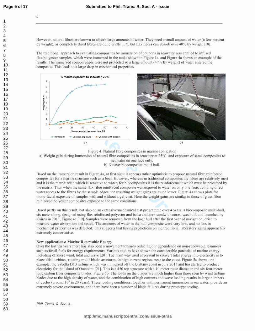
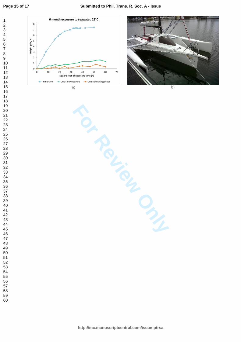
The traditional approach to evaluating composites by immersion of coupons in seawater was applied to infused
flax/polyester samples, which were immersed in the tanks shown in Figure 1a, and Figure 4a shows an example of the
results. The immersed coupon edges were not protected so a large amount (>7% by weight) of water entered the
composite. This leads to a large drop in mechanical properties.
a) b)
Figure 4. Natural fibre composites in marine application
a) Weight gain during immersion of natural fibre composites in seawater at 25°C, and exposure of same composites to
seawater on one face only.
b) Gwalaz biocomposite multi-hull.
Based on the immersion result in Figure 4a, at first sight it appears rather optimistic to propose natural fibre reinforced
composites for a marine structure such as a boat. However, whereas in traditional composites the fibres are relatively inert
and it is the matrix resin which is sensitive to water, for biocomposites it is the reinforcement which must be protected by
the matrix. Thus when the same flax fibre reinforced composite was exposed to water on only one face, avoiding direct
water access to the fibres by the sample edges, the resulting weight gains are much lower. Figure 4a shows plots for
mono-facial exposure of samples with and without a gel-coat. Here the weight gains are similar to those of glass fibre
reinforced polyester composites exposed to the same conditions.
Based partly on this result, but also on an extensive mechanical test programme over 4 years, a biocomposite multi-hull,
six meters long, designed using flax reinforced polyester and balsa and cork sandwich cores, was built and launched by
Kairos in 2013, Figure 4c [19]. Samples were removed from the boat hull after the first year of navigation, dried to
measure water absorption and tested. The amounts of water in the hull composite were very low, and no loss in
mechanical properties was detected. This suggests that basing predictions on the traditional laboratory aging approach is
extremely conservative.
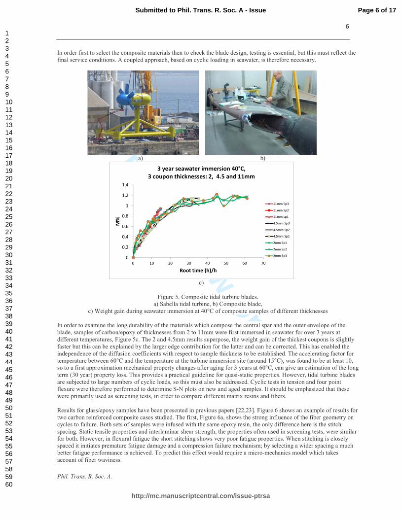
New applications: Marine Renewable Energy
Over the last ten years there has also been a movement towards reducing our dependence on non-renewable resources
such as fossil fuels for energy requirements. Various studies have shown the considerable potential of marine energy,
including offshore wind, tidal and wave [20]. The main way used at present to convert tidal energy into electricity is to
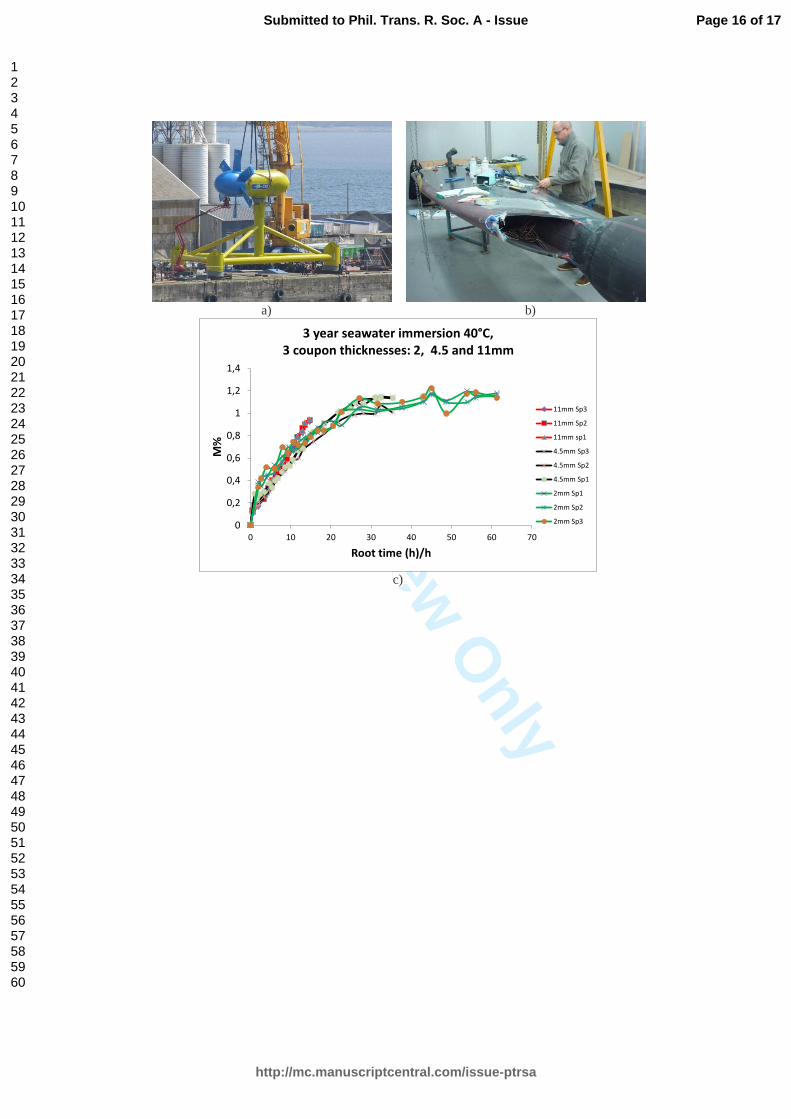
place tidal turbines, rotating multi-blade structures, in high current regions near to the coast. Figure 5a shows one
example, the Sabella D10 turbine which was immersed off the Brittany coast in July 2015 and has started to produce
electricity for the Island of Ouessant [21]. This is a 450 ton structure with a 10 meter rotor diameter and six four meter
long carbon fiber composite blades, Figure 5b. The loads on the blades are much higher than those seen by wind turbine
blades due to the high density of water, and the combination of high currents and wave loading results in large numbers
of cycles (around 108 in 20 years). These loading conditions, together with permanent immersion in sea water, provide an
extremely severe environment, and there have been a number of blade failures during prototype testing.
0
1
2
3
4
5
6
7
8
0 10 20 30 40 50 60 70
We
igh
t g
ain
, %
Square root of exposure time (h)
6 month exposure to seawater, 25°C
Immersion One side exposure One side with gelcoat
Page 5 of 17
http://mc.manuscriptcentral.com/issue-ptrsa
Submitted to Phil. Trans. R. Soc. A - Issue
123456789101112131415161718192021222324252627282930313233343536373839404142434445464748495051525354555657585960
For Review O
nly
6
Phil. Trans. R. Soc. A.
In order first to select the composite materials then to check the blade design, testing is essential, but this must reflect the
final service conditions. A coupled approach, based on cyclic loading in seawater, is therefore necessary.
a) b)
c)
Figure 5. Composite tidal turbine blades.
a) Sabella tidal turbine, b) Composite blade,
c) Weight gain during seawater immersion at 40°C of composite samples of different thicknesses
In order to examine the long durability of the materials which compose the central spar and the outer envelope of the
blade, samples of carbon/epoxy of thicknesses from 2 to 11mm were first immersed in seawater for over 3 years at
different temperatures, Figure 5c. The 2 and 4.5mm results superpose, the weight gain of the thickest coupons is slightly
faster but this can be explained by the larger edge contribution for the latter and can be corrected. This has enabled the
independence of the diffusion coefficients with respect to sample thickness to be established. The accelerating factor for
temperature between 60°C and the temperature at the turbine immersion site (around 15°C), was found to be at least 10,
so to a first approximation mechanical property changes after aging for 3 years at 60°C, can give an estimation of the long
term (30 year) property loss. This provides a practical guideline for quasi-static properties. However, tidal turbine blades
are subjected to large numbers of cyclic loads, so this must also be addressed. Cyclic tests in tension and four point
flexure were therefore performed to determine S-N plots on new and aged samples. It should be emphasized that these
were primarily used as screening tests, in order to compare different matrix resins and fibers.
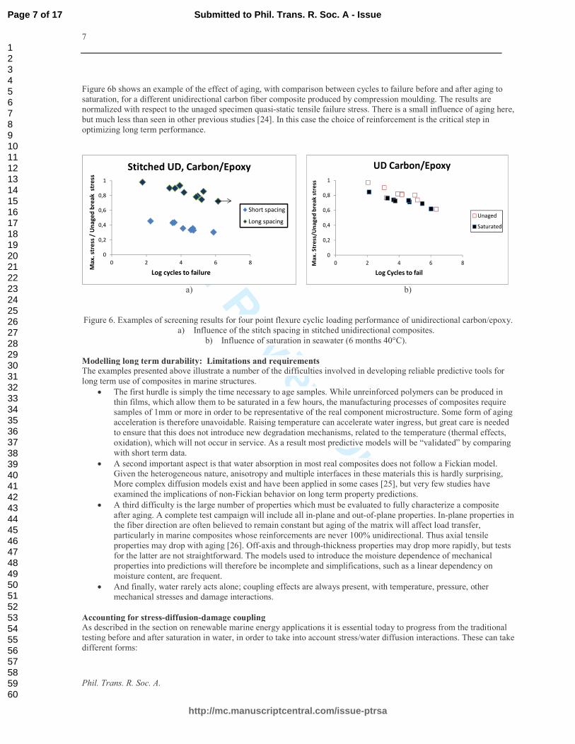
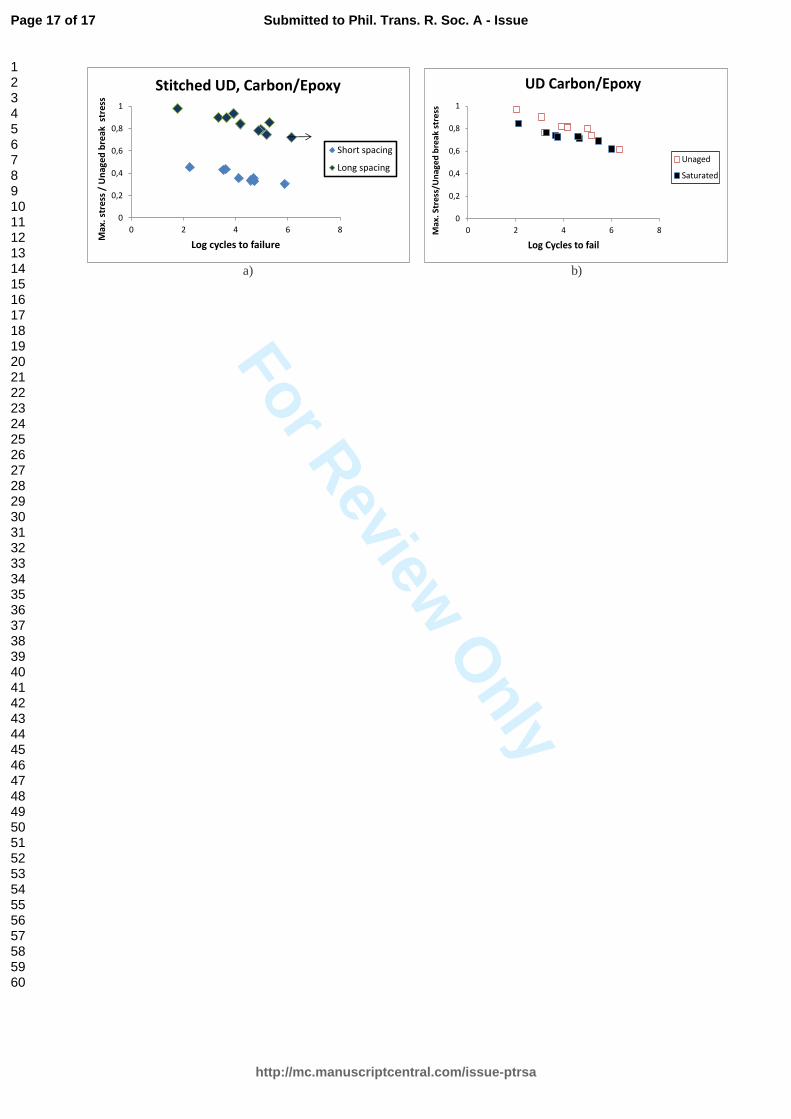
Results for glass/epoxy samples have been presented in previous papers [22,23]. Figure 6 shows an example of results for
two carbon reinforced composite cases studied. The first, Figure 6a, shows the strong influence of the fiber geometry on
cycles to failure. Both sets of samples were infused with the same epoxy resin, the only difference here is the stitch
spacing. Static tensile properties and interlaminar shear strength, the properties often used in screening tests, were similar
for both. However, in flexural fatigue the short stitching shows very poor fatigue properties. When stitching is closely
spaced it initiates premature fatigue damage and a compression failure mechanism; by selecting a wider spacing a much
better fatigue performance is achieved. To predict this effect would require a micro-mechanics model which takes
account of fiber waviness.
0
0,2
0,4
0,6
0,8
1
1,2
1,4
0 10 20 30 40 50 60 70
M%
Root time (h)/h
3 year seawater immersion 40°C,
3 coupon thicknesses: 2, 4.5 and 11mm
11mm Sp3
11mm Sp2
11mm sp1
4.5mm Sp3
4.5mm Sp2
4.5mm Sp1
2mm Sp1
2mm Sp2
2mm Sp3
Page 6 of 17
http://mc.manuscriptcentral.com/issue-ptrsa
Submitted to Phil. Trans. R. Soc. A - Issue
123456789101112131415161718192021222324252627282930313233343536373839404142434445464748495051525354555657585960
For Review O
nly
7
Phil. Trans. R. Soc. A.
Figure 6b shows an example of the effect of aging, with comparison between cycles to failure before and after aging to
saturation, for a different unidirectional carbon fiber composite produced by compression moulding. The results are
normalized with respect to the unaged specimen quasi-static tensile failure stress. There is a small influence of aging here,
but much less than seen in other previous studies [24]. In this case the choice of reinforcement is the critical step in
optimizing long term performance.
a) b)
Figure 6. Examples of screening results for four point flexure cyclic loading performance of unidirectional carbon/epoxy.
a) Influence of the stitch spacing in stitched unidirectional composites.
b) Influence of saturation in seawater (6 months 40°C).
Modelling long term durability: Limitations and requirements
The examples presented above illustrate a number of the difficulties involved in developing reliable predictive tools for
long term use of composites in marine structures.
• The first hurdle is simply the time necessary to age samples. While unreinforced polymers can be produced in
thin films, which allow them to be saturated in a few hours, the manufacturing processes of composites require
samples of 1mm or more in order to be representative of the real component microstructure. Some form of aging
acceleration is therefore unavoidable. Raising temperature can accelerate water ingress, but great care is needed
to ensure that this does not introduce new degradation mechanisms, related to the temperature (thermal effects,
oxidation), which will not occur in service. As a result most predictive models will be “validated” by comparing
with short term data.
• A second important aspect is that water absorption in most real composites does not follow a Fickian model.
Given the heterogeneous nature, anisotropy and multiple interfaces in these materials this is hardly surprising,
More complex diffusion models exist and have been applied in some cases [25], but very few studies have
examined the implications of non-Fickian behavior on long term property predictions.
• A third difficulty is the large number of properties which must be evaluated to fully characterize a composite
after aging. A complete test campaign will include all in-plane and out-of-plane properties. In-plane properties in
the fiber direction are often believed to remain constant but aging of the matrix will affect load transfer,
particularly in marine composites whose reinforcements are never 100% unidirectional. Thus axial tensile
properties may drop with aging [26]. Off-axis and through-thickness properties may drop more rapidly, but tests
for the latter are not straightforward. The models used to introduce the moisture dependence of mechanical
properties into predictions will therefore be incomplete and simplifications, such as a linear dependency on
moisture content, are frequent.
• And finally, water rarely acts alone; coupling effects are always present, with temperature, pressure, other
mechanical stresses and damage interactions.
Accounting for stress-diffusion-damage coupling
As described in the section on renewable marine energy applications it is essential today to progress from the traditional
testing before and after saturation in water, in order to take into account stress/water diffusion interactions. These can take
different forms:
0
0,2
0,4
0,6
0,8
1
0 2 4 6 8
Ma
x.
stre
ss /
Un
ag
ed
bre
ak
str
ess
Log cycles to failure
Stitched UD, Carbon/Epoxy
Short spacing
Long spacing
0
0,2
0,4
0,6
0,8
1
0 2 4 6 8Ma
x.
Str
ess
/Un
ag
ed
bre
ak
str
ess
Log Cycles to fail
UD Carbon/Epoxy
Unaged
Saturated
Page 7 of 17
http://mc.manuscriptcentral.com/issue-ptrsa
Submitted to Phil. Trans. R. Soc. A - Issue
123456789101112131415161718192021222324252627282930313233343536373839404142434445464748495051525354555657585960
For Review O
nly
8
Phil. Trans. R. Soc. A.
- Weak coupling can be observed between water diffusion and damage. The presence of damage can accelerate
water entry (access to internal free surfaces) or water can accelerate the appearance of damage (through matrix
swelling, interface debonding, or modification of internal stress states for example).
- Strong coupling can occur when water and mechanical loads are applied simultaneously. In this case the stress
can accelerate damage development which in turn allows faster diffusion resulting in more damage.
While experimental data are rare, various authors have discussed these phenomena. Considering first stress-diffusion
coupling a free volume model was proposed to account for the influence of stress on diffusion, resulting in simple
expressions [27]. These indicated that the presence of stress in a glassy polymer affects the free volume fraction which
influences migration and diffusion of small molecules such as water. The diffusion coefficient will be increased if the
polymer is under a tensile stress and decreased under a compressive stress.
Neumann and Marom [28] used this approach to estimate the influence of tensile loads on diffusion coefficients in
laminates and found good egreement with test results. More complex models have also been proposed, Weitsman
presented an elaborate theory including viscoelastic deformation based on continuum mechanics and irreversible
thermodynamics [29]. He presented some test data and noted an influence of stress on the diffusion process, but the tests
did not reach equilibrium moisture contents. His model requires the identification of a large number of input parameters.
Derrien and Gilormini [30] used a micro-mechanics approach, starting from the resin response, to develop a model
relating water diffusion to stress. They highlighted the influence of swelling, and concluded that due to the coupling
between internal stresses and absorption capacity, even if the matrix shows linear (Fickian) behavior the water absorption
of a composite can show a non-linear (Langmuir) behavior. More recently Sar et al. [31] described a thermodynamic
approach, based on the definition of the chemical potential of water, to establish a model coupling the diffusion of
moisture to the mechanical states experienced by a polymer. The model enables the evolution of both the density of the
polymer and its maximum moisture absorption capacity occurring during the diffusion process to be estimated.
Finally, Yagoubi et al. [32] included a chemical contribution in their model. They considered water transport in an epoxy
resin to involve competition between diffusion, which can involve several fundamental mechanisms (free volume,
water/polymer interactions), and a reactive process that can induce a certain evolution of the polymer (structure or
microstructure). Thus hydrolysis of an anhydride cured epoxy will modify the available hydrophilic sites and explain
non-Fickian behavior.
An example of coupling which has been studied in some detail is the influence of hydrostatic pressure on diffusion
kinetics. There have been various sets of experimental data published, which show varying effects. Some authors have
noted rather small effects [33], with increases in moisture absorption [34-36], no effect [37] or decreases in absorption
[38] also being reported. The latter study emphasized the role of the fibre/matrix interface, and recent work confirms this
[39]. However, tests on specimens taken from filament wound cylinders [40] have shown very strong pressure effects.
Three samples cut from the same ±55° filament wound cylinder were immersed in tap water for 3.5 years, two without
pressure at 20 and 60°C and a third at 60°C under 100 bar (10 MPa) pressure. At 20°C Fickian behavior was noted, with a
clear saturation Ms weight value around 0.7%, while at 60°C weight continued to increase beyond the 20°C plateau. After
2 years the samples without pressure were placed with the sample at 10 MPa, and there was a strong increase in weight
gain of both, up to the value of the specimen which had been subjected to pressure from the start. These results and those
from more recent studies [41] reveal the importance of porosity in weight gain measurements. This may explain the
contrasting conclusions in much published work.
Modelling diffusion becomes more complex when the applied stress introduces damage. Indeed, modelling damage in
composites is already complex, so it is not surprising that few authors have attempted to address damage/diffusion
interactions. Nevertheless some studies are available. Suri and Perreux [42] presented results from a study on a
glass/epoxy composite tubes. These were loaded in tension fatigue to introduce different amounts of damage, then
immersed in water. Diffusion followed a Langmuir model. The authors introduced an "effective time", proportional to
the degree of damage, which then allowed them to calculate the water content of the material as a function of ageing and
degree of damage. In a second paper [43] they developed a multiaxial behavior model which includes internal variables to
describe damage and which can be coupled to moisture content. For the internal pressure test described a reasonable
prediction of axial damage was obtained. Weitsman [44] proposed a continuum damage mechanics approach together
with a thermodynamics based moisture/stress/damage relationship to describe coupled damage development but
concluded in 1987 that “a larger data base for damage and a basic physico-chemical understanding of the debonding
process are necessary for further progress in this subject”. Fifteen years later he showed some more results and introduced
a double mechanism including both diffusion and capillary action, to explain differences in damage observed at the
interior and near the surface of aged specimens [45].
Lundgren and Gudmundsen, [46] proposed a micro-mechanics approach to describe diffusion in cracked cross-ply
laminates, proposing a moisture transfer coefficient which is related to crack density.
Page 8 of 17
http://mc.manuscriptcentral.com/issue-ptrsa
Submitted to Phil. Trans. R. Soc. A - Issue
123456789101112131415161718192021222324252627282930313233343536373839404142434445464748495051525354555657585960
For Review O
nly
9
Phil. Trans. R. Soc. A.
Roy et al. [47] proposed a model to describe the interaction between water and biaxial damage by combining
micromechanics and irreversible thermodynamics. It was found that both diffusion rate and maximum saturation level
could be expressed as quadratic functions of crack density.
It is also possible to use numerical tools such as FE analysis to study coupling effects: For example, Lundgren and
Gudmundson [48] used an uncoupled FE model to show that crack closure could occur due to matrix swelling, and slow
down diffusion into cracked cross-ply laminates. Determining whether crack closure actually occurs is complex, as it will
depend on the applied loading, laminate sequence and residual manufacturing stresses. In a recent study Tual et al.[49]
presented a 3D moisture diffusion model, which was correlated with weight gain data on samples of different geometries
and then used to examine the influence of introducing cracks on water diffusion. While this approach requires many
simplifications, if it can be validated it offers the potential to vary material parameters and boundary conditions in order
to reduce prolonged experimental campaigns.
This brief description of available coupled models underlines the complexity involved in predicting long term behavior
and the scope of the work required to integrate realistic water diffusion models in composite design tools.
Conclusions
Environmental aging is an essential element in the multi-scale modelling of the behaviour of composites. However, it
cannot be limited to solid mechanics aspects, it is a multi-disciplinary subject in which chemistry, polymer physics, and
fluid/structure interactions all play a role. When natural fibres are used biological expertise is also necessary. The use of
composites in highly loaded marine components, such as tidal turbine blades or composite propellers, is increasing and
requires a detailed understanding of coupling between stress and seawater. The theoretical framework to account for
coupling effects exists but few experimental data are available, as coupled experiments are long to perform and require
specific test equipment. This is an area where further work is urgently required.
Acknowledgments
The work presented here is based on recent collaborations between the author and colleagues within IFREMER (D.
Choqueuse, P-Y LeGac, C. Humeau, M. Arhant and M. LeGall), and at the University of South Brittany (C. Baley, A.
LeDuigou, A. Bourmaud) and at ENSTA Bretagne (N. Carrere, N. Tual). Samples from the Gwalaz project with Kairos
(R. Jourdain, E. Grossman, L. Bosser, E. Poisson), from Arkema (S. Taillemite, P. Gerard), and from the Sabella D10
project (A. Guerrier, E. Nicolas) are also gratefully acknowledged.
Funding Statement
The author is employed by IFREMER, the French Ocean Research Institute, and the work described here has been
performed within the research programmes of the Institute and the EDROME Carnot Institute. The financial support of
the ADEME, for the Sabella D10 project, and the ONR Solid Mechanics program, with program monitor Dr Y.
Rajapakse for the stress-diffusion coupling work, is gratefully acknowledged.
Competing Interests
The author has no competing interests with respect to the work published in this paper.
References 1. Smith CS, 1990, Design of Marine Structures in Composite Materials, Elsevier.
2. Mouritz, A, Gellert, E, Burchill, P and Challis, K, 2001, 'Review of advanced composite structures for naval ships
and submarines', Composite Structures, 53, no. 1, pp. 21-41.
3. Shenoi RA, Wellicome JF, 1993, Composite materials in Maritime Structures, Cambridge Ocean Technology
series.
4. Davies P, 2012, Marine Composites, in Encyclopedia of Composites, 2nd Edition, Editors: L. Nicolais, A.
Borzacchiello, publisher John Wiley &Sons, Hoboken, New Jersey.
Page 9 of 17
http://mc.manuscriptcentral.com/issue-ptrsa
Submitted to Phil. Trans. R. Soc. A - Issue
123456789101112131415161718192021222324252627282930313233343536373839404142434445464748495051525354555657585960
For Review O
nly
10
Phil. Trans. R. Soc. A.
5. Graham-Jones J, Summerscales J (Editors), Marine Applications of Advanced Fibre-Reinforced Composites,
Woodhead Publishers, 2015.
6. Weitsman YJ. 2012. Fluid effects in polymers and polymeric composites. Springer.
7. Davies P, Rajapakse Y. (Editors) 2014, Durability of composites in a marine environment, Springer
8. Gellert EP, Turley DM, Seawater immersion ageing of glass-fibre reinforced polymer laminates for marine
applications, Composites Part A, 30, Issue 11, November 1999, 1259-1265
9. Davies P, Mazeas F, Casari P, Sea water aging of glass reinforced composites: Shear behaviour and Damage
modeling, Journal of Composite Materials 35, No. 15, 2001, pp1343-1372
10. Smith R (Editor), Biodegradable polymers for industrial applications, CRC Woodhead Publishers, 2005.
11. LeDuigou A, Davies P, Baley C, Seawater ageing of flax/poly(lactic acid) biocomposites, Polymer Degradation
and Stability, 94, (2009), 1151-1162
12. http://www.arkema.com/en/products/product-finder/range-viewer/Elium-resins-for-composites
13. Boufaida Z, Farge L, André S, Meshaka Y, Influence of the fiber/matrix strength on the mechanical properties of
a glass fiber/thermoplastic-matrix plain weave fabric composite, Composites Part A, 75, 2015, 28-38
14. Fowler PA, Hughes JM, Elias RE, 2006, Biocomposites: technology, environmental credentials and market
forces, Journal of the Science of Food and Agriculture. 86:1781–1789.
15. JEC/CELC, 2012, Flax and Hemp fibres: a natural solution for the composite industry.
16. Le Duigou A, Davies P, Baley C, 2011, Environmental impact analysis of the production of flax fibres to be used
as composite material reinforcement, J. Biobased materials and Bioenergy, 5, 1, 1-13.
17. Baley C , Le Duigou A, Bourmaud A, Davies P, 2012, Influence of drying on the mechanical behaviour of flax
fibres and their unidirectional composites, Composites Part A, 43, 8, 1226–1233
18. Stamoulis A, Baillie CA, Garkhail SK, Van Melick HGH, Peijs T, 2000, Environmental Durability of Flax Fibres
and their Composites based on Polypropylene Matrix, Applied Composite Materials 7: 273–294.
19. Bosser L, Poisson E, Grossmann E, Davies P, 2013,The first all-flax composite trimaran, JEC magazine, No.84
October, 45-47.
21. Bahaj AS, 2011, Generating electricity from the oceans, Renewable and Sustainable Energy Reviews, 15, 7,
September, 3399–3416
22. Sabella website, http://www.sabella.fr/
23. Davies P, Germain G, Gaurier B, Boisseau A, Perreux D, 2013, Evaluation of the durability of composite tidal
turbine blades, Royal Society Philosophical Transactions A, February, vol. 371
24. Boisseau A, Davies P, Thiebaud F, Fatigue behavior of glass fibre reinforced composites for ocean energy
conversion systems, Applied Composite Materials, 20, issue 2 pp145-155, 2013
25. Carter HG, Kibler KG, 1978, Langmuir type model for anomalous moisture diffusion in composite resins, J.
Comp. Mats, 12, 118-31.
26. Tual N, Carrere N, Davies P, Bonnemains T, Lolive E, 2015, Characterization of sea water ageing effects on
mechanical properties of carbon/epoxy composites for tidal turbine blades, Composites Part A, 78, 380-389
27. Fahmy AA, Hurt JC. 1980. Stress dependence of water diffusion in epoxy resin. Polymer Composites 1, 77-80. 28. Neumann S, Marom G, Prediction of moisture diffusion parameters in composite materials under stress, Journal
of Composite Materials, 1987, 21 (1), 68-80.
29. Weitsman Y. 1987. Stress assisted diffusion in elastic and viscoelastic materials. J. Mech. Phys. Solids 35, 73-93
30. Derrien K, Gilormini P. 2009. The effect of moisture induced swelling on the absorption capacity of transversely
isotropic elastic polymer matrix composites. Int. J. Solids & Struct. 46, 1547-1553.
31. Sar BE, Fréour S, Davies P, Jacquemin F, 2012, Coupling moisture diffusion and internal mechanical states in
polymers - A thermodynamical approach, European Journal of Mechanics A/Solids, 36 (2012) 38-43
32. Yagoubi JE, Lubineau G, Roger F, Verdu J, 2012, A fully coupled diffusion-reaction scheme for moisture
sorption desorption in an anhydride-cured epoxy resin, Polymer, 53, 5582-5595
33. Choqueuse D, Davies P, Mazéas F, Baizeau R, 1997, Aging of Composites in Water: Comparison of Five
Materials in Terms of Absorption Kinetics and Evolution of Mechanical Properties, ASTM STP 1302 Aging of
composites in water. 73-96.
34. Tucker, W.C., S.-B. Lee, and T. Rockett, 1993, The Effects of Pressure on Water Transport in Polymers. Journal
of Composite Materials,. 27(8), 756-763.
35. Tucker, W.C. and R. Brown, Moisture Absorption of Graphite/Polymer Composites Under 2000 Feet of Seawater.
1989 Journal of Composite Materials, 23(8), 787-797.
36. Pollard, A., et al., 1989, Influence of hydrostatic pressure on the moisture absorption of glass fibre-reinforced
polyester. Journal of Materials Science, 24 (5), 1665-1669.
37. Bradley W.L., Chiou P.-L.B., Grant TS, 1993, The effect of seawater on polymeric composite materials. Proc. 1st
Offshore composites workshop, Houston.
38. Avena, A, Bunsell AR, 1988, Effect of hydrostatic pressure on the water absorption of glass fibre-reinforced
epoxy resin. Composites, 9(5): p. 355-357.
Page 10 of 17
http://mc.manuscriptcentral.com/issue-ptrsa
Submitted to Phil. Trans. R. Soc. A - Issue
123456789101112131415161718192021222324252627282930313233343536373839404142434445464748495051525354555657585960
For Review O
nly
11
Phil. Trans. R. Soc. A.
39. Fichera M, Totten K, Carlsson LA, 2015, Seawater effects on transverse tensile strength of carbon/vinylester as
determined from single-fiber and macroscopic specimens, J. Materials Sci., 50, 22, 7248-61
40. Davies, P., D. Choqueuse, and F. Mazéas, 1997, Composites Underwater. Proc DURACOSYS.
41. Humeau C, Davies P, Jacquemin F, 2015, Moisture diffusion under pressure in composites, Proc. ICCM20,
Copenhagen, July
42. Suri C, Perreux D, 1995. The effects of mechanical damage in a glass/epoxy composite on the absorption rate,
Composites Engineering, 4, 5, 415-424
43. Perreux D, Suri C, 1997, A study of the coupling between the phenomenon of water absorption and damage in
glass/epoxy composite pipes, Comp. Sci & Tech. 57 (9-10), 1403-14.
44. Weitsman YJ, 1987. Coupled damage and moisture transport in fiber reinforced, polymeric composites, Int. J.
Solids Struct., 23 (7) 1003-1025.
45. Weitsman YJ, Guo YJ, 2002, A correlation between fluid-induced damage and anomalous fluid sorption in
polymeric composites, Composites Science and Technology, 62, 889–908
46. Lundgren J-E, Gudmundson R, 1998. A model for moisture absorption in cross-ply composite laminates with
matrix cracks. J Composite Materials 32, 2226-53.
47. Roy S, Weiqun X, Patel S, Case S. 2001. Modelling of moisture diffusion in the presence of bi-axial damage in
polymer matrix composite laminates. Int. J. Solids & Struct. 38, 7627-7641.
48. Lundgren J-E, Gudmundson P. 1999. Moisture absorption in glass-fibre/epoxy laminates with transverse matrix
cracks. Comp. Sci & Tech. 59, 1983-1991.
49. Tual N, Carrère N, Davies P, 2015, Characterization of seawater aging effects on mechanical properties of
carbon/epoxy composites for tidal turbine blades, Proc. ICCM20, Copenhagen, July.
Page 11 of 17
http://mc.manuscriptcentral.com/issue-ptrsa
Submitted to Phil. Trans. R. Soc. A - Issue
123456789101112131415161718192021222324252627282930313233343536373839404142434445464748495051525354555657585960
For Review O
nly
a) b) c)
Page 12 of 17
http://mc.manuscriptcentral.com/issue-ptrsa
Submitted to Phil. Trans. R. Soc. A - Issue
123456789101112131415161718192021222324252627282930313233343536373839404142434445464748495051525354555657585960
For Review O
nly
a) b)
0
1
2
0 20 40 60 80 100
M%
root time, h
Acrylic Resin
25°C1
25°C2
25°C3
40°C 1
40°C2
40°C3
60°C 1
60°C 2
60°C 3
2000
2500
3000
3500
0,00 0,50 1,00 1,50 2,00
E, M
Pa
Water content, %
Tensile modulus
Wet
Dried
Page 13 of 17
http://mc.manuscriptcentral.com/issue-ptrsa
Submitted to Phil. Trans. R. Soc. A - Issue
123456789101112131415161718192021222324252627282930313233343536373839404142434445464748495051525354555657585960
For Review O
nly
0
0,2
0,4
0,6
0,8
1
1,2
0 0,2 0,4 0,6 0,8 1
No
rmal
ize
d s
tre
ngt
h
Degree of saturation
Resin strength loss with 60°C SW immersion
Epoxy
Acrylic
Page 14 of 17
http://mc.manuscriptcentral.com/issue-ptrsa
Submitted to Phil. Trans. R. Soc. A - Issue
123456789101112131415161718192021222324252627282930313233343536373839404142434445464748495051525354555657585960
For Review O
nly
a) b)
0
1
2
3
4
5
6
7
8
0 10 20 30 40 50 60 70
We
igh
t ga
in, %
Square root of exposure time (h)
6 month exposure to seawater, 25°C
Immersion One side exposure One side with gelcoat
Page 15 of 17
http://mc.manuscriptcentral.com/issue-ptrsa
Submitted to Phil. Trans. R. Soc. A - Issue
123456789101112131415161718192021222324252627282930313233343536373839404142434445464748495051525354555657585960
For Review O
nly
a) b)
c)
0
0,2
0,4
0,6
0,8
1
1,2
1,4
0 10 20 30 40 50 60 70
M%
Root time (h)/h
3 year seawater immersion 40°C, 3 coupon thicknesses: 2, 4.5 and 11mm
11mm Sp3
11mm Sp2
11mm sp1
4.5mm Sp3
4.5mm Sp2
4.5mm Sp1
2mm Sp1
2mm Sp2
2mm Sp3
Page 16 of 17
http://mc.manuscriptcentral.com/issue-ptrsa
Submitted to Phil. Trans. R. Soc. A - Issue
123456789101112131415161718192021222324252627282930313233343536373839404142434445464748495051525354555657585960
For Review O
nly
a) b)
0
0,2
0,4
0,6
0,8
1
0 2 4 6 8
Max
. str
ess
/ U
nag
ed b
reak
str
ess
Log cycles to failure
Stitched UD, Carbon/Epoxy
Short spacing
Long spacing
0
0,2
0,4
0,6
0,8
1
0 2 4 6 8Ma
x. S
tre
ss/U
na
ged
bre
ak
stre
ss
Log Cycles to fail
UD Carbon/Epoxy
Unaged
Saturated
Page 17 of 17
http://mc.manuscriptcentral.com/issue-ptrsa
Submitted to Phil. Trans. R. Soc. A - Issue
123456789101112131415161718192021222324252627282930313233343536373839404142434445464748495051525354555657585960