ENVIRONMENTAL CONTROL QUICK REFERENCE DATA
25
APOLLO NEWS REFERENCE ENVIRONMENTAL CONTROL Atmosphere revitalization section (ARS) Cabin pressure Suit circuit pressure Cabin mode Egress mode Suit inlet temperature range Gas cooled mode Liquid cooled mode Relative humidity Suit circuit fan flow Liquid cooled garment flow QUICK REFERENCE DATA 4.8±0.2 psia (normal, steady-state) 4.8±0.2 psia (may exceed 5.0 psia during powered flight) 3.8±0.2 psia (4.7 psia maximum during wered flight) With suit temperature control valve in full cold position, temperature ranges from +38° to +65° F; in full hot position, from +42° to 100° F. Within 7° of HTS glycol temperature at liquid circuit cooling package inlet. 40% to 80% (during periods of cabin mode operation) At 4.8 psia · 36.0 pounds per hour (minimum) At 3.8 psia · 28.4 pounds per hour (minimum) At 5.65 psid · 4.0 unds per minute (nominal) (1.9 minimum each suit) Oxygen supply and cabin pressure control section (OSCPCS) Suit pressure increase Cabin repressurization and emergency oxygen valve delivery rate Descent mode Ascent me PLSS refill Cabin volume Manual cabin pressure dump rate (without oxygen inflow) Number of cabin repressurizations Cabin repressurization time Cabin pressure switch settings Deent oxyn tanks Capacity Burst pressure First 1- psi increase may occur in less than 1 send. Each succeeding 1-psi increase occurs in not less than 8 seconds. 4 pounds per minute (maximum) 8 pounds per minute at 5psia 1.60 pound/refill at 1410 psia; can only be partially filled at lower pressures 195 cubic feet (nominal) Each dump valve from 5.0 psia down to 0.08 psia in 180 seconds; both valves, 90 seconds 4 at 5.5 pounds each (nominal) 1 minute (minimum) · 6 minutes (maximum) When cabin pressure drops to 3.7 to 4.45 psia, contacts close. When cabin pressure increas to 4.40 to 5.0 psia, contacts open. 48.01 pounds (each tank) at 2,690 psia and +70° F (residual oxyn: 84 pound (each tank) at 50 psia and +70° F) 4700 psig RUMM , EC-1
Transcript of ENVIRONMENTAL CONTROL QUICK REFERENCE DATA

APOLLO NEWS REFERENCE
ENVIRONMENTAL CONTROL
Atmosphere revitalization section (ARS)
Cabin pressure
Suit circuit pressure Cabin mode Egress mode
Suit inlet temperature range Gas cooled mode
Liquid cooled mode
Relative humidity
Suit circuit fan flow
Liquid cooled garment flow
QUICK REFERENCE DATA
4.8±0.2 psia (normal, steady-state)
4.8±0.2 psia (may exceed 5.0 psia during powered flight) 3.8±0.2 psia (4.7 psia maximum during powered flight)
With suit temperature control valve in full cold position, temperature ranges from +38° to +65° F; in full hot position, from +42° to 100° F.
Within 7° of HTS glycol temperature at liquid circuit cooling package inlet.
40% to 80% (during periods of cabin mode operation)
At 4.8 psia · 36.0 pounds per hour (minimum) At 3.8 psia · 28.4 pounds per hour (minimum)
At 5.65 psid · 4.0 pounds per minute (nominal) (1.9 minimum each suit)
Oxygen supply and cabin pressure control section (OSCPCS)
Suit pressure increase
Cabin repressurization and emergency oxygen valve delivery rate
Descent mode Ascent mode
PLSS refill
Cabin volume
Manual cabin pressure dump rate (without oxygen inflow)
Number of cabin repressurizations
Cabin repressurization time
Cabin pressure switch settings
Descent oxygen tanks Capacity
Burst pressure
First 1-psi increase may occur in less than 1 second. Each succeeding 1-psi increase occurs in not less than 8 seconds.
4 pounds per minute (maximum) 8 pounds per minute at 500 psia
1.60 pound/refill at 1410 psia; can only be partially filled at lower pressures
195 cubic feet (nominal)
Each dump valve from 5.0 psia down to 0.08 psia in 180 seconds; both valves, 90 seconds
4 at 5.5 pounds each (nominal)
1 minute (minimum) · 6 minutes (maximum)
When cabin pressure drops to 3.7 to 4.45 psia, contacts close. When cabin pressure increases to 4.40 to 5.0 psia, contacts open.
48.01 pounds (each tank) at 2,690 psia and +70° F (residual oxygen: 84 pound (each tank) at 50 psia and +70° F) 4700 psig
CIRUMMAN
, EC-1

APOLLO NEWS REFERENCE
Oxygen supply and cabin pressure control section (cont)
Ascent oxygen tanks Capacity
Burst pressure
Bypass relief valve Full flow pressure Cracking pressure Reseat pressure
Overboard relief valve Full flow pressure Cracking pressure Reseat pressure
High-pressure regulator Outlet pressure with primary and secondary regulators operating normally
PLSS Oxygen Regulator Regulator outlet pressure with primary and secondary regulators operating normally
Overboard Relief Valve Full flow pressure Cracking pressure Reseat pressure
Flow Limiter
Water management section (WMS)
Descent water tanks Capacity Initial fill pressure Residual water Pressure upon expulsion of all expellable water
Ascent water tanks Capacity Initial fill pressure Residual water
Pressure regulators discharge pressure
PLSS refill (each) Heat transport section ( HTS)
Coolant
Coolant slush point
Coolant pump rated flow
EC-2
2.43 pounds (each tank) at 840 psia and +70° F (residual oxygen: 0.14 pounds (each tank) at 50 psia and +70° F) 1 ,500 psig
3,030 psig (maximum) at +75° F 2,875 psig (minimum) at +75° F 2,850 psig (minimum) at +75° F
1,090 psig (maximum) at +75° F 1,025 psig (minimum) at +75° F 985 psig (minimum) at +75° F
At inlet pressure of 1,100 to 3,000 psig and flow of 0.01 to 4.0 pounds per hour, and inlet pressure of 975 to 1,100 psig and flow of 0.1 pound per hour, will regulate to 875 to 960 psig at 75° F
1395 psia (minimum) at +75° F 1445 psia (maximum) at +75° F
1560 psia (maximum) at +75° F 1500 psia (minimum) at +75° F 1460 psia (minimum) at +75° F
1.5 lbs/hr (maximum) at 2700 psia inlet and 1500 psia outlet
333 pounds (each tank) at 0 . 75 fill ratio 48.2 psia (maximum) at +80° F 6.66 pounds 11.0 psia (minimum) at +35° F
42.5 pounds (each tank) at 0.75 fill ratio 48.2 psia (maximum) at +80° F 0.85 pound (each tank)
0.4 to 1.0 psi above A RS gas pressure
11.8 pounds of water (maximum)
Solution of ethylene glycol and water (35% and 65%, respectively, by weight) with inhibitors
Approximately 25 pounds of coolant is used in HTS.
-3° F
Flow rate of 222 pounds per hour (minimum) at +40° F, 30 psid, and 28-vdc input voltage
CIRUMMAN
,

APOLLO NEWS REFERENCE
Heat transport section (HTS) (cont)
Coolant pump bypass relief valve Cracking pressure Fully open pressure Reseat pressure
Coolant temperatures Flow into primary sublimator Flow out of sublimator Flow into secondary sublimator Flow out of sublimator
Vacuum fill requirements
Primary and secondary coolant filters Efficiency
Maximum bypass valve cracking pressure
Coolant flow Primary coolant loop Secondary coolant loop
Cold plates Coolant inlet operating temperature Coolant inlet operating pressure Coolant inlet operating flow
33 psi (minimum) 39 psi (maximum) 1 psi less than cracking
+29° to +120° F +38° to HXt F +29° to +36° F +60.1 ° F (nominal) +47° F (nominal)
HTS withstands internal pressure of 500 microns in sea-level ambient pressure environment.
35 microns absolute for primary; 45 microns absolute for secondary 0.4 psid for primary; 1.0 psid for secondary
222 pounds per hour (minimum) 222 pounds per hour (minimum)
+32° to +100° F 5 to 45 psia 12 to 85 pounds per hour, depending on cold-plate size
ENVIRONMENTAL CONTROL SUBSYSTEM (ECS)
R-31
WATER MANAGEMENT SECTION (WMS)
DRINKING FOOD PREPARATION
COOliNG RECHARGING PLSS
FIRE EXTINGUISHING
OXYGEN SUPPLY AND CABIN PRESSURE CONTROL SECTION (OSCPCS)
CABIN PRESSURIZATION SPACE SUIT PRESSURIZATION
RECHARGING PLSS OXYGEN FOR BREATHING
ATMOSPHERE REVITILIZATION SECTION (ARS)
SPACE SUIT VENTILATION CARBON DIOXIDE CONTROL
ODOR REMOVAL CABIN AND SPACE SUIT TEMPERATURE
AND HUMIDITY CONTROL CONDITIONS OXYGEN FOR
BREATHING
HEAT TRANSPORT SECTION (HTS)
ARS TEMPERATURE CONTROL ELECTRONICS THERMAL CONTROL
WASTE HEAT REJECTION
Block Diagram of the Environmental Control Subsystem
OIRUMMAN
, EC-3

APOLLO NEWS REFERENCE
The Environmental Control Subsystem (ECS) enables pressurization of the cabin and space suits, controls the temperature of electronic equipment, and provides breathable oxygen for the astronauts. It also provides water for drinking, cooling, fire extinguishing, and food preparation and supplies oxygen and water to the portable life support system (P LSS).
The major portion of the ECS is in the cabin. The peripheral ECS equipment, such as oxygen and water tanks, is located outside the cabin, in the ascent and descent stages. The ECS consists of the fol lowing sections:
Atmosphere revitalization section (ARS)
Oxygen supply and cabin pressure control section (OSCPCS)
Water management section (WMS)
Heat transport section (HTS)
The ARS pu rifies and conditions the oxygen for the cabin and the space suits. Oxygen conditioning c o n sists of removing carbon dioxide, odors, particulate matter, and excess water vapor. It also temperature conditions the oxygen and water used to cool the astronauts' space suits.
The OSCPCS stores gaseous oxygen and maintains cabin and suit pressure by supplying oxygen to the ARS to compensate for crew metabolic consumption and cabin or suit leakage. Two oxygen tanks in the descent stage provide oxygen during descent and lunar stay. Two oxygen tanks in the ascent stage are used during ascent and rendezvous.
The WMS supplies water for drinking, cooling, fire extinguishing, and food preparation, and for refilling the PLSS cooling water tank. It also provides for delivery of water from ARS water separators to HTS sublimators and from water tanks to ARS and HTS sublimators.
The water tanks are pressurized before launch, to maintain the required pu mping pressure in the tanks. The descent stage tanks supply most of the water required until staging occurs. After staging, water is supplied by the two ascent stage tanks. A self-sealing valve delivers water for drinking and food preparation.
The HTS consists of a primary coolant loop and a secondary coolant loop. The secondary loop serves as a backup loop; it functions if the primary l oo p fails. A water-glycol solution circu lates through each loop. The primary loop provides temperature control for batteries, electronic equipment that requires active thermal control, and for the oxygen and water that circulates through the space suits. The batteries and electronic equipment are mounted on cold plates and rails through which coolant is routed to remove waste heat. The cold plates used for equipment that is required for mission a b ort contain two separate coolant passages: one for the primary loop and one for the secondary loop. The secondary coolant loop, which is used only if the primary loop is inoperative, serves only these cold plates.
In-flight waste heat rejection from both coolant loops is achieved by the primary and secondary sublimators, which are vented overboard. A coolant pump recirculation assembly contains al l the HTS coolant pumps and associated check and relief valves. Coolant flow from the assembly is directed through paral lel circuits to the cold plates for the electronic equipment and the oxygen-to-glycol and water-to-glycol heat exchangers in the ARS.
FUNCTIONAL DESCRIPTION
The functional description of each of the four major ECS sections is supported by a functional flow diagram, which, to reduce complexity, does not contain electrical circuitry.
EC-4 CIRUMMAN
,

APOLLO NEWS REFERENCE
GASEOUS OXYGEN TANKS
ELECTRONIC REPLACEABLE ASSEMBLY, AND ASCENT BATTERY COLD PLATES
R-32A
GN & CS COLD PLATES
STRAIN/TEMPERATURE SIGNAL CONDITIONER
COLD PLATE
BATTERY COLD RAILS
GASEOUS OXYGEN TANK (QUAD 3)
TRANSMinER COLD PLATES
WATER TANK (QUAD 2)
C-BAND COLD PLATES
Environmental Control Subsystem, Component Location (Sheet 1}
CIRUMMAN
,
COMMUNICATIONS COLD PLATES
DATA STORAGE EQUIPMENT COLD PLATE
GASTA COLD PLATES
LIGHTING CONTROL ASSEMBLY COLD PLATE
EC-5

NEWS REFERENCE APOLLO
R-33A
EC-6
0 SUIT GAS DIVERTE� UMP VALVE CABIN RELIEF AND D
0
FLOW CONTROLS SUIT
HI PLSS 02 VALVE
MANAGEMENT CONTROLS WATER OXYGEN CONTROL MODULE
Environmen a anent Location (Sheet 2) t I Control Subsystem, Camp
IJRUMMAN
,
(j) LIQUID GARMENi'
COOLING

APOLLO NEWS REFERENCE
ATMOSPH E R E R EVITAL IZATION SECTION
The ARS is a recirculation system that conditions oxygen by cooling or heating, dehumidifying, and deodorizing it for use within the space suits and cabin, circulates water through the liquid cooling garment to provide cooling during peak heat loads, and recirculates and filters the cabin atmosphere. The major portion of the ARS is contained within the suit circuit assembly.
In normal operation, conditioned oxygen flows to the space suits and is discharged through the return umbil ical to the suit circuit. Suit circuit pressure, sensed at a point downstream of the suits, is referenced to the oxygen regulators that control pressure by supplying makeup oxygen to the suit circuit. The suit circuit relief valve protects the suit circuit against overpressurization, by venting the ARS.
The cabin position of the suit gas diverter valve is used during pressurized-cabin operation, to direct sufficient conditioned oxygen to the cabin to control carbon dioxide and humidity levels. Pulling the valve handle selects the egress position to isolate the suit circuit from the cabin. The egress position is used for al l unpressurized-cabin operations, as well as closed suit mode with pressurized cabin. An electrical solenoid override automatical ly repositions the valve from cabin to egress when cabin pressure drops below the normal level or when the egress position is selected on the pressure regulators.
With the suit gas diverter valve set to the cabin position, cabin discharge oxygen is returned to the suit circuit through the cabin gas return valve. Setting the cabin gas return valve to automatic position enables cabin pressure to open the valve. When the cabin is depressurized, differential pressure closes the valve, preventing suit pressure loss.
A small amount of oxygen is tapped from the suit circuit upstream of the PGA inlets and fed to the carbon dioxide partial pressure sensor, which provides a voltage to the C02 partial pressure indicator.
The primary and secondary carbon dioxide and odor removal canisters are connected to form a parallel loop. The primary canister contains a LM
cartridge with a capacity of 41 man hours; the secondary canister, a PLSS cartridge with a capacity of 18 man hours. A debris trap in the primary canister cover prevents particulate matter from entering the cartridge. A relief valve in the primary canister permits flow to bypass the debris trap if it becomes clogged. Oxygen is routed to the C02 and odor removal canisters through the canister selector valve. The carbon dioxide level is controlled by passing the flow across a bed of lithium hydroxide (LiOH); odors are removed by absorption on activated charcoal. When carbon dioxide partial pressure reaches or exceeds 7.6 mm Hg, as indicated on the partial pressure C02 indicator, the C02 component caution light and ECS caution light go on. (The C02 component caution light also goes on when the C02 canister selector valve is in the secondary position.) The C02 canister selector valve is then set to the secondary position, placing the secondary canister onstream. The primary cartridge is replaced and the C02 canister selector valve is set to the primary position, placing the primary canister back onstream.
From the canisters, conditioned oxygen flows to the suit fan assembly, which maintains circu lation in the suit circuit. Only one fan operates at a time. The ECS suit fan 1 circuit breaker is closed and the S U IT FAN selector switch is set to 1 to initiate suit fan operation. At startup, a fan differential pressure sensor is in the low position (low .6 P). which, through the fan condition signal control, energizes the ECS caution light and suit fan component caution light. The lights remain on until the differential pressure across the operating fan increases sufficiently to cause the differential pressure sensor to move to the normal position. If the differential pressure drops to 6.0 inches of water or less, the lights go on and switchover to fan No. 2 is required. The ECS caution light goes off when fan No. 2 is selected and the suit fan warning light goes on. The suit fan component caution light goes off when fan No. 2 comes up to speed and builds up normal differential pressure. The suit fan warning light and suit fan component caution light go off if fan No. 2 differential pressure reaches 9.0 inches of water. The fan check valve permits air to pass from the operating fan without backflow through the inoperative fan.
IIRUMMAN EC-7

APOLLO NEWS REFERENCE
TO WATER MANAGEMENT
SECTION
R-34A
EC-8
I HEAT TRANSPORT -1 I SECTION I I I
�IIIII�DI!IIIIIIl��IJm:Iiiimm� SUIT CIRCUIT
HEAT EXCHANGER
I I I I I
SUIT CIRCUIT REGENERATIVE I HEAT EXCHANGER I
'<amm:Cijl1IIIlll:m:!itrmmnl t (HEATING)
I I I I
PRESS PART PlESS CO 1
llll
I I L ____ _
ATMOSPHERE REVIT ALIZA liON
SECTION
_j
Atmosphere Revitalization Section, Flow Diagram
CIFIUMMAN
,
LEGEND � PRIMARY WATER-GLYCOL
IITII!IIII CONDITIONED OXYGEN
WATER
GASEOUS OXYGEN
C02 AND ODOR REMOVAL CANISTERS

APOLLO NEWS REFERENCE
From the check valve, the conditioned oxygen passes through a sublimator to the cooling heat exchanger. The sublimator cools the oxygen under emergency conditions. Heat transfer to the coolant in the heat exchanger reduces gas temperature and causes some condensation of water vapor.
The conditioned oxygen is next routed to two parallel-redundant water separators through the water separator selector valve. One separator, selected by pushing or pulling the water separator selector valve handle, is operated at a time. The separator is driven by the gas flowing through it. Moisture removed from the oxygen is discharged under a dynamic head of pressure sufficient to ensure positive flow from the separator to the WMS. A water drain carries residual water from the separators to a surge (collection) tank outside the recirculation system when the loop is shut down.
The conditioned oxygen from the water separator is mixed with makeup oxygen from the OSCPCS to maintain system pressure. The mixture flows through the regenerative (heating) heat exchanger, where the temperature may be increased, to the suit isolation valves. The suit temperature control valve on the water control module controls the flow of coolant through the regenerative heat exchanger. Setting the valve to the increase hot position increases oxygen temperature; setting it to decrease cold position reduces the temperature.
SUIT LIQU I D COOLING ASSEMBLY
The suit liquid cooling assembly assists in removing metabolic heat by circulating cool water through the liquid cooled garment (LCG) . Suit inlet temperature can be manually selected to within 7° F of the HTS glycol temperature at the assembly inlet. A pump maintains the flow of warm water returning from the LCG through the water umbilicals. An accumulator in the system compensates for volumetric changes and leakage. A mixing bypass valve controls the quantity of water t h at f l ows t h ro u g h t h e w a t er-glycol heat exchanger. This bypassed (warm) water is mixed with the cool water downstream of the heat exchanger, flows through the water umbilicals back
to the LCG. The assembly also includes one cabin atmosphere recirculation fan.
OXYG E N SUPPLY AND CABIN PRESSU R E CONTROL SECTION
The ECS descent stage oxygen supply hardware consists of the following: descent oxygen tanks, high-pressure fill coupling, high-pressure oxygen c o n t rol assembly, interstage flex lines, PLSS recharge regulator assembly, and descent stage disconnects. The descent tank pressure transducers, part of the instrumentation subsystem, generate an output proportionate to tank pressu re.
The ascent stage oxygen supply hardware consists of the following: ascent stage disconnects, interstage flex lines, oxygen module, two ascent oxygen tanks, a PLSS hose, PLSS oxygen disconnect, and the cabin pressure switch. Two automatic cabin pressure relief and dump valves, one in each hatch, are provided to protect the cabin from overpressurization. Two ascent stage tank pressure transducers and a selected oxygen supply transducer, part of the IS, operate in conjunction with the OSCPCS.
The OSCPCS stores gaseous oxygen, replenishes the ARS oxygen, and provides refills for the PLSS oxygen tank. Before staging, oxygen is supplied from the descent stage oxygen tanks. After staging, or if the descent tank is depleted, the ascent stage oxygen tanks supply oxygen to the oxygen control modu le. The high-pressure assembly in the descent stage, and the oxygen control module in the ascent stage, contain the valves and regulators necessary to control oxygen in the OSCPCS. The cabin relief and dump valves vent excess cabin pressure.
A high-pressure regulator reduces descent tank pressure, approximately 2,690 psia, to a level that is compatible with the components of the oxygen control module, approximately 900 psig. A seriesredundant overboard relief valve protects the oxygen control module against excessive pressure caused by a defective regulator or by flow through the bypass relief valve. If the pressure on the outlet
GRUMMAN E C-9 ,

APOLLO NEWS REFERENCE
_Q____
.
I 021H20 QTY MON
C W®t:ISET OfS�fSl AK I
AK2
R-35A
PLSS FILL VALVE
PLSS RECHARGE
PORT
PLSS RECHARGE
PORT
· . . •, . . .
TO CABIN •
:. :-< ·�·.
NO.2 ASCENT02
VALVE
FILTER
T'-o..I/r-=.,..,...,�'i11h�...,......11J BURST DIAPHRAGM
�-CABIN REPRESS VALVE
TO CABIN (EMERGENCY OXYGEN)
Oxygen Supply and Cabin Pressure Control Section, Flow Diagram
side of the regulator rises to a dangerous level, the burst diaphragm assembly vents the high-pressure assembly to ambient. A poppet in the burst diaphragm assembly reseats when pressure in the high-pressure assembly is reduced to approximately 1 ,000 psig. Descent oxygen flow through the interstage disconnect to the oxygen control module is controlled with the descent oxygen shutoff valve. The interstage disconnect acts as a redundant seal to prevent loss of oxygen overboard after staging.
When ascent stage oxygen is required, the ascent oxygen shutoff valves are used to select their respective tank. A mechanical interlock prevents the valves from being opened unless the descent oxygen shutoff valve is closed. The mechanical interlock may be overridden (if the descent oxygen
shutoff valve cannot be closed and the ascent oxygen shutoff valves must be opened) by pressing the interlock override pushbutton on the oxygen control module.
From the oxygen shutoff valves, oxygen is routed to oxygen demand regulators, an alternate PLSS fil l valve, and a cabin repressurization and emergency oxygen valve. For PLSS fills, oxygen is diverted from Descent Tank No. 2 upstream of the check valve and routed to the PLSS Oxygen R e c h a r g e R e g u Ia t o r Assembly. This seriesredundant regulator reduces descent tank pressure to approximately 1 400 psia. A series-redundant overboard relief valve protects the PLSS fill line against excessive pressure caused by a defective regulator. Oxygen flows through the interstage dis-
EC-10 DRUM MAN
,

APOLLO NEWS REFERENCE
connect and a shutoff valve to the Hi h Press PLSS fill disconnect. The PLSS fill disconnect connects the PLSS oxygen tank through a flexible service hose. A check valve in the PLSS disconnect is opened when the hose is connected. The valve automatically closes when the hose is disconnected. The oxygen demand regulators maintain the pressure of the suit circuit at a level consistent with normal requirements. Both regulators are manually controlled with a four-position handle; both are ordinarily set to the same position. The CABIN posit ion i s selected during normal pressurized-cabin operations, to provide oxygen at 4.8±0.2 psia. Setting the regulators to the egress position maintains suit circuit pressure at 3.8±0.2 psia. The direct 02 position provides an unregulated flow of oxygen into the suit circuit. The close position shuts off all flow through the regulator. In the cabin and egress positions, the regulator is internally modulated by a reference pressure from the suit circuit. The demand regulators are redundant; either one can fulfill the ARS oxygen requirements .
I f cabin pressure drops t o 3.7 to 4.45 psia, the cabin pressure switch energizes the cabin repressurization valve and oxygen flows through the valve into the cabin. If cabin pressure builds up to 4.45 to 5.0 psia, the cabin pressure switch deenergizes the valve solenoid, shutting off the oxygen flow. The valve can maintain cabin pressure at 3.5 psia for at least 2 minutes following a 0.5-inch-diameter puncture of the cabin. It responds to signals from the cabin pressure switch during pressurized-cabin operation and to a suit circuit pressure switch during unpressurized operation. Manual override capabilities are provided.
Both cabin relief and dump valves (one in the forward hatch, the other in the overhead hatch) are manually and pneumatically operated. They prevent excessive cabin pressure and permit deliberate cabin depressurization. The valves automatically relieve cabin pressure when the cabin-to-ambient differential reaches 5.4 to 5.8 psid. When set to the automatic position, the valves can be manually opened with their external handle. The valves can
each dump cabin pressure from 5.0 to 0.08 psia in 180 seconds without cabin inflow. In addition to relieving positive pressure, the valves relieve a negative cabin pressure condition.
To egress from the LM, the oxygen demand regulators are set to the egress position, turning off the cabin fan and closing the suit gas diverter valve; the cabin gas return valve is set to the egress position; and cabin pressure is dumped by opening the cabin relief and dump valve. When repressurizing the cabin, the cabin relief and dump valve is set to the a u tomatic position, the oxygen demand regulator valves are set to the cabin position, and the cabin gas return valve is set to the automatic position. The cabin warning light goes on when the regulators are set to the cabin position and goes off when cabin pressure reaches the actuation pressure of the cabin pressure switch.
WATER MANAGEMENT SECTION
The WMS stores water for metabolic consumption, evaporative cooling, fire extinguishing, and PLSS water tank refill. It controls the distribution of this stored water and the water reclaimed from the ARS by the water separators. Reclaimed water is used only for evaporative cooling, in the ECS sublimators. Water is stored in two tanks in the descent stage and two smaller tanks in the upper midsection of the ascent stage. All four tanks are bladder-type vessels, which are pressurized with nitrogen before launch. The controls for the WMS are grouped together on the water control module located to the right rear of the LM Pilot's station.
Water from the descent stage water tanks is fed through a manually operated shutoff valve and a check valve to the PLSS water disconnect . Water quanti!'/ is determined b'{ N essure tranducers. The output is displayed on the H20 quantity indicator after the 02/H20 quantity monitor selector switch is set to the descent position. When the descent H20 valve is opened, high-pressure water is available for drinking, food preparation, PLSS fill, and fire extinguishing.
GRUMMAN EC-11
,

APOLLO NEWS REFERENCE
FILL PORT
ASCENT H20 TANK NO.2
QUANTITY
_a
I 01/M�O On MOt<
'�@�:: t��"����=������R
��--DIFFERENTIAL SECONDARY
PRESSURE r-D-----------1 REGULATOR
R-36A
COOLANT ISOLATION
VALVE
TO SUIT CIRCUIT
SUBLIMATOR (HTS)
FROM WATER SEPARATORS
TO SECONDARY
WATER SUBLIMATOR
PRIM EVAP FLOW #2 VALVE
PRIM EVAP FLOW #1 VALVE
FILTER
TO PRIMARY WATER
SUBLIMATOR
Water Management Section, Flow Diagram
EC-12 IIRUMMAN
,
PRESSURE SENSOR
LEGEND
.',"a'x"a'x"n WATER
· ... ,,,",,,.,.,.,,, .,, . ..m,., NITROGEN

APOLLO NEWS REFERENCE
When the vehicle is staged, the descent interstage water feed line is severed by the interstage umbilical guillotine, and water is supplied from the ascent stage water tanks. Water quantity is monitored on either ascent water tank as required by switching. Water from ascent stage water tank No. 1 is fed to the PLSS water disconnect through the ascent water valve for drinking, food preparation, PLSS fill, and fire extinguishing.
Water from the four water tanks enters the water tank selector valve, which consists of two water diverting spools . Setting the valve to the descent or ascent position determines which tanks are on-line.
When using the descent tanks, water is supplied to the primary manifold (which consists of the primary pressure regulators and the primary evaporator flow No. 1 valve ) by setting the water tank select valve to descent. The water flows through the series primary pressure regulators, which control water discharge pressure, in response to suit circuit gas reference pressure, at 0.4 to 1 .0 psi above this gas pressure. With the primary evaporator flow valve opened, the water is routed to the primary sublimator. Discharge water from the water separator is routed through the secondary spool of the selector valve and joins the water from the primary pressure regulators . Setting the selector valve to ASC routes water from the ascent tanks through the primary pressure regulators and, with the primary evaporator flow No. 1 valve opened, to the primary sublimator. Water flow from the water separators is not changed by selection of the ASC position. If the primary pressure regulators fail, an alternative path to the primary sublimator is provided with the primary evaporator flow No. 2 valve opened. Water then flows directly from the ascent water tanks through the secondary pressure regulator and the primary evaporator flow No. 2 valve to the primary sublimator.
Under emergency conditions (failure of the primary HTS loop ), water from the ascent tanks is directed through the seconda.ry manifold
(secondary pressure regulator) to the secondary sublimator and the suit circuit sublimator by opening the secondary evaporator flow valve . Discharge water from the water separators is also directed to the sublimator.
HEAT TRANSPORT SECTION
The HTS consists of two closed loops (primary and secondary) through which a water-glycol solution is circulated to cool the suit circuits and electronic equipment. Coolant is continuously circulated through cold plates and cold rails to remove heat from electronic equipment and bat· teries. Heat is removed by conduction and is rejected to space by process of sublimation. For the purpose of clarity, the primary and secondary coolant loops, and the primary and secondary coolant loop cold plates and rails are discussed separately in the following paragraphs.
The primary coolant loop is charged with coolant at the fill points and is then sealed. The glycol pumps force the coolant through the loop. The glycol accumulator maintains a constant head of pressure (5.25 to 9 psia, depending on coolant level) at the inlets of the primary loop glycol pumps. Coolant temperature at the inlets is approximately +40° F . A switch in a low-level sensor trips when only 1 0±5% of coolant volume remains in the accumulator. When tripped, the switch provides a telemetry signal and causes the glycol caution light to go on.
The coolant is routed to the pumps through a filter. They are started by closing the appropriate circuit breakers and setting the glycol selector switch to pump 1 or pump 2. If the operating pump does not maintain a minimum differential pressure (LlP ) of 7±2 psi, the Ll P switch generates a signal to energize the ECS caution light and the glycol component caution light. Selecting the other pump deenergizes the lights when the onstream pump develops a minimum LlP of 5.0 to 9.0 psi. If both pumps fail, the secondary loop is activated by setting the water tank selector valve to the secondary, setting the glycol pump switch to I NST
CIRUMMAN EC-13
,

APOLLO NEWS REFERENCE
PRIM GLYCOL SEC GLYCOL G�TCOl
_a ACCUMULATOR ACCUMULATOR FROM WATER OJIIIIl!IDDli[Ili� \( SEPA��:;;
:
:;;II I II II II II II I l
f'-"�;: :::: ::�,:::P .�� m :�:ric;rr;:--NrM/1
.. ... . I
FILL PORT
SECONDARY .; WATER :
SUBLIMATOR
, :: Fl ..... : .. ......
PRIMARY ........_ :·: . ..-,... WATER ..._... .......
SUB - . ,
ASCENT STAGE
BATTERIES COLD RAILS
lu M u 11• r--;EL�E �CT
�R�O�N�IC;-�===·=·=··�··=·· ·= ··=, ======·=·=·====
LIM=
A=
T=O=R==�� ����� .. ·:mW'JlW'Jl� EQUIPMENT
INTERSTAGE DISCONNECT
SUIT CIRCUIT � L __ c�o�L� D�P�LA� T� E:s __ ����������
HEAT EXCHANGER t:m�m:l:����m:l:'U
R-37
FROM SUIT CIRCUIT
FROM SEC EVAP
�IIIIIIIllliJliD TO WATER ' SEPARATORS
LEGEND �SECONDARY �WATER-GLYCOL �PRIMARY
WATER-GLYCOL
�WATER
miiiiiiiJ CONDITIONED OXYGEN
TO MULTIPLE H20 CONNECTOR
AFT EQUIPMENT COLD RAILS
"""'
DESCENT STAGE BATTERY
COLD RAILS
I Heat Transport Section, Flow Diagram
(SEC), and closing the glycol pump secondary circuit breaker . Automatic transfer from primary pump No. 1 to primary pump No. 2 is initiated by closing the glycol automatic transfer circuit breaker and setting the selector switch to pump 1 . When transfer is necessary, the caution I ights go on, the transfer is accomplished, and the ECS caution light goes off. The glycol pump component light remains on.
If primary loop D.P exceeds 33 psi, the pump bypass relief valve opens and routes the coolant back to the pump inlet, relieving the pressure . The valves start to open at 33 psi, are fully open at a
maximum of 3 9 psia, and reseat at a minimum of 3 2 psia. Check valves prevent coolant from feeding back through an inoperative primary pump.
Part of the coolant leaving the recirculation assembly flows to the suit circuit heat exchanger to cool the suit circuit gas of the ARS. The remainder of the coolant flows to the electronic equipment mounted on cold plates. The flow paths then converge and the coolant is directed to the liquid cooling garment water glycol heat exchanger to cool suit water as required. The coolant then flows through the aft equipment bay cold rails.
EC-14 CIRUMMAN
,

APOLLO NEWS REFERENCE
A portion of the warmer coolant flow can be diverted to the suit circuit regenerative heat exchanger through the suit temperature control valve to increase suit inlet gas temperature. The diverted flow returning from the heat exchanger, combined with the bypassed coolant is routed to the primary sublimator.
The sublimator decreases the temperature of the coolant by rejecting heat to space through sublimation of water, followed by venting of generated steam through an overboard duct. Deflector plates, attached to the duct, prevent escaping steam from applying thrust to the vehicle. Water is fed to the sublimator at a pressure that exceeds 4.0 psia, but is less than 6.5 psia. The water pressure must be less than the suit circuit static pressure plus the head pressure from the water separators to the sublimator. The water regulators, referenced to suit circuit pressure, are in the water feed line to the sublimator. Regulated water pressure varies from 0.5 to 1 .0 psid above suit circuit pressure. The sublimator inlet and outlet temperatures are sensed by temperature transducers, which provide telemetry signals . Coolant from the sublimator flows through the ascent and descent battery cold rails, then returns to the recirculation assembly.
Two self-sealing disconnects upstream and downstream of the glycol pumps permit servicing of the HTS. lnterstage disconnects are installed in coolant lines that connect to the descent stage. Before staging, coolant flows through the ascent and descent stage battery cold rails. After staging, the interstage disconnects separate, the lines are sealed by spring-loaded valves, and the full coolant flow enters the ascent stage battery cold rails.
The secondary (emergency) coolant loop provi des thermal control for those electronic assemblies and batteries whose performance is
necessary to effect a safe return to the CSM. Cooling is provided by the secondary sublimator.
As in the primary loop, a secondary glycol accumulator provides pressure for the pump inlet side and compensates for loss due to leakage. A pump bypass relief valve relieves excessive pressure by routing coolant back to the pump inlet. A check valve at the discharge side of the glycol pump prevents coolant flow from bypassing the HTS during GSE operation. The coolant from the pump passes through the check valve to the secondary passage of the cold plates and cold rails of the electronics and batteries cold plate section. Waste heat is absorbed by the coolant. The warm coolant then flows to the secondary sublimator.
The secondary sublimator operates in the same manner as the primary sublimator in the primary coolant loop. Water for the sublimator is provided when the secondary evaporator flow valve is opened. The coolant returns to the pump for recirculation.
Equipment essential for mission abort is mounted on cold plates and rails that have two independent coolant passages, one for the primary loop and one for the secondary loop.
PRIMARY COOLANT LOOP COLD PLATES AND RAILS
The cold plates and rails in the primary coolant loop are arranged in three groups: upstream electronics, aft equipment bay, and batteries.
Coolant from the recirculation assembly flows into parallel paths that serve the upstream electronics cold plate group. In this group, the data storage electronics assembly ( DS EA) is cooled by cold rails; the remainder of the electronics, by cold
CJRUMMAN EC-15 ,

APOLLO NEWS REFERENCE
plates. The cold plates are in the pressurized and unpressurized areas of the LM. The flow rates through the parallel paths are controlled by flow restrictors, installed downstream of the cold plate group. The first upstream electronics flow path cools the suit circuit heat exchanger. The second flow path cools five cold plates mounted on the pressurized side of the equipment tunnel back wall . The third path serves the integrally cooled IMU and the rate gyro assembly (RGA) cold plate, both located in the unpressurized area (on the naviga· tion base). The fourth path cools the abort sensor assembly (ASA) and pulse torque assembly (PTA) cold plates. All the plates for the fourth path are in the unpressurized area above the cabin; the ASA is on the navigation base of the alignment optical telescope (AOT). The fifth path serves the tracking light electronics (TLE), gimbal angle sequencing transformation assembly (GASTA), lighting control assembly (LCA). and DSEA plates: one in the unpressurized area in front of the cabin, a second one in the control and display panel area, a third one below the cabin floor, and another one on the left wall of the cabin.
The aft equipment bay is cooled by eight cold rails; the flow is in parallel. The batteries are cooled by cold rails. The ascent batteries are in the center section of the aft equipment bay; the descent batteries are on the -Z bulkhead of the descent stage. During the descent phase, the coolant flow is split between the descent batteries and the ascent batteries; the ascent batteries are not used during this time. When the stages are separated, quick-disconnects break the coolant lines and seal the ends; all coolant then flows through the ascent battery cold rails.
SECONDARY COOLANT LOOP COLD PLATES AND R A I LS
The secondary coolant loop is for emergency use. Only cold plates and cold rails that have two independent passages (one for the primary loop and one for the secondary loop) are served by this loop.
In the upstream electronics area, the secondary coolant flow is split between three cold plates (RGA, ASA, and TLE) in parallel. The flow rate is controlled by a flow restrictor downstream of the TLE and RGA. After these three plates, the secondary loop cools the ascent battery cold rails and the aft equipment bay cold rails in a seriesparallel arrangement. The coolant first flows through three ascent battery cold rails in parallel, then through eight aft equipment bay cold rails in parallel.
EQUIPMENT
ATMOSPH E R E R EVITALIZATION SECTION
SUIT CI RCUIT ASSEMBLY
Suit Circuit Relief Valve. The suit circuit relief valve protects the suit circuit against overpressurization. The valve has automatic, open, and close positions. Two externally mounted microswitches provide telemetry signals when the open or close position is selected.
In the automatic position, the valve responds to pressure sensed by the aneroid; it cracks open at approximately 4.3 psia to prevent overpressurization of the suit loop by allowing oxygen to flow to the cabin. At 4.7 psia, the valve is fully open and flows approximately 7.8 pph at +90° F. The valve reseats at approximately 4.3 psi a. In the open position, the valve handle displaces the poppet from the seat to open the valve, regardless of pressure. In the close position, if the valve fails to reseat, the automatic poppet is left open, but an auxiliary poppet is closed, maintaining pressure.
Suit Gas Diverter Valve . The suit gas diverter valve is a manually operated, two-way valve (one inlet and two outlets) with a solenoid override in one direction. The valve is on the ECS package above the oxygen control module. When the valve handle is pushed into the cabin position, oxygen is directed into the cabin; pulling the valve handle to the egress position shuts off flow to the cabin.
EC-16 CIRUMMAN
,
APOLLO NEWS REFERENCE
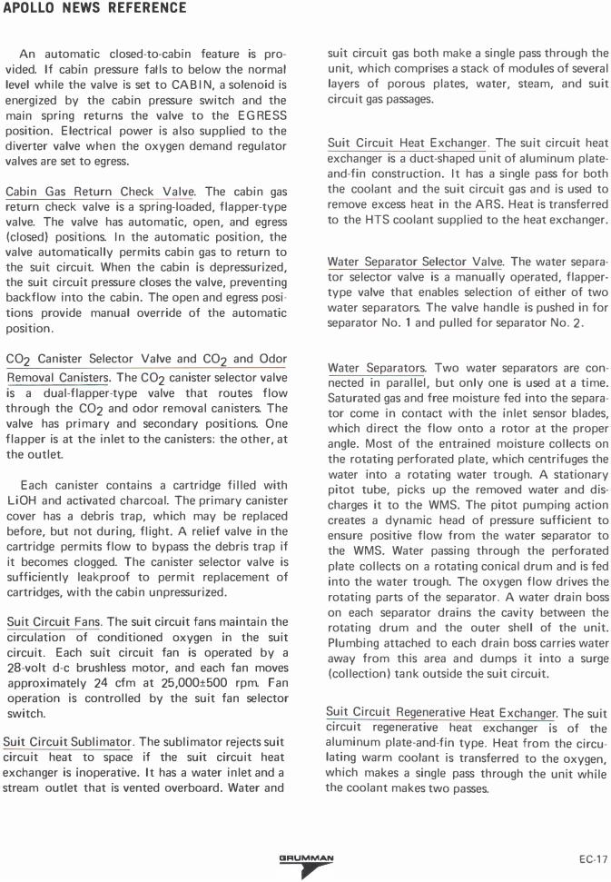
An automatic closed-to-cabin feature is provided. If cabin pressure falls to below the normal level while the valve is set to CABIN, a solenoid is energized by the cabin pressure switch and the main spring returns the valve to the EGRESS position. Electrical power is also supplied to the diverter valve when the oxygen demand regulator valves are set to egress.
Cabin Gas Return Check Valve. The cabin gas return check valve is a spring-loaded, flapper-type valve. The valve has automatic, open, and egress (closed) positions. In the automatic position, the valve automatically permits cabin gas to return to the suit circuit. When the cabin is depressurized, the suit circuit pressure closes the valve, preventing backflow into the cabin. The open and egress positions provide manual override of the automatic position .
C02 Canister Selector Valve and C02 and Odor
Removal Canisters. The C02 canister selector valve is a dual-flapper-type valve that routes flow through the C02 and odor removal canisters. The valve has primary and secondary positions. One flapper is at the inlet to the canisters: the other, at the outlet.
Each canister contains a cartridge filled with LiOH and activated charcoal. The primary canister cover has a debris trap, which may be replaced before, but not during, flight. A relief valve in the cartridge permits flow to bypass the debris trap if it becomes clogged. The canister selector valve is sufficiently leakproof to permit replacement of cartridges, with the cabin unpressurized.
Suit Circuit Fans. The suit circuit fans maintain the circulation of conditioned oxygen in the suit circuit. Each suit circuit fan is operated by a 28-volt d-e brushless motor, and each fan moves approximately 24 cfm at 25,000±500 rpm. Fan operation is controlled by the suit fan selector switch.
Suit Circuit Sublimator. The sublimator rejects suit circuit heat to space if the suit circuit heat exchanger is inoperative. It has a water inlet and a stream outlet that is vented overboard. Water and
suit circuit gas both make a single pass through the unit, which comprises a stack of modules of several layers of porous plates, water, steam, and suit circuit gas passages.
Suit Circuit Heat Exchanger. The suit circuit heat exchanger is a duct-shaped unit of aluminum plateand-fin construction. It has a single pass for both the coolant and the suit circuit gas and is used to remove excess heat in the ARS. Heat is transferred to the HTS coolant supplied to the heat exchanger.
Water Separator Selector Valve. The water separator selector valve is a manually operated, flappertype valve that enables selection of either of two water separators. The valve handle is pushed in for separator No. 1 and pulled for separator No. 2 .
Water Separators. Two water separators are connected in parallel, but only one is used at a time. Saturated gas and free moisture fed into the separator come in contact with the inlet sensor blades, which direct the flow onto a rotor at the proper angle. Most of the entrained moisture collects on the rotating perforated plate, which centrifuges the water into a rotating water trough. A stationary pitot tube, picks up the removed water and discharges it to the WMS. The pitot pumping action creates a dynamic head of pressure sufficient to ensure positive flow from the water separator to the WMS. Water passing through the perforated plate collects on a rotating conical drum and is fed into the water trough. The oxygen flow drives the rotating parts of the separator. A water drain boss on each separator drains the cavity between the rotating drum and the outer shell of the unit. Plumbing attached to each drain boss carries water away from this area and dumps it into a surge (collection ) tank outside the suit circuit.
Suit Circuit Regenerative Heat Exchanger. The suit circuit regenerative heat exchanger is of the aluminum plate-and-fin type. Heat from the circulating warm coolant is transferred to the oxygen, which makes a single pass through the unit while the coolant makes two passes.
CJRUMMAN EC-17 ,

APOLLO NEWS REFERENCE
Suit Temperature Control Valve. The suit temperature control valve is a manually operated diverter valve that controls coolant flow through the suit circuit regenerative heat exchanger. The valve can be throttled from no bypass (no heating ) to maximum bypass (maximum heating) .
Suit Isolation Valve. The suit isolation valve is a manually operated, two-position dual-ball valve. In the suit flow position, suit-circuit gas is directed through the valve into the PGA, and from the PGA back into the suit circuit. In the suit disconnect position, the valve keeps the gas in the suit circuit, by passing the PGA's and preventing flow in either direction between the suit circuit and PGA's.
RETURN TO SUIT CIRCUIT
CONDI· TIONED 02 TO
SUIT
VALVE IN SUIT FLOW (OPEN) POSITION
R-38
Suit Isolation Valve
FROM SUIT
Setting the valve handle to suit flow loads a solenoid-operated spring return mechanism. A signal from the suit circuit pressure switch energizes the solenoid, releasing the return mechanism, which turns the valve to suit disconnect. The
ACTUATOR OVRD lever enables manual release of the return mechanism to the SUIT DISC position. A valve position indicator switch provides a telemetry signal for S UIT DISC position.
Carbon Dioxide Partial Pressure Sensor. The carbon dioxide partial pressure sensor, in the suit circuit assembly, is a single-beam, dual-wavelength, filter photometer with ratio readout. The sensor operates on the infrared-absorption principle. It measures the amount of infrared energy absorbed by the carbon dioxide in a gas sample that passes through the sensor, by comparing transmitted energy of two different wavelengths in the infrared spectrum . (One wavelength is absorbed by carbon dioxide; the other is a reference . ) This establishes an amplified ratio signal that is indicated as a d-e voltage proportional to the partial pressure of carbon dioxide in the gas sample.
The sensor has two sections: optics and electronics. The optics section has the infrared energy source (a small tungsten lamp), a collimating lens, a lens that reimages the source on the dual filter, an aperture to fix the source image on the dual filter, and a lens that reimages the chopped and filtered source image onto the detector target. The electronics section detects and decodes the signal, computes the ratio and, then, reads out a continuous d-e voltage proportional to the partial pressure of carbon dioxide in the gas sample. The sensor provides an electrical signal to the PART PRESS C02 indicator and a telemetry signal to indicate the carbon dioxide level in the gas supplied to the astronauts.
SUIT LIQUID COOLING ASSEMBLY
Cabin Fan. The fan motor is of the brushless, d-e type; it operates on 28 volts de with an input power of 62 watts average, 2 1 0 watts peak. The fan circulates cabin gas and can move approximately 5 pounds of air per minute at 1 3,000 rpm. The fan permits operation at sea level for checkout purposes. An input voltage of 1 5 volts de is provided for this purpose.
Water-Glycol Heat Exchanger. The water glycol heat exchanger transfers heat from the warm water
EC·18 CIRUMMAN
,

APOLLO NEWS REFERENCE
returning from the LCG to the coolant of the heat transport section. T his heat exchanger is of the cross-counterflow, single-pass water and multipass coolant type.
Liquid Garment Cooling Valve. The liquid garment cooling valve is a manually operated diverter valve that controls water flow to the water-glycol heat exchanger. Part or all of the water may be manually diverted around the heat exchanger to provide varying degrees of cooling, depending on astronaut needs.
Water Accumulator. T he water accumulator consists of an aluminum housing, diaphragm, spring, diaphragm piston guide, and diaphragm piston. The system water pressure opposes the spring action in the accumulator to maintain the correct pressure level in the water loop . The accumulator which is filled, prior to launch, with 8.0 cubic inches of water, serves as a reservoir to make up for system leakage and volumetric changes due to temperature changes.
Water Pump. The water pump circulates cooling water through the suit liquid cooling assembly. The pump motor is of the oscillator type, with integral electronics to convert the DC supply to AC to drive the motor. A voltage regulator steps down the LM-supplied 28 volts de to 1 6.5 volts de for pump operation.
Suit Umbilical Water Hoses. The water umbilical hoses transport water between the LCG and the suit liquid cooling assembly. The hoses are flexible silicon rubber, covered with Beta cloth.
Multiple Water Connector. The multiple water connectors are quick disconnects that connect the water umbilical hoses to the LCG receptacle on the astronauts outer suit. The connectors provide dual flow into, and out of, the LCG. Poppet valves minimize leakage during connecting and disconnecting.
OXYG E N SUPPLY AND CABIN PRESSU R E CONTROL SECTION
DESCENT OXYG EN TANKS
The descent oxygen tanks are in quad 3 and 4 of the descent stage. The tanks hold 48.01 pounds of oxygen, stored at a pressure of 2,690 psia. The tanks provides four P LSS refills at 1 .60 pounds each and four cabin pressurizations at 5.5 pounds each. The tanks are filled through a high-pressure fill port, which is capped and lockwired before launch.
H I G H-PRESSURE OXYG EN CONTROL ASSEMBLY
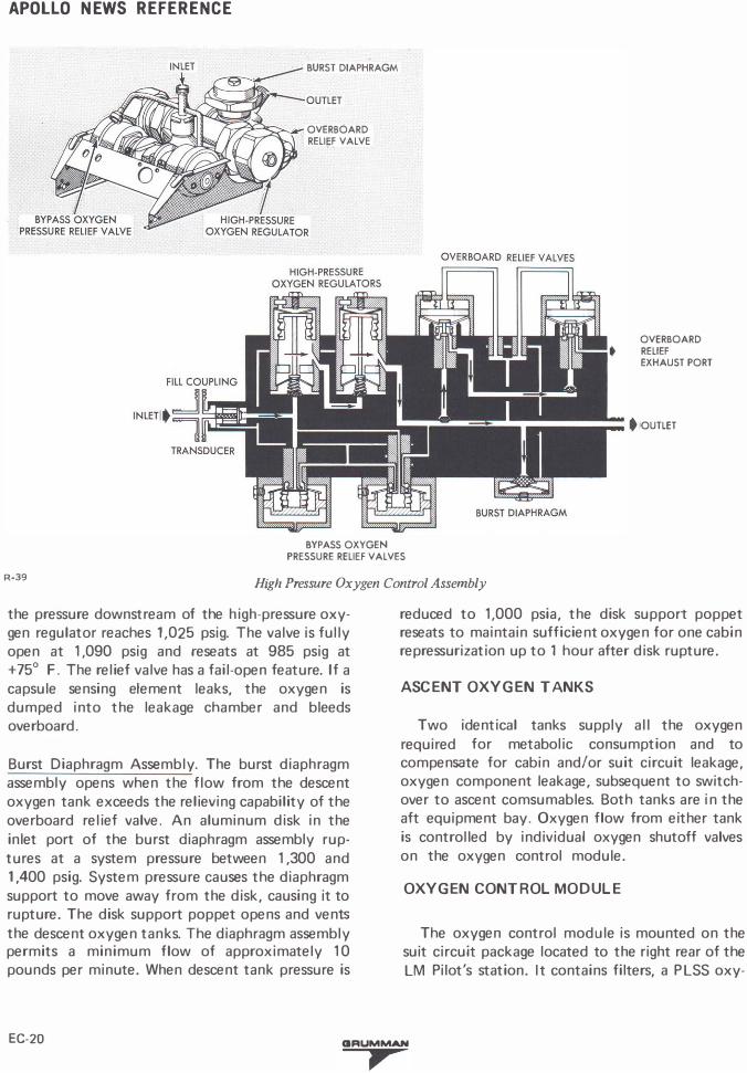
The major components of the high-pressure oxygen control assembly are a high-pressure oxygen regulator, a bypass oxygen pressure relief valve, an overboard relief valve, and a burst diaphragm assembly.
High-Pressure Oxygen Regulator. The internally series redundant high-pressure oxygen regulator receives high-pressure oxygen from the descent oxygen tanks and regulates the pressure to 875 to 960 psia. If the upstream (primary) regulator sensor fails, the valve fails open, permitting the downstream (secondary) regulator to control outlet pressure. Descent oxygen that enters the regulator is sensed by the primary sensor. As the pressure builds up inside the sensor, it expands and allows the primary valve poppet to move towards its seat, regulating the outlet pressure to the secondary regulator. The secondary regulator operates the same as the primary regulator.
Bypass Oxygen Pressure Relief Valve. The bypass oxygen .Pressure relief valve protects the descent oxygen tanks against overpressurization by bypass-ing the high-pressure oxygen regulator. The valve is designed to fail in the open condition if it malfunctions. If the relief valve malfunctions (bellows ruptures), the valve is automatically placed in the failed-open condition, bypassing the oxygen to a secondary (identical) relief valve.
Overboard Relief Valve. The series-redundant overboard relief valve vents oxygen to ambient when
CIRUMMAN EC-19
,
APOLLO NEWS REFERENCE
BURST DIAPHRAGM
OVERBOARD • RELI�F VALVE
OVERBOARD RELIEF EXHAUST PORT
• OUTLET
BYPASS OXYGEN PRESSURE RELIEF VALVES
R-39 High Pressure Oxygen Control Assembly
the pressure downstream of the high-pressure oxygen regulator reaches 1,025 psig. The valve is fully open at 1 ,090 psig and reseats at 985 psig at +75° F . The relief valve has a fail-open feature. If a capsule sensing element leaks, the oxygen is dumped into the leakage chamber and bleeds overboard.
Burst Diaphragm Assembly. The burst diaphragm assembly opens when the flow from the descent oxygen tank exceeds the relieving capability of the overboard relief valve. An aluminum disk in the inlet port of the burst diaphragm assembly ruptures at a system pressure between 1 ,300 and 1,400 psig. System pressure causes the diaphragm support to move away from the disk, causing it to rupture. The disk support poppet opens and vents the descent oxygen tanks. The diaphragm assembly permits a minimum flow of approximately 1 0 pounds per minute. When descent tank pressure is
reduced to 1,000 psia, the disk support poppet reseats to maintain sufficient oxygen for one cabin repressurization up to 1 hour after disk rupture.
ASCENT OXYGEN TANKS
Two identical tanks supply all the oxygen required for metabolic consumption and to compensate for cabin and/or suit circuit leakage, oxygen component leakage, subsequent to switchover to ascent comsumables. Both tanks are in the aft equipment bay. Oxygen flow from either tank is controlled by individual oxygen shutoff valves on the oxygen control module.
OXYGEN CONTROL MODULE
The oxygen control module is mounted on the suit circuit package located to the right rear of the LM Pilot's station. It contains filters, a PLSS oxy-
EC-20 GRUMMAN
,

APOLLO NEWS REFERENCE
gen shutoff valve, descent and ascent oxygen shutoff valves, oxygen demand regulators, and a cabin repressurization and emergency oxygen valve. An interlock prevents opening the ascent oxygen shutoff valves until the descent oxygen shutoff valve is closed. Filters at the inlets to the oxygen control module and the PLSS disconnect remove particulate matter from the oxygen . Filtering capability is 1 8 microns nominal and 40 microns absolute.
PLSS and Oxygen Tank Shutoff Valves. Four positive-action, manually operated shutoff valves control oxygen flow into the oxygen control module. Rotating the valve handle to the open position displaces a spring-loaded seal. The valves have detents in the open and closed positions; mechanical stops on the handle prevent overtravel.
Oxygen Demand Regulators. Two, parallel oxygen demand regulators regulate oxygen from the tanks to the suit circuit. Both regulators are manually controlled by individual four-position selector handles. Suit circuit pressure is fed back to an aneroid bellows that actuates a poppet. Rotating the valve handle to cabin or egress position changes the spring force acting on the poppet and establishes two outlet pressure levels. Selecting the direct 02 position, fully opens the valve. With an upstream pressure of 900 psia and a temperature of + 70° F, one regulator can flow approximately 7.0 pounds per hour into the suit c ircuit. In the closed position, an auxiliary poppet stops all flow through the regulator. Each regulator has valve position indicator (VPI) switches, and two functional switches that control electrical circuits in the ECS.
Cabin Repressurization and Emergency Oxygen Valve. The cabin repressurization and emergency oxygen valve is a solenoid-operated valve with manual override. It is used to repressurize the cabin after a deliberate decompression and provides an emergency flow of oxygen if the cabin is punctured. If the cabin is punctured and the diameter of the hole does not exceed 0.5 inch, the valve can maintain cabin pressure at 3.5 psia for at least 2 minutes, allowing the astronauts to return to a closed-suit environment. The cabin repressurization
and emergency oxygen valve is controlled by a three-position handle on the oxygen control module.
When the automatic pos1t10n is selected, valve operation is controlled by the solenoid, which is actuated by the cabin pressure switch. If cabin pressure drops below normal, the cabin pressure switch energizes the solenoid. This moves the valve yoke to open the in let valve and permits oxygen from the oxygen manifold to flow through the valve into the cabin. If cabin pressure increases to normal, the cabin pressure switch deenergizes the solenoid and spring action closes the valve. When supplied by the descent GOX tanks, flow is 4 pounds per minute maximum; when supplied by the ascent tanks, 8 pounds per minute at 500 psia. When the manual position is selected, the handle shaft actuates a cam that moves the yoke to open the inlet valve and establish flow to the cabin. In the close position an auxiliary poppet is forced onto its seat, shutting off the flow.
CABIN R E LI E F AND DUMP VALVES
A cabin relief and dump valve is installed in each hatch. The valve is a differential-pressure, servoactuated poppet valve that prevents cabin overpressurization and permits manual dumping of cabin pressure. Each valve is controlled with either of two handles : one, inside the cabin; the other, outside. The inside handles can be used to select three positions (dump, automatic, or closed). The outside handles have only a dump position.
Normally, the cabin relief and dump valves are set to the automatic position. In this position, the valves are operated by the servo valve. When the cabin-to-ambient pressure differential reaches approximately 5.4 psi, oxygen is vented overboard and cabin pressure is reduced to an acceptable value. When the pressure differential is 5.8 psi, one fully open dump valve can dump 1 1 . 1 pounds of oxygen per minute overboard. When the valve handle inside the cabin is set to the automatic position, the valve can be opened manually from outside.
CIFIUMMAN EC-21
,

APOLLO NEWS REFERENCE
HANDLE
R-40
Cabin Relief and Dump Valve
OVERBOARD - -&BiN" Sio"E
Setting the internal handle to the dump position unseats the poppet . The valve can dump cabin pressure from 5.0 to 0.08 psia in 1 80 seconds without cabin oxygen inflow. Setting the handle to the closed position prevents the valve from opening at normal pressures, if the servo valve fails.
CABIN PR ESSU R E SWITCH
The cabin pressure switch monitors cabin pressure and enables electrical signals to control related ECS functions. The switch is an absolute-pressure device that consists of three separate hermetically sealed microswitch capsules. The capsules are set to cause switch closure when cabin pressure decays to 3.7 to 4.45 psia during pressurized-cabin operation.
If this occurs with either oxygen demand regulator in cabin mode, the suit gas diverter valve closes, the cabin repressurization and emergency oxygen valve opens, and the cabin warning light goes on. Increasing cabin pressure to 4.40 to 5.0 psia opens the cabin pressure switch circuits, closes the cabin repressurization and emergency oxygen valve, and deenergizes the cabin warning light.
WATER MANAGEMENT SECTION
DESCENT STAGE WATER TAN KS
The descent stage water tanks are aluminum tanks with an internally mounted standpipe and bladder. The bladder contains the water; the space between the bladder is charged with nitrogen according to a schedule dependent on the load (48.2 psia maximum at +80° F ) . The nitrogen forces the water out of the bladder through the standpipe and into the system. The tank outlets are connected to the water control module. Water from the descent water tanks is routed through the water tank select valve by setting it to the descent position.
Descent Water Valve. The descent water ( D ES H20 ) valve is a manually operated, poppet-type shutoff valve. The valve has open and c losed positions. In the open position, the valve provides high-pressure water flow from the descent tanks to the water dispenser.
ASCENT STAG E WATER TANKS
The ascent stage water tanks are in the overhead unpressurized portion of the cabin. They are similar to the descent stage water tank, but are smaller. An initial nitrogen charge of 48.2 psia at +80° F is used in each tank. The tank outlets are connected to the water control module. Water from the ascent water tanks is routed through the water tank selector valve by setting it to the ascent position.
EC-22 IIRUMMAN
,

APOLLO NEWS REFERENCE
Ascent Water Valve. The ascent water valve, at the top of the water control module, is a manually operated, poppet-type shutoff valve. The valve has open and closed positions. In the open position, the valve provides high-pressure water flow from the ascent tank to the water dispenser.
WATER CONTROL MODULE
The manual controls of the WMS are grouped together on the water control module. The module consists of check valves, shutoff valves, a water tank selector valve, and water pressure regulators. Each water tank outlet is connected to the module, which diverts the water to selected flow paths.
Check Valves. There are five check valves in the water control module : one in each tank feed line, and one in each discharge line from the ARS water separators. The check valves prevent water flow from the module to the water tanks and water separators.
Water Tank Selector Valve. The water tank selector valve is a manually operated, three-position, twospool valve. The two spools (primary and secondary), linked to the valve handle, rearrange the internal ports to establish proper flow paths. The valve has descent, ascent, and secondary positions. In the descent position, the primary spool establishes a flow path between the descent water
PRIMARY
WATER COOLANT' ISOLATION VALVE (CAPPED PORT)
LEGEND
� DESCENT WATER
� ASCENT WATER WATER FROM SEPARATORS
PRIMARY SPOOL
DESCENT ASCENT
DESCENT POSITION
R-41
PRIM EVAP FLOW NO. 1
SECONDARY SPOOL
TANK TANKS
WATER IN FROM SEPARATORS
ASCENT POSITION
Water Tank Selector Valve
GRUMMAN
,
PRIM EVAP FLOW NO. 2 SEC EVAP FLOW
SEC POSITION
EC-23

APOLLO NEWS REFERENCE
tanks and the primary water manifold. In the ascent position, the primary spool establishes a flow path between the ascent tanks and the primary water manifold. When the valve is in the secondary position, flow is diverted from the ARS separator to the secondary manifold and water is routed from the ascent water tanks to the secondary manifold.
Water Pressure Regulators. Fouli water pressure regulators are in the WMS. Two are in series in the primary manifold, one in the secondary manifold, and one is located external to the water module in the water pressure regulator module. The regulators contain a spring-loaded diaphragm that senses the differential between ARS reference pressure and the downstream water pressure. The diaphragm moves a balanced lever attached to a metering poppet. The water discharge pressure is maintained at 0.4 to 1 .0 psi above the reference pressure.
Primary Evaporator Flow Valve No. 1 . The primary evaporator flow No. 1 valve is a manually operated, poppet-type shutoff valve. It has open and closed positions. In the open position, the valve allows flow from the ascent or descent water tanks, through the primary regulators, to the primary sublimator.
Primary Evaporator Flow Valve No. 2. The primary evaporator flow No. 2 valve is a manually operated, poppet-type shutoff valve. It has open and closed positions. In the open position, the valve acts as a backup to the primary evaporator flow valve to provide ascent tank water from the secondary water manifold to the primary sublimator.
Secondary Evaporator Flow Valve. The secondary evaporator flow valve is a manually operated, poppet-type shutoff valve. It has open and close positions. The valve controls water flow from the secondary water manifold to the secondary sublimator and to the suit circuit sublimator.
Water Pressure Regulator Module. The water pressure regulator module consists of a pressure regulator and a manifold. The module is located in the secondary water circuit, downstream and in series with the secondary water pressure regulator in the water control module.
HEAT TR ANSPORT SECTION
COOLANT ACCUMU LATOR
There are two accumulators, one in the primary loop and an identical one in the secondary loop. The coolant accumulator consists of a two-piece aluminum cylinder that contains a movable springloaded piston bonded to a diaphragm. The fluid side contains approximately 46 cubic inches of fluid under pressure. The pressure varies, directly with fluid level, from 5.6 psia at 5% level to 8.0 psia at 80% level. The accumulator maintains a head of pressure on the glycol pump inlets to prevent pump cavitation and replaces coolant lost through subsystem leakage . The piston moves in response to volumetric changes caused by temperature variations in the primary loop or by leakage. The accumulator spring side is vented to space.
The accumulator has a low-level sensor with a switch that trips when only 1 0 ± 5% of the coolant volume remains. The switch is mounted on top of the accumulator. A tube extending from the top of the accumulator, houses a rod attached to the piston. The switch provides a telemetry signal.
PRIMARY COOLANT F I LT E R
The primary coolant filter has a filtering capability of 35 microns. It has an integral pressure relief bypass feature that opens at 0.27 to 0.4 psid to maintain coolant flow to the pumps if the filter becomes clogged.
COOLANT PUMP
The three coolant pumps are identical . Two pumps are connected in the primary loop; the third pump, in the secondary loop. The pumps are of the sliding-vane, positive-displacement type; they are driven by 28-volt d-e brushless motors. The motors are of wet or submerged design and are cooled by
EC-24 CIRUMMAN
,

APOLLO NEWS REFERENCE
the recirculating coolant. The pump speeds will vary with changes in coolant temperatures and pump input voltages. As a resu lt, system coolant flow rates may vary from 4.2 to 5.4 pounds per hour causing primary pump pressure rise of 1 2 to 25 psi and secondary pump pressure rise of 8 to 1 8 psi.
SUIT TEMPERATUR E CONTROL VALVE
The suit temperature control valve is a manually operated diverter valve. The amount of warm coolant flowing through the suit circuit regenerative heat exchanger is regulated by the handle, which can be turned from hot to cold.
SUBLIMATORS
The porous-plate-type sublimators (one in the primary loop and another in the secondary loop) are identical, except that the primary sublimator has a larger capacity. Each sublimator has a coolant inlet and outlet, a water inlet, and a steam outlet. Water makes one pass through the unit; coolant makes six passes through the primary sublimator and four passes through the secondary sublimator. For proper sublimator operation, water pressure must exceed 4.0 psia, but be less than 6.5 psia. The water pressure must also be less than the suit circuit static pressure plus the head pressure from the water separators to the sublimator.
The unit rejects heat to space by sublimation of ice. Water from the WMS flows through the water passages, into the porous plates, and is exposed to space environment. The vacuum pressure is below the triple point of water; this causes an ice layer to develop within the pores and on the inner surface of the plates. As the hot coolant flows through the sublimator passages, heat transfers from the coolant to the water and to the ice layer. The ice sublimates from the solid state to steam without passing through a liquid state, rejecting its heat
load overboard through a duct. The thickness of the ice layer varies with the heat load imposed on the sublimator, resulting in a regulated output temperature over a range of input temperatures.
COLD PLATES AND RAILS
E lectronic equipment that requires active temperature control is cooled by cold plates and cold rails. Most flat cold plates are installed between electronic equipment and the LM structure in a manner that minimizes heat transfer from the structure to the coolant, to avoid a reduction of the coolant cooling capacity. The surrounding structure and equipment may have a temperature range of 0° to + 1 60° F . The remaining flat cold plates are installed directly on the electronic equipment without making contact with the LM structure. Cold rails are also structural members and are used in the aft equipment bay in the descent stage for the DSEA. The IMU has an integral cooling circuit. Cold plates and cold rails for equipment essential for mission abort have two independent coolant passages, one for the primary loop and one for the secondary loop.
The flat cold plates are brazed assemblies with inlet and outlet fittings. The coolant flows between two parallel sheets, which are connected by fins for increased heat transfer and structural strength. The internal fin arrangement of these cold plates ensures sufficient flow distribution.
The cold rails are channel-and-tube-type extrusions; the tubular part forms the inside center of the channel. The tube has fins and, at the ends, coolant inlet and outlet fittings. The cold rails are installed in parallel arrangement, with equal space between the rails to accommodate equipment designed for mounting on cold rails. Each cold rail (except the first and the last one) cools two adjacent rows of equipment.
CIRUMMAN EC-25 ,


![CCNP BCMSN Quick Reference Sheets - Lagout Quick Reference... · CCNP BCMSN Quick Reference Sheets Exam 642-812 ... [ 4 ] CCNP BCMSN Quick Reference Sheets. ... switch would be used](https://static.fdocuments.net/doc/165x107/5a7a6ec87f8b9a05538dccf5/ccnp-bcmsn-quick-reference-sheets-lagout-quick-referenceccnp-bcmsn-quick-reference.jpg)