ENVIRONMENT GUIDELINES FOR SIZING BAGHOUSE FILTERS … · environment guidelines for sizing...
8
ENVIRONMENT GUIDELINES FOR SIZING BAGHOUSE FILTERS USED FOR FERROALLOY AND SILICON METAL FURNACE APPLICATIONS 1 Francis D. Fereday, 2 Louis Raath, 3 Benoit de Montard 1 W. L. Gore and Associates, Inc., Elkton, Maryland, USA, e-mail: [email protected] 2 W. L. Gore and Associates, Inc., Elkton, Maryland, USA, e-mail: [email protected] 3 W. L. Gore & Associes S.A.R.L., Paris France, e-mail: [email protected] ABSTRACT Baghouse filters are commonly used to capture emissions from ferroalloy and silicon metal furnaces. In order to avoid operational problems careful consideration must be given to the baghouse sizing, equipment selection, and maintenance procedures. The affect of the following cooling methods on the baghouse are examined • Dilution or Tempering Air. • Evaporative. • Radiant/Convective (forced air vs. natural). Filter media selection and filter bag cleaning methods are reviewed as well as baghouse design considerations. Baghouse filtration media selection depends on the following factors: - Cleaning style-pulse, shaker, or reverse air - Gas Temperature - Gas Composition (moisture and acid gases) - T)tpe of Dust (fine or larger particulate) - Required Filtration Efficiency - Dust generation rate - Cost The operation of positive pressure and negative pressure baghouse designs are reviewed. In addition to theoretical considerations actual baghouse operating results are presented. 1. INTRODUCTION Baghouse filters are commonly used to capture emissions from ferroalloy and silicon metal furnaces. In order to avoid operational problems careful consideration must be given to the baghouse sizing, equipment selection and maintenance procedures. Ferroalloys and silicon metal are produced in electric arc furnaces that are specially designed for smelting purposes. These furnaces are referred to as Submerged Arc Furnaces (SAF's). In the SAF electric power heats the raw materials and provides the energy needed to smelt the ore to a metallic state. These furnaces are termed submerged arc since the electrodes are buried deep in the furnace burden and the reduction takes place near the tip of the electrode. These processes produce copious amounts of heat and fume that must be captured before escaping to the atmosphere. The environmental regulatory agencies in most countries strictly regulate emissions from these operations. The thirteenth International Ferroalloys Congress Efficient technologies in ferroalloy industry 1015 June 9 - 13, 2013 Almaty, Kazakhstan
Transcript of ENVIRONMENT GUIDELINES FOR SIZING BAGHOUSE FILTERS … · environment guidelines for sizing...
ENVIRONMENT
GUIDELINES FOR SIZING BAGHOUSE FILTERS USED FOR FERROALLOY AND SILICON METAL FURNACE APPLICATIONS
1Francis D. Fereday, 2Louis Raath, 3Benoit de Montard
1W. L. Gore and Associates, Inc., Elkton, Maryland, USA, e-mail: [email protected] 2W. L. Gore and Associates, Inc., Elkton, Maryland, USA, e-mail: [email protected]
3W. L. Gore & Associes S.A.R.L., Paris France, e-mail: [email protected]
ABSTRACT
Baghouse filters are commonly used to capture emissions from ferroalloy and silicon metal furnaces. In order to avoid operational problems careful consideration must be given to the baghouse sizing, equipment selection, and maintenance procedures.
The affect of the following cooling methods on the baghouse are examined • Dilution or Tempering Air. • Evaporative. • Radiant/Convective (forced air vs. natural). Filter media selection and filter bag cleaning methods are reviewed as well as baghouse
design considerations. Baghouse filtration media selection depends on the following factors: - Cleaning style-pulse, shaker, or reverse air - Gas Temperature - Gas Composition (moisture and acid gases) - T)tpe of Dust (fine or larger particulate) - Required Filtration Efficiency - Dust generation rate - Cost The operation of positive pressure and negative pressure baghouse designs are reviewed. In addition to theoretical considerations actual baghouse operating results are presented.
1. INTRODUCTION
Baghouse filters are commonly used to capture emissions from ferroalloy and silicon metal furnaces. In order to avoid operational problems careful consideration must be given to the baghouse sizing, equipment selection and maintenance procedures.
Ferroalloys and silicon metal are produced in electric arc furnaces that are specially designed for smelting purposes.
These furnaces are referred to as Submerged Arc Furnaces (SAF's). In the SAF electric power heats the raw materials and provides the energy needed to smelt the ore to a metallic state. These furnaces are termed submerged arc since the electrodes are buried deep in the furnace burden and the reduction takes place near the tip of the electrode.
These processes produce copious amounts of heat and fume that must be captured before escaping to the atmosphere.
The environmental regulatory agencies in most countries strictly regulate emissions from these operations.
The thirteenth International Ferroalloys Congress Efficient technologies in ferroalloy industry
1015
June 9 - 13, 2013 Almaty, Kazakhstan

ENVIRONMENT
2. FURNACE OVERVIEW
The furnace hood design and process conditions are critical to the air pollution control equipment sizing. Closed furnaces are often used to produce alloys with a low gas generation rate. The furnace off gas may have a high percentage of CO that can be captured and used somewhere in the process. High carbon ferromanganese (FeMn) and ferrosilicon 50% or less in silicon content may be produced in closed furnaces. Ferrosilicon with more than 50% silicon content and silicon metal are produced in open or semi open furnaces due to the high gas generation rate from these processes. The focus of this paper is on open and semi open furnaces that are operated open to the atmosphere.
3. SILICON SMELTING PROCESS
Metallurgical silicon is produced by the carbothermic reduction of quartz in an arc furnace according to the following overall reaction [1]:
Si02 + 2C ~ Si +2CO (1)
For this reaction, 100 % carbon theory is defined as two moles of fixed carbon per mole of silicon dioxide. In practice, however, the above reaction does not represent the entire picture. Several side reactions are known to occur, the principal ones are as follows:
SiC Forming Reaction: Si02, + 3C ~ SiC + 2CO (2)
SiO Forming Reaction Si02 + C ~ SiO + CO (3)
For the formation of silicon, the carbon requirements have to be precise. Excess carbon results in SiC formation. On the other hand insufficient carbon results in excessive SiO formation which is lost in the off-gas [2].
As the raw materials are consumed, a cave is formed around the electrode, and the top of the charge bed becomes a hard crust. This crust must be physically stoked (rabled) from the top in order for additional raw materials to be fed [ 1]. The energy required for the process is provided by the electric arc between the electrodes.
4. SYSTEM SIZING CRITERIA
The heat content and the gas volume removed through the furnace hood must be enough to prevent the heat and fumes generated by the smelting process from spilling from the hood. The temperature under the hood has to be low enough to avoid damage to the hood or to the flexible electrical connections to the electrode columns; particular care must be taken if the flexible connections are under the hood.
Two benchmarks are used for system sizing. The ratio of heat in the off gas to the furnace power input. This is often referred to as the X
factor. This can be expressed the following way:
"X" = Q (off gas) /kW (furnace)
The thirteenth International Ferroalloys Congress Efficient technologies in ferroalloy industry
1016
(4)
June 9 - 13, 2013 Almaty, Kazakhstan
ENVIRONMENT
Where Q = m · C(p) · [T(hood exhaust) - T( ambient)]
T (hood rise)= [T(hood exhaust) -T(ambient)]
m =mass flow of the gas extracted from the hood
(6)
(7)
(8)
The ratio of hood exhaust flow expressed in Nm3 /h to the furnace power input in kW. This can be referred to as the Specific Evacuation (SE) from the hood.
SE= (Nm3/h)/kW(fumace) (9)
Equations 1through9 above show the inverse relationship between the mass flow through the hood (SE) and the temperature rise through the hood [T (hood rise)].
A high volume/low temperature rise approach would be used with the open furnace or if the flexible connections are below the hood The semi open furnace may allow a lower gas volume, but the downstream system must cater to a higher gas temperature from the hood.
5. INFLUENCES ON THE X FACTOR (OFF GAS HEAT/FURNACE POWER)
5. 1. The energy efficiency of the process and silicon recovery
Higher power usage (kWh/ton) indicates that more of the raw material charge is lost. In the silicon alloy case this is mostly silica fume. Decreasing energy efficiency and decreasing silicon recovery point to higher Si02 fume losses from the charge mix. SiO emerges from the furnace charge material and burns to Si02 under the hood.
The silicon monoxide reaction [see (3) above] is favored by a deficiency in carbon in the charge mix and is the main cause of the loss of silicon during smelting [ 1]. Robiette refers to this situation as ''under carbonized".
In summary decreased energy efficiency and silicon recovery has these two detrimental effects on the air pollution control system:
• Increased silica fume going into the gas stream. • Increased heat generated under the hood (an increase in the X factor).
5. 2. The ratio of fixed carbon to the Si02 charged to the furnace
At a 100% stoichiometric ratio (also referred to as 100% carbon theory) a quantity of 0.4 kg of carbon would be used for every kg of Si02.
The silicon carbide reaction [see (2) above] produces SiC and is well known to occur when accretions of SiC are found in the cooler parts of the furnace. The reaction is favored by an excess of carbon in the charge. Robiette [2] refers to this situation as the furnace being "over carbonized" or "over coked" [2].
The excess carbon increases the amount of CO escaping from the furnace burden. That CO burns to C02 under the hood and leads to an increase in the X factor.
5.3. The ratio of volatile matter (VM) in the charge mix to the Si02 charged
The commonly used carbon reducing agents (charcoal, coke, and coal), and the wood chips contain volatile matter. The choice of reducing agents depends on raw material availability and the desired purity of the final product. Irrespective of the carbon source, there is a loss of volatile
The thirteenth International Ferroalloys Congress Efficient technologies in ferroalloy industry
1017
June 9 - 13, 2013 Almaty, Kazakhstan
ENVIRONMENT
material when the carbon is heated. The carbon left after the heating process is referred to as "fixed carbon". The fixed carbon in the feed recipe is typically specified to be 90-98% carbon theory [1].
Generally, there is an indirect relationship between the cost of the reducing agent and the amount of volatile matter. For example, coke is relatively expensive when compared to coal and Low volatile coal is more expensive than high volatile coal.
In summary, one can expect an increase in the X factor as the amount of volatile matter in the charge mix increases.
In a case study of a ferrosilicon furnace at Elkem Salten, Kamfjord, et al [3] reported the energy content of the off gas from a 10 MW furnace producing 75% FeSi to be 11.14 kW yielding anXratioofl.11 (11.14/10).
Hjartarson, et al [ 4] found 45.5 MW in the off gas from a 75% FeSi furnace at Elkem Iceland with a furnace electrical input= 39.7 MW. In this case X = 1.15. The reported silicon recovery was 89%.
Typical X Factors • Si-Metal X = 1.3 to 1.5 • 75% FeSi X = 1.1 to 1.3 • SiMn X = 0.9 to 1.1 • 50% FeSi X = 0.8 to 1.0 • FeCr X = 0.6 to 0.8
6. DILUTION AIR COOLING COMPARED TO RADIANT/CONVECTIVE COOLING
For a comparison of dilution air to radiant/convective cooling consider the following example case. Furnace Power (MW) Product x Ambient (° C)
25 Si Metal
1.35 20
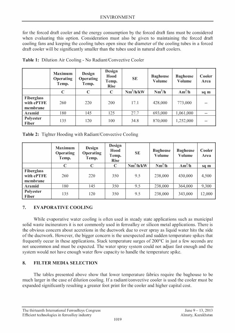
Table 1 shows the increase in gas volume if lower temperature filter media is used. Using Aramid fabric requires a 37 % increase in gas volume to maintain a safe baghouse operating temperature. Table 2 shows the significant reduction in baghouse gas volume when a cooler is used. In the example case there is a 45% reduction in baghouse gas volume if the cooler is used. There will also be a significant reduction in the capital cost for baghouse, the air moving equipment, ductwork, and any cyclones used to remove heavy particles (mostly unburned carbon) from the gas stream.
There is some additional pressure loss across a cooler, but a well designed cooler creates no more than 0.5 kPa in pressure loss. The energy to overcome the additional pressure loss will be more than offset by the fan energy savings owing to the lower gas volume and lower filter bag replacement cost since there would be fewer filter bags. The cooler also protects the baghouse when the stack temperature surges due to gas blowing or stoking. The heat sink effect of the mass of the metal in the cooler tubes buffers the temperature spike.
Table 2 shows the substantial reduction in the cooler area by using higher temperature filter media. In the demonstration case the cooler would need more than twice as much surface area to cool the gas to 145°C as compared to 220°C.
The cooling surface areas shown in table 2 are based on natural radiation and convection from the surface of the cooling tube. One can also consider a forced draft cooler. Depending on the design the surface cooling area could be reduced considerably; however, the additional capital cost
The thirteenth International Ferroalloys Congress Efficient technologies in ferroalloy industry
1018
June 9 - 13, 2013 Almaty, Kazakhstan
ENVIRONMENT
for the forced draft cooler and the energy consumption by the forced draft fans must be considered when evaluating this option. Consideration must also be given to maintaining the forced draft cooling fans and keeping the cooling tubes open since the diameter of the cooling tubes in a forced draft cooler will be significantly smaller than the tubes used in natural draft coolers.
Table 1: Dilution Air Cooling - No Radiant/Convective Cooler
Maximum Design Design Hood Baghouse Baghouse Cooler Operating Operating Temp. SE Volume Volume Area
Temp. Temp. Rise
c c c Nm3/h/kW Nm3/h Am3/h sqm FI"berglass withePTFE 260 220 200 17.1 428,000 773,000 --membrane Ar amid 180 145 125 27.7 693,000 1,061,000 --Polyester
135 120 100 34.8 870,000 1,252,000 --FI"ber
Table 2: Tighter Hooding with Radiant/Convective Cooling
Maximum Design Design Hood Baghouse Baghouse Cooler Operating Operating Temp. SE Volume Volume Area
Temp. Temp. Rise
c c c Nm3/h/kW Nm3/h Am3/h SQ m FI"berglass withePTFE 260 220 350 9.5 238,000 430,000 4,500 membrane Ar amid 180 145 350 9.5 238,000 364,000 9,300 Polyester
135 120 350 9.5 238,000 343,000 12,000 FI"ber
7. EVAPORATIVE COOLING
While evaporative water cooling is often used in steady state applications such as municipal solid waste incinerators it is not commonly used in ferroalloy or silicon metal applications. There is the obvious concern about accretions in the ductwork due to over spray as liquid water hits the side of the ductwork. However, the bigger concern is the unexpected and sudden temperature spikes that frequently occur in these applications. Stack temperature surges of 200°C in just a few seconds are not uncommon and must be expected. The water spray system could not adjust fast enough and the system would not have enough water flow capacity to handle the temperature spike.
8. FILTER MEDIA SELECTION
The tables presented above show that lower temperature fabrics require the baghouse to be much larger in the case of dilution cooling. If a radiant/convective cooler is used the cooler must be expanded significantly resulting a greater foot print for the cooler and higher capital cost.
The thirteenth International Ferroalloys Congress Efficient technologies in ferroalloy industry
1019
June 9 - 13, 2013 Almaty, Kazakhstan
ENVIRONMENT
The lower temperature fabrics (Aramid and polyester) are not immune to spark damage; however, fiberglass filters have consistently proven to be immune to spark damage. Sparks are defined as light incandescent particles carried in the gas stream.
Aramid and polyester are subject to moist heat hydrolysis and acid attack. This is an important consideration since sul:furic acid formation may occur when the furnace load and gas temperature decrease. However, ePTFE membrane glass bags show no damage from acid attack in ferroalloy and silicon metal applications. PTFE and fiberglass are not subject to hydrolysis. Therefore, most systems today use fiberglass filter media. To enhance the effectiveness of the filter media many systems use an expanded PTFE (ePTFE) membrane on the dust collection surface of the bag. Elverd, et al [5] described the reduction in filter drag in a FeSi operation in the USA. Changing to ePTFE filter bags reduced the filter drag by 75 %. Filter drag is defined as the pressure loss across the fabric/divided by the apparent filter speed (air to cloth ratio).
This change to ePTFE membrane fiberglass filter bags allowed a 30 % reduction in the total number of filter bags, a 28 % increase in gas flow, lower differential pressure, and longer bag life.
In reverse air baghouses the premium for membrane bags may be a factor of the two, but the additional cost is more than off set by the demonstrated reduction in filter drag.
Filtration efficiency is an important consideration in the selection of the filter media. Regulatory agencies in the industrialized countries have established strict emissions limits on emissions from ferroalloy and silicon metal applications. Given the proper design and with reliable maintenance procedures baghouses equipped with ePTFE membrane fiberglass filter bags are complying with the strict emission limits established for plants in the USA and Europe.
An extensive study conducted at the Elkem Fiskaa plant showed plant particulate emissions were less than 1.0 mg/Nm3 from a reverse air baghouse with ePTFE membrane :fiberglass filter bags. The baghouse :filtered the off gas from two silicon metal furnaces (22 MW and 12.5 MW). Stack emissions averaged 0.2 kg/metric ton of silicon metal produced. Energy usage averaged 12 MWh per ton of metal produced [ 6].
9. BAGHOUSE TYPE - PULSE JET, SHAKER OR REVERSE AIR CLEANING
Person [7] described actual results with shaker and conventional :fiberglass bags. Shaker baghouse are rarely used today or even considered for new applications due to the high cost of maintaining the shakers and the limitation on media that can be used with shaker cleaning. Most shaker mechanisms used in ferroalloy and silicon metal applications are not suitable for fiberglass filter media. That means Aramid fiber would have to be used; however, Aramid fiber requires a much larger baghouse or a greatly expanded cooling surface area.
Person also describes the filter drag in a shaker baghouse equipped with Aramid filter media. This value is more than two times higher than is the case as with reverse air baghouses that use ePTFE membrane filter bags referred to by Elverd.
Pulse jet baghouses that use a burst of compressed air to clean the bags are also used in some applications. In these type collectors the dust accwnulates on the outside of the filter bag.
Considering the low density and low settling velocity of the silica fume generated by FeSi and Si smelting :furnaces the filter velocity (air to cloth ratio) has to be kept low, and bags longer than 4.2 meters must be avoided. Careful consideration must be given to the spacing between the bags, the spacing between the bags and the internal walls. Horizontal stiffeners between the filter bags must be absolutely avoided.
Bag life in pulse collectors is likely to be shorter than is the case with reverse air baghouses. In case of pulse jet baghouses using fiberglass filter media the pulse pressure should be limited to low value (3 bar or less). Most baghouses used in ferrosilicon and silicon metal applications are of the reverse air baghouse type. Like shaker baghouses the dust collects on the inside of the bags.
The thirteenth International Ferroalloys Congress Efficient technologies in ferroalloy industry
1020
June 9 - 13, 2013 Almaty, Kazakhstan
ENVIRONMENT
For the reasons explained above (less dilution air or cooling surface) most of these reverse air baghouses use fiberglass filter media. Due to the high percentage of submicron size particulate generated by ferroalloy and silicon metal operations the fume is difficult to clean from the bag collection surface resulting in high pressure drop across the filter bags.
To overcome this problem the performance of reverse air baghouses has been enhanced by the use of the ePTFE membrane with a fiberglass backing material. The membrane improves the dust release from the surface of the bags and provides a highly efficient filtering of extremely fine particulate. In addition to the paper by Elverd, the improved performance with the use of the ePTFE membrane has been reported by Eriksen [8] and by Stordahl [9].
10. POSITIVE VERSUS NEGATIVE PRESSURE BAGHOUSE DESIGN
10.1. Positive Pressure
Traditionally the shaker and reverse air baghouses have induced draft fans on the dirty side of the baghouse; therefore, the baghouse is at positive pressure to the atmosphere. The cleaned air exits the baghouse through a continuous ventilator at the top ridge of the baghouse. In most cases the perimeter area around the tubesheets at the bottom of the baghouse is covered with bar grating. This allows cooling air to enter the baghouse from below and facilitates inspection and routine maintenance at the bag bottom (tube sheet) level. The filtered air rises through the baghouse due to the gravity effect of the hot air and exits through the ridge ventilator. Since this arrangement makes sampling of the exhaust gas more difficult regulatory agencies are challenging this gas discharge method, and are encouraging construction of a common discharge stack.
Although the use of a stack simplifies the sampling procedure, in the case of a positive pressure baghouse it may seriously deter the inspection and maintenance that has to be done inside the baghouse. Most positive pressure baghouses do not have outlet dampers so there is no way to isolate the gas from an on line compartment from an off line compartment. In most cases this means the interior of the baghouse will be under a slight positive pressure due to the stack and can only be entered when the furnace is shut down due to the excessive temperature, CO levels, and high sulfur levels.
10.2. Negative Pressure
The induced draft fans can be placed on the clean side of the reverse air baghouse with a stack used for the gas discharge. The baghouse is furnished with inlet and outlet dampers, so individual compartments can be serviced while keeping the other compartment on line. There is no need to shut down the furnace for routine inspection and maintenance. The improvement in serviceability must be weighed against the higher capital cost since the housing must be reinforced against the suction pressure that the ID fims will produce on the housing.
Traditionally, pulse jet baghouses are under negative pressure and use a stack discharge. This makes sampling easier, but must be weighed against the shorter bag life and pressure loss that can be expected with these type baghouses.
REFERENCES
[1] Dosai, Vishu, Collection and Conversion of Silicon Furnace Waste Gas into Higher Value Products, Phase III 6 MW Pilot Plant DC Closed Furnace Technology Final Report, January 1995.
[2] Robiette, A.G.E., Charles Griffin and Company, London, 1973.
The thirteenth International Ferroalloys Congress Efficient technologies in ferroalloy industry
1021
June 9 - 13, 2013 Almaty, Kazakhstan
ENVIRONMENT
[3] Kamfjord, N.E., Myrhaug, E.H., Tveit, Wittgens, B., "Energy Balance of a 45 MW (Ferro-) Silicon Submerged Arc Furnace, INFACON XII, 2010.
[4] Hjatarson, H., Palsson, H., Saevardottir, G., Waste Heat Utilization from a Submerged Arc Furnace Producing Ferrosilicon, INFACON XII, 2010.
[5] Elverd, D.,Katt, D., Rich, J., Fereday, F., Fisher, T., Maresca, F., ''Key Ferrosilicon Producers Increases Productivity through Baghouse Rehabilatation", Electric Furnace Conference Proceedings, Volume 55, 1997.
[6] Nestaas, I., Lindstad, T., Kolbeinsen, L., "Results of a Comprehensive Survey of Emissions of Air Pollutants from Ferrosilicon and High Purity Silicon Metal Furnaces", Electric Arc Furnace Conference Proceedings, Volume 56, 1998.
[7] Person,R.,"Current Status ofFerroalloy Emission Controls", Electric Conference Proceedings, Volume 33, 1975.
[8] Eriksen E., "Economy and Development in Ferroalloy Dust Collection", Electric Arc Furnace conference Proceedings, Volume 43, 1985.
[9] Stordah~ S. "Recent Developments in Elkem Pollution Control Technology", The User and Fabric Filtration Equipment APCA International Specialty Conference Proceedings, Toronto, Canada, 1988.
The thirteenth International Ferroalloys Congress Efficient technologies in ferroalloy industry
1022
June 9 - 13, 2013 Almaty, Kazakhstan