ENVIRONMENT-FRIENDLY POLYMERIC … Samad and S. K. Sinha, Nanocomposite UHMWPE-CNT polymer coatings...
241
ENVIRONMENT-FRIENDLY POLYMERIC BOUNDARY LUBRICANTS FOR MECHANICAL BEARING SYSTEMS MOHAMMED ABDUL SAMAD NATIONAL UNIVERSITY OF SINGAPORE 2010
-
Upload
nguyenmien -
Category
Documents
-
view
218 -
download
0
Transcript of ENVIRONMENT-FRIENDLY POLYMERIC … Samad and S. K. Sinha, Nanocomposite UHMWPE-CNT polymer coatings...

ENVIRONMENT-FRIENDLY POLYMERIC BOUNDARY
LUBRICANTS FOR MECHANICAL BEARING SYSTEMS
MOHAMMED ABDUL SAMAD
NATIONAL UNIVERSITY OF SINGAPORE
2010
ENVIRONMENT-FRIENDLY POLYMERIC BOUNDARY
LUBRICANTS FOR MECHANICAL BEARING SYSTEMS
MOHAMMED ABDUL SAMAD (B. E, Osmania University, Hyderabad, India
M.S., King Fahd University of Petroleum & Minerals, Dhahran, KSA)
A THESIS SUBMITTED
FOR THE DEGREE OF DOCTOR OF PHILOSOPHY
DEPARTMENT OF MECHANICAL ENGINEERING
NATIONAL UNIVERSITY OF SINGAPORE
2010

Preamble
i
Preamble
This thesis is submitted for the degree of Doctor of Philosophy in the Department
of Mechanical Engineering, National University of Singapore under the supervision of
Dr. Sujeet Kumar Sinha. No part of this thesis has been submitted for any degree or
diploma at any other Universities or Institution. As far as the author is aware, all work in
this thesis is original unless reference is made to other work. Part of this thesis has been
published/accepted and under review for publication as listed below:
List of Publications
1. M. Abdul Samad, Satyanarayana Nalam and S. K. Sinha, Tribology of
UHMWPE film on air-plasma treated tool steel and the effect of PFPE overcoat,
Surface & Coatings Technology, 204 (2010) 1330-1338. (Chapter 4 & part of
chapter 6)
2. M. Abdul Samad and S. K. Sinha, Nanocomposite UHMWPE-CNT polymer
coatings for boundary lubrication on aluminium substrates, Tribology Letters,
Vol. 38 (2010) 301-311. (part of chapter 8)
3. M. Abdul Samad and S. K. Sinha, Mechanical, thermal and tribological
characterization of a UHMWPE film reinforced with carbon nanotubes coated on
steel, (under review). (Chapter 5)
4. M. Abdul Samad and Sujeet K. Sinha, “Dry sliding and boundary lubrication
performance of a UHMWPE/CNTs nanocomposite coating on steel substrates at
elevated temperatures” Wear, 270(2011), p. 395 - 402. (Chapter 9 & part of
chapter 8)

Preamble
ii
5. M. Abdul Samad and S. K. Sinha, Effect of counterface and UV radiation on the
tribological performance of the UHMWPE/CNTs nanocomposite coating on steel
substrates, (under review). (Chapter 7)
6. M. Abdul Samad, N. Satyanarayana and S. K. Sinha, “Effect of Air-Plasma pre-
treatment of Si substrate on adhesion strength and tribological properties of a
UHMWPE film”, Journal of Adhesion Science and Technology, 24(2010), p.2557
– 2570.
Conference Oral Presentations
1. M. Abdul Samad, Nalam Satyanarayana and Sujeet K. Sinha, “Effect of the air-
plasma pre-treatment of the substrate on the tribological properties of UHMWPE thin
films coated onto Si”, WTC2009-90213, World Tribology Conference IV, Kyoto,
Japan, 6th
– 11th
September, 2009.
2. M. Abdul Samad, Nalam Satyanarayana and Sujeet K. Sinha, “A Comparative study
of two surface modification processes for better adhesion and tribological properties
of UHMWPE film deposited on a Si substrate”, Proceedings of the International
Conference on Materials for Advanced Technologies 2009 (ICMAT 2009), 2nd
July
2009, Singapore.
3. M. Abdul Samad, Nalam Satyanarayana and Sujeet K. Sinha, “Effect of air-plasma
pre-treatment of the substrate and the thickness of the film on the tribological
performance of UHMWPE\PFPE films steel substrates”, Proceedings of the 2nd
International Conference in Advanced Tribology (iCAT), Singapore, 4th
Dec, 2008.

Preamble
iii
Conference Poster Presentations
1. M. Abdul Samad and S. K. Sinha, Nanocomposite UHMWPE/CNT polymer
coatings for boundary lubrication in sliding components, 4th
MRS-S Conference
on Advanced Materials, Institute of Materials Research and Engineering
(IMRE) during 17th
- 19th
March 2010.
Book Chapters
1. Nalam Satyanarayana, Myo Minn, Mohammed Abdul Samad and Sujeet. K.
Sinha, “Tribology of Polymer Coatings / Thin Films”.

Acknowledgements
iv
Acknowledgements
I would like to express my sincere thanks and gratitude to many people who directly or
indirectly helped me in fulfilling my dream of completing my PhD. First and foremost, I
would like to thank my graduate advisor and mentor, Dr. Sujeet Kumar Sinha for his
guidance, encouragement and support throughout the period of my PhD. Secondly, my
sincere thanks to Dr. Nalam Satyanarayana for his unstinting help and continuous
support.
I am grateful to the Material Science Lab staff, Mr. Thomas Tan Bah Chee, Mr.
Abdul Khalim Bin Abdul, Mr. Ng Hong Wei, Mrs. Zhong Xiang Li, Mr. Maung Aye
Thein and Mr. Juraimi Bin Madon for their support and assistance for many experiments.
I would also like express my gratitude to the ME dept office staff, Ms. Teo Lay Tin,
Sharen and Ms. Thong Siew Fah for their support.
I would like to thank all my colleagues in the lab, Minn, Amit, Chandra, Sashi,
Srinath and Jahangeer, for their support and friendship.
Finally, I would like to thank my family for their support and encouragement, and
most of all, my wife, Rana, for having the courage, patience and stamina for supporting
me through out my PhD candidature. No words are sufficient to express my gratitude and
thanks for her support and understanding. Thanks to my two lovely children, Jawad and
Nida for their love, without which the journey of my PhD would have been mundane.
Last but not the least I would like to thank GOD and my parents for all their
blessings and support.

Table of Contents
v
Table of Contents
Page Number
Preamble i
Acknowledgements iv
Table of Contents v
Summary xiv
List of Tables xvii
List of Figures xviii
List of Notations xxvi
Chapter 1 Introduction 1
1.1 Background 2
1.1.1 Principle of working of a journal bearing 2
1.1.2 Stribeck curve 4
1.1.3 Base oils and its categories 5
1.1.4 Additives 8
1.2 Present state of lubrication in mechanical components 9
1.3 Research Objectives 11
1.4 Research methodology in the present work 12
1.5 Significance of the present work 14
Chapter 2 Literature Review 18
2.1 History of Tribology and its significance to Industry 18
2.2 Tribology and Surface Engineering 19
2.3 Low friction coatings for machine elements 20
Table of Contents
vi
2.4 Polymer Coatings 23
2.5 UHMWPE as a polymer coating 26
2.5.1 Structure and properties of UHMWPE 29
APPROACH
2.6 Surface pre-treatment of the metallic substrates – First approach 32
2.6.1 Air-plasma pre-treatment 33
2.6.2 What is Air-plasma? 34
2.6.3 Advantages of air-plasma treatment 35
2.7 Carbon nanotubes as filler materials – Second approach 35
2.7.1 What are carbon nanotubes? 35
2.7.2 Types of carbon nanotubes and related structures 37
2.7.3 Properties of carbon nanotubes 38
2.7.4 Carbon nanotubes as nanofillers 38
2.8 Providing an overcoat of PFPE – Third approach 43
2.9 Research objectives 44
Chapter 3 Experimental Procedures 46
3.1 Surface Pre-treatment 46
3.1.1 Air-plasma pre-treatment 46
3.1.2 Working principle of air-plasma 46
3.1.3 Air-plasma used in the present research 47
3.2 Surface Characterization and analysis 47
3.2.1 Contact angle measurement 47
3.2.2 Topography measurements with atomic force microscopy

Table of Contents
vii
(AFM) 48
3.2.3 Fourier Transform-Infrared Spectroscopy (FTIR) 49
3.2.4 X-ray Photoelectron Spectroscopy (XPS) 50
3.2.5 X-ray diffraction technique (XRD) 51
3.2.6 FESEM observation of polymer films 51
3.2.7 Surface roughness measurements 52
3.3 Measurement of thickness of the polymer films using field emission
Ion beam (FIB) technique 52
3.4 Scratch tests 53
3.5 Thermal characterization of the polymer films 54
3.5.1 Thermogravimetric analysis (TGA) 54
3.5.2 Thermal conductivity measurements 55
3.6 Tribological characterization of the polymer films 55
3.6.1 Wear and friction tests on flat samples (point contact) 55
3.6.2 Wear and Friction tests on Cylindrical samples (Dry and Oil-
Lubricated conditions at room temperature) [Line contact] 56
3.6.3 Wear and Friction tests on Cylindrical samples
(Dry and Oil-Lubricated conditions at elevated temperatures)
[Line contact] 58
3.6.4.1Opertional procedure 59
3.6.4.2 Calibration of the setup 61
3.7 Nano-mechanical property characterization of polymer
films using Nanoindentation 63

Table of Contents
viii
3.8 Materials and chemical used in the experiments 64
3.8.1 UHMWPE polymer 64
3.8.2 PFPE – perfluoropolyether 64
3.8.3 SWCNTs – Single walled carbon nanotubes 65
Chapter 4 Deposition and Tribology of UHMWPE coating on air-plasma treated
tool steel – First Approach 66
4.1 Background 66
4.1.1 Main Objective 67
4.2 Materials 68
4.3 Sample Preparation 68
4.3.1 Pre-treatment procedure for the steel surface 68
4.3.2 Dip-coating of the polymer films on the steel substrate 68
4.4 Experimental procedures 69
4.5 Results 70
4.5.1 Physical and chemical analysis of the UHMWPE film 70
4.5.2 Effect of the air-plasma treatment on adhesion and tribological
properties of the UHMWPE film 73
(a) Improvement of surface energy of the steel substrate 73
(b) Surface characterization using XPS 74
(c) Adhesion between the steel substrate and the UHMWPE
film 77
(d) Effects of the air-plasma treatment on the tribological
properties of the UHMWPE film 80

Table of Contents
ix
4.5.3 Effect of UHMWPE film thickness on friction and wear 81
4.5.4 Effect of normal load and speed on friction and wear 87
4.6 Conclusions 89
Chapter 5 Development of a Nanocomposite UHMWPE polymer coating reinforced
with single walled carbonnanotubes – Second Approach 91
5.1 Background 91
5.2 Materials and chemicals 93
5.3 Preparation of SWCNT/UHMWPE nanocomposite film on
steel substrates 93
5.3.1 Modified heat treatment process 95
5.4 Experimental procedures 96
5.5 Results and Discussion 97
5.5.1 Effect of plasma treatment on the functionalization of SWCNTs
(XPS analysis) 97
5.5.2 Effect of plasma treatment of SWCNTs on the tribological
properties and penetration depth of the composite film 100
5.5.3 Surface characterization of the nanocomposite film 103
5.5.3.1 Surface Roughness 103
5.5.3.2 Water Contact Angle Measurements 104
5.5.4 Chemical characterization of the nanocomposite film
(FT-IR and XRD results) 105
5.5.4.1 FT-IR analysis of the nanocomposite film 105
5.5.4.2 XRD results evaluating the crystallinity
Table of Contents
x
of the nanocomposite film 106
5.5.5 Mechanical Properties of the nanocomposite film 108
5.5.5.1 Nanoindentation Results 109
5.5.5.2 Nanoscratch Results 110
5.5.6 Thermal Characterization of the nanocomposite film 112
5.5.6.1 Thermogravimetric Analysis 112
5.5.6.2 Thermal Conductivity of the nanocomposite films 114
5.5.7 Effect of SWCNT addition on the tribological
properties of the UHMWPE film 114
5.6 Discussions 120
5.7 Conclusions 122
Chapter 6 PFPE overcoat to further improve the tribological properties
of the nanocomposite film – Third Approach 124
6.1 Background 124
6.2 Materials 126
6.3 Dip-Coating of PFPE on the nanocomposite film 126
6.4 Results and Discussion 127
6.4.1 Tribological properties of the dual-layer film:
Tool Steel/UHMWPE/PFPE 127
6.4.2 Effect of PFPE overcoat on the tribological
properties of the UHMWPE/CNTs Nanocomposite coating 130
6.5 Conclusions 133

Table of Contents
xi
Chapter 7 Effect of Counterface material and UV Radiation on the tribological
properties of the nanocomposite coating 134
7.1 Background 134
7.2 Materials 135
7.3 Experimental Procedures 136
7.3.1 UV – Radiations 136
7.4 Results and Discussions 136
7.4.1 Effect of the counterface material on the coefficient of
friction 136
7.4.2 Effect of counterface material on the wear of the
nanocomposite coating 138
7.4.3 Performnace of the nanocomposite coating under
more severe conditions 140
7.4.4 Effect of UV-radiation on the resistance to penetration
of the nanocomposite coating 142
7.4.5 Effect of UV-radiation on the tribological properties
of the nanocomposite coating 143
7.5 Conclusions 145
Chapter 8 Nanocomposite UHMWPE-CNT polymer coating for boundary lubrication
on aluminum and steel substrates 147
8.1 Materials and Chemicals 147
(a) Aluminium Samples 147
(b) Steel Samples 150
(c) Lubricants 151

Table of Contents
xii
8.2 Deposition of the nanocomposite coating on the aluminium and steel
substrates 151
8.3 Experimental setup 152
8.4 Characterization Techniques 152
8.5 Results for the nanocomposite coating deposited on aluminium
shafts under dry and base oil lubricated conditions 152
8.5.1 Evaluation of the pristine and nanocomposite
coating under dry conditions 152
8.5.2 Evaluation of the pristine and nanocmposite coating
under lubricated conditions 155
8.5.2.1 Stribeck Curves 156
8.5.2.2 Evaluation of the nanocomposite coating
under boundary lubrication 157
8.5.2.3 Evaluation of the nanocomposite polymer
coatings in the mixed lubrication regime 164
8.5.2.4 Nanoindentation results 166
8.6 Results for the nanocomposite coating deposited on steel shafts
under dry and base oil lubricated conditions with an without a PFPE
overcoat 167
8.6.1 Effect of PFPE overcoat on the tribological
properties of the nanocomposite coating under
dry conditions at room temperature 167
8.6.2 Performance of the nanocomposite coating with

Table of Contents
xiii
an overcoat of PFPE under base oil lubricated
conditions at room temperature 169
8.7 Conclusions 170
Chapter 9 Effect of temperature on the performance of the nanocomposite coating
under dry and lubricated conditions 172
9.1 Materials and Chemicals 172
9.2 Experimental Procedures 173
9.2.1 Deposition of the nanocomposite coating on steel substrates 173
9.2.2 Deposition of DLC coatings on the steel samples 173
9.2.3 Surface characterization and tribological characterizations 174
9.3 Results and Discussions 174
9.3.1 Performance of the nanocomposite coating at elevated
temperatures under dry conditions 174
9.3.2 Effect of temperature on the crystallinity of the
nanocomposite coating 179
9.3.3 Performance of the nanocomposite coating at elevated
temperatures under base oil lubricated conditions 180
9.3.4 Comparison of the nanocomposite coating with the DLC
coatings in dry and lubricated conditions 182
9.4 Conclusions 186
Chapter 10 Conclusions 187
Chapter 11 Future Recommendations 196
References 197
Curriculum vitae 212

Summary
xiv
Summary
Every mechanical system has sliding components which experience friction and if
proper lubrication is not provided, the component will wear and this will eventually lead
to failure. For example, in automotive\aerospace industry, various parts such as engine,
gears, bearings etc need proper lubrication which determines the life of the component.
Therefore, reducing friction and wear will help in conserving energy. The current
methods of lubrication for many contacting surfaces in mechanical systems are the use of
protective coatings on surfaces and the use of lubricants added with appropriate additives.
Various protective coatings that are in practice are Diamond-like carbon (DLC), several
PVD (physical vapor deposition) coatings such as TiAlN, CrAlN, ZrN, ZrC, WC/C, W-
C: H and TiO2, Al2O3 etc. Commonly used additives in the lubricants are ZDDP (zinc
dialkyl dithiophosphate) and MoDTC (molybdenum dialkyl dithiocarbamate) etc. The
function of the additives is to react with contacting surface and form tribo-films which
protect the surfaces from wear. Even though the use of many coatings, as stated above,
provide high wear resistance, they suffer from disadvantages such as poor adhesion with
the substrates, high thermal stresses in the coating, sensitivity to the environment,
incompatibility with the lubricant etc. Therefore, much attention has been paid recently
towards the development of novel lubricant additives and/or improving the performance
of current lubricant additives. However, the additives used in the lubricants are major
source of air pollution which causes health hazards and contributes towards global
warming. Hence, there is an urgent need to modify the lubrication strategies where the
use of lubricant additives is reduced or fully eliminated. Governments around the world,
are taking necessary steps and passing legislations, to control the amount of harmful

Summary
xv
additives to be used in the lubricants. Moreover the problem of wear is not totally
eliminated even with the best of additives. Therefore, the present research strategy is
developed with one major goal: To provide energy saving and environmental-friendly
lubrication method whereby to fully eliminate the use of harmful additives as well as
reduce the amount of lubricants needed.
Lately, polymers have been used as protective coatings in many applications due
to their low production cost, ease of deposition onto intricate shapes and good corrosion
resistance. However, their potential to improve the tribological properties such as
reducing the coefficient of friction and increasing the wear life of contacting surfaces has
not been tapped completely. The self-lubricating properties of the polymers make them a
very attractive candidate to be used as thin films on metallic substrates such as steel/Al
which are extensively used in the mechanical components such as gears and bearings.
Therefore, the present study is focused on the main objective of exploring the
feasibility of using polymer films as boundary lubricant layers onto metallic substrates
modified with appropriate surface pre-treatments, which are expected to enhance the
lubrication characteristics and reduce the consumption of harmful additives and the
amount of lubricants in sliding mechanical components.
Mainly three approaches are explored: (1) Air-plasma pretreatment of the
substrate to improve the adhesion between the polymer film and the substrate (2)
development of nanocomposite polymer films; (3) overcoating an ultra-thin layer of
perfluoropolyether (PFPE) onto the nanocomposite polymer film for achieving high wear
durability under dry and base oil (lubricant without any additives) lubricating conditions.

Summary
xvi
Single walled carbon nanotubes (SWCNTs) are used as nano filler reinforcements in this
study for developing the nanocomposite film.
Mechanical, thermal and tribological characterizations of the developed
nanocomposite coatings are performed. Effects of temperature, counterface material and
the UV radiations on the tribological performance of the nanocomposite film is also
evaluated.
It is observed that the addition of SWCNTs to the UHMWPE polymer film
improved the wear durability of the film significantly under dry and base oil lubricated
conditions. The enhancement in the tribological properties of the nanocomposite coating
is explained based on the improvements in their mechanical and thermal properties.
List of Tables
xvii
List of Tables Page
Number
Table 2.1
Table 2.2
Table 3.1
Table 4.1
Table 5.1
Table 5.2
Table 8.1
Table 8.2
Table 10.1
Table 10.2
Table 10.3
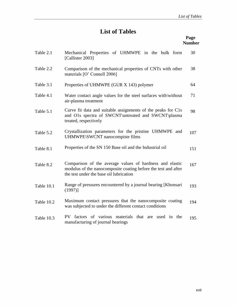
Mechanical Properties of UHMWPE in the bulk form
[Callister 2003]
Comparison of the mechanical properties of CNTs with other
materials [O’ Connell 2006]
Properties of UHMWPE (GUR X 143) polymer
Water contact angle values for the steel surfaces with\without
air-plasma treatment
Curve fit data and suitable assignments of the peaks for C1s
and O1s spectra of SWCNT\untreated and SWCNT\plasma
treated, respectively
Crystallization parameters for the pristine UHMWPE and
UHMWPE\SWCNT nanocompiste films
Properties of the SN 150 Base oil and the Industrial oil
Comparison of the average values of hardness and elastic
modulus of the nanocomposite coating before the test and after
the test under the base oil lubrication
Range of pressures encountered by a journal bearing [Khonsari
(1997)]
Maximum contact pressures that the nanocomposite coating
was subjected to under the different contact conditions
PV factors of various materials that are used in the
manufacturing of journal bearings
30
38
64
71
98
107
151
167
193
194
195

List of Figures
xviii
List of Figures Page
Number
Figure 1.1
Figure 1.2
Figure 1.3
Figure 1.4
Figure 1.5
Figure 2.1
Figure 2.2
Figure 2.3
Figure 2.4
Figure 2.5
Figure 2.6
Figure 2.7
Figure 2.8
Figure 2.9
Figure 3.1
Figure 3.2
Schematic diagram of a journal bearing
A schematic diagram of the stribeck curve showing different
lubrication regimes in liquid lubricated joints. ‘h’ is the oil film
thickness and R is the roughness of the surfaces
Evolution process of the various categories of base oils from the
crude petroleum
Formulation of the industrial lubricating oil
Research Methodology adopted in the present study
Wear rate of various polymers [Harvey 1999]
Impact resistance of various polymers [Harvey 1999]
Chemical Structures of Ethylene and Polyethylene
A schematic diagram of water contact angle measurement
Structures of different allotropes of carbon
Structures of SWNT and MWNT
Variations of weight loss as a function of CNT addition after wear
test [Zoo et al (2004)].
Variation of (a) Tensile strength (b) Electrical conductivity & (c)
Thermal conductivity with addition of CNTs and a comparison
between the well dispersed and poorly dispersed CNTs [Bal et al.
2007]
CNT length as a function of time with ultrasonication bath [Hilding
et al. 2003]
A schematic showing the working principle of the air-plasma
treatment
A typical example of polymer film thickness calculations using the
FIB technique
2
4
6
8
13
27
27
30
33
36
37
40
41
42
47
53

List of Figures
xix
Figure 3.3
Figure 3.4
Figure 3.5
Figure 3.6
Figure 3.7
Figure 3.8
Figure 3.9
Figure 4.1
Figure 4.2
Figure 4.3
Figure 4.4
Figure 4.5
A ball-on-disk configuration used for tribological characterization of
polymer films on flat surfaces
(a) Experimental setup for the flat-on-cylinder wear tests (b) Shape
of the two samples used for conducting the tests (c) Oil reservoir
used to supply oil to the mating surfaces (d) A schematic of the line
contact
(a) Experimental setup for heating the counterface to conduct
experiments at elevated temperatures (b) A thermocouple used to
monitor the temperature of the oil
(a) Procedure for mounting the cylindrical shaft on the motor shaft
(b) Procedure of securing the flat plate in the cantilever
Dial gauge positioning to check the concentricity to minimize the
alignment error.
Top view of the cantilever loading mechanism on to the cylindrical
shaft
Calibration graph for the tribometer setup
Flow process of the experimental procedure
(a) SEM morphology of the UHMWPE film on the DF3 tool steel
surface. (b) AFM image of the DF3 tool steel/UHMWPE surface (c)
FTIR spectrum of the UHMWPE coated steel surface
(a) Comparison of the XPS spectra for the (A) untreated and the (B)
Plasma treated steel samples (b) XPS analysis of C 1s on the plasma
treated sample (c) XPS analysis of Fe 2p3/2 on the plasma treated
sample
FESEM images of the scratches of (a) untreated sample tested at a
scratch load of 0.04 N and (b) air-plasma treated sample tested at a
scratch load of 0.12 N. Inset, EDS analysis images, showing the
failure of the polymer film with a peak of Fe
Comparison of the coefficient of friction with respect to the number
of cycles for a typical run for the bare and UHMWPE film coated
steel, with/without air-plasma treatment before the coating of
UHMWPE film. 3 wt% of UHMWPE was used to obtain the film
56
58
59
60
61
62
62
70
72
76
79
81

List of Figures
xx
Figure 4.6
Figure 4.7
Figure 4.8
Figure 4.9
Figure 5.1
Figure 5.2
Figure 5.3
Figure 5.4
Figure 5.5
Figure 5.6
Figure 5.7
FIB-Qunta3D image for 5 wt% UHMWPE film on the steel
substrate. The film thickness value = (Reading) X sin52O
(a) Coefficient of friction as a function of sliding cycles for different
wt% (different thicknesses) of UHMWPE at a normal load of 0.3 N
and a rotational speed of 200 rpm. Inset: Average wear life for the
three different thicknesses of the film. (* Wear life exceeded
100,000 cycles for all the three runs)
(a), (c) & (e), FESEM/EDS images of the coated surface of the steel
sample for 1 wt%, 3 wt% and 5 wt% of UHMWPE. (b), (d) & (f),
FESEM/EDS images of the wear track for 1 wt%, 3 wt% and 5 wt%
UHMWPE. Inset (right-hand side corner), optical images of the ball
surface taken immediately after the wear test
Effect of the rotational speed on the average wear life at a normal
load of 4 N
(a) & (b) Nanocomposite coating with the earlier post heat treatment
process (c) Nanocomposite coating with the modified post heat
treatment process
Comparison of the (I) Complete, (II) C1s and (III) O1s XPS spectra
obtained for the pristine and plasma treated SWCNTs respectively
(a) Comparison of the scratch penetration depth (b) Comparison of
the frictional graphs for the nanocomposite film reinforced with
plasma and non-plasma treated CNTs respectively
Variation of average surface roughness (Ra) of the film with
different concentrations of SWCNTs Surface topographical image
using DMEMS for the (a) pristine UHMWPE film and (b) 0.1 wt%
SWCNTs
FT-IR spectra obtained for the UHMWPE\SWCNT nanocomposite
films for different concentrations of SWCNTs
(a) XRD patterns for the UHMWPE\SWCNT nanocomposite films
with varying concentrations of SWCNTs (b) Variation of
crystallinity in the nanocomposite film with the addition of
SWCNTs
Variation of hardness and elastic modulus of the nanocomposite
films with SWCNTs content as obtained from the nano-indentations
tests
82
83
86
89
95
99
102
104
106
108
110

List of Figures
xxi
Figure 5.8
Figure 5.9
Figure 5.10
Figure 5.11
Figure 5.12
Figure 5.13
Figure 6.1
Figure 6.2
Figure 6.3
Figure 6.4
Figure 6.5
(a) Scratch penetration depth as a function of applied load of the
nanocomposite films with varying content of SWCNTs. (b) FESEM
images of scratch deformation for the 0 wt% and 0.1 wt% of
SWCNT nanocomposite films respectively. The scratch direction is
from left to right
(a) Thermogravimetric anaysis of UHMWPE\SWCNT
nanocomposite films with varying concentration of SWCNTs (b) A
magnified view of the TGA curves
Variation of thermal conductivity of the nanocomposite film with
SWCNT content
(a) A typical friction plot of the nanocomposite film for the different
concentrations of SWCNTs. Inset: The change in the average
coefficient of friction with the SWCNT content for the
nanocomposite film. (b) Wear life in cycles for the different
nanocomposite films at a load of 4 N and speeds of 1000, 2000 and
2500 rpm respectively
Optical micrographs of the Si3N4 balls and the wear track for the 0.1
wt% and 0.2 wt% SWCNT nanocomposite film after the wear test
after 10 million cycles. The test was conducted at a load of 4 N and
a speed of 2500 rpm
FESEM images of the wear track widths for the nanocomposite
films after 10,000 cycles. The test was conducted at a load of 4 N
and a speed of 1000 rpm. Inset: Optical images of the Si3N4 balls
immediately after the test and before cleaning them with acetone
A schematic diagram showing the deposition of the dual layer film
(Steel/UHMWPE/PFPE)
(a) Comparison of the average wear life for the single layer film
(TS/UHMWPE) and for the dual-layer film (TS/UHMWPE/PFPE)
for speeds of 1000 rpm and 2000 rpm respectively at a normal load
of 4 N
Comparison of typical frictional graphs for the single layer and the
dual layer films
(a) SEM morphology of the UHMWPE film on the DF3 tool steel
surface. (b) AFM image of the DF3 tool steel/UHMWPE surface
Comparison of Wear life of different types of coatings at a load of 4
N and speeds of 2000 rpm and 2500 rpm respectively
111
113
114
117
119
120
126
128
128
129
131

List of Figures
xxii
Figure 6.6
Figure 6.7
Figure 7.1
Figure 7.2
Figure 7.3
Figure 7.4
Figure 7.5
Figure 7.6
Figure 7.7
Comparison of a typical friction graph for the nanocomposite film
with and without the overcoat of PFPE
(a), (b) – Ball images after the test sliding against the
nanocomposite film without the PFPE overcoat. (c), (d) – Ball
images after the test sliding against the nanocomposite film with a
PFPE overcoat. (e) – Wear track after the test of the nanocomposite
film without PFPE overcoat. (f) – Wear track after the test of the
nanocomposite film with PFPE overcoat
Properties and one sample measurement of water contact angle and
surface roughness for Si3N4, steel and brass balls
Typical frictional graphs for the nanocomposite coating sliding
against the three different balls
2D-plots of the wear tracks after 10,000 and 240,000 cycles
respectively for the nanocomposite coating sliding against the three
different balls. Inset (left): Optical micrograph of the ball after the
test at a magnification of x100 . Inset (right): FESEM images of the
wear tracks after the wear tests
(a) Typical frictional graphs for the nanocomposite coating sliding
against the three different balls at a load of 4 N and a rotational
speed of 2500 rpm (linear velocity = 0.52 m/s) until 1 million
cycles. (b) 2-D and 3-D plots for the wear tracks after 1 million
cycles for the three different counterface materials
Comparison of the resistance to penetration of the nanocomposite
coating before and after the 300 h exposure to UV radiation.
FESEM images of the scratches for the two cases
(a) Comparison of the typical frictional graphs of the nanocomposite
coating slid against Si3N4 ball, before and after the exposure to UV
radiations. Inset (Table): Properties such as hardness, crystallinity
and water contact angle of the nanocomposite coating before and
after the UV radiations. (b) FESEM image of the wear track after
the test for the nanocomposite coating not exposed to UV radiations.
(c) FESEM image of the wear track after the test for the
nanocomposite coating exposed to UV radiations
Comparison of typical frictional graphs for a nanocomposite coating
overcoated with an ultra-thin film of PFPE with and without
exposure to UV radiations. Wear tests were conducted at a load of 4
N and a speed of 2000 rpm (linear velocity = 0.41 m/s)
132
133
136
137
139
141
143
144
145

List of Figures
xxiii
Figure 8.1
Figure 8.2
Figure 8.3
Figure 8.4
Figure 8.5
Figure 8.6
Figure 8.7
Figure 8.8
(a) Schematic drawing of the cylindrical shaft (b) Schematic
diagram of the flat counterface pin
Schematic diagram of the flat counterface pin for the AISI bearing
steel experiments
Cylindrical shaft coated with the nanocomposite coating
Comparison of the coefficients of friction and wear life for the
uncoated Al shaft, UHMWPE coated and UHMWPE + CNTs
coated shafts against Al flat plate under dry sliding conditions
(a) The nanocomposite (UHMWPE + CNTs) coated sample after
100 hrs of wear test under dry conditions under a load of 45 N and
a linear speed of 0.57 m/s. (b) FESEM image of the wear track and
the unworn region of the coating after 100 hrs of wear test under dry
conditions with a load of 45 N and a linear speed of 0.57 m/s. (c)
EDS spectrum for the unworn part of the nanocomposite coating (d)
EDS spectrum on the wear track after a test of 100 hrs under dry
conditions with a load of 45 N and a linear speed of 0.57 m/s
Stribeck curves for the uncoated Al shaft, UHMWPE coated and
UHMWPE + CNTs coated shaft against flat Al plate under base oil
(SN 150) lubricating conditions under a constant load of 45 N. Data
for uncoated Al shaft under industrial lubricant is also provided for
comparison.
(a) A comparison of the specific wear rates of the uncoated Al
cylindrical shaft under the base oil and the industrial lubricant
conditions and that of the nanocomposite coating under base oil
lubrication under a load of 60 N and a linear speed of 0.11 m/s. (b)
A comparison of the specific wear rates of the counterface Al flat
pin under the base oil and the industrial lubricant conditions and that
of the nanocomposite coating under base oil lubrication under a load
of 60 N and a linear speed of 0.11 m/s.. (c) EDS spectrum in the
wear track of the nanocomposite coating after a wear test of 100 hrs
under the base oil under a load of 60 N and a linear speed of 0.11
m/s. (d) Initial base oil quality (e) Quality of the base oil after a
wear test (100 hrs) of uncoated Al shaft under a load of ~ 60 N and
a linear speed of 0.11 m/s. (f) Quality of the industrial oil after a
wear test (100 hrs) of uncoated Al shaft under a load of 60 N and a
linear speed of 0.11 m/s. (g) Quality of the base oil after a wear test
(100 hrs) of nanocomposite coated Al shaft under a load of 60 N and
a linear speed of 0.11 m/s.
(a), (b) & (c) 3D profile, the actual profile and the 2D profile of the
149
150
152
154
155
157
161
163

List of Figures
xxiv
Figure 8.9
Figure 8.10
Figure 8.11
Figure 8.12
Figure 9.1
Figure 9.2
Figure 9.3
scar on the counterface Al flat pin after a wear test of 100 hrs with
the base oil lubrication under a load of 60 N and a linear speed of
0.11 m/s when slid against the uncoated cylindrical Al shaft. (d), (e)
& (f) 3D profile, the actual profile and the 2D profile of the scar on
the counterface Al flat pin after a wear test of 100 hrs with the base
oil lubrication under a load of 60 N and a linear speed of 0.11 m/s
when slid against the nanocomposite coated cylindrical Al shaft
A typical coefficient of friction curve for the uncoated/base oil,
uncoated/industrial oil and UHMWPE+CNTs/base oil under a load
of 60 N and linear speed of 0.11m/s. Inset: Comparison of the
average coefficients of friction for the three cases
FESEM image, 3D profile, EDS spectrums for the nanocomposite
coating after a wear test of 100 hrs with a load of 45 N and a linear
speed of 0.57 m/s under the base oil lubricating conditions
(a), (b) & (c) 2-D profile, contour plot and the 3-D profile of the
coating across the wear track and the non-worn regions of the
cylindrical shaft coated with the nanocomposite coating and an
overcoat of PFPE. (d) SEM image of the surface morphology of the
worn and the non-worn regions across the interface (e) Typical
frictional graphs for the nanocomposite coating with and without the
PFPE overcoat at a normal load of 60 N and a linear speed of 0.11
ms-1
under dry conditions
Comparison of the typical frictional graphs for the nanocomposite
coating with an overcoat of PFPE under dry and base oil lubricated
conditions
Photograph of the counterface plate with the heating cartridge and
the thermocouple
A comparison of typical frictional graphs of the nanocomposite
coatings with or without the PFPE overcoat at different temperatures
with the inset table showing the average coefficient of friction
values for each case for a normal load of 60 N and a linear speed of
0.11 ms-1
under dry conditions.
(a) SEM micrograph after the test for the nanocomposite coating
without the PFPE overcoat at 80 OC (b) SEM micrograph after the
test for the nanocomposite coating without the PFPE overcoat at 120 OC (c) 2-D profile of the worn and the non-worn regions across the
interface for the nanocomposite coating without the PFPE overcoat
at 80 OC. (d) EDX spectrum on the wear track for the
nanocomposite coating without the PFPE overcoat at 120 OC. The
164
166
169
170
173
175
176

List of Figures
xxv
Figure 9.4
Figure 9.5
Figure 9.6
Figure 9.7
Figure 9.8
Figure 9.9
experiments were conducted at a normal load of 60 N and a linear
speed of 0.11 ms-1
under dry conditions for 50 hrs.
(a) SEM micrograph after the test for the nanocomposite coating
with an overcoat of PFPE at 120 OC. (b) 2-D profile of the worn and
the non-worn regions of the nanocomposite coating with an overcoat
of PFPE after 50 hrs of test conducted at 120 OC. (c) EDX spectrum
on the wear track region of the nanocomposite coating with an
overcoat of PFPE. The experiments were conducted at a normal load
of 60 N and a linear speed of 0.11 ms-1
under dry conditions for 50
hrs.
2-D profiles & inset - a photographs of the countersurface after the
test for (a) nanocomposite coating without PFPE overcoat at 80 OC
(b) nanocomposite coating without PFPE overcoat at 120 OC (c)
nanocomposite coating with PFPE overcoat at 120 OC. The
experiments were conducted at a normal load of 60 N and a linear
speed of 0.11 ms-1
under dry conditions for 50 hrs
XRD spectrums obtained for the nanocomposite coatings after the
test at various elevated temperatures for 50 hrs.
(a) Comparison of typical frictional graphs for the nanocoatings
with PFPE overcoat at room temperature, 80 OC and 105
OC
respectively under base oil lubricated conditions at a normal load of
60 N and a linear speed of 0.11 ms-1
after 50 hrs. (b) A photograph
of the lubricated test at room temperature (c) Quality of the oil after
the test at room temperature (d) The counterface surface after the
lubricated test conducted at room temperature.
(a) Comparison of typical frictional graphs for the nanocoatings
with and without the PFPE overcoat and DLC coatings under dry
conditions at room temperature. (b) 3-D plot of the counterface
surface when slid against the nanocomposite coating with PFPE
overcoat (c) 3-D plot of the counterface surface when slid against
the DLC coating.
(a) Comparison of typical frictional graphs for the nanocomposite
coating with the PFPE overcoat and DLC coatings under base oil
lubricated conditions at room temperature. (b) Photograph of the
counterface flat plate after sliding against the DLC coating for 100
hrs under base oil lubricated conditions (c) Photograph of the
counterface flat plate after sliding against the nanocomposite
coating for 100 hrs under base oil lubricated conditions.
177
178
180
182
184
185

List of Notations
xxvi
List of Notations
AFM: Atomic force microscopy
CNT: Carbon nano tube
CSM: Continuous Stiffness Measurement
DMEMS: Dynamic microelectromechanical systems
FE-SEM: Field Emission- Scanning Electron Spectroscopy
FIB: Focused ion beam
FTIR: Fourier Transform- Infrared Spectroscopy
HDPE: High density polyethylene
LDPE: Low density polyethylene
MPa: Mega Pascal
MWCNT: Multi walled CNT
PE: Polyethylene
PEEK: Poly ether ether ketone
PFPE: Perfluoropolyether
PI: Polyimide
PMMA: Polymethylmethacrylate
PTFE: Polytetrafluoroethylene
RMS- Root mean square roughness
EDS: Energy Dispersion Spectroscopy
Si3N4: Silicon nitride
SWCNT : Single walled Carbon nano tube
UHMWPE: Ultra-high-molecular-weight polyethylene
XPS: X-ray photoelectron spectroscopy
Chapter 1: Introduction
1
Chapter 1
INTRODUCTION
Global warming and energy conservation are the major challenges of the 21st century.
Industrialization throughout the world has put enormous pressure on the present day
researchers and technologists to look for various ways and means to conserve energy on
one hand and to invent products which are environmental friendly to reduce pollution and
tackle the issue of global warming on the other.
Every mechanical system has sliding components which experience friction and if
proper lubrication is not provided, the component will wear and this will eventually lead
to failure. For example, in automotive\aerospace industry, various parts such as engine,
gears, bearings etc need proper lubrication which determines the life of the components.
Reducing friction and wear will help in conserving energy which is one of the major
issues of today. Moreover, most of the lubricants used in the automotive\aerospace
industry today have many harmful additives which are added to the lubricant to improve
its efficiency and reduce friction. These additives are one of the major causes of air
pollution which in turn is creating many health hazards and contributing tremendously to
the global warming.
Recent research has shown that polymer coatings and thin films have excellent
tribological properties when coated on various substrates. The polymer coatings, if used
effectively, may result in reducing the overall consumption of lubricants and contribute to
lubricants with low additive contents or biodegradable fluids leading to an environmental
friendly lubricant technology.

Chapter 1: Introduction
2
The main focus of the present study is to evaluate the feasibility of using these
polymer coatings on metallic substrates, which would be helpful in developing energy
efficient and environmental friendly mechanical components such as bearings etc. thus
contributing to the ongoing research in the pursuit of finding solutions to these major
problems of global warming and energy conservation.
1.1 Background
1.1.1 Principle of working of a Journal Bearing
A journal bearing as shown in Fig. 1.1, is a simple bearing in which a shaft, or "journal",
or crankshaft rotates in the bearing with a layer of oil or grease separating the two parts
through fluid dynamic effects. It does not have any rolling elements in it. The shaft and
bearing are usually simple polished cylinders with lubricant filling the gap. The shaft is
not centered in the bearing but rotates with an offset which is termed as the “eccentricity”
of the bearing.
Figure 1.1: Schematic diagram of a journal bearing
Journal bearings can be classified into two main categories depending upon the
type of lubrication used. They are hydrodynamically lubricated or hydrostatically

Chapter 1: Introduction
3
lubricated. In a hydrostatic bearing, the pressure is always maintained at a value that is
required and is achieved by an external pump which forces lubricant into the system. This
may not be possible in every machine as it adds to the initial cost and the cost of
maintenance. In a hydrodynamic lubricated bearing the pressure in the oil film is
maintained by the rotation of the shaft itself. However, this is effective at high rotational
speeds of the shaft as shown by the Stribeck curve in Figure 1.2
Journal bearings undergo much wear and tear mainly during the startup and the
shutdown of the machine. It is due to the fact that, during these periods the rotational
speeds of the shaft or the journal are not high enough so as to maintain a sufficient oil
film thickness. This results in metal-to-metal contact similar to that of operating in the
boundary lubrication regime as shown in the Stribeck curve in Figure 1.2. However
during normal operation, the rotational speed of the shaft are sufficiently high enough to
maintain a hydrodynamic oil film by forcing the lubricant into the mating surfaces of the
shaft and the bearing. The oil film provides the journal bearing with its excellent load
carrying capacity at higher rotational speeds.
The pressures encountered in the contact area of journal bearings are significantly
less than those generated in rolling bearings. This is because of the larger contact area
created by the conforming surfaces of the journal and the bearing. The mean pressure in
the load zone of a journal bearing is determined by the force per unit area. In most
industrial applications, the values of the contact pressures range from 0.69 to 2.07 MPa.
Automotive reciprocating engine bearings and some severely loaded industrial
applications may have mean pressures of 20 to 35 Mpa [Khonsari (1997)].

Chapter 1: Introduction
4
1.1.2 Stribeck Curve
The Stribeck curve plays an important role in identifying boundary, mixed,
elastohydrodynamic, and hydrodynamic lubrication regimes.
Based on friction experiments on bearings, Stribeck expressed the relationship
between the friction coefficient [f], viscosity of the lubricating oil [η], bearing load [FN],
and velocity [V] in the Stribeck curve as shown in the Figure. 1.2. This curve captures the
characteristics of various lubrication regions, including [I] boundary lubrication, [II]
elastohydrodynamic lubrication (EHL), and [III] hydrodynamic lubrication.
Boundary lubrication
Mixed lubrication
Hydrodynamic lubrication
Sommerfeld Number (ηV/P)
Co
eff
icie
nt
of f
rict
ion
h 0
h ≈ R
h >> R
Figure 1.2: A schematic diagram of the stribeck curve showing different lubrication regimes in
liquid lubricated joints. ‘h’ is the oil film thickness and R is the roughness of the surfaces

Chapter 1: Introduction
5
In the hydrodynamic lubrication regime, the fluid completely isolates the friction
surfaces [h >> R], and internal fluid friction alone determines tribological characteristics.
The coefficient of friction exhibited in this regime is very low in the order of 10-4
to 10-3
.
In elastohydrodynamic lubrication [h ≈ R], fluid viscosity, the viscosity-pressure
coefficient and the elastic coefficients of the solid surfaces are the most dominant factors.
The boundary lubrication region is reached as the lubricant film thickness
approaches zero as a result of which the coefficient of friction increases from 10-1
to ~1
depending upon the interfacial friction between the two solid surfaces. This regime is
mainly characterized by the following three points:
friction surfaces are in contact at microasperities
hydrodynamic effects of lubricating oil or rheological characteristics of bulk
do not significantly influence tribological characteristics
interactions in the contact between friction surfaces and between friction
surfaces and the lubricant (including additives) dominate tribological
characteristics.
Generally, wear of one or both surfaces is high.
1.1.3 Base Oils and its categories
A lubricant is defined as a solid or fluid film interposed between surfaces in relative
motion to reduce friction and/or wear.
Base oil is the basic building block of any lubricant. Base oils, also known as
lubricant base oils, are a complex mixture of paraffinic, aromatic and napthenic
hydrocarbons with molecular weights ranging from medium to high values, which
produce oils with desirable viscosities, densities and distillation curves. Fig.1.3 describes

Chapter 1: Introduction
6
the flow process of the evolution of the base oil from crude petroleum. The quality of
base oils is determined by their olefinic, nitrogenated and sulfured compound contents.
Base oils are generally fully saturated and extremely pure, with very low volatility and
high viscosity index. There are two types of base oils:
o Mineral oils, and
o Synthetic oils
Figure 1.3: Evolution process of the various categories of base oils from the crude petroleum

Chapter 1: Introduction
7
Mineral oils are by-products of refined crude oil. Refining helps reduce impurities but
leaves molecules of all shapes and sizes. Synthetic oils are man-made compounds the
molecules of which are of all same size and shape. Synthetic oil shows less friction and
performs better than mineral oils.
The API (American Petroleum Institute) has defined five specific categories of base oils
by the quality of their viscosity index as follows:
Group I - Solvent Freezing: They are the least refined containing a mix of
different hydrocarbon chains used in less demanding applications.
Group II - Hydro Processing and Refining: They have good lubricating
properties and are very common in mineral based motor oils.
Group III - Hydro Processing and Refining: These are subjected to the highest
level of mineral oil refining and offer good performance in a wide range of
attributes and stability. They are commonly used with additives in the blending
product lines.
Group IV - Chemical Reactions: They are chemically engineered synthetic base
stocks, which offer excellent performance in lubricating properties and stable
chemical compositions.
Group V - Ester Synthetic Base Oils: They are chemically engineered synthetic
base stocks. They are rarely used due to their high cost and inability to mix
readily with gasoline and some other oils [Mang et al. 2000, Bartz 1993 and
Sequeria 1994].

Chapter 1: Introduction
8
1.1.4 Additives
Commercial lubricants, required to operate under severe conditions, are comprised of
several components. The most abundant of these is the base fluid, which may be a
mineral oil. The lubricants are „formulated‟ by adding various components known as
„additives‟ as shown in Figure. 1.4. The function of the additives is to react with
contacting surfaces and form tribo-films which protect the surfaces from wear especially
during boundary lubrication regime. Some of these function, for example, to stabilize the
fluid against oxidation or biological decay and a few others help in improving the
tribological performance. A wide range of compounds has been claimed to be effective
extreme-pressure additives, but the ones that are currently most commonly used generally
contain chlorine, sulfur or phosphorus such as ZDDP (zinc dialkyl dithiophosphate) and
MoDTC (molybdenum dialkyl dithiocarbamate) etc. [Varlot et al. 2001, Neville et al.
2007, Li et al. 2000, Ren et al. 2000, Ren et al. 1994, Jimenez et al. 2006, Glovnea et al.
2005 and Stachowiak et al. 2000 ].
Refined Base Oil AdditivesFormulated
Lubricating Oil
Detergent AdditivesOil Soluble Sulphonates &
Phenates of calcium, barium
And magnesium.
RolePrevent deposition of carbon
and varnish piston-ring zone
DispersantsSuccinimides, polyamides &
copolymers containing polar
groups
RoleTo prevent low temperature
sludge deposition
AntiwearSulphur and Phosphorous
Compounds.
Zinc dialkyl dithiophosphates
RoleTo prevent wear of the
contacting surfaces
Extreme PressureSulphur and Phosphorous
Compounds.
RoleIncreasing the load bearing
capacity of the lubricating
oil
Figure 1.4: Formulation of the industrial lubricating oil

Chapter 1: Introduction
9
The additives are most often added as organic compounds, which render them
soluble in the base lubricating fluid. Since many of the compounds that are currently used
for this purpose are either environmental pollutants or health hazards, or both, these will
ultimately have to be replaced by more benign alternatives [Bartz 1998].
Governments around the world, are taking necessary steps and passing
legislations, to control the amount of harmful additives to be used in the lubricants.
Hence, there is a greater need to modify the lubrication strategies where the use of
lubricant additives is reduced or fully eliminated. Moreover the problem of wear is not
totally eliminated even with the best of additives.
1.2 Present state of Lubrication in mechanical components
The current methods of lubrication for many contacting surfaces in mechanical
systems are the use of protective coatings on surfaces and the use of lubricants added
with appropriate additives. Various protective coatings that are in practice are Diamond-
like carbon (DLC) [Gahlin et al. 2001], several PVD (physical vapor deposition) coatings
such as TiAlN, CrAlN, ZrN, ZrC, WC/C, W-C: H [Gold et al. 2002] and TiO2, Al2O3 etc.
As mentioned above, most commonly used additives in the lubricants are ZDDP (zinc
dialkyl dithiophosphate) and MoDTC (molybdenum dialkyl dithiocarbamate) etc.
Further, the function of the additives is to react with contacting surface and form tribo-
films which protect the surfaces from wear. Eventhough the use of many coatings,
provide high wear resistance, they suffer from disadvantages such as poor adhesion with
the substrates, high thermal stresses in the coating, sensitivity to the environment,
incompatibility with the lubricant etc [Harris et al. 1993 and Neville et al. 2007]. Despite,
extensive research that is going on throughout the world to develop novel lubricant

Chapter 1: Introduction
10
additives with improved performance and/or improving the performance of current
lubricant additives [Jimenez et al 2006, Ren et al 2000, Ren et al 1994 and Glovnea et al
2005], there is an equally important need to modify the lubrication strategies where the
use of lubricant additives is largely reduced or fully eliminated, because of their harmful
nature to the environment. Therefore, the present research strategy is developed with one
major goal: To provide energy saving and environmental-friendly lubrication method
whereby to fully eliminate the use of harmful additives as well as reduce the amount of
lubricants needed.
Lately, polymers have been used as protective coatings in many applications due
to their low production cost, ease of deposition onto intricate shapes and good corrosion
resistance. However, their potential to improve the tribological properties such as
reducing the coefficient of friction and increasing the wear life of contacting surfaces has
not been tapped completely. The self lubricating properties of the polymers make them a
very attractive candidate to be used as thin films on metallic substrates such as steel
which is extensively used in the mechanical components such as gears and bearings.
Chapter 1: Introduction
11
Why Polymer Coatings:
Ability to be coated using simple techniques
Low cost and ease of fabrication into different shapes
Excellent tribological properties for selected polymers
High wear resistance coupled with low density and toughness property
Low coefficient of friction even in dry condition.
1.3 Research Objectives
The present study is focused on the main objective of exploring the feasibility of using
polymer films as boundary lubricant layers onto metallic substrates modified with
appropriate surface pre-treatments, which are expected to enhance the lubrication
performance and reduce the consumption of harmful additives and the amount of
lubricants in sliding mechanical components.
As explained earlier, mechanical sliding components like the journal bearing
undergo severe wear and tear usually during the start and stop periods and providing a
layer of polymer coating on the journal or the bearing would protect the mating surfaces
from this severe wear and tear not only during the start and stop periods but also during
the normal operating conditions.
Thus the main objectives of this study are listed as follows:
To develop cost-effective and efficient processes to deposit
polymer/nanocomposite coatings onto various substrates such as steel and
aluminium, modified with necessary surface treatments.
To characterize physical, chemical and mechanical properties of the coated
substrates and optimize the coating technique (parameters such as pre-treatment to

Chapter 1: Introduction
12
the substrate, coating thickness, post-treatment, filler distribution etc) to obtain
the desired properties.
To test the tribological properties such as adhesion, scratch resistance, friction,
wear etc under dry and oil lubrication conditions (without the use of additives)
and to investigate the corresponding mechanisms.
1.4 Research Methodology in the present work
To accomplish the above-mentioned objectives, we have carried out deposition of
polymer films on steel and aluminium substrates. The polymer selected for our study is
ultra high molecular weight polyethylene (UHMWPE) which has shown exceptional
wear durability as bulk or as coating. To further enhance the mechanical, thermal and
tribological properties of the polymer film a nanocomposite polymer film has been
developed by reinforcing the polymer coating with single-walled carbon nanotubes. A
deposition methodology for the nanocomposite film has been developed for aluminium
and steel substrates. An experimental rig was developed to simulate the line contact
conditions as in a journal bearing and the tribological properties of the nanocomposite
film have been investigated under dry and base oil lubricated conditions. Furthermore,
experiments were conducted to investigate the effectiveness of the nanocomposite film at
elevated operating temperatures. In a specific study, we have studied the effects of
counterface material and UV radiations (simulating long term UV exposure from the sun
in an outdoor application) on the tribological properties of the nanocomposite polymer
films.

Chapter 1: Introduction
13
Figure 1.5: Research Methodology adopted in the present study
Substrate
Pre-treatment
(Air-Plasma)
Coating of the
polymer layer
Multilayer
(UHMWPE/PFPE)
Composite
(UHMWPE+CNTs)
Characterization of the physical,
chemical and mechanical properties
Are properties
satisfactory?
Optimize the coating process from the
beginning
NO
Characterization of the tribological properties such as wear life and coefficient
of friction under dry and lubricated
conditions
Understanding the friction and wear
mechanism
YES

Chapter 1: Introduction
14
Thus, the present research is categorized into six major phases as follows:
Phase I: To evaluate the feasibility of using UHMWPE as a coating in its pristine form
on metallic substrates and study the effect of surface pre-treatment, thickness and a PFPE
overcoat on the tribological properties of the film.
Phase II: To develop and evaluate the mechanical, thermal and tribological properties of
a nanocomposite film (UHMWPE + CNTs) with addition of nano fillers like SWCNTs.
Phase III: To investigate the effect of counterface material and UV radiations on the
tribological properties of the nanocomposite film.
Phase IV: To evaluate the effectiveness of the nanocomposite coating in the presence of
liquid lubricants without any additives added to them.
Phase V: To evaluate the effectiveness of the nanocomnposite coating at elevated
temperatures.
1.5 Significance of the present work
The world in general and Singapore in particular is moving towards creating a green
environment by reducing pollution to solve the problems of global warming and constant
health risk. The motivation for the present study is driven by the global and the local
interests towards a clean and green pollutant-free environment (air as well as water).
According to the NEA (National Environmental Agency) of Singapore
[http://app.nea.gov.sg/cms/htdocs/category_sub.asp?cid=29#q1], two of the three major
sources of the air pollution in Singapore are:
Stationary sources such as power stations, oil refineries and industries
Motor vehicles

Chapter 1: Introduction
15
Even though the power stations and oil refineries do produce the pollutants from
some inherent production methods, many of the machineries used in those industries also
contribute largely to the air-pollution. Therefore, if proper lubrication is provided to these
machineries, the harmful effects of generating pollutants can be reduced. Moreover, in
motor vehicles, one of the major contributors to the air pollution is the improper use of
lubrication and the harmful additives used. Singapore has been taking stringent efforts in
reducing the amounts of sulfur, phosphorous, metallic pollutants, oxides of nitrogen etc
by imposing strict regulations for their content in fuels etc. For example, with effect from
1st Dec‟2005, the sulfur content in the diesel has been reduced to less than 0.005% by
weight which was previously 0.05% by weight [www.app.nea.gov.sg]. A study
conducted by Chew et al. [1999] in Singapore over a period of 5 years (1990-1994) had
suggested that children aged 3-12 years are susceptible to asthma due to air pollutants,
particularly sulfur dioxide and total suspended particles (TSP), although the levels of
these pollutants were within “acceptable” range within the air-quality guidelines
established by the World Health Organization [Chew et al. 1999]. Actually, apart from
the fuels, lubricant additives are also major source of sulfur, phosphorous, oxides of
nitrogen and metallic pollutants and hence the recent research has focused on the
development of additives with lower amounts of all these harmful chemical additives
[Buck et al. 2007]. Therefore, greater attention towards the improvement in the
lubrication strategies for the mechanical components (which eventually reduce the use of
additives), is needed to improve the environmental situation in a developed country such
as Singapore, which will lead to a greater increase in economic situation through
sustainable industrial growth and better living standards.

Chapter 1: Introduction
16
The above discussed stringent requirements in reducing air pollutants to create clean
environment has imposed greater challenges on we researchers to improve the lubricant
quality and performance [Taylor et al 2005]. So far, researchers have been trying to
improve the performance of the current lubricant additives, to develop novel lubricant
additives, to improve the performance of existing coatings by some modifications etc [Li
et al. 2000 and Gahlin et al. 2001]. Li et al [2000] were successful in developing N-
alkylated tetrazole derivative as an alternative to ZDDP which has shown good load-
carrying capacity, excellent anti-wear and friction reduction properties when added as an
additive to liquid paraffin. For the improvements in the existing coatings, there are many
studies carried out on the performance of DLC coatings; for example, doping of DLC
coatings with light elements such as B, Si, N, O or F, metals etc have improved the
hardness, tribological properties etc [Sanchez-Lopez et al. 2008]. In spite of all these
efforts, we are still not able to eliminate the use of additives altogether. Therefore, there
is a strong technological need to develop novel lubrication strategies which may reduce
or fully eliminate the use of additives in the lubricants. The presently proposed research
is a major effort towards providing solutions to the above problems. The outcome of this
project is expected to open up several new directions in the field of lubrication for
mechanical systems. The polymers selected will be totally harmless to our body as they
will mostly contain carbon, hydrogen and oxygen. The knowledge from these studies
may also help in other fields such as “lubricating polymer surfaces”, which has many
scientific and industrial importance in fields such as biology and nanotechnology [Ikada
et al. 1995]. Further, the success of this approach may open-up several possibilities of

Chapter 1: Introduction
17
new inventions, new industries and applications of this technology to newer advanced
fields.
The potential advantages of the proposed boundary polymer lubricant layers are listed
below which strongly support the significance of this work:
Materials and the coating procedures are simple and cost effective.
Tailoring of the film functionality is easy.
Most polymer films are inherently corrosive resistant which serves the dual
purpose.
The proposed lubrication methodology is expected to reduce (or even eliminate)
the consumption of lubricant additives.
The present procedures will lead to a cleaner environment.
Reduction in the friction and wear of the mechanical system/component will
contribute directly and significantly to the energy saving by reducing energy
consumption and increasing durability of the machines.
Polymer coatings, can provide sufficient damping (low vibrational noise coming
from bearings) to the mechanical system as an additional benefit.

Chapter 2: Literature Review
18
Chapter 2
Literature Review
2.1 History of Tribology and its significance to Industry
Tribology is defined as the study of friction, wear and lubrication. It is the science and
technology of two interacting surfaces in relative motion, in a given environment.
Friction and wear are often undesirable (though they are essential and helpful in a few
applications) phenomena resulting from sliding and rolling surface contacts. Friction is
defined as the resistance offered to sliding or rolling motions whereas wear is defined as
the surface material removal phenomenon. Low friction and low wear are desirable, in
many applications, to increase the life or durability of components in relative motion. The
word “tribology” was derived from the Greek word “tribos” meaning rubbing. Even
though the term “tribology” is new, its applications spans a period similar to that of
recorded history [Dowson 1998].
The realization of tribology dates back to 3500 BC when the wheel was invented
to reduce friction in translationary motion. The Egyptians in 1880 BC used sledges to
transport large statues and used water to lubricate the sledges. Leonardo da Vinci (1452-
1519), was the first to state that the coefficient of friction is the ratio of friction force to
normal load. Amonton in 1699 experimentally found that the friction force is directly
proportional to the normal load and is independent of the apparent area of contact. These
two observations are popularly known as Amonton‟s laws of friction. A third law stated
as, the friction force is independent of velocity for ordinary sliding speeds, has been
experimentally observed and proposed by Charles Augustine Coulomb which is
frequently included with those of Amonton‟s laws.

Chapter 2: Literature Review
19
Tribology has grown over the years as an engineering discipline keeping pace
with other technical developments in industrialized world. Today, this area of knowledge
is receiving ever-increasing attention due to the fact that machines with greater precision
and smaller tolerances are being designed and built, whose performance is critically
dependent upon the nature of the surface of interacting components whether in lubricated
or dry conditions. Friction and wear are major concerns in practically all modern
mechanical machines. A few examples are internal combustion and aircraft engines,
automobiles, gears, cams, bearing, and seals. The invention of new characterization
techniques such as Surface Force apparatus (SFA) [Tabor and Winterton 1969 and
Israelachvili and Tabor 1972] and AFM/LFM [Binnig et al 1986 and Mate et al 1987]
and the advanced technical applications such as magnetic storage devices,
MEMS/NEMS, nanotechnology have led to further developments in tribology and
opened the doors to the new field of tribology known as micro-tribology/nano-tribology
involving the study of friction and wear at very small length scales [Bhushan 1991].
2.2 Tribology and Surface Engineering
Sometime for a certain application an essential property is needed only at the surface of
the component. For instance, low wear and low friction is mainly controlled by the
surface properties. An elegant way to achieve this can be to use a material with optimal
mechanical properties, e.g. high strength and toughness, and low weight as the base
material, and coat it with a thin layer of a wear resistant material with low friction
coefficient for the improvement of tribological performance. Another name for this
approach is surface engineering. As the name suggests, by manipulating only the surface
of a component its performance in a certain application is improved. Besides the use of

Chapter 2: Literature Review
20
thin functional coatings, surface engineering also includes for instance changing the
surface topography of a component or increasing the hardness of a surface by e.g. case
hardening or nitriding.
The technique with thin surface coatings of a functional material is today
successfully employed in various fields of technology such as electrical equipment,
optical devices as well as tools for cutting and forming [Sproul 1996, Hedenquist et al.
1992, Zweibel 2000]. Depending upon the application, either pure metals or compounds,
often ceramics, are used as coating material. There are many advantages of using thin
surface coatings. Both the bulk and surface properties can be optimised at the same time
and, moreover, materials that are not possible to synthesise in any other way can be used
as coating material. Another advantage is that an expensive material can also be used
since only very small amount of the material is needed to form the thin coating.
2.3 Low friction coatings for machine elements
The current state of lubrication for many contacting surfaces in mechanical systems is the
use of protective coatings on surfaces and the use of lubricants with the appropriate
additives [Vizintin et al 2004].
A special type of coating is the vapour deposited coatings. As the name suggests
these coatings are formed on the surface of the specimen (or the substrate) that should be
coated, from a vapour containing the coating material elements. This takes place in a
chamber with controlled atmosphere at relatively low pressure and high temperature.
The vapour deposition techniques can be divided into two subgroups, physical
vapour deposition (PVD) and chemical vapour deposition (CVD). The major difference
between them is how the coating materials are evaporated and the process temperature.

Chapter 2: Literature Review
21
Typical deposition temperatures in PVD processes are 200-500 °C but recently processes
running at lower temperatures have also been developed [Vossen et al. 1992, Gold et al.
2002]. Traditionally, the temperature is in the range 600-1100 °C for thermally activated
CVD processes [Vossen et al. 1992].
Important properties of a coating for machine element applications are, beside
good adhesion to the substrate, a combination of high wear resistance and low coefficient
of friction. Also the wear of the uncoated counter surface is critical. Of course there are
different opinions on what could be considered as low friction. Among researchers and
engineers working with machine element applications, an unlubricated sliding friction
coefficient under ambient conditions around 0.2 or lower is usually considered to be low.
This can be compared with the steel against steel friction coefficient, which typically is in
the 0.6-0.9 region and with boundary oil lubrication of steel around 0.1. Examples of
coating materials that can provide a friction coefficient under 0.2 when sliding against
steel are different metal carbides (WC, TiC, CrC), diamond-like carbon (DLC),
molybdenum disulphide (MoS2) and several PVD (physical vapor deposition) coatings
such as TiAlN, CrAlN, ZrN, ZrC, WC/C, W-C: H, TiO2, Al2O3 etc. [Voevodin et al.
1999, Monaghan et al. 1993, Delplancke-Ogletree et al. 1998, Erdermir et al. 1994, Grill
1997, Kodali et al. 1997, Gahlin et al. 1997, Gilmore et al. 1998, Siu et al. 2000].
However, in practice, many mechanical components need to operate under
lubricated conditions, and the inertness of the DLC coatings raises several questions
about whether they are able to provide real „boundary‟ lubrication or whether they are
just a „passive‟ member in these mechanical contacts [Kalin et al. 2005, Vercammem et
al. 2004, Ronkainen et al. 1998, Harris et al. 1993]. Moreover, to enhance the

Chapter 2: Literature Review
22
performance of the lubricant, various additives are added to it. Commonly used additives
in the lubricants are ZDDP (zinc dialkyl dithiophosphate) and MoDTC (molybdenum
dialkyl dithiocarbamate) etc. The function of additives is to react with contacting surface
and form tribo-films which protect the surfaces from wear [Varlot et al. 2001].
Eventhough the use of many coatings, as stated above, provide high wear
resistance, they suffer from disadvantages such as poor adhesion with the substrates
[Neville et al. 2007], high thermal stresses in the coating, sensitive to the environment,
incompatibility with the lubricant etc [Li et al. 2000]. CVD coatings often display high
residual compressive stresses [Monaghan et al. 1993]. The high residual stress level in
the coatings brings both advantages and problems. Compressive stresses will reduce the
propagation of cracks in the coating by pressing together the two surfaces formed at the
crack tip. If there is a residual compressive stress in the coating and the component is
subject to tension, the coating is protected from tensile stresses. If the substrate is not
perfectly smooth, a high residual stress in combination with a weak interface can cause
the coating to spall off spontaneously even before the coated component has been taken
into use [Erdemir et al. 1994].
In view of the above challenges encountered in using the various protective
coatings, much attention has been paid recently towards the development of additives
through the understanding of their lubrication mechanism [Li et al. 2000]. Eventhough,
extensive research is going on through out the world to develop novel lubricant additives
with improved performance and/or improving the performance of current lubricant
additives [Neville et al. 2007, Li et al. 2000, Ren et al. 1994, Jimenez et al. 2006,
Glovnea et al. 2005], there is an equally important need to modify the lubrication

Chapter 2: Literature Review
23
strategies where the use of lubricant additives is reduced or fully eliminated. Polymer
coatings provide this opportunity.
2.4 Polymer coatings
The ever-increasing demand for improving the wear life and decreasing the coefficient of
friction in order to facilitate energy conservation has motivated many researchers to
investigate the role of polymer coatings in various tribological applications. Due to the
fact that the PVD or CVD coating techniques are expensive and difficult to handle,
polymer coatings with their ability to be coated using simple techniques and their cost
effectiveness present a very good alternative protecting technology [Klein 1988].
Polymer coatings are among the most promising methods to enhance the wear life
of various substrates as a protective coating since some polymers have high wear
resistance coupled with low density, low cost and ease of fabrication into different shapes
[Suh 1986]. Most widely used polymers for coatings are polytetrafluoroethylene (PTFE),
polyetheretherketone (PEEK), ultra high molecular weight polyethylene (UHMWPE),
epoxy, polydimethylsiloxane (PDMS) and polymethylmethacrylate (PMMA).
Polytetrafluoroethylene (PTFE) coating is widely used for tribological
applications due to their superior properties such as low friction coefficient, high
temperature stability and high chemical resistance. However, PTFE exhibits poor wear
and abrasion resistances, each leading to failure in the machine parts [Unal et al. 2004].
In order to improve the wear resistance of PTFE in bulk form, various reinforcing fillers
have been added. Lee et al have studied a composite film of 2wt% nanodiamond with
PTFE and they reported that the wear rate and the coefficient of friction of the composite
were significantly low (0.08). They explained that the nanodiamond particles were well

Chapter 2: Literature Review
24
dispersed which enhanced the tribological properties of PTFE by hardening PTFE
composite. PTFE helped in the self-lubrication effect between the PTFE composite film
and the sliding ball. Adding epoxy into PTFE reduced the coefficient of friction of the
composite film when compared to that of PTFE or epoxy alone. And, the wear rate of the
composite film reduced by two orders of magnitude under the normal load of 2N and the
sliding speed of 1m/s. An increased elastic modulus of the composite by the addition of
epoxy reduced the actual contact area and hence reduced friction [McCook et al. 2005].
Polyetheretherketone (PEEK) is a stable polymer for coating due to its
outstanding chemical resistance, high strength and excellent tribological properties. Many
researchers [Friedrich et al 2008, Lu et al. 1995, Hanchi et al. 1997, Flock et al. 1999]
have reported friction and wear behavior of PEEK based composites. They have
generally shown that the friction and wear properties are greatly dependent upon the
volume fractions of the filler materials such as PTFE and short carbon fibers. PEEK in
bulk form gives a coefficient of friction of ~ 0.35 to 0.4, whereas in a composite form
with carbon nanofiber (CNF) gives a coefficient of friction of ~0.2 [Friedrich et al 2008],
Ultra high molecular weight polyetheylene (UHMWPE) is another polymer which
is a potential candidate to be used as a protective coating in various applications.
UHMWPE has demonstrated good tribological properties as a protective coating on Si
showing a coefficient of friction for Si/UHMWPE as 0.09 compared to that of bare Si
which was 0.65. In addition, after coating UHMWPE, the wear life of Si/UHMWPE
increases more than 4000 times in comparison with that of bare Si [Satyanarayana et al.
2004]. Bao Y et al. [2005] have studied the effect of UHMWPE particle size on the
coating film quality using thermal spray methods. They showed that reducing particle
Chapter 2: Literature Review
25
size of UHMWPE could improve the coating quality but reducing particle size required
high-energy grinding and increased processing cost.
Polymer thin films have shown excellent tribological properties when coated onto
various metallic substrates such as steel and aluminium [NASA report 1980, Fusaro
1987, Bello et al. 2005, Gadow et al. 2002, Sinha et al. 2008]. Fusaro [1987] evaluated
ten different polymer based materials in bulk form and in the form of a film coated on to
AISI 440C stainless steel under a vacuum environment for their tribological properties.
The three polymer films evaluated were, 100 PMDA Polyimide film (Polyimide made
from the diamine 2, 2-bis (4-(aminophenoxy)phenyl)-hexafluoropane (4-BDAF) and the
dianhydride pyromellitic acid), a PI – 4701 Polyimide film, a PI – 4701 Polyimide film
with 50 wt% of the solid lubricant graphite fluoride. Pin-on-Disk testes were carried out
at a speed of 100 rpm, load of 9.8 N. The average coefficient of friction for all the films
was quite low in the range of ~0.14.
McCook et al [2005] investigated a composite coating of PTFE and epoxy on low
carbon steel, which demonstrated low friction coefficient of ~0.15 under dry conditions.
Bello et al [2005] evaluated the tribological properties of polyamide (PA11) coatings.
Pure PA11 coating and PA11 based filled with solid fillers TiO2 (14%) and TiO2 &
dolomite (16.5%) were evaluated using a 5 micron SiC slurry with a solid concentration
of 0.375 g/cm3 under a load of 2 to 10 and a sliding speed of 0.1m/s. The unfilled
coatings exhibited a specific wear rate of ~1.3 times lower than that of the filled coatings.
The results, contrary to expectations, show that the fillers do not act to protect the
material and the wear rate increased as a result of the presence of the filler.

Chapter 2: Literature Review
26
Gadow and Scherer [2002] and Sinha et al. [2008] successfully coated composite
polymer coatings on light metal substrates, magnesium and aluminium respectively, and
found out that the coatings demonstrated considerable improvements in the tribological
behaviour of these metals.
Thus after this extensive literature review, it has been found that the polymer
coatings, inspite of their very good tribological properties, have not been used to their full
potential in the sliding mechanical components such as bearings, gears etc. If these
polymer coatings are used effectively, it may result in reducing the overall consumption
of lubricants and at the same time reducing wear of the metal components. Excellent
wear resistance of the film will also allow the use of lubricants with low harmful additive
contents or even bio-lubricants (such as soybean oil), leading to an environmental
friendly lubrication technology. Lubricant additives such as phosphates and sulphates are
used as boundary lubricant, which pose major health hazard. In the presence of a thin
layer of highly wear resistant polymer, there may not be any need of a boundary layer
forming lubricant additive.
2.5 UHMWPE as a Polymer coating
Ultra-High Molecular Weight Polyethylene (UHMWPE) is a unique polymer which has
exceptional tribological properties. It has the highest sliding abrasion resistance and
highest notched impact strength of any commercial plastic. Combined with abrasion
resistance and toughness, the low coefficient of friction of UHMWPE yields a self
lubricating non-stick surface. In its bulk form, UHMWPE is highly wear resistant
compared to many other polymers such as polyetheretherketone (PEEK), polyethylene
(PE), polystyrene (PS) etc. [Harvey 1999, Sinha 2002].

Chapter 2: Literature Review
27
Figure 2.1: Wear rate of various polymers [Harvey 1999]
Figure 2.2: Impact resistance of various polymers [Harvey 1999]

Chapter 2: Literature Review
28
Eventhough, bulk UHMWPE has high level of mechanical properties and wear
performance, its coating application is restricted due to its high viscosity. Recently,
Satyanarayana et al. [2006] have found that decahydronapthalin (decalin) solvent can
dissolve UHMWPE when the solvent is heated to a temperature of 160°C. The
UHMWPE film is coated on Si substrate by the cost effective and simple method of dip-
coating the specimen in a UHMWPE/decalin solution.
Bao et al. [2005] have developed UHMWPE coating by thermal spraying method.
This method consists of injecting powder particles into a hot jet in which the particles
melt and is projected onto a substrate to form a coating. An important requirement of this
process is that the powder particles flow extensively on impact with substrate. This
enables them to make close contact with the surface irregularities of the underlying
substrate and form dense coating. Therefore a highly uniform coating by thermal
spraying is difficult to form and it depends on many parameters such as molecular
weight, particle size, additional binder and flame temperature. In comparison with
thermal spraying method, dip-coating method is easy and effective on substrates such as
Si and metals.
Research on the tribological properties of UHMWPE films on bare Si surface and
suitably modified Si surface has shown that, UHMWPE is an excellent candidate material
as thin film coating because of its very high wear resistance coupled with low coefficient
of friction against metals and ceramic materials [Satyanarayana et al. 2006, Minn et al.
2008]. Minn et al. [2008] coated UHMWPE polymer film on a Si surface deposited with
a 50 nm DLC film as the intermediate layer. The hard film of DLC as an intermediate
layer enhanced the load carrying capacity of the UHMWPE film resulting in a reduction
Chapter 2: Literature Review
29
of the contact area. This reduced the coefficient of friction and wear. It was observed that
the wear life of Si\DLC\UHMWPE was about five times greater than the Si\UHMWPE
coated layer.
UHMWPE was also coated successfully onto Al substrate to improve the wear life of
this metal [Sinha et al. 2008] by using the dip coating process. The coating demonstrated
a very good wear life with a low value of coefficient of friction of ~0.02 to 0.2. However,
not much research has been done to tap the potential of the UHMWPE coatings on
substrates such as steel for tribological applications and mechanical sliding components
such as bearings and gears, which is the focus of the current study. Due to its high
resistance to corrosive chemicals UHMWPE can be used in conjunction with various
lubricants as well.
Therefore, in this research we have chosen UHMWPE as the protective polymer film
because of its low coefficient of friction, high wear resistance, moderate thermal stability,
good corrosion resistance and the ease in deposition using simple dip-coating.
2.5.1 Structure and properties of UHMWPE
UHMWPE is a linear homopolymer with a simple composition of only hydrogen and
carbon and it is produced by the polymerization of ethylene (C2H4) gas. The chemical
formula for polyethylene is (C2H4)n, where n is the degree of polymerization. The
schematic chemical structures for ethylene and polyethylene are shown in Fig. 2.3. For
ultra-high molecular weight polyethylene, a single molecular chain can consist of as
many as 200,000 ethylene repeat units and the molecular weight number is more than 2
million.

Chapter 2: Literature Review
30
Figure 2.3: Chemical Structures of Ethylene and Polyethylene
UHMWPE is a very tough material with the highest impact strength of any
thermoplastic. It has very low coefficient of friction against metallic surfaces and is
highly resistant to abrasion. Its coefficient of friction is comparable to that of PTFE, but
UHMWPE has much better abrasion resistance than PTFE. Some mechanical properties
of bulk UHMWPE are shown in Table 2.1. The outstanding characteristics of UHMWPE
can be maintained from -269oC to 90
oC and even higher for shorter periods of time. Since
it does not melt flow or liquefy at its melting point of 138 to 142oC, it retains excellent
dimensional stability at temperatures upto 200oC [Harvey 1999, Sinha 2002].
Table 2.1: Mechanical Properties of UHMWPE in the bulk form [Callister 2003]

Chapter 2: Literature Review
31
The main advantage of UHMWPE in tribological application is its ability to
plastically deform only in the top interfacial layer and thus reducing the shear stress and
friction. There are evidences of molecular alignment in the direction of sliding and even
some crystallinity change during dry sliding of UHMWPE. However, the soft UHMWPE
coating is easy to penetrate, especially in continuous sliding that increases the contact
area and friction force by Equation 1 over time.
AF
where F is the friction force, τ is the shear stress and A is the contact area. The increasing
contact area or the lowering of the load carrying capacity of UHMWPE is one of the
main reasons for early failure of the pristine UHMWPE film especially when the
thickness is not optimized.
Thus, in spite of its excellent properties, use of UHMWPE in demanding
tribological applications has been limited due to various constraints such as its poor
adhesion to the substrates [Harvey et al. 1999], low load bearing capacity and thermal
instability. Thus, in the present study we have adopted three approaches to improve the
adhesion, mechanical, thermal and tribological properties of the UHMWPE coating for
its use as a boundary lubricant coating in mechanical components.
1. Surface pre-treatment like air-plasma treatment of the metallic substrates to
improve the adhesion of the polymer film is the first approach.
2. Addition of reinforcements like carbon nanotubes is the second approach to
improve the mechanical, thermal and tribological properties of the UHMWPE
film.
( 1 )

Chapter 2: Literature Review
32
3. The third approach is to apply an overcoat of perfluoropolyether (PFPE) which
acts as a nano lubricant to increase the wear life and lower down the coefficient of
friction.
2.6 Surface pre-treatment of the metallic substrates – The First
Approach
The concept of surface cleaning plays a very important role in the adhesion of thin films
onto a substrate. The wetting property of the substrate is an important criterion in
achieving good adhesion between the film and the substrate. Condensation of water due
to high surface energy of the substrate is one of the most important factors that strongly
affect the adhesion strength of the coating [O‟Brein et al. 2006]. On the other hand a very
hydrophobic substrate would not allow the coating material to bond with the substrate
because of de-wetting.
Steel is one of the most extensively used materials for manufacturing various
mechanical components due to its excellent properties. However, its surface cleaning is a
considerable trouble due to high consumption of energy and expenditure. One approach
has been to treat the surface with pre-treatment processes which would increase the
surface free energy thus increasing the adhesion. In general, surfaces are classified into
two types: high energy surface and low energy surface. High energy surface is essentially
synonymous with hydrophilic and low energy surface with hydrophobic [Wu 1982].
Surface energy is a function of water contact angle (θ), which is given by the
Young‟s Equation [Wu. 1982]. The contact angle of a liquid drop on a solid surface is
defined by mechanical equilibrium of the drop under the action of interfacial energies as
illustrated in the Fig. 2.4.

Chapter 2: Literature Review
33
Figure 2.4: A schematic diagram of water contact angle measurement
The relation between the contact angle, θ and interfacial energy is given as
SLSL cos
where
S = surface free energy of solid
L = surface free energy of liquid L
SL = interfacial free energy
Thus, we can measure the surface energy by measuring the water contact angle. Some
physical and chemical treatments of the surface can be employed for changing surface
energy. Higher surface energy of the substrate promotes adhesion of the coating.
2.6.1 Air-Plasma Pre-Treatment
After an extensive literature review and conducting a few preliminary experiments, air-
plasma treatment has been selected as a pre-treatment process for the steel substrate prior
to coating it with the UHMWPE film for better adhesion in the present study.
Air-plasma treatment is one of the most effective surface adhesion enhancement
technique with lower processing cost, time and practically no environmental pollution
problems. Earlier studies have shown that plasma cleaning is one of the best methods of
pre-treatment for metals prior to the thin film deposition which improves the adhesion
Surface (S)
Water (L) θ
( 2 )
Chapter 2: Literature Review
34
between the film and the substrates [Tang et al. 2005, Tereshin et al. 2001, Kim et al
2003, Han et al. 2007, Brovikova et al. 1992, Mittal 1992].
Kim et al. [2003] modified a surface of stainless steel surface by plasma treatment using
high purity reactive gases N2 and O2. They confirmed that the pre-treatment was
responsible for the generation of functional groups causing an increase in the
hydropilicity which in turn increases the surface free energy.
Han et al. [2007] modified a tin free steel plate with plasma treatment for improving
adhesion between the steel and PET film. The adhesion increased remarkably due to the
carbon cleaning effect and surface oxidation effect.
2.6.2 What is Air-Plasma?
When air is subjected to high energy with an aid of an electric spark, the electrons in the
atoms and molecules get separated from the nuclei. These independently moving
electrons and nuclei constitute the stream of ionized air which is termed as air plasma.
Different gases such as oxygen, nitrogen, argon etc. can also be used with the plasma to
functionalize some specific chemical groups on the surfaces.
The equipment mainly consists of a glass chamber, a vacuum pump and a power
supply. The sample to be treated is subjected to plasma inside the glass chamber. An inlet
is provided to the chamber so that air or any other gas as mentioned above can be sent
into the chamber for the respective surface treatment [Mittal 1992].
Plasma treatment is used to clean the surfaces of dirt and other contaminants, thus
increasing the surface energy of the surfaces resulting in enhanced wettability and
adhesion of coatings. It is also used to functionalize certain specific chemical groups on
the surfaces which help in improving the quality of the coatings on the surfaces.

Chapter 2: Literature Review
35
2.6.3 Advantages of Air Plasma Treatment
The advantages of air-plasma treatment are:
o it eliminates the use of harmful elements such as sulphur and phosphorous which
most of the other pre-treatment procedures implement,
o it is simple and less time consuming
o cost effective and
o it can easily be adapted to industrial applications.
2.7 Carbon Nanotubes as filler materials – The Second Approach
Among the numerous categories in the evolving field of newly synthesized
nanomaterials, carbon nanotubes (CNTs) are perhaps among the most promising
meterails with very rapid pace of development. Carbon nanotubes (CNTs) - cylindrical
particles made of one or several concentric graphite layers are new materials that are
expected to have broad and bountiful applications in many fields, ranging from
biomedicine to electronics. Over the next decade, their global production is expected to
increase dramatically due to their inherent properties and applications. The past 5 years
have witnessed relentless growth in research, development, and technological
understanding of these remarkable materials [O‟Connell 2006].
2.7.1 What are Carbon Nanotubes?
Carbon is a very versatile element in its ability to bond in various ways to form materials
which have very different properties. The most abundant form of pure carbon on earth is
graphite, which is composed of sheets of trigonally bonded carbon atoms arranged in
hexagonal sheets called graphene layers as shown in Fig. 2.5(a). Graphite is a soft, grey
solid with high electrical conductivity along the direction of its graphene layers.

Chapter 2: Literature Review
36
Under conditions of extreme temperature and/or extreme pressure, carbon forms
diamond, which is composed of tetrahedrally bonded carbon atoms as shown Fig. 2.5(b).
Diamond is a precious stone which is transparent, insulating and the hardest material
known on earth. There also exists a whole range of closed-caged carbon structures called
fullerenes, the most famous of which is the C60 molecule (Fig. 2.5(c)) or the Buckminster
fullerene which was discovered by Kroto in 1985.
In 1991, Iijima, while studying the carbonaceous deposit from an arc discharge
between graphite electrodes, found highly crystallized carbon filaments which were
merely a few nanometers in diameter and few microns long. These high aspect ratio
structures had a unique form – they contained carbon atoms arranged in graphene sheets
which were rolled together to form a seamless cylindrical tube (Fig. 2.5(d)), which were
named as Carbon Nanotubes (CNTs) [O‟Connell 2006].
(a) GRAPHITE STRUCTURE (b) DIAMOND STRUCTURE
(c) FULLERENE STRUCTURE (d) CNT STRUCTURE
Figure 2.5: Structures of different allotropes of carbon

Chapter 2: Literature Review
37
2.7.2 Types of Carbon Nanotubes And Related Structures
Carbon nanotubes are tubular carbon molecules with structure similar to fullerene;
whereas the fullerene's molecules form a spherical shape, nanotubes are cylindrical
structures with the ends covered by half of a fullerene molecule. Nanotube diameter is of
the order of a few nanometers, however their length can be of the order of several
millimeters. They are known to be up to one hundred times as strong as steel [Pan et al.
1998]. They are light, flexible, thermally stable, and are chemically inert. They have the
ability to be either metallic or semi-conducting depending on the "twist" of the tube.
Carbon nanotubes can be broadly classified as:
Single walled carbon nanotubes (SWNTs) have one shell of carbon atoms in a
hexagonal arrangement (Fig. 2.6(a)).
Multiple walled carbon nanotubes (MWNTs) consist of multiple concentrically
nested single walled carbon tubes, similar to the rings of a tree trunk (Fig. 2.6(b)).
Figure 2.6: Structures of SWNT and MWNT
Each type has its advantages and disadvantages. MWNTs are easier and less
expensive to produce because current synthesis methods for SWNTs result in major

Chapter 2: Literature Review
38
concentrations of impurities. But MWNTs have a higher occurrence of structural defects,
which diminishes their useful properties.
2.7.3 Properties of Carbon Nanotubes
CNTs have a set of unique properties which make them a very potential basic material for
various important engineering applications. A few of them have been listed below [O‟
Connell 2006].
Very High Tensile Strength
Highly Flexible- can be bent considerably without damage
Very Elastic ~18% elongation to failure
High Thermal Conductivity (1750-5800 W/mK)
Low Thermal Expansion Coefficient
Good Field Emission of Electrons
Highly Absorbent
High Aspect Ratio (length = ~1000 x diameter)
High electrical conductivity (10-6
ohm m typically)
Table 2.2: Comparison of the mechanical properties of CNTs with other materials [O’ Connell
2006]
Material Young's modulus (GPa) Tensile Strength (GPa) Density (g/cm3)
Single wall nanotube 1054 150
Multi wall nanotube 1200 150 2.6
Steel 208 0.4 7.8
Epoxy 3.5 0.005 1.25
Wood 16 0.008 0.6

Chapter 2: Literature Review
39
2.7.4 Carbon Nanotubes as Nanofillers
The usage of carbon nanotubes (CNT) as nanofillers in polymer matrices is one of their
most promising applications to date. Multiple enhanced properties at low loadings due to
their high aspect ratio (length-to-diameter ratio) of up to 1000, are the major advantage of
CNT over other fillers. Due to their excellent mechanical properties they have a great
potential to improve the overall properties such as the tensile strength, electrical
conductivity and thermal conductivity of the polymer matrix [Bal et al. (2007), Gao et al.
(2008), Meng et al. (2009)].
Wang et al. [2003] synthesized the CNTs-Ni-P composite coating by the
electrodes plating method. The wear behaviour was investigated under dry conditions and
the results showed that the CNTs improved the wear resistance, and the wear rate
decreased with increasing the volume fraction of CNTs in the CNTs-Ni-P composite
coating.
CNTs have also been used effectively in reinforcing UHMWPE polymer matrices
to form composites of UHMWPE and CNTs [Wang et al. 2005, Ruan et al. 2006, Xue et
al. 2005, Zoo et al. 2004]. Xue et al. [2005] studied the wear and creep resistance of a
composite material consisting of UHMWPE and HDPE with multi-wall carbon nanotubes
(MWCNTs). The CNT content was varied from 0.2 to 2 wt% and they were pre-treated in
boiling nitric acid for obtaining uniform dispersion in the matrix. They found out that the
wear resistance of the composite increased considerably. The addition of only 0.5 wt%
CNTs to the UHMWPE/HDPE blend caused about 50% reduction in the wear rate.

Chapter 2: Literature Review
40
Zoo et al. [2004], studied the effect of CNT additionon on the tribological
properties of UHMWPE. With an increase in the CNT content from 0 to 0.5 wt%, the
wear loss decreased significantly from 0.35 mg to 0.025 mg and increased the friction
coefficient slightly from 0.07 to 0.12 with an addition of 5 wt% of CNTs.
Figure 2.7: Variations of weight loss as a function of CNT addition after wear test [Zoo et al
(2004)].
However, the application of carbon nanotubes as reinforcements in composites is
dependent on the efficient dispersion of the nanotubes in a polymer matrix [Sandler et al.
1999, Foster et al. 2005]. It is very important that the fibers are uniformly distributed
throughout the matrix for superior physical properties [Shaffer et al. 1999].
Bal et al. [2007] have found out that the lack of proper dispersion of CNTs in the
polymer matrix gave rise to inferior properties of the composite as shown in the Fig. 2.8.
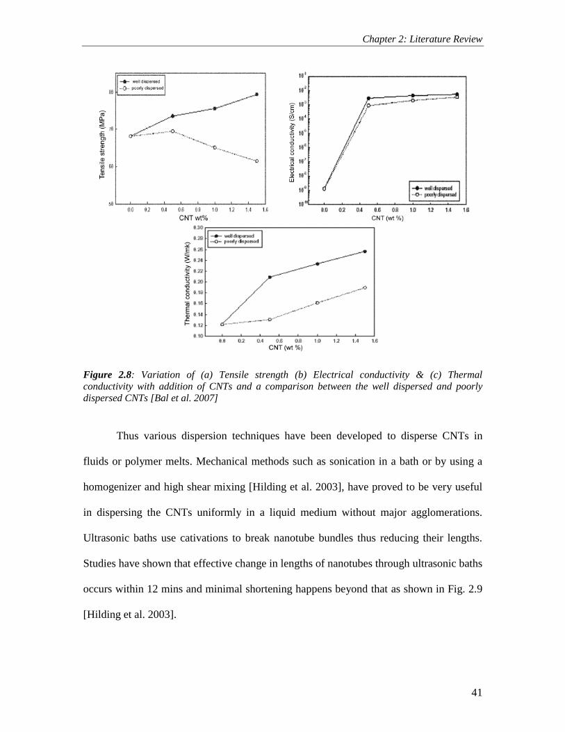
Chapter 2: Literature Review
41
Figure 2.8: Variation of (a) Tensile strength (b) Electrical conductivity & (c) Thermal
conductivity with addition of CNTs and a comparison between the well dispersed and poorly
dispersed CNTs [Bal et al. 2007]
Thus various dispersion techniques have been developed to disperse CNTs in
fluids or polymer melts. Mechanical methods such as sonication in a bath or by using a
homogenizer and high shear mixing [Hilding et al. 2003], have proved to be very useful
in dispersing the CNTs uniformly in a liquid medium without major agglomerations.
Ultrasonic baths use cativations to break nanotube bundles thus reducing their lengths.
Studies have shown that effective change in lengths of nanotubes through ultrasonic baths
occurs within 12 mins and minimal shortening happens beyond that as shown in Fig. 2.9
[Hilding et al. 2003].

Chapter 2: Literature Review
42
Figure 2.9: CNT length as a function of time with ultrasonication bath [Hilding et al. 2003]
Moreover , good interfacial bonding is essential to achieve load transfer across the
CNT-matrix interface which is very important for improving the mechanical properties of
the composite. If the adhesion between the matrix and the CNTs is not strong enough to
sustain high loads, the benefits of the high tensile strength of CNTs are nearly lost. Load
transfer depends on the interfacial shear stress between the fibre and the matrix [Schadler
et al 1998].
Thus many methods have been developed to functionalize the CNTs by chemical
methods such as acidic treatments [Huang et al. 2002, Moon et al. 2001],
fluorination[Margrave et al. 1999], by using surfactants [Riggs et al. 2000] and more
recently by plasma treatment [Utegulov et al. 2005]. The functionaliztion of CNTs
improves the interaction between the CNTs and the surrounding matrix. The interaction
can be influenced by selecting a specific kind of functional groups. This helps in the

Chapter 2: Literature Review
43
proper dispersion of the CNTs and also in improving the adhesion of the CNTs with its
surrounding polymer matrix [Hilding et al. 2003] through chemical bonding.
Eventhough much studies have been conducted in improving the properties of
polymer matrix with CNT reinforcements, very few studies have been reported for the
polymer film. Thus, in view of the above literature presented, one of the approaches
taken in this present study to improve the mechanical and thermal properties of the
UHMWPE film is to reinforce the UHMWPE film with Single walled Carbon Nanotubes
(SWNTs). The various dispersion and functionalization techniques adopted will be
discussed in the following chapters.
2.8 Providing an overcoat of PFPE – The Third Approach
Zoo et al. [2004] observed that an increase in the CNTs content in the UHMWPE
polymer decreased the wear loss with a slight increase in the coefficient of friction. Thus,
to reduce the friction of the nanocomposite film we adopted the approach of overcoating
the film with a thin layer of perfluropolyether (PFPE).
Perfluoropolyether (PFPE) lubricants were first developed in the early 1960‟s and
used in wear resistant lubricant applications. Perfluoropolyethers are a unique class of
lubricants and functional fluids, which can be used, in dramatically different applications
because of their versatility. The reasons for the selection of PFPE being, its chemical and
thermal stability, low vapour pressure, low surface tension and good lubricity that are all
necessary for better tribological performances.
PFPE has been used as a top layer to improve the wear life of high speed steel
(HSS) tools [Rabinovich et al. 2002]. They observed that due to the top layer of PFPE,
the coefficient of friction was low and this protected the tool from any surface damage.

Chapter 2: Literature Review
44
Similar concept of overcoating a mobile hydrocarbon-based lubricant onto
chemically bound monolayers onto Si based MEMS component has been used to enhance
wear durability by Eapen et al [2005]. PFPE overcoats were also applied on UHMWPE
films deposited on Si substrate and a significant improvement in the wear life of the
UHMWPE film was observed [Satyanarayana et al. 2006, Minn et al. 2008].
Thus, seeing the advantages of a PFPE overcoat in reducing the friction and
increasing the wear life and the thermal stability of UHMWPE film which are essential
properties required for the film to sustain in demanding tribological applications, we
propose to use it as the top layer, only a few nanometer in thickness over the
nanocomposite film in the present study.
2.9 Research Objectives
To summarize, three approaches are adopted to enhance the tribological
properties of the UHMWPE film. First, is to improve the adhesion between the steel
substrate and the film by subjecting the substrate to proper pre-treatment such as air-
plasma treatment. Second, is to improve the load carrying capacity of the film by the
addition of some suitable filler materials such as SWCNTs and third is to improve the
tribological properties by overcoating the film by a thin layer of PFPE. Thus the main
objectives of the present study can be defined as follows:
To evaluate the feasibility of using UHMWPE as a coating in its pristine form and
with the addition of CNT as fillers with an overcoat of PFPE. (Chapters 4, 5, 6)
To evaluate the effectiveness of the nanocomposite film against different
counterfaces and exposure to UV radiations. (Chapter 7)

Chapter 2: Literature Review
45
To evaluate the effectiveness of the UHMWPE coating in the presence of liquid
lubricants without any additives in the base lubricating oil. (Chapter 8)
To evaluate the effectiveness of the nanocomposite film of UHMWPE and
SWCNTs at higher temperatures under dry and base oil lubricated conditions.
(Chapter 9)

Chapter 3: Experimental Procedure
46
Chapter 3
Experimental Procedures
In the present chapter we will describe various common experimental methods used for
fundamental physical, chemical, mechanical and tribological characterizations of the
films developed in this research. Details of the materials used, film deposition and sample
preparation are given in respective chapters for easy reference.
3.1 Surface Pre-treatment
3.1.1 Air-Plasma Pre-Treatment
As mentioned earlier in section 2.5.1, air-plasma treatment is one of the most effective
surface adhesion enhancement technique with lower processing cost, time and practically
no environmental pollution problems.
3.1.2 Working Principle of Air-Plasma
Surfaces exposed to the atmosphere contain a lot of organic or inorganic contaminants
from dust, CO2 and hydrocarbon existing in the surface, resulting in poor adhesion
property. These surfaces, on exposure to air plasma discharge, are subjected to very high
energy bombarding electrons, thus breaking the molecular bonds on the surface. The
carbon contaminants on the surface are removed in the form of CO2 which is formed due
to the reaction of carbon with the free oxygen radicals in the plasma. This is termed as the
carbon cleaning effect. Moreover, the oxygen radicals in the plasma oxidize the surface
generating a few functionalized groups which help in improving the wettability and the
adhesion property of the surface. This is termed as the oxidation effect [Loh 1999]. The
principle of air plasma treatment is schematically illustrated in the Fig. 3.1.

Chapter 3: Experimental Procedure
47
Figure 3.1: A schematic showing the working principle of the air-plasma treatment
3.1.3 Air-Plasma Used in the present research
The air-plasma treatment was used to for two purposes in the present research.
1. Pre-treatment of steel/Al surfaces for improving the adhesion between the
polymer film and the substrate.
2. Functionalization of the catbon nanotubes for improving the adhesion between the
CNTs and the polymer matrix.
3.2 Surface Characterization and analysis
3.2.1 Contact angle measurement
Contact angles on the unmodified and modified surfaces were measured with VCA
Optima Contact Angle System (AST Products, Inc. USA). A water droplet of 0.5 to 1 μl
was used for contact angle measurement. At least 5 to 6 replicate measurements, for three

Chapter 3: Experimental Procedure
48
different samples, were carried out and an average value was taken. The variation in the
water contact values at various locations of a sample is within 2o.
3.2.2 Topography measurements with Atomic Force Microscopy (AFM)
In AFM imaging, a tip is brought close to the surface where the tip interacts with the
surface through many interfacial forces, which in turn causes the tip to deflect. A laser
beam focused on the tip is reflected from the tip into a photodiode array to measure the
deflection of the tip. Primarily, AFM can be operated in two modes to measure the
topography (contact mode and tapping mode) [Digital Instruments MultiModeTM
Instruction Manual 1997]. In the contact mode AFM, the tip rasters the surface while the
deflection is maintained constant via a feedback loop. In the tapping mode AFM, the tip
is oscillated at its resonance frequency (on the order of 300 kHz), while scanning the
sample surface. The reflected laser beam operates a sinusoidal signal in the photodiode
array, whose amplitude depends on the surface topography. As the oscillating tip is
rastered over the surface, the tip is deflected by its interactions with the surface and
causes a change in the measured amplitude. The tip in the contact mode AFM is dragged
across the surface and hence may sometimes damage/alter the surface features whereas
the tapping mode is gentler and cannot lead to any modification of the surface features.
Hence, tapping mode AFM is routinely used for topography studies of ultra-thin films
(especially organic thin films).
The tip geometry plays an important role in determining the actual topography of
the thin film or any surface. Variations in tip structure may cause variations in AFM
images. Typically, a sharp tip would provide an accurate representation of the surface
topography. If the tip is blunt the surface topography is going to be erroneous. For

Chapter 3: Experimental Procedure
49
example, if the tip is blunt and the surface features of the sample (to be imaged) are such
that the dimensions of the surface features are smaller than those of the apex of the tip,
then instead of tip imaging the sample surface features, the sample surface features image
the tip surface. Additionally, the mechanical properties of the cantilever are important in
controlling the performance of the AFM imaging, for example, the spring constant and
the resonance frequency are of particular importance. A small spring constant is desired
to effectively detect small forces and a high resonance frequency is required to make the
tip insensitive to vibrations and mechanical noise.
The surface topography of the polymer films on the metallic substrates, in the
present research, was investigated using Digital Instruments MultimodeTM
AFM (Veeco,
USA). Tapping mode was used for imaging using a silicon tip and all images were
collected in air. The set point voltage used was 1-2 V and the scan rate was 1 Hz.
3.2.3 Fourier Transform-Infrared Spectroscopy (FTIR)
FTIR is an analytical technique to identify organic (and in some cases inorganic)
materials. This technique measures the absorption of infrared radiation by the sample
material versus wavelength. The infrared absorption bands identify molecular
components and structures. When a material is irradiated with infrared radiation,
absorbed IR radiation usually excites molecules into a higher vibrational state. The
wavelength of light absorbed by a particular molecule is a function of the energy
difference between the at-rest and excited vibrational states. The wavelengths that are
absorbed by the sample are characteristic of its molecular structure.
An interferometer is used in the FTIR spectroscopy to modulate the wavelength
from a broadband infra-red source. A detector measures the intensity of transmitted or

Chapter 3: Experimental Procedure
50
reflected light as a function of its wavelength and provides an interferogram, which must
be analyzed with a computer using Fourier transforms to obtain a single-beam infrared
spectrum. The FTIR spectra are usually presented as plots of intensity versus
wavenumber (in cm-1
) where the wavenumber is the reciprocal of the wavelength. The
intensity can be plotted as the percentage of light transmittance or absorbance at each
wavenumber.
FTIR spectra for UHMWPE and the nanocomposite coatings on steel were
obtained in air using a Bio-Rad FTIR model 400 spectrophotometer using transmission
mode. Each spectrum was collected by accumulating 16 scans at a resolution of 4 cm-1
.
The spectra were collected from at least 5 to 6 replicate points. Bare Steel was used for
background scan.
3.2.4 X-ray Photoelectron Spectroscopy (XPS)
XPS was used to study the chemical state of the sample surface. XPS gives information
about the atomic composition of the surface and is especially sensitive to the local
chemical environment of an atom. In the XPS measurement, x-rays are usually generated
either by Mg or Al source and directed to the sample surface. The x-rays cause a core
electron to be emitted from the sample. The kinetic energy of this electron is detected
with an electron multiplier and is equal to the difference between the energy of the x-ray
(1253 eV for Mg, 1486 eV for Al) and the binding energy of the electron.
In the present research, XPS measurements were made on a Kratos Analytical
AXIS HSi spectrometer with a monochromatized Al Kα X-ray source (1486.6 eV
photons) at a constant dwell time of 100 ms and pass energy of 40 eV. A photoelectron
take-off angle of 90o (with respect to the sample surface) was used to obtain the core-

Chapter 3: Experimental Procedure
51
level signals. All binding energies (BE) were referenced to the C1s hydrocarbon peak at
284.6 eV.
3.2.5 X-Ray Diffraction Technique
XRD is a non-destructive analytical technique for identification and quantitative
determination of the various crystalline forms, known as „phases‟. XRD enables us to
determine:
• Which phases are present?
• At what concentration levels?
• What are the amorphous content of the sample?
When a monochromatic x-ray beam with wavelength is incident on the lattice planes of
a crystal plane in a crystal at an angle , diffraction occurs only when the distance
traveled by the rays reflected from successive planes differs by a complete number n of
wavelengths. By varying the angle , the Bragg‟s Law conditions are satisfied by
different d-spacing in polycrystalline materials. Plotting the angular positions and
intensities of the resultant diffraction peaks produces a pattern which is characteristic of
the sample [Callister 2003].
In the present research, X-ray diffraction was conducted to determine the
crystallinity and any possible change in the chemical structure of the polymer coating due
to the addition of SWCNTs. XRD was carried out using Cu NF (k = 1.542A ˚) radiation
in a Shimadzu XRD-6000 X-ray diffractometer operating at 40 kV and 20 mA.
3.2.6 FESEM observation of polymer films
JEOL JSM-5600 LV SEM (scanning electron microscope) equipped with EDS (energy
dispersive spectroscopy) was used to investigate the surface morphology of the polymer

Chapter 3: Experimental Procedure
52
films studied in the present research. The EDS/EDX analysis was used to determine the
failure/peeling-off of the coatings at different loads and speeds. Before taking FESEM
images, gold coating was performed on the films at 10mA for 40s (JEOL, JFC-1200 Fine
Coater).
3.2.7 Surface Roughness Measurements
Surface roughness of the pristine and the nanocomposite films with different
concentrations of SWCNTs were measured using the Wyko NT1100 Optical profiler
(Veeco, USA). NT1100 utilizes white light interferometry for high resolution 3D surface
measurements, from sub – nanometer roughness to millimeter- high steps.
3.3 Measurement of thickness of the polymer films using Field Emission
Ion Beam (FIB) technique
Polymer film thickness is usually measured by using non-contact laser profilometer
[Satyanarayana et al. 2006], sectioning/SEM [Minn et al. 2008], AFM [Lobo et al. 1999].
In this study a new technique of Focussed Ion Beam (FIB) milling is implemented for
measuring the film thickness deposited onto the steel substrates. Conventionally, FIB is
used for failure analysis, defect characterization, design modification. However, in the
present study, FIB is used to cut the film in the direction perpendicular to the film surface
until a certain depth into the substrate and the thickness is measured through the cross
sectional analysis of the cut obtained through this milling. The thicknesses of the
UHMWPE films obtained using FIB milling in the present study are in good agreement
with the earlier obtained thicknesses for the UHMWPE film [Minn et al. 2008].
The film thicknesses were measured using the Focussed Ion Beam milling
technique. FIB – Quanta 200 3D-Dual Beam from FEI Company, USA, was used for this

Chapter 3: Experimental Procedure
53
purpose. Square patterns of size 50 µm X 50 µm with a depth of 40 µm were cut in the
coated sample using an ion beam with a current of magnitude equal to 7 nA under
vacuum. The walls of the cut were viewed under Scanning electron Microscopy (SEM) in
a tilted position, at ~52o to clearly see the cross-section of the film, the substrate and the
interface, and, the thickness of the polymer film was measured. Three readings for every
sample were recorded and an average value was calculated. The actual thickness of the
film was calculated from the reading obtained in the tilted position by using the following
equation: Thickness = (Reading) X Sin52O, as the stage in the FIB-Quanta 3D machine is
inclined at 52O
to the horizontal to the line of view. Figure 3.2 shows a typical case of
thickness calculations.
Figure 3.2: A typical example of polymer film thickness measurements using the FIB
technique
3.4 Scratch Tests
The tribological properties of thin films are governed to a great extent to the adhesion
strength between the film and the substrate. To evaluate the critical load under which the
film would fail, scratch tests were performed.
Scratch tests are carried out on a custom-built scratch tester by using a conical
diamond tip of radius 2 µm. The length of the scratch and the traverse velocity of the tip
Polymer Steel Substrate

Chapter 3: Experimental Procedure
54
we kept constant for every scratch as 10 mm and 0.1 mm/s, respectively. Normal load
was also kept constant during scratching. However, the normal load was varied from 1 g
to 15 g with an increment of 1g for every successive scratch. After the test, the scratches
were characterized using FESEM/EDS technique to ascertain the critical load defined as
the load at which the polymer film showed signs of failure which was characterized by
the peeling off or ploughing mechanism and the appearance of Fe peaks (because of
exposed substrate) in the EDS spectrum. Before observing the scratches under FESEM
(Field Emission SEM), gold coating is performed on the films at 10 mA for 40 s by using
a JEOL, JFC-1200 Fine Coater.
3.5 Thermal Characterization of the polymer films
3.5.1 Thermogravimetric Analysis (TGA)
TGA is a testing procedure in which changes in the weight of a specimen are recorded as
the specimen is heated in air or in a controlled atmosphere such as nitrogen.
Thermogravimetric curves (thermograms) provide information regarding
polymerization reactions, the efficiencies of stabilizers and activators, the thermal
stability of final materials, and direct analysis. It is a well established technique to study
the thermal stability of polymers.
In the present research, DTG-60H machine from Shimadzu (Japan) was used to
perform the TGA. The nanocomposite films were heated up to 800 OC at a rate of 10
OC/minute in the air atmosphere.

Chapter 3: Experimental Procedure
55
3.5.2 Thermal Conductivity Measurements
Thermal conductivity was measured using the QuickLine-10 machine (Thermophysical
Instruments, Anter Corporation, USA). The QuickLine-10 implements the ASTM E1530
guarded heat flow meter method to compute the thermal conductivity of the samples with
an accuracy of ± 3% to ± 8%. Steel samples of 50 mm diameter and 20 mm thickness
were coated with the nanocomposite films having different concentrations of SWCNTs
and used to measure the thermal conductivity. A compressive pressure of 20 psi (0.137
MPa) was applied to ensure proper contact between the test samples and the platens of
the equipment. The reported thermal conductivity is an average value of three readings
measured on three different samples.
3.6 Tribological Characterization of the polymer films
3.6.1 Wear and Frictions tests on Flat samples [Point Contact]
Ball-on-disk wear tests as show in Figure 3.3, were carried out on UMT-2 (Universal
Micro Tribometer, CETR, USA) under dry conditions using ball-on-disk mode. The
tribometer has the capability of applying loads upto 500 gms (5 N) and rotational speeds
of up to 5000 rpm (1.04 m/s). A silicon nitride ball of Φ4 mm with a surface roughness of
5 nm (as provided by the supplier) was used as a counterface material. The ball was
thoroughly cleaned with acetone before each test. The wear track radius was fixed at 2
mm for all the tests. In this study, wear life of the thin film in dry sliding is defined as the
number of cycles until the coefficient of friction exceeds 0.3 or until continuous large
fluctuations are observed in the coefficient of friction data (indicative of film failure),
whichever happens first [Miyoshi (2001)]. At least three repetitions for every
combination of load and speed were carried out and average values were calculated. Tests

Chapter 3: Experimental Procedure
56
were carried out in a clean booth environment (class 100) at a temperature of 25±2 OC
and a relative humidity of 55±5%.
Figure 3.3: A ball-on-disk configuration used for tribological characterization of polymer films
on flat surfaces
The FESEM (JEOL JSM-5600 LV) was used to observe the worn surfaces after
appropriate number of sliding cycles. Wear tests were carried out at varying loads and
speeds such as specified in the respective chapters.
3.6.2 Wear and Friction tests on Cylindrical samples (Dry and Oil-Lubricated
conditions at room temperature) [Line contact]
A custom built plate-on-cylinder tribometer was used to simulate the line contact. Figure
3.4(a) shows the experimental setup used to conduct the wear tests. The principle of
operation of this tribometer is a shaft mounted onto an AC motor where a speed
controller drives the cylindrical shaft at selected speeds. The loading weights are used to
transmit a normal force onto the flat plate pivoted at one end of the cantilever arm. The
strain gauges attached to the cantilever beam, measure the frictional force which is
determined by the cantilever beam deflection during loading. The resistance of strain
gauges is therefore converted and transmitted to a digital data logger from KYOWA
BRAND PCD-300A. The transmitted data (frictional force) is displayed graphically as a

Chapter 3: Experimental Procedure
57
function of frequency onto a computer with the aid of software (PCD Reader).
Furthermore, a thermocouple was used to measure the temperature change of the oil in
the oil reservoir. The tribometer is used to measure the coefficient of friction, wear life
and wear rate of the pristine and the nanocomposite UHMWPE coatings under dry and
lubricated conditions. In this study, the cylindrical shaft was coated with the coatings
instead of the flat plate because this project aims to simulate a more realistic experiment
where the shaft acting as a journal is coated and undergoes wear at various conditions in
terms of load and speed, hence providing a more realistic wear life and wear rate. An oil
reservoir was designed to provide the rotating shaft with continuous supply of the
lubricant to conduct the tests under simulated lubricated conditions. In addition, a
thermocouple was introduced during lubricated conditions to observe how temperature of
the lubricant contained in the oil reservoir changed with time during the experiments. The
experimental parameters such as the loads and rotational speeds are selected to simulate
the boundary and mixed lubrication regimes for evaluating the effectiveness of the
nanocomposite coating in protecting the metallic surfaces.

Chapter 3: Experimental Procedure
58
Speed
Controller
ThermocoupleCantilever
Strain Gauges
Weight
Oil Reservoir Specimens
Strain Data LoggerTemperature Data
Logger
(a)
(b) (c) (d)Shaft
Figure 3.4: (a) Experimental setup for the flat-on-cylinder wear tests (b) Shape of the two
samples used for conducting the tests (c) Oil reservoir used to supply oil to the mating surfaces
(d) A schematic of the line contact sample setup.
3.6.3 Wear and Friction tests on Cylindrical samples (Dry and Oil-Lubricated
conditions at elevated temperatures) [Line contact]
To evaluate the nanocomposite coating at elevated temperatures, the counterface flat steel
plate was heated using a cartridge heater as shown in Figure 3.5(a). A feedback loop
system was used to monitor the temperature at the point of contact by inserting a
thermocouple in the flat plate as shown in Figure 3.5(a). The variation in the temperature
obtained at the contact surface was less than ±5 OC. Care was taken to insulate the flat

Chapter 3: Experimental Procedure
59
counterface plate properly to decrease the heat losses and also to prevent any damage to
the strain gauges.
For the tests under base oil lubrication at higher temperatures, an oil reservoir as shown
in Figure 3.5 (b) is used. A constant flow of oil is ensured in the contact region depending
upon the rotational speed and the normal load. A thermocouple is also used to monitor
the temperature of the oil bath during the experiment.
Figure 3.5: (a) Experimental setup for heating the counterface to conduct experiments at
elevated temperatures (b) A thermocouple used to monitor the temperature of the oil
3.6.4.1 Operational Procedure
The cylindrical shaft specimen could be easily mounted and un-mounted from the
motor‟s shafts by means of interlocking with a M4 bolt as shown in Figure 3.6(a). The
flat plate is mounted on a shaft and gripped by 4x M6 bolts at one end of the cantilever
beam. The flat plate is then placed on top of the cylindrical shaft which is partly
submerged into an oil reservoir below, as shown in Figure 3.6(b).

Chapter 3: Experimental Procedure
60
Figure 3.6: (a) Procedure for mounting the cylindrical shaft on the motor shaft (b) Procedure of
securing the flat plate in the cantilever
A dial gauge was used to check the concentricity of both the shaft and the
cylindrical work piece as shown in Figure 3.7, before each experiment to ensure that the
error did not exceed 0.05-0.025 mm in the alignment of the line contact between the flat
plate and the cylinder.
Motor
M4 bolt
Cylindrical
shaft specimen
Motor Shaft
(a)
Oil reservoir
Shaft & Flat plate
Cantilever beam
(b)

Chapter 3: Experimental Procedure
61
Figure 3.7: Dial gauge positioning to check the concentricity to minimize the alignment error
3.6.4.2 Calibration of the setup
Figure 3.8 shows the direction of friction force generated when AC motor rotates in an
anticlockwise direction. The data logger is always set to “0” each time the weight is
added on the other end of the cantilever. The cantilever is then allowed to balance itself
to achieve its new equilibrium position each time new weights are added. An incremental
new weight of 100g is gradually added by making use of a pulley system using a rope
which was attached to the pin clamp.

Chapter 3: Experimental Procedure
62
Figure 3.8: Top view of the cantilever loading mechanism on to the cylindrical shaft
Each time, calibration is conducted at least 3 times to obtain an average
measurement and to minimize error from the data logger. Readings are taken and plotted
on a graph as shown in Figure 3.9.
Figure 3.9: Calibration graph for the tribometer setup
Direction of rotation of cylindrical shaft
Shaft Flat Plate Cantilever
Frictional Force

Chapter 3: Experimental Procedure
63
3.7 Nano-mechanical property characterization of polymer films using
Nanoindentation
MTS Nano Indenter® XP (MTS Corporation, Nano Instruments Innovation Center, TN,
USA) was used for measuring elastic modulus and hardness of polymer films with a
CSM technique. A small and sinusoidally varying signal is imposed in the CSM
technique in addition to a DC signal, for driving the motion of the indenter. The data are
obtained by analyzing the response of the system using a frequency-specific amplifier. In
the CSM method, the contact stiffness can be measured at any point along the loading
curve and not just at the point of unloading as in the conventional measurement. The
equipment will provide the hardness and elastic modulus values calculated from the CSM
stiffness data (acquired during the indentation experiment) using the analytical
expressions developed by Oliver and Pharr [1992]. Therefore, in the CSM method, the
hardness and modulus values are determined as functions of indentation penetration
depth with a single indentation load/unload cycle. The load and displacement resolutions
in the CSM technique are 50 nN and < 0.01 nm respectively. A triangular pyramid
diamond indenter (known as Berkovich indenter) was employed for all nanoindentation
tests. The average hardness and elastic modulus values are calculated from the data of a
total of 5 indentations made on different random surface locations. In the current work,
typical indentation load vs displacement curves are obtained, for certain coatings, at an
applied load of 250 µN and the hardness and elastic modulus are computed using Oliver
and Pharr [1992] method.
The NanoIndenter XP was also used for the nano-scratch tests on some polymer
films. Conical diamond tip with a cone angle of 90o and 1 µm radius was used for

Chapter 3: Experimental Procedure
64
scratching. For each sample, a scratch length of 200 µm at an increasing normal load,
from 10 µN to 500,000 µN, was made at a scratch velocity of 1 µm s-1
. The scratches
were then imaged using FESEM to understand the scratch resistance of polymer films
and to determine the critical loads.
3.8 Materials and Chemicals used in the Experiments
3.8.1 UHMWPE Polymer
In this study the polymer used for coating the various samples was ultra high molecular
weight polyethylene (UHMWPE). UHMWPE polymer (Grade: GUR X 143) in the form
of powder was supplied by Ticona Engineering Polymers, Germany and was procured
from a local Singapore supplier. The properties of the polymer are as shown in Table 3.1.
Decahydronapthalin (decalin) was used as a solvent to dissolve the polymer powder prior
to dip-coating.
Table 3.1: Properties of UHMWPE (GUR X 143) polymer
PROPERTY VALUE
Melt index MFR 190/15 = 1.8 ± 0.5 G/10 min
Bulk Density 0.33 ± 0.03 g/cm3
Average Particle size 20 ± 5 µm
3.8.2 Perfluropolyether (PFPE)
PFPE used in this study was Z-dol 4000 obtained from Solvay Solexis, Singapore. It was
dissolved in H-Galden ZV60 obtained from Anusimont INC. The chemical formulae of
Z-dol and H-Galden ZV 60 are HOCH2CF2O-(CF2CF2O)p-(CF2O)q-CF2CH2OH and
HCF2O-(CF2O)p-(CF2CF2O)q-CF2H, respectively, where the ratio p/q is 2/3.

Chapter 3: Experimental Procedure
65
3.8.3 SWCNTs – Single walled carbon nanotubes
Single walled carbon nanotubes with an average diameter of 10 nm were used as the filler
materials in this study. They were procured from Iljin Nanotech Co. Ltd, Korea. Which
were as processed grade and were produced using arc-discharge process.

Chapter 4: Deposition and tribology of UHMWPE coating on air-plasma treated tool steel –
First Approach
66
Chapter 4
Deposition and Tribology of UHMWPE coating on air-
plasma treated tool steel – First Approach
In view of the objectives of the thesis as stated in chapter 2, the feasibility of depositing
the UHMWPE coating by dip coating process onto air-plasma treated metallic substrates
and the tribological properties of the same at various loads and speeds will be discussed.
The effects of pre-treatment of the substrate before coating, and thickness of the film on
the tribological properties of the UHMWPE coating are evaluated and presented in this
chapter. This forms a foundation for the work to be explained in the following chapters.
4.1 Background
As already emphasized in the literature survey presented in the Chapter 2, steel is one of
the extensively used materials in engineering applications such as bearings and gears
where the tribological aspects of the contacting surfaces play very important roles in
determining the life of the component and the frictional energy losses. The ever-
increasing demand for improving the wear life and decreasing the coefficient of friction
in order to facilitate energy conservation in mechanical systems has motivated many
researchers to investigate the role of polymer coatings in these tribological applications.
Recent research has shown that polymer thin films have excellent tribological properties
when coated onto various metallic substrates such as steel and aluminium [McCook et al.
2005, Gadow et al. 2002, Sinha et al.2008].

Chapter 4: Deposition and tribology of UHMWPE coating on air-plasma treated tool steel –
First Approach
67
4.1.1 Main Objective
The main objective of this study was to explore the feasibility of depositing UHMWPE
polymer films on metallic substrates such as steel and evaluate its tribological properties
at different loads and speeds. As stated in chapter 2, three strategies to improve the
tribological properties of the UHMWPE polymer coatings were proposed and this chapter
focuses mainly on the first strategy as stated below:
Strategy 1: To improve the adhesion between the polymer coating and the substrate by
adopting an environmental friendly pre-treatment process of the substrate and study its
effects on the tribological properties of the polymer film.
The present chapter discusses the results obtained from implementing the above
strategy. In this study, a thin film of UHMWPE is coated onto DF3 tool steel substrate
using the dip coating process. Prior to the coating, the steel substrate was cleaned using
air-plasma under vacuum. Scratch tests were conducted to evaluate the adhesion strength
of the film to the steel substrate. The coated substrate was slid against a Φ4 mm silicon
nitride ball under dry conditions to investigate the tribological performance. Varying film
thicknesses were obtained by using different wt% concentrations of UHMWPE in the
coating solution and the film thickness was measured by the technique of FIB milling.
Wear tests were conducted to ascertain the optimum film thickness which demonstrated
the best tribological characteristics. Effects of different sliding speeds and normal loads
on the coefficient of friction and wear life were investigated by conducting wear tests.
UHMWPE wear track morphology was studied in an effort to deduce the wear
mechanisms.

Chapter 4: Deposition and tribology of UHMWPE coating on air-plasma treated tool steel –
First Approach
68
4.2 Materials
Specimens were prepared on DF3 Tool steel (C-0.95%, Mn-1.1%, Cr-0.6%, W-0.6%, V-
0.1% and the rest Fe) coupons of 25 mm X 25 mm X 5 mm dimensions with an average
hardness value of 60 HRC. The steel specimens were grounded flat and polished to an
average surface roughness of 18 nm. The properties of the UHMWPE polymer used have
already been listed out in chapter 3.
4.3 Sample preparation
4.3.1 Pre-treatment procedure for the steel surface
The pre-treatment procedure included the following steps. Steel samples were polished
and cleaned with distilled water and acetone successively in an ultrasonic bath prior to
drying using nitrogen gas. The samples were then air-plasma treated using Harrick
Plasma Cleaner/Steriliser. The sample surface was exposed to plasma under vacuum for
approximately 5 min using a RF power of 30 W. Care was taken not to expose the surface
to any further contamination and was immediately processed for the dip coating of
UHMWPE films.
4.3.2 Dip-Coating of polymer films on the steel substrate
UHMWPE polymer in powder form was dissolved in decalin by heating the solution to
170 OC for 60 min. Magnetic stirrers were used for uniform distribution of heat in the
solution and for speeding up the dissolution process. Coating was carried out once the
solution turned from white colour to transparent indicating a complete dissolution. The
specimens were dip-coated using a custom built dip-coating machine which could
submerge and withdraw the sample at a speed of 2.1 mm/s. The samples were held in the

Chapter 4: Deposition and tribology of UHMWPE coating on air-plasma treated tool steel –
First Approach
69
polymer-decalin solution for 30 s in submerged condition prior to withdrawal. The coated
samples were dried in air for 60 s and then post-heat-treated in a hot oven at 120 OC for
about 20 h for the complete evaporation of the solvent. After the post-heat-treatment the
samples were cooled slowly to room temperature in the oven and stored carefully in
desiccators before proceeding to tribological testing.
4.4 Experimental procedures
Surface characterizations such as water contact angle measurements, AFM
topography, FTIR and XPS were used to evaluate the physical and chemical properties of
the modified samples. The thickness measurements were carried out using the FIB
milling process. The adhesion strength of the film to the substrate is measured using the
scratch test. Tribological properties such as coefficient of friction and wear life are
measured using the micro-tribometer. All these characterization techniques have been
explained in detail in chapter 3. Fig.4.1 describes the flow process of the experiments.

Chapter 4: Deposition and tribology of UHMWPE coating on air-plasma treated tool steel –
First Approach
70
Mechanical
grinding/polishing
Surface
Modification
Cleaning with
water/acetone
Air-plasma
treatment
(RF-30 W, 5 min)
Dip Coating1 wt%, 3 wt%, 5 wt%UHMWPE in Decalin
Thermal
treatment
(120 OC, 20 hrs)
Dry Wear Tests(CETR tribometer)
Ball-on-DiskCounterface: Φ 4mm, Si3N4
Ex
perim
en
ta
l P
ro
ced
ure
Figure 4.1: Flow process of the experimental procedure
4.5 Results
4.5.1 Physical and chemical analysis of the UHMWPE coating
Table 4.1 lists the water contact angles for different conditions of the steel surface
with/without plasma treatment and with/without UHMWPE coating. It can be observed
that after coating UHMWPE onto a steel sample without the plasma treatment, the water
contact angle increased from ~62O to ~102
O, thus making the surface more hydrophobic.
In the case of plasma treated steel samples, the water contact angle increased from ~10O
before coating to ~98
O after UHMWPE coating, thus making the surface from very
hydrophilic (owing to the plasma treatment) to hydrophobic i.e. more water repellent. For
a comparison, the water contact angle of bulk UHMWPE measured using a water droplet
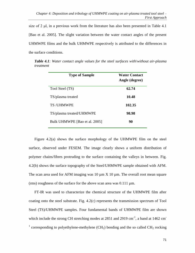
Chapter 4: Deposition and tribology of UHMWPE coating on air-plasma treated tool steel –
First Approach
71
size of 2 μl, in a previous work from the literature has also been presented in Table 4.1
[Bao et al. 2005]. The slight variation between the water contact angles of the present
UHMWPE films and the bulk UHMWPE respectively is attributed to the differences in
the surface conditions.
Table 4.1: Water contact angle values for the steel surfaces with\without air-plasma
treatment
Type of Sample Water Contact
Angle (degree)
Tool Steel (TS) 62.74
TS/plasma treated 10.48
TS /UHMWPE 102.35
TS/plasma treated/UHMWPE 98.98
Bulk UHMWPE [Bao et al. 2005] 90
Figure 4.2(a) shows the surface morphology of the UHMWPE film on the steel
surface, observed under FESEM. The image clearly shows a uniform distribution of
polymer chains/fibres protruding to the surface containing the valleys in between. Fig.
4.2(b) shows the surface topography of the Steel/UHMWPE sample obtained with AFM.
The scan area used for AFM imaging was 10 µm X 10 µm. The overall root mean square
(rms) roughness of the surface for the above scan area was 0.111 µm.
FT-IR was used to characterize the chemical structure of the UHMWPE film after
coating onto the steel substrate. Fig. 4.2(c) represents the transmission spectrum of Tool
Steel (TS)/UHMWPE samples. Four fundamental bands of UHMWPE film are shown
which include the strong CH stretching modes at 2851 and 2919 cm-1
, a band at 1462 cm-
1 corresponding to polyethylene-methylene (CH2) bending and the so called CH2 rocking

Chapter 4: Deposition and tribology of UHMWPE coating on air-plasma treated tool steel –
First Approach
72
mode at 719 cm-1
, which are identical with the characteristic features of the bulk PE or
UHMWPE polymers [Elliot 1969, Alves et al. 2005]. The presence of these peaks
confirms that the chemical structure of the UHMWPE film after coating is similar to that
of the bulk UHMWPE.
Figure 4.2: (a) SEM morphology of the UHMWPE film on the DF3 tool steel surface. (b) AFM
image of the DF3 tool steel/UHMWPE surface (c) FTIR spectrum of the UHMWPE coated steel
surface
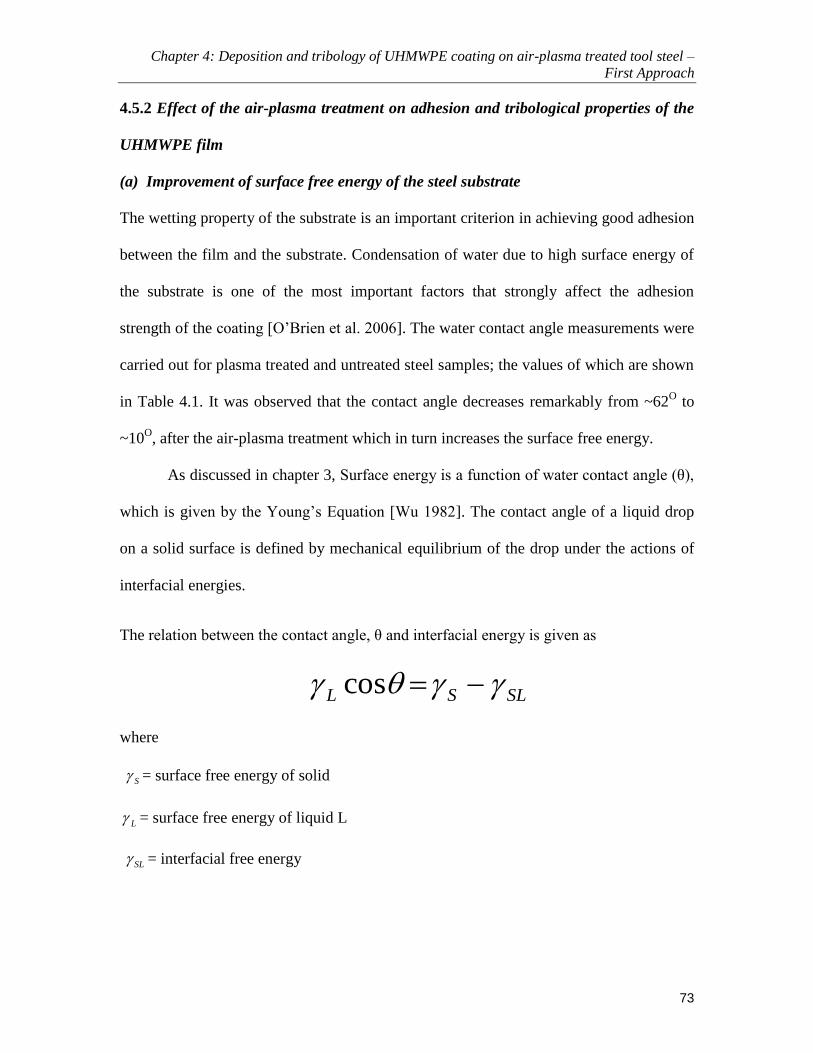
Chapter 4: Deposition and tribology of UHMWPE coating on air-plasma treated tool steel –
First Approach
73
4.5.2 Effect of the air-plasma treatment on adhesion and tribological properties of the
UHMWPE film
(a) Improvement of surface free energy of the steel substrate
The wetting property of the substrate is an important criterion in achieving good adhesion
between the film and the substrate. Condensation of water due to high surface energy of
the substrate is one of the most important factors that strongly affect the adhesion
strength of the coating [O’Brien et al. 2006]. The water contact angle measurements were
carried out for plasma treated and untreated steel samples; the values of which are shown
in Table 4.1. It was observed that the contact angle decreases remarkably from ~62O to
~10O, after the air-plasma treatment which in turn increases the surface free energy.
As discussed in chapter 3, Surface energy is a function of water contact angle (θ),
which is given by the Young’s Equation [Wu 1982]. The contact angle of a liquid drop
on a solid surface is defined by mechanical equilibrium of the drop under the actions of
interfacial energies.
The relation between the contact angle, θ and interfacial energy is given as
SLSL cos
where
S = surface free energy of solid
L = surface free energy of liquid L
SL = interfacial free energy

Chapter 4: Deposition and tribology of UHMWPE coating on air-plasma treated tool steel –
First Approach
74
The increase in the surface free energy of the steel surface as a result of reduction
in water contact angle is expected to improve the adhesion between the polymer film and
the substrate as discussed later in this chapter.
(b) Surface characterization using XPS
To investigate the reason for the increase in the surface free energy of the substrate, XPS
analysis was conducted on the surface of steel to study the effect of air-plasma treatment.
As evident from the contact angle measurements, the surface of steel becomes more
hydrophilic after the air-plasma treatment. This is due to the generation of new oxygen
containing groups on the surface of the substrate and the removal of the organic
contaminants as evident from the XPS analysis results. Figure 4.3(a) shows a smaller C
1s peak for the plasma treated sample as the sample surface is cleaned of the organic
contaminants after the plasma treatment. These findings are in accordance with the
investigations of many researchers who attribute the increase in the surface free energy to
the generation of new oxygen-containing groups [Tang et al. 2005, Loh et al. 1999]. After
the air-plasma treatment a decrease in the carbon concentration could be seen due to the
removal of the organic contaminants in the form of CO2 and CO by the breaking of bonds
due to the heat generated and the bombardment of the surface by the high energy plasma
as shown in Fig. 3.1. From the curve fitting of the C 1s spectra as shown in Figure 4.3(b)
it was observed that there was a considerable decrease in the concentration of organic
contaminants after the plasma treatment as compared to that of the untreated samples. It
was observed that due to the plasma treatment of the sample, there was a remarkable
increase in the concentration of the oxides on the surface as evident from Figure 4.3(c),
wherein peaks of FeOOH (711.8 eV) and Fe2O3 (710.2 eV) can be clearly seen. The

Chapter 4: Deposition and tribology of UHMWPE coating on air-plasma treated tool steel –
First Approach
75
results conform to the earlier research on the surface characterization of the steel surface
using the XPS measurements showing that after the plasma treatment, there is a decrease
in the carbon and an increase in the oxygen contents at the surface of the steel due to the
carbon cleaning effect and surface oxidation effect [Tang et al. 2005]. Thus, the increase
in the surface free energy is expected to enhance adhesion between the steel surface and
the UHMWPE film [Tang et al. 2006].
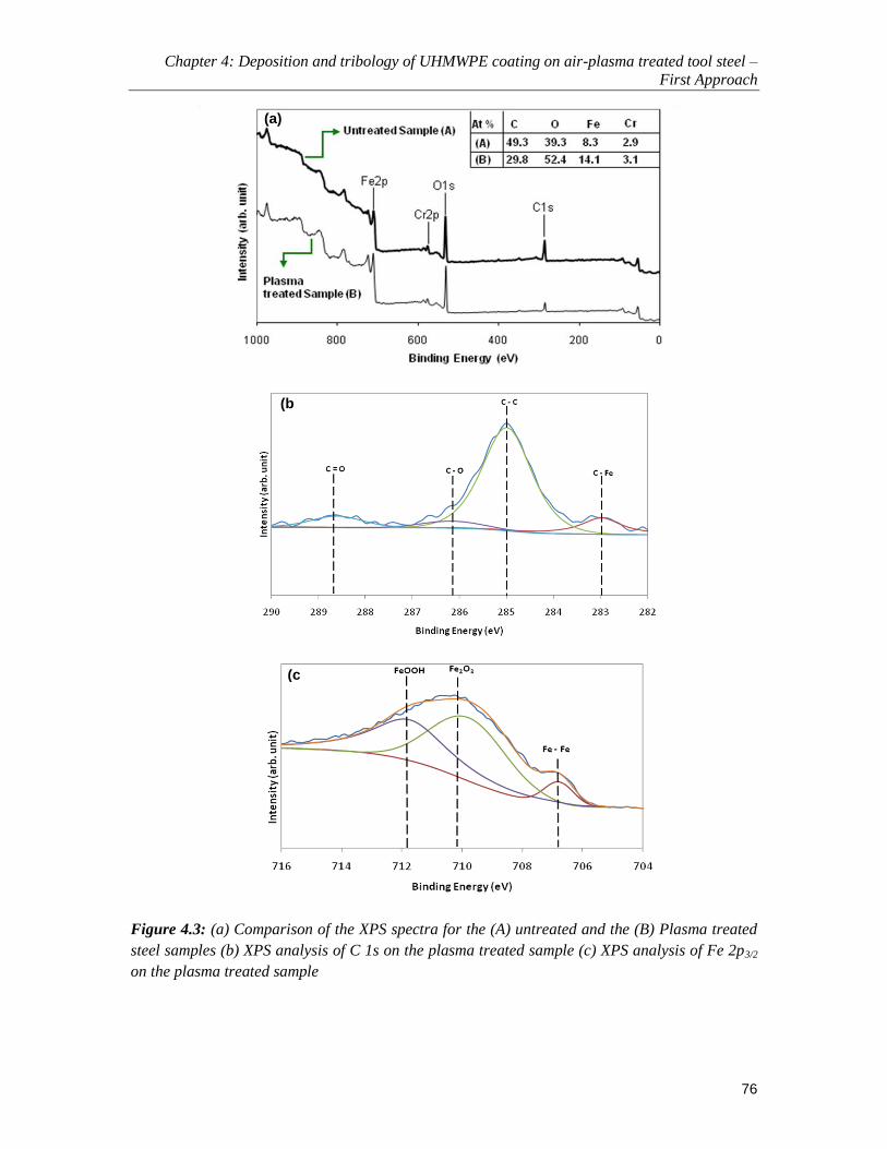
Chapter 4: Deposition and tribology of UHMWPE coating on air-plasma treated tool steel –
First Approach
76
Figure 4.3: (a) Comparison of the XPS spectra for the (A) untreated and the (B) Plasma treated
steel samples (b) XPS analysis of C 1s on the plasma treated sample (c) XPS analysis of Fe 2p3/2
on the plasma treated sample
(a)
(b)
(c)

Chapter 4: Deposition and tribology of UHMWPE coating on air-plasma treated tool steel –
First Approach
77
(c) Adhesion between the steel substrate and the UHMWPE film
Scratch tests were performed to investigate the effect of the air-plasma treatment on the
adhesion strength of the UHMWPE film to the steel surface. Results showed that after
air-plasma treatment the critical load at which the film failed during scratching, increased
by three times to ~0.12 N when compared to ~0.04 N for the untreated sample.
Considerable peeling-off and ploughing was observed along the whole length of the
scratch in the case of untreated samples at a scratch load of 0.04 N. The EDS spectrum
further confirmed the film failure by the presence of the Fe peak at the regions of peeling-
off. Such a failure of UHMWPE film is observed at a scratch load of 0.12 N in the case
of plasma-treated samples which infers greater scratch resistance and in turn greater
adhesion strength of the UHMWPE film to the substrate due to the air-plasma treatment.
Figure 4.4 shows FESEM images of the scratches under the critical load of 0.12 N for the
treated sample and 0.04 N for the untreated sample, along with the EDS spectra showing
the Fe peak indicating the failure of the UHMWPE film. The higher intensity of the Fe
peak in the EDS spectrum for the untreated sample indicates greater exposure of the tool
steel substrate.
The increase in the adhesion strength may be attributed to increased wettability
and surface energy due to the generation of active species after the plasma treatment.
Carbon contaminations from dust, CO2 and hydrocarbon on the surface of the steel which
is exposed to atmosphere will have a detrimental effect on the adhesion property. But
when the steel is treated by air-plasma, these carbon contaminations are removed by the
oxygen radicals by the carbon cleaning effect. Moreover, activated oxygen radicals in the
plasma oxidize the surface of steel, and, functional groups, which improve the adhesion

Chapter 4: Deposition and tribology of UHMWPE coating on air-plasma treated tool steel –
First Approach
78
on the steel surface, are generated by this surface oxidation effect [Tang et al. 2005].
Thus, after the air-plasma pre-treatment, the wettability on the steel surface was better
due to increased surface free energy as a result of the carbon cleaning and surface
oxidation effects (see Table 4.1).

Chapter 4: Deposition and tribology of UHMWPE coating on air-plasma treated tool steel –
First Approach
79
Figure 4.4: FESEM images of the scratches of (a) untreated sample tested at a scratch load of
0.04 N and (b) air-plasma treated sample tested at a scratch load of 0.12 N. Inset, EDS analysis
images, showing the failure of the polymer film with a peak of Fe.

Chapter 4: Deposition and tribology of UHMWPE coating on air-plasma treated tool steel –
First Approach
80
(d) Effects of the air-plasma treatment on the tribological properties of the
UHMWPE film
Wear tests were carried out on a ball-on-disk micro-tribometer (CETR Inc. USA) for the
untreated/coated and treated/coated samples for comparison purpose. The normal load
was kept constant at 0.3 N and the speed at 200 rpm. Three runs for each of the
conditions were conducted. Figure 4.5 demonstrates the variation of the coefficient of
friction with the number of cycles for a typical run for each of the surface condition. It
has been observed that in the case of treated/coated sample, the steady state coefficient of
friction for a complete run of 100,000 cycles (experiment was stopped at this point) was
approximately ~0.14 when compared to that of ~0.4 for the untreated/coated samples.
The average wear life for this study is defined as the point at which the coefficient of
friction reaches a value of 0.3 or continuous fluctuations are observed in the coefficient
of friction curve [Miyoshi et al. 2001] whichever happens first. The average wear life for
the untreated/coated samples was ~8000 cycles which was much lower (by several orders
of magnitude) than that of the treated/coated samples for which the film did not fail even
after 100,000 cycles of sliding (The experiment was stopped at 100,000 cycles due to
long test duration). This increased wear life could be attributed to the inherent lubrication
properties of the UHMWPE molecules due to its linear chains [Briscoe and Sinha, 2002]
and, more importantly, to the improved adhesion between the film and the substrate due
to an increase in the surface energy after the air-plasma treatment on the steel substrate.

Chapter 4: Deposition and tribology of UHMWPE coating on air-plasma treated tool steel –
First Approach
81
0
0.2
0.4
0.6
0.8
1
1.2
0 25000 50000 75000 100000
Co
effi
cein
t o
f F
rict
ion
Number of Cycles
Without plasma
treatment\coated
with UHMWPE
With air-plasma treatment\coated with UHMWPE
Bare Steel Surface
Figure 4.5: Comparison of the coefficient of friction with respect to the number of cycles for a
typical run for the bare and UHMWPE film coated steel, with/without air-plasma treatment
before the coating of UHMWPE film. 3 wt% of UHMWPE was used to obtain the film
4.5.3 Effect of UHMWPE film thickness on friction and wear
The film thickness in the present study is calculated by using the FIB milling technique
as described in chapter 3. Wear tests were conducted to ascertain the optimum UHMWPE
film thickness which would show the best tribological properties. The normal load and
rotational speed were kept constant at 0.3 N and 200 rpm respectively. Three varying
concentrations of 5 wt%, 3 wt% and 1 wt% of UHMWPE were dissolved in 50 ml of
decalin respectively and dip coated onto polished and air-plasma treated steel samples to
obtain different film thicknesses. The film thicknesses were measured by the FIB-Quanta
3D method for the different concentrations of UHMWPE. The values of film thicknesses
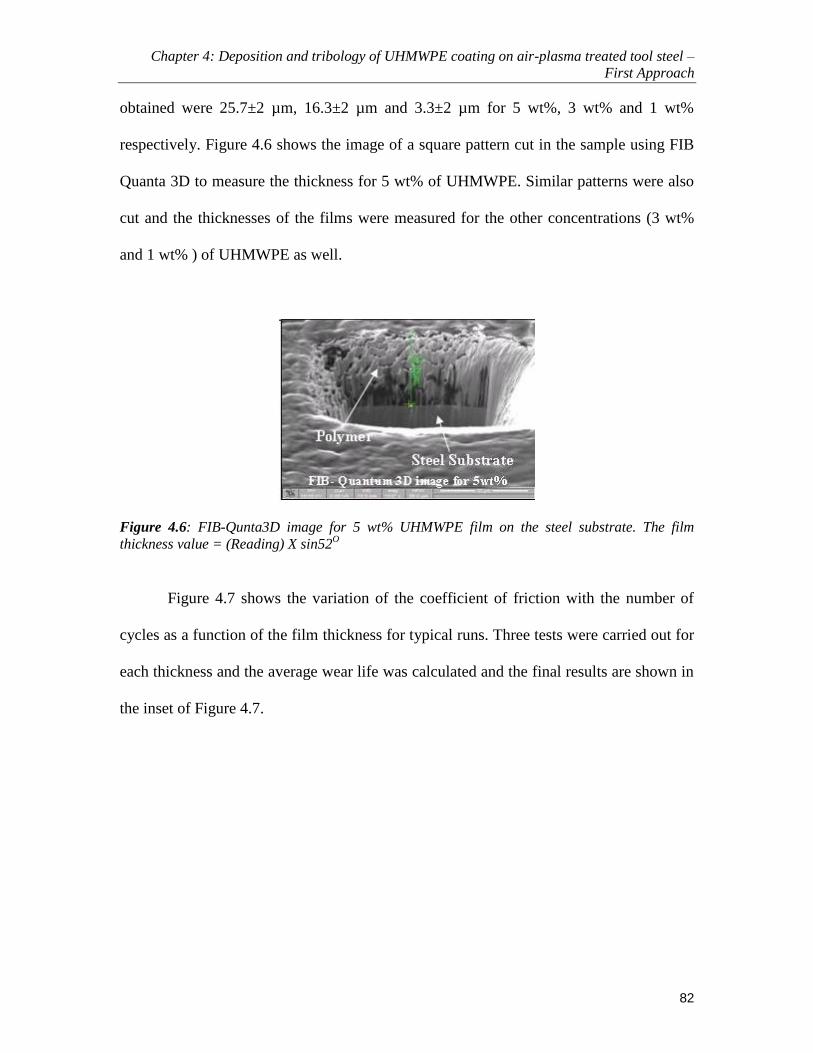
Chapter 4: Deposition and tribology of UHMWPE coating on air-plasma treated tool steel –
First Approach
82
obtained were 25.7±2 µm, 16.3±2 µm and 3.3±2 µm for 5 wt%, 3 wt% and 1 wt%
respectively. Figure 4.6 shows the image of a square pattern cut in the sample using FIB
Quanta 3D to measure the thickness for 5 wt% of UHMWPE. Similar patterns were also
cut and the thicknesses of the films were measured for the other concentrations (3 wt%
and 1 wt% ) of UHMWPE as well.
Figure 4.6: FIB-Qunta3D image for 5 wt% UHMWPE film on the steel substrate. The film
thickness value = (Reading) X sin52O
Figure 4.7 shows the variation of the coefficient of friction with the number of
cycles as a function of the film thickness for typical runs. Three tests were carried out for
each thickness and the average wear life was calculated and the final results are shown in
the inset of Figure 4.7.

Chapter 4: Deposition and tribology of UHMWPE coating on air-plasma treated tool steel –
First Approach
83
0
0.2
0.4
0.6
0.8
1
1.2
0 25000 50000 75000 100000
Co
effi
ccie
nt o
f F
rict
ion
Number of Cycles
Bare Steel Surface
1 wt% (thickness: 3.3 2 µm)
5 wt% (thickness: 25.7 2 µm)
3 wt% (thickness: 16.3 2 µm)
10
100,000
9000
1.E+00
1.E+01
1.E+02
1.E+03
1.E+04
1.E+05
1.E+06
Avera
ge W
ear L
ife (C
ycle
s)
Concentration of the polymer
Experiment wasstopped *
1 wt% 3 wt% 5 wt%
Figure 4.7: (a) Coefficient of friction as a function of sliding cycles for different wt% (different
thicknesses) of UHMWPE at a normal load of 0.3 N and a rotational speed of 200 rpm. Inset:
Average wear life for the three different thicknesses of the film. (* Wear life exceeded 100,000
cycles for all the three runs)
In the case of 1 wt% of UHMWPE film, the failure was immediate just after a few
cycles. This could be attributed to a very thin and possibly incomplete film formed on the
steel surface which was not adequate to support the pressure. This is quite evident from
the FESEM/EDS image [Figure 4.8(a) and (b)] analysis conducted on the coated surface
which shows the Fe peak very clearly indicating an inadequate film formation on the steel
surface. The EDS analysis of the wear track also indicates the complete failure of the film
and the higher coefficient of friction is due to the interaction between the ball and the
exposed steel substrate without any intermediate polymer film.

Chapter 4: Deposition and tribology of UHMWPE coating on air-plasma treated tool steel –
First Approach
84
It was observed that the film formed by the 3 wt% conc. UHMWPE/decalin
solution (thickness ~16.3±2 μm) demonstrated the best tribological properties as the film
did not fail until 100,000 cycles (for all the repeat runs) after which the experiment was
stopped. The film exhibited very low coefficient of friction throughout the sliding test
until 100,000 cycles as shown in Figure 4.7. Figure 4.8-(c) and (d) show FESEM/EDS
images for the film surface (left) and the wear-track (right), respectively, after the sliding
test until 100,000 cycles for 3 wt% UHMWPE film. In the inset, the optical micrograph
of the ball surface taken immediately after the wear test is also shown. FESEM image
analysis shows no debris formation along the wear track and the width of the wear track
was smaller when compared to that of the other two cases (1 wt% and 5 wt% UHMWPE
films). The wear track mark is a result of the ironing and plastic deformation of the initial
polymer film asperities that lead to the characteristic smoothening effect. The EDS
analysis of the wear track clearly shows the absence of the rupture or failure of the film.
The ball surface showed very little to no transfer of the polymer. After cleaning the ball
with acetone, the surface of the Si3N4 ball was very smooth with no indication of any
surface scratching or wear.
In the case of 5 wt% concentration of UHMWPE film (thickness ~25.7±2 μm),
the film failed early in spite of its higher thickness, as it showed an average coefficient of
friction greater than ~0.4 after about 9000 cycles. As stated earlier, if the coefficient of
friction exceeds a value of 0.3, the film is considered as failed for the present study.
Figure 4.8-(e) and (f) show the FESEM/EDS images of the surface and the wear track
respectively for 5wt % UHMWPE film. The optical micrograph of the ball surface is
shown in the inset. The early film failure can be attributed to the large amount of polymer

Chapter 4: Deposition and tribology of UHMWPE coating on air-plasma treated tool steel –
First Approach
85
transfer to the Si3N4 ball which is quite evident from the optical micrograph as shown in
Figure 4.8(f) which was taken immediately after the test. After the initial polymer film
formation on the Si3N4 ball, the interaction at the interface is no longer between the
ball/polymer but it becomes a polymer/polymer interaction with lumps of polymer at the
interface which eventually leads to an increase in the coefficient of friction due to 2-body
to 3-body adhesive and abrasive interactions, similar to that observed in many polymers
[20, 21]. The FESEM image analysis showed a great deal of debris formation around the
wear track. The EDS analysis showed that there was no complete failure (as evident from
the absence of Fe peak) of the film but in spite of this, the coefficient of friction was
higher which must be due to the polymer/polymer interaction and larger contact area
between the ball and the film as is evident from the size of the wear track which was
wider in comparison to the case in Figure 4.8(d).
Thus, it was observed that a concentration of 3 wt% of UHMWPE, which gave a film
thickness of ~16.3±2 μm, provided the best tribological results among those considered,
demonstrating a low coefficient of friction of ~ 0.08 to 0.17 and a wear life of greater
than 100,000 cycles.

Chapter 4: Deposition and tribology of UHMWPE coating on air-plasma treated tool steel –
First Approach
86
Figure 4.8: (a), (c) & (e), FESEM/EDS images of the coated surface of the steel sample for 1
wt%, 3 wt% and 5 wt% of UHMWPE. (b), (d) & (f), FESEM/EDS images of the wear track for 1
wt%, 3 wt% and 5 wt% UHMWPE. Inset (right-hand side corner), optical images of the ball
surface taken immediately after the wear test

Chapter 4: Deposition and tribology of UHMWPE coating on air-plasma treated tool steel –
First Approach
87
4.5.4 Effect of normal load and speed on friction and wear
Once the optimum thickness of the film was known, wear tests were carried out at
varying loads and speeds to study their effects on the friction and wear characteristics of
the UHMWPE film. All the samples were polished, cleaned, air-plasma treated and then
coated with 3 wt% of UHMWPE polymer obtaining a film thickness of ~ 16.3±2 µm.
To evaluate the load effect, rotational speed was kept constant at 200 rpm and tests
were carried out at normal loads of 0.3, 1, 2 and 4 N respectively. It was observed that the
UHMWPE film demonstrated excellent wear resistance up to the load of 4 N. The film
did not fail until 100,000 cycles for all the loads showing a very low coefficient of
friction between ~0.08 to 0.12. 4 N is the maximum normal load that the present machine
could reach.
To evaluate the effect of speed, the load was kept constant at 4 N and tests were
carried out at rotational speeds of 200, 400, 600, 1000 and 2000 rpm, respectively. Figure
4.9, shows the wear lives demonstrated by the UHMWPE film at various speeds. The
film demonstrated a wear life of greater than 100,000 cycles (experiment was stopped
due to long test duration) up to the speed of 600 rpm. However, the wear life reduced to
60,000 cycles at a speed of 1000 rpm and the film failed quite early (at 700 cycles) at a
speed of 2000 rpm. The PV factor (multiplication product of the pressure and the linear
sliding velocity) that the air-plasma treated/UHMWPE coated/Tools Steel sample
withstood was calculated to be approximately ~17.79 MPa ms-1
using Hertizian
calculations for pressure calculation taking a normal load of 4 N and a rotational speed of
600 rpm, the conditions at which the film did not fail. The calculation procedure is as
shown below:

Chapter 4: Deposition and tribology of UHMWPE coating on air-plasma treated tool steel –
First Approach
88
The PV factor (multiplication of the pressure and the linear sliding velocity was
calculated using Hertzian equation [Hutchings 1992] for calculating the contact pressure,
as given below:
202
3
a
PP
where 0P is the contact pressure, P is the normal load and a is the radius of the circular
contact area which is given by:
31
4
3
E
PRa
R is the radius of the ball and E is the contact modulus which is calculated as follows:
2
2
2
1
2
1 111
EEE
2,1 and E1,2 are the poisson’s ratio and elastic modulus of the two contacting surfaces
respectively. (E1=3 GPa, E2=310 GPa, ν1=0.43, ν2=0.22, R=2 mm)
The calculated PV factor was quite high with excellent life in dry sliding when
compared to other actual bearing materials such as PTFE: 0.350 MPa ms-1
, Composite
bearings: 2 MPa ms-1
, Magnesium Bronze: 5.25 MPa ms-1
[Hutchings 1992].

Chapter 4: Deposition and tribology of UHMWPE coating on air-plasma treated tool steel –
First Approach
89
200 400 600
60,000
1.E+00
1.E+01
1.E+02
1.E+03
1.E+04
1.E+05
1.E+06
Speed (rpm)
Av
era
ge W
ea
r L
ife (
Cy
cle
s) Experiment was stopped
1000
100,000
2000
700
Figure 4.9: Effect of the rotational speed on the average wear life at a normal load of 4 N
4.6 Conclusions
The effects of air-plasma pre-treatment, film thickness, normal load and sliding speed on
the tribological characteristics of UHMWPE films coated onto tool steel (DF3) samples
were investigated. Below listed are the conclusions drawn from the present study:
The air-plasma treatment has considerable effect on improving the adhesion
between the UHMWPE film and the steel substrate by enhancing the surface
energy which in turn results in good tribological characteristics of the film. The
wear life of the plasma treated steel sample coated with UHMWPE film increased
by more than 10 to 12 times when compared to that of the untreated steel samples
coated with UHMWPE film.

Chapter 4: Deposition and tribology of UHMWPE coating on air-plasma treated tool steel –
First Approach
90
The thickness of the UHMWPE film has a greater effect on the wear life and it
was observed that an optimum thickness of ~16.3±2 µm has greater wear
durability.
The tribological tests carried out at various loads and rotational speeds have
demonstrated that the presently optimized UHMWPE film on steel surface did not
show any failure until 100,000 cycles of sliding at a load of 4 N and rotational
speed of 600 rpm in completely dry sliding case (equivalent PV factor of ~17.79
MPa ms-1
).

Chapter 5: Development of a Nanocomposite UHMWPE polymer coating reinforced with single
walled carbonnanotubes – Second Approach
91
Chapter 5
Development of a Nanocomposite UHMWPE polymer coating
reinforced with single walled carbonnanotubes – Second
Approach
After the encouraging results obtained on the tribological properties of the pristine
UHMWPE film as described in chapter 4, a nanocomposite film of UHMWPE reinforced
with single walled carbon nanotubes was developed to improve upon the overall
mechanical and thermal properties of the film in general and the load bearing capacity in
particular. Carbon nanotubes, due to their excellent mechanical and thermal properties
have been selected for the filler material to improve the overall properties of the
UHMWPE polymer film. The development and deposition techiniques, the improvement
in the mechanical, thermal and tribological properties of the UHMWPE film are
discussed in the present chapter.
5.1 Background
In spite of its excellent properties as evident from the results presented in chapter 4, the
usage of UHMWPE in demanding tribological applications has been limited due to
various constraints such as its low load bearing capacity and thermal instability. The air-
plasma treated/UHMWPE film in its pristine form was able to sustain itself until a PV
factor (multiplication product of the pressure and the linear sliding velocity) of
approximately ~17.79 MPa ms-1
taking a normal load of 4 N and a rotational speed of
600 rpm, the conditions at which the film did not fail until 100,000 cycles. However, to
make the UHMWPE film suitable for demanding tribological applications such as in

Chapter 5: Development of a Nanocomposite UHMWPE polymer coating reinforced with single
walled carbonnanotubes – Second Approach
92
bearings and gears, its load bearing capacity has to be improved considerably. For this
purpose we decided to take up our second approach of reinforcing the polymer with some
nano fillers to develop a nanocomposite film to improve its overall mechanical, thermal
and tribological properties.
Addition of carbon nanotubes as reinforcement is one approach to overcome these
constraints. As explained in chapter 2, carbon nanotubes (CNTs) due to their excellent
mechanical (exceptionally high tensile strength and stiffness), electrical and thermal
properties have caught the attention of researchers in the recent years and are being
considered as a potential filler material for many polymer matrices. Several studies have
shown that the addition of CNTs resulted in significant improvements in the mechanical
properties such as the tensile modulus and strength of the polymer matrices [Bal et al
(2007), Giraldo et al (2008), Satyanarayana et al (2007)]. An increase in the wear
resistance of bulk UHMWPE with the CNTs addition has also been observed [Zoo et al
(2004), Xue et al (2006), Ruan et al (2006), Wei et al (2006)]. However, no study has
been reported on reinforcing the UHMWPE polymer coating with CNTs to improve its
overall mechanical, thermal and tribological properties for steel/aluminium substrates to
be used in sliding mechanical components.
Thus, the primary objective of this study is to evaluate the mechanical, thermal
and tribological properties of the UHMWPE film reinforced with the single-walled CNTs
(SWCNTs) coated onto steel substrates. The present study holds much significance in
view of its applications to many advanced tribological applications such as bearings,
gears, cams, pistons etc.

Chapter 5: Development of a Nanocomposite UHMWPE polymer coating reinforced with single
walled carbonnanotubes – Second Approach
93
5.2 Materials and Chemicals
Coatings were prepared on DF3 Tool steel (C-0.95%, Mn-1.1%, Cr-0.6%, W-
0.6%, V-0.1% and the rest Fe) coupons of 25 mm X 25 mm X 5 mm dimensions with an
average hardness value of 60 HRC. The steel specimens were first ground flat and
polished before coating them with the film. The properties of the UHMPWE polymer and
the carbon nanotubes used in this study are as listed in chapter 3.
5.3 Preparation of SWCNT/UHMWPE nanocomposite film on steel
substrates
To realize the benefits of SWCNT addition to the polymer film, it is extremely essential
to achieve their uniform dispersion in the polymer matrix without any agglomeration and
also to ensure proper bonding between the SWCNTs and the polymer [Xie et al (2005),
Foster et al (2005), Zhang et al (2006)]. Surface modification or functionalization of the
SWCNTs is one of the approaches to ensure good bonding between the nanotubes and the
polymer [Xie et al (2005), Wang et al (2005)]. Techniques like wet chemistry or exposure
to high temperature vapours which involve numerous steps have traditionally been used
to functionalize the SWCNTs [Cao et al (2002), Riggs et al (2000)]. Recently, plasma
treatment which is an environmental-friendly and a less time consuming process has been
used effectively to functionalize the SWCNTs to achieve strong bonding between the
nanotubes and the polymer matrix and also to obtain a uniform dispersion of the
SWCNTs [Zhandos et al (2005), Chen et al (2001), Plank et al (2003), Khare et al
(2002)].
In the present study, SWCNTs were plasma-treated using Harrick Plasma
equipment. To ensure that most of the SWCNTs were exposed to the plasma, the

Chapter 5: Development of a Nanocomposite UHMWPE polymer coating reinforced with single
walled carbonnanotubes – Second Approach
94
SWCNTs were spread out uniformly in a flat crucible and placed inside the plasma
chamber. Before the plasma treatment the base pressure inside the plasma chamber is
lowered to ~ 30 mTorr. In our study no monomer has been used. Once the SWCNTs are
plasma-treated, appropriate amount of decalin, the solvent for the matrix, is added to the
SWCNTs and sonicated using Sonics VCX-130 ultrasound homogenizer for 12 mins with
an amplitude of 30 % and a cycle on/off time of 20/5 s to ensure uniform dispersion in
decalin without major agglomeration. Studies have shown that effective change in lengths
of nanotubes through sonication occurs within 12 mins and minimal shortening happens
beyond that [Hilding et al (2003)]. After the sonication, appropriate amount of
UHMWPE powder is added to CNT dispersed decalin to make a 3 wt% solution of the
polymer. The solution subjected to mechanical stirring for 20 mins for proper mixing of
the SWCNTs and the polymer powder. The mixture is then heated at 170 OC for about an
hour to ensure a complete dissolution of UHMWPE. Magnetic stirrers were used for
uniform thermal distribution and for speeding up the polymer dissolution process. The
coating solution (with 3 wt% UHMWPE) was prepared using 0, 0.05, 0.1 and 0.2 wt% of
SWCNTs respectively.
Prior to coating, the steel samples were plasma-treated (RF power of 30 W for 5
min) to increase the surface hydrophilicity to ensure strong adhesion between the
polymer film and the substrate [Abdul Samad et al (2009)]. Coating was carried out
immediately using a custom built dip-coating machine at a constant speed of 2.1 mm/s.
The samples were held in the solution for 30 s and then withdrawn at the same speed to
obtain a uniform film.

Chapter 5: Development of a Nanocomposite UHMWPE polymer coating reinforced with single
walled carbonnanotubes – Second Approach
95
5.3.1 Modified Post Heat Treatment Process
To ensure a complete evaporation of the solvent, the steel samples were subjected to a
step-wise heat treatment. However, the post heat treatment process that was followed for
depositing the pristine UHMWPE film as explained earlier in Chapter 4, i.e. of heating
the samples for 20 hrs at 120 OC had to be modified slightly in case of the nanocomposite
film to obtain a uniform film. As shown in Fig. 5.1(a) & (b), the film obtained using the
earlier post heat treatment process was not uniform with the carbon nanotubes getting
agglomerated. This could be due to the fact that when the film is exposed to a
temperature of 120 OC which is close to the melting temperature of UHMWPE of 137
OC
immediately after coating, there is an excess flow of the polymer in all directions along
which the CNTs also get concentrated at specific places as clearly shown in Fig. 5.1 (a) &
(b).
Figure 5.1: (a) & (b) Nanocomposite coating with the earlier post heat treatment process (c)
Nanocomposite coating with the modified post heat treatment process
Thus, to obtain a uniform film the post heat treatment process was modified as follows:
30 mins at 45 OC, 30 mins at 70
OC, 30 mins at 95
OC followed by a 20 hrs heating at a
temperature of ~120 OC in a hot plate oven. This step wise heat treatment process gave
enough time for the coating to stabilize before being subjected to a higher temperature of
120OC. The quality of the film obtained was uniform as shown in Fig. 5.1 (c). However,
(a) (b) (c)

Chapter 5: Development of a Nanocomposite UHMWPE polymer coating reinforced with single
walled carbonnanotubes – Second Approach
96
the film thickness for the pristine and the nanocomposite films with step-wise heat
treatment was found to be ~ 55 ± 4 µm. An increase in the film thickness was observed as
compared to that of the reported value in chapter 4. This can be attributed to the
improved step-wise heat treatment process to obtain a uniform nanocomposite film which
gives less time for the polymer to flow freely. However, it was confirmed that no
considerable change in the film thickness was observed due to the addition of the CNTs.
The samples were stored in desiccators for further mechanical and tribological testing.
5.4 Experimental procedures
Surface characterizations such as water contact angle measurement, FESEM
morphology, XPS, FTIR are used to measure the properties of the thin films formed.
Tribological properties are measured using a micro-tribometer. Nano-mechanical
properties (Elastic modulus and hardness) are measured using Nano Indenter XP. The
thermal properties such as thermal degradation and thermal conductivity are measured by
using the TGA analysis [DTG-60H machine from Shimadzu (Japan)] and QuickLine-10
machine (Thermophysical Instruments, Anter Corporation, USA), respectively. The
thickness of the nanocomposite polymer films was estimated by the FIB quantum 3D
method. XRD (Shimadzu XRD-6000) is used to estimate the crystallinity of the
nanocomposite polymer films. The operational procedures of all the equipment are
explained elaborately in chapter 3.

Chapter 5: Development of a Nanocomposite UHMWPE polymer coating reinforced with single
walled carbonnanotubes – Second Approach
97
5.5 Results and Discussion
5.5.1 Effect of plasma treatment on the functionalization of SWCNTs (XPS analysis)
SWCNTs were air-plasma treated prior to adding them into the UHMWPE polymer
solution. This was to functionalize the surface of the SWCNTs that would help in
improving the overall adhesion of the SWCNTs to the surrounding polymer matrix.
Earlier studies have shown that the plasma treatment helped in substantial covalent
bonding of the polymer to the SWCNTs and unwrapping of the SWCNT bundles
resulting in their uniform dispersion in the polymer matrix [Plank et al (2003)].
XPS analysis of the plasma-treated SWCNTs showed a considerable increase in
the oxygen containing groups such as carbonyl (C=O), hydroxide (C—OH) and carboxyl
(COOH) on the SWCNTs surface. Figure 5.2 shows the overall C1s and O1s XPS spectra
for the untreated and the plasma-treated SWCNTs respectively, wherein the increase in
the intensity of the O 1s peak can be clearly seen. The atomic percent of oxygen on the
surface of the SWCNTs after the plasma treatment increased from 10.44% to 21.06%.
The curve fitting data with suitable peak assignments are shown in Table 5.1. The C1s
spectra for the untreated and plasma-treated SWCNT surfaces contain peak components
corresponding to C-C at 284.6 eV, C-O at 286.2 eV and C=O at 289 eV [29],
respectively. However, the area under the C-C peak is less in the case of plasma-treated
SWCNT than that corresponding to the untreated SWCNT, whereas the area under the C-
O and C=O peaks is more when compared to the untreated SWCNTs. This suggests that
the plasma treatment is very effective in generating the oxygen containing functionalized
groups on the surface of the SWCNTs as also reported by Plank et al (2003).

Chapter 5: Development of a Nanocomposite UHMWPE polymer coating reinforced with single
walled carbonnanotubes – Second Approach
98
Table 5.1: Curve fit data and suitable assignments of the peaks for C1s and O1s spectra of
SWCNT\untreated and SWCNT\plasma treated, respectively.
Pre-treatment Core-
level
spectrum
Binding
Energy
(eV)
Peak
Assignment
Area
(arb.
Unit)
FWHM*
(eV)
SWCNT-
untreated
C1s 284.6 C-C 22045 1.13
286.2 C-O 11597.4 1.2
289.0 C=O 4140.0 1.66
O1s 532.0 O-C 11066.6 1.25
533.3 O=C 1809.4 1.15
SWCNT-plasma
treated
C1s 284.6 C-C 18466.2 1.12
286.2 C-O 11855.0 1.23
288.9 C=O 6058.7 1.83
O1s 532.0 O-C 14892.4 1.16
533.0 O=C 5223.26 1.05
*FWHM means full width at half maximum
A similar trend is observed in the O1s spectra. The O1s spectra of both the
untreated and the plasma-treated SWCNT surfaces contain peak components
corresponding to O-C and/or OH groups at 532 eV [Kuemmel et al (2007)] and O-C at
533.3 eV [Beamson and Briggs (1992)], respectively. However, the area under both the
peaks of O-C/OH and O=C is higher, in the case of plasma-treated SWCNT when
compared to those untreated SWCNTs. The higher peak area at a binding energy (BE) of
532 eV for plasma-treated SWCNTs, suggests that the plasma treatment is effective in
producing more hydroxyl groups on the SWCNT surface [Kuemmel et al (2007)]. The
generation of these hydroxyl groups helps in increasing the surface energy and thus
making the surface more hydrophilic which is expected to improve the adhesion between
the polymer matrix and the SWCNTs.
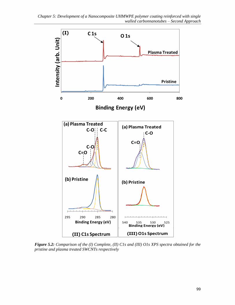
Chapter 5: Development of a Nanocomposite UHMWPE polymer coating reinforced with single
walled carbonnanotubes – Second Approach
99
0 200 400 600 800
Inte
nsi
ty (
arb
. U
nit
)
Binding Energy (eV)
Plasma Treated
Pristine
C 1s O 1s(I)
280285290295
C-O
C-OC=O
(b) Pristine
C-C(a) Plasma Treated
(II) C1s Spectrum
Binding Energy (eV) 525530535540
C-O
C=O
(a) Plasma Treated
(b) Pristine
Binding Energy (eV)
(III) O1s Spectrum
Figure 5.2: Comparison of the (I) Complete, (II) C1s and (III) O1s XPS spectra obtained for the
pristine and plasma treated SWCNTs respectively

Chapter 5: Development of a Nanocomposite UHMWPE polymer coating reinforced with single
walled carbonnanotubes – Second Approach
100
This can also be explained from the fact that when the SWCNTs are exposed to
the plasma under a low base pressure of ~30mTorr, only the components of air such as
oxygen (21%), nitrogen (78%) and 1% of CO2, H2, He Ar etc. are present. When the
plasma is turned on, these components are subjected to high energy bombarding electrons
which help in their dissociation into individual atoms. The dissociation energy of N2
(~941 kJ/mol) being much higher than that of O2 (~494 kJ/mol), the tendency of the O2
molecules to dissociate into its nascent atoms and react with the surface of SWCNTs, is
much higher than that of nitrogen, despite the higher concentration of N2 in the
atmosphere [Yasuda (1985)]. Therefore, the functionalization of the SWCNTs is obtained
mainly due to the oxidation effect [Utegulov et al (2005)].
5.5.2 Effect of plasma treatment of SWCNTs on the tribological properties and
penetration depth of the composite film
Scratch tests were performed to see the effect of plasma treatment on the resistance to
penetration which in turn would give an indication of the improvement in the adhesion
strength between the SWCNTs and the polymer matrix. The scratch test was performed at
a constant load of 100 mN with a speed of 0.25mm/min for a scratch length of 1mm on a
nanocomposite film with 0.1 wt% plasma treated and non-plasma treated CNTs. As
shown in Figure 5.3(a) it is observed that the plasma treatment of SWCNTs improved the
resistance of the film to penetration. Figure 5.3(b) shows the comparison of the typical
frictional graphs resulting from the ball-on-disk tribological tests at a load of 4 N and a
rotational speed of 2000 rpm. Fluctuations in the coefficient of friction was observed for
the non-plasma treated SWCNTs coupled with a lot of wear debris and polymer transfer
on the counterface Si3N4 ball as compared to that of the plasma treated SWCNTs. This

Chapter 5: Development of a Nanocomposite UHMWPE polymer coating reinforced with single
walled carbonnanotubes – Second Approach
101
can be attributed to the improved uniform dispersion of CNTs resulting in an
enhancement in the load transfer from the polymer onto the SWCNTs. Earlier studies
have also reported a similar behaviour of improvement in the adhesion strength between
the functionalized CNTs and UHMWPE polymer wherein the CNTs were functionalized
with OH functional groups using chemical treatments [Wang et al. (2005), Lee at al.
(2010), Ko et al. (2009), Khan et al. (2008)].

Chapter 5: Development of a Nanocomposite UHMWPE polymer coating reinforced with single
walled carbonnanotubes – Second Approach
102
0 0.2 0.4 0.6 0.8 1 1.2
Pe
ne
trat
ion
De
pth
(µm
)
Scratch Length (mm)
Non-Plasma Plasma Treated
10
15
(a)
0
0.02
0.04
0.06
0.08
0.1
0.12
0.14
0.16
0 50000 100000 150000 200000 250000 300000
Co
eff
icie
nt
of f
rict
ion
Number of Cycles
Plasma Treated Non-Plasma Treated(b)
5
Figure 5.3: (a) Comparison of the scratch penetration depth (b) Comparison of the frictional
graphs for the nanocomposite film reinforced with plasma and non-plasma treated CNTs
respectively

Chapter 5: Development of a Nanocomposite UHMWPE polymer coating reinforced with single
walled carbonnanotubes – Second Approach
103
5.5.3 Surface characterization of the nanocomposite film
Various surface characterization techniques such as optical profilometry and water
contact angle measurements were conducted to ascertain the physical nature of the
polymer film after the addition of SWCNTs.
5.5.3.1 Surface Roughness
Figure 5.4 shows the variation of the surface roughness of the film with SWCNT
addition. It is observed that the surface roughness of the film decreases with the addition
of SWCTs. This can be explained from the fact that the addition of SWCNTs which have
a very high thermal conductivity of 3000 W/m.K in comparison to that of UHMWPE
powder which has a relatively low thermal conductivity of 0.4 W/m.K (results to be
shown later in this chapter), leads to an efficient heat conduction in the composite film.
This leads to an increase in the flow of the highly viscous UHMWPE polymer in case of
the composites films resulting in a smoother coating during the post heat treatment
process [Bakshi et al (2007)].

Chapter 5: Development of a Nanocomposite UHMWPE polymer coating reinforced with single
walled carbonnanotubes – Second Approach
104
0
1
2
3
4
5
6
Avg
. Su
rfac
e R
ou
ghn
ess
(μm
)
CNT Addition (wt%)
0 0.05 0.1 0.2
Figure 5.4: Variation of average surface roughness (Ra) of the film with different concentrations
of SWCNTs Surface topographical image using DMEMS for the (a) pristine UHMWPE film and
(b) 0.1 wt% SWCNTs
5.5.3.2 Water Contact Angle Measurements
Water contact angle measurements were conducted on the surfaces of the pristine
polymer and the nanocomposite films. It is observed that the water contact angle
increases with the SWCNT content. The water contact angle for the pristine UHMWPE
film is found to be approximately 129O. This value is slightly higher than our previously

Chapter 5: Development of a Nanocomposite UHMWPE polymer coating reinforced with single
walled carbonnanotubes – Second Approach
105
reported value in chapter 4, which may be because of slightly different (step-wise) heat
treatment procedure adopted in the present case for obtaining a uniform nanocomposite
film. The water contact angle for the 0.05 wt%, 0.1 wt% and 0.2 wt% reinforced
nanocomposite film was found to be ~135O, ~139
O and ~143
O, respectively. This shows
that the addition of SWCNT to the UHMWPE film makes the surfaces highly
hydrophobic.
5.5.4 Chemical characterization of the nanocomposite film (FT-IR and XRD results)
FTIR and XRD techniques were used to evaluate the chemical nature of the
nanocomposite coating with different SWCNT content.
5.5.4.1 FT-IR analysis of the nanocomposite film
FT-IR was used to characterize the chemical structure of the UHMWPE film in
the pristine form and with the SWCNTs reinforcements, after coating onto the steel
substrate. Figure 5.5 shows a comparison of the FT-IR spectra on all of the samples. Four
fundamental bands of UHMWPE can be clearly seen in each of the spectrum, which
include the strong CH stretching modes at 2851 and 2919 cm-1
, a band at 1462 cm-1
corresponding to polyethylene-methylene (CH2) bending and the so called CH2 rocking
mode at 719 cm-1
, which are identical with the characteristic features of the bulk PE or
UHMWPE polymers [Elliot (1969)]. The presence of these peaks confirms that the
chemical structure of the UHMWPE has not been altered due to the addition of
SWCNTs.

Chapter 5: Development of a Nanocomposite UHMWPE polymer coating reinforced with single
walled carbonnanotubes – Second Approach
106
5001000150020002500300035004000
Inte
nsi
ty (
arb
itra
ry u
nit
)
Wavenumber (cm-1)
72014622919 2851
0.2% - CNTs
0.1% - CNTs
0.05% - CNTs
0% - CNTs
Figure 5.5: FT-IR spectra obtained for the UHMWPE\SWCNT nanocomposite films for different
concentrations of SWCNTs
5.5.4.2 XRD results evaluating the crystallinity of the nanocomposite film
To investigate the effect of SWCNTs reinforcement on the crystallinity of
UHMWPE, X-Ray diffraction technique (XRD) was used. Figure 5.6(a) shows the XRD
patterns obtained for the UHMWPE films with the various concentrations of SWCNTs.
The diffraction peaks obtained at 21.6O, 24
O and 44.01
O of 2θ are assigned to the (110),
(200) and (220) crystal planes of polyethylene [Clark (1996)]. The XRD patterns of the
nanocomposite film have another diffraction peak at about 26.3O of 2θ, which is a
signature of (002) crystal plane of carbon [35]. As observed from the XRD patterns, the
intensity of the carbon diffraction peak increases with an increase in the SWCNT content
in the nanocomposite film. Table 5.2 summarizes the 2θ values corresponding to the
diffraction peaks of UHMWPE and the respective dspacing (perpendicular distance
between two adjacent parallel planes) values for the crystal planes.

Chapter 5: Development of a Nanocomposite UHMWPE polymer coating reinforced with single
walled carbonnanotubes – Second Approach
107
The crystallinity of the films was computed by using XRD-600 computer
software by taking the ratio of the area under the crystalline peaks to the area under all
the peaks. It can be observed from Figure 5.6(b) that the SWCNT addition to UHMWPE
did not affect the crystallinity of the film significantly, indicating that SWCNTs are a
potential reinforcement without any considerable structural changes. This is also evident
from the fact that there was no obvious shift in the positions of the diffraction peaks at 2θ
values of (110), (200) and (220) polyethylene crystal planes with the addition of
SWCNTs as shown in Table 5.2. These results are also consistent with that of Zoo et al
(2004) who prepared UHMWPE and CNT composites with varying concentrations of
CNTs and reported no change in the crystalline structure of the nanocomposites from that
of the bulk.
Table 5.2: Crystallization parameters for the pristine UHMWPE and UHMWPE\SWCNT
nanocompiste films
SWCNT wt % 0% 0.05% 0.1% 0.2%
Diffraction Peak 2θ(O) d hkl (AO) 2θ(O) d hkl (A
O) 2θ(O) d hkl (AO) 2θ(O) d hkl (A
O)
110 21.50 4.13 21.44 4.14 21.49 4.13 21.45 4.14
200 23.90 3.72 23.80 3.74 23.91 3.72 23.79 3.74
220 44.32 2.04 44.28 2.04 44.36 2.04 44.28 2.04

Chapter 5: Development of a Nanocomposite UHMWPE polymer coating reinforced with single
walled carbonnanotubes – Second Approach
108
10 20 30 40 50 60
Inte
nsi
ty (a
rbit
rary
un
it)
Angle (2θ)
0 % - CNTs
0.05 % - CNTs
0.1 % - CNTs
0.2 % - CNTs(CNTs)002
(a)(PE)110(PE)200
(PE)220
0
15
30
45
60
75
90
Cry
stal
lin
ity
(%)
CNT Addition (wt %)
0 0.05 0.1 0.15 0.2 0.25
(b)
Figure 5.6: (a) XRD patterns for the UHMWPE\SWCNT nanocomposite films with varying
concentrations of SWCNTs (b) Variation of crystallinity in the nanocomposite film with the
addition of SWCNTs
5.5.5 Mechanical Properties of the nanocomposite film
The mechanical properties of the film play a very important role in determining its
tribological performance. Thus, nanoindentation and nanoscratch tests were conducted to

Chapter 5: Development of a Nanocomposite UHMWPE polymer coating reinforced with single
walled carbonnanotubes – Second Approach
109
evaluate the mechanical properties such as the hardness, elastic modulus and the
resistance to penetration depth of the nanocomposite film after the addition of SWCNTs.
5.5.5.1 Nanoindentation Results
Figure 5.7 shows the changes in hardness and elastic modulus as a function of the
concentration of SWCNTs as obtained from the CSM nanoindentation tests. An increase
of approximately 66% in the hardness value of the film can be observed as the amount of
SWCNTs reinforcement is increased from 0 wt% to 0.2 wt%. A similar increase of ~58%
can be observed in the elastic modulus of the film. The trends obtained are consistent
with the results reported by Bakshi et al. (2007) who observed an increase in the hardness
and elastic modulus of UHMWPE film when reinforced with 5 wt% of multi-walled
carbon nanotubes. As mentioned earlier, the addition of SWCNTs to the UHMWPE film
does not induce any chemical or structural changes in the polymer matrix, thus the
increase in the hardness and elastic modulus can be attributed to the excellent mechanical
properties and load bearing capacity of SWCNTs. Moreover, it can also be due to the
enhanced dispersion of the SWCNTs in the surrounding polymer matrix because of the
functionalization of the SWCNTs with the plasma treatment [Xie at al (2005), Utegulov
et al. (2005), Bal et al (2007)]. The enhanced dispersion of the SWCNTs in the polymer
matrix ensures that the applied load will be transferred to the SWCNT as the load transfer
is a function of the interfacial shear strength between the SWCNT and the matrix
[Schadler et al (1998)]. The hardness and the elastic modulus values were computed from
20 different indents that were made at various locations on the sample. The error in the
measured values for each of the sample was no more than ± 7 MPa and ± 0.73 GPa for
the hardness and elastic modulus respectively.

Chapter 5: Development of a Nanocomposite UHMWPE polymer coating reinforced with single
walled carbonnanotubes – Second Approach
110
0
2
4
6
8
10
0
20
40
60
80
100
120
Elas
tic
Mo
du
lus
(Gp
a)
Har
dn
ess
(Mp
a)
CNT Addition (wt %)
Hardness
Elastic Modulus
0.05 0.1 0.15 0.2 0.250
Figure 5.7: Variation of hardness and elastic modulus of the nanocomposite films with SWCNTs
content as obtained from the nano-indentations tests
5.5.5.2 Nanoscratch Results
The scratch tests were conducted on the UHMWPE films with different concentrations of
SWCNTs with the ramp loading setup of 0 to 500 mN. Figure 5.8(a) shows the variation
of the penetration depth of the indenter with increasing load. It can be clearly seen that as
the concentration of SWCNTs increased in the UHMWPE film, the resistance to
penetration of the film increased. This can be attributed to the enhanced load bearing
capacity of the film due to the addition of SWCNTs. The FESEM images of the scratches
for the 0 wt% and 0.1 wt% additions of SWCNTs are shown in the Figure 5.8(b). In the
case of pristine UHMWPE film, considerable peeling off of the film is observed along
the edges and a pile up of the polymer is observed at the end of the scratch due to partial
delamination and plastic deformation [Bakshi et al. (2007), Briscoe et al. (1996)]. In the
case of the reinforced UHMWPE film, no debris generation along the edges and no pile
up of the polymer at the end of the scratch are observed. This could be mainly due to the

Chapter 5: Development of a Nanocomposite UHMWPE polymer coating reinforced with single
walled carbonnanotubes – Second Approach
111
enhanced dispersion of the SWCNTs in the polymer which keeps the polymer matrix
intact by the formation of bridges and thus increasing the resistance to scratch.
Figure 5.8: (a) Scratch penetration depth as a function of applied load of the nanocomposite
films with varying content of SWCNTs. (b) FESEM images of scratch deformation for the 0 wt%
and 0.1 wt% of SWCNT nanocomposite films respectively. The scratch direction is from left to
right

Chapter 5: Development of a Nanocomposite UHMWPE polymer coating reinforced with single
walled carbonnanotubes – Second Approach
112
5.5.6 Thermal Characterization of the nanocomposite film
For a superior tribological performance of the polymer film, it is essential that the film
has good thermal stability. Technique such as Thermogravimetric analysis (TGA) was
used to evaluate the effect of addition of SWCNTs on the thermal stability of the
nanocomposite film. The effect of the addition of SWCNTs on the thermal conductivity
of the nanocomposite film is also evaluated.
5.5.6.1 Thermogravimetric Analysis
To investigate the effect of the SWCNTs addition on the thermal stability of the
UHMWPE film, we conducted thermogravimetric analysis (TGA) on our samples. Figure
5.9(a) shows the TGA results for the various concentrations of the SWCNT addition to
the UHMWPE film. A precipitous drop in the weight can be observed at around 400 OC
for all the compositions. But, if seen in a magnified manner as shown in Figure 5.9(b), it
is clearly observed that with an increase in the percentage of SWCNTs, the thermal
degradation of the polymer is delayed significantly. As explained by Gilman et al, the
thermal degradation is easier when molecules have higher mobility at the interface.
Therefore, the delay in the thermal degradation can be explained from the fact that the
SWCNTs present in the polymer matrix lowers the mobility of the molecules by acting as
barriers and enhancing the thermal stability of UHMWPE film. Moreover, the SWCNTs
have excellent thermal conductivity of around 3000 W/mK [Kim et al (2002)], so they
could help in heat dissipation within the nanocomposite film and to the substrate, thus
retarding the degradation of the polymer matrix that otherwise would have been caused
by the heat concentration in one region. A similar observation was reported by Wang et al

Chapter 5: Development of a Nanocomposite UHMWPE polymer coating reinforced with single
walled carbonnanotubes – Second Approach
113
(2005), wherein addition of SWCNTs to UHMWPE composites enhanced the thermal
stability of the polymer.
0
25
50
75
100
0 200 400 600 800
We
igh
t (%
)
Temperature (0C)
(a)
90
95
100
300 320 340 360 380 400
We
igh
t (%
)
Temperature (0C)
0%-CNTS
0.05%-CNTS
0.1%-CNTS
0.2%-CNTS
(b)
Figure 5.9: (a) Thermogravimetric anaysis of UHMWPE\SWCNT nanocomposite films with
varying concentration of SWCNTs (b) A magnified view of the TGA curves.
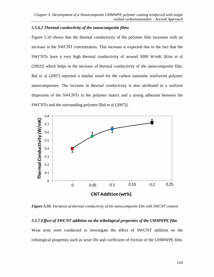
Chapter 5: Development of a Nanocomposite UHMWPE polymer coating reinforced with single
walled carbonnanotubes – Second Approach
114
5.5.6.2 Thermal conductivity of the nanocomposite films
Figure 5.10 shows that the thermal conductivity of the polymer film increases with an
increase in the SWCNT concentration. This increase is expected due to the fact that the
SWCNTs have a very high thermal conductivity of around 3000 W/mK [Kim et al
(2002)] which helps in the increase of thermal conductivity of the nanocomposite film.
Bal et al (2007) reported a similar trend for the carbon nanotube reinforced polymer
nanocomposites. The increase in thermal conductivity is also attributed to a uniform
dispersion of the SWCNTs in the polymer matrix and a strong adhesion between the
SWCNTs and the surrounding polymer [Bal et al (2007)].
0
0.1
0.2
0.3
0.4
0.5
0.6
0.7
0.8
The
rmal
Co
nd
uct
ivit
y (W
/mK
)
CNT Addition (wt%)
0.05 0.1 0.15 0.2 0.250
Figure 5.10: Variation of thermal conductivity of the nanocomposite film with SWCNT content
5.5.7 Effect of SWCNT addition on the tribological properties of the UHMWPE film
Wear tests were conducted to investigate the effect of SWCNT addition on the
tribological properties such as wear life and coefficient of friction of the UHMWPE film.

Chapter 5: Development of a Nanocomposite UHMWPE polymer coating reinforced with single
walled carbonnanotubes – Second Approach
115
Tests were conducted at a normal load of 4 N and at rotational speeds of 1000, 2000 and
2500 rpm giving a PV factor in the range of ~ 34 to 86 MPa.ms-1
.
Figure 5.11(a) demonstrates typical friction graphs for the four different
concentrations of the SWCNT addition to the UHMWPE film. As mentioned earlier, in
this study, wear life of the thin film is defined as the number of cycles when the
coefficient of friction exceeds 0.3 or when continuous large fluctuations are observed in
the coefficient of friction data (indicative of film failure), whichever happens first
[Miyoshi (2001)]. Figure 5.11(a) inset shows the variation of the coefficient of friction as
a function of the SWCNT addition. It is observed that the coefficient of friction increases
with an increase in the SWCNT addition from a value of ~ 0.08 for a pristine UHMWPE
film to a values of ~0.16 for an addition of 0.2 wt% of SWCNT. Zoo et al. (2004)
observed a similar trend for the UHMWPE composites reinforced with SWCNTs (0 to
0.5 wt%), wherein the coefficient of friction increased from 0.05 to 0.11. The coefficient
of friction depends on several factors such as surface roughness and the material
properties of the samples in contact. A harder and a wear resistant film would impose
more frictional resistance to the movement of the counterface over its surface. From the
nanoindentation and nanoscratch results presented earlier it can be observed that the
hardness of the polymer film improved significantly with the SWCNT content. Thus, the
slight increase in the coefficient of friction with the SWCNT content may be possibly due
to the higher shear strength induced in the UHMWPE film by the addition of SWCNTs.
Figure 5.11(b) shows wear durability in terms of number of cycles to failure for
different rotational speeds. It can be clearly seen that the pristine UHMWPE film failed
after about 60,000 cycles at a load of 4 N and a rotational speed of 1000 rpm. On

Chapter 5: Development of a Nanocomposite UHMWPE polymer coating reinforced with single
walled carbonnanotubes – Second Approach
116
inspection of the wear track under FESEM, several wear debris were observed along the
sides due to peeling-off or delamination of the film. In comparison to that, a UHMWPE
film reinforced with 0.05 wt% SWCNT lasted for ~ 150,000 cycles for the same
conditions of 4 N normal load and a rotational speed of 1000 rpm. The debris content was
less when compared to that of the pristine UHMWPE film. A significant increase in the
wear life with an increasing content of SWCNT was observed thereof. The
nanocomposite film showed wear lives of > ~ 250,000 cycles (the experiment was
stopped) for both 0.1 wt% and 0.2 wt% of SWCNT additions.

Chapter 5: Development of a Nanocomposite UHMWPE polymer coating reinforced with single
walled carbonnanotubes – Second Approach
117
0
0.05
0.1
0.15
0.2
0.25
0 50000 100000 150000 200000 250000 300000
Co
eff
ice
int
of f
rict
ion
Number of Cycles
0 % - CNT
0.05 % - CNT
0.1 % - CNT
0.2 % - CNT
(a)
0
0.1
0.2
0 0.05 0.1 0.15 0.2
Avg
CO
F
CNT Addition (wt %)
0.0E+0
5.0E+4
1.0E+5
1.5E+5
2.0E+5
2.5E+5
3.0E+5
We
ar L
ife
(No
. of
Cyc
les)
CNT Addition (wt %)
1000 rpm
0 0.05 0.1 0.2
2000 rpm
2500 rpm
Experiment was Stopped(b)
Figure 5.11: (a) A typical friction plot of the nanocomposite film for the different concentrations
of SWCNTs. Inset: The change in the average coefficient of friction with the SWCNT content for
the nanocomposite film. (b) Wear life in cycles for the different nanocomposite films at a load of 4
N and speeds of 1000, 2000 and 2500 rpm respectively

Chapter 5: Development of a Nanocomposite UHMWPE polymer coating reinforced with single
walled carbonnanotubes – Second Approach
118
To further investigate the performance of the nanocomposite films, long duration wear
tests were carried out. The tests were carried out at a severe condition of the rotational
speed of 2500 rpm with the same normal load of 4 N for the nanocomposite films with
0.1 and 0.2 wt% SWCNTs. It was observed that both the nanocomposite films did not fail
even until 10 million cycles (the experiment was stopped).
The wear of the counterface material was checked by observing the surface of the
Si3N4 ball under the microscope after the test, before and after cleaning the ball with
acetone. Figure 5.12 shows the surface of the counterface Si3N4 balls after sliding against
the nanocomposite film with 0.1 wt% and 0.2 wt% of SWCNT for 10 million cycles at a
load of 4 N and a rotational speed of 2500 rpm. No wear was observed on the Si3N4 ball
which was slid against 0.1 wt% and 0.2 wt% nanocomposite films as seen in Figure
5.12(b) and 5.12(e). Thus, despite an increase in the hardness of the film due to SWCNT
addition, the counterface does not wear. It is also noted that the hardness of the Si3N4 ball
is approximately 14.71 GPa, which is ~130 times higher than that of the nanocomposite
film.

Chapter 5: Development of a Nanocomposite UHMWPE polymer coating reinforced with single
walled carbonnanotubes – Second Approach
119
Figure 5.12: Optical micrographs of the Si3N4 balls and the wear track for the 0.1 wt% and 0.2
wt% SWCNT nanocomposite film after the wear test after 10 million cycles. The test was
conducted at a load of 4 N and a speed of 2500 rpm
Wear track widths were measured on UHMWPE films reinforced with SWCNT
from 0 to 0.2 wt%. Ball-on-disk wear tests were conducted at a load of 4 N and a
rotational speed of 1000 rpm for exactly 10,000 cycles on all the four films. Figure 5.13
shows FESEM images of the wear track widths for the varying SWCNT concentrations.
It is observed that with an increase in the SWCNT content, the wear track width
decreases which is due to an increase in the wear resistance upon reinforcement by
SWCNTs. The amount of polymer transfer on the counterface ball after 10,000 cycles
reduced with an increase in the SCWNT content. This can be explained from the fact that
the SWCNTs act as anchor in the polymer matrix holding the polymer intact due to a
strong bonding between the SCWNTs and the polymer.

Chapter 5: Development of a Nanocomposite UHMWPE polymer coating reinforced with single
walled carbonnanotubes – Second Approach
120
Figure 5.13: FESEM images of the wear track widths for the nanocomposite films after 10,000
cycles. The test was conducted at a load of 4 N and a speed of 1000 rpm. Inset: Optical images of
the Si3N4 balls immediately after the test and before cleaning them with acetone
5.6 Discussions
The overall improvement in the tribological properties of the UHMWPE film can be
because of the properties of the SWCNTs which helped in enhancing the mechanical and
thermal properties of the film without inducing any structural changes to the polymer
matrix.
These can be observed from the nanoindentation (Fig. 5.7), nanoscratch (Fig. 5.8)
and the wear track (Fig.5.13) results. The slope of the load-penetration depth curve in
Figure 5.8 is much steeper for the pristine UHMWPE film when compared to that of the

Chapter 5: Development of a Nanocomposite UHMWPE polymer coating reinforced with single
walled carbonnanotubes – Second Approach
121
reinforced UHMWPE film, which means that the SWCNT helps in enhancing the
penetration resistance because of higher load bearing capacity. The same trend can be
seen in Figure 5.13, wherein the width of the wear track is smaller in the case of the
reinforced polymer film and the amount of polymer transfer on the counterface is also
less. This is due to very strong bonding between the plasma-treated SWCNTs and the
polymer matrix. The plasma treatment of the SWCNTs helps in generating the oxygen
containing radicals on the surface of SWCNTs which in turn helps in the uniform
dispersion of the SWCNTs in the polymer matrix. This helps in keeping the polymer
intact and thus preventing the peeling-off or delamination of the film from the substrate
[Utegulov et al. (2005), Bakshi et al (2007)].
The elastic modulus also plays an important role in governing the wear
characteristics of the polymer film. Lower the elastic modulus, higher is the mobility of
the molecules to flow in a viscous manner due to less strong inter-molecular bonding.
Thus the relaxation time for larger contact area decreases with decreasing elastic modulus
and the film is prone to damage because of the thermal effect [Gorkhovskii et al. (1966)].
It is observed that the SWCNT reinforcement increased the elastic modulus of the
nanocomposite film when compared to that of the pristine film. Due to this increase, the
relaxation time increases for the nanocomposite film thus increasing its resistance to any
change in the elastic properties because of the interface temperature over time, thus
preventing the nanocomposite film from being removed from the wear track. Moreover,
an increase in the thermal stability of the nanocomposite film as evident from the TGA
and the thermal conductivity results helps the nanocomposite film from being peeled-off
from the substrate due to any temperature changes at the contact interface.

Chapter 5: Development of a Nanocomposite UHMWPE polymer coating reinforced with single
walled carbonnanotubes – Second Approach
122
The improvement in the thermal stability of the nanocomposite film is one of the
significant factors for the high wear resistance. The enhanced thermal conductivity of the
nanocomposite film helps in quickly dissipating the frictional heat from the point of
contact on the wear track. As discussed earlier, the addition of SWCNTs also delayed the
thermal degradation of the UHMWPE polymer which makes it possible for the polymer
to sustain a slightly higher temperatures and thus helping in improving the wear
resistance. Thermal degradation of UHMWPE, if it happens, is expected to worsen the
wear performance of the films.
Thus, the uniform dispersion of the SWCNTs in the polymer matrix along with
the enhanced load bearing capacity of the nanocomposite film and the improved thermal
stability leads to the exceptional tribological properties of the nanocomposite film as
presented above.
5.7 Conclusions
Following conclusions can be drawn from the present study:
An increase of ~66% and ~58% in the hardness and elastic modulus values
respectively, is observed for the pristine UHMWPE film when reinforced with
0.2 wt% SWCNT.
An increase in the resistance to scratch and penetration is also observed with
the increase in the SWCNT content due to higher load bearing capacity of the
nanocomposite film and due to the improvement in the interfacial bonding.
An increase in the thermal stability of the polymer film is observed with
increasing SWCNT content, because of the higher thermal conductivity of

Chapter 5: Development of a Nanocomposite UHMWPE polymer coating reinforced with single
walled carbonnanotubes – Second Approach
123
SWCNTs. This contributes to better heat dissipation during sliding and longer
wear life for the nanocomposite.
A significant increase in the wear life (> 250,000 cycles) of the polymer film
at a load of 4 N and a rotational speed of 2500 rpm is observed because of the
overall improvement in the mechanical and thermal properties of the film with
SWCNT reinforcement.
A slight increase in the coefficient of friction from ~0.08 to ~0.16 is observed
with an increase in the SWCNT content from 0 wt% to 0.2 wt% respectively.
This is attributed to the higher shear strength of the nanocomposite film.

Chapter 6: PFPE overcoat to further improve the tribological properties of the nanocomposite
film – Third Approach
124
Chapter 6
PFPE overcoat to further improve the tribological properties of
the nanocomposite film – Third Approach
The carbon nanotubes reinforcement to the UHMWPE polymer coating resulted in a
significant improvement in its overall mechanical, thermal and tribological properties as
described in chapter 5. The improvement in the wear life of the coating can be mainly
attributed to the improved load bearing capacity of the film due to the SWCNT
reinforcement and the higher thermal conductivity of the SWCNTs as explained in chapter
5. However, this increase in the wear life was associated with a slight increase in the
coefficient of friction. Thus, we took up our third approach of coating the nanocomposite
coating with an ultra-thin layer of perfluoropolyether (PFPE) to reduce the coefficient of
friction and also to improve the wear life of the coating and also the counterface.
6.1 Background
Perfluoropolyether (PFPE) is a unique lubricant that is safe, nontoxic, environmental
friendly. Its excellent chemical and thermal stability, low vapour pressure, low surface
tension and good lubricity, which are all essential for better tribological performances,
makes it a potential candidate for tribological applications [Mahmoud 1998].
PFPE has been used extensively as a top overcoat on hard coatings [Fox-
Rabinovich et al. 2002, Gulanskiy 1992, Miyake et al. 2005] and polymer coatings
[Satyanarayan et al. 2005, Satyanarayana et al. 2006, Minn et al.] alike to improve the
tribological behaviour of these coatings. Perfluoropolyether (PFPE) is also employed as a
lubricant in magnetic recording disk drives to improve their tribological properties. An ultra-

Chapter 6: PFPE overcoat to further improve the tribological properties of the nanocomposite
film – Third Approach
125
thin PFPE lubricant film is particularly effective in decreasing the wear of the protective
carbon overcoat due to the head disk and the slider interactions. The wear durability of the
medium depends strongly on the retention and replenishment of the lubricant on the
protective overcoat surface. Both the retention and replenishment of lubricant are dependent
on the interactions between the lubricant molecules and the overcoat surface. Many studies
on the spreading, migration and replenishment behaviour of PFPE lubricant have been
reported [Tani et al. 2001, Tani et al. 1999]. In a study by Miyake et al. [2005], the critical
load for the disk coated with the PFPE–DLC film was found to be approximately five times
that of the disk coated with the DLC film alone. They observed that the durability of the
magnetic disk improved significantly since the disk was protected first by a layer of PFPE
lubricant and then by a bonded PFPE–DLC. Fox-Rabonovich et al. [2002] coated PVD TiN
coatings for High Speed steel cutting tools with a layer of PFPE and observed that during
the initial running-in stage of the cutting tool, the PFPE layer helped in reducing the
coefficient of friction significantly and also protect the surface of the tool from any damage.
Satyanarayana et al [2006] applied an ultra-thin layer of PFPE on a UHMWPE polymer
coating deposited on a Si substrate and found that the dual layer improved the wear life of
the Si substrate by several orders of magnitude.
Thus, due to its unique properties and the ability to protect the surfaces from wear and tear,
PFPE was selected to overcoat the UHMWPE/CNT nanocomposite coating to further
improve its tribological performance. The present chapter will discuss the results obtained
for the same.

Chapter 6: PFPE overcoat to further improve the tribological properties of the nanocomposite
film – Third Approach
126
6.2 Materials
Specimens were prepared on DF3 Tool steel (C-0.95%, Mn-1.1%, Cr-0.6%, W-0.6%, V-
0.1% and the rest Fe) coupons of 25 mm X 25 mm X 5 mm dimensions with an average
hardness value of 60 HRC. The steel specimens were ground flat and polished to an average
surface roughness of 18 nm. The specifications of the UHMWPE polymer and PFPE used in
this study are stated in chapter 3.
6.3 Dip-Coating of PFPE on the nanocomposite film
A 0.2 wt% of PFPE solution in H-Galden was prepared for the dip coating of a ultrathin
layer of PFPE on the pristine and nanocomposite films. Dip-coating was selected for its
ability to be adapted to industrial applications easily and its cost effectiveness
[Satyanarayana et al. 2005, 2006]. The steel subatrates coated with pristine UHMWPE films
and the nanocomposite films of UHMWPE/CNT were dipped into the PFPE solution at a
dipping speed of 2.1 mm/s and held inside the solution for a period of 1 min and withdrawn
from the solution at the same speed [Satyanarayana et al. 2006] providing a thin overcoat of
PFPE on the polymer film. No further heat treatment was conducted after the PFPE coating
of the film.
Figure 6.1: A schematic diagram showing the deposition of the dual layer film
(Steel/UHMWPE/PFPE)

Chapter 6: PFPE overcoat to further improve the tribological properties of the nanocomposite
film – Third Approach
127
6.4 Results and Discussion
6.4.1 Tribological properties of the dual-layer film: Tool Steel/UHMWPE/PFPE
PFPE was coated on a pristine UHMWPE polymer film to evaluate the changes in its
tribological propertie. Figure 6.2 shows the wear lives for TS/UHMWPE and
TS/UHMWPE/PFPE at a normal load of 4 N and at rotational speeds of 1000 rpm and
2000 rpm. As presented in chapter 4, TS/UHMWPE film showed wear lives of about
60,000 and 700 cycles, at a normal load of 4 N and at rotational speeds of 1000 and 2000
rpm, respectively. The overcoating of an ultra-thin layer of PFPE greatly enhanced the
wear life of UHMWPE film. The dual layer film of TS/UHMWPE/PFPE showed wear
lives of >240,000 and ~130,000 cycles, at rotational speeds of 1000 rpm and 2000 rpm ,
respectively, at a fixed normal load of 4 N. The increase in the wear life was also coupled
with a significant decrease in the coefficient of friction from a value of ~ 0.1 to ~ 0.05.
The present improvement in the wear-life after PFPE overcoating onto UHMWPE film is
similar to that observed in the earlier research on the Al and Si substrates [Sinha et al.
2008, Satyanaryana et al. 2006]. The improvement in the wear life and the reduction in
the coefficient of friction is attributed to the beneficial effect of the entrapped PFPE in
the gaps between the molecules and inside the asperities [Sinha et al. 2008, Satyanaryana
et al. 2006] and to the excellent lubrication properties of PFPE itself. This is quite evident
from the Fig. 6.3 which shows a comparison of the friction graphs for the pristine
UHMWPE coatings with and without an overcoat of PFPE.

Chapter 6: PFPE overcoat to further improve the tribological properties of the nanocomposite
film – Third Approach
128
Experiment was stopped
60,000
TS/U
HM
WP
E
TS/U
HM
WP
E/P
FPE
240,000
1.E+00
1.E+01
1.E+02
1.E+03
1.E+04
1.E+05
1.E+06
Speed (rpm)
Av
era
ge W
ea
r L
ife (
Cy
cle
s)
2000
700
TS/U
HM
WP
E/P
FPE
TS/U
HM
WP
E
130,000
1000
Figure 6.2: Comparison of the average wear life for the single layer film (TS/UHMWPE) and for
the dual-layer film (TS/UHMWPE/PFPE) for speeds of 1000 rpm and 2000 rpm respectively at a
normal load of 4 N
0
0.05
0.1
0.15
0.2
0.25
0.3
0.35
0.4
0 50000 100000 150000 200000 250000 300000
Number of Cycles
Co
eff
icie
nt
of
fric
tio
n
TS / UHMWPE / 1000 RPM
TS / UHMWPE / PFPE / 2000 RPM
TS / UHMWPE / PFPE / 1000 RPM
TS / UHMWPE / 2000 RPM
Figure 6.3: Comparison of typical frictional graphs for the single layer and the dual layer films

Chapter 6: PFPE overcoat to further improve the tribological properties of the nanocomposite
film – Third Approach
129
The same entrapment of PFPE into the gaps between the asperities is also possible
in the present case as the UHMWPE film contains very rough features (rms
roughness=0.111 µm) and fibrous structure which contain several valleys as shown in
Figure 6.4(a) and (b).
Figure 6.4: (a) SEM morphology of the UHMWPE film on the DF3 tool steel surface. (b) AFM
image of the DF3 tool steel/UHMWPE surface
Therefore, a combination of excellent lubrication properties and high thermal
stability of PFPE [Sinha et al. 2008] and the additional lubrication from the entrapped
PFPE are responsible for very high wear durability of the dual-layer film
(UHMWPE/PFPE). Further, the presence of PFPE on the UHMWPE film minimizes any
transfer of the polymer to the counterface. This is because of the hydrophobic property of
PFPE. Thus, the polymer-polymer interaction which leads to high friction is largely
avoided in this case. Nevertheless, the present dual-layer film withstands a load of 4 N at
a rotational speed of 2000 rpm up to ~130,000 cycles; a three order of improvement over
UHMWPE without the ultra-thin layer of PFPE. At a lower speed of 1000 rpm, the film
did not fail even after 240,000 cycles of sliding. It is possible that the low load bearing
capacity of the pristine UHMWPE film attributes to its earlier failure.

Chapter 6: PFPE overcoat to further improve the tribological properties of the nanocomposite
film – Third Approach
130
6.4.2 Effect of PFPE overcoat on the tribological properties of the UHMWPE/CNTs
Nanocomposite coating
After evaluating the wear life of the pristine UHMWPE polymer film with an overcoat of
PFPE, we proceeded to see the effect of the PFPE overcoat on the tribological properties
of the developed nanocomposite film. The UHMWPE/CNTs nanocomposite film
exhibited excellent tribological properties until a load of 4N and rotational speed of 2500
rpm.
For evaluating the effect of a ultrathin layer of PFPE, a nanocomposite film with
0.1 wt% of CNTs was selected and dipped into the 0.2 wt% of PFPE/H-Galden solution
for 1 min and withdrawn. The sample was not subjected to any further heat treatment
process after the PFPE coating. Ball-on-disk tests were conducted at a normal load of 4N
and rotational speeds of 2000 and 2500 rpm. As shown in Fig. 6.5, it was observed that
the dual film layer of the nanocomposite film and the overcoat of PFPE did not fail until
240,000 cycles.

Chapter 6: PFPE overcoat to further improve the tribological properties of the nanocomposite
film – Third Approach
131
0
50000
100000
150000
200000
250000
300000
1 2
We
ar L
ife
(Cyc
les)
Rotational Speed (rpm)
TS/UHMWPE/PFPE TS/UHMWPE+CNTs TS/UHMWPE+CNTs/PFPE
2500 rpm
Experiment was stopped
2000 rpm
Figure 6.5: Comparison of Wear life of different types of coatings at a load of 4 N and speeds of
2000 rpm and 2500 rpm respectively
As can be seen from the above figure that the nanocomposite film with and
without the PFPE overcoat did not fail until 240,000 cycles after which the experiment
was stopped. However, there was a significant decrease in the coefficient of friction from
a value of ~0.14 to ~0.05 after the overcoat of PFPE on the nanocomposite film. Fig. 6.6
shows a comparison of the friction graphs for the nanocomposite film with and without
the overcoat of the PFPE film. As reported in chapter 5, the addition of CNTs to the
UHMWPE polymer film resulted in an increase in the coefficient of friction from ~0.1 to
~0.14. Thus, providing an ultrathin layer of the PFPE film on the nanocomposite film
reduced the coefficient of friction which is expected to help in improving the wear life of
the coating and also the counterface material.

Chapter 6: PFPE overcoat to further improve the tribological properties of the nanocomposite
film – Third Approach
132
0
0.02
0.04
0.06
0.08
0.1
0.12
0.14
0.16
0 50000 100000 150000 200000 250000 300000
Co
eff
icie
nt
of f
rict
ion
Number of Cycles
TS/UHMWPE + 0.1 wt% CNTs/PFPE
TS/UHMWPE + 0.1 wt% CNTs
Figure 6.6: Comparison of a typical friction graph for the nanocomposite film with and without
the overcoat of PFPE
Figure 6.7 shows the optical micrographs of the wear track and the counterface Si3N4 ball
after 240,000 cycles at a load of 4 N and a rotational speed of 2000 rpm. It can be seen
that in both the cases the wear track is clean without any wear debris. There was no
evidence of any material transfer on to the counterface either. As mentioned before,
material transfer to the counterface often leads to unsteady friction and low wear life in
tribological interactions.

Chapter 6: PFPE overcoat to further improve the tribological properties of the nanocomposite
film – Third Approach
133
Figure 6.7: (a), (b) – Ball images after the test sliding against the nanocomposite film without the
PFPE overcoat. (c), (d) – Ball images after the test sliding against the nanocomposite film with a
PFPE overcoat. (e) – Wear track after the test of the nanocomposite film without PFPE overcoat.
(f) – Wear track after the test of the nanocomposite film with PFPE overcoat
6.5 Conclusions
The following conclusions can be deduced from the results presented above:
An overcoat of PFPE improved the wear life of the nanocomposite polymer film
significantly to >240,000 cycles for a normal load of 4 N and a rotational speed of
2500 rpm.
The overcoat of PFPE helped in reducing the coefficient of friction of the
nanocomposite film from a value of ~0.14 to ~0.05, which in turn has improved
the wear life of the film and the counterface.

Chapter 7: Effect of counterface material and UV Radiation on the tribological properties of the
nanocomposite coating
134
Chapter 7
Effect of Counterface material and UV Radiation on the
tribological performance of the nanocomposite coating
In the context of the developed nanocomposite coating being used as a boundary lubricant in
sliding mechanical components, it is very important to evaluate the tribological performance
of the coating against different counterface materials. It is also valuable to evaluate the
mechanical and tribologiccal properties of the nanocomposite coating after being exposed to
UV radiations, simulating the actual sunlight conditions. Thus, the present study focuses on
the above two stated objectives.
7.1 Background
Eventhough, UHMWPE does not absorb radiations of wavelengths longer than 190 nm
[Rabek (1995)], due to the presence of impurities such as UV/light aborbing chromophoric
groups, the absorbing wavelength of the UHMWPE polymer may be changed up to 270-330
nm [Rabek (1996), Ranby et al (1975)] which might alter the mechanical properties of the
polymer and thus effecting its tribological performance. Since, the shortest wavelength
(highest energy) radiation in the UV spectrum of the sun at ground level is 290 nm [Rabek
(1995)], it will be valuable to study the effect of UV radiations on the nanocomposite
coating. Studies have shown that the there was a degradation in the tensile properties of the
UHMWPE fibers after exposure to 300 h of sunlight-simulated UV beam radiation [Zhang
et al (2003)]. However, Fouad et al (2008) found an improvement in the nanoscale
mechanical properties of UHMWPE on its exposure to UV radiation. As the present
nanocomposite coating is developed using UHMWPE reinforced with SWCNTs for a

Chapter 7: Effect of counterface material and UV Radiation on the tribological properties of the
nanocomposite coating
135
possible application as a boundary lubricant, it will be important to study the effect of UV
radiations on the mechanical and tribological properties.
As mentioned earlier, the present nanocomposite coating was developed for a possible
application as a boundary lubricant in mechanical sliding components. Thus, an
understanding about the behaviour of the nanocomposite coating when slid against different
counteface materials in terms of friction and wear is extremely important from the design
perspective of the components.
7.2 Materials
Specimens were prepared on DF3 Tool steel (C-0.95%, Mn-1.1%, Cr-0.6%, W-0.6%, V-
0.1% and the rest Fe) coupons of 25 mm X 25 mm X 5 mm dimensions with an average
hardness value of 60 HRC. The steel specimens were grounded flat and polished to an
average surface roughness of 18 nm. The specifications of the UHMWPE polymer and
PFPE used in this study are as stated in chapter 3.
Three different counterface materials, Silicon Nitride (Si3N4), AISI 52100 bearing steel and
brass, in the form of Φ4 mm balls were used. The hardness, surface roughness and water
contact angles for each of the material is shown in Figure 7.1.
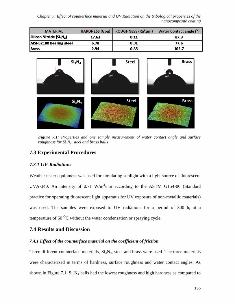
Chapter 7: Effect of counterface material and UV Radiation on the tribological properties of the
nanocomposite coating
136
Si3N4 Steel Brass
Si3N4 Steel Brass
Figure 7.1: Properties and one sample measurement of water contact angle and surface
roughness for Si3N4, steel and brass balls
7.3 Experimental Procedures
7.3.1 UV-Radiations
Weather tester equipment was used for simulating sunlight with a light source of fluorescent
UVA-340. An intensity of 0.71 W/m2/nm according to the ASTM G154-06 (Standard
practice for operating fluorescent light apparatus for UV exposure of non-metallic materials)
was used. The samples were exposed to UV radiations for a period of 300 h, at a
temperature of 60 OC without the water condensation or spraying cycle.
7.4 Results and Discussion
7.4.1 Effect of the counterface material on the coefficient of friction
Three different counterface materials, Si3N4, steel and brass were used. The three materials
were characterized in terms of hardness, surface roughness and water contact angles. As
shown in Figure 7.1, Si3N4 balls had the lowest roughness and high hardness as compared to
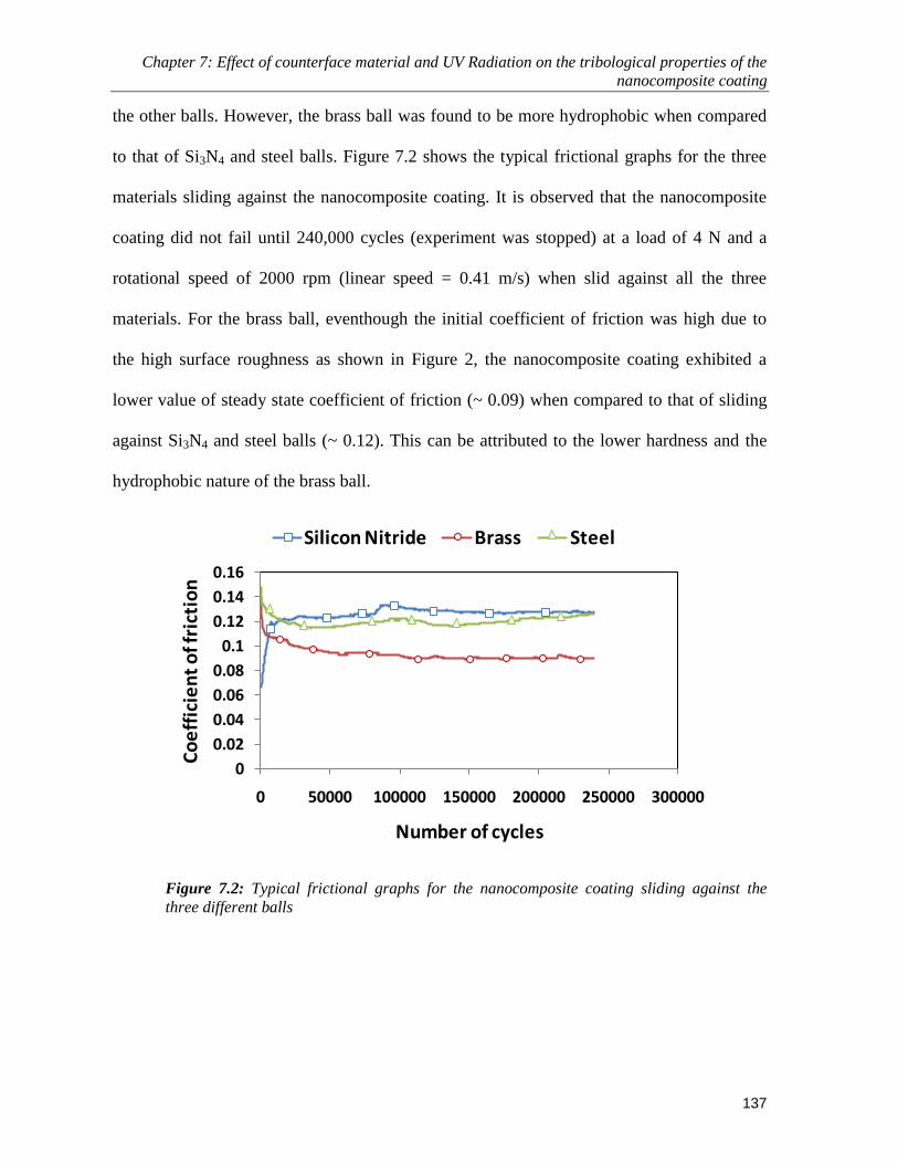
Chapter 7: Effect of counterface material and UV Radiation on the tribological properties of the
nanocomposite coating
137
the other balls. However, the brass ball was found to be more hydrophobic when compared
to that of Si3N4 and steel balls. Figure 7.2 shows the typical frictional graphs for the three
materials sliding against the nanocomposite coating. It is observed that the nanocomposite
coating did not fail until 240,000 cycles (experiment was stopped) at a load of 4 N and a
rotational speed of 2000 rpm (linear speed = 0.41 m/s) when slid against all the three
materials. For the brass ball, eventhough the initial coefficient of friction was high due to
the high surface roughness as shown in Figure 2, the nanocomposite coating exhibited a
lower value of steady state coefficient of friction (~ 0.09) when compared to that of sliding
against Si3N4 and steel balls (~ 0.12). This can be attributed to the lower hardness and the
hydrophobic nature of the brass ball.
0
0.02
0.04
0.06
0.08
0.1
0.12
0.14
0.16
0 50000 100000 150000 200000 250000 300000
Co
eff
icie
nt
of f
rict
ion
Number of cycles
Silicon Nitride Brass Steel
Figure 7.2: Typical frictional graphs for the nanocomposite coating sliding against the
three different balls

Chapter 7: Effect of counterface material and UV Radiation on the tribological properties of the
nanocomposite coating
138
7.4.2 Effect of counterface material on the wear of the nanocomposite coating
Wear tests were conducted for a duration of 10,000 cycles and 240,000 cycles at a load of 4
N and a rotational speed of 2000 rpm (linear speed = 0.41 m/s) to see the effect of the
different counterface materials on the progressive wear performance of the nanocomposite
coating. Figure 7.3 shows the 2-D wear track analysis plots as obtained from the Wyko
optical profilometer. The insets show the optical micrograph of the counterface ball
immediately after the test prior to cleaning with acetone and the FESEM image of the
corresponding wear track. Comparing the 2-D profiles of the wear tracks after 10,000 and
240,000 cycles, it can be observed that there was no change in the wear track depth after an
initial running-in period in all the three cases. This can be explained from the fact that
during the running-in period the coating undergoes smoothening as evident from the
FESEM wear track analysis. Thus, after the initial running-in period the coating there-by
plastically flows in the direction of sliding with the UHMWPE polymer in the
nanocomposite coating providing the lubricity for low friction and the SWCNTs helping in
improved load bearing capacity and shear strength, thus resisting any further increase in the
depth of the wear track.
It was also observed that there was no wear on the counterface ball after 10, 000 and
240,000 cycles, irrespective of the type of material of the ball. This can be attributed to the
lubricious characteristic of the UHMWPE polymer transfer film formed on the counterface
ball which helps in protecting the ball from any wear. However, the amount of polymer
transfer to the surface of the ball was found to be very less, which is due to the strong
interfacial bonding between the SWCNTs and the UHMWPE polymer matrix as explained
in chapter 5

Chapter 7: Effect of counterface material and UV Radiation on the tribological properties of the
nanocomposite coating
139
0
-4
2
4
-2
-6
-8
Brass - 10,000 Cycles
0
-4
2
4
-2
-6
-8
6
8Brass - 240,000 Cycles
0
-4
2
4
-2
-6
-8
-10
6 Si3N4 - 10,000 Cycles
0
-4
2
4
-2
-6
-8
-10
6 Steel - 10,000 CyclesSteel - 240,000 Cycles
0
-4
2
4
-2
-6
-8
-10
6
8
0
-4
2
4
-2
-6
-8
-10
6 Si3N4 - 240,000 Cycles
15 kV X70 200µm 15 kV X70 200µm
15 kV X70 200µm 15 kV X70 200µm
15 kV X70 200µm 15 kV X70 200µm
Figure 7.3: 2D-plots of the wear tracks after 10,000 and 240,000 cycles respectively for the nanocomposite
coating sliding against the three different balls. Inset (left): Optical micrograph of the ball after the test at a
magnification of x100 . Inset (right): FESEM images of the wear tracks after the wear tests

Chapter 7: Effect of counterface material and UV Radiation on the tribological properties of the
nanocomposite coating
140
7.4.3 Performnace of the nanocomposite coating under more severe conditions
To evaluate the performance of the nanocomposite coating against the three different
counterface materials, long term tribological tests were also conducted until 1 million cycles
under a normal load of 4 N and a higher rotational speed of 2500 rpm (0.52 m/s). It was
observed that the nanocomposite film did not fail until 1 million cycles when slid against the
three different counterface materials. Fig. 7.4(a) shows the typical frictional graphs for the
nanocomposite coating slid against Si3N4, steel and brass respectively. Fig. 7.4(b) shows the
wear track analysing using the optical profilometer. It can be seen that the depth of the wear
track did not change even after 1 million cycles after the initial running-in period, as
compared to that after the 10,000 and 240,000 cycles respectively (Fig. 7.3). However, there
was some amount of polymer build-up observed on the either side of the track as can be
seen in the 3D-plot (Figure 7.4(b)) of the wear tracks. This excellent performance of the
nanocomposite coating can be attributed to the lubricous nature of UHMWPE coupled with
the higher load bearing capacity of SWCNTs as explained earlier. In the long term test, no
particular difference in the friction and wear performance of the coating was observed for
different counterface materials.

Chapter 7: Effect of counterface material and UV Radiation on the tribological properties of the
nanocomposite coating
141
0
0.02
0.04
0.06
0.08
0.1
0.12
0.14
0 200000 400000 600000 800000 1000000 1200000
Co
eff
icie
nt
of f
rict
ion
Number of cycles
SiN Steel Brass(a)
-8
-4
0
4
8
12
16
0 500 1000 1500 2000 2500µm
µm
Si3N4 ball - 1 million cycles3D - Plot
-8
-4
0
4
8
12
16
0 500 1000 1500 2000 2500 µm
µm
Steel ball - 1 million cycles3D - Plot
-8
-4
0
4
8
12
16
20
0 500 1000 1500 2000 2500 µm
µm
3D - PlotBrass ball - 1 million cycles
(b)
Figure 7.4: (a) Typical frictional graphs for the nanocomposite coating sliding against the
three different balls at a load of 4 N and a rotational speed of 2500 rpm (linear velocity =
0.52 m/s) until 1 million cycles. (b) 2-D and 3-D plots for the wear tracks after 1 million
cycles for the three different counterface materials.

Chapter 7: Effect of counterface material and UV Radiation on the tribological properties of the
nanocomposite coating
142
7.4.4 Effect of UV-radiation on the resistance to penetration of the nanocomposite
coating
Nanoscratch tests were conducted on the coating to evaluate the effect of exposure to UV
radiation on the resistance to penetration depth. It is observed from Figure 7.5 that the
exposure to UV radiation did not alter the resistance to penetration depth of the
nanocomposite coating. The FESEM images of the scratches before and after exposure to
UV radiation as shown in Figure 7.5 do not show any peeling off of the coating along the
edges of the scratch without any polymer pile-up at the end of the scratch. This better
performance of the nanocomposite coating even after the exposure to 300 h of UV radiation
can be attributed to the presence of SWCNTs in the coating which keeps the polymer intact
by the formation of bridges in the polymer matrix and thus increasing the resistance to
penetration.

Chapter 7: Effect of counterface material and UV Radiation on the tribological properties of the
nanocomposite coating
143
-60
-50
-40
-30
-20
-10
0
0 20 40 60 80 100P
en
etr
atri
on
De
pth
(µm
)
Normal Load (mN)
No UV With UV
-10
- 5
-15
-20
-25
-30
WD15.5mm 15.0kV x2.0k 20µm WD15.5mm 15.0kV x2.0k 20µm
Without UV exposure After UV exposure
Figure 7.5: Comparison of the resistance to penetration of the nanocomposite coating before and
after the 300 h exposure to UV radiation. FESEM images of the scratches for the two cases
7.4.5 Effect of UV-radiation on the tribological properties of the nanocomposite coating
Ball-on-disk wear tests were conducted on the nanocomposite coated steel samples before
and after being exposed to UV radiation for a period of 300 h, by using a Φ 4mm Si3N4 ball.
It was observed that the nanocomposite coating did not fail until 240,000 cycles showing no
effect of UV radiation on its tribological performance. Figure 7.6 shows a comparison of the
typical frictional graphs for the nanocomposite coating before and after exposure to the UV
radiation. Not much change in the frictional behaviour is observed. The FESEM images of

Chapter 7: Effect of counterface material and UV Radiation on the tribological properties of the
nanocomposite coating
144
the wear tracks are also shown in Figure 7.6 (b) and (c), which do not exhibit any peculiar
behaviour after the exposure to UV radiations.
0
0.02
0.04
0.06
0.08
0.1
0.12
0.14
0.16
0 50000 100000 150000 200000 250000 300000
Co
eff
icie
nt
of f
rict
ion
Number of cycles
After UV radiation Before UV radiation
Micro voids
(b) Before UV radiation (c) After UV radiation
(a)
Figure 7.6: (a) Comparison of the typical frictional graphs of the nanocomposite coating slid
against Si3N4 ball, before and after the exposure to UV radiations. Inset (Table): Properties such as
hardness, crystallinity and water contact angle of the nanocomposite coating before and after the
UV radiations. (b) FESEM image of the wear track after the test for the nanocomposite coating not
exposed to UV radiations. (c) FESEM image of the wear track after the test for the nanocomposite
coating exposed to UV radiations
The nanocomposite coating was overcoated with an ultra-thin layer of PFPE and
exposed to the same intensity of UV radiations for 300 h. Figure 7.7 shows the typical
Before After
Hardness (Mpa) 103 ± 5 95 ± 7Crystallinity (%) 30.01 30.74
Water Contact Angle (O) 139.2 134.3
UV - RadiationProperty of the
nanocomposite coating

Chapter 7: Effect of counterface material and UV Radiation on the tribological properties of the
nanocomposite coating
145
frictional graphs for the nanocomposite coating with an overcoat of PFPE, before and after
the exposure to the UV radiations. It is observed that the coating did not fail until 240,000
cycles under a load of 4 N and a rotational speed of 2000 rpm (linear velocity = 0.41 m/s).
The dual layer coating exhibited a very low coefficient of friction of ~ 0.05, which is due to
the lubricious ultra-thin film of PFPE. There was no wear observed on the counterface ball
either.
0
0.05
0.1
0.15
0.2
0.25
0.3
0 50000 100000 150000 200000 250000 300000
Co
eff
icie
nt
of f
rict
ion
Number of Cycles
With UV-Radiation Without UV-Radiation
Figure 7.7: Comparison of typical frictional graphs for a nanocomposite coating overcoated with an
ultra-thin film of PFPE with and without exposure to UV radiations. Wear tests were conducted at a
load of 4 N and a speed of 2000 rpm (linear velocity = 0.41 m/s)
7.5 Conclusions
In the context of the nanocomposite coating being used as a potential boundary lubricant in
sliding mechanical components, it is very important to know its performance against
different materials and exposure to UV radiations. The following conclusions can be drawn
from this study:

Chapter 7: Effect of counterface material and UV Radiation on the tribological properties of the
nanocomposite coating
146
The nanocomposite coating did not fail until 240,000 cycles under a load of 4 N and
a rotational speed of 2000 rpm (linear velocity = 0.41 m/s) when slid against the
Si3N4, steel and brass balls, with no wear to the counterface balls.
However, the nanocomposite coating exhibited a lower friction value of ~0.09 as
against a value of ~0.12 when sliding against brass, in the beginning of sliding.
Exposure to UV radiations for 300 h did not affect the tribological performance of
the nanocomposite coating until 240,000 cycles at a normal load of 4 N and a
rotational speed of 2000 rpm (linear velocity = 0.41 m/s) when slid against Si3N4
balls.
With an overcoat of PFPE, the nanocompoite coating exhibited low coefficient of
friction of ~ 0.05 with or without the exposure to UV radiations.

Chapter 8: Nanocomposite UHMWPE-CNT polymer coating for boundary lubrication on
aluminum and steel substrates
147
Chapter 8
Nanocomposite UHMWPE-CNT polymer coating for boundary
lubrication on aluminum and steel substrates
As highlighted in chapter 4 the nanocomposite coating of UHMWPE and CNTs
demonstrated exceptionally well in terms of mechanical, thermal and tribological
properties under dry conditions. In view of our main objective, which is: To provide
energy saving and environmental-friendly lubrication method whereby to fully
eliminate the use of harmful additives as well as reduce the amount of lubricants
needed, we proceeded to evaluate the developed nanocomposite coating under
lubricating conditions by simulating the actual contact conditions (line contact) in a
journal bearing. Initially, the nancomposite coating without the overcoat of PFPE is
tested under the line contact conditions to evaluate the effectiveness of the
nanocomposite coating under the boundary lubricating conditions in protecting the two
mating surfaces from wear and tear. Later, the effect of PFPE overcoat is also evaluated
under the dry and boundary lubricating conditions. The nanocomposite coating is
deposited on two different substrates, aluminium and AISI 52100 bearing steel. The
results are discussed in this chapter.
8.1 Materials and Chemicals
(a) Aluminium samples
Initially, aluminium (Al) is selected as the substrate material because of its extensive
use in the automobile/aerospace industries. Its high strength-to-weight ratio combined
with its abundance makes it a widely used material in various tribological applications as

Chapter 8: Nanocomposite UHMWPE-CNT polymer coating for boundary lubrication on
aluminum and steel substrates
148
well. Moreover Al, being corrosion resistant due to its adherent aluminium oxide layer
(Al2O3), is useful for applications requiring a longer life. However, Al is a soft and
ductile material with very poor tribological properties. Dry sliding of Al with metals,
such as steel or itself, yields high coefficient of friction (>0.6) and very short wear life if
at all.
Aluminium cylindrical shaft of 40 mm diameter and a flat Al plate of (15mm x
15mm) were used. In the context of a simple journal bearing application, the cylindrical
shaft acts as a journal while the flat plate acts as the bearing housing to simulate a
continuous line sliding contact. The cylindrical shaft was coated with the polymer and the
nanocomposite films, and the bare flat Al pin was used as the counterface. Figure 8.1(a)
& (b) shows the geometry of the cylindrical shaft and the aluminium flat pin (Ra = 0.4 ±
0.05 μm) respectively.

Chapter 8: Nanocomposite UHMWPE-CNT polymer coating for boundary lubrication on
aluminum and steel substrates
149
Figure 8.1: (a) Schematic drawing of the cylindrical shaft (b) Schematic diagram of the flat
counterface pin

Chapter 8: Nanocomposite UHMWPE-CNT polymer coating for boundary lubrication on
aluminum and steel substrates
150
(b) Steel samples
AISI52100 bearing steel (Hardness = 60 HRC) cylindrical shaft of 40 mm diameter and a
flat AISI52100 bearing steel (Hardness = 60 HRC, Ra = 0.3 ± 0.05 µm) disk of Φ20 mm
were used. The cylindrical shaft was coated with the nanocomposite films and the bare
flat steel plate was used as the counterface. The specifications of the cylindrical shaft
used were exactly the same as shown in Figure 8.1(a). However, the shape of the flat
plate was altered slightly for ease in manufacturing. The schematic of the modified flat
counterface plate is as shown in Figure 8.2.
Figure 8.2: Schematic diagram of the flat counterface pin for the AISI bearing steel experiments

Chapter 8: Nanocomposite UHMWPE-CNT polymer coating for boundary lubrication on
aluminum and steel substrates
151
The specifications of the UHMWPE polymer and the CNTs in this study have been
listed in chapter 3.
(c) Lubricants
SN 150 Base oil (Group – I), which has no additives and an industrial bearing
lubricant Beslux Atox 32, with viscosity indices of 100 and 105, respectively, were used
as the lubricants in the experiments. They were supplied by Premier Six Pte Ltd and
Tecsia Lubricants Pte Ltd , Singapore. The physical properties of the base oil (SN 150)
and the industrial oil are shown in Table 8.1.
Table 8.1: Properties of the SN 150 Base oil and the Industrial oil
Property SN 150 Base OIL
(Group – I)
BESLUX ATOX-32
Kinematics Viscosity@40O
C (cSt) 28 – 34 28.8 – 35.2
Kinematics Viscosity@100O
C (cSt) 5.2 – 5.4 -
Viscosity Index 100 105
Flash point (open cup), O
C, min 200 170
Density, kg/m3 868 -
8.2 Deposition of the nanocomposite coating on the aluminium and steel
substrates
The nanocomposite coating was deposited on the cylindrical aluminium and steel shafts
by the dip coating process. The procedure of coating has been discussed in chapter 5,
wherein the CNTs are plasma treated and then dispersed uniformly in the solvent and
mixed with the UHMWPE powder prior to heating. Figure 8.3 shows the cylindrical shaft
after the nanocomposite polymer coating.

Chapter 8: Nanocomposite UHMWPE-CNT polymer coating for boundary lubrication on
aluminum and steel substrates
152
Figure 8.3: Cylindrical shaft coated with the nanocomposite coating
8.3 Experimental Setup
The experimental setup used for this study is explained in detail in chapter 3.
8.4 Characterization Techniques
Optical profilometry was used to evaluate the reduction in thickness of the polymer film
which in turn is used to calculate the specific wear rate of the polymer film under various
conditions. FESEM is used to study the surface morphology of the coating before and
after the wear tests. Nanoindentation is used to evaluate the hardness and the elastic
modulus of the polymer film before and after the lubricated tests to check the effect of
lubricant on the mechanical properties. The operational procedures of all the equipment
are explained in detail in chapter 3.
8.5 Results for the nanocomposite coating deposited on aluminium
shafts under dry and base oil lubricated conditions
8.5.1 Evaluation of the pristine and nanocomposite coating under dry conditions
Wear tests were conducted at a normal load of 45 N and rotational speed of 272 rpm
(linear speed =0.57 m/s) under dry conditions to evaluate the tribological performance of
Chapter 8: Nanocomposite UHMWPE-CNT polymer coating for boundary lubrication on
aluminum and steel substrates
153
the pristine and the nanocomposite polymer films. In the present study, the criteria for the
film failure under dry conditions is taken as when the coefficient of friction exceeds a
value of 0.3 or when continuously large fluctuations are seen in the coefficient of friction
curve, whichever happens first [Miyoshi 2001]. Figure 8.4 shows the comparison of the
wear lives and the coefficients of friction for the two coatings. It is observed that the
pristine UHMWPE film shows a wear life of 250,000 cycles when compared to that of
the nanocomposite film which did not fail until 2 million cycles (experiment was stopped
due to the long test duration). This considerable increase in the wear life of the film is
attributed to the excellent mechanical and thermal properties of CNTs as discussed in
chapter 5. There is a slight increase in the coefficient of friction for the nanocomposite
coating which can be because of the increase in the shear strength of the nanocomposite
film [Zoo et al. 2004]. The CNT presence renders the film strong and the top layer is not
able to plastically shear in the same way as it would without CNT. This results in slightly
greater resistance to sliding motion.

Chapter 8: Nanocomposite UHMWPE-CNT polymer coating for boundary lubrication on
aluminum and steel substrates
154
0
500000
1000000
1500000
2000000
2500000
0
0.1
0.2
0.3
0.4
0.5
0.6
0.7
We
ar L
ife
(cyc
les)
Co
eff
icie
nt
of f
rict
ion
Type of Coating
Experiment was stopped
Wear Life Coefficient of friction
No wear life
Figure 8.4: Comparison of the coefficients of friction and wear life for the uncoated Al shaft,
UHMWPE coated and UHMWPE + CNTs coated shafts against Al flat plate under dry sliding
conditions.
Figure 8.5(a) shows the cylindrical shaft coated with the nanocomposite coating
after the wear test which had run until 2 million cycles. As can be seen from the figure
that the length of the cylindrical part is about 20 mm and the length of the flat Al plate
which is used as the counterface is about 15 mm. Thus after the test, both the wear track
and the non-worn region can be seen on the cylindrical part which is also shown very
clearly in the FESEM image in Figure 8.5(b). EDS analysis was conducted on the worn
and the non-worn region as shown in Figures 8.5(c) and 8.5(d). The presence of the
strong carbon peak which corresponds to the polymer coating in the EDS spectrum
confirms that the film has not failed even after 2 million cycles. As can be seen from the
FESEM image in Figure 8.5(d), the polymer film has been smoothened-out without

Chapter 8: Nanocomposite UHMWPE-CNT polymer coating for boundary lubrication on
aluminum and steel substrates
155
causing much wear to the nanocomposite coating. The RMS roughness values of the
unworn and worn parts of the coating were measured as 2.42 μm and 1.86 μm,
respectively. There was no wear observed even on the counterface Al flat plate with
nearly no polymer transfer.
Figure 8.5: (a) The nanocomposite (UHMWPE + CNTs) coated sample after 100 hrs of wear test
under dry conditions under a load of 45 N and a linear speed of 0.57 m/s. (b) FESEM image of
the wear track and the unworn region of the coating after 100 hrs of wear test under dry
conditions with a load of 45 N and a linear speed of 0.57 m/s. (c) EDS spectrum for the unworn
part of the nanocomposite coating (d) EDS spectrum on the wear track after a test of 100 hrs
under dry conditions with a load of 45 N and a linear speed of 0.57 m/s.
8.5.2 Evaluation of the pristine and nanocmposite coating under lubricated conditions
Wear tests were conducted under lubricated conditions using a Group-I base oil (without
any additives) SN-150. Lubricated tests were conducted for the uncoated Al shaft on Al
flat plate, pristine UHMWPE coated and nanocomposite film (UHMWPE + CNTs)
coated Al shafts on Al pins.

Chapter 8: Nanocomposite UHMWPE-CNT polymer coating for boundary lubrication on
aluminum and steel substrates
156
8.5.2.1 Stribeck Curves
Stribeck curve is a very important tool for identifying the boundary, mixed,
elastohydrodynamic and hydrodynamic lubrication regimes in a lubricated contact. It
gives a relationship between the coefficient of friction and the Sommerfeld number
(ηV/P), where η is the viscosity of the oil, V is the relative velocity and P is the apparent
pressure at the point of contact.
In the present study, part of the Stribeck curve was generated for the lubricated
sliding with base oil at a normal load of 45 N and varying speeds ranging from 0.062 m/s
to 0.833 m/s respectively. The viscosity of the lubricating oil is assumed to be constant as
the temperature of the oil remained constant at 25 OC through out the experiment. At each
speed the experiment was run for approximately 20 mins to let the reading for the
coefficient of friction stabilize and then the average value is calculated. Figure 8.7 shows
the Stribeck curves generated for the three conditions, namely, uncoated, UHMWPE
coated and the nanocomposite film coated respectively, under the base oil lubrication. It
can be observed that for the uncoated Al sample, the lubrication regimes are very well
defined from boundary to mixed lubrication regime. However, for the polymer coatings,
there is not much change in the coefficient of friction with increasing speed, indicating
the effectiveness of these films to protect the metal substrate from any wear and tear
especially in the boundary to mixed lubrication regime. Nevertheless, there is a slight
increase in the coefficient of friction from 0.09 to 0.1 in case of the nanocomposite film
when compared to that of the pristine UHMWPE film. This can be because of the
increase in the shear strength of the film due to the addition of the CNTs.

Chapter 8: Nanocomposite UHMWPE-CNT polymer coating for boundary lubrication on
aluminum and steel substrates
157
0
0.05
0.1
0.15
0.2
0.25
0.0 0.1 0.2 0.3 0.4 0.5 0.6 0.7 0.8 0.9
Co
eff
icie
nt
of f
rict
ion
Linear Speed (m/s)
Uncoated Al/Base Oil
Al/UHMWPE+CNT/Base Oil
Al/UHMWPE/Base Oil
Uncoated Al/Industrial Oil
Figure 8.6: Stribeck curves for the uncoated Al shaft, UHMWPE coated and UHMWPE + CNTs
coated shaft against flat Al plate under base oil (SN 150) lubricating conditions under a constant
load of 45 N. Data for uncoated Al shaft under industrial lubricant is also provided for
comparison.
8.5.2.2 Evaluation of the nanocomposite coating under boundary lubrication
The main characteristics of the boundary lubrication regime are that there is a
considerable interaction between the asperities of the two mating surfaces resulting in
increased wear. In this regime, the friction and wear are determined by the surface
properties as well as the properties of the lubricants, and the applied load is shared
between the asperity to asperity contacts and the lubricant pressure generated by the
squeezed film between the surfaces.
To evaluate the effectiveness of the nanocomposite film which showed
exceptional tribological properties under the dry conditions in protecting the metal
substrate, wear tests were also carried out under boundary lubrication conditions at a
higher normal load of 60 N and a sliding speed of 0.11 m/s for 100 hr test duration. As

Chapter 8: Nanocomposite UHMWPE-CNT polymer coating for boundary lubrication on
aluminum and steel substrates
158
evident from the Stribeck curves (Figure 8.6), these conditions correspond to the
boundary lubrication regime. To ascertain the same, oil film thickness under the above
conditions is measured and compared with the roughness values of the two counterfaces.
The oil film thickness is measured using the equation for the cylinder on flat plate (line
contact) [Bhushan 1999]:
11
1
118
0 )(08.2 WUGRh
Where:
0h : Oil film thickness
)( *0
RE
uU - a dimensionless speed parameter
*EG - a dimensionless material parameter
)( *REW
W Z - a dimensionless load parameter where ZW is the normal load per
unit width of the cylinder.
*E = effective modulus 2
2
2
1
2
1
*
111
EEE where 21 & EE are the
elastic modulii and 21 & are the Poisson’s ratios of the two solid bodies in contact. (E1
= 68.9 GPa, E2 = 4 GPa, ν1 = 0.33, ν2 = 0.43)
0 - Viscosity of the fluid at atmospheric pressure = 0.0264 kg/m.s
u - Mean entrainment velocity of the two surfaces in x-direction
R - Initial radius of the cylinder = 0.02 m
- Viscosity-pressure coefficient = 3.8 10-8
m2N
-1

Chapter 8: Nanocomposite UHMWPE-CNT polymer coating for boundary lubrication on
aluminum and steel substrates
159
On calculation for the condition of a load = 60 N and a linear speed = 0.11 m/s, which
were used to simulate the boundary conditions, the oil film thickness was found to be
0.5μm, which is much less than the roughness values of the surfaces in contact. This
suggests clearly that the experimental conditions selected are simulating the boundary
lubrication conditions. For comparison purposes, experiments were also conducted for
bare Al shaft and Al plate for the industrial lubricant with additives for the boundary
conditions.
Figure 8.7(a) compares the specific wear rates calculated for the bare Al with the
base oil, industrial lubricant and the nanocomposite film coated cylindrical shaft and the
flat pin under the boundary lubricating conditions of base oil without any additives. It can
be clearly observed that the wear rates of the (uncoated) bare Al shaft with the base oil
and the industrial lubricant are much higher when compared to that of the nanocomposite
coated shaft case under the same test conditions with the base oil. For the nanocomposite
coated shaft, the data shows the wear of the coating and not that of the substrate, and
hence we may say that there was zero wear of the Al shaft itself. The EDS analysis
conducted on the nanocomposte film after 100 hrs of wear test, is shown in Figure 8.7(c).
The presence of the strong C peak and the absence of the Al peak, verifies that the
nanocomposite film did not peel off or wear off from the surface of the Al substrate
showing its effectiveness in protecting the Al surface of the shaft.
Figure 8.7(b) gives the specific wear rates of the conuterface Al flat plate when
slid against the bare Al and the nanocomposite film coated shafts, respectively under the
boundary lubrication conditions. It is observed that when the Al flat plate is slid against
the bare Al cylindrical shaft with the base oil and the industrial lubricant, the specific

Chapter 8: Nanocomposite UHMWPE-CNT polymer coating for boundary lubrication on
aluminum and steel substrates
160
wear rate of Al is much higher (more than three orders of magnitude) than when slid
against the naocomposite coated shaft. This can be mainly attributed to the excellent wear
properties of the nanocomposite film with low friction and no adhesion with the bare Al
plate surface. Sliding between two bare metals in the boundary lubrication regime
produces severe wear because of the direct adhesive interaction between the surfaces.
Metals are known to fail by scuffing when lubrication is insufficient.
Figures 8.7(d), (e) and (g) show the quality of the lubricating base oil before the
test, after the test (100 hrs) for the bare Al shaft and after the test for the nanocomposite
coated Al shaft respectively. Figure 8.7(f) shows the quality of the industrial lubricating
oil after a test of 100 hrs under the same conditions. It can be seen that the oil quality in
the case of bare Al shaft has deteriorated considerably because of the oxidation and the
generation of the wear debris due to the wear and tear caused during the test. The
blacking sludge type of wear debris is typical of metal wear in insufficient lubrication. It
is observed that the colour of the oil doesn’t change in the case of the nanocomposite
coated Al shaft due to the protection offered by the coating against any wear. No wear
debris was observed in the oil after filtration which can be attributed to the excellent
mechanical properties of the nanocomposite film and the strong bonding between the
carbon nanotubes and the polymer matrix.

Chapter 8: Nanocomposite UHMWPE-CNT polymer coating for boundary lubrication on
aluminum and steel substrates
161
(c)
1.04E-15
3.15E-19
Spe
cifi
c W
ear
Rat
e (m
3 /N
m)
(b) Flat Plate
1.58E-14
7.91E-17
Spe
cifi
c W
ear
Rat
e (m
3 /N
m)
(a) Shaft
3.16E-15 9.43E-16
(d) (e) (g)(f)
Figure 8.7: (a) A comparison of the specific wear rates of the uncoated Al cylindrical shaft under
the base oil and the industrial lubricant conditions and that of the nanocomposite coating under
base oil lubrication under a load of 60 N and a linear speed of 0.11 m/s. (b) A comparison of the
specific wear rates of the counterface Al flat pin under the base oil and the industrial lubricant
conditions and that of the nanocomposite coating under base oil lubrication under a load of 60 N
and a linear speed of 0.11 m/s.. (c) EDS spectrum in the wear track of the nanocomposite coating
after a wear test of 100 hrs under the base oil under a load of 60 N and a linear speed of 0.11
m/s. (d) Initial base oil quality (e) Quality of the base oil after a wear test (100 hrs) of uncoated
Al shaft under a load of ~ 60 N and a linear speed of 0.11 m/s. (f) Quality of the industrial oil
after a wear test (100 hrs) of uncoated Al shaft under a load of 60 N and a linear speed of 0.11
m/s. (g) Quality of the base oil after a wear test (100 hrs) of nanocomposite coated Al shaft under
a load of 60 N and a linear speed of 0.11 m/s.

Chapter 8: Nanocomposite UHMWPE-CNT polymer coating for boundary lubrication on
aluminum and steel substrates
162
Figures 8.8(a), (b) and (c) show the profiles of the wear scar on the flat plate as
obtained from the optical profilometer, when slid against bare Al shaft under the base oil
lubricated conditions. It can be observed that the counterface flat plate undergoes much
wear mainly due to the absence of the oil film between the mating surfaces during the
boundary lubrication regime. However, with a protective nanocomposite film on the
cylindrical shaft no wear is observed on the counterface Al flat plate reiterating the
effectiveness of the nanocomposite film in protecting the metal parts during the boundary
lubrication as shown in Figures 8.8(d), (e) and (f).

Chapter 8: Nanocomposite UHMWPE-CNT polymer coating for boundary lubrication on
aluminum and steel substrates
163
(a)(b)
(c)
(d) (e)
(f)
Figure 8.8: (a), (b) & (c) 3D profile, the actual profile and the 2D profile of the scar on the
counterface Al flat pin after a wear test of 100 hrs with the base oil lubrication under a load of 60
N and a linear speed of 0.11 m/s when slid against the uncoated cylindrical Al shaft. (d), (e) & (f)
3D profile, the actual profile and the 2D profile of the scar on the counterface Al flat pin after a
wear test of 100 hrs with the base oil lubrication under a load of 60 N and a linear speed of 0.11
m/s when slid against the nanocomposite coated cylindrical Al shaft

Chapter 8: Nanocomposite UHMWPE-CNT polymer coating for boundary lubrication on
aluminum and steel substrates
164
Figure 8.9 shows a typical frictional graphs for the bare Al and nanocomposite
film coated shaft under the boundary lubrication conditions. Even though the average
coefficient of friction in both the cases are nearly the same as seen from the figure, a lot
of wear is observed on the two mating surfaces in case of the bare Al shaft. The
lubricating oil was completely contaminated with the wear debris in the case of uncoated
shaft, as discussed above.
Figure 8.9: A typical coefficient of friction curve for the uncoated/base oil, uncoated/industrial
oil and UHMWPE+CNTs/base oil under a load of 60 N and linear speed of 0.11m/s. Inset:
Comparison of the average coefficients of friction for the three cases.
8.5.2.3 Evaluation of the nanocomposite polymer coatings in the mixed lubrication
regime
Wear tests were also conducted under the mixed lubrication conditions at a load of 45 N
and a speed of 0.57 m/s to evaluate the effectiveness of the nanocomposite coatings in
this regime. Basically, in the mixed lubrication regime, the two contacting surfaces are

Chapter 8: Nanocomposite UHMWPE-CNT polymer coating for boundary lubrication on
aluminum and steel substrates
165
partially separated due to the thin oil film formation between them, thus reducing the
amount of wear on the mating surfaces. In this regime the load is shared between the oil
film formed between the surfaces and partially by the asperity contacts, thus leading to
less wear. To verify our experimental parameters, the oil film thickness in this regime is
also calculated by using the above mentioned equation. The film thickness was found to
be 1.69 μm, which is comparable to the roughness of the coating suggesting that it is the
mixed lubrication regime [Guanteng et al. 2000].
It is observed that in this regime, the specific wear rates of the uncoated Al shaft
(4.22x10⁻¹⁶
m3/Nm) and the mating plate (6.65x10
-17 m
3/Nm) are lower when compared
to that during the boundary lubrication regime. However, once again in case of the
nanocomposite coating no wear was observed on the wear track except for the flattening
and smoothening of the coating as is evident from the FESEM images, 3D profile images
from the optical profilometer and the EDS analysis as shown in Figure 8.10. EDS in the
wear track region showed no Al peak. Moreover, the colour of the lubricating oil turned
blackish in the case of the uncoated Al shaft due to the generation of the wear debris and
oxidation, similar to what was observed during the boundary lubrication tests as
mentioned above. On the other hand, the oil remained uncontaminated and clear in the
case of the nanocomposite coated Al shaft, again proving the effectiveness of the film in
protecting the metal parts from wear and also from oxidation.

Chapter 8: Nanocomposite UHMWPE-CNT polymer coating for boundary lubrication on
aluminum and steel substrates
166
Non-Wear RegionWear Track Region
Non-WearRegion
Wear TrackRegion
WD 13.0 mm 15.0 kV x80 500 μm
Wear Track Region
Non-Wear Region
Interface, due to polymer pile-up
Figure 8.10 : FESEM image, 3D profile, EDS spectrums for the nanocomposite coating after a
wear test of 100 hrs with a load of 45 N and a linear speed of 0.57 m/s under the base oil
lubricating conditions.
8.5.2.4 Nanoindentation results
Nanoindentation tests were conducted to evaluate the effect of the lubricating base oil on
the hardness and the elastic modulus of the nanocomposite film. Tests were carried out
after the nanocomposite film had been subjected to a 100 hrs of wear test under the dry
and boundary lubricating conditions. Table 7.2 shows the average values of hardness and
elastic modulus of the nanocomposite film before and after the wear tests under
lubricated conditions with the base oil for 100 hrs. It is observed that the base oil does not
alter the mechanical properties of the nanocomposite film to any great extent. The
reduction observed is the effect of the presence of lubricant in between the indenter and
the coating. The lubricant allows the indenter to penetrate slightly deeper and hence the
measured hardness value is slightly low for the lubricated coating. The currently
measured difference is an indication of no reduction in the mechanical properties of the
coating in the presence of oil.
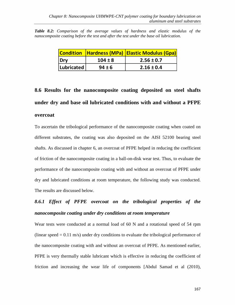
Chapter 8: Nanocomposite UHMWPE-CNT polymer coating for boundary lubrication on
aluminum and steel substrates
167
Table 8.2: Comparison of the average values of hardness and elastic modulus of the
nanocomposite coating before the test and after the test under the base oil lubrication.
Condition Hardness (MPa) Elastic Modulus (Gpa)
Dry 104 ± 8 2.56 ± 0.7
Lubricated 94 ± 6 2.16 ± 0.4
8.6 Results for the nanocomposite coating deposited on steel shafts
under dry and base oil lubricated conditions with and without a PFPE
overcoat
To ascertain the tribological performance of the nanocomposite coating when coated on
different substrates, the coating was also deposited on the AISI 52100 bearing steel
shafts. As discussed in chapter 6, an overcoat of PFPE helped in reducing the coefficient
of friction of the nanocomposite coating in a ball-on-disk wear test. Thus, to evaluate the
performance of the nanocomposite coating with and without an overcoat of PFPE under
dry and lubricated conditions at room temperature, the following study was conducted.
The results are discussed below.
8.6.1 Effect of PFPE overcoat on the tribological properties of the
nanocomposite coating under dry conditions at room temperature
Wear tests were conducted at a normal load of 60 N and a rotational speed of 54 rpm
(linear speed = 0.11 m/s) under dry conditions to evaluate the tribological performance of
the nanocomposite coating with and without an overcoat of PFPE. As mentioned earlier,
PFPE is very thermally stable lubricant which is effective in reducing the coefficient of
friction and increasing the wear life of components [Abdul Samad et al (2010),

Chapter 8: Nanocomposite UHMWPE-CNT polymer coating for boundary lubrication on
aluminum and steel substrates
168
Satyanarayana et al. (2006), Minn et al. (2008)]. Figure 8.11 (a-c) shows the surface
morphology of the wear track region and the non-worn region for the PFPE coated
nanocomposite coating, as obtained from the optical profilometer after a test duration of
100 hrs. It can be clearly observed from the 2-D profile [Figure 8.11(a)] of the sample
that the nanocomposite coating with the PFPE overcoat has just been smoothened out
without any trace of wear. No trace of wear was observed on the counterface flat plate.
Moreover, the overcoat of PFPE reduced the coefficient of friction of the nanocomposite
coating from 0.14 to 0.09 as shown in Figure 8.11(e). It was observed earlier that the
addition of CNTs to the UHMWPE polymer film resulted in an improvement of its
mechanical and thermal properties with a slight increase in the coefficient of friction
[Zoo et al. (2004), Abdul Samad et al (2010)]. However, adding an overcoat of PFPE on
the nanocomposite coating resulted in a reduction in the coefficient of friction which in
turn has increased the wear life and even the thermal stability of the nanocomposite
coating.

Chapter 8: Nanocomposite UHMWPE-CNT polymer coating for boundary lubrication on
aluminum and steel substrates
169
Non-WornRegion Wear track
Region
Polymer build-up(a) 2-D Profile
(b) Contour Plot
(c) 3-D Plot
(d) SEM Micrograph
0
0.05
0.1
0.15
0.2
0.25
0.3
0 10000 20000 30000 40000 50000
Co
eff
icie
nt
of f
rict
ion
Sliding Distance (m)
UHMWPE + CNTs @ Room Temp UHMWPE + CNTs / PFPE @ Room Temp
(e) Friction Graphs
Figure 8.11: (a), (b) & (c) 2-D profile, contour plot and the 3-D profile of the coating across the
wear track and the non-worn regions of the cylindrical shaft coated with the nanocomposite
coating and an overcoat of PFPE. (d) SEM image of the surface morphology of the worn and the
non-worn regions across the interface (e) Typical frictional graphs for the nanocomposite
coating with and without the PFPE overcoat at a normal load of 60 N and a linear speed of 0.11
ms-1
under dry conditions.
8.6.2 Performance of the nanocomposite coating with an overcoat of PFPE under base
oil lubricated conditions at room temperature
The nanocomposite coating with an overcoat of PFPE performed exceptionally well even
under the base oil lubricated conditions at a load of 60 N and a rotational speed of 54 rpm
(linear velocity = 0.11m/s). Figure 8.12 shows the comparison of the typical frictional
graphs of the nanocomposite coating with an overcoat of PFPE under dry and base oil
lubricated conditions. It is observed that at room temperature, the nanocomposite coating
with the PFPE overcoat, exhibited a slightly lower friction value of ~ 0.07 when

Chapter 8: Nanocomposite UHMWPE-CNT polymer coating for boundary lubrication on
aluminum and steel substrates
170
compared to that of ~ 0.09. The lower friction is because of the presence of the base oil,
which forms partial fluid film at the interface.
0
0.05
0.1
0.15
0.2
0 10000 20000 30000 40000 50000
Co
eff
icie
nt
of f
rict
ion
Sliding distance (m)
Dry Lubricated
Figure 8.12: Comparison of the typical frictional graphs for the nanocomposite coating with an
overcoat of PFPE under dry and base oil lubricated conditions
8.7 Conclusions
In this study, the effectiveness of the nanocomposite (UHMWPE + 0.1 wt% CNTs)
polymer film as a boundary lubricant has been evaluated under the base oil lubrication
without any additive. The following conclusions can be drawn from this study:
The addition of 0.1 wt% CNTs to the UHMWPE polymer improved the wear life
of the coating from 250,000 cycles to more than 2 million cycles under dry
sliding conditions against a bare Al flat plate.
Under the severe boundary-lubrication condition, the nanocomposite polymer
film is found to be very effective in protecting the mating surfaces from wear
under the base oil lubrication without any additive.

Chapter 8: Nanocomposite UHMWPE-CNT polymer coating for boundary lubrication on
aluminum and steel substrates
171
Minimal wear or only smoothening of the coating and no wear of the counterface
metal were observed up to 2 million cycles of sliding in lubricated contact with
the nanocomposite film.
The mechanical properties of the nanocomposite film are not altered by the base
oil even after a test duration of 100 hrs.
The PFPE overcoat on the UHMWPE-CNT nanocomposite coating is very
effective in reducing the coefficient of friction from 0.14 to 0.09 under dry
conditions, and to 0.07 under base oil lubricated conditions.
The tribological performance of the nanocomposite coating was found to be
excellent irrespective of the substrate on which it was deposited.
The nanocomposite polymer coating as boundary lubricant is found to be an
effective way to reduce or eliminate the usage of additives in the lubricating oil.

Chapter 9: Effect of temperature on the performance of the nanocomposite coating under dry and
lubricated conditions
172
Chapter 9
Effect of temperature on the performance of the nanocomposite
coating under dry and lubricated conditions
One of the major constraints for the usage of polymer coatings in sliding mechanical
components like bearings and gears, is their thermal instability. Thus, experiments were
conducted at higher temperatures to evaluate the maximum temperature until which the
presently developed nanocomposite coating could maintain its stability under the dry and
lubricated conditions. Since diamond like carbon (DLC) coatings are becoming popular
tribological coatings, the performance of the developed nanocomposite coating is
compared with that of DLC coatings under various conditions and the results are
discussed in this chapter.
9.1 Materials and Chemicals
AISI52100 bearing steel (Hardness = 60 HRC) cylindrical shaft of 40 mm diameter and a
flat AISI52100 bearing steel (Hardness = 60 HRC, Ra = 0.3 ± 0.05 µm) disk of Φ20 mm
were used. The cylindrical shaft was coated with the nanocomposite films and the bare
flat steel plate was used as the counterface. The specifications of the cylindrical shaft
used were exactly the same as discussed in chapter 8 [Figure 8.2(a)]. However, the shape
of the flat plate was altered for introducing the cartridge heater and the thermocouple to
monitor the temperature at the interface. The schematic of the modified flat counterface
plate is as shown in Figure 9.1.

Chapter 9: Effect of temperature on the performance of the nanocomposite coating under dry and
lubricated conditions
173
Figure 9.1: Photograph of the counterface plate with the heating cartridge and the thermocouple
The specifications of the UHMWPE polymer and other materials used are as
stated in chapter 3. SN 150 Base oil (Grade – I, Kinematics viscocity@40OC = 28-34 cSt,
Kinematics viscocity@100OC = 5.2-5.4 cSt, Viscocity Index = 100, Flash point = 200
OC, Density = 868 kg/m
3), which had no additives, was used as a liquid lubricant in the
experiments.
9.2 Experimental Procedures
9.2.1 Deposition of the nanocomposite coating on steel substrates
The detailed procedure of the coating process is described in chapter 8.
9.2.2 Deposition of DLC coatings on the steel samples
Tetrahedral amorphous carbon, ta-C, (non-hydrogenated DLC) film was deposited onto
steel substrates by Filtered Cathodic Vacuum Arc (FCVA) technology (Nanofilm

Chapter 9: Effect of temperature on the performance of the nanocomposite coating under dry and
lubricated conditions
174
Technologies International Pte. Ltd, Singapore) and the detailed deposition procedure can
be found in Tay et al. (2000). The thickness of DLC film is in the range of 1-2 µm and
hardness is 3000-5000 Vickers, as provided by the supplier.
9.2.3 Surface characterization and tribological characterizations
The experimental procedures for the surface characterizing techniques used in this study
such as the FESEM and XRD are described in chapter 3. The tribological experimental
setup for conducting the wear tests at elevated temperatures is also explained in Chapter
3.
9.3 Results and Discussions
9.3.1 Performance of the nanocomposite coating at elevated temperatures under
dry conditions
Friction and wear experiments were carried out on the custom-built tribometer at
temperatures of 80 OC and 120
OC to evaluate the performance of the nanocomposite
coating with and without the overcoat of PFPE at high temperatures. The experiments
were conducted at a normal load of 60 N and a rotational speed of 54 rpm (linear speed =
0.11 m/s). All the tests at elevated temperatures were run for a fixed duration of 50 hrs.
Figure 9.2 shows a comparison of typical frictional graphs of the nanocomposite coatings
at different temperatures with the inset table showing the average coefficient of friction
value for each case. It can be observed that for the nanocomposite coating without the
PFPE overcoat, the coefficient of friction reduces significantly from 0.14 to 0.07 with an
increase in temperature. This can be attributed to the softening of the polymer matrix due
to the rise in temperature. However, in the case of the nanocomposite coating with an
overcoat of PFPE, the reduction in the coefficient of friction is not very significant from a

Chapter 9: Effect of temperature on the performance of the nanocomposite coating under dry and
lubricated conditions
175
value of 0.09 to 0.08 when the temperature is raised from room temperature to 120 OC.
This could be because of the thermal stability of the PFPE overcoat and the fact that the
coefficient of friction was already low in the presence of PFPE.
Figure 9.2: A comparison of typical frictional graphs of the nanocomposite coatings with or
without the PFPE overcoat at different temperatures with the inset table showing the average
coefficient of friction values for each case for a normal load of 60 N and a linear speed of 0.11
ms-1
under dry conditions.
Figure 9.3 (a-b) shows the FESEM micrographs for the nanocomposite coating
without the PFPE overcoat for the experiment run at 80 OC and 120
OC respectively. It
can be observed that even though the nanocomposite film has not failed even after 50 hrs
of test at 120 OC, as evident from the EDX spectrum, there is a change in the surface
morphology of the wear track. We can observe that at 120 OC, the polymer has started to
flow due to some plastic deformation resulting in an increase in the roughness of the wear
track region. However, no significant change in the thickness of the film was observed
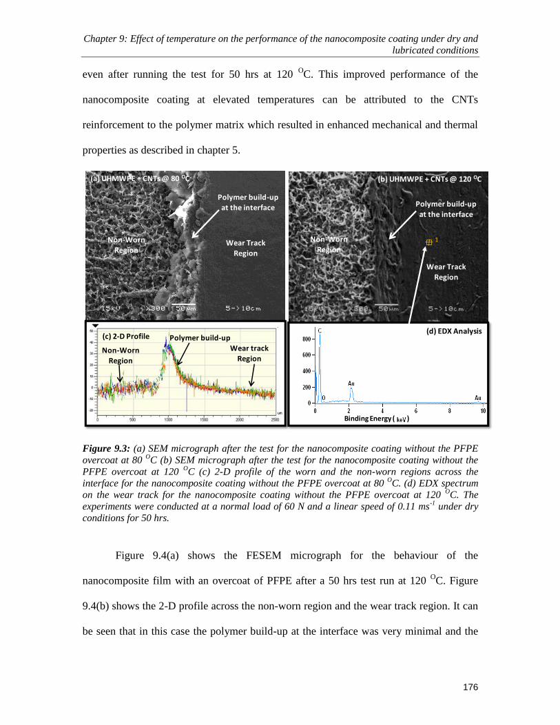
Chapter 9: Effect of temperature on the performance of the nanocomposite coating under dry and
lubricated conditions
176
even after running the test for 50 hrs at 120 OC. This improved performance of the
nanocomposite coating at elevated temperatures can be attributed to the CNTs
reinforcement to the polymer matrix which resulted in enhanced mechanical and thermal
properties as described in chapter 5.
1
Binding Energy ( )
(a) UHMWPE + CNTs @ 80 OC
Non-Worn
RegionWear Track
Region
Polymer build-up at the interface
(b) UHMWPE + CNTs @ 120 OC
Non-Worn Region
Wear Track
Region
Polymer build-up
at the interface
(d) EDX Analysis(c) 2-D Profile
Non-WornRegion
Wear track Region
Polymer build-up
Figure 9.3: (a) SEM micrograph after the test for the nanocomposite coating without the PFPE
overcoat at 80 OC (b) SEM micrograph after the test for the nanocomposite coating without the
PFPE overcoat at 120 OC (c) 2-D profile of the worn and the non-worn regions across the
interface for the nanocomposite coating without the PFPE overcoat at 80 OC. (d) EDX spectrum
on the wear track for the nanocomposite coating without the PFPE overcoat at 120 OC. The
experiments were conducted at a normal load of 60 N and a linear speed of 0.11 ms-1
under dry
conditions for 50 hrs.
Figure 9.4(a) shows the FESEM micrograph for the behaviour of the
nanocomposite film with an overcoat of PFPE after a 50 hrs test run at 120 OC. Figure
9.4(b) shows the 2-D profile across the non-worn region and the wear track region. It can
be seen that in this case the polymer build-up at the interface was very minimal and the

Chapter 9: Effect of temperature on the performance of the nanocomposite coating under dry and
lubricated conditions
177
surface morphology in the wear track region is not as rough as the one compared to that
of the nanocomposite film without the PFPE overcoat. This can be attributed to the
excellent lubricity and thermal stability of the PFPE overcoat coupled with the enhanced
thermal properties of the nanocomposite film due to the CNT reinforcements. Low
friction means less plastic deformation at the surface.
Wear track Region
(b) 2-D Profile
Non-Worn Region
Very less polymer build-up
Binding Energy ( )
1
(a) UHMWPE + CNTs/PFPE @ 120 OC
Non-Worn Region
Wear Track Region
Interface
(c) EDX Analysis
Figure 9.4: (a) SEM micrograph after the test for the nanocomposite coating with an overcoat of
PFPE at 120 OC. (b) 2-D profile of the worn and the non-worn regions of the nanocomposite
coating with an overcoat of PFPE after 50 hrs of test conducted at 120 OC. (c) EDX spectrum on
the wear track region of the nanocomposite coating with an overcoat of PFPE. The experiments
were conducted at a normal load of 60 N and a linear speed of 0.11 ms-1
under dry conditions for
50 hrs.
Figure 9.5 (a-c) shows the 2-D profiles and photographs of the counterface steel
flat plate for the wear tests of the nanocomposite coating without the PFPE overcoat at 80
OC [Figure 9.5(a)], at 120
OC [Figure 9.5(b)] and that of the nanocomposite coating with
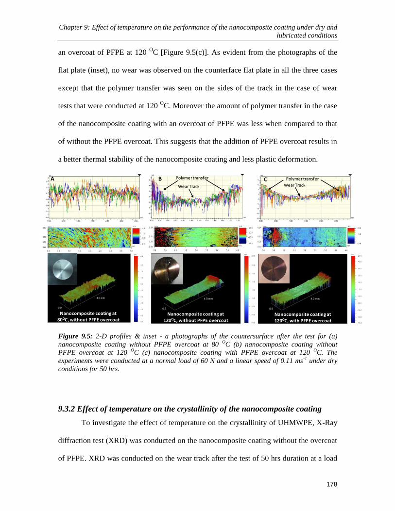
Chapter 9: Effect of temperature on the performance of the nanocomposite coating under dry and
lubricated conditions
178
an overcoat of PFPE at 120 OC [Figure 9.5(c)]. As evident from the photographs of the
flat plate (inset), no wear was observed on the counterface flat plate in all the three cases
except that the polymer transfer was seen on the sides of the track in the case of wear
tests that were conducted at 120 OC. Moreover the amount of polymer transfer in the case
of the nanocomposite coating with an overcoat of PFPE was less when compared to that
of without the PFPE overcoat. This suggests that the addition of PFPE overcoat results in
a better thermal stability of the nanocomposite coating and less plastic deformation.
Wear Track
Polymertransfer
Wear Track
Polymer transferA B C
Nanocomposite coating at
80OC, without PFPE overcoatNanocomposite coating at
120OC, without PFPE overcoatNanocomposite coating at 120OC, with PFPE overcoat
Figure 9.5: 2-D profiles & inset - a photographs of the countersurface after the test for (a)
nanocomposite coating without PFPE overcoat at 80 OC (b) nanocomposite coating without
PFPE overcoat at 120 OC (c) nanocomposite coating with PFPE overcoat at 120
OC. The
experiments were conducted at a normal load of 60 N and a linear speed of 0.11 ms-1
under dry
conditions for 50 hrs.
9.3.2 Effect of temperature on the crystallinity of the nanocomposite coating
To investigate the effect of temperature on the crystallinity of UHMWPE, X-Ray
diffraction test (XRD) was conducted on the nanocomposite coating without the overcoat
of PFPE. XRD was conducted on the wear track after the test of 50 hrs duration at a load

Chapter 9: Effect of temperature on the performance of the nanocomposite coating under dry and
lubricated conditions
179
of 60 N and a rotational speed of 54 rpm to observe the effects of temperature on the
crystallinity of the coating. Figure 9.6 shows the XRD patterns obtained for the
UHMWPE films at different temperatures. The diffraction peaks obtained at 21.6O, 24
O
and 44.01O
of 2θ are assigned to the (110), (200) and (220) crystal planes of polyethylene
[Clark (1996)]. The XRD patterns of the nanocomposite film have another diffraction
peak at about 26.3O of 2θ, which is a signature of (002) crystal plane of carbon.
The crystallinity of the films was computed by using XRD-600 computer
software. It can be observed from Figure 9.6(inset) that the temperature did not affect the
crystallinity of the film significantly. This is also evident from the fact that there was no
obvious shift in the positions of the diffraction peaks at 2θ values of (110), (200) and
(220) polyethylene crystal planes with the change in temperature.

Chapter 9: Effect of temperature on the performance of the nanocomposite coating under dry and
lubricated conditions
180
10 20 30 40 50 60
Inte
nsi
ty (a
rbit
rary
un
it)
Angle (2θ)
Room Temp
80 Deg C
120 Deg C
(PE)110
(PE)200
(PE)220(CNTs)002
0
20
40
60
80
100
0 50 100 150
Cry
stal
linit
y (%
)
Temperature (OC)
Figure 9.6: XRD spectrums obtained for the nanocomposite coatings after the test at various
elevated temperatures for 50 hrs.
9.3.3 Performance of the nanocomposite coating at elevated temperatures under
base oil lubricated conditions
Figure 9.7 shows typical frictional graphs for the nanocomposite coating with an overcoat
of PFPE under base oil lubricated conditions. It is observed that the nanocomposite
coating performed well under a temperature of 80 OC. The quality of the oil after 50 hrs
of test was unchanged without any debris particles as shown in Figure 9.7 (c) for both the
cases, i.e. at room temperature and at 80 OC. No polymer transfer and wear was observed
on the counterface after the test. Figure 9.7(d) shows the counterface surface after the test
conducted at room temperature.

Chapter 9: Effect of temperature on the performance of the nanocomposite coating under dry and
lubricated conditions
181
With a rise in the temperature to approximately 105 OC a considerable softening
of the nanocomposite coating is observed in the beginning. It may be due to the rise in
temperature coupled with the diffusion of the base oil into the top rough part of the
coating resulting in a significant drop in the coefficient of friction as can be seen from
Figure 8.8. However, the test was continued for another 50 hrs after removing this mobile
top layer of the nanocomposite coating and changing the base oil. It was observed that the
nanocomposite coating performed well without failing until 50 hrs as can be seen from
the frictional graph of Figure 9.7. Thus, a possible reason for this phenomenon would be
that at elevated temperatures due to the diffusion of the base oil into the coating the top
layer of the polymer gets softened considerably resulting in its peeling off of the top
mobile layer. However, when this top layer is physically removed and the experiment is
again restarted with a fresh supply of base oil, the film lasted for another 50 hrs without
any failure. This initial softening of the top layer does not harm the coating wear
performance in any way and may be considered as the running-in event for this case.

Chapter 9: Effect of temperature on the performance of the nanocomposite coating under dry and
lubricated conditions
182
Figure 9.7: (a) Comparison of typical frictional graphs for the nanocoatings with PFPE overcoat
at room temperature, 80 OC and 105
OC respectively under base oil lubricated conditions at a
normal load of 60 N and a linear speed of 0.11 ms-1
after 50 hrs. (b) A photograph of the
lubricated test at room temperature (c) Quality of the oil after the test at room temperature (d)
The counterface surface after the lubricated test conducted at room temperature.
9.3.4 Comparison of the nanocomposite coating with the DLC coatings in dry
and lubricated conditions
Friction and wear experiments were conducted with the cylindrical shafts coated with
DLC coatings. Tests were carried out under dry and base oil lubricated conditions. The
counterface used is the bare AISI52100 bearing steel flat plate. Figure 8.9 (a) shows the
comparison of the typical frictional graphs for the DLC coating and the nanocomposite
coating with an overcoat of PFPE at room temperature in dry conditions, under a normal
load of 60 N and a linear speed of 0.11 ms-1
. The nanocomposite coating with the PFPE
overcoat showed lower coefficient of friction of 0.09 when compared to that of 0.15 for

Chapter 9: Effect of temperature on the performance of the nanocomposite coating under dry and
lubricated conditions
183
the DLC coating. This can be attributed to the lubricious nature of the UHMWPE and
PFPE combine. No significant wear was observed on either the nanocomposite films or
the DLC films. However, a considerable amount of wear was observed on the
counterface flat plate when it is slid against the DLC coating when compared to that
when slid against the nanocomposite coating. Figures 9.8(b) & (c) represent the 3-D plots
of the wear groove formed on the flat steel plate when slid against the DLC and the
nanocomposite coatings, respectively. UHMWPE-based coating is relatively softer than
the counterface and hence is able to protect both the substrate and the counterface by
undergoing plastic deformation in the top thin layer of the polymer. This is a great
advantage of a softer polymer-based coating over a hard DLC coating.

Chapter 9: Effect of temperature on the performance of the nanocomposite coating under dry and
lubricated conditions
184
0
0.05
0.1
0.15
0.2
0.25
0.3
0.35
0 10000 20000 30000 40000 50000 60000
Co
eff
icie
nt
of f
rict
ion
Sliding Distance (m)
DLC UHMWPE + CNTs UHMWPE+CNTs/PFPE
(a)
(b) Counterface slid against
nanocomposite \ PFPE overcoat
(C) Counterface slid against DLC
coating
Figure 9.8: (a) Comparison of typical frictional graphs for the nanocoatings with and without the
PFPE overcoat and DLC coatings under dry conditions at room temperature. (b) 3-D plot of the
counterface surface when slid against the nanocomposite coating with PFPE overcoat (c) 3-D
plot of the counterface surface when slid against the DLC coating.
Under the base oil lubricated conditions also, the same phenomenon is observed.
Figure 9.9(a) shows the comparison of typical frictional graphs obtained for the
nanocomposite coating with an overcoat of PFPE and the DLC coatings under the base
oil lubricated conditions. The DLC coating showed a higher coefficient of friction value

Chapter 9: Effect of temperature on the performance of the nanocomposite coating under dry and
lubricated conditions
185
of 0.09 when compared to that of the nanocomposite coating with the PFPE overcoat
which showed a coefficient of friction value of 0.07. Figure 9.9(b) and (c) shows the
photographs of the flat plate counterface after a test of 100 hrs under the base oil
lubricated conditions at a load of 60 N and a speed of 0.11m\s when slid against the DLC
and the nanocomposite coating, respectively. The wear scar is very clearly seen on the
counterface plate when slid against the DLC coating, whereas no wear was observed for
the plate slid against the nanocomposite coating. This can be attributed to the excellent
lubricious nature of the UHMWPE based nanocomposite coating.
0
0.02
0.04
0.06
0.08
0.1
0.12
0 10000 20000 30000 40000 50000 60000
Co
eff
icie
nt
of f
rict
ion
Sliding Distance (m)
DLC\Base Oil UHMWPE+CNTs\PFPE\Base oil(a)
(b) (c)
Wear Scar
Figure 9.9: (a) Comparison of typical frictional graphs for the nanocomposite coating with the
PFPE overcoat and DLC coatings under base oil lubricated conditions at room temperature. (b)
Photograph of the counterface flat plate after sliding against the DLC coating for 100 hrs under
base oil lubricated conditions (c) Photograph of the counterface flat plate after sliding against
the nanocomposite coating for 100 hrs under base oil lubricated conditions.

Chapter 9: Effect of temperature on the performance of the nanocomposite coating under dry and
lubricated conditions
186
9.4 Conclusions
The following conclusions can be drawn from this study:
The nanocomposite coating with or without the PFPE overcoat performed
extremely well at elevated temperatures of 80 OC and 120
OC respectively at a
load of 60 N and an equivalent linear speed of 0.11 ms-1
, under dry conditions for
50 hrs without failure (number of cycles of rotation =150,000).
Under the base oil lubricated conditions, the nanocomposite coating with the
overcoat of PFPE performed well at 80 OC for 50 hrs. However, at 105
OC
considerable softening of the top layer of the coating is observed during the
running-in. The coating performed well up to 50 hrs after the initial softened layer
was physically removed and the oil was changed after the running –in period (~
2000 m of sliding distance).
The nanocomposite coating can be effectively used as a boundary lubricant at
elevated temperatures up to 105 OC in tribological applications such as bearings
and gears where base oil is used as the lubricant.
The nanocomposite coating showed excellent performance when compared to that
of the DLC coatings, especially in terms of low coefficient of friction and nearly
no wear of the coating, substrate or the counterface materials.

Chapter 10: Conclusions
187
Chapter 10
Conclusions
The major goal of this thesis was to explore ways: To provide energy saving and
environmental-friendly lubrication method whereby to fully eliminate the use of
harmful additives as well as reduce the amount of lubricants needed.
The present study was focused on investigating the feasibility of using polymer
films as boundary lubricant layers onto metallic substrates modified with appropriate
surface pre-treatments, which are expected to enhance the lubrication performance and
reduce the consumption of harmful additives and the amount of lubricants in sliding
mechanical components.
The specific objectives of this study were as follows:
To evaluate the feasibility of using UHMWPE as a coating in its pristine form and
with addition of CNT as filler and an overcoat of PFPE.
To evaluate the effectiveness of the nanocomposite film against different
counterface materials and exposure to UV radiations.
To evaluate the effectiveness of the UHMWPE coating in the presence of liquid
lubricants without any additives in the base lubricating oil.
To evaluate the effectiveness of the nanocomposite film of UHMWPE and
SWCNTs at higher temperatures under dry and base oil lubricated conditions.

Chapter 10: Conclusions
188
Three approaches were taken to achieve the above mentioned objectives:
1. First, was to improve the adhesion between the steel substrate and the film by
subjecting the substrate to air-plasma pre-treatment.
2. Second, was to improve the load carrying capacity of the film by the addition of
SWCNTs as filler materials.
3. Third was to improve the tribological properties by overcoating the
nanocomposite film by a thin layer of PFPE.
Thus a single walled carbon nanotube reinforced UHMWPE polymer nanocomposite
coating has been developed to be used as a boundary lubricant in sliding mechanical
components such as bearings and gears. The tribological performance of the
nanocomposite coating was evaluated at room and elevated temperatures under both dry
and base oil (without additives) lubricated conditions. The developed nanocomposite
coating exhibited excellent mechanical and tribological performance in terms of wear
under the tested conditions.
The following specific conclusions can be drawn from each of the approaches taken in
this study:
Approach – I: To improve the adhesion between the steel substrate and the film by
subjecting the substrate to proper pre-treatment such as air-plasma treatment.
The air-plasma treatment has considerable effect on improving the adhesion
between the UHMWPE film and the steel substrate by enhancing the surface
energy which in turn results in good tribological characteristics of the film. The
wear life of the plasma treated steel sample coated with UHMWPE film increased

Chapter 10: Conclusions
189
by more than 10 to 12 times when compared to that of the untreated steel samples
coated with UHMWPE film.
The thickness of the UHMWPE film has a greater effect on the wear life and it
was observed that an optimum thickness of ~16.3±2 µm has greater wear
durability.
The tribological tests carried out at various loads and rotational speeds have
demonstrated that the presently optimized UHMWPE film on steel surface did not
show any failure until 100,000 cycles of sliding at a load of 4 N and rotational
speed of 600 rpm in completely dry sliding case (equivalent PV factor of ~17.79
MPa ms-1
).
Approach – II: Second, is to improve the load carrying capacity of the film by the
addition of some suitable filler materials such as SWCNTs
An increase of ~66% and ~58% in the hardness and elastic modulus values
respectively, is observed for the pristine UHMWPE film when reinforced with
0.2 wt% SWCNT.
An increase in the resistance to scratch and penetration is also observed with
the increase in the SWCNT content due to the increase in the load bearing
capacity of the film and due to the improvement in the interfacial bonding.
An increase in the thermal stability of the polymer film is observed with
increasing SWCNT content, because of the higher thermal conductivity of
SWCNTs. This contributes to better heat dissipation during sliding and longer
wear life for the nanocomposite.

Chapter 10: Conclusions
190
A significant increase in the wear life (> 250,000 cycles) of the polymer film
at a load of 4 N and a rotational speed of 2500 rpm is observed because of the
overall improvement in the mechanical and thermal properties of the film with
SWCNT reinforcement.
A slight increase in the coefficient of friction from ~0.08 to ~0.16 is observed
with an increase in the SWCNT content from 0 wt% to 0.2 wt% respectively.
Approach – III: To improve the tribological properties by overcoating the
nanocomposite film by a thin layer of PFPE
An overcoat of PFPE improved the wear life of the nanocomposite polymer film
significantly to >240,000 cycles for a normal load of 4 N and a rotational speed of
2500 rpm.
The overcoat of PFPE helped in reducing the coefficient of friction of the
nanocomposite film from a value of ~0.14 to ~0.05, which in turn has improved
the wear life of the film and the counterface.
After the UHMWPE+CNTs nanocomposite coating was developed successfully, the
coating was tested and evaluated under dry and base oil lubricated conditions, at room
and elevated temperatures, against different counterface materials and after exposure to
UV radiations. The following conclusions can be drawn from the above mentioned
evaluations:
1. Effect of Counterface material and UV Radiation on the tribological properties
of the nanocomposite coating

Chapter 10: Conclusions
191
The nanocomposite coating did not fail until 240,000 cycles under a load of 4 N
and a rotational speed of 2000 rpm (linear velocity = 0.41 m/s) when slid against
the Si3N4, steel and brass balls, with no wear to the counterface balls.
However, the nanocomposite coating exhibited a lower friction value of ~0.09
when slid against brass as against a value of ~0.12 against Si3N4 and steel.
Exposure to UV radiations for 300 h did not affect the tribological performance of
the nanocomposite coating as there was no failure until 240,000 cycles at a
normal load of 4 N and a rotational speed of 2000 rpm (linear velocity = 0.41
m/s) when slid against Si3N4 balls after the coating was exposed to UV radiation.
With an overcoat of PFPE, the nanocomposite coating exhibited low coefficient
of friction of ~ 0.05 with or without the exposure to UV radiations.
2. Tribological performance of the nanocomposite coating under dry and base oil
lubricated conditions
The addition of 0.1 wt% CNTs to the UHMWPE polymer improved the wear life
of the coating from 250,000 cycles to more than 2 million cycles under dry
sliding conditions against a bare Al flat plate.
Under the severe boundary-lubrication condition, the nanocomposite polymer
film is found to be very effective in protecting the mating surfaces from wear
under the base oil lubrication without any additive.
Minimal wear or only smoothening of the coating and no wear of the counterface
metal were observed up to 2 million cycles of sliding in lubricated contact with
the nanocomposite film.

Chapter 10: Conclusions
192
The mechanical properties of the nanocomposite film are not altered by the base
oil even after a test duration of 100 hrs.
The PFPE overcoat on the UHMWPE-CNT nanocomposite coating is very
effective in reducing the coefficient of friction from 0.14 to 0.09 under dry
conditions, and to 0.07 under base oil lubricated conditions.
The tribological performance of the nanocomposite coating was found to be
excellent irrespective of the substrate on which it was deposited.
The nanocomposite polymer coating as boundary lubricant is found to be an
effective way to reduce or eliminate the usage of additives in the lubricating oil.
3. Effect of temperature on the performance of the nanocomposite coating under
dry and lubricated conditions
The nanocomposite coating with or without the PFPE overcoat performed
extremely well at elevated temperatures of 80 OC and 120
OC respectively at a
load of 60 N and an equivalent linear speed of 0.11 ms-1
, under dry conditions
for 50 hrs without failure (number of cycles of rotation =150,000).
Under the base oil lubricated conditions, the nanocomposite coating with the
overcoat of PFPE performed well at 80 OC for 50 hrs. However, at 105
OC
considerable softening of the top layer of the coating is observed during the
initial running-in. The coating performed well up to 50 hrs after the initial
softened layer was physically removed and the oil was changed after the running
–in period (~ 2000 m of sliding distance).
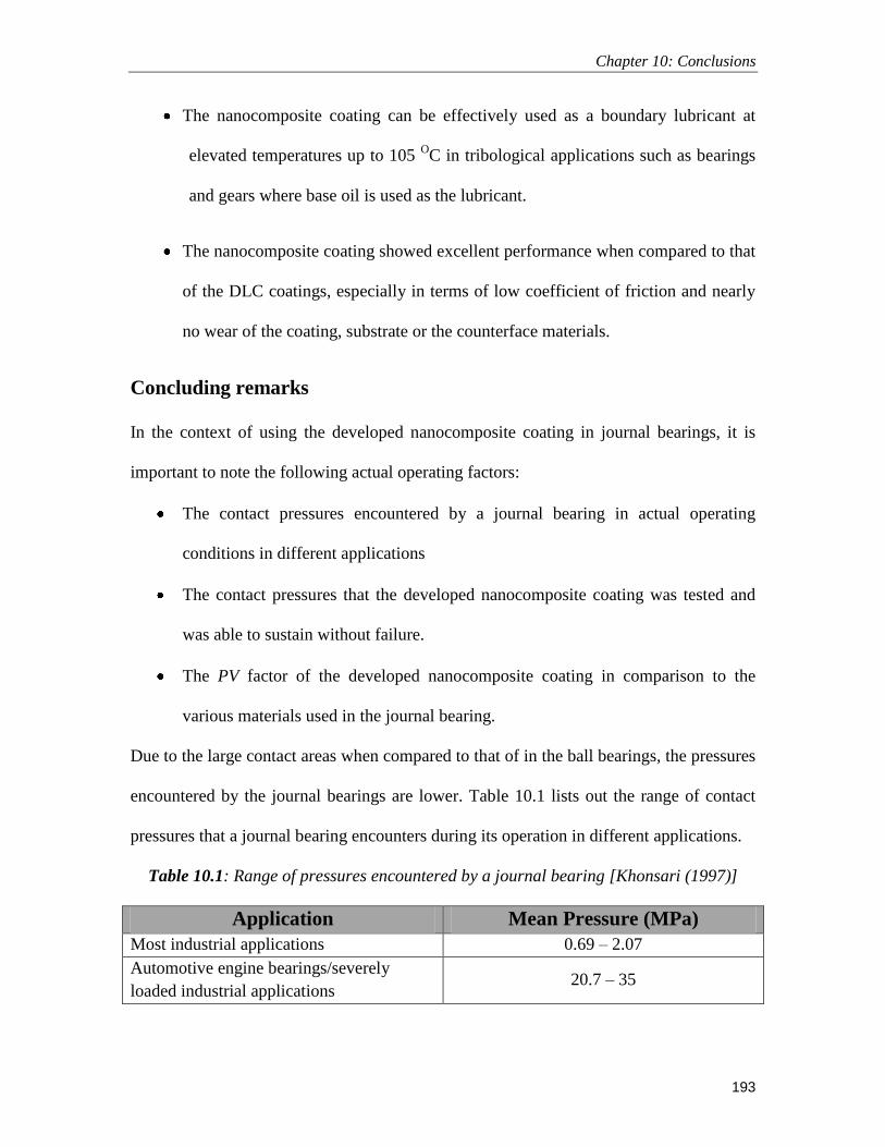
Chapter 10: Conclusions
193
The nanocomposite coating can be effectively used as a boundary lubricant at
elevated temperatures up to 105 OC in tribological applications such as bearings
and gears where base oil is used as the lubricant.
The nanocomposite coating showed excellent performance when compared to that
of the DLC coatings, especially in terms of low coefficient of friction and nearly
no wear of the coating, substrate or the counterface materials.
Concluding remarks
In the context of using the developed nanocomposite coating in journal bearings, it is
important to note the following actual operating factors:
The contact pressures encountered by a journal bearing in actual operating
conditions in different applications
The contact pressures that the developed nanocomposite coating was tested and
was able to sustain without failure.
The PV factor of the developed nanocomposite coating in comparison to the
various materials used in the journal bearing.
Due to the large contact areas when compared to that of in the ball bearings, the pressures
encountered by the journal bearings are lower. Table 10.1 lists out the range of contact
pressures that a journal bearing encounters during its operation in different applications.
Table 10.1: Range of pressures encountered by a journal bearing [Khonsari (1997)]
Application Mean Pressure (MPa)
Most industrial applications 0.69 – 2.07
Automotive engine bearings/severely
loaded industrial applications 20.7 – 35

Chapter 10: Conclusions
194
In the present study, the developed nanocomposite coating has been tested under point
contact (ball-on-disk) and line contact (plate-on-cylinder) conditions. The maximum
contact pressures that the nanocomposite coating was subjected to under the different
contact conditions are listed out in Table 10.2. It was observed from Table 11.2, that the
nanocomposite coating performed well without failure even until contact pressures of
0.165 GPa.
Table 10.2: Maximum contact pressures that the nanocomposite coating was subjected to
under the different contact conditions
Nanocomposite
coating/PFPE
Max. Tested
Pressure (MPa)
Tested
Velocity (m/s)
Max. Tested
Temp (°C)
Condition
Point Contact 165 0.5 Room Temp. Dry
Line Contact 25 0.11 120 Dry
Line Contact 25 0.11 105 Lubricated
The PV factors of various materials that are used in the manufacturing of journal bearings
are listed out in Table 10.3 along with the calculated PV factor of the developed
nanocomposite coating. The PV factor calculated for the nanocomposite coating is with
respect to the conditions of maximum contact pressure of 0.165 GPa and maximum
velocity of 0.5 m/s at which the coating did not fail. It can be observed that the PV factor
of the nanocomposite coating is significantly high when compared to the various
materials used for journal bearings.

Chapter 10: Conclusions
195
Table 10.3: PV factors of various materials that are used in the manufacturing of journal
bearings [Norton (2010), Hamrock et al. (1999)]
Material
Max.
Pressure
(MPa)
Max.
Temperature
(°C)
Max.
Velocity
(m/s)
Max. PV
value
MPa m/s
Cast Bronze 31 165 7.5 1.75
Sintered Fe 55 65 4 1.75
Pb-bronze 24 150 7.6 2.1
Sintered Fe-Cu 28 65 1.1 1.2
Cast Iron 4 150 1.5 0.5
Hardenable
Fe-Cu
55 - 0.2 2.6
Lead iron 7 - 4.1 1.8
Nanocomposite
coating
165 0.5 120 82.5
Thus it can be concluded from this study that the developed nanocomposite coating is an
excellent alternative to traditional lubrication strategies whereby the usage of harmful
additives can be completely eliminated or reduced considerably leading to a more
pollution free environment.

Chapter 11: Future Recommendations
196
Chapter 11
Future Recommendations
The nanocomposite coating of UHMWPE reinforced with SWCNTs developed in the
present study demonstrated promising resluts to be used as a boundary lubricant in
mechanical sliding components such as bearings and gears. The nanocomposite coating
was tested at room and elevated temperatures under the dry and base oil lubricated
conditions at which it performed exceptionally well in terms of wear. However, it will be
worthwhile to test the performance of the nanocomposite coating under more varying
conditions. Below is a list of recommendations for future studies related to this coating.
Research has shown that UHMWPE has the ability to perform well under
cryogenic or sub zero temperature conditions. However, no tribological study has
been conducted to substantiate that claim. So, evaluating the performance of the
developed nanocomposite coating under the sub zero conditions would give a
more global view of its performance.
UHMWPE has the ability not to absorb moisture. So, it is an excellent candidate
to be used under water lubricated conditions. During the present times, wherein
extra emphasis is being given to clean energy, it is worthwhile to evaluate the
performance of the nanocomposite coating under water lubricated conditions.
For the scalability of applying the developed coating to industrial applications,
alternate and more efficient methods of coating procedures such as spraying etc.
can be explored

References
197
References
Abdul Samad, M., Satyanarayana N. and Sinha, S. K., Tribology of UHMWPE film
on air-plasma treated tool steel and the effect of PFPE overcoat, Surface & Coatings
Technology, 204 (2010) 1330-1338.
Abdul Samad, M. and Sinha, S. K., Nanocomposite UHMWPE-CNT polymer coatings
for boundary lubrication on aluminium substrates, Tribology Letters, Vol. 38 (2010) 301-
311.
Abdul Samad, M. and Sinha, S. K., Mechanical, thermal and tribological
characterization of a UHMWPE film reinforced with carbon nanotubes coated on steel,
(under review).
Abdul Samad, M. and Sujeet K. Sinha, ―Dry sliding and boundary lubrication
performance of a UHMWPE/CNTs nanocomposite coating on steel substrates at elevated
temperatures‖ Wear, 270(2011), p. 395 - 402.
Abdul Samad, M. and Sinha, S. K., Effect of counterface and UV radiation on the
tribological performance of the UHMWPE/CNTs nanocomposite coating on steel
substrates, (under review).
Abdul Samad, M, Satyanarayana, N and Sujeet K. Sinha, ―Effect of Air-Plasma pre-
treatment of Si substrate on adhesion strength and tribological properties of a UHMWPE
film‖, Journal of Adhesion Science and Technology, 24(2010), p.2557 – 2570.
Alves, A. L. S., Nascimento, L. F. C. and Suarez, J. C.M., Influence of weathering and
gamma irradiation on the mechanical and ballistic behavior of UHMWPE composite
armor, Polymer Testing, 24 (2005) 104-113.
Bal, S and Samal, S. S., Carbon nanotube reinforced polymer compostes – A state of the
art, Bulletin of Material Science, 30(2007) 379-386.

References
198
Bao, Y., Zhang, T and Gawne, D. T., Influence of composition and process parameters
on the thermal spray deposition of UHMWPE coatings, Journal of Materials Science, 40
(2005), 77-85.
Bartz, W. J., Engine oils and automotive lubrication, New York, Marcel Dekker, 1993.
Bartz, W. J., Lubricants and the environment, Tribology International, 31(1998), 35-47.
Beamson, G. and Briggs, D., High resolution XPS of organic polymers: The scienta
ESCA300 database. John Wiley and Sons, 1992, pp. 277-283.
Bello, J. O., Wood, R. J. K., Micro-abrasion of filled and unfilled polyamide 11
coatings, Wear, 258(2005), 294-302.
Bhushan, B. Handbook of Micro/Nano Tribology. Boca Raton, Fl, CRC Press, 1991.
Bhushan, B. Principles and applications of tribology, John Wiley and Sons Inc. New
York (1999)
Binnig, G., Quate, C. F. and Gerber, Ch. Atomic force microscope, Physical Review
Letters, 56, pp. 930-934, 1986.
Briscoe, B. J and Sinha, S. K., Wear of Polymers, Proceedings of the Institution of
Mechanical Engineers, Part J: Journal of Engineering Tribology, 216 (2002), 401-413
Briscoe, B.J., Pelillo, E. and Sinha, S.K., Scratch hardness and deformation maps for
Poly(carbonate) and Poly(ethylene), Polymer Engineering & Science, 36 (24) (1996)
2996-3005.
Brovikova, N., Abramov, V. L and Menagarishvili, S. D., Application of plasma
treatment to improve adhesive properties of polymer materials, Volokna, 3 (1992), 31-32.
Buck, W. H., Farang, O. L., Deckman, D. E., Givens Jr, W. A. and Horodysky, A.
G., Low sulfur, low ash and low phosphorous lubricant additive and composition, United
states patent 20070203030.

References
199
Callister WD Jr. Materials science and engineering an introduction, Sixth edition. New
Jersey: John Wiley & Sons, Inc: 2003.
Cao, L., Chen, H. Z., Wang, M. and Sun, J. Z., Photoconductivity study of modified
carbon nanotube/oxotitanium phthalocyanine composites, Journal of Physical Chemistry
B, 106 (2002) 8971-8975.
Chen, Q., Dai, L., Gao, M., Huag, S. and Mau, J., Plasma activation of carbon
nanotubes for chemical modification, Journal of Physical Chemistry B, 105 (2001) 618-
622.
Chew, F. T., Goh, D. Y. T., Ooi, B. C., Saharom, R., Hui, J. K. S. and Lee, B. W.,
Association of ambient air-pollution levels with acute asthma exacerbation among
children in Singapore, Allergy, 54 (1999), pp. 320-329.
Clark, E. S., Physical properties of polymers handbook, American Institute of physics,
Woodburry, New York (1996).
Delplancke-Ogletree, M. P. and Monteiro, O. R., Wear behaviour of diamondlike
carbon/metal carbide multilayers, Surface and coatings technology, 108-109 (1998) 484-
488.
Digital Instruments MultiModeTM
Instruction Manual, Version 4.22 ce, 1997.
Dowson, D. History of Tribology. Longmans, London, 1979.
Eapen, K. C., Patton, S. T. and Zabinski, J. S. Lubrication of microelectromechanical
systems (MEMS) using bound and mobile phases of Fomblin Zdol®, Tribology Letters,
12, pp. 35-41, 2002.
Elliott, A., Infra-red Spectra and Structure of Organic Long-chain Polymers, Edward
Arnold (Publishers) Ltd., 1969, p. 48
References
200
Erdemir, F. A., Nichols and Pan, X. Z., Friction and wear performance of ion-beam-
deposited diamond-like carbon films on steel substrates, Diamond and Related Materials,
3(1994), 119-125.
Flock J et al. On the friction and wear behaviour of PAN- and pitch-carbon fiber
reinforced PEEK composites, Wear, 29 (1999), 304.
Foster, J., Singamaneni, S., Kattumenu, R. and Bliznyuk, V., Dispersion and phase
separation of carbon nanotubes in ultrathin polymer films, Colloid and Interface Science,
287 (2005) 167-172.
Fouad Mohamed, H., Mourad, A. H. I and Barton, D. C., UV irradiation and aging
effects on nanoscale mechanical properties of ultra high molecular weight polyethylene
for biomedical implants, Plastics, Rubber and Composites, 37 (2008) 346-352.
Fox-Rabinovich, G. S., Kovalev, A. I., Wainstein, D. L., Sh, L., Shuster, G.K.
Dosbaeva, Improvement of Duplex PVD coatings for HSS cutting tools by PFPE
(perfluropolyether ―Z-Dol‖), Surface & Coatings technology, 160(2002) 99-107.
Freidrich, K and Schlarb, A. K., Tribology of Polymer Nanocomposites: Friction and
wear of bulk materials and coatings, Tribology and Interface engineering, 55 (2008) 1 –
551
Fusaro, R. L., Tribological Properties of Polymer Films and Solid Bodies in a Vacuum
Environment: Prepared for the 1987 Annual Meeting of the American Society of
Lubrication Engineers. NASA Report.
Gadow, R. and Scherer, D., Composite coatings with dry lubrication ability on light
metal substrates, Surface and Coatings Technology, 151-152 (2002) 471-477.
Gahlin, R., Larsson, M and Hedenqvist, P., ME-C:H coatings in roller bearings, Wear,
249(2001), 302-309.

References
201
Gao, J. F., Li, Z. M., Meng, Q. J and Yang, Q., CNTs/UHMWPE composites with a
two-dimensional conductive network, 62(2008), 3530-3532.
Gilmore, R., Baker, M. A., Gibson, P. N., Gissler, W., Stoiber, M., Losbichler, P. and
Mitterer, C., Low-friction TiN-MoS2 coatings produced by dc magnetron co deposition,
Surface and coatings technology, 108-109 (1998) 345-351.
Giraldo, L. F., Brostow, W., Devaux, E., Lopez, B. L. and Perez, L. D., Scratch and
wear resistance of polyamide 6 reinforced with multiwall carbon nanotubes, Nanoscience
and Nanotechnology, 8 (2008) 1-8.
Glovnea, R. P., Olver, A. V., and Spikes, H., Lubrication of rough surfaces by a
boundary film-forming viscosity modifier additive, Journal of Tribology, 127(2005),
223-312.
Gold, P. W. and Loos, J., Wear resistance of PVD coatings in roller bearings, Wear, 253
(2002), pp. 465-472.
Gorokhovskii, G.A. and Agulov, I., Effect of orientation and crystallinity on the friction
and wear of PTFE, Mechanics of Composite Materials, 2 (1) (1966) 61-64.
Grill, Tribology of diamondlike carbon and related materials: an updated review, Surface
and Coatings Technology, 94-95(1997), 507-513.
Hamrock, B. J., Jacobson, B. and Schmid, S. R., Fundamentals of machine elements,
McGrew Hill Publishing Co, New York, (1999)
Han, M. H., Jegal, J. P., Park, K. W., Choi, J. H., Baik, H. K., Noh, J. H., Song, K.
M. and Lim, Y. S., Surface modification for adhesion enhancement of PET-laminated
steel using atmosphere pressure plasma, Surface & Coatings Technology, 201 (2007),
4948-4952.
Hanchi J et al. Dry sliding friction and wear of short carbon-fiber-reinforced
polyetheretherketone (PEEK) at elevated temperatures, Wear, 203(1997), 380.

References
202
Harris, S. J., Weiner, A. M., Tung, S. C., Simko, S. J. and Militello, M. C., A
diamond-like carbon film for wear protection of steel, Surface and Coatings Technology,
62 (1993), pp. 550-557.
Harvey, P. V. and Stein, L., ―Ultra High Molecular Weight Polyethylene (UHMWPE)‖,
Ticona LLC, ASM International, 1999.
Hedenqvist, P., Olsson, M., Hogmark, S., and Bhushan, B., Tribological studies of
various magnetic heads and thin-film rigid disks, Wear, 153 (1992) 65-78.
Hilding, J., Grulke, E. A., Zhang, Z. G. and Lockwood, F., Dispersion of carbon
nanotubes in liquids, Journal of Dispersion Science and Technology, 24 (2003) 1-41.
http://app.nea.gov.sg/cms/htdocs/category_sub.asp?cid=29#q1
Huang H, kajiura, H., Yamada A, Ata M, Purification and alignment of arc-synthesis
single walled carbon nanotube bundles, Chemical Phys. Letters, 356(2002), 567-572.
Hutchings, I. M., Tribology: Friction and Wear of engineering Materials, Edward Arnold
(Publishers) Ltd., 1992.
Ikada, Y. and Uyama, Y., Lubricating Polymer Surfaces, Technonic Publishing Co.,
Basel, Switzerland, 1995.
Israelachvili, J. N. and Tabor, D. The measurement of Van der waals dispersion forces
in the range 1.5 to 130nm. Proceedings of the Royal Society of London A, 331, pp. 19-38,
1972.
Jimenez, E., Bermudez, M. D., Carrion, F. J. and Martinez-Nicolas, G., Room
temperature ionic liquids as lubricant additives in steel-aluminium contacts: Influence of
sliding velocity, normal load and temperature‖, Wear, 261(2006), 347-359.
Julthongpiput, D. Design of nanocomposite polymer coatings for MEMS applications.
PhD thesis, Iowa State University, 2003 (a).

References
203
Kalin, M. And Vizintin, J., A comparison of the tribological behaviour of steel/steel,
steel/DLC and DLC/DLC contacts when lubricated with mineral and biodegradable oils,
Wear, 261 (2005), 22-31.
Khan, M. R, Mahfuz, H and Kyriacou, A, Synthesis and characterization of Low
density Polyethylene (LDPE) reinforced with functionalized CNTs, Mechanics of Solids
12 (2008) 451-458.
Khare, B. N., Meyyappan, M., Cassel, A. M., Nguen, C. V. and Han, J.,
Functionalization of carbon nanotubes using atomic hydrogen from a glow discharge,
Nano Letters, 2 (2002) 73-77.
Khonsari, M Tribology Data Handbook. Chapter 61: Journal Bearing Design and
Analysis. CRC Press, (1997).
Kim, M. C., Song, D. K., Shin, H. S., Baeg, S. H., Kim, G. S., Boo, J. H., Han, J. G
and Yang, S. H., Surface modification for hydrophilic property of stainless steel treated
by atmosphere-pressure plasma jet, Surface & Coatings Technology, 171 (2003), 312-
316.
Kim, P., Shi, L., Majumdar, A. and McEuen, PL., Mesoscopic thermal transport and
energy dissipation in carbon nanotubes. Physica B , 323 (2002) 67-70.
Klein, L. C., Sol-Gel Technology for Thin films, fibres, performs, electronics and
specilaity shapes, Noyes Publications (1988), Park Ridge, NJ.
Ko, Heong-Ho and Chang, J. H, Properties of ultrahigh-molecular-weight polyethylene
nanocomposite films containing different functionalized multiwalled carbon nanotubes,
Ploymer Engineering Science, 49 (2009) 2168-2178.
Kodali, P., Walter, K. C., and Nastasi, M., Investigation of mechanical and tribological
properties of amorphous diamond-like carbon coatings, Tribology International,
30(1997), 591-598.

References
204
Kuemmel, M., Allouche, J., Nicole, L., Boissiere, C., Laberty, C., Amenitsch, H.,
Sanchez, C. and Grosso, D., A chemical solution deposition route to nanopatterned
inorganic material surfaces. Chemistry of Materials 19 (2007) 3717-3725.
Lee, J. Y and Lim, D. S., Tribological behavior of PTFE film with nanodiamond.
Surface & Coatings Technology, 188 (2004), 534–538.
Lee, Ji-Hoon, Kathi, J, Rhee, K. Y and lee, J. H, Wear properties of 3-
aminopropyltriethoxysilane-functionalized carbon nanotubes reinforced ultra high
molecular weight polyethylene nanocomposites, Polymer Engineering and Science, 50
(2010) 1433-1439.
Li, J., Ren, T., Liu, H., Wang, D. and Liu, W., The tribological study of a tetrazole
derivative as additive in liquid paraffin, Wear, 246(2000), 130-133.
Li, X. and Bhushan, B., A review of nanoindentation continuous stiffness measurement
technique and its applications, Materials Characterization, 48 (2002) 11-36.
Lobo, R. F. M., Pereira-da-Silva, M. A., Raposo, M., Faria, R. M and Oliveira Jr, O.
N., In situ thickness measurements of ultra-thin multilayer polymer films by atomic force
microscopy, Nanotechnology, 10 (1999) 389-393.
Loh, J. H., Plasma surface modification in biomedical applications, Medical Device
Technology, 10 (1999) 24-30.
Lu, Z. P. and Friedrich, K., On sliding friction and wear of PEEK, Wear, 181 (1995),
624.
Mahmoud A Fowzy, PFPE, A unique lubricant for a unique application, Castrol
Industrial North America, Specialty Products Division, 1998
Mang, T and Dresel, W., Lubricants and lubrications, Weinheim : Wiley-VCH, 2001.
Margrave, J.L.; Mickelson, E.T.; Chiang, I.W.; Zimmerman, J.L.; Boul, P.J.;
Lozano, J.; Liu, J.; Smalley, R.E.; Hauge, R.H. Solvation of fluorinated single-wall

References
205
carbon nanotubes in alcohol solvents. Book of Abstracts, 218th ACS National Meeting,
New Orleans, Aug. 22–26, 1999; FLUO-013.
Mate, C. M., McClelland, G. M., Erlandsson, R. and Chiang, S. Atomic-scale friction
of a tungsten tip on a graphite surface. Physical Review Letters, 59, pp. 1942-1945, 1987.
McCook, N. L., Burris, D. L., Bourne, G. R., Steffenes, J., Hanrahan, J. R and
Sawyer, W. G., Wear resistant solid lubricant coating made from PTFE and epoxy,
Tribology Letters, 18 (2005) 119-124.
Meng, H., Sui, G. X., Xie, G. Y and Yang, R., Friction and wear behavior of carbon
nanotubes reinforced polyamide 6 composites under dry sliding and water lubricated
condition, Composites and Science Technology, 69(2009) 606-611.
Micheal O’Connell, Carbon nanotubes: properties and applications (Taylor & Francis,
Bocaraton, 2006).
Mittal, K. L., Metallized plastics : fundamentals and applications, New York, Marcel
Dekker, 1998.
Miyoshi, K., Solid lubrication fundamentals and applications, Marcel Dekker, Inc. 2001,
pp. 266.
Monaghan, D. P., Teer, D. G., Logan, P. A., Efeoglu, I., and Arnell, R. D., Deposition
of wear resistant coatings based on diamond like carbon by unbalanced magnetron
sputtering, Surface and coatings technology, 60 (1993) 525-530.
Moon, J.M, An, K.H., lee, y.H., Park, Y. S., Bae, D. J, Park, G.S, High Yield
purification process of single walled carbon nanotubes, Journal of Physical chemistry B,
105(2001), 5677-5681
Myo Minn and Sinha, S. K., DLC and UHMWPE as hard/soft composite film on Si for
improved tribological performance, Surface and Coatings Technology, 202 (2008) 3698-
3708.

References
206
NASA Comparison of the tribological properties at 25 OC of seven different Polyimide
Films bonded to 301 stainless steel: NASA, Report. Feb. 1980.
Neville, A., Morina, T., Haque and Voong, M., Compatibility between tribological
surfaces and lubricant additives- How friction and wear reduction can be controlled by
surface/lube synergies, Tribology International, 40(2007), 1680-1695.
Norton, R. L., Machine Design, McGrew Hill Publishing Co, New York, (2010)
O’Brien, E. P., White, C. C and Vogt, B. D., Corerelating interfacial moisture content
and adhesive fracture energy of polymer, Advanced Engineering Materials, 8 (2006)
114-118.
Oliver, W. C. and Pharr, G. M. An improved technique for determining hardness and
elastic modulus using load and displacement sensing indentation experiments. Journal of
Materials Research, 7, pp. 1564, 1992.
Pan, Z. W., Xie, S. S., Chang, B. H., Wang, C. Y., Lu, L., Liu, W., Zhou, W. Y., Li,
W. Z. and Qian, L. X., Nature, 394, 6694 (1998).
Park, K., Mishra, S., Lewis, G., Losby, J., Fan, Z. and Park, J. B., Quasi-static and
dynamic nanoindentation studies on highly crosslinked ultra-high-molecular-weight
polyethylene, Biomaterials, 25 (2004) 158-164.
Plank, N.O.V., Jiang, L. and Cheung, R., Fluorination of carbon nanotubes in CF4
plasma, Applied Physics Letters, 83 (2003) 2426–2428.
Rabek, J. F., Photodegradation of polymers: Physical characterization and applications;
Springer-Verlag: Berlin (1996) pp 98-107.
Rabek, J. F., Polymer photodegradation: Mechanisms and experimental methods,
Chapman & Hall, London (1995), pp. 577
Ranby, A and Rabek, J. F., Photodegradation: Photo-oxidation and photostabalization
of polymers; Wiley : New York (1975)

References
207
Ren, T., Xue, Q and Wang, H., A study of S- (1H-benzotriazol-1-yl) methyl N,N-
dialkyldithiocarbamates as novel multifunctional lubricating oil additives, Wear,
172(1994), 59-64.
Riggs, J. E., Guo, Z., Carroll, D. L. and Sun, Y. P., Strong luminescence of solubilized
carbon nanotubes, Journal of the American Chemical Society, 122 (2000) 5879-5880.
Riggs, J.E.; Walker, D.B.; Carroll, D.L.; Sun, Y.-P. Carbon nanotubes as optical
limiters. Proceedings Electrochemical Society, 2000; 2000-10 (Fullerenes 2000—Volume
8: Electrochemistry and Photochemistry), 267–280.
Ronkainen, H., Varjus, S and Holmberg, K., Friction and wear properties in dry,
water- and oil-lubricated DLC against alumina and DLC against steel contacts, Wear, 222
(1998), 120-128.
Ruan,S., Gao, P and Yu, T. X., Ultra-strong gel-spun UHMWPE fibers reinforced using
multiwalled carbon nanotubes, 47(2006) 1604-1611.
Sandler, J., Shaffer, M. S. P, Prasse, T., Bauhifer, W., Schulte, K and Windle, A. H.,
Development of a Dispersion Process for Carbon Nanotubes in an Epoxy Matrix,
Polymer 40(1999) 5967-5971.
Satyanarayana, N., Rajan, K. S. S., Sinha, S. K. and Shen, L. Carbon nanotube
reinforced polyimide thin film for high wear durability, Tribology letters, 27 (2007) 181-
188.
Satyanarayana, N., Sinha, S. K. and Ong, B. H., Tribology of a novel UHMWPE/PFPE
dual film coated onto Si surface, Sensors and Actuators A Physical, 128 (2006) 98 – 108.
Schadler, L.S., Giannaris, S.C. and Ajayan, P.M. 'Load transfer in carbon nanotube
epoxy composites', Applied Physics Letters, 73(1998), pp.38–42.
Sequeria Jr., Lubricant base oil and wax processing, New York, Marcel Dekker, 1994.

References
208
Shaffer, M. S. P and Windle, A. H., Fabrication and Characterization of Carbon
Nanotube/Poly(vinyl alcohol) Composites, Advanced Materials, 11 (1999) 937-941.
Sinha, S. K., Lee, C. B. and Lim, S. C., Tribological Peformance of UHMWPE and
PFPE coated films on Aluminium surface, Tribology Letters, 29 (2008) 193-199.
Sinha, S. K., Wear Failures of plastics, in ASM International Handbook, 11, ASM
International, Ohio, 2002 p. 1019-1027.
Siu, J. H. W., and Li, L. K. Y., An investigation of the effect of surface roughness and
coating thickness on the friction and wear behaviour of a commercial MoS2-metal
coating on AISI 400C steel, Wear, 237 (2000) 283-287.
Sproul, W. D., Physical vapour deposition tool coatings, Surface and coatings
technology, 81 (1996) 1-7.
Stachowiak, G. W and Batchelor, A. W., Engineering Tribology, Elsevier Publishers,
2000, USA.
Suh, N. P., Tribophysics. New Jersey: Englewood Cliffs: Prentice-Hall; 1986.
Tabor, D. and Winterton, R. H. S. The direct measurement of normal and retarted van
der Waals forces. Proceedings of the Royal Society of London A, 312, pp. 435-450, 1969.
Tang,S., Kwon, O. J., Lu, N and Choi, H. S., Surface characteristics of AISI 304 L
stainless steel after an atmospheric pressure plasma treatment, Surface and Coatings
Technology, 195 (2005) 298-306.
Tang,S., Lu, N., Myung, S. W. and Choi, H. S., Enhancement of adhesion strength
between two AISI 316 L stainless steel plates through atmospheric pressure plasma
treatment, Surface and Coatings Technology, 200 (2006) 5220-5228.
Tay, K., Sheeja, D., Choong, Y. S., Lau, S. P and Shi, X., ‗Pin-on-disk characterization
of amorphous carbon films prepared by filtered cathodic vacuum arc technique‘,
Diamond and Related Materials, 9 (2000), 819-824.

References
209
Taylor, R. I., Mainwaring, R. and Martier, R. M., Engine lubricant trends since 1990,
Proc. IMechE. Part J: Journal of Engineering Tribology, 219 (2005), pp. 331-346.
Tereshin, V. I., Chebotarev, V. V., Garkusha, I. E and Bovda, A. M., Application of
pulsed plasma accelerators for surface modification, Nukleonika, 46 (2001), 27-30.
Unal, H., Mimaroglu, A., Kadioglu, U and Ekiz, H., Sliding friction and wear
behaviour of polytetrafluoroethylene and its composites under dry conditions. Material
and designs, 25 (2004), 239-45.
Utegulov, Z. N. and Mast, D. B., Functionalization of single-walled carbon nanotubes
using isotropic plasma treatment: Resonant Raman spectroscopy study, Journal of
Applied Physics, 97 (2005) 104324:1-4.
Varlot, K., Kasrai, M., Bancroft, GM., Yamaguchi, ES., Ryason, PR. and Igarashi,
J., X-ray absorption study of antiwear films generated from ZDDP and borate micelles,
Wear, 249 (2001), 1029-35.
Vercammem, K., Van Acker, K., Vanhulsel, A., Barriga, J., Arnsek, A., Kalin M
and Meneve, J., Tribological behavious of DLC coatings in combination with
biodegradable lkubricants, Tribology International, 37 (2004), 983-989.
Vizintin, J., Kalin, M., Dohda, K., and Jahanmir. S. (Editors), Tribology of
Mechanical Systems: A Guide to Present and Future Technologies, American Society of
Mechanical Engineers, 2004, USA.
Voevodin, A. A., O´Neill, J. P., and Sabinski, J. S., Tribological performance and
tribochemistry of nanocrystalline WC/amorphous diamond-like carbon composites, Thin
solid films, 342 (1999) 194-200.
Vossen, J. L., and Kern, W., Thin film processes II, Academic press, 1991.

References
210
Wang, L.Y, Tu, J. P., Chen, W.X., Wang, Y.C., Liu X.L., Olk, C, Cheng D.H,
Zhangd X.B., Friction and wear behaior of electroless Ni-bsed CNT composite coatings.
Wear 254(2003), 1289.
Wang, Y., Cheng, R., Liang, L. and Wang, Y., Study on the preparation and
characterization of ultro-high molecular weigth polyethylene-carbon nanotubes composite
fiber, Composites Science and Technology, 65 (2005) 793-797.
Wei, Z., Zhao, Y. P., Ruan, S. L., Gao, P. and Yu, T. X., A study of the tribological
behaviour of carbon-nanotube-reinforced ultrahigh molecular weight polyethylene
composites, Surface and Interface Analysis, 38 (2006) 883-886.
Wu,S., Polymer interface and adhesion, Marcel Dekker, Inc. 1982.
Xie, X. L., Mai, Y. W. and Zhou, X. P., Dispersion and alignment of carbon nanotubes
in polymer matrix: A review, Materials Science and Engineering, R 49 (2005) 89-112.
Xue, Y., Wu, W., Jacobs, O. and Schadel, B., Tribological behaviour of
UHMWPE/HDPE blends reinforced with multi-wall carbon nanotubes, Polymer Testing,
25 (2006) 221-229.
Yasuda, H., Plasma Ploymerization, Academic, New York, 1985.
Zhang, H., Shi, M., Zhang, J and Wang, S., Effects of sunshine UV irradiation on the
tensile properties and structure of ultra high molecular weight polyethylene fiber, Jounal
of applied Polymer, 89 (2003) 2757-2763.
Zhang, Q., Lippits, D. R. and Rastogi, S., Dispersion and rheological aspects of
SWNTs in ultrahigh molecular weight polyethylene, Macromolecules, 39 (2006) 658-
666.
Zoo, Y. S., An, J. W., Lim, D. P and Lim, D. S., Effect of carbon nanotube addiion on
tribological behavior of UHMWPE, Tribology Letters, 16(2004) 305-309.
References
211
Zweibel, K., Thin film PV manufacturing: materials costs and their optimisation, Solar
energy materials and solar cells, 63 (2000) 375-386.

Curriculum Vitae
212
Curriculum vitae
Personal Information
Name: Mohammed Abdul Samad
Nationality: Indian
Date of birth: 4th
August, 1972
Present Address: Materials Science Division, Department of Mechanical
Engineering, National University of Singapore, Singapore-
117576
Permanent Address: 12-2-823/A/50, Santosh Nagar Colony, Mehdipatnam,
Hyd-500028, AP, India
E-mail: [email protected], [email protected]
Education
Doctor of Philosophy in Mechanical Engineering (2007-Present), National
University of Singapore, Singapore. Specialization: Nano-Tribology of polymer
films (GPA: 4.33\5)
Master of Science in Mechanical Engineering (1994-1997), King Fahd
University of Petroleum & Minerals, Dhahran – 31261, KSA. Specialization:
Materials and Manufacturing (GPA: 3.75\4)
Bachelor of Engineering in Mechanical Engineering (1989-1993), College of
Engineering, Osmania University, Hyderabad, India. (Marks: 80%)
Certifications
Project Management Professional (PMP), 2005
Tutoring Online: Principles & Practices, University of ILLINOIS, USA.

Curriculum Vitae
213
Academic/Teaching Experience
Research Scholar (2007 - present), Mechanical Engineering Department,
National University of Singapore, Singapore
Lecturer (1997 – 2007), Mechanical Engineering Department, King Fahd
University of Petroleum & Minerals, Dhahran – 31261, KSA.
Research Assistant (1994 - 1997), Mechanical Engineering Department, King
Fahd University of Petroleum & Minerals, Dhahran – 31261, KSA.
Courses Taught
Manufacturing Processes – I
Manufacturing Processes – II
Machine Design – II
Materials Science
Engineering Drawing and Graphics
Teaching Evaluations
Quantitative scores always more than 9 on a scale of 10